Hamriyah SWRO Desalination Plant – Largest Sea Water IMS Plant Authors: Guido Codemo – Head of Process – Desalination, Aqua Engineering GmbH Ali A. Rahim Awadalla – Hamriyah Station Manager - SEWA Malcolm J. Parker – Manager – Technical Affairs - SEWA John Banham – Manager UF Technology, Hydranautics – A Nitto Denko Company Dr. Stefan Rybar – Consultant Presenter: Rudolf Edlinger – Director Sales, Aqua Engineering GmbH - Austria Abstract Increasing water and power demand in the Middle East puts more pressure on countries in the region to built new or extend existing water and power producing facilities. In February 2007, the Sharjah Electricity & Water Authority (SEWA) issued a tender for design and construction of seawater RO desalination plant on Hamriyah Power Station in Sharjah Emirate. Tender document has specified ultra filtration as one of pretreatment steps to be used upstream of the seawater RO membranes. Evaluation of technical and commercial offers from various bidders was finalized in July 2007 and SEWA awarded the turn-key Contract of the 20 MIGD Hamriyah SWRO desalination plant to Aqua Engineering GmbH who has already successfully designed and built a number of SWRO plants in the UAE since the late Eighties. Aqua Engineering has employed in the design Hydranautics Integrated Membrane Solutions (IMS ® ) technology, which incorporates Hydranautics HydraCap60™ ultra filtration modules and Hydranautics high rejection and energy saving SWC5 seawater RO membranes. The design is based on long experience from operation of the recently largest IMS ® SWRO installed in Kindasa Phase B1 desalination plant, which is treating very difficult Red Sea water in Jeddah Islamic Port of Saudi Arabia. There are different views in desalination industry on use of membrane pre-treatment utilizing microfiltration or ultra filtration upstream of sea water reverse osmosis systems. Not properly approached design can worsen the situation and RO part may perform in a much worse level than expected and sometime SWRO utilizing conventional process may perform better than plant utilizing UF/MF pre-treatment. During the tender phase as well as design phase, Aqua Engineering very carefully weighed all aspects of the design and possible problems with UF and RO operation. The Hamriyah SWRO IMS ® is designed for product capacity of 90,920 m³/day (20 MIGD). Plant will employ dissolved air flotation (DAF) pretreatment followed by Hydranautics IMS ® membrane technology consisting of 24 ultra filtration racks equipped with Hydranautics HydraCap60™ elements and downstream 8 seawater RO trains with SWC5 membranes working at 40% recovery. Unique feature of the plant will be operation of seawater RO membranes with elevated feed seawater pH for increased boron rejection. Elevation of pH in the seawater permits to achieve high Boron rejection and comply with Boron requirement in permeate below 1 mg/l within very wide temperature range of Arabic Gulf water. Combination of ultra filtration pretreatment together with operation at high feed seawater pH will allow operation of the plant at high permeate flux and achieve low TDS and boron concentration in RO permeate in just single pass configuration. This paper will present in details all design aspects of Hamriyah SWRO desalination plant and discuss its advantages against other more conventional designs. IDA World Congress – Atlantis, The Palm – Dubai, UAE November 7-12, 2009 REF: IDAWC/DB09-125

Welcome message from author
This document is posted to help you gain knowledge. Please leave a comment to let me know what you think about it! Share it to your friends and learn new things together.
Transcript
Hamriyah SWRO Desalination Plant – Largest Sea Water IMS Plant Authors: Guido Codemo – Head of Process – Desalination, Aqua Engineering GmbH
Ali A. Rahim Awadalla – Hamriyah Station Manager - SEWA Malcolm J. Parker – Manager – Technical Affairs - SEWA John Banham – Manager UF Technology, Hydranautics – A Nitto Denko Company Dr. Stefan Rybar – Consultant
Presenter: Rudolf Edlinger – Director Sales, Aqua Engineering GmbH - Austria Abstract Increasing water and power demand in the Middle East puts more pressure on countries in the region to built new or extend existing water and power producing facilities. In February 2007, the Sharjah Electricity & Water Authority (SEWA) issued a tender for design and construction of seawater RO desalination plant on Hamriyah Power Station in Sharjah Emirate. Tender document has specified ultra filtration as one of pretreatment steps to be used upstream of the seawater RO membranes. Evaluation of technical and commercial offers from various bidders was finalized in July 2007 and SEWA awarded the turn-key Contract of the 20 MIGD Hamriyah SWRO desalination plant to Aqua Engineering GmbH who has already successfully designed and built a number of SWRO plants in the UAE since the late Eighties.
Aqua Engineering has employed in the design Hydranautics Integrated Membrane Solutions (IMS®) technology, which incorporates Hydranautics HydraCap60™ ultra filtration modules and Hydranautics high rejection and energy saving SWC5 seawater RO membranes. The design is based on long experience from operation of the recently largest IMS® SWRO installed in Kindasa Phase B1 desalination plant, which is treating very difficult Red Sea water in Jeddah Islamic Port of Saudi Arabia.
There are different views in desalination industry on use of membrane pre-treatment utilizing microfiltration or ultra filtration upstream of sea water reverse osmosis systems. Not properly approached design can worsen the situation and RO part may perform in a much worse level than expected and sometime SWRO utilizing conventional process may perform better than plant utilizing UF/MF pre-treatment. During the tender phase as well as design phase, Aqua Engineering very carefully weighed all aspects of the design and possible problems with UF and RO operation. The Hamriyah SWRO IMS® is designed for product capacity of 90,920 m³/day (20 MIGD). Plant will employ dissolved air flotation (DAF) pretreatment followed by Hydranautics IMS® membrane technology consisting of 24 ultra filtration racks equipped with Hydranautics HydraCap60™ elements and downstream 8 seawater RO trains with SWC5 membranes working at 40% recovery. Unique feature of the plant will be operation of seawater RO membranes with elevated feed seawater pH for increased boron rejection. Elevation of pH in the seawater permits to achieve high Boron rejection and comply with Boron requirement in permeate below 1 mg/l within very wide temperature range of Arabic Gulf water. Combination of ultra filtration pretreatment together with operation at high feed seawater pH will allow operation of the plant at high permeate flux and achieve low TDS and boron concentration in RO permeate in just single pass configuration. This paper will present in details all design aspects of Hamriyah SWRO desalination plant and discuss its advantages against other more conventional designs.
IDA World Congress – Atlantis, The Palm – Dubai, UAE November 7-12, 2009 REF: IDAWC/DB09-125
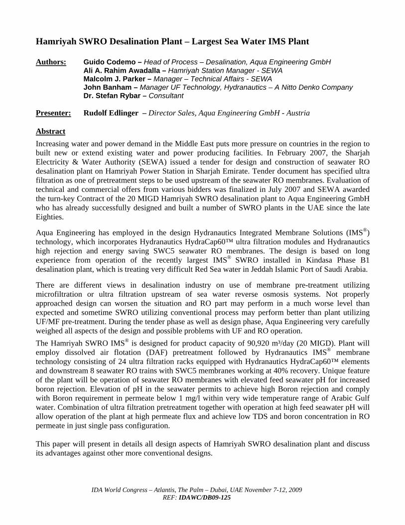
I. INTRODUCTION 1.1 Services by SEWA in Sharjah Emirate in UAE Under the guidance of His Highness Sheikh Abdullah bin Salim Al Qassimi, the Deputy Ruler of Sharjah and Chairman of SEWA Board of Directors, ambitious expansions and development projects were implemented by SEWA to cope pace with the comprehensive population growth and industrial development witnessed in the Emirate of Sharjah. SEWA has been always committed to provide high quality supply of electricity, water and gas, and continuously develop its facilities to achieve the excellence in securing reliable services that would meet the growing demand and exceed the future needs and expectations of its customers who totalled 298,898 by October 2008. Beside development of gas supplies, in electrical power supply several new generation units, distribution and transmission substations were installed to raise the power generation, distribution and transmission capacities. By November 2008, the power generated units totalled 9,125.7 million KWh. In water supply a similar growth trend was affected in field of water supplies with the commissioning and development of more desalination plants and well fields. As consequence, the total water production reached to 29,269 million gallons by October 2008 i.e. an average of 87.8 MIGD. SEWA is providing all parts of the Emirate with drinking water from both underground and desalination sources. Modern desalination and production plants to produce and treat seawater and underground water to be distributed to residential, commercial and industrial consumers via our transmission & distribution networks Below graph from SEWA statistic shows the current diversification of water supply in sources and individual capacities.
Picture 1: SEWA water production by source, statistic 2007
Source: SEWA Statistical Book 2007
IDA World Congress – Atlantis, The Palm – Dubai, UAE November 7-12, 2009 REF: IDAWC/DB09-125
-2-
IDA World Congress – Atlantis, The Palm – Dubai, UAE November 7-12, 2009 REF: IDAWC/DB09-125
-3-
As shown on the chart, about 33% of potable water comes from ground water resources with mostly brackish water desalination and the balance of 67% comes from seawater desalination with majority thermal desalination technology employed. As a consequence of high growth in demand and environmental considerations there is a great need to expand water production facilities be desalination while maintaining or reducing abstraction from ground water and partially desalination by use of brackish water RO systems. Based on latest good experience with application of RO technology and reliability in operation SEWA has decided to employ more RO desalination technology to make use of economic benefits in capital cost and running cost. In Hamriyah Station a hybrid of 71,5 % reverse osmosis (RO) and 28,5 % multi effect distillation (MED) desalination technologies has been planned in order to maximise overall Station efficiency and operate on lowest production cost of power generation and water desalination. The planned total desalination capacity in Hamriyah Station is 140 MIGD. 1.2 SEWA`s Development and long term plan for Hamriyah Station (HAMPS) The project with the single largest impact on production capacity is the combines Station for Power Generation and Desalination at Hamriyah, which will be about 2,600 MW on power generation by gas turbines in combined cycle and 140 MIGD desalination, where 40 MIGD will be MED and 100 MIGD RO desalination to cover the additional water and power requirements of the Emirate till 2018. As per original plan by 2021, Hamriyah Power Station will be provided with a total desalination capacity of 140 million gallons of drinking water per day with individual installation of Phase 1 RO plant with total capacity of 20 million gallons per day in 2010, and MED desalination plants with total capacity of 20 million gallons per day in 2011 while the period between 2013 to 2021 will witness the provision of further 80 million gallons per day in RO and 20 million gallons per day in MED with the rate of 20 million gallons per day in steps of every two years. Due to current unclear economic global situation and the impact on Sharjah´s future demand in power and water and the continuation of extension in power generation and water desalination facilities has been put on hold to review the original time schedule in relation to an expected slower future growth The further development on future Phases at Hamriyah Station are shown below:
PHASE FACILITIES Phase I Power generation of 400 MW by Gas Turbines (GT) and in service Phase II
RO Desalination of 20 MIGD presently under construction by Aqua Engineering with expected completion by mid 2010
Phase 3
Power generation of about 2,200 MW with GT`s and combined cycle presently on hold
Phase IV
RO Desalination of 80 MIGD in 4 x 20 MIGD units, presently tendered but not awarded and on hold
Phase V MED thermal desalination of 40 MIGD tendered but not awarded and on hold
Table 1: Development Phases of Hamriyah Station Source: SEWA
IDA World Congress – Atlantis, The Palm – Dubai, UAE November 7-12, 2009 REF: IDAWC/DB09-125
-4-
1.3 SEWA Design Consideration for Hamriyah SWRO plant The following key considerations for design of Hamriyah desalination facilities have been adopted by SEWA, i.e. - plant shall be operated as base load plant with maximum availability throughout the year - plant shall be built according to applied standards in power generation to allow best longterm
performance and reliability - plant shall be fully automated to latest standards in power generation to avoid unnecessary
shutdowns by instrument or process logic control (PLC) failure - plant shall use high grade materials, i.e. super duplex steel for high pressure system and all
seawater pumping and all equipment shall be graded to local conditions, particularly all electrical system,
in order to secure a continuous uninterrupted operation as a base load plant, similar to such philosophy what is used in power generation. The process design of plant was influenced by long term experiences of SEWA at Layyah Power Station with open intake sea water abstraction and the trends of deteriorating quality of seawater over the last years. This deterioration was particularly experienced with high levels of suspended solids and heavy marine biological growth likely due to ongoing marine works and dredging along the coast line and a conventional pre-treatment was considered unfit to deal with these sea water conditions. Again, the concept of a base load plant has large influence in the requirement of a very sophisticated and reliable pre-treatment to operate water production during all regular variations in seawater quality throughout the seasons and in future. Further worsening of raw water quality and in particular the recent experience with extended red tide has confirmed the good decision to go for extended and latest state of the art technology for pretreatment. The SWRO desalination facility, further presented in detail in this paper consists of the following process units: - open seawater intake (in combination with common intake for power station cooling water), - coarse screens and band screens - pre-treatment chemical dosing to requirements - dissolved air flotation (DAF) - ultra filtration (UF) - reverse osmosis desalination (RO) in a single pass/single stage designed for high Boron removal - Post treatment and potabilisation to neutral Langelier Saturation Index (LSI) - Product water storage - Product water forwarding to Hamriyah and Sharjah
IDA World Congress – Atlantis, The Palm – Dubai, UAE November 7-12, 2009 REF: IDAWC/DB09-125
-5-
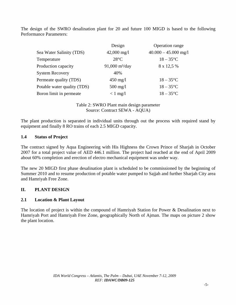
The design of the SWRO desalination plant for 20 and future 100 MIGD is based to the following Performance Parameters:
Design Operation range Sea Water Salinity (TDS) 42,000 mg/l 40.000 – 45.000 mg/l Temperature 28°C 18 – 35°C Production capacity 91,000 m³/day 8 x 12,5 % System Recovery 40% Permeate quality (TDS) 450 mg/l 18 – 35°C Potable water quality (TDS) 500 mg/l 18 – 35°C Boron limit in permeate < 1 mg/l 18 – 35°C
Table 2: SWRO Plant main design parameter
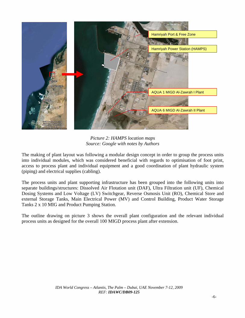
Source: Contract SEWA - AQUA) The plant production is separated in individual units through out the process with required stand by equipment and finally 8 RO trains of each 2.5 MIGD capacity. 1.4 Status of Project The contract signed by Aqua Engineering with His Highness the Crown Prince of Sharjah in October 2007 for a total project value of AED 446.1 million. The project had reached at the end of April 2009 about 60% completion and erection of electro mechanical equipment was under way. The new 20 MIGD first phase desalination plant is scheduled to be commissioned by the beginning of Summer 2010 and to resume production of potable water pumped to Sajjah and further Sharjah City area and Hamriyah Free Zone. II. PLANT DESIGN 2.1 Location & Plant Layout The location of project is within the compound of Hamriyah Station for Power & Desalination next to Hamriyah Port and Hamriyah Free Zone, geographically North of Ajman. The maps on picture 2 show the plant location.
Hamriyah Port & Free Zone
Hamriyah Power Station (HAMPS)
AQUA 6 MIGD Al-Zawrah II Plant
AQUA 1 MIGD Al-Zawrah I Plant
Picture 2: HAMPS location maps
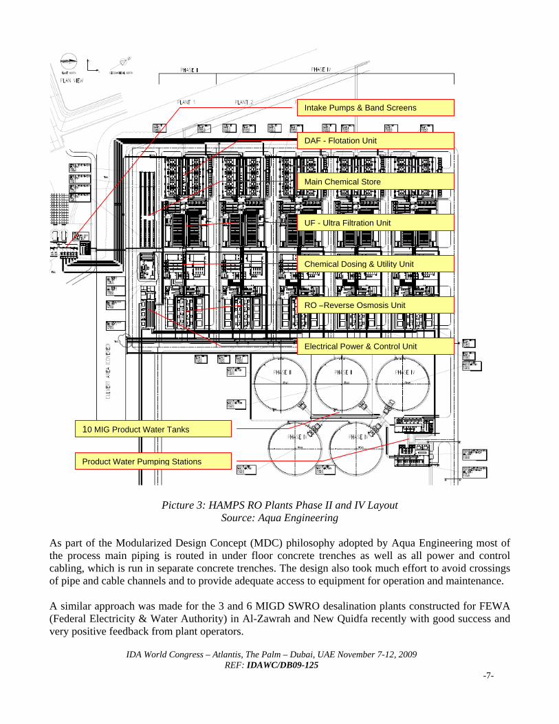
Source: Google with notes by Authors The making of plant layout was following a modular design concept in order to group the process units into individual modules, which was considered beneficial with regards to optimisation of foot print, access to process plant and individual equipment and a good coordination of plant hydraulic system (piping) and electrical supplies (cabling). The process units and plant supporting infrastructure has been grouped into the following units into separate buildings/structures: Dissolved Air Flotation unit (DAF), Ultra Filtration unit (UF), Chemical Dosing Systems and Low Voltage (LV) Switchgear, Reverse Osmosis Unit (RO), Chemical Store and external Storage Tanks, Main Electrical Power (MV) and Control Building, Product Water Storage Tanks 2 x 10 MIG and Product Pumping Station. The outline drawing on picture 3 shows the overall plant configuration and the relevant individual process units as designed for the overall 100 MIGD process plant after extension.
IDA World Congress – Atlantis, The Palm – Dubai, UAE November 7-12, 2009 REF: IDAWC/DB09-125
-6-
Intake Pumps & Band Screens
DAF - Flotation Unit
IDA World Congress – Atlantis, The Palm – Dubai, UAE November 7-12, 2009 REF: IDAWC/DB09-125
-7-
Picture 3: HAMPS RO Plants Phase II and IV Layout
Source: Aqua Engineering As part of the Modularized Design Concept (MDC) philosophy adopted by Aqua Engineering most of the process main piping is routed in under floor concrete trenches as well as all power and control cabling, which is run in separate concrete trenches. The design also took much effort to avoid crossings of pipe and cable channels and to provide adequate access to equipment for operation and maintenance. A similar approach was made for the 3 and 6 MIGD SWRO desalination plants constructed for FEWA (Federal Electricity & Water Authority) in Al-Zawrah and New Quidfa recently with good success and very positive feedback from plant operators.
UF - Ultra Filtration Unit
Main Chemical Store
Chemical Dosing & Utility Unit
RO –Reverse Osmosis Unit
Electrical Power & Control Unit
10 MIG Product Water Tanks
Product Water Pumping Stations
IDA World Congress – Atlantis, The Palm – Dubai, UAE November 7-12, 2009 REF: IDAWC/DB09-125
-8-
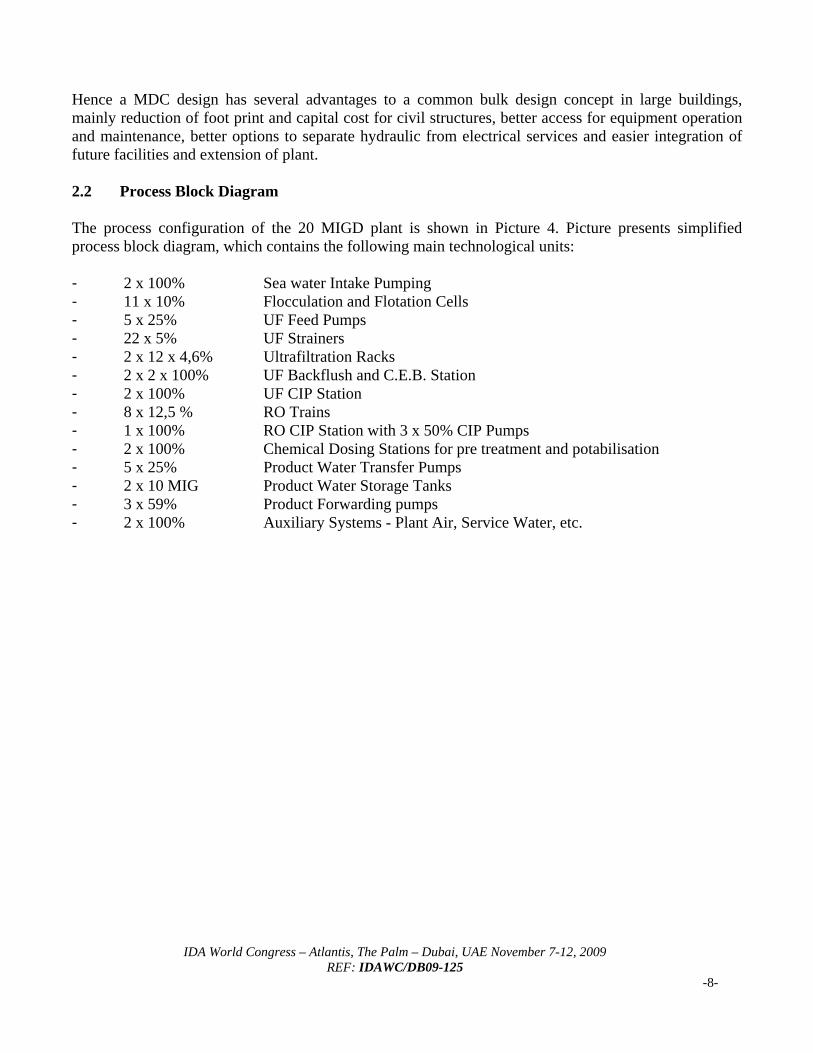
Hence a MDC design has several advantages to a common bulk design concept in large buildings, mainly reduction of foot print and capital cost for civil structures, better access for equipment operation and maintenance, better options to separate hydraulic from electrical services and easier integration of future facilities and extension of plant. 2.2 Process Block Diagram The process configuration of the 20 MIGD plant is shown in Picture 4. Picture presents simplified process block diagram, which contains the following main technological units: - 2 x 100% Sea water Intake Pumping - 11 x 10% Flocculation and Flotation Cells - 5 x 25% UF Feed Pumps - 22 x 5% UF Strainers - 2 x 12 x 4,6% Ultrafiltration Racks - 2 x 2 x 100% UF Backflush and C.E.B. Station - 2 x 100% UF CIP Station - 8 x 12,5 % RO Trains - 1 x 100% RO CIP Station with 3 x 50% CIP Pumps - 2 x 100% Chemical Dosing Stations for pre treatment and potabilisation - 5 x 25% Product Water Transfer Pumps - 2 x 10 MIG Product Water Storage Tanks - 3 x 59% Product Forwarding pumps - 2 x 100% Auxiliary Systems - Plant Air, Service Water, etc.
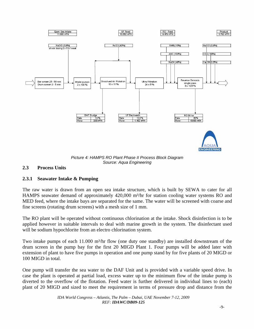
Picture 4: HAMPS RO Plant Phase II Process Block Diagram
Source: Aqua Engineering 2.3 Process Units 2.3.1 Seawater Intake & Pumping The raw water is drawn from an open sea intake structure, which is built by SEWA to cater for all HAMPS seawater demand of approximately 420,000 m³/hr for station cooling water systems RO and MED feed, where the intake bays are separated for the same. The water will be screened with coarse and fine screens (rotating drum screens) with a mesh size of 1 mm. The RO plant will be operated without continuous chlorination at the intake. Shock disinfection is to be applied however in suitable intervals to deal with marine growth in the system. The disinfectant used will be sodium hypochlorite from an electro chlorination system. Two intake pumps of each 11.000 m³/hr flow (one duty one standby) are installed downstream of the drum screen in the pump bay for the first 20 MIGD Plant 1. Four pumps will be added later with extension of plant to have five pumps in operation and one pump stand by for five plants of 20 MIGD or 100 MIGD in total. One pump will transfer the sea water to the DAF Unit and is provided with a variable speed drive. In case the plant is operated at partial load, excess water up to the minimum flow of the intake pump is diverted to the overflow of the flotation. Feed water is further delivered in individual lines to (each) plant of 20 MIGD and sized to meet the requirement in terms of pressure drop and distance from the
IDA World Congress – Atlantis, The Palm – Dubai, UAE November 7-12, 2009 REF: IDAWC/DB09-125
-9-
IDA World Congress – Atlantis, The Palm – Dubai, UAE November 7-12, 2009 REF: IDAWC/DB09-125
-10-
intake; a surge protection is foreseen in each line to the plants in case of power failure to avoid under pressure in the pipe work and to protect intake pumps from water hammer. Ferric chloride is dosed in the feed water line leading to the flocculation basins of the DAF Unit. 2.3.2 DAF Dissolved Air Flotation A dissolved air flotation (DAF) is a well proven device has been selected upstream to an UF pre-treatment and designed to remove suspended solids, oil and grease (both in emulsified and non-dissolved form) and removal of plankton organisms and algae. The expected removal rate is >90% and ferric chloride dosing should allow good coagulation also in variable water conditions and during “red tide”; pH levels are kept at natural pH of sea water without acidification. The DAF system employed in this plant is a turbulent flotation based on O.I. Ryktor design, which has been successfully used by Aqua Engineering in another plant treating heavy loaded surface water in Croatia and other applications in the industry. The cost-effective DAF process flocculates water that has been pretreated with coagulant. In the air injection zone, flocculated particles attach to micro-bubbles created by a supersaturated recycle stream, and the solids float to the water’s surface. With the solids removed periodically, the clarified water is free of solids, algae and reduced in organic matter. The DAF system applied with its patented effluent collection system creates a vortex flow pattern within the DAF basin that results in a dense air bed and increased bubble surface area for significantly higher flotation rates and has been working successfully at loading rates of 30 m/h and higher. The intake pump transfers the required water with the common header to ten flocculation and flotation lines. Flocculent will be dosed and mixed by means of an inline mixer as described above. The dosing is flow proportional to the sum of flows to all flotation lines. The flow to each flotation chamber (11 x 10%) is controlled via individual control valve. Starting the plant the minimum flow is divided to the number of flotation lines available and the flow to each line is adjusted accordingly. Operation of DAF and Intake pump speed when the UF and RO are in operation is driven by the water demand of the UF feed pumps and the level in the intermediate tank. The distribution in the first flocculation chamber is done with a slotted pipe along the whole width of the basin. In each basin two mixers are installed to allow coagulation of the flocs. The flotation is entered from the bottom, where the water is mixed with the saturated recycle stream. The flotation chamber is provided with a perforated floor to ensure laminar flow conditions which is required to allow the solids to float to the surface. The flotation removes the suspended solids by means of introducing air saturated water under pressure in the flotation cell. By expanding the water to atmospheric conditions micro bubbles lift the suspended solids to the surface, where the sludge is collected. Periodically the floated sludge is removed by surface scrapers into a sludge trough and further discharged by sludge pumps. DAF recirculation pumps pressurize the water prior to saturation. A compressor station with one duty and one stand by compressor is provided for the required air.
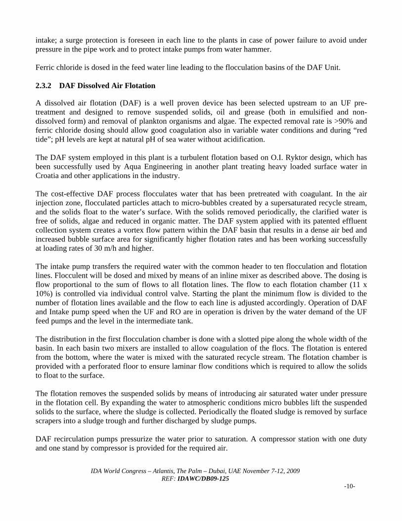
Below schematic shows the design of the used DAF technology.
Picture 5: Turbulent DAF Block Diagram
Source: Degremont AquaDAF [8] To assure no debris is passing to the UF feed pumps and to the recirculation pumps, all intermediate tank is covered with either solid concrete slabs and/or GRP covers. In case the raw water quality is good enough to comply with requirements of UF membranes and turbidity is less than 5 NTU, the flotation can also be bypassed and the flocculated water flows directly to the UF feed pumps. The clear water reservoir downstream of the flotation is designed with sufficient volume to operate the UF and RO plant for 6 minutes at full capacity. 2.3.3 Ultra Filtration Ultra Filtration Unit UF feed pumps (4 duty, 1 stand by) draw the water from the intermediate tank downstream of DAF. To allow smooth start up and shut down of the UF blocks without pressure peaks, two of the pumps are equipped with a variable speed drive and 3 pumps are started with a soft starter. Hamriyah desalination plant design utilizes Hydranautics IMS® technology and HYDRAcap60™ UF membranes are used in the pre-treatment. As the available discharge pressure is not required as long as the UF membranes are not fouled a control valve is installed at the fixed speed pumps. To avoid any clogging of the UF fibers, an automatic strainer system is installed upstream of the UF plant. As a rule of thumb the strainers shall have a clearance of one fifth of the internal diameter of the fibers. Thus 130 micron is suitable for the internal diameter (ID) 0.8 mm of UF fibers considered for this plant. For final removal of remaining inorganic and organic particles and colloidal matter upstream to the RO system, an ultra filtration unit consisting of 2 lines UF blocks is installed. Each line consists of 12 UF blocks with all auxiliary equipment for back flush, chemical enhanced back flush and air integrity testing. The cleaning of the UF membranes will be done very infrequent, thus only one cleaning in place station is sufficient.
IDA World Congress – Atlantis, The Palm – Dubai, UAE November 7-12, 2009 REF: IDAWC/DB09-125
-11-
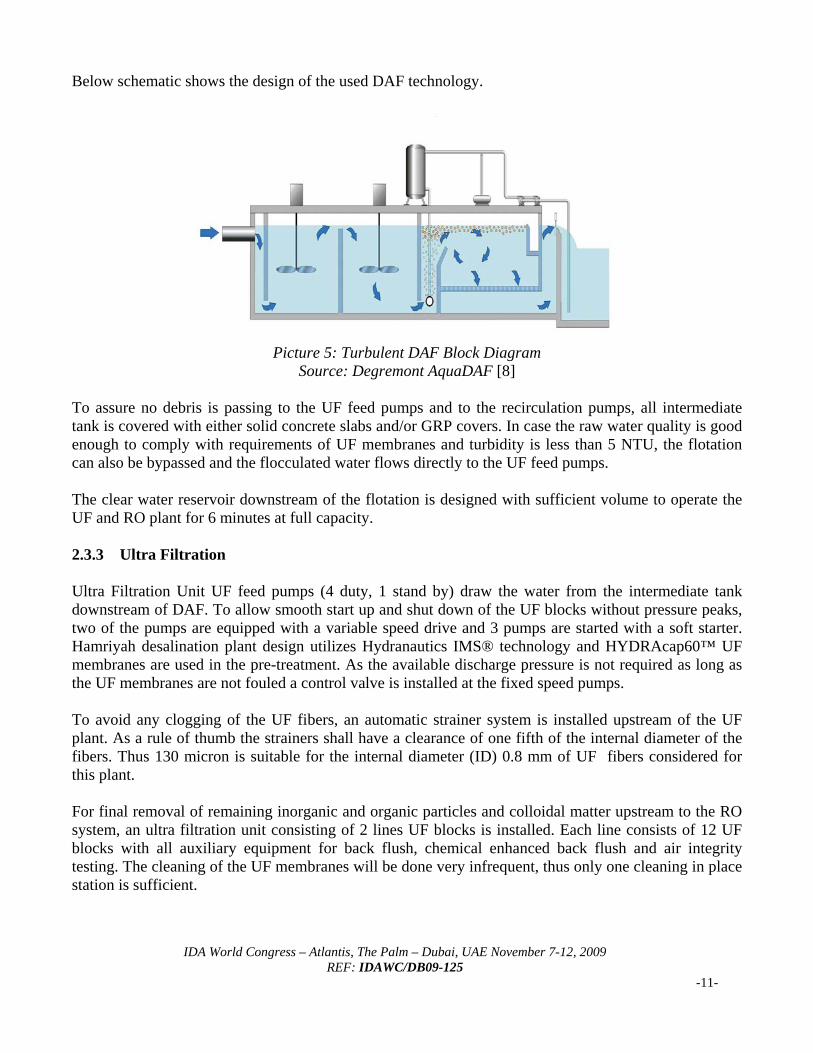
An injection point for coagulant is located also upstream of the ultra filtration plant in case a secondary flocculation downstream of the flotation is required. A static mixer is installed to ensure efficient mixing of chemicals. Each UF block consists of 120 UF elements of single bore hollow fiber membranes with a bore size of 0.8 mm and a cut off limit of 0.025 micron. The overall UF plant is designed for a continuous UF permeate flow of 9,500 m³/h. The nominal flux rate is 71.7 l/m²/h with all UF blocks in operation with a maximum flux of 86.1 l/m²/h with two blocks per line out of service for (CEB) back flush and/or chemical cleaning. The control valve in the UF filtrate is used as a flow limiting valve, i.e. the flow through a single UF block is limited to 475 m³/h. During normal operation the flow through each UF block may vary from 395 to 475 m³/h.
Picture 6: UF Projection Source: Hydranautics
IDA World Congress – Atlantis, The Palm – Dubai, UAE November 7-12, 2009 REF: IDAWC/DB09-125
-12-
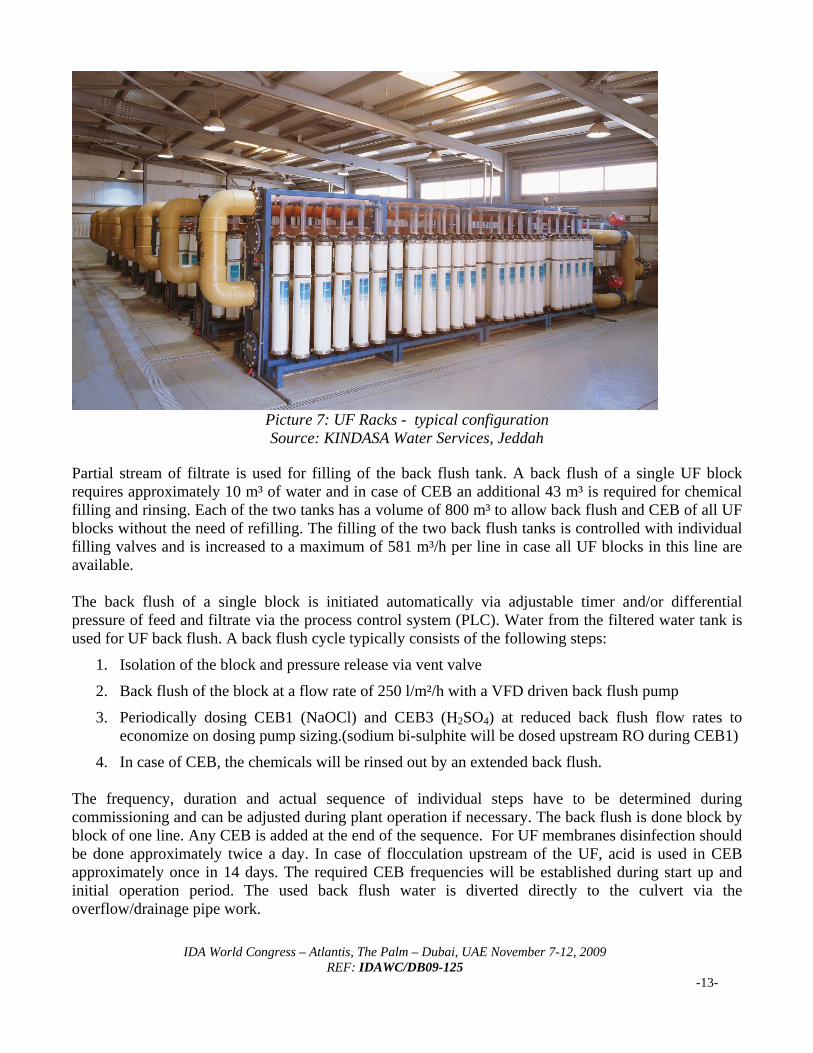
Picture 7: UF Racks - typical configuration Source: KINDASA Water Services, Jeddah
Partial stream of filtrate is used for filling of the back flush tank. A back flush of a single UF block requires approximately 10 m³ of water and in case of CEB an additional 43 m³ is required for chemical filling and rinsing. Each of the two tanks has a volume of 800 m³ to allow back flush and CEB of all UF blocks without the need of refilling. The filling of the two back flush tanks is controlled with individual filling valves and is increased to a maximum of 581 m³/h per line in case all UF blocks in this line are available. The back flush of a single block is initiated automatically via adjustable timer and/or differential pressure of feed and filtrate via the process control system (PLC). Water from the filtered water tank is used for UF back flush. A back flush cycle typically consists of the following steps:
1. Isolation of the block and pressure release via vent valve
2. Back flush of the block at a flow rate of 250 l/m²/h with a VFD driven back flush pump
3. Periodically dosing CEB1 (NaOCl) and CEB3 (H2SO4) at reduced back flush flow rates to economize on dosing pump sizing.(sodium bi-sulphite will be dosed upstream RO during CEB1)
4. In case of CEB, the chemicals will be rinsed out by an extended back flush. The frequency, duration and actual sequence of individual steps have to be determined during commissioning and can be adjusted during plant operation if necessary. The back flush is done block by block of one line. Any CEB is added at the end of the sequence. For UF membranes disinfection should be done approximately twice a day. In case of flocculation upstream of the UF, acid is used in CEB approximately once in 14 days. The required CEB frequencies will be established during start up and initial operation period. The used back flush water is diverted directly to the culvert via the overflow/drainage pipe work.
IDA World Congress – Atlantis, The Palm – Dubai, UAE November 7-12, 2009 REF: IDAWC/DB09-125
-13-
IDA World Congress – Atlantis, The Palm – Dubai, UAE November 7-12, 2009 REF: IDAWC/DB09-125
-14-
It is very important to keep always in mind that use of oxidative biocides upstream of RO membranes must be minimized or better – eliminated completely. Contact of natural organic matter with strong oxidants creates assimilable organic carbon and significantly accelerates bio-fouling. Since UF membranes provide a barrier to particulates, they provide significant benefits to the RO and overall system design. Everybody must be aware that if UF is not handled together with respect RO as one compact system – significant problems in RO performance may occur. RO performance could suffer due to heavy bio-fouling despite the fact that UF filtrate will provide very good membrane feed water with no particulates. But despite this – one important parameter may be out of control – bio-fouling. Bio-fouling is much bigger and more dangerous threat for UF-RO system than i.e. fiber breakage [1, 2]. To assure the best possible performance of the UF membranes and to detect any fiber breakages, facilities for an air bubble integrity test are foreseen. During this test a small pressure difference will be applied by means of air and the pressure decay for a certain period is observed. In addition the filtrate pipes of each UF module are equipped with transparent pipes to observe any bubbles passing the membranes. If leakages are located, the individual fibers can be blocked with a repair kit. As already mentioned, fiber breaks are however not so critical upstream of an RO system in desalination as the RO system retains all bacteria and virus, critical in potable water purification. A compressed air line is provided for each UF line, comprising an air receiver, compressor, etc. with common standby for both units. Chemical cleaning will be performed when needed by the common CIP station. Downstream of the UF, several instruments are incorporated to monitor the RO feed quality, such as Turbidity, SDI, pH value and ORP value. A key parameter is ORP, as this is the most reliable parameter for content of oxidizing substances. When pre-set limiting values for critical parameters are exceeded the RO system is shut down and filtered water is drained through dump valves until the problem is solved and the feed water quality is within the limits again. For water conditioning downstream of the UF plant following chemicals will be dosed: - Sodium meta bisulfite in case of chlorination of the intake - Antiscalant in case for scaling control - Caustic soda to alkalize RO feed for boron removal Due to the specification requirement to ensure Boron in product water <1 mg/l, the RO system shall be operated in alkaline mode which allows for high boron removal of RO membranes as per Hydranautics (patent protected) design [9]. 2.3.4 RO Reverse Osmosis Desalination The Reverse Osmosis Unit consists of eight RO Trains with a design capacity of 2.5 million Imperial Gallon per day (2.5 MIGD = 11,365 m³/day) each, equipped with Hydranautics SWC5 membranes. In developing the SWC5, Hydranautics design strategy was based on optimizing membrane chemistry, element design and element manufacturing. It is important to remember that the seawater element is comprised of not only high performance membrane, but other state of the art components too. By optimizing element design and construction, membrane area is increased keeping same spacers and
IDA World Congress – Atlantis, The Palm – Dubai, UAE November 7-12, 2009 REF: IDAWC/DB09-125
-15-
pressure losses are reduced, leading to increased element productivity. SWC5 has productivity of 34.2 m³/d (9,000 GPD) at standard test conditions and rejection is 99.8%. This excellent performance cannot be overlooked when searching for the lowest operational costs. To meet final product water requirements, sea water RO plants usually use second pass brackish RO system. SWC5 offers the highest combination of flow, overall excellent rejection and also very good Boron rejection. Alkalization of the seawater with target to achieve good Boron rejection is technology protected by Hydranautics patent [9]. This technology combined with state of the art sea water membrane permits to achieve Boron in final product bellow 1 mg/l. In case acidification would be adopted in pre-treatment, split partial second pass will be needed to ensure boron removal to <1 mg/l over membrane life time and temperature range; hence alkalization of feed is a good economic and efficient technological approach [4, 5]. It is however required to add CO2 injection in permeate to adjust bicarbonate level in treated water to allow for LSI adjustment and potabilisation of water. As already mentioned, SW RO part consists of 8 trains operating in single pass configuration. Each train has 110 pressure vessels with 7 elements. Averaged flux used in the design is 16.6 lmh. It is well known and proven from operational data of running installations equipped with Hydranautics membranes that better membrane feed water quality allows increased RO membrane fluxes. Flux is always dependent on feed water quality. As few examples – SWRO in New Quidfa equipped with SWC3+ operates with flux of 15.6 lmh with SDI values permanently below 3. SWRO in Malta is equipped with Hydranautics SWC4+ operating with fluxes 16 lmh. The plant operates with beach wells intake and membrane feed water quality is of a very good standard. Sea water installation in Nirma, India works with an average flux of 17 lmh. Membrane feed water quality is also very good and allows RO operation at elevated fluxes. In the case of Hamriyah SWRO design, an averaged flux of 16.6 lmh was selected. Selection of RO flux was driven by Hydranautics’ long experience with performance of HYDRAcap60 UF in sea water in combination with operation of SWRO downstream of UF. UF cuts spikes in membrane feed water quality – i.e. SDI spikes and turbidity spikes after filter backwashing and eliminates particulate matter completely. Besides having a MWCO of HYDRAcap60 membrane of around 100 kDaltons. which partly reduces the amount of macromolecular organic material, Hydranautics HYDRAcap60™ UF operating in a sea water environment produces turbidities permanently below 0.1 NTU. Achieved SDI values are permanently around 1 and not exceeding value of 2 in long term performance [1, 2, 7]. This experience permits to push fluxes to higher and more aggressive levels saving investment costs as well as operating costs. To improve the energy efficiency of the plant, an energy recovery system by pressure exchanger is installed. This technology is found to be the most economic, since only a flow corresponding approximately to the permeate capacity has to be pressurized by the high pressure pump whereas the remaining portion of the feed (approx. equal to the brine flow) is boosted via the pressure exchanger without external power and only a small booster pump is required to compensate for losses in the pressure exchanger and piping. The membranes are arranged in a single stage array for the design recovery rate of 40%. This is considered as optimum for the design conditions at this site. Permeate from the RO trains flows to the RO-permeate and flushing tank.
IDA World Congress – Atlantis, The Palm – Dubai, UAE November 7-12, 2009 REF: IDAWC/DB09-125
-16-
Automatic flushing of stainless steel piping, high pressure pump, pressure exchanger and membranes is performed after the plant or individual trains have been stopped and will not be started again within a short period. Water from the permeate tank is used to displace high salinity water. The membrane cleaning system is used for cleaning and disinfection of the membranes. The cleaning solution is prepared in the cleaning tank and circulated with the cleaning pumps (3 x 50%) across the cartridge filter and membrane blocks. Tank, pumps and cartridge filters are designed for cleaning of one complete RO unit. 2.3.5 Post Treatment From the flushing and permeate tank. permeate is pumped to the product water tanks by the product water transfer pumps (4 duty, 1 standby). Downstream the product water transfer pumps carbon dioxide and lime milk for pH adjustment and sodium hypochlorite for disinfection is dosed. Because the RO system may be operated either at natural pH value or likely alkalized, it is required to dose also carbon dioxide to increase the buffer capacity. The dosing rate depends on the CO2 content of the original RO permeate and may vary from 15 to 27 mg/l Carbon dioxide is available downstream of the evaporators of the CO2 production and storage plant supplied under Phase 1. The pressure of the gaseous CO2 is reduced to 5 – 7 bar and dosed flow proportional by mass flow meters and control valves. After adding the appropriate amount of CO2 to the RO permeate the pH-value is adjusted by addition of lime milk dosed downstream the product water transfer pumps. 2.3.6 Product Water Storage & Forwarding In the present Phase 1 RO plant, there are 2 nos. 10 MIG (or 45,500 m³) circular concrete type water tanks provided, both to store 1 day of production from the RO plant. Three more tanks of same capacity will be added with future extension of HAMPS RO plants. Product water is further pumped to Hamriyah Free Zone and Shajjah reservoirs of SEWA, from where Sharjah City will be supplied. In Phase 1 of RO plants, one pumping station for 20 MIGD pumping capacity is constructed with 40 m and 150 m discharge heads and each 3 x 50% installed capacity. III. IMS DESIGN AND ADVANTAGES CONSIDERED Up to date – Hydranautics has very valuable experience with the largest SWRO IMS® installations in Middle East area, running very successfully already for 3 years in difficult water of Jeddah Islamic Port. We have already mentioned that very important factor of every RO installation operating with UF as pre-treatment has the ability to keep bio-fouling under control. Hydranautics, as membrane IMS® supplier, is responsible to address all potential problems in UF as well as in RO membrane performance. The confidence by Hydranautics about IMS® SWRO performance is reflected in the agreement to cover Hamriyah SWRO with very low membrane replacement rate and 7 years system performance warranty.
IDA World Congress – Atlantis, The Palm – Dubai, UAE November 7-12, 2009 REF: IDAWC/DB09-125
-17-
Advantages of IMS®
Smaller foot print than multistage treatment Lower chemical consumption Reduced power consumption Excellent pre-treated water quality results in longer RO membranes service life Enables flux increase of seawater membranes Reduced cleaning frequency Reduced membrane replacement rate One warranty for the whole membrane system – eliminates potential never ending
disputes when two membrane suppliers are used IV. GENERAL DESIGN CONSIDERATIONS Based on the requirements of SEWA and the fact, that this plant is integrated in a power station complex and designed for fulltime base load operation, design standards have been considerably higher as in other projects. The most significant design highlights are summarized below:
- Sophisticated pretreatment with high flexibility to cope with local variable seawater conditions now and in future
- Integrated membrane system (IMS) from one source with simple ‘UF – in’ and ‘RO – out’ guarantee parameters without future problems for the plant owner / operator in case of problems
- Selection of all materials of process pumps in Super Duplex with PREN > 40 acc. To DIN standards
- Selection of high pressure piping in Super Duplex with PREN > 40 acc. To DIN standards (used material is ZERON 100 from Weir Materials)
- High efficiencies in all process pumps - Optimization of process chemical dosing - High end hydraulic design to allow for safe carrying of high flows and cater for water hammer /
surges in case of power cut and process related disturbances - Design of piping in RO; good venting and no dead zones to avoid high stress to membranes
during pressurization and subsequent element damage - High end SIMATIC distributed control system to latest power station standards with full
redundancy till individual I/O`s. hot changeover, etc. - Integration of control system in overall power station control room - Full uninterrupted power system backup, - Optimized footprint due to modular design concept - Separation of hydraulic systems from plant cabling systems, all under floor in trenches with
minimum crossings The above project specific design highlights and other practical design aspects to the plant operators benefit are based on experiences of over 20 years application know-how of RO technology in the Region by Aqua Engineering.
IDA World Congress – Atlantis, The Palm – Dubai, UAE November 7-12, 2009 REF: IDAWC/DB09-125
-18-
V. CONCLUSIONS Hamriyah first Phase 20 MIGD RO desalination plant will be surely one of the most sophisticated SWRO plants in the Region based on latest technology in pre-treatment, design, selection of materials and plant control to match the high standards applied in power station engineering. It will be also largest IMS® SWRO in the world recently under operation. Hence the plant will be fully equipped to provide the required high availability and operational reliability in long term operation for SEWA as a base load plant to ensure safe potable water supplies to Sharjah city and Hamriyah Free Zone. Based on today’s experience with poor quality of feed water caused by high levels of suspended solids, extensive marine biological growth and harmful algae growth (also known as red tide), the process should be able to produce potable water under most difficult conditions, when other conventional RO plants either could not be operated or else only partially at most. The close cooperation between membrane supplier and key OEM`s together with SEWA as the client is a key for the success of this project and on behalf of Aqua Engineering we all parties concerned for the high level of commitment and cooperation throughout the various stages of this project. VI. REFERENCES
1. Eng.Aziz H.Gulamhusein, Eng.Ashraf Al Sheikh Khalil, Eng.Mohideen A.K.Kasiar, Eng.Inam A.Khan, Eng.Amir Basha Syed K., Eng.Mohammed Saud, Dr.Mourad Ben Boudinar, Dr.Stefan Rybar - Operation of SWRO Plant with Hybrid IMS – Second Annual China Water Congress 2008
2. Eng.Aziz H.Gulamhusein, Eng.Ashraf Al Sheikh Khalil, Eng. Ibrahim A. Fatah, Roman Boda Dr.Stefan Rybar; IMS SWRO Kindasa – Two Years of Operational Experience – EDS Conference Jordan 2008
3. V.Bonnelye, L.Guey, J.Del Castillo – UF/MF as RO pretreatment: real benefit; Desalination 222 (2008) 59-65
4. Brett Andrews, Bhasker Dave, Paloma Lopes-Serrano, Shih-Perng Tsai, Rich Franks, Mark Wilf, Erineos Koutsakos - Effective Scale Control for Sea Water RO Operating at High pH and Temperature - Halkidiki Greece, EDS Conference 2007
5. Mark Wilf – The Guidebook to Membrane Desalination Technology; Desalination Publications 2007
6. Boris Liberman, Mark Wilf - Evolution of configuration of RO seawater desalination systems - IDA World Congress on Desalination and Water Reuse, Singapore, 2005.
7. Paul Choules, Dr.Mourad Ben Boudinar, Bernie Mack – Membrane Pre-treatment Design and Operational Experience From Three SWRO Plants – AMTA Conference – Austin, Texas 2009
8. Degremont – AquaDAF technical information 9. USP 7442309
Related Documents