2H1-IX Hall effect & polarity effect on flow structure in counter-helicity spheromak merging University of Tokyo Y. Kaminou,M. Inomoto,Y. Ono, and R. Horiuchi NIFS US-Japan Workshop on Compact Torus August 22-24, 2016 Irvine, California, USA

Welcome message from author
This document is posted to help you gain knowledge. Please leave a comment to let me know what you think about it! Share it to your friends and learn new things together.
Transcript
2H1-IX
Hall effect & polarity effect on flow structure in counter-helicity spheromak merging
University of Tokyo Y. Kaminou,M. Inomoto,Y. Ono, and R. HoriuchiNIFS
US-Japan Workshop on Compact Torus August 22-24, 2016 Irvine, California, USA
Outline
2H1-IX
• Introduction
• Hall-MHD simulation
• Particle in Cell simulation
• Summary
2
2H1-IX
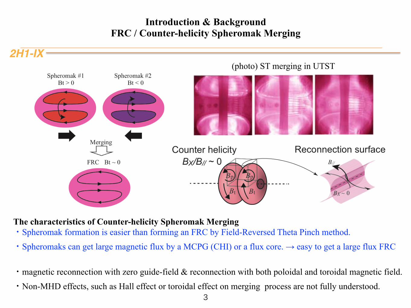
Introduction & Background FRC / Counter-helicity Spheromak Merging
3
(photo) ST merging in UTST
The characteristics of Counter-helicity Spheromak Merging ・Spheromak formation is easier than forming an FRC by Field-Reversed Theta Pinch method. ・Spheromaks can get large magnetic flux by a MCPG (CHI) or a flux core. → easy to get a large flux FRC
・magnetic reconnection with zero guide-field & reconnection with both poloidal and toroidal magnetic field. ・Non-MHD effects, such as Hall effect or toroidal effect on merging process are not fully understood.
2H1-IX
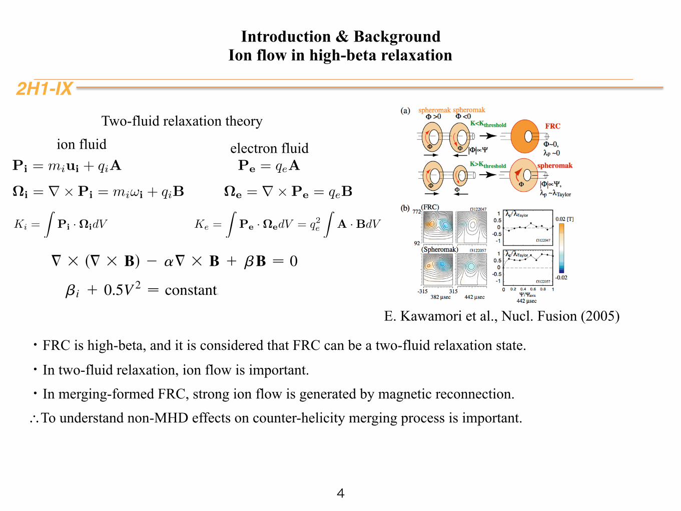
Introduction & Background Ion flow in high-beta relaxation
4
E. Kawamori et al., Nucl. Fusion (2005)
Ki =
ZPi ·⌦idV
⌦i = r⇥Pi = mi!i + qiB
Pi = miui + qiA
ion fluid
⌦e = r⇥Pe = qeB
Pe = qeA
Ke =
ZPe ·⌦edV = q2e
ZA ·BdV
electron fluid
VOLUME 81, NUMBER 22 P HY S I CA L REV I EW LE T T ER S 30 NOVEMBER 1998
and effective velocities,U1 ≠ V 2 === 3 B, U2 ≠ V . (8)
The first equation is the induction equation with thedifference that we do not neglect === 3 B s, Jd withrespect to V as is often done in MHD. This departurefrom the standard one-fluid treatment is crucial; it isthe source of the === 3 === 3 B term in Eq. (11), andhence of the possible diamagnetic structures. The secondequation is the Lorentz force equation which also includesthe standard fluid force V 3 s= 3 Vd. Let us introduceUj ≠ Uj 2 mjVj s j ≠ 1, 2d, and rewrite (6) as
≠Vjy≠t 2 = 3 sUj 3 Vjd ≠ 0 s j ≠ 1, 2d , (9)where m1 and m2 are scale parameters that can be consid-ered as intensives in a possible thermodynamic interpre-tation (to be discussed later). The simplest equilibriumsolution to (9) is Uj ≠ 0 s j ≠ 1, 2d, or equivalently thesystem of linear equations in B and V (a ≠ 1ym1 andb ≠ 1ym2)
B ≠ asV 2 = 3 Bd ,
B 1 = 3 V ≠ bV ,(10)
which describes, explicitly, the strong coupling betweenthe magnetic and the fluid aspects of the plasma. It isfrom this coupling that new physics is expected to arise.Equations (10) can be combined to yield, in either V orB, the second order partial differential equation [a ≠b 2 s1yad and b ≠ 1 2 bya]
= 3 s= 3 Bd 2 a= 3 B 1 bB ≠ 0 , (11)which, will, naturally lead to magnetic field (and flowvelocity) structures far richer than the ones contained inthe “constant-a Beltrami-Taylor” (BT) system.The equilibrium solution (10), when substituted into (2)
and (3) leads to the Bernoulli conditions =sbe 1 ged ≠0 ≠ =sbi 1 gi 1 V 2y2d suggesting a mechanism forcreating pressure sbd gradients in this extended relaxedstate. In the simplest case s g1 ≠ 0 ≠ ged,
bi 1 0.5V 2 ≠ constant, (12)revealing that an appropriate sheared velocity field cansustain a desired ion pressure gradient. Equations (11)and (12) will serve as a basis for designing a highlyeffective plasma confinement machine. We note that:(1) The set of equations (10) can be derived by
following the Taylor prescription of relaxed equilibriaapplied to (9), which allows two bilinear constants ofmotion, the usual total magnetic helicity h1 ≠ 20.5
RA ?
B d3x, and the generalized helicity h2 ≠ 0.5R
sA 1 Vd ?sB 1 = 3 Vd d3x [3]. Minimization of the total energyE ≠ 0.5
RsB2 1 V 2d d3x with the constraints of constant
h1 and h2 will directly lead us to (10). The constants aand b are related to the Lagrange multipliers needed in theconstrained minimization. The approach of constrainedminimization of an appropriate free energy has been usedby many authors [4–6] to generalize the BT system
especially with the idea of imparting a finite pressure anda finite flow to the “relaxed state.” Different combinationsof the helicities h1 and h2 were invoked (cross-helicityin Ref. [4], for example) for this purpose. Althoughthe “double curl Beltrami” system was accessible toany of these approaches, it was not recovered. Forexample, the assumption B ≠ aV in Ref. [5], makesthe more general solution inaccessible. We do wish toemphasize, however, that our interest (in this paper) wasnot to develop another minimum energy principle; wewere looking for a new genre of equilibria which willsimultaneously satisfy the induction and the force balanceequations.(2) The general steady-state solution allowed by (9)
consists of a set of nonlinear equations Uj ≠ AjsxdVj ,and Vj ? =Ajsxd ≠ 0 s j ≠ 1, 2d of which (10) is a spe-cial case where Ajsxd ; mj ≠ constant s j ≠ 1, 2d. In athermodynamic sense, the spatially inhomogeneous (ho-mogeneous) Aj imply a nonequilibrium (equilibrium)state. The latter corresponds to the Euler-Lagrange equa-tions associated with the global free energy F ≠ E 2P
j mjhj with mj acting as Lagrange multipliers. Thesystem can be viewed as a “grand-canonical ensemble” inwhich the injection of a “helicity” hj creates an equivalentenergy mhhj . Equations (10) then follow as the global“relaxed state.”Before writing down some highly revealing solutions,
we analyze the mathematical structure of the doubleBeltrami flow (11). We rewrite it in the form
s= 3 2l1d s= 3 2l2dB ≠ 0 , (13)
where l6 ≠ fa 6p
a2 2 4b gy2. At the boundary ≠Vof the three-dimensional bounded domain V, we as-sume n ? B ≠ 0, n ? s= 3 Bd ≠ 0, n ? s= 3 = 3 Bd ≠0, where n is the unit normal vector onto ≠V. The thirdcondition follows, for smooth solutions, from the first andsecond conditions and (11). If V is simply connected, theboundary value problem has nontrivial solution (B 6; 0in V), only if at least one of l6 belongs to the pointspectrum [discrete eigenvalues, spscurld] associated withthe self-adjoint part of the curl operator [7]. When Vis multiply connected, however, l1 and l2 can take ar-bitrary real values (and, moreover, complex values) fornontrivial solutions. For a multiply connected domain Vfl6 fi spscurldg with the topological genus (first Bettinumber) n fi 1, the boundary value problem will have2n degrees of freedom. Let S, s, ≠ 1, . . . , nd be the cutsof V such that Vn >n
,≠1 S, becomes a simply connecteddomain. On each cut, we define fluxes (currents)
FB, ≠
Z
S,
n ? B ds, FJ, ≠
Z
S,
n ? s= 3 Bd ds
s, ≠ 1, . . . , nd , (14)
where n is the unit normal vector onto S, and ds is thesurface element on S,. Because of the divergence-free
4864
・FRC is high-beta, and it is considered that FRC can be a two-fluid relaxation state.
・In two-fluid relaxation, ion flow is important. ・In merging-formed FRC, strong ion flow is generated by magnetic reconnection. ∴To understand non-MHD effects on counter-helicity merging process is important.
Two-fluid relaxation theory
2H1-IX
Introduction & Background Objective of the work
5
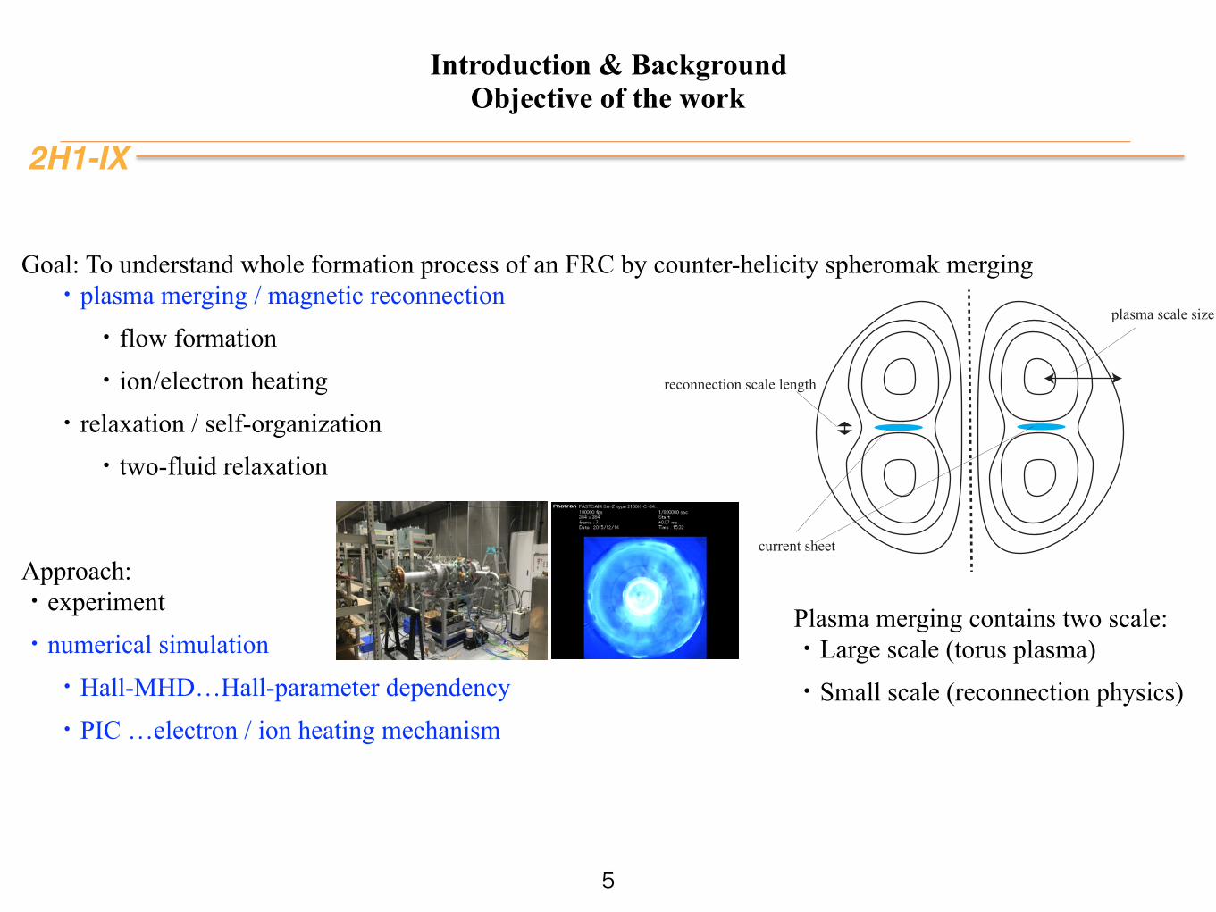
Goal: To understand whole formation process of an FRC by counter-helicity spheromak merging ・plasma merging / magnetic reconnection ・flow formation ・ion/electron heating ・relaxation / self-organization ・two-fluid relaxation
Approach: ・experiment ・numerical simulation ・Hall-MHD…Hall-parameter dependency ・PIC …electron / ion heating mechanism
plasma scale size
current sheet
reconnection scale length
Plasma merging contains two scale: ・Large scale (torus plasma) ・Small scale (reconnection physics)
2H1-IX
Introduction & Background Polarity of counter-helicity spheromak merging : Case-O & Case-I
6
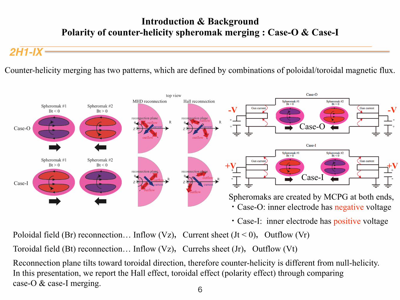
Poloidal field (Br) reconnection… Inflow (Vz),Current sheet (Jt < 0),Outflow (Vr) Toroidal field (Bt) reconnection… Inflow (Vz),Currehs sheet (Jr),Outflow (Vt) Reconnection plane tilts toward toroidal direction, therefore counter-helicity is different from null-helicity. In this presentation, we report the Hall effect, toroidal effect (polarity effect) through comparing case-O & case-I merging.
Counter-helicity merging has two patterns, which are defined by combinations of poloidal/toroidal magnetic flux.
Spheromaks are created by MCPG at both ends, ・Case-O: inner electrode has negative voltage ・Case-I: inner electrode has positive voltage
Case-O
Case-I+V+V
-V-V
Outline
2H1-IX
• Introduction
• Hall-MHD simulation
• Particle in Cell simulation
• Summary
7
2H1-IX
Hall-MHD plasma merging simulation Basic equations & numerical scheme
8
2
II. SIMULATION MODEL
In this paper, we used two-dimensional axisymmetri-cal explicit Hall-MHD code. 4th-order spatial differenceis adopted for spacial difference, and 2nd-order Adams-Bashforth scheme is adopted for time-advancing. 4th-order numerical smoothing17 is used as artificial viscos-ity, which suppresses grid-scale numerical oscillations. Inthis code, we installed sub-cycling scheme12, in which thetime step for solving magnetic field and fluid quantitiesare different (Fig.2). The time step solving the inductionequation is determined by CFL condition of whistler wavespeed, and the time step solving the density continuousequation, the pressure equation, and the equation of mo-tion, is determined by fast Alfven wave speed. We cansolve Hall-MHD faster by installing this scheme. All pa-rameters are normalized by physical quantities of the ini-tial state, in which maximum poloidal maximum poloidalmagnetic field and maximum plasma density at the mag-netic axis are unity. Electric resistivity (η), viscosity co-efficient (ν), and Hall parameter di are free parameters.In this simulation, we set η = 1 × 10⁻⁴ (Rm = 10000),and ν = 1× 10⁻⁴ (Re = 10000).
∂ρ
∂t= −∇ · (ρv) (1)
∂p
∂t= −∇ · (pv)− (γ − 1)p(∇ · v)
+ (γ − 1)!ηj2 + ν(
4
3(∇ · v)2 + |∇× v|2)
"(2)
∂(ρv)
∂t= −∇ · ρvv −∇p+ j×B
+ ν(4
3∇(∇ · v)−∇×∇× v) (3)
∂B
∂t= ∇× (v ×B− ηj− di
j×B
ρ) (4)
ǻWHall
ǻWMHD
Y�W�
W
W
nn-1 n+1
%�W�/LQHDU�LQWHUSRODWLRQ
FIG. 2. A schematic of sub-cycling scheme
III. RESULTS AND DISCUSSION
A. An overview of merging process
In this section, we report an overview of the CHSM,comparing the MHD case and the Hall-MHD case.Firstly, we discuss an symmetry between case-O andcase-I in the MHD cases. Figure 3 shows the 2D pro-files of poloidal flux (lines) and toroidal magnetic field(Bθ, colored) in case-O and case-I CHSM. (a) is case-Oof the MHD (di = 0), (b) is case-I of the MHD (di = 0),(c) is case-O of the Hall-MHD (di = 0.05), (d) is case-Iof the Hall-MHD (di = 0.05). Two spheromaks with re-verse polarity merge together, and the toroidal field van-ishes by magnetic reconnection, and then a single plasmawith no toroidal flux is generated. In case-O, toroidalmagnetic field is positive at the +Z side, and negativeat the −Z side. On the other hand, toroidal magneticfield is negative at the +Z side and positive at the −Zside in case-I. In both cases, toroidal plasma current ispositive and poloidal magnetic flux is positive. Duringthese merging, a little toroidal field with reversed polarityis generated on the reconnected poloidal magnetic field.This phenomena is called “slingshot effect”15. Toroidalflow shear which is generated by reconnection distort thepoloidal magnetic field, and then toroidal magnetic fieldwith reversed polarity is re-generated. Figure 4 shows2D profiles of thermal pressure. In all cases, two low-beta plasma become a single plasma with high thermalpressure.
In MHD, there is no difference between case-O andcase-I except the polarity of toroidal magnetic field andgenerated toroidal flow. Magnitude of all quantities arecompletely same between case-O and case-I. However,in Hall-MHD cases, there are some differences betweencase-O and case-I. In case-O, the reconnection X-point islocated on a high position at the radial direction, whilethat is located on a low position in case-I. The motion ofthe X-point during merging was experimentally observedin MRX experiment13. Figure 6 shows time evolutionsof the radial position of the X-point. It is clearly shownthat the locations of the X-point in case-O of the Hall-MHD cases (di = 0.01, 0.05) are higher than those incase-I of the Hall-MHD cases. Therefore, it is assumedthat the Hall effect moves the X-point. However, com-paring the di = 0.01 case with di = 0.05 case, there islittle tendency for the magnitude of the Hall parameter(di). There is little difference of the location of the X-point between the di = 0.01 cases and the di = 0.05 casesin both case-O and case-I, while the difference betweenMHD cases and Hall-MHD cases is not negligible. Andthe location of the X-point is determined at the earlyphase of the merging, and it does not keep moving to-ward unique direction which is predicted by the Hall ef-fect (outward in case-O, inward in case-I) at the middleor late phase of the merging. Therefore, it is assumedthat the motion of the X-point is saturated at the earlyphase of the merging, and the position is also affected
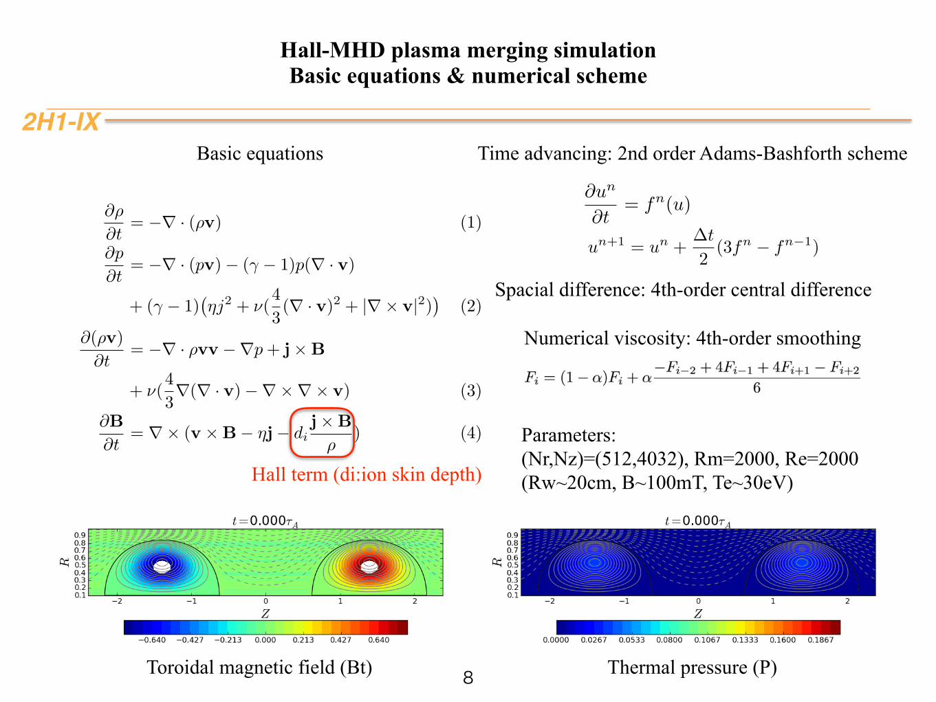
Basic equations
Numerical viscosity: 4th-order smoothing
un+1 = un +�t
2(3fn � fn�1)
@un
@t= fn(u)
Time advancing: 2nd order Adams-Bashforth scheme
Spacial difference: 4th-order central difference
Hall term (di:ion skin depth)
Toroidal magnetic field (Bt) Thermal pressure (P)
Parameters: (Nr,Nz)=(512,4032), Rm=2000, Re=2000 (Rw~20cm, B~100mT, Te~30eV)
2H1-IX
Hall-MHD plasma merging simulation Polarity effect & Hall effect on merging speed
9
Case-O
Case-I
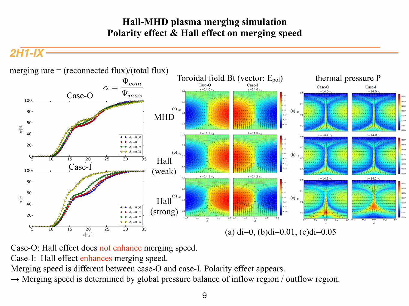
Case-O: Hall effect does not enhance merging speed. Case-I: Hall effect enhances merging speed. Merging speed is different between case-O and case-I. Polarity effect appears. → Merging speed is determined by global pressure balance of inflow region / outflow region.
merging rate = (reconnected flux)/(total flux)Toroidal field Bt (vector: Epol) thermal pressure P
MHD
Hall (weak)
Hall (strong)
(a) di=0, (b)di=0.01, (c)di=0.05
2H1-IX
Hall-MHD plasma merging simulation Hall effect on current sheet structure
10
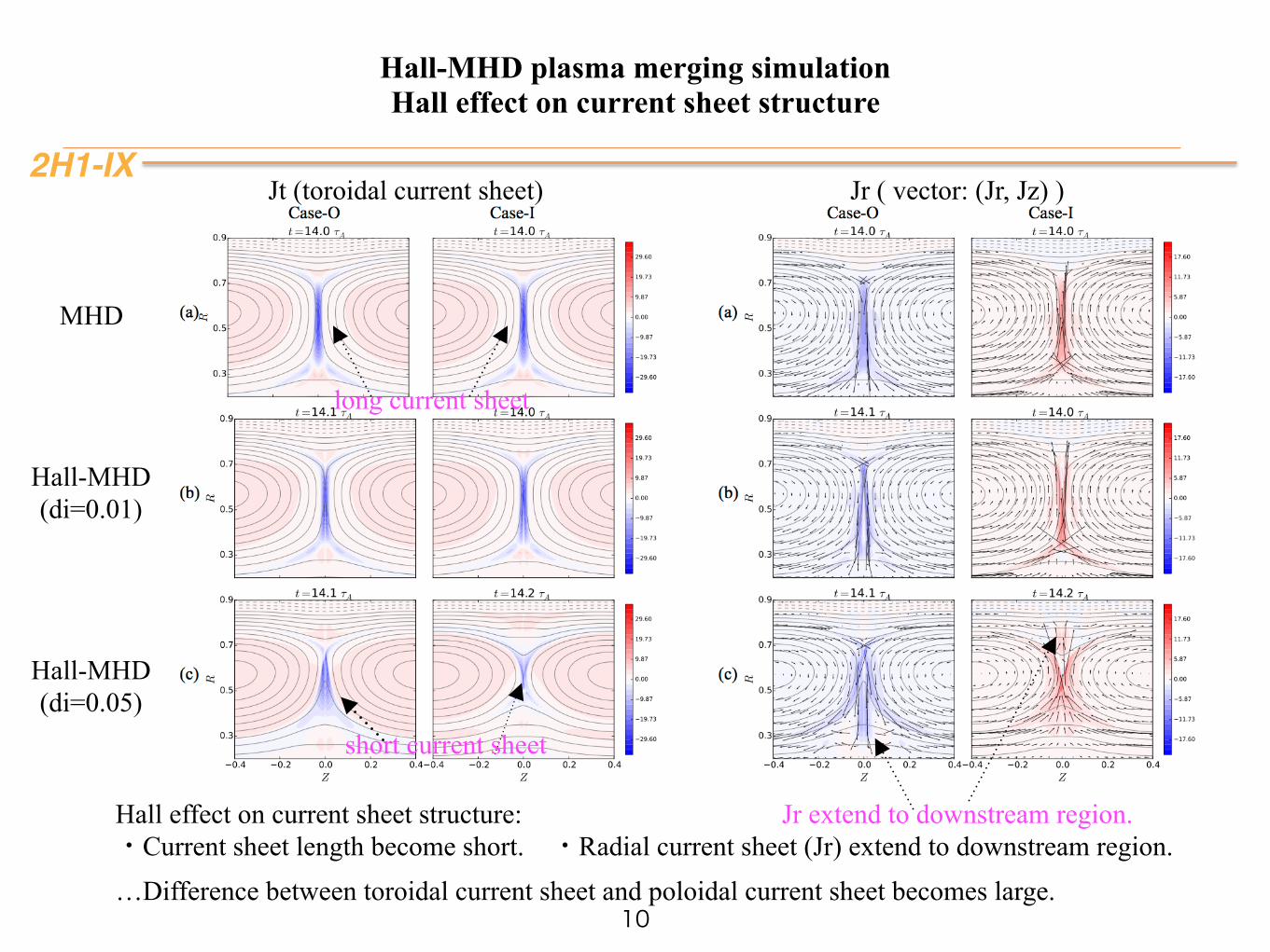
Jt (toroidal current sheet) Jr ( vector: (Jr, Jz) )
Hall effect on current sheet structure: ・Current sheet length become short. ・Radial current sheet (Jr) extend to downstream region. …Difference between toroidal current sheet and poloidal current sheet becomes large.
MHD
Hall-MHD (di=0.01)
Hall-MHD (di=0.05)
Jr extend to downstream region.
long current sheet
short current sheet
2H1-IX
Hall-MHD plasma merging simulation Polarity effect & Hall effect on flow structure
11
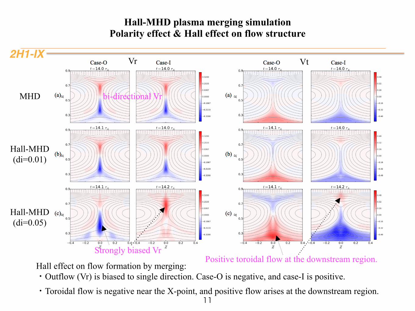
Vr Vt
MHD
Hall-MHD (di=0.01)
Hall-MHD (di=0.05)
Hall effect on flow formation by merging: ・Outflow (Vr) is biased to single direction. Case-O is negative, and case-I is positive. ・Toroidal flow is negative near the X-point, and positive flow arises at the downstream region.
Positive toroidal flow at the downstream region.Strongly biased Vr
bi-directional Vr
2H1-IX
Hall-MHD plasma merging simulation role of Hall effect on flow formation
12
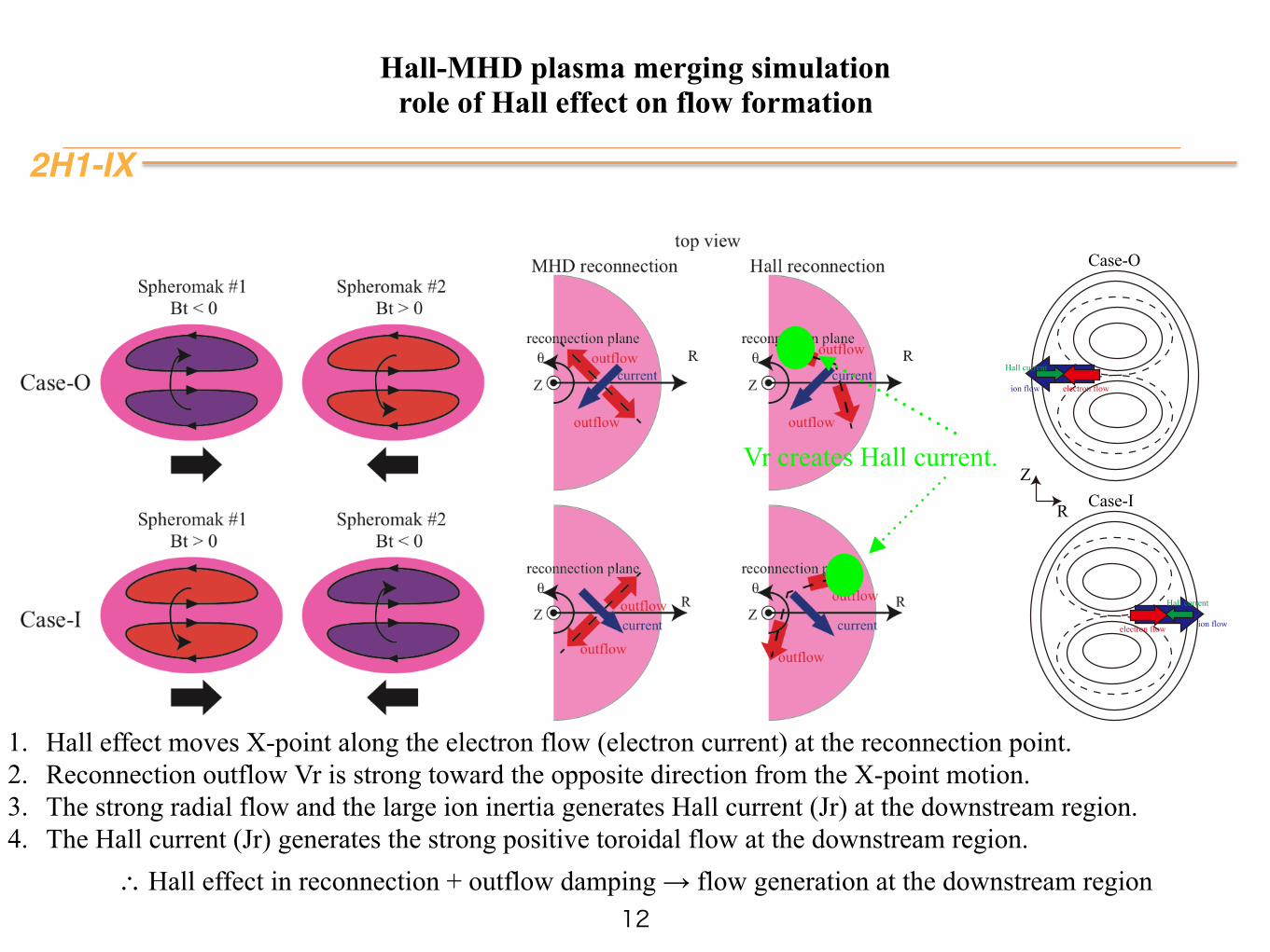
1. Hall effect moves X-point along the electron flow (electron current) at the reconnection point. 2. Reconnection outflow Vr is strong toward the opposite direction from the X-point motion. 3. The strong radial flow and the large ion inertia generates Hall current (Jr) at the downstream region. 4. The Hall current (Jr) generates the strong positive toroidal flow at the downstream region.
∴ Hall effect in reconnection + outflow damping → flow generation at the downstream region
Vr creates Hall current.
Hall current
ion flow electron flow
Hall current
ion flowelectron flow
Case-O
Case-IR
Z
2H1-IX
Hall-MHD plasma merging simulation Hall effect on structure of energy conversion (ion acceleration) region
13
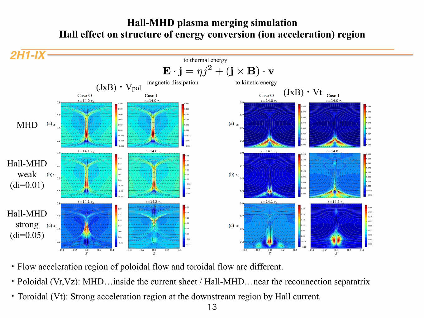
(JxB)・Vpol (JxB)・Vt
・Flow acceleration region of poloidal flow and toroidal flow are different. ・Poloidal (Vr,Vz): MHD…inside the current sheet / Hall-MHD…near the reconnection separatrix ・Toroidal (Vt): Strong acceleration region at the downstream region by Hall current.
magnetic dissipation
to thermal energy
to kinetic energy
MHD
Hall-MHD weak
(di=0.01)
Hall-MHD strong
(di=0.05)
Outline
2H1-IX
• Introduction
• Hall-MHD simulation
• Particle in Cell simulation
• Summary
14
2H1-IX
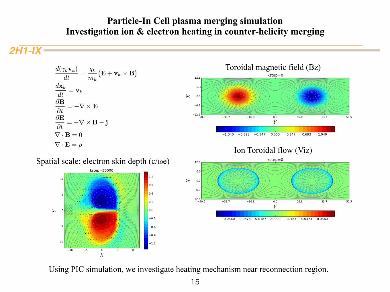
Particle-In Cell plasma merging simulation Investigation ion & electron heating in counter-helicity merging
15Using PIC simulation, we investigate heating mechanism near reconnection region.
Spatial scale: electron skin depth (c/ωe)
Toroidal magnetic field (Bz)
Ion Toroidal flow (Viz)
2H1-IX
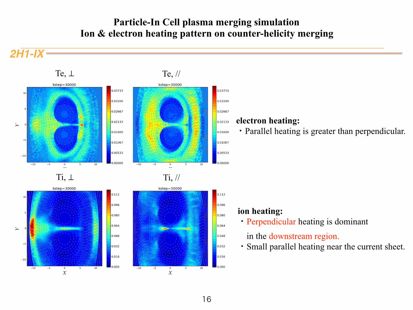
Ti, //
Te, //
Particle-In Cell plasma merging simulation Ion & electron heating pattern on counter-helicity merging
16
Ti, ⊥
ion heating: ・Perpendicular heating is dominant in the downstream region. ・Small parallel heating near the current sheet.
Te, ⊥
electron heating: ・Parallel heating is greater than perpendicular.
Outline
2H1-IX
• Introduction
• Hall-MHD simulation
• Particle in Cell simulation
• Summary
17
2H1-IX
Summary & Future work
18
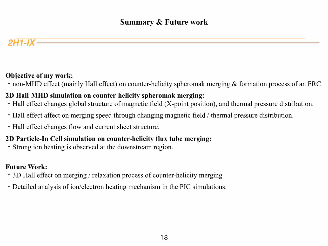
Objective of my work: ・non-MHD effect (mainly Hall effect) on counter-helicity spheromak merging & formation process of an FRC 2D Hall-MHD simulation on counter-helicity spheromak merging: ・Hall effect changes global structure of magnetic field (X-point position), and thermal pressure distribution. ・Hall effect affect on merging speed through changing magnetic field / thermal pressure distribution. ・Hall effect changes flow and current sheet structure.
2D Particle-In Cell simulation on counter-helicity flux tube merging: ・Strong ion heating is observed at the downstream region.
Future Work: ・3D Hall effect on merging / relaxation process of counter-helicity merging ・Detailed analysis of ion/electron heating mechanism in the PIC simulations.
2H1-IX
Hall-MHD plasma merging simulation Sub-cycling method
19
Sub-cycling method
2
II. SIMULATION MODEL
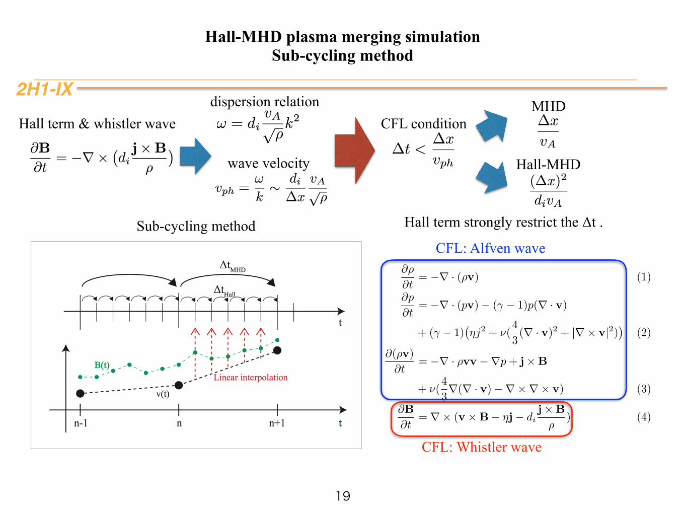
In this paper, we used two-dimensional axisymmetri-cal explicit Hall-MHD code. 4th-order spatial differenceis adopted for spacial difference, and 2nd-order Adams-Bashforth scheme is adopted for time-advancing. 4th-order numerical smoothing17 is used as artificial viscos-ity, which suppresses grid-scale numerical oscillations. Inthis code, we installed sub-cycling scheme12, in which thetime step for solving magnetic field and fluid quantitiesare different (Fig.2). The time step solving the inductionequation is determined by CFL condition of whistler wavespeed, and the time step solving the density continuousequation, the pressure equation, and the equation of mo-tion, is determined by fast Alfven wave speed. We cansolve Hall-MHD faster by installing this scheme. All pa-rameters are normalized by physical quantities of the ini-tial state, in which maximum poloidal maximum poloidalmagnetic field and maximum plasma density at the mag-netic axis are unity. Electric resistivity (η), viscosity co-efficient (ν), and Hall parameter di are free parameters.In this simulation, we set η = 1 × 10⁻⁴ (Rm = 10000),and ν = 1× 10⁻⁴ (Re = 10000).
∂ρ
∂t= −∇ · (ρv) (1)
∂p
∂t= −∇ · (pv)− (γ − 1)p(∇ · v)
+ (γ − 1)!ηj2 + ν(
4
3(∇ · v)2 + |∇× v|2)
"(2)
∂(ρv)
∂t= −∇ · ρvv −∇p+ j×B
+ ν(4
3∇(∇ · v)−∇×∇× v) (3)
∂B
∂t= ∇× (v ×B− ηj− di
j×B
ρ) (4)
ǻWHall
ǻWMHD
Y�W�
W
W
nn-1 n+1
%�W�/LQHDU�LQWHUSRODWLRQ
FIG. 2. A schematic of sub-cycling scheme
III. RESULTS AND DISCUSSION
A. An overview of merging process
In this section, we report an overview of the CHSM,comparing the MHD case and the Hall-MHD case.Firstly, we discuss an symmetry between case-O andcase-I in the MHD cases. Figure 3 shows the 2D pro-files of poloidal flux (lines) and toroidal magnetic field(Bθ, colored) in case-O and case-I CHSM. (a) is case-Oof the MHD (di = 0), (b) is case-I of the MHD (di = 0),(c) is case-O of the Hall-MHD (di = 0.05), (d) is case-Iof the Hall-MHD (di = 0.05). Two spheromaks with re-verse polarity merge together, and the toroidal field van-ishes by magnetic reconnection, and then a single plasmawith no toroidal flux is generated. In case-O, toroidalmagnetic field is positive at the +Z side, and negativeat the −Z side. On the other hand, toroidal magneticfield is negative at the +Z side and positive at the −Zside in case-I. In both cases, toroidal plasma current ispositive and poloidal magnetic flux is positive. Duringthese merging, a little toroidal field with reversed polarityis generated on the reconnected poloidal magnetic field.This phenomena is called “slingshot effect”15. Toroidalflow shear which is generated by reconnection distort thepoloidal magnetic field, and then toroidal magnetic fieldwith reversed polarity is re-generated. Figure 4 shows2D profiles of thermal pressure. In all cases, two low-beta plasma become a single plasma with high thermalpressure.
In MHD, there is no difference between case-O andcase-I except the polarity of toroidal magnetic field andgenerated toroidal flow. Magnitude of all quantities arecompletely same between case-O and case-I. However,in Hall-MHD cases, there are some differences betweencase-O and case-I. In case-O, the reconnection X-point islocated on a high position at the radial direction, whilethat is located on a low position in case-I. The motion ofthe X-point during merging was experimentally observedin MRX experiment13. Figure 6 shows time evolutionsof the radial position of the X-point. It is clearly shownthat the locations of the X-point in case-O of the Hall-MHD cases (di = 0.01, 0.05) are higher than those incase-I of the Hall-MHD cases. Therefore, it is assumedthat the Hall effect moves the X-point. However, com-paring the di = 0.01 case with di = 0.05 case, there islittle tendency for the magnitude of the Hall parameter(di). There is little difference of the location of the X-point between the di = 0.01 cases and the di = 0.05 casesin both case-O and case-I, while the difference betweenMHD cases and Hall-MHD cases is not negligible. Andthe location of the X-point is determined at the earlyphase of the merging, and it does not keep moving to-ward unique direction which is predicted by the Hall ef-fect (outward in case-O, inward in case-I) at the middleor late phase of the merging. Therefore, it is assumedthat the motion of the X-point is saturated at the earlyphase of the merging, and the position is also affected
CFL: Whistler wave
CFL: Alfven wave
MHD
Hall-MHD
CFL conditionHall term & whistler wavedispersion relation
Hall term strongly restrict the Δt .
wave velocity
2H1-IX
Hall-MHD plasma merging simulation Overview of merging (MHD)
20
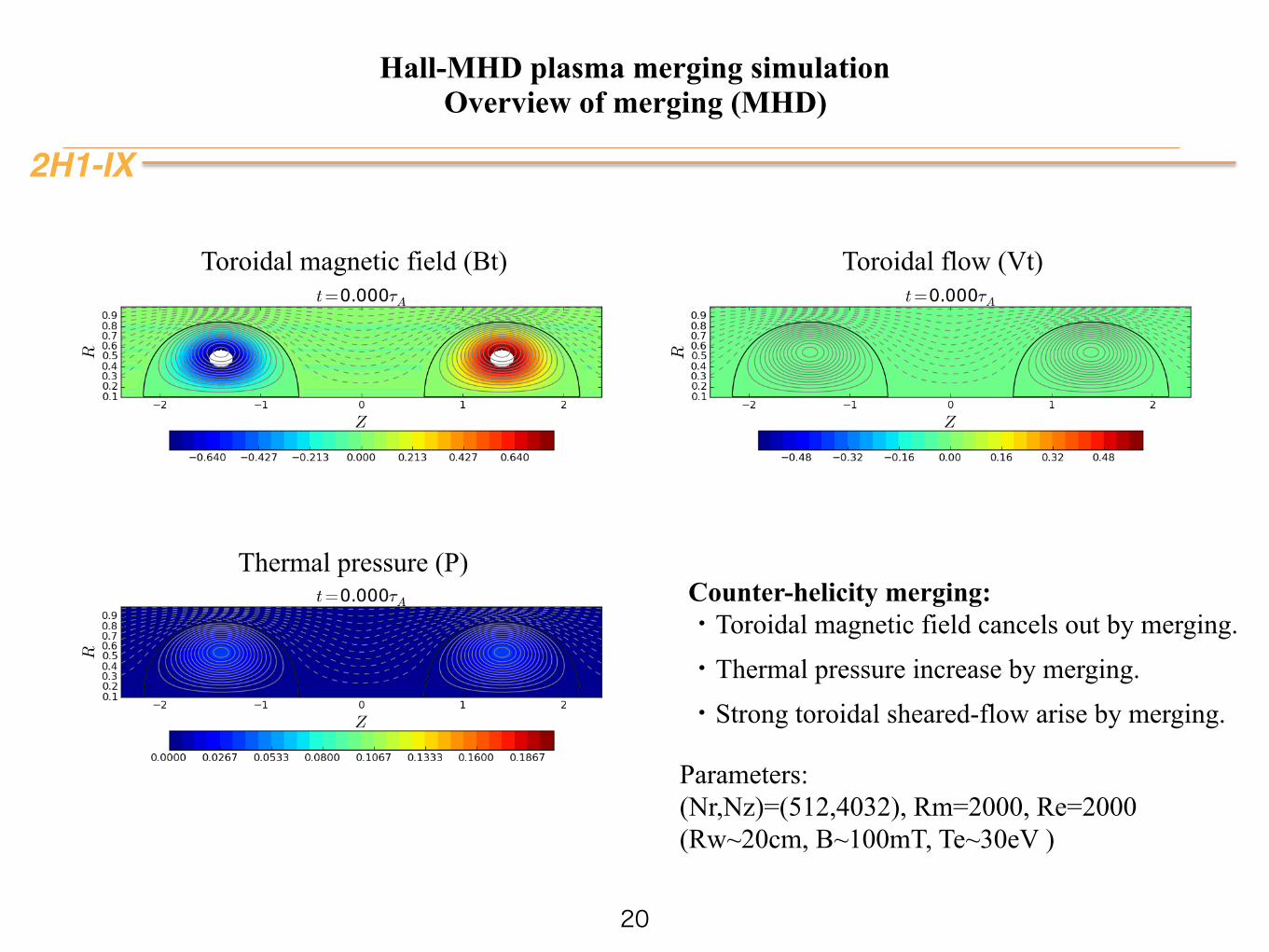
Thermal pressure (P)
Toroidal magnetic field (Bt) Toroidal flow (Vt)
Counter-helicity merging: ・Toroidal magnetic field cancels out by merging. ・Thermal pressure increase by merging. ・Strong toroidal sheared-flow arise by merging.
Parameters: (Nr,Nz)=(512,4032), Rm=2000, Re=2000 (Rw~20cm, B~100mT, Te~30eV )
Related Documents