GUIDELINES FOR ENERGY AUDITING OF PULVERISED COAL/LIGNITE FIRED THERMAL POWER PLANTS INDO-GERMAN ENERGY PROGRAMME

Welcome message from author
This document is posted to help you gain knowledge. Please leave a comment to let me know what you think about it! Share it to your friends and learn new things together.
Transcript

GUIDELINES FOR
ENERGY AUDITING OF PULVERISED COAL/LIGNITE FIRED THERMAL POWER PLANTS
INDO-GERMAN ENERGY PROGRAMME

TABLE CONTENTS
SECTIONS PAGE
INTRODUCTION ................................................................................. 14
1.0 ENERGY AUDIT REPORT STRUCTURE .......................................... 19
1.1 INTRODUCTION ..................................................................................20 1.2 CONTENT OF THE REPORT ..................................................................20 1.3 TITLE PAGE OF THE REPORT ...............................................................20 1.4 TABLE OF CONTENTS..........................................................................21 1.5 AUDIT FIRM, TEAM DETAILS AND CERTIFICATION ...............................22 1.6 EXECUTIVE SUMMARY .........................................................................23 1.7 INTRODUCTION TO ENERGY AUDIT AND METHODOLOGY ...................24 1.8 DESCRIPTION OF THE PLANT ..............................................................24 1.9 ENERGY CONSUMPTION PROFILE AND ENERGY MANAGEMENT SYSTEMS:
..........................................................................................................25 1.10 EQUIPMENT / MAJOR AREAS FOR ENERGY AUDIT ................................27 1.11 ACTION PLAN PREPARATION ..............................................................29 1.12 SUPPLIERS / VENDORS/ CONTRACTOR LIST ........................................30 1.13 APPENDICES .......................................................................................30 1.14 REFERENCES, SOFTWARE USED ............................................................30
2.0 COAL HANDLING PLANT ........................................................... 30
2.1 BACKGROUND ....................................................................................32 2.2 STEPS INVOLVED IN CONDUCTING THE ENERGY AUDIT .......................32 2.3 DATA COLLECTION ............................................................................33
2.3.1 Specification of Coal Handling Plant ........................................33 2.3.2 System data collection .............................................................35
2.4 INSTRUMENTS REQUIRED ....................................................................35 2.5 MEASUREMENTS & OBSERVATION TO BE MADE ...................................36 2.6 OBSERVATIONS AND ANALYSIS ...........................................................36
2.6.1 System familiarisation and operational details .........................36 2.6.2 Measurements and Evaluation .................................................37 2.6.3 Study of coal feeding circuits ..................................................39 2.6.4 Exploration of energy conservation possibilities ......................39
3.0 BOILER ..................................................................................... 42
3.1 BACKGROUND ....................................................................................43 3.2 DATA COLLECTION ............................................................................45
3.2.1 Specifications of boiler and associated equipment ...................46 3.3 INSTRUMENTS REQUIRED ....................................................................51 3.4 MEASUREMENTS AND OBSERVATIONS TO BE MADE .............................51
2 of 240

3.5 OBSERVATIONS AND ANALYSIS ...........................................................52 3.5.1 System familiarisation and operational details .........................52 3.5.2 Operational efficiency of the boiler ..........................................53 3.5.3 Measurement locations ...........................................................54 3.5.4 As run boiler test ....................................................................55
3.6 CALCULATION OF LOSSES ...................................................................56 3.6.1 Performance of Coal Mills ........................................................59 3.6.2 Combustion control, excess air and cold air infiltration ...........63 3.6.3 Performance of air preheaters .................................................65 3.6.4 Controllable losses due to un burnt carbon in ash ...................67 3.6.5 Operation of soot blowers .......................................................68 3.6.6 Water Treatment .....................................................................69 3.6.7 Visual survey and insulation survey of the boiler system .........70 3.6.8 Exploration of energy conservation possibilities ......................71 3.6.9 Exploration of energy conservation opportunities ....................72
4.0 THERMAL INSULATION .............................................................. 75
4.1 BACKGROUND ....................................................................................76 4.2 STEPS INVOLVED IN CONDUCTING THE ENERGY AUDIT .......................76 4.3 DATA COLLECTION ............................................................................77 4.4 MEASUREMENTS AND OBSERVATION TO BE MADE ...............................77 4.5 ESTIMATION OF CONTROLLABLE HEAT LOSSES AND ENERGY SAVINGS 79 4.6 COMPILATION OF DATA FOR THE SECTIONS WHERE ATTENTION NEEDS
TO BE PAID .........................................................................................81
5.0 ASH HANDLING ........................................................................ 82
5.1 BACKGROUND ....................................................................................83 5.2 STEPS INVOLVED IN CONDUCTING ENERGY AUDIT ..............................84 5.3 DATA COLLECTION ............................................................................84
5.3.1 Instruments required ..............................................................86 5.3.2 Parameters to be measured .....................................................86 5.3.3 System details .........................................................................87 5.3.4 Energy and water consumption pattern ...................................87 5.3.5 Operating efficiency and performance evaluation of the pumps
...............................................................................................88 5.3.6 Measurement of electrical parameters and motor loading .......90 5.3.7 Ash water/ ash slurry water pressure and flow measurement ..91 5.3.8 Evaluation of ash to water ratio ...............................................91 5.3.9 Adequacy of pipe sizes of ash slurry lines ...............................92 5.3.10 Exploration of energy conservation possibilities ......................93
6.0 WATER PUMPING ...................................................................... 93
3 of 240

6.1 BACKGROUND ....................................................................................95 6.2 STEPS INVOLVED IN CONDUCTING ENERGY AUDIT ..............................96 6.3 DATA COLLECTION ............................................................................96
6.3.1 Specifications and design details .............................................96 6.3.2 Instruments required ..............................................................96 6.3.3 Parameters to be measured .....................................................96
6.4 OBSERVATIONS AND MEASUREMENTS .................................................96 6.4.1 System details .........................................................................97 6.4.2 Energy consumption Pattern ....................................................97 6.4.3 Operating efficiency and performance evaluation of the pumps
...............................................................................................98 6.4.4 Flow distribution to the major users and water balance .........100 6.4.5 Pressure drop in the system ..................................................102 6.4.6 Application and matching of the pump ..................................102 6.4.7 Exploration of energy conservation possibilities ....................102 6.4.8 Measuring and tracking system performance ........................104
7.0 FANS ...................................................................................... 106
7.1 BACKGROUND ..................................................................................107 7.2 STEPS INVOLVED IN CONDUCTING THE ENERGY AUDIT .....................110 7.3 DATA COLLECTION ..........................................................................111
7.3.1 Specification of fans ..............................................................111 7.3.2 Details of the fans and ducting system ..................................111
7.4 INSTRUMENTS REQUIRED ..................................................................112 7.5 MEASUREMENTS AND OBSERVATIONS TO BE MADE ...........................112 7.6 OBSERVATIONS AND ANALYSIS .........................................................113
7.6.1 System familiarisation and operational details .......................113 7.6.2 Energy consumption Pattern ..................................................113 7.6.3 Operating efficiency and performance evaluation of the fans .114 7.6.4 Visual survey and insulation survey of the ducting system .....118 7.6.5 Study of air infiltration in to the system.................................119 7.6.6 Application potential for variable frequency drives ................120 7.6.7 Belt tension and drive speed .................................................121 7.6.8 Application and matching of fan ...........................................121 7.6.9 Exploration of energy conservation possibilities ....................121
8.0 TURBINE ................................................................................. 124
8.1 BACKGROUND ..................................................................................125 8.2 STEPS INVOLVED IN CONDUCTING THE ENERGY AUDIT .....................129 8.3 DATA COLLECTION ..........................................................................129
8.3.1 Specification of turbine and associated equipment ................130 8.4 INSTRUMENTS REQUIRED ..................................................................131
4 of 240

8.5 MEASUREMENTS ...............................................................................132 8.6 OBSERVATIONS AND ANALYSIS .........................................................133
8.6.1 System familiarisation and operational details .......................133 8.6.2 Turbine heat rate evaluation and efficiency ...........................133 8.6.3 HP Feed Heaters / LP Feed Heaters ........................................136 8.6.4 H P Heaters / LP heaters – Performance Analysis ...................137 8.6.5 HP heaters not being in service .............................................141 8.6.6 Key observations and analysis ...............................................141 8.6.7 Effect on heat rate for parameter deviation............................142 8.6.8 Turbine cycle losses ..............................................................142
9.0 CONDENSER COOLING ............................................................. 142
9.1 BACKGROUND ..................................................................................143 9.2 STEPS INVOLVED ..............................................................................147 9.3 DATA COLLECTION ..........................................................................148
9.3.1 Cooling tower specifications .................................................148 9.3.2 Specification of water pumps and motors ..............................148 9.3.3 Condenser specifications ......................................................150
9.4 INSTRUMENTS REQUIRED ..................................................................150 9.5 MEASUREMENTS AND OBSERVATIONS TO BE MADE ...........................151 9.6 Observations and Analysis ...............................................................152
9.6.1 System familiarisation and operational details .......................152 9.6.2 Energy consumption pattern .................................................152 9.6.3 Operating efficiency and performance evaluation of the pumps
.............................................................................................153 9.6.4 Flow distribution to the major users and cooling towers ........155 9.6.5 Performance of condensers ...................................................156 9.6.6 Performance of cooling towers ..............................................161 9.6.7 Power consumption of CT fans ..............................................163 9.6.8 Application and matching of pump .......................................164 9.6.9 Exploration of energy conservation possibilities ....................164
10.0 COMPRESSED AIR SYSTEM ........................................................ 167
10.1 BACKGROUND ..................................................................................168 10.2 STEPS INVOLVED IN CONDUCTING ENERGY AUDIT ............................168 10.3 DATA COLLECTION ..........................................................................169
10.3.1 Specification of compressors .................................................169 10.3.2 Details of compressed air network ........................................169 10.3.3 Dryer and specifications ........................................................170 10.3.4 Details of Air receivers ..........................................................170 10.3.5 Auxiliary sections / equipment ..............................................171 10.3.6 Instruments Required ............................................................171
5 of 240

10.4 MEASUREMENTS & OBSERVATION BE MADE .......................................171 10.4.1 System familiarization and operational details .......................173 10.4.2 Energy consumption pattern .................................................173 10.4.3 Free air delivery test (compressor output assessment test) ....174 10.4.4 Estimation of Specific Power Consumption – Compressor wise
.............................................................................................176 10.4.5 Estimation of actual compressed air consumption .................177 10.4.6 Quantification of compressed air leakage ..............................179 10.4.7 Performance of intercoolers and after coolers .......................180 10.4.8 Pressure drop survey .............................................................181 10.4.9 Belt tension and drive speed .................................................182 10.4.10 Location of compressors .......................................................182 10.4.11 Pressure settings ...................................................................183 10.4.12 Compressed air dryers ..........................................................183 10.4.13 Pressure drop across the filter ...............................................184 10.4.14 Compressed air optimisation .................................................184 10.4.15 Effective utilization of compressed air ...................................184 10.4.16 Variable speed drive application ............................................184 10.4.17 Exploration of energy conservation possibilities ....................185
11.0 MOTORS ................................................................................. 188
11.1 BACKGROUND ..................................................................................189 11.2 STEPS INVOLVED IN CONDUCTING ENERGY AUDIT ............................189 11.3 DATA COLLECTION ..........................................................................190
11.3.1 Motor details .........................................................................190 11.3.2 Instruments required ............................................................191 11.3.3 Parameters to be measured ...................................................191
11.4 OBSERVATIONS AND MEASUREMENTS ...............................................192 11.4.1 System Details ......................................................................192 11.4.2 Energy consumption Pattern ..................................................192 11.4.3 Motor loading survey ............................................................193 11.4.4 Motor rewinding history ........................................................196 11.4.5 Exploration for energy conservation possibilities ...................196
12.0 AIR CONDITIONING ................................................................. 198
12.1 BACKGROUND ..................................................................................199 12.2 STEPS INVOLVED IN CONDUCTING THE ENERGY AUDIT .....................199 12.3 DATA COLLECTION ..........................................................................199
12.3.1 Specifications of refrigeration compressors / vapour absorption chiller units ...........................................................................200
12.3.2 Details of auxiliary equipment ...............................................201 12.3.3 Instruments Required ............................................................204
6 of 240

12.4 MEASUREMENTS & OBSERVATION TO BE MADE .................................204 12.4.1 System familiarisation and operational details .......................204 12.4.2 Energy consumption Pattern ..................................................204 12.4.3 Measurements.......................................................................205 12.4.4 Evaluation of net refrigeration capacity and specific energy
consumption .........................................................................207 12.4.5 Operating efficiency and performance evaluation of the pumps
.............................................................................................211 12.4.6 Performance of cooling towers ..............................................211 12.4.7 Power consumption of CT fans ..............................................211 12.4.8 Performance evaluation of air handling units .........................211 12.4.9 Room Condition / User location parameters ..........................213 12.4.10 Pressure drop and insulation survey of chilled water lines .....214 12.4.11 Performance of condensers and evaporators .........................214 12.4.12 Belt tension and drive speed .................................................215 12.4.13 Exploration of energy conservation possibilities ....................215
13.0 LIGHTING ................................................................................ 217
13.1 BACKGROUND ..................................................................................218 13.2 STEPS INVOLVED IN CONDUCTING THE ENERGY AUDIT .....................218 13.3 DATA COLLECTION ..........................................................................218 13.4 INSTRUMENTS REQUIRED ..................................................................219 13.5 MEASUREMENTS AND OBSERVATION TO BE MADE .............................219 13.6 OBSERVATIONS AND ANALYSIS .........................................................220
13.6.1 System familiarisation and operational details .......................220 13.6.2 Measurements AND Evaluation ..............................................220 13.6.3 Exploration of energy conservation possibilities ....................221 13.6.4 Recommendations .................................................................222
14.0 ELECTROSTATIC PRECIPITATOR ................................................ 224
14.1 BACKGROUND ..................................................................................225 14.2 STEPS INVOLVED IN CONDUCTING THE ENERGY AUDIT .....................225 14.3 DATA COLLECTION ..........................................................................225 14.4 INSTRUMENTS REQUIRED ..................................................................226 14.5 MEASUREMENTS AND OBSERVATION TO BE MADE .............................226 14.6 OBSERVATIONS AND ANALYSIS .........................................................228
14.6.1 System familiarisation and operational details .......................228 14.6.2 Measurements and evaluation ...............................................228
ANNEXURES ..................................................................................... 230
ANNEXURE–1 : INFORMATION PERTAINING TO ACTION PLAN AS PER FORMAT ........................................................................................................231
7 of 240

ANNEXURE–2 : DETAILS OF ILLUMINATION LEVEL REQUIRED ........................232 ANNEXURE-3 : INFORMATION ON COAL BLENDING .....................................235 ANNEXURE-4: PERFORMANCE OF LUMINARIES WHICH ARE COMMONLY USED
........................................................................................................239 ANNEXURE-5 : PROCEDURE FOR ESTIMATING THE ENERGY SAVING POTENTIAL
IN PUMPS WITH VALVE CONTROL ......................................................240 LIST OF TABLES Table 1-1 : Auxiliary power consumption of___MW/Unit ........................ 27 Table 2-1 : Key Specification parameters .............................................. 34 Table 2-2 : Production and operating data (___year) ............................. 35 Table 2-3 : Coal parameters ................................................................. 35 Table 2-4 : Power consumption and throughput –Direct bunkering ....... 37 Table 2-5 : Power consumption and throughput –Reclaiming ................ 38 Table 2-6 : Power consumption and throughput –Stacking .................... 38 Table 3-1 : Brief specifications of boiler specifications (of a typical
210MW Unit) .................................................................................. 44 Table 3-2 : Design Specifications of boiler ............................................ 46 Table 3-3: Specifications of economiser ................................................ 47 Table 3-4: Specifications of air pre heater (APH).................................... 47 Table 3-5: Flue gas temperature profile ................................................ 48 Table 3-6: Heat balance of boiler .......................................................... 48 Table 3-7: Recommended feed water and boiler water limits ................. 49 Table 3-8: Mills and Burners Performance ............................................. 49 Table 3-9: Soot blowers ........................................................................ 50 Table 3-10: Data sheet for boiler efficiency evaluation .......................... 55 Table 3-11: Efficiency evaluation of boiler ............................................ 58 Table 3-12: Mill Performance ................................................................ 62 Table 3-13: Coal fineness ..................................................................... 63 Table 3-14: Mill rejects ......................................................................... 63 Table 3-15: Data sheet for estimating air infiltration ............................. 64 Table 3-16: Data sheet for air preheaters (APH) .................................... 66 Table 3-17: Un burnt – reported values ................................................. 68 Table 3-18: Data sheet for soot blowers ............................................... 68 Table 3-19: Comparison of actual and normative spray consumption .... 69 Table 3-20: Feed water and condensate parameters .............................. 70 Table 4-1 : Typical format for recoding the surface temperature ........... 78 Table 5-1 : Specifications of pumps and motors (Ash Handing Plant) ..... 85
8 of 240

Table 5-2 : Energy and water consumption and ash generation ............ 87 Table 5-3 : Energy consumption of pumps ............................................ 88 Table 5-4 : Performance parameters for water pumps ........................... 88 Table 5-5 : Motor loading parameters ................................................... 91 Table 5-6 : Comparison of design and actual water flow and pressure .. 91 Table 5-7 : Comparison of design and actual parameters ...................... 91 Table 6-1 : Typical Boiler feed pump specifications of 210 MW power
plant .............................................................................................. 95 Table 6-2 : Energy consumption of water pumps .................................. 97 Table 6-3 : Comparison of design and actual water requirement ......... 101 Table 7-1 : Typical specifications of ID fan for 210 MW unit ................ 108 Table 7-2 : Typical specifications of Forced draft fans for 210 MW unit109 Table 7-3 : Typical specifications of PA fans for 210MW unit ............... 110 Table 7-4 : Fans Parameters ( FD, ID and PA Fan ) ............................... 111 Table 7-5 : Energy consumption pattern ............................................. 114 Table 7-6 : Performance parameters for fans ...................................... 115 Table 7-7 : Air infiltration in the system.............................................. 119 Table 8-1 : Brief specifications of turbine ........................................... 128 Table 8-2 : Design specifications of turbine ........................................ 130 Table 8-3 : Data Sheet for Turbine Efficiency Evaluation ...................... 134 Table 8-4 : Turbine Efficiency Evaluation Data Sheet (Typical).............. 135 Table 8-5 : Design Specifications of HP Heaters .................................. 136 Table 8-6 : Data Sheet for HP Heaters ................................................. 138 Table 8-7 : Data sheet of economic evaluation .................................... 141 Table 8-8 : Effect on heat rate for parameter deviation (500 MW unit) . 142 Table 9-1 : Brief specifications of condenser (typical) .......................... 144 Table 9-2 : Brief typical specifications of cooling towers used in a 210 MW
plant ............................................................................................ 145 Table 9-3 : Specifications of a typical cooling water pump used in a 210
MW power plant ........................................................................... 147 Table 9-4 : Specifications of cooling towers ........................................ 148 Table 9-5 : Design Specifications of pumps & motors ......................... 149 Table 9-6 : Energy consumption pattern ............................................. 152 Table 9-7 : Performance parameters for water pumps ......................... 153 Table 9-8 : Parameters for condenser performance ............................. 157 Table 9-9 : Performance of cooling tower ........................................... 161 Table 9-10 : Power consumption of fans ............................................. 163
9 of 240

Table 10-1: Specifications of the compressors .................................... 169 Table 10-2 : Equipment wise compressed air requirement and air
pressure requirement ................................................................... 170 Table 10-3 : Air receiver capacity ........................................................ 170 Table 10-4 : Compressors parameters ................................................ 172 Table 10-5 : Energy consumption pattern (to be measured) ................ 174 Table 10-6 : Free air delivery test of compressors ............................... 176 Table 10-7 : Specific energy consumption of compressors .................. 177 Table 10-8 : Estimation of compressed air consumption, .................... 178 Table 10-9 : Air leakages from the orifices ......................................... 180 Table 10-10 : Data sheet for inter coolers and after coolers ................ 180 Table 10-11 : Pressure drop in the system .......................................... 182 Table 11-1 : Specifications of Motors .................................................. 190 Table 11-2 : Energy consumption of Electrical motors ......................... 192 Table 11-3 : Motor Loading Pattern .................................................... 193 Table 12-1 : Design specifications of air conditioning compressors..... 200 Table 12-2 : Condensers / cooling system .......................................... 202 Table 12-3 : Design specification of Cooling tower ............................. 202 Table 12-4 : Design Specifications of pumps & motors ....................... 203 Table 12-5 : Design Specifications of Air Handling Units ..................... 203 Table 12-6 : User area details of AHUS .............................................. 204 Table 12-7 : Energy consumption pattern .......................................... 205 Table 12-8 : Performance evaluation of refrigeration units ................. 209 Table 12-9 : Power consumption of auxiliaries and compressors ........ 210 Table 12-10 : Air handling unit .......................................................... 212 Table 12-11 : User area parameters ................................................... 213 Table 12-12 : Pressure drop in the system ......................................... 214 Table 12-13 : Temperature raise in the system .................................. 214 Table 13-1 : Typical Data parameters ................................................. 218 Table 13-2 : Summary of lighting measurements and calculations ...... 220 Table 14-1 : Field data sheet of ESP .................................................... 225 Table 14-2 : Measurement and observation to be made ...................... 227 Table 14-3 : Electrostatic Precipitator ................................................. 228 LIST OF FIGURES Figure 2-1: Coal handling plant processes ............................................ 33 Figure 3-1: A Typical 210 MW Pulverised Fuel Boiler ............................. 42
10 of 240

Figure 3-2: Schematic diagram of boiler ............................................... 43 Figure 3-3: Bowl Mill ............................................................................ 61 Figure 3-4: Typical heat balance for a pulverised coal fired boiler ......... 74 Figure 4-1: Typical thermal images ....................................................... 78 Figure 6-1: Pump Curves ...................................................................... 94 Figure 6-2: BFP Arrangement ................................................................ 98 Figure 7-1 : Schematic network of ID fan System (Flue gas path) ......... 107 Figure 7-2 : Schematic diagram for LT VFD installation ....................... 120 Figure 7-3 : Fan Laws ......................................................................... 123 Figure 8-1: Barrel Type HP Turbine ..................................................... 124 Figure 8-2: View of the internals of a typical power station steam turbine
.................................................................................................... 125 Figure 8-3: Another view of the internals of a typical steam turbine .... 125 Figure 8-4: Double Flow IP turbine ...................................................... 126 Figure 8-5: Double Flow LP turbine ..................................................... 127 Figure 8-6: Double Flow IP turbine ...................................................... 127 Figure 8-7: Double Flow LP turbine ..................................................... 128 Figure 8-8: Steam cycle for 210 MW unit ............................................. 129 Figure 8-9: Steam Flow Diagram of Steam Turbine .............................. 132 Figure 8-10: Heat transfer zone in HP heaters ..................................... 139 Figure 8-11: Turbine Cycle Losses ...................................................... 142 Figure 9-1 : Water balance .................................................................. 156
11 of 240

LIST OF ABBREVIATIONS AHU AIR HANDLING UNITS APH AIR PRE HEATER ASD ADJUSTABLE SPEED DRIVE BEE BUREAU OF ENERGY EFFICIENCY BHEL BHARAT HEAVY ELECTRICAL LTD CEA CENTRAL ELECTRICITY AUTHORITY CEP CONDENSATE EXTRACTION PUMP CFM CUBIC FEET PER METER CHP COAL HANDLING PLANT COP CO-EFFICIENT OF PERFORMANCE CT COOLING TOWER CW COOLING WATER DM DEMINARALISED ECR ECONOMICAL CONTINUOUS RATING ESP ELECTRO STATIC PRECIPITATOR ESV EMERGENCY STOP VALVE FAD FREE AIR DELIVERY FD FORCED DRAFT FAN FO FURNACE OIL GCV GROSS CALORIFIC VALUE GTZ GERMAN TECHNICAL CORPORATION HHV HIGH HEATING VALUE HP HIGH PRESSURE HT HIGH TENSION ID INDUCED DRAFT FAN IGEN INDO GERMAN ENERGY PROGRAM IP INTERMEDIATE PRESSURE IV INTERCEPTOR VALVE kcal KILOCALORIES LG LIQUID TO GAS LMTD LOGARITHMIC MEAN TEMPERATURE DIFFERENCE LP LOW PRESSURE LT LOW TENSION LTSH LOW TEMPERATURE SUPERHEATER MCR MAXIMUM CONTINUOUS RATING Mt METRIC TON
12 of 240

mWC METER OF WATER COLUMN NCR NORMAL CONTINUOUS RATING NCV NET CALORIFIC VALUE O&M OPERATION AND MAINTENANCE PA PRIMARY AIR FAN pf POWER FACTOR PG PERFORMANCE GUARANTEE PLF PLANT LOAD FACTOR PPM PARTS PER MILLION RCF RAW COAL FEEDER RH RELATIVE HUMIDITY RPM REVOLUTION PER MINUTE SG STEAM GENERATOR ST STEAM TURBINE tph TONS PER HOUR TR TONS OF REFRIGERATION TTD TERMINAL TEMPERATURE DIFFERENCE VFD VARIABLE FREQUENCY DRIVE VWO VALVE WIDE OPEN
13 of 240

INTRODUCTION
14 of 240

INTRODUCTION EC Act 2001 and Energy Audit Considering the vast potential of energy savings and the importance of energy efficiency in various sectors of industries, the Government of India enacted the Energy Conservation Act, 2001. The Act provides for a legal framework, institutional arrangement and a regulatory mechanism at the Central and State level to embark upon energy efficiency drive in the country. Under the provisions of the Act, Bureau of Energy Efficiency has been established with effect from 1st March 2002 by merging erstwhile Energy Management Centre of the Ministry of Power. The Bureau would be responsible for implementation of policy, program and coordination of implementation of energy conservation activities. The EC Act has three major provision, which relate to standard and labelling for energy consuming equipment and appliances, Energy Conservation Buildings Codes for new commercial buildings and Energy intensive industry and other establishments which have been notified as Designated Consumers. Thermal Power Stations have been included in the EC Act as one of the Designated Consumers. Designated Consumers (DC) are required to meet the following mandatory provision under the Act:
• Appoint or designate certified energy managers, for efficient use of energy and its conservation.
• Get energy audits conducted by accredited energy auditors as per the manner and interval of time notified.
• Implement techno-economic viable recommendations of Energy Audit.
• Comply with standards and norms as notified
The activities mentioned in the above provisions focus on energy intensive industries (including thermal power stations) and commercial sector through establishment of energy management system, capacity building of energy professionals, implementation of energy audits, establishments of specific energy consumption norms and support to consumers on providing and information on authentic energy data.
15 of 240

In the Energy Conservation Act, the definition of energy audit has been expanded to include the verification, monitoring and analysis of use of energy, including submission of technical report containing recommendations for improving energy efficiency with cost benefit analysis and an action plan to reduce energy consumption. The mandatory nature of energy audit requires not only establishing guidelines for energy auditing procedures but also calls for standardization of energy audit reports. Power plants consist of equipments of varied nature and functionality performing different functions. There is, therefore, need for establishing procedures for conducting energy audit on different types of equipment at site operating under different conditions according to the process of operation of the power plant. Model Guidelines for conduct of energy audits in Thermal Power Stations under Indo-German Energy Programme (IGEN) sponsored by German Technical Corporation (GTZ) being implemented in co-operation with Central Electricity Authority (CEA) and Bureau of Energy Efficiency (BEE) and serve as guidance document for conducting energy audit of thermal power units covering all the auditing components and fully satisfy the provisions of EC Act. About the Guidelines This manual contains energy audit guidelines in respect of all major energy consuming equipment of thermal power plants where energy losses occur and wherein various options for improving energy efficiency could be identified. It contains, also, the details of instruments required to be used for energy audit and the calculation formulae used for computing various kinds of losses for different types of equipments. These guidelines should help, therefore, in carrying out energy audit with the identified scope of work and provide the level of detail required for accurate analysis. It also takes into account the need for ensuring economic implementation and provides environmental benefits as required under the EC Act.
16 of 240

Need for Energy Audit Having been declared designated consumer under the EC Act, it is obligatory on the part of thermal power stations to get energy audits carried out periodically. The emphasis on energy audit has been strengthened, also, by the outcome of software assisted mapping studies of selected 85 thermal power generating units carried out by Evonik Energy Services. According to these extensive studies, the gross heat rate of the mapped units was found to have deteriorated by as much as 15%. The main reasons for the high heat rate are system inadequacies, non – adherence to efficient operation and maintenance standard practices and poor quality of coal supplies. Systematic energy audit of thermal power plant can highlight these deficiencies and enable plant managers to take remedial action. Auditing Procedures This manual covers the guidelines for the audit report structure and auditing procedures for the following systems of the power plant:
1. Energy Audit Report Structure 2. Coal Handling Plant 3. Boiler 4. Thermal Insulation 5. Ash Handling 6. Water Pumping 7. Fans 8. Steam Turbine 9. Condenser Cooling 10. Compressor Air System 11. Motors 12. Air Conditioning 13. Lighting 14. ESP
17 of 240

18 of 240
1.0 ENERGY AUDIT REPORT STRUCTURE
19 of 240

ENERGY AUDIT REPORT STRUCTURE 1.1 INTRODUCTION The structure of the energy audit report is governed basically by the directives issued by the Bureau of Energy Efficiency. The energy audit reports are required to highlight:
• Details of energy consumption, their costs, and specific energy consumption.
• Energy efficiency / performance analysis of various equipment. • Energy conservation measures suggested, energy savings, benefits,
cost economics, monitoring and evaluation. The following sections are suggested for preparation of the audit report: 1.2 CONTENT OF THE REPORT Each report may include the following:
• Title page • Table of contents • Acknowledgement • Auditor firm and audit team details and certification • Executive summary • Introduction to the energy audit and methodology • Description of the plant / establishment • Energy consumption profile and evaluation of energy management
system • Equipment / systems specific section reports • Summary of recommendations and action plan • List of suppliers of retrofits / vendors. • Annexures / references, software tools used
The details pertaining to each content are given in the following sections. 1.3 TITLE PAGE OF THE REPORT The title page of the report may contain:
• Audit report title For example if the detailed energy audit is carried out for one unit (A) of plant (XYZ) having several such units, then the title could be “Energy Audit Report of Unit (A) of XYZ thermal power plant”.
20 of 240

Similarly if the audit covers one system or equipment (e.g. Boiler) of Unit A of Plant XYZ then the title can be “Energy Audit Report of Unit (A) Boiler of XYZ thermal power plant”. Name of the power plant and location: The title sheet may also include the name along with designated consumer ID Code and category if issued by BEE. It should include, also, the location details including the district and state in which the consumer is located. • Date of report (month and year) • Auditor name: The name of the auditor may be written on the
title sheet. If the auditor is accredited energy auditor, then ID code of the auditor may be given
• Mandatory audit details: If the energy audit is carried out as a part of mandatory requirement, it may be mentioned.
1.4 TABLE OF CONTENTS A table of contents usually headed simply "Contents" is a list of the parts of the energy audit report organized in the order in which the parts appear. The contents usually include the titles or descriptions such as chapter titles and in longer reports second level (section level) and third level (subsections level ) as applicable. Like any engineering report, table of contents should be very comprehensive and include:
• Sections and subsections along with page numbers in main content sheet
• List of tables along with the table number and corresponding page number
• List of figures and graphs including diagrams and flow charts if any along with number and corresponding page number
• Abbreviations used in the report
21 of 240

All chapters, sections and subsections of the chapters, tables, figures, graphs, flow charts and diagrams should be numbered for easy identification and references. 1.5 AUDIT FIRM, TEAM DETAILS AND CERTIFICATION The report shall contain the energy auditor details (such as name, address, phone, fax, e-mail Ids. etc). The details shall also include the accreditation details in case the auditor is accredited with Bureau of Energy Efficiency. The report may contain the energy auditor details (such as name, address, phone, fax, email IDs. etc). The details may also include the accreditation details in case the auditor is accredited with BEE. The accredited auditor shall sign the energy audit report under the seal of the firm giving all the accreditation details along with details of energy auditors employed for conducting energy audit study. Certification number of auditors can also be given, also, in case they are certified as energy auditors by BEE. The certification may also state that:
• The data collection has been carried out diligently and truthfully; • All data measuring devices used by the auditor are in good working
condition, have been calibrated and have valid certificate from the authorized approved agencies and no tampering of such devices has occurred;
• All reasonable professional skill, care and diligence had been taken in preparing the energy audit report and the contents thereof are a true representation of the facts;
• The energy audit has been carried out in accordance with the Bureau of Energy Efficiency Regulation (manner and intervals of time for the conduct of energy audit).
Signature Name of the accredited energy auditor Accreditation details
22 of 240
Seal
1.6 EXECUTIVE SUMMARY An executive summary provides an overview of the energy audit report. The purpose of an executive summary is to summarize the key points of the energy audit study such as energy saving potential, recommendations, cost savings, investment requirement etc, for each sub system for which energy audit done. The executive summary shall draw the entire information from the main report. The executive summary shall contain:
• Brief company profile: Name, unit(s), plant(s), location of audited facility and a very brief description of plant / capacity details and salient specifications, year of installation, etc.
• Scope of the audit study (the sections and equipments covered in the audit)
• Date the audit took place (for data collection, field studies and audit report preparation)
• Energy consumption and energy generation of the plant: The executive summary shall give an over view of fuel consumption, cost, efficiency / heat rates, auxiliary power consumption, major performance indicators, etc.
• Major observations: The executive summary shall highlight major observations on the efficiency / performance/ energy consumption which will form a base for recommendations
• Energy saving measures: A brief description of energy saving measures along with title, basis for recommendation, energy savings, cost savings and investment required
• Classifications: The recommendations shall be classified based on payback period (such as no cost/low cost/ short term measures medium term measures and long term measures.
• Summary list: Summary list of energy saving measures along with classification shall be given. A typical format is given below:
Sl. No
Energy saving measure
Fuel savings, metric
Electricity savings,
MWh/year
Cost savings,
Rs.
Investment required,
Rs.
Simple payback period,
23 of 240

tons/ year
millions / year
millions/ Year
years
Short / Medium / Long term measure
1 2
The executive summary shall also provide the information pertaining to action plan as per the format given in the ANNEXURE-1.
• Impact of energy saving measures: The executive summary shall
highlight the impact of implementation of energy saving measures in energy savings, cost savings, improvement in efficiency / performance and heat rate,
1.7 INTRODUCTION TO ENERGY AUDIT AND METHODOLOGY The introduction to energy audit should include:
• Audit objectives and purpose of energy audit. • Scope of work: Brief description of scope of work can be given in
this section while detailed scope can be enclosed as annexure. • Methodology and approach followed for the audit (i.e. inspection,
measurements, calculations, analysis and assumptions). • Time schedule for conducting the energy audit – field study and
report preparation. • Instruments used: Details of portable energy audit instruments and
specific online instruments used during the audit (such as make, model, type, parameters measured, calibration details, etc.)
1.8 DESCRIPTION OF THE PLANT Under the description of the plant, energy audit report shall include the information pertaining to:
• General overview of the plant which shall include location details, capacity details, technology used, type of plant, type of fuel used.
• Process description – brief description of power generation process, process flow diagram.
• Salient features of the plant – facility layout, water sources, fuel source, coal linkages, power evacuation, etc.
• Brief description about the major equipment such as boiler,
24 of 240

turbines, cooling system, pumps and fans – such as type, make, model, capacity, year etc.
• Salient design features on heat rates, efficiencies, etc. • Salient operational features of the plant.
1.9 ENERGY CONSUMPTION PROFILE AND ENERGY MANAGEMENT SYSTEMS:
The section shall include the following: • Energy consumption pattern: The audit report shall contain data for
the year preceding the year for which energy audit report is being prepared as per format notified by the Bureau of Energy Efficiency giving details of energy consumed and specific energy consumption/ unit of generation as applicable for thermal power stations.
• Specific energy consumption data per unit of electricity generation/dispatch (GHR & NHR) in terms of kcal/kWh, kg of fuel/kWh, percentage auxiliary power consumption etc.
• Desegregations of the energy consumption data and identification of major energy consuming equipment /section /process
• Collections of following data on yearly basis (for the past two years) Units generated (gross and net) Coal consumption (Mt) Gross heat rate kcal/ kWh Plant availability (%) Plant load factor (%) Auxiliary power consumption (%) Oil consumption (ml/ kWh) Thermal efficiency (%) Average hours of generation DM water consumption
• Ultimate analysis and proximate analysis of fuels and their GCV and
NCV parameters. • Auxiliary power consumption and its break up after consultation
with the plant management (refer Table 1-1).
25 of 240

• Unit cost considered for techno-economic evaluation. • Details of energy manager and energy cell at the plant energy
management unit, energy management systems followed, relevant results of energy saving initiatives, amount of finances available for energy efficiency improvement projects, past achievements, future plans and strategies, etc.
• Roles and responsibilities of energy cell and energy manger • Review of present energy consumption metering and monitoring
system and suggestions to improve the same • Main strengths and weaknesses of the designated consumers on
energy management, main constraints in implementing the energy conservation measures
• Type of benchmarking, if any followed and suggestions for improvement
• Development and establishment of procedures to include energy efficiency improvement possibilities
• General audit review • Other relevant information.
26 of 240

Table 1-1 : Auxiliary power consumption of___MW/Unit Year___ Total Annual Generation____MWh
Equipment Annual
consumption, MWh
Actual load, kW % of total
generation % of total APC
Boiler feed pump Condensate extraction pumps
CW pumps ID fans FD fans PA fans Mills CT fans Air compressors Ash handling plant Coal handling plant Raw water pumps DM water pumps Air conditioning systems
ESP Others Total
In case of common auxiliaries, the power consumption can be derived based on the capacity and its utilisation. 1.10 EQUIPMENT / MAJOR AREAS FOR ENERGY AUDIT The major areas for conducting energy audit in thermal power plants are:
• Boilers and associated parts • Turbines and associated parts • Insulation • Draft system /fans (ID fans, FD fans, PA fans and other fans.) • Cooling system (condensers, cooling towers and cooling water
pumping system) • Water pumping systems (boiler feed water pumping system,
condensate extraction pumping system, DM water pumping system, make up water pumping, raw water pumping system, etc.)
27 of 240

• Fuel handling system (e.g.: coal handling system, coal mills, fuel oil handling system)
• Ash handling system • Compressed air system • Air conditioning system • Electrical systems • Electric drives and motors • Plant lighting system
There may be some other sections /equipment in addition to those mentioned above which may need to be added. Each item of the above list shall be treated in a separate chapter while preparing the report. Under each equipment/ section the following may be given (refer relevant sections pertaining to the equipment)
• Introduction and description of the equipment and process • Specifications / design parameter / PG test values • Energy consumption pattern and specific energy consumption • Observations, analysis and findings: General condition of the facility and equipment Operation and operating parameters Surveys conducted Test and trial runs Performance analysis / efficiency evaluation
• Energy saving recommendations • Summary list of energy saving measures and classification as per
suggested implementation schedule (short term, medium term and long term)
• Impact of implementation of energy saving recommendations (pre and post scenario) in terms of specific energy consumption /specific energy cost.
All energy conservation measures suggested during the audit study shall include:
• A suitable title of recommendation (for easy identification) • A brief description of present practice/ system/ equipment shall be
28 of 240

given, its background and its impact on energy efficiency or energy consumption should be provided. The technical estimations on energy loss/wastage due to the present system can be included. A brief process flow / line diagram can help in easy explanation of present system
• Description of recommendation: Details pertaining to the recommendation regarding its technical and operational features, benefits expected and any known risk, etc
• If the recommendation pertains to replacement, retrofitting, or resizing, the auditor shall give the key technical specifications along with energy performance parameters (efficiency / specific energy consumption, etc).
• Detailed estimation of energy savings and energy cost reduction over a reasonable technical or economic life of the measure
• Detailed techno-economic evaluation • Preliminary assessment of the financial attractiveness or
assessment of maximum investment based on the estimated energy cost and saving potential over the life of the measure
• Where different alternatives are available, all options may be compared and better options suggested.
• Where the installation or implementation of any recommended energy saving measure affects the procedure of operation and maintenance, staff deployment and the budget, the recommendation shall include discussion of such impacts including their solution.
• Suppliers / vendors /contractors details for implementation • Cost effective monitoring and verification protocol
1.11 ACTION PLAN PREPARATION The auditor shall summarise all recommendations and provide action plan for implementation in which the recommendations are prioritised. This shall be discussed with the energy manager / concerned plant personnel. The action plan shall include:
• Preparation of detailed techno-economics of the selected measures in consultation with energy manager / plant personnel
29 of 240

• A monitoring and verification protocol to quantify on annual basis the impact of each measure with respect to energy conservation and cost reduction for reporting to Bureau of Energy Efficiency and respective State Designated Agency (SDA)
• A time schedule agreed upon by the designated consumer of selected measures taking into consideration constraints such as availability of finance, resources and availability of proposed equipment.
1.12 SUPPLIERS / VENDORS/ CONTRACTOR LIST The energy audit report shall provide the information for implementation of proposed recommendations such as suppliers / vendors / contractors etc. The details shall include name and address, contact person, contact details such as phone, fax, email etc. 1.13 APPENDICES Appendices shall include background material that is essential for understanding the calculations and recommendations and may include:
• Facility layout diagrams • Process diagrams • Reference graphs used in calculations, such as motor efficiency
curves, pump performance curves etc. • Data sets that are large enough to clutter the text of the report. • Detailed specifications, design details, test certificates,
performance covers • Detailed calculations
1.14 REFERENCES, SOFTWARE USED The audit report shall include the references utilized for technical inputs such as papers, journals, handbooks, publications etc. In addition, if the auditor used any software for the analysis, the details of such software shall be given in the report.
2.0 COAL HANDLING PLANT
30 of 240

A Typical Coal Handing Plant
31 of 240

COAL HANDLING PLANT 2.1 BACKGROUND Coal handling plant is one of the important energy consumers in thermal power plants and contains the following energy consuming equipments:
• Crushers • Conveyors • Feeders • Wagon tipplers • Stacker reclaimer
2.2 STEPS INVOLVED IN CONDUCTING THE ENERGY AUDIT The energy audit of a coal handling plant should emphasise on evaluating specific energy consumption and capacity utilisation and compare with design/PG values pertaining to following:
• Overall CHP • Stage wise • Equipment wise which shall include conveyor belts, paddle feeders,
crushers, vibro feeders, belt feeders, wagon tippler, stacker, reclaimer etc.,
The steps involved in conducting energy audit of coal handling plant are:
• Data collection • Observations and analysis of Drive speed Belt tension Condition of rollers Condition of belts Loading of belts with respect to design value. Loss of energy in the coal lying in stockyard due to spontaneous
combustion / degradation due to aging. System capacity utilization.
• Identification of energy conservation measures • Report preparation
32 of 240
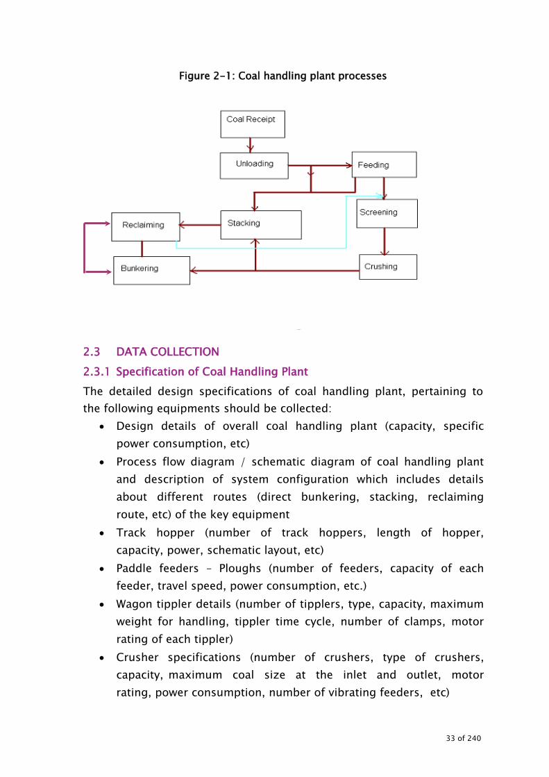
Figure 2-1: Coal handling plant processes
2.3 DATA COLLECTION 2.3.1 Specification of Coal Handling Plant The detailed design specifications of coal handling plant, pertaining to the following equipments should be collected:
• Design details of overall coal handling plant (capacity, specific power consumption, etc)
• Process flow diagram / schematic diagram of coal handling plant and description of system configuration which includes details about different routes (direct bunkering, stacking, reclaiming route, etc) of the key equipment
• Track hopper (number of track hoppers, length of hopper, capacity, power, schematic layout, etc)
• Paddle feeders – Ploughs (number of feeders, capacity of each feeder, travel speed, power consumption, etc.)
• Wagon tippler details (number of tipplers, type, capacity, maximum weight for handling, tippler time cycle, number of clamps, motor rating of each tippler)
• Crusher specifications (number of crushers, type of crushers, capacity, maximum coal size at the inlet and outlet, motor rating, power consumption, number of vibrating feeders, etc)
33 of 240

• Coal - design parameters and sizes • Belt conveyers (capacity, number, speed, width, application,
motor rating, power consumption) • Stacker reclaimer (quantity, capacity of reclaimer, travel speed,
number of buckets and length of boom, motor rating for travel, slew mechanism, bucket wheel drive mechanism, luffing mechanism, boom conveyor, etc)
• Other equipments – vibrating feeders, dust suppression system pumps, belt feeder, dust extraction fans, etc.
• The design / PG test values for the above mentioned equipments shall be compiled.
The key specifications parameters shall be complied as shown in Table 2-1. These should be measured stream wise wherever possible.
Table 2-1 : Key Specification parameters
Equipment reference
Capacity Motor input
power, kW
Speed of driven
equipment (rpm or linear speed)
Length (in case of belts)
Hours of operation
Specific energy
consumption
Units Value No
Load Average
Load rpm M Hrs
kWh / ton of coal handled
Paddle Feeders tph
Belt conveyors tph Vibro feeders tph Grizzly feeders tph Belt feeders tph Dust extraction fans
NM3/h
Dust suppression system pumps
M3/Hr
Crusher tph
Stacker reclaimer
tph
Other equipments
34 of 240

2.3.2 System data collection Data for last one year data as given in Table 2-2 should be collected as also day wise data for a period of two/three days when plant is under normal operation.
Table 2-2 : Production and operating data (___year)
Parameter Unit Total coal receipt Lakh tons Total electrical related load MW Over all operating load MW Energy consumption of CHP kWh Coal handling plant equipment operating hours
Hrs
Plant utilization factor Hrs Total gross generation of station MU Total auxiliary power consumption of the station
MU
Total power consumption by the CHP plant
MU
% of power consumption of CHP with respect to total auxiliary power consumption
%
Specific energy consumption, kWh/Mt of coal
Table 2-3 : Coal parameters
Unit Design Actual Remarks Coal size – crusher upstream mm Coal size – crusher downstream mm Total coal bunker capacity tph
2.4 INSTRUMENTS REQUIRED The following instruments are required for conducting the energy audit of coal handling system.
• Power analyzer for measurement of electrical parameters such as kW, kVA, pf, V, A and Hz of class 0.5 accuracy.
• Stroboscope to measure the speed of the driven equipment and motor.
• Belt tensiometer
35 of 240

• On line instruments (calibrated) for coal transfer rates, production, etc.
2.5 MEASUREMENTS & OBSERVATION TO BE MADE While conducting the audit, the following measurements and observations are necessary:
• Equipment operations and throughput, power consumption, loading, comparison with PG test / design condition, etc.
• Power consumption of the equipments (load and unload condition) • Drive speed • Belt speed • Condition of rollers • Condition of belts • Loading of belts with respect to the design • Loss of energy in the coal in stack yard due to spontaneous
combustion • Input coal parameters • Unit load of the plant • Date and time of measurement • Instruments used for measurement • Frequency of measurement
2.6 OBSERVATIONS AND ANALYSIS 2.6.1 System familiarisation and operational details Detailed interactions with the plant personnel should be carried out to get familiarisation with system detail and operational details. Pre-visit can be made to get familiarisation with CHP configuration, particularly different routes such as direct bunkering mode, stacking mode and reclaiming mode.
36 of 240

2.6.2 Measurements and Evaluation 2.6.2.1 Power parameters Measure the power input i.e. electrical parameters such as kW, kVA, current, voltage, power factor, for all drives for no load and load conditions.
2.6.2.2 Coal throughput rate Study track hopper management/ coal unloading. It is also necessary to carry out time-motion study. The coal throughput may be measured using coal totalisers or other alternative methods. 2.6.2.3 Evaluation of equipment loading and specific energy
consumption • Determine equipment wise percentage loading (i.e. actual tph /
rated tph) as well as the motor percentage loading (i.e. actual input kW / rated input kW)
• Also make a table (as shown in Table 2-4), for the equipment and their actual and design electrical parameters like KW, PF, V, A. Also provide remarks and calculations.
• Obtain operating hours. • Identify the operational constrains to achieve the optimum loading.
Table 2-4 : Power consumption and throughput –Direct bunkering
Direct Bunkering (Design capacity ….tph, Average capacity …tph, Annual operating hours ….)
Equipment Motor Rated
kW
Motor No load
Motor Average load
Specific Energy Consumption Average Design
A kW A kW kW /Mt kW /Mt Remarks on throughput, condition, power consumption, operating hours, operational controls for energy efficiency, specific energy consumption, operational constrains etc.
37 of 240

Table 2-5 : Power consumption and throughput –Reclaiming Reclaiming (Design capacity ….tph, Average capacity …tph, Annual operating hours ….)
Equipment Motor Rated
kW
Motor No load
Motor Average load
Specific Energy Consumption Average Design
A kW A kW kW /Mt kW /Mt Remarks on throughput, condition, power consumption, operating hours, operational controls for energy efficiency, specific energy consumption, operational constrains etc.
Table 2-6 : Power consumption and throughput –Stacking Stacking (Design capacity ….tph, Average capacity …tph, Annual operating hours ….)
Equipment Motor Rated
kW
Motor No load
Motor Average load
Specific Energy Consumption Average Design
A kW A kW kW /Mt kW /Mt Remarks on throughput, condition, power consumption, operating hours, operational controls for energy efficiency, specific energy consumption, operational constrains etc. 2.6.2.4 Calculation of Specific Energy Consumption
• Calculate kW /MT for existing operations i.e. bunkering, stacking, and reclaiming and also equipment wise.
• Based on energy meter reading and coal receipt data, calculate month wise kWh / MT for last one year for CHP plant.
• Plot a chart with kWh/MT on Y-axis and months on X-axis. 2.6.2.5 Coal Sample Analysis Send 2-3 samples of coal taken from the belts feeding the crushers for sieve analysis to determine extent of coal particles below 20 mm size / design size as applicable. This analysis will help in optimizing crusher operation, loading etc. 2.6.2.6 Lube oil Inspection
• Collect the lube oil sample. • Get the sample analysed. • If metal traces are found beyond permissible limits, recommend
complete oil change or inspection of bearings gear internals.
38 of 240
2.6.2.7 Performance of crushers
• Observe and compare the operation of crushers and their throughput, hours of operation, power consumption, etc.
• Carryout the sieve analysis and compare with the design or optimum values.
If significant proportion of coal > 20 mm size is observed on the downstream of crusher, it may lead to substantial increase in power consumption of coal mills. 2.6.3 Study of coal feeding circuits The different coal feeding circuits routes should be studied. The details of feeding circuits of coal handling system should be given in the report along with the specifications and schematic layout indicating equipments. Comparative study of various coal feeding circuits should be made. The measured and calculated specific energy consumption data for these circuits should be compiled and compared. The merit order studies for energy consumption of various paths which indicate scope for energy conservation should be identified. 2.6.4 Exploration of energy conservation possibilities While conducting the energy audit of the CHP, the following need to be explored in detail to arrive at appropriate energy conservation measures.
• Performance improvement options: Possibilities for improving the throughput. This is the major
energy saving area which offers substantial savings at no cost.
Minimum investment. Reduce idling time Increase the loading Modifications and changes in coal feeding circuits Need for automation and controls Identification of least power consuming streams /
equipments and recommending their operation on merit order basis.
39 of 240
Use of natural day light through the use of fire resistant translucent sheets on conveyor galleries.
Comparison of no load power drawn by similar capacity equipment and identification of causes responsible for increased no load power consumption.
• Explore installation of power saver devices in major LT motors
(conveyor belt etc.): Major HT /LT motors i.e. conveyors, crushers etc. are often partially loaded and, also, there are frequent starts / stops. Possibility of providing power saver devices (soft starters) in major motors should be explored.
• Power factor correction possibility: Induction motors are
characterized by power factors less than unity leading to lower overall efficiency (and higher overall operating cost) associated with the plant’s electrical system. Capacitors connected in parallel impacts of PF correction in a power plant are reduced I2R losses in cable upstream of capacitor (and hence reduced distribution losses), reduced voltage drop in cables (leading to improved voltage regulation), and an increase in the overall efficiency of the plant electrical system.
• Explore the possibility of using chemicals for reduced water spray: Mixing of chemical compounds in water for suppression of dust provides much better atomization of water spray by reducing surface tension of water. Thus, for the given application of dust suppression, lesser quantity of water is sprayed which also results in lesser wastage of latent heat in the steam generator.
• Maximum mechanical handling, minimum bulldozing: Sequence of coal handling operations like receipt, unloading, stacking and reclaiming and the selection of machinery should be made in such a way that all the handling operations are accomplished without the use of semi-mechanized means like bulldozers which are more energy intensive equipments. The principle of “FIRST IN FIRST OUT” should be adopted for coal receipt and consumption and at any time coal should not to be stocked in yard for more than incubation period (duration between coal mined and
40 of 240

spontaneous combustion)
• Reduced number of fillings: Live storage capacity of raw coal bunkers and the filling pattern of bunkers should be so planned that 24 hours coal requirement of the generating units is met by not more than two fillings per day. This will eliminate frequent starting and stopping of the CHP.
41 of 240
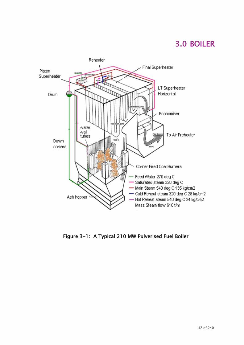
3.0 BOILER
Figure 3-1: A Typical 210 MW Pulverised Fuel Boiler
42 of 240

BOILER 3.1 BACKGROUND The boiler of a thermal power plant is used to produce steam at the high pressure and temperature required for the steam turbine that drives the electrical generator. The boiler has furnace, steam drum, super heater coils, reheater coils, economizer and air pre-heaters. The air and flue gas path equipment include forced draft fan (FD), induced draft fan (ID), air preheaters (APH), boiler furnace, fan, fly ash collectors (electrostatic precipitator or bag house) and the flue gas stack. Brief schematic diagram of a typical pulverised coal fired sub-critical boiler is given in Figure 3-2.
Figure 3-2: Schematic diagram of boiler
43 of 240
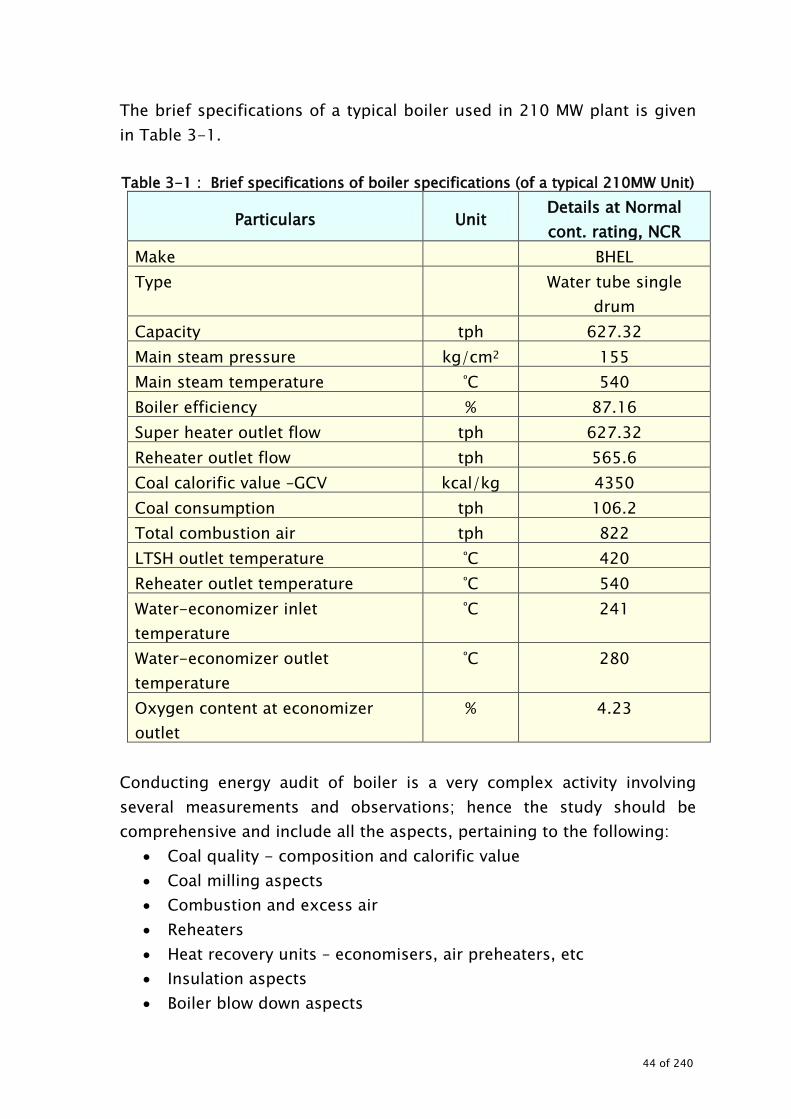
The brief specifications of a typical boiler used in 210 MW plant is given in Table 3-1.
Table 3-1 : Brief specifications of boiler specifications (of a typical 210MW Unit)
Particulars Unit Details at Normal cont. rating, NCR
Make BHEL Type Water tube single
drum Capacity tph 627.32 Main steam pressure kg/cm2 155 Main steam temperature ºC 540 Boiler efficiency % 87.16 Super heater outlet flow tph 627.32 Reheater outlet flow tph 565.6 Coal calorific value –GCV kcal/kg 4350 Coal consumption tph 106.2 Total combustion air tph 822 LTSH outlet temperature ºC 420 Reheater outlet temperature ºC 540 Water-economizer inlet temperature
ºC 241
Water-economizer outlet temperature
ºC 280
Oxygen content at economizer outlet
% 4.23
Conducting energy audit of boiler is a very complex activity involving several measurements and observations; hence the study should be comprehensive and include all the aspects, pertaining to the following:
• Coal quality - composition and calorific value • Coal milling aspects • Combustion and excess air • Reheaters • Heat recovery units – economisers, air preheaters, etc • Insulation aspects • Boiler blow down aspects
44 of 240

• Soot blowing aspects • Operation and maintenance features which affect the energy
efficiency • Condition and status of boiler and their internals • Feed water system aspects • Air and flue gas system aspects • Others aspects
3.2 DATA COLLECTION The first step in energy audit of boiler is to collect the design / PG test parameters pertaining to boiler, economiser, air preheaters, coal and coal milling, soot blowing and other key associated equipments. The following data sheets give brief specifications to be collected. It is suggested that comprehensive technical specifications of boilers and its associated equipment should be obtained.
45 of 240

3.2.1 Specifications of boiler and associated equipment 3.2.1.1 Boiler The following gives the list of specifications to be collected for energy audit study.
Table 3-2 : Design Specifications of boiler Particulars Unit Design NCR Actual
Make and year of manufacture
Main steam flow tph Pressure kg/cm2
Main steam temperature ºC
Steam temperature at re heater inlet ºC
Steam temperature at re heater outlet ºC
Steam pressure at re heater inlet kg/cm2
Steam pressure at re heater outlet kg/cm2
Steam temperature at LTSH outlet ºC Saturated steam temperature in drum ºC
Super heater platen outlet temperature ºC
Pressure drop in re heater Kg/cm2
Super heater spray tph
Re heater Spray tph
Ambient temperature ºC
Coal consumption tph
GCV kcal/kg
46 of 240

3.2.1.2 Economiser Table 3-3 gives the specifications to be collected for economiser.
Table 3-3: Specifications of economiser
Particulars Unit Design Actual
Feed water pressure at the inlet kg/cm2
Feed water pressure at the outlet kg/cm2
Feed water flow tph Feed water temperature at the inlet ºC
Feed water temperature at the out let ºC Oxygen content in flue gas before economizer %
Excess air % in flue gas before economizer %
Flue gas inlet temperature ºC
Flue gas outlet temperature ºC
Flue gas quantity tph 3.2.1.3 Air pre heater Design specifications to be collected for air pre-heater are given in Table 3-4.
Table 3-4: Specifications of air pre heater (APH) Particulars Unit Design Actual
Air quantity at APH outlet (primary) tph Tempering air tph Air Quantity at APH outlet (secondary) tph Total combustion air tph Air temperature at fan outlet oC Air outlet temperature of APH – primary oC Air outlet temperature of APH– secondary oC Oxygen content in flue gas before APH % Excess air % in flue gas before APH % Flue gas inlet temperature oC Flue gas outlet temperature oC Flue gas quantity tph Others
47 of 240

3.2.1.4 Flue gas parameters Parameters for flue gas to be collected are given in Table 3-5.
Table 3-5: Flue gas temperature profile
Particulars Unit Design Actual Super heater platen outlet ºC RH front inlet ºC RH rear inlet ºC SH finish inlet ºC LTSH inlet ºC Economizer inlet ºC APH inlet ºC APH outlet ºC ID Fan inlet ºC ID fan outlet ºC
3.2.1.5 Heat balance parameters Heat balance parameters for a boiler to be collected are shown in Table 3-6.
Table 3-6: Heat balance of boiler
Particulars Unit Design Actual Ambient temperature ºC
Excess air %
Dry flue gas loss %
Hydrogen loss %
Moisture in fuel loss %
Moisture in air loss %
Un burnt combustible loss %
Radiation loss %
Un accounted loss %
Gross boiler efficiency on HHV %
Guaranteed efficiency %
48 of 240

3.2.1.6 Feed and Boiler Water Limits Design feed and boiler water limits to be collected are shown in Table 3-7.
Table 3-7: Recommended feed water and boiler water limits Particulars Unit Feed Water Boiler Water Remarks
Design Actual Design Actual Hardness ppm pH at 25oC pH Oxygen – maximum ppm Total iron- maximum ppm Total silica – maximum ppm Conductivity at 25ºC ŲΩ/cm Hydrazine residual ppm Total solids – maximum ppb chlorides ppm Copper – maximum ppm Oil ppm Permanganate consumption ppm Others
3.2.1.7 Mill performance indicators Design specifications of mill and burner performance are shown in Table 3-8.
Table 3-8: Mills and Burners Performance
Particulars Unit Requirement at
MCR Actual Remarks
No of coal burners No Primary air fuel tph No of mills in operation No Mill loading % Air temperature at mill inlet after tempering
oC
Air – fuel mixture temperature after leaving mills
oC
Total coal fired tph Air – fuel ratio A/F Air coal ratio A/C
49 of 240

In addition to the above, the individual mill specifications and design coal parameters should be collected: Mill specifications: Type of mill : Make : Capacity : __________tph Fineness : ___________% through ________mesh Motor rating :____________kW Motor voltage :________ V No of mills :__________ Running /standby :_________/________ Design coal parameter Moisture :_____% Ash :_____% Volatile matter :_____% Fixed carbon :______% HGI :_____% 3.2.1.8 Soot blower Information of soot blowers is given in Table 3-9.
Table 3-9: Soot blowers
Particulars Type Number Soot blowers for furnace Soot blowers for super heaters Soot blowers for re heaters Soot blowers for air pre heaters Medium of blow Steam pressure before reduction Steam pressure after reduction Steam consumption
50 of 240

3.3 INSTRUMENTS REQUIRED Main instruments with requisite accuracy required for conducting boiler energy audit are given below:
• Non contact power analyser: Used for measuring electrical parameters such as kW, kVA, pf, V, A and Hz
• Temperature indicator & probe • Stroboscope: To measure the speed of the driven equipment and
motor • Sling hygrometer or digital hygrometer • Anemometer • Available on line instruments at the site (calibrated ) • Digital manometer of suitable range and appropriate probes for
measurement of pressure head and velocity head. • Additional pressure gauges with appropriate range of measurement
and calibrated before audit. • Flue gas analysers / Orsat apparatus • Infrared pyrometers • Pressure gauges • Steam trap tester / ultra sonic leak detectors
3.4 MEASUREMENTS AND OBSERVATIONS TO BE MADE While conducting the audit, the following measurements and observations are necessary.
• Average GCV of coal during audit period. • Coal analysis – ultimate and proximate • Coal and oil consumption details • Performance parameters of coal mills • Steam parameters of main steam, reheat, super heater, LTSH (flow,
pressure and temperature) • Air – flow, temperature, pressures • Flue gas – flow, temperature and pressure • Flue gas analysis • Coal consumption pattern • Ambient temperature • Boiler loading • Motor electrical parameters (kW, kVA, Pf, A, V, Hz, THD) of ID, FD,
PA, mills, BFP, forced circulation pump, mill air fan etc.
51 of 240

• Surface temperatures of insulation and boiler surfaces • Un burnt carbon (%) (fly and bottom ash) • While conducting the measurement or performance evaluation of
any system simultaneously the following need to be noted Unit load of the plant Date and time of measurement Instruments used for measurement Frequency of measurement
3.5 OBSERVATIONS AND ANALYSIS 3.5.1 System familiarisation and operational details Detailed interactions with the plant personnel should be carried out to obtain familiarisation with the system and its operational details. The brief details of the system should to be given in the report along with the specifications. During familiarisation, boiler, plant key performance data should be collected pertaining to the following
• Availability factor (%) • PLF (%) • Specific coal consumption (kg/kWh) • Specific oil consumption in ml/kWh • Makeup water and auxiliary power consumption (MWH)
During the familiarization of power plant and its operation, past observation and data should be obtained pertaining to:
• Past performance trends on boiler loading, operation, PLF, efficiency
• Major constraints in achieving high PLF, load or efficiency (input from plant personnel)
• Major renovation and modifications carried out in the recent past • Coal quality and calorific values aspects • Operational failures leading to in efficient operation such as tube
failures, constraints for efficient heater operation, • Soot blower operations • Tripping • Performance of economiser, air pre heaters, LP / HP heater from
52 of 240

past records • Combustion control system – practice followed • Mills performance • If plant has online and off line tools for performance evaluation of
main equipment and BOP equipment, then details of these tools • Plant side initiatives to improve the performance and efficiency of
the boiler The data and information collected should be consolidated and the same should be given in the report for reference. For all major observations arrived at during the discussions, which affect the performance and energy efficiency of the boiler, it is suggested that the same should be verified from the records and history. 3.5.2 Operational efficiency of the boiler The boiler efficiency trial has to be conducted to estimate the operational efficiency under as run conditions. The efficiency evaluation, by and large, follows the loss components mentioned in the reference standards for Boiler Testing at site using indirect methods mentioned in BS 845: 1987 as amended on date and USA Standard ASME (PTC-4-1) Power Test Code for Steam Generating Units. The test method employed is based on abbreviated efficiency by the loss method (or indirect method) test, which neglects the minor losses and heat credits, which are covered in full text version of the relevant standard. The major losses covered are:
• Heat loss due to dry flue gas losses • Heat loss due to moisture in fuel • Heat loss due to moisture in air • Heat loss due to hydrogen in fuel • Heat loss due to un burnt carbon in fly ash and bottom ash • Heat loss due to radiation to be assumed depending on emissivity
of surface, (typical value for 210/500 MW is 0.4% - 1% of GCV) • Unaccounted losses as declared by the boiler supplier
53 of 240

Indirect method is also called as heat loss method. The efficiency can be arrived at by subtracting the heat loss fractions from 100. The standards do not include blow down loss in the efficiency determination process. While conducting the efficiency evaluation, the following pre-audit checks need to be ensured. Trials should be conducted at least for two hours and measurements should be taken every fifteen minutes
• Load on the boiler to be by and large constant and represent
average loading and normal operation • No soot blowers are operated during the evaluation period • No intermittent blow down is given. The continuous blow down
needs to be stopped. • A team of 3-4 members is required for simultaneous
measurements and data collection of various parameters. The members should be trained / explained prior to the test regarding their assignments in measurements and observations.
• Before conducting the actual measurement for the evaluation, it is suggested that a demo exercise may be carried out for one set of measurements and observations.
3.5.3 Measurement locations During the test, the power plant, under the coordination of energy auditor, may organise the collection and analysis of samples at the following locations
• Flue gas analysis at air pre heaters inlet / out let for O2, CO, CO2 • Temperature of flue gas at air pre heaters inlet / out let • Fly ash sampling at the economiser outlet and ESP hoppers
for un burnt carbon in fly ash • Sample of bottom ash from hopper or scrapper • Sample of raw coal from RC feeder of the mill for proximate
and ultimate analysis of fuel and gross calorific value. • Pulverised coal samples from each mill for sieve analysis. • Sample of mill rejects for GCV.
54 of 240
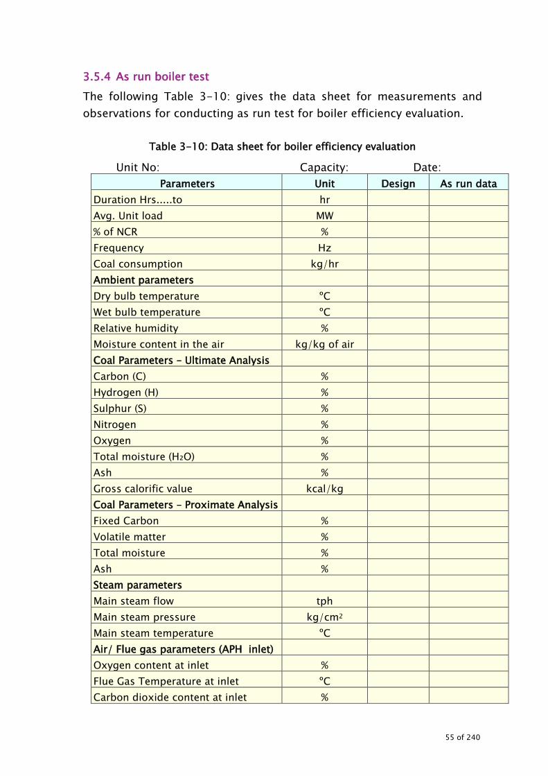
3.5.4 As run boiler test The following Table 3-10: gives the data sheet for measurements and observations for conducting as run test for boiler efficiency evaluation.
Table 3-10: Data sheet for boiler efficiency evaluation
Unit No: Capacity: Date: Parameters Unit Design As run data
Duration Hrs.....to hr Avg. Unit load MW % of NCR % Frequency Hz Coal consumption kg/hr Ambient parameters Dry bulb temperature ºC Wet bulb temperature ºC Relative humidity % Moisture content in the air kg/kg of air Coal Parameters – Ultimate Analysis Carbon (C) % Hydrogen (H) % Sulphur (S) % Nitrogen % Oxygen % Total moisture (H₂O) % Ash % Gross calorific value kcal/kg Coal Parameters – Proximate Analysis Fixed Carbon % Volatile matter % Total moisture % Ash % Steam parameters Main steam flow tph Main steam pressure kg/cm2 Main steam temperature ºC Air/ Flue gas parameters (APH inlet) Oxygen content at inlet % Flue Gas Temperature at inlet ºC Carbon dioxide content at inlet %
55 of 240
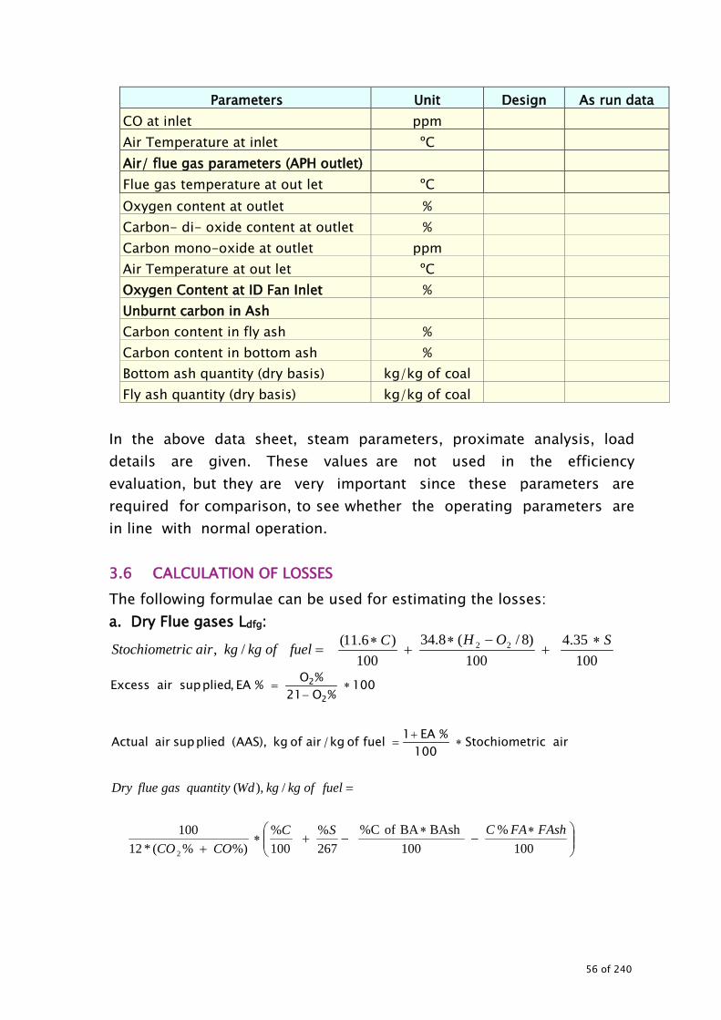
Parameters Unit Design As run data CO at inlet ppm Air Temperature at inlet ºC Air/ flue gas parameters (APH outlet) Flue gas temperature at out let ºC Oxygen content at outlet % Carbon- di- oxide content at outlet % Carbon mono-oxide at outlet ppm Air Temperature at out let ºC Oxygen Content at ID Fan Inlet % Unburnt carbon in Ash Carbon content in fly ash % Carbon content in bottom ash % Bottom ash quantity (dry basis) kg/kg of coal Fly ash quantity (dry basis) kg/kg of coal
In the above data sheet, steam parameters, proximate analysis, load details are given. These values are not used in the efficiency evaluation, but they are very important since these parameters are required for comparison, to see whether the operating parameters are in line with normal operation. 3.6 CALCULATION OF LOSSES The following formulae can be used for estimating the losses: a. Dry Flue gases Ldfg:
10035.4
100)8/(8.34
100)6.11(/, 22 SOHCfuelofkgkgairricStochiomet ∗
+−∗
+∗
=
100%O21
%O%EA,pliedsupairExcess2
2 ∗−
=
airricStochiomet
100%EA1fuelofkg/airofkg),AAS(pliedsupairActual ∗
+=
∗−
∗−+∗
+
=
100%
100BAshBA of %C
267%
100%
%)%(*12100
/),(
2
FAshFACSCCOCO
fuelofkgkgWdquantitygasflueDry
56 of 240

100kcal/kg
)CABTC(FGTCkcal/kgheat Specificfuel of /kgquantityKggasflueDry%, ∗°−°∗°∗
=FuelofCGV
LlossesgasflueDry dfg
Where C%BA – % of carbon in bottom ash C%FA - % of carbon in fly ash Bash – Bottom ash quantity in kg/kg Fash – Fly ash quantity in kg/kg FGT – Flue gas temperature at APH outlet in ºC ABT – Ambient dry bulb temperature in ºC Cp - Specific heat of flue gas in kcal/kg ºC =0.23
b. Loss due to un burnt carbon in ash, Luca
[ ])BAshBA%C()FAshFA%C(kg/KCalfuelofGCV
kg/kcalincarbonofvalueCalorific
L,ashincarbonunburnttodueLoss uca
∗+∗∗
=
c. Loss due to moisture in fuel, Lmf
[ ]
GCV100584)ABTFGT(45.0(ML,fuelinmoisturetodueLoss mf
∗+−∗∗=
Where M is kg of Moisture in 1 kg of fuel
d. Loss due to Hydrogen in fuel, Lhf
[ ]
GCV100584)ABTFGT(45.0(H9L,fuelinhydrogentodueLoss 2
hf∗+−∗∗∗
=
Where H2 is kg of H2 in 1 kg of fuel e. Loss due to moisture in air, Lma
GCVABTFGThumidityAASLairinmoistureintodueLoss ma
100)(45.0, ∗−∗∗∗=
Where AAS=Actual mass of air supplied Humidity = humidity of air in kg/kg of dry air f. Loss due to carbon monoxide, Lco
GCVCOCOCCOLmonoxidecarbontodueLoss co
1005744%%
%, 2
∗∗
+∗
=
57 of 240

During the flue gas analysis when CO is obtained in ppm, then losses can be obtained
GCVhkginnconsumptiofuelppminCO
LmonoxidecarbontodueLoss co
100574428/10
,
6 ∗∗∗∗∗= −
g. Radiation and un accounted losses Consider these losses as given in the PG test / Design documents.
Alternatively, the radiation losses can be estimated by measuring the surface temperatures and surface areas of the boiler section.
Normally surface loss and other unaccounted losses are assumed based on the type and size of the boiler. These losses can be calculated if the surface area of boiler and its surface temperature are known as given below:
[ ] ( ) m25.1
as4
sG VxTT x 957.1}55.55/T{ x 0.548 L −+=
( )( )K mperatureAmbient te K re temperatuSurface Ts
m/sin velocity Wind Vm m / in watts lossRadiation
0
0
2
=
=
==
Ta
LG
After estimating the individual components, the losses need to be tabulated and compared with the PG test value or best achievable values. While comparing the losses, the deviations need to be highlighted and factors contributing for these deviations need to be arrived at. The following Table 3-11: gives the tabulation sheet for boiler efficiency
Table 3-11: Efficiency evaluation of boiler Date and time of the test.............
Particulars Unit Design Value
Actual value
% Deviation
Remark
58 of 240

Particulars Unit Design Value
Actual value
% Deviation
Remark
Load MW Fuel GCV kcal/kg Loss due to hydrogen in fuel % Loss due to dry flue gases, Ldfg % Loss due to moisture in air % Loss due to un burnt carbon in ash, Luca % Loss due to moisture in fuel, Lmf % Loss due to carbon monoxide, Lco % Radiation losses % Unaccounted losses and manufacturers margin
%
Total losses % Boiler Efficiency %
All loss components should be thoroughly examined for the deviations, since in most of the plants, the actual GCV of the fuel and composition of the fuel does not match with design specifications and the above losses need to be corrected for the present fuel. 3.6.1 Performance of Coal Mills The major objectives of coal mill energy audit are:
• To evaluate specific energy consumption of the mills (kWh/ton of coal)
• To establish air to coal ratio of the mills (ton of air per ton of coal) • To evaluate specific coal consumption of the generating unit (kg
/kWh) • To compare the actual consumption with design/PG test values. • To suggest ways to optimise energy consumption • To discuss general health of equipment and review maintenance
practices which affect energy consumption. The energy audit of coal mills has to be commenced by obtaining an overview of system which includes mills, RC feeders, PA fans, seal air fans, mill reject handling system and associated ducts, piping, valves and dampers, lubrication system, thermal insulation status of mills/PA fans ducts / piping etc.
59 of 240

While monitoring the general health of various installations auditor should identify noticeable leakages of coal, air, oil and check condition of thermal insulation etc. Data collection-Coal Milling System Samples of raw coal, pulverised coal, mill rejects, mill gearbox oil, fly ash and bottom ash should be obtained during audit and analysed for the various parameters. The following parameters should be noted. Raw Coal: GCV, ash content, volatile matter, fixed carbon, total moisture, and HGI value of coal. Pulverised Coal: Mill fineness (% passing through 200 mesh), running hours of mill grinding elements with material composition of each part. Individual RCF coal integrator readings should be compared with overall coal integrator readings. Mill Reject Coal: Ash content and gross calorific value of mill rejects, fly ash, bottom ash and combustibles in fly ash and bottom ash and GCV. Mill Gear Box Oil: Viscosity, moisture, mechanical impurities and appearance of lubricating oil in mill gearboxes.
• Power measurements of mills, PA fans, seal air fans, etc., should be carried out. In the absence of energy meters, readings may be taken from on-line panel instruments for current, voltage, power factor etc. For LT equipment, portable instrument can be used for power measurements.
• Coal flow should be established by dirty Pitot tube test (to be carried out on pulverised coal lines). This also helps to identify unbalancing/choking occurring in flow in the pulverised coal lines. The on line coal flow values if available, may also to be taken by appropriate coal feeder calibration.
• Airflow should be established per PA fan by clean air Pitot tube method or by Aerofoil DP where available.
• Various parameters observed should be listed as per Table 3-12.
60 of 240

Figure 3-3: Bowl Mill
61 of 240

Table 3-12: Mill Performance
Particulars Observations
Mill No. Date Time (hr) Unit load (MW) Mill inlet coal flow (tph) – (instantaneous as observed from control room)
Mill inlet temp. (ºC) Mill outlet temp. (ºC) Mill differential pressure. (mmWC)
Air flow to mill (tph) PA common header pressure (mmWC)
Mill reject, kg/hr. Mill current (amps) RCF coal integration readings as observed from control room for working out the coal inflow (tph)
Energy meter readings (kWh) Specific energy consumption kWh/ton of coal.
Based on above observations, Auditor may draw inference as follow:
• Specific power consumption kWh per tonnage of coal handled • Coal fineness and its impact on the un burnt and air to fuel ratio.
For a typical coal fired boiler, the design indicates that 70% passing through 200 mesh is ideal. These values need to be obtained and compared with the actual. The following Table 3-13 can be used as data sheet for mill fineness analysis.
62 of 240

Table 3-13: Coal fineness
Particulars / Mill Coal fineness passing through (%)
50 mesh 100 mesh 140 mesh 200 mesh
Design
Mill No #
Mill No #
Mill No #
Mill No #
The auditor should observe the mill rejects with respect to the quantity and calorific value and tabulate the results as shown in Table 3-14.
Table 3-14: Mill rejects
Mill No Fuel input,
tph Fuel reject,
kg/h Mill reject
% Calorific value of the reject
Remarks
Mill No #
Mill No #
Mill No #
Mill No #
Carry out the detailed analysis of mill rejects and compare with other mills and coal quality. The variation in mill rejects (among the mills) could be due to variation in the performance of the mills due to mill internals status, fuel handling, etc. 3.6.2 Combustion control, excess air and cold air infiltration While conducting the study, the following need to be verified:
• Present excess air and comparison with PG test or design value • Combustion control systems installed and status of operation,
calibration systems. • Monitoring and controlling mechanism for oxygen, excess air and
reporting systems in place. • Effect of excess air on boiler performance and with respect to boiler
load variation. • Cold air infiltration in to the system – observe the present method
of measurement, frequency of measurement for estimating the
63 of 240

losses and control mechanisms initiated. The air infiltration also increases load on the ID fan and hinders the capacity of the boiler.
The best way to identify the cold air infiltration is to measure the oxygen profile across the flue gas path. The following data sheet Table 3-15 can be used for excess air and combustion control system.
Table 3-15: Data sheet for estimating air infiltration
Location Parameter Oxygen
(%) Excess air
(%)
Flue gas temperature
(ºC)
Flue gas quantity
(%)
ID fan inlet
Design
Actual
Deviation
Remarks
APH inlet
Design
Actual
Deviation
Remarks
The above data sheet will help in identifying suitable improvement options. If there is any increase in oxygen content then the following should be carried out:
• Assess the quantity of air ingress (the exhaust / flue gas quantity can be measured / estimated based on the oxygen content)
• Assess heat losses due to ingress (impact on boiler efficiency) • Investigate sources for air ingress • Suggest measures to reduce cold air ingress into the system.
Typical acceptance value for a 210 MW power plant is increase in oxygen by 3% points across the APH inlet to ID fan inlet.
• Recommend suitable monitoring system for oxygen profiling in flue gas path and suggest instruments required for the monitoring
64 of 240

along with suggesting ideal locations for sensors installation. • Estimate the energy saving benefits in the following equipment by
having very good cold air ingress controlling mechanism Improvement in boiler efficiency Improvement in APH Reduction in ID/PA and FD fan power consumption Increase in boiler loading / PLF
3.6.3 Performance of air preheaters Air preheater is a critical component of the boiler system and its performance has direct affect on boiler efficiency. “As run test” has to be carried out to assess the performance of the air preheaters. APH leakage and APH gas side efficiency has to be checked to assess the performance of APH. Air heater leakage in APH is the weight of air passing from the air side to gas side of the APH. This is an indicator of the condition of the air heater’s seals. As the air heater seals wear, air heater leakage increases. The increase in air heater leakage increases the power requirements of the draft fans, increasing the unit net heat rate and possibly limiting the unit loading. Air heater gas side efficiency is defined as the ratio of temperature drop, corrected for leakage, to the temperature head expressed as a percentage. This is an indicator of the internal condition of the air heater. Gas Side Efficiency = (Tgnl-Tge)/(Tae-Tge) The corrected gas outlet temperature Tgnl is defined as the outlet gas temperature for no air leakage and is given by the following formula:
TglCpg*100
)TaeTgl(Cpa*ALTgnl +−
=
where:
Units AL Air leakage into APH system %
65 of 240

Tgnl Cpa Tae Tal Tgl Cpg
Gas outlet temperature corrected for no leakage The mean specific heat between Tac and Tgl Temperature of the air entering the APH Temperature of the air leaving the APH Temperature of the gas leaving the APH The mean specific heat between Tgl and Tgnl
ºC kcal/kg/ºC
ºC ºC ºC
kcal/kg/ºC
Tge Temperature of gas entering the APH ºC
As conditions inside the air heater worsen (baskets wear, ash plugging, etc), the air heater gas side efficiency decreases. This is generally accompanied by an increase in exit gas temperature and decrease in air heater outlet temperature. The following formula gives the air leakage in to the (APH) system if the oxygen percentage is measured at the entry and exit of the (APH)
100
)%21()%%(
%,2
22 ∗−
−=
APHleavinggastheinOAPHenteringgastheinOAPHtheleavinggastheinO
ALleakageAPH
Alternatively, if the CO2% is measured in the exhaust gases then the air leakage is estimated by
)(%,
2
22 ∗−
=APHleavinggastheinppmCO
APHleavinggastheinppmCOAPHtheenteringgastheinppmCOALleakageAPH
Gas side efficiency: Air leakage estimation and gas side efficiency estimation are important while evaluating the performance of the air heater. The measured data and estimated parameters need to be tabulated for comparison with the designer best-run values. Table 3-16 gives the data sheet for filling the parameters.
Table 3-16: Data sheet for air preheaters (APH)
Particulars Unit Design / PG test
Actual %
Deviation Remarks
Total Primary air + secondary air + seal air
tph
Total Coal Fired tph
66 of 240

Particulars Unit Design / PG test
Actual %
Deviation Remarks
Flue gas quantity at APH inlet tph Oxygen content in flue gas before APH % Excess air % in flue gas before APH % Oxygen content in flue gas after APH % Excess air % in flue gas after APH % Air heater leakage % Quantity of air ingress tph Temperature of air entering the APH ºC Temperature of air leaving the APH ºC Air temperature at PA fan outlet ºC Temperature of flue gas leaving the APH ºC Flue Gas outlet temperature corrected for no leakage
ºC
Notes: Energy Auditor can identify the following from the above observations / analysis: 1) Increase in forced draft fan power consumption 2) APH performance in general. 3.6.4 Controllable losses due to un burnt carbon in ash The auditor should collect the fly ash and bottom ash samples, during the efficiency test period for the analysis of un burnt carbon. It is also suggested that the past data pertaining to the following should be verified.
• Ash quantities – bottom ash and fly ash • Un burnt carbon analysis • Coal used, coal mill performance parameters, unit load, etc. (for the
data required for un burnt carbon analysis) • Does the plant monitor the un- burnt carbon regularly by plotting
graphs. For this purpose, the historical data of analysis may be collected.
• Work out boiler efficiency and impact on coal consumption for every increase of 0.1% in un burnt carbon.
67 of 240
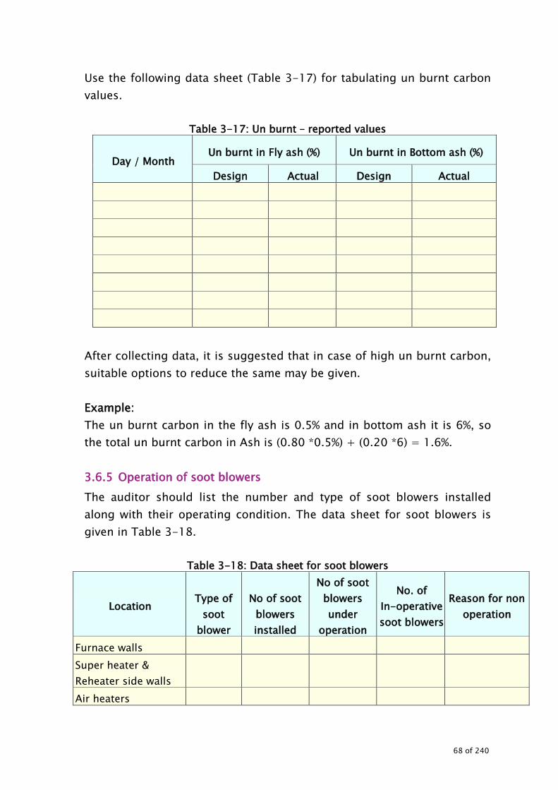
Use the following data sheet (Table 3-17) for tabulating un burnt carbon values.
Table 3-17: Un burnt – reported values
Day / Month Un burnt in Fly ash (%) Un burnt in Bottom ash (%)
Design Actual Design Actual
After collecting data, it is suggested that in case of high un burnt carbon, suitable options to reduce the same may be given. Example: The un burnt carbon in the fly ash is 0.5% and in bottom ash it is 6%, so the total un burnt carbon in Ash is (0.80 *0.5%) + (0.20 *6) = 1.6%. 3.6.5 Operation of soot blowers The auditor should list the number and type of soot blowers installed along with their operating condition. The data sheet for soot blowers is given in Table 3-18.
Table 3-18: Data sheet for soot blowers
Location
Type of
soot blower
No of soot
blowers installed
No of soot blowers under
operation
No. of In-operative soot blowers
Reason for non operation
Furnace walls Super heater & Reheater side walls
Air heaters
68 of 240

The inoperative soot blowers cause clinker build up and loss of heat transfer which leads to break downs, higher flue gas temperature, higher steam temperature at the super heater zone, higher de-super heater spray, etc. The normative de-superheater spray should be compared with actual spray quantity as in Table 3-19 below:
Table 3-19: Comparison of actual and normative spray consumption
Unit load Steam
flow, tph
Steam temperature,
ºC
Attemperation spray, tph
% of Attemperation of
steam flow Remarks
At NCR - …MW At actual load - ...MW
If the actual super heater spray is more than normal, this will affect the unit performance and heat rate. The auditor should identify causes for mal-functioning of soot blowers of each zone and possible remedies. The following may be checked:
• Soot blower piping. • Poppet valves servicing. • Functioning of rotary and traverse motor. • Positioning of split cam assembly, shifting of nozzle position. • Retract limit switches. • Sleeves condition. • Positioning of concentricity of swivel tube in respect of wall • Other parameters which affect the performance of soot blowers
During the study, it may be observed as to how the above factors lead to inoperative soot blowers. 3.6.6 Water Treatment Water quality influences the performance of the boiler internals. The auditor may observe the present water treatment parameters pertaining to:
• Type and rated capacity
69 of 240
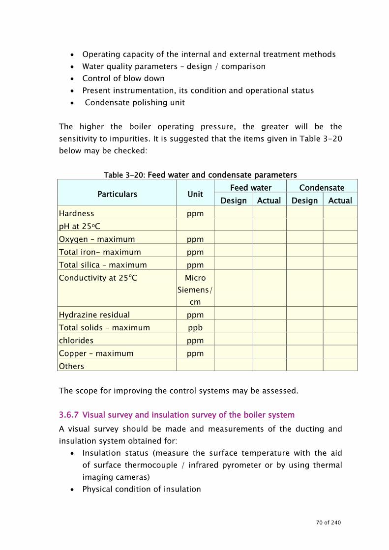
• Operating capacity of the internal and external treatment methods • Water quality parameters – design / comparison • Control of blow down • Present instrumentation, its condition and operational status • Condensate polishing unit
The higher the boiler operating pressure, the greater will be the sensitivity to impurities. It is suggested that the items given in Table 3-20 below may be checked:
Table 3-20: Feed water and condensate parameters
Particulars Unit Feed water Condensate
Design Actual Design Actual Hardness ppm pH at 25oC Oxygen – maximum ppm Total iron- maximum ppm Total silica – maximum ppm Conductivity at 25ºC Micro
Siemens/ cm
Hydrazine residual ppm Total solids – maximum ppb chlorides ppm Copper – maximum ppm Others The scope for improving the control systems may be assessed. 3.6.7 Visual survey and insulation survey of the boiler system A visual survey should be made and measurements of the ducting and insulation system obtained for:
• Insulation status (measure the surface temperature with the aid of surface thermocouple / infrared pyrometer or by using thermal imaging cameras)
• Physical condition of insulation
70 of 240
• Identification of locations where action is required to improve the insulation (provide detailed techno-economics evaluation)
• Improvement options Procedure for conducting the energy audit of insulation is given separately. 3.6.8 Exploration of energy conservation possibilities While conducting the energy audit of the boilers, the following need to be explored in detail to arrive at appropriate energy conservation measures.
• Boilers Steam and water parameters (flow, pressure and
temperature) Air and gas parameters (flow, pressure and temperature) Operation of burners Primary and secondary air ratios and temperatures Air ingress in to boilers Un burnt carbon loss Combustion control – boiler excess air, O2 measurement
inaccuracy or unbalance, Dry flue gas losses Insulation Air infiltration in flue gas path Blow down and its control Water quality and its control Coal quality and performance of coal mills Super heater and re heater performance Super heater temperature, slagging of furnace water walls
and tubes − Fouling on the pendant and horizontal convection
tubes, − soot blowers performance
Boiler control systems Limitation on performance of associated equipments
(pumps, fans, heaters, soot blowers, mills, etc. affecting boiler loading and efficiency)
71 of 240

Loading on ID, FD and PA fans Operation of dampers /inlet guide vanes / speed controllers
of fans. Fouling of boiler heating surfaces Installation of energy saving retrofits DM water consumption
• Air pre heaters Air Infiltration Gas side efficiency Performance of air pre heaters
• Economiser Pressure drop Performance
3.6.9 Exploration of energy conservation opportunities High Stack temperature Boiler soot deposits, higher excess air, air in leakages before the combustion chamber, low feed water temperature, passing dampers and poor air heater seals, higher elevation burners in service, improper combustion. Incomplete combustion Poor milling i.e. coarse grinding, poor air/fuel distribution to burners, low combustion air temperature, low primary air temperature, primary air velocity being very high/very low, lack of adequate fuel/air mixing. Blow down 1 % of blow down implies 0.17% heat added in the boiler. So blow down should be adhered to the chemist requirement. Soot blowing losses Super heated steam with high enthalpy is used for soot blowing. 1% of steam required, contains 0.62% heat content. To make up the loss another 0.25% heat has to be added to feed water resulting in total heat loss of 0.87%.
72 of 240

Frequency of soot blowing must be carefully planned. High Dry flue gas loss Air leakage through man holes, peep holes, bottom seals, air heater seal leakage, uneven distribution of secondary air, inaccurate sample/analysis, poor automatic boiler SADC, burner tilting poor O2 control. Radiation and convection heat loss Casing radiation, sensible heat in refuse, bottom water seal operation, not largely controllable but better maintenance of casing insulation can minimize the loss. Saving analysis with improvement in efficiency Fuel Saving
new 100*is) as -new ( Saving %
ηηη
=
Annual energy savings
year/MWhnew * is as
is) as - new (*PLF*8760*installed MWSaηη
ηη=
73 of 240

Annual cost savings
year/Rsnew * is as
MWh C ) is as - new ( * PLF * 8760* installed MWSacηη
ηη=
Where η as is = the actual system efficiency ηnew = proposed system efficiency CMWh = Fuel costs in Rs/MWh
where MWh refers to energy in the fuel PLF = plant load factor as a fraction
8760 * InstalledMW OperatedMW
=
The following Figure 3-4 fives typical heat balance for a boiler.
Figure 3-4: Typical heat balance for a pulverised coal fired boiler
74 of 240

4.0 THERMAL INSULATION
THERMAL INSULATION
75 of 240

THERMAL INSULATION 4.1 BACKGROUND Detailed study of thermal insulation for consideration of energy loss is a part of any energy audit, since thermal insulation condition is an indicative parameter for the potential thermal energy savings. The study aims at judging the potential thermal energy saving by insulation up gradation but also for planning proper maintenance schedule keeping in view equipment and personnel safety. In addition, periodic insulation survey should be carried out to initiate measures by maintenance personnel to prevent heat losses due to poor insulation. These guidelines, give a standard procedure for energy audit of thermal insulation of boiler, turbine and piping. It is generic in nature and can be customized as per the actual site conditions.
4.2 STEPS INVOLVED IN CONDUCTING THE ENERGY AUDIT The scope of insulation study includes: • Temperature profile survey of insulated surfaces in areas of boiler,
steam pipes, ducts and turbine etc. / thorough thermal scanning of all related surfaces for identifying hot spots with poor insulation.
• Identification of areas of poor / damaged insulation, contributing to excessive heat losses.
• Estimation of extra heat loss/ revenue loss due to the hot spots because of damaged or poor insulation.
The steps involved in conducting energy audit of insulation system are: • Data collection • Measurements and observations • Estimation of heat losses (controllable) • Exploration for energy conservation measures • Report preparation
The following instruments are required for conducting the energy audit of the thermal insulation. • Non contact type infrared pyrometer
76 of 240

• Measuring tape • Distance measuring instrument (for the pipes)
4.3 DATA COLLECTION • Single line diagram of all the insulated lines / surfaces of the plant
with their dimensions. • Dimensional sketches of other hot surfaces of boiler, turbine, vessels
etc. • Details of insulating material and cladding used (type of insulation,
pipe sizes, type of cladding, emissivity of cladding, thickness etc). • Also collect the following:
− Emissivity (refer the instruction manual of the instrument) − Permissible surface temperature oC Tsa = Tambient + Δ T (allowed) − Generation (last one year) in million units − Calorific value of fuel (kcal/kg) − Price of fuel (Rs /ton) at station end − Boiler efficiency (%) − Cost of reinsulation (Rs / m2)
4.4 MEASUREMENTS AND OBSERVATION TO BE MADE Before start of temperature measurement, the auditor should ensure from control room that unit is running around base load and boiler furnace vacuum is maintained. The following should be recorded. • Record average unit load in MW and ambient temperature (Ta) in ºC
prevailing at the time of survey. • Scan and record the temperatures at various locations of the insulated
surface at intervals of 1-2 meters with the help of non-contact type thermometer or thermo vision camera.
• Typical format is shown in the Table 4-1 taking one section of the boiler as an example. Similarly, measurement can be carried out for other sections/equipments.
77 of 240

Table 4-1 : Typical format for recoding the surface temperature Temperature profile: ________________________ Date and time of measurement: _________________________ Ambient temperature:___________________________________ Section Boiler First pass- Level M
Direction of measurement
1 2 3 4 5 6 7 8 9 10
Front Back Left Right
• After recording the temperature and tabulating, highlight the measurements where temperatures are above acceptable level.
• If the plant uses thermal vision camera, the printout of measurements should be enclosed. Typical printouts are given in the following Figure 4-1.
Figure 4-1: Typical thermal images
Thermal Image of 8 Meter level: Down comer line RHS
Thermal imager of 8 Meter level: 2 & 3 corner rear side (channel
below APH)
• Carryout physical survey and make a list of defective insulation areas
indicating type of defect i.e. insulation damaged / poor insulation / cladding missing / cladding loose/ uninsulated or any other) along
78 of 240

with description of location and approximate area of defect. • Record external factors responsible for increase of insulation surface
temperature, e.g. leakages of flue gas, steam, hot air etc. along with locations.
• Ensure that no other external factors like steam, air, flue gas leakages are affecting the surface temperature of the scanned areas. If so, take temperature of near by surface.
4.5 ESTIMATION OF CONTROLLABLE HEAT LOSSES AND ENERGY
SAVINGS The surface heat loss can be computed with the help of equation given below.
• For surface temperature up to 200 ºC
Ta)-(Ts x Ta)/20]-(Ts [10 S +=
Where: S = Surface heat loss in kcal/hr-m2 Ts = Hot surface temperature in oC Ta = Ambient temperature in oC
• For surface temperature above 200 ºC
As radiation losses are high at surface temperature above 200 oC, formula given below, can be used to calculate heat loss
+
−
+
+×=44
1.25100
273 Ta100
273 TsE88.4 Ta) - (Ts a S
Where, a = Factor regarding direction of the surface of natural
convection = 2.2 Ts = Temperature of external surface (°C) Ta = Temperature of air around the surface (°C) E = Emissivity of external surface of the insulation
79 of 240

Based upon this formula, calculate heat loss S1 from the existing surface and the permitted loss S0 based on acceptable surface temperature criteria.
01P S-S S potential, saving Heat = (Total heat loss minus unavoidable heat loss from a high temperature defective area) Calculate SP1, SP2……. for all the identified high temperature areas / defects
) xASP A x (SP Sum (kcal/h) Hs potential savingheat Total 2211 ………+= Where A1, A2……. are area of the high temperature surface in m2.
hrs running Annual x (kcal/hr) Hs potential savingheat Total (kcal) potential savingsheat Annual =
Error! Bookmark not defined.
(kWh)in generation Annual (kcal) potential savingsheat Annual (kcal/kWh) potential saving rateHeat =
efficiencyboiler (kcal/kg) fuel of valueCalorific (kcal) potential savingsheat Annual potential savings Fuel Annual
×=
fuel of Cost potential savings Fuel Annual savings cost Fuel Annual ×=
)(Rs/mon reinsulatior repair ofcost x )(m repaired be toArea Investment Total 22=
(Rs) savingscost Fuel Annual(Rs) investment Totalyears) Period(back pay Simple =
In case of pipes and ducts, while calculating the heat losses for bare piping, the modified surface area after the insulation should be calculated on the basis of final dimensions of the surface after adding the insulation thickness. However it remains the same for flat surfaces.
80 of 240

4.6 COMPILATION OF DATA FOR THE SECTIONS WHERE ATTENTION
NEEDS TO BE PAID The Auditor should: • Compile and list all the problematic area indicating heat loss, heat rate
loss, Investment and payback period as per formulae given. • Record all the related information like date of insulation, reinsulation
practice etc. • Make recommendations for all corrective actions pertaining to the
change or repair of insulation. • Prepare an action plan for implementation of recommendations.
81 of 240

5.0 ASH HANDLING
A Typical Ash Handling Plant
82 of 240

ASH HANDLING 5.1 BACKGROUND All thermal plants operating on coal have ash handling systems for disposal of bottom ash and fly ash. A typical system used in a 210 MW unit is described below. Bottom ash: Water impounded bottom ash received from furnace is stored and periodically discharged to clinker grinder. With the aid of water jet (generated by ash water pump), it is transported to disposal area through a channel. Fly ash: Dry, free flowing ash is collected from fly ash hoppers. Fly ash is removed from hoppers in a dry state and conveyed pneumatically to elevated silos. This ash is either directly loaded in trucks for cement manufacturing or added with water for disposing to fly ash disposal area. Bottom ash and fly ash is collected in common sumps or separate sumps and then is pumped to ash dyke. The major energy consumers in ash handling plant (AHP) are ash water pumps and ash slurry series pumps. Many new plants have designed their AHP on dry ash handling mode using compressed air for conveying the ash from source to storage silos. Some of these plants also supply fine fly ash collected from ESP hoppers on a continuous basis to cement plants. The contribution of wet ash handling plant to auxiliary power consumption varies from between 1.5 to 2.0%. The major objectives of energy audit in ash handling plant include: • Evaluation of ash water ratio. • Analysis of high consumption of water, if any, and to suggest ways to
reduce water consumption. • Comparison of actual ash water ratio with design value, P.G. test value
and previous energy audit values. • Suggest ways to optimise the water consumption and reduce power
consumption.
83 of 240

• Techno-economic analysis of available new technologies for energy savings.
5.2 STEPS INVOLVED IN CONDUCTING ENERGY AUDIT The steps involved in conducting energy audit of ash handling plant are:
• Data collection • Observations, measurement and analysis • Exploration for energy conservation measures with detailed techno-
economic analysis. • Report preparation
5.3 DATA COLLECTION The following should be collected:
• Single line diagram of ash handling systems of fly ash and bottom ash depicting the pumps and other energy consumers.
• Detailed specification of ash handling plant (for fly ash and bottom ash) pertaining to type of the plant, handling capacity, design ash percentage, ash collection rates, fly ash and bottom ash extraction capacities, operating hours, design bulk densities, etc.
• PG test values / design values of the plant pertaining to the Coal parameters (proximate / ultimate analysis, consumption,
etc) Ash generation Ash to water ratio design and actual Power consumption parameters (design power consumption to
evacuate one ton of ash) Slurry velocities Maximum and average concentration details of bottom and fly
ash slurries (W/W) including combined No of pumps installed / in operation
• Energy consumption details of the ash handling system and pumps • Water consumption details of the ash handling plants
Table 5-1 gives the list of design specifications of water pumps and motors to be collected.
84 of 240
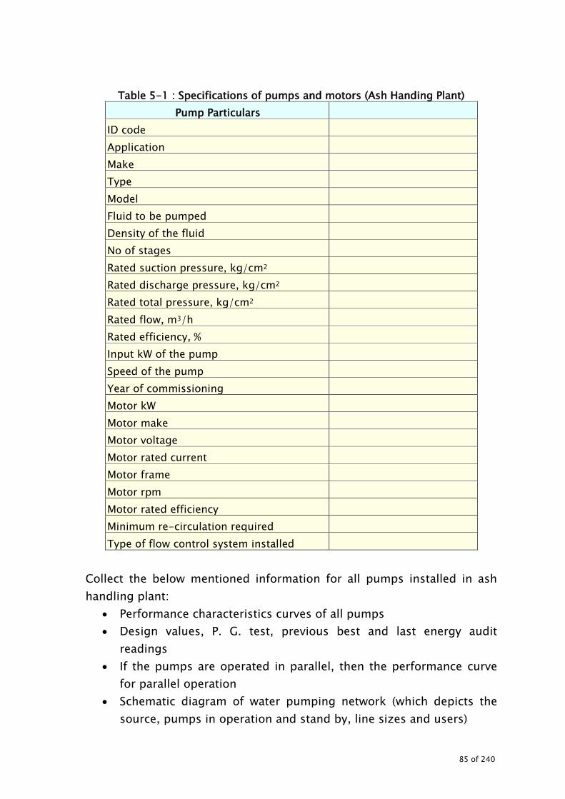
Table 5-1 : Specifications of pumps and motors (Ash Handing Plant)
Pump Particulars ID code Application Make Type Model Fluid to be pumped Density of the fluid No of stages Rated suction pressure, kg/cm2 Rated discharge pressure, kg/cm2 Rated total pressure, kg/cm2 Rated flow, m3/h Rated efficiency, % Input kW of the pump Speed of the pump Year of commissioning Motor kW Motor make Motor voltage Motor rated current Motor frame Motor rpm Motor rated efficiency Minimum re-circulation required Type of flow control system installed
Collect the below mentioned information for all pumps installed in ash handling plant:
• Performance characteristics curves of all pumps • Design values, P. G. test, previous best and last energy audit
readings • If the pumps are operated in parallel, then the performance curve
for parallel operation • Schematic diagram of water pumping network (which depicts the
source, pumps in operation and stand by, line sizes and users)
85 of 240

• Water and pressure equipments at the users as per the design requirements
• Brief description of the pumping, with brief specifications, where pumps are used
5.3.1 Instruments required The following instruments are required for conducting ash handling plant audit
• Power analyzer: Used for measuring electrical parameters such as kW, kVA, pf, V, A and Hz
• Temperature indicator and probe • Pressure gauge: To measure operating pressure and pressure drop
in the system • Stroboscope: To measure the speed of the driven equipment and
motor • The above instruments can be used in addition to the calibrated
online / plant instruments 5.3.2 Parameters to be measured While conducting audit, the following measurements and observations are necessary:
• Energy consumption pattern of pumps (daily / monthly /yearly consumption)
• Motor electrical parameters (kW, kVA, Pf, A, V, Hz, THD) for individual pumps
• Water supply rate to ash handling system • Water velocity • Operating parameters to be monitored for each pump as namely: Discharge Head (suction and discharge) Valve position Temperature Load variation Simultaneous power parameters of pumps Pumps operating hours and operating schedule Pressure drop in the system (between discharge and user point) Pressure drop and temperature across the users (heat
86 of 240

exchangers, condensers, etc) Pump / motor speed Actual pressure prevailing and required water pressure at the
user end User area pressure for operational requirement
• While conducting the measurement or performance evaluation of
any system simultaneously, the following need to be noted Unit load of the plant Date and time of measurement Instruments used for measurement Frequency of measurement
5.3.3 System details Detailed interactions with the plant personnel have to be carried out to get familiarisation for system detail and operational details. The system needs to be briefed in the report. 5.3.4 Energy and water consumption pattern If the plant is monitoring the energy and water consumption, it is suggested to record the data and daily and monthly consumption pattern. The past energy consumption data should be collected (month wise for at least 12 months, daily consumption for about one week of different seasons and daily consumption during the audit period). Typical format is shown in Table 5-2.
Table 5-2 : Energy and water consumption and ash generation
Month Energy
consumption, MWh
Fly ash, Mt
Bottom Ash, Mt
Total Ash, Mt
Water consumption, m3
The total energy consumption of pumping system should be worked out to arrive at percentage to the total consumption of the auxiliary consumption.
87 of 240

In case the energy meters are not installed with water pumps and its auxiliary units, instantaneous measurements can be carried out based on the loading pattern and the daily consumption can be worked out (Table 5-3).
Table 5-3 : Energy consumption of pumps Equipment Instantaneous kW Daily consumption, kWh
The energy consumption of pumping system in ash handling plant : kWh Total auxiliary power consumption of the unit : kWh Percentage of total auxiliary consumption : % 5.3.5 Operating efficiency and performance evaluation of the pumps All pumps need to be studied for its operating efficiency with the aid of energy audit instruments in addition to online valid calibrated instruments to identify the energy saving measures. The parameters to be studied in detail are:
• Water flow rates and pressures of pumps / headers • Velocity in the main headers (to verify that lines and headers are
adequately sized) • Power consumption of pumps (for estimating the operating
efficiency of the pumps) • Present flow control system and frequency of control valve
operation if any The following Table 5-4 gives the list of parameters to be considered for performance evaluation.
Table 5-4 : Performance parameters for water pumps
Particulars Unit Design/ PG test value
Actual Remarks
Unit load Pump ID code
88 of 240

Particulars Unit Design/ PG test value
Actual Remarks
Pump application Fluid pumped Density of the fluid No of stages Suction head Discharge head Total head developed by pump Water flow Speed of the pump/ motor Input kW to the pump - Input kW of the motor - Hydraulic kW Combined efficiency Motor efficiency (refer to motor performance curve)
Pump efficiency Type of flow control mechanism Discharge throttle valve position % open
Flow control frequency and duration if any
% loading of pump on flow % loading of pump on head % loading of motor
In addition, the pumps need to be observed for the following in case their efficiency is low:
• Suction abstractions • Impeller pitting • Shaft alignment • Throttle control • Re-circulation • Clearances • Bearing condition • Inter-stage leakages
89 of 240

Hydraulic power can be calculated using the following formula:
1000)s/m( g*)m/kg(*)m( )hh( head total*)s/m( QkW Hydraulic
23sd
3 ρ−=
Where Parameters Units
Q Water flow rate m3/s Total head
Difference between discharge head (hd) and suction head ( hs )
m
ρ Density of the water or fluid being pumped kg/m3 g Acceleration due to gravity m/s2
If the pumps are operating in parallel, it is necessary to measure all the above parameter for every pump separately to evaluate the pump performance. However, combined parameters of flow and head need to be verified with performance curve for parallel operation. Compare the actual values with the design / performance test values and, if any deviation is found, list the factors with the details and suggestions to over come.
• Compare the specific energy consumption with the best achievable value (considering the different alternatives). The investigations should be carried out for problematic areas.
• Enlist scope of improvement with extensive physical checks / observations.
• Based on the actual operating parameters, provide recommendations for action to be taken for improvement,
• Conduct cost analysis with savings potential with improvement measures implemented.
5.3.6 Measurement of electrical parameters and motor loading • Measure the electrical input parameters like A, V, kW, KVA, Pf, Hz and
tabulate. (as shown in Table 5-5). The energy measurements should be done for at least one hour for each equipment.
• Note the average operating hours for all the equipments. • Determine equipment wise motor percentage loading.
= loadingmotor % 100) () ( xinputRated
kwinputActual = FL
kwinputActualηkw/ Rated
90 of 240

Table 5-5 : Motor loading parameters
Motor Application
INPUT
ID code Rated kW A V kW kVA pf Hz % Loading
5.3.7 Ash water/ ash slurry water pressure and flow measurement Carryout the measurement of pressure and water flow rates and compare with the design / PG test values (Refer Table 5-6).
Table 5-6 : Comparison of design and actual water flow and pressure Water System Design Actual
Flow, m3/h
Pressure, kg/cm2
Flow, m3/h
Pressure, kg/cm2
Ash water Ash slurry water
5.3.8 Evaluation of ash to water ratio Calculate the ash generation based on coal consumption rate and ash content in the coal. (Refer Table 5-7).
Table 5-7 : Comparison of design and actual parameters
Parameter Unit Fly ash
Bottom ash
Combined
Design ash generation tph Actual ash generation tph Design ash to water ratio Actual ash to water ratio (based on lab test or flow measurement)
Design density of slurry ton/m³ Actual density of slurry ton/m³ Total energy consumption of pump kWh Specific energy consumption, kWh/Ton of ash evacuation
kWh/ton
Design ash evacuation rate, tph tph Actual ash evacuation rate tph Recommended ash slurry velocity m/min
91 of 240

Parameter Unit Fly ash
Bottom ash
Combined
Actual ash slurry velocity m/min Design head drop in ash slurry pipe line
kg/cm²
Actual head drop in ash slurry pipe line
kg/cm²
Existing ash to water ratio can be obtained based on ash slurry samples collected. Reduction in dilution shall result into energy savings in case of ash water pumps and ash slurry pumps apart from water savings. Concentration of slurry is given by:
waterofweight Ash ofWeight Ash ofWeight slurry of ionConcentrat
+=
5.3.9 Adequacy of pipe sizes of ash slurry lines Adequacy of line sizes of ash slurry lines can be checked by comparing the present velocity with the design / desired velocity. Velocity can be measured by using portable flow meter or by calculation if the slurry flow rate and diameter of the pipe is known. If diameter of pipe is known their velocity can be calculated as follows:
2d
Q4v∏
∗=
where: Q = Flow of ash slurry (m3/sec.) V = Velocity (m/sec.) max. value for slurry is 2.8 m/sec. d = Diameter of pipe (m)
Head drop in ash slurry pipe line
167.1852.1
852.1
dCv3.6895H
∗
∗=
⋅
Where:
92 of 240

H = Head drop ash slurry pipe line (m / km) V = Velocity (m/sec.) d = Internal diameter (mm) OD = Outer diameter (mm) T = Thickness of pipe line (mm)
(Max thickness of ash slurry pipeline is 9.52mm)
5.3.10 Exploration of energy conservation possibilities While conducting the energy audit of pumping, the following aspects need to be explored in detail:
• Optimisation / improving the ash to water ratio • Possibilities of reducing the operating hours of the AHP • Adequacy of pipe sizes • Rationalisation of pressures • Improvement of pumping systems and drives.
Use of energy efficient pumps Replacement of inefficient pumps Use of high efficiency motors: Use of high performance lubricants: The low temperature
fluidity and high temperature stability of high performance lubricants can increase energy efficiency by reducing frictional losses.
Booster pump application • Measuring and tracking system performance: • Measuring water use and energy consumption is essential for
determining whether changes in maintenance practices or investment in equipment could be more cost effective in total auxiliary power consumption.
6.0 WATER PUMPING
93 of 240
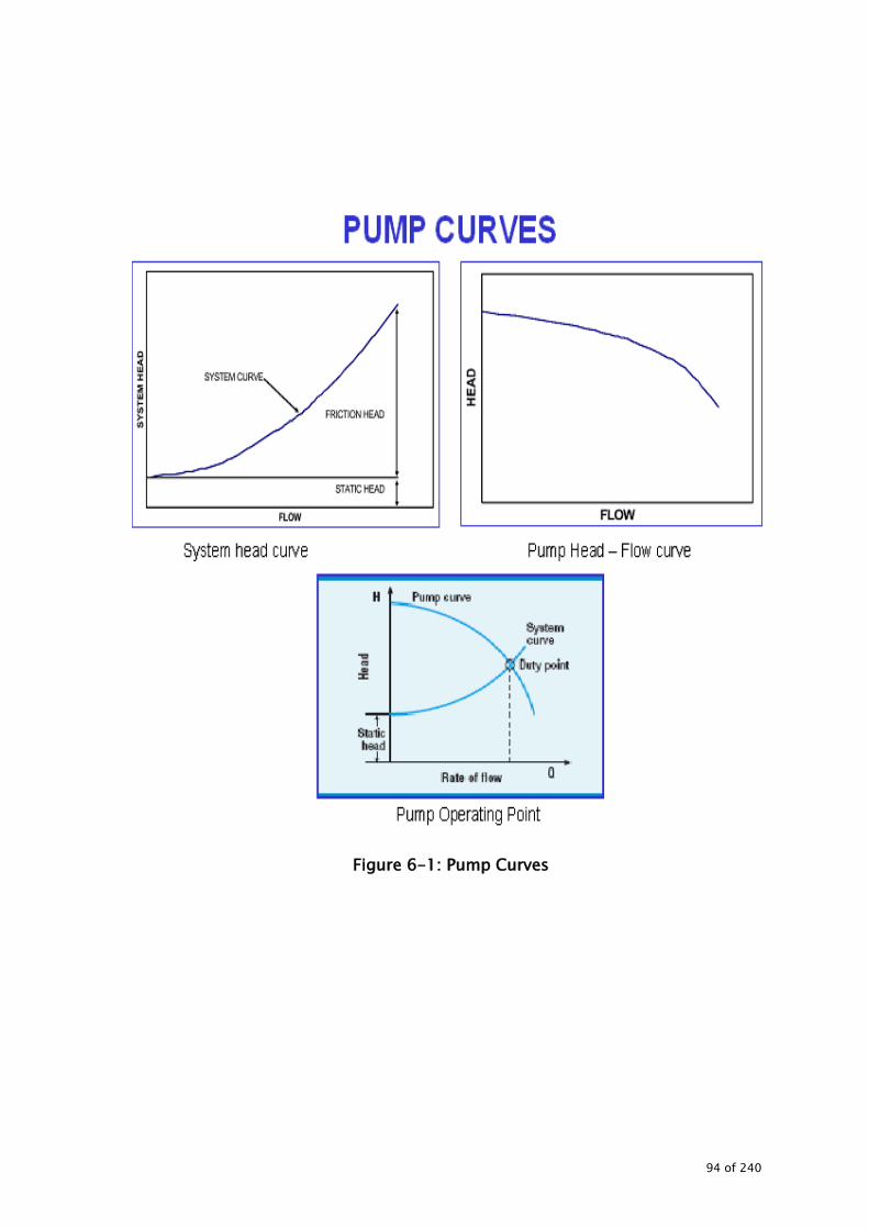
Figure 6-1: Pump Curves
94 of 240
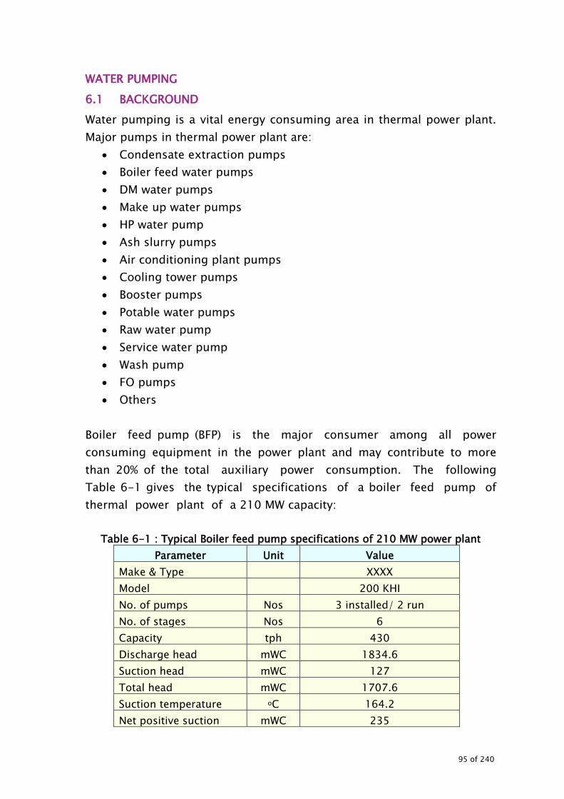
WATER PUMPING 6.1 BACKGROUND Water pumping is a vital energy consuming area in thermal power plant. Major pumps in thermal power plant are:
• Condensate extraction pumps • Boiler feed water pumps • DM water pumps • Make up water pumps • HP water pump • Ash slurry pumps • Air conditioning plant pumps • Cooling tower pumps • Booster pumps • Potable water pumps • Raw water pump • Service water pump • Wash pump • FO pumps • Others
Boiler feed pump (BFP) is the major consumer among all power consuming equipment in the power plant and may contribute to more than 20% of the total auxiliary power consumption. The following Table 6-1 gives the typical specifications of a boiler feed pump of thermal power plant of a 210 MW capacity:
Table 6-1 : Typical Boiler feed pump specifications of 210 MW power plant
Parameter Unit Value Make & Type XXXX Model 200 KHI No. of pumps Nos 3 installed/ 2 run No. of stages Nos 6 Capacity tph 430 Discharge head mWC 1834.6 Suction head mWC 127 Total head mWC 1707.6 Suction temperature oC 164.2 Net positive suction mWC 235
95 of 240

Parameter Unit Value Minimum re- circulation
tph 80
Pump efficiency % 75.0 Pump speed rpm 4320 Input power to pump kW 2900 Motor rating kW 4000 Motor input kW kW 4145 Motor efficiency % 96.5 Motor speed Rpm 1485 Rated voltage & amps kV & A 6.6 & 421
mWC: meter of water column
6.2 STEPS INVOLVED IN CONDUCTING ENERGY AUDIT The steps involved in conducting energy audit water pumping systems are:
• Data collection • Measurements and observations • Exploration for energy conservation measures • Report preparation
6.3 DATA COLLECTION 6.3.1 Specifications and design details Collect the design specification of water pumps and motors as indicated in Table 5-1 in previous section. 6.3.2 Instruments required For details refer para 5.3.1
6.3.3 Parameters to be measured For details refer para 5.3.2
6.4 OBSERVATIONS AND MEASUREMENTS The following tests should be carried out during the energy audit of water pumping system.
• Operating efficiency and performance evaluation of pumps • Flow distribution of water to the condensers and cooling towers
(preparation of Sankey diagram)
96 of 240
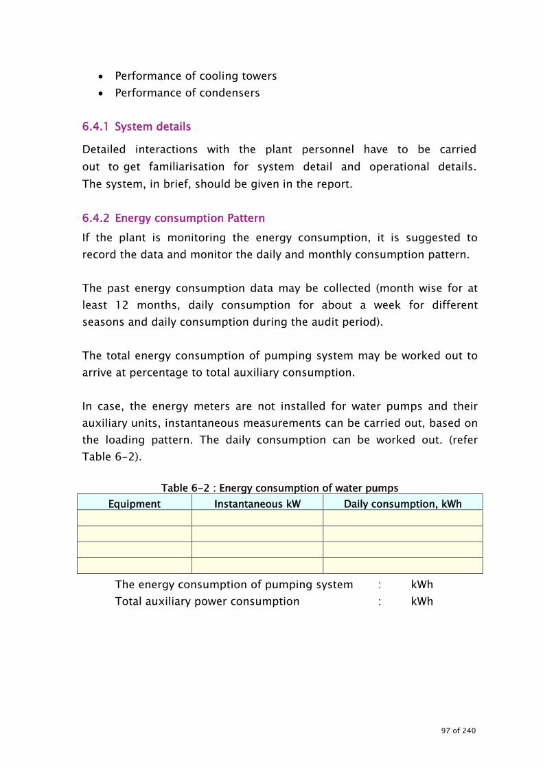
• Performance of cooling towers • Performance of condensers
6.4.1 System details
Detailed interactions with the plant personnel have to be carried out to get familiarisation for system detail and operational details. The system, in brief, should be given in the report. 6.4.2 Energy consumption Pattern If the plant is monitoring the energy consumption, it is suggested to record the data and monitor the daily and monthly consumption pattern. The past energy consumption data may be collected (month wise for at least 12 months, daily consumption for about a week for different seasons and daily consumption during the audit period). The total energy consumption of pumping system may be worked out to arrive at percentage to total auxiliary consumption. In case, the energy meters are not installed for water pumps and their auxiliary units, instantaneous measurements can be carried out, based on the loading pattern. The daily consumption can be worked out. (refer Table 6-2).
Table 6-2 : Energy consumption of water pumps
Equipment Instantaneous kW Daily consumption, kWh
The energy consumption of pumping system : kWh Total auxiliary power consumption : kWh
97 of 240

Figure 6-2: BFP Arrangement
All pumps need to be studied for their operating efficiency with the aid of energy audit instruments in addition to online valid calibrated instruments to identify the energy saving measures. The parameters to be studied in detail are:
• Water flow rates and pressures of pumps / headers • Velocity in the main headers (to verify that the lines sizes and
headers are adequately sized) • Power consumption of pumps (for estimating the operating
efficiency of the pumps) • Monitor present flow control system and frequency of control valve
operation if any (for application of variable speed drives)
The list of parameters to be considered for performance evaluation are given in Table 5-4 in previous section.
6.4.3 Operating efficiency and performance evaluation of the pumps In addition, the parameters for all pumps need to be observed for the following in case their efficiency is low:
• Suction abstractions
98 of 240

• Impeller pitting • Shaft alignment • Throttle control • Re circulation • Clearances • Bearing condition • Strainer condition • Inter stage leakages
If the pumps are operating in parallel, it is advised to measure all the above parameters for every pump separately to evaluate the pump performance. However, combined parameters of flow and head need to be verified with reference to performance curve for parallel operation The actual values should be compared with the design / performance test values. If any deviation is found, the factors with the details should be listed and suggestions given to over come the deficiencies.
• Compare the specific energy consumption with the best achievable value (considering the different alternatives). Investigations should be carried out for problematic areas.
• Enlist scope of improvement with extensive physical checks / observations.
• Based on the actual operating parameters, provide recommendations for action to be taken for improvement, if applicable such as Replacement of pumps Impeller replacement Impeller trimming Variable speed drive application, etc
• Perform cost analysis with savings potential for taking improvement
measures. • Hydraulic power can be calculated by using the following formula:
1000)s/m( g*)m/kg(*)m( )hh( head total*)s/m( QkW Hydraulic
23sd
3 ρ−=
where
99 of 240

Parameters Unit Q Water flow rate m3/s Total head
Difference between discharge head (hd) and suction head (hs )
M
ρ Density of the water or fluid being pumped kg/m3 g Acceleration due to gravity m/s2
6.4.4 Flow distribution to the major users and water balance Detailed water balance to be carried out to:
• Assess circulation and consumption for various applications such as raw water, clarified/service water consumption, DM water, make up water
• Identify areas of water savings and associated energy conservation possibilities.
• Evaluate the performance of various pumps associated with different water supply systems of the plant.
• Evaluate specific power consumption kW/m3 of all water pumps. • Evaluate water losses in the system. • Evaluate energy losses in the system.
Water balance study primarily consists of total water balancing of following: -
• Raw water • Makeup water • Circulating water. • Ash water • Service water • DM water • Colony water etc.
It is recommended to do this study in two parts. • Unit as a whole • Study of specific system • Conduct the survey for leakage assessment and prepare a defect
list
100 of 240
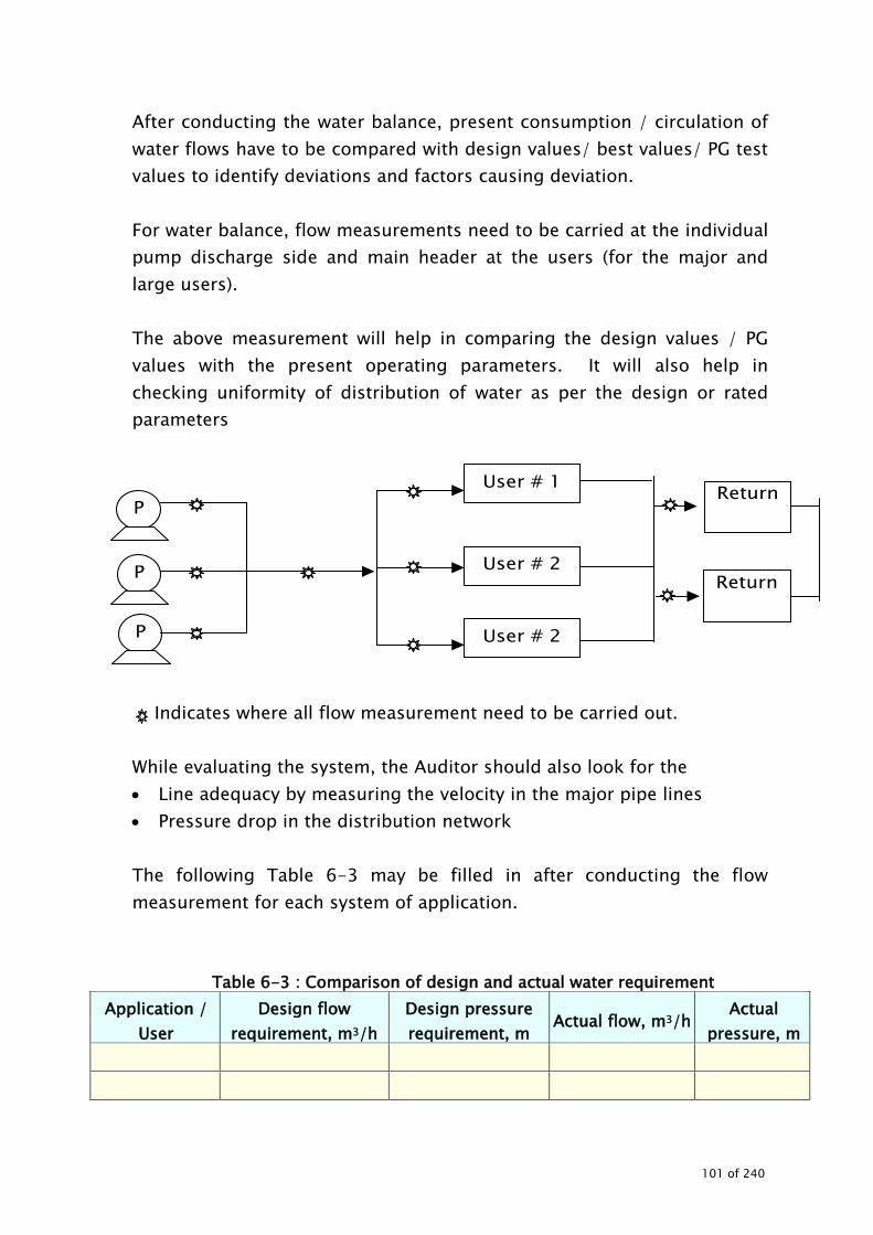
After conducting the water balance, present consumption / circulation of water flows have to be compared with design values/ best values/ PG test values to identify deviations and factors causing deviation. For water balance, flow measurements need to be carried at the individual pump discharge side and main header at the users (for the major and large users). The above measurement will help in comparing the design values / PG values with the present operating parameters. It will also help in checking uniformity of distribution of water as per the design or rated parameters
Indicates where all flow measurement need to be carried out. While evaluating the system, the Auditor should also look for the • Line adequacy by measuring the velocity in the major pipe lines • Pressure drop in the distribution network The following Table 6-3 may be filled in after conducting the flow measurement for each system of application.
Table 6-3 : Comparison of design and actual water requirement Application /
User Design flow
requirement, m3/h Design pressure requirement, m
Actual flow, m3/h Actual
pressure, m
P
P
P
User # 1
User # 2
User # 2
Return
Return
101 of 240

The above comparison will help in optimising the systems for • Flow and pressure • Scope for booster pump requirement • Scope for decentralisation / centralisation • Correct sizing of the pumps
6.4.5 Pressure drop in the system All pumping systems need to be observed for the pressure drop by simultaneously monitoring the discharge /header pressure and pressure at the major users. The pressure drop may be compared with the acceptable values to arrive at options to reduce the same 6.4.6 Application and matching of the pump Installed pump should be thoroughly verified for its application i.e. whether the pump is best suited for the application, duty, load variation, etc. The various options to be considered to improve energy efficiency are:
• Replacement of present pump with best suited energy efficient pump
• Replace or trim the impeller, if the pump is throttled to reduce the flow by 10-20%. (where a smaller impeller is not available, the impeller may be trimmed in consultation with the manufacturers)
• Retrofit with variable speed drives pumps if the pumps are serving variable loads
6.4.7 Exploration of energy conservation possibilities While conducting the energy audit of the pumping, the following need to be explored in detail for:
• Improvement of systems and drives. • Use of energy efficient pumps • Replacement of inefficient pumps • Trimming of impellers • Correcting inaccuracies of the pump sizing • Use of high efficiency motors • Integration of variable speed drives into pumps: The integration of
adjustable speed drives (ASD) into pumps could lead to energy efficiency improvements, depending on load characteristics.
102 of 240

• Use of high performance lubricants: The low temperature fluidity and high temperature stability of high performance lubricants can increase energy efficiency by reducing frictional losses.
• Booster pump application • Centralisation/decentralisation • Categorising according to the pressure requirement
The energy conservation opportunities with different energy saving measures are depicted below diagrammatically.
103 of 240

6.4.8 Measuring and tracking system performance Measurement of water usage and energy consumption is essential in determining whether changes in maintenance practices or investment in equipment could be more cost effective.
104 of 240

In this case, it is advised to monitor the water flow rate, temperature and pressures across the major users periodically i.e. at least once in three months and energy consumption on daily basis. This will help in identifying the:
• Deviations in water flow rates • Heat duty users • Measures to improve the performance • System Effect Factors Equipment cannot perform at capacity, if pumps have poor inlet
and outlet conditions. Correction of system effect factors (SEFs) can have a significant effect on performance and energy savings.
Elimination of cavitation: Flow, pressure, and efficiency are reduced in pumps operating under cavitation. Performance can be restored to manufacturer’s specifications through modifications. This usually involves inlet alterations and may involve elevation of a supply tank.
Internal running clearances: The internal running clearances between rotating and non-rotating elements strongly influence the turbo machine's ability to meet rated performance. Proper setup reduces the amount of leakage (recirculation) from the discharge to the suction side of the impeller.
Reducing work load of pumping: Reducing of obstructions in the suction / delivery pipes thereby
reducing frictional losses. This includes removal of unnecessary valves of the system. System and layout changes may help in this including increased pipe diameter.
Replacement of components which have deteriorated due to wear and tear during operation,
Modifications in piping system After the identification of energy conservation measures, detailed techno-economic evaluation has to be carried out.
105 of 240
7.0 FANS
Power Station Fan
106 of 240
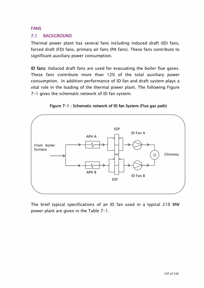
FANS 7.1 BACKGROUND Thermal power plant has several fans including induced draft (ID) fans, forced draft (FD) fans, primary air fans (PA fans). These fans contribute to significant auxiliary power consumption. ID fans: Induced draft fans are used for evacuating the boiler flue gases. These fans contribute more than 12% of the total auxiliary power consumption. In addition performance of ID fan and draft system plays a vital role in the loading of the thermal power plant. The following Figure 7-1 gives the schematic network of ID fan system.
Figure 7-1 : Schematic network of ID fan System (Flue gas path)
The brief typical specifications of an ID fan used in a typical 210 MW power plant are given in the Table 7-1.
From boiler furnace
APH A
APH B
Chimney
ID Fan A
ID Fan B ESP
ESP
107 of 240
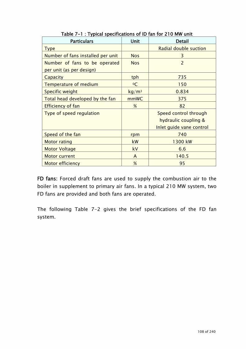
Table 7-1 : Typical specifications of ID fan for 210 MW unit Particulars Unit Detail
Type Radial double suction Number of fans installed per unit Nos 3 Number of fans to be operated per unit (as per design)
Nos 2
Capacity tph 735 Temperature of medium 0C 150 Specific weight kg/m3 0.834 Total head developed by the fan mmWC 375 Efficiency of fan % 82 Type of speed regulation Speed control through
hydraulic coupling & Inlet guide vane control
Speed of the fan rpm 740 Motor rating kW 1300 kW Motor Voltage kV 6.6 Motor current A 140.5 Motor efficiency % 95
FD fans: Forced draft fans are used to supply the combustion air to the boiler in supplement to primary air fans. In a typical 210 MW system, two FD fans are provided and both fans are operated. The following Table 7-2 gives the brief specifications of the FD fan system.
108 of 240

Table 7-2 : Typical specifications of Forced draft fans for 210 MW unit
Reference Particulars Type Axial reaction No of fans installed per unit 2 No of fans in operation 2 Orientation Horizontal Type of fan regulation Variable pitch control Capacity 105 m3/s ( 405 tph ) Total head developed 495 mmWC Type / temperature of medium Clean air / 500C (max.) Specific wt. of medium 1.069 kg/m3 Speed 1480 rpm Type of coupling Rear coupling with intermediate shaft Make BHEL Type Induction Motor Rating 800 kW Motor Voltage 6.6 kV Motor current 85.4 A Motor efficiency 93.7% Speed 1490 rpm
PA fans: Primary air fans are the second high power consuming fans in a thermal power plant. Though the quantity of air delivered by the PA fans is less as compared to FD fans, the discharge air pressure is high, since primary air fans are used for atomisation of fuel. The following Table 7-3 gives the brief specifications (typical values for 210 MW power plant) of the PA fan system.
109 of 240

Table 7-3 : Typical specifications of PA fans for 210MW unit Reference Particulars
No of fans installed Two No of fans operated Two Type Radial, single suction Orientation Delivery bottom horizontal Type of fan regulation Inlet Guide Vane (IGV) Capacity 67.5 M3 / Sec. Total head developed 1375 mmWC Application Clean air Temperature 500C (max.) Specific weight of the medium 1.109 kg/m3 Speed of the fan 1480 rpm Fan drive coupling Pin type Make BHEL Type Induction Motor rating 1250 kW Motor voltage 6.6 kV Motor current 132 A Motor efficiency 94.1% Motor speed 1490 rpm
In addition to the above, the audit study should cover all major fans installed in the power plants. The selection of fans for the study can be done based on the following criteria
• Application and number of fans installed and operated • KW rating of fan • Operating hours • Significance of power consumption on total power • Potential of energy savings and application potential for energy
saving retrofits 7.2 STEPS INVOLVED IN CONDUCTING THE ENERGY AUDIT The steps involved in conducting energy audit are:
• Data collection • Observations and analysis • Exploration for energy conservation measures • Report preparation
110 of 240
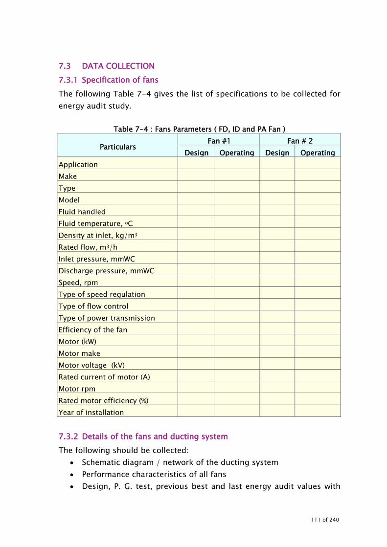
7.3 DATA COLLECTION 7.3.1 Specification of fans The following Table 7-4 gives the list of specifications to be collected for energy audit study.
Table 7-4 : Fans Parameters ( FD, ID and PA Fan )
Particulars Fan #1 Fan # 2
Design Operating Design Operating Application Make Type Model Fluid handled Fluid temperature, oC Density at inlet, kg/m3 Rated flow, m3/h Inlet pressure, mmWC Discharge pressure, mmWC Speed, rpm Type of speed regulation Type of flow control Type of power transmission Efficiency of the fan Motor (kW) Motor make Motor voltage (kV) Rated current of motor (A) Motor rpm Rated motor efficiency (%) Year of installation 7.3.2 Details of the fans and ducting system The following should be collected:
• Schematic diagram / network of the ducting system • Performance characteristics of all fans • Design, P. G. test, previous best and last energy audit values with
111 of 240

respect to fans and draft system which include excess air • If the fans are operated in parallel, then it is advised to collect the
performance curve for the parallel operation • Air quality and pressure equipments at the users as per the design
requirements 7.4 INSTRUMENTS REQUIRED The following instruments are required for conducting the energy audit of fan:
• Power Analyser: Used for measuring electrical parameters such as kW, kVA, pf, V, A and Hz
• Temperature indicator and Probe • Stroboscope: To measure the speed of the driven equipment and
motor • Sling hygrometer or digital hygrometer • Anemometer • On line instruments – (calibrated) • Digital manometer of suitable range and appropriate probes for
measurement of pressure head and velocity head. • Pitot tubes • Additional pressure gauges with appropriate range of measurement
and calibrated before audit.
7.5 MEASUREMENTS AND OBSERVATIONS TO BE MADE While conducting the audit, the following measurements and observations need to be carried out.
• Energy consumption pattern of fans • Motor electrical parameters (kW, kVA, Pf, A, V, Hz, THD) of fans • Fan operating parameters to be measured/monitored for each fan
are: Discharge / flow rates Pressure (suction & discharge)
• Static pressure • Dynamic pressure • Total pressure
Damper position / guide vane position/ VSD setting Temperature of fluid handled
112 of 240
Load variation Power parameters of fans Fan operating hours and operating schedule Pressure drop in the system (between discharge and user
point) Pressure drop and temperatures drop across the equipment Fan /motor speed
• Oxygen content, flow, temperature and pressure measurement across in exhaust gas path Before and after air preheater Before and after economiser Before and after ID fan Before and after ESP In case where flow measurement (for air preheater and ESP) is
not possible, it can be estimated based on mass balance principles, stochiometric analysis, etc.
• While conducting the measurement or performance evaluation any system simultaneously, the following should to be noted Unit load of the plant Date and time of measurement Instruments used of measurement Frequency of measurement
7.6 OBSERVATIONS AND ANALYSIS 7.6.1 System familiarisation and operational details Detailed interactions with the plant personnel have to be carried out to get familiarisation for system detail and operational details. The brief details of the entire system should be given in the report. 7.6.2 Energy consumption Pattern If the plant is monitoring the energy consumption, it is suggested to record the data and monitor the daily and monthly consumption pattern. The past energy consumption data should be collected (month wise for at least 12 months, daily consumption for about a week for different seasons, daily consumption during the audit period).
113 of 240

The total consumption of fans should be worked out to arrive at percentage to the total consumption of the auxiliary consumption. If energy meters are not installed with fans, instantaneous measurements can be carried out, based on the loading pattern and the daily consumption can be worked out (as shown in Table 7-5).
Table 7-5 : Energy consumption pattern Equipment Instantaneous kW Daily consumption, kWh
ID fans FD fans PA fans Others fans Total 7.6.3 Operating efficiency and performance evaluation of the fans All fans need to be studied for their operating efficiency (as run performance test) with the aid of sophisticated energy audit instruments in addition to online valid calibrated instruments to identify the energy saving measures. The parameters to be studied in detail are:
• Air /gas rates of fans / main ducts • Static pressure and dynamic pressure and total pressure • Power consumption of fan (for estimating the operating efficiency
of the fan) • Present flow control system and frequency of control valve
operation if any (for application of variable speed drives) Table 7-6 gives the list of parameters to be considered for performance evaluation.
114 of 240

Table 7-6 : Performance parameters for fans
Particulars Unit Design/
PG test value Actual
Remarks 1 2 3 Avg
Date & time Load Frequency Hz Fan ID code Fan application Fluid pumped Temperature of fluid Suction side Static Pressure Dynamic Pressure Total Pressure Discharge side Static Pressure Dynamic Pressure Total Pressure Total static pressure developed by the fan
Air/ gas flow rate Type of flow control mechanism
Discharge position (% open) Flow control frequency and duration if any
Air kW - Power consumption, kW (Input power to motor)
Motor efficiency (Refer to motor performance curve)
Fan static efficiency % % Loading of fans on flow % Loading of fans on head % Loading of motor Specific energy consumption, kWh/tph
kWh/tph
115 of 240

Fan static kW can be calculated by using the following formula:
102mmWCin fan by developed pressure static x m3/sin Q kW StaticFan =
where Q - Air flow rate in m3/s Static pressure - Difference between discharge and suction in mmWC
Fan static efficiency can be calculated by:
m *motor kW toInput 100*kW Static Fanefficiency staticFan
η=
where Fan static kW - Static power consumption of the fan in kW Input to motor - Measured power consumption of the motor in kW ɳm - Efficiency of the motor at the operating load in %
Fan total kW can be calculated by using the following:
102 WCmmin fan by the developed pressure x totalm3in Q kW Fan total =
Where Q - air flow rate in m3/s Total pressure - Difference between discharge and suction in mmwc
Fan mechanical efficiency can be calculated by
mmotor *motor kW toinput 100 *kW Fan total (%) efficiency mechanicalFan
η=
Where Fan total kW - Total power consumption of the fan in kW Input kW to motor - Measured power consumption of the motor in kW ɳm - Efficiency of the motor at the operating load in %
116 of 240

Corrected air density can be calculated by:
Cin atureAir temper 273293.1*273DensityAir Corrected
+=
Once the air density and velocity pressure (dynamic pressure is established), the velocity can be determined by:
γγ
=* WCmmin pressure velocity alDifferenti*9.81*2* Cp
s/m in Velocity
Where Cp Pitot tube constant - 0.85 or as given by the manufacturer γ Density of air or gas at test condition in kg/m3
In case of gas flow measurement of ID fans, where it is not possible to measure the gas flow, the mass flow method can be adopted, provided that the oxygen content and actual coal flow measurements are available. For flow estimation through this method, the following are required:
• Stoichiometric air requirement (work out based on the coal composition)
• Oxygen content at ID fan inlet (measured) • Excess air (estimate) • Coal flow (based on actual measurement or on average basis) • Fly ash content (assumed based on past data)
Excess air can be estimated by:
100*gas fluein % O -21
gas fluein O %air Excess %2
2=
For air flow measurement for FD and PA fans, the following instruments (which ever are suitable) can be used
• Thermal anemometer • Vane type anemometer • Pitot tube along with micro manometer can be used • Online measuring instrument
117 of 240

If the fans are operating in parallel, it is advised to measure all above parameters for every fan separately to evaluate the individual performance. However, combined parameters of flow and head need to be verified with performance curve for parallel operation. The actual values should be compared with the design / performance test values. If any deviation is found, the factors should be listed with details and suggestions given to over come the deficiencies.
• The investigations for abnormality should be carried out for problems.
• List the scope of improvement with extensive physical checks / observations.
• Based on the actual operating parameters, list recommendations for action to be taken for improvement, as applicable such as: Replacement of fans Impeller replacement Variable speed drive application, etc
• Cost analysis with savings potential for taking improvement measures should be worked out.
7.6.4 Visual survey and insulation survey of the ducting system A visual survey of the ducting and insulation system should be made for:
• Insulation status (measure the surface temperature with the aid of surface thermocouple / infrared pyrometer or by using thermal imaging cameras)
• Bends and ducting status • Physical condition of insulation • Identification of locations where action is required to improve the
insulation (provide detailed techno-economics analysis) • Improvement options for ducting systems if any • Sources of air infiltration
Procedure for conducting the energy audit of insulation is given separately.
118 of 240

7.6.5 Study of air infiltration in to the system Air infiltration in the system has high adverse impact on the boiler loading, efficiency, power consumption of the fans, plant load factor etc. It is suggested to check for air infiltration in to the system periodically (once in a month by monitoring oxygen content at the following sections:
• Before and after air pre heater • Before and after ESP • Before and after ID fan
The difference in the oxygen gives the extent of air filtration in to the system. Measurements of oxygen content across all units in flue gas path, indicates the locations where infiltration is occurring. Based on the oxygen content, coal flow and stoichiometric air requirement (in case where measurement of air flow across all units in the flue gas path is not possible) the flue gas quantity can be estimated. These flue gas quantities should be compared with the design/PG test or best-run values for that particular loading. The values should be tabulated as shown in Table 7-7.
Table 7-7 : Air infiltration in the system
Location Design O2 content %
Design Air flow rate,
kg/h
Actual O2 content %
Actual Air flow rate,
kg/h
Deviation / Remarks
Before Air preheater After air preheater
Before ESP
After ESP Before ID fan After ID Fan Based on the deviations, suitable suggestions for improvement can be arrived after detailed analysis. Reduction in air infiltration will result in
119 of 240

• Reduced power consumption of ID fans • Reduced boiler losses • Improvement in boiler loading • Increased unit load • Increased margins in ID fan • Several other system benefits
Minimising air in-leaks in hot flue gas path will reduce ID fan load as cold air in-leaks increase ID fan load tremendously, due to density increase of flue gases and in fact choke up the capacity of fan, resulting in a bottleneck 7.6.6 Application potential for variable frequency drives The application potential for variable speed drives in fans should be explored, by studying the load pattern and variation. Since most of the fans installed in power plants belong to high-tension category and installation of high-tension variable speed drives are very expensive, the following can be explored to reduce the investment. Adopt low-tension variable speed drive with the aid of step up and step down transformer. This may reduce the total investment cost significantly. The schematic network of the system is given below (Figure 7-2 ).
Figure 7-2 : Schematic diagram for LT VFD installation
HT supply
Step down transformer
LT variable speed drive
Step up transformer
LT supply
Frequency controlled HT supply
M
Fan motor
120 of 240
7.6.7 Belt tension and drive speed The Auditor may:
• Compare base load power for all fans. • Measure actual motor (drive) speed N1 and (with the help of
tachometer). • Measure the diameter of drive and driven pulley D1, D2. • Calculate theoretical value of driven rpm (N2)
N1D1=N2D2 • Measure actual driven rpm. (Na) by tachometer. • Calculate slip (N2-Na) • As per the result of slip, look for the possibility for lagging of
pulley, filling the grooves or changing the pulley. • Measure belt tension and recommend accordingly.
7.6.8 Application and matching of fan Installed fan has to be thoroughly verified for its application, whether the fan is best suited for the application, duty, load variation, etc. The various options to be considered for improvement in energy efficiency are:
• Replacement of present fan with best suited energy efficient fan • Replace / trim the impeller, if the fan is throttled to reduce the flow
by 10-20%. (where a smaller impeller is not available, the impeller may be trimmed in consultation with the manufacturers)
• Retrofit with variable speed drive fans if the fans are serving variable loads
7.6.9 Exploration of energy conservation possibilities While conducting energy audit of the cooling water system, the following need to be explored in detail for
• Use of energy efficient fans • Replacement of inefficient fans • Change of impeller with energy efficient impeller • Impeller derating • Correcting inaccuracies of the fan sizing • Use of high efficiency motors • Fan speed reduction by pulley dia modifications for de-rating • Option of two speed motors or variable speed drives for variable
duty conditions
121 of 240

• Use of high performance lubricants: The low temperature fluidity and high temperature stability of high performance lubricants can increase energy efficiency by reducing frictional losses.
• Use of energy efficient transmission systems (use of latest energy efficient transmission belts)
• Improvement in operations Minimising excess air level in combustion systems to reduce
FD fan and ID fan load. Minimising air in-leaks in hot flue gas path to reduce ID fan
load and cold air in-leaks Minimizing system resistance and pressure drops by
improvements in duct system Insulation aspects
• Measuring and tracking system performance: Measuring energy consumption is essential in determining whether changes in maintenance practices or investment in equipment could be cost effective. It is advisable to monitor the pressure, temperature, flow and power parameters periodically at least once in a three months and energy consumption on daily basis. This will help in identifying the
• Deviations in air flow rates • Measures to up keep the performance
After the identification of energy conservation measures, detailed techno-economic evaluation should be carried out. The relationships between different fan parameters are depicted graphically in Figure 7-3.
122 of 240

Figure 7-3 : Fan Laws
123 of 240
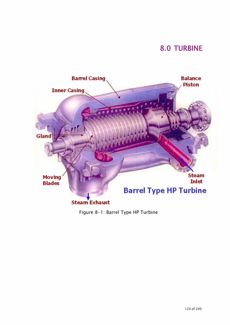
8.0 TURBINE
Figure 8-1: Barrel Type HP Turbine
124 of 240

TURBINE 8.1 BACKGROUND Steam turbine is a mechanical device that extracts thermal energy from pressurized steam, and converts it to useful mechanical work. The steam turbines are split into three separate stages, High Pressure (HP), Intermediate Pressure (IP) and Low Pressure (LP) stage. After the steam has passed through the HP stage, it is returned to the boiler to be re-heated to its design reheat temperature although the pressure remains greatly reduced. The reheated steam then passes through the IP stage and finally to the LP stage of the turbine. Steam turbines are generally configured in many different ways. Several IP or LP stages can be incorporated into one steam turbine. A single shaft or several shafts coupled together may be used. Either way, the principles are the same for all steam turbines. The configuration is decided by the use to which the steam turbine is put, co-generation or pure electricity production.
Figure 8-2: View of the internals of a typical power station steam turbine
Figure 8-3: Another view of the internals of a typical steam turbine
125 of 240

Power plant turbine to convert heat energy of steam in to mechanical work and torque on the rotor shaft is used to generate electrical power in the generator. The brief details of typical steam turbine (LMW or Russian design) used in a 210 MW thermal power plant are given in the Table 8-1.
Figure 8-4: Double Flow IP turbine
126 of 240

Figure 8-5: Double Flow LP turbine
Figure 8-6: Double Flow IP turbine
127 of 240
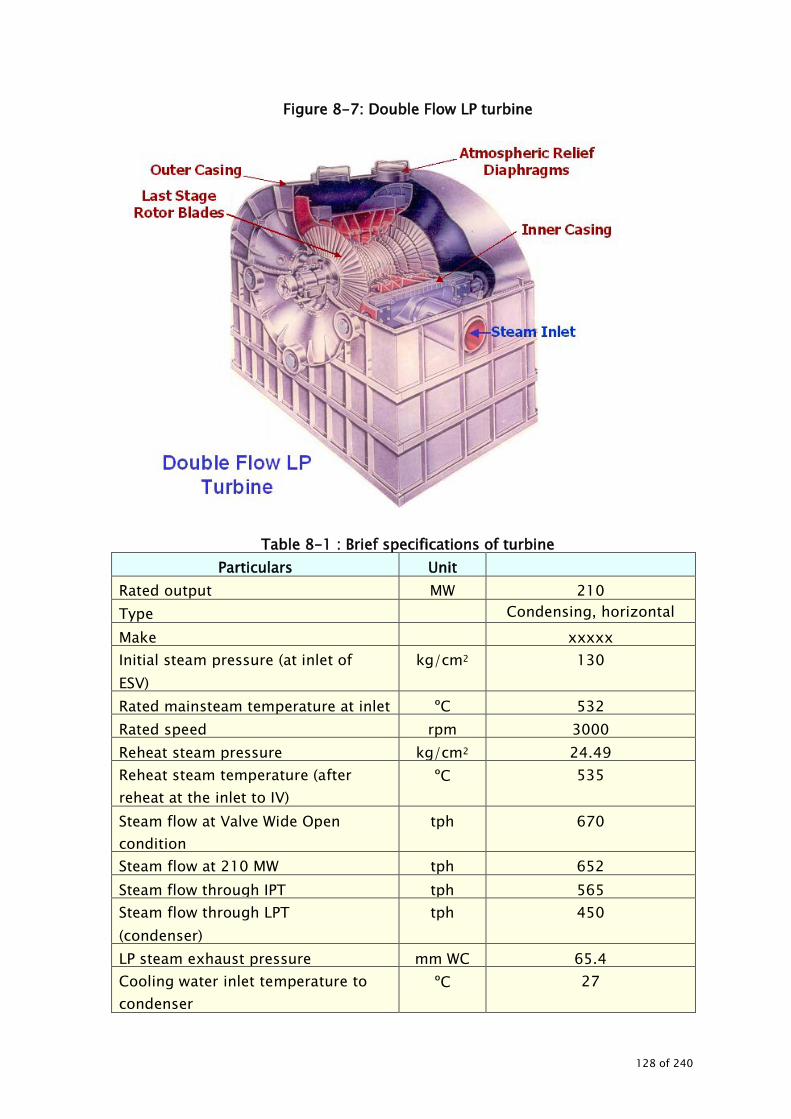
Figure 8-7: Double Flow LP turbine
Table 8-1 : Brief specifications of turbine Particulars Unit
Rated output MW 210 Type Condensing, horizontal Make xxxxx Initial steam pressure (at inlet of ESV)
kg/cm2 130
Rated mainsteam temperature at inlet ºC 532 Rated speed rpm 3000 Reheat steam pressure kg/cm2 24.49 Reheat steam temperature (after reheat at the inlet to IV)
ºC 535
Steam flow at Valve Wide Open condition
tph 670
Steam flow at 210 MW tph 652 Steam flow through IPT tph 565 Steam flow through LPT (condenser)
tph 450
LP steam exhaust pressure mm WC 65.4 Cooling water inlet temperature to condenser
ºC 27
128 of 240

Particulars Unit Cooling water flow through the condenser
m3/h 27000
Turbine Heat rate kcal/kWh
2040
Efficiency of the turbine cycle % 42.15 No of stages HP- 12
IP – 11 LP-08 (two flow of 4
each) Type of governing Nozzle type Type of sealing Steam sealing
Figure 8-8: Steam cycle for 210 MW unit
8.2 STEPS INVOLVED IN CONDUCTING THE ENERGY AUDIT The steps involved in conducting energy audit of turbines are:
• Data collection • Observations and analysis • Exploration for energy conservation measures • Report preparation
8.3 DATA COLLECTION
129 of 240

Table 8-2 gives brief typical specifications to be collected. 8.3.1 Specification of turbine and associated equipment 8.3.1.1 Turbine Collect the detailed design specifications of the turbine. The following Table 8-2 gives the specifications to be collected for energy audit study. In addition, following specific details may be obtained.
• Type of the turbine • Make and model • No of stages (for HP, IP and LP) • Number of cylinders • No of main and reheat valves • Construction details of HP, IP LP • Turbine extraction systems • Control systems • Type of governing • Type of sealing • Year of installation • Major modifications carried out during the recent past
Table 8-2 : Design specifications of turbine Particulars Unit MCR NCR
Rated output MW Turbine heat rate kcal/kWh Efficiency of the turbine cycle % Steam flow for rated output tph HP inlet steam pressure kg/cm2 HP inlet steam temperature ºC HP exhaust steam pressure kg/cm2 HP exhaust steam temperature ºC IP inlet steam pressure kg/cm2 IP inlet steam temperature ºC IP exhaust steam pressure kg/cm2 IP exhaust steam temperature ºC LP inlet steam pressure kg/cm2 LP inlet steam temperature ºC LP exhaust steam pressure kg/cm2 LP exhaust steam temperature ºC
130 of 240

Particulars Unit MCR NCR Condenser vacuum mmWC Cooling water inlet temperature of condenser ºC Cooling water outlet temperature of condenser
ºC
Cooling water flow through the condenser m3/h Super heater spray tph Reheater spray tph
8.4 INSTRUMENTS REQUIRED The following instruments are required for conducting turbine energy audit:
• Temperature indicator and sensors • Pressure gauges • Flow measuring instrument (water)- Ultrasonic • Ultrasonic leak detector (for condenser air leakage detection)
While conducting the turbine efficiency test, measurements of steam flow pressure and temperatures should be taken. Calibrated on line instruments can be used, also, for conducting the tests.
131 of 240

Figure 8-9: Steam Flow Diagram of a typical Steam Turbine of 210 MW
8.5 MEASUREMENTS While conducting the audit, the following measurements (temperature and pressure) are necessary:
• Feed water at inlet and outlet of heaters • Main steam • HP turbine extraction • Hot reheat steam, cold reheat steam • IP extraction • IP exhaust
In addition, the following measurements are required:
• Condenser back pressure • Cooling water flow and temperatures • Generator output • Barometric pressure
132 of 240

• Reheater spray (flow) • Superheater spray (flow) • Feed water (flow)
8.6 OBSERVATIONS AND ANALYSIS 8.6.1 System familiarisation and operational details Detailed interactions with the plant personnel should be carried out to get familiarisation for system detail and operational details. The brief details of the entire system have to be given in the report along with the specifications. PG test reports of the turbine and associated equipment data need to be collected. The consolidated data sheets should be given in the report for reference. During the familiarization on power plant and its operation, plant observations and past data should be obtained pertaining to:
• Past performance trends on turbine loading, operation, PLF • Major constraints in achieving high PLF, load or efficiency • Major renovations and modifications carried out in the recent past • Operational failures leading to in-efficient operation • Tripping • Performance of associated equipment (condenser, boiler, etc.) • Plant side initiatives to improve the performance and efficiency of
the turbine
All major observations arrived at during the discussions, which affect the performance and efficiency of the turbine, need to be verified from the records and history. 8.6.2 Turbine heat rate evaluation and efficiency Trials are conducted for heat rate (kcal/kWh) and turbine efficiency assessment under as run conditions or as agreed to between power plant and auditor. The efficiency method given in this procedure is the enthalpy drop efficiency method (As run Performance Test). This method determines
133 of 240

the ratio of actual enthalpy drop across turbine section to the isentropic enthalpy drop. This method provides a good measure for monitoring purposes. Each section of the turbine must be considered as a separate turbine. Each section should be tested and results treated separately. While conducting the tests, it has to be ensured that they are conducted over normal operating load range. The following gives the data sheet for measurements:
Table 8-3 : Data Sheet for Turbine Efficiency Evaluation
Operating parameters Unit As run data/as
mutually agreed Date Duration h Average unit load MW % of NCR % Frequency Hz Speed rpm Control valve – A % open Control valve – B % open Main steam flow tph Feed water flow tph HP turbine inlet temperature (left/right)
ºC
HP turbine inlet pressure (left/right) kg/cm2 IP turbine inlet temperature (left/right) ºC IP turbine inlet pressure (left/right) kg/cm2 LP turbine inlet temperature (left/right)
ºC
LP turbine inlet pressure (left/right) kg/cm2 Condenser vacuum (A/B) mmWC LP gland steam line pressure kg/cm2 LP gland steam line temperature ºC Super heater spray tph Reheater spray tph Ext. to feed heaters pressure kg/cm2 Ext. to feed heaters temperature ºC
134 of 240

Turbine Heat Rate is given by: Where:
Units Q1 Main steam flow Kg/hr H1 Main steam enthalpy Kacl/kg h2 Feed water enthalpy Kacl/kg H3 Hot reheat enthalpy Kacl/kg H2 Cold reheat enthalpy Kacl/kg Q2 Reheat steam flow Kg/hr
Turbine Cylinder efficiency is given by:
kcal/kginturbinetheacrossdropenthalphyal)(theoroticIsentropickcal/kgindropenthalphyActualEfficiencycylinderTurbine =
The following Table 8-4 can be used for turbine cylinder efficiency evaluation.
Table 8-4 : Turbine Efficiency Evaluation Data Sheet (Typical)
Operating parameters Unit Design As run Deviation from
design Remarks
Average unit load MW % of NCR % Frequency Hz Speed rpm Main steam parameters Pressure Kg/cm2 Temperature ºC Enthalpy kcal/kg Entropy kcal/kg/ k Exhaust steam parameters Pressure kg/cm2 Temperature ºC
OutputGenerator Gross)2H3H(*2Q)2h1H(*1Q)kWh/kcals( rate heat Turbine −+−
=
100*RateHeat Turbine
860 (%) efficiency cycle Turbine =
135 of 240

Operating parameters Unit Design As run Deviation from
design Remarks
Enthalpy kcal/kg Entropy kcal/kg/ k Actual enthalpy drop kcal/kg Isentropic enthalpy drop kcal/kg Cylinder efficiency %
The above table can be used for all stages of turbines. After evaluating the turbine heat rate and efficiency, the deviation from the design should be check and factors contributing to the deviations may be identified. The major factors to be looked into are:
• Main steam and reheat steam inlet parameters • Turbine exhaust steam parameters • Reheater and super heater spray • Passing of high energy draining • Loading on the turbine • Boiler loading and boiler performance • Operations and maintenance constraints • Condenser performance and cooling water parameters • Silica deposition and its impact on the turbine efficiency • Inter stage sealing, balance drum and gland sealing • Sealing fins clearances • Nozzle blocks • Turbine blade erosion • Functioning of the valves • Operational status of HP heaters • Performance of reheaters
8.6.3 HP Feed Heaters / LP Feed Heaters Design specifications given for HP heaters in Table 8-5, should be collected.
Table 8-5 : Design Specifications of HP Heaters
Particulars Unit HP
Heater # H P
Heater # H P
Heater # Heater position (horizontal/vertical) H P heater ID code & number
136 of 240

Particulars Unit HP
Heater # H P
Heater # H P
Heater # No of zones (De-superheating, condensing, drain cooling) No of tubes Nos. Surface area m2 Tube size (ODx thickness) mm Feed water inlet temperature ºC Feed water outlet temperature ºC Extraction steam flow tph Extraction steam pressure kg/cm2 Pressure drop (water side) mmWC Terminal temperature difference ºC DCA – Drain cooler approach temperature ºC Temperature rise ºC
Similar specifications of LP heaters should be collected. 8.6.4 H P Heaters / LP heaters – Performance Analysis The performance of the feed water heaters can be analysed by monitoring:
• The terminal temperature difference, • Drain cooler approach temperature, • Pressure drop on the feed water side • Temperature rise across the heater • The approach temperature (DCA)
137 of 240
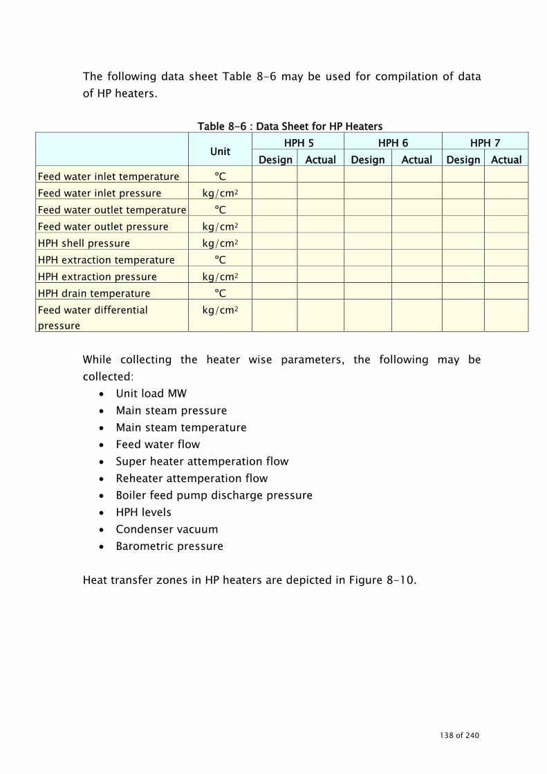
The following data sheet Table 8-6 may be used for compilation of data of HP heaters.
Table 8-6 : Data Sheet for HP Heaters
Unit HPH 5 HPH 6 HPH 7
Design Actual Design Actual Design Actual Feed water inlet temperature ºC Feed water inlet pressure kg/cm2 Feed water outlet temperature ºC Feed water outlet pressure kg/cm2 HPH shell pressure kg/cm2 HPH extraction temperature ºC HPH extraction pressure kg/cm2 HPH drain temperature ºC Feed water differential pressure
kg/cm2
While collecting the heater wise parameters, the following may be collected:
• Unit load MW • Main steam pressure • Main steam temperature • Feed water flow • Super heater attemperation flow • Reheater attemperation flow • Boiler feed pump discharge pressure • HPH levels • Condenser vacuum • Barometric pressure
Heat transfer zones in HP heaters are depicted in Figure 8-10.
138 of 240

Figure 8-10: Heat transfer zone in HP heaters
After the collecting the above data the following should be evaluated.
• Terminal temperature difference – TTD (should be as little as possible)
• Heater drain cooler approach temperature difference –DCA • Temperature rise across heater –TR (should be as large as possible)
139 of 240
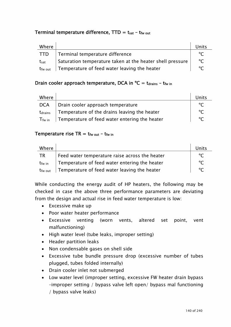
Terminal temperature difference, TTD = tsat – tfw out
Where Units TTD Terminal temperature difference ºC tsat Saturation temperature taken at the heater shell pressure ºC tfw out Temperature of feed water leaving the heater ºC
Drain cooler approach temperature, DCA in ºC = tdrains – tfw in
Where Units DCA Drain cooler approach temperature ºC tdrains Temperature of the drains leaving the heater ºC Tfw in Temperature of feed water entering the heater ºC
Temperature rise TR = tfw out – tfw in
Where Units TR Feed water temperature raise across the heater ºC tfw in Temperature of feed water entering the heater ºC tfw out Temperature of feed water leaving the heater ºC
While conducting the energy audit of HP heaters, the following may be checked in case the above three performance parameters are deviating from the design and actual rise in feed water temperature is low:
• Excessive make up • Poor water heater performance • Excessive venting (worn vents, altered set point, vent
malfunctioning) • High water level (tube leaks, improper setting) • Header partition leaks • Non condensable gases on shell side • Excessive tube bundle pressure drop (excessive number of tubes
plugged, tubes folded internally) • Drain cooler inlet not submerged • Low water level (improper setting, excessive FW heater drain bypass
–improper setting / bypass valve left open/ bypass mal functioning / bypass valve leaks)
140 of 240
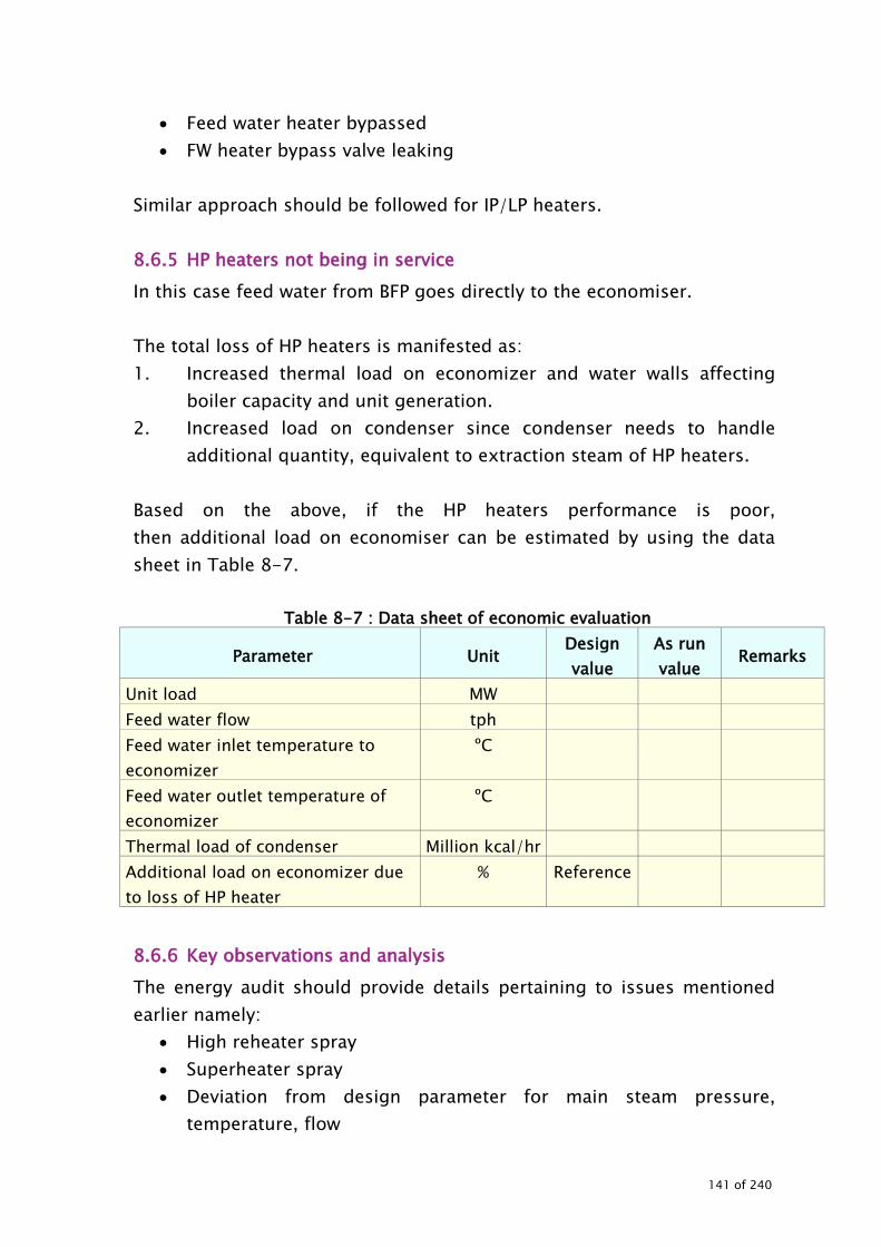
• Feed water heater bypassed • FW heater bypass valve leaking
Similar approach should be followed for IP/LP heaters. 8.6.5 HP heaters not being in service In this case feed water from BFP goes directly to the economiser. The total loss of HP heaters is manifested as: 1. Increased thermal load on economizer and water walls affecting
boiler capacity and unit generation. 2. Increased load on condenser since condenser needs to handle
additional quantity, equivalent to extraction steam of HP heaters. Based on the above, if the HP heaters performance is poor, then additional load on economiser can be estimated by using the data sheet in Table 8-7.
Table 8-7 : Data sheet of economic evaluation
Parameter Unit Design value
As run value
Remarks
Unit load MW Feed water flow tph Feed water inlet temperature to economizer
ºC
Feed water outlet temperature of economizer
ºC
Thermal load of condenser Million kcal/hr Additional load on economizer due to loss of HP heater
% Reference
8.6.6 Key observations and analysis The energy audit should provide details pertaining to issues mentioned earlier namely:
• High reheater spray • Superheater spray • Deviation from design parameter for main steam pressure,
temperature, flow
141 of 240
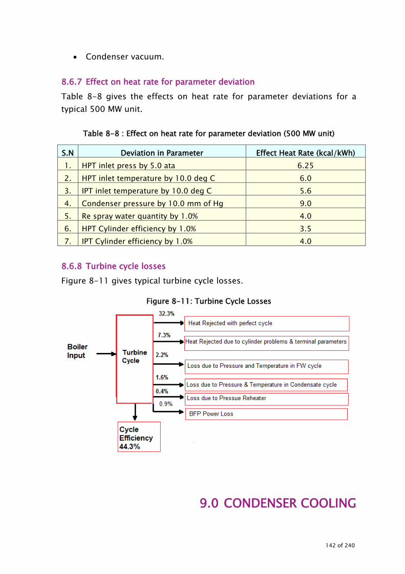
• Condenser vacuum. 8.6.7 Effect on heat rate for parameter deviation Table 8-8 gives the effects on heat rate for parameter deviations for a typical 500 MW unit.
Table 8-8 : Effect on heat rate for parameter deviation (500 MW unit) S.N Deviation in Parameter Effect Heat Rate (kcal/kWh) 1. HPT inlet press by 5.0 ata 6.25 2. HPT inlet temperature by 10.0 deg C 6.0 3. IPT inlet temperature by 10.0 deg C 5.6 4. Condenser pressure by 10.0 mm of Hg 9.0 5. Re spray water quantity by 1.0% 4.0 6. HPT Cylinder efficiency by 1.0% 3.5 7. IPT Cylinder efficiency by 1.0% 4.0
8.6.8 Turbine cycle losses Figure 8-11 gives typical turbine cycle losses.
Figure 8-11: Turbine Cycle Losses
9.0 CONDENSER COOLING
142 of 240

CONDENSER COOLING 9.1 BACKGROUND
143 of 240

In a power plant, the cooling towers, water pumping systems and condensers are involved in condensing the exhaust steam from a steam turbine and transferring the waste heat to the atmosphere. Condensers: The condenser is the most important component of the turbine cycle that affects the turbine heat rate. The function of the condenser is to condense exhaust steam from the steam turbine by rejecting the heat of vaporisation to the cooling water passing through the condenser. The brief typical specifications of a condenser used in 210 MW power plants are given in Table 9-1.
Table 9-1 : Brief specifications of condenser (typical) Description Units Value
ID code XXXXX Type Twin shell design Number of Passes No 2 No passes of circulating water No 2 Heat load considered for design M kcal/hr 285.88 Cooling water circulation rate m3/hr 2x13500 Pressure at turbine exhaust kg/cm2.abs 0.1 Tube length between tube plates m 10
Total number of tubes No 2x7810 ID of condenser tube mm 28
Tube material — Admiralty brass or cupronickel 90/10 depending upon cooling water
condition
Cooling surface area m2 2x7300
Cleanliness factor % 85 Design pressure at tube and water boxes
kg/cm2abs 6
Cooling water temperature raise °C 9 TTD at Design Cooling water flow and Inlet temperature
°C 3.4
Saturation temperature °C 45.4
Saturation and CW inlet temperature difference
°C 12.4
Condenser effectiveness factor 0.72
144 of 240
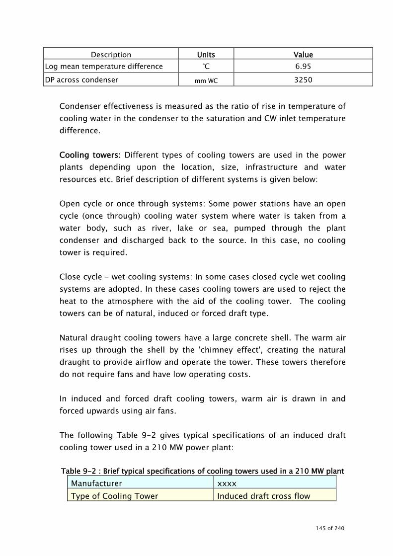
Description Units Value Log mean temperature difference °C 6.95
DP across condenser mm WC 3250
Condenser effectiveness is measured as the ratio of rise in temperature of cooling water in the condenser to the saturation and CW inlet temperature difference. Cooling towers: Different types of cooling towers are used in the power plants depending upon the location, size, infrastructure and water resources etc. Brief description of different systems is given below: Open cycle or once through systems: Some power stations have an open cycle (once through) cooling water system where water is taken from a water body, such as river, lake or sea, pumped through the plant condenser and discharged back to the source. In this case, no cooling tower is required. Close cycle – wet cooling systems: In some cases closed cycle wet cooling systems are adopted. In these cases cooling towers are used to reject the heat to the atmosphere with the aid of the cooling tower. The cooling towers can be of natural, induced or forced draft type. Natural draught cooling towers have a large concrete shell. The warm air rises up through the shell by the 'chimney effect', creating the natural draught to provide airflow and operate the tower. These towers therefore do not require fans and have low operating costs. In induced and forced draft cooling towers, warm air is drawn in and forced upwards using air fans. The following Table 9-2 gives typical specifications of an induced draft cooling tower used in a 210 MW power plant: Table 9-2 : Brief typical specifications of cooling towers used in a 210 MW plant
Manufacturer xxxx Type of Cooling Tower Induced draft cross flow
145 of 240

Number of cells 12 Nos No of fans per cell One Hot water inlet temperature 40.3oC Wet bulb temperature 27 oC Dry bulb temperature 29.67 oC Atmospheric pressure at power plant
762 mm Hg
Total heat exchange per hour 324 x 106k.cal/hr Re-cooled water temperature. 31.8 oC Cooling range 9 oC Fan blade material FRP
Condenser cooling water pumps: Cooling water pumps supply cooling water at the required flow rate and pressure to the power plant condenser and the plant auxiliary cooling water heat exchangers. These pumps are required to operate economically and reliably over the life of the plant. For once through systems, vertical wet pit pumps are in common usage. The brief specifications of the cooling water pumps installed in a 210 MW power plant are given in Table 9-3.
146 of 240

Table 9-3 : Specifications of a typical cooling water pump used in a 210 MW power plant
Particulars Unit Unit # Pump Type Mixed flow
No. Pumps Installed Nos 3 (Two run and one
stand by) Normal Operation Nos 3 Total head mmWC 26.3 Flow rate m3/hr 13500 Pump input power at duty point kW 975 Pump Efficiency at duty point % 88 Speed rpm 490 Motor Rating kW 1200 Rated voltage kV 6.6 Rated current A 140 Rated speed rpm 490 Motor rating kW 1200
The major energy consuming equipments in the cooling systems are: Cooling towers and fans Cooling water pumps Make up water pumps Condensers
* In some cases cooling tower pump function is performed by condenser cooling water pumps 9.2 STEPS INVOLVED
The steps involved in conducting energy audit of cooling water and cooling tower are: Data collection Observations and analysis Exploration for energy conservation measures Report preparation
147 of 240

9.3 DATA COLLECTION 9.3.1 Cooling tower specifications The following Table 9-4 gives the list of cooling tower specifications to be collected for conducting the energy audit study.
Table 9-4 : Specifications of cooling towers
Particulars Cooling Tower #1 Cooling tower # 2
Design Operating Design Operating
Make Type
Cooling Capacity, TR (or) Cooling Capacity, kcal/h No of cells
Rated water flow, m3/h Fill details No of CT fans CT fan kW No of blades per fan Air flow rate, m3/h Blade angle
Diameter of the blade assembly Blade material (FRP/Al/other) L / G Ratio Inlet water temperature, oC Outlet water temperature, oC Dry bulb temperature, oC Wet bulb temperature, oC Atmospheric pressure at the plant Range, oC Approach, oC Drift losses 9.3.2 Specification of water pumps and motors The following Table 9-5 gives the list of specifications of the pumps and pumping systems to be collected before conducting the energy audit.
148 of 240

Table 9-5 : Design Specifications of pumps & motors
Particulars ID code Location No of pumps installed No of pumps operated Make Type of the pump
Model No of stages
Rated pressure, kg/cm2
Rated flow, m3/h Rated efficiency, % Input kW of the pump Speed of the pump Year of commissioning Motor kW Motor make Motor voltage Rated current of motor Motor rpm Rated motor efficiency Collect the following information for all pumps in the cooling water circuit Performance characteristics of all pumps and motors Data regarding design, P. G. test, previous best and last energy
audit value with respect to cooling tower and cooling water system along with the condensers
If the pumps are operated in parallel then it is necessary to collect the performance curve for the parallel operation
Schematic diagram of water pumping network (which depict the source, pumps in operation and stand by, line sizes and users)
Water and pressure equipments at the users as per the design requirements
Brief description of the system with the key specifications in which pumps are used (for example, if pumps are used for supplying
149 of 240

water to condenser, then add a brief write up about the cooling water system)
9.3.3 Condenser specifications Collect the condenser design specifications as follows:
• Heat load considered for design • Design inlet cooling water temperature • Design TTD • Cleanliness factor • Cooling water temperature raise • Condenser back pressure • Cooling water flow • Cooling water side pressure drop • No of cooling water passes • Total heat transfer area • Number of tubes in condenser
Condensing zone Air cooling zone
• Tube dimensions Tube OD x thickness Length of tube for ordering
• Tube material Condensing zone Air cooling zone
• Water box design pressure 9.4 INSTRUMENTS REQUIRED The following instruments are required for conducting the water pumping energy audit
• Power analyzer: Used for measuring electrical parameters of motors such as kW, kVA, pf, V, A and Hz
• Temperature indicator and probe • Pressure gauge: To measure operating pressure and pressure drop
in the system • Stroboscope: To measure the speed of the driven equipment and
motor • Ultra sonic flow meter or online flow meter
150 of 240

• Sling hygrometer or digital hygrometer • Anemometer • PH meter • In addition to above, calibrated online instruments can be used
9.5 MEASUREMENTS AND OBSERVATIONS TO BE MADE While conducting the audit, the following measurements and observations are necessary
• Energy consumption pattern of pumps and cooling tower fans • Motor electrical parameters (kW, kVA, pf, A, V, Hz, THD) for pumps
and cooling tower fans • Pump operating parameters to be measured/monitored for
each pump are: Suction / discharge flow in m3/hr Head (suction pressure or sump level and discharge
pressure) Suction / discharge valve position (observation) Load variation Power parameters of pumps Pumps operating hours and operating schedule Pressure drop in the system (between discharge and user
point) Pressure drop and temperatures across the users (heat
exchangers, condensers, etc) Cooling water flow rate to users Pump /motor speed Actual pressure at the user end User area pressure of operation and requirement
• Cooling tower parameters to be monitored are: Inlet water temperature Outlet water temperature Temperature of air entering cooling tower: Outlet Temperature Dry bulb temperature Wet bulb temperature or relative humidity Water flow to cooling tower Air flow rate of cooling tower to be measured at each CT cell
at suitable location OR calculated by each CT fan power
151 of 240

consumption Range, ºC L/G ratio Approach, ºC Fan speed, rpm Fan power consumption (kW/cell)
• While conducting the measurement or performance evaluation of any system the following should be noted Unit load of the plant Date and time of measurement Instruments used for measurement Frequency of measurement
9.6 Observations and Analysis
9.6.1 System familiarisation and operational details Detailed interactions with the plant personnel have to be carried out to get familiarisation with system detail and operational details. The brief details along with single line schematic diagram of the entire system may be given in the report.
9.6.2 Energy consumption pattern
If the plant is monitoring energy consumption, it is suggested to record the data record and monitor the daily and monthly consumption pattern. Collect the past power consumption data (month wise for at least 12 months, daily consumption for about a week for different seasons, daily consumption during the audit period). Worked out the total power consumption of cooling water and cooling tower system should be worked out to arrive at percentage to the total consumption of the auxiliary consumption. If the energy meters are not installed for water pumps and cooling tower fans etc, instantaneous measurements can be carried out and based on the loading pattern the daily consumption can be worked out as shown in Table 9-6.
Table 9-6 : Energy consumption pattern Equipment Instantaneous kW Daily consumption, kWh
152 of 240

Equipment Instantaneous kW Daily consumption, kWh Cooling water pumps Make up water pumps Cooling tower fans Others Total Energy consumption of cooling water : kWh/day and associated system Total auxiliary power consumption : kWh/day
9.6.3 Operating efficiency and performance evaluation of the pumps All operating pumps in cooling water circuit need to be studied for their operating efficiency (as run performance test) with the aid of sophisticated energy audit instruments. In addition to these portable instruments, online valid calibrated instruments can be used also the during energy audits. The parameters to be studied in detail are: Water flow rate and suction / discharge pressure of pumps /
headers Velocity in the main headers and pumps and major lines (to verify
adequacy of line sizes) Power consumption of pumps (for estimating the
specific power consumption and operating efficiency of the pumps) Present flow control system and frequency of control valve and
variations if any (for application of variable speed drives) should be noted.
Table 9-7 gives the list of parameters to be noted for energy pump for performance evaluation.
Table 9-7 : Performance parameters for water pumps
Particulars Unit Design/ PG test
value Actual Remarks
Pump ID code Pump application Fluid pumped m3/hr
153 of 240

Particulars Unit Design/ PG test
value Actual Remarks
No of stages Nos. Suction head m Discharge head m Total head developed by pump m Water flow m3/hr Speed of the pump/ motor rpm Hydraulic kW kW Input kW to the motor kW - Combined efficiency % Motor efficiency (Refer to motor performance curve)
%
Pump efficiency % Type of discharge flow control mechanism
Discharge throttle valve position (% open)
Flow control frequency and duration if any
% load of pump on flow % % load of pump on head % % load on motor % Specific energy kW/m3/h The above analysis and comparison will help in arriving at various energy efficiency improvement measures.
154 of 240

Hydraulic power can be calculated by using the following:
1000
2smg3mkgmshdhheadtotals3mQkWHydraulic
)/( *)/(*)( )( *)/(
ρ−=
where
Dimension Q Water flow rate m3/s Total head
Difference between discharge head (hd) and suction head ( Hs )
m
ρ Density of the water or fluid being pumped kg/m3 g Acceleration due to gravity m/s2
If the pumps are operating in parallel, it is necessary to measure all above parameters for every pump separately to evaluate the individual pump performance. However combined parameters of flow and head need to be verified with performance curve for parallel operation. Compare the actual values with the design / performance test values. If any deviation is found, contributing factors should be investigated to arrive at appropriate suggestions.
• The investigations for abnormality should be carried out with extensive physical checks /observations and scope of improvement.
• Recommendations may be given for action to be taken for improvement, such as: Replacement of pumps Impeller replacement Impeller trimming Variable speed drive application, etc.
• Specific energy consumption should be compared with similar type of pumps and latest energy efficient pumps.
• Cost analysis with savings potential may be carried out for taking improvement measures.
9.6.4 Flow distribution to the major users and cooling towers
The flow should be measured at the individual pump discharge side, main header at the users end (for the major and large users) along with the
155 of 240

pressure and velocity. These values may be depicted in a schematic diagram. The following Figure 9-1 gives the typical distribution network where measurements need to be carried out.
Figure 9-1 : Water balance
P
P
P
User # 1
User # 2
User # 2
Cooling tower
Cooling tower
Indicates where all flow measurement need to be carried out. The above measurement will help in comparing the design values / PG values with the present operating parameters. The above detailed measurements will help in checking for uniform distribution of water as per the design or rated parameters. While evaluating the system, following may be observed. Line adequacy (by measuring the velocity in the major pipe lines) Pressure drop in the distribution network Specific water flow rate
9.6.5 Performance of condensers
The performance of the condenser may be evaluated by measuring the following parameters and comparing the same with design/PG test values. The following Table 9-8 lists the parameters to be considered while evaluating condenser performance
156 of 240

Table 9-8 : Parameters for condenser performance
Particulars Design/ PG test value
Actual (at different intervals) Remarks
1 2 3 4 Avg Unit load MW Frequency HZ Condenser back pressure, mmWC
Cooling water flow, m3/h Cooling water inlet temperature, oC
Cooling water outlet temperature, oC
Cooling water temperature raise, oC
Cooling water in /out pressure kg/cm2
Cooling water pressure drop across the condenser kg/cm2
Condenser heat load (estimated) kcal/hr
Condensate site (inlet of condenser)
Pressure mmWC Temperature oC Enthalpy kcal/kg Flow m3/hr Condensate site (outlet of condenser)
Pressure mmWC Temperature oC Enthalpy kcal/kg Saturation temperature oC Saturation and inlet water temperature difference oC
LMTD oC TTD oC Condenser effectiveness
The following need to be computed:
157 of 240

9.6.5.1 Condenser heat load Condenser heat load = Q x T x Cp
Dimension Q Water flow rate Kg/h T Average CW temperature rise oC Cp Specific heat kcal/kg oC
Expected condenser vacuum can be calculated from the performance curves of condenser as given by the manufacturer. 9.6.5.2 Calculated condenser vacuum
pressurebackCondensorpressurecAtmospherivacuumcondenserCacluated −= 9.6.5.3 Deviation in condenser vacuum
vacuumcondensorMeasuredvacuumcondensorExpectedvacuuminDeviation −= 9.6.5.4 Condenser TTD
etemperaturoutletwatercoolingetemperarurSaturationTTDCondensor −= 9.6.5.5 Condenser Effectiveness
etemperaturinletwatercoolingetemperaturSaturationetemperaturwatercoolinginRiseessEffectivenCondensor
−=
9.6.5.6 Condenser heat duty Condenser heat duty (kcal/h) can be computed by :
dutyheatCondensor
( )radiationtoduelossHeatPP860BFPbyaddedHeationattemperatRHbyaddedHeat
ionattemperatSHbyaddedheatreheaterbyaddedheatsteammainbyaddedheat
lossesgengen ++∗−−++
+++=
Heat added by main steam (MS)
158 of 240
= Flow MS * (hMS - hFW), kcal/hr Flow MS = Flow of main steam excluding SH attemperation in kg/hr hMS = Enthalpy of main steam in kcal/kg hFW = Enthalpy of feed water in kcal/kg Heat added by reheater = Flow reheater* (hHRH – hCRH), kcal/hr Flow reheater = Flow cold reheat steam, kg/hr hHRH = Enthalpy of hot reheat steam in kcal/ kg hCRH = Enthalpy of cold reheat steam in kcal/kg Heat added by BFP = Flow FW* ( hBFP Out – hBFP In ) kcal/hr Flow FW = Total FW flow kg/hr hBFP Out = (Enthalpy of FW at BFP outlet), kcal/kg hBFP In = (Enthalpy of FW at BFP inlet), kcal/kg Heat added by RH attemperation = Flow RH attemperation * (hHRH – hRHATT ) kcal/ h hRHATT = Enthalpy of RH attemperation in kcal/kg Flow RH Attemp =kg/hr Heat added by SH Attemperation = Flow SH attemp * (hMS – hSHATT ) kcal/hr hSHATT = ( Enthalpy of SH Attemp ), kcal/kg Flow SH Attemp = kg/hr Heat Loss rad = 0.1% of Pgen (radiation losses) kW Pgen = (Gross generator output), kW Pgen Losses* = (Mech Losses+Iron Losses+Stator Current Losses), kW * Values to be taken from Generator Loss Curve 9.6.5.7 Condenser tube velocity Tube velocity is given by:
159 of 240
passperpluggedtubesofNopasspertubesofNo(areaTube360010rateflowwaterCoolingvelocityTube
6
−∗∗∗
=
where: Cooling water flow is in m3/h Tube velocity is in m/s Tube area in mm2 9.6.5.8 Determination of actual LMTD Actual LMTD is given by:
outSat
inSat
inout
TTTTLn
TTLMTD
−−
−=
where LMTD – Log Mean Temperature Difference Tsat is saturation temperature in oC corresponding to condenser back pressure Tin is cooling water in let temperature oC Tout is cooling water outlet let temperature oC 9.6.5.9 Determination of expected LMTD Expected LMTD is given by:
fqfwfttestLMTDectedexpLMTD ∗∗∗=
25.0
designLMTDdesignetemperatursaturationDesigntesttheduringLMTDtesttheduringetemperaturSaturationft
−
−=
Correction for cooling water flow rate (fw) is given by
50.0
designvelocityTubetestduringvelocityTubefw
=
Correction for cooling water heat load (fq) is given by
160 of 240

=
testtheduringdutyCondensordutydesignCondensorfq
While conducting the energy audit of condensers, the following observations need to be carried out:
• Tubes in operation Vs total installed • Cleaning system operation • Filtering system for cooling water • Regular monitoring system for performance • Comparison of LMTD, TTD, heat load, condenser vacuum, flow,
temperatures, pressures with design / PG test- arriving at factors causing deviation
• Modifications carried out in the recent past • Cooling water flow • Pressure drop on water side and choking • Affect of present performance of cooling tower • Accurate metering of vacuum • Absolute back pressure deviation from expected value • Sub cooling of air –steam mixture and condensate • Circulation water temperature raise • Effectiveness of cleaning the tubes • Circulating water velocity in tubes
9.6.6 Performance of cooling towers Cooling tower performance can be evaluated by measuring / monitoring the parameters given in Table 9-9 for each cell of the cooling tower:
Table 9-9 : Performance of cooling tower Particulars Units Design/ Actual Remarks
161 of 240

PG test value 1 2 3 4 Avg Cooling water flow m3/hr Cooling water inlet temperature
°C
Cooling water outlet temperature
°C
Ambient dry bulb temperature
°C
Ambient wet bulb temperature
°C
Air flow rate m3/Sec L/G ratio No of fans operated No. Power consumption of fan
kWh
Fan speed rpm Range °C Approach °C TR TR Evaporation losses % Make up water requirement
%
While conducting the cooling tower tests, visual observations need
to be made with respect to: Adequate water level in the trough Cross flow air from other cooling towers (which are under
maintenance) Nozzle condition and operation Fill condition Change of blade angles during change of seasons The CT airflow should be measured using an anemometer and
compared with calculated airflow derived from fan characteristic curves of CT fans with actual power measurements.
The range, approach, L/G (liquid to gas) ratio and effectiveness, evaporation losses and makeup water consumption for design and operating conditions for each tower should be calculated as follows:
162 of 240

temp. outlet Water- etemperatur inlet WaterRange C.T. =
temp.bulb Wet - peratureOutlet temWater Approach C.T. =
approach} {range100 x range %essEffectiven
+=
kg inflow Air kg inflow Water ratio G / L =
Fan airflow actual (Nm3 /h)/cell Error! Bookmark not defined.=
rated) input (Fanactual)kW input (Fan x h / Nm inflow fan Rated
1/3
1/33
Air mass flow / cell = flow x density of air
675C in RangeCT x hr) / (mflow CW losses nEvaporatio
o3=
Error! Bookmark not
defined. 1)-(COClossesn Evaporatio n consumptio water Makeup =
Where COC is the cycle of concentration. The above test readings should be taken preferably during monsoon period when ambient air has maximum relative humidity. The unit load (MW), frequency, and condenser vacuum condition may be noted while taking the cooling tower measurement.
9.6.7 Power consumption of CT fans Power consumption of all fans (Table 9-10) should be measured and compared with the airflow and blade angles.
163 of 240

Table 9-10 : Power consumption of fans CT Fan # Blade angle setting kW drawn
9.6.8 Application and matching of pump The installed pump has to be thoroughly verified for its application, to see whether the pump is best suited for the application, duty, load variation, etc. The various options to be considered to improvement energy efficiency are: Replacement of present pump with best suited energy efficient
pump Replace of trim the impeller, if the pump is throttled to reduce the
flow by 10-20%. (where a smaller impeller is not available, the impeller may be trimmed in consultation with the manufacturers)
Retrofit with variable speed drives pumps if the pumps are serving variable loads
9.6.9 Exploration of energy conservation possibilities
While conducting the energy audit of the condenser and cooling water system, the following need to be explored in detail.
Condenser • Possibility of Improvement in condenser vacuum • Turbine heat rate reduction possibilities • Improving the effectiveness of condenser and TTD • Cooling water flow adequacy and flow optimisation • Air ingress • Fouling of tubes
Water pumping and cooling tower • Improvement of systems and drives. • Use of energy efficient pumps • Replacement of inefficient pumps • Trimming of impellers
164 of 240

• Correcting inaccuracies of the pump sizing • Use of high efficiency motors • Integration of variable speed drives into pumps • Use of high performance lubricants: The low temperature
fluidity and high temperature stability of high performance lubricants can increase energy efficiency by reducing frictional losses.
• Improvements in condenser performance • Improvement in cooling tower performance • Application potential for energy efficient fans for cooling
tower fans • Measuring and tracking system performance:
Measuring water use and energy consumption is essential in determining whether changes in maintenance practices or investment in equipment could be more cost effective. It is necessary to monitor the water flow rate, condenser parameters and cooling tower parameters periodically i.e. at least once in three months and energy consumption on daily basis. This will help in identifying the Deviations in water flow rates Heat duty of condenser and cooling towers Measures to up keep the performance
• System effect factors
Equipment cannot perform at its optimum capacity if fans, pumps, and blowers have poor inlet and outlet conditions. Correction of system effect factors (SEFs) can have a significant effect on performance and energy savings. This needs attention to:
Elimination of cavitation: Flow, pressure, and efficiency are reduced in pumps operating under cavitation. Performance can be restored to manufacturer’s specifications through modifications. This usually involves inlet alterations and may involve elevation of a supply tank.
Internal running clearances: The internal running clearances between rotating and non-rotating elements strongly
165 of 240

influence the turbo machine's ability to meet rated performance. Proper set-up reduces the amount of leakage (re-circulation) from the discharge to the suction side of the impeller.
Reduction in work load of pumping: Reducing of obstructions in the suction / delivery pipes
thereby reduction in frictional losses. This includes removal of unnecessary valves of the system due to changes. Even system and layout changes may help in this including increased pipe diameter. Replacement of components deteriorated due to wear and tear during operation may be done.
Modifications in piping system For efficiency improvement, consider energy efficient polymer
coating on pump internals. After the identification of energy conservation measures, detailed techno-economic evaluation should be carried out.
166 of 240

10.0 COMPRESSED AIR SYSTEM
167 of 240

COMPRESSED AIR SYSTEM 10.1 BACKGROUND Compressed air system in thermal power plant normally includes plant service air system and instrument air system. In many of the power plants the compressed air is categorised / grouped as station auxiliary loads rather than as unit auxiliary. The energy consumption of compressed air system in same thermal power plants is about 2% of the total auxiliary power consumption. The plant may have different compressors for plant air (or service air) and for instrument air. Alternatively, common compressors are used for both requirements. However, the instrument air is passed through the dryer while for service air system dryers installation is not required. The instrument air is used for control systems, solenoid valves operations, etc. while service air is used atomisation, cleaning, maintenance, general service applications, etc. The major energy consuming sections in compressed air system are:
• Compressors • Compressed air dryers • Cooling water – pumps and cooling tower fans
10.2 STEPS INVOLVED IN CONDUCTING ENERGY AUDIT The steps involved in conducting energy audit of compressed air system are:
• Data collection • Observations and analysis • Exploration for energy conservation measures • Report preparation
168 of 240

10.3 DATA COLLECTION 10.3.1 Specification of compressors Specifications for all compressors installed in the plant should be collected as shown in Table 10-1.
Table 10-1: Specifications of the compressors
Compressor Particulars Make XXXX Type Reciprocating /Screw / Centrifugal Sub type Lubricated /Non Lubricated
Air cooled / Water cooled Model No of stages
Discharge pressure, kg/cm2 Rated Free air delivery, cfm (or m3/min) Specific power consumption, kW/cfm Type of cooling Compressor rpm Transmission type Year of commissioning Motor kW Motor make Motor voltage (V) Rated current of motor (I) Motor frame Motor rpm Rated motor efficiency (%)
While collecting information, auditor my check, whether the compressors are installed with variable speed drive, synthetic flat belt, pressure controllers, auto cut off valves or any energy saving retrofits. 10.3.2 Details of compressed air network The compressed air network diagram should be collected or made depicting the major compressed air consuming equipment. It is
169 of 240

necessary to collect the pressurized air requirement and information pertaining to the major users (as shown in Table 10-2 ). Table 10-2 : Equipment wise compressed air requirement and air pressure requirement
Equipment Section Compressed air
pressure required Kg/cm3
Compressed air requirement, cfm
Application
10.3.3 Dryer and specifications While conducting the study following specifications pertaining to the compressed air dryer have to be collected.
• Make • Model • Type • Atmospheric dew point • Rated capacity • Compressed air dew point • Rated power consumption • Specific power consumption • Equipment requiring dry compressed air • In case of Desiccant purge air drier, air purge percentage
10.3.4 Details of Air receivers The details pertaining to air receivers may be collected for their size, location, equipment served, total installed capacity of receivers in the plant, as shown in the Table 10-3.
Table 10-3 : Air receiver capacity
Air receiver Location Capacity
m3
Area/ equipment
served Remarks
170 of 240

It is also suggested to check whether the receivers are installed with auto drain valves; if so type of valve may be indicated. 10.3.5 Auxiliary sections / equipment If the compressors are having dedicated cooling tower and cooling water systems, the audit should also cover these units. The procedure for conducting the energy audit of these systems is given separately.
• Cooling tower • Cooling tower fans • Water pumps
10.3.6 Instruments Required The following instruments are required for conducting compressed air energy audit
• Power Analyser: Used for measuring electrical parameters such as kW, kVA, pf, V, A and Hz
• Temperature indicator and probe: To measure air and water inlet and outlet temperatures of inter-cooler and after-coolers
• Pressure Gauge: To measure operating pressure and pressure drop in the system
• Stroboscope: To measure the speed of the compressor and motor • Stop watch for conducting leak test, loading duration, unloading
duration of compressors • Tensiometer for belt tension check
10.4 MEASUREMENTS & OBSERVATION BE MADE While conducting the audit, the following measurements and observations are necessary
• Energy consumption pattern of compressors and associated equipment (complete system)
• Motor electrical parameters during load and unload (kW, kVA, Pf, A, V, Hz, THD) of individual loads
• Compressor loading pattern, compressor pressure settings (load
171 of 240

and unload pressure) • Compressors operating hours and operating schedule • Pressure drop across the filters • Inter coolers and after cooler parameters ( air and cooling media -
inlet and outlet temperatures and pressures of inter coolers and after coolers)
• Cooling water flow rate to intercoolers and after coolers • Compressor speed • Motor speed • Ambient air temperature and % RH • Actual air pressure used for equipment operation • Pressure drop in the system and in the suction filters, dryers, etc • Air receiver volume at the compressor house and users • Cooling tower performance (range and approach) • Cooling tower fan and cooling water pump power consumption
While conducting the energy audit, the typical summary measurement sheet (Table 10-4 ) for compressed air system should be filled.
Table 10-4 : Compressors parameters Location Compressor
ID Code Location Make Rated pressure, kg/cm2g Rated Free Air Discharge, cfm Operating parameters Compressor rpm Load (cut in) pressure, kg/cm2g Unload (cut off) pressure, kg/cm2g Motor rpm Motor input power during load, kW Motor input power during unload, kW Inter cooler temperature, ºC Air in ºC Air out ºC Cooling media in ºC Cooling media out in ºC
172 of 240

Location Compressor Inter cooler Pressure, kg/cm2g Air in kg/cm2g Air out in kg/cm2g Cooling media in kg/cm2g Cooling media out kg/cm2g After cooler temperature, ºC Air in ºC Air out ºC Cooling media in ºC Cooling media out ºC After cooler Pressure, kg/cm2g Air in kg/cm2g Air out kg/cm2g Cooling media in kg/cm2g Cooling media out kg/cm2g Ambient temperature, ºC Ambient RH, % Cooling water source Cooling water flow to intercooler, lpm Cooling water flow to after cooler, lpm Pressure drop across the filters, mmWC
10.4.1 System familiarization and operational details Detailed interactions with the plant personnel should be carried out to get familiar with system detail and operational details. The entire system should be stated briefly in the report. 10.4.2 Energy consumption pattern If the plant is monitoring energy consumption, it is suggested that record of data should be obtained and the daily and monthly consumption pattern monitored. Past energy consumption data should be obtained if available month wise for at least 12 months, daily consumption for about a week for different seasons and daily consumption during the audit period.
173 of 240

Total consumption of compressed air system should be worked out to arrive at percentage to the total consumption of the auxiliary consumption. In case, energy meters are not installed for the compressors and their auxiliary units, the instantaneous measurements of energy consumption can be carried out and based on the loading pattern, the daily consumption can be worked out as shown in Table 10-5.
Table 10-5 : Energy consumption pattern (to be measured)
Equipment Instantaneous
kW
Daily consumption,
kWh
No of operating hrs
Compressors # 1 Total
The energy consumption of compressed air system and associated system: ----kWh Total auxiliary power consumption: ---------kWh Contribution of compressed air system to total auxiliary power: -----% 10.4.3 Free air delivery test (compressor output assessment test) This test is to be conducted to assess the actual output of the compressor. The procedure of conducting the test is as follows: • Isolate the compressor along with its individual receiver being taken
for test from main compressed air system by tightly closing the isolation valve or blanking the receiver outlet. Ensure that the valves are closed completely.
• Check the pressure gauge and the temperature gauge installed for the air receiver for calibration and working status
• Open water trap drain outlet and empty the receiver and the pipeline. Make sure that water trap line is tightly closed once again to start the test.
• Start the compressor and activate the stopwatch. • Note the time to attain the normal generated pressure P2 (in the
174 of 240

receiver) from initial pressure P1 • Measure the temperature of ambient and compressed air (receiver) • Calculate the capacity as per the formula given below. Actual Free Air Discharge:
TV *
PP-(P Q
0
1)2=
where: Q : Actual free air discharge. P2 : Final pressure after filling (kg/cm2 a). P1 : Initial pressure (kg/cm2a) after bleeding. P0 : Atmospheric pressure (kg/cm2 a). V : Receiver and connected pipe volume in m3
T : Time taken to build up pressure to P2in minutes. The above equation is relevant where the compressed air temperature is same as the ambient air temperature, i.e., perfect isothermal compression. In case the actual compressed air temperature at discharge, say t20C is higher than ambient air temperature say t10C (as is the usual case), the FAD is to be corrected by a factor (273 + t1) / (273 + t2). Once the actual output is assessed, then it should be compared with rated output. If any deviation is found then the various factors causing deviation should be investigated to arrive at the remedial measures to improve the performance. Efficiency evaluation • Calculate the ideal kW as per formula given below.
Ideal Power kW =
−
−1 -
PsPd
612.0Ps*Q
1KNK NK/)1K(
K
where: N : No. of stages K : Ratio of spec Heat (1.35 for air) PS : Suction pressure in kg /cm2g
Pd : Discharge pressure in kg/cm2g
Q : Actual air flow (m3/min)
175 of 240

• Measure actual kW during steady state load condition • Calculate the actual efficiency
ActualkW
IdealkW=η
• Compare actual with the design efficiency. The typical data sheet is given below (Table 10-6 ).
Table 10-6 : Free air delivery test of compressors Compressor Comp #1 Comp #2 Comp #3 Design output, m3/min Time & Date Atmospheric pressure, kg/cm2a Initial pressure, kg/cm2a Final pressure, kg/cm2a Receiver and connected pipe volume, m3 Ambient temperature, oC Receiver temperature, oC Time taken to fill the receiver (min.) Actual output, m3/min Actual power consumption, kW Actual efficiency, % Rated efficiency, %
In case the compressors are provided with flow nozzles then out put should be measured directly. 10.4.4 Estimation of Specific Power Consumption – Compressor wise
• Measure kW for base load and unload conditions. • Compare above measurement with respective design values. • Compare unload power of all compressors. • Compare base load power for all compressors. • In case of appreciable difference in similar compressors, detailed
analysis should be made.
176 of 240

Specific power consumption (SPC) needs to be evaluated based on the actual output and actual power consumption of the compressor. Table 10-7 gives the parameters to be monitored.
Table 10-7 : Specific energy consumption of compressors
Compressor Rated cfm
Actual cfm
Rated kW
Actual Load kW
Actual, Unload
kW
Actual SPC, kW/cfm
Design SPC, kW/cfm
After arriving at the specific power consumption,
• Compare actual with design • Compare actual with latest compressors of same type or other
different types of compressor • Arrive at options to reduce the gap between the design and actual
value with detailed techno-economic analysis. The above will also help in framing operating schedule of the compressors for lowest power consumption 10.4.5 Estimation of actual compressed air consumption This evaluation of actual compressed air consumption can be carried out where no flow meters are installed with the compressors. This evaluation can be carried out only after estimating the actual output of the individual compressors (free air delivery test). The total plant consumption can be arrived at by monitoring the loading and unloading times of the compressors simultaneously. For multiple compressor operation, a team is required to monitor all compressors simultaneously. The time selected for the study should represent normal operation of the facility. Alternatively, in order to estimate compressed air consumption over a period of the day, the following steps can be carried out:
• Adjust the load and unload pressures of compressors in such a way
177 of 240

that, only one or two compressors will meet the variable load while others are loaded continuously.
• Install current recorder to the compressors and record the current for a considerable time. Monitor the load and unload pattern based on the current record
• Estimate the actual consumption of the air and compare with design value.
The following Table 10-8 gives typical estimation of compressed air consumption:
Table 10-8 : Estimation of compressed air consumption, Particulars Compressor # 1 Compressor # 2
Average loading, sec Average unloading, sec Percentage loading, % Actual output of compressors, cfm (FAD test result) Air consumption in the section, cfm Total consumption
The above estimation of actual air consumption will help in comparing the design values (if available) and help in arriving at other options such as
• Compressors application (whether the type and capacity are best suited)
• Capacity utilization • Scope for centralization or decentralization • Application potential for variable speed drive, pulley replacement,
etc • % Leakage (after conducting the leakage test) • Minimize low load compressor operation; if air demand is less than
50 percent of compressor capacity, consider change over to a smaller compressor or reduce compressor speed appropriately (by changing the motor pulley size in case of belt driven compressors).
• If more than one compressor is feeding a common header, compressors must be operated in such a way that only one small
178 of 240

compressor may handle the small load variations whereas other compressors will operate at full load.
10.4.6 Quantification of compressed air leakage This test can be conducted only when plant is not in operation. (during the maintenance shut down the plant). This test may not be possible in a running coal fired plant since this involves isolation of all user points individually in the whole system across the power plant which may not be practically possible. In such a case, intensive physical leak survey should be undertaken as detailed below.
• Shut off compressed air operated equipments (or conduct test when no equipment is using compressed air).
• Run the compressor to charge the system to set pressure of operation. Note the subsequent time taken for ‘load’ and ‘unload’ cycles of the compressors. For accuracy, take ON & OFF times for 8 – 10 cycles continuously. Then calculate total ‘ON’ Time (T) and Total ‘OFF’ time (t).
• The system leakage is calculated as:
t)(TT x Q(cfm) leakage System
+=
Q : Actual free air delivery, cfm T : Time on load, sec t : time of load, sec
In case, where leak test cannot be conducted, detailed survey has to be initiated to identify the leakage points in the plant and to estimate the compressed air leakage based on the following table. The procedure for conducting survey is as follows:
• Survey the compressed air network throughout the plant and note down the leakages.
• Estimate the leakage based on diameter of leakage point and pressure of the pipe.
• Recommend steps to plug leakages.
Table 10-9 gives details of air leakages from the orifices.
179 of 240

Table 10-9 : Air leakages from the orifices
Discharge of Air (m3/minute) through Orifice (Orifice Constant Cd – 1.0) Gauge Pressure
Bar 0.5 mm 1 mm 2 mm 3 mm 5 mm 10 mm 12.5 mm
0.5 0.06 0.22 0.92 2.1 5.7 22.8 35.5 1.0 0.08 0.33 1.33 3.0 8.4 33.6 52.5 2.5 0.14 0.58 2.33 5.5 14.6 58.6 91.4 5.0 0.25 0.97 3.92 8.8 24.4 97.5 152.0 7.0 0.33 1.31 5.19 11.6 32.5 129.0 202.0
10.4.7 Performance of intercoolers and after coolers The performance of inter coolers and after coolers can be verified by monitoring the temperature and pressure of air and water.
• Measure inlet air temperature to cooler (Ta) • Measure outlet air temperature of cooler (To) • Calculate temperature difference (To-Ta) • If (To-Ta)>5 ºC, recommend for cooler checking with respect to
circulating water flow rate, rusting, choking and tube leakage. • Similarly check for pressure drop in water and air side and compare
with the design values (acceptable values) of heat exchanger • Repeat the test for after cooler.
Typical data sheet for measurement and analysis of the inter and after cooler is given in Table 10-10.
Table 10-10 : Data sheet for inter coolers and after coolers
Location Compressor ID Code Make Inter cooler temperature ºC Air in (Ta) ºC Air out (To) ºC Temperature difference (To-Ta) ºC Water in ºC Water out ºC Inter cooler pressure, kg/cm2g Air in Kg/cm2g Air out Kg/cm2g
180 of 240

Location Compressor Water in Kg/cm2g Water out Kg/cm2g After cooler temperature ºC Air in (Ta) ºC Air out (To) ºC Temperature difference (To-Ta) ºC Water in ºC Water out ºC After cooler pressure, kg/cm2g Air in Kg/cm2g Air out Kg/cm2g Water in Kg/cm2g Water out Kg/cm2g Ambient temperature (Ta) ºC Ambient RH %
As a thumb rule, an increase of 5.50C in the inlet air temperature to the second stage results in a 2 % increase in the specific energy consumption. Fouled inter coolers reduce compressor efficiency and causes more water condensation in air receivers and distribution lines resulting in increased corrosion. Periodic cleaning of inter coolers must be ensured. 10.4.8 Pressure drop survey It may be measured as follows:
• Run the compressor and fill the system. • Achieve the steady state. • Note pressure at different locations simultaneously. • Calculate the ideal pressure at those locations as below:
P = 7.57 x Q x 1.85 x L x 10 -10 5 x d x p P = Pressure drop in the pipeline, bar Q = Air flow quantity, m3/ min L = Length of the pipeline, m d = Inside diameter of the pipeline, in mm p = Initial absolute air pressure, bar
• Estimate the actual pressure drop in the pipeline. Typical data sheet
181 of 240
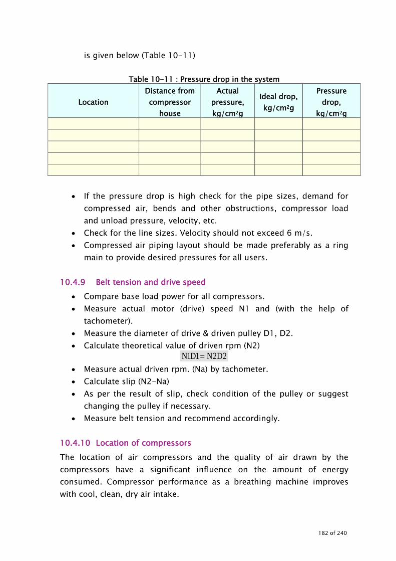
is given below (Table 10-11)
Table 10-11 : Pressure drop in the system
Location Distance from compressor
house
Actual pressure, kg/cm2g
Ideal drop, kg/cm2g
Pressure drop,
kg/cm2g
• If the pressure drop is high check for the pipe sizes, demand for
compressed air, bends and other obstructions, compressor load and unload pressure, velocity, etc.
• Check for the line sizes. Velocity should not exceed 6 m/s. • Compressed air piping layout should be made preferably as a ring
main to provide desired pressures for all users. 10.4.9 Belt tension and drive speed
• Compare base load power for all compressors. • Measure actual motor (drive) speed N1 and (with the help of
tachometer). • Measure the diameter of drive & driven pulley D1, D2. • Calculate theoretical value of driven rpm (N2)
2D2N1D1N = • Measure actual driven rpm. (Na) by tachometer. • Calculate slip (N2-Na) • As per the result of slip, check condition of the pulley or suggest
changing the pulley if necessary. • Measure belt tension and recommend accordingly.
10.4.10 Location of compressors The location of air compressors and the quality of air drawn by the compressors have a significant influence on the amount of energy consumed. Compressor performance as a breathing machine improves with cool, clean, dry air intake.
182 of 240

Cool air intake As a thumb rule, “Every 40C rise in inlet air temperature results in higher energy consumption by 1 % to achieve equivalent output”. Dry air intake Atmospheric air always contains some amount of water vapour, depending on the relative humidity, being high in wet weather. The moisture level will also be high if air is drawn from a damp area. Thus, locating a compressor close to cooling tower, or dryer exhaust is to be avoided. 10.4.11 Pressure settings Survey of compressors may be made for load and unload pressure and user equipment for actual operating pressure and required pressure. Based on the above data, pressure settings may be corrected if necessary. The possibility of lowering (optimizing) the delivery pressure settings should be explored by careful study of pressure requirements of various equipment, and the pressure drop in the line between the compressed air generation and utilization points.
• During the audit, this measure can be demonstrated since most of the plants have stand by compressor arrangements.
• Compressor delivery pressure may be reduced wherever possible, to save energy.
• Pneumatic equipment should not be operated above the recommended operating pressure as this not only wastes energy but can also lead to excessive wear of equipment components which leads to further energy wastage.
10.4.12 Compressed air dryers
• Segregate the loads which do not require dry air and reduce the load on the dryer
• Check for the requirement of dew point and suggest energy efficient dryers.
• Automatic timer controlled drain traps wastes compressed air every time the valve opens. So frequency of draining should be
183 of 240

optimised. 10.4.13 Pressure drop across the filter Measure the pressure drop across the filter. Compressor efficiency will be reduced by 2 percent for every 250 mm WC pressure drop across the filter. 10.4.14 Compressed air optimisation
• Consideration should be given to two stage or multistage compressor as it consumes less power for the same air output than a single stage compressor
• If pressure requirements for processes are widely different (e.g. 3 bar to 7 bar), it is advisable to have two separate compressed air systems.
• The minimum possible range should be kept between loads and unload pressure settings.
10.4.15 Effective utilization of compressed air Check the application potential for the following:
• A smaller dedicated compressor can be installed at load point, located far off from the central compressor house, instead of supplying air through lengthy pipelines.
• In case the facility has pneumatic transport, it can be replaced by mechanical system as the former consumes about 8 times more energy. Highest possibility of energy savings is by reducing compressed air use.
• Pneumatic tools such as drill and grinders consume about 20 times more energy than motor driven tools. Hence, they have to be used efficiently. Wherever possible, they should be replaced with electrically operated tools.
10.4.16 Variable speed drive application Retrofit with variable speed drives in big compressors, say over 100 kW will eliminate the `unloaded’ running condition altogether.
184 of 240

10.4.17 Exploration of energy conservation possibilities While conducting the energy audit of the compressed air system, the following need to be explored in detail.
• Improvement of drives use of high efficiency motors and integration of variable speed drives into compressors: The use of high efficiency motors improves energy efficiency. The integration of adjustable speed drives (ASD) into compressors shall lead to energy efficiency improvements, depending on load characteristics.
• Optimal choice of the type of compressor, as a function of specific end use applications: A large number of alternative technologies exist namely piston, vane, scroll, centrifugal, and turbine compressors. The choice between oil injected or oil free machines, as well as between single stage or multi stage machines constitute other parameters of choice. Within each family of compressors, there are multiple variants. Compressor selection should be guided by minimum life cycle cost.
• This choice can affect the energy efficiency of the system, both in terms of compressor performance and also in terms of the multiple interactions with other elements of system. For benefit of multi stage systems, high duty cycle installations should be stressed.
• Improvement of compressor technology / energy efficient compressors, Use of multi stage compressors Opting for centrifugal or latest energy efficient compressors Water cooled compressors Lubricated compressors wherever applicable
• Use of sophisticated control systems: Sophisticated control systems are used to match compressor output to system air demand. They save energy by optimising the transitions between the, idling and stopped states of the compressor. Sequencers optimise the operation of multi machine installations. These control systems can often be used in conjunction with speed controllers. Predictive controls apply fuzzy logic or other algorithms to predict future air demand from past performance of the system.
• Recuperating waste heat for use in other functions: The cost effectiveness of recuperating waste heat depends on the alternate sources of energy, which are available. It might be very cost
185 of 240

effective if the alternative solution would be electric heat. It may be less cost effective if natural gas, waste process heat or waste process gas could be used.
• Improved air treatment: Reducing pressure and energy losses in cooling, drying and filtering; optimising filtering and drying as a function of users' needs and of temperature conditions; In case of drying, the present system may be compared with various latest available options
• Overall system design to reduce the cost: Explore and compare the options
Single pressure or multi pressure systems, Building system delivering a lower pressure, and adding
pressure boosters for those devices requiring higher air pressure
Automatic sensing and alarm equipment to warn of excessive pressure drop can be very cost effective.
Limiting pressure variations in the system • Optimising certain end use devices: more efficient, better adapted
devices, or, in some applications, replacing compressed air by electrical or hydraulic systems;
• Measuring and tracking system performance: Measuring air use and energy consumption is essential in determining whether changes in maintenance practices or investment in equipment could be more cost effective. In this case it is advised to monitor the free air delivery and loading and unloading of compressors periodically i.e. at least once every three months. This will help in identifying the Deviations in free air delivery Compressed air consumption in the plant Leakage level (if there are no addition of loads) during two
consequent tests
186 of 240

Three basic parameters– airflow, air pressure, and electricity consumption must be measured and recorded in order to evaluate system performance. While this seems simple in principle, the interpretation of this data can be difficult, particularly in variable load applications. Measuring airflow also poses technical problems, and retrofitting reliable measuring equipment can be difficult or impossible. Where information on air flow is not available, low cost pressure sensing equipment can still be very useful, for instance to measure the pressure differential across filters or the pressure loss in the network or to detect excessive pressure variation in a system.
187 of 240

11.0 MOTORS
188 of 240
MOTORS 11.1 BACKGROUND Different types of electrical motors are used in thermal power plants to drive the various equipment like:
• Pumps • Fans • Blowers • Material handling equipments • Crushers • Mills Compressors • Others
These motors and connected equipment consume significant amount of energy, which contributes to auxiliary consumption (APC). The auxiliary power consumption (APC) varies from 6-14% depending on the size of the plant, use of turbine driven boiler feed water pumps (TDBFP) and age of the plant etc. The 500 MW units register the least APC while in some of the old 110MW plants, APC consumption of 14% is observed. For conducting energy audit in a large thermal power station (TPS) plant operations are segregated into different sub-areas. Motors constitute an important element of APC consumption. 11.2 STEPS INVOLVED IN CONDUCTING ENERGY AUDIT The steps involved in conducting energy audit of electrical motors systems are:
• Data collection • Measurements and observations • Exploration for energy conservation measures • Report preparation
Since thermal power plant have several motors ranging from fractional kW to MW it is difficult to cover all motors in energy audit. Hence it is advisable to cover motors of certain rating and above in stages. In cases where multiple motors of low rating are used for a common operation, a sample study can be carried out. Criteria for selection of representative LT motor drives among the motor population, for analysis, are:
189 of 240
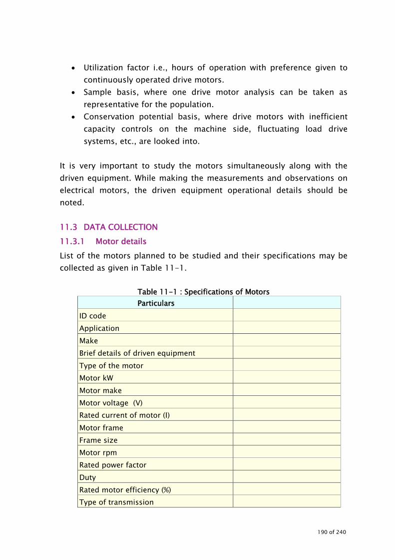
• Utilization factor i.e., hours of operation with preference given to
continuously operated drive motors. • Sample basis, where one drive motor analysis can be taken as
representative for the population. • Conservation potential basis, where drive motors with inefficient
capacity controls on the machine side, fluctuating load drive systems, etc., are looked into.
It is very important to study the motors simultaneously along with the driven equipment. While making the measurements and observations on electrical motors, the driven equipment operational details should be noted. 11.3 DATA COLLECTION 11.3.1 Motor details List of the motors planned to be studied and their specifications may be collected as given in Table 11-1.
Table 11-1 : Specifications of Motors Particulars
ID code Application Make Brief details of driven equipment Type of the motor Motor kW Motor make Motor voltage (V) Rated current of motor (I) Motor frame Frame size Motor rpm Rated power factor Duty Rated motor efficiency (%) Type of transmission
190 of 240
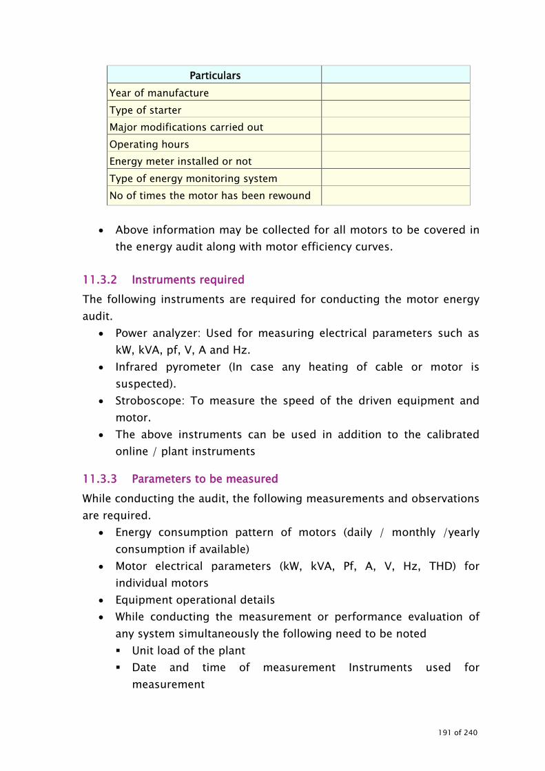
Particulars Year of manufacture Type of starter Major modifications carried out Operating hours Energy meter installed or not Type of energy monitoring system No of times the motor has been rewound
• Above information may be collected for all motors to be covered in
the energy audit along with motor efficiency curves. 11.3.2 Instruments required The following instruments are required for conducting the motor energy audit.
• Power analyzer: Used for measuring electrical parameters such as kW, kVA, pf, V, A and Hz.
• Infrared pyrometer (In case any heating of cable or motor is suspected).
• Stroboscope: To measure the speed of the driven equipment and motor.
• The above instruments can be used in addition to the calibrated online / plant instruments
11.3.3 Parameters to be measured While conducting the audit, the following measurements and observations are required.
• Energy consumption pattern of motors (daily / monthly /yearly consumption if available)
• Motor electrical parameters (kW, kVA, Pf, A, V, Hz, THD) for individual motors
• Equipment operational details • While conducting the measurement or performance evaluation of
any system simultaneously the following need to be noted Unit load of the plant Date and time of measurement Instruments used for
measurement
191 of 240

Frequency of measurement. 11.4 OBSERVATIONS AND MEASUREMENTS 11.4.1 System Details Detailed interactions with the plant personnel should be carried out to get familiar with operational details. The brief details of the system have to be given in the report. 11.4.2 Energy consumption Pattern If the plant is monitoring energy consumption, it is suggested to obtain the record of data and monitor the daily and monthly consumption pattern. The total consumption of electrical motors may be worked out to arrive at percentage to the total auxiliary consumption. If the energy meters are not installed with motors, instantaneous measurements can be carried out and based on the loading pattern, the daily consumption can be worked out. (refer Table 11-2).
Table 11-2 : Energy consumption of Electrical motors
Equipment Annual
consumption, MWh Actual
load, kW % of total
generation % of total
APC Boiler feed pump Condensate extraction pumps
CW pumps ID fans FD fans PA fans Mills CT fans Air compressors Ash handling plant Coal handling plant Raw water pumps DM water pumps Air conditioning systems Others
192 of 240

Equipment Annual
consumption, MWh Actual
load, kW % of total
generation % of total
APC Total
Energy consumption of electrical motors : kWh/day Total auxiliary power consumption : kWh/day
11.4.3 Motor loading survey Studies on selected LT motors involve measurement of electrical load parameters namely voltage, current, kVA, kW drawn, power factor, frequency and speed. These should be measured and parameters tabulated in Table 11-3.
Table 11-3 : Motor Loading Pattern Motor A Motor ID # 1 Motor ID # 2 Motor ID # 3 Motor ID # 4
Motor ID code Application Driven equipment details Rated kW Rated efficiency (% ) Rated speed (rpm) Measured parameters Voltage (V) Current ( I ) Power factor kVA kW drawn Frequency (Hz) Harmonics (THD) Motor speed (rpm) Driven equipment parameters Operational observations Transmission % loading on the motor
Motor loading can be estimated by:
efficiencymotorloadfullplateName/kWplateName100motortokWInputLoadingPercentage ∗
=
Slip Method
193 of 240

In the absence of a power meter, the slip method can be used which requires a tachometer.
%100ss
SlipLoadrs
×−
=
The accuracy of the slip method, however, is limited. The largest uncertainty relates to the accuracy with which manufacturers report the nameplate full-load speed. Manufacturers generally round their reported full-load speed values to some multiple of 5 rpm. Though it is small percentage of the full-load speed and may be considered as insignificant, it affects the slip method measurement which relies on the difference between full-load nameplate speed and synchronous speed (Given a 40 rpm “correct” slip) a seemingly minor 5 rpm disparity causes a 12% change in calculated load. Slip also varies inversely with respect to the square of motor terminal voltage. A voltage correction factor can, also, be inserted into the slip load equation. The voltage compensated load can be calculated as shown.
2
VVrSr)-(Ss
100% x slipLoad
=
Where: Load = Output power as a % of rated power Slip = Synchronous speed - Measured speed in rpm Ss = Synchronous speed in rpm at the operating frequency Sr = Nameplate full-load speed V = RMS voltage, mean line to line of 3 phases Vr = Nameplate rated voltage
While conducting motor load survey, observations on machine side parameters such as speed, load, pressure, temperature, etc., (as relevant) are also taken. Availability of online instruments for routine
194 of 240

measurements, availability of tail-end capacitors for PF correction, energy meters for monitoring is, also, looked into for each case. Analysis of observations for motors and connected drives is carried out towards following:
• Loading pattern -% loading on kW • Comments of power supply quality: The BIS standards specify that a
motor should be capable of delivering its rated output with a voltage variation of ± 6 % and frequency variation of ±3 %.
• Remarks on voltage unbalance if any: The condition where the voltages in the three phases are not equal can be detrimental to motor performance and motor life. Unbalance typically occurs as a result of supplying single-phase loads disproportionately from one of the phases. It can also result from the use of different sizes of cables in the distribution system.
• Voltage, current, frequency, power factor, machine side conditions like load / unload condition, pressure, flow, temperature, damper / throttle operation, whether it is a rewound motor, idle operations, metering provisions, etc.
• Scope for improving monitoring systems • Scope of energy conservation with related cost benefits and source
information. The findings / recommendations may include:
• Identification of motors with less than 50 % loading, 50 – 75 % loading, 75 – 100 % loading, over 100 % loading.
• Identification of motors with low voltage / power factor / voltage imbalance for needed improvement measures.
• Identification of motors with machine side losses / inefficiencies like idle operations, throttling / damper operations for avenues like automatic controls / interlocks, variable speed drives, etc.
Motor load survey is aimed at not only to identify motor efficiency areas but equally importantly, as a means to check combined efficiency of the motor driven machine and controller if any. The margins in motor efficiency may be less than 10 % of consumption often, but the load
195 of 240

survey helps to bring out savings in driven machines / systems, which can give significant energy savings.
11.4.4 Motor rewinding history It is common practice in industry to rewind burnt-out motors. Careful rewinding can sometimes maintain motor efficiency at previous levels, but in most cases, losses in efficiency result. Rewinding can lead to deterioration of motor efficiency due to factors such as winding and slot design, winding material and insulation performance. The impact of rewinding on motor efficiency and power factor can be easily assessed if the no-load losses of a motor are known before and after rewinding. Maintaining documentation of no-load losses and no-load speed from the time of purchase of each motor can facilitate assessing this impact. For example, comparison of no load current and stator resistance per phase of a rewound motor with the original no-load current and stator resistance at the same voltage can be one of the indicators to assess the efficacy of rewinding. 11.4.5 Exploration for energy conservation possibilities While conducting the energy audit of the motors, the following need to be investigated in detail:
• Replacement / sizing of motors • Opting for energy efficient motors • Use of high efficiency motors • Integration of variable speed drives • On and off controllers • Use of energy efficient transmission • Replacement of pulleys • Direct coupling
196 of 240

Measuring energy consumption and tracking system performance, is essential in determining whether changes in maintenance practices or investment in equipment would be more cost effective. After the identification of energy conservation measures, detailed techno-economic evaluation should be carried out.
197 of 240

12.0 AIR CONDITIONING
198 of 240

AIR CONDITIONING 12.1 BACKGROUND In thermal power plants air conditioning is used to provide desired working environment for the control rooms, server / data centre rooms, office space etc. The air conditioning system can be either centralised or decentralised type using vapour compression or vapour absorption techniques. The major energy consuming sections in air conditioning systems are: • Compressors (centrifugal/ screw / reciprocating) or the plant using
vapour absorption chiller units • Cooling water pumps or condenser pumps / fans • Chilled water pumps • Air handling units or evaporative cooling units • Cooling towers The energy consumed in air conditioning system is sensitive to ambient conditions, load changes, seasonal variations, operation and maintenance, etc 12.2 STEPS INVOLVED IN CONDUCTING THE ENERGY AUDIT The steps involved in conducting energy audit of air conditioning system are:
1. Data collection 2. Observations and analysis 3. Exploration for energy conservation measures 4. Report preparation
12.3 DATA COLLECTION While collecting the data, it is suggested to make a schematic diagram comprising compressor, cooling system components (cooling tower, chilled water component (pumps) and air handling units. One typical system is depicted below. While making such schematic system, the ID code and capacity should be indicated.
199 of 240

Typical air conditioning system is presented below:
12.3.1 Specifications of refrigeration compressors / vapour
absorption chiller units The specifications for all the compressors installed in the plant should be collected as shown in Table 12-1.
Table 12-1 : Design specifications of air conditioning compressors Particulars
Make ID code Type Reciprocating /Screw / Centrifugal Model Design evaporator refrigerant temperature, oC Chiller TR Specific power consumption, kW/TR Refrigerant Type of condenser cooling Suction pressure kg / cm2 Discharge pressure kg / cm2 Chilled water in let temperature, (oC) Chilled water out let temperature, (oC) Compressor rpm Transmission type Cooling type Air cooling/ water cooling Year of commissioning
200 of 240

Particulars Motor kW Motor make Motor voltage ( V ) Rated current of motor ( I ) Motor frame Motor rpm Rated motor efficiency ( % ) Cooling tower TR (In case of water cooled) No of condenser fans and rated kW (in case of air cooled) No of AHUs served and their rated TR Details of cooling water pumps – ID code, capacity, rated kW Details of chilled water pumps – ID code, capacity, rated kW While collecting the information, it should be checked whether the compressors are installed with VSD, synthetic flat belt, waste heat recovery units, automatic controllers, or any other energy saving retrofits. 12.3.2 Details of auxiliary equipment The following system details should be collected:
• Condenser / cooling system (refer (Table 12-2) • Cooling tower (refer Table 12-3 ) • Design specifications / /rated parameters of pumps and motors
(refer Table 12-4 ) • Rated parameters / design specifications of air handling units (refer
Table 12-5 ) • User area details of AHUS (refer Table 12-6 )
201 of 240

Table 12-2 : Condensers / cooling system Particulars Condenser Type Id code Model Capacity, TR Cooling water flow, m3/h Cooling water in let temperature, oC Cooling water out let temperature, oC Cooling water in let pressure kg/cm2 Cooling water outlet pressure kg/cm2 Pressure drop across condenser kg/cm2 Refrigerant side inlet and outlet parameters – Pressure, temperature
No of cooling water pumps installed / operated
Table 12-3 : Design specification of Cooling tower
Particulars Make Type Cooling capacity, TR (or) Cooling capacity, kcal/h No of cells Rated water flow, m3/h Fill details No of CT fans CT fan kW per cell No of blades per fan Air flow rate, m3/h Diameter of the blade assembly Blade material (FRP/Al/other) L / G Ratio Inlet water temperature, ºC Outlet water temperature, ºC Wet bulb temperature oC Atmospheric pressure at the plant bar Range oC
202 of 240

Particulars Approach oC Drift losses %
Table 12-4 : Design Specifications of pumps & motors Particulars ID code Location No of pumps installed and operated Make Type of the pump Model Rated pressure, kg/cm2 Rated flow, m3/h Rated efficiency, % Input kW of the pump Speed of the pump rpm Year of commissioning Motor kW Motor make Motor voltage (V) Rated current of motor (A) Motor rpm Rated motor efficiency
Table 12-5 : Design Specifications of Air Handling Units Particulars ID code Location Rated TR Air flow, m3/h Areas served Desired conditions at user end Type of control User area dimensions Energy saving retrofits installed if any Major heat loads at user areas
203 of 240

Table 12-6 : User area details of AHUS Particulars User Area Name Activity carried out at user area Operating hours User dimensions – Length, Width, Height No of AHU used, rated flow and capacity of AHU Type of controls installed Major heat load and their details Type of ceiling Other details 12.3.3 Instruments Required The following instruments are required for conducting the compressed air energy audit 1. Power Analyser: Used for measuring electrical parameters such as
kW, kVA, pf, V, A and Hz 2. Temperature indicator and probe: To measure air & water inlet &
outlet temperatures of inter-cooler and after-coolers 3. Pressure Gauge: To measure operating pressure and pressure drop
in the system 4. Stroboscope: To measure the speed of the compressor and motor 5. Ultrasonic flow meter 6. Anemometer 7. Digital thermo hygrometer 8. Psychrometer 12.4 MEASUREMENTS & OBSERVATION TO BE MADE 12.4.1 System familiarisation and operational details Detailed interactions with the plant personnel have to be carried out to get familiar with system and operational details. The details of the entire system have to be given in the report briefly. 12.4.2 Energy consumption Pattern If the plant is monitoring the energy consumption, it is suggested to
204 of 240

record energy consumption data and monitor the daily and monthly consumption pattern. Collect the past energy consumption data if available (month wise for at least 12 months, daily consumption for about a week for different seasons, daily consumption during the audit period). Workout the total consumption of air conditioning system to arrive at percentage to the total consumption of the auxiliary consumption. If the energy meters are not installed, instantaneous measurements can be carried out and based on the loading pattern and the daily consumption can be worked out as shown in Table 12-7.
Table 12-7 : Energy consumption pattern
Equipment Instantaneous kW Daily consumption, kWh Air conditioning compressors Condenser pumps Chilled water pumps Air handling units Cooling tower fans Total The energy consumption of air conditioning system : kWh/day Total auxiliary power consumption : kWh/day 12.4.3 Measurements While conducting the audit, the following measurements and observations are necessary:
• Energy consumption pattern of compressors, pumps, fans and associated equipment (complete system)
• Electrical parameters of motor for individual drives • Compressor loading pattern, power drawn and temperature
settings • Compressors operating hours and operating schedule • Condenser parameters • Evaporator parameters • Compressor speed
205 of 240

• Motor speed • Operating hours of all equipment – compressor, chilled water
pumps, cooling water pumps, cooling tower fans, AHU fans, etc. 1. Pump operating parameters to be measured/monitored for each
pump are: a. Discharge b. Head (suction and discharge) c. Valve position d. Temperature e. Load variation f. Power parameters of pumps g. Pumps operating hours and operating schedule h. Pressure drop in the system (between discharge and user point) i. Pressure drop and temperatures across the users (heat
exchangers, condensers, etc) j. Cooling water flow rate to users k. Pump /Motor speed l. Actual pressure at the user end m. User area pressure of operation and requirement
2. Cooling tower parameters to be monitored
a. Inlet temperature b. Outlet temperature c. Dry bulb temperature d. Wet bulb temperature or relative humidity e. Water flow to cooling tower f. Air flow rate of cooling tower g. Range, oC h. L/G ratio i. Approach, oC j. Fan speed, rpm k. Fan power consumption (kW/cell)
3. AHU details a. Air flow rates b. Suction and discharge air temperature and RH
206 of 240

c. Filter pressure drop d. AHU fan power consumption e. Suction and discharge pressure of AHU fans
4. User area details at various locations a. Temperature b. RH
All the above parameters need to be tabulated and compared with the design / best achievable values. 12.4.4 Evaluation of net refrigeration capacity and specific energy
consumption The test shall include a measurement of the net heat removed from the water as it passes through the evaporator by determination of the following:
1. Water flow rate 2. Temperature difference between entering and leaving water
The heat removed from the chilled water is equal to the product of the chilled water flow rate, the water temperature difference, and the specific heat of the water. The net refrigeration capacity in tons shall be obtained by the following equation:
3024 ) t(t x cp x m (TR)capacity ion refrigeratNet out-in
=
Where m – Mass flow rate of chilled water, m3/hr cp - Specific heat, kcal/kg ºC tin – Chilled water temperature at evaporator inlet ºC tout - Chilled water temperature at evaporator outlet ºC
The accurate temperature measurement is very vital in refrigeration and air conditioning and therefore least count of temperature measured should be at least to one decimal place.
207 of 240

For water flow measurement, in absence of an on-line flow meter the chilled water flow can be measured by the following methods:
1. In case where hot well and cold well are available, the flow can be measured from the tank level dip or rise by switching off the secondary pump.
2. Non invasive method would require a well calibrated ultrasonic flow meter to measure flow without disturbing the system.
3. If the waterside pressure drops are close to the design values, it can be assumed that the water flow of pump is same as the design rated flow.
Indirect estimation of net refrigeration effect in evaporator can be made by measurements on condenser side when measurement or estimation of cooled fluid flow rate in the evaporator is not possible or is inconvenient, but measurement of cooling water or cooling airflow rate in the condenser is possible. In this case the following methodology can be followed.
1. Estimation of heat rejection rate in the condenser. 2. Measurement/estimation of electrical power input, shaft power or
thermal power input to the refrigeration machine. 3. Estimation of refrigeration effect in the evaporator by the difference
of heat rejection in the condenser and the refrigeration effect. 4. Estimation of specific power/fuel/steam consumption, COP and
EER. COP – Co efficient of performance
EER – Energy efficiency ratio
After arriving at net refrigerating capacity, the specific energy consumption can be arrived at by measuring power consumption.
TRin effect ion refrigeratNet motor theinput tokW kW/TR n,consumptiopower Specific =
The compressor power can be measured by a portable power analyzer, which would give reading directly in kW.
208 of 240

Other specific energy parameters are:
power input Motor kWin effect ion Refrigerat COP eperformanc oft Coefficien =
powerinput Motor btu/hin effect ion Refrigerat EER ratio efficiencyEnergy =
Depending on the terms used by the plant, specific parameters can be selected. There after the information, data, estimations can be tabulated as shown in (Table 12-8).
Table 12-8 : Performance evaluation of refrigeration units
Unit Design /
rated Actual Remarks
ID code Make Type Ambient temperature and RH Compressor Refrigerant suction pressure/temperature Refrigerant discharge pressure/ temperature Motor Input parameters kW kVA pf A V Hz Loading % Compressor rpm Motor rpm Condenser Cooling water inlet / outlet temperature Cooling water inlet / outlet pressure Cooling water pressure drop
209 of 240

Unit Design /
rated Actual Remarks
Raise in cooling water temperature, ºC Cooling water flow m3/min Power consumption of condenser/ cooling water pumps, kW Evaporator Chilled water inlet / outlet temperature Chilled water inlet / outlet pressure Chilled water pressure drop Drop in chilled water temperature, ºC Chilled water flow Power consumption of chilled water pumps Performance parameters Specific energy consumption – kW/TR Coefficient of performance Energy efficiency ratio EER It is suggested to compare the observed parameters with the best achieved values / design values to arrive at suitable measures. Power consumption of auxiliaries: • Measure all electrical parameters of air conditioning auxiliaries such as
pumps, fans and blowers • Tabulate the measured parameters • Evaluate specific energy consumption • Compare above measurement with respective design / best achieved
values. Table 12-9 gives the typical tabulation of power consumption of auxiliaries and compressors
Table 12-9 : Power consumption of auxiliaries and compressors
Particulars Unit Design /
rated Value
Actual Value
Remarks
Rated TR
210 of 240

Particulars Unit Design /
rated Value
Actual Value
Remarks
Actual TR Power consumption, kW Compressors Chilled water pumps Cooling water pumps AHUs Cooling tower fans Total power consumption Specific power consumption, kW/TR
After arriving at the specific power consumption,
• Compare actual with design value • Compare actual value with comparable values of latest compressors
and latest auxiliaries of same type or other different types. • Arrive at options to reduce the gap between the design and actual
value with detailed techno-economics study. • The above will also help in working out schedule of compressors
for lowest power consumption. 12.4.5 Operating efficiency and performance evaluation of the pumps All pumps need to be studied for their operating efficiency (as run performance test) with the aid of sophisticated energy audit instruments in addition to online valid calibrated instruments to identify the energy saving measures. For details refer para 9.6.3. 12.4.6 Performance of cooling towers For details refer to para 9.6.6. 12.4.7 Power consumption of CT fans For details refer to para 9.6.7. 12.4.8 Performance evaluation of air handling units Performance of air handling units needs to be evaluated for the following:
• TR of AHU (Heat load)
211 of 240

• No of air changes of fresh air supply • Air flow rate • Operating parameters
For centralized air conditioning systems the airflow at the air-handling unit (AHU) can be measured with an anemometer. The dry bulb and RH can be measured at the AHU inlet and outlet by using thermal hygrometer. The data can be used along with a psychrometric chart (now a software is available) to determine the enthalpy (heat content of air at the AHU inlet and outlet)
3024 x 4.18)h - (h x m(TR) load Heat outin
=
Where: m – mass flow rate of air, kg/hr hin – enthalpy of inlet air at AHU, kJ/kg hout – enthalpy of outlet air at AHU, kJ/kg
Heat load can also be calculated theoretically by estimating the various heat loads, both sensible and latent, in the air-conditioned room (refer standard air conditioning handbooks). The difference between these two indicates the losses by way of leakages, unwanted loads, heat ingress etc. The measured and evaluated parameters can to be tabulated as shown in Table 12-10.
Table 12-10 : Air handling unit Parameter Design Actual Remarks ID code Application Rated TR Rated air flow m3/min Actual air flow m3/min Inlet air parameters Temperature ºC RH Heat content kcal Outlet air parameters
212 of 240
Parameter Design Actual Remarks Temperature ºC RH % Heat content kcal Pressure drop across the filter mmWC Fresh air supply quantity Recirculation air supply quantity TR of AHU Room dimensions No of air changes Type of controls
The actual parameters should be compared with desired / best achieved values for improvements. 12.4.9 Room Condition / User location parameters Room condition test consists of taking the readings of dry and RH (wet bulb temperature) at different location points which are air conditioned by respective system/plant. The dry / wet bulb temperature shall be measured by sling psychrometer which shall have accuracy of 0.5 with a least count of 0.5ºC. Digital hygrometers can be used also. Presently, economical data loggers are available where the parameters can be logged for considerable time. By using these, measurements can be carried out for 24 hours continuously and readings will be taken every two hours. Table 12-11 gives typical data sheet.
Table 12-11 : User area parameters Particulars User area
Time and date of measurement User area AHUs served Ambient parameters Dry bulb temperature, oC
213 of 240

Particulars User area Wet bulb temperature, oC Major heat loads in rooms with details Ambient relative humidity, RH Room parameters Dry bulb temperature, oC Wet bulb temperature, oC Relative humidity
12.4.10 Pressure drop and insulation survey of chilled water lines Pressure drop and insulation survey need to be carried out on chilled water lines to assess the losses. The following Table 12-12 gives the typical pressure drop data sheet.
Table 12-12 : Pressure drop in the system
Location Distance from Chiller house
Actual pressure, kg/cm2
Ideal drop, kg/cm2
Pressure drop, kg/cm2
Similarly the temperature rise in the line should be measured by carrying out simultaneous measurement of chilled water temperature at supply end and at AHU inlet. Table 12-13 gives the typical pressure drop data sheet.
Table 12-13 : Temperature raise in the system
Location Distance from Chiller house
Temperature at supply end, oC
Temperature at the user end of
user, o C
Temperature raise, o C
12.4.11 Performance of condensers and evaporators Performance of condenser, evaporator should be checked with regard to;
• Pressure drop
214 of 240

• Flow • Temperature profile
12.4.12 Belt tension and drive speed These may be checked as follows:
• Compare base load power for all compressors. • Measure actual motor (drive) speed N1 with the help of tachometer. • Measure the diameter of drive & driven pulley D1, D2. • Calculate theoretical value of driven rpm (N2).
2211 DNDN = • Measure actual compressor rpm. (Na) by tachometer/ Stroboscope. • Calculate slip (N2-Na). • Measure belt tension and recommend accordingly.
12.4.13 Exploration of energy conservation possibilities While conducting the energy audit of the air conditioning system, the following need to be explored in detail: • Improvement of drives: Use of high efficiency motors, integration of
variable speed drives into compressors, and use of high efficiency motors improves energy efficiency. The integration of adjustable speed drives (ASD) into compressors could lead to energy efficiency improvements, depending on load characteristics.
• Optimal choice of the type of compressor, as a function of specific end use applications: A large number of alternative technologies exist.
• Use of multi-stage compressors. Opting for centrifugal or latest energy efficient compressors Water cooled compressors
• Opting for vapour absorption chiller in case where waste heat is available
• Reduction of heat gains and heat ingress at users end. • Centralised or decentralised systems. • Measuring and tracking system performance:
Measuring air use and energy consumption is essential in determining whether changes in maintenance practices or investment in equipment could be cost effective.
• Use of evaporative cooling systems where ever applicable.
215 of 240

216 of 240

13.0 LIGHTING
217 of 240

LIGHTING 13.1 BACKGROUND The major objectives of energy audit of the lighting system include:
• Measurement and comparison of illumination levels at various locations.
• Measurement of total power consumption of all lighting feeders. • Calculate the installed load efficacy in terms of lux/watt/m²
(existing vs design) for general lighting installation. • Compare calculated value with the norms for specific types of
interior installations for assessing improvement options. • To suggest ways and means to optimise the illumination levels and
to optimise the power consumption at different locations. • To identify energy saving measures and quantify the energy and
cost savings. 13.2 STEPS INVOLVED IN CONDUCTING THE ENERGY AUDIT The steps involved in conducting energy audit of lighting plant are:
• Data collection • Observations, measurement and analysis • Exploration for energy conservation measures with detailed techno-
economic analysis • Report preparation
13.3 DATA COLLECTION
• Collect the single line diagram of electrical drawing pertaining to lighting.
• Obtain Lighting fixture details for each section. • Typical format for data collection of lighting details is given in
Table 13-1. Table 13-1 : Typical Data parameters
Section/ Department
Fixture Type & ballast type
Wattage of each fitting
No of fixtures
Total connected
wattage
Feeder details
Other energy
consumer details
Room dimensions
Illumines required
Remarks
218 of 240

In case these details are not available, it is suggest to conduct a survey and obtain the above details. In the above table under “other energy consumers” the details of fans, air conditioners, computers, photocopiers, etc which are connected to lighting circuit may be given. Illumination levels required for different areas and activities are given in Annexure-2, where recommended illumination values as per IS: 3646 (Part-1) –1992 for various areas in power stations are provided. The following details may be provided also:
• Details of transformers if the plant has separate transformers for lighting circuit
• Details of energy saving retrofits installed in the plant (such as voltage controllers, sensors, controllers, timers, etc)
• Details of on and off mechanism of lighting circuits • Details of energy meters provided in the lighting circuit and
sections served by these meters • Details of energy consumption monitoring of lighting systems • Energy consumption of lighting circuit
13.4 INSTRUMENTS REQUIRED The following instruments are required for conducting the energy audit of lighting system
• Power Analyzer: Used for measuring electrical parameters such as kW, kVA, pf, V, A and Hz of class 0.5 accuracy
• LUX meters • Measuring tape • On line energy meter instruments – (calibrated)
13.5 MEASUREMENTS AND OBSERVATION TO BE MADE While conducting the audit, a detailed survey may be carried out for the following:
• Monitor the condition of lightning fixtures • Lux measurements at various places: Number of measurements to
be carried out is given in the following sections. • Measurement of power parameters kW, kVA, current, voltage,
power factor, harmonics, frequency of all feeders • Room dimensions
219 of 240

• Counting of installed fixtures v/s number of fixtures in operation • Maintenance practices – for cleaning, replacement, etc
13.6 OBSERVATIONS AND ANALYSIS 13.6.1 System familiarisation and operational details Detailed interactions with the plant personnel have to carried out to get familiar with system and operational details. A visit to the plant can be made to get familiarisation with the lighting system 13.6.2 Measurements AND Evaluation The summary of lighting measurements are shown in Table 13-2.
Table 13-2 : Summary of lighting measurements and calculations
Location / Room No
Type of lamps
Measured Average Lux level
Standard Lux level
(as per I S 3646)
Measured Power (kW)
13.6.2.1 Observations on house keeping and maintenance practices Interactions and surveys to be carried out on:
• House keeping measures in up keep of luminaries • Failure rate of lamps and ballasts • Replacement procedure of failed lamps • Procurement options • Maintenance practices • Operational practices (on / off controls) • Operational status of energy saving retrofits installed in the plant • Identification of areas where poor illumination and excess
illumination is provided • Assessment of various alternate types of lamps / luminaries for
various sections • Type of panel lamps or sign lamps used – to explore possibility of
220 of 240

using LED lamps • Observations on other loads which are connected to the lighting
circuit and their energy consumption 13.6.3 Exploration of energy conservation possibilities While conducting the energy audit various energy conservation measures may be explored such as:
• Natural lighting opportunities through windows and other openings. Suggest ways to improve natural lighting during the day time and maximize sunlight use through use of transparent roof sheets, north light roof, etc.
• Explore the scope for introducing translucent sheets. • Use of energy efficient lighting methods / products / equipments /
retrofits. • Examine scope for replacements of lamps by more energy efficient
lamps, with due consideration to luminaries, colour rendering index, lux level as well as expected life. Performances of luminaries which are commonly used are given in Annexure-4.
• Replace conventional magnetic ballasts by more energy efficient ballasts, with due consideration to life and power factor apart from watt loss.
• Select interior colours for light reflection. • Assess scope for delamping. • Assess scope for re-arrangement of lighting fixtures. • Modify layout for optimum lighting. • Provide individual / group controls for lighting for improving
energy efficiency such as: On / off type voltage regulation type (for illumination control) Group control switches / units Occupancy sensors Photocell controls Timer operated controls Modified switches / electrical circuits
• Install input voltage regulators / controllers for higher energy efficiency as well as longer life expectancy for lamps where high voltages / fluctuations are expected.
• Replace energy efficient displays like LEDs in place of lamp type
221 of 240
displays in control panels / instrumentation areas, etc. • Opt for better reflectors in lighting • Cleaning of reflectors at regular intervals • In power plant, locations like HT/LT switchgear rooms, cable
galleries etc or the sites / locations which are rarely visited, lighting circuits may be modified in such a way that 25% to 30% lights are kept “ON” and remaining lights are controlled by simple ON /OFF switch provided at the entrance of the room / hall.
• Opportunities to reduce the power consumption/ improve the energy efficiency of other loads which are connected to the lighting circuit may be explored.
Some good practices in lighting are:
• Installation of energy efficient fluorescent lamps in place of "Conventional" fluorescent lamps.
• Installation of compact fluorescent lamps (CFLs) in place of incandescent lamps.
• Installation of metal halide lamps in place of mercury / sodium vapour lamps.
• Installation of high pressure sodium vapour (HPSV) lamps for applications where colour rendering is not critical.
• Installation of LED panel indicator lamps in place of filament lamps. • Light control
Grouping of lighting system, to provide greater flexibility in lighting control
Installation of microprocessor based controllers Optimum usage of day lighting Installation of "exclusive" transformer for lighting Installation of servo stabilizer for lighting feeder Installation of high frequency (HF) electronic ballasts in place
of conventional ballasts 13.6.4 Recommendations Each energy conservation measure should discuss:
• Back ground • Analysis and suggestions • Energy savings evaluation (estimated – before and after)
222 of 240

• Impact on energy consumption after implementation • Economic feasibility • Investment required and payback period • Monitoring and verification of energy savings after implementation • Efforts and resources required for sustainability of energy savings • Details of vendors/ suppliers/ manufacturers.
223 of 240
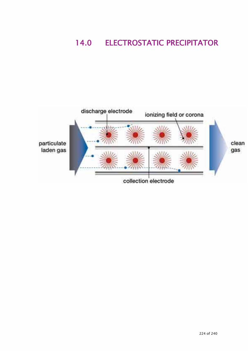
14.0 ELECTROSTATIC PRECIPITATOR
224 of 240

ELECTROSTATIC PRECIPITATOR 14.1 BACKGROUND The major objectives of energy audit for Electrostatic Precipitator( ESP) include:
• Measurement and comparison of existing dust collection efficiency of electrostatic precipitator
• Evaluation of specific power consumption in kwh/ Nm3 of gas flow and kwh/kg of dust collection.
• Identification of energy saving measures and quantification of energy and cost savings.
14.2 STEPS INVOLVED IN CONDUCTING THE ENERGY AUDIT The steps involved in conducting energy audit of electrostatic precipitator are:
• Data collection • Observations, measurement and analysis • Exploration for energy conservation measures with detailed techno-
economic calculations • Report preparation
14.3 DATA COLLECTION
• Single line diagram of electrical drawing pertaining to electrostatic precipitator may be obtained.
• Data collection for Electrostatic Precipitator details is given in Table 14-1
Table 14-1 : Field data sheet of ESP
S.N Item Reference Time in Hrs 1 Source, equipment load 2 Boiler main steam flow (tph) 3 Boiler coal flow (tph) 4 Flue gas temperature at ESP
Inlet ºC
5 Flue gas Temperature at ESP outlet ºC
6 CO₂ or O₂ at ESP inlet (%) 7 CO₂ or O₂ at ESP outlet (%)
225 of 240

S.N Item Reference Time in Hrs 8 Dust Loading at ESP Inlet
(mg/Nm3)
9 Dust Loading at ESP Outlet (mg/Nm3)
10 Rectifier Primary side kwh (AC)
11 Rectifier Secondary side kwh (DC)
12 Drying heater power (kwh 14.4 INSTRUMENTS REQUIRED The following instruments are required for conducting the energy audit of lighting system
• Stack monitoring kit (for gas flow and dust loading) • On line instruments • Power analyser • Temperature indicators
14.5 MEASUREMENTS AND OBSERVATION TO BE MADE While conducting the audit, detailed survey may be conducted as given in Table 14-2.
226 of 240

Table 14-2 : Measurement and observation to be made
Time FIELD -1 Field – 2 FIELD – 3 FIELD -4 FIELD – 5
Current (mA)
Voltage (kv)
Charge Ratio
Current (mA)
Voltage (kv)
Charge Ratio
Current (mA)
Voltage (kv)
Charge Ratio
Current (mA)
Voltage (kv)
Charge Ratio
Current (mA)
Voltage (kv)
Charge Ratio
9.00 9.30 10.00 10.30 11.00 11.30 12.00 12.30 13.00 13.30 14.00 14.30 15.00 15.30 16.00 16.30 17.00 17.30
227 of 240

14.6 OBSERVATIONS AND ANALYSIS 14.6.1 System familiarisation and operational details Detailed interactions with the plant personnel have to be carried out to get familiar with system detail and operational details. A visit to the plant should be made for familiarization with ESP. 14.6.2 Measurements and evaluation The summary of electrostatic precipitator details may be obtained as shown in Table 14-3.
Table 14-3 : Electrostatic Precipitator Gas Flow Units Actual Design
Gas flow Nm³/hr % Dust removed % ESP efficiency % Rectifier conversion efficiency % Specific power consumption kWh/Nm³ Dust Removed kWh/kg
Specific heater power consumption
kWh/Nm³
Calculation may be performed as per the formulae given to obtain:
• Dust collection efficiency • Specific power consumption per Nm3 of dust handled and per kg of
dust collected. • Excess air levels before and after ESP.
The above values may be compared with PG test/design values. If these values are worse, then the reasons for the same may be found out and measures for energy savings suggested. ESP Efficiency = di-do/di * 100 Rectifier Efficiency = kWh dc output/kwh ac input *100 where
228 of 240

di= inlet dust loading in mg/nm³ do =out let dust loading in mg/nm³ Specific Power Consumption kwh/nm³ gas flow = Power consumption in kwh/hrs/gas flow rate in nm³/hr Specific Power Consumption Kwh/kg dust collected =Power consumption in kwh/hrs/kg dust collected per hour
229 of 240

ANNEXURES
230 of 240

ANNEXURE–1 : INFORMATION PERTAINING TO ACTION PLAN AS PER FORMAT Details of energy saving measures recommended in the energy audit report (year)
SI.No. Energy saving measures Investment Rs Million.
Reasons for not implementing the measures
Date of completion of measure/likely
completion
Life cycle year’s
2 Annual Energy savings
Oil Gas Coal Electricity Other 1. 2. 3.
Signature Name of the energy manager Name of the Company Full address Contact person Email address Telephone/Fax numbers Plant address
Signature Name of the accredited energy auditor Accreditation details Seal
1 Estimate the predicted life of the measure, meaning the number of years the level of first year energy saving or even larger amounts will materialize. 2 Indicate commercial units of fuel used such as liter, kg, tones, normal cubic meter, kWh or MWh and indicate unit. Indicate the anticipated potential in
energy savings.
DECEMBER 2009 231 of 240

ANNEXURE–2 : DETAILS OF ILLUMINATION LEVEL REQUIRED Recommended illumination values as per IS: 3646 (Part-1) –1992 for various area in Power Stations
S.No Type of Interior or Activity Range of Service
Illuminance in lux Remarks
General Plant 1 Turbine house (operating floor) 150-200-300 2 Boiler and turbine house basements 50-100-150
3 Boiler house, platform, areas around burner
50-100-150
4 Switch rooms, meter rooms, oil plant room, HV substation (indoor)
100-150-200
5 Control rooms 200-300-500
Localize lighting of control display and the control desk may be appropriate
6 Relay and telecommunication rooms 200-300-500
7 Diesel generator rooms, compressor rooms
100-150-200
8 Pump houses, water treatment plant houses
100-150-200
9 Battery rooms, charges, rectifiers 50-100-150
10
Cable tunnels and basements, circulating water culverts and screen chambers, storage tanks (indoor), operating areas and filling at outdoor tanks
30-50-100
Coal Plants
1 Conveyors, gantries, junction tower, unloading hopers, ash handling plants, settling pits, dust hoppers outlets
50-100-150
2 Other areas where operators may be in attendance
100-150-200
Welding and Soldering Shops
1 Gas and arc welding, rough spot welding
200-300-500
2 Medium soldering, brazing, spot welding
300-500-750
3 Fine soldering, fine spot welding 750-1000-1500 Local lighting is
DECEMBER 2009 232 of 240

S.No Type of Interior or Activity Range of Service
Illuminance in lux Remarks
desirable GENERAL BUILDING AREAS Entrance 1 Entrance halls, lobbies, waiting rooms 150-200-300
2 Enquiry desks 300-500-750 Localized lighting may be appropriate
3 Gatehouses 150-200-300 Circulation Areas 1 Lifts 50-100-150 2 Corridors, passageways, stairs 50-100-150 3 Escalators, travellators 100-150-200 Medical and First Aid Centers 1 Consulting rooms, treatment rooms 300-500-750 2 Rest rooms 100-150-200 3 Medical Stores 100-150-200 Staff Rooms
1 Changing, locker and cleaners rooms, cloakrooms. Laboratories
50-100-150
2 Rest rooms 100-150-200 Staff Restaurants
1 Canteen, cafeterias, dining rooms, mess rooms
150-200-300
2 Server, vegetable preparation, washing up area
200-300-500
3 Food preparation and cooking 300-500-750 4 Food stores and cellars 100-150-200 Communications 1 Switchboard rooms 200-300-500 2 Telephone apparatus rooms 100-150-200 3 Telex rooms, post room 300-500-750 4 Reprographic room 200-300-500 Building Services 1 Boiler houses a General 50-100-150 b Boiler front 100-150-200
c Boiler control room 200-300-500
Localized lighting of the control display and the control desk may
DECEMBER 2009 233 of 240

S.No Type of Interior or Activity Range of Service
Illuminance in lux Remarks
be appropriate
d Control rooms
200-300-500
Localized lighting of the control display and the control desk may be appropriate
e Mechanical plant room 100-150-200
f Electrical power supply and distribution room 100-150-200
g Store rooms 50-100-150 Car parks 1 Covered car parks a Floors 5-20 b Ramps and corners 30 c Entrance and exits 50-100-150 d Control booths 150-200-300 e Outdoor car parks 5-20
Note:- For details please refer IS:3646(Part-1):1992
DECEMBER 2009 234 of 240

ANNEXURE-3 : INFORMATION ON COAL BLENDING
Guidelines for coal blending and soot blowers Coal blending has become a very common phenomenon nowadays in Indian thermal power plants. Typically Indian coal is blended with imported coal (from Indonesia, Australia or South Africa) and fired in the boiler. The power plants are adopting coal blending for various reasons. Some of the reasons are:
• To improve the overall economy of the fuel firing • To achieve the required quality of coal matching with the design
coal characteristics and increase the operating efficiency of the plant
• To improve the grindability and there by increasing capacity utilization of the plant
• To minimize the ash content in the coal and there by minimizing the problems associated with coal handling
• To minimize the SPM emissions Majority of the plants decide the blending proportions depending upon the availability of the coal and the overall cost of firing. The blending procedures also adopted based on their previous experience and convenience. These adhoc decisions on blending proposition and the improper blending mechanism could result in reduction in operating efficiency of the plant and increased cost of firing. In some cases, this may lead even to fire accidents in the mills. Some of the broad guidelines for coal blending are given below for achieving improved efficiency and economy of firing.
• The blended coal characteristics should be close to the design coal characteristics. Particularly the calorific value and the volatile matter of the blended coal need to be very close to the design coal.
• The proportion of the coal could be further optimized for maximum
DECEMBER 2009 235 of 240

cost economy by carrying out performance test of the boiler. The performance test for the boiler need to be carried out for different proportions and based on the best possible efficiency achieved, the optimum percentage of coal blending needs to be decided.
• Preferably, the coals selected for blending should have very little
variation (not more than 5-8%) in volatile matter content.
• Blending of the coal before mills should not be adopted if the volatile matter and ignition characteristics of the coals vary as this may lead to firing in the mill itself.
• If the ignition characteristics vary significantly, pulverizing can be done in a separate mills and level firing in the furnace may be practiced. In that case for milling the high volatile matter and low ignition temperature coals, the mill outlet temperature needs to be adjusted to avoid fire hazards. The temperature adjustment can be taken up through trial and error method.
• The air fuel ratio needs to be readjusted based on the characteristics of the blended coal to achieve the maximum boiler operating efficiency.
Guidelines for optimization of soot blowers To improve the performance and thermal efficiency of the boiler, it is important to remove the deposits periodically and maintain the heating surface clean. Boilers are designed such that the radiation and convective zone heat transfer surfaces absorb the released heat proportionately. Any deviation in heat transfer in radiation and convection zone due to deposit formation will affect the function of feed water preheating in the economiser, steam super heating in LTSH, platen super heater and final super heater. This will result in reduction in boiler operating efficiency. The wall blowing systems are operated sequentially once in 8 hrs. All soot blowers are operated 3 times a day. Soot blowing requires about 3.3 tons of steam per cycle.
DECEMBER 2009 236 of 240

In a periodical system, the furnace condition is not taken into consideration. The changes in fuel characteristics and boiler load are also not taken into account for controlling the soot blowing. Only periodical (and not regular) operation of the soot blowing system leads to the following:
• Significant variation in super heater and reheater spray. This leads to reduction in overall efficiency of the plant
• Increased steam consumption • Blowing steam on cleaner tubes leads to boiler tube erosion.
The soot blowing system can be optimized based on the requirement. The optimization need to be taken up on a trial and error basis. This optimization will vary depending upon the plant operating conditions and the characteristics of the fuel fired. The following guidelines may be followed for optimizing the soot blower operation and increasing the overall efficiency of the plant.
• The optimization of the soot blowers need to be taken up based on the super heater spray. The objective should be to minimize the super heater spray fluctuations and keep the spray quantity at as minimum a level as possible.
• Monitor closely the trend of the attemperation spray quantity. If the spray quantity is higher compared to the design and continuous, one of the reasons could be increased deposits in the water walls and hence reduction in heat transfer in the water wall areas.
• Marginally increase the wall blower operating duration. This will help in reducing the super heater spray quantity.
• If the spray quantity is lower compared to design and stable, it offers scope for minimizing the operating frequency of the soot blowers. This could be experimented upon by avoiding the operation / minimizing the duration in alternate shifts with close monitoring of the attemperation spray quantity.
• If there is no variation in spray quantity over a period of time, the identified operating condition could be continued as a practice. However, operation of all the soot blowers atleast once in a day
DECEMBER 2009 237 of 240

needs to be ensured. When avoiding operation of the soot blowers becomes impossible, similar kind of experimentation can be carried out by marginally reducing the operating pressure of the soot blowers (i.e by 2-3 kg/cm2). For precise control of the soot blowers and the maximum benefit, smart soot blowing systems can be adopted.
DECEMBER 2009 238 of 240

ANNEXURE-4: PERFORMANCE OF LUMINARIES WHICH ARE COMMONLY USED
Luminous Performance Characteristics of Commonly Used Luminaries
Type of Lamp Lumens / Watt
Color Rendering Index
Typical Application Typical Life
(hours) Range Avg.
Incandescent 8-18 14 Excellent Homes, restaurants, general lighting, emergency lighting
1000
Fluorescent Lamps
46-60 50 Good w.r.t. Coating
Offices, shops, hospitals, homes
5000
Compact fluorescent lamps (CFL)
40-70 60 Very good Hotels, shops, homes, offices
8000-10000
High pressure mercury (HPMV)
44-57 50 Fair General lighting in factories, garages, car parking, flood lighting
5000
Halogen lamps 18-24 20 Excellent Display, flood lighting, stadium exhibition grounds, construction areas
2000-4000
High pressure sodium (HPSV) SON
67-121 90 Fair General lighting in factories, ware houses, street lighting
6000-12000
Low pressure sodium (LPSV) SOX
101-175 150 Poor Roadways, tunnels, canals, street lighting
6000-12000
DECEMBER 2009 239 of 240

ANNEXURE-5 : PROCEDURE FOR ESTIMATING THE ENERGY SAVING POTENTIAL IN PUMPS WITH VALVE CONTROL A typical pumping system in a process with excess capacity / head is given below. For matching with the process requirement, the pump is throttled at the outlet. Throttling of the pump at the outlet leads to pressure loss and hence energy loss.
The energy saving potential in the pump can be calculated as below: Pressure at the locations P1, P2 and P3 as indicated the diagram can be measured. Pressure deferential across the valve - (P3 – P2) Total pressure raise by the pump - (P2 – P1) Energy saving potential in the pump in % - (P3 – P2) x 100/ (P2 – P1) This indicates the maximum energy saving potential available in the pump.
Process
Storage
Tank
Valve
P1 P2 P3
DECEMBER 2009 240 of 240
Related Documents