GUIDE FOR RISK EVALUATIONS FOR THE CLASSIFICATION OF MARINE-RELATED FACILITIES JUNE 2003 American Bureau of Shipping Incorporated by Act of Legislature of the State of New York 1862 Copyright 2003 American Bureau of Shipping ABS Plaza 16855 Northchase Drive Houston, TX 77060 USA

Welcome message from author
This document is posted to help you gain knowledge. Please leave a comment to let me know what you think about it! Share it to your friends and learn new things together.
Transcript
GUIDE FOR
RISK EVALUATIONS FOR THE CLASSIFICATION OF MARINE-RELATED FACILITIES
JUNE 2003
American Bureau of Shipping Incorporated by Act of Legislature of the State of New York 1862
Copyright 2003 American Bureau of Shipping ABS Plaza 16855 Northchase Drive Houston, TX 77060 USA

This Page Intentionally Left Blank

ABS GUIDE FOR RISK EVALUATIONS FOR THE CLASSIFICATION OF MARINE-RELATED FACILITIES . 2003 iii
Foreword
The mission of the American Bureau of Shipping (ABS) is to serve the public interest, as well as the needs of its clients, by promoting the security of life, property, and the natural environment primarily through the development and verification of standards for the design, construction and operational maintenance of marine-related facilities.
The Rules on which classification is predicated are established from principles of naval architecture, marine engineering and other engineering principles that have proven satisfactory by service experience and systematic analysis. The perceived benefits of the deterministic and prescriptive regulatory requirements were based mostly on experience, testing programs and expert judgment. The objective of these Rules has always been to ensure that the probabilities of accidents with the potential for adversely affecting life, property and the natural environment are low. However, this assurance was not explicit, as Rules and regulations until recently were developed without the benefit of explicit estimates of risk.
In recent years, there have been significant advances in and experience with risk assessment methodology. ABS is continually seeking the improvement of its Rules and methods of analysis and exploring the directions where the industry is headed. Thus, ABS is exploring certain changes to the development and implementation of its Rules and regulations through the use of risk-based, and ultimately performance-based, approaches. The rewards for this potential process are improved classification services and, ultimately and foremost, improved safety and productivity.
The transition to a risk-based regulatory framework is expected to be incremental. Many of the present requirements are based on deterministic and prescriptive requirements that cannot be quickly replaced. Therefore, the current requirements will have to be maintained, while risk-based and/or performance-based approaches are being developed and implemented.
The information and process outlined in this Guide provides a risk-based perspective to evaluating proposed designs that offer alternative means of compliance to current prescriptive requirements, or novel designs for which classification requirements do not exist. This perspective offers many advantages to ship owners/designers and ABS. Some of these advantages are:
i) Increased ability to suggest innovative designs that are technically superior and more cost-effective.
ii) Increased confidence that the proposed designs will provide the same level of safety.
iii) Better understanding of hazards, mitigation measures, and risk posed by the proposed design.
The process defined in this Guide provides a sound and practical approach for performing risk-evaluations to support the classification of proposed designs, so that the advantages listed above can be realized.
This document provides guidance on how to prepare a risk-based submittal to demonstrate that a proposed design meets the overall safety and strength standards of the Rules. It defines a process that the client can implement to prepare and submit documentation for consideration by ABS. It also outlines the approach that ABS will take in reviewing the submittal to determine if the proposed design is acceptable for classification.
Additional guidance will be published on the application of risk-based approaches to classification activities, such as the ABS Guidance Notes on Review and Approval of Novel Concepts, the ABS Guide for Surveys Using Risk Based Inspection Techniques, and the ABS Guide for Surveys Based on Reliability Centered-Maintenance.

This Page Intentionally Left Blank

GUIDE FOR
RISK EVALUATIONS FOR THE CLASSIFICATION OF MARINE-RELATED FACILITIES
CONTENTS SECTION 1 General....................................................................................1
1 Objective ................................................................................1 2 Application .............................................................................1 3 Definitions ..............................................................................1
SECTION 2 Concept of Equivalency ........................................................3
1 General ..................................................................................3 2 Evaluation Metrics..................................................................3 3 Evaluation of Alternative Arrangements ................................4 4 Evaluation of Novel Features.................................................4 5 Acceptance Criteria................................................................5
SECTION 3 Risk Evaluation Process .......................................................7
1 General ..................................................................................7 FIGURE 1 Risk Evaluation Process ..............................................8
SECTION 4 Evaluation Objectives............................................................9
1 General ..................................................................................9 2 Selection of Evaluation Metrics..............................................9 3 Comparative versus Absolute Assessment .........................10
3.1 Comparative Risk Assessment ....................................... 10 3.2 Absolute Risk Assessment.............................................. 10
SECTION 5 Basic Risk Assessment.......................................................11
1 General ................................................................................11 2 Development of Basic Risk Assessment Plan.....................12
2.1 Selection of Risk Assessment Technique ....................... 12 2.2 Establishment of Acceptance Criteria ............................. 13 2.3 Scope of the Risk Assessment........................................ 13
ABS GUIDE FOR RISK EVALUATIONS FOR THE CLASSIFICATION OF MARINE-RELATED FACILITIES . 2003 v
3 Performance of the Basic Risk Assessment........................14 3.1 Identifying the Risk Analysis Team..................................14 3.2 Preparing for the Risk Assessment .................................14 3.3 Hazard Analysis ..............................................................14 3.4 Estimation of the Evaluation Metrics ...............................15 3.5 Comparative Assessments and the Change Analysis
Method ............................................................................15 4 Evaluation of Results of the Basic Risk Assessment ..........16
4.1 Evaluation of Comparative Risk Assessment ..................16 4.2 Evaluation of Absolute Risk Assessment ........................16 4.3 Confidence of the Results ...............................................16
5 Documentation of Basic Risk Assessment ..........................17 6 Use of an Existing Risk Model .............................................17
6.1 General............................................................................17 6.2 Appropriateness of Model................................................17 6.3 Risk Impact......................................................................18
FIGURE 1 Risk Matrix Concept...................................................13
SECTION 6 Detailed Risk Assessment .................................................. 19
1 General ................................................................................19 2 Development of Detailed Risk Assessment Plan ................20
2.1 Selection of a Risk Assessment Technique.....................20 2.2 Establishment of the Acceptance Criteria........................21 2.3 Scoping of the Risk Assessment .....................................22
3 Performance of the Detailed Risk Assessment ...................22 4 Evaluation of Results of the Detailed Risk Assessment ......22 5 Documentation of the Detailed Risk Assessment................22
SECTION 7 Submittals to ABS................................................................ 23
1 General ................................................................................23 2 Prior to Conducting Risk Assessments................................23
2.1 Risk Assessment Plan.....................................................23 3 Basic Risk Assessment Submittal Requirements................24 4 Detailed Risk Assessment Submittal Requirements ...........24 5 Review/Approval of Submittals ............................................25 6 Life Cycle Risk Management ...............................................25
APPENDIX 1 References............................................................................ 27 APPENDIX 2 Risk Analysis Team ............................................................. 29
1 Overview of the Risk Analysis Team ...................................29 1.1 Team Leader ...................................................................29 1.2 Scribe ..............................................................................29 1.3 Subject Matter Experts ....................................................30
vi ABS GUIDE FOR RISK EVALUATIONS FOR THE CLASSIFICATION OF MARINE-RELATED FACILITIES . 2003

APPENDIX 3 ABS Risk Models..................................................................31 1 Overview of ABS Risk Models .............................................31 TABLE 1 Tanker Model General Design Assumptions .............31 TABLE 2 FPSO Model General Design Assumptions...............31 TABLE 3 Risk Model Consequences ........................................32
APPENDIX 4 Overview of Risk Assessment Techniques .......................33
1 Hazard Identification (HAZID) Technique............................33 2 Change Analysis Methodology ............................................33
2.1 Typical Analysis Activities for Change Analyses ............. 34 3 What-if Analysis ...................................................................36
3.1 Typical Analysis Activities for What-if Analyses .............. 36 4 Checklist Analysis ................................................................37
4.1 Typical Analysis Activities for Checklist Analyses ........... 38 5 Hazard and Operability (HAZOP) Analysis..........................39
5.1 Typical Analysis Activities for HAZOP Analyses ............. 40 6 Failure Modes and Effects Analysis (FMEA) .......................41
6.1 Typical Analysis Activities for FMEAs ............................. 42 7 Event Tree Analysis .............................................................44
7.1 Typical Analysis Activities for Event Tree Analysis ......... 44 8 Fault Tree Analysis ..............................................................45
8.1 Typical Analysis Activities for Fault Tree Analysis........... 45 9 Summary of Key Aspects of Risk Assessment
Techniques ..........................................................................47 10 Additional Literature Resources...........................................49 TABLE 1 Example Change Analysis .........................................35 TABLE 2 What-if Evaluation Example.......................................37 TABLE 3 Checklist Analysis Example.......................................39 TABLE 4 Example of a HAZOP Analysis ..................................41 TABLE 5 FMEA Evaluation Example ........................................43 TABLE 6 Overview of Commonly Used Risk Assessment
Techniques.................................................................48 FIGURE 1 Example Event Tree Analysis ....................................45 FIGURE 2 Example Fault Tree Analysis .....................................47
APPENDIX 5 Survey of the Use of Risk Acceptance Criteria .................51
1 US Offshore Oil Production Industry....................................51 2 US Coast Guard (USCG).....................................................52 3 US Nuclear Regulatory Commission (NRC)........................56 4 US Department of Defense (DOD) ......................................58
ABS GUIDE FOR RISK EVALUATIONS FOR THE CLASSIFICATION OF MARINE-RELATED FACILITIES . 2003 vii

5 US Department of Energy (DOE) ........................................60 6 United Kingdom Health and Safety Executive.....................62 7 International Maritime Organization (IMO)...........................64 TABLE 1 Risk Assessment Code Levels and Recommended
Response Criteria ......................................................55 TABLE 2 U.S. Department of Energy Risk Matrix with Risk
Goals Consequence versus Frequency.....................61 TABLE 3 Chemical Accident Consequence Levels ..................61 TABLE 4 Example Radiological Accident Consequence
Levels.........................................................................61 FIGURE 1 USCG Frequency/Consequence Categories and
Risk Screening Criteria ..............................................54 FIGURE 2 Blank Risk Matrix with RACs .....................................54 FIGURE 3 Example Risk Profile..................................................56 FIGURE 4 MIL-STD-882D Risk Matrix ........................................59 FIGURE 5 Risk Tolerance Distribution within Risk Matrix
(MIL-STD-882D).........................................................60 FIGURE 6 IMO Formal Safety Assessment (FSA) Process........65
viii ABS GUIDE FOR RISK EVALUATIONS FOR THE CLASSIFICATION OF MARINE-RELATED FACILITIES . 2003
ABS GUIDE FOR RISK EVALUATIONS FOR THE CLASSIFICATION OF MARINE-RELATED FACILITIES . 2003 1
S E C T I O N 1 General
1 Objective
This document provides guidance to ABS clients on how to prepare a risk evaluation to demonstrate that a design proposed for classification meets the overall criteria for safety and strength standards of the ABS Rules and Guides. It defines a process that the client can implement to prepare and submit documentation for consideration by ABS. It also outlines the approach that ABS will take in reviewing the submittal to determine if the proposed design is acceptable for classification.
2 Application
This document applies to any situation where a design is being proposed on the premise that it provides equivalent protection against the risks addressed by the ABS Class Rules, rather than by strict compliance with existing prescriptive classification Rules. Evaluations of hardware and survey issues are included in the scope of this document.
This Guide is applicable to both ships and offshore facilities. Specifically, this Guide is applicable when ABS clients are proposing:
i) Alternative Arrangements. Marine-related facilities with design characteristics that include alternative means of compliance to applicable prescriptive classification Rules.
ii) Novel Features. Marine-related facilities that contain novel features of design in respect to the hull, machinery, or equipment to which provisions of the Rules are not directly applicable.
A special comment will be entered in the Record indicating that classification of the vessel/installation has incorporated the provisions of this Guide.
If proposed designs include alternative arrangements or novel features that conflict with existing applicable statutory requirements or regulations from any other regulatory body outside ABS, the decision for approval lies with those external bodies. While many regulatory bodies are evolving to accept the use of risk evaluations to demonstrate safety equivalency to prescriptive requirements, there may always be a number of regulatory bodies that will not accept such flexibility. The cognizant administration or regulatory body is the final determining body for statutory or regulatory requirements under their jurisdiction.
Note that if a proposed design is categorized as a Novel Concept according to the application scope defined in the ABS Guidance Notes on Review and Approval of Novel Concepts, then those Guidance Notes should be followed, unless otherwise instructed by ABS.
3 Definitions
Absolute Risk is the expression of risk in terms of the specific estimates of the frequency and consequence.
Acceptable Risk is the expected risk that is considered tolerable for a given activity.

Section 1 General
Analysis Team is a team of the subject matter experts and risk analyst(s) who are responsible for performing the risk assessment.
Change Analysis is a comparative risk assessment technique that logically identifies risk impacts and risk management strategies in situations where change is occurring.
Confidence is the analyst’s/team’s certainty of the risk evaluation.
Consequence is an unwanted event that can negatively affect subjects of interest. It can be expressed as number of people affected (injured or killed), property damage, amount of a spill, area affected, outage time, mission delay, dollars lost or other measure of negative impact.
Direct Design is a design that results from the direct application of the ABS Rules or Guides.
Evaluation Metrics are qualitative and/or quantitative parameters selected to characterize or evaluate a proposed design in terms of its level of safety, that are used to judge the adequacy of the proposed design for classification. The evaluation metrics could be directly a risk measure (e.g. fatalities per year), but it could also be any one component that affects risk. Examples of evaluation metrics are: the reliability of a system, the frequency of loss of propulsion events, the number of safeguards available to mitigate a fire in a specific location, etc.
Event is an occurrence that has an associated outcome. There are typically a number of potential outcomes from any one initial event that may range in severity from trivial to catastrophic, depending upon other conditions and subsequent events.
Frequency is the expected number of occurrences of an undesirable event expressed as events per unit time.
Hazards are conditions that exist that may potentially lead to an undesirable event.
Major Hazard is a hazard with potentially unacceptable risk if not eliminated, controlled, and/or managed. Chapters 4 and 5 of ABS’s Guidance Notes on Risk Assessment Application for the Marine and Offshore Oil and Gas Industries provide a list of major hazards.
Qualitative Risk Assessment is a risk assessment that expresses the risk in terms of quality or kind (e.g., low, high, very high).
Quantitative Risk Assessment is a risk assessment that expresses the risk in terms of risk impact per unit time (e.g., $1,000,000 per year).
Relative Risk is the expression of the change in risk relative to a case of interest or baseline case.
Risk is the product of frequency with which an undesirable event is anticipated to occur and the consequence of the event’s outcome.
Risk Analysis is the process of understanding (1) what undesirable things can happen, (2) how likely they are to happen, and (3) how severe the effects may be. More precisely, it is an integrated array of analytical techniques, e.g. reliability, availability and maintainability engineering, statistics, decision theory, systems engineering, human behavior, that can successfully integrate diverse aspects of design and operation in order to assess risk.
Risk Assessment includes a risk analysis, but it also involves the process by which the results from risk analysis are considered against judgment, standards or criteria.
Safety Margin is an adjustment made to compensate for the uncertainties and assumptions used in the risk assessment.
Sensitivity Analysis is the determination of how rapidly (sensitive) the output of a risk analysis changes with respect to variations in the input (it can include variations in input data or assumptions.)
2 ABS GUIDE FOR RISK EVALUATIONS FOR THE CLASSIFICATION OF MARINE-RELATED FACILITIES . 2003

S E C T I O N 2 Concept of Equivalency
1 General
Proposed designs that do not strictly comply with applicable prescriptive classification Rules can be submitted to ABS for consideration for class under the terms of this Guide, if equivalency to the ABS Rules and requirements is demonstrated. For a design to be considered equivalent, it must provide compliance with the overall criteria for safety and suitability for intended service established in the applicable ABS Rules and Guides. This is called an equivalency demonstration.
An equivalency demonstration can be relatively simple in some cases, but it can be very complicated in others. It depends on the degree of innovation of the proposed designs, on the number of prescriptive requirements involved and on the nature of the goals/objectives of those requirements.
The key issue in the demonstration of equivalency is the identification of the criteria for safety and suitability for intended service of the applicable ABS requirements. These criteria are the objectives of the ABS Rules.
The primary objective of the classification Rules and Guides is to promote the security of life, property and the natural environment. Consequently, any equivalency demonstration needs to consider the following areas:
i) Personnel safety
ii) Property protection
iii) Environmental protection
The objectives of the Rules constitute the foundation for demonstrating equivalency. A proposed design can be approved for classification under the terms of this Guide if it is shown that even though some prescriptive requirements are not strictly complied with, all the goals and objectives of those affected requirements are being met by the proposed design. This equivalency can be demonstrated by defining parameters for evaluation, based on the goals and objectives of the Rules under consideration, and then demonstrating that the estimations of those parameters for the proposed design are acceptable or equivalent to the same parameters for the direct design. The following subsection describes the concept of these parameters called evaluation metrics.
2 Evaluation Metrics
Evaluation metrics are qualitative and/or quantitative parameters selected to characterize or evaluate a proposed design in terms of its level of safety. They are used to judge the adequacy of the proposed design for classification. The goals and objectives of the prescriptive classification Rules constitute the foundation for defining the evaluation metrics that can be used to demonstrate acceptability for classification.
In the most generic case, the total risk of a proposed design constitutes a valid evaluation metric that could be used to demonstrate acceptability for classification design. However, in many cases, the estimation of such metrics could be very time consuming, and its accuracy may not be sufficient to confidently arrive at an acceptability conclusion. In general, it is advisable to select evaluation metrics
ABS GUIDE FOR RISK EVALUATIONS FOR THE CLASSIFICATION OF MARINE-RELATED FACILITIES . 2003 3

Section 2 Concept of Equivalency
that are simple to estimate, and still capture the goals and objectives of the Rules for which alternative compliance is being sought. Examples of simpler evaluation metrics could be: the reliability of a system, the frequency of loss of propulsion events, the number of safeguards available to mitigate a specific undesirable event, etc. Being that the objectives of ABS Rules and requirements are to reduce risks, the evaluation metrics are always going to be related to risk, directly or indirectly. For that reason, risk assessment techniques are useful to estimate the evaluation metrics.
The selection of appropriate evaluation metrics is a very important task in determining equivalency, because the evaluation effort and adequacy of the demonstration are directly dependent on this selection. The following subsections give more details on the selection of evaluation metrics for the two distinctive cases of application: alternative arrangements and novel features.
3 Evaluation of Alternative Arrangements
Alternative arrangements refer to proposed designs that include alternative means of compliance to applicable prescriptive classification Rules. In most cases, the affected classification Rules are going to be limited in number, so that the equivalency analysis can be limited in scope to the goals and objectives of only those affected Rules. The selection of evaluation metrics to represent the identified Rule goals and objectives becomes more manageable. If such goals and objectives are not explicitly stated, and cannot be easily inferred, ABS can be contacted for guidance.
Additionally, for alternative arrangements, a comparable direct design is normally easily identified and defined, so that the selection of evaluation metrics and equivalency evaluation can be performed in terms of a comparative assessment. In this case, the change analysis methodology, or any other comparative assessment, should be selected to start the evaluation, as described in Section 5 on Basic Risk Assessment.
Examples of evaluation metrics for alternative arrangements can be:
i) The reliability of a subsystem (to be compared to the reliability of the comparable subsystem that results from the direct application of the ABS Rules and Guides)
ii) The effectiveness of a proposed protective control (to be compared with the effectiveness of a specific protective control required by a Rule requirement)
In determining equivalency, there are two major attributes that must be considered:
i) The safety performance of the proposed design (e.g., the hazards and potential undesirable events addressed by the design) is acceptable, preferably as compared to a direct design, i.e. in comparative terms, or in absolute terms if a comparative assessment is not possible
ii) An assurance that no new unacceptable hazards are introduced by the proposed design. Based on these two attributes, equivalency can be established by performing a hazard identification, defining adequate evaluation metrics and applying appropriate risk assessment methodologies to assess the evaluation metrics.
4 Evaluation of Novel Features Novel features are innovative and unique designs for which provisions of the Rules are not directly applicable, and therefore specific goals and objectives are not available. If a comparable design is identified, then the evaluation can be made in comparative terms to demonstrate equivalency as described in the Evaluation of Alternative Arrangements. However, in some cases, a comparable design cannot be identified, so comparisons are not possible, and “equivalency” cannot be established by comparative means. For such cases, these novel features must be considered for classification based on the concept of acceptability, derived from pre-established (i.e. by the organization, regulatory agency) acceptance criteria.
4 ABS GUIDE FOR RISK EVALUATIONS FOR THE CLASSIFICATION OF MARINE-RELATED FACILITIES . 2003

Section 2 Concept of Equivalency
The selection of evaluation metrics is still possible, based on identified generic objectives, depending on the nature of the novel features. Examples of evaluation metrics for novel features can be:
i) The number of safeguards provided in the novel design for each potential undesirable event.
ii) The total risk for the proposed installation.
iii) The target reliability or frequency of failure of the installation.
For completely new designs, the acceptability demonstration needs to be based on the overall safety of the design, i.e. through an absolute risk assessment.
5 Acceptance Criteria
Once the evaluation metrics are assessed, either qualitatively or quantitatively, they need to be compared with pre-established acceptance criteria. The acceptance criteria can be qualitative (e.g. risk matrix) or quantitative, in accordance with the evaluation metrics selected. The acceptance criteria can be defined in absolute or relative basis, depending on the type of risk assessment (absolute assessment or comparative assessment) and the type of equivalency evaluation being made
In using absolute criteria, each evaluation metric is compared to previously established acceptance criteria. These criteria can be derived from existing designs with an adequate amount of operational history, from internally derived criteria, or from recognized external sources. Appendix 5 provides a survey of risk acceptance criteria used by some organizations.
For relative criteria, equivalency is determined by judging if the level of the defined evaluation metrics increases, decreases, or remains unchanged when compared to the same metrics for a direct design. In general, detrimental or unfavorable changes in the evaluation metrics are not allowed.
In addition, the degree of confidence in the qualitative judgments and quantitative measures needs to be considered when establishing equivalency. The confidence in the estimations of the evaluation metrics is key in determining the safety margin required for the proposed design to be considered equivalent. A high confidence can allow a design to be accepted as equivalent with lower safety margin than the same design with a low confidence in the estimated value of the evaluation metrics.
ABS GUIDE FOR RISK EVALUATIONS FOR THE CLASSIFICATION OF MARINE-RELATED FACILITIES . 2003 5

This Page Intentionally Left Blank

S E C T I O N 3 Risk Evaluation Process
1 General
Due to the fast pace at which technology develops in the industry, ABS recognizes that ship and offshore facility designers and Owners have the need to propose novel designs, or designs that include alternative means of compliance to existing ABS Class Rules. Typically, alternatives or novel designs are proposed as a means to optimize resources while at the same time providing an equivalent (or better) level of safety. The application of risk evaluations provides a practical and effective means to demonstrate that the proposed designs appropriately manage the risk, and thus provide an equivalent level of safety. The evaluation process described in this section provides ABS clients with a formal method for risk evaluation when proposing designs to ABS for classification approval.
The major activities in the evaluation process are:
Step 1 – Define the objectives of the evaluation.
Step 2 – Conduct a Basic Risk Assessment (comparative or absolute).
Step 3 – Conduct a Detailed Risk Assessment (comparative or absolute, if needed).
Each of these steps is explained in Sections 4 through 6, respectively. Section 3, Figure 1 is a flowchart outlining the risk evaluation process.
This process provides a flexible evaluation approach that can be applied to a variety of situations. It provides ABS and its clients with opportunity to determine (1) the appropriate level of analysis required and (2) the acceptance criteria to be used to judge the equivalency of the design to be classed. Increased communication between ABS and clients during development and execution of the risk evaluation process will be necessary as the complexity of the evaluation increases.
The risk evaluation process can use any combination of basic, detailed, comparative or absolute assessments and as many iterations as necessary, provided that the analysts believe that such combination of techniques will support a conclusion.
The responsibility for developing the assessment plan and performing any analysis rests with the organization proposing the design to be classed.
Past experience, if available, can be used in the risk assessments to demonstrate equivalency. The ABS client must demonstrate that (1) the past experience is applicable and (2) it has provided an acceptable level of safety.
ABS GUIDE FOR RISK EVALUATIONS FOR THE CLASSIFICATION OF MARINE-RELATED FACILITIES . 2003 7

Section 3 Risk Evaluation Process
FIGURE 1 Risk Evaluation Process
Step 3Detailed
Risk AssessmentSection 6
Step 1EvaluationObjectivesSection 4
Define the proposed design and the evaluationmetrics to prove equivalency
Can a comparative risk assessment beused to evaluate equivalency?
Define the evaluation objectivein comparative terms
Conduct basic risk assessment
Based on the basic riskassessment, can the proposed design be
considered to be acceptable for classification,unacceptable, or inconclusive?
Modify design andreanalyze, or reject it
Document and submitdesign for approval
Unacceptable Acceptable
Based on the detailed riskassessment, can the proposed design be
considered to be acceptable for classification,unacceptable, or inconclusive?
Modify design andreanalyze, or reject it
Document and submitdesign for approval
Unacceptable Acceptable
Inconclusive
Define the evaluation objectivein absolute terms
Step 2Basic
Risk AssessmentSection 5
Comparative Assessment Absolute Assessment
Conduct detailed risk assessment
Comparative Assessment Absolute Assessment
Yes
Inconclusive
No
8 ABS GUIDE FOR RISK EVALUATIONS FOR THE CLASSIFICATION OF MARINE-RELATED FACILITIES . 2003

S E C T I O N 4 Evaluation Objectives
1 General
The first step in the risk evaluation of the proposed design is to define the objectives of the evaluation. This is a very critical step, because the objectives will dictate the type of risk methodology to use and the necessary level of effort. Well-defined, written objectives for the risk evaluation are necessary to efficiently execute the risk assessment. Doing more than is necessary to satisfy the particular need is counterproductive and can be very expensive.
In this step, the following items have to be defined and documented:
i) Design specification of the proposed design,
ii) Reason for proposing the design (e.g. reduction of risk, reduction of construction cost, lower maintenance cost, etc.),
iii) Description of a comparable direct design (if applicable),
iv) Identification of any applicable ABS class requirements for which the proposed design will comply by alternative means,
v) Definition of the goals and objectives of the ABS class requirements identified above and
vi) Preliminary selection of the evaluation metrics to be used to demonstrate equivalency.
The design specifications will include the process or functional description, engineering drawings, material specifications, etc.
It is very important to carefully determine the classification requirements of interest and their corresponding goals and objectives. Without an understanding of why the Rule requirements exist, successfully analyzing a proposed design on a risk basis may not be possible. Clients are encouraged to contact ABS to initiate early discussions of specific Class Rule requirements for which the client is considering alternative means for compliance.
The information listed above is used to determine the appropriate analysis methodology to employ for equivalency evaluation. In addition, it provides much of the essential technical information needed to perform the evaluation.
2 Selection of Evaluation Metrics
One or more evaluation metrics should be defined at this step, at least for preliminary considerations. This is desirable, because the risk assessment plan and acceptance criteria can be better selected if the evaluation metrics of choice are known.
In a comparative assessment, if the goals/objectives of the Rules (for which alternative compliance is being sought) can be identified, the selection of evaluation metrics based on those goals may be straightforward. Otherwise, more information may be needed in order to define appropriate metrics.
ABS GUIDE FOR RISK EVALUATIONS FOR THE CLASSIFICATION OF MARINE-RELATED FACILITIES . 2003 9
Section 4 Evaluation Objectives
3 Comparative versus Absolute Assessment
As indicated in the risk-based evaluation process of Section 3, Figure 1, Step 1 includes the determination of whether a comparative risk assessment can be used to evaluate equivalency. As mentioned before, a comparative risk assessment is the preferred method, because it can limit the scope to just the differences of two designs, the proposed one and a direct design, therefore reducing the evaluation effort. However, a comparative risk assessment is not always possible. The following paragraphs give some guidance for when to select each approach.
3.1 Comparative Risk Assessment In order to simplify the risk evaluation of a new proposed design, a good approach is to first identify a comparable design to the one being proposed; for example one which is already in Class and has significant operating experience. If a comparable design can be identified, then the risk evaluation can be limited to the differences between the two designs, and more specifically to those differences that affect risk.
The comparative evaluation is recommended for designs that include alternative means of compliance to a few and specific ABS Class Rule requirements. Typically, for a design to be evaluated using a comparative analysis, the following should be true:
i) ABS Class Rules include a specific requirement (e.g., hardware, system, program, activity) for which the proposed design complies in an alternative way (deemed by the client to be equivalent) and
ii) The alternative means of compliance for the proposed design can easily be defined in terms of discrete changes or deviations from ABS Class Rules.
3.2 Absolute Risk Assessment Designs that are highly innovative when compared to existing conventional designs (e.g. novel designs) can be difficult to evaluate using comparative analysis because:
i) A direct design may not be readily identifiable;
ii) The specifics of the direct design are not readily identifiable; and/or
iii) The differences may be too numerous to efficiently analyze via a comparative risk assessment.
Submittals that are not covered as an alternative to an explicit ABS Class Rule and are not suitable to be evaluated by a comparative analysis include:
i) Proposed designs that have never been implemented but are subject to general requirements in ABS Class Rules (e.g., safety objectives) or
ii) Proposed designs that include too many changes or deviations from a direct design to be easily defined (e.g., complete system changes).
For such cases, the risk evaluation should be conducted by an absolute risk assessment.
10 ABS GUIDE FOR RISK EVALUATIONS FOR THE CLASSIFICATION OF MARINE-RELATED FACILITIES . 2003

S E C T I O N 5 Basic Risk Assessment
1 General
The purpose of this step is to evaluate the proposed design using a simple risk assessment method, usually qualitative, including Change Analysis, Hazard Identification (HAZID), Hazard and Operability (HAZOP), What-If and Failure Mode and Effects Analysis (FMEA). In many cases, the proposed design would be an alternative to a direct design, for which case a comparison assessment using qualitative techniques may be the most effective option. If an applicable risk model is available, it can also be used in this basic risk assessment step. The rationale is to first apply a simple method and/or existing models to determine if equivalency can be demonstrated with a minor level of effort, without initiating more in-depth and complex studies.
It is recommended that this type of analysis be the first type of risk assessment done for any proposed design. There would be instances where the basic assessment provides adequate knowledge and confidence on the risks associated with the proposed design to demonstrate equivalency. In these instances, no additional risk assessments would be necessary for classification purposes.
The basic risk assessment can be done in the very early stages of the design, such as concept design, or later, such as in the Front-End Engineering and Design (FEED) or the detailed engineering phases. A risk assessment for the concept design phase is likely to give insight on the type, number and magnitude of risk scenarios associated with the concept design. This information would allow investigation of lower risk design alternatives before considerable effort has been dedicated to refining the design. In some cases a proposed design that has gone through a risk assessment in the concept stage will need to go through another risk assessment as the design becomes more complete and detailed.
The main steps for conducting a basic risk assessment are as follows:
i) Development of basic risk assessment plan, including acceptance criteria
ii) Performance of the basic risk assessment
iii) Evaluation of results of the basic risk assessment
iv) Documentation of basic risk assessment
Both comparative and absolute assessments would follow the same steps. The main differences between the two approaches are in:
i) The scope of the assessment (limited to the differences vs. whole)
ii) The definition of evaluation metrics (comparative vs. absolute)
iii) The definition of acceptance criteria (comparative vs. absolute)
The following sections will describe each step in more detail, as well as the differences for conducting a comparative assessment as opposed to an absolute assessment.
ABS GUIDE FOR RISK EVALUATIONS FOR THE CLASSIFICATION OF MARINE-RELATED FACILITIES . 2003 11

Section 5 Basic Risk Assessment
2 Development of Basic Risk Assessment Plan
A written plan should be prepared for every risk evaluation for classification. Such a plan will provide direction and ensure that those aspects of the proposed design which are alternative features, can, through the risk evaluation, be demonstrated as being acceptable for classification. ABS will accept and review any risk evaluation plan submitted by the clients in relation to classification. However, submittal of such plans is not mandatory at the basic risk assessment stage, unless specifically requested by ABS. It is the responsibility of the organization proposing the design to select and implement an appropriate plan for the analyses to be submitted.
At a minimum, the following three aspects must be addressed in the basic risk assessment plan:
i) Selection of a risk assessment technique
ii) Establishment of acceptance criteria
iii) Scope of the risk assessment
The following paragraphs provide more guidance on these aspects of a risk assessment plan. This section assumes the use of qualitative risk assessment techniques. Quantitative methods are usually more time consuming and require more detailed information of the proposed design, so they are not normally employed at this stage. However, there are exceptions to this rule, for example when a quantitative risk model has already been developed for some other application.
2.1 Selection of Risk Assessment Technique In selecting an analysis technique, the following should be considered:
i) Type of results needed to determine the acceptability of the alternative. Typically, this can be determined by considering the following:
• Possible unwanted events.
• Ways in which these unwanted events occur (i.e., failure modes, causes, sequences).
• Ways to reduce the frequency of these unwanted events.
• Areas needing (or potentially needing) further analysis or input for a quantitative risk assessment.
ii) Type of resources available. The key factors to consider are (a) the current phase of life for the proposed design (e.g., conceptual design, detailed design) and (b) the quality and timeliness of the documentation.
iii) Complexity and size of the risk assessment. Some techniques are not suited to analyze very complicated unwanted events. The complexity and size of the unwanted events are based on the number of activities or systems, the number of pieces of equipment, and the number and types of events and effects being analyzed.
iv) Type of activity or system. While many techniques can be used to analyze almost any marine system, some techniques are better suited for some systems than for others. Appendix 4, Table 2 provides some guidance on this issue.
v) Type of accidents targeted. For proposed designs believed to (a) have a significant risk or (b) potentially result in failures that are expected to result in severe consequences, more thorough analysis techniques are typically used.
Appendix 4 provides a basic description of most commonly used risk assessment techniques, and a greater level of detail is given in the book Marine Safety Tools for Risk-Based Decision Making by Government Institutes/ABS Consulting.
12 ABS GUIDE FOR RISK EVALUATIONS FOR THE CLASSIFICATION OF MARINE-RELATED FACILITIES . 2003

Section 5 Basic Risk Assessment
When a comparable direct design can be defined, a comparative risk assessment, such as the change analysis method is recommended as a first approach. Paragraph 5/3.5 gives a description of this methodology.
2.2 Establishment of Acceptance Criteria Acceptance criteria for judging the equivalency of the proposed design must be established. As described before, the acceptance criteria should be applicable to the evaluation metrics chosen. The criteria can be based on absolute or relative terms, in accordance with the type of assessment being made. If a risk measure is used for evaluation metrics, at this stage, a risk matrix with acceptance criteria will typically be used (Section 5, Figure 1 depicts an example risk matrix). Alternatively, for comparative assessments, the acceptance criteria could be based on consequences or frequencies only, if it is deemed that respective frequencies or consequences remain the same when compared with a direct design. Examples of this and other risk acceptance criteria are provided in Appendix 5.
FIGURE 1 Risk Matrix Concept
Consequence
Like
lihoo
d
High RiskRegion
Low RiskRegion
Medium Risk Region
Low Medium High
MediumLow
High
Low
Med
ium
Hig
hM
ediu
mL
owH
igh
2.3 Scope of the Risk Assessment Scoping the risk assessment involves defining (1) the objectives of the risk assessment, (2) the scenarios of concern, (3) the physical limits of the risk assessment, including the depth of analysis (e.g., system-level, part-level) and the confidence required to meet the risk evaluation’s objectives, (4) the analysis assumptions and (5) the operational modes of the vessel/installation that need to be considered during the risk assessment.
In general, the basic risk evaluation will have the following two objectives:
i) To conduct a hazard identification in order to evaluate if any new hazards have been introduced by the proposed design, and if so, to assure that adequate protection is provided.
ii) To assess the evaluation metrics previously defined, in order to demonstrate equivalency or acceptability for classification submittal.
ABS GUIDE FOR RISK EVALUATIONS FOR THE CLASSIFICATION OF MARINE-RELATED FACILITIES . 2003 13

Section 5 Basic Risk Assessment
14 ABS GUIDE FOR RISK EVALUATIONS FOR THE CLASSIFICATION OF MARINE-RELATED FACILITIES . 2003
3 Performance of the Basic Risk Assessment
3.1 Identifying the Risk Analysis Team Once it is determined that the proposed design can be evaluated via a qualitative risk assessment technique involving a brainstorming session, an analysis team responsible for performing the risk evaluation is assembled. This is important because many of the risk assessment techniques rely heavily on the team’s knowledge and experience. Additionally, it is important to have any brainstorming session facilitated by a person experienced in the assessment technique. Appendix 2 provides information on risk analysis team composition.
3.1.1 ABS Participation in the Risk Analysis Team ABS does not mandate that ABS personnel be part of the risk analysis team. However, benefits can be derived by the participation of an ABS representative that will be directly involved in reviewing the risk assessment to support the approval decision. Some of those benefits include: i) As a participant the ABS representative will be able to point out the issues that ABS
considers to be relevant for the classification of the proposed design, and thus should be discussed
ii) Participation will minimize the amount of questions and clarifications at the time of the ABS review of the risk evaluation because he/she will be familiar with the study and design.
3.2 Preparing for the Risk Assessment Preparing for the risk assessment involves: i) collecting background information (e.g., design drawings, process flow diagrams, piping and
instrumentation diagrams, electrical diagrams, layout, process operation and maintenance procedures, design information, reliability data, policies, ABS Class Rules)
ii) defining a schedule, and iii) organizing the information, including preparing worksheets or software The facilitator must ensure that (1) any meetings run smoothly, (2) the risk assessment is performed in a systematic and thorough manner, (3) the methodology is appropriately applied (i.e., accepted analysis procedures are followed) and (4) the evaluation objectives are met (depth, targets, and completeness).
3.3 Hazard Analysis The initial step of the basic risk assessment should be to identify the potential hazards posed by the proposed design. To help ensure that all pertinent hazards are considered, a qualitative method is suggested to screen and identify hazards of concern. Hazards can be identified via a variety of analysis methods, such as What-if, checklist and HAZOP. In order to identify the ultimate consequences, it is necessary to assess the potential hazards posed by the proposed design assuming that the controls or safeguards in place do not work. The credit for the safeguards will be given during the risk impact evaluation phase of the analysis, usually reducing the likelihood of the hazard. To identify the undesirable events, it is usually helpful to consider the hazards associated with the operation and then postulate deviations that can result in the consequences associated with the hazards. All operational modes of the vessel/installation need to be considered during the risk assessment. The ABS Guidance Notes on Risk Assessment Application for the Marine and Offshore Oil and Gas Industries provides lists of typical hazards to be considered when identifying undesirable events for the shipping industry (Chapter 4, Section 2) and for the offshore industry (Chapter 5, Section 2).

Section 5 Basic Risk Assessment
For comparative assessments, the hazard analysis can be limited to the differences between the two designs.
3.4 Estimation of the Evaluation Metrics Once the hazard analysis has been completed, the preliminary evaluation metrics defined in Step 1 should be reconsidered, in case some new safety issues are identified in the hazard analysis which may require a change of the preliminary metrics selected. The preliminary evaluation metrics can be validated for continued use in this step, they can be redefined or additional metrics added to the preliminary ones. The objective is to have a set of metrics that together are sufficient to demonstrate equivalency to applicable Rules objectives or to existing previously classed designs.
Once the evaluation metrics are revalidated or redefined, they have to be assessed using the most appropriate risk assessment technique. The basic risk assessment plan should have defined the technique to use based on the preliminary evaluation metrics. However, if the evaluation metrics have changed, the plan may need to be revised accordingly.
3.5 Comparative Assessments and the Change Analysis Method The purposes of a comparative basic risk assessment are to:
i) Identify and define the differences between the proposed design and the specific ABS Class Rule requirements for which the design is complying in some alternative way;
ii) Perform an assessment of the risk impact of the differences, via the assessment of the evaluation metrics;
iii) Analyze the results of the comparison and decide if the evaluation can clearly arrive to a conclusion
iv) If unable to arrive to a conclusion, provide information needed for further risk evaluation, for example (a) to determine an acceptable assessment plan and (b) for any additional analyses.
The change analysis methodology, or another comparative risk assessment method, is an excellent tool for assessing relative risk between two comparable designs (in this case, the proposed design against a direct design). It is a very efficient methodology because it can immediately identify those differences in the designs that affect risk, so that the assessment resources are spent on those important issues.
In conducting the change analysis, the analysis team must:
i) Establish the key differences between the proposed design and a comparable design that complies with the ABS Class Rule requirements in a conventional way.
ii) Identify the undesirable events that can potentially be impacted by the differences.
iii) Assess the impact of the differences on the risk factors of interest for all the identified scenarios.
iv) Evaluate the results to determine if, based on the analysis, the proposed design can be deemed clearly acceptable or clearly unacceptable for classification. If the analysis is inconclusive, consider developing a risk assessment plan to further evaluate the proposed design.
v) Document the analysis.
In establishing the key differences, the team should consider technological or equipment changes, layout changes, functional changes, environmental changes, schedule changes and material changes.
ABS GUIDE FOR RISK EVALUATIONS FOR THE CLASSIFICATION OF MARINE-RELATED FACILITIES . 2003 15

Section 5 Basic Risk Assessment
4 Evaluation of Results of the Basic Risk Assessment
This step is the process of actually assessing the acceptability of the evaluation results for classification submittal of the proposed design. The process is slightly different depending on whether the assessment was comparative or absolute.
4.1 Evaluation of Comparative Risk Assessment To assess the acceptability for classification submittal via a comparative assessment, the analysis team should:
i) Compare the risk impact (via the evaluation metrics) for the proposed design compared to the direct design.
ii) Assure that if any new hazard is introduced, sufficient risk controls are in place so that any risk increase is negligible.
For comparative risk assessments, the analysis team must first characterize the risk impact of the direct design and the proposed case individually, and then compare the two risk levels to determine the risk impact. The risk impact is characterized using defined relative criteria. For example, an upward change in the risk matrix from a low risk region to a high-risk region signifies a large risk increase, which would be unacceptable. Then the risk of any new hazards introduced by the proposed case must be examined to ensure that those risks are adequately controlled.
4.2 Evaluation of Absolute Risk Assessment To assess the acceptability for classification submittal via an absolute assessment, the analysis team should:
i) Evaluate the risk impact (via the evaluation metrics) for the proposed design against previously established criteria.
ii) Assure that all hazards have sufficient risk controls in place so that they are considered acceptable.
In most cases, for an absolute assessment, the evaluation metrics selected are likely to be risk measures for specific undesirable events (those identified as higher risk), so the hazard analysis performed to satisfy item ii) above most likely will also be used to satisfy the risk evaluation in item i). In this case, i.e. if the evaluation metrics are defined in terms of risk measures, one widely used qualitative method of characterizing risks impacts is through the use of a risk matrix. The risk matrix is an X-Y plot with one axis representing the likelihood and the other axis representing the consequence of a particular scenario. The team can assess where each scenario falls within the risk matrix according to defined categories for 1) the severity or consequence and 2) the frequency of occurrence. The position in the matrix of each scenario allows the characterization of the risk impacts for the scenario, and an easy visualization of the high-risk issues. Section 5, Figure 1 depicts the risk matrix concept. Actual examples of risk matrices are provided in Appendix 5.
4.3 Confidence of the Results In addition to assessing the risk impact, the analysis team must assess its confidence in the assessment of the individual evaluation metrics (i.e. direct design and proposed design). The team must determine if it has high or low confidence in the estimations, so that they can be considered for decision-making when comparing values against acceptance criteria. In borderline cases, if the confidence in the results is low, then more detailed analysis should be considered, as described in Section 6 for Detailed Risk Assessment. Once the risk impact has been evaluated, the analysis team must determine if the proposed design can be considered to be (1) acceptable for classification submittal, (2) unacceptable for classification submittal, (3) modified or (4) needs further analysis to better understand the risk and demonstrate equivalency.
16 ABS GUIDE FOR RISK EVALUATIONS FOR THE CLASSIFICATION OF MARINE-RELATED FACILITIES . 2003

Section 5 Basic Risk Assessment
5 Documentation of Basic Risk Assessment
Each risk assessment method has its own method for collecting, organizing and reporting data. The key is that the analysis meeting proceedings and results are thoroughly and accurately documented as the meetings progress. Typically, a meeting scribe records the information as it is being discussed and consensus is reached. It is essential that no qualitative assessment be “documented by exception”, but instead it should include documentation of all the hazardous scenarios discussed. “Documentation by exception” refers to a streamlined documentation process where only those scenarios resulting in recommendations, or only scenarios resulting in problems or hazardous consequences, are documented in the analysis worksheets. Only full documentation of the analysis proceedings demonstrates to reviewers that the risk evaluation was complete and comprehensive. In addition, the results of the evaluation metrics evaluation must be documented. Section 7 provides more details on the type of documentation required to support the submittal of the risk evaluation for classification.
6 Use of an Existing Risk Model
6.1 General In many cases, previous work may have resulted in documentation of a risk model that is pertinent to the design being proposed. If an applicable risk model is available, its use may be considered during this step. For example, ABS has developed quantitative risk models for (1) a tanker and (2) an FPSO. These models have been constructed as “generic” vessels/facilities. From the model results, risk information, as it relates to the importance of various pieces of equipment, system and hazards, may be obtained. Using the risk information and defining appropriate evaluation metrics, the alternative may be compared with the model to estimate the relative importance of the changes (e.g., equipment substitutions) being proposed. The general steps that the analysis team should follow in using the risk models for this step are outlined in the following paragraphs.
6.2 Appropriateness of Model
6.2.1 Determine if the Risk Model Is Appropriate When it has been determined that a change analysis is not appropriate or capable of evaluating the proposed design, a determination should be made if the risk models are appropriate for the evaluation. This determination includes the following questions:
i) Is there a model for the general type of vessel/facility for which the alternative is being proposed?
ii) Are the consequences in the model appropriate for decision making?
6.2.2 Determine the Relationship of the Proposed Design to the Risk Model If the risk model is determined to be appropriate for use in evaluating the proposed alternative, the analysis team will need to determine how this design relates to the design that has been modeled. Determining the model information required is dependent on the type of alternative design being considered, but in general follows the following steps:
i) Determine systems/structures/components affected by the change.
ii) Determine relevant consequences potentially affected by alternative.
ABS GUIDE FOR RISK EVALUATIONS FOR THE CLASSIFICATION OF MARINE-RELATED FACILITIES . 2003 17
Section 5 Basic Risk Assessment
6.2.3 Identify the Relevant Risk Information Identify the appropriate risk information to be obtained from the model for comparison to the proposed design. Types of information that can be obtained are:
i) Consequence frequencies.
ii) Risk importance measures (e.g., Fussell-Vesely, Risk Achievement Worth).
iii) Function/system/component reliabilities.
iv) Initiating event frequencies.
6.3 Risk Impact Using the available risk information from the model, the risk impact of the proposed design can be characterized, via definition of evaluation metrics. Evaluation metrics could be defined as:
i) The absolute risk of the proposed design.
ii) Any other quantitative measure extracted form the risk model (e.g. frequency of a certain event or events, failure frequency of a system, etc.)
Those metrics can be evaluated against a comparative or absolute acceptance criteria.
18 ABS GUIDE FOR RISK EVALUATIONS FOR THE CLASSIFICATION OF MARINE-RELATED FACILITIES . 2003

S E C T I O N 6 Detailed Risk Assessment
1 General
In some cases, the analysis team is unable to accept or reject the proposed design based on the information generated during the basic risk assessment. When this occurs, the team may recommend additional risk assessment(s) to determine the acceptability for risk based classification of the proposed design or to improve confidence on the results of the basic assessment. A more detailed evaluation can be performed for a limited scope of issues identified during the basic risk assessment.
Examples of what these additional analyses may involve are as follows:
i) Expanding a qualitative analysis to quantify the risk (e.g., adding point risk estimates to an FMEA)
ii) Using a different qualitative or quantitative analysis technique to analyze a specific issue or event (e.g., event tree to study specific flammable release events and the associated safeguards)
iii) Collecting additional data to improve confidence in quantitative analysis results
A more refined risk assessment may be required if 1) the basic risk assessment did not provide conclusive information to make a conclusion regarding equivalency or acceptability for classification, or if 2) specific risk issues were identified in the basic risk assessment and need to be assessed with more detail, or if 3) the basic assessment was done in the early design phase and, as the design matures, more refined assessments are required to increase understanding and level of confidence to ensure it meets applicable safety requirements.
Methodologies used to further examine the risk of proposed designs include more refined qualitative evaluations and quantitative risk assessments. The most appropriate technique is dependent on the available information on the proposed design and the type of design.
Typically, qualitative methodologies are used in the basic risk assessments, where the hazards related to the proposed design are identified and their risk evaluated. The detailed risk assessment focuses then on the most critical issues of the proposed design as identified during the basic risk assessment. In most cases, the detailed risk assessment uses quantitative techniques, such as fault tree analysis, event tree analysis, consequence simulation models (fire, explosion, gas dispersion, spill dispersion) and reliability analysis.
Comparative risk assessments may also be appropriate in the detailed step. For example, if the basic assessment identified specific issues of concern, a more refined and quantitative risk comparison between the proposed design and the direct design may provide the more detailed information necessary to arrive at a conclusion.
As indicated before, the main steps for conducting a risk assessment are as follows:
i) Development of the detailed risk assessment plan, including acceptance criteria
ii) Performance of the detailed risk assessment
iii) Evaluation of the results of the detailed risk assessment
iv) Documentation of the detailed risk assessment
ABS GUIDE FOR RISK EVALUATIONS FOR THE CLASSIFICATION OF MARINE-RELATED FACILITIES . 2003 19
Section 6 Detailed Risk Assessment
The following subsections will describe each step in more detail.
2 Development of Detailed Risk Assessment Plan
ABS requires that an assessment plan be developed and submitted to ABS prior to conducting any detailed risk assessment. At a minimum, the following three aspects must be addressed in the risk assessment plan:
i) Selection of a risk assessment technique.
ii) Establishment of the acceptance criteria.
iii) Scoping of the risk assessment.
The following paragraphs provide more guidance on these aspects of a risk assessment plan. These paragraphs assume the use of quantitative risk assessment techniques.
2.1 Selection of a Risk Assessment Technique This may involve defining the technique(s) to be used to model the evaluation metrics defined. The evaluation metrics may be measures of risk, in which case the risk assessment technique will be used to determine (1) the frequency of undesirable events occurring and/or (2) the consequence severity of those events. Quantitative risk assessments are used when there is a need to:
i) Increase the accuracy of the evaluation metrics
ii) Better understand the frequency and/or consequence of events (e.g., consequence modeling needed to determine effects)
iii) Improve the team’s confidence in the risk assessment results
The following subparagraphs briefly describe modeling the frequency and the consequence severity, and evaluating and presenting quantitative risk results.
2.1.1 Frequency Modeling Modeling the frequencies of undesirable events involves (1) determining the important combinations of failures and circumstances that can cause the undesirable events of interest, (2) developing basic failure data from industry or ship-specific data and (3) using appropriate probabilistic mathematics to determine the frequency estimates. Typically, event trees or fault trees are quantified to determine frequency estimates. An event tree is often used to define all of the possible undesirable scenarios that could result for a particular upset initiating event (e.g., rupture of cargo tank), while fault trees can be used to estimate the frequency or probability of individual events in an event tree (e.g., probability of failure of a protective measure).
Specifically, the frequency modeling results in an estimate of the undesirable events’ statistically expected occurrence frequency. The estimates often are very small numbers (e.g., 2 × 10⁻⁴ events per year).
2.1.2 Consequence Modeling Consequence modeling involves (1) characterizing the unwanted event associated with the hazard being analyzed (2) measuring, through accident history or using models/correlations, the effect of the unwanted event to a target of interest (3) identifying the outcome on the target of interest, and 4) quantifying the health, safety, environmental, and economic impacts on the target of interest. The results from the consequence modeling are an estimate of the statistically expected exposure of the target population to the hazard of interest and the safety/health, environmental and/or economic effects related to that level of exposure.
20 ABS GUIDE FOR RISK EVALUATIONS FOR THE CLASSIFICATION OF MARINE-RELATED FACILITIES . 2003
Section 6 Detailed Risk Assessment
2.1.3 Risk Evaluation and Presentation If the evaluation metrics are direct measures of risk, once the frequency and consequence estimates are generated, the risk can be evaluated in many ways. It is essential that the large number of frequency/consequence estimates from the risk assessment be integrated into a presentation format that is easy to interpret and use. The presentation format selected will depend on the purpose of the evaluation and the evaluation metrics of interest.
Societal and individual risk measures are potential risk metrics to be used when absolute risk assessments are conducted. Societal risk is defined as the risk experienced by all people exposed to the source of risk, during a certain period of time. Individual risk is the risk as experienced by an individual onboard a ship (crew or passenger) or third parties that could be affected by a ship accident. Individual fatality risks can be presented as annual fatality rates or as FAR values (fatalities/108 working hours). Both societal and individual risk measures may need to be produced, evaluated and presented. They may be presented on absolute basis and compared to specific risk acceptance criteria. Conversely, they may be presented on a relative basis to avoid arguments regarding the accuracy and/or adequacy of the absolute numbers while preserving any noticeable differences between the proposed design and a design built according to the ABS Class Rules.
A common risk evaluation and presentation method is simply to multiply the frequency of each undesirable event by each consequence, and then sum these products for all situations considered in the evaluation.
2.2 Establishment of the Acceptance Criteria
2.2.1 Absolute Assessment As previously discussed, for absolute assessments, absolute risk acceptance criteria need to be defined. Absolute risk acceptance criteria can be established by setting specific acceptable/threshold limits for the defined evaluation metrics. Depending on the evaluation metrics, threshold limits can be defined, for example, for any of the following:
i) Frequency of the undesirable events for certain consequence severity (e.g., fatalities, severe injuries, spills greater than so many barrels of oil).
ii) Consequence severity of the undesirable events.
iii) Risk (i.e., combination of frequency and consequence severity).
The risk acceptance criteria must be established and documented prior to conducting the analysis.
2.2.2 Comparative Assessment For comparative assessments, the acceptance criteria can be defined in relative terms as explained in the basic risk assessment section. For evaluation metrics that are a measure of risk, relative acceptance criteria can be established for one or more of the following: i) Relative frequency of undesirable events as compared to the analogous frequency for
a comparable direct design. ii) Relative consequence severity of undesirable events as compared to the analogous
consequence severity of a comparable direct design. iii) Relative risk level provided by the proposed design as compared to the risk level of a
comparable direct design. In establishing the relative risk acceptance criteria, the factors listed above should be considered. Likewise, the risk acceptance criteria must be established, documented, and accepted by all parties prior to conducting the analysis. Examples of specific risk acceptance criteria used by some industries are provided in Appendix 5.
ABS GUIDE FOR RISK EVALUATIONS FOR THE CLASSIFICATION OF MARINE-RELATED FACILITIES . 2003 21
Section 6 Detailed Risk Assessment
22 ABS GUIDE FOR RISK EVALUATIONS FOR THE CLASSIFICATION OF MARINE-RELATED FACILITIES . 2003
2.3 Scoping of the Risk Assessment Scoping the risk assessment involves defining (1) the objectives of the risk assessment, (2) the scenarios of concern, (3) the physical limits of the risk assessment, including the depth of analysis (e.g., system-level, part-level) and the confidence required to meet the risk evaluation’s objectives, (4) the analysis assumptions and (5) the operational modes of the vessel/installation that need to be considered during the risk assessment.
3 Performance of the Detailed Risk Assessment Once the risk plan has been developed and approved, the risk assessment is conducted in accordance with the plan. For detailed qualitative risk assessments, conducting the risk assessment will typically include the same activities already described in Subsection 5/3 for the basic risk assessment. It is important to note that the detailed risk assessment is a continuation of the basic risk assessment, and therefore all available results should be used as inputs to this step. Specifically, the hazard analysis is a very valuable input. It is the responsibility of the proposing organization to conduct the risk assessment. ABS involvement while carrying out of the risk assessment is encouraged, but not mandated. Quantitative detailed risk assessments usually involve the use of one or two individuals skilled in the particular risk assessment technique with support from subject matter experts in the technical areas involved in the specific evaluation for the proposed design, as necessary. Communication between ABS and clients during the execution of the plan will be necessary as complexity of the evaluation increases. ABS participation at this stage depends on the specific plan evaluation to be followed. Examples of activities for which ABS could participate are: providing answers to specific Rule-related questions, participating in discussion meetings and providing technical reviews at intermediate steps of the analysis. If the detailed assessment is accomplished via qualitative methods with brainstorming team exercises, ABS will welcome invitations to participate as team members.
4 Evaluation of Results of the Detailed Risk Assessment The description given in Subsection 5/4 for the Basic Risk Assessment also applies to the Detailed Risk Assessment. A key part of conducting the risk assessment is evaluating the criteria defined in the risk assessment plan. This evaluation can result in the analysis team recommending that: i) The proposed design is acceptable for classification submittal, ii) The proposed design is acceptable for classification submittal provided that recommended
modifications are implemented, iii) The proposed design is unacceptable for classification submittal and should be rejected, or iv) The proposed design be further analyzed using a different risk assessment technique. In some cases, sensitivity analysis may be needed to assess analysis assumptions and other aspects of the analysis.
5 Documentation of the Detailed Risk Assessment The results of this analysis should be documented in a formal report. The documentation needs for a detailed/quantitative risk assessment should include appropriate documentation on the input data utilized, the assumptions made, the methodology or models used, and clear depiction of the evaluation results to satisfy the objectives. Section 7 gives a more detailed list of the type of information that ABS requires to be submitted in order to support a risk-based classification submittal.

S E C T I O N 7 Submittals to ABS
1 General
This section provides the guidance on the type of documentation ABS requires to be submitted in order to gain the required knowledge and confidence about the risk evaluation performed for the proposed design.
2 Prior to Conducting Risk Assessments
As part of the risk assessment plan, there are important pieces of information that need to be developed prior to conducting the risk assessment. ABS encourages early communication on proposed designs that may deviate or not be addressed in the Rules. For this reason, ABS will accept and review any risk assessment plan submitted prior to conducting the assessment. The plan submittal for the basic risk assessment is not mandatory, unless specifically requested by ABS. However, this Guide requires the submittal of the risk assessment plan for the detailed risk assessment. This requirement will ensure that communication with ABS is established at the latest at this detailed step when questions raised during the basic assessment warrant potentially significant effort on the part of the proposing organization. Note that even though the risk assessment plan information may not be required to be submitted for approval prior to conducting the assessment, it is fundamental information that must be included in the completed risk assessment submittal.
2.1 Risk Assessment Plan As part of the risk assessment plan, the following information shall be developed prior to conducting the assessment, and if required, submitted to ABS for approval:
i) Description of the proposed design
ii) Description of direct design, highlighting primary differences and similarities (for comparative studies)
iii) Quantitative or Qualitative Risk assessment method(s) to be used and description if using a non-standard method
iv) Scope and objectives of the assessment
v) Subject matter experts/participants/risk analysts, including their background and areas of expertise
vi) Proposed risk acceptance criteria or risk matrix
ABS GUIDE FOR RISK EVALUATIONS FOR THE CLASSIFICATION OF MARINE-RELATED FACILITIES . 2003 23

Section 7 Submittals to ABS
3 Basic Risk Assessment Submittal Requirements
Once the risk assessment is completed, the documentation supporting the basic risk assessment must be submitted for review. The minimum information to be provided includes the following:
i) Description of the proposed design
ii) Description of direct design, highlighting primary differences and similarities (for comparative studies)
iii) Quantitative or qualitative risk assessment method(s) used and description if a non-standard method was used
iv) Scope and objectives of the assessment
v) Subject matter experts/participants/risk analysts, including their background and areas of expertise
vi) Evaluation metrics and risk acceptance criteria or risk matrix
vii) The potential new hazards introduced by the proposed design and its potential impact on other systems
viii) Evaluation of the risk impacts (via evaluation metrics)
ix) Identified risk controls (safeguards and mitigation measures) proposed for the design which would lower the risk (if applicable)
x) Identified areas or issues related to the proposed design that may warrant further analysis, testing or risk evaluations (if applicable)
xi) Analysis worksheets
xii) A plan for the life-cycle management of critical components/systems of the proposed design, as described in Subsection 7/6.
4 Detailed Risk Assessment Submittal Requirements
Documentation supporting the detailed risk assessments must be submitted for review. The following list assumes that the detailed risk assessment uses quantitative methods. If qualitative methods are used, the non-pertinent documents should be replaced with equivalent documents, as applicable. The minimum information to be provided includes the following items:
i) Description of the proposed design
ii) Description of direct design, highlighting primary differences and similarities (for comparative studies)
iii) Quantitative or qualitative risk assessment method(s) used and description if a non-standard method was used
iv) Scope and objectives of the assessment
v) Risk analysts, including their background and areas of expertise
vi) Evaluation metrics and risk acceptance criteria or risk matrix
vii) Conclusions summarizing the risk impacts and the evaluation metrics. The conclusions must clearly indicate the risks of the proposed design relative to the risk acceptance criteria or as compared with the direct design.
viii) Identified risk controls (safeguards and mitigation measures) proposed for the design which would lower the risk (if applicable)
24 ABS GUIDE FOR RISK EVALUATIONS FOR THE CLASSIFICATION OF MARINE-RELATED FACILITIES . 2003
Section 7 Submittals to ABS
ABS GUIDE FOR RISK EVALUATIONS FOR THE CLASSIFICATION OF MARINE-RELATED FACILITIES . 2003 25
ix) Risk assessment assumptions and data references
x) Description of uncertainties and sensitivities of risk assessment
xi) Risk assessment worksheets, fault trees, event trees and supporting calculations
xii) Identified areas or issues related with the proposed design that may warrant further analysis, testing or risk evaluations (if applicable)
xiii) A plan for the life-cycle management of critical components/systems of the proposed design, as described in Subsection 7/6.
5 Review/Approval of Submittals
ABS’s review of a risk-based submittal will involve several aspects:
i) Review of assessment process implemented
ii) Consideration of the qualifications of the personnel performing the analysis
iii) Review of the risk acceptance criteria. The use of the organization’s acceptance criteria may be acceptable provided it is in general compliance with ABS’s safety, environmental and operability philosophies. Approval of the criteria will be determined on a case-by-case basis.
iv) Review of the assessment results for each step of the analysis approach (e.g., hazard identification, risk assessment, risk evaluation)
v) Comparison of the results to those from other studies and historical data
The acceptance of the submittal will involve several factors, including but not limited to the following:
i) The appropriateness of the risk analysis team composition and expertise (i.e., was the analysis performed by an appropriate team)
ii) The proper application of the risk assessment methodology
iii) The actual assessment results (i.e., the conclusions on the acceptability and unacceptability of the alternative).
iv) The risk analysis team’s and ABS’s confidence in the results.
In some instances ABS may require during the construction phase the testing of any key risk assessment assumptions. In such cases, the acceptable performance and validation of these key risk assessment assumptions is also a condition for class acceptance.
6 Life Cycle Risk Management
Once class approval is obtained and the proposed design is proceeding into the construction phase, it must be ensured that the knowledge gained by the risk assessments is fed into the quality control process during construction and also in-service once the application is commissioned. These considerations are to be documented in the submitted life-cycle risk management plan. Any operational constraints or additional maintenance or inspection requirements must be identified by this plan. For example, a particularly important but non-traditional safeguard of the design recommended by the risk analysis team as a way to prevent a hazard may require special maintenance and testing through its life cycle.
During review of the life-cycle risk management plan, ABS may require additional in-service survey, inspection, monitoring and testing requirements to gain confidence in the actual application. The need for additional in-service requirements is dependent upon the type of design justification and risk assessments performed as part of the class approval process.

This Page Intentionally Left Blank

A P P E N D I X 1 References
1. American Bureau of Shipping. Guidance Notes on Risk Assessment Application for the Marine and Offshore Oil and Gas Industries. Houston, TX.
2. Government Institutes/ABS Consulting. Marine Safety Tools for Risk-Based Decision Making. Rockville, MD.
ABS GUIDE FOR RISK EVALUATIONS FOR THE CLASSIFICATION OF MARINE-RELATED FACILITIES . 2003 27

This Page Intentionally Left Blank
A P P E N D I X 2 Risk Analysis Team
1 Overview of the Risk Analysis Team
A key part of any risk assessment is to ensure that an appropriate risk analysis team is assembled. This appendix provides an overview of the roles and responsibilities for an analysis team.
Most analysis teams will require the following team members:
1.1 Team Leader This member is responsible for organizing and facilitating the analysis. This person will have to be knowledgeable in the analysis technique being employed, as well as possess good people and meeting skills. Some characteristics of good team leaders are:
• Independent of the subject activity or system; not the activity or system expert
• Able to organize and negotiate
• Communicates well with a diverse group
• Can focus group energy and build consensus
• Impartial, honest and ethical
• Experienced with the risk assessment techniques
1.2 Scribe This member is responsible for recording the analysis meeting proceedings. This person has to be detailed-oriented and also understand the risk assessment technique. Some characteristics of a good scribe are:
• Attentive to detail
• Able to organize
• Understands technical terminology
• Able to summarize discussions
• Good writing and typing skills
• Understands the risk assessment techniques
ABS GUIDE FOR RISK EVALUATIONS FOR THE CLASSIFICATION OF MARINE-RELATED FACILITIES . 2003 29

Appendix 2 Risk Assessment Team
1.3 Subject Matter Experts These members are responsible for identifying hazards, postulating causes, estimating consequences, identifying safeguards and suggesting ways to address loss exposures. They provide the understanding of the design, operation and maintenance of the systems or activities being analyzed. Having subject matter experts with appropriate knowledge and experience are key to the quality and accuracy of the risk assessments. Some characteristics of good subject matter experts are:
• Enter into discussions enthusiastically
• Contribute their experience
• Confine the discussion to the specific issue under consideration
• Listen attentively to the discussion
• Appreciate other team members’ points of view
For many risk assessment techniques, the analysis team will consist of (1) a team leader, (2) a scribe and (3) three to five subject matter experts. Typically, the subject matter experts will be from different functions within the organization (e.g., engineering, maintenance and operations) and will include a mix of personnel.
30 ABS GUIDE FOR RISK EVALUATIONS FOR THE CLASSIFICATION OF MARINE-RELATED FACILITIES . 2003

A P P E N D I X 3 ABS Risk Models
1 Overview of ABS Risk Models
ABS has developed quantitative risk assessment models for a typical FPSO and Oil Tanker. Appendix 3, Tables 1 through 3 provide high-level information on these models.
TABLE 1 Tanker Model General Design Assumptions
Equipment Single Propulsion Redundant Propulsion Class of tanker Suezmax Suezmax Main engine Slow speed diesel Slow-speed diesels in separate engine
rooms Normal electric power One generator and nonredundant high
voltage and 480 V switchboards One generator and nonredundant high voltage and 480 V switchboards per engine
Emergency switchboard One Shared by port and starboard electrical distribution systems
Emergency diesel generator One One Engine auxiliaries (lube oil, fuel oil, jacket cooling)
One train of each with redundant lube oil, fuel oil, and jacket water pumps
Two trains of each with redundant lube oil, fuel oil, and jacket water pumps
Seawater/freshwater cooling One train of each with redundant pumps, two sea chests
Two trains of each with redundant pumps, two sea chests total
Compressed air Redundant compressors, separate service air
Redundant compressors on each side, separate service air
Steering gear/rudder Single rudder with redundant hydraulics
Twin rudders, each with redundant hydraulics
Hull Double hull Double hull
TABLE 2 FPSO Model General Design Assumptions
Equipment Design FPSO overall design Converted tanker, 1,000,000 to 2,000,000 bbls storage Mooring Internal turret moored Normal electric power Four turbine generators feeding high voltage and 480 V switchboards Emergency bus Two Emergency diesel generator One Process topsides Two production trains, each 50% capacity Compressors Three stage Process fluid Three-phase, oil, water, gas Hull Single hull
ABS GUIDE FOR RISK EVALUATIONS FOR THE CLASSIFICATION OF MARINE-RELATED FACILITIES . 2003 31

Appendix 3 ABS Risk Models
TABLE 3 Risk Model Consequences
Consequence
Single Engine/Rudder
Tanker
Twin Engine/Rudder
Tanker FPSO Loss of propulsion and/or steering Fire initiation/propagation Explosion Structural failure Grounding Collision Expected risk of environmental release Expected risk of fatalities
32 ABS GUIDE FOR RISK EVALUATIONS FOR THE CLASSIFICATION OF MARINE-RELATED FACILITIES . 2003
A P P E N D I X 4 Overview of Risk Assessment Techniques
1 Hazard Identification (HAZID) Technique
HAZID is a general term used to describe an exercise whose goal is to identify hazards and associated events that have the potential to result in a significant consequence. For example, a HAZID of an offshore petroleum facility may be conducted to identify potential hazards which could result in consequences to personnel (e.g., injuries and fatalities), environmental (oil spills and pollution) and financial assets (e.g., production loss/delay). The HAZID technique can be applied to all or part of a facility or vessel or it can be applied to analyze operational procedures. Depending upon the system being evaluated and the resources available, the process used to conduct a HAZID can vary. Typically, the system being evaluated is divided into manageable parts, and a team is led through a brainstorming session (often with the use of checklists) to identify potential hazards associated with each part of the system. This process is usually performed with a team experienced in the design and operation of the facility, and the hazards that are considered significant are prioritized for further evaluation.
2 Change Analysis Methodology
Change analysis looks systematically for possible risk impacts and appropriate risk management strategies in situations where change is occurring. This includes situations in which system configurations are altered, operating practices or policies are changed, new or different activities will be performed, etc. The following is a summary of the characteristics for the change analysis methodology:
i) Systematically explores all of the differences from normal operations and conditions that may introduce significant risks or may have contributed to an actual unwanted event
ii) Is used effectively for proactive hazard and risk assessment in changing situations and environments as well as during accident investigations
iii) Is a conceptually simple tool that can be implemented in a reasonable amount of time
Change analysis, like other risk assessment methodologies, has some limitations. The following briefly describes key limitations:
i) Highly dependent on points of comparison. Change analysis relies on comparisons of two systems or activities to identify weaknesses in one of the systems in relation to the other. Thus, an appropriate point of comparison is very important.
ii) Does not inherently quantify risks. Change analysis does not traditionally involve quantification of risk levels; however, the results of change analysis can be used with other risk assessment methods that produce quantitative risk estimates, such as an event tree analysis that explores the risk associated with the notable differences.
ABS GUIDE FOR RISK EVALUATIONS FOR THE CLASSIFICATION OF MARINE-RELATED FACILITIES . 2003 33
Appendix 4 Overview of Risk Assessment Techniques
iii) Strongly dependent on the expertise of those participating in the analysis. The knowledge and experience of the people participating in a change analysis strongly affect their ability to recognize and evaluate notable differences between the system or activity of interest and the point of comparison. In addition, the expertise and experience of the participants certainly affect the quality of the risk management options that are identified.
The procedure for performing a change analysis is described in the following six steps.
Step 1: Define the system or activity of interest. Specify and clearly define the boundaries of any physical system or operational activity of interest.
Step 2: Establish the key differences from some point of comparison. Choose a comparable physical system or operational activity that is well understood and would expose weaknesses in the system or activity of interest when comparisons are made. Then, systematically identify all of the differences, regardless of how subtle, between the system or activity of interest and the chosen point of comparison.
Step 3: Evaluate the possible effects of notable differences. Examine each of the identified differences, and decide whether each has the potential to contribute to losses of interest. This evaluation often generates recommendations to better control any significant risks associated with notable differences.
Step 4: Characterize the risk impacts of notable differences (if necessary). Use some type of risk evaluation approach, such as a risk matrix to indicate how the differences affect the risks of various types of losses.
Step 5: Examine important issues in more detail (if necessary). Further analyze important potential loss scenarios with other risk assessment tools.
Step 6: Use the results in decision making. Use the results of the analysis to identify significant system or activity vulnerabilities and to make effective recommendations for managing the risks.
Appendix 4, Table 1 provides an example format for documenting a change analysis.
2.1 Typical Analysis Activities for Change Analyses
2.1.1 Scoping the Assessment • Identifying a system or activity for comparison
• Identifying the boundaries for the two systems/activities
2.1.2 Identifying the Analysis Team • Personnel with knowledge of, and experience with, the two systems/activities are required
2.1.3 Preparing for the Assessment • Collecting information (e.g., drawings, procedures, failure history)
• Initial determining of the key differences between the two systems/activities
• Preparing analysis worksheets
2.1.4 Performing the Assessment • Agreeing on key differences
• Determining other key differences (not included in the initial determination)
• Evaluating the possible effects of the differences – The key question is “Can this difference contribute to a loss event/accident of concern?”
34 ABS GUIDE FOR RISK EVALUATIONS FOR THE CLASSIFICATION OF MARINE-RELATED FACILITIES . 2003

Appendix 4 Overview of Risk Assessment Techniques
• Characterizing the risk impacts resulting from the key differences. The key question is “How do the notable differences affect the frequency and/or severity of the loss events?”
• Examining important issues in more detail if necessary
• Developing recommendations for improvement
2.1.5 Evaluating the Assessment Results • Comparing the risk impacts to the acceptance criteria
• Determining the acceptability for classification submittal of the proposed design and/or the need for additional risk assessments
• Evaluating the recommendations for implementation
2.1.6 Documenting the Assessment • Table summarizing the change analysis
• All responses should be recorded in a manner that is understandable, logical and consistent.
• Report outlining the analysis and the analysis results and recommendations
TABLE 1 Example Change Analysis
No.: 1 Comparison of Gas Fuel Engine Guide to Gas Fuel Boiler Rules – Space Arrangement Item Design
Intent Dual Fuel Design Features
Boiler Design Features End Effects Perceived Risk Impact
1.1 Space Arrangement – General
Addition of ignition sources into the engine compartment is limited/controlled Dual compartment is required Compartment size is limited Singled-wall piping is acceptable
Additional ignition sources are allowed in the machinery space with the boiler Single compartment is allowed Compartment size is not limited
1. Fire in engine compartment 2. Explosion in engine compartment 3. Oxygen deficiency in engine compartment 4. Loss of propulsion 5. Release to the environment
Significant increase Significant increase No change to slight increase Slight decrease Slight increase
1.2 Space Arrangement – Ventilation
Compartment is to be ventilated with 30 changes per hour Compartment is to be maintained at less than atmospheric pressure Loss of ventilation isolates the fuel gas and switches the engine to oil fuel Inlet duct is to be located as to not draw in flammable gas, and outlet duct is to be located away from ignition sources
Annular space is to be ventilated with 30 changes per hour Annular space is to be maintained at less than atmospheric pressure Loss of ventilation isolates the fuel gas and switches the engine to oil fuel Location of inlet and outlet ducts is not specified
1. Fire in engine compartment 2. Explosion in engine compartment 3. Oxygen deficiency in engine compartment 4. Loss of propulsion 5. Release to the environment
Slight increase Slight increase Slight increase No change No change
ABS GUIDE FOR RISK EVALUATIONS FOR THE CLASSIFICATION OF MARINE-RELATED FACILITIES . 2003 35

Appendix 4 Overview of Risk Assessment Techniques
No.: 1 Comparison of Gas Fuel Engine Guide to Gas Fuel Boiler Rules – Space Arrangement Item Design
Intent Dual Fuel Design Features
Boiler Design Features End Effects Perceived Risk Impact
1.3 Space Arrangement – Gas Detection
Gas detection is required in the compartment Gas detection shuts off the gas fuel and switches to oil fuel at >30% LFL Gas detection shuts down the engine compartment at >60% LFL
Gas detection is required in the annular space of the doubled-wall pipe Gas detection alarms at >30% LFL Gas detection shuts off the gas fuel and switches to oil fuel at > 60% LFL
1. Fire in the engine compartment 2. Explosion in engine compartment 3. Oxygen deficiency in engine compartment 4. Loss of propulsion 5. Release to the environment
No change No change No change Slight increase No change
3 What-if Analysis What-if analysis is a brainstorming approach that uses broad, loosely structured questioning to (1) postulate potential upsets that may result in mishaps or system performance problems and (2) ensure that appropriate safeguards against those problems are in place. This technique relies upon a team of experts brainstorming to generate a comprehensive review and can be used for any activity or system. What-if analysis generates qualitative descriptions of potential problems (in the form of questions and responses) as well as lists of recommendations for preventing problems. It is applicable for almost every type of analysis application; especially those dominated by relatively simple failure scenarios. It can occasionally be used alone, but most often is used to supplement other, more structured techniques (especially checklist analysis). Appendix 4, Table 2 is an example of a portion of a what-if analysis of a vessel’s compressed air system.
3.1 Typical Analysis Activities for What-if Analyses
3.1.1 Scoping the Assessment • Identifying the physical boundaries for the system and/or operational activities to be
analyzed
• Identifying the problems of interest for the analysis
3.1.2 Identifying the Analysis Team • Personnel with knowledge of, and experience with the system and/or activity are required
• Typically, operations, maintenance and engineering personnel are needed
3.1.3 Preparing for the Assessment • Collecting information (e.g., drawings, procedures)
• Sectioning the system and/or activity into major elements for analysis
• Developing the initial what-if questions for each element and/or activity
• Preparing the analysis worksheets and/or analysis software files
3.1.4 Performing the Assessment • Developing response to what-if questions
• Generating and responding to additional what-if questions
• Developing recommendations for improvement
36 ABS GUIDE FOR RISK EVALUATIONS FOR THE CLASSIFICATION OF MARINE-RELATED FACILITIES . 2003

Appendix 4 Overview of Risk Assessment Techniques
3.1.5 Evaluating the Assessment Results • Comparing the what-if results to the acceptance criteria
• Determining the acceptability for classification submittal of the proposed design and/or the need for additional risk assessments
• Evaluating the recommendations for implementation
3.1.6 Documenting the Assessment • Table summarizing the responses to the what-if questions
• All responses should be recorded in a manner that is understandable, logical and consistent.
• Report outlining the analysis and the analysis results and recommendations
TABLE 2 What-if Evaluation Example
Summary of the What-if Review of the Vessel’s Compressed Air System
What if …?
Immediate System
Condition Ultimate Consequences Safeguards
Risk Ranking (Consequence,
Likelihood) Recommendations 1. The intake air
filter begins to plug
Reduced air flow through the compressor affecting its performance
Inefficient compressor operation, leading to excessive energy use and possible compressor damage Low/no air flow to equipment, leading to functional inefficiencies and possibly outages
Pressure/vacuum gauge between the compressor and the intake filter Annual replacement of the filter Rain cap and screen at the air intake
Medium Risk (Consequence: Medium, Likelihood: Medium)
Make checking the pressure gauge reading part of someone’s daily rounds
OR Replace the local gauge with a low pressure switch that alarms in a manned area
2. Someone leaves a drain valve open on the compressor discharge
High air flow rate through the open valve to the atmosphere
Low/no air flow to equipment, leading to functional inefficiencies and possibly outages Potential for personnel injury from escaping air and/or blown debris
Small drain line would divert only a portion of the air flow, but maintaining pressure would be difficult
Low Risk (Consequence: Low, Likelihood: Medium)
—
4 Checklist Analysis
Checklist analysis is a systematic evaluation against pre-established criteria in the form of one or more checklists. It is applicable for high-level or detailed-level analysis and is used primarily to provide structure for interviews, documentation reviews and field inspections of the system being analyzed. The technique generates qualitative lists of conformance and nonconformance determinations with recommendations for correcting non-conformances. Checklist analysis is frequently used as a supplement to or integral part of another method (especially what-if analysis) to address specific requirements.
Appendix 4, Table 3 below is an example of a portion of a checklist analysis of a vessel’s compressed air system.
ABS GUIDE FOR RISK EVALUATIONS FOR THE CLASSIFICATION OF MARINE-RELATED FACILITIES . 2003 37

Appendix 4 Overview of Risk Assessment Techniques 4.1 Typical Analysis Activities for Checklist Analyses
4.1.1 Scoping the Assessment • Identifying the physical boundaries for the system and/or operational activities to be
analyzed
• Identifying the problems of interest for the analysis
4.1.2 Identifying the Analysis Team • Personnel with knowledge of, and experience with, the system and/or activity are required
• Typically, operations, maintenance and engineering personnel are needed
4.1.3 Preparing for the Assessment • Collecting information (e.g., drawings, procedures)
• Sectioning the system and/or activity into major elements for analysis
• Selecting or developing the checklists for each element and/or activity
• Preparing the analysis worksheets and/or analysis software files
4.1.4 Performing the Assessment • Developing response the checklists questions
• Generating and responding to additional checklist questions
• Developing recommendations for improvement
4.1.5 Evaluating the Assessment Results • Comparing the checklist analysis results to the acceptance criteria
• Determining the acceptability for classification submittal of the proposed design and/or the need for additional risk assessments
• Evaluating the recommendations for implementation
4.1.6 Documenting the Assessment • Table summarizing the responses to the checklist questions
• All responses should be recorded in a manner that is understandable, logical and consistent.
• Report outlining the analysis and the analysis results and recommendations
38 ABS GUIDE FOR RISK EVALUATIONS FOR THE CLASSIFICATION OF MARINE-RELATED FACILITIES . 2003

Appendix 4 Overview of Risk Assessment Techniques
TABLE 3 Checklist Analysis Example
Responses to Checklist Questions for the Vessel’s Compressed Air System
Questions Responses Risk Ranking
(Consequence, Likelihood) Recommendations Piping
Have thermal relief valves been installed in piping runs (e.g., cargo loading/unloading lines) where thermal expansion of trapped fluids would separate flanges or damage gaskets?
• • •
Piping Not applicable
• • •
Piping Not applicable
• • •
Piping —
• • •
Cargo Tanks Is a vacuum relief system needed to protect the vessel’s cargo tanks during liquid withdrawal?
• • •
Cargo Tanks Yes, the cargo tanks will be damaged if vacuum relief is not provided. A vacuum relief system is installed on each cargo tank
• • •
Cargo Tanks Low Risk (Consequence: Medium, Likelihood: Low)
• • •
Cargo Tanks —
• • •
Compressors Are air compressor intakes protected against contaminants (rain, birds, flammable gases, etc.)?
• • •
Compressors Yes, except for intake of flammable gases. There is a nearby cargo tank vent
• • •
Compressors Low Risk (Consequence: Medium, Likelihood: Low)
• • •
Compressors Consider routing the cargo tank vent to a different location
• • •
5 Hazard and Operability (HAZOP) Analysis The HAZOP analysis technique uses special guidewords to prompt an experienced group of individuals to identify potential hazards or operability concerns relating to pieces of equipment or systems. Guidewords describing potential deviations from design intent are created by applying a pre-defined set of adjectives (i.e. high, low, no, etc.) to a pre-defined set of process parameters (flow, pressure, composition, etc.). The group then brainstorms potential causes of these deviations and if a legitimate concern is identified, they ensure that appropriate safeguards are in place to help prevent the cause from occurring. This type of analysis is generally used on a system level and generates primarily qualitative results, although some simple quantification is possible. The primary use of the HAZOP methodology is identification of safety hazards and operability problems of continuous process systems (especially fluid and thermal systems). For example, this technique would be applicable for an oil transfer system consisting of multiple pumps, tanks and process lines. The HAZOP analysis can also be used to review procedures and sequential operations. Appendix 4, Table 4 below is an example of a portion of a HAZOP analysis performed on a compressed air system onboard a vessel.
ABS GUIDE FOR RISK EVALUATIONS FOR THE CLASSIFICATION OF MARINE-RELATED FACILITIES . 2003 39

Appendix 4 Overview of Risk Assessment Techniques 5.1 Typical Analysis Activities for HAZOP Analyses
5.1.1 Scoping the Assessment • Identifying the physical boundaries for the system and/or operational activities to be
analyzed
• Identifying the problems of interest for the analysis
5.1.2 Identifying the Analysis Team • Personnel with knowledge of, and experience with the system and/or activity are required
• Typically, operations, maintenance and engineering personnel are needed
5.1.3 Preparing for the Assessment • Collecting information (e.g., drawings, procedures)
• Sectioning the system and/or activity into major elements for analysis
• Developing the deviations based on the guide word and the process operation/activity for each element and/or activity
• Preparing the analysis worksheets and/or analysis software files
5.1.4 Performing the Assessment • Responding to deviations
• Generating and evaluating additional deviations
• Characterizing the risk resulting from deviations of interest (i.e., those that result in an end effect of interest)
• Developing recommendations for improvement
5.1.5 Evaluating the Assessment Results • Comparing the HAZOP results and/or risk estimates to the acceptance criteria
• Determining the acceptability for classification submittal of the proposed design and/or the need for additional risk assessments
• Evaluating the recommendations for implementation
5.1.6 Documenting the Assessment • Table summarizing the responses to the deviations and the associated risk estimates (if
developed) and documenting all deviations analyzed. This includes identifying and documenting 1) the consequence/effects/accidents potentially resulting from the deviation (or documenting that the deviation does not result in a problem of interest), 2) credible causes for the deviation, 3) applicable safeguards, 4) risk evaluation and 5) recommendations.
• Report outlining the analysis and the analysis results and recommendations
40 ABS GUIDE FOR RISK EVALUATIONS FOR THE CLASSIFICATION OF MARINE-RELATED FACILITIES . 2003
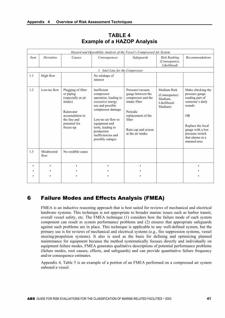
Appendix 4 Overview of Risk Assessment Techniques
TABLE 4 Example of a HAZOP Analysis
Hazard and Operability Analysis of the Vessel’s Compressed Air System Item Deviation Causes Consequences Safeguards Risk Ranking
(Consequence, Likelihood)
Recommendations
1. Intel Line for the Compressor 1.1 High flow
No mishaps of
interest
1.2 Low/no flow Plugging of filter or piping (especially at air intake) Rainwater accumulation in the line and potential for freeze-up
Inefficient compressor operation, leading to excessive energy use and possible compressor damage Low/no air flow to equipment and tools, leading to production inefficiencies and possibly outages
Pressure/vacuum gauge between the compressor and the intake filter Periodic replacement of the filter Rain cap and screen at the air intake
Medium Risk (Consequence: Medium, Likelihood: Medium)
Make checking the pressure gauge reading part of someone’s daily rounds OR Replace the local gauge with a low pressure switch that alarms in a manned area
1.3 Misdirected flow
No credible cause
• • •
• • •
• • •
• • •
• • •
• • •
6 Failure Modes and Effects Analysis (FMEA)
FMEA is an inductive reasoning approach that is best suited for reviews of mechanical and electrical hardware systems. This technique is not appropriate to broader marine issues such as harbor transit, overall vessel safety, etc. The FMEA technique (1) considers how the failure mode of each system component can result in system performance problems and (2) ensures that appropriate safeguards against such problems are in place. This technique is applicable to any well-defined system, but the primary use is for reviews of mechanical and electrical systems (e.g., fire suppression systems, vessel steering/propulsion systems). It also is used as the basis for defining and optimizing planned maintenance for equipment because the method systematically focuses directly and individually on equipment failure modes. FMEA generates qualitative descriptions of potential performance problems (failure modes, root causes, effects, and safeguards) and can provide quantitative failure frequency and/or consequence estimates.
Appendix 4, Table 5 is an example of a portion of an FMEA performed on a compressed air system onboard a vessel.
ABS GUIDE FOR RISK EVALUATIONS FOR THE CLASSIFICATION OF MARINE-RELATED FACILITIES . 2003 41
Appendix 4 Overview of Risk Assessment Techniques 6.1 Typical Analysis Activities for FMEAs
6.1.1 Scoping the Assessment • Identifying the physical boundaries for the system to be analyzed
• Identifying the end effects of interest for the analysis
• Selecting the FMEA approach to be applied (top-down, bottom-up or combination)
6.1.2 Identifying the Analysis Team • Personnel with knowledge of, and experience with, the system and/or activity are required
• Typically, operations, maintenance and engineering personnel are needed
6.1.3 Preparing for the Assessment • Alternatively, can be conducted by a single individual after meeting with experts to
understand the operation of the system
• Collecting information (e.g., drawings, procedures, failure history)
• Sectioning the system into major elements for analysis
• Developing the initial failure modes for each element
• Preparing analysis worksheets and/or analysis software files
6.1.4 Performing the Assessment • Evaluating the failure modes capability of producing the end effects of interest
• Generating and evaluating additional failure modes
• Characterizing the risk results from failure modes of interest (i.e., those that result in an end effect of interest)
• Developing recommendations for improvement
6.1.5 Evaluating the Assessment Results • Comparing the FMEA results and/or risk estimates to the acceptance criteria
• Determining the acceptability for classification submittal of the proposed design and/or the need for additional risk assessments
• Evaluating the recommendations for implementation
6.1.6 Documenting the assessment • Table summarizing the failure modes and the associated risk estimates (if developed)
• Appropriate documentation requires identifying and documenting 1) the effects potentially resulting from the failure mode (or documenting that the failure mode does not result in a problem of interest), 2) credible causes for the failure mode, 3) any indications that the failure mode has occurred, 4) applicable safeguards, 5) risk evaluation and 6) recommendations.
• Report outlining the analysis and the analysis results and recommendations
42 ABS GUIDE FOR RISK EVALUATIONS FOR THE CLASSIFICATION OF MARINE-RELATED FACILITIES . 2003

Appendix 4 Overview of Risk Assessment Techniques
TABLE 5 FMEA Evaluation Example
Example from a Hardware-based FMEA
Machine/Process: Onboard Compressed air system Subject: 1.2.2 Compressor control loop Description: Pressure-sensing control loop that automatically starts/stops the compressor
based on system pressure (starts at 95 psig and stops at 105 psig) Next higher level: 1.2 Compressor subsystem
Effects Failure Mode Local
Higher Level End Causes
Indications/Safeguards
Risk Ranking (Consequence,
Likelihood) Recommendations/
Remarks A. No start
signal when the system pressure is low
Open control circuit
Low pressure and air flow in the system
Interruption of the systems supported by compressed air
Sensor failure or miscalibrated Controller failure or set incorrectly Wiring fault Control circuit relay failure Loss of power for the control circuit
Low pressure indicated on air receiver pressure gauge Compressor not operating (but has power and no other obvious failure) Rapid detection because of quick interruption of the supported systems
Medium Risk (Consequence: Medium, Likelihood: Medium)
Consider a redundant compressor with separate controls Calibrate sensors periodically in accordance with written procedure
B. No stop signal when the system pressure is high
• • •
• • •
• • •
• • •
• • •
• • •
• • •
• • •
• • •
• • •
• • •
• • •
• • •
• • •
• • •
ABS GUIDE FOR RISK EVALUATIONS FOR THE CLASSIFICATION OF MARINE-RELATED FACILITIES . 2003 43
Appendix 4 Overview of Risk Assessment Techniques
7 Event Tree Analysis
Event tree analysis utilizes decision trees to graphically model the possible outcomes of an initiating event capable of producing an end event of interest. This type of analysis can provide (1) qualitative descriptions of potential problems (combinations of events producing various types of problems from initiating events) and (2) quantitative estimates of event frequencies or likelihoods, which assist in demonstrating the relative importance of various failure sequences. Event tree analysis may be used to analyze almost any sequence of events, but is most effectively used to address possible outcomes of initiating events for which multiple safeguards are in line as protective features.
The following example event tree in Appendix 4, Figure 1 below illustrates the range of outcomes for a tanker having redundant steering and propulsion systems. In this particular example, the tanker can be steered using the redundant propulsion systems even if the vessel loses both steering systems.
7.1 Typical Analysis Activities for Event Tree Analysis
7.1.1 Scoping the Assessment • Identifying the physical boundaries and initial conditions for the system and/or
operational activities to be analyzed
• Determining the consequences of interest
7.1.2 Identifying the Analysis Team • Experienced analysts who work with personnel with knowledge of, and experience with,
the system and/or activity
7.1.3 Preparing for the Assessment • Collecting information (e.g., drawings, procedures)
• Identifying initiating events of interest
• Identifying lines of assurance and physical phenomena
7.1.4 Performing the Assessment • Developing the accident scenarios for each initiating event
• Developing the event tree model to represent the accident scenarios
• Developing individual events in the event tree that may require fault tree analysis
• Quantifying the event tree and analyzing accident sequence outcomes
• Generating recommendations for improvement
7.1.5 Evaluating the Assessment Results • Comparing the risk results to the acceptance criteria
• Evaluating contributions to the undesired consequences from various scenario events
• Determining the acceptability for classification submittal of the proposed design and/or the need for additional risk assessments
• Evaluating the recommendations for implementation
44 ABS GUIDE FOR RISK EVALUATIONS FOR THE CLASSIFICATION OF MARINE-RELATED FACILITIES . 2003

Appendix 4 Overview of Risk Assessment Techniques
7.1.6 Documenting the Assessment • Graphical representation of the event tree
• Report outlining the analysis, data used to quantify the event tree and the analysis results
FIGURE 1 Example Event Tree Analysis
Initiating event Both propulsion systems operate
Second propulsion system operates
Both steering systems operate
Second steering system operates Outcomes
OK
OK
YesTanker enters waterway
OK, vessel is steered using engines
OKNo
OK
Vessel loses steering
Vessel losses propulsion
8 Fault Tree Analysis
Fault Tree Analysis is a deductive analysis that graphically models (using Boolean logic) how logical relationships among equipment failures, human errors and external events can combine to cause specific mishaps of interest. Similar to event tree analysis, this type of analysis can provide (1) qualitative descriptions of potential problems (combinations of events causing specific problems of interest) and (2) quantitative estimates of failure frequencies/likelihoods and the relative importance of various failure sequences/contributing events. This methodology can also be applied to many types of applications, but is most effectively used to analyze system failures caused by relatively complex combinations of events.
The following example in Appendix 4, Figure 2 illustrates a very simple fault tree analysis of a loss of propulsion event for a vessel.
8.1 Typical Analysis Activities for Fault Tree Analysis
8.1.1 Scoping the Assessment • Identifying the physical boundaries and initial conditions for the system and/or
operational activities to be analyzed
• Defining the undesired (top) event to be studied
8.1.2 Identifying the Analysis Team • Experienced analysts who work with personnel with knowledge of, and experience with,
the system and/or activity
ABS GUIDE FOR RISK EVALUATIONS FOR THE CLASSIFICATION OF MARINE-RELATED FACILITIES . 2003 45

Appendix 4 Overview of Risk Assessment Techniques
8.1.3 Preparing for the Assessment • Collecting information (e.g., drawings, procedures) and failure and probability data (if
applicable)
8.1.4 Performing the Assessment • Defining the tree top structure and exploring each branch in successive levels of detail.
Detail can be defined by quantitative data available if quantitative analysis is performed
• Defining the basic event naming scheme to be unique and logical, with clear and consistent naming conventions (and descriptions).
• Designing the analysis such that each basic event should represent one discrete event.
• Requiring each basic event represented under a gate to fail in the manner modeled to realize the gate event. That is, the minimal failures to result in a gate or top event should be modeled with no extraneous events.
• Ensuring that the logic is constructed in a way that the outputs (minimal cutsets) would cause the top event to occur.
• Considering the following types of failures, events and operating stages 1) common cause failures, 2) human errors, 3) all operational phases, 4) external events and 5) required operational time for the basic events
• Solving the fault tree for combinations of events and identifying important contributors and dependent failure potentials
• Quantifying the fault tree (if applicable) and solving the fault tree to determine the frequency/ probability of the TOP event
• Generating recommendations for improvement
8.1.5 Evaluating the Assessment Results • Comparing the fault tree results and/or risk estimates to the acceptance criteria
• Determining the acceptability for classification submittal of the proposed design and/or the need for additional risk assessments
• Evaluating the recommendations for implementation
8.1.6 Documenting the Assessment • Graphical representation of the fault tree
• Report outlining the analysis, data used to quantify the fault tree, and the analysis results and recommendations
46 ABS GUIDE FOR RISK EVALUATIONS FOR THE CLASSIFICATION OF MARINE-RELATED FACILITIES . 2003

Appendix 4 Overview of Risk Assessment Techniques
FIGURE 2 Example Fault Tree Analysis
A
B
C
Basicfailure of the
propeller(1)
Basic failureof the engine
(stops)(2)
Contaminatedfuel in bunker
tanks(3)
Onboard fuelcleanup system
fails(4)
Fuel supply toengine is
contaminated
Engine fails tooperate
Engine stops
Vessel losespropulsion
9 Summary of Key Aspects of Risk Assessment Techniques
Appendix 4, Tables 6 and 7 below give a summary overview of the commonly used risk assessment techniques.
ABS GUIDE FOR RISK EVALUATIONS FOR THE CLASSIFICATION OF MARINE-RELATED FACILITIES . 2003 47

Appendix 4 Overview of Risk Assessment Techniques
TABLE 6 Overview of Commonly Used Risk Assessment Techniques
Risk Assessment Tool Summary of Method More Common Uses Change Analysis Change analysis looks logically for possible
risk effects and proper risk management strategies in changing situations (e.g., when system layouts are changed, when operating practices or policies change, when new or different activities will be performed).
• Used for any situation in which change from normal setup, operation or activities is likely to affect risks (e.g., marine events in ports or waterways)
• Can be used as an effective root cause analysis method, as well as a forecasting risk assessment method
What-if Analysis What-if analysis is a problem-solving approach that uses loosely structured questioning to (1) suggest upsets that may result in accidents or system performance problems and (2) make sure the proper safeguards against those problems are in place.
• Useful for any type of system, process or activity
• Most often used when the use of other, more precise, methods (e.g., FMEA and HAZOP analysis) are not possible or practical
• What-if analysis is frequently combined with checklist analysis to add structure to the analysis.
Failure Modes and Effects Analysis (FMEA)
FMEA is a reasoning approach best suited to reviews of mechanical and electrical hardware systems. The FMEA technique (1) considers how the failure modes of each system component can result in system performance problems and (2) makes sure the proper safeguards are in place. A quantitative version of FMEA is known as failure modes, effects and criticality analysis (FMECA).
• Used for reviews of mechanical and electrical systems (e.g., fire suppression systems, vessel steering and propulsion systems)
• Often used to make planned maintenance and equipment inspection plans more effective
• Sometimes used to gather information to help find trouble areas in systems
Hazard and Operability (HAZOP) Analysis
The HAZOP analysis technique uses special guide words for (1) suggesting departures from design intents for sections of systems and (2) making sure that the proper safeguards are in place to help prevent system performance problems.
• Used for finding safety hazards and operability problems in continuous process systems, especially fluid and thermal systems. Also used to review procedures and other sequential or batch operations
• Another type of guideword analysis is Worker and Instruction Safety Evaluation, which is used to understand the significance of human errors.
Fault Tree Analysis (FTA)
FTA is a technique that graphically models how logical relationships between equipment failures, human errors and external events can combine to cause specific accidents of interest. Probabilities and frequencies can be added to the analysis to estimate risks numerically.
• Suited to almost every type of risk assessment, but best used to focus on the basic causes of specific system failures of relatively complex combinations of events
• Often used for complex electronic, control or communication systems
Event Tree Analysis (ETA)
ETA is an analysis technique that uses decision trees to model the possible outcomes of an event that can produce an accident of interest. Probabilities and frequencies can be added to the analysis to estimate risks numerically
• Suited to almost every type of risk assessment, but best used to focus on possible results of events for which many safeguards are in place as protective features
• Often used for analysis of vessel movement incidents, the spread of fires or explosions or toxic releases
• A human reliability analysis event tree is a specific and detailed method used in modeling human reliability
48 ABS GUIDE FOR RISK EVALUATIONS FOR THE CLASSIFICATION OF MARINE-RELATED FACILITIES . 2003
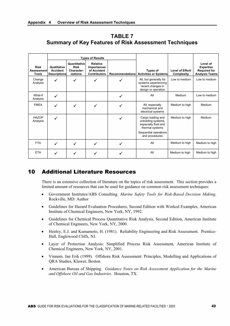
Appendix 4 Overview of Risk Assessment Techniques
TABLE 7 Summary of Key Features of Risk Assessment Techniques
RiskAssessment
Tools
QualitativeAccident
Descriptions
QuantitativeRisk
Character-izations
RelativeImportancesof Accident
Contributors Recommendations
Types of Results
Types ofActivities or Systems
Level of Effort/Complexity
Level ofExpertise
Required forAnalysis Teams
HAZOPAnalysis
Cargo loading andunloading systems,especially fluid andthermal systems
Sequential operationsand procedures
Medium to high Medium
What-ifAnalysis
All Medium Low to medium
FMEA All, especiallymechanical and
electrical systems
Medium to high Medium
ChangeAnalysis
All, but generally forsystems experiencing
recent changes indesign or operation
Low to medium Low to medium
FTA All Medium to high
ETA All Medium to high
Medium to high
Medium to high
10 Additional Literature Resources
There is an extensive collection of literature on the topics of risk assessment. This section provides a limited amount of resources that can be used for guidance on common risk assessment techniques:
• Government Institutes/ABS Consulting. Marine Safety Tools for Risk-Based Decision Making. Rockville, MD: Author
• Guidelines for Hazard Evaluation Procedures, Second Edition with Worked Examples, American Institute of Chemical Engineers, New York, NY, 1992.
• Guidelines for Chemical Process Quantitative Risk Analysis, Second Edition, American Institute of Chemical Engineers, New York, NY, 2000.
• Henley, E.J. and Kumamoto, H. (1981). Reliability Engineering and Risk Assessment. Prentice-Hall, Englewood Cliffs, NJ.
• Layer of Protection Analysis: Simplified Process Risk Assessment, American Institute of Chemical Engineers, New York, NY, 2001.
• Vinnem, Jan Erik (1999). Offshore Risk Assessment: Principles, Modelling and Applications of QRA Studies, Kluwer, Boston
• American Bureau of Shipping. Guidance Notes on Risk Assessment Application for the Marine and Offshore Oil and Gas Industries. Houston, TX.
ABS GUIDE FOR RISK EVALUATIONS FOR THE CLASSIFICATION OF MARINE-RELATED FACILITIES . 2003 49

This Page Intentionally Left Blank

A P P E N D I X 5 Survey of the Use of Risk Acceptance Criteria
A survey of the use of risk assessment criteria was performed to provide users, with an understanding of how industry and government organizations have used risk acceptance (or risk tolerance) criteria in the past. It is based on publicly available information only. The reader should recognize that many industrial organizations that use formal risk assessment technologies and associated criteria do not make those criteria public, so the information provided here is limited. Also, the applications described in this document have occurred over the last 20 years, so not all of them reflect current approaches.
However, based on the survey, the following conclusions can be drawn:
i) There are many different forms of risk acceptance criteria that can and have been used
ii) Effective criteria must reflect:
• The purpose of the risk assessment activity
• The scope and breadth of the study being performed (e.g., whether ultimate consequences are going to be estimated for risk assessment purposes or whether interim consequence measures will be employed)
Finally, and most importantly of all, risk acceptance criteria do not make decisions for an organization. The criteria reflect decisions that an organization has already made, and wants to implement consistently in a series of analyses, regulatory decisions or design activities. However, when an analysis shows that some aspect of a proposed activity does or does not meet a given criteria, that is only one piece of information regarding the acceptability or unacceptability of the activity, many other factors may affect decision making in real world situations.
The following subsections present a selected number of cases extracted from the survey.
1 US Offshore Oil Production Industry
History in the Industry The US offshore oil production industry is dominated by Gulf of Mexico (GOM) operations. Most of the standards (API 14 series) reflect the GOM approach to managing risk.
In response to a number of offshore accidents in the 1960s and 1970’s, the American Petroleum Institute (API) initiated an effort that culminated in the development of API 14C (Analysis, Design, Installation, and Testing of Basic Surface Safety Systems on Offshore Production Platforms), API 14J (Design and Hazards Analysis for Offshore Production Facilities) and related guidance standards. The MMS incorporated API 14C into its offshore rules, with some additional requirements (such as monthly testing of alarms and shutdowns).
More recently, with the development of process safety management (PSM), the MMS has asked industry to apply PSM principles to offshore operations. API responded by producing API 75 (Safety and Environmental Management Program), a spin-off of API 750. API 75 contains all the essential elements of PSM.
ABS GUIDE FOR RISK EVALUATIONS FOR THE CLASSIFICATION OF MARINE-RELATED FACILITIES . 2003 51

Appendix 5 Survey of the Use of Risk Acceptance Criteria
What are the drivers for risk based methods? Deepwater projects have forced many operators to rethink offshore risk. Increased production rates, lengthy flowlines and risers, difficulty in emergency response and the threat of sinking the structure have caused some unease among traditional GOM operators. Many of the deepwater projects have used risk-based tools to help make tough decisions – such as riser routing or block valve location. In general, the combination of potentially higher consequences and higher likelihood, along with very significant costs, has demonstrated that traditional risk control tools, such as API 14C, may not be sufficient.
What methods are used? Qualitative HAZOPS are widely used. The use of quantitative tools is generally limited to selecting design alternatives rather than platform-wide risk assessments. It is worth noting that many GOM operators have international affiliates which may increase the internal drivers for using more quantitative techniques.
What tolerance criteria are used/what is the basis? Companies utilize qualitative tolerance criteria in the form of risk ranking matrices. A few major companies have imported company-wide quantitative tolerance criteria on a limited basis.
How is compliance obtained? Risk is not explicitly measured. Therefore, there are no available numerical indicators for monitoring compliance. Compliance with implicit risk criteria is achieved in the form of a feedback loop. When there is a serious accident, MMS regulators are involved in the assessment, and faulty management systems are identified and repaired. This method works well for conventional shallow water facilities. For deepwater, the consequences are too great to allow a serious accident to occur. MMS and API are collaborating with industry to develop a recommended practice for “Qualification of New Technology for Deepwater Applications”.
Key references • Analysis, Design, Installation, and Testing of Basic Surface Safety Systems on Offshore
Production Platforms, (API 14C)
• Design and Hazards Analysis for Offshore Production Facilities, (API 14J)
• MMS Offshore Safety Guidelines
2 US Coast Guard (USCG)
History in the industry In 1992, the United States Coast Guard’s (Coast Guard’s) Research and Development Center (RDC) launched a multiyear project to develop methodologies and tools to improve the effectiveness of risk management within the Coast Guard. This overall project is called Loss Exposure and Risk Analysis Methodology (LERAM). Since 1995, work on this project has been performed by RDC personnel and personnel from ABS Consulting, Knoxville.
What are the drivers for risk based methods? ABS Consulting, Knoxville, assisted the USCG in developing a process to improve the management and control of risk for its units while operating with limited resources. This process is anchored on risk analysis, which has been performed at various units within the organization. The information generated during the analyses helps USCG make better-informed risk-based decisions.
52 ABS GUIDE FOR RISK EVALUATIONS FOR THE CLASSIFICATION OF MARINE-RELATED FACILITIES . 2003

Appendix 5 Survey of the Use of Risk Acceptance Criteria
What methods are used? The USCG uses the Risk-Based Decision Making (RBDM) process to organize information about the possibility for one or more unwanted outcomes to occur into a broad, orderly structure that helps decision makers make more informed management choices. RBDM asks the following questions and uses the answers in the decision-making process:
i) What can go wrong?
ii) How likely are the potential problems to occur?
iii) How severe might the potential problems be?
iv) Is the risk of potential problems tolerable?
v) What can/should be done to lessen the risk?
The question is not, “Should I use risk-based decision making?” The question is, “How should I use risk-based decision making?” The key is to focus on using the most suitable tool(s) for your situation.
Many unique approaches exist for studying how operations are performed and how equipment is configured to find weaknesses that could lead to accidents. Most of these tools also help measure the risk of potential problems so that appropriate attention/resources can be focused on the issues of greatest concern. Some of the tools also help investigate accidents that have already occurred. The second edition of the RBDM Guidelines describes in detail (with worked examples) how and when to apply many risk analysis tools.
One of the tools uses an enterprise risk assessment approach to characterize the risk and determine the high-risk elements. A hierarchy of USCG activities, operations and functions is developed to assist in assigning the risk. A risk profile is then developed for the various activities, operations and functions. The risk profile is based on a risk matrix as described below.
What tolerance criteria are used/what is the basis? USCG has developed frequency scoring categories, consequence severity categories and risk screening criteria, which define the level of risk (frequency of occurrence of losses) that USCG is not willing to pursue for further analysis. The criterion for each is defined in Appendix 5, Figure 1 below.
ABS GUIDE FOR RISK EVALUATIONS FOR THE CLASSIFICATION OF MARINE-RELATED FACILITIES . 2003 53

Appendix 5 Survey of the Use of Risk Acceptance Criteria
FIGURE 1 USCG Frequency/Consequence Categories and Risk Screening Criteria
Revised: 9/15/00
ScreeningCriteria
(equal to orless than)
* Actual frequency estimate is at leastan order of magnitude less than thebounds of this category
A
1*
B
1
C
3
D
4
Types of Effects*
* Losses in these categories result from both immediate as well as long-term effects associated with a losssequence (e.g., considering both acute and chronic effects when evaluating safety/health).
Safety/Health Equipment/Property Mission Interruption Environmental
Levelof
Effect
An injury or illnessresults in a fatality orpemanent totaldisability
The cost of reportableproperty damage is$1,000,000 or more
Vessel/base is unableto respond toaccomplish criticalmissions
Substantial offsiteimpact (ocean lifeeffects or offsitehealth effects)extending beyond thelocal area
A
Any injury and/orillness results inpartial disability
Five or more peopleare inpatienthospitalized
The cost of propertydamage is $200,000or more, but less than$1,000,000
Major impact onability of vessel/baseto rapidly accomplishcritical missions
Significant commandattention
Major local area/offsite impact (oceanlife effects or offsitehealth effects)B
A nonfatal injury orillness results in lossof time from work forfour or more work/duty days
The cost of propertydamage is $10,000 ormore, but less than$200,000
Moderate impact onability of vessel/baseto rapidly accomplishcritical missions
Limited capabilities,but able to respond ifneeded
Significant local area/offsite impact (enoughfor an internationaltreaty violation,community alert, orawareness)
C
A nonfatal injury orillness occurs thatdoes not meet thecriteria above
A person isoverboard, anaccidental firearmsdischarge occurs, oran electric shockoccurs, none of whichmeets the criteria of ahigher classification
The cost of propertydamage is less than$10,000
Minor impact onability of vessel/baseto rapidly accomplishcritical missions
Operational nuisance
Vessel/onsite releaseof a substance withminor/no offsiteeffects
Possible personnelexposureD
Low contributor to the deviation risk; a minimal portion ofthe deviation risk is due to this location
No or little significant contribution to the deviation risk; littleor no portion of the deviation risk is due to this location
Description
High contributor to the deviation risk; most all of thedeviation risk is due to this location
Moderate contributor to the deviation risk; a moderate(significant) portion of the deviation risk is due to thislocation
L
N
LocationContribution
H
M
Very confident that the actual frequency is at or below theassigned frequency category and data exist to support thefrequency category
Little confidence that the actual frequency is at or belowthe assigned frequency category and unsure whether dataexist or no data exist to support the frequency category
Confident that the actual frequency is at or below theassigned frequency category and expect data could beobtained to support the frequency category
Description
High
Low
Medium
CertaintyCategory
0
1
2
3
4
5
6
8
7
1x10⁻³/y
1x10⁻⁴/y
100/y
10/y
1/y
0.1/y
1x10⁻²/y
FrequencyScore
Descriptions
Frequency Scores(with frequency
bounds) Example Benchmarks
Continuous
Very Frequent
Frequent
Occasional
Probable
Improbable
Rare
Remote
Incredible
Frequency Scoring Categories
1x10⁻⁵/y
100 events per year
10 events per year
1 event per year
1 event over 10 years
1 event over 100 years(10% chance of an eventover 10 years)
1 event over 1,000 years(1% chance of an eventover 10 years)
1 event over 10,000years (1% chance of anevent over 100 years)
1 event over 100,000years (1% chance of anevent over 1,000 years)
During an analysis, the frequency scores for a loss sequence are also used to determine the risk assessment code (RAC) level and corresponding actions required to address the risk of each loss sequence. The matrix in Appendix 5, Figure 2 shows example RAC regions. Appendix 5, Table 1 provides example actions for each RAC level.
FIGURE 2 Blank Risk Matrix with RACs
Class A/B Class C Class D
Continuous (8) RAC 1
Very Frequent (7)
Frequent (6) RAC 2
Occasional (5)
Probable (4) RAC 3
Improbable (3)
Rare (2) RAC 4
Remote (1)
Incredible (0) RAC 5
54 ABS GUIDE FOR RISK EVALUATIONS FOR THE CLASSIFICATION OF MARINE-RELATED FACILITIES . 2003

Appendix 5 Survey of the Use of Risk Acceptance Criteria
TABLE 1 Risk Assessment Code Levels and Recommended Response Criteria
RAC Certainty Recommended Response High/ Medium
Related operations must be stopped immediately. Changes must be formally approved and implemented (e.g., added/modified safeguards, modified operations, reduced hazards) before operations can resume.
1 Low
Related operations must be stopped within 1 month. To avoid stopping or to resume operations, either (1) additional information must be provided showing that the actual risk for the existing approach is lower with high certainty or (2) changes must be formally approved and implemented.
High/ Medium
Related operations must be stopped within 3 months. To avoid stopping or to resume operations, either (1) the risk for the existing approach must be formally accepted or (2) changes must be formally approved and implemented.
2
Low
Related operations must be stopped within 6 months. To avoid stopping or to resume operations, either (1) additional information must be provided showing that the actual risk is lower with a high certainty, (2) the risk for the existing approach must be formally accepted, or (3) changes must be formally approved and implemented. If the risk for the existing approach is formally accepted, the associated loss sequences should be kept on a “watch list” and monitored to ensure that the loss sequences are not being experienced at a higher frequency.
High/ Medium
Related operations must be stopped within 1 year. To avoid stopping or to resume operations, either (1) the risk for the existing approach must be formally accepted or (2) changes must be formally approved and implemented.
3
Low
Related operations must be stopped within 3 years. To avoid stopping or to resume operations, either (1) additional information must be provided showing that the actual risk is lower with a high certainty, (2) the risk for the existing approach must be formally accepted, or (3) changes must be formally approved and implemented. If the risk for the existing approach is formally accepted, the associated loss sequences should be kept on a “watch list” and monitored to ensure that the loss sequences are not being experienced at a higher frequency.
High/ Medium
Related operations must be stopped within 4 years. To avoid stopping or to resume operations, either (1) the risk for the existing approach must be formally accepted or (2) changes must be formally approved and implemented.
4
Low
Related operations must be stopped within 4 years. To avoid stopping or to resume operations, either (1) additional information must be provided showing that the actual risk is lower with a high certainty, (2) the risk for the existing approach must be formally accepted, or (3) changes must be formally approved and implemented. If the risk for the existing approach is formally accepted, the associated loss sequences should be kept on a “watch list” and monitored to ensure that the loss sequences are not being experienced at a higher frequency.
High/ Medium No action required.
5 Low The associated loss sequences should be kept on a “watch list” and monitored to ensure that the loss
sequences are not being experienced at a higher frequency.
Once the risk of each loss scenario is characterized, a risk matrix is developed which depicts the risk profile of the unit. An example risk profile is illustrated in Appendix 5, Figure 3. Each cell in the matrix indicates the number of loss sequences having that frequency and consequence. The matrix is a valuable risk communication tool and helps decision-makers understand how many loss sequences fall into the various categories.
ABS GUIDE FOR RISK EVALUATIONS FOR THE CLASSIFICATION OF MARINE-RELATED FACILITIES . 2003 55

Appendix 5 Survey of the Use of Risk Acceptance Criteria
FIGURE 3 Example Risk Profile
C
0
2
5
9
15
14
17
20
4
B
0
0
0
1
2
6
11
36
9
A
0
0
0
0
2
4
27
19
13
D
0
2
5
9
22
14
10
3
0
Number of Loss Sequences
Continuous (8)
Very frequent (7)
Frequent (6)
Occasional (5)
Probable (4)
Improbable (3)
Rare (2)
Remote (1)
Incredible (0)
Insights/lessons learned from application Although this work is still under development, the USCG has successfully demonstrated the application of the RBDM tools. An effort is underway to develop and distribute the RBDM toolbox throughout the USCG.
Key references • USCG Research and Development Center:
http://www.rdc.uscg.mil/rdcpages/research-3000_copy(2).htm
• USCG Guide to Risk Based Decision Making: http://www.uscg.mil/hq/g-m/risk
3 US Nuclear Regulatory Commission (NRC)
History in the industry The Energy Reorganization Act of 1974 created the Nuclear Regulatory Commission, which began operations on January 19, 1975. The NRC (like the AEC before it) focused its attention on several broad issues that were essential to protecting public health and safety. The focus of the regulatory programs of the AEC and the NRC was prevention of a major reactor accident that would threaten public health and safety. Both agencies issued a series of requirements designed to make certain that a massive release of radiation from a power reactor would not occur. As the number of plants being built and the size of those plants rapidly increased during the late 1960s and early 1970s, reactor safety became a hotly disputed and enormously complex public policy issue. Often bitter debates over the reliability of emergency core cooling systems, pressure vessel integrity, quality assurance, the probability of a major accident and other questions received a great deal of attention from the AEC and NRC, Congress, the nuclear industry, environmentalists and the news media.
56 ABS GUIDE FOR RISK EVALUATIONS FOR THE CLASSIFICATION OF MARINE-RELATED FACILITIES . 2003

Appendix 5 Survey of the Use of Risk Acceptance Criteria
What are the drivers for risk based methods? In the aftermath of the Three Mile Island accident in 1979, the NRC placed much greater emphasis on operator training and “human factors” in plant performance, severe accidents that could occur as a result of small equipment failures, emergency planning, plant operating histories and other matters. In 1986, the U.S. Nuclear Regulatory Commission (NRC) established the quantitative risk tolerance criterion for commercial nuclear facility operations in the United States.
The Nuclear Regulatory Commission’s (NRC’s) responsibility is centered on ensuring that there is no undue risk to the health and safety of the public associated with the operation of nuclear power plants, or other facilities which it licenses. It does this by the application and enforcement of a set of technical requirements on plant design and operations, described in Title 10 of the Code of Federal Regulations (10 CFR). Generally, these are written in terms of traditional engineering practices such as “safety margins” in design, construction and operations.
What methods are used? The NRC has supported the development and use of the Probabilistic Risk Assessment (PRA) methodology and related techniques since the agency’s establishment in 1975. PRA is a systematic process for examining how engineered systems, built and operated based on these requirements and practices, and human interactions with these systems work together to ensure plant safety. This process is quantitative, in that probabilities of events with potential public health consequences are calculated, as are the magnitudes of these potential health consequences. The risk of such events is the product of the event probabilities and their consequences. Information on this risk and what failures contribute most to the risk, is of great value to the NRC in helping to determine the acceptability of a licensed facility’s overall design and operation, as well as in focusing the agency’s and the regulated industry’s resources on those aspects of design and operation which are most risk-important.
The PRA Policy Statement was issued in 1995, encouraging the use of PRA in a manner that complements traditional engineering practices. The NRC now makes use of PRA techniques, guided by the Safety Goal and PRA Policy Statements, to improve its regulatory processes and decision-making. PRA as an analytical tool includes consideration of the following: identification and delineation of the combinations of events that, if they occur, could lead to an accident (or other undesired event), estimation of the chance of occurrence for each combination and estimation of the consequences associated with each combination.
As practiced in the field of nuclear power, PRAs generally focus on accidents that can severely damage the power plant’s reactor core (containing the largest amount of radioactive material in the plant) and can also challenge the surrounding containment structures, since they pose the greatest potential risk to the public. This technique, or related risk assessment techniques, can be used, however, in the evaluation of all aspects of the fuel cycle, from fuel fabrication to high-level waste disposal. The PRA integrates into a uniform assessment tool the relevant information about plant design, operational practices, operating history, component reliability, human performance, the physical progression of core-damage accidents and the potential environmental and health consequences in as realistic a manner as practical.
PRA accounts for certain processes and phenomena that may have never occurred, or may occur infrequently, and may involve severe conditions that are difficult to replicate in experiments. Similarly, data on component or human behavior may not be available in sufficient quantities or for the circumstances of concern. Therefore, the results are inherently uncertain. PRA illuminates these uncertainties and provides a way of considering them in regulatory decisions. The degree to which a detailed uncertainty analysis may be required will vary with the nature of the regulatory decision involved. Thus, analyses which depend only on the ability to separate the important from the obviously unimportant (e.g., prioritizing inspection efforts) may require only a general understanding of the magnitude of the uncertainty. Other applications, such as decisions regarding plant backfits, may require detailed uncertainty analyses.
ABS GUIDE FOR RISK EVALUATIONS FOR THE CLASSIFICATION OF MARINE-RELATED FACILITIES . 2003 57

Appendix 5 Survey of the Use of Risk Acceptance Criteria
What tolerance criteria are used/what is the basis? “The risk to an average individual in the vicinity of a nuclear power plant of prompt fatalities that might result from reactor accidents should not exceed one-tenth of one percent (0.1 percent) of the sum of prompt fatality risks resulting from other accidents to which members of the U.S. population are generally exposed.” (Reference: U.S. Nuclear Regulatory Commission, 51 Federal Register 30028 et seq., August 1986.)
If the prompt fatality risk resulting from accidents to which the U.S. population is generally exposed is estimated as roughly 10-4 per year, this acceptance criteria would be 10-7 per year. Note that this criterion addresses only the risk of public fatality. The word prompt is used before the word fatality. This use of the word prompt implies that the criterion is not necessarily concerned with long-term fatalities that may occur many years after the accident (i.e., long-term health effects [from the initial exposure to radiation or hazardous materials during the accident] that ultimately result in death).
This NRC approach benchmarks the risk of catastrophic industrial (i.e., nuclear) accidents having potentially high public safety impacts (i.e., potential disabling injuries and/or fatalities) to the risk of fatality of individual members of the public from other commonly encountered and accepted risks (i.e., motor vehicle operation, commercial air travel, disease, etc.). This approach has become somewhat prevalent in countries where national governments have established risk acceptance criteria for industrial facilities and land-use planning and decision-making.
NRC’s risk tolerance criterion (risk goal) limits one or more public fatalities from a nuclear accident to a frequency of occurrence that is no greater than 10-7.
How is compliance obtained? The NRC's PRA Implementation Plan describes the various NRC activities to expand the use of PRA in the agency’s regulatory functions. Recently, NRC published a series of guidance documents describing how PRA should be used in changes to the licensing basis of nuclear power plants. Key principles and acceptance guidelines for this were published in July 1998 in Regulatory Guide 1.174, “An Approach for Using Probabilistic Risk Assessment in Risk-Informed Decisions on Plant-Specific Changes to the Licensing Basis.” More recently, NRC has accelerated its work to consider requests for license changes using this guidance, to use PRA more in other regulatory functions (including plant inspection, enforcement, and assessment) and to change NRC regulations on plant design and operations to reflect the methods and results of PRA. For example, the licensee is required to perform a PRA for any “events” that occur during the operation of a unit. The licensee must submit a Licensee Event Report (LER) to the NRC and evaluate the event as per PRA guidelines to ensure that the Core Damage frequency is below 10-6.
Key references • U.S. Nuclear Regulatory Commission, 51 Federal Register 30028 et seq., August 1986.
4 US Department of Defense (DOD)
History in the industry MIL-STD-882D, Standard Practice for System Safety, February 2000, presents an approach to evaluate environmental, safety, and health mishap risks encountered in the development, test, use, and disposal of U.S. Department of Defense (DoD) systems, subsystems, equipment, and facilities. MIL-STD-882D was developed by the U.S. Airforce Materiel Command for the DoD.
58 ABS GUIDE FOR RISK EVALUATIONS FOR THE CLASSIFICATION OF MARINE-RELATED FACILITIES . 2003

Appendix 5 Survey of the Use of Risk Acceptance Criteria
What tolerance criteria are used/what is the basis? Appendix 5, Figure 4 shows the MIL-STD-882D risk matrix. Mishap severity categories are defined to provide a qualitative measure of the most credible mishap. The dollar values shown in the risk matrix may be modified based on the size of the system being analyzed. In fact, the standard recommends categories be explicitly adapted for the system under analysis before being used. The mishap probability is the probability that a mishap will occur during the planned life expectancy of the system. The probability can be based on occurrences per unit time, events, population, items or activities. Each cell in the matrix contains a mishap risk assessment value. Appendix 5, Figure 5 shows the minimum quantitative risk and mishap risk acceptance levels (i.e., mishap risk category) for each mishap risk assessment value. Referring back to Appendix 5, Figure 4, the mishap risk assessment level identifies the individual responsible for achieving acceptable risk mishap levels.
FIGURE 4 MIL-STD-882D Risk Matrix
us mil-std-882d risk assessment matrix.vsd
EImprobable
DRemote
COccasional
BProbable
AFrequent
P = 10-6 P = 10-3 P = 10-2 P = 10-1
ICatastrophic
S = 2 x 10³ $
S = 104 $
S = 2 x 10⁵ $
S = 106 $
IICritical
IIIMarginal
IVNegligible
ind.*< R <ind.*
121.0
< R <ind.*
8103
< R <ind.*
4104
< R <ind.*
2105
< R <ind.*
1
ind.*< R <1.0
150.2
< R <103
10200
< R <104
62 x 103
< R <105
52 x 104
< R <ind.*
3
ind.*< R <0.2
170.01< R <200
1410
< R <2 x 10³
11100
< R <2 x 10⁴
9103
< R <ind.*
7
ind.*< R <0.01
200.002< R <
10
192.0
< R <100
1820
< R <103
16200
< R <ind.*
13
Mis
hap
Seve
rity
Mishap Probability
Key NRmin
< R <Rmax
Mishap RiskAssessment Valuefrom Table A-III of
Ref. 1
*ind. = indeterminate ** From Table A-IV of Ref. 1
Mishap Risk Acceptance Level **
High Component Acquisition ExecutiveSerious Program Executive OfficerMedium Program ManagerLow As directed
18-20 1-5
Mishap Risk Category
Low High
10-17
Medium
6-9
SeriousR(isk)
($/T)
Reference 1: Standard Practice for System Safety, MIL-STD-882D, February 2000
Key references • Standard Practice for System Safety, MIL-STD-882D, February 2000
ABS GUIDE FOR RISK EVALUATIONS FOR THE CLASSIFICATION OF MARINE-RELATED FACILITIES . 2003 59

Appendix 5 Survey of the Use of Risk Acceptance Criteria
FIGURE 5 Risk Tolerance Distribution within Risk Matrix (MIL-STD-882D)
Mishap RiskAssessment
Value*
12345
Matrix Cell*
I/AI/BII/AI/CII/B
MinimumQuantitativeRisk ($/T)**
105
104
2 x 10⁴
103
2 x 10³
Mishap RiskCategory*
High
6789
II/CIII/AI/DIII/B
200103
1.0100
Serious
1011121314151617
II/DIII/CI/E
IV/AIII/DII/EIV/BIII/E
0.210
ind.***2000.01
ind.***20
ind.***
Medium
181920
IV/CIV/DIV/E
2.00.002ind.***
Low
* From Tables A-III and A-IV of Ref. 1** From MIL-STD-882D Risk Matrix*** ind. = indeterminate
us mil std-882d quantitative risk tolerance distribution.vsd
Reference 1: Standard Practice for System Safety, MIL-STD-882D,February 2000
5 US Department of Energy (DOE)
History in the industry The U.S. Department of Energy (DOE) requires the development of safety analysis reports that document the adequacy of hazard analyses to ensure that facilities can be constructed, operated, maintained, shut down and decommissioned safely and in compliance with applicable laws and regulations. These reports require identification and analysis of potential accidents.
What tolerance criteria are used/what is the basis? Accidents identified during hazard analysis and shown to have an expected frequency < 10-6 per year require no further analysis. The following risk matrix illustrates that DOE’s tolerable (i.e., target) risk region is the region containing scenario classes III, IV, and V. This tolerable risk region is bounded on the right hand side by the bold line in the matrix. The bold line indicates that scenario classes I and II are outside this tolerable region and do not meet DOE’s risk (tolerance) goals. These risk goals are expressed in quantitative terms. Note that DOE’s RTC address the risk to human safety only (i.e., the public and plant workers only).
60 ABS GUIDE FOR RISK EVALUATIONS FOR THE CLASSIFICATION OF MARINE-RELATED FACILITIES . 2003

Appendix 5 Survey of the Use of Risk Acceptance Criteria
TABLE 2 U.S. Department of Energy Risk Matrix with Risk Goals
Consequence versus Frequency
Consequence Level Scenario Class
High V II I I
Moderate V III II I
Low V IV III II
F < 10-6
Incredible 10-6 < F < 10-4
Extremely Unlikely 10-4 < F < 10-2
Unlikely F > 10-2
Anticipated
Frequency Category (per year)
Source: DOE Standard 3011-94, Guidance for Preparation of DOE 5480.22 (TSR) and 5480.23 (SAR) Implementation Plans, DOE-STD-3011-94, November 1994
DOE’s Risk Matrix above and the associated consequence level tables below are examples of DOE’s application of their RTC. The matrix and tables have been reproduced from DOE standards that are referenced further below in this discussion. DOE’s example Risk Matrix illustrates their RTC by scenario classes that are based on consequence levels and frequency categories (i.e., ranges) for both chemical accidents and radiological accidents.
TABLE 3 Chemical Accident Consequence Levels
Consequence Level Public Workers High > ERPG-2 at site boundary > ERPG-3 at 600 meters or prompt death in facility Moderate Not applicable Serious injury or fatality Low < High level consequence < Moderate level consequence
TABLE 4
Example Radiological Accident Consequence Levels
Consequence Level Public Workers High > 5 rem at site boundary > 25 rem at 600 meters or prompt death in facility Moderate > 0.1 rem at site boundary > 0.5 rem at 600 meters or serious injury in facility Low < Moderate level consequence < Moderate level consequence
* Values are intended for (risk) binning purposes only and do not reflect the acceptability of accident consequences.
DOE’s tolerable (i.e., target) risk region is represented by a combination of consequence levels and frequency categories that range from scenarios having low consequences with unlikely occurrence frequencies (i.e., scenario class III) to high consequences with incredible frequencies of occurrence (i.e., scenario class V). These examples are provided in the referenced DOE standards as risk goals (i.e., risk targets, rough risk guidelines). Each DOE field office/site is given the flexibility to construct its own risk matrix. While each field office/site is expected to demonstrate compliance with these risk goals, they are not considered to be absolute risk limits in all cases. Accidents with estimated frequencies > 10-6 per year require detailed analysis.
ABS GUIDE FOR RISK EVALUATIONS FOR THE CLASSIFICATION OF MARINE-RELATED FACILITIES . 2003 61

Appendix 5 Survey of the Use of Risk Acceptance Criteria
Note that the consequence tables include standard measurements for nuclear radioactivity and chemical toxicity. A rem is a standard unit of radioactive energy dose, i.e., a measurement of the radioactivity dose to people. ERPG is the acronym for Emergency Response Planning Guideline (ERPG). Emergency Response Planning Guidelines (ERPGs) [i.e., ERPG values] were developed as industry-consensus toxicity values to assist emergency planners and responders to plan for and respond to possible accidental releases of toxic chemicals. ERPG values (i.e., ERPG–1, 2, and 3) are an estimation of the anticipated health effects (threats) to people from acute (single) exposures to such toxic chemical releases. ERPG values are considered by professional toxicologists to represent the most technically sound basis of any of the competing values for expressing chemical accident exposure limits. An ERPG–2 value “is the maximum airborne concentration below which it is believed that nearly all individuals could be exposed for up to 1 hour without experiencing or developing irreversible or other serious health effects or symptoms that could impair their ability to take protective action.”
DOE’s risk tolerance criterion (risk goal) limits one or more public fatalities from a nuclear accident to a frequency of occurrence that is no greater than 10-6. More information on this topic can be obtained from the following U.S. Department of Energy Standards:
Key references • Preparation Guide for U.S. Department of Energy Nonreactor Nuclear Facility Safety Analysis
Reports, DOE-STD-3009-94, July 1994.
• DOE Standard 3011-94, Guidance for Preparation of DOE 5480.22 (TSR) and 5480.23 (SAR) Implementation Plans, DOE-STD-3011-94, November 1994
• Guidance for Preparation of DOE 5480.22 (TSR) and 5480.23 (SAR) Implementation Plans, DOE-STD-3011-94, November 1994.
6 United Kingdom Health and Safety Executive
History in the industry The United Kingdom (U.K.) Health & Safety Executive (U.K. HSE) is a government regulatory agency that oversees U.K. industry for public and employee safety purposes. RTC has been established for at least three sectors of the regulated U.K. industry. The U.K. HSE historically established quantitative RTC for the following types of industrial installations/facilities:
i) New nuclear power stations
ii) New housing near existing onshore industrial installations/plants and activities
iii) Offshore oil and gas production facilities
In addition, a different U.K. industry oversight organization called the Advisory Committee on Dangerous Substances regulates the U.K. transportation industry. Major transportation hazards must be analyzed and are expected to fall within RTC established specifically for transportation risks.
What are the drivers for risk based methods? Like the Netherlands and Hong Kong, the U.K. government’s RTC was originally developed for planning the use of land surrounding onshore hazardous industrial facilities and operations (i.e. land-use planning). The concept of risk assessment, RTC and the ALARP principle was expanded to the U.K. offshore oil and gas production industry following the Piper Alpha offshore platform accident in late 1988. The U.K. approach addresses risks to employees and the public, i.e., individual and societal risks, respectively, arising from industrial hazards. Both sets of risk criteria address only life safety consequences. U.K. RTC does not address other consequence categories such as property/asset damage, environmental damage or business interruption (earnings) losses.
62 ABS GUIDE FOR RISK EVALUATIONS FOR THE CLASSIFICATION OF MARINE-RELATED FACILITIES . 2003

Appendix 5 Survey of the Use of Risk Acceptance Criteria
What methods are used? The promulgation of the COMAH (Control of Major Accident Hazards Regulations, 1999) regulations (i.e., the U.K. implementation of the European Union’s Seveso II Directive) by the U.K. authorities has recently expanded the use of RTC to existing and new onshore industrial installations/plants and activities. The RTC for onshore installations is reported below. However, it is not certain at this time exactly how the RTC is applied to widespread onshore installations/activities that are covered within the scope of the new COMAH regulations.
The U.K. has several guidance documents related to their regulations for Offshore Safety (i.e. Safety Case Regulations) and onshore COMAH regulations. These U.K. regulations are also promulgated and enforced by the U.K. Health and Safety Executive (U.K. HSE). The European Union’s (EU’s) Seveso II Directive is being implemented and enforced across the EU. The COMAH regulation and Seveso II Directive are similar to the U.S. Occupational Health and Safety Administration’s (OSHA) Process Safety Management (PSM) and Environmental Protection Agency’s Risk Management Program regulations. However, compared to their U.S. counterparts, these EU and U.K. regulations require that potential accident frequencies be assessed more thoroughly. In addition, such onshore risks must be benchmarked to the specified ALARP risk range and mitigation measures taken accordingly. This process is addressed in a COMAH guidance document for onshore plants.
What tolerance criteria are used/what is the basis? The U.K. HSE’s Assessment Principles for Offshore Safety Cases, includes a discussion about U.K. offshore application of RTC and the ALARP principle. The guidance addresses risk tolerability goals that loosely define the upper and lower boundaries of the ALARP risk region as it is expected to be applied by industry to offshore oil and gas production facilities. For the U.K. onshore and offshore petroleum, petrochemical and chemical industries, the U.K. ALARP risk range is not explicitly defined in terms of strict quantitative risk limits. Rather, the stated boundaries of the applicable ALARP region are treated as risk goals by U.K. regulatory authorities and industry. The contemporary U.K. ALARP range has its basis in a risk tolerability range first established in the U.K. for their nuclear power operations.
How is compliance obtained? Of all major international government RTC established for safety purposes, the U.K. RTC are probably the most lenient (i.e., least strict, most flexible). Since the U.K.’s RTC are considered to be risk goals instead of absolute risk limits or boundaries, they are not applied and enforced quite as strictly as RTC is in the Netherlands or Hong Kong. Experts on the U.K. ALARP approach speak of it as being a “goal setting” process without strict risk limits or boundaries. The U.K. criteria and risk calculations for public risk exposures (i.e., societal risk) generally take into account (1) people being indoors and (2) escape actions that together have been attributed to an estimated reduction in risks to the public by one order of magnitude. However, the UK application of the ALARP principle, in conjunction with stated the risk goals, typically ensures that very few installations approach the maximum tolerable criterion. This result contrasts with practices and results in the Netherlands and Hong Kong. In those countries, RTC are treated more as risk limits and possibly less emphasis is placed on applying the ALARP principle to achieve a good balance between risk reduction measures and their cost of implementation. As a result, some risk experts believe that the risk of many existing industrial installations in the Netherlands and Hong Kong fall just below their respective maximum tolerable risk criterion, i.e., just lower than the upper risk limit.
Key references • Web site: http://www.hse.gov.uk/index.htm
ABS GUIDE FOR RISK EVALUATIONS FOR THE CLASSIFICATION OF MARINE-RELATED FACILITIES . 2003 63

Appendix 5 Survey of the Use of Risk Acceptance Criteria
7 International Maritime Organization (IMO)
History in the industry The Maritime Safety Committee, at its seventy-fourth session (30 May to 8 June 2001), and the Marine Environment Protection Committee, at its forty-seventh session (4 to 8 May 2002), approved the Guidelines for Formal Safety Assessment (FSA) for use in the IMO Rule-Making Process. These Guidelines were released as MSC/Circ.1023-MEPC/Circ.392 on 5 April 2002 and superseded MSC/Circ.829-MEPC/Circ.335 on Interim Guidelines for the Application of Formal Safety Assessment to the IMO Rule-Making Process. The new Guidelines include an appendix on “Guidance on Human Reliability Analysis (HRA)”.
FSA is a rational and systematic process for assessing the risks relating to maritime safety and the protection of the marine environment and for evaluating the costs and benefits of IMO’s options for reducing these risks. The use of FSA is consistent with, and should provide support to, the IMO decision-making process. It provides a basis for making decisions in accordance with resolutions A.500(XII) “Objectives of the Organization in the 1980’s” and A.777(18) “Work Methods and Organization of Work in Committees and their Subsidiary Bodies”, and A.900(21) “Objectives of the Organization in the 2000’s”.
What are the drivers for risk based methods? The FSA was originally developed partly at least as a response to the Piper Alpha disaster of 1988, when an offshore platform exploded in the North Sea and 167 people lost their lives. It is now being applied to the IMO rule making process.
What methods are used? The FSA is a structured and systematic methodology, aimed at enhancing maritime safety, including protection of life, health, the marine environment and property, by using risk and cost/benefit assessments.
FSA can be used as a tool to help in the evaluation of new safety regulations or making a comparison between existing and possibly improved regulations, with a view to achieving a balance between the various technical and operational issues, including the human element, and between safety and costs. The decision makers at IMO, through FSA, will be able to appreciate the effect of proposed regulatory changes in terms of benefits (e.g. expected reduction of lives lost or of pollution) and related costs incurred for the industry as a whole and for individual parties affected by the decision. FSA should facilitate development of regulatory changes equitable to the various parties thus aiding the achievement of consensus.
What tolerance criteria are used/what is the basis? IMO has not set any tolerance criteria. The IMO FSA Guidelines suggest the use of a risk matrix to rank the scenarios identified in the Hazard Identification step. Appendix 5 in the Guidelines discusses “Measures and Tolerability of Risks.” There are two fundamental measures of risk: individual risk and societal risk. Individual risk is usually assessed against frequency of occurrence (ranging from extremely remote to frequent) and severity of outcome (ranging from insignificant to catastrophic). Societal risk is usually assessed by a technique such as an FN curve where the acceptable level of frequency (F) of an accident is plotted against the cumulative number (N or more) of people killed by an accident. As far as tolerability, the Guidelines state that the current best practice is to recognize that there are three levels of risk: Intolerable, As Low As Reasonably Practical (ALARP) and Negligible. Appendix 5, Figure 6, which has been reproduced from the IMO Interim Guidelines for the Application of FSA, illustrates a risk matrix that is divided into three different risk regions in accordance with the ALARP principle as described above. This figure is useful to show conceptually how the ALARP principle can also be applied to a risk-ranking matrix in addition to its application to straight numerical values for risk tolerance. Risk (ranking) matrices are commonly used for conducting a relative ranking of the risks of accident events.
64 ABS GUIDE FOR RISK EVALUATIONS FOR THE CLASSIFICATION OF MARINE-RELATED FACILITIES . 2003

Appendix 5 Survey of the Use of Risk Acceptance Criteria
FIGURE 6 IMO Formal Safety Assessment (FSA) Process
MajorInsignificant Minor
Intolerable
Catastrophic
Consequence
ALARP = As Low As Reasonably Practicable
Note: Risk level boundaries (Negligible/ALARP/Intolerable) are purelyillustrative
ALARP
Negligible
Frequency
ReasonablyProbable
Frequent
Remote
ExtremelyRemote
Risk Matrix
How is compliance obtained? The guidelines are intended to outline the FSA methodology as a tool which may be applied in the IMO rule-making process.
Insights/lessons learned from application One area where FSA is already being applied is bulk carrier safety. In December 1998, the Maritime Safety Committee, IMO’s senior technical body, agreed to a framework setting out project objectives, scope and application, namely:
i) To inform IMO’s future decision-making regarding measures to improve the safety of bulk carriers,
ii) To apply FSA methodology to the safety of dry bulk shipping, and
iii) To secure international collaboration and agreement.
Results of several Bulk Carrier FSA studies submitted by different administrations were discussed at MSC. During the seventy-sixth session of MSC, when all studies were completed, the administrations supported a proposal to proceed with a number of safety standards based on the risk control options (RCOs) identified.
In connection with its consideration of bulk carrier safety, MSC discussed the impact of FSA in the rule-making process. It concluded that the subject of bulk carrier safety had attracted considerable debate over the years and that never before had there been available so much background material on which to make decisions. However, it was noted that the FSA process was not a decision-maker but an important tool in decision-making. The progress to date was a crucial step in the right direction.
ABS GUIDE FOR RISK EVALUATIONS FOR THE CLASSIFICATION OF MARINE-RELATED FACILITIES . 2003 65

Appendix 5 Survey of the Use of Risk Acceptance Criteria
66 ABS GUIDE FOR RISK EVALUATIONS FOR THE CLASSIFICATION OF MARINE-RELATED FACILITIES . 2003
One of the lessons learned from the FSA studies for Bulk Carriers, was the apparent inconsistent application of FSA principles in determining which risk reduction factors would comprise mandatory regulation. Because of the noted inconsistencies, IMO will consider revising its FSA Guidelines to require that interactive effects of RCOs on one another be considered in the decision making process.
FSA was also used to help ensure the safety of high-speed craft, a fast-growing sector of the shipping industry that has seen speeds increase dramatically in the last few years.
Key references • Interim Guidelines for the Application of Formal Safety Assessment to the IMO Rule-Making
Process, MSC/Circ. 829 and MEPC/Circ. 335, 17 November 1997
http://www.imo.org/includes/blast_bindoc.asp?doc_id=646&format=PDF
• Guidelines for Formal Safety Assessment (FSA) for use in the IMO Rule-Making Process, MSC/Circ. 1023 and MEPC/Circ. 392, 5 April 2002
http://www.imo.org/includes/blastDataOnly.asp/data_id%3D5111/1023-MEPC392.pdf
Related Documents