Rules for Materials and Welding Part 2 January 2022

Welcome message from author
This document is posted to help you gain knowledge. Please leave a comment to let me know what you think about it! Share it to your friends and learn new things together.
Transcript
Rules for
Materials and Welding
Part 2
January 2022
RULES FOR
MATERIALS AND WELDINGJANUARY 2022
PART 2
American Bureau of ShippingIncorporated by Act of Legislature ofthe State of New York 1862
© 2022 American Bureau of Shipping. All rights reserved.ABS Plaza1701 City Plaza DriveSpring, TX 77389 USA
PART 2Foreword (1 July 2021)
For the 1996 edition, the “Rules for Building and Classing Steel Vessels – Part 2: Materials and Welding”was re-titled “Rule Requirements for Materials and Welding (Part 2).” The purpose of this generic titlewas to emphasize the common applicability of the material and welding requirements in “Part 2” to ABSclassed vessels, other marine structures and their associated machinery, and thereby make “Part 2” morereadily a common “Part” of the various ABS Rules and Guides, as appropriate.
Accordingly, the subject booklet, Rules for Materials and Welding (Part 2), is to be considered, forexample, as being applicable and comprising a “Part” of the following ABS Rules and Guides:
● Rules for Building and Classing Marine Vessels
● Rules for Building and Classing Steel Vessels for Service on Rivers and Intracoastal Waterways
● Rules for Building and Classing Mobile Offshore Units
● Rules for Building and Classing Steel Barges
● Rules for Building and Classing High-Speed Craft
● Rules for Building and Classing Floating Production Installations
● Rules for Building and Classing Light Warships, Patrol and High-Speed Naval Vessels
● Guide for Building and Classing Liftboats
● Guide for Building and Classing International Naval Ships
● Guide for Building and Classing Yachts
In the 2002 edition, Section 4, “Piping” was added to Part 2, Chapter 4, “Welding and Fabrication”. ThisSection is applicable only to piping to be installed on vessels to be built in accordance with the ABS Rulesfor Building and Classing Marine Vessels, or the ABS Rules for Building and Classing Light Warships,Patrol and High-Speed Naval Vessels.
In the 2004 edition, Part 2 was reorganized to incorporate the new divisions “Rules for Testing andCertification of Materials,” comprised of Chapters 1, 2 and 3 and Appendices 1, 4, 5, 6 and 7, and “Rulesfor Welding and Fabrication,” comprised of Chapter 4 and Appendices 2 and 3. This reorganization waspurely an editorial change intended to clarify the requirements for the materials themselves and forconstruction, respectively, and does not contain any technical changes.
In the 2018 edition, Part 2 was consolidated to include both the ABS Rules for Materials and Welding(Part 2) and the ABS Rules for Materials and Welding (Part 2) – Aluminum and Fiber Reinforced Plastics(FRP).
ABS RULES FOR MATERIALS AND WELDING • 2022 ii
Materials and Welding
CONTENTSCHAPTER 1 Materials for Hull Construction.......................................................... 1
Section 1 General Requirements.......................................................9Section 2 Ordinary-strength Hull Structural Steel ........................... 28Section 3 Higher-strength Hull Structural Steel .............................. 39Section 4 Low Temperature Materials............................................. 48Section 5 Hull Steel Castings.......................................................... 50Section 6 Hull Steel Forgings.......................................................... 56Section 7 Ordinary and Higher Strength Steels with Enhanced
Corrosion Resistance Properties for Cargo Oil Tanks(2014).............................................................................. 62
Section 8 Extra High Strength Steel (2018).....................................68
CHAPTER 2 Equipment.......................................................................................... 79Section 1 Anchors ...........................................................................83Section 2 Anchor Chain .................................................................. 97Section 3 Rolled Steel Bars for Chain, Cast and Forged
Materials for Accessories and Materials for Studs ........116
CHAPTER 3 Materials for Machinery, Boilers, Pressure Vessels, and Piping.121Section 1 General Requirements...................................................138Section 2 Steel Plates for Machinery, Boilers and Pressure
Vessels.......................................................................... 149Section 3 Seamless Forged-steel Drums...................................... 159Section 4 Seamless-steel Pressure Vessels................................. 160Section 5 Boiler and Superheater Tubes.......................................161Section 6 Boiler Rivet and Staybolt Steel and Rivets.................... 176Section 7 Steel Machinery Forgings.............................................. 178Section 8 Hot-rolled Steel Bars for Machinery...............................213Section 9 Steel Castings for Machinery, Boilers and Pressure
Vessels.......................................................................... 214Section 10 Ductile (Nodular) Iron Castings (2006) ......................... 220Section 11 Gray-iron Castings (2006)............................................. 229
PART 2
ABS RULES FOR MATERIALS AND WELDING • 2022 iii
Section 12 Steel Piping....................................................................235Section 13 Piping, Valves and Fittings for Low-temperature
Service[ Below -18°C (0°F) ] ........................................ 254Section 14 Bronze Castings............................................................ 257Section 15 Austenitic Stainless Steel Propeller Castings................ 262Section 16 Seamless Copper Piping (1998)....................................265Section 17 Seamless Red-brass Piping.......................................... 269Section 18 Seamless Copper Tube (1998)......................................272Section 19 Condenser and Heat Exchanger Tube (1998)...............276Section 20 Copper-Nickel Tube and Pipe (1998)............................ 283Section 21 Monel Pipe and Tube (1999)......................................... 290
CHAPTER 4 Welding and Fabrication................................................................. 298Section 1 Hull Construction........................................................... 306
Appendix 1 - Welding In Way of Water Backing............ 314Section 2 Boilers, Unfired Pressure Vessels, Piping and
Engineering Structures*.................................................319Section 3 Weld Tests..................................................................... 344Section 4 Piping.............................................................................369Section 5 Aluminum Welding in Hull Construction (2018)............. 377
CHAPTER 5 Materials for Hull Construction – Aluminum.................................409Section 1 General.......................................................................... 414Section 2 Standard Test Methods..................................................418Section 3 Chemical Composition...................................................419Section 4 Heat Treatment..............................................................421Section 5 Tensile Properties.......................................................... 422Section 6 Corrosion Testing...........................................................434Section 7 Sheet, Plate and Rolled Products..................................436Section 8 Extrusions...................................................................... 438Section 9 Forgings.........................................................................441Section 10 Castings.........................................................................443Section 11 Rivets.............................................................................445Appendix 1 Aluminum/Steel Bi-material Transition Joints (2015).....446Appendix 2 Dissimilar Materials (2015)............................................ 453Appendix 3 List of Destructive and Nondestructive Tests
Required for Materials and Responsibility forVerifying (2017)..............................................................454
CHAPTER 6 Materials for Hull Construction – Fiber Reinforced Plastics(FRP)................................................................................................. 456Section 1 General.......................................................................... 461Section 2 Fabrication..................................................................... 468Section 3 Building Process Description......................................... 470
ABS RULES FOR MATERIALS AND WELDING • 2022 iv
Section 4 Quality Control............................................................... 481Section 5 Testing........................................................................... 488Section 6 Repair............................................................................ 490
APPENDIX 1 Tests Required for Materials, and Responsibility for Verifying...504Section 1 List of Destructive and Nondestructive Tests
Required for Materials and Responsibility for Verifying. 505
APPENDIX 2 Requirements for the Approval of Filler Metals............................ 512Section 1 General.......................................................................... 517Section 2 Electrodes for Shielded Metal Arc Welding................... 531Section 3 Wire-Flux Combinations for Submerged Arc Welding... 538Section 4 Wire and Wire Gas Combinations for Gas Metal Arc
Welding and Flux Cored Wires for Flux Cored ArcWelding..........................................................................547
Section 5 Requirements for the Approval of Aluminum FillerMetals (2018).................................................................555
APPENDIX 3 Application of Filler Metals to ABS Steels.....................................561Section 1 Application of Filler Metals to ABS Steels (2014).......... 562
APPENDIX 4 Procedure for the Approval of Manufacturers of HullStructural Steel (2003)..................................................................... 564Section 1 Procedure for the Approval of Manufacturers of
Semi-Finished Products for Hull Structural Steel(2010)............................................................................ 566
Section 2 Procedure for the Approval of Manufacturers ofRolled Hull Structural Steel (2010)................................ 572
Section 3 Procedure for the Approval of Manufacturers of ExtraHigh Strength Steels (2018).......................................... 581
APPENDIX 5 Hull Structural Steels Intended for Welding with High HeatInput.................................................................................................. 593Section 1 Procedure for the Approval of Manufacturers of
Hull Structural Steels Intended for Welding withHigh Heat Input (2006) ................................................594
APPENDIX 6 Nondestructive Examination of Marine Steel Castings (2014).... 598Section 1 General ......................................................................... 600Section 2 Surface Inspection ........................................................ 601Section 3 Volumetric Inspection.....................................................606
Annex 1 General Location for the Type of NondestructiveExaminations of Typical Hull Steel Castings..................609
ABS RULES FOR MATERIALS AND WELDING • 2022 v
APPENDIX 7 Nondestructive Examination of Hull and Machinery SteelForgings (2014)................................................................................ 614Section 1 General ......................................................................... 616Section 2 Surface Inspection ........................................................ 617Section 3 Volumetric Inspection.....................................................628
APPENDIX 8 Steel with Enhanced Corrosion Resistance Properties............... 636Section 1 Additional Approval Procedure for Steel with
Enhanced Corrosion Resistance Properties (2014)...... 637
APPENDIX 9 Welding Procedure Qualification Tests of Steels for HullConstruction and Marine Structures (1 July 2014)....................... 640Section 1 General Requirements...................................................642
Annex 1 Location of Charpy V-Notch Impact Test....................... 657Annex 2 Hardness Test (Typical examples of hardness test)...... 659Annex 3 Welding Positions.......................................................... 664
APPENDIX 10 Procedure for the Approval of Aluminum Manufacturers............668Section 1 Scheme for the Approval of Aluminum Manufacturers.. 669
APPENDIX 11 Qualification for Welders and Welding Operators........................ 673Section 1 General.......................................................................... 676Section 2 Welders Qualification for Hull Structures*......................677Section 3 Welding Operators Qualification.................................... 693Section 4 Certification Process......................................................694
Annex 1 Example of Welder’s Qualification Certificate................695
APPENDIX 12 Comparison of Existing Materials and Welding Rules vs. 2018Materials and Welding Rules.......................................................... 697Section 1 Comparison of Existing Materials and Welding Rules
vs. 2018 Materials and Welding Rules.......................... 698
ABS RULES FOR MATERIALS AND WELDING • 2022 vi
C H A P T E R 1Materials for Hull Construction
CONTENTSSECTION 1 General Requirements.........................................................................9
1 Testing and Inspection ...................................................................91.1 General.............................................................................. 91.2 Manufacturer Approval (2003)........................................... 91.3 Test and Test Data........................................................... 101.5 Certification on the Basis of the ABS Quality
Assurance Program for Rolled Products......................... 101.7 Rejection of Previously Accepted Material...................... 101.9 Calibrated Testing Machines (2005)................................ 101.11 Structural Pipe (2016)......................................................101.13 ASTM References (1998)................................................ 10
3 Surface Quality............................................................................. 113.1 General............................................................................ 113.3 Manufacturer Responsibility.............................................113.5 Acceptance Criteria..........................................................113.7 Repair.............................................................................. 113.9 Bars, Shapes and Tubulars............................................. 12
5 Identification of Materials .............................................................127 Manufacturer's Certificates .......................................................... 13
7.1 Form of Certificate........................................................... 137.2 Electronic Certification System (2017).............................137.3 Other Certificates (2015)................................................. 13
9 Marking and Retests ....................................................................149.1 Identification of Specimens..............................................149.3 Defects in Specimens...................................................... 149.5 Retests.............................................................................149.7 Rejected Material.............................................................14
11 Standard Test Specimens ............................................................1411.1 General (2005).................................................................1411.3 Test Specimens Orientation.............................................1411.5 Tension Test Specimens, Plates and Shapes (1996)...... 14
PART 2
ABS RULES FOR MATERIALS AND WELDING • 2022 1
11.7 Tension Test Specimens for Castings (other thanGray Cast Iron) and Forgings (2006)...............................14
11.9 Bend Test Specimens, Castings and Forgings (2005).....1511.11 Impact Test Specimens (2013)........................................ 1511.13 Tolerances (1998)............................................................ 15
13 Definition and Determination of Yield Point and Yield Strength ...1513.1 Yield Point (2005)............................................................ 1513.3 Yield Strength (2005).......................................................1513.5 Tensile Strength (2005)....................................................16
14 Elongation (2005)......................................................................... 1615 Permissible Variations in Dimensions (1994) .............................. 16
15.1 Scope (2002)................................................................... 1615.3 Plates and Wide Flats......................................................1615.5 Shapes and Bars............................................................. 20
16 Rolled Plates over 100 mm (4 in.) Thick (2016)........................... 2017 Steel Plates and Wide Flats with Specified Minimum Through
Thickness Properties (“Z” Quality) (2013).....................................2317.1 Sampling..........................................................................2317.3 Number of Tensile Test Specimens................................. 2417.5 Tensile Test Specimen Dimensions................................. 2417.7 Tensile Test Results......................................................... 2417.9 Retests.............................................................................2517.11 Ultrasonic Inspection (2007)............................................ 2517.13 Marking............................................................................ 2517.15 Certification (2013).......................................................... 25
19 Formed Materials .........................................................................2621 Ultrasonic Examination of Plate and Wide Flats ..........................26
21.1 .........................................................................................2621.3 .........................................................................................26
23 Fracture Toughness Testing (2006).............................................. 2623.1 .........................................................................................2623.3 .........................................................................................2623.5 .........................................................................................2623.6 (2009).............................................................................. 2723.7 .........................................................................................2723.9 .........................................................................................2723.11 .........................................................................................2723.13 .........................................................................................2723.15 .........................................................................................2723.17 .........................................................................................27
TABLE 1 Batch Size Depending Upon Product and SulfurContent (2005)..................................................................... 24
TABLE 2 Reduction of Area Acceptance Values (2005)..................... 25
ABS RULES FOR MATERIALS AND WELDING • 2022 2
FIGURE 1 (1 July 2013)........................................................................ 18FIGURE 2 Standard Tension Test Specimen(1) (1995).......................... 20FIGURE 3 Standard Round Tension Test Specimen with 50 mm (2
in.) Gauge Length (2008).....................................................21FIGURE 4 Charpy V-notch Impact Test Specimens (2015)...................22FIGURE 5 Plate and Wide Flat Sampling Position (2005).....................24FIGURE 6 Diagram Showing Acceptance/Rejection and Retest
Criteria (2005)...................................................................... 25
SECTION 2 Ordinary-strength Hull Structural Steel .......................................... 281 Ordinary-strength Hull Structural Steel.........................................283 Process of Manufacture................................................................28
3.1 Plates Produced from Coils............................................. 285 Chemical Composition..................................................................28
5.1 Ladle Analysis..................................................................285.3 Product Analysis.............................................................. 285.5 Special Compositions...................................................... 295.7 Fine Grain Practice.......................................................... 29
7 Condition of Supply.......................................................................297.1 As Rolled – AR................................................................ 297.3 Heat Treatment................................................................297.5 Controlled Manufacturing Process...................................307.7 Quenching and Tempering – QT......................................30
9 Tensile Properties......................................................................... 309.1 Required Tensile Properties.............................................309.3 Tension Test Specimens.................................................. 309.5 Exceptions....................................................................... 319.7 <No Text> (2007)............................................................. 319.9 Omission of Elongation Requirements............................ 319.11 Retests (1996)................................................................. 319.13 Unsatisfactory Tests.........................................................31
11 Impact Properties..........................................................................3111.1 Impact Tests.....................................................................3111.3 Impact Test Frequency.................................................... 3211.5 Initial Test Requirements (2015)...................................... 3211.7 Retests.............................................................................3211.9 Unsatisfactory Tests.........................................................3211.11 Thin Plates or Tubulars....................................................32
13 Marking.........................................................................................3213.1 Stamped or Stenciled Material.........................................3213.3 Coils, Lifts and Bundles................................................... 3313.5 Flanging-quality Identification (2015)...............................3313.7 Special Stamping and Marking........................................ 3313.9 Special Impact Testing.....................................................33
ABS RULES FOR MATERIALS AND WELDING • 2022 3
13.11 Steel with Improved Through Thickness Properties........ 3313.13 Steel with Ultrasonic Examination................................... 3313.15 Shipping Procedure......................................................... 3313.17 Steel at Secondary Sources............................................ 33
15 Surface Finish...............................................................................3415.1 Surface Examination (2008)............................................ 3415.3 Treatment of Surface Defects -Plates..............................3415.4 Treatment of Surface Defects - Tubulars.........................3415.5 Treatment of Surface Defects -Shapes............................3415.7 Bar-stock Repairs............................................................ 3415.9 Rivet Steel and Rivets (1996).......................................... 35
TABLE 1 Chemical Properties of Ordinary Strength HullStructural Steel150 mm (6.0 in.) and Under.........................35
TABLE 2 Tensile Properties of Ordinary Strength Hull StructuralSteel150 mm (6.0 in.) and Under.........................................36
TABLE 3 Elongation Requirements for Alternative B Specimen(1995)...................................................................................36
TABLE 4 Impact Properties of Ordinary-Strength Hull StructuralSteel150 mm (6.0 in.) and Under.........................................36
TABLE 5 Condition of Supply and Frequency of ImpactTestsOrdinary Strength Hull Structural Steel........................37
SECTION 3 Higher-strength Hull Structural Steel ..............................................391 Higher-strength Hull Structural Steel ........................................... 393 General (1996) .............................................................................395 Fine Grain Practice (1996) ...........................................................397 Additional Requirements of TMCP Steel (1996) ..........................40
7.1 Carbon Equivalent........................................................... 407.3 Cold Cracking Susceptibility............................................ 40
TABLE 1 Chemical Properties of Higher-strength Hull StructuralSteel 150 mm (6.0 in.) and Under........................................40
TABLE 2 Tensile Properties of Higher-strength Hull StructuralSteel 150 mm (6.0 in.) and Under .......................................41
TABLE 3 Elongation Requirements for Alternative B Specimen(1996)...................................................................................42
TABLE 4 Impact Properties of Higher-strength Steel150 mm (6.0in.) and Under...................................................................... 42
TABLE 5 Condition of Supply and Frequency of Impact TestsHigher-strength Hull Structural Steel....................................44
TABLE 6 Carbon Equivalent for Higher-strength Hull StructuralSteel 150 mm (6.0 in.) and Under Produced by TMCP........47
SECTION 4 Low Temperature Materials...............................................................48
ABS RULES FOR MATERIALS AND WELDING • 2022 4
1 General ........................................................................................483 Marking ........................................................................................485 Toughness Tests ..........................................................................48
5.1 Charpy V-notch................................................................ 485.3 Drop-weight Test..............................................................48
7 Service Temperature 0°C (32°F) or Above .................................. 489 Service Temperature at or Above -55°C (-67°F) up to 0°C
(32°F) (2018)................................................................................ 4911 Service Temperature at or Above -196°C (-320°F) up to
-55°C (-67°F) ............................................................................... 4913 Service Temperatures below -196°C (-320°F) .............................49
SECTION 5 Hull Steel Castings............................................................................ 501 Process of Manufacture (2005).................................................... 50
1.1 General (2012).................................................................501.3 Chemical Composition (2006)......................................... 50
3 Marking and Retests (2005)......................................................... 513.1 Marking............................................................................ 513.3 Retests.............................................................................51
5 Heat Treatment (2017)................................................................. 517 Mechanical Properties ................................................................. 52
7.1 Ordinary Grade Castings (2006)......................................527.3 Special Grade Castings (2006)........................................52
9 Test Specimens............................................................................ 539.1 Material Coupons (2016)................................................. 539.3 Separately Cast Coupons................................................53
11 Number of Tests (2005)................................................................ 5313 Inspection and Repair (2005)....................................................... 54
13.1 General (2008).................................................................5413.3 Minor Defects (2006)....................................................... 5413.5 Major Defects...................................................................5413.7 Welded Repair (2018)......................................................5413.9 Post Weld Repair Heat Treatment................................... 5513.11 Non-destructive Testing................................................... 55
15 Certification (2005)....................................................................... 55
SECTION 6 Hull Steel Forgings............................................................................ 561 Process of Manufacture ...............................................................56
1.1 General (2017).................................................................561.3 Degree of Reduction (2005)............................................ 561.5 Discard.............................................................................571.7 Chemical Composition (2008)......................................... 57
3 Marking and Retests (2005)......................................................... 573.1 Marking............................................................................ 57
ABS RULES FOR MATERIALS AND WELDING • 2022 5
3.3 Retests.............................................................................575 Heat Treatment ............................................................................58
5.1 General (2017).................................................................585.3 Cooling Prior to Heat Treatment...................................... 585.5 Annealing.........................................................................585.7 Normalizing......................................................................595.9 Tempering (2005).............................................................59
7 Tensile Properties (2008)..............................................................599 Test Specimens ........................................................................... 59
9.1 Location and Orientation of Specimens...........................599.3 Hollow-drilled Specimens................................................ 599.5 Small Forgings.................................................................599.7 Specimen Identification (2015)........................................ 60
11 Number of Tests ...........................................................................6011.1 Tension Test.....................................................................6011.3 Brinell Hardness Test.......................................................6011.5 Special Situations............................................................ 6011.7 Examination (2008)..........................................................6011.9 Rectification of Defective Forgings (2018).......................61
13 Certification (2005)....................................................................... 61
SECTION 7 Ordinary and Higher Strength Steels with EnhancedCorrosion Resistance Properties for Cargo Oil Tanks (2014)........621 Scope............................................................................................62
1.1 .........................................................................................621.3 .........................................................................................621.5 .........................................................................................621.7 .........................................................................................621.9 .........................................................................................63
3 Approval........................................................................................633.1 .........................................................................................633.3 .........................................................................................633.5 .........................................................................................63
5 Method of Manufacture.................................................................635.1 .........................................................................................63
7 Chemical Composition..................................................................637.1 .........................................................................................637.3 .........................................................................................637.5 .........................................................................................647.7 .........................................................................................64
9 Condition of Supply.......................................................................649.1 .........................................................................................64
11 Mechanical Properties.................................................................. 6411.1 .........................................................................................64
ABS RULES FOR MATERIALS AND WELDING • 2022 6
13 Surface Quality ............................................................................ 6415 Tolerances.................................................................................... 64
15.1 .........................................................................................6417 Identification of Materials..............................................................64
17.1 .........................................................................................6417.3 .........................................................................................64
19 Testing and Inspection..................................................................6419.1 Facilities for Inspection.................................................... 6419.3 Testing Procedures.......................................................... 6519.5 Through Thickness Tensile Tests.....................................6519.7 Ultrasonic Inspection....................................................... 6519.9 Surface Inspection and Dimensions................................ 65
21 Test Material................................................................................. 6521.1 .........................................................................................65
23 Test Specimens............................................................................ 6523.1 Mechanical Test Specimens............................................ 65
25 Number of Test Specimens...........................................................6525.1 .........................................................................................65
27 Retest Procedures........................................................................6527.1 .........................................................................................65
29 Marking.........................................................................................6529.1 .........................................................................................6529.3 .........................................................................................6629.5 .........................................................................................6629.7 .........................................................................................66
31 Documentation..............................................................................6631.1 .........................................................................................6631.3 .........................................................................................6631.5 .........................................................................................6631.7 .........................................................................................6631.9 .........................................................................................6631.11 .........................................................................................6731.13 .........................................................................................67
SECTION 8 Extra High Strength Steel (2018)...................................................... 681 General.........................................................................................682 Method of Manufacture ............................................................. 683 Delivery Condition – Rolling Process and Heat Treatment ... 69
3.1 Rolling Reduction Ratio................................................... 693.3 Thickness Limits.............................................................. 69
4 Chemical Composition ..............................................................705 Mechanical Properties.................................................................. 72
5.1 Tensile Test...................................................................... 73
ABS RULES FOR MATERIALS AND WELDING • 2022 7
5.3 Impact Test...................................................................... 735.5 Through Thickness Tensile Test...................................... 735.7 Test Frequency................................................................ 735.9 Traceability.......................................................................745.11 Re-test............................................................................. 74
7 Tolerances.................................................................................... 769 Surface Quality............................................................................. 76
9.1 Plate Edge Inspection......................................................7611 Internal Soundness.......................................................................76
11.1 Ultrasonic Examination.................................................... 7613 Stress Relieving Heat Treatment and Other Heat Treatments..... 7615 Fabrication & Welding...................................................................7717 Facilities for Inspection................................................................. 7719 Identification of Materials..............................................................7721 Marking.........................................................................................7723 Documentation of Inspection Tests...............................................77
TABLE 1 Steel Category Based on Minimum Yield Strength (2018)...68TABLE 2 Steel Grade Suffix Based on Test Temperature (2018)........68TABLE 3 Maximum Thickness Limits..................................................70TABLE 4A Chemical Composition......................................................... 71TABLE 4B Maximum Ceq, CET and Pcm Values(1,2).................................72TABLE 5A Mechanical Properties Requirements (2018).......................74TABLE 5B Requirements for Alternative Specimen(1)(2018)................. 75
ABS RULES FOR MATERIALS AND WELDING • 2022 8
C H A P T E R 1Materials for Hull Construction
S E C T I O N 1General Requirements
1 Testing and Inspection
1.1 GeneralAll materials subject to test and inspection, intended for use in the construction of hulls and equipment ofvessels classed or proposed for classification, are to be to the satisfaction of the Surveyor and inaccordance with the following requirements or their equivalent. Materials, test specimens and mechanicaltesting procedures having characteristics differing from those prescribed herein may be approved uponapplication, due regard being given to established practices in the country in which the material isproduced and the purpose for which the material is intended, such as the parts for which it is to be used, thetype of vessel and intended service, and the nature of the construction of the vessel.
1.2 Manufacturer Approval (2003)1.2.1 (2019)
All products for hull construction are to be manufactured at steel works approved by ABS for thetype and grade of steel contemplated. The suitability of the products for welding and assumedforming is to be demonstrated during the initial approval test at the steel works. Approval of thesteel works for rolled products is to be in accordance with Part 2, Appendix 4. Refer to 2-1-1/1.11for structural pipe. Structural pipe for hull construction refers to stanchions, pillars and trussmembers integral to the hull.
1.2.2 (2006)It is the manufacturer’s responsibility to assure that effective procedures and production controlsare implemented during the production, and that the manufacturing specifications are adhered to.Should any deviation from the procedures and controls occur that could produce an inferiorproduct, the manufacturer is to carry out a thorough investigation to determine the cause of themishap and establish countermeasures to prevent its recurrence. The complete investigation reportis to be submitted to the Surveyor. ABS reserves the right to request a closer survey until the causeis resolved to the satisfaction of the Surveyor. Each affected piece is to be tested to the satisfactionof the attending Surveyor prior to distribution from the steel works. In addition, the frequency oftesting for subsequent products may be increased to gain confidence in the quality.
1.2.3Where the steel is not produced at the rolling mill, the procedures in 2-1-1/7.3 are to be followed.
PART 2
ABS RULES FOR MATERIALS AND WELDING • 2022 9
1.2.4 (2011)It is the manufacturer’s responsibility to ensure that raw materials used/semi-finished/finished castor wrought steel products produced are within radioactive contamination limits as permitted by anappropriate regulatory body/agency, as applicable to the place of manufacture. Radiation level andreference to the allowed limits are to be specified and documented in manufacturer’s QA/QCprocedures.
1.3 Test and Test Data1.3.1 Witnessed Tests
The designation (W) indicates that a Surveyor is to witness the testing unless the plant is enrolledand product is manufactured under ABS’s Quality Assurance Program.
1.3.2 Manufacturer's DataThe designation (M) indicates that test data is to be provided by the manufacturer withoutverification by a Surveyor of the procedures used or the results obtained.
1.3.3 Other TestsThe designation (A) indicates those tests for which test data is to be provided by the supplier andaudited by the Surveyor to verify that the procedures used and random tests witnessed are incompliance with Rule requirements.
See Part 2, Appendix 1 for complete listing of indicated designations for the various tests called out by Part2, Chapter 1 and Part 2, Chapter 2 of this Part.
1.5 Certification on the Basis of the ABS Quality Assurance Program for Rolled ProductsUpon application, consideration will be given to the acceptance of plates, shapes and bars withoutwitnessing of mechanical tests by the Surveyor, on the basis of compliance with ABS’s Quality AssuranceProgram.
1.7 Rejection of Previously Accepted MaterialIn the event of any material proving unsatisfactory in the process of being worked, it is to be rejected,notwithstanding any previous certificate of satisfactory testing.
1.9 Calibrated Testing Machines (2005)The Surveyor is to be satisfied that the testing machines are maintained in a satisfactory and accuratecondition. Additionally, the Surveyor is to keep a record of the dates and by whom the machines wererechecked or calibrated. All tests are to be carried out to a recognized national or international Standard bycompetent personnel.
1.11 Structural Pipe (2016)Unless otherwise indicated (e.g.,3-1-4/1.1 of the ABS Rules for Building and Classing Mobile OffshoreUnits), pipes intended for structural use are to be tested to the applicable specification or physicalrequirements of Section 2-3-12, as applicable.
1.13 ASTM References (1998)Frequent references will be found within Part 2, Chapter 1 through Part 2, Chapter 3 to various AmericanSociety for Testing and Materials (ASTM) specification designations without year notations. Unlessotherwise noted, the current issue of the ASTM specification is to be used.
Part 2 Materials and WeldingChapter 1 Materials for Hull ConstructionSection 1 General Requirements 2-1-1
ABS RULES FOR MATERIALS AND WELDING • 2022 10
3 Surface Quality (1 July 2018)
3.1 GeneralThe steel is to be free from cracks, injurious surface flaws, injurious laminations and similar defectsprejudicial to the use of the material for the intended application.
The finished material is to have a surface quality in accordance with a recognized standard such as EN10163 Parts 1 (General), 2 (Plates), or ASTM A6 or an equivalent standard accepted by ABS, unlessotherwise specified in this Section. In case there is conflict between the requirements, the more stringentrequirements are to be followed.
3.3 Manufacturer ResponsibilityThe responsibility for meeting the surface quality requirements rests with the manufacturer of the material,who is to take the necessary manufacturing precautions and is to inspect the products prior to delivery. Atthat stage, however, rolling or heat treatment scale may conceal surface discontinuities and defects. If,during the subsequent descaling or working operations, the material is found to be defective, ABS mayrequire materials to be repaired or rejected.
3.3.1The surface quality inspection method shall be in accordance with recognized national orinternational standard agreed between purchaser and manufacturer, accepted by ABS.
3.3.2If agreed by the manufacturer and purchaser, steel may be ordered with improved surface qualityover and above these requirements.
3.5 Acceptance Criteria3.5.1 Imperfections
Imperfections, for example pitting, rolled-in scale, indentations, roll marks, scratches and grooves,regarded as being inherent to the manufacturing process, are permissible irrespective of theirnumber, provided the maximum permissible limits of Class A of EN 10163-2 or limits specified ina recognized equivalent standard accepted by ABS, are not exceeded and the remaining plate orwide flat thickness remains within the average allowable minus thickness tolerances specified in2-1-1/15. Total affected area with imperfections not exceeding the specified limits are not toexceed 15% of the total surface on each side.
3.5.2 DefectsAffected areas with imperfections with a depth exceeding the limits of Class A of EN10163-2 orthe maximum permissible limits specified in a recognized equivalent standard accepted by ABS,shall be repaired irrespective of their number.
Cracks, injurious surface flaws, shells (over lapping material with non-metallic inclusion), sandpatches, laminations and sharp edged seams (elongated defects) visually evident on surface and/oredge of plate are considered defects, which would impair the end use of the product and whichrequired rejection or repair, irrespective of their size and number.
3.7 Repair3.7.1 Grinding Repair
Unless otherwise agreed, grinding may be applied provided all the conditions below are adheredto:
i) The nominal product thickness will not be reduced by more than 7% or 3 mm (0.12 in.),whichever is the less.
Part 2 Materials and WeldingChapter 1 Materials for Hull ConstructionSection 1 General Requirements 2-1-1
ABS RULES FOR MATERIALS AND WELDING • 2022 11
ii) Each single ground area below the minimum thickness does not exceed 0.25 m2 (2.7 ft2).
iii) All ground areas below the minimum thickness do not exceed 2% of the total surface inquestion.
iv) Ground areas lying in a distance less than their average width to each other are to beregarded as one single area.
v) Ground areas lying opposite each other on both surface shall not decrease the productthickness by values exceeding the limits as stated under i.
Defects or unacceptable imperfections are to be completely removed by grinding and theremaining plate or wide flat thickness shall remain within the average allowable thicknesstolerance specified in 2-1-1/15. The ground areas are to have a smooth transition to thesurrounding surface of the product. Complete elimination of the defect can be verified by visualinspection, Magnetic particle (MT) or liquid penetrant (LT) testing. Note: The NDE techniqueinitially used to detect a defect is to be applied after grinding to verify defect removal. NDEoperators are to be qualified to the satisfaction of the attending Surveyor.
NDE can be carried out in accordance with the manufacturer’s conformance standard, providedthe conformance standard is submitted to ABS Materials for acceptance.
3.7.2 Welding RepairWeld repair procedures and the method for repair are to be reported and be approved by ABS. Toconfirm defects have been removed prior to weld repair, MP or LP may be required. Repair ofdefects such as unacceptable imperfections, cracks, shells or seams shall be followed by MP or LPtesting.
Local defects which cannot be repaired by grinding as stated in 2-1-1/3.7.1 may be repaired bywelding with the agreement of ABS subject to the following conditions:
i) Any single welded area shall not exceed 0.125 m2 (1.35 ft2) and the sum of all areas shallnot exceed 2% of the surface side in question.
ii) The distance between two welded areas shall not be less than their average width.
iii) The weld preparation shall not reduce the thickness of the product below 80% of thenominal thickness. For occasional defects with depths exceeding the 80% limit, specialconsideration at the Surveyor’s discretion will be necessary.
iv) If weld repair depth exceeds 3 mm, UT may be requested by ABS. If required, UT shallbe carried out in accordance with an approved procedure.
v) The repair shall be carried out by qualified welders using an approved procedure for theappropriate steel grade. The electrodes shall be of low hydrogen type and shall be dried inaccordance with the manufacturer’s requirements and protected against re-humidificationbefore and during welding.
3.9 Bars, Shapes and TubularsThe surface quality and condition requirement herein are not applied to products in forms of bars andtubulars, which will be subject to manufacturer’s conformance standards.
5 Identification of MaterialsThe manufacturer is to adopt a system for the identification of ingots, slabs, finished plates, shapes,castings and forgings which will enable the material to be traced to its original heat and the Surveyor is tobe given every facility for so tracing the material.
Part 2 Materials and WeldingChapter 1 Materials for Hull ConstructionSection 1 General Requirements 2-1-1
ABS RULES FOR MATERIALS AND WELDING • 2022 12
7 Manufacturer's Certificates
7.1 Form of CertificateUnless requested otherwise, four copies of the certified mill test reports and shipping information (may beseparate or combined documents) of all accepted material indicating the grade of material, heatidentification numbers, test results and weight shipped are to be furnished to the Surveyor. One copy of themill test report is to be endorsed by the Surveyor and forwarded to the Purchaser, and three are to beretained for the use of ABS. Before the certified mill tests reports and shipping information are distributedto the local ABS office, the manufacturer is to furnish the Surveyor with a certificate stating that thematerial has been made by an approved process and that it has satisfactorily withstood the prescribed tests.The following form of certificate will be accepted if printed on each certified mill test report with the nameof the firm and initialed by the authorized representative of the manufacturer:
“We hereby certify that the material described herein has been made to the applicable specification by the________ process (state process) and tested in accordance with the requirements of ___________ (theAmerican Bureau of Shipping Rules or state other specification) with satisfactory results.”
At the request of manufacturers, consideration may be given to modifications in the form of the certificate,provided it correspondingly indicates compliance with the requirements of the Rules to no less degree thanindicated in the foregoing statement.
7.2 Electronic Certification System (2017)An electronic certification system may be used to issue certified mill test reports, which may beelectronically signed and stamped by the attending Surveyor, subject to the following conditions.
● All relevant information regarding the customer order, including the electronic certification request, isto be provided to the attending Surveyor by the manufacturer.
● Procedures are to be established to control handling and distribution of certified mill test reportsamong the manufacturer, ABS, and the purchaser.
● In order to implement the electronic certification system, the steel mills are to be under mandatoryABS QA program.
● The mills under ABS QA program are to implement security provisions that appropriately controlelectronic storage and protect unauthorized use of all electronic signatures provided by ABS.
● These provisions are to be assessed at the time of periodic and annual QA audits at the mill.
7.3 Other Certificates (2015)Where steel is not produced in the works at which it is rolled or forged, a certificate is to be supplied to theSurveyor stating the process by which it was manufactured, the name of the manufacturer who supplied it,the number of the heat from which it was made and the ladle analysis. The number of the heat is to bemarked on each ingot, bloom, slab or billet for the purpose of identification.
Where the product is not heat treated in the works at which it is rolled, a certificate is to be supplied to theSurveyor by the works at which it is finally heat treated, stating the process by which it was rolled, thename of the manufacturer who supplied it, the heat number from which it was made and the ladle analysis.All heat treatment facilities are to be ABS approved, in association with qualification testing being carriedout on the final product after final heat treatment. The heat treatment works should also supply the recordof heat treatment, including heat treatment curves, indicating time and temperature, and heating andcooling rates.
Part 2 Materials and WeldingChapter 1 Materials for Hull ConstructionSection 1 General Requirements 2-1-1
ABS RULES FOR MATERIALS AND WELDING • 2022 13
9 Marking and Retests
9.1 Identification of SpecimensWhere test specimens are required to be selected by the Surveyor, they are not to be detached until stampedwith his identification mark, nor are they to be detached until the material has received its final treatment.
9.3 Defects in SpecimensIf any test specimen shows defective machining or develops defects, it may be discarded and anotherspecimen substituted, except that for forgings a retest is not allowed if a defect develops during testingwhich is caused by rupture, cracks or flakes in the steel.
9.5 RetestsIf the percentage of elongation of any tension test specimen is less than that specified and any part of thefracture is more than 19 mm (0.75 in.) from the center of the gauge length of a 50 mm (2 in.) specimen, oris outside the middle half of the gauge length of a 200 mm (8 in.) specimen, as indicated by scribescratches marked on the specimen before testing, a retest is to be allowed.
9.7 Rejected MaterialIn the event that any set of test specimens fails to meet the requirements, the material from which suchspecimens have been taken is to be rejected and the required markings withheld or obliterated.
11 Standard Test Specimens
11.1 General (2005)The tension test specimens are to be of the full thickness or section of material as rolled, except asotherwise specified. The specimens are to receive no other preparation than that prescribed and are toreceive similarly and simultaneously all of the treatment given the material from which they are cut.Straightening of specimens distorted by shearing is to be carried out while the piece is cold. The accuracyof the tensile test machines is to be within ±1% of the load.
11.3 Test Specimens OrientationTension test specimens are to be taken longitudinal to the final direction of rolling for plates equal to orless than 600 mm (24 in.) in width and transverse to the final direction of rolling for plates wider than 600mm (24 in.), except for shapes and bars which are to be taken longitudinal to the final direction of rolling.
11.5 Tension Test Specimens, Plates and Shapes (1996)11.5.1 Flat Specimens
Tension test specimens for rolled plates, shapes and flats are to be cut from the finished materialand machined to the form and dimensions referred to in 2-1-1/16 FIGURE 2 or tension testspecimens of dimensions other than described may be approved at the request of the manufacturer.
11.5.2 Round SpecimensFor material over 19 mm (0.75 in.) in thickness or diameter, tension test specimens may bemachined to dimensions referred to in 2-1-1/16 FIGURE 2. The axis of each round specimen is tobe located as nearly as practicable midway between the center and the surface of the material.Tension test specimens of dimensions other than described above may be approved at the requestof the manufacturer.
11.7 Tension Test Specimens for Castings (other than Gray Cast Iron) and Forgings (2006)Tension test specimens for castings and forgings are to be machined to the form and dimensions shown infor the round specimen alternative C in 2-1-1/16 FIGURE 2 or in accordance with 2-1-1/16 FIGURE 3.
Part 2 Materials and WeldingChapter 1 Materials for Hull ConstructionSection 1 General Requirements 2-1-1
ABS RULES FOR MATERIALS AND WELDING • 2022 14
11.9 Bend Test Specimens, Castings and Forgings (2005)When required, bend test specimens for castings and forgings may be machined to 25 mm × 20 mm (1 in.× 0.790 in.) in section. The length is unimportant provided it is enough to perform the bending operation.The edges on the tensile side of the bend test specimens may have the corners rounded to a radius of 1 - 2mm (0.040 - 0.080 in.).
11.11 Impact Test Specimens (2013)An impact test is to consist of three specimens taken from a single test coupon or test location. Impact testspecimens are to be machined to the form, dimensions and tolerances shown in 2-1-1/16 FIGURE 4. Fullsize standard specimens are to be used unless the section thickness of the product is less than 11 mm (7/16")or the absorbed energy is expected to exceed 80% of the test machine full scale capacity. For plates, flatsand bars, the specimens are to be located with their edges within 2 mm (0.08 in.) from the surface, exceptthat where the thickness exceeds 40 mm (1.57 in.), the longitudinal axis of the specimen is to be located ata point midway between the surface and the center of the thickness. These test specimens are to be cut withtheir longitudinal axes either longitudinal or transverse to the final direction of rolling of the material at theoption of the steel manufacturer, unless a specific orientation is specified. The length of the notch is to beperpendicular to the original rolled surface. Also see 2-1-2/11.1 and 2-1-4/5.1, as applicable.
11.13 Tolerances (1998)The tolerances of the tension test specimen dimensions are to be in accordance with a recognized nationalstandard.
13 Definition and Determination of Yield Point and Yield Strength
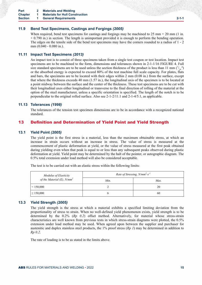
13.1 Yield Point (2005)The yield point is the first stress in a material, less than the maximum obtainable stress, at which anincrease in strain occurs without an increase in stress. The value of stress is measured at thecommencement of plastic deformation at yield, or the value of stress measured at the first peak obtainedduring yielding even when that peak is equal to or less than any subsequent peaks observed during plasticdeformation at yield. Yield point may be determined by the halt of the pointer, or autographic diagram. The0.5% total extension under load method will also be considered acceptable.
The test is to be carried out with an elastic stress within the following limits:
Modulus of Elasticityof the Material (E), N/mm2
Rate of Stressing, N/mm2-s-1
Min. Max.
< 150,000 2 20
≥ 150,000 6 60
13.3 Yield Strength (2005)The yield strength is the stress at which a material exhibits a specified limiting deviation from theproportionality of stress to strain. When no well-defined yield phenomenon exists, yield strength is to bedetermined by the 0.2% (Rp 0.2) offset method. Alternatively, for material whose stress-straincharacteristics are well known from previous tests in which stress-strain diagrams were plotted, the 0.5%extension under load method may be used. When agreed upon between the supplier and purchaser foraustenitic and duplex stainless steel products, the 1% proof stress (Rp 1) may be determined in addition toRp 0.2.
The rate of loading is to be as stated in the limits above.
Part 2 Materials and WeldingChapter 1 Materials for Hull ConstructionSection 1 General Requirements 2-1-1
ABS RULES FOR MATERIALS AND WELDING • 2022 15
13.5 Tensile Strength (2005)After reaching the yield or proof load, for ductile material, the machine speed during the tensile test is notto exceed that corresponding to a strain rate of 0.008 s-1. For brittle materials, such as gray cast iron, theelastic stress rate is not to exceed 10 N/mm2 per second.
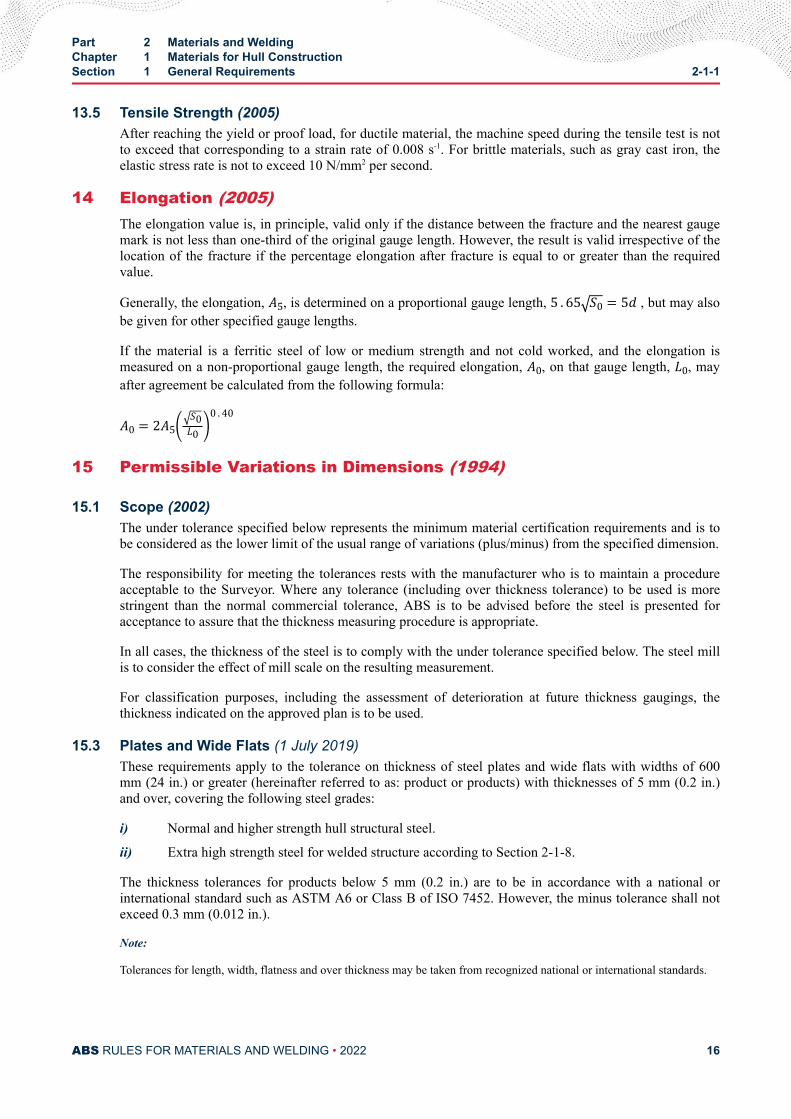
14 Elongation (2005)The elongation value is, in principle, valid only if the distance between the fracture and the nearest gaugemark is not less than one-third of the original gauge length. However, the result is valid irrespective of thelocation of the fracture if the percentage elongation after fracture is equal to or greater than the requiredvalue.
Generally, the elongation, A5, is determined on a proportional gauge length, 5 . 65 S0 = 5d , but may alsobe given for other specified gauge lengths.
If the material is a ferritic steel of low or medium strength and not cold worked, and the elongation ismeasured on a non-proportional gauge length, the required elongation, A0, on that gauge length, L0, mayafter agreement be calculated from the following formula:
A0 = 2A5 S0L0 0 . 4015 Permissible Variations in Dimensions (1994)
15.1 Scope (2002)The under tolerance specified below represents the minimum material certification requirements and is tobe considered as the lower limit of the usual range of variations (plus/minus) from the specified dimension.
The responsibility for meeting the tolerances rests with the manufacturer who is to maintain a procedureacceptable to the Surveyor. Where any tolerance (including over thickness tolerance) to be used is morestringent than the normal commercial tolerance, ABS is to be advised before the steel is presented foracceptance to assure that the thickness measuring procedure is appropriate.
In all cases, the thickness of the steel is to comply with the under tolerance specified below. The steel millis to consider the effect of mill scale on the resulting measurement.
For classification purposes, including the assessment of deterioration at future thickness gaugings, thethickness indicated on the approved plan is to be used.
15.3 Plates and Wide Flats (1 July 2019)These requirements apply to the tolerance on thickness of steel plates and wide flats with widths of 600mm (24 in.) or greater (hereinafter referred to as: product or products) with thicknesses of 5 mm (0.2 in.)and over, covering the following steel grades:
i) Normal and higher strength hull structural steel.
ii) Extra high strength steel for welded structure according to Section 2-1-8.
The thickness tolerances for products below 5 mm (0.2 in.) are to be in accordance with a national orinternational standard such as ASTM A6 or Class B of ISO 7452. However, the minus tolerance shall notexceed 0.3 mm (0.012 in.).
Note:
Tolerances for length, width, flatness and over thickness may be taken from recognized national or international standards.
Part 2 Materials and WeldingChapter 1 Materials for Hull ConstructionSection 1 General Requirements 2-1-1
ABS RULES FOR MATERIALS AND WELDING • 2022 16
Class C of ISO 7452 latest version, or equivalent recognized national or international standards, may beapplied in lieu of 15.3.2, in which case the requirements in 15.3.3 and 15.3.4 need not be applied.
Additionally, if Class C ISO 7452 latest version is applied, it is required that the steel mill demonstrate tothe satisfaction of ABS that the number of measurements and measurement distribution is appropriate toestablish that the mother plates produced are at or above the specified nominal thickness.
15.3.1 ResponsibilityThe responsibility for verification and maintenance of the production within the requiredtolerances rests with the manufacturer. The Surveyor may require that he witness somemeasurements. The responsibility for storage and maintenance of the delivered product(s) withacceptable level of surface conditions rests with the shipyard before the products are used infabrication.
15.3.2 Thickness Tolerances15.3.2(a) Thickness tolerances of a given products are defined as:
● Minus tolerance is the lower limit of the acceptable range below the nominal thickness.
● Plus tolerance is the upper limit of the acceptable range above the nominal thickness.
Note:
Nominal thickness is defined by the purchaser at the time of enquiry and order.
15.3.2(b) The minus tolerance on nominal thickness of products in the scope of 2-1-1/15.3 is 0.3mm (0.012 in.) irrespective of nominal thickness.
15.3.2(c) Thickness tolerances are not applicable to areas repaired by grinding in accordance with2-1-1/3.7.1, unless more stringent requirements are specified by the purchaser and agreed by ABSMaterials Department.
15.3.2(d) Plus tolerances on nominal thickness are to be in accordance with a recognized nationalor international standard such as ASTM A6, unless otherwise specified by the purchaser andagreed by ABS Materials Department.
15.3.2(e) Weight tolerance may be specified by purchaser.
15.3.3 Average Thickness15.3.3(a) The average thickness of a product is defined as the arithmetic mean of themeasurements made in accordance with the requirements of 2-1-1/15.3.4.
15.3.3(b) The average thickness of the product is not to be less than the nominal thickness.
15.3.4 Thickness Measurements15.3.4(a) Thickness is to be measured at locations as defined in 2-1-1/15.3.4 FIGURE 1.Automated or manual measurement methods may be used.
15.3.4(b) The procedure and records of measurements are to be made available to the Surveyorand copies provided on request.
Part 2 Materials and WeldingChapter 1 Materials for Hull ConstructionSection 1 General Requirements 2-1-1
ABS RULES FOR MATERIALS AND WELDING • 2022 17
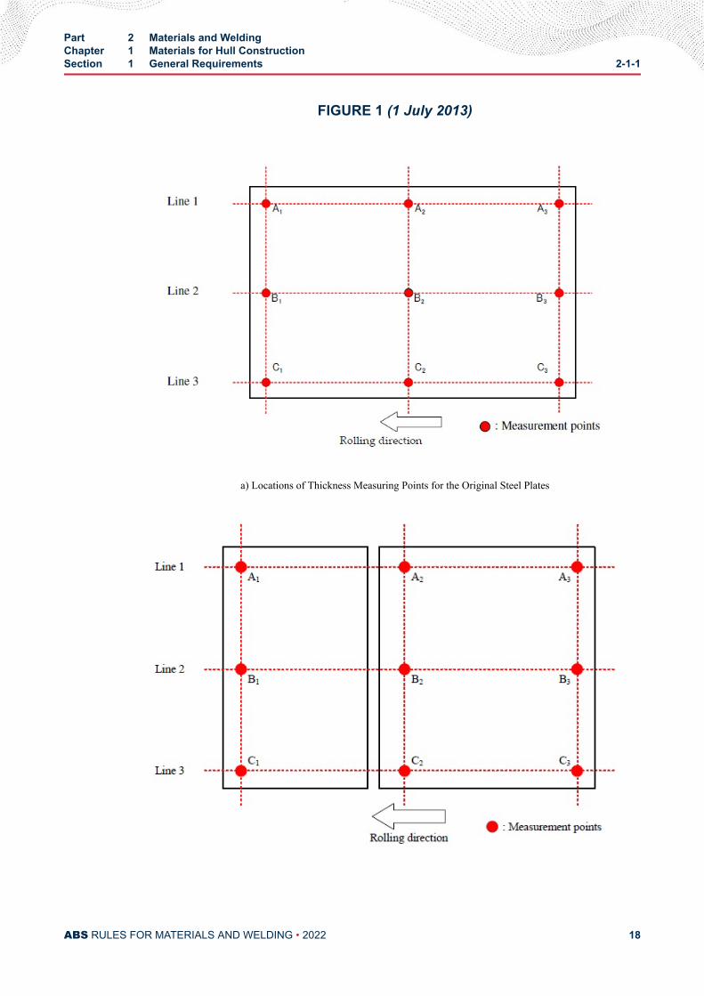
FIGURE 1 (1 July 2013)
a) Locations of Thickness Measuring Points for the Original Steel Plates
Part 2 Materials and WeldingChapter 1 Materials for Hull ConstructionSection 1 General Requirements 2-1-1
ABS RULES FOR MATERIALS AND WELDING • 2022 18
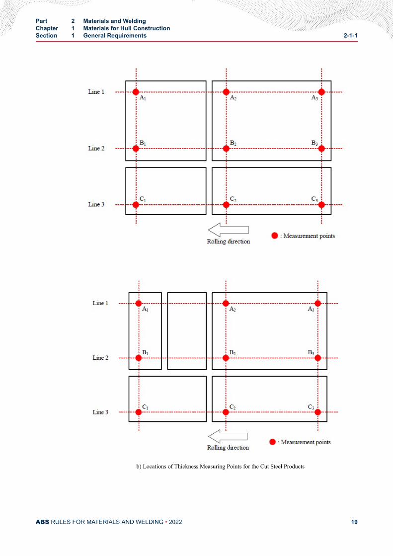
b) Locations of Thickness Measuring Points for the Cut Steel Products
Part 2 Materials and WeldingChapter 1 Materials for Hull ConstructionSection 1 General Requirements 2-1-1
ABS RULES FOR MATERIALS AND WELDING • 2022 19
Notes:
1 ( 1 July 2013) At least two lines are to be selected from Lines 1, 2, or 3 as shown, and at least threepoints on each selected line are to be selected for thickness measurement. If more than three points aretaken on each Line, the number of points on each line is to be the same.The measurement locations apply to a product rolled directly from one slab or steel ingot even if theproduct is to be later cut by the manufacturer. Examples of the original measurements relative to latercut products are shown in 2-1-1/15.3.4 FIGURE 1b). It is to be noted that the examples shown are notrepresentative of all possible cutting scenarios.
2 For automated measuring, peripheral points are to be located 10-300 mm (0.375-12.0 in.) from the edge.
3 For manual measuring, peripheral points are to be located 10-100 mm (0.375-4.0 in.) from the edge.
15.5 Shapes and BarsThe under tolerance of cross sectional dimensions for shapes and bars are based on the ordered dimensionsand are to conform to those given in ASTM A6 or other recognized standards as may be specified in thepurchase order.
16 Rolled Plates over 100 mm (4 in.) Thick (2016)When ABS and non-ABS grade rolled plates of over 100 mm (4 in.) thickness are used for vessel hullstructural application, in addition to chemical analysis the following test data is to be obtained atonequarter and mid thickness locations:
● Tensile properties, and
● Impact properties in the longitudinal or transverse directions
Also, each plate is to be UT inspected in accordance with either ASTM A578 Level B or anotherequivalent recognized standard to evaluate the internal soundness.
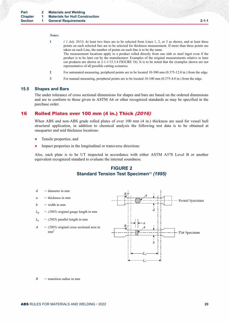
FIGURE 2Standard Tension Test Specimen(1) (1995)
d = diameter in mma = thickness in mmb = width in mmLo = (2005) original gauge length in mmLc = (2005) parallel length in mmA = (2005) original cross sectional area inmm2
R = transition radius in mm
Part 2 Materials and WeldingChapter 1 Materials for Hull ConstructionSection 1 General Requirements 2-1-1
ABS RULES FOR MATERIALS AND WELDING • 2022 20
d a b Lo Lc RFlat specimen Alternative A - t (2) 25 5 . 65 A Lo+ 2 A 25
Flat specimen Alternative B - t (2) 25 200 225 25
Round specimen Alternative C 14 - - 70 85 10
Notes:
1 Standard specimen in accordance with ASTM E8/E8M or A370 will also be acceptable in conjunction with thecorresponding elongation requirements in 2-1-2/15.9 TABLE 2 or 2-1-3/7.3 TABLE 2.
2 t is the full thickness of the material as produced. If the capacity of the testing machine does not allow fullthickness specimens to be broken, the thickness may be reduced by machining one surface only.
3 (2005) Lo , the proportional gauge length, is to be greater than 20 mm.
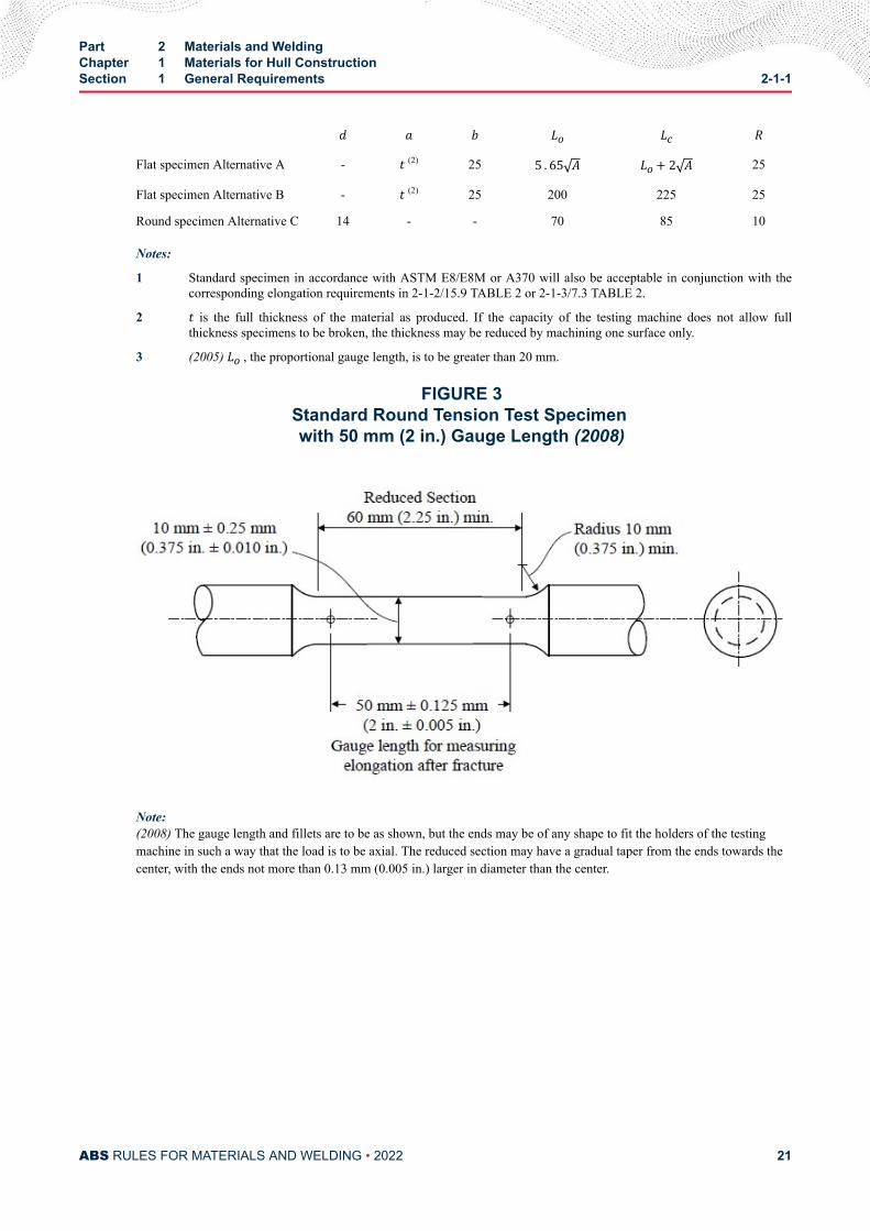
FIGURE 3Standard Round Tension Test Specimen with 50 mm (2 in.) Gauge Length (2008)
Note:(2008) The gauge length and fillets are to be as shown, but the ends may be of any shape to fit the holders of the testingmachine in such a way that the load is to be axial. The reduced section may have a gradual taper from the ends towards thecenter, with the ends not more than 0.13 mm (0.005 in.) larger in diameter than the center.
Part 2 Materials and WeldingChapter 1 Materials for Hull ConstructionSection 1 General Requirements 2-1-1
ABS RULES FOR MATERIALS AND WELDING • 2022 21
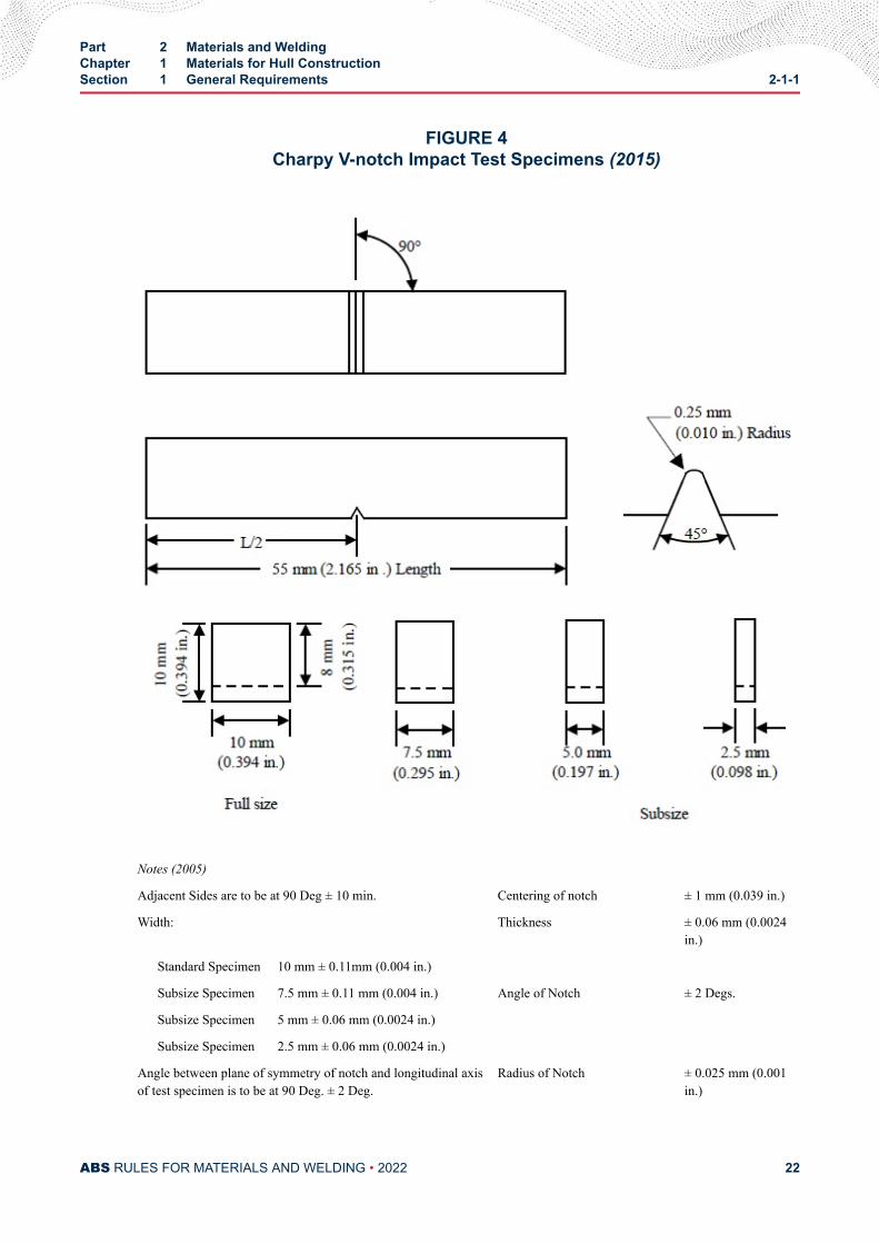
FIGURE 4Charpy V-notch Impact Test Specimens (2015)
Notes (2005)
Adjacent Sides are to be at 90 Deg ± 10 min. Centering of notch ± 1 mm (0.039 in.)
Width: Thickness ± 0.06 mm (0.0024in.)
Standard Specimen 10 mm ± 0.11mm (0.004 in.)
Subsize Specimen 7.5 mm ± 0.11 mm (0.004 in.) Angle of Notch ± 2 Degs.
Subsize Specimen 5 mm ± 0.06 mm (0.0024 in.)
Subsize Specimen 2.5 mm ± 0.06 mm (0.0024 in.)
Angle between plane of symmetry of notch and longitudinal axisof test specimen is to be at 90 Deg. ± 2 Deg.
Radius of Notch ± 0.025 mm (0.001in.)
Part 2 Materials and WeldingChapter 1 Materials for Hull ConstructionSection 1 General Requirements 2-1-1
ABS RULES FOR MATERIALS AND WELDING • 2022 22
Length of specimen ± 0.60 mm (0.024 in.) Dimension to Bottom of Notch ± 0.06 mm (0.0024in.)
Surface Finish Requirements on:
Notched surface and opposite face 2 μm (63 μin.)
Other surfaces 4 μm (125 μin.)
All impact tests are to be carried out on Charpy machines complying with the requirements of ISO 148 or other nationaland international recognized Standards, and having a striking energy of not less than 150 J.
(2015) Where the test temperature is other than ambient, the temperature of the test specimen at the moment of breaking isto be the specified temperature within ± 2°C (± 3.6°F).
17 Steel Plates and Wide Flats with Specified Minimum ThroughThickness Properties (“Z” Quality) (2013)“Z” quality steel is employed in those structural details subject to strains in the through thickness directionin order to minimize the possibility of lamellar tearing during fabrication.
These requirements are intended for material with a thickness greater than or equal to 15 mm (0.60 in.)where a specified minimum ductility in the through thickness or “Z” direction is specified. Products with athickness less than 15 mm (0.60 in.) may also be included.
Two “Z” quality steels are specified:
Z25 for normal ship applications
Z35 for more severe applications.
Through thickness properties are characterized by specified values for reduction of area in a throughthickness tension test.
The steel works are to be approved by ABS for the manufacture of “Z” quality steels, in accordance withPart 2, Appendix 4. In addition, the maximum sulfur content is to be 0.008%, determined by ladle analysis.
When steels with improved through thickness properties are specified, special steel-making processes areto be used. The following processes used either singly or in combination would be considered to meet thisrequirement.
i) Low sulfur practices
ii) Additions of elements known to control the shape of nonmetallic inclusions.
iii) Electroslag or vacuum arc remelting.
iv) Control of centerline segregation during continuous casting
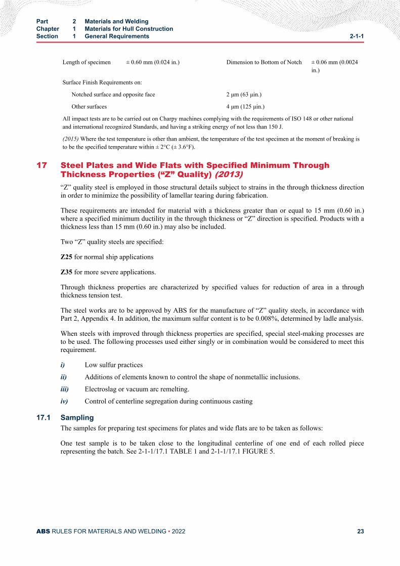
17.1 SamplingThe samples for preparing test specimens for plates and wide flats are to be taken as follows:
One test sample is to be taken close to the longitudinal centerline of one end of each rolled piecerepresenting the batch. See 2-1-1/17.1 TABLE 1 and 2-1-1/17.1 FIGURE 5.
Part 2 Materials and WeldingChapter 1 Materials for Hull ConstructionSection 1 General Requirements 2-1-1
ABS RULES FOR MATERIALS AND WELDING • 2022 23
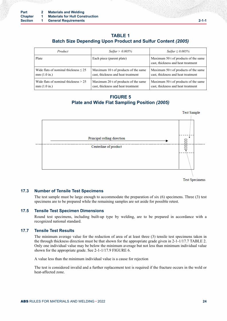
TABLE 1Batch Size Depending Upon Product and Sulfur Content (2005)
Product Sulfur > 0.005% Sulfur ≤ 0.005%
Plate Each piece (parent plate) Maximum 50 t of products of the samecast, thickness and heat treatment
Wide flats of nominal thickness ≤ 25mm (1.0 in.)
Maximum 10 t of products of the samecast, thickness and heat treatment
Maximum 50 t of products of the samecast, thickness and heat treatment
Wide flats of nominal thickness > 25mm (1.0 in.)
Maximum 20 t of products of the samecast, thickness and heat treatment
Maximum 50 t of products of the samecast, thickness and heat treatment
FIGURE 5Plate and Wide Flat Sampling Position (2005)
17.3 Number of Tensile Test SpecimensThe test sample must be large enough to accommodate the preparation of six (6) specimens. Three (3) testspecimens are to be prepared while the remaining samples are set aside for possible retest.
17.5 Tensile Test Specimen DimensionsRound test specimens, including built-up type by welding, are to be prepared in accordance with arecognized national standard.
17.7 Tensile Test ResultsThe minimum average value for the reduction of area of at least three (3) tensile test specimens taken inthe through thickness direction must be that shown for the appropriate grade given in 2-1-1/17.7 TABLE 2.Only one individual value may be below the minimum average but not less than minimum individual valueshown for the appropriate grade. See 2-1-1/17.9 FIGURE 6.
A value less than the minimum individual value is a cause for rejection
The test is considered invalid and a further replacement test is required if the fracture occurs in the weld orheat-affected zone.
Part 2 Materials and WeldingChapter 1 Materials for Hull ConstructionSection 1 General Requirements 2-1-1
ABS RULES FOR MATERIALS AND WELDING • 2022 24
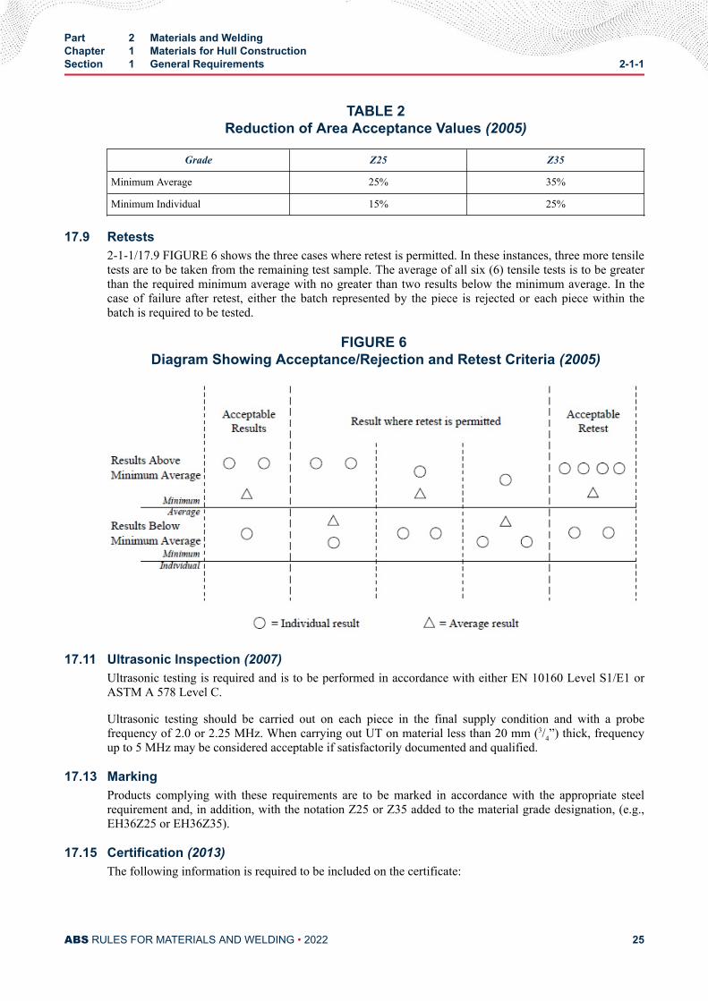
TABLE 2Reduction of Area Acceptance Values (2005)
Grade Z25 Z35
Minimum Average 25% 35%
Minimum Individual 15% 25%
17.9 Retests2-1-1/17.9 FIGURE 6 shows the three cases where retest is permitted. In these instances, three more tensiletests are to be taken from the remaining test sample. The average of all six (6) tensile tests is to be greaterthan the required minimum average with no greater than two results below the minimum average. In thecase of failure after retest, either the batch represented by the piece is rejected or each piece within thebatch is required to be tested.
FIGURE 6 Diagram Showing Acceptance/Rejection and Retest Criteria (2005)
17.11 Ultrasonic Inspection (2007)Ultrasonic testing is required and is to be performed in accordance with either EN 10160 Level S1/E1 orASTM A 578 Level C.
Ultrasonic testing should be carried out on each piece in the final supply condition and with a probefrequency of 2.0 or 2.25 MHz. When carrying out UT on material less than 20 mm (3/4”) thick, frequencyup to 5 MHz may be considered acceptable if satisfactorily documented and qualified.
17.13 MarkingProducts complying with these requirements are to be marked in accordance with the appropriate steelrequirement and, in addition, with the notation Z25 or Z35 added to the material grade designation, (e.g.,EH36Z25 or EH36Z35).
17.15 Certification (2013)The following information is required to be included on the certificate:
Part 2 Materials and WeldingChapter 1 Materials for Hull ConstructionSection 1 General Requirements 2-1-1
ABS RULES FOR MATERIALS AND WELDING • 2022 25
i) Through thickness reduction in area (%)
ii) Steel grade with Z25 or Z35 notation.
iii) Ultrasonic Inspection result of each plate
19 Formed MaterialsWhen material is hot or cold formed, confirmatory mechanical tests are to be conducted when required by2-4-1/3.13.
21 Ultrasonic Examination of Plate and Wide Flats (1 July 2018)
21.1 (1 July 2018)If plates and wide flats are ordered with ultrasonic inspection this is to be made in accordance with anaccepted standard such as EN10160, ASTM A435 or equivalent, at the discretion of ABS. Acceptancecriteria is to be agreed between the purchaser and manufacturer, and accepted by ABS. The products willbe specially marked in accordance with 2-1-2/13.3.
Refer to 2-1-8/11.1 for requirements extra high strength steels.
21.3 (1 July 2018)Verification of internal soundness is the responsibility of the manufacturer. The acceptance of internalsoundness by the ABS Surveyor shall not absolve the manufacturer from this responsibility.
23 Fracture Toughness Testing (2006)When specified, fracture toughness testing of materials and weldments is to be carried out. Fracturetoughness testing may involve tests for properties such as plane strain fracture toughness parameter, KIC ;elastic-plastic fracture toughness parameter, JIC ; or critical crack-tip opening displacement (CTOD)parameter, for mode-I type of deformation. Tests are to be carried out as per BS 7448 Parts 1 & 2/ASTME1820 specification or any other recognized standard. The test is deemed to be valid and acceptableprovided post-test data analyses meets all validity criteria of BS 7448 Parts 1 & 2/ASTM E1820 or anyother recognized standard, and the fracture toughness value determined is equal to or greater than theminimum specified value in the ABS approved specification. Specific aspects that are to be taken intoconsiderations before testing is initiated are listed below:
23.1Specimen geometry, notch orientation and load type (bend or tension) are to be selected as per thespecification and are to be in conformity with BS 7448 Parts 1 & 2/ASTM E 1823 or any other recognizedstandard.
23.3Cut samples for machining test specimens are to be extracted from test coupons or locations with properorientation identified as specified in the material specification for plates, and for welds, as given in themanufacturing procedure specification. Orientation mark, heat number, plate number, etc., based on themanufacturer’s evolved traceability system are to be transferred onto the samples using a template andpaint, local chemical etching or appropriate mechanical means. No plastic deformation or distortions arepermitted during this process. This process is to be repeated on the finished, inspected and acceptedspecimens before the testing program is initiated. A mix-up of specimens without proper identification willcall for rejection of the test results.
23.5If straightening of the samples is needed, then it is to be carried out between the platens of a suitable press(mechanical or hydraulic) under the slowest possible loading rate, and the compressive load applied is not
Part 2 Materials and WeldingChapter 1 Materials for Hull ConstructionSection 1 General Requirements 2-1-1
ABS RULES FOR MATERIALS AND WELDING • 2022 26
to exceed the compressive yield stress of the material. It is the responsibility of the manufacturer duringthis operation to ensure complete safety to personnel and the witnessing Surveyor.
23.6 (2009)In the case of weldment testing, the residual stresses are not to be altered in any way by pre-compressioncrack front straightening method(s), unless specially permitted in the ABS-approved material and productmanufacturing procedure specifications.
23.7Dimensions, machined notch root radius, side grooving and other fine details (such as specimen surfacefinish, centerline offset of loading pins, etc.) in the test specimens are to be as per the approved specimendrawing and in conformity with ASTM E1820 or to any other recognized standard.
23.9Calibration certificates for servo-mechanical/hydraulic universal testing machines, load cells, transducers,and recording equipment used in testing are to be provided to the Surveyor by the testing lab forverification and record. Selection of the loading roller diameter and its alignment with the crack plane ofthe specimen in the case of bend specimen testing and proper alignment of the clevis for compact tensiontesting are to be ensured by the Surveyor prior to the beginning of a test.
23.11Crack opening displacement (COD) gauges are to be calibrated once per batch of testing in the presence ofthe Surveyor.
23.13Fatigue pre-cracking loads and cyclic loading rates (applied stress intensity level/time) are to be as perBS7448/ASTM E1820 or any other recognized standards, and the Surveyor is to witness at least onespecimen in a batch of specimens being tested. For the rest, the test lab has to provide the loading historyand certify that these were done in accordance with BS 7448/ASTM E1820 or any other recognizedstandard requirements.
23.15Crack length measurement can be made by compliance or electrical potential technique and may besupplemented by optical means of measurements. The calibration method employed is to be verified by theSurveyor and is to be validated by nine (9) point measurements made on the broken specimen after the testas per BS 7448/ASTM E1820 or to any other recognized standard. Heat tinting/etching or any othersuitable method(s) used to reveal the crack front to estimate the final crack length in post-test analysis shallbe to the satisfaction of the Surveyor. Photo-macrographs of the broken samples are to be captured anddocumented along with the valid test report for each specimen tested.
23.17The following acceptance criteria for CTOD tests are to be applied whenever CTOD tests are specified andperformed. If the scatter in CTOD (δc, δu or δm) data from a set of three tests is such that the minimumvalue is greater than or equal to 70% of the average value of the set, then the minimum value of the threespecimens is to be taken as the characteristic CTOD value for a specified location (base metal, weld metal,or HAZ) and is to be equal to or higher than the specified minimum CTOD value for the material at thelocation. If the minimum value is less than 70% of the average value of the set, or if the minimum value ofthe three specimens fails to meet the specified minimum CTOD value, then three additional specimens areto be machined and tested from the same previously tested plate, product, or weldment. The second lowestof all six values is to be reported as the characteristic CTOD value and this has to be equal to or greaterthan the specified minimum CTOD value as stipulated in the ABS-approved material and fabricationspecifications for the specified location.
Part 2 Materials and WeldingChapter 1 Materials for Hull ConstructionSection 1 General Requirements 2-1-1
ABS RULES FOR MATERIALS AND WELDING • 2022 27
C H A P T E R 1Materials for Hull Construction
S E C T I O N 2Ordinary-strength Hull Structural Steel
1 Ordinary-strength Hull Structural Steel (1 July 2021)The requirements in this subsection are intended for products of the following thicknesses.
Plates and Wide Flats up to and including 150 mm (6.0 in.)
Tubulars (seamless or welded) up to and including 70 mm (2.75 in.)
Sections and Bars up to and including 50 mm (2.0 in.)
3 Process of Manufacture (1 July 2021)The steel is to be made by one or more of the following processes: open-hearth, basic-oxygen,electricfurnace, vacuum-arc remelt, electro-slag remelt, or such other process as may be speciallyapproved. The steel may be cast in ingots or may be strand (continuous) cast. The ratio of reduction ofthickness from a strand (continuous) cast slab to finished plate is to be a minimum of 3 to 1 unlessspecially approved. Data in support of mechanical properties, weldability and compliance with the Rules inall respects are to be submitted by the steel or pipe manufacturer for review and approval when new orspecial steels or production methods are proposed or when new steel mills or pipe mills begin production.
3.1 Plates Produced from CoilsFor coiled plate, the manufacturer or processor is to submit supporting data for review and approval toindicate that the manufacturing, processing, and testing will provide material which is in compliance withthe Rules.
5 Chemical Composition
5.1 Ladle AnalysisThe chemical composition is to be determined by the steel manufacturer on samples taken from each ladleof each heat and is to conform to the applicable chemical requirements of the grades of steel listed in2-1-2/15.9 TABLE 1.
5.3 Product AnalysisWhen product (check) analysis is required, the chemical tolerances of ASTM A6 or of other nationallyrecognized standards are to be applied.
PART 2
ABS RULES FOR MATERIALS AND WELDING • 2022 28
5.5 Special CompositionsMaterial differing in chemical composition, deoxidation practice, mechanical properties or heat treatmentfrom that shown in 2-1-2/15.9 TABLE 1 will be subjected to special approval.
5.7 Fine Grain PracticeWhere steel is required to be made using fine grain practice, the requirement is to be met by addingaluminum, unless some other method is specially approved. The fine grain requirement may be determinedby one of the following methods.
5.7.1A McQuaid-Ehn austenite grain size of 5 or finer in accordance with ASTM E112 for each ladleof each heat, or
5.7.2Minimum Acid-soluble Aluminum content of 0.015% or minimum total Aluminum content of0.020% for each ladle of each heat.
7 Condition of Supply (1 July 2018)The conditions of supply are to be in accordance with the requirements in 2-1-2/15.9 TABLE 5 and thefollowing:
Controlled manufacturing processes require approval for each plant and combination of grade andthickness limit.
The applicable rolling procedures are defined as follows. Reference can also be made to ASTM A941, forcooling definitions.
7.1 As Rolled – AR (1 July 2018)This procedure involves the rolling of steel at high temperature followed by air cooling, as it is rolled, withno further heat treatment. The rolling and finishing temperatures are typically in the austeniterecrystallization region and above the normalizing temperature. The strength and toughness properties ofsteel produced by this process are generally less than steel heat treated after rolling or than steel producedby advanced processes.
7.3 Heat Treatment7.3.1 Normalizing Heat Treatment (1 July 2021)
A normalizing heat treatment is to consist of heating plates, tubulars, wide flats, bars or shapesabove the critical temperature, AC3, and in the lower end of the austenite recrystallization regionfor a specific period of time to effect the desired transformation and then individually cooling thematerial in air. The process improves the mechanical properties of asrolled steel by refining theaustenitic grain size and homogenizing the microstructure, provided that the steel is produced tofine austenitic grain size practice. Normalizing heat treatments are usually conducted at the steelmanufacturer’s plant. Such heat treatment may be carried out at a shipyard or fabricator’s plant,provided the Surveyor is satisfied with the heat-treating facilities and procedures. In such cases,the shipyard or fabricator is to indicate on the purchase order that the mill tests are to be made onnormalized coupons. Otherwise, tests on the normalized material will be required at the shipyardor fabricator’s plant.
7.3.2 Special Heat TreatmentOther types of heat treatment are to be specially approved.
Part 2 Materials and WeldingChapter 1 Materials for Hull ConstructionSection 2 Ordinary-strength Hull Structural Steel 2-1-2
ABS RULES FOR MATERIALS AND WELDING • 2022 29
7.5 Controlled Manufacturing Process7.5.1 Controlled Rolling - CR (Normalized Rolling - NR) (1 July 2018)
Controlled rolling is a procedure in which the final rolling temperature is generally controlledwithin the range used for normalizing heat treatments so that the austenite completelyrecrystallizes, allowed to cool in air, resulting in a material condition generally equivalent to thatobtained by normalizing.
7.5.2 Thermo-mechanical Rolling - TM (Thermo-mechanical Controlled Processing - TMCP)(1 July 2018)
Thermo-mechanical controlled processing involves the strict control of the steel temperature andthe rolling reduction. Generally, a high proportion of the rolling reduction is carried out close to orbelow the Ar3 transformation temperature and may involve rolling toward the lower end of thetemperature range of the intercritical duplex phase region, thus permitting little if anyrecrystallization of the austenite. Unlike controlled rolling, the properties produced by TM(TMCP) cannot be reproduced by subsequent normalizing or other heat treatment.
The use of accelerated cooling on completion of rolling may also be accepted, subject to thespecial approval of ABS.
Accelerated cooling (AcC) is a process which aims to improve mechanical properties bycontrolled cooling with rates higher than air cooling immediately after the final TM (TMCP)operation. Direct quenching is excluded from accelerated cooling.
Where NR (CR) and TM with/without AcC are applied, the programmed rolling schedules are tobe verified by ABS at the time of the steel works approval, and are to be made available whenrequired by the attending Surveyor. On the manufacturer’s responsibility, the programmed rollingschedules are to be adhered to during the rolling operation. Refer to 2-1-1/1.2.2. To this effect, theactual rolling records are to be reviewed by the manufacturer and occasionally by the Surveyor.
When deviation from the programmed rolling schedules or normalizing or quenching andtempering procedures occurs, the manufacturer shall take the further measures required in2-1-1/1.2.2 to the Surveyor’s satisfaction.
7.7 Quenching and Tempering – QT (1 July 2018)Quenching involves a heat treatment process in which steel is heated to an appropriate temperature abovethe AC3, held for a specific period of time, and then cooled with an appropriate coolant for the purpose ofhardening the microstructure. Tempering subsequent to quenching is a process in which the steel isreheated to an appropriate temperature not higher than the AC1, maintained at that temperature for aspecific period of time to restore toughness properties by improving the microstructure and reduce theresidual stress caused by the quenching process.
9 Tensile Properties
9.1 Required Tensile PropertiesThe material, except as specified in 2-1-2/9.5, is to conform to the requirements of 2-1-2/15.9 TABLE 2 asto tensile properties.
9.3 Tension Test Specimens (1 July 2021)One tension test is to be made on two different plates, tubulars, shapes or bars from each heat of steel,unless the finished material from a heat is less than 50 tons, when one tension test will be sufficient. If,however, material from one heat differs 9.5 mm (0.375 in.) or more in thickness or diameter, one tensiontest is to be made from both the thickest and the thinnest material rolled, regardless of the weightrepresented. One tension test is to be made on each plate as quenched and tempered. For plates from coils,tension tests are to be made from not less than two coils from each heat, except where a single coil is to be
Part 2 Materials and WeldingChapter 1 Materials for Hull ConstructionSection 2 Ordinary-strength Hull Structural Steel 2-1-2
ABS RULES FOR MATERIALS AND WELDING • 2022 30
certified in which case tension test specimens from that coil only need be tested. Two tension tests are to bemade from each coil tested. One tension test specimen is to be obtained from a location immediately priorto the first plate produced and a second test specimen obtained from the approximate center lap. When thecoiled material from one heat differs by 1.6 mm (1/16 in.) or more in thickness, test specimens are to beobtained from both the thinnest and the thickest material rolled.
9.5 ExceptionsShapes less than 645 mm2 (1 in2) in cross section and bars, other than flats, less than 12.5 mm (1/2 in.) inthickness or diameter need not be subject to tension test, but chemistry consistent with the required tensileproperties is to be applied.
9.7 <No Text> (2007)9.9 Omission of Elongation Requirements
For raised-pattern floor plates not exceeding 12.5 mm (0.50 in.) in thickness, the requirement forelongation is waived.
9.11 Retests (1996)Where the results of the tension test do not comply with the requirements, two further tests may be carriedout on specimens taken from the same sample. For elongation retest, 2-1-1/9.5 is to be complied with. Forplates from coils the retest specimens are to be taken adjacent to the original specimen.
If the results of both additional tests meet the requirements, the material tested or represented by the testmay be accepted.
When the results of one or both additional tests do not meet the requirements, the sample is to be rejectedunless the manufacturer elects to resubmit it after heat treatment or reheat treatment, or as another grade.The rest of the material represented by the test may be treated under 2-1-2/9.13.
9.13 Unsatisfactory Tests (1 July 2021)Where the tests under 2-1-2/9.3 and 2-1-2/9.13 fail, the remaining material from the same heat may beaccepted, provided satisfactory results are obtained on both of two additional plates, tubulars, shapes orbars selected in accordance with 2-1-2/9.3.
When the results of one or both samples do not meet the requirements, all materials represented by thetests are to be rejected unless the manufacturer elects to submit each piece individually, or to resubmit thelot after heat treatment or reheat treatment or as another grade.
11 Impact Properties
11.1 Impact Tests (1 July 2021)Charpy V-notch impact tests are to be carried out in accordance with 2-1-2/15.9 TABLE 4. These samerequirements apply for tubulars, flats, rounds, and shapes when specially ordered in these grades unlessagreed otherwise. For rolled sections impact tests specimens are to be taken from the flanges of beams,channels, and tees, and from the legs of angles and bulb angles. One set of three impact specimens is to beobtained from the thickest material rolled except when the maximum thickness or diameter of the materialrepresented by the test differs by 9.5 mm (0.375 in.) or more, in which case, one set of impacts is to bemade from both the thickest and the thinnest material represented, regardless of their weight. See2-1-1/11.11.
For plates produced from coils, impact test coupons are to be obtained adjacent to both tension testcoupons and a third impact test coupon is to be obtained immediately after the last plate produced to thequalifying grade or specification; in no case, however, is the frequency of impact testing to be less than
Part 2 Materials and WeldingChapter 1 Materials for Hull ConstructionSection 2 Ordinary-strength Hull Structural Steel 2-1-2
ABS RULES FOR MATERIALS AND WELDING • 2022 31
that given above for plates, and where additional testing is required, three sets of specimens are to beobtained from each coil tested.
11.3 Impact Test FrequencyThe frequency of impact testing is to be in accordance with 2-1-2/15.9 TABLE 5.
11.5 Initial Test Requirements (2015)The average value of three specimens is to equal or exceed the required average value indicated in theapplicable Rule Tables. Only one individual value may be below the required average, provided it is notless than 70% of the required average value.
Where the subsize specimens in 2-1-1/16 FIGURE 4 are to be used, the modified energy values will applyas follows:
Subsize Specimen Impact Requirements
Specimen Size 10 × 7.5 mm 10 × 5.0 mm 10 × 2.5 mm
(0.394 × 0.295 in.) (0.394 × 0.197 in.) (0.394 × 0.098 in.)
Required Energy 5E/6 2E/3 E/2
E = energy required for 10 × 10 mm (0.394 × 0.394 in.) specimen
11.7 RetestsWhen the results fail to meet the above requirements but conditions ii) and iii) below are complied with,three additional specimens may be taken from the location as close to the initial specimens as possible andtheir test results added to those previously obtained to form a new average. The material represented maybe accepted if for the six specimens all of the following conditions are met:
i) The average is not less than the required average.
ii) No more than two individual values are below the required average.
iii) No more than one individual value is below 70% of the required average.
If the results of tests do not meet the above requirements, the material tested is to be rejected unless themanufacturer elects to resubmit it after heat treatment or reheat treatment, or to resubmit as another grade.
11.9 Unsatisfactory Tests (1 July 2021)The remaining material from the heat may be accepted, provided satisfactory impact results are obtainedon both of two further plates or tubulars of the same thickness as the rejected plate or tubular in the heat.Alternatively, the manufacturer may qualify material of the same thickness by impact testing each plate ortubular. Plates or tubulars of a lesser thickness in the same heat may be accepted, provided that satisfactoryresults are obtained on impact specimens taken from the next lower thickness than the rejected plate ortubular.
11.11 Thin Plates or Tubulars (1 July 2021)Generally, impact tests are not required for plates or tubulars less than 6 mm (0.24 in.) in thickness.
13 Marking
13.1 Stamped or Stenciled Material (1 July 2021)The ABS markings AB and the applicable grades listed in 2-1-2/15.9 TABLE 1 indicating satisfactorycompliance with the Rules are to be clearly steel-die-stamped or stenciled by the manufacturer on each
Part 2 Materials and WeldingChapter 1 Materials for Hull ConstructionSection 2 Ordinary-strength Hull Structural Steel 2-1-2
ABS RULES FOR MATERIALS AND WELDING • 2022 32
finished plate, tubular, shape and bar to signify that the material has satisfactorily complied with the testsprescribed and that certificates for the material will be furnished to the Surveyor in accordance with2-1-1/7. Coiled steel which is certified for chemical analysis only, is to be marked AB without the gradedesignation.
13.3 Coils, Lifts and BundlesIn special cases, upon application, coils intended for light plate and secured lifts or bundles of light plates,shapes or bars of comparatively small size may be steel-die stamped, stenciled, or labeled on only the toppiece or at another approved location, or the markings may be shown on a tag attached to each coil, lift orbundle.
13.5 Flanging-quality Identification (2015)All material intended for cold flanging, when specially approved in accordance with 3-1-2/1.3.3 of theABS Rules for Building and Classing Marine Vessels (Marine Vessel Rules) is to be additionally marked Fto signify that it is of such quality. Cold flanging is to be carried out in accordance with ASTM A6.
13.7 Special Stamping and Marking (1 July 2021)Material other than those grades listed in 2-1-2/15.9 TABLE 1 , is to be marked with both the initials AB/Sand with either the applicable specification number, or such other markings as may be required for readyidentification, to signify that the material has been produced and satisfactorily tested in accordance withthe specification. When a specification does not specifically require normalizing but the material is soordered and so produced, then the plates or tubular are also to be marked with the initial N to indicate thatthe material has been normalized. A shipyard or fabricator who carries out a normalizing heat treatment inaccordance with 2-1-2/7 is to also mark such material with the initial N.
13.9 Special Impact TestingWhen steel is impact tested at temperatures other than those specified in 2-1-2/15.9 TABLE 4, the grademarking is to be followed by the test temperature in degrees Celsius. A prefix “0” to the test temperature isto indicate a temperature colder than zero degrees Celsius.
13.11 Steel with Improved Through Thickness Properties (1 July 2021)Steel plates or tubulars meeting the requirements of 2-1-1/17 are to have the letter Z marked after the gradedesignation.
13.13 Steel with Ultrasonic ExaminationSteels meeting the requirements of 2-1-1/21 are to have the letter U marked after the grade designation as afinal letter.
13.15 Shipping ProcedureNo material bearing these markings is to be forwarded from the steel works until the prescribed tests havebeen satisfactorily carried out in accordance with the Rules.
13.17 Steel at Secondary SourcesSecondary sources for ABS Grade Steel are required to assure traceability of steel intended for ABScertification. To retain proper identification, steel may be marked with the information indicated by themanufacturer’s markings to the satisfaction of the Surveyor.
Part 2 Materials and WeldingChapter 1 Materials for Hull ConstructionSection 2 Ordinary-strength Hull Structural Steel 2-1-2
ABS RULES FOR MATERIALS AND WELDING • 2022 33
15 Surface Finish
15.1 Surface Examination (2008)The material surfaces will be examined by the Surveyor when specially requested by the purchaser. It is tobe free from defects and have a workmanlike finish subject to the conditions given in the followingsubparagraphs.
15.3 Treatment of Surface Defects -Plates (1 July 2018)Refer to 2-1-1/3.
15.4 Treatment of Surface Defects - Tubulars (1 July 2021)Treatment of surface defects in tubulars is to be in accordance with a recognized standard and agreed withABS during qualification of the mill.
15.5 Treatment of Surface Defects -ShapesShapes may be conditioned by the manufacturer for the removal of surface defects by grinding or bychipping to sound metal and depositing weld metal, in accordance with the following limitations.
15.5.1 Chipping and Grinding Material Under 9.5 mm (0.375 in.) in ThicknessFor material less than 9.5 mm (0.375 in.) thickness, in which the defects are not more than 0.8 mm(0.031 in.) in depth, the defects may be removed by grinding or chipping and grinding with theedges well faired.
15.5.2 Chipping and Grinding Material 9.5 mm (0.375 in.) and Over in ThicknessFor material 9.5 mm (0.375 in.) and over in thickness, in which the defects are not more than 1.6mm (0.063 in.) in depth, the defects may be removed by grinding or chipping and grinding withthe edges well faired.
15.5.3 Welding RepairsSurface defects which are greater in depth than the limits shown above may be removed bychipping or grinding and then depositing weld metal, subject to the following limiting conditions.
15.5.3(a) The total area of the chipped or ground surface of any piece is not to exceed 2% of thetotal surface area of that piece.
15.5.3(b) After removal of any defect preparatory to welding, the thickness of the shape is not tobe reduced by more than 30% of the nominal thickness, nor is the depth of depression prior towelding to exceed 12.5 mm (0.50 in.) in any case.
15.5.3(c) The toes of angles, beams, channels and zees and the stems and toes of tees may beconditioned by grinding or chipping and welding. Prior to welding, the depth of depression,measured from the toe inward, is to be limited to the thickness of the material at the base of thedepression, with a maximum depth limit of 12.5 mm (0.50 in.).
15.5.3(d) An experienced mill inspector is to inspect and the welding is to be done in accordancewith the requirements of 2-1-1/3.7.2.
15.7 Bar-stock RepairsBars may be conditioned by the manufacturer for the removal of surface defects by grinding, chipping orsome other means, provided the conditioned area is well faired and the depth of depression does not extendbelow the nominal thickness or diameter by more than 1.5%.
Part 2 Materials and WeldingChapter 1 Materials for Hull ConstructionSection 2 Ordinary-strength Hull Structural Steel 2-1-2
ABS RULES FOR MATERIALS AND WELDING • 2022 34
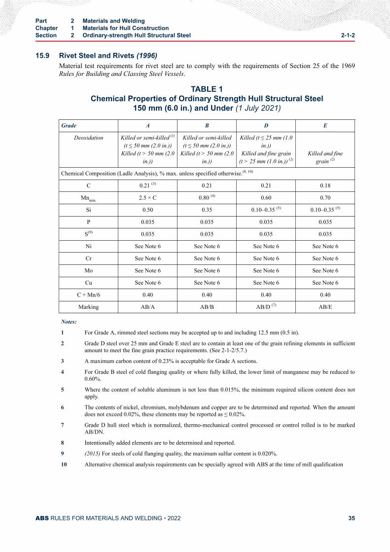
15.9 Rivet Steel and Rivets (1996)Material test requirements for rivet steel are to comply with the requirements of Section 25 of the 1969Rules for Building and Classing Steel Vessels.
TABLE 1Chemical Properties of Ordinary Strength Hull Structural Steel
150 mm (6.0 in.) and Under (1 July 2021)
Grade A B D E
Deoxidation Killed or semi-killed (1)
(t ≤ 50 mm (2.0 in.))Killed (t > 50 mm (2.0
in.))
Killed or semi-killed(t ≤ 50 mm (2.0 in.))
Killed (t > 50 mm (2.0in.))
Killed (t ≤ 25 mm (1.0in.))
Killed and fine grain(t > 25 mm (1.0 in.)) (2)
Killed and finegrain (2)
Chemical Composition (Ladle Analysis), % max. unless specified otherwise.(8, 10)
C 0.21 (3) 0.21 0.21 0.18
Mnmin. 2.5 × C 0.80 (4) 0.60 0.70
Si 0.50 0.35 0.10–0.35 (5) 0.10–0.35 (5)
P 0.035 0.035 0.035 0.035
S(9) 0.035 0.035 0.035 0.035
Ni See Note 6 See Note 6 See Note 6 See Note 6
Cr See Note 6 See Note 6 See Note 6 See Note 6
Mo See Note 6 See Note 6 See Note 6 See Note 6
Cu See Note 6 See Note 6 See Note 6 See Note 6
C + Mn/6 0.40 0.40 0.40 0.40
Marking AB/A AB/B AB/D (7) AB/E
Notes:
1 For Grade A, rimmed steel sections may be accepted up to and including 12.5 mm (0.5 in).
2 Grade D steel over 25 mm and Grade E steel are to contain at least one of the grain refining elements in sufficientamount to meet the fine grain practice requirements. (See 2-1-2/5.7.)
3 A maximum carbon content of 0.23% is acceptable for Grade A sections.
4 For Grade B steel of cold flanging quality or where fully killed, the lower limit of manganese may be reduced to0.60%.
5 Where the content of soluble aluminum is not less than 0.015%, the minimum required silicon content does notapply.
6 The contents of nickel, chromium, molybdenum and copper are to be determined and reported. When the amountdoes not exceed 0.02%, these elements may be reported as ≤ 0.02%.
7 Grade D hull steel which is normalized, thermo-mechanical control processed or control rolled is to be markedAB/DN.
8 Intentionally added elements are to be determined and reported.
9 (2015) For steels of cold flanging quality, the maximum sulfur content is 0.020%.
10 Alternative chemical analysis requirements can be specially agreed with ABS at the time of mill qualification
Part 2 Materials and WeldingChapter 1 Materials for Hull ConstructionSection 2 Ordinary-strength Hull Structural Steel 2-1-2
ABS RULES FOR MATERIALS AND WELDING • 2022 35
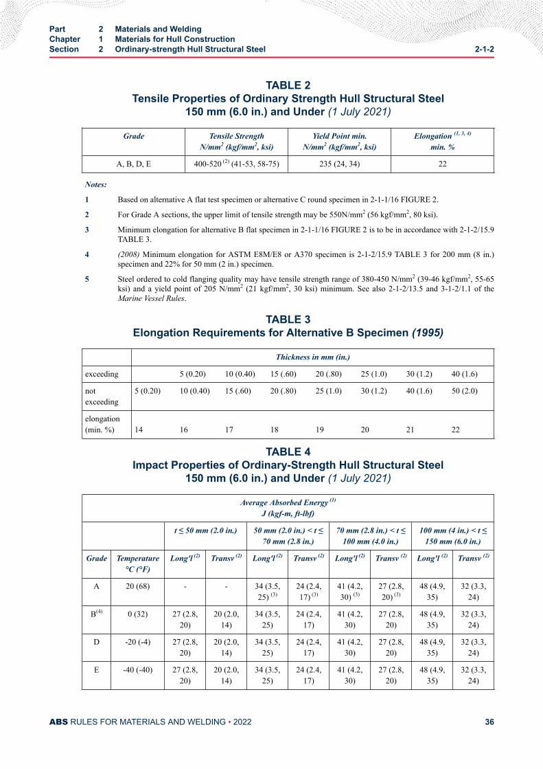
TABLE 2Tensile Properties of Ordinary Strength Hull Structural Steel
150 mm (6.0 in.) and Under (1 July 2021)
Grade Tensile StrengthN/mm2 (kgf/mm2, ksi)
Yield Point min.N/mm2 (kgf/mm2, ksi)
Elongation (1, 3, 4)
min. %
A, B, D, E 400-520 (2) (41-53, 58-75) 235 (24, 34) 22
Notes:
1 Based on alternative A flat test specimen or alternative C round specimen in 2-1-1/16 FIGURE 2.
2 For Grade A sections, the upper limit of tensile strength may be 550N/mm2 (56 kgf/mm2, 80 ksi).
3 Minimum elongation for alternative B flat specimen in 2-1-1/16 FIGURE 2 is to be in accordance with 2-1-2/15.9TABLE 3.
4 (2008) Minimum elongation for ASTM E8M/E8 or A370 specimen is 2-1-2/15.9 TABLE 3 for 200 mm (8 in.)specimen and 22% for 50 mm (2 in.) specimen.
5 Steel ordered to cold flanging quality may have tensile strength range of 380-450 N/mm2 (39-46 kgf/mm2, 55-65ksi) and a yield point of 205 N/mm2 (21 kgf/mm2, 30 ksi) minimum. See also 2-1-2/13.5 and 3-1-2/1.1 of theMarine Vessel Rules.
TABLE 3Elongation Requirements for Alternative B Specimen (1995)
Thickness in mm (in.)
exceeding 5 (0.20) 10 (0.40) 15 (.60) 20 (.80) 25 (1.0) 30 (1.2) 40 (1.6)
notexceeding
5 (0.20) 10 (0.40) 15 (.60) 20 (.80) 25 (1.0) 30 (1.2) 40 (1.6) 50 (2.0)
elongation(min. %) 14 16 17 18 19 20 21 22
TABLE 4Impact Properties of Ordinary-Strength Hull Structural Steel
150 mm (6.0 in.) and Under (1 July 2021)
Average Absorbed Energy (1)
J (kgf-m, ft-lbf)
t ≤ 50 mm (2.0 in.) 50 mm (2.0 in.) < t ≤70 mm (2.8 in.)
70 mm (2.8 in.) < t ≤100 mm (4.0 in.)
100 mm (4 in.) < t ≤150 mm (6.0 in.)
Grade Temperature°C (°F)
Long'l (2) Transv (2) Long'l (2) Transv (2) Long'l (2) Transv (2) Long'l (2) Transv (2)
A 20 (68) - - 34 (3.5,25) (3)
24 (2.4,17) (3)
41 (4.2,30) (3)
27 (2.8,20) (3)
48 (4.9,35)
32 (3.3,24)
B(4) 0 (32) 27 (2.8,20)
20 (2.0,14)
34 (3.5,25)
24 (2.4,17)
41 (4.2,30)
27 (2.8,20)
48 (4.9,35)
32 (3.3,24)
D -20 (-4) 27 (2.8,20)
20 (2.0,14)
34 (3.5,25)
24 (2.4,17)
41 (4.2,30)
27 (2.8,20)
48 (4.9,35)
32 (3.3,24)
E -40 (-40) 27 (2.8,20)
20 (2.0,14)
34 (3.5,25)
24 (2.4,17)
41 (4.2,30)
27 (2.8,20)
48 (4.9,35)
32 (3.3,24)
Part 2 Materials and WeldingChapter 1 Materials for Hull ConstructionSection 2 Ordinary-strength Hull Structural Steel 2-1-2
ABS RULES FOR MATERIALS AND WELDING • 2022 36
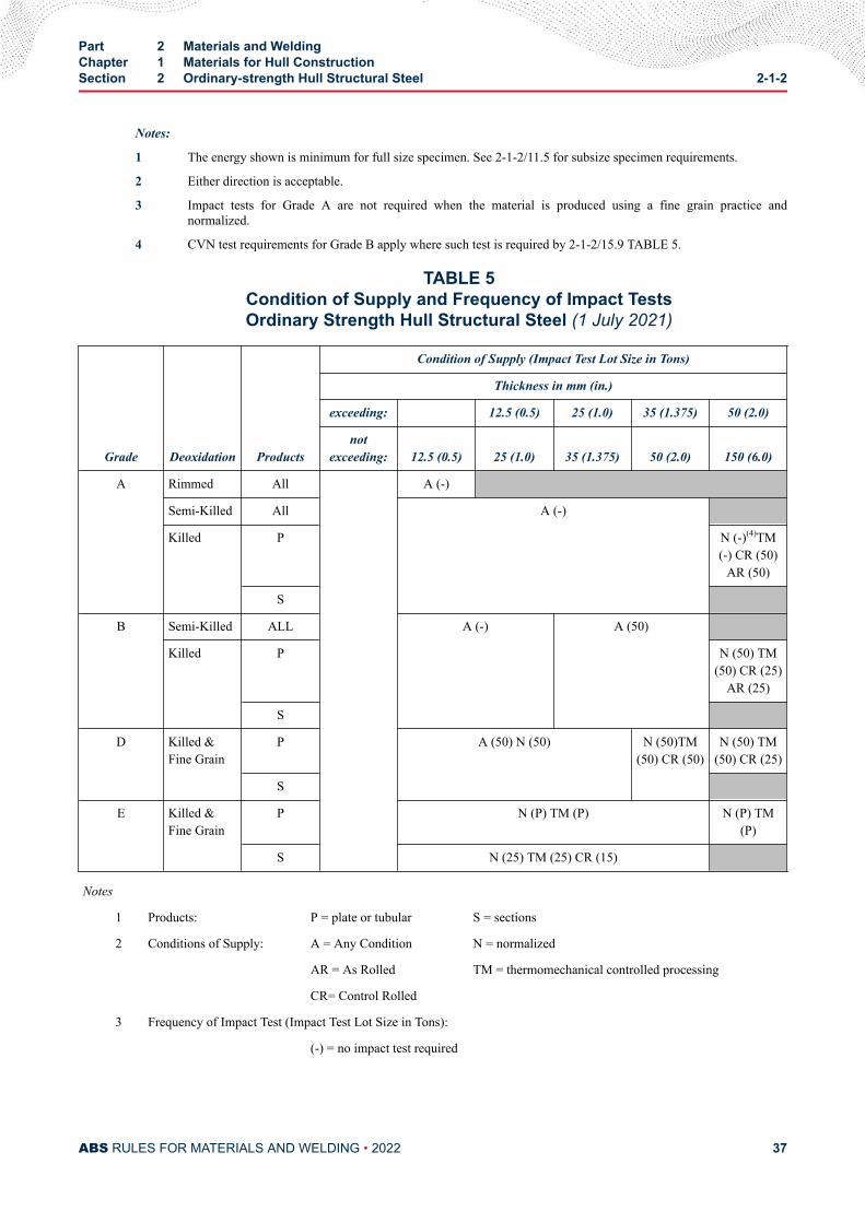
Notes:
1 The energy shown is minimum for full size specimen. See 2-1-2/11.5 for subsize specimen requirements.
2 Either direction is acceptable.
3 Impact tests for Grade A are not required when the material is produced using a fine grain practice andnormalized.
4 CVN test requirements for Grade B apply where such test is required by 2-1-2/15.9 TABLE 5.
TABLE 5Condition of Supply and Frequency of Impact TestsOrdinary Strength Hull Structural Steel (1 July 2021)
Grade Deoxidation Products
Condition of Supply (Impact Test Lot Size in Tons)
Thickness in mm (in.)
exceeding: 12.5 (0.5) 25 (1.0) 35 (1.375) 50 (2.0)
notexceeding: 12.5 (0.5) 25 (1.0) 35 (1.375) 50 (2.0) 150 (6.0)
A Rimmed All A (-)
Semi-Killed All A (-)
Killed P N (-)(4)TM(-) CR (50)
AR (50)
S
B Semi-Killed ALL A (-) A (50)
Killed P N (50) TM(50) CR (25)
AR (25)
S
D Killed &Fine Grain
P A (50) N (50) N (50)TM(50) CR (50)
N (50) TM(50) CR (25)
S
E Killed &Fine Grain
P N (P) TM (P) N (P) TM(P)
S N (25) TM (25) CR (15)
Notes
1 Products: P = plate or tubular S = sections
2 Conditions of Supply: A = Any Condition N = normalized
AR = As Rolled TM = thermomechanical controlled processing
CR= Control Rolled
3 Frequency of Impact Test (Impact Test Lot Size in Tons):
(-) = no impact test required
Part 2 Materials and WeldingChapter 1 Materials for Hull ConstructionSection 2 Ordinary-strength Hull Structural Steel 2-1-2
ABS RULES FOR MATERIALS AND WELDING • 2022 37

(P) = each piece
4 Impact tests for Grade A are not required when material is produced using a fine grain practice andnormalized.
Part 2 Materials and WeldingChapter 1 Materials for Hull ConstructionSection 2 Ordinary-strength Hull Structural Steel 2-1-2
ABS RULES FOR MATERIALS AND WELDING • 2022 38
C H A P T E R 1Materials for Hull Construction
S E C T I O N 3Higher-strength Hull Structural Steel
1 Higher-strength Hull Structural Steel (1 July 2021)The requirements in this subsection are intended for products for the following thicknesses:
Plates and Wide Flats
AH32, DH32, EH32, AH36, DH36 and EH36 steels: up to and including 150 mm (6 in.)
AH40, DH40, EH40, FH32, FH36 and FH40 steels: up to and including 150 mm (6 in.)
Tubulars (Seamless and Welded) up to and including 70 mm (2.75 in.)
Sections and Bars up to and including 50 mm (2 in.)
3 General (1996)The requirements in 2-1-2/3 through 2-1-2/15 are also applicable to higher-strength hull structural steelswith the following paragraphs and Tables replaced by the higher-strength requirements as indicated.
2-1-2/15.9 TABLE 1 replaced by 2-1-3/7.3 TABLE 1
2-1-2/15.9 TABLE 2 replaced by 2-1-3/7.3 TABLE 2
2-1-2/15.9 TABLE 3 replaced by 2-1-3/7.3 TABLE 3
2-1-2/15.9 TABLE 4 replaced by 2-1-3/7.3 TABLE 4
2-1-2/15.9 TABLE 5 replaced by 2-1-3/7.3 TABLE 5
2-1-2/5.7 replaced by 2-1-3/5
5 Fine Grain Practice (1996)Where steel is required to be made using fine grain practice, the requirement may be met by one of thefollowing conditions.
i) A McQuaid-Ehn austenite grain size of 5 or finer in accordance with ASTM E112 for each ladleof each heat, or
ii) Minimum Acid-soluble Aluminum content of 0.015% or minimum total Aluminum content of0.020% for each ladle of each heat, or
PART 2
ABS RULES FOR MATERIALS AND WELDING • 2022 39
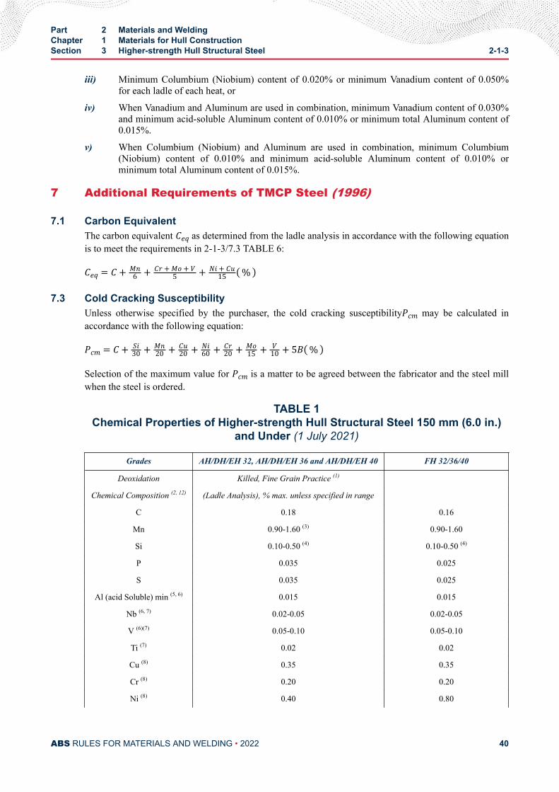
iii) Minimum Columbium (Niobium) content of 0.020% or minimum Vanadium content of 0.050%for each ladle of each heat, or
iv) When Vanadium and Aluminum are used in combination, minimum Vanadium content of 0.030%and minimum acid-soluble Aluminum content of 0.010% or minimum total Aluminum content of0.015%.
v) When Columbium (Niobium) and Aluminum are used in combination, minimum Columbium(Niobium) content of 0.010% and minimum acid-soluble Aluminum content of 0.010% orminimum total Aluminum content of 0.015%.
7 Additional Requirements of TMCP Steel (1996)
7.1 Carbon EquivalentThe carbon equivalent Ceq as determined from the ladle analysis in accordance with the following equationis to meet the requirements in 2-1-3/7.3 TABLE 6:Ceq = C+ Mn6 + Cr+Mo+ V5 + Ni+ Cu15 %
7.3 Cold Cracking SusceptibilityUnless otherwise specified by the purchaser, the cold cracking susceptibilityPcm may be calculated inaccordance with the following equation:Pcm = C+ Si30 + Mn20 + Cu20 + Ni60 + Cr20 + Mo15 + V10 + 5B %Selection of the maximum value for Pcm is a matter to be agreed between the fabricator and the steel millwhen the steel is ordered.
TABLE 1Chemical Properties of Higher-strength Hull Structural Steel 150 mm (6.0 in.)
and Under (1 July 2021)
Grades AH/DH/EH 32, AH/DH/EH 36 and AH/DH/EH 40 FH 32/36/40
Deoxidation Killed, Fine Grain Practice (1)
Chemical Composition (2, 12) (Ladle Analysis), % max. unless specified in range
C 0.18 0.16
Mn 0.90-1.60 (3) 0.90-1.60
Si 0.10-0.50 (4) 0.10-0.50 (4)
P 0.035 0.025
S 0.035 0.025
Al (acid Soluble) min (5, 6) 0.015 0.015
Nb (6, 7) 0.02-0.05 0.02-0.05
V (6)(7) 0.05-0.10 0.05-0.10
Ti (7) 0.02 0.02
Cu (8) 0.35 0.35
Cr (8) 0.20 0.20
Ni (8) 0.40 0.80
Part 2 Materials and WeldingChapter 1 Materials for Hull ConstructionSection 3 Higher-strength Hull Structural Steel 2-1-3
ABS RULES FOR MATERIALS AND WELDING • 2022 40
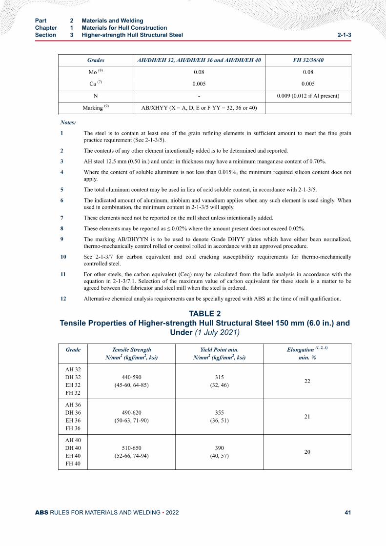
Grades AH/DH/EH 32, AH/DH/EH 36 and AH/DH/EH 40 FH 32/36/40
Mo (8) 0.08 0.08
Ca (7) 0.005 0.005
N - 0.009 (0.012 if Al present)
Marking (9) AB/XHYY (X = A, D, E or F YY = 32, 36 or 40)
Notes:
1 The steel is to contain at least one of the grain refining elements in sufficient amount to meet the fine grainpractice requirement (See 2-1-3/5).
2 The contents of any other element intentionally added is to be determined and reported.
3 AH steel 12.5 mm (0.50 in.) and under in thickness may have a minimum manganese content of 0.70%.
4 Where the content of soluble aluminum is not less than 0.015%, the minimum required silicon content does notapply.
5 The total aluminum content may be used in lieu of acid soluble content, in accordance with 2-1-3/5.
6 The indicated amount of aluminum, niobium and vanadium applies when any such element is used singly. Whenused in combination, the minimum content in 2-1-3/5 will apply.
7 These elements need not be reported on the mill sheet unless intentionally added.
8 These elements may be reported as ≤ 0.02% where the amount present does not exceed 0.02%.
9 The marking AB/DHYYN is to be used to denote Grade DHYY plates which have either been normalized,thermo-mechanically control rolled or control rolled in accordance with an approved procedure.
10 See 2-1-3/7 for carbon equivalent and cold cracking susceptibility requirements for thermo-mechanicallycontrolled steel.
11 For other steels, the carbon equivalent (Ceq) may be calculated from the ladle analysis in accordance with theequation in 2-1-3/7.1. Selection of the maximum value of carbon equivalent for these steels is a matter to beagreed between the fabricator and steel mill when the steel is ordered.
12 Alternative chemical analysis requirements can be specially agreed with ABS at the time of mill qualification.
TABLE 2Tensile Properties of Higher-strength Hull Structural Steel 150 mm (6.0 in.) and
Under (1 July 2021)
Grade Tensile StrengthN/mm2 (kgf/mm2, ksi)
Yield Point min.N/mm2 (kgf/mm2, ksi)
Elongation (1, 2, 3)
min. %
AH 32DH 32EH 32FH 32
440-590(45-60, 64-85)
315(32, 46) 22
AH 36DH 36EH 36FH 36
490-620(50-63, 71-90)
355(36, 51) 21
AH 40DH 40EH 40FH 40
510-650(52-66, 74-94)
390(40, 57) 20
Part 2 Materials and WeldingChapter 1 Materials for Hull ConstructionSection 3 Higher-strength Hull Structural Steel 2-1-3
ABS RULES FOR MATERIALS AND WELDING • 2022 41
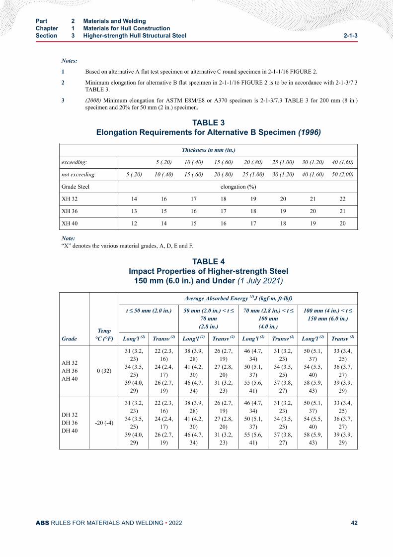
Notes:
1 Based on alternative A flat test specimen or alternative C round specimen in 2-1-1/16 FIGURE 2.
2 Minimum elongation for alternative B flat specimen in 2-1-1/16 FIGURE 2 is to be in accordance with 2-1-3/7.3TABLE 3.
3 (2008) Minimum elongation for ASTM E8M/E8 or A370 specimen is 2-1-3/7.3 TABLE 3 for 200 mm (8 in.)specimen and 20% for 50 mm (2 in.) specimen.
TABLE 3Elongation Requirements for Alternative B Specimen (1996)
Thickness in mm (in.)
exceeding: 5 (.20) 10 (.40) 15 (.60) 20 (.80) 25 (1.00) 30 (1.20) 40 (1.60)
not exceeding: 5 (.20) 10 (.40) 15 (.60) 20 (.80) 25 (1.00) 30 (1.20) 40 (1.60) 50 (2.00)
Grade Steel elongation (%)
XH 32 14 16 17 18 19 20 21 22
XH 36 13 15 16 17 18 19 20 21
XH 40 12 14 15 16 17 18 19 20
Note:“X” denotes the various material grades, A, D, E and F.
TABLE 4Impact Properties of Higher-strength Steel
150 mm (6.0 in.) and Under (1 July 2021)
GradeTemp
°C (°F)
Average Absorbed Energy (1)J (kgf-m, ft-lbf)
t ≤ 50 mm (2.0 in.) 50 mm (2.0 in.) < t ≤70 mm(2.8 in.)
70 mm (2.8 in.) < t ≤100 mm(4.0 in.)
100 mm (4 in.) < t ≤150 mm (6.0 in.)
Long'l (2) Transv (2) Long'l (2) Transv (2) Long'l (2) Transv (2) Long'l (2) Transv (2)
AH 32AH 36AH 40
0 (32)
31 (3.2,23)
34 (3.5,25)
39 (4.0,29)
22 (2.3,16)
24 (2.4,17)
26 (2.7,19)
38 (3.9,28)
41 (4.2,30)
46 (4.7,34)
26 (2.7,19)
27 (2.8,20)
31 (3.2,23)
46 (4.7,34)
50 (5.1,37)
55 (5.6,41)
31 (3.2,23)
34 (3.5,25)
37 (3.8,27)
50 (5.1,37)
54 (5.5,40)
58 (5.9,43)
33 (3.4,25)
36 (3.7,27)
39 (3.9,29)
DH 32DH 36DH 40
-20 (-4)
31 (3.2,23)
34 (3.5,25)
39 (4.0,29)
22 (2.3,16)
24 (2.4,17)
26 (2.7,19)
38 (3.9,28)
41 (4.2,30)
46 (4.7,34)
26 (2.7,19)
27 (2.8,20)
31 (3.2,23)
46 (4.7,34)
50 (5.1,37)
55 (5.6,41)
31 (3.2,23)
34 (3.5,25)
37 (3.8,27)
50 (5.1,37)
54 (5.5,40)
58 (5.9,43)
33 (3.4,25)
36 (3.7,27)
39 (3.9,29)
Part 2 Materials and WeldingChapter 1 Materials for Hull ConstructionSection 3 Higher-strength Hull Structural Steel 2-1-3
ABS RULES FOR MATERIALS AND WELDING • 2022 42
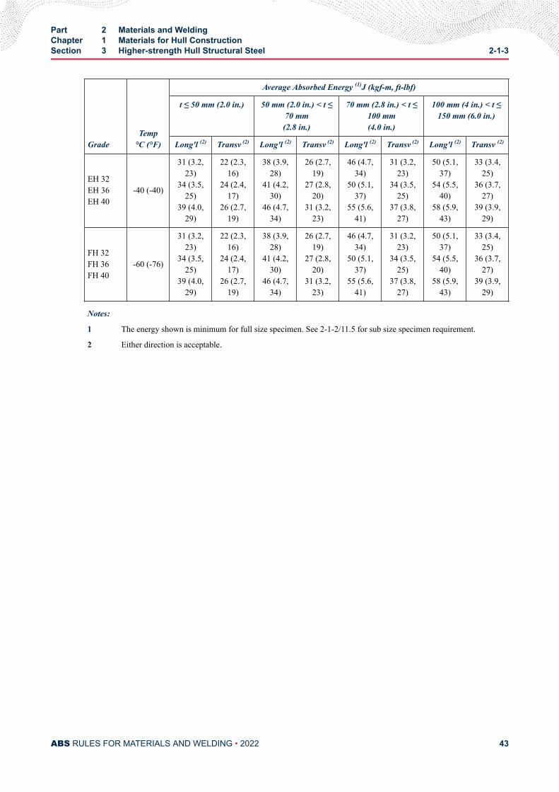
GradeTemp
°C (°F)
Average Absorbed Energy (1)J (kgf-m, ft-lbf)
t ≤ 50 mm (2.0 in.) 50 mm (2.0 in.) < t ≤70 mm(2.8 in.)
70 mm (2.8 in.) < t ≤100 mm(4.0 in.)
100 mm (4 in.) < t ≤150 mm (6.0 in.)
Long'l (2) Transv (2) Long'l (2) Transv (2) Long'l (2) Transv (2) Long'l (2) Transv (2)
EH 32EH 36EH 40
-40 (-40)
31 (3.2,23)
34 (3.5,25)
39 (4.0,29)
22 (2.3,16)
24 (2.4,17)
26 (2.7,19)
38 (3.9,28)
41 (4.2,30)
46 (4.7,34)
26 (2.7,19)
27 (2.8,20)
31 (3.2,23)
46 (4.7,34)
50 (5.1,37)
55 (5.6,41)
31 (3.2,23)
34 (3.5,25)
37 (3.8,27)
50 (5.1,37)
54 (5.5,40)
58 (5.9,43)
33 (3.4,25)
36 (3.7,27)
39 (3.9,29)
FH 32FH 36FH 40
-60 (-76)
31 (3.2,23)
34 (3.5,25)
39 (4.0,29)
22 (2.3,16)
24 (2.4,17)
26 (2.7,19)
38 (3.9,28)
41 (4.2,30)
46 (4.7,34)
26 (2.7,19)
27 (2.8,20)
31 (3.2,23)
46 (4.7,34)
50 (5.1,37)
55 (5.6,41)
31 (3.2,23)
34 (3.5,25)
37 (3.8,27)
50 (5.1,37)
54 (5.5,40)
58 (5.9,43)
33 (3.4,25)
36 (3.7,27)
39 (3.9,29)
Notes:
1 The energy shown is minimum for full size specimen. See 2-1-2/11.5 for sub size specimen requirement.
2 Either direction is acceptable.
Part 2 Materials and WeldingChapter 1 Materials for Hull ConstructionSection 3 Higher-strength Hull Structural Steel 2-1-3
ABS RULES FOR MATERIALS AND WELDING • 2022 43
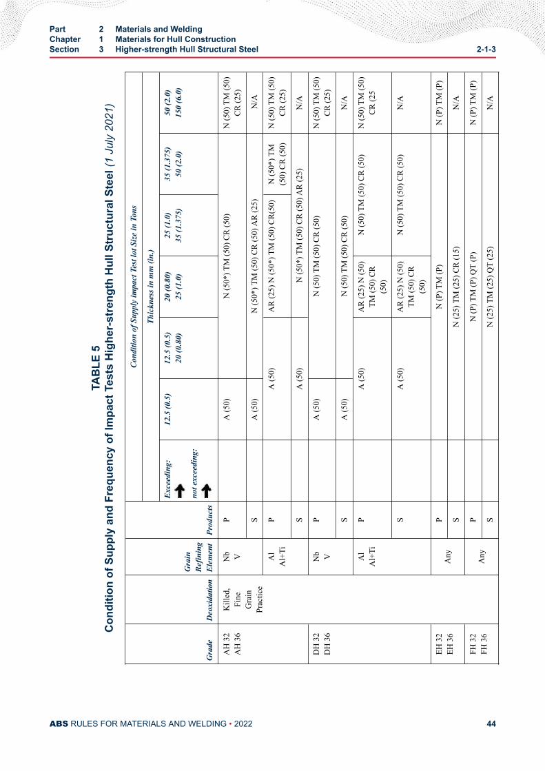
TAB
LE 5
Con
ditio
n of
Sup
ply
and
Freq
uenc
y of
Impa
ct T
ests
Hig
her-
stre
ngth
Hul
l Str
uctu
ral S
teel
(1 J
uly
2021
)
Gra
deD
eoxi
datio
n
Gra
inRe
finin
gEl
emen
tPr
oduc
ts
Cond
ition
of S
uppl
y im
pact
Tes
t lot
Size
in T
ons
Thic
knes
s in
mm
(in.
)
Exce
edin
g:
not e
xcee
ding
:
12.5
(0.5
)12
.5 (0
.5)
20 (0
.80)
20 (0
.80)
25 (1
.0)
25 (1
.0)
35 (1
.375
)35
(1.3
75)
50 (2
.0)
50 (2
.0)
150
(6.0
)
AH
32
AH
36
Kill
ed,
Fine
Gra
inPr
actic
e
Nb V
P
A (5
0)N
(50*
) TM
(50)
CR
(50)
N (5
0) T
M (5
0)CR
(25)
SA
(50)
N (5
0*) T
M (5
0) C
R (5
0) A
R (2
5) N
/A
Al
Al+
TiP
A (5
0)A
R (2
5) N
(50*
) TM
(50)
CR(
50)
N (5
0*) T
M(5
0) C
R (5
0)N
(50)
TM
(50)
CR (2
5)
SA
(50)
N (5
0*) T
M (5
0) C
R (5
0) A
R (2
5)N
/A
DH
32
DH
36
Nb V
PA
(50)
N (5
0) T
M (5
0) C
R (5
0)N
(50)
TM
(50)
CR (2
5)
SA
(50)
N (5
0) T
M (5
0) C
R (5
0)N
/A
Al
Al+
TiP
A (5
0)A
R (2
5) N
(50)
TM (5
0) C
R(5
0)
N (5
0) T
M (5
0) C
R (5
0)N
(50)
TM
(50)
CR (2
5
SA
(50)
AR
(25)
N (5
0)TM
(50)
CR
(50)
N (5
0) T
M (5
0) C
R (5
0)N
/A
EH 3
2EH
36
Any
PN
(P) T
M (P
)N
(P) T
M (P
)
SN
(25)
TM
(25)
CR
(15)
N/A
FH 3
2FH
36
Any
PN
(P) T
M (P
) QT
(P)
N (P
) TM
(P)
SN
(25)
TM
(25)
QT
(25)
N/A
Part 2 Materials and WeldingChapter 1 Materials for Hull ConstructionSection 3 Higher-strength Hull Structural Steel 2-1-3
ABS RULES FOR MATERIALS AND WELDING • 2022 44
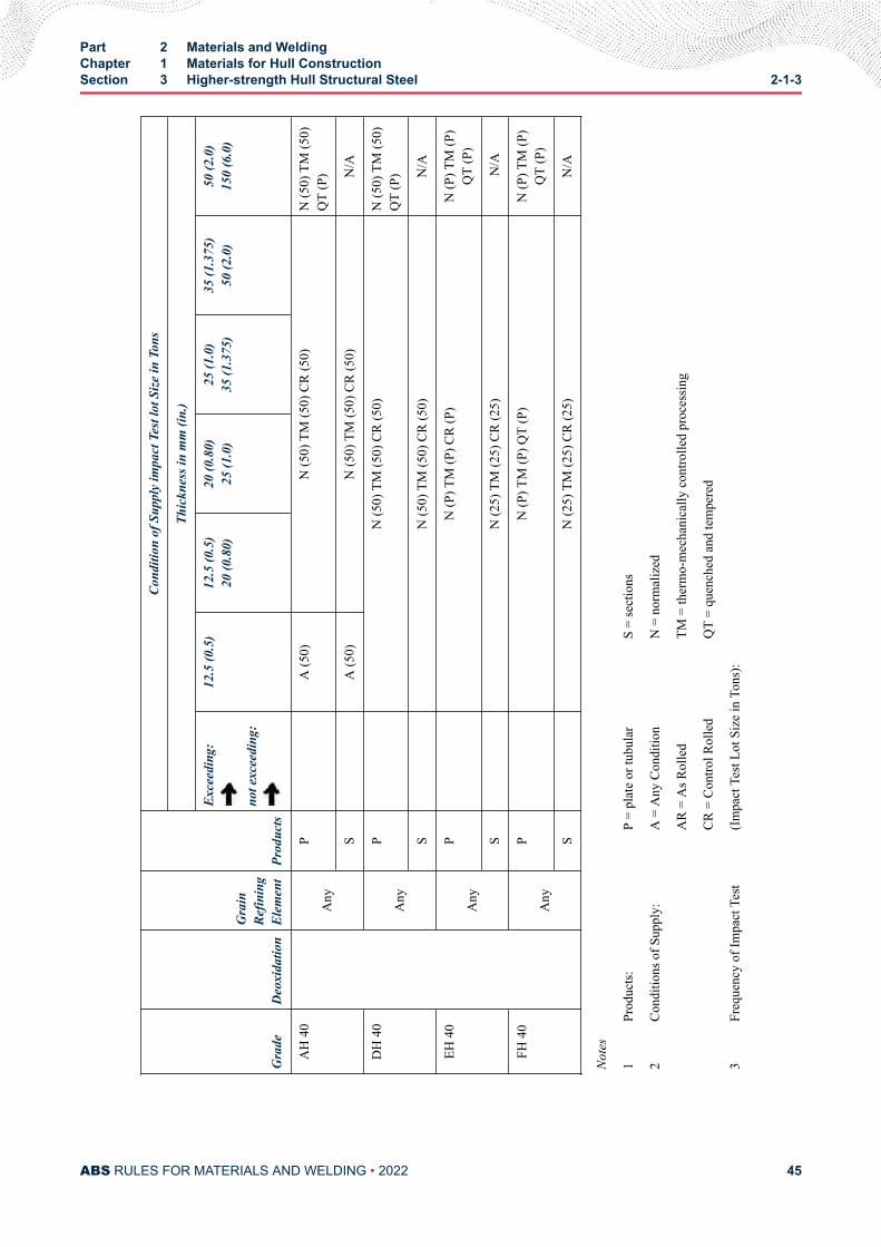
Gra
deD
eoxi
datio
n
Gra
inRe
finin
gEl
emen
tPr
oduc
ts
Cond
ition
of S
uppl
y im
pact
Tes
t lot
Size
in T
ons
Thic
knes
s in
mm
(in.
)
Exce
edin
g:
not e
xcee
ding
:
12.5
(0.5
)12
.5 (0
.5)
20 (0
.80)
20 (0
.80)
25 (1
.0)
25 (1
.0)
35 (1
.375
)35
(1.3
75)
50 (2
.0)
50 (2
.0)
150
(6.0
)
AH
40
Any
PA
(50)
N (5
0) T
M (5
0) C
R (5
0)N
(50)
TM
(50)
QT
(P)
SA
(50)
N (5
0) T
M (5
0) C
R (5
0)N
/A
DH
40
Any
PN
(50)
TM
(50)
CR
(50)
N (5
0) T
M (5
0)Q
T (P
)
SN
(50)
TM
(50)
CR
(50)
N/A
EH 4
0
Any
PN
(P) T
M (P
) CR
(P)
N (P
) TM
(P)
QT
(P)
SN
(25)
TM
(25)
CR
(25)
N/A
FH 4
0
Any
PN
(P) T
M (P
) QT
(P)
N (P
) TM
(P)
QT
(P)
SN
(25)
TM
(25)
CR
(25)
N/A
Not
es
1Pr
oduc
ts:P
= pl
ate
or tu
bula
rS
= se
ctio
ns
2Co
nditi
ons o
f Sup
ply:
A =
Any
Con
ditio
nN
= n
orm
aliz
ed
AR
= A
s Rol
led
TM =
ther
mo-
mec
hani
cally
con
trolle
d pr
oces
sing
CR =
Con
trol R
olle
dQ
T =
quen
ched
and
tem
pere
d
3Fr
eque
ncy
of Im
pact
Tes
t(Im
pact
Tes
t Lot
Siz
e in
Ton
s):
Part 2 Materials and WeldingChapter 1 Materials for Hull ConstructionSection 3 Higher-strength Hull Structural Steel 2-1-3
ABS RULES FOR MATERIALS AND WELDING • 2022 45
(-) =
no
impa
ct te
st re
quire
d(P
) = e
ach
piec
e
(*) =
upo
n ap
plic
atio
n an
d ap
prov
al, t
he im
pact
freq
uenc
y m
ay b
e re
duce
d
Part 2 Materials and WeldingChapter 1 Materials for Hull ConstructionSection 3 Higher-strength Hull Structural Steel 2-1-3
ABS RULES FOR MATERIALS AND WELDING • 2022 46
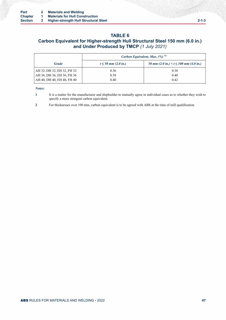
TABLE 6Carbon Equivalent for Higher-strength Hull Structural Steel 150 mm (6.0 in.)
and Under Produced by TMCP (1 July 2021)
Grade
Carbon Equivalent, Max. (%) (1)
t ≤ 50 mm (2.0 in.) 50 mm (2.0 in.) < t ≤ 100 mm (4.0 in.)
AH 32, DH 32, EH 32, FH 32AH 36, DH 36, EH 36, FH 36AH 40, DH 40, EH 40, FH 40
0.360.380.40
0.380.400.42
Notes:
1 It is a matter for the manufacturer and shipbuilder to mutually agree in individual cases as to whether they wish tospecify a more stringent carbon equivalent.
2 For thicknesses over 100 mm, carbon equivalent is to be agreed with ABS at the time of mill qualification.
Part 2 Materials and WeldingChapter 1 Materials for Hull ConstructionSection 3 Higher-strength Hull Structural Steel 2-1-3
ABS RULES FOR MATERIALS AND WELDING • 2022 47
C H A P T E R 1Materials for Hull Construction
S E C T I O N 4Low Temperature Materials
1 GeneralMaterials for Liquefied Gas Carriers are also to comply with the requirements of Section 5C-8-6 of theMarine Vessel Rules.
3 MarkingIn addition to the ABS marking requirements detailed in Part 2, the name or brand of the manufacturer, theletter indicating the grade designation, the manufacturer's identification numbers and for pressure vesselquality material the letters PV are to be legibly marked at each end of the finished plate.
Aluminum sheet and plate is to be identified at each end with the manufacturer’s name or trade mark, theapplicable alloy and temper designation, and in addition for plate, the lot number and the specificationnumber.
5 Toughness Tests
5.1 Charpy V-notchThe specimen is to be transverse to the final direction of rolling for plates and longitudinal to the finaldirection of rolling for profiles, shapes and bars. Subject to special approval acceptance may be based on aminimum lateral expansion opposite the notch of 0.38 mm (0.015 in.) for transverse specimens and 0.50mm (0.020 in.) for longitudinal specimens. See 2-1-1/11.11.
5.3 Drop-weight TestWhere drop-weight tests are required, they are to be conducted for no-break performance of two specimensin accordance with ASTM E208, “Conducting Drop-weight Tests to Determine Nil-ductility TransitionTemperature of Ferritic Steels.” Drop-weight tests are not to be conducted on material of less than 12.5mm (0.5 in.) thickness. For thickness between 12.5 mm (0.5 in.) and 16 mm (0.63 in.), the E208 specimenP-3 machined to 12.5 mm (0.5 in.) thickness is to be used with a stop distance of 2.29 mm (0.09 in.).
7 Service Temperature 0°C (32°F) or AboveSee 5C-8-6/4 of the Marine Vessel Rules.
PART 2
ABS RULES FOR MATERIALS AND WELDING • 2022 48
9 Service Temperature at or Above -55°C (-67°F) up to 0°C (32°F)(2018)See 5C-8-6/4 (ABS) of the Marine Vessel Rules. Steels intended for this temperature range are normallycarbon manganese steels furnished fully killed fine grain normalized.
These steels meeting the requirements in 5C-8-6/4 (ABS) of the Marine Vessel Rules may be markedAB/V-OXX or AB/VH32-OXX or AB/VH36-OXX indicating by XX the test temperature in Celsius belowzero in accordance with 2-1-2/13.9.
11 Service Temperature at or Above -196°C (-320°F) up to -55°C (-67°F)(2022)See 5C-8-6/4 and 5C-8-6/4 of the Marine Vessel Rules. Steels intended for this temperature range arenormally of the ferritic nickel-alloy type made with fine-grain practice, but austenitic stainless steels oraluminum alloys may be used. In general, the following ASTM grades of material or their equivalents maybe used for the temperature listed below. The chemical composition, heat treatment, tensile and impactproperties are to conform to the requirements of the applicable approved specification.
A203, 21/4% Ni -62°C (-80°F)-59°C (-75°F)
for Grade Afor Grade B
A203, 31/2% Ni -90°C (-130°F)-79°C (-110°F)
for Grade Dfor Grade E
A645, 5% Ni -105°C (-155°F)(1)
A353, 9% Ni -196°C (-320°F)
A553, 9% Ni -196°C (-320°F)
Austenitic stainless steels -196°C (-320°F)
36% Ni(2) -196°C (-320°F)
B209, Type 5083, Alum.Alloy
-196°C (-320°F)
Notes:
1 5% Nickel steel may be used down to -165°C (-265°F) upon special consideration provided that impact tests areconducted at -196°C (-320°F).
2 Applicable standard or proprietary specification for 36% Ni can be agreed on a case-by-case basis. In addition,chemistry will be specially considered for lowering the coefficient of expansion.
13 Service Temperatures below -196°C (-320°F)Austenitic low carbon (less than 0.10%) stainless steels and aluminum alloys are to be used for thesetemperatures. The chemical composition, heat treatment, and tensile properties are to conform to therequirements of the approved specification. Stainless steels types 304, 304L, and 347 and type 5083aluminum alloy do not require toughness testing for service temperatures above -254°C (-425°F).Toughness tests for -254°C (-425°F) service temperature and below will be subject to specialconsideration.
Part 2 Materials and WeldingChapter 1 Materials for Hull ConstructionSection 4 Low Temperature Materials 2-1-4
ABS RULES FOR MATERIALS AND WELDING • 2022 49
C H A P T E R 1Materials for Hull Construction
S E C T I O N 5Hull Steel Castings
Note:
In substantial agreement with ASTM A27 Mild to Medium-strength Carbon-steel Castings for General Application. (Grade60-30 Class I.). In addition, the following requirements are applicable:
1 Process of Manufacture (2005)
1.1 General (2012)The following requirements cover carbon-steel castings intended to be used in hull construction andequipment such as stern frames and rudder frames. These requirements are applicable only to steel castingswhere the design and acceptance tests are related to mechanical properties at ambient temperature. Forother applications, additional requirements may be necessary, especially when the castings are intended forservice at low or elevated temperatures. Alternatively, castings which comply with national or proprietaryspecifications may be accepted, provided such specifications give reasonable equivalence to theserequirements. This does not preclude the use of alloy steels in accordance with the permissibility expressedin Section 2-1-1. The steel is to be manufactured by a process approved by ABS.
Castings are to be made by a manufacturer approved by ABS. ABS approval is valid for 5 years subject toannual verification and/or endorsement by the attending Surveyor. The Surveyor is permitted at any time tomonitor important aspects of casting production, including but not limited to mold preparation and chapletpositioning; pouring times and temperatures; mold breakout; repairs; heat treatment andinspection.Thermal cutting, scarfing or arc-air gouging to remove surplus metal is to be undertaken inaccordance with recognized good practice and is to be carried out before the final heat treatment.Preheating is to be employed when necessitated by the chemical composition and/or thickness of thecastings. If necessary, the affected areas are to be either machined or ground smooth.
When two or more castings are joined by welding to form a composite component, the proposed weldingprocedure is to be submitted for approval and welding is to be carried out to the satisfaction of theattending Surveyor.
1.3 Chemical Composition (2006)Castings are to be made from killed steel and the chemical composition is to be appropriate for the type ofsteel and the mechanical properties specified for the castings. The chemical composition of each heat is tobe determined by the manufacturer on a sample taken preferably during the pouring of the heat. Whenmultiple heats are tapped into a common ladle, the ladle analysis shall apply.
PART 2
ABS RULES FOR MATERIALS AND WELDING • 2022 50
For ordinary grade carbon and carbon-manganese steel castings for welded construction and where weldedrepair is anticipated, the chemical composition is to comply with the following limits or, where applicable,the requirements of the approved specification.
Carbon 0.23% max
Silicon 0.60% max
Manganese 0.70-1.60%
Sulfur 0.040% max
Phosphorous 0.040% max
Residual elements 0.80% max
Notes:
1 Grain refining elements such as aluminum may be used at the discretion of the manufacturer. The content of suchelements is to be reported.
2 Residual elements individual % maximums (Cu = 0.30, Cr = 0.30, Ni = 0.40, Mo = 0.15)
3 For non-welded castings, the maximum carbon content is to be 0.40%.
For special grade castings refer to 2-1-5/7.3.
3 Marking and Retests (2005)
3.1 MarkingThe manufacturer is to adopt a system of identification which will enable all finished castings to be tracedto the original cast and the Surveyor is to be given full facilities for tracing the castings when required.
The manufacturer’s name or identification mark/pattern number is to be cast on all castings, except thoseof such small size as to make this type of marking impracticable. The ABS markings, indicatingsatisfactory compliance with the Rule requirements, and as furnished by the Surveyor, is to be stamped onall castings accepted in such location as to be discernible after machining and installation. In addition,identification numbers of the heats used for pouring the castings are to be stamped on all castingsindividually weighing 227 kg (500 lb) or more.
3.3 RetestsIf the results of the physical tests for any casting or any lot of castings do not conform to the requirementsspecified, the manufacturer may reheat-treat castings or a lot of castings that have failed to meet testrequirements. Two additional test samples representative of the casting or casting batch may be taken. Ifsatisfactory results are obtained from both of the additional tests, the casting or batch of castings isacceptable. If one or both retests fail, the casting or batch of castings is to be rejected.
5 Heat Treatment (2017)Heat treatment facilities used in producing ABS certified castings are to be included in the foundryapproval; this includes subcontracted heat treatment facilities. Approved subcontracted facilities are to beincluded in the scope of foundry approval.
Heat treatment details are to be included in the approval documentation.
Foundry qualification is to include all of the heat treatment facilities that the foundry uses.
An independent heat treatment facility can obtain approval, provided that it is documented and verifiedthat the facility is capable of producing heat treated products that meet the mechanical properties of the
Part 2 Materials and WeldingChapter 1 Materials for Hull ConstructionSection 5 Hull Steel Castings 2-1-5
ABS RULES FOR MATERIALS AND WELDING • 2022 51
specification and the NDE requirements of the Rules or applicable standard, and that there is a feedbacksystem to confirm same during production.
If additional sub-contracted or independent facilities are selected to carry out heat treatment an ABSapproval is to be obtained for the new facility.
The ABS Surveyor is to attend the heat treatment facility during qualification, to verify that the heattreatment process is carried out according to specification.
During production, the extent of monitoring is to be agreed with the Surveyor.
Except in cases specifically approved otherwise, all castings are to be either fully annealed, normalized ornormalized and tempered in a furnace of ample proportions to bring the whole casting to a uniformtemperature above the transformation range on the annealing or normalizing cycle. The furnaces are to bemaintained and have adequate means for control and recording temperature. Castings are to be held“soaking” at the proper temperature for at least a length of time equivalent to one hour per 25.5 mm (1 in.)of thickness of the heaviest member for the first 127.5 mm (5.00 in.) plus an additional 15 minutes for eachadditional 25.5 mm (1.00 in.) over 127.5 mm (5.00 in.) of thickness. No annealed casting is to be removedfrom the furnace until the temperature of the entire furnace charge has fallen to or below a temperature of455°C (850°F). A sufficient number of thermocouples are to be connected to the furnace charge to measureand record that its temperature is adequately uniform unless the temperature uniformity of the furnace canbe verified at regular intervals. Tempering is to be carried out at a temperature of not less than 550°C(1022°F).
Local heating or cooling and bending and straightening of annealed castings are not permitted, except withthe express sanction of the Surveyor.
The foundry is to maintain records of heat treatment, identifying the furnace used, furnace charge, date,temperature and time at temperature, together with the number and location of thermocouples. The recordsare to be available to the Surveyor upon request.
7 Mechanical Properties
7.1 Ordinary Grade Castings (2006)Steel castings are to conform to the following requirements as to tensile properties.
Tensile strength min. 415 N/mm2 (42 kgf/mm2, 60000 psi)
Yield point min. 205 N/mm2 (21 kgf/mm2, 30000 psi)
Elongation in 50 mm (2 in.) min. 25%
Reduction of area min. 40%
7.3 Special Grade Castings (2006)Cast stern frames, rudder horns and shoepieces are to be manufactured from special grade material with thefollowing additional mechanical and chemical requirements:
7.3.1 Charpy testsA set of 3 Charpy v-notch impact tests are to be taken from an extension of the thickest part of thecasting and have dimensions that represent the thickest casting section. Charpy tests are to becarried out as indicated in 2-1-1/11.11 and meet 27 J (20 ft-lbs) at 0°C (32°F)
Part 2 Materials and WeldingChapter 1 Materials for Hull ConstructionSection 5 Hull Steel Castings 2-1-5
ABS RULES FOR MATERIALS AND WELDING • 2022 52
7.3.2 Chemical CompositionCarbon 0.23% max
Silicon 0.60% max
Manganese 0.70-1.60%
Sulfur 0.035% max
Phosphorous 0.035% max
Aluminum (acid sol) 0.015-0.080%
or Aluminum (total) 0.020-0.10%
Residual elements 0.80% max
Note: For special grade steel castings a ladle and a product analysis is to be made.
9 Test Specimens
9.1 Material Coupons (2016)Castings and test material are to be heat treated together in the same furnace, and quenched in the samebath/tank (for Q & T castings).
Test material sufficient for the required number of tests and for possible retest purposes is to be providedfor each casting. The physical properties are to be determined from test specimens prepared from couponswhich, except as specified in 2-1-5/9.3, are to be cast integral with the casting to be inspected. When this isimpracticable, the coupons may be cast with and gated to the casting, and are to have a thickness of notless than the critical controlling cross section thickness of the casting or 30 mm (1.2 in.), whichever isgreater. In any case, these coupons are not to be detached until the heat treatment of the castings has beencompleted, nor until the coupons have been stamped by the Surveyor for identification. Where the materialidentification system of the manufacturer is found acceptable to ABS and is maintained in that conditionthrough initial and periodical verification by ABS, it may be considered in lieu of stamping by theSurveyor before detachment.
Where the finished casting mass exceeds 10,000 kg (22,000 lb) or is of complex design, two test samplesare to be provided. Where large castings are made from two or more casts which are not from the samepour, two or more test samples are to be provided corresponding to the number of casts involved. Thesamples are to be integrally cast at locations as widely separated as possible.
Note:
The controlling cross section thickness is the diameter of the largest theoretical sphere which can be inscribed within thecritical section of the casting.
9.3 Separately Cast CouponsIn the case of small castings having an estimated weight of less than 908 kg (2000 lb) each, the couponsmay be cast separately, provided the Surveyor is furnished an affidavit by the manufacturer stating that theseparately cast coupons were cast from the same heat as the castings represented and that they wereheattreated with the castings.
11 Number of Tests (2005)At least one tension test is to be made from each heat in each heat-treatment charge, except where two ormore samples are required, as indicated in 2-1-5/9.1 If the manufacturer’s quality-control procedureincludes satisfactory automatic chart recording of temperature and time, then one tension test from eachheat for castings subject to the same heat-treating procedure may be accepted at the discretion of theattending Surveyor.
Part 2 Materials and WeldingChapter 1 Materials for Hull ConstructionSection 5 Hull Steel Castings 2-1-5
ABS RULES FOR MATERIALS AND WELDING • 2022 53
13 Inspection and Repair (2005)
13.1 General (2008)All castings are to be examined by the Surveyor after final heat treatment and thorough cleaning to ensurethat the castings are free from defects, in accordance with applicable acceptance criteria. Where applicable,internal surfaces are to be inspected. Surfaces are not to be hammered or peened or treated in any waywhich may obscure defects.
In the event of a casting proving to be defective during subsequent inspection, machining or testing, it is tobe rejected, notwithstanding any previous certification.
The manufacturer is to verify that all dimensions meet the specified requirements. The Surveyor is to spotcheck key dimensions to confirm the manufacturer’s recorded dimensions.
13.3 Minor Defects (2006)Defects are to be considered minor when the cavity prepared for welding repair has a depth not greaterthan 20% of the actual wall thickness, but in no case greater than 25 mm (1 in.), and has no linealdimension greater than four times the wall thickness nor greater than 150 mm (6 in.). Shallow grooves ordepressions resulting from the removal of defects may be accepted, provided that they will cause noappreciable reduction in the strength of the casting. The resulting grooves or depressions are to besubsequently ground smooth, and complete elimination of the defective material is to be verified bymagnetic particle testing or liquid penetrant testing. Repairs of minor defects where welding is required areto be treated as weld repairs and repaired in accordance with an approved procedure. Minor defects incritical locations are to be treated as, and repaired in the same manner as, major defects.
13.5 Major DefectsDefects other than minor defects with dimensions greater than those given in 2-1-5/13.3 above, may, withthe Surveyor’s prior approval, be repaired by welding to the satisfaction of the Surveyor, using anapproved procedure. Where major defects are considered numerous or excessive by the Surveyor, anevaluation of the casting is to be made to assess if weld repair is appropriate.
13.7 Welded Repair (2018)After it has been agreed that a casting can be repaired by welding, full details of the extent and location ofthe repair, the proposed welding procedure, heat treatment and subsequent inspection procedures are to besubmitted for approval.
Weld procedures for all types of welds are to be appropriately qualified to the satisfaction of the attendingSurveyor.
Before undertaking the repair welding of castings, the manufacturer is to prove to the satisfaction of theSurveyor that the welders or welding operators are duly qualified for the work intended.
Removal of defects and weld repair are to be carried out in accordance with Part 2, Appendix 6. Thedefects are to be removed to sound metal, and before welding the excavation is to be investigated bysuitable approved nondestructive examination methods to ensure that the defect has been removed. In thecase of repair of major defects on large castings such as rudder horns, stern frames, shoe pieces and rudderstocks, welding is not permitted on unheat-treated castings. Corrective welding is to be associated with theuse of preheat.
Temporary welds made for operations such as lifting, handling, staging, etc., are to be carried out toqualified welding procedures and by qualified welders/operators and are to be removed, ground andinspected using suitable approved, nondestructive examination methods.
Part 2 Materials and WeldingChapter 1 Materials for Hull ConstructionSection 5 Hull Steel Castings 2-1-5
ABS RULES FOR MATERIALS AND WELDING • 2022 54
13.9 Post Weld Repair Heat TreatmentAll welded repairs of defects are to be given a suitable post weld heat treatment, as indicated in 2-1-5/5, orsubject to the prior approval of the ABS materials department, consideration may be given to theacceptance of local stress-relieving heat treatment at a temperature of not less than 550°C (1022°F). Theheat treatment employed is dependent on the chemical composition of the casting, the casting and defectdimensions, and the position of the repairs.
On completion of heat treatment, the weld repairs and adjacent material are to be ground smooth andexamined by magnetic particle or liquid penetrant testing. Supplementary examination by ultrasonics orradiography may also be required, depending on the dimensions and nature of the original defect.Satisfactory results are to be obtained from all forms of nondestructive testing used.
The manufacturer is to maintain full records detailing the extent and location of all minor and major repairsmade to each casting and details of weld procedures and heat treatments applied. These records are to beavailable to the Surveyor and copies provided on request.
13.11 Non-destructive TestingImportant hull castings, such as cast-steel stern frames and rudder horns, are to be subjected to surfaceinspection by magnetic particle, dye penetrant or other equivalent means. See Part 2, Appendix 6. Cast-steel stern frames are to be subjected to such inspection over the entire skeg portion of the casting,including the enlarged portion forming the junction to the propeller post, and at such other criticallocations as may be indicated on the approved plan of the stern frame. These surfaces are to be clean andfree of all substances that will affect the sensitivity of the magnetic-particle test and the degree ofmagnetization is to produce a satisfactory magnetic potential on the surfaces being tested. In addition tosurface inspection, cast-steel rudder horns are to be inspected by radiographic means or, at the discretion ofthe attending Surveyor, in accordance with an approved ultrasonic procedure at the area just below theconnection to the shell, and at such other locations as may be indicated in Part 2, Appendix 6, and on theapproved plan. Additional NDE is to be considered at chaplet locations and areas of expected defects. Theradiographic acceptance standard for all categories of defects is to be at least equivalent to severity level 4of ASTM E186, E280 or E446. The ultrasonic acceptance standard is to be at least equivalent to qualitylevel 4 of ASTM A609.
15 Certification (2005)The manufacturer is to provide the required type of inspection certificate, giving the following particularsfor each casting or batch of castings which has been accepted:
i) Purchaser’s name and order number
ii) Description of castings, steel quality and weight
iii) Identification number
iv) Steel making process, cast number and chemical analysis of ladle samples
v) Results of mechanical tests
vi) Results of nondestructive tests, where applicable
vii) Details of heat treatment, including temperatures and holding times
viii) Where applicable, test pressure
ix) Specification
Part 2 Materials and WeldingChapter 1 Materials for Hull ConstructionSection 5 Hull Steel Castings 2-1-5
ABS RULES FOR MATERIALS AND WELDING • 2022 55
C H A P T E R 1Materials for Hull Construction
S E C T I O N 6Hull Steel Forgings
Note: In substantial agreement with ASTM A668 Carbon-steel Forgings for General Industrial Use (Class B = Grade 2).
1 Process of Manufacture
1.1 General (2017)The following requirements cover carbon-steel forgings intended to be used in hull construction andequipment. These requirements are applicable only to steel forgings where the design and acceptance testsare related to mechanical properties at ambient temperature. For other applications, additionalrequirements may be necessary, especially when the forgings are intended for service at low or elevatedtemperatures. This does not preclude the use of other steels as permitted by Section 2-1-1. Alternatively,forgings which comply with national or proprietary specifications may be accepted, provided suchspecifications give reasonable equivalence to these requirements.
Forgings are to be made by a manufacturer approved by ABS.
ABS approval is valid for 5 years subject to annual verification and/or endorsement by the attendingSurveyor. The Surveyor is permitted at any time to monitor important aspects of forging production,including but not limited to die preparation and die maintenance, forging temperatures, forging reductionor upset, heat treatment and inspection.
Raw materials for forging such as cast steel or semi-finished products are to be manufactured at a facilityapproved by ABS. Steel is to be fully killed and is to be manufactured by a process approved by ABS.
The shaping of forgings or rolled slabs and billets by thermal cutting, scarfing or arc-air gouging is to beundertaken in accordance with recognized good practice and, unless otherwise approved, is to be carriedout before the final heat treatment. Preheating is to be employed when necessitated by the compositionand/or thickness of the steel. For certain components, subsequent machining of all thermal cut surfacesmay be required.
When two or more forgings are joined by welding to form a composite component, the proposed weldingprocedure specification is to be submitted for approval.
1.3 Degree of Reduction (2005)The plastic deformation is to be such as to ensure soundness, uniformity of structure and satisfactorymechanical properties after heat treatment. The reduction ratio is to be calculated with reference to the
PART 2
ABS RULES FOR MATERIALS AND WELDING • 2022 56
average cross-sectional area of the cast material. Where the cast material is initially upset, this referencearea may be taken as the average cross-sectional area after this operation. Unless otherwise approved, thetotal reduction ratio is to be at least:
● For forgings made from ingots or from forged blooms or billets, 3:1 where L > D and 1.5:1 whereL ≤ D● For forgings made from rolled products, 4:1 where L > D and 2:1 where L ≤ D● For forgings made by upsetting, the length after upsetting is to be not more than one-third of the length
before upsetting or, in the case of an initial forging reduction of at least 1.5:1, not more than one-halfof the length before upsetting
● For rolled bars used in lieu of forgings, 6:1.L and D are the length and diameter, respectively, of the part of the forging under consideration.
1.5 DiscardA sufficient discard is to be made from each ingot to secure freedom from piping and undue segregation.
1.7 Chemical Composition (2008)All forgings are to be made from killed steel. The chemical composition is to be reported. Carbon contentis not to exceed 0.23% or carbon equivalent (Ceq) is not to exceed 0.41%, unless specially approved.Specially approved grades having more than 0.35% carbon are to have S marked after the grade number.
The maximum sulfur and phosphorus contents are to be 0.035%.
Rudder stocks and pintles are to be of a weldable quality.
The chemical composition of each heat is to be determined by the manufacturer on a sample takenpreferably during the pouring of the heat. When multiple heats are tapped into a common ladle, the ladleanalysis shall apply.
3 Marking and Retests (2005)
3.1 MarkingThe manufacturer is to adopt a system of identification which will enable all finished forgings to be tracedto the original cast and the Surveyor is to be given full facilities for tracing the forgings when required.
In addition to appropriate identification markings of the manufacturer, the ABS markings, indicatingsatisfactory compliance with the Rule requirements and as furnished by the Surveyor, are to be stamped onall forgings accepted in such location as to be discernible after machining and installation. Grade 2forgings are to be stamped AB/2.
3.3 RetestsTest material, sufficient for the required number of tests and for possible retest purposes is to be providedfor each forging. If the results of the physical tests for any forging or any lot of forgings do not conform tothe requirements specified, two additional test samples representative of the forging or forging batch maybe taken. If satisfactory results are obtained from both of the additional tests, the forging or batch offorgings is acceptable. If one or both retests fail, the forging or batch of forgings is to be rejected. Themanufacturer may reheat-treat forgings that have failed to meet test requirements, but not more than threeadditional times.
Part 2 Materials and WeldingChapter 1 Materials for Hull ConstructionSection 6 Hull Steel Forgings 2-1-6
ABS RULES FOR MATERIALS AND WELDING • 2022 57
5 Heat Treatment
5.1 General (2017)Heat treatment facilities used in producing ABS certified forgings are to be included in the forge approval;this includes subcontracted heat treatment facilities. Approved subcontracted facilities are to be included inthe scope of forge approval.
Heat treatment details are to be included in the approval documentation.
Forge qualification is to include all of the heat treatment facilities that the forge uses.
An independent heat treatment facility can obtain approval, provided that it is documented and verifiedthat the facility is capable of producing heat treated products that meet the mechanical properties of thespecification and the NDE requirements of the Rules or applicable standard, and that there is a feedbacksystem to confirm same during production.
If additional sub-contracted or independent facilities are selected to carry out heat treatment an ABSapproval is to be obtained for the new facility.
The ABS Surveyor is to attend the heat treatment facility during qualification, to verify that the heattreatment process is carried out according to specification.
During production, the extent of monitoring is to be agreed with the Surveyor.
Unless a departure from the following procedures is specifically approved, all forgings are to be annealed,normalized, normalized and tempered or quenched and tempered in a furnace of ample proportions tobring the forgings to a uniform temperature.
A sufficient number of thermocouples are to be connected to the furnace charge to measure and record thatits temperature is adequately uniform unless the temperature uniformity of the furnace can be verified atregular intervals.
Heat treatment is to be carried out in properly constructed furnaces which are efficiently maintained andhave adequate means for control and recording of temperature. The furnace dimensions are to be such as toallow the whole furnace charge to be uniformly heated to the necessary temperature. In the case of verylarge forgings, alternative methods of heat treatment will be specially considered. If for any reason aforging is subsequently heated for further hot working, the forging is to be reheat-treated. If a forging islocally reheated or any straightening operation is performed after the final heat treatment, consideration isto be given to a subsequent stress relieving heat treatment.
The forge is to maintain records of heat treatment, identifying the furnace used, furnace charge, date,temperature and time at temperature, together with the number and location of thermocouples. The recordsare to be available to the Surveyor upon request.
5.3 Cooling Prior to Heat TreatmentAfter forging and before reheating for heat treatment, the forgings are to be allowed to cool in a manner toprevent injury and to accomplish transformation.
5.5 AnnealingThe forgings are to be reheated to and held at the proper austenitizing temperature for a sufficient time toeffect the desired transformation and then be allowed to cool slowly and evenly in the furnace until thetemperature has fallen to about 455°C (850°F) or lower.
Part 2 Materials and WeldingChapter 1 Materials for Hull ConstructionSection 6 Hull Steel Forgings 2-1-6
ABS RULES FOR MATERIALS AND WELDING • 2022 58
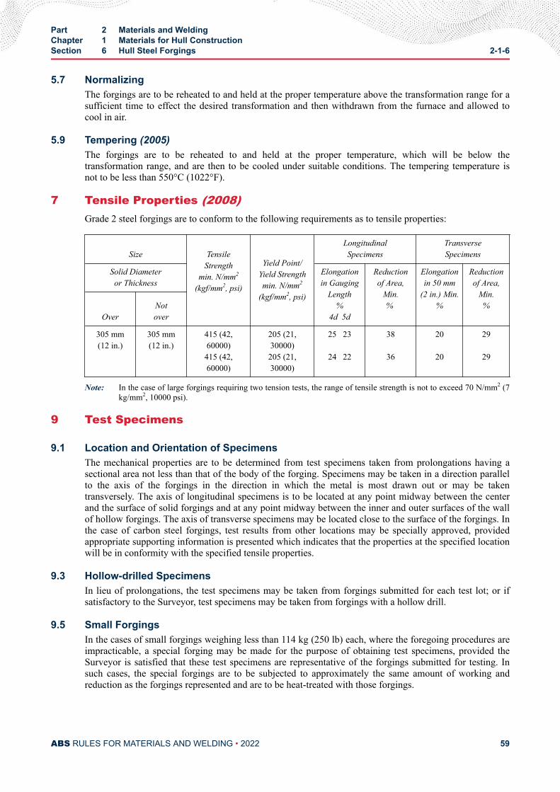
5.7 NormalizingThe forgings are to be reheated to and held at the proper temperature above the transformation range for asufficient time to effect the desired transformation and then withdrawn from the furnace and allowed tocool in air.
5.9 Tempering (2005)The forgings are to be reheated to and held at the proper temperature, which will be below thetransformation range, and are then to be cooled under suitable conditions. The tempering temperature isnot to be less than 550°C (1022°F).
7 Tensile Properties (2008)Grade 2 steel forgings are to conform to the following requirements as to tensile properties:
Size
TensileStrength
min. N/mm2
(kgf/mm2, psi)
Yield Point/Yield Strengthmin. N/mm2
(kgf/mm2, psi)
Longitudinal Specimens
Transverse Specimens
Solid Diameteror Thickness
Elongationin Gauging
Length % 4d 5d
Reductionof Area,
Min. %
Elongationin 50 mm
(2 in.) Min. %
Reductionof Area,
Min. %
Over Not
over
305 mm(12 in.)
305 mm(12 in.)
415 (42,60000)415 (42,60000)
205 (21,30000)205 (21,30000)
25 23
24 22
38
36
20
20
29
29
Note: In the case of large forgings requiring two tension tests, the range of tensile strength is not to exceed 70 N/mm2 (7kg/mm2, 10000 psi).
9 Test Specimens
9.1 Location and Orientation of SpecimensThe mechanical properties are to be determined from test specimens taken from prolongations having asectional area not less than that of the body of the forging. Specimens may be taken in a direction parallelto the axis of the forgings in the direction in which the metal is most drawn out or may be takentransversely. The axis of longitudinal specimens is to be located at any point midway between the centerand the surface of solid forgings and at any point midway between the inner and outer surfaces of the wallof hollow forgings. The axis of transverse specimens may be located close to the surface of the forgings. Inthe case of carbon steel forgings, test results from other locations may be specially approved, providedappropriate supporting information is presented which indicates that the properties at the specified locationwill be in conformity with the specified tensile properties.
9.3 Hollow-drilled SpecimensIn lieu of prolongations, the test specimens may be taken from forgings submitted for each test lot; or ifsatisfactory to the Surveyor, test specimens may be taken from forgings with a hollow drill.
9.5 Small ForgingsIn the cases of small forgings weighing less than 114 kg (250 lb) each, where the foregoing procedures areimpracticable, a special forging may be made for the purpose of obtaining test specimens, provided theSurveyor is satisfied that these test specimens are representative of the forgings submitted for testing. Insuch cases, the special forgings are to be subjected to approximately the same amount of working andreduction as the forgings represented and are to be heat-treated with those forgings.
Part 2 Materials and WeldingChapter 1 Materials for Hull ConstructionSection 6 Hull Steel Forgings 2-1-6
ABS RULES FOR MATERIALS AND WELDING • 2022 59
9.7 Specimen Identification (2015)Forgings and test material are to be heat treated together in the same furnace, and quenched in the samebath/tank (for Q & T forgings).
The test specimens are not to be detached from the forgings until the final heat treatment of the forgingshas been completed nor until the test specimens have been stamped by the Surveyor for identification.Where the material identification system of the manufacture is found acceptable to ABS and is maintainedin that condition through initial and periodical verification by ABS, it may be considered in lieu ofstamping by the Surveyor before detachment.
11 Number of Tests
11.1 Tension Test11.1.1 Large Forgings
In the case of large forgings with rough machined weights of 3180 kg (7000 lb) or over, onetension test is to be made from each end of the forging.
11.1.2 Intermediate-sized ForgingsIn the case of forgings with rough machined weights less than 3180 kg (7000 lb), except as notedin the following paragraph, at least one tension test is to be made from each forging.
11.1.3 Small Forgings (2005)In the case of small normalized forgings with rough machined weights less than 1000 kg (2200lb), and quenched and tempered forgings with rough machined weights less than 500 kg (1100 lb),one tension test may be taken from one forging as representative of a lot provided the forgings ineach such lot are of similar size, are of one grade and kind only, are made from the same heat andare heat-treated in the same furnace charge. The total mass of the furnace charge is not to exceed6000 kg (13200 lb) for normalized forgings and 3000 kg (6600 lb) for quenched and temperedforgings.
11.3 Brinell Hardness TestEach forging, except those with rough machined weights less than 113 kg (250 lb), are to be BrinellHardness tested and are to meet the following requirements.
Grade Brinell Hardness Number Minimum
10 mm ball, 3000 kg load
2 120
11.5 Special SituationsIn the cases of a number of pieces cut from a single forging, individual tests need not necessarily be madefor each piece, but forgings may be tested in accordance with whichever of the foregoing procedures isapplicable to the primary forging involved.
11.7 Examination (2008)All forgings are to be examined by the Surveyor after final heat treatment and they are to be found freefrom defects. Where applicable, this is to include the examination of internal surfaces and bores.
The manufacturer is to verify that all dimensions meet the specified requirements.
When required by the relevant construction Rules or by the approved procedure for welded compositecomponents, appropriate nondestructive testing is also to be carried out before acceptance and the results
Part 2 Materials and WeldingChapter 1 Materials for Hull ConstructionSection 6 Hull Steel Forgings 2-1-6
ABS RULES FOR MATERIALS AND WELDING • 2022 60
are to be reported by the manufacturer. The extent of testing and acceptance criteria are to be agreed withABS. Part 2, Appendix 7 is regarded as an example of an acceptable standard.
In the event of any forging proving defective during subsequent machining or testing, it is to be rejected,notwithstanding any previous certification.
11.9 Rectification of Defective Forgings (2018)Defects may be removed by grinding or chipping and grinding, provided that the component dimensionsare acceptable. The resulting grooves are to have a bottom radius of approximately three times the groovedepth and are to be blended into the surrounding surface so as to avoid any sharp contours. Completeelimination of the defective material is to be verified by magnetic particle testing or liquid penetranttesting.
Repair welding of forgings may be permitted subject to prior approval of ABS. In such cases, full details ofthe extent and location of the repair, the proposed welding procedure, heat treatment and subsequentinspection procedures are to be submitted for the approval.
Weld procedures for all types of welds are to be appropriately qualified to the satisfaction of the attendingSurveyor.
Before undertaking the repair welding of forgings, the manufacturer is to prove to the satisfaction of theSurveyor that the welders or welding operators are duly qualified for the work intended.
The forging manufacturer is to maintain records of repairs and subsequent inspections traceable to eachforging repaired. The records are to be presented to the Surveyor upon request.
Temporary welds made for operations such as lifting, handling, staging, etc., are to be carried out toqualified welding procedures and by qualified welders/operators and are to be removed, ground andinspected using suitable approved, nondestructive examination methods.
13 Certification (2005)The manufacturer is to provide the required type of inspection certificate, giving the following particularsfor each forging or batch of forgings which has been accepted:
i) Purchaser’s name and order number
ii) Description of forgings and steel quality
iii) Identification number
iv) Steelmaking process, cast number and chemical analysis of ladle sample
v) Results of mechanical tests
vi) Results of nondestructive tests, where applicable
vii) Details of heat treatment, including temperature and holding times
viii) Specification
Part 2 Materials and WeldingChapter 1 Materials for Hull ConstructionSection 6 Hull Steel Forgings 2-1-6
ABS RULES FOR MATERIALS AND WELDING • 2022 61
C H A P T E R 1Materials for Hull Construction
S E C T I O N 7Ordinary and Higher Strength Steels with Enhanced Corrosion Resistance
Properties for Cargo Oil Tanks (2014)
1 Scope
1.1These requirements apply to ordinary and higher strength steels with enhanced corrosion resistanceproperties when such steel is used as the alternative means of corrosion protection for cargo oil tanks asspecified in the performance standard MSC 289 (87) of Regulation 3-11, Part A-1, Chapter II-1 of theSOLAS Convention (Corrosion protection of cargo oil tanks of crude oil tankers).
1.3The requirements are primarily intended to apply to steel products with a thickness as follows:
i) For steel plates and wide flats:
● All Grades: Up to 50 mm (2 in.) in thickness
ii) For sections and bars:
● All Grades: Up to 50 mm (2 in.) in thickness
1.5Ordinary and higher strength steels with enhanced corrosion resistance properties as defined within thissection, are steels whose corrosion resistance performance in the bottom or top of the internal cargo oiltank is tested and approved to satisfy the requirements in MSC.289(87) in addition to other relevantrequirements for ship material, structural strength and construction. It is not intended that such steels beused for corrosion resistant applications in other areas of a vessel that are outside of those specified in theperformance standard MSC 289 (87) of Regulation 3-11, Part A-1, Chapter II-1 of the SOLAS Convention.
1.7Since steels with enhanced corrosion resistance properties are similar to the ship steels as specified inSection 2-1-2 for Ordinary-strength Hull Structural Steel and Section 2-1-3 for Higher-strength HullStructural Steel, the basic requirements of Section 2-1-2 and Section 2-1-3 apply to these steels exceptwhere modified by this section.
PART 2
ABS RULES FOR MATERIALS AND WELDING • 2022 62
1.9The weldability of steels with enhanced corrosion resistance properties is similar to those given in Section2-4-1, therefore welding requirements specified in 2-4-3/3 for Approval of consumables for weldingordinary and higher strength hull structural steels and Welding procedure qualification tests of steels forhull construction and marine structures also apply except as modified by this section.
3 Approval
3.1All materials are to be manufactured at works which have been approved by ABS for steel in accordancewith Part 2, Appendix 4.
3.3Corrosion tests are to be carried out in accordance with Part 2, Appendix 8. Approval can be given forapplication in one of the following areas of a cargo oil tank:
i) Lower surface of strength deck and surrounding structures;
ii) Upper surface of inner bottom plating and surrounding structures;
iii) For both strength deck and inner bottom plating
3.5It is the manufacturer’s responsibility to assure that effective process and production controls in operationare adhered to within the manufacturing specifications. If the process or production controls are changed inany way, or any product fails to meet specifications, the manufacturer is to issue a report explaining thereasons, and, in the instance of product which fails to meet specifications, the measures to preventrecurrence. The complete report is to be submitted to the Surveyor along with such additional informationas the Surveyor may require. Each affected piece is to be tested to the Surveyor’s satisfaction. Thefrequency of testing for subsequent products is at the discretion of ABS.
5 Method of Manufacture
5.1Method of manufacture, deoxidation practice and rolling practice is to be in accordance with Part 2,Appendix 4.
7 Chemical Composition
7.1The chemical composition of samples taken from each ladle of each cast is to be determined by themanufacturer in an adequately equipped and competently staffed laboratory and is to be in accordance withthe requirements 2-1-2/5 for Ordinary-strength Hull Structural Steel and 2-1-3/3 for Higher-strength HullStructural Steel.
7.3The manufacturer will establish a relationship of all the chemical elements which affect the corrosionresistance, the chemical elements added or controlled to achieve this are to be specifically verified foracceptance. Verification is to be based on the ladle analysis of the steel.
Part 2 Materials and WeldingChapter 1 Materials for Hull ConstructionSection 7 Ordinary and Higher Strength Steels with Enhanced Corrosion Resistance Properties
for Cargo Oil Tanks (2014)2-1-7
ABS RULES FOR MATERIALS AND WELDING • 2022 63
7.5The manufacturer's declared analysis will be accepted subject to periodic random checks as required by theSurveyor.
7.7The carbon equivalent is to be in accordance with 2-1-3/7.1.
9 Condition of Supply
9.1All materials are to be supplied in one of the supply conditions specified in 2-1-2/15.9 TABLE 5 forOrdinary-strength Hull Structural Steel and 2-1-3/7.3 TABLE 5 for Higher-strength Hull Structural steel.
11 Mechanical Properties
11.1Tensile testing is to be carried out in accordance with 2-1-2/15.9 TABLE 2 for Ordinary-strength HullStructural Steel and 2-1-3/7.3 TABLE 2 for Higher-strength Hull Structural steel. Charpy V-notch ImpactTesting is to be carried out in accordance with 2-1-2/15.9 TABLE 4 for Ordinary-strength Hull StructuralSteel and 2-1-3/7.3 TABLE 4 for Higher-strength Hull Structural steel.
13 Surface Quality (1 July 2018)Please refer to 2-1-1/3.
15 Tolerances
15.1Unless otherwise agreed or specially required the thickness tolerances in 2-1-1/15, “Permissible Variationsin Dimensions” are applicable.
17 Identification of Materials
17.1The steelmaker is to adopt a system for the identification of ingots, slabs and finished pieces which willenable the material to be traced to its original cast.
17.3The Surveyor is to be given full facilities for so tracing the material when required.
19 Testing and Inspection
19.1 Facilities for InspectionThe manufacturer is to afford the Surveyor all necessary facilities and access to all relevant parts of theworks to enable him to verify that the approved process is adhered to, for the selection of test materials,and the witnessing of tests, as required by the Rules, and for verifying the accuracy of the testingequipment.
Part 2 Materials and WeldingChapter 1 Materials for Hull ConstructionSection 7 Ordinary and Higher Strength Steels with Enhanced Corrosion Resistance Properties
for Cargo Oil Tanks (2014)2-1-7
ABS RULES FOR MATERIALS AND WELDING • 2022 64
19.3 Testing ProceduresThe prescribed tests and inspections are to be carried out at the place of manufacture before dispatch. Thetest specimens and procedures are to be in accordance with 2-1-1/11. All the test specimens are to beselected and stamped by the Surveyor and tested in his presence, unless otherwise agreed.
19.5 Through Thickness Tensile TestsIf plates and wide flats with thickness of 15 mm (0.60 in.) and over are ordered with through thicknessproperties, the through thickness tensile test in accordance with 2-1-1/17 is to be carried out.
19.7 Ultrasonic InspectionIf plates and wide flats are ordered with ultrasonic inspection, this is to be made in accordance with anaccepted standard at the discretion of ABS.
19.9 Surface Inspection and DimensionsSurface inspection and verification of dimensions are the responsibility of the manufacturer. Theacceptance by the Surveyor shall not absolve the manufacturer from this responsibility.
21 Test Material
21.1Definitions and requirements for test samples are to be in accordance with 2-1-1/11.
23 Test Specimens
23.1 Mechanical Test SpecimensThe dimensions, orientation and location of the tensile and Charp V-notch test specimens within the testsamples are to be in accordance with 2-1-1/11.
25 Number of Test Specimens
25.1Number of Tensile and Charpy V-notch Impact test specimens are to be in accordance with 2-1-1/11.
27 Retest Procedures
27.1To be in accordance with 2-1-1/9.5.
29 Marking
29.1Every finished piece is to be clearly stamped or stenciled by the maker in at least one place with the ABSmarkings and the following particulars:
i) Unified identification mark for the grade of steel (e.g., [AH 36]).
ii) Steel plates that have complied with these requirements will be marked with a designation byadding a corrosion designation to the unified identification mark for the grade of steel. Example ofdesignation: AH36 RCB
Part 2 Materials and WeldingChapter 1 Materials for Hull ConstructionSection 7 Ordinary and Higher Strength Steels with Enhanced Corrosion Resistance Properties
for Cargo Oil Tanks (2014)2-1-7
ABS RULES FOR MATERIALS AND WELDING • 2022 65
iii) The steel with enhanced corrosion resistance properties is to be designated according to its area ofapplication as follows:
● Lower surface of strength deck and surrounding structures: RCU● Upper surface of inner bottom plating and surrounding structures: RCB● For both strength deck and inner bottom plating: RCW
iv) When required by ABS, material supplied in the thermo mechanically controlled processcondition is to have the letters “TM” added after the identification mark but before the corrosiondesignation. (e.g., [EH36 TM RCU Z35).
v) Name or initials to identify the steelworks.
vi) Cast or other number to identify the piece.
vii) If required by the purchaser, his order number or other identification marks.
29.3The above particulars, but excluding the manufacturer's name or trade marks where this is embossed onfinished products are to be encircled with paint or otherwise marked so as to be clearly legible.
29.5Where a number of light materials are securely fastened together in bundles the manufacturer may, subjectto the agreement of ABS, brand only the top piece of each bundle, or alternatively, a firmly fasteneddurable label containing the brand may be attached to each bundle.
29.7In the event that any material bearing the ABS brand fails to comply with the test requirements, the brandis to be unmistakably defaced by the manufacturer.
31 Documentation
31.1The Surveyor is to verify certificates before the material is accepted by ABS.
31.3The number of copies required are to be specified by ABS.
31.5The certificate is to be supplied in either electronic or paper format as required by ABS.
31.7ABS may require separate documents for each grade of steel.
31.9The certificate is to contain, in addition to the description, dimensions, etc., of the material, at least thefollowing particulars:
i) Purchaser's order number and if known the hull number for which the material is intended.
ii) Identification of the cast and piece including, where appropriate, the test specimen number.
iii) Identification of the steelworks.
iv) Identification of the grade of steel [and the manufacturer’s brand name].
Part 2 Materials and WeldingChapter 1 Materials for Hull ConstructionSection 7 Ordinary and Higher Strength Steels with Enhanced Corrosion Resistance Properties
for Cargo Oil Tanks (2014)2-1-7
ABS RULES FOR MATERIALS AND WELDING • 2022 66
v) Ladle analysis (for elements specified in 2-1-2/15.9 TABLE 1 for Ordinary-strength Hullstructural steel and 2-1-3/7.3 TABLE 1 for Higher-strength Hull structural steel).
vi) If the steel is approved in accordance with 2-1-7/7.3, the weight percentage of each element addedor intentionally controlled for improving corrosion resistance.
vii) Condition of supply when other than as rolled (i.e., normalized, controlled rolled or thermomechanically rolled).
viii) Test Results
31.11Before the test certificates are signed by the Surveyor, the manufacturer is required to furnish him with awritten declaration stating that the material has been made by an approved process and that it has beensubjected to and has withstood satisfactorily the required tests in the presence of the Surveyor or hisauthorized deputy. The ABS name is to appear on the test certificate. The following form of declarationwill be accepted if stamped or printed on each test certificate or shipping statement with the name of thesteelworks and initialled for the makers by an authorized official:
“We hereby certify that the material has been made by an approved process and has been satisfactorilytested in accordance with the Rules of the American Bureau of Shipping.”
31.13In the case of electronic certification, ABS is to agree upon a procedure with the steel mill to confirmrelease is authorized by the Surveyor.
Part 2 Materials and WeldingChapter 1 Materials for Hull ConstructionSection 7 Ordinary and Higher Strength Steels with Enhanced Corrosion Resistance Properties
for Cargo Oil Tanks (2014)2-1-7
ABS RULES FOR MATERIALS AND WELDING • 2022 67
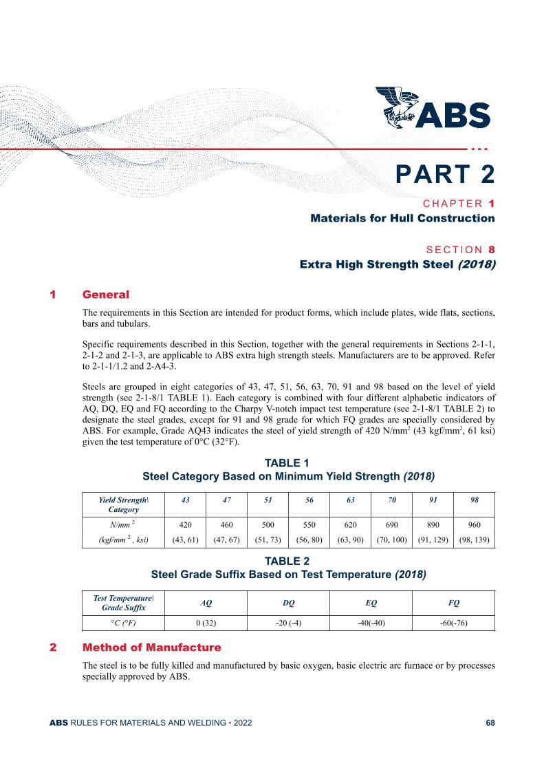
C H A P T E R 1Materials for Hull Construction
S E C T I O N 8Extra High Strength Steel (2018)
1 GeneralThe requirements in this Section are intended for product forms, which include plates, wide flats, sections,bars and tubulars.
Specific requirements described in this Section, together with the general requirements in Sections 2-1-1,2-1-2 and 2-1-3, are applicable to ABS extra high strength steels. Manufacturers are to be approved. Referto 2-1-1/1.2 and 2-A4-3.
Steels are grouped in eight categories of 43, 47, 51, 56, 63, 70, 91 and 98 based on the level of yieldstrength (see 2-1-8/1 TABLE 1). Each category is combined with four different alphabetic indicators ofAQ, DQ, EQ and FQ according to the Charpy V-notch impact test temperature (see 2-1-8/1 TABLE 2) todesignate the steel grades, except for 91 and 98 grade for which FQ grades are specially considered byABS. For example, Grade AQ43 indicates the steel of yield strength of 420 N/mm2 (43 kgf/mm2, 61 ksi)given the test temperature of 0°C (32°F).
TABLE 1 Steel Category Based on Minimum Yield Strength (2018)
Yield Strength\Category
43 47 51 56 63 70 91 98
N/mm 2 420 460 500 550 620 690 890 960
(kgf/mm 2 , ksi) (43, 61) (47, 67) (51, 73) (56, 80) (63, 90) (70, 100) (91, 129) (98, 139)
TABLE 2 Steel Grade Suffix Based on Test Temperature (2018)
Test Temperature\Grade Suffix AQ DQ EQ FQ
°C (°F) 0 (32) -20 (-4) -40(-40) -60(-76)
2 Method of ManufactureThe steel is to be fully killed and manufactured by basic oxygen, basic electric arc furnace or by processesspecially approved by ABS.
PART 2
ABS RULES FOR MATERIALS AND WELDING • 2022 68
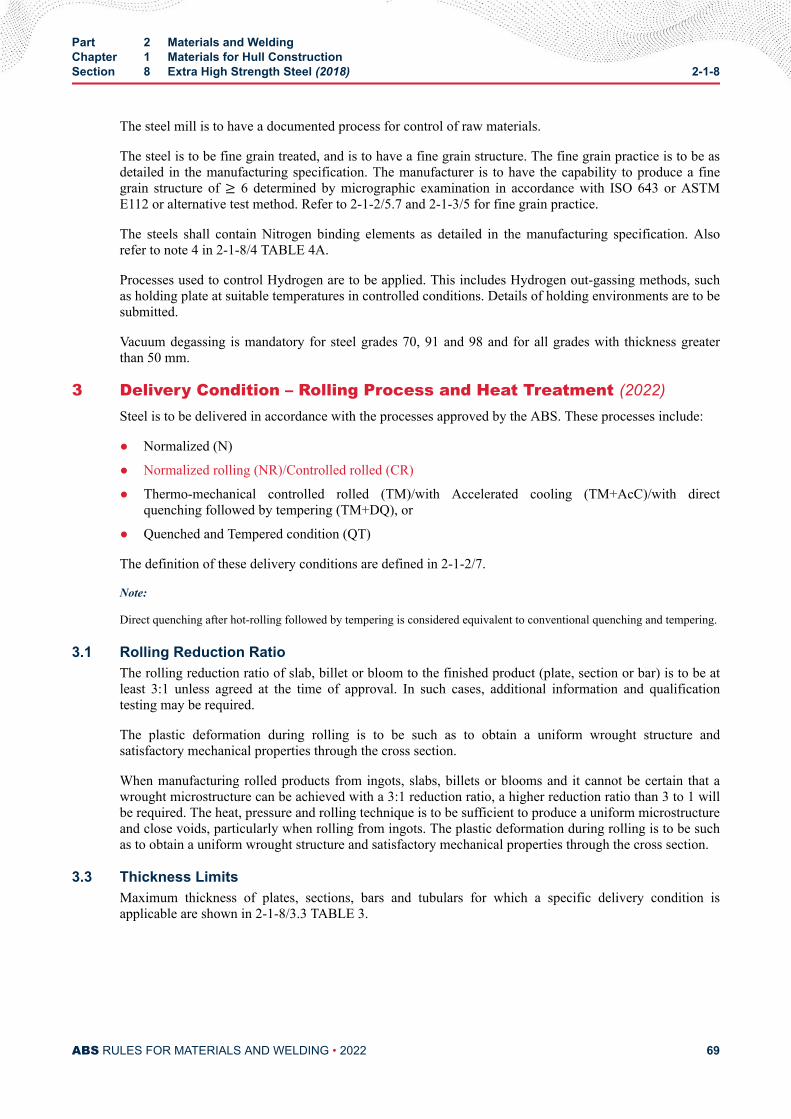
The steel mill is to have a documented process for control of raw materials.
The steel is to be fine grain treated, and is to have a fine grain structure. The fine grain practice is to be asdetailed in the manufacturing specification. The manufacturer is to have the capability to produce a finegrain structure of ≥ 6 determined by micrographic examination in accordance with ISO 643 or ASTME112 or alternative test method. Refer to 2-1-2/5.7 and 2-1-3/5 for fine grain practice.
The steels shall contain Nitrogen binding elements as detailed in the manufacturing specification. Alsorefer to note 4 in 2-1-8/4 TABLE 4A.
Processes used to control Hydrogen are to be applied. This includes Hydrogen out-gassing methods, suchas holding plate at suitable temperatures in controlled conditions. Details of holding environments are to besubmitted.
Vacuum degassing is mandatory for steel grades 70, 91 and 98 and for all grades with thickness greaterthan 50 mm.
3 Delivery Condition – Rolling Process and Heat Treatment (2022)Steel is to be delivered in accordance with the processes approved by the ABS. These processes include:
● Normalized (N)
● Normalized rolling (NR)/Controlled rolled (CR)
● Thermo-mechanical controlled rolled (TM)/with Accelerated cooling (TM+AcC)/with directquenching followed by tempering (TM+DQ), or
● Quenched and Tempered condition (QT)
The definition of these delivery conditions are defined in 2-1-2/7.
Note:
Direct quenching after hot-rolling followed by tempering is considered equivalent to conventional quenching and tempering.
3.1 Rolling Reduction RatioThe rolling reduction ratio of slab, billet or bloom to the finished product (plate, section or bar) is to be atleast 3:1 unless agreed at the time of approval. In such cases, additional information and qualificationtesting may be required.
The plastic deformation during rolling is to be such as to obtain a uniform wrought structure andsatisfactory mechanical properties through the cross section.
When manufacturing rolled products from ingots, slabs, billets or blooms and it cannot be certain that awrought microstructure can be achieved with a 3:1 reduction ratio, a higher reduction ratio than 3 to 1 willbe required. The heat, pressure and rolling technique is to be sufficient to produce a uniform microstructureand close voids, particularly when rolling from ingots. The plastic deformation during rolling is to be suchas to obtain a uniform wrought structure and satisfactory mechanical properties through the cross section.
3.3 Thickness LimitsMaximum thickness of plates, sections, bars and tubulars for which a specific delivery condition isapplicable are shown in 2-1-8/3.3 TABLE 3.
Part 2 Materials and WeldingChapter 1 Materials for Hull ConstructionSection 8 Extra High Strength Steel (2018) 2-1-8
ABS RULES FOR MATERIALS AND WELDING • 2022 69
TABLE 3Maximum Thickness Limits (2022)
Delivery conditionMaximum thickness (mm) (1)
Plates Sections Bars Tubulars
N 250 50 250 70
NR/CR 150 See Note 2
TM 150 50 Not Applicable Not Applicable
QT 250 50 Not Applicable 70
Notes:
1 Approval for steels with thickness greater than indicated in the above table are subject to the special considerationof ABS.
2 The maximum thickness limits of sections, bars and tubulars produced by NR/CR process are to be agreed withABS. (NR/CR maximum thicknesses are generally less than N maximum thickness.)
4 Chemical CompositionElements used for alloying, deoxidizing, fine grain treatment, nitrogen binding, inclusion shape control andmodification, and any residual elements are to be included in the material specification.
Ladle Analysis – The chemical composition is to be determined by the steel manufacturer on samplestaken from each heat and is to conform to the applicable requirements of the grade of steel listed in 2-1-8/4TABLE 4A. The method of sampling is to be in accordance with that carried out for the initial qualificationtests. The aim analysis is to be in accordance with the material specification. All elements listed in 2-1-8/4TABLE 4A are to be reported.
i) For all steel grades, the carbon equivalent (Ceq) value is to be calculated from the ladle analysis.Maximum values are specified in 2-1-8/4 TABLE 4B in accordance with the following equation:Ceq = C+ Mn6 + Cr+Mo+ V5 + Ni+ Cu15 %
ii) For steel grades 47 and higher, carbon equivalent (CET) may be used instead of Ceq at thediscretionof the manufacturer, and is to be calculated in accordance to the following equation:CET = C+ (Mn+Mo)10 + (Cr + Cu)20 + Ni40 %Note:
The CET is included in the standard EN 1011-2:2001 used as one of the parameters for preheatingtemperaturedetermination which is necessary for avoiding cold cracking.
iii) For TM and QT steels with carbon content no more than 0.12%, the cold crackingsusceptibilityPcm for evaluating weldability may be used instead of carbon equivalent Ceq or CETatmanufacturer’s discretion and is to be calculated using the following equation:Pcm = C+ Si30 + Mn20 + Cu20 + Ni60 + Cr20 + Mo15 + V10 + 5B%
Part 2 Materials and WeldingChapter 1 Materials for Hull ConstructionSection 8 Extra High Strength Steel (2018) 2-1-8
ABS RULES FOR MATERIALS AND WELDING • 2022 70
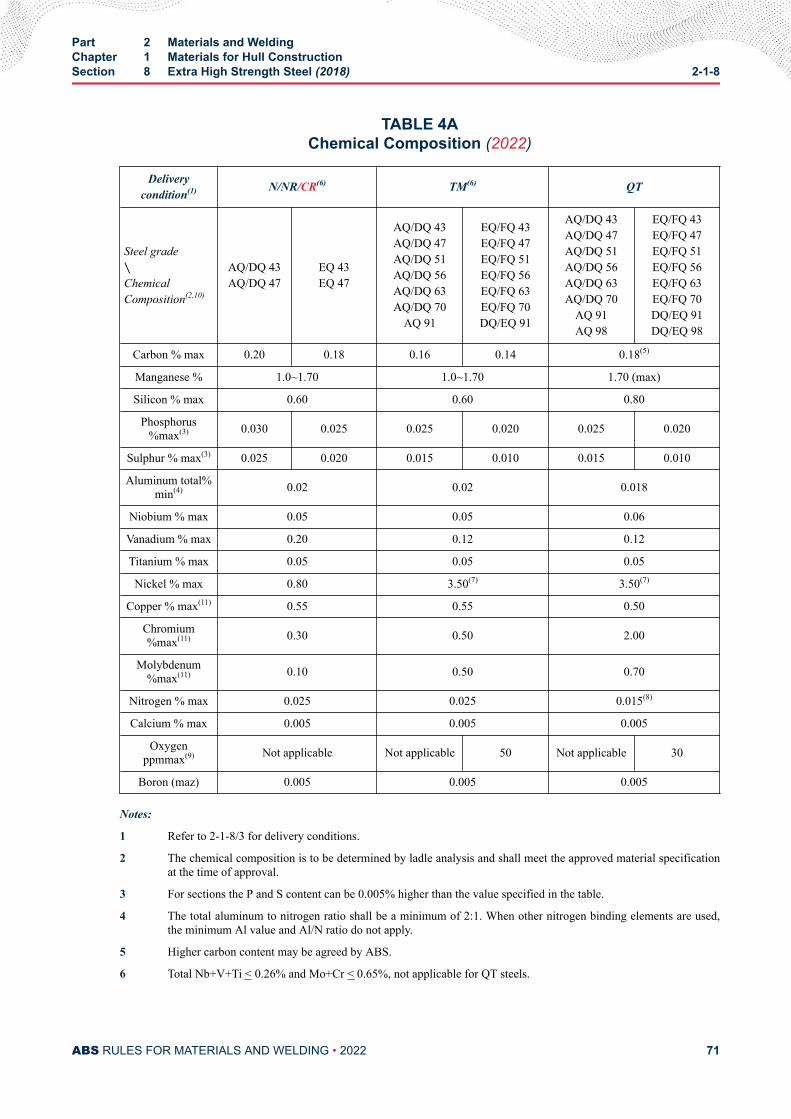
TABLE 4AChemical Composition (2022)
Deliverycondition(1) N/NR/CR(6) TM(6) QT
Steel grade∖ChemicalComposition(2,10)
AQ/DQ 43AQ/DQ 47
EQ 43EQ 47
AQ/DQ 43AQ/DQ 47AQ/DQ 51AQ/DQ 56AQ/DQ 63AQ/DQ 70
AQ 91
EQ/FQ 43EQ/FQ 47EQ/FQ 51EQ/FQ 56EQ/FQ 63EQ/FQ 70DQ/EQ 91
AQ/DQ 43AQ/DQ 47AQ/DQ 51AQ/DQ 56AQ/DQ 63AQ/DQ 70
AQ 91AQ 98
EQ/FQ 43EQ/FQ 47EQ/FQ 51EQ/FQ 56EQ/FQ 63EQ/FQ 70DQ/EQ 91DQ/EQ 98
Carbon % max 0.20 0.18 0.16 0.14 0.18(5)
Manganese % 1.0~1.70 1.0~1.70 1.70 (max)
Silicon % max 0.60 0.60 0.80
Phosphorus%max(3) 0.030 0.025 0.025 0.020 0.025 0.020
Sulphur % max(3) 0.025 0.020 0.015 0.010 0.015 0.010
Aluminum total%min(4) 0.02 0.02 0.018
Niobium % max 0.05 0.05 0.06
Vanadium % max 0.20 0.12 0.12
Titanium % max 0.05 0.05 0.05
Nickel % max 0.80 3.50(7) 3.50(7)
Copper % max(11) 0.55 0.55 0.50
Chromium%max(11) 0.30 0.50 2.00
Molybdenum%max(11) 0.10 0.50 0.70
Nitrogen % max 0.025 0.025 0.015(8)
Calcium % max 0.005 0.005 0.005
Oxygenppmmax(9) Not applicable Not applicable 50 Not applicable 30
Boron (maz) 0.005 0.005 0.005
Notes:
1 Refer to 2-1-8/3 for delivery conditions.
2 The chemical composition is to be determined by ladle analysis and shall meet the approved material specificationat the time of approval.
3 For sections the P and S content can be 0.005% higher than the value specified in the table.
4 The total aluminum to nitrogen ratio shall be a minimum of 2:1. When other nitrogen binding elements are used,the minimum Al value and Al/N ratio do not apply.
5 Higher carbon content may be agreed by ABS.
6 Total Nb+V+Ti < 0.26% and Mo+Cr < 0.65%, not applicable for QT steels.
Part 2 Materials and WeldingChapter 1 Materials for Hull ConstructionSection 8 Extra High Strength Steel (2018) 2-1-8
ABS RULES FOR MATERIALS AND WELDING • 2022 71
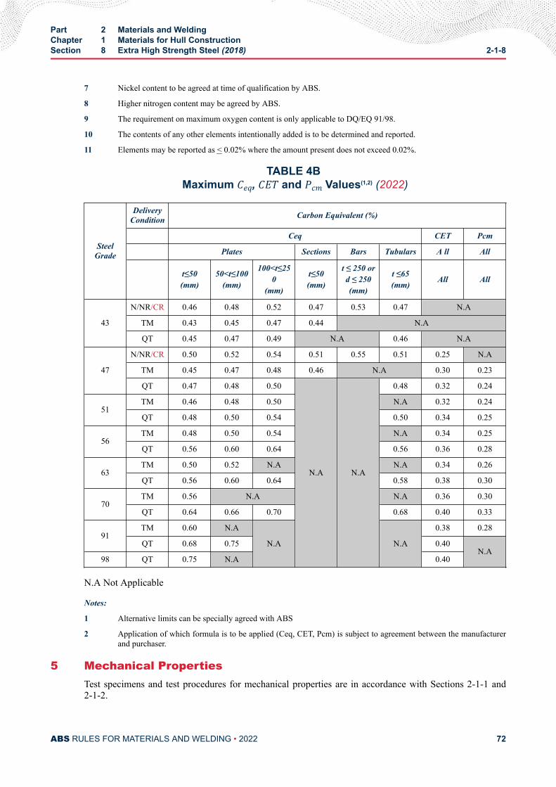
7 Nickel content to be agreed at time of qualification by ABS.
8 Higher nitrogen content may be agreed by ABS.
9 The requirement on maximum oxygen content is only applicable to DQ/EQ 91/98.
10 The contents of any other elements intentionally added is to be determined and reported.
11 Elements may be reported as < 0.02% where the amount present does not exceed 0.02%.
TABLE 4B Maximum Ceq, CET and Pcm Values(1,2) (2022)
SteelGrade
DeliveryCondition Carbon Equivalent (%)
Ceq CET Pcm
Plates Sections Bars Tubulars A ll All
t≤50(mm)
50<t≤100(mm)
100<t≤250
(mm)
t≤50(mm)
t ≤ 250 ord ≤ 250(mm)
t ≤65(mm) All All
43
N/NR/CR 0.46 0.48 0.52 0.47 0.53 0.47 N.A
TM 0.43 0.45 0.47 0.44 N.A
QT 0.45 0.47 0.49 N.A 0.46 N.A
47
N/NR/CR 0.50 0.52 0.54 0.51 0.55 0.51 0.25 N.A
TM 0.45 0.47 0.48 0.46 N.A 0.30 0.23
QT 0.47 0.48 0.50
N.A N.A
0.48 0.32 0.24
51TM 0.46 0.48 0.50 N.A 0.32 0.24
QT 0.48 0.50 0.54 0.50 0.34 0.25
56TM 0.48 0.50 0.54 N.A 0.34 0.25
QT 0.56 0.60 0.64 0.56 0.36 0.28
63TM 0.50 0.52 N.A N.A 0.34 0.26
QT 0.56 0.60 0.64 0.58 0.38 0.30
70TM 0.56 N.A N.A 0.36 0.30
QT 0.64 0.66 0.70 0.68 0.40 0.33
91TM 0.60 N.A
N.A N.A
0.38 0.28
QT 0.68 0.75 0.40N.A
98 QT 0.75 N.A 0.40
N.A Not Applicable
Notes:
1 Alternative limits can be specially agreed with ABS
2 Application of which formula is to be applied (Ceq, CET, Pcm) is subject to agreement between the manufacturerand purchaser.
5 Mechanical PropertiesTest specimens and test procedures for mechanical properties are in accordance with Sections 2-1-1 and2-1-2.
Part 2 Materials and WeldingChapter 1 Materials for Hull ConstructionSection 8 Extra High Strength Steel (2018) 2-1-8
ABS RULES FOR MATERIALS AND WELDING • 2022 72
5.1 Tensile TestTest specimens are to be cut with their longitudinal axes transverse to the final direction of rolling, exceptin the case of sections, bars, tubulars and rolled flats with a finished width or diameter of 600 mm or less,where the tensile specimens may be taken in the longitudinal direction. Plates for leg, rack and chordmaterial may be tested in the longitudinal direction.
Full thickness flat tensile specimens are to be prepared. When the capacity of the test machine is exceededby the use of a full thickness specimen, sub-sized flat tensile specimens representing either the fullthickness or half of the product thickness obtained by machining and retaining one of the original surfacesmay be used. Alternatively, machined round test specimens as per 2-1-1/11.5.2 may be used. The roundspecimens are to be located at a position lying at a distance of t/4 from the surface and additionally at t/2for thickness above 100 mm or as near as possible to these positions.
The results of the tests are to comply with the appropriate requirements of 2-1-8/5.11 TABLE 5A. In thecase of product forms other than plates and wide flats where longitudinal tests are agreed, the elongationvalues are to be 2 percentage units above those transverse requirements as listed in 2-1-8/5.11 TABLE 5B.
5.3 Impact TestThe Charpy V-notch impact test specimens are to be taken with their axes longitudinal or transverse to thefinal rolling direction and the results are to comply with the appropriate requirements of 2-1-8/5.11TABLE 5A.
Sub-surface test specimens are to be located with their edges not more than 2 mm (0.08 in.) from the rolledsurface. For thickness greater than 40 mm (1.57 in.) the impact test specimens are to be taken at quarterthickness (t/4) and for products with thickness in excess of 100 mm (4.0 in.), impact tests shall be taken atthe quarter thickness (t/4) location and mid-thickness (t/2). Tests carried out at mid t and are to achieve atleast 2/3 of the required Joule value indicated in table 2-1-8/5.11 TABLE 5A. Alternatively, the mid t testcan be carried out at 10°C above the specified CVN test temperature to achieve the same Charpy valuespecified for the sub-surface specimen.
Impact test for a nominal thickness less than 6 mm are normally not required.
5.5 Through Thickness Tensile TestFor steels designated with improved through thickness properties, through thickness tensile tests are to beperformed in accordance with 2-1-1/17.
5.7 Test Frequency5.7.1 Tensile Test (2022)
For plates and tubulars, tension test specimens are to be taken from each heat treatment batch ofthe same cast, delivery condition and thickness. In the case of tubulars supplied in QT condition,properties are to be verified from both ends of the product. This may be established by tensile testor hardness test.
For sections and bars, tension test specimens are to be randomly selected from every 25 tonnes orpart thereof, from each heat treatment batch of the same cast, delivery condition and thickness.
5.7.2 Impact Test (2022)For plates and tubulars, impact test specimens are to be taken from each heat treatment batch ofthe same cast, delivery condition and thickness. In the case of tubulars supplied in QT condition,properties are to be verified from both ends of the product during qualification.
For sections and bars, impact test specimens are to be randomly selected from every 25 tonnes orpart thereof, from each heat treatment batch of the same cast, delivery condition and thickness.
Part 2 Materials and WeldingChapter 1 Materials for Hull ConstructionSection 8 Extra High Strength Steel (2018) 2-1-8
ABS RULES FOR MATERIALS AND WELDING • 2022 73
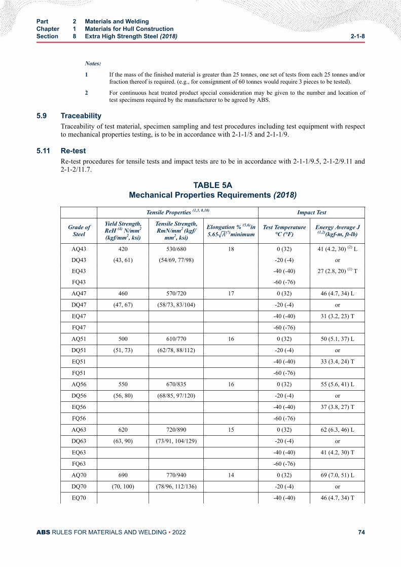
Notes:
1 If the mass of the finished material is greater than 25 tonnes, one set of tests from each 25 tonnes and/orfraction thereof is required. (e.g., for consignment of 60 tonnes would require 3 pieces to be tested).
2 For continuous heat treated product special consideration may be given to the number and location oftest specimens required by the manufacturer to be agreed by ABS.
5.9 TraceabilityTraceability of test material, specimen sampling and test procedures including test equipment with respectto mechanical properties testing, is to be in accordance with 2-1-1/5 and 2-1-1/9.
5.11 Re-testRe-test procedures for tensile tests and impact tests are to be in accordance with 2-1-1/9.5, 2-1-2/9.11 and2-1-2/11.7.
TABLE 5AMechanical Properties Requirements (2018)
Tensile Properties (1,3, 8,10) Impact Test
Grade ofSteel
Yield Strength,ReH (4) N/mm2
(kgf/mm2, ksi)
Tensile Strength,RmN/mm2 (kgf/
mm2, ksi)
Elongation % (5,6)in5.65 A(7)minimum
Test Temperature°C (°F)
Energy Average J(1,2)(kgf-m, ft-lb)
AQ43 420 530/680 18 0 (32) 41 (4.2, 30) (2) L
DQ43 (43, 61) (54/69, 77/98) -20 (-4) or
EQ43 -40 (-40) 27 (2.8, 20) (1) T
FQ43 -60 (-76)
AQ47 460 570/720 17 0 (32) 46 (4.7, 34) L
DQ47 (47, 67) (58/73, 83/104) -20 (-4) or
EQ47 -40 (-40) 31 (3.2, 23) T
FQ47 -60 (-76)
AQ51 500 610/770 16 0 (32) 50 (5.1, 37) L
DQ51 (51, 73) (62/78, 88/112) -20 (-4) or
EQ51 -40 (-40) 33 (3.4, 24) T
FQ51 -60 (-76)
AQ56 550 670/835 16 0 (32) 55 (5.6, 41) L
DQ56 (56, 80) (68/85, 97/120) -20 (-4) or
EQ56 -40 (-40) 37 (3.8, 27) T
FQ56 -60 (-76)
AQ63 620 720/890 15 0 (32) 62 (6.3, 46) L
DQ63 (63, 90) (73/91, 104/129) -20 (-4) or
EQ63 -40 (-40) 41 (4.2, 30) T
FQ63 -60 (-76)
AQ70 690 770/940 14 0 (32) 69 (7.0, 51) L
DQ70 (70, 100) (78/96, 112/136) -20 (-4) or
EQ70 -40 (-40) 46 (4.7, 34) T
Part 2 Materials and WeldingChapter 1 Materials for Hull ConstructionSection 8 Extra High Strength Steel (2018) 2-1-8
ABS RULES FOR MATERIALS AND WELDING • 2022 74
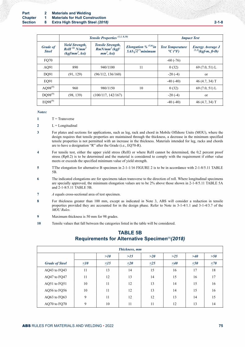
Tensile Properties (1,3, 8,10) Impact Test
Grade ofSteel
Yield Strength,ReH (4) N/mm2
(kgf/mm2, ksi)
Tensile Strength,RmN/mm2 (kgf/
mm2, ksi)
Elongation % (5,6)in5.65 A(7)minimum
Test Temperature°C (°F)
Energy Average J(1,2)(kgf-m, ft-lb)
FQ70 -60 (-76)
AQ91 890 940/1100 11 0 (32) 69 (7.0, 51) L
DQ91 (91, 129) (96/112, 136/160) -20 (-4) or
EQ91 -40 (-40) 46 (4.7, 34) T
AQ98(9) 960 980/1150 10 0 (32) 69 (7.0, 51) L
DQ98(9) (98, 139) (100/117, 142/167) -20 (-4) or
EQ98(9) -40 (-40) 46 (4.7, 34) T
Notes:
1 T = Transverse
2 L = Longitudinal
3 For plates and sections for applications, such as leg, rack and chord in Mobile Offshore Units (MOU), where thedesign requires that tensile properties are maintained through the thickness, a decrease in the minimum specifiedtensile properties is not permitted with an increase in the thickness. Materials intended for leg, racks and chordsare to have a designation “R” after the Grade (i.e., EQ70-R).
4 For tensile test, either the upper yield stress (ReH) or where ReH cannot be determined, the 0,2 percent proofstress (Rp0.2) is to be determined and the material is considered to comply with the requirement if either valuemeets or exceeds the specified minimum value of yield strength.
5 TThe elongation for alternative B specimen in 2-1-1/16 FIGURE 2 is to be in accordance with 2-1-8/5.11 TABLE5B.
6 The indicated elongations are for specimens taken transverse to the direction of roll. Where longitudinal specimensare specially approved, the minimum elongation values are to be 2% above those shown in 2-1-8/5.11 TABLE 5Aand 2-1-8/5.11 TABLE 5B.
7 A equals cross-sectional area of test specimen.
8 For thickness greater than 100 mm, except as indicated in Note 3, ABS will consider a reduction in tensileproperties provided they are accounted for in the design phase. Refer to Note in 3-1-4/1.1 and 3-1-4/3.7 of theMOU Rules.
9 Maximum thickness is 50 mm for 98 grades.
10 Tensile values that fall between the categories listed in the table will be considered.
TABLE 5BRequirements for Alternative Specimen(1)(2018)
Thickness, mm
Grade of Steel
>10 >15 >20 >25 >40 >50
<10 <15 <20 <25 <40 <50 <70
AQ43 to FQ43 11 13 14 15 16 17 18
AQ47 to FQ47 11 12 13 14 15 16 17
AQ51 to FQ51 10 11 12 13 14 15 16
AQ56 to FQ56 10 11 12 13 14 15 16
AQ63 to FQ63 9 11 12 12 13 14 15
AQ70 to FQ70 9 10 11 11 12 13 14
Part 2 Materials and WeldingChapter 1 Materials for Hull ConstructionSection 8 Extra High Strength Steel (2018) 2-1-8
ABS RULES FOR MATERIALS AND WELDING • 2022 75
Note:
1 91 and 98 specimens which are not included in this table shall be proportional specimens with a gauge length ofL0 = 5 . 65 S0.
7 TolerancesUnless otherwise agreed or specially required, the thickness tolerances are to be in accordance with2-1-1/15.
9 Surface QualityAll materials are to be free from cracks, injurious surface flaws, injurious laminations and similar defects.The surface quality inspection method shall be in accordance with EN 10163 Parts 1, 2 and 3 or equivalentstandards agreed between purchaser and manufacturer and accepted by ABS.
Surface finish requirement shall be in accordance with the relevant requirements in 2-1-2/15.
Surface inspection is the responsibility of the manufacturer. The acceptance by ABS Surveyor of materiallater found to be defective shall not absolve the manufacturer of this responsibility.
9.1 Plate Edge InspectionEdge of the plate is to be inspected. Any discontinuity greater than 25 mm in length is to be furtherinvestigated for depth and extent. Treatment of discontinuity is to be agreed with ABS.
11 Internal SoundnessVerification of internal soundness is the responsibility of the manufacturer. The acceptance by the ABSSurveyor shall not absolve the manufacturer of this responsibility.
11.1 Ultrasonic Examination (2022)All steel grades with thickness greater than or equal to 15 mm (0.60 in.) are to be inspected for internalquality at the mill in accordance with EN10160 or ASTM A578 or other recognized standard as agreedwith ABS. Acceptance criteria is to be agreed between the purchaser and manufacturer, and accepted byABS.
Acceptable standards are as follows:
For leg, rack and chord plates in Mobile Offshore Units (MOU), the acceptance criteria shall be aminimum of EN10160 Level S2/E3.
If chords are ordered with ultrasonic inspection in the final formed and heat treated condition, thespecification and acceptance criteria is to be agreed between the purchaser and manufacturer, and acceptedby ABS
Note:
For Z quality steels, ultrasonic examination is to be carried out on products of thickness 15 mm and above (refer to2-1-1/17).
13 Stress Relieving Heat Treatment and Other Heat TreatmentsSteels approved by the procedures given in 2-A4-3 are suitable for stress relieving heat treatment such aspost-weld heat treatment and stress relieving heat treatment after cold forming (refer to 2-A4-3/5.11.3(e))
Note:
Part 2 Materials and WeldingChapter 1 Materials for Hull ConstructionSection 8 Extra High Strength Steel (2018) 2-1-8
ABS RULES FOR MATERIALS AND WELDING • 2022 76
Products can be susceptible to deterioration in mechanical strength and toughness if they are subjected to incorrect post-weldheat treatment procedures or other processes involving heating such as flame straightening, rerolling, etc., where the heatingtemperature and the holding time exceed the limits provided by the manufacturer.
15 Fabrication & WeldingUpon request from the fabricator, the steel mill may supply the parameters applied during the weldabilitytests (carried out in accordance with 2-A4-2/5.13) in order to develop fabrication procedures. Also ABScan populate this information on ABS website with written consent from the steel mill.
17 Facilities for InspectionTesting is to be carried out under the witness of the Surveyor in order to verify that the test results meet thespecified requirements.
The manufacturer is to provide access to the steel works to enable the Surveyor to,
i) Verify that the approved manufacturing process is followed
ii) Select test materials
iii) Witness mechanical tests and to verify testing is in accordance with standards
iv) Witness/verify NDE inspection, calibration of inspection equipment.
19 Identification of MaterialsThe manufacturer is to adopt a system for the identification of ingots, slabs, billet or bloom and finishedproducts, which will enable the material to be traced to its original cast.
The steel mill is to facilitate the Surveyor to verify traceability of the material.
21 MarkingRefer to requirements in 2-1-2/13.
Permanent marking of the grade and delivery condition is to be done on the product in the final deliverycondition. Marking of the final designated grade is not permitted on semi-finished products.
Materials intended for leg, racks and chords are to have a designation “R” after the Grade (i.e., EQ70-R).
23 Documentation of Inspection TestsThe Surveyor is to be supplied with a copy, of the test certificates or shipping statements for all acceptedmaterials. In addition to the description, dimensions, etc., of the material, the following particulars are tobe included:
i) Purchaser’s order number
ii) Identification of the cast/heat, batch and plate number
iii) Manufacturer’s identification
iv) Identification of the grade of steel
v) Chemical analysis and Ceq, CET or Pcm value
vi) Delivery condition with heat treatment temperatures
vii) Mechanical properties test results, including traceable test identification
viii) Surface quality and inspection results
Part 2 Materials and WeldingChapter 1 Materials for Hull ConstructionSection 8 Extra High Strength Steel (2018) 2-1-8
ABS RULES FOR MATERIALS AND WELDING • 2022 77

ix) UT report
x) Manufacturer’s Certificate refer to 2-1-1/7
Part 2 Materials and WeldingChapter 1 Materials for Hull ConstructionSection 8 Extra High Strength Steel (2018) 2-1-8
ABS RULES FOR MATERIALS AND WELDING • 2022 78
C H A P T E R 2Equipment
CONTENTSSECTION 1 Anchors ............................................................................................. 83
1 General Requirements (2007)...................................................... 831.1 Scope...............................................................................831.3 Types of Anchor...............................................................83
3 Materials for Anchors (2012)........................................................ 843.1 Superior Holding Power (SHP) Anchors for
Restricted Service and to a Maximum Weight of1500 kg (3306 lbs)........................................................... 84
5 Manufacture of Anchors (2007).................................................... 845.1 Tolerance......................................................................... 845.3 Welding of Anchors..........................................................855.5 Heat Treatment (2012).....................................................855.7 Surface Cleanliness.........................................................865.9 Repairs (2010)................................................................. 865.11 Anchor Assembly.............................................................86
7 Testing and Certification (2007)....................................................867.1 Proof Load Testing of Anchors.........................................867.3 Product Tests................................................................... 877.5 Mass and Dimensional Inspection................................... 907.7 Retests.............................................................................90
9 Marking for Anchors .....................................................................909.1 Markings.......................................................................... 909.3 Provisions for Marks (2005).............................................90
11 Certification (2007)....................................................................... 9113 Painting (2007)............................................................................. 91
TABLE 1 Applicable Test Programs for Each Product Form (2010)....88TABLE 2 Product Test Requirements for Program A and B (2010).....88TABLE 3 General NDE for Ordinary and SHP Anchors...................... 88TABLE 4 General NDE for SHP Anchors for Restricted Service
with 4 Times Holding Power of Ordinary Anchors................89TABLE 5 Extended NDE for Ordinary and all SHP Anchors............... 89
PART 2
ABS RULES FOR MATERIALS AND WELDING • 2022 79
TABLE 6 Proof Tests for Anchors .......................................................92
FIGURE 1 Allowable Lateral Movement of Shank (2007)..................... 85FIGURE 2 Proof Load Application.........................................................87FIGURE 3 Stockless Anchor (2008)......................................................90
SECTION 2 Anchor Chain .................................................................................... 971 Scope............................................................................................973 General.........................................................................................975 Specially Approved Chain.............................................................977 Qualification of Manufacturers .....................................................97
7.1 General............................................................................ 977.3 Stud Attachment (2005)...................................................98
9 Chain Dimensions and Tolerances .............................................. 989.1 Shape.............................................................................. 989.3 Dimensions (2005)...........................................................989.5 Tolerances (1999)............................................................ 999.7 Length Over Five Links..................................................100
11 Material for Chain....................................................................... 10011.1 General.......................................................................... 100
13 Material Testing ..........................................................................10113.1 Heat Treatment of Test Specimens................................10113.3 Number of Tests.............................................................10113.5 Tension Test Specimens (1996).....................................10113.7 Bend Test Specimens.................................................... 10113.9 Impact Test Specimens..................................................10113.11 Additional Tests before Rejection (1996)....................... 10213.13 Manufacturer's Option....................................................102
15 Heat Treatment of Chain Lengths...............................................10215.1 Flash Butt-welded Chain................................................10215.3 Drop-forged, Cast-steel and Extra-high-strength Chain 10215.5 Sequence of Heat Treatment.........................................102
17 Testing and Inspection of Chain Lengths ...................................10317.1 General (1996)...............................................................10317.3 Chain Identification........................................................ 10317.5 Testing Precautions....................................................... 10317.7 Weighing of Tested Chain..............................................10317.9 Testing of Used Chain....................................................103
19 Details of Tests on Chain Lengths ............................................. 10319.1 Breaking Test (2005)......................................................10319.3 Proof Test.......................................................................10419.5 Mechanical Tests on Completed Chain (2005).............. 104
ABS RULES FOR MATERIALS AND WELDING • 2022 80
19.7 Mechanical and Breaking Tests on Chain Producedin Long Continuous Lengths.......................................... 104
21 Marking for Chain (2001)............................................................10523 Anchor Chain Accessories .........................................................106
23.1 Dimensions and Dimensional Tolerances (1996).......... 10623.2 Locking Pins in Accessories.......................................... 10623.3 Material Testing..............................................................10623.5 Cast Accessories........................................................... 10623.7 Forged Accessories....................................................... 10623.9 Inspection...................................................................... 10623.11 Hardness Test................................................................10623.13 Break Test (2001).......................................................... 10623.15 Proof Tests.....................................................................10723.17 Markings........................................................................ 107
25 Unstudded Short-link Chain........................................................10725.1 General.......................................................................... 10725.3 Testing........................................................................... 10725.5 Marking.......................................................................... 107
27 Material Hardness for Windlass-Wildcats and Gypsy Wheels....10827.1 Wear and Abrasion........................................................ 10827.3 Approximate Hardness Values for Wildcats and
Gypsy Wheels................................................................10827.5 Cladding and Hardfacing............................................... 109
TABLE 1 Chain Materials -Mechanical Properties (1999).................108TABLE 2 Stud-link Anchor-chain Proof and Break Tests...................110TABLE 3 Unstudded Short-link Chain............................................... 115
FIGURE 1 Location and Orientation of Test Specimens......................102FIGURE 2 Marking for Chain...............................................................105
SECTION 3 Rolled Steel Bars for Chain, Cast and Forged Materials forAccessories and Materials for Studs ............................................ 1161 General (2005)............................................................................116
1.1 Process and Qualification of Manufacture (2012)..........1161.3 Deoxidation Practice...................................................... 1161.5 Chemical Composition and Heat Treatment (1999).......1161.7 Mechanical Properties (1999)........................................ 1161.9 Dimensional properties (1999).......................................117
3 Material Testing...........................................................................1173.1 Heat Treatment of Test Specimens................................1173.3 Number of Tests.............................................................1173.5 Tension Test Specimens (1996).....................................1173.7 Bend Test Specimens.................................................... 117
ABS RULES FOR MATERIALS AND WELDING • 2022 81
3.9 Impact Test Specimens..................................................1173.11 Additional Tests before Rejection(1996)........................ 1183.13 Manufacturer's Option....................................................1183.15 Freedom from Defects (2005)........................................1183.17 Identification of Material (2005)......................................1183.19 Marking (2005)...............................................................1183.21 Material Certification (2005)...........................................1183.23 Forged Steels for Chain Cables and Accessories
(2005).............................................................................1183.25 Cast Steels for Chain Cables and Accessories (2005).. 1193.27 Materials for Studs (2005)..............................................119
TABLE 1 Rolled Bars for Chain – Chemical Composition andIntended Chain Condition (2008)....................................... 119
TABLE 2 Rolled Bar for Chain – Dimensional Tolerances (1999)..... 119
ABS RULES FOR MATERIALS AND WELDING • 2022 82
C H A P T E R 2Equipment
S E C T I O N 1Anchors
1 General Requirements (2007)
1.1 ScopeThese requirements apply to the materials, manufacture, testing and certification of anchors, shanks andanchor shackles produced from cast or forged steel, or fabricated by welded rolled steel plate and bars.
These manufacturing requirements are applicable to ordinary anchors and superior holding power (SHP)anchors.
1.3 Types of Anchor1.3.1 Ordinary Anchors (Also see 3-5-1/7)
Ordinary stockless anchors are to be of an approved design. Any changes or alterations from theapproved design are to be approved prior to manufacture.
The mass of the heads of stockless anchors including pins and fittings are not to be less than 60%of the total mass of the anchor.
1.3.2 Superior Holding Power (SHP) Anchors (Also see 3-5-1/7)SHP anchors are to be of an approved design and subject to special approval. Any changes oralterations to the approved design made during manufacture are to have prior approval.
SHP anchors are to be suitable for ship use and are not to require prior adjustment or specialplacement on the seabed.
SHP anchors are to have at least twice the holding power of ordinary stockless anchors of thesame weight.
The mass of each bower anchor can be reduced by up to 25% of the mass specified in 2-2-1/13TABLE 6.
Approved manufacturers of SHP anchors are included in a specific directory maintained by ABS.
PART 2
ABS RULES FOR MATERIALS AND WELDING • 2022 83
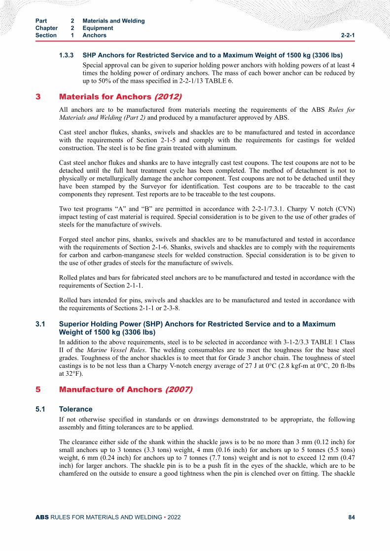
1.3.3 SHP Anchors for Restricted Service and to a Maximum Weight of 1500 kg (3306 lbs)Special approval can be given to superior holding power anchors with holding powers of at least 4times the holding power of ordinary anchors. The mass of each bower anchor can be reduced byup to 50% of the mass specified in 2-2-1/13 TABLE 6.
3 Materials for Anchors (2012)All anchors are to be manufactured from materials meeting the requirements of the ABS Rules forMaterials and Welding (Part 2) and produced by a manufacturer approved by ABS.
Cast steel anchor flukes, shanks, swivels and shackles are to be manufactured and tested in accordancewith the requirements of Section 2-1-5 and comply with the requirements for castings for weldedconstruction. The steel is to be fine grain treated with aluminum.
Cast steel anchor flukes and shanks are to have integrally cast test coupons. The test coupons are not to bedetached until the full heat treatment cycle has been completed. The method of detachment is not tophysically or metallurgically damage the anchor component. Test coupons are not to be detached until theyhave been stamped by the Surveyor for identification. Test coupons are to be traceable to the castcomponents they represent. Test reports are to be traceable to the test coupons.
Two test programs “A” and “B” are permitted in accordance with 2-2-1/7.3.1. Charpy V notch (CVN)impact testing of cast material is required. Special consideration is to be given to the use of other grades ofsteels for the manufacture of swivels.
Forged steel anchor pins, shanks, swivels and shackles are to be manufactured and tested in accordancewith the requirements of Section 2-1-6. Shanks, swivels and shackles are to comply with the requirementsfor carbon and carbon-manganese steels for welded construction. Special consideration is to be given tothe use of other grades of steels for the manufacture of swivels.
Rolled plates and bars for fabricated steel anchors are to be manufactured and tested in accordance with therequirements of Section 2-1-1.
Rolled bars intended for pins, swivels and shackles are to be manufactured and tested in accordance withthe requirements of Sections 2-1-1 or 2-3-8.
3.1 Superior Holding Power (SHP) Anchors for Restricted Service and to a MaximumWeight of 1500 kg (3306 lbs)In addition to the above requirements, steel is to be selected in accordance with 3-1-2/3.3 TABLE 1 ClassII of the Marine Vessel Rules. The welding consumables are to meet the toughness for the base steelgrades. Toughness of the anchor shackles is to meet that for Grade 3 anchor chain. The toughness of steelcastings is to be not less than a Charpy V-notch energy average of 27 J at 0°C (2.8 kgf-m at 0°C, 20 ft-lbsat 32°F).
5 Manufacture of Anchors (2007)
5.1 ToleranceIf not otherwise specified in standards or on drawings demonstrated to be appropriate, the followingassembly and fitting tolerances are to be applied.
The clearance either side of the shank within the shackle jaws is to be no more than 3 mm (0.12 inch) forsmall anchors up to 3 tonnes (3.3 tons) weight, 4 mm (0.16 inch) for anchors up to 5 tonnes (5.5 tons)weight, 6 mm (0.24 inch) for anchors up to 7 tonnes (7.7 tons) weight and is not to exceed 12 mm (0.47inch) for larger anchors. The shackle pin is to be a push fit in the eyes of the shackle, which are to bechamfered on the outside to ensure a good tightness when the pin is clenched over on fitting. The shackle
Part 2 Materials and WeldingChapter 2 EquipmentSection 1 Anchors 2-2-1
ABS RULES FOR MATERIALS AND WELDING • 2022 84
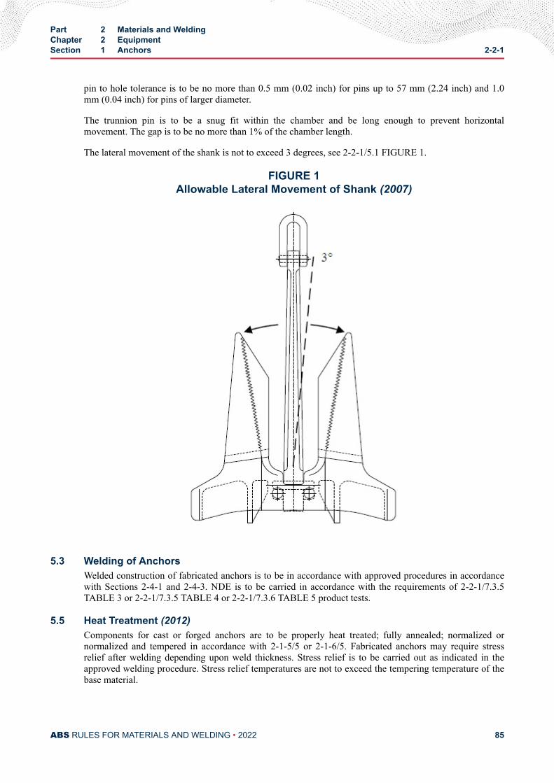
pin to hole tolerance is to be no more than 0.5 mm (0.02 inch) for pins up to 57 mm (2.24 inch) and 1.0mm (0.04 inch) for pins of larger diameter.
The trunnion pin is to be a snug fit within the chamber and be long enough to prevent horizontalmovement. The gap is to be no more than 1% of the chamber length.
The lateral movement of the shank is not to exceed 3 degrees, see 2-2-1/5.1 FIGURE 1.
FIGURE 1Allowable Lateral Movement of Shank (2007)
5.3 Welding of AnchorsWelded construction of fabricated anchors is to be in accordance with approved procedures in accordancewith Sections 2-4-1 and 2-4-3. NDE is to be carried in accordance with the requirements of 2-2-1/7.3.5TABLE 3 or 2-2-1/7.3.5 TABLE 4 or 2-2-1/7.3.6 TABLE 5 product tests.
5.5 Heat Treatment (2012)Components for cast or forged anchors are to be properly heat treated; fully annealed; normalized ornormalized and tempered in accordance with 2-1-5/5 or 2-1-6/5. Fabricated anchors may require stressrelief after welding depending upon weld thickness. Stress relief is to be carried out as indicated in theapproved welding procedure. Stress relief temperatures are not to exceed the tempering temperature of thebase material.
Part 2 Materials and WeldingChapter 2 EquipmentSection 1 Anchors 2-2-1
ABS RULES FOR MATERIALS AND WELDING • 2022 85
The foundry or forge is to provide the Surveyor records of heat treatment, identifying the furnace used,furnace charge, date, temperature and time at temperature, together with the number and location ofthermocouples. The heat treatment temperature and time is to be based on sensors attached to the furnacecharge. The time lag between the thermocouples on the furnace charge and wall/interior of the furnace is tobe determined in order to assess that the heating and soaking times are sufficient.
Integrally cast or forged coupons are to be of sufficient size to represent the heat transfer experienced inthe cast or forged component itself during the complete heat treatment cycle.
5.7 Surface CleanlinessAll parts are to have a clean surface consistent with the method of manufacture and intended method ofinspection.
5.9 Repairs (2010)Any necessary repairs to forged and cast anchors are to be agreed to by the Surveyor and carried out inaccordance with the repair criteria indicated in 2-1-5/13 and 2-1-6/11.9. The restrictions of 2-2-1/7.3.7 -Repair Criteria, also apply.
The manufacturer is to maintain full records detailing the extent and location of all weld repairs made toeach casting or forging and details of weld procedures and heat treatments applied. These records are to beavailable to the Surveyor and copies provided on request.
Repairs to fabricated anchors are to be agreed to by the Surveyor and carried out in accordance withqualified weld procedures, by qualified welders, following the parameters of the welding procedures usedin construction.
5.11 Anchor AssemblyAssembly and fitting are to be done in accordance with the design details. Securing of the anchor pin,shackle pin or swivel nut, by welding, is to be in accordance with an approved procedure.
7 Testing and Certification (2007)All anchors are to be inspected and tested in the presence of the Surveyor, the proof testing is to be done ina machine recognized for such purposes. The Surveyor is to be satisfied that all testing machines, includingmaterial testing machines, are maintained in a satisfactory condition, and is to keep a record of the datesand by whom the machines were rechecked and calibrated.
7.1 Proof Load Testing of AnchorsProof load testing for ordinary and SHP anchors is to be carried out by an approved testing facility.
7.1.1 Proof Load Testing of Ordinary Anchors (2014)Before application of proof test load, the anchors are to be visually examined, and all defects areto be removed, and if necessary repaired by welding, prior to testing. Proof tests are to be carriedout on all anchors after being temporarily assembled. The proof tests are to be in accordance withthe values given in 2-2-1/13 TABLE 6. The proof load in accordance with 2-2-1/13 TABLE 6 is tobe applied on the fluke at a location one third of the distance from the tip of the fluke to the centerof the crown as shown in 2-2-1/7.1.1 FIGURE 2.
In the case of stockless anchors, both arms are to be tested at the same time, first on one side ofthe shank, then reversed and tested on the other.
After proof load testing the anchors are to be examined for cracks and other defects, and forexcessive deformation due to seating.
Part 2 Materials and WeldingChapter 2 EquipmentSection 1 Anchors 2-2-1
ABS RULES FOR MATERIALS AND WELDING • 2022 86
Upon completion of the proof load tests, anchors made in more than one piece are to be examinedfor free rotation of their heads over the complete angle. The anchor shackle that underwent proofload testing is to be fitted to the anchor before shipping to the customer.
The gauge lengths (see 2-2-1/7.1.1 FIGURE 2) under a load equal to one-tenth of the proof testload are to be determined before and after the application of full proof load on each side. Thegauge length after the application of full proof load is to be not more than 1% in excess of thecorresponding gauge length before the application of full proof load.
FIGURE 2Proof Load Application
7.1.2 Proof Load Testing of SHP AnchorsSHP anchors are to be proof tested with loads required by 2-2-1/13 TABLE 6 for an anchor massequal to 1.33 times the actual mass of the SHP anchor. The proof loading procedure andexamination procedure for SHP anchors are to comply with those for ordinary anchors, describedin 2-2-1/7.1.
7.1.3 Testing of SHP Anchors for Restricted Service with 4 Times Holding Power of OrdinaryAnchors
These anchors are to be proof tested with the load required by 2-2-1/13 TABLE 6 for an anchormass equal to 2 times the actual mass of the SHP anchor. The proof loading procedure andexamination procedure for SHP anchors are to comply with those for ordinary anchors, describedin 2-2-1/7.1.
7.1.4 SHP Full Scale Anchor Holding Power Tests at SeaIn addition to proof tests SHP anchors are to undergo anchor holding power sea tests on varioustypes of sea bottom, using anchors representative of the full range of anchor size proposed.
7.3 Product Tests7.3.1 Product Test Programs
There are two test programs, which apply to anchor manufacture.
● Program A, or
● Program B.
Part 2 Materials and WeldingChapter 2 EquipmentSection 1 Anchors 2-2-1
ABS RULES FOR MATERIALS AND WELDING • 2022 87
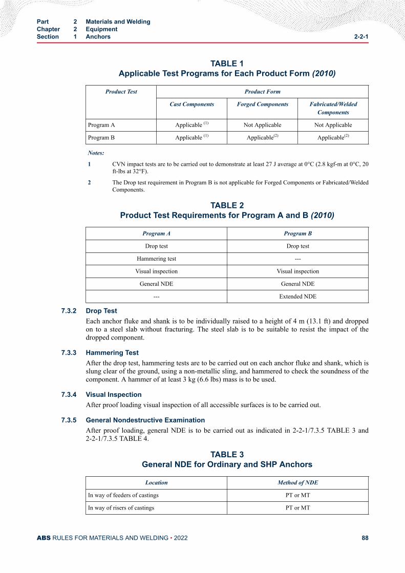
TABLE 1Applicable Test Programs for Each Product Form (2010)
Product Test Product Form
Cast Components Forged Components Fabricated/WeldedComponents
Program A Applicable (1) Not Applicable Not Applicable
Program B Applicable (1) Applicable(2) Applicable(2)
Notes:
1 CVN impact tests are to be carried out to demonstrate at least 27 J average at 0°C (2.8 kgf-m at 0°C, 20ft-lbs at 32°F).
2 The Drop test requirement in Program B is not applicable for Forged Components or Fabricated/WeldedComponents.
TABLE 2Product Test Requirements for Program A and B (2010)
Program A Program B
Drop test Drop test
Hammering test ---
Visual inspection Visual inspection
General NDE General NDE
--- Extended NDE
7.3.2 Drop TestEach anchor fluke and shank is to be individually raised to a height of 4 m (13.1 ft) and droppedon to a steel slab without fracturing. The steel slab is to be suitable to resist the impact of thedropped component.
7.3.3 Hammering TestAfter the drop test, hammering tests are to be carried out on each anchor fluke and shank, which isslung clear of the ground, using a non-metallic sling, and hammered to check the soundness of thecomponent. A hammer of at least 3 kg (6.6 lbs) mass is to be used.
7.3.4 Visual InspectionAfter proof loading visual inspection of all accessible surfaces is to be carried out.
7.3.5 General Nondestructive ExaminationAfter proof loading, general NDE is to be carried out as indicated in 2-2-1/7.3.5 TABLE 3 and2-2-1/7.3.5 TABLE 4.
TABLE 3General NDE for Ordinary and SHP Anchors
Location Method of NDE
In way of feeders of castings PT or MT
In way of risers of castings PT or MT
Part 2 Materials and WeldingChapter 2 EquipmentSection 1 Anchors 2-2-1
ABS RULES FOR MATERIALS AND WELDING • 2022 88
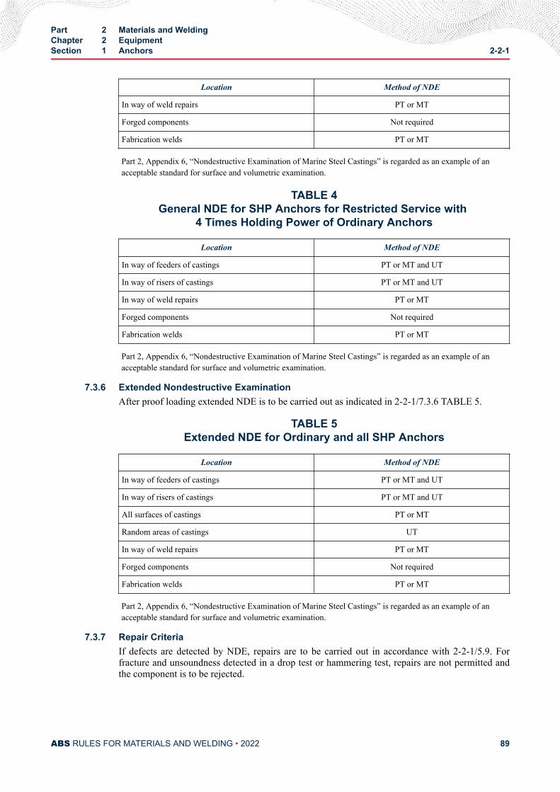
Location Method of NDE
In way of weld repairs PT or MT
Forged components Not required
Fabrication welds PT or MT
Part 2, Appendix 6, “Nondestructive Examination of Marine Steel Castings” is regarded as an example of anacceptable standard for surface and volumetric examination.
TABLE 4General NDE for SHP Anchors for Restricted Service with
4 Times Holding Power of Ordinary Anchors
Location Method of NDE
In way of feeders of castings PT or MT and UT
In way of risers of castings PT or MT and UT
In way of weld repairs PT or MT
Forged components Not required
Fabrication welds PT or MT
Part 2, Appendix 6, “Nondestructive Examination of Marine Steel Castings” is regarded as an example of anacceptable standard for surface and volumetric examination.
7.3.6 Extended Nondestructive ExaminationAfter proof loading extended NDE is to be carried out as indicated in 2-2-1/7.3.6 TABLE 5.
TABLE 5Extended NDE for Ordinary and all SHP Anchors
Location Method of NDE
In way of feeders of castings PT or MT and UT
In way of risers of castings PT or MT and UT
All surfaces of castings PT or MT
Random areas of castings UT
In way of weld repairs PT or MT
Forged components Not required
Fabrication welds PT or MT
Part 2, Appendix 6, “Nondestructive Examination of Marine Steel Castings” is regarded as an example of anacceptable standard for surface and volumetric examination.
7.3.7 Repair CriteriaIf defects are detected by NDE, repairs are to be carried out in accordance with 2-2-1/5.9. Forfracture and unsoundness detected in a drop test or hammering test, repairs are not permitted andthe component is to be rejected.
Part 2 Materials and WeldingChapter 2 EquipmentSection 1 Anchors 2-2-1
ABS RULES FOR MATERIALS AND WELDING • 2022 89
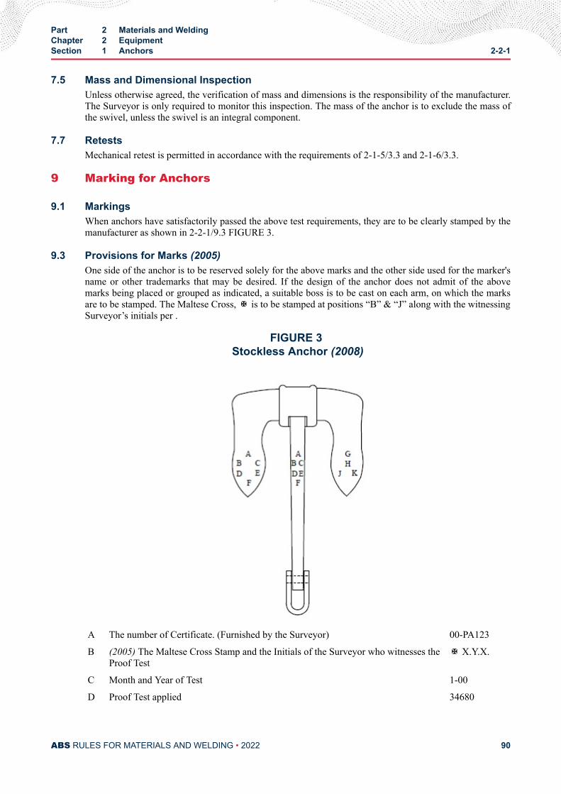
7.5 Mass and Dimensional InspectionUnless otherwise agreed, the verification of mass and dimensions is the responsibility of the manufacturer.The Surveyor is only required to monitor this inspection. The mass of the anchor is to exclude the mass ofthe swivel, unless the swivel is an integral component.
7.7 RetestsMechanical retest is permitted in accordance with the requirements of 2-1-5/3.3 and 2-1-6/3.3.
9 Marking for Anchors
9.1 MarkingsWhen anchors have satisfactorily passed the above test requirements, they are to be clearly stamped by themanufacturer as shown in 2-2-1/9.3 FIGURE 3.
9.3 Provisions for Marks (2005)One side of the anchor is to be reserved solely for the above marks and the other side used for the marker'sname or other trademarks that may be desired. If the design of the anchor does not admit of the abovemarks being placed or grouped as indicated, a suitable boss is to be cast on each arm, on which the marksare to be stamped. The Maltese Cross, ✠ is to be stamped at positions “B” & “J” along with the witnessingSurveyor’s initials per .
FIGURE 3 Stockless Anchor (2008)
A The number of Certificate. (Furnished by the Surveyor) 00-PA123
B (2005) The Maltese Cross Stamp and the Initials of the Surveyor who witnesses theProof Test
✠ X.Y.X.
C Month and Year of Test 1-00
D Proof Test applied 34680
Part 2 Materials and WeldingChapter 2 EquipmentSection 1 Anchors 2-2-1
ABS RULES FOR MATERIALS AND WELDING • 2022 90
E Signifying that the Testing Machine is recognized by the Committee of theAmerican Bureau of Shipping
AB
F The Weight of Anchor 1906
G (2008) Signifying that Anchor Head has been verified by a Surveyor to theAmerican Bureau of Shipping
AB
H The Weight of Anchor Head 1140
J (2005) The Maltese Cross Stamp and the Initials of the Surveyor who witnesses theDrop Test
✠ X.Y.X.
K Month and Year of Drop Test 6-00
11 Certification (2007)Anchors which meet the requirements of this section are to be certified by ABS. The following items thatare to be included in the certificate:
● Manufacturer’s name
● Type
● Mass
● Fluke and Shank identification numbers
● Grade of materials
● Proof test loads
● Heat treatment
● Markings applied to anchor
13 Painting (2007)All types of anchor are to remain unpainted until all tests and inspections have been completed.
Part 2 Materials and WeldingChapter 2 EquipmentSection 1 Anchors 2-2-1
ABS RULES FOR MATERIALS AND WELDING • 2022 91
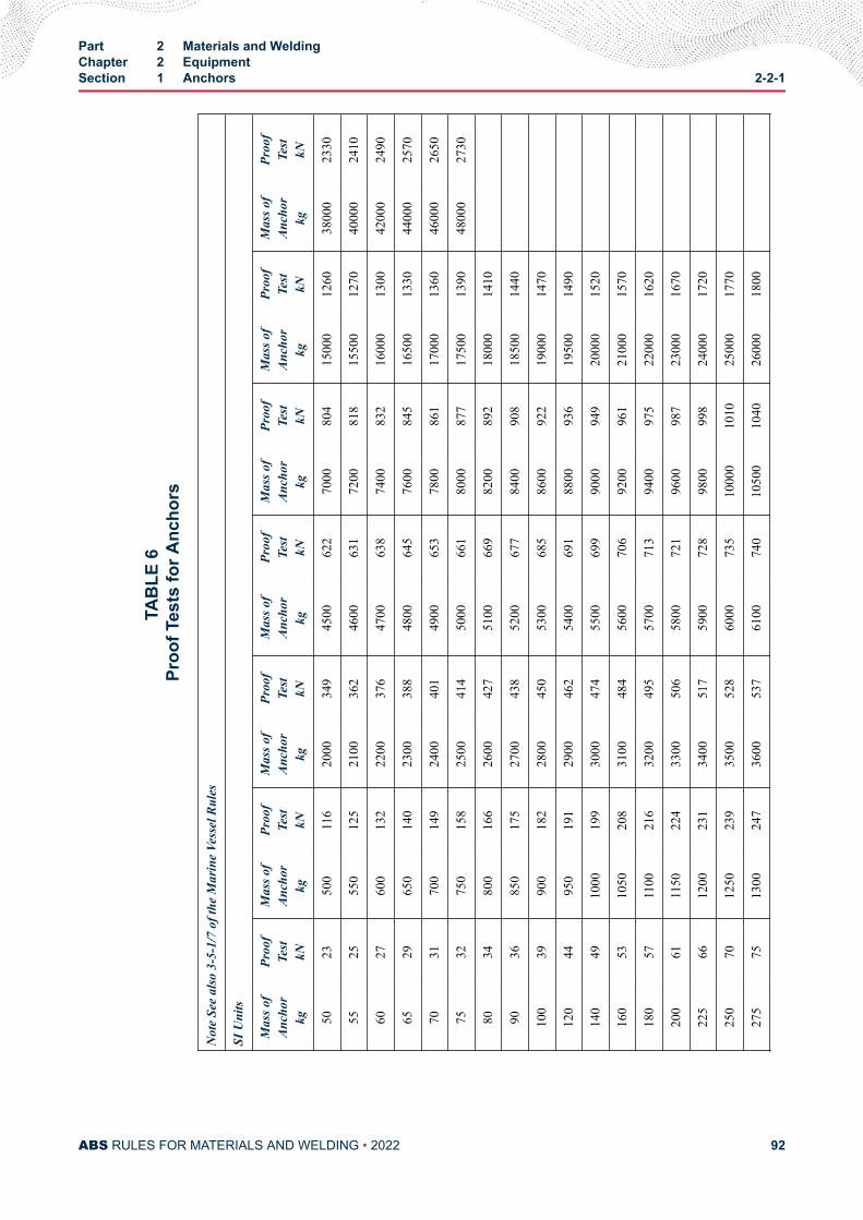
TAB
LE 6
Pr
oof T
ests
for A
ncho
rs
Not
e Se
e al
so 3
-5-1
/7 o
f the
Mar
ine
Vess
el R
ules
SI U
nits
Mas
s of
Anch
orkg
Proo
fTe
stkN
Mas
s of
Anch
orkg
Proo
fTe
stkN
Mas
s of
Anch
orkg
Proo
fTe
stkN
Mas
s of
Anch
orkg
Proo
fTe
stkN
Mas
s of
Anch
orkg
Proo
fTe
stkN
Mas
s of
Anch
orkg
Proo
fTe
stkN
Mas
s of
Anch
orkg
Proo
fTe
stkN
5023
500
116
2000
349
4500
622
7000
804
1500
012
6038
000
2330
5525
550
125
2100
362
4600
631
7200
818
1550
012
7040
000
2410
6027
600
132
2200
376
4700
638
7400
832
1600
013
0042
000
2490
6529
650
140
2300
388
4800
645
7600
845
1650
013
3044
000
2570
7031
700
149
2400
401
4900
653
7800
861
1700
013
6046
000
2650
7532
750
158
2500
414
5000
661
8000
877
1750
013
9048
000
2730
8034
800
166
2600
427
5100
669
8200
892
1800
014
10
9036
850
175
2700
438
5200
677
8400
908
1850
014
40
100
3990
018
228
0045
053
0068
586
0092
219
000
1470
120
4495
019
129
0046
254
0069
188
0093
619
500
1490
140
4910
0019
930
0047
455
0069
990
0094
920
000
1520
160
5310
5020
831
0048
456
0070
692
0096
121
000
1570
180
5711
0021
632
0049
557
0071
394
0097
522
000
1620
200
6111
5022
433
0050
658
0072
196
0098
723
000
1670
225
6612
0023
134
0051
759
0072
898
0099
824
000
1720
250
7012
5023
935
0052
860
0073
510
000
1010
2500
017
70
275
7513
0024
736
0053
761
0074
010
500
1040
2600
018
00
Part 2 Materials and WeldingChapter 2 EquipmentSection 1 Anchors 2-2-1
ABS RULES FOR MATERIALS AND WELDING • 2022 92
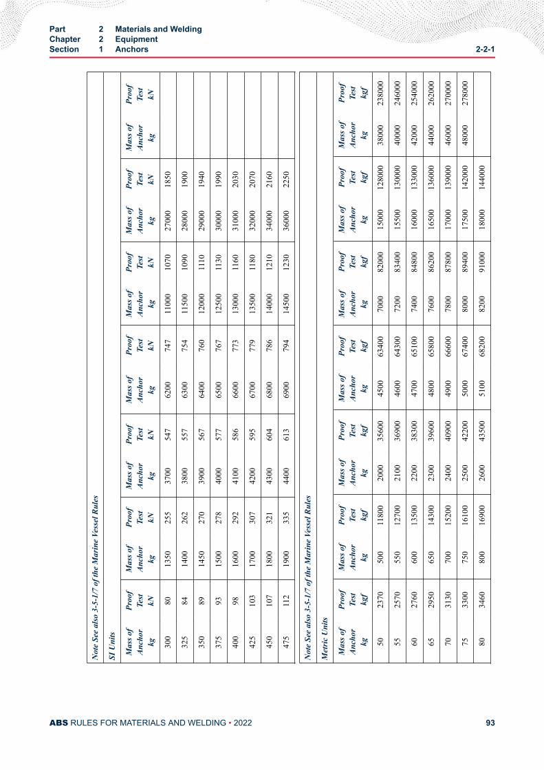
Not
e Se
e al
so 3
-5-1
/7 o
f the
Mar
ine
Vess
el R
ules
SI U
nits
Mas
s of
Anch
orkg
Proo
fTe
stkN
Mas
s of
Anch
orkg
Proo
fTe
stkN
Mas
s of
Anch
orkg
Proo
fTe
stkN
Mas
s of
Anch
orkg
Proo
fTe
stkN
Mas
s of
Anch
orkg
Proo
fTe
stkN
Mas
s of
Anch
orkg
Proo
fTe
stkN
Mas
s of
Anch
orkg
Proo
fTe
stkN
300
8013
5025
537
0054
762
0074
711
000
1070
2700
018
50
325
8414
0026
238
0055
763
0075
411
500
1090
2800
019
00
350
8914
5027
039
0056
764
0076
012
000
1110
2900
019
40
375
9315
0027
840
0057
765
0076
712
500
1130
3000
019
90
400
9816
0029
241
0058
666
0077
313
000
1160
3100
020
30
425
103
1700
307
4200
595
6700
779
1350
011
8032
000
2070
450
107
1800
321
4300
604
6800
786
1400
012
1034
000
2160
475
112
1900
335
4400
613
6900
794
1450
012
3036
000
2250
Not
e Se
e al
so 3
-5-1
/7 o
f the
Mar
ine
Vess
el R
ules
Met
ric U
nits
Mas
s of
Anch
orkg
Proo
fTe
stkg
f
Mas
s of
Anch
orkg
Proo
fTe
stkg
f
Mas
s of
Anch
orkg
Proo
fTe
stkg
f
Mas
s of
Anch
orkg
Proo
fTe
stkg
f
Mas
s of
Anch
orkg
Proo
fTe
stkg
f
Mas
s of
Anch
orkg
Proo
fTe
stkg
f
Mas
s of
Anch
orkg
Proo
fTe
stkg
f
5023
7050
011
800
2000
3560
045
0063
400
7000
8200
015
000
1280
0038
000
2380
00
5525
7055
012
700
2100
3690
046
0064
300
7200
8340
015
500
1300
0040
000
2460
00
6027
6060
013
500
2200
3830
047
0065
100
7400
8480
016
000
1330
0042
000
2540
00
6529
5065
014
300
2300
3960
048
0065
800
7600
8620
016
500
1360
0044
000
2620
00
7031
3070
015
200
2400
4090
049
0066
600
7800
8780
017
000
1390
0046
000
2700
00
7533
0075
016
100
2500
4220
050
0067
400
8000
8940
017
500
1420
0048
000
2780
00
8034
6080
016
900
2600
4350
051
0068
200
8200
9100
018
000
1440
00
Part 2 Materials and WeldingChapter 2 EquipmentSection 1 Anchors 2-2-1
ABS RULES FOR MATERIALS AND WELDING • 2022 93
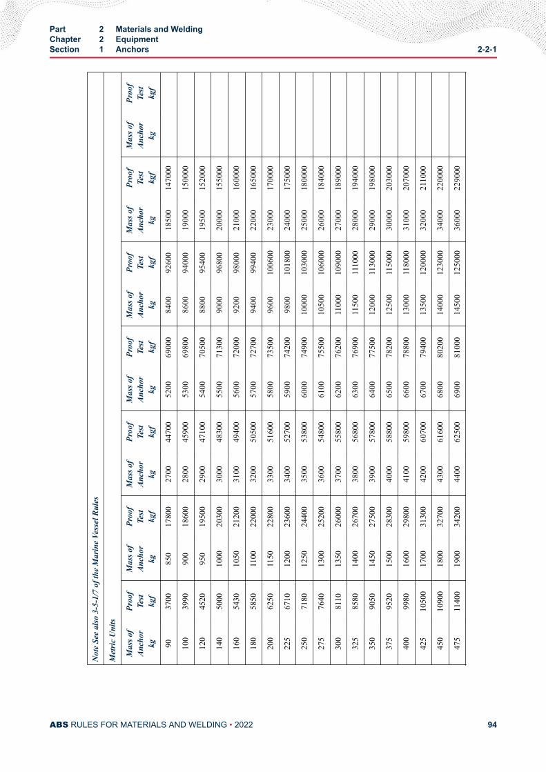
Not
e Se
e al
so 3
-5-1
/7 o
f the
Mar
ine
Vess
el R
ules
Met
ric U
nits
Mas
s of
Anch
orkg
Proo
fTe
stkg
f
Mas
s of
Anch
orkg
Proo
fTe
stkg
f
Mas
s of
Anch
orkg
Proo
fTe
stkg
f
Mas
s of
Anch
orkg
Proo
fTe
stkg
f
Mas
s of
Anch
orkg
Proo
fTe
stkg
f
Mas
s of
Anch
orkg
Proo
fTe
stkg
f
Mas
s of
Anch
orkg
Proo
fTe
stkg
f
9037
0085
017
800
2700
4470
052
0069
000
8400
9260
018
500
1470
00
100
3990
900
1860
028
0045
900
5300
6980
086
0094
000
1900
015
0000
120
4520
950
1950
029
0047
100
5400
7050
088
0095
400
1950
015
2000
140
5000
1000
2030
030
0048
300
5500
7130
090
0096
800
2000
015
5000
160
5430
1050
2120
031
0049
400
5600
7200
092
0098
000
2100
016
0000
180
5850
1100
2200
032
0050
500
5700
7270
094
0099
400
2200
016
5000
200
6250
1150
2280
033
0051
600
5800
7350
096
0010
0600
2300
017
0000
225
6710
1200
2360
034
0052
700
5900
7420
098
0010
1800
2400
017
5000
250
7180
1250
2440
035
0053
800
6000
7490
010
000
1030
0025
000
1800
00
275
7640
1300
2520
036
0054
800
6100
7550
010
500
1060
0026
000
1840
00
300
8110
1350
2600
037
0055
800
6200
7620
011
000
1090
0027
000
1890
00
325
8580
1400
2670
038
0056
800
6300
7690
011
500
1110
0028
000
1940
00
350
9050
1450
2750
039
0057
800
6400
7750
012
000
1130
0029
000
1980
00
375
9520
1500
2830
040
0058
800
6500
7820
012
500
1150
0030
000
2030
00
400
9980
1600
2980
041
0059
800
6600
7880
013
000
1180
0031
000
2070
00
425
1050
017
0031
300
4200
6070
067
0079
400
1350
012
0000
3200
021
1000
450
1090
018
0032
700
4300
6160
068
0080
200
1400
012
3000
3400
022
0000
475
1140
019
0034
200
4400
6250
069
0081
000
1450
012
5000
3600
022
9000
Part 2 Materials and WeldingChapter 2 EquipmentSection 1 Anchors 2-2-1
ABS RULES FOR MATERIALS AND WELDING • 2022 94
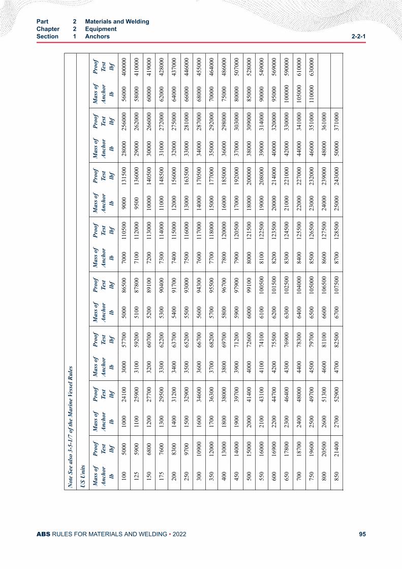
Not
e Se
e al
so 3
-5-1
/7 o
f the
Mar
ine
Vess
el R
ules
US
Uni
ts
Mas
s of
Anch
orlb
Proo
fTe
stlb
f
Mas
s of
Anch
orlb
Proo
fTe
stlb
f
Mas
s of
Anch
orlb
Proo
fTe
stlb
f
Mas
s of
Anch
orlb
Proo
fTe
stlb
f
Mas
s of
Anch
orlb
Proo
fTe
stlb
f
Mas
s of
Anch
orlb
Proo
fTe
stlb
f
Mas
s of
Anch
orlb
Proo
fTe
stlb
f
Mas
s of
Anch
orlb
Proo
fTe
stlb
f
100
5000
1000
2410
030
0057
700
5000
8650
070
0011
0500
9000
1315
0028
000
2560
0056
000
4000
00
125
5900
1100
2590
031
0059
200
5100
8780
071
0011
2000
9500
1360
0029
000
2620
0058
000
4100
00
150
6800
1200
2770
032
0060
700
5200
8910
072
0011
3000
1000
014
0500
3000
026
6000
6000
041
9000
175
7600
1300
2950
033
0062
200
5300
9040
073
0011
4000
1100
014
8500
3100
027
2000
6200
042
8000
200
8300
1400
3120
034
0063
700
5400
9170
074
0011
5000
1200
015
6000
3200
027
5000
6400
043
7000
250
9700
1500
3290
035
0065
200
5500
9300
075
0011
6000
1300
016
3500
3300
028
1000
6600
044
6000
300
1090
016
0034
600
3600
6670
056
0094
300
7600
1170
0014
000
1705
0034
000
2870
0068
000
4550
00
350
1200
017
0036
300
3700
6820
057
0095
500
7700
1180
0015
000
1770
0035
000
2920
0070
000
4640
00
400
1300
018
0038
000
3800
6970
058
0096
700
7800
1200
0016
000
1850
0036
000
2980
0075
000
4860
00
450
1400
019
0039
700
3900
7120
059
0097
900
7900
1205
0017
000
1920
0037
000
3030
0080
000
5070
00
500
1500
020
0041
400
4000
7260
060
0099
100
8000
1215
0018
000
2000
0038
000
3090
0085
000
5280
00
550
1600
021
0043
100
4100
7410
061
0010
0500
8100
1225
0019
000
2080
0039
000
3140
0090
000
5490
00
600
1690
022
0044
700
4200
7550
062
0010
1500
8200
1235
0020
000
2140
0040
000
3200
0095
000
5690
00
650
1780
023
0046
400
4300
7690
063
0010
2500
8300
1245
0021
000
2210
0042
000
3300
0010
0000
5900
00
700
1870
024
0048
000
4400
7830
064
0010
4000
8400
1255
0022
000
2270
0044
000
3410
0010
5000
6100
00
750
1960
025
0049
700
4500
7970
065
0010
5000
8500
1265
0023
000
2320
0046
000
3510
0011
0000
6300
00
800
2050
026
0051
300
4600
8110
066
0010
6500
8600
1275
0024
000
2390
0048
000
3610
00
850
2140
027
0052
900
4700
8250
067
0010
7500
8700
1285
0025
000
2430
0050
000
3710
00
Part 2 Materials and WeldingChapter 2 EquipmentSection 1 Anchors 2-2-1
ABS RULES FOR MATERIALS AND WELDING • 2022 95
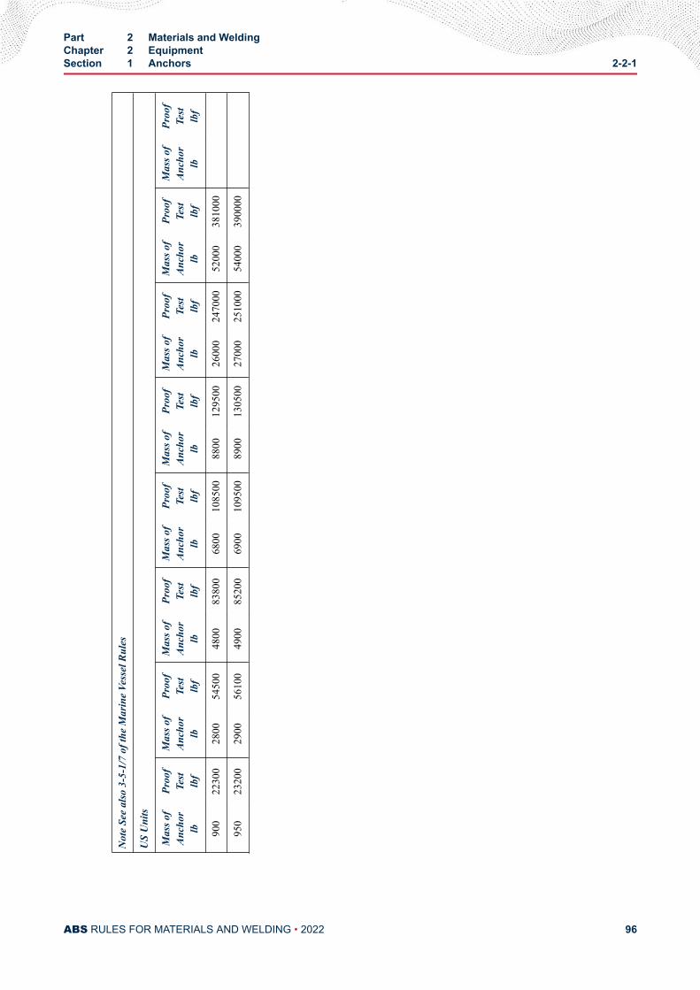
Not
e Se
e al
so 3
-5-1
/7 o
f the
Mar
ine
Vess
el R
ules
US
Uni
ts
Mas
s of
Anch
orlb
Proo
fTe
stlb
f
Mas
s of
Anch
orlb
Proo
fTe
stlb
f
Mas
s of
Anch
orlb
Proo
fTe
stlb
f
Mas
s of
Anch
orlb
Proo
fTe
stlb
f
Mas
s of
Anch
orlb
Proo
fTe
stlb
f
Mas
s of
Anch
orlb
Proo
fTe
stlb
f
Mas
s of
Anch
orlb
Proo
fTe
stlb
f
Mas
s of
Anch
orlb
Proo
fTe
stlb
f
900
2230
028
0054
500
4800
8380
068
0010
8500
8800
1295
0026
000
2470
0052
000
3810
00
950
2320
029
0056
100
4900
8520
069
0010
9500
8900
1305
0027
000
2510
0054
000
3900
00
Part 2 Materials and WeldingChapter 2 EquipmentSection 1 Anchors 2-2-1
ABS RULES FOR MATERIALS AND WELDING • 2022 96
C H A P T E R 2Equipment
S E C T I O N 2Anchor Chain
1 ScopeThree grades of stud-link anchor chain are covered, and are described as follows:
Strength Level Grade Method of Manufacture
Normal Strength 1 Flash Butt-welded
High Strength 2a2b
Flash Butt-welded or Drop-forgedCast Steel
Extra-high Strength 3a3b
Flash Butt-welded or Drop-forgedCast Steel
3 GeneralAll chain is to have a workmanlike finish and be free from injurious defects. There is to be an odd numberof links in each shot of anchor chain cable to insure shackles leading over the windlass are in the sameposition.
5 Specially Approved ChainSteel chain made by processes or to requirements differing from those shown in 2-2-2/25.5 TABLE 1 andcertain types of drop-forged chain will be subject to special consideration.
7 Qualification of Manufacturers (2020)
7.1 General (2020)Anchor chain and chain accessories are to be produced by manufacturers approved by ABS. For approvalpurposes, the manufacturer is to submit a manufacturing procedure specification, applicable materialgrades, and dimensional details of chain/accessories along with a test plan for ABS review. The approvaltests, as a minimum, are to include: chemical analyses, proof and break load tests, tensile/impact tests,metallographic examinations, dimensional measurements, visual and non-destructive examinations.Qualification testing is to be carried out on the largest size chain or accessory. The approval tests are to bewitnessed by an attending Surveyor and the test-data are to be submitted to ABS Materials, Houston forreview and acceptance. The approval is valid for a maximum of 5 years and the renewal process is to be onsimilar lines as specified in 2-A4-2/11.
PART 2
ABS RULES FOR MATERIALS AND WELDING • 2022 97
7.3 Stud Attachment (2005)Studs are to be securely fastened by press fitting or welding with an approved procedure. When the stud iswelded in place, the weld is to be opposite the flash butt weld in the chain. The welding is to be carried outin the horizontal position at least on both faces of the link for a length sufficient to hold the stud securely inplace. Any welding of chain subsequent to the approved manufacturing process is to be approved by theattending Surveyor.
Welding of studs is to be in accordance with an approved procedure subject to the following conditions:
i) The studs must be of weldable steel.
ii) The studs are to be welded at one end only, i.e., opposite to the weldment of the link. The studends must fit the inside of the link without appreciable gap.
iii) The welds, preferably in the horizontal position, shall be executed by qualified welders usingsuitable welding consumables.
iv) All welds must be carried out before the final heat treatment of the chain cable.
v) The welds must be free from defects liable to impair the proper use of the chain. Under-cuts, endcraters and similar defects are to be ground off, where necessary.
ABS reserves the right to call for a procedure test for the welding of chain studs.
9 Chain Dimensions and Tolerances
9.1 ShapeEach link is to be uniform and symmetrical, and is to have smooth internal radii that are to be at least 0.65times the chain diameter.
9.3 Dimensions (2005)The dimensions, shape and proportions of links and accessories must conform to an approved recognizedstandard, such as ISO 1704, or the designs are to be specially approved.
After proof testing, measurements are to be taken on at least one link per each 27.5 m (15 fathoms) ofchain tested and conform to the dimensions shown below.
Part 2 Materials and WeldingChapter 2 EquipmentSection 2 Anchor Chain 2-2-2
ABS RULES FOR MATERIALS AND WELDING • 2022 98
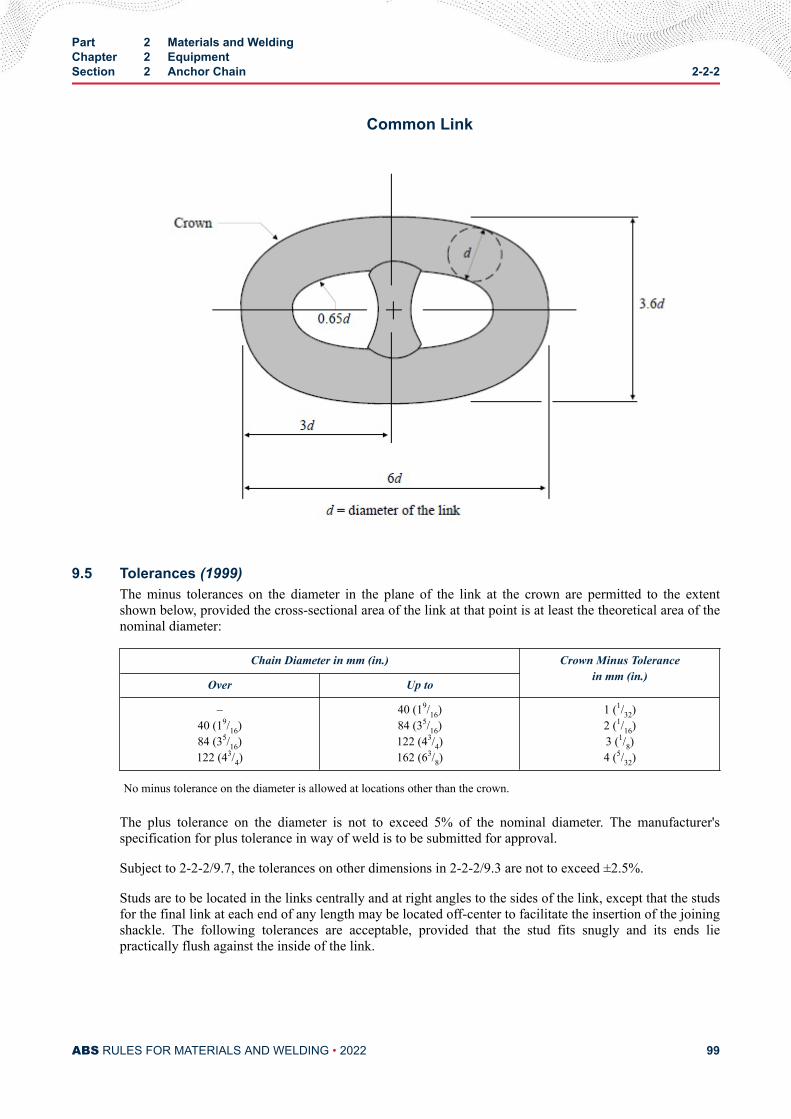
Common Link
9.5 Tolerances (1999)The minus tolerances on the diameter in the plane of the link at the crown are permitted to the extentshown below, provided the cross-sectional area of the link at that point is at least the theoretical area of thenominal diameter:
Chain Diameter in mm (in.) Crown Minus Tolerancein mm (in.)
Over Up to
–40 (19/16)84 (35/16)122 (43/4)
40 (19/16)84 (35/16)122 (43/4)162 (63/8)
1 (1/32)2 (1/16)3 (1/8)4 (5/32)
No minus tolerance on the diameter is allowed at locations other than the crown.
The plus tolerance on the diameter is not to exceed 5% of the nominal diameter. The manufacturer'sspecification for plus tolerance in way of weld is to be submitted for approval.
Subject to 2-2-2/9.7, the tolerances on other dimensions in 2-2-2/9.3 are not to exceed ±2.5%.
Studs are to be located in the links centrally and at right angles to the sides of the link, except that the studsfor the final link at each end of any length may be located off-center to facilitate the insertion of the joiningshackle. The following tolerances are acceptable, provided that the stud fits snugly and its ends liepractically flush against the inside of the link.
Part 2 Materials and WeldingChapter 2 EquipmentSection 2 Anchor Chain 2-2-2
ABS RULES FOR MATERIALS AND WELDING • 2022 99
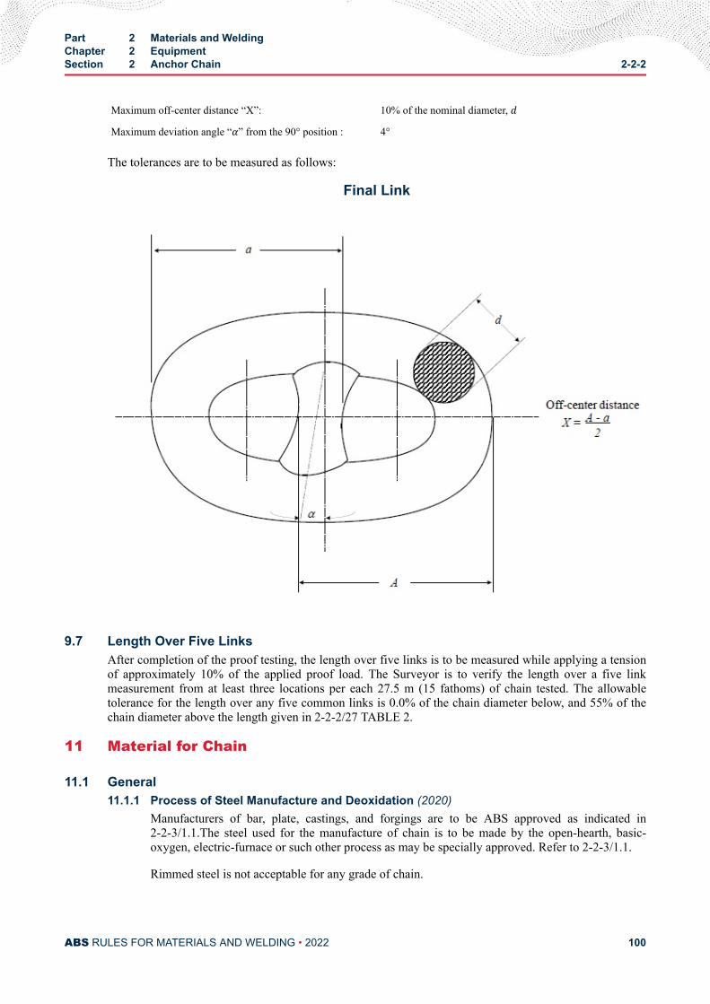
Maximum off-center distance “X”: 10% of the nominal diameter, dMaximum deviation angle “α” from the 90° position : 4°
The tolerances are to be measured as follows:
Final Link
9.7 Length Over Five LinksAfter completion of the proof testing, the length over five links is to be measured while applying a tensionof approximately 10% of the applied proof load. The Surveyor is to verify the length over a five linkmeasurement from at least three locations per each 27.5 m (15 fathoms) of chain tested. The allowabletolerance for the length over any five common links is 0.0% of the chain diameter below, and 55% of thechain diameter above the length given in 2-2-2/27 TABLE 2.
11 Material for Chain
11.1 General11.1.1 Process of Steel Manufacture and Deoxidation (2020)
Manufacturers of bar, plate, castings, and forgings are to be ABS approved as indicated in2-2-3/1.1.The steel used for the manufacture of chain is to be made by the open-hearth, basic-oxygen, electric-furnace or such other process as may be specially approved. Refer to 2-2-3/1.1.
Rimmed steel is not acceptable for any grade of chain.
Part 2 Materials and WeldingChapter 2 EquipmentSection 2 Anchor Chain 2-2-2
ABS RULES FOR MATERIALS AND WELDING • 2022 100
11.1.2 Chemical Composition (1996)The chemical composition of the material for chain manufacture is to be determined by thesteelmaker on samples taken from each ladle of each heat and is to comply with the approvedspecification of the chain manufacturer.
13 Material Testing
13.1 Heat Treatment of Test SpecimensTest specimens are to be taken from material heat-treated in the same manner as intended for the finishedchain, except that in the case of Grades 1 and 2a flash butt-welded chain, test specimens may be takenfrom material in either the as-rolled or heat-treated condition.
13.3 Number of TestsOne set of tests consisting of one tension, and one bend or three impact test specimens as required in2-2-2/25.5 TABLE 1 are to be taken from the largest casting or drop forging from each lot of 50 tons orfraction thereof from each heat.
13.5 Tension Test Specimens (1996)For cast or drop-forged links, machined type specimens are to be used. They are to be cut and notched asshown in 2-2-2/13.13 FIGURE 1. The tension-test results for stud-link anchor chain materials are to meetthe applicable requirements shown in 2-2-2/25.5 TABLE 1.
The required minimum percentage elongation values in 2-2-2/25.5 TABLE 1 are based on specimenshaving gauge lengths equal to 5 times the diameter. For specimens having other gauge lengths theequivalent elongation value is to be calculated by the following equation:n = 2E A/L 0 . 4wheren = equivalent minimum elongationA = actual cross-sectional area of the specimenL = actual gauge lengthE = specified minimum percentage elongation for specimens having a gauge length of 5 times the
diameter
The above equation is not applicable to quenched and tempered steel, for which the specimen is to have agauge length of 5 times the specimen diameters.
13.7 Bend Test SpecimensFor cast or drop-forged links, machined type specimens are to be used. Each specimen is to withstand,without fracture, cold bending around a mandril diameter and through the angle specified in 2-2-2/25.5TABLE 1.
13.9 Impact Test SpecimensImpact test specimens are to be in accordance with 2-1-1/11.11. They are to be cut and notched as shownin 2-2-2/13.13 FIGURE 1. The average value of 3 specimens is to comply with the requirements of2-2-2/25.5 TABLE 1.
Part 2 Materials and WeldingChapter 2 EquipmentSection 2 Anchor Chain 2-2-2
ABS RULES FOR MATERIALS AND WELDING • 2022 101
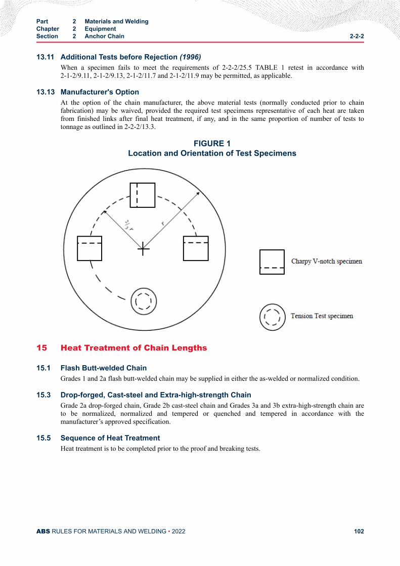
13.11 Additional Tests before Rejection (1996)When a specimen fails to meet the requirements of 2-2-2/25.5 TABLE 1 retest in accordance with2-1-2/9.11, 2-1-2/9.13, 2-1-2/11.7 and 2-1-2/11.9 may be permitted, as applicable.
13.13 Manufacturer's OptionAt the option of the chain manufacturer, the above material tests (normally conducted prior to chainfabrication) may be waived, provided the required test specimens representative of each heat are takenfrom finished links after final heat treatment, if any, and in the same proportion of number of tests totonnage as outlined in 2-2-2/13.3.
FIGURE 1Location and Orientation of Test Specimens
15 Heat Treatment of Chain Lengths
15.1 Flash Butt-welded ChainGrades 1 and 2a flash butt-welded chain may be supplied in either the as-welded or normalized condition.
15.3 Drop-forged, Cast-steel and Extra-high-strength ChainGrade 2a drop-forged chain, Grade 2b cast-steel chain and Grades 3a and 3b extra-high-strength chain areto be normalized, normalized and tempered or quenched and tempered in accordance with themanufacturer’s approved specification.
15.5 Sequence of Heat TreatmentHeat treatment is to be completed prior to the proof and breaking tests.
Part 2 Materials and WeldingChapter 2 EquipmentSection 2 Anchor Chain 2-2-2
ABS RULES FOR MATERIALS AND WELDING • 2022 102
17 Testing and Inspection of Chain Lengths
17.1 General (1996)All anchor chain is to be subjected to breaking and proof tests in the presence of a Surveyor. The Surveyoris to satisfy himself that the testing machines are maintained in a satisfactory and accurate condition and isto keep a record of the dates and by whom the machines were rechecked or calibrated. Prior to test andinspection, the chain is to be free from paint or other coating which would tend to conceal defects. Afterproof testing, links are to be carefully examined for workmanship, concentricity, distortion, studattachment, test grip damage, surface appearance and alignment of butt welds.
Provided their depth is not greater than 5% of the link diameter, surface discontinuities may be removed bygrinding and blending to a smooth contour. The cross sectional area in way of the grinding is to be not lessthan the theoretical area of nominal chain diameter. Links repaired by grinding are to be subjected tomagnetic particle or dye penetrant inspection.
17.3 Chain IdentificationEach shot is to be stamped with a distinctive mark in order to identify it through the several processes ofgauging, testing, measuring, examining, repairing and weighing, and in the event of the Surveyor being inattendance at the works while forged chains are being fabricated, which will ultimately be submitted fortesting, the break test specimens will be selected as far as possible during the process of fabrication.
17.5 Testing PrecautionsCare is to be taken that arrangements are made for each link to be tested at least once. The grippingarrangements are to be such that they do not put any stress on the end links of the portion under test, exceptsuch stress as is equally applied to every link tested.
17.7 Weighing of Tested ChainWhen chains have satisfactorily passed the requirements, they are to be weighed, together with theshackles forming the outfit, and this actual weight will be given on the certificate of test.
17.9 Testing of Used ChainWhen a chain, which has been in use, is submitted for testing or retesting, the size for testing purposes is tobe the original chain diameter. The certificate issued for such chain will include for descriptive purposesthe original chain diameter as well as the mean diameter of the part most worn, and will be marked, “Thischain is not new, and has been previously used’’.
19 Details of Tests on Chain Lengths
19.1 Breaking Test (2005)A break-test specimen consisting of at least three links is to be taken from the chain or produced at thesame time and the same way as the chain. Where produced separately, the specimen is to be securelyattached to the chain during any heat treatment. One specimen is to be taken from each four 27.5 m (15fathoms) lengths or less of flash butt-welded or drop-forged chain and one from each heat treatment batchwith a minimum of one from each four 27.5 m (15 fathoms) lengths or less of cast-steel chain. Eachspecimen is to be subjected to the applicable breaking load given in 2-2-2/27 TABLE 2 (stud-link chain).The breaking load test is to be carried out in the presence of the Surveyor and is to be maintained for aminimum of 30 seconds. A specimen will be considered to have successfully passed the test if there is nosign of fracture after application of the required load. Special attention is to be given to the visualinspection of the flash butt weld. Where the first test is not satisfactory, one more specimen may be cut outand subjected to the breaking load. If this test fails, the shot is to be rejected, and additional specimens areto be cut from each of the three remaining shots of 27.5 m (15 fathoms) or less and subjected to thebreaking load. In such cases, each shot from which the satisfactory break specimens have been taken is to
Part 2 Materials and WeldingChapter 2 EquipmentSection 2 Anchor Chain 2-2-2
ABS RULES FOR MATERIALS AND WELDING • 2022 103
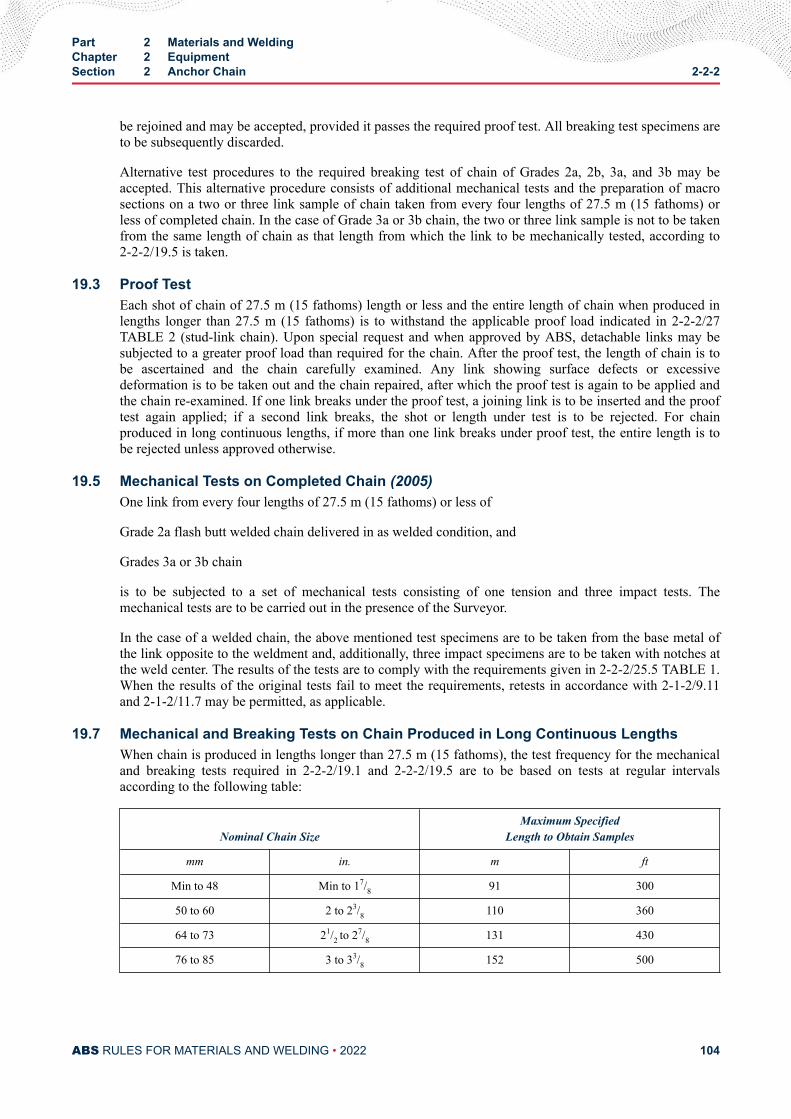
be rejoined and may be accepted, provided it passes the required proof test. All breaking test specimens areto be subsequently discarded.
Alternative test procedures to the required breaking test of chain of Grades 2a, 2b, 3a, and 3b may beaccepted. This alternative procedure consists of additional mechanical tests and the preparation of macrosections on a two or three link sample of chain taken from every four lengths of 27.5 m (15 fathoms) orless of completed chain. In the case of Grade 3a or 3b chain, the two or three link sample is not to be takenfrom the same length of chain as that length from which the link to be mechanically tested, according to2-2-2/19.5 is taken.
19.3 Proof TestEach shot of chain of 27.5 m (15 fathoms) length or less and the entire length of chain when produced inlengths longer than 27.5 m (15 fathoms) is to withstand the applicable proof load indicated in 2-2-2/27TABLE 2 (stud-link chain). Upon special request and when approved by ABS, detachable links may besubjected to a greater proof load than required for the chain. After the proof test, the length of chain is tobe ascertained and the chain carefully examined. Any link showing surface defects or excessivedeformation is to be taken out and the chain repaired, after which the proof test is again to be applied andthe chain re-examined. If one link breaks under the proof test, a joining link is to be inserted and the prooftest again applied; if a second link breaks, the shot or length under test is to be rejected. For chainproduced in long continuous lengths, if more than one link breaks under proof test, the entire length is tobe rejected unless approved otherwise.
19.5 Mechanical Tests on Completed Chain (2005)One link from every four lengths of 27.5 m (15 fathoms) or less of
Grade 2a flash butt welded chain delivered in as welded condition, and
Grades 3a or 3b chain
is to be subjected to a set of mechanical tests consisting of one tension and three impact tests. Themechanical tests are to be carried out in the presence of the Surveyor.
In the case of a welded chain, the above mentioned test specimens are to be taken from the base metal ofthe link opposite to the weldment and, additionally, three impact specimens are to be taken with notches atthe weld center. The results of the tests are to comply with the requirements given in 2-2-2/25.5 TABLE 1.When the results of the original tests fail to meet the requirements, retests in accordance with 2-1-2/9.11and 2-1-2/11.7 may be permitted, as applicable.
19.7 Mechanical and Breaking Tests on Chain Produced in Long Continuous LengthsWhen chain is produced in lengths longer than 27.5 m (15 fathoms), the test frequency for the mechanicaland breaking tests required in 2-2-2/19.1 and 2-2-2/19.5 are to be based on tests at regular intervalsaccording to the following table:
Nominal Chain SizeMaximum Specified
Length to Obtain Samples
mm in. m ft
Min to 48 Min to 17/8 91 300
50 to 60 2 to 23/8 110 360
64 to 73 21/2 to 27/8 131 430
76 to 85 3 to 33/8 152 500
Part 2 Materials and WeldingChapter 2 EquipmentSection 2 Anchor Chain 2-2-2
ABS RULES FOR MATERIALS AND WELDING • 2022 104
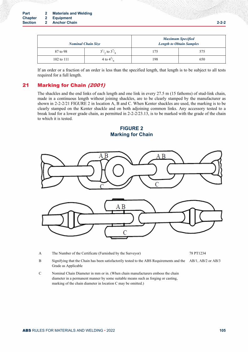
Nominal Chain SizeMaximum Specified
Length to Obtain Samples
87 to 98 31/2 to 37/8 175 575
102 to 111 4 to 43/8 198 650
If an order or a fraction of an order is less than the specified length, that length is to be subject to all testsrequired for a full length.
21 Marking for Chain (2001)The shackles and the end links of each length and one link in every 27.5 m (15 fathoms) of stud-link chain,made in a continuous length without joining shackles, are to be clearly stamped by the manufacturer asshown in 2-2-2/21 FIGURE 2 in location A, B and C. When Kenter shackles are used, the marking is to beclearly stamped on the Kenter shackle and on both adjoining common links. Any accessory tested to abreak load for a lower grade chain, as permitted in 2-2-2/23.13, is to be marked with the grade of the chainto which it is tested.
FIGURE 2Marking for Chain
A The Number of the Certificate (Furnished by the Surveyor) 78 PT1234
B Signifying that the Chain has been satisfactorily tested to the ABS Requirements and theGrade as Applicable
AB/1, AB/2 or AB/3
C Nominal Chain Diameter in mm or in. (When chain manufacturers emboss the chaindiameter in a permanent manner by some suitable means such as forging or casting,marking of the chain diameter in location C may be omitted.)
Part 2 Materials and WeldingChapter 2 EquipmentSection 2 Anchor Chain 2-2-2
ABS RULES FOR MATERIALS AND WELDING • 2022 105
23 Anchor Chain Accessories
23.1 Dimensions and Dimensional Tolerances (1996)The dimensions of anchor chain accessories are to be in accordance with a recognized standard such asISO 1704. The following tolerances are applicable to anchor chain accessories.
nominal diameter : +5%, -0%
other dimensions : ±2.5%
23.2 Locking Pins in Accessories (2020)Locking pins in detachable connecting links are to have taper contact at both top and bottom in the linkhalves. Acceptable material is to be used for plugging the locking pin hole, which is to contain anappropriate undercut recess or equivalent arrangement to secure the plug.
23.3 Material TestingTest specimens are to be taken either from finished accessories, or from special test bars indicated in2-2-2/23.5 and 2-2-2/23.7. In all cases the specimens are to be taken from pieces representing the largestdiameter accessory in the lot. A lot is defined as the accessories of the same grade, made from the sameheat of steel and heat treated in the same furnace charge where the diameter does not differ by more than25 mm (1 in.). Test results are to comply with 2-2-2/25.5 TABLE 1 or such other specification as may bespecially approved. When the results of original tests fail to meet the requirements, retests in accordancewith 2-1-2/9.11 and 2-1-2/11.7 may be permitted, as applicable.
23.5 Cast AccessoriesTest specimens may be taken from integrally or separately cast test blocks, heat-treated together with theaccessories represented.
23.7 Forged AccessoriesTest specimens may be taken from a special forging, representative of the accessories in the lot. In suchcases, the special forging is to be subjected to approximately the same amount of working and reduction asthe forging represented, and is to be heat-treated with the forgings represented.
23.9 InspectionAll accessories are to be inspected by magnetic particle or other suitable method to assure freedom frominjurious surface defects. Special attention is to be given to welds.
23.11 Hardness TestAll accessories are to be subjected to a Brinell hardness test to meet the following:
GradeBrinell Hardness Number Minimum
10 mm ball, 3000 kg load
123
120145207
23.13 Break Test (2001)Break tests are to be made on 1 out of 25 accessories (or 1 out of 50 in the case of Kenter shackles),representative of the same type, grade and heat treatment procedure, but not necessarily representative ofeach heat of steel, heat treatment charge or individual purchase order. When the range of Brinell hardnessreadings of these accessories in the batch exceed 30 Brinell hardness numbers, the accessories represented
Part 2 Materials and WeldingChapter 2 EquipmentSection 2 Anchor Chain 2-2-2
ABS RULES FOR MATERIALS AND WELDING • 2022 106
by the lowest and highest Brinell hardness readings are to be tested. This requirement may be waived whenthe range of properties represented by the Brinell hardness numbers is established to the satisfaction of theSurveyor. For accessories from the same lot (see 2-2-2/23.3), the Surveyor may reduce the number ofbreak tests to a minimum of two per lot. All parts of the accessory subjected to a break test required by thissubparagraph are to be subsequently discarded, except where further use is permitted by 2-2-2/23.13.1below.
23.13.1 Use of Break Tested Parts (2001)Where it is demonstrated by either one of the following methods that the accessories canwithstand at least 140% of the breaking test load prescribed in 2-2-2/27 TABLE 2 for the chain inwhich they are intended, such accessories may be used in service provided:
23.13.1(a) the materialof the accessories is of higher grade than the chain (e.g., grade 3accessories of grade 2 size in grade 2 chain), or
23.13.1(b) where an accessory of increased dimension is specially approved for the particularapplication and a procedure test is completed at 140% of the 2-2-2/27 TABLE 2 break test load.All parts of the accessories used in this procedure test are to be subsequently discarded.
In either case, each accessory requiring a break test is to be tested to 100% of the 2-2-2/27 TABLE2 break load for the chain in which it is intended to be used.
23.15 Proof TestsEach accessory is to be subjected to a proof test in accordance with 2-2-2/19.3.
23.17 MarkingsThe certificate number, AB/Chain Grade, and nominal chain diameter are to be steel die stamped oneach accessory. The stamping of the nominal chain diameter may be omitted provided the nominal chaindiameter is cast or forged into the accessory. Markings are to be located in such a manner as to be readilyvisible when completely assembled together with the chain.
25 Unstudded Short-link Chain
25.1 GeneralUnstudded short-link chain is to meet the requirements specified in 2-2-2/3 and 2-2-2/11. Material is to bein accordance with the manufacturer's specification which is to be the equivalent of normal strength Grade1 requirements of 2-2-2/25.5 TABLE 1.
25.3 TestingBreaking and proof testing are to be in accordance with 2-2-2/19 and subjected to the applicable testingloads as given in 2-2-2/27 TABLE 3.
25.5 MarkingOne link including the end link in every 4.5 m 1(2.5 fathoms) is to be steel die stamped as prescribed inlocations A, B and C by the manufacturer as shown in 2-2-2/13.13 FIGURE 1. In special cases, shots ofcomparatively small size may be marked or stenciled in lieu of die stamping or the markings may beshown on a metal tag attached at every 4.5 m (2.5 fathoms).
Part 2 Materials and WeldingChapter 2 EquipmentSection 2 Anchor Chain 2-2-2
ABS RULES FOR MATERIALS AND WELDING • 2022 107
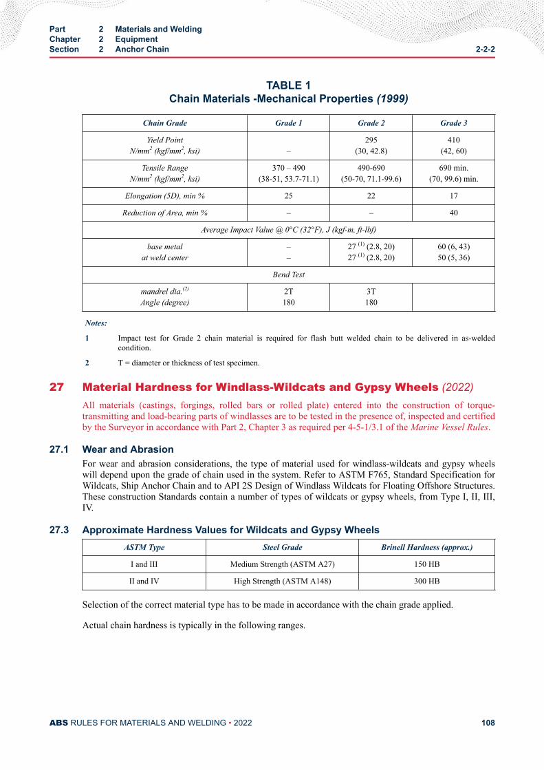
TABLE 1Chain Materials -Mechanical Properties (1999)
Chain Grade Grade 1 Grade 2 Grade 3
Yield PointN/mm2 (kgf/mm2, ksi) –
295(30, 42.8)
410(42, 60)
Tensile RangeN/mm2 (kgf/mm2, ksi)
370 – 490(38-51, 53.7-71.1)
490-690(50-70, 71.1-99.6)
690 min.(70, 99.6) min.
Elongation (5D), min % 25 22 17
Reduction of Area, min % – – 40
Average Impact Value @ 0°C (32°F), J (kgf-m, ft-lbf)
base metalat weld center
––
27 (1) (2.8, 20)27 (1) (2.8, 20)
60 (6, 43)50 (5, 36)
Bend Test
mandrel dia.(2)
Angle (degree)2T180
3T180
Notes:
1 Impact test for Grade 2 chain material is required for flash butt welded chain to be delivered in as-weldedcondition.
2 T = diameter or thickness of test specimen.
27 Material Hardness for Windlass-Wildcats and Gypsy Wheels (2022)All materials (castings, forgings, rolled bars or rolled plate) entered into the construction of torque-transmitting and load-bearing parts of windlasses are to be tested in the presence of, inspected and certifiedby the Surveyor in accordance with Part 2, Chapter 3 as required per 4-5-1/3.1 of the Marine Vessel Rules.
27.1 Wear and AbrasionFor wear and abrasion considerations, the type of material used for windlass-wildcats and gypsy wheelswill depend upon the grade of chain used in the system. Refer to ASTM F765, Standard Specification forWildcats, Ship Anchor Chain and to API 2S Design of Windlass Wildcats for Floating Offshore Structures.These construction Standards contain a number of types of wildcats or gypsy wheels, from Type I, II, III,IV.
27.3 Approximate Hardness Values for Wildcats and Gypsy WheelsASTM Type Steel Grade Brinell Hardness (approx.)
I and III Medium Strength (ASTM A27) 150 HB
II and IV High Strength (ASTM A148) 300 HB
Selection of the correct material type has to be made in accordance with the chain grade applied.
Actual chain hardness is typically in the following ranges.
Part 2 Materials and WeldingChapter 2 EquipmentSection 2 Anchor Chain 2-2-2
ABS RULES FOR MATERIALS AND WELDING • 2022 108
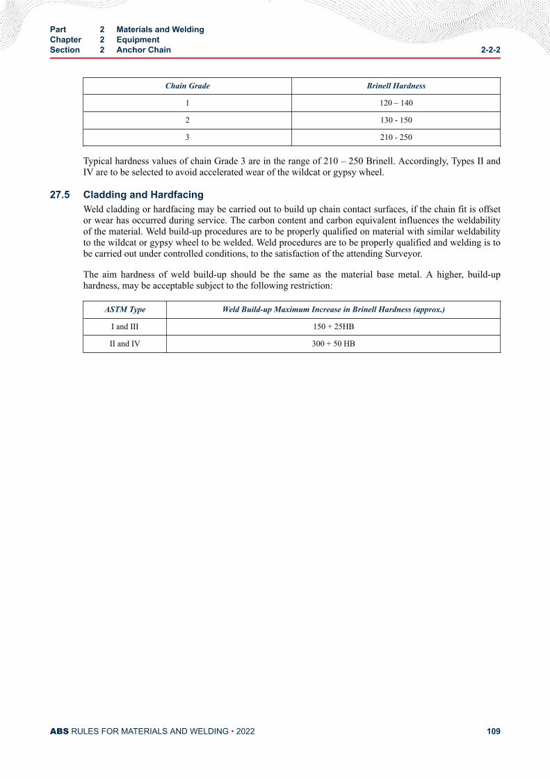
Chain Grade Brinell Hardness
1 120 – 140
2 130 - 150
3 210 - 250
Typical hardness values of chain Grade 3 are in the range of 210 – 250 Brinell. Accordingly, Types II andIV are to be selected to avoid accelerated wear of the wildcat or gypsy wheel.
27.5 Cladding and HardfacingWeld cladding or hardfacing may be carried out to build up chain contact surfaces, if the chain fit is offsetor wear has occurred during service. The carbon content and carbon equivalent influences the weldabilityof the material. Weld build-up procedures are to be properly qualified on material with similar weldabilityto the wildcat or gypsy wheel to be welded. Weld procedures are to be properly qualified and welding is tobe carried out under controlled conditions, to the satisfaction of the attending Surveyor.
The aim hardness of weld build-up should be the same as the material base metal. A higher, build-uphardness, may be acceptable subject to the following restriction:
ASTM Type Weld Build-up Maximum Increase in Brinell Hardness (approx.)
I and III 150 + 25HB
II and IV 300 + 50 HB
Part 2 Materials and WeldingChapter 2 EquipmentSection 2 Anchor Chain 2-2-2
ABS RULES FOR MATERIALS AND WELDING • 2022 109
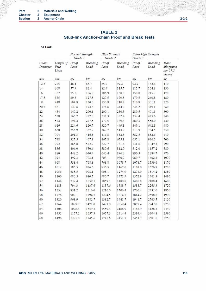
TABLE 2 Stud-link Anchor-chain Proof and Break Tests
Part 2 Materials and WeldingChapter 2 EquipmentSection 2 Anchor Chain 2-2-2
ABS RULES FOR MATERIALS AND WELDING • 2022 110
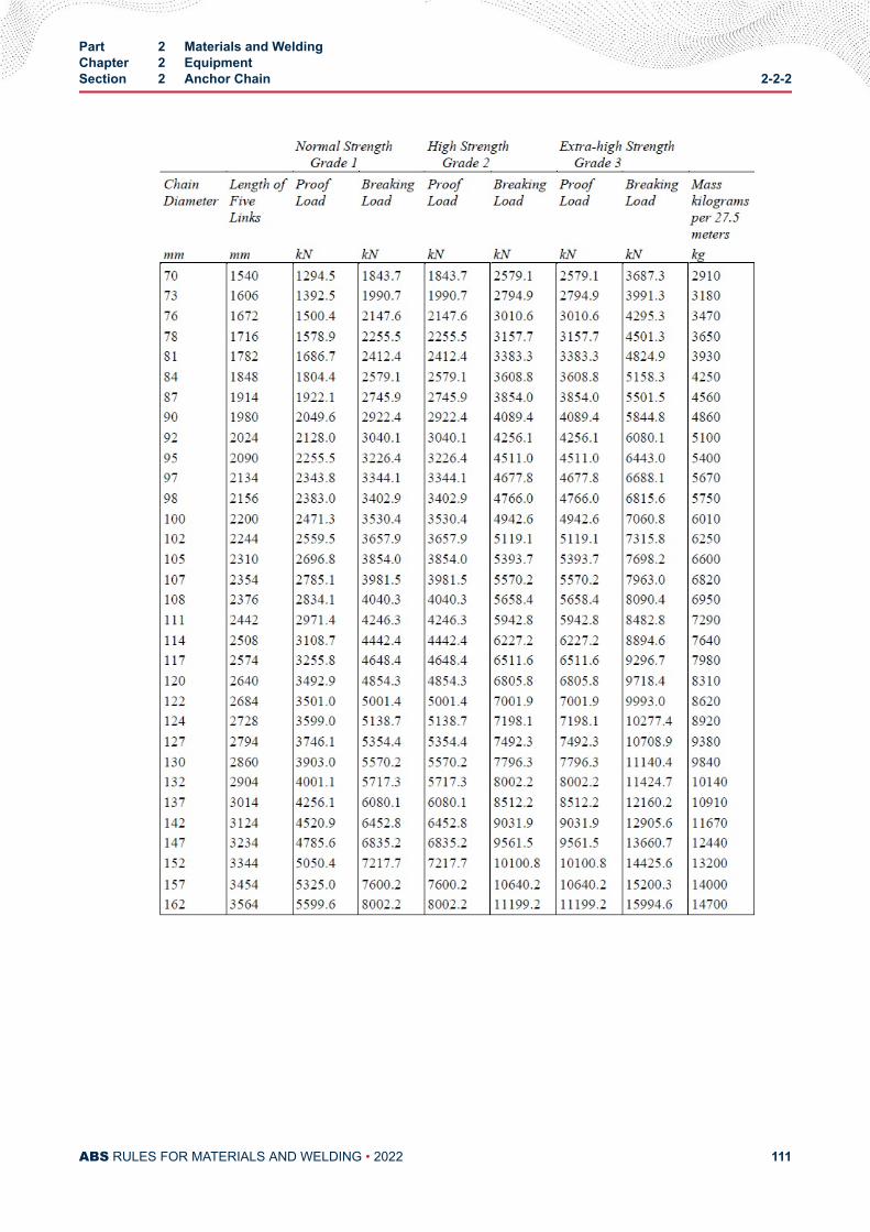
Part 2 Materials and WeldingChapter 2 EquipmentSection 2 Anchor Chain 2-2-2
ABS RULES FOR MATERIALS AND WELDING • 2022 111
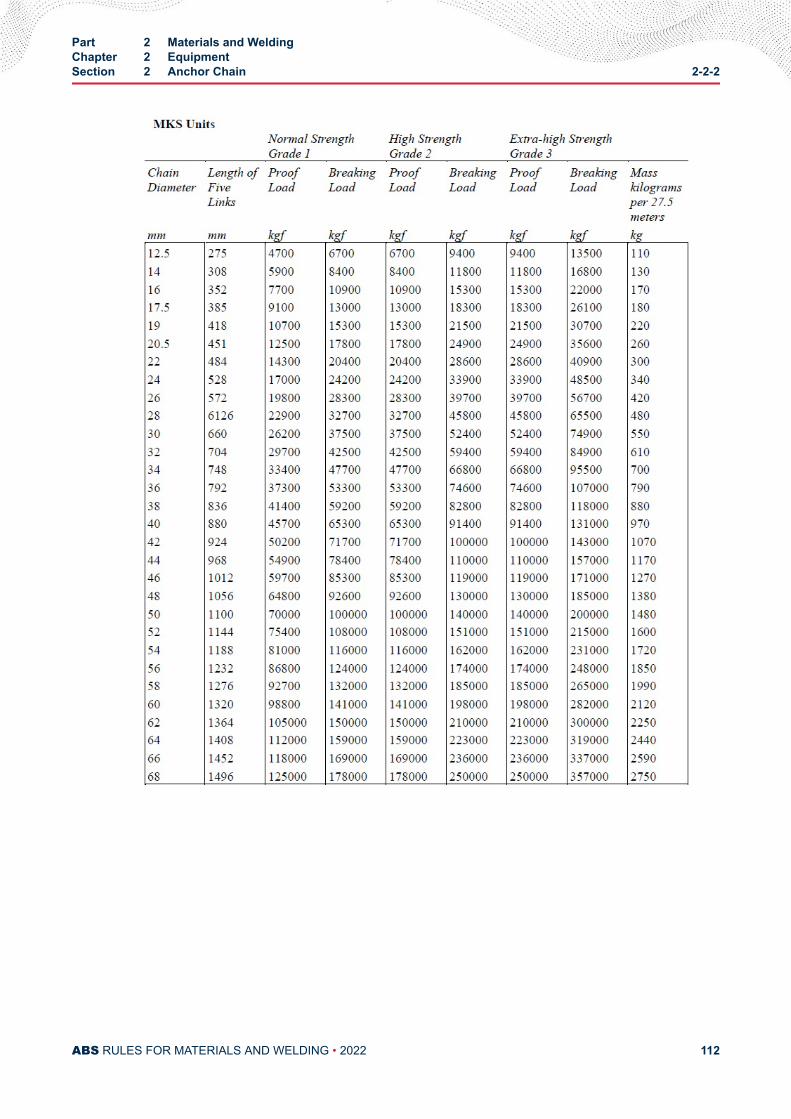
Part 2 Materials and WeldingChapter 2 EquipmentSection 2 Anchor Chain 2-2-2
ABS RULES FOR MATERIALS AND WELDING • 2022 112
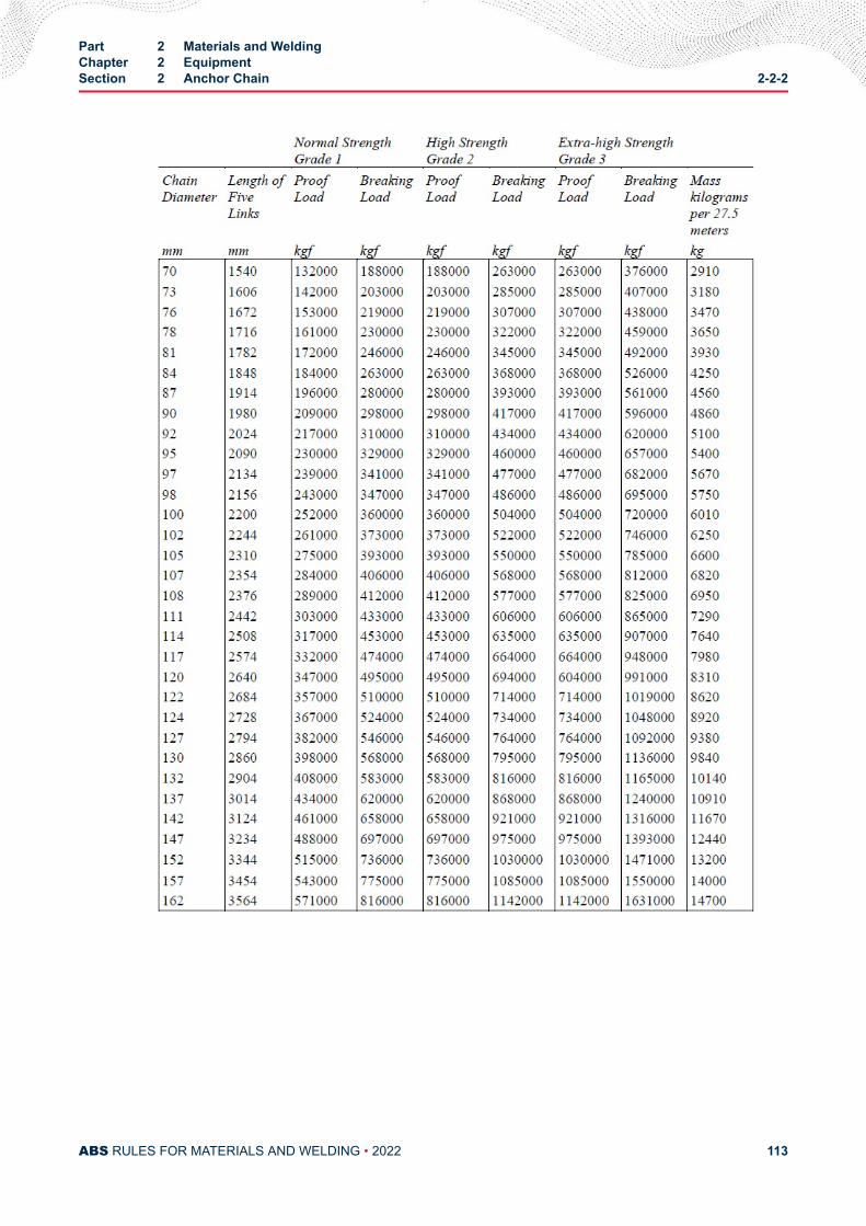
Part 2 Materials and WeldingChapter 2 EquipmentSection 2 Anchor Chain 2-2-2
ABS RULES FOR MATERIALS AND WELDING • 2022 113
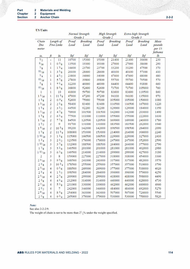
Note:See also 2-2-2/9.The weight of chain is not to be more than 21/2% under the weight specified.
Part 2 Materials and WeldingChapter 2 EquipmentSection 2 Anchor Chain 2-2-2
ABS RULES FOR MATERIALS AND WELDING • 2022 114
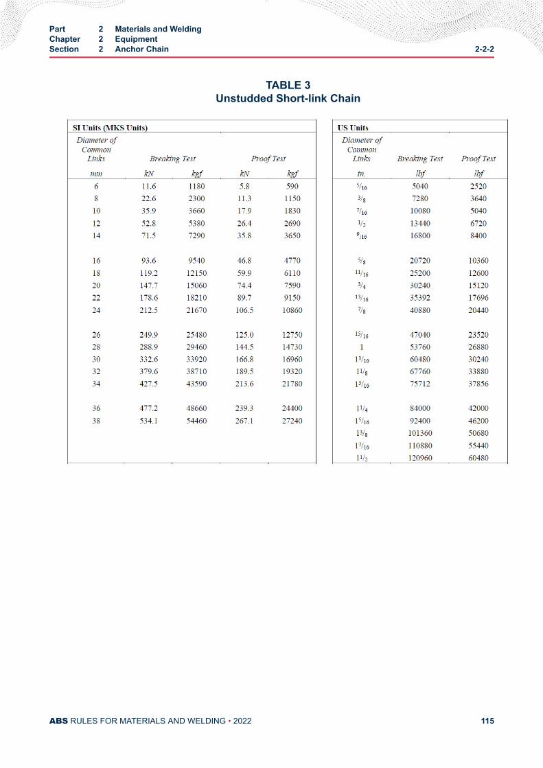
TABLE 3Unstudded Short-link Chain
Part 2 Materials and WeldingChapter 2 EquipmentSection 2 Anchor Chain 2-2-2
ABS RULES FOR MATERIALS AND WELDING • 2022 115
C H A P T E R 2Equipment
S E C T I O N 3Rolled Steel Bars for Chain, Cast and Forged Materials for Accessories
and Materials for Studs
1 General (2005)Rolled steel bars Grades U1, U2 or U3 for Grade 1, 2 or 3 chains, cast and forged materials for accessoriesand materials for studs are to be in accordance with this section. Bars for offshore mooring chains are to bein accordance with the ABS Guide for the Certification of Offshore Mooring Chain.
These Rules are not intended to replace or modify any part of a chain manufacturer’s specificationapproved by ABS.
1.1 Process and Qualification of Manufacture (2012)The manufacturers of materials for anchor chain and accessories are to be approved. Approval is notrequired for Grade 1 bars. The bar manufacturers are to submit the manufacturing specifications and thedetails of the manufacturing procedure. The approval tests are to be carried out in accordance with Section2-A4-2, the scope of which is to be agreed with ABS.
The steel is to be made by the open-hearth, basic oxygen, vacuum-arc remelt, electro-slag remelt electric-furnace or such other process as may be specially approved.
Unless otherwise stipulated, the steel bars are to be supplied in the as rolled condition.
1.3 Deoxidation PracticeBars are to be fully killed and, in addition, Grade U2 or U3 bars are to be produced to a fine grain practice.
1.5 Chemical Composition and Heat Treatment (1999)The chemical composition and heat treatment are to be in accordance with the manufacturer’s specificationthat is to be approved by ABS. In general, they are to conform to 2-2-3/3 TABLE 1.
1.7 Mechanical Properties (1999)Mechanical tests are to be carried out in accordance with 2-2-3/3 and the results are to meet therequirements in 2-2-2/25.5 TABLE 1.
PART 2
ABS RULES FOR MATERIALS AND WELDING • 2022 116
1.9 Dimensional properties (1999)Unless otherwise approved, the tolerances on diameter and roundness (dmax – dmin) are to be within thelimits listed in 2-2-3/3 TABLE 2, where dmax and dmin are the maximum and minimum diameter measured atthe section under consideration.
3 Material Testing
3.1 Heat Treatment of Test SpecimensTest specimens are to be taken from material heat-treated in the same manner as intended for the finishedchain.
3.3 Number of TestsOne tensile and three impact test specimens are to be taken from two different bars of steel from each heatunless the material from a heat is less than 50 metric tons (49.21 long tons), in which case, tests from onebar will be sufficient. If, however, the material from one heat differs 9.5 mm (0.375 in.) or more indiameter, one set of tests is to be taken from the thinnest and thickest material rolled.
3.5 Tension Test Specimens (1996)Tension test specimens for bar material are to be taken at 2 3r as shown in 2-2-2/13.13 FIGURE 1 or asclose thereto as possible and machined to 2-1-1/16 FIGURE 2 or appropriate national standard specimen.
The required minimum percentage elongation values in 2-2-2/25.5 TABLE 1 are based on specimenshaving gauge lengths equal to 5 times the diameter. For specimens having other gauge lengths theequivalent elongation value is to be calculated by the following equation:n = 2E( A/L)0 . 4wheren = equivalent minimum elongationA = actual cross-sectional area of the specimenL = actual gauge lengthE = specified minimum percentage elongation for specimens having a gauge length of 5 times the
diameter
The above equation is not applicable to quenched and tempered steel, for which the specimen is to have agauge length of five (5) times the specimen diameter.
3.7 Bend Test SpecimensBend test specimens may be either the full section of the bar or may be machined at the option of themanufacturer to a 25 mm (1 in.) diameter or to a rectangular cross section of 25 mm × 12.5 mm (1 in. × 0.5in.), but not less than 12.5 mm × 12.5 mm (0.5 in. × 0.5 in.). Each specimen is to withstand, withoutfracture, cold bending around a mandrel diameter and through the angle specified in 2-2-2/25.5 TABLE 1.
3.9 Impact Test SpecimensImpact test specimens are to be in accordance with 2-1-1/11.11. They are to be cut and notched as shownin 2-2-2/13.13 FIGURE 1. The average value of 3 specimens is to comply with the requirements of2-2-2/25.5 TABLE 1.
Part 2 Materials and WeldingChapter 2 EquipmentSection 3 Rolled Steel Bars for Chain, Cast and Forged Materials for Accessories and Materials
for Studs2-2-3
ABS RULES FOR MATERIALS AND WELDING • 2022 117
3.11 Additional Tests before Rejection(1996)When a specimen fails to meet the requirements of 2-2-2/25.5 TABLE 1 retests in accordance with2-1-2/9.11, 2-1-2/9.13, 2-1-2/11.7 and 2-1-2/11.9 may be permitted, as applicable.
3.13 Manufacturer's OptionAt the option of the chain manufacturer, the above material tests (normally conducted prior to chainfabrication) may be waived, provided the required test specimens representative of each heat are takenfrom finished links after final heat treatment, if any, and in the same proportion of number of tests totonnage as outlined in 2-2-2/13.3.
3.15 Freedom from Defects (2005)The materials are to be free from internal and surface defects that might impair proper workability and use.Surface defects may be repaired by grinding, provided the admissible tolerance is not exceeded.
3.17 Identification of Material (2005)Manufacturers are to effectively operate an identification system ensuring traceability of the material to theoriginal cast.
3.19 Marking (2005)The minimum markings required for the steel bars are the manufacturer’s brandmark, the steel grade andan abbreviated symbol of the heat. Steel bars having diameters up to and including 40 mm (1.6 in.) andcombined into bundles may be marked on permanently affixed labels.
3.21 Material Certification (2005)Bar material for Grade 2 or Grade 3 is to be certified by ABS. For each consignment, manufacturers shallforward to the Surveyor a certificate containing at least the following data:
● Manufacturer’s name and/or purchaser’s order No.
● Number and dimensions of bars and weight of consignment
● Steel specification and chain grade
● Heat number
● Manufacturing procedure
● Chemical composition
● Details of heat treatment of the test sample (where applicable)
● Results of mechanical tests (where applicable)
● Number of test specimens (where applicable)
3.23 Forged Steels for Chain Cables and Accessories (2005)Forged steels used for the manufacture of chain cables and accessories are to be in compliance withSection 2-1-6 “Hull Steel Forgings”, unless otherwise specified in the following paragraphs.
The chemical composition is to comply with the specification approved by ABS. The steel manufacturermust determine and certify the chemical composition of every heat of material.
The stock material may be supplied in the as-rolled condition. Finished forgings are to be properly heattreated, i.e., normalized, normalized and tempered or quenched and tempered, whichever is specified forthe relevant grade of chain.
Part 2 Materials and WeldingChapter 2 EquipmentSection 3 Rolled Steel Bars for Chain, Cast and Forged Materials for Accessories and Materials
for Studs2-2-3
ABS RULES FOR MATERIALS AND WELDING • 2022 118
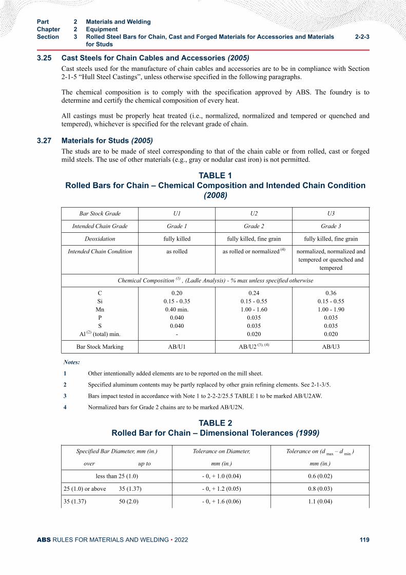
3.25 Cast Steels for Chain Cables and Accessories (2005)Cast steels used for the manufacture of chain cables and accessories are to be in compliance with Section2-1-5 “Hull Steel Castings”, unless otherwise specified in the following paragraphs.
The chemical composition is to comply with the specification approved by ABS. The foundry is todetermine and certify the chemical composition of every heat.
All castings must be properly heat treated (i.e., normalized, normalized and tempered or quenched andtempered), whichever is specified for the relevant grade of chain.
3.27 Materials for Studs (2005)The studs are to be made of steel corresponding to that of the chain cable or from rolled, cast or forgedmild steels. The use of other materials (e.g., gray or nodular cast iron) is not permitted.
TABLE 1Rolled Bars for Chain – Chemical Composition and Intended Chain Condition
(2008)
Bar Stock Grade U1 U2 U3
Intended Chain Grade Grade 1 Grade 2 Grade 3
Deoxidation fully killed fully killed, fine grain fully killed, fine grain
Intended Chain Condition as rolled as rolled or normalized (4) normalized, normalized andtempered or quenched and
tempered
Chemical Composition (1) , (Ladle Analysis) - % max unless specified otherwise
CSi
MnPS
Al (2) (total) min.
0.200.15 - 0.350.40 min.
0.0400.040
-
0.240.15 - 0.551.00 - 1.60
0.0350.0350.020
0.360.15 - 0.551.00 - 1.90
0.0350.0350.020
Bar Stock Marking AB/U1 AB/U2 (3), (4) AB/U3
Notes:
1 Other intentionally added elements are to be reported on the mill sheet.
2 Specified aluminum contents may be partly replaced by other grain refining elements. See 2-1-3/5.
3 Bars impact tested in accordance with Note 1 to 2-2-2/25.5 TABLE 1 to be marked AB/U2AW.
4 Normalized bars for Grade 2 chains are to be marked AB/U2N.
TABLE 2Rolled Bar for Chain – Dimensional Tolerances (1999)
Specified Bar Diameter, mm (in.) Tolerance on Diameter, Tolerance on (d max – d min )
over up to mm (in.) mm (in.)
less than 25 (1.0) - 0, + 1.0 (0.04) 0.6 (0.02)
25 (1.0) or above 35 (1.37) - 0, + 1.2 (0.05) 0.8 (0.03)
35 (1.37) 50 (2.0) - 0, + 1.6 (0.06) 1.1 (0.04)
Part 2 Materials and WeldingChapter 2 EquipmentSection 3 Rolled Steel Bars for Chain, Cast and Forged Materials for Accessories and Materials
for Studs2-2-3
ABS RULES FOR MATERIALS AND WELDING • 2022 119
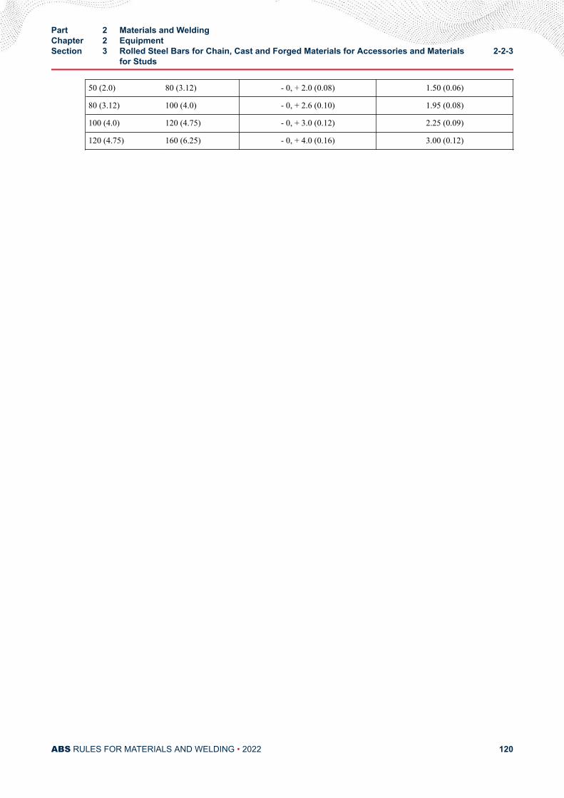
50 (2.0) 80 (3.12) - 0, + 2.0 (0.08) 1.50 (0.06)
80 (3.12) 100 (4.0) - 0, + 2.6 (0.10) 1.95 (0.08)
100 (4.0) 120 (4.75) - 0, + 3.0 (0.12) 2.25 (0.09)
120 (4.75) 160 (6.25) - 0, + 4.0 (0.16) 3.00 (0.12)
Part 2 Materials and WeldingChapter 2 EquipmentSection 3 Rolled Steel Bars for Chain, Cast and Forged Materials for Accessories and Materials
for Studs2-2-3
ABS RULES FOR MATERIALS AND WELDING • 2022 120
C H A P T E R 3Materials for Machinery, Boilers, Pressure Vessels, and Piping
CONTENTSSECTION 1 General Requirements.....................................................................138
1 Testing and Inspection................................................................1381.1 General (2007)...............................................................1381.3 Test and Test Data......................................................... 1381.5 Rejection of Previously Accepted Material.................... 1381.7 Calibrated Testing Machines (2005).............................. 1391.9 ASTM References......................................................... 139
3 Defects........................................................................................1395 Identification of Materials............................................................1397 Manufacturer's Certificates......................................................... 139
7.1 Form of Certificate......................................................... 1397.3 Other Certificates...........................................................139
9 Marking and Retests...................................................................1409.1 Identification of Test Specimens.................................... 1409.3 Defects in Specimens.................................................... 1409.5 Retests (2005)............................................................... 1409.7 Rejected Material...........................................................140
11 Standard Test Specimens...........................................................14011.1 General.......................................................................... 14011.3 Test Specimens (2005).................................................. 14011.5 Tension Test Specimens for Plates and Shapes............14011.7 Tension Test Specimens for Castings (Other than
Gray Cast Iron) and Forgings (2006).............................14111.9 Tension Test Specimens (for Gray Cast Iron) (2006).....14111.11 Transverse or Flexure Test Specimens for Gray Cast
Iron (2006)..................................................................... 14111.13 Bend Test Specimens for Steel Castings and
Forgings (2005)............................................................. 14113 Definition and Determination of Yield Point and Yield Strength..143
13.1 Yield Point (2005).......................................................... 14313.3 Yield Strength (2005).....................................................14313.5 Tensile Strength (2005)..................................................143
PART 2
ABS RULES FOR MATERIALS AND WELDING • 2022 121
15 Permissible Variations in Dimensions (1994)............................. 14415.1 Scope.............................................................................14415.3 Plates.............................................................................144
FIGURE 1 Standard Tension Test Specimen (1)(2006)........................ 141FIGURE 2 Standard Round Tension Test Specimen with 50 mm (2
in.) Gauge Length (2008)...................................................142FIGURE 3 Tension Test Specimen Machined from Transverse or
Flexure Test Bars for Gray Cast Iron (2006)...................... 143FIGURE 4 Locations for Checking Thickness Tolerance and
Average Thickness (1,2,3) (2014)..........................................146
SECTION 2 Steel Plates for Machinery, Boilers and Pressure Vessels.......... 1491 General Requirements for All Grades of Steel Plates for
Machinery, Boilers, and Pressure Vessels .................................1491.1 General.......................................................................... 1491.2 Manufacturer Approval.................................................. 1491.3 Marking.......................................................................... 1491.5 Process of Manufacture.................................................1501.7 Chemical Composition...................................................1501.9 Test Specimens............................................................. 1501.11 Tensile Properties.......................................................... 1511.13 Retests...........................................................................1511.15 Thickness Variation........................................................1521.17 Finish............................................................................. 1521.19 Weldability..................................................................... 152
3 Steel Plates for Intermediate-temperature Service ....................1523.1 Scope.............................................................................1523.3 General.......................................................................... 1523.5 Chemical Composition...................................................1523.7 Specimen Preparation................................................... 1533.9 Tensile Properties.......................................................... 153
5 Steel Plates for Intermediate- and Higher-temperature Service 1535.1 Scope.............................................................................1535.3 General.......................................................................... 1535.5 Heat Treatment..............................................................1535.7 Chemical Composition...................................................1545.9 Test Specimens............................................................. 1545.11 Tensile Properties.......................................................... 154
7 Steel Plates for Intermediate- and Lower-temperature Service .1547.1 Scope.............................................................................1547.3 General.......................................................................... 1547.5 Heat Treatment..............................................................1547.7 Chemical Composition...................................................155
ABS RULES FOR MATERIALS AND WELDING • 2022 122
7.9 Test Specimens............................................................. 1557.11 Tensile Properties.......................................................... 155
9 Materials for Low Temperature Service [Below - 18°C (0°F)] .... 155
TABLE 1 Chemical Composition for Plate Grades MD, ME, MF,MG, H, I, J..........................................................................155
TABLE 2 Tensile Properties for Plate Grades MD, ME, MF, MG,H, I, J..................................................................................156
TABLE 3 Chemical Composition for Plate Grades K, L, M, N...........157TABLE 4 Tensile Properties for Plate Grades K, L, M, N.................. 158
SECTION 3 Seamless Forged-steel Drums....................................................... 1591 Tests and Inspections ................................................................ 1593 Heat Treatment ..........................................................................159
SECTION 4 Seamless-steel Pressure Vessels.................................................. 1601 General ......................................................................................1603 Tension Test ...............................................................................1605 Flattening Test ........................................................................... 1607 Hydrostatic Test ......................................................................... 1609 Inspection .................................................................................. 16011 Marking ......................................................................................160
SECTION 5 Boiler and Superheater Tubes........................................................ 1611 Scope (1998) ............................................................................. 1613 General ......................................................................................161
3.1 Grades D and F............................................................. 1613.3 Grade G......................................................................... 1613.5 Grade H......................................................................... 1613.7 Grade J.......................................................................... 1613.9 Grades K, L and M.........................................................1613.11 Grades N, O and P........................................................ 1613.13 Grades R and S (1998)..................................................1613.15 ASTM Designation (1998)............................................. 162
5 Process of Manufacture .............................................................1625.1 Grades D, F, and G........................................................1625.3 Grades H, J, K, L, and M (1998)....................................1625.5 Grades N, O, and P (1998)............................................1625.7 Grades R and S (1998)..................................................163
7 Marking (1998)............................................................................1639 Chemical Composition - Ladle Analysis .................................... 16311 Check Analysis .......................................................................... 163
11.1 General (1998)...............................................................163
ABS RULES FOR MATERIALS AND WELDING • 2022 123
11.3 Samples.........................................................................16311.5 Grades D, F, G, and H................................................... 16311.7 Grades J, K, L, M, N, O, P, R, and S (1998).................. 16411.9 Retests for Seamless Tubes (1998).............................. 16411.11 Retests for Electric-resistance-welded Tubes................164
13 Mechanical Tests Required ........................................................16415 Test Specimens ......................................................................... 164
15.1 Selection of Specimens (1998)......................................16415.3 Tension Test Specimens................................................ 16415.5 Testing Temperature...................................................... 164
17 Tensile Properties ...................................................................... 16419 Flattening Test ........................................................................... 164
19.1 Seamless and Electric-resistance-welded Tubes(1998)............................................................................ 164
19.3 Electric-resistance-welded Tubes..................................16521 Reverse Flattening Test .............................................................16523 Flange Test ................................................................................ 16525 Flaring Test (1998) .....................................................................16627 Crush Test ..................................................................................16629 Hardness Tests ..........................................................................166
29.1 Type of Test (1998)........................................................ 16629.3 Brinell Hardness Test.....................................................16629.5 Rockwell Hardness Test................................................ 16729.7 Tubes with Formed Ends...............................................16729.9 Maximum Permissible Hardness (1998)........................167
31 Hydrostatic Test ......................................................................... 16731.1 General.......................................................................... 16731.3 Maximum Hydrostatic Test Pressure............................. 16731.5 Duration of Test..............................................................16831.7 Alternate Tests............................................................... 16831.9 Rejection........................................................................168
33 Nondestructive Electric Test (NDET) (1998)...............................16833.1 General.......................................................................... 16833.3 Ultrasonic Calibration Standards................................... 16833.5 Eddy-current Calibration Standards...............................16833.7 Flux Leakage Calibration Standards..............................16933.9 Rejection........................................................................16933.11 Affidavits........................................................................ 169
35 Retests (1998)............................................................................ 16937 Finish (2008)...............................................................................16939 Permissible Variations in Dimensions (1998)............................. 170
39.1 Wall Thickness...............................................................17039.3 Outside Diameter...........................................................170
ABS RULES FOR MATERIALS AND WELDING • 2022 124
TABLE 1 Chemical Composition for Tubes (1998)............................171TABLE 2 Mechanical Tests (1998).................................................... 172TABLE 3 Tensile Properties of Tubes (1998).................................... 173TABLE 4 Permissible Variations in Outside Diameter for Tubes (1)... 174
SECTION 6 Boiler Rivet and Staybolt Steel and Rivets....................................1761 Process of Manufacture (2008).................................................. 1763 Marking and Retests...................................................................176
3.1 Manufacturer's Markings................................................1763.3 ABS Markings................................................................ 1763.5 Retests...........................................................................176
5 Tensile Properties....................................................................... 1767 Bending Properties..................................................................... 1779 Test Specimens.......................................................................... 17711 Number of Tests..........................................................................17713 Tests of Finished Rivets..............................................................177
13.1 Bending Properties........................................................ 17713.3 Flattening Tests..............................................................17713.5 Number of Tests.............................................................177
SECTION 7 Steel Machinery Forgings............................................................... 1781 Carbon Steel Machinery Forgings (2000)...................................178
1.1 Process of Manufacture.................................................1781.3 Marking, Retests and Rejection.....................................1791.5 Heat treatment............................................................... 1801.7 Tensile Properties.......................................................... 1811.9 Test Specimens............................................................. 1811.11 Number and Location of Tests....................................... 1821.13 Examination (2008)........................................................1861.15 Rectification of Defective Forgings (2018).....................1861.17 Certification (2005)........................................................ 187
3 Alloy Steel Gear Assembly Forgings (2000)...............................1873.1 Process of Manufacture.................................................1873.3 Marking, Retests and Rejection.....................................1893.5 Heat Treatment..............................................................1893.7 Mechanical Properties................................................... 1913.9 Test Specimens............................................................. 1913.11 Examination (2008)........................................................1943.13 Rectification of Defective Forgings (2005).....................1943.15 Certification (2005)........................................................ 194
5 Alloy Steel Shaft and Stock Forgings (2000)..............................1945.1 Process of Manufacture.................................................1945.3 Marking, Retests and Rejection.....................................196
ABS RULES FOR MATERIALS AND WELDING • 2022 125
5.5 Heat Treatment..............................................................1965.7 Mechanical Properties................................................... 1985.9 Test Specimens............................................................. 1985.11 Examination (2008)........................................................2005.13 Rectification of Defective Forgings (2005).....................2005.15 Certification (2005)........................................................ 200
7 General Shipboard Alloy Steel Forgings (2000)......................... 2007.1 Process of Manufacture.................................................2007.3 Marking, Retests and Rejection.....................................2017.5 Heat Treatment..............................................................2027.7 Mechanical Properties................................................... 2037.9 Mechanical Testing........................................................ 2047.11 Number and Location of Tests....................................... 2047.13 Examination (2008)........................................................2057.15 Rectification of Defective Forgings (2005).....................2057.17 Certification (2005)........................................................ 205
TABLE 1 Chemical Composition Requirements for Carbon SteelMachinery Forgings (1), in percent (2013)...........................205
TABLE 2 Tensile Property Requirements(1)for Carbon-steelMachinery Forgings (2013)................................................ 206
TABLE 3 Chemical Composition Requirements for Alloy SteelGear Assembly Forgings (1), in percent.............................. 207
TABLE 4 Tensile Property Requirements for Alloy Steel GearAssembly Forgings (1) (2008)............................................. 208
TABLE 5 Chemical Composition Requirements for Alloy SteelShaft and Stock Forgings (1), in percent............................. 209
TABLE 6 Tensile Property Requirements for Alloy Steel Shaft andStock Forgings (1) (2008).................................................... 210
TABLE 7 Chemical Composition Requirements forGeneralShipboard Alloy Steel Forgings (1), in percent.................... 210
TABLE 8 Tensile Property Requirements for General ShipboardAlloy Steel Forgings (1) (2008)............................................ 211
FIGURE 1 Gear Ring Forgings - Test Speciment Locations andOrientations (2017)............................................................ 183
FIGURE 2 Pinion or Gear Forging - Test Specimen Locations andOrientations (2017)............................................................ 184
FIGURE 3 Gear Shaft Forging - Test Specimen Locations andOrientations (2017)............................................................ 184
FIGURE 4 Pinion or Gear Forgining - Test Speciment Locationsand Orientations (2017)..................................................... 192
FIGURE 5 Gear Shaft Forging - Test Speciment Locations andOrientations (2017)............................................................ 193
SECTION 8 Hot-rolled Steel Bars for Machinery...............................................213
ABS RULES FOR MATERIALS AND WELDING • 2022 126
1 Hot-rolled Steel Bars (2018)....................................................... 2133 Number of Tests..........................................................................213
SECTION 9 Steel Castings for Machinery, Boilers and Pressure Vessels......2141 General.......................................................................................214
1.1 Process of Manufacture (2012)..................................... 2141.3 ASTM Designations (2005)............................................214
3 Marking and Retests...................................................................2153.1 Marking (2005)...............................................................2153.3 Retests (2005)............................................................... 215
5 Heat Treatment (2017)............................................................... 2157 Tensile Properties (2008)............................................................2169 Application.................................................................................. 216
9.1 General and High-temperature Applications..................2169.3 Propeller and Forging Applications................................2169.5 Alloy Steels or Special Carbon Steels........................... 216
11 Test Specimens.......................................................................... 21711.1 Material Coupons (2016)............................................... 21711.3 Separately Cast Coupons..............................................217
13 Number of Tests..........................................................................21713.1 Machinery Castings (2005)............................................21713.3 Steel Propeller Castings................................................ 217
15 Inspection and Repair.................................................................21715.1 General (2008)...............................................................21715.3 Minor Defects (2006)..................................................... 21815.5 Major Defects.................................................................21815.7 Welded Repair (2018)....................................................21815.9 Postweld-repair Heat Treatment (2012).........................21815.11 Crankshaft Castings (2005)........................................... 219
17 Nondestructive Testing (2005)....................................................21919 Certification (2005)..................................................................... 219
SECTION 10 Ductile (Nodular) Iron Castings (2006) ..........................................2201 Scope..........................................................................................220
1.1 .......................................................................................2201.3 .......................................................................................2201.5 .......................................................................................2201.7 .......................................................................................220
3 Manufacture................................................................................2203.1 (2012)............................................................................ 2203.3 .......................................................................................2213.5 .......................................................................................221
5 Quality of Casting....................................................................... 221
ABS RULES FOR MATERIALS AND WELDING • 2022 127
7 Chemical Composition................................................................2219 Heat Treatment...........................................................................221
9.1 .......................................................................................2219.3 .......................................................................................2219.5 .......................................................................................2219.7 (2018)............................................................................ 2219.9 (2018)............................................................................ 2219.11 (2018)............................................................................ 2219.13 (2018)............................................................................ 2219.15 (2018)............................................................................ 2229.17 (2018)............................................................................ 2229.19 (2018)............................................................................ 222
11 Mechanical Tests........................................................................ 22211.1 .......................................................................................22211.3 .......................................................................................22211.5 .......................................................................................22411.7 .......................................................................................22411.9 (2016)............................................................................ 22411.11 .......................................................................................22411.13 .......................................................................................22411.15 .......................................................................................22411.17 .......................................................................................22411.19 .......................................................................................22411.21 .......................................................................................225
13 Mechanical Properties................................................................ 22513.1 .......................................................................................22513.3 .......................................................................................22513.5 .......................................................................................22513.7 .......................................................................................225
15 Inspection................................................................................... 22615.1 .......................................................................................22615.3 .......................................................................................22615.5 .......................................................................................22615.7 .......................................................................................22615.9 .......................................................................................22615.11 .......................................................................................226
17 Metallographic Examination........................................................22717.1 .......................................................................................22717.3 .......................................................................................22717.5 .......................................................................................227
19 Rectification of Defective Castings............................................. 22719.1 .......................................................................................22719.3 .......................................................................................22719.5 .......................................................................................227
ABS RULES FOR MATERIALS AND WELDING • 2022 128
21 Identification of Castings.............................................................22721.1 .......................................................................................22721.3 .......................................................................................22721.5 .......................................................................................228
23 Certification.................................................................................22823.1 .......................................................................................228
TABLE 1 Mechanical Properties for Spheroidal or Nodular CastIron.....................................................................................225
TABLE 2 Mechanical Properties for Spheroidal or Nodular CastIron with Additional Charpy Requirements.........................226
FIGURE 1 Type A Test Samples (U-type)........................................... 222FIGURE 2 Type B Test Samples (Double U-type)...............................223FIGURE 3 Type C Test Samples (Y-type)............................................223
SECTION 11 Gray-iron Castings (2006)............................................................... 2291 Scope..........................................................................................229
1.1 .......................................................................................2291.3 .......................................................................................2291.5 .......................................................................................229
3 Process of Manufacture..............................................................2293.1 (2012)............................................................................ 2293.3 .......................................................................................2293.5 .......................................................................................230
5 Quality of Castings......................................................................2307 Chemical Composition................................................................2309 Heat Treatment...........................................................................230
9.1 .......................................................................................2309.3 .......................................................................................2309.5 (2018)............................................................................ 2309.7 (2018)............................................................................ 2309.9 (2018)............................................................................ 2309.11 (2018)............................................................................ 2309.13 (2018)............................................................................ 2309.15 (2018)............................................................................ 2309.17 (2018)............................................................................ 231
11 Mechanical Tests........................................................................ 23111.1 .......................................................................................23111.3 .......................................................................................23111.5 .......................................................................................23111.7 .......................................................................................23111.9 .......................................................................................23111.11 .......................................................................................231
ABS RULES FOR MATERIALS AND WELDING • 2022 129
11.13 .......................................................................................23111.15 .......................................................................................23111.17 .......................................................................................23111.19 .......................................................................................23211.21 .......................................................................................232
13 Mechanical Properties................................................................ 23213.1 Tensile Strength............................................................. 232
15 Inspection................................................................................... 23215.1 .......................................................................................23215.3 .......................................................................................23215.5 .......................................................................................23215.7 .......................................................................................23215.9 .......................................................................................233
17 Rectification of Defective Casting...............................................23317.1 .......................................................................................23317.3 .......................................................................................23317.5 .......................................................................................233
19 Identification of Castings.............................................................23319.1 .......................................................................................23319.3 .......................................................................................23319.5 .......................................................................................233
21 Certification.................................................................................233
SECTION 12 Steel Piping...................................................................................... 2351 Scope (1998).............................................................................. 2353 General ......................................................................................235
3.1 Grades 1, 2 and 3.......................................................... 2353.3 Grades 4 and 5.............................................................. 2353.5 Grade 6..........................................................................2353.7 Grades 7, 11, 12, 13 and 14 (1998)...............................2353.9 Grades 8 and 9.............................................................. 2363.11 ASTM Designations (2006)............................................236
5 Process of Manufacture .............................................................2365.1 Grades 1, 2 and 3.......................................................... 2365.3 Grades 4 and 5.............................................................. 2365.5 Grades 6 and 7.............................................................. 2365.7 Grades 8 and 9.............................................................. 2375.9 Grades 11, 12, 13 and 14 (1998)...................................237
7 Marking (1998)............................................................................2379 Chemical Composition................................................................23711 Ladle Analysis (1998)................................................................. 23713 Check Analysis .......................................................................... 238
13.1 General.......................................................................... 238
ABS RULES FOR MATERIALS AND WELDING • 2022 130
13.3 Samples.........................................................................23813.5 Grades 1, 2 and 3.......................................................... 23813.7 Grades 4 and 5.............................................................. 23813.9 Grades 6, 7, 11, 12, 13 and 14 (1998)...........................23813.11 Grades 8 and 9.............................................................. 23813.13 Retests for Grades 1, 2, 3, 4 and 5................................23813.15 Retests for Grades 6, 7, 11, 12, 13 and 14 (1998)........ 23813.17 Retests for Grades 8 and 9............................................238
15 Mechanical Tests Required (1998)............................................. 23917 Tension Test Specimens ............................................................239
17.1 Grades 1, 2 and 3.......................................................... 23917.3 Grades 4, 5, 6, 7, 11, 12, 13 and 14 (1998)...................23917.5 Grades 8 and 9.............................................................. 239
19 Bend and Flattening Test Specimens......................................... 23921 Testing Temperature................................................................... 24023 Tensile Properties....................................................................... 24025 Bend Test....................................................................................240
25.1 General.......................................................................... 24025.3 Details of Test................................................................ 240
27 Flattening Test ........................................................................... 24027.1 General.......................................................................... 24027.3 Furnace-welded Pipe.....................................................24027.5 Electric-resistance-welded Pipe.....................................24127.7 Seamless Pipe (1998)................................................... 241
29 Hydrostatic Test ......................................................................... 24229.1 General (1998)...............................................................24229.3 Grades 1, 2 and 3 (1999)...............................................24229.5 Grades 4, 5, 6, 7, 11, 12, 13 and 14 (1999)...................24229.7 Grades 8 and 9.............................................................. 24229.9 Test Pressures (1999)....................................................24229.11 Exceptions (1999)..........................................................243
31 Nondestructive Electric Test (NDET) for Seamless Pipe (1998).24331.1 General.......................................................................... 24331.3 Ultrasonic Calibration Standards................................... 24331.5 Eddy-Current Calibration Standards..............................24331.7 Flux Leakage Calibration Standards..............................24431.9 Rejection........................................................................24431.11 Affidavits........................................................................ 244
33 Retests .......................................................................................24433.1 General (1998)...............................................................24433.3 Grades 1, 2, 3, 8 and 9.................................................. 24433.5 Grades 4 and 5.............................................................. 24433.7 Grades 6, 7, 11, 12, 13 and 14 (1998)...........................244
35 Pipe Testing and Inspection .......................................................245
ABS RULES FOR MATERIALS AND WELDING • 2022 131
35.1 Group I Piping (2008).................................................... 24535.3 Group I and II Piping (1998).......................................... 245
37 Permissible Variation in Wall Thickness (1998)..........................24539 Permissible Variations in Outside Diameter ...............................245
39.1 Grades 1, 2, 3................................................................ 24539.3 Grades 4, 5, 6, 7, 11, 12, 13 and 14 (1998)...................24539.5 Grades 8 and 9.............................................................. 24539.7 Inspection (1998)........................................................... 245
TABLE 1 Maxima or Permissible Range of ChemicalComposition in Percent for Pipe (1998)............................. 246
TABLE 2 Lot Sizes for Pipe Grades 6, 7, 11, 12, 13 and 14 (1998).. 246TABLE 3 Mechanical Tests for Pipe (1998).......................................247TABLE 4 Tensile Requirements for Pipe (1998)................................248TABLE 5 Hydrostatic-test Pressure for Welded and Seamless
Plain-end Steel Pipe...........................................................250TABLE 6 Out-of-roundness Variation (1998).....................................253
SECTION 13 Piping, Valves and Fittings for Low-temperatureService[ Below -18°C (0°F) ] ...........................................................2541 Scope..........................................................................................2543 Designation (2013)..................................................................... 2545 Manufacture................................................................................2547 Heat Treatment...........................................................................2549 Marking.......................................................................................25511 Chemical Composition................................................................25513 Mechanical Tests........................................................................ 25515 Impact Properties........................................................................25517 Steels for Service Temperatures Between -18°C (0°F) and
-196°C (-320°F) ......................................................................... 25519 Steels for Service Temperatures Below -196°C (-320°F)........... 25521 Materials for Nuts and Bolts........................................................25523 Toughness.................................................................................. 25525 Impact Test Temperature............................................................ 25627 Witnessed Tests (2006).............................................................. 25629 Retests........................................................................................25631 Welding.......................................................................................256
SECTION 14 Bronze Castings...............................................................................2571 For General Purposes ............................................................... 257
1.1 Tensile Properties.......................................................... 2571.3 Number of Tests (2012)................................................. 257
3 Propellers and Propeller Blades ................................................ 2573.1 Foundry Approval (2006)............................................... 257
ABS RULES FOR MATERIALS AND WELDING • 2022 132
3.2 Castings.........................................................................2583.3 Chemical Composition (1 July 2013)............................. 2583.5 Zinc Equivalent.............................................................. 2583.7 Alternative Zinc Equivalent............................................ 2583.9 Tensile Properties (2012)...............................................2593.11 Test Specimens (2008).................................................. 2593.13 Separately Cast Coupons (1996).................................. 2593.15 Integrally Cast Coupons................................................ 2603.17 Number of Tests.............................................................2603.19 Special Compositions.................................................... 2603.21 Inspection and Repair (2014)........................................ 2603.23 Marking.......................................................................... 261
FIGURE 1 Test Coupons (1996)..........................................................260
SECTION 15 Austenitic Stainless Steel Propeller Castings.............................. 2621 Process of Manufacture and Foundry Approval (2006)..............262
1.1 Process of Manufacture.................................................2621.3 Foundry Approval (2012)............................................... 2621.5 Scope of the Approval Test............................................2621.7 Quality Control............................................................... 263
3 Inspection and Repair.................................................................2635 Chemical Composition................................................................2637 Tensile Properties....................................................................... 2639 Tests and Marking ......................................................................263
9.1 Test Specimens............................................................. 2639.3 Separately Cast Coupons (2006).................................. 2649.5 Integral Coupons (2006)................................................ 2649.7 Number of Tests.............................................................2649.9 Special Compositions.................................................... 2649.11 Marking.......................................................................... 264
SECTION 16 Seamless Copper Piping (1998)..................................................... 2651 Scope..........................................................................................2653 General.......................................................................................265
3.1 Grades C1, C2, C3, C4, C5, C6 and C7........................2653.3 ASTM Designation.........................................................265
5 Process of Manufacture (2009).................................................. 2667 Marking ......................................................................................266
7.1 Manufacturer's Marking................................................. 2667.3 ABS Markings................................................................ 266
9 Chemical Composition................................................................26611 Tension Test ...............................................................................266
ABS RULES FOR MATERIALS AND WELDING • 2022 133
11.1 Tension Test Specimens................................................ 26611.3 Tensile Properties.......................................................... 266
13 Expansion Test........................................................................... 26615 Flattening Test............................................................................ 26617 Hydrostatic Test ......................................................................... 267
17.1 Limiting Test Pressures..................................................26717.3 Affidavits of Tests...........................................................267
19 Number of Tests..........................................................................26721 Retests........................................................................................26723 Permissible Variations in Dimensions.........................................268
TABLE 1 Chemical Composition for Copper Pipe and Tube (1998). 268TABLE 2 Tensile Properties for Copper Pipe and Tube (1998).........268
SECTION 17 Seamless Red-brass Piping............................................................2691 Process of Manufacture (2009).................................................. 2693 Marking ......................................................................................269
3.1 Manufacturer's Marking................................................. 2693.3 ABS Marking..................................................................269
5 Scope..........................................................................................2697 Chemical Composition................................................................2699 Expansion Test........................................................................... 27011 Flattening Test............................................................................ 27013 Mercurous Nitrate Test................................................................27015 Bend Test....................................................................................27017 Hydrostatic Test ......................................................................... 270
17.1 Limiting Test Pressures..................................................27017.3 Affidavits of Tests...........................................................271
19 Number of Tests..........................................................................27121 Retests........................................................................................27123 Permissible Variations in Dimensions.........................................271
SECTION 18 Seamless Copper Tube (1998)........................................................ 2721 Scope..........................................................................................2723 General ......................................................................................272
3.1 Grades CA, CB, CC, CD, CE, CF and CG.................... 2723.3 ASTM Designation.........................................................272
5 Process of Manufacture (2009).................................................. 2737 Marking ......................................................................................273
7.1 Manufacturer's Marking................................................. 2737.3 ABS Markings................................................................ 273
9 Chemical Composition................................................................27311 Tension Test ...............................................................................273
ABS RULES FOR MATERIALS AND WELDING • 2022 134
11.1 Tension Test Specimens................................................ 27311.3 Tensile Properties.......................................................... 273
13 Expansion Test........................................................................... 27315 Flattening Test............................................................................ 27317 Hydrostatic Test ......................................................................... 274
17.1 Limiting Test Pressures..................................................27417.3 Affidavits of Tests...........................................................274
19 Number of Tests..........................................................................27421 Retests........................................................................................27423 Permissible Variations in Dimensions.........................................275
SECTION 19 Condenser and Heat Exchanger Tube (1998)................................2761 Scope..........................................................................................2763 General ......................................................................................276
3.1 Grades CNA and CNB...................................................2763.3 ASTM Designation.........................................................276
5 Process of Manufacture .............................................................2765.1 Grade CNA.................................................................... 2765.3 Grade CNB.................................................................... 276
7 Marking.......................................................................................2779 Chemical Composition ...............................................................277
9.1 Chemical Requirements................................................ 2779.3 Chemical Analysis Sampling......................................... 277
11 Tension Test ...............................................................................27711.1 Tension Test Specimens................................................ 27711.3 Tensile Properties.......................................................... 277
13 Expansion Test........................................................................... 27715 Flattening Test............................................................................ 27717 Nondestructive Electric Test (NDET).......................................... 27819 Hydrostatic Test ......................................................................... 278
19.1 Limiting Test Pressures..................................................27819.3 Affidavits of Tests...........................................................279
21 Number of Tests..........................................................................27923 Retests........................................................................................27925 Finish.......................................................................................... 27927 Dimensions and Tolerances........................................................279
27.1 Diameter........................................................................ 27927.3 Wall Thickness Tolerances............................................ 28027.5 Length............................................................................28127.7 Squareness of Cut......................................................... 281
TABLE 1 Chemical Composition for Copper Nickel Pipe andTube (1998)........................................................................282
ABS RULES FOR MATERIALS AND WELDING • 2022 135
TABLE 2 Tensile Properties for Seamless Copper Nickel Pipeand Tube (1998).................................................................282
SECTION 20 Copper-Nickel Tube and Pipe (1998)..............................................2831 Scope..........................................................................................2833 General ......................................................................................283
3.1 Grades CN1 and CN2....................................................2833.3 Grades CN3 and CN4....................................................2833.5 ASTM Designation.........................................................283
5 Process of Manufacture..............................................................2845.1 Grades CN1 and CN2....................................................2845.3 Grades CN3 and CN4....................................................284
7 Marking.......................................................................................2849 Chemical Composition ...............................................................284
9.1 Chemical Requirements................................................ 2849.3 Chemical Analysis Sampling......................................... 284
11 Tension Test ...............................................................................28411.1 Tension Test Specimens................................................ 28411.3 Seamless Tensile Properties......................................... 28411.5 Welded (WO61) Tensile Properties............................... 28511.7 Welded (WO50) Tensile Properties............................... 285
13 Expansion Test........................................................................... 28513.1 Grades CN1 and CN2....................................................28513.3 Grades CN3 and CN4....................................................285
15 Flattening Test............................................................................ 28517 Nondestructive Examination ......................................................286
17.1 Nondestructive Electric Test (NDET)............................. 28617.3 Radiographic Examination.............................................286
19 Hydrostatic Test ......................................................................... 28619.1 Limiting Test Pressures..................................................28619.3 Affidavits of Tests...........................................................286
21 Number of Tests..........................................................................28623 Retests........................................................................................28725 Finish.......................................................................................... 28727 Dimensions and Tolerances........................................................287
27.1 Diameter........................................................................ 28727.3 Roundness.....................................................................28827.5 Wall Thickness Tolerances............................................ 28827.7 Length............................................................................28827.9 Squareness of Cut......................................................... 28827.11 Straightness Tolerances................................................ 289
SECTION 21 Monel Pipe and Tube (1999)............................................................290
ABS RULES FOR MATERIALS AND WELDING • 2022 136
1 Scope .........................................................................................2903 General.......................................................................................290
3.1 Grades M1 and M2........................................................ 2903.3 Grades M3 and M4........................................................ 2903.5 ASTM Designation.........................................................290
5 Process of Manufacture .............................................................2915.1 Grades M1 and M2........................................................ 2915.3 Grades M3 and M4........................................................ 291
7 Marking ......................................................................................2919 Chemical Composition ...............................................................291
9.1 Ladle Analysis................................................................2919.3 Chemical Composition -Check Analysis........................ 292
11 Tension Test ...............................................................................29211.1 Tension Test Specimens................................................ 29211.3 Annealed Tensile Properties.......................................... 29211.5 Stress Relieved Tensile Properties................................ 292
13 Flattening Test ........................................................................... 29215 Flare Test ...................................................................................29217 Flange Test ................................................................................ 29319 Number of Tests .........................................................................293
19.1 Chemical Analysis......................................................... 29319.3 Other Tests.................................................................... 293
21 Hydrostatic Test.......................................................................... 29321.1 Limiting Test Pressures..................................................29321.3 Exceeding Limiting Test Pressures................................29421.5 Affidavits of Tests...........................................................294
23 Nondestructive Electric Test (NDET) ......................................... 29423.1 General.......................................................................... 29423.3 Ultrasonic Calibration Standards................................... 29423.5 Eddy-Current Calibration Standards..............................29423.7 Rejection........................................................................29523.9 Affidavits........................................................................ 295
25 Retests .......................................................................................29527 Finish ......................................................................................... 29529 Dimensions and Tolerances .......................................................295
29.1 Diameter........................................................................ 29529.3 Wall Thickness -Seamless.............................................29629.5 Wall Thickness -Welded................................................ 29629.7 Cut Ends........................................................................ 29629.9 Straightness...................................................................297
ABS RULES FOR MATERIALS AND WELDING • 2022 137
C H A P T E R 3Materials for Machinery, Boilers, Pressure Vessels, and Piping
S E C T I O N 1General Requirements
1 Testing and Inspection
1.1 General (2007)All materials subject to test and inspection, intended for use in boilers, pressure vessels, piping andmachinery of vessels classed or proposed for classification, are to be verified by the Surveyor inaccordance with the following requirements or their equivalent. Materials, test specimens, and testingprocedures having characteristics differing from those prescribed herein require special approval for eachapplication of such materials and the physical tests may be modified to suit conditions as approved inconnection with the design.
1.3 Test and Test Data1.3.1 Witnessed Tests
The designation (W) indicates that the Surveyor is to witness the testing unless the plant andproduct is approved under ABS’s Quality Assurance Program.
1.3.2 Manufacturer's DataThe designation (M) indicated that test data is to be provided by the manufacturer withoutverification by a Surveyor of the procedures used or the results obtained.
1.3.3 Other TestsThe designation (A) indicates those tests for which test data is to be provided by the supplier andaudited by the Surveyor to verify that the procedures used and random tests witnessed are incompliance with Rule requirements.
See Part 2, Appendix 1 for complete listing of indicated designations for the various tests calledout by Part 2, Chapter 3.
1.5 Rejection of Previously Accepted MaterialIn the event of any material proving unsatisfactory in the process of being worked, it is to be rejected,notwithstanding any previous certificate of satisfactory testing.
PART 2
ABS RULES FOR MATERIALS AND WELDING • 2022 138
1.7 Calibrated Testing Machines (2005)The Surveyor is to be satisfied that the testing machines are maintained in a satisfactory and accuratecondition and is to keep a record of the dates and by whom the machines were rechecked or calibrated. Alltests are to be carried out to a recognized national or international Standard by competent personnel.
1.9 ASTM ReferencesFor identification of ASTM references, see Section 2-1-1.
3 DefectsAll materials are to be free from cracks, injurious surface flaws, injurious laminations and similar defects.Except as indicated for specific materials, welding or dressing for the purpose of remedying defects is notpermitted unless and until sanctioned by the Surveyor. In such cases, where sanction is required formaterials to be so treated, the Surveyor may prescribe further probing and necessary heat treatment; then,if found satisfactory, the part treated is to be stamped with the Surveyor’s identification mark andsurrounded by a ring of paint.
5 Identification of MaterialsThe manufacturer is to adopt a system of marking ingots, slabs, finished plates, shapes, castings andforgings which will enable the material to be traced to its original heat; and the Surveyor is to be givenevery facility for so tracing material.
7 Manufacturer's Certificates
7.1 Form of CertificateUnless requested otherwise, four copies of the certified mill test reports and shipping information (may beseparate or combined documents) of all accepted material indicating the grade of steel, heat identificationnumbers, test results and weight shipped are to be furnished to the Surveyor. One copy of the mill testreport is to be endorsed by the Surveyor and forwarded to the Purchaser, and three are to be retained for theuse of ABS. Before the certified mill test reports and shipping information are distributed to the local ABSoffice, the manufacturer is to furnish the Surveyor with a certificate stating that the material has been madeby an approved process and that it has satisfactorily withstood the prescribed tests. The following form ofcertificate will be accepted if printed on each certified mill test report with the name of the firm andinitialed by the authorized representative of the manufacturer:
“We hereby certify that the material described herein has been made to the applicable specification by the_________ process (state process) and tested in accordance with the requirements of _______________(the American Bureau of Shipping Rules or state other specification) with satisfactory results.”
At the request of manufacturers, consideration may be given to modifications in the form of the certificate,provided it correspondingly indicates compliance with the requirements of the Rules to no less degree thanindicated in the foregoing statement.
7.3 Other CertificatesWhere steel is not produced in the works at which it is rolled or forged, a certificate is to be supplied to theSurveyor stating the process by which it was manufactured, the name of the manufacturer who supplied itand the number of the heat from which it was made. The number of the heat is to be marked on each plateor bar for the purpose of identification.
Part 2 Materials and WeldingChapter 3 Materials for Machinery, Boilers, Pressure Vessels, and PipingSection 1 General Requirements 2-3-1
ABS RULES FOR MATERIALS AND WELDING • 2022 139
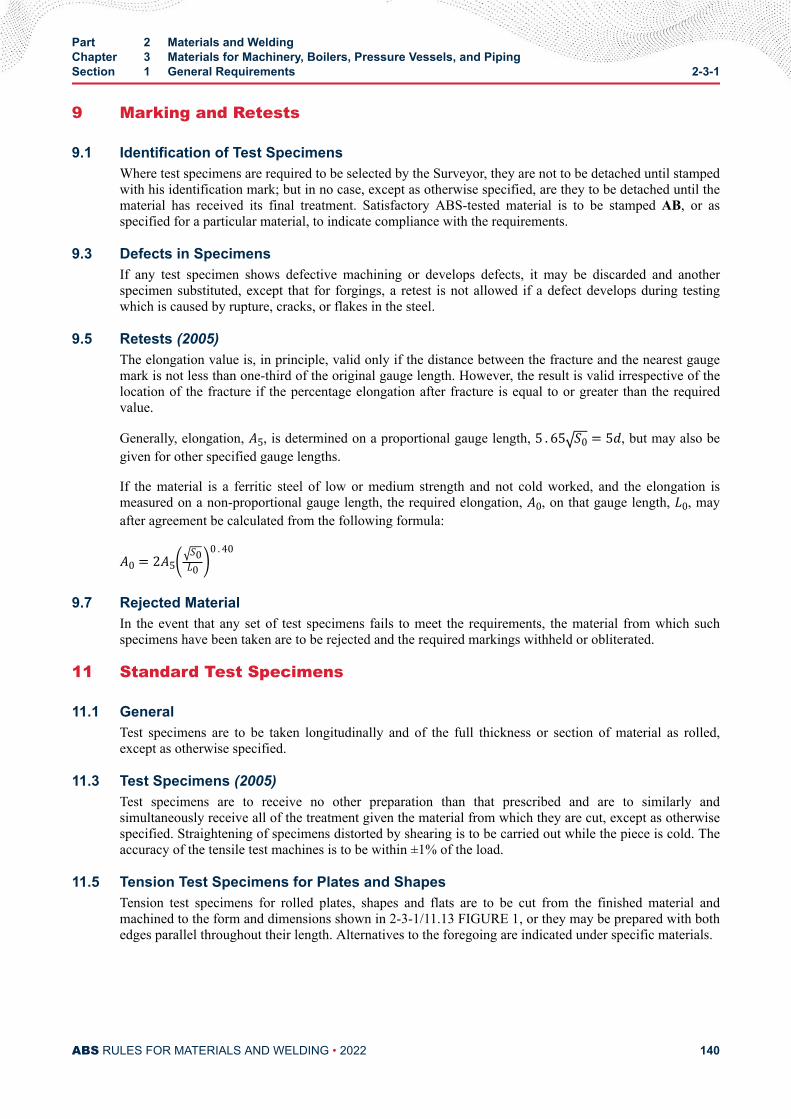
9 Marking and Retests
9.1 Identification of Test SpecimensWhere test specimens are required to be selected by the Surveyor, they are not to be detached until stampedwith his identification mark; but in no case, except as otherwise specified, are they to be detached until thematerial has received its final treatment. Satisfactory ABS-tested material is to be stamped AB, or asspecified for a particular material, to indicate compliance with the requirements.
9.3 Defects in SpecimensIf any test specimen shows defective machining or develops defects, it may be discarded and anotherspecimen substituted, except that for forgings, a retest is not allowed if a defect develops during testingwhich is caused by rupture, cracks, or flakes in the steel.
9.5 Retests (2005)The elongation value is, in principle, valid only if the distance between the fracture and the nearest gaugemark is not less than one-third of the original gauge length. However, the result is valid irrespective of thelocation of the fracture if the percentage elongation after fracture is equal to or greater than the requiredvalue.
Generally, elongation, A5, is determined on a proportional gauge length, 5 . 65 S0 = 5d, but may also begiven for other specified gauge lengths.
If the material is a ferritic steel of low or medium strength and not cold worked, and the elongation ismeasured on a non-proportional gauge length, the required elongation, A0, on that gauge length, L0, mayafter agreement be calculated from the following formula:
A0 = 2A5 S0L0 0 . 409.7 Rejected Material
In the event that any set of test specimens fails to meet the requirements, the material from which suchspecimens have been taken are to be rejected and the required markings withheld or obliterated.
11 Standard Test Specimens
11.1 GeneralTest specimens are to be taken longitudinally and of the full thickness or section of material as rolled,except as otherwise specified.
11.3 Test Specimens (2005)Test specimens are to receive no other preparation than that prescribed and are to similarly andsimultaneously receive all of the treatment given the material from which they are cut, except as otherwisespecified. Straightening of specimens distorted by shearing is to be carried out while the piece is cold. Theaccuracy of the tensile test machines is to be within ±1% of the load.
11.5 Tension Test Specimens for Plates and ShapesTension test specimens for rolled plates, shapes and flats are to be cut from the finished material andmachined to the form and dimensions shown in 2-3-1/11.13 FIGURE 1, or they may be prepared with bothedges parallel throughout their length. Alternatives to the foregoing are indicated under specific materials.
Part 2 Materials and WeldingChapter 3 Materials for Machinery, Boilers, Pressure Vessels, and PipingSection 1 General Requirements 2-3-1
ABS RULES FOR MATERIALS AND WELDING • 2022 140
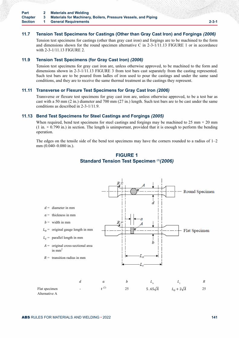
11.7 Tension Test Specimens for Castings (Other than Gray Cast Iron) and Forgings (2006)Tension test specimens for castings (other than gray cast iron) and forgings are to be machined to the formand dimensions shown for the round specimen alternative C in 2-3-1/11.13 FIGURE 1 or in accordancewith 2-3-1/11.13 FIGURE 2.
11.9 Tension Test Specimens (for Gray Cast Iron) (2006)Tension test specimens for gray cast iron are, unless otherwise approved, to be machined to the form anddimensions shown in 2-3-1/11.13 FIGURE 3 from test bars cast separately from the casting represented.Such test bars are to be poured from ladles of iron used to pour the castings and under the same sandconditions, and they are to receive the same thermal treatment as the castings they represent.
11.11 Transverse or Flexure Test Specimens for Gray Cast Iron (2006)Transverse or flexure test specimens for gray cast iron are, unless otherwise approved, to be a test bar ascast with a 50 mm (2 in.) diameter and 700 mm (27 in.) length. Such test bars are to be cast under the sameconditions as described in 2-3-1/11.9.
11.13 Bend Test Specimens for Steel Castings and Forgings (2005)When required, bend test specimens for steel castings and forgings may be machined to 25 mm × 20 mm(1 in. × 0.790 in.) in section. The length is unimportant, provided that it is enough to perform the bendingoperation.
The edges on the tensile side of the bend test specimens may have the corners rounded to a radius of 1–2mm (0.040–0.080 in.).
FIGURE 1Standard Tension Test Specimen (1)(2006)
d = diameter in mma = thickness in mmb = width in mmLo = original gauge length in mmLc = parallel length in mmA = original cross-sectional areain mm2R = transition radius in mm
d a b Lo Lc R
Flat specimenAlternative A
- t (2) 25 5 . 65 A Lo+ 2 A 25
Part 2 Materials and WeldingChapter 3 Materials for Machinery, Boilers, Pressure Vessels, and PipingSection 1 General Requirements 2-3-1
ABS RULES FOR MATERIALS AND WELDING • 2022 141
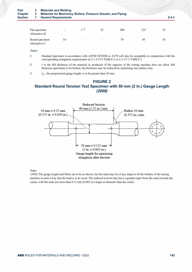
Flat specimenAlternative B
- t (2) 25 200 225 25
Round specimenAlternative C
14 - - 70 85 10
Notes:
1 Standard specimen in accordance with ASTM E8/E8M or A370 will also be acceptable in conjunction with thecorresponding elongation requirements in 2-1-2/15.9 TABLE 2 or 2-1-3/7.3 TABLE 2
2 t is the full thickness of the material as produced. If the capacity of the testing machine does not allow fullthickness specimens to be broken, the thickness may be reduced by machining one surface only.
3 Lo , the proportional gauge length, is to be greater than 20 mm.
FIGURE 2Standard Round Tension Test Specimen with 50 mm (2 in.) Gauge Length
(2008)
Note:(2008) The gauge length and fillets are to be as shown, but the ends may be of any shape to fit the holders of the testingmachine in such a way that the load is to be axial. The reduced section may have a gradual taper from the ends towards thecenter, with the ends not more than 0.13 mm (0.005 in.) larger in diameter than the center.
Part 2 Materials and WeldingChapter 3 Materials for Machinery, Boilers, Pressure Vessels, and PipingSection 1 General Requirements 2-3-1
ABS RULES FOR MATERIALS AND WELDING • 2022 142
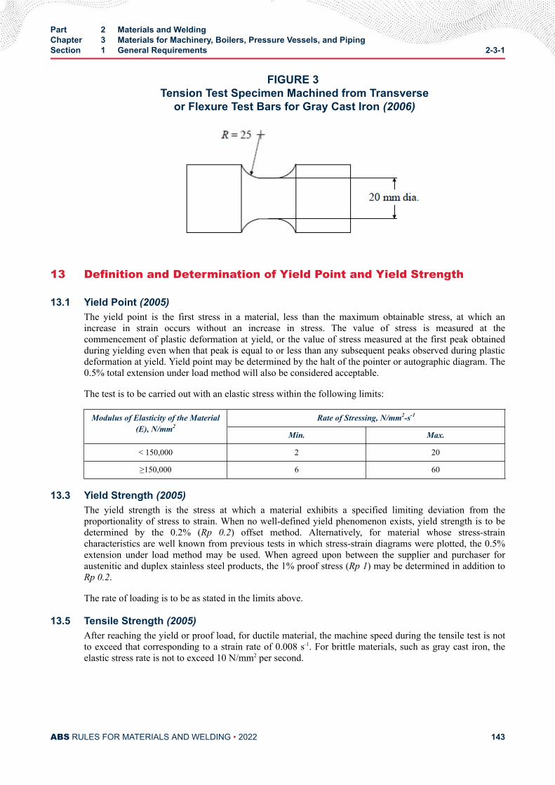
FIGURE 3 Tension Test Specimen Machined from Transverse
or Flexure Test Bars for Gray Cast Iron (2006)
13 Definition and Determination of Yield Point and Yield Strength
13.1 Yield Point (2005)The yield point is the first stress in a material, less than the maximum obtainable stress, at which anincrease in strain occurs without an increase in stress. The value of stress is measured at thecommencement of plastic deformation at yield, or the value of stress measured at the first peak obtainedduring yielding even when that peak is equal to or less than any subsequent peaks observed during plasticdeformation at yield. Yield point may be determined by the halt of the pointer or autographic diagram. The0.5% total extension under load method will also be considered acceptable.
The test is to be carried out with an elastic stress within the following limits:
Modulus of Elasticity of the Material(E), N/mm2
Rate of Stressing, N/mm2-s-1
Min. Max.
< 150,000 2 20
≥150,000 6 60
13.3 Yield Strength (2005)The yield strength is the stress at which a material exhibits a specified limiting deviation from theproportionality of stress to strain. When no well-defined yield phenomenon exists, yield strength is to bedetermined by the 0.2% (Rp 0.2) offset method. Alternatively, for material whose stress-straincharacteristics are well known from previous tests in which stress-strain diagrams were plotted, the 0.5%extension under load method may be used. When agreed upon between the supplier and purchaser foraustenitic and duplex stainless steel products, the 1% proof stress (Rp 1) may be determined in addition toRp 0.2.
The rate of loading is to be as stated in the limits above.
13.5 Tensile Strength (2005)After reaching the yield or proof load, for ductile material, the machine speed during the tensile test is notto exceed that corresponding to a strain rate of 0.008 s-1. For brittle materials, such as gray cast iron, theelastic stress rate is not to exceed 10 N/mm2 per second.
Part 2 Materials and WeldingChapter 3 Materials for Machinery, Boilers, Pressure Vessels, and PipingSection 1 General Requirements 2-3-1
ABS RULES FOR MATERIALS AND WELDING • 2022 143
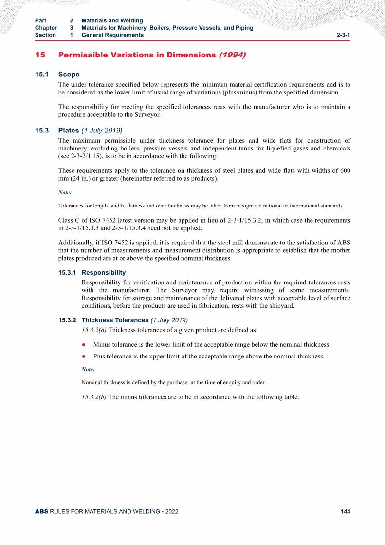
15 Permissible Variations in Dimensions (1994)
15.1 ScopeThe under tolerance specified below represents the minimum material certification requirements and is tobe considered as the lower limit of usual range of variations (plus/minus) from the specified dimension.
The responsibility for meeting the specified tolerances rests with the manufacturer who is to maintain aprocedure acceptable to the Surveyor.
15.3 Plates (1 July 2019)The maximum permissible under thickness tolerance for plates and wide flats for construction ofmachinery, excluding boilers, pressure vessels and independent tanks for liquefied gases and chemicals(see 2-3-2/1.15), is to be in accordance with the following:
These requirements apply to the tolerance on thickness of steel plates and wide flats with widths of 600mm (24 in.) or greater (hereinafter referred to as products).
Note:
Tolerances for length, width, flatness and over thickness may be taken from recognized national or international standards.
Class C of ISO 7452 latest version may be applied in lieu of 2-3-1/15.3.2, in which case the requirementsin 2-3-1/15.3.3 and 2-3-1/15.3.4 need not be applied.
Additionally, if ISO 7452 is applied, it is required that the steel mill demonstrate to the satisfaction of ABSthat the number of measurements and measurement distribution is appropriate to establish that the motherplates produced are at or above the specified nominal thickness.
15.3.1 ResponsibilityResponsibility for verification and maintenance of production within the required tolerances restswith the manufacturer. The Surveyor may require witnessing of some measurements.Responsibility for storage and maintenance of the delivered plates with acceptable level of surfaceconditions, before the products are used in fabrication, rests with the shipyard.
15.3.2 Thickness Tolerances (1 July 2019)15.3.2(a) Thickness tolerances of a given product are defined as:
● Minus tolerance is the lower limit of the acceptable range below the nominal thickness.
● Plus tolerance is the upper limit of the acceptable range above the nominal thickness.
Note:
Nominal thickness is defined by the purchaser at the time of enquiry and order.
15.3.2(b) The minus tolerances are to be in accordance with the following table.
Part 2 Materials and WeldingChapter 3 Materials for Machinery, Boilers, Pressure Vessels, and PipingSection 1 General Requirements 2-3-1
ABS RULES FOR MATERIALS AND WELDING • 2022 144
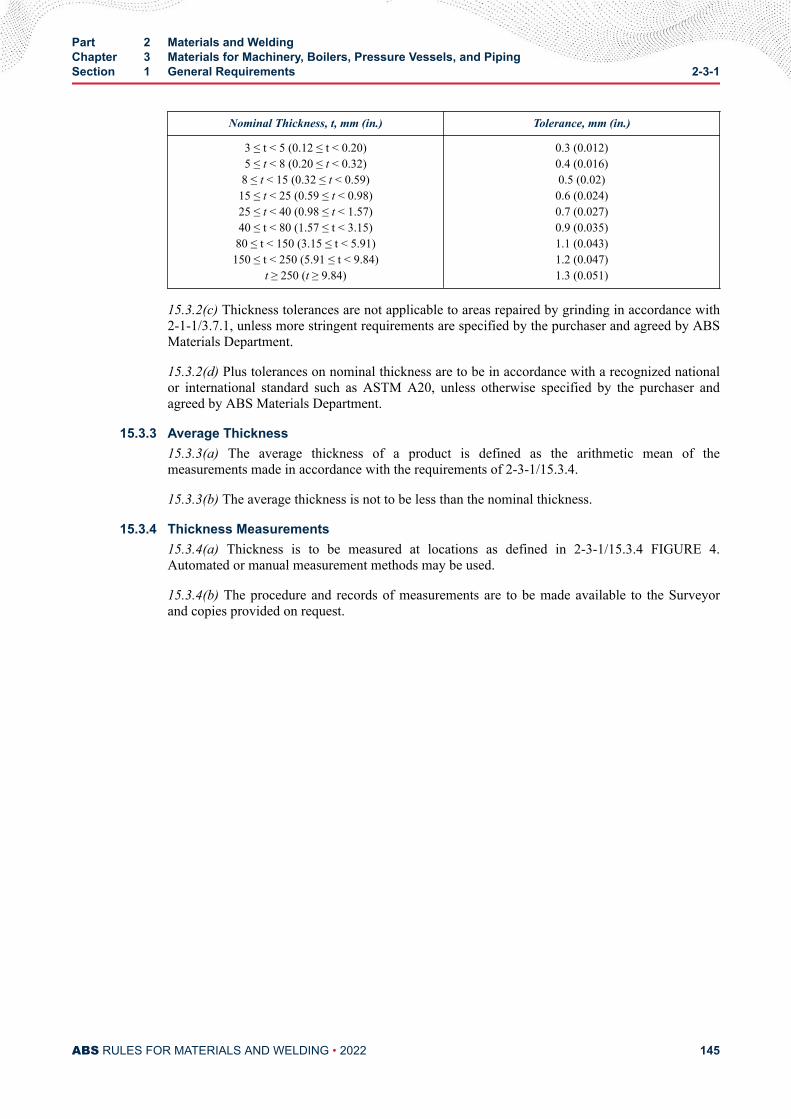
Nominal Thickness, t, mm (in.) Tolerance, mm (in.)
3 ≤ t < 5 (0.12 ≤ t < 0.20)5 ≤ t < 8 (0.20 ≤ t < 0.32)8 ≤ t < 15 (0.32 ≤ t < 0.59)15 ≤ t < 25 (0.59 ≤ t < 0.98)25 ≤ t < 40 (0.98 ≤ t < 1.57)40 ≤ t < 80 (1.57 ≤ t < 3.15)80 ≤ t < 150 (3.15 ≤ t < 5.91)150 ≤ t < 250 (5.91 ≤ t < 9.84)
t ≥ 250 (t ≥ 9.84)
0.3 (0.012)0.4 (0.016)0.5 (0.02)0.6 (0.024)0.7 (0.027)0.9 (0.035)1.1 (0.043)1.2 (0.047)1.3 (0.051)
15.3.2(c) Thickness tolerances are not applicable to areas repaired by grinding in accordance with2-1-1/3.7.1, unless more stringent requirements are specified by the purchaser and agreed by ABSMaterials Department.
15.3.2(d) Plus tolerances on nominal thickness are to be in accordance with a recognized nationalor international standard such as ASTM A20, unless otherwise specified by the purchaser andagreed by ABS Materials Department.
15.3.3 Average Thickness15.3.3(a) The average thickness of a product is defined as the arithmetic mean of themeasurements made in accordance with the requirements of 2-3-1/15.3.4.
15.3.3(b) The average thickness is not to be less than the nominal thickness.
15.3.4 Thickness Measurements15.3.4(a) Thickness is to be measured at locations as defined in 2-3-1/15.3.4 FIGURE 4.Automated or manual measurement methods may be used.
15.3.4(b) The procedure and records of measurements are to be made available to the Surveyorand copies provided on request.
Part 2 Materials and WeldingChapter 3 Materials for Machinery, Boilers, Pressure Vessels, and PipingSection 1 General Requirements 2-3-1
ABS RULES FOR MATERIALS AND WELDING • 2022 145
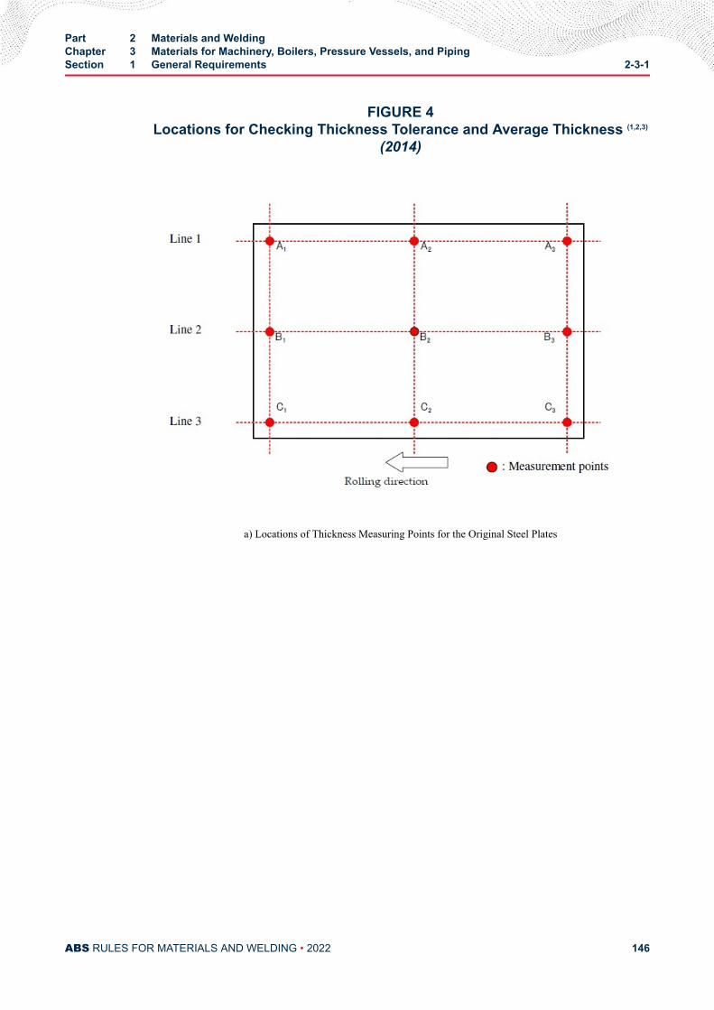
FIGURE 4Locations for Checking Thickness Tolerance and Average Thickness (1,2,3)
(2014)
a) Locations of Thickness Measuring Points for the Original Steel Plates
Part 2 Materials and WeldingChapter 3 Materials for Machinery, Boilers, Pressure Vessels, and PipingSection 1 General Requirements 2-3-1
ABS RULES FOR MATERIALS AND WELDING • 2022 146
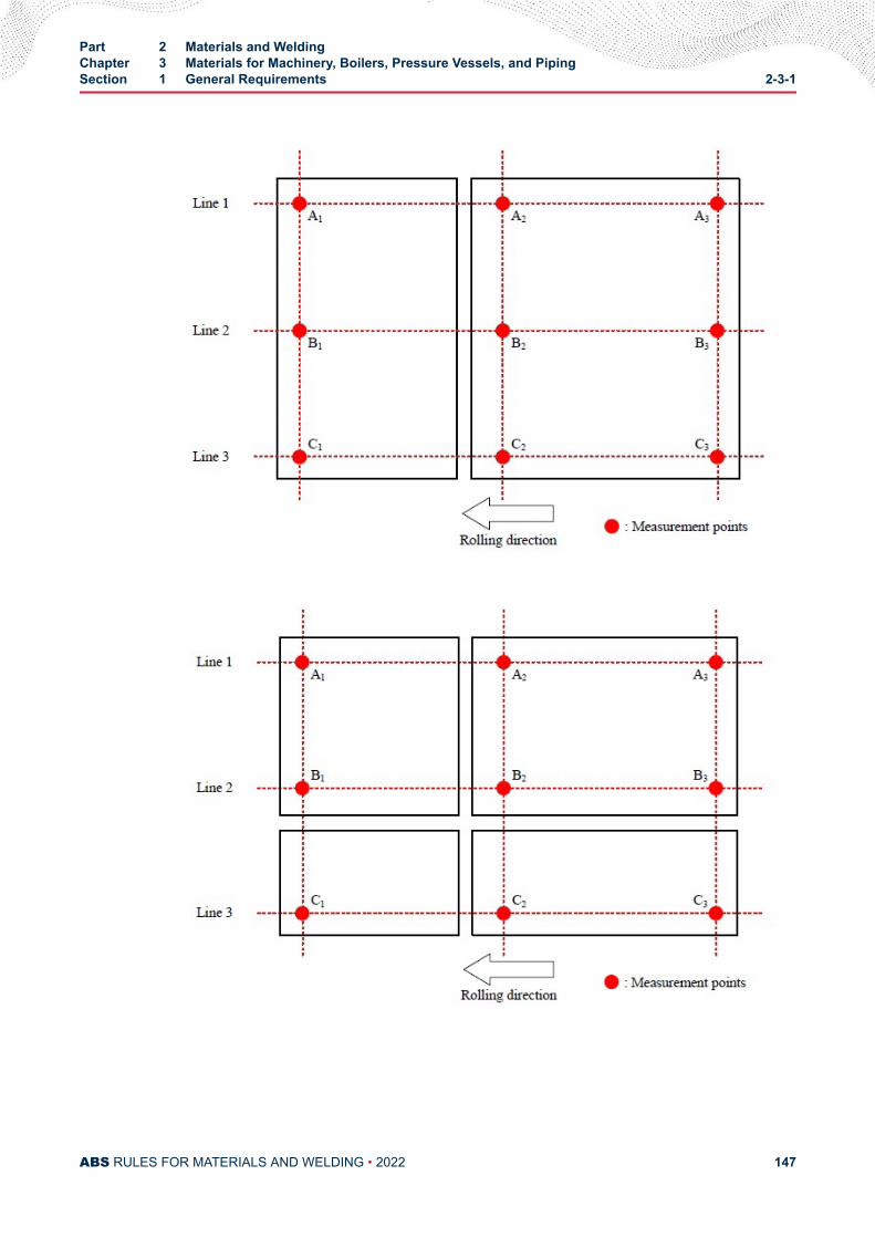
Part 2 Materials and WeldingChapter 3 Materials for Machinery, Boilers, Pressure Vessels, and PipingSection 1 General Requirements 2-3-1
ABS RULES FOR MATERIALS AND WELDING • 2022 147
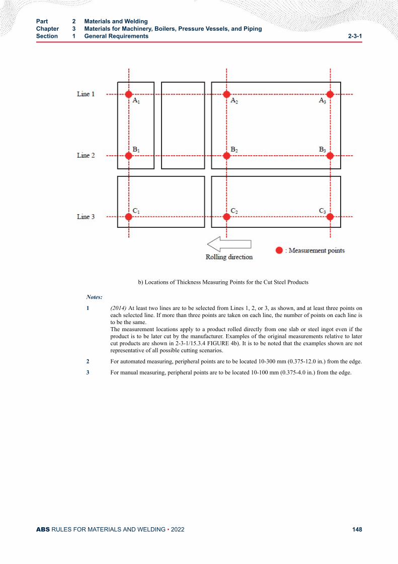
b) Locations of Thickness Measuring Points for the Cut Steel Products
Notes:
1 (2014) At least two lines are to be selected from Lines 1, 2, or 3, as shown, and at least three points oneach selected line. If more than three points are taken on each line, the number of points on each line isto be the same.The measurement locations apply to a product rolled directly from one slab or steel ingot even if theproduct is to be later cut by the manufacturer. Examples of the original measurements relative to latercut products are shown in 2-3-1/15.3.4 FIGURE 4b). It is to be noted that the examples shown are notrepresentative of all possible cutting scenarios.
2 For automated measuring, peripheral points are to be located 10-300 mm (0.375-12.0 in.) from the edge.
3 For manual measuring, peripheral points are to be located 10-100 mm (0.375-4.0 in.) from the edge.
Part 2 Materials and WeldingChapter 3 Materials for Machinery, Boilers, Pressure Vessels, and PipingSection 1 General Requirements 2-3-1
ABS RULES FOR MATERIALS AND WELDING • 2022 148
C H A P T E R 3Materials for Machinery, Boilers, Pressure Vessels, and Piping
S E C T I O N 2Steel Plates for Machinery, Boilers and Pressure Vessels
1 General Requirements for All Grades of Steel Plates for Machinery,Boilers, and Pressure Vessels
1.1 General (2022)1.1.1 Examination at Mills (2022)
The grades of steel covered in 2-3-2/3, 2-3-2/5 and 2-3-2/7 are rolled plates intended for use inmachinery, boilers and other pressure vessels. All tests are to be conducted in the presence of theSurveyor at the place of manufacture prior to shipping, unless the plant is approved under ABS’sQuality Assurance Program for Rolled Products. The material surfaces will be examined by theSurveyor when specially requested by the purchaser. Plates are to be free from defects and have aworkmanlike finish, subject to the conditions given under 2-3-2/1.7. Refer to 4-4-1/Table 3 of theMarine Vessel Rules for certification requirements for boiler and pressure vessels.
1.2 Manufacturer Approval (2022)All grades of steel plates for Group I boiler and pressure vessels are to be manufactured at steel worksapproved by ABS for the type and grade of steel contemplated. The suitability of the steel plates forwelding and assumed forming is to be demonstrated during the initial approval test at the steel works.Approval of the steel works for steel plates is to be in accordance with Part 2, Appendix 4.
Approval can be requested for grades of steel covered in 2-3-2/3, 2-3-2/5 and 2-3-2/7 or other grades asapproved in design.
Refer to 2-1-1/1.5 for the certification on the basis of the ABS Quality Assurance Program for RolledProducts.
1.3 Marking1.3.1 Plates and Test Specimens
The name or brand of the manufacturer, the letter indicating the grade of steel, the manufacturer’sidentification numbers and the letters PV to indicate pressure-vessel quality are to be legiblystamped (except as specified in 2-3-2/1.3.4) on each finished plate in two places, not less than 300mm (12 in.) from the edges. Plates, the maximum lengthwise and crosswise dimensions of whichdo not exceed 1800 mm (72 in.), are to have the marking stamped in one place approximatelymidway between the center and an edge. The manufacturer’s test identification number is to be
PART 2
ABS RULES FOR MATERIALS AND WELDING • 2022 149
legibly stamped on each test specimen. All test specimens are to be ring-stamped, match-markedor otherwise suitably identified to the satisfaction of the attending Surveyor before being detached.
1.3.2 Heat-treatment MarkingWhen the heat treatment is to be carried out by the fabricator as covered in 2-3-2/5.5 and2-3-2/7.5, the letter G is to also be stamped on each plate by the steel producer to indicate that thematerial is in the unheat-treated (green) condition. After heat treatment at the fabricator's plant, theletter T is to be stamped following the letter G.
1.3.3 ABS MarkingsABS markings AB, indicating satisfactory compliance with the Rule requirements and othermarkings as furnished by the Surveyor, are to be stamped on all plates near the marking specifiedin 2-3-2/1.3.1 to signify that the material has satisfactorily complied with the test prescribed, andthat certificates for the material will be furnished to the Surveyor in accordance with 2-3-1/7. Forcoiled steel which is certified for chemical analysis only, the marking AB without gradedesignation is to be marked on the outer wrap of each coil shipped.
1.3.4 Thin PlatesPlates under 6.4 mm (0.25 in.) in thickness are to be legibly stenciled with the markings specifiedin 2-3-2/1.3.1 and 2-3-2/1.3.2 instead of stamped.
1.3.5 Special Impact TestingWhen steel is impact tested in accordance with 2-3-2/9 the grade marking is to be followed by thetest temperature in degrees Celsius. A prefix “0” to the test temperature is to indicate atemperature colder than zero degrees Celsius.
1.5 Process of ManufactureThe steel is to be made by one or more of the following processes: open-hearth, basic-oxygen or electric-furnace. The steel may be cast in ingots or may be strand (continuous) cast. The ratio of reduction ofthickness from strand (continuous) cast slab to finished plate is to be a minimum of 3 to 1 unless speciallyapproved.
1.5.1 Plates Produced from CoilsFor coiled plate, the manufacturer or processor is to submit supporting data for review andapproval to indicate that the manufacturing, processing and testing will provide material which isin compliance with the Rules.
1.7 Chemical Composition1.7.1 Ladle Analysis
An analysis of each heat of steel is to be made by the manufacturer to determine the percentage ofthe elements specified. This analysis is to be made from a test sample taken during pouring of theheat. The chemical composition thus determined is to be reported to the Surveyor and is toconform to the requirements as specified for each grade in 2-3-2/3.5, 2-3-2/5.7 or 2-3-2/7.7.
1.7.2 Check AnalysisThe chemical composition determined by check analysis is to conform to the requirements asspecified for each Grade in 2-3-2/3.5, 2-3-2/5.7, and 2-3-2/7.7.
1.9 Test Specimens1.9.1 Selection of Specimens
One tension test specimen is to be taken from each plate as rolled in such manner that thelongitudinal axis of the specimen is transverse to the final direction of rolling of the plate. The
Part 2 Materials and WeldingChapter 3 Materials for Machinery, Boilers, Pressure Vessels, and PipingSection 2 Steel Plates for Machinery, Boilers and Pressure Vessels 2-3-2
ABS RULES FOR MATERIALS AND WELDING • 2022 150
tension test specimen is to be taken from a corner of the plate. If the final rolling direction of theplate is parallel to the original longitudinal ingot axis, the tension test specimen is to be taken fromthe “bottom” end of the plate. If the final direction of rolling of the plate is transverse to theoriginal longitudinal ingot axis, or if the relationship of final rolling direction and original ingotaxis is unknown, the tension test specimen may be taken from either end. For plates producedfrom coils, two tension test specimens are to be made from each coil. One tension test specimen isto be obtained from a location immediately prior to the first plate produced and a second testspecimen obtained from the approximate center lap. When required, impact tests are to beobtained adjacent to both tension test coupons and a third coupon is to be obtained immediatelyafter the last plate produced to the qualifying grade or specification.
1.9.2 Specimens from Plates 19 mm (0.75 in.) and Under in ThicknessFor plates 19 mm (0.75 in.) and under in thickness, tension test specimens are to be the fullthickness of the material and are to be machined to the form and dimensions shown in 2-3-1/11.13FIGURE 1 or with both edges parallel.
1.9.3 Specimens from Plates Over 19 mm (0.75 in.) ThicknessFor plates over 19 mm (0.75 in.) in thickness, tension test specimens may be machined to the formand dimensions shown in 2-3-1/11.13 FIGURE 2, and the axis of each such specimen is to belocated as nearly as practicable midway between the center and the surface of the plate, or forplates up to 101.6 mm (4 in.) inclusive in thickness, they may be the full thickness of the materialand of the form shown in 2-3-1/11.13 FIGURE 1 when adequate testing-machine capacity isavailable.
1.9.4 Stress RelievingWhen required, test specimens are to be stress-relieved by gradually and uniformly heating themto 590–650°C (1100–1200°F), holding at temperature for at least 1 hour per 25 mm (1 in.)thickness and cooling in still atmosphere to a temperature not exceeding 315°C (600°F). Ifapplicable, in the case of plates which are to be heat-treated and subsequently stress-relieved, thetest specimens for such plates are to, before testing, be stress-relieved following the heattreatment.
1.11 Tensile Properties1.11.1 Tensile Requirements
The material is to conform to the tensile requirements as specified for each grade in 2-3-2/3.9,2-3-2/5.11 or 2-3-2/7.11.
1.11.2 Elongation Deduction for Material Under 7.9 mm (0.313 in.) ThickFor material under 7.9 mm (0.313 in.) in thickness, a deduction from the specified percentage ofelongation in 200 mm (8 in.) of 1.25% is to be made for each decrease of 0.8 mm (0.031 in.) of thespecified thickness below 7.9 mm (0.313 in.).
1.11.3 Elongation Deduction for Material Over 88.9 mm (3.50 in.) ThickFor material over 88.9 mm (3.50 in.) in thickness, a deduction from the specified percentage ofelongation in 50 mm (2 in.) of 0.50% is to be made for each increase of 12.7 mm (0.50 in.) of thespecified thickness above 88.9 mm (3.50 in.). This deduction is not to exceed 3%.
1.13 Retests1.13.1 For All Thicknesses
When the result of any of the physical tests specified for any of the material does not conform tothe requirements, two additional specimens may, at the request of the manufacturer, be taken fromthe same plate and tested in the manner specified, but in such case, both of the specimens are toconform to the requirements (see 2-3-1/9.5).
Part 2 Materials and WeldingChapter 3 Materials for Machinery, Boilers, Pressure Vessels, and PipingSection 2 Steel Plates for Machinery, Boilers and Pressure Vessels 2-3-2
ABS RULES FOR MATERIALS AND WELDING • 2022 151
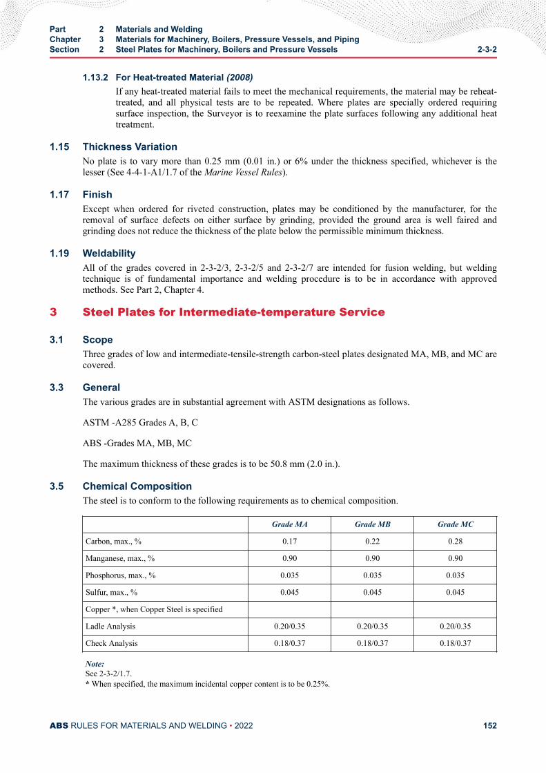
1.13.2 For Heat-treated Material (2008)If any heat-treated material fails to meet the mechanical requirements, the material may be reheat-treated, and all physical tests are to be repeated. Where plates are specially ordered requiringsurface inspection, the Surveyor is to reexamine the plate surfaces following any additional heattreatment.
1.15 Thickness VariationNo plate is to vary more than 0.25 mm (0.01 in.) or 6% under the thickness specified, whichever is thelesser (See 4-4-1-A1/1.7 of the Marine Vessel Rules).
1.17 FinishExcept when ordered for riveted construction, plates may be conditioned by the manufacturer, for theremoval of surface defects on either surface by grinding, provided the ground area is well faired andgrinding does not reduce the thickness of the plate below the permissible minimum thickness.
1.19 WeldabilityAll of the grades covered in 2-3-2/3, 2-3-2/5 and 2-3-2/7 are intended for fusion welding, but weldingtechnique is of fundamental importance and welding procedure is to be in accordance with approvedmethods. See Part 2, Chapter 4.
3 Steel Plates for Intermediate-temperature Service
3.1 ScopeThree grades of low and intermediate-tensile-strength carbon-steel plates designated MA, MB, and MC arecovered.
3.3 GeneralThe various grades are in substantial agreement with ASTM designations as follows.
ASTM -A285 Grades A, B, C
ABS -Grades MA, MB, MC
The maximum thickness of these grades is to be 50.8 mm (2.0 in.).
3.5 Chemical CompositionThe steel is to conform to the following requirements as to chemical composition.
Grade MA Grade MB Grade MC
Carbon, max., % 0.17 0.22 0.28
Manganese, max., % 0.90 0.90 0.90
Phosphorus, max., % 0.035 0.035 0.035
Sulfur, max., % 0.045 0.045 0.045
Copper *, when Copper Steel is specified
Ladle Analysis 0.20/0.35 0.20/0.35 0.20/0.35
Check Analysis 0.18/0.37 0.18/0.37 0.18/0.37
Note:See 2-3-2/1.7.* When specified, the maximum incidental copper content is to be 0.25%.
Part 2 Materials and WeldingChapter 3 Materials for Machinery, Boilers, Pressure Vessels, and PipingSection 2 Steel Plates for Machinery, Boilers and Pressure Vessels 2-3-2
ABS RULES FOR MATERIALS AND WELDING • 2022 152
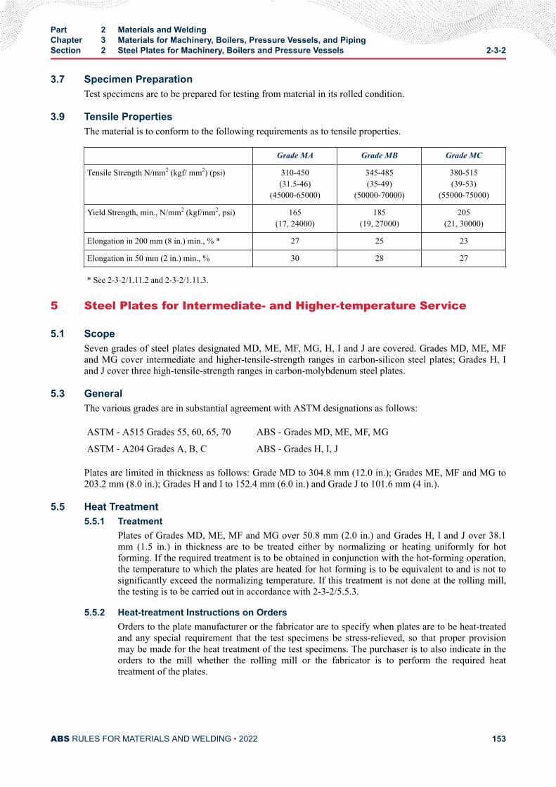
3.7 Specimen PreparationTest specimens are to be prepared for testing from material in its rolled condition.
3.9 Tensile PropertiesThe material is to conform to the following requirements as to tensile properties.
Grade MA Grade MB Grade MC
Tensile Strength N/mm2 (kgf/ mm2) (psi) 310-450(31.5-46)
(45000-65000)
345-485(35-49)
(50000-70000)
380-515(39-53)
(55000-75000)
Yield Strength, min., N/mm2 (kgf/mm2, psi) 165(17, 24000)
185(19, 27000)
205(21, 30000)
Elongation in 200 mm (8 in.) min., % * 27 25 23
Elongation in 50 mm (2 in.) min., % 30 28 27
* See 2-3-2/1.11.2 and 2-3-2/1.11.3.
5 Steel Plates for Intermediate- and Higher-temperature Service
5.1 ScopeSeven grades of steel plates designated MD, ME, MF, MG, H, I and J are covered. Grades MD, ME, MFand MG cover intermediate and higher-tensile-strength ranges in carbon-silicon steel plates; Grades H, Iand J cover three high-tensile-strength ranges in carbon-molybdenum steel plates.
5.3 GeneralThe various grades are in substantial agreement with ASTM designations as follows:
ASTM - A515 Grades 55, 60, 65, 70 ABS - Grades MD, ME, MF, MG
ASTM - A204 Grades A, B, C ABS - Grades H, I, J
Plates are limited in thickness as follows: Grade MD to 304.8 mm (12.0 in.); Grades ME, MF and MG to203.2 mm (8.0 in.); Grades H and I to 152.4 mm (6.0 in.) and Grade J to 101.6 mm (4 in.).
5.5 Heat Treatment5.5.1 Treatment
Plates of Grades MD, ME, MF and MG over 50.8 mm (2.0 in.) and Grades H, I and J over 38.1mm (1.5 in.) in thickness are to be treated either by normalizing or heating uniformly for hotforming. If the required treatment is to be obtained in conjunction with the hot-forming operation,the temperature to which the plates are heated for hot forming is to be equivalent to and is not tosignificantly exceed the normalizing temperature. If this treatment is not done at the rolling mill,the testing is to be carried out in accordance with 2-3-2/5.5.3.
5.5.2 Heat-treatment Instructions on OrdersOrders to the plate manufacturer or the fabricator are to specify when plates are to be heat-treatedand any special requirement that the test specimens be stress-relieved, so that proper provisionmay be made for the heat treatment of the test specimens. The purchaser is to also indicate in theorders to the mill whether the rolling mill or the fabricator is to perform the required heattreatment of the plates.
Part 2 Materials and WeldingChapter 3 Materials for Machinery, Boilers, Pressure Vessels, and PipingSection 2 Steel Plates for Machinery, Boilers and Pressure Vessels 2-3-2
ABS RULES FOR MATERIALS AND WELDING • 2022 153
5.5.3 Responsibility for Heat TreatmentWhen a fabricator is equipped and elects to perform the required normalizing or fabricates by hotforming as provided in 2-3-2/5.5.1, the plates are to be accepted on the basis of tests made at theplate manufacturer’s plant on specimens heat-treated in accordance with the purchaser’s orderrequirements. If the heat-treatment temperatures are not indicated on the purchase order, the platemanufacturer is to heat-treat the specimens under conditions considered appropriate to meet thetest requirements. The plate manufacturer is to inform the fabricator of the procedure followed intreating the specimens at the mill for guidance in treating the plates. When the plates are to benormalized at the plate manufacturer’s plant, the mechanical properties are to be determined onspecimens simultaneously treated with the plates.
5.7 Chemical CompositionThe steel is to conform to the requirements of 2-3-2/9 TABLE 1 as to chemical composition.
5.9 Test Specimens5.9.1 Plates Not Requiring Heat Treatment
For plates not requiring heat treatment (see 2-3-2/5.5.1), the test specimens are to be prepared fortesting from the material in its rolled condition. When Grades H, I and J plates are to be used in aboiler or pressure vessel which is to be stress-relieved, the test specimens for Grades H, I and J areto be stress-relieved. See 2-3-2/1.9.
5.9.2 Plates Requiring Heat TreatmentFor plates requiring heat treatment (see 2-3-2/5.5.1), the test specimens are to be prepared fromthe material in its heat-treated condition, or from full-thickness samples similarly andsimultaneously treated. When Grades H, I and J plates are to be used in a boiler or pressure vesselwhich is to be stress-relieved, the test specimens for Grades H, I and J are to be stress-relievedfollowing the heat treatment. See 2-3-2/1.9 and 2-3-2/5.5.
5.11 Tensile PropertiesThe material is to conform to the requirements of 2-3-2/9 TABLE 2 as to tensile properties.
7 Steel Plates for Intermediate- and Lower-temperature Service
7.1 ScopeFour grades of carbon-manganese-silicon steel plates made to fine-grain practice in four tensile-strengthranges designated K, L, M, N are covered.
7.3 GeneralThe various grades are in substantial agreement with ASTM designations as follows.
ASTM - A516 Grades 55, 60, 65, 70
ABS - Grades K, L, M, N
Plates are limited in thickness, as follows: Grade K to 304.8 mm (12.0 in.); Grades L, M and N to 203.2mm (8.0 in.).
Materials for Liquefied Gas Carriers are to comply with Section 5C-8-6 of the Marine Vessel Rules.
7.5 Heat Treatment7.5.1 Grain Refinement
Plates over 38.1 mm (1.5 in.) are to be heat-treated to produce grain refinement either bynormalizing or heating uniformly for hot forming. If the required treatment is to be obtained in
Part 2 Materials and WeldingChapter 3 Materials for Machinery, Boilers, Pressure Vessels, and PipingSection 2 Steel Plates for Machinery, Boilers and Pressure Vessels 2-3-2
ABS RULES FOR MATERIALS AND WELDING • 2022 154
conjunction with hot forming, the temperature to which the plates are heated for hot forming is tobe equivalent to and is not to exceed significantly the normalizing temperature. If this treatment isnot done at the rolling mill, the testing is to be carried out in accordance with 2-3-2/7.5.3. Whenimproved notch toughness is required for plates 38 mm (1.5 in.) and under in thickness, heattreatment is to be specified as above.
7.5.2 Heat-treatment Instructions on OrdersOrders to the plate manufacturer or the fabricator are to specify when plates are to be heat-treatedfor grain refinement, and any special requirements that the test specimens be stress-relieved, sothat proper provision may be made for the heat treatment of the test specimens. The purchaser isalso to indicate in the orders to the mill whether the rolling mill or the fabricator is to perform therequired heat treatment of the plates.
7.5.3 Responsibility for Heat TreatmentWhen a fabricator is equipped and elects to perform the required normalizing or fabricates by hotforming as provided in 2-3-2/7.5.1, the plates are to be accepted on the basis of tests made at theplate manufacturer’s plant on specimens heat-treated in accordance with the purchaser’s orderrequirements. If the heat-treatment temperatures are not indicated on the purchase order, the platemanufacturer is to heat-treat the specimens under conditions considered appropriate for grainrefinement, and to meet the test requirements. The plate manufacturer is to inform the fabricator ofthe procedure followed in treating the specimens at the mill for guidance in treating the plates.When the plates are to be normalized at the plate manufacturer’s plant, the mechanical propertiesare to be determined on specimens simultaneously treated with the plates.
7.7 Chemical CompositionThe steel is to conform to the requirements of 2-3-2/9 TABLE 3 as to chemical composition.
7.9 Test Specimens7.9.1 Plates 38.1 mm (1.5 in.) and Under in Thickness
For plates 38.1 mm (1.5 in.) and under in thickness, not requiring heat treatment, the testspecimens are to be prepared for testing from the material in its rolled condition.
7.9.2 Plates Requiring Heat TreatmentFor plates 38.1 mm (1.5 in.) and under in thickness, requiring heat treatment (see 2-3-2/7.5.1), orfor plates over 38.1 mm (1.5 in.) in thickness, the test specimens are to be prepared from thematerial in its heat-treated condition, or from full-thickness samples similarly and simultaneouslytreated.
7.11 Tensile PropertiesThe material is to conform to the requirements of 2-3-2/9 TABLE 4 as to tensile properties.
9 Materials for Low Temperature Service [Below - 18°C (0°F)]Materials intended for service temperatures of below -18°C (0°F) may be provided in accordance withthose requirements listed in 2-1-4/9. Other special low temperature materials, when the Charpy V-notchimpact tests are conducted at 5°C (10°F) below minimum design temperature in accordance with 2-1-4/5.1and meet the applicable requirements of 2-1-2/11 and 5C-8-6/4 (ABS) may also be accepted. Such tests arenot required for austenitic stainless steels, or aluminum alloys such as type 5083.
TABLE 1Chemical Composition for Plate Grades MD, ME, MF, MG, H, I, J
Note: See also 2-3-2/1.7
Part 2 Materials and WeldingChapter 3 Materials for Machinery, Boilers, Pressure Vessels, and PipingSection 2 Steel Plates for Machinery, Boilers and Pressure Vessels 2-3-2
ABS RULES FOR MATERIALS AND WELDING • 2022 155
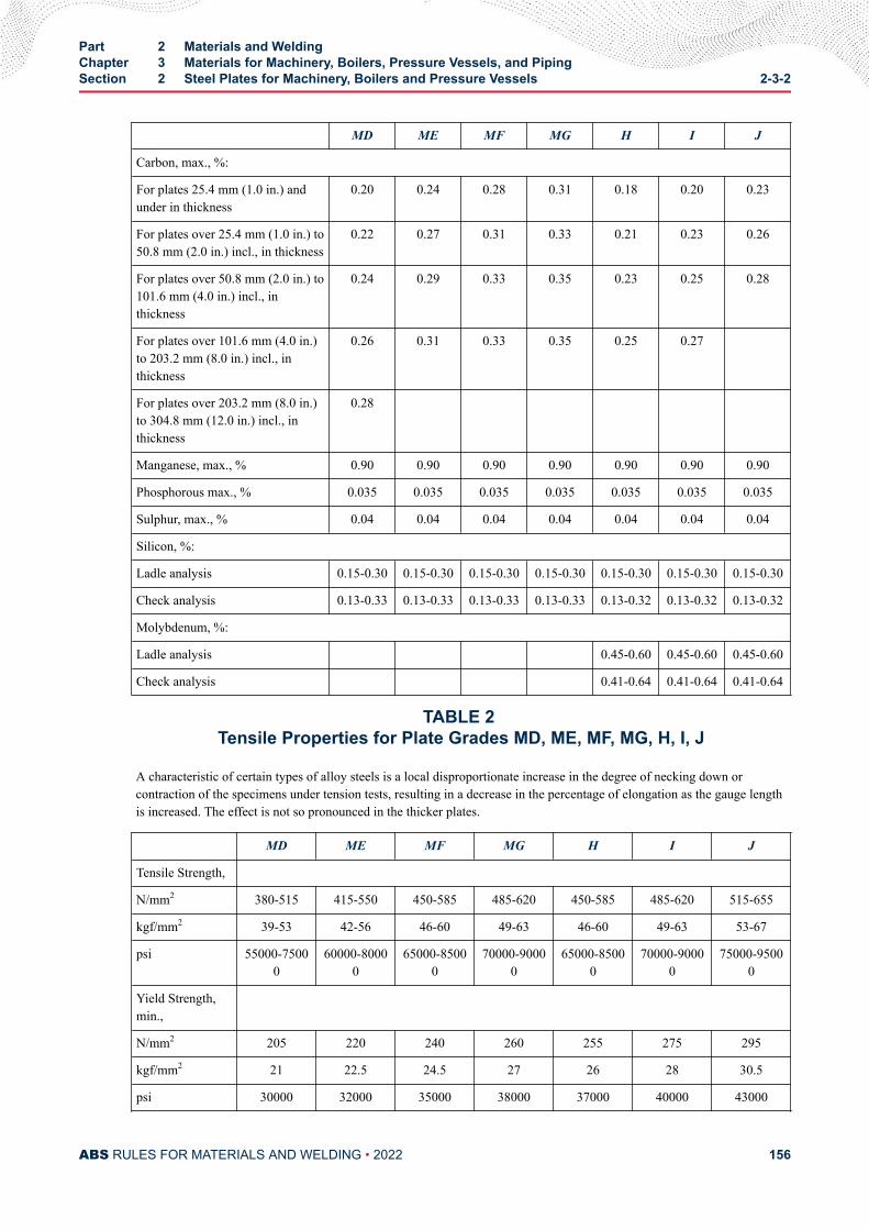
MD ME MF MG H I J
Carbon, max., %:
For plates 25.4 mm (1.0 in.) andunder in thickness
0.20 0.24 0.28 0.31 0.18 0.20 0.23
For plates over 25.4 mm (1.0 in.) to50.8 mm (2.0 in.) incl., in thickness
0.22 0.27 0.31 0.33 0.21 0.23 0.26
For plates over 50.8 mm (2.0 in.) to101.6 mm (4.0 in.) incl., inthickness
0.24 0.29 0.33 0.35 0.23 0.25 0.28
For plates over 101.6 mm (4.0 in.)to 203.2 mm (8.0 in.) incl., inthickness
0.26 0.31 0.33 0.35 0.25 0.27
For plates over 203.2 mm (8.0 in.)to 304.8 mm (12.0 in.) incl., inthickness
0.28
Manganese, max., % 0.90 0.90 0.90 0.90 0.90 0.90 0.90
Phosphorous max., % 0.035 0.035 0.035 0.035 0.035 0.035 0.035
Sulphur, max., % 0.04 0.04 0.04 0.04 0.04 0.04 0.04
Silicon, %:
Ladle analysis 0.15-0.30 0.15-0.30 0.15-0.30 0.15-0.30 0.15-0.30 0.15-0.30 0.15-0.30
Check analysis 0.13-0.33 0.13-0.33 0.13-0.33 0.13-0.33 0.13-0.32 0.13-0.32 0.13-0.32
Molybdenum, %:
Ladle analysis 0.45-0.60 0.45-0.60 0.45-0.60
Check analysis 0.41-0.64 0.41-0.64 0.41-0.64
TABLE 2 Tensile Properties for Plate Grades MD, ME, MF, MG, H, I, J
A characteristic of certain types of alloy steels is a local disproportionate increase in the degree of necking down orcontraction of the specimens under tension tests, resulting in a decrease in the percentage of elongation as the gauge lengthis increased. The effect is not so pronounced in the thicker plates.
MD ME MF MG H I J
Tensile Strength,
N/mm2 380-515 415-550 450-585 485-620 450-585 485-620 515-655
kgf/mm2 39-53 42-56 46-60 49-63 46-60 49-63 53-67
psi 55000-75000
60000-80000
65000-85000
70000-90000
65000-85000
70000-90000
75000-95000
Yield Strength,min.,
N/mm2 205 220 240 260 255 275 295
kgf/mm2 21 22.5 24.5 27 26 28 30.5
psi 30000 32000 35000 38000 37000 40000 43000
Part 2 Materials and WeldingChapter 3 Materials for Machinery, Boilers, Pressure Vessels, and PipingSection 2 Steel Plates for Machinery, Boilers and Pressure Vessels 2-3-2
ABS RULES FOR MATERIALS AND WELDING • 2022 156
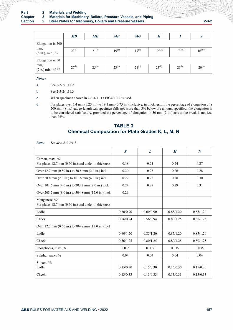
MD ME MF MG H I J
Elongation in 200mm,(8 in.), min., %
23(a) 21(a) 19(a) 17(a) 19(a,d) 17(a,d) 16(a,d)
Elongation in 50mm,(2in.) min., % (c)
27(b) 25(b) 23(b) 21(b) 23(b) 21(b) 20(b)
Notes:
a See 2-3-2/1.11.2
b See 2-3-2/1.11.3
c When specimen shown in 2-3-1/11.13 FIGURE 2 is used.
d For plates over 6.4 mm (0.25 in.) to 19.1 mm (0.75 in.) inclusive, in thickness, if the percentage of elongation of a200 mm (8 in.) gauge-length test specimen falls not more than 3% below the amount specified, the elongation isto be considered satisfactory, provided the percentage of elongation in 50 mm (2 in.) across the break is not lessthan 25%.
TABLE 3Chemical Composition for Plate Grades K, L, M, N
Note: See also 2-3-2/1.7
K L M N
Carbon, max., %:For plates 12.7 mm (0.50 in.) and under in thickness 0.18 0.21 0.24 0.27
Over 12.7 mm (0.50 in.) to 50.8 mm (2.0 in.) incl. 0.20 0.23 0.26 0.28
Over 50.8 mm (2.0 in.) to 101.6 mm (4.0 in.) incl. 0.22 0.25 0.28 0.30
Over 101.6 mm (4.0 in.) to 203.2 mm (8.0 in.) incl. 0.24 0.27 0.29 0.31
Over 203.2 mm (8.0 in.) to 304.8 mm (12.0 in.) incl. 0.26
Manganese, %:For plates 12.7 mm (0.50 in.) and under in thickness
Ladle 0.60/0.90 0.60/0.90 0.85/1.20 0.85/1.20
Check 0.56/0.94 0.56/0.94 0.80/1.25 0.80/1.25
Over 12.7 mm (0.50 in.) to 304.8 mm (12.0 in.) incl
Ladle 0.60/1.20 0.85/1.20 0.85/1.20 0.85/1.20
Check 0.56/1.25 0.80/1.25 0.80/1.25 0.80/1.25
Phosphorus, max., % 0.035 0.035 0.035 0.035
Sulphur, max., % 0.04 0.04 0.04 0.04
Silicon, %:Ladle 0.15/0.30 0.15/0.30 0.15/0.30 0.15/0.30
Check 0.13/0.33 0.13/0.33 0.13/0.33 0.13/0.33
Part 2 Materials and WeldingChapter 3 Materials for Machinery, Boilers, Pressure Vessels, and PipingSection 2 Steel Plates for Machinery, Boilers and Pressure Vessels 2-3-2
ABS RULES FOR MATERIALS AND WELDING • 2022 157
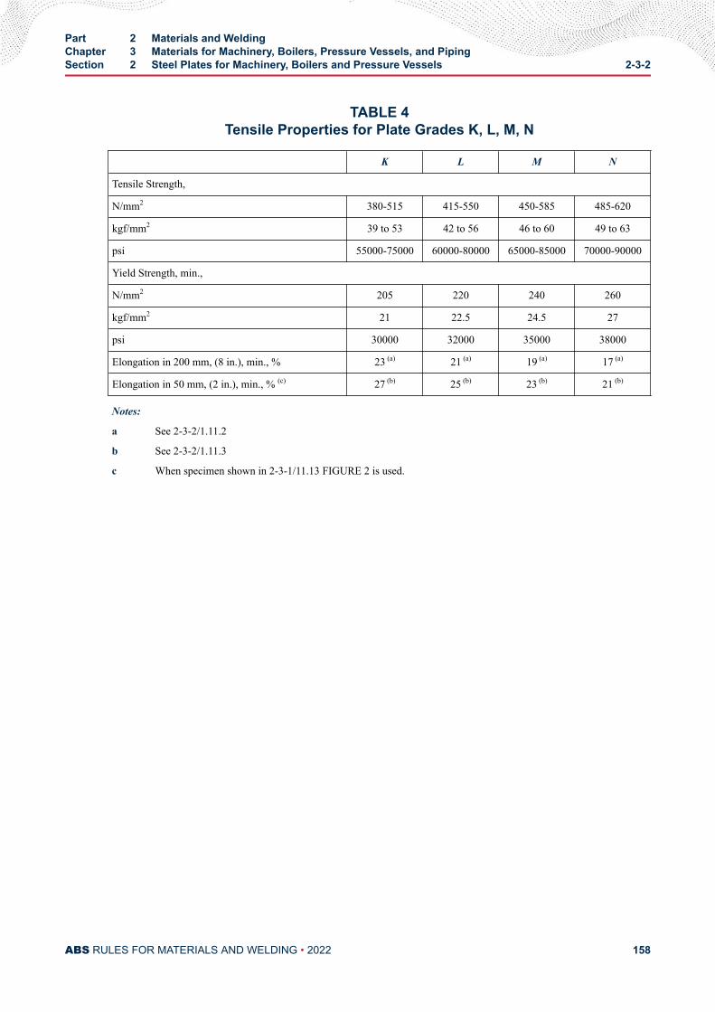
TABLE 4Tensile Properties for Plate Grades K, L, M, N
K L M N
Tensile Strength,
N/mm2 380-515 415-550 450-585 485-620
kgf/mm2 39 to 53 42 to 56 46 to 60 49 to 63
psi 55000-75000 60000-80000 65000-85000 70000-90000
Yield Strength, min.,
N/mm2 205 220 240 260
kgf/mm2 21 22.5 24.5 27
psi 30000 32000 35000 38000
Elongation in 200 mm, (8 in.), min., % 23 (a) 21 (a) 19 (a) 17 (a)
Elongation in 50 mm, (2 in.), min., % (c) 27 (b) 25 (b) 23 (b) 21 (b)
Notes:
a See 2-3-2/1.11.2
b See 2-3-2/1.11.3
c When specimen shown in 2-3-1/11.13 FIGURE 2 is used.
Part 2 Materials and WeldingChapter 3 Materials for Machinery, Boilers, Pressure Vessels, and PipingSection 2 Steel Plates for Machinery, Boilers and Pressure Vessels 2-3-2
ABS RULES FOR MATERIALS AND WELDING • 2022 158
C H A P T E R 3Materials for Machinery, Boilers, Pressure Vessels, and Piping
S E C T I O N 3Seamless Forged-steel Drums
Note: In substantial agreement with ASTM A266 as to physical properties for Classes 1 and 3.
1 Tests and InspectionsIn the event that any seamless forged-steel drums are presented for survey after special approval for eachspecific application, they are to be tested and surveyed in general accordance with the applicableprocedures given for steel forgings. One tension test is to be taken from each end of the forging midwaybetween the inner and outer surfaces of the wall in a tangential direction, the two specimens being takenfrom opposite sides of the drum. Grade A material is to have the following minimum properties, tensilestrength 415 N/mm2 (42 kgf/mm2, 60,000 psi), yield strength 205 N/mm2 (21 kgf/mm2, 30,000 psi),elongation 23% in a 50 mm (2 in.) gauge length; Grade B material is to have the following minimumproperties, tensile strength 515 N/mm2 (53 kgf/mm2, 75,000 psi), yield strength 260 N/mm2 (26.5 kgf/mm2,37,500 psi), elongation 19% in a 50 mm (2 in.) gauge length.
3 Heat TreatmentExcept as specified herein, tests for acceptance are to be made after final treatment of the forgings. Whenthe ends of drums are closed in by reforging after machining, the drums may be treated and tested prior toreforging. After reforging, the whole of the forging is to be simultaneously re-treated. If the originaltreatment was annealing, the re-anneal is to be above the transformation range, but not above thetemperature of the first anneal. If the original treatment was normalizing and tempering, the re-treatment isto be identical with the original.
PART 2
ABS RULES FOR MATERIALS AND WELDING • 2022 159
C H A P T E R 3Materials for Machinery, Boilers, Pressure Vessels, and Piping
S E C T I O N 4Seamless-steel Pressure Vessels
1 GeneralThe material for the manufacture of and the finished seamless pressure vessels are to be free from seams,cracks or other defects. Test specimens are to be cut from each cylinder before the necking-down process,stamped with the identification mark of the Surveyor and is to receive all heat treatments simultaneouslywith the cylinders.
3 Tension TestA standard test specimen cut either longitudinally or circumferentially from each cylinder is to show thematerial to have a minimum tensile strength of 415 N/mm2 (42 kgf/mm2, 60,000 psi), maximum yield pointof 70% of the tensile strength and a minimum elongation of 10% in 200 mm (8 in.).
5 Flattening TestA ring 200 mm (8 in.) long is to be cut from each cylinder and is to stand being flattened without signs offracture until the outside distance over the parallel sides is not greater than six times the thickness of thematerial.
7 Hydrostatic TestEach cylinder is to be subjected to a hydrostatic pressure of not less than one and one-half times theworking pressure while submerged in a water jacket for a period of at least thirty seconds. The permanentvolumetric expansion is not to exceed 5% of the total volumetric expansion at the prescribed test pressure.This test is to be made without previously subjecting the cylinder to any pressure in excess of one-third ofthe working pressure.
9 InspectionAll cylinders are to be properly annealed and be free from dirt and scale. Before necking-down, theSurveyor is to examine the cylinders carefully for defects and gauge the cylinder walls to ascertain that thethickness of the material is in accordance with the approved plan.
11 MarkingUpon satisfactory compliance with the above requirements, the cylinders will be stamped AB with theidentification mark of the Surveyor, the serial number, hydrostatic pressure and the date of acceptance.
PART 2
ABS RULES FOR MATERIALS AND WELDING • 2022 160
C H A P T E R 3Materials for Machinery, Boilers, Pressure Vessels, and Piping
S E C T I O N 5Boiler and Superheater Tubes
1 Scope (1998)The following specifications cover thirteen grades of boiler and superheater tubes designated D, F, G, H, J,K, L, M, N, O, P, R, and S.
3 General
3.1 Grades D and FGrades D and F cover electric-resistance-welded tubes made of carbon steel and intended for boiler tubes,boiler flues, superheater flues and safe ends. Grade F tubes are not suitable for safe-ending by forge-welding.
3.3 Grade GGrade G covers electric-resistance-welded, steel boiler and superheater tubes intended for high-pressureservice.
3.5 Grade HGrade H covers seamless carbon-steel boiler tubes and superheater tubes intended for high-pressureservice.
3.7 Grade JGrade J covers seamless medium carbon-steel boiler tubes and superheater tubes, boiler flues, includingsafe ends, arch and stay tubes. Grade J tubes are not suitable for safe-ending by forge-welding.
3.9 Grades K, L and MGrades K, L and M cover seamless carbon-molybdenum alloy-steel boiler and superheater tubes.
3.11 Grades N, O and PGrades N, O and P cover seamless chromium-molybdenum alloy-steel boiler and superheater tubes.
3.13 Grades R and S (1998)Grades R and S cover seamless austenitic stainless steel superheater tubes.
PART 2
ABS RULES FOR MATERIALS AND WELDING • 2022 161
3.15 ASTM Designation (1998)The various Grades are in substantial agreement with ASTM, as follows:
ABS Grade ASTM Designation
D A178, Grade A
F A178, Grade C
G A226
H A192
J A210, Grade A-1
K A209, Grade T1
L A209, Grade T1a
M A209, Grade T1b
N A213, Grade T11
O A213, Grade T12
P A213, Grade T22
R A213, Grade TP321
S A213, Grade TP347
5 Process of Manufacture
5.1 Grades D, F, and GThe steel is to be made by one or more of the following processes: open-hearth, basic-oxygen or electric-furnace. Special consideration may be given to other processes, subject to such supplementaryrequirements or limits on application as will be specially determined in each case. Grade G is to be killedsteel. All tubes of Grade D, F, and G are to be made by electric-resistance welding and are to benormalized at a temperature above the upper critical temperature.
5.3 Grades H, J, K, L, and M (1998)The steel is to be killed steel made by one or more of the following processes: open hearth, electricfurnace, or basic oxygen furnace. Tubes are to be made by the seamless process and are to be either hot-finished or cold-drawn. Cold-drawn tubes are to be heat-treated by isothermal annealing or by fullannealing at a temperature of 650°C (1200°F) or higher. Cold-drawn tubes of Grades H, and J may also beheat-treated by normalizing. Cold-drawn tubes of Grades K, L, and M may also be heat-treated bynormalizing and tempering at 650°C (1200°F) or higher. Hot-finished Grades H and J tubes need not beheat-treated. Hot-finished Grades K, L, and M tubes are to be heat-treated at a temperature of 650°C(1200°F) or higher.
5.5 Grades N, O, and P (1998)The steel is to be made by the electric-furnace process or other approved process, except that Grade N maybe made by the basic oxygen process and Grade O by basic oxygen or open hearth process. Tubes are to bemade by the seamless process and are to be either hot-finished or cold-drawn. All material is to befurnished in the heat-treated condition. The heat treatment for Grades N and P is to consist of fullannealing, isothermal annealing, or normalizing and tempering, as necessary to meet the requirements. Thetempering temperature following normalizing is to be 650°C (1200°F) or higher for Grade N and 680°C(1250°F) or higher for Grade P. The hot-rolled or cold-drawn tubes Grade O, as a final heat treatment, areto be process annealed at 650°C (1200°F) to 730°C (1350°F).
Part 2 Materials and WeldingChapter 3 Materials for Machinery, Boilers, Pressure Vessels, and PipingSection 5 Boiler and Superheater Tubes 2-3-5
ABS RULES FOR MATERIALS AND WELDING • 2022 162
5.7 Grades R and S (1998)The steel is to be made by the electric-furnace or other approved process. Tubes are to be made by theseamless process and are to be either hot-finished or cold-drawn. After the completion of mechanicalworking, tubes are to be solution annealed at a minimum of 1040°C (1900°F) and then quenched in wateror rapidly cooled by other means. Solution annealing above 1065°C (1950°F) may impair resistance tointergranular corrosion after subsequent exposure to sensitizing conditions. Subsequent to the initial high-temperature solution anneal, a stabilization or resolution anneal at 815°C to 900°C (1500°F to 1650°F)may be used to meet the requirements.
7 Marking (1998)Identification markings are to be legibly stenciled on each tube 31.8 mm (1.25 in.) in outside diameter orover, provided the length is not under 900 mm (3 ft). For Grades R and S tubes, the marking fluid, ID tagsand securing wire are not to contain any harmful metal or metal salt such as zinc, lead or copper, whichcause corrosive attack upon heating. For tubes less than 31.8 mm (1.25 in.) in outside diameter and alltubes less than 900 mm (3 ft) in length, the required markings are to be marked on a tag securely attachedto the bundle or box in which the tubes are shipped. The markings are to include: the name or brand of themanufacturer; either the ABS grade or the ASTM designation and grade for the material from which thetube is made; the hydrostatic test pressure or the letters NDET; whether electric-resistance-welded orseamless, hot-finished or cold-drawn; also the ABS markings as furnished by the Surveyor and indicatingsatisfactory compliance with the Rule requirements. The markings are to be arranged as follows:
● The name or brand of the manufacturer
● The ABS grade or ASTM designation and type or grade
● The test pressure or the letters NDET
● The method of forming (i.e., seamless hot-finished or cold-drawn or electric-resistance-welded)
● The ABS markings from the Surveyor
9 Chemical Composition - Ladle AnalysisAn analysis of each heat is to be made to determine the percentages of the elements specified. Thechemical composition thus determined is to be reported to the Surveyor and is to conform to therequirements of 2-3-5/39.3 TABLE 1.
11 Check Analysis
11.1 General (1998)A check analysis is required for Grades K, L, M, N, O, P, R, and S. Check analysis for other grades mayalso be made where required by the purchaser. The check analysis is to be in accordance with the followingrequirements and the chemical composition is to conform to the requirements in 2-3-5/39.3 TABLE 1.
11.3 SamplesSamples for check analysis are to be taken by drilling several points around each tube selected for analysisor, when taken from the billet, they are to be obtained by drilling parallel to the axis at any point midwaybetween the outside and center of the piece, or the samples may be taken as prescribed in ASTM E59(Method of Sampling Steel for Determination of Chemical Composition).
11.5 Grades D, F, G, and HFor these Grades, the check analysis is to be made by the supplier from one tube per heat or from one tubeper lot.
Note:
Part 2 Materials and WeldingChapter 3 Materials for Machinery, Boilers, Pressure Vessels, and PipingSection 5 Boiler and Superheater Tubes 2-3-5
ABS RULES FOR MATERIALS AND WELDING • 2022 163
A lot consists of 250 tubes for sizes 76.2 mm (3.0 in.) and under or 100 tubes for sizes over 76.2 mm (3.0 in.) prior to cuttinglength.
11.7 Grades J, K, L, M, N, O, P, R, and S (1998)For these Grades, check analysis is to be made by the supplier from one tube or billet per heat.
11.9 Retests for Seamless Tubes (1998)If the original test for check analysis for Grades H, J, K, L, M, N, O, P, R, or S tubes fails, retests of twoadditional billets or tubes are to be made. Both retests for the elements in question are to meet therequirements; otherwise, all remaining material in the heat or lot is to be rejected or, at the option of thesupplier, each billet or tube may be individually tested for acceptance.
11.11 Retests for Electric-resistance-welded TubesIf the original test for check analysis for Grades D, F, or G tubes fails, retests of two additional lengths offlat-rolled stock or tubes are to be made. Both retests, for the elements in question, are to meet therequirements; otherwise all remaining material in the heat or lot is to be rejected or, at the option of thesupplier, each length of flat-rolled stock or tube may be individually tested for acceptance.
13 Mechanical Tests RequiredThe type and number of mechanical tests are to be in accordance with 2-3-5/39.3 TABLE 2. For adescription and requirements of each test see 2-3-5/17 through and including 2-3-5/33. For retests see2-3-5/35.
15 Test Specimens
15.1 Selection of Specimens (1998)Test specimens required for the flattening, flanging, flaring, tension, crushing and reverse flattening testsare to be taken from the ends of drawn tubes after any heat treatment and straightening, but prior toupsetting, swaging, expanding, or other forming operations, or being cut to length. They are to be smoothon the ends and free from burrs and defects.
15.3 Tension Test SpecimensIf desirable and practicable, tension tests may be made on full sections of the tubes up to the capacity ofthe testing machine. For larger-size tubes, the tension test specimen is to consist of a strip cutlongitudinally from the tube not flattened between gauge marks. The sides of this specimen are to beparallel between gauge marks; the width, irrespective of the thickness, is to be 25 mm (1 in.); the gaugelength is to be 50 mm (2 in.).
15.5 Testing TemperatureAll specimens are to be tested at room temperature.
17 Tensile PropertiesThe material is to conform to the requirements as to tensile properties in the grades specified in 2-3-5/39.3TABLE 3.
19 Flattening Test
19.1 Seamless and Electric-resistance-welded Tubes (1998)For all Grades of tubing, a section of tube, not less than 65 mm (2.5 in.) in length for seamless and not lessthan 100 mm (4 in.) in length for welded, is to be flattened cold between parallel plates in two steps.
Part 2 Materials and WeldingChapter 3 Materials for Machinery, Boilers, Pressure Vessels, and PipingSection 5 Boiler and Superheater Tubes 2-3-5
ABS RULES FOR MATERIALS AND WELDING • 2022 164
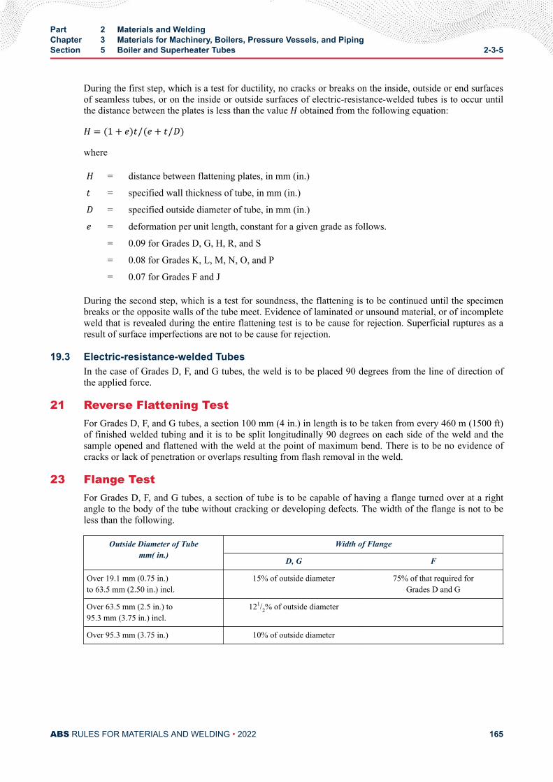
During the first step, which is a test for ductility, no cracks or breaks on the inside, outside or end surfacesof seamless tubes, or on the inside or outside surfaces of electric-resistance-welded tubes is to occur untilthe distance between the plates is less than the value H obtained from the following equation:H = (1 + e)t/(e+ t/D)whereH = distance between flattening plates, in mm (in.)t = specified wall thickness of tube, in mm (in.)D = specified outside diameter of tube, in mm (in.)e = deformation per unit length, constant for a given grade as follows.
= 0.09 for Grades D, G, H, R, and S
= 0.08 for Grades K, L, M, N, O, and P
= 0.07 for Grades F and J
During the second step, which is a test for soundness, the flattening is to be continued until the specimenbreaks or the opposite walls of the tube meet. Evidence of laminated or unsound material, or of incompleteweld that is revealed during the entire flattening test is to be cause for rejection. Superficial ruptures as aresult of surface imperfections are not to be cause for rejection.
19.3 Electric-resistance-welded TubesIn the case of Grades D, F, and G tubes, the weld is to be placed 90 degrees from the line of direction ofthe applied force.
21 Reverse Flattening TestFor Grades D, F, and G tubes, a section 100 mm (4 in.) in length is to be taken from every 460 m (1500 ft)of finished welded tubing and it is to be split longitudinally 90 degrees on each side of the weld and thesample opened and flattened with the weld at the point of maximum bend. There is to be no evidence ofcracks or lack of penetration or overlaps resulting from flash removal in the weld.
23 Flange TestFor Grades D, F, and G tubes, a section of tube is to be capable of having a flange turned over at a rightangle to the body of the tube without cracking or developing defects. The width of the flange is not to beless than the following.
Outside Diameter of Tubemm( in.)
Width of Flange
D, G F
Over 19.1 mm (0.75 in.)to 63.5 mm (2.50 in.) incl.
15% of outside diameter 75% of that required forGrades D and G
Over 63.5 mm (2.5 in.) to95.3 mm (3.75 in.) incl.
121/2% of outside diameter
Over 95.3 mm (3.75 in.) 10% of outside diameter
Part 2 Materials and WeldingChapter 3 Materials for Machinery, Boilers, Pressure Vessels, and PipingSection 5 Boiler and Superheater Tubes 2-3-5
ABS RULES FOR MATERIALS AND WELDING • 2022 165
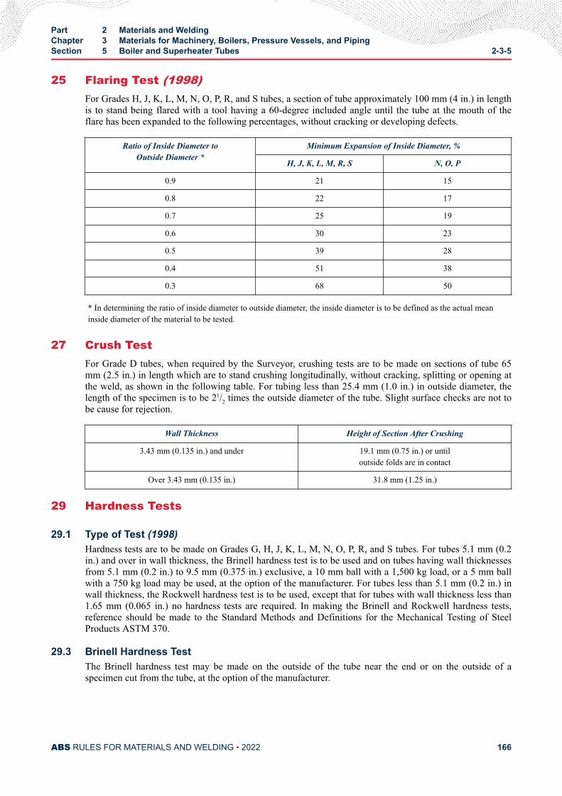
25 Flaring Test (1998)For Grades H, J, K, L, M, N, O, P, R, and S tubes, a section of tube approximately 100 mm (4 in.) in lengthis to stand being flared with a tool having a 60-degree included angle until the tube at the mouth of theflare has been expanded to the following percentages, without cracking or developing defects.
Ratio of Inside Diameter toOutside Diameter *
Minimum Expansion of Inside Diameter, %
H, J, K, L, M, R, S N, O, P
0.9 21 15
0.8 22 17
0.7 25 19
0.6 30 23
0.5 39 28
0.4 51 38
0.3 68 50
* In determining the ratio of inside diameter to outside diameter, the inside diameter is to be defined as the actual meaninside diameter of the material to be tested.
27 Crush TestFor Grade D tubes, when required by the Surveyor, crushing tests are to be made on sections of tube 65mm (2.5 in.) in length which are to stand crushing longitudinally, without cracking, splitting or opening atthe weld, as shown in the following table. For tubing less than 25.4 mm (1.0 in.) in outside diameter, thelength of the specimen is to be 21/2 times the outside diameter of the tube. Slight surface checks are not tobe cause for rejection.
Wall Thickness Height of Section After Crushing
3.43 mm (0.135 in.) and under 19.1 mm (0.75 in.) or untiloutside folds are in contact
Over 3.43 mm (0.135 in.) 31.8 mm (1.25 in.)
29 Hardness Tests
29.1 Type of Test (1998)Hardness tests are to be made on Grades G, H, J, K, L, M, N, O, P, R, and S tubes. For tubes 5.1 mm (0.2in.) and over in wall thickness, the Brinell hardness test is to be used and on tubes having wall thicknessesfrom 5.1 mm (0.2 in.) to 9.5 mm (0.375 in.) exclusive, a 10 mm ball with a 1,500 kg load, or a 5 mm ballwith a 750 kg load may be used, at the option of the manufacturer. For tubes less than 5.1 mm (0.2 in.) inwall thickness, the Rockwell hardness test is to be used, except that for tubes with wall thickness less than1.65 mm (0.065 in.) no hardness tests are required. In making the Brinell and Rockwell hardness tests,reference should be made to the Standard Methods and Definitions for the Mechanical Testing of SteelProducts ASTM 370.
29.3 Brinell Hardness TestThe Brinell hardness test may be made on the outside of the tube near the end or on the outside of aspecimen cut from the tube, at the option of the manufacturer.
Part 2 Materials and WeldingChapter 3 Materials for Machinery, Boilers, Pressure Vessels, and PipingSection 5 Boiler and Superheater Tubes 2-3-5
ABS RULES FOR MATERIALS AND WELDING • 2022 166
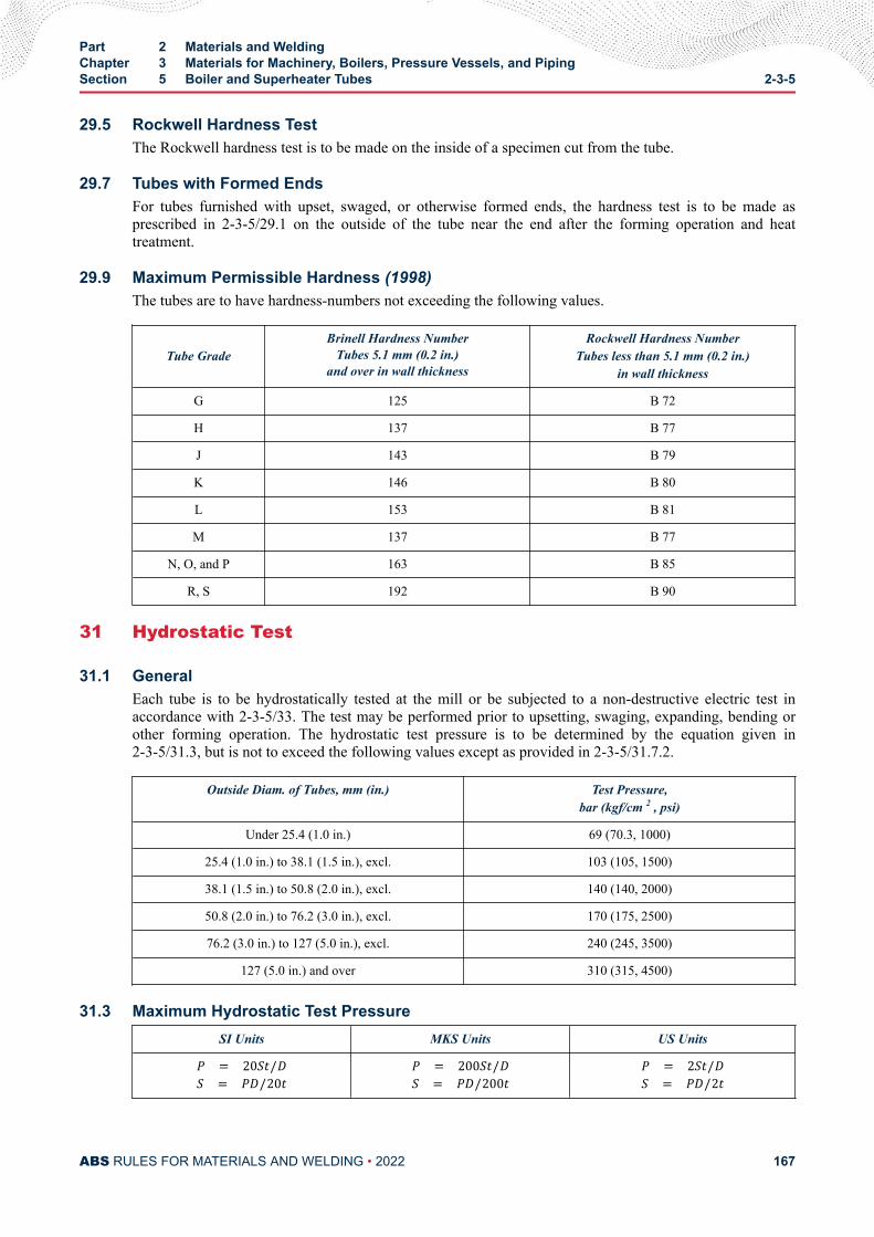
29.5 Rockwell Hardness TestThe Rockwell hardness test is to be made on the inside of a specimen cut from the tube.
29.7 Tubes with Formed EndsFor tubes furnished with upset, swaged, or otherwise formed ends, the hardness test is to be made asprescribed in 2-3-5/29.1 on the outside of the tube near the end after the forming operation and heattreatment.
29.9 Maximum Permissible Hardness (1998)The tubes are to have hardness-numbers not exceeding the following values.
Tube GradeBrinell Hardness Number
Tubes 5.1 mm (0.2 in.)and over in wall thickness
Rockwell Hardness NumberTubes less than 5.1 mm (0.2 in.)
in wall thickness
G 125 B 72
H 137 B 77
J 143 B 79
K 146 B 80
L 153 B 81
M 137 B 77
N, O, and P 163 B 85
R, S 192 B 90
31 Hydrostatic Test
31.1 GeneralEach tube is to be hydrostatically tested at the mill or be subjected to a non-destructive electric test inaccordance with 2-3-5/33. The test may be performed prior to upsetting, swaging, expanding, bending orother forming operation. The hydrostatic test pressure is to be determined by the equation given in2-3-5/31.3, but is not to exceed the following values except as provided in 2-3-5/31.7.2.
Outside Diam. of Tubes, mm (in.) Test Pressure,bar (kgf/cm 2 , psi)
Under 25.4 (1.0 in.) 69 (70.3, 1000)
25.4 (1.0 in.) to 38.1 (1.5 in.), excl. 103 (105, 1500)
38.1 (1.5 in.) to 50.8 (2.0 in.), excl. 140 (140, 2000)
50.8 (2.0 in.) to 76.2 (3.0 in.), excl. 170 (175, 2500)
76.2 (3.0 in.) to 127 (5.0 in.), excl. 240 (245, 3500)
127 (5.0 in.) and over 310 (315, 4500)
31.3 Maximum Hydrostatic Test PressureSI Units MKS Units US UnitsP = 20St/DS = PD/20t P = 200St/DS = PD/200t P = 2St/DS = PD/2t
Part 2 Materials and WeldingChapter 3 Materials for Machinery, Boilers, Pressure Vessels, and PipingSection 5 Boiler and Superheater Tubes 2-3-5
ABS RULES FOR MATERIALS AND WELDING • 2022 167
whereP = hydrostatic test pressure, in bar (kgf/cm2, psi)S = allowable fiber stress of 110 N/mm2 (11 kgf/mm2, 16,000 psi)t = specified wall thickness, in mm (in.)D = specified outside diameter, in mm (in.)
31.5 Duration of TestThe test pressure is to be held for a minimum of 5 seconds.
31.7 Alternate Tests31.7.1
When requested by the purchaser and so stated in the order, tubes are to be tested to one and one-half times the specified working pressure (when one and one-half times the specified workingpressure exceeds the test pressure prescribed in 2-3-5/31.1), provided the fiber stresscorresponding to those test pressures does not exceed 110 N/mm2 (11 kgf/mm2, 16,000 psi) ascalculated in accordance with 2-3-5/31.3.
31.7.2When requested by the purchaser and so stated in the order, or at the option of the manufacturer,tubes are to be tested at pressures, calculated in accordance with 2-3-5/31.1 corresponding to afiber stress of more than 110 N/mm2 (11 kgf/mm2, 16,000 psi), but not more than 165 N/mm2 (17kgf/mm2, 24,000 psi).
31.9 RejectionIf any tube shows leaks during the hydrostatic test, it is to be rejected.
33 Nondestructive Electric Test (NDET) (1998)
33.1 GeneralWhen specified by the purchaser, each ferritic steel tube, Grades D, F, G, H, J, K, L, M, N, O, and P, is tobe tested in accordance with ASTM E213, for Ultrasonic Examination of Metal Pipe and Tubing or ASTME309, for Eddy-Current Examination of Steel Tubular Products Using Magnetic Saturation, ASTM E570,for Flux Leakage Examination of Ferromagnetic Steel Tubular Products, or other approved standard. Whenspecified by the purchaser, each austenitic stainless steel tube, Grades R and S, is to be tested inaccordance with ASTM E213, for Ultrasonic Examination of Metal Pipe and Tubing or ASTM E426, forElectromagnetic (Eddy-Current) Examination of Seamless and Welded Tubular Products, AusteniticStainless Steel and Similar Alloys, or other approved standard. It is the intent of this test to reject tubescontaining defects and the Surveyor is to be satisfied that the nondestructive testing procedures are used ina satisfactory manner
33.3 Ultrasonic Calibration StandardsNotches on the inside or outside surfaces may be used. The depth of the notch is not to exceed 12.5% ofthe specified wall thickness of the tube or 0.1 mm (0.004 in.), whichever is greater. The width of the notchis not to exceed two times the depth.
33.5 Eddy-current Calibration StandardsIn order to accommodate the various types of nondestructive electrical testing equipment and techniques inuse, and manufacturing practices employed, any one of the following calibration standards may be used at
Part 2 Materials and WeldingChapter 3 Materials for Machinery, Boilers, Pressure Vessels, and PipingSection 5 Boiler and Superheater Tubes 2-3-5
ABS RULES FOR MATERIALS AND WELDING • 2022 168
the option of the producer to establish a minimum sensitivity level for rejection. For welded tubing, theyare to be placed in the weld, if visible.
33.5.1 Drilled HoleThree or more holes not larger than 0.785 mm (0.031 in.) in diameter and equally spaced about thepipe circumference and sufficiently separated longitudinally to ensure a separately distinguishableresponse are to be drilled radially and completely through tube wall, care being taken to avoiddistortion of the tube while drilling. Alternatively, one hole may be used, provided that thecalibration tube is scanned at a minimum of three locations each 120 degrees apart, or at morefrequent scans with smaller angular increments, provided that the entire 360 degrees of the eddy-current coil is checked.
33.5.2 Transverse Tangential NotchUsing a round tool or file with a 6.35 mm (0.25 in.) diameter, a notch is to be filed or milledtangential to the surface and transverse to the longitudinal axis of the tube. Said notch is to have adepth not exceeding 12.5% of the nominal wall thickness of the tube or 0.1 mm (0.004 in.),whichever is greater.
33.5.3 Longitudinal NotchA notch 0.785 mm (0.031 in.) or less in width is to be machined in a radial plane parallel to thetube axis on the outside surface of the tube, to have a depth not exceeding 12.5% of the nominalwall thickness of the tube or 0.1 mm (0.004 in.), whichever is greater. The length of the notch is tobe compatible with the testing method.
33.7 Flux Leakage Calibration StandardsThe depth of longitudinal notches on the inside and outside surfaces is not to exceed 12.5% of the specifiedwall thickness of the tube or 0.1 mm (0.004 in.), whichever is greater. The width of the notch is not toexceed the depth, and the length of the notch is not to exceed 25.4 mm (1.0 in.). Outside and inside surfacenotches are to be located sufficiently apart to allow distinct identification of the signal from each notch.
33.9 RejectionTubing producing a signal equal to or greater than the calibration defect is to be subject to rejection.
33.11 AffidavitsWhen each tube is subjected to an approved nondestructive electrical test as a regular procedure during theprocess of manufacture, an affidavit covering this test may be accepted by the Surveyor.
35 Retests (1998)For all grades of tubes, if the results of the mechanical tests do not conform to the requirements, retestsmay be made on additional tubes from the same lot, double the original number specified, each of which isto conform to the requirements. If heat-treated tubes fail to conform to the test requirements, the individualtubes, groups or lots of tubes represented, may be re-heat-treated and resubmitted for retest, as indicated.Only two reheat treatments will be permitted.
37 Finish (2008)Tubes of all grades are to be examined by the Surveyor prior to fabrication or installation, and are to bereasonably straight and have smooth ends free from burrs. At a minimum, the finished tubes are to bevisually inspected at the same frequency as that required for the flattening test specified in 2-3-5/39.3TABLE 2 for the applicable grade. They are to be free from defects and are to have a workmanlike finish.Grade R and S tubes are to be free from scale by pickling or by the use of bright annealing. Minor defectsmay be removed by grinding provided the wall thicknesses are not decreased beyond the permissible
Part 2 Materials and WeldingChapter 3 Materials for Machinery, Boilers, Pressure Vessels, and PipingSection 5 Boiler and Superheater Tubes 2-3-5
ABS RULES FOR MATERIALS AND WELDING • 2022 169
variations in dimensions. Welding repair to any tube is not to be carried out without the purchaser’sapproval and is to be to the Surveyor’s satisfaction.
39 Permissible Variations in Dimensions (1998)At a minimum, the finished tubes are to be measured at the same frequency as that required for theflattening test specified in 2-3-5/39.3 TABLE 2 for the applicable grade.
39.1 Wall ThicknessThe permissible variations in wall thickness for all tubes are based on the ordered thickness and shouldconform to that given in the applicable ASTM designation for acceptance, but the minimum thickness forall tubes is not to be less than that required by the Rules for a specific application, regardless of such prioracceptance.
39.3 Outside DiameterVariations from the ordered outside diameter are not to exceed the amounts prescribed in 2-3-5/39.3TABLE 4.
Part 2 Materials and WeldingChapter 3 Materials for Machinery, Boilers, Pressure Vessels, and PipingSection 5 Boiler and Superheater Tubes 2-3-5
ABS RULES FOR MATERIALS AND WELDING • 2022 170
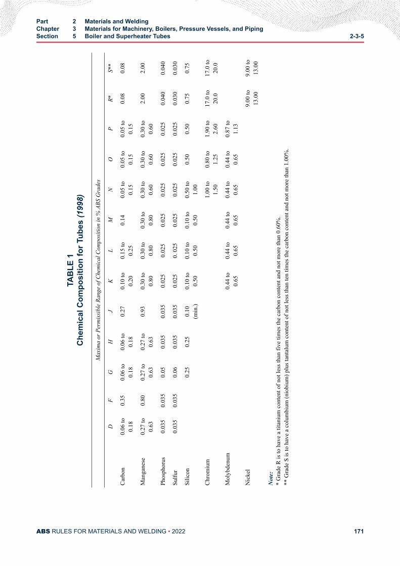
TAB
LE 1
Che
mic
al C
ompo
sitio
n fo
r Tub
es (1
998)
Max
ima
or P
erm
issi
ble
Rang
e of
Che
mic
al C
ompo
sitio
n in
% A
BS G
rade
s
D
FG
HJ
KL
MN
OP
R*S*
*
Carb
on0.
06 to
0.18
0.35
0.06
to0.
180.
06 to
0.18
0.27
0.10
to0.
200.
15 to
0.25
0.14
0.05
to0.
150.
05 to
0.15
0.05
to0.
150.
080.
08
Man
gane
se0.
27 to
0.63
0.80
0.27
to0.
630.
27 to
0.63
0.93
0.30
to0.
800.
30 to
0.80
0.30
to0.
800.
30 to
0.60
0.30
to0.
600.
30 to
0.60
2.00
2.00
Phos
phor
us0.
035
0.03
50.
050.
035
0.03
50.
025
0.02
50.
025
0.02
50.
025
0.02
50.
040
0.04
0
Sulfu
r0.
035
0.03
50.
060.
035
0.03
50.
025
0. 0
250.
025
0.02
50.
025
0.02
50.
030
0.03
0
Silic
on
0.25
0.25
0.10
(min
.)0.
10 to
0.50
0.10
to0.
500.
10 to
0.50
0.50
to1.
000.
500.
500.
750.
75
Chro
miu
m
1.
00 to
1.50
0.80
to1.
251.
90 to
2.60
17.0
to20
.017
.0 to
20.0
Mol
ybde
num
0.44
to0.
650.
44 to
0.65
0.44
to0.
650.
44 to
0.65
0.44
to0.
650.
87 to
1.13
Nic
kel
9.
00 to
13.0
09.
00 to
13.0
0
Not
e:*
Gra
de R
is to
hav
e a
titan
ium
con
tent
of n
ot le
ss th
an fi
ve ti
mes
the
carb
on c
onte
nt a
nd n
ot m
ore
than
0.6
0%.
** G
rade
S is
to h
ave
a co
lum
bium
(nio
bium
) plu
s tan
talu
m c
onte
nt o
f not
less
than
ten
times
the
carb
on c
onte
nt a
nd n
ot m
ore
than
1.0
0%.
Part 2 Materials and WeldingChapter 3 Materials for Machinery, Boilers, Pressure Vessels, and PipingSection 5 Boiler and Superheater Tubes 2-3-5
ABS RULES FOR MATERIALS AND WELDING • 2022 171
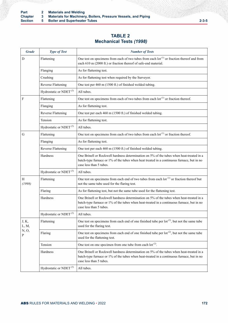
TABLE 2 Mechanical Tests (1998)
Grade Type of Test Number of Tests
D Flattening One test on specimens from each of two tubes from each lot (1) or fraction thereof and fromeach 610 m (2000 ft.) or fraction thereof of safe-end material.
Flanging As for flattening test.
Crushing As for flattening test when required by the Surveyor.
Reverse Flattening One test per 460 m (1500 ft.) of finished welded tubing.
Hydrostatic or NDET (3) All tubes.
F Flattening One test on specimens from each of two tubes from each lot (1) or fraction thereof.
Flanging As for flattening test.
Reverse Flattening One test per each 460 m (1500 ft.) of finished welded tubing.
Tension As for flattening test.
Hydrostatic or NDET (3) All tubes.
G Flattening One test on specimens from each of two tubes from each lot (1) or fraction thereof.
Flanging As for flattening test.
Reverse Flattening One test per each 460 m (1500 ft.) of finished welded tubing.
Hardness One Brinell or Rockwell hardness determination on 5% of the tubes when heat-treated in abatch-type furnace or 1% of the tubes when heat treated in a continuous furnace, but in nocase less than 5 tubes.
Hydrostatic or NDET (3) All tubes.
H(1998)
Flattening One test on specimens from each end of two tubes from each lot (1) or fraction thereof butnot the same tube used for the flaring test.
Flaring As for flattening test, but not the same tube used for the flattening test.
Hardness One Brinell or Rockwell hardness determination on 5% of the tubes when heat-treated in abatch-type furnace or 1% of the tubes when heat-treated in a continuous furnace, but in nocase less than 5 tubes.
Hydrostatic or NDET (3) All tubes.
J, K,L, M,N, O,P
Flattening One test on specimens from each end of one finished tube per lot (2), but not the same tubeused for the flaring test.
Flaring One test on specimens from each end of one finished tube per lot (2), but not the same tubeused for the flattening test.
Tension One test on one specimen from one tube from each lot (2).
Hardness One Brinell or Rockwell hardness determination on 5% of the tubes when heat-treated in abatch-type furnace or 1% of the tubes when heat-treated in a continuous furnace, but in nocase less than 5 tubes.
Hydrostatic or NDET (3) All tubes.
Part 2 Materials and WeldingChapter 3 Materials for Machinery, Boilers, Pressure Vessels, and PipingSection 5 Boiler and Superheater Tubes 2-3-5
ABS RULES FOR MATERIALS AND WELDING • 2022 172
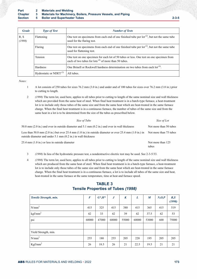
Grade Type of Test Number of Tests
R, S(1998)
Flattening One test on specimens from each end of one finished tube per lot (2), but not the same tubeused for the flaring test.
Flaring One test on specimens from each end of one finished tube per lot (2), but not the same tubeused for flattening test.
Tension One test on one specimen for each lot of 50 tubes or less. One test on one specimen fromeach of two tubes for lots (4) of more than 50 tubes.
Hardness One Brinell or Rockwell hardness determination on two tubes from each lot (4).
Hydrostatic or NDET (3) All tubes.
Notes:
1 A lot consists of 250 tubes for sizes 76.2 mm (3.0 in.) and under and of 100 tubes for sizes over 76.2 mm (3.0 in.) priorto cutting to length.
2 (1998) The term lot, used here, applies to all tubes prior to cutting to length of the same nominal size and wall thicknesswhich are provided from the same heat of steel. When final heat treatment is in a batch-type furnace, a heat-treatmentlot is to include only those tubes of the same size and from the same heat which are heat-treated in the same furnacecharge. When the final heat treatment is in a continuous furnace, the number of tubes of the same size and from thesame heat in a lot is to be determined from the size of the tubes as prescribed below.
Size of Tube Size of Lot
50.8 mm (2.0 in.) and over in outside diameter and 5.1 mm (0.2 in.) and over in wall thickness Not more than 50 tubes
Less than 50.8 mm (2.0 in.) but over 25.4 mm (1.0 in.) in outside diameter or over 25.4 mm (1.0 in.) inoutside diameter and under 5.1 mm (0.2 in.) in wall thickness
Not more than 75 tubes
25.4 mm (1.0 in.) or less in outside diameter Not more than 125tubes
3 (1998) In lieu of the hydrostatic pressure test, a nondestructive electric test may be used. See 2-3-5/33.
4 (1998) The term lot, used here, applies to all tubes prior to cutting to length of the same nominal size and wall thicknesswhich are produced from the same heat of steel. When final heat treatment is in a batch-type furnace, a heat-treatmentlot is to include only those tubes of the same size and from the same heat which are heat-treated in the same furnacecharge. When the final heat treatment is in a continuous furnace, a lot is to include all tubes of the same size and heat,heat-treated in the same furnace at the same temperature, time at heat and furnace speed.
TABLE 3Tensile Properties of Tubes (1998)
Tensile Strength, min. F G*,H* J K L M N,O,P R,S(1998)
N/mm2 415 325 415 380 415 365 415 519
kgf/mm2 42 33 42 39 42 37.5 42 53
psi 60000 47000 60000 55000 60000 53000 600 75000
Yield Strength, min.
N/mm2 255 180 255 205 220 195 205 205
Kgf/mm2 26 18.5 26 21 22.5 19.5 21 21
Part 2 Materials and WeldingChapter 3 Materials for Machinery, Boilers, Pressure Vessels, and PipingSection 5 Boiler and Superheater Tubes 2-3-5
ABS RULES FOR MATERIALS AND WELDING • 2022 173
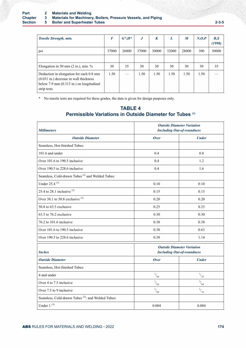
Tensile Strength, min. F G*,H* J K L M N,O,P R,S(1998)
psi 37000 26000 37000 30000 32000 28000 300 30000
Elongation in 50 mm (2 in.), min. % 30 35 30 30 30 30 30 35
Deduction in elongation for each 0.8 mm(0.031 in.) decrease in wall thicknessbelow 7.9 mm (0.313 in.) on longitudinalstrip tests
1.50 — 1.50 1.50 1.50 1.50 1.50 —
* No tensile tests are required for these grades, the data is given for design purposes only.
TABLE 4Permissible Variations in Outside Diameter for Tubes (1)
MillimetersOutside Diameter VariationIncluding Out-of-roundness
Outside Diameter Over Under
Seamless, Hot-finished Tubes:
101.6 and under 0.4 0.8
Over 101.6 to 190.5 inclusive 0.4 1.2
Over 190.5 to 228.6 inclusive 0.4 1.6
Seamless, Cold-drawn Tubes (2) and Welded Tubes:
Under 25.4 (3) 0.10 0.10
25.4 to 28.1 inclusive (3) 0.15 0.15
Over 38.1 to 50.8 exclusive (3) 0.20 0.20
50.8 to 63.5 exclusive 0.25 0.25
63.5 to 76.2 exclusive 0.30 0.30
76.2 to 101.6 inclusive 0.38 0.38
Over 101.6 to 190.5 inclusive 0.38 0.63
Over 190.5 to 228.6 inclusive 0.38 1.14
InchesOutside Diameter VariationIncluding Out-of-roundness
Outside Diameter Over Under
Seamless, Hot-finished Tubes:
4 and under 1/641/32
Over 4 to 7.5 inclusive 1/643/64
Over 7.5 to 9 inclusive 1/641/16
Seamless, Cold-drawn Tubes (2): and Welded Tubes:
Under 1 (3) 0.004 0.004
Part 2 Materials and WeldingChapter 3 Materials for Machinery, Boilers, Pressure Vessels, and PipingSection 5 Boiler and Superheater Tubes 2-3-5
ABS RULES FOR MATERIALS AND WELDING • 2022 174
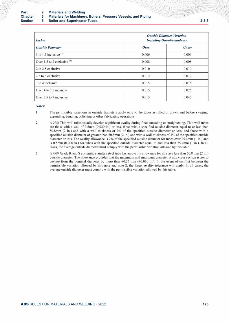
InchesOutside Diameter VariationIncluding Out-of-roundness
Outside Diameter Over Under
1 to 1.5 inclusive (3) 0.006 0.006
Over 1.5 to 2 exclusive (3) 0.008 0.008
2 to 2.5 exclusive 0.010 0.010
2.5 to 3 exclusive 0.012 0.012
3 to 4 inclusive 0.015 0.015
Over 4 to 7.5 inclusive 0.015 0.025
Over 7.5 to 9 inclusive 0.015 0.045
Notes:
1 The permissible variations in outside diameters apply only to the tubes as rolled or drawn and before swaging,expanding, bending, polishing or other fabricating operations.
2 (1998) Thin wall tubes usually develop significant ovality during final annealing or straightening. Thin wall tubesare those with a wall of 0.5mm (0.020 in.) or less, those with a specified outside diameter equal to or less than50.8mm (2 in.) and with a wall thickness of 2% of the specified outside diameter or less, and those with aspecified outside diameter of greater than 50.8mm (2 in.) and with a wall thickness of 3% of the specified outsidediameter or less. The ovality allowance is 2% of the specified outside diameter for tubes over 25.4mm (1 in.) andis 0.5mm (0.020 in.) for tubes with the specified outside diameter equal to and less than 25.4mm (1 in.). In allcases, the average outside diameter must comply with the permissible variation allowed by this table.
3 (1998) Grade R and S austenitic stainless steel tube has an ovality allowance for all sizes less than 50.8 mm (2 in.)outside diameter. The allowance provides that the maximum and minimum diameter at any cross section is not todeviate from the nominal diameter by more than ±0.25 mm (±0.010 in.). In the event of conflict between thepermissible variation allowed by this note and note 2, the larger ovality tolerance will apply. In all cases, theaverage outside diameter must comply with the permissible variation allowed by this table.
Part 2 Materials and WeldingChapter 3 Materials for Machinery, Boilers, Pressure Vessels, and PipingSection 5 Boiler and Superheater Tubes 2-3-5
ABS RULES FOR MATERIALS AND WELDING • 2022 175
C H A P T E R 3Materials for Machinery, Boilers, Pressure Vessels, and Piping
S E C T I O N 6Boiler Rivet and Staybolt Steel and Rivets
Note: In substantial agreement with ASTM A31 Boiler Rivet Steel and Rivets.
1 Process of Manufacture (2008)The steel is to be made by one or more of the following processes: open-hearth, basic-oxygen or electric-furnace. All such bars and rivets will be examined at the mills by the Surveyor when specially requested bythe purchaser. They are to be free from defects and have a workmanlike finish.
3 Marking and Retests
3.1 Manufacturer's MarkingsThe bars and rivets, when loaded for shipment, are to be properly separated in bundles or containersmarked with the name or brand of the manufacturer, the letter indicating the grade of steel and the heatnumber of identification.
3.3 ABS MarkingsThe ABS markings, indicating satisfactory compliance with the Rule requirements, and as furnished by theSurveyor, are to be marked on the material or on each bundle or container near the marking specified in2-3-6/3.1.
3.5 RetestsWhen the result of any of the physical tests specified for any of the material does not conform to therequirements, two additional specimens may, at the request of the manufacturer, be taken from the same lotand tested in the manner specified, but in such case, both of the specimens must conform to therequirements. In the case of tension tests, this retest is to be allowed if the percent of elongation obtained isless than required.
5 Tensile PropertiesThe material is to conform to the following requirements as to tensile properties.
Grade A Grade B
Tensile Strength N/mm2 (kgf/mm2, psi) 310-380 (31.5-39, 45000-55000) 400-470 (41-48, 58000-68000)
PART 2
ABS RULES FOR MATERIALS AND WELDING • 2022 176
Yield Point, min., N/mm2 (kgf/mm2,psi)
155 (16, 23000) 195 (20, 29000)
Elongation in 200 mm (8 in.), min., % 27 22
7 Bending PropertiesThe test specimen for Grade A steel is to stand being bent cold through 180 degrees flat on itself withoutcracking on the outside of the bent portion. The test specimen for Grade B steel is to stand being bent coldthrough 180 degrees without cracking on the outside of the bent portion, as follows: for material 19.1 mm(0.75 in.) and under in diameter, around an inside diameter which is equal to one-half the diameter of thespecimen; for material over 19.1 mm (0.75 in.) in diameter, around an inside diameter which is equal to thediameter of the specimen.
9 Test SpecimensBend and tension test specimens are to be the full diameter of the bars as rolled and, in the case of rivetbars which have been cold-drawn, the test specimens shall be normalized before testing.
11 Number of TestsTwo tension and two cold-bend tests are to be made from each heat.
13 Tests of Finished Rivets
13.1 Bending PropertiesThe rivet shank of Grade A steel is to stand being bent cold through 180 degrees flat on itself withoutcracking on the outside of the bent portion. The rivet shank of Grade B steel is to stand being bent coldthrough 180 degrees without cracking on the outside of the bent portion, as follows: for material 19.1 mm(0.75 in.) and under in diameter, around an inside diameter which is equal to the diameter of the shank; formaterial over 19.1 mm (0.75 in.) in diameter, around an inside diameter which is equal to one and one-halftimes the diameter of the shank.
13.3 Flattening TestsThe rivet head is to stand being flattened, while hot, to a diameter two and one-half times the diameter ofthe shank without cracking at the edges.
13.5 Number of TestsThree bend and three flattening tests are to be made from each size in each lot of rivets offered forinspection.
Part 2 Materials and WeldingChapter 3 Materials for Machinery, Boilers, Pressure Vessels, and PipingSection 6 Boiler Rivet and Staybolt Steel and Rivets 2-3-6
ABS RULES FOR MATERIALS AND WELDING • 2022 177
C H A P T E R 3Materials for Machinery, Boilers, Pressure Vessels, and Piping
S E C T I O N 7Steel Machinery Forgings
1 Carbon Steel Machinery Forgings (2000)
1.1 Process of Manufacture1.1.1 General (2017)
The following requirements cover carbon-steel forgings intended to be used in machineryconstruction. Alternatively, forgings which comply with national or proprietary specifications maybe accepted, provided such specifications give reasonable equivalence to these requirements.
Forgings are to be made by a manufacturer approved by ABS.
ABS approval is valid for 5 years subject to annual verification and/or endorsement by theattending Surveyor. The Surveyor is permitted at any time to monitor important aspects of forgingproduction, including but not limited to die preparation and die maintenance, forgingtemperatures, forging reduction or upset, heat treatment and inspection.
Raw materials for forging such as cast steel or semi-finished products are to be manufactured at afacility approved by ABS. Steel is to be fully killed and is to be manufactured by a processapproved by ABS.
For crankshafts, where grain flow is required in the most favorable direction with regard to themode of stressing in service, the proposed method of manufacture may require special approval. Insuch cases, tests may be required to demonstrate that satisfactory microstructure and grain floware obtained.
For components used in the direct load path of a jacking system, refer to Section 6-1-9 of theMOU Rules for additional qualification requirements.
The shaping of forgings or rolled slabs and billets by thermal cutting, scarfing or arc-air gougingis to be undertaken in accordance with recognized good practice and, unless otherwise approved,is to be carried out before the final heat treatment. Preheating is to be employed when necessitatedby the composition and/or thickness of the steel. For certain components, subsequent machining ofall thermal cut surfaces may be required.
When two or more forgings are joined by welding to form a composite component, the proposedwelding procedure specification is to be submitted for approval.
PART 2
ABS RULES FOR MATERIALS AND WELDING • 2022 178
The plastic deformation is to be such as to ensure soundness, uniformity of structure andsatisfactory mechanical properties after heat treatment. The reduction ratio is to be calculated withreference to the average cross-sectional area of the cast material. Where the cast material isinitially upset, this reference area may be taken as the average cross-sectional area after thisoperation.
Unless otherwise approved, the total reduction ratio is to be at least:
● For forgings made from ingots or from forged blooms or billets, 3:1 where L > D and 1.5:1where L ≤ D.
● For forgings made from rolled products, 4:1 where L > D and 2:1 where L ≤ D.
● For forgings made by upsetting, the length after upsetting is to be not more than one-third ofthe length before upsetting or, in the case of an initial forging reduction of at least 1.5:1, notmore than one-half of the length before upsetting.
● For rolled bars used in lieu of forgings, 6:1.L and D are the length and diameter, respectively, of the part of the forging under consideration.
A sufficient discard is to be made from each ingot to secure freedom from piping and unduesegregation.
1.1.2 Chemical Composition (2008)All forgings are to be made from killed steel. An analysis of each heat is to be made to determinethe percentages of the elements specified. The chemical composition thus determined is to bereported to the Surveyor and is to conform to the requirements of 2-3-7/7.17 TABLE 1. Thecarbon content of Grades 2, 3 and 4 is not to exceed 0.23% or carbon equivalent (Ceq) of Grades2, 3 and 4 is not to exceed 0.41%, unless specially approved, see 2-3-7/7.17 TABLE 1. The carboncontent of Grade 4C is not to exceed 0.55%. Welding of Grade 4C is not permitted unlessspecially approved. Specially approved grades having more than the maximum specified carbonare to have S marked after the grade designation.
Forgings for rudder stocks and pintles are to be of weldable quality.
The chemical composition of each heat is to be determined by the manufacturer on a sample takenpreferably during the pouring of the heat. When multiple heats are tapped into a common ladle,the ladle analysis shall apply.
1.1.3 ASTM DesignationsThe grades are in substantial agreement with ASTM as follows:
ABS Grade ASTM Designation
234
4C
A668, Class BA668, Class DA668, Class EA668, Class E
1.3 Marking, Retests and Rejection1.3.1 Marking (2005)
The manufacturer is to adopt a system of identification which will enable all finished forgings tobe traced to the original cast and the Surveyor is to be given full facilities for tracing the forgingswhen required.
Part 2 Materials and WeldingChapter 3 Materials for Machinery, Boilers, Pressure Vessels, and PipingSection 7 Steel Machinery Forgings 2-3-7
ABS RULES FOR MATERIALS AND WELDING • 2022 179
In addition to appropriate identification markings of the manufacturer, ABS markings, indicatingsatisfactory compliance with the Rule requirements, and as furnished by the Surveyor, are to bestamped on all forgings in such locations as to be discernible after machining and installation. Inaddition, Grade 2, Grade 3, Grade 4, and Grade 4C forgings are to be stamped AB/2, AB/3, AB/4and AB/4C, respectively.
1.3.2 Retests (2005)Test material, sufficient for the required number of tests and for possible retest purposes, is to beprovided for each forging. If the results of the mechanical tests for any forging or any lot offorgings do not conform to the requirements specified, two additional test samples representativeof the forging or forging batch may be taken in accordance with 2-3-1/9. If satisfactory results areobtained from both of the additional tests, the forging or batch of forgings is acceptable. If one orboth retests fail, the forging or batch of forgings is to be rejected. The manufacturer may reheat-treat forgings that have failed to meet test requirements, in accordance with 2-3-7/1.5.6. Afterreheat-treating, the forgings are to be submitted for all mechanical testing.
1.3.3 RejectionAny forging having injurious discontinuities that are observed prior to or subsequent to acceptanceat the manufacturer’s plant is to be subject to rejection.
1.5 Heat treatment1.5.1 General (2017)
Heat treatment facilities used in producing ABS certified forgings are to be included in the forgeapproval; this includes subcontracted heat treatment facilities. Approved subcontracted facilitieswill be included in the scope of forge approval.
Heat treatment details are to be included in the approval documentation.
Forge qualification is to include all of the heat treatment facilities that the forge will use.
An independent heat treatment facility can obtain approval, provided that it is documented andverified that the facility is capable of producing heat treated products that meet the mechanicalproperties of the specification and the NDE requirements of the Rules or applicable standard, andthat there is a feedback system to confirm same during production.
If additional sub-contracted or independent facilities are selected to carry out heat treatment anABS approval is to be obtained for the new facility.
The ABS Surveyor is to attend the heat treatment facility during qualification, to verify that theheat treatment process is carried out according to specification.
During production, the extent of monitoring is to be agreed with the Surveyor.
Unless a departure for the following procedures is specifically approved, Grade 2 and 3 forgingsare to be annealed, normalized or normalized and tempered. Grade 4 and 4C forgings are to benormalized and tempered or double-normalized and tempered. The furnace is to be of ampleproportions to bring the forgings to a uniform temperature.
A sufficient number of thermocouples are to be connected to the furnace charge to measure andrecord that its temperature is adequately uniform unless the temperature uniformity of the furnacecan be verified at regular intervals.
Heat treatment is to be carried out in properly constructed furnaces, which are efficientlymaintained with adequate means to control and record temperature. The furnace dimensions are tobe such as to allow the whole furnace charge to be uniformly heated to the necessary temperature.
Part 2 Materials and WeldingChapter 3 Materials for Machinery, Boilers, Pressure Vessels, and PipingSection 7 Steel Machinery Forgings 2-3-7
ABS RULES FOR MATERIALS AND WELDING • 2022 180
In the case of very large forgings, alternative methods of heat treatment will be speciallyconsidered. If for any reason a forging is subsequently heated for further hot working, the forgingis to be reheat-treated. If a forging is locally reheated or any straightening operation is performedafter the final heat treatment, consideration is to be given to a subsequent stress relieving heattreatment. The forge is to maintain records of heat treatment, identifying the furnace used, furnacecharge, date, temperature and time at temperature, together with the number and location ofthermocouples. The records are to be available to the Surveyor upon request.
1.5.2 Cooling Prior to Heat Treatment (2016)After forging and before reheating for heat treatment, the forgings are allowed to cool in a mannerto prevent injury and to accomplish transformation.
1.5.3 AnnealingThe forgings are to be reheated to and held at the proper austenitizing temperature for a sufficienttime to effect the desired transformation and then be allowed to cool slowly and evenly in thefurnace until the temperature has fallen to about 455°C (850°F) or lower.
1.5.4 NormalizingThe forgings are to be reheated to and held at the proper temperature above the transformationrange for a sufficient time to effect the desired transformation and then withdrawn from thefurnace and allowed to cool in air. Water sprays and air blasts may be specially approved for use toachieve more rapid cooling. The faster cooling rates are to be agreed to by the purchaser.
1.5.5 Tempering (2005)The forgings are to be reheated to and held at the proper temperature, which will be below thetransformation range, and are then to be cooled under suitable conditions to 315°C (600°F) orlower. The tempering temperature is not to be less than 550°C (1022°F).
1.5.6 RetreatmentThe manufacturer may re-heat treat the forging, but not more than three additional times.
1.5.7 Surface Hardening (2017)Where it is intended to surface harden forgings, full details of the proposed procedure andspecification are to be submitted for approval. For the purposes of this approval, the manufacturermay be required to demonstrate by test that the proposed procedure gives a uniform surface layerof the required hardness and depth, and that it does not impair the soundness and properties of thesteel.
Where induction hardening or nitriding is to be carried out, forgings are to be heat-treated at anappropriate stage to a condition suitable for this subsequent surface hardening.
Where carburizing is to be carried out, forgings are to be heat treated at an appropriate stage to acondition suitable for subsequent machining and carburizing.
1.7 Tensile PropertiesThe forging tensile properties are to conform the requirements of 2-3-7/7.17 TABLE 2.
1.9 Test Specimens1.9.1 Location and Orientation of Specimens
Mechanical properties are to be determined from test specimens taken from prolongations havinga sectional area not less than the body of the forging. Specimens may be taken in a directionparallel to the axis of the forging in the direction in which the metal is most drawn out or may betaken transversely. The axes of longitudinal specimens are to be located at any point midway
Part 2 Materials and WeldingChapter 3 Materials for Machinery, Boilers, Pressure Vessels, and PipingSection 7 Steel Machinery Forgings 2-3-7
ABS RULES FOR MATERIALS AND WELDING • 2022 181
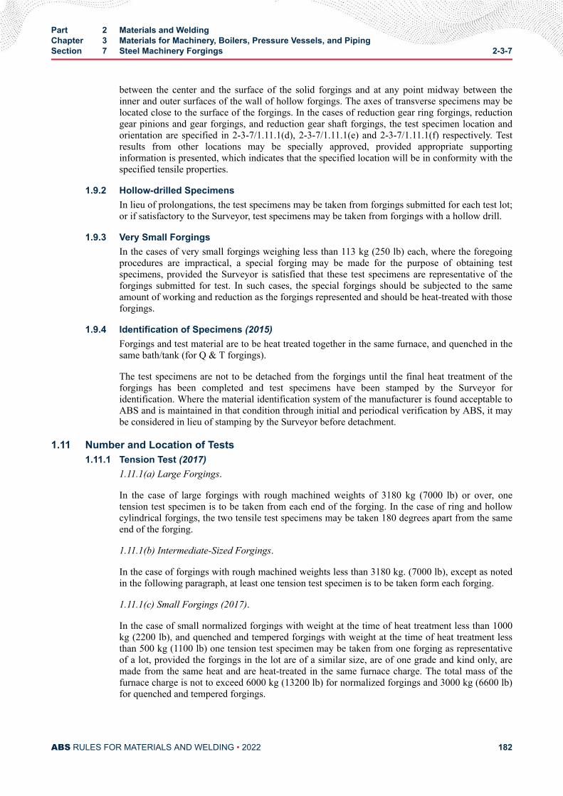
between the center and the surface of the solid forgings and at any point midway between theinner and outer surfaces of the wall of hollow forgings. The axes of transverse specimens may belocated close to the surface of the forgings. In the cases of reduction gear ring forgings, reductiongear pinions and gear forgings, and reduction gear shaft forgings, the test specimen location andorientation are specified in 2-3-7/1.11.1(d), 2-3-7/1.11.1(e) and 2-3-7/1.11.1(f) respectively. Testresults from other locations may be specially approved, provided appropriate supportinginformation is presented, which indicates that the specified location will be in conformity with thespecified tensile properties.
1.9.2 Hollow-drilled SpecimensIn lieu of prolongations, the test specimens may be taken from forgings submitted for each test lot;or if satisfactory to the Surveyor, test specimens may be taken from forgings with a hollow drill.
1.9.3 Very Small ForgingsIn the cases of very small forgings weighing less than 113 kg (250 lb) each, where the foregoingprocedures are impractical, a special forging may be made for the purpose of obtaining testspecimens, provided the Surveyor is satisfied that these test specimens are representative of theforgings submitted for test. In such cases, the special forgings should be subjected to the sameamount of working and reduction as the forgings represented and should be heat-treated with thoseforgings.
1.9.4 Identification of Specimens (2015)Forgings and test material are to be heat treated together in the same furnace, and quenched in thesame bath/tank (for Q & T forgings).
The test specimens are not to be detached from the forgings until the final heat treatment of theforgings has been completed and test specimens have been stamped by the Surveyor foridentification. Where the material identification system of the manufacturer is found acceptable toABS and is maintained in that condition through initial and periodical verification by ABS, it maybe considered in lieu of stamping by the Surveyor before detachment.
1.11 Number and Location of Tests1.11.1 Tension Test (2017)
1.11.1(a) Large Forgings.
In the case of large forgings with rough machined weights of 3180 kg (7000 lb) or over, onetension test specimen is to be taken from each end of the forging. In the case of ring and hollowcylindrical forgings, the two tensile test specimens may be taken 180 degrees apart from the sameend of the forging.
1.11.1(b) Intermediate-Sized Forgings.
In the case of forgings with rough machined weights less than 3180 kg. (7000 lb), except as notedin the following paragraph, at least one tension test specimen is to be taken form each forging.
1.11.1(c) Small Forgings (2017).
In the case of small normalized forgings with weight at the time of heat treatment less than 1000kg (2200 lb), and quenched and tempered forgings with weight at the time of heat treatment lessthan 500 kg (1100 lb) one tension test specimen may be taken from one forging as representativeof a lot, provided the forgings in the lot are of a similar size, are of one grade and kind only, aremade from the same heat and are heat-treated in the same furnace charge. The total mass of thefurnace charge is not to exceed 6000 kg (13200 lb) for normalized forgings and 3000 kg (6600 lb)for quenched and tempered forgings.
Part 2 Materials and WeldingChapter 3 Materials for Machinery, Boilers, Pressure Vessels, and PipingSection 7 Steel Machinery Forgings 2-3-7
ABS RULES FOR MATERIALS AND WELDING • 2022 182
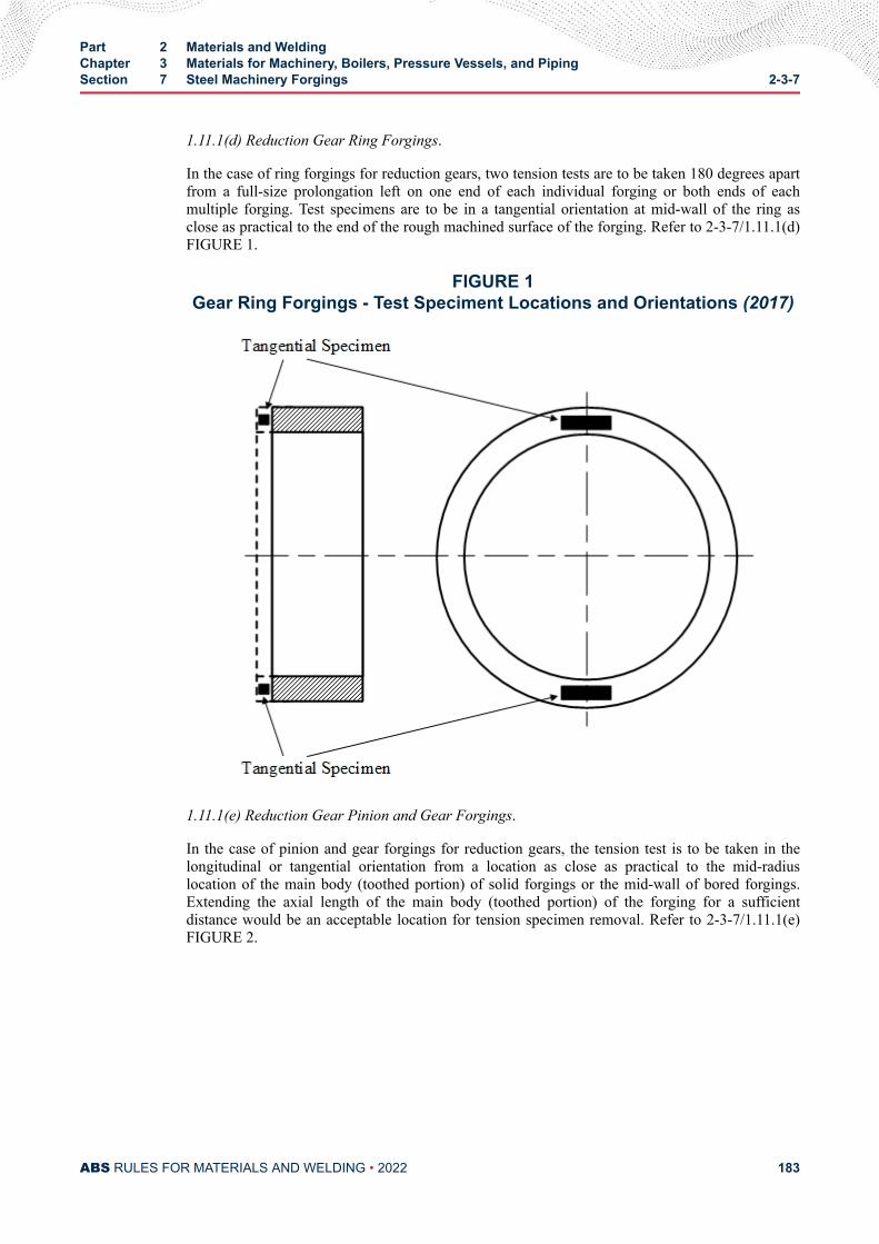
1.11.1(d) Reduction Gear Ring Forgings.
In the case of ring forgings for reduction gears, two tension tests are to be taken 180 degrees apartfrom a full-size prolongation left on one end of each individual forging or both ends of eachmultiple forging. Test specimens are to be in a tangential orientation at mid-wall of the ring asclose as practical to the end of the rough machined surface of the forging. Refer to 2-3-7/1.11.1(d)FIGURE 1.
FIGURE 1Gear Ring Forgings - Test Speciment Locations and Orientations (2017)
1.11.1(e) Reduction Gear Pinion and Gear Forgings.
In the case of pinion and gear forgings for reduction gears, the tension test is to be taken in thelongitudinal or tangential orientation from a location as close as practical to the mid-radiuslocation of the main body (toothed portion) of solid forgings or the mid-wall of bored forgings.Extending the axial length of the main body (toothed portion) of the forging for a sufficientdistance would be an acceptable location for tension specimen removal. Refer to 2-3-7/1.11.1(e)FIGURE 2.
Part 2 Materials and WeldingChapter 3 Materials for Machinery, Boilers, Pressure Vessels, and PipingSection 7 Steel Machinery Forgings 2-3-7
ABS RULES FOR MATERIALS AND WELDING • 2022 183
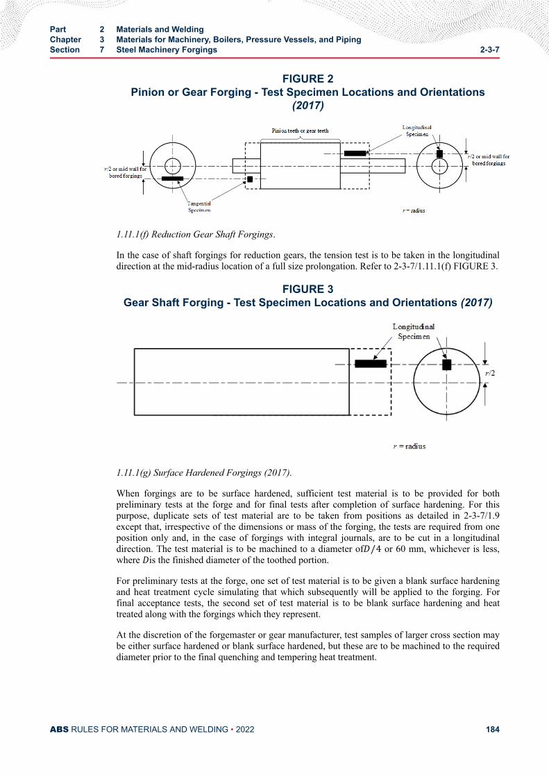
FIGURE 2Pinion or Gear Forging - Test Specimen Locations and Orientations
(2017)
1.11.1(f) Reduction Gear Shaft Forgings.
In the case of shaft forgings for reduction gears, the tension test is to be taken in the longitudinaldirection at the mid-radius location of a full size prolongation. Refer to 2-3-7/1.11.1(f) FIGURE 3.
FIGURE 3Gear Shaft Forging - Test Specimen Locations and Orientations (2017)
1.11.1(g) Surface Hardened Forgings (2017).
When forgings are to be surface hardened, sufficient test material is to be provided for bothpreliminary tests at the forge and for final tests after completion of surface hardening. For thispurpose, duplicate sets of test material are to be taken from positions as detailed in 2-3-7/1.9except that, irrespective of the dimensions or mass of the forging, the tests are required from oneposition only and, in the case of forgings with integral journals, are to be cut in a longitudinaldirection. The test material is to be machined to a diameter ofD/4 or 60 mm, whichever is less,where Dis the finished diameter of the toothed portion.
For preliminary tests at the forge, one set of test material is to be given a blank surface hardeningand heat treatment cycle simulating that which subsequently will be applied to the forging. Forfinal acceptance tests, the second set of test material is to be blank surface hardening and heattreated along with the forgings which they represent.
At the discretion of the forgemaster or gear manufacturer, test samples of larger cross section maybe either surface hardened or blank surface hardened, but these are to be machined to the requireddiameter prior to the final quenching and tempering heat treatment.
Part 2 Materials and WeldingChapter 3 Materials for Machinery, Boilers, Pressure Vessels, and PipingSection 7 Steel Machinery Forgings 2-3-7
ABS RULES FOR MATERIALS AND WELDING • 2022 184
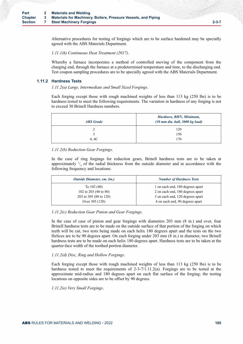
Alternative procedures for testing of forgings which are to be surface hardened may be speciallyagreed with the ABS Materials Department.
1.11.1(h) Continuous Heat Treatment (2017).
Whereby a furnace incorporates a method of controlled moving of the component from thecharging end, through the furnace at a predetermined temperature and time, to the discharging end.Test coupon sampling procedures are to be specially agreed with the ABS Materials Department.
1.11.2 Hardness Tests1.11.2(a) Large, Intermediate and Small Sized Forgings.
Each forging except those with rough machined weights of less than 113 kg (250 lbs) is to behardness tested to meet the following requirements. The variation in hardness of any forging is notto exceed 30 Brinell Hardness numbers.
ABS GradeHardness, BHN, Minimum,
(10 mm dia. ball, 3000 kg load)
23
4, 4C
120150170
1.11.2(b) Reduction Gear Forgings.
In the case of ring forgings for reduction gears, Brinell hardness tests are to be taken atapproximately 1/4 of the radial thickness from the outside diameter and in accordance with thefollowing frequency and locations:
Outside Diameter, cm. (in.) Number of Hardness Tests
To 102 (40)102 to 203 (40 to 80)203 to 305 (80 to 120)
Over 305 (120)
1 on each end, 180 degrees apart2 on each end, 180 degrees apart3 on each end, 120 degrees apart4 on each end, 90 degrees apart
1.11.2(c) Reduction Gear Pinion and Gear Forgings.
In the case of case of pinion and gear forgings with diameters 203 mm (8 in.) and over, fourBrinell hardness tests are to be made on the outside surface of that portion of the forging on whichteeth will be cut, two tests being made on each helix 180 degrees apart and the tests on the twoHelices are to be 90 degrees apart. On each forging under 203 mm (8 in.) in diameter, two Brinellhardness tests are to be made on each helix 180 degrees apart. Hardness tests are to be taken at thequarter-face width of the toothed portion diameter.
1.11.2(d) Disc, Ring and Hollow Forgings.
Each forging except those with rough machined weights of less than 113 kg (250 lbs) is to behardness tested to meet the requirements of 2-3-7/1.11.2(a). Forgings are to be tested at theapproximate mid-radius and 180 degrees apart on each flat surface of the forging; the testinglocations on opposite sides are to be offset by 90 degrees.
1.11.2(e) Very Small Forgings.
Part 2 Materials and WeldingChapter 3 Materials for Machinery, Boilers, Pressure Vessels, and PipingSection 7 Steel Machinery Forgings 2-3-7
ABS RULES FOR MATERIALS AND WELDING • 2022 185
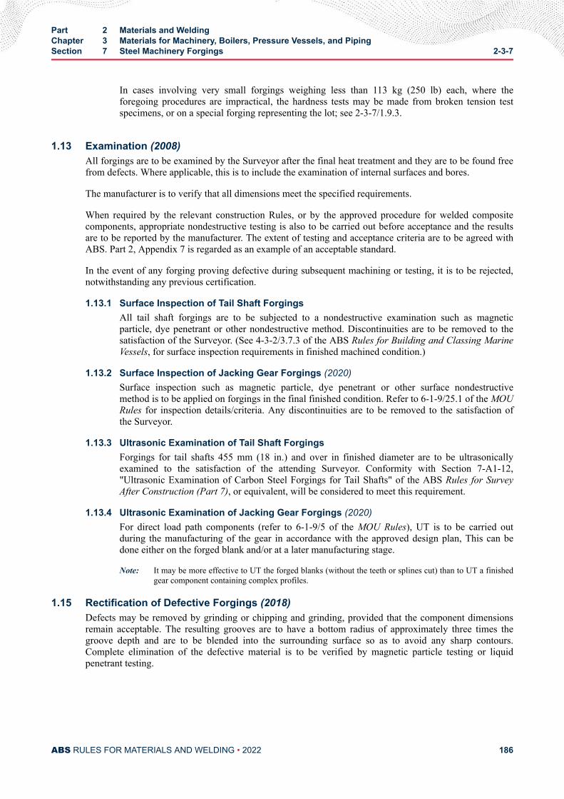
In cases involving very small forgings weighing less than 113 kg (250 lb) each, where theforegoing procedures are impractical, the hardness tests may be made from broken tension testspecimens, or on a special forging representing the lot; see 2-3-7/1.9.3.
1.13 Examination (2008)All forgings are to be examined by the Surveyor after the final heat treatment and they are to be found freefrom defects. Where applicable, this is to include the examination of internal surfaces and bores.
The manufacturer is to verify that all dimensions meet the specified requirements.
When required by the relevant construction Rules, or by the approved procedure for welded compositecomponents, appropriate nondestructive testing is also to be carried out before acceptance and the resultsare to be reported by the manufacturer. The extent of testing and acceptance criteria are to be agreed withABS. Part 2, Appendix 7 is regarded as an example of an acceptable standard.
In the event of any forging proving defective during subsequent machining or testing, it is to be rejected,notwithstanding any previous certification.
1.13.1 Surface Inspection of Tail Shaft ForgingsAll tail shaft forgings are to be subjected to a nondestructive examination such as magneticparticle, dye penetrant or other nondestructive method. Discontinuities are to be removed to thesatisfaction of the Surveyor. (See 4-3-2/3.7.3 of the ABS Rules for Building and Classing MarineVessels, for surface inspection requirements in finished machined condition.)
1.13.2 Surface Inspection of Jacking Gear Forgings (2020)Surface inspection such as magnetic particle, dye penetrant or other surface nondestructivemethod is to be applied on forgings in the final finished condition. Refer to 6-1-9/25.1 of the MOURules for inspection details/criteria. Any discontinuities are to be removed to the satisfaction ofthe Surveyor.
1.13.3 Ultrasonic Examination of Tail Shaft ForgingsForgings for tail shafts 455 mm (18 in.) and over in finished diameter are to be ultrasonicallyexamined to the satisfaction of the attending Surveyor. Conformity with Section 7-A1-12,"Ultrasonic Examination of Carbon Steel Forgings for Tail Shafts" of the ABS Rules for SurveyAfter Construction (Part 7), or equivalent, will be considered to meet this requirement.
1.13.4 Ultrasonic Examination of Jacking Gear Forgings (2020)For direct load path components (refer to 6-1-9/5 of the MOU Rules), UT is to be carried outduring the manufacturing of the gear in accordance with the approved design plan, This can bedone either on the forged blank and/or at a later manufacturing stage.
Note: It may be more effective to UT the forged blanks (without the teeth or splines cut) than to UT a finishedgear component containing complex profiles.
1.15 Rectification of Defective Forgings (2018)Defects may be removed by grinding or chipping and grinding, provided that the component dimensionsremain acceptable. The resulting grooves are to have a bottom radius of approximately three times thegroove depth and are to be blended into the surrounding surface so as to avoid any sharp contours.Complete elimination of the defective material is to be verified by magnetic particle testing or liquidpenetrant testing.
Part 2 Materials and WeldingChapter 3 Materials for Machinery, Boilers, Pressure Vessels, and PipingSection 7 Steel Machinery Forgings 2-3-7
ABS RULES FOR MATERIALS AND WELDING • 2022 186
Repair welding of forgings may be permitted subject to prior approval by ABS. In such cases, full detailsof the extent and location of the repair, the proposed welding procedure, heat treatment and subsequentinspection procedures are to be submitted for approval.
Weld procedures for all types of welds are to be appropriately qualified to the satisfaction of the attendingSurveyor.
Before undertaking the repair welding of forgings, the manufacturer is to prove to the satisfaction of theSurveyor that the welders or welding operators are duly qualified for the work intended.
The forging manufacturer is to maintain records of repairs and subsequent inspections that are traceable toeach forging repaired. The records are to be presented to the Surveyor on request.
Temporary welds made for operations such as lifting, handling, staging, etc., are to be carried out toqualified welding procedures and qualified welders/operators and are to be removed, ground and inspectedusing suitable approved, nondestructive examination methods.
1.17 Certification (2005)The manufacturer is to provide the required type of inspection certificate giving the following particularsfor each forging or batch of forgings which has been accepted:
i) Purchaser’s name and order number
ii) Description of forgings and steel quality
iii) Identification number
iv) Steelmaking process, cast number and chemical analysis of ladle sample
v) Results of mechanical tests
vi) Results of nondestructive tests, where applicable
vii) Details of heat treatment, including temperature and holding times
viii) Specification
3 Alloy Steel Gear Assembly Forgings (2000)
3.1 Process of Manufacture3.1.1 General (2017)
The following requirements cover gear and pinion alloy steel forgings intended to be usedprincipally for propulsion units and auxiliary turbines. Typical components include forging rimsand blanks for steel gears and pinions, used in shipboard gear assemblies. Alternatively, forgingswhich comply with national or proprietary specifications may be accepted, provided suchspecifications give reasonable equivalence to these requirements.
Forgings are to be made by a manufacturer approved by ABS.
ABS approval is valid for 5 years subject to annual verification and/or endorsement by theattending Surveyor. The Surveyor is permitted at any time to monitor important aspects of forgingproduction, including but not limited to die preparation and die maintenance, forgingtemperatures, forging reduction or upset, heat treatment and inspection.
Raw materials for forging such as cast steel or semi-finished products are to be manufactured at afacility approved by ABS. Steel is to be fully killed and is to be manufactured by a processapproved by ABS.
Part 2 Materials and WeldingChapter 3 Materials for Machinery, Boilers, Pressure Vessels, and PipingSection 7 Steel Machinery Forgings 2-3-7
ABS RULES FOR MATERIALS AND WELDING • 2022 187
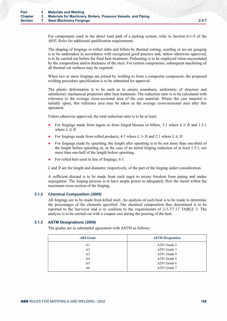
For components used in the direct load path of a jacking system, refer to Section 6-1-9 of theMOU Rules for additional qualification requirements.
The shaping of forgings or rolled slabs and billets by thermal cutting, scarfing or arc-air gougingis to be undertaken in accordance with recognized good practice and, unless otherwise approved,is to be carried out before the final heat treatment. Preheating is to be employed when necessitatedby the composition and/or thickness of the steel. For certain components, subsequent machining ofall thermal cut surfaces may be required.
When two or more forgings are joined by welding to form a composite component, the proposedwelding procedure specification is to be submitted for approval.
The plastic deformation is to be such as to ensure soundness, uniformity of structure andsatisfactory mechanical properties after heat treatment. The reduction ratio is to be calculated withreference to the average cross-sectional area of the cast material. Where the cast material isinitially upset, this reference area may be taken as the average cross-sectional area after thisoperation.
Unless otherwise approved, the total reduction ratio is to be at least:
● For forgings made from ingots or from forged blooms or billets, 3:1 where L > D and 1.5:1where L ≤ D.
● For forgings made from rolled products, 4:1 where L > D and 2:1 where L ≤ D.
● For forgings made by upsetting, the length after upsetting is to be not more than one-third ofthe length before upsetting or, in the case of an initial forging reduction of at least 1.5:1, notmore than one-half of the length before upsetting.
● For rolled bars used in lieu of forgings, 6:1.L and D are the length and diameter, respectively, of the part of the forging under consideration.
A sufficient discard is to be made from each ingot to secure freedom from piping and unduesegregation. The forging process is to have ample power to adequately flow the metal within themaximum cross-section of the forging.
3.1.2 Chemical Composition (2005)All forgings are to be made from killed steel. An analysis of each heat is to be made to determinethe percentages of the elements specified. The chemical composition thus determined is to bereported to the Surveyor and is to conform to the requirements of 2-3-7/7.17 TABLE 3. Theanalysis is to be carried out with a coupon cast during the pouring of the heat.
3.1.3 ASTM Designations (2009)The grades are in substantial agreement with ASTM as follows:
ABS Grade ASTM Designation
A1A2A3A4A5A6
A291 Grade 2A291 Grade 3A291 Grade 4A291 Grade 5A291 Grade 6A291 Grade 7
Part 2 Materials and WeldingChapter 3 Materials for Machinery, Boilers, Pressure Vessels, and PipingSection 7 Steel Machinery Forgings 2-3-7
ABS RULES FOR MATERIALS AND WELDING • 2022 188
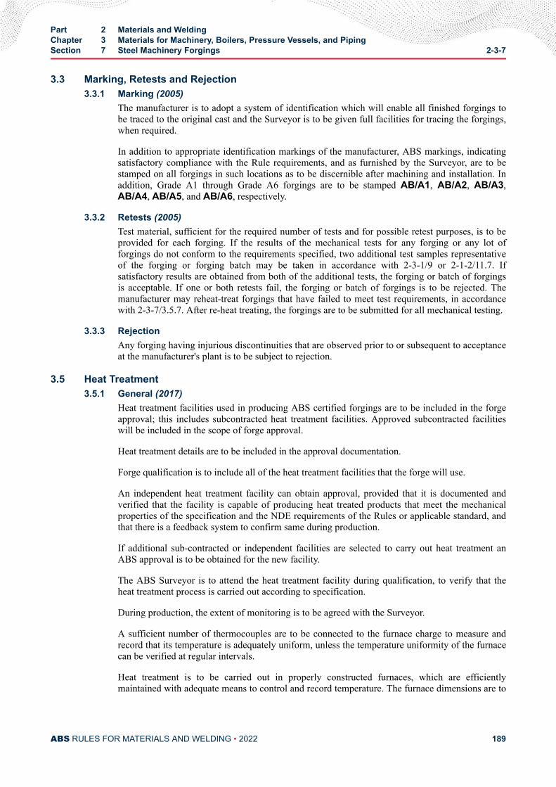
3.3 Marking, Retests and Rejection3.3.1 Marking (2005)
The manufacturer is to adopt a system of identification which will enable all finished forgings tobe traced to the original cast and the Surveyor is to be given full facilities for tracing the forgings,when required.
In addition to appropriate identification markings of the manufacturer, ABS markings, indicatingsatisfactory compliance with the Rule requirements, and as furnished by the Surveyor, are to bestamped on all forgings in such locations as to be discernible after machining and installation. Inaddition, Grade A1 through Grade A6 forgings are to be stamped AB/A1, AB/A2, AB/A3,AB/A4, AB/A5, and AB/A6, respectively.
3.3.2 Retests (2005)Test material, sufficient for the required number of tests and for possible retest purposes, is to beprovided for each forging. If the results of the mechanical tests for any forging or any lot offorgings do not conform to the requirements specified, two additional test samples representativeof the forging or forging batch may be taken in accordance with 2-3-1/9 or 2-1-2/11.7. Ifsatisfactory results are obtained from both of the additional tests, the forging or batch of forgingsis acceptable. If one or both retests fail, the forging or batch of forgings is to be rejected. Themanufacturer may reheat-treat forgings that have failed to meet test requirements, in accordancewith 2-3-7/3.5.7. After re-heat treating, the forgings are to be submitted for all mechanical testing.
3.3.3 RejectionAny forging having injurious discontinuities that are observed prior to or subsequent to acceptanceat the manufacturer's plant is to be subject to rejection.
3.5 Heat Treatment3.5.1 General (2017)
Heat treatment facilities used in producing ABS certified forgings are to be included in the forgeapproval; this includes subcontracted heat treatment facilities. Approved subcontracted facilitieswill be included in the scope of forge approval.
Heat treatment details are to be included in the approval documentation.
Forge qualification is to include all of the heat treatment facilities that the forge will use.
An independent heat treatment facility can obtain approval, provided that it is documented andverified that the facility is capable of producing heat treated products that meet the mechanicalproperties of the specification and the NDE requirements of the Rules or applicable standard, andthat there is a feedback system to confirm same during production.
If additional sub-contracted or independent facilities are selected to carry out heat treatment anABS approval is to be obtained for the new facility.
The ABS Surveyor is to attend the heat treatment facility during qualification, to verify that theheat treatment process is carried out according to specification.
During production, the extent of monitoring is to be agreed with the Surveyor.
A sufficient number of thermocouples are to be connected to the furnace charge to measure andrecord that its temperature is adequately uniform, unless the temperature uniformity of the furnacecan be verified at regular intervals.
Heat treatment is to be carried out in properly constructed furnaces, which are efficientlymaintained with adequate means to control and record temperature. The furnace dimensions are to
Part 2 Materials and WeldingChapter 3 Materials for Machinery, Boilers, Pressure Vessels, and PipingSection 7 Steel Machinery Forgings 2-3-7
ABS RULES FOR MATERIALS AND WELDING • 2022 189
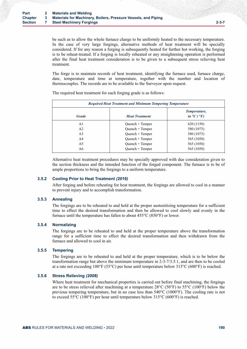
be such as to allow the whole furnace charge to be uniformly heated to the necessary temperature.In the case of very large forgings, alternative methods of heat treatment will be speciallyconsidered. If for any reason a forging is subsequently heated for further hot working, the forgingis to be reheat-treated. If a forging is locally reheated or any straightening operation is performedafter the final heat treatment consideration is to be given to a subsequent stress relieving heattreatment.
The forge is to maintain records of heat treatment, identifying the furnace used, furnace charge,date, temperature and time at temperature, together with the number and location ofthermocouples. The records are to be available to the Surveyor upon request.
The required heat treatment for each forging grade is as follows:
Required Heat Treatment and Minimum Tempering Temperature
Grade Heat TreatmentTemperature,
in °C ( °F)
A1A2A3A4A5A6
Quench + TemperQuench + TemperQuench + TemperQuench + TemperQuench + TemperQuench + Temper
620 (1150)580 (1075)580 (1075)565 (1050)565 (1050)565 (1050)
Alternative heat treatment procedures may be specially approved with due consideration given tothe section thickness and the intended function of the forged component. The furnace is to be ofample proportions to bring the forgings to a uniform temperature.
3.5.2 Cooling Prior to Heat Treatment (2016)After forging and before reheating for heat treatment, the forgings are allowed to cool in a mannerto prevent injury and to accomplish transformation.
3.5.3 AnnealingThe forgings are to be reheated to and held at the proper austenitizing temperature for a sufficienttime to effect the desired transformation and then be allowed to cool slowly and evenly in thefurnace until the temperature has fallen to about 455°C (850°F) or lower.
3.5.4 NormalizingThe forgings are to be reheated to and held at the proper temperature above the transformationrange for a sufficient time to effect the desired transformation and then withdrawn from thefurnace and allowed to cool in air.
3.5.5 TemperingThe forgings are to be reheated to and held at the proper temperature, which is to be below thetransformation range but above the minimum temperature in 2-3-7/3.5.1, and are then to be cooledat a rate not exceeding 100°F (55°C) per hour until temperature below 315°C (600°F) is reached.
3.5.6 Stress Relieving (2008)Where heat treatment for mechanical properties is carried out before final machining, the forgingsare to be stress relieved after machining at a temperature 28°C (50°F) to 55°C (100°F) below theprevious tempering temperature, but in no case less than 540°C (1000°F). The cooling rate is notto exceed 55°C (100°F) per hour until temperature below 315°C (600°F) is reached.
Part 2 Materials and WeldingChapter 3 Materials for Machinery, Boilers, Pressure Vessels, and PipingSection 7 Steel Machinery Forgings 2-3-7
ABS RULES FOR MATERIALS AND WELDING • 2022 190
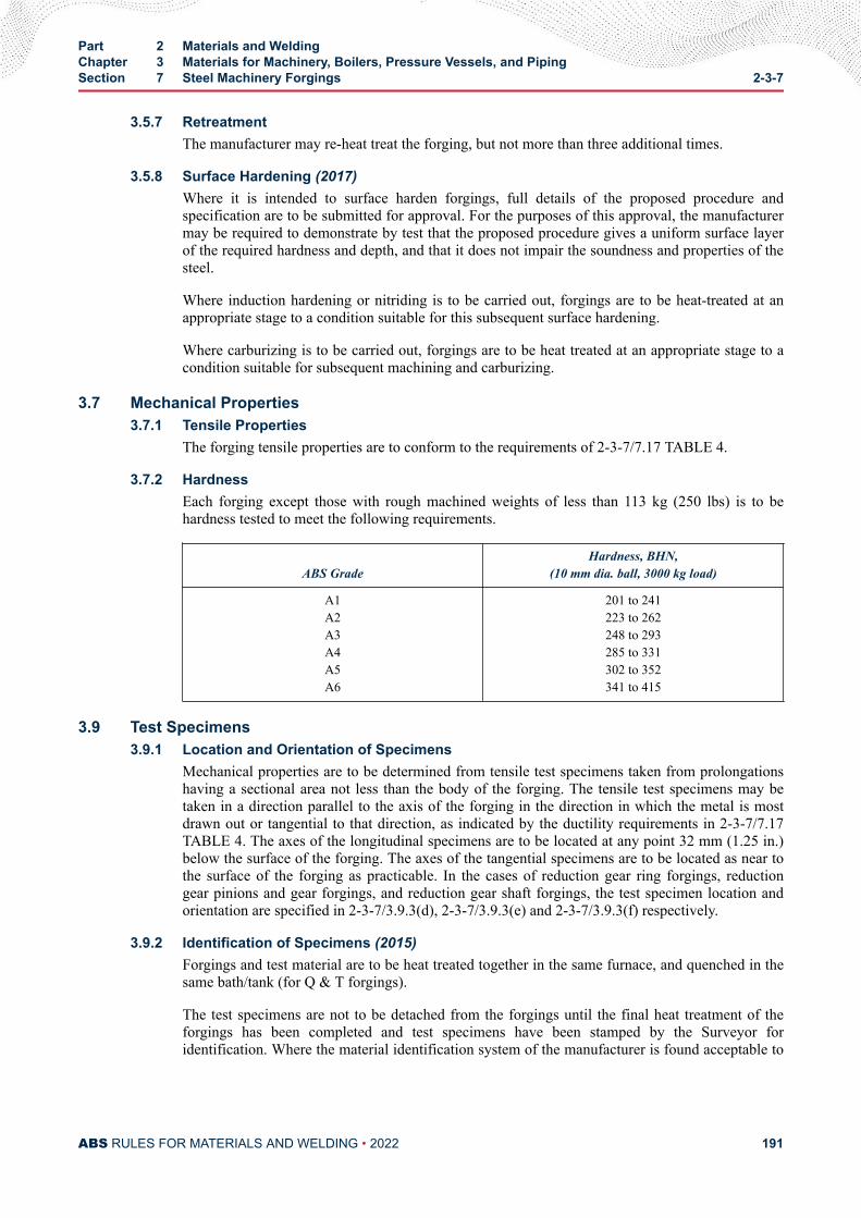
3.5.7 RetreatmentThe manufacturer may re-heat treat the forging, but not more than three additional times.
3.5.8 Surface Hardening (2017)Where it is intended to surface harden forgings, full details of the proposed procedure andspecification are to be submitted for approval. For the purposes of this approval, the manufacturermay be required to demonstrate by test that the proposed procedure gives a uniform surface layerof the required hardness and depth, and that it does not impair the soundness and properties of thesteel.
Where induction hardening or nitriding is to be carried out, forgings are to be heat-treated at anappropriate stage to a condition suitable for this subsequent surface hardening.
Where carburizing is to be carried out, forgings are to be heat treated at an appropriate stage to acondition suitable for subsequent machining and carburizing.
3.7 Mechanical Properties3.7.1 Tensile Properties
The forging tensile properties are to conform to the requirements of 2-3-7/7.17 TABLE 4.
3.7.2 HardnessEach forging except those with rough machined weights of less than 113 kg (250 lbs) is to behardness tested to meet the following requirements.
ABS GradeHardness, BHN,
(10 mm dia. ball, 3000 kg load)
A1A2A3A4A5A6
201 to 241223 to 262248 to 293285 to 331302 to 352341 to 415
3.9 Test Specimens3.9.1 Location and Orientation of Specimens
Mechanical properties are to be determined from tensile test specimens taken from prolongationshaving a sectional area not less than the body of the forging. The tensile test specimens may betaken in a direction parallel to the axis of the forging in the direction in which the metal is mostdrawn out or tangential to that direction, as indicated by the ductility requirements in 2-3-7/7.17TABLE 4. The axes of the longitudinal specimens are to be located at any point 32 mm (1.25 in.)below the surface of the forging. The axes of the tangential specimens are to be located as near tothe surface of the forging as practicable. In the cases of reduction gear ring forgings, reductiongear pinions and gear forgings, and reduction gear shaft forgings, the test specimen location andorientation are specified in 2-3-7/3.9.3(d), 2-3-7/3.9.3(e) and 2-3-7/3.9.3(f) respectively.
3.9.2 Identification of Specimens (2015)Forgings and test material are to be heat treated together in the same furnace, and quenched in thesame bath/tank (for Q & T forgings).
The test specimens are not to be detached from the forgings until the final heat treatment of theforgings has been completed and test specimens have been stamped by the Surveyor foridentification. Where the material identification system of the manufacturer is found acceptable to
Part 2 Materials and WeldingChapter 3 Materials for Machinery, Boilers, Pressure Vessels, and PipingSection 7 Steel Machinery Forgings 2-3-7
ABS RULES FOR MATERIALS AND WELDING • 2022 191
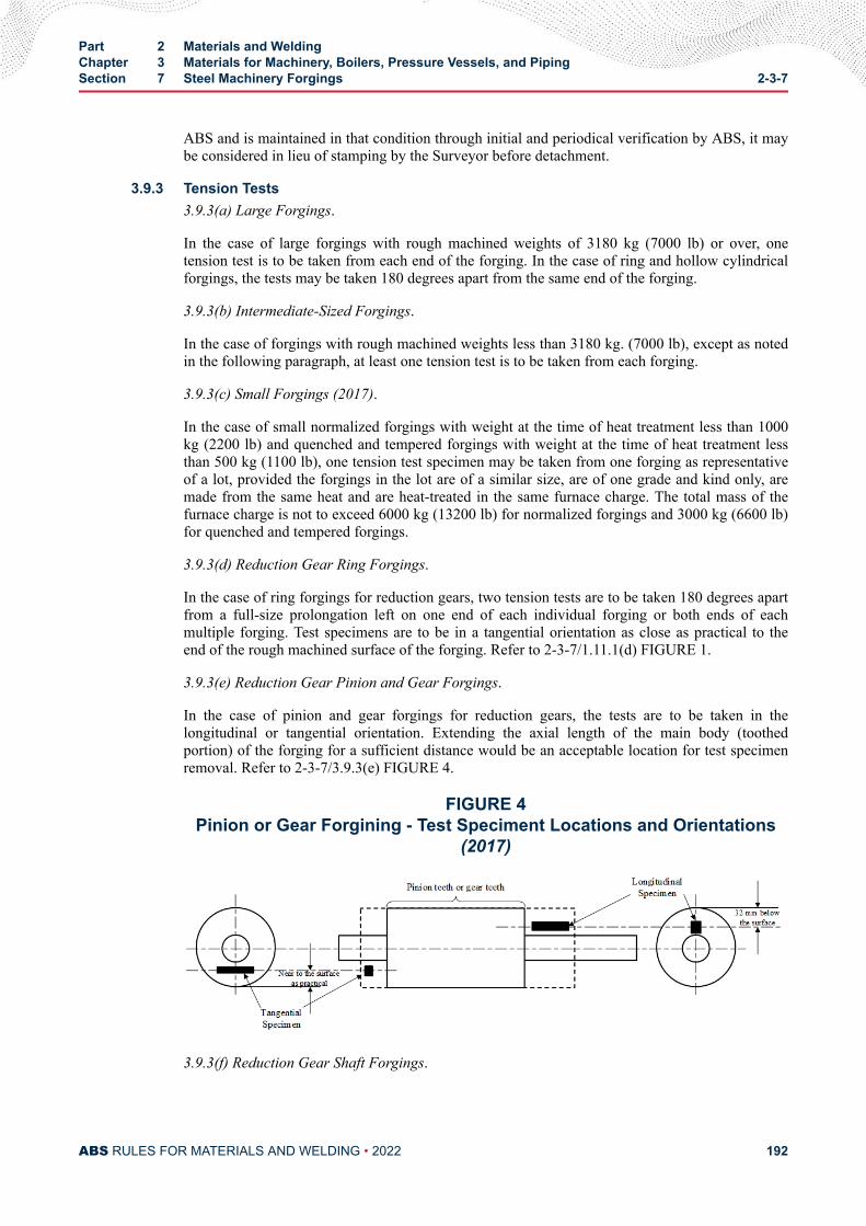
ABS and is maintained in that condition through initial and periodical verification by ABS, it maybe considered in lieu of stamping by the Surveyor before detachment.
3.9.3 Tension Tests3.9.3(a) Large Forgings.
In the case of large forgings with rough machined weights of 3180 kg (7000 lb) or over, onetension test is to be taken from each end of the forging. In the case of ring and hollow cylindricalforgings, the tests may be taken 180 degrees apart from the same end of the forging.
3.9.3(b) Intermediate-Sized Forgings.
In the case of forgings with rough machined weights less than 3180 kg. (7000 lb), except as notedin the following paragraph, at least one tension test is to be taken from each forging.
3.9.3(c) Small Forgings (2017).
In the case of small normalized forgings with weight at the time of heat treatment less than 1000kg (2200 lb) and quenched and tempered forgings with weight at the time of heat treatment lessthan 500 kg (1100 lb), one tension test specimen may be taken from one forging as representativeof a lot, provided the forgings in the lot are of a similar size, are of one grade and kind only, aremade from the same heat and are heat-treated in the same furnace charge. The total mass of thefurnace charge is not to exceed 6000 kg (13200 lb) for normalized forgings and 3000 kg (6600 lb)for quenched and tempered forgings.
3.9.3(d) Reduction Gear Ring Forgings.
In the case of ring forgings for reduction gears, two tension tests are to be taken 180 degrees apartfrom a full-size prolongation left on one end of each individual forging or both ends of eachmultiple forging. Test specimens are to be in a tangential orientation as close as practical to theend of the rough machined surface of the forging. Refer to 2-3-7/1.11.1(d) FIGURE 1.
3.9.3(e) Reduction Gear Pinion and Gear Forgings.
In the case of pinion and gear forgings for reduction gears, the tests are to be taken in thelongitudinal or tangential orientation. Extending the axial length of the main body (toothedportion) of the forging for a sufficient distance would be an acceptable location for test specimenremoval. Refer to 2-3-7/3.9.3(e) FIGURE 4.
FIGURE 4Pinion or Gear Forgining - Test Speciment Locations and Orientations
(2017)
3.9.3(f) Reduction Gear Shaft Forgings.
Part 2 Materials and WeldingChapter 3 Materials for Machinery, Boilers, Pressure Vessels, and PipingSection 7 Steel Machinery Forgings 2-3-7
ABS RULES FOR MATERIALS AND WELDING • 2022 192
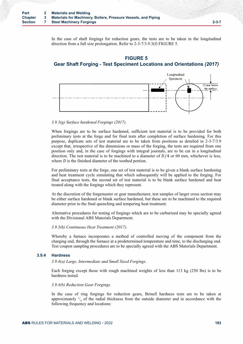
In the case of shaft forgings for reduction gears, the tests are to be taken in the longitudinaldirection from a full size prolongation. Refer to 2-3-7/3.9.3(f) FIGURE 5.
FIGURE 5Gear Shaft Forging - Test Speciment Locations and Orientations (2017)
3.9.3(g) Surface hardened Forgings (2017).
When forgings are to be surface hardened, sufficient test material is to be provided for bothpreliminary tests at the forge and for final tests after completion of surface hardening. For thispurpose, duplicate sets of test material are to be taken from positions as detailed in 2-3-7/3.9except that, irrespective of the dimensions or mass of the forging, the tests are required from oneposition only and, in the case of forgings with integral journals, are to be cut in a longitudinaldirection. The test material is to be machined to a diameter of D/4 or 60 mm, whichever is less,where D is the finished diameter of the toothed portion.
For preliminary tests at the forge, one set of test material is to be given a blank surface hardeningand heat treatment cycle simulating that which subsequently will be applied to the forging. Forfinal acceptance tests, the second set of test material is to be blank surface hardened and heattreated along with the forgings which they represent.
At the discretion of the forgemaster or gear manufacturer, test samples of larger cross section maybe either surface hardened or blank surface hardened, but these are to be machined to the requireddiameter prior to the final quenching and tempering heat treatment.
Alternative procedures for testing of forgings which are to be carburized may be specially agreedwith the Divisional ABS Materials Department.
3.9.3(h) Continuous Heat Treatment (2017).
Whereby a furnace incorporates a method of controlled moving of the component from thecharging end, through the furnace at a predetermined temperature and time, to the discharging end.Test coupon sampling procedures are to be specially agreed with the ABS Materials Department.
3.9.4 Hardness3.9.4(a) Large, Intermediate and Small Sized Forgings.
Each forging except those with rough machined weights of less than 113 kg (250 lbs) is to behardness tested.
3.9.4(b) Reduction Gear Forgings.
In the case of ring forgings for reduction gears, Brinell hardness tests are to be taken atapproximately 1/4 of the radial thickness from the outside diameter and in accordance with thefollowing frequency and locations:
Part 2 Materials and WeldingChapter 3 Materials for Machinery, Boilers, Pressure Vessels, and PipingSection 7 Steel Machinery Forgings 2-3-7
ABS RULES FOR MATERIALS AND WELDING • 2022 193
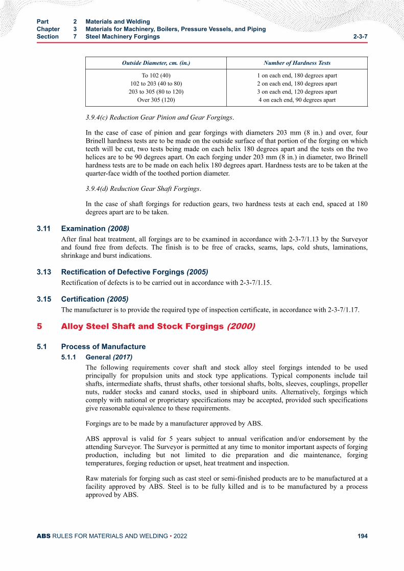
Outside Diameter, cm. (in.) Number of Hardness Tests
To 102 (40)102 to 203 (40 to 80)203 to 305 (80 to 120)
Over 305 (120)
1 on each end, 180 degrees apart2 on each end, 180 degrees apart3 on each end, 120 degrees apart4 on each end, 90 degrees apart
3.9.4(c) Reduction Gear Pinion and Gear Forgings.
In the case of case of pinion and gear forgings with diameters 203 mm (8 in.) and over, fourBrinell hardness tests are to be made on the outside surface of that portion of the forging on whichteeth will be cut, two tests being made on each helix 180 degrees apart and the tests on the twohelices are to be 90 degrees apart. On each forging under 203 mm (8 in.) in diameter, two Brinellhardness tests are to be made on each helix 180 degrees apart. Hardness tests are to be taken at thequarter-face width of the toothed portion diameter.
3.9.4(d) Reduction Gear Shaft Forgings.
In the case of shaft forgings for reduction gears, two hardness tests at each end, spaced at 180degrees apart are to be taken.
3.11 Examination (2008)After final heat treatment, all forgings are to be examined in accordance with 2-3-7/1.13 by the Surveyorand found free from defects. The finish is to be free of cracks, seams, laps, cold shuts, laminations,shrinkage and burst indications.
3.13 Rectification of Defective Forgings (2005)Rectification of defects is to be carried out in accordance with 2-3-7/1.15.
3.15 Certification (2005)The manufacturer is to provide the required type of inspection certificate, in accordance with 2-3-7/1.17.
5 Alloy Steel Shaft and Stock Forgings (2000)
5.1 Process of Manufacture5.1.1 General (2017)
The following requirements cover shaft and stock alloy steel forgings intended to be usedprincipally for propulsion units and stock type applications. Typical components include tailshafts, intermediate shafts, thrust shafts, other torsional shafts, bolts, sleeves, couplings, propellernuts, rudder stocks and canard stocks, used in shipboard units. Alternatively, forgings whichcomply with national or proprietary specifications may be accepted, provided such specificationsgive reasonable equivalence to these requirements.
Forgings are to be made by a manufacturer approved by ABS.
ABS approval is valid for 5 years subject to annual verification and/or endorsement by theattending Surveyor. The Surveyor is permitted at any time to monitor important aspects of forgingproduction, including but not limited to die preparation and die maintenance, forgingtemperatures, forging reduction or upset, heat treatment and inspection.
Raw materials for forging such as cast steel or semi-finished products are to be manufactured at afacility approved by ABS. Steel is to be fully killed and is to be manufactured by a processapproved by ABS.
Part 2 Materials and WeldingChapter 3 Materials for Machinery, Boilers, Pressure Vessels, and PipingSection 7 Steel Machinery Forgings 2-3-7
ABS RULES FOR MATERIALS AND WELDING • 2022 194
The shaping of forgings or rolled slabs and billets by thermal cutting, scarfing or arc-air gougingis to be undertaken in accordance with recognized good practice and, unless otherwise approved,is to be carried out before the final heat treatment. Preheating is to be employed when necessitatedby the composition and/or thickness of the steel. For certain components, subsequent machining ofall thermal cut surfaces may be required.
When two or more forgings are joined by welding to form a composite component, the proposedwelding procedure specification is to be submitted for approval.
The plastic deformation is to be such as to ensure soundness, uniformity of structure andsatisfactory mechanical properties after heat treatment. The reduction ratio is to be calculated withreference to the average cross-sectional area of the cast material. Where the cast material isinitially upset, this reference area may be taken as the average cross-sectional area after thisoperation
Unless otherwise approved, the total reduction ratio is to be at least:
● For forgings made from ingots or from forged blooms or billets, 3:1 where L > D and 1.5:1where L ≤ D.
● For forgings made from rolled products, 4:1 where L > D and 2:1 where L ≤ D.
● For forgings made by upsetting, the length after upsetting is to be not more than one-third ofthe length before upsetting or, in the case of an initial forging reduction of at least 1.5:1, notmore than one-half of the length before upsetting.
● For rolled bars used in lieu of forgings, 6:1.L and D are the length and diameter, respectively, of the part of the forging under consideration.
A sufficient discard is to be made from each ingot to secure freedom from piping and unduesegregation.
5.1.2 Chemical Composition (2005)All forgings are to be made from killed steel. An analysis of each heat is to be made to determinethe percentages of the elements specified. The chemical composition thus determined is to bereported to the Surveyor and is to conform to the requirements of 2-3-7/7.17 TABLE 5. Theanalysis is to be carried out with a coupon cast during the pouring of the heat.
5.1.3 Product AnalysisThe forgings are to be subjected to a product chemical analysis and meet the requirements of2-3-7/7.17 TABLE 5, as modified by the product variation requirements specified in A778,General Requirements for Steel Forgings.
5.1.4 ASTM DesignationsThe grades are in substantial agreement with ASTM as follows:
ABS Grade ASTM Designation
A7A8A9A10
A470 Class 2A470 Class 4A470 Class 6A470 Class 7
Part 2 Materials and WeldingChapter 3 Materials for Machinery, Boilers, Pressure Vessels, and PipingSection 7 Steel Machinery Forgings 2-3-7
ABS RULES FOR MATERIALS AND WELDING • 2022 195
5.3 Marking, Retests and Rejection5.3.1 Marking (2005)
The manufacturer is to adopt a system of identification which will enable all finished forgings tobe traced to the original cast and the Surveyor is to be given full facilities for tracing the forgings,when required.
In addition to appropriate identification markings of the manufacturer, ABS markings, indicatingsatisfactory compliance with the Rule requirements, and as furnished by the Surveyor, are to bestamped on all forgings in such locations as to be discernible after machining and installation. Inaddition, Grade A7 through Grade A10 forgings are to be stamped AB/A7, AB/A8, AB/A9 andAB/A10 respectively.
5.3.2 Retests (2005)Test material, sufficient for the required number of tests and for possible retest purposes, is to beprovided for each forging. If the results of the mechanical tests for any forging or any lot offorgings do not conform to the requirements specified, two additional test samples representativeof the forging or forging batch may be taken in accordance with 2-3-1/9 or 2-1-2/11.7. Ifsatisfactory results are obtained from both of the additional tests, the forging or batch of forgingsis acceptable. If one or both retests fail, the forging or batch of forgings is to be rejected. Themanufacturer may reheat-treat forgings that have failed to meet test requirements, in accordancewith 2-3-7/5.5.7. After re-heat treating, the forgings are to be submitted for all mechanical testing.
5.3.3 RejectionAny forging having injurious discontinuities that are observed prior to or subsequent to acceptanceat the manufacturer's plant is to be subject to rejection.
5.5 Heat Treatment5.5.1 General (2017)
Heat treatment facilities used in producing ABS certified forgings are to be included in the forgeapproval; this includes subcontracted heat treatment facilities. Approved subcontracted facilitieswill be included in the scope of forge approval.
Heat treatment details are to be included in the approval documentation.
Forge qualification is to include all of the heat treatment facilities that the forge will use.
An independent heat treatment facility can obtain approval, provided that it is documented andverified that the facility is capable of producing heat treated products that meet the mechanicalproperties of the specification and the NDE requirements of the Rules or applicable standard, andthat there is a feedback system to confirm same during production.
If additional sub-contracted or independent facilities are selected to carry out heat treatment anABS approval is to be obtained for the new facility.
The ABS Surveyor is to attend the heat treatment facility during qualification, to verify that theheat treatment process is carried out according to specification.
During production, the extent of monitoring is to be agreed with the Surveyor.
A sufficient number of thermocouples are to be connected to the furnace charge to measure andrecord that its temperature is adequately uniform, unless the temperature uniformity of the furnacecan be verified at regular intervals.
Heat treatment is to be carried out in properly constructed furnaces which are efficientlymaintained with adequate means to control and record temperature. The furnace dimensions are to
Part 2 Materials and WeldingChapter 3 Materials for Machinery, Boilers, Pressure Vessels, and PipingSection 7 Steel Machinery Forgings 2-3-7
ABS RULES FOR MATERIALS AND WELDING • 2022 196
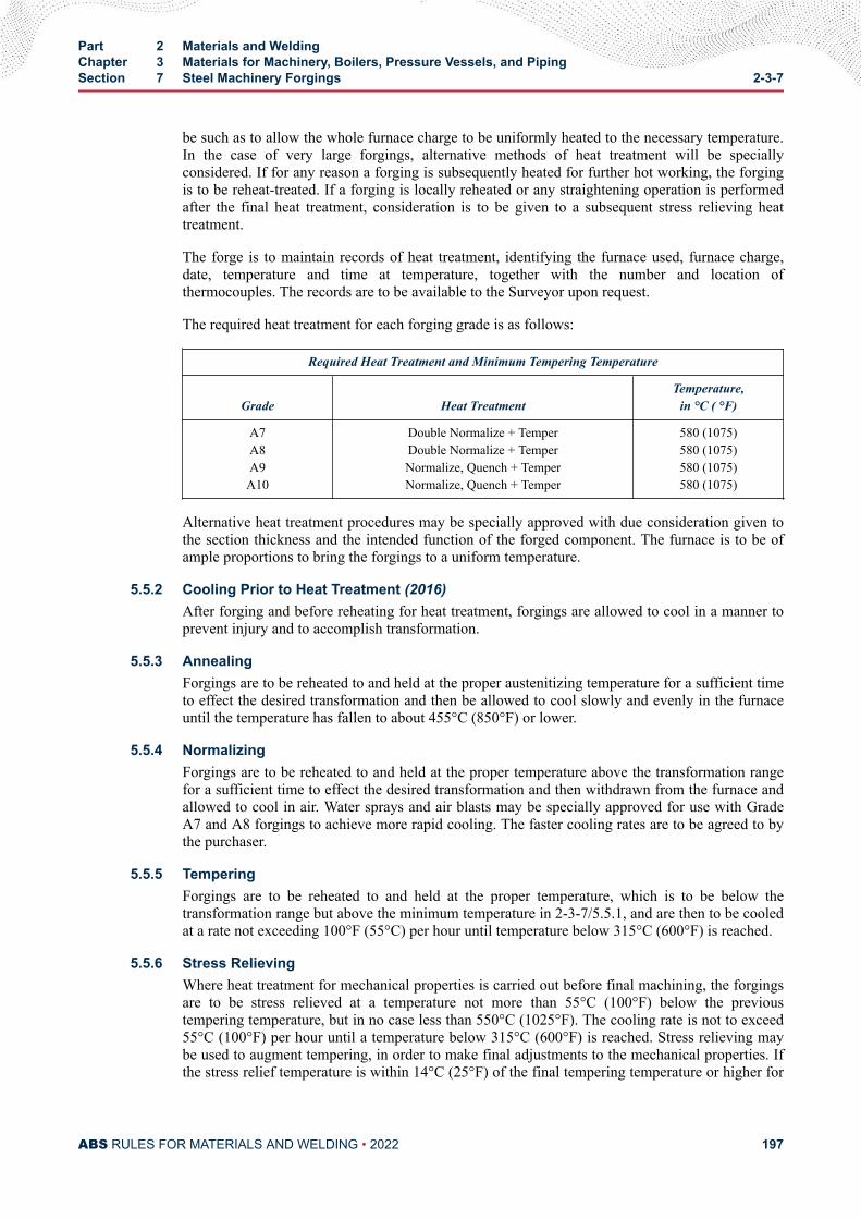
be such as to allow the whole furnace charge to be uniformly heated to the necessary temperature.In the case of very large forgings, alternative methods of heat treatment will be speciallyconsidered. If for any reason a forging is subsequently heated for further hot working, the forgingis to be reheat-treated. If a forging is locally reheated or any straightening operation is performedafter the final heat treatment, consideration is to be given to a subsequent stress relieving heattreatment.
The forge is to maintain records of heat treatment, identifying the furnace used, furnace charge,date, temperature and time at temperature, together with the number and location ofthermocouples. The records are to be available to the Surveyor upon request.
The required heat treatment for each forging grade is as follows:
Required Heat Treatment and Minimum Tempering Temperature
Grade Heat TreatmentTemperature,
in °C ( °F)
A7A8A9A10
Double Normalize + TemperDouble Normalize + TemperNormalize, Quench + TemperNormalize, Quench + Temper
580 (1075)580 (1075)580 (1075)580 (1075)
Alternative heat treatment procedures may be specially approved with due consideration given tothe section thickness and the intended function of the forged component. The furnace is to be ofample proportions to bring the forgings to a uniform temperature.
5.5.2 Cooling Prior to Heat Treatment (2016)After forging and before reheating for heat treatment, forgings are allowed to cool in a manner toprevent injury and to accomplish transformation.
5.5.3 AnnealingForgings are to be reheated to and held at the proper austenitizing temperature for a sufficient timeto effect the desired transformation and then be allowed to cool slowly and evenly in the furnaceuntil the temperature has fallen to about 455°C (850°F) or lower.
5.5.4 NormalizingForgings are to be reheated to and held at the proper temperature above the transformation rangefor a sufficient time to effect the desired transformation and then withdrawn from the furnace andallowed to cool in air. Water sprays and air blasts may be specially approved for use with GradeA7 and A8 forgings to achieve more rapid cooling. The faster cooling rates are to be agreed to bythe purchaser.
5.5.5 TemperingForgings are to be reheated to and held at the proper temperature, which is to be below thetransformation range but above the minimum temperature in 2-3-7/5.5.1, and are then to be cooledat a rate not exceeding 100°F (55°C) per hour until temperature below 315°C (600°F) is reached.
5.5.6 Stress RelievingWhere heat treatment for mechanical properties is carried out before final machining, the forgingsare to be stress relieved at a temperature not more than 55°C (100°F) below the previoustempering temperature, but in no case less than 550°C (1025°F). The cooling rate is not to exceed55°C (100°F) per hour until a temperature below 315°C (600°F) is reached. Stress relieving maybe used to augment tempering, in order to make final adjustments to the mechanical properties. Ifthe stress relief temperature is within 14°C (25°F) of the final tempering temperature or higher for
Part 2 Materials and WeldingChapter 3 Materials for Machinery, Boilers, Pressure Vessels, and PipingSection 7 Steel Machinery Forgings 2-3-7
ABS RULES FOR MATERIALS AND WELDING • 2022 197
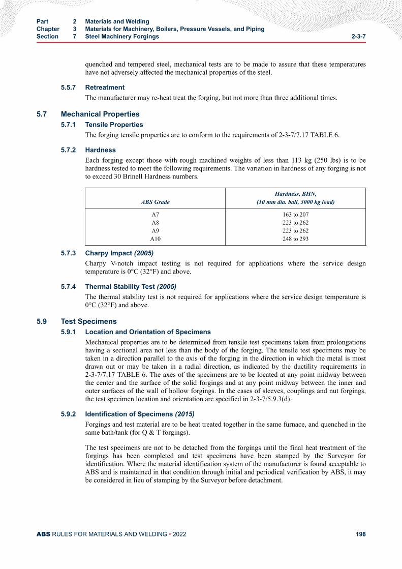
quenched and tempered steel, mechanical tests are to be made to assure that these temperatureshave not adversely affected the mechanical properties of the steel.
5.5.7 RetreatmentThe manufacturer may re-heat treat the forging, but not more than three additional times.
5.7 Mechanical Properties5.7.1 Tensile Properties
The forging tensile properties are to conform to the requirements of 2-3-7/7.17 TABLE 6.
5.7.2 HardnessEach forging except those with rough machined weights of less than 113 kg (250 lbs) is to behardness tested to meet the following requirements. The variation in hardness of any forging is notto exceed 30 Brinell Hardness numbers.
ABS GradeHardness, BHN,
(10 mm dia. ball, 3000 kg load)
A7A8A9A10
163 to 207223 to 262223 to 262248 to 293
5.7.3 Charpy Impact (2005)Charpy V-notch impact testing is not required for applications where the service designtemperature is 0°C (32°F) and above.
5.7.4 Thermal Stability Test (2005)The thermal stability test is not required for applications where the service design temperature is0°C (32°F) and above.
5.9 Test Specimens5.9.1 Location and Orientation of Specimens
Mechanical properties are to be determined from tensile test specimens taken from prolongationshaving a sectional area not less than the body of the forging. The tensile test specimens may betaken in a direction parallel to the axis of the forging in the direction in which the metal is mostdrawn out or may be taken in a radial direction, as indicated by the ductility requirements in2-3-7/7.17 TABLE 6. The axes of the specimens are to be located at any point midway betweenthe center and the surface of the solid forgings and at any point midway between the inner andouter surfaces of the wall of hollow forgings. In the cases of sleeves, couplings and nut forgings,the test specimen location and orientation are specified in 2-3-7/5.9.3(d).
5.9.2 Identification of Specimens (2015)Forgings and test material are to be heat treated together in the same furnace, and quenched in thesame bath/tank (for Q & T forgings).
The test specimens are not to be detached from the forgings until the final heat treatment of theforgings has been completed and test specimens have been stamped by the Surveyor foridentification. Where the material identification system of the manufacturer is found acceptable toABS and is maintained in that condition through initial and periodical verification by ABS, it maybe considered in lieu of stamping by the Surveyor before detachment.
Part 2 Materials and WeldingChapter 3 Materials for Machinery, Boilers, Pressure Vessels, and PipingSection 7 Steel Machinery Forgings 2-3-7
ABS RULES FOR MATERIALS AND WELDING • 2022 198
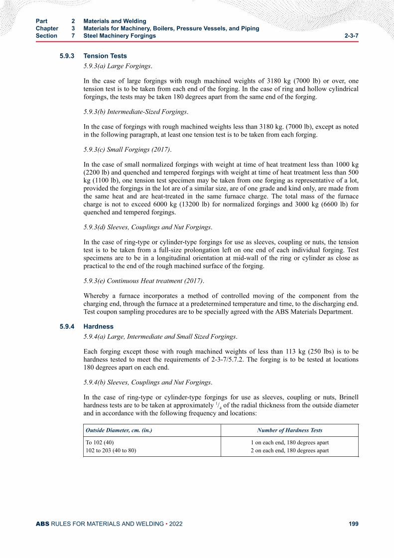
5.9.3 Tension Tests5.9.3(a) Large Forgings.
In the case of large forgings with rough machined weights of 3180 kg (7000 lb) or over, onetension test is to be taken from each end of the forging. In the case of ring and hollow cylindricalforgings, the tests may be taken 180 degrees apart from the same end of the forging.
5.9.3(b) Intermediate-Sized Forgings.
In the case of forgings with rough machined weights less than 3180 kg. (7000 lb), except as notedin the following paragraph, at least one tension test is to be taken from each forging.
5.9.3(c) Small Forgings (2017).
In the case of small normalized forgings with weight at time of heat treatment less than 1000 kg(2200 lb) and quenched and tempered forgings with weight at time of heat treatment less than 500kg (1100 lb), one tension test specimen may be taken from one forging as representative of a lot,provided the forgings in the lot are of a similar size, are of one grade and kind only, are made fromthe same heat and are heat-treated in the same furnace charge. The total mass of the furnacecharge is not to exceed 6000 kg (13200 lb) for normalized forgings and 3000 kg (6600 lb) forquenched and tempered forgings.
5.9.3(d) Sleeves, Couplings and Nut Forgings.
In the case of ring-type or cylinder-type forgings for use as sleeves, coupling or nuts, the tensiontest is to be taken from a full-size prolongation left on one end of each individual forging. Testspecimens are to be in a longitudinal orientation at mid-wall of the ring or cylinder as close aspractical to the end of the rough machined surface of the forging.
5.9.3(e) Continuous Heat treatment (2017).
Whereby a furnace incorporates a method of controlled moving of the component from thecharging end, through the furnace at a predetermined temperature and time, to the discharging end.Test coupon sampling procedures are to be specially agreed with the ABS Materials Department.
5.9.4 Hardness5.9.4(a) Large, Intermediate and Small Sized Forgings.
Each forging except those with rough machined weights of less than 113 kg (250 lbs) is to behardness tested to meet the requirements of 2-3-7/5.7.2. The forging is to be tested at locations180 degrees apart on each end.
5.9.4(b) Sleeves, Couplings and Nut Forgings.
In the case of ring-type or cylinder-type forgings for use as sleeves, coupling or nuts, Brinellhardness tests are to be taken at approximately 1/4 of the radial thickness from the outside diameterand in accordance with the following frequency and locations:
Outside Diameter, cm. (in.) Number of Hardness Tests
To 102 (40)102 to 203 (40 to 80)
1 on each end, 180 degrees apart2 on each end, 180 degrees apart
Part 2 Materials and WeldingChapter 3 Materials for Machinery, Boilers, Pressure Vessels, and PipingSection 7 Steel Machinery Forgings 2-3-7
ABS RULES FOR MATERIALS AND WELDING • 2022 199
5.11 Examination (2008)After final heat treatment, all forgings are to be examined, in accordance with 2-3-7/1.13, by the Surveyorand found free from defects. The finish is to be free of cracks, seams, laps, cold shuts, laminations,shrinkage and burst indications.
5.11.1 Surface Inspection of Tail Shaft ForgingsAll tail shaft forgings are to be subjected to a nondestructive examination such as magneticparticle, dye penetrant or other nondestructive method. Discontinuities are to be removed to thesatisfaction of the Surveyor. (See 4-3-2/3.7.3 of the ABS Rules for Building and Classing MarineVessels for surface inspection requirements in finished machined condition.)
5.11.2 Ultrasonic Examination of Tail Shaft ForgingsForgings for tail shafts 455 mm (18 in) and over in finished diameter are to be ultrasonicallyexamined to the satisfaction of the attending Surveyor. Conformity with Section 7-A1-12,“Ultrasonic Examination of Carbon Steel Forgings of Tail Shafts” of the ABS Rules for SurveyAfter Construction (Part 7), or equivalent, will be considered to meet this requirement.
5.13 Rectification of Defective Forgings (2005)Rectification of defects is to be carried out in accordance with 2-3-7/1.15.
5.15 Certification (2005)The manufacturer is to provide the required type of inspection certificate, in accordance with 2-3-7/1.17.
7 General Shipboard Alloy Steel Forgings (2000)
7.1 Process of Manufacture7.1.1 General (2017)
The following requirements cover alloy steel forgings intended to be used for general shipboardapplications. Alternatively, forgings which comply with national or proprietary specifications maybe accepted, provided such specifications give reasonable equivalence to these requirements.
Forgings are to be made by a manufacturer approved by ABS.
ABS approval is valid for 5 years subject to annual verification and/or endorsement by theattending Surveyor. The Surveyor is permitted at any time to monitor important aspects of forgingproduction, including but not limited to die preparation and die maintenance, forgingtemperatures, forging reduction or upset, heat treatment and inspection.
Raw materials for forging such as cast steel or semi-finished products are to be manufactured at afacility approved by ABS. Steel is to be fully killed and is to be manufactured by a processapproved by ABS.
The shaping of forgings or rolled slabs and billets by flame cutting, scarfing or arc-air gouging isto be undertaken in accordance with recognized good practice and, unless otherwise approved, isto be carried out before the final heat treatment. Preheating is to be employed when necessitatedby the composition and/or thickness of the steel. For certain components, subsequent machining ofall flame cut surfaces may be required.
When two or more forgings are joined by welding to form a composite component, the proposedwelding procedure specification is to be submitted for approval.
The plastic deformation is to be such as to ensure soundness, uniformity of structure andsatisfactory mechanical properties after heat treatment. The reduction ratio is to be calculated withreference to the average cross-sectional area of the cast material. Where the cast material is
Part 2 Materials and WeldingChapter 3 Materials for Machinery, Boilers, Pressure Vessels, and PipingSection 7 Steel Machinery Forgings 2-3-7
ABS RULES FOR MATERIALS AND WELDING • 2022 200
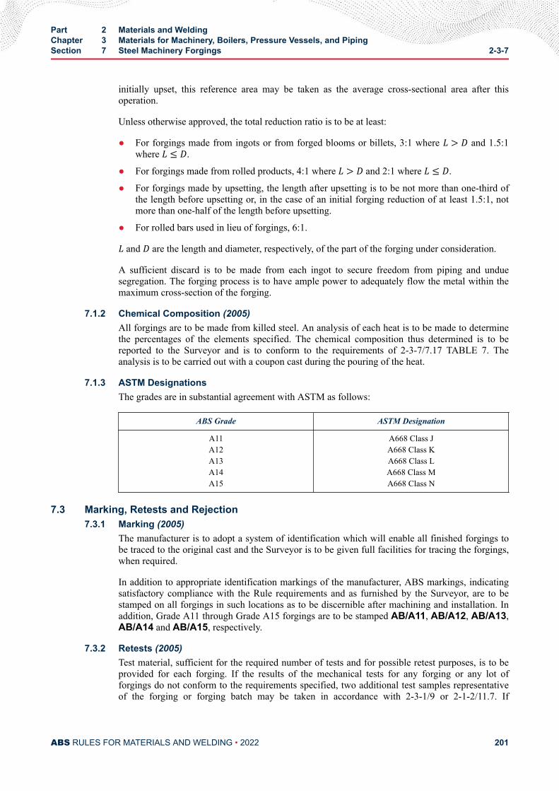
initially upset, this reference area may be taken as the average cross-sectional area after thisoperation.
Unless otherwise approved, the total reduction ratio is to be at least:
● For forgings made from ingots or from forged blooms or billets, 3:1 where L > D and 1.5:1where L ≤ D.
● For forgings made from rolled products, 4:1 where L > D and 2:1 where L ≤ D.
● For forgings made by upsetting, the length after upsetting is to be not more than one-third ofthe length before upsetting or, in the case of an initial forging reduction of at least 1.5:1, notmore than one-half of the length before upsetting.
● For rolled bars used in lieu of forgings, 6:1.L and D are the length and diameter, respectively, of the part of the forging under consideration.
A sufficient discard is to be made from each ingot to secure freedom from piping and unduesegregation. The forging process is to have ample power to adequately flow the metal within themaximum cross-section of the forging.
7.1.2 Chemical Composition (2005)All forgings are to be made from killed steel. An analysis of each heat is to be made to determinethe percentages of the elements specified. The chemical composition thus determined is to bereported to the Surveyor and is to conform to the requirements of 2-3-7/7.17 TABLE 7. Theanalysis is to be carried out with a coupon cast during the pouring of the heat.
7.1.3 ASTM DesignationsThe grades are in substantial agreement with ASTM as follows:
ABS Grade ASTM Designation
A11A12A13A14A15
A668 Class JA668 Class KA668 Class LA668 Class MA668 Class N
7.3 Marking, Retests and Rejection7.3.1 Marking (2005)
The manufacturer is to adopt a system of identification which will enable all finished forgings tobe traced to the original cast and the Surveyor is to be given full facilities for tracing the forgings,when required.
In addition to appropriate identification markings of the manufacturer, ABS markings, indicatingsatisfactory compliance with the Rule requirements and as furnished by the Surveyor, are to bestamped on all forgings in such locations as to be discernible after machining and installation. Inaddition, Grade A11 through Grade A15 forgings are to be stamped AB/A11, AB/A12, AB/A13,AB/A14 and AB/A15, respectively.
7.3.2 Retests (2005)Test material, sufficient for the required number of tests and for possible retest purposes, is to beprovided for each forging. If the results of the mechanical tests for any forging or any lot offorgings do not conform to the requirements specified, two additional test samples representativeof the forging or forging batch may be taken in accordance with 2-3-1/9 or 2-1-2/11.7. If
Part 2 Materials and WeldingChapter 3 Materials for Machinery, Boilers, Pressure Vessels, and PipingSection 7 Steel Machinery Forgings 2-3-7
ABS RULES FOR MATERIALS AND WELDING • 2022 201
satisfactory results are obtained from both of the additional tests, the forging or batch of forgingsis acceptable. If one or both retests fail, the forging or batch of forgings is to be rejected. Themanufacturer may reheat-treat forgings that have failed to meet test requirements, in accordancewith 2-3-7/7.5.6. After re-heat treating, the forgings are to be submitted for all mechanical testing.
7.3.3 RejectionAny forging having injurious discontinuities that are observed prior to or subsequent to acceptanceat the manufacturer’s plant is to be subject to rejection.
7.5 Heat Treatment7.5.1 General (2017)
Heat treatment facilities used in producing ABS certified forgings are to be included in the forgeapproval; this includes subcontracted heat treatment facilities. Approved subcontracted facilitieswill be included in the scope of forge approval.
Heat treatment details are to be included in the approval documentation.
Forge qualification is to include all of the heat treatment facilities that the forge will use.
An independent heat treatment facility can obtain approval, provided that it is documented andverified that the facility is capable of producing heat treated products that meet the mechanicalproperties of the specification and the NDE requirements of the Rules or applicable standard, andthat there is a feedback system to confirm same during production.
If additional sub-contracted or independent facilities are selected to carry out heat treatment anABS approval is to be obtained for the new facility.
The ABS Surveyor is to attend the heat treatment facility during qualification, to verify that theheat treatment process is carried out according to specification.
During production, the extent of monitoring is to be agreed with the Surveyor.
A sufficient number of thermocouples are to be connected to the furnace charge to measure andrecord that its temperature is adequately uniform, unless the temperature uniformity of the furnacecan be verified at regular intervals.
Heat treatment is to be carried out in properly constructed furnaces which are efficientlymaintained with adequate means to control and record temperature. The furnace dimensions are tobe such as to allow the whole furnace charge to be uniformly heated to the necessary temperature.In the case of very large forgings, alternative methods of heat treatment will be speciallyconsidered. If for any reason a forging is subsequently heated for further hot working, the forgingis to be reheat-treated. If a forging is locally reheated or any straightening operation is performedafter the final heat treatment, consideration is to be given to a subsequent stress relieving heattreatment.
The forge is to maintain records of heat treatment, identifying the furnace used, furnace charge,date, temperature and time at temperature, together with the number and location ofthermocouples. The records are to be available to the Surveyor upon request.
Unless a departure from the following procedures is specifically approved, Grade A11 forgings areto be normalized and tempered, or normalized, quenched and tempered. Grades A12, A13, A14and A15 forgings are to be normalized, quenched and tempered. The furnace is to be of ampleproportions to bring the forgings to a uniform temperature.
Part 2 Materials and WeldingChapter 3 Materials for Machinery, Boilers, Pressure Vessels, and PipingSection 7 Steel Machinery Forgings 2-3-7
ABS RULES FOR MATERIALS AND WELDING • 2022 202
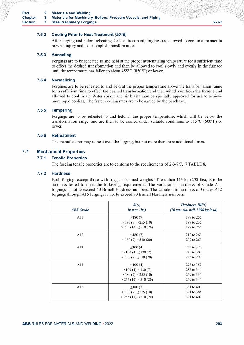
7.5.2 Cooling Prior to Heat Treatment (2016)After forging and before reheating for heat treatment, forgings are allowed to cool in a manner toprevent injury and to accomplish transformation.
7.5.3 AnnealingForgings are to be reheated to and held at the proper austenitizing temperature for a sufficient timeto effect the desired transformation and then be allowed to cool slowly and evenly in the furnaceuntil the temperature has fallen to about 455°C (850°F) or lower.
7.5.4 NormalizingForgings are to be reheated to and held at the proper temperature above the transformation rangefor a sufficient time to effect the desired transformation and then withdrawn from the furnace andallowed to cool in air. Water sprays and air blasts may be specially approved for use to achievemore rapid cooling. The faster cooling rates are to be agreed by the purchaser.
7.5.5 TemperingForgings are to be reheated to and held at the proper temperature, which will be below thetransformation range, and are then to be cooled under suitable conditions to 315°C (600°F) orlower.
7.5.6 RetreatmentThe manufacturer may re-heat treat the forging, but not more than three additional times.
7.7 Mechanical Properties7.7.1 Tensile Properties
The forging tensile properties are to conform to the requirements of 2-3-7/7.17 TABLE 8.
7.7.2 HardnessEach forging, except those with rough machined weights of less than 113 kg (250 lbs), is to behardness tested to meet the following requirements. The variation in hardness of Grade A11forgings is not to exceed 40 Brinell Hardness numbers. The variation in hardness of Grades A12forgings through A15 forgings is not to exceed 50 Brinell Hardness numbers.
ABS GradeSize,
in mm. (in.)Hardness, BHN,
(10 mm dia. ball, 3000 kg load)
A11 ≤180 (7)> 180 (7), ≤255 (10)> 255 (10), ≤510 (20)
197 to 255187 to 235187 to 255
A12 ≤180 (7)> 180 (7), ≤510 (20)
212 to 269207 to 269
A13 ≤100 (4)> 100 (4), ≤180 (7)> 180 (7), ≤510 (20)
255 to 321235 to 302223 to 293
A14 ≤100 (4)> 100 (4), ≤180 (7)> 180 (7), ≤255 (10)> 255 (10), ≤510 (20)
293 to 352285 to 341269 to 331269 to 341
A15 ≤180 (7)> 180 (7), ≤255 (10)> 255 (10), ≤510 (20)
331 to 401321 to 388321 to 402
Part 2 Materials and WeldingChapter 3 Materials for Machinery, Boilers, Pressure Vessels, and PipingSection 7 Steel Machinery Forgings 2-3-7
ABS RULES FOR MATERIALS AND WELDING • 2022 203
7.9 Mechanical Testing7.9.1 Location and Orientation of Specimens
Mechanical properties are to be determined from tensile test specimens taken from prolongationshaving a sectional area not less than the body of the forging. The length of the prolongation is tobe such that the distance from the test specimen mid-gauge to the end of the prolongation is to be89 mm (3.5 in.) or one-half the forging section thickness or diameter,whichever is less. The tensiletest specimens may be taken in a direction parallel to the axis of the forging in the direction inwhich the metal is most drawn out or tangential to that direction, as indicated by the ductilityrequirements in 2-3-7/7.17 TABLE 8. The axes of the specimens are to be located at any pointmidway between the center and the surface of the solid forgings and at any point midway betweenthe inner and outer surfaces of the wall of hollow forgings.
7.9.2 Hollow-drilled SpecimensIn lieu of prolongations, the test specimens may be taken from forgings submitted for each test lot;or if satisfactory to the Surveyor, test specimens may be taken from forgings with a hollow drill.
7.9.3 Very Small ForgingsIn the cases of very small forgings weighing less than 113 kg (250 lb) each, where the foregoingprocedures are impractical, a special forging may be made for the purpose of obtaining testspecimens, provided the Surveyor is satisfied that these test specimens are representative of theforgings submitted for test. In such cases, the special forgings should be subjected to the sameamount of working and reduction as the forgings represented and should be heat-treated with thoseforgings.
7.9.4 Identification of Specimens (2015)Forgings and test material are to be heat treated together in the same furnace, and quenched in thesame bath/tank (for Q & T forgings).
The test specimens are not to be detached from the forgings until the final heat treatment of theforgings has been completed and test specimens have been stamped by the Surveyor foridentification. Where the material identification system of the manufacturer is found acceptable toABS and is maintained in that condition through initial and periodical verification by ABS, it maybe considered in lieu of stamping by the Surveyor before detachment.
7.11 Number and Location of Tests7.11.1 Tension Tests
7.11.1(a) Large Forgings.
In the case of large forgings with rough machined weights of 3180 kg (7000 lb) or over, onetension test is to be taken from each end of the forging. In the case of ring and hollow cylindricalforgings, the tests may be taken 180 degrees apart from the same end of the forging.
7.11.1(b) Intermediate-Sized Forgings.
In the case of forgings with rough machined weights less than 3180 kg. (7000 lb), except as notedin the following paragraph, at least one tension test is to be taken from each forging.
7.11.1(c) Small Forgings (2017).
In the case of small normalized forgings with weight at time of heat treatment less than 1000 kg(2200 lb) and quenched and tempered forgings with weight at time of heat treatment less than 500kg (1100 lb), one tension test specimen may be taken from one forging as representative of a lot,provided the forgings in the lot are of a similar size, are of one grade and kind only, are made fromthe same heat and are heat-treated in the same furnace charge. The total mass of the furnace
Part 2 Materials and WeldingChapter 3 Materials for Machinery, Boilers, Pressure Vessels, and PipingSection 7 Steel Machinery Forgings 2-3-7
ABS RULES FOR MATERIALS AND WELDING • 2022 204
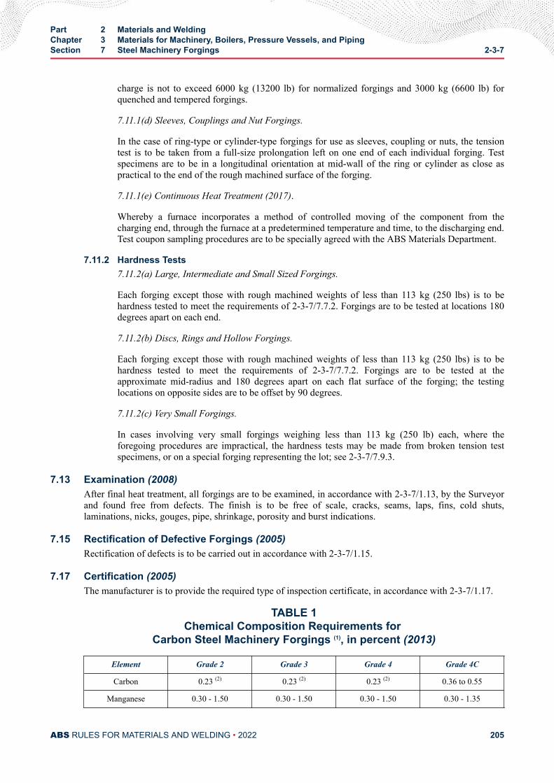
charge is not to exceed 6000 kg (13200 lb) for normalized forgings and 3000 kg (6600 lb) forquenched and tempered forgings.
7.11.1(d) Sleeves, Couplings and Nut Forgings.
In the case of ring-type or cylinder-type forgings for use as sleeves, coupling or nuts, the tensiontest is to be taken from a full-size prolongation left on one end of each individual forging. Testspecimens are to be in a longitudinal orientation at mid-wall of the ring or cylinder as close aspractical to the end of the rough machined surface of the forging.
7.11.1(e) Continuous Heat Treatment (2017).
Whereby a furnace incorporates a method of controlled moving of the component from thecharging end, through the furnace at a predetermined temperature and time, to the discharging end.Test coupon sampling procedures are to be specially agreed with the ABS Materials Department.
7.11.2 Hardness Tests7.11.2(a) Large, Intermediate and Small Sized Forgings.
Each forging except those with rough machined weights of less than 113 kg (250 lbs) is to behardness tested to meet the requirements of 2-3-7/7.7.2. Forgings are to be tested at locations 180degrees apart on each end.
7.11.2(b) Discs, Rings and Hollow Forgings.
Each forging except those with rough machined weights of less than 113 kg (250 lbs) is to behardness tested to meet the requirements of 2-3-7/7.7.2. Forgings are to be tested at theapproximate mid-radius and 180 degrees apart on each flat surface of the forging; the testinglocations on opposite sides are to be offset by 90 degrees.
7.11.2(c) Very Small Forgings.
In cases involving very small forgings weighing less than 113 kg (250 lb) each, where theforegoing procedures are impractical, the hardness tests may be made from broken tension testspecimens, or on a special forging representing the lot; see 2-3-7/7.9.3.
7.13 Examination (2008)After final heat treatment, all forgings are to be examined, in accordance with 2-3-7/1.13, by the Surveyorand found free from defects. The finish is to be free of scale, cracks, seams, laps, fins, cold shuts,laminations, nicks, gouges, pipe, shrinkage, porosity and burst indications.
7.15 Rectification of Defective Forgings (2005)Rectification of defects is to be carried out in accordance with 2-3-7/1.15.
7.17 Certification (2005)The manufacturer is to provide the required type of inspection certificate, in accordance with 2-3-7/1.17.
TABLE 1Chemical Composition Requirements for
Carbon Steel Machinery Forgings (1), in percent (2013)
Element Grade 2 Grade 3 Grade 4 Grade 4C
Carbon 0.23 (2) 0.23 (2) 0.23 (2) 0.36 to 0.55
Manganese 0.30 - 1.50 0.30 - 1.50 0.30 - 1.50 0.30 - 1.35
Part 2 Materials and WeldingChapter 3 Materials for Machinery, Boilers, Pressure Vessels, and PipingSection 7 Steel Machinery Forgings 2-3-7
ABS RULES FOR MATERIALS AND WELDING • 2022 205

Element Grade 2 Grade 3 Grade 4 Grade 4C
Silicon (3) 0.10 - 0.45 0.10 - 0.45 0.10 - 0.45 0.10 - 0.45
Sulfur 0.035 0.035 0.035 0.035
Phosphorus 0.035 0.035 0.035 0.035
Note:
1 Single values are maxima, unless noted.
2 (2013) The carbon content may be increased above this level, provided that the carbon equivalent (Ceq) is notmore than 0.41 %, as calculated using the following formula:Ceq = C+ Mn6 + Cr+Mo+ V5 + Ni+ Cu15 %
3 Silicon minimum is applicable if the steel is silicon killed.
TABLE 2Tensile Property Requirements(1)
for Carbon-steel Machinery Forgings (2013)
Grade Size,in mm (in)
TensileStrength (2)
in N/mm2
(kgf/mm2,ksi)
YieldStrength (3)
in N/mm2
(kgf/mm2,ksi)
Longitudinal (4) Tangential (4)
Elongation (5), inpercent
RA, inpercent
Elongation (5),in percent
RA, inpercent
Gauge Length Gauge Length
4d 5d 4d 5d
2 ≤300 (12) 415 (42,60)
205 (21,30)
25 23 38 20 18 29
> 300 (12) 415 (42,60)
205 (21,30)
24 22 36
3 ≤200 (8) 515 (53,75)
260 (26.5,37.5)
24 22 40
18 16 28
> 200 (8)≤300 (12)
515 (53,75)
260 (26.5,37.5)
22 20 35
> 300 (12)≤500 (20)
515 (53,75)
260 (26.5,37.5)
20 18 32
> 500 (20) 515 (53,75)
260 (26.5,37.5)
19 17 30
4, 4C(6) ≤ 500 (20) 570 (58.5,83)
295 (30.5,43)
20 18 35 17 16 27
Part 2 Materials and WeldingChapter 3 Materials for Machinery, Boilers, Pressure Vessels, and PipingSection 7 Steel Machinery Forgings 2-3-7
ABS RULES FOR MATERIALS AND WELDING • 2022 206
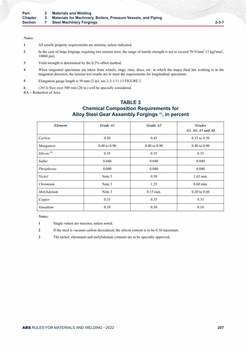
Notes:
1 All tensile property requirements are minima, unless indicated.
2 In the case of large forgings requiring two tension tests, the range of tensile strength is not to exceed 70 N/mm2 (7 kgf/mm2,10000 psi).
3 Yield strength is determined by the 0.2% offset method.
4 When tangential specimens are taken from wheels, rings, rims, discs, etc. in which the major final hot working is in thetangential direction, the tension test results are to meet the requirements for longitudinal specimens.
5 Elongation gauge length is 50 mm (2 in); see 2-3-1/11.13 FIGURE 2.
6 (2013) Size over 500 mm (20 in.) will be specially considered.RA = Reduction of Area
TABLE 3Chemical Composition Requirements for
Alloy Steel Gear Assembly Forgings (1), in percent
Element Grade A1 Grade A2 GradesA3, A4, A5 and A6
Carbon 0.50 0.45 0.35 to 0.50
Manganese 0.40 to 0.90 0.40 to 0.90 0.40 to 0.90
Silicon (2) 0.35 0.35 0.35
Sulfur 0.040 0.040 0.040
Phosphorus 0.040 0.040 0.040
Nickel Note 3 0.50 1.65 min.
Chromium Note 3 1.25 0.60 min.
Molybdenum Note 3 0.15 min. 0.20 to 0.60
Copper 0.35 0.35 0.35
Vanadium 0.10 0.50 0.10
Notes:
1 Single values are maxima, unless noted.
2 If the steel is vacuum-carbon deoxidized, the silicon content is to be 0.10 maximum.
3 The nickel, chromium and molybdenum contents are to be specially approved.
Part 2 Materials and WeldingChapter 3 Materials for Machinery, Boilers, Pressure Vessels, and PipingSection 7 Steel Machinery Forgings 2-3-7
ABS RULES FOR MATERIALS AND WELDING • 2022 207
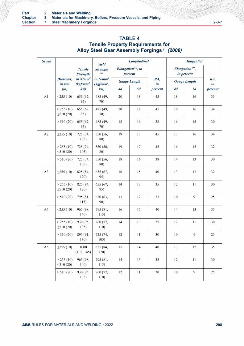
TABLE 4Tensile Property Requirements for
Alloy Steel Gear Assembly Forgings (1) (2008)
Grade
Diameter,in mm
(in)
TensileStrengthin N/mm2
(kgf/mm2,ksi)
YieldStrength
(2)
in N/mm2
(kgf/mm2,ksi)
Longitudinal Tangential
Elongation (3), inpercent
RA,in
percent
Elongation (3),in percent
RA,in
percent
Gauge Length Gauge Length
4d 5d 4d 5d
A1 ≤255 (10) 655 (67,95)
485 (49,70)
20 18 45 18 16 35
> 255 (10)≤510 (20)
655 (67,95)
485 (49,70)
20 18 45 19 16 34
> 510 (20) 655 (67,95)
485 (49,70)
18 16 38 16 15 30
A2 ≤255 (10) 725 (74,105)
550 (56,80)
19 17 45 17 16 34
> 255 (10)≤510 (20)
725 (74,105)
550 (56,80)
19 17 45 16 15 32
> 510 (20) 725 (74,105)
550 (56,80)
18 16 38 14 13 30
A3 ≤255 (10) 825 (84,120)
655 (67,95)
16 15 40 13 12 32
> 255 (10)≤510 (20)
825 (84,120)
655 (67,95)
14 13 35 12 11 30
> 510 (20) 795 (81,115)
620 (63,90)
13 12 33 10 9 25
A4 ≤255 (10) 965 (98,140)
795 (81,115)
16 15 40 14 13 35
> 255 (10)≤510 (20)
930 (95,135)
760 (77,110)
14 13 35 12 11 30
> 510 (20) 895 (91,130)
725 (74,105)
12 11 30 10 9 25
A5 ≤255 (10) 1000(102, 145)
825 (84,120)
15 14 40 13 12 35
> 255 (10)≤510 (20)
965 (98,140)
795 (81,115)
14 13 35 12 11 30
> 510 (20) 930 (95,135)
760 (77,110)
12 11 30 10 9 25
Part 2 Materials and WeldingChapter 3 Materials for Machinery, Boilers, Pressure Vessels, and PipingSection 7 Steel Machinery Forgings 2-3-7
ABS RULES FOR MATERIALS AND WELDING • 2022 208
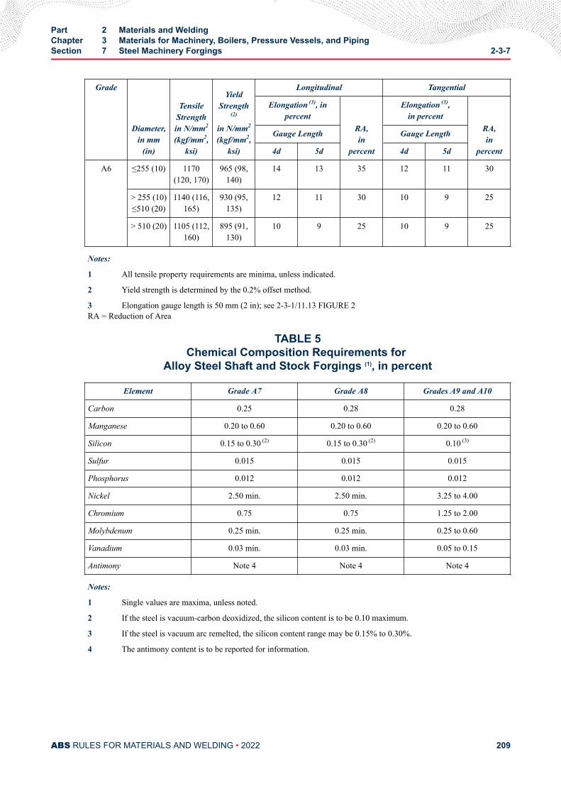
Grade
Diameter,in mm
(in)
TensileStrengthin N/mm2
(kgf/mm2,ksi)
YieldStrength
(2)
in N/mm2
(kgf/mm2,ksi)
Longitudinal Tangential
Elongation (3), inpercent
RA,in
percent
Elongation (3),in percent
RA,in
percent
Gauge Length Gauge Length
4d 5d 4d 5d
A6 ≤255 (10) 1170(120, 170)
965 (98,140)
14 13 35 12 11 30
> 255 (10)≤510 (20)
1140 (116,165)
930 (95,135)
12 11 30 10 9 25
> 510 (20) 1105 (112,160)
895 (91,130)
10 9 25 10 9 25
Notes:
1 All tensile property requirements are minima, unless indicated.
2 Yield strength is determined by the 0.2% offset method.
3 Elongation gauge length is 50 mm (2 in); see 2-3-1/11.13 FIGURE 2RA = Reduction of Area
TABLE 5Chemical Composition Requirements for
Alloy Steel Shaft and Stock Forgings (1), in percent
Element Grade A7 Grade A8 Grades A9 and A10
Carbon 0.25 0.28 0.28
Manganese 0.20 to 0.60 0.20 to 0.60 0.20 to 0.60
Silicon 0.15 to 0.30 (2) 0.15 to 0.30 (2) 0.10 (3)
Sulfur 0.015 0.015 0.015
Phosphorus 0.012 0.012 0.012
Nickel 2.50 min. 2.50 min. 3.25 to 4.00
Chromium 0.75 0.75 1.25 to 2.00
Molybdenum 0.25 min. 0.25 min. 0.25 to 0.60
Vanadium 0.03 min. 0.03 min. 0.05 to 0.15
Antimony Note 4 Note 4 Note 4
Notes:
1 Single values are maxima, unless noted.
2 If the steel is vacuum-carbon deoxidized, the silicon content is to be 0.10 maximum.
3 If the steel is vacuum arc remelted, the silicon content range may be 0.15% to 0.30%.
4 The antimony content is to be reported for information.
Part 2 Materials and WeldingChapter 3 Materials for Machinery, Boilers, Pressure Vessels, and PipingSection 7 Steel Machinery Forgings 2-3-7
ABS RULES FOR MATERIALS AND WELDING • 2022 209
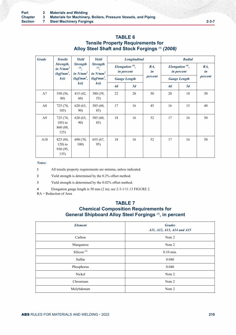
TABLE 6Tensile Property Requirements for
Alloy Steel Shaft and Stock Forgings (1) (2008)
Grade TensileStrength,in N/mm2
(kgf/mm2,ksi)
YieldStrength
(2),in N/mm2
(kgf/mm2,ksi)
YieldStrength
(3),in N/mm2
(kgf/mm2,ksi)
Longitudinal Radial
Elongation (4),in percent
RA,in
percent
Elongation (4),in percent
RA,in
percentGauge Length Gauge Length
4d 5d 4d 5d
A7 550 (56,80)
415 (42,60)
380 (39,55)
22 20 50 20 18 50
A8 725 (74,105)
620 (63,90)
585 (60,85)
17 16 45 16 15 40
A9 725 (74,105) to860 (88,
125)
620 (63,90)
585 (60,85)
18 16 52 17 16 50
A10 825 (84,120) to930 (95,
135)
690 (70,100)
655 (67,95)
18 16 52 17 16 50
Notes:
1 All tensile property requirements are minima, unless indicated.
2 Yield strength is determined by the 0.2% offset method.
3 Yield strength is determined by the 0.02% offset method.
4 Elongation gauge length is 50 mm (2 in); see 2-3-1/11.13 FIGURE 2.RA = Reduction of Area
TABLE 7Chemical Composition Requirements for
General Shipboard Alloy Steel Forgings (1), in percent
Element GradesA11, A12, A13, A14 and A15
Carbon Note 2
Manganese Note 2
Silicon (3) 0.10 min.
Sulfur 0.040
Phosphorus 0.040
Nickel Note 2
Chromium Note 2
Molybdenum Note 2
Part 2 Materials and WeldingChapter 3 Materials for Machinery, Boilers, Pressure Vessels, and PipingSection 7 Steel Machinery Forgings 2-3-7
ABS RULES FOR MATERIALS AND WELDING • 2022 210
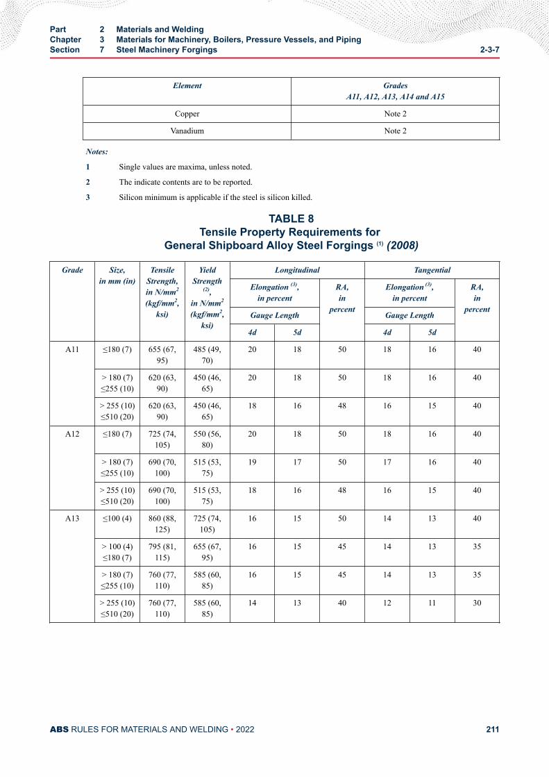
Element GradesA11, A12, A13, A14 and A15
Copper Note 2
Vanadium Note 2
Notes:
1 Single values are maxima, unless noted.
2 The indicate contents are to be reported.
3 Silicon minimum is applicable if the steel is silicon killed.
TABLE 8Tensile Property Requirements for
General Shipboard Alloy Steel Forgings (1) (2008)
Grade Size,in mm (in)
TensileStrength,in N/mm2
(kgf/mm2,ksi)
YieldStrength
(2),in N/mm2
(kgf/mm2,ksi)
Longitudinal Tangential
Elongation (3),in percent
RA,in
percent
Elongation (3),in percent
RA,in
percentGauge Length Gauge Length
4d 5d 4d 5d
A11 ≤180 (7) 655 (67,95)
485 (49,70)
20 18 50 18 16 40
> 180 (7)≤255 (10)
620 (63,90)
450 (46,65)
20 18 50 18 16 40
> 255 (10)≤510 (20)
620 (63,90)
450 (46,65)
18 16 48 16 15 40
A12 ≤180 (7) 725 (74,105)
550 (56,80)
20 18 50 18 16 40
> 180 (7)≤255 (10)
690 (70,100)
515 (53,75)
19 17 50 17 16 40
> 255 (10)≤510 (20)
690 (70,100)
515 (53,75)
18 16 48 16 15 40
A13 ≤100 (4) 860 (88,125)
725 (74,105)
16 15 50 14 13 40
> 100 (4)≤180 (7)
795 (81,115)
655 (67,95)
16 15 45 14 13 35
> 180 (7)≤255 (10)
760 (77,110)
585 (60,85)
16 15 45 14 13 35
> 255 (10)≤510 (20)
760 (77,110)
585 (60,85)
14 13 40 12 11 30
Part 2 Materials and WeldingChapter 3 Materials for Machinery, Boilers, Pressure Vessels, and PipingSection 7 Steel Machinery Forgings 2-3-7
ABS RULES FOR MATERIALS AND WELDING • 2022 211
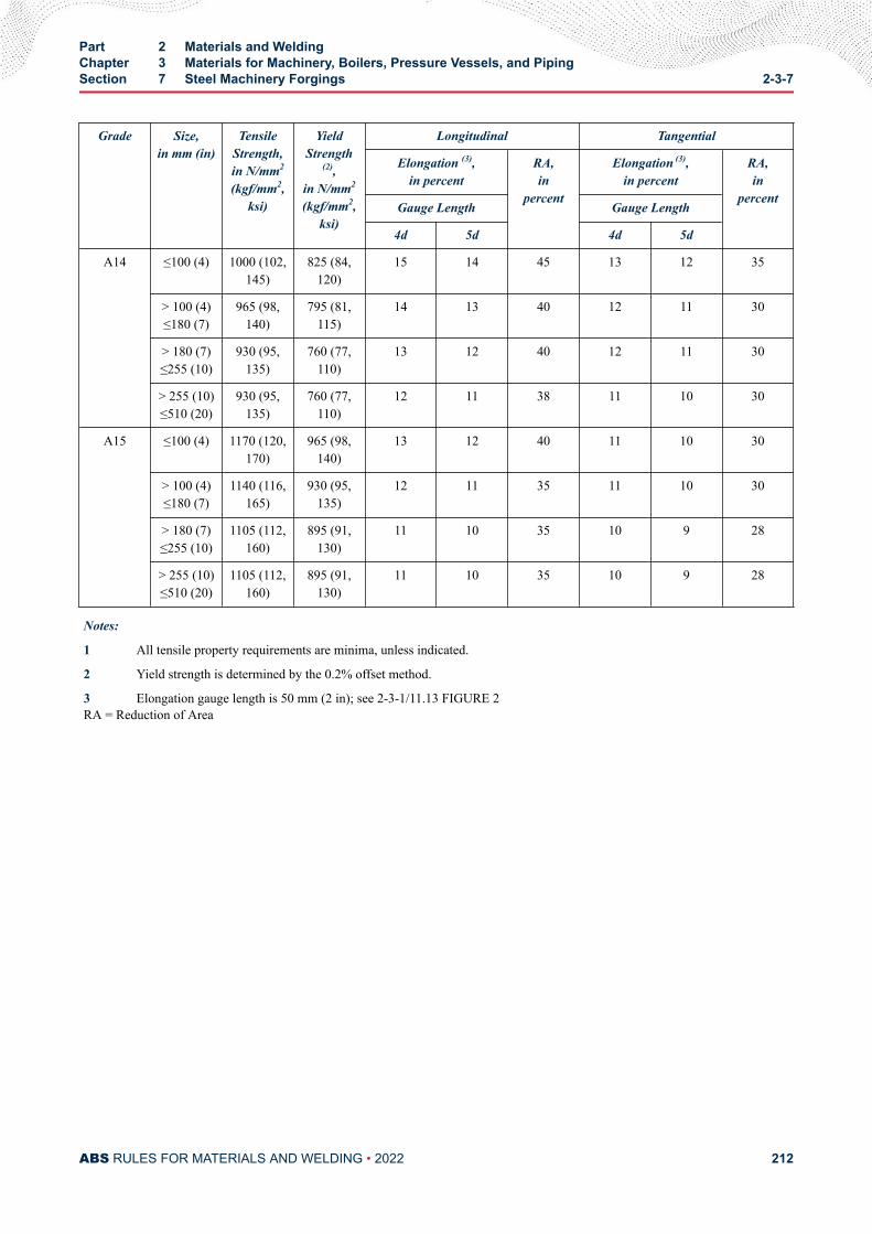
Grade Size,in mm (in)
TensileStrength,in N/mm2
(kgf/mm2,ksi)
YieldStrength
(2),in N/mm2
(kgf/mm2,ksi)
Longitudinal Tangential
Elongation (3),in percent
RA,in
percent
Elongation (3),in percent
RA,in
percentGauge Length Gauge Length
4d 5d 4d 5d
A14 ≤100 (4) 1000 (102,145)
825 (84,120)
15 14 45 13 12 35
> 100 (4)≤180 (7)
965 (98,140)
795 (81,115)
14 13 40 12 11 30
> 180 (7)≤255 (10)
930 (95,135)
760 (77,110)
13 12 40 12 11 30
> 255 (10)≤510 (20)
930 (95,135)
760 (77,110)
12 11 38 11 10 30
A15 ≤100 (4) 1170 (120,170)
965 (98,140)
13 12 40 11 10 30
> 100 (4)≤180 (7)
1140 (116,165)
930 (95,135)
12 11 35 11 10 30
> 180 (7)≤255 (10)
1105 (112,160)
895 (91,130)
11 10 35 10 9 28
> 255 (10)≤510 (20)
1105 (112,160)
895 (91,130)
11 10 35 10 9 28
Notes:
1 All tensile property requirements are minima, unless indicated.
2 Yield strength is determined by the 0.2% offset method.
3 Elongation gauge length is 50 mm (2 in); see 2-3-1/11.13 FIGURE 2RA = Reduction of Area
Part 2 Materials and WeldingChapter 3 Materials for Machinery, Boilers, Pressure Vessels, and PipingSection 7 Steel Machinery Forgings 2-3-7
ABS RULES FOR MATERIALS AND WELDING • 2022 212
C H A P T E R 3Materials for Machinery, Boilers, Pressure Vessels, and Piping
S E C T I O N 8Hot-rolled Steel Bars for Machinery
1 Hot-rolled Steel Bars (2018)Hot-rolled steel bars up to and including 305 mm (12 in.) diameter, presented for inspection after specialapproval for each specific application, are to be made by one or more of the following processes: openhearth, basic-oxygen, electric-furnace or such other process as may be approved. Hot rolled bars are to bemade by a manufacturer approved by ABS. ABS approval is valid for 5 years subject to annual verificationand/or endorsement by the attending Surveyor. The Surveyor is permitted at any time to monitor importantaspects of bar production. Raw materials for rolled bar manufacturers such as cast steel or semi-finishedproducts are to be manufactured at a facility approved by ABS.
Hot-rolled bars used in lieu of carbon-steel forgings (see Section 2-3-7) are to be fully killed, heat treatedin accordance with 2-3-7/1.5, and the cross-sectional area of the unmachined finished bar is not to exceedone-sixth of the cross-sectional area of the ingot. In addition, hot-rolled bars used in lieu of forgings for tailshafts are to meet the nondestructive examination requirements of 2-3-7/1.13.1. The tensile properties areto meet the requirements of 2-3-7/1.7 for the proposed application.
3 Number of TestsFour tension tests are to be taken from each lot of material exceeding 907 kg (2000 lb) in weight. When theweight of a lot is 907 kg (2000 lb) or less, two tension tests may be taken. In any case, only one tensiontest will be required from any one bar. A lot is to consist of bars from the same heat; if the bars are heat-treated, then a lot is to consist of bars from the same heat which have been heat-treated in the same furnacecharge. If the bars in a lot differ 9.5 mm (0.375 in.) or more in diameter, the test specimens taken are to berepresentative of the greatest and least diameter bar
PART 2
ABS RULES FOR MATERIALS AND WELDING • 2022 213
C H A P T E R 3Materials for Machinery, Boilers, Pressure Vessels, and Piping
S E C T I O N 9Steel Castings for Machinery, Boilers and Pressure Vessels
1 General
1.1 Process of Manufacture (2012)The following requirements cover carbon-steel castings intended to be used in machinery, boiler andpressure-vessel construction, such as crankshafts, turbine casings and bedplates. For other applications,additional requirements may be necessary, especially when the castings are intended for service at lowtemperatures. Castings which comply with national or proprietary specifications may also be accepted,provided such specifications give reasonable equivalence to these requirements. None of the abovepreclude the use of alloy steels in accordance with the permissibility expressed in 2-3-1/1. The steel is tobe manufactured by a process approved by ABS.
Castings are to be made by a manufacturer approved by ABS. ABS approval is valid for 5 years subject toannual verification and/or endorsement by the attending Surveyor. The Surveyor is permitted at any time tomonitor important aspects of casting production, including but not limited to mold preparation and chapletpositioning; pouring times and temperatures; mold breakout; repairs; heat treatment andinspection.Thermal cutting, scarfing or arc-air gouging to remove surplus metal is to be undertaken inaccordance with recognized good practice and is to be carried out before the final heat treatment.Preheating is to be employed when necessitated by the chemical composition and/or thickness of thecastings. If necessary, the affected areas are to be either machined or ground smooth.
When two or more castings are joined by welding to form a composite component, the proposed weldingprocedure is to be submitted for approval and welding is to be carried out to the satisfaction of theattending Surveyor.
Sulfur and phosphorous contents are to be less than 0.040% and silicon less than 0.60%.
For welded construction, the maximum carbon content is to be 0.23%.
1.3 ASTM Designations (2005)The various Grades are in substantial agreement with ASTM, as follows and, in addition, the requirementsof this Section apply:
PART 2
ABS RULES FOR MATERIALS AND WELDING • 2022 214
ABS Grade ASTM Designation
1 A27, Grade 60-30
2 A27, Grade 70-36
3 A216, Grade WCA
4 A216, Grade WCB
3 Marking and Retests
3.1 Marking (2005)The manufacturer is to adopt a system of identification which will enable all finished castings to be tracedto the original cast and the Surveyor is to be given full facilities for tracing the castings when required.
The manufacturer’s name or identification mark and pattern number is to be cast on all castings, exceptthose of such small size as to make this type of marking impracticable. The ABS markings, indicatingsatisfactory compliance with the Rule requirements, and as furnished by the Surveyor is to be stamped onall castings accepted in such location as to be discernible after machining and installation. Grade 1, 2, 3and 4 castings are to be stamped AB/1, AB/2, AB/3 and AB/4, respectively. In addition, identificationnumbers of the heats used for pouring the castings are to be stamped on all castings individually weighing227 kg (500 lb) or more.
3.3 Retests (2005)If the results of the physical tests for any casting or any lot of castings do not conform to the requirementsspecified, the manufacturer may reheat-treat castings or lots of castings that have failed to meet testrequirements. Two additional test samples representative of the casting or casting batch may be taken. Ifsatisfactory results are obtained from both of the additional tests, the casting or batch of castings isacceptable. If one or both retests fail, the casting or batch of castings is to be rejected.
5 Heat Treatment (2017)Heat treatment facilities used in producing ABS certified castings are to be included in the foundryapproval; this includes subcontracted heat treatment facilities. Approved subcontracted facilities will beincluded in the scope of foundry approval.
Heat treatment details are to be included in the approval documentation.
Foundry qualification is to include all of the heat treatment facilities that the foundry will use.
An independent heat treatment facility can obtain approval, provided that it is documented and verifiedthat the facility is capable of producing heat treated products that meet the mechanical properties of thespecification and the NDE requirements of the Rules or applicable standard, and that there is a feedbacksystem to confirm same during production.
If additional sub-contracted or independent facilities are selected to carry out heat treatment an ABSapproval is to be obtained for the new facility.
The ABS Surveyor is to attend the heat treatment facility during qualification, to verify that the heattreatment process is carried out according to specification.
During production, the extent of monitoring is to be agreed with the Surveyor.
Except in cases specifically approved otherwise, all castings are to be either fully annealed, normalized ornormalized and tempered in a furnace of ample proportions to bring the whole casting to uniform
Part 2 Materials and WeldingChapter 3 Materials for Machinery, Boilers, Pressure Vessels, and PipingSection 9 Steel Castings for Machinery, Boilers and Pressure Vessels 2-3-9
ABS RULES FOR MATERIALS AND WELDING • 2022 215
temperature above the transformation range on the annealing or normalizing cycle. The furnaces are to bemaintained and have adequate means for control and recording temperature. Castings are to be heldsoaking at the proper temperature for at least a length of time equivalent to one hour per 25.5 mm (1 in.) ofthickness of the heaviest member. No annealed casting is to be removed from the furnace until thetemperature of the entire furnace charge has fallen to or below a temperature of 455°C (850°F). Asufficient number of thermocouples are to be connected to the furnace charge to measure and record that itstemperature is adequately uniform, unless the temperature uniformity of the furnace can be verified atregular intervals. Tempering is to be carried out at a temperature of not less than 550°C (1022°F).
Local heating or cooling and bending and straightening of annealed castings are not permitted, except withthe express sanction of the Surveyor.
The foundry is to maintain records of heat treatment, identifying the furnace used, furnace charge, date,temperature and time at temperature, together with the number and location of thermocouples. The recordsare to be available to the Surveyor upon request.
7 Tensile Properties (2008)Steel castings are to conform to the following requirements as to tensile properties.
ABSGrade
Tensile Strength,Min., N/mm2
(kgf/mm2, psi)
Yield Point/Yield Strength,Min., N/mm2
(kgf/mm2, psi)
Elongation Min., %Reduction of Area
Min%Gauge Length4d 5d1 415 (42, 60000) 205 (21.0, 30000) 24 22 35
2 485 (49, 70000) 250 (25.5, 36000) 22 20 30
3 415 (42, 60000) 205 (21.0, 30000) 24 22 35
4 485 (49, 70000) 250 (25.5, 36000) 22 20 35
9 Application
9.1 General and High-temperature ApplicationsAny of the above grades may be used for miscellaneous applications. Grade 3 or Grade 4 castings are to beused for boiler mountings, valves, fittings and for pressure parts of boilers and other pressure vesselswhere the temperature does not exceed 427°C (800°F). See 4-6-2/3.1.3 of the ABS Rules for Building andClassing Marine Vessels.
9.3 Propeller and Forging ApplicationsAny of the above grades may be used for propellers and for castings which have been approved to take theplace of forgings.
9.5 Alloy Steels or Special Carbon SteelsWhen alloy steels or carbon steels differing from the requirements of 2-3-9/7 are proposed for any purpose,the purchaser's specification shall be submitted for approval in connection with the approval of the designfor which the material is proposed. Specifications such as ASTM A356 or A217 Grades WC1, WC6, orWC9, or other steels suitable for the intended service will be considered.
Part 2 Materials and WeldingChapter 3 Materials for Machinery, Boilers, Pressure Vessels, and PipingSection 9 Steel Castings for Machinery, Boilers and Pressure Vessels 2-3-9
ABS RULES FOR MATERIALS AND WELDING • 2022 216
11 Test Specimens
11.1 Material Coupons (2016)Castings and test material are to be heat treated together in the same furnace, and quenched in the samebath/tank (for Q & T forgings).
Test material, sufficient for the required number of tests and for possible retest purposes, is to be providedfor each casting. The physical properties are to be determined from test specimens prepared from couponswhich, except as specified in 2-3-9/11.3, are to be cast integral with the casting to be inspected. When thisis impracticable, the coupons may be cast with and gated to the casting and are to have a thickness of notless than the critical controlling cross section thickness of the casting or 30 mm (1.2 in.), whichever isgreater. In any case, these coupons are not to be detached until the heat treatment of the castings has beencompleted, nor until the coupons have been stamped by the Surveyor for identification. Where the materialidentification system of the manufacturer is found acceptable to ABS and is maintained in that conditionthrough initial and periodical verification by ABS, it may be considered in lieu of stamping by theSurveyor before detachment.
Where the casting finished mass exceeds 10,000 kg (22,000 lb) or is of complex design, two test samplesare to be provided. Where large castings are made from two or more casts which are not from the samepour, two or more test samples are to be provided, corresponding to the number of casts involved. Thesamples are to be integrally cast at locations as widely separated as possible.
Note:
Controlling cross section thickness is the diameter of the largest theoretical sphere which can be inscribed within the volumeof the casting.
11.3 Separately Cast CouponsIn the case of small castings having an estimated weight of less than 907 kg (2000 lb), each of the couponsmay be cast separately, provided the Surveyor is furnished an affidavit by the manufacturer stating that theseparately cast coupons were cast from the same heat as the castings represented and that they were heat-treated with the castings.
13 Number of Tests
13.1 Machinery Castings (2005)At least one tension test is to be made from each heat in each heat-treatment charge except where two ormore samples are required as indicated in 2-3-9/11.1. If the manufacturer’s quality-control procedureincludes satisfactory automatic chart recording of temperature and time, then one tension test from eachheat for castings subject to the same heat-treating procedure may be allowed at the discretion of theattending Surveyor.
13.3 Steel Propeller CastingsOne tension test is to be made from each blade of a built-up propeller, and for solid propellers there is to beone tension test from each of two opposite blades when the propeller is over 2130 mm (7 ft) in diameterand one tension test from one of the blades when the diameter of the propeller is 2130 mm (7 ft) or smaller.
15 Inspection and Repair
15.1 General (2008)All castings are to be examined by the Surveyor after final heat treatment and thorough cleaning to ensurethat the castings are free from defects. Where applicable internal surfaces are to be inspected, surfaces arenot to be hammered or peened or treated in any way which may obscure defects.
Part 2 Materials and WeldingChapter 3 Materials for Machinery, Boilers, Pressure Vessels, and PipingSection 9 Steel Castings for Machinery, Boilers and Pressure Vessels 2-3-9
ABS RULES FOR MATERIALS AND WELDING • 2022 217
In the event of a casting proving to be defective during subsequent machining or testing, it is to be rejected,notwithstanding any previous certification.
The manufacturer is to verify that all dimensions meet the specified requirements. The Surveyor is to spotcheck key dimensions to confirm the manufacturer’s recorded dimensions.
When required by the relevant construction Rules, castings are to be pressure tested before finalacceptance. The tests are to be carried out in the presence and to the satisfaction of the attending Surveyor.
15.3 Minor Defects (2006)Defects are to be considered minor when the cavity prepared for welding has a depth not greater than 20%of the actual wall thickness, but in no case greater than 25 mm (1 in.), and has no lineal dimension greaterthan four times the wall thickness nor greater than 150 mm (6 in.). Shallow grooves or depressionsresulting from the removal of defects may be accepted, provided that they will cause no appreciablereduction in the strength of the casting. The resulting grooves or depressions are to be subsequently groundsmooth and complete elimination of the defective material is to be verified by MT or PT. Repairs of minordefects where welding is required are to be treated as weld repairs and repaired in accordance with anapproved procedure. Minor defects in critical locations are to be treated as, and repaired in the samemanner as, major defects.
15.5 Major DefectsDefects other than minor defects with dimensions greater than those given in 2-3-9/15.3 above, may, withthe Surveyor's approval, be repaired by welding using an approved procedure.
15.7 Welded Repair (2018)After it has been agreed that a casting can be repaired by welding, full details of the extent and location ofthe repair, the proposed welding procedure, heat treatment and subsequent inspection procedures are to besubmitted for approval.
Weld procedures for all types of welds are to be appropriately qualified to the satisfaction of the attendingSurveyor.
Before undertaking the repair welding of castings, the manufacturer is to prove to the satisfaction of theSurveyor that the welders or welding operators are duly qualified for the work intended.
Removal of defects and weld repair are to be carried out in accordance with a recognized standard. SeePart 2, Appendix 6. The defects are to be removed to sound metal, and before welding, the excavation is tobe investigated by suitable approved, nondestructive examination methods to ensure that the defect hasbeen removed. In the case of repair of major defects, welding is not permitted on unheat-treated castings.Corrective welding is to be associated with the use of preheat.
Temporary welds made for operations such as lifting, handling, staging, etc., are to be carried out toqualified welding procedures and qualified welders/operators and are to be removed, ground and inspectedusing suitable approved, nondestructive examination methods.
15.9 Postweld-repair Heat Treatment (2012)All welded repairs of defects are to be given a suitable postweld heat treatment, as indicated in 2-3-9/5, orsubject to the prior agreement of the ABS materials department consideration may be given to theacceptance of a local stress relieving heat treatment at a temperature of not less than 550°C (1022°F). Theheat treatment employed will be dependent on the chemical composition of the casting, the casting andrepair weld dimensions, and the position of the repairs. The extent of weld repair is to be in accordancewith 2-1-5/13.
Part 2 Materials and WeldingChapter 3 Materials for Machinery, Boilers, Pressure Vessels, and PipingSection 9 Steel Castings for Machinery, Boilers and Pressure Vessels 2-3-9
ABS RULES FOR MATERIALS AND WELDING • 2022 218
On completion of heat treatment, the weld repairs and adjacent material are to be ground smooth andexamined by magnetic particle or liquid penetrant testing. Supplementary examination by ultrasonics orradiography may also be required, depending on the dimensions and nature of the original defect.Satisfactory results are to be obtained from all forms of nondestructive testing used.
The manufacturer is to maintain full records detailing the extent and location of minor and major repairsmade to each casting and details of weld procedures and heat treatments applied. These records are to beavailable to the Surveyor and copies provided on request.
15.11 Crankshaft Castings (2005)The foregoing provisions may not apply in their entirety to the repair of crankshaft castings. In the case ofrepair of crankshaft castings, the applicable procedures and extent of repairs will be specially considered.All castings for crankshafts are to be suitably preheated prior to welding.
17 Nondestructive Testing (2005)When required by the relevant construction Rules or by the approved procedure for welded components,appropriate nondestructive testing is also to be carried out before acceptance and the results are to bereported by the manufacturer. The extent of testing and acceptance criteria are to be agreed with ABS. Part2, Appendix 6 is regarded as an example of an acceptable standard. Additional NDE is to be considered atchaplet locations and areas of expected defects.
19 Certification (2005)The manufacturer is to provide the required type of inspection certificate giving the following particularsfor each casting or batch of castings which has been accepted:
i) Purchaser's name and order number
ii) Description of forgings and steel quality
iii) Identification number
iv) Steelmaking process, cast number and chemical analysis of ladle sample
v) Results of mechanical tests
vi) Results of nondestructive tests, where applicable
vii) Details of heat treatment, including temperature and holding times.
viii) Where applicable, test pressure.
ix) Specification
Part 2 Materials and WeldingChapter 3 Materials for Machinery, Boilers, Pressure Vessels, and PipingSection 9 Steel Castings for Machinery, Boilers and Pressure Vessels 2-3-9
ABS RULES FOR MATERIALS AND WELDING • 2022 219
C H A P T E R 3Materials for Machinery, Boilers, Pressure Vessels, and Piping
S E C T I O N 1 0Ductile (Nodular) Iron Castings (2006)
1 Scope
1.1Important spheroidal or nodular graphite iron castings, as defined in the relevant construction Rules, are tobe manufactured and tested in accordance with the requirements of this Section.
1.3These requirements are applicable only to castings where the design and acceptance tests are related tomechanical properties at ambient temperature. For other applications additional requirements may benecessary, especially when the castings are intended for service at low or elevated temperatures.
1.5Alternatively, castings which comply with national or proprietary specifications may be accepted providedsuch specifications give reasonable equivalence to these requirements or otherwise are specially approvedor required by ABS.
1.7Where small castings are produced in large quantities, the manufacturer may employ alternativeprocedures for testing and inspection subject to the approval of ABS.
3 Manufacture
3.1 (2012)Ductile iron castings (for example, castings that are required to be certified per 4-2-1/15.11 TABLE 1 ofthe Marine Vessel Rules) are to be made at ABS-approved foundries where the manufacturer hasdemonstrated to the satisfaction of ABS that the necessary manufacturing and testing facilities areavailable and are supervised by qualified personnel.
ABS approval is valid for 5 years subject to annual verification and/or endorsement by the attendingSurveyor. The Surveyor is permitted at any time to monitor important aspects of casting production,including but not limited to mold preparation and chaplet positioning; pouring times and temperatures;mold breakout; repairs; heat treatment and inspection.
PART 2
ABS RULES FOR MATERIALS AND WELDING • 2022 220
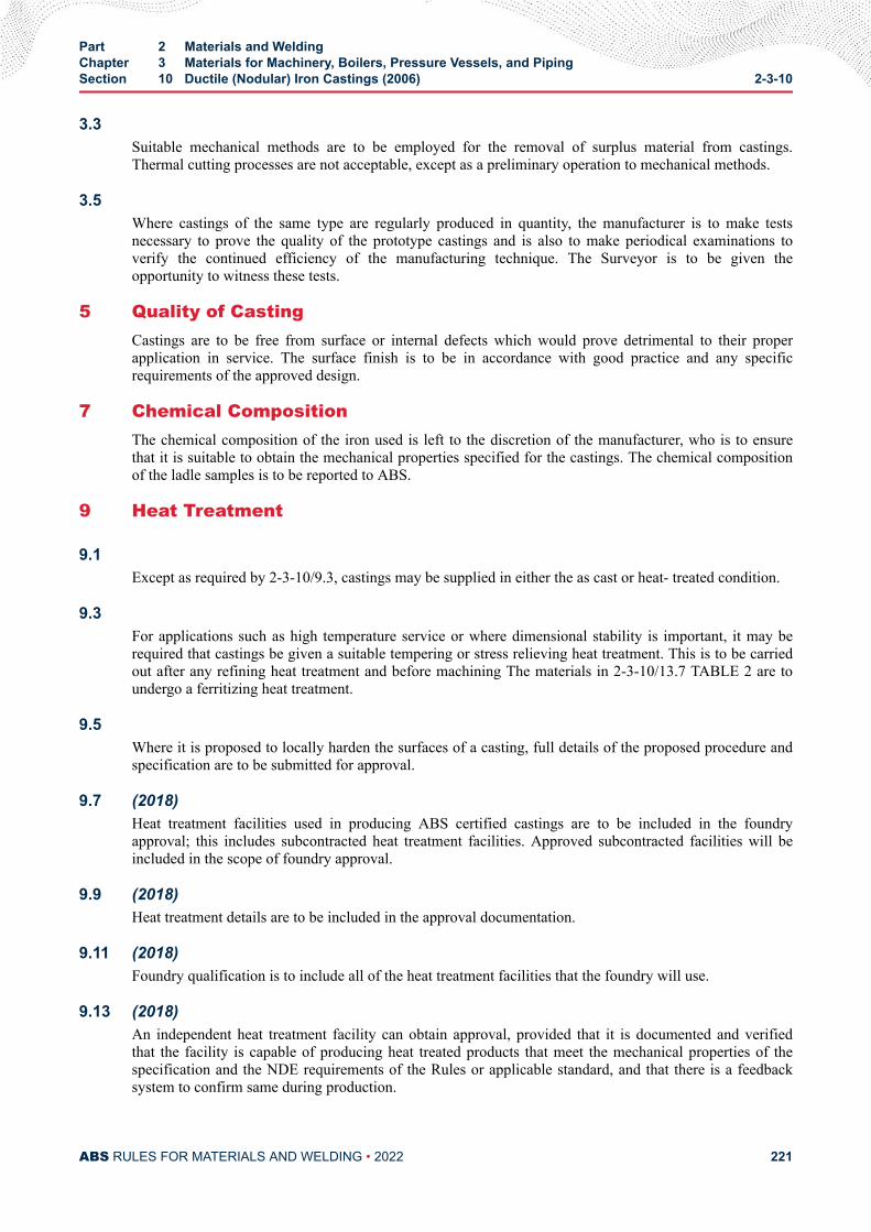
3.3Suitable mechanical methods are to be employed for the removal of surplus material from castings.Thermal cutting processes are not acceptable, except as a preliminary operation to mechanical methods.
3.5Where castings of the same type are regularly produced in quantity, the manufacturer is to make testsnecessary to prove the quality of the prototype castings and is also to make periodical examinations toverify the continued efficiency of the manufacturing technique. The Surveyor is to be given theopportunity to witness these tests.
5 Quality of CastingCastings are to be free from surface or internal defects which would prove detrimental to their properapplication in service. The surface finish is to be in accordance with good practice and any specificrequirements of the approved design.
7 Chemical CompositionThe chemical composition of the iron used is left to the discretion of the manufacturer, who is to ensurethat it is suitable to obtain the mechanical properties specified for the castings. The chemical compositionof the ladle samples is to be reported to ABS.
9 Heat Treatment
9.1Except as required by 2-3-10/9.3, castings may be supplied in either the as cast or heat- treated condition.
9.3For applications such as high temperature service or where dimensional stability is important, it may berequired that castings be given a suitable tempering or stress relieving heat treatment. This is to be carriedout after any refining heat treatment and before machining The materials in 2-3-10/13.7 TABLE 2 are toundergo a ferritizing heat treatment.
9.5Where it is proposed to locally harden the surfaces of a casting, full details of the proposed procedure andspecification are to be submitted for approval.
9.7 (2018)Heat treatment facilities used in producing ABS certified castings are to be included in the foundryapproval; this includes subcontracted heat treatment facilities. Approved subcontracted facilities will beincluded in the scope of foundry approval.
9.9 (2018)Heat treatment details are to be included in the approval documentation.
9.11 (2018)Foundry qualification is to include all of the heat treatment facilities that the foundry will use.
9.13 (2018)An independent heat treatment facility can obtain approval, provided that it is documented and verifiedthat the facility is capable of producing heat treated products that meet the mechanical properties of thespecification and the NDE requirements of the Rules or applicable standard, and that there is a feedbacksystem to confirm same during production.
Part 2 Materials and WeldingChapter 3 Materials for Machinery, Boilers, Pressure Vessels, and PipingSection 10 Ductile (Nodular) Iron Castings (2006) 2-3-10
ABS RULES FOR MATERIALS AND WELDING • 2022 221
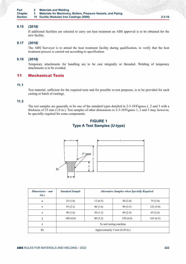
9.15 (2018)If additional facilities are selected to carry out heat treatment an ABS approval is to be obtained for thenew facility.
9.17 (2018)The ABS Surveyor is to attend the heat treatment facility during qualification, to verify that the heattreatment process is carried out according to specification.
9.19 (2018)Temporary attachments for handling are to be cast integrally or threaded. Welding of temporaryattachments is to be avoided.
11 Mechanical Tests
11.1Test material, sufficient for the required tests and for possible re-test purposes, is to be provided for eachcasting or batch of castings.
11.3The test samples are generally to be one of the standard types detailed in 2-3-10/Figures.1, 2 and 3 with athickness of 25 mm (1.0 in.). Test samples of other dimensions to 2-3-10/Figures 1, 2 and 3 may, however,be specially required for some components.
FIGURE 1Type A Test Samples (U-type)
Dimensions – mm(in.)
Standard Sample Alternative Samples when Specially Required
u 25 (1.0) 12 (0.5) 50 (2.0) 75 (3.0)v 55 (2.2) 40 (1.6) 90 (3.5) 125 (5.0)x 40 (1.6) 30 (1.2) 60 (2.4) 65 (2.6)y 100 (4.0) 80 (3.2) 150 (6.0) 165 (6.5)z To suit testing machineRs Approximately 5 mm (0.20 in.)
Part 2 Materials and WeldingChapter 3 Materials for Machinery, Boilers, Pressure Vessels, and PipingSection 10 Ductile (Nodular) Iron Castings (2006) 2-3-10
ABS RULES FOR MATERIALS AND WELDING • 2022 222
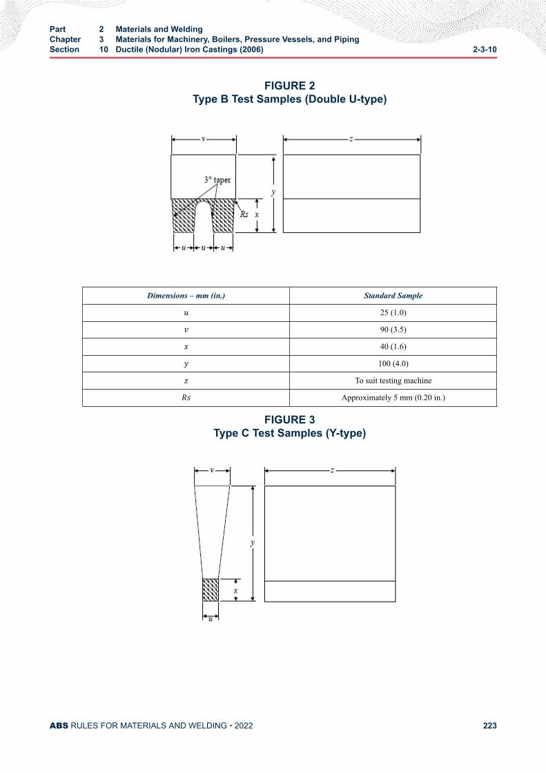
FIGURE 2Type B Test Samples (Double U-type)
Dimensions – mm (in.) Standard Sampleu 25 (1.0)v 90 (3.5)x 40 (1.6)y 100 (4.0)z To suit testing machineRs Approximately 5 mm (0.20 in.)
FIGURE 3Type C Test Samples (Y-type)
Part 2 Materials and WeldingChapter 3 Materials for Machinery, Boilers, Pressure Vessels, and PipingSection 10 Ductile (Nodular) Iron Castings (2006) 2-3-10
ABS RULES FOR MATERIALS AND WELDING • 2022 223
Dimensions – mm(in.)
Standard Sample Alternative Samples when Specially Required
u 25 (1.0) 12 (0.5) 50 (2.0) 75 (3.0)v 55 (2.2) 40 (1.6) 100 (4.0) 125 (5.0)x 40 (1.6) 25 (1.0) 50 (2.4) 65 (2.6)y 140 (5.5) 135 (5.5) 150 (6.0) 175 (7.0)z To suit testing machine
Min. thickness of moldsurrounding test
sample
40 (1.6) 40 (1.6) 80 (3.2) 80 (3.2)
11.5At least one test sample is to be provided for each casting and, unless otherwise required, may be eithergated to the casting or separately cast. Alternatively, test material of other suitable dimensions may beprovided integral with the casting.
11.7For large castings where more than one ladle of treated metal is used, additional test samples are to beprovided so as to be representative of each ladle used.
11.9 (2016)As an alternative to 2-3-10/11.5, a batch testing procedure may be adopted for castings with a fettled massof 1,000 kg (2,200 lb) or less. All castings in a batch are to be of similar type and dimensions, and castfrom the same ladle of treated metal. One separately cast test sample is to be provided for each multiple of2,000 kg (4,400 lb) of fettled castings in the batch.
11.11Where separately cast test samples are used, they are to be cast in molds made from the same type ofmaterial as used for the castings and are to be taken towards the end of pouring of the castings. Thesamples are not to be stripped from the molds until the temperature is below 500°C (930°F).
11.13All test samples are to be suitably marked to identify them with the castings which they represent.
11.15Where castings are supplied in the heat treated condition, the test samples are to be heat treated togetherwith the castings which they represent.
11.17One tensile specimen is to be prepared from each test sample and is to be machined to the dimensionsgiven in 2-3-1/11.13 FIGURE 2. Note that for nodular cast iron with an elongation less than 10%, theradius R≥ 20 mm (0.8 in.).
11.19All tensile tests are to be carried out using test procedures in accordance with Section 2-3-1. Unlessotherwise agreed, all tests are to be carried out in the presence of the Surveyor.
Part 2 Materials and WeldingChapter 3 Materials for Machinery, Boilers, Pressure Vessels, and PipingSection 10 Ductile (Nodular) Iron Castings (2006) 2-3-10
ABS RULES FOR MATERIALS AND WELDING • 2022 224
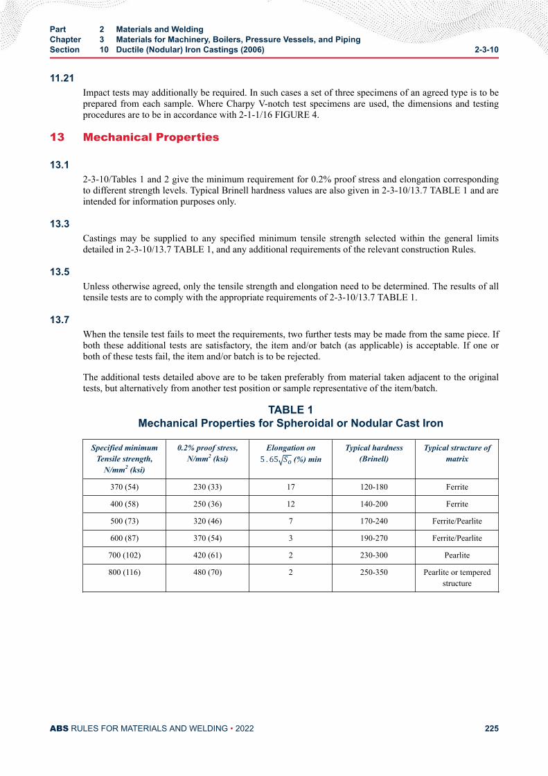
11.21Impact tests may additionally be required. In such cases a set of three specimens of an agreed type is to beprepared from each sample. Where Charpy V-notch test specimens are used, the dimensions and testingprocedures are to be in accordance with 2-1-1/16 FIGURE 4.
13 Mechanical Properties
13.12-3-10/Tables 1 and 2 give the minimum requirement for 0.2% proof stress and elongation correspondingto different strength levels. Typical Brinell hardness values are also given in 2-3-10/13.7 TABLE 1 and areintended for information purposes only.
13.3Castings may be supplied to any specified minimum tensile strength selected within the general limitsdetailed in 2-3-10/13.7 TABLE 1, and any additional requirements of the relevant construction Rules.
13.5Unless otherwise agreed, only the tensile strength and elongation need to be determined. The results of alltensile tests are to comply with the appropriate requirements of 2-3-10/13.7 TABLE 1.
13.7When the tensile test fails to meet the requirements, two further tests may be made from the same piece. Ifboth these additional tests are satisfactory, the item and/or batch (as applicable) is acceptable. If one orboth of these tests fail, the item and/or batch is to be rejected.
The additional tests detailed above are to be taken preferably from material taken adjacent to the originaltests, but alternatively from another test position or sample representative of the item/batch.
TABLE 1Mechanical Properties for Spheroidal or Nodular Cast Iron
Specified minimumTensile strength,
N/mm2 (ksi)
0.2% proof stress,N/mm2 (ksi)
Elongation on5 . 65 So (%) minTypical hardness
(Brinell)Typical structure of
matrix
370 (54) 230 (33) 17 120-180 Ferrite
400 (58) 250 (36) 12 140-200 Ferrite
500 (73) 320 (46) 7 170-240 Ferrite/Pearlite
600 (87) 370 (54) 3 190-270 Ferrite/Pearlite
700 (102) 420 (61) 2 230-300 Pearlite
800 (116) 480 (70) 2 250-350 Pearlite or temperedstructure
Part 2 Materials and WeldingChapter 3 Materials for Machinery, Boilers, Pressure Vessels, and PipingSection 10 Ductile (Nodular) Iron Castings (2006) 2-3-10
ABS RULES FOR MATERIALS AND WELDING • 2022 225
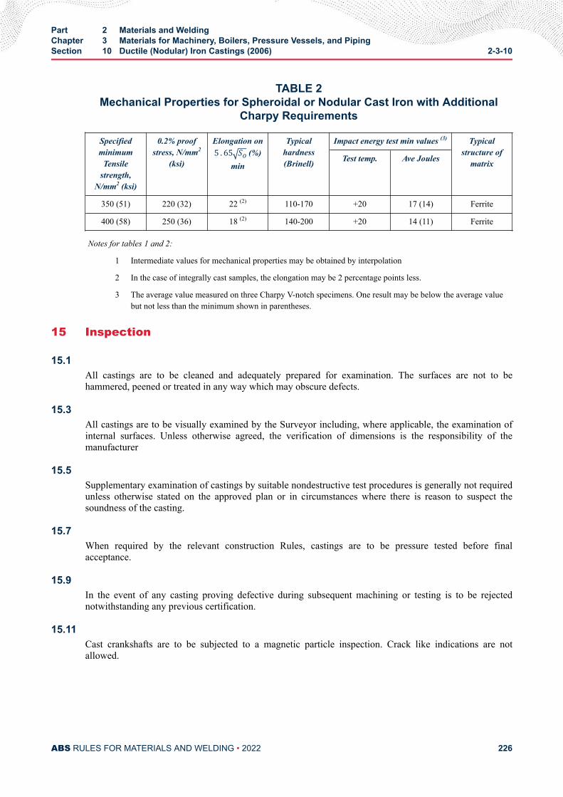
TABLE 2Mechanical Properties for Spheroidal or Nodular Cast Iron with Additional
Charpy Requirements
Specifiedminimum
Tensilestrength,
N/mm2 (ksi)
0.2% proofstress, N/mm2
(ksi)
Elongation on5 . 65 So (%)min
Typicalhardness(Brinell)
Impact energy test min values (3) Typicalstructure of
matrixTest temp. Ave Joules
350 (51) 220 (32) 22 (2) 110-170 +20 17 (14) Ferrite
400 (58) 250 (36) 18 (2) 140-200 +20 14 (11) Ferrite
Notes for tables 1 and 2:
1 Intermediate values for mechanical properties may be obtained by interpolation
2 In the case of integrally cast samples, the elongation may be 2 percentage points less.
3 The average value measured on three Charpy V-notch specimens. One result may be below the average valuebut not less than the minimum shown in parentheses.
15 Inspection
15.1All castings are to be cleaned and adequately prepared for examination. The surfaces are not to behammered, peened or treated in any way which may obscure defects.
15.3All castings are to be visually examined by the Surveyor including, where applicable, the examination ofinternal surfaces. Unless otherwise agreed, the verification of dimensions is the responsibility of themanufacturer
15.5Supplementary examination of castings by suitable nondestructive test procedures is generally not requiredunless otherwise stated on the approved plan or in circumstances where there is reason to suspect thesoundness of the casting.
15.7When required by the relevant construction Rules, castings are to be pressure tested before finalacceptance.
15.9In the event of any casting proving defective during subsequent machining or testing is to be rejectednotwithstanding any previous certification.
15.11Cast crankshafts are to be subjected to a magnetic particle inspection. Crack like indications are notallowed.
Part 2 Materials and WeldingChapter 3 Materials for Machinery, Boilers, Pressure Vessels, and PipingSection 10 Ductile (Nodular) Iron Castings (2006) 2-3-10
ABS RULES FOR MATERIALS AND WELDING • 2022 226
17 Metallographic Examination
17.1For crankshafts, a metallographic examination is to be carried out.
17.3When required, a representative sample from each ladle of treated metal is to be prepared formetallographic examination. These samples may be taken from the tensile test specimens but alternativearrangements for the provisions of the samples may be adopted provided that they are taken from the ladletowards the end of the casting period.
17.5Examination of the samples is to show that at least 90% of the graphite is in a dispersed spheroidal ornodular form. Details of typical matrix structures are given in 2-3-10/13.7 TABLE 1 and are intended forinformation purposes only.
19 Rectification of Defective Castings
19.1At the discretion of the Surveyor, small surface blemishes may be removed by local grinding.
19.3Subject to approval, castings containing local porosity may be rectified by impregnation with suitableplastic filler.
19.5Repairs by welding are generally not permitted.
21 Identification of Castings
21.1The manufacturer is to adopt a system of identification, which will enable all finished castings to be tracedto the original ladle of treated metal and the Surveyor is to be given full facilities for tracing the castingswhen required.
21.3Before acceptance, all castings, which have been tested and inspected with satisfactory results are to beclearly marked by the manufacturer with the following details:
i) Grade of cast iron
ii) Identification number or other marking enabling the full history of the casting to be traced.
iii) Manufacturer’s name or trademark.
iv) Date of final inspection.
v) ABS office, initials or symbol.
vi) Personal stamp of Surveyor responsible for inspection
vii) Test pressure, if applicable
Part 2 Materials and WeldingChapter 3 Materials for Machinery, Boilers, Pressure Vessels, and PipingSection 10 Ductile (Nodular) Iron Castings (2006) 2-3-10
ABS RULES FOR MATERIALS AND WELDING • 2022 227
21.5Where small castings are manufactured in large numbers, modified arrangements for identification may bespecially agreed with the Surveyor.
23 Certification
23.1The manufacturer is to provide the Surveyor with a test certificate or shipping statement giving thefollowing particulars for each casing or batch of castings which has been accepted:
i) Purchaser’s name and order number
ii) Description of castings and quality of cast iron
iii) Identification number
iv) Results of mechanical tests
v) Where applicable, general details of heat treatment
vi) Where specifically required, the chemical analysis of the ladle samples
vii) Where applicable, test pressure
Part 2 Materials and WeldingChapter 3 Materials for Machinery, Boilers, Pressure Vessels, and PipingSection 10 Ductile (Nodular) Iron Castings (2006) 2-3-10
ABS RULES FOR MATERIALS AND WELDING • 2022 228
C H A P T E R 3Materials for Machinery, Boilers, Pressure Vessels, and Piping
S E C T I O N 1 1Gray-iron Castings (2006)
1 Scope
1.1Gray iron castings, as defined in the relevant construction rules, are to be manufactured and tested inaccordance with the requirements of this Section.
1.3Alternatively, castings which comply with national or proprietary specifications may be accepted, providedsuch specifications give reasonable equivalence to these requirements or otherwise are specially approvedor required by ABS.
1.5Where small castings are produced in large quantities, the manufacturer may adopt alternative proceduresfor testing and inspection subject to the approval of ABS.
3 Process of Manufacture
3.1 (2012)Gray iron castings (for example, castings that are required to be certified per 4-2-1/15.11 TABLE 1 of theMarine Vessel Rules) are to be made at ABS-approved foundries where the manufacturer has demonstratedto the satisfaction of ABS that the necessary manufacturing and testing facilities are available and aresupervised by qualified personnel.
ABS approval is valid for 5 years subject to annual verification and/or endorsement by the attendingSurveyor. The Surveyor is permitted at any time to monitor important aspects of casting production,including but not limited to mold preparation and chaplet positioning; pouring times and temperatures;mold breakout; repairs; heat treatment and inspection.
3.3Suitable mechanical methods are to be employed for the removal of surplus material from castings.Thermal cutting processes are not acceptable, except as a preliminary operation to mechanical methods.
PART 2
ABS RULES FOR MATERIALS AND WELDING • 2022 229
3.5Where castings of the same type are regularly produced in quantity, the manufacturer is to carry out testsnecessary to prove the quality of the prototype castings and is also to make periodical examinations toverify the continued efficiency of the manufacturing technique. The Surveyor is to be given theopportunity to witness these tests.
5 Quality of CastingsCastings are to be free from surface or internal defects, which would prove detrimental to their properapplication in service. The surface finish is to be in accordance with good practice and any specificrequirements of the approved design.
7 Chemical CompositionThe chemical composition of the iron used is left to the discretion of the manufacturer, who is to ensurethat it is suitable to obtain mechanical properties specified for the castings. The composition of ladlesample is to be reported to ABS.
9 Heat Treatment
9.1Except as required for 2-3-11/9.3, castings may be supplied in either the cast or heat treated condition.
9.3For applications such as high temperature service or when dimensional stability is important, castings mayrequire to be given a suitable tempering or stress relieving heat treatment.
9.5 (2018)Heat treatment facilities used in producing ABS certified castings are to be included in the foundryapproval; this includes subcontracted heat treatment facilities. Approved subcontracted facilities will beincluded in the scope of foundry approval.
9.7 (2018)Heat treatment details are to be included in the approval documentation.
9.9 (2018)Foundry qualification is to include all of the heat treatment facilities that the foundry will use.
9.11 (2018)An independent heat treatment facility can obtain approval, provided that it is documented and verifiedthat the facility is capable of producing heat treated products that meet the mechanical properties of thespecification and the NDE requirements of the Rules or applicable standard, and that there is a feedbacksystem to confirm same during production.
9.13 (2018)If additional facilities are selected to carry out heat treatment an ABS approval is to be obtained for thenew facility.
9.15 (2018)The ABS Surveyor is to attend the heat treatment facility during qualification, to verify that the heattreatment process is carried out according to specification.
Part 2 Materials and WeldingChapter 3 Materials for Machinery, Boilers, Pressure Vessels, and PipingSection 11 Gray-iron Castings (2006) 2-3-11
ABS RULES FOR MATERIALS AND WELDING • 2022 230
9.17 (2018)Temporary attachments for handling are to be cast integrally or threaded. Welding of temporaryattachments is to be avoided.
11 Mechanical Tests
11.1Test material sufficient for the required tests and for possible re-tests is to be provided for each casting orbatch of castings.
11.3Separately cast test samples are to be used unless otherwise agreed between the manufacturer andpurchaser, and are to be in the form of round bars 30 mm (1.2 in.) in diameter and of a suitable length.They are to be of cast iron from the same ladle as the castings in molds of the same type of material as themolds for the castings and are not to be stripped from the molds until the metal temperature is below500°C (930°F). When two or more test samples are cast simultaneously in a single mold, the bars are to beat least 50 mm (2.0 in.) apart.
11.5Integrally cast samples may be used when a casting is more than 20 mm (0.8 in.) thick and its massexceeds 200 kg (440 lb), subject to agreement between the manufacturer and the purchaser. The type andlocation of the sample are to be selected to provide approximately the same cooling conditions as for thecasting it represents and also subject to agreement.
11.7With the exception of 2-3-11/11.13, at least one test sample is to be cast with each batch.
11.9With the exception of 2-3-11/11.11, a batch consists of the castings poured from a single ladle of metal,provided that they are all of similar type and dimensions. A batch should not normally exceed 2,000 kg(4,400 lbs) of fettled castings and a single casting will constitute a batch if its mass is 2,000 kg (4,400 lbs)or more.
11.11For large mass casting of the same grade, produced by continuous melting, the batch weight may be takenas the weight of casting produced in two hours of pouring. The pouring rate is not to be accelerated beyondthe capacity of the caster.
11.13If one grade of cast iron is melted in large quantities and production is monitored by systematic checkingof the melting process, such as a chill testing, chemical analysis or thermal analysis, test samples may betaken at longer intervals, as agreed by the Surveyor.
11.15All test samples are to be suitably marked to identify them with the castings which they represent.
11.17Where castings are supplied in the heat-treated condition, the test samples are to be heat treated togetherwith the castings which they represent. For cast-on-test samples, the sample shall not be removed from thecasting until after the heat treatment.
Part 2 Materials and WeldingChapter 3 Materials for Machinery, Boilers, Pressure Vessels, and PipingSection 11 Gray-iron Castings (2006) 2-3-11
ABS RULES FOR MATERIALS AND WELDING • 2022 231
11.19One tensile test specimen is to be prepared from each test sample. 30 mm (1.2 in.) diameter samples are tobe machined to the dimensions given in 2-3-1/11.13 FIGURE 3. Where test samples of other dimensionsare specially required, the tensile test specimens are to be machined to agreed dimensions.
11.21All tensile tests are to be carried out using test procedures in accordance with Section 2-3-1. Unlessotherwise agreed, all tests are to be carried out in the presence of the Surveyor.
13 Mechanical Properties
13.1 Tensile Strength13.1.1
The tensile strength is to be determined, and the results obtained from tests are to comply with theminimum value specified for the castings being supplied. The value selected for the specifiedminimum tensile strength is not to be less than 200 N/mm2 (29.0 ksi) but subject to any additionalrequirements of the relevant construction Rules. The fractured surfaces of all tensile testspecimens are to be granular and gray in appearance.
13.1.2When the tensile test fails to meet the requirements, two further tests may be made from the samepiece. If both of these additional tests are satisfactory, the item and/or batch (as applicable) isacceptable. If one or both of these tests fail, the item and/or batch is to be rejected.
13.1.3 Higher Strength CastingsWhen higher-strength cast iron is proposed for any purpose, the purchaser’s specifications are tobe submitted specially for approval in connection with the approval of the design for which thematerial is intended.
15 Inspection
15.1All castings are to be cleaned and adequately prepared for examination. The surfaces are not to behammered, peened or treated in any way which may obscure defects.
15.3All castings are to be visually examined by the Surveyor including the examination of internal surfaceswhere applicable. Unless otherwise agreed, the verification of dimensions is the responsibility of themanufacturer.
15.5Supplementary examination of castings by suitable nondestructive testing procedures is generally notrequired unless otherwise stated on the approved plan or in circumstances where there is reason to suspectthe soundness of the casting.
15.7When required by the relevant construction Rules, castings are to be pressure tested before finalacceptance.
Part 2 Materials and WeldingChapter 3 Materials for Machinery, Boilers, Pressure Vessels, and PipingSection 11 Gray-iron Castings (2006) 2-3-11
ABS RULES FOR MATERIALS AND WELDING • 2022 232
15.9In any event of any casting proving defective during subsequent machining or testing, it is to be rejectednotwithstanding any previous certification.
17 Rectification of Defective Casting
17.1At the discretion of the Surveyor, small surface blemishes may be removed by local grinding.
17.3Subject to approval, castings containing local porosity may be rectified by impregnation with a suitableplastic filler.
17.5Repairs by welding are generally not permitted. In cases where welding is proposed, full details of theproposed repair are to be submitted for review prior to commencing the repair.
19 Identification of Castings
19.1The manufacturer is to adopt a system of identification, which will enable all finished castings to be tracedto the original ladle of metal. The Surveyor is to be given full facilities for tracing the castings whenrequired.
19.3Before acceptance, all castings which have been tested and inspected with satisfactory results are to beclearly marked by the manufacturer with the following details:
● Grade of cast iron
● Identification number or other marking enabling the full history of the casting to be traced.
● Manufacturer’s name or trademark.
● Date of final inspection
● ABS office, initials or symbol
● Personal stamp of Surveyor responsible for inspection
● Test pressure, if applicable
19.5Where small castings are manufactured in large numbers, modified arrangements for identification may bespecially agreed with the Surveyor.
21 CertificationThe manufacturer is to provide the Surveyor with a test certificate or shipping statement giving thefollowing particulars for each casting or batch of castings which has been accepted:
● Purchaser’s name and order number
● Description of castings and quality of cast iron
● Identification number
● Results of mechanical test
Part 2 Materials and WeldingChapter 3 Materials for Machinery, Boilers, Pressure Vessels, and PipingSection 11 Gray-iron Castings (2006) 2-3-11
ABS RULES FOR MATERIALS AND WELDING • 2022 233

● Where applicable, general details of the heat treatment
● Where specifically required, the chemical analysis of ladle samples
● Where applicable, test pressures
Part 2 Materials and WeldingChapter 3 Materials for Machinery, Boilers, Pressure Vessels, and PipingSection 11 Gray-iron Castings (2006) 2-3-11
ABS RULES FOR MATERIALS AND WELDING • 2022 234
C H A P T E R 3Materials for Machinery, Boilers, Pressure Vessels, and Piping
S E C T I O N 1 2Steel Piping
1 Scope (1998)The following specifications cover thirteen grades of steel pipe designated 1, 2, 3, 4, 5, 6, 7, 8, 9, 11, 12, 13and 14.
3 General
3.1 Grades 1, 2 and 3Grades 1, 2 and 3 cover seamless and welded steel pipe. Pipe ordered under these grades is of a nominal(average) wall thickness suitable for welding and suitable for forming operations involving coiling,bending and flanging, subject to the following limitations: Grade 1 furnace-butt-welded pipe is notintended for flanging; when seamless or electric-resistance-welded pipe is required for close-coiling orcold-bending, Grade 2 should be specified; this provision is not intended to prohibit the cold-bending ofGrade 3 pipe. When pipe is required for close-coiling, this is to be specified on the order. Electric-resistance-welded Grades 2 and 3 may be furnished either non-expanded or cold-expanded, at the option ofthe manufacturer. When pipe is cold expanded, the amount of expansion is not to exceed 1.5% of theoutside diameter pipe size.
3.3 Grades 4 and 5Grades 4 and 5 cover seamless carbon-steel pipe for high-temperature service. Pipe ordered to these gradesis of a nominal (average) wall thickness and is to be suitable for bending, flanging and similar formingoperations. Grade 4 rather than Grade 5 pipe should be used for close-coiling, cold-bending or forge-welding; this provision is not intended to prohibit the cold-bending of Grade 5 pipe.
3.5 Grade 6Grade 6 covers seamless carbon-molybdenum alloy-steel pipe for high-temperature service. Pipe orderedto this grade is of a nominal (average) wall thickness and is to be suitable for bending, flanging(vanstoning) and similar forming operations, and for fusion-welding.
3.7 Grades 7, 11, 12, 13 and 14 (1998)Grades 7, 11, 12, 13 and 14 cover seamless chromium-molybdenum alloy-steel pipe for high-temperatureservice. Pipe ordered to these grades is of a nominal (average) wall thickness and is to be suitable forbending, flanging (vanstoning) and similar forming operations, and for fusion-welding.
PART 2
ABS RULES FOR MATERIALS AND WELDING • 2022 235
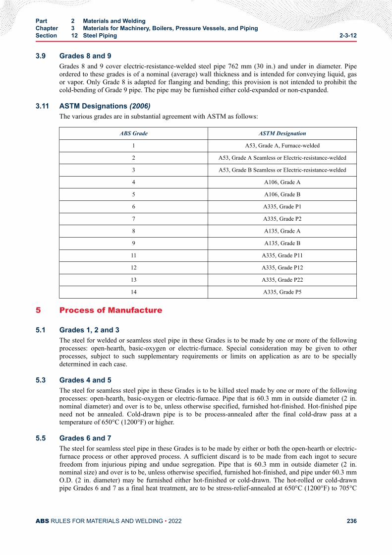
3.9 Grades 8 and 9Grades 8 and 9 cover electric-resistance-welded steel pipe 762 mm (30 in.) and under in diameter. Pipeordered to these grades is of a nominal (average) wall thickness and is intended for conveying liquid, gasor vapor. Only Grade 8 is adapted for flanging and bending; this provision is not intended to prohibit thecold-bending of Grade 9 pipe. The pipe may be furnished either cold-expanded or non-expanded.
3.11 ASTM Designations (2006)The various grades are in substantial agreement with ASTM as follows:
ABS Grade ASTM Designation
1 A53, Grade A, Furnace-welded
2 A53, Grade A Seamless or Electric-resistance-welded
3 A53, Grade B Seamless or Electric-resistance-welded
4 A106, Grade A
5 A106, Grade B
6 A335, Grade P1
7 A335, Grade P2
8 A135, Grade A
9 A135, Grade B
11 A335, Grade P11
12 A335, Grade P12
13 A335, Grade P22
14 A335, Grade P5
5 Process of Manufacture
5.1 Grades 1, 2 and 3The steel for welded or seamless steel pipe in these Grades is to be made by one or more of the followingprocesses: open-hearth, basic-oxygen or electric-furnace. Special consideration may be given to otherprocesses, subject to such supplementary requirements or limits on application as are to be speciallydetermined in each case.
5.3 Grades 4 and 5The steel for seamless steel pipe in these Grades is to be killed steel made by one or more of the followingprocesses: open-hearth, basic-oxygen or electric-furnace. Pipe that is 60.3 mm in outside diameter (2 in.nominal diameter) and over is to be, unless otherwise specified, furnished hot-finished. Hot-finished pipeneed not be annealed. Cold-drawn pipe is to be process-annealed after the final cold-draw pass at atemperature of 650°C (1200°F) or higher.
5.5 Grades 6 and 7The steel for seamless steel pipe in these Grades is to be made by either or both the open-hearth or electric-furnace process or other approved process. A sufficient discard is to be made from each ingot to securefreedom from injurious piping and undue segregation. Pipe that is 60.3 mm in outside diameter (2 in.nominal size) and over is to be, unless otherwise specified, furnished hot-finished, and pipe under 60.3 mmO.D. (2 in. diameter) may be furnished either hot-finished or cold-drawn. The hot-rolled or cold-drawnpipe Grades 6 and 7 as a final heat treatment, are to be stress-relief-annealed at 650°C (1200°F) to 705°C
Part 2 Materials and WeldingChapter 3 Materials for Machinery, Boilers, Pressure Vessels, and PipingSection 12 Steel Piping 2-3-12
ABS RULES FOR MATERIALS AND WELDING • 2022 236
(1300°F). The steel from which Grade 7 pipe is made is to be a coarse-grained steel having a carburizedaustenitic grain size of 1 to 5 as determined in accordance with the Methods for Estimating the AverageGrain Size of Metals (ASTM E112) and its Plate IV, by carburizing at 925°C (1700°F) for 8 hours. Thespecimen is to be taken from the bloom or billet.
5.7 Grades 8 and 9The steel for electric-resistance-welded steel pipe in these Grades is to be made by one or more of thefollowing processes: open-hearth, basic-oxygen or electric-furnace.
5.9 Grades 11, 12, 13 and 14 (1998)The steel for seamless alloy steel pipe is to be made by the electric-furnace process or other approvedprocess, except that Grade 12 may be made by the open-hearth process. A sufficient discard is to be madefrom each ingot to secure freedom from injurious piping and undue segregation. Pipe that is 60.3 mm inoutside diameter (2 in. nominal diameter) and over is to be, unless otherwise specified, furnished hot-finished, and pipe under 60.3 mm O.D. (2 in. nominal diameter) may be furnished either hot-finished orcold-drawn. The steel for Grade 12 pipe is to be made by coarse-grain melting practice. Grades 11, 13 and14 pipe are to be reheated and furnished in the full-annealed, isothermal annealed or normalized andtempered condition; if furnished in the normalized and tempered condition, or if cold drawn pipe isfurnished, the temperature for tempering following normalizing or cold drawing is to be 677°C (1250°F) orhigher for Grades 13 and 14, and 650°C (1200°F) or higher for Grade 11. The hot-rolled or cold-drawnGrade 12 pipe, as a final heat treatment, is to be given a stress-relieving treatment at 650°C (1200°F) to705°C (1300°F).
7 Marking (1998)Identification markings are to be legibly stenciled, stamped, or rolled on each length of pipe, except that inthe case of small-diameter pipe which is bundled, the required markings are to be placed on a tag securelyattached to the bundle. The markings are to be arranged and are to include the following information:
● Name or brand of the manufacturer
● ABS Grade or ASTM Designation and Type or Grade. Heat number or manufacturer's number bywhich the heat can be identified (For Grades 6, 7, 11, 12, 13 and 14 pipe only)
● Test pressure or the letters NDE
● Method of forming (i.e. butt-welded, lap-welded, electric-resistance-welded or seamless hot-finishedor cold-drawn)
● “XS” for extra strong or “XXS” for double-extra strong (when applicable for Grades 1, 2 and 3 pipeonly)
● ABS markings by the Surveyor
9 Chemical CompositionThe material for pipe is to conform to the applicable requirements as to chemical composition shown in2-3-12/39.7 TABLE 1.
11 Ladle Analysis (1998)For Grades 4, 5, 6, 7, 8, 9, 11, 12, 13 and 14, the manufacturer is to submit a report showing the ladleanalysis of each heat of steel from which the pipe has been made and the chemical composition is toconform to the requirements specified in 2-3-12/9. In lieu of a report of the ladle analysis, a report of checkanalysis as provided for in 2-3-12/13 will be acceptable.
Part 2 Materials and WeldingChapter 3 Materials for Machinery, Boilers, Pressure Vessels, and PipingSection 12 Steel Piping 2-3-12
ABS RULES FOR MATERIALS AND WELDING • 2022 237
13 Check Analysis
13.1 GeneralA check analysis may be made where so specified by the purchaser. The chemical composition thusdetermined is to conform to the requirements specified in 2-3-12/9. If check analyses are made, they are tobe in accordance with the following requirements.
13.3 SamplesSamples for check analysis are to be taken by drilling several points around each pipe selected for analysisor when taken from the billet they are to be obtained by drilling parallel to the billet axis at a point midwaybetween the outside and center or when taken from a broken tension test specimen, they are to be taken soas to represent the entire cross section of the specimen.
13.5 Grades 1, 2 and 3For these grades, analyses of two pipes from each lot of 500 lengths or fraction thereof are to be made.
13.7 Grades 4 and 5For these grades, analyses of two pipes from each lot of 400 lengths or fraction thereof, of each size andheat 60.3 mm O.D. (2 in. nominal diameter) up to, but not including 168.3 mm O.D. (6 in. nominaldiameter), and from each lot of 200 lengths or fraction thereof of each size and heat 168.3 mm O.D. (6 in.nominal diameter) and over, are to be made.
13.9 Grades 6, 7, 11, 12, 13 and 14 (1998)For these grades, analyses of two pipes from each lot and heat, as specified in 2-3-12/39.7 TABLE 2, are tobe made.
13.11 Grades 8 and 9For these grades, analyses of two pipes from each lot of 400 lengths or fraction thereof of each size under168.3 mm O.D. (6 in. nominal), from each lot of 200 lengths or fraction thereof of each size 168.3 mmO.D. (6 in. nominal diameter) to 508 mm (20 in.) O.D., and from each lot of 100 lengths or fraction thereofof each size over 508 mm (20 in.) O.D. to 762 mm (30 in.) O.D. are to be made. With the Surveyor’spermission, the analysis may be made of the skelp and the number is to be determined in the same manneras when taken from the finished pipe.
13.13 Retests for Grades 1, 2, 3, 4 and 5If an analysis for these grades does not conform to the requirements specified, analyses are to be made onadditional pipes of double the original number from the same lot, each of which is to conform to therequirements specified.
13.15 Retests for Grades 6, 7, 11, 12, 13 and 14 (1998)If a check or ladle analysis for these grades does not conform to the requirements specified, an analysis ofeach billet or pipe from the same heat or lot may be made, and all billets or pipe conforming to therequirements are to be accepted.
13.17 Retests for Grades 8 and 9For these grades, if the analysis of either length of pipe or length of skelp does not conform to therequirements, analyses of two additional lengths from the same lot are to be made, each of which is toconform to the requirements specified.
Part 2 Materials and WeldingChapter 3 Materials for Machinery, Boilers, Pressure Vessels, and PipingSection 12 Steel Piping 2-3-12
ABS RULES FOR MATERIALS AND WELDING • 2022 238
15 Mechanical Tests Required (1998)The type and number of mechanical tests are to be in accordance with 2-3-12/39.7 TABLE 3. For adescription and the requirements of each test see 2-3-12/17 through and including 2-3-12/29. For retestssee 2-3-12/33.
17 Tension Test Specimens
17.1 Grades 1, 2 and 3For these grades, tension test specimens are to be cut longitudinally from the end of the pipe and notflattened between gauge marks. The sides of strip specimens are to be parallel between gauge marks; thewidth is to be 38 mm (1.5 in.) and the gauge length 50 mm (2 in.). If desired, tension test specimens mayconsist of a full section of pipe. When impracticable to pull a test specimen in full thickness, the tensiontest specimen shown in 2-3-1/11.13 FIGURE 2 may be used. The transverse-weld tension test specimensfrom electric-resistance-welded Grade 2 and Grade 3 pipe are to be taken with the weld at the center of thespecimen and are to be 38 mm (1.5 in.) wide in the gauge length.
17.3 Grades 4, 5, 6, 7, 11, 12, 13 and 14 (1998)For these grades, the tension test specimens are to be cut longitudinally, but may be cut transversely forpipe 219.1 mm in outside diameter (8 in. nominal diameter) and over.
17.3.1 Longitudinal Tension Test SpecimensThe longitudinal tension test may be made in full section of the pipe, up to the capacity of thetesting machine. For larger sizes, tension test specimens are to consist of strips cut from the pipe;the width of these specimens is to be 38 mm (1.5 in.) and they are to have a gauge length of 50mm (2 in.). When the pipe-wall thickness is 19.1 mm (0.75 in.) and over, the tension test specimenshown in 2-3-1/11.13 FIGURE 2 may be used. Longitudinal tension test specimens are not to beflattened between gauge marks. The sides of the specimens are to be parallel between gaugemarks.
17.3.2 Transverse Tension Test SpecimensTransverse tension test specimens may be taken from a ring cut from the pipe or from sectionsresulting from the flattening tests. Test specimens are to consist of strips cut transversely from thepipe; the width of the specimens is to be 38 mm (1.5 in.) and their gauge length 50 mm (2 in.).When the pipe-wall thickness is 19.1 mm (0.75 in.) and over, the tension test specimen shown in2-3-1/11.13 FIGURE 2 may be used. Specimens cut from the ring section are to be flattened coldand are to be parallel between gauge marks. Specimens from Grades 6, 7, 11, 12, 13 and 14 pipesare to be flattened cold and heat-treated in the same manner as the pipe. Transverse tension testspecimens may be machined off on either or both surfaces to secure uniform thickness.
17.5 Grades 8 and 9For these grades, the tension test specimens are to be cut longitudinally from the end of the pipe, or byagreement between the manufacturer and the Surveyor, the specimens may be taken from the skelp, at apoint approximately 90 degrees from the weld. The specimens are not to be flattened between the gaugemarks. Transverse tension test specimens are to be taken across the weld and from the same end of the pipeas the longitudinal test specimens. The sides of each strip specimen are to be parallel between gaugemarks; the width is to be 38 mm (1.5 in.) and the gauge length 50 mm (2 in.). When impracticable to pull atest specimen in full thickness, the tension test specimen shown 2-3-1/11.13 FIGURE 2 may be used.
19 Bend and Flattening Test SpecimensTest specimens for the bend and flattening tests are to consist of sections cut from a pipe and the specimensfor flattening tests are to be smooth on the ends and free from burrs, except when made on crop ends.
Part 2 Materials and WeldingChapter 3 Materials for Machinery, Boilers, Pressure Vessels, and PipingSection 12 Steel Piping 2-3-12
ABS RULES FOR MATERIALS AND WELDING • 2022 239
21 Testing TemperatureAll test specimens are to be tested at room temperature.
23 Tensile PropertiesThe material is to conform to the applicable requirements as to tensile properties shown in 2-3-12/39.7TABLE 4.
25 Bend Test
25.1 GeneralThis test is required for Grades 1, 2, 3, 4 and 5 pipe having outside diameters of 60.3 mm (2 in. nominaldiameter) and under, except that double-extra-strong pipe over 42.2 mm in outside diameter (1.25 in.nominal diameter) need not be subjected to a bend test.
25.3 Details of TestA sufficient length of pipe is to stand being bent cold around a cylindrical mandrel without developingcracks at any portion or without opening the weld. The requirements for bending angle, mandrel diameter,and pipe diameter are tabulated below.
Pipe Grade Bending Angle in degreesRatio of Mandrel Diameterto Nominal Pipe Diameter
1, 2, 3, 4, 5 90 12
1, 2, 3, 4, 5 for close-coiling 180 8
27 Flattening Test
27.1 GeneralFlattening tests are to be made for all Grades of pipe except Grades 1, 2 and 3 double extra strong andGrades 1, 2, 3, 4 and 5 in sizes 60.3 mm in outside diameter (2 in. nominal diameter) and under. The test isto consist of flattening cold a section of pipe between parallel plates.
27.3 Furnace-welded PipeFor Grade 1 furnace-welded pipe, the test section is not to be less than 100 mm (4 in.) in length and theweld is to be located 45 degrees from the line of direction of the applied force. The test is to be made inthree steps.
27.3.1 Test Step No. 1During the first step, which is a test for quality of the weld, no cracks or breaks on the inside,outside or end surfaces are to occur until the distance between the plates is less than three-fourthsof the original outside diameter.
27.3.2 Test Step No. 2During the second step, which is a test for ductility exclusive of the weld, the flattening is to becontinued and no cracks or breaks on the inside, outside or end surfaces are to occur until thedistance between the plates is less than 60% of the original outside diameter for butt-welded pipe.
27.3.3 Test Step No. 3During the third step, which is a test for soundness, the flattening is to be continued until the testspecimen breaks or the opposite walls of the pipe meet. Evidence of laminated or unsound
Part 2 Materials and WeldingChapter 3 Materials for Machinery, Boilers, Pressure Vessels, and PipingSection 12 Steel Piping 2-3-12
ABS RULES FOR MATERIALS AND WELDING • 2022 240
material or of incomplete weld that is revealed during the entire flattening test is to be cause forrejection. Superficial ruptures as a result of surface imperfections are not to be cause for rejection.
27.5 Electric-resistance-welded PipeFor electric-resistance-welded pipe of Grades 2, 3, 8 and 9 the crop ends, at least 100 mm (4 in.) in length,cut from each end of each single length of pipe are to be flattened and the tests from each end are to bemade alternately with the welds at 0 degrees and 90 degrees from the line of direction of force. Whenproduced in multiple lengths, flattening tests are required from each end of each multiple length or coilwith the weld at 90 degrees from the line of direction of force. In addition, tests are to be made on twointermediate rings cut from each multiple length or coil with the weld at 0 degrees from the line ofdirection of force. The test is to be made in three steps.
27.5.1 Test Step No. 1During the first step, which is a test for ductility of the weld, no cracks or breaks on the inside oroutside surfaces are to occur until the distance between the plates is less than two-thirds of theoriginal outside diameter of the pipe.
27.5.2 Test Step No. 2During the second step, which is a test for ductility exclusive of the weld, the flattening is to becontinued and no cracks or breaks on the inside or outside surfaces, elsewhere than in the weld,are to occur until the distance between the plates is less than one-third of the original outsidediameter of the pipe.
27.5.3 Test Step No. 3During the third step, which is a test for soundness, the flattening is to be continued until the testspecimen breaks or the opposite walls of the pipe meet. Evidence of laminated, burned or unsoundmaterial or of an incomplete weld that is revealed during the entire flattening test is to be cause forrejection. Superficial ruptures as a result of surface imperfections are not to be cause for rejection.
27.7 Seamless Pipe (1998)For seamless pipe of Grades 2, 3, 4, 5, 6, 7, 11, 12, 13 and 14, the test section is not to be less than 63.5mm (2.5 in.) in length. The test is to be made in two steps.
27.7.1 Test Step No. 1During the first step, which is a test for ductility, no cracks or breaks on the inside or outside orend surfaces are to occur until the distance between the plates is less than the value of H obtainedfrom the following equation:H = (1 + e)t/(e+ t/D)whereH = distance between flattening plates, in mm (in.)t = specified wall thickness of pipe, in mm (in.)D = specified outside diameter of pipe, in mm (in.)e = deformation per unit length, constant for a given Grade as follows.
= 0.09 for Grade 2
= 0.08 for Grades 4, 6, 7, 11, 12, 13 and 14
= 0.07 for Grades 3 and 5
Part 2 Materials and WeldingChapter 3 Materials for Machinery, Boilers, Pressure Vessels, and PipingSection 12 Steel Piping 2-3-12
ABS RULES FOR MATERIALS AND WELDING • 2022 241
27.7.2 Test Step No. 2During the second step, which is a test for soundness, the flattening is to be continued until thespecimen breaks or the opposite walls of the pipe meet. Evidence of laminated, burned or unsoundmaterial that is revealed during the entire flattening test is to be cause for rejection.
29 Hydrostatic Test
29.1 General (1998)Except when intended for structural use, such as stanchions, each length of pipe of all grades is to behydrostatically tested at the mill in accordance with the following requirements, or when specified by thepurchaser, seamless pipe is to be subjected to a nondestructive electrical test in accordance with 2-3-12/31.When each pipe is hydrostatically tested as a regular procedure during the process of manufacture, anaffidavit covering this test may be accepted by the Surveyor.
29.3 Grades 1, 2 and 3 (1999)For these grades, each pipe is to withstand an internal hydrostatic pressure as shown in 2-3-12/39.7TABLE 5. This does not prohibit testing at a higher pressure, but the maximum fiber stress produced bythe test is not to exceed 90% of the minimum specified yield strength of the material. Welded pipe that is60.3 mm O.D. (2 in. nominal diameter) and larger is to be jarred near one end while under test pressure.The hydrostatic pressure is to be maintained for not less than 5 seconds for all sizes of seamless andelectric-welded pipe.
29.5 Grades 4, 5, 6, 7, 11, 12, 13 and 14 (1999)For these grades, each pipe is to withstand an internal hydrostatic test pressure which will produce in thepipe wall a stress of not less than 60% of the minimum specified yield point at room temperature. Thispressure is to be determined by the equation given in 2-3-12/29.9. The hydrostatic test pressure determinedby the equation is to be rounded to the nearest 5 bar (5 kgf/cm2, 50 psi) for pressures below 70 bar (70kgf/cm2, 1000 psi) and to the nearest 10 bar (10 kgf/cm2, 100 psi) for pressures 70 bar (70 kgf/cm2, 1000psi) and above. Regardless of the pipe wall stress determined by the equation in 2-3-12/29.9, the minimumhydrostatic test pressure required to satisfy this requirement need not exceed 170 bar (170 kgf/cm2, 2500psi) for sizes 88.9 mm O.D. (3 in. nominal diameter) and under, or 190 bar (190 kgf/cm2, 2800 psi) for allsizes over 88.9 mm O.D. (3 in. nominal diameter). This does not prohibit testing at a higher pressure, butthe maximum fiber stress produced by the test is not to exceed 90% of the minimum specified yieldstrength of the material. The hydrostatic pressure is to be maintained for not less than 5 seconds.
29.7 Grades 8 and 9For these grades, each pipe is to withstand an internal hydrostatic test pressure calculated from theequation given in 2-3-12/29.9. The maximum test pressure is not to exceed 172 bar (176 kgf/cm2, 2500psi). For pipe with a wall thickness greater than 3.9 mm (0.154 in.) the pipe is to be jarred near both endswith a 1 kg (2 lb.) hammer or its equivalent while under the test pressure. The hydrostatic pressure is to bemaintained for not less than 5 seconds.
29.9 Test Pressures (1999)The test pressures for applicable grades are to be determined by the following equation.P = KSt/DwhereK = 20 (200, 2)P = maximum hydrostatic-test pressure, in bar (kgf/cm2, psi)t = specified thickness of pipe wall, in mm (in.)
Part 2 Materials and WeldingChapter 3 Materials for Machinery, Boilers, Pressure Vessels, and PipingSection 12 Steel Piping 2-3-12
ABS RULES FOR MATERIALS AND WELDING • 2022 242
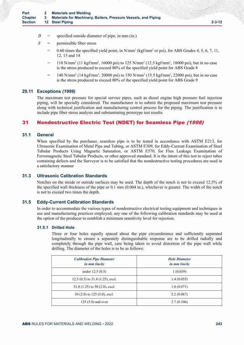
D = specified outside diameter of pipe, in mm (in.)S = permissible fiber stress
= 0.60 times the specified yield point, in N/mm2 (kgf/mm2 or psi), for ABS Grades 4, 5, 6, 7, 11,12, 13 and 14
= 110 N/mm2 (11 kgf/mm2, 16000 psi) to 125 N/mm2 (12.5 kgf/mm2, 18000 psi), but in no caseis the stress produced to exceed 80% of the specified yield point for ABS Grade 8
= 140 N/mm2 (14 kgf/mm2, 20000 psi) to 150 N/mm2 (15.5 kgf/mm2, 22000 psi), but in no caseis the stress produced to exceed 80% of the specified yield point for ABS Grade 9
29.11 Exceptions (1999)The maximum test pressure for special service pipes, such as diesel engine high pressure fuel injectionpiping, will be specially considered. The manufacturer is to submit the proposed maximum test pressurealong with technical justification and manufacturing control process for the piping. The justification is toinclude pipe fiber stress analysis and substantiating prototype test results.
31 Nondestructive Electric Test (NDET) for Seamless Pipe (1998)
31.1 GeneralWhen specified by the purchaser, seamless pipe is to be tested in accordance with ASTM E213, forUltrasonic Examination of Metal Pipe and Tubing, or ASTM E309, for Eddy-Current Examination of SteelTubular Products Using Magnetic Saturation, or ASTM E570, for Flux Leakage Examination ofFerromagnetic Steel Tubular Products, or other approved standard. It is the intent of this test to reject tubescontaining defects and the Surveyor is to be satisfied that the nondestructive testing procedures are used ina satisfactory manner
31.3 Ultrasonic Calibration StandardsNotches on the inside or outside surfaces may be used. The depth of the notch is not to exceed 12.5% ofthe specified wall thickness of the pipe or 0.1 mm (0.004 in.), whichever is greater. The width of the notchis not to exceed two times the depth.
31.5 Eddy-Current Calibration StandardsIn order to accommodate the various types of nondestructive electrical testing equipment and techniques inuse and manufacturing practices employed, any one of the following calibration standards may be used atthe option of the producer to establish a minimum sensitivity level for rejection.
31.5.1 Drilled HoleThree or four holes equally spaced about the pipe circumference and sufficiently separatedlongitudinally to ensure a separately distinguishable response are to be drilled radially andcompletely through the pipe wall, care being taken to avoid distortion of the pipe wall whiledrilling. The diameter of the holes is to be as follows:
Calibration Pipe Diameterin mm (inch)
Hole Diameterin mm (inch)
under 12.5 (0.5) 1 (0.039)
12.5 (0.5) to 31.8 (1.25), excl. 1.4 (0.055)
31.8 (1.25) to 50 (2.0), excl. 1.8 (0.071)
50 (2.0) to 125 (5.0), excl. 2.2 (0.087)
125 (5.0) and over 2.7 (0.106)
Part 2 Materials and WeldingChapter 3 Materials for Machinery, Boilers, Pressure Vessels, and PipingSection 12 Steel Piping 2-3-12
ABS RULES FOR MATERIALS AND WELDING • 2022 243
31.5.2 Transverse Tangential NotchUsing a round file or tool with a 6.35 mm (0.25 in.) diameter, a notch is to be filed or milledtangential to the surface and transverse to the longitudinal axis of the pipe. Said notch is to have adepth not exceeding 12.5% of the nominal wall thickness of the pipe or 0.1 mm (0.004 in.),whichever is greater.
31.5.3 Longitudinal NotchA notch 0.785 mm. (0.031 in.) or less in width is to be machined in a radial plane parallel to thepipe axis on the outside surface of the tube to a depth not exceeding 12.5% of the nominal wallthickness of the pipe or 0.1 mm (0.004 in.), whichever is greater. The length of the notch is to becompatible with the testing method.
31.7 Flux Leakage Calibration StandardsThe depth of longitudinal notches on the inside and outside surfaces is not to exceed 12.5% of the specifiedwall thickness of the pipe or 0.1 mm (0.004 in.), whichever is greater. The width of the notch is not toexceed the depth, and the length of the notch is not to exceed 25.4 mm (1.0 in.). Outside and inside surfacenotches are to be located sufficiently apart to allow distinct identification of the signal from each notch.
31.9 RejectionTubing producing a signal equal to or greater than the calibration defect is to be subject to rejection.
31.11 AffidavitsWhen each tube is subjected to an approved nondestructive electric test as a regular procedure during theprocess of manufacture, an affidavit covering this test may be accepted by the Surveyor.
33 Retests
33.1 General (1998)For all grades of pipe, if the results of the mechanical tests of any lot do not conform to the requirements,retests may be made on additional pipe of double the original number from the same lot, each of which isto conform to the requirements specified.
33.3 Grades 1, 2, 3, 8 and 9For these grades, should any section fail when flattening tests are made on the crop ends of each length ofwelded pipe, other pieces from the length may be cut until satisfactory tests are obtained, otherwise, thelength is to be rejected.
33.5 Grades 4 and 5For these grades, should a crop end of a finished pipe fail in the flattening test, one retest may be madefrom the failed end. The pipe may be normalized either before or after the first test, but the pipe is to besubjected to only two normalizing treatments.
33.7 Grades 6, 7, 11, 12, 13 and 14 (1998)For these grades, should individual lengths of pipe selected to represent any lot fail to conform to themechanical requirements, the lot may be reheat-treated and resubmitted for test, except that any individuallengths which meet the test requirements before re-treating will be accepted.
Part 2 Materials and WeldingChapter 3 Materials for Machinery, Boilers, Pressure Vessels, and PipingSection 12 Steel Piping 2-3-12
ABS RULES FOR MATERIALS AND WELDING • 2022 244
35 Pipe Testing and Inspection
35.1 Group I Piping (2008)Pipes intended for use in Group I piping systems (Class I and Class II, see 4-6-1/5, Rules for Building andClassing Marine Vessels) are to be tested, preferably at the mill, to the satisfaction of the Surveyor. Thematerial surfaces will be examined by the Surveyor when specially requested by the purchaser. See also4-6-7/3.5.1 of the Rules for Building and Classing Marine Vessels.
35.3 Group I and II Piping (1998)The pipes are to be reasonably straight, free from defects, and have a workmanlike finish. At a minimum,the finished pipe is to be visually inspected at the same frequency as that required for the tension testspecified in 2-3-12/39.7 TABLE 3 for the applicable grade. Welding repair to the pipe is not to be carriedout without the purchasers approval and is to be the Surveyors satisfaction.
37 Permissible Variation in Wall Thickness (1998)The permissible variations in wall thickness for all pipe are based on the ordered thickness and are toconform to that given in the applicable ASTM designation for acceptance, but the minimum thickness forall pipe is not to be less than that required by the Rules for a specific application regardless of such prioracceptance. At a minimum, the finished pipe is to be measured at the same frequency as that required forthe tension test specified in 2-3-12/39.7 TABLE 3 for the applicable grade.
39 Permissible Variations in Outside Diameter
39.1 Grades 1, 2, 3For pipe of these grades 48.3 mm O.D. (1.5 in. nominal diameter) and under, the outside diameter at anypoint is not to vary more than 0.4 mm (0.016 in.) over nor more than 0.8 mm (0.131 in.) under thespecified diameter. For pipe 60.3 mm O.D. (2 in. nominal diameter) and over, the outside diameter is not tovary more than plus or minus 1% from the specified diameter.
39.3 Grades 4, 5, 6, 7, 11, 12, 13 and 14 (1998)For these grades, variation in outside diameter from that specified is not to exceed the amount prescribedin 2-3-12/39.7 TABLE 6.
39.5 Grades 8 and 9For these grades, the outside diameter is not to vary more than plus or minus 1% from the nominaldiameter specified.
39.7 Inspection (1998)At a minimum, the finished pipe is to be measured at the same frequency as that required for the tensiontest specified in 2-3-12/39.7 TABLE 3 for the applicable grade.
Part 2 Materials and WeldingChapter 3 Materials for Machinery, Boilers, Pressure Vessels, and PipingSection 12 Steel Piping 2-3-12
ABS RULES FOR MATERIALS AND WELDING • 2022 245
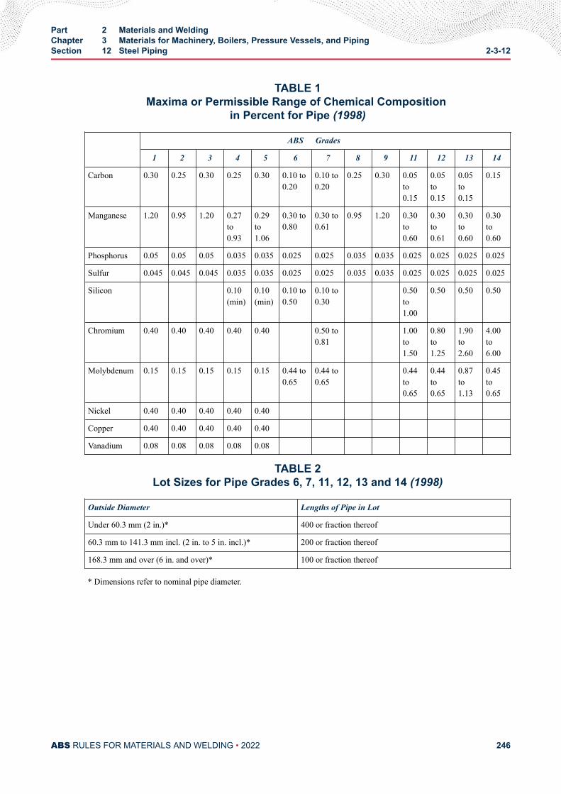
TABLE 1Maxima or Permissible Range of Chemical Composition
in Percent for Pipe (1998)
ABS Grades
1 2 3 4 5 6 7 8 9 11 12 13 14
Carbon 0.30 0.25 0.30 0.25 0.30 0.10 to0.20
0.10 to0.20
0.25 0.30 0.05to0.15
0.05to0.15
0.05to0.15
0.15
Manganese 1.20 0.95 1.20 0.27to0.93
0.29to1.06
0.30 to0.80
0.30 to0.61
0.95 1.20 0.30to0.60
0.30to0.61
0.30to0.60
0.30to0.60
Phosphorus 0.05 0.05 0.05 0.035 0.035 0.025 0.025 0.035 0.035 0.025 0.025 0.025 0.025
Sulfur 0.045 0.045 0.045 0.035 0.035 0.025 0.025 0.035 0.035 0.025 0.025 0.025 0.025
Silicon 0.10(min)
0.10(min)
0.10 to0.50
0.10 to0.30
0.50to1.00
0.50 0.50 0.50
Chromium 0.40 0.40 0.40 0.40 0.40 0.50 to0.81
1.00to1.50
0.80to1.25
1.90to2.60
4.00to6.00
Molybdenum 0.15 0.15 0.15 0.15 0.15 0.44 to0.65
0.44 to0.65
0.44to0.65
0.44to0.65
0.87to1.13
0.45to0.65
Nickel 0.40 0.40 0.40 0.40 0.40
Copper 0.40 0.40 0.40 0.40 0.40
Vanadium 0.08 0.08 0.08 0.08 0.08
TABLE 2Lot Sizes for Pipe Grades 6, 7, 11, 12, 13 and 14 (1998)
Outside Diameter Lengths of Pipe in Lot
Under 60.3 mm (2 in.)* 400 or fraction thereof
60.3 mm to 141.3 mm incl. (2 in. to 5 in. incl.)* 200 or fraction thereof
168.3 mm and over (6 in. and over)* 100 or fraction thereof
* Dimensions refer to nominal pipe diameter.
Part 2 Materials and WeldingChapter 3 Materials for Machinery, Boilers, Pressure Vessels, and PipingSection 12 Steel Piping 2-3-12
ABS RULES FOR MATERIALS AND WELDING • 2022 246
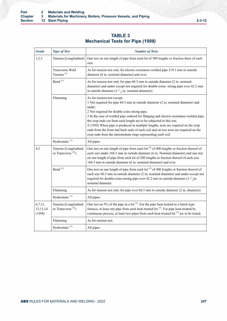
TABLE 3Mechanical Tests for Pipe (1998)
Grade Type of Test Number of Tests
1,2,3 Tension (Longitudinal) One test on one length of pipe from each lot of 500 lengths or fraction there of eachsize.
Transverse WeldTension (1)
As for tension test only for electric-resistance-welded pipe 219.1 mm in outsidediameter (8 in. nominal diameter) and over.
Bend (1) As for tension test only for pipe 60.3 mm in outside diameter (2 in. nominaldiameter) and under except not required for double-extra- strong-pipe over 42.2 mmin outside diameter (1-1/4 in. nominal diameter).
Flattening As for tension test except:1 Not required for pipe 60.3 mm in outside diameter (2 in. nominal diameter) andunder.2 Not required for double-extra strong pipe.3 In the case of welded pipe ordered for flanging and electric-resistance-welded pipe,the crop ends cut from each length are to be subjected to this test.4 (1998) When pipe is produced in multiple lengths, tests are required on the cropends from the front and back ends of each coil and on two tests are required on thecrop ends from the intermediate rings representing each coil.
Hydrostatic (1) All pipes.
4,5 Tension (Longitudinalor Transverse (5))
One test on one length of pipe from each lot (2) of 400 lengths or fraction thereof ofeach size under 168.3 mm in outside diameter (6 in. Nominal diameter) and one teston one length of pipe from each lot of 200 lengths or fraction thereof of each size168.3 mm in outside diameter (6 in. nominal diameter) and over.
Bend (1) One test on one length of pipe from each lot (2) of 400 lengths or fraction thereof ofeach size 60.3 mm in outside diameter (2 in. nominal diameter) and under except notrequired for double-extra-strong pipe over 42.2 mm in outside diameter (1-1/4in.nominal diameter.
Flattening As for tension test only for pipe over 60.3 mm in outside diameter (2 in. diameter).
Hydrostatic (1) All pipes.
6,7,11,12,13,14(1998)
Tension (Longitudinalor Transverse (5))
One test on 5% of the pipe in a lot (3). For the pipe heat-treated in a batch-typefurnace, at least one pipe from each heat-treated lot (3). For pipe heat-treated bycontinuous process, at least two pipes from each heat-treated lot (3) are to be tested.
Flattening As for tension test.
Hydrostatic (1) All pipes.
Part 2 Materials and WeldingChapter 3 Materials for Machinery, Boilers, Pressure Vessels, and PipingSection 12 Steel Piping 2-3-12
ABS RULES FOR MATERIALS AND WELDING • 2022 247
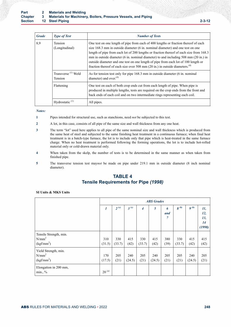
Grade Type of Test Number of Tests
8,9 Tension(Longitudinal)
One test on one length of pipe from each of 400 lengths or fraction thereof of eachsize 168.3 mm in outside diameter (6 in. nominal diameter) and one test on onelength of pipe from each lot of 200 lengths or fraction thereof of each size from 168.3mm in outside diameter (6 in. nominal diameter) to and including 508 mm (20 in.) inoutside diameter and one test on one length of pipe from each lot of 100 length orfraction thereof of each size over 508 mm (20 in.) in outside diameters.(4)
Transverse (1) WeldTension
As for tension test only for pipe 168.3 mm in outside diameter (6 in. nominaldiameter) and over.(4)
Flattening One test on each of both crop ends cut from each length of pipe. When pipe isproduced in multiple lengths, tests are required on the crop ends from the front andback ends of each coil and on two intermediate rings representing each coil.
Hydrostatic (1) All pipes.
Notes:
1 Pipes intended for structural use, such as stanchions, need not be subjected to this test.
2 A lot, in this case, consists of all pipe of the same size and wall thickness from any one heat.
3 The term “lot” used here applies to all pipe of the same nominal size and wall thickness which is produced fromthe same heat of steel and subjected to the same finishing heat treatment in a continuous furnace; when final heattreatment is in a batch-type furnace, the lot is to include only that pipe which is heat-treated in the same furnacecharge. When no heat treatment is performed following the forming operations, the lot is to include hot-rolledmaterial only or cold-drawn material only.
4 When taken from the skelp, the number of tests is to be determined in the same manner as when taken fromfinished pipe.
5 The transverse tension test maynot be made on pipe under 219.1 mm in outside diameter (8 inch nominaldiameter).
TABLE 4Tensile Requirements for Pipe (1998)
SI Units & MKS Units
ABS Grades
1 2 (c) 3 (c) 4 5 6and
7
8 (b) 9 (b) 11,12,13,14
(1998)
Tensile Strength, min.N/mm2
(kgf/mm2)310
(31.5)330
(33.7)415(42)
330(33.7)
415(42)
380(39)
330(33.7)
415(42)
415(42)
Yield Strength, min.N/mm2
(kgf/mm2)170
(17.5)205(21)
240(24.5)
205(21)
240(24.5)
205(21)
205(21)
240(24.5)
205(21)
Elongation in 200 mm,min., % 20 (a)
Part 2 Materials and WeldingChapter 3 Materials for Machinery, Boilers, Pressure Vessels, and PipingSection 12 Steel Piping 2-3-12
ABS RULES FOR MATERIALS AND WELDING • 2022 248
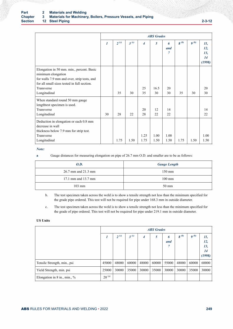
ABS Grades
1 2 (c) 3 (c) 4 5 6and
7
8 (b) 9 (b) 11,12,13,14
(1998)
Elongation in 50 mm. min., percent. Basicminimum elongationfor walls 7.9 mm and over, strip tests, andfor all small sizes tested in full section.TransverseLongitudinal
35 302535
16.530
2030 35 30
2030
When standard round 50 mm gaugelengthtest specimen is used.TransverseLongitudinal 30 28 22
2028
1222
1422
1422
Deduction in elongation or each 0.8 mmdecrease in wallthickness below 7.9 mm for strip test.TransverseLongitudinal
1.75 1.501.251.75
1.001.50
1.001.50 1.75 1.50
1.001.50
Note:
a Gauge distances for measuring elongation on pipe of 26.7 mm O.D. and smaller are to be as follows:
O.D. Gauge Length
26.7 mm and 21.3 mm 150 mm
17.1 mm and 13.7 mm 100 mm
103 mm 50 mm
b. The test specimen taken across the weld is to show a tensile strength not less than the minimum specified forthe grade pipe ordered. This test will not be required for pipe under 168.3 mm in outside diameter.
c. The test specimen taken across the weld is to show a tensile strength not less than the minimum specified forthe grade of pipe ordered. This test will not be required for pipe under 219.1 mm in outside diameter.
US Units
ABS Grades
1 2 (c) 3 (c) 4 5 6and
7
8 (b) 9 (b) 11,12,13,14
(1998)
Tensile Strength, min., psi 45000 48000 60000 48000 60000 55000 48000 60000 60000
Yield Strength, min. psi 25000 30000 35000 30000 35000 30000 30000 35000 30000
Elongation in 8 in., min., % 20 (a)
Part 2 Materials and WeldingChapter 3 Materials for Machinery, Boilers, Pressure Vessels, and PipingSection 12 Steel Piping 2-3-12
ABS RULES FOR MATERIALS AND WELDING • 2022 249
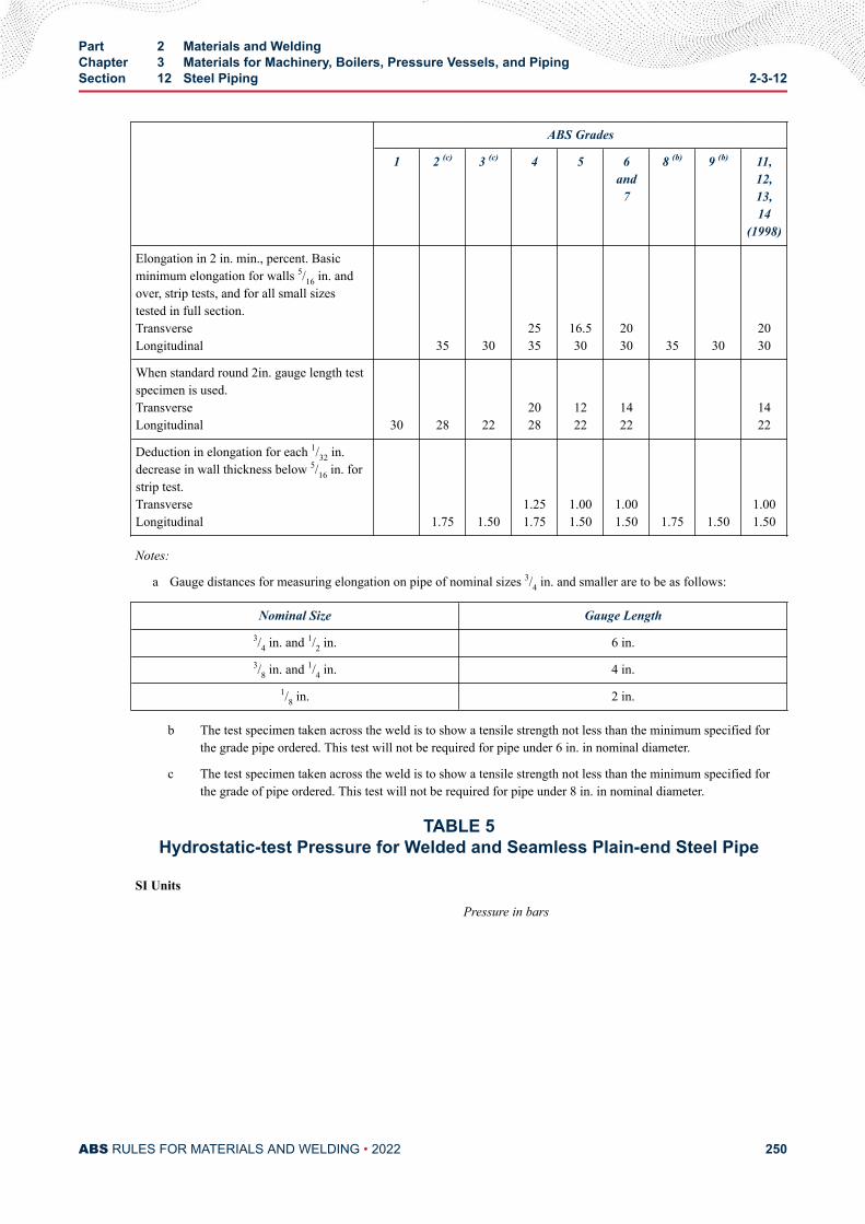
ABS Grades
1 2 (c) 3 (c) 4 5 6and
7
8 (b) 9 (b) 11,12,13,14
(1998)
Elongation in 2 in. min., percent. Basicminimum elongation for walls 5/16 in. andover, strip tests, and for all small sizestested in full section.TransverseLongitudinal
35 302535
16.530
2030 35 30
2030
When standard round 2in. gauge length testspecimen is used.TransverseLongitudinal 30 28 22
2028
1222
1422
1422
Deduction in elongation for each 1/32 in.decrease in wall thickness below 5/16 in. forstrip test.TransverseLongitudinal
1.75 1.501.251.75
1.001.50
1.001.50 1.75 1.50
1.001.50
Notes:
a Gauge distances for measuring elongation on pipe of nominal sizes 3/4 in. and smaller are to be as follows:
Nominal Size Gauge Length3/4 in. and 1/2 in. 6 in.3/8 in. and 1/4 in. 4 in.
1/8 in. 2 in.
b The test specimen taken across the weld is to show a tensile strength not less than the minimum specified forthe grade pipe ordered. This test will not be required for pipe under 6 in. in nominal diameter.
c The test specimen taken across the weld is to show a tensile strength not less than the minimum specified forthe grade of pipe ordered. This test will not be required for pipe under 8 in. in nominal diameter.
TABLE 5Hydrostatic-test Pressure for Welded and Seamless Plain-end Steel Pipe
SI Units
Pressure in bars
Part 2 Materials and WeldingChapter 3 Materials for Machinery, Boilers, Pressure Vessels, and PipingSection 12 Steel Piping 2-3-12
ABS RULES FOR MATERIALS AND WELDING • 2022 250
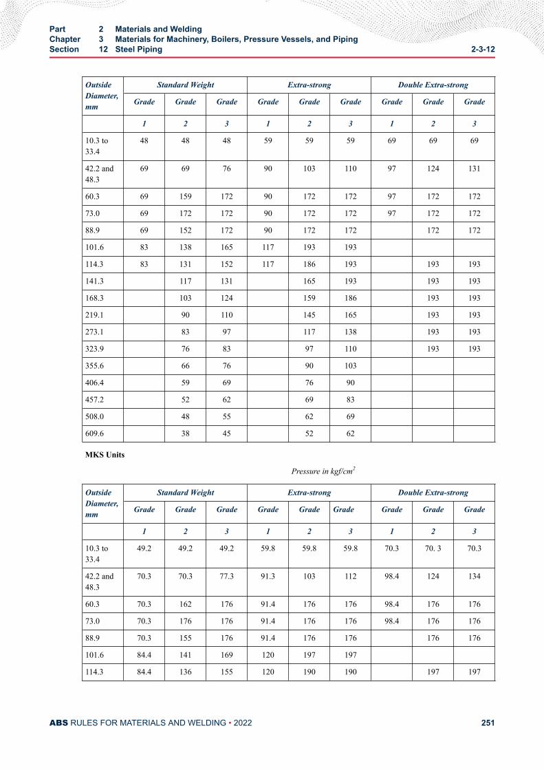
OutsideDiameter,mm
Standard Weight Extra-strong Double Extra-strong
Grade Grade Grade Grade Grade Grade Grade Grade Grade
1 2 3 1 2 3 1 2 3
10.3 to33.4
48 48 48 59 59 59 69 69 69
42.2 and48.3
69 69 76 90 103 110 97 124 131
60.3 69 159 172 90 172 172 97 172 172
73.0 69 172 172 90 172 172 97 172 172
88.9 69 152 172 90 172 172 172 172
101.6 83 138 165 117 193 193
114.3 83 131 152 117 186 193 193 193
141.3 117 131 165 193 193 193
168.3 103 124 159 186 193 193
219.1 90 110 145 165 193 193
273.1 83 97 117 138 193 193
323.9 76 83 97 110 193 193
355.6 66 76 90 103
406.4 59 69 76 90
457.2 52 62 69 83
508.0 48 55 62 69
609.6 38 45 52 62
MKS Units
Pressure in kgf/cm2
OutsideDiameter,mm
Standard Weight Extra-strong Double Extra-strong
Grade Grade Grade Grade Grade Grade Grade Grade Grade
1 2 3 1 2 3 1 2 3
10.3 to33.4
49.2 49.2 49.2 59.8 59.8 59.8 70.3 70. 3 70.3
42.2 and48.3
70.3 70.3 77.3 91.3 103 112 98.4 124 134
60.3 70.3 162 176 91.4 176 176 98.4 176 176
73.0 70.3 176 176 91.4 176 176 98.4 176 176
88.9 70.3 155 176 91.4 176 176 176 176
101.6 84.4 141 169 120 197 197
114.3 84.4 136 155 120 190 190 197 197
Part 2 Materials and WeldingChapter 3 Materials for Machinery, Boilers, Pressure Vessels, and PipingSection 12 Steel Piping 2-3-12
ABS RULES FOR MATERIALS AND WELDING • 2022 251
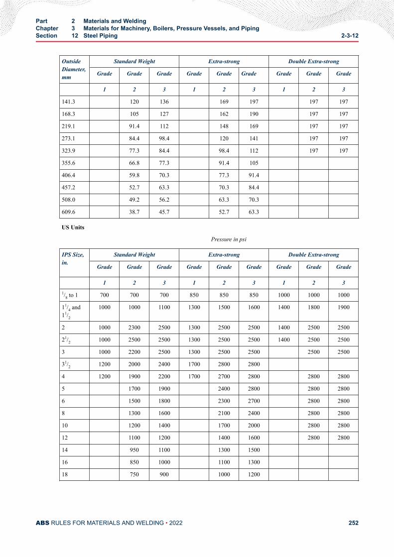
OutsideDiameter,mm
Standard Weight Extra-strong Double Extra-strong
Grade Grade Grade Grade Grade Grade Grade Grade Grade
1 2 3 1 2 3 1 2 3
141.3 120 136 169 197 197 197
168.3 105 127 162 190 197 197
219.1 91.4 112 148 169 197 197
273.1 84.4 98.4 120 141 197 197
323.9 77.3 84.4 98.4 112 197 197
355.6 66.8 77.3 91.4 105
406.4 59.8 70.3 77.3 91.4
457.2 52.7 63.3 70.3 84.4
508.0 49.2 56.2 63.3 70.3
609.6 38.7 45.7 52.7 63.3
US Units
Pressure in psi
IPS Size,in.
Standard Weight Extra-strong Double Extra-strong
Grade Grade Grade Grade Grade Grade Grade Grade Grade
1 2 3 1 2 3 1 2 31/8 to 1 700 700 700 850 850 850 1000 1000 1000
11/4 and11/2
1000 1000 1100 1300 1500 1600 1400 1800 1900
2 1000 2300 2500 1300 2500 2500 1400 2500 2500
21/2 1000 2500 2500 1300 2500 2500 1400 2500 2500
3 1000 2200 2500 1300 2500 2500 2500 2500
31/2 1200 2000 2400 1700 2800 2800
4 1200 1900 2200 1700 2700 2800 2800 2800
5 1700 1900 2400 2800 2800 2800
6 1500 1800 2300 2700 2800 2800
8 1300 1600 2100 2400 2800 2800
10 1200 1400 1700 2000 2800 2800
12 1100 1200 1400 1600 2800 2800
14 950 1100 1300 1500
16 850 1000 1100 1300
18 750 900 1000 1200
Part 2 Materials and WeldingChapter 3 Materials for Machinery, Boilers, Pressure Vessels, and PipingSection 12 Steel Piping 2-3-12
ABS RULES FOR MATERIALS AND WELDING • 2022 252
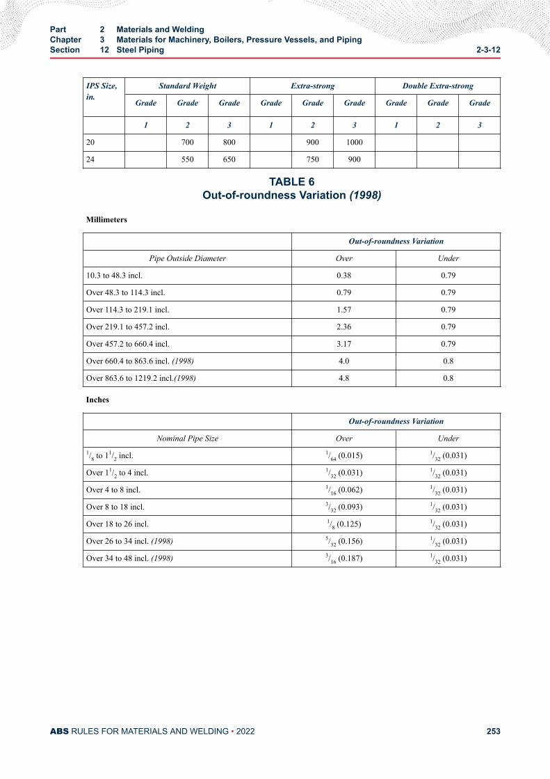
IPS Size,in.
Standard Weight Extra-strong Double Extra-strong
Grade Grade Grade Grade Grade Grade Grade Grade Grade
1 2 3 1 2 3 1 2 3
20 700 800 900 1000
24 550 650 750 900
TABLE 6Out-of-roundness Variation (1998)
Millimeters
Out-of-roundness Variation
Pipe Outside Diameter Over Under
10.3 to 48.3 incl. 0.38 0.79
Over 48.3 to 114.3 incl. 0.79 0.79
Over 114.3 to 219.1 incl. 1.57 0.79
Over 219.1 to 457.2 incl. 2.36 0.79
Over 457.2 to 660.4 incl. 3.17 0.79
Over 660.4 to 863.6 incl. (1998) 4.0 0.8
Over 863.6 to 1219.2 incl.(1998) 4.8 0.8
Inches
Out-of-roundness Variation
Nominal Pipe Size Over Under1/8 to 11/2 incl. 1/64 (0.015) 1/32 (0.031)
Over 11/2 to 4 incl. 1/32 (0.031) 1/32 (0.031)
Over 4 to 8 incl. 1/16 (0.062) 1/32 (0.031)
Over 8 to 18 incl. 3/32 (0.093) 1/32 (0.031)
Over 18 to 26 incl. 1/8 (0.125) 1/32 (0.031)
Over 26 to 34 incl. (1998) 5/32 (0.156) 1/32 (0.031)
Over 34 to 48 incl. (1998) 3/16 (0.187) 1/32 (0.031)
Part 2 Materials and WeldingChapter 3 Materials for Machinery, Boilers, Pressure Vessels, and PipingSection 12 Steel Piping 2-3-12
ABS RULES FOR MATERIALS AND WELDING • 2022 253
C H A P T E R 3Materials for Machinery, Boilers, Pressure Vessels, and Piping
S E C T I O N 1 3Piping, Valves and Fittings for Low-temperature Service[ Below -18°C
(0°F) ]
1 ScopeThe following specifications cover six representative grades of steel for pipes, valves and fittings for use inpiping systems designed for temperatures lower than -18°C (0°F). Steels differing in chemicalcomposition, mechanical properties or heat treatment will be specially considered. The requirements foraluminum alloys or other non-ferrous materials will be specially considered.
Materials for Liquefied Gas Carrier are to comply with 5C-8-6 of the Marine Vessel Rules
3 Designation (2013)The various grades are to be in substantial agreement with ASTM as follows.
ABS Grade Nominal Composition ASTM
1L Carbon Steels A333 Grades 1 and 6; A334 Grades 1 and 6; A350 Grades LF1 and LF2;A352 Grade LCB; A420 Grade WPL6
2L 1/2 Mo A352 Grade LC1
3L 21/2 Ni A333 Grade 7; A334 Grade 7; A352 Grade LC2
4L 31/2 Ni A333 Grade 3; A334 Grade 3; A350 Grade LF3; A352 Grade LC3;A420 Grade WPL3
5L 9 Ni A333 Grade 8; A334 Grade 8; A522; A420 Grade WPL8
6L 10 Ni 20 Cr or 20 Ni 25 Cr A351 Grades CF8C and CK20
5 ManufactureThe steel is to be made by the basic oxygen, open hearth or electric furnace process. The steel is to bekilled and made with a fine-grain deoxidation practice.
7 Heat TreatmentThe steel is to be furnished in the normalized condition or as required by the applicable specification.
PART 2
ABS RULES FOR MATERIALS AND WELDING • 2022 254
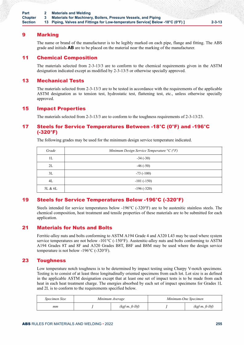
9 MarkingThe name or brand of the manufacturer is to be legibly marked on each pipe, flange and fitting. The ABSgrade and initials AB are to be placed on the material near the marking of the manufacturer.
11 Chemical CompositionThe materials selected from 2-3-13/3 are to conform to the chemical requirements given in the ASTMdesignation indicated except as modified by 2-3-13/5 or otherwise specially approved.
13 Mechanical TestsThe materials selected from 2-3-13/3 are to be tested in accordance with the requirements of the applicableASTM designation as to tension test, hydrostatic test, flattening test, etc., unless otherwise speciallyapproved.
15 Impact PropertiesThe materials selected from 2-3-13/3 are to conform to the toughness requirements of 2-3-13/23.
17 Steels for Service Temperatures Between -18°C (0°F) and -196°C(-320°F)The following grades may be used for the minimum design service temperature indicated.
Grade Minimum Design Service Temperature °C (°F)
1L -34 (-30)
2L -46 (-50)
3L -73 (-100)
4L -101 (-150)
5L & 6L -196 (-320)
19 Steels for Service Temperatures Below -196°C (-320°F)Steels intended for service temperatures below -196°C (-320°F) are to be austenitic stainless steels. Thechemical composition, heat treatment and tensile properties of these materials are to be submitted for eachapplication.
21 Materials for Nuts and BoltsFerritic-alloy nuts and bolts conforming to ASTM A194 Grade 4 and A320 L43 may be used where systemservice temperatures are not below -101°C (-150°F). Austenitic-alloy nuts and bolts conforming to ASTMA194 Grades 8T and 8F and A320 Grades B8T, B8F and B8M may be used where the design servicetemperature is not below -196°C (-320°F).
23 ToughnessLow temperature notch toughness is to be determined by impact testing using Charpy V-notch specimens.Testing is to consist of at least three longitudinally oriented specimens from each lot. Lot size is as definedin the applicable ASTM designation except that at least one set of impact tests is to be made from eachheat in each heat treatment charge. The energies absorbed by each set of impact specimens for Grades 1Land 2L is to conform to the requirements specified below.
Specimen Size Minimum Average Minimum-One Specimen
mm J (kgf-m, ft-lbf) J (kgf-m, ft-lbf)
Part 2 Materials and WeldingChapter 3 Materials for Machinery, Boilers, Pressure Vessels, and PipingSection 13 Piping, Valves and Fittings for Low-temperature Service[ Below -18°C (0°F) ] 2-3-13
ABS RULES FOR MATERIALS AND WELDING • 2022 255
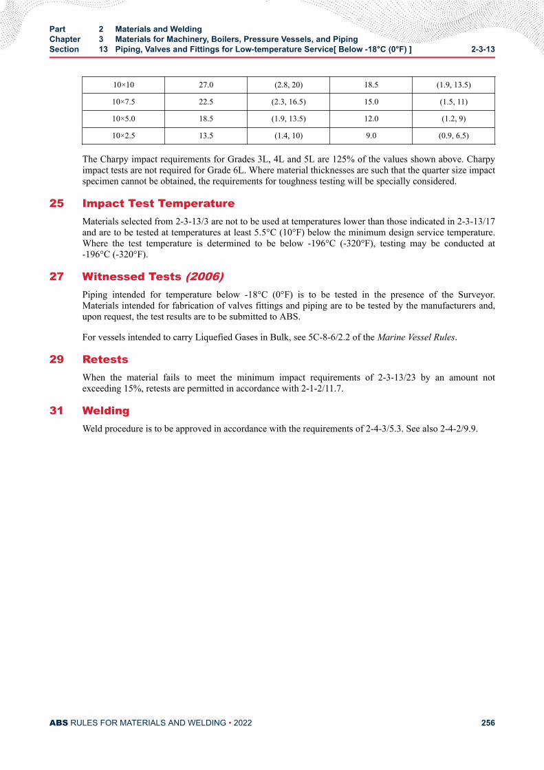
10×10 27.0 (2.8, 20) 18.5 (1.9, 13.5)
10×7.5 22.5 (2.3, 16.5) 15.0 (1.5, 11)
10×5.0 18.5 (1.9, 13.5) 12.0 (1.2, 9)
10×2.5 13.5 (1.4, 10) 9.0 (0.9, 6.5)
The Charpy impact requirements for Grades 3L, 4L and 5L are 125% of the values shown above. Charpyimpact tests are not required for Grade 6L. Where material thicknesses are such that the quarter size impactspecimen cannot be obtained, the requirements for toughness testing will be specially considered.
25 Impact Test TemperatureMaterials selected from 2-3-13/3 are not to be used at temperatures lower than those indicated in 2-3-13/17and are to be tested at temperatures at least 5.5°C (10°F) below the minimum design service temperature.Where the test temperature is determined to be below -196°C (-320°F), testing may be conducted at-196°C (-320°F).
27 Witnessed Tests (2006)Piping intended for temperature below -18°C (0°F) is to be tested in the presence of the Surveyor.Materials intended for fabrication of valves fittings and piping are to be tested by the manufacturers and,upon request, the test results are to be submitted to ABS.
For vessels intended to carry Liquefied Gases in Bulk, see 5C-8-6/2.2 of the Marine Vessel Rules.
29 RetestsWhen the material fails to meet the minimum impact requirements of 2-3-13/23 by an amount notexceeding 15%, retests are permitted in accordance with 2-1-2/11.7.
31 WeldingWeld procedure is to be approved in accordance with the requirements of 2-4-3/5.3. See also 2-4-2/9.9.
Part 2 Materials and WeldingChapter 3 Materials for Machinery, Boilers, Pressure Vessels, and PipingSection 13 Piping, Valves and Fittings for Low-temperature Service[ Below -18°C (0°F) ] 2-3-13
ABS RULES FOR MATERIALS AND WELDING • 2022 256
C H A P T E R 3Materials for Machinery, Boilers, Pressure Vessels, and Piping
S E C T I O N 1 4Bronze Castings
1 For General Purposes
1.1 Tensile PropertiesThe castings are to be free from injurious defects. The material is to have the following tensile properties.
TypeTensile Strength Minimum, N/
mm2(kgf/mm2, psi)Elongation in 50 mm (2 in.) Minimum
percent Stamping
1 205 (21, 30000) 15 AB/1
1.3 Number of Tests (2012)At least one tension test is to be made from each melt and the tension test specimen is to be machined tothe dimensions shown in 2-3-1/11.13 FIGURE 1 (Round Specimen Alternative C).
3 Propellers and Propeller Blades
3.1 Foundry Approval (2006)3.1.1 Approval (2012)
All propellers and propeller components are to be cast by ABS-approved foundries. For thispurpose, the foundries are to demonstrate that they have available the necessary facilities andskilled personnel to enable proper manufacture of propellers which will satisfy these Rules.
ABS approval is valid for 5 years subject to annual verification and/or endorsement by theattending Surveyor. The Surveyor is permitted at any time to monitor important aspects of castingproduction, including but not limited to mold preparation and chaplet positioning; pouring timesand temperatures; mold breakout; repairs; heat treatment and inspection. Refer to 7-A1-10/1 of theABS Rules for Survey After Construction (Part 7).
3.1.2 Scope of the Approval Test (1 July 2021)The following aspects of manufacture are to be taken into account:
● Casting types and sizes
● Material specifications
PART 2
ABS RULES FOR MATERIALS AND WELDING • 2022 257
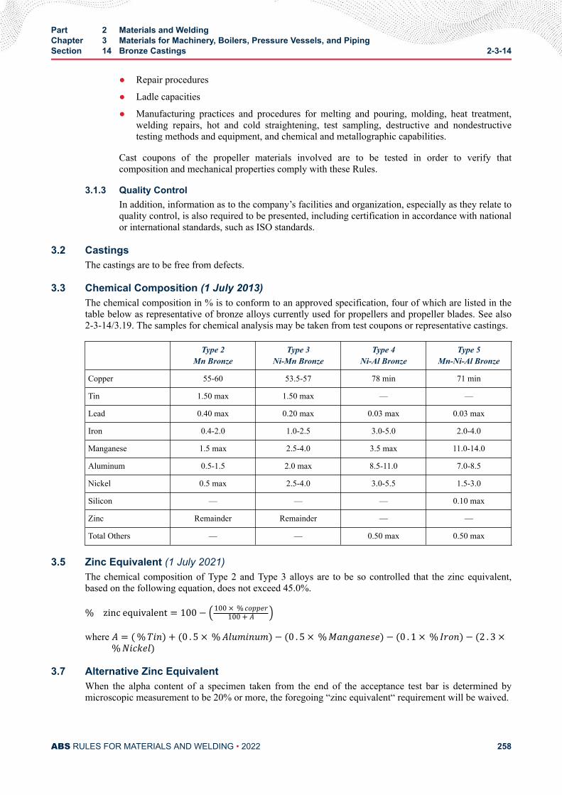
● Repair procedures
● Ladle capacities
● Manufacturing practices and procedures for melting and pouring, molding, heat treatment,welding repairs, hot and cold straightening, test sampling, destructive and nondestructivetesting methods and equipment, and chemical and metallographic capabilities.
Cast coupons of the propeller materials involved are to be tested in order to verify thatcomposition and mechanical properties comply with these Rules.
3.1.3 Quality ControlIn addition, information as to the company’s facilities and organization, especially as they relate toquality control, is also required to be presented, including certification in accordance with nationalor international standards, such as ISO standards.
3.2 CastingsThe castings are to be free from defects.
3.3 Chemical Composition (1 July 2013)The chemical composition in % is to conform to an approved specification, four of which are listed in thetable below as representative of bronze alloys currently used for propellers and propeller blades. See also2-3-14/3.19. The samples for chemical analysis may be taken from test coupons or representative castings.
Type 2Mn Bronze
Type 3Ni-Mn Bronze
Type 4Ni-Al Bronze
Type 5Mn-Ni-Al Bronze
Copper 55-60 53.5-57 78 min 71 min
Tin 1.50 max 1.50 max — —
Lead 0.40 max 0.20 max 0.03 max 0.03 max
Iron 0.4-2.0 1.0-2.5 3.0-5.0 2.0-4.0
Manganese 1.5 max 2.5-4.0 3.5 max 11.0-14.0
Aluminum 0.5-1.5 2.0 max 8.5-11.0 7.0-8.5
Nickel 0.5 max 2.5-4.0 3.0-5.5 1.5-3.0
Silicon — — — 0.10 max
Zinc Remainder Remainder — —
Total Others — — 0.50 max 0.50 max
3.5 Zinc Equivalent (1 July 2021)The chemical composition of Type 2 and Type 3 alloys are to be so controlled that the zinc equivalent,based on the following equation, does not exceed 45.0%.% zinc equivalent = 100− 100 × % copper100 + Awhere A = (%Tin) + (0 . 5 × %Aluminum)− (0 . 5 × %Manganese)− (0 . 1 × % Iron)− (2 . 3 ×%Nickel)
3.7 Alternative Zinc EquivalentWhen the alpha content of a specimen taken from the end of the acceptance test bar is determined bymicroscopic measurement to be 20% or more, the foregoing “zinc equivalent“ requirement will be waived.
Part 2 Materials and WeldingChapter 3 Materials for Machinery, Boilers, Pressure Vessels, and PipingSection 14 Bronze Castings 2-3-14
ABS RULES FOR MATERIALS AND WELDING • 2022 258
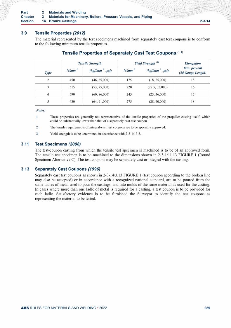
3.9 Tensile Properties (2012)The material represented by the test specimens machined from separately cast test coupons is to conformto the following minimum tensile properties.
Tensile Properties of Separately Cast Test Coupons (1, 2)
Type
Tensile Strength Yield Strength (3) ElongationMin. percent
(5d Gauge Length)N/mm 2 (kgf/mm 2 , psi) N/mm 2 (kgf/mm 2 , psi)
2 450 (46, 65,000) 175 (18, 25,000) 18
3 515 (53, 75,000) 220 (22.5, 32,000) 16
4 590 (60, 86,000) 245 (25, 36,000) 15
5 630 (64, 91,000) 275 (28, 40,000) 18
Notes:
1 These properties are generally not representative of the tensile properties of the propeller casting itself, whichcould be substantially lower than that of a separately cast test coupon.
2 The tensile requirements of integral-cast test coupons are to be specially approved.
3 Yield strength is to be determined in accordance with 2-3-1/13.3.
3.11 Test Specimens (2008)The test-coupon casting from which the tensile test specimen is machined is to be of an approved form.The tensile test specimen is to be machined to the dimensions shown in 2-3-1/11.13 FIGURE 1 (RoundSpecimen Alternative C). The test coupons may be separately cast or integral with the casting.
3.13 Separately Cast Coupons (1996)Separately cast test coupons as shown in 2-3-14/3.13 FIGURE 1 (test coupon according to the broken linemay also be accepted) or in accordance with a recognized national standard, are to be poured from thesame ladles of metal used to pour the castings, and into molds of the same material as used for the casting.In cases where more than one ladle of metal is required for a casting, a test coupon is to be provided foreach ladle. Satisfactory evidence is to be furnished the Surveyor to identify the test coupons asrepresenting the material to be tested.
Part 2 Materials and WeldingChapter 3 Materials for Machinery, Boilers, Pressure Vessels, and PipingSection 14 Bronze Castings 2-3-14
ABS RULES FOR MATERIALS AND WELDING • 2022 259
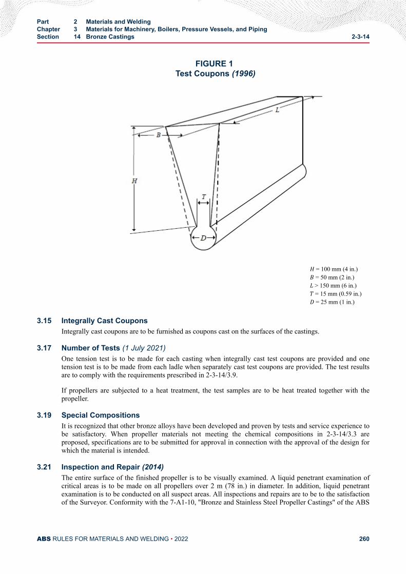
FIGURE 1 Test Coupons (1996)
H = 100 mm (4 in.)B = 50 mm (2 in.)L > 150 mm (6 in.)T = 15 mm (0.59 in.)D = 25 mm (1 in.)
3.15 Integrally Cast CouponsIntegrally cast coupons are to be furnished as coupons cast on the surfaces of the castings.
3.17 Number of Tests (1 July 2021)One tension test is to be made for each casting when integrally cast test coupons are provided and onetension test is to be made from each ladle when separately cast test coupons are provided. The test resultsare to comply with the requirements prescribed in 2-3-14/3.9.
If propellers are subjected to a heat treatment, the test samples are to be heat treated together with thepropeller.
3.19 Special CompositionsIt is recognized that other bronze alloys have been developed and proven by tests and service experience tobe satisfactory. When propeller materials not meeting the chemical compositions in 2-3-14/3.3 areproposed, specifications are to be submitted for approval in connection with the approval of the design forwhich the material is intended.
3.21 Inspection and Repair (2014)The entire surface of the finished propeller is to be visually examined. A liquid penetrant examination ofcritical areas is to be made on all propellers over 2 m (78 in.) in diameter. In addition, liquid penetrantexamination is to be conducted on all suspect areas. All inspections and repairs are to be to the satisfactionof the Surveyor. Conformity with the 7-A1-10, "Bronze and Stainless Steel Propeller Castings" of the ABS
Part 2 Materials and WeldingChapter 3 Materials for Machinery, Boilers, Pressure Vessels, and PipingSection 14 Bronze Castings 2-3-14
ABS RULES FOR MATERIALS AND WELDING • 2022 260
Rules for Survey After Construction (Part 7), will be considered to meet requirements for the inspectionand repair of propeller castings.
In addition to the above requirements, Controllable Pitch Propeller (CPP) blades are to undergo thefollowing:
● Each blade is to be weighed and recorded for all accuracy classes, CPP blades (ISO 484 /1 & 2). Thedeviation of each blade should be less than the maximum permissible balancing mass as defined byISO 484 / 1 & 2 or as specified on the approved drawing.
● Each bolt hole area of a CPP blade is to be air tested in the final delivery condition. The air tightnesstest is to be conducted with a 5 bar pressure held for 15 minutes, followed by a soap and water checkaround the bolt hole areas. Or alternatively a 1.5 times hydrostatic working pressure test for 30minutes minimum as specified in the assembly drawing may be carried out.
● A liquid penetrant examination of the flange and bolt hole area of the CPP blade is to be maderegardless of blade size. The PT is to be witnessed by attending Surveyor(s) and should be free fromany significant surface defects. Acceptance Criteria is shown in 7-A1-10 of the ABS Rules for SurveyAfter Construction (Part 7).
3.23 MarkingThe manufacturer's name and other appropriate identification markings are to be stamped on each propelleror propeller blade in such location as to be discernible after finishing and assembly. In addition, Type 2, 3,4 and 5 castings are to be stamped AB/2, AB/3, AB/4 or AB/5, respectively, to indicate satisfactorycompliance with Rule requirements. Bronze alloys produced to specifications other than those coveredherein in accordance with the permissibility expressed in 2-3-14/3.19 are to be stamped AB/S and with theapplicable specification number.
Part 2 Materials and WeldingChapter 3 Materials for Machinery, Boilers, Pressure Vessels, and PipingSection 14 Bronze Castings 2-3-14
ABS RULES FOR MATERIALS AND WELDING • 2022 261
C H A P T E R 3Materials for Machinery, Boilers, Pressure Vessels, and Piping
S E C T I O N 1 5Austenitic Stainless Steel Propeller Castings
Note:In substantial agreement with ASTM A-743, Grade CF-3
1 Process of Manufacture and Foundry Approval (2006)
1.1 Process of ManufactureThe following requirements cover austenitic stainless steel castings intended to be used for propellers andpropeller blades. The stainless steel is to be melted by the electric arc or electric induction process, or otherprocess as may be approved.
1.3 Foundry Approval (2012)Stainless steel propellers and propeller components, including grade CF-3 and other grades, as indicated in7-A1-10 of the ABS Rules for Survey After Construction (Part 7), are to be cast by ABS-approvedfoundries. For this purpose, foundries are to demonstrate that they have available the necessary facilitiesand skilled personnel to enable proper manufacture of propellers which will satisfy these Rules.
ABS approval is valid for 5 years subject to annual verification and/or endorsement by the attendingSurveyor. The Surveyor is permitted at any time to monitor important aspects of casting production,including but not limited to mold preparation and chaplet positioning; pouring times and temperatures;mold breakout; repairs; heat treatment and inspection. Refer to 7-A1-10/1.3.1 of the ABS Rules for SurveyAfter Construction (Part 7).
1.5 Scope of the Approval TestThe following aspects of manufacture are to be taken into account:
● Casting types and sizes
● Material specifications
● Repair procedures
● Ladle capacities
● Manufacturing practices and procedures for: Melting and pouring, molding, heat treatment, weldingrepairs, hot and cold straightening, destructive and nondestructive testing methods and equipment, andchemical and metallographic capabilities.
PART 2
ABS RULES FOR MATERIALS AND WELDING • 2022 262
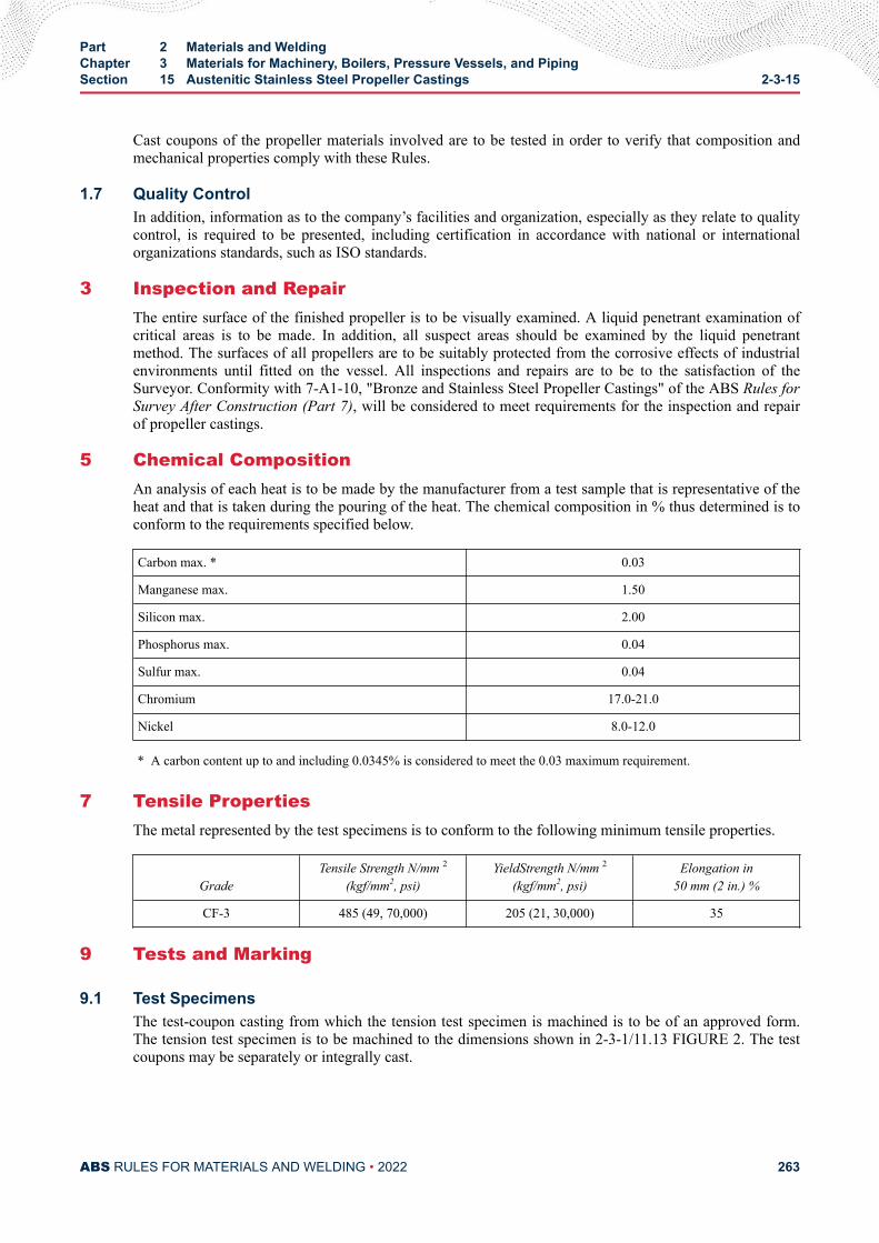
Cast coupons of the propeller materials involved are to be tested in order to verify that composition andmechanical properties comply with these Rules.
1.7 Quality ControlIn addition, information as to the company’s facilities and organization, especially as they relate to qualitycontrol, is required to be presented, including certification in accordance with national or internationalorganizations standards, such as ISO standards.
3 Inspection and RepairThe entire surface of the finished propeller is to be visually examined. A liquid penetrant examination ofcritical areas is to be made. In addition, all suspect areas should be examined by the liquid penetrantmethod. The surfaces of all propellers are to be suitably protected from the corrosive effects of industrialenvironments until fitted on the vessel. All inspections and repairs are to be to the satisfaction of theSurveyor. Conformity with 7-A1-10, "Bronze and Stainless Steel Propeller Castings" of the ABS Rules forSurvey After Construction (Part 7), will be considered to meet requirements for the inspection and repairof propeller castings.
5 Chemical CompositionAn analysis of each heat is to be made by the manufacturer from a test sample that is representative of theheat and that is taken during the pouring of the heat. The chemical composition in % thus determined is toconform to the requirements specified below.
Carbon max. * 0.03
Manganese max. 1.50
Silicon max. 2.00
Phosphorus max. 0.04
Sulfur max. 0.04
Chromium 17.0-21.0
Nickel 8.0-12.0
* A carbon content up to and including 0.0345% is considered to meet the 0.03 maximum requirement.
7 Tensile PropertiesThe metal represented by the test specimens is to conform to the following minimum tensile properties.
GradeTensile Strength N/mm 2
(kgf/mm2, psi)YieldStrength N/mm 2
(kgf/mm2, psi)Elongation in
50 mm (2 in.) %
CF-3 485 (49, 70,000) 205 (21, 30,000) 35
9 Tests and Marking
9.1 Test SpecimensThe test-coupon casting from which the tension test specimen is machined is to be of an approved form.The tension test specimen is to be machined to the dimensions shown in 2-3-1/11.13 FIGURE 2. The testcoupons may be separately or integrally cast.
Part 2 Materials and WeldingChapter 3 Materials for Machinery, Boilers, Pressure Vessels, and PipingSection 15 Austenitic Stainless Steel Propeller Castings 2-3-15
ABS RULES FOR MATERIALS AND WELDING • 2022 263
9.3 Separately Cast Coupons (2006)Separately cast test coupons are to be poured from the same ladles of metal used to pour the castings, andinto molds of the same material as used for the casting. Test coupons are to be heat treated with thecastings represented. In cases where more than one ladle of metal is required for a casting, a test coupon isto be provided for each ladle. Satisfactory evidence is to be furnished the Surveyor to identify the testcoupons as representing the material to be tested.
9.5 Integral Coupons (2006)Integral test coupons are to be furnished as coupons attached to the hub or on the blade. Where possible,test bars attached on blades are to be located in an area between 0.5 to 0 . 6R, where R is the radius of thepropeller. Test bars are not to be detached from the casting until final heat treatment has been carried out.Removal is to be by non-thermal means.
9.7 Number of TestsOne tension test is to be made for each casting when integrally cast test coupons are provided and onetension test is to be made from each ladle when separately cast test coupons are provided. The test resultsare to comply with the requirements prescribed in 2-3-15/7.
9.9 Special CompositionsIt is recognized that other alloys have been developed and proven by tests and service experience to besatisfactory. When propeller materials not meeting the chemical compositions in 2-3-15/5 are proposed,specifications are to be submitted for approval in connection with the approval of the design for which thematerial is intended.
9.11 MarkingThe manufacturer's name and other appropriate identification markings are to be stamped on each propelleror propeller blade in such location as to be discernible after finishing and assembly. In addition, GradeCF-3 castings are to be stamped AB/CF-3 to indicate satisfactory compliance with Rule requirements.Alloys produced to specifications other than those covered herein in accordance with the permissibilityexpressed in 2-3-15/9.9 are to be stamped AB/S, and with the applicable specification number.
Part 2 Materials and WeldingChapter 3 Materials for Machinery, Boilers, Pressure Vessels, and PipingSection 15 Austenitic Stainless Steel Propeller Castings 2-3-15
ABS RULES FOR MATERIALS AND WELDING • 2022 264
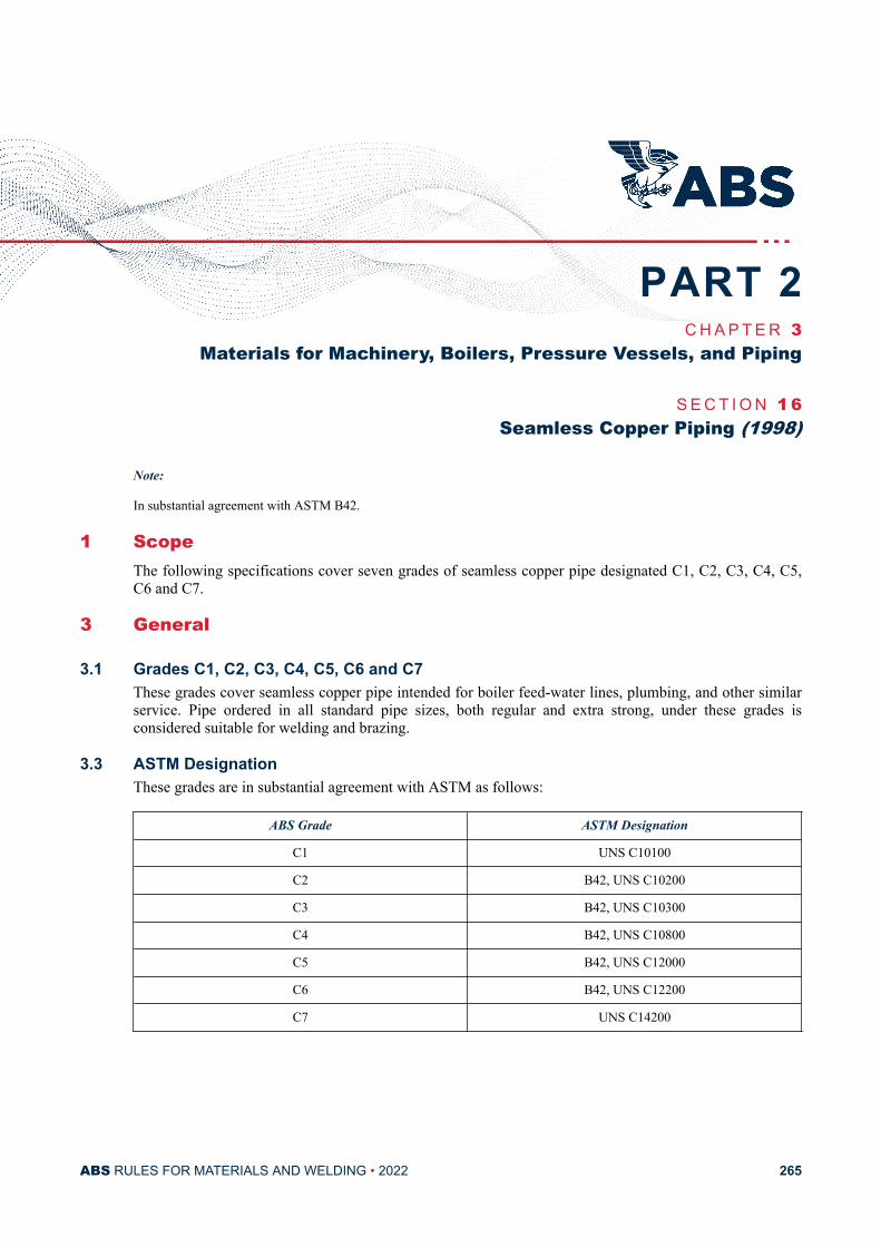
C H A P T E R 3Materials for Machinery, Boilers, Pressure Vessels, and Piping
S E C T I O N 1 6Seamless Copper Piping (1998)
Note:
In substantial agreement with ASTM B42.
1 ScopeThe following specifications cover seven grades of seamless copper pipe designated C1, C2, C3, C4, C5,C6 and C7.
3 General
3.1 Grades C1, C2, C3, C4, C5, C6 and C7These grades cover seamless copper pipe intended for boiler feed-water lines, plumbing, and other similarservice. Pipe ordered in all standard pipe sizes, both regular and extra strong, under these grades isconsidered suitable for welding and brazing.
3.3 ASTM DesignationThese grades are in substantial agreement with ASTM as follows:
ABS Grade ASTM Designation
C1 UNS C10100
C2 B42, UNS C10200
C3 B42, UNS C10300
C4 B42, UNS C10800
C5 B42, UNS C12000
C6 B42, UNS C12200
C7 UNS C14200
PART 2
ABS RULES FOR MATERIALS AND WELDING • 2022 265
5 Process of Manufacture (2009)The material is to be produced by either hot or cold working operations, or both. It is to be finished, unlessotherwise specified, by such cold working and annealing or heat treatment as may be necessary to meet theproperties specified. All pipe is to be normally furnished in the drawn-temper condition, (H55). Hard-drawn temper (H80) may be furnished also. When pipe is required for bending, the pipe is to be furnishedwith a proper bending temper, or annealed temper (061). All pipes for working pressures over 10 bar (10.5kgf/cm2, 150 psi) are to be tested and inspected at the mills to the satisfaction of the Surveyor. The pipesare examined by the Surveyor when requested by the purchaser. The pipe is to be commercially round andis to be free from defects that interfere with normal applications.
7 Marking
7.1 Manufacturer's MarkingThe name or brand of the manufacturer, the designation B42, and the test pressure are to be legibly markedby stamping or stenciling on each length of pipe. On small-diameter pipe, which is bundled, thisinformation may be marked on a tag securely attached to each bundle.
7.3 ABS MarkingsThe ABS markings, indicating satisfactory compliance with the Rule requirements, and as furnished by theSurveyor, are to be placed on the material near the markings specified in 2-3-16/7.1.
9 Chemical CompositionThe material is to conform to the applicable requirements as to chemical composition as shown in2-3-16/23 TABLE 1.
11 Tension Test
11.1 Tension Test SpecimensTensile test specimens are to be a full section of the pipe. For larger sizes, tension test specimens are toconsist of longitudinal strips cut from the pipe in accordance with ASTM E8.
11.3 Tensile PropertiesThe material is to conform to the applicable requirements as to tensile properties shown in 2-3-16/23TABLE 2.
13 Expansion TestSpecimens selected for test, after annealing, are to withstand an expansion of 25% of the outside diameterwhen expanded by a tapered pin having a 60-degree included angle. The expanded tube is to show nocracking or rupture visible to the unaided eye.
15 Flattening TestAs an alternate to the expansion test for pipe over 114.3 mm outside diameter (4 in. nominal size) in theannealed condition, a section 100 mm (4 in.) in length is to be cut from the end of one of the lengths for aflattening test. This 100 mm (4 in.) specimen is to be flattened so that a gauge set at three times the wallthickness will pass over the pipe freely throughout the flattened part. The pipe so tested is to develop nocracks or defects visible to the unaided eye as a result of this test. In making the flattening test, thespecimens are to be slowly flattened by one stroke of the press.
Part 2 Materials and WeldingChapter 3 Materials for Machinery, Boilers, Pressure Vessels, and PipingSection 16 Seamless Copper Piping (1998) 2-3-16
ABS RULES FOR MATERIALS AND WELDING • 2022 266
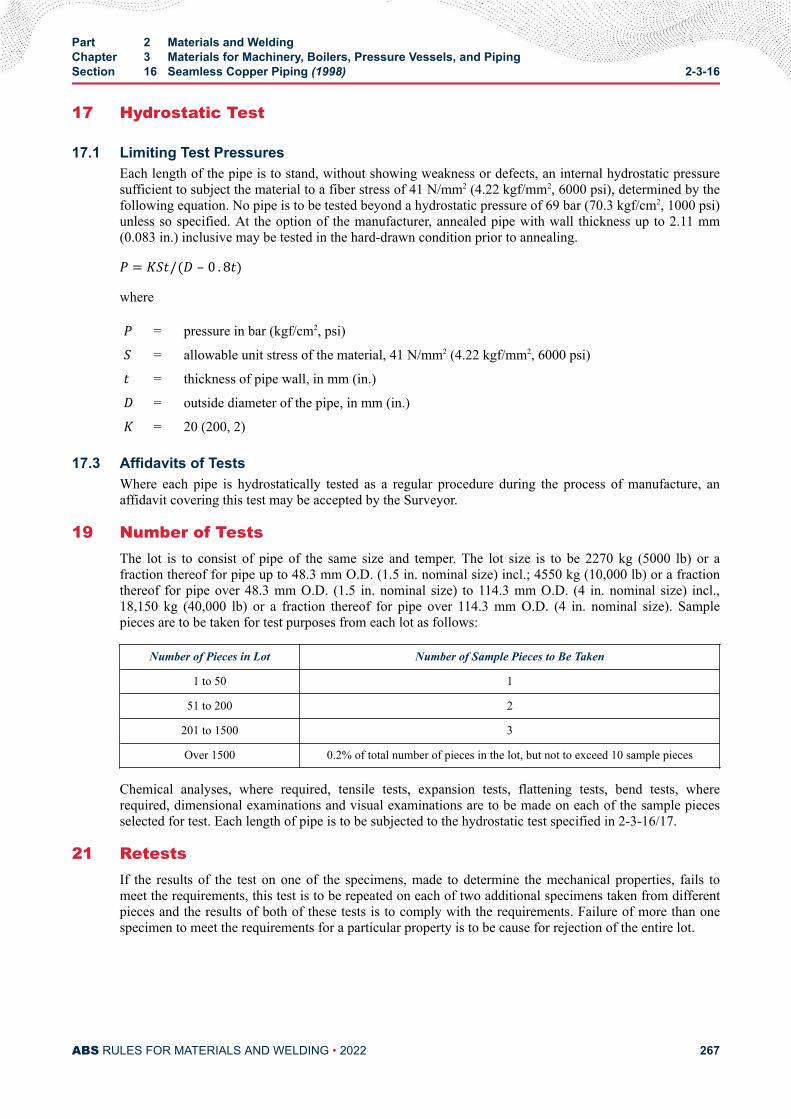
17 Hydrostatic Test
17.1 Limiting Test PressuresEach length of the pipe is to stand, without showing weakness or defects, an internal hydrostatic pressuresufficient to subject the material to a fiber stress of 41 N/mm2 (4.22 kgf/mm2, 6000 psi), determined by thefollowing equation. No pipe is to be tested beyond a hydrostatic pressure of 69 bar (70.3 kgf/cm2, 1000 psi)unless so specified. At the option of the manufacturer, annealed pipe with wall thickness up to 2.11 mm(0.083 in.) inclusive may be tested in the hard-drawn condition prior to annealing.P = KSt/(D – 0 . 8t)whereP = pressure in bar (kgf/cm2, psi)S = allowable unit stress of the material, 41 N/mm2 (4.22 kgf/mm2, 6000 psi)t = thickness of pipe wall, in mm (in.)D = outside diameter of the pipe, in mm (in.)K = 20 (200, 2)
17.3 Affidavits of TestsWhere each pipe is hydrostatically tested as a regular procedure during the process of manufacture, anaffidavit covering this test may be accepted by the Surveyor.
19 Number of TestsThe lot is to consist of pipe of the same size and temper. The lot size is to be 2270 kg (5000 lb) or afraction thereof for pipe up to 48.3 mm O.D. (1.5 in. nominal size) incl.; 4550 kg (10,000 lb) or a fractionthereof for pipe over 48.3 mm O.D. (1.5 in. nominal size) to 114.3 mm O.D. (4 in. nominal size) incl.,18,150 kg (40,000 lb) or a fraction thereof for pipe over 114.3 mm O.D. (4 in. nominal size). Samplepieces are to be taken for test purposes from each lot as follows:
Number of Pieces in Lot Number of Sample Pieces to Be Taken
1 to 50 1
51 to 200 2
201 to 1500 3
Over 1500 0.2% of total number of pieces in the lot, but not to exceed 10 sample pieces
Chemical analyses, where required, tensile tests, expansion tests, flattening tests, bend tests, whererequired, dimensional examinations and visual examinations are to be made on each of the sample piecesselected for test. Each length of pipe is to be subjected to the hydrostatic test specified in 2-3-16/17.
21 RetestsIf the results of the test on one of the specimens, made to determine the mechanical properties, fails tomeet the requirements, this test is to be repeated on each of two additional specimens taken from differentpieces and the results of both of these tests is to comply with the requirements. Failure of more than onespecimen to meet the requirements for a particular property is to be cause for rejection of the entire lot.
Part 2 Materials and WeldingChapter 3 Materials for Machinery, Boilers, Pressure Vessels, and PipingSection 16 Seamless Copper Piping (1998) 2-3-16
ABS RULES FOR MATERIALS AND WELDING • 2022 267
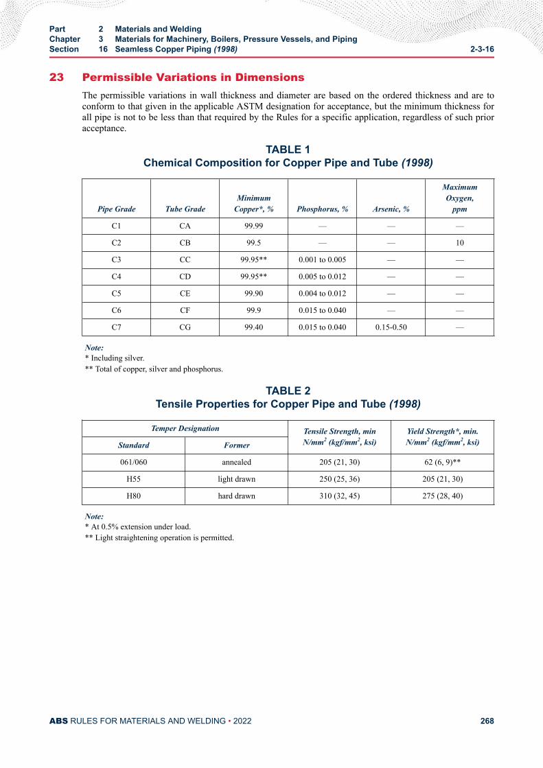
23 Permissible Variations in DimensionsThe permissible variations in wall thickness and diameter are based on the ordered thickness and are toconform to that given in the applicable ASTM designation for acceptance, but the minimum thickness forall pipe is not to be less than that required by the Rules for a specific application, regardless of such prioracceptance.
TABLE 1Chemical Composition for Copper Pipe and Tube (1998)
Pipe Grade Tube GradeMinimum
Copper*, % Phosphorus, % Arsenic, %
MaximumOxygen,
ppm
C1 CA 99.99 — — —
C2 CB 99.5 — — 10
C3 CC 99.95** 0.001 to 0.005 — —
C4 CD 99.95** 0.005 to 0.012 — —
C5 CE 99.90 0.004 to 0.012 — —
C6 CF 99.9 0.015 to 0.040 — —
C7 CG 99.40 0.015 to 0.040 0.15-0.50 —
Note:* Including silver.** Total of copper, silver and phosphorus.
TABLE 2Tensile Properties for Copper Pipe and Tube (1998)
Temper Designation Tensile Strength, minN/mm2 (kgf/mm2, ksi)
Yield Strength*, min.N/mm2 (kgf/mm2, ksi)Standard Former
061/060 annealed 205 (21, 30) 62 (6, 9)**
H55 light drawn 250 (25, 36) 205 (21, 30)
H80 hard drawn 310 (32, 45) 275 (28, 40)
Note:* At 0.5% extension under load.** Light straightening operation is permitted.
Part 2 Materials and WeldingChapter 3 Materials for Machinery, Boilers, Pressure Vessels, and PipingSection 16 Seamless Copper Piping (1998) 2-3-16
ABS RULES FOR MATERIALS AND WELDING • 2022 268
C H A P T E R 3Materials for Machinery, Boilers, Pressure Vessels, and Piping
S E C T I O N 1 7Seamless Red-brass Piping
Note:
In substantial agreement with ASTM B43.
1 Process of Manufacture (2009)The material is to be produced by either hot or cold working operations, or both. It is to be finished, unlessotherwise specified, by such cold working and annealing or heat treatment as may be necessary to meet theproperties specified. All pipe is normally to be furnished in the annealed condition. The degree of anneal isto be sufficient to show complete recrystallization and to enable the pipe to meet the test requirementsprescribed in these specifications. The pipe may be furnished in the drawn-temper condition instead of theannealed condition if so specified by the purchaser. All pipes for working pressures over 10 bar (10.5kgf/cm2, 150 psi) are to be tested and inspected at the mills to the satisfaction of the Surveyor. The pipesare examined by the Surveyor when requested by the purchaser. The pipe is to be commercially round andis to be free from defects that interfere with normal applications.
3 Marking
3.1 Manufacturer's MarkingThe name or brand of the manufacturer, the designation B43, and the test pressure is to be legibly markedby stamping or stenciling on each length of pipe. On small-diameter pipe, which is bundled, thisinformation may be marked on a tag securely attached to each bundle.
3.3 ABS MarkingThe ABS markings, indicating satisfactory compliance with the Rule requirements, and as furnished by theSurveyor, are to be marked on the material near the markings specified in 2-3-17/3.1.
5 ScopeThese specifications cover seamless red-brass pipe in all standard sizes, both regular and extra strong.
7 Chemical CompositionThe material is to conform to the following requirements as to chemical composition.
PART 2
ABS RULES FOR MATERIALS AND WELDING • 2022 269
Copper 84.00% to 86.00%
Lead 0.06% max.
Iron 0.05% max.
Zinc remainder
Total other elements 0.15%
Analysis is regularly to be made only for the elements specifically mentioned in this table. If, however, thepresence of other elements is suspected or indicated in the course of routine analysis, further analysis is tobe made to determine that the total of these other elements is not in excess of the limit specified.
9 Expansion TestSpecimens selected for test, after annealing, are to withstand an expansion of 25% of the inside diameter,without cracking, when expanded by a tapered pin having a 60-degree included angle. The expanded tubeis to show no cracking or rupture visible to the unaided eye.
11 Flattening TestAs an alternate to the expansion test for pipe over 114.3 mm outside diameter (4 in. nominal size) in theannealed condition, a section 100 mm (4 in.) in length is to be cut from the end of one of the lengths for aflattening test. This 100 mm (4 in.) specimen is to be flattened so that a gauge set at three times the wallthickness will pass over the pipe freely through the flattened part. The pipe so tested is to develop nocracks or defects visible to the unaided eye as a result of this test. In making the flattening test, theelements are to be slowly flattened by one stroke of the press.
13 Mercurous Nitrate TestA test specimen 150 mm (6 in.) in length is to be taken from each pipe selected for test and, after propercleaning, is to withstand, without cracking, an immersion of 30 minutes in an aqueous mercurous nitratesolution containing 10 grams of mercurous nitrate and 10 milliliters of nitric acid (specific gravity 1.42)per liter of solution. Immediately after removal from the solution, the specimen is to be wiped free ofexcess mercury and examined for cracks.
15 Bend TestIn the case of pipe required for bending, annealed full sections of the pipe are to stand being bent coldthrough an angle of 180 degrees around a pin, the diameter of which is one and one-half times the insidediameter of the pipe, without cracking on the outside of the bent portion. This test is to apply only to sizes50.8 mm (2 in.) and under in outside diameter.
17 Hydrostatic Test
17.1 Limiting Test PressuresEach length of the pipe is to stand, without showing weakness or defects, an internal hydrostatic pressuresufficient to subject the material to a fiber stress of 48 N/mm2 (4.92 kgf/mm2, 7000 psi), determined by thefollowing equation. No pipe is to be tested beyond a hydrostatic pressure of 69 bar (70.3 kgf/cm2, 1000 psi)unless so specified.P = KSt/(D – 0 . 8t)where
Part 2 Materials and WeldingChapter 3 Materials for Machinery, Boilers, Pressure Vessels, and PipingSection 17 Seamless Red-brass Piping 2-3-17
ABS RULES FOR MATERIALS AND WELDING • 2022 270
P = pressure, in bar (kgf/cm2, psi)S = allowable unit stress of the material, 48 N/mm2 (4.92 kgf/mm2, 7000 psi)t = thickness of pipe wall, in mm (in.)D = outside diameter of the pipe, in mm (in.)K = 20 (200, 2)
17.3 Affidavits of TestsWhere each pipe is hydrostatically tested as a regular procedure during the process of manufacture, anaffidavit covering this test may be accepted by the Surveyor.
19 Number of TestsThe lot is to consist of pipe of the same size and temper. The lot size is to be 2270 kg (5000 lb) or afraction thereof for pipe up to 48.3 mm O.D. (1.5 in. nominal size) incl., 4540 kg (10,000 lb) or a fractionthereof for pipe over 48.3 mm O.D. (1.5 in. nominal size) to 114.3 mm O.D. incl. (4 in. nominal size),18,150 kg (40,000 lb) or a fraction thereof for pipe over 114.3 mm O.D. (4 in. nominal size). Samplepieces are to be taken for test purposes from each lot as follows.
Number of Pieces in Lot Number of Sample Pieces to Be Taken
1 to 50 1
51 to 200 2
701 to 1500 3
over 1500 0.2% of total number of pieces in the lot, but not to exceed 10 sample pieces
Expansion, flattening and bend tests, where required, are to be made on each of the sample pieces selectedfor test. Each length of pipe is to be subjected to the hydrostatic test specified in 2-3-17/17.1.
21 RetestsIf the results of the test on one of the specimens, made to determine the physical properties, fails to meetthe requirements, this test is to be repeated on each of two additional specimens taken from different piecesand the results of both of these tests are to comply with the requirements. Failure of more than onespecimen to meet the requirements for a particular property is to be cause for rejection of the entire lot.
23 Permissible Variations in DimensionsThe permissible variations in wall thicknesses are based on the ordered thicknesses and is to conform tothat given in the applicable ASTM designation for acceptance, but the minimum thickness for all pipe isnot to be less than that required by the Rules for a specific application, regardless of such prior acceptance.
Part 2 Materials and WeldingChapter 3 Materials for Machinery, Boilers, Pressure Vessels, and PipingSection 17 Seamless Red-brass Piping 2-3-17
ABS RULES FOR MATERIALS AND WELDING • 2022 271
C H A P T E R 3Materials for Machinery, Boilers, Pressure Vessels, and Piping
S E C T I O N 1 8Seamless Copper Tube (1998)
Note:
In substantial agreement with ASTM B75.
1 ScopeThe following specifications cover seven grades of seamless copper tube designated CA, CB, CC, CD, CE,CF and CG.
3 General
3.1 Grades CA, CB, CC, CD, CE, CF and CGThese grades cover seamless copper tube intended for boiler feedwater lines, plumbing, and generalengineering applications. Tube is to be ordered to outer diameter and wall thickness specified by thepurchaser and approved for the application. Tube ordered under these grades are considered suitable forwelding and brazing. Seamless round copper tube in standard pipe sizes and schedules is considered to bepipe and is covered by Section 2-3-16.
3.3 ASTM DesignationThe grades are in substantial agreement with ASTM as follows:
ABS Grade ASTM Designation
CA B75, UNS C10100
CB B75, UNS C10200
CC B75, UNS C10300
CD B75, UNS C10800
CE B75, UNS C12000
CF B75, UNS C12200
CG B75, UNS C14200
PART 2
ABS RULES FOR MATERIALS AND WELDING • 2022 272
5 Process of Manufacture (2009)The material is to be produced by either hot or cold working operations, or both. It is to be finished, unlessotherwise specified, by such cold working and annealing or heat treatment as may be necessary to meet theproperties specified. All tube is to be normally furnished in the drawn-temper condition, (H55). Hard-drawn temper (H80) may be furnished also. When tube is required for bending, the tube is to be furnishedwith a proper bending temper, or annealed temper (O60). All tubes for working pressures over 10 bar (10.5kgf/cm2, 150 psi) are to be tested and inspected at the mills to the satisfaction of the Surveyor. The pipesare examined by the Surveyor when requested by the purchaser. The tube is to be commercially round andis to be free from defects that interfere with normal applications.
7 Marking
7.1 Manufacturer's MarkingThe name or brand of the manufacturer, the designation B75, and the test pressure are to be legibly markedby stamping or stenciled on each length of tube. On small-diameter tube, which is bundled, thisinformation may be marked on a tag securely attached to each bundle.
7.3 ABS MarkingsThe ABS markings, indicating satisfactory compliance with the Rule requirements, and as furnished by theSurveyor, are to be placed on the material near the markings specified in 2-3-18/7.1.
9 Chemical CompositionThe material is to conform to the applicable requirements as to chemical composition as shown in2-3-16/23 TABLE 1.
11 Tension Test
11.1 Tension Test SpecimensTensile test specimens are to be a full section of the tube. For larger sizes, tension test specimens are toconsist of longitudinal strips cut from the tube in accordance with ASTM E8.
11.3 Tensile PropertiesThe material is to conform to the applicable requirements as to tensile properties shown in 2-3-16/23TABLE 2.
13 Expansion TestNote:
This test is required for tubes manufactured in the annealed temper.
Specimens selected for test, after annealing, are to withstand an expansion of the outside diameter whenexpanded by a tapered pin having a 60-degree included angle to 30 percent for tube over 19.0 mm (3/4 in.)in outside diameter and to 40 percent for smaller sized tube. The expanded tube is to show no cracking orrupture visible to the unaided eye.
15 Flattening TestAs an alternate to the expansion test for tube over 114.3 mm outside diameter (4 in. nominal size) in theannealed condition, a section 100 mm (4 in.) in length is to be cut from the end of one of the lengths for aflattening test. This 100 mm (4 in.) specimen is to be flattened so that a gauge set at three times the wallthickness will pass over the pipe freely throughout the flattened part. The tube so tested is to develop no
Part 2 Materials and WeldingChapter 3 Materials for Machinery, Boilers, Pressure Vessels, and PipingSection 18 Seamless Copper Tube (1998) 2-3-18
ABS RULES FOR MATERIALS AND WELDING • 2022 273
cracks or defects visible to the unaided eye as a result of this test. In making the flattening test, thespecimens are to be slowly flattened by one stroke of the press.
17 Hydrostatic Test
17.1 Limiting Test PressuresEach length of the tube is to stand, without showing weakness or defects, an internal hydrostatic pressuresufficient to subject the material to a fiber stress of 41 N/mm2 (4.22 kgf/mm2, 6000 psi), determined by thefollowing equation. No pipe is to be tested beyond a hydrostatic pressure of 69 bar (70.3 kgf/cm2, 1000 psi)unless so specified. At the option of the manufacturer, annealed tube with wall thickness up to 2.11 mm(0.083 in.) inclusive may be tested in the hard-drawn condition prior to annealing.P = KSt/(D – 0 . 8t)whereP = pressure, in bar (kgf/cm2, psi)S = allowable unit stress of the material, 41 N/mm2 (4.22 kgf/mm2, 6000 psi)t = thickness of pipe wall, in mm (in.)D = outside diameter of the pipe, in mm (in.)K = 20 (200, 2)
17.3 Affidavits of TestsWhere each tube is hydrostatically tested as a regular procedure during process of manufacture, anaffidavit covering this test may be accepted by the Surveyor.
19 Number of TestsThe lot is to consist of tubes of the same size and temper. The lot size is to be 4540 kg (10,000 lb) or afraction thereof. Sample pieces are to be taken for test purposes at random from each lot, as follows:
Number of Pieces in Lot Number of Sample Pieces to be Taken
1 to 50 1
51 to 200 2
201 to 1500 3
over 1500 0.2% of total number of pieces in the lot, but not to exceed 10 sample pieces
Chemical analyses, where required, tensile tests, expansion tests, flattening tests, bend tests, whererequired, dimensional examinations and visual examinations are to be made on each of the sample piecesselected for test. Each length of pipe is to be subjected to the hydrostatic test specified in 2-3-18/19.
21 RetestsIf the results of the test on one of the specimens, made to determine the mechanical properties, fails tomeet the requirements, this test is to be repeated on each of two additional specimens taken from differentpieces and the results of both of these tests is to comply with the requirements. Failure of more than onespecimen to meet the requirements for a particular property is to be cause for rejection of the entire lot.
Part 2 Materials and WeldingChapter 3 Materials for Machinery, Boilers, Pressure Vessels, and PipingSection 18 Seamless Copper Tube (1998) 2-3-18
ABS RULES FOR MATERIALS AND WELDING • 2022 274

23 Permissible Variations in DimensionsThe permissible variations in wall thickness and diameter are based on the ordered thickness and are toconform to that given in the applicable ASTM for acceptance, but the minimum thickness for all pipe isnot to be less than that required by the Rules for a specific application, regardless of any prior acceptance.
Part 2 Materials and WeldingChapter 3 Materials for Machinery, Boilers, Pressure Vessels, and PipingSection 18 Seamless Copper Tube (1998) 2-3-18
ABS RULES FOR MATERIALS AND WELDING • 2022 275
C H A P T E R 3Materials for Machinery, Boilers, Pressure Vessels, and Piping
S E C T I O N 1 9Condenser and Heat Exchanger Tube (1998)
Note:
In substantial agreement with ASTM B111.
1 ScopeThe following specifications covers two grades of seamless copper-nickel tube designated CNA and CNB.
3 General
3.1 Grades CNA and CNBGrades CNA, and CNB cover seamless copper-nickel tube intended for use in condensers, evaporators andheat exchanger which may use sea water as the cooling medium. Tube ordered under these grades isconsidered suitable for welding, and suitable for forming operations involving coiling, bending, flaring andtube rolling. Tube is to be ordered to outer diameter and wall thickness specified by the purchaser andapproved for the application.
3.3 ASTM DesignationThe grades are in substantial agreement with ASTM, as follows:
ABS Grade ASTM Designation
CNA B111, UNS C70600
CNB B111, UNS C71500
5 Process of Manufacture
5.1 Grade CNAGrade CNA tube is to be cold worked to the specified size. The tube may be supplied either in the annealedtemper (O61) or in the light drawn temper (H55).
5.3 Grade CNBGrade CNB tube is to be cold worked to the specified size. The tube may be supplied either in the annealedtemper (O61) or in the drawn and stress relieved temper (HR50).
PART 2
ABS RULES FOR MATERIALS AND WELDING • 2022 276
All grades of tube shall be round, straight, clean, smooth and free from harmful defects and deleteriousfilms in the bore.
7 MarkingIdentification markings are to be legibly stenciled, or suitably marked on each length of tube, except that inthe case of smaller-diameter tube which is bundled, the required markings are to be placed on a tagsecurely attached to the bundle. The markings are to be arranged and are to include the followinginformation:
● Name or brand of the manufacturer
● ABS Grade or ASTM Designation and Grade
● Temper number
● Tube diameter
● Wall thickness
● Test Pressure, or the letters NDET
● ABS markings by the Surveyor
9 Chemical Composition
9.1 Chemical RequirementsThe material is to conform to the applicable requirements as to chemical composition as shown in2-3-19/27.7 TABLE 1.
9.3 Chemical Analysis SamplingSamples may be taken at the time the metal is cast or may be taken from semi-finished product, or fromfinished product in accordance with sampling in 2-3-19/21.
11 Tension Test
11.1 Tension Test SpecimensTensile test specimens are to be a full section of the tube. For larger sizes, tension test specimens are toconsist of longitudinal strips cut from the tube in accordance with ASTM E8, for Tension Testing ofMetallic Materials.
11.3 Tensile PropertiesThe material is to conform to the applicable requirements as to tensile properties shown in 2-3-19/27.7TABLE 2.
13 Expansion TestSpecimens selected for testing in accordance with ASTM B153, for Expansion (Pin Test) of Copper andCopper-Alloy Pipe and Tubing, are to withstand an expansion of the outside diameter to 30 percent forannealed temper (O61) tube and to 20 percent for drawn temper (H55 or HR50) tube. The expanded tube isto show no cracking or rupture visible to the unaided eye.
15 Flattening TestThe specimen selected for testing is to be at least 450 mm (18 in.) in length, and is to be flattened so that agauge set at three times the wall thickness will pass over the tube freely throughout the flattened part. The
Part 2 Materials and WeldingChapter 3 Materials for Machinery, Boilers, Pressure Vessels, and PipingSection 19 Condenser and Heat Exchanger Tube (1998) 2-3-19
ABS RULES FOR MATERIALS AND WELDING • 2022 277
tube so tested is to develop no cracks or defects visible to the unaided eye as a result of this test. In makingthe flattening test, the specimens are to be slowly flattened by one stroke of the press. Specimens notinitially in the annealed temper (O61) are to be annealed prior to flattening.
17 Nondestructive Electric Test (NDET)All tubes are to be eddy-current tested in accordance with ASTM E243, for Electromagnetic (Eddy-Current) Examination of Copper and Copper-Alloy Tubes or, alternatively, when specified, may behydrostatically tested in accordance with 2-3-19/19. A calibration reference standard is to be made from alength of tube of the same type, wall thickness, and outside diameter as that to be tested. The standard is tohave transverse notches or drilled holes in accordance with the dimensions shown. Tubing producing asignal equal to or greater than the calibration defect is to be rejected.
Diameter of Drilled Hole
Tube OD, in mm (inch) Diameter, in mm (inch)
6.0 (0.25) ≤ OD ≤ 19.0 (0.75) 0.635 (0.025)
19.0 (0.75) < OD ≤ 25.4 (1.0) 0.785 (0.031)
25.4 (1.0) < OD ≤ 31.8 (1.25) 0.915 (0.036)
31.8 (1.25) < OD ≤ 38.1 (1.5) 1.07 (0.042)
38.1 (1.5) < OD ≤ 44.4 (1.75) 1.17 (0.046)
44.4 (1.75) < OD ≤ 50.8 (2.0) 1.32 (0.052)
Notch Depth
Tube WallThickness, in mm (inch)
Tube OD, in mm (inch)
6.4 (0.25) ≤≤ 19.1 (0.75)
19.1 (0.75) <≤ 31.8 (1.25)
31.8 (1.25) <≤ 80 (3.125)
0.43 (0.17) <T < 0.8 (0.032) 0.127 (0.005) 0.152 (0.006) 0.179 (0.007)
0.80 (0.032) < T < 1.24 (0.049) 0.152 (0.006) 0.152 (0.006) 0.191 (0.0075)
1.24 (0.049) <T < 2.10 (0.083) 0.179 (0.007) 0.191 (0.0075) 0.216 (0.008)
2.10 (0.083) < T < 2.77 (0.109) 0.191 (0.0075) 0.216 (0.0085) 0.241 (0.0095)
2.77 (0.109) < T < 3.05 (0.120) 0.229 (0.009) 0.229 (0.009) 0.279 (0.011)
19 Hydrostatic Test
19.1 Limiting Test PressuresAs an alternate to the eddy-current test, hydrostatic testing may be performed. Each tube that is tested is tostand, without showing evidence of leakage, an internal hydrostatic pressure sufficient to subject thematerial to a fiber stress of 48 N/mm2 (4.92 kgf/mm2, 7000 psi), determined by the following equation forthin hollow cylinders under tension. The tube is not to be tested at a hydrostatic pressure of over 69 bar(70.3 kgf/cm2, 1000 psi) unless so specified.P = KSt/(D – 0 . 8t)where
Part 2 Materials and WeldingChapter 3 Materials for Machinery, Boilers, Pressure Vessels, and PipingSection 19 Condenser and Heat Exchanger Tube (1998) 2-3-19
ABS RULES FOR MATERIALS AND WELDING • 2022 278
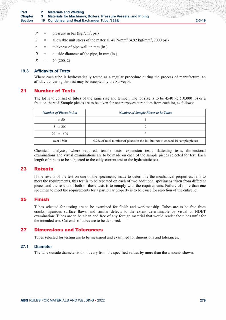
P = pressure in bar (kgf/cm2, psi)S = allowable unit stress of the material, 48 N/mm2 (4.92 kgf/mm2, 7000 psi)t = thickness of pipe wall, in mm (in.)D = outside diameter of the pipe, in mm (in.)K = 20 (200, 2)
19.3 Affidavits of TestsWhere each tube is hydrostatically tested as a regular procedure during the process of manufacture, anaffidavit covering this test may be accepted by the Surveyor.
21 Number of TestsThe lot is to consist of tubes of the same size and temper. The lot size is to be 4540 kg (10,000 lb) or afraction thereof. Sample pieces are to be taken for test purposes at random from each lot, as follows:
Number of Pieces in Lot Number of Sample Pieces to be Taken
1 to 50 1
51 to 200 2
201 to 1500 3
over 1500 0.2% of total number of pieces in the lot, but not to exceed 10 sample pieces
Chemical analyses, where required, tensile tests, expansion tests, flattening tests, dimensionalexaminations and visual examinations are to be made on each of the sample pieces selected for test. Eachlength of pipe is to be subjected to the eddy-current test or the hydrostatic test.
23 RetestsIf the results of the test on one of the specimens, made to determine the mechanical properties, fails tomeet the requirements, this test is to be repeated on each of two additional specimens taken from differentpieces and the results of both of these tests is to comply with the requirements. Failure of more than onespecimen to meet the requirements for a particular property is to be cause for rejection of the entire lot.
25 FinishTubes selected for testing are to be examined for finish and workmanship. Tubes are to be free fromcracks, injurious surface flaws, and similar defects to the extent determinable by visual or NDETexamination. Tubes are to be clean and free of any foreign material that would render the tubes unfit forthe intended use. Cut ends of tubes are to be deburred.
27 Dimensions and TolerancesTubes selected for testing are to be measured and examined for dimensions and tolerances.
27.1 DiameterThe tube outside diameter is to not vary from the specified values by more than the amounts shown.
Part 2 Materials and WeldingChapter 3 Materials for Machinery, Boilers, Pressure Vessels, and PipingSection 19 Condenser and Heat Exchanger Tube (1998) 2-3-19
ABS RULES FOR MATERIALS AND WELDING • 2022 279
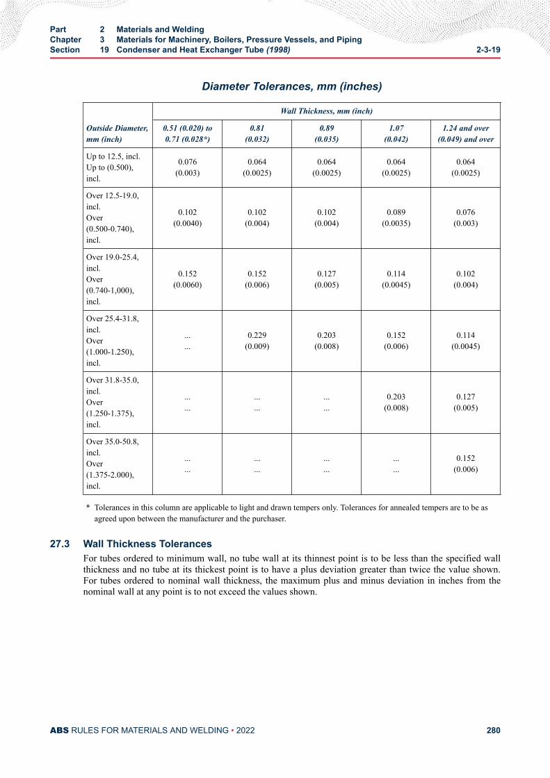
Diameter Tolerances, mm (inches)
Outside Diameter,mm (inch)
Wall Thickness, mm (inch)
0.51 (0.020) to0.71 (0.028*)
0.81(0.032)
0.89(0.035)
1.07(0.042)
1.24 and over(0.049) and over
Up to 12.5, incl.Up to (0.500),incl.
0.076(0.003)
0.064(0.0025)
0.064(0.0025)
0.064(0.0025)
0.064(0.0025)
Over 12.5-19.0,incl.Over(0.500-0.740),incl.
0.102(0.0040)
0.102(0.004)
0.102(0.004)
0.089(0.0035)
0.076(0.003)
Over 19.0-25.4,incl.Over(0.740-1,000),incl.
0.152(0.0060)
0.152(0.006)
0.127(0.005)
0.114(0.0045)
0.102(0.004)
Over 25.4-31.8,incl.Over(1.000-1.250),incl.
...
...0.229
(0.009)0.203
(0.008)0.152
(0.006)0.114
(0.0045)
Over 31.8-35.0,incl.Over(1.250-1.375),incl.
...
.........
...
...0.203
(0.008)0.127
(0.005)
Over 35.0-50.8,incl.Over(1.375-2.000),incl.
...
.........
...
.........
0.152(0.006)
* Tolerances in this column are applicable to light and drawn tempers only. Tolerances for annealed tempers are to be asagreed upon between the manufacturer and the purchaser.
27.3 Wall Thickness TolerancesFor tubes ordered to minimum wall, no tube wall at its thinnest point is to be less than the specified wallthickness and no tube at its thickest point is to have a plus deviation greater than twice the value shown.For tubes ordered to nominal wall thickness, the maximum plus and minus deviation in inches from thenominal wall at any point is to not exceed the values shown.
Part 2 Materials and WeldingChapter 3 Materials for Machinery, Boilers, Pressure Vessels, and PipingSection 19 Condenser and Heat Exchanger Tube (1998) 2-3-19
ABS RULES FOR MATERIALS AND WELDING • 2022 280
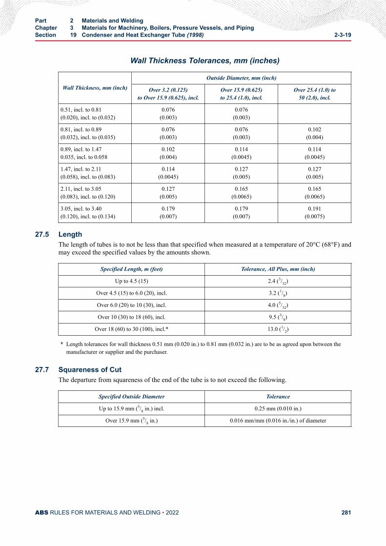
Wall Thickness Tolerances, mm (inches)
Wall Thickness, mm (inch)
Outside Diameter, mm (inch)
Over 3.2 (0.125)to Over 15.9 (0.625), incl.
Over 15.9 (0.625)to 25.4 (1.0), incl.
Over 25.4 (1.0) to50 (2.0), incl.
0.51, incl. to 0.81(0.020), incl. to (0.032)
0.076(0.003)
0.076(0.003)
0.81, incl. to 0.89(0.032), incl. to (0.035)
0.076(0.003)
0.076(0.003)
0.102(0.004)
0.89, incl. to 1.470.035, incl. to 0.058
0.102(0.004)
0.114(0.0045)
0.114(0.0045)
1.47, incl. to 2.11(0.058), incl. to (0.083)
0.114(0.0045)
0.127(0.005)
0.127(0.005)
2.11, incl. to 3.05(0.083), incl. to (0.120)
0.127(0.005)
0.165(0.0065)
0.165(0.0065)
3.05, incl. to 3.40(0.120), incl. to (0.134)
0.179(0.007)
0.179(0.007)
0.191(0.0075)
27.5 LengthThe length of tubes is to not be less than that specified when measured at a temperature of 20°C (68°F) andmay exceed the specified values by the amounts shown.
Specified Length, m (feet) Tolerance, All Plus, mm (inch)
Up to 4.5 (15) 2.4 (3/32)
Over 4.5 (15) to 6.0 (20), incl. 3.2 (1/8)
Over 6.0 (20) to 10 (30), incl. 4.0 (5/32)
Over 10 (30) to 18 (60), incl. 9.5 (3/8)
Over 18 (60) to 30 (100), incl.* 13.0 (1/2)
* Length tolerances for wall thickness 0.51 mm (0.020 in.) to 0.81 mm (0.032 in.) are to be as agreed upon between themanufacturer or supplier and the purchaser.
27.7 Squareness of CutThe departure from squareness of the end of the tube is to not exceed the following.
Specified Outside Diameter Tolerance
Up to 15.9 mm (5/8 in.) incl. 0.25 mm (0.010 in.)
Over 15.9 mm (5/8 in.) 0.016 mm/mm (0.016 in./in.) of diameter
Part 2 Materials and WeldingChapter 3 Materials for Machinery, Boilers, Pressure Vessels, and PipingSection 19 Condenser and Heat Exchanger Tube (1998) 2-3-19
ABS RULES FOR MATERIALS AND WELDING • 2022 281
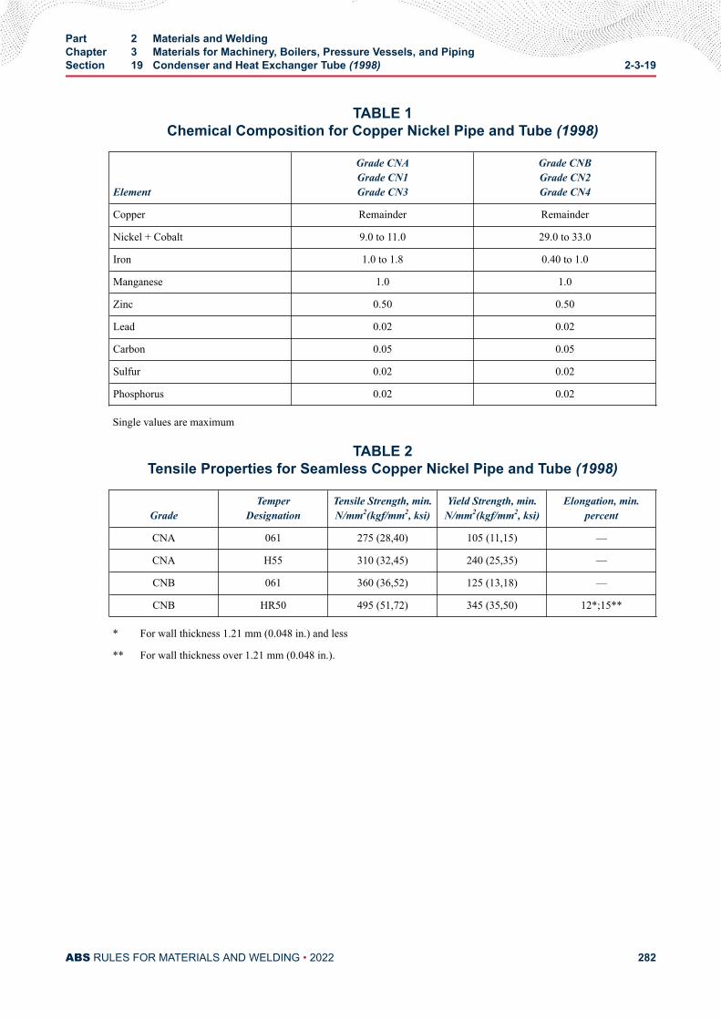
TABLE 1Chemical Composition for Copper Nickel Pipe and Tube (1998)
Element
Grade CNAGrade CN1Grade CN3
Grade CNBGrade CN2Grade CN4
Copper Remainder Remainder
Nickel + Cobalt 9.0 to 11.0 29.0 to 33.0
Iron 1.0 to 1.8 0.40 to 1.0
Manganese 1.0 1.0
Zinc 0.50 0.50
Lead 0.02 0.02
Carbon 0.05 0.05
Sulfur 0.02 0.02
Phosphorus 0.02 0.02
Single values are maximum
TABLE 2Tensile Properties for Seamless Copper Nickel Pipe and Tube (1998)
GradeTemper
DesignationTensile Strength, min.N/mm2(kgf/mm2, ksi)
Yield Strength, min.N/mm2(kgf/mm2, ksi)
Elongation, min.percent
CNA 061 275 (28,40) 105 (11,15) —
CNA H55 310 (32,45) 240 (25,35) —
CNB 061 360 (36,52) 125 (13,18) —
CNB HR50 495 (51,72) 345 (35,50) 12*;15**
* For wall thickness 1.21 mm (0.048 in.) and less
** For wall thickness over 1.21 mm (0.048 in.).
Part 2 Materials and WeldingChapter 3 Materials for Machinery, Boilers, Pressure Vessels, and PipingSection 19 Condenser and Heat Exchanger Tube (1998) 2-3-19
ABS RULES FOR MATERIALS AND WELDING • 2022 282
C H A P T E R 3Materials for Machinery, Boilers, Pressure Vessels, and Piping
S E C T I O N 2 0Copper-Nickel Tube and Pipe (1998)
Note:
In substantial agreement with ASTM B466 and B467.
1 ScopeThis specification covers four grades of seamless and welded copper-nickel tube and pipe designated CN1,CN2, CN3 and CN4.
3 General
3.1 Grades CN1 and CN2Grades CN1 and CN2 cover seamless copper-nickel tube and pipe intended for use in general engineeringapplications requiring seawater corrosion resistance. Tube and pipe ordered under these grades areconsidered suitable for welding, and suitable for forming operations involving bending, flaring andflanging. Tube is to be ordered to outer diameter and wall thickness specified by the purchaser andapproved for the application.
3.3 Grades CN3 and CN4Grades CN3 and CN4 cover welded copper-nickel pipe intended for use in general engineeringapplications requiring seawater corrosion resistance. Pipe ordered under these grades are consideredsuitable for welding, and suitable for forming operations involving bending, flaring and flanging.
3.5 ASTM DesignationThese grades are in substantial agreement with ASTM as follows:
ABS Grade ASTM Designation
CN1 B466, UNS C70600
CN2 B466, UNS C71500
CN3 B467, UNS C70600
CN4 B467, UNS C71500
PART 2
ABS RULES FOR MATERIALS AND WELDING • 2022 283
5 Process of ManufactureThe material is to be produced by either hot or cold working operations, or both. The tubing is to befinished, unless otherwise specified, by such cold working or annealing or heat treatment as may benecessary to meet the properties for either annealed or light drawn material. The light drawn propertiesapply only to grades CN1 and CN3.
5.1 Grades CN1 and CN2Grade CN1 may be supplied in either annealed (O60) or light drawn (H55) tempers. Grade CN2 may besupplied in only annealed (O60) temper.
5.3 Grades CN3 and CN4Grade CN3 may be supplied in either the welded from annealed skelp temper (WM50), or the welded andfully finished as annealed temper (WO61). Grade CN4 may be supplied in the welded and fully finished asannealed temper (WO61). The internal and external flash is to be removed by scarfing and there is to be nocrevice in the weld seam visible to the unaided eye.
7 MarkingIdentification markings are to be legibly stenciled, or suitably marked on each length of tubular, except thatin the case of small-diameter tubular which is bundled, the required markings are to be placed on a tagsecurely attached to the bundle. The markings are to be arranged and are to include the followinginformation:
● Name or brand of the manufacturer
● ABS Grade or ASTM Designation and Grade
● Temper number
● Diameter
● Wall thickness or Pipe Schedule
● Test Pressure, or the letters NDET
● ABS markings by the Surveyor
9 Chemical Composition
9.1 Chemical RequirementsThe material is to conform to the chemical requirements specified in 2-3-19/27.7 TABLE 1.
9.3 Chemical Analysis SamplingSamples may be taken at the time the metal is cast or may be taken from semi-furnished product, or fromfinished product in accordance with sampling in 2-3-20/21.
11 Tension Test
11.1 Tension Test SpecimensTensile test specimens are to be a full section of the tube. For larger sizes, tension test specimens are toconsist of longitudinal strips cut from the tube in accordance with ASTM E8, for Tension Testing ofMetallic Materials.
11.3 Seamless Tensile PropertiesSeamless material is to conform to the applicable requirements as to tensile properties shown.
Part 2 Materials and WeldingChapter 3 Materials for Machinery, Boilers, Pressure Vessels, and PipingSection 20 Copper-Nickel Tube and Pipe (1998) 2-3-20
ABS RULES FOR MATERIALS AND WELDING • 2022 284
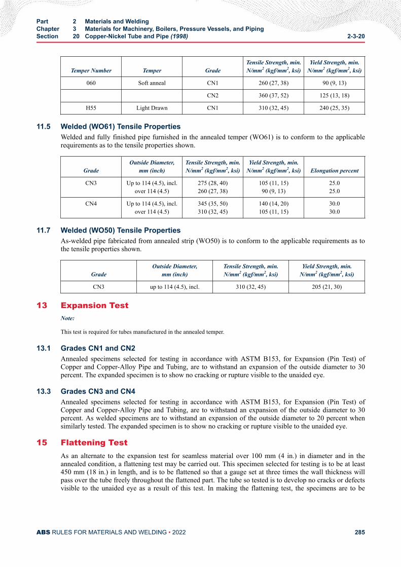
Temper Number Temper GradeTensile Strength, min.N/mm2 (kgf/mm2, ksi)
Yield Strength, min.N/mm2 (kgf/mm2, ksi)
060 Soft anneal CN1 260 (27, 38) 90 (9, 13)
CN2 360 (37, 52) 125 (13, 18)
H55 Light Drawn CN1 310 (32, 45) 240 (25, 35)
11.5 Welded (WO61) Tensile PropertiesWelded and fully finished pipe furnished in the annealed temper (WO61) is to conform to the applicablerequirements as to the tensile properties shown.
GradeOutside Diameter,
mm (inch)Tensile Strength, min.N/mm2 (kgf/mm2, ksi)
Yield Strength, min.N/mm2 (kgf/mm2, ksi) Elongation percent
CN3 Up to 114 (4.5), incl.over 114 (4.5)
275 (28, 40)260 (27, 38)
105 (11, 15)90 (9, 13)
25.025.0
CN4 Up to 114 (4.5), incl.over 114 (4.5)
345 (35, 50)310 (32, 45)
140 (14, 20)105 (11, 15)
30.030.0
11.7 Welded (WO50) Tensile PropertiesAs-welded pipe fabricated from annealed strip (WO50) is to conform to the applicable requirements as tothe tensile properties shown.
GradeOutside Diameter,
mm (inch)Tensile Strength, min.N/mm2 (kgf/mm2, ksi)
Yield Strength, min.N/mm2 (kgf/mm2, ksi)
CN3 up to 114 (4.5), incl. 310 (32, 45) 205 (21, 30)
13 Expansion TestNote:
This test is required for tubes manufactured in the annealed temper.
13.1 Grades CN1 and CN2Annealed specimens selected for testing in accordance with ASTM B153, for Expansion (Pin Test) ofCopper and Copper-Alloy Pipe and Tubing, are to withstand an expansion of the outside diameter to 30percent. The expanded specimen is to show no cracking or rupture visible to the unaided eye.
13.3 Grades CN3 and CN4Annealed specimens selected for testing in accordance with ASTM B153, for Expansion (Pin Test) ofCopper and Copper-Alloy Pipe and Tubing, are to withstand an expansion of the outside diameter to 30percent. As welded specimens are to withstand an expansion of the outside diameter to 20 percent whensimilarly tested. The expanded specimen is to show no cracking or rupture visible to the unaided eye.
15 Flattening TestAs an alternate to the expansion test for seamless material over 100 mm (4 in.) in diameter and in theannealed condition, a flattening test may be carried out. This specimen selected for testing is to be at least450 mm (18 in.) in length, and is to be flattened so that a gauge set at three times the wall thickness willpass over the tube freely throughout the flattened part. The tube so tested is to develop no cracks or defectsvisible to the unaided eye as a result of this test. In making the flattening test, the specimens are to be
Part 2 Materials and WeldingChapter 3 Materials for Machinery, Boilers, Pressure Vessels, and PipingSection 20 Copper-Nickel Tube and Pipe (1998) 2-3-20
ABS RULES FOR MATERIALS AND WELDING • 2022 285
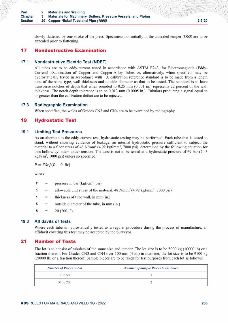
slowly flattened by one stroke of the press. Specimens not initially in the annealed temper (O60) are to beannealed prior to flattening.
17 Nondestructive Examination
17.1 Nondestructive Electric Test (NDET)All tubes are to be eddy-current tested in accordance with ASTM E243, for Electromagnetic (Eddy-Current) Examination of Copper and Copper-Alloy Tubes or, alternatively, when specified, may behydrostatically tested in accordance with . A calibration reference standard is to be made from a lengthtube of the same type, wall thickness and outside diameter as that to be tested. The standard is to havetransverse notches of depth that when rounded to 0.25 mm (0.001 in.) represents 22 percent of the wallthickness. The notch depth tolerance is to be 0.013 mm (0.0005 in.). Tubulars producing a signal equal toor greater than the calibration defect are to be rejected.
17.3 Radiographic ExaminationWhen specified, the welds of Grades CN3 and CN4 are to be examined by radiography.
19 Hydrostatic Test
19.1 Limiting Test PressuresAs an alternate to the eddy-current test, hydrostatic testing may be performed. Each tube that is tested tostand, without showing evidence of leakage, an internal hydrostatic pressure sufficient to subject thematerial to a fiber stress of 48 N/mm2 (4.92 kgf/mm2, 7000 psi), determined by the following equation forthin hollow cylinders under tension. The tube is not to be tested at a hydrostatic pressure of 69 bar (70.3kgf/cm2, 1000 psi) unless so specified.P = KSt/ D − 0 . 8twhereP = pressure in bar (kgf/cm2, psi)S = allowable unit stress of the material, 48 N/mm2 (4.92 kgf/mm2, 7000 psi)t = thickness of tube wall, in mm (in.)D = outside diameter of the tube, in mm (in.)K = 20 (200, 2)
19.3 Affidavits of TestsWhere each tube is hydrostatically tested as a regular procedure during the process of manufacture, anaffidavit covering this test may be accepted by the Surveyor.
21 Number of TestsThe lot is to consist of tubulars of the same size and temper. The lot size is to be 5000 kg (10000 lb) or afraction thereof. For Grades CN3 and CN4 over 100 mm (4 in.) in diameter, the lot size is to be 9100 kg(20000 lb) or a fraction thereof. Sample pieces are to be taken for test purposes from each lot as follows:
Number of Pieces in Lot Number of Sample Pieces to Be Taken
1 to 50 1
51 to 200 2
Part 2 Materials and WeldingChapter 3 Materials for Machinery, Boilers, Pressure Vessels, and PipingSection 20 Copper-Nickel Tube and Pipe (1998) 2-3-20
ABS RULES FOR MATERIALS AND WELDING • 2022 286
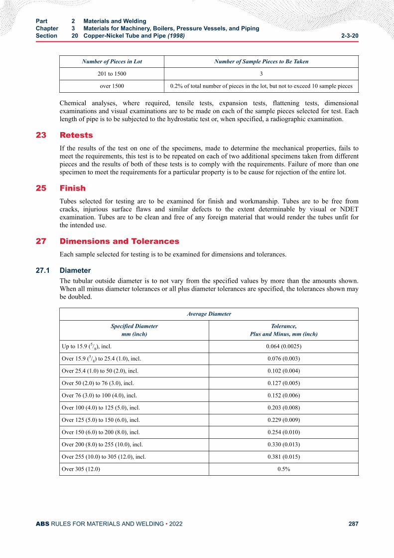
Number of Pieces in Lot Number of Sample Pieces to Be Taken
201 to 1500 3
over 1500 0.2% of total number of pieces in the lot, but not to exceed 10 sample pieces
Chemical analyses, where required, tensile tests, expansion tests, flattening tests, dimensionalexaminations and visual examinations are to be made on each of the sample pieces selected for test. Eachlength of pipe is to be subjected to the hydrostatic test or, when specified, a radiographic examination.
23 RetestsIf the results of the test on one of the specimens, made to determine the mechanical properties, fails tomeet the requirements, this test is to be repeated on each of two additional specimens taken from differentpieces and the results of both of these tests is to comply with the requirements. Failure of more than onespecimen to meet the requirements for a particular property is to be cause for rejection of the entire lot.
25 FinishTubes selected for testing are to be examined for finish and workmanship. Tubes are to be free fromcracks, injurious surface flaws and similar defects to the extent determinable by visual or NDETexamination. Tubes are to be clean and free of any foreign material that would render the tubes unfit forthe intended use.
27 Dimensions and TolerancesEach sample selected for testing is to be examined for dimensions and tolerances.
27.1 DiameterThe tubular outside diameter is to not vary from the specified values by more than the amounts shown.When all minus diameter tolerances or all plus diameter tolerances are specified, the tolerances shown maybe doubled.
Average Diameter
Specified Diametermm (inch)
Tolerance,Plus and Minus, mm (inch)
Up to 15.9 (5/8), incl. 0.064 (0.0025)
Over 15.9 (5/8) to 25.4 (1.0), incl. 0.076 (0.003)
Over 25.4 (1.0) to 50 (2.0), incl. 0.102 (0.004)
Over 50 (2.0) to 76 (3.0), incl. 0.127 (0.005)
Over 76 (3.0) to 100 (4.0), incl. 0.152 (0.006)
Over 100 (4.0) to 125 (5.0), incl. 0.203 (0.008)
Over 125 (5.0) to 150 (6.0), incl. 0.229 (0.009)
Over 150 (6.0) to 200 (8.0), incl. 0.254 (0.010)
Over 200 (8.0) to 255 (10.0), incl. 0.330 (0.013)
Over 255 (10.0) to 305 (12.0), incl. 0.381 (0.015)
Over 305 (12.0) 0.5%
Part 2 Materials and WeldingChapter 3 Materials for Machinery, Boilers, Pressure Vessels, and PipingSection 20 Copper-Nickel Tube and Pipe (1998) 2-3-20
ABS RULES FOR MATERIALS AND WELDING • 2022 287
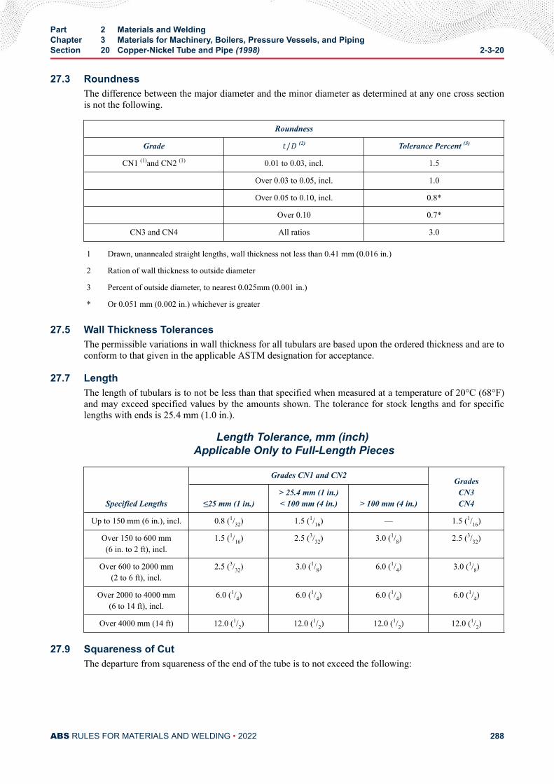
27.3 RoundnessThe difference between the major diameter and the minor diameter as determined at any one cross sectionis not the following.
Roundness
Grade t/D (2) Tolerance Percent (3)
CN1 (1)and CN2 (1) 0.01 to 0.03, incl. 1.5
Over 0.03 to 0.05, incl. 1.0
Over 0.05 to 0.10, incl. 0.8*
Over 0.10 0.7*
CN3 and CN4 All ratios 3.0
1 Drawn, unannealed straight lengths, wall thickness not less than 0.41 mm (0.016 in.)
2 Ration of wall thickness to outside diameter
3 Percent of outside diameter, to nearest 0.025mm (0.001 in.)
* Or 0.051 mm (0.002 in.) whichever is greater
27.5 Wall Thickness TolerancesThe permissible variations in wall thickness for all tubulars are based upon the ordered thickness and are toconform to that given in the applicable ASTM designation for acceptance.
27.7 LengthThe length of tubulars is to not be less than that specified when measured at a temperature of 20°C (68°F)and may exceed specified values by the amounts shown. The tolerance for stock lengths and for specificlengths with ends is 25.4 mm (1.0 in.).
Length Tolerance, mm (inch) Applicable Only to Full-Length Pieces
Specified Lengths
Grades CN1 and CN2Grades
CN3CN4≤25 mm (1 in.)
> 25.4 mm (1 in.)< 100 mm (4 in.) > 100 mm (4 in.)
Up to 150 mm (6 in.), incl. 0.8 (1/32) 1.5 (1/16) — 1.5 (1/16)
Over 150 to 600 mm(6 in. to 2 ft), incl.
1.5 (1/16) 2.5 (3/32) 3.0 (1/8) 2.5 (3/32)
Over 600 to 2000 mm(2 to 6 ft), incl.
2.5 (3/32) 3.0 (1/8) 6.0 (1/4) 3.0 (1/8)
Over 2000 to 4000 mm(6 to 14 ft), incl.
6.0 (1/4) 6.0 (1/4) 6.0 (1/4) 6.0 (1/4)
Over 4000 mm (14 ft) 12.0 (1/2) 12.0 (1/2) 12.0 (1/2) 12.0 (1/2)
27.9 Squareness of CutThe departure from squareness of the end of the tube is to not exceed the following:
Part 2 Materials and WeldingChapter 3 Materials for Machinery, Boilers, Pressure Vessels, and PipingSection 20 Copper-Nickel Tube and Pipe (1998) 2-3-20
ABS RULES FOR MATERIALS AND WELDING • 2022 288
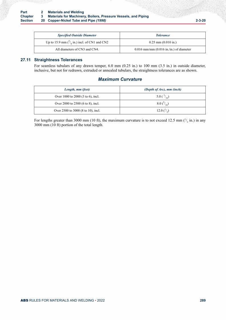
Specified Outside Diameter Tolerance
Up to 15.9 mm (5/8 in.) incl. of CN1 and CN2 0.25 mm (0.010 in.)
All diameters of CN3 and CN4. 0.016 mm/mm (0.016 in./in.) of diameter
27.11 Straightness TolerancesFor seamless tubulars of any drawn temper, 6.0 mm (0.25 in.) to 100 mm (3.5 in.) in outside diameter,inclusive, but not for redrawn, extruded or annealed tubulars, the straightness tolerances are as shown.
Maximum Curvature
Length, mm (feet) (Depth of Arc), mm (inch)
Over 1000 to 2000 (3 to 6), incl. 5.0 ( 3/16)
Over 2000 to 2500 (6 to 8), incl. 8.0 (5/16)
Over 2500 to 3000 (8 to 10), incl. 12.0 (1/2)
For lengths greater than 3000 mm (10 ft), the maximum curvature is to not exceed 12.5 mm (1/2 in.) in any3000 mm (10 ft) portion of the total length.
Part 2 Materials and WeldingChapter 3 Materials for Machinery, Boilers, Pressure Vessels, and PipingSection 20 Copper-Nickel Tube and Pipe (1998) 2-3-20
ABS RULES FOR MATERIALS AND WELDING • 2022 289
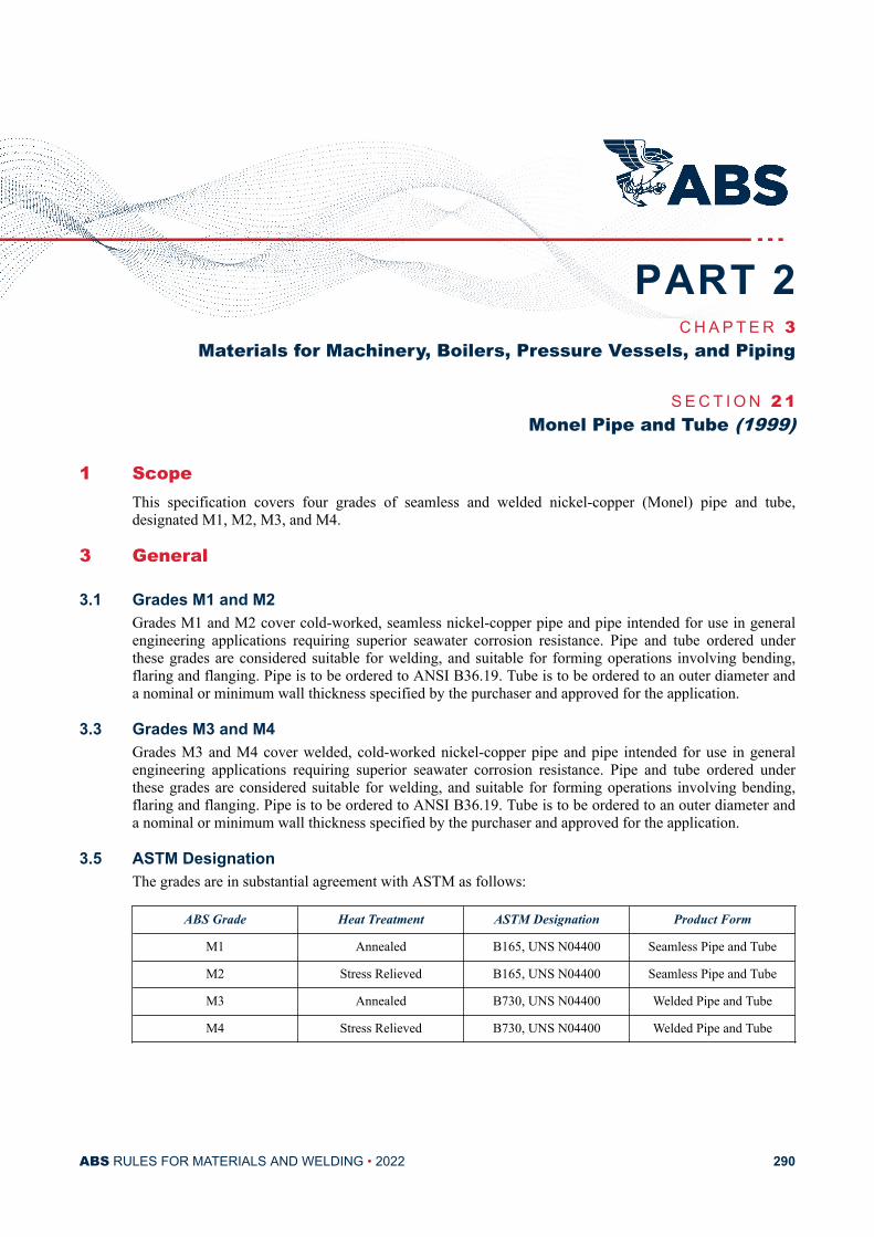
C H A P T E R 3Materials for Machinery, Boilers, Pressure Vessels, and Piping
S E C T I O N 2 1Monel Pipe and Tube (1999)
1 ScopeThis specification covers four grades of seamless and welded nickel-copper (Monel) pipe and tube,designated M1, M2, M3, and M4.
3 General
3.1 Grades M1 and M2Grades M1 and M2 cover cold-worked, seamless nickel-copper pipe and pipe intended for use in generalengineering applications requiring superior seawater corrosion resistance. Pipe and tube ordered underthese grades are considered suitable for welding, and suitable for forming operations involving bending,flaring and flanging. Pipe is to be ordered to ANSI B36.19. Tube is to be ordered to an outer diameter anda nominal or minimum wall thickness specified by the purchaser and approved for the application.
3.3 Grades M3 and M4Grades M3 and M4 cover welded, cold-worked nickel-copper pipe and pipe intended for use in generalengineering applications requiring superior seawater corrosion resistance. Pipe and tube ordered underthese grades are considered suitable for welding, and suitable for forming operations involving bending,flaring and flanging. Pipe is to be ordered to ANSI B36.19. Tube is to be ordered to an outer diameter anda nominal or minimum wall thickness specified by the purchaser and approved for the application.
3.5 ASTM DesignationThe grades are in substantial agreement with ASTM as follows:
ABS Grade Heat Treatment ASTM Designation Product Form
M1 Annealed B165, UNS N04400 Seamless Pipe and Tube
M2 Stress Relieved B165, UNS N04400 Seamless Pipe and Tube
M3 Annealed B730, UNS N04400 Welded Pipe and Tube
M4 Stress Relieved B730, UNS N04400 Welded Pipe and Tube
PART 2
ABS RULES FOR MATERIALS AND WELDING • 2022 290
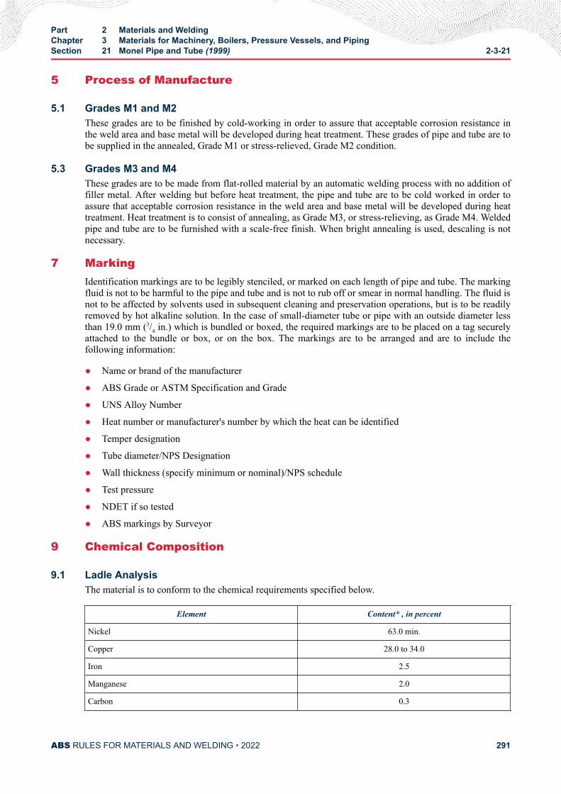
5 Process of Manufacture
5.1 Grades M1 and M2These grades are to be finished by cold-working in order to assure that acceptable corrosion resistance inthe weld area and base metal will be developed during heat treatment. These grades of pipe and tube are tobe supplied in the annealed, Grade M1 or stress-relieved, Grade M2 condition.
5.3 Grades M3 and M4These grades are to be made from flat-rolled material by an automatic welding process with no addition offiller metal. After welding but before heat treatment, the pipe and tube are to be cold worked in order toassure that acceptable corrosion resistance in the weld area and base metal will be developed during heattreatment. Heat treatment is to consist of annealing, as Grade M3, or stress-relieving, as Grade M4. Weldedpipe and tube are to be furnished with a scale-free finish. When bright annealing is used, descaling is notnecessary.
7 MarkingIdentification markings are to be legibly stenciled, or marked on each length of pipe and tube. The markingfluid is not to be harmful to the pipe and tube and is not to rub off or smear in normal handling. The fluid isnot to be affected by solvents used in subsequent cleaning and preservation operations, but is to be readilyremoved by hot alkaline solution. In the case of small-diameter tube or pipe with an outside diameter lessthan 19.0 mm (3/4 in.) which is bundled or boxed, the required markings are to be placed on a tag securelyattached to the bundle or box, or on the box. The markings are to be arranged and are to include thefollowing information:
● Name or brand of the manufacturer
● ABS Grade or ASTM Specification and Grade
● UNS Alloy Number
● Heat number or manufacturer's number by which the heat can be identified
● Temper designation
● Tube diameter/NPS Designation
● Wall thickness (specify minimum or nominal)/NPS schedule
● Test pressure
● NDET if so tested
● ABS markings by Surveyor
9 Chemical Composition
9.1 Ladle AnalysisThe material is to conform to the chemical requirements specified below.
Element Content* , in percent
Nickel 63.0 min.
Copper 28.0 to 34.0
Iron 2.5
Manganese 2.0
Carbon 0.3
Part 2 Materials and WeldingChapter 3 Materials for Machinery, Boilers, Pressure Vessels, and PipingSection 21 Monel Pipe and Tube (1999) 2-3-21
ABS RULES FOR MATERIALS AND WELDING • 2022 291
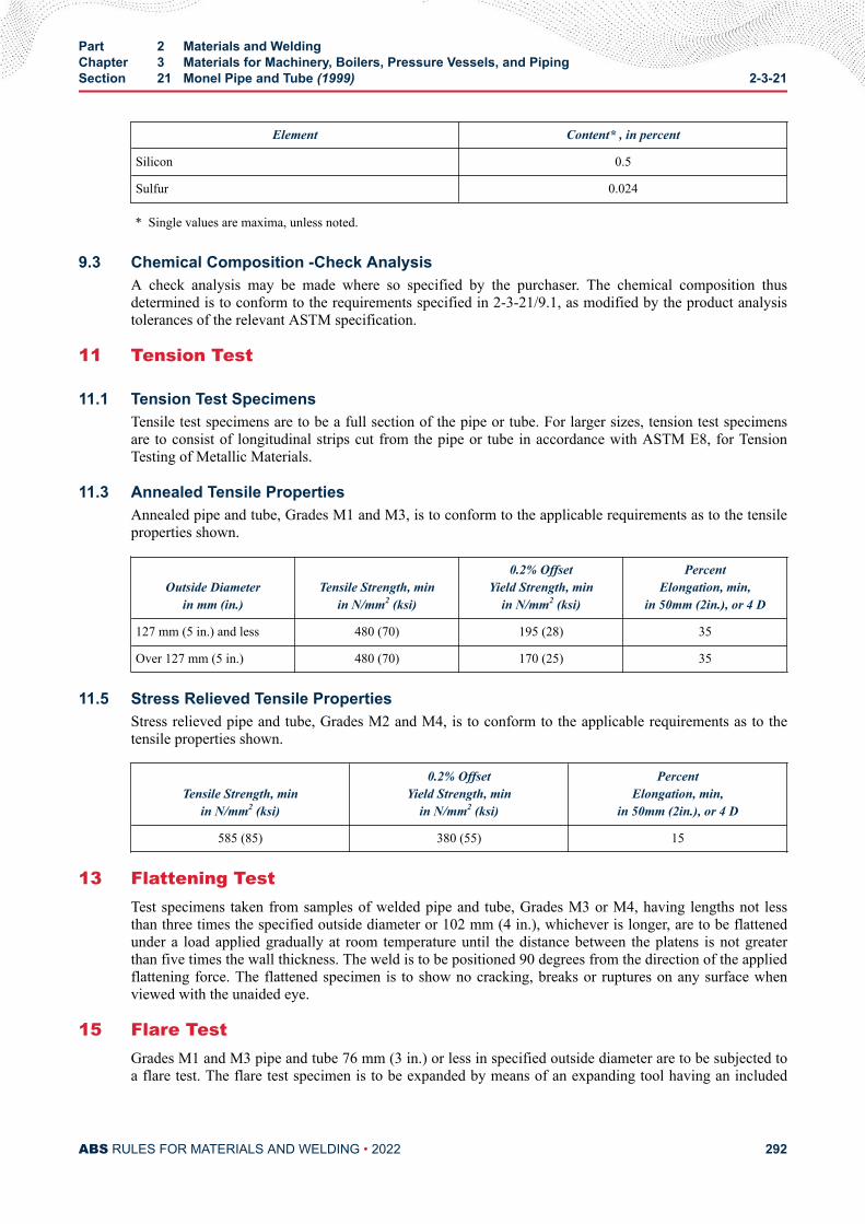
Element Content* , in percent
Silicon 0.5
Sulfur 0.024
* Single values are maxima, unless noted.
9.3 Chemical Composition -Check AnalysisA check analysis may be made where so specified by the purchaser. The chemical composition thusdetermined is to conform to the requirements specified in 2-3-21/9.1, as modified by the product analysistolerances of the relevant ASTM specification.
11 Tension Test
11.1 Tension Test SpecimensTensile test specimens are to be a full section of the pipe or tube. For larger sizes, tension test specimensare to consist of longitudinal strips cut from the pipe or tube in accordance with ASTM E8, for TensionTesting of Metallic Materials.
11.3 Annealed Tensile PropertiesAnnealed pipe and tube, Grades M1 and M3, is to conform to the applicable requirements as to the tensileproperties shown.
Outside Diameterin mm (in.)
Tensile Strength, minin N/mm2 (ksi)
0.2% OffsetYield Strength, min
in N/mm2 (ksi)
PercentElongation, min,
in 50mm (2in.), or 4 D
127 mm (5 in.) and less 480 (70) 195 (28) 35
Over 127 mm (5 in.) 480 (70) 170 (25) 35
11.5 Stress Relieved Tensile PropertiesStress relieved pipe and tube, Grades M2 and M4, is to conform to the applicable requirements as to thetensile properties shown.
Tensile Strength, minin N/mm2 (ksi)
0.2% OffsetYield Strength, min
in N/mm2 (ksi)
PercentElongation, min,
in 50mm (2in.), or 4 D
585 (85) 380 (55) 15
13 Flattening TestTest specimens taken from samples of welded pipe and tube, Grades M3 or M4, having lengths not lessthan three times the specified outside diameter or 102 mm (4 in.), whichever is longer, are to be flattenedunder a load applied gradually at room temperature until the distance between the platens is not greaterthan five times the wall thickness. The weld is to be positioned 90 degrees from the direction of the appliedflattening force. The flattened specimen is to show no cracking, breaks or ruptures on any surface whenviewed with the unaided eye.
15 Flare TestGrades M1 and M3 pipe and tube 76 mm (3 in.) or less in specified outside diameter are to be subjected toa flare test. The flare test specimen is to be expanded by means of an expanding tool having an included
Part 2 Materials and WeldingChapter 3 Materials for Machinery, Boilers, Pressure Vessels, and PipingSection 21 Monel Pipe and Tube (1999) 2-3-21
ABS RULES FOR MATERIALS AND WELDING • 2022 292
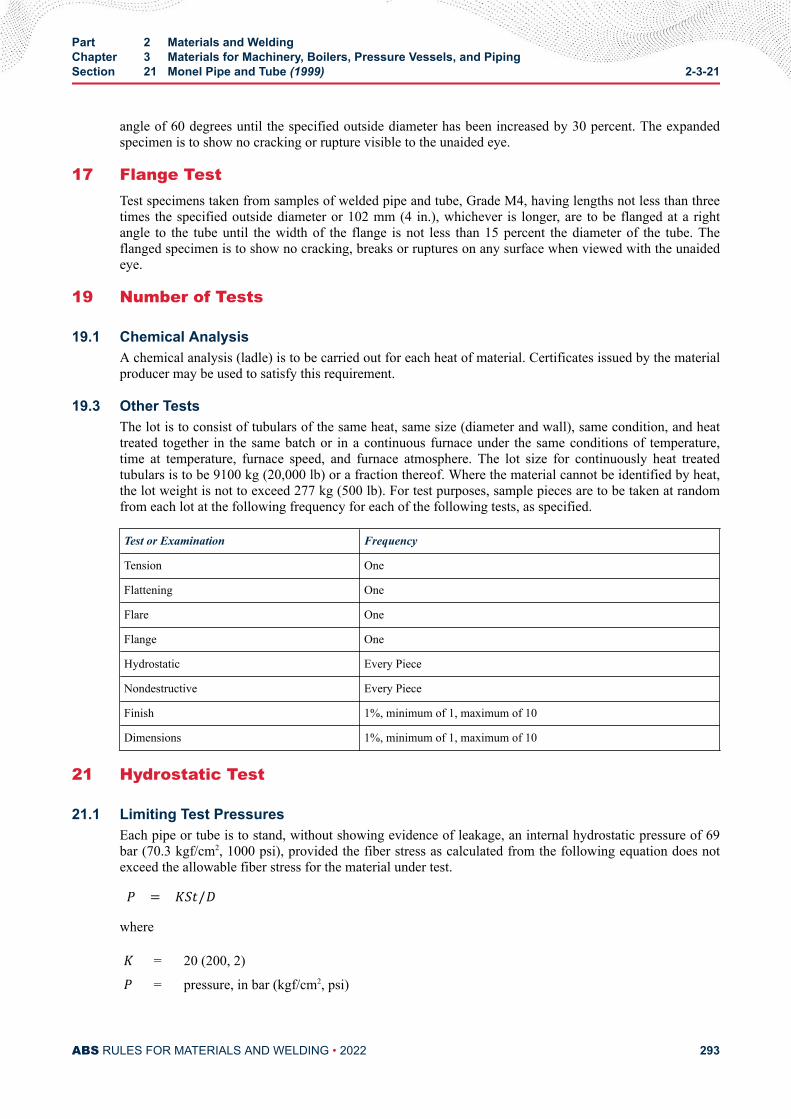
angle of 60 degrees until the specified outside diameter has been increased by 30 percent. The expandedspecimen is to show no cracking or rupture visible to the unaided eye.
17 Flange TestTest specimens taken from samples of welded pipe and tube, Grade M4, having lengths not less than threetimes the specified outside diameter or 102 mm (4 in.), whichever is longer, are to be flanged at a rightangle to the tube until the width of the flange is not less than 15 percent the diameter of the tube. Theflanged specimen is to show no cracking, breaks or ruptures on any surface when viewed with the unaidedeye.
19 Number of Tests
19.1 Chemical AnalysisA chemical analysis (ladle) is to be carried out for each heat of material. Certificates issued by the materialproducer may be used to satisfy this requirement.
19.3 Other TestsThe lot is to consist of tubulars of the same heat, same size (diameter and wall), same condition, and heattreated together in the same batch or in a continuous furnace under the same conditions of temperature,time at temperature, furnace speed, and furnace atmosphere. The lot size for continuously heat treatedtubulars is to be 9100 kg (20,000 lb) or a fraction thereof. Where the material cannot be identified by heat,the lot weight is not to exceed 277 kg (500 lb). For test purposes, sample pieces are to be taken at randomfrom each lot at the following frequency for each of the following tests, as specified.
Test or Examination Frequency
Tension One
Flattening One
Flare One
Flange One
Hydrostatic Every Piece
Nondestructive Every Piece
Finish 1%, minimum of 1, maximum of 10
Dimensions 1%, minimum of 1, maximum of 10
21 Hydrostatic Test
21.1 Limiting Test PressuresEach pipe or tube is to stand, without showing evidence of leakage, an internal hydrostatic pressure of 69bar (70.3 kgf/cm2, 1000 psi), provided the fiber stress as calculated from the following equation does notexceed the allowable fiber stress for the material under test. P = KSt/DwhereK = 20 (200, 2)P = pressure, in bar (kgf/cm2, psi)
Part 2 Materials and WeldingChapter 3 Materials for Machinery, Boilers, Pressure Vessels, and PipingSection 21 Monel Pipe and Tube (1999) 2-3-21
ABS RULES FOR MATERIALS AND WELDING • 2022 293
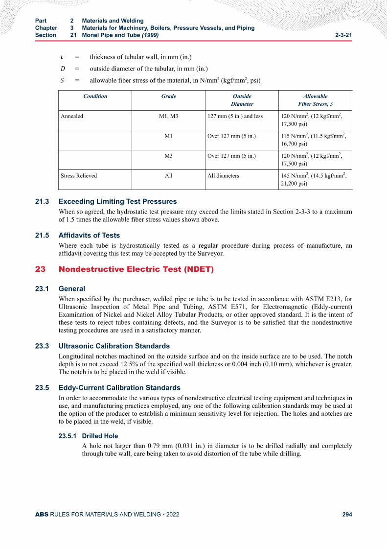
t = thickness of tubular wall, in mm (in.)D = outside diameter of the tubular, in mm (in.)S = allowable fiber stress of the material, in N/mm2 (kgf/mm2, psi)
Condition Grade OutsideDiameter
AllowableFiber Stress, S
Annealed M1, M3 127 mm (5 in.) and less 120 N/mm2, (12 kgf/mm2,17,500 psi)
M1 Over 127 mm (5 in.) 115 N/mm2, (11.5 kgf/mm2,16,700 psi)
M3 Over 127 mm (5 in.) 120 N/mm2, (12 kgf/mm2,17,500 psi)
Stress Relieved All All diameters 145 N/mm2, (14.5 kgf/mm2,21,200 psi)
21.3 Exceeding Limiting Test PressuresWhen so agreed, the hydrostatic test pressure may exceed the limits stated in Section 2-3-3 to a maximumof 1.5 times the allowable fiber stress values shown above.
21.5 Affidavits of TestsWhere each tube is hydrostatically tested as a regular procedure during process of manufacture, anaffidavit covering this test may be accepted by the Surveyor.
23 Nondestructive Electric Test (NDET)
23.1 GeneralWhen specified by the purchaser, welded pipe or tube is to be tested in accordance with ASTM E213, forUltrasonic Inspection of Metal Pipe and Tubing, ASTM E571, for Electromagnetic (Eddy-current)Examination of Nickel and Nickel Alloy Tubular Products, or other approved standard. It is the intent ofthese tests to reject tubes containing defects, and the Surveyor is to be satisfied that the nondestructivetesting procedures are used in a satisfactory manner.
23.3 Ultrasonic Calibration StandardsLongitudinal notches machined on the outside surface and on the inside surface are to be used. The notchdepth is to not exceed 12.5% of the specified wall thickness or 0.004 inch (0.10 mm), whichever is greater.The notch is to be placed in the weld if visible.
23.5 Eddy-Current Calibration StandardsIn order to accommodate the various types of nondestructive electrical testing equipment and techniques inuse, and manufacturing practices employed, any one of the following calibration standards may be used atthe option of the producer to establish a minimum sensitivity level for rejection. The holes and notches areto be placed in the weld, if visible.
23.5.1 Drilled HoleA hole not larger than 0.79 mm (0.031 in.) in diameter is to be drilled radially and completelythrough tube wall, care being taken to avoid distortion of the tube while drilling.
Part 2 Materials and WeldingChapter 3 Materials for Machinery, Boilers, Pressure Vessels, and PipingSection 21 Monel Pipe and Tube (1999) 2-3-21
ABS RULES FOR MATERIALS AND WELDING • 2022 294
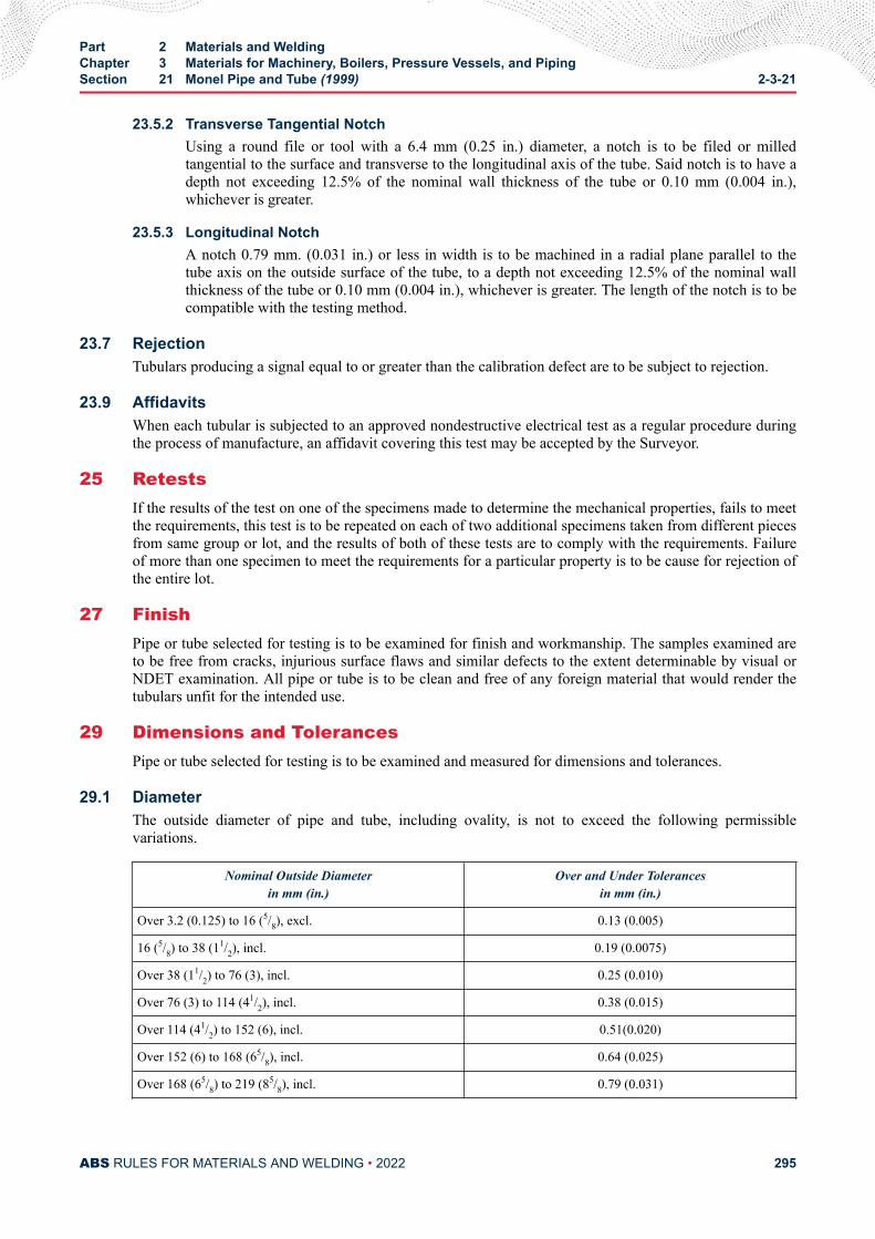
23.5.2 Transverse Tangential NotchUsing a round file or tool with a 6.4 mm (0.25 in.) diameter, a notch is to be filed or milledtangential to the surface and transverse to the longitudinal axis of the tube. Said notch is to have adepth not exceeding 12.5% of the nominal wall thickness of the tube or 0.10 mm (0.004 in.),whichever is greater.
23.5.3 Longitudinal NotchA notch 0.79 mm. (0.031 in.) or less in width is to be machined in a radial plane parallel to thetube axis on the outside surface of the tube, to a depth not exceeding 12.5% of the nominal wallthickness of the tube or 0.10 mm (0.004 in.), whichever is greater. The length of the notch is to becompatible with the testing method.
23.7 RejectionTubulars producing a signal equal to or greater than the calibration defect are to be subject to rejection.
23.9 AffidavitsWhen each tubular is subjected to an approved nondestructive electrical test as a regular procedure duringthe process of manufacture, an affidavit covering this test may be accepted by the Surveyor.
25 RetestsIf the results of the test on one of the specimens made to determine the mechanical properties, fails to meetthe requirements, this test is to be repeated on each of two additional specimens taken from different piecesfrom same group or lot, and the results of both of these tests are to comply with the requirements. Failureof more than one specimen to meet the requirements for a particular property is to be cause for rejection ofthe entire lot.
27 FinishPipe or tube selected for testing is to be examined for finish and workmanship. The samples examined areto be free from cracks, injurious surface flaws and similar defects to the extent determinable by visual orNDET examination. All pipe or tube is to be clean and free of any foreign material that would render thetubulars unfit for the intended use.
29 Dimensions and TolerancesPipe or tube selected for testing is to be examined and measured for dimensions and tolerances.
29.1 DiameterThe outside diameter of pipe and tube, including ovality, is not to exceed the following permissiblevariations.
Nominal Outside Diameterin mm (in.)
Over and Under Tolerancesin mm (in.)
Over 3.2 (0.125) to 16 (5/8), excl. 0.13 (0.005)
16 (5/8) to 38 (11/2), incl. 0.19 (0.0075)
Over 38 (11/2) to 76 (3), incl. 0.25 (0.010)
Over 76 (3) to 114 (41/2), incl. 0.38 (0.015)
Over 114 (41/2) to 152 (6), incl. 0.51(0.020)
Over 152 (6) to 168 (65/8), incl. 0.64 (0.025)
Over 168 (65/8) to 219 (85/8), incl. 0.79 (0.031)
Part 2 Materials and WeldingChapter 3 Materials for Machinery, Boilers, Pressure Vessels, and PipingSection 21 Monel Pipe and Tube (1999) 2-3-21
ABS RULES FOR MATERIALS AND WELDING • 2022 295
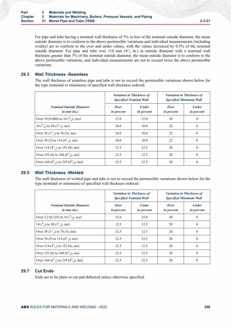
For pipe and tube having a nominal wall thickness of 3% or less of the nominal outside diameter, the meanoutside diameter is to conform to the above permissible variations and individual measurements (includingovality) are to conform to the over and under values, with the values increased by 0.5% of the nominaloutside diameter. For pipe and tube over 114 mm (41/2 in.) in outside diameter with a nominal wallthickness greater than 3% of the nominal outside diameter, the mean outside diameter is to conform to theabove permissible variations, and individual measurements are not to exceed twice the above permissiblevariations.
29.3 Wall Thickness -SeamlessThe wall thickness of seamless pipe and tube is not to exceed the permissible variations shown below forthe type (nominal or minimum) of specified wall thickness ordered.
Nominal Outside Diameterin mm (in.)
Variation in Thickness ofSpecified Nominal Wall
Variation in Thickness ofSpecified Minimum Wall
Overin percent
Underin percent
Overin percent
Underin percent
Over 10 (0.400) to 16 (5/8), excl. 15.0 15.0 30 0
16 (5/8) to 38 (11/2), incl. 10.0 10.0 22 0
Over 38 (11/2) to 76 (3), incl. 10.0 10.0 22 0
Over 76 (3) to 114 (41/2), incl. 10.0 10.0 22 0
Over 114 (41/2) to 152 (6), incl. 12.5 12.5 28 0
Over 152 (6) to 168 (65/8), incl. 12.5 12.5 28 0
Over 168 (65/8) to 219 (85/8), incl. 12.5 12.5 28 0
29.5 Wall Thickness -WeldedThe wall thickness of welded pipe and tube is not to exceed the permissible variations shown below for thetype (nominal or minimum) of specified wall thickness ordered.
Nominal Outside Diameterin mm (in.)
Variation in Thickness ofSpecified Nominal Wall
Variation in Thickness ofSpecified Minimum Wall
Overin percent
Underin percent
Overin percent
Underin percent
Over 3.2 (0.125) to 16 (5/8), excl 15.0 15.0 30 0
16 (5/8) to 38 (11/2), incl. 12.5 12.5 28 0
Over 38 (11/2) to 76 (3), incl. 12.5 12.5 28 0
Over 76 (3) to 114 (41/2), incl. 12.5 12.5 28 0
Over 114 (41/2) to 152 (6), incl. 12.5 12.5 28 0
Over 152 (6) to 168 (65/8), incl. 12.5 12.5 28 0
Over 168 (65/8) to 219 (85/8), incl. 12.5 12.5 28 0
29.7 Cut EndsEnds are to be plain or cut and deburred unless otherwise specified.
Part 2 Materials and WeldingChapter 3 Materials for Machinery, Boilers, Pressure Vessels, and PipingSection 21 Monel Pipe and Tube (1999) 2-3-21
ABS RULES FOR MATERIALS AND WELDING • 2022 296

29.9 StraightnessPipe and tube are to be reasonably straight and free of bends and kinks.
Part 2 Materials and WeldingChapter 3 Materials for Machinery, Boilers, Pressure Vessels, and PipingSection 21 Monel Pipe and Tube (1999) 2-3-21
ABS RULES FOR MATERIALS AND WELDING • 2022 297
C H A P T E R 4Welding and Fabrication
CONTENTSSECTION 1 Hull Construction.............................................................................306
1 General.......................................................................................3061.1 Hull Welding...................................................................3061.3 Plans and Specifications (2013).................................... 3061.5 Workmanship and Supervision...................................... 3061.7 Welding Procedures...................................................... 3061.9 TMCP Plates -Note to Users (1996).............................. 307
3 Preparation for Welding.............................................................. 3073.1 Edge Preparation and Fitting......................................... 3073.3 Alignment.......................................................................3073.5 Cleanliness.................................................................... 3073.7 Tack Welds.................................................................... 3083.9 Run-on and Run-off Tabs...............................................3083.11 Stud Welding................................................................. 3083.13 Forming (1 July 2013)....................................................308
5 Production Welding.....................................................................3085.1 Environment...................................................................3085.3 Sequence.......................................................................3085.5 Preheat and Interpass Temperature Control..................3095.7 Low-hydrogen Electrodes or Welding Processes.......... 3105.9 Back Gouging................................................................ 3105.11 Peening (2010).............................................................. 3115.12 Weld Profiling (2010)......................................................3115.13 Fairing and Flame Shrinking.......................................... 3115.15 Surface Appearance and Weld Soundness................... 3115.17 Inspection of Welds........................................................3115.19 Repair Welding (2006)...................................................3125.21 Fillet Weld Ends (2018)................................................. 3125.23 Post Weld Heat Treatment of Welds in Dissimilar
Materials (2011)............................................................. 3127 Butt Welds.................................................................................. 312
7.1 Manual Welding Using Covered Electrodes.................. 312
PART 2
ABS RULES FOR MATERIALS AND WELDING • 2022 298
7.3 Submerged-arc Welding................................................ 3137.5 Gas Metal-arc and Flux Cored-arc Welding (2005)....... 3137.7 Electroslag and Electrogas Welding.............................. 3137.9 Special Welding Processes and Techniques (2008)......313
FIGURE 1 Illustration of Setup to Qualify Weld Procedures withWater Backing....................................................................316
FIGURE 2 Fillet Weld Test Specimen..................................................317
SECTION 1 Appendix 1 - Welding In Way of Water Backing............................3141 General.......................................................................................314
1.1 Weld Procedure Qualification Requirements.................3141.3 Alternative Requirements.............................................. 315
3 Welding Procedure Qualification Tests....................................... 3153.1 General.......................................................................... 3153.3 Butt Weld Testing...........................................................3153.5 Fillet Weld Testing..........................................................3163.7 Acceptance Criteria....................................................... 3173.9 Approval Range............................................................. 317
FIGURE 1 Illustration of Setup to Qualify Weld Procedures withWater Backing....................................................................316
FIGURE 2 Fillet Weld Test Specimen..................................................317
SECTION 2 Boilers, Unfired Pressure Vessels, Piping and EngineeringStructures*........................................................................................3191 General Considerations .............................................................319
1.1 Fabrication..................................................................... 3191.3 Welding Approval (2010)............................................... 3191.5 Grouping of Welded Structures..................................... 3191.7 Weld Repairs to Ductile (Nodular) Iron.......................... 321
3 Plans and Specifications.............................................................3213.1 Details............................................................................3213.3 Base Materials............................................................... 321
5 Workmanship and Supervision................................................... 3215.1 Construction...................................................................3215.3 Joint Tolerance...............................................................3215.5 Surfaces of Parts........................................................... 3225.7 Out of Roundness..........................................................322
7 Details of Joints.......................................................................... 3227.1 Dimensions and Shape..................................................3227.3 Double-welded Butt Joints............................................. 3227.5 Single-welded Butt Joints.............................................. 3227.7 Joint Finish.....................................................................323
ABS RULES FOR MATERIALS AND WELDING • 2022 299
7.9 Lap Joints...................................................................... 3237.11 Head to Shell Attachments............................................ 3237.13 Bending Stresses in Welds............................................3237.15 Connections...................................................................3237.17 Nozzles.......................................................................... 3237.19 Limitations......................................................................324
9 Forms of Welded Joints Required.............................................. 3249.1 Boilers and Group I Pressure Vessels........................... 3249.3 Group II Pressure Vessels............................................. 3249.5 Group I Pipe Welded Joints........................................... 3259.7 Group II Pipe Welded Joints.......................................... 3259.9 Low-temperature Piping Systems [Below -18°C (0°F)]..3269.11 Engineering Structures.................................................. 326
11 Preheat....................................................................................... 32611.1 Boilers, Pressure Vessels, and Group I Piping.............. 32611.3 Group I Pipe Connections..............................................327
13 General Requirements for Postweld Heat Treatment.................32713.1 General.......................................................................... 32713.3 Heat-treatment Determination....................................... 327
15 Fusion-welded Boilers................................................................ 32715.1 Postweld Heat Treatment.............................................. 32715.3 Lower Temperatures - Carbon and Carbon
Molybdenum Steels....................................................... 32815.5 Heat-treatment Exceptions for Fusion-welded Boilers
- ABS Plate Grades MA, MB, MC, MD, ME, MF, MG,K, L, M, N, Tube Grades D, F, G, H, J and Group IPiping Grades 1, 2, 3, 4, 5, 8, and 9.............................. 328
15.7 Heat-treatment Exceptions for Fusion-welded Boilers- ABS Plate Grades H, I, J, Tube Grades K, L, M,and Group I Piping Grades 6 and 7............................... 329
15.9 Heat Treatment Exceptions for Fusion-weldedBoilers - ABS Tube Grades N, O and Group I PipeGrades 11 and 12.......................................................... 329
15.11 Heat Treatment Exceptions for Fusion WeldedBoilers - ABS Tube Grade P and Group I Pipe Grade13...................................................................................330
15.13 Other Materials.............................................................. 33015.15 Other Welded Connections............................................33015.17 Welded Joints................................................................ 331
17 Fusion-welded Pressure Vessels................................................33117.1 Postweld Heat Treatment.............................................. 33117.3 Heat-treatment Exceptions - ABS Plate Grades MA,
MB, MC, MD, ME, MF, MG, K, L, M, N and TubeGrades D, F, G, H, J...................................................... 331
17.5 Heat-treatment Exceptions - ABS Plate Grades, H, I,J and Tube Grades K, L, M............................................332
ABS RULES FOR MATERIALS AND WELDING • 2022 300
17.7 Heat-treatment Exceptions - Attachments..................... 33217.9 Other Materials.............................................................. 33217.11 Welded Connections......................................................332
19 Pipe Welded Joints and Engineering Structures........................ 33219.1 Group I Pipe Welded Joints........................................... 33219.3 Group II Pipe Welded Joints.......................................... 33319.5 Group I Engineering Structures..................................... 33319.7 Group II Engineering Structures.................................... 33319.9 Low-temperatures Piping Systems [Below -18°C (0°F)]333
21 Postweld Heat-treatment Details................................................ 33321.1 Boilers and Pressure Vessels........................................ 33321.3 Pipe Connections...........................................................33321.5 Other Steels...................................................................33321.7 Clad Pressure Vessels...................................................33321.9 Opening Connections.................................................... 33321.11 Seal Welding..................................................................334
23 Radiography............................................................................... 33423.1 General.......................................................................... 33423.3 Boilers............................................................................33423.5 Other Pressure Vessels................................................. 33423.7 Group I Pipe Connections (1999).................................. 33523.9 Group II Pipe Connections(1999).................................. 33523.11 Low Temperature Piping Connections [Below -18°C
(0°F)]..............................................................................33523.13 Group I Engineering Structures..................................... 33523.15 Group II Engineering Structures.................................... 33523.17 Engine Bedplates...........................................................33623.19 Miscellaneous................................................................ 336
25 Hydrostatic Test.......................................................................... 33625.1 Boilers and Pressure Vessels........................................ 33625.3 Piping.............................................................................33625.5 Defects...........................................................................33625.7 Retest............................................................................ 337
TABLE 1 Hydrostatic Testing of Piping..............................................336
FIGURE 1 Head to Shell Attachments.................................................338FIGURE 2 Types of Fusion-welded Construction Details....................341
SECTION 3 Weld Tests........................................................................................ 3441 General (2018)............................................................................344
1.1 Weld Groups..................................................................3441.3 Tests (2018)................................................................... 344
ABS RULES FOR MATERIALS AND WELDING • 2022 301
3 Filler Metals................................................................................ 3443.1 General (2018)...............................................................3443.3 Approval Basis (2005)................................................... 345
5 Approval of Welding Procedures................................................ 3455.1 Approved Filler Metals................................................... 3455.3 Surveyor's Acceptance.................................................. 3455.5 New Procedures and Methods...................................... 3455.7 Tests (2006)................................................................... 3455.9 Special Tests..................................................................3465.11 Repair and Cladding of Stern Tube and Tail Shafts.......346
7 Workmanship Tests.................................................................... 3467.1 Hull Construction........................................................... 3467.3 Boilers and Group I Pressure Vessels........................... 3467.5 Other Pressure Vessels................................................. 3477.7 Group I Pipe Connections..............................................3477.9 Group II Pipe Connections.............................................3477.11 Group I Engineering Structures..................................... 3477.13 Group II Engineering Structures.................................... 347
9 Radiographic or Ultrasonic Inspection........................................3479.1 Hull Construction........................................................... 3479.3 Boilers, Pressure Vessels, Machinery and Piping
(2014)............................................................................ 34711 Welders.......................................................................................348
11.1 General Requirements...................................................34811.3 Qualification Tests..........................................................34811.5 Tests Nos. Q1, Q2, and Q3 (2016)................................ 349
TABLE 1 Welder Qualification Tests (2010)...................................... 349TABLE 2 Minimum Average Weld Metal and HAZ CVN Impact
Values for ABS Grade Steels ............................................ 367
FIGURE 1 Preparation of Test Plates and Pipes for Weld TestsNos. 1 and 2.......................................................................351
FIGURE 2 Typical Arrangement of Test Plates for WorkmanshipTests in Group B1...............................................................353
FIGURE 3 Test No. 1 -Reduced-section Tension Test for Plate(2016).................................................................................354
FIGURE 4 Test No. 1 -Reduced-section Tension Test for Pipe (2016)355FIGURE 5 Test No. 2 - Guided Bend Test for Root Bend and Face
Bend(Plate or Pipe) (2007)................................................ 356FIGURE 6 Test No. 2 - Guided Bend Test for Side Bend (Plate or
Pipe)(1996)........................................................................ 356FIGURE 7 Guided Bend Test Jig (2016)..............................................357FIGURE 8 Test No. 3 -Fillet-weld Test.................................................358FIGURE 9 Welder Qualification Test No. Q1....................................... 359
ABS RULES FOR MATERIALS AND WELDING • 2022 302
FIGURE 10 Welder Qualification Test No. Q2....................................... 360FIGURE 11A Welder Qualification Test No. Q3 (2005)............................361FIGURE 11B Welder Qualification Test No. Q3 - 6GR............................ 362FIGURE 11C Welder Qualification Test No. Q3R (2014)......................... 363FIGURE 12 Welder Qualification Test No. Q4....................................... 365FIGURE 13 Orientation and Location of Charpy V-notch Specimens
for Weld and Heat Affected Zone Properties (2013).......... 366
SECTION 4 Piping................................................................................................ 3691 General.......................................................................................369
1.1 Application..................................................................... 3691.3 Pipe Classes..................................................................3691.5 Materials........................................................................ 3691.7 Welding Filler Metals..................................................... 370
3 Welding Procedures and Welders.............................................. 3703.1 Welding Procedures...................................................... 3703.3 Welders and Welding Operators....................................370
5 Types of Welded Joints...............................................................3715.1 Full Penetration Butt Joints............................................3715.3 Square-groove Butt Joint............................................... 3715.5 Fillet-welded Joints........................................................ 3715.7 Flange Attachment Welds..............................................3725.9 Branch Connections...................................................... 3725.11 Tack Welding................................................................. 3725.13 Brazing (2005)............................................................... 372
7 Preheat....................................................................................... 3729 Post-weld Heat Treatment.......................................................... 373
9.1 Procedure...................................................................... 3739.3 Requirement.................................................................. 373
11 Nondestructive Examination.......................................................37411.1 Visual Examination........................................................ 37411.3 Butt Weld Joints.............................................................37411.5 Fillet Weld Joints............................................................375
13 Weld Repair................................................................................ 37515 Pipe Forming and Bending......................................................... 375
15.1 Cold Forming................................................................. 37515.3 Hot Forming (2013)........................................................375
17 Additional Requirements for Low Temperature Piping [below-10°C (14°F)].............................................................................. 37617.1 Application..................................................................... 37617.3 Welding Procedure........................................................ 37617.5 Pipe Joints..................................................................... 37617.7 Post-weld Heat Treatment............................................. 37617.9 Nondestructive Examination.......................................... 376
ABS RULES FOR MATERIALS AND WELDING • 2022 303
SECTION 5 Aluminum Welding in Hull Construction (2018)............................3771 General.......................................................................................377
1.1 Hull Welding...................................................................3771.3 Plans and Specifications................................................3771.5 Workmanship and Supervision...................................... 3771.7 Welding Procedures...................................................... 377
3 Preparation for Welding.............................................................. 3783.1 Edge Preparation and Fitting......................................... 3783.3 Alignment.......................................................................3783.5 Cleanliness (2012).........................................................3803.7 Tack Welds.................................................................... 3803.9 Stud Welding................................................................. 3803.11 Temporary Back-up Plates and Tapes........................... 3813.13 Run-on and Run-off Tabs...............................................3813.15 Forming..........................................................................381
5 Production Welding.....................................................................3825.1 Environment...................................................................3825.3 Preheat.......................................................................... 3825.5 Postheating....................................................................3825.7 Accessibility................................................................... 3825.8 Avoiding Joint Corrosion................................................3825.9 Sequence.......................................................................3835.11 Back Gouging................................................................ 3835.13 Fairing and Flame Shrinking..........................................3835.15 Inspection of Welds....................................................... 3835.17 Workmanship Requirements......................................... 3865.19 Quality Control............................................................... 3875.21 Repair Welding.............................................................. 387
7 Butt Welds.................................................................................. 3877.1 Joint Design................................................................... 387
9 Fillet Welds................................................................................. 38711 Filler Metals................................................................................ 388
11.1 General.......................................................................... 38811.3 Approval Basis...............................................................388
13 Approval of Welding Procedures................................................ 38813.1 Approved Filler Metals................................................... 38813.3 Surveyor’s Acceptance..................................................38813.5 New Procedures and Methods...................................... 38813.7 Tests.............................................................................. 38813.9 Special Tests..................................................................389
15 Welder Qualifications..................................................................38915.1 General.......................................................................... 38915.3 Qualification Tests..........................................................389
17 Alternatives.................................................................................389
ABS RULES FOR MATERIALS AND WELDING • 2022 304
TABLE 1 Minimum Cold-forming Radii for Aluminum Alloys (1, 2, 3).... 381TABLE 2 Minimum Mechanical Properties for Butt-Welded
Aluminum Alloys.................................................................389TABLE 3 Aluminum Alloy Filler Metal Composition (2016)............... 390TABLE 4 Filler Metals for Welding Aluminum Alloy – Sheet, Plate
and Extrusions (2016)........................................................391TABLE 5 Filler Metals for Welding Aluminum Alloy Castings to
Castings and Plate.............................................................391TABLE 6 Welder Qualification Tests..................................................392
FIGURE 1A Inserts and Patches in Plating............................................379FIGURE 1B Inserts and Patches in Plating............................................380FIGURE 2 Repairs of Misalignments...................................................384FIGURE 3 Permissible Unfairness in Aluminum Welded Structure.....393FIGURE 4 Permissible Unfairness in Other Aluminum Welded
Structure.............................................................................394FIGURE 5 Preparation of Test Plates and Pipes for Weld Tests
Nos. 1 and 2.......................................................................395FIGURE 6 Typical Arrangement of Test Plates for Workmanship
Tests in Group B1...............................................................397FIGURE 7 Test No. 1 – Reduced-section Tension Test for Plate.........398FIGURE 8 Test No. 1 – Reduced-section Tension Test for Pipe..........399FIGURE 9 Test No. 2 – Guided Bend Test for Root Bend and Face
Bend (Plate or Pipe) (2007)............................................... 400FIGURE 10 Test No. 2 – Guided Bend Test for Side Bend (Plate or
Pipe)...................................................................................400FIGURE 11 Guided Bend Test Jig.........................................................400FIGURE 12 Alternative Guided Bend Test Jig.......................................402FIGURE 13 Test No. 3 – Fillet Weld Test (2013)................................... 402FIGURE 14 Welder Qualification Test No. Q1....................................... 403FIGURE 15 Welder Qualification Test No. Q2....................................... 404FIGURE 16 Welder Qualification Test No. Q4....................................... 406FIGURE 17 Welder Qualification Test No. Q5....................................... 408
ABS RULES FOR MATERIALS AND WELDING • 2022 305
C H A P T E R 4Welding and Fabrication
S E C T I O N 1Hull Construction (1 July 2021)
1 General
1.1 Hull Welding (1 July 2021)Welding in hull construction is to comply with the requirements of this section, unless specially approvedotherwise. It is recommended that appropriate permanent markings be applied to the side shell of weldedvessels to indicate the location of bulkheads for reference. In all instances welding procedures and fillermetals are to produce sound welds having strength and toughness comparable to the base material. Forweld design, see Section 3-2-19 of the Marine Vessel Rules.
In cases where welding is proposed with water backing, refer to Appendix 2-4-1-A1, which includesrequirements for qualification of weld procedures with water backing.
1.3 Plans and Specifications (2013)The plans submitted are to clearly indicate the proposed extent of welding to be used in the principal partsof the structure. The welding process, filler metal and joint design indicating full/partial penetration weldare to be shown on the detail drawings or in separate specifications submitted for approval which shoulddistinguish between manual and automatic welding. The shipbuilders are to prepare and file with theSurveyor a planned procedure to be followed in the erection and welding of the important structuralmembers.
1.5 Workmanship and SupervisionThe Surveyor is to satisfy himself that all welders and welding operators to be employed in theconstruction of vessels to be classed are properly qualified and are experienced in the work proposed. TheSurveyor is also to be satisfied as to the employment of a sufficient number of skilled supervisors to ensurea thorough supervision and control of all welding operations. Inspection of welds employing methodsoutlined in 2-4-1/5.17 is to be carried out to the satisfaction of the Surveyor.
1.7 Welding Procedures1.7.1 General (2021)
Welding procedures are to be qualified to Part 2, Appendix 9 or to equivalent recognized standardssuch as AWS, EN, ISO, ASME, MIL and JIS. Also refer to Section 2-4-3. which may be appliedas an alternative to Part 2, Appendix 9.
PART 2
ABS RULES FOR MATERIALS AND WELDING • 2022 306
Procedures for the welding of all joints are to be established before construction for the weldingprocesses, types of electrodes, edge preparations, welding techniques, and positions proposed. See2-4-3/5. Details of proposed welding procedures and sequences may be required to be submittedfor review depending on the intended application.
1.7.2 Weld Metal Toughness -Criteria for ABS Grades of Steel (2009)For steels shown in 2-1-2/15.9 TABLE 4 and 2-1-3/7.3 TABLE 4 of these Rules, and 2-1-8/5.11TABLE 5A of the ABS Rules for Materials and Welding (Part 2), Approved filler metalsappropriate to the grades shown in Part 2, Appendix 3 may be used.
1.7.3 Weld Metal Toughness -Criteria for Other SteelsWeld metal is to exhibit Charpy V-notch toughness values at least equivalent to transverse basemetal requirements (2/3 of the longitudinal base metal requirements).
1.9 TMCP Plates -Note to Users (1996)When considering thermo-mechanically controlled steels for further heating for forming or stress relieving,or for high heat input welding, the attention of the fabricator is drawn to the possible reduction in themechanical properties. A procedure test using representative material is to be considered.
3 Preparation for Welding
3.1 Edge Preparation and Fitting (1 July 2020)The edge preparation is to be accurate and uniform and the parts to be welded are to be fitted in accordancewith the approved joint detail. All means adopted for correcting improper fitting are to be to thesatisfaction of the Surveyor. The Surveyor may accept a welding procedure for build up of each edge thatdoes not exceed one half the thickness of the member or 12.5 mm (0.5 in.), whichever is the lesser. TheSurveyor may accept edge build up in excess of the above, up to the full thickness of the member on acase-by-case basis, provided the Surveyor is notified of such cases before the members are weldedtogether. Where plates to be joined differ in thickness and have an offset on either side of more than 4 mm(0.16 in.), a suitable transition taper is to be provided. For the transverse butts in bottom shell, sheer strake,and strength deck plating within the midship portion of the hull, and other joints which may be subject tocomparatively high stresses, the transition taper length is to be not less than three times the offset. Thetransition may be formed by tapering the thicker member or by specifying a weld joint design which willprovide the required transition.
3.3 AlignmentMeans are to be provided for maintaining the parts to be welded in correct position and alignment duringthe welding operation. In general, strong backs, or other appliances used for this purpose are to be soarranged as to allow for expansion and contraction during production welding. The removal of such itemsis to be carried out to the satisfaction of the Surveyor.
3.5 Cleanliness (2019)All surfaces to be welded are to be free from moisture, grease, loose mill scale, paint, and excessive rust.Primer coatings of ordinary thickness, thin coatings of linseed oil, or equivalent coatings may be used,provided it is demonstrated that their use has no adverse effect in the production of satisfactory welds. Slagand scale are to be removed not only from the edges to be welded but also from each pass or layer beforethe deposition of subsequent passes or layers. Weld joints prepared by arc-air gouging may requireadditional preparation by grinding or chipping and wire brushing prior to welding to minimize thepossibility of excessive carbon on the scarfed surfaces. Compliance with these cleanliness requirements isof prime importance in the welding of higher-strength steels, especially those which are quenched andtempered.
Part 2 Materials and WeldingChapter 4 Welding and FabricationSection 1 Hull Construction 2-4-1
ABS RULES FOR MATERIALS AND WELDING • 2022 307
3.7 Tack WeldsTack welds of consistently good quality, made with the same grade of filler metal as intended forproduction welding and deposited in such a manner as not to interfere with the completion of the finalweld, need not be removed, provided they are found upon examination to be thoroughly clean and freefrom cracks or other defects. Preheat may be necessary prior to tack welding when the materials to bejoined are highly restrained. Special consideration is to be given to use the same preheat as specified in thewelding procedure when tack welding higher-strength steels, particularly those materials which arequenched and tempered. These same precautions are to be followed when making any permanent weldedmarkings.
3.9 Run-on and Run-off TabsWhen used, run-on and run-off tabs are to be designed to minimize the possibility of high-stressconcentrations and base-metal and weld-metal cracking.
3.11 Stud WeldingThe attachment of pins, hangers, studs, and other related items to ordinary and higher-strength hullstructural steels or equivalent by stud welding may be approved at the discretion of the Surveyor. Studwelded attachment to quenched and tempered steel is to be specially approved. At the Surveyor’sdiscretion, trial stud welds may be tested to demonstrate that the base material in way of the stud welds isfree from cracking and excessively high hardness. The use of stud welding for structural attachments issubject to special approval and may require special procedure tests appropriate to each application.
3.13 Forming (1 July 2013)Steel is not to be formed between the upper and lower critical temperatures; forming of ordinary-strengthand higher-strength steel in the range between 205°C (400°F) and 425°C (800°F) should be avoided.Forming of high-strength quenched and tempered steel in the range between 260°C (500°F) and 595°C(1100°F) should be avoided. If it is intended to form within these ranges for either of the above steels, themanufacturer should be consulted prior to forming. If the forming temperature exceeds 650°C (1200°F) foras-rolled, controlled rolled, thermo-mechanical controlled rolled or normalized steels, or is not at least28°C (50°F) lower than the tempering temperature for quenched and tempered steels, mechanical tests areto be made to assure that these temperatures have not adversely affected the mechanical properties of thesteel. See 2-4-1/1.9.
For applications where toughness is of particular concern (such as Class III in 3-1-2/3.3 TABLE 2A of theMarine Vessel Rules), when steel is formed below 650°C (1200°F) beyond 3% strain* on the outer fiber,supporting data is to be provided to the satisfaction of the Surveyor indicating that the impact propertiesmeet minimum requirements after forming. After straining, specimens used in Charpy impact tests are tobe subjected to an artificial aging treatment of 250°C (480°F) for one (1) hour before testing. Rule steels of2-1-2/15.9 TABLE 5 and 2-1-3/7.3 TABLE 5 or equivalent steels used for radius gunwales (in accordancewith 3-1-2/3.3 TABLE 1 of the Marine Vessel Rules) may be cold formed to a minimum radius of 15twithout requiring stress relieving or other supporting data.* Calculated on the basis of % strain = 65 × plate thicknessouter radius
5 Production Welding
5.1 EnvironmentProper precautions are to be taken to insure that all welding is done under conditions where the weldingsite is protected against the deleterious effects of moisture, wind and severe cold.
5.3 SequenceWelding is to be planned to progress symmetrically so that shrinkage on both sides of the structure will beequalized. The ends of frames and stiffeners should be left unattached to the plating at the subassembly
Part 2 Materials and WeldingChapter 4 Welding and FabricationSection 1 Hull Construction 2-4-1
ABS RULES FOR MATERIALS AND WELDING • 2022 308
stage until connecting welds are made in the intersecting systems of plating, framing and stiffeners at theerection stage. Welds are not to be carried across an unwelded joint or beyond an unwelded joint whichterminates at the joint being welded unless specially approved.
5.5 Preheat and Interpass Temperature Control (1 July 2018)Preheat and interpass temperatures are to be in accordance with the approved welding procedurespecification; that is appropriate to the alloy chemistry and thickness.
An increase in specified preheat is to be considered during the weld procedure qualification for steels withspecific property requirements, such as, high toughness, extra high strength, crack arrest and enhancedcorrosion resistance.
The minimum preheat temperature is to be maintained throughout all welding operations, including tackwelds and temporary attachment welds.
The minimum and maximum interpass temperatures are to be maintained within the qualified WPS rangesthroughout all welding operations, including tack welds and temporary attachment welds.
In all cases, preheat and interpass temperature control are to be sufficient to maintain dry surfaces andminimize the possibility of the formation of fractures.
When welding is performed under high humidity conditions or when the temperature of steel is below 0°C(32°F), the base metal is to be preheated to at least 20°C (70°F) or as specified in the WPS, whichever isthe higher.
Particular close attention to control, with verification by the ABS Surveyor, of preheat and interpasstemperature (using calibrated equipment) is to be applied when welding extra-high-strength steels, forgingsand castings, and materials of thick cross-section or materials subject to high restraint, for example,cruciform T butt welds.
If any of the following apply, an increase in preheat temperature is to be considered:
i) Structural members in critical areas
ii) Members such as cruciform joints which have high restraint
iii) Increased material thickness as combined thickness; over 25 mm (1 in.), over 50 mm (2 in.), over70 mm (2.8 in.), over 100 mm (4.0 in.)
iv) Welding connections of castings to thick rolled plates or large structures, which could act as heatsinks
v) Any weld repairs
vi) Higher Carbon content or high Carbon equivalent
Note:
Depending upon the welding code applied (e.g., AWS D1.1, ASME IX), a requalification of a WPS with a higher preheatmight be required.
Calculation of Combined Thickness below:
Combined thickness tcomb = t1+ t2+ t3+ t4 , see figure
Part 2 Materials and WeldingChapter 4 Welding and FabricationSection 1 Hull Construction 2-4-1
ABS RULES FOR MATERIALS AND WELDING • 2022 309
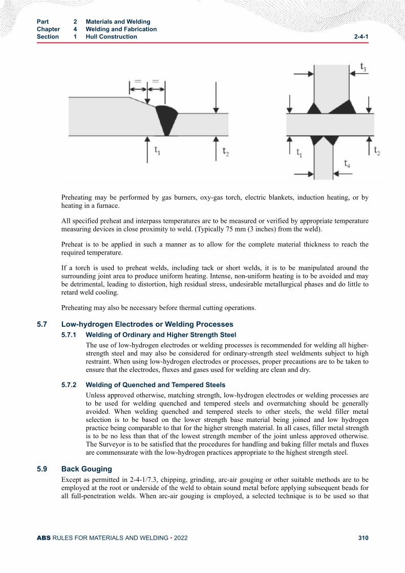
Preheating may be performed by gas burners, oxy-gas torch, electric blankets, induction heating, or byheating in a furnace.
All specified preheat and interpass temperatures are to be measured or verified by appropriate temperaturemeasuring devices in close proximity to weld. (Typically 75 mm (3 inches) from the weld).
Preheat is to be applied in such a manner as to allow for the complete material thickness to reach therequired temperature.
If a torch is used to preheat welds, including tack or short welds, it is to be manipulated around thesurrounding joint area to produce uniform heating. Intense, non-uniform heating is to be avoided and maybe detrimental, leading to distortion, high residual stress, undesirable metallurgical phases and do little toretard weld cooling.
Preheating may also be necessary before thermal cutting operations.
5.7 Low-hydrogen Electrodes or Welding Processes5.7.1 Welding of Ordinary and Higher Strength Steel
The use of low-hydrogen electrodes or welding processes is recommended for welding all higher-strength steel and may also be considered for ordinary-strength steel weldments subject to highrestraint. When using low-hydrogen electrodes or processes, proper precautions are to be taken toensure that the electrodes, fluxes and gases used for welding are clean and dry.
5.7.2 Welding of Quenched and Tempered SteelsUnless approved otherwise, matching strength, low-hydrogen electrodes or welding processes areto be used for welding quenched and tempered steels and overmatching should be generallyavoided. When welding quenched and tempered steels to other steels, the weld filler metalselection is to be based on the lower strength base material being joined and low hydrogenpractice being comparable to that for the higher strength material. In all cases, filler metal strengthis to be no less than that of the lowest strength member of the joint unless approved otherwise.The Surveyor is to be satisfied that the procedures for handling and baking filler metals and fluxesare commensurate with the low-hydrogen practices appropriate to the highest strength steel.
5.9 Back GougingExcept as permitted in 2-4-1/7.3, chipping, grinding, arc-air gouging or other suitable methods are to beemployed at the root or underside of the weld to obtain sound metal before applying subsequent beads forall full-penetration welds. When arc-air gouging is employed, a selected technique is to be used so that
Part 2 Materials and WeldingChapter 4 Welding and FabricationSection 1 Hull Construction 2-4-1
ABS RULES FOR MATERIALS AND WELDING • 2022 310
carbon buildup and burning of the weld or base metal is minimized. Quenched and tempered steels are notto be flame gouged.
5.11 Peening (2010)Peening, when used to correct distortion, is to be effected immediately after depositing and cleaning eachweld pass. The use of peening is not recommended for single-pass welds, the root or cover passes onmultipass welds, or on the base metal at the edges of the weld except as provided in 2-4-1/5.12 to enhancefatigue life.
5.12 Weld Profiling (2010)For fatigue life enhancement, weld profiling may be carried out (e.g., in critical areas). Welds may beprofiled using grinding, TIG dressing, or peening, at weld toes to the satisfaction of the attending Surveyor.
5.13 Fairing and Flame ShrinkingFairing by heating or flame shrinking and other methods of correcting distortion or defective workmanshipin fabrication of main strength members within the midship portion of the vessel and other plating whichmay be subject to high stresses is to be carried out only with the express approval of the Surveyor. Thesecorrective measures are to be kept to an absolute minimum when the higher-strength steels are involved,due to high local stresses and the possible degradation of the mechanical properties of the base material.See 2-4-1/1.9.
5.15 Surface Appearance and Weld Soundness5.15.1 Surface Appearance (2011)
The surfaces of welds are to be visually inspected and are to be regular and uniform with aminimum amount of reinforcement and reasonably free from undercut and overlap. Welds andadjacent base metal are to be free from injurious arc strikes. In seawater ballast tanks as requiredby IMO Resolution MSC.215(82) and ISO 8501-3 Grade P2, welds and surrounding areas are toconform as follows:
● Surfaces are to be free of all loose and lightly adhering weld spatter.
● Surfaces are to be dressed (e.g., by grinding) to remove irregular and sharp-edged profiles.
● Surfaces are to be free from slag.
● Surfaces are to be free from sharp or deep undercut.
● Surface pores are to be sufficiently open to allow penetration of paint or are to be dressed out.
● End craters are to be free from sharp edges.
5.15.2 Weld SoundnessWelds are to be sound, crack free throughout the weld cross section, and fused to the base materialto the satisfaction of the attending Surveyor and should generally be considered on the basis of2-4-1/1.5 "Workmanship and Supervision", 2-4-1/1.7 "Welding Procedure Qualification", and2-4-1/5.17 "Nondestructive Inspection of Welds".
5.17 Inspection of Welds (2020)Inspection of welded joints in important locations is to be carried out by an approved nondestructive testmethod such as radiographic, ultrasonic, magnetic-particle or dye-penetrant inspection. ABS’s separatelyissued Guide for Nondestructive Inspection or an approved equivalent standard is to be used in evaluatingradiographs and ultrasonic indications. Evaluation of radiographs and ultrasonic indications is one of thefactors in assessing shipyard weld quality control. Radiographic or ultrasonic inspection, or both, is to beused when the overall soundness of the weld cross section is to be evaluated. Magnetic-particle or dye-penetrant inspection or other approved methods are to be used when investigating the outer surface ofwelds or may be used as a check of intermediate weld passes such as root passes and also to check back-
Part 2 Materials and WeldingChapter 4 Welding and FabricationSection 1 Hull Construction 2-4-1
ABS RULES FOR MATERIALS AND WELDING • 2022 311
gouged joints prior to depositing subsequent passes. Surface inspection of important tee or corner joints incritical locations, using an approved magnetic particle or dye penetrant method, is to be conducted to thesatisfaction of the Surveyor. Extra high-strength steels, [415-960 N/mm2 (42-98 kgf/mm2, 60,000-139,000psi) minimum yield strength] may be susceptible to delayed cracking. When welding these materials, thefinal nondestructive testing is to be delayed sufficiently to permit detection of such defects in accordancewith 1/2.5 of the ABS Guide for Nondestructive Inspection. Weld run-on or run-off tabs may be usedwhere practical and be sectioned for examination. Where a method (such as radiographic or ultrasonic) isselected as the primary nondestructive method of inspection, the acceptance standards of such a methodgoverns. However, if additional inspection by any method should indicate the presence of defects thatcould jeopardize the integrity of structure, removal and repair of such defects are to be to the satisfaction ofthe attending Surveyor.
5.19 Repair Welding (2006)Defective welds and other injurious defects, including base metal defects, as determined by visualinspection, nondestructive test methods, or leakage are to be excavated in way of the defects to soundmetal and corrected by rewelding, using a suitable repair welding procedure to be consistent with thematerial being welded. Removal by grinding of minor surface imperfections such as scars, tack welds andarc strikes may be permitted at the discretion of the attending Surveyor. Special precautions, such as theuse of preheat, interpass temperature control, and low-hydrogen electrodes, are to be considered whenrepairing welds in all higher strength steel, ordinary strength steel of thick cross section, or steel subject tohigh restraint. Materials thicker than approximately 19 mm (3/4 in.) are considered to be of thick cross-section. In all cases, preheat and interpass temperature control are to be sufficient to maintain dry surfacesand minimize the possibility of the formation of fractures.
5.19.1 Repair to Casting Defect Identified after Machining or During Assembly (2017)After it has been agreed, by the attending Surveyor, that a casting can be repaired by welding, fulldetails of the extent and location of the repair are to be submitted for approval together with thequalified welding procedures, welders’ qualifications, heat treatment (if applicable) andsubsequent inspection procedures.
Defects are to be removed to sound metal, and the excavation is to be investigated by suitableapproved nondestructive examination methods to confirm that the defect has been removed.Corrective welding is to be associated with the use of preheat.
Temporary welds made to castings (for operations such as lifting, handling, staging etc) are to becarried out to qualified welding procedures and are to be removed, ground and inspected usingsuitable approved, nondestructive examination methods.
5.21 Fillet Weld Ends (2018)The ends of continuous fillet welds should be seal welded (wrapped) at terminations of structural membersand in way of cut-outs or holes and along all edges of any provided brackets.
5.23 Post Weld Heat Treatment of Welds in Dissimilar Materials (2011)Post weld heat treatment of welds between dissimilar materials, carbon steel to stainless steels or highalloy steels, including weld metal overlay clad base material or parts, requires the prior approval of ABSMaterials.
7 Butt Welds
7.1 Manual Welding Using Covered ElectrodesManual welding using covered electrodes may be ordinarily employed for butt welds in members notexceeding 6.5 mm (1/4 in.) in thickness without beveling the abutting edges. Members exceeding 6.5 mm(1/4 in.) are to be prepared for welding in a manner acceptable to the Surveyor by using an appropriate edge
Part 2 Materials and WeldingChapter 4 Welding and FabricationSection 1 Hull Construction 2-4-1
ABS RULES FOR MATERIALS AND WELDING • 2022 312
preparation, root opening and root face (land) to provide for welding from one or both sides. For weldsmade from both sides, the root of the first side welded is to be removed to sound metal by an approvedmethod before applying subsequent weld passes on the reverse side. Where welding is to be depositedfrom one side only, using ordinary welding techniques, appropriate backing (either permanent ortemporary) is to be provided. The backing is to be fitted so that spacing between the backing and themembers to be joined is in accordance with established procedures. Unless specially approved otherwise,splices in permanent backing strips are to be welded with full penetration welds prior to making theprimary weld.
7.3 Submerged-arc WeldingSubmerged-arc welding, using wire-flux combinations for butt welds in members not exceeding 16 mm (5/8in.) in thickness, may be ordinarily employed without beveling the abutting edges. Members exceeding 16mm (5/8 in.) are normally to be prepared for welding in a manner acceptable to the Surveyor by using anappropriate edge preparation, root opening and root face (land) to provide for welding from one or bothsides. When it is determined that sound welds can be made without back gouging, the provisions 2-4-1/5.9are not applicable. Where the metal is to be deposited from one side only, using ordinary weldingtechniques, backing (either permanent or temporary) is to be provided and the members are to be beveledand fitted in accordance with established procedures.
7.5 Gas Metal-arc and Flux Cored-arc Welding (2005)Semiautomatic or mechanized gas metal-arc welding and flux cored-arc welding using wire-gascombinations and associated processes may be ordinarily employed utilizing the conditions as specified in2-4-1/7.1, except that specific joint designs may differ between processes.
Short circuit gas metal arc welding (GMAW-S) is to be restricted to welding thickness up to 6.5 mm (1/4in.) unless specially approved otherwise (see 2-4-3/11.3 for special requirement for welder qualification)
7.7 Electroslag and Electrogas WeldingThe use of electroslag and electrogas welding processes will be subject to special consideration, dependingupon the specific application and the mechanical properties of the resulting welds and heat-affected zones.See 2-4-1/1.9.
7.9 Special Welding Processes and Techniques (2008)Special welding techniques employing any of the basic welding processes mentioned in 2-4-1/7.1 through2-4-1/7.7 will also be specially considered, depending upon the extent of the variation from the generallyaccepted technique. Such special techniques include narrow-gap welding, tandem-arc welding andconsumable guide electroslag welding. In addition, the use of gas tungsten arc welding will be subject tospecial consideration, depending upon the application and whether welding is manual or mechanized.Welding processes such as friction stir welding and hybrid laser welding will be specially considered.
Part 2 Materials and WeldingChapter 4 Welding and FabricationSection 1 Hull Construction 2-4-1
ABS RULES FOR MATERIALS AND WELDING • 2022 313
C H A P T E R 4Welding and Fabrication
S E C T I O N 1Appendix 1 - Welding In Way of Water Backing (1 July 2021)
1 GeneralThis section is intended to provide requirements for qualification of weld procedures with water asbacking. Some examples include,
i) Where the vessel or offshore structure is in water, fillet welds on shell plating below the waterlineare considered welding with water backing.
ii) Where the vessel or offshore structure is in water, weld build-up on shell plating below thewaterline are considered welding with water backing.
iii) Where the vessel or offshore structure is in water, full penetration welds with a backing plate onshell plating below waterline is considered welding with water backing (backing platearrangement prevents water seepage to the root of the weld).
The primary problem encountered in welding steels against water backing is the tendency towards reducedelongation and toughness in the weld metal resulting from the relatively rapid cooling. Special measuresare required during production welding, so weld procedures are to be specifically qualified.
Prior to beginning welding a preliminary welding procedure specification (pWPS) is to be submitted toABS Materials Department for review. After satisfactory testing, the weld procedure (weld procedurespecification (WPS) and supporting procedure qualification record (PQR)) are also to be submitted to ABSMaterials Department for review.
Note: This Appendix is not required to be applied for cases where a cofferdam is installed on the shell plating to removewater as backing.
1.1 Weld Procedure Qualification RequirementsProcedure qualification testing is to be carried out to qualify for welding against water backing. Butt weldswith backing plate, fillet welds or weld build-up (in corroded/pitted areas) - qualification testing is to becarried out, with welding and testing as indicated below to the satisfaction of the attending Surveyor.
i) Base material used in the qualification testing is to be representative of the plate(s) in productionwelding. Factors that need to be considered during selection of base material are chemicalanalysis, Carbon content, Carbon equivalent (refer to 2-1-3/7.1), cold cracking susceptibility (referto 2-1-3/7.3), tensile and impact properties and delivery condition.
ii) Weld procedure qualification test assembly and set-up is to simulate the actual weldingenvironment. The qualification should include setting the plate to be welded against a water
PART 2
ABS RULES FOR MATERIALS AND WELDING • 2022 314
backing, Water should be flowing during welding and the water temperature is to be cooled andcirculated to maintain a temperature lower than the actual production weld water temperature.
iii) All moisture is to be removed from the weld prep before welding. Preheat is to be appropriate forthe steel grade to be welded. If preheat is required, the minimum preheat temperature it is to bemaintined during qualification and production welding. Preheat is to extend to at least 100 mm (4in.) beyond the weld area or four times the base metal thickness, whichever is greater. If the watertemperature is less than 5oC, preheat is to be applied during qualification and production welding.
iv) Low Hydrogen welding consumables are to be used.
v) Qualification test assembly is to be carried out in each position intended for production.
vi) Welding heat input is to be at least 1600 J/mm (40 kJ/in). Welding heat input is determined asfollow; Heat Input (J/in) = 60 × Volts × AmpsTravel Speed (in/min)
Note that in the case of fillet weld qualification testing, only the water backed member need to complywith this section.
1.3 Alternative RequirementsAlternative weld procedures qualified to other recognized standards such as MIL-STD-1689A, whichspecifically includes requirements for water back welding, may be applied provided full complaince withthe standard is maintained. The weld procedure is to be submitted for review and acceptance by ABSMaterials Department.
Upon review, established weld procedures qualified with water backing, previously reviewed by ABSMaterials Department, may be accepted by ABS provided they are suitable and the procedure is supportedby proven results.
3 Welding Procedure Qualification Tests
3.1 GeneralWelding of the test assemblies and testing of test specimens are to be witnessed by the Surveyor. Figure 1below provides an illustration of setup to qualify weld procedures with water backing.
3.3 Butt Weld Testingi) Base metal thickness is to be similar to the full thickness of that being repaired in production.
ii) The test assembly is to be a butt weld with backing plate. The backing plate should be the samegrade as the base metal. Alternatively, the test assembly can represent the production repair jointconfiguration, such as a weld buildup of a corroded/pitted plate where a depression or groove canbe ground out in the test plate to a specified depth representing the actual repair.
iii) The thickness of the backing plate or the remaining plate thickness is to be the minimumremaining thickness of production plate after removal of corrosion pitting or imperfection. It is tobe noted that water backed repair on plate thickness or remaining plate thickness of less than 6mm (0.24 in.) is not recommended, as there are risks of burn through, of plate cracking, and ofembrittlement. In such cases, the use of an external cofferdam with the water evacuated is a safersolution.
iv) Qualification testing is to include the following (Refer to 2-A9-1/Figure 2 for test sampling);
● One all-weld metal tensile test
● Two transverse weld tensile test
● Four bend test
Part 2 Materials and WeldingChapter 4 Welding and FabricationSection 1 Appendix 1 - Welding In Way of Water Backing 2-4-1A1
ABS RULES FOR MATERIALS AND WELDING • 2022 315
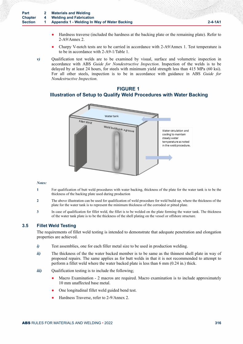
● Hardness traverse (included the hardness at the backing plate or the remaining plate). Refer to2-A9/Annex 2.
● Charpy V-notch tests are to be carried in accordance with 2-A9/Annex 1. Test temperature isto be in accordance with 2-A9-1/Table 1.
v) Qualification test welds are to be examined by visual, surface and volumetric inspection inaccordance with ABS Guide for Nondestructive Inspection. Inspection of the welds is to bedelayed by at least 24 hours, for steels with minimum yield strength less than 415 MPa (60 ksi).For all other steels, inspection is to be in accordance with guidance in ABS Guide forNondestructive Inspection.
FIGURE 1 Illustration of Setup to Qualify Weld Procedures with Water Backing
Notes:
1 For qualification of butt weld procedures with water backing, thickness of the plate for the water tank is to be thethickness of the backing plate used during production
2 The above illustration can be used for qualification of weld procedure for weld build-up, where the thickness of theplate for the water tank is to represent the minimum thickness of the corroded or pitted plate.
3 In case of qualification for fillet weld, the fillet is to be welded on the plate forming the water tank. The thicknessof the water tank plate is to be the thickness of the shell plating on the vessel or offshore structure.
3.5 Fillet Weld TestingThe requirements of fillet weld testing is intended to demonstrate that adequate penetration and elongationproperties are achieved.
i) Test assemblies, one for each filler metal size to be used in production welding.
ii) The thickness of the the water backed member is to be same as the thinnest shell plate in way ofproposed repairs. The same applies as for butt welds in that it is not recommended to attempt toperform a fillet weld where the water backed plate is less than 6 mm (0.24 in.) thick.
iii) Qualification testing is to include the following;
● Macro Examination - 2 macros are required. Macro examination is to include approximately10 mm unaffected base metal.
● One longitudinal fillet weld guided bend test.
● Hardness Traverse, refer to 2-9/Annex 2.
Part 2 Materials and WeldingChapter 4 Welding and FabricationSection 1 Appendix 1 - Welding In Way of Water Backing 2-4-1A1
ABS RULES FOR MATERIALS AND WELDING • 2022 316
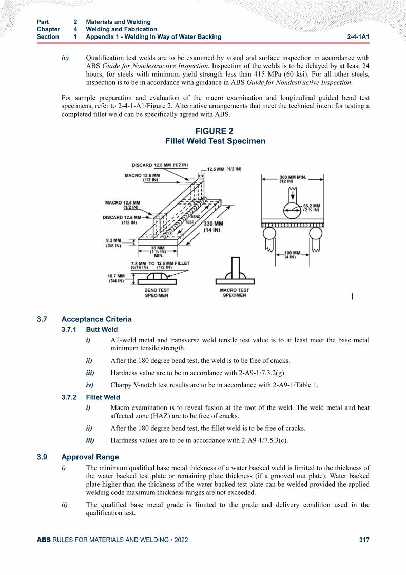
iv) Qualification test welds are to be examined by visual and surface inspection in accordance withABS Guide for Nondestructive Inspection. Inspection of the welds is to be delayed by at least 24hours, for steels with minimum yield strength less than 415 MPa (60 ksi). For all other steels,inspection is to be in accordance with guidance in ABS Guide for Nondestructive Inspection.
For sample preparation and evaluation of the macro examination and longitudinal guided bend testspecimens, refer to 2-4-1-A1/Figure 2. Alternative arrangements that meet the technical intent for testing acompleted fillet weld can be specifically agreed with ABS.
FIGURE 2 Fillet Weld Test Specimen
3.7 Acceptance Criteria3.7.1 Butt Weld
i) All-weld metal and transverse weld tensile test value is to at least meet the base metalminimum tensile strength.
ii) After the 180 degree bend test, the weld is to be free of cracks.
iii) Hardness value are to be in accordance with 2-A9-1/7.3.2(g).
iv) Charpy V-notch test results are to be in accordance with 2-A9-1/Table 1.
3.7.2 Fillet Weldi) Macro examination is to reveal fusion at the root of the weld. The weld metal and heat
affected zone (HAZ) are to be free of cracks.
ii) After the 180 degree bend test, the fillet weld is to be free of cracks.
iii) Hardness values are to be in accordance with 2-A9-1/7.5.3(c).
3.9 Approval Rangei) The minimum qualified base metal thickness of a water backed weld is limited to the thickness of
the water backed test plate or remaining plate thickness (if a grooved out plate). Water backedplate higher than the thickness of the water backed test plate can be welded provided the appliedwelding code maximum thickness ranges are not exceeded.
ii) The qualified base metal grade is limited to the grade and delivery condition used in thequalification test.
Part 2 Materials and WeldingChapter 4 Welding and FabricationSection 1 Appendix 1 - Welding In Way of Water Backing 2-4-1A1
ABS RULES FOR MATERIALS AND WELDING • 2022 317
iii) Minimum preheating temperature is not to be less than that used in the qualification test.
iv) Maximum interpass temperature is not to be higher than that used in the qualification test.
v) Separate weld procedure qualification tests are required for each position. Ideally the productionposition qualified should be the position of welding during qualificaiton. If a range of qualificationis required, procedures are to be qualified in the highest and lowest heat input welding positions.
vi) A change in the welding process would require a new weld procedure qualification test.
vii) A change in welding consumable would require ABS approval.
viii) The upper and lower limit of heat input approved is plus/minus 25% used in the qualification test.
ix) Other variables may also be considered in determining the range of approval, on a case-by-casebasis.
Part 2 Materials and WeldingChapter 4 Welding and FabricationSection 1 Appendix 1 - Welding In Way of Water Backing 2-4-1A1
ABS RULES FOR MATERIALS AND WELDING • 2022 318
C H A P T E R 4Welding and Fabrication
S E C T I O N 2Boilers, Unfired Pressure Vessels, Piping and Engineering Structures*
(1 July 2021)
Note:
* (2016) The piping requirements in this Section are applicable to piping for applications other than for installation onvessels to be built in accordance with the ABS Rules for Building and Classing Marine Vessels (MVR), the ABS Rules forBuilding and Classing Mobile Offshore Units (MOU), and the ABS Rules for Building and Classing Light Warships, Patroland High-Speed Naval Vessels (LHSNV). For piping for installation on vessels to be built in accordance with the ABS Rulesfor Building and Classing Marine Vessels (MVR) or the ABS Rules for Building and Classing Light Warships, Patrol andHigh-Speed Naval Vessels (LHSNV), see Section 2-4-4.
1 General Considerations
1.1 FabricationDrums or shells, other pressure parts of boilers, unfired pressure vessels, pipes and pipe connections, andother engineering structures may be fabricated by means of an approved process of fusion welding inaccordance with the following requirements, provided they comply in all other respects with the applicablerequirements of Part 4, Chapter 4 and Part 4, Chapter 6 respectively.
1.3 Welding Approval (2010)Before undertaking the welding of any structure subject to the requirements of these Rules, a manufactureris to prove to the satisfaction of the Surveyor that the welding consumables and the process themanufacturer proposes to use have been approved and that welders and welding operators are dulyqualified for the work intended. See 2-4-3/3 and 2-4-3/5.
1.5 Grouping of Welded StructuresWhile, in general, all welding and tests are to be executed in accordance with the requirements of thissection, the Rules necessarily vary according to the application in each case and the work is thereforedivided into the following groups for the purpose of these Rules.
PART 2
ABS RULES FOR MATERIALS AND WELDING • 2022 319
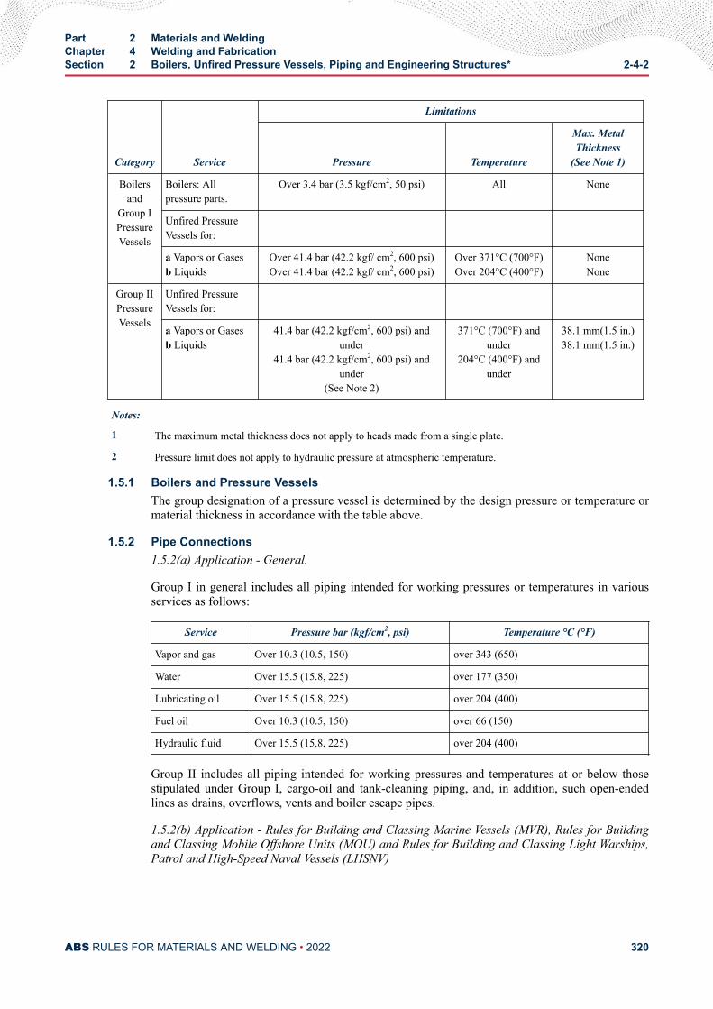
Category Service
Limitations
Pressure Temperature
Max. MetalThickness
(See Note 1)
Boilersand
Group IPressureVessels
Boilers: Allpressure parts.
Over 3.4 bar (3.5 kgf/cm2, 50 psi) All None
Unfired PressureVessels for:
a Vapors or Gasesb Liquids
Over 41.4 bar (42.2 kgf/ cm2, 600 psi)Over 41.4 bar (42.2 kgf/ cm2, 600 psi)
Over 371°C (700°F)Over 204°C (400°F)
NoneNone
Group IIPressureVessels
Unfired PressureVessels for:
a Vapors or Gasesb Liquids
41.4 bar (42.2 kgf/cm2, 600 psi) andunder
41.4 bar (42.2 kgf/cm2, 600 psi) andunder
(See Note 2)
371°C (700°F) andunder
204°C (400°F) andunder
38.1 mm(1.5 in.)38.1 mm(1.5 in.)
Notes:
1 The maximum metal thickness does not apply to heads made from a single plate.
2 Pressure limit does not apply to hydraulic pressure at atmospheric temperature.
1.5.1 Boilers and Pressure VesselsThe group designation of a pressure vessel is determined by the design pressure or temperature ormaterial thickness in accordance with the table above.
1.5.2 Pipe Connections1.5.2(a) Application - General.
Group I in general includes all piping intended for working pressures or temperatures in variousservices as follows:
Service Pressure bar (kgf/cm2, psi) Temperature °C (°F)
Vapor and gas Over 10.3 (10.5, 150) over 343 (650)
Water Over 15.5 (15.8, 225) over 177 (350)
Lubricating oil Over 15.5 (15.8, 225) over 204 (400)
Fuel oil Over 10.3 (10.5, 150) over 66 (150)
Hydraulic fluid Over 15.5 (15.8, 225) over 204 (400)
Group II includes all piping intended for working pressures and temperatures at or below thosestipulated under Group I, cargo-oil and tank-cleaning piping, and, in addition, such open-endedlines as drains, overflows, vents and boiler escape pipes.
1.5.2(b) Application - Rules for Building and Classing Marine Vessels (MVR), Rules for Buildingand Classing Mobile Offshore Units (MOU) and Rules for Building and Classing Light Warships,Patrol and High-Speed Naval Vessels (LHSNV)
Part 2 Materials and WeldingChapter 4 Welding and FabricationSection 2 Boilers, Unfired Pressure Vessels, Piping and Engineering Structures* 2-4-2
ABS RULES FOR MATERIALS AND WELDING • 2022 320
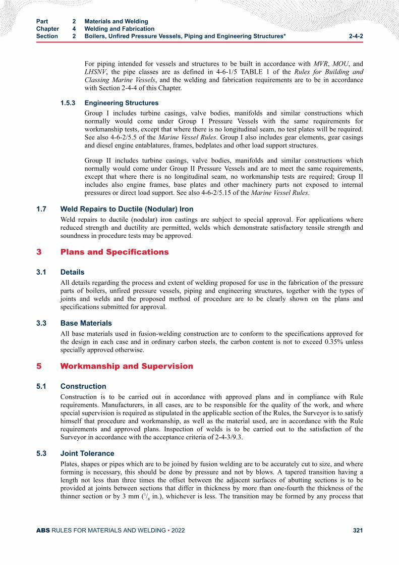
For piping intended for vessels and structures to be built in accordance with MVR, MOU, andLHSNV, the pipe classes are as defined in 4-6-1/5 TABLE 1 of the Rules for Building andClassing Marine Vessels, and the welding and fabrication requirements are to be in accordancewith Section 2-4-4 of this Chapter.
1.5.3 Engineering StructuresGroup I includes turbine casings, valve bodies, manifolds and similar constructions whichnormally would come under Group I Pressure Vessels with the same requirements forworkmanship tests, except that where there is no longitudinal seam, no test plates will be required.See also 4-6-2/5.5 of the Marine Vessel Rules. Group I also includes gear elements, gear casingsand diesel engine entablatures, frames, bedplates and other load support structures.
Group II includes turbine casings, valve bodies, manifolds and similar constructions whichnormally would come under Group II Pressure Vessels and are to meet the same requirements,except that where there is no longitudinal seam, no workmanship tests are required; Group IIincludes also engine frames, base plates and other machinery parts not exposed to internalpressures or direct load support. See also 4-6-2/5.15 of the Marine Vessel Rules.
1.7 Weld Repairs to Ductile (Nodular) IronWeld repairs to ductile (nodular) iron castings are subject to special approval. For applications wherereduced strength and ductility are permitted, welds which demonstrate satisfactory tensile strength andsoundness in procedure tests may be approved.
3 Plans and Specifications
3.1 DetailsAll details regarding the process and extent of welding proposed for use in the fabrication of the pressureparts of boilers, unfired pressure vessels, piping and engineering structures, together with the types ofjoints and welds and the proposed method of procedure are to be clearly shown on the plans andspecifications submitted for approval.
3.3 Base MaterialsAll base materials used in fusion-welding construction are to conform to the specifications approved forthe design in each case and in ordinary carbon steels, the carbon content is not to exceed 0.35% unlessspecially approved otherwise.
5 Workmanship and Supervision
5.1 ConstructionConstruction is to be carried out in accordance with approved plans and in compliance with Rulerequirements. Manufacturers, in all cases, are to be responsible for the quality of the work, and wherespecial supervision is required as stipulated in the applicable section of the Rules, the Surveyor is to satisfyhimself that procedure and workmanship, as well as the material used, are in accordance with the Rulerequirements and approved plans. Inspection of welds is to be carried out to the satisfaction of theSurveyor in accordance with the acceptance criteria of 2-4-3/9.3.
5.3 Joint TolerancePlates, shapes or pipes which are to be joined by fusion welding are to be accurately cut to size, and whereforming is necessary, this should be done by pressure and not by blows. A tapered transition having alength not less than three times the offset between the adjacent surfaces of abutting sections is to beprovided at joints between sections that differ in thickness by more than one-fourth the thickness of thethinner section or by 3 mm (1/8 in.), whichever is less. The transition may be formed by any process that
Part 2 Materials and WeldingChapter 4 Welding and FabricationSection 2 Boilers, Unfired Pressure Vessels, Piping and Engineering Structures* 2-4-2
ABS RULES FOR MATERIALS AND WELDING • 2022 321
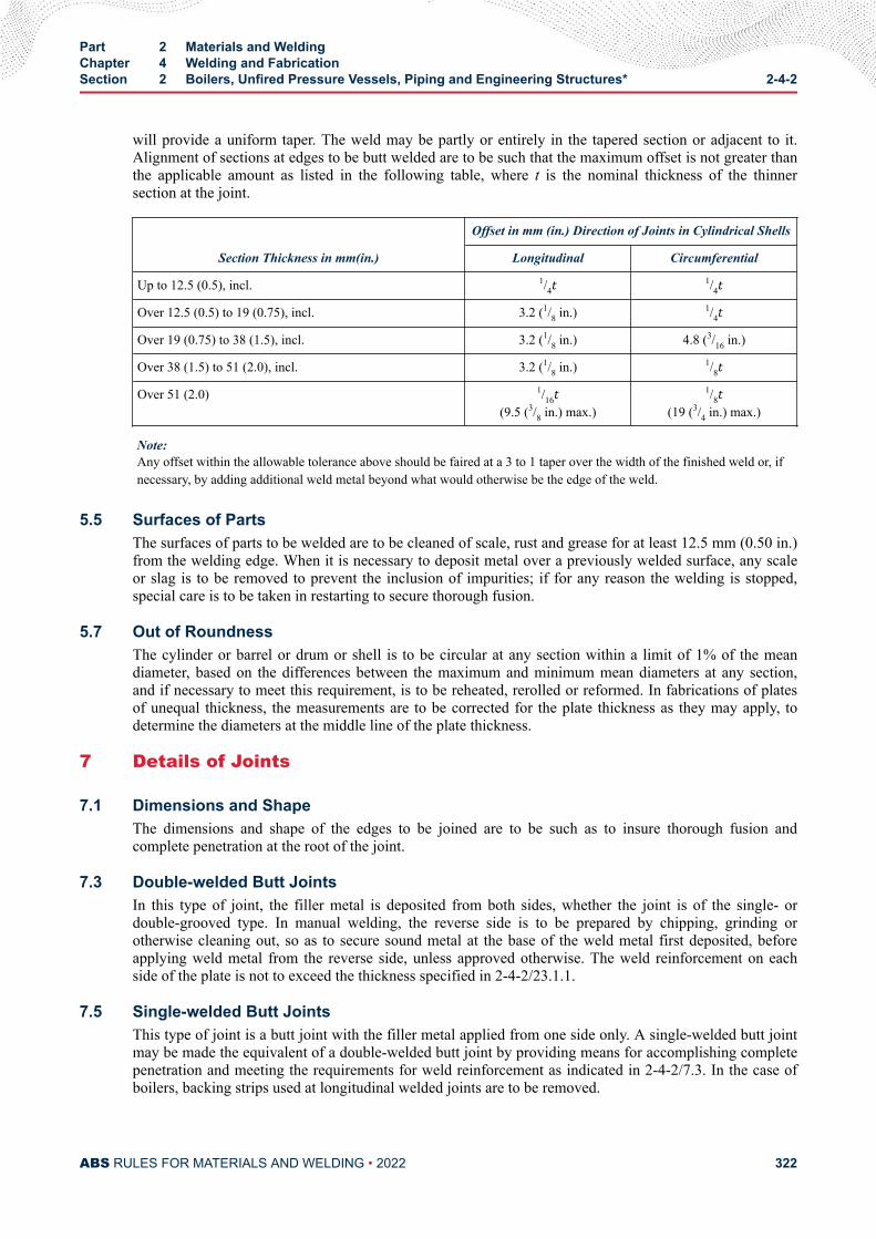
will provide a uniform taper. The weld may be partly or entirely in the tapered section or adjacent to it.Alignment of sections at edges to be butt welded are to be such that the maximum offset is not greater thanthe applicable amount as listed in the following table, where t is the nominal thickness of the thinnersection at the joint.
Section Thickness in mm(in.)
Offset in mm (in.) Direction of Joints in Cylindrical Shells
Longitudinal Circumferential
Up to 12.5 (0.5), incl. 1/4t 1/4tOver 12.5 (0.5) to 19 (0.75), incl. 3.2 (1/8 in.) 1/4tOver 19 (0.75) to 38 (1.5), incl. 3.2 (1/8 in.) 4.8 (3/16 in.)
Over 38 (1.5) to 51 (2.0), incl. 3.2 (1/8 in.) 1/8tOver 51 (2.0) 1/16t
(9.5 (3/8 in.) max.)
1/8t(19 (3/4 in.) max.)
Note:Any offset within the allowable tolerance above should be faired at a 3 to 1 taper over the width of the finished weld or, ifnecessary, by adding additional weld metal beyond what would otherwise be the edge of the weld.
5.5 Surfaces of PartsThe surfaces of parts to be welded are to be cleaned of scale, rust and grease for at least 12.5 mm (0.50 in.)from the welding edge. When it is necessary to deposit metal over a previously welded surface, any scaleor slag is to be removed to prevent the inclusion of impurities; if for any reason the welding is stopped,special care is to be taken in restarting to secure thorough fusion.
5.7 Out of RoundnessThe cylinder or barrel or drum or shell is to be circular at any section within a limit of 1% of the meandiameter, based on the differences between the maximum and minimum mean diameters at any section,and if necessary to meet this requirement, is to be reheated, rerolled or reformed. In fabrications of platesof unequal thickness, the measurements are to be corrected for the plate thickness as they may apply, todetermine the diameters at the middle line of the plate thickness.
7 Details of Joints
7.1 Dimensions and ShapeThe dimensions and shape of the edges to be joined are to be such as to insure thorough fusion andcomplete penetration at the root of the joint.
7.3 Double-welded Butt JointsIn this type of joint, the filler metal is deposited from both sides, whether the joint is of the single- ordouble-grooved type. In manual welding, the reverse side is to be prepared by chipping, grinding orotherwise cleaning out, so as to secure sound metal at the base of the weld metal first deposited, beforeapplying weld metal from the reverse side, unless approved otherwise. The weld reinforcement on eachside of the plate is not to exceed the thickness specified in 2-4-2/23.1.1.
7.5 Single-welded Butt JointsThis type of joint is a butt joint with the filler metal applied from one side only. A single-welded butt jointmay be made the equivalent of a double-welded butt joint by providing means for accomplishing completepenetration and meeting the requirements for weld reinforcement as indicated in 2-4-2/7.3. In the case ofboilers, backing strips used at longitudinal welded joints are to be removed.
Part 2 Materials and WeldingChapter 4 Welding and FabricationSection 2 Boilers, Unfired Pressure Vessels, Piping and Engineering Structures* 2-4-2
ABS RULES FOR MATERIALS AND WELDING • 2022 322
7.7 Joint FinishButt joints are to have complete joint penetration and are to be free from overlaps or abrupt ridges orgrooves and reasonably free from undercuts. The reinforcements permitted for both double-and single-welded butt joints may be removed upon completion to provide a smooth finish.
7.9 Lap JointsWhere lapped joints are permitted, they are to be made with an overlap of the edges not less than fourtimes the thickness of the thinner plate, except as noted in 2-4-2/25.7 FIGURE 1.
7.11 Head to Shell Attachments7.11.1 Length of Flange
Dished heads other than concaved hemispherical to the pressure which are to be attached by butt-welding, and flanged heads or flanged furnace connections which are to be fillet-welded are tohave a length of flange not less than 25 mm (1 in.) for heads or furnace openings not over 610 mm(24 in.) in external diameter and not less than 38 mm (1.5 in.) for heads or furnace openings over610 mm (24 in.) in diameter. For unfired pressure vessels, see 2-4-2/25.7 FIGURE 1 for details.
7.11.2 Inserted HeadsWhen dished heads are fitted inside or over a shell, they are to have a driving fit before welding.
7.11.3 ConnectionsAcceptable types of fusion-welded connections of heads to shells are illustrated in 2-4-2/25.7FIGURE 1, subject to the tabulated limitations in 4-4-1-A1/21 TABLE 1 of the Marine VesselRules.
7.13 Bending Stresses in WeldsThe design of a Group I or II welded container is to be such that the weld will not be subjected to directbending stresses [see 2-4-2/25.7 FIGURE 1]. Corner welds are not to be used unless the plates forming thecorner are supported independently of the welds.
7.15 ConnectionsAll welding for fusion-welded connections is to be equivalent to that required for the joints of the vessel towhich they are attached.
7.17 NozzlesAcceptable types of fusion-welded nozzle connections are illustrated in 2-4-2/25.7 FIGURE 2 and are tocomply with the following.
7.17.1 2-4-2/Figure 2(a) and (b)Necks abutting the vessel wall are to be attached by a full penetration groove weld.
7.17.2 2-4-2/Figure 2(c) through (h)Necks inserted into or through a hole cut in the vessel wall and without additional reinforcingelements are to be attached by a full penetration groove weld or by two partial penetration welds,one on each face of the vessel wall. These may be any desired combination of fillet, single-beveland single-J welds.
7.17.3 2-4-2/Figure 2(l), (m), (n), (o) and (p)Inserted type necks having added reinforcement in the form of one or more separate reinforcingplates are to be attached by welds at the outer edge of the reinforcing plate and at the nozzle-neckperiphery. The welds attaching the neck to the vessel wall and to the reinforcement plate are toconsist of one of the following combinations.
Part 2 Materials and WeldingChapter 4 Welding and FabricationSection 2 Boilers, Unfired Pressure Vessels, Piping and Engineering Structures* 2-4-2
ABS RULES FOR MATERIALS AND WELDING • 2022 323
7.17.3(a) Single-bevel or single-J weld in the shell plate, and full penetration groove weld or asingle-bevel or single-J weld in each reinforcement plate. See 2-4-2/25.7 FIGURE 2(n) and (p).
7.17.3(b) A full penetration groove weld in the shell plate, and a fillet, single-bevel, or single-Jweld or a full penetration groove weld in each reinforcement plate. See 2-4-2/25.7 FIGURE 2(m)and (o).
7.17.3(c) A full penetration groove weld in each reinforcement plate, and a fillet, single-bevel, orsingle-J weld in the shell plate. See 2-4-2/25.7 FIGURE 2(l).
7.17.4 2-4-2/Figure 2(k), (q), (r), (s) and (t)Nozzles with integral reinforcement in the form of extended necks or saddle type pads are to beattached by a full penetration weld or by means of a fillet weld along the outer edge and a fillet,single-bevel, or single-J weld along the inner edge.
7.17.5 2-4-2/Figure 2(u), (v), (w) and (x)Fittings with internal threads are to be attached by a full penetration groove weld or by two filletor partial penetration welds, one on each face of the vessel wall. See 2-4-2/25.7 FIGURE 2(u), (v),(w) and (x). Internally threaded fittings not exceeding 89 mm OD (3 in. NPS) may be attached bya fillet groove weld from the outside only. See 2-4-2/25.7 FIGURE 2(w-3).
For all cases, the strength of the welded connection is to be in accordance with the requirements of4-4-1-A1/7.9.3.ii of the Marine Vessel Rules.
7.19 LimitationsThe use of various types of welded construction is subject to the limitations of the group for which it isintended as well as the limitations tabulated in 4-4-1-A1/21 TABLE 1 of the Marine Vessel Rules.
9 Forms of Welded Joints Required
9.1 Boilers and Group I Pressure VesselsJoints are to be in accordance with the following details.
9.1.1 Double-weldedAll joints are to be of the double-welded butt type, single-or double-grooved, except where asingle-welded butt joint is made the equivalent of a double-welded butt joint. See 2-4-2/7.5.
9.1.2 Nozzles and Other ConnectionsSome acceptable types of welded nozzles and other connections to shells, drums and headers areshown in 2-4-2/25.7 FIGURE 2.
9.1.3 Closing PlatesClosing plates of headers for boilers and superheaters as well as flat heads of other pressurevessels may be attached by welding as indicated in 2-4-2/25.7 FIGURE 1(g) or (h) and 4-4-1-A1/5.7.2 FIGURE 7 of the Marine Vessel Rules.
9.3 Group II Pressure VesselsJoints are to be the same as Group I, except as noted below.
9.3.1 Single-weldedButt joints welded from one side, with or without backing strips, are subject to the tabulatedlimitations in 4-4-1-A1/21 TABLE 1 of the Marine Vessel Rules. When backing strips are used,they may be left in place or removed.
Part 2 Materials and WeldingChapter 4 Welding and FabricationSection 2 Boilers, Unfired Pressure Vessels, Piping and Engineering Structures* 2-4-2
ABS RULES FOR MATERIALS AND WELDING • 2022 324
9.3.2 Full-fillet LapDouble full-fillet lap joints or single full-fillet lap joints, with or without plug welds, when used,are subject to the tabulated limitations in 4-4-1-A1/21 TABLE 1. See also 2-4-2/25.7 FIGURE 1.
9.5 Group I Pipe Welded JointsWelded joints are to be in accordance with the following.
9.5.1 Pipes Over 89 mm OD (3 in. NPS)Joints for connecting two lengths of pipe or a pipe to a welding fitting, valve or flange are to be ofthe grooved type. In welding single-welded butt joints, complete penetration at the root is requiredand is to be demonstrated by the qualification of the procedure used. If complete penetrationcannot otherwise be secured, the procedure is to include backing. The depth of weld is to be notless than the minimum thickness permitted by the applicable material specifications for theparticular size and thickness of the pipe used.
9.5.2 Pipes 89 mm OD (3 in. NPS) and BelowJoints for connecting two lengths of pipe may be made by sleeves fitted over the joint and attachedby fillet welds or by using socket-type joints with a fillet weld. For sleeve joints, the insidediameter of the sleeve is not to exceed the outside diameter of the pipe by more than 2.0 mm(0.080 in.). The fit and fillet weld sizes are to be in accordance with an applicable recognizedstandard (e.g., ANSI B16.11 for socket-type joints, ASTM F682 for sleeve-type joints and ANSIB31.1 for fillet weld sizes). The depth of insertion of the pipe into the sleeve or socket fitting is tobe at least 9.5 mm (0.375 in.). A minimum gap of approximately 2.0 mm (0.080 in.) is to beprovided between the ends of the pipe for a sleeve joint or between the pipe and socket shoulderfor socket-type joints prior to welding. The fittings are to be reasonably centered around the pipe.
9.5.3 FlangesANSI slip-on flanges may be attached to piping by double-fillet welds for applications with aservice rating no higher than ANSI 300 Class, provided the throats of the fillet welds are not lessthan 0.7 times the thickness of the part to which the flange is attached. For boiler external piping,the use of slip-on flanges is additionally limited to sizes not exceeding 114 mm OD (4 in. NPS)and the throats of fillet welds may be not less than 0.7 times the thickness of the part to which theflange is attached. Slip-on flanges for higher ratings which comply with ASME or otherrecognized standards will be subject to special consideration.
Socket-type flanges up to and including ANSI 600 Class may be used in piping 89 mm OD (3 in.NPS) or less and up to and including the ANSI 1500 Class in piping 73 mm OD (2.5 in. NPS) pipesize or less.
9.5.4 BackingBacking for grooved joints may be omitted in pipes under 33 mm OD (1 in. NPS). Backing isrecommended for welding pipes on shipboard for all sizes 33 mm OD (1 in. NPS) and above whenwelded with single butt joints.
9.5.5 WeldingWelding in pipe lines is to be done in the shop, as far as practicable, and joints made in theinstallation onboard ship are to be in positions accessible for proper welding.
9.7 Group II Pipe Welded JointsThe type of welded joints in the construction of piping under this Group is to be similar to those in Group Iexcept for the following modifications. For 2-4-2/9.7.1, 2-4-2/9.7.2 and 2-4-2/9.7.3 below, full penetrationwelds are required.
Part 2 Materials and WeldingChapter 4 Welding and FabricationSection 2 Boilers, Unfired Pressure Vessels, Piping and Engineering Structures* 2-4-2
ABS RULES FOR MATERIALS AND WELDING • 2022 325
9.7.1 Single-grooveSingle-groove welded-butt joints may be without backing in all sizes if the weld is chipped orground off flush on the root side.
9.7.2 BackingBacking may also be dispensed with, without grinding the root of the weld, in such services astank-vent and overflow pipes.
9.7.3 Square-groove WeldsSquare-groove welds may be used in lieu of the single-V groove weld for tank vent and overflowpipes where the thickness of the pipe does not exceed 4.8 mm (3/16 in.).
9.7.4 SleevesSleeves fitted over the joint and attached by fillet welds or socket-type joints with a fillet weld willbe acceptable in all sizes. The fit and fillet weld sizes are to be in accordance with an applicablerecognized standard (e.g., ANSI B16.11 for socket joints, ASTM F682 for sleeve type joints andANSI B31.1 for fillet weld sizes.) The depth of insertion and gap are to be as per 2-4-2/9.5.2. Thefittings are to be reasonably centered around the pipe.
9.9 Low-temperature Piping Systems [Below -18°C (0°F)]For service temperatures lower than -18°C (0°F), each welding procedure is to be approved in accordancewith the requirements of 2-4-3/5 and Part 5C, Chapter 8 of the Marine Vessel Rules. All piping systemsover 10.3 bar (10.5 kgf/cm2, 150 psi) are to be considered Group I piping systems, except that socket-weldjoints, slip-on flanges, single-welded butt joints with backing strips left in place, pipe-joining sleeves andthreaded joints are not to be used, except where permitted by Part 5C, Chapter 8 of the Marine VesselRules.
9.11 Engineering StructuresThe type of welded joints used in either Group I or II in this class of construction is subject to specialconsideration in connection with the design in each case
11 Preheat
11.1 Boilers, Pressure Vessels, and Group I PipingWhen ambient temperatures are below 10°C (50°F), the welded parts of boilers, pressure vessels, andGroup I piping are to be preheated prior to welding, so that the parts to be joined by welding will be at atemperature not less than 10°C (50°F). Higher preheat is required for material composition, thicknesses,and carbon content in accordance with the following paragraphs.
11.1.1 GeneralThe thicknesses referred to are nominal at the weld for the parts to be joined. Where thequalification procedure specifies a higher preheat, this higher preheat is to be used. Wheredifferent materials having different preheat requirements are joined by welding, the higher preheatis to be used. For materials, refer to 2-3-2/1, 2-3-2/3, 2-3-2/5, 2-3-2/7, Section 2-3-5 and Section2-3-12.
11.1.2 Preheat TemperaturesWelds joining pressure parts or attachments to pressure parts are to be preheated to not less thanthe following temperatures.
11.1.2(a) ABS Plate Grades MA, MB, MC, MD, ME, MF, MG, K, L, M, N, Tube Grades D, F, H, J,and Pipe Grades 1, 2, 3, 4, 5, 8, and 9. to 79°C (175°F) for material which has both specified
Part 2 Materials and WeldingChapter 4 Welding and FabricationSection 2 Boilers, Unfired Pressure Vessels, Piping and Engineering Structures* 2-4-2
ABS RULES FOR MATERIALS AND WELDING • 2022 326
maximum carbon content in excess of 0.30% and a thickness at the joint in excess of 25.4 mm (1.0in.).
11.1.2(b) ABS Plate Grades H, I, J, Tube Grades K, L, M and Pipe Grades 6 and 7. to 79°C(175°F) for material which has either a specified minimum tensile strength in excess of 485N/mm2 (49 kgf/mm2, 70,000 psi) or a thickness at the joint in excess of 16.0 mm (0.625 in.).
11.1.2(c) ABS Tube Grades N and O and Piping Grades 11 and 12. to 121°C (250°F) for materialwhich has a thickness at the joint in excess of 12.5 mm (0.5 in.).
11.1.2(d) ABS Tube Grade P and Piping Grade 13. to 149°C (300°F) regardless of thickness.
11.1.2(e) Other Materials. The preheating of other materials will be subject to specialconsideration.
11.3 Group I Pipe ConnectionsAll Group I pipe connections defined in 2-4-2/1.5.2 are to be preheated in accordance with 2-4-2/11.
13 General Requirements for Postweld Heat Treatment
13.1 GeneralPrior to the application of the following requirements, satisfactory weld-procedure qualifications of theprocedures to be used are to be performed in accordance with all the essential variables of Section 2-4-3,including conditions of postweld heat treatment or lack of postweld heat treatment and other restrictions aslisted in the following paragraphs.
13.3 Heat-treatment DeterminationExcept as otherwise specifically provided for, all welded pressure parts of boilers and all welded pressurevessels or pressure parts are to be given a postweld heat treatment at a temperature not less than thatspecified in the following paragraphs. Where pressure parts of two different materials are joined bywelding, the postweld heat treatment is to be that specified for the material requiring the higher postweldtemperature. When nonpressure parts are welded to pressure parts, the postweld-heat-treatmenttemperature of the pressure part is to control.
15 Fusion-welded Boilers
15.1 Postweld Heat TreatmentAll boilers of plate, pipe and tube materials listed in 2-3-2/3, 2-3-2/5, 2-3-2/7, Section 2-3-5 and Section2-3-12 are to be given a post-weld heat treatment after all pads, flanges or nozzles have been welded inplace. Postweld heat treatment is to be as follows:
Part 2 Materials and WeldingChapter 4 Welding and FabricationSection 2 Boilers, Unfired Pressure Vessels, Piping and Engineering Structures* 2-4-2
ABS RULES FOR MATERIALS AND WELDING • 2022 327
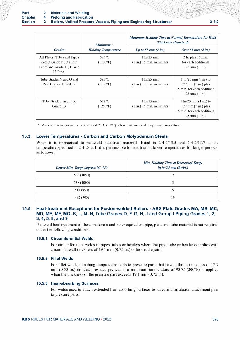
GradesMinimum *
Holding Temperature
Minimum Holding Time at Normal Temperature for WeldThickness (Nominal)
Up to 51 mm (2 in.) Over 51 mm (2 in.)
All Plates, Tubes and Pipesexcept Grade N, O and P
Tubes and Grade 11, 12 and13 Pipes
593°C(1100°F)
1 hr/25 mm(1 in.) 15 min. minimum
2 hr plus 15 min.for each additional
25 mm (1 in.)
Tube Grades N and O andPipe Grades 11 and 12
593°C(1100°F)
1 hr/25 mm(1 in.) 15 min. minimum
1 hr/25 mm (1in.) to127 mm (5 in.) plus
15 min. for each additional25 mm (1 in.)
Tube Grade P and PipeGrade 13
677°C(1250°F)
1 hr/25 mm(1 in.) 15 min. minimum
1 hr/25 mm (1 in.) to127 mm (5 in.) plus
15 min. for each additional25 mm (1 in.)
* Maximum temperature is to be at least 28°C (50°F) below base material tempering temperature.
15.3 Lower Temperatures - Carbon and Carbon Molybdenum SteelsWhen it is impractical to postweld heat-treat materials listed in 2-4-2/15.5 and 2-4-2/15.7 at thetemperature specified in 2-4-2/15.1, it is permissible to heat-treat at lower temperatures for longer periods,as follows.
Lower Min. Temp. degrees °C (°F)Min. Holding Time at Decreased Temp.
in hr/25 mm (hr/in.)
566 (1050) 2
538 (1000) 3
510 (950) 5
482 (900) 10
15.5 Heat-treatment Exceptions for Fusion-welded Boilers - ABS Plate Grades MA, MB, MC,MD, ME, MF, MG, K, L, M, N, Tube Grades D, F, G, H, J and Group I Piping Grades 1, 2,3, 4, 5, 8, and 9Postweld heat treatment of these materials and other equivalent pipe, plate and tube material is not requiredunder the following conditions:
15.5.1 Circumferential WeldsFor circumferential welds in pipes, tubes or headers where the pipe, tube or header complies witha nominal wall thickness of 19.1 mm (0.75 in.) or less at the joint.
15.5.2 Fillet WeldsFor fillet welds, attaching nonpressure parts to pressure parts that have a throat thickness of 12.7mm (0.50 in.) or less, provided preheat to a minimum temperature of 93°C (200°F) is appliedwhen the thickness of the pressure part exceeds 19.1 mm (0.75 in).
15.5.3 Heat-absorbing SurfacesFor welds used to attach extended heat-absorbing surfaces to tubes and insulation attachment pinsto pressure parts.
Part 2 Materials and WeldingChapter 4 Welding and FabricationSection 2 Boilers, Unfired Pressure Vessels, Piping and Engineering Structures* 2-4-2
ABS RULES FOR MATERIALS AND WELDING • 2022 328
15.5.4 TubesFor tubes or pressure retaining hand hole and inspection plugs or fittings that are secured byphysical means (rolling, shoulder construction, machine threads, etc.) and seal welded, providedthe seal weld has a throat thickness of 9.5 mm (0.375 in.) or less.
15.5.5 StudsFor studs welded to pressure parts for purposes not included in 2-4-2/15.5.3, provided preheat to aminimum temperature of 93°C (200°F) is applied when the thickness of the pressure part exceeds19.1 mm (0.75 in.).
15.7 Heat-treatment Exceptions for Fusion-welded Boilers - ABS Plate Grades H, I, J, TubeGrades K, L, M, and Group I Piping Grades 6 and 7Postweld heat treatment of these materials and other equivalent pipe, plate and tube material is not requiredunder the following conditions.
15.7.1 Circumferential WeldsFor circumferential welds in pipes, tubes or headers where the pipes, tubes or headers comply withboth a nominal wall thickness of 16 mm (0.625 in.) or less, and a specified maximum carboncontent of not more than 0.25%.
15.7.2 Fillet WeldsFor fillet welds attaching nonpressure parts having a specified maximum carbon content not morethan 0.25% that have a throat thickness of 12.7 mm (0.5 in.) or less, provided preheat to aminimum temperature of 93°C (200°F) is applied when the pressure part exceeds 15.9 mm (0.625in.).
15.7.3 Heat-absorbing SurfacesFor welds used to attach extended heat-absorbing surfaces to tubes and insulation attachment pinsto pressure parts.
15.7.4 TubesFor tubes or pressure-retaining handhole and inspection plugs or fittings that are secured byphysical means (rolling, shoulder construction, machine threads, etc.) and seal welded, providedthe seal weld has a throat thickness of not more than 9.5 mm (0.375 in.).
15.7.5 StudsPostweld heat treatment is not mandatory for studs welded to pressure parts for purposes notincluded in 2-4-2/15.7.3 and which have a specified maximum carbon content of not more than0.25%, provided a preheat to a minimum temperature of 93°C (200°F) is applied when thethickness of the pressure part exceeds 16 mm (0.625 in.).
15.9 Heat Treatment Exceptions for Fusion-welded Boilers - ABS Tube Grades N, O andGroup I Pipe Grades 11 and 12Postweld heat treatment of these materials and other equivalent pipe and tube material with 0.15% carbonmaximum is not required under the following conditions.
15.9.1 Circumferential WeldsFor circumferential welds where the pipe or tubes comply with all of the following.
15.9.1(a) a maximum outside diameter of 101.6 mm (4 in.)
15.9.1(b) a maximum thickness of 16 mm (0.625 in.)
15.9.1(c) a minimum preheat of 121°C (250°F)
Part 2 Materials and WeldingChapter 4 Welding and FabricationSection 2 Boilers, Unfired Pressure Vessels, Piping and Engineering Structures* 2-4-2
ABS RULES FOR MATERIALS AND WELDING • 2022 329
15.9.2 Fillet WeldsFor fillet welds attaching nonpressure parts to pressure parts, provided the fillet weld has aspecified throat thickness of 12.5 mm (0.5 in.) or less and the pressure part meets the requirementsof 2-4-2/15.9.1(a) and 2-4-2/15.9.1(b).
15.9.3 Heat-absorbing Surfaces and StudsFor heat-absorbing surfaces and non-load-carrying studs, provided the material is preheated to121°C (250°F) minimum and the pressure part meets the requirements of 2-4-2/15.9.1(a) and2-4-2/15.9.1(b).
15.9.4 TubesFor tubes or pressure retaining handhole and inspection plugs or fittings that are secured byphysical means (rolling, shoulder construction, machine threads, etc.) and seal welded, providedthe seal weld has a throat thickness of 9.5 mm (0.375 in.) or less.
15.11 Heat Treatment Exceptions for Fusion Welded Boilers - ABS Tube Grade P and GroupI Pipe Grade 13Postweld heat treatment of this material and other equivalent pipe and tube material with 0.15% carbonmaximum is not required under the following conditions.
15.11.1 Circumferential WeldsFor circumferential welds where the pipe or tube complies with all of the following.
15.11.1(a) a maximum outside diameter of 101.6 mm (4 in.)
15.11.1(b) a maximum thickness of 16 mm (0.625 in.)
15.11.1(c) a minimum preheat of 149°C (300°F)
15.11.2 Fillet WeldsFor fillet welds attaching nonpressure parts that have a specified throat thickness of 12.5 mm (0.5in.) or less, provided the pressure part meets the requirements of 2-4-2/15.11.1(a) and2-4-2/15.11.1(b).
15.11.3 Heat-absorbing Surfaces and StudsHeat-absorbing surfaces and non-load-carrying studs, provided the material is preheated to 149°C(300°F) and the pressure part meets the requirements of 2-4-2/15.11.1(a) and 2-4-2/15.11.1(b).
15.11.4 TubesFor tubes or pressure retaining handhole and inspection plugs or fittings with a specifiedmaximum chrome content of 6% that are secured by physical means (rolling, shoulderconstruction, machine threads, etc.) and seal welded, provided the seal weld has a throat thicknessof 9.5 mm (0.375 in.) or less.
15.13 Other MaterialsPostweld heat treatment of other materials for boilerplate and tubes will be subject to special consideration.
15.15 Other Welded ConnectionsNozzles or other welded attachments for which postweld heat treatment is required may be locallypostweld heat-treated by heating a circumferential band around the entire vessel with the weldedconnection located at the middle of the band. The width of the band is to be at least three times the wallthickness of the vessel wider than the nozzle or other attachment weld, and is to be located in such amanner that the entire band will be heated to the temperature and held for the time specified in 2-4-2/15.1for post-weld heat treatment.
Part 2 Materials and WeldingChapter 4 Welding and FabricationSection 2 Boilers, Unfired Pressure Vessels, Piping and Engineering Structures* 2-4-2
ABS RULES FOR MATERIALS AND WELDING • 2022 330
15.17 Welded JointsIn the case of welded joints in pipes, tubes and headers, the width of the heated circumferential band is tobe at least three times the width of the widest part of the welding groove, but in no case less than twice thewidth of the weld reinforcement.
17 Fusion-welded Pressure Vessels
17.1 Postweld Heat Treatment17.1.1 General
All pressure vessels and pressure-vessel parts are to be given a postweld heat treatment at atemperature not less than that specified in 2-4-2/15.1 and 2-4-2/15.3 when the nominal thickness,including corrosion allowance of any welded joint in the vessel or vessel part exceeds the limits asnoted in 2-4-2/17.3 and 2-4-2/17.5. In addition, postweld heat treatment is required for thefollowing.
17.1.1(a) For all independent cargo tanks where required by Part 5C, Chapter 8 of the MarineVessel Rules.
17.1.1(b) For all carbon or carbon manganese steel pressure vessels and independent cargopressure vessels not covered by 2-4-2/17.1.1(a), when the metal temperature is below -29°C(-20°F).
17.1.1(c) For all pressure vessels and independent cargo pressure vessels, which are fabricated ofcarbon or carbon manganese steel and intended to carry anhydrous ammonia.
17.1.2 Welded JointsWhen the welded joint connects parts that are of different thickness, the thickness to be used inapplying these requirements is to be the thinner of two adjacent butt-welded plates, including headto shell connections, the thickness of the head or shell plate in nozzle attachment welds, and thethickness of the nozzle neck at the joint in nozzle neck to flange connections, the thickness of theshell in connections to tube sheets, flat heads, covers or similar connections, and the thicker ofplate in connections of the type shown in 2-4-2/25.7 FIGURE 1.
17.3 Heat-treatment Exceptions - ABS Plate Grades MA, MB, MC, MD, ME, MF, MG, K, L, M,N and Tube Grades D, F, G, H, JPostweld heat treatment of these materials is not required under the following conditions.
17.3.1 38.1 mm (1.5 in.) and UnderFor material up to and including 38.1 mm (1.5 in.) thickness, provided that material over 31.8 mm(1.25 in.) thickness is preheated to a minimum temperature of 93°C (200°F) during welding.
17.3.2 Over 38.1 mm (1.5 in.)For material over 38.1 mm (1.5 in.) thickness, all welded connections and attachments are to bepostweld heat-treated except that postweld heat treatment is not required for:
17.3.2(a) Nozzle Connections.
Fillet welds with a throat not over 12.7 mm (0.50 in.) and groove welds not over 12.7 mm (0.50in.) in size that attach nozzle connections having a finished inside diameter not greater than 50.8mm (2 in.), provided the connections do not form ligaments that require an increase in shell orhead thickness, and preheat to a minimum temperature of 93°C (200°F) is applied.
17.3.2(b) Nonpressure Attachments.
Part 2 Materials and WeldingChapter 4 Welding and FabricationSection 2 Boilers, Unfired Pressure Vessels, Piping and Engineering Structures* 2-4-2
ABS RULES FOR MATERIALS AND WELDING • 2022 331
Fillet welds having a throat not over 12.7 mm (0.5 in.), or groove welds not over 12.7 mm (0.50in.) in size, used for attaching nonpressure parts to pressure parts, and preheat to a minimumtemperature of 93°C (200°F) is applied when the thickness of the pressure part exceeds 19 mm(0.75 in.).
17.5 Heat-treatment Exceptions - ABS Plate Grades, H, I, J and Tube Grades K, L, MPostweld heat treatment of these materials is not required under the following conditions.
17.5.1 15.9 mm (0.625 in.) and UnderFor material up to and including 15.9 mm (0.625 in.) in thickness having a specified maximumcarbon content of not more than 0.25%, provided a welding procedure qualification has been madein equal or greater thickness than the production weld.
17.5.2 Over 15.9 mm (0.625 in.)For material over 15.9 mm (0.625 in.) thicknesses, all welded connections and attachments are tobe postweld heat-treated, except that postweld treatment is not required for:
17.5.2(a) Nonpressure Attachments.
Attaching to pressure parts which have a specified maximum carbon content of not more than0.25% and nonpressure parts with fillet welds that have a throat thickness of 12.7 mm (0.50 in.) orless, provided preheat to a minimum temperature of 80°C (175°F) is applied.
17.5.2(b) Tube or Pipe Attachments.
Circumferential welds in pipes or tubes where the pipes or tubes have both a nominal wallthickness of 12.7 mm (0.50 in.) or less, and a specified maximum carbon content of not more than0.25%.
17.7 Heat-treatment Exceptions - AttachmentsOn pressure vessels which do not require postweld heat treatment as a whole, connections and otherattachments after being attached by fusion welding need not be post-weld heat-treated. See also2-4-2/21.11 for nozzles or other welded attachments for which postweld heat treatment is not required.
17.9 Other MaterialsPostweld heat treatment of other materials for boiler plate and tubes will be subject to specialconsideration.
17.11 Welded ConnectionsNozzles or other welded attachments for which postweld heat treatment is required may be heat-treated byheating a circumferential band around the entire vessel in such a manner that the entire band is to bebrought up uniformly to the required temperature and held for the specified time. The circumferential bandis to extend around the entire vessel and include the nozzle or welded attachment, and is to extend at leastsix times the plate thickness beyond the welding which connects the nozzle or other attachment to thevessel. The portion of the vessel outside of the circumferential band is to be protected so that thetemperature gradient is not harmful.
19 Pipe Welded Joints and Engineering Structures
19.1 Group I Pipe Welded JointsAll Group I Pipe welded joints, defined in 2-4-2/1.5 are to be postweld heat-treated in accordance with2-4-2/15 or the American National Standard ANSI B31.1.
Part 2 Materials and WeldingChapter 4 Welding and FabricationSection 2 Boilers, Unfired Pressure Vessels, Piping and Engineering Structures* 2-4-2
ABS RULES FOR MATERIALS AND WELDING • 2022 332
19.3 Group II Pipe Welded JointsUnless specially required, welded joints in Group II piping need not be postweld heat-treated.
19.5 Group I Engineering StructuresAll welded structures under this group are to be postweld heat-treated in accordance with the applicablerequirements of 2-4-2/17.
19.7 Group II Engineering StructuresPostweld heat treatment of structures under this group depends on the type and purpose of the construction,and the matter will be subject to special consideration in connection with the approval of the design.
19.9 Low-temperatures Piping Systems [Below -18°C (0°F)]In general, all piping weldments except socket-weld joints and slip-on flanges, where permitted, are to bepostweld heat-treated. Exceptions will be considered for specific materials where it can be shown thatpostweld heat treatment is unnecessary.
21 Postweld Heat-treatment Details
21.1 Boilers and Pressure VesselsThe weldment is to be heated uniformly and slowly to the temperature and time specified in 2-4-2/15.1,and is to be allowed to cool slowly in a still atmosphere to a temperature not exceeding 427°C (800°F).The postweld heat treatment may be done either by heating the complete welded structure as a whole or byheating a complete section containing the parts to be postweld heat-treated. The postweld-heat-treatmenttemperature is to be controlled by at least two pyrometric instruments to avoid the possibility of error.
21.3 Pipe ConnectionsIn the case of welded pipe connections requiring postweld heat treatment, the adjacent pipes or fittings areto be heated in a circumferential band at least three (3) times the width of the widest part of the weldinggroove but not less than twice the width of the weld reinforcement.
21.5 Other SteelsThe postweld heat treatment of other steels not specifically covered in Part 2, Chapter 3 will be subject tospecial consideration.
21.7 Clad Pressure VesselsPostweld heat treatment of vessels or parts of vessels constructed of integrally clad or applied corrosion-resistant lining material will be subject to special consideration.
21.9 Opening ConnectionsWelded connections may be added to a vessel after post-weld heat treatment without requiring repostweldheat treatment, provided the following conditions are met.
21.9.1 Size of WeldThe inside and outside attachment welds do not exceed 9.5 mm (0.375 in.) throat dimension.
21.9.2 Opening DiameterThe diameter of the attachment opening in the vessel shell does not exceed that allowed for anunreinforced opening, or does not exceed 50.8 mm (2 in.), whichever is smaller.
Part 2 Materials and WeldingChapter 4 Welding and FabricationSection 2 Boilers, Unfired Pressure Vessels, Piping and Engineering Structures* 2-4-2
ABS RULES FOR MATERIALS AND WELDING • 2022 333
21.9.3 ExceptionThis provision does not apply to those connections so placed as to form ligaments in the shell, theefficiency of which will affect the shell thickness. Such added connections are to be postweldheat-treated.
21.11 Seal WeldingSeal welding consisting of a fillet weld under 9.5 mm (0.375 in.) without subsequent stress relieving maybe applied to secure tightness of connections where the construction is such that no design stress is placedupon the weld even though the structure itself has to be stress-relieved in accordance with these Rules.
23 Radiography
23.1 General23.1.1 Welded-joint Preparation
All welded joints to be radiographed are to be prepared as follows: The weld ripples or weldsurface irregularities, on both the inside and outside, are to be removed by any suitable mechanicalprocess to such a degree that the resulting radiographic contrast due to any irregularities cannotmask or be confused with the image of any objectionable defect. Also, the weld surface is tomerge smoothly into the plate surface. The finished surface of the reinforcement of all butt-weldedjoints may be flush with the plate or may have a reasonably uniform crown not to exceed thefollowing thickness.
Plate Thickness, in mm (in.) Thickness of Reinforcement, in mm (in.)
Up to 12.7 (0.5) incl. 1.6 (1/16)
Over 12.7 (0.5) to 25.4 (1.0) 2.4 (3/32)
Over 25.4 (1.0) to 50.8 (2.0) 3.2 (1/8)
Over 50.8 (2.0) 4.0 (5/32)
23.1.2 Radiographic Examination with Backing StripA single-welded circumferential butt joint with backing strip may be radiographed withoutremoving the backing strip, provided it is not to be removed subsequently and provided the imageof the backing strip does not interfere with the interpretation of the resultant radiographs.
23.1.3 Details of Radiographic SearchSee 2-4-3/9 for further details of radiographic search of finished joints.
23.3 BoilersAll circumferential, longitudinal, and head joints are to be examined for their full length by radiographyexcept that parts of boilers fabricated of pipe material, such as drums, shells, downcomers, risers, cross-pipes, headers, and tubes are to be nondestructively examined as required by 2-4-2/23.7.
23.5 Other Pressure Vessels23.5.1 Full Radiography
Double-welded butt joints or their equivalent are to be examined radiographically for their fulllength under any of the following conditions.
23.5.1(a) Joint Efficiency.
Where the design of the vessel or vessel section is based on the use of the joint efficiencytabulated in column (a) of 4-4-1-A1/21 TABLE 1 of the Marine Vessel Rules.
Part 2 Materials and WeldingChapter 4 Welding and FabricationSection 2 Boilers, Unfired Pressure Vessels, Piping and Engineering Structures* 2-4-2
ABS RULES FOR MATERIALS AND WELDING • 2022 334
23.5.1(b) Material Used.
Complete radiographic examination is required for each butt-welded joint in vessels built of SteelPlate for Boilers and Pressure Vessels ABS Grades, MA, MB, MC, MD, ME, MF, MG, K, L, Mand N having a thickness in excess of 31.8 mm (1.25 in.) as well as for ABS Grades H, I and Jhaving a thickness in excess of 19 mm (0.75 in.). Other steels not specifically covered in Part 2,Chapter 3 will be subject to special consideration.
23.5.2 Spot (Random) RadiographyAll longitudinal and circumferential double-welded butt joints or their equivalent which are notrequired to be fully radiographed in 2-4-2/23.5.1 are to be examined by spot (random) radiographywhere the pressure vessel or pressure vessel section is based on the use of the joint efficiencytabulated in column (b) of 4-4-1-A1/21 TABLE 1 of the Marine Vessel Rules. The extent of spotradiography is to compare favorably with accepted practice such as that specified in the ASMEBoiler and Pressure Vessel Code and is to be the satisfaction of the Surveyor.
23.7 Group I Pipe Connections (1999)Group I pipe connections are to be radiographically examined according to either of the conditionsindicated below, as applicable.
Pipe Size Extent of Radiography(1, 2)
Wall Thickness > 9.5 mm (3/8 in.) 100%
Diameter > 76.1 mm (3.0 in) O.D. 100%
Notes:
1 Where radiographic testing is not practicable, such as for fillet welds, another effective method of nondestructivetesting is to be carried out.
2 Where radiographic testing is not required in the above table, alternative nondestructive testing, magnetic particleor penetration methods, may be required by the attending Surveyor when further inspection deems it necessary.
23.9 Group II Pipe Connections(1999)Spot (random) radiographic or ultrasonic examination of welded joints with an outer diameter greater than101.6 mm (4.0 in) may be required by the Surveyor when further inspection deems it necessary.
23.11 Low Temperature Piping Connections [Below -18°C (0°F)]In all carbon and alloy steel piping with a service temperature below -18°C (0°F) and an inside diameter ofmore than 75 mm (3 in.) or where the wall thickness exceeds 10 mm or 0.375 in., welds made inaccordance with this group are to be subjected to 100% radiographic search or to other approved method oftest if the former is not practicable. For pipe of smaller diameter or thickness, welds are to be subjected tospot (random) radiographic examination or to other approved methods of test of at least 10% of the welds,to the satisfaction of the Surveyor.
23.13 Group I Engineering StructuresGroup I Engineering Structures are to meet the same radiographic requirements as Group I PressureVessels.
23.15 Group II Engineering StructuresGroup II Engineering Structures which correspond in service requirements to Group II Pressure Vessels arenot required to be subjected to a full or spot (random) radiographic examination of welded joints.
Part 2 Materials and WeldingChapter 4 Welding and FabricationSection 2 Boilers, Unfired Pressure Vessels, Piping and Engineering Structures* 2-4-2
ABS RULES FOR MATERIALS AND WELDING • 2022 335
23.17 Engine BedplatesBedplates for main propulsion internal-combustion engines with cylinders 458 mm (18 in.) in diameter andover are to be examined radiographically or ultrasonically in way of principal welds.
23.19 Miscellaneous23.19.1 Alloy and Clad Pressure Vessels
The radiographic examination of vessels or parts of vessels constructed of alloy, integrally clad orapplied corrosion-resistant lining materials, will be subject to special consideration.
23.19.2 Nozzles, Sumps, etc.Butt welds of inserted-type nozzles are to be radiographed when used for attachment to a vessel orvessel section that is required to be radiographed or the joint efficiency tabulated in column (a) of4-4-1-A1/21 TABLE 1 of the Marine Vessel Rules is used. Nozzles and manhole attachment weldswhich are not of the double-welded butt-type need not be radiographed. Joints used in thefabrication of nozzles, sumps, etc. are to be radiographed when intended for installation in a vesselor vessel section that is required to be radiographed or when the joint efficiency tabulated incolumn (a) of 4-4-1-A1/21 TABLE 1 of the Marine Vessel Rules is used, except thatcircumferential-welded butt joints of nozzles and sumps not exceeding 254 mm (10 in.) nominalpipe size or 28.6 mm (1.125 in.) wall thickness need not be radiographed.
25 Hydrostatic Test
25.1 Boilers and Pressure VesselsHydrostatic tests are to be conducted in accordance with 4-4-1/7.11 and 4-4-1-A1/21 of the Marine VesselRules.
25.3 PipingHydrostatic tests are to be conducted in accordance with 2-4-2/25.3 TABLE 1 below:
TABLE 1Hydrostatic Testing of Piping
MVR* MOU*
Class I Class II Class III Group I Group II
4-6-2/7.3 4-6-2/7.3 4-6-2/7.3.1 7-1-4/41 7-1-4/41
4-6-7/7.7
Note:*MVR – Rules for Building and Classing Marine VesselsMOU – Rules for Building and Classing Mobile Offshore Units
For conditions of hydrostatic testing in other Rules and Guides, see the requirements within the relevantRules or Guides.
25.5 DefectsPinholes, cracks or other defects are to be repaired only by chipping, machining or burning out the defectsand rewelding. Boiler drums and vessels requiring stress relieving are to be stress-relieved after anywelding repairs have been made.
Part 2 Materials and WeldingChapter 4 Welding and FabricationSection 2 Boilers, Unfired Pressure Vessels, Piping and Engineering Structures* 2-4-2
ABS RULES FOR MATERIALS AND WELDING • 2022 336

25.7 RetestAfter repairs have been made, the drum, vessel or piping is to be again subjected to the hydrostatic testrequired in 2-4-2/25.1 through 2-4-2/25.3, inclusive.
Part 2 Materials and WeldingChapter 4 Welding and FabricationSection 2 Boilers, Unfired Pressure Vessels, Piping and Engineering Structures* 2-4-2
ABS RULES FOR MATERIALS AND WELDING • 2022 337
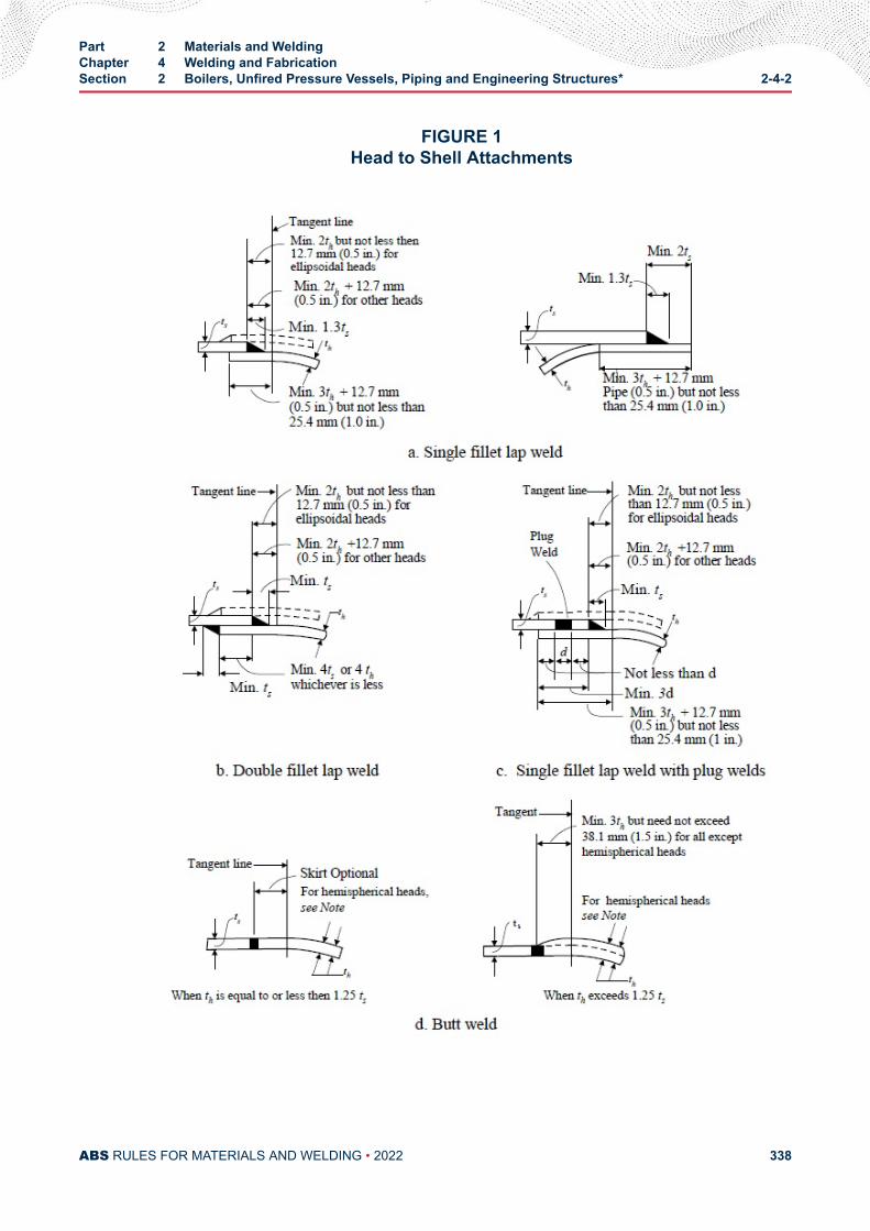
FIGURE 1Head to Shell Attachments
Part 2 Materials and WeldingChapter 4 Welding and FabricationSection 2 Boilers, Unfired Pressure Vessels, Piping and Engineering Structures* 2-4-2
ABS RULES FOR MATERIALS AND WELDING • 2022 338
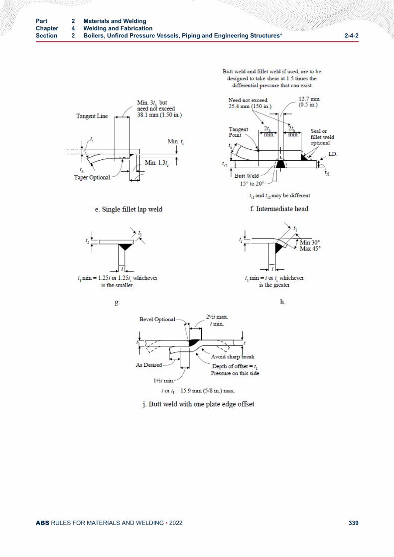
Part 2 Materials and WeldingChapter 4 Welding and FabricationSection 2 Boilers, Unfired Pressure Vessels, Piping and Engineering Structures* 2-4-2
ABS RULES FOR MATERIALS AND WELDING • 2022 339
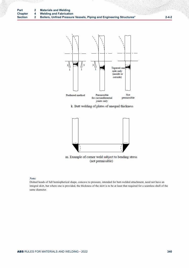
Note:Dished heads of full hemispherical shape, concave to pressure, intended for butt-welded attachment, need not have anintegral skirt, but where one is provided, the thickness of the skirt is to be at least that required for a seamless shell of thesame diameter.
Part 2 Materials and WeldingChapter 4 Welding and FabricationSection 2 Boilers, Unfired Pressure Vessels, Piping and Engineering Structures* 2-4-2
ABS RULES FOR MATERIALS AND WELDING • 2022 340
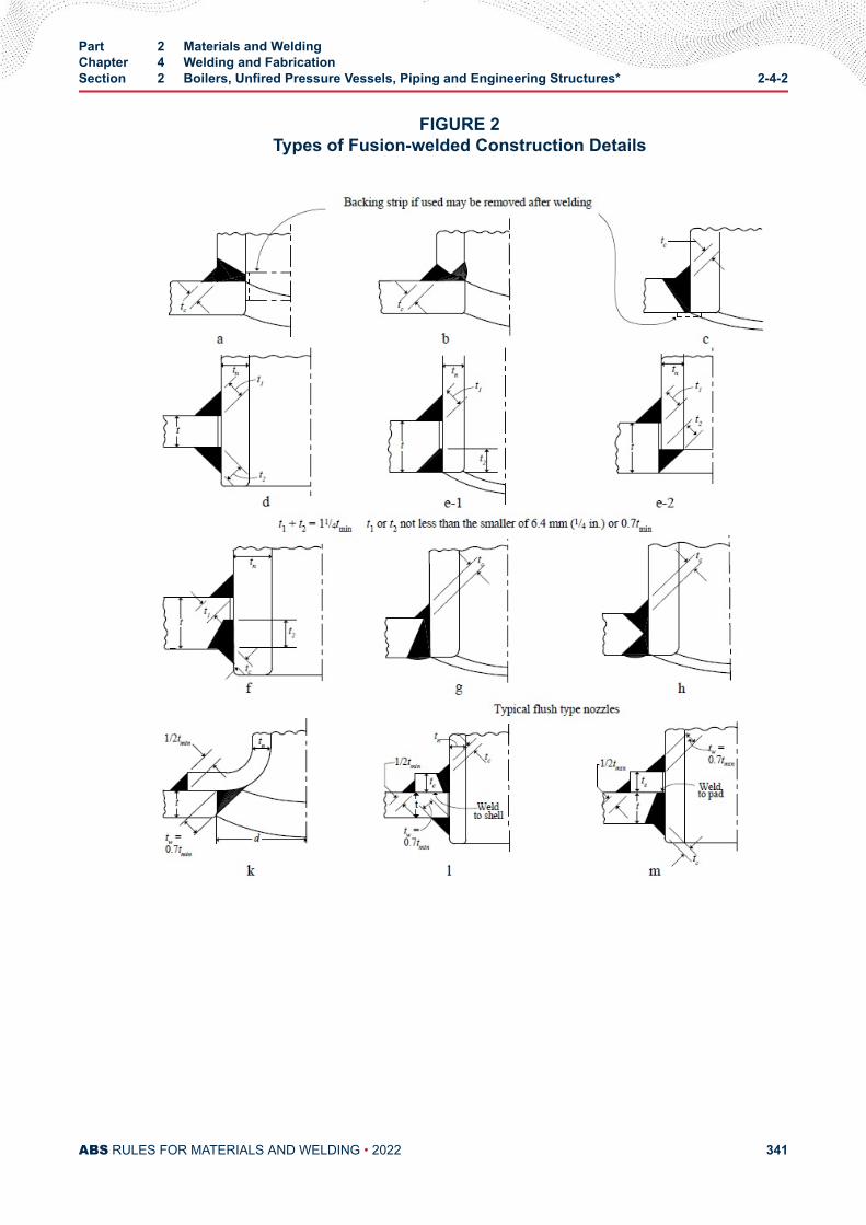
FIGURE 2Types of Fusion-welded Construction Details
Part 2 Materials and WeldingChapter 4 Welding and FabricationSection 2 Boilers, Unfired Pressure Vessels, Piping and Engineering Structures* 2-4-2
ABS RULES FOR MATERIALS AND WELDING • 2022 341
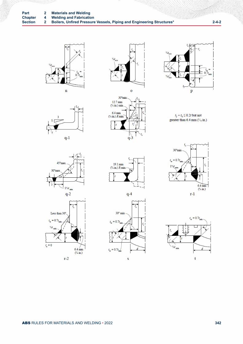
Part 2 Materials and WeldingChapter 4 Welding and FabricationSection 2 Boilers, Unfired Pressure Vessels, Piping and Engineering Structures* 2-4-2
ABS RULES FOR MATERIALS AND WELDING • 2022 342
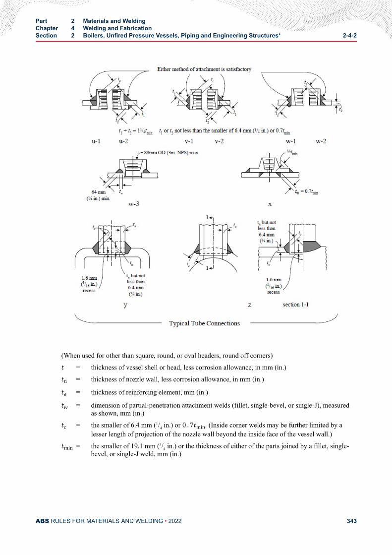
(When used for other than square, round, or oval headers, round off corners)t = thickness of vessel shell or head, less corrosion allowance, in mm (in.)tn = thickness of nozzle wall, less corrosion allowance, in mm (in.)te = thickness of reinforcing element, mm (in.)tw = dimension of partial-penetration attachment welds (fillet, single-bevel, or single-J), measuredas shown, mm (in.)tc = the smaller of 6.4 mm (1/4 in.) or 0 . 7tmin. (Inside corner welds may be further limited by alesser length of projection of the nozzle wall beyond the inside face of the vessel wall.)tmin = the smaller of 19.1 mm (3/4 in.) or the thickness of either of the parts joined by a fillet, single-bevel, or single-J weld, mm (in.)
Part 2 Materials and WeldingChapter 4 Welding and FabricationSection 2 Boilers, Unfired Pressure Vessels, Piping and Engineering Structures* 2-4-2
ABS RULES FOR MATERIALS AND WELDING • 2022 343
C H A P T E R 4Welding and Fabrication
S E C T I O N 3Weld Tests
1 General (2018)The steps to be taken in obtaining approval by ABS of electrodes, filler metals, and welding procedures forqualifying welders and for demonstrating satisfactory workmanship are given below.
1.1 Weld GroupsThe various groups of welds are designated by index letters and numbers, by which they are referred to insubsequent paragraphs, as follows.
Hull Construction H All hull structures
Boilers, etc. Group I B1
Unfired Pressure Vessels Group II B2
Piping Group I P1 As defined in 2-4-2/1.5
Piping Group II P2
Engineering Structures Group I E1
Engineering Structures Group II E2
1.3 Tests (2018)Details of tests, preparation of specimens and test results required for approval in each application aregiven in 2-4-3/3 to 2-4-3/9, and 2-4-3/Figure 1 to 2-4-3/Figure 13. Where position of welding is referredto, the same is to be defined in the American Welding Society D1.1 or 2-A9-A3..
3 Filler Metals
3.1 General (2018)Filler metals are to be a type suitable to produce sound welds that have strength and toughness comparableto the materials being welded. ABS maintains a separately issued list of approved filler metals entitled,“Approved Welding Consumables” in the ABS web site, www.eagle.org. This list, together with Part 2,Appendix 3, indicates the grade, and general application for which such filler metals may be employed. Itis intended that these lists will serve as useful guides in the selection of suitable filler metals for variouswelding applications.
PART 2
ABS RULES FOR MATERIALS AND WELDING • 2022 344
3.3 Approval Basis (2005)Filler metals will be approved and listed, subject to tests conducted at a manufacturer’s plant oralternatively, at a location outside of the manufacturer’s plant under the supervision of the manufacturer.Upon satisfactory completion of tests, a certificate will be issued for general approval, indicating, whereapplicable, the ABS Grade, operating characteristics and limits of application. Test assemblies are to beprepared in the presence of the Surveyor and all tests are to be carried out in the Surveyor’s presence andto the Surveyor’s satisfaction. Procedure and testing are to comply with either of the following standards.
3.3.1 ABS StandardsApproval of filler metals for welding vessels and other engineering structures will be granted uponcompliance with the Requirements for the Approval of Filler Metals contained in Part 2, Appendix2.
3.3.2 Standards of Other AgenciesFiller metals will be considered for approval based upon tests conducted to standards establishedby The American Welding Society or other recognized agencies.
3.3.3 Special ApprovalUnder circumstances where exact specifications have not been established, ABS will considerapproval on the basis of a filler metal manufacturer’s guaranteed requirements. Qualifiedapprovals will also be considered, with and without classifying as to grade, for special applicationswith reliance upon procedure tests at a user’s plant.
5 Approval of Welding Procedures
5.1 Approved Filler MetalsThe type of approved filler metals used on ABS-classed weldments will depend upon the specificapplication for which the filler metal is intended. Procedure tests may be required at the discretion of theattending Surveyor to determine the shipyard or fabricator’s capability in the application of the proposedfiller metal to the base material. The extent of such tests may vary depending upon the intendedapplication, but generally are to follow those tests outlined in 2-4-3/5.7.
5.3 Surveyor's AcceptanceThe Surveyor may, at his discretion, accept a filler metal, welding procedure, or both, in a shipyard orfabricator’s plant where it is established to the Surveyor’s satisfaction that they have been effectively usedfor similar work under similar conditions.
5.5 New Procedures and MethodsWeld tests using procedures and materials similar to those intended for production welding may berequired to be prepared by each shipyard or fabricator when new or unusual methods, base metals or fillermetals are proposed. All tests are to be made in the presence of the Surveyor and carried out to theSurveyor’s satisfaction.
5.7 Tests (2006)See 2-4-3/11.5 FIGURE 1. Unless otherwise approved, the number of specimens is to be as indicated. Theminimum test results required are stated with the following figures.
● Test No. 1 (For butt welds) Reduced-section Tension Test (2-4-3/11.5 FIGURE 3 or 2-4-3/11.5FIGURE 4). One test assembly for each position involved; two reduced-section tension test specimenstaken from each test assembly as shown in 2-4-3/11.5 FIGURE 1.
● Test No. 2 (For butt welds) Guided Bend Test (2-4-3/11.5 FIGURE 5 and 2-4-3/11.5 FIGURE 6).Onetest assembly for each position involved. For material 19 mm (0.75 in.) thick and under, two face-bendand two root-bend specimens taken from each test assembly as shown in 2-4-3/11.5 FIGURE 1, except
Part 2 Materials and WeldingChapter 4 Welding and FabricationSection 3 Weld Tests 2-4-3
ABS RULES FOR MATERIALS AND WELDING • 2022 345
that at the option of the fabricator, four side bends may be substituted for material thickness over 9.5mm (3/8 in.). For material over 19 mm (0.75 in.) thick, four side-bend specimens taken from each testassembly as shown in 2-4-3/11.5 FIGURE 1. The bending jig and test requirements are indicated in2-4-3/11.5 FIGURE 7.
● Test No. 3 Fillet-weld Test (2-4-3/11.5 FIGURE 8). One specimen made in each position involved.
5.9 Special TestsAll weld-metal tension, Charpy V-notch impact, macro-etch or other relevant tests may be required forcertain applications, such as higher-strength steels, electroslag welding, one-side welding, etc., and theresults submitted for consideration. 2-4-3/11.5 FIGURE 13 defines the location of Charpy V-notch impacttests when heat affected zone tests are required. A Charpy V-notch test is to consist of three specimens perlocation.
5.11 Repair and Cladding of Stern Tube and Tail ShaftsWeld repairs and cladding on stern tube shafts and tail shafts are to be performed in an approved facility.
Approval of welding procedures for the repair or cladding of stern tube shafts and tail shafts is to be inaccordance with 7-A1-11 "Repair and Cladding of Shafts" of the ABS Rules for Survey After Construction(Part 7).
7 Workmanship Tests
7.1 Hull ConstructionThe Surveyor may, when it is considered desirable, require welders to prepare specimens for Fillet-weldTests (Test No. 3) for the positions involved. Details of the specimen are shown in 2-4-3/11.5 FIGURE 8.
7.3 Boilers and Group I Pressure Vessels7.3.1 Required Tests
The following tests are to be conducted/performed using equivalent material of the same thicknessas the boiler or pressure vessel. The results required are stated with the applicable figures and in2-4-3/9.3.
● Test No. 1 Reduced-section Tension Test (2-4-3/11.5 FIGURE 3)
● Test No. 2 Guided Bend Test, (2-4-3/11.5 FIGURE 5 or 2-4-3/11.5 FIGURE 6)
● Test No. 3 Radiographic Search of Welds on Finished Joint
7.3.2 Test ExceptionsTest Nos. 1 and 2 are not required for cylindrical pressure parts of Boilers and Group I PressureVessels constructed of ABS Steel Plate for Boilers and Pressure Vessels Grades A through Ginclusive and Grades K through N inclusive whose welded joints are fully examined byradiography.
7.3.3 Attached Test PlatesStructures made in accordance with the requirements of Group B1 of materials other than thosegiven in 2-4-3/7.3.2 are to have test plates attached as shown in 2-4-3/11.5 FIGURE 2 to permitthe longitudinal joint of the shell and test plates to be welded continuously. The test plate is to beof sufficient length to provide two specimens for each of Tests Nos. 1 and 2 detailed above. Onespecimen is to be tested; the other specimen is for use in retesting, if necessary.
Part 2 Materials and WeldingChapter 4 Welding and FabricationSection 3 Weld Tests 2-4-3
ABS RULES FOR MATERIALS AND WELDING • 2022 346
7.3.4 Separate Test PlatesCircumferential joints of a boiler or pressure vessel need not be provided with test plates unlessthere be no longitudinal welded joint, in which case, test plates are required to be weldedseparately.
7.3.5 Number of Test PlatesWhere several drums or vessels of the same design and grade of material are welded insuccession, a set of test plates for each linear 61 m (200 ft) of longitudinal joints, or 61 m (200 ft)of circumferential joints where there are no longitudinal joints, will be acceptable, provided thejoints are welded by the same operators and the same welding method. Shells having nolongitudinal joints may be considered as being of the same design if the plate thicknesses fallwithin a range of 6.4 mm (0.25 in.) and the shell diameters do not vary by more than 150 mm (6in.).
7.3.6 Test-plate Heat Treatment and RetestsIn all cases, the welded test plates are to be treated as to stress relieving, etc., in the same manneras the work which they represent. Should any of the tests fail, one retest is to be made for eachfailure; and should the retest also fail, the welding represented is to be chipped or gouged out andrewelded and new test plates provided.
7.5 Other Pressure VesselsWorkmanship test plates are not required for structures in this Group. Test No. 3 is to be carried out whenrequired in 2-4-2/23.3.
7.7 Group I Pipe ConnectionsIn carbon and carbon-molybdenum steel piping for all diameters where the thickness exceeds 9.5 mm(0.375 in.) and other alloy-steel piping 76 mm (3 in.) in diameter and over regardless of thickness, weldsmade in accordance with the requirements of this group are to be subjected to 100% Radiographic Search -Test No. 3, or to other approved method of test, where the former is not applicable.
7.9 Group II Pipe ConnectionsNo workmanship tests are required.
7.11 Group I Engineering StructuresGroup I Engineering Structures are to meet the same requirements as 2-4-3/7.3, except that where there isno longitudinal joint, no test plates will be required.
7.13 Group II Engineering StructuresWelds in structures in this group which correspond in service requirements to Group B2 are to be tested inthe same manner as Group B2, except that where there is no longitudinal joint, no tests will be required.
9 Radiographic or Ultrasonic Inspection
9.1 Hull ConstructionWhere radiographic or ultrasonic inspection is required, such testing should be carried out in accordancewith ABS’s separately issued Guide for Nondestructive Inspection.
9.3 Boilers, Pressure Vessels, Machinery and Piping (2014)9.3.1 General
When radiographic examination of the finished joint is required, as indicated in 2-4-3/7.3,2-4-3/7.5, 2-4-3/7.7 and 2-4-3/7.11, the radiographs are to be obtained by means of an approvedtechnique and are to compare favorably with accepted standards.
Part 2 Materials and WeldingChapter 4 Welding and FabricationSection 3 Weld Tests 2-4-3
ABS RULES FOR MATERIALS AND WELDING • 2022 347
9.3.2 Acceptability of Welds-Full RadiographyIn general, sections of weld that are shown by full radiography to have any of the following typesof imperfections are to be considered unacceptable and are to be repaired.
9.3.2(a) Incomplete Fusion or Penetration.
Any type of crack or zone of incomplete fusion or penetration
9.3.2(b) Elongated Slag Inclusions or Cavities.
Any elongated slag inclusion or cavity which has a length greater than the following, where t isthe thickness of the thinner plate being welded.
6.4 mm (0.25 in.) for t up to 19.1 mm (0.75 in.)1/3t for t from 19.1 mm (0.75 in.) to 57.2 mm (2.25 in.)19.1 mm (0.75 in.) for t over 57.2 mm (2.25 in.)
9.3.2(c) Slag Inclusion in Line.
Any group of slag inclusions in line that have an aggregate length greater than t in a length of 12t,except when the distance between the successive imperfections exceeds 6L where L is the lengthof the longest imperfection in the group
9.3.2(d) Porosity Standards.
Porosity in excess of that permitted by accepted porosity standards such as given in the AmericanSociety of Mechanical Engineers’ (ASME) Boiler and Pressure Vessel Code.
9.3.3 Acceptability of Welds-Spot (Random) RadiographyThe inspection of the production welds by spot radiography is to compare favorably with acceptedstandards and methods, such as given in the ASME Boiler and Pressure Vessel Code.
9.3.4 Survey Report DataIn each case, a statement on the extent and the results of the radiographic examination is toaccompany the Surveyor’s report. The inspection procedure and technique is to be maintained onfile by the manufacturer and is to compare favorably with accepted practice such as that specifiedin the ASME Boiler and Pressure Vessel Code.
9.3.5 Pipe-joint ExceptionAn approved method of test may be used in lieu of the radiographic inspection of pipe joints,where the latter cannot be applied.
11 Welders
11.1 General RequirementsThe Surveyor is to be satisfied that the welders are proficient in the type of work which they are calledupon to perform, either through requiring any or all of the tests outlined in the following paragraphs orthrough due consideration of the system of employment, training, apprenticeship, plant testing, inspection,etc., employed.
11.3 Qualification Tests (1 July 2018)The tests, if required for qualification in the various positions for different materials and thicknesses, aregiven in 2-4-3/11.5 TABLE 1. The tests are referred to by Nos. Q1 to Q4 inclusive for which specimensare to be prepared in accordance with 2-4-3/Figure 9 to 2-4-3/Figure 12 respectively, and physically tested
Part 2 Materials and WeldingChapter 4 Welding and FabricationSection 3 Weld Tests 2-4-3
ABS RULES FOR MATERIALS AND WELDING • 2022 348
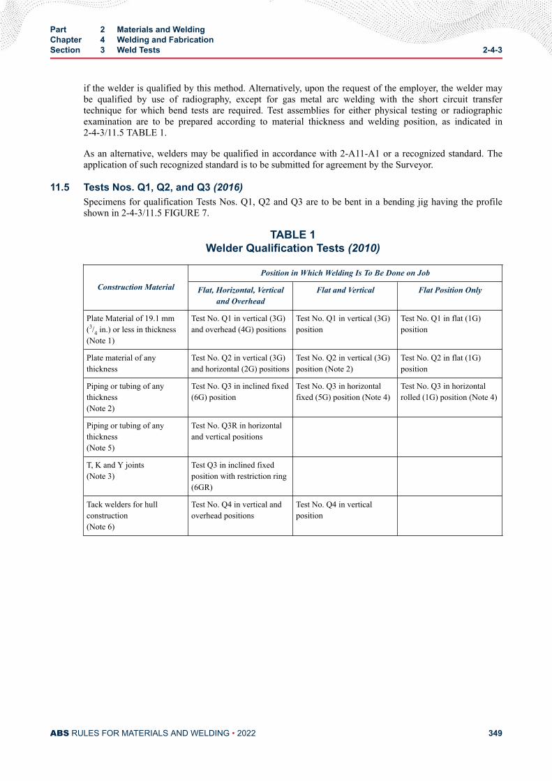
if the welder is qualified by this method. Alternatively, upon the request of the employer, the welder maybe qualified by use of radiography, except for gas metal arc welding with the short circuit transfertechnique for which bend tests are required. Test assemblies for either physical testing or radiographicexamination are to be prepared according to material thickness and welding position, as indicated in2-4-3/11.5 TABLE 1.
As an alternative, welders may be qualified in accordance with 2-A11-A1 or a recognized standard. Theapplication of such recognized standard is to be submitted for agreement by the Surveyor.
11.5 Tests Nos. Q1, Q2, and Q3 (2016)Specimens for qualification Tests Nos. Q1, Q2 and Q3 are to be bent in a bending jig having the profileshown in 2-4-3/11.5 FIGURE 7.
TABLE 1Welder Qualification Tests (2010)
Construction Material
Position in Which Welding Is To Be Done on Job
Flat, Horizontal, Verticaland Overhead
Flat and Vertical Flat Position Only
Plate Material of 19.1 mm(3/4 in.) or less in thickness(Note 1)
Test No. Q1 in vertical (3G)and overhead (4G) positions
Test No. Q1 in vertical (3G)position
Test No. Q1 in flat (1G)position
Plate material of anythickness
Test No. Q2 in vertical (3G)and horizontal (2G) positions
Test No. Q2 in vertical (3G)position (Note 2)
Test No. Q2 in flat (1G)position
Piping or tubing of anythickness(Note 2)
Test No. Q3 in inclined fixed(6G) position
Test No. Q3 in horizontalfixed (5G) position (Note 4)
Test No. Q3 in horizontalrolled (1G) position (Note 4)
Piping or tubing of anythickness(Note 5)
Test No. Q3R in horizontaland vertical positions
T, K and Y joints(Note 3)
Test Q3 in inclined fixedposition with restriction ring(6GR)
Tack welders for hullconstruction(Note 6)
Test No. Q4 in vertical andoverhead positions
Test No. Q4 in verticalposition
Part 2 Materials and WeldingChapter 4 Welding and FabricationSection 3 Weld Tests 2-4-3
ABS RULES FOR MATERIALS AND WELDING • 2022 349
Notes:
1 Where the maximum plate thickness to be welded is less than 9.5 mm (3/8 in.), the test plate thickness is to be 5.0mm (3/16 in.).
2 Welders qualified under the requirements of Test No. Q3 will be considered as qualified to make welds governedby Test Nos. Q1 and Q2, in accordance with test thickness; test thickness over 5.0 mm (3/16 in.) but less than 19.0mm (3/4 in.) qualifies for range of 1.5 mm (1/16 in.) to 2t; test thickness 19.0 mm (3/4 in.) and greater qualifies forrange of 5.0 mm (3/16 in.) to unlimited thickness. Welders qualified to weld on plate in the vertical position may bepermitted to weld on pipe in the horizontal rolled position.
3 For qualification of T, K and Y joints, Test No. Q3 in the inclined fixed position with restriction ring (6GR) isrequired.
4 Test No. Q3 in the horizontal fixed (5G) position also qualifies for overhead (4G) welding. Test No. Q3 in the 2Gposition qualifies for welding in the 1G, 1F, 2G and 2F positions.
5 Test No. Q3R may be used when special qualification for welding in areas of restricted access is required.
6 See 2-4-4/5.11 applicable for pipe welding.
Part 2 Materials and WeldingChapter 4 Welding and FabricationSection 3 Weld Tests 2-4-3
ABS RULES FOR MATERIALS AND WELDING • 2022 350
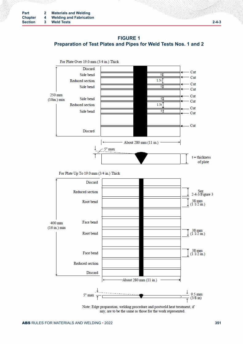
FIGURE 1Preparation of Test Plates and Pipes for Weld Tests Nos. 1 and 2
Part 2 Materials and WeldingChapter 4 Welding and FabricationSection 3 Weld Tests 2-4-3
ABS RULES FOR MATERIALS AND WELDING • 2022 351
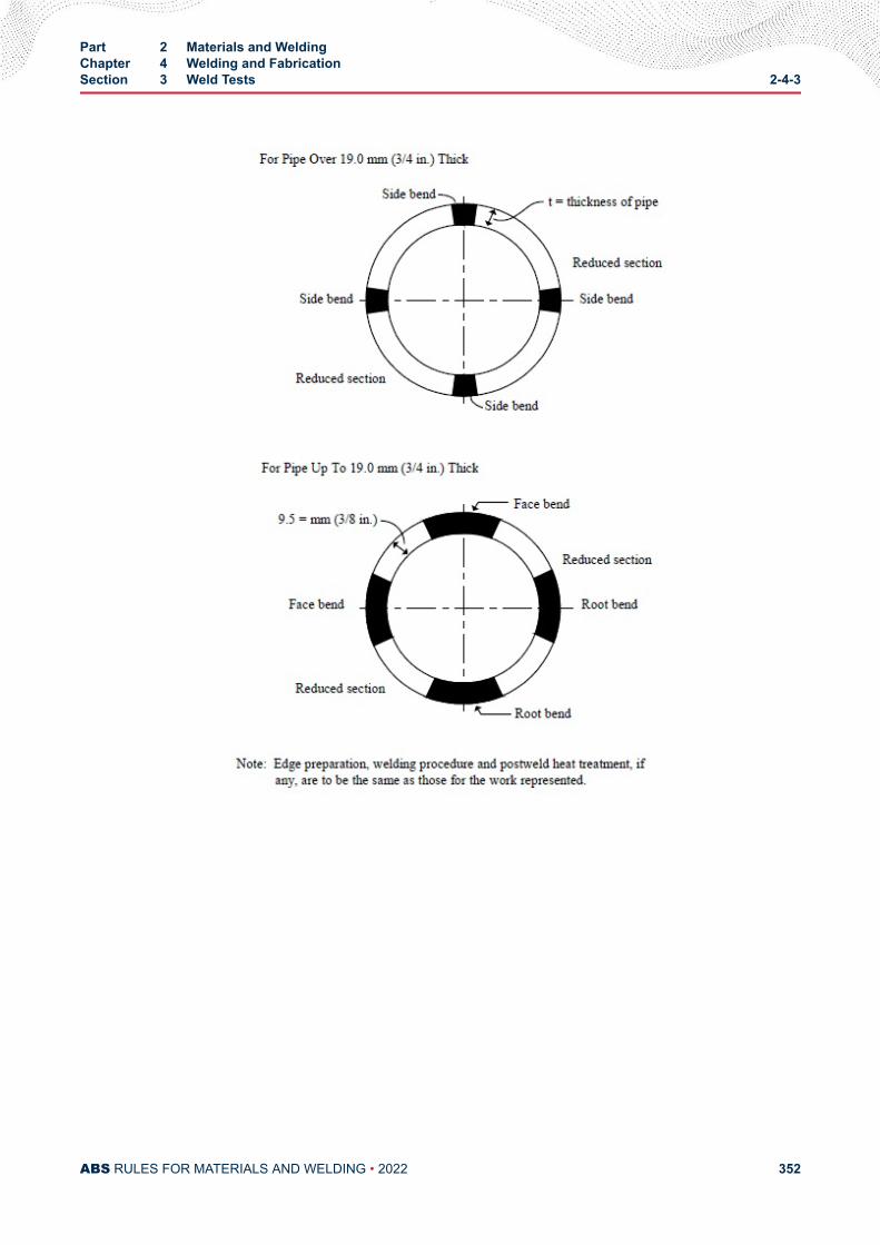
Part 2 Materials and WeldingChapter 4 Welding and FabricationSection 3 Weld Tests 2-4-3
ABS RULES FOR MATERIALS AND WELDING • 2022 352
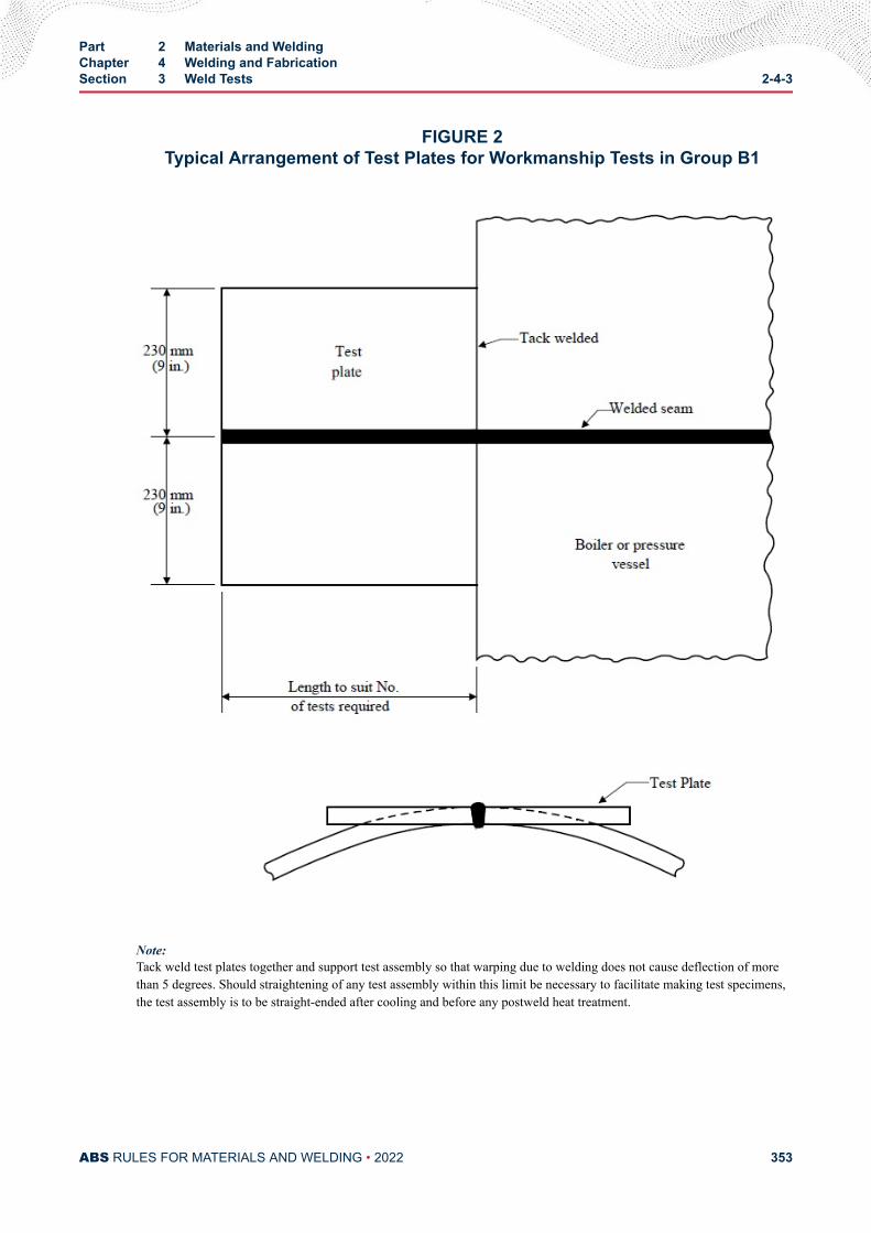
FIGURE 2Typical Arrangement of Test Plates for Workmanship Tests in Group B1
Note:Tack weld test plates together and support test assembly so that warping due to welding does not cause deflection of morethan 5 degrees. Should straightening of any test assembly within this limit be necessary to facilitate making test specimens,the test assembly is to be straight-ended after cooling and before any postweld heat treatment.
Part 2 Materials and WeldingChapter 4 Welding and FabricationSection 3 Weld Tests 2-4-3
ABS RULES FOR MATERIALS AND WELDING • 2022 353
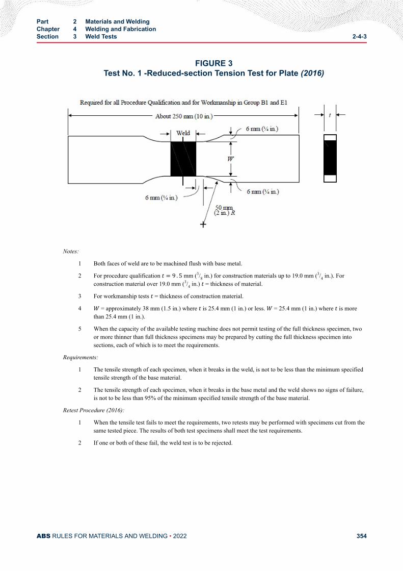
FIGURE 3Test No. 1 -Reduced-section Tension Test for Plate (2016)
Notes:
1 Both faces of weld are to be machined flush with base metal.
2 For procedure qualification t = 9 . 5 mm (3/8 in.) for construction materials up to 19.0 mm (3/4 in.). Forconstruction material over 19.0 mm (3/4 in.) t = thickness of material.
3 For workmanship tests t = thickness of construction material.
4 W = approximately 38 mm (1.5 in.) where t is 25.4 mm (1 in.) or less. W = 25.4 mm (1 in.) where t is morethan 25.4 mm (1 in.).
5 When the capacity of the available testing machine does not permit testing of the full thickness specimen, twoor more thinner than full thickness specimens may be prepared by cutting the full thickness specimen intosections, each of which is to meet the requirements.
Requirements:
1 The tensile strength of each specimen, when it breaks in the weld, is not to be less than the minimum specifiedtensile strength of the base material.
2 The tensile strength of each specimen, when it breaks in the base metal and the weld shows no signs of failure,is not to be less than 95% of the minimum specified tensile strength of the base material.
Retest Procedure (2016):
1 When the tensile test fails to meet the requirements, two retests may be performed with specimens cut from thesame tested piece. The results of both test specimens shall meet the test requirements.
2 If one or both of these fail, the weld test is to be rejected.
Part 2 Materials and WeldingChapter 4 Welding and FabricationSection 3 Weld Tests 2-4-3
ABS RULES FOR MATERIALS AND WELDING • 2022 354
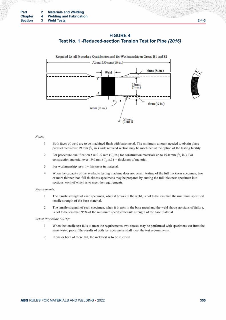
FIGURE 4Test No. 1 -Reduced-section Tension Test for Pipe (2016)
Notes:
1 Both faces of weld are to be machined flush with base metal. The minimum amount needed to obtain planeparallel faces over 19 mm (3/4 in.) wide reduced section may be machined at the option of the testing facility.
2 For procedure qualification t = 9 . 5 mm (3/8 in.) for construction materials up to 19.0 mm (3/4 in.). Forconstruction material over 19.0 mm (3/4 in.) t = thickness of material.
3 For workmanship tests t = thickness in material.
4 When the capacity of the available testing machine does not permit testing of the full thickness specimen, twoor more thinner than full thickness specimens may be prepared by cutting the full thickness specimen intosections, each of which is to meet the requirements.
Requirements:
1 The tensile strength of each specimen, when it breaks in the weld, is not to be less than the minimum specifiedtensile strength of the base material.
2 The tensile strength of each specimen, when it breaks in the base metal and the weld shows no signs of failure,is not to be less than 95% of the minimum specified tensile strength of the base material.
Retest Procedure (2016):
1 When the tensile test fails to meet the requirements, two retests may be performed with specimens cut from thesame tested piece. The results of both test specimens shall meet the test requirements.
2 If one or both of these fail, the weld test is to be rejected.
Part 2 Materials and WeldingChapter 4 Welding and FabricationSection 3 Weld Tests 2-4-3
ABS RULES FOR MATERIALS AND WELDING • 2022 355
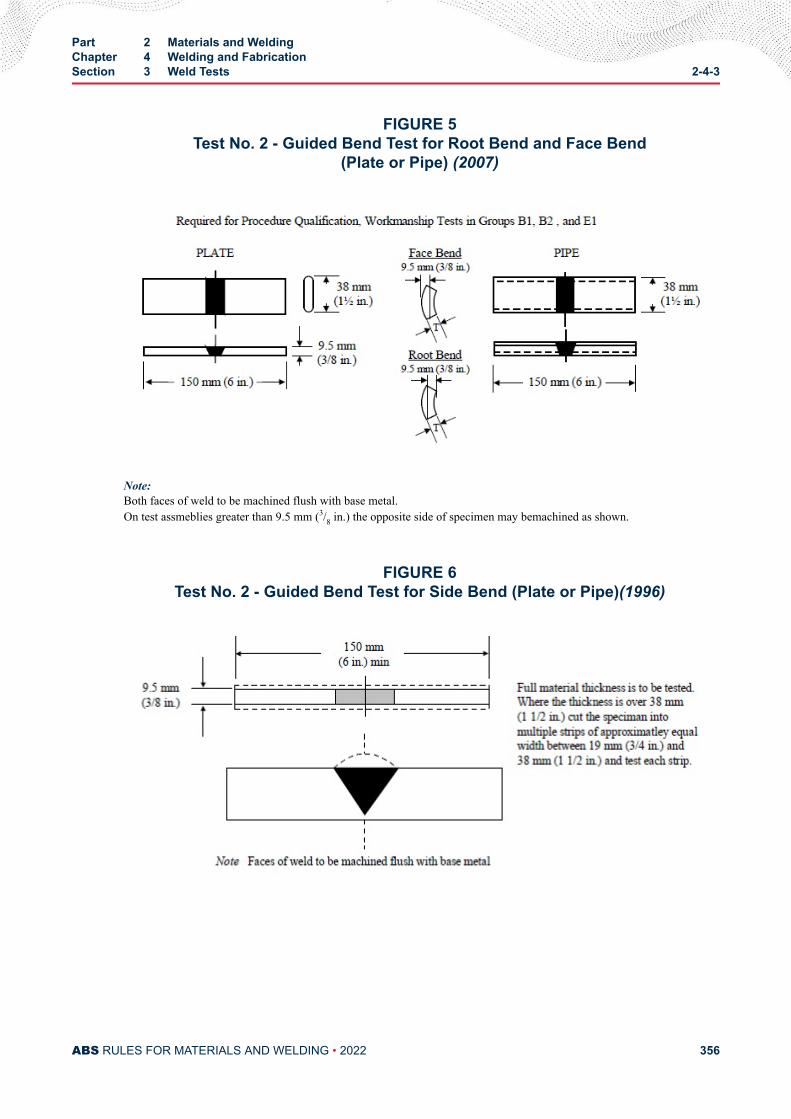
FIGURE 5Test No. 2 - Guided Bend Test for Root Bend and Face Bend
(Plate or Pipe) (2007)
Note:Both faces of weld to be machined flush with base metal.On test assmeblies greater than 9.5 mm (3/8 in.) the opposite side of specimen may bemachined as shown.
FIGURE 6Test No. 2 - Guided Bend Test for Side Bend (Plate or Pipe)(1996)
Part 2 Materials and WeldingChapter 4 Welding and FabricationSection 3 Weld Tests 2-4-3
ABS RULES FOR MATERIALS AND WELDING • 2022 356
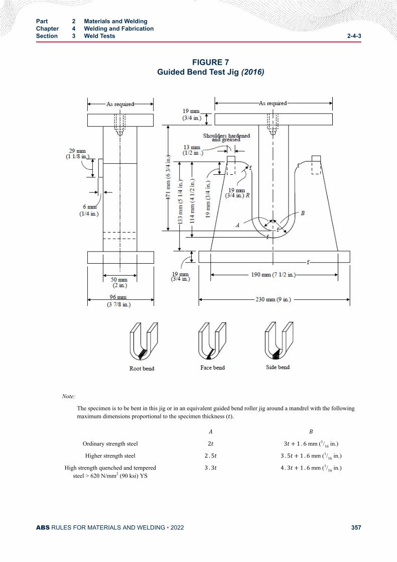
FIGURE 7Guided Bend Test Jig (2016)
Note:
The specimen is to be bent in this jig or in an equivalent guided bend roller jig around a mandrel with the followingmaximum dimensions proportional to the specimen thickness (t).A B
Ordinary strength steel 2t 3t+ 1 . 6 mm (1/16 in.)
Higher strength steel 2 . 5t 3 . 5t+ 1 . 6 mm (1/16 in.)
High strength quenched and temperedsteel > 620 N/mm2 (90 ksi) YS
3 . 3t 4 . 3t+ 1 . 6 mm (1/16 in.)
Part 2 Materials and WeldingChapter 4 Welding and FabricationSection 3 Weld Tests 2-4-3
ABS RULES FOR MATERIALS AND WELDING • 2022 357
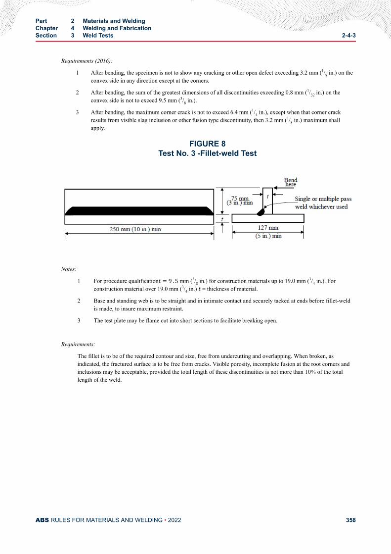
Requirements (2016):
1 After bending, the specimen is not to show any cracking or other open defect exceeding 3.2 mm (1/8 in.) on theconvex side in any direction except at the corners.
2 After bending, the sum of the greatest dimensions of all discontinuities exceeding 0.8 mm (1/32 in.) on theconvex side is not to exceed 9.5 mm (3/8 in.).
3 After bending, the maximum corner crack is not to exceed 6.4 mm (1/4 in.), except when that corner crackresults from visible slag inclusion or other fusion type discontinuity, then 3.2 mm (1/8 in.) maximum shallapply.
FIGURE 8Test No. 3 -Fillet-weld Test
Notes:
1 For procedure qualificationt = 9 . 5 mm (3/8 in.) for construction materials up to 19.0 mm (3/4 in.). Forconstruction material over 19.0 mm (3/4 in.) t = thickness of material.
2 Base and standing web is to be straight and in intimate contact and securely tacked at ends before fillet-weldis made, to insure maximum restraint.
3 The test plate may be flame cut into short sections to facilitate breaking open.
Requirements:
The fillet is to be of the required contour and size, free from undercutting and overlapping. When broken, asindicated, the fractured surface is to be free from cracks. Visible porosity, incomplete fusion at the root corners andinclusions may be acceptable, provided the total length of these discontinuities is not more than 10% of the totallength of the weld.
Part 2 Materials and WeldingChapter 4 Welding and FabricationSection 3 Weld Tests 2-4-3
ABS RULES FOR MATERIALS AND WELDING • 2022 358
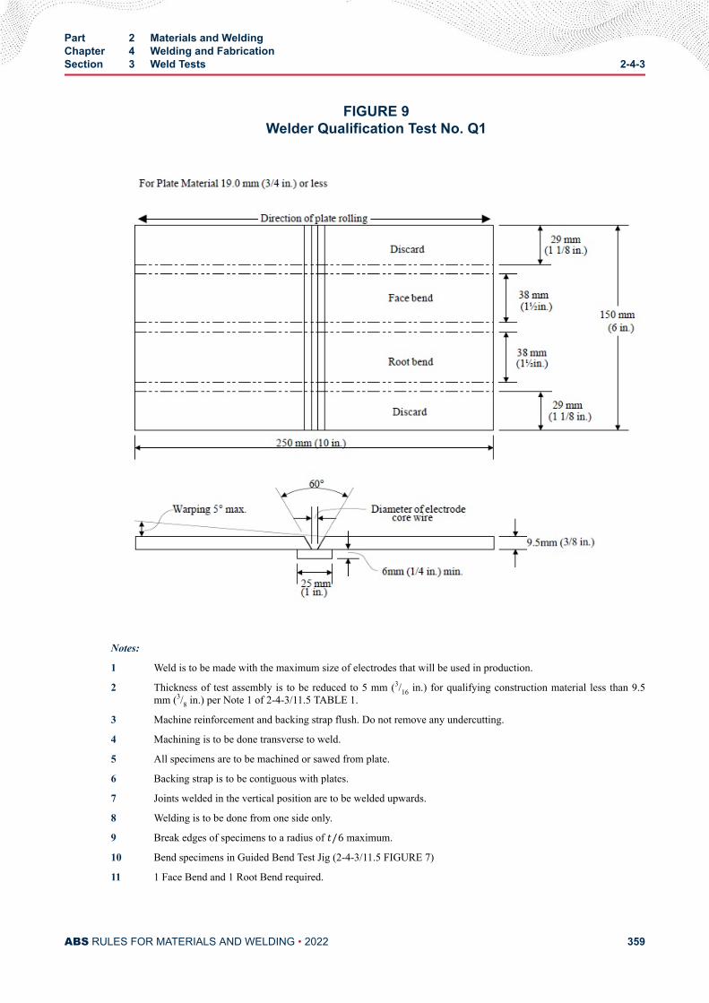
FIGURE 9Welder Qualification Test No. Q1
Notes:
1 Weld is to be made with the maximum size of electrodes that will be used in production.
2 Thickness of test assembly is to be reduced to 5 mm (3/16 in.) for qualifying construction material less than 9.5mm (3/8 in.) per Note 1 of 2-4-3/11.5 TABLE 1.
3 Machine reinforcement and backing strap flush. Do not remove any undercutting.
4 Machining is to be done transverse to weld.
5 All specimens are to be machined or sawed from plate.
6 Backing strap is to be contiguous with plates.
7 Joints welded in the vertical position are to be welded upwards.
8 Welding is to be done from one side only.
9 Break edges of specimens to a radius of t/6 maximum.
10 Bend specimens in Guided Bend Test Jig (2-4-3/11.5 FIGURE 7)
11 1 Face Bend and 1 Root Bend required.
Part 2 Materials and WeldingChapter 4 Welding and FabricationSection 3 Weld Tests 2-4-3
ABS RULES FOR MATERIALS AND WELDING • 2022 359
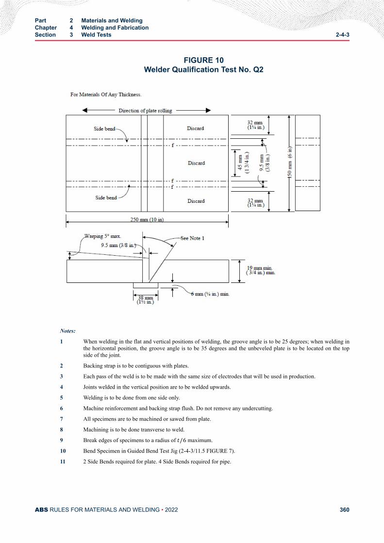
FIGURE 10Welder Qualification Test No. Q2
Notes:
1 When welding in the flat and vertical positions of welding, the groove angle is to be 25 degrees; when welding inthe horizontal position, the groove angle is to be 35 degrees and the unbeveled plate is to be located on the topside of the joint.
2 Backing strap is to be contiguous with plates.
3 Each pass of the weld is to be made with the same size of electrodes that will be used in production.
4 Joints welded in the vertical position are to be welded upwards.
5 Welding is to be done from one side only.
6 Machine reinforcement and backing strap flush. Do not remove any undercutting.
7 All specimens are to be machined or sawed from plate.
8 Machining is to be done transverse to weld.
9 Break edges of specimens to a radius of t/6 maximum.
10 Bend Specimen in Guided Bend Test Jig (2-4-3/11.5 FIGURE 7).
11 2 Side Bends required for plate. 4 Side Bends required for pipe.
Part 2 Materials and WeldingChapter 4 Welding and FabricationSection 3 Weld Tests 2-4-3
ABS RULES FOR MATERIALS AND WELDING • 2022 360
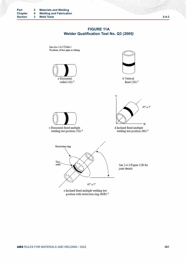
FIGURE 11AWelder Qualification Test No. Q3 (2005)
Part 2 Materials and WeldingChapter 4 Welding and FabricationSection 3 Weld Tests 2-4-3
ABS RULES FOR MATERIALS AND WELDING • 2022 361
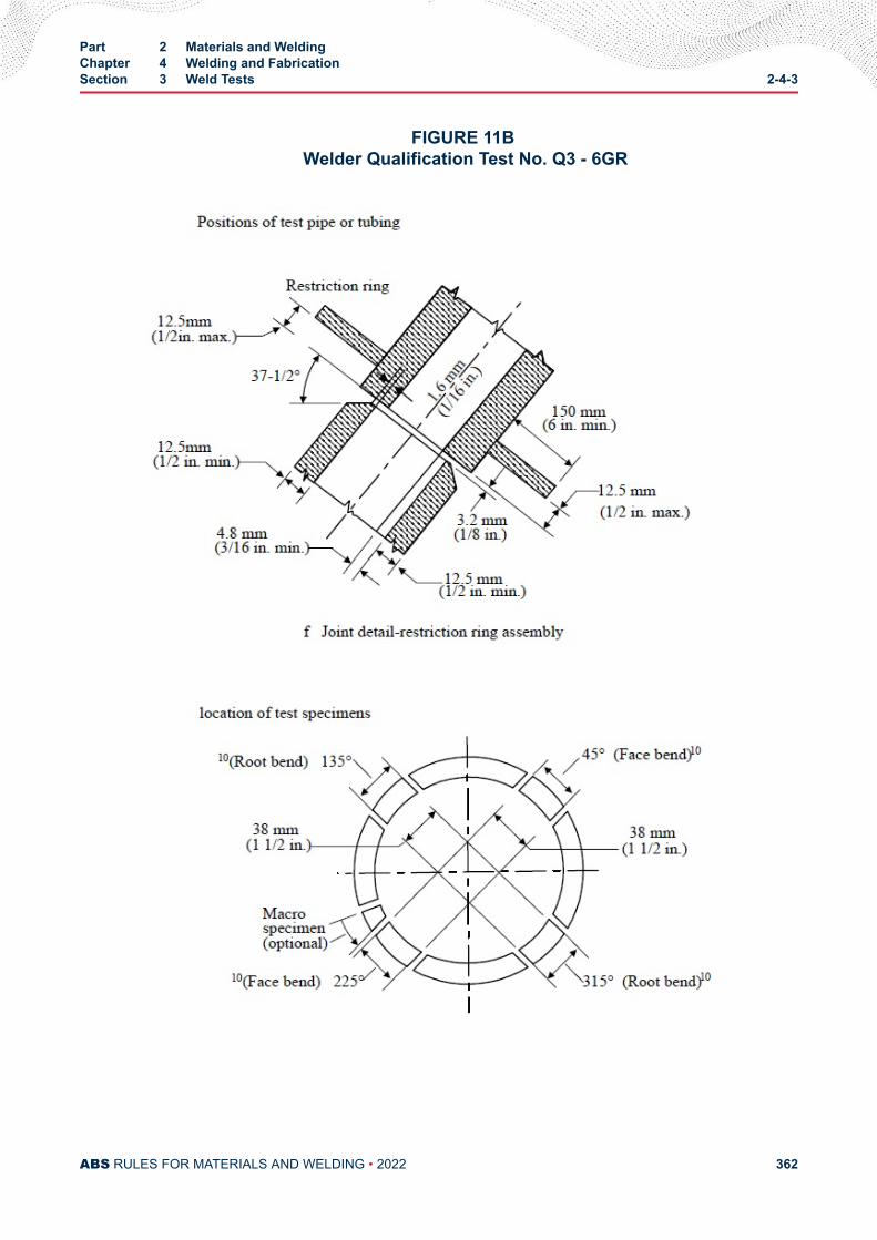
FIGURE 11B Welder Qualification Test No. Q3 - 6GR
Part 2 Materials and WeldingChapter 4 Welding and FabricationSection 3 Weld Tests 2-4-3
ABS RULES FOR MATERIALS AND WELDING • 2022 362
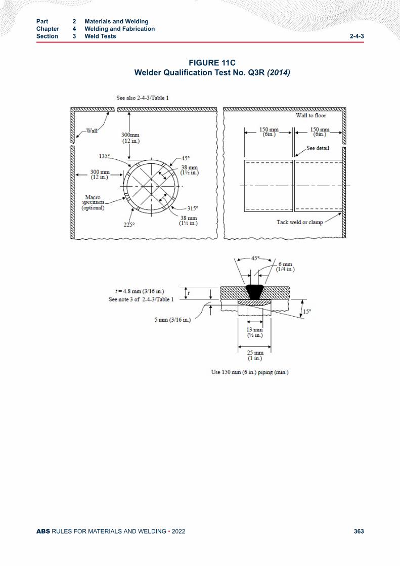
FIGURE 11CWelder Qualification Test No. Q3R (2014)
Part 2 Materials and WeldingChapter 4 Welding and FabricationSection 3 Weld Tests 2-4-3
ABS RULES FOR MATERIALS AND WELDING • 2022 363
Notes:
1 Welds are to be made with electrode sizes representative of production.
2 Machine reinforcement and backing strap flush. Do not remove any undercutting.
3 All specimens are to be machined or sawed from piping.
4 break edges of bend specimens to a radius of t/6 maximum.
5 Mark top and front of piping to insure proper location of specimens.
6 Remove face-bend specimens from 45 and 225 degree points, and root-bend specimens from 135 and 315 degreepoints as indicated. If piping of greater wall thickness than 9.5 mm (3/8 in.) is used in this test four (4) side bendtests are to be conducted in lieu of root and face bends.
7 Welding is to be done from one side only.
8 Bend specimens in Guided Bend Test Jig (2-4-3/11.5 FIGURE 7).
9 Position designations.
Part 2 Materials and WeldingChapter 4 Welding and FabricationSection 3 Weld Tests 2-4-3
ABS RULES FOR MATERIALS AND WELDING • 2022 364
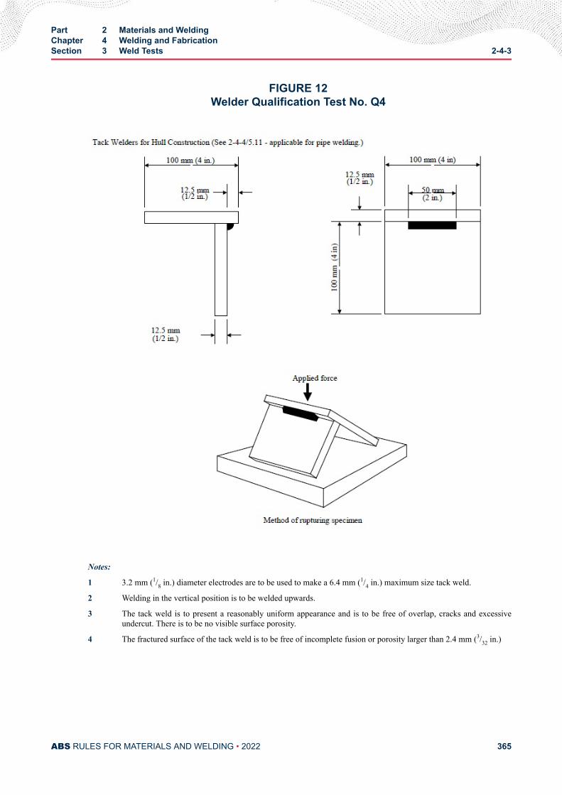
FIGURE 12Welder Qualification Test No. Q4
Notes:
1 3.2 mm (1/8 in.) diameter electrodes are to be used to make a 6.4 mm (1/4 in.) maximum size tack weld.
2 Welding in the vertical position is to be welded upwards.
3 The tack weld is to present a reasonably uniform appearance and is to be free of overlap, cracks and excessiveundercut. There is to be no visible surface porosity.
4 The fractured surface of the tack weld is to be free of incomplete fusion or porosity larger than 2.4 mm (3/32 in.)
Part 2 Materials and WeldingChapter 4 Welding and FabricationSection 3 Weld Tests 2-4-3
ABS RULES FOR MATERIALS AND WELDING • 2022 365
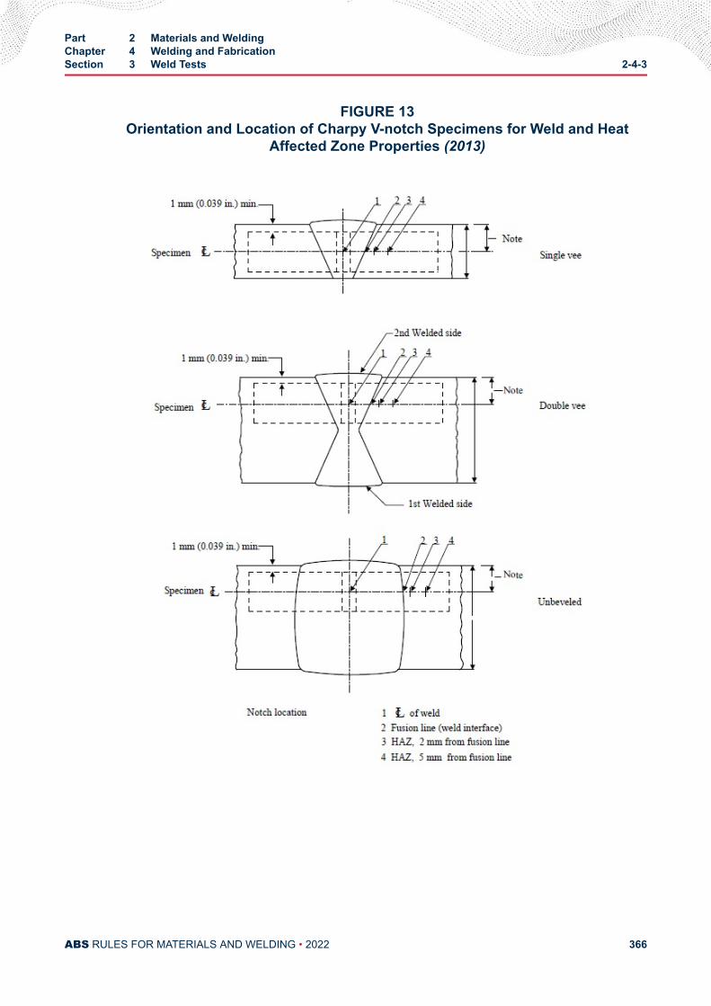
FIGURE 13Orientation and Location of Charpy V-notch Specimens for Weld and Heat
Affected Zone Properties (2013)
Part 2 Materials and WeldingChapter 4 Welding and FabricationSection 3 Weld Tests 2-4-3
ABS RULES FOR MATERIALS AND WELDING • 2022 366
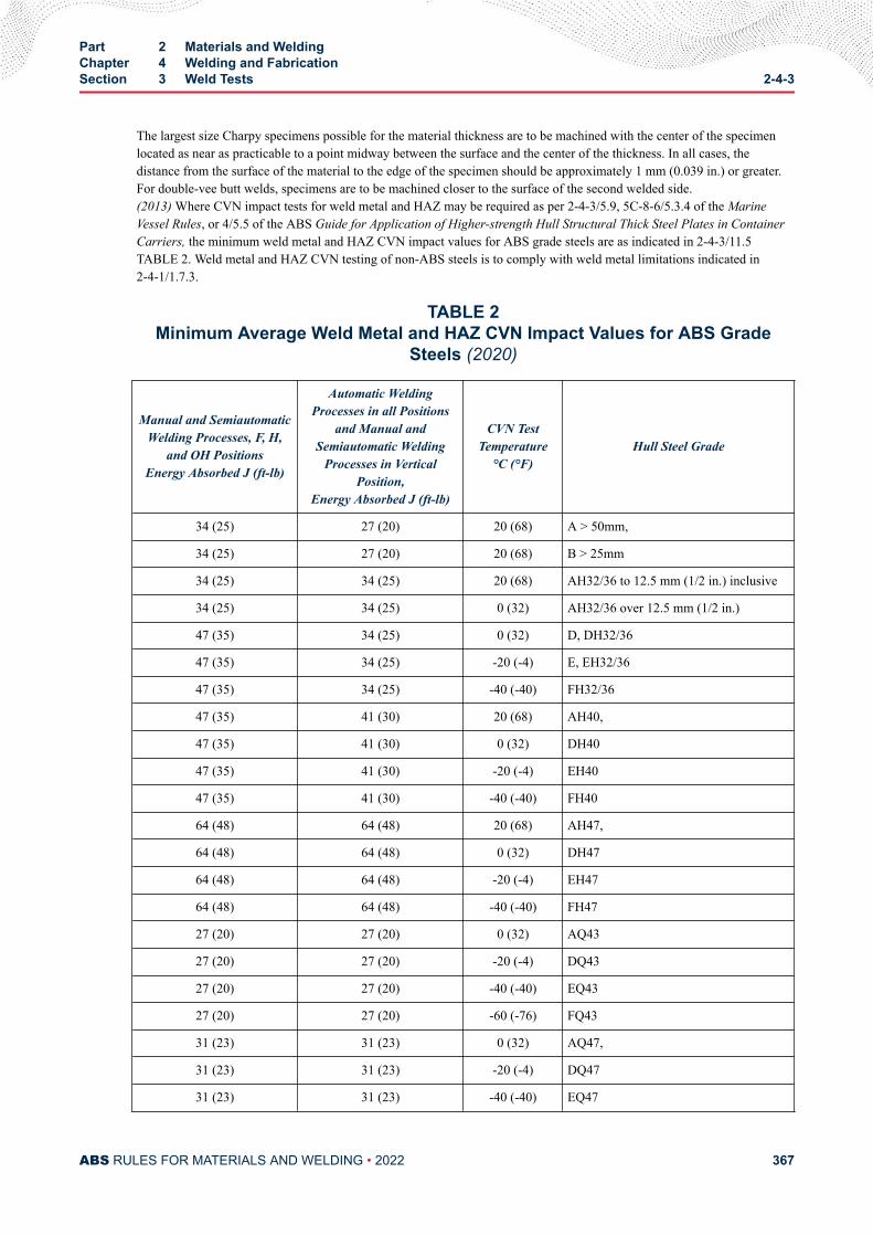
The largest size Charpy specimens possible for the material thickness are to be machined with the center of the specimenlocated as near as practicable to a point midway between the surface and the center of the thickness. In all cases, thedistance from the surface of the material to the edge of the specimen should be approximately 1 mm (0.039 in.) or greater.For double-vee butt welds, specimens are to be machined closer to the surface of the second welded side.(2013) Where CVN impact tests for weld metal and HAZ may be required as per 2-4-3/5.9, 5C-8-6/5.3.4 of the MarineVessel Rules, or 4/5.5 of the ABS Guide for Application of Higher-strength Hull Structural Thick Steel Plates in ContainerCarriers, the minimum weld metal and HAZ CVN impact values for ABS grade steels are as indicated in 2-4-3/11.5TABLE 2. Weld metal and HAZ CVN testing of non-ABS steels is to comply with weld metal limitations indicated in2-4-1/1.7.3.
TABLE 2Minimum Average Weld Metal and HAZ CVN Impact Values for ABS Grade
Steels (2020)
Manual and SemiautomaticWelding Processes, F, H,
and OH PositionsEnergy Absorbed J (ft-lb)
Automatic WeldingProcesses in all Positions
and Manual andSemiautomatic Welding
Processes in VerticalPosition,
Energy Absorbed J (ft-lb)
CVN TestTemperature
°C (°F)Hull Steel Grade
34 (25) 27 (20) 20 (68) A > 50mm,
34 (25) 27 (20) 20 (68) B > 25mm
34 (25) 34 (25) 20 (68) AH32/36 to 12.5 mm (1/2 in.) inclusive
34 (25) 34 (25) 0 (32) AH32/36 over 12.5 mm (1/2 in.)
47 (35) 34 (25) 0 (32) D, DH32/36
47 (35) 34 (25) -20 (-4) E, EH32/36
47 (35) 34 (25) -40 (-40) FH32/36
47 (35) 41 (30) 20 (68) AH40,
47 (35) 41 (30) 0 (32) DH40
47 (35) 41 (30) -20 (-4) EH40
47 (35) 41 (30) -40 (-40) FH40
64 (48) 64 (48) 20 (68) AH47,
64 (48) 64 (48) 0 (32) DH47
64 (48) 64 (48) -20 (-4) EH47
64 (48) 64 (48) -40 (-40) FH47
27 (20) 27 (20) 0 (32) AQ43
27 (20) 27 (20) -20 (-4) DQ43
27 (20) 27 (20) -40 (-40) EQ43
27 (20) 27 (20) -60 (-76) FQ43
31 (23) 31 (23) 0 (32) AQ47,
31 (23) 31 (23) -20 (-4) DQ47
31 (23) 31 (23) -40 (-40) EQ47
Part 2 Materials and WeldingChapter 4 Welding and FabricationSection 3 Weld Tests 2-4-3
ABS RULES FOR MATERIALS AND WELDING • 2022 367
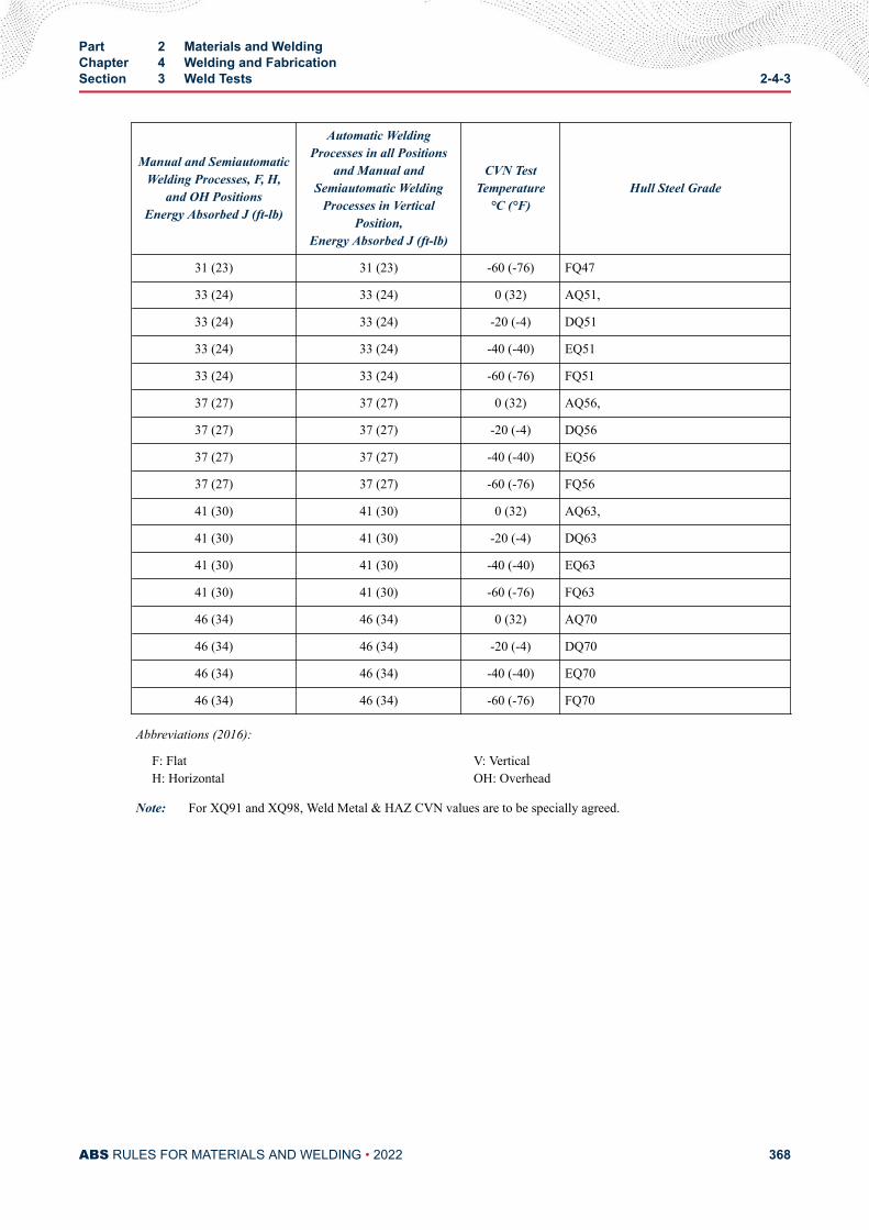
Manual and SemiautomaticWelding Processes, F, H,
and OH PositionsEnergy Absorbed J (ft-lb)
Automatic WeldingProcesses in all Positions
and Manual andSemiautomatic Welding
Processes in VerticalPosition,
Energy Absorbed J (ft-lb)
CVN TestTemperature
°C (°F)Hull Steel Grade
31 (23) 31 (23) -60 (-76) FQ47
33 (24) 33 (24) 0 (32) AQ51,
33 (24) 33 (24) -20 (-4) DQ51
33 (24) 33 (24) -40 (-40) EQ51
33 (24) 33 (24) -60 (-76) FQ51
37 (27) 37 (27) 0 (32) AQ56,
37 (27) 37 (27) -20 (-4) DQ56
37 (27) 37 (27) -40 (-40) EQ56
37 (27) 37 (27) -60 (-76) FQ56
41 (30) 41 (30) 0 (32) AQ63,
41 (30) 41 (30) -20 (-4) DQ63
41 (30) 41 (30) -40 (-40) EQ63
41 (30) 41 (30) -60 (-76) FQ63
46 (34) 46 (34) 0 (32) AQ70
46 (34) 46 (34) -20 (-4) DQ70
46 (34) 46 (34) -40 (-40) EQ70
46 (34) 46 (34) -60 (-76) FQ70
Abbreviations (2016):
F: FlatH: Horizontal
V: VerticalOH: Overhead
Note: For XQ91 and XQ98, Weld Metal & HAZ CVN values are to be specially agreed.
Part 2 Materials and WeldingChapter 4 Welding and FabricationSection 3 Weld Tests 2-4-3
ABS RULES FOR MATERIALS AND WELDING • 2022 368
C H A P T E R 4Welding and Fabrication
S E C T I O N 4Piping (1 July 2021)
Note:
* (2016) This Section is applicable only to piping for installation on vessels to be built in accordance with the ABS Rules forBuilding and Classing Marine Vessels (MVR), the ABS Rules for Building and Classing Mobile Offshore Units (MOU)), andthe ABS Rules for Building and Classing Light Warships, Patrol and High-Speed Naval Vessels (LHSNV). Piping intendedfor all other applications is to comply with Section 2-4-2.
1 General
1.1 ApplicationThe provisions of this section are intended for welding of steel pipes in systems covered in Part 4, Chapter6 of the Rules for Building and Classing Marine Vessels, (MVR). Additional provisions, as may bespecified for piping systems of specialized carriers in Part 5C and Part 5D of the Rules for Building andClassing Marine Vessels, where applicable, are also to be complied with. Consideration will be given tocompliance with a recognized national or international welding standard that is considered equallyeffective.
1.3 Pipe ClassesPipe classes are as defined in 4-6-1/5 TABLE 1, (MVR). Classes I and II pipes are to comply with all theprovisions of this Section. Class III pipes are to comply at least with 2-4-4/1.7, 2-4-4/3, 2-4-4/5 and2-4-4/11.1 of this Section.
1.5 MaterialsFor purpose of determining welding requirements, steel pipe materials are grouped as follows:
Material group DescriptionRepresentative standards (1)
ABS grade ASTM grade
C and C/Mn Carbon;carbon manganese
1, 2, 3, 4, 5;8, 9
A53, A106;A135
0.5 Mo0.5 Mo/0.5 Cr
Up to 0.5% Molybdenum;0.5% Molybdenum & 0.5%
Chromium
6; 7 A335 P1;A335 P2
PART 2
ABS RULES FOR MATERIALS AND WELDING • 2022 369
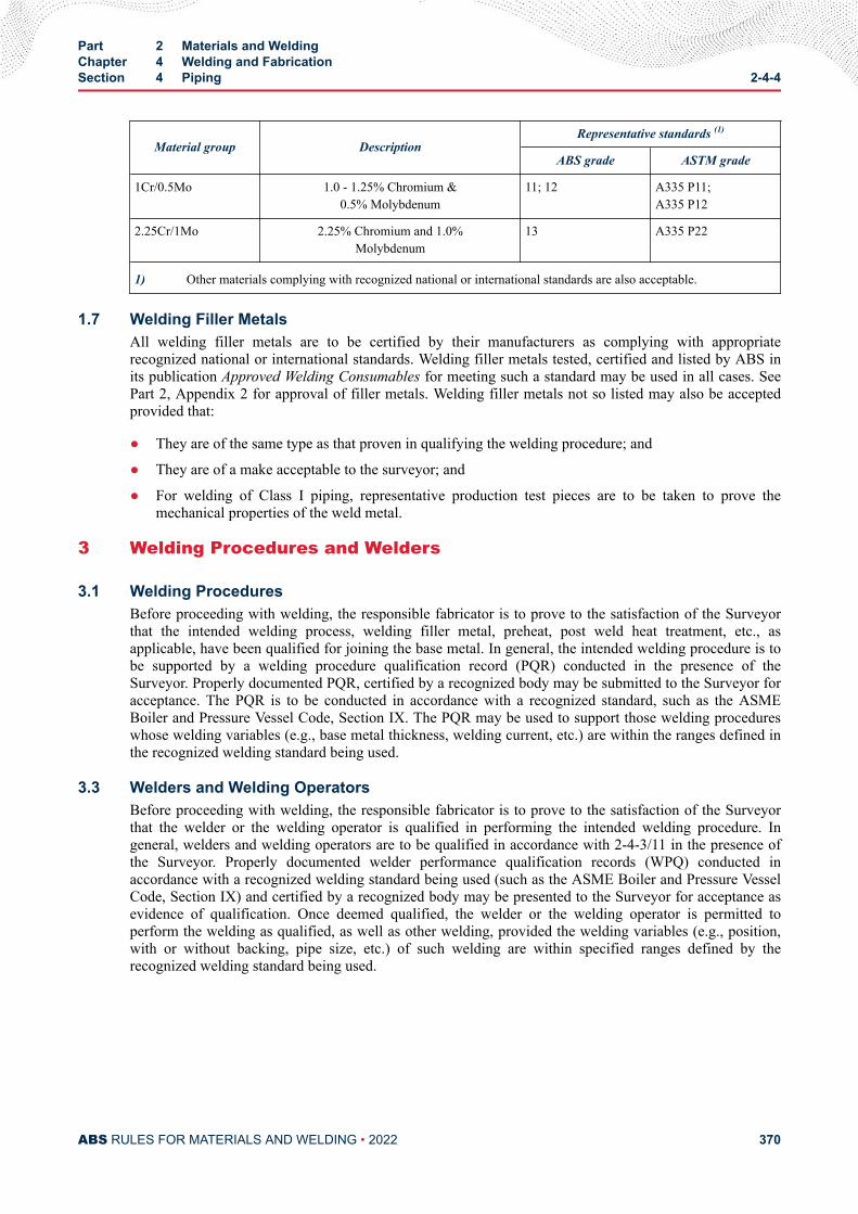
Material group DescriptionRepresentative standards (1)
ABS grade ASTM grade
1Cr/0.5Mo 1.0 - 1.25% Chromium &0.5% Molybdenum
11; 12 A335 P11;A335 P12
2.25Cr/1Mo 2.25% Chromium and 1.0%Molybdenum
13 A335 P22
1) Other materials complying with recognized national or international standards are also acceptable.
1.7 Welding Filler MetalsAll welding filler metals are to be certified by their manufacturers as complying with appropriaterecognized national or international standards. Welding filler metals tested, certified and listed by ABS inits publication Approved Welding Consumables for meeting such a standard may be used in all cases. SeePart 2, Appendix 2 for approval of filler metals. Welding filler metals not so listed may also be acceptedprovided that:
● They are of the same type as that proven in qualifying the welding procedure; and
● They are of a make acceptable to the surveyor; and
● For welding of Class I piping, representative production test pieces are to be taken to prove themechanical properties of the weld metal.
3 Welding Procedures and Welders
3.1 Welding ProceduresBefore proceeding with welding, the responsible fabricator is to prove to the satisfaction of the Surveyorthat the intended welding process, welding filler metal, preheat, post weld heat treatment, etc., asapplicable, have been qualified for joining the base metal. In general, the intended welding procedure is tobe supported by a welding procedure qualification record (PQR) conducted in the presence of theSurveyor. Properly documented PQR, certified by a recognized body may be submitted to the Surveyor foracceptance. The PQR is to be conducted in accordance with a recognized standard, such as the ASMEBoiler and Pressure Vessel Code, Section IX. The PQR may be used to support those welding procedureswhose welding variables (e.g., base metal thickness, welding current, etc.) are within the ranges defined inthe recognized welding standard being used.
3.3 Welders and Welding OperatorsBefore proceeding with welding, the responsible fabricator is to prove to the satisfaction of the Surveyorthat the welder or the welding operator is qualified in performing the intended welding procedure. Ingeneral, welders and welding operators are to be qualified in accordance with 2-4-3/11 in the presence ofthe Surveyor. Properly documented welder performance qualification records (WPQ) conducted inaccordance with a recognized welding standard being used (such as the ASME Boiler and Pressure VesselCode, Section IX) and certified by a recognized body may be presented to the Surveyor for acceptance asevidence of qualification. Once deemed qualified, the welder or the welding operator is permitted toperform the welding as qualified, as well as other welding, provided the welding variables (e.g., position,with or without backing, pipe size, etc.) of such welding are within specified ranges defined by therecognized welding standard being used.
Part 2 Materials and WeldingChapter 4 Welding and FabricationSection 4 Piping 2-4-4
ABS RULES FOR MATERIALS AND WELDING • 2022 370
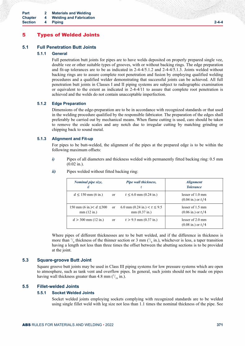
5 Types of Welded Joints
5.1 Full Penetration Butt Joints5.1.1 General
Full penetration butt joints for pipes are to have welds deposited on properly prepared single vee,double vee or other suitable types of grooves, with or without backing rings. The edge preparationand fit-up tolerances are to be as indicated in 2-4-4/5.1.2 and 2-4-4/5.1.3. Joints welded withoutbacking rings are to assure complete root penetration and fusion by employing qualified weldingprocedures and a qualified welder demonstrating that successful joints can be achieved. All fullpenetration butt joints in Classes I and II piping systems are subject to radiographic examinationor equivalent to the extent as indicated in 2-4-4/11 to assure that complete root penetration isachieved and the welds do not contain unacceptable imperfection.
5.1.2 Edge PreparationDimensions of the edge-preparation are to be in accordance with recognized standards or that usedin the welding procedure qualified by the responsible fabricator. The preparation of the edges shallpreferably be carried out by mechanical means. When flame cutting is used, care should be takento remove the oxide scales and any notch due to irregular cutting by matching grinding orchipping back to sound metal.
5.1.3 Alignment and Fit-upFor pipes to be butt-welded, the alignment of the pipes at the prepared edge is to be within thefollowing maximum offsets:
i) Pipes of all diameters and thickness welded with permanently fitted backing ring: 0.5 mm(0.02 in.).
ii) Pipes welded without fitted backing ring:
Nominal pipe size,d Pipe wall thickness,t AlignmentToleranced ≤ 150 mm (6 in.) or t ≤ 6.0 mm (0.24 in.) lesser of 1.0 mm
(0.04 in.) or t/4150 mm (6 in.)< d ≤300
mm (12 in.)or 6.0 mm (0.24 in.) < t ≤ 9.5
mm (0.37 in.)lesser of 1.5 mm(0.06 in.) or t/4d > 300 mm (12 in.) or t > 9.5 mm (0.37 in.) lesser of 2.0 mm(0.08 in.) or t/4
Where pipes of different thicknesses are to be butt welded, and if the difference in thickness ismore than 1/4 thickness of the thinner section or 3 mm (1/8 in.), whichever is less, a taper transitionhaving a length not less than three times the offset between the abutting sections is to be providedat the joint.
5.3 Square-groove Butt JointSquare groove butt joints may be used in Class III piping systems for low pressure systems which are opento atmosphere, such as tank vent and overflow pipes. In general, such joints should not be made on pipeshaving wall thickness greater than 4.8 mm (3/16 in.).
5.5 Fillet-welded Joints5.5.1 Socket Welded Joints
Socket welded joints employing sockets complying with recognized standards are to be weldedusing single fillet weld with leg size not less than 1.1 times the nominal thickness of the pipe. See
Part 2 Materials and WeldingChapter 4 Welding and FabricationSection 4 Piping 2-4-4
ABS RULES FOR MATERIALS AND WELDING • 2022 371
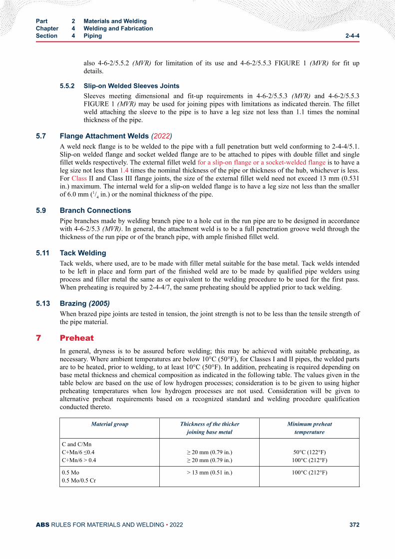
also 4-6-2/5.5.2 (MVR) for limitation of its use and 4-6-2/5.5.3 FIGURE 1 (MVR) for fit updetails.
5.5.2 Slip-on Welded Sleeves JointsSleeves meeting dimensional and fit-up requirements in 4-6-2/5.5.3 (MVR) and 4-6-2/5.5.3FIGURE 1 (MVR) may be used for joining pipes with limitations as indicated therein. The filletweld attaching the sleeve to the pipe is to have a leg size not less than 1.1 times the nominalthickness of the pipe.
5.7 Flange Attachment Welds (2022)A weld neck flange is to be welded to the pipe with a full penetration butt weld conforming to 2-4-4/5.1.Slip-on welded flange and socket welded flange are to be attached to pipes with double fillet and singlefillet welds respectively. The external fillet weld for a slip-on flange or a socket-welded flange is to have aleg size not less than 1.4 times the nominal thickness of the pipe or thickness of the hub, whichever is less.For Class II and Class III flange joints, the size of the external fillet weld need not exceed 13 mm (0.531in.) maximum. The internal weld for a slip-on welded flange is to have a leg size not less than the smallerof 6.0 mm (1/4 in.) or the nominal thickness of the pipe.
5.9 Branch ConnectionsPipe branches made by welding branch pipe to a hole cut in the run pipe are to be designed in accordancewith 4-6-2/5.3 (MVR). In general, the attachment weld is to be a full penetration groove weld through thethickness of the run pipe or of the branch pipe, with ample finished fillet weld.
5.11 Tack WeldingTack welds, where used, are to be made with filler metal suitable for the base metal. Tack welds intendedto be left in place and form part of the finished weld are to be made by qualified pipe welders usingprocess and filler metal the same as or equivalent to the welding procedure to be used for the first pass.When preheating is required by 2-4-4/7, the same preheating should be applied prior to tack welding.
5.13 Brazing (2005)When brazed pipe joints are tested in tension, the joint strength is not to be less than the tensile strength ofthe pipe material.
7 PreheatIn general, dryness is to be assured before welding; this may be achieved with suitable preheating, asnecessary. Where ambient temperatures are below 10°C (50°F), for Classes I and II pipes, the welded partsare to be heated, prior to welding, to at least 10°C (50°F). In addition, preheating is required depending onbase metal thickness and chemical composition as indicated in the following table. The values given in thetable below are based on the use of low hydrogen processes; consideration is to be given to using higherpreheating temperatures when low hydrogen processes are not used. Consideration will be given toalternative preheat requirements based on a recognized standard and welding procedure qualificationconducted thereto.
Material group Thickness of the thickerjoining base metal
Minimum preheattemperature
C and C/MnC+Mn/6 ≤0.4C+Mn/6 > 0.4
≥ 20 mm (0.79 in.)≥ 20 mm (0.79 in.)
50°C (122°F)100°C (212°F)
0.5 Mo0.5 Mo/0.5 Cr
> 13 mm (0.51 in.) 100°C (212°F)
Part 2 Materials and WeldingChapter 4 Welding and FabricationSection 4 Piping 2-4-4
ABS RULES FOR MATERIALS AND WELDING • 2022 372
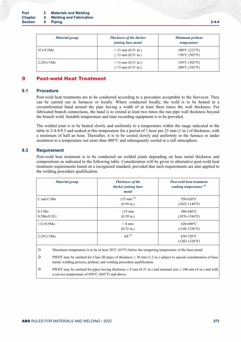
Material group Thickness of the thickerjoining base metal
Minimum preheattemperature
1Cr/0.5Mo < 13 mm (0.51 in.)≥ 13 mm (0.51 in.)
100°C (212°F)150°C (302°F)
2.25Cr/1Mo < 13 mm (0.51 in.)≥ 13 mm (0.51 in.)
150°C (302°F)200°C (392°F)
9 Post-weld Heat Treatment
9.1 ProcedurePost-weld heat treatments are to be conducted according to a procedure acceptable to the Surveyor. Theycan be carried out in furnaces or locally. Where conducted locally, the weld is to be heated in acircumferential band around the pipe having a width of at least three times the wall thickness. Forfabricated branch connections, the band is to extend at least two times the run pipe wall thickness beyondthe branch weld. Suitable temperature and time recording equipment is to be provided.
The welded joint is to be heated slowly and uniformly to a temperature within the range indicated in thetable in 2-4-4/9.3 and soaked at this temperature for a period of 1 hour per 25 mm (1 in.) of thickness, witha minimum of half an hour. Thereafter, it is to be cooled slowly and uniformly in the furnace or underinsulation to a temperature not more than 400°C and subsequently cooled in a still atmosphere.
9.3 RequirementPost-weld heat treatment is to be conducted on welded joints depending on base metal thickness andcompositions as indicated in the following table. Consideration will be given to alternative post-weld heattreatment requirements based on a recognized standard, provided that such requirements are also applied tothe welding procedure qualification.
Material group Thickness of thethicker joining base
metal
Post-weld heat treatmentsoaking temperature (1)
C and C/Mn ≥15 mm (2)
(0.59 in.)550-620°C
(1022-1148°F)
0.5 Mo0.5Mo/0.5Cr
≥15 mm(0.59 in.)
580-640°C(1076-1184°F)
1 Cr/0.5Mo > 8 mm(0.32 in.)
620-680°C(1148-1256°F)
2.25Cr/1Mo All (3) 650-720°C(1202-1328°F)
1) Maximum temperature is to be at least 20°C (65°F) below the tempering temperature of the base metal.
2) PWHT may be omitted for Class III pipes of thickness ≤ 30 mm (1.2 in.) subject to special consideration of basemetal, welding process, preheat, and welding procedure qualification.
3) PWHT may be omitted for pipes having thickness ≤ 8 mm (0.31 in.) and nominal size ≤ 100 mm (4 in.) and witha service temperature of 450°C (842°F) and above.
Part 2 Materials and WeldingChapter 4 Welding and FabricationSection 4 Piping 2-4-4
ABS RULES FOR MATERIALS AND WELDING • 2022 373
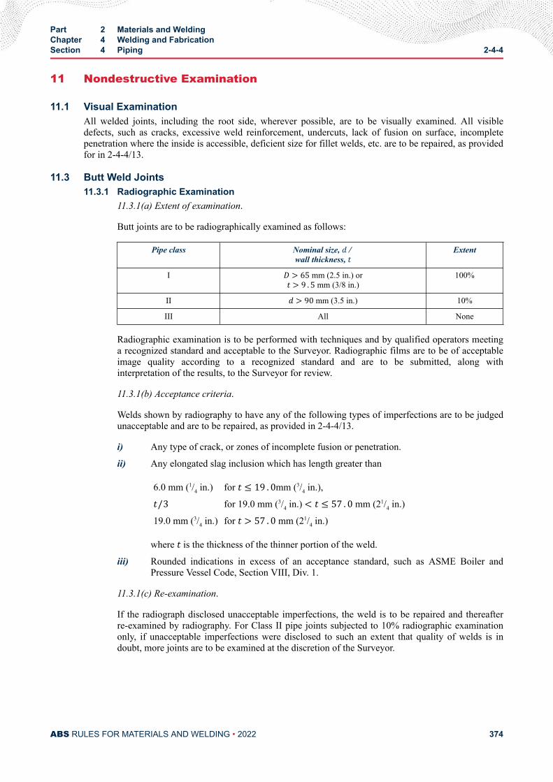
11 Nondestructive Examination
11.1 Visual ExaminationAll welded joints, including the root side, wherever possible, are to be visually examined. All visibledefects, such as cracks, excessive weld reinforcement, undercuts, lack of fusion on surface, incompletepenetration where the inside is accessible, deficient size for fillet welds, etc. are to be repaired, as providedfor in 2-4-4/13.
11.3 Butt Weld Joints11.3.1 Radiographic Examination
11.3.1(a) Extent of examination.
Butt joints are to be radiographically examined as follows:
Pipe class Nominal size, d / wall thickness, t Extent
I D > 65 mm (2.5 in.) ort > 9 . 5 mm (3/8 in.)100%
II d > 90 mm (3.5 in.) 10%
III All None
Radiographic examination is to be performed with techniques and by qualified operators meetinga recognized standard and acceptable to the Surveyor. Radiographic films are to be of acceptableimage quality according to a recognized standard and are to be submitted, along withinterpretation of the results, to the Surveyor for review.
11.3.1(b) Acceptance criteria.
Welds shown by radiography to have any of the following types of imperfections are to be judgedunacceptable and are to be repaired, as provided in 2-4-4/13.
i) Any type of crack, or zones of incomplete fusion or penetration.
ii) Any elongated slag inclusion which has length greater than
6.0 mm (1/4 in.) for t ≤ 19 . 0mm (3/4 in.),t/3 for 19.0 mm (3/4 in.) < t ≤ 57 . 0 mm (21/4 in.)
19.0 mm (3/4 in.) for t > 57 . 0 mm (21/4 in.)
where t is the thickness of the thinner portion of the weld.
iii) Rounded indications in excess of an acceptance standard, such as ASME Boiler andPressure Vessel Code, Section VIII, Div. 1.
11.3.1(c) Re-examination.
If the radiograph disclosed unacceptable imperfections, the weld is to be repaired and thereafterre-examined by radiography. For Class II pipe joints subjected to 10% radiographic examinationonly, if unacceptable imperfections were disclosed to such an extent that quality of welds is indoubt, more joints are to be examined at the discretion of the Surveyor.
Part 2 Materials and WeldingChapter 4 Welding and FabricationSection 4 Piping 2-4-4
ABS RULES FOR MATERIALS AND WELDING • 2022 374
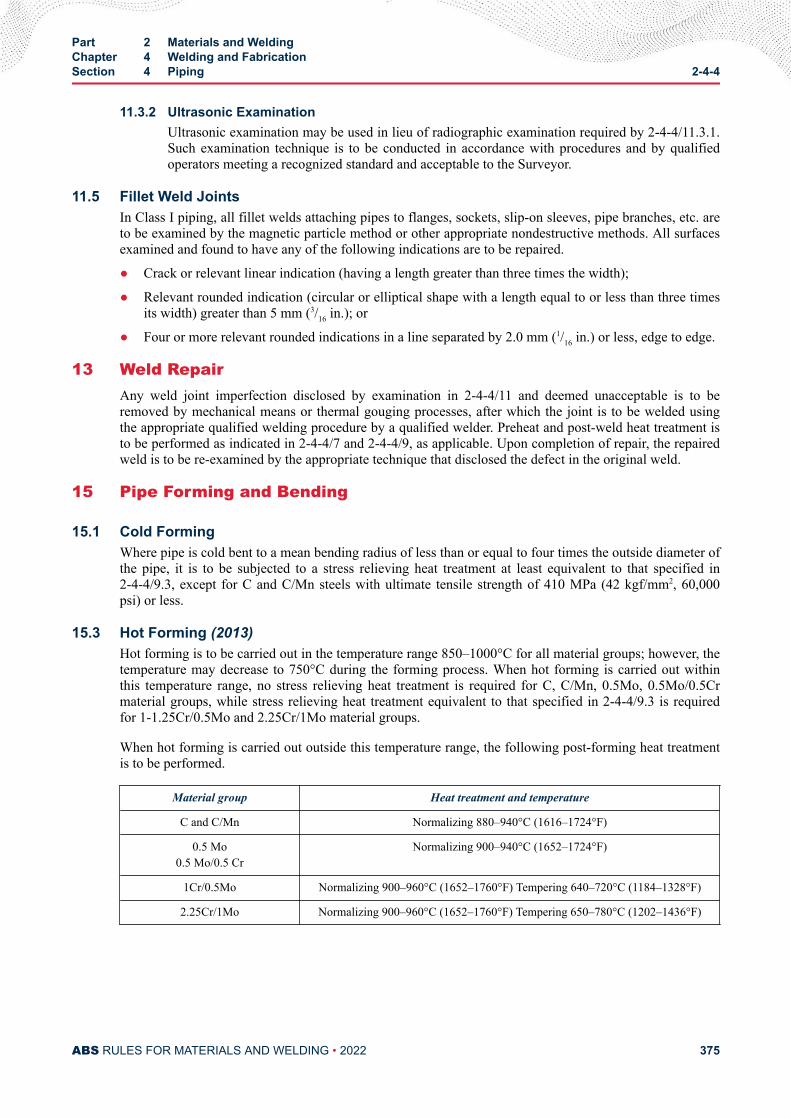
11.3.2 Ultrasonic ExaminationUltrasonic examination may be used in lieu of radiographic examination required by 2-4-4/11.3.1.Such examination technique is to be conducted in accordance with procedures and by qualifiedoperators meeting a recognized standard and acceptable to the Surveyor.
11.5 Fillet Weld JointsIn Class I piping, all fillet welds attaching pipes to flanges, sockets, slip-on sleeves, pipe branches, etc. areto be examined by the magnetic particle method or other appropriate nondestructive methods. All surfacesexamined and found to have any of the following indications are to be repaired.
● Crack or relevant linear indication (having a length greater than three times the width);
● Relevant rounded indication (circular or elliptical shape with a length equal to or less than three timesits width) greater than 5 mm (3/16 in.); or
● Four or more relevant rounded indications in a line separated by 2.0 mm (1/16 in.) or less, edge to edge.
13 Weld RepairAny weld joint imperfection disclosed by examination in 2-4-4/11 and deemed unacceptable is to beremoved by mechanical means or thermal gouging processes, after which the joint is to be welded usingthe appropriate qualified welding procedure by a qualified welder. Preheat and post-weld heat treatment isto be performed as indicated in 2-4-4/7 and 2-4-4/9, as applicable. Upon completion of repair, the repairedweld is to be re-examined by the appropriate technique that disclosed the defect in the original weld.
15 Pipe Forming and Bending
15.1 Cold FormingWhere pipe is cold bent to a mean bending radius of less than or equal to four times the outside diameter ofthe pipe, it is to be subjected to a stress relieving heat treatment at least equivalent to that specified in2-4-4/9.3, except for C and C/Mn steels with ultimate tensile strength of 410 MPa (42 kgf/mm2, 60,000psi) or less.
15.3 Hot Forming (2013)Hot forming is to be carried out in the temperature range 850–1000°C for all material groups; however, thetemperature may decrease to 750°C during the forming process. When hot forming is carried out withinthis temperature range, no stress relieving heat treatment is required for C, C/Mn, 0.5Mo, 0.5Mo/0.5Crmaterial groups, while stress relieving heat treatment equivalent to that specified in 2-4-4/9.3 is requiredfor 1-1.25Cr/0.5Mo and 2.25Cr/1Mo material groups.
When hot forming is carried out outside this temperature range, the following post-forming heat treatmentis to be performed.
Material group Heat treatment and temperature
C and C/Mn Normalizing 880–940°C (1616–1724°F)
0.5 Mo0.5 Mo/0.5 Cr
Normalizing 900–940°C (1652–1724°F)
1Cr/0.5Mo Normalizing 900–960°C (1652–1760°F) Tempering 640–720°C (1184–1328°F)
2.25Cr/1Mo Normalizing 900–960°C (1652–1760°F) Tempering 650–780°C (1202–1436°F)
Part 2 Materials and WeldingChapter 4 Welding and FabricationSection 4 Piping 2-4-4
ABS RULES FOR MATERIALS AND WELDING • 2022 375
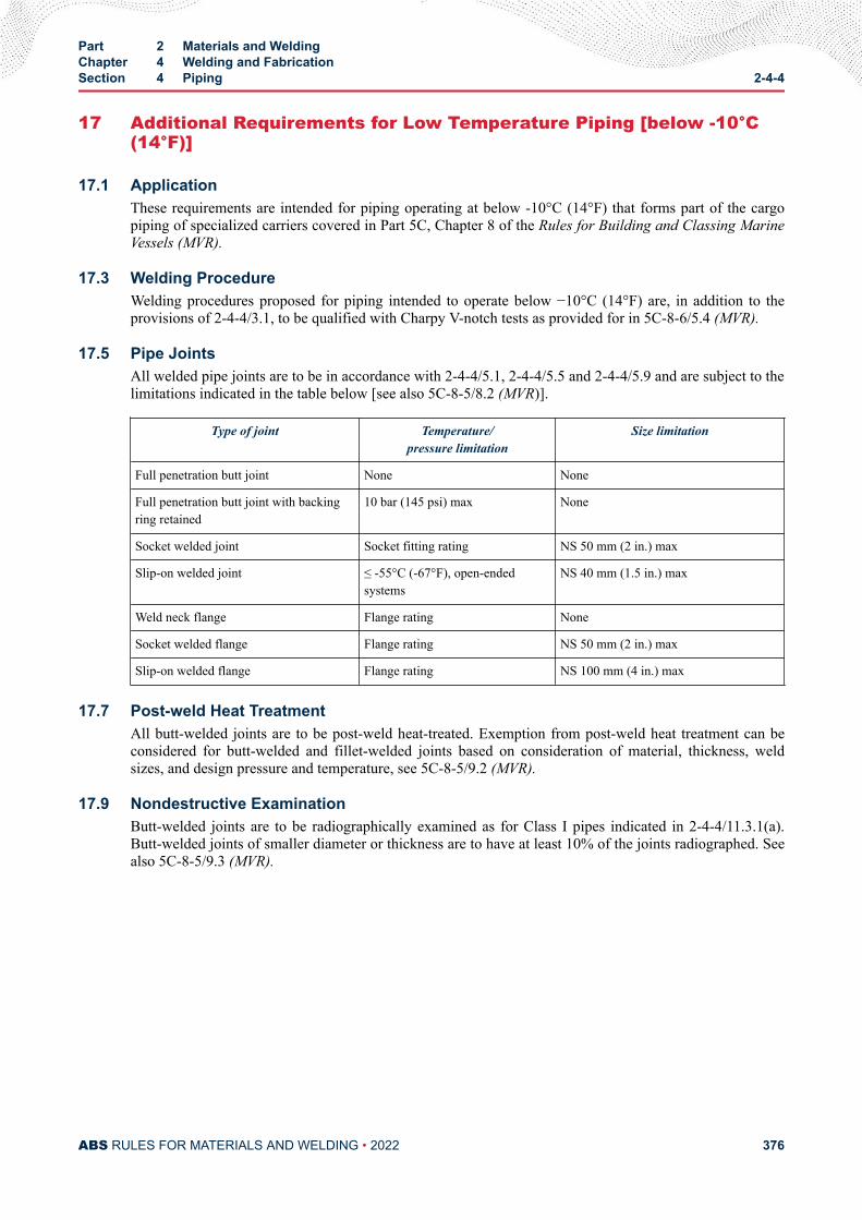
17 Additional Requirements for Low Temperature Piping [below -10°C(14°F)]
17.1 ApplicationThese requirements are intended for piping operating at below -10°C (14°F) that forms part of the cargopiping of specialized carriers covered in Part 5C, Chapter 8 of the Rules for Building and Classing MarineVessels (MVR).
17.3 Welding ProcedureWelding procedures proposed for piping intended to operate below −10°C (14°F) are, in addition to theprovisions of 2-4-4/3.1, to be qualified with Charpy V-notch tests as provided for in 5C-8-6/5.4 (MVR).
17.5 Pipe JointsAll welded pipe joints are to be in accordance with 2-4-4/5.1, 2-4-4/5.5 and 2-4-4/5.9 and are subject to thelimitations indicated in the table below [see also 5C-8-5/8.2 (MVR)].
Type of joint Temperature/pressure limitation
Size limitation
Full penetration butt joint None None
Full penetration butt joint with backingring retained
10 bar (145 psi) max None
Socket welded joint Socket fitting rating NS 50 mm (2 in.) max
Slip-on welded joint ≤ -55°C (-67°F), open-endedsystems
NS 40 mm (1.5 in.) max
Weld neck flange Flange rating None
Socket welded flange Flange rating NS 50 mm (2 in.) max
Slip-on welded flange Flange rating NS 100 mm (4 in.) max
17.7 Post-weld Heat TreatmentAll butt-welded joints are to be post-weld heat-treated. Exemption from post-weld heat treatment can beconsidered for butt-welded and fillet-welded joints based on consideration of material, thickness, weldsizes, and design pressure and temperature, see 5C-8-5/9.2 (MVR).
17.9 Nondestructive ExaminationButt-welded joints are to be radiographically examined as for Class I pipes indicated in 2-4-4/11.3.1(a).Butt-welded joints of smaller diameter or thickness are to have at least 10% of the joints radiographed. Seealso 5C-8-5/9.3 (MVR).
Part 2 Materials and WeldingChapter 4 Welding and FabricationSection 4 Piping 2-4-4
ABS RULES FOR MATERIALS AND WELDING • 2022 376
C H A P T E R 4Welding and Fabrication
S E C T I O N 5Aluminum Welding in Hull Construction (2018)
1 General
1.1 Hull WeldingWelding in aluminum hull construction is to comply with the requirements of this Section, unless speciallyapproved otherwise. It is recommended that appropriate permanent welded markings be applied to the sideshell of welded craft to indicate the location of bulkheads for reference. In all instances, weldingprocedures and filler metals are to be applied which will produce sound welds that have strength inaccordance with 2-4-5/17 TABLE 2; the chemical compositions of the filler metals are to be generally inaccordance with 2-4-5/17 TABLE 3. The selection of filler metals for welding various aluminum alloys isto be in accordance with 2-4-5/Tables 4 and 5.
1.3 Plans and SpecificationsThe plans submitted are to clearly indicate the extent to which welding is proposed to be used. Thewelding process, filler metal and joint design are to be shown on the detail drawings or in separatespecifications submitted for approval, which are to distinguish between manual, semi-automatic andautomatic welding. The shipbuilders are to prepare and file with the Surveyor a planned procedure to befollowed in the erection and welding of the important structural members.
1.5 Workmanship and SupervisionIt shall be the responsibility of the contractor to insure that personnel, procedures and NDT equipmentused for fabrication and inspection comply with these requirements. However, the Surveyor is to satisfyhimself that all welders and welding operators to be employed in the construction of craft to be classed areproperly qualified and are experienced in the type of work proposed and in the proper use of the weldingprocesses and procedures to be followed. The Surveyor is to be satisfied with the employment of asufficient number of skilled supervisors to ensure a thorough supervision and control of all weldingoperations.
1.7 Welding Procedures (2020)Procedures for the welding of all joints are to be established in writing for each welding test, process, typeof electrode, edge preparation, welding technique and position proposed. Details of proposed weldingprocedures and sequences are required to be submitted for review. Procedure qualifications previouslyprepared and approved by ABS may be submitted for consideration for the current designs, if applicable.
PART 2
ABS RULES FOR MATERIALS AND WELDING • 2022 377
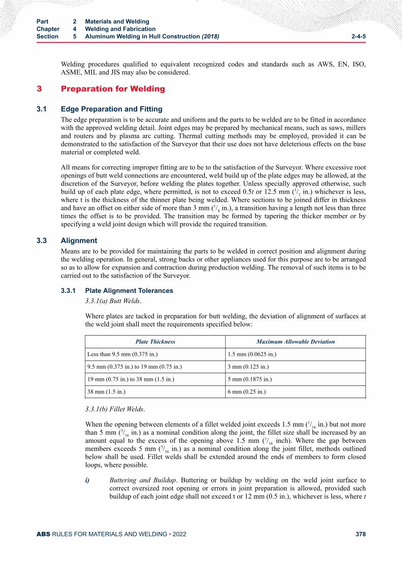
Welding procedures qualified to equivalent recognized codes and standards such as AWS, EN, ISO,ASME, MIL and JIS may also be considered.
3 Preparation for Welding
3.1 Edge Preparation and FittingThe edge preparation is to be accurate and uniform and the parts to be welded are to be fitted in accordancewith the approved welding detail. Joint edges may be prepared by mechanical means, such as saws, millersand routers and by plasma arc cutting. Thermal cutting methods may be employed, provided it can bedemonstrated to the satisfaction of the Surveyor that their use does not have deleterious effects on the basematerial or completed weld.
All means for correcting improper fitting are to be to the satisfaction of the Surveyor. Where excessive rootopenings of butt weld connections are encountered, weld build up of the plate edges may be allowed, at thediscretion of the Surveyor, before welding the plates together. Unless specially approved otherwise, suchbuild up of each plate edge, where permitted, is not to exceed 0.5t or 12.5 mm (1/2 in.) whichever is less,where t is the thickness of the thinner plate being welded. Where sections to be joined differ in thicknessand have an offset on either side of more than 3 mm (1/8 in.), a transition having a length not less than threetimes the offset is to be provided. The transition may be formed by tapering the thicker member or byspecifying a weld joint design which will provide the required transition.
3.3 AlignmentMeans are to be provided for maintaining the parts to be welded in correct position and alignment duringthe welding operation. In general, strong backs or other appliances used for this purpose are to be arrangedso as to allow for expansion and contraction during production welding. The removal of such items is to becarried out to the satisfaction of the Surveyor.
3.3.1 Plate Alignment Tolerances3.3.1(a) Butt Welds.
Where plates are tacked in preparation for butt welding, the deviation of alignment of surfaces atthe weld joint shall meet the requirements specified below:
Plate Thickness Maximum Allowable Deviation
Less than 9.5 mm (0.375 in.) 1.5 mm (0.0625 in.)
9.5 mm (0.375 in.) to 19 mm (0.75 in.) 3 mm (0.125 in.)
19 mm (0.75 in.) to 38 mm (1.5 in.) 5 mm (0.1875 in.)
38 mm (1.5 in.) 6 mm (0.25 in.)
3.3.1(b) Fillet Welds.
When the opening between elements of a fillet welded joint exceeds 1.5 mm (1/16 in.) but not morethan 5 mm (3/16 in.) as a nominal condition along the joint, the fillet size shall be increased by anamount equal to the excess of the opening above 1.5 mm (1/16 inch). Where the gap betweenmembers exceeds 5 mm (3/16 in.) as a nominal condition along the joint fillet, methods outlinedbelow shall be used. Fillet welds shall be extended around the ends of members to form closedloops, where possible.
i) Buttering and Buildup. Buttering or buildup by welding on the weld joint surface tocorrect oversized root opening or errors in joint preparation is allowed, provided suchbuildup of each joint edge shall not exceed t or 12 mm (0.5 in.), whichever is less, where t
Part 2 Materials and WeldingChapter 4 Welding and FabricationSection 5 Aluminum Welding in Hull Construction (2018) 2-4-5
ABS RULES FOR MATERIALS AND WELDING • 2022 378
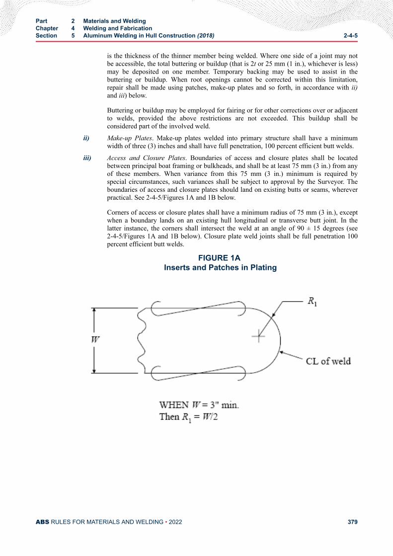
is the thickness of the thinner member being welded. Where one side of a joint may notbe accessible, the total buttering or buildup (that is 2t or 25 mm (1 in.), whichever is less)may be deposited on one member. Temporary backing may be used to assist in thebuttering or buildup. When root openings cannot be corrected within this limitation,repair shall be made using patches, make-up plates and so forth, in accordance with ii)and iii) below.
Buttering or buildup may be employed for fairing or for other corrections over or adjacentto welds, provided the above restrictions are not exceeded. This buildup shall beconsidered part of the involved weld.
ii) Make-up Plates. Make-up plates welded into primary structure shall have a minimumwidth of three (3) inches and shall have full penetration, 100 percent efficient butt welds.
iii) Access and Closure Plates. Boundaries of access and closure plates shall be locatedbetween principal boat framing or bulkheads, and shall be at least 75 mm (3 in.) from anyof these members. When variance from this 75 mm (3 in.) minimum is required byspecial circumstances, such variances shall be subject to approval by the Surveyor. Theboundaries of access and closure plates should land on existing butts or seams, whereverpractical. See 2-4-5/Figures 1A and 1B below.
Corners of access or closure plates shall have a minimum radius of 75 mm (3 in.), exceptwhen a boundary lands on an existing hull longitudinal or transverse butt joint. In thelatter instance, the corners shall intersect the weld at an angle of 90 ± 15 degrees (see2-4-5/Figures 1A and 1B below). Closure plate weld joints shall be full penetration 100percent efficient butt welds.
FIGURE 1A Inserts and Patches in Plating
Part 2 Materials and WeldingChapter 4 Welding and FabricationSection 5 Aluminum Welding in Hull Construction (2018) 2-4-5
ABS RULES FOR MATERIALS AND WELDING • 2022 379
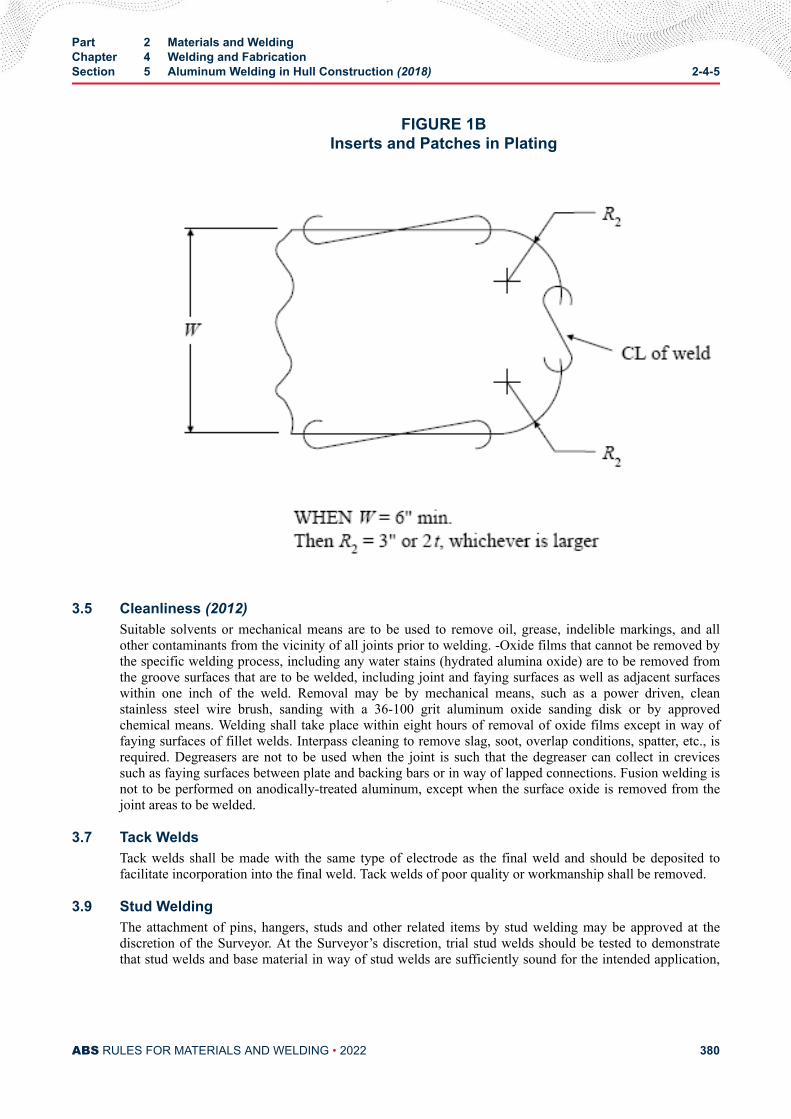
FIGURE 1BInserts and Patches in Plating
3.5 Cleanliness (2012)Suitable solvents or mechanical means are to be used to remove oil, grease, indelible markings, and allother contaminants from the vicinity of all joints prior to welding. -Oxide films that cannot be removed bythe specific welding process, including any water stains (hydrated alumina oxide) are to be removed fromthe groove surfaces that are to be welded, including joint and faying surfaces as well as adjacent surfaceswithin one inch of the weld. Removal may be by mechanical means, such as a power driven, cleanstainless steel wire brush, sanding with a 36-100 grit aluminum oxide sanding disk or by approvedchemical means. Welding shall take place within eight hours of removal of oxide films except in way offaying surfaces of fillet welds. Interpass cleaning to remove slag, soot, overlap conditions, spatter, etc., isrequired. Degreasers are not to be used when the joint is such that the degreaser can collect in crevicessuch as faying surfaces between plate and backing bars or in way of lapped connections. Fusion welding isnot to be performed on anodically-treated aluminum, except when the surface oxide is removed from thejoint areas to be welded.
3.7 Tack WeldsTack welds shall be made with the same type of electrode as the final weld and should be deposited tofacilitate incorporation into the final weld. Tack welds of poor quality or workmanship shall be removed.
3.9 Stud WeldingThe attachment of pins, hangers, studs and other related items by stud welding may be approved at thediscretion of the Surveyor. At the Surveyor’s discretion, trial stud welds should be tested to demonstratethat stud welds and base material in way of stud welds are sufficiently sound for the intended application,
Part 2 Materials and WeldingChapter 4 Welding and FabricationSection 5 Aluminum Welding in Hull Construction (2018) 2-4-5
ABS RULES FOR MATERIALS AND WELDING • 2022 380
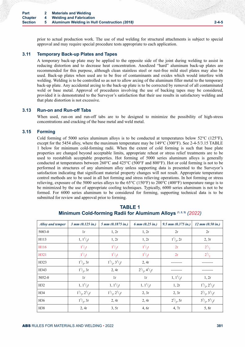
prior to actual production work. The use of stud welding for structural attachments is subject to specialapproval and may require special procedure tests appropriate to each application.
3.11 Temporary Back-up Plates and TapesA temporary back-up plate may be applied to the opposite side of the joint during welding to assist inreducing distortion and to decrease heat concentration. Anodized “hard” aluminum back-up plates arerecommended for this purpose, although clean stainless steel or rust-free mild steel plates may also beused. Back-up plates when used are to be free of contaminants and oxides which would interfere withwelding. Welding is to be controlled so as not to allow arcing of the aluminum filler metal to the temporaryback-up plate. Any accidental arcing to the back-up plate is to be corrected by removal of all contaminatedweld or base metal. Approval of procedures involving the use of backing tapes may be considered,provided it is demonstrated to the Surveyor’s satisfaction that their use results in satisfactory welding andthat plate distortion is not excessive.
3.13 Run-on and Run-off TabsWhen used, run-on and run-off tabs are to be designed to minimize the possibility of high-stressconcentrations and cracking of the base metal and weld metal.
3.15 FormingCold forming of 5000 series aluminum alloys is to be conducted at temperatures below 52°C (125°F),except for the 5454 alloy, where the maximum temperature may be 149°C (300°F). See 2-4-5/3.15 TABLE1 below for minimum cold-forming radii. When the extent of cold forming is such that base plateproperties are changed beyond acceptable limits, appropriate reheat or stress relief treatments are to beused to reestablish acceptable properties. Hot forming of 5000 series aluminum alloys is generallyconducted at temperatures between 260°C and 425°C (500°F and 800°F). Hot or cold forming is not to beperformed in structures of any aluminum alloy unless supporting data is presented to the Surveyor’ssatisfaction indicating that significant material property changes will not result. Appropriate temperaturecontrol methods are to be used in all hot forming and stress relieving operations. In hot forming or stressrelieving, exposure of the 5000 series alloys to the 65°C (150°F) to 200°C (400°F) temperature range is tobe minimized by the use of appropriate cooling techniques. Typically, 6000 series aluminum is not to beformed. For 6000 series aluminum to be considered for forming, supporting technical data is to besubmitted for review and approval prior to forming.
TABLE 1Minimum Cold-forming Radii for Aluminum Alloys (1, 2, 3) (2022)
Alloy and temper 3 mm (0.125 in.) 5 mm (0.1875 in.) 6 mm (0.25 in.) 9.5 mm (0.375 in.) 12 mm (0.50 in.)
5083-0 1t 1, 2t 1, 2t 2t 2t
H113 1, 11/2t 1, 2t 1, 2t 11/2, 2t 2, 3t
H116 11/2t 11/2t 11/2t 2t 21/2
H321 11/2t 11/2t 11/2t 2t 21/2
H323 11/2, 3t 11/2, 31/2t 2, 4t --------- ---------
H343 11/2, 3t 2, 4t 21/2, 41/2t --------- ---------
5052-0 1t 1t 1t 1, 11/2t 1, 2t
H32 1, 11/2t 1, 11/2t 1, 11/2t 1, 2t 11/2, 21/2t
H34 11/2, 21/2t 11/2, 2
1/2t 2, 3t 2, 3t 21/2, 31/2t
H36 11/2, 3t 2, 4t 2, 4t 21/2, 5t 31/2, 51/2t
H38 2, 4t 3, 5t 4, 6t 4, 7t 5, 8t
Part 2 Materials and WeldingChapter 4 Welding and FabricationSection 5 Aluminum Welding in Hull Construction (2018) 2-4-5
ABS RULES FOR MATERIALS AND WELDING • 2022 381
Alloy and temper 3 mm (0.125 in.) 5 mm (0.1875 in.) 6 mm (0.25 in.) 9.5 mm (0.375 in.) 12 mm (0.50 in.)
5086-0 1t 1t 1t 1, 11/2t 1, 2t
H32,H116,H117 1, 2t 1, 2t 11/2, 21/2t 2, 21/2t 21/2, 3t
H34 11/2, 21/2t 2, 3t 2, 3t 21/2, 3
1/2t 3, 4t
H36 2, 31/2t 21/2, 4t 3, 41/2t 3, 5t 31/2, 51/2t
H112 1, 2t 1, 2t 11/2, 21/2t
5456-0 1t 1, 2t 1, 2t 2t 2t
H116,H117 2, 3t 2, 3t 2, 3t 3, 4t 3, 4t
H323 11/2, 3t 11/2, 31/2t 2, 4t ------ ------
H343 11/2, 3t 2, 4t 21/2, 41/2t ------ -----
Notes:
1 Where two radii are shown, the larger radius is applicable when the bend is parallel to the direction of rolling.
2 These bending radii are applicable to aluminum alloys which are free of visible oxide coating.
3 The radii shall be the mandrel radii or inside radii.
5 Production Welding
5.1 EnvironmentProper precautions are to be taken to insure that all welding is done under conditions where the weldingsite is protected against deleterious effects of moisture, wind and severe cold. Paint or oil mist and othercontaminants which tend to cause weld porosity are to be excluded from the vicinity where welding is inprogress.
5.3 PreheatPreheating is not generally required for aluminum alloys. The use of preheat may be desirable whenwelding materials of thick cross section, materials subject to high restraint, and when welding is performedunder high humidity conditions or when the temperature of the aluminum alloy is below 0°C (32°F). Whenpreheating is used, appropriate production controls are to be used to maintain the specified temperatures, inaccordance with accepted procedures and to the satisfaction of the Surveyor. Preheating temperatureswhich sensitize an alloy to corrosion are to be avoided. For the 5000 series alloys, it is generallyrecommended to avoid prolonged exposure to the 65°C to 200°C (150°F to 400°F) temperature range.Preheat and interpass temperatures shall be verified by temperature sticks, small contact thermometer,pyrometer, etc. a minimum of 25 mm (1 in.) away from the weld area.
5.5 PostheatingWeldments of work hardenable 5000 series aluminum alloys are not to be postweld heat treated unless theprocedures have been specially approved. Where use of a heat-treatable alloy has been approved, anypostweld heat treatment proposed is to be as established in procedure qualification tests. Post weld heattreatment is not required on 5000 series aluminum materials, stainless steels, copper alloys or nickel alloys.
5.7 AccessibilityAssembly and welding is to be arranged to provide sufficient accessibility to the joint by the welder, thewelding equipment and for inspection.
5.8 Avoiding Joint Corrosion (2020)For guidance, refer to D3.7/6.11 of the AWS Guide for Aluminum Hull Welding.
Part 2 Materials and WeldingChapter 4 Welding and FabricationSection 5 Aluminum Welding in Hull Construction (2018) 2-4-5
ABS RULES FOR MATERIALS AND WELDING • 2022 382
5.9 SequenceWelding is to be planned to progress symmetrically so that shrinkage on both sides of the structure will beequalized. The ends of frames and stiffeners are to be left unattached to the plating at the sub-assemblystage for a distance of about 300 mm (12 in.) until connecting welds are made in the intersecting systemsof plating, framing and stiffeners at the erection stage. Welds are not to be carried across an unwelded jointor beyond an unwelded joint which terminates at the joint being welded unless especially approved.
5.11 Back GougingChipping, routing, milling, grinding or other suitable methods are to be employed at the root or undersideof the weld to obtain sound metal before applying subsequent beads for all full-penetration welds.
5.13 Fairing and Flame ShrinkingShrink welds may be used, but fairing by heating or flame shrinking to correct distortion or defectiveworkmanship in fabrication of main strength members within the midships portion of the craft and otherplating which may be subject to high stresses is not generally recommended. If intended to be used, it is tobe carried out only with the expressed approval of the Surveyor. For the 5000 series alloys, it is generallyrecommended that heating and cooling through the sensitizing range of 65°C-200°C (150°F-400°F) is tobe as rapid as practicable.
5.15 Inspection of Welds5.15.1 Visual Inspection
Visual inspection during construction is to consist of inspecting the surface appearance of weldsfor the existence of flaws or defects, as stated below. The inspection zone includes the weld faceand 12 mm (0.5 in.) of adjacent base metal. The surface of the welds is to be regular and uniformwith proper contour, a minimum amount of reinforcement and reasonably free from undercut andoverlap, slag, paint and weld splatter.
5.15.1(a) Appearance. (1 July 2021)Welds shall be free of cracks, incomplete fusion and burn-through. Visible arc-strikes on weldsand the adjacent base metal are not allowed and shall not exceed 1 mm (1/32 in.) in depth afterremoval. Weld spatter greater in diameter than 1 mm (1/32 in.) is not acceptable. Gouge marks,nicks and other fabrication scars in the weld inspection zone shall not exceed the requirements forundercut. Weld surfaces shall be free of slag to the extent that there is no interference with visualor other required nondestructive test. Crater pits are not acceptable and shall be filled to the fullcross section of the weld.
5.15.1(b) Melt-through.Melt-through and repaired burn-through areas are acceptable, provided the areas do not containcracks, crevices, excessive oxidation or globules, and provided that the root convexity andconcavity limits are not exceeded.
5.15.1(c) Suckback.Suckback is unacceptable in a weld or base metal when it occurs as a sharp notch or where thedepth reduces the weld thickness below the minimum base metal thickness.
5.15.1(d) Undercut.The maximum undercut shall be 1 mm (1/32 in.) or 10% of the adjacent base metal thickness,whichever is less. For base metal thickness 12 mm (0.5 in.) and greater, undercut from 1 mm (1/32in.) to 1.5 mm (1/16 in) is allowed if the accumulated length of undercut does not exceed 15% ofthe joint length or 300 mm (12 in.), whichever is less.
5.15.1(e) Welded Joint Offset.The maximum offset for all welded joints shall be as follows:
Part 2 Materials and WeldingChapter 4 Welding and FabricationSection 5 Aluminum Welding in Hull Construction (2018) 2-4-5
ABS RULES FOR MATERIALS AND WELDING • 2022 383
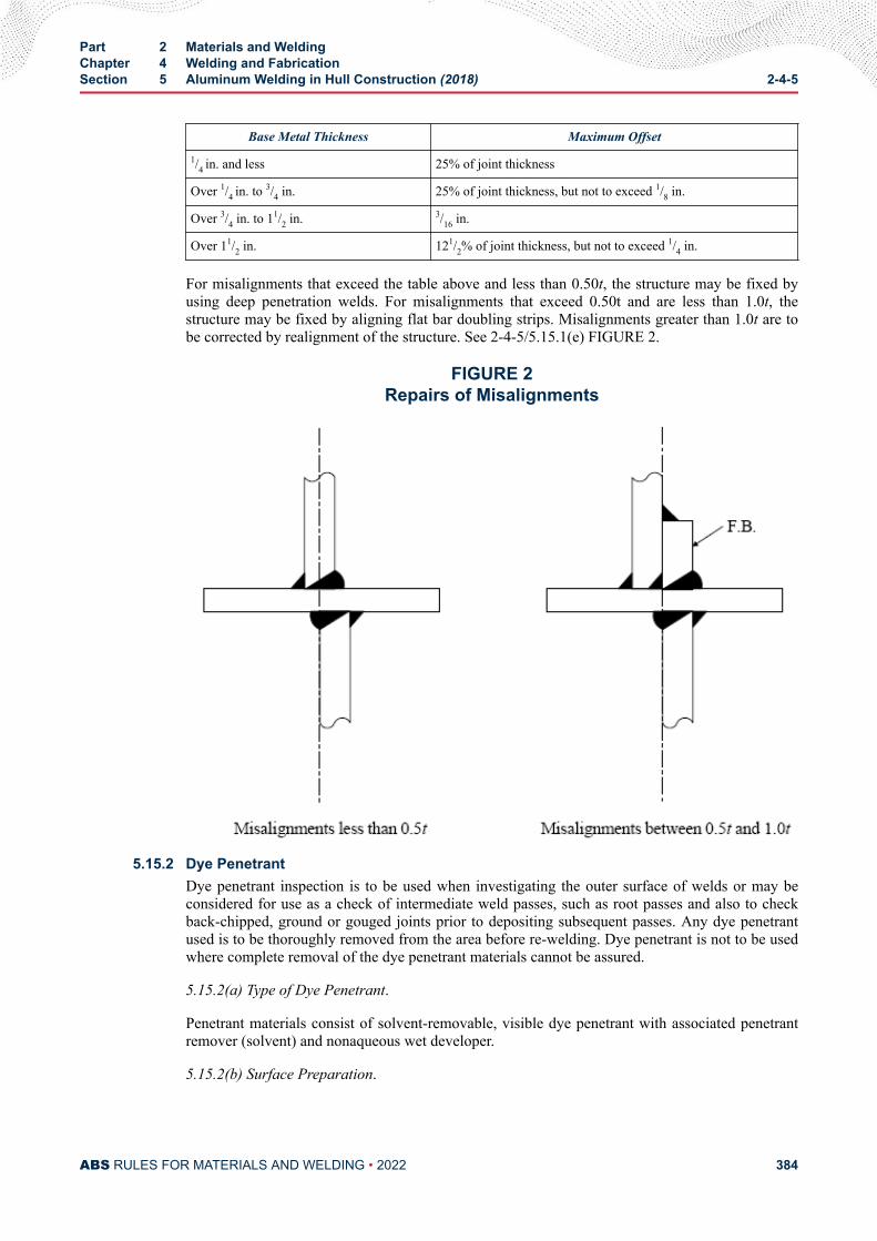
Base Metal Thickness Maximum Offset1/4 in. and less 25% of joint thickness
Over 1/4 in. to 3/4 in. 25% of joint thickness, but not to exceed 1/8 in.
Over 3/4 in. to 11/2 in. 3/16 in.
Over 11/2 in. 121/2% of joint thickness, but not to exceed 1/4 in.
For misalignments that exceed the table above and less than 0.50t, the structure may be fixed byusing deep penetration welds. For misalignments that exceed 0.50t and are less than 1.0t, thestructure may be fixed by aligning flat bar doubling strips. Misalignments greater than 1.0t are tobe corrected by realignment of the structure. See 2-4-5/5.15.1(e) FIGURE 2.
FIGURE 2Repairs of Misalignments
5.15.2 Dye PenetrantDye penetrant inspection is to be used when investigating the outer surface of welds or may beconsidered for use as a check of intermediate weld passes, such as root passes and also to checkback-chipped, ground or gouged joints prior to depositing subsequent passes. Any dye penetrantused is to be thoroughly removed from the area before re-welding. Dye penetrant is not to be usedwhere complete removal of the dye penetrant materials cannot be assured.
5.15.2(a) Type of Dye Penetrant.
Penetrant materials consist of solvent-removable, visible dye penetrant with associated penetrantremover (solvent) and nonaqueous wet developer.
5.15.2(b) Surface Preparation.
Part 2 Materials and WeldingChapter 4 Welding and FabricationSection 5 Aluminum Welding in Hull Construction (2018) 2-4-5
ABS RULES FOR MATERIALS AND WELDING • 2022 384
Surfaces to be inspected shall be free from scale, slag and adhering or imbedded sand or otherextraneous materials. With the exception of undercuts which are within allowances, the contour ofwelds shall blend smoothly and gradually into the base metal. Weld surface irregularities shall beremoved to the extent that they will not interfere with interpretation of the test results. The finalliquid penetrant inspection shall be performed in the final surface condition, as specified herein.
Peening, shot, sand, grit and vapor blasting shall not be performed on surfaces before liquidpenetrant inspection.
Surfaces for which a specific finish is required shall be given this surface finish prior to the finalliquid penetrant inspection.
5.15.2(c) Test Procedure Requirements.
All surfaces being tested shall be thoroughly cleaned of extraneous material. If a nonvolatile liquidis used for cleaning, the surface shall be heated or dried with hot air to assure complete removal ofthe cleaner. As a final cleaning operation, each surface shall be dipped, sprayed, wiped or brushedwith an acceptable solvent and thoroughly dried by removing the excess with a clean dry cloth orabsorbent paper, and allowing the remainder to evaporate for a minimum of five minutes. Prior toliquid penetrant inspection, the surface to be tested and any adjacent area within one (1) inch ofthe surface to be tested shall be dry and free of any dirt, grease, lint, scale and salts, coatings orother extraneous matter that would obscure surface openings or otherwise interfere with the test.
Maximum penetration into extremely small openings requires that the penetrant and the testsurface be maintained at the temperature recommended by the penetrant manufacturer, but in nocase shall be less than 50°F. The temperature of the penetrant and the test surface shall not exceed100°F. Due to the flammable nature of liquid penetrant inspection materials, the use of an openflame for heating purposes shall be prohibited. Special conditions requiring deviation from theabove requirement requires approval of the Surveyor.
The surface to be tested shall be thoroughly and uniformly coated with penetrant by flooding,brushing, immersion or spraying. Unless otherwise recommended by the manufacturer andapproved by the Surveyor, dwelling time for the penetrant shall be not less than 15 minutes and nogreater than 20.
The excess penetrant shall be removed from all surfaces as follows:
i) As much excess penetrant as possible shall be removed by wiping the surface thoroughlywith a clean dry cloth or absorbent paper.
ii) The remaining excess penetrant shall be removed by wiping the surface with a clean clothor absorbent paper dampened with a penetrant remover specified by the penetrantmaterial manufacturer.
Flushing of the surface with any liquid following application of the penetrant and prior todeveloping is prohibited.
The drying of the test surface after the removal of the excess penetrant shall be accomplished onlyby normal evaporation, or by blotting with absorbent paper or clean, lint-free cloth. Forced aircirculation in excess of normal ventilation in the inspection area shall not be used. Unlessotherwise specified by the penetrant manufacturer, the time for surface drying after removal ofexcess penetrant and prior to application of the developer shall be limited to a maximum of ten(10) minutes.
A nonaqueous wet developer specified by the penetrant manufacturer shall be used. Immediatelyprior to application, the developing liquid shall be kept agitated in order to prevent settling of solid
Part 2 Materials and WeldingChapter 4 Welding and FabricationSection 5 Aluminum Welding in Hull Construction (2018) 2-4-5
ABS RULES FOR MATERIALS AND WELDING • 2022 385
particles dispersed in the liquid. The developer shall be uniformly applied in a thin coating to thetest surfaces by spraying. Pools of wet developer in cavities on the inspection surface is notpermitted since these pools will dry to an excessively heavy coating in such areas resulting in themasking of indications. Inspection shall be made a minimum of seven (7) minutes and not laterthan 30 minutes after the developer has dried.
When the inspection is concluded, the penetrant materials shall be removed as soon as possible bymeans of wiping, water-wetted clean cloth or solvents, as described above, and with applicablecleaning procedures.
5.15.3 Radiographic or Ultrasonic InspectionRadiographic or ultrasonic inspection or both may be used when the overall soundness of the weldcross section is to be evaluated. Finished welding is to be sound and thoroughly fused throughoutits cross section and to the base material. Production welds are to be crack free. Otherdiscontinuities, such as incomplete fusion or incomplete penetration, slag and porosity, are only tobe present to the degree permitted by the pertinent inspection standard. The procedures andstandards for radiographic and ultrasonic inspection is to be in accordance with ABS’s separatelyissued publication, Guide for Nondestructive Inspection, or other approved acceptance standards.
5.15.4 Weld Plugs or SamplesThe practice of taking weld plugs or samples by machining or cutting from the welded structure isnot recommended and is to be considered only in the absence of other suitable inspection methodsand is to be subject to the special approval of the Surveyor. When such weld plugs or samples areremoved from the welded structure, the holes or cavities formed are to be properly prepared andwelded, using a suitable welding procedure approved by the Surveyor and as established for theoriginal joint
5.17 Workmanship RequirementsThe workmanship requirements include the visual acceptance criteria stated in 2-4-5/5.15.2 above plus thefollowing structural fairness requirements provided below. In addition, welded attachments shall beremoved to a minimum of 1.5 mm (0.0625 in.) away from the permanent member to which they areattached by chipping, sawing or cutting, followed by grinding or sanding to restore the plate surface.
5.17.1 Structural Fairness for PlatingUnfairness (deviation from the design molded line) of welded plating shall not exceed thetolerances shown on 2-4-5/Figures 3 and 4. Permissible unfairness should result in a generally faircurve across the panel, except that an additional deviation of 3 mm (1.8 in.) from the fair curve ispermitted in way of welded butts and seams. Sharp knuckling or bend in way of stiffeners shall beavoided. A procedure for measuring fairness and taking corrective actions shall be developed andbe available for review by the surveyor.
If aid is necessary in determining the acceptability of the fairness of welded structure, ameasurement of the unfairness of plating may be made in the area of interest. In such cases, themeasurement shall be made across the minor dimension of the panel. The tolerances specified on2-4-5/Figures 3 and 4 are plus or minus the dimensions from a fair line.
For stiffener spacings greater or less than those shown on 2-4-5/Figures 3 and 4, the curves shallbe extrapolated proportionately.
5.17.2 Structural Fairness for Framing and StiffenersFrame, beam and stiffener bows in primary strength structure or structure subject to dynamicloading shall be corrected when it varies plus or minus from the designated or molded line inexcess of the following:T = C ℓdw mm(in.)
Part 2 Materials and WeldingChapter 4 Welding and FabricationSection 5 Aluminum Welding in Hull Construction (2018) 2-4-5
ABS RULES FOR MATERIALS AND WELDING • 2022 386
whereT = tolerance in mm (in.)C = 530 (0.25)ℓ = span of member between the fixed ends at the support structure in m (ft)dw = depth of the stiffening member measured from the underside of the flange in mm (in.)
5.17.3 Underwater Exterior SurfacesIn general, weld surfaces shall not extend greater than 1.5 mm (0.0625 in.) above the plate surface.
5.19 Quality ControlTo maintain quality control, sample welds may be required to be made by welders and operators duringeach three (3) month period, at the discretion of the Surveyor and at the location of production welding,using the same equipment, material and filler metal as intended for production. The sample welds are to beexamined for acceptable workmanship and may be required to be sectioned, etched and examined for weldsoundness. When necessary, measures are to be taken to correct unacceptable workmanship.
5.21 Repair WeldingUnsatisfactory welding, as determined by visual inspection, nondestructive test methods, or leakage underhydrostatic tests, is to be corrected by the removal of the defective weld or adjacent material or both andcorrected by rewelding, using a suitable repair welding procedure consistent with the material beingwelded. The repair procedures shall be available for the welder. Multiple repairs (weld cycles) to 5000series aluminum alloys in the same general area are allowed. Removal by mechanical means of minorsurface defects such as arc strikes, scratches or shallow gouges may be permitted at the discretion of theattending Surveyor. Repaired welds must meet the inspection requirements for the original weld.
7 Butt Welds
7.1 Joint DesignHull plating up to 5.0 mm (3/16 in.) in thickness may be square-butt welded without beveling the abuttingplate edges. Plates exceeding 5.0 mm (3/16 in.) may be prepared for welding by similarly beveling the edgesof both plates from one or both sides to form a single-Vee or double-Vee butt joint with an included anglefrom 60 degrees to 90 degrees. For single-Vee butt joints in material 5.0 mm (3/16 in.) and thicker, the rootface or land may be up to 3.0 mm (1/8 in.) in depth. Root faces or lands below 1.5 mm (1/16 in.) are notgenerally recommended. For double-Vee butt joints in material 8.0 mm (5/16 in.) and thicker, the gap mayvary from 0 to 5.0 mm (3/16 in.). Joints of other designs and root openings, such as the square butt joints inheavy thicknesses used with automated procedures will be subject to special consideration. In general, useof double-Vee in lieu of single-Vee joints and the narrowest root gap practicable is recommended tominimize distortion.
Butt-type permanent backing strap joints welded from one side shall not be used. For both single-Vee anddouble-Vee joints, the weld metal at the root on the reverse side of a weld made without permanentbacking is to be removed to sound metal by an approved method before applying subsequent weld passes.See 2-4-5/5.11. Welded butt joints made against removable backing and on which the root is inspected inaccordance with these requirements shall be considered the equivalent of a joint welded from both sides.
9 Fillet Welds (1 July 2021)See Section 3-2-13 of the ABS Rules for Building and Classing Light Warships, Patrol and High-SpeedNaval Vessels.
Part 2 Materials and WeldingChapter 4 Welding and FabricationSection 5 Aluminum Welding in Hull Construction (2018) 2-4-5
ABS RULES FOR MATERIALS AND WELDING • 2022 387
11 Filler Metals
11.1 GeneralFiller metals are to be of a type suitable to produce sound welds that have strength, ductility and corrosion-resistant properties comparable to the materials being welded. Appropriate precautions are to be used toprevent any critical property change of filler wire quality during storage and handling. A list ofrecommended filler metals for different alloys is given in 2-4-5/Tables 4 and 5.
11.3 Approval BasisFiller metals will be approved and listed, subject to tests conducted at the manufacturer’s plant. Uponsatisfactory completion of tests, a certificate will be issued for general approval indicating the grade orclassification to which the filler metal was tested and the relevant characteristics of the filler metal. Testassemblies are to be prepared in the presence of the Surveyor and all tests are to be attended by and carriedout to the satisfaction of the Surveyor. Procedure and testing is to comply with either of the followingstandards.
i) Filler metals will be considered for approval based upon tests conducted to standards establishedby the American Welding Society or other recognized agency.
ii) Special approvals to manufacturer’s specifications.
13 Approval of Welding Procedures
13.1 Approved Filler MetalsApproval of aluminum alloy filler metals used on ABS-classed weldments will depend on the specificapplication and alloys for which the filler metal is intended. Procedure tests may be required as a generalcondition of approval or at the discretion of the attending Surveyor to determine the shipyard’s orfabricator’s capability in the application of the proposed filler metal to the base material. The extent ofsuch tests may vary depending upon the intended application, but generally would follow those testsoutlined in 2-4-5/13.7, and are to be carried out under production conditions.
13.3 Surveyor’s AcceptanceThe Surveyor may, at his discretion, accept a filler metal, welding procedure, or both, in a shipyard orfabricator’s plant where it is established to his satisfaction that they have been adequately used for similarwork under similar conditions.
13.5 New Procedures and MethodsWeld tests, as outlined in 2-4-5/13.7 and 2-4-5/13.9 and 2-4-5/Figure 5 to 2-4-5/Figure 17, usingprocedures and materials similar to those intended for production welding and carried out under productionconditions, may be required to be prepared by each shipyard or fabricator when new or unusual methods,base metals or filler metals are proposed.
All tests are to be made in the presence of the Surveyor and carried out to the Surveyor’s satisfaction.
13.7 TestsTests Nos. 1 and 2 are to be carried out for procedures involving butt welds. Test No. 3 is to be carried outfor procedures involving fillet welds. Unless otherwise specified, the number of specimens is to be asindicated. The minimum test results required are stated with the figures:
● Test No. 1 – Reduced Section Tension Test (with reinforcement removed) (2-4-5/17 FIGURE 7 or2-4-5/17 FIGURE 8). Two specimens made in each position involved. The test specimens are to meetor exceed the ultimate tensile strength shown in 2-4-5/3.15 TABLE 1.
Part 2 Materials and WeldingChapter 4 Welding and FabricationSection 5 Aluminum Welding in Hull Construction (2018) 2-4-5
ABS RULES FOR MATERIALS AND WELDING • 2022 388
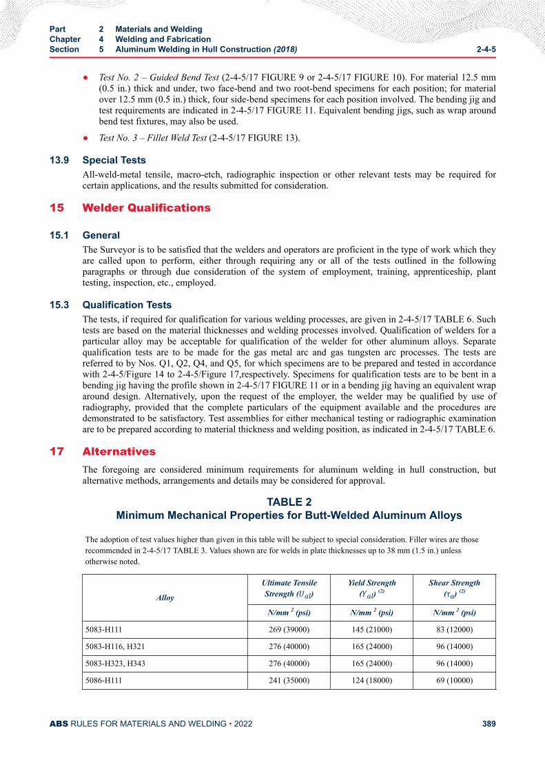
● Test No. 2 – Guided Bend Test (2-4-5/17 FIGURE 9 or 2-4-5/17 FIGURE 10). For material 12.5 mm(0.5 in.) thick and under, two face-bend and two root-bend specimens for each position; for materialover 12.5 mm (0.5 in.) thick, four side-bend specimens for each position involved. The bending jig andtest requirements are indicated in 2-4-5/17 FIGURE 11. Equivalent bending jigs, such as wrap aroundbend test fixtures, may also be used.
● Test No. 3 – Fillet Weld Test (2-4-5/17 FIGURE 13).
13.9 Special TestsAll-weld-metal tensile, macro-etch, radiographic inspection or other relevant tests may be required forcertain applications, and the results submitted for consideration.
15 Welder Qualifications
15.1 GeneralThe Surveyor is to be satisfied that the welders and operators are proficient in the type of work which theyare called upon to perform, either through requiring any or all of the tests outlined in the followingparagraphs or through due consideration of the system of employment, training, apprenticeship, planttesting, inspection, etc., employed.
15.3 Qualification TestsThe tests, if required for qualification for various welding processes, are given in 2-4-5/17 TABLE 6. Suchtests are based on the material thicknesses and welding processes involved. Qualification of welders for aparticular alloy may be acceptable for qualification of the welder for other aluminum alloys. Separatequalification tests are to be made for the gas metal arc and gas tungsten arc processes. The tests arereferred to by Nos. Q1, Q2, Q4, and Q5, for which specimens are to be prepared and tested in accordancewith 2-4-5/Figure 14 to 2-4-5/Figure 17,respectively. Specimens for qualification tests are to be bent in abending jig having the profile shown in 2-4-5/17 FIGURE 11 or in a bending jig having an equivalent wraparound design. Alternatively, upon the request of the employer, the welder may be qualified by use ofradiography, provided that the complete particulars of the equipment available and the procedures aredemonstrated to be satisfactory. Test assemblies for either mechanical testing or radiographic examinationare to be prepared according to material thickness and welding position, as indicated in 2-4-5/17 TABLE 6.
17 AlternativesThe foregoing are considered minimum requirements for aluminum welding in hull construction, butalternative methods, arrangements and details may be considered for approval.
TABLE 2Minimum Mechanical Properties for Butt-Welded Aluminum Alloys
The adoption of test values higher than given in this table will be subject to special consideration. Filler wires are thoserecommended in 2-4-5/17 TABLE 3. Values shown are for welds in plate thicknesses up to 38 mm (1.5 in.) unlessotherwise noted.
Alloy
Ultimate TensileStrength (Ual) Yield Strength
(Yal) (2)Shear Strength
(τa) (2)
N/mm 2 (psi) N/mm 2 (psi) N/mm 2 (psi)
5083-H111 269 (39000) 145 (21000) 83 (12000)
5083-H116, H321 276 (40000) 165 (24000) 96 (14000)
5083-H323, H343 276 (40000) 165 (24000) 96 (14000)
5086-H111 241 (35000) 124 (18000) 69 (10000)
Part 2 Materials and WeldingChapter 4 Welding and FabricationSection 5 Aluminum Welding in Hull Construction (2018) 2-4-5
ABS RULES FOR MATERIALS AND WELDING • 2022 389
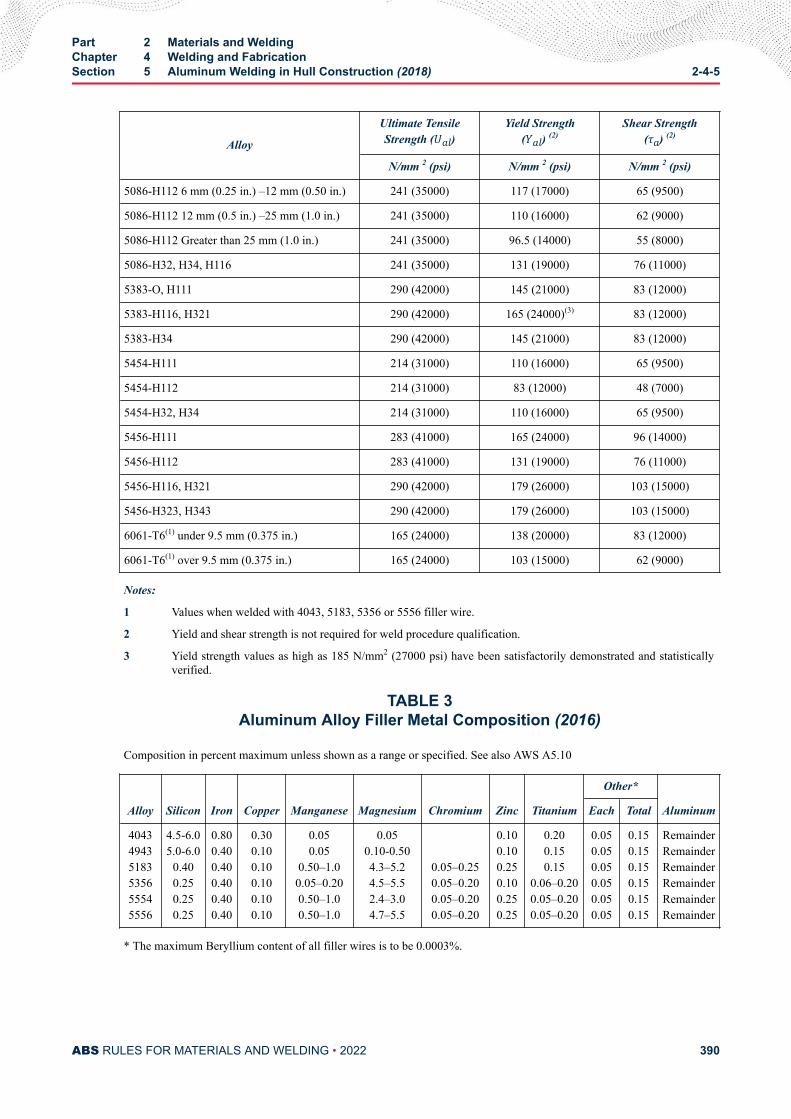
Alloy
Ultimate TensileStrength (Ual) Yield Strength
(Yal) (2)Shear Strength
(τa) (2)
N/mm 2 (psi) N/mm 2 (psi) N/mm 2 (psi)
5086-H112 6 mm (0.25 in.) –12 mm (0.50 in.) 241 (35000) 117 (17000) 65 (9500)
5086-H112 12 mm (0.5 in.) –25 mm (1.0 in.) 241 (35000) 110 (16000) 62 (9000)
5086-H112 Greater than 25 mm (1.0 in.) 241 (35000) 96.5 (14000) 55 (8000)
5086-H32, H34, H116 241 (35000) 131 (19000) 76 (11000)
5383-O, H111 290 (42000) 145 (21000) 83 (12000)
5383-H116, H321 290 (42000) 165 (24000)(3) 83 (12000)
5383-H34 290 (42000) 145 (21000) 83 (12000)
5454-H111 214 (31000) 110 (16000) 65 (9500)
5454-H112 214 (31000) 83 (12000) 48 (7000)
5454-H32, H34 214 (31000) 110 (16000) 65 (9500)
5456-H111 283 (41000) 165 (24000) 96 (14000)
5456-H112 283 (41000) 131 (19000) 76 (11000)
5456-H116, H321 290 (42000) 179 (26000) 103 (15000)
5456-H323, H343 290 (42000) 179 (26000) 103 (15000)
6061-T6(1) under 9.5 mm (0.375 in.) 165 (24000) 138 (20000) 83 (12000)
6061-T6(1) over 9.5 mm (0.375 in.) 165 (24000) 103 (15000) 62 (9000)
Notes:
1 Values when welded with 4043, 5183, 5356 or 5556 filler wire.
2 Yield and shear strength is not required for weld procedure qualification.
3 Yield strength values as high as 185 N/mm2 (27000 psi) have been satisfactorily demonstrated and statisticallyverified.
TABLE 3Aluminum Alloy Filler Metal Composition (2016)
Composition in percent maximum unless shown as a range or specified. See also AWS A5.10
Alloy Silicon Iron Copper Manganese Magnesium Chromium Zinc Titanium
Other*
AluminumEach Total
404349435183535655545556
4.5-6.05.0-6.0
0.400.250.250.25
0.800.400.400.400.400.40
0.300.100.100.100.100.10
0.050.05
0.50–1.00.05–0.200.50–1.00.50–1.0
0.050.10-0.504.3–5.24.5–5.52.4–3.04.7–5.5
0.05–0.250.05–0.200.05–0.200.05–0.20
0.100.100.250.100.250.25
0.200.150.15
0.06–0.200.05–0.200.05–0.20
0.050.050.050.050.050.05
0.150.150.150.150.150.15
RemainderRemainderRemainderRemainderRemainderRemainder
* The maximum Beryllium content of all filler wires is to be 0.0003%.
Part 2 Materials and WeldingChapter 4 Welding and FabricationSection 5 Aluminum Welding in Hull Construction (2018) 2-4-5
ABS RULES FOR MATERIALS AND WELDING • 2022 390
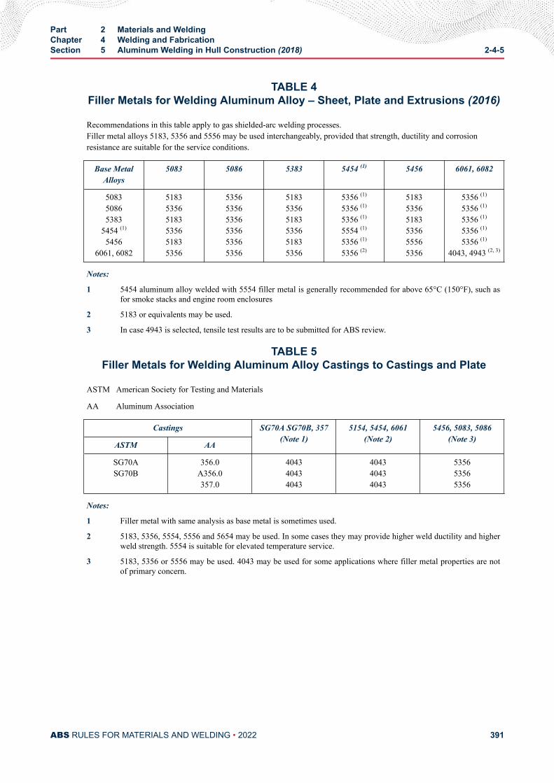
TABLE 4Filler Metals for Welding Aluminum Alloy – Sheet, Plate and Extrusions (2016)
Recommendations in this table apply to gas shielded-arc welding processes.Filler metal alloys 5183, 5356 and 5556 may be used interchangeably, provided that strength, ductility and corrosionresistance are suitable for the service conditions.
Base MetalAlloys
5083 5086 5383 5454 (1) 5456 6061, 6082
508350865383
5454 (1)
54566061, 6082
518353565183535651835356
535653565356535653565356
518353565183535651835356
5356 (1)
5356 (1)
5356 (1)
5554 (1)
5356 (1)
5356 (2)
518353565183535655565356
5356 (1)
5356 (1)
5356 (1)
5356 (1)
5356 (1)
4043, 4943 (2, 3)
Notes:
1 5454 aluminum alloy welded with 5554 filler metal is generally recommended for above 65°C (150°F), such asfor smoke stacks and engine room enclosures
2 5183 or equivalents may be used.
3 In case 4943 is selected, tensile test results are to be submitted for ABS review.
TABLE 5Filler Metals for Welding Aluminum Alloy Castings to Castings and Plate
ASTM American Society for Testing and Materials
AA Aluminum Association
Castings SG70A SG70B, 357(Note 1)
5154, 5454, 6061(Note 2)
5456, 5083, 5086(Note 3)
ASTM AA
SG70ASG70B
356.0A356.0357.0
404340434043
404340434043
535653565356
Notes:
1 Filler metal with same analysis as base metal is sometimes used.
2 5183, 5356, 5554, 5556 and 5654 may be used. In some cases they may provide higher weld ductility and higherweld strength. 5554 is suitable for elevated temperature service.
3 5183, 5356 or 5556 may be used. 4043 may be used for some applications where filler metal properties are notof primary concern.
Part 2 Materials and WeldingChapter 4 Welding and FabricationSection 5 Aluminum Welding in Hull Construction (2018) 2-4-5
ABS RULES FOR MATERIALS AND WELDING • 2022 391
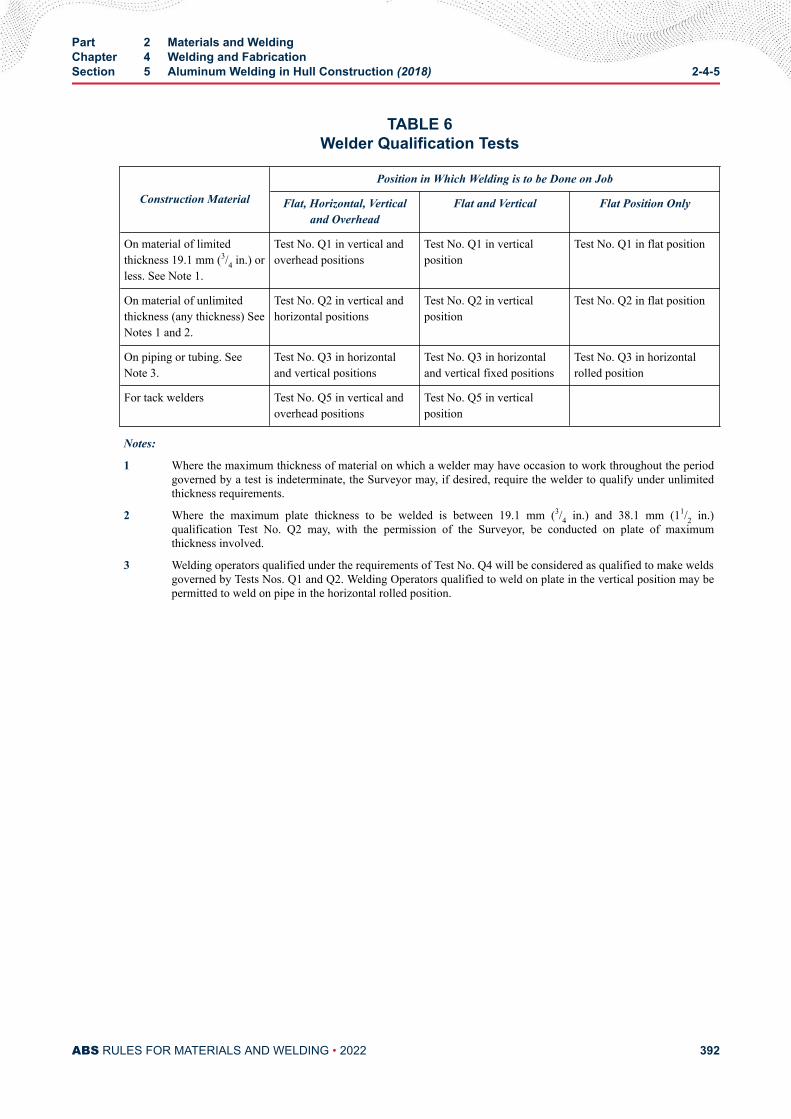
TABLE 6Welder Qualification Tests
Construction Material
Position in Which Welding is to be Done on Job
Flat, Horizontal, Verticaland Overhead
Flat and Vertical Flat Position Only
On material of limitedthickness 19.1 mm (3/4 in.) orless. See Note 1.
Test No. Q1 in vertical andoverhead positions
Test No. Q1 in verticalposition
Test No. Q1 in flat position
On material of unlimitedthickness (any thickness) SeeNotes 1 and 2.
Test No. Q2 in vertical andhorizontal positions
Test No. Q2 in verticalposition
Test No. Q2 in flat position
On piping or tubing. SeeNote 3.
Test No. Q3 in horizontaland vertical positions
Test No. Q3 in horizontaland vertical fixed positions
Test No. Q3 in horizontalrolled position
For tack welders Test No. Q5 in vertical andoverhead positions
Test No. Q5 in verticalposition
Notes:
1 Where the maximum thickness of material on which a welder may have occasion to work throughout the periodgoverned by a test is indeterminate, the Surveyor may, if desired, require the welder to qualify under unlimitedthickness requirements.
2 Where the maximum plate thickness to be welded is between 19.1 mm (3/4 in.) and 38.1 mm (11/2 in.)qualification Test No. Q2 may, with the permission of the Surveyor, be conducted on plate of maximumthickness involved.
3 Welding operators qualified under the requirements of Test No. Q4 will be considered as qualified to make weldsgoverned by Tests Nos. Q1 and Q2. Welding Operators qualified to weld on plate in the vertical position may bepermitted to weld on pipe in the horizontal rolled position.
Part 2 Materials and WeldingChapter 4 Welding and FabricationSection 5 Aluminum Welding in Hull Construction (2018) 2-4-5
ABS RULES FOR MATERIALS AND WELDING • 2022 392
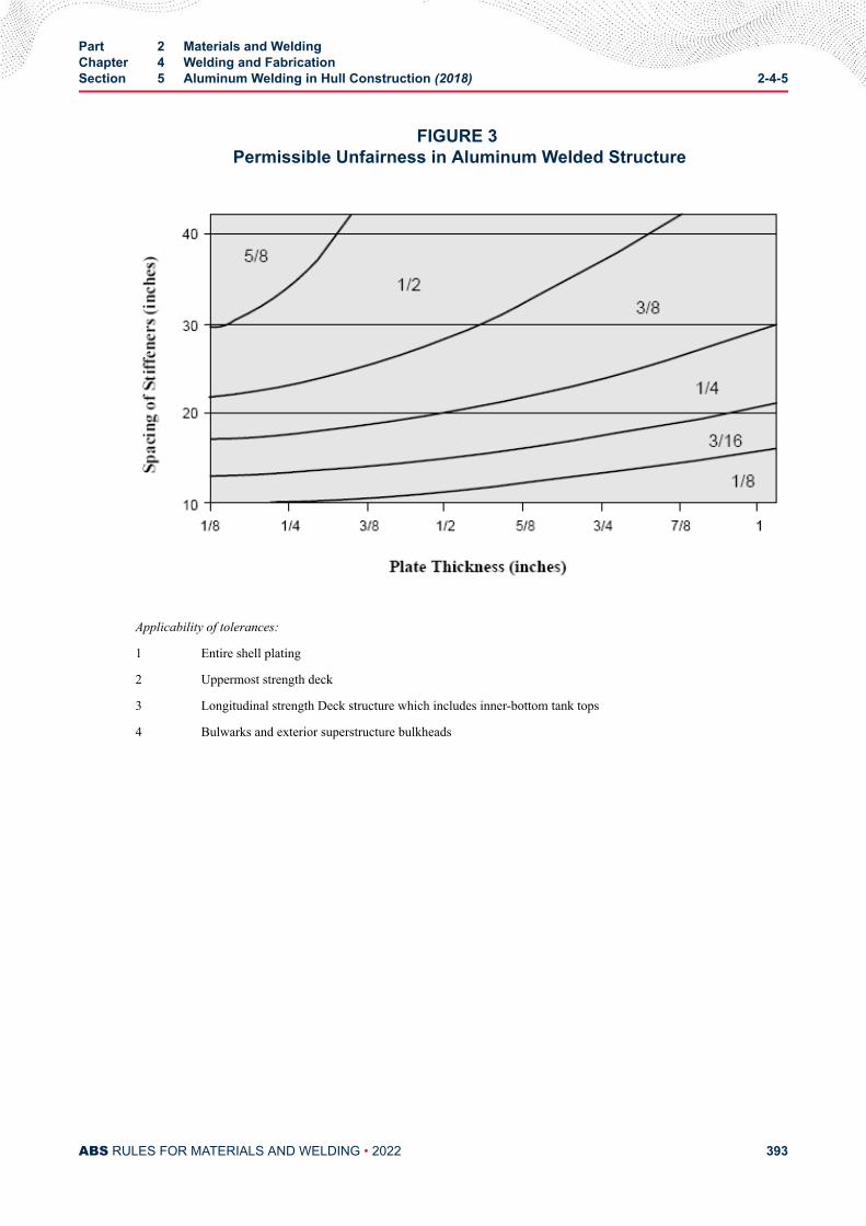
FIGURE 3 Permissible Unfairness in Aluminum Welded Structure
Applicability of tolerances:
1 Entire shell plating
2 Uppermost strength deck
3 Longitudinal strength Deck structure which includes inner-bottom tank tops
4 Bulwarks and exterior superstructure bulkheads
Part 2 Materials and WeldingChapter 4 Welding and FabricationSection 5 Aluminum Welding in Hull Construction (2018) 2-4-5
ABS RULES FOR MATERIALS AND WELDING • 2022 393
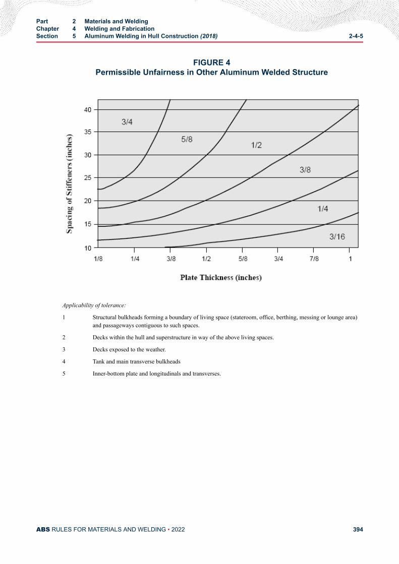
FIGURE 4Permissible Unfairness in Other Aluminum Welded Structure
Applicability of tolerance:
1 Structural bulkheads forming a boundary of living space (stateroom, office, berthing, messing or lounge area)and passageways contiguous to such spaces.
2 Decks within the hull and superstructure in way of the above living spaces.
3 Decks exposed to the weather.
4 Tank and main transverse bulkheads
5 Inner-bottom plate and longitudinals and transverses.
Part 2 Materials and WeldingChapter 4 Welding and FabricationSection 5 Aluminum Welding in Hull Construction (2018) 2-4-5
ABS RULES FOR MATERIALS AND WELDING • 2022 394
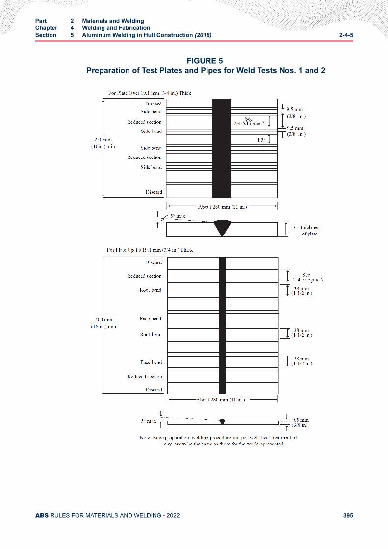
FIGURE 5 Preparation of Test Plates and Pipes for Weld Tests Nos. 1 and 2
Part 2 Materials and WeldingChapter 4 Welding and FabricationSection 5 Aluminum Welding in Hull Construction (2018) 2-4-5
ABS RULES FOR MATERIALS AND WELDING • 2022 395
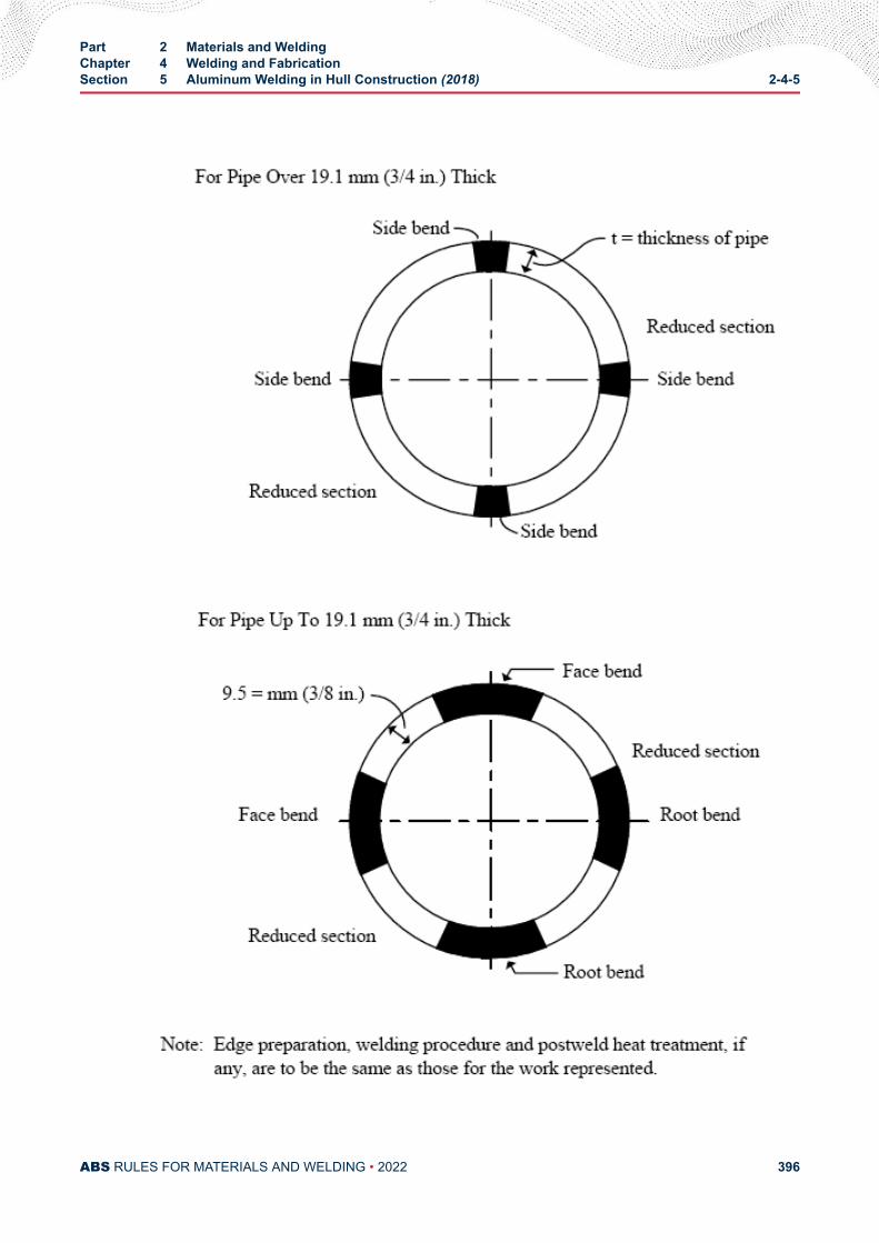
Part 2 Materials and WeldingChapter 4 Welding and FabricationSection 5 Aluminum Welding in Hull Construction (2018) 2-4-5
ABS RULES FOR MATERIALS AND WELDING • 2022 396
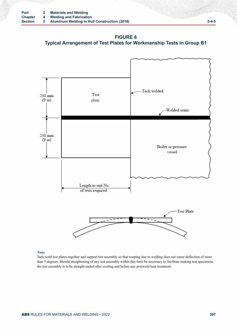
FIGURE 6Typical Arrangement of Test Plates for Workmanship Tests in Group B1
Note:Tack weld test plates together and support test assembly so that warping due to welding does not cause deflection of morethan 5 degrees. Should straightening of any test assembly within this limit be necessary to facilitate making test specimens,the test assembly is to be straight-ended after cooling and before any postweld heat treatment.
Part 2 Materials and WeldingChapter 4 Welding and FabricationSection 5 Aluminum Welding in Hull Construction (2018) 2-4-5
ABS RULES FOR MATERIALS AND WELDING • 2022 397
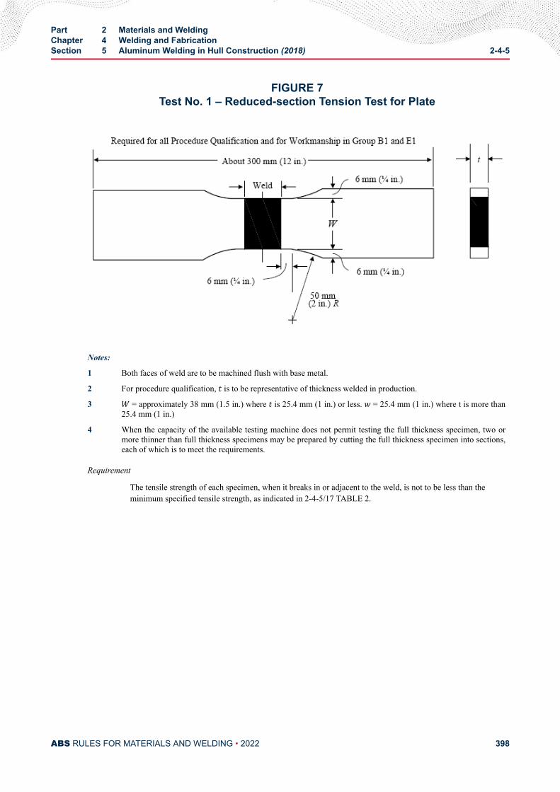
FIGURE 7Test No. 1 – Reduced-section Tension Test for Plate
Notes:
1 Both faces of weld are to be machined flush with base metal.
2 For procedure qualification, t is to be representative of thickness welded in production.
3 W = approximately 38 mm (1.5 in.) where t is 25.4 mm (1 in.) or less. w = 25.4 mm (1 in.) where t is more than25.4 mm (1 in.)
4 When the capacity of the available testing machine does not permit testing the full thickness specimen, two ormore thinner than full thickness specimens may be prepared by cutting the full thickness specimen into sections,each of which is to meet the requirements.
Requirement
The tensile strength of each specimen, when it breaks in or adjacent to the weld, is not to be less than theminimum specified tensile strength, as indicated in 2-4-5/17 TABLE 2.
Part 2 Materials and WeldingChapter 4 Welding and FabricationSection 5 Aluminum Welding in Hull Construction (2018) 2-4-5
ABS RULES FOR MATERIALS AND WELDING • 2022 398
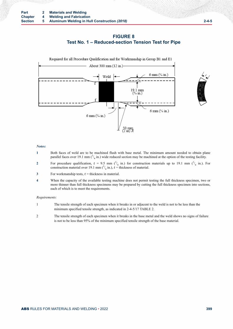
FIGURE 8Test No. 1 – Reduced-section Tension Test for Pipe
Notes:
1 Both faces of weld are to be machined flush with base metal. The minimum amount needed to obtain planeparallel faces over 19.1 mm (3/4 in.) wide reduced section may be machined at the option of the testing facility.
2 For procedure qualification, t = 9.5 mm (3/8 in.) for construction materials up to 19.1 mm (3/4 in.). Forconstruction material over 19.1 mm (3/4 in.), t = thickness of material.
3 For workmanship tests, t = thickness in material.
4 When the capacity of the available testing machine does not permit testing the full thickness specimen, two ormore thinner than full thickness specimens may be prepared by cutting the full thickness specimen into sections,each of which is to meet the requirements.
Requirements:
1 The tensile strength of each specimen when it breaks in or adjacent to the weld is not to be less than theminimum specified tensile strength, as indicated in 2-4-5/17 TABLE 2.
2 The tensile strength of each specimen when it breaks in the base metal and the weld shows no signs of failureis not to be less than 95% of the minimum specified tensile strength of the base material.
Part 2 Materials and WeldingChapter 4 Welding and FabricationSection 5 Aluminum Welding in Hull Construction (2018) 2-4-5
ABS RULES FOR MATERIALS AND WELDING • 2022 399
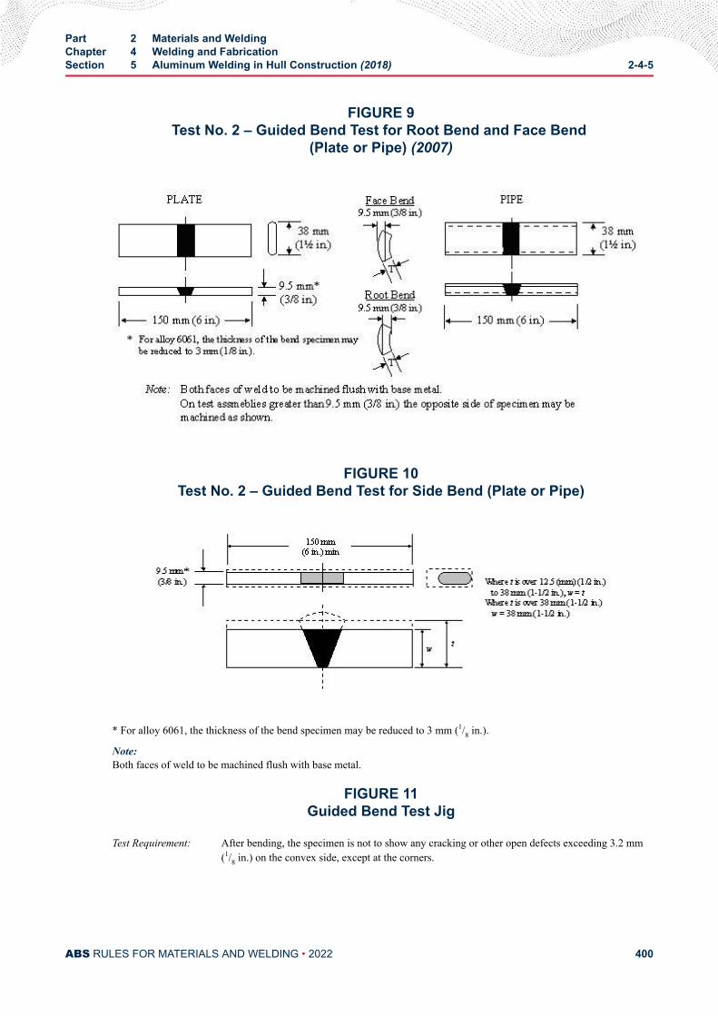
FIGURE 9Test No. 2 – Guided Bend Test for Root Bend and Face Bend
(Plate or Pipe) (2007)
FIGURE 10Test No. 2 – Guided Bend Test for Side Bend (Plate or Pipe)
* For alloy 6061, the thickness of the bend specimen may be reduced to 3 mm (1/8 in.).
Note:Both faces of weld to be machined flush with base metal.
FIGURE 11Guided Bend Test Jig
Test Requirement: After bending, the specimen is not to show any cracking or other open defects exceeding 3.2 mm(1/8 in.) on the convex side, except at the corners.
Part 2 Materials and WeldingChapter 4 Welding and FabricationSection 5 Aluminum Welding in Hull Construction (2018) 2-4-5
ABS RULES FOR MATERIALS AND WELDING • 2022 400
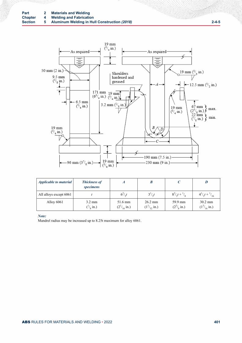
Applicable to material Thickness ofspecimens
A B C D
All alloys except 6061 t 62/3t 31/3t 82/3t + 1/8 41/3t + 1/16
Alloy 6061 3.2 mm(1/8 in.)
51.6 mm(21/16 in.)
26.2 mm(11/32 in.)
59.9 mm(23/8 in.)
30.2 mm(13/16 in.)
Note:Mandrel radius may be increased up to 8.25t maximum for alloy 6061.
Part 2 Materials and WeldingChapter 4 Welding and FabricationSection 5 Aluminum Welding in Hull Construction (2018) 2-4-5
ABS RULES FOR MATERIALS AND WELDING • 2022 401
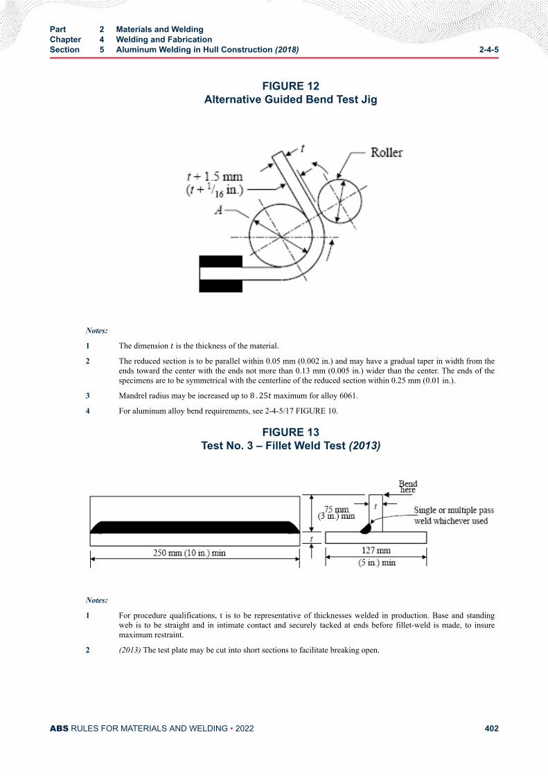
FIGURE 12Alternative Guided Bend Test Jig
Notes:
1 The dimension t is the thickness of the material.
2 The reduced section is to be parallel within 0.05 mm (0.002 in.) and may have a gradual taper in width from theends toward the center with the ends not more than 0.13 mm (0.005 in.) wider than the center. The ends of thespecimens are to be symmetrical with the centerline of the reduced section within 0.25 mm (0.01 in.).
3 Mandrel radius may be increased up to 8 . 25t maximum for alloy 6061.
4 For aluminum alloy bend requirements, see 2-4-5/17 FIGURE 10.
FIGURE 13Test No. 3 – Fillet Weld Test (2013)
Notes:
1 For procedure qualifications, t is to be representative of thicknesses welded in production. Base and standingweb is to be straight and in intimate contact and securely tacked at ends before fillet-weld is made, to insuremaximum restraint.
2 (2013) The test plate may be cut into short sections to facilitate breaking open.
Part 2 Materials and WeldingChapter 4 Welding and FabricationSection 5 Aluminum Welding in Hull Construction (2018) 2-4-5
ABS RULES FOR MATERIALS AND WELDING • 2022 402
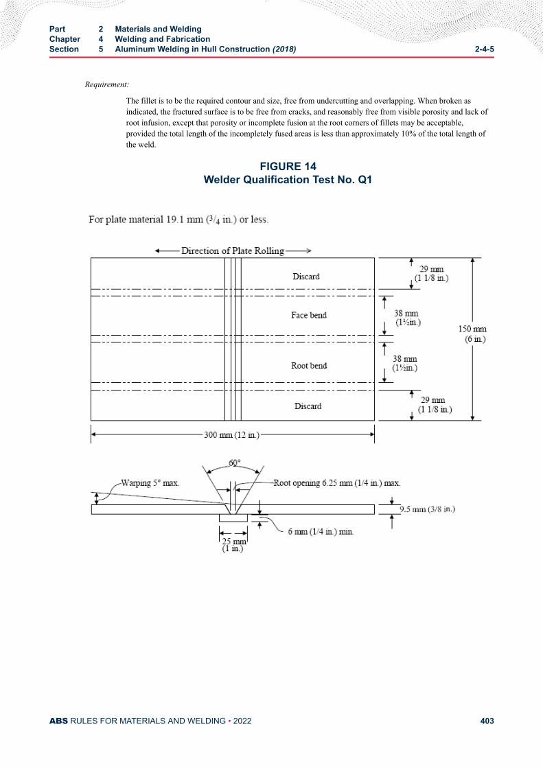
Requirement:
The fillet is to be the required contour and size, free from undercutting and overlapping. When broken asindicated, the fractured surface is to be free from cracks, and reasonably free from visible porosity and lack ofroot infusion, except that porosity or incomplete fusion at the root corners of fillets may be acceptable,provided the total length of the incompletely fused areas is less than approximately 10% of the total length ofthe weld.
FIGURE 14Welder Qualification Test No. Q1
Part 2 Materials and WeldingChapter 4 Welding and FabricationSection 5 Aluminum Welding in Hull Construction (2018) 2-4-5
ABS RULES FOR MATERIALS AND WELDING • 2022 403
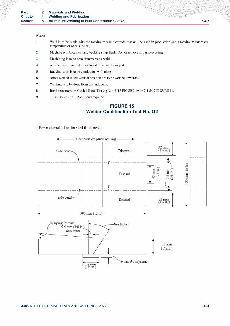
Notes:
1 Weld is to be made with the maximum size electrode that will be used in production and a maximum interpasstemperature of 66°C (150°F).
2 Machine reinforcement and backing strap flush. Do not remove any undercutting.
3 Machining is to be done transverse to weld.
4 All specimens are to be machined or sawed from plate.
5 Backing strap is to be contiguous with plates.
6 Joints welded in the vertical position are to be welded upwards.
7 Welding is to be done from one side only.
8 Bend specimens in Guided Bend Test Jig (2-4-5/17 FIGURE 10 or 2-4-5/17 FIGURE 11.
9 1 Face Bend and 1 Root Bend required.
FIGURE 15Welder Qualification Test No. Q2
Part 2 Materials and WeldingChapter 4 Welding and FabricationSection 5 Aluminum Welding in Hull Construction (2018) 2-4-5
ABS RULES FOR MATERIALS AND WELDING • 2022 404
Notes:
1 When welding in the flat and vertical positions of welding, the groove angle is to be 25 degrees; when weldingin the horizontal position, the groove angle is to be 35 degrees and the unbeveled plate is to be located on the topside of the joint.
2 Backing strap is to be contiguous with plates.
3 Each pass of the weld is to be made with the same size electrode that will be used in production and a maximuminterpass temperature of 66°C (150°F).
4 Joints welded in the vertical position are to be welded upwards.
5 Welding is to be done from one side only.
6 Machine reinforcement and backing strap flush. Do not remove any undercutting.
7 All specimens are to be machined or sawed from plate.
8 Machining is to be done transverse to weld.
9 Break edges of specimens to a radius of t/6 maximum.
10 Bend Specimen in Guided Bend Test Jig (2-4-5/17 FIGURE 10 or 2-4-5/17 FIGURE 11).
11 2 Side Bends required for plate. 4 Side Bends required for pipe.
Part 2 Materials and WeldingChapter 4 Welding and FabricationSection 5 Aluminum Welding in Hull Construction (2018) 2-4-5
ABS RULES FOR MATERIALS AND WELDING • 2022 405
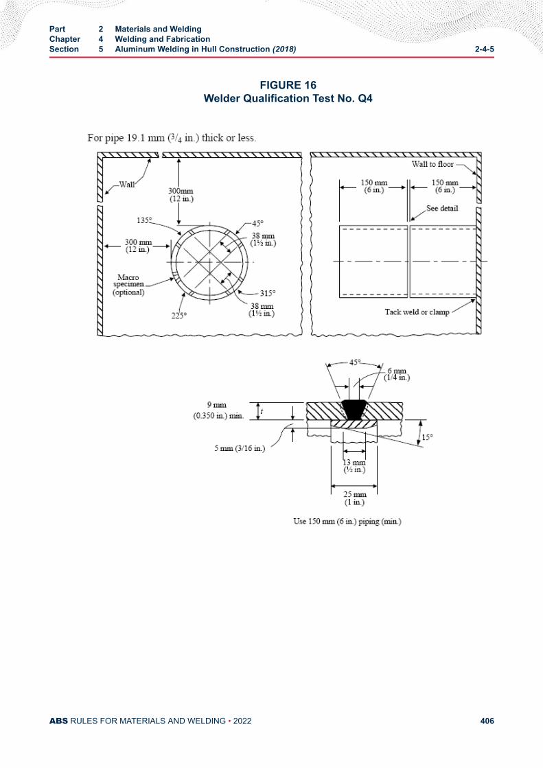
FIGURE 16Welder Qualification Test No. Q4
Part 2 Materials and WeldingChapter 4 Welding and FabricationSection 5 Aluminum Welding in Hull Construction (2018) 2-4-5
ABS RULES FOR MATERIALS AND WELDING • 2022 406
Notes:
1 Each pass of the weld is to be made with the same size electrode that will be used in production and a maximuminterpass temperature of 66°C (150°F).
2 Machine reinforcement and backing strap flush. Do not remove any undercutting.
3 Machining is to be done transverse to weld.
4 All specimens are to be machined or sawed from piping.
5 Break edges of specimens to a radius of t/6 maximum.
6 Mark top and front of piping to insure proper location of specimens.
7 Remove face-bend specimens from 45 degree and 225 degree points, and root-bend specimens from 135 degreeand 315 degree points, as indicated.
8 Welding is to be done from one side only.
9 Bend Specimen in Guided Bend Test Jig (2-4-5/17 FIGURE 10 or 2-4-5/17 FIGURE 11.
10 Two Root Bends and two Face Bends required.
11 For thicknesses over 19.1 mm (3/4 in.), t is to be a minimum of 1/2 of the thickness to be welded in production.
12 For GTA welding, no backing bar need be employed and root opening may be reduced to zero.
Part 2 Materials and WeldingChapter 4 Welding and FabricationSection 5 Aluminum Welding in Hull Construction (2018) 2-4-5
ABS RULES FOR MATERIALS AND WELDING • 2022 407
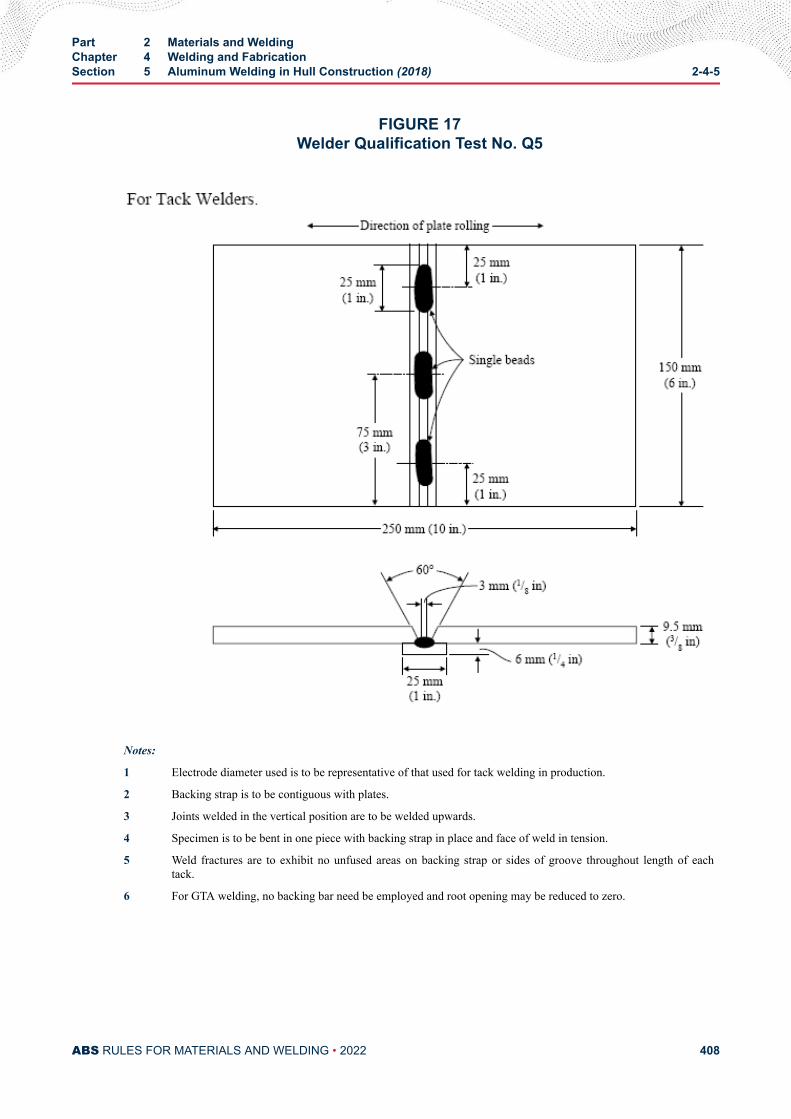
FIGURE 17Welder Qualification Test No. Q5
Notes:
1 Electrode diameter used is to be representative of that used for tack welding in production.
2 Backing strap is to be contiguous with plates.
3 Joints welded in the vertical position are to be welded upwards.
4 Specimen is to be bent in one piece with backing strap in place and face of weld in tension.
5 Weld fractures are to exhibit no unfused areas on backing strap or sides of groove throughout length of eachtack.
6 For GTA welding, no backing bar need be employed and root opening may be reduced to zero.
Part 2 Materials and WeldingChapter 4 Welding and FabricationSection 5 Aluminum Welding in Hull Construction (2018) 2-4-5
ABS RULES FOR MATERIALS AND WELDING • 2022 408
C H A P T E R 5Materials for Hull Construction – Aluminum
CONTENTSSECTION 1 General..............................................................................................414
1 Testing and Inspection................................................................4141.1 General (2014)...............................................................4141.3 Witnessed Tests.............................................................4141.5 Rejection of Previously Accepted Material.................... 4151.7 Calibrated Testing Machines..........................................4151.9 Referenced Documents (2011)......................................415
3 Defects........................................................................................4155 Manufacturer’s Certificates.........................................................416
5.1 Form of Certificate (2014)..............................................4165.3 Other Certificates...........................................................4165.5 Dual Certification........................................................... 4165.7 Electronic Certification System (2011)...........................416
7 Identification Markings................................................................4177.1 Marine Grades............................................................... 4177.3 Material Identification (2011)..........................................4177.5 Stenciled Material.......................................................... 417
SECTION 2 Standard Test Methods....................................................................4181 General (2011)............................................................................418
1.1 Chemical Analysis......................................................... 4181.3 Tension Testing.............................................................. 4181.5 Shear Testing.................................................................4181.7 Hardness Testing*..........................................................4181.9 Electrical Conductivity Testing*......................................418
SECTION 3 Chemical Composition.................................................................... 4191 General.......................................................................................4193 Sampling.....................................................................................4195 Definition of an Inspection Lot.................................................... 419
PART 2
ABS RULES FOR MATERIALS AND WELDING • 2022 409
TABLE 1 Chemical Composition Limits of Wrought AluminumAlloys (2013)...................................................................... 419
TABLE 2 Chemical Composition Limits of Cast Aluminum Alloys.....420
SECTION 4 Heat Treatment................................................................................. 421
SECTION 5 Tensile Properties............................................................................ 4221 General.......................................................................................4223 Yield Strength............................................................................. 4225 Standard Test Specimens...........................................................422
5.1 General (2011)...............................................................4225.3 Full-Section Specimens................................................. 4225.5 Machined Specimens.................................................... 4225.7 Dimensions.................................................................... 4235.9 Test Specimens Orientation and Location (2011).......... 424
7 Retests........................................................................................4247.1 Defective Test specimen................................................4247.3 Failure to Meet Requirements (2012)............................ 424
TABLE 1A Mechanical Property Limits of Non-Heat-TreatableSheet and Plate Aluminum Alloys (2,3) (2014)..................... 425
TABLE 1B Mechanical Property Limits of Non-Heat-TreatableMarine Grade Sheet and Plate Aluminum Alloys for HullConstruction (2, 3, 4).............................................................. 427
TABLE 2 Long Transverse Mechanical Property Limits of Heat-Treatable Sheet and Plate Aluminum Alloys (2, 6)(2011)......428
TABLE 3 Longitudinal Mechanical Property Limits of Non-Heat-Treatable Aluminum Alloys for Extruded Bars, Rods,Shapes, and Tubes (2, 3)(2011)............................................429
TABLE 4 Mechanical Property Limits of Heat-TreatableAluminum Alloys for Extruded Products (2,6)(2011)............. 430
TABLE 5 Mechanical Property Limits for Die Forgings(3) (2011)........431TABLE 6 Mechanical Property Limits for Hand Forgings(2, 3) (2011)..431TABLE 7 Mechanical Property Limits for Aluminum Alloy
Castings (2011).................................................................. 432TABLE 8 Cross Reference of Active International Designations
with Former Wrought Alloy Designations (2016)................432
FIGURE 1 Standard Tension Test Specimen.......................................423
SECTION 6 Corrosion Testing............................................................................ 4341 General (2016)............................................................................4343 Reference Photomicrograph (2016)........................................... 4345 Batch Microstructural Analysis and Acceptance (2016)............. 4347 Surveillance of Corrosion Testing (2011).................................... 435
ABS RULES FOR MATERIALS AND WELDING • 2022 410
SECTION 7 Sheet, Plate and Rolled Products...................................................4361 Scope..........................................................................................4363 Selection of Tension Test Specimen (2011)................................4365 Number of Tension Tests............................................................ 436
5.1 Sheet............................................................................. 4365.3 Plate and Rolled Products............................................. 4365.5 Definition of a Batch.......................................................437
7 Surface Finish (2014)................................................................. 4379 Nondestructive Examination (NDE)............................................43711 Dimensions and Tolerance......................................................... 437
TABLE 1 Under-thickness Tolerance for Rolled Products (2018)......437
SECTION 8 Extrusions........................................................................................ 4381 Scope..........................................................................................4383 Selection of Specimens.............................................................. 4385 Number of Tests..........................................................................438
5.1 Tension Tests................................................................. 4385.3 Drift Expansion Tests..................................................... 4385.5 Definition of a Batch.......................................................440
7 Surface Finish (2014)................................................................. 4409 Nondestructive Examination (NDE)............................................44011 Dimensions and Tolerance......................................................... 440
FIGURE 1 Drift Expansion Test........................................................... 439
SECTION 9 Forgings............................................................................................4411 Scope .........................................................................................4413 Selection of Specimens.............................................................. 441
3.1 Location of Specimens.................................................. 4413.3 Small Forgings...............................................................4413.5 Test Specimens............................................................. 442
5 Number of Tests..........................................................................4425.1 Large Forgings...............................................................4425.3 Intermediate sized Forgings.......................................... 4425.5 Small Forgings...............................................................4425.7 Special Situations.......................................................... 4425.9 Retests...........................................................................442
7 Inspection................................................................................... 4429 Nondestructive Examination (NDE)............................................44211 Dimensions and Tolerance......................................................... 442
SECTION 10 Castings............................................................................................443
ABS RULES FOR MATERIALS AND WELDING • 2022 411
1 Scope (2013).............................................................................. 4433 Selection of Specimens.............................................................. 443
3.1 Large Castings...............................................................4433.3 Small Castings...............................................................4433.5 Test Specimens............................................................. 443
5 Number of Tests..........................................................................4447 Inspection................................................................................... 4449 Welded Repair of Defects...........................................................44411 Nondestructive Examination (NDE)............................................44413 Dimensions and Tolerance......................................................... 444
SECTION 11 Rivets................................................................................................ 4451 General.......................................................................................445
APPENDIX 1 Aluminum/Steel Bi-material Transition Joints (2015)................... 4461 Scope..........................................................................................4463 Supplementary Requirements ................................................... 446
3.1 Reference Documents................................................... 4463.3 Process of Manufacture.................................................4463.5 Tensile Strength............................................................. 4463.7 Bend Test.......................................................................4473.9 Shear Test......................................................................4473.11 Axial Fatigue Strength Test............................................4473.13 Welded Tensile Test.......................................................4473.15 Nondestructive Examination.......................................... 4483.17 Dimensional Tolerances.................................................4483.19 Sampling Lots................................................................ 4483.21 Test Sampling................................................................ 4483.23 Retest Sampling............................................................ 4493.25 First Article Inspection................................................... 4493.27 Ordering Data................................................................ 449
TABLE 1 Fatigue Test Conditions and Requirements (2015)............447TABLE 2 Production Lot Testing (2015)............................................ 448TABLE 3 First Article Testing (2015)................................................. 449
FIGURE 1 Ram Tensile Test Setup (2015)..........................................450FIGURE 2 Ram Tensile Specimen (2015)...........................................451FIGURE 3 Weld Tensile Test Assembly (2015)................................... 451
APPENDIX 2 Dissimilar Materials (2015)..............................................................4531 Material.......................................................................................453
1.1 Dissimilar Materials........................................................453
ABS RULES FOR MATERIALS AND WELDING • 2022 412

APPENDIX 3 List of Destructive and Nondestructive Tests Required forMaterials and Responsibility for Verifying (2017)......................... 454
ABS RULES FOR MATERIALS AND WELDING • 2022 413
C H A P T E R 5Materials for Hull Construction – Aluminum
S E C T I O N 1General
1 Testing and Inspection
1.1 General (2014)All materials subject to test and inspection, intended for use in the construction of the hulls of craft classedor proposed for classification, are to be tested by the material producer and inspected by the ABS Surveyorin accordance with the following requirements or their equivalent. These requirements are not applicable tothe use of aluminum alloys at low temperature for cryogenic applications. Materials, test specimens andmechanical testing procedures having characteristics differing from those prescribed herein may beapproved for application, with due regard being given to established practices in the country in which thematerial is produced and the purpose for which the material is intended, such as the parts for which it is tobe used, the type of craft and intended service, and the nature of the construction of the craft. Therequirements are based on both metric and U.S. customary units. Each system of units is to be treated asseparate and independent from the other. Mixing and matching of units from one system to another are notpermitted. The numerical designation (grade) of aluminum alloys and the temper designation are based onthose of the Aluminum Association or recognized Standards.
Consideration may be given to aluminium alloys not specified in these requirements, and to alternativetemper conditions, subject to prior agreement with ABS further to a detailed study of their properties,including corrosion resistance, and of their conditions of use (in particular welding procedures).
All materials, including semi-finished products are to be manufactured at works which are approved byABS for the grades and maximum thickness of aluminum alloy supplied.
1.3 Witnessed TestsAll tests are to be carried out by competent personnel and conducted in the presence of the Surveyors at theplace of manufacture prior to shipping. Consideration will be given to the acceptance of rolled andextruded products without witnessing of mechanical tests by the Surveyor, on the basis of compliance withABS’s Quality Assurance Program. Testing procedures are to follow established practices in internationalor national Standards. Test samples are to be taken from material which has undergone the same treatmentas the material to be certified. Preparation of specimens is not to involve significant straining or heating.Thermally cut samples are to have excess material to allow a specimen to be machined from material thatis unaffected by the cutting process.
PART 2
ABS RULES FOR MATERIALS AND WELDING • 2022 414
1.5 Rejection of Previously Accepted MaterialIn the event of any material proving unsatisfactory in the process of being worked, it shall be rejected,notwithstanding any previous certificate of satisfactory testing.
1.7 Calibrated Testing MachinesAll testing machines shall be maintained in good condition by the manufacturer and to the satisfaction ofthe attending Surveyor. The measuring equipment and machinery used shall be periodically calibrated bythe manufacturer in accordance with ISO standards or any other recognized national/internationalstandards requirements. The validity of calibration certificates shall be verified by the Surveyor beforewitnessing tests.
1.9 Referenced Documents (2011)The following documents form a part of the overall specification to the extent they are referenced in thisABS Rules document:
ANSI H35.1 Alloy and Temper Designation Systems for Aluminum
ASTM B928/928M Standard Specification for High Magnesium Aluminum-Alloy sheet and plate for marine Service.
ASTM B221/221M Standard Specification for Aluminum and Aluminum-Alloy Extruded Bars, Rods, Wire, Profiles,and Tubes
ASTM B247/247M Standard Specification for Aluminum and Aluminum-Alloy Die Forgings, Hand Forgings, andRolled Ring Forgings
ASTM B316/316M Standard Specification for Aluminum and Aluminum – Alloy Rivet and Cold-Heading Wire andRods
ASTM B209/209M Standard Specification for Aluminum and Aluminum-Alloy Sheet and Plate
ASTM B26/26M Standard Specification for Aluminum-Alloy Sand Castings
ASTM B108 Standard Specification for Aluminum-Alloy Permanent Castings
ASTM B918 Standard Practice for Heat Treatment of Wrought Aluminum Alloys
ASTM E34 Test methods for Chemical Analysis of Aluminum and Aluminum-Base Alloys
ASTM E1251 Test Method for optical Emission Spectrometric Analysis of Aluminum and Aluminum Alloys byArgon Atmosphere, point-to-plane, unipolar self-initiating Capacitor Discharge.
ASTM E8/8M Standard Test methods for Tension Testing of Metallic Materials
ASTM B557/557M Standard Test Methods of Tension Testing Wrought and Cast Aluminum – and Magnesium-AlloyProducts
ASTM B565 Method for Shear Testing of Aluminum and Aluminum – Alloy Rivet and Cold-Heading Wire andRods
AWS D1.2/D1.2M Structural Welding Code – Aluminum
IACS UR W25 Materials and Welding – Aluminum Alloys for Hull Construction and Marine Structure
IACS UR W26 Materials and Welding – Requirements for Welding Consumables for Aluminum Alloys
3 DefectsAll materials and weldments are to be generally free from linear, planar and volumetric physical defectssuch as embedded and through thickness flaws, laminations and injurious surface flaws or similar forms ofdefects that would be detrimental to the use of the materials and weldments in the intended applications.Welding or dressing for the purpose of remedying defects is not permitted unless and until sanctioned bythe Surveyor. Discoloration characteristic of proper heat treatment schedules is not cause for rejection.
Part 2 Materials and WeldingChapter 5 Materials for Hull Construction – AluminumSection 1 General 2-5-1
ABS RULES FOR MATERIALS AND WELDING • 2022 415
5 Manufacturer’s Certificates
5.1 Form of Certificate (2014)Four copies of the mill certificates or the shipping statements of all accepted plate and shape materialsindicating the aluminum alloy and temper, the purchaser and order number, the construction projectnumber (if available), the product quantity, dimension and weight, the chemical composition, the batchnumber (or identifying mark) and mechanical and corrosion test results as applicable, are to be furnished tothe Surveyor for his approval; one is to be forwarded to the purchaser, three are to be retained for the useof ABS.
Before the mill certificates or shipping statements are distributed by the local ABS office, the manufactureris to furnish the Surveyor with a certificate stating that the material has been sampled, tested and inspectedin accordance with these Rules and that it has met the requirements. The following form of certificate willbe accepted if printed on each mill sheet or shipping statement with the name of the firm and initialed bythe authorized representative of the manufacturer:
“We hereby certify that the material described herein has been made to the applicable specifications ofalloy __________; temper __________, and the required samples tested in accordance with therequirements of __________ (The American Bureau of Shipping Rules or state other specification) in thepresence of a Surveyor from the American Bureau of Shipping with satisfactory results.”
At the request of manufacturers, consideration may be given to modifications to the form of certificate,provided it correspondingly indicates compliance with the requirements of these Rules to no less degreethan indicated in the foregoing statement.
5.3 Other CertificatesWhere an aluminum alloy ingot is not produced in the plant where it is rolled, extruded or forged, acertified report is to be supplied to the Surveyor stating the name of the manufacturer, the alloy, ingot ormanufacturing and inspection lot identification numbers and certification that the alloy meets the requiredchemical composition limits.
5.5 Dual CertificationDual certification of aluminum alloys is permitted only when alloy designations involved meet thespecified chemical composition and specified minimum mechanical property requirements; provided theyhave the same ANSI temper designations in order to avoid any differences that may arise in welding andmarine corrosion characteristics of the alloys with differing temper designations.
5.7 Electronic Certification System (2011)An electronic certification system may be used to issue certified mill test reports, which may beelectronically signed and stamped by an attending Surveyor, subject to the following conditions.
● All relevant information regarding the customer order, including the electronic certification request, isto be provided to the attending Surveyor by the manufacturer.
● Procedures are to be established to control handling and distribution of certified mill test reportsamong the manufacturer, ABS, and the purchaser.
● In order to implement the electronic certification system, the manufacturer is to be under mandatoryABS-QA program.
Part 2 Materials and WeldingChapter 5 Materials for Hull Construction – AluminumSection 1 General 2-5-1
ABS RULES FOR MATERIALS AND WELDING • 2022 416
7 Identification Markings
7.1 Marine GradesAluminum alloys with ability to resist intergranular and exfoliation forms of corrosion when in directcontact with seawater or when used in marine environment conditions shall be treated as marine grades.Aluminum alloys with magnesium content greater than or equal to 3% are prone to these forms ofcorrosion and shall be tested, inspected and certified in accordance with ASTM B928 specification by themanufacturer. The acceptance criteria for corrosion tests (ASTM G66 and G67) are to follow ABS Rulerequirements. The test results shall be reported on the mill certificates and are to be verified by theSurveyor. The alloy grade shall be suffixed with the letters “MG” while marking as indicated in 2-5-1/7.3.
7.3 Material Identification (2011)All materials which have been sampled, tested and have successfully passed the requirements and havebeen approved by the Surveyor are to be clearly ink marked or stamped with the manufacturer’s name ortrademark and material identification on each finished sheet, plate, shape, bar, rod casing or forging tosignify that the material has satisfactorily complied with the tests prescribed. The material identification isto include:
i) The initials AB.
ii) The aluminum alloy designation according to the Aluminum Association.
iii) The temper designation according to the Aluminum Association.
iv) The manufacturers batch number.
v) The letter “MG” is to be added after the grade and temper designation only if the material hasbeen corrosion tested as per requirements of 2-5-6 of these Rules and ASTM B928. Example: AB/5083 H321 MG.
7.5 Stenciled MaterialIn special cases, when approved, strapped or secured lifts or bundles of light sheet, plates, shapes, bars,rods or tubes of comparatively small size may be marked or stenciled on only the top piece or the markingmay be shown on the tag attached to each lift or bundle.
Part 2 Materials and WeldingChapter 5 Materials for Hull Construction – AluminumSection 1 General 2-5-1
ABS RULES FOR MATERIALS AND WELDING • 2022 417
C H A P T E R 5Materials for Hull Construction – Aluminum
S E C T I O N 2Standard Test Methods
1 General (2011)The latest issue of the following test methods or specifications or their equivalents are consideredacceptable:
1.1 Chemical AnalysisThe chemical analyses are to be carried out in accordance with ASTM E34 or ASTM E716 or ASTME1251 or equivalent, as may be appropriate to a specific alloy under testing and consideration forcertification. The sampling practice for chemical analyses is to be carried out as indicated in 2-5-3/3 andmay follow a recognized standard to the extent as may be modified or stated in this document.
1.3 Tension TestingRefer to Section 2-5-5 for requirements for test specimens.
Alternative Standards ASTM E 8/8M or ASTM B557/557M or equivalent may be used.
1.5 Shear TestingShear tests are to be carried out in accordance with ASTM B769 or ASTM B565 or equivalent.
1.7 Hardness Testing*Hardness tests, if applicable, are to be carried out in accordance with ASTM E18 or equivalent.
1.9 Electrical Conductivity Testing*Electrical Conductivity tests, if applicable, are to be carried out in accordance with ASTM E1004 orequivalent.
Note:
* Hardness and Electrical Conductivity testing are reference only for evaluation of alloys and tempers of heat treatablealuminum products.
PART 2
ABS RULES FOR MATERIALS AND WELDING • 2022 418
C H A P T E R 5Materials for Hull Construction – Aluminum
S E C T I O N 3Chemical Composition
1 GeneralThe chemical composition of each cast is to be determined by the aluminum manufacturer and is toconform to the applicable requirements of the alloys listed in 2-5-3/Table 1 or 2-5-3/Table 2 or such otherrequirements as may be specially approved.
3 SamplingA control sample for chemical analysis is to be taken before starting to pour and one additional sample isto be taken during the pouring of each group of ingots poured simultaneously from the same source ofmolten metal. If not analyzed during pouring samples, it may be taken from semi-finished or finishedproducts. When samples are taken from finished or semi-finished products, one sample is to represent each1800 kg (4000 lb), or fraction thereof, of each alloy in an inspection lot. The manufacturer’s declaredanalysis will be subject to occasional checks if required by the Surveyor.
Product analysis may be required where the final product chemistry is not well represented by the analysisfrom the cast.
When the aluminum alloys are not cast in the same works in which they are manufactured into semi-finished products, a certificate issued by the works is to be provided to the Surveyor which indicates thereference numbers and chemical composition of the heats.
5 Definition of an Inspection LotAn inspection lot is defined as:
For non-heat treated tempers, an identifiable quantity of material of the same mill form, alloy, temper,section and size submitted for an inspection at one time before shipment. And for heat treated temper anidentifiable quantity of material of the same mill form, alloy, temper, section and size traceable to a heattreated lot or lots and submitted for inspection at one time before shipment. Mill forms: sheet and plate, allmaterial of the same thickness is considered to be of the same size.
TABLE 1Chemical Composition Limits of Wrought Aluminum Alloys (2013)
Limits are in weight percent. Single value represents maximum limit, unless shown as a range or indicated as a minimum.
PART 2
ABS RULES FOR MATERIALS AND WELDING • 2022 419
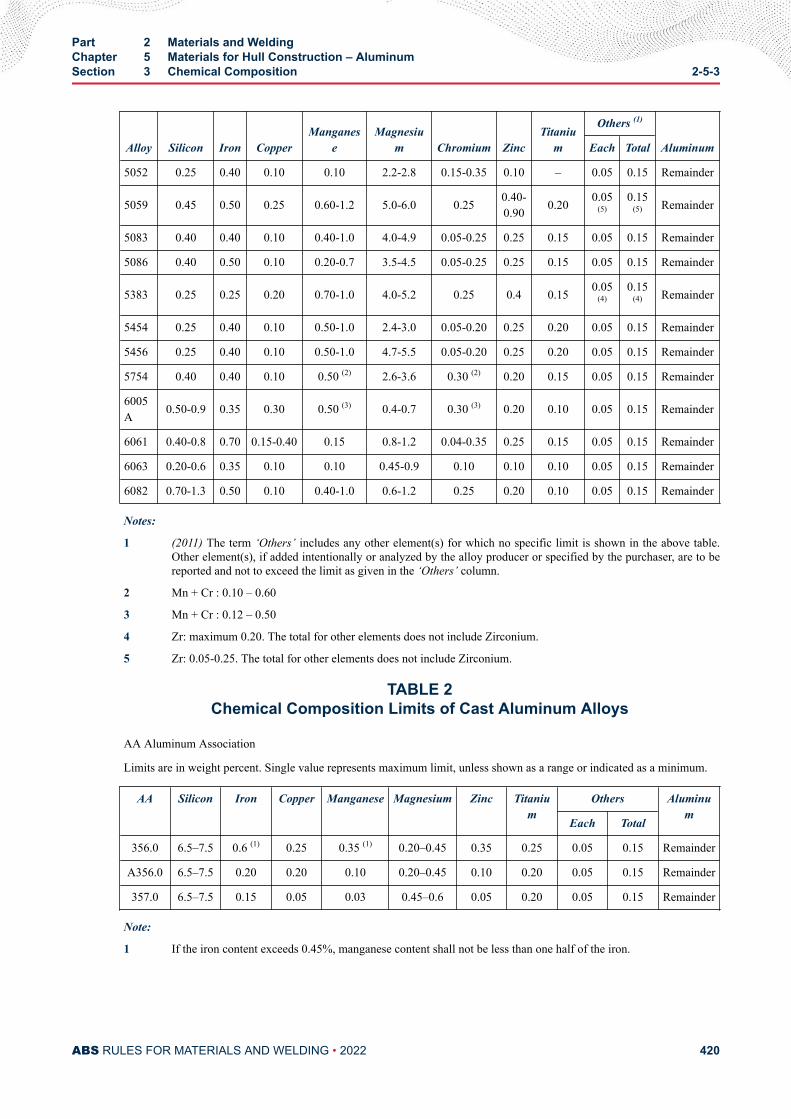
Alloy Silicon Iron CopperManganes
eMagnesiu
m Chromium ZincTitaniu
m
Others (1)
AluminumEach Total
5052 0.25 0.40 0.10 0.10 2.2-2.8 0.15-0.35 0.10 – 0.05 0.15 Remainder
5059 0.45 0.50 0.25 0.60-1.2 5.0-6.0 0.25 0.40-0.90 0.20 0.05
(5)0.15
(5) Remainder
5083 0.40 0.40 0.10 0.40-1.0 4.0-4.9 0.05-0.25 0.25 0.15 0.05 0.15 Remainder
5086 0.40 0.50 0.10 0.20-0.7 3.5-4.5 0.05-0.25 0.25 0.15 0.05 0.15 Remainder
5383 0.25 0.25 0.20 0.70-1.0 4.0-5.2 0.25 0.4 0.15 0.05(4)
0.15(4) Remainder
5454 0.25 0.40 0.10 0.50-1.0 2.4-3.0 0.05-0.20 0.25 0.20 0.05 0.15 Remainder
5456 0.25 0.40 0.10 0.50-1.0 4.7-5.5 0.05-0.20 0.25 0.20 0.05 0.15 Remainder
5754 0.40 0.40 0.10 0.50 (2) 2.6-3.6 0.30 (2) 0.20 0.15 0.05 0.15 Remainder
6005A 0.50-0.9 0.35 0.30 0.50 (3) 0.4-0.7 0.30 (3) 0.20 0.10 0.05 0.15 Remainder
6061 0.40-0.8 0.70 0.15-0.40 0.15 0.8-1.2 0.04-0.35 0.25 0.15 0.05 0.15 Remainder
6063 0.20-0.6 0.35 0.10 0.10 0.45-0.9 0.10 0.10 0.10 0.05 0.15 Remainder
6082 0.70-1.3 0.50 0.10 0.40-1.0 0.6-1.2 0.25 0.20 0.10 0.05 0.15 Remainder
Notes:
1 (2011) The term ‘Others’ includes any other element(s) for which no specific limit is shown in the above table.Other element(s), if added intentionally or analyzed by the alloy producer or specified by the purchaser, are to bereported and not to exceed the limit as given in the ‘Others’ column.
2 Mn + Cr : 0.10 – 0.60
3 Mn + Cr : 0.12 – 0.50
4 Zr: maximum 0.20. The total for other elements does not include Zirconium.
5 Zr: 0.05-0.25. The total for other elements does not include Zirconium.
TABLE 2Chemical Composition Limits of Cast Aluminum Alloys
AA Aluminum Association
Limits are in weight percent. Single value represents maximum limit, unless shown as a range or indicated as a minimum.
AA Silicon Iron Copper Manganese Magnesium Zinc Titanium
Others Aluminum
Each Total
356.0 6.5–7.5 0.6 (1) 0.25 0.35 (1) 0.20–0.45 0.35 0.25 0.05 0.15 Remainder
A356.0 6.5–7.5 0.20 0.20 0.10 0.20–0.45 0.10 0.20 0.05 0.15 Remainder
357.0 6.5–7.5 0.15 0.05 0.03 0.45–0.6 0.05 0.20 0.05 0.15 Remainder
Note:
1 If the iron content exceeds 0.45%, manganese content shall not be less than one half of the iron.
Part 2 Materials and WeldingChapter 5 Materials for Hull Construction – AluminumSection 3 Chemical Composition 2-5-3
ABS RULES FOR MATERIALS AND WELDING • 2022 420
C H A P T E R 5Materials for Hull Construction – Aluminum
S E C T I O N 4Heat Treatment
Alloys 6005A, 6061 and 6082 products are to be suitably heat treated to develop the mechanicalproperties specified in2-5-5/Tables 2, 4, 5 and 6 for the various tempers. Alternative heat treatments will bespecially considered.
• T4 Solution heat treated and then naturally aged.
• T451 For sheet and plate that are stress relieved by stretching after solution heat treatment.
• T4511 For extruded bars, rods or shapes that are stress relieved by stretching after solution heat treatment.
• T5 Cooled from an elevated temperature shaping process and then artificially aged. Usually associated withextruded products.
• T6 Solution heat treated and then artificially aged.
• T651 For sheet and plate that are stress relieved by stretching after solution heat treatment and then artificiallyaged.
• T6511 For extruded bars, rods or shapes that are stress relieved by stretching after solution heat treatment andthen artificially aged.
PART 2
ABS RULES FOR MATERIALS AND WELDING • 2022 421
C H A P T E R 5Materials for Hull Construction – Aluminum
S E C T I O N 5Tensile Properties
1 GeneralTensile properties are to conform to the applicable requirements of the alloys and tempers listed in 2-5-5/Tables 1 through 7. Mechanical properties for welded joints are lower for strain hardened or heat treatedalloys. For as welded properties refer to Section 2-4-5.
3 Yield StrengthThe yield strength is defined as that determined at 0.2% offset.
5 Standard Test Specimens
5.1 General (2011)Tension test specimens may be the full cross section of the material being tested or they may be machinedas indicated for specific product forms. Test specimens in accordance with other recognized standards maybe accepted subject to special approval.
5.3 Full-Section SpecimensTension test specimens of the full cross section of the material may be used for wire, rod, bar, shapes andtubular products. It is permissible to reduce the section slightly throughout the section to insure fracturewithin the gauge marks.
5.5 Machined SpecimensStandard tension test specimens’ requirements are indicated in 2-5-5/5.5 FIGURE 1.
The following designations are used:d = diametera = thicknessb = widthL0 = original gauge lengthLc = parallel length
PART 2
ABS RULES FOR MATERIALS AND WELDING • 2022 422
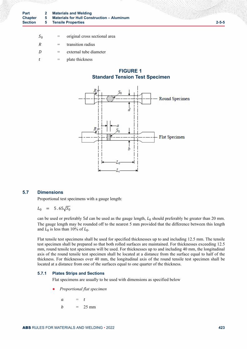
S0 = original cross sectional areaR = transition radiusD = external tube diametert = plate thickness
FIGURE 1 Standard Tension Test Specimen
5.7 DimensionsProportional test specimens with a gauge length:L0 = 5 . 65 S0can be used or preferably 5d can be used as the gauge length, L0 should preferably be greater than 20 mm.The gauge length may be rounded off to the nearest 5 mm provided that the difference between this lengthand L0 is less than 10% of L0.Flat tensile test specimens shall be used for specified thicknesses up to and including 12.5 mm. The tensiletest specimen shall be prepared so that both rolled surfaces are maintained. For thicknesses exceeding 12.5mm, round tensile test specimens will be used. For thicknesses up to and including 40 mm, the longitudinalaxis of the round tensile test specimen shall be located at a distance from the surface equal to half of thethickness. For thicknesses over 40 mm, the longitudinal axis of the round tensile test specimen shall belocated at a distance from one of the surfaces equal to one quarter of the thickness.
5.7.1 Plates Strips and SectionsFlat specimens are usually to be used with dimensions as specified below
● Proportional flat specimena = tb = 25 mm
Part 2 Materials and WeldingChapter 5 Materials for Hull Construction – AluminumSection 5 Tensile Properties 2-5-5
ABS RULES FOR MATERIALS AND WELDING • 2022 423
L0 = 5 . 65 S0Lc = L0+ 2 S0R = 25 mm
● Non-proportional flat specimena = tb = 25 mmL0 = 200 mmLc > 212.5 mmR = 25 mm
When the capacity of the available testing machine is insufficient to allow the use of test specimenof full thickness, this may be reduced by machining one of the rolled surfaces.
Alternatively, for materials over 40 mm thick, proportional round test specimens with dimensionsas specified below may be used.
● Round specimend ≥ 10 mm to 20 mm, preferably 14 mmL0 = 5dLc ≥ L0+ d2R ≥ 10 mm (for materials with a specified elongation less than 10%, R ≥ 1 . 5d)
The axes of the round test specimens are to be located at approximately one quarter of thethickness from one of the rolled surfaces.
5.7.2 Forgings and CastingsProportional round test specimens with dimensions as specified above in 2-5-5/5.7.1 are usually tobe used. are usually to be used. For small size bars and similar products the test specimens mayconsist of a suitable length of bar or other product tested in the full cross-section.
5.9 Test Specimens Orientation and Location (2011)The practice for orientation and location of tension test specimens is to be followed as per ASTMB557/557M or equivalent standard and to the extent as may be modified or stated in this document. Theorientation and location of tension test specimens are to be indicated in the test report.
7 Retests
7.1 Defective Test specimenIf the percentage elongation of a tension test specimen is less than that specified, and if any part of thefracture is outside of the middle half of the gauge length or in a punched or scribed mark within thereduced section, another test specimen may be selected.
7.3 Failure to Meet Requirements (2012)If any tension test specimen selected in accordance with 2-5-7/5, 2-5-8/5 or 2-5-9/5 fails to conform to therequirements, two additional specimens, for each specimen that failed, may be selected from the area that
Part 2 Materials and WeldingChapter 5 Materials for Hull Construction – AluminumSection 5 Tensile Properties 2-5-5
ABS RULES FOR MATERIALS AND WELDING • 2022 424
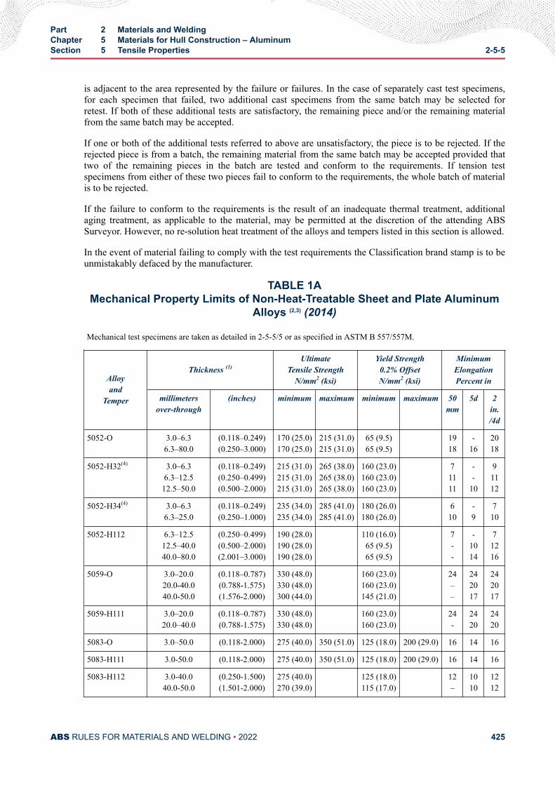
is adjacent to the area represented by the failure or failures. In the case of separately cast test specimens,for each specimen that failed, two additional cast specimens from the same batch may be selected forretest. If both of these additional tests are satisfactory, the remaining piece and/or the remaining materialfrom the same batch may be accepted.
If one or both of the additional tests referred to above are unsatisfactory, the piece is to be rejected. If therejected piece is from a batch, the remaining material from the same batch may be accepted provided thattwo of the remaining pieces in the batch are tested and conform to the requirements. If tension testspecimens from either of these two pieces fail to conform to the requirements, the whole batch of materialis to be rejected.
If the failure to conform to the requirements is the result of an inadequate thermal treatment, additionalaging treatment, as applicable to the material, may be permitted at the discretion of the attending ABSSurveyor. However, no re-solution heat treatment of the alloys and tempers listed in this section is allowed.
In the event of material failing to comply with the test requirements the Classification brand stamp is to beunmistakably defaced by the manufacturer.
TABLE 1AMechanical Property Limits of Non-Heat-Treatable Sheet and Plate Aluminum
Alloys (2,3) (2014)
Mechanical test specimens are taken as detailed in 2-5-5/5 or as specified in ASTM B 557/557M.
Alloyand
Temper
Thickness (1)Ultimate
Tensile StrengthN/mm2 (ksi)
Yield Strength0.2% OffsetN/mm2 (ksi)
MinimumElongationPercent in
millimetersover-through
(inches) minimum maximum minimum maximum 50mm
5d 2in./4d
5052-O 3.0–6.36.3–80.0
(0.118–0.249)(0.250–3.000)
170 (25.0)170 (25.0)
215 (31.0)215 (31.0)
65 (9.5)65 (9.5)
1918
-16
2018
5052-H32(4) 3.0–6.36.3–12.512.5–50.0
(0.118–0.249)(0.250–0.499)(0.500–2.000)
215 (31.0)215 (31.0)215 (31.0)
265 (38.0)265 (38.0)265 (38.0)
160 (23.0)160 (23.0)160 (23.0)
71111
--
10
91112
5052-H34(4) 3.0–6.36.3–25.0
(0.118–0.249)(0.250–1.000)
235 (34.0)235 (34.0)
285 (41.0)285 (41.0)
180 (26.0)180 (26.0)
610
-9
710
5052-H112 6.3–12.512.5–40.040.0–80.0
(0.250–0.499)(0.500–2.000)(2.001–3.000)
190 (28.0)190 (28.0)190 (28.0)
110 (16.0)65 (9.5)65 (9.5)
7--
-1014
71216
5059-O 3.0–20.020.0-40.040.0-50.0
(0.118–0.787)(0.788-1.575)(1.576-2.000)
330 (48.0)330 (48.0)300 (44.0)
160 (23.0)160 (23.0)145 (21.0)
24––
242017
242017
5059-H111 3.0–20.020.0–40.0
(0.118–0.787)(0.788-1.575)
330 (48.0)330 (48.0)
160 (23.0)160 (23.0)
24-
2420
2420
5083-O 3.0–50.0 (0.118-2.000) 275 (40.0) 350 (51.0) 125 (18.0) 200 (29.0) 16 14 16
5083-H111 3.0-50.0 (0.118-2.000) 275 (40.0) 350 (51.0) 125 (18.0) 200 (29.0) 16 14 16
5083-H112 3.0-40.040.0-50.0
(0.250-1.500)(1.501-2.000)
275 (40.0)270 (39.0)
125 (18.0)115 (17.0)
12–
1010
1212
Part 2 Materials and WeldingChapter 5 Materials for Hull Construction – AluminumSection 5 Tensile Properties 2-5-5
ABS RULES FOR MATERIALS AND WELDING • 2022 425
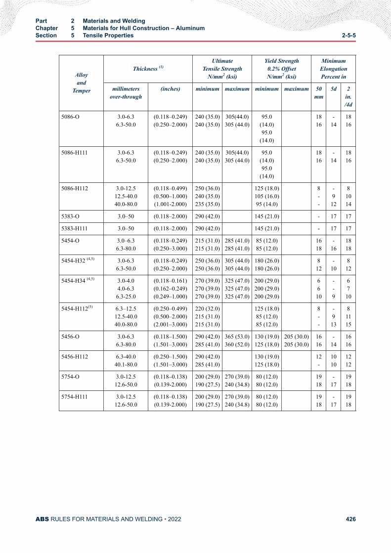
Alloyand
Temper
Thickness (1)Ultimate
Tensile StrengthN/mm2 (ksi)
Yield Strength0.2% OffsetN/mm2 (ksi)
MinimumElongationPercent in
millimetersover-through
(inches) minimum maximum minimum maximum 50mm
5d 2in./4d
5086-O 3.0-6.36.3-50.0
(0.118–0.249)(0.250–2.000)
240 (35.0)240 (35.0)
305(44.0)305 (44.0)
95.0(14.0)95.0
(14.0)
1816
-14
1816
5086-H111 3.0-6.36.3-50.0
(0.118–0.249)(0.250–2.000)
240 (35.0)240 (35.0)
305(44.0)305 (44.0)
95.0(14.0)95.0
(14.0)
1816
-14
1816
5086-H112 3.0-12.512.5-40.040.0-80.0
(0.118–0.499)(0.500–1.000)(1.001-2.000)
250 (36.0)240 (35.0)235 (35.0)
125 (18.0)105 (16.0)95 (14.0)
8--
-912
81014
5383-O 3.0–50 (0.118–2.000) 290 (42.0) 145 (21.0) - 17 17
5383-H111 3.0–50 (0.118–2.000) 290 (42.0) 145 (21.0) - 17 17
5454-O 3.0–6.36.3-80.0
(0.118–0.249)(0.250–3.000)
215 (31.0)215 (31.0)
285 (41.0)285 (41.0)
85 (12.0)85 (12.0)
1618
-16
1818
5454-H32 (4,5) 3.0-6.36.3-50.0
(0.118–0.249)(0.250–2.000)
250 (36.0)250 (36.0)
305 (44.0)305 (44.0)
180 (26.0)180 (26.0)
812
-10
812
5454-H34 (4,5) 3.0-4.04.0-6.36.3-25.0
(0.118–0.161)(0.162–0.249)(0.249–1.000)
270 (39.0)270 (39.0)270 (39.0)
325 (47.0)325 (47.0)325 (47.0)
200 (29.0)200 (29.0)200 (29.0)
6610
--9
6710
5454-H112(5) 6.3–12.512.5-40.040.0-80.0
(0.250–0.499)(0.500–2.000)(2.001–3.000)
220 (32.0)215 (31.0)215 (31.0)
125 (18.0)85 (12.0)85 (12.0)
8--
-913
81115
5456-O 3.0-6.36.3-80.0
(0.118–1.500)(1.501–3.000)
290 (42.0)285 (41.0)
365 (53.0)360 (52.0)
130 (19.0)125 (18.0)
205 (30.0)205 (30.0)
1616
-14
1616
5456-H112 6.3-40.040.1-80.0
(0.250–1.500)(1.501–3.000)
290 (42.0)285 (41.0)
130 (19.0)125 (18.0)
12-
1010
1212
5754-O 3.0-12.512.6-50.0
(0.118–0.138)(0.139-2.000)
200 (29.0)190 (27.5)
270 (39.0)240 (34.8)
80 (12.0)80 (12.0)
1918
-17
1918
5754-H111 3.0-12.512.6-50.0
(0.118–0.138)(0.139-2.000)
200 (29.0)190 (27.5)
270 (39.0)240 (34.8)
80 (12.0)80 (12.0)
1918
-17
1918
Part 2 Materials and WeldingChapter 5 Materials for Hull Construction – AluminumSection 5 Tensile Properties 2-5-5
ABS RULES FOR MATERIALS AND WELDING • 2022 426
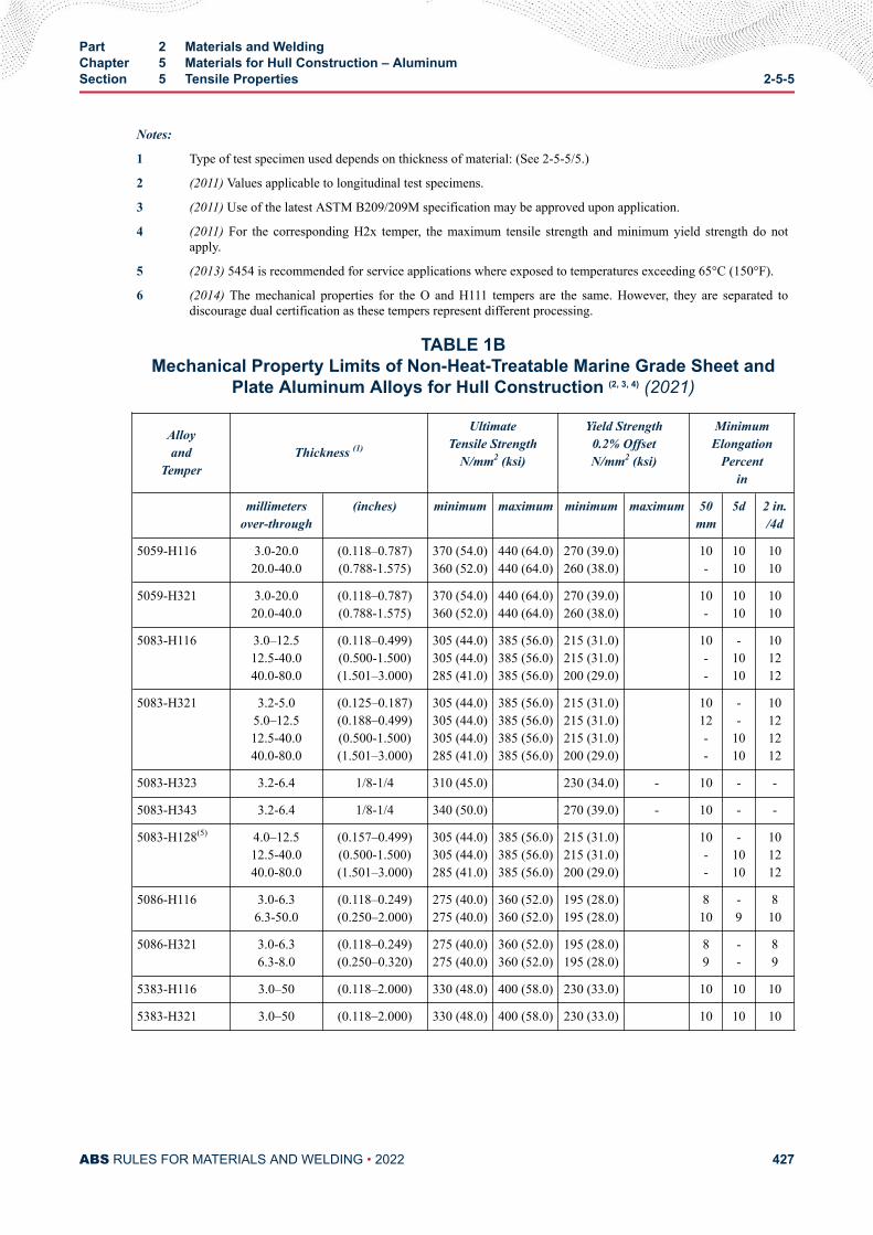
Notes:
1 Type of test specimen used depends on thickness of material: (See 2-5-5/5.)
2 (2011) Values applicable to longitudinal test specimens.
3 (2011) Use of the latest ASTM B209/209M specification may be approved upon application.
4 (2011) For the corresponding H2x temper, the maximum tensile strength and minimum yield strength do notapply.
5 (2013) 5454 is recommended for service applications where exposed to temperatures exceeding 65°C (150°F).
6 (2014) The mechanical properties for the O and H111 tempers are the same. However, they are separated todiscourage dual certification as these tempers represent different processing.
TABLE 1BMechanical Property Limits of Non-Heat-Treatable Marine Grade Sheet and
Plate Aluminum Alloys for Hull Construction (2, 3, 4) (2021)
Alloyand
TemperThickness (1)
UltimateTensile Strength
N/mm2 (ksi)
Yield Strength0.2% OffsetN/mm2 (ksi)
MinimumElongation
Percentin
millimetersover-through
(inches) minimum maximum minimum maximum 50mm
5d 2 in./4d
5059-H116 3.0-20.020.0-40.0
(0.118–0.787)(0.788-1.575)
370 (54.0)360 (52.0)
440 (64.0)440 (64.0)
270 (39.0)260 (38.0)
10-
1010
1010
5059-H321 3.0-20.020.0-40.0
(0.118–0.787)(0.788-1.575)
370 (54.0)360 (52.0)
440 (64.0)440 (64.0)
270 (39.0)260 (38.0)
10-
1010
1010
5083-H116 3.0–12.512.5-40.040.0-80.0
(0.118–0.499)(0.500-1.500)(1.501–3.000)
305 (44.0)305 (44.0)285 (41.0)
385 (56.0)385 (56.0)385 (56.0)
215 (31.0)215 (31.0)200 (29.0)
10--
-1010
101212
5083-H321 3.2-5.05.0–12.512.5-40.040.0-80.0
(0.125–0.187)(0.188–0.499)(0.500-1.500)(1.501–3.000)
305 (44.0)305 (44.0)305 (44.0)285 (41.0)
385 (56.0)385 (56.0)385 (56.0)385 (56.0)
215 (31.0)215 (31.0)215 (31.0)200 (29.0)
1012--
--
1010
10121212
5083-H323 3.2-6.4 1/8-1/4 310 (45.0) 230 (34.0) - 10 - -
5083-H343 3.2-6.4 1/8-1/4 340 (50.0) 270 (39.0) - 10 - -
5083-H128(5) 4.0–12.512.5-40.040.0-80.0
(0.157–0.499)(0.500-1.500)(1.501–3.000)
305 (44.0)305 (44.0)285 (41.0)
385 (56.0)385 (56.0)385 (56.0)
215 (31.0)215 (31.0)200 (29.0)
10--
-1010
101212
5086-H116 3.0-6.36.3-50.0
(0.118–0.249)(0.250–2.000)
275 (40.0)275 (40.0)
360 (52.0)360 (52.0)
195 (28.0)195 (28.0)
810
-9
810
5086-H321 3.0-6.36.3-8.0
(0.118–0.249)(0.250–0.320)
275 (40.0)275 (40.0)
360 (52.0)360 (52.0)
195 (28.0)195 (28.0)
89
--
89
5383-H116 3.0–50 (0.118–2.000) 330 (48.0) 400 (58.0) 230 (33.0) 10 10 10
5383-H321 3.0–50 (0.118–2.000) 330 (48.0) 400 (58.0) 230 (33.0) 10 10 10
Part 2 Materials and WeldingChapter 5 Materials for Hull Construction – AluminumSection 5 Tensile Properties 2-5-5
ABS RULES FOR MATERIALS AND WELDING • 2022 427
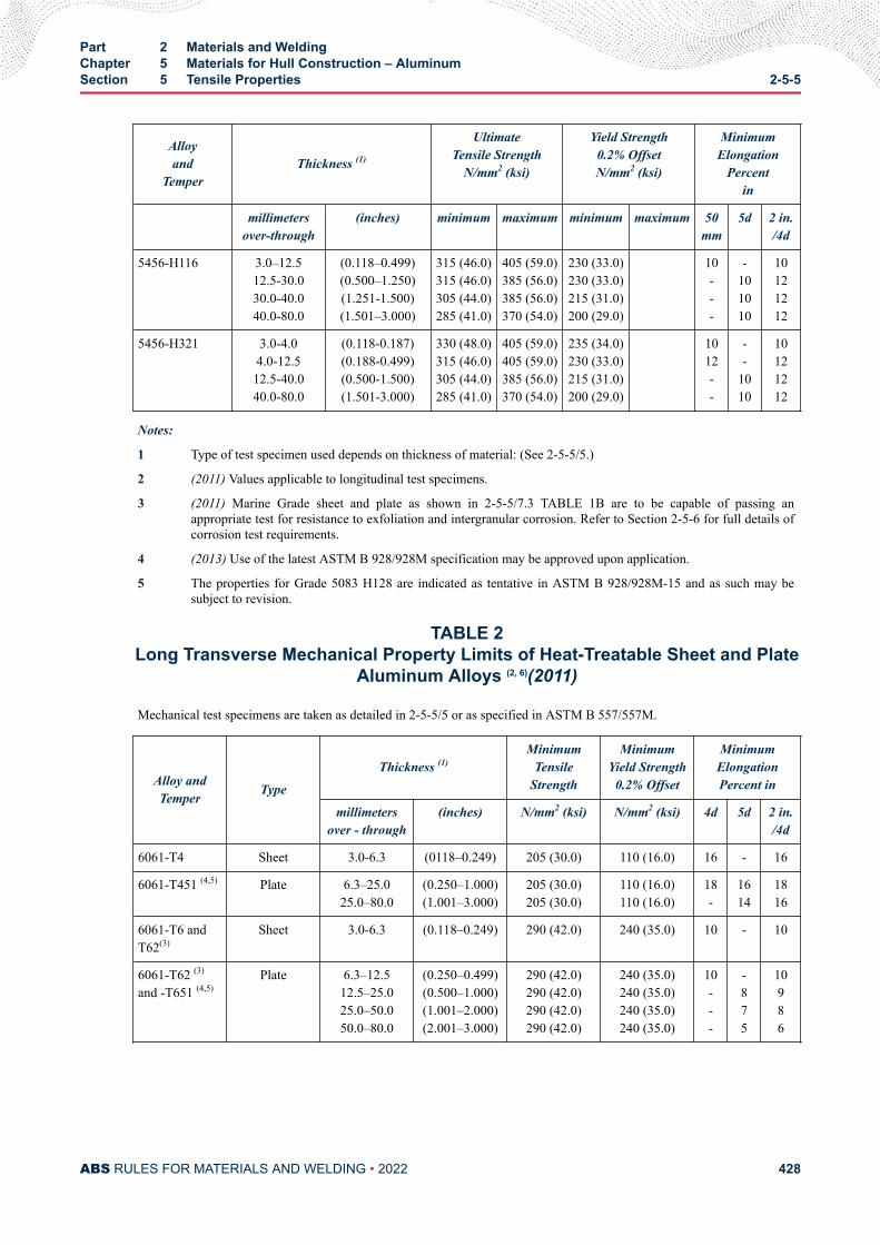
Alloyand
TemperThickness (1)
UltimateTensile Strength
N/mm2 (ksi)
Yield Strength0.2% OffsetN/mm2 (ksi)
MinimumElongation
Percentin
millimetersover-through
(inches) minimum maximum minimum maximum 50mm
5d 2 in./4d
5456-H116 3.0–12.512.5-30.030.0-40.040.0-80.0
(0.118–0.499)(0.500–1.250)(1.251-1.500)(1.501–3.000)
315 (46.0)315 (46.0)305 (44.0)285 (41.0)
405 (59.0)385 (56.0)385 (56.0)370 (54.0)
230 (33.0)230 (33.0)215 (31.0)200 (29.0)
10---
-101010
10121212
5456-H321 3.0-4.04.0-12.512.5-40.040.0-80.0
(0.118-0.187)(0.188-0.499)(0.500-1.500)(1.501-3.000)
330 (48.0)315 (46.0)305 (44.0)285 (41.0)
405 (59.0)405 (59.0)385 (56.0)370 (54.0)
235 (34.0)230 (33.0)215 (31.0)200 (29.0)
1012--
--
1010
10121212
Notes:
1 Type of test specimen used depends on thickness of material: (See 2-5-5/5.)
2 (2011) Values applicable to longitudinal test specimens.
3 (2011) Marine Grade sheet and plate as shown in 2-5-5/7.3 TABLE 1B are to be capable of passing anappropriate test for resistance to exfoliation and intergranular corrosion. Refer to Section 2-5-6 for full details ofcorrosion test requirements.
4 (2013) Use of the latest ASTM B 928/928M specification may be approved upon application.
5 The properties for Grade 5083 H128 are indicated as tentative in ASTM B 928/928M-15 and as such may besubject to revision.
TABLE 2Long Transverse Mechanical Property Limits of Heat-Treatable Sheet and Plate
Aluminum Alloys (2, 6)(2011)
Mechanical test specimens are taken as detailed in 2-5-5/5 or as specified in ASTM B 557/557M.
Alloy andTemper Type
Thickness (1)Minimum
TensileStrength
MinimumYield Strength
0.2% Offset
MinimumElongationPercent in
millimetersover - through
(inches) N/mm2 (ksi) N/mm2 (ksi) 4d 5d 2 in./4d
6061-T4 Sheet 3.0-6.3 (0118–0.249) 205 (30.0) 110 (16.0) 16 - 16
6061-T451 (4,5) Plate 6.3–25.025.0–80.0
(0.250–1.000)(1.001–3.000)
205 (30.0)205 (30.0)
110 (16.0)110 (16.0)
18-
1614
1816
6061-T6 andT62(3)
Sheet 3.0-6.3 (0.118–0.249) 290 (42.0) 240 (35.0) 10 - 10
6061-T62 (3)
and -T651 (4,5)Plate 6.3–12.5
12.5–25.025.0–50.050.0–80.0
(0.250–0.499)(0.500–1.000)(1.001–2.000)(2.001–3.000)
290 (42.0)290 (42.0)290 (42.0)290 (42.0)
240 (35.0)240 (35.0)240 (35.0)240 (35.0)
10---
-875
10986
Part 2 Materials and WeldingChapter 5 Materials for Hull Construction – AluminumSection 5 Tensile Properties 2-5-5
ABS RULES FOR MATERIALS AND WELDING • 2022 428
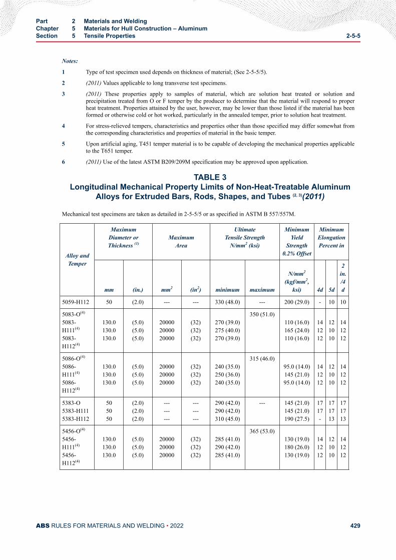
Notes:
1 Type of test specimen used depends on thickness of material; (See 2-5-5/5).
2 (2011) Values applicable to long transverse test specimens.
3 (2011) These properties apply to samples of material, which are solution heat treated or solution andprecipitation treated from O or F temper by the producer to determine that the material will respond to properheat treatment. Properties attained by the user, however, may be lower than those listed if the material has beenformed or otherwise cold or hot worked, particularly in the annealed temper, prior to solution heat treatment.
4 For stress-relieved tempers, characteristics and properties other than those specified may differ somewhat fromthe corresponding characteristics and properties of material in the basic temper.
5 Upon artificial aging, T451 temper material is to be capable of developing the mechanical properties applicableto the T651 temper.
6 (2011) Use of the latest ASTM B209/209M specification may be approved upon application.
TABLE 3Longitudinal Mechanical Property Limits of Non-Heat-Treatable Aluminum
Alloys for Extruded Bars, Rods, Shapes, and Tubes (2, 3)(2011)
Mechanical test specimens are taken as detailed in 2-5-5/5 or as specified in ASTM B 557/557M.
Alloy andTemper
MaximumDiameter orThickness (1)
MaximumArea
UltimateTensile Strength
N/mm2 (ksi)
MinimumYield
Strength0.2% Offset
MinimumElongationPercent in
mm (in.) mm2 (in2) minimum maximum
N/mm2
(kgf/mm2,ksi) 4d 5d
2in./4d
5059-H112 50 (2.0) --- --- 330 (48.0) --- 200 (29.0) - 10 10
5083-O(4)
5083-H111(4)
5083-H112(4)
130.0130.0130.0
(5.0)(5.0)(5.0)
200002000020000
(32)(32)(32)
270 (39.0)275 (40.0)270 (39.0)
350 (51.0)110 (16.0)165 (24.0)110 (16.0)
141212
121010
141212
5086-O(4)
5086-H111(4)
5086-H112(4)
130.0130.0130.0
(5.0)(5.0)(5.0)
200002000020000
(32)(32)(32)
240 (35.0)250 (36.0)240 (35.0)
315 (46.0)95.0 (14.0)145 (21.0)95.0 (14.0)
141212
121010
141212
5383-O5383-H1115383-H112
505050
(2.0)(2.0)(2.0)
---------
---------
290 (42.0)290 (42.0)310 (45.0)
--- 145 (21.0)145 (21.0)190 (27.5)
1717-
171713
171713
5456-O(4)
5456-H111(4)
5456-H112(4)
130.0130.0130.0
(5.0)(5.0)(5.0)
200002000020000
(32)(32)(32)
285 (41.0)290 (42.0)285 (41.0)
365 (53.0)130 (19.0)180 (26.0)130 (19.0)
141212
121010
141212
Part 2 Materials and WeldingChapter 5 Materials for Hull Construction – AluminumSection 5 Tensile Properties 2-5-5
ABS RULES FOR MATERIALS AND WELDING • 2022 429
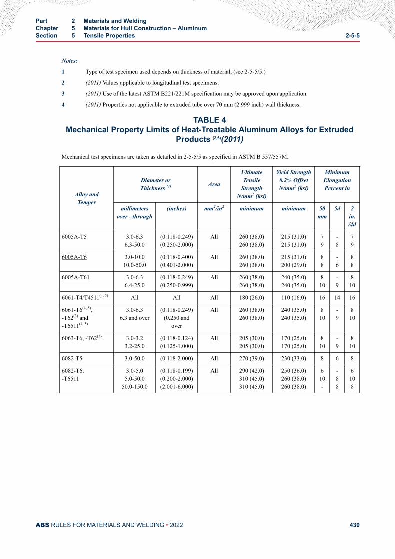
Notes:
1 Type of test specimen used depends on thickness of material; (see 2-5-5/5.)
2 (2011) Values applicable to longitudinal test specimens.
3 (2011) Use of the latest ASTM B221/221M specification may be approved upon application.
4 (2011) Properties not applicable to extruded tube over 70 mm (2.999 inch) wall thickness.
TABLE 4Mechanical Property Limits of Heat-Treatable Aluminum Alloys for Extruded
Products (2,6)(2011)
Mechanical test specimens are taken as detailed in 2-5-5/5 as specified in ASTM B 557/557M.
Alloy andTemper
Diameter orThickness (1) Area
UltimateTensile
StrengthN/mm2 (ksi)
Yield Strength0.2% OffsetN/mm2 (ksi)
MinimumElongationPercent in
millimetersover - through
(inches) mm2/in2 minimum minimum 50mm
5d 2in./4d
6005A-T5 3.0-6.36.3-50.0
(0.118-0.249)(0.250-2.000)
All 260 (38.0)260 (38.0)
215 (31.0)215 (31.0)
79
-8
79
6005A-T6 3.0-10.010.0-50.0
(0.118-0.400)(0.401-2.000)
All 260 (38.0)260 (38.0)
215 (31.0)200 (29.0)
88
-6
88
6005A-T61 3.0-6.36.4-25.0
(0.118-0.249)(0.250-0.999)
All 260 (38.0)260 (38.0)
240 (35.0)240 (35.0)
810
-9
810
6061-T4/T4511(4, 5) All All All 180 (26.0) 110 (16.0) 16 14 16
6061-T6(4, 5),-T62(3) and-T6511(4, 5)
3.0-6.36.3 and over
(0.118-0.249)(0.250 and
over
All 260 (38.0)260 (38.0)
240 (35.0)240 (35.0)
810
-9
810
6063-T6, -T62(3) 3.0-3.23.2-25.0
(0.118-0.124)(0.125-1.000)
All 205 (30.0)205 (30.0)
170 (25.0)170 (25.0)
810
-9
810
6082-T5 3.0-50.0 (0.118-2.000) All 270 (39.0) 230 (33.0) 8 6 8
6082-T6,-T6511
3.0-5.05.0-50.0
50.0-150.0
(0.118-0.199)(0.200-2.000)(2.001-6.000)
All 290 (42.0)310 (45.0)310 (45.0)
250 (36.0)260 (38.0)260 (38.0)
610-
-88
6108
Part 2 Materials and WeldingChapter 5 Materials for Hull Construction – AluminumSection 5 Tensile Properties 2-5-5
ABS RULES FOR MATERIALS AND WELDING • 2022 430
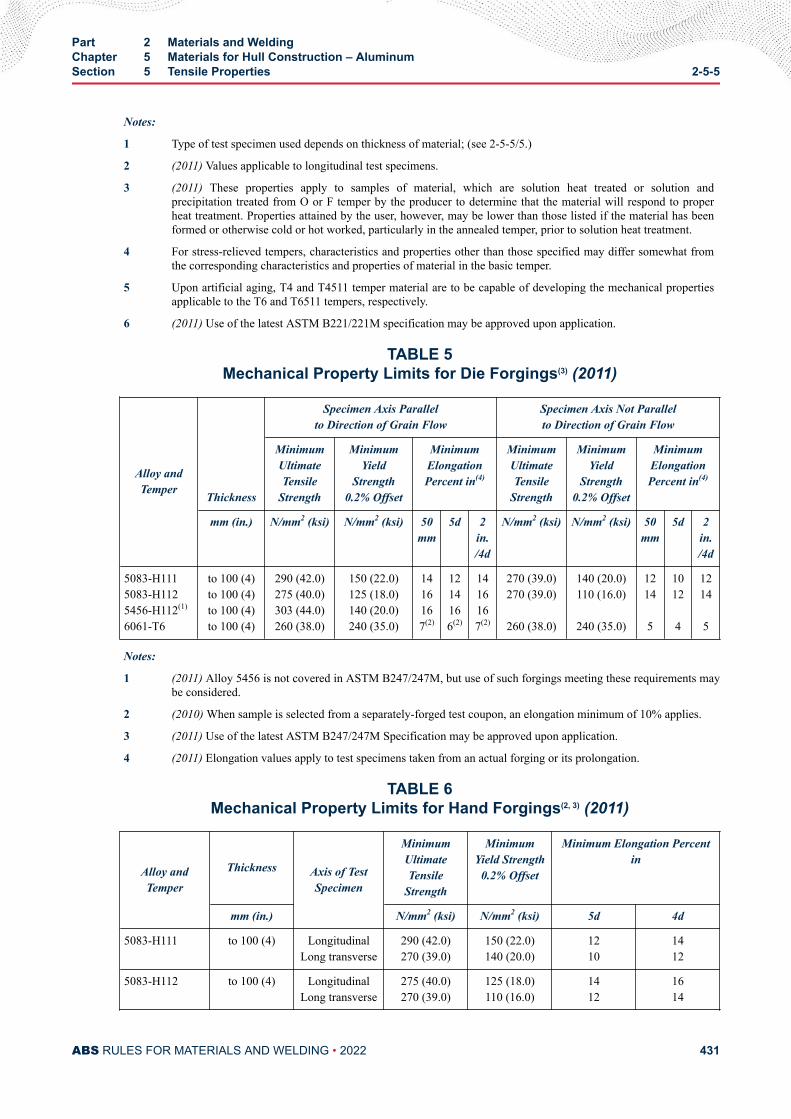
Notes:
1 Type of test specimen used depends on thickness of material; (see 2-5-5/5.)
2 (2011) Values applicable to longitudinal test specimens.
3 (2011) These properties apply to samples of material, which are solution heat treated or solution andprecipitation treated from O or F temper by the producer to determine that the material will respond to properheat treatment. Properties attained by the user, however, may be lower than those listed if the material has beenformed or otherwise cold or hot worked, particularly in the annealed temper, prior to solution heat treatment.
4 For stress-relieved tempers, characteristics and properties other than those specified may differ somewhat fromthe corresponding characteristics and properties of material in the basic temper.
5 Upon artificial aging, T4 and T4511 temper material are to be capable of developing the mechanical propertiesapplicable to the T6 and T6511 tempers, respectively.
6 (2011) Use of the latest ASTM B221/221M specification may be approved upon application.
TABLE 5Mechanical Property Limits for Die Forgings(3) (2011)
Alloy andTemper Thickness
Specimen Axis Parallelto Direction of Grain Flow
Specimen Axis Not Parallelto Direction of Grain Flow
MinimumUltimateTensile
Strength
MinimumYield
Strength0.2% Offset
MinimumElongationPercent in(4)
MinimumUltimateTensile
Strength
MinimumYield
Strength0.2% Offset
MinimumElongationPercent in(4)
mm (in.) N/mm2 (ksi) N/mm2 (ksi) 50mm
5d 2in./4d
N/mm2 (ksi) N/mm2 (ksi) 50mm
5d 2in./4d
5083-H1115083-H1125456-H112(1)
6061-T6
to 100 (4)to 100 (4)to 100 (4)to 100 (4)
290 (42.0)275 (40.0)303 (44.0)260 (38.0)
150 (22.0)125 (18.0)140 (20.0)240 (35.0)
1416167(2)
1214166(2)
1416167(2)
270 (39.0)270 (39.0)
260 (38.0)
140 (20.0)110 (16.0)
240 (35.0)
1214 5
1012 4
1214 5
Notes:
1 (2011) Alloy 5456 is not covered in ASTM B247/247M, but use of such forgings meeting these requirements maybe considered.
2 (2010) When sample is selected from a separately-forged test coupon, an elongation minimum of 10% applies.
3 (2011) Use of the latest ASTM B247/247M Specification may be approved upon application.
4 (2011) Elongation values apply to test specimens taken from an actual forging or its prolongation.
TABLE 6Mechanical Property Limits for Hand Forgings(2, 3) (2011)
Alloy andTemper
Thickness Axis of TestSpecimen
MinimumUltimateTensile
Strength
MinimumYield Strength
0.2% Offset
Minimum Elongation Percentin
mm (in.) N/mm2 (ksi) N/mm2 (ksi) 5d 4d
5083-H111 to 100 (4) LongitudinalLong transverse
290 (42.0)270 (39.0)
150 (22.0)140 (20.0)
1210
1412
5083-H112 to 100 (4) LongitudinalLong transverse
275 (40.0)270 (39.0)
125 (18.0)110 (16.0)
1412
1614
Part 2 Materials and WeldingChapter 5 Materials for Hull Construction – AluminumSection 5 Tensile Properties 2-5-5
ABS RULES FOR MATERIALS AND WELDING • 2022 431
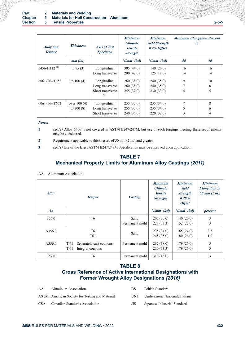
Alloy andTemper
Thickness Axis of TestSpecimen
MinimumUltimateTensile
Strength
MinimumYield Strength
0.2% Offset
Minimum Elongation Percentin
mm (in.) N/mm2 (ksi) N/mm2 (ksi) 5d 4d
5456-H112 (1) to 75 (3) LongitudinalLong transverse
305 (44.0)290 (42.0)
140 (20.0)125 (18.0)
1614
1614
6061-T6/-T652 to 100 (4) LongitudinalLong transverseShort transverse
(2)
260 (38.0)260 (38.0)255 (37.0)
240 (35.0)240 (35.0)230 (33.0)
974
1085
6061-T6/-T652 over 100 (4)to 200 (8)
LongitudinalLong transverseShort transverse
255 (37.0)255 (37.0)240 (35.0)
235 (34.0)235 (34.0)220 (32.0)
753
864
Notes:
1 (2011) Alloy 5456 is not covered in ASTM B247/247M, but use of such forgings meeting these requirementsmay be considered.
2 Requirement applicable to thicknesses of 50 mm (2 in.) and greater.
3 (2011) Use of the latest ASTM B247/247M Specification may be approved upon application.
TABLE 7Mechanical Property Limits for Aluminum Alloy Castings (2011)
AA Aluminum Association
AlloyTemper Casting
MinimumUltimateTensile
Strength
MinimumYield
Strength0.20%Offset
MinimumElongation in50 mm (2 in.)
AA N/mm2 (ksi) N/mm2 (ksi) percent
356.0
T6
SandPermanent mold
205 (30.0)228 (33.3)
140 (20.0)152 (22.0)
33
A356.0 T6T61 Sand 235 (34.0)
245 (35.0)165 (24.0)180 (26.0)
3.51.0
A356.0 T-61 Separately cast couponsT-61 Integral coupons
Permanent mold 262 (38.0)230 (33.3)
179 (26.0)179 (26.0)
55
357.0 T6 Permanent mold 310 (45.0) 3
TABLE 8Cross Reference of Active International Designations with
Former Wrought Alloy Designations (2016)
AA Aluminum Association BS British Standard
ASTM American Society for Testing and Material UNI Unificazione Nazionale Italiana
CSA Canadian Standards Association JIS Japanese Industrial Standard
Part 2 Materials and WeldingChapter 5 Materials for Hull Construction – AluminumSection 5 Tensile Properties 2-5-5
ABS RULES FOR MATERIALS AND WELDING • 2022 432
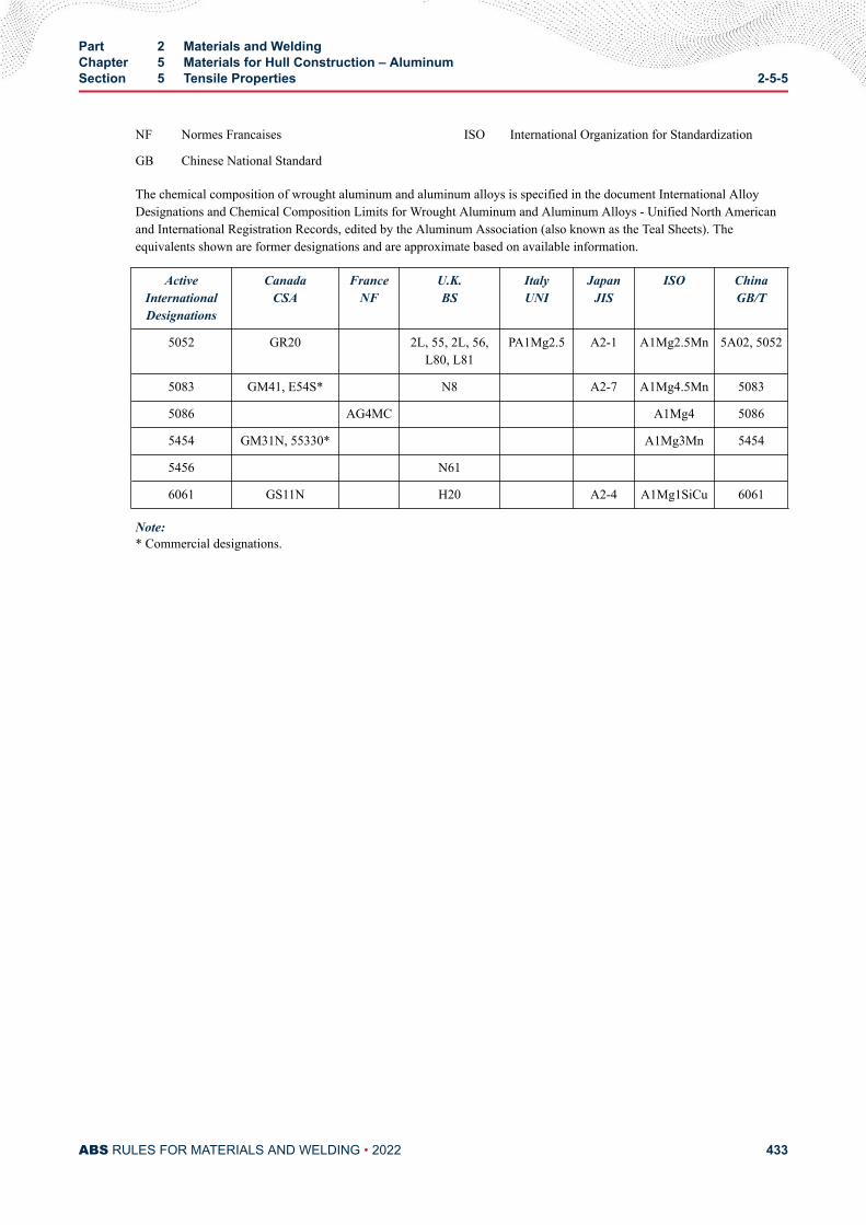
NF Normes Francaises ISO International Organization for Standardization
GB Chinese National Standard
The chemical composition of wrought aluminum and aluminum alloys is specified in the document International AlloyDesignations and Chemical Composition Limits for Wrought Aluminum and Aluminum Alloys - Unified North Americanand International Registration Records, edited by the Aluminum Association (also known as the Teal Sheets). Theequivalents shown are former designations and are approximate based on available information.
ActiveInternationalDesignations
CanadaCSA
FranceNF
U.K.BS
ItalyUNI
JapanJIS
ISO ChinaGB/T
5052 GR20 2L, 55, 2L, 56,L80, L81
PA1Mg2.5 A2-1 A1Mg2.5Mn 5A02, 5052
5083 GM41, E54S* N8 A2-7 A1Mg4.5Mn 5083
5086 AG4MC A1Mg4 5086
5454 GM31N, 55330* A1Mg3Mn 5454
5456 N61
6061 GS11N H20 A2-4 A1Mg1SiCu 6061
Note:* Commercial designations.
Part 2 Materials and WeldingChapter 5 Materials for Hull Construction – AluminumSection 5 Tensile Properties 2-5-5
ABS RULES FOR MATERIALS AND WELDING • 2022 433
C H A P T E R 5Materials for Hull Construction – Aluminum
S E C T I O N 6Corrosion Testing
1 General (2016)Rolled 5xxx-alloys delivered in the H116, H128 and H321 tempers (as listed in 2-5-5/7.3 TABLE 1B)intended for use in marine hull construction or in marine applications where frequent direct contact withseawater is expected are to be corrosion tested with respect to exfoliation and intergranular corrosionresistance as per requirements of this Section and ASTM B 928/928M. These alloys should not be used forservice which provides prolonged exposure (continuous or discontinuous) to temperatures exceeding 65°C(150°F) because of the risk of sensitization and the resulting susceptibility to intergranular corrosion andstress corrosion cracking.
The alloy grades of the 6000 series should not be used in direct contact with seawater unless protected byanodes and/or paint system.
3 Reference Photomicrograph (2016)For 5xxx-alloys delivered in H116 and H321 tempers, the manufacturers shall establish the relationshipbetween microstructure and resistance to corrosion when the above alloys are approved. A referencephotomicrograph taken at 500× [using 40% phosphoric acid etch for 3 minutes at 35°C (50°F)], under theconditions specified in ASTM B928, Section 9.4.1, shall be established for each of the alloy-tempers andthickness ranges relevant. The reference photographs shall be taken from samples which have exhibited noevidence of exfoliation corrosion and a pitting rating of PB or better, when subjected to the test describedin ASTM G66 (ASSET). The samples shall also have exhibited resistance to intergranular corrosion at amass loss no greater than 15 mg/cm2, when subjected to the test described in ASTM G67 (NAMLT). Uponsatisfactory establishment of the relationship between microstructure and resistance to corrosion, themaster photomicrographs and the results of the corrosion tests are to be approved by ABS. Productionpractices shall not be changed after approval of the reference micrographs.
Other recognized test methods may also be accepted at ABS’s discretion.
5 Batch Microstructural Analysis and Acceptance (2016)For batch acceptance of 5xxx-alloys in the H116 and H321 tempers, metallographic examination of onesample selected from mid width at one end of a coil or random sheet or plate may be carried out, providedthat surveillance testing as stated in 2-5-6/7 is performed. The microstructure of the sample is to becompared to the reference photomicrograph [taken at 500× after 3 minutes etch in phosphoric acid at 35°C(50°F)] of acceptable material in the presence of the Surveyor. A longitudinal section perpendicular to therolled surface shall be prepared for metallographic examination, under the conditions specified in ASTM
PART 2
ABS RULES FOR MATERIALS AND WELDING • 2022 434
B928, Section 9.6.1. If the microstructure shows evidence of continuous grain boundary network ofaluminum-magnesium precipitate in excess of the reference photomicrographs of acceptable material, thebatch is either to be rejected or tested for exfoliation-corrosion resistance and intergranular corrosionresistance subject to the agreement of the Surveyor. The corrosion tests are to be in accordance withASTM G66 and G67 or equivalent standards. Acceptance criteria are that the sample shall exhibit noevidence of exfoliation corrosion and a pitting rating of PB or better when test subjected to ASTM G66ASSET test, and the sample shall exhibit resistance to intergranular corrosion at a mass loss no greater than15 mg/cm2 (0.0002 lbs/in2) when subjected to ASTM G67 NAMLT test. If the results from testing satisfythe acceptance criteria stated in 2-5-6/3 the batch is accepted, else it is to be rejected.
As an alternative to metallographic examination, each batch may be tested for exfoliation corrosionresistance and intergranular corrosion resistance, in accordance with ASTM G66 and G67 under theconditions specified in ASTM B928, or equivalent standards and accepted if the results satisfy theacceptance criteria stated in 2-5-6/3.
7 Surveillance of Corrosion Testing (2011)The manufacturer shall perform, each quarter or after any process change, at least one test for exfoliationcorrosion resistance and one test for intergranular corrosion resistance, in accordance with ASTM G66 andG67 or equivalent standards for each approved alloy grade. The manufacturer shall maintain records of allsurveillance test results and make them available to the Surveyor for product certification.
Part 2 Materials and WeldingChapter 5 Materials for Hull Construction – AluminumSection 6 Corrosion Testing 2-5-6
ABS RULES FOR MATERIALS AND WELDING • 2022 435
C H A P T E R 5Materials for Hull Construction – Aluminum
S E C T I O N 7Sheet, Plate and Rolled Products
1 ScopeThe following requirements cover non-heat-treatable and heat-treatable aluminum alloys for sheet plate,and rolled products intended to be used in hull construction.
3 Selection of Tension Test Specimen (2011)For rolled products, test samples are taken at one-third of the width from the longitudinal edge. Tensiontest specimens for non-heat-treatable rolled products are to be taken in the longitudinal direction. For heat-treatable rolled products, generally tests in the long transverse direction are required. If the width isinsufficient to obtain long transverse test specimens, and when specified, tests in the longitudinal directionmay be permitted. Short transverse testing, when specified, is only applicable to plate having a specifiedthickness of 40 mm (1.500 in.) or greater. The standard rectangular tension test specimen shown in2-5-5/5.5 FIGURE 1 is to be used for sheet and plate less than 12.5 mm (0.5 in.) in thickness. For plate12.5 mm (0.5 in.) and greater in thickness, the round tension test specimen shown in 2-5-5/5.5 FIGURE 1is to be used. The tension test specimen is to be taken midway between the two plate surfaces for plate inthicknesses of 12.5 mm (0.5 in.) up to 40 mm (1.57 in.). For plate over 40 mm (1.57 in.) in thickness, thespecimen shall be taken midway between the center and surface of the plate.
After removal of test samples, each test specimen is to be marked in order that its original identity, locationand orientation is maintained.
5 Number of Tension TestsTension test specimens are to be selected as follows.
5.1 SheetFor sheet under 6.3 mm (0.25 in.) in thickness, one tensile test specimen is be taken from one random sheetrepresentative of 900 kg (2000 pounds) or fraction thereof in each batch.
5.3 Plate and Rolled ProductsFor plate and rolled products 6.3 mm (0.25 in.) and over in thicknesses, one tensile test specimen is to betaken from each batch of the product. If the weight of one batch exceeds 2000 kg (4410 lb), or fractionthereof, one extra tensile test specimen is to be taken from every 2000 kg (4410 lb) or fraction thereof, ineach batch.
PART 2
ABS RULES FOR MATERIALS AND WELDING • 2022 436
For single plates or coils weighing more than 2000 kg (4410 lb) each, only one tensile test specimen perplate or coil is to be taken.
5.5 Definition of a BatchThe term batch applies to products if they are all:
● The same alloy grade from the same cast;
● The same product form and similar dimensions (for plates, the same thickness);
● Manufactured by the same process, and;
● Submitted simultaneously to the same temper condition.
7 Surface Finish (2014)The material is to be free from injurious defects and have a workmanlike finish. Surface imperfections maybe removed by smooth grinding or machining as long as the thickness of the material remains within thetolerances given in 2-5-7/11. It is to be surface inspected at the mill by the surveyors only whenspecifically requested and so ordered by the purchaser.
9 Nondestructive Examination (NDE)In general NDE of material is not required for acceptance purposes.
However, the manufacturer is expected to employ suitable methods of NDE for maintaining compliancewith quality standards.
11 Dimensions and ToleranceIt is the Manufacturer’s responsibility to check dimensions and to comply with the following tolerancerequirements.
Under-thickness for rolled products are given in 2-5-7/11 TABLE 1. Dimensional tolerances other thanunder-thickness tolerance are to comply with a recognized national or international standard.
TABLE 1Under-thickness Tolerance for Rolled Products (2018)
Nominal Thickness (t), mm Thickness Tolerances for Nominal Width (w), mm
w ≤ 1500 1500 < w ≤ 2000 2000 < w ≤ 3500
3.0 ≤ t < 4.0 0.10 0.15 0.15
4.0 ≤ t < 8.0 0.20 0.20 0.25
8.0 ≤ t < 12.0 0.25 0.25 0.25
12.0 ≤ t < 20.0 0.35 0.40 0.50
20.0 ≤ t < 50.0 0.45 0.50 0.65
Note:For thicknesses greater than 50.0 mm, tolerances are to be agreed between the purchaser and manufacturer and accepted byABS.
Part 2 Materials and WeldingChapter 5 Materials for Hull Construction – AluminumSection 7 Sheet, Plate and Rolled Products 2-5-7
ABS RULES FOR MATERIALS AND WELDING • 2022 437
C H A P T E R 5Materials for Hull Construction – Aluminum
S E C T I O N 8Extrusions
1 ScopeThe following requirements cover extruded non-heat-treatable and heat-treatable aluminum alloy productsintended to be used in hull construction.
3 Selection of SpecimensFor extruded products tension test specimens are to be taken in the range 1/3 to 1/2 of the distance from thelongitudinal edge to the center of the thickest part.
Tension test specimens are to be taken in the longitudinal direction and are to be of the full section of thematerial where practicable. Otherwise, the specimens shown in 2-5-5/5.5 FIGURE 1 are to be used. Formaterial 40 mm (1.57 in.) and less in diameter or thickness, the specimen is to be taken from the center ofthe section. For material greater than 40 mm (1.57 in.) in thickness or diameter the specimen is to belocated midway between the center and an edge.
After removal of test samples, each test specimen is to be marked in order that its original identity, locationand orientation are maintained.
5 Number of Tests
5.1 Tension TestsFor the products with a nominal weight of less than 1 kg/m (0.7 lb/ft), one tensile test specimen is to betaken from each 1000 kg, (2205 lb) or fraction thereof, in each batch. For nominal weights between 1 and5 kg/m (0.7 and 3.5 lb/ft), one tensile test specimen is to be taken from each 2000 kg (4410 lb) or fractionhereof, in each batch. If the nominal weight exceeds 5 kg/m (3.5 lb/ft), one tensile test specimen is to betaken for each 3000 kg (6615 lb) of the product or fraction thereof, in each batch.
5.3 Drift Expansion TestsThe Manufacturer is to demonstrate by macrosection tests or drift expansion tests of closed profilesperformed on each batch of closed profiles that there is no lack of fusion at the press welds.
5.3.1 Drift Expansion Tests (2008)● Every fifth profile shall be sampled after final heat treatment.
● Batches of five profiles or less shall be sampled one profile.
PART 2
ABS RULES FOR MATERIALS AND WELDING • 2022 438
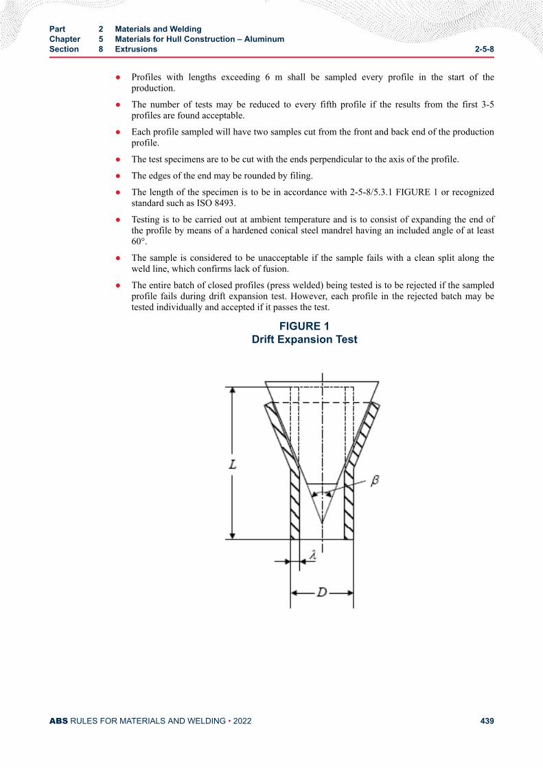
● Profiles with lengths exceeding 6 m shall be sampled every profile in the start of theproduction.
● The number of tests may be reduced to every fifth profile if the results from the first 3-5profiles are found acceptable.
● Each profile sampled will have two samples cut from the front and back end of the productionprofile.
● The test specimens are to be cut with the ends perpendicular to the axis of the profile.
● The edges of the end may be rounded by filing.
● The length of the specimen is to be in accordance with 2-5-8/5.3.1 FIGURE 1 or recognizedstandard such as ISO 8493.
● Testing is to be carried out at ambient temperature and is to consist of expanding the end ofthe profile by means of a hardened conical steel mandrel having an included angle of at least60°.
● The sample is considered to be unacceptable if the sample fails with a clean split along theweld line, which confirms lack of fusion.
● The entire batch of closed profiles (press welded) being tested is to be rejected if the sampledprofile fails during drift expansion test. However, each profile in the rejected batch may betested individually and accepted if it passes the test.
FIGURE 1Drift Expansion Test
Part 2 Materials and WeldingChapter 5 Materials for Hull Construction – AluminumSection 8 Extrusions 2-5-8
ABS RULES FOR MATERIALS AND WELDING • 2022 439
Notes:
1 L equal to twice the external diameter D of the tube if the angle of the drift is 30°, and L equal to 1.5D ifthe angle of the drift is 45° or 60°.
2 The test piece may be shorter provided that after testing the remaining cylindrical portion is not lessthan 0.5D.
3 The rate of penetration of the mandrel shall not exceed 50 mm/min.
5.5 Definition of a BatchThe term batch applies to products if they are all:
● The same alloy grade from the same cast;
● The same product form and similar dimensions (for plates, the same thickness);
● Manufactured by the same process, and;
● Submitted simultaneously to the same temper condition.
7 Surface Finish (2014)The material is to be free from injurious defects and have a workmanlike finish. Surface imperfections maybe removed by smooth grinding or machining as long as the thickness of the material remains within thetolerances given in 2-5-8/11. It is to be surface inspected at the mill only when specifically requested andso ordered by the purchaser.
9 Nondestructive Examination (NDE)In general NDE of material is not required for acceptance purposes.
However, the manufacturer is expected to employ suitable methods of NDE for maintaining compliancewith quality standards.
11 Dimensions and ToleranceIt is the Manufacturer’s responsibility to check dimensions and to comply with the following tolerancerequirements:
Under-thickness tolerances for extruded products are to be in accordance with recognized national orinternational standards.
Dimensional tolerances other than under-thickness tolerance are to comply with recognized national orinternational standards.
Part 2 Materials and WeldingChapter 5 Materials for Hull Construction – AluminumSection 8 Extrusions 2-5-8
ABS RULES FOR MATERIALS AND WELDING • 2022 440
C H A P T E R 5Materials for Hull Construction – Aluminum
S E C T I O N 9Forgings
1 Scope (1 July 2019)The following requirements cover non-heat-treatable and heat-treatable aluminum alloy die and handforgings intended to be used in hull construction. The material covered is in substantial agreement withASTM B247. Forgings differing in chemical composition, mechanical properties or heat treatment will bespecially considered.
Forgings are to be made by a manufacturer approved by ABS.
ABS approval is valid for 5 years subject to annual verification and/or endorsement by the attendingSurveyor. The Surveyor is permitted at any time to monitor important aspects of forging production,including but not limited to die preparation and die maintenance, forging temperatures, forging reductionor upset, heat treatment and inspection.
Raw materials for forgings, such as Aluminum ingots or semi-finished products, are to be manufactured ata facility approved by ABS and manufactured by a process approved by ABS.
3 Selection of Specimens
3.1 Location of SpecimensTension test specimens are to be taken from prolongations having a sectional area not less than that of thebody of the forging. Tension test specimens are normally taken parallel to the direction in which the metalis most drawn out (longitudinal) but may be taken transversely. Specimens taken in the longitudinaldirection are to be taken from as near to the center of the cross-section of the forging as is practicable. Themidpoint of the axes of transverse specimens are to be near to the center of the cross section of the forging.
3.3 Small ForgingsIn the case of forgings weighing less than 114 kg (250 lb) each, where the foregoing procedures areimpracticable, a special forging may be made for the purpose of obtaining test specimens, provided theSurveyor is satisfied that these test specimens are representative of the forgings submitted for testing. Insuch cases, the special forging should be subjected to the same amount of working and reduction as theforging represented and, if applicable, be heat treated with those forgings. Alternatively, test specimensmay be taken from one of the forgings in the lot.
PART 2
ABS RULES FOR MATERIALS AND WELDING • 2022 441
3.5 Test SpecimensThe tension test specimen shown in 2-5-5/5.5 FIGURE 1 is to be used.
5 Number of Tests
5.1 Large ForgingsIn the case of forgings weighing over 2700 kg (6000 lb) each, one tension test specimen is to be taken fromeach end of the forging.
5.3 Intermediate sized Forgings (1 July 2019)In the case of forgings weighing less than 2700 kg (6000 lb) each, except as noted in 2-5-9/5.5 and2-5-9/5.7, one tension test specimen is to be taken from each forging.
5.5 Small ForgingsIn the case of forgings weighing less than 114 kg (250 lb) each, one tension test specimen may be takenfrom one forging as representative of 900 kg (2000 lb), provided the forgings are of similar size, of onealloy and temper, are made from the same lot of stock and, if applicable, heat treated in the same furnacecharge.
5.7 Special SituationsIn the case of a number of pieces cut from a single forging, individual tests need not necessarily be madefor each piece, but forgings may be tested in accordance with whichever of the foregoing procedures isapplicable to the primary forging involved.
5.9 Retests (1 July 2019)Test material, sufficient for the required number of tests and for possible retest purposes, is to be providedfor each forging. If the results of the mechanical tests for any forging or any lot of forgings do not conformto the requirements specified, two additional test samples representative of the forging or forging batchmay be taken. If satisfactory results are obtained from both of the additional tests, the forging or batch offorgings is acceptable. If one or both retests fail, the forging or batch of forgings is to be rejected.
7 InspectionThe forgings are to be inspected by the Surveyor after final heat treatment, where applicable, to insure thatthe forgings are free from injurious defects.
9 Nondestructive Examination (NDE)The manufacturer is to carry out suitable methods of NDE for maintaining compliance with qualitystandards.
11 Dimensions and ToleranceIt is the Manufacturer’s responsibility to check dimensions and to comply with tolerance requirements.
Part 2 Materials and WeldingChapter 5 Materials for Hull Construction – AluminumSection 9 Forgings 2-5-9
ABS RULES FOR MATERIALS AND WELDING • 2022 442
C H A P T E R 5Materials for Hull Construction – Aluminum
S E C T I O N 1 0Castings
1 Scope (2013)The following requirements cover aluminum alloy castings for use in hull construction. The materialcovered is in substantial agreement with alloys in accordance with ASTM Designations B26 and B108(Aluminum Association alloys 356.0, A356.0 and AA357.0)-. Except in cases specifically approvedotherwise, all aluminum castings are to be furnished in the heat treated condition. Castings differing inchemical composition, mechanical properties or heat treatment from those covered herein will be speciallyconsidered.
Castings are to be made by a manufacturer approved by ABS.
ABS approval is valid for 5 years subject to annual verification and/or endorsement by the attendingSurveyor. The Surveyor is permitted at any time to monitor important aspects of casting production,including but not limited to mold preparation and chaplet positioning; pouring times and temperatures;mold breakout; repairs; heat treatment and inspection.
3 Selection of Specimens
3.1 Large CastingsTensile specimens are to be taken from integral test bars. Integral test bars are not to be detached until theheat treatment of the castings has been completed nor until the coupons have been stamped by theSurveyor for identification.
3.3 Small CastingsIn the case of castings weighing less than 450 kg (1000 lb) each, test coupons may be cast separately,provided they are poured from the same source of molten metal as the castings represented. When separatecoupons are used, the Surveyor is to be furnished an affidavit by the manufacturer stating that the couponswere poured from the same source of molten metal as the castings represented and that they were heattreated with the castings.
3.5 Test SpecimensThe tension test specimen shown in 2-5-5/5.5 FIGURE 1 is to be used.
PART 2
ABS RULES FOR MATERIALS AND WELDING • 2022 443
5 Number of TestsAt least one tension test is to be made representative of the same source of molten metal and in each heat-treatment charge.
7 InspectionThe castings are to be inspected by the Surveyor after final heat treatment and thorough cleaning to insurethat the castings are free from injurious defects, such as cracks, laminations, or embedded porosity. Thefinal machined casting is to be examined to avoid the presence of surface defects.
9 Welded Repair of DefectsDefects in noncritical areas may, with the Surveyor’s approval, be repaired by welding using an approvedprocedure. The welding is to be done before the final heat-treatment.
11 Nondestructive Examination (NDE)The manufacturer is to carry out suitable methods of NDE for maintaining compliance with qualitystandards.
13 Dimensions and ToleranceIt is the Manufacturer’s responsibility to check dimensions and to comply with tolerance requirements.
Part 2 Materials and WeldingChapter 5 Materials for Hull Construction – AluminumSection 10 Castings 2-5-10
ABS RULES FOR MATERIALS AND WELDING • 2022 444
C H A P T E R 5Materials for Hull Construction – Aluminum
S E C T I O N 1 1Rivets
1 GeneralNon-heat-treatable and heat-treatable aluminum alloy cold heading rod and wire for use in manufacturingrivets should be in agreement with a specification equivalent to ASTM Designation B316. Materialdiffering from ASTM B316 in chemical composition, mechanical properties or heat-treatment may bespecially considered.
PART 2
ABS RULES FOR MATERIALS AND WELDING • 2022 445
C H A P T E R 5Materials for Hull Construction – Aluminum
A P P E N D I X 1Aluminum/Steel Bi-material Transition Joints (2015)
1 ScopeThe following specification covers metallurgically bonded bimetallic transition joints intended forstructural connections between aluminum and steel in an atmospheric or dry environment.
3 Supplementary RequirementsAluminum/steel bimetallic transition joints are to be produced, tested, inspected and certified inaccordance the following supplementary requirements.
3.1 Reference DocumentsThe following documents of the issue in effect on the date of the material purchase form a part of thisspecification to the extent referenced herein.
• ASTM A264 Standard Specification for Stainless Chromium-Nickel Steel-Clad Plate, Sheet,and Strip
• MIL-STD-1689 Fabrication, Welding, and Inspection of Ship Structures
• NAVSEA Technical Publication T9074-AS-GIB-010/271, Nondestructive TestingRequirements for Metals
3.3 Process of ManufactureThe bimetallic bond may be produced by explosion-bonding or by roll-bonding. In both cases, the materialis to be produced in the form of plate, which will subsequently be cut into bar-like transition joints.Aluminum alloys in accordance with Part 2, Chapter 5 and the steels in accordance with Part 2, Chapter 1,are considered suitable for use as transition joint material.
The use of an intermediate aluminum material at the bond interface is permitted.
3.5 Tensile StrengthThe ultimate tensile strength of the bond zone is to be determined by means of the ram tensile testdescribed in 2-5-A1/3.27 FIGURE 1. Test specimens machined to the dimensions in 2-5-A1/3.27 FIGURE2 are to be loaded in tension to failure. The minimum tensile strength is 75 N/mm2 (8 kgf/mm2, 11 ksi).Tests are to be made in the as-clad condition, and in the simulated welded condition.
PART 2
ABS RULES FOR MATERIALS AND WELDING • 2022 446
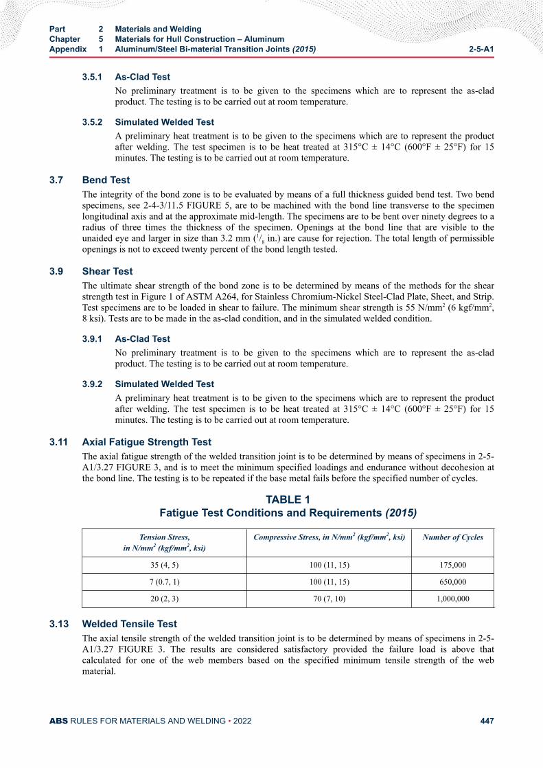
3.5.1 As-Clad TestNo preliminary treatment is to be given to the specimens which are to represent the as-cladproduct. The testing is to be carried out at room temperature.
3.5.2 Simulated Welded TestA preliminary heat treatment is to be given to the specimens which are to represent the productafter welding. The test specimen is to be heat treated at 315°C ± 14°C (600°F ± 25°F) for 15minutes. The testing is to be carried out at room temperature.
3.7 Bend TestThe integrity of the bond zone is to be evaluated by means of a full thickness guided bend test. Two bendspecimens, see 2-4-3/11.5 FIGURE 5, are to be machined with the bond line transverse to the specimenlongitudinal axis and at the approximate mid-length. The specimens are to be bent over ninety degrees to aradius of three times the thickness of the specimen. Openings at the bond line that are visible to theunaided eye and larger in size than 3.2 mm (1/8 in.) are cause for rejection. The total length of permissibleopenings is not to exceed twenty percent of the bond length tested.
3.9 Shear TestThe ultimate shear strength of the bond zone is to be determined by means of the methods for the shearstrength test in Figure 1 of ASTM A264, for Stainless Chromium-Nickel Steel-Clad Plate, Sheet, and Strip.Test specimens are to be loaded in shear to failure. The minimum shear strength is 55 N/mm2 (6 kgf/mm2,8 ksi). Tests are to be made in the as-clad condition, and in the simulated welded condition.
3.9.1 As-Clad TestNo preliminary treatment is to be given to the specimens which are to represent the as-cladproduct. The testing is to be carried out at room temperature.
3.9.2 Simulated Welded TestA preliminary heat treatment is to be given to the specimens which are to represent the productafter welding. The test specimen is to be heat treated at 315°C ± 14°C (600°F ± 25°F) for 15minutes. The testing is to be carried out at room temperature.
3.11 Axial Fatigue Strength TestThe axial fatigue strength of the welded transition joint is to be determined by means of specimens in 2-5-A1/3.27 FIGURE 3, and is to meet the minimum specified loadings and endurance without decohesion atthe bond line. The testing is to be repeated if the base metal fails before the specified number of cycles.
TABLE 1Fatigue Test Conditions and Requirements (2015)
Tension Stress,in N/mm2 (kgf/mm2, ksi)
Compressive Stress, in N/mm2 (kgf/mm2, ksi) Number of Cycles
35 (4, 5) 100 (11, 15) 175,000
7 (0.7, 1) 100 (11, 15) 650,000
20 (2, 3) 70 (7, 10) 1,000,000
3.13 Welded Tensile TestThe axial tensile strength of the welded transition joint is to be determined by means of specimens in 2-5-A1/3.27 FIGURE 3. The results are considered satisfactory provided the failure load is above thatcalculated for one of the web members based on the specified minimum tensile strength of the webmaterial.
Part 2 Materials and WeldingChapter 5 Materials for Hull Construction – AluminumAppendix 1 Aluminum/Steel Bi-material Transition Joints (2015) 2-5-A1
ABS RULES FOR MATERIALS AND WELDING • 2022 447
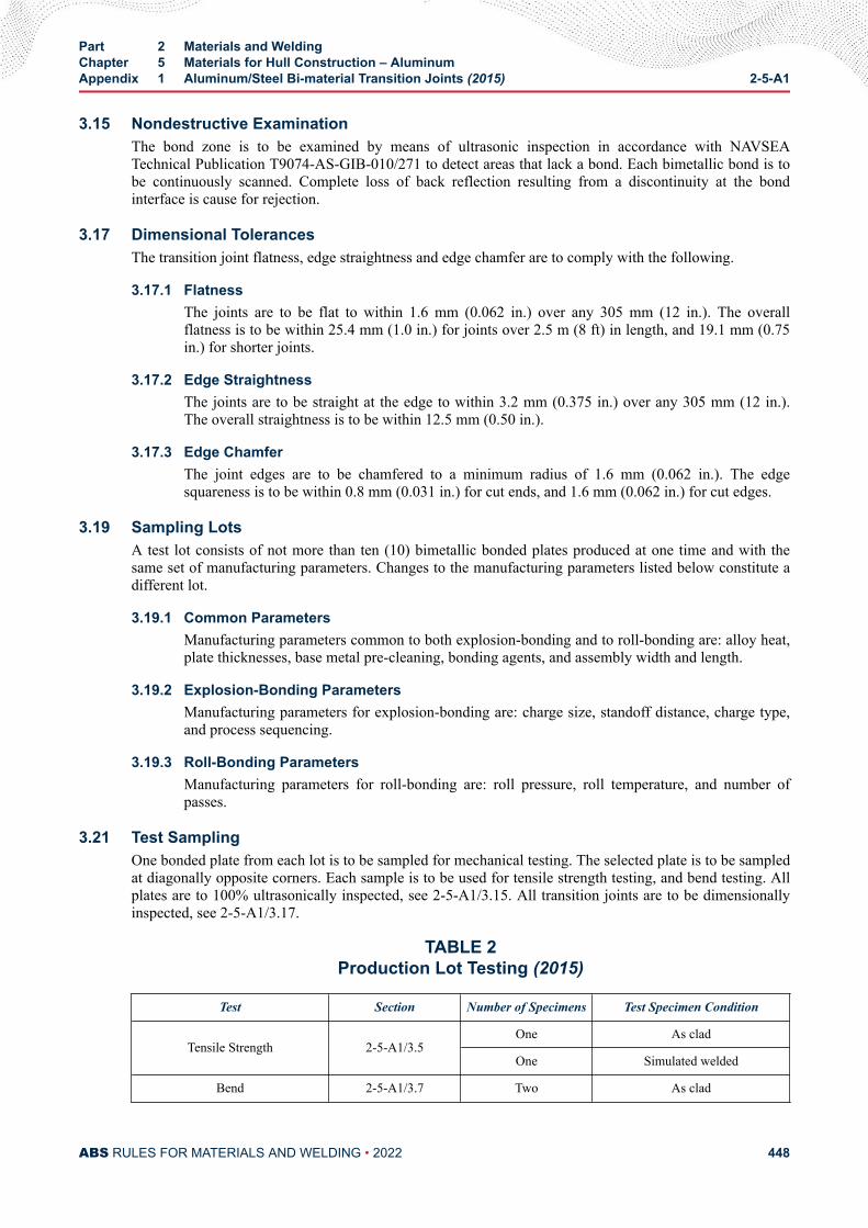
3.15 Nondestructive ExaminationThe bond zone is to be examined by means of ultrasonic inspection in accordance with NAVSEATechnical Publication T9074-AS-GIB-010/271 to detect areas that lack a bond. Each bimetallic bond is tobe continuously scanned. Complete loss of back reflection resulting from a discontinuity at the bondinterface is cause for rejection.
3.17 Dimensional TolerancesThe transition joint flatness, edge straightness and edge chamfer are to comply with the following.
3.17.1 FlatnessThe joints are to be flat to within 1.6 mm (0.062 in.) over any 305 mm (12 in.). The overallflatness is to be within 25.4 mm (1.0 in.) for joints over 2.5 m (8 ft) in length, and 19.1 mm (0.75in.) for shorter joints.
3.17.2 Edge StraightnessThe joints are to be straight at the edge to within 3.2 mm (0.375 in.) over any 305 mm (12 in.).The overall straightness is to be within 12.5 mm (0.50 in.).
3.17.3 Edge ChamferThe joint edges are to be chamfered to a minimum radius of 1.6 mm (0.062 in.). The edgesquareness is to be within 0.8 mm (0.031 in.) for cut ends, and 1.6 mm (0.062 in.) for cut edges.
3.19 Sampling LotsA test lot consists of not more than ten (10) bimetallic bonded plates produced at one time and with thesame set of manufacturing parameters. Changes to the manufacturing parameters listed below constitute adifferent lot.
3.19.1 Common ParametersManufacturing parameters common to both explosion-bonding and to roll-bonding are: alloy heat,plate thicknesses, base metal pre-cleaning, bonding agents, and assembly width and length.
3.19.2 Explosion-Bonding ParametersManufacturing parameters for explosion-bonding are: charge size, standoff distance, charge type,and process sequencing.
3.19.3 Roll-Bonding ParametersManufacturing parameters for roll-bonding are: roll pressure, roll temperature, and number ofpasses.
3.21 Test SamplingOne bonded plate from each lot is to be sampled for mechanical testing. The selected plate is to be sampledat diagonally opposite corners. Each sample is to be used for tensile strength testing, and bend testing. Allplates are to 100% ultrasonically inspected, see 2-5-A1/3.15. All transition joints are to be dimensionallyinspected, see 2-5-A1/3.17.
TABLE 2Production Lot Testing (2015)
Test Section Number of Specimens Test Specimen Condition
Tensile Strength 2-5-A1/3.5One As clad
One Simulated welded
Bend 2-5-A1/3.7 Two As clad
Part 2 Materials and WeldingChapter 5 Materials for Hull Construction – AluminumAppendix 1 Aluminum/Steel Bi-material Transition Joints (2015) 2-5-A1
ABS RULES FOR MATERIALS AND WELDING • 2022 448
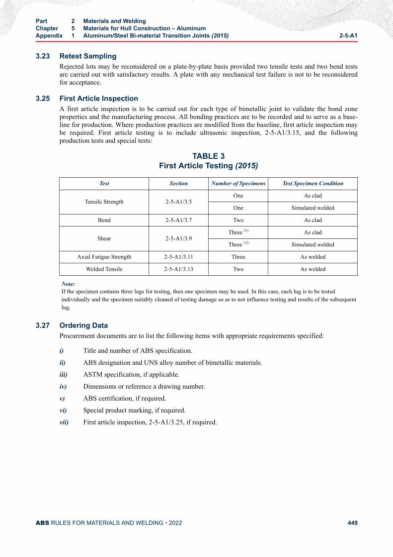
3.23 Retest SamplingRejected lots may be reconsidered on a plate-by-plate basis provided two tensile tests and two bend testsare carried out with satisfactory results. A plate with any mechanical test failure is not to be reconsideredfor acceptance.
3.25 First Article InspectionA first article inspection is to be carried out for each type of bimetallic joint to validate the bond zoneproperties and the manufacturing process. All bonding practices are to be recorded and to serve as a base-line for production. Where production practices are modified from the baseline, first article inspection maybe required. First article testing is to include ultrasonic inspection, 2-5-A1/3.15, and the followingproduction tests and special tests:
TABLE 3First Article Testing (2015)
Test Section Number of Specimens Test Specimen Condition
Tensile Strength 2-5-A1/3.5One As clad
One Simulated welded
Bend 2-5-A1/3.7 Two As clad
Shear 2-5-A1/3.9Three (1) As clad
Three (1) Simulated welded
Axial Fatigue Strength 2-5-A1/3.11 Three As welded
Welded Tensile 2-5-A1/3.13 Two As welded
Note:If the specimen contains three lugs for testing, then one specimen may be used. In this case, each lug is to be testedindividually and the specimen suitably cleaned of testing damage so as to not influence testing and results of the subsequentlug.
3.27 Ordering DataProcurement documents are to list the following items with appropriate requirements specified:
i) Title and number of ABS specification.
ii) ABS designation and UNS alloy number of bimetallic materials.
iii) ASTM specification, if applicable.
iv) Dimensions or reference a drawing number.
v) ABS certification, if required.
vi) Special product marking, if required.
vii) First article inspection, 2-5-A1/3.25, if required.
Part 2 Materials and WeldingChapter 5 Materials for Hull Construction – AluminumAppendix 1 Aluminum/Steel Bi-material Transition Joints (2015) 2-5-A1
ABS RULES FOR MATERIALS AND WELDING • 2022 449
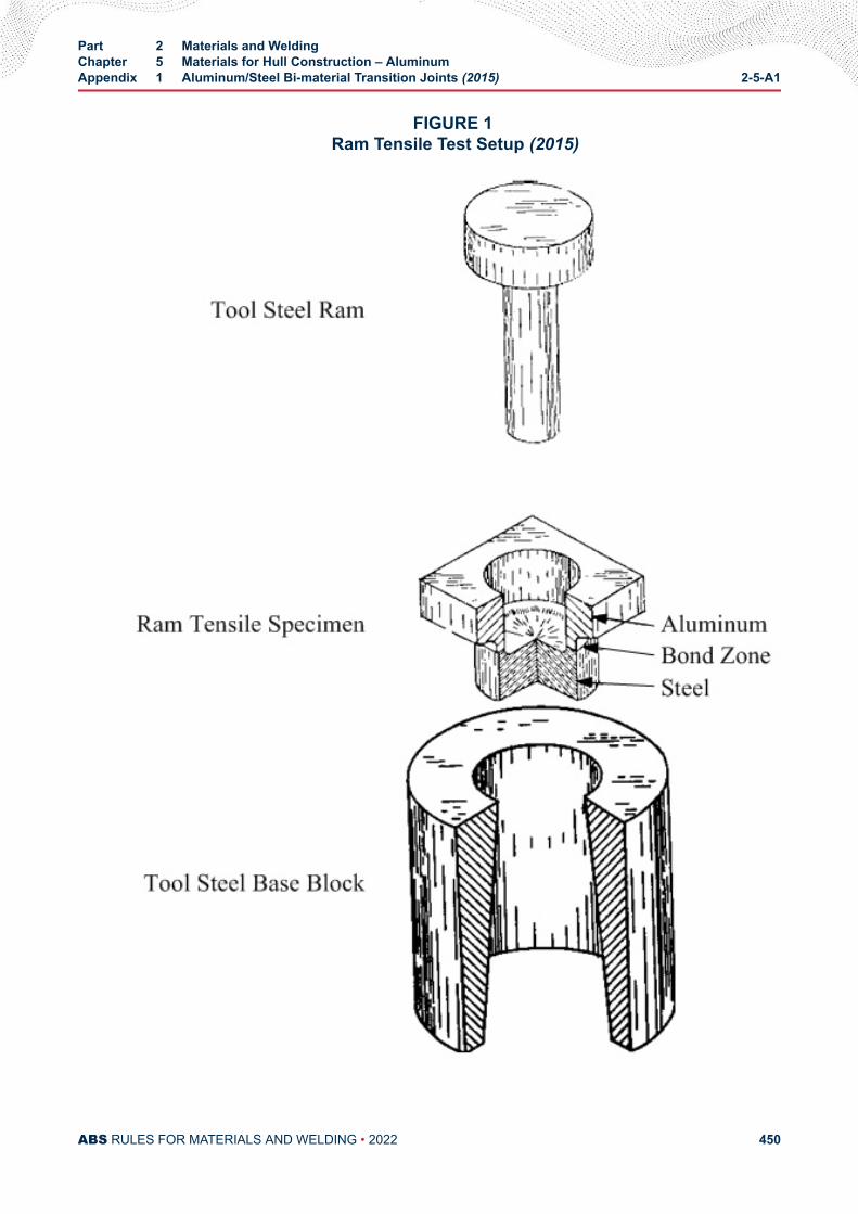
FIGURE 1 Ram Tensile Test Setup (2015)
Part 2 Materials and WeldingChapter 5 Materials for Hull Construction – AluminumAppendix 1 Aluminum/Steel Bi-material Transition Joints (2015) 2-5-A1
ABS RULES FOR MATERIALS AND WELDING • 2022 450
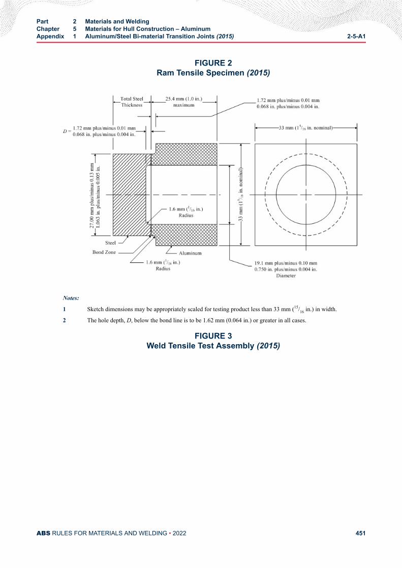
FIGURE 2Ram Tensile Specimen (2015)
Notes:
1 Sketch dimensions may be appropriately scaled for testing product less than 33 mm (15/16 in.) in width.
2 The hole depth, D, below the bond line is to be 1.62 mm (0.064 in.) or greater in all cases.
FIGURE 3Weld Tensile Test Assembly (2015)
Part 2 Materials and WeldingChapter 5 Materials for Hull Construction – AluminumAppendix 1 Aluminum/Steel Bi-material Transition Joints (2015) 2-5-A1
ABS RULES FOR MATERIALS AND WELDING • 2022 451
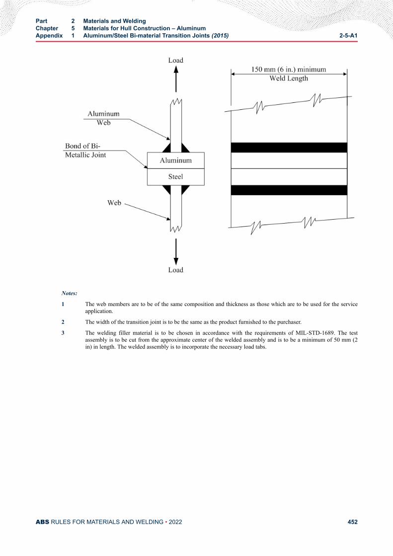
Notes:
1 The web members are to be of the same composition and thickness as those which are to be used for the serviceapplication.
2 The width of the transition joint is to be the same as the product furnished to the purchaser.
3 The welding filler material is to be chosen in accordance with the requirements of MIL-STD-1689. The testassembly is to be cut from the approximate center of the welded assembly and is to be a minimum of 50 mm (2in) in length. The welded assembly is to incorporate the necessary load tabs.
Part 2 Materials and WeldingChapter 5 Materials for Hull Construction – AluminumAppendix 1 Aluminum/Steel Bi-material Transition Joints (2015) 2-5-A1
ABS RULES FOR MATERIALS AND WELDING • 2022 452
C H A P T E R 5Materials for Hull Construction – Aluminum
A P P E N D I X 2Dissimilar Materials (2015)
1 Material
1.1 Dissimilar MaterialsWhere dissimilar materials such as aluminum and steel, stainless steel and carbon steel, or copper/nickeland carbon steel, are used in combination and exposed to water or weather, measures are to be taken toavoid galvanic corrosion.
PART 2
ABS RULES FOR MATERIALS AND WELDING • 2022 453
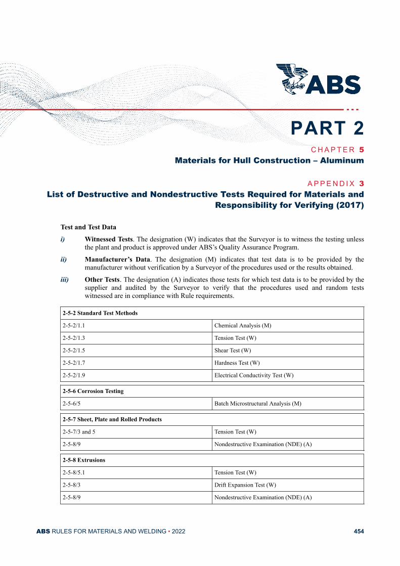
C H A P T E R 5Materials for Hull Construction – Aluminum
A P P E N D I X 3List of Destructive and Nondestructive Tests Required for Materials and
Responsibility for Verifying (2017)
Test and Test Datai) Witnessed Tests. The designation (W) indicates that the Surveyor is to witness the testing unless
the plant and product is approved under ABS’s Quality Assurance Program.
ii) Manufacturer’s Data. The designation (M) indicates that test data is to be provided by themanufacturer without verification by a Surveyor of the procedures used or the results obtained.
iii) Other Tests. The designation (A) indicates those tests for which test data is to be provided by thesupplier and audited by the Surveyor to verify that the procedures used and random testswitnessed are in compliance with Rule requirements.
2-5-2 Standard Test Methods
2-5-2/1.1 Chemical Analysis (M)
2-5-2/1.3 Tension Test (W)
2-5-2/1.5 Shear Test (W)
2-5-2/1.7 Hardness Test (W)
2-5-2/1.9 Electrical Conductivity Test (W)
2-5-6 Corrosion Testing
2-5-6/5 Batch Microstructural Analysis (M)
2-5-7 Sheet, Plate and Rolled Products
2-5-7/3 and 5 Tension Test (W)
2-5-8/9 Nondestructive Examination (NDE) (A)
2-5-8 Extrusions
2-5-8/5.1 Tension Test (W)
2-5-8/3 Drift Expansion Test (W)
2-5-8/9 Nondestructive Examination (NDE) (A)
PART 2
ABS RULES FOR MATERIALS AND WELDING • 2022 454
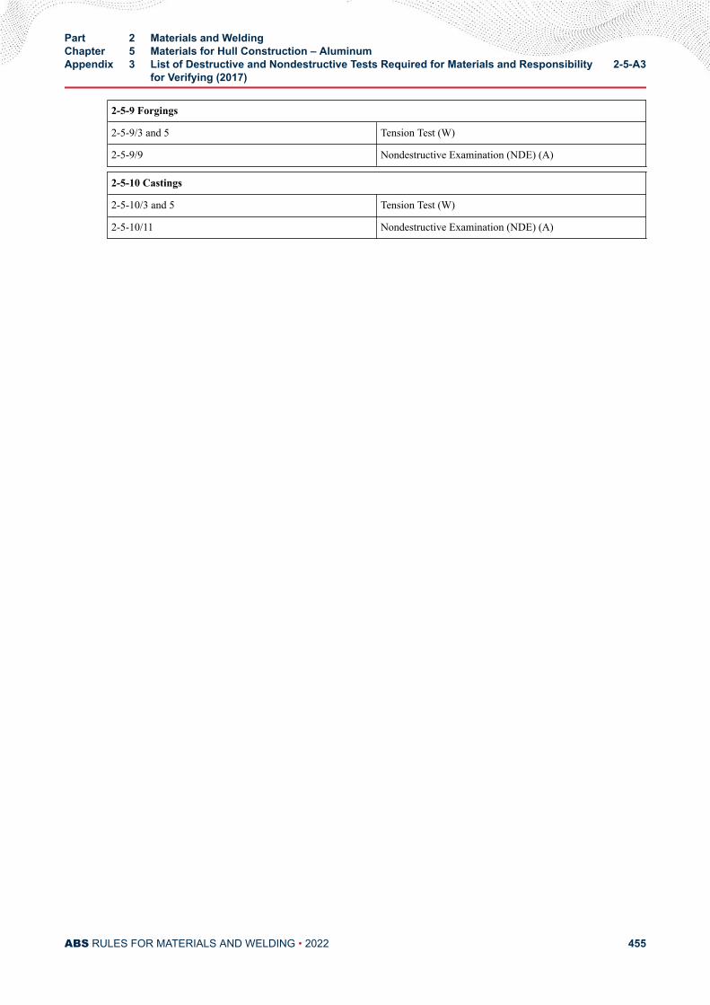
2-5-9 Forgings
2-5-9/3 and 5 Tension Test (W)
2-5-9/9 Nondestructive Examination (NDE) (A)
2-5-10 Castings
2-5-10/3 and 5 Tension Test (W)
2-5-10/11 Nondestructive Examination (NDE) (A)
Part 2 Materials and WeldingChapter 5 Materials for Hull Construction – AluminumAppendix 3 List of Destructive and Nondestructive Tests Required for Materials and Responsibility
for Verifying (2017)2-5-A3
ABS RULES FOR MATERIALS AND WELDING • 2022 455
C H A P T E R 6Materials for Hull Construction – Fiber Reinforced Plastics (FRP)
CONTENTSSECTION 1 General..............................................................................................461
1 Resins.........................................................................................4611.1 Polyester Resins............................................................4611.3 Vinylester and Epoxy Resins......................................... 4611.5 Gel Coats.......................................................................4611.7 Curing Systems............................................................. 4611.9 Phenolic Resins............................................................. 4611.11 Resin Properties............................................................ 4611.13 Additives........................................................................ 4621.15 Fillers............................................................................. 462
3 Reinforcing Materials..................................................................4635 Core Materials............................................................................ 463
5.1 PVC Foam Cores...........................................................4635.3 Balsa Wood................................................................... 4635.5 Core Bonding Materials................................................. 463
7 Laminates................................................................................... 4647.1 Basic Laminate.............................................................. 4647.3 Uni-directional Laminates.............................................. 4647.5 Bi-Directional Laminates................................................4647.7 Sandwich Laminates......................................................4647.9 Mechanical Properties................................................... 4647.11 Nonstructural Plies.........................................................4657.13 Laminate Thickness.......................................................4657.15 Plywood and Timber Members...................................... 465
9 Adhesives................................................................................... 4669.1 General.......................................................................... 4669.3 Requirements for Structural Application........................ 467
TABLE 1 Properties of Core Materials.............................................. 463TABLE 2 FRP Laminate Properties...................................................466
PART 2
ABS RULES FOR MATERIALS AND WELDING • 2022 456
SECTION 2 Fabrication........................................................................................4681 General.......................................................................................4683 Fabrication Procedures...............................................................468
3.1 General.......................................................................... 4683.3 Laminate Layup............................................................. 4683.5 Sandwich Panel Layup.................................................. 4683.7 Secondary Bonds.......................................................... 469
SECTION 3 Building Process Description.........................................................4701 General.......................................................................................4703 Building Facilities........................................................................470
3.1 Material Storage Premises............................................ 4703.3 Mold Construction..........................................................4713.5 Laminating Premises..................................................... 4713.7 Equipment......................................................................472
5 Specifications and Data Sheets for Materials.............................4735.1 Resins, Gel Coats, Catalysts, Accelerators,
Hardeners and Other Additives..................................... 4735.3 Reinforcing Materials..................................................... 4735.5 Core Materials............................................................... 473
7 Receiving Materials.................................................................... 4747.1 Resins, Gel Coats, Catalysts, Accelerators,
Hardeners and Other Additives..................................... 4747.3 Reinforcing Materials..................................................... 4747.5 Core Materials............................................................... 474
9 Laminating Procedure.................................................................4749.1 Start-up.......................................................................... 4749.3 Application of Gel Coat.................................................. 4759.5 Lamination of Skin Coat.................................................4759.7 Main Lamination – Single Skin...................................... 4759.9 Main Lamination – Sandwich Laminate......................... 4769.11 Release and Curing....................................................... 4789.13 Secondary Bonding....................................................... 478
11 Inspection................................................................................... 47911.1 General.......................................................................... 47911.3 Voids.............................................................................. 479
13 Faults..........................................................................................47913.1 General.......................................................................... 47913.3 Production Faults...........................................................480
SECTION 4 Quality Control................................................................................. 4811 Application.................................................................................. 4813 Definitions...................................................................................481
3.1 Hull Construction........................................................... 481
ABS RULES FOR MATERIALS AND WELDING • 2022 457
3.3 Quality Assurance Standard.......................................... 4813.5 Quality Assurance..........................................................4813.7 Quality Assurance System.............................................4813.9 Building Process Description......................................... 4813.11 Quality Control............................................................... 4823.13 Inspection...................................................................... 4823.15 Assessment................................................................... 4823.17 Audit...............................................................................4823.19 System Monitoring......................................................... 482
5 Design.........................................................................................4825.1 Plan Review...................................................................4825.3 Revisions....................................................................... 482
7 Building Process Description – Quality Control.......................... 4829 Certification of Quality Assurance...............................................48211 Documentation of Quality Assurance System............................ 48313 Personnel....................................................................................48315 Internal Audit...............................................................................48317 Documentation............................................................................48319 Purchase.....................................................................................483
19.1 .......................................................................................48319.3 .......................................................................................48419.5 .......................................................................................48419.7 .......................................................................................484
21 Material Receipt, Inspection and Storage...................................48421.1 .......................................................................................48421.3 .......................................................................................48421.5 .......................................................................................48421.7 .......................................................................................48421.9 .......................................................................................48421.11 .......................................................................................48421.13 .......................................................................................484
23 Production...................................................................................48423.1 .......................................................................................48423.3 .......................................................................................48423.5 .......................................................................................48523.7 .......................................................................................48523.9 .......................................................................................48523.11 .......................................................................................48523.13 .......................................................................................48523.15 .......................................................................................48523.17 .......................................................................................485
25 Production Inspections and Tests...............................................48527 Final Inspection...........................................................................48529 Nonconforming Materials and Components............................... 485
ABS RULES FOR MATERIALS AND WELDING • 2022 458
29.1 .......................................................................................48529.3 .......................................................................................486
31 Corrective Action........................................................................ 48631.1 .......................................................................................48631.3 .......................................................................................48631.5 .......................................................................................486
33 Calibration and Maintenance of Equipment................................48633.1 .......................................................................................48633.3 .......................................................................................48633.5 .......................................................................................48633.7 .......................................................................................48633.9 .......................................................................................48633.11 .......................................................................................486
35 Training.......................................................................................48637 Records...................................................................................... 487
37.1 .......................................................................................48737.3 .......................................................................................48737.5 .......................................................................................487
SECTION 5 Testing...............................................................................................4881 Gel Time..................................................................................... 4883 Barcol Hardness......................................................................... 4885 Burnout and Thickness...............................................................4887 Void Content............................................................................... 4899 Laminate Properties....................................................................48911 Test Results................................................................................ 489
TABLE 1 Tests for Physical Properties of FRP Laminates................489
SECTION 6 Repair................................................................................................4901 General.......................................................................................4903 Materials..................................................................................... 490
3.1 Resins............................................................................4903.3 Fiber Reinforcements.................................................... 490
5 Repair Procedures – Single Skin Laminate................................4905.1 Damage Assessment.....................................................4905.3 Removal of Damaged Laminate.................................... 4915.5 Laminating Procedures..................................................4925.7 Laminating Process....................................................... 494
7 Repair Procedure – Sandwich Construction...............................5037.1 Damage Assessment.....................................................5037.3 Removal of Damaged Laminate.................................... 5037.5 Laminating Procedure and Process...............................503
ABS RULES FOR MATERIALS AND WELDING • 2022 459
9 Repair Acceptance..................................................................... 503
FIGURE 1 Scarf Joint Preparation.......................................................492FIGURE 2 Repair Sequence............................................................... 493FIGURE 3 Ply Overlap Requirements................................................. 494FIGURE 4 Partially Through Thickness Defect Repair........................495FIGURE 5 Double Sided Scarf Repair.................................................496FIGURE 6 One Sided Scarf Repair – Backing Plate Installation.........497FIGURE 7 Repair Using Defective Section as Backing Plate..............498FIGURE 8 Single Sided Scarf Repair on Thin Laminate..................... 499FIGURE 9 Backing Plate Installation – Access from One Sided
Repair.................................................................................500FIGURE 10 Repair in Way of Through Bolt Failure............................... 501FIGURE 11 Stepped Angle Defect Repair.............................................502
ABS RULES FOR MATERIALS AND WELDING • 2022 460
C H A P T E R 6Materials for Hull Construction – Fiber Reinforced Plastics (FRP)
S E C T I O N 1General
1 ResinsResins for the basic laminate of these Rules, other than those utilized for gel coats, are to be unsaturated,general-purpose or fire retardant polyesters suitable for marine use, and are to be catalyzed in strictaccordance with manufacturers’ recommendations.
1.1 Polyester ResinsIsophthalic polyester or orthophthalic polyester may be used. The former is often used for gel coat andouter ply lamination; the latter is an effective laminating resin.
1.3 Vinylester and Epoxy ResinsEpoxy resins cannot form a primary bond with polyester and vinylester resins. Epoxies can only be usedeither by themselves or in conjunction with fully cured polyester or vinylester resins.
1.5 Gel CoatsAll gel coats are to be used in strict accordance with the manufacturers’ recommendations. Where a gelcoat is not used, details of the proposed water barrier are to be submitted for consideration.
1.7 Curing SystemsFor polyester and vinylester resins, the level of catalyst and accelerator are to be as recommended by themanufacturer to ensure full polymerization of the resin. In general, the rate of gelation is to be controlledby the amount of catalyst accelerator added to the resin. The amount of catalyst is not to be less than 1% ofthe base resin, by weight.
1.9 Phenolic ResinsPhenolic resins having superior properties for fire resistance may not be suitable for structural applications.Where fire retardant additives to the resin system are used, the type and quantity are to be as recommendedby the resin manufacturer. The results of independently tested fire retardant and fire restricting materialsare to be submitted. All fire retardant systems are to be used in strict accordance with the resinmanufacturer’s recommendation.
1.11 Resin PropertiesThe properties of a resin are to be for the final form of the resin actually used in production with alladditives and fillers included. The amount of silicon dioxide or other material added to provide thixotropy
PART 2
ABS RULES FOR MATERIALS AND WELDING • 2022 461
is to be the minimum necessary to resist flowing or draining. The following liquid and cured conditionproperties of resins are to be provided for the gel coat resin and laminating resin, and if different, for theskin coat:
● Liquid Properties (at 25°C)
Monomer Content %
Viscosity – Brookfield (Spindle No. & RPM) CPS
Thixotropic Index, Minimum
Specific Gravity
Flash Point, Closed Cup
Fillers (type and amount)
● Cure Characteristics (at 25°C)
Gel Time, Minutes (indicate initiator (catalyst) and activator (promoter) and %)
Gel to Peak, Minutes
Peak Exotherm
● Cured Properties for Resin Clear Casting
Barcol Hardness
Heat Deflection Temperature
Tensile Strength and Tensile Modulus
Tensile Elongation at Break, %
Flexural Strength & Modulus
Volume Shrinkage
Water Absorption
● Chemical analysis and shelf life.
For polyester resins, the tensile elongation at break is generally not to be less than 1.0% for laminatingresins and is to be generally not less than 2.0% for gel coat resins. Elongation of other resins will bespecifically considered.
1.13 AdditivesAdditives are only to be added by the resin manufacturer in accordance with the agreed procedure andtested accordingly. Where a resin contains an ingredient that can settle within the resin system, it is thebuilder’s responsibility to ensure that the resin manufacturer’s recommendations regarding mixing andconditioning are complied with prior to use.
1.15 FillersAll fillers added by a builder are to be of the dispersed type. The amount of filler that may be added to aresin is to be recommended by the resin manufacturer and is not to significantly alter the viscosity of theresin nor is it to affect the overall strength properties of the laminate. Recommendations by the resin
Part 2 Materials and WeldingChapter 6 Materials for Hull Construction – Fiber Reinforced Plastics (FRP)Section 1 General 2-6-1
ABS RULES FOR MATERIALS AND WELDING • 2022 462

manufacturer to adopt amounts of fillers in excess of 13% by weight of the base resin will be subject toindividual approval and testing. Pigments, thixotropes and fire retardant additives are to be considered asfillers in the calculation of total filler content. Fillers are to be carefully and thoroughly mixed into the baseresin that is then to be allowed to stand to ensure that the entrapped air is released. The resinmanufacturer’s recommendations regarding the method of mixing are to be followed. Details of all fillersare to be submitted.
3 Reinforcing MaterialsFiber reinforcement includes E glass fiber, S or R glass, carbon and aramid (Kevlar) fibers. The use ofhybrid reinforcing materials is also acceptable. To be considered a reinforced plastic, the properties of thecured laminate of resin and fiber must exceed those of the cured clear resin without fiber. Where couplingagents are used, they are to be of the silane type, and are to be compatible with the laminating resins.
5 Core MaterialsExpected shear strengths of core materials are shown in 2-6-1/5.5 TABLE 1. Core materials other thanthose shown will be subject to special consideration. Polyester fiber or vinylester mat is not considered alightweight structural core, and use will be subject to special consideration. Shear strength for use in thedesign is to be verified by test, as required in Section 2-6-5. Construction methods and procedures for corematerials are to be in strict accordance with core manufacturer’s recommendations.
5.1 PVC Foam CoresFoam cores are to be of the closed cell types and impervious to water, fuel and oils. Foam cores are to becompatible with the resin system and have good aging ability. Foam cores are to have good strengthretention at 60°C (140°F). If the foam core is manufactured into formable sheets of small blocks, the openweave backing material and adhesive are to be compatible and soluble with the laminating resin. Wherenecessary, foam core materials are to be conditioned in accordance with the manufacturer’srecommendations. Conditioning at an elevated temperature in excess of that which may be experienced inservice may be necessary to ensure the release of entrapped residual gaseous blowing agents from the cellsof the foam core.
5.3 Balsa WoodBalsa wood is to be end-grained. Balsa wood is to be treated chemically against fungal and insect attackand kiln-dried shortly after felling, and is to be sterilized and homogenized. Balsa wood is to have anaverage moisture content of 12%. If the balsa wood is manufactured into formable sheets of small blocks,the open weave backing material and adhesive are to be compatible and soluble, respectively, with thelaminating resin.
5.5 Core Bonding MaterialsCore bonding materials are to be used in accordance with the manufacturer’s instructions. The proposedcore bonding to be used with the core material is to be indicated on the Material Data Sheet and theconstruction plans.
TABLE 1Properties of Core Materials
Density Minimum Shear Strength
Material kg/m3 lb/ft3 N/mm2 kgf/mm2 psi
Balsa, end-grain 104 6.5 1.6 (1) 0.16 (1) 225 (1)
Balsa, end-grain 144 9 2.5 (1) 0.25 (1) 360 (1)
PVC, crosslinked 80 5 0.9 0.09 122
Part 2 Materials and WeldingChapter 6 Materials for Hull Construction – Fiber Reinforced Plastics (FRP)Section 1 General 2-6-1
ABS RULES FOR MATERIALS AND WELDING • 2022 463
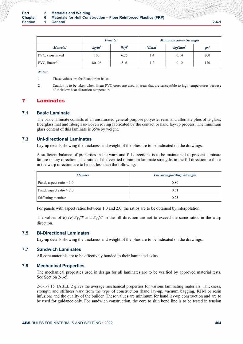
Density Minimum Shear Strength
Material kg/m3 lb/ft3 N/mm2 kgf/mm2 psi
PVC, crosslinked 100 6.25 1.4 0.14 200
PVC, linear (2) 80–96 5–6 1.2 0.12 170
Notes:
1 These values are for Ecuadorian balsa.
2 Caution is to be taken when linear PVC cores are used in areas that are susceptible to high temperatures becauseof their low heat distortion temperature.
7 Laminates
7.1 Basic LaminateThe basic laminate consists of an unsaturated general-purpose polyester resin and alternate plies of E-glass,fiberglass mat and fiberglass-woven roving fabricated by the contact or hand lay-up process. The minimumglass content of this laminate is 35% by weight.
7.3 Uni-directional LaminatesLay-up details showing the thickness and weight of the plies are to be indicated on the drawings.
A sufficient balance of properties in the warp and fill directions is to be maintained to prevent laminatefailure in any direction. The ratios of the verified minimum laminate strengths in the fill direction to thosein the warp direction are to be not less than the following:
Member Fill Strength/Warp Strength
Panel, aspect ratio = 1.0 0.80
Panel, aspect ratio > 2.0 0.61
Stiffening member 0.25
For panels with aspect ratios between 1.0 and 2.0, the ratios are to be obtained by interpolation.
The values of EF/F,ET/T and EC/C in the fill direction are not to exceed the same ratios in the warpdirection.
7.5 Bi-Directional LaminatesLay-up details showing the thickness and weight of the plies are to be indicated on the drawings.
7.7 Sandwich LaminatesAll core materials are to be effectively bonded to their laminated skins.
7.9 Mechanical PropertiesThe mechanical properties used in design for all laminates are to be verified by approved material tests.See Section 2-6-5.
2-6-1/7.15 TABLE 2 gives the average mechanical properties for various laminating materials. Thickness,strength and stiffness vary from the type of construction (hand lay-up, vacuum bagging, RTM or resininfusion) and the quality of the builder. These values are minimum for hand lay-up construction and are tobe used for guidance only. For sandwich construction, the core to skin bond line is to be tested in tension
Part 2 Materials and WeldingChapter 6 Materials for Hull Construction – Fiber Reinforced Plastics (FRP)Section 1 General 2-6-1
ABS RULES FOR MATERIALS AND WELDING • 2022 464
(flatwise tension test, see 2-6-1/5.5 TABLE 1) to determine its integrity. The bondline is consideredacceptable if failure occurs in the cored region of the sample or within the laminate skins. The properties tobe used for a particular laminate are subject to verification by approved material tests, as required inSection 2-6-5.
7.11 Nonstructural PliesGel coats and skin coats of either fiber mat or fiber cloth weighing less than 30 grams per square meter(0.1 ounce per square foot) are considered to be nonstructural. They are not to be included when assessinglaminate strength and stiffness.
7.13 Laminate ThicknessThe average thicknesses given below are provided only as guidance to the designer for mat and wovenplies laid-up separately. Thickness indicated on the submitted plans for use with the guide are to be verifiedby the Surveyor and approved material tests.
The cured resin-and-mat plies may be taken to have average thickness equal to 0.25 millimeters per 100grams of mat in each square meter (0.03 inches per ounce of mat in each square foot) of the basic laminate.The cured resin-and-woven roving plies may be taken to have an average thickness equal to 0.12millimeters per 100 grams of woven roving in each square meter (0.0016 inches per ounce of wovenroving in each square yard) of the basic laminate.
For mat and woven roving laminates differing in glass content from the basic laminate, the average curedlaminate thickness, t, (excluding nonstructural plies) can be obtained from the following equation:t = Wkc 305fg − 2 . 69 mm(in)wherek = 0.35 mm (0.0138 inches)fg = glass content, percentage by weight, of one ply of the mat and one ply of the woven-roving of
the laminate to be usedc = glass content per pair of composite fiberglass reinforcement of basic laminate,
= 1272 g/m2 (4.17 oz/ft2)W = total weight of fiberglass reinforcement of the laminate in g/m2 (oz/ft2), of the laminate thickness,t
7.15 Plywood and Timber MembersWhere plywood and timber members are to be used in structural applications and are to be laminated onto,or encapsulated within the laminate, the surface of the wood is to be suitably prepared and primed prior tolaminating.
Part 2 Materials and WeldingChapter 6 Materials for Hull Construction – Fiber Reinforced Plastics (FRP)Section 1 General 2-6-1
ABS RULES FOR MATERIALS AND WELDING • 2022 465
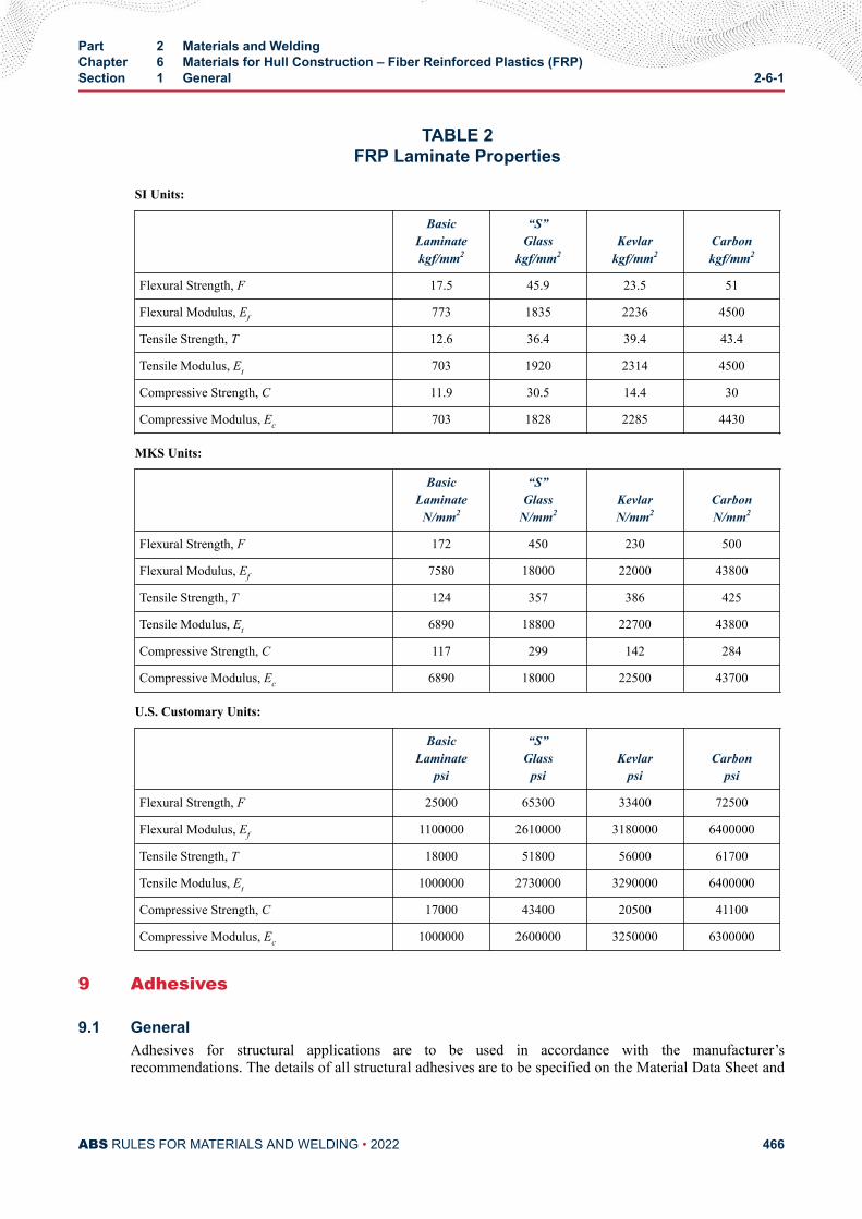
TABLE 2FRP Laminate Properties
SI Units:
BasicLaminatekgf/mm2
“S”Glass
kgf/mm2Kevlar
kgf/mm2Carbonkgf/mm2
Flexural Strength, F 17.5 45.9 23.5 51
Flexural Modulus, Ef 773 1835 2236 4500
Tensile Strength, T 12.6 36.4 39.4 43.4
Tensile Modulus, Et 703 1920 2314 4500
Compressive Strength, C 11.9 30.5 14.4 30
Compressive Modulus, Ec 703 1828 2285 4430
MKS Units:
BasicLaminate
N/mm2
“S”Glass
N/mm2KevlarN/mm2
CarbonN/mm2
Flexural Strength, F 172 450 230 500
Flexural Modulus, Ef 7580 18000 22000 43800
Tensile Strength, T 124 357 386 425
Tensile Modulus, Et 6890 18800 22700 43800
Compressive Strength, C 117 299 142 284
Compressive Modulus, Ec 6890 18000 22500 43700
U.S. Customary Units:
BasicLaminate
psi
“S”Glass
psiKevlar
psiCarbon
psi
Flexural Strength, F 25000 65300 33400 72500
Flexural Modulus, Ef 1100000 2610000 3180000 6400000
Tensile Strength, T 18000 51800 56000 61700
Tensile Modulus, Et 1000000 2730000 3290000 6400000
Compressive Strength, C 17000 43400 20500 41100
Compressive Modulus, Ec 1000000 2600000 3250000 6300000
9 Adhesives
9.1 GeneralAdhesives for structural applications are to be used in accordance with the manufacturer’srecommendations. The details of all structural adhesives are to be specified on the Material Data Sheet and
Part 2 Materials and WeldingChapter 6 Materials for Hull Construction – Fiber Reinforced Plastics (FRP)Section 1 General 2-6-1
ABS RULES FOR MATERIALS AND WELDING • 2022 466
on the construction plans submitted. Details concerning the handling, mixing and application of adhesivesare to form part of the Builders Process Instruction. Particular attention is to be given to the surfacepreparation and cleanliness of the surfaces to be bonded. Where excessive unevenness of the fayingsurfaces exists, a suitable gap-filling adhesive is to be used or local undulations removed by the applicationof additional reinforcements. The Builder Process Description is to identify the level of training requiredfor personnel involved in the application of structural adhesives.
9.3 Requirements for Structural ApplicationFor adhesive materials to be acceptable for use in structural applications, they are to comply with thefollowing requirements:
i) The minimum shear strength of the adhesive is to be between 6.9 N/mm2 (1000 psi) and 10 N/mm2
(1500 psi). This shear strength is to be achieved in temperatures ranging from ambient to 49°C(120°F). The testing is to be performed to ASTM D1002 or ASTM D3165 using FRP substrates.All failures of test samples are to be either cohesive or fiber tear.
ii) The adhesive is to be tested in fatigue using ASTM D3166 (note: the test substrates may bemetallic). The test is to be conducted at 50% of the ultimate tensile strength and is to last for aminimum of one million cycles at 30 Hz.
iii) The process for the application of the adhesive is to be submitted for review and is to include themaximum bondline thickness, nondestructive testing methods and maximum creep.
iv) The elastic modulus of the adhesive is to be considerably less than that of the FRP skin to which itis being adhered
v) The strain of failure ratio of the adhesive is to be much larger than the surrounding structure.
vi) The mechanical properties of the adhesive are achieved rapidly, such that the use of screws orbolts will not be necessary to hold the substrates together while the adhesive cures.
vii) The adhesive is to be compatible with the lamination resin.
Part 2 Materials and WeldingChapter 6 Materials for Hull Construction – Fiber Reinforced Plastics (FRP)Section 1 General 2-6-1
ABS RULES FOR MATERIALS AND WELDING • 2022 467
C H A P T E R 6Materials for Hull Construction – Fiber Reinforced Plastics (FRP)
S E C T I O N 2Fabrication
1 GeneralThe use of fabricating procedures differing from those given below will be specially considered.
3 Fabrication Procedures
3.1 GeneralThe laminate is to be lay-up by one of the following methods:
● Hand layup or contact process
● Vacuum Bagging
● Resin Impregnation
● Resin Transfer Molding (RTM)
● Resin Infusion
● Pre-preg
3.3 Laminate LayupA layer or ply of reinforcing material may consist of a number of pieces. The pieces are to be lapped alongtheir edges and ends. The width of each lap is to be not less than 50 mm (2 in.). Unless otherwisespecifically approved, no laps in the various plies of a laminate are to be closer than 100 mm (4 in.) to eachother.
Transitions in laminate thickness are to be tapered over a length not less than three times the thickness ofthe thicker laminate. A gradual transition in fiber reinforcement is to be provided between bidirectionaland unidirectional laminates.
3.5 Sandwich Panel LayupSandwich panels may be laminated with cores that either are effective in resisting bending; tension,compression, shear and deflection (e.g., plywood) or are essentially ineffective in resisting bending,tension, compression and deflection, but are capable of carrying shear loads, (e.g., balsa wood and plasticfoam).
PART 2
ABS RULES FOR MATERIALS AND WELDING • 2022 468
All cores are to be effectively bonded to the skins in accordance with the manufacturer’s recommendation(e.g., vacuum bag techniques with an approved bedding putty). Joints in core materials are to be scarphedand bonded or connected by similar effective means.
Where sandwich panels with ineffective cores are used in way of mechanically connected structures, gearsand equipment, a core effective in resisting bearing, shear, flexure and compression is to be inserted. Theinserts are to be bonded to the skins or faces of the sandwich and to the adjacent core.
The ply of skin laminate in contact with each face of a core material is to be chopped-strand mat. The matis to be thoroughly impregnated with resin and the core is to be coated with resin before lay-up. For foamcores, the resin is to be applied and sufficiently rolled to ensure that all voids are filled, and the coat ofresin for wood cores should be substantial enough to seal the grain of the wood.
3.7 Secondary BondsIn general, secondary bonds should only be used when a primary bond cannot be achieved. Where everpossible, peel-ply should be applied to the outer layer of the surface requiring the secondary bond. Whenpreparing for a secondary bond, the following criteria along with the manufacturer’s recommendationsshould be adhered to:
i) The area is to be clean and free from all foreign particles such as wax, grease, dirt and dust.
ii) When grinding is required, the grinding is not to damage any of the structural glass fibers, thusweakening the laminate, especially in highly stressed areas.
In general, the first ply of the secondary lay-up is to be chopped-strand mat. The final ply of laminatealong the bond line of the cured laminate is preferably to be chopped-strand mat.
Where methods other than conventional secondary bonding are proposed, the shipyard is to demonstratethat the proposed method is equivalent in strength to a conventional secondary bond.
Part 2 Materials and WeldingChapter 6 Materials for Hull Construction – Fiber Reinforced Plastics (FRP)Section 2 Fabrication 2-6-2
ABS RULES FOR MATERIALS AND WELDING • 2022 469
C H A P T E R 6Materials for Hull Construction – Fiber Reinforced Plastics (FRP)
S E C T I O N 3Building Process Description
1 GeneralThe building process description is to be submitted for review by the builder before construction starts.Information on the following items is to be included.
i) Description of construction facilities, including environmental control and material storage andhandling.
ii) Specifications for resins, reinforcing products and core materials including the manufacturer’srecommendations.
iii) Lay-up procedures, including type, orientation of reinforcements, sequence, resin mixing methodsand resin pot-life limits.
iv) Secondary bonding procedures.
v) Inspection and quality control systems
vi) Laminate properties derived from destructive qualification testing including sample check sheets,forms and guides.
3 Building Facilities
3.1 Material Storage PremisesThe premises are to be equipped and arranged so that the material manufacturer’s recommendations forstorage and handling can be followed:
3.1.1Premises are to be enclosed, protected from the sun, clean, dry, ventilated as necessary andsufficiently free of dust so that materials are not contaminated or degraded. Materials are toremain sealed in storage as recommended by the manufacturer.
3.1.2Before use, fiber reinforcements are to be stored for at least 48 hours at a temperature andhumidity similar to that of the laminating premises.
PART 2
ABS RULES FOR MATERIALS AND WELDING • 2022 470
3.1.3Resins, catalysts, hardeners and accelerators are to be stored in a well-ventilated space attemperatures recommended by the manufacturer. The storage period is not to exceed the shelflives. Fillers and additives are to be stored in closed containers impervious to humidity and dust.Resin tanks are to be arranged so that they can be stirred at the frequency and time recommendedby the manufacturer.
3.1.4Core materials are to be stored in a dry space and protected against damage; they are to becontained in their protective packaging until immediately prior to use.
3.1.5Materials that may be considered hazardous to each other are to be stored separately. Catalyst is tobe stored in a cool, dry location away from manufacturing facility in accordance with fire andinsurance codes.
3.3 Mold ConstructionMolds are to be constructed to the following criteria:
3.3.1Molds are to be constructed of a suitable material and are to be adequately stiffened to maintaintheir overall shape and fairness of form.
3.3.2The materials used in the construction of molds are not to affect the resin cure.
3.3.3The finish on a mold is to be such that the moldings produced are suitable for the purposeintended. The resultant aesthetic appearance of the molding is not part of ABS Survey andapproval.
3.3.4Where multiple section molds are used, the sections are to be carefully aligned to the attendingSurveyor’s satisfaction prior to molding. Mismatch between mold sections is to be avoided.
3.3.5The release agent (e.g., mold wax, etc.) is to be of a type recommended by the resin manufacturerand is not to affect the cure of the resin.
3.3.6Prior to use, all molds are to be conditioned to the workshop temperature.
3.3.7Lifting arrangements are to be designed such that moldings are subjected to minimal distortionand unnecessary stressing. Moldings are to be adequately supported to avoid distortion duringfinal cure.
3.5 Laminating PremisesPremises are to be arranged and equipped so that the material manufacturer’s recommendations andbuilder’s standards for handling, laminating and curing can be followed:
Part 2 Materials and WeldingChapter 6 Materials for Hull Construction – Fiber Reinforced Plastics (FRP)Section 3 Building Process Description 2-6-3
ABS RULES FOR MATERIALS AND WELDING • 2022 471
3.5.1Premises are to be fully enclosed, dry, clean, shaded from the sun and adequately ventilated toremove fumes, overspray and dust from the molds and laminating area and properly andadequately lighted. Precautions are to be taken to avoid any effects on the resin cure due to directsunlight or artificial lighting.
3.5.2Temperature is to be maintained adequately constant at a temperature between 16°C and 32°C(60°F and 90°F). The humidity is to be kept adequately constant to prevent condensation and isnot to exceed 80%. Where spray molding is taking place, the humidity is not to be less than 40%.Temperature and humidity are to be within limits recommended by the manufacturer of thematerials. Departures from the foregoing will be considered, provided the temperatures andhumidity are within the limits recommended by the manufacturer and are reviewed by ABS priorto laminating.
3.5.3The laminating temperature in the premises is to be attained at least 24 hours beforecommencement of lamination, and is to be maintainable, regardless of the outdoor temperature.
3.5.4Sufficient temperature and humidity monitoring equipment is to be provided, and detailed recordsare to be kept in accordance with the Quality Assurance system.
3.5.5Laminating areas are to be remote from operations creating dust.
3.5.6Scaffolding is to be provided, where necessary, to avoid standing on cores or on laminatedsurfaces. Such arrangements are to conform to the National Authority requirements and are not, ingeneral, to be connected to the molding or impinge on the mold surface.
3.5.7It is the responsibility of the builder to ensure that the ventilation and working conditions, togetherwith discharges into the atmosphere, are such that levels of substances are within the limitsspecified in any pertinent National or International legislation.
3.7 EquipmentAll equipment is to be well maintained and operated to the specifications underlined by the equipmentmanufacturer’s recommendations and the following guidelines:
3.7.1Production equipment, hose connections, gauge faces, spray guns, meters and pumps are to bekept clean and properly serviced.
3.7.2Floors and work tables are to be regularly cleaned and reasonably free of accumulation of resinand reinforcing materials.
3.7.3Compressed air for air operated equipment is to be clean, dry and free from contaminates such asoil, moisture or dirt. The system should include traps that are cleaned and serviced frequently.
Part 2 Materials and WeldingChapter 6 Materials for Hull Construction – Fiber Reinforced Plastics (FRP)Section 3 Building Process Description 2-6-3
ABS RULES FOR MATERIALS AND WELDING • 2022 472
3.7.4The catalyst injection accelerator of the spray gun is to introduce the catalyst into the resin or gelcoat in a precise ratio and to result in a thoroughly homogeneous mixture. This accelerator is to bechecked and calibrated frequently.
3.7.5Chopper guns are to be maintained properly adjusted to ensure the desired fiber to resin ratio, fiberlength and fiber distribution.
3.7.6Resin delivery systems, both portable and fixed, are to be readily accessible for service andmaintenance, including the cleaning of lines to prevent contamination.
3.7.7For spray laminating, the weight of resin and reinforcement used is to be continuously monitoredto check the glass/resin ratio. Samples are also to be taken on a regular basis to validate thecalibration equipment.
3.7.8All measuring equipment is to be certified and suitable for the quantity of material beingmeasured. Valid certificates of calibration are to form part of the quality control documentation.
5 Specifications and Data Sheets for MaterialsMaterial specifications and data sheets are to be provided to the builders by the material manufacturers. Ingeneral, these data sheets are to include the cured, mechanical properties of sample laminates as guidanceto the designer. The material specification and data sheets are to also include information indicating thesafe use and treatment of operators in the case of contamination.
5.1 Resins, Gel Coats, Catalysts, Accelerators, Hardeners and Other AdditivesThe specifications are to indicate the contents of the resin and gel coats, type and amount of catalyst,accelerators, hardeners and other additives, as well as recommendations for storage, handling and use.
Data sheets are to provide liquid and cured form physical and mechanical properties, as well as curingcharacteristics at a specified temperature indicating the gel time variation with air temperature and amountof catalyst and accelerator, or amount of hardener. Cured mechanical properties are to be given for un-reinforced resin. Batch data sheets are to be supplied with each delivery, indicating the physical andmechanical properties of the particular delivered batch. All resins are to be used within 90 days of theirspecified “batch date,” unless acceptable by the manufacturer of the material. Batch data sheets are to beretained.
5.3 Reinforcing MaterialsFor reinforcing material, the specification is to indicate the fiber type and form, weave, fiber orientation,weight, physical data and mechanical properties.
Detailed storage records are to be maintained as part of the quality control documentation.
5.5 Core MaterialsCore material specifications are to indicate the material specification number, material type, density andrecommendations for storage, handling and use.
Part 2 Materials and WeldingChapter 6 Materials for Hull Construction – Fiber Reinforced Plastics (FRP)Section 3 Building Process Description 2-6-3
ABS RULES FOR MATERIALS AND WELDING • 2022 473
7 Receiving Materials
7.1 Resins, Gel Coats, Catalysts, Accelerators, Hardeners and Other AdditivesThe builder is to have a range of acceptance criteria for properties. The builder is to sample and test eachbatch to verify properties. Cured samples should be retained for future reference in the event of subsequentproblems such as rapid yellowing, sun blistering and print through. All incoming raw materials are to betested and inspected on receipt. Following testing, the drums or containers are to be labeled “Approved” or“Rejected.” “Rejected” material is to be immediately returned to the manufacturer. See Section 2-6-5.
7.3 Reinforcing MaterialsTesting on incoming materials should include a weight check and a visual inspection of a sample of thematerial for its physical condition. Batch data sheets are to be retained.
7.5 Core MaterialsCheck tests on density and moisture content for core materials are required. Batch data sheets are to beretained.
9 Laminating ProcedureThis laminating procedure is for a standard hand lay-up technique. Different laminating techniques will bespecially considered.
9.1 Start-upBefore laminating, the following items are to be checked and complied with:
9.1.1Clean, dry, contaminant free air is delivered to equipment.
9.1.2All materials are at laminating premise temperature.
9.1.3Resins and gel coats are to be agitated to ensure a uniform mix. Manufacturer’s recommendationsare to be adhered to, do not over agitate. Curing agents, fillers and pigments are to be added instrict accordance with the resin manufacturer’s recommendations.
9.1.4The condition of the resin, gel coat and catalyst delivery system is to be checked to ensure properpump operations, tips are clean, clear and in good condition, seals and lines are free of leaks andthat the filters are clean.
9.1.5The equipment is to be calibrated in accordance with the equipment manufacturer’s instructions.Set delivery rates, ratios and mix to the material manufacturer’s instructions. Check the gel andcure times to verify calibration.
9.1.6Record temperature, flow rates and catalyst ratios and maintain.
9.1.7Catalyst amount is to be determined in accordance with the manufacturer’s instructions.
Part 2 Materials and WeldingChapter 6 Materials for Hull Construction – Fiber Reinforced Plastics (FRP)Section 3 Building Process Description 2-6-3
ABS RULES FOR MATERIALS AND WELDING • 2022 474
9.1.8Inspect the mold to ensure that there is adequate mold release agent, that the surface is dry andclean and that the mold temperature is the same as the laminating premise temperature.
9.3 Application of Gel Coat9.3.1
Apply the catalyzed gel coat, typically using multiple uniform passes of six to eight mils to buildup a uniform wet thickness of 25 to 30 mils. Recommended time between passes is 15 to 30seconds; consult the manufacturer for optimum time and for optimum gel coat thickness.
9.3.2Commence lamination of skin coat as soon as adequate film cure has occurred in accordance withgel coat manufacturer’s specification.
9.5 Lamination of Skin Coat9.5.1
Exposed surface of gel coat is to be kept clean, free of dust and contaminants.
9.5.2Wet film of catalyzed resin is applied by pouring, brushing or spraying to the entire gel coatsurface. Apply at least 300 g/m2 (1 oz/ft2) chopped strand or other skin coat, as indicated on theapproved plans, into wet resin and apply sufficient additional resin to complete wet-out of glass,i.e., resin encirclement of each individual fiber or complete impregnation of the mat, roving orcloth.
9.5.3Roll-out skin coat to ensure saturation of fibers and elimination of air and voids in the skin coat.The consolidation is to be done with gentle rolling and with care not to damage the gel coat.
9.7 Main Lamination – Single Skin9.7.1
Laminating is to be carried out by skilled workers trained and qualified to the level required by theQuality Control Plan.
9.7.2Carry out lay-up in accordance with the lay-up schedule on the approved plans giving particularattention to type of reinforcing ply and their orientation.
9.7.3Wet film of catalyzed resin is applied by pouring, brushing or spraying to the entire skin-coatedsurface. Apply next reinforcing ply as required, and apply it to sufficient resin to completelysaturate the glass fibers. Carefully roll-out the laminate to remove air pockets and void spaces.
9.7.4Continue as indicated in the lay-up schedule. Time between plies is to be in accordance with thematerial manufacturer’s recommendations.
9.7.5The approved laminate schedule is to be carefully followed with respect to the particular ply type,weight and orientation. Ply overlaps along edges and at ends and ply staggering are to be inaccordance with the approved plan.
Part 2 Materials and WeldingChapter 6 Materials for Hull Construction – Fiber Reinforced Plastics (FRP)Section 3 Building Process Description 2-6-3
ABS RULES FOR MATERIALS AND WELDING • 2022 475
9.7.6During lay-up, guidance on gel time is to be strictly followed with regard to laminating premisetemperature and the amount of catalyst. The gelation time is to be suitable for the proposedapplication such that full wet-out of the reinforcement can be obtained without unnecessarydrainage on vertical surfaces or excessive loss of the monomer.
9.7.7The degree of laminate cure is established by the Barcol Hardness Test. The hardness meter is tobe regularly checked for calibration during use. A value of 40 or more indicates a satisfactorydegree of cure for polyester resin. Lesser values may be used for vinylester and epoxy resins.These are to be in accordance with the manufacturer’s recommendations.
9.7.8Excessive exothermic heat generation caused by thick laminate construction is to be avoided.Where thick laminates are to be laid, the builder is to demonstrate to the Surveyor’s satisfactionthat the number of plies can be laid wet on wet and that the resultant temperature during the curecycle does not have any adverse effect on the mechanical properties of the cured laminate.
9.7.9Laminating is to be carried out in a sequence and documented in the quality control procedure forthe particular resin system. Similarly, the time lapse between the forming and bonding ofstructural members is to be kept within the limits recommended by the resin manufacturer. Wherethis is not practicable, the surface of the laminate is to be prepared to improve the bond inaccordance with the resin manufacturer’s instructions.
9.7.10Particular attention is to be given to localized thinning of the laminate in way of chines, coamings,knuckles and openings. Further deposition may be required in such areas to compensate for anyreduction in thickness. Alternatively, layers of other equivalent reinforcements may be laid toachieve the required local thickness.
9.7.11The exposed edges of all openings cut in single skin laminate panels are to be suitably sealed.Where such edges are in wet spaces or under water, the edges of such openings are to haverounded edges and are to be sealed by two plies of 450 g/m2 (1.5 oz/ft2) chopped strand mat (orequivalent) reinforcement.
9.9 Main Lamination – Sandwich Laminate9.9.1
For sandwich laminates, where applicable, single skin requirements are to be adhered to.
9.9.2The ply before the core is to be chopped strand mat. Mat is to be thoroughly wet-out with agenerous application of resin. Alternatively, core manufacturer’s putty or compound may be used.Core is to be laid-up in strict accordance with the core manufacturer’s instructions and approvedplans. A generous coat of resin or putty, etc. is to be applied to the core and subsequent ply,generally chopped strand mat, applied and thoroughly wet-out and rolled out. The core is to bevacuum bagged to the skins. Where it is not practicable, alternative lamination will be considered.
9.9.3Where the core material is to be laid onto a pre-molded skin, it is to be laid as soon as practicableafter the laminate cure has passed the exothermic stage.
Part 2 Materials and WeldingChapter 6 Materials for Hull Construction – Fiber Reinforced Plastics (FRP)Section 3 Building Process Description 2-6-3
ABS RULES FOR MATERIALS AND WELDING • 2022 476
9.9.4Where the core is applied to a laminated surface, particular care is to be taken to ensure that auniform bond is obtained. Where a core is to be applied to an uneven surface, additional buildingup of the surface or contouring of the core is required.
9.9.5Where other than epoxy resins are being used, the reinforcement against either side of the core isto be of the chopped strand mat type. No additional flow coating is to be applied to the foam coreprior to laminating.
9.9.6Prior to bonding, the core is to be cleaned and primed (sealed) in accordance with themanufacturer’s recommendations. The primer is to be allowed to cure and is not to inhibit thesubsequent cure of the materials contained within the manufacturer’s recommended bond process.The primer is to seal the panels, including all surfaces between the blocks of contoured material,without completely filling the surface cells.
9.9.7Where panels of rigid core materials are to be used, the vacuum bagging techniques are to beadopted. The core is to be prepared by providing “breather” holes to ensure efficient removal ofair under the core. Bonding paste is to be visible at such breather holes after vacuum bagging. Thenumber and pitch of such “breather” holes is to be in accordance with the core manufacturer’sapplication procedure and any specific requirements of the core bonding paste manufacturer.
9.9.8Thermoforming of core material is to be carried out with the core manufacturer’srecommendations. Maximum temperature limits are to be observed.
9.9.9Where panels of controllable core material are to be used, it is necessary to ensure that the core iscut/scored through the entire thickness such that the panels will conform to the desired shape ofthe molding. The builder is to demonstrate that the quantity of bonding material indicated in thecore manufacturer’s application procedure is sufficient to penetrate the full depths of the corebetween the blocks. It is recommended that grid-scored panels using a carrier scrim cloth areadopted.
9.9.10In all application procedures, cured excess bonding material is to be removed and the panelcleaned and primed prior to the lamination of the final sandwich skin.
9.9.11Inserts in sandwich laminates are to be of a material capable of resisting crushing. Inserts are to bewell bonded to the core material and to the laminate skins in strict accordance with the approvedplans.
9.9.12The level of vacuum applied for initial consolidation and during the cure period is not to be higherthan that recommended by the relevant manufacturer of the materials being used, to avoid thepossibility of evaporative boiling and excessive loss of monomer.
9.9.13Exposed edges of openings cut in sandwich panels are to be suitably sealed. The cut edges are, ingeneral, to be sealed with a weight of reinforcement not less than that required for the outer skin
Part 2 Materials and WeldingChapter 6 Materials for Hull Construction – Fiber Reinforced Plastics (FRP)Section 3 Building Process Description 2-6-3
ABS RULES FOR MATERIALS AND WELDING • 2022 477
of the sandwich. Where other than an epoxy resin system is used, the first layer of suchreinforcement is to be chopped strand mat with a weight not exceeding 450 g/m2 (1.5 oz/ft2).
9.9.14Scored core material should be avoided whenever possible. However, when necessary, only singlecut core material should be used in all external panels. When scored core material is used, thescores are to be properly filled with the bedding putty. The layer of bedding putty between thecore material and the FRP skins should be between 0.5 mm and 2 mm (0.02 in. and 0.08 in.) thick.
9.11 Release and Curing9.11.1
After completion of the lay-up, the molding is to be left in the mold for a period to allow the resinto cure before being removed. This period is not to be less than 12 hours or that recommended bythe resin manufacturer.
9.11.2Care is to be exercised during removal from the mold to ensure that the hull, deck and other largeassemblies are adequately braced and supported to avoid damage and to maintain the form of themolding.
9.11.3Where female molds are adopted, all primary stiffening and transverse bulkheads are to beinstalled prior to the removal from the mold unless agreed otherwise.
9.11.4Moldings are not to be stored outside of the workshop environment until they have attained thestage of cure recommended by the resin manufacturer for that particular resin. Provision is to bemade for moldings to be protected against adverse weather conditions.
9.11.5Moldings are, in general, to be stabilized in the molding environment for at least 24 hours, or thatrecommended by the resin manufacturer, before the application of any special cure treatment,details of which are to be submitted for approval.
9.13 Secondary Bonding9.13.1
Laminating is to proceed as a continuous process, as far as practicable, with the minimum of delaybetween successive plies. Where a secondary bond is to be made, it is to be carried out with theresin manufacturer’s recommendation, details of which are to be incorporated into the builder’squality assurance plan.
9.13.2Internal stiffening members, internal structural bulkheads, etc. are generally secondary bonded tothe hull. Secondary bonding is the application of a resin wet ply to an already fully cured surface.
9.13.3The cured surface is to be sanded and thoroughly cleaned and dry. A generous coat of resin is tobe applied to the cured surface and the first ply laid-on and further resin applied. The first ply isgenerally chopped strand mat. An alternative method is to use a peel ply on the cured laminate,which is to be removed and the laminate is to be lightly abraded prior to the secondary bond.
Part 2 Materials and WeldingChapter 6 Materials for Hull Construction – Fiber Reinforced Plastics (FRP)Section 3 Building Process Description 2-6-3
ABS RULES FOR MATERIALS AND WELDING • 2022 478
9.13.4The overlap of the resin wet plies to the cured laminate are to be in accordance with the approvedplans.
11 Inspection
11.1 GeneralInspection is to be carried out by the builders and Surveyors, as indicated and approved in the buildingprocess description and building quality control manual. A constant visual inspection of the laminatingprocess is to be maintained by the builder. If improper curing or blistering of the laminate is observed,immediate remedial action is to be taken. Inspections of the following are to be carried out:
i) Check the mold to ensure it is clean and releasing agent is properly applied.
ii) Gel coat, check thickness, uniformity and application and cure before applying laminating resinfirst layer of reinforcement.
iii) Check resin formulation and mixing. Check and record amounts of base resin, catalysts,hardeners, accelerators, additives and fillers.
iv) Check that reinforcements are uniformly impregnated and well wet-out, and that lay-up is inaccordance with approved drawings and the approved standards of overlaps are complied with. Allvariation in materials should be brought to the attention of the appropriate ABS TechnicalDepartment.
v) Check and record resin/fiber ratios.
vi) Check that curing is occurring as specified. Immediate remedial action is to be taken whenimproper curing or blistering is noted.
vii) Visual overall inspection of completed lay-up for defects that can be corrected before release fromthe mold. The laminated parts are to be free of open voids, pits, cracks or protruding fibers.
viii) Check and record hardness of cured hull prior to release from mold.
ix) The ambient temperature, humidity and gel time is to be monitored and recorded.
11.3 VoidsExcessive void content can reduce the overall strength of the laminate, and therefore, the laminate is to beinspected for the following:
i) There are to be no voids extending through more than one ply of laminate.
ii) There are to be no voids larger than 12 mm (0.50 in.) in their greatest dimension.
iii) There are to be no voids larger than 3 mm (0.125 in.) on each ply in any 150 mm × 150 mm (6 in.× 6 in.) area, with a maximum of six (6) total voids in this area.
iv) There are to be no more than three (3) voids larger than 3 mm (0.125 in.) on each ply in any 300mm × 300 mm (12 in. × 12 in.) area, with a maximum of twenty (20) total voids in this area.
Note that interconnected voids are to be considered a single void, and spaces occupied by foreign matter inthe laminate are to be considered as voids.
13 Faults
13.1 GeneralAll faults are to be classified according to their severity and recorded, together with the remedial actiontaken, under the requirements of the Quality Assurance systems.
Part 2 Materials and WeldingChapter 6 Materials for Hull Construction – Fiber Reinforced Plastics (FRP)Section 3 Building Process Description 2-6-3
ABS RULES FOR MATERIALS AND WELDING • 2022 479

13.3 Production FaultsProduction faults are to be brought to the attention of the attending Surveyor and a rectification system isto be agreed upon.
Part 2 Materials and WeldingChapter 6 Materials for Hull Construction – Fiber Reinforced Plastics (FRP)Section 3 Building Process Description 2-6-3
ABS RULES FOR MATERIALS AND WELDING • 2022 480
C H A P T E R 6Materials for Hull Construction – Fiber Reinforced Plastics (FRP)
S E C T I O N 4Quality Control
1 ApplicationA quality assurance system is to be set up in association with the building process description. Theobjective of the system is to measure and record compliance with approved plans and the building processdescription. Quality control records are to be carefully kept, and are to be available at all times for reviewand routine verification by the ABS Surveyor. Compliance with the quality assurance system is required, ingeneral, for craft that are obtaining ABS classification.
3 Definitions
3.1 Hull ConstructionHull construction consists of construction of the hull, deck, deckhouse and all other structure that affectsthe structural, weathertight and watertight integrity of the craft. Included are windows, doors, hatches,rudders, skegs and keels.
3.3 Quality Assurance StandardThe quality assurance requirements of ABS for the hull construction of small craft.
3.5 Quality AssuranceAll activities and procedures concerned with the attaining of quality, including records and documents toverify attainment.
3.7 Quality Assurance SystemThe organization indicating responsibilities, activities, resources and events that provide the proceduresfrom which data and records originate to verify the builder’s capability to comply with qualityrequirements. It includes the building process description.
3.9 Building Process DescriptionA description of the building process, covering building facilities, material receiving procedures,laminating process, inspection and testing. Monitoring and recording of the building process descriptionimplements quality control.
PART 2
ABS RULES FOR MATERIALS AND WELDING • 2022 481
3.11 Quality ControlThe operational means and functions used to measure and regulate the quality of construction to therequired standards.
3.13 InspectionThe process of measuring, examining, testing and comparing an item with the approved plans, approvedbuilding process and approved builder’s standards.
3.15 AssessmentThe initial inspection of the quality system at the builder’s facilities to verify that all requirements are metand that the facilities are in accordance with the approved building process description and quality controlprocedures.
3.17 AuditVerification that the building process and quality control process continue to be as effectively maintainedas they were at the initial assessment.
3.19 System MonitoringThe checking by ABS Surveyors on a regular basis the processes, activities and necessary documentationto verify that the builder’s quality system continues to be effectively carried out in accordance with theABS quality assurance standard.
5 Design
5.1 Plan ReviewThe plans showing scantlings and arrangements and details of materials, building process description andquality assurance manual, as listed below, are to be submitted for review prior to start of production. Allreview amendments are to be included on the working plans.
5.3 RevisionsAny revisions made after approval are to be submitted to the attending Surveyor, who, at his discretion,may agree to the revision or require the plans to be resubmitted for approval. Where the Surveyor agrees tothe revision, he is to provide the Technical Office responsible for plan approval with the details.
7 Building Process Description – Quality ControlA building process description is to be submitted for review. It is to cover in detail the building facilities,receipt of materials process, manufacture, inspection and testing. The relevant stages in the buildingprocess description are to be monitored and recorded as given in the quality assurance manual. It is to beagreed upon at which stages the Surveyor will carry out quality control monitoring and direct inspection.Direct inspection will include, but will not be limited to, final inspection on completion of construction.
9 Certification of Quality AssuranceAt the request of the builder, ABS will carry out plan approval of the craft to be constructed and review ofthe Building Process Description and Quality Assurance Manual. On satisfactory completion of this andsubsequent inspection by an ABS Surveyor to verify the building process and quality assurance system arein accordance with the reviewed documents, a Quality Assurance Certificate will be issued.
The certificate is valid for one year and will be reissued each year, subject to a satisfactory audit.
All information and data submitted by a builder for approval or review under the ABS Quality Assuranceprogram will be treated with strictest confidence and will not be shown to or discussed with any third partywithout the written consent of the builder.
Part 2 Materials and WeldingChapter 6 Materials for Hull Construction – Fiber Reinforced Plastics (FRP)Section 4 Quality Control 2-6-4
ABS RULES FOR MATERIALS AND WELDING • 2022 482
Builders receiving ABS Quality Assurance Certificates will be published by ABS, together withinformation on whether the craft are receiving classification or type approval.
11 Documentation of Quality Assurance SystemThe builder is to establish, document and maintain an effective quality assurance system to ensure andverify that the material, processes and procedures used comply with the applicable requirements.
This documentation is to be in the form of a quality assurance manual that provides the policies, and fullydetails procedures adopted to comply with the applicable requirements.
13 PersonnelA representative of the builder will be named to have the necessary authority and responsibility to ensurethe requirements of this standard are complied with. Unless specifically approved otherwise, the qualityassurance representative is to have no other duties or functions. This representative is to have the authorityto stop production in the event of a serious quality problem.
The builder is to have an adequately staffed quality control group whose duties are carried out free ofproduction priorities. This group will generally be supervised by the builder’s quality assurancerepresentative.
Other staff whose duties affect quality, including production management, are to have specifiedresponsibility and authority to identify, control and assess quality. In process, inspections may be done byproduction staff, provided it is checked by the builder’s quality control group representative on staff.
15 Internal AuditInternal audits of the quality assurance system in all production areas and other areas concerned withproduct quality, as given in this standard, are to be carried out under the supervision of the builder’s qualityassurance representative. The audits are to be at an agreed frequency and the results are to be evaluated at amanagement review meeting attended by the builder’s quality assurance representative and the productionand testing management.
17 DocumentationThe approved quality assurance manual, building process description, approved plans, materialspecifications, material bunch data sheets, completed quality control forms, material sample and testresults are to be prepared and maintained readily available for inspection by the Surveyor.
19 Purchase
19.1Materials and components incorporated into the hull construction that affect quality are to be obtainedfrom recognized manufacturers and suppliers. Recognition may be on the following:
i) Documented records of previous satisfaction in supply.
ii) Approval by a recognized independent organization to a suitable quality assurance standard.
iii) Batch sample inspection and testing against batch data sheets and approval by ABS.
iv) Satisfactory assessment and evaluation of the manufacturer’s/supplier’s capability or qualityassurance system at the manufacturer’s/supplier’s plant by the builder’s quality assurancerepresentative.
Part 2 Materials and WeldingChapter 6 Materials for Hull Construction – Fiber Reinforced Plastics (FRP)Section 4 Quality Control 2-6-4
ABS RULES FOR MATERIALS AND WELDING • 2022 483
19.3Records of manufacturers and suppliers are to be kept to monitor their performance. Those with a poorrecord are to be considered for replacement.
19.5Purchase requisitions are to contain all of the necessary technical specification details.
19.7Purchase orders are to be precise and clear, giving revision status of all referenced documents, standards,etc. and are to include any requirements for certification. Purchase orders are to be reviewed for accuracyprior to issue.
21 Material Receipt, Inspection and Storage
21.1The material is to be kept separate prior to receiving inspection.
21.3All materials are to be confirmed as identifiable to a purchase order, and that they are in a satisfactorycondition, having no damage or contamination. Data batch sheets are to be provided with each delivery,and where required, certificates of conformity. Batch sample test may be required.
21.5The temperature, humidity and cleanliness of the storage spaces for resin system materials, fiberreinforcing materials and core materials are to be monitored and recorded at a suitable frequency.
21.7Materials with a limited shelf life are to be used before the expiration date and in full compliance with themanufacturer’s recommendations.
21.9Where the ambient temperature of the production area differs from that of the storage area, and thematerial performance is affected by this temperature difference, the material is to be placed in theproduction area in time to allow the necessary temperature change to occur before the material is used.
21.11All material is to be fully identifiable in storage and is to be maintained from issue to use in production.
21.13All material known or thought to be nonconforming is to be segregated from acceptable material.
23 Production
23.1The necessary plans and other instructions are to be available to the manufacturing staff in all work areas.Instructions are to include control of equipment and method of working.
23.3All material, parts, hulls and decks during construction are to be specifically identified and are to betraceable to the applicable plans, work instructions, etc.
Part 2 Materials and WeldingChapter 6 Materials for Hull Construction – Fiber Reinforced Plastics (FRP)Section 4 Quality Control 2-6-4
ABS RULES FOR MATERIALS AND WELDING • 2022 484
23.5Work during the manufacturing stages is to be carried out strictly in accordance with the applicablebuilding process description and monitored and recorded on documents that are part of the buildingprocess description. The builder’s staff member responsible for each stage is to sign to acceptresponsibility as soon as the stage is satisfactorily completed.
23.7Production areas are to have the means of controlling the ambient temperature and humidity. Therespective values are to be monitored and recorded at regular intervals. The working areas are also to bekept adequately clean and dust free.
23.9Materials are to be taken from the stores in sufficient quantities so that they can be processed withoutdelay. Materials waiting to be used are to be kept in conditions that will not lead to contamination, such asmoisture absorption or deterioration.
23.11The production staff is to have ready access to instructions on mold preparation, resin mixing, laminating,curing and release processes.
23.13The time of application of gel coat, laminating and other time sensitive processes is to be monitored andrecorded.
23.15All equipment and tools in the laminating process such as gel coat and resin application systems, catalystmixing systems, spray lay-up equipment, compressed air systems, etc. are to be maintained, serviced andcalibrated at suitable intervals to ensure that they are in good working order.
23.17The list of personnel trained in the laminating processes is to be readily available.
25 Production Inspections and TestsInspection and tests are to be carried out at the appropriate stages of manufacture in accordance with thebuilding process description. The acceptance/rejection criteria are also to be in accordance with thebuilding process description. Inspections and tests are to be carried out and recorded by authorizedpersonnel and each inspection and test is to be signed for when satisfactorily completed. Subject to prioragreement, certain inspections may be carried out by production personnel, provided there is a system formonitoring by the quality control staff.
27 Final InspectionFinal inspection of each completed hull is to be carried out by the quality control staff. It is to includeverification that the construction processes and inspections have been completed satisfactorily, documentedand that no outstanding nonconforming items remain.
29 Nonconforming Materials and Components
29.1All materials and components considered to be nonconforming are to be clearly labeled as such and keptseparated from accepted materials.
Part 2 Materials and WeldingChapter 6 Materials for Hull Construction – Fiber Reinforced Plastics (FRP)Section 4 Quality Control 2-6-4
ABS RULES FOR MATERIALS AND WELDING • 2022 485
29.3There is to be a system of recording a nonconformance, for documenting the authorized correctivemeasures and for confirmation, where applicable, that the nonconformance has been eliminated bycorrective measures.
31 Corrective Action
31.1Guarantee claims and other customer complaints are to be recorded, together with the agreed method ofrectification.
31.3Records of guarantee claims and customer complaints, cases of nonconformance and inspection test resultsare to be analyzed at suitable intervals to detect trends and introduce corrective measures to reduce theprobability of any recurrence.
31.5Corrective actions are to be kept under surveillance until their effectiveness and suitability are provensatisfactory by experience.
33 Calibration and Maintenance of Equipment
33.1Production and inspection equipment is to be calibrated and maintained to ensure the procedures andcriteria for workmanship and inspection can be carried out with the necessary precision and quality.Whenever available, the manufacturers’ calibrations are to be used.
33.3A list of all such equipment is to be maintained with each item specifically identified and its requiredcalibration/maintenance marked on the item.
33.5The calibration/maintenance interval and the method and accuracy of the calibration/maintenance of eachtype of equipment are to be established.
33.7Records of the calibration/maintenance process are to be maintained and are to include details of anyadjustment or repairs.
33.9Calibration is to be carried out against master instruments of known accuracy based on national orinternational standards or in accordance with the manufacturer’s instructions.
33.11The interval, method and results of calibration/maintenance are to be reviewed at internal audits.
35 TrainingThe necessary basic training, qualifications or experience for, as a minimum, the quality assurance,inspection and test personnel, and those performing the laminating and forming processes, calibration,maintenance and internal or external auditing/assessing, are to be prescribed by the builder.
Part 2 Materials and WeldingChapter 6 Materials for Hull Construction – Fiber Reinforced Plastics (FRP)Section 4 Quality Control 2-6-4
ABS RULES FOR MATERIALS AND WELDING • 2022 486
37 Records
37.1The builder is to develop and maintain records that show achievement of the required quality and theeffective operation of the quality system. The following categories of documents, as a minimum, are to beretained as records after their use:
37.1.1Superseded versions of the quality assurance manual, documented procedures, generallyapplicable work instructions and workmanship standards, internally produced standards, accept/reject criteria and representative samples, procedure approval tests and lists of recognizedsuppliers.
37.1.2Working drawings and their revision history, copies of purchase orders, records of incoming, in-process and final inspections and tests, certificates of conformity for the raw materials used,records of temperature and humidity, completed nonconformance reports, guarantee claims,customer complaints, training records, internal audit reports, corrective action analysis andminutes of management review meetings.
37.3All records are to be kept for a defined period of time. Product related records are to be kept for a statutoryperiod of time.
37.5All records are to be efficiently collated, held in secure storage and systematically identified and indexedto enable retrieval.
Part 2 Materials and WeldingChapter 6 Materials for Hull Construction – Fiber Reinforced Plastics (FRP)Section 4 Quality Control 2-6-4
ABS RULES FOR MATERIALS AND WELDING • 2022 487
C H A P T E R 6Materials for Hull Construction – Fiber Reinforced Plastics (FRP)
S E C T I O N 5Testing
1 Gel TimeThe builder is to establish and implement a resin gel-time control system for the gel-time desired inproduction. This gel time is to be within the gel time upper and lower limits recommended by the resinmanufacturer. Resin mixes are to be monitored and recorded to assure proper gel times. During layup, thetemperature and humidity in the laminating area is to be recorded at regular intervals. The catalyst and geltime are to be adjusted to suit any changing conditions.
3 Barcol HardnessPrior to removal from the mold, the laminate is to be checked with a Barcol hardness tester at a suitablenumber of locations to determine the degree of cure. The Barcol hardness number of the cured laminatemeasured on the surface without the gel coat is to be not less than 40. When using a Barcol hardness tester,the minimum thickness is 1/32 inch, and the following should be applied:
i ) For a Barcol reading between 0-30: 25 readings, discard high and low and average the rest.
ii ) For a Barcol reading between 30-40: 12 readings, discard high and low and average the rest.
iii) Barcol hardness tester cannot generally be used with epoxy.
5 Burnout and ThicknessThe builder is to conduct and record the results of a predetermined, sufficient number of tests for glass/fiber content and thickness checks on cutouts or plugs that have been removed from laminates to makeway for through-hull and through-deck fittings. The plugs are to be identified by their location in hull.Each burnout test for glass-reinforced laminates is to be made on a sample that is at least 25 mm (1 in.) indiameter. A record is to be made of the cured laminate thickness and the glass content by weight. Fibercontent measurements for carbon and aramid (Kevlar) fiber reinforced laminates are to be carried out byacid tests.
Additionally, a visual inspection of the residue may be required to determine the types and the number oflayers of reinforcement used in the laminate.
The cured laminate thickness, in general, is not to differ more than 15% from the thickness indicated on theapproved plans.
PART 2
ABS RULES FOR MATERIALS AND WELDING • 2022 488
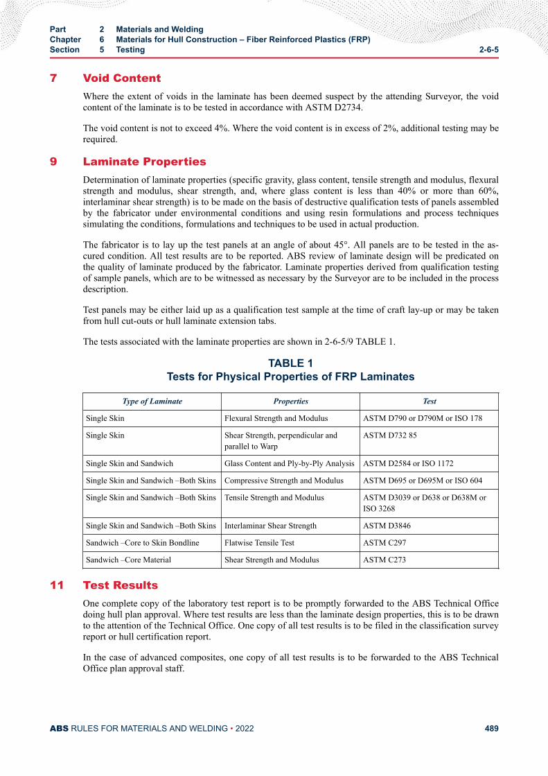
7 Void ContentWhere the extent of voids in the laminate has been deemed suspect by the attending Surveyor, the voidcontent of the laminate is to be tested in accordance with ASTM D2734.
The void content is not to exceed 4%. Where the void content is in excess of 2%, additional testing may berequired.
9 Laminate PropertiesDetermination of laminate properties (specific gravity, glass content, tensile strength and modulus, flexuralstrength and modulus, shear strength, and, where glass content is less than 40% or more than 60%,interlaminar shear strength) is to be made on the basis of destructive qualification tests of panels assembledby the fabricator under environmental conditions and using resin formulations and process techniquessimulating the conditions, formulations and techniques to be used in actual production.
The fabricator is to lay up the test panels at an angle of about 45°. All panels are to be tested in the as-cured condition. All test results are to be reported. ABS review of laminate design will be predicated onthe quality of laminate produced by the fabricator. Laminate properties derived from qualification testingof sample panels, which are to be witnessed as necessary by the Surveyor are to be included in the processdescription.
Test panels may be either laid up as a qualification test sample at the time of craft lay-up or may be takenfrom hull cut-outs or hull laminate extension tabs.
The tests associated with the laminate properties are shown in 2-6-5/9 TABLE 1.
TABLE 1Tests for Physical Properties of FRP Laminates
Type of Laminate Properties Test
Single Skin Flexural Strength and Modulus ASTM D790 or D790M or ISO 178
Single Skin Shear Strength, perpendicular andparallel to Warp
ASTM D732 85
Single Skin and Sandwich Glass Content and Ply-by-Ply Analysis ASTM D2584 or ISO 1172
Single Skin and Sandwich –Both Skins Compressive Strength and Modulus ASTM D695 or D695M or ISO 604
Single Skin and Sandwich –Both Skins Tensile Strength and Modulus ASTM D3039 or D638 or D638M orISO 3268
Single Skin and Sandwich –Both Skins Interlaminar Shear Strength ASTM D3846
Sandwich –Core to Skin Bondline Flatwise Tensile Test ASTM C297
Sandwich –Core Material Shear Strength and Modulus ASTM C273
11 Test ResultsOne complete copy of the laboratory test report is to be promptly forwarded to the ABS Technical Officedoing hull plan approval. Where test results are less than the laminate design properties, this is to be drawnto the attention of the Technical Office. One copy of all test results is to be filed in the classification surveyreport or hull certification report.
In the case of advanced composites, one copy of all test results is to be forwarded to the ABS TechnicalOffice plan approval staff.
Part 2 Materials and WeldingChapter 6 Materials for Hull Construction – Fiber Reinforced Plastics (FRP)Section 5 Testing 2-6-5
ABS RULES FOR MATERIALS AND WELDING • 2022 489
C H A P T E R 6Materials for Hull Construction – Fiber Reinforced Plastics (FRP)
S E C T I O N 6Repair
1 GeneralThis Section specifies the requirements for repairs of defects during construction. These details are alsoapplicable for repair of damaged laminates due to collisions, allisions or other extreme forces.
All repair work relies on the use of proper secondary bonding technique (see 2-6-3/9.13). Therefore,additional replacement material is required to achieve the original strength of the laminate. Details of thearea to be repaired, the materials to be used (resins, reinforcing materials, cores, etc.) and the repairprocess is to be submitted for review. Damage to the gel-coat and/or skin coat is not part of the ABSsurvey unless it has an adverse effect on the laminate structural layers.
3 Materials
3.1 ResinsIn general, isophthalic polyester, vinyl ester or epoxy resins are to be used for all repairs. Specialconsideration will be given for the use of other resins, provided they are used in accordance with themanufacturer’s recommendations. In all cases, the shipyard is to demonstrate to the satisfaction of theattending Surveyor that the resin is capable of bonding to the cured laminate of the craft being repaired.
3.3 Fiber ReinforcementsThe original, primary fiber reinforcement is to be used in repair, whenever practical. Where alternativereinforcements are used, they are to be similar in type and weight to those being replaced. Dissimilar fibertypes are not to be used in a repair unless they were part of the original laminate.
5 Repair Procedures – Single Skin Laminate
5.1 Damage AssessmentDamages can be found either by visual inspection, probing or hammer sounding of the structure. Damagecan be found from indicators such as the following:
i) Cracked or chipped paint or abrasion of the surface
ii) Distortion of a structure or support member
iii) Unusual build-up or presence of moisture, oil or rust
iv) Structure that appears blistered or bubbled and feels soft to the touch
PART 2
ABS RULES FOR MATERIALS AND WELDING • 2022 490
v) Surface and penetrating cracks, open fractures and exposed fibers
vi) Gouges
vii) Debonding of joints
For the proper inspection of suspect areas, the removal of insulation, outfitting or equipment may berequired. The extent of damage is to be clearly indicated on the hull and is to be agreed upon by all partiesprior to removal.
Where water is found in the laminate or core, the area is to be rinsed by fresh water and be allowed to dryfor a minimum of 48 hours. Work is not to be performed on the laminate until the moisture is 0.5% byweight or less.
5.3 Removal of Damaged Laminate5.3.1 Damage Partially Through the Thickness
For damage extending partially through the thickness of a laminate, the damaged laminate can beremoved using a course grit grinder. The damaged area is then to be shaped for repair using a finegrit grinder. See 2-6-6/5.3.2 FIGURE 1 for preparation details.
5.3.2 Damage Through the ThicknessFor damage that extends through the thickness of the laminate, the damaged area can be cut away.The laminating surfaces are to be prepared as indicated in 2-6-6/5.3.1 and 2-6-6/5.3.2 FIGURE 1.
Part 2 Materials and WeldingChapter 6 Materials for Hull Construction – Fiber Reinforced Plastics (FRP)Section 6 Repair 2-6-6
ABS RULES FOR MATERIALS AND WELDING • 2022 491
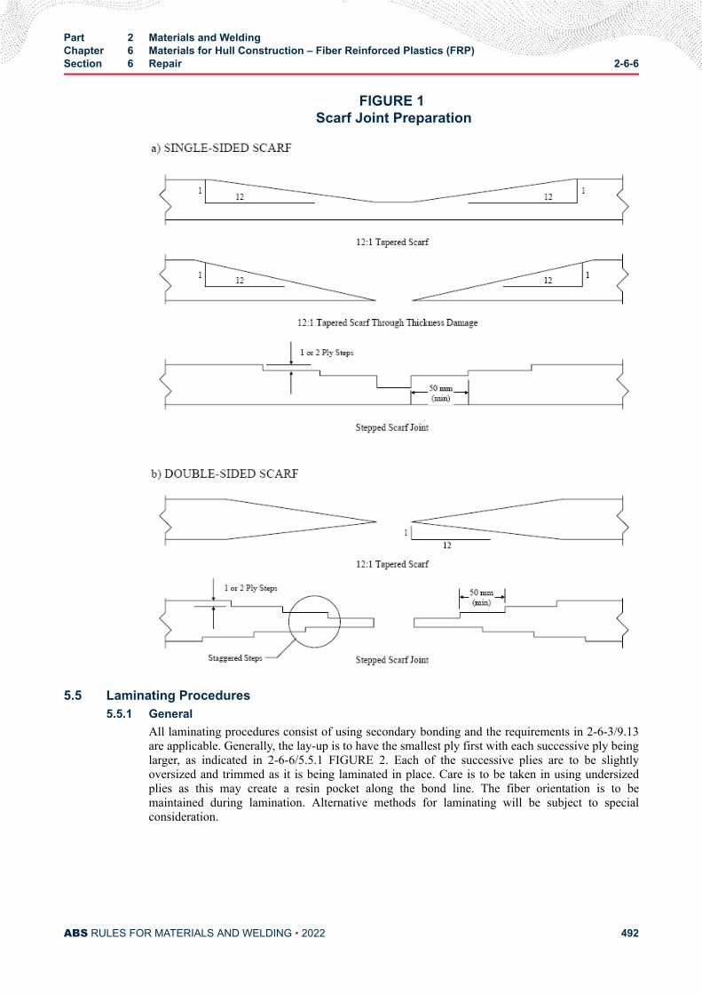
FIGURE 1 Scarf Joint Preparation
5.5 Laminating Procedures5.5.1 General
All laminating procedures consist of using secondary bonding and the requirements in 2-6-3/9.13are applicable. Generally, the lay-up is to have the smallest ply first with each successive ply beinglarger, as indicated in 2-6-6/5.5.1 FIGURE 2. Each of the successive plies are to be slightlyoversized and trimmed as it is being laminated in place. Care is to be taken in using undersizedplies as this may create a resin pocket along the bond line. The fiber orientation is to bemaintained during lamination. Alternative methods for laminating will be subject to specialconsideration.
Part 2 Materials and WeldingChapter 6 Materials for Hull Construction – Fiber Reinforced Plastics (FRP)Section 6 Repair 2-6-6
ABS RULES FOR MATERIALS AND WELDING • 2022 492
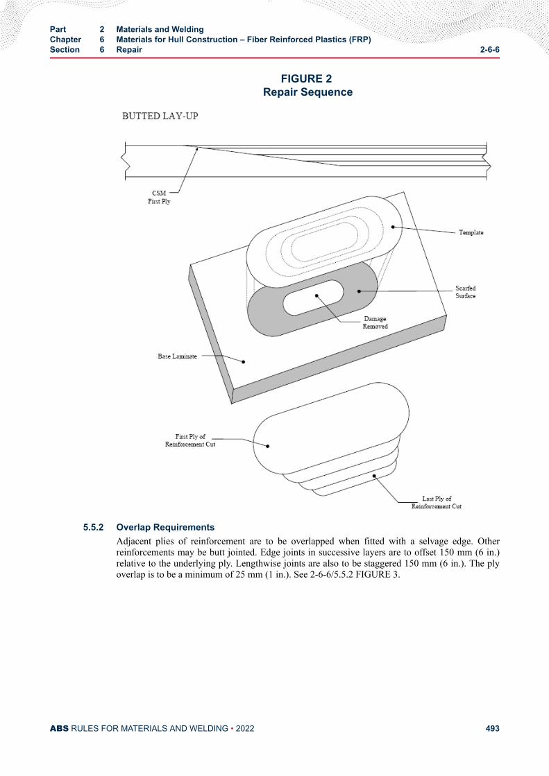
FIGURE 2 Repair Sequence
5.5.2 Overlap RequirementsAdjacent plies of reinforcement are to be overlapped when fitted with a selvage edge. Otherreinforcements may be butt jointed. Edge joints in successive layers are to offset 150 mm (6 in.)relative to the underlying ply. Lengthwise joints are also to be staggered 150 mm (6 in.). The plyoverlap is to be a minimum of 25 mm (1 in.). See 2-6-6/5.5.2 FIGURE 3.
Part 2 Materials and WeldingChapter 6 Materials for Hull Construction – Fiber Reinforced Plastics (FRP)Section 6 Repair 2-6-6
ABS RULES FOR MATERIALS AND WELDING • 2022 493
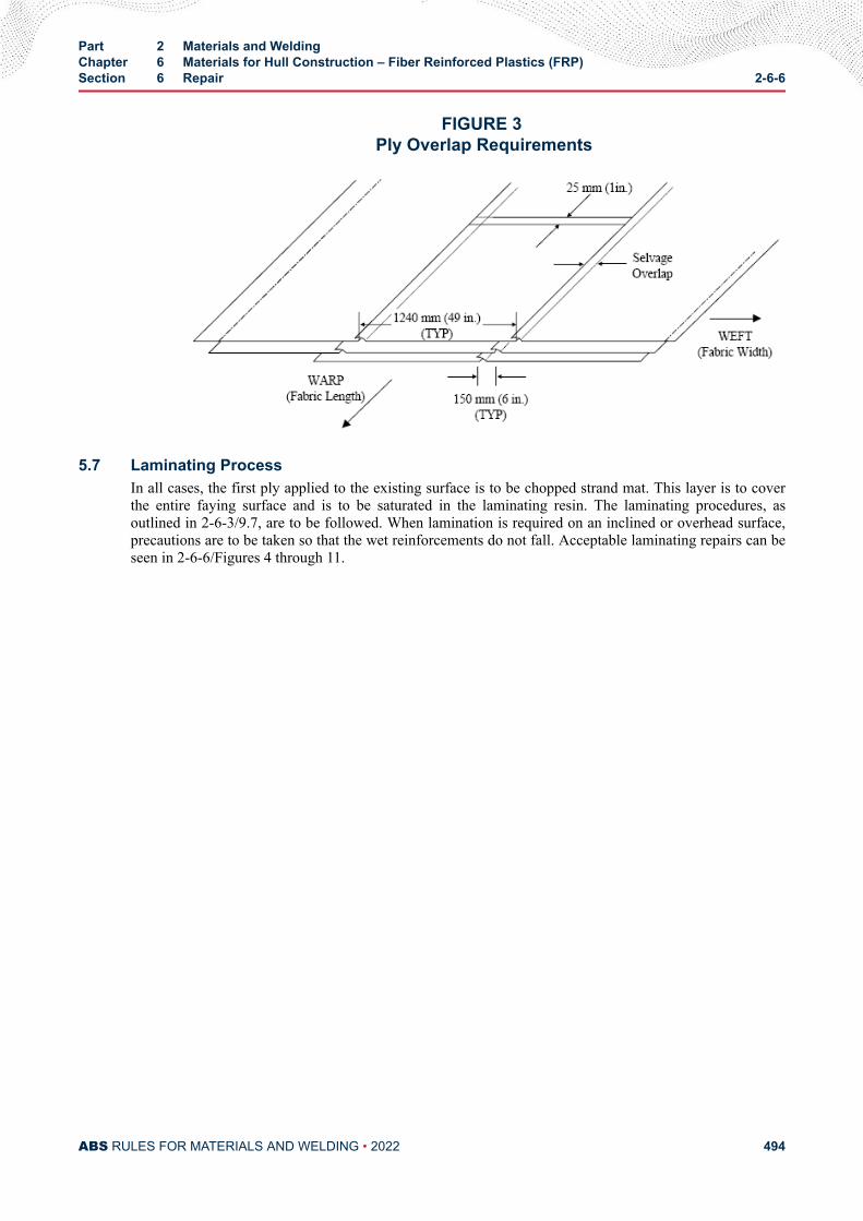
FIGURE 3 Ply Overlap Requirements
5.7 Laminating ProcessIn all cases, the first ply applied to the existing surface is to be chopped strand mat. This layer is to coverthe entire faying surface and is to be saturated in the laminating resin. The laminating procedures, asoutlined in 2-6-3/9.7, are to be followed. When lamination is required on an inclined or overhead surface,precautions are to be taken so that the wet reinforcements do not fall. Acceptable laminating repairs can beseen in 2-6-6/Figures 4 through 11.
Part 2 Materials and WeldingChapter 6 Materials for Hull Construction – Fiber Reinforced Plastics (FRP)Section 6 Repair 2-6-6
ABS RULES FOR MATERIALS AND WELDING • 2022 494
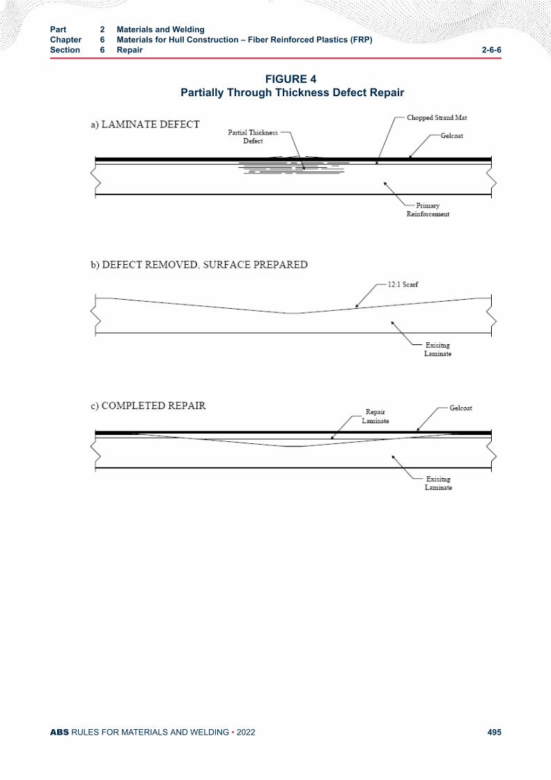
FIGURE 4 Partially Through Thickness Defect Repair
Part 2 Materials and WeldingChapter 6 Materials for Hull Construction – Fiber Reinforced Plastics (FRP)Section 6 Repair 2-6-6
ABS RULES FOR MATERIALS AND WELDING • 2022 495
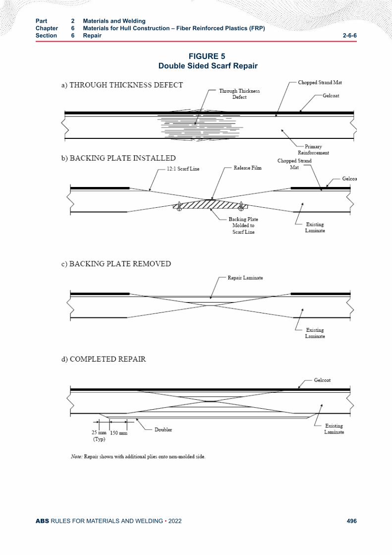
FIGURE 5 Double Sided Scarf Repair
Part 2 Materials and WeldingChapter 6 Materials for Hull Construction – Fiber Reinforced Plastics (FRP)Section 6 Repair 2-6-6
ABS RULES FOR MATERIALS AND WELDING • 2022 496
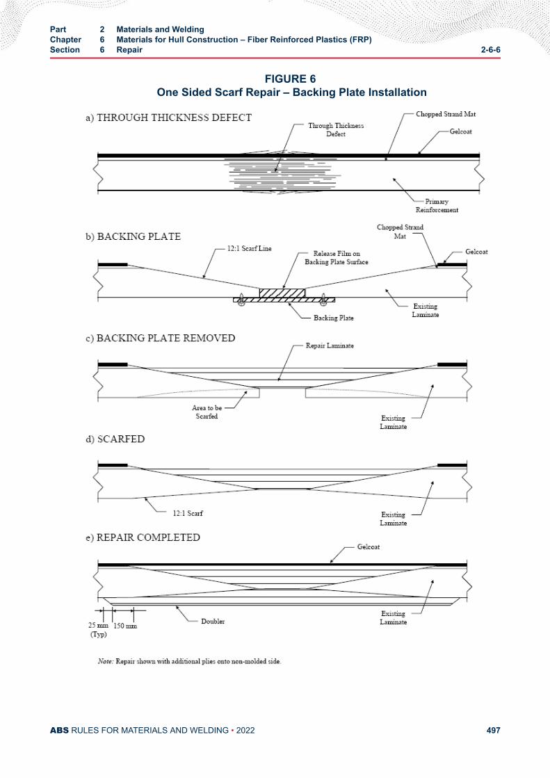
FIGURE 6 One Sided Scarf Repair – Backing Plate Installation
Part 2 Materials and WeldingChapter 6 Materials for Hull Construction – Fiber Reinforced Plastics (FRP)Section 6 Repair 2-6-6
ABS RULES FOR MATERIALS AND WELDING • 2022 497
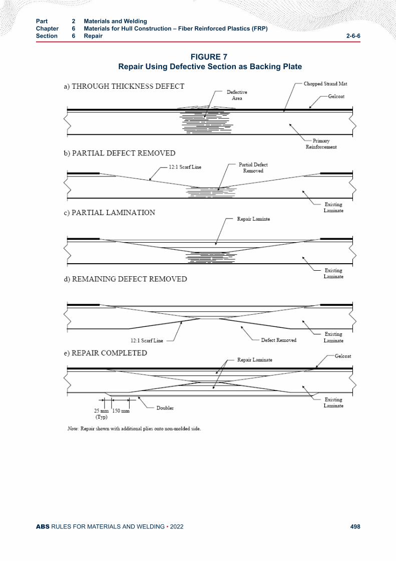
FIGURE 7 Repair Using Defective Section as Backing Plate
Part 2 Materials and WeldingChapter 6 Materials for Hull Construction – Fiber Reinforced Plastics (FRP)Section 6 Repair 2-6-6
ABS RULES FOR MATERIALS AND WELDING • 2022 498
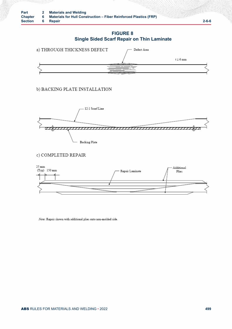
FIGURE 8 Single Sided Scarf Repair on Thin Laminate
Part 2 Materials and WeldingChapter 6 Materials for Hull Construction – Fiber Reinforced Plastics (FRP)Section 6 Repair 2-6-6
ABS RULES FOR MATERIALS AND WELDING • 2022 499
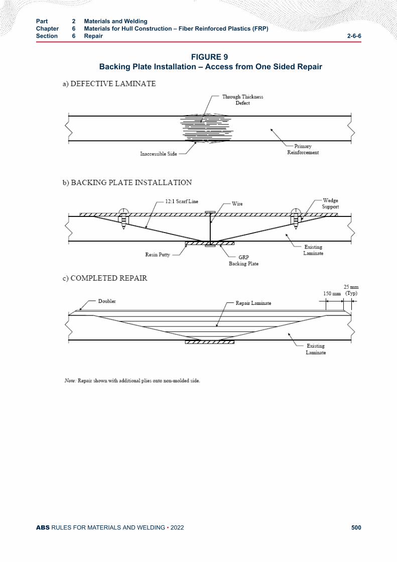
FIGURE 9 Backing Plate Installation – Access from One Sided Repair
Part 2 Materials and WeldingChapter 6 Materials for Hull Construction – Fiber Reinforced Plastics (FRP)Section 6 Repair 2-6-6
ABS RULES FOR MATERIALS AND WELDING • 2022 500
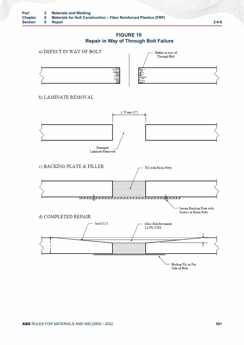
FIGURE 10 Repair in Way of Through Bolt Failure
Part 2 Materials and WeldingChapter 6 Materials for Hull Construction – Fiber Reinforced Plastics (FRP)Section 6 Repair 2-6-6
ABS RULES FOR MATERIALS AND WELDING • 2022 501
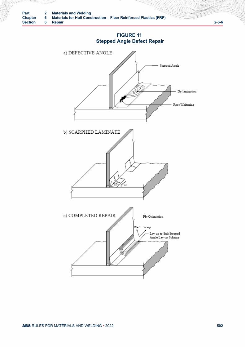
FIGURE 11 Stepped Angle Defect Repair
Part 2 Materials and WeldingChapter 6 Materials for Hull Construction – Fiber Reinforced Plastics (FRP)Section 6 Repair 2-6-6
ABS RULES FOR MATERIALS AND WELDING • 2022 502
7 Repair Procedure – Sandwich Construction
7.1 Damage AssessmentThe techniques outlined in 2-6-6/5.1 are to be applied to sandwich laminate. However, the extent ofdamage may extend far beyond the area of visible damage.
7.3 Removal of Damaged LaminateThe requirements in 2-6-6/5.3 are, in general, applicable to sandwich laminates. The cut back area will beincreasingly larger, proceeding from the outer skin to the inner skin.
7.5 Laminating Procedure and ProcessIn general, the skins of a sandwich laminate are to be as indicated in 2-6-6/5.5 and 2-6-6/5.7. The new coreis to be similar in type and density to the core that is being replaced. The new core will need to be slightlythinner than the existing core to accommodate the additional repair laminate thickness. The laminatingprocedure outlined in 2-6-3/9.9 is to be followed.
9 Repair AcceptancePrior to the acceptance and painting of the repair, the area is to be inspected for the following:
i) There are to be no open voids, pits, cracks, crazing, delaminations or embedded contaminates inthe laminate.
ii) There is to be no evidence of resin discoloration or other evidence of extreme exotherm.
iii) There is to be no dry reinforcement as indicated by white laminate
iv) There are to be no wrinkles in the reinforcement and no voids greater than 12 mm (1/2 in.)
The surface of the repair is to be smooth and conform to the surrounding surface contour. The degree ofcure is to be within 10% of the required BARCOL hardness, as indicated in 2-6-5/3.
Part 2 Materials and WeldingChapter 6 Materials for Hull Construction – Fiber Reinforced Plastics (FRP)Section 6 Repair 2-6-6
ABS RULES FOR MATERIALS AND WELDING • 2022 503
A P P E N D I X 1Tests Required for Materials, and Responsibility for Verifying
CONTENTSSECTION 1 List of Destructive and Nondestructive Tests Required for
Materials and Responsibility for Verifying.................................... 505
PART 2
ABS RULES FOR MATERIALS AND WELDING • 2022 504
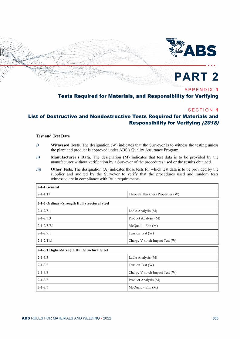
A P P E N D I X 1Tests Required for Materials, and Responsibility for Verifying
S E C T I O N 1List of Destructive and Nondestructive Tests Required for Materials and
Responsibility for Verifying (2018)
Test and Test Data
i) Witnessed Tests. The designation (W) indicates that the Surveyor is to witness the testing unlessthe plant and product is approved under ABS’s Quality Assurance Program.
ii) Manufacturer's Data. The designation (M) indicates that test data is to be provided by themanufacturer without verification by a Surveyor of the procedures used or the results obtained.
iii) Other Tests. The designation (A) indicates those tests for which test data is to be provided by thesupplier and audited by the Surveyor to verify that the procedures used and random testswitnessed are in compliance with Rule requirements.
2-1-1 General
2-1-1/17 Through Thickness Properties (W)
2-1-2 Ordinary-Strength Hull Structural Steel
2-1-2/5.1 Ladle Analysis (M)
2-1-2/5.3 Product Analysis (M)
2-1-2/5.7.1 McQuaid - Ehn (M)
2-1-2/9.1 Tension Test (W)
2-1-2/11.1 Charpy V-notch Impact Test (W)
2-1-3/1 Higher-Strength Hull Structural Steel
2-1-3/3 Ladle Analysis (M)
2-1-3/3 Tension Test (W)
2-1-3/3 Charpy V-notch Impact Test (W)
2-1-3/3 Product Analysis (M)
2-1-3/5 McQuaid - Ehn (M)
PART 2
ABS RULES FOR MATERIALS AND WELDING • 2022 505
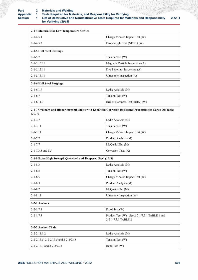
2-1-4 Materials for Low Temperature Service
2-1-4/5.1 Charpy V-notch Impact Test (W)
2-1-4/5.3 Drop-weight Test (NDTT) (W)
2-1-5 Hull Steel Castings
2-1-5/7 Tension Test (W)
2-1-5/13.11 Magnetic Particle Inspection (A)
2-1-5/13.11 Dye Penetrant Inspection (A)
2-1-5/13.11 Ultrasonic Inspection (A)
2-1-6 Hull Steel Forgings
2-1-6/1.7 Ladle Analysis (M)
2-1-6/7 Tension Test (W)
2-1-6/11.3 Brinell Hardness Test (BHN) (W)
2-1-7 Ordinary and Higher Strength Steels with Enhanced Corrosion Resistance Properties for Cargo Oil Tanks(2017)
2-1-7/7 Ladle Analysis (M)
2-1-7/11 Tension Test (W)
2-1-7/11 Charpy V-notch Impact Test (W)
2-1-7/7 Product Analysis (M)
2-1-7/7 McQuaid-Ehn (M)
2-1-7/3.3 and 3.5 Corrosion Tests (A)
2-1-8 Extra High Strength Quenched and Tempered Steel (2018)
2-1-8/3 Ladle Analysis (M)
2-1-8/5 Tension Test (W)
2-1-8/5 Charpy V-notch Impact Test (W)
2-1-8/3 Product Analysis (M)
2-1-8/2 McQuaid-Ehn (M)
2-1-8/11 Ultrasonic Inspection (W)
2-2-1 Anchors
2-2-1/7.1 Proof Test (W)
2-2-1/7.3 Product Test (W) - See 2-2-1/7.3.1 TABLE 1 and2-2-1/7.3.1 TABLE 2
2-2-2 Anchor Chain
2-2-2/11.1.2 Ladle Analysis (M)
2-2-2/13.5, 2-2-2/19.5 and 2-2-2/23.3 Tension Test (W)
2-2-2/13.7 and 2-2-2/23.3 Bend Test (W)
Part 2 Materials and WeldingAppendix 1 Tests Required for Materials, and Responsibility for VerifyingSection 1 List of Destructive and Nondestructive Tests Required for Materials and Responsibility
for Verifying (2018)2-A1-1
ABS RULES FOR MATERIALS AND WELDING • 2022 506
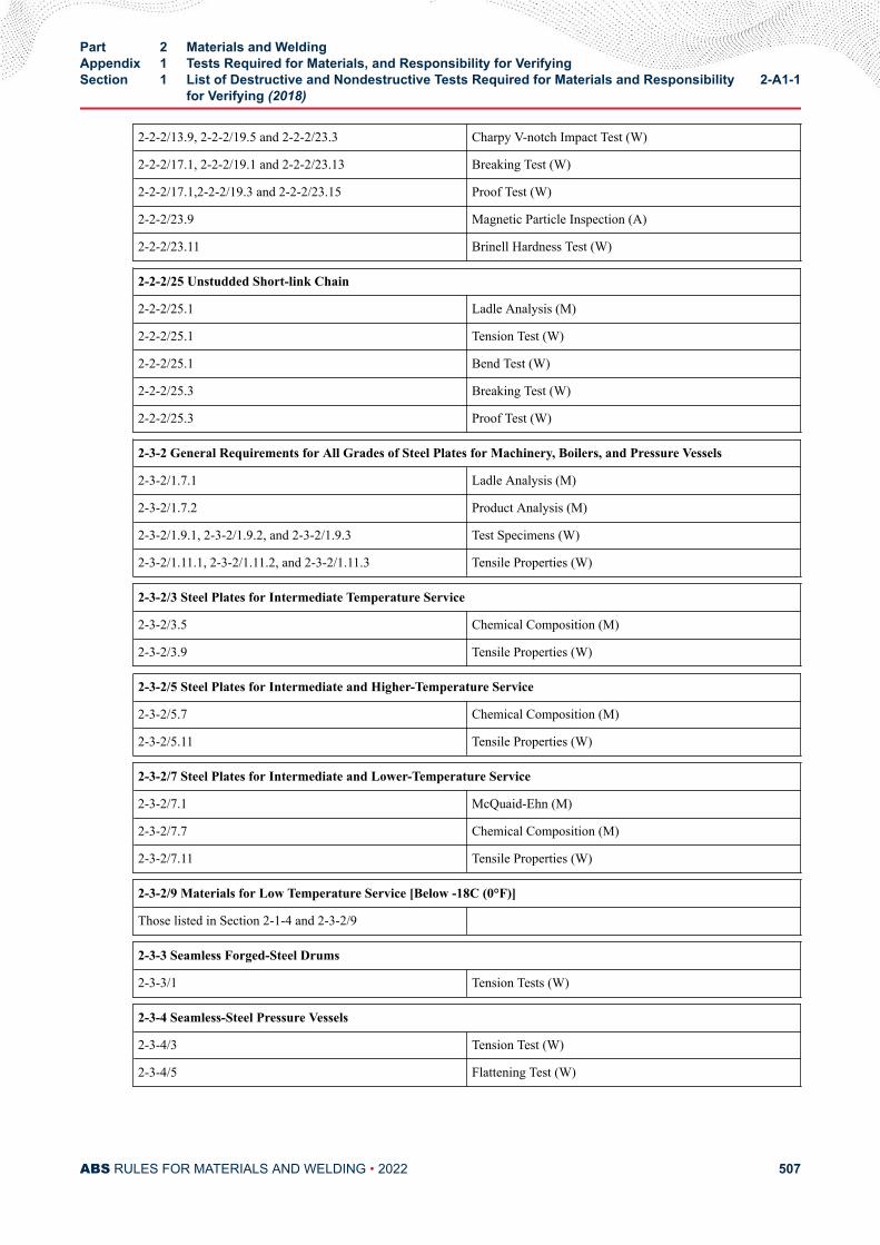
2-2-2/13.9, 2-2-2/19.5 and 2-2-2/23.3 Charpy V-notch Impact Test (W)
2-2-2/17.1, 2-2-2/19.1 and 2-2-2/23.13 Breaking Test (W)
2-2-2/17.1,2-2-2/19.3 and 2-2-2/23.15 Proof Test (W)
2-2-2/23.9 Magnetic Particle Inspection (A)
2-2-2/23.11 Brinell Hardness Test (W)
2-2-2/25 Unstudded Short-link Chain
2-2-2/25.1 Ladle Analysis (M)
2-2-2/25.1 Tension Test (W)
2-2-2/25.1 Bend Test (W)
2-2-2/25.3 Breaking Test (W)
2-2-2/25.3 Proof Test (W)
2-3-2 General Requirements for All Grades of Steel Plates for Machinery, Boilers, and Pressure Vessels
2-3-2/1.7.1 Ladle Analysis (M)
2-3-2/1.7.2 Product Analysis (M)
2-3-2/1.9.1, 2-3-2/1.9.2, and 2-3-2/1.9.3 Test Specimens (W)
2-3-2/1.11.1, 2-3-2/1.11.2, and 2-3-2/1.11.3 Tensile Properties (W)
2-3-2/3 Steel Plates for Intermediate Temperature Service
2-3-2/3.5 Chemical Composition (M)
2-3-2/3.9 Tensile Properties (W)
2-3-2/5 Steel Plates for Intermediate and Higher-Temperature Service
2-3-2/5.7 Chemical Composition (M)
2-3-2/5.11 Tensile Properties (W)
2-3-2/7 Steel Plates for Intermediate and Lower-Temperature Service
2-3-2/7.1 McQuaid-Ehn (M)
2-3-2/7.7 Chemical Composition (M)
2-3-2/7.11 Tensile Properties (W)
2-3-2/9 Materials for Low Temperature Service [Below -18C (0°F)]
Those listed in Section 2-1-4 and 2-3-2/9
2-3-3 Seamless Forged-Steel Drums
2-3-3/1 Tension Tests (W)
2-3-4 Seamless-Steel Pressure Vessels
2-3-4/3 Tension Test (W)
2-3-4/5 Flattening Test (W)
Part 2 Materials and WeldingAppendix 1 Tests Required for Materials, and Responsibility for VerifyingSection 1 List of Destructive and Nondestructive Tests Required for Materials and Responsibility
for Verifying (2018)2-A1-1
ABS RULES FOR MATERIALS AND WELDING • 2022 507
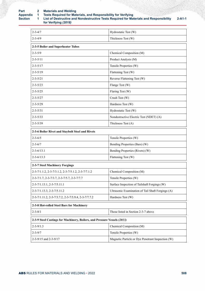
2-3-4/7 Hydrostatic Test (W)
2-3-4/9 Thickness Test (W)
2-3-5 Boiler and Superheater Tubes
2-3-5/9 Chemical Composition (M)
2-3-5/11 Product Analysis (M)
2-3-5/17 Tensile Properties (W)
2-3-5/19 Flattening Test (W)
2-3-5/21 Reverse Flattening Test (W)
2-3-5/23 Flange Test (W)
2-3-5/25 Flaring Test (W)
2-3-5/27 Crush Test (W)
2-3-5/29 Hardness Test (W)
2-3-5/31 Hydrostatic Test (W)
2-3-5/33 Nondestructive Electric Test (NDET) (A)
2-3-5/39 Thickness Test (A)
2-3-6 Boiler Rivet and Staybolt Steel and Rivets
2-3-6/5 Tensile Properties (W)
2-3-6/7 Bending Properties (Bars) (W)
2-3-6/13.1 Bending Properties (Rivets) (W)
2-3-6/13.3 Flattening Test (W)
2-3-7 Steel Machinery Forgings
2-3-7/1.1.2, 2-3-7/3.1.2, 2-3-7/5.1.2, 2-3-7/7.1.2 Chemical Composition (M)
2-3-7/1.7, 2-3-7/3.7, 2-3-7/5.7, 2-3-7/7.7 Tensile Properties (W)
2-3-7/1.13.1, 2-3-7/5.11.1 Surface Inspection of Tailshaft Forgings (W)
2-3-7/1.13.3, 2-3-7/5.11.2 Ultrasonic Examination of Tail Shaft Forgings (A)
2-3-7/1.11.2, 2-3-7/3.7.2, 2-3-7/5.9.4, 2-3-7/7.7.2 Hardness Test (W)
2-3-8 Hot-rolled Steel Bars for Machinery
2-3-8/1 Those listed in Section 2-3-7 above
2-3-9 Steel Castings for Machinery, Boilers, and Pressure Vessels (2013)
2-3-9/1.3 Chemical Composition (M)
2-3-9/7 Tensile Properties (W)
2-3-9/15 and 2-3-9/17 Magnetic Particle or Dye Penetrant Inspection (W)
Part 2 Materials and WeldingAppendix 1 Tests Required for Materials, and Responsibility for VerifyingSection 1 List of Destructive and Nondestructive Tests Required for Materials and Responsibility
for Verifying (2018)2-A1-1
ABS RULES FOR MATERIALS AND WELDING • 2022 508
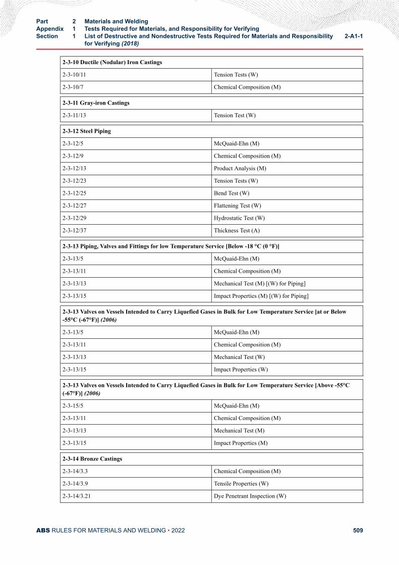
2-3-10 Ductile (Nodular) Iron Castings
2-3-10/11 Tension Tests (W)
2-3-10/7 Chemical Composition (M)
2-3-11 Gray-iron Castings
2-3-11/13 Tension Test (W)
2-3-12 Steel Piping
2-3-12/5 McQuaid-Ehn (M)
2-3-12/9 Chemical Composition (M)
2-3-12/13 Product Analysis (M)
2-3-12/23 Tension Tests (W)
2-3-12/25 Bend Test (W)
2-3-12/27 Flattening Test (W)
2-3-12/29 Hydrostatic Test (W)
2-3-12/37 Thickness Test (A)
2-3-13 Piping, Valves and Fittings for low Temperature Service [Below -18 °C (0 °F)]
2-3-13/5 McQuaid-Ehn (M)
2-3-13/11 Chemical Composition (M)
2-3-13/13 Mechanical Test (M) [(W) for Piping]
2-3-13/15 Impact Properties (M) [(W) for Piping]
2-3-13 Valves on Vessels Intended to Carry Liquefied Gases in Bulk for Low Temperature Service [at or Below-55°C (-67°F)] (2006)
2-3-13/5 McQuaid-Ehn (M)
2-3-13/11 Chemical Composition (M)
2-3-13/13 Mechanical Test (W)
2-3-13/15 Impact Properties (W)
2-3-13 Valves on Vessels Intended to Carry Liquefied Gases in Bulk for Low Temperature Service [Above -55°C(-67°F)] (2006)
2-3-15/5 McQuaid-Ehn (M)
2-3-13/11 Chemical Composition (M)
2-3-13/13 Mechanical Test (M)
2-3-13/15 Impact Properties (M)
2-3-14 Bronze Castings
2-3-14/3.3 Chemical Composition (M)
2-3-14/3.9 Tensile Properties (W)
2-3-14/3.21 Dye Penetrant Inspection (W)
Part 2 Materials and WeldingAppendix 1 Tests Required for Materials, and Responsibility for VerifyingSection 1 List of Destructive and Nondestructive Tests Required for Materials and Responsibility
for Verifying (2018)2-A1-1
ABS RULES FOR MATERIALS AND WELDING • 2022 509
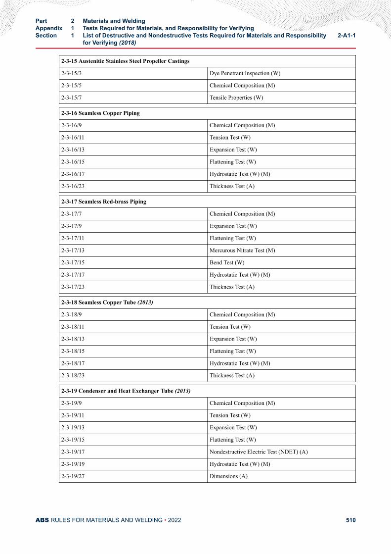
2-3-15 Austenitic Stainless Steel Propeller Castings
2-3-15/3 Dye Penetrant Inspection (W)
2-3-15/5 Chemical Composition (M)
2-3-15/7 Tensile Properties (W)
2-3-16 Seamless Copper Piping
2-3-16/9 Chemical Composition (M)
2-3-16/11 Tension Test (W)
2-3-16/13 Expansion Test (W)
2-3-16/15 Flattening Test (W)
2-3-16/17 Hydrostatic Test (W) (M)
2-3-16/23 Thickness Test (A)
2-3-17 Seamless Red-brass Piping
2-3-17/7 Chemical Composition (M)
2-3-17/9 Expansion Test (W)
2-3-17/11 Flattening Test (W)
2-3-17/13 Mercurous Nitrate Test (M)
2-3-17/15 Bend Test (W)
2-3-17/17 Hydrostatic Test (W) (M)
2-3-17/23 Thickness Test (A)
2-3-18 Seamless Copper Tube (2013)
2-3-18/9 Chemical Composition (M)
2-3-18/11 Tension Test (W)
2-3-18/13 Expansion Test (W)
2-3-18/15 Flattening Test (W)
2-3-18/17 Hydrostatic Test (W) (M)
2-3-18/23 Thickness Test (A)
2-3-19 Condenser and Heat Exchanger Tube (2013)
2-3-19/9 Chemical Composition (M)
2-3-19/11 Tension Test (W)
2-3-19/13 Expansion Test (W)
2-3-19/15 Flattening Test (W)
2-3-19/17 Nondestructive Electric Test (NDET) (A)
2-3-19/19 Hydrostatic Test (W) (M)
2-3-19/27 Dimensions (A)
Part 2 Materials and WeldingAppendix 1 Tests Required for Materials, and Responsibility for VerifyingSection 1 List of Destructive and Nondestructive Tests Required for Materials and Responsibility
for Verifying (2018)2-A1-1
ABS RULES FOR MATERIALS AND WELDING • 2022 510
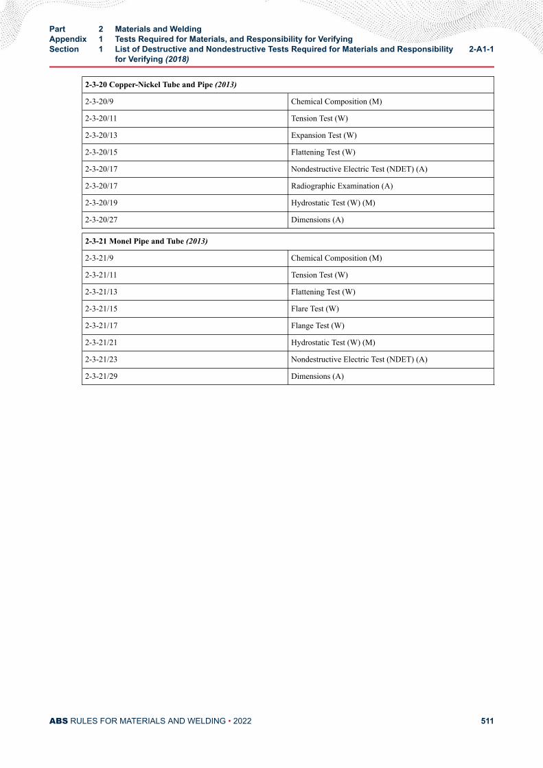
2-3-20 Copper-Nickel Tube and Pipe (2013)
2-3-20/9 Chemical Composition (M)
2-3-20/11 Tension Test (W)
2-3-20/13 Expansion Test (W)
2-3-20/15 Flattening Test (W)
2-3-20/17 Nondestructive Electric Test (NDET) (A)
2-3-20/17 Radiographic Examination (A)
2-3-20/19 Hydrostatic Test (W) (M)
2-3-20/27 Dimensions (A)
2-3-21 Monel Pipe and Tube (2013)
2-3-21/9 Chemical Composition (M)
2-3-21/11 Tension Test (W)
2-3-21/13 Flattening Test (W)
2-3-21/15 Flare Test (W)
2-3-21/17 Flange Test (W)
2-3-21/21 Hydrostatic Test (W) (M)
2-3-21/23 Nondestructive Electric Test (NDET) (A)
2-3-21/29 Dimensions (A)
Part 2 Materials and WeldingAppendix 1 Tests Required for Materials, and Responsibility for VerifyingSection 1 List of Destructive and Nondestructive Tests Required for Materials and Responsibility
for Verifying (2018)2-A1-1
ABS RULES FOR MATERIALS AND WELDING • 2022 511
A P P E N D I X 2Requirements for the Approval of Filler Metals
CONTENTSSECTION 1 General..............................................................................................517
1 Scope .........................................................................................5171.1 Condition of Approval.................................................... 5171.3 Approval Procedure (1 October 1993)...........................5171.5 Aluminum Filler Metals.................................................. 517
3 Grading ......................................................................................5173.1 ABS Grades...................................................................5173.3 Other Standards............................................................ 5183.5 Special Properties..........................................................518
5 Manufacturer's Guarantee (1 October 1994) .............................5187 Plant Inspection ......................................................................... 518
7.1 Initial Inspection............................................................. 5187.3 Annual Inspection (2015)...............................................518
9 Test Requirements .....................................................................5199.1 General.......................................................................... 5199.3 Test Plate Material......................................................... 519
11 Welding Conditions ....................................................................52013 Chemical Analysis (2009)...........................................................52015 Deposited Metal Tension Test ....................................................520
15.1 Specimen Type and Preparation................................... 52015.3 Hydrogen Removal........................................................ 52015.5 Test Requirements (1 October 1994).............................520
17 Butt Weld Tension Test .............................................................. 52017.1 Specimen Type and Preparation................................... 52017.3 Test Requirements (1 October 1994).............................520
19 Impact Test ................................................................................ 52119.1 Specimen Type and Preparation (2015)........................ 52119.3 Test Requirements (2015)............................................. 52119.5 Retest............................................................................ 521
21 Butt Weld Bend Test .................................................................. 52121.1 Specimen Type and Preparation................................... 521
PART 2
ABS RULES FOR MATERIALS AND WELDING • 2022 512
21.3 Test Requirements.........................................................52121.5 Alternative Test for YQ-Grades (1997).......................... 522
23 Diffusible Hydrogen Test (1997) ................................................ 52223.1 Optional or Required Test.............................................. 52223.3 Test Methods (2005)...................................................... 52223.5 Alternative Test Method................................................. 52223.7 Test Requirements (2005)............................................. 523
25 Special Tests ..............................................................................52325.1 Nondestructive Testing.................................................. 52325.3 Additional Tests..............................................................523
27 Licensee Approvals (2007).........................................................52329 Annual Check Tests (2015) ........................................................524
29.1 Upgrading and Uprating (1 October 1993).................... 52431 Quality Assurance Program (1 October 1993) ...........................52433 Retests (2006) ........................................................................... 524
TABLE 1 Tension Test Requirements ...............................................527TABLE 2 Impact Test Requirements................................................. 528
FIGURE 1 Deposited Metal Tension Test Specimen (2014)................525FIGURE 2 Butt Weld Tension Test Specimen (2005).......................... 525FIGURE 3 Charpy V-Notch Impact Test Specimen............................. 526FIGURE 4 Bending Elongation Test (1997).........................................527
SECTION 2 Electrodes for Shielded Metal Arc Welding...................................5311 General ......................................................................................5313 Chemical Analysis ..................................................................... 5315 Deposited Metal Test Assemblies ..............................................531
5.1 Test Assembly (2005).................................................... 5315.3 Test Specimens (1 October 1994)................................. 531
7 Butt Weld Test Assemblies ........................................................ 5317.1 Test Assemblies.............................................................5317.3 Welding Procedure (1996).............................................5327.5 Test Specimens (2008).................................................. 532
9 Fillet Weld Test Assemblies ....................................................... 5329.1 General (2005)...............................................................5329.3 Test Assemblies.............................................................5339.5 Welding Procedure........................................................ 5339.7 Test Specimens............................................................. 533
11 Low Hydrogen Approval (1997) .................................................53311.1 Ordinary-Strength Filler Metals (1997).......................... 53311.3 Higher-Strength Filler Metals (2009)..............................53311.5 YQ Grade Filler Metals (2005).......................................534
ABS RULES FOR MATERIALS AND WELDING • 2022 513
13 Annual Check Tests ...................................................................53413.1 General (1 October 1993)..............................................53413.3 Upgrading and Uprating (2008)..................................... 534
FIGURE 1 Deposited-Metal Test Assembly for Manual and Gas-Metal Arc Welding.............................................................. 535
FIGURE 2 Butt-Weld Test Assembly for Manual and Gas-Metal ArcWelding.............................................................................. 536
FIGURE 3 Fillet-Weld Test Assembly.................................................. 537FIGURE 4 Fillet Weld Hardness Test Locations.................................. 537
SECTION 3 Wire-Flux Combinations for Submerged Arc Welding................. 5381 General (1997) ...........................................................................5383 Chemical Analysis ..................................................................... 5385 Deposited Metal Test Assemblies for Multi-run Technique ........ 538
5.1 Test Assembly (2005).................................................... 5385.3 Test Specimens (1 October 1994)................................. 538
7 Butt Weld Test Assemblies for Multi-run Technique ...................5397.1 Test Assembly................................................................5397.3 Test Specimens............................................................. 539
9 Butt Weld Assemblies for Two-run Technique ........................... 5399.1 Test Assemblies (2005)................................................. 5399.3 Test Specimens (1 October 1994)................................. 5399.5 Longitudinal All-Weld-Metal Tension Test (1 October
1994)..............................................................................53911 Fillet Weld Tests .........................................................................53913 Low Hydrogen Approval (1997) .................................................540
13.1 YQ Grade Wires -Flux Combination (2005)...................54015 Annual Check Tests ...................................................................540
15.1 General (1996)...............................................................54015.3 Upgrading and Uprating (2008)..................................... 540
17 Multiple Electrodes .................................................................... 54019 Electroslag Welding (1996) ........................................................540
19.1 General (1997)...............................................................54019.3 Annual Tests (1996).......................................................54119.5 Upgrading and Uprating (1996)..................................... 541
FIGURE 1 Deposited-Metal Test Assembly for Submerged ArcWelding -Multi-runTechnique and Automatic Gas-MetalArc Welding........................................................................542
FIGURE 2Butt-Weld Test Assembly for Submerged Arc Welding –Multi-run Technique (2008)................................................ 543
FIGURE 3 Butt-Weld Test Assembly for Submerged Arc Welding -Two-run Technique (2009)................................................. 544
ABS RULES FOR MATERIALS AND WELDING • 2022 514
FIGURE 4 Butt-Weld Impact Specimen Location for Submergedand Gas-Metal Arc Welding -Two-run Technique...............546
SECTION 4 Wire and Wire Gas Combinations for Gas Metal Arc Weldingand Flux Cored Wires for Flux Cored Arc Welding.......................5471 General (1997) ...........................................................................5473 Chemical Analysis and Shielding Gas Compositions (2008)......5475 Deposited Metal Test Assemblies for Semi-automatic and
Automatic Testing ...................................................................... 5485.1 Semi-automatic Test Assemblies (2009)....................... 5485.3 Test Specimens for Semi-automatic.............................. 5485.5 Automatic Test Assembly (2008)................................... 5485.7 Test Specimens for Automatic....................................... 549
7 Butt Weld Test Assemblies for Semi-automatic andAutomatic Techniques ................................................................5497.1 Test Assemblies.............................................................5497.3 Welding Procedure (2009).............................................5497.5 Test Specimens (2005).................................................. 549
9 Butt Weld Test Assemblies for Two-run Technique ....................5499.1 Test Assemblies.............................................................5499.3 Test Specimens (1996).................................................. 5509.5 Longitudinal All-Weld-Metal Tension Test...................... 550
11 Fillet Weld Tests .........................................................................55011.1 General (2018)...............................................................55011.3 Test Assemblies.............................................................55011.5 Welding Procedure........................................................ 55011.7 Test Requirements.........................................................550
13 Low Hydrogen Approval ............................................................ 55013.1 Flux Cored Wire.............................................................550
15 Annual Check Tests ...................................................................55115.1 General (2011)...............................................................55115.3 Upgrading and Uprating (2008)..................................... 551
17 Electrogas Welding (1996) ........................................................ 55217.1 General (1997)...............................................................55217.3 Annual Tests (1996).......................................................55217.5 Upgrading and Uprating (1996)..................................... 552
TABLE 1 Compositional Limits of Designated Groups of GasTypes and Mixtures (2008).................................................548
FIGURE 1 Butt-Weld Test Assembly for Gas-Metal Arc Welding -Two-run Technique.............................................................553
FIGURE 2 Contact Tip to Work Distance (2005)................................. 554
ABS RULES FOR MATERIALS AND WELDING • 2022 515
SECTION 5 Requirements for the Approval of Aluminum Filler Metals(2018).................................................................................................5551 General.......................................................................................555
1.1 Scope.............................................................................5551.3 Grading, Designation..................................................... 5551.5 Manufacture, Testing and Approval Procedure..............556
3 Testing and Required Properties................................................ 5573.1 Testing of the Deposited Weld Metal............................. 5573.3 Testing of Butt Weld Assemblies................................... 557
5 Annual Check Tests....................................................................560
TABLE 1 Consumable Grades and Base Materials for theApproval Test (2009)..........................................................555
TABLE 2 Compositional Limits of Shielding Gases and Mixturesto be Used..........................................................................556
TABLE 3 Requirements for the Transverse Tensile and BendTests (2009)....................................................................... 560
FIGURE 1 Deposited Weld Metal Test Assembly................................557FIGURE 2 Butt Weld Test Assembly for Out-of-position Welding........557FIGURE 3 Butt Weld Test Assembly in Flat Position...........................558
ABS RULES FOR MATERIALS AND WELDING • 2022 516
A P P E N D I X 2Requirements for the Approval of Filler Metals
S E C T I O N 1General
1 Scope
1.1 Condition of ApprovalThe scope and conditions of classification contained in Part 1, Chapter 1 of the ABS Rules for Conditionsof Classification (Part 1) are applicable to the approval of welding filler metals, insofar as they areappropriate. Approval will be for each plant of each manufacturer carrying out its own quality controlinspection and certification.
1.3 Approval Procedure (1 October 1993)Welding filler metals intended for hull construction will be approved by ABS, subject to compliance withthe requirements and test schedules as outlined herein. The requirements are based on the following:
1.3.1Guarantee by the manufacturer of the minimum properties
1.3.2Inspection of the manufacturing facility by an ABS Surveyor
1.3.3Testing of selected samples
The test assemblies are to be prepared and tested in the presence of an ABS Surveyor. TheSurveyor is to be satisfied that the manufacturer’s plant and method of filler metal production arecapable of ensuring reasonable uniformity in production. ABS is to be notified of any alterationsproposed to be made in the production of filler metals.
1.5 Aluminum Filler MetalsApproval of aluminum filler metals is covered in Section 2-A2-5.
3 Grading
3.1 ABS Grades (1 July 2019)Filler metals are divided into three groups based on the steel for which they are intended.
PART 2
ABS RULES FOR MATERIALS AND WELDING • 2022 517
Ordinary-Strength Steel(2-1-2/Table 1 through 2-1-2/Table 4)
No suffix.
Higher-Strength Steel(2-1-3/Table 1 through 2-1-3/Table 4)
Suffix Y and Y400
Extra High-Strength Steel(2-1-8/Tables 4A and 5A)
Suffix YQ420 through YQ960
Each group is further divided into multiple levels based on the strength and/or toughness, the latter beingrepresented by the toughness digit 1 through 5. Exact combination of digit/suffix and corresponding tensileand impact requirements are indicated in 2-A2-1/33 TABLE 1 and 2-A2-1/33 TABLE 2.
3.3 Other StandardsAt the option of the manufacturer, filler metals may be approved to a recognized standard. The requiredtests and procedures for such approval are to be in accordance with the specified standard. In addition,annual inspection and testing are to be carried out for continued approval.
3.5 Special PropertiesWelding filler metals may be approved to the manufacturer’s guaranteed minimum properties over andabove or in addition to the requirements for the applicable standard. Notations indicating guaranteedminimum properties will be added, as appropriate, upon verification by test.
5 Manufacturer's Guarantee (1 October 1994)Each plant of the manufacturer is to file an application for each filler metal indicating the following:
● Specification and Grade/Classification
● Electrode (wire) size and welding position
● Flux or shielding gas
● Current/Polarity
● Recommended volts and amperage
● Guaranteed all-weld-metal chemical and mechanical properties
● Guaranteed hydrogen content (for H15, H10, H5, Y or Y400 designation)
7 Plant Inspection
7.1 Initial InspectionBefore marketing the product, each plant manufacturing welding filler metals submitted for ABS approvalis to be inspected by an ABS Surveyor to satisfy himself that the facilities, production method, qualityassurance procedures, etc., in that plant are adequate to maintain uniform and acceptable quality inproduction.
The Surveyor is also to satisfy himself that the testing machines are maintained in an accurate conditionand that a record of periodical calibration is maintained up to date.
Where a plant approved by ABS intends to commence production of a new product, plant inspection maybe required for the facilities, production methods, and quality control procedures for the new product.
7.3 Annual Inspection (2015)Each plant manufacturing ABS-approved welding filler metals is to be inspected by an ABS Surveyorannually. These inspections are to be completed and reported within one year after the initial approval date,
Part 2 Materials and WeldingAppendix 2 Requirements for the Approval of Filler MetalsSection 1 General 2-A2-1
ABS RULES FOR MATERIALS AND WELDING • 2022 518
and repeated annually so as to provide at least an average of one annual inspection per year. The extent ofthe inspection is as indicated in 2-A2-1/7.1. Special consideration for equivalent arrangements may beaccepted subject to special agreement with ABS.
9 Test Requirements
9.1 GeneralWhen the plant inspection required in 2-A2-1/7 is completed, representative filler metal samples will beselected by the Surveyor for welding and testing in his presence. The preparation of the test assemblies andtest specimens are to be in accordance with the following:
9.3 Test Plate Material9.3.1 Deposited Metal Test and Diffusible Hydrogen Test (2010)
Except as indicated below, any grade of ordinary-strength or higher-strength hull structural steelmay be used for the preparation of all test assemblies.
For the deposited metal test assemblies of YQ Grades, fine grain structural steel compatible withthe properties of the weld metal is to be used. Alternatively, other steel may be used, provided thegroove is buttered with the filler metal or, if deposited metal testing is carried out with a processnot suitable for buttering, buttering may be carried out using another process and a filler metal ofequivalent chemical composition.
9.3.2 Butt Weld Test and Fillet Weld Test (1 July 2019)For butt weld test assembly and fillet weld test assembly, as applicable, one of the grades of steelas listed below, or equivalent IACS grade or other classification society grade, for the individualgrade of filler metals is to be used
Grade 1 A
Grade 2 A, B, D
Grade 3 A, B, D, E
Grade 1Y AH32, AH36
Grade 2Y AH32, AH36, DH32, DH36
Grade 3Y AH32, AH36, DH32, DH36, EH32, EH36
Grade 4Y AH32, AH36, DH32, DH36, EH32, EH36, FH32, FH36
Grade 2Y400 AH36, AH40, DH36, DH40
Grade 3Y400 AH36, AH40, DH36, DH40, EH36, EH40
Grades 4Y400, 5Y400 AH36, AH40, DH36, DH40, EH36, EH40, FH36, FH40
Grade 3 YQXXX : AQZZ, DQZZ
Grade 4 YQXXX AQZZ, DQZZ, EQZZ
Grade 5 YQXXX AQZZ, DQZZ, EQZZ, FQZZ
(XXX/ZZ = 420/43, 460/47, 500/51, 550/56, 620/63, 690/70, 890/91, and 960/98)
For Y grade filler metals, the tensile strength of the base metal is to be at least 490 N/mm2 (50kgf/mm2, 71 ksi).
Part 2 Materials and WeldingAppendix 2 Requirements for the Approval of Filler MetalsSection 1 General 2-A2-1
ABS RULES FOR MATERIALS AND WELDING • 2022 519
9.3.3 Ordinary and Higher-strength Filler Metals (Dual Approvals) (1 October 1994)The required deposit metal test assemblies may be made using either ordinary or H32/36 higher-strength hull structural steel. The required butt weld test assemblies are to be made using steelwith a tension strength of 490 N/mm2 (50 Kgf/mm2, 71 ksi) or greater. The test results are toconform to the requirements of 2-A2-1/33 TABLE 1 and2-A2-1/33 TABLE 2 for the applicablegrade.
Dual approval of Y400 grade filler metals will be specially considered.
9.3.4 Electroslag or Electrogas Welding for Higher-Strength Steel (2005)For unrestricted approval, the test plate should contain niobium close to its maximum allowablelimit of 0.05%. Where such a plate is not used, the filler metal approval may be restricted to platesother than niobium treated.
11 Welding ConditionsThe welding conditions used, such as amperage, voltage, travel speed, etc., are to be held within the rangerecommended by the manufacturer for normal good welding practice. Where a filler metal is stated to besuitable for both alternating current (AC) and direct current (DC), AC is to be used for the welding of thetest assemblies, unless specified otherwise by the applicable standard of 2-A2-1/3.3.
13 Chemical Analysis (2009)The chemical analysis of the deposited weld metal is to be supplied by the manufacturer and is to includethe content of all significant alloying elements (e.g., those identified in an AWS filler metal specification).Results of the analysis shall not exceed the limit values specified in the standard or by the manufacturer,the narrower tolerances being applicable in each case.
15 Deposited Metal Tension Test
15.1 Specimen Type and PreparationThe deposited metal tension test specimens are to be machined to the dimensions indicated in 2-A2-1/33FIGURE 1, care being taken that the longitudinal axis coincides with the center of the weld and the mid-thickness of the plate.
15.3 Hydrogen RemovalThe tension test specimen may be subjected to a temperature not exceeding 250°C (482°F) for a period notexceeding 16 hours for hydrogen removal, prior to testing.
15.5 Test Requirements (1 October 1994)The values of tensile strength, yield stress and elongation are to be recorded. The results are to conform tothe requirements of 2-A2-1/33 TABLE 1.
17 Butt Weld Tension Test
17.1 Specimen Type and PreparationThe butt weld tension test specimens are to be machined to the dimensions indicated in 2-A2-1/33FIGURE 2. The upper and lower surfaces of the weld are to be filed, ground or machined flush with thesurface of the plate.
17.3 Test Requirements (1 October 1994)The results are to conform to the tensile strength requirement of 2-A2-1/33 TABLE 1. The position of thefracture is to be reported.
Part 2 Materials and WeldingAppendix 2 Requirements for the Approval of Filler MetalsSection 1 General 2-A2-1
ABS RULES FOR MATERIALS AND WELDING • 2022 520
19 Impact Test
19.1 Specimen Type and Preparation (2015)The impact test specimens are to be of the Charpy V-notch type and machined to dimensions indicated in2-A2-1/33 FIGURE 3. The test specimens are to be cut with their longitudinal axis perpendicular to theweld and are to be taken from the middle of the plate thickness for multi-pass welds, from the middle ofthe second (2nd) run for two-run technique welds and from 2 mm (5/64 in.) maximum below one surface forelectroslag or electrogas welds. The notch is to be positioned in the center of the weld, unless specifiedotherwise in 2-A2-3/19 and 2-A2-4/17. The notch is to be cut perpendicular to the surface of the plate.Where the test temperature is other than ambient, the test temperature of the test pieces at the moment ofbreaking is to be controlled to within ±2°C (±3.6° F) of the required temperature.
19.3 Test Requirements (2015)The average value of three specimens is to equal or exceed the required average value indicated in 2-A2-1/33 TABLE 2, according to the applicable grade and welding technique. Only one individual valuemay be below the required average value, provided it is not less than 70% of the required average value.
19.5 RetestWhen the results fail to meet the above requirements but conditions (2-A2-1/19.5.2) and (2-A2-1/19.5.3)below are complied with, three additional specimens may be taken from the same assembly and the resultsadded to those previously obtained to form a new average. The retest is acceptable, if for the sixspecimens, all of the following conditions are met.
19.5.1The new average is not less than the required average.
19.5.2No more than two individual values are below the required average.
19.5.3No more than one individual value is below 70% of the required average.
If the test is unsatisfactory, further tests may be made, at the discretion of the Surveyor, on a new assembly.In such cases, all required tests, including those previously found satisfactory, are to be carried out.
21 Butt Weld Bend Test
21.1 Specimen Type and PreparationThe butt weld face and root bend test specimens are to be 30 mm (1.2 in.) in width. The upper and lowersurfaces of the weld are to be filed, ground, or machined flush with the surface of the plate. The corners ofthe specimens may be rounded to a radius not exceeding 2 mm (5/64 in.).
21.3 Test Requirements (1 July 2019)The test specimens are to be bent through an angle of 120 degrees around a pin or mandrel having thefollowing diameter:
Ordinary Strength Three times the thickness of the specimen
Y and Y400 Three times the thickness of the specimen
YQ420, YQ460 & YQ500 Four times the thickness of the specimen
YQ550, YQ620 & YQ690 Five times the thickness of the specimen.
Part 2 Materials and WeldingAppendix 2 Requirements for the Approval of Filler MetalsSection 1 General 2-A2-1
ABS RULES FOR MATERIALS AND WELDING • 2022 521
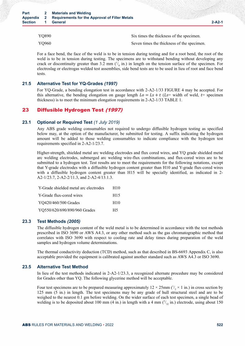
YQ890 Six times the thickness of the specimen.
YQ960 Seven times the thickness of the specimen.
For a face bend, the face of the weld is to be in tension during testing and for a root bend, the root of theweld is to be in tension during testing. The specimens are to withstand bending without developing anycrack or discontinuity greater than 3.2 mm (1/8 in.) in length on the tension surface of the specimen. Forelectroslag or electrogas welded test assemblies, side bend tests are to be used in lieu of root and face bendtests.
21.5 Alternative Test for YQ-Grades (1997)For YQ-Grade, a bending elongation test in accordance with 2-A2-1/33 FIGURE 4 may be accepted. Forthis alternative, the bending elongation on gauge length Lo = Ls+ t (Ls= width of weld, t= specimenthickness) is to meet the minimum elongation requirements in 2-A2-1/33 TABLE 1.
23 Diffusible Hydrogen Test (1997)
23.1 Optional or Required Test (1 July 2019)Any ABS grade welding consumables not required to undergo diffusible hydrogen testing as specifiedbelow may, at the option of the manufacturer, be submitted for testing. A suffix indicating the hydrogenamount will be added to those welding consumables to indicate compliance with the hydrogen testrequirements specified in 2-A2-1/23.7.
Higher-strength, shielded metal arc welding electrodes and flux cored wires, and YQ grade shielded metalarc welding electrodes, submerged arc welding wire-flux combinations, and flux-cored wires are to besubmitted to a hydrogen test. Test results are to meet the requirements for the following notations, exceptthat Y-grade electrodes with a diffusible hydrogen content greater than H10 and Y-grade flux-cored wireswith a diffusible hydrogen content greater than H15 will be specially identified, as indicated in 2-A2-1/23.7, 2-A2-2/11.3, and 2-A2-4/13.1.3.
Y-Grade shielded metal arc electrodes H10
Y-Grade flux-cored wires H15
YQ420/460/500 Grades H10
YQ550/620/690/890/960 Grades H5
23.3 Test Methods (2005)The diffusible hydrogen content of the weld metal is to be determined in accordance with the test methodsprescribed in ISO 3690 or AWS A4.3, or any other method such as the gas chromatographic method thatcorrelates with ISO 3690 with respect to cooling rate and delay times during preparation of the weldsamples and hydrogen volume determinations.
The thermal conductivity deduction (TCD) method, such as that described in BS-6693 Appendix C, is alsoacceptable provided the equipment is calibrated against another standard such as AWS A4.3 or ISO 3690.
23.5 Alternative Test MethodIn lieu of the test methods indicated in 2-A2-1/23.3, a recognized alternate procedure may be consideredfor Grades other than YQ. The following glycerine method will be acceptable.
Four test specimens are to be prepared measuring approximately 12 × 25mm (1/2 × 1 in.) in cross section by125 mm (5 in.) in length. The test specimens may be any grade of hull structural steel and are to beweighed to the nearest 0.1 gm before welding. On the wider surface of each test specimen, a single bead ofwelding is to be deposited about 100 mm (4 in.) in length with a 4 mm (5/32 in.) electrode, using about 150
Part 2 Materials and WeldingAppendix 2 Requirements for the Approval of Filler MetalsSection 1 General 2-A2-1
ABS RULES FOR MATERIALS AND WELDING • 2022 522
mm (6 in.) of the electrode. The welding is to be carried out with as short an arc as possible and with acurrent of approximately 150 amperes.
The electrodes, prior to welding, can be subjected to the normal drying process recommended by themanufacturer. Within thirty seconds of the completion of the welding of each specimen, the slag is to beremoved and the specimen quenched in water having a temperature of approximately 20°C (68°F). Afteran additional 30 seconds the specimens are to be cleaned and placed in an apparatus suitable for thecollection of hydrogen by displacement of glycerin. The glycerin is to be kept at a temperature of 45°C(113°F) during the test. All four test specimens are to be welded and placed in the hydrogen collectingapparatus within 30 minutes.
The specimens are to be kept immersed in the glycerin for a period of 48 hours and after removal are to becleaned in water or suitable solvent, dried, and weighed to the nearest 0.1 gram to determine the amount ofweld deposited. The amount of gas evolved is to be measured to the nearest 0.01 ml and corrected fortemperature and pressure to 0°C (32°F) and 760 mm (30 in.) Hg.
23.7 Test Requirements (2005)The individual and average diffusible hydrogen content of the four specimens is to be reported and theaverage value in milliliters (ml) per 100 grams is not to exceed the following:
Suffix AWS A4.3 or ISO 3690 Glycerin Method
H15 15 10
H10 10 5
H5 5 -
All higher-tensile strength steel grade shielded metal arc electrodes with an average value above the H10requirement and flux cored wires with an average value above the H15 requirement are to be identifiedwith “non-low hydrogen electrode, requires special approval for use with higher-strength steel”.
25 Special Tests
25.1 Nondestructive TestingThe welded assemblies may be subjected to radiographic or ultrasonic examination to ascertain anydiscontinuities in the weld prior to testing.
25.3 Additional TestsABS may specify any additional tests as may be necessary.
27 Licensee Approvals (2007)When a filler metal is manufactured in more than one plant of the same company or by a licenseecompany, a complete set of approval tests is to be carried out on the samples selected from products of themain plant. In the other plants, a reduced test program equivalent to annual check tests plus diffusiblehydrogen test may be permitted, if the main plant and licensee can certify that the materials used, thefabrication process and final products by the licensee are identical to those in the main plant. Affidavitsfrom both the main plant and licensee are to be submitted attesting to this fact. However, should there beany doubt, a complete test series may be required.
Note:
Part 2 Materials and WeldingAppendix 2 Requirements for the Approval of Filler MetalsSection 1 General 2-A2-1
ABS RULES FOR MATERIALS AND WELDING • 2022 523
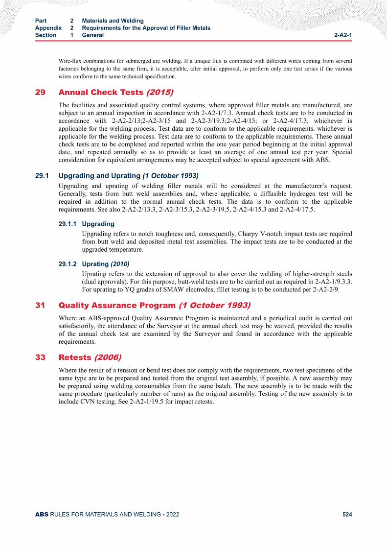
Wire-flux combinations for submerged arc welding. If a unique flux is combined with different wires coming from severalfactories belonging to the same firm, it is acceptable, after initial approval, to perform only one test series if the variouswires conform to the same technical specification.
29 Annual Check Tests (2015)The facilities and associated quality control systems, where approved filler metals are manufactured, aresubject to an annual inspection in accordance with 2-A2-1/7.3. Annual check tests are to be conducted inaccordance with 2-A2-2/13;2-A2-3/15 and 2-A2-3/19.3;2-A2-4/15; or 2-A2-4/17.3, whichever isapplicable for the welding process. Test data are to conform to the applicable requirements. whichever isapplicable for the welding process. Test data are to conform to the applicable requirements. These annualcheck tests are to be completed and reported within the one year period beginning at the initial approvaldate, and repeated annually so as to provide at least an average of one annual test per year. Specialconsideration for equivalent arrangements may be accepted subject to special agreement with ABS.
29.1 Upgrading and Uprating (1 October 1993)Upgrading and uprating of welding filler metals will be considered at the manufacturer’s request.Generally, tests from butt weld assemblies and, where applicable, a diffusible hydrogen test will berequired in addition to the normal annual check tests. The data is to conform to the applicablerequirements. See also 2-A2-2/13.3, 2-A2-3/15.3, 2-A2-3/19.5, 2-A2-4/15.3 and 2-A2-4/17.5.
29.1.1 UpgradingUpgrading refers to notch toughness and, consequently, Charpy V-notch impact tests are requiredfrom butt weld and deposited metal test assemblies. The impact tests are to be conducted at theupgraded temperature.
29.1.2 Uprating (2010)Uprating refers to the extension of approval to also cover the welding of higher-strength steels(dual approvals). For this purpose, butt-weld tests are to be carried out as required in 2-A2-1/9.3.3.For uprating to YQ grades of SMAW electrodes, fillet testing is to be conducted per 2-A2-2/9.
31 Quality Assurance Program (1 October 1993)Where an ABS-approved Quality Assurance Program is maintained and a periodical audit is carried outsatisfactorily, the attendance of the Surveyor at the annual check test may be waived, provided the resultsof the annual check test are examined by the Surveyor and found in accordance with the applicablerequirements.
33 Retests (2006)Where the result of a tension or bend test does not comply with the requirements, two test specimens of thesame type are to be prepared and tested from the original test assembly, if possible. A new assembly maybe prepared using welding consumables from the same batch. The new assembly is to be made with thesame procedure (particularly number of runs) as the original assembly. Testing of the new assembly is toinclude CVN testing. See 2-A2-1/19.5 for impact retests.
Part 2 Materials and WeldingAppendix 2 Requirements for the Approval of Filler MetalsSection 1 General 2-A2-1
ABS RULES FOR MATERIALS AND WELDING • 2022 524
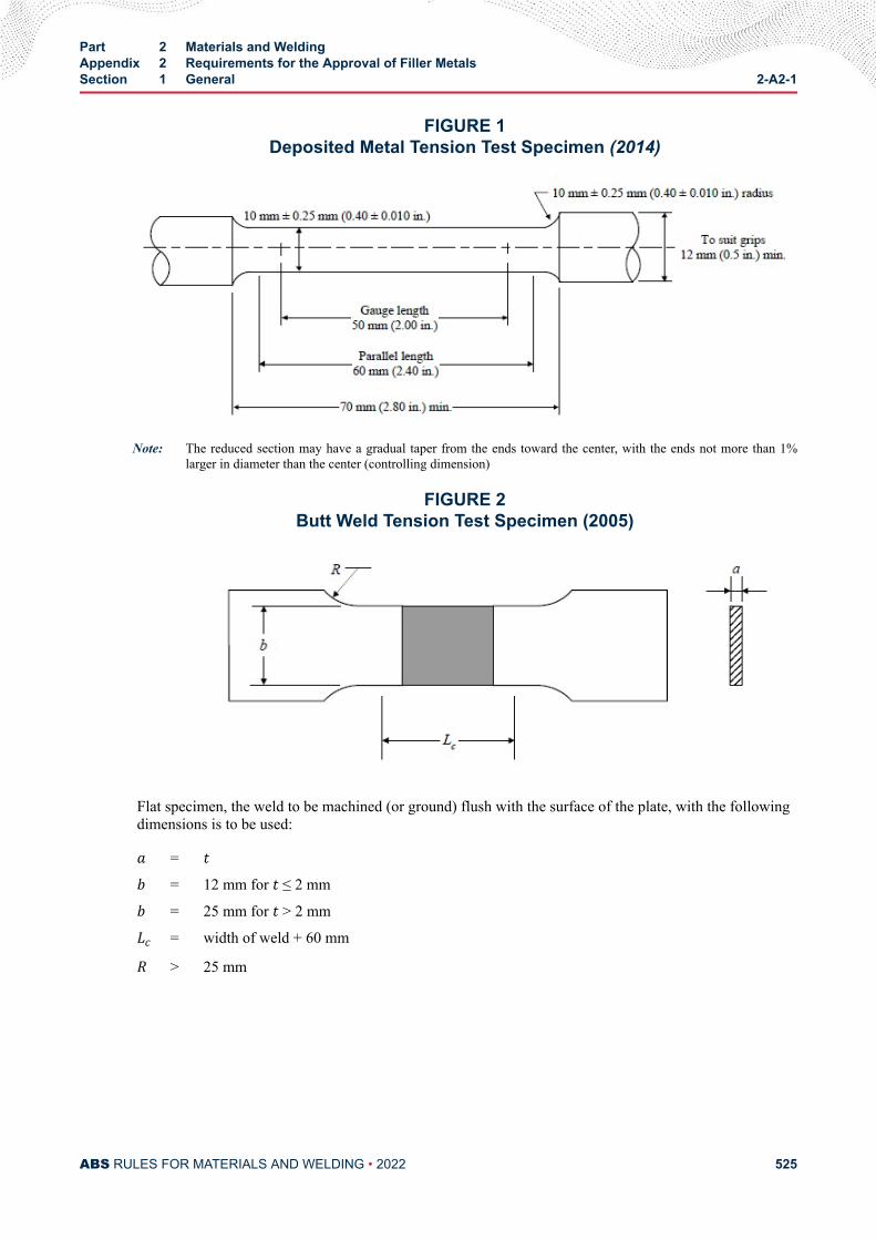
FIGURE 1Deposited Metal Tension Test Specimen (2014)
Note: The reduced section may have a gradual taper from the ends toward the center, with the ends not more than 1%larger in diameter than the center (controlling dimension)
FIGURE 2Butt Weld Tension Test Specimen (2005)
Flat specimen, the weld to be machined (or ground) flush with the surface of the plate, with the followingdimensions is to be used:a = t b = 12 mm for t ≤ 2 mmb = 25 mm for t > 2 mmLc = width of weld + 60 mmR > 25 mm
Part 2 Materials and WeldingAppendix 2 Requirements for the Approval of Filler MetalsSection 1 General 2-A2-1
ABS RULES FOR MATERIALS AND WELDING • 2022 525
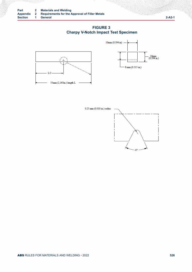
FIGURE 3 Charpy V-Notch Impact Test Specimen
Part 2 Materials and WeldingAppendix 2 Requirements for the Approval of Filler MetalsSection 1 General 2-A2-1
ABS RULES FOR MATERIALS AND WELDING • 2022 526

FIGURE 4 Bending Elongation Test (1997)
TABLE 1Tension Test Requirements (1 July 2019)
The tensile requirements are based on the type of test specimen (longitudinal or transverse) specified elsewhere in theseRequirements for the particular combination of weld process and the type of required test.To find the required tension test properties, first locate in the “process” column the welding process for which the fillermetal is intended (e.g., wire-flux). Then locate in that line under “applicable test” column the test in question (e.g., DM/M).The required properties are found below the box in which the particular test is located (longitudinal specimen for theexample chosen).
Process Applicable Tests
MWWF
WG/SAWG/AESEG
DMDM/M, DM/TM, BW/T, BW/TM
DMDM/M, DM/TM, BW/T, BW/TM
BW
BWBW/M, BW/T, BW/TM
BWBW/M, BW/T, BW/TM
BW
Required Properties
Grade*3
Longitudinal Specimen Transv. Specimen(1999)
Tensile StrengthN/mm2 (kgf/mm2, ksi)
Yield Point, min.N/mm2(kgf/mm2, ksi)
Elongationmin.%
Tensile Strength, min.N/mm2 (kgf/mm2, ksi)
1, 2 & 3 (2006) 400/560 (41/57, 58/82) 305 (31, 44) 22 400 (41, 58)
1Y(1), 2Y, 3Y & 4Y 490/660 (50/67, 71/95) 375 (38, 54) 22 490 (50, 71)
Part 2 Materials and WeldingAppendix 2 Requirements for the Approval of Filler MetalsSection 1 General 2-A2-1
ABS RULES FOR MATERIALS AND WELDING • 2022 527
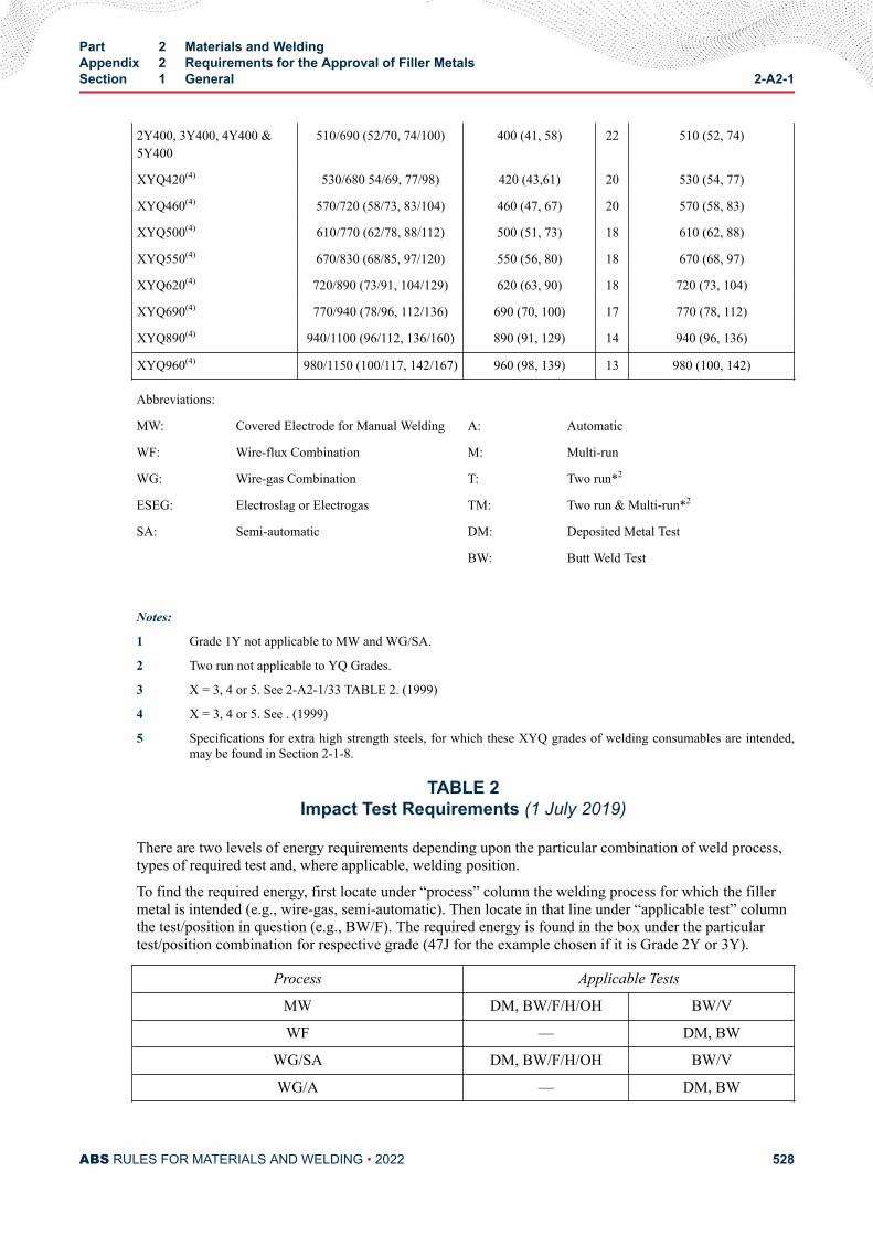
2Y400, 3Y400, 4Y400 &5Y400
510/690 (52/70, 74/100) 400 (41, 58) 22 510 (52, 74)
XYQ420(4) 530/680 54/69, 77/98) 420 (43,61) 20 530 (54, 77)
XYQ460(4) 570/720 (58/73, 83/104) 460 (47, 67) 20 570 (58, 83)
XYQ500(4) 610/770 (62/78, 88/112) 500 (51, 73) 18 610 (62, 88)
XYQ550(4) 670/830 (68/85, 97/120) 550 (56, 80) 18 670 (68, 97)
XYQ620(4) 720/890 (73/91, 104/129) 620 (63, 90) 18 720 (73, 104)
XYQ690(4) 770/940 (78/96, 112/136) 690 (70, 100) 17 770 (78, 112)
XYQ890(4) 940/1100 (96/112, 136/160) 890 (91, 129) 14 940 (96, 136)
XYQ960(4) 980/1150 (100/117, 142/167) 960 (98, 139) 13 980 (100, 142)
Abbreviations:
MW: Covered Electrode for Manual Welding A: Automatic
WF: Wire-flux Combination M: Multi-run
WG: Wire-gas Combination T: Two run*2
ESEG: Electroslag or Electrogas TM: Two run & Multi-run*2
SA: Semi-automatic DM: Deposited Metal Test
BW: Butt Weld Test
Notes:
1 Grade 1Y not applicable to MW and WG/SA.
2 Two run not applicable to YQ Grades.
3 X = 3, 4 or 5. See 2-A2-1/33 TABLE 2. (1999)
4 X = 3, 4 or 5. See . (1999)
5 Specifications for extra high strength steels, for which these XYQ grades of welding consumables are intended,may be found in Section 2-1-8.
TABLE 2Impact Test Requirements (1 July 2019)
There are two levels of energy requirements depending upon the particular combination of weld process,types of required test and, where applicable, welding position.
To find the required energy, first locate under “process” column the welding process for which the fillermetal is intended (e.g., wire-gas, semi-automatic). Then locate in that line under “applicable test” columnthe test/position in question (e.g., BW/F). The required energy is found in the box under the particulartest/position combination for respective grade (47J for the example chosen if it is Grade 2Y or 3Y).
Process Applicable Tests
MW DM, BW/F/H/OH BW/V
WF — DM, BW
WG/SA DM, BW/F/H/OH BW/V
WG/A — DM, BW
Part 2 Materials and WeldingAppendix 2 Requirements for the Approval of Filler MetalsSection 1 General 2-A2-1
ABS RULES FOR MATERIALS AND WELDING • 2022 528
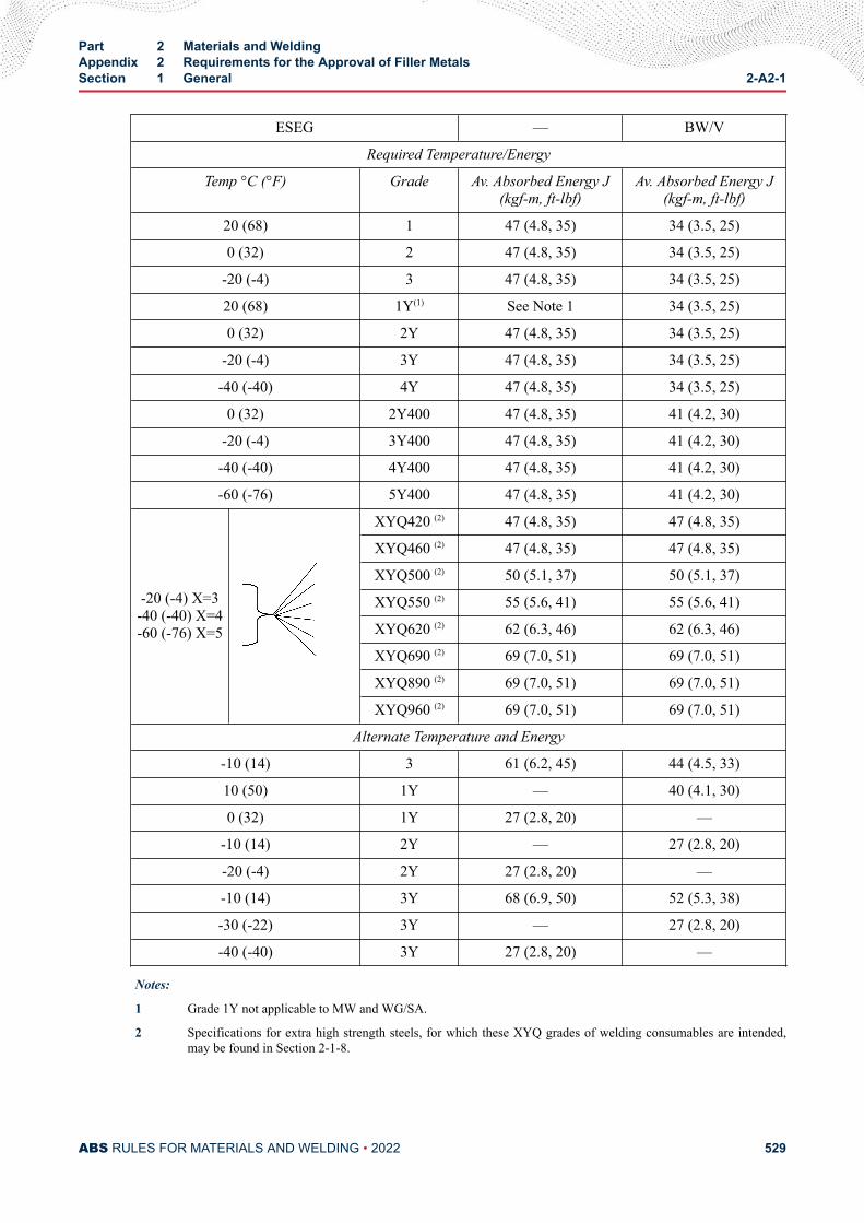
ESEG — BW/V
Required Temperature/Energy
Temp °C (°F) Grade Av. Absorbed Energy J(kgf-m, ft-lbf)
Av. Absorbed Energy J(kgf-m, ft-lbf)
20 (68) 1 47 (4.8, 35) 34 (3.5, 25)
0 (32) 2 47 (4.8, 35) 34 (3.5, 25)
-20 (-4) 3 47 (4.8, 35) 34 (3.5, 25)
20 (68) 1Y(1) See Note 1 34 (3.5, 25)
0 (32) 2Y 47 (4.8, 35) 34 (3.5, 25)
-20 (-4) 3Y 47 (4.8, 35) 34 (3.5, 25)
-40 (-40) 4Y 47 (4.8, 35) 34 (3.5, 25)
0 (32) 2Y400 47 (4.8, 35) 41 (4.2, 30)
-20 (-4) 3Y400 47 (4.8, 35) 41 (4.2, 30)
-40 (-40) 4Y400 47 (4.8, 35) 41 (4.2, 30)
-60 (-76) 5Y400 47 (4.8, 35) 41 (4.2, 30)
-20 (-4) X=3-40 (-40) X=4-60 (-76) X=5
XYQ420 (2) 47 (4.8, 35) 47 (4.8, 35)
XYQ460 (2) 47 (4.8, 35) 47 (4.8, 35)
XYQ500 (2) 50 (5.1, 37) 50 (5.1, 37)
XYQ550 (2) 55 (5.6, 41) 55 (5.6, 41)
XYQ620 (2) 62 (6.3, 46) 62 (6.3, 46)
XYQ690 (2) 69 (7.0, 51) 69 (7.0, 51)
XYQ890 (2) 69 (7.0, 51) 69 (7.0, 51)
XYQ960 (2) 69 (7.0, 51) 69 (7.0, 51)
Alternate Temperature and Energy
-10 (14) 3 61 (6.2, 45) 44 (4.5, 33)
10 (50) 1Y — 40 (4.1, 30)
0 (32) 1Y 27 (2.8, 20) —
-10 (14) 2Y — 27 (2.8, 20)
-20 (-4) 2Y 27 (2.8, 20) —
-10 (14) 3Y 68 (6.9, 50) 52 (5.3, 38)
-30 (-22) 3Y — 27 (2.8, 20)
-40 (-40) 3Y 27 (2.8, 20) —
Notes:
1 Grade 1Y not applicable to MW and WG/SA.
2 Specifications for extra high strength steels, for which these XYQ grades of welding consumables are intended,may be found in Section 2-1-8.
Part 2 Materials and WeldingAppendix 2 Requirements for the Approval of Filler MetalsSection 1 General 2-A2-1
ABS RULES FOR MATERIALS AND WELDING • 2022 529

Abbreviations (2016):
F: FlatH: Horizontal(See also 2-A2-1/33 TABLE1.)
V: VerticalOH: Overhead
Part 2 Materials and WeldingAppendix 2 Requirements for the Approval of Filler MetalsSection 1 General 2-A2-1
ABS RULES FOR MATERIALS AND WELDING • 2022 530
A P P E N D I X 2Requirements for the Approval of Filler Metals
S E C T I O N 2Electrodes for Shielded Metal Arc Welding
1 GeneralThe annual check test shall consist of two deposited metal test assemblies welded and tested in accordancewith 2-A2-2/5.
3 Chemical AnalysisThe chemical analysis of the deposited weld metal is to be supplied by the manufacturer.
5 Deposited Metal Test Assemblies
5.1 Test Assembly (2005)Two deposited metal test assemblies, as indicated in 2-A2-2/13.3 FIGURE 1, are to be welded in the flatposition, one using 4 mm (5/32 in.) electrodes or the smallest size manufactured, whichever is greater, andthe other using the largest size manufactured. If an electrode is produced in one size only or if the largestsize produced is 4 mm (5/32 in.) or less, one test assembly is sufficient. The weld metal is to be deposited insingle or multi-run layers according to normal practice, and the direction of deposition of each layer is toalternate from each end of the plate, each run of weld metal being not less than 2 mm (5/64 in.) and not morethan 4 mm (5/32 in.) thick. Between each run, the assembly is to be left in still air until it has cooled to lessthan 250°C (482°F), but not below 100°C (212°F), the temperature being taken in the center of the weld,on the surface of the seam. After being welded, the test assemblies are not to be subjected to any heattreatment, except hydrogen removal, as permitted in 2-A2-1/15.3.
5.3 Test Specimens (1 October 1994)One tension and one set of three impact specimens are to be prepared from each deposited metal testassembly, as indicated in 2-A2-2/13.3 FIGURE 1 and the results are to conform to the requirements of of2-A2-1/33 TABLE 1 and 2-A2-1/33.1 TABLE 2 for the applicable grade and welding technique.
7 Butt Weld Test Assemblies
7.1 Test AssembliesOne butt weld test assembly, as indicated in 2-A2-2/13.3 FIGURE 2 is to be welded in each position (flat,vertical-up, vertical-down, overhead and horizontal) for which the electrode is recommended by themanufacturer, except that those electrodes meeting the requirements for flat and vertical positions will be
PART 2
ABS RULES FOR MATERIALS AND WELDING • 2022 531
considered as also complying with the requirements for the horizontal position. Where the electrode is onlyto be approved in the flat position, one additional test assembly is to be welded in that position.
7.3 Welding Procedure (1996)In general, the following welding procedure is to be adopted in making the test assemblies:
Flat. First run using 4 mm (5/32 in.) electrodes; remaining runs except last two layers with 5 mm (3/16 in.) orabove according to the normal welding practice with the electrodes; the runs of the last two layers with thelargest size electrodes manufactured. When a second flat assembly is required, the runs of the last threelayers are to be welded with the largest size electrode manufactured.
Horizontal. First pass with 4 mm (5/32 in.) or 5 mm (3/16 in.) diameter electrode. Subsequent passes with 5mm (3/16 in.) diameter electrode.
Vertical-up and Overhead. The first run with 3.25 mm (1/8 in.) electrodes; remaining runs with the largestdiameter recommended by the manufacturer for the position concerned.
Vertical down. The electrode diameter used is to be as recommended by the manufacturer.
For all assemblies, the back weld is to be made with 4 mm (5/32 in.) electrodes in the welding positionappropriate to each test sample, after removing the root run to clean metal. For electrodes suitable only forflat position welding, the test assemblies may be turned over to carry out the back weld.
Normal welding practice is to be used, and between each run, the assembly is to be left in still air until ithas cooled to less than 250°C (482°F) but not below 100°C (212°F), the temperature being taken in thecenter of the weld, on the surface of the seam. After welding, the test assemblies are not to be subjected toany heat treatment.
7.5 Test Specimens (2008)One tension, one face bend, one root bend are to be prepared from each butt weld test assembly togetherwith one set of three impact specimens from the flat and vertical test assemblies, as indicated in 2-A2-2/13.3 FIGURE 2. The results of tension and impact tests are to conform to the requirements of 2-A2-1/33 FIGURE 1 and 2-A2-1/33 TABLE 1 for the applicable grade, position and welding technique.The results of bend tests are to meet the requirements of 2-A2-1/21.3.
9 Fillet Weld Test Assemblies
9.1 General (2005)For gravity fillet welding electrodes (including combination gravity/manual electrodes), fillet weld testingis required in addition to deposited metal testing. Butt weld testing is not required. For gravity weldingelectrodes (including combination gravity/manual electrodes) intended for both fillet and butt welding,fillet weld testing is required in addition to deposited metal and butt weld testing. Gravity weldingequipment is to be used in welding fillet weld test assemblies. Such fillet weld tests are to be carried outand tested in accordance with 2-A2-2/9.3 through 2-A2-2/9.7 using gravity welding equipment and thelongest size electrode manufactured.
The following applies to SMAW electrodes other than gravity electrodes: An electrode other than YQGrades is considered approved for fillet welding in position for which the butt weld test of 2-A2-2/7 wassatisfactory. Electrodes meeting the flat butt weld requirements will be considered as complying with therequirements for horizontal fillet (HF) welds. Where an electrode is submitted for approval for fillet weldsonly, the butt weld tests indicated in 2-A2-2/7 may be omitted and fillet weld tests are to be carried out andtested in accordance with 2-A2-2/9.3 through 2-A2-2/9.7.
Part 2 Materials and WeldingAppendix 2 Requirements for the Approval of Filler MetalsSection 2 Electrodes for Shielded Metal Arc Welding 2-A2-2
ABS RULES FOR MATERIALS AND WELDING • 2022 532
9.3 Test AssembliesOne fillet weld test assembly, as indicated in 2-A2-2/13.3 FIGURE 3, is to be welded in each position forwhich the electrode is recommended by the manufacturer.
9.5 Welding ProcedureThe length L of the fillet test assemblies is to be sufficient to allow for the tests required in 2-A2-2/9.7 andis to provide for at least the deposition of the entire length of the electrode being tested. One side is to bewelded using the maximum size electrode manufactured and the second side using the minimum size ofelectrode manufactured that is recommended for fillet welds. The fillet size will, in general, be determinedby the electrode size and the welding current employed during testing. The fillet weld is to be carried outwith the longest size electrode using the welding equipment and technique recommended by themanufacturer. The current used while conducting the test, and the manufacturer’s recommended currentrange are to be reported for each electrode size and welding position.
9.7 Test Specimens9.7.1 Macrographs and Hardness Tests (1 October 1994)
Each fillet weld test assembly is to be sectioned, as indicated in 2-A2-2/13.3 FIGURE 3 to formthree macro-sections. These are to be examined for root penetration, satisfactory profile, freedomfrom cracking and reasonable freedom from porosity, undercut and slag inclusions. Hardnessreadings are to be made on each section. The number and location of hardness readings are toapproximate those indicated in 2-A2-2/13.3 FIGURE 4. The hardness of the weld is to bedetermined and is to meet the following listed equivalent values.
Load Grade 1, 2, 3 Grades Y, Y400 and YQ
Diamond Pyramid (Vickers)Hardness-10 kg (98 N)
To be reported forinformation
150 min.
Rockwell B-100 kg (980 N) 80 min.
The hardness of the heat affected zone (HAZ) and base metal are also to be determined andreported for information only.
9.7.2 Breaking TestOne of the remaining sections of the fillet weld is to have the weld, on the side welded first,gouged or machined to facilitate breaking the fillet weld on the other side by closing the twoplates together, subjecting the root of the weld to tension. On the other remaining section, the weldon the side welded second is to be gouged or machined and the section fractured using the aboveprocedure. The fractured surfaces are to be examined and there is to be no evidence of incompletepenetration or internal cracking and they are to be reasonably free from porosity.
11 Low Hydrogen Approval (1997)
11.1 Ordinary-Strength Filler Metals (1997)Electrodes which have satisfied the requirements of Grades 2 and 3 may, at the option of the manufacturer,be subjected to a hydrogen test, as specified in 2-A2-1/23.3. A suffix indicating the hydrogen amount willbe added to the grade number of those electrodes to indicate compliance with the hydrogen testrequirements specified in 2-A2-1/23.7.
11.3 Higher-Strength Filler Metals (2009)Electrodes which are submitted for approval according to Grades 2Y, 3Y, 4Y, 2Y400, 3Y400, 4Y400, or5Y400 are to be subjected to a hydrogen test and are to meet the requirement specified in 2-A2-1/23.7 forthe H10 suffix. Such suffix, however, will not be added to the grade. Electrodes meeting H5 requirementswill be so identified. Electrodes meeting the higher-strength requirements, except for hydrogen test, will
Part 2 Materials and WeldingAppendix 2 Requirements for the Approval of Filler MetalsSection 2 Electrodes for Shielded Metal Arc Welding 2-A2-2
ABS RULES FOR MATERIALS AND WELDING • 2022 533
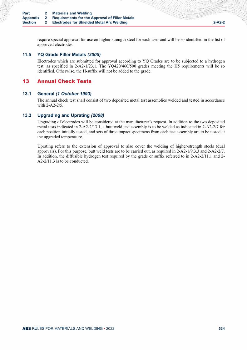
require special approval for use on higher strength steel for each user and will be so identified in the list ofapproved electrodes.
11.5 YQ Grade Filler Metals (2005)Electrodes which are submitted for approval according to YQ Grades are to be subjected to a hydrogentest, as specified in 2-A2-1/23.1. The YQ420/460/500 grades meeting the H5 requirements will be soidentified. Otherwise, the H-suffix will not be added to the grade.
13 Annual Check Tests
13.1 General (1 October 1993)The annual check test shall consist of two deposited metal test assemblies welded and tested in accordancewith 2-A2-2/5.
13.3 Upgrading and Uprating (2008)Upgrading of electrodes will be considered at the manufacturer’s request. In addition to the two depositedmetal tests indicated in 2-A2-2/13.1, a butt weld test assembly is to be welded as indicated in 2-A2-2/7 foreach position initially tested, and sets of three impact specimens from each test assembly are to be tested atthe upgraded temperature.
Uprating refers to the extension of approval to also cover the welding of higher-strength steels (dualapprovals). For this purpose, butt weld tests are to be carried out, as required in 2-A2-1/9.3.3 and 2-A2-2/7.In addition, the diffusible hydrogen test required by the grade or suffix referred to in 2-A2-2/11.1 and 2-A2-2/11.3 is to be conducted.
Part 2 Materials and WeldingAppendix 2 Requirements for the Approval of Filler MetalsSection 2 Electrodes for Shielded Metal Arc Welding 2-A2-2
ABS RULES FOR MATERIALS AND WELDING • 2022 534
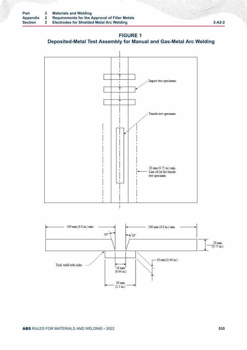
FIGURE 1 Deposited-Metal Test Assembly for Manual and Gas-Metal Arc Welding
Part 2 Materials and WeldingAppendix 2 Requirements for the Approval of Filler MetalsSection 2 Electrodes for Shielded Metal Arc Welding 2-A2-2
ABS RULES FOR MATERIALS AND WELDING • 2022 535
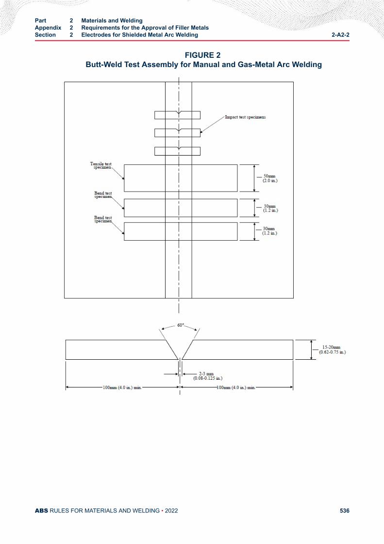
FIGURE 2 Butt-Weld Test Assembly for Manual and Gas-Metal Arc Welding
Part 2 Materials and WeldingAppendix 2 Requirements for the Approval of Filler MetalsSection 2 Electrodes for Shielded Metal Arc Welding 2-A2-2
ABS RULES FOR MATERIALS AND WELDING • 2022 536
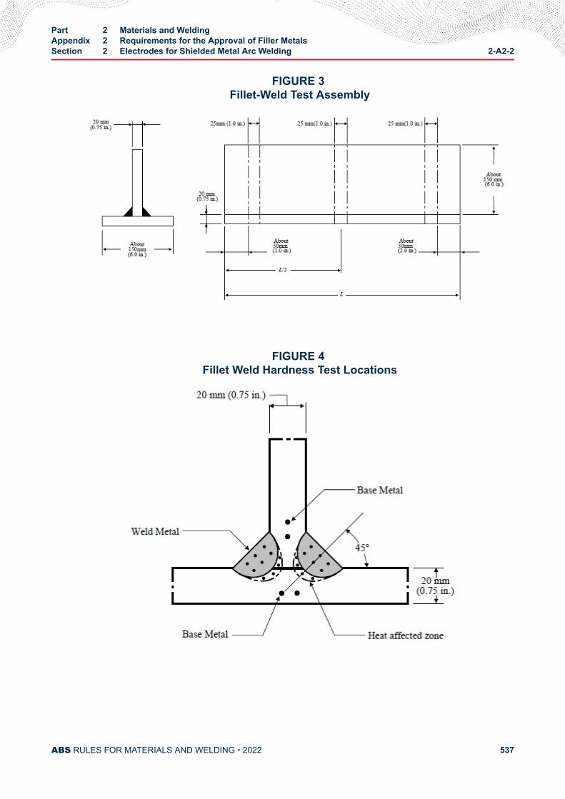
FIGURE 3 Fillet-Weld Test Assembly
FIGURE 4 Fillet Weld Hardness Test Locations
Part 2 Materials and WeldingAppendix 2 Requirements for the Approval of Filler MetalsSection 2 Electrodes for Shielded Metal Arc Welding 2-A2-2
ABS RULES FOR MATERIALS AND WELDING • 2022 537
A P P E N D I X 2Requirements for the Approval of Filler Metals
S E C T I O N 3Wire-Flux Combinations for Submerged Arc Welding
1 General (1997)This test program is intended for the approval of automatic or semi-automatic, single-electrode submergedarc welding. Provisions are made for the testing of weld metal deposited by multi-run and two-run (onepass each side) techniques. For YQ Grades automatic welding, a multi-run technique is contemplated.Application for high heat input process, such as automatic welding two-run technique, may be consideredunder 2-A2-1/3.5 and approval by a technical office. Where a manufacturer states that a particular wire-flux combination is suitable for welding with both techniques, both series of tests are to be carried out. Thesuffix T, M, or TM will be added to the grade to indicate two-run technique, multi-run technique, or bothtechniques, respectively.
3 Chemical AnalysisThe chemical analysis of the deposited weld metal is to be supplied by the manufacturer.
5 Deposited Metal Test Assemblies for Multi-run Technique
5.1 Test Assembly (2005)One deposited metal test assembly, as indicated in 2-A2-3/19.5 FIGURE 1 is to be welded in the flatposition using the wire size recommended by the manufacturer. The direction of deposition of each run isto alternate from each end of the plate and after completion of each run, the flux and welding slag are to beremoved. The thickness of each layer is not to be less than the size of the wire, or 4 mm (5/32 in.),whichever is the greater. Between each run, the assembly is to be left in still air until it has cooled to lessthan 250°C (482°F), but not below 100°C (212°F), the temperature being taken in the center of the weld,on the surface of the seam. The welding conditions (amperage, voltage, and travel speed) are to be inaccordance with the recommendations of the manufacturer and are to conform with normal good weldingpractice for multi-run welding. The welded test assembly is not to be subjected to heat treatment, excepthydrogen removal, as permitted in 2-A2-1/15.3.
5.3 Test Specimens (1 October 1994)Two tension and one set of three impact specimens are to be prepared from the deposited metal testassembly, as indicated in 2-A2-3/19.5 FIGURE 1 and the results are to conform to the requirements of 2-A2-1/33 TABLE 1 and 2-A2-1/33.1 TABLE 2 for the applicable grade and welding technique.
PART 2
ABS RULES FOR MATERIALS AND WELDING • 2022 538
7 Butt Weld Test Assemblies for Multi-run Technique
7.1 Test AssemblyOne butt weld test assembly, as indicated in 2-A2-3/19.5 FIGURE 3 is to be welded in the flat positionusing the wire size recommended by the manufacturer. The welding conditions are to be essentially thesame as those indicated in 2-A2-3/5.1 for deposited metal test assembly. The back weld is to be applied inthe flat position after removing the root run to clean metal. After being welded, the test assembly is not tobe subjected to any heat treatment.
7.3 Test SpecimensTwo tension, two face bend and two root bend together with one set of three impact specimens are to beprepared from the butt weld test assembly, as indicated in 2-A2-3/19.5 FIGURE 3, and the results oftension and impact tests are to conform to the requirements of 2-A2-1/33 TABLE 1 and 2-A2-1/33 TABLE2 for the applicable grade and welding technique. The results of bend tests are to meet the requirements of2-A2-1/21.3.
9 Butt Weld Assemblies for Two-run Technique
9.1 Test Assemblies (2005)Two butt weld test assemblies, as indicated in 2-A2-3/19.5 FIGURE 3 are to be welded in the flat position.The maximum size of wire, grades of steel plate, and the edge preparation to be used are also to be inaccordance with 2-A2-3/19.5 FIGURE 3. At the request of the manufacturer, small deviations in the edgepreparation may be allowed. The root gap is not to exceed 1.0 mm (0.04 in.). Each test assembly is to bewelded in two runs, one from each side, using welding conditions (amperage, voltage, and travel speed)which are in accordance with the recommendations of the manufacturer and normal good welding practice.After completion of the first run, the flux and welding slag are to be removed and the assembly is to be leftin still air until it has cooled to 100°C (212°F) or less, the temperature being taken in the center of theweld, on the surface of the seam. After being welded, the test assemblies are not to be subjected to anytreatment.
9.3 Test Specimens (1 October 1994)Two tension, one face bend, one root bend, and one set of three impact specimens are to be prepared fromeach butt weld assembly, as indicated in 2-A2-3/Figure 3 and 2-A2-3/Figure 4, and the results of tensionand impact tests are to conform to the requirements of 2-A2-1/33 TABLE 1 and 2-A2-1/33 TABLE 2 forthe applicable grade and welding technique. The results of bend tests are to meet the requirements of 2-A2-1/23.1. The edges of all test specimens and also the discards are to be examined to ensure completefusion and interpenetration of the welds.
9.5 Longitudinal All-Weld-Metal Tension Test (1 October 1994)Where the combination is to be approved for two-run technique only, one longitudinal all-weld-metaltension specimen is to be cut from the thicker butt weld test assembly, as indicated in 2-A2-3/19.5FIGURE 3, and machined to the dimensions indicated in 2-A2-1/33 FIGURE 1, care being taken that thelongitudinal axis coincides with the center of the weld and is approximately 7 mm (0.28 in.) below theplate surface on the side from which the second run is made. The test specimen may be subjected to atemperature not exceeding 250°C (482°F) for up to 16 hours for hydrogen removal, prior to testing. Theresults of the tests are to conform to the requirements of 2-A2-1/33 TABLE 1.
11 Fillet Weld TestsWhere a wire-flux combination is submitted for approval for fillet welds only, then the butt weld tests maybe omitted, and fillet weld tests are to be carried out and tested in accordance with the applicable parts of2-A2-4/11.3 to 2-A2-4/11.7.
Part 2 Materials and WeldingAppendix 2 Requirements for the Approval of Filler MetalsSection 3 Wire-Flux Combinations for Submerged Arc Welding 2-A2-3
ABS RULES FOR MATERIALS AND WELDING • 2022 539
13 Low Hydrogen Approval (1997)
13.1 YQ Grade Wires -Flux Combination (2005)All wire-flux combination of this grade are to be submitted to the diffusible hydrogen test, as required by2-A2-1/23.1. The YQ420/460/500 grades meeting the H5 requirements will be so identified. Otherwise,the H-suffix will not be added to the grade.
15 Annual Check Tests
15.1 General (1996)The annual check tests for each approved technique shall consist of the following.
Multi-run Technique. One deposited metal test assembly is to be welded in accordance with 2-A2-3/5.1.One tension and one set of three impact specimens are to be prepared and tested in accordance with 2-A2-3/5.3.
Two-run Technique. One butt weld test assembly of 20 mm (0.75 in.) thickness is to be welded inaccordance with 2-A2-3/9.1. One transverse tension, one face bend, one root bend, and one set of threeimpact specimens are to be prepared and tested in accordance with 2-A2-3/9.3 and 2-A2-3/9.5. Onelongitudinal tension test specimen is also to be prepared where wire-flux combination is approved solelyfor the two-run technique.
15.3 Upgrading and Uprating (2008)Upgrading of wire-flux combinations will be considered at the manufacturer’s request. For multi-runtechnique, in addition to the deposited metal test indicated in 2-A2-3/15.1, one butt weld test assembly isto be welded, as indicated in 2-A2-3/7 and one set of three impact specimens is to be tested at the upgradedtemperature. For the two-run technique, butt weld testing is to be carried out as indicated in 2-A2-3/15.1,except the test assembly is to be fabricated using the maximum thickness approved.
Uprating refers to the extension of approval to also cover welding of higher-strength steels (dualapprovals). For this purpose butt weld tests are to be carried out as required in 2-A2-3/7 and 2-A2-3/9, and2-A2-1/9.3.3, as applicable.
17 Multiple ElectrodesWire-flux combinations for multiple electrode submerged arc welding will be subject to separate approvaltests. They are to be carried out generally in accordance with the requirements of this section.
19 Electroslag Welding (1996)
19.1 General (1997)Where approval is requested for wire-flux combinations other than YQ Grades, (with or withoutconsumable nozzles) for use in electroslag welding, two test assemblies of 20–25 mm (0.75–1.0 in.) and35–40 mm (1.38–1.58 in.) or more in thickness are to be prepared with a minimum root opening of 16 mm(0.63 in.), or with another joint design sufficient to allow the selection of the following test specimens. Thechemical composition of the plates including the content of grain refining elements is to be reported.
● 2 longitudinal tension specimens from the axis to the weld,
● 2 transverse tension specimens,
● 2 side bend specimens,
● 3 Charpy-V specimens notched at the center of the weld,
● 3 Charpy-V specimens with their notches in the weld metal at 2 mm (5/64 in.) from the fusion line,
Part 2 Materials and WeldingAppendix 2 Requirements for the Approval of Filler MetalsSection 3 Wire-Flux Combinations for Submerged Arc Welding 2-A2-3
ABS RULES FOR MATERIALS AND WELDING • 2022 540
● 2 macro-sections.
The results are to conform to the requirements of 2-A2-1/33 TABLE 1 and 2-A2-1/33 TABLE 2 accordingto the applicable grade and welding technique.
19.3 Annual Tests (1996)One butt test assembly of 20–25 mm (0.75–1.0 in.) or more in thickness is to be prepared. One longitudinaltension, one transverse tension, two side bend and two sets of three Charpy V-notch specimens are to beprepared and tested. The notch of the impact specimens is to be located at the center of the weld and 2 mm(0.08 in.) from the fusion line in the weld. One macro-section is also to be examined.
The test results are to conform to the requirements of 2-A2-1/33 TABLE 1 and 2-A2-1/33 TABLE 2according to the applicable grade and welding technique.
19.5 Upgrading and Uprating (1996)Upgrading and uprating will be considered at the manufacturer’s request. Full tests as indicated in 2-A2-3/19.1 will be required.
The test results are to conform to the requirements of 2-A2-1/33 TABLE 1 and 2-A2-1/33 TABLE 2according to the applicable grade and welding technique.
Part 2 Materials and WeldingAppendix 2 Requirements for the Approval of Filler MetalsSection 3 Wire-Flux Combinations for Submerged Arc Welding 2-A2-3
ABS RULES FOR MATERIALS AND WELDING • 2022 541
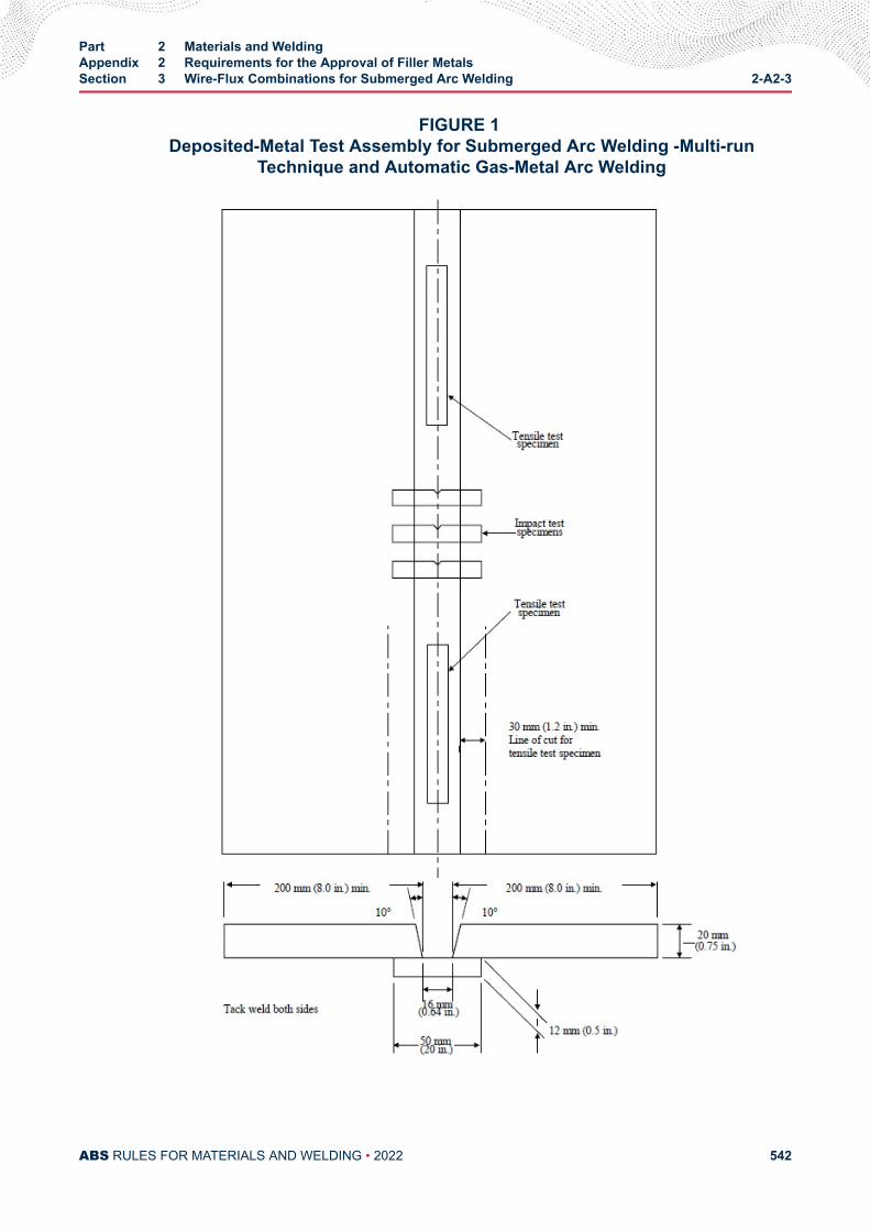
FIGURE 1 Deposited-Metal Test Assembly for Submerged Arc Welding -Multi-run
Technique and Automatic Gas-Metal Arc Welding
Part 2 Materials and WeldingAppendix 2 Requirements for the Approval of Filler MetalsSection 3 Wire-Flux Combinations for Submerged Arc Welding 2-A2-3
ABS RULES FOR MATERIALS AND WELDING • 2022 542
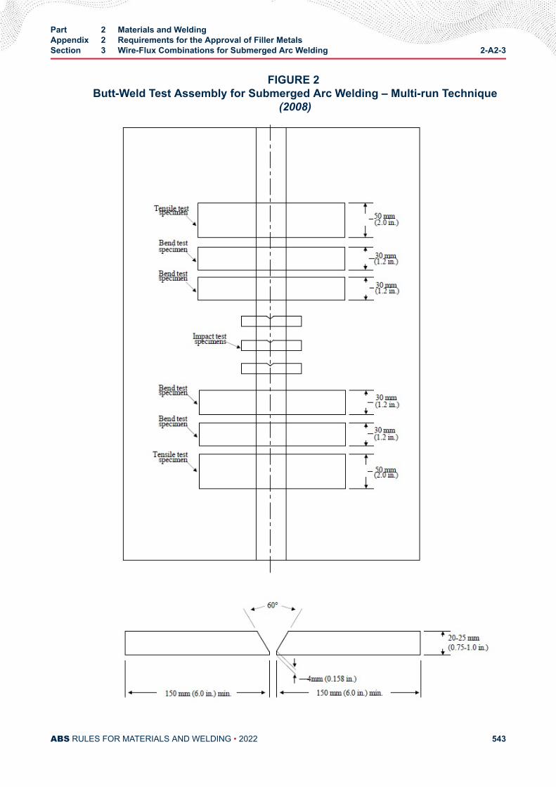
FIGURE 2 Butt-Weld Test Assembly for Submerged Arc Welding – Multi-run Technique
(2008)
Part 2 Materials and WeldingAppendix 2 Requirements for the Approval of Filler MetalsSection 3 Wire-Flux Combinations for Submerged Arc Welding 2-A2-3
ABS RULES FOR MATERIALS AND WELDING • 2022 543
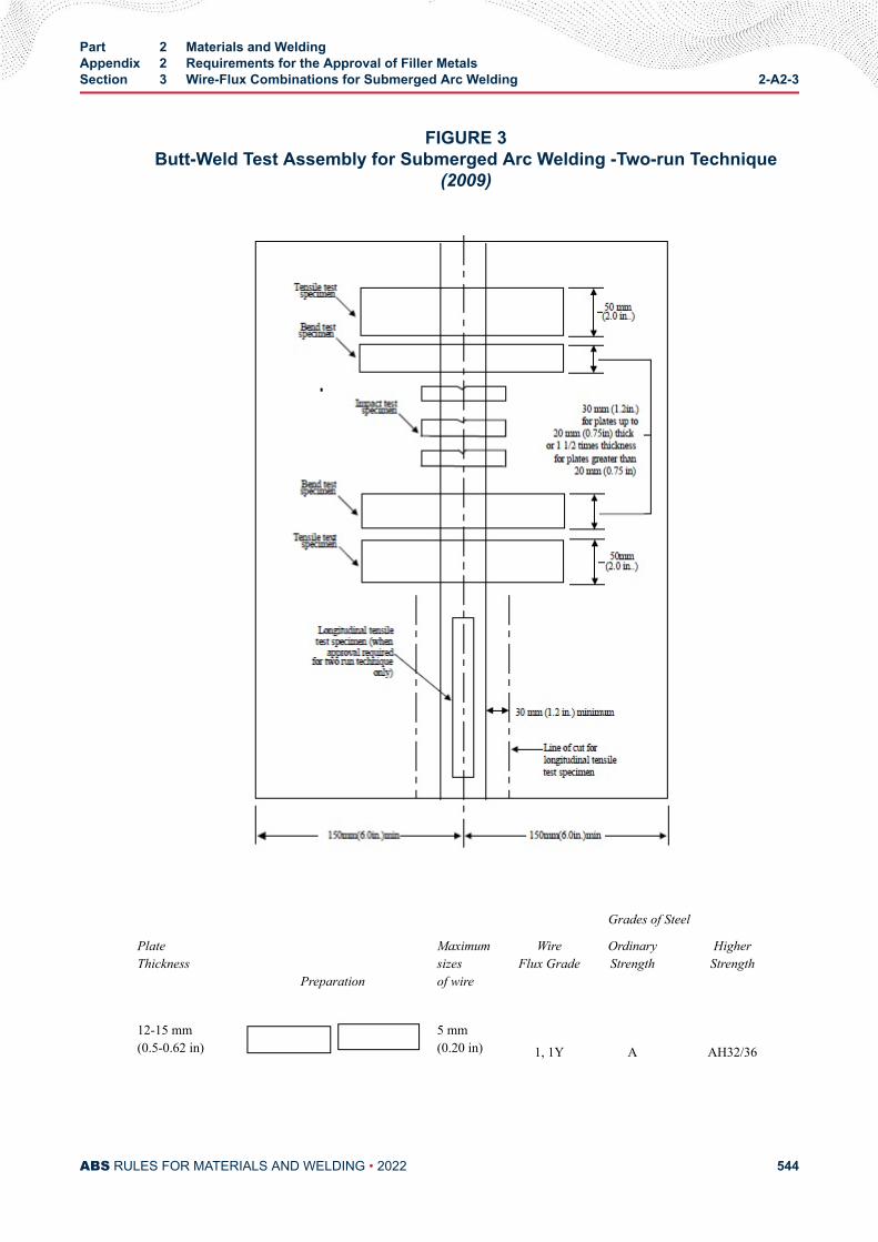
FIGURE 3Butt-Weld Test Assembly for Submerged Arc Welding -Two-run Technique
(2009)
Grades of Steel
PlateThickness
Preparation
Maximumsizesof wire
WireFlux Grade
OrdinaryStrength
HigherStrength
12-15 mm(0.5-0.62 in)
5 mm(0.20 in)
1, 1Y A AH32/36
Part 2 Materials and WeldingAppendix 2 Requirements for the Approval of Filler MetalsSection 3 Wire-Flux Combinations for Submerged Arc Welding 2-A2-3
ABS RULES FOR MATERIALS AND WELDING • 2022 544
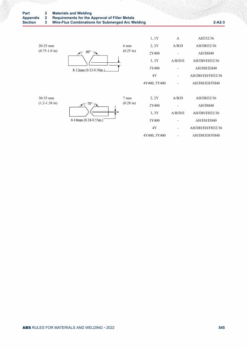
1, 1Y A AH332/36
20-25 mm(0.75-1.0 in)
6 mm(0.25 in)
2, 2Y A/B/D AH/DH32/36
2Y400 - AH/DH40
3, 3Y A/B/D/E AH/DH/EH32/36
3Y400 - AH/DH/EH40
4Y - AH/DH/EH/FH32/36
4Y400, 5Y400 - AH/DH/EH/FH40
30-35 mm(1.2-1.38 in)
7 mm(0.28 in)
2, 2Y A/B/D AH/DH32/36
2Y400 - AH/DH40
3, 3Y A/B/D/E AH/DH/EH32/36
3Y400 - AH/EH/EH40
4Y - AH/DH/EH/FH32/36
4Y400, 5Y400 - AH/DH/EH/FH40
Part 2 Materials and WeldingAppendix 2 Requirements for the Approval of Filler MetalsSection 3 Wire-Flux Combinations for Submerged Arc Welding 2-A2-3
ABS RULES FOR MATERIALS AND WELDING • 2022 545
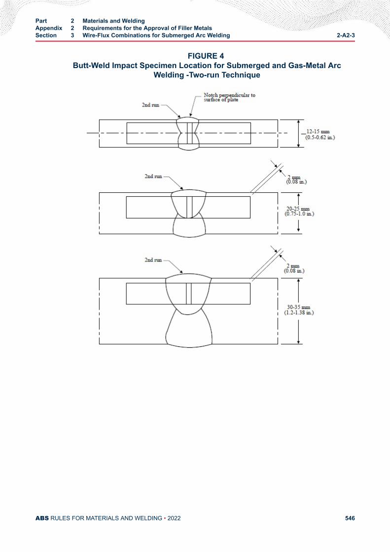
FIGURE 4 Butt-Weld Impact Specimen Location for Submerged and Gas-Metal Arc
Welding -Two-run Technique
Part 2 Materials and WeldingAppendix 2 Requirements for the Approval of Filler MetalsSection 3 Wire-Flux Combinations for Submerged Arc Welding 2-A2-3
ABS RULES FOR MATERIALS AND WELDING • 2022 546
A P P E N D I X 2Requirements for the Approval of Filler Metals
S E C T I O N 4Wire and Wire Gas Combinations for Gas Metal Arc Welding and Flux
Cored Wires for Flux Cored Arc Welding
1 General (1997)This test program is intended for the approval of wire-gas combinations and flux cored wires with orwithout shielding gas intended for semi-automatic or automatic arc welding techniques. For bothtechniques, the welding gun provides continuous wire feed; for semi-automatic welding, the welding gunis held manually, and for automatic welding, the welding gun is machine held with various degrees ofcontrolled motion provided by the machine. The impact requirements for the semi-automatic weldingtechnique and those for the automatic welding technique are indicated separately in 2-A2-1/33 TABLE 1and 2-A2-1/33 TABLE 1 according to the applicable grade. The suffix SA will be added to the grade toindicate approval for manual semi-automatic or machine-automatic gas-metal arc welding. The suffix Awill be added to the Grade to indicate approval for machine automatic welding only. An additional suffix Twill be added to the grade to indicate approval for two-run (one pass each side) technique for machineautomatic welding. Wire-gas combinations and flux cored wires approved for semi-automatic welding maybe used for automatic welding under the procedure recommended by the manufacturer, except that for thetwo-run automatic technique, testing in accordance with 2-A2-4/9 is required. For YQ Grades semi-automatic or automatic welding, a multi run technique is contemplated. Application for high heat inputprocess, such as semi-automatic or automatic welding two-run technique, may be considered under 2-A2-1/3.5 and approval by technical office.
3 Chemical Analysis and Shielding Gas Compositions (2008)The chemical analysis of the deposited weld metal is to be supplied by the manufacturer. The trade nameof the shielding gas, when used, as well as its composition, is to be reported. The approval of a wire incombination with any particular gas can be applied or transferred to any combination of the same wire andany gas in the same numbered group as defined in 2-A2-4/3 TABLE 1.
PART 2
ABS RULES FOR MATERIALS AND WELDING • 2022 547
TABLE 1Compositional Limits of Designated Groups of Gas Types and Mixtures (2008)
Group Gas composition (Vol.%)
CO 2 O2 H2 Ar
M1 1 >0 to 5 -- >0 to 5 Rest (1, 2)
2 >0 to 5 -- -- Rest (1, 2)
3 -- >0 to 3 -- Rest (1, 2)
4 >0 to 5 >0 to 3 -- Rest (1, 2)
M2 1 >5 to 25 -- -- Rest (1, 2)
2 -- >3 to 10 -- Rest (1, 2)
3 >5 to 25 >0 to 8 -- Rest (1, 2)
M3 1 >25 to 50 -- -- Rest (1, 2)
2 -- >10 to 15 -- Rest (1, 2)
3 >5 to 50 >8 to 15 -- Rest (1, 2)
C 1 100 -- -- --
2 Rest >0 to 30 -- --
Notes:
1 Argon may be substituted by Helium up to 95% of the Argon content.
2 Approval covers gas mixtures with equal or higher Helium contents only.
5 Deposited Metal Test Assemblies for Semi-automatic and AutomaticTesting
5.1 Semi-automatic Test Assemblies (2009)Two deposited metal test assemblies, as indicated in 2-A2-2/13.3 FIGURE 1, are to be welded in the flatposition, one using the smallest size wire intended for approval, and the other using the largest sizeintended for approval. If a wire is produced in one size only or if the largest size produced is 1.2 mm(0.045 in.) or less, one test assembly is sufficient. The weld metal is to be deposited in single or multi-runlayers according to recommended practice and the thickness of each layer of weld metal is to be between 2mm (5/64 in.) and 6 mm (15/64 in.). Between each run, the assembly is to be left in still air until it has cooledto less than 250°C (482°F), but not below 100°C (212°F), the temperature being taken in the center of theweld, on the surface of the seam. After being welded, the test assemblies are not to be subjected to any heattreatment, except hydrogen removal, as permitted in 2-A2-1/15.3.
5.3 Test Specimens for Semi-automaticOne tension and one set of three impact specimens are to be prepared from each deposited metal testassembly, as indicated in 2-A2-2/13.3 FIGURE 1 and the results are to conform to the requirements of 2-A2-1/33 TABLE 1 and 2-A2-1/33 TABLE 2 for the applicable grade.
5.5 Automatic Test Assembly (2008)For automatic welding one test assembly, as indicated in 2-A2-3/19.5 FIGURE 1 is to be welded in the flatposition using 2.4 mm (3 32 in.) wire or the largest size manufactured. The thickness of each layer is not tobe less than 3 mm (1 8 in.). Between each run, the assembly is to be left in still air until it has cooled to
Part 2 Materials and WeldingAppendix 2 Requirements for the Approval of Filler MetalsSection 4 Wire and Wire Gas Combinations for Gas Metal Arc Welding and Flux Cored Wires for
Flux Cored Arc Welding2-A2-4
ABS RULES FOR MATERIALS AND WELDING • 2022 548
250°C (482°F), but not below 100°C (212°F), the temperature being taken in the center of the weld, on thesurface of the seam. After being welded, the test assembly is not to be subjected to any heat treatment,except hydrogen removal, as permitted in 2-A2-1/15.3
5.7 Test Specimens for AutomaticTwo tension and one set of three impact specimens are to be prepared from the test assembly, as indicatedin 2-A2-1/33 FIGURE 1, and the results are to conform to the requirements of 2-A2-1/33 TABLE 1 and 2-A2-1/33 TABLE 2 for the applicable grade.
7 Butt Weld Test Assemblies for Semi-automatic and AutomaticTechniques
7.1 Test AssembliesOne butt weld test assembly, as indicated in 2-A2-2/13.3 FIGURE 2,is to be welded in each position (flat,vertical-up, vertical-down, overhead, and horizontal) for which the wire is recommended by themanufacturer, except that wires meeting the requirements for flat and vertical positions will be consideredas also complying with the requirements for horizontal position. Where the wire is only to be approved inthe flat position, one additional test assembly is to be welded in that position.
7.3 Welding Procedure (2009)In general, the following welding procedure is to be adopted in making the test assemblies:
Flat. First run using the smallest size wire intended for; remaining runs with the largest size intended forapproval. Where a second flat assembly is required, it is to be prepared using wires of different sizes.
Vertical-up, Vertical-down, Overhead and Horizontal. First run with the smallest size wire intended forapproval; remaining runs using the largest size wire intended for approval recommended by themanufacturer for the position involved.
In all cases, the back weld is to be made with the smallest size wire intended for approval, after removingthe root run to clean metal. Normal welding practice is to be used and between each run, the assembly is tobe left in still air until it has cooled to less than 250°C (482°F), but not below 100°C (212°F), thetemperature being taken in the center of the weld on the surface of the seam. After being welded, the testassemblies are not to be subjected to any heat treatment.
7.5 Test Specimens (2005)One tension, one face bend, one root bend, and one set of three impact specimens are to be prepared fromeach butt-weld test assembly, as indicated in 2-A2-2/13.3 FIGURE 2. The results of tension and impacttests are to conform to the requirements of 2-A2-1/33 TABLE 1 and 2-A2-1/33 TABLE 2 for theapplicable grade, position and welding technique. The results of bend tests are to meet the requirements of2-A2-1/21.3.
9 Butt Weld Test Assemblies for Two-run Technique
9.1 Test AssembliesTwo butt weld test assemblies, as indicated in 2-A2-4/17.5 FIGURE 1 are to be welded in the flat position.One test assembly is to be welded using 1.2 mm (0.045 in.) wire or the smallest size manufactured,whichever is greater and one test assembly using 2.4 mm (3/32 in.) wire or the largest size wirerecommended by the manufacturer for two-run technique. Each test assembly is to be welded in two runs,one from each side. Between each run, the assembly is to be left in still air until it has cooled to 100°C(212°F), the temperature being taken in the center of the weld, on the surface of the seam. After beingwelded, the test assemblies are not to be subjected to any heat treatment.
Part 2 Materials and WeldingAppendix 2 Requirements for the Approval of Filler MetalsSection 4 Wire and Wire Gas Combinations for Gas Metal Arc Welding and Flux Cored Wires for
Flux Cored Arc Welding2-A2-4
ABS RULES FOR MATERIALS AND WELDING • 2022 549
9.3 Test Specimens (1996)Two tension, one face bend, one root bend and one set of three impact specimens are to be prepared fromeach butt weld test assembly, as indicated in 2-A2-4/17.5 FIGURE 1 and 2-A2-3/19.5 FIGURE 4. Ifapproval is requested for welding plate thicker than 25 mm (1.0 in.), one assembly is to be prepared usingplates approximately 20 mm (0.75 in.) in thickness and the other using plates of the maximum thicknessfor which approval is requested. For assemblies using plates over 25 mm (1.0 in.) in thickness, the edgepreparation is to be reported for information. The results of tension and impact tests are to conform to therequirements of 2-A2-1/33 TABLE 1 and 2-A2-1/33 TABLE 2 for the applicable grade. The results ofbend tests are to meet the requirements of 2-A2-1/21.3. The edges of all test specimens and also thediscards are to be examined to ensure complete fusion and interpenetration of the welds.
9.5 Longitudinal All-Weld-Metal Tension TestWhere the wire is to be approved for two-run technique only, one longitudinal all-weld-metal tensionspecimen is to be cut from the thicker butt weld test assembly, as indicated in 2-A2-4/17.5 FIGURE 1 andmachined to the dimensions indicated in 2-A2-1/33 FIGURE 1 care being taken that the longitudinal axiscoincides with the center of the weld and is about 7 mm (0.28 in.) below the plate surface on the side fromwhich the second run is made. The test specimen may be subjected to a temperature not exceeding 250°C(482°F) for a period not exceeding 16 hours for hydrogen removal, prior to testing. The results of the testare to conform to the requirements of 2-A2-1/33 TABLE 1 and 2-A2-1/33 TABLE 2 for the applicablegrade.
11 Fillet Weld Tests
11.1 General (2018)A wire-gas combination or flux cored wire is considered approved for fillet welding in the weldingposition for which the butt weld test of 2-A2-4/7 was satisfactory. A wire-gas combination or flux coredwire meeting the flat butt weld requirements will be considered as complying with the requirements forhorizontal fillet (HF) welds. Where a wire-gas combination or a flux cored wire is submitted for approvalfor fillet welding only, the butt weld tests indicated in 2-A2-4/7 and 2-A2-4/9 may not be required, andfillet weld tests are to be carried out and tested in accordance with 2-A2-4/11.3 through 2-A2-4/11.7.
11.3 Test AssembliesOne fillet weld test assembly, as indicated in 2-A2-2/13.3 FIGURE 3, is to be welded in each weldingposition for which the wire is recommended by the manufacturer.
11.5 Welding ProcedureThe length L of the fillet weld test assemblies is to be sufficient to allow for the tests prescribed in 2-A2-2/9.5. One side is to be welded using the maximum size wire manufactured and the second side is to bewelded using the minimum size wire manufactured and recommended for fillet welding. The fillet size willin general be determined by the wire size and the welding current employed during testing. The filletwelding is to be carried out with the welding equipment and technique recommended by the manufacturer.The manufacturer’s recommended current range is to be reported for each wire size and welding position.
11.7 Test RequirementsThe results of hardness and breaking tests are to meet the requirements 2-A2-2/9.7.
13 Low Hydrogen Approval
13.1 Flux Cored Wire13.1.1 Welding Conditions for Test Assemblies (2005)
When flux cored wires undergo diffusible hydrogen testing as indicated in 2-A2-4/13.1.2, 2-A2-4/13.1.3 and 2-A2-4/13.1.4 below, the following apply unless otherwise specified by the
Part 2 Materials and WeldingAppendix 2 Requirements for the Approval of Filler MetalsSection 4 Wire and Wire Gas Combinations for Gas Metal Arc Welding and Flux Cored Wires for
Flux Cored Arc Welding2-A2-4
ABS RULES FOR MATERIALS AND WELDING • 2022 550
diffusible hydrogen test standard. Welding of diffusible hydrogen test assemblies is to be carriedout using the same welding conditions (including contact tip to work distance) that were used inwelding the deposited metal test assembly. The travel speed may be adjusted to give a weight ofweld deposit per sample similar to manual electrodes.
13.1.2 Ordinary Strength Wires (2005)A flux-cored wire which has satisfied the requirements of grade 2 or 3 may, at the manufacturer’soption, be submitted to the diffusible hydrogen test, as detailed in 2-A2-1/23.3 or 2-A2-1/23.5. Asuffix indicating the hydrogen amount will be added to the grade number to indicate compliancewith the hydrogen test requirements specified in 2-A2-1/23.7.
13.1.3 YQ-Grade Wires (2005)All flux-cored wires of this grade are to be submitted to the diffusible hydrogen test, as requiredby 2-A2-1/23.1. The YQ420/460/500 grades meeting the H5 requirements will be so identified.Otherwise, the H-suffix will not be added to the grade.
13.1.4 Higher Strength Wires (2009)Flux-cored wires submitted for approval according to Grades 2Y, 3Y, 4Y, 2Y400, 3Y400 4Y400 or5Y400 are to be subjected to a hydrogen test, as detailed in 2-A2-1/23.3 or 2-A2-1/23.5.Diffusible hydrogen test results are to meet the requirement specified in 2-A2-1/23.7 for the H15suffix. Such suffix, however, will not be added to the grade. Flux cored wires meeting H5 or H10requirements will be so identified. Electrodes meeting the higher-strength requirements, except forthe hydrogen test, will require special approval for use on higher strength steel for each user andwill be so identified in the list of approved consumables.
15 Annual Check Tests
15.1 General (2011)The annual check tests for each approved technique shall consist of the following:
Semi-automatic and Automatic. One deposited metal test assembly is to be welded using a wire of diameterwithin the range approved in accordance with 2-A2-4/5.1 or 2-A2-4/5.5 as applicable. One tension and oneset of three impact specimens are to be prepared and tested in accordance with 2-A2-4/5.3 or 2-A2-4/5.7,as applicable.
Two-run Automatic Technique. One butt weld test assembly of 20 mm (0.75 in.) thickness is to be weldedin accordance with 2-A2-4/9.1. The wire diameter used is to be reported. One longitudinal tension, oneface bend, one root bend and one set of three impact specimens are to be prepared and tested in accordancewith 2-A2-4/9.3 and 2-A2-4/9.5. A longitudinal tension test will not be required for wires also approvedfor multi-run technique.
15.3 Upgrading and Uprating (2008)Upgrading of wire-gas combinations and flux cored wires will be considered at the manufacturer’s request.For semi-automatic and automatic welding, in addition to the deposited metal test indicated in 2-A2-4/15.1, butt weld test assembly is to be welded as indicated in 2-A2-4/7 for each position initiallytested, and sets of three impact specimens from each test assembly are to be tested at the upgradedtemperature.
Uprating refers to the extension of approval to also cover welding of higher-strength steels (dualapprovals). For this purpose butt weld tests are to be carried out as required in 2-A2-4/7 or 2-A2-4/9, and2-A2-1/9.3.3, as applicable. In addition, the diffusible hydrogen test required by the grade or suffixreferred to 2-A2-4/13.1.2 and 2-A2-4/13.1.4 is to be conducted.
Part 2 Materials and WeldingAppendix 2 Requirements for the Approval of Filler MetalsSection 4 Wire and Wire Gas Combinations for Gas Metal Arc Welding and Flux Cored Wires for
Flux Cored Arc Welding2-A2-4
ABS RULES FOR MATERIALS AND WELDING • 2022 551
17 Electrogas Welding (1996)
17.1 General (1997)Where approval is requested for wire-gas combinations other than YQ Grades, (with or withoutconsumable nozzles or self-shielding gas) for use in electrogas welding, two test assemblies of 20-25 mm(0.75-1.0 in.) and 35-40 mm (1.38-1.58 in.) or more in thickness are to be prepared with a minimum rootopening of 16 mm (0.63 in.), or with another joint design sufficient to allow the selection of the followingtest specimens. The chemical composition of the plates including the content of grain refining elements isto be reported.
● 2 longitudinal tension specimens from the axis to the weld.
● 2 transverse tension specimens,
● 2 side bend specimens,
● 3 Charpy-V specimens notched at the center of the weld,
● 3 Charpy-V specimens with their notches in the weld metal at 2 mm (5/64 in.) from the fusion line,
● 2 macro-sections.
The results are to conform to the requirements of 2-A2-1/33 TABLE 1 and 2-A2-1/33 TABLE 2 accordingto the applicable grade and welding technique.
17.3 Annual Tests (1996)One butt test assembly of 20–25 mm (0.75–1.0 in.) or more in thickness is to be prepared. One longitudinaltension, one transverse tension, two side bend and two sets of three Charpy V-notch specimens are to beprepared and tested. The notch of the impact specimens is to be located at the center of the weld and 2 mm(0.08 in.) from the fusion line in the weld. One macro-section is also to be examined.
The test results are to conform to the requirements of 2-A2-1/33 TABLE 1 and 2-A2-1/33 TABLE 2according to the applicable grade and welding technique.
17.5 Upgrading and Uprating (1996)Upgrading and uprating will be considered at the manufacturer’s request. Full tests as indicated in 2-A2-4/17.1 will be required.
The test results are to conform to the requirements of 2-A2-1/33 TABLE 1 and 2-A2-1/33 TABLE 2according to the applicable grade and welding technique.
Part 2 Materials and WeldingAppendix 2 Requirements for the Approval of Filler MetalsSection 4 Wire and Wire Gas Combinations for Gas Metal Arc Welding and Flux Cored Wires for
Flux Cored Arc Welding2-A2-4
ABS RULES FOR MATERIALS AND WELDING • 2022 552
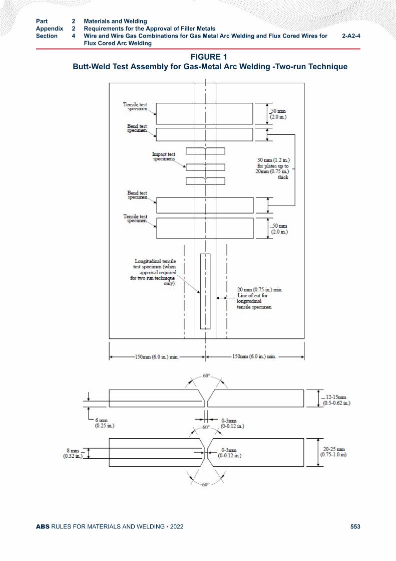
FIGURE 1 Butt-Weld Test Assembly for Gas-Metal Arc Welding -Two-run Technique
Part 2 Materials and WeldingAppendix 2 Requirements for the Approval of Filler MetalsSection 4 Wire and Wire Gas Combinations for Gas Metal Arc Welding and Flux Cored Wires for
Flux Cored Arc Welding2-A2-4
ABS RULES FOR MATERIALS AND WELDING • 2022 553
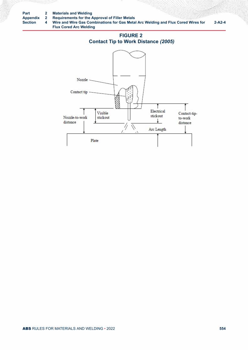
FIGURE 2 Contact Tip to Work Distance (2005)
Part 2 Materials and WeldingAppendix 2 Requirements for the Approval of Filler MetalsSection 4 Wire and Wire Gas Combinations for Gas Metal Arc Welding and Flux Cored Wires for
Flux Cored Arc Welding2-A2-4
ABS RULES FOR MATERIALS AND WELDING • 2022 554
A P P E N D I X 2Requirements for the Approval of Filler Metals
S E C T I O N 5Requirements for the Approval of Aluminum Filler Metals (2018)
1 General
1.1 ScopeThese requirements give the conditions of approval and inspection for welding consumables to be used inhull construction and marine structures using aluminum alloys according to Part 2, Chapter 5. Where nospecial requirements are given herein (e.g., for the approval procedure or for welding of test assembliesand testing), those of Sections 1 through 4 of Appendix 2 apply in analogous manner.
The welding consumables preferably to be used for aluminum alloys concerned are divided into twocategories as follows:
W = Wire electrode, and wire-gas combinations for GMAW, GTAW, or PAW
R = Rod-gas combinations for GTAW
1.3 Grading, Designation1.3.1
Consumables are graded as indicated in 2-A2-5/1.3.1 TABLE 1, in accordance with the alloy typeand strength level of base materials used for approval tests.
TABLE 1Consumable Grades and Base Materials for the Approval Test (2009)
Consumable Quality Grade(Symbol)
Base Materials for Tests
Alloy Designation
Numerical Chemical Symbol
RA/WA 5754 AlMg3
RB/WB 5086 AlMg4
PART 2
ABS RULES FOR MATERIALS AND WELDING • 2022 555
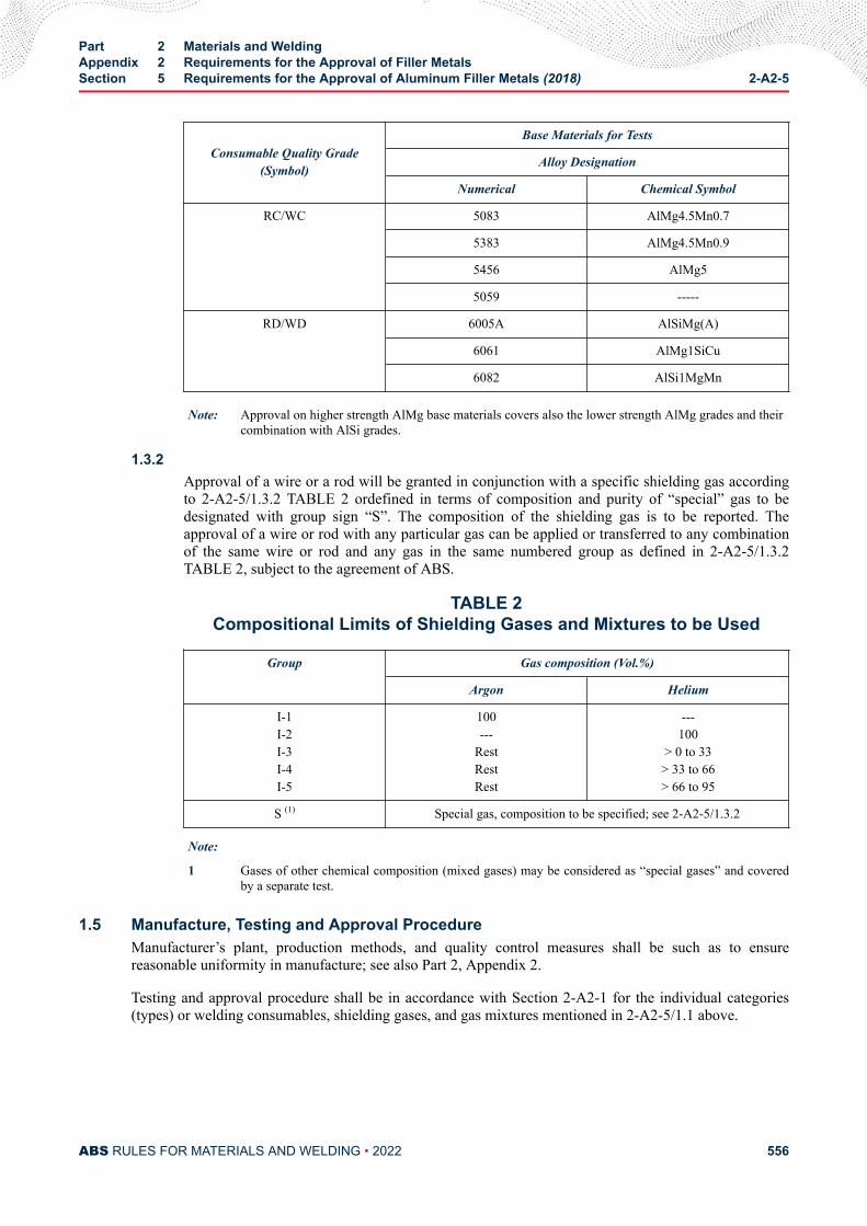
Consumable Quality Grade(Symbol)
Base Materials for Tests
Alloy Designation
Numerical Chemical Symbol
RC/WC 5083 AlMg4.5Mn0.7
5383 AlMg4.5Mn0.9
5456 AlMg5
5059 -----
RD/WD 6005A AlSiMg(A)
6061 AlMg1SiCu
6082 AlSi1MgMn
Note: Approval on higher strength AlMg base materials covers also the lower strength AlMg grades and theircombination with AlSi grades.
1.3.2Approval of a wire or a rod will be granted in conjunction with a specific shielding gas accordingto 2-A2-5/1.3.2 TABLE 2 ordefined in terms of composition and purity of “special” gas to bedesignated with group sign “S”. The composition of the shielding gas is to be reported. Theapproval of a wire or rod with any particular gas can be applied or transferred to any combinationof the same wire or rod and any gas in the same numbered group as defined in 2-A2-5/1.3.2TABLE 2, subject to the agreement of ABS.
TABLE 2Compositional Limits of Shielding Gases and Mixtures to be Used
Group Gas composition (Vol.%)
Argon Helium
I-1I-2I-3I-4I-5
100---
RestRestRest
---100
> 0 to 33> 33 to 66> 66 to 95
S (1) Special gas, composition to be specified; see 2-A2-5/1.3.2
Note:
1 Gases of other chemical composition (mixed gases) may be considered as “special gases” and coveredby a separate test.
1.5 Manufacture, Testing and Approval ProcedureManufacturer’s plant, production methods, and quality control measures shall be such as to ensurereasonable uniformity in manufacture; see also Part 2, Appendix 2.
Testing and approval procedure shall be in accordance with Section 2-A2-1 for the individual categories(types) or welding consumables, shielding gases, and gas mixtures mentioned in 2-A2-5/1.1 above.
Part 2 Materials and WeldingAppendix 2 Requirements for the Approval of Filler MetalsSection 5 Requirements for the Approval of Aluminum Filler Metals (2018) 2-A2-5
ABS RULES FOR MATERIALS AND WELDING • 2022 556
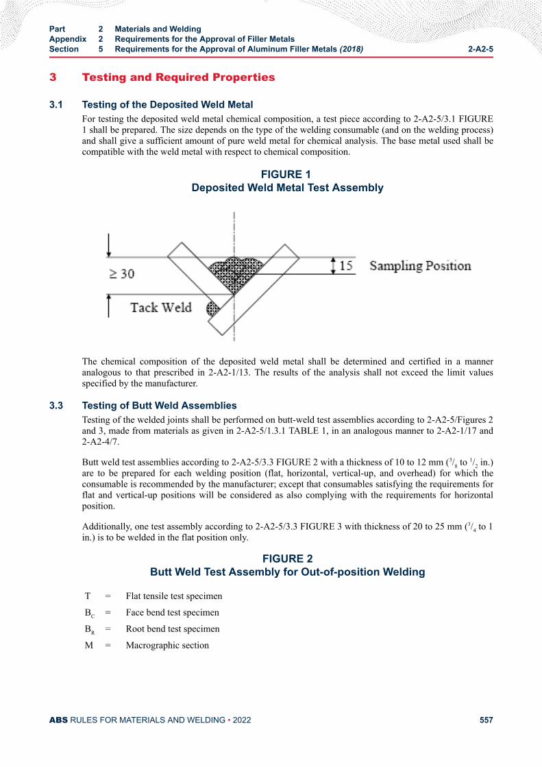
3 Testing and Required Properties
3.1 Testing of the Deposited Weld MetalFor testing the deposited weld metal chemical composition, a test piece according to 2-A2-5/3.1 FIGURE1 shall be prepared. The size depends on the type of the welding consumable (and on the welding process)and shall give a sufficient amount of pure weld metal for chemical analysis. The base metal used shall becompatible with the weld metal with respect to chemical composition.
FIGURE 1 Deposited Weld Metal Test Assembly
The chemical composition of the deposited weld metal shall be determined and certified in a manneranalogous to that prescribed in 2-A2-1/13. The results of the analysis shall not exceed the limit valuesspecified by the manufacturer.
3.3 Testing of Butt Weld AssembliesTesting of the welded joints shall be performed on butt-weld test assemblies according to 2-A2-5/Figures 2and 3, made from materials as given in 2-A2-5/1.3.1 TABLE 1, in an analogous manner to 2-A2-1/17 and2-A2-4/7.
Butt weld test assemblies according to 2-A2-5/3.3 FIGURE 2 with a thickness of 10 to 12 mm (3/8 to 1/2 in.)are to be prepared for each welding position (flat, horizontal, vertical-up, and overhead) for which theconsumable is recommended by the manufacturer; except that consumables satisfying the requirements forflat and vertical-up positions will be considered as also complying with the requirements for horizontalposition.
Additionally, one test assembly according to 2-A2-5/3.3 FIGURE 3 with thickness of 20 to 25 mm (3/4 to 1in.) is to be welded in the flat position only.
FIGURE 2Butt Weld Test Assembly for Out-of-position Welding
T = Flat tensile test specimen
BC = Face bend test specimen
BR = Root bend test specimen
M = Macrographic section
Part 2 Materials and WeldingAppendix 2 Requirements for the Approval of Filler MetalsSection 5 Requirements for the Approval of Aluminum Filler Metals (2018) 2-A2-5
ABS RULES FOR MATERIALS AND WELDING • 2022 557
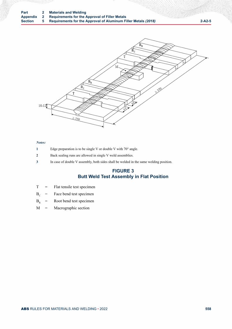
Notes:
1 Edge preparation is to be single V or double V with 70° angle.
2 Back sealing runs are allowed in single V weld assemblies.
3 In case of double V assembly, both sides shall be welded in the same welding position.
FIGURE 3Butt Weld Test Assembly in Flat Position
T = Flat tensile test specimen
BC = Face bend test specimen
BR = Root bend test specimen
M = Macrographic section
Part 2 Materials and WeldingAppendix 2 Requirements for the Approval of Filler MetalsSection 5 Requirements for the Approval of Aluminum Filler Metals (2018) 2-A2-5
ABS RULES FOR MATERIALS AND WELDING • 2022 558
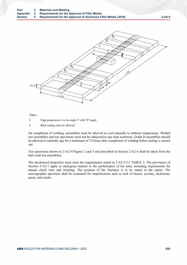
Notes:
1 Edge preparation is to be single V with 70° angle.
2 Back sealing runs are allowed.
On completion of welding, assemblies must be allowed to cool naturally to ambient temperature. Weldedtest assemblies and test specimens must not be subjected to any heat treatment. Grade D assemblies shouldbe allowed to naturally age for a minimum of 72 hours after completion of welding before testing is carriedout.
Test specimens shown in 2-A2-5/Figures 2 and 3 and described in Section 2-A2-4 shall be taken from thebutt weld test assemblies.
The mechanical properties must meet the requirements stated in 2-A2-5/3.3 TABLE 3. The provisions ofSection 2-A2-1 apply in analogous manner to the performance of the tests, including requirements forannual check tests and retesting. The position of the fractures is to be stated in the report. Themacrographic specimen shall be examined for imperfections such as lack of fusion, cavities, inclusions,pores, and cracks.
Part 2 Materials and WeldingAppendix 2 Requirements for the Approval of Filler MetalsSection 5 Requirements for the Approval of Aluminum Filler Metals (2018) 2-A2-5
ABS RULES FOR MATERIALS AND WELDING • 2022 559
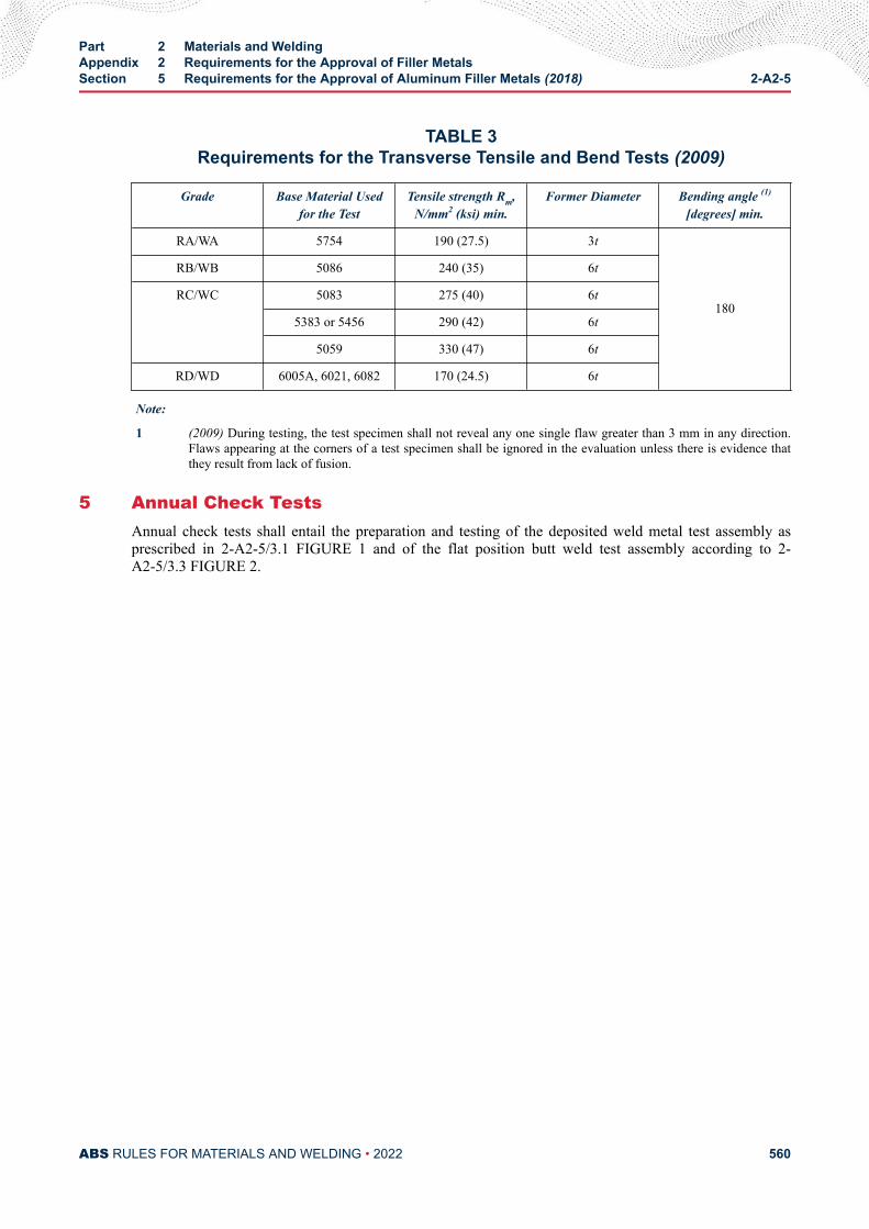
TABLE 3Requirements for the Transverse Tensile and Bend Tests (2009)
Grade Base Material Usedfor the Test
Tensile strength Rm,N/mm2 (ksi) min.
Former Diameter Bending angle (1)
[degrees] min.
RA/WA 5754 190 (27.5) 3t
180
RB/WB 5086 240 (35) 6t
RC/WC 5083 275 (40) 6t
5383 or 5456 290 (42) 6t
5059 330 (47) 6t
RD/WD 6005A, 6021, 6082 170 (24.5) 6t
Note:
1 (2009) During testing, the test specimen shall not reveal any one single flaw greater than 3 mm in any direction.Flaws appearing at the corners of a test specimen shall be ignored in the evaluation unless there is evidence thatthey result from lack of fusion.
5 Annual Check TestsAnnual check tests shall entail the preparation and testing of the deposited weld metal test assembly asprescribed in 2-A2-5/3.1 FIGURE 1 and of the flat position butt weld test assembly according to 2-A2-5/3.3 FIGURE 2.
Part 2 Materials and WeldingAppendix 2 Requirements for the Approval of Filler MetalsSection 5 Requirements for the Approval of Aluminum Filler Metals (2018) 2-A2-5
ABS RULES FOR MATERIALS AND WELDING • 2022 560
A P P E N D I X 3Application of Filler Metals to ABS Steels
CONTENTSSECTION 1 Application of Filler Metals to ABS Steels (2014)......................... 562
PART 2
ABS RULES FOR MATERIALS AND WELDING • 2022 561
A P P E N D I X 3Application of Filler Metals to ABS Steels
S E C T I O N 1Application of Filler Metals to ABS Steels (2014)
A chart indicating acceptable ABS filler metal grades for welding various ABS grades of hull steel is givenbelow.
(2021)
ABS Hull Structural Steel Acceptable ABS Filler Metal Grade
Ordinary Strength
A to 12.5 mm (1/2 in.) inclusive 1, 2, 3, 1Y**, 2Y, 3Y, 4Y
A over 12.5 mm (1/2 in.), B, D 2, 3, 2Y, 3Y, 4Y
E 3, 3Y, 4Y
Higher Strength (2009)*
AH 32/36 to 12.5 mm (1/2 in.) inclusive 1Y, 2Y**, 2Y400, 3Y, 3Y400, 4Y, 4Y400, 5Y400
AH 32/36 over 12.5 mm (1/2 in.), DH32/36 2Y, 2Y400, 3Y, 3Y400, 4Y, 4Y400, 5Y400
EH32/36 3Y, 3Y400, 4Y, 4Y400, 5Y400
FH32/36 4Y, 4Y400, 5Y400
AH40, DH40 2Y400, 3Y400, 4Y400, 5Y400
EH40 3Y400, 4Y400, 5Y400
FH40 4Y400, 5Y400
Extra High Strength
XQ43 ZYQ420, ZYQ460***, ZYQ500***
XQ47 ZYQ460, ZYQ500***
XQ51 ZYQ500, ZYQ550***
XQ56 ZYQ550, ZYQ620***
XQ63 ZYQ620, ZYQ690***
XQ70 ZYQ690
PART 2
ABS RULES FOR MATERIALS AND WELDING • 2022 562
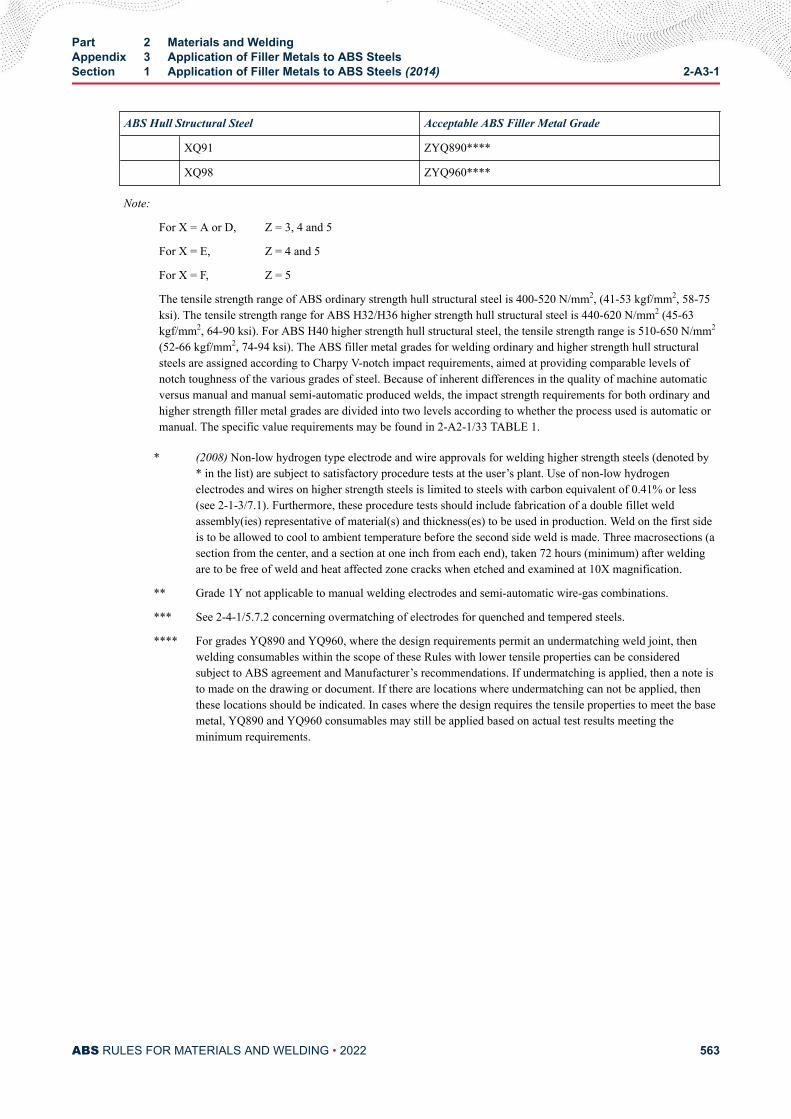
ABS Hull Structural Steel Acceptable ABS Filler Metal Grade
XQ91 ZYQ890****
XQ98 ZYQ960****
Note:
For X = A or D, Z = 3, 4 and 5
For X = E, Z = 4 and 5
For X = F, Z = 5
The tensile strength range of ABS ordinary strength hull structural steel is 400-520 N/mm2, (41-53 kgf/mm2, 58-75ksi). The tensile strength range for ABS H32/H36 higher strength hull structural steel is 440-620 N/mm2 (45-63kgf/mm2, 64-90 ksi). For ABS H40 higher strength hull structural steel, the tensile strength range is 510-650 N/mm2
(52-66 kgf/mm2, 74-94 ksi). The ABS filler metal grades for welding ordinary and higher strength hull structuralsteels are assigned according to Charpy V-notch impact requirements, aimed at providing comparable levels ofnotch toughness of the various grades of steel. Because of inherent differences in the quality of machine automaticversus manual and manual semi-automatic produced welds, the impact strength requirements for both ordinary andhigher strength filler metal grades are divided into two levels according to whether the process used is automatic ormanual. The specific value requirements may be found in 2-A2-1/33 TABLE 1.
* (2008) Non-low hydrogen type electrode and wire approvals for welding higher strength steels (denoted by* in the list) are subject to satisfactory procedure tests at the user’s plant. Use of non-low hydrogenelectrodes and wires on higher strength steels is limited to steels with carbon equivalent of 0.41% or less(see 2-1-3/7.1). Furthermore, these procedure tests should include fabrication of a double fillet weldassembly(ies) representative of material(s) and thickness(es) to be used in production. Weld on the first sideis to be allowed to cool to ambient temperature before the second side weld is made. Three macrosections (asection from the center, and a section at one inch from each end), taken 72 hours (minimum) after weldingare to be free of weld and heat affected zone cracks when etched and examined at 10X magnification.
** Grade 1Y not applicable to manual welding electrodes and semi-automatic wire-gas combinations.
*** See 2-4-1/5.7.2 concerning overmatching of electrodes for quenched and tempered steels.
**** For grades YQ890 and YQ960, where the design requirements permit an undermatching weld joint, thenwelding consumables within the scope of these Rules with lower tensile properties can be consideredsubject to ABS agreement and Manufacturer’s recommendations. If undermatching is applied, then a note isto made on the drawing or document. If there are locations where undermatching can not be applied, thenthese locations should be indicated. In cases where the design requires the tensile properties to meet the basemetal, YQ890 and YQ960 consumables may still be applied based on actual test results meeting theminimum requirements.
Part 2 Materials and WeldingAppendix 3 Application of Filler Metals to ABS SteelsSection 1 Application of Filler Metals to ABS Steels (2014) 2-A3-1
ABS RULES FOR MATERIALS AND WELDING • 2022 563
A P P E N D I X 4Procedure for the Approval of Manufacturers of Hull Structural Steel
(2003)
CONTENTSSECTION 1 Procedure for the Approval of Manufacturers of Semi-
Finished Products for Hull Structural Steel (2010)....................... 5661 Scope .........................................................................................5663 Approval Application...................................................................566
3.1 Documents to be Submitted.......................................... 5665 Approval Tests............................................................................ 568
5.1 Extent of the approval tests........................................... 5685.3 Approval Test Program.................................................. 5685.5 Approval Survey............................................................ 5685.7 Selection of the Test Product......................................... 5685.9 Position of the Test Samples......................................... 5695.11 Tests on Base Material (2012)....................................... 569
7 Results........................................................................................5699 Certification.................................................................................570
9.1 Approval.........................................................................5709.3 List of Approved Manufacturers.....................................570
11 Renewal of Approval...................................................................57013 Withdrawal of the Approval.........................................................570
SECTION 2 Procedure for the Approval of Manufacturers of Rolled HullStructural Steel (2010)..................................................................... 5721 Scope .........................................................................................5723 Approval Application...................................................................572
3.1 Documents to be Submitted.......................................... 5725 Approval Tests............................................................................ 575
5.1 Extent of the Approval Tests.......................................... 5755.3 Approval Test Program.................................................. 5755.5 Approval Survey............................................................ 5755.7 Selection of the Test Product......................................... 5755.9 Position of the Test Samples......................................... 5765.11 Tests on Base Material.................................................. 576
PART 2
ABS RULES FOR MATERIALS AND WELDING • 2022 564
5.13 Weldability Tests............................................................ 5787 Results........................................................................................5799 Certification.................................................................................579
9.1 Approval.........................................................................5799.3 List of Approved Manufacturers.....................................579
11 Renewal of Approval (2007)....................................................... 58013 Withdrawal of the Approval.........................................................580
TABLE 1 Tests for Rolled Products Manufacturer Approval..............576
SECTION 3 Procedure for the Approval of Manufacturers of Extra HighStrength Steels (2018)..................................................................... 5811 Scope..........................................................................................5813 Approval Application...................................................................581
3.1 Documents to be Submitted.......................................... 5815 Approval Tests............................................................................ 584
5.1 Extent of the Approval Tests.......................................... 5845.3 Approval Test Program.................................................. 5845.5 Approval Survey............................................................ 5845.7 Selection of the Test Product......................................... 5855.9 Position of the Test Samples and Specimens................5855.11 Tests on Base Material.................................................. 585
7 Results........................................................................................5919 Certification.................................................................................591
9.1 Approval.........................................................................5919.3 List of Approved Manufacturers.....................................591
11 Maintenance and Renewal of Approval......................................59213 Withdrawal of the Approval.........................................................592
TABLE 1 Tests on Base Material(2018)............................................ 585
FIGURE 1A Plate Thickness t ≤ 50 mm (2018)..................................... 590FIGURE 1B Plate Thickness t > 50 mm (2018)..................................... 591
ABS RULES FOR MATERIALS AND WELDING • 2022 565
A P P E N D I X 4Procedure for the Approval of Manufacturers of Hull Structural Steel
(2003)
S E C T I O N 1Procedure for the Approval of Manufacturers of Semi-Finished Products
for Hull Structural Steel (2010)
1 ScopeIn accordance with 2-1-1/1.2, this Section provides specific requirements for the approval of manufacturersof semi-finished products such as ingots, slabs, blooms and billets for hull structural steels. Slabs, blooms,and billets can also be supplied in the partially-rolled condition.
The manufacturer approval procedure is intended to verify the manufacturer’s capability of furnishingsatisfactory products in a consistent manner under effective process and production controls in operation,as required in 2-1-1/1.2.2.
3 Approval Application
3.1 Documents to be Submitted3.1.1 Initial Approval
The manufacturer is to submit to ABS request of approval together with proposed approval testprogram (see 2-A4-1/5.1) and general information relative to:
3.1.1(a) Name and address of the manufacturer, location of the workshops, general indicationsrelevant to the background, dimension of the works, estimated total annual production of semi-finished products for shipbuilding and for other applications, as deemed useful.
3.1.1(b) Organization and Quality
● Organizational chart
● Staff employed
● Organization of the quality control department and its staff employed
● Qualification of the personnel involved in activities related to the quality of the products
● Certification of compliance of the quality system with IS0 9001 or 9002, if any.
● Approval certificates already granted by other Classification Societies, if any.
PART 2
ABS RULES FOR MATERIALS AND WELDING • 2022 566
3.1.1(c) Manufacturing facilities
● Flow chart of the manufacturing process
● Origin and storage of raw materials
● Storage of semi-finished products
● Equipment for systematic control during fabrication
3.1.1(d) Details of inspections and quality control facilities
● Details of system used for identification of materials at the different stages of manufacturing
● Equipment for mechanical tests, chemical analyses and metallography and relevant calibrationprocedures
● Equipment for nondestructive examinations
● List of quality control procedures
3.1.1(e) Type of Products (ingots, slabs, blooms, billets), Types of Steel (normal or higherstrength), Range of Thickness and Target Material Properties as Follows:
● Range of chemical composition and target analyses, including grain refining, micro alloyingand residual elements, for the various grades of steel; if the range of chemical compositiondepends on thickness and supply condition, the different ranges are to be specified, asappropriate
● Target maximum carbon equivalent according to IIW formula
● Target maximum Pcm content for higher strength grades with low carbon content C < 0.13%
● Production statistics of the chemical composition and, if available at rolling mills, mechanicalproperties (ReH, Rm, A% and KV). The statistics are intended to demonstrate the capabilityto manufacture the steel products in accordance with the requirements.
3.1.1(f) Steelmaking
● Steel making process and capacity of furnace/s or converter/s
● Raw material used
● Deoxidation and alloying practice
● Desulphurization and vacuum degassing installations, if any
● Casting methods: ingot or continuous casting. In the case of continuous casting, informationrelevant to type of casting machine, teeming practice, methods to prevent re-oxidation,inclusions and segregation control, presence of electromagnetic stirring, soft reduction, etc., isto be provided, as appropriate.
● Ingot or slab size and weight
● Ingot or slab treatment: scarfing and discarding procedures
3.1.1(g) Approval already granted by the other Classification Societies and documentation ofapproval tests performed.
3.1.1(h) Where any part of the manufacturing process is assigned to other companies or othermanufacturing plants, additional information required by ABS is to be included.
Part 2 Materials and WeldingAppendix 4 Procedure for the Approval of Manufacturers of Hull Structural Steel (2003)Section 1 Procedure for the Approval of Manufacturers of Semi-Finished Products for Hull
Structural Steel (2010)2-A4-1
ABS RULES FOR MATERIALS AND WELDING • 2022 567
3.1.2 Changes to the Approval ConditionsWhere any one or more of the following cases 2-A4-1/3.1.2(a) through 2-A4-1/3.1.2(c) areapplicable, the manufacturer is to submit to ABS the documents required in 2-A4-1/3.1.1 togetherwith the request of changing the approval conditions,
3.1.2(a) Change of the manufacturing process (steel making, casting, steel making plant, caster)
3.1.2(b) Change of the maximum thickness (dimension)
3.1.2(c) Change of the chemical composition, added element, etc.
However, where the documents are duplicated by the ones at the previous approval for the sametype of product, part or all of the documents may be omitted, except the approval test program(see 2-A4-1/5.1).
5 Approval Tests
5.1 Extent of the approval testsThe extent of the test program is specified in 2-A4-1/5.11. The test program may be modified on the basisof the preliminary information submitted by the manufacturer.
In particular, a reduction of the indicated number of casts, product thicknesses and types to be tested orcomplete omission of the approval tests may be considered, taking into account:
i) Approval already granted by other Classification Societies and documentation of approval testsperformed
ii) Types of steel to be approved and availability of long-term historical statistic results of chemicalproperties and of mechanical properties tested on rolled products
iii) Change of the approval conditions
On the other hand, an increase of the number of casts and thicknesses to be tested may be required in thecase of newly developed types of steel or manufacturing processes.
5.3 Approval Test ProgramWhere the number of tests differs from those shown in 2-A4-1/5.11, the program is to be confirmed byABS before the commencement of the tests.
5.5 Approval SurveyThe approval tests are to be witnessed by the Surveyor at the manufacturer’s plant. An inspection by theSurveyor of the plant in operation will be required.
If the testing facilities are not available at the works, the tests are to be carried out at recognizedlaboratories.
5.7 Selection of the Test ProductFor each type of steel and for each manufacturing process (e.g., steel making, casting), one test productwith the maximum thickness (dimension) and one test product with the minimum thickness to be approvedare, in general, to be selected for each kind of product (ingots, slabs, blooms/billets).
In addition, for initial approval, ABS will require selection of one test product of average thickness.
Part 2 Materials and WeldingAppendix 4 Procedure for the Approval of Manufacturers of Hull Structural Steel (2003)Section 1 Procedure for the Approval of Manufacturers of Semi-Finished Products for Hull
Structural Steel (2010)2-A4-1
ABS RULES FOR MATERIALS AND WELDING • 2022 568
The selection of the casts for the test product is to be based on the typical chemical composition, withparticular regard to the specified Ceq or Pcm values and grain refining micro-alloying additions.
5.9 Position of the Test SamplesThe test samples are to be taken, unless otherwise agreed, from the product (slabs, blooms, billets)corresponding to the top of the ingot, or, in the case of continuous casting, a random sample.
5.11 Tests on Base Material (2012)5.11.1 Type of Tests (2022)
The tests to be carried out for the approval of the manufacturing process of semi-finished productsare:
i) Chemical analysis. The analysis is to be complete including micro alloying elements.
ii) Sulphur prints and photomacrograph (acid etched) pictures. Alternatively, non-metallicinclusion content may be proposed in lieu of Sulphur prints.
In addition, for initial approval and for any upgrade of the approval, ABS will require full testsindicated in 2-A4-2/5 to be performed at rolling mill on the minimum thickness semi-finishedproduct.
In case of a multi-caster work, full tests on finished products shall be carried out for one caster andreduced tests (chemical analysis, sulphur print, and photomacrograph picture) for the others. Theselection of the caster shall be based on the technical characteristics of the casters to be evaluatedon case by case basis to be performed at rolling mill on products manufactured from the minimumthickness semi-finished product.
5.11.2 Test Specimens and Testing ProcedureThe test specimens and testing procedures are to be, as a rule, in accordance with Section 2-1-1with particular attention to the following:
5.11.2(a) Chemical analyses.Both the ladle and product analyses are to be reported. In general, the content of the followingelements is to be checked: C, Mn, Si, P, S, Ni, Cr, Mo, Al, N, Nb, V, Cu, As, Sn, Ti, Ca, and, forsteel manufactured from electric or open-hearth furnace, Sb and B.
5.11.2(b) Sulphur Prints and Photomacrograph (Acid Etched) Pictures.Sulphur prints and photomacrograph pictures are to be taken from product edges which areperpendicular to the axis of the ingot or slab (full transverse cross-section). These sulphur printsand photomacrograph pictures are to be approximately 600 mm long, taken from the center of theedge selected (i.e., on the ingot centerline) and are to include the full product thickness.
5.11.2(c) Non-Metallic Inclusion Content. (2022)The level of non-metallic inclusions and impurities in term of amount, size, shape and distributionshall be controlled by the manufacturer. The standards of the micrographic examination methodsISO 4967 or ASTM E45 or equivalent standards are applicable. Alternative methods fordemonstrating the non-metallic inclusions and impurities may be used by the manufacturer.
7 ResultsBefore the approval, all test results are evaluated for compliance with the Rules. Depending upon thefinding, limitations or testing conditions, as deemed appropriate, may be specified in the approvaldocument.
Part 2 Materials and WeldingAppendix 4 Procedure for the Approval of Manufacturers of Hull Structural Steel (2003)Section 1 Procedure for the Approval of Manufacturers of Semi-Finished Products for Hull
Structural Steel (2010)2-A4-1
ABS RULES FOR MATERIALS AND WELDING • 2022 569
All information required under 2-A4-2/3, applicable to the products submitted to the tests, is to becollected by the manufacturer and incorporated into a single document including all test results andoperation records relevant to steel making, casting, and when applicable, rolling and heat treatment of thetested products.
9 Certification
9.1 ApprovalUpon satisfactory completion of the survey, approval will be granted by ABS.
The following information is to be stated on the approval certificate:
i) Type of products (ingots, slabs, blooms, billets)
ii) Steelmaking and casting processes
iii) Thickness range of the semi-finished products
iv) Types of steel (normal or higher strength)
It is also to be indicated that the individual users of the semi-finished products are to be approved for themanufacturing process of the specific grade of rolled steel products they are going to manufacture withthose semi-finished products.
9.3 List of Approved ManufacturersThe approved manufacturers are entered in a list containing the types of steel and the main conditions ofapproval.
11 Renewal of ApprovalThe validity of the approval is to be to the maximum of five years, renewable subject to an audit andassessment of the result of satisfactory survey during the preceding period. The Surveyor’s reportconfirming no process changes, along with mechanical property statistical data for various approved types,is to be made available to the ABS Engineering/Materials department for review and issuance of renewalletter/certificate. *
Where for operational reasons, the renewal audit cannot be carried out within the validity of approval, themanufacturer will still be considered as being approved if agreement to such extension of audit date isprovided for in the original approval. In such instance, the extension of approval will be backdated to theoriginal renewal date.
Manufacturers who have not produced the approved types and products during the period preceding therenewal may be required to carry out approval tests, unless the results of production of similar types ofproducts during the period are evaluated by ABS and found acceptable for renewal.
Note:
* The provisions for renewal of approval are also applicable to all grades and products which were approved by ABS prior toan implementation of 2-1-1/1.2 and this Appendix, regardless of any validity of prior approval. Such renewal is to becompleted before 1 January 2008, that is, within five years after the 1 January 2003 effective date of this Rule change.
13 Withdrawal of the ApprovalThe approval may be withdrawn before the expiry of the validity period in the following cases:
i) In-service failures traceable to product quality
ii) Nonconformity of the product revealed during fabrication and construction
Part 2 Materials and WeldingAppendix 4 Procedure for the Approval of Manufacturers of Hull Structural Steel (2003)Section 1 Procedure for the Approval of Manufacturers of Semi-Finished Products for Hull
Structural Steel (2010)2-A4-1
ABS RULES FOR MATERIALS AND WELDING • 2022 570
iii) Discovery of failure of the manufacturer’s quality system
iv) Changes made by the manufacturer, without prior agreement of ABS, to the extent of the approvaldefined at the time of the approval
v) Evidence of major nonconformities during testing of the products.
Part 2 Materials and WeldingAppendix 4 Procedure for the Approval of Manufacturers of Hull Structural Steel (2003)Section 1 Procedure for the Approval of Manufacturers of Semi-Finished Products for Hull
Structural Steel (2010)2-A4-1
ABS RULES FOR MATERIALS AND WELDING • 2022 571
A P P E N D I X 4Procedure for the Approval of Manufacturers of Hull Structural Steel
(2003)
S E C T I O N 2Procedure for the Approval of Manufacturers of Rolled Hull Structural
Steel (2010)
1 ScopeIn accordance with 2-1-1/1.2, this Appendix provides specific requirements for the approval ofmanufacturers of rolled hull structural steel.
The manufacturer approval procedure is intended to verify the manufacturer’s capability of furnishingsatisfactory products in a consistent manner under effective process and production controls in operationincluding programmed rolling.
3 Approval Application
3.1 Documents to be Submitted3.1.1 Initial Approval
The manufacturer is to submit to ABS request of approval together with proposed approval testprogram (see 2-A4-2/5.1) and general information relative to:
3.1.1(a) Name and address of the manufacturer, location of the workshops, general indicationsrelevant to the background, dimension of the works, estimated total annual production of finishedproducts for shipbuilding and for other applications, as deemed useful.
3.1.1(b) Organization and Quality
● Organizational chart
● Staff employed
● Organization of the quality control department and its staff employed
● Qualification of the personnel involved in activities related to the quality of the products
● Certification of compliance of the quality system with IS0 9001 or 9002, if any.
● Approval certificates already granted by other Classification Societies, if any.
3.1.1(c) Manufacturing Facilities
PART 2
ABS RULES FOR MATERIALS AND WELDING • 2022 572
● Flow chart of the manufacturing process
● Origin and storage of raw materials
● Storage of finished products
● Equipment for systematic control during fabrication
3.1.1(d) Details of Inspections and Quality Control Facilities
● Details of system used for identification of materials at the different stages of manufacturing
● Equipment for mechanical tests, chemical analyses and metallography and relevant calibrationprocedures
● Equipment for non destructive examinations
● List of quality control procedures
3.1.1(e) Type of Products (plates, sections, coils), Grades of Steel, Range of Thickness and TargetMaterial Properties as Follows:
● Range of chemical composition and aim analyses, including grain refining, micro alloying andresidual elements, for the various grades of steel; if the range of chemical compositiondepends on thickness and supply condition, the different ranges are to be specified, asappropriate
● Target maximum carbon equivalent according to IIW formula
● Target maximum Pcm content for higher strength grades with low carbon content C < 0.13%
● Production statistics of the chemical composition and mechanical properties (ReH, Rm, A%and KV). The statistics are intended to demonstrate the capability to manufacture the steelproducts in accordance with the requirements.
3.1.1(f) Steelmaking
● Steel making process and capacity of furnace/s or converter/s
● Raw material used
● Deoxidation and alloying practice
● Desulphurisation and vacuum degassing installations, if any
● Casting methods: ingot or continuous casting. In the case of continuous casting, informationrelevant to type of casting machine, teeming practice, methods to prevent re-oxidation,inclusions and segregation control, presence of electromagnetic stirring, soft reduction, etc., isto be provided, as appropriate.
● Ingot or slab size and weight
● Ingot or slab treatment: scarfing and discarding procedures
3.1.1(g) Reheating and Rolling
● Type of furnace and treatment parameters
● Rolling: reduction ratio of slab/bloom/billet to finished product thickness, rolling andfinishing temperatures
● Descaling treatment during rolling
● Capacity of the rolling stands
3.1.1(h) Heat Treatment
Part 2 Materials and WeldingAppendix 4 Procedure for the Approval of Manufacturers of Hull Structural Steel (2003)Section 2 Procedure for the Approval of Manufacturers of Rolled Hull Structural Steel (2010) 2-A4-2
ABS RULES FOR MATERIALS AND WELDING • 2022 573
● Type of furnaces, heat treatment parameters and their relevant records
● Accuracy and calibration of temperature control devices
3.1.1(i) Programmed Rolling.
For products delivered in the controlled rolling (CR) or thermo-mechanical rolling (TM)condition, the following additional information on the programmed rolling schedules is to begiven:
● Description of the rolling process
● Normalizing temperature, re-crystallization temperature and Ar3 temperature and the methodsused to determine them
● Control standards for typical rolling parameters used for the different thickness and grades ofsteel (temperature and thickness at the beginning and at the end of the passes, intervalbetween passes, reduction ratio, temperature range and cooling speed of accelerated cooling,if any) and relevant method of control
● Calibration of the control equipment
3.1.1(j) Recommendations for working and welding, in particular, for products delivered in the CRor TM condition
● Cold and hot working recommendations, if needed, in addition to the normal practice used inthe shipyards and workshops
● Minimum and maximum heat input, if different from the ones usually used in the shipyardsand workshops (15 – 50 kJ/cm)
3.1.1(k) Where any part of the manufacturing process is assigned to other companies or othermanufacturing plants, additional information required by ABS is to be included.
3.1.1(l) (2010) Approval already granted by other IACS Member Societies and documentation ofapproval tests performed.
3.1.2 Changes to the Approval ConditionsWhere any one or more of the following cases 2-A4-2/3.1.2(a) through 2-A4-2/3.1.2(e) areapplicable, the manufacturer is to submit to ABS the documents required in 2-A4-2/3.1.1 togetherwith the request of changing the approval conditions,
3.1.2(a) Change of the manufacturing process (steel making, casting, rolling and heat treatment)
3.1.2(b) Change of the maximum thickness (dimension)
3.1.2(c) Change of the chemical composition, added element, etc.
3.1.2(d) Subcontracting the rolling, heat treatment, etc.
3.1.2(e) (2010) Use of the slabs, blooms and billets manufactured by companies other than theones verified in the approval tests.
However, where the documents are duplicated by the ones at the previous approval for the sametype of product, part or all of the documents may be omitted, except the approval test program(see 2-A4-2/5.1).
Part 2 Materials and WeldingAppendix 4 Procedure for the Approval of Manufacturers of Hull Structural Steel (2003)Section 2 Procedure for the Approval of Manufacturers of Rolled Hull Structural Steel (2010) 2-A4-2
ABS RULES FOR MATERIALS AND WELDING • 2022 574
5 Approval Tests
5.1 Extent of the Approval Tests (2022)The extent of the test program is specified in 2-A4-2/5.11 and 2-A4-2/5.13. The test program may bemodified on the basis of the preliminary information submitted by the manufacturer.
In particular, a reduction of the indicated number of casts, steel plate or tubular thicknesses and grades tobe tested or complete omission of the approval tests may be considered, taking into account:
i) Approval already granted by other Classification Societies and documentation of approval testsperformed
ii) Grades of steel to be approved and availability of long term historical statistic results of chemicaland mechanical properties
iii) Approval for any grade of steel also covers approval for any lower grade in the same strengthlevel, provided that the target analyses, method of manufacture and condition of supply aresimilar.
iv) For higher tensile steels, approval of one strength level covers the approval of the strength levelimmediately below, provided the steelmaking process, deoxidation and fine grain practice, castingmethod and condition of supply are the same.
v) Change of the approval conditions
On the other hand, an increase of the number of casts and thicknesses to be tested may be required in thecase of newly developed types of steel or manufacturing processes.
In case of multi-source slabs or changing of slab manufacturer, the rolled steel manufacturer is required toobtain the approval of the manufacturing process of rolled steels using the slabs from each slabmanufacturer and to conduct approval tests in accordance with 2-A4-2/5.11 and 2-A4-2/5.13. A reductionor complete omission of the approval tests may be considered, taking into account previous approval asfollows:
● The rolled steel manufacturer has already been approved for the manufacturing process using othersemi-finished products characterized by the same thickness, steel grade, grain refining and micro-alloying elements, steel making and casting process;
● The semi-finished products manufacturer has been approved for the complete manufacturing processwith the same conditions (steelmaking, casting, rolling and heat treatment) for the same steel types.
5.3 Approval Test ProgramWhere the number of tests differs from those shown in 2-A4-2/5.11 and 2-A4-2/5.13, the program is to beconfirmed by ABS before the commencement of the tests.
5.5 Approval SurveyThe approval tests are to be witnessed by the Surveyor at the manufacturer’s plant. An inspection by theSurveyor of the plant in operation will be required.
If the testing facilities are not available at the works, the tests are to be carried out at recognizedlaboratories.
5.7 Selection of the Test ProductFor each grade of steel and for each manufacturing process (e.g., steel making, casting, rolling andcondition of supply), one test product with the maximum thickness (dimension) to be approved is, ingeneral, to be selected for each kind of product.
In addition, for initial approval, ABS will require selection of one test product of average thickness.
Part 2 Materials and WeldingAppendix 4 Procedure for the Approval of Manufacturers of Hull Structural Steel (2003)Section 2 Procedure for the Approval of Manufacturers of Rolled Hull Structural Steel (2010) 2-A4-2
ABS RULES FOR MATERIALS AND WELDING • 2022 575
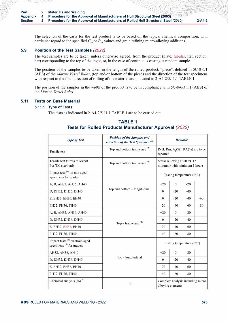
The selection of the casts for the test product is to be based on the typical chemical composition, withparticular regard to the specified Ceq or Pcm values and grain refining micro-alloying additions.
5.9 Position of the Test Samples (2022)The test samples are to be taken, unless otherwise agreed, from the product (plate, tubular, flat, section,bar) corresponding to the top of the ingot, or, in the case of continuous casting, a random sample.
The position of the samples to be taken in the length of the rolled product, “piece”, defined in 5C-8-6/1(ABS) of the Marine Vessel Rules, (top and/or bottom of the piece) and the direction of the test specimenswith respect to the final direction of rolling of the material are indicated in 2-A4-2/5.11.1 TABLE 1.
The position of the samples in the width of the product is to be in compliance with 5C-8-6/3.5.1 (ABS) ofthe Marine Vessel Rules.
5.11 Tests on Base Material5.11.1 Type of Tests
The tests as indicated in 2-A4-2/5.11.1 TABLE 1 are to be carried out.
TABLE 1Tests for Rolled Products Manufacturer Approval (2022)
Type of Test Position of the Samples andDirection of the Test Specimen (1) Remarks
Tensile test Top and bottom transverse (2) ReH, Rm, A5(%), RA(%) are to bereported
Tensile test (stress relieved)For TM steel only Top and bottom transverse (2) Stress relieving at 600°C (2
min/mm) with minimum 1 hour)
Impact tests(3) on non agedspecimens for grades:
Top and bottom – longitudinal
Testing temperature (0°C)
A, B, AH32, AH36, AH40 +20 0 -20
D, DH32, DH36, DH40 0 -20 -40
E, EH32, EH36, EH40 0 -20 -40 -60
FH32, FH36, FH40 -20 -40 -60 -80
A, B, AH32, AH36, AH40
Top – transverse (4)
+20 0 -20
D, DH32, DH36, DH40 0 -20 -40
E, EH32, EH36, EH40 -20 -40 -60
FH32, FH36, FH40 -40 -60 -80
Impact tests (3) on strain agedspecimens (5) for grades:
Top - longitudinal
Testing temperature (0°C)
AH32, AH36, AH40 +20 0 -20
D, DH32, DH36, DH40 0 -20 -40
E, EH32, EH36, EH40 -20 -40 -60
FH32, FH36, FH40 -40 -60 -80
Chemical analysis (%) (6)Top Complete analysis including micro
alloying elements
Part 2 Materials and WeldingAppendix 4 Procedure for the Approval of Manufacturers of Hull Structural Steel (2003)Section 2 Procedure for the Approval of Manufacturers of Rolled Hull Structural Steel (2010) 2-A4-2
ABS RULES FOR MATERIALS AND WELDING • 2022 576
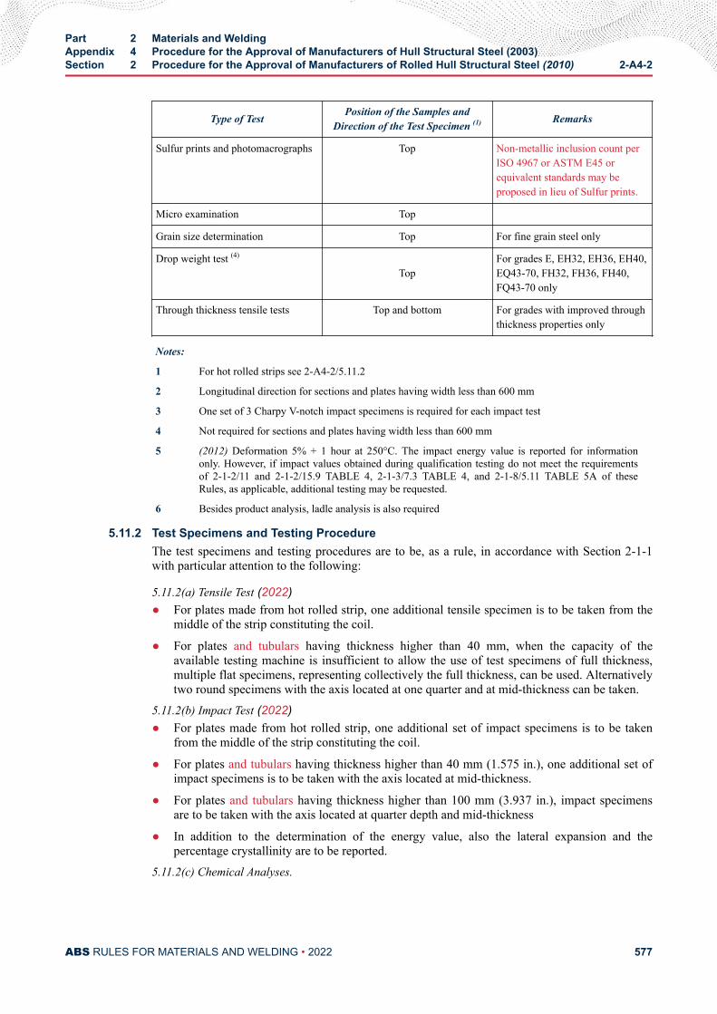
Type of Test Position of the Samples andDirection of the Test Specimen (1) Remarks
Sulfur prints and photomacrographs Top Non-metallic inclusion count perISO 4967 or ASTM E45 orequivalent standards may beproposed in lieu of Sulfur prints.
Micro examination Top
Grain size determination Top For fine grain steel only
Drop weight test (4)
TopFor grades E, EH32, EH36, EH40,EQ43-70, FH32, FH36, FH40,FQ43-70 only
Through thickness tensile tests Top and bottom For grades with improved throughthickness properties only
Notes:
1 For hot rolled strips see 2-A4-2/5.11.2
2 Longitudinal direction for sections and plates having width less than 600 mm
3 One set of 3 Charpy V-notch impact specimens is required for each impact test
4 Not required for sections and plates having width less than 600 mm
5 (2012) Deformation 5% + 1 hour at 250°C. The impact energy value is reported for informationonly. However, if impact values obtained during qualification testing do not meet the requirementsof 2-1-2/11 and 2-1-2/15.9 TABLE 4, 2-1-3/7.3 TABLE 4, and 2-1-8/5.11 TABLE 5A of theseRules, as applicable, additional testing may be requested.
6 Besides product analysis, ladle analysis is also required
5.11.2 Test Specimens and Testing ProcedureThe test specimens and testing procedures are to be, as a rule, in accordance with Section 2-1-1with particular attention to the following:
5.11.2(a) Tensile Test (2022)● For plates made from hot rolled strip, one additional tensile specimen is to be taken from the
middle of the strip constituting the coil.
● For plates and tubulars having thickness higher than 40 mm, when the capacity of theavailable testing machine is insufficient to allow the use of test specimens of full thickness,multiple flat specimens, representing collectively the full thickness, can be used. Alternativelytwo round specimens with the axis located at one quarter and at mid-thickness can be taken.
5.11.2(b) Impact Test (2022)● For plates made from hot rolled strip, one additional set of impact specimens is to be taken
from the middle of the strip constituting the coil.
● For plates and tubulars having thickness higher than 40 mm (1.575 in.), one additional set ofimpact specimens is to be taken with the axis located at mid-thickness.
● For plates and tubulars having thickness higher than 100 mm (3.937 in.), impact specimensare to be taken with the axis located at quarter depth and mid-thickness
● In addition to the determination of the energy value, also the lateral expansion and thepercentage crystallinity are to be reported.
5.11.2(c) Chemical Analyses.
Part 2 Materials and WeldingAppendix 4 Procedure for the Approval of Manufacturers of Hull Structural Steel (2003)Section 2 Procedure for the Approval of Manufacturers of Rolled Hull Structural Steel (2010) 2-A4-2
ABS RULES FOR MATERIALS AND WELDING • 2022 577
Both the ladle and product analyses are to be reported. The material for the product analysesshould be taken from the tensile test specimen. In general, the content of the following elements isto be checked: C, Mn, Si, P, S, Ni, Cr, Mo, Al, N, Nb, V, Cu, As, Sn, Ti and, for steelmanufactured from electric or open-hearth furnace, Sb and B.
5.11.2(d) Sulphur Prints and Photomacrograph (Acid Etched) Pictures (2012).Sulphur prints and photomacrograph pictures are to be taken from plate edges which areperpendicular to the axis of the ingot or slab. These sulphur prints and photomacrograph picturesare to be approximately 600 mm long, taken from the center of the edge selected (i.e., on the ingotcenterline) and are to include the full plate thickness.
5.11.2(e) Micrographic Examination.The micrographs are to be representative of the full thickness. For thick products in general, atleast three examinations are to be made at surface, one quarter and mid-thickness of the product.
All photomicrographs are to be taken at ×100 magnification and where ferrite grain size exceedsASTM 10, additionally at ×500 magnification. Ferrite grain size should be determined for eachphotomicrograph
5.11.2(f) Drop Weight Test.The test is to be performed in accordance with ASTM E208. The NDTT is to be determined andphotographs of the tested specimens are to be taken and enclosed with the test report.
5.11.2(g) Through Thickness Tensile Test.The test is to be performed in accordance with 2-1-1/17.
The test results are to be in accordance, where applicable, with the requirements specified for thedifferent steel grades in Part 2, Chapter 1.
5.11.3 Other TestsAdditional tests such as CTOD test, large scale brittle fracture tests (Double Tension test, ESSOtest, Deep Notch test, etc.) or other tests may be required in the case of newly developed type ofsteel, outside the scope of Part 2, Chapter 1, or when deemed necessary by ABS.
5.13 Weldability Tests5.13.1 General (2022)
Weldability tests are required for plates and tubulars and are to be carried out on samples of thethickest product. Tests are required for normal strength grade E and for higher strength steels.
5.13.2 Preparation and Welding of the Test AssembliesIn general the following tests are to be carried out:
i) One (1) butt weld test assembly welded with a heat input approximately 15 kJ/cm
ii) One (1) butt weld test assembly welded with a heat input approximately 50 kJ/cm.
The butt weld test assemblies are to be prepared with the weld seam transverse to the plate rollingdirection, so that impact specimens will result in the longitudinal direction.
The edge preparation is preferably to be 1/2 V or K.
As far as possible, the welding procedure is to be in accordance with the normal welding practiceused at the yards for the type of steel in question.
Part 2 Materials and WeldingAppendix 4 Procedure for the Approval of Manufacturers of Hull Structural Steel (2003)Section 2 Procedure for the Approval of Manufacturers of Rolled Hull Structural Steel (2010) 2-A4-2
ABS RULES FOR MATERIALS AND WELDING • 2022 578
The welding parameters including consumables designation and diameter, pre-heatingtemperatures, interpass temperatures, heat input, number of passes, etc. are to be reported.
5.13.3 Type of TestsFrom the test assemblies, the following test specimens are to be taken:
5.13.3(a) One (1) cross weld tensile test
5.13.3(b) A set of three (3) Charpy V-notch impact specimens transverse to the weld with the notch locatedat the fusion line and at a distance 2, 5 and minimum 20 mm from the fusion line. The fusionboundary is to be identified by etching the specimens with a suitable reagent. The test temperatureis to be the one prescribed for the testing of the steel grade in question.
5.13.3(c) (2022)
Hardness tests HV 10 across the weldment. The indentations are to be made along a 1 mmtransverse line beneath the surface on both the face side and the root side of the weld as follows:
● Fusion line
● HAZ: at each 0.7 mm from fusion line into unaffected base material (6 to 7 minimummeasurements for each HAZ)
The maximum hardness value is to be not higher than 350 HV10.
A sketch of the weld joint depicting groove dimensions, number of passes, hardness indentationsis to be attached to the test report, together with photomacrographs of the weld cross section.
5.13.4 Other TestsAdditional tests such as cold cracking tests (CTS, Cruciform, Implant, Tekken, Bead-on plate),CTOD, or other tests may be required in the case of newly developed type of steel, outside thescope of Part 2, Chapter 1, or when deemed necessary by ABS.
7 ResultsBefore the approval, all test results are evaluated for compliance with the Rules. Depending upon thefinding, limitations or testing conditions, as deemed appropriate, may be specified in the approvaldocument.
All information required under 2-A4-2/3, applicable to the products submitted to the tests, is to becollected by the manufacturer and incorporated into a single document including all test results andoperation records relevant to steel making, casting, rolling and heat treatment of the tested products.
9 Certification
9.1 ApprovalUpon satisfactory completion of the survey, approval will be granted by ABS.
9.3 List of Approved ManufacturersThe approved manufacturers are entered in a list containing the types of steel and the main conditions ofapproval.
Part 2 Materials and WeldingAppendix 4 Procedure for the Approval of Manufacturers of Hull Structural Steel (2003)Section 2 Procedure for the Approval of Manufacturers of Rolled Hull Structural Steel (2010) 2-A4-2
ABS RULES FOR MATERIALS AND WELDING • 2022 579
11 Renewal of Approval (2007)The validity of the approval is to be to the maximum of five years, renewable subject to an audit andassessment of the result of satisfactory survey during the preceding period. The Surveyor’s reportconfirming no process changes, along with mechanical property statistical data for various approvedgrades, is to be made available to the ABS Engineering/Materials department for review and issuance ofrenewal letter/ certificate. *
Where for operational reasons, the renewal audit cannot be carried out within the validity of approval, themanufacturer will still be considered as being approved if agreement to such extension of audit date isprovided for in the original approval. In such instance, the extension of approval will be backdated to theoriginal renewal date.
Manufacturers who have not produced the approved grades and products during the period preceding therenewal may be required to carry out approval tests, unless the results of production of similar grades ofproducts during the period are evaluated by ABS and found acceptable for renewal.
Note:
* The provisions for renewal of approval are also applicable to all grades and products which were approved by ABS prior toan implementation of 2-1-1/1.2 and this Appendix, regardless of any validity of prior approval. Such renewal is to becompleted before 1 January 2008, that is, within five years after the 1 January 2003 effective date of this Rule change.
13 Withdrawal of the ApprovalThe approval may be withdrawn before the expiry of the validity period in the following cases:
i) In-service failures traceable to product quality
ii) Non conformity of the product revealed during fabrication and construction
iii) Discovery of failure of the manufacturer’s quality system
iv) Changes made by the manufacturer, without prior agreement of ABS, to the extent of the approvaldefined at the time of the approval
v) Evidence of major non conformities during testing of the products.
Part 2 Materials and WeldingAppendix 4 Procedure for the Approval of Manufacturers of Hull Structural Steel (2003)Section 2 Procedure for the Approval of Manufacturers of Rolled Hull Structural Steel (2010) 2-A4-2
ABS RULES FOR MATERIALS AND WELDING • 2022 580
A P P E N D I X 4Procedure for the Approval of Manufacturers of Hull Structural Steel
(2003)
S E C T I O N 3Procedure for the Approval of Manufacturers of Extra High Strength
Steels (2018)
1 ScopeIn accordance with 2-1-1/1.2, this section provides specific requirements for the approval of manufacturersof rolled extra high strength steels.
All materials are to be manufactured at works which have been approved by ABS for the type, deliverycondition, grade and thickness of steel which is being supplied. The suitability of each grade of steel forforming and welding is to be demonstrated during the initial approval tests at the steelworks.
The manufacturer approval procedure is intended to verify the manufacturer’s capability of furnishingsatisfactory products in a consistent manner under effective process and production controls in operationincluding programmed rolling.
3 Approval Application
3.1 Documents to be Submitted3.1.1 Initial Approval
The manufacturer is to submit to ABS a request for approval together with a proposed approvaltest program (see 2-A4-3/5.1) and general information relative to:
3.1.1(a) Name and site address of the manufacturer, location of the workshops, general indicationsrelevant to the background, dimension of the works, estimated total annual production of finishedproducts for shipbuilding and for other applications, as deemed useful.
3.1.1(b) Organization and Quality● Organizational chart
● Number of staff employed
● Organization of the quality control department and its staff employed
● Qualification of the personnel involved in activities related to the quality of the products
● Certification of compliance of the quality system with IS0 9001 or 9002, if any.
● Approval certificates already granted by other Classification Societies, if any.
PART 2
ABS RULES FOR MATERIALS AND WELDING • 2022 581
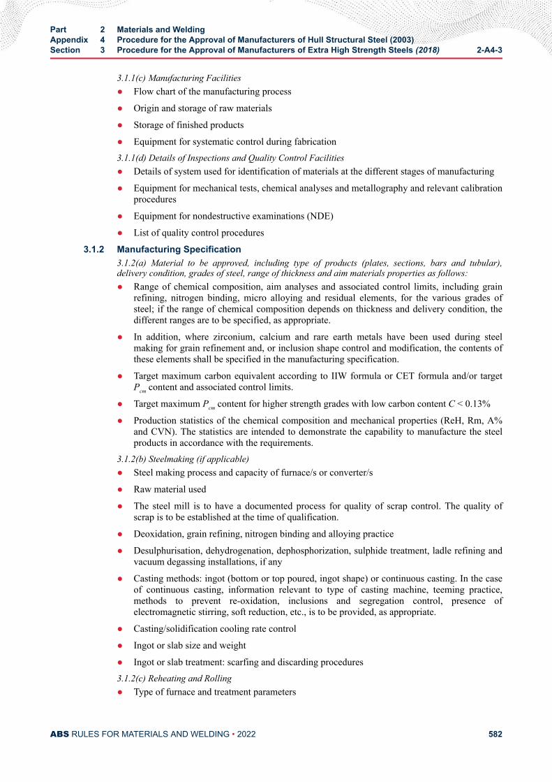
3.1.1(c) Manufacturing Facilities● Flow chart of the manufacturing process
● Origin and storage of raw materials
● Storage of finished products
● Equipment for systematic control during fabrication3.1.1(d) Details of Inspections and Quality Control Facilities● Details of system used for identification of materials at the different stages of manufacturing
● Equipment for mechanical tests, chemical analyses and metallography and relevant calibrationprocedures
● Equipment for nondestructive examinations (NDE)
● List of quality control procedures
3.1.2 Manufacturing Specification3.1.2(a) Material to be approved, including type of products (plates, sections, bars and tubular),delivery condition, grades of steel, range of thickness and aim materials properties as follows:● Range of chemical composition, aim analyses and associated control limits, including grain
refining, nitrogen binding, micro alloying and residual elements, for the various grades ofsteel; if the range of chemical composition depends on thickness and delivery condition, thedifferent ranges are to be specified, as appropriate.
● In addition, where zirconium, calcium and rare earth metals have been used during steelmaking for grain refinement and, or inclusion shape control and modification, the contents ofthese elements shall be specified in the manufacturing specification.
● Target maximum carbon equivalent according to IIW formula or CET formula and/or targetPcm content and associated control limits.
● Target maximum Pcm content for higher strength grades with low carbon content C < 0.13%
● Production statistics of the chemical composition and mechanical properties (ReH, Rm, A%and CVN). The statistics are intended to demonstrate the capability to manufacture the steelproducts in accordance with the requirements.
3.1.2(b) Steelmaking (if applicable)● Steel making process and capacity of furnace/s or converter/s
● Raw material used
● The steel mill is to have a documented process for quality of scrap control. The quality ofscrap is to be established at the time of qualification.
● Deoxidation, grain refining, nitrogen binding and alloying practice
● Desulphurisation, dehydrogenation, dephosphorization, sulphide treatment, ladle refining andvacuum degassing installations, if any
● Casting methods: ingot (bottom or top poured, ingot shape) or continuous casting. In the caseof continuous casting, information relevant to type of casting machine, teeming practice,methods to prevent re-oxidation, inclusions and segregation control, presence ofelectromagnetic stirring, soft reduction, etc., is to be provided, as appropriate.
● Casting/solidification cooling rate control
● Ingot or slab size and weight
● Ingot or slab treatment: scarfing and discarding procedures3.1.2(c) Reheating and Rolling● Type of furnace and treatment parameters
Part 2 Materials and WeldingAppendix 4 Procedure for the Approval of Manufacturers of Hull Structural Steel (2003)Section 3 Procedure for the Approval of Manufacturers of Extra High Strength Steels (2018) 2-A4-3
ABS RULES FOR MATERIALS AND WELDING • 2022 582
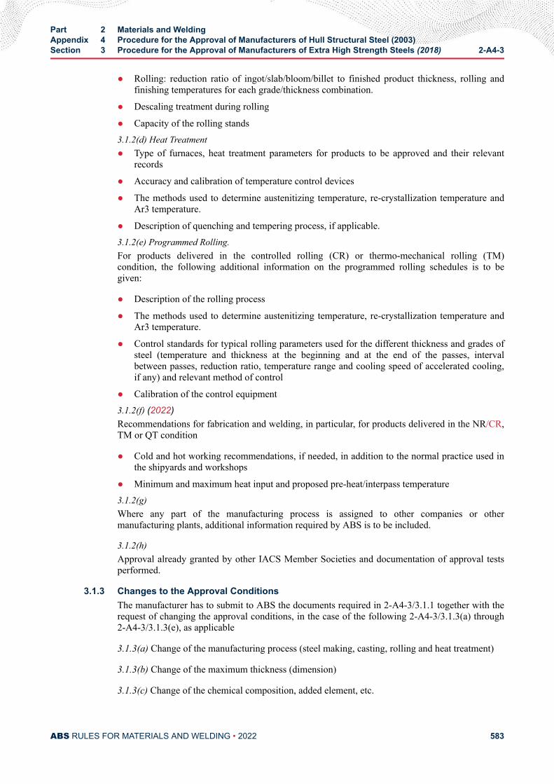
● Rolling: reduction ratio of ingot/slab/bloom/billet to finished product thickness, rolling andfinishing temperatures for each grade/thickness combination.
● Descaling treatment during rolling
● Capacity of the rolling stands3.1.2(d) Heat Treatment● Type of furnaces, heat treatment parameters for products to be approved and their relevant
records
● Accuracy and calibration of temperature control devices
● The methods used to determine austenitizing temperature, re-crystallization temperature andAr3 temperature.
● Description of quenching and tempering process, if applicable.3.1.2(e) Programmed Rolling.For products delivered in the controlled rolling (CR) or thermo-mechanical rolling (TM)condition, the following additional information on the programmed rolling schedules is to begiven:
● Description of the rolling process
● The methods used to determine austenitizing temperature, re-crystallization temperature andAr3 temperature.
● Control standards for typical rolling parameters used for the different thickness and grades ofsteel (temperature and thickness at the beginning and at the end of the passes, intervalbetween passes, reduction ratio, temperature range and cooling speed of accelerated cooling,if any) and relevant method of control
● Calibration of the control equipment3.1.2(f) (2022)Recommendations for fabrication and welding, in particular, for products delivered in the NR/CR,TM or QT condition
● Cold and hot working recommendations, if needed, in addition to the normal practice used inthe shipyards and workshops
● Minimum and maximum heat input and proposed pre-heat/interpass temperature3.1.2(g) Where any part of the manufacturing process is assigned to other companies or othermanufacturing plants, additional information required by ABS is to be included.
3.1.2(h) Approval already granted by other IACS Member Societies and documentation of approval testsperformed.
3.1.3 Changes to the Approval ConditionsThe manufacturer has to submit to ABS the documents required in 2-A4-3/3.1.1 together with therequest of changing the approval conditions, in the case of the following 2-A4-3/3.1.3(a) through2-A4-3/3.1.3(e), as applicable
3.1.3(a) Change of the manufacturing process (steel making, casting, rolling and heat treatment)
3.1.3(b) Change of the maximum thickness (dimension)
3.1.3(c) Change of the chemical composition, added element, etc.
Part 2 Materials and WeldingAppendix 4 Procedure for the Approval of Manufacturers of Hull Structural Steel (2003)Section 3 Procedure for the Approval of Manufacturers of Extra High Strength Steels (2018) 2-A4-3
ABS RULES FOR MATERIALS AND WELDING • 2022 583
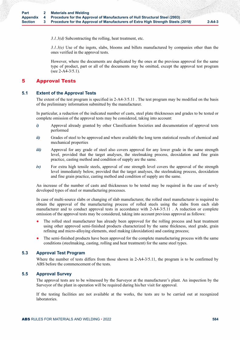
3.1.3(d) Subcontracting the rolling, heat treatment, etc.
3.1.3(e) Use of the ingots, slabs, blooms and billets manufactured by companies other than theones verified in the approval tests.
However, where the documents are duplicated by the ones at the previous approval for the sametype of product, part or all of the documents may be omitted, except the approval test program(see 2-A4-3/5.1).
5 Approval Tests
5.1 Extent of the Approval TestsThe extent of the test program is specified in 2-A4-3/5.11 . The test program may be modified on the basisof the preliminary information submitted by the manufacturer.
In particular, a reduction of the indicated number of casts, steel plate thicknesses and grades to be tested orcomplete omission of the approval tests may be considered, taking into account:
i) Approval already granted by other Classification Societies and documentation of approval testsperformed
ii) Grades of steel to be approved and where available the long term statistical results of chemical andmechanical properties
iii) Approval for any grade of steel also covers approval for any lower grade in the same strengthlevel, provided that the target analyses, the steelmaking process, deoxidation and fine grainpractice, casting method and condition of supply are the same.
iv) For extra high tensile steels, approval of one strength level covers the approval of the strengthlevel immediately below, provided that the target analyses, the steelmaking process, deoxidationand fine grain practice, casting method and condition of supply are the same.
An increase of the number of casts and thicknesses to be tested may be required in the case of newlydeveloped types of steel or manufacturing processes.
In case of multi-source slabs or changing of slab manufacturer, the rolled steel manufacturer is required toobtain the approval of the manufacturing process of rolled steels using the slabs from each slabmanufacturer and to conduct approval tests in accordance with 2-A4-3/5.11 . A reduction or completeomission of the approval tests may be considered, taking into account previous approval as follows:
● The rolled steel manufacturer has already been approved for the rolling process and heat treatmentusing other approved semi-finished products characterized by the same thickness, steel grade, grainrefining and micro-alloying elements, steel making (deoxidation) and casting process;
● The semi-finished products have been approved for the complete manufacturing process with the sameconditions (steelmaking, casting, rolling and heat treatment) for the same steel types.
5.3 Approval Test ProgramWhere the number of tests differs from those shown in 2-A4-3/5.11, the program is to be confirmed byABS before the commencement of the tests.
5.5 Approval SurveyThe approval tests are to be witnessed by the Surveyor at the manufacturer’s plant. An inspection by theSurveyor of the plant in operation will be required during his/her visit for approval.
If the testing facilities are not available at the works, the tests are to be carried out at recognizedlaboratories.
Part 2 Materials and WeldingAppendix 4 Procedure for the Approval of Manufacturers of Hull Structural Steel (2003)Section 3 Procedure for the Approval of Manufacturers of Extra High Strength Steels (2018) 2-A4-3
ABS RULES FOR MATERIALS AND WELDING • 2022 584
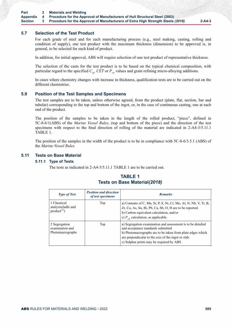
5.7 Selection of the Test ProductFor each grade of steel and for each manufacturing process (e.g., steel making, casting, rolling andcondition of supply), one test product with the maximum thickness (dimension) to be approved is, ingeneral, to be selected for each kind of product.
In addition, for initial approval, ABS will require selection of one test product of representative thickness.
The selection of the casts for the test product is to be based on the typical chemical composition, withparticular regard to the specified Ceq, CET or Pcm values and grain refining micro-alloying additions.
In cases where chemistry changes with increase in thickness, qualification tests are to be carried out on thedifferent chemistries.
5.9 Position of the Test Samples and SpecimensThe test samples are to be taken, unless otherwise agreed, from the product (plate, flat, section, bar andtubular) corresponding to the top and bottom of the ingot, or, in the case of continuous casting, one at eachend of the product.
The position of the samples to be taken in the length of the rolled product, “piece”, defined in5C-8-6/1(ABS) of the Marine Vessel Rules, (top and bottom of the piece) and the direction of the testspecimens with respect to the final direction of rolling of the material are indicated in 2-A4-3/5.11.1TABLE 1.
The position of the samples in the width of the product is to be in compliance with 5C-8-6/3.5.1 (ABS) ofthe Marine Vessel Rules.
5.11 Tests on Base Material5.11.1 Type of Tests
The tests as indicated in 2-A4-3/5.11.1 TABLE 1 are to be carried out.
TABLE 1Tests on Base Material(2018)
Type of Test Position and directionof test specimens Remarks
1 Chemicalanalysis(ladle andproduct(1))
Top a) Contents of C, Mn, Si, P, S, Ni, Cr, Mo, Al, N, Nb, V, Ti, B,Zr, Cu, As, Sn, Bi, Pb, Ca, Sb, O, H are to be reported.b) Carbon equivalent calculation, and/orc) Pcm calculation, as applicable.
2 Segregationexamination andPhotomacrographs
Top a) Segregation examination and assessment is to be detailedand acceptance standards submittedb) Photomacrographs are to be taken from plate edges whichare perpendicular to the axis of the ingot or slab.c) Sulphur prints may be required by ABS
Part 2 Materials and WeldingAppendix 4 Procedure for the Approval of Manufacturers of Hull Structural Steel (2003)Section 3 Procedure for the Approval of Manufacturers of Extra High Strength Steels (2018) 2-A4-3
ABS RULES FOR MATERIALS AND WELDING • 2022 585
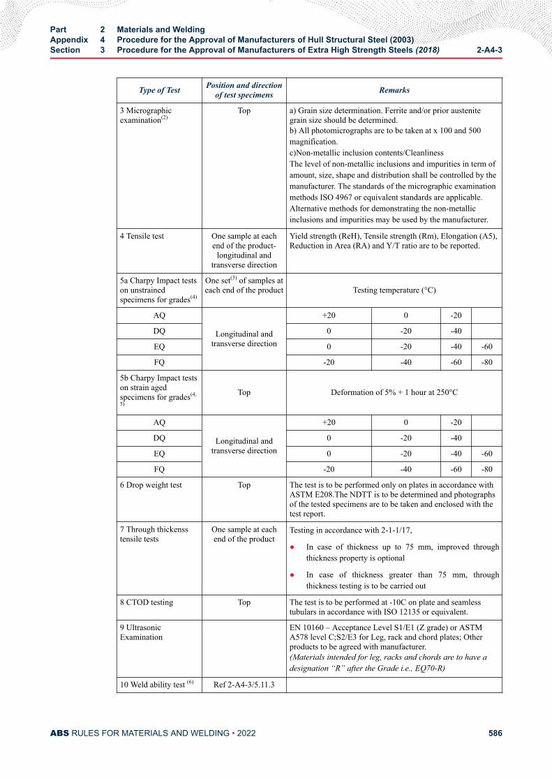
Type of Test Position and directionof test specimens Remarks
3 Micrographicexamination(2)
Top a) Grain size determination. Ferrite and/or prior austenitegrain size should be determined.b) All photomicrographs are to be taken at x 100 and 500magnification.c)Non-metallic inclusion contents/CleanlinessThe level of non-metallic inclusions and impurities in term ofamount, size, shape and distribution shall be controlled by themanufacturer. The standards of the micrographic examinationmethods ISO 4967 or equivalent standards are applicable.Alternative methods for demonstrating the non-metallicinclusions and impurities may be used by the manufacturer.
4 Tensile test One sample at eachend of the product-
longitudinal andtransverse direction
Yield strength (ReH), Tensile strength (Rm), Elongation (A5),Reduction in Area (RA) and Y/T ratio are to be reported.
5a Charpy Impact testson unstrainedspecimens for grades(4)
One set(3) of samples ateach end of the product Testing temperature (°C)
AQ
Longitudinal andtransverse direction
+20 0 -20
DQ 0 -20 -40
EQ 0 -20 -40 -60
FQ -20 -40 -60 -80
5b Charpy Impact testson strain agedspecimens for grades(4,
5)
Top Deformation of 5% + 1 hour at 250°C
AQ
Longitudinal andtransverse direction
+20 0 -20
DQ 0 -20 -40
EQ 0 -20 -40 -60
FQ -20 -40 -60 -80
6 Drop weight test Top The test is to be performed only on plates in accordance withASTM E208.The NDTT is to be determined and photographsof the tested specimens are to be taken and enclosed with thetest report.
7 Through thickensstensile tests
One sample at eachend of the product
Testing in accordance with 2-1-1/17,
● In case of thickness up to 75 mm, improved throughthickness property is optional
● In case of thickness greater than 75 mm, throughthickness testing is to be carried out
8 CTOD testing Top The test is to be performed at -10C on plate and seamlesstubulars in accordance with ISO 12135 or equivalent.
9 UltrasonicExamination
EN 10160 – Acceptance Level S1/E1 (Z grade) or ASTMA578 level C;S2/E3 for Leg, rack and chord plates; Otherproducts to be agreed with manufacturer.(Materials intended for leg, racks and chords are to have adesignation “R” after the Grade i.e., EQ70-R)
10 Weld ability test (6) Ref 2-A4-3/5.11.3
Part 2 Materials and WeldingAppendix 4 Procedure for the Approval of Manufacturers of Hull Structural Steel (2003)Section 3 Procedure for the Approval of Manufacturers of Extra High Strength Steels (2018) 2-A4-3
ABS RULES FOR MATERIALS AND WELDING • 2022 586
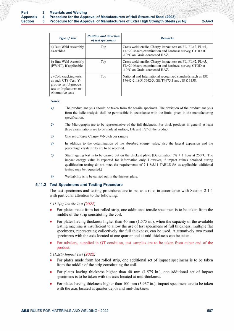
Type of Test Position and directionof test specimens Remarks
a) Butt Weld Assemblyas-welded
Top Cross weld tensile, Charpy impact test on FL, FL+2, FL+5,FL+20 Macro examination and hardness survey, CTOD at-10°C on Grain-coarsened HAZ.
b) Butt Weld Assembly(PWHT), if applicable
Top Cross weld tensile, Charpy impact test on FL, FL+2, FL+5,FL+20 Macro examination and hardness survey, CTOD at-10°C on Grain-coarsened HAZ.
c) Cold cracking testsas such CTS-Test, Y-groove test U-groovetest or Implant test orAlternative tests
Top National and International recognized standards such as ISO17642-2, ISO17642-3, GB/T4675.1 and JIS Z 3158.
Notes:
1) The product analysis should be taken from the tensile specimen. The deviation of the product analysisfrom the ladle analysis shall be permissible in accordance with the limits given in the manufacturingspecification.
2) The Micrographs are to be representative of the full thickness. For thick products in general at leastthree examinations are to be made at surface, 1/4t and 1/2t of the product.
3) One set of three Charpy V-Notch per sample
4) In addition to the determination of the absorbed energy value, also the lateral expansion and thepercentage crystallinity are to be reported.
5) Strain ageing test is to be carried out on the thickest plate. (Deformation 5% + 1 hour at 250°C. Theimpact energy value is reported for information only. However, if impact values obtained duringqualification testing do not meet the requirements of 2-1-8/5.11 TABLE 5A as applicable, additionaltesting may be requested.)
6) Weldability is to be carried out in the thickest plate.
5.11.2 Test Specimens and Testing ProcedureThe test specimens and testing procedures are to be, as a rule, in accordance with Section 2-1-1with particular attention to the following:
5.11.2(a) Tensile Test (2022)● For plates made from hot rolled strip, one additional tensile specimen is to be taken from the
middle of the strip constituting the coil.
● For plates having thickness higher than 40 mm (1.575 in.), when the capacity of the availabletesting machine is insufficient to allow the use of test specimens of full thickness, multiple flatspecimens, representing collectively the full thickness, can be used. Alternatively two roundspecimens with the axis located at one quarter and at mid-thickness can be taken.
● For tubulars, supplied in QT condition, test samples are to be taken from either end of theproduct.
5.11.2(b) Impact Test (2022)● For plates made from hot rolled strip, one additional set of impact specimens is to be taken
from the middle of the strip constituting the coil.
● For plates having thickness higher than 40 mm (1.575 in.), one additional set of impactspecimens is to be taken with the axis located at mid-thickness.
● For plates having thickness higher than 100 mm (3.937 in.), impact specimens are to be takenwith the axis located at quarter depth and mid-thickness
Part 2 Materials and WeldingAppendix 4 Procedure for the Approval of Manufacturers of Hull Structural Steel (2003)Section 3 Procedure for the Approval of Manufacturers of Extra High Strength Steels (2018) 2-A4-3
ABS RULES FOR MATERIALS AND WELDING • 2022 587
● For tubulars, supplied in QT condition, test samples are to be taken from either end of theproduct.
● In addition to the determination of the energy value, also the lateral expansion and thepercentage crystallinity are to be reported.
5.11.2(c) CTOD Tests.CTOD test specimens are to be taken from full thickness of the plate or seamless tubulars, with thenotch in the through thickness direction. Three tests shall be performed at –10°C. CTOD test is tobe carried out in accordance with ISO 12135 or equivalent.
Alternative CTOD specimen dimensions can be agreed with ABS.
5.11.2(d) Other Tests.Additional tests on parent plate such as large scale brittle fracture tests (Double Tension test,ESSO test, Deep Notch test, etc.) or other tests may be required in the case of newly developedtype of steel, outside the scope of Part 2 or when deemed necessary by ABS.
5.11.3 Weldability Test - Butt Weld Test5.11.3(a) For 43 to 51 Grade Steels. (2022)Weldability tests are to be carried out on samples of the thickest plate. Testing on higher gradescan cover the lower strength and toughness grades.
i) 1x butt weld test assembly welded with a heat input 15 ± 2 kJ/cm is to be tested aswelded.
ii) 1x butt weld test assembly welded with a heat input 50 ± 5 kJ/cm for N/NR/CR and TMand 35 ± 3.5 kJ/cm for QT steels is to be tested as welded.
iii) 1x butt weld test assembly welded with the same heat input as given in ii) is to be post-weld heat treated (PWHT) prior to testing.
Alternative heat inputs can be agreed with ABS.
Option: Steels intended to be designated as steels for high heat input welding are to be tested with1x butt weld test assembly in the as-welded condition and 1x test assembly in the PWHTcondition, both welded with the maximum heat input being approved.
5.11.3(b) For 56 to 98 Grade Steels.In general, the thickest plate with the highest toughness grade for each strength grade is to betested. Provided the chemical composition of the higher grade is similar to the lower grade, testingrequirements on the lower grades may be reduced at the discretion of ABS.
i) 1x butt weld test assembly welded with a heat input 10 ± 2 kJ/cm is to be tested as-welded.
ii) 1x butt weld test assembly welded with a maximum heat input as proposed by themanufacturer is to be tested as-welded. The approved maximum heat input shall be statedon the manufacturer approval letter.
Alternative heat inputs can be agreed with ABS.
Option: If the manufacturer requests to include the approval for Post Weld Heat Treated (PWHT)condition, 1x additional butt weld test assembly welded with a maximum heat input proposed bythe manufacturer for the approval same as test assembly ii) is to be post-weld heat treated (PWHT)prior to testing. See 2-A4-3/5.11.3(e).
5.11.3(c) Butt Weld Test Assembly.
Part 2 Materials and WeldingAppendix 4 Procedure for the Approval of Manufacturers of Hull Structural Steel (2003)Section 3 Procedure for the Approval of Manufacturers of Extra High Strength Steels (2018) 2-A4-3
ABS RULES FOR MATERIALS AND WELDING • 2022 588
The butt weld test assemblies of plates are to be prepared with the weld seam parallel to the finalplate rolling direction.
The butt weld test assemblies of long products, sections and seamless tubular in any deliverycondition are to be prepared with the weld seam transverse to the rolling direction.
5.11.3(d) Bevel Preparation.The bevel preparation should be preferably 1/2V or K related to thickness.
The welding procedure should be as far as possible in accordance with the normal weldingpractice used for the type of steel in question.
The welding procedure and welding record are to be submitted to ABS for review.
5.11.3(e) Post-weld Heat Treatment Procedure. (2022)i) Steels delivered in N/NR/CR or TM/TM+AcC/TM+DQ condition shall be heat treated for
a minimum time of 1 hour per 25 mm thickness (but not less than 30 minutes), where theminimum and maximum temperatures are to be established.
ii) Steels delivered in QT condition shall be heat treated for a minimum time of 1 hour per25 mm thickness (but not less than 30 minutes) where the minimum and maximumtemperatures are to be established and should generally be at least 14°C (25°F) below thetempering temperature, unless otherwise agreed at the time of approval.
iii) Heating and cooling above 300°C shall be carried out in a controlled manner in order toheat/cool the material uniformly. The cooling rate from the maximum holdingtemperature to 300°C shall not be slower than 55°C/hr.
5.11.3(f) Type of Tests.From the test assemblies, the following test specimens are to be taken:
i) 1 cross weld tensile test - 1 full thickness test sample or sub-sized samples cut from thefull thickness cross section.
ii) 1 set of 3 Charpy V-notch impact specimens transverse to the weld seam and 1-2 mmbelow the surface with the notch located at the fusion line and at a distance 2, 5 and 20mm from the straight fusion line. An additional set of 3 Charpy test specimens at root isrequired for each aforementioned position for plate thickness t ≥ 50 mm. The fusionboundary is to be identified by etching the specimens with a suitable reagent. The testtemperature is to be the one prescribed for the testing of the steel grade.
iii) Hardness tests HV10 across the weldment. The indentations are to be made along a 1- 2mm transverse line beneath the plate surface on both the face side and the root side of theweld as follows:
● Fusion line
● HAZ: at each 0.7 mm from fusion line into unaffected base material (6 to 7 minimummeasurements for each HAZ)
The maximum hardness value should not be higher than 350HV10 for grade steels 43to 47; not be higher than 420HV10 for 51 to 70; and not be higher than 450HV10 for91 and 98.
A sketch of the weld joint depicting groove dimensions, number of passes, hardnessindentations should be attached to the test report together with photomacrographs ofthe weld cross section.
Part 2 Materials and WeldingAppendix 4 Procedure for the Approval of Manufacturers of Hull Structural Steel (2003)Section 3 Procedure for the Approval of Manufacturers of Extra High Strength Steels (2018) 2-A4-3
ABS RULES FOR MATERIALS AND WELDING • 2022 589
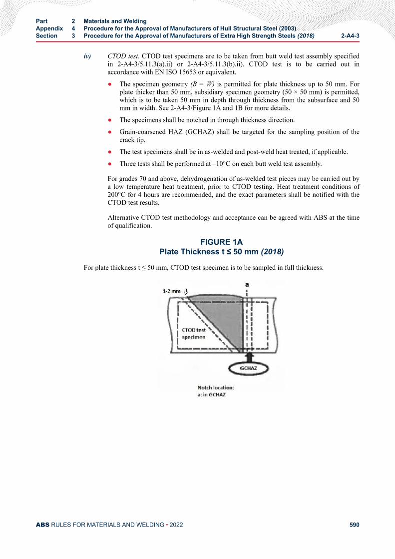
iv) CTOD test. CTOD test specimens are to be taken from butt weld test assembly specifiedin 2-A4-3/5.11.3(a).ii) or 2-A4-3/5.11.3(b).ii). CTOD test is to be carried out inaccordance with EN ISO 15653 or equivalent.
● The specimen geometry (B = W) is permitted for plate thickness up to 50 mm. Forplate thicker than 50 mm, subsidiary specimen geometry (50 × 50 mm) is permitted,which is to be taken 50 mm in depth through thickness from the subsurface and 50mm in width. See 2-A4-3/Figure 1A and 1B for more details.
● The specimens shall be notched in through thickness direction.
● Grain-coarsened HAZ (GCHAZ) shall be targeted for the sampling position of thecrack tip.
● The test specimens shall be in as-welded and post-weld heat treated, if applicable.
● Three tests shall be performed at –10°C on each butt weld test assembly.
For grades 70 and above, dehydrogenation of as-welded test pieces may be carried out bya low temperature heat treatment, prior to CTOD testing. Heat treatment conditions of200°C for 4 hours are recommended, and the exact parameters shall be notified with theCTOD test results.
Alternative CTOD test methodology and acceptance can be agreed with ABS at the timeof qualification.
FIGURE 1APlate Thickness t ≤ 50 mm (2018)
For plate thickness t ≤ 50 mm, CTOD test specimen is to be sampled in full thickness.
Part 2 Materials and WeldingAppendix 4 Procedure for the Approval of Manufacturers of Hull Structural Steel (2003)Section 3 Procedure for the Approval of Manufacturers of Extra High Strength Steels (2018) 2-A4-3
ABS RULES FOR MATERIALS AND WELDING • 2022 590
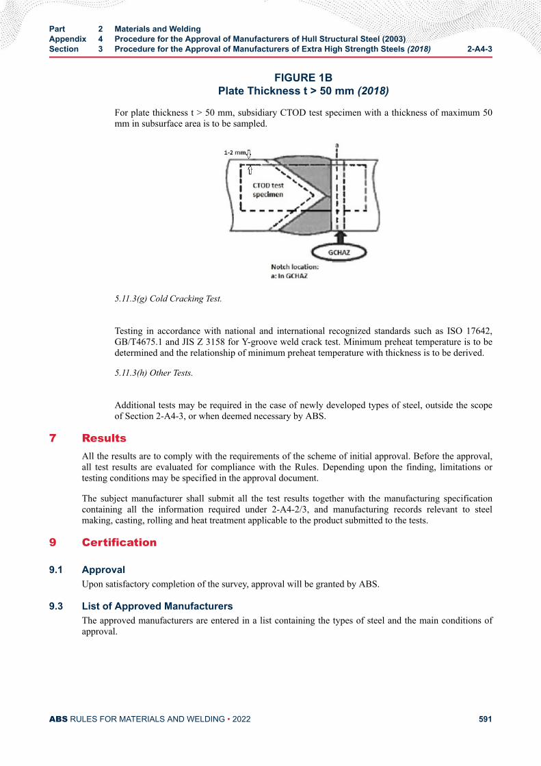
FIGURE 1BPlate Thickness t > 50 mm (2018)
For plate thickness t > 50 mm, subsidiary CTOD test specimen with a thickness of maximum 50mm in subsurface area is to be sampled.
5.11.3(g) Cold Cracking Test.
Testing in accordance with national and international recognized standards such as ISO 17642,GB/T4675.1 and JIS Z 3158 for Y-groove weld crack test. Minimum preheat temperature is to bedetermined and the relationship of minimum preheat temperature with thickness is to be derived.
5.11.3(h) Other Tests.
Additional tests may be required in the case of newly developed types of steel, outside the scopeof Section 2-A4-3, or when deemed necessary by ABS.
7 ResultsAll the results are to comply with the requirements of the scheme of initial approval. Before the approval,all test results are evaluated for compliance with the Rules. Depending upon the finding, limitations ortesting conditions may be specified in the approval document.
The subject manufacturer shall submit all the test results together with the manufacturing specificationcontaining all the information required under 2-A4-2/3, and manufacturing records relevant to steelmaking, casting, rolling and heat treatment applicable to the product submitted to the tests.
9 Certification
9.1 ApprovalUpon satisfactory completion of the survey, approval will be granted by ABS.
9.3 List of Approved ManufacturersThe approved manufacturers are entered in a list containing the types of steel and the main conditions ofapproval.
Part 2 Materials and WeldingAppendix 4 Procedure for the Approval of Manufacturers of Hull Structural Steel (2003)Section 3 Procedure for the Approval of Manufacturers of Extra High Strength Steels (2018) 2-A4-3
ABS RULES FOR MATERIALS AND WELDING • 2022 591
11 Maintenance and Renewal of ApprovalThe validity of the approval is to be to the maximum of five years, renewable subject to an audit andassessment of the result of satisfactory survey during the preceding period. The Surveyor’s reportconfirming no process changes, along with mechanical property statistical data for various approvedgrades, is to be made available to the ABS Engineering/Materials department for review and issuance ofrenewal letter/ certificate.*
Where for operational reasons, the renewal audit cannot be carried out within the validity of approval, themanufacturer will still be considered as being approved if agreement to such extension of audit date isprovided for in the original approval. In such instance, the extension of approval will be backdated to theoriginal renewal date.
Manufacturers who have not produced the approved grades and products during the period preceding therenewal may be required to carry out approval tests, unless the results of production of similar grades ofproducts during the period are evaluated by ABS and found acceptable for renewal.
Note:
* The provision for renewal of approval is also to be applied to all grades and products which were approved by ABS priorto an implementation of 2-1-1/1.2 and this Appendix regardless of the validity of certificate in existing approvals. Suchrenewal is to be completed within five years after the 1 January 2018 effective date of this rule change.
13 Withdrawal of the ApprovalThe approval may be withdrawn before the expiry of the validity period in the following cases:
i) In-service failures traceable to product quality
ii) Non conformity of the product revealed during fabrication and construction
iii) Discovery of failure of the manufacturer’s quality system
iv) Changes made by the manufacturer, without prior agreement of ABS, to the extent of invalidatingthe approval
v) Evidence of major non conformities during testing of the products.
Part 2 Materials and WeldingAppendix 4 Procedure for the Approval of Manufacturers of Hull Structural Steel (2003)Section 3 Procedure for the Approval of Manufacturers of Extra High Strength Steels (2018) 2-A4-3
ABS RULES FOR MATERIALS AND WELDING • 2022 592
A P P E N D I X 5Hull Structural Steels Intended for Welding with High Heat Input
CONTENTSSECTION 1 Procedure for the Approval of Manufacturers of Hull
Structural Steels Intended for Welding with High Heat Input(2006) ................................................................................................5941 Scope .........................................................................................5943 Application for Certification.........................................................5945 Confirmation tests.......................................................................595
5.1 Range of Certification.................................................... 5955.3 Weldability Test Program............................................... 5955.5 Test Plate....................................................................... 5955.7 Test Assembly................................................................5955.9 Examinations and Tests for the Test Assembly............. 596
7 Results........................................................................................5979 Certification.................................................................................59711 Grade Designation......................................................................597
PART 2
ABS RULES FOR MATERIALS AND WELDING • 2022 593
A P P E N D I X 5Hull Structural Steels Intended for Welding with High Heat Input
S E C T I O N 1Procedure for the Approval of Manufacturers of Hull Structural Steels
Intended for Welding with High Heat Input (2006)
1 Scope This Appendix specifies the weldability confirmation procedures of normal and higher strength hullstructural steels stipulated in Sections 2-1-2 and 2-1-3 intended for welding with high heat input over 50kJ/cm (127 kJ/in.).
The weldability confirmation procedure is to be generally applied at manufacturer’s option and valid forcertifying that the steel has satisfactory weldability for high heat input welding concerned under testingconditions.
Demonstration of conformance to the requirements of this Appendix approves a particular steel mill tomanufacture grades of steel to the specific chemical composition range, melting practice, and processingpractice for which conformance was established. The approval scheme does not apply to qualification ofwelding procedures to be undertaken by shipyards.
3 Application for CertificationThe manufacturer is to submit to ABS a request for certification of the proposed weldability test program(see 2-A5-1/5.3 below) and technical documents relevant to:
i) Outline of steel plate to be certified
● Grade
● Thickness range
● Deoxidation practice
● Fine grain practice
● Aim range of chemical composition
● Aim maximum Ceq and Pcm● Production statistics of mechanical properties (tensile and Charpy V-notch impact tests), if
any
ii) Manufacturing control points to prevent toughness deterioration in heat affected zones of highheat input welds, relevant to chemical elements, steel making, casting, rolling, heat treatment etc.
PART 2
ABS RULES FOR MATERIALS AND WELDING • 2022 594
iii) Welding control points to improve joint properties on strength and toughness.
5 Confirmation tests
5.1 Range of CertificationRange of certification for steel grades is to be in accordance with the following, unless otherwise agreed byABS:
i) Approval tests on the lowest and highest toughness levels cover the intermediate toughness level.
ii) Approval tests on normal strength level cover that strength level only.
iii) For high tensile steels, approval tests on one strength level cover strength level immediatelybelow.
iv) Tests may be carried out separately provided the same manufacturing process is applied.
v) Certification and documentation of confirmation tests performed by another Classification Societymay be accepted at the discretion of ABS.
5.3 Weldability Test ProgramThe extent of the test program is specified in 2-A5-1/5.9, but it may be modified according to the contentsof certification. In particular, additional test assemblies and/or test items may be required in the case ofnewly developed types of steel, welding consumable and welding method, or when deemed necessary byABS. Where the content of tests differs from those specified in 2-A5-1/5.9, the program is to be confirmedby ABS before the tests are carried out.
5.5 Test PlateThe test plate is to be manufactured by a process approved by ABS in accordance with the requirements ofPart 2, Appendix 4. For each manufacturing process route, two test plates with different thickness are to beselected. The thicker plate (t) and thinner plate (less than or equal to t/2) are to be proposed by themanufacturer.
Minor changes in manufacturing processing (e.g. within the TMCP process) may be considered foracceptance without testing, at the discretion of ABS.
5.7 Test AssemblyOne butt weld assembly welded with heat input over 50 kJ/cm is generally to be prepared with the weldaxis transverse to the plate rolling direction.
Dimensions of the test assembly are to be amply sufficient to take all the required test specimens specifiedin 2-A5-1/5.5.
The welding procedures should be as far as possible in accordance with the normal practices applied atshipyards for the test plate concerned, and including the following:
● Welding process
● Welding position
● Welding consumable (manufacturer, brand, grade, diameter and shield gas)
● Welding parameters including bevel preparation, heat input, preheating temperatures, interpasstemperatures, number of passes, etc.
Part 2 Materials and WeldingAppendix 5 Hull Structural Steels Intended for Welding with High Heat InputSection 1 Procedure for the Approval of Manufacturers of Hull Structural Steels Intended for
Welding with High Heat Input (2006)2-A5-1
ABS RULES FOR MATERIALS AND WELDING • 2022 595
5.9 Examinations and Tests for the Test AssemblyThe test assembly is to be examined and tested in accordance with the following, unless otherwise agreedby ABS.
i) Visual examination. Overall welded surface is to be uniform and free from injurious defects suchas cracks, undercuts, overlaps, etc.
ii) Macroscopic test. One macroscopic photograph is to be representative of transverse section of thewelded joint and is to show absence of cracks, lack of penetration, lack of fusion and otherinjurious defects.
iii) Microscopic test. Along mid-thickness line across transverse section of the weld, one micrographwith ×100 magnification is to be taken at each position of the weld metal centerline, fusion lineand at a distance 2, 5, 10 and a minimum 20 mm (0.8 in.) from the fusion line. The test result isprovided for information purpose only.
iv) Hardness test. Along two lines across transverse weld section 1 mm beneath plate surface on bothface and root side of the weld, indentations by HV5 are to be made at weld metal centerline,fusion line and each 0.7 mm (0.28 in.) position from fusion line to unaffected base metal(minimum 6 to 7 measurements for each heat affected zone). The maximum hardness value shouldnot be higher than 350 HV.
v) Transverse tensile test. Two transverse (cross weld) tensile specimens are to be taken from the testassembly. Test specimens and testing procedures are to comply with the requirements of Section2-4-3.
The tensile strength is to be not less than the minimum required value for the grade of base metal.
vi) Bend test. Two transverse (cross weld) test specimens are to be taken from the test assembly andbent on a mandrel with diameter of quadruple specimen thickness. Bending angle is to be at least120 degrees. Test specimens are to comply with the requirements of 2-4-3.
For plate thickness up to 20 mm (0.8 in.), one face-bend and one root-bend specimens or two side-bend specimens are to be taken. For plate thickness over 20 mm (0.8 in.), two side-bendspecimens are to be taken. After testing, the test specimens shall not reveal any crack nor otheropen defect in any direction greater than 3 mm (0.12 in.).
vii) Impact test. Charpy V-notch impact specimens (three specimens for one set) are to be taken within2 mm (0.08 in.) below plate surface on face side of the weld with the notch perpendicular to theplate surface.
One set of the specimens transverse to the weld is to be taken with the notch located at the fusionline and at a distance 2, 5 and a minimum 20 mm (0.8 in.) from the fusion line. The fusionboundary is to be identified by etching the specimens with a suitable reagent. The test temperatureis to be the one prescribed for the testing of the steel grade in question.
For steel plate with thickness greater than 50 mm (2.0 in.) or one side welding for plate thicknessgreater than 20 mm (0.8 in.), one additional set of the specimens is to be taken from the root sideof the weld with the notch located at each of the same positions as for the face side.
The average impact energy at the specified test temperature is to comply with the requirements of2-1-2/15.9 TABLE 4 or 2-1-3/7.3 TABLE 4, depending on the steel grade and thickness. Only oneindividual value may be below the specified average value provided it is not less than 70% of thatvalue. Additional tests at the different testing temperatures may be required for evaluating thetransition temperature curve of absorbed energy and percentage crystallinity at the discretion ofABS.
viii) Other tests. Additional tests, such as wide-width tensile test, HAZ tensile test, cold cracking tests(CTS, Cruciform, Implant, Tekken, and Bead-on plate), CTOD or other tests may be required atthe discretion of ABS (see 2-A5-1/5.3).
Part 2 Materials and WeldingAppendix 5 Hull Structural Steels Intended for Welding with High Heat InputSection 1 Procedure for the Approval of Manufacturers of Hull Structural Steels Intended for
Welding with High Heat Input (2006)2-A5-1
ABS RULES FOR MATERIALS AND WELDING • 2022 596
7 ResultsThe manufacturer is to submit to ABS the complete test report including all the results and requiredinformation relevant to the confirmation tests specified in 2-A5-1/5.
The contents of the test report are to be reviewed and evaluated by ABS in accordance with thisweldability confirmation scheme.
9 CertificationABS will issue a certificate where the test report is found to be satisfactory. The following information isto be included on the certificate:
i) Manufacturer
ii) Grade designation with notation of heat input (refer to 2-A5-1/11)
iii) Deoxidation practice
iv) Fine grain practice
v) Condition of supply
vi) Plate thickness tested
vii) Welding process
viii) Welding consumable (manufacturer, brand, grade).
ix) Actual heat input applied.
11 Grade DesignationUpon issuance of the certificate, the notation indicating the value of heat input applied in the confirmationtest may be added to the grade designation of the test plate, e.g. “E36-W300” [in the case of heat input 300kJ/cm (762 kJ/in.) applied]. The value of this notation is to be not less than 50 and every 10 added.
Part 2 Materials and WeldingAppendix 5 Hull Structural Steels Intended for Welding with High Heat InputSection 1 Procedure for the Approval of Manufacturers of Hull Structural Steels Intended for
Welding with High Heat Input (2006)2-A5-1
ABS RULES FOR MATERIALS AND WELDING • 2022 597
A P P E N D I X 6Nondestructive Examination of Marine Steel Castings (2014)
CONTENTSSECTION 1 General .............................................................................................600
1 Scope..........................................................................................6001.1 .......................................................................................6001.3 .......................................................................................6001.5 .......................................................................................6001.7 .......................................................................................6001.9 .......................................................................................600
SECTION 2 Surface Inspection ..........................................................................6011 General.......................................................................................601
1.1 .......................................................................................6011.3 .......................................................................................6011.5 .......................................................................................601
3 Products......................................................................................6013.1 .......................................................................................6013.3 .......................................................................................601
5 Location for Surface Inspections................................................ 6015.1 .......................................................................................6015.3 .......................................................................................602
7 Surface Condition ...................................................................... 6029 Surface Inspection .....................................................................602
9.1 .......................................................................................6029.3 .......................................................................................6029.5 .......................................................................................6029.7 .......................................................................................6029.9 .......................................................................................602
11 Acceptance Criteria and Rectification of Defects .......................60211.1 Acceptance Criteria –Visual Inspection......................... 60211.3 Acceptance Criteria –Magnetic Particle Testing and
Liquid Penetrant Testing................................................ 60311.5 Rectification of Defects.................................................. 603
13 Record........................................................................................ 604
PART 2
ABS RULES FOR MATERIALS AND WELDING • 2022 598
13.1 .......................................................................................604
TABLE 1 Allowable Number and Size of Indications in aReference Band Length/Area.............................................605
SECTION 3 Volumetric Inspection......................................................................6061 General ......................................................................................606
1.1 .......................................................................................6061.3 .......................................................................................6061.5 .......................................................................................6061.7 .......................................................................................606
3 Products .....................................................................................6063.1 .......................................................................................606
5 Location for Volumetric Inspection .............................................6065.1 .......................................................................................6065.3 .......................................................................................6075.5 .......................................................................................607
7 Surface Condition....................................................................... 6077.1 .......................................................................................6077.3 .......................................................................................607
9 Acceptance Criteria ................................................................... 60711 Record ....................................................................................... 607
TABLE 1 Acceptance Criteria for Steel Castings.............................. 608
ANNEX 1 General Location for the Type of NondestructiveExaminations of Typical Hull Steel Castings.................................609FIGURE 1 Stern Frame....................................................................... 609FIGURE 2 Rudder stock......................................................................610FIGURE 3 Stern Boss (2011).............................................................. 610FIGURE 4 Rudder Hangings (2011).................................................... 611FIGURE 5 Rudder (Upper Part) (2011)............................................... 612FIGURE 6 Rudder (Lower Part) (2011)............................................... 613
ABS RULES FOR MATERIALS AND WELDING • 2022 599
A P P E N D I X 6Nondestructive Examination of Marine Steel Castings (2014)
S E C T I O N 1General
Note:
The requirements in this Appendix are adopted from the IACS Recommendation No. 69. "Guidelines for Non-destructiveExamination of Marine Steel Castings" with some modifications in order to be consistent with existing ABS publications. Itbecomes effective as of 1 January 2014.
1 Scope
1.1This Appendix contains general guidance for the nondestructive examination methods, the extent ofexamination and the minimum recommended quality levels to be complied with for marine steel castings,unless otherwise approved or specified.
1.3This document contains guidelines on “Surface Inspections” (2-A6-2) by visual examination, magneticparticle testing and liquid penetrant testing and “Volumetric Inspection” (2-A6-3) by ultrasonic testing andradiographic testing.
1.5Although no detailed guidelines are given for machinery components, the requirements in this Appendixmay apply correspondingly considering their materials, kinds, shapes and stress conditions beingsubjected.
1.7Castings should be examined in the final delivery condition. For specific requirements, see 2-A6-2/9.3 and2-A6-3/7.3.
1.9Where intermediate inspections have been performed the manufacturer is to furnish the documentation ofthe results upon request of the Surveyor.
PART 2
ABS RULES FOR MATERIALS AND WELDING • 2022 600
A P P E N D I X 6Nondestructive Examination of Marine Steel Castings (2014)
S E C T I O N 2Surface Inspection
1 General
1.1Surface inspections in this Appendix are to be carried out by visual examination and magnetic particletesting or liquid penetrant testing.
1.3The testing procedures, apparatus and conditions of magnetic particle testing and liquid penetrant testingare to comply with a recognized national or international standard.
1.5Personnel engaged in visual examination are to have sufficient knowledge and experience. Personnelengaged in magnetic particle testing or liquid penetrant testing are to be qualified in accordance with theABS Guide for Nondestructive Inspection. The qualification is to be verified by the certificates.
3 Products
3.1Steel castings are to be subjected to a 100% visual examination of all accessible surfaces by the Surveyor.
3.3Surface inspections by magnetic particle and/or liquid penetrant methods apply to the hull steel castingsindicated in 2-A6-A1 of this Appendix.
5 Location for Surface Inspections
5.1Surface inspections are to be carried out in the following locations:
● At all accessible fillets and changes of section
● At positions where surplus metal has been removed by flame cutting, scarfing or arc-air gouging
● In way of fabrication weld preparation, for a band width of 30 mm (1.2 in.)
PART 2
ABS RULES FOR MATERIALS AND WELDING • 2022 601

● In way of weld repairs
5.3The following quality levels are considered for magnetic particle testing (MT) and/or liquid penetranttesting (PT):
● Level MT1/PT1 –fabrication weld preparation and weld repairs.
● Level MT2/PT2 –other locations shown in 2-A6-2/5.1.
The required quality level is to be shown on the manufacturer’s drawings.
7 Surface ConditionThe surfaces of castings to be examined are to be free from scale, dirt, grease or paint and are to be shotblasted or ground.
9 Surface Inspection
9.1Magnetic particle inspection is to be carried out with the following exceptions, when liquid penetranttesting is to be permitted:
● Austenitic stainless steels
● Interpretation of open visual or magnetic particle indications
● At the instruction of the Surveyor
9.3Unless otherwise specified in the order, the magnetic particle test is to be performed on a casting in thefinal delivery condition and final thermally treated condition or within 0.3 mm (0.012 in.) of the finalmachined surface condition for AC techniques [0.8 mm (0.03 in.) for DC techniques].
9.5Unless otherwise agreed, the surface inspection is to be carried out in the presence of the Surveyor.
9.7For magnetic particle testing, attention is to be paid to the contact between the casting and the clampingdevices of stationary magnetization benches in order to avoid local overheating or burning damage in itssurface. Prods are not permitted on finished machined items.
9.9When indications are detected as a result of the surface inspection, the acceptance or rejection is to bedecided in accordance with 2-A6-2/11.
11 Acceptance Criteria and Rectification of Defects
11.1 Acceptance Criteria –Visual InspectionAll castings are to be free of cracks, crack-like indications, hot tears, laps, seams, folds or other injuriousindications. Thickness of the remains of sprues, heads or burrs is to be within the casting dimensionaltolerance. Additional magnetic particle, liquid penetrant and ultrasonic testing may be required for a moredetailed evaluation of surface irregularities at the request of the Surveyor.
Part 2 Materials and WeldingAppendix 6 Nondestructive Examination of Marine Steel Castings (2014)Section 2 Surface Inspection 2-A6-2
ABS RULES FOR MATERIALS AND WELDING • 2022 602
11.3 Acceptance Criteria –Magnetic Particle Testing and Liquid Penetrant Testing11.3.1
The following definitions relevant to indications apply:
● Linear indication. An indication in which the length is at least three times the width.
● Nonlinear indication. An indication of circular or elliptical shape with a length less than threetimes the width.
● Aligned indication. Three or more indications in a line, separated by 2 mm (0.08 in.) or lessedge-to-edge.
● Open indication. An indication visible after removal of the magnetic particles or that can bedetected by the use of contrast dye penetrant.
● Non-open indication. An indication that is not visually detectable after removal of themagnetic particles or that cannot be detected by the use of contrast dye penetrant.
● Relevant indication. An indication that is caused by a condition or type of discontinuity thatrequires evaluation. Only indications which have any dimension greater than 1.5 mm (0.06in.) are to be considered relevant.
11.3.2For the purpose of evaluating indications, the surface is to be divided into reference band length of150 mm (6 in.) for level MT1/PT1 and into reference areas of 225 cm2 (35 in2) for level MT2/PT2.The band length and/or area is to be taken in the most unfavorable location relative to theindication being evaluated.
11.3.3The allowable number and size of indications in the reference band length and/or area is given in2-A6-2/13.1 TABLE 1. Cracks and hot tears are not acceptable.
11.5 Rectification of DefectsDefects and unacceptable indications are to be repaired as indicated below and detailed in 2-A6-2/11.5.2.
11.5.1Defective parts of material may be removed by grinding, or by chipping and grinding, or by arcair-gouging and grinding. All grooves are to have a bottom radius of approximately three times thegroove depth and be smoothly blended to the surface area with a finish equal to the adjacentsurface.
11.5.2Repairs by welding are defined as follows:
Major repairs:
● Where the depth is greater than 25% of the wall thickness or 25 mm (1 in.) whichever is theless, or
● Where the weld area (length x width) exceeds 1250 cm2 (194 in2) (Note:where a distancebetween two welds is less than their average width, they are considered as one weld), or
● Where the total weld area on a casting exceeds 2% of the casting surface.
Minor repairs:
● Where the total weld area (length x width) exceeds 5 cm2 (0.8 in2).
Cosmetic repairs:
Part 2 Materials and WeldingAppendix 6 Nondestructive Examination of Marine Steel Castings (2014)Section 2 Surface Inspection 2-A6-2
ABS RULES FOR MATERIALS AND WELDING • 2022 603
● All other welds.
11.5.2(a) Major repairs are to be approved before the repair is carried out. The repair should becarried out before final furnace heat treatment.
11.5.2(b) Minor repairs do not require approval before the repair is carried out but should berecorded on a weld repair sketch as a part of the manufacturing procedure documents. Theserepairs should be carried out before final furnace heat treatment.
11.5.2(c) Cosmetic repairs do not require approval before the repair is carried out but should berecorded on a weld repair sketch. These repairs may be carried out after final furnace heattreatment but are subject to a local stress relief heat treatment. Thermal methods of metal removalshould only be allowed before the final heat treatment. After final heat treatment only grinding orchipping and grinding should be al-lowed. Weld repairs should be suitably classified.
Parts which are repaired should be examined by the same method as at initial inspection as well asby additional methods as required by the Surveyor.
13 Record
13.1Test results of surface inspections are to be recorded at least with the following items:
i) Date of testing
ii) Names and qualification level of inspection personnel
iii) Kind of testing method
● For liquid penetrant testing: test media combination
● For magnetic particle testing: method of magnetizing, test media and magnetic field strength
iv) Kind of product
v) Product number for identification
vi) Grade of steel
vii) Heat treatment
viii) Stage of testing
ix) Locations for testing
x) Surface condition
xi) Test standards used
xii) Testing condition
xiii) Results
xiv) Statement of acceptance/non acceptance
xv) Details of weld repair including sketch
Part 2 Materials and WeldingAppendix 6 Nondestructive Examination of Marine Steel Castings (2014)Section 2 Surface Inspection 2-A6-2
ABS RULES FOR MATERIALS AND WELDING • 2022 604
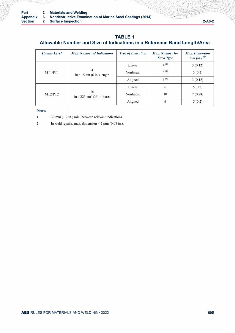
TABLE 1Allowable Number and Size of Indications in a Reference Band Length/Area
Quality Level Max. Number of Indications Type of Indication Max. Number forEach Type
Max. Dimensionmm (in.) (2)
MT1/PT1 4in a 15 cm (6 in.) length
Linear 4 (1) 3 (0.12)
Nonlinear 4 (1) 5 (0.2)
Aligned 4 (1) 3 (0.12)
MT2/PT2 20in a 225 cm2 (35 in2) area
Linear 6 5 (0.2)
Nonlinear 10 7 (0.28)
Aligned 6 5 (0.2)
Notes:
1 30 mm (1.2 in.) min. between relevant indications.
2 In weld repairs, max. dimension < 2 mm (0.08 in.).
Part 2 Materials and WeldingAppendix 6 Nondestructive Examination of Marine Steel Castings (2014)Section 2 Surface Inspection 2-A6-2
ABS RULES FOR MATERIALS AND WELDING • 2022 605
A P P E N D I X 6Nondestructive Examination of Marine Steel Castings (2014)
S E C T I O N 3Volumetric Inspection
1 General
1.1Volumetric inspection in this Appendix is to be carried out by ultrasonic testing using the contact methodwith straight beam and/or angle beam technique.
1.3The testing procedures, apparatus and conditions of ultrasonic testing are to comply with the recognizednational or international standards. Generally, the DGS (distance-gain size) procedure is to be appliedusing straight beam probes and/or angle beam probes with 1 to 4 MHz and an inspection should be carriedout using a twin crystal 0° probe for near surface scans [25 mm (1 in.)] plus a 0° probe for the remainingvolume. Fillet radii should be examined using 45°, 60° or 70° probes.
1.5Radiographic testing is to be carried out in accordance with an approved plan.
1.7Personnel engaged in ultrasonic or radiographic testing is to be qualified in accordance with the ABSGuide for Nondestructive Inspection. The qualification is to be verified by certificates.
3 Products
3.1Volumetric inspection by ultrasonic or radiographic testing applies to the hull steel castings indicated in 2-A6-A1 of this Appendix.
5 Location for Volumetric Inspection
5.1Volumetric inspection is to be carried out according to the inspection plan. The inspection plan shouldspecify the extent of the examination, the examination procedure, the quality level or, if necessary, levelsfor different locations of the castings. The inspection plan is to be approved.
PART 2
ABS RULES FOR MATERIALS AND WELDING • 2022 606
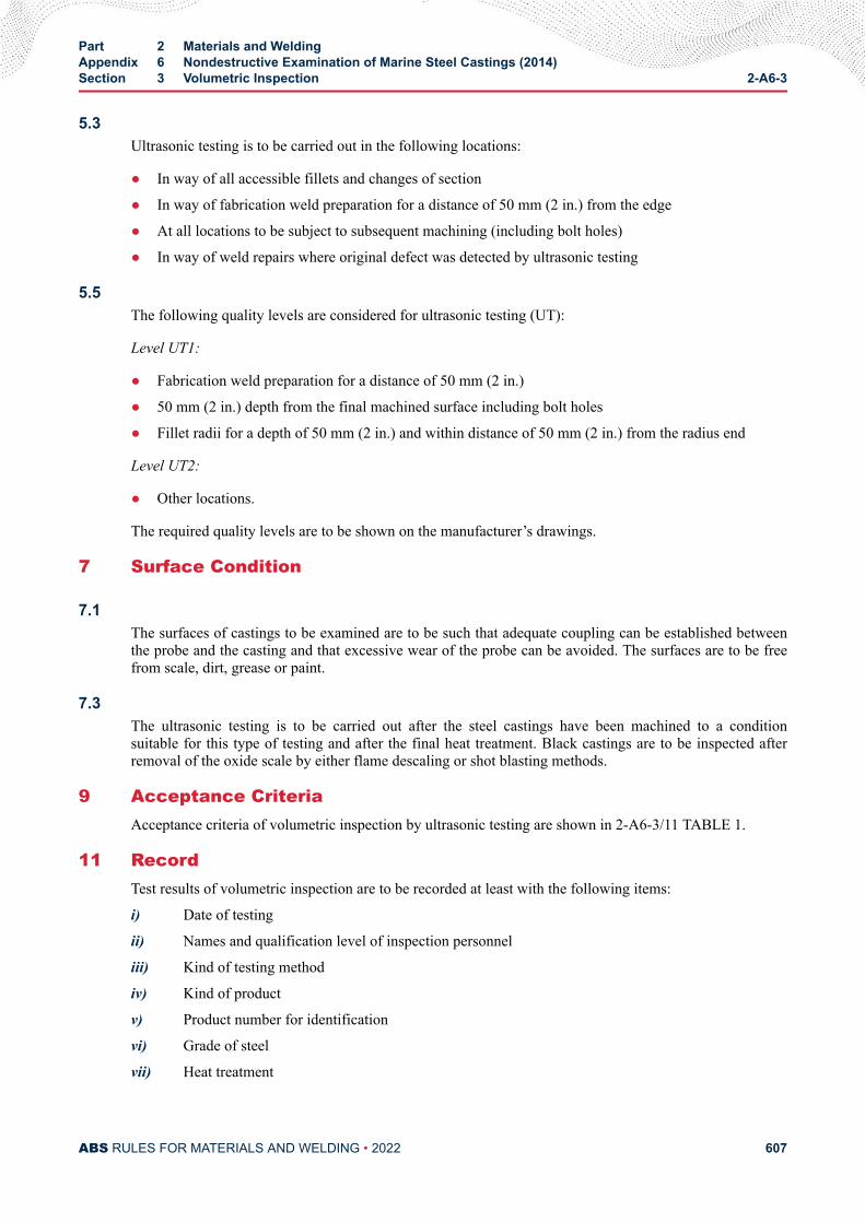
5.3Ultrasonic testing is to be carried out in the following locations:
● In way of all accessible fillets and changes of section
● In way of fabrication weld preparation for a distance of 50 mm (2 in.) from the edge
● At all locations to be subject to subsequent machining (including bolt holes)
● In way of weld repairs where original defect was detected by ultrasonic testing
5.5The following quality levels are considered for ultrasonic testing (UT):
Level UT1:
● Fabrication weld preparation for a distance of 50 mm (2 in.)
● 50 mm (2 in.) depth from the final machined surface including bolt holes
● Fillet radii for a depth of 50 mm (2 in.) and within distance of 50 mm (2 in.) from the radius end
Level UT2:
● Other locations.
The required quality levels are to be shown on the manufacturer’s drawings.
7 Surface Condition
7.1The surfaces of castings to be examined are to be such that adequate coupling can be established betweenthe probe and the casting and that excessive wear of the probe can be avoided. The surfaces are to be freefrom scale, dirt, grease or paint.
7.3The ultrasonic testing is to be carried out after the steel castings have been machined to a conditionsuitable for this type of testing and after the final heat treatment. Black castings are to be inspected afterremoval of the oxide scale by either flame descaling or shot blasting methods.
9 Acceptance CriteriaAcceptance criteria of volumetric inspection by ultrasonic testing are shown in 2-A6-3/11 TABLE 1.
11 RecordTest results of volumetric inspection are to be recorded at least with the following items:
i) Date of testing
ii) Names and qualification level of inspection personnel
iii) Kind of testing method
iv) Kind of product
v) Product number for identification
vi) Grade of steel
vii) Heat treatment
Part 2 Materials and WeldingAppendix 6 Nondestructive Examination of Marine Steel Castings (2014)Section 3 Volumetric Inspection 2-A6-3
ABS RULES FOR MATERIALS AND WELDING • 2022 607
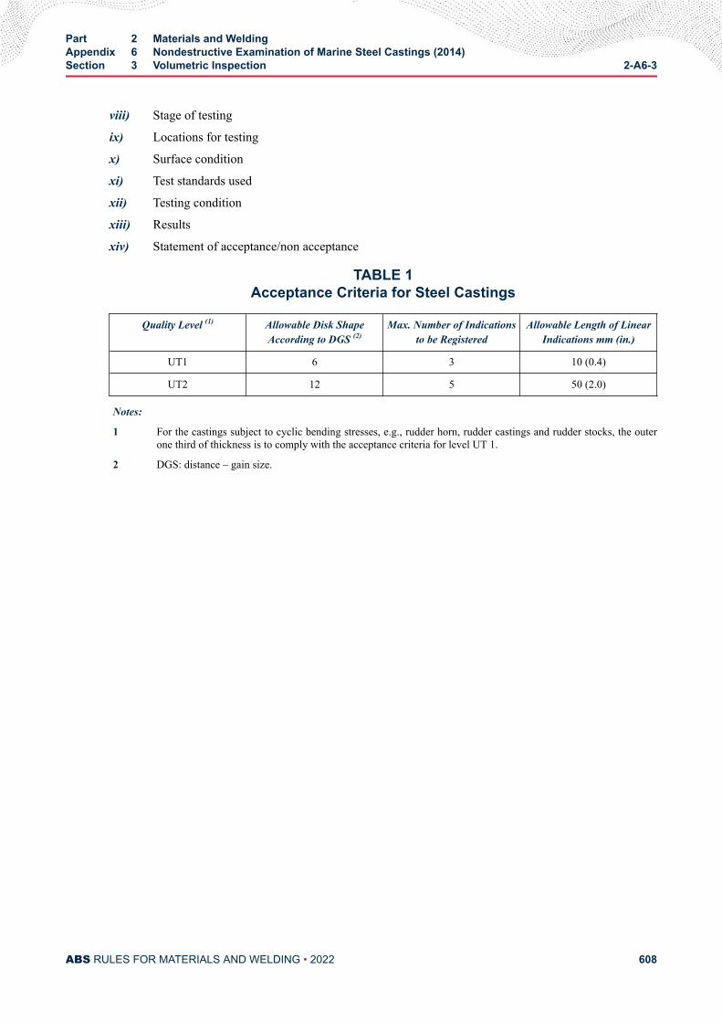
viii) Stage of testing
ix) Locations for testing
x) Surface condition
xi) Test standards used
xii) Testing condition
xiii) Results
xiv) Statement of acceptance/non acceptance
TABLE 1Acceptance Criteria for Steel Castings
Quality Level (1) Allowable Disk ShapeAccording to DGS (2)
Max. Number of Indicationsto be Registered
Allowable Length of LinearIndications mm (in.)
UT1 6 3 10 (0.4)
UT2 12 5 50 (2.0)
Notes:
1 For the castings subject to cyclic bending stresses, e.g., rudder horn, rudder castings and rudder stocks, the outerone third of thickness is to comply with the acceptance criteria for level UT 1.
2 DGS: distance – gain size.
Part 2 Materials and WeldingAppendix 6 Nondestructive Examination of Marine Steel Castings (2014)Section 3 Volumetric Inspection 2-A6-3
ABS RULES FOR MATERIALS AND WELDING • 2022 608
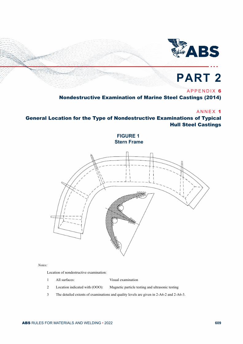
A P P E N D I X 6Nondestructive Examination of Marine Steel Castings (2014)
A N N E X 1General Location for the Type of Nondestructive Examinations of Typical
Hull Steel Castings
FIGURE 1 Stern Frame
Notes:
Location of nondestructive examination:
1 All surfaces: Visual examination
2 Location indicated with (OOO): Magnetic particle testing and ultrasonic testing
3 The detailed extents of examinations and quality levels are given in 2-A6-2 and 2-A6-3.
PART 2
ABS RULES FOR MATERIALS AND WELDING • 2022 609
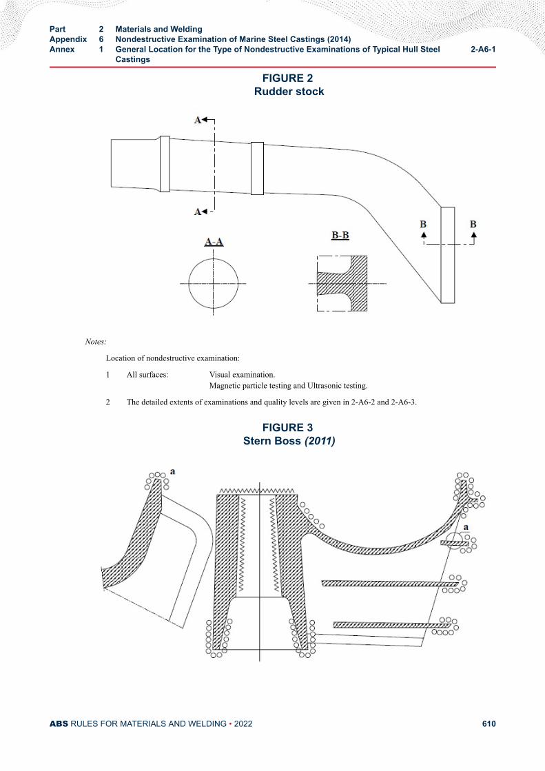
FIGURE 2 Rudder stock
Notes:
Location of nondestructive examination:
1 All surfaces: Visual examination.Magnetic particle testing and Ultrasonic testing.
2 The detailed extents of examinations and quality levels are given in 2-A6-2 and 2-A6-3.
FIGURE 3 Stern Boss (2011)
Part 2 Materials and WeldingAppendix 6 Nondestructive Examination of Marine Steel Castings (2014)Annex 1 General Location for the Type of Nondestructive Examinations of Typical Hull Steel
Castings2-A6-1
ABS RULES FOR MATERIALS AND WELDING • 2022 610
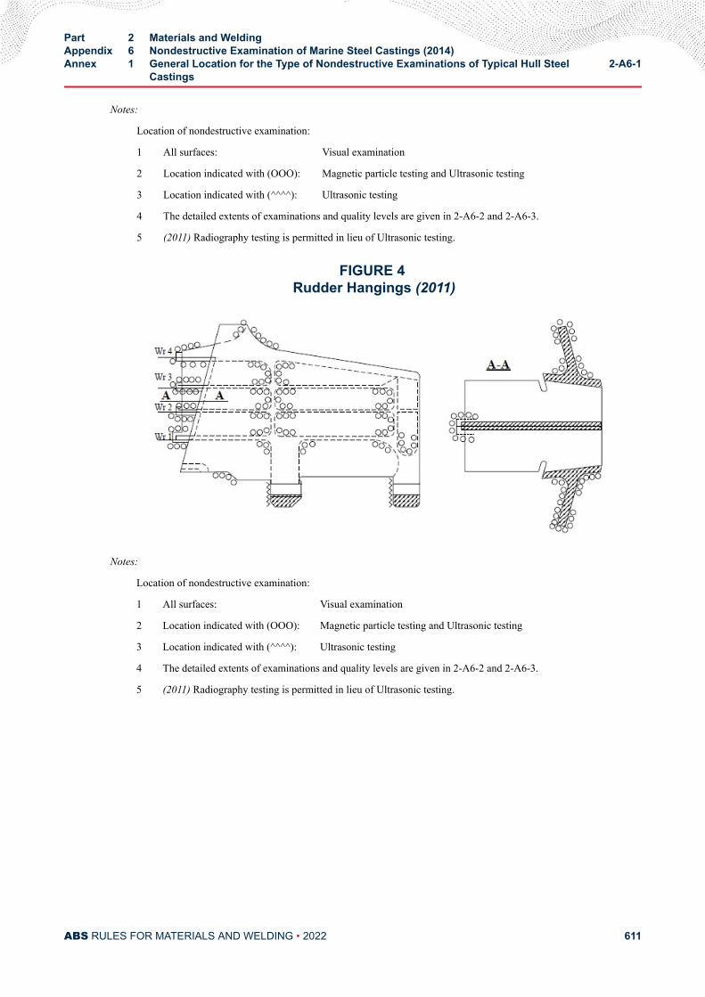
Notes:
Location of nondestructive examination:
1 All surfaces: Visual examination
2 Location indicated with (OOO): Magnetic particle testing and Ultrasonic testing
3 Location indicated with (^^^^): Ultrasonic testing
4 The detailed extents of examinations and quality levels are given in 2-A6-2 and 2-A6-3.
5 (2011) Radiography testing is permitted in lieu of Ultrasonic testing.
FIGURE 4 Rudder Hangings (2011)
Notes:
Location of nondestructive examination:
1 All surfaces: Visual examination
2 Location indicated with (OOO): Magnetic particle testing and Ultrasonic testing
3 Location indicated with (^^^^): Ultrasonic testing
4 The detailed extents of examinations and quality levels are given in 2-A6-2 and 2-A6-3.
5 (2011) Radiography testing is permitted in lieu of Ultrasonic testing.
Part 2 Materials and WeldingAppendix 6 Nondestructive Examination of Marine Steel Castings (2014)Annex 1 General Location for the Type of Nondestructive Examinations of Typical Hull Steel
Castings2-A6-1
ABS RULES FOR MATERIALS AND WELDING • 2022 611
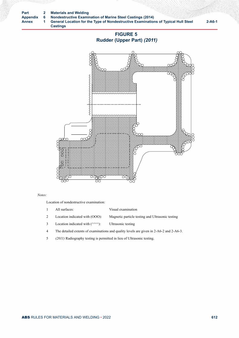
FIGURE 5 Rudder (Upper Part) (2011)
Notes:
Location of nondestructive examination:
1 All surfaces: Visual examination
2 Location indicated with (OOO): Magnetic particle testing and Ultrasonic testing
3 Location indicated with (^^^^): Ultrasonic testing
4 The detailed extents of examinations and quality levels are given in 2-A6-2 and 2-A6-3.
5 (2011) Radiography testing is permitted in lieu of Ultrasonic testing.
Part 2 Materials and WeldingAppendix 6 Nondestructive Examination of Marine Steel Castings (2014)Annex 1 General Location for the Type of Nondestructive Examinations of Typical Hull Steel
Castings2-A6-1
ABS RULES FOR MATERIALS AND WELDING • 2022 612
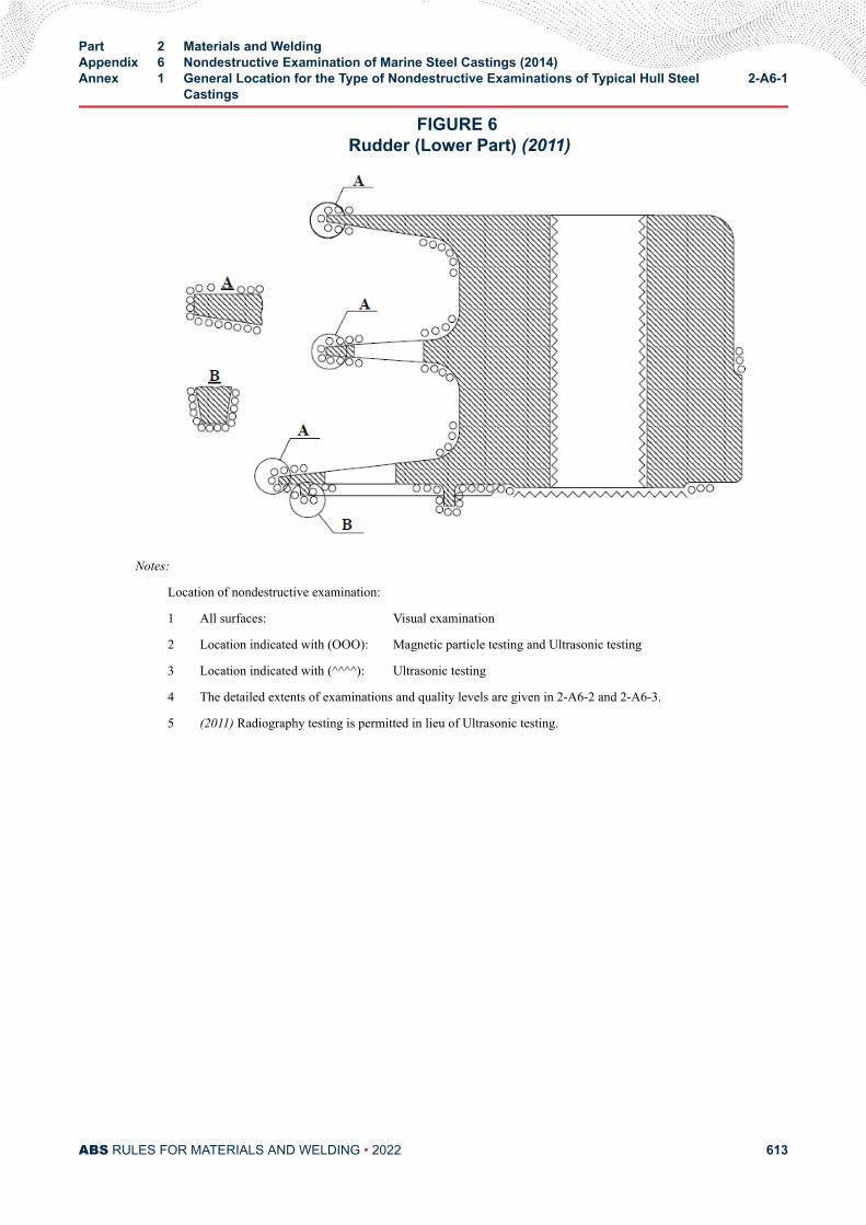
FIGURE 6 Rudder (Lower Part) (2011)
Notes:
Location of nondestructive examination:
1 All surfaces: Visual examination
2 Location indicated with (OOO): Magnetic particle testing and Ultrasonic testing
3 Location indicated with (^^^^): Ultrasonic testing
4 The detailed extents of examinations and quality levels are given in 2-A6-2 and 2-A6-3.
5 (2011) Radiography testing is permitted in lieu of Ultrasonic testing.
Part 2 Materials and WeldingAppendix 6 Nondestructive Examination of Marine Steel Castings (2014)Annex 1 General Location for the Type of Nondestructive Examinations of Typical Hull Steel
Castings2-A6-1
ABS RULES FOR MATERIALS AND WELDING • 2022 613
A P P E N D I X 7Nondestructive Examination of Hull and Machinery Steel Forgings (2014)
CONTENTSSECTION 1 General .............................................................................................616
1 Scope..........................................................................................6161.1 .......................................................................................6161.3 .......................................................................................6161.5 .......................................................................................6161.7 .......................................................................................6161.9 .......................................................................................6161.11 .......................................................................................616
SECTION 2 Surface Inspection ..........................................................................6171 General.......................................................................................617
1.1 .......................................................................................6171.3 .......................................................................................6171.5 .......................................................................................617
3 Products......................................................................................6173.1 .......................................................................................6173.3 .......................................................................................617
5 Zones for Surface Inspections....................................................6187 Surface Condition....................................................................... 6189 Surface Inspection......................................................................618
9.1 .......................................................................................6189.3 .......................................................................................6189.5 .......................................................................................6189.7 .......................................................................................6189.9 .......................................................................................618
11 Acceptance Criteria and Rectification of Defects........................61811.1 Acceptance Criteria Visual Inspection........................... 61811.3 Acceptance Criteria Magnetic Particle Testing and
Liquid Penetrant Testing................................................ 61911.5 Rectification of Defects.................................................. 620
13 Record........................................................................................ 62113.1 .......................................................................................621
PART 2
ABS RULES FOR MATERIALS AND WELDING • 2022 614
TABLE 1 Crankshaft Forgings - Allowable Number and Size ofIndications in a Reference Area of 225 cm2(35 in2)(2010).................................................................................619
TABLE 2 Steel Forgings Excluding Crankshaft Forgings -Allowable Number and Size of Indications in aReference Area of 225 cm2(35 in2) (2010)......................... 620
FIGURE 1 Zones for Magnetic Particle/Liquid Penetrant Testing onCrankshafts........................................................................622
FIGURE 2 Zones for Magnetic Particle/Liquid Penetrant Testing onShafts.................................................................................624
FIGURE 3 Zones for Magnetic Particle/Liquid Penetrant Testing onMachinery Components..................................................... 625
FIGURE 4 Zones for Magnetic Particle/Liquid Penetrant Testing onRudder Stocks....................................................................627
SECTION 3 Volumetric Inspection......................................................................6281 General.......................................................................................628
1.1 .......................................................................................6281.3 .......................................................................................6281.5 .......................................................................................628
3 Products......................................................................................6283.1 (2012)............................................................................ 628
5 Zones for Volumetric Inspection................................................. 6297 Surface Condition....................................................................... 629
7.1 .......................................................................................6297.3 .......................................................................................629
9 Acceptance Criteria.................................................................... 62911 Record........................................................................................ 629
TABLE 1 Acceptance Criteria for Crankshafts.................................. 630TABLE 2 Acceptance Criteria for Shafts and Machinery
Components (2012)........................................................... 630
FIGURE 1 Zones for Ultrasonic Testing on Crankshafts..................... 631FIGURE 2 Zones for Ultrasonic Testing on Shafts.............................. 632FIGURE 3 Zones for Ultrasonic Testing on Machinery Components...634FIGURE 4 Zones for Ultrasonic Testing on Rudder Stocks.................635
ABS RULES FOR MATERIALS AND WELDING • 2022 615
A P P E N D I X 7Nondestructive Examination of Hull and Machinery Steel Forgings (2014)
S E C T I O N 1General
Note:
Requirements in the Appendix are based on IACS Recommendation No. 68. "Guidelines for Non-destructive Examination ofHull and Machinery Steel Forgings" with modifications in order to be consistent with existing ABS publications.
1 Scope
1.1This Appendix complements the ABS requirements for “Hull and machinery steel forgings” and “Parts ofinternal combustion engines for which non-destructive tests are required”, and contains general guidancefor the nondestructive examination methods, the extent of examination and the minimum recommendedquality levels to be complied with unless otherwise approved or specified.
1.3This document contains guidelines on “Surface Inspections” (2-A7-2) by visual examination, magneticparticle testing and liquid penetrant testing and “Volumetric Inspection” (2-A7-3) by ultrasonic testing.
1.5For steel forgings (e.g., components for couplings, gears, boilers and pressure vessels) other than thosespecified in this Appendix, the requirements in this Appendix may apply correspondingly considering theirmaterials, kinds, shapes and stress conditions being subjected.
1.7Forgings should be examined in the final delivery condition. For specific requirements, see 2-A7-2/9.3 and2-A7-3/7.3.
1.9Where intermediate inspections have been performed, the manufacturer is to furnish a documentation ofthe results upon the request of the Surveyor.
1.11Where a forging is supplied in semi-finished condition, the manufacturer is to take into consideration thequality level of final finished machined components.
PART 2
ABS RULES FOR MATERIALS AND WELDING • 2022 616
A P P E N D I X 7Nondestructive Examination of Hull and Machinery Steel Forgings (2014)
S E C T I O N 2Surface Inspection
1 General
1.1Surface inspections in this Appendix are to be carried out by visual examination and magnetic particletesting or liquid penetrant testing.
1.3The testing procedures, apparatus and conditions of magnetic particle testing and liquid penetrant testingare to comply with a recognized national or international standard.
1.5Personnel engaged in visual examination are to have sufficient knowledge and experience. Personnelengaged in magnetic particle testing or liquid penetrant testing are to be qualified in accordance with theABS Guide for Nondestructive Inspection. The qualification is to be verified by certificates.
3 Products
3.1The steel forgings intended for hull and machinery applications such as rudder stocks, pintles, propellershafts, crankshafts, connecting rods, piston rods, gearing, etc. are to be subjected to a 100% visualexamination by the Surveyor. For mass produced forgings the extent of examination is to be established atthe discretion of the attending Surveyor.
3.3Surface inspections by magnetic particle and/or liquid penetrant methods generally apply to the followingsteel forgings:
i) Crankshafts with minimum crankpin diameter not less than 100 mm (4 in.)
ii) Propeller shafts, intermediate shafts, thrust shafts and rudder stocks with minimum diameter notless than 100 mm (4 in.)
iii) Connecting rods, piston rods and crosshead with minimum diameter not less than 75 mm (3 in.) orequivalent cross section
PART 2
ABS RULES FOR MATERIALS AND WELDING • 2022 617
iv) Bolts with minimum diameter not less than 50 mm (2 in.), which are subjected to dynamic stressessuch as cylinder cover bolts, tie rods, crankpin bolts, main bearing bolts, propeller blade fasteningbolts
5 Zones for Surface InspectionsMagnetic particle, or where permitted, liquid penetrant testing, is to be carried out in the zones I and II asindicated in 2-A7-2/Figures 1 to 4.
7 Surface ConditionThe surfaces of forgings to be examined are to be free from scale, dirt, grease or paint.
9 Surface Inspection
9.1Where indicated by Section 2, Figures 1 to 4, magnetic particle inspections are to be carried out with thefollowing exceptions, when liquid penetrant testing is permitted:
● Austenitic stainless steels
● Interpretation of open visual or magnetic particle indications
● At the instruction of the Surveyor
9.3Unless otherwise specified in the order, the magnetic particle test is to be performed on a forging in thefinal machined surface condition and final thermally treated condition or within 0.3 mm (0.012 in.) of thefinal machined surface condition for AC techniques [0.8 mm (0.0315 in.) for DC techniques].
9.5Unless otherwise agreed, the surface inspection is to be carried out in the presence of the Surveyor. Thesurface inspection is to be carried out before the shrink fitting, where applicable.
9.7For magnetic particle testing, attention is to be paid to the contact between the forging and the clampingdevices of stationary magnetization benches in order to avoid local overheating or burning damage in itssurface. Prods are not permitted on finished machined items.
9.9When indications are detected as a result of the surface inspection, the acceptance or rejection is to bedecided in accordance with 2-A7-2/11.
11 Acceptance Criteria and Rectification of Defects
11.1 Acceptance Criteria Visual InspectionAll forgings are to be free of cracks, crack-like indications, laps, seams, folds or other injuriousindications. At the request of the Surveyor, additional magnetic particle, liquid penetrant and ultrasonictesting may be required for a more detailed evaluation of surface irregularities.
The bores of hollow propeller shafts are to be visually examined for imperfections uncovered by themachining operation. Machining marks are to be ground to a smooth profile.
Part 2 Materials and WeldingAppendix 7 Nondestructive Examination of Hull and Machinery Steel Forgings (2014)Section 2 Surface Inspection 2-A7-2
ABS RULES FOR MATERIALS AND WELDING • 2022 618
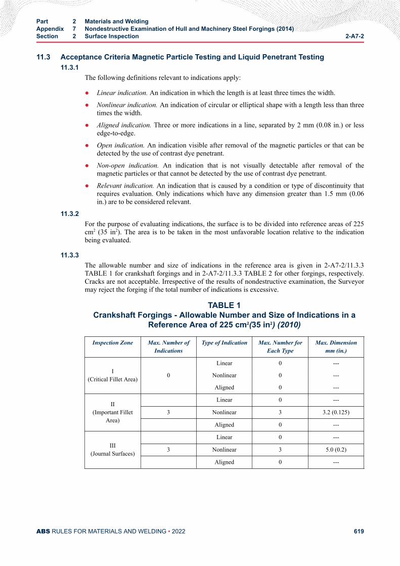
11.3 Acceptance Criteria Magnetic Particle Testing and Liquid Penetrant Testing11.3.1
The following definitions relevant to indications apply:
● Linear indication. An indication in which the length is at least three times the width.
● Nonlinear indication. An indication of circular or elliptical shape with a length less than threetimes the width.
● Aligned indication. Three or more indications in a line, separated by 2 mm (0.08 in.) or lessedge-to-edge.
● Open indication. An indication visible after removal of the magnetic particles or that can bedetected by the use of contrast dye penetrant.
● Non-open indication. An indication that is not visually detectable after removal of themagnetic particles or that cannot be detected by the use of contrast dye penetrant.
● Relevant indication. An indication that is caused by a condition or type of discontinuity thatrequires evaluation. Only indications which have any dimension greater than 1.5 mm (0.06in.) are to be considered relevant.
11.3.2For the purpose of evaluating indications, the surface is to be divided into reference areas of 225cm2 (35 in2). The area is to be taken in the most unfavorable location relative to the indicationbeing evaluated.
11.3.3The allowable number and size of indications in the reference area is given in 2-A7-2/11.3.3TABLE 1 for crankshaft forgings and in 2-A7-2/11.3.3 TABLE 2 for other forgings, respectively.Cracks are not acceptable. Irrespective of the results of nondestructive examination, the Surveyormay reject the forging if the total number of indications is excessive.
TABLE 1Crankshaft Forgings - Allowable Number and Size of Indications in a
Reference Area of 225 cm2(35 in2) (2010)
Inspection Zone Max. Number ofIndications
Type of Indication Max. Number forEach Type
Max. Dimensionmm (in.)
I(Critical Fillet Area)
Linear 0 ---
0 Nonlinear 0 ---
Aligned 0 ---
II(Important Fillet
Area)
Linear 0 ---
3 Nonlinear 3 3.2 (0.125)
Aligned 0 ---
III(Journal Surfaces)
Linear 0 ---
3 Nonlinear 3 5.0 (0.2)
Aligned 0 ---
Part 2 Materials and WeldingAppendix 7 Nondestructive Examination of Hull and Machinery Steel Forgings (2014)Section 2 Surface Inspection 2-A7-2
ABS RULES FOR MATERIALS AND WELDING • 2022 619
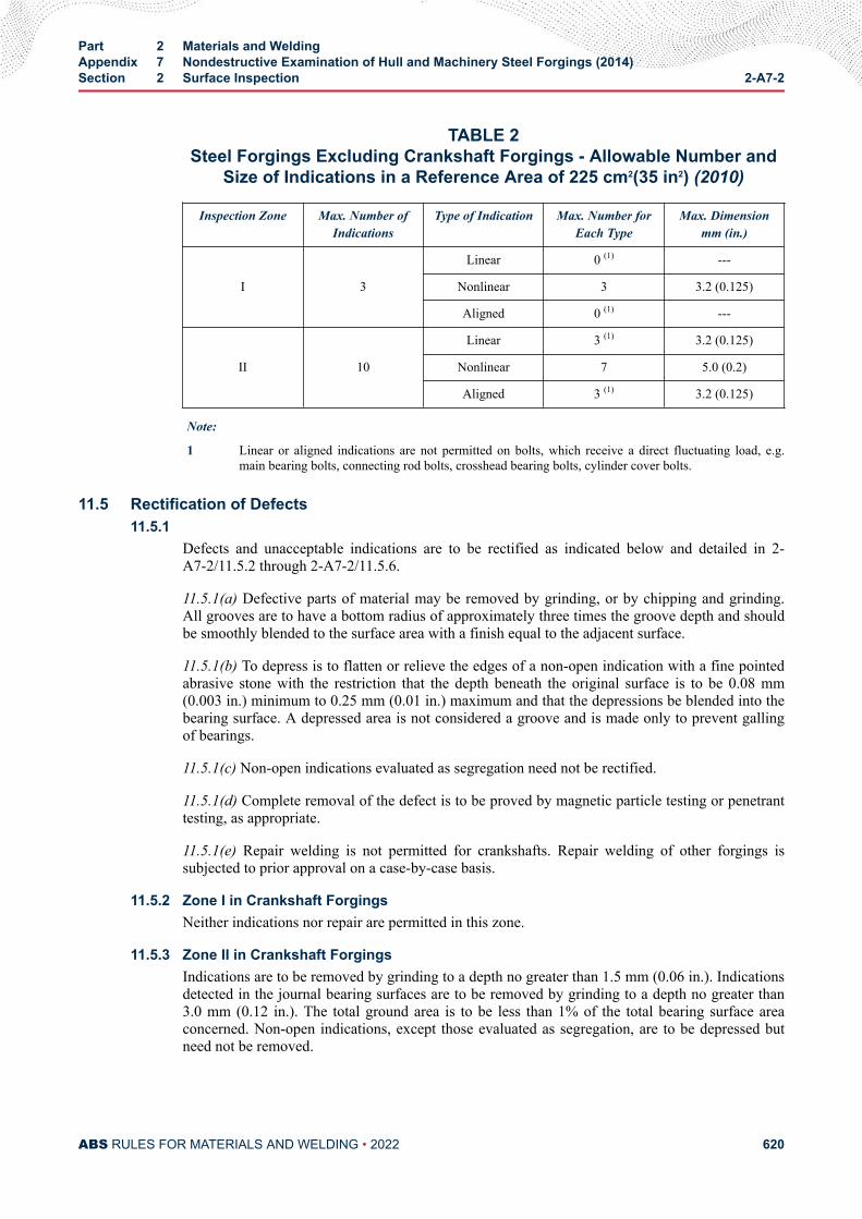
TABLE 2Steel Forgings Excluding Crankshaft Forgings - Allowable Number and
Size of Indications in a Reference Area of 225 cm2(35 in2) (2010)
Inspection Zone Max. Number ofIndications
Type of Indication Max. Number forEach Type
Max. Dimensionmm (in.)
I 3
Linear 0 (1) ---
Nonlinear 3 3.2 (0.125)
Aligned 0 (1) ---
II
10
Linear 3 (1) 3.2 (0.125)
Nonlinear 7 5.0 (0.2)
Aligned 3 (1) 3.2 (0.125)
Note:
1 Linear or aligned indications are not permitted on bolts, which receive a direct fluctuating load, e.g.main bearing bolts, connecting rod bolts, crosshead bearing bolts, cylinder cover bolts.
11.5 Rectification of Defects11.5.1
Defects and unacceptable indications are to be rectified as indicated below and detailed in 2-A7-2/11.5.2 through 2-A7-2/11.5.6.
11.5.1(a) Defective parts of material may be removed by grinding, or by chipping and grinding.All grooves are to have a bottom radius of approximately three times the groove depth and shouldbe smoothly blended to the surface area with a finish equal to the adjacent surface.
11.5.1(b) To depress is to flatten or relieve the edges of a non-open indication with a fine pointedabrasive stone with the restriction that the depth beneath the original surface is to be 0.08 mm(0.003 in.) minimum to 0.25 mm (0.01 in.) maximum and that the depressions be blended into thebearing surface. A depressed area is not considered a groove and is made only to prevent gallingof bearings.
11.5.1(c) Non-open indications evaluated as segregation need not be rectified.
11.5.1(d) Complete removal of the defect is to be proved by magnetic particle testing or penetranttesting, as appropriate.
11.5.1(e) Repair welding is not permitted for crankshafts. Repair welding of other forgings issubjected to prior approval on a case-by-case basis.
11.5.2 Zone I in Crankshaft ForgingsNeither indications nor repair are permitted in this zone.
11.5.3 Zone II in Crankshaft ForgingsIndications are to be removed by grinding to a depth no greater than 1.5 mm (0.06 in.). Indicationsdetected in the journal bearing surfaces are to be removed by grinding to a depth no greater than3.0 mm (0.12 in.). The total ground area is to be less than 1% of the total bearing surface areaconcerned. Non-open indications, except those evaluated as segregation, are to be depressed butneed not be removed.
Part 2 Materials and WeldingAppendix 7 Nondestructive Examination of Hull and Machinery Steel Forgings (2014)Section 2 Surface Inspection 2-A7-2
ABS RULES FOR MATERIALS AND WELDING • 2022 620
11.5.4 Zone I in Other ForgingsIndications are to be removed by grinding to a depth no greater than 1.5 mm (0.06 in.). However,grinding is not permitted in way of finished machined threads.
11.5.5 Zone II in Other ForgingsIndications are to be removed by grinding to a depth no greater than 2% of the diameter or 4.0 mm(0.16 in.), whichever is smaller.
11.5.6 Zones Other than I and II in All ForgingsDefects detected by visual inspection are to be removed by grinding to a depth no greater than 5%of the diameter or 10 mm (0.4 in.), whichever is smaller. The total ground area is to be less than2% of the forging surface area.
13 Record
13.1Test results of surface inspections are to be recorded at least with the following items:
i) Date of testing
ii) Names and qualification level of inspection personnel
iii) Kind of testing method
● For liquid penetrant testing: test media combination
● For magnetic particle testing: method of magnetizing, test media and magnetic field strength
iv) Kind of product
v) Product number for identification
vi) Grade of steel
vii) Heat treatment
viii) Stage of testing
ix) Position (zone) of testing
x) Surface condition
xi) Test standards used
xii) Testing condition
xiii) Results
xiv) Statement of acceptance/non acceptance
xv) Details of weld repair including sketch
Part 2 Materials and WeldingAppendix 7 Nondestructive Examination of Hull and Machinery Steel Forgings (2014)Section 2 Surface Inspection 2-A7-2
ABS RULES FOR MATERIALS AND WELDING • 2022 621
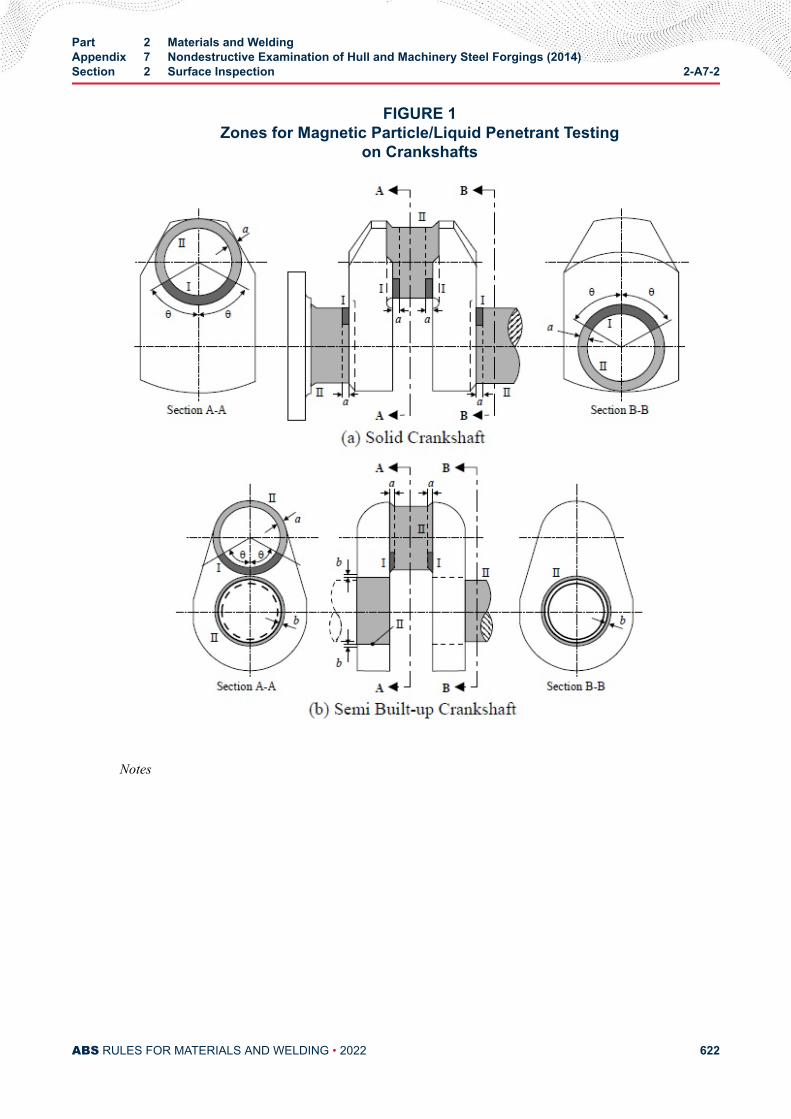
FIGURE 1Zones for Magnetic Particle/Liquid Penetrant Testing
on Crankshafts
Notes
Part 2 Materials and WeldingAppendix 7 Nondestructive Examination of Hull and Machinery Steel Forgings (2014)Section 2 Surface Inspection 2-A7-2
ABS RULES FOR MATERIALS AND WELDING • 2022 622
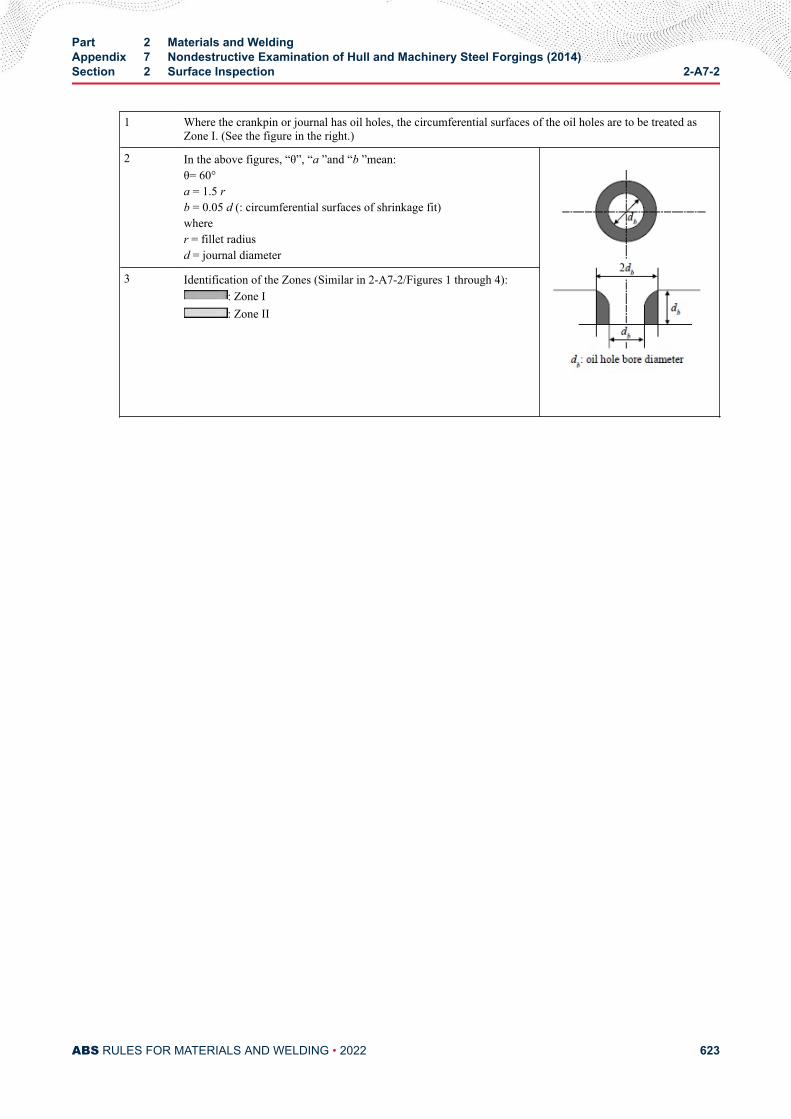
1 Where the crankpin or journal has oil holes, the circumferential surfaces of the oil holes are to be treated asZone I. (See the figure in the right.)
2 In the above figures, “θ”, “a ”and “b ”mean:θ= 60°a = 1.5 rb = 0.05 d (: circumferential surfaces of shrinkage fit)wherer = fillet radiusd = journal diameter
3 Identification of the Zones (Similar in 2-A7-2/Figures 1 through 4):: Zone I: Zone II
Part 2 Materials and WeldingAppendix 7 Nondestructive Examination of Hull and Machinery Steel Forgings (2014)Section 2 Surface Inspection 2-A7-2
ABS RULES FOR MATERIALS AND WELDING • 2022 623
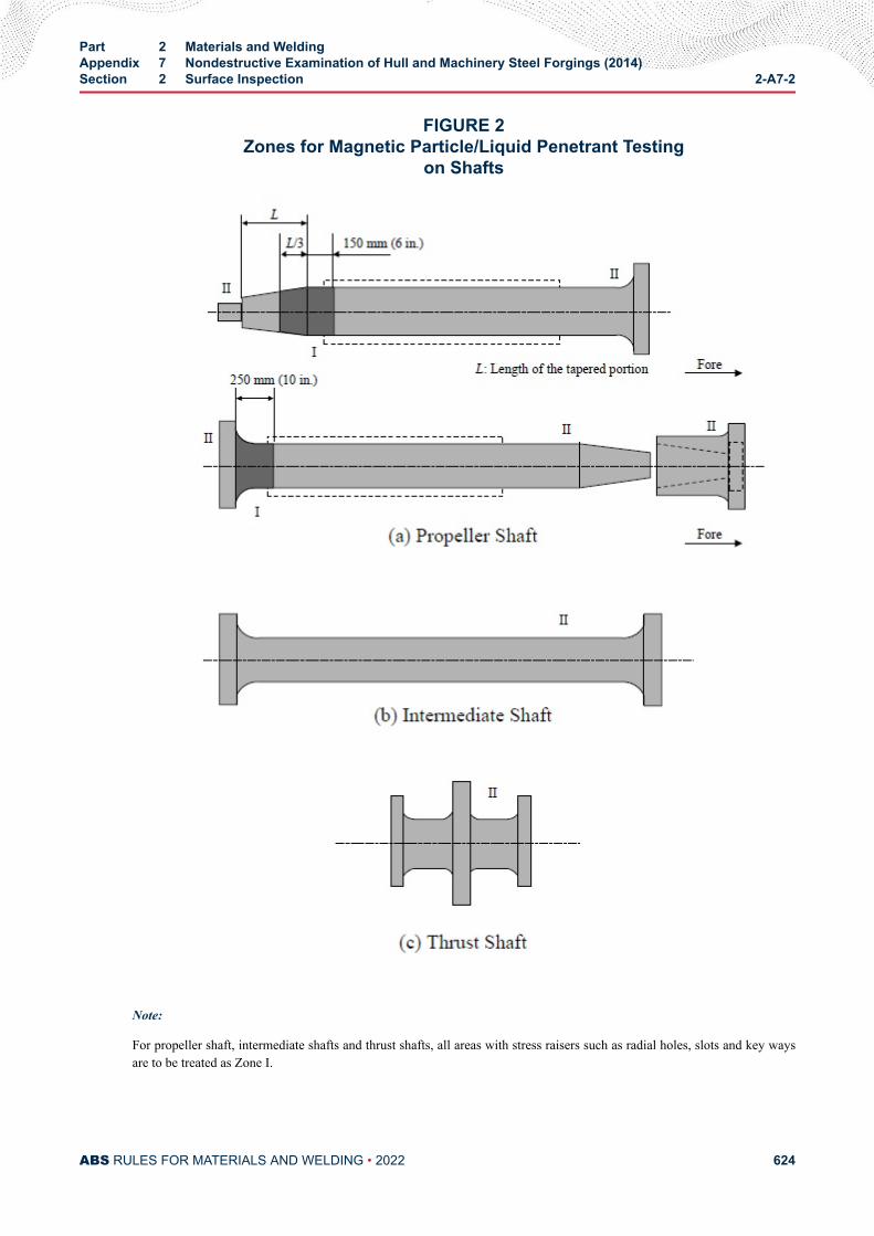
FIGURE 2Zones for Magnetic Particle/Liquid Penetrant Testing
on Shafts
Note:
For propeller shaft, intermediate shafts and thrust shafts, all areas with stress raisers such as radial holes, slots and key waysare to be treated as Zone I.
Part 2 Materials and WeldingAppendix 7 Nondestructive Examination of Hull and Machinery Steel Forgings (2014)Section 2 Surface Inspection 2-A7-2
ABS RULES FOR MATERIALS AND WELDING • 2022 624
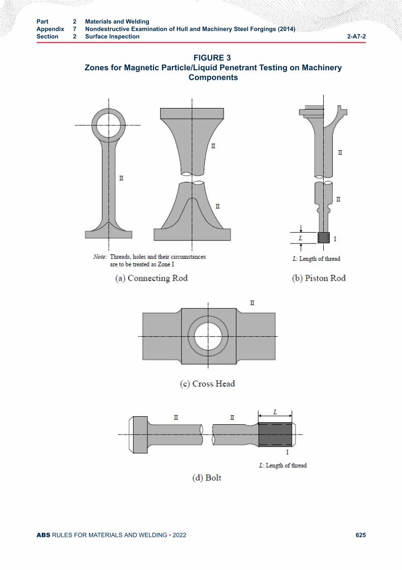
FIGURE 3 Zones for Magnetic Particle/Liquid Penetrant Testing on Machinery
Components
Part 2 Materials and WeldingAppendix 7 Nondestructive Examination of Hull and Machinery Steel Forgings (2014)Section 2 Surface Inspection 2-A7-2
ABS RULES FOR MATERIALS AND WELDING • 2022 625

.
Part 2 Materials and WeldingAppendix 7 Nondestructive Examination of Hull and Machinery Steel Forgings (2014)Section 2 Surface Inspection 2-A7-2
ABS RULES FOR MATERIALS AND WELDING • 2022 626
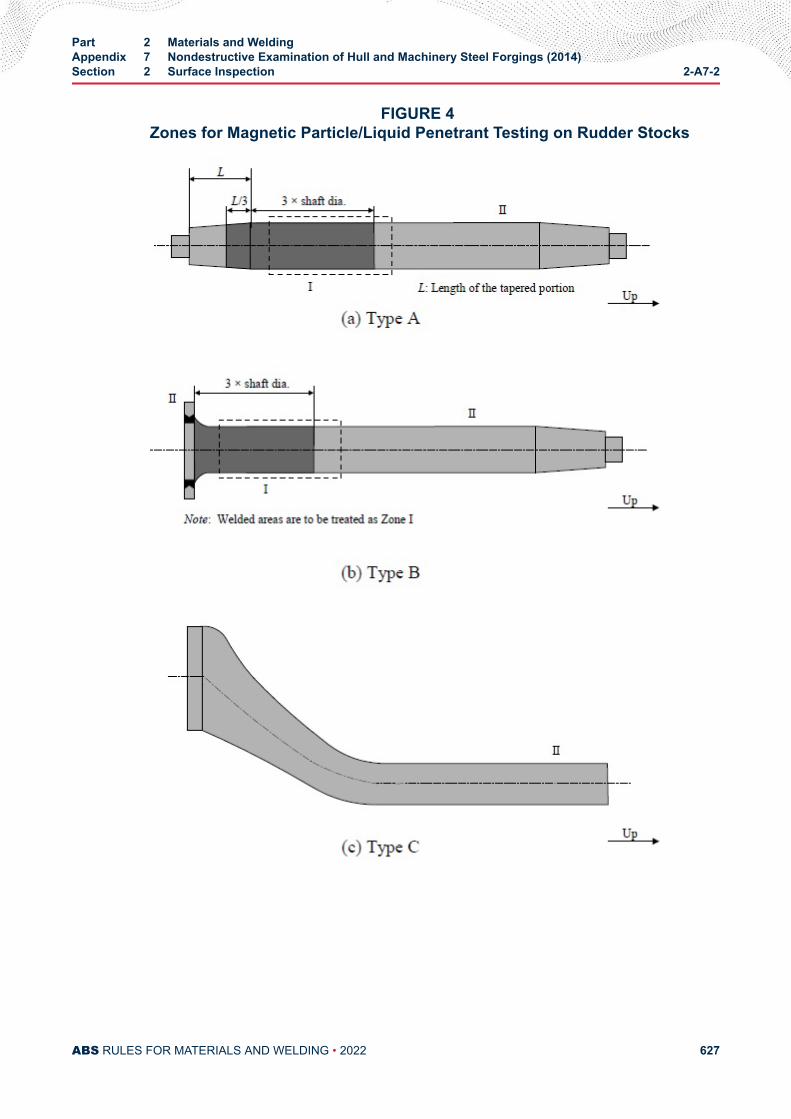
FIGURE 4 Zones for Magnetic Particle/Liquid Penetrant Testing on Rudder Stocks
Part 2 Materials and WeldingAppendix 7 Nondestructive Examination of Hull and Machinery Steel Forgings (2014)Section 2 Surface Inspection 2-A7-2
ABS RULES FOR MATERIALS AND WELDING • 2022 627
A P P E N D I X 7Nondestructive Examination of Hull and Machinery Steel Forgings (2014)
S E C T I O N 3Volumetric Inspection
1 General
1.1Volumetric inspection in this Appendix is to be carried out by ultrasonic testing using the contact methodwith straight beam and/or angle beam technique.
1.3The testing procedures, apparatus and conditions of ultrasonic testing are to comply with the recognizednational or international standards. Generally the DGS (distance-gain size) procedure is to be applied usingstraight beam probes and/or angle beam probes with 2 to 4 MHz and inspection should be carried out usinga twin crystal 0° probe for near surface scans [25 mm (1 in.)] plus a 0° probe for the remaining volume.Fillet radii should be examined using 45°, 60° or 70° probes.
1.5Personnel engaged in ultrasonic testing is to be qualified in accordance with the ABS Guide forNondestructive Inspection. The qualification is to be verified by certificates.
3 Products
3.1 (2012)Volumetric inspections by ultrasonic testing generally apply to the following steel forgings:
i) Crankshaft with minimum crankpin diameter not less than 150 mm (6 in.)
ii) Tail shafts with minimum diameter not less than 200 mm (8 in.) and up to 455 mm (18 in.). UT ofpropeller shafts 455 mm (18 in.) in diameter and over is to be carried out in accordance withSection 7-A1-12.
iii) Intermediate shafts, thrust shafts and rudder stocks with minimum diameter not less than 200 mm(8 in.)
iv) Connecting rods, piston rods and crossheads are to be examined in accordance with 4-2-1/15.11TABLE 1.
PART 2
ABS RULES FOR MATERIALS AND WELDING • 2022 628
5 Zones for Volumetric InspectionUltrasonic testing is to be carried out in the zones I to III as indicated in 2-A7-3/Figures 1 to 4. Areas maybe upgraded to a higher zone at the discretion of the Surveyors.
7 Surface Condition
7.1The surfaces of forgings to be examined are to be such that adequate coupling can be established betweenthe probe and the forging and that excessive wear of the probe can be avoided. The surfaces are to be freefrom scale, dirt, grease or paint.
7.3The ultrasonic testing is to be carried out after the steel forgings have been machined to a conditionsuitable for this type of testing and after the final heat treatment, but prior to the drilling of the oil boresand prior to surface hardening. Black forgings are to be inspected after removal of the oxide scale by eitherflame descaling or shot blasting methods.
9 Acceptance CriteriaAcceptance criteria of volumetric inspection by ultrasonic testing are shown in 2-A7-3/Tables 1 and 2.
11 RecordTest results of volumetric inspection are to be recorded at least with the following items:
i) Date of testing
ii) Names and qualification level of inspection personnel
iii) Kind of testing method
iv) Kind of product
v) Product number for identification
vi) Grade of steel
vii) Heat treatment
viii) Stage of testing
ix) Position (zone) of testing
x) Surface condition
xi) Test standards used
xii) Testing condition
xiii) Results
xiv) Statement of acceptance/non acceptance
Part 2 Materials and WeldingAppendix 7 Nondestructive Examination of Hull and Machinery Steel Forgings (2014)Section 3 Volumetric Inspection 2-A7-3
ABS RULES FOR MATERIALS AND WELDING • 2022 629
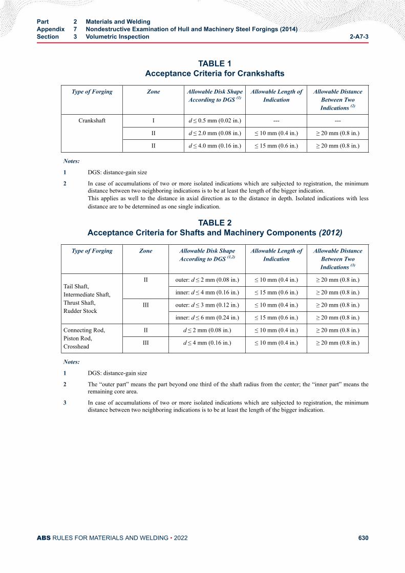
TABLE 1Acceptance Criteria for Crankshafts
Type of Forging Zone Allowable Disk ShapeAccording to DGS (1)
Allowable Length ofIndication
Allowable DistanceBetween TwoIndications (2)
Crankshaft
I d ≤ 0.5 mm (0.02 in.) --- ---
II d ≤ 2.0 mm (0.08 in.) ≤ 10 mm (0.4 in.) ≥ 20 mm (0.8 in.)
II d ≤ 4.0 mm (0.16 in.) ≤ 15 mm (0.6 in.) ≥ 20 mm (0.8 in.)
Notes:
1 DGS: distance-gain size
2 In case of accumulations of two or more isolated indications which are subjected to registration, the minimumdistance between two neighboring indications is to be at least the length of the bigger indication.This applies as well to the distance in axial direction as to the distance in depth. Isolated indications with lessdistance are to be determined as one single indication.
TABLE 2Acceptance Criteria for Shafts and Machinery Components (2012)
Type of Forging Zone Allowable Disk ShapeAccording to DGS (1,2)
Allowable Length ofIndication
Allowable DistanceBetween TwoIndications (3)
Tail Shaft,Intermediate Shaft,Thrust Shaft,Rudder Stock
II outer: d ≤ 2 mm (0.08 in.) ≤ 10 mm (0.4 in.) ≥ 20 mm (0.8 in.)
inner: d ≤ 4 mm (0.16 in.) ≤ 15 mm (0.6 in.) ≥ 20 mm (0.8 in.)
III outer: d ≤ 3 mm (0.12 in.) ≤ 10 mm (0.4 in.) ≥ 20 mm (0.8 in.)
inner: d ≤ 6 mm (0.24 in.) ≤ 15 mm (0.6 in.) ≥ 20 mm (0.8 in.)
Connecting Rod,Piston Rod,Crosshead
II d ≤ 2 mm (0.08 in.) ≤ 10 mm (0.4 in.) ≥ 20 mm (0.8 in.)
III d ≤ 4 mm (0.16 in.) ≤ 10 mm (0.4 in.) ≥ 20 mm (0.8 in.)
Notes:
1 DGS: distance-gain size
2 The “outer part” means the part beyond one third of the shaft radius from the center; the “inner part” means theremaining core area.
3 In case of accumulations of two or more isolated indications which are subjected to registration, the minimumdistance between two neighboring indications is to be at least the length of the bigger indication.
Part 2 Materials and WeldingAppendix 7 Nondestructive Examination of Hull and Machinery Steel Forgings (2014)Section 3 Volumetric Inspection 2-A7-3
ABS RULES FOR MATERIALS AND WELDING • 2022 630
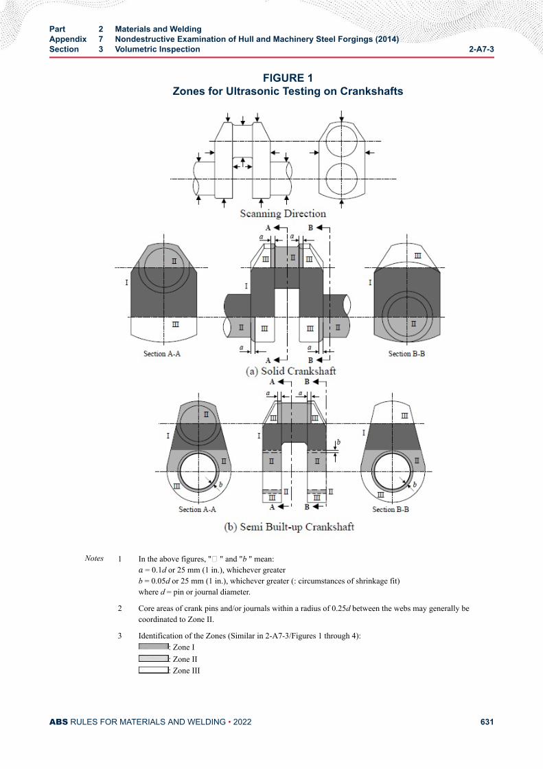
FIGURE 1Zones for Ultrasonic Testing on Crankshafts
Notes 1 In the above figures, "� " and "b " mean:a = 0.1d or 25 mm (1 in.), whichever greaterb = 0.05d or 25 mm (1 in.), whichever greater (: circumstances of shrinkage fit)where d = pin or journal diameter.
2 Core areas of crank pins and/or journals within a radius of 0.25d between the webs may generally becoordinated to Zone II.
3 Identification of the Zones (Similar in 2-A7-3/Figures 1 through 4):: Zone I: Zone II: Zone III
Part 2 Materials and WeldingAppendix 7 Nondestructive Examination of Hull and Machinery Steel Forgings (2014)Section 3 Volumetric Inspection 2-A7-3
ABS RULES FOR MATERIALS AND WELDING • 2022 631
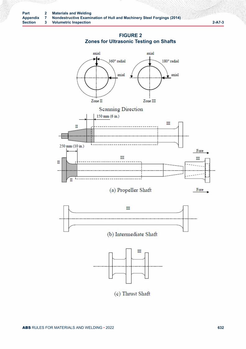
FIGURE 2Zones for Ultrasonic Testing on Shafts
Part 2 Materials and WeldingAppendix 7 Nondestructive Examination of Hull and Machinery Steel Forgings (2014)Section 3 Volumetric Inspection 2-A7-3
ABS RULES FOR MATERIALS AND WELDING • 2022 632

Notes:
1 For hollow shafts, 360° radial scanning applies to Zone III.
2 Circumferences of the bolt holes in the flanges are to be treated as Zone II.
Part 2 Materials and WeldingAppendix 7 Nondestructive Examination of Hull and Machinery Steel Forgings (2014)Section 3 Volumetric Inspection 2-A7-3
ABS RULES FOR MATERIALS AND WELDING • 2022 633
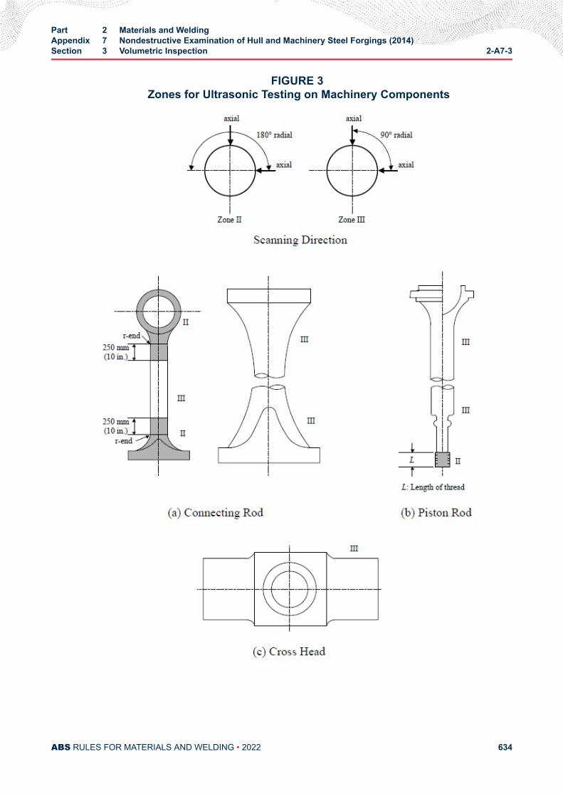
FIGURE 3 Zones for Ultrasonic Testing on Machinery Components
Part 2 Materials and WeldingAppendix 7 Nondestructive Examination of Hull and Machinery Steel Forgings (2014)Section 3 Volumetric Inspection 2-A7-3
ABS RULES FOR MATERIALS AND WELDING • 2022 634
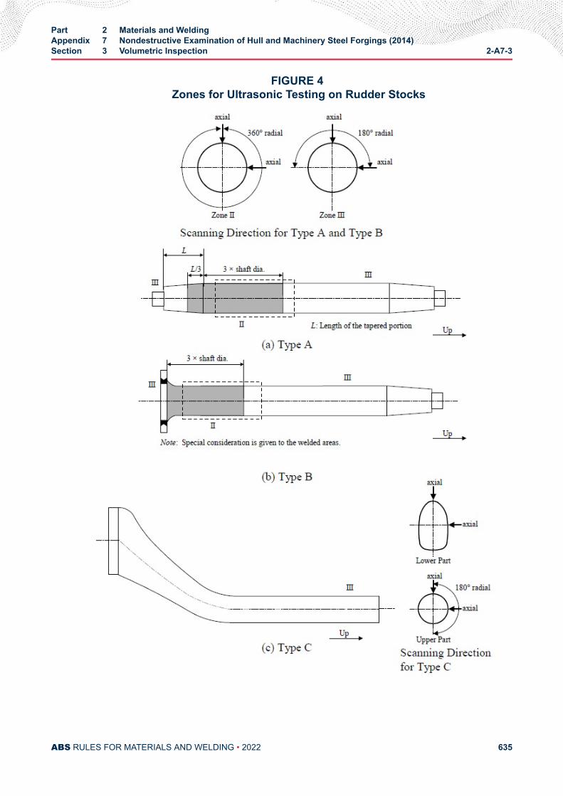
FIGURE 4 Zones for Ultrasonic Testing on Rudder Stocks
Part 2 Materials and WeldingAppendix 7 Nondestructive Examination of Hull and Machinery Steel Forgings (2014)Section 3 Volumetric Inspection 2-A7-3
ABS RULES FOR MATERIALS AND WELDING • 2022 635
A P P E N D I X 8Steel with Enhanced Corrosion Resistance Properties
CONTENTSSECTION 1 Additional Approval Procedure for Steel with Enhanced
Corrosion Resistance Properties (2014)........................................6371 Scope..........................................................................................637
1.1 .......................................................................................6371.3 .......................................................................................637
3 Application for Approval..............................................................6373.1 .......................................................................................637
5 Approval of Test Plan..................................................................6385.1 .......................................................................................6385.3 .......................................................................................6385.5 .......................................................................................638
7 Carrying out the Approval Test................................................... 6397.1 .......................................................................................639
9 Attendance of the ABS Surveyor for Test................................... 6399.1 .......................................................................................639
11 Test Results................................................................................ 63911.1 .......................................................................................63911.3 .......................................................................................63911.5 .......................................................................................639
13 Assessment Criteria for Results of Corrosion ResistanceTests of Welded Joint..................................................................63913.1 .......................................................................................639
TABLE 1 Designations for Steels with Enhanced CorrosionResistance Properties (2014).............................................638
PART 2
ABS RULES FOR MATERIALS AND WELDING • 2022 636
A P P E N D I X 8Steel with Enhanced Corrosion Resistance Properties
S E C T I O N 1Additional Approval Procedure for Steel with Enhanced Corrosion
Resistance Properties (2014)
1 Scope
1.1Approval is to be carried out in accordance with the requirements of the Appendices in the ABS Rules forMaterials and Welding (Part 2) together with the additional requirements for corrosion testing specified inthis Appendix.
1.3The corrosion tests and assessment criteria are to be in accordance with the Appendix of the Annex toPerformance Standard for Alternative Means of Corrosion Protection for Cargo Oil Tanks of Crude OilTankers (MSC.289 (87)).
3 Application for Approval
3.1The manufacturer has to submit to ABS a request for approval, which is to include the following:
i) Corrosion test plan and details of equipment and test environments.
ii) Technical data related to product assessment criteria for confirming corrosion resistance
iii) The technical background explaining how the variation in added and controlled elements improvescorrosion resistance.
iv) The grades, the brand name and maximum thickness of steel with enhanced corrosion resistanceproperties to be approved. Designations for steels with enhanced corrosion resistance propertiesare given in 2-A8-1/5.3.3 TABLE 1.
v) The welding processes and the brand name of the welding consumables to be used for approval.
PART 2
ABS RULES FOR MATERIALS AND WELDING • 2022 637
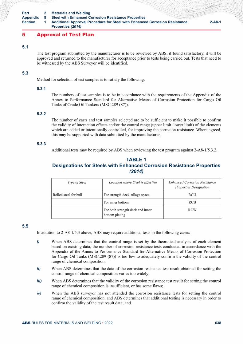
5 Approval of Test Plan
5.1The test program submitted by the manufacturer is to be reviewed by ABS, if found satisfactory, it will beapproved and returned to the manufacturer for acceptance prior to tests being carried out. Tests that need tobe witnessed by the ABS Surveyor will be identified.
5.3Method for selection of test samples is to satisfy the following:
5.3.1The numbers of test samples is to be in accordance with the requirements of the Appendix of theAnnex to Performance Standard for Alternative Means of Corrosion Protection for Cargo OilTanks of Crude Oil Tankers (MSC.289 (87)).
5.3.2The number of casts and test samples selected are to be sufficient to make it possible to confirmthe validity of interaction effects and/or the control range (upper limit, lower limit) of the elementswhich are added or intentionally controlled, for improving the corrosion resistance. Where agreed,this may be supported with data submitted by the manufacturer.
5.3.3Additional tests may be required by ABS when reviewing the test program against 2-A8-1/5.3.2.
TABLE 1Designations for Steels with Enhanced Corrosion Resistance Properties
(2014)
Type of Steel Location where Steel is Effective Enhanced Corrosion ResistanceProperties Designation
Rolled steel for hull For strength deck, ullage space. RCU
For inner bottom RCB
For both strength deck and innerbottom plating
RCW
5.5In addition to 2-A8-1/5.3 above, ABS may require additional tests in the following cases:
i) When ABS determines that the control range is set by the theoretical analysis of each elementbased on existing data, the number of corrosion resistance tests conducted in accordance with theAppendix of the Annex to Performance Standard for Alternative Means of Corrosion Protectionfor Cargo Oil Tanks (MSC.289 (87)) is too few to adequately confirm the validity of the controlrange of chemical composition;
ii) When ABS determines that the data of the corrosion resistance test result obtained for setting thecontrol range of chemical composition varies too widely;
iii) When ABS determines that the validity of the corrosion resistance test result for setting the controlrange of chemical composition is insufficient, or has some flaws;
iv) When the ABS surveyor has not attended the corrosion resistance tests for setting the controlrange of chemical composition, and ABS determines that additional testing is necessary in order toconfirm the validity of the test result data; and
Part 2 Materials and WeldingAppendix 8 Steel with Enhanced Corrosion Resistance PropertiesSection 1 Additional Approval Procedure for Steel with Enhanced Corrosion Resistance
Properties (2014)2-A8-1
ABS RULES FOR MATERIALS AND WELDING • 2022 638
v) When ABS determines that it is necessary, for reasons other than cases i) to iv) above.
Note:
The chemical composition of the steel with enhanced corrosion resistance properties is to be within the range specified forrolled steel for hull. Elements to be added for improving the corrosion resistance and for which content is not specified are tobe generally within 1% in total.
7 Carrying out the Approval Test
7.1The manufacturer is to carry out the approval test in accordance with the approved test plan.
9 Attendance of the ABS Surveyor for Test
9.1The ABS Surveyor is to be present, as a rule, when the test samples for the approval test are beingidentified and for approval tests, see also 2-A8-1/5.1.
11 Test Results
11.1After completion of the approval test, the manufacturer is to produce the report of the approval test andsubmit it to ABS.
11.3ABS will give approval for steel with enhanced corrosion resistance properties where approval tests areconsidered by the society to have given satisfactory results based on the data submitted in accordance withthe provisions of this Appendix.
11.5The certificate is to contain the manufacturer's name, the period of validity of the certificate, the grades andthickness of the steel approved, welding methods and welding consumables approved.
13 Assessment Criteria for Results of Corrosion Resistance Tests ofWelded Joint
13.1The results will be assessed by ABS in accordance with the acceptance criteria specified in the Appendixof the Annex to Performance Standard for Alternative Means of Corrosion Protection for Cargo Oil Tanks(MSC.289 (87)).
Part 2 Materials and WeldingAppendix 8 Steel with Enhanced Corrosion Resistance PropertiesSection 1 Additional Approval Procedure for Steel with Enhanced Corrosion Resistance
Properties (2014)2-A8-1
ABS RULES FOR MATERIALS AND WELDING • 2022 639
A P P E N D I X 9Welding Procedure Qualification Tests of Steels for Hull Construction and
Marine Structures (1 July 2014)
CONTENTSSECTION 1 General Requirements.....................................................................642
1 Scope..........................................................................................6421.1 .......................................................................................6421.3 .......................................................................................642
3 General.......................................................................................6423.1 .......................................................................................6423.3 .......................................................................................6423.5 .......................................................................................6423.7 .......................................................................................6423.9 .......................................................................................6433.11 .......................................................................................6433.13 .......................................................................................6433.15 .......................................................................................6433.17 .......................................................................................643
5 Welding Procedure Specification – pWPS and WPS................. 6435.1 Preliminary Welding Procedure Specification (pWPS)
and Welding Procedure Specification (WPS)................ 6437 Welding Procedure Qualification Test –WPQT........................... 644
7.1 General.......................................................................... 6447.3 Butt Welds..................................................................... 6447.5 Fillet Welds.................................................................... 6497.7 Re-testing...................................................................... 6517.9 Test Record....................................................................652
9 Range of Approval......................................................................6529.1 General.......................................................................... 6529.3 Base Metal.....................................................................6529.5 Thickness.......................................................................6539.7 Welding Position............................................................ 6549.9 Welding Process............................................................6549.11 Welding Consumable.....................................................6549.13 Heat Input...................................................................... 655
PART 2
ABS RULES FOR MATERIALS AND WELDING • 2022 640
9.15 Preheating and Interpass Temperature......................... 6559.17 Post-weld Heat Treatment............................................. 6559.19 Type of Joint.................................................................. 6559.21 Other Variables.............................................................. 656
TABLE 1 Impact Test Requirements for Butt Joints (t ≤ 50 mm)(1,
2) (1 July 2014)................................................................... 648TABLE 2 Approval Range of Thickness for Butt and T-Joint
Welds and Fillet Welds (1 July 2014).................................653TABLE 3 Range of Approval for Type of Welded Joint (1 July
2014)..................................................................................655
FIGURE 1 Test Assembly for Butt Weld (1 July 2014)........................ 645FIGURE 2 Test Sampling (1 July 2014)...............................................646FIGURE 3 Test Assembly for Fillet Weld (1 July 2014)....................... 650
ANNEX 1 Location of Charpy V-Notch Impact Test.......................................657FIGURE 1 Locations of V-notch for Butt Weld of Normal Heat Input
(Heat Input ≤ 50 kJ/cm) (1 July 2014)................................657FIGURE 2 Locations of V-Notch for Butt Weld of High Heat Input
(Heat Input > 50 kJ/cm) (1 July 2014)................................658
ANNEX 2 Hardness Test (Typical examples of hardness test).....................659TABLE 1 Recommended Distances ℓ Between Indentations for
Hardness Test in the Heat Affected Zone (1 July 2014).....660
FIGURE 1 Examples of Hardness Test with Rows of Indentations(R) in Butt Welds (1 July 2014).......................................... 659
FIGURE 2 Example Showing the Position of the Indentations forHardness Test in the Weld Metal, the Heat AffectedZone and the Base Metal of a Butt Weld (dimensions inmm) (1 July 2014).............................................................. 660
FIGURE 3 Examples of Hardness Test with Row Indentation (R) inFillet Welds and in T-Joint Welds (1 July 2014)................. 661
FIGURE 4A Example Showing the Position of the Indentations forHardness Test in the Weld Metal, the Heat AffectedZone and the Base Metal of a Fillet Weld (dimensionsin mm) (1 July 2014).......................................................... 662
FIGURE 4B Example Showing the Position of the Indentations forHardness Test on the Weld Metal, the Heat AffectedZone and the Base Metal of a T-Joint Weld (dimensionsin mm) (1 July 2014).......................................................... 663
ANNEX 3 Welding Positions............................................................................6641 Welding Positions According to ISO Standard........................... 6643 Welding Positions According to AWS-Code............................... 665
ABS RULES FOR MATERIALS AND WELDING • 2022 641
A P P E N D I X 9Welding Procedure Qualification Tests of Steels for Hull Construction and
Marine Structures (1 July 2014)
S E C T I O N 1General Requirements
1 Scope
1.1 (2022)Refer to 2-4-1/1.7 "Welding Procedures". This appendix covers weld procedure qualification of steels usedin marine and offshore hull structures.
1.3 (2022)For weld procedure qualification of stainless steels, refer to the ABS Guide for Materials and Welding ofStainless Steels.
3 General
3.1Welding procedure qualification tests are intended to verify that a manufacturer is adequately qualified toperform welding operations using a particular procedure.
3.3In general, welding procedure tests are to reflect fabrication conditions with respect to welding equipment,inside or outside fabrication, weld preparation, preheating and any post-weld heat treatment. It is themanufacturer’s responsibility to establish and document whether a procedure is suitable for the particularapplication.
3.5For welding procedure approval, welding procedure qualification tests are to be carried out withsatisfactory results. Welding procedure specifications are to reference the weld qualification test resultsachieved during welding procedure qualification testing.
3.7The approved WPS shall be restricted to the contractor or subcontractor performing the qualification. If theapproved WPS’s are to be applied at workshops or yards belonging to the contractor or subcontractor, they
PART 2
ABS RULES FOR MATERIALS AND WELDING • 2022 642
are to be under the same technical management and working to the same quality assurance procedures andprogram.
3.9 (2022)For slot welding, a procedure qualification test is to be carried out in accordance with AWS D1.1 Figure6.26 or other recognized standards as agreed with ABS. Alternatively, a butt weld qualification may alsoqualify slot welds.
3.11 (2022)Stud welding procedure qualificaiton is to be carried out in accordance with AWS D1.1 Chapter 5 or otherrecognized standards, as agreed with ABS.
3.13 (2022)This qualification scheme does not cover welding of process piping, structural tubulars or TKY joints.Weld procedures for process piping are to be qualified in accordance with ASME IX or other weldingcodes or standards agreed with ABS. For qualification of weld procedures intended for structural tubularsor TKY joints, refer to AWS D1.1 or other welding codes as agreed with ABS.
3.15 (2022)A butt weld procedure qualification is required for welding full penetration T-butt joint.
3.17 (2022)Butt weld qualification will permit welding of partial penetration welds. Alternatives for weld procedurequalification for partial penetration welds can be specifically agreed with ABS.
5 Welding Procedure Specification – pWPS and WPS
5.1 Preliminary Welding Procedure Specification (pWPS) and Welding ProcedureSpecification (WPS)5.1.1 pWPS
The shipyard or manufacturer is to submit a pWPS for review prior to the Weld ProcedureQualification Tests (WPQT). The pWPS can be modified and amended during the WPQT asdeemed necessary. The pWPS is to define all the variables (refer to AWS D.1.1, ISO 15614 orother recognized standards) that will be included in the WPS. In case the test pieces weldedaccording to the pWPS show unacceptable results the pWPS is to be adjusted by the shipyard ormanufacturer. The new pWPS is to be prepared and the test pieces welded in accordance with thenew pWPS.
5.1.2 WPSUpon completion of the WPQT and satisfactory review, the pWPS is given approval and becomesthe WPS. The WPS is to be used as a basis for production welds. The approval range of the WPSis to be in compliance with 2-A9-1/9.
Note:
The generic term WPS is sometimes applied to a document before and after qualification tests, this can beaccepted. The use of pWPS helps identify that the document has not yet been qualified by satisfactory tests.
Part 2 Materials and WeldingAppendix 9 Welding Procedure Qualification Tests of Steels for Hull Construction and Marine
Structures (1 July 2014)Section 1 General Requirements 2-A9-1
ABS RULES FOR MATERIALS AND WELDING • 2022 643
7 Welding Procedure Qualification Test –WPQT
7.1 General7.1.1
Preparation and welding of test pieces are to be carried out in accordance with the pWPS andunder the general condition of production welding which it represents.
7.1.2Welding of the test assemblies and testing of test specimens are to be witnessed by the Surveyor.
7.1.3If tack welds and/or start and stop points are a condition of the weld process they are to be fusedinto the joint and are to be included in the test assemblies.
7.3 Butt Welds7.3.1 Assembly of Test Pieces
The test assembly is to be in accordance with 2-A9-1/7.3.1 FIGURE 1 with the followingminimum dimensions:
● Manual or Semi-automatic Welding:
Thickness = t
Width = 2a, where a = 3 × t. Minimum width to be no less than 150 mm
Length b = 6 × t. Minimum length to be no less than 350 mm
● Automatic Welding:
Thickness = t
Width = 2a, where a = 4 × t. Minimum width to be no less than 200 mm
Length b. Minimum length to be no less than 1000 mm
Part 2 Materials and WeldingAppendix 9 Welding Procedure Qualification Tests of Steels for Hull Construction and Marine
Structures (1 July 2014)Section 1 General Requirements 2-A9-1
ABS RULES FOR MATERIALS AND WELDING • 2022 644
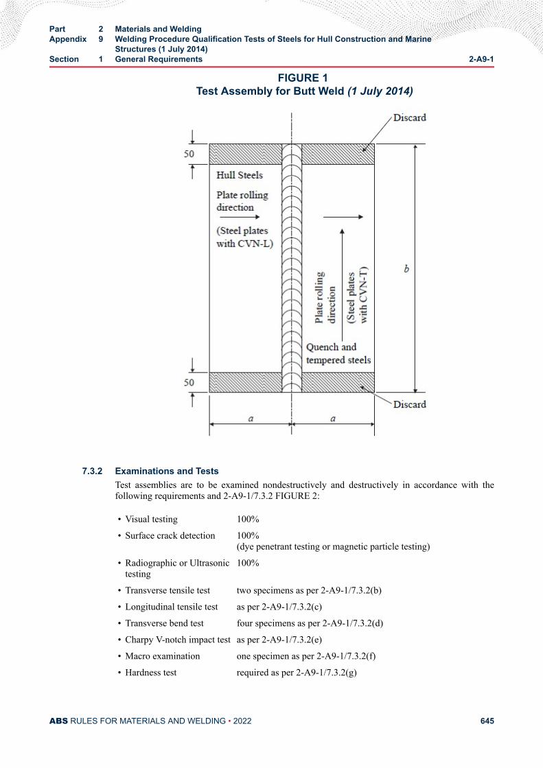
FIGURE 1 Test Assembly for Butt Weld (1 July 2014)
7.3.2 Examinations and TestsTest assemblies are to be examined nondestructively and destructively in accordance with thefollowing requirements and 2-A9-1/7.3.2 FIGURE 2:
• Visual testing 100%
• Surface crack detection 100%(dye penetrant testing or magnetic particle testing)
• Radiographic or Ultrasonictesting
100%
• Transverse tensile test two specimens as per 2-A9-1/7.3.2(b)
• Longitudinal tensile test as per 2-A9-1/7.3.2(c)
• Transverse bend test four specimens as per 2-A9-1/7.3.2(d)
• Charpy V-notch impact test as per 2-A9-1/7.3.2(e)
• Macro examination one specimen as per 2-A9-1/7.3.2(f)
• Hardness test required as per 2-A9-1/7.3.2(g)
Part 2 Materials and WeldingAppendix 9 Welding Procedure Qualification Tests of Steels for Hull Construction and Marine
Structures (1 July 2014)Section 1 General Requirements 2-A9-1
ABS RULES FOR MATERIALS AND WELDING • 2022 645
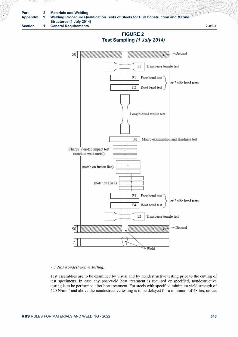
FIGURE 2 Test Sampling (1 July 2014)
7.3.2(a) Nondestructive Testing.
Test assemblies are to be examined by visual and by nondestructive testing prior to the cutting oftest specimens. In case any post-weld heat treatment is required or specified, nondestructivetesting is to be performed after heat treatment. For steels with specified minimum yield strength of420 N/mm2 and above the nondestructive testing is to be delayed for a minimum of 48 hrs, unless
Part 2 Materials and WeldingAppendix 9 Welding Procedure Qualification Tests of Steels for Hull Construction and Marine
Structures (1 July 2014)Section 1 General Requirements 2-A9-1
ABS RULES FOR MATERIALS AND WELDING • 2022 646
post weld heat treatment has been carried out. NDT procedures are to be to the satisfaction of theSurveyor.
Imperfections detected by visual or nondestructive testing are to be assessed in accordance withISO 5817, class B, except for excess weld metal and excess penetration for which the level Capplies.
7.3.2(b) Transverse Tensile Test.
The testing is to be carried out in accordance with 2-4-3/11.5 FIGURE 3. The tensile strengthrecorded for each specimen is not to be less than the minimum required for the base metal. Whenbutt welds are made between plates of different grades, the tensile strength to be obtained on thewelded assembly is to be in accordance with the requirements relating to the steel grade havinglower strength. If a lower strength consumable is proposed the details are to be submitted to ABSfor consideration.
7.3.2(c) Longitudinal Tensile Test.
Longitudinal tensile test of deposited weld metal taken lengthways from the weld is required forcases where the welding consumable is not ABS approved.
Testing is to be carried out in accordance with 2-A2-1/33 FIGURE 1. The tensile propertiesrecorded for each specimen are not to be less than the minimum required for the approval of theappropriate grade of consumable.
Where more than one welding process or type of consumable has been used to make the test weld,test specimens are to be taken from the area of the weld where each was used with the exceptionof those processes or consumables used to make the first weld run or root deposit.
7.3.2(d) Bend Test.
Transverse bend tests for butt joints are to be in accordance with 2-4-3/11.5 FIGURE 5 and2-4-3/11.5 FIGURE 6. The mandrel diameter to thickness ratio (i.e., D/t) is to be in accordancewith 2-4-3/11.5 FIGURE 7.
The bending angle is to be 180°. After testing, the test specimens are not to reveal any opendefects in any direction greater than 3 mm. Defects appearing at the corners of a test specimenduring testing are to be investigated case by case.
Two root and two face bend specimens are to be tested. For thickness 12 mm and over, four sidebend specimens may alternatively be tested.
For butt joints in heterogeneous steel plates, face and root longitudinal bend test specimens maybe used instead of the transverse bend test specimens.
7.3.2(e) Impact Testi) Normal and higher strength hull structural steels. The positions of specimens are to be in
accordance with these requirements. Dimensions and testing are to be in accordance withthe requirements of 2-1-1/11.11.
Test specimens with Charpy-V-notch are to be used and sampled from 1 to 2 mm belowthe surface of the base metal, transverse to the weld and on the side containing the lastweld run. V-notch specimens are located in the butt-welded joint as indicated in 2-A9-A1/FIGURE 1 and 2-A9-A1/ FIGURE 2, and the V-notch is to be cut perpendicular to thesurface of the weld.
Part 2 Materials and WeldingAppendix 9 Welding Procedure Qualification Tests of Steels for Hull Construction and Marine
Structures (1 July 2014)Section 1 General Requirements 2-A9-1
ABS RULES FOR MATERIALS AND WELDING • 2022 647
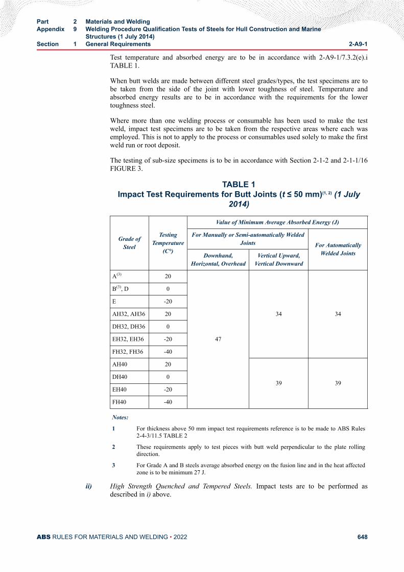
Test temperature and absorbed energy are to be in accordance with 2-A9-1/7.3.2(e).iTABLE 1.
When butt welds are made between different steel grades/types, the test specimens are tobe taken from the side of the joint with lower toughness of steel. Temperature andabsorbed energy results are to be in accordance with the requirements for the lowertoughness steel.
Where more than one welding process or consumable has been used to make the testweld, impact test specimens are to be taken from the respective areas where each wasemployed. This is not to apply to the process or consumables used solely to make the firstweld run or root deposit.
The testing of sub-size specimens is to be in accordance with Section 2-1-2 and 2-1-1/16FIGURE 3.
TABLE 1Impact Test Requirements for Butt Joints (t ≤ 50 mm)(1, 2) (1 July
2014)
Grade ofSteel
TestingTemperature
(C°)
Value of Minimum Average Absorbed Energy (J)
For Manually or Semi-automatically WeldedJoints For Automatically
Welded JointsDownhand,Horizontal, Overhead
Vertical Upward,Vertical Downward
A(3) 20
47
34 34
B(3), D 0
E -20
AH32, AH36 20
DH32, DH36 0
EH32, EH36 -20
FH32, FH36 -40
AH40 20
39 39DH40 0
EH40 -20
FH40 -40
Notes:
1 For thickness above 50 mm impact test requirements reference is to be made to ABS Rules2-4-3/11.5 TABLE 2
2 These requirements apply to test pieces with butt weld perpendicular to the plate rollingdirection.
3 For Grade A and B steels average absorbed energy on the fusion line and in the heat affectedzone is to be minimum 27 J.
ii) High Strength Quenched and Tempered Steels. Impact tests are to be performed asdescribed in i) above.
Part 2 Materials and WeldingAppendix 9 Welding Procedure Qualification Tests of Steels for Hull Construction and Marine
Structures (1 July 2014)Section 1 General Requirements 2-A9-1
ABS RULES FOR MATERIALS AND WELDING • 2022 648
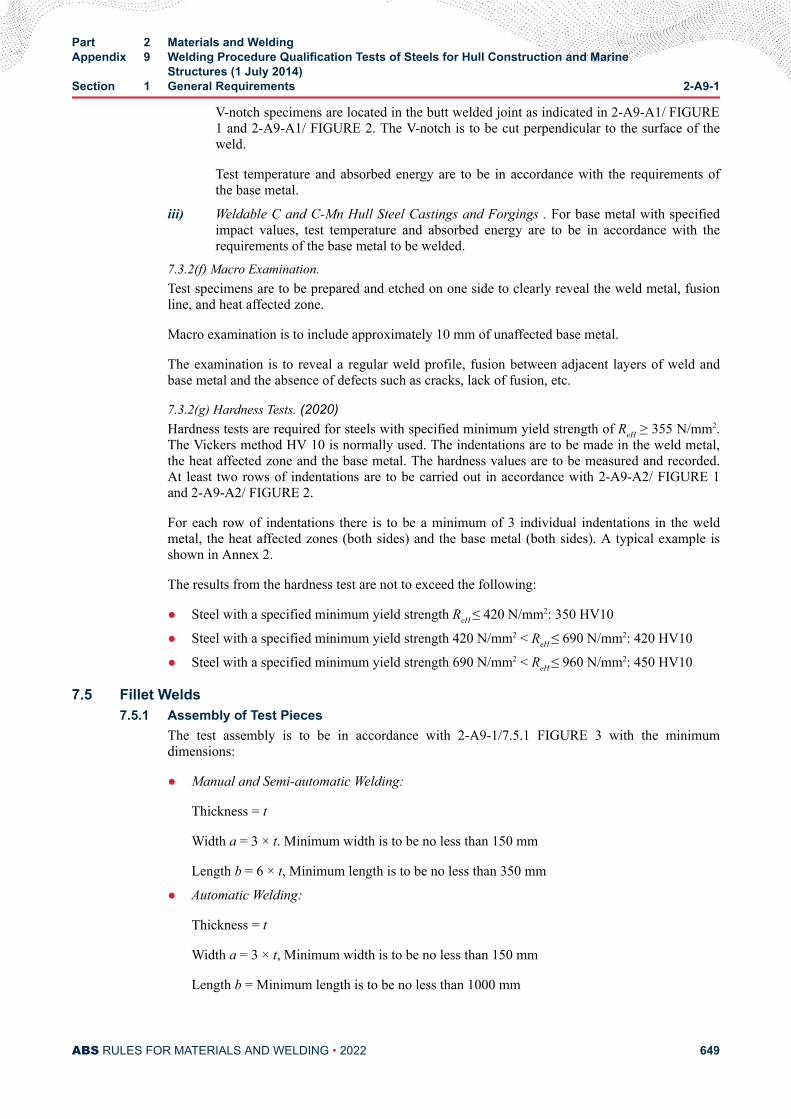
V-notch specimens are located in the butt welded joint as indicated in 2-A9-A1/ FIGURE1 and 2-A9-A1/ FIGURE 2. The V-notch is to be cut perpendicular to the surface of theweld.
Test temperature and absorbed energy are to be in accordance with the requirements ofthe base metal.
iii) Weldable C and C-Mn Hull Steel Castings and Forgings . For base metal with specifiedimpact values, test temperature and absorbed energy are to be in accordance with therequirements of the base metal to be welded.
7.3.2(f) Macro Examination.Test specimens are to be prepared and etched on one side to clearly reveal the weld metal, fusionline, and heat affected zone.
Macro examination is to include approximately 10 mm of unaffected base metal.
The examination is to reveal a regular weld profile, fusion between adjacent layers of weld andbase metal and the absence of defects such as cracks, lack of fusion, etc.
7.3.2(g) Hardness Tests. (2020)Hardness tests are required for steels with specified minimum yield strength of ReH ≥ 355 N/mm2.The Vickers method HV 10 is normally used. The indentations are to be made in the weld metal,the heat affected zone and the base metal. The hardness values are to be measured and recorded.At least two rows of indentations are to be carried out in accordance with 2-A9-A2/ FIGURE 1and 2-A9-A2/ FIGURE 2.
For each row of indentations there is to be a minimum of 3 individual indentations in the weldmetal, the heat affected zones (both sides) and the base metal (both sides). A typical example isshown in Annex 2.
The results from the hardness test are not to exceed the following:
● Steel with a specified minimum yield strength ReH ≤ 420 N/mm2: 350 HV10
● Steel with a specified minimum yield strength 420 N/mm2 < ReH ≤ 690 N/mm2: 420 HV10
● Steel with a specified minimum yield strength 690 N/mm2 < ReH ≤ 960 N/mm2: 450 HV10
7.5 Fillet Welds7.5.1 Assembly of Test Pieces
The test assembly is to be in accordance with 2-A9-1/7.5.1 FIGURE 3 with the minimumdimensions:
● Manual and Semi-automatic Welding:
Thickness = t
Width a = 3 × t. Minimum width is to be no less than 150 mm
Length b = 6 × t, Minimum length is to be no less than 350 mm
● Automatic Welding:
Thickness = t
Width a = 3 × t, Minimum width is to be no less than 150 mm
Length b = Minimum length is to be no less than 1000 mm
Part 2 Materials and WeldingAppendix 9 Welding Procedure Qualification Tests of Steels for Hull Construction and Marine
Structures (1 July 2014)Section 1 General Requirements 2-A9-1
ABS RULES FOR MATERIALS AND WELDING • 2022 649
FIGURE 3 Test Assembly for Fillet Weld (1 July 2014)
7.5.2 Welding of Test PiecesThe test assembly is welded on one side only. For single run manual and semi-automatic welding,a stop/restart is to be included in the test length and its position is to be clearly marked forsubsequent examination.
7.5.3 Examinations and TestsTest assemblies are to be examined nondestructively and destructively in accordance with thefollowing:
• Visual testing 100%
• Surface crack detection 100% (dye penetrant testing or magnetic particle testing)
• Macro examination two specimen as per 2-A9-1/7.5.3(b)
• Hardness test required as per 2-A9-1/7.5.3(c)
• Fracture test required as per 2-A9-1/7.5.3(d)
7.5.3(a) Nondestructive Testing.
Test assemblies are to be examined by visual and by nondestructive testing prior to the cutting oftest specimens. In case any post-weld heat treatment is required or specified nondestructive testingis to be performed after heat treatment. For steels with specified minimum yield strength of 420N/mm2 and above, nondestructive testing is to be delayed for a minimum of 48 hrs, unless postweld heat treatment has been carried out. NDT procedures are to be to the satisfaction of theSurveyor.
Imperfections detected by visual or nondestructive testing are to be assessed in accordance withISO 5817, class B except for excess convexity and excess throat thickness for which the level Capplies.
Part 2 Materials and WeldingAppendix 9 Welding Procedure Qualification Tests of Steels for Hull Construction and Marine
Structures (1 July 2014)Section 1 General Requirements 2-A9-1
ABS RULES FOR MATERIALS AND WELDING • 2022 650
7.5.3(b) Macro Examination.
Test specimens are to be prepared and etched on one side to clearly reveal the weld metal, fusionline, root penetration and the heat affected zone.
Macro examination is to include approximately 10 mm unaffected base metal.
The examination is to reveal a regular weld profile, fusion between adjacent layers of weld andbase metal, sufficient root penetration and the absence of defects such as cracks, lack of fusion,etc.
7.5.3(c) Hardness Test. (2020)Hardness test is required for steels with specified minimum yield strength of ReH ≥ 355 N/mm2.The Vickers method HV10 is normally used. The indentations are to be made in the weld metal,heat affected zone, and base metal. The hardness values are to be measured and recorded. At leasttwo rows of indentations are to be carried out in accordance with 2-A9-A2/ FIGURE 3, 2-A9-A2/FIGURE 4A and 2-A9-A2/FIGURE 4B.
For each row of indentations there is to be a minimum of 3 individual indentations in the weldmetal, heat affected zone (both sides), and base metal (both sides). A typical example is shown in2-A9-A2.
Results from the hardness test are not to exceed the following:
● Steel with a specified minimum yield strength ReH ≤ 420 N/mm2 : 350 HV10
● Steel with a specified minimum yield strength 420 N/mm2 < ReH ≤ 690 N/mm2 : 420 HV10
● Steel with a specified minimum yield strength 690 N/mm2 < ReH ≤ 960 N/mm2: 450 HV10
7.5.3(d) Fracture Test.
The fracture test is to be carried out by folding the upright plate onto the through plate.
Evaluation is to concentrate on cracks, porosity and pores, inclusions, lack of fusion andincomplete penetration. Imperfections that are detected are to be assessed in accordance with ISO5817, class B.
7.7 Re-testing7.7.1
If the test piece fails to comply with any of the requirements for visual or nondestructive testingone further test piece is to be welded and subjected to the same examination. If this additional testpiece does not comply with the relevant requirements, the pWPS is to be regarded as not capableof complying with the requirements without modification.
7.7.2If any test specimens fail to comply with the relevant requirements for mechanical testing due toweld imperfections only, two further test specimens are to be obtained for each one that failed.These specimens can be taken from the same test piece if there is sufficient material available orfrom a new test piece, and are to be subjected to the same test. If either of these additional testspecimens does not comply with the relevant requirements, the pWPS is to be regarded as notcapable of complying with the requirements without modification.
7.7.3If a tensile test specimen fails to meet the requirements, re-testing is to be in accordance with2-1-2/9.11.
Part 2 Materials and WeldingAppendix 9 Welding Procedure Qualification Tests of Steels for Hull Construction and Marine
Structures (1 July 2014)Section 1 General Requirements 2-A9-1
ABS RULES FOR MATERIALS AND WELDING • 2022 651
7.7.4If there is a single hardness value above the maximum values allowed, additional hardness testsare to be carried out (on the reverse of the specimen or after sufficient grinding of the testedsurface). None of the additional hardness values is to exceed the maximum hardness valuesrequired.
7.7.5Re-testing of Charpy impact specimens is to be carried out in accordance with the requirements of2-1-2/11.7.
7.7.6Where there is insufficient welded assembly remaining to provide additional test specimens, afurther assembly is to be welded using the same procedure to provide the additional specimens.
7.9 Test Record7.9.1
Welding conditions for test assemblies and test results are to be recorded in the welding proceduretest record, sometimes referred to as the PQR or WPQR.
7.9.2A statement of the results of assessing each test piece, including repeat tests, is to be made foreach welding procedure test. The relevant items listed for the WPS of these requirements are to beincluded.
7.9.3A statement that the test piece was made according to the particular welding procedure is to besigned by the Surveyor witnessing the test and is to include the ABS stamp.
9 Range of Approval
9.1 GeneralAll the conditions governing the range of approval stated below are to be met independently of each other.
Changes outside of the ranges specified are to require a new welding procedure test.
Shop primer may have an influence on the quality of fillet welds and is to be considered.
Welding procedure qualification with shop primer will qualify those without but not vice versa.
9.3 Base Metal9.3.1 Ordinary Strength Hull Structural Steel
For each grade tested, welding procedures are considered applicable to that grade and the lowertoughness designations (grades).
9.3.2 Higher Strength Hull Structural Steel9.3.2(a) For each strength level tested, welding procedures are considered applicable to thatstrength level, and any of the lower toughness designations (grades) in that strength level.
9.3.2(b) For each toughness designation (grade) tested, welding procedures are consideredapplicable to that toughness designation (grade) and two lower strength levels in that toughnessdesignation (grade), including the lower toughness designations (grades) of the lower strengthlevels.
Part 2 Materials and WeldingAppendix 9 Welding Procedure Qualification Tests of Steels for Hull Construction and Marine
Structures (1 July 2014)Section 1 General Requirements 2-A9-1
ABS RULES FOR MATERIALS AND WELDING • 2022 652
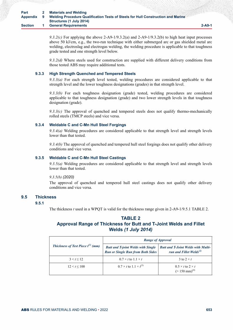
9.3.2(c) For applying the above 2-A9-1/9.3.2(a) and 2-A9-1/9.3.2(b) to high heat input processesabove 50 kJ/cm, e.g., the two-run technique with either submerged arc or gas shielded metal arcwelding, electroslag and electrogas welding, the welding procedure is applicable to that toughnessgrade tested and one strength level below.
9.3.2(d) Where steels used for construction are supplied with different delivery conditions fromthose tested ABS may require additional tests.
9.3.3 High Strength Quenched and Tempered Steels9.3.3(a) For each strength level tested, welding procedures are considered applicable to thatstrength level and the lower toughness designations (grades) in that strength level.
9.3.3(b) For each toughness designation (grade) tested, welding procedures are consideredapplicable to that toughness designation (grade) and two lower strength levels in that toughnessdesignation (grade).
9.3.3(c) The approval of quenched and tempered steels does not qualify thermo-mechanicallyrolled steels (TMCP steels) and vice versa.
9.3.4 Weldable C and C-Mn Hull Steel Forgings9.3.4(a) Welding procedures are considered applicable to that strength level and strength levelslower than that tested.
9.3.4(b) The approval of quenched and tempered hull steel forgings does not qualify other deliveryconditions and vice versa.
9.3.5 Weldable C and C-Mn Hull Steel Castings9.3.5(a) Welding procedures are considered applicable to that strength level and strength levelslower than that tested.
9.3.5(b) (2020)The approval of quenched and tempered hull steel castings does not qualify other deliveryconditions and vice versa.
9.5 Thickness9.5.1
The thickness t used in a WPQT is valid for the thickness range given in 2-A9-1/9.5.1 TABLE 2.
TABLE 2Approval Range of Thickness for Butt and T-Joint Welds and Fillet
Welds (1 July 2014)
Thickness of Test Piece t(1) (mm)
Range of Approval
Butt and T-joint Welds with SingleRun or Single Run from Both Sides
Butt and T-Joint Welds with Multi-run and Fillet Welds(2)
3 < t ≤ 12 0.7 × t to 1.1 × t 3 to 2 × t
12 < t ≤ 100 0.7 × t to 1.1 × t(3) 0.5 × t to 2 × t(> 150 mm)(4)
Part 2 Materials and WeldingAppendix 9 Welding Procedure Qualification Tests of Steels for Hull Construction and Marine
Structures (1 July 2014)Section 1 General Requirements 2-A9-1
ABS RULES FOR MATERIALS AND WELDING • 2022 653
Notes:
1 For multi process procedures, the recorded thickness contribution of each process is to be used as abasis for the range of approval for the individual welding process.
2 For fillet welds, the range of approval is to be applied to both base metals.
3 For high heat input processes over 50 kJ/cm, the upper limit of range of approval is to be 1.0 × t.
4 Thicknesses above 150 mm are subject to special consideration.
9.5.2In addition to the requirements of 2-A9-1/9.5.1 TABLE 2, the range of approval of throatthickness “a” for fillet welds is to be as follows:
● Single run ; “0.75 × a” to “1.5 × a ”
● Multi-run ; as for butt welds with multi-run (i.e., a = t)
9.5.3For vertical-down welding, the test piece thickness “t” is always taken as the upper limit of therange of application.
9.5.4For unequal plate thickness of butt welds the lesser thickness is the ruling dimension.
9.5.5Notwithstanding the above, the approval of maximum thickness of base metal for any technique isto be restricted to the thickness of test assembly if three of the hardness values in the heat affectedzone are found to be within 25 HV of the maximum permitted, as stated in 2-A9-1/7.3.2(g) and 2-A9-1/7.5.3(c).
9.7 Welding PositionApproval for a test made in any position is restricted to that position (see 2-A9-A3). To qualify a range ofpositions, test assemblies are to be welded using the highest heat input position and the lowest heat inputposition, and all applicable tests are to be made on those assemblies.
9.9 Welding Process9.9.1
The approval is only valid for the welding process(es) used in the welding procedure test. It is notpermitted to change from a multi-run process to a single run process.
9.9.2For multi-process procedures the welding procedure approval may be carried out with separatewelding procedure tests for each welding process. It is also possible to make the weldingprocedure test as a multi-process procedure test. The approval of such a test is only valid for theprocess sequence carried out during the multi-process procedure test.
9.11 Welding Consumable (2022)Except high heat input processes over 50 kJ/cm, welding consumables cover other approved weldingconsumables having the same grade mark including all suffixes specified in Section 2-A2-1 with thewelding consumable tested.
A re-qualification test is to be carried out if any one or more of below conditions are met.
● Any change in consumable classifications: mechanical properties, type of covering core or flux (e.g.,basic, rutile), nominal chemical composition and increase in hydrogen content
Part 2 Materials and WeldingAppendix 9 Welding Procedure Qualification Tests of Steels for Hull Construction and Marine
Structures (1 July 2014)Section 1 General Requirements 2-A9-1
ABS RULES FOR MATERIALS AND WELDING • 2022 654
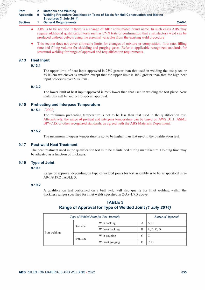
● ABS is to be notified if there is a change of filler consumable brand name. In such cases ABS mayrequire additional qualification tests such as CVN tests or confirmation that a satisfactory weld can beproduced without defects using the essential variables from the existing weld procedure
● This section does not cover allowable limits for changes of mixture or composition, flow rate, fillingtime and filling volume for shielding and purging gases. Refer to applicable recognized standards forstructural welding for range of approval and requalificaiton requirements.
9.13 Heat Input9.13.1
The upper limit of heat input approved is 25% greater than that used in welding the test piece or55 kJ/cm whichever is smaller, except that the upper limit is 10% greater than that for high heatinput processes over 50 kJ/cm.
9.13.2The lower limit of heat input approved is 25% lower than that used in welding the test piece. Newmaterials will be subject to special approval.
9.15 Preheating and Interpass Temperature9.15.1 (2022)
The minimum preheating temperature is not to be less than that used in the qualification test.Alternatively, the range of preheat and interpass temperature can be based on AWS D1.1, ASMEBPVC.IX or other recognized standards, as agreed with the ABS Materials Department.
9.15.2The maximum interpass temperature is not to be higher than that used in the qualification test.
9.17 Post-weld Heat TreatmentThe heat treatment used in the qualification test is to be maintained during manufacture. Holding time maybe adjusted as a function of thickness.
9.19 Type of Joint9.19.1
Range of approval depending on type of welded joints for test assembly is to be as specified in 2-A9-1/9.19.2 TABLE 3.
9.19.2A qualification test performed on a butt weld will also qualify for fillet welding within thethickness ranges specified for fillet welds specified in 2-A9-1/9.5 above.
TABLE 3Range of Approval for Type of Welded Joint (1 July 2014)
Type of Welded Joint for Test Assembly Range of Approval
Butt welding
One sideWith backing A A, C
Without backing B A, B, C, D
Both sideWith gouging C C
Without gouging D C, D
Part 2 Materials and WeldingAppendix 9 Welding Procedure Qualification Tests of Steels for Hull Construction and Marine
Structures (1 July 2014)Section 1 General Requirements 2-A9-1
ABS RULES FOR MATERIALS AND WELDING • 2022 655

9.21 Other Variables (2022)i) A change in the current (AC or DC) or polarity (electrode positive or negative for DC current)
would require weld procedure requalification.
ii) A change from semi-automatic to automatic welding processes, or vice versa would require weldprocedure requalification.
Other variables may also be considered in determining the range of approval.
Part 2 Materials and WeldingAppendix 9 Welding Procedure Qualification Tests of Steels for Hull Construction and Marine
Structures (1 July 2014)Section 1 General Requirements 2-A9-1
ABS RULES FOR MATERIALS AND WELDING • 2022 656
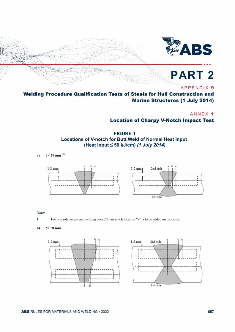
A P P E N D I X 9Welding Procedure Qualification Tests of Steels for Hull Construction and
Marine Structures (1 July 2014)
A N N E X 1Location of Charpy V-Notch Impact Test
FIGURE 1Locations of V-notch for Butt Weld of Normal Heat Input
(Heat Input ≤ 50 kJ/cm) (1 July 2014)
a) t < 50 mm (1)
Note:
1 For one side single run welding over 20 mm notch location “a” is to be added on root side.
b) t > 50 mm
PART 2
ABS RULES FOR MATERIALS AND WELDING • 2022 657
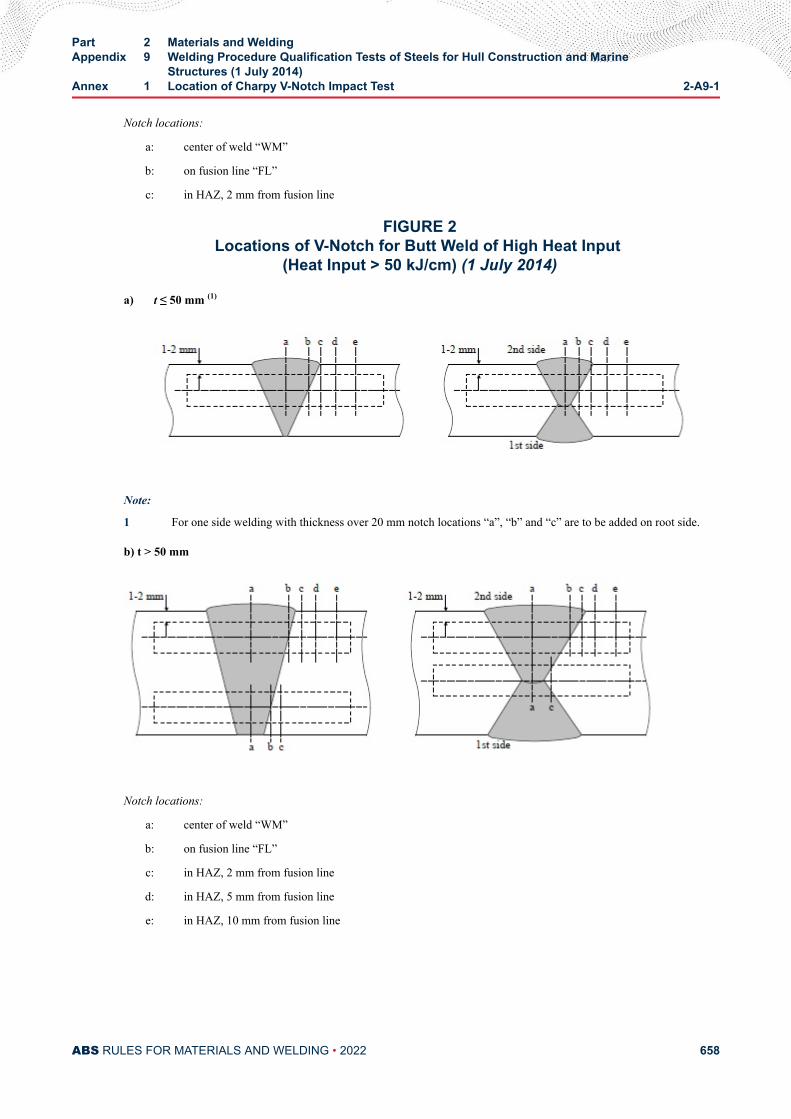
Notch locations:
a: center of weld “WM”
b: on fusion line “FL”
c: in HAZ, 2 mm from fusion line
FIGURE 2Locations of V-Notch for Butt Weld of High Heat Input
(Heat Input > 50 kJ/cm) (1 July 2014)
a) t ≤ 50 mm (1)
Note:
1 For one side welding with thickness over 20 mm notch locations “a”, “b” and “c” are to be added on root side.
b) t > 50 mm
Notch locations:
a: center of weld “WM”
b: on fusion line “FL”
c: in HAZ, 2 mm from fusion line
d: in HAZ, 5 mm from fusion line
e: in HAZ, 10 mm from fusion line
Part 2 Materials and WeldingAppendix 9 Welding Procedure Qualification Tests of Steels for Hull Construction and Marine
Structures (1 July 2014)Annex 1 Location of Charpy V-Notch Impact Test 2-A9-1
ABS RULES FOR MATERIALS AND WELDING • 2022 658
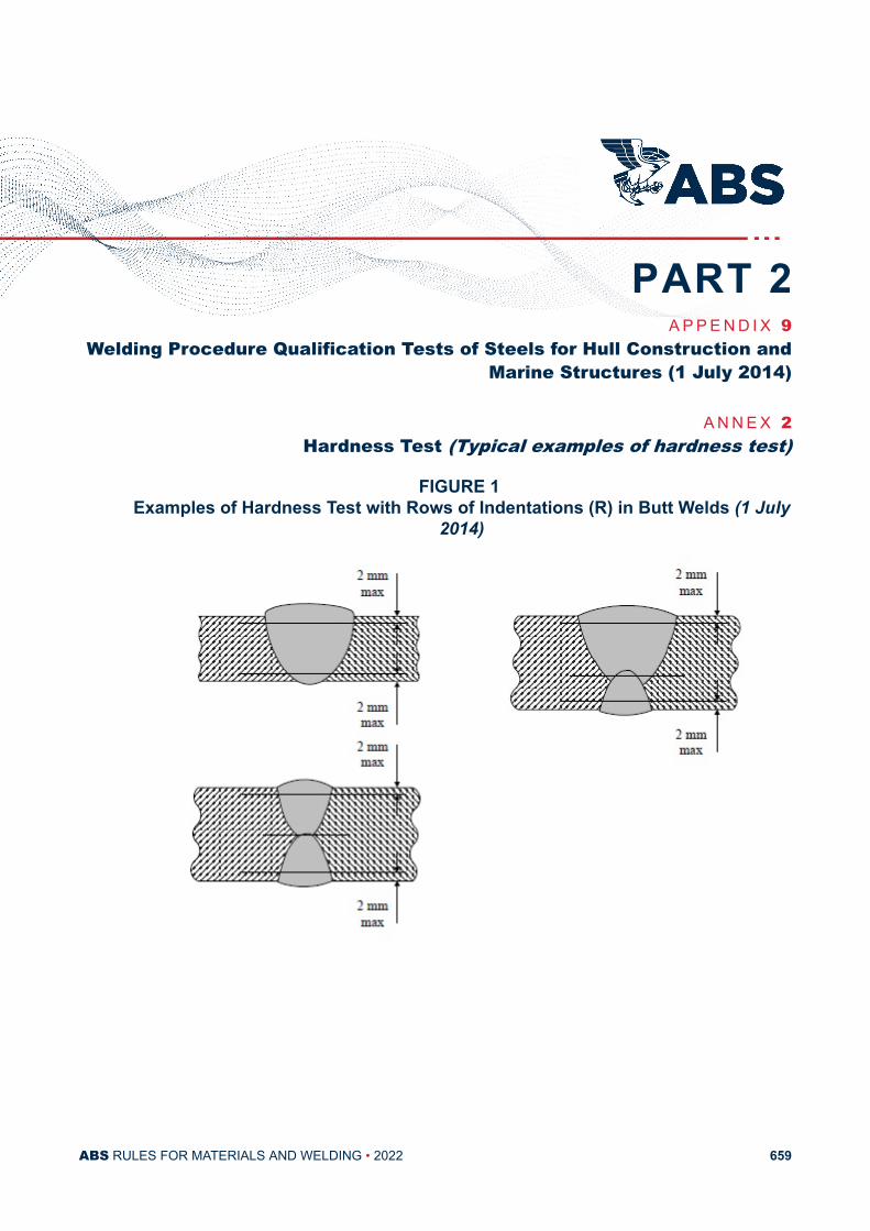
A P P E N D I X 9Welding Procedure Qualification Tests of Steels for Hull Construction and
Marine Structures (1 July 2014)
A N N E X 2Hardness Test (Typical examples of hardness test)
FIGURE 1 Examples of Hardness Test with Rows of Indentations (R) in Butt Welds (1 July
2014)
PART 2
ABS RULES FOR MATERIALS AND WELDING • 2022 659
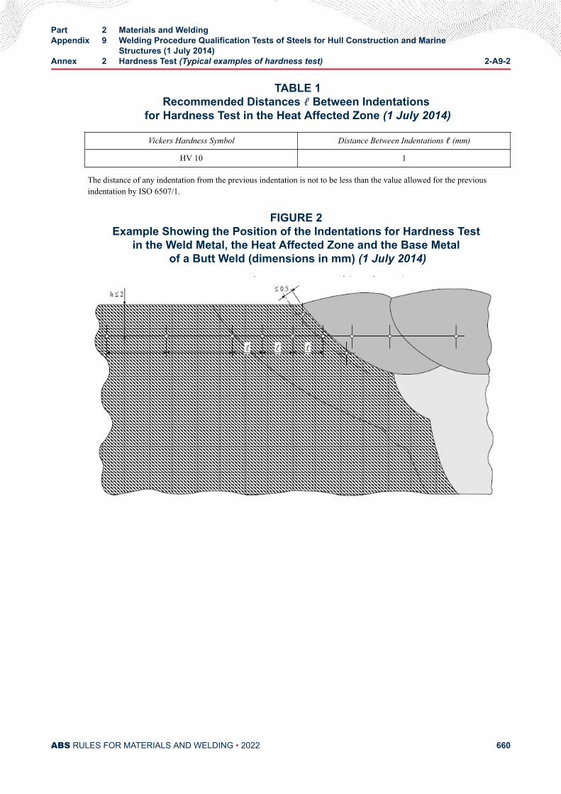
TABLE 1Recommended Distances ℓ Between Indentations
for Hardness Test in the Heat Affected Zone (1 July 2014)
Vickers Hardness Symbol Distance Between Indentations ℓ (mm)
HV 10 1
The distance of any indentation from the previous indentation is not to be less than the value allowed for the previousindentation by ISO 6507/1.
FIGURE 2 Example Showing the Position of the Indentations for Hardness Test
in the Weld Metal, the Heat Affected Zone and the Base Metal of a Butt Weld (dimensions in mm) (1 July 2014)
Part 2 Materials and WeldingAppendix 9 Welding Procedure Qualification Tests of Steels for Hull Construction and Marine
Structures (1 July 2014)Annex 2 Hardness Test (Typical examples of hardness test) 2-A9-2
ABS RULES FOR MATERIALS AND WELDING • 2022 660
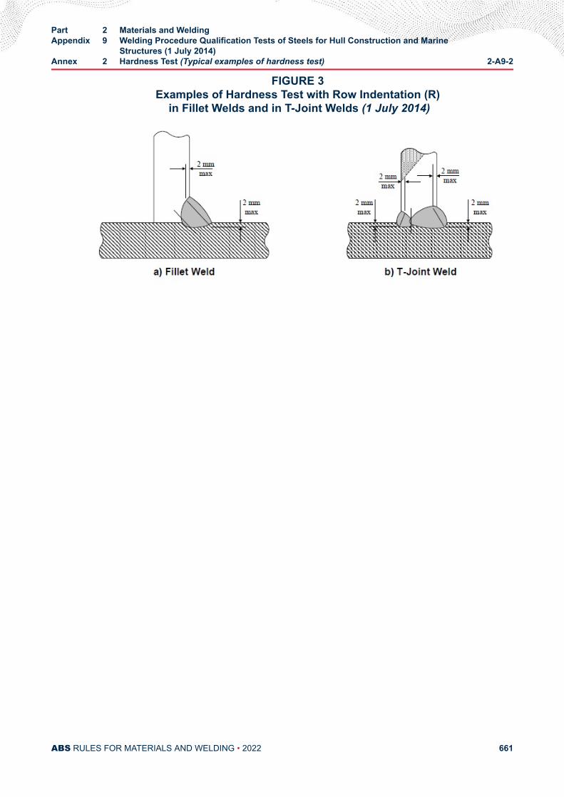
FIGURE 3 Examples of Hardness Test with Row Indentation (R)
in Fillet Welds and in T-Joint Welds (1 July 2014)
Part 2 Materials and WeldingAppendix 9 Welding Procedure Qualification Tests of Steels for Hull Construction and Marine
Structures (1 July 2014)Annex 2 Hardness Test (Typical examples of hardness test) 2-A9-2
ABS RULES FOR MATERIALS AND WELDING • 2022 661
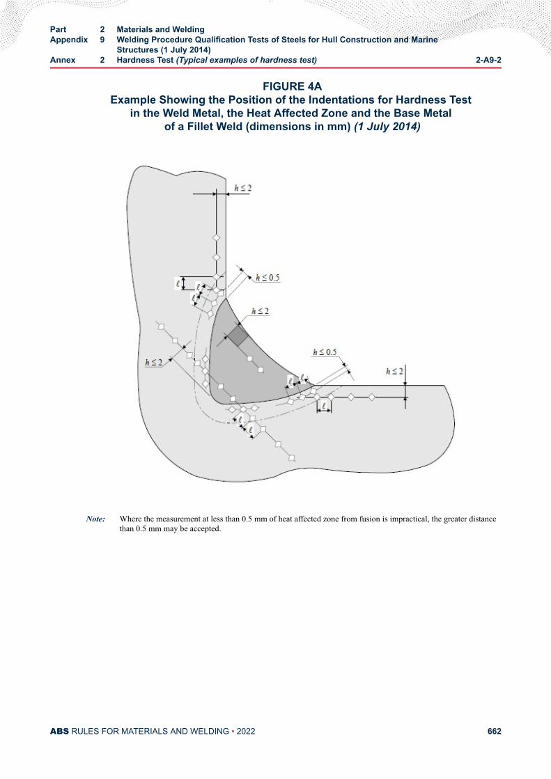
FIGURE 4AExample Showing the Position of the Indentations for Hardness Test
in the Weld Metal, the Heat Affected Zone and the Base Metal of a Fillet Weld (dimensions in mm) (1 July 2014)
Note: Where the measurement at less than 0.5 mm of heat affected zone from fusion is impractical, the greater distancethan 0.5 mm may be accepted.
Part 2 Materials and WeldingAppendix 9 Welding Procedure Qualification Tests of Steels for Hull Construction and Marine
Structures (1 July 2014)Annex 2 Hardness Test (Typical examples of hardness test) 2-A9-2
ABS RULES FOR MATERIALS AND WELDING • 2022 662
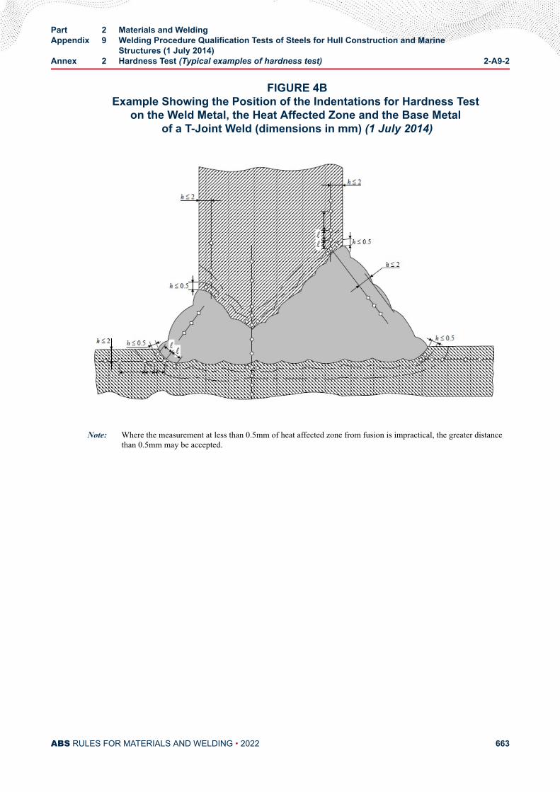
FIGURE 4BExample Showing the Position of the Indentations for Hardness Test
on the Weld Metal, the Heat Affected Zone and the Base Metal of a T-Joint Weld (dimensions in mm) (1 July 2014)
Note: Where the measurement at less than 0.5mm of heat affected zone from fusion is impractical, the greater distancethan 0.5mm may be accepted.
Part 2 Materials and WeldingAppendix 9 Welding Procedure Qualification Tests of Steels for Hull Construction and Marine
Structures (1 July 2014)Annex 2 Hardness Test (Typical examples of hardness test) 2-A9-2
ABS RULES FOR MATERIALS AND WELDING • 2022 663
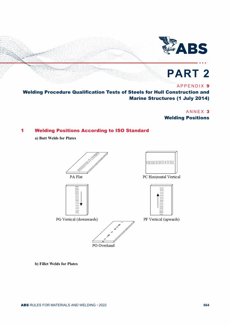
A P P E N D I X 9Welding Procedure Qualification Tests of Steels for Hull Construction and
Marine Structures (1 July 2014)
A N N E X 3Welding Positions
1 Welding Positions According to ISO Standarda) Butt Welds for Plates
b) Fillet Welds for Plates
PART 2
ABS RULES FOR MATERIALS AND WELDING • 2022 664
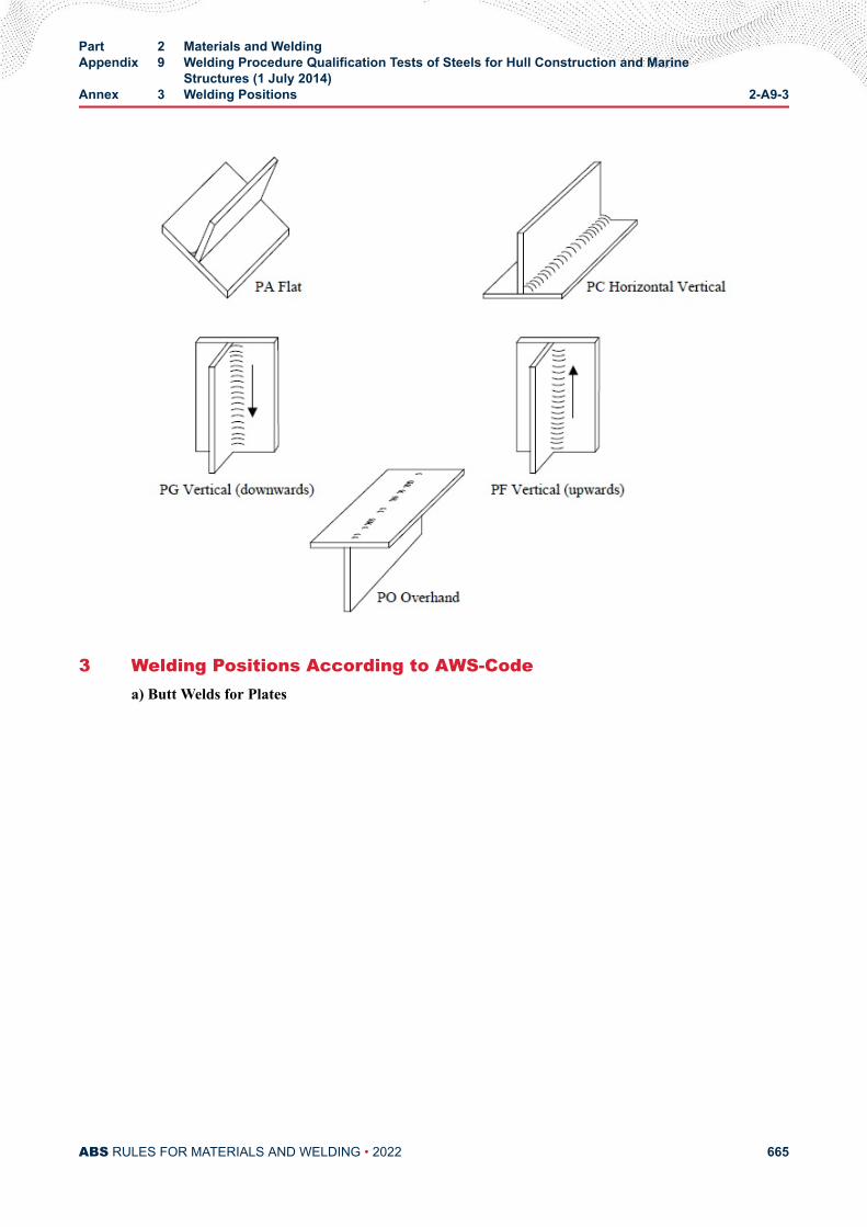
3 Welding Positions According to AWS-Codea) Butt Welds for Plates
Part 2 Materials and WeldingAppendix 9 Welding Procedure Qualification Tests of Steels for Hull Construction and Marine
Structures (1 July 2014)Annex 3 Welding Positions 2-A9-3
ABS RULES FOR MATERIALS AND WELDING • 2022 665
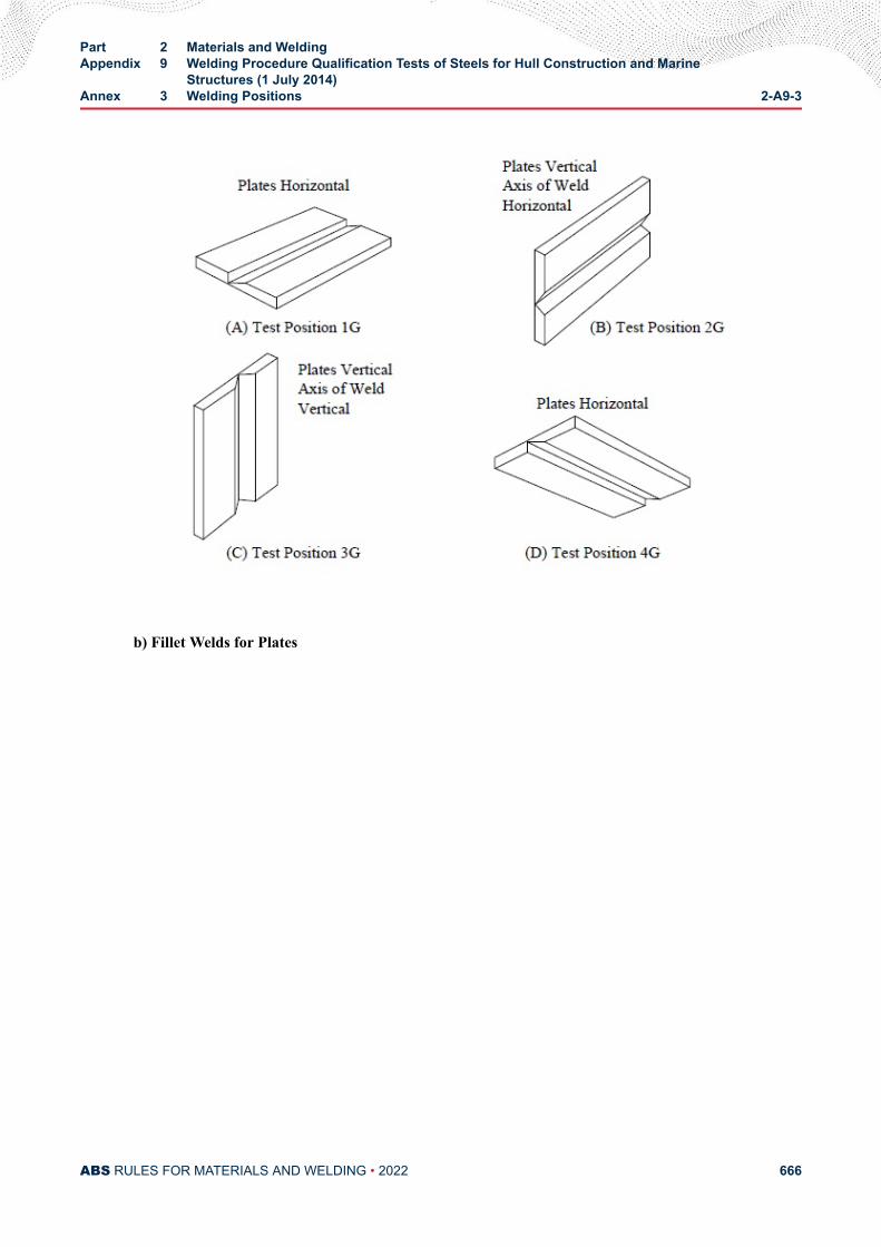
b) Fillet Welds for Plates
Part 2 Materials and WeldingAppendix 9 Welding Procedure Qualification Tests of Steels for Hull Construction and Marine
Structures (1 July 2014)Annex 3 Welding Positions 2-A9-3
ABS RULES FOR MATERIALS AND WELDING • 2022 666
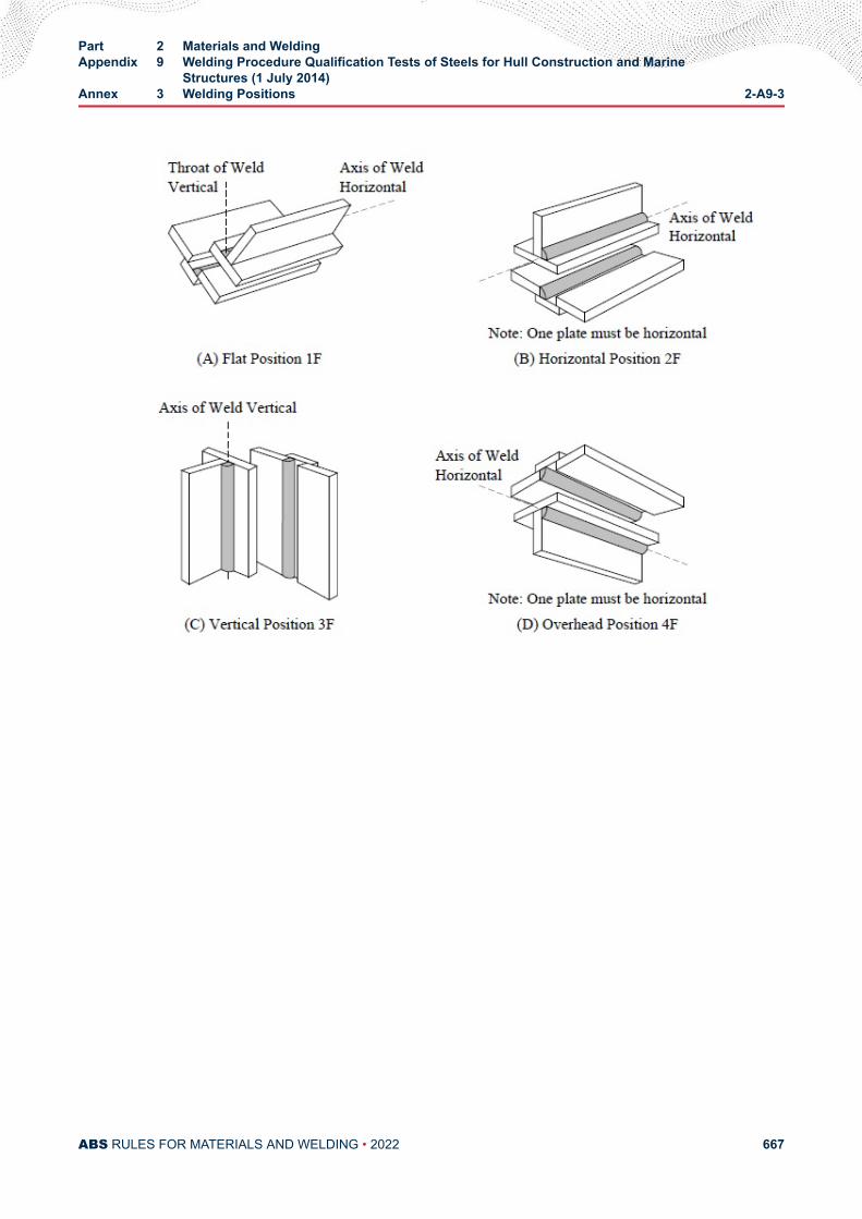
Part 2 Materials and WeldingAppendix 9 Welding Procedure Qualification Tests of Steels for Hull Construction and Marine
Structures (1 July 2014)Annex 3 Welding Positions 2-A9-3
ABS RULES FOR MATERIALS AND WELDING • 2022 667
A P P E N D I X 1 0Procedure for the Approval of Aluminum Manufacturers
CONTENTSSECTION 1 Scheme for the Approval of Aluminum Manufacturers................669
1 Scope (2013).............................................................................. 6693 Approval Application...................................................................669
3.1 Initial Approval............................................................... 6693.3 Content of Application....................................................6693.5 Information and Data Required for Approval................. 6693.7 Superior Properties........................................................6713.9 ABS Activity in the Approval Process............................ 671
5 Renewal of Approval (2011)....................................................... 671
PART 2
ABS RULES FOR MATERIALS AND WELDING • 2022 668
A P P E N D I X 1 0Procedure for the Approval of Aluminum Manufacturers
S E C T I O N 1Scheme for the Approval of Aluminum Manufacturers
1 Scope (2013)In accordance with 2-5-1/1.3, this Appendix provides specific requirements for the approval ofmanufacturers of aluminum plate, sheet, extrusions, castings, and forgings. The manufacturer approvalscheme is intended to certify the manufacturer’s capability of furnishing satisfactory products in aconsistent manner under effective process and production controls in operation.
3 Approval Application
3.1 Initial ApprovalFor consideration to produce ABS-certified aluminum alloy plate and sheet or extrusions, the manufactureris to apply for approval of the process of manufacture by submitting information and supporting test datato ABS Houston Materials Department, or alternatively to the local Surveyor who attends the facility whois to include this information with the survey report.
3.3 Content of ApplicationThe submittal is to be specific to the Alloy and Temper, product form, maximum thickness, meltingpractice, casting practice and heat treatment or special rolling or extrusion practice for which approval issought. At the option of the facility, this submittal may be preceded by a proposed test program to assurethat the appropriate testing is scheduled.
3.5 Information and Data Required for ApprovalThe following summarizes the minimum information and test data required for approval as well additionalrequirements for special alloys, claimed to exhibit superior properties.
3.5.1 Production and Process Informationi) Plant tonnage capacity
ii) Product type and grade
iii) Maximum thickness
iv) Melting, refining and pouring practices
● Furnace type
● Melting practice-including charges of metallics and slag
PART 2
ABS RULES FOR MATERIALS AND WELDING • 2022 669
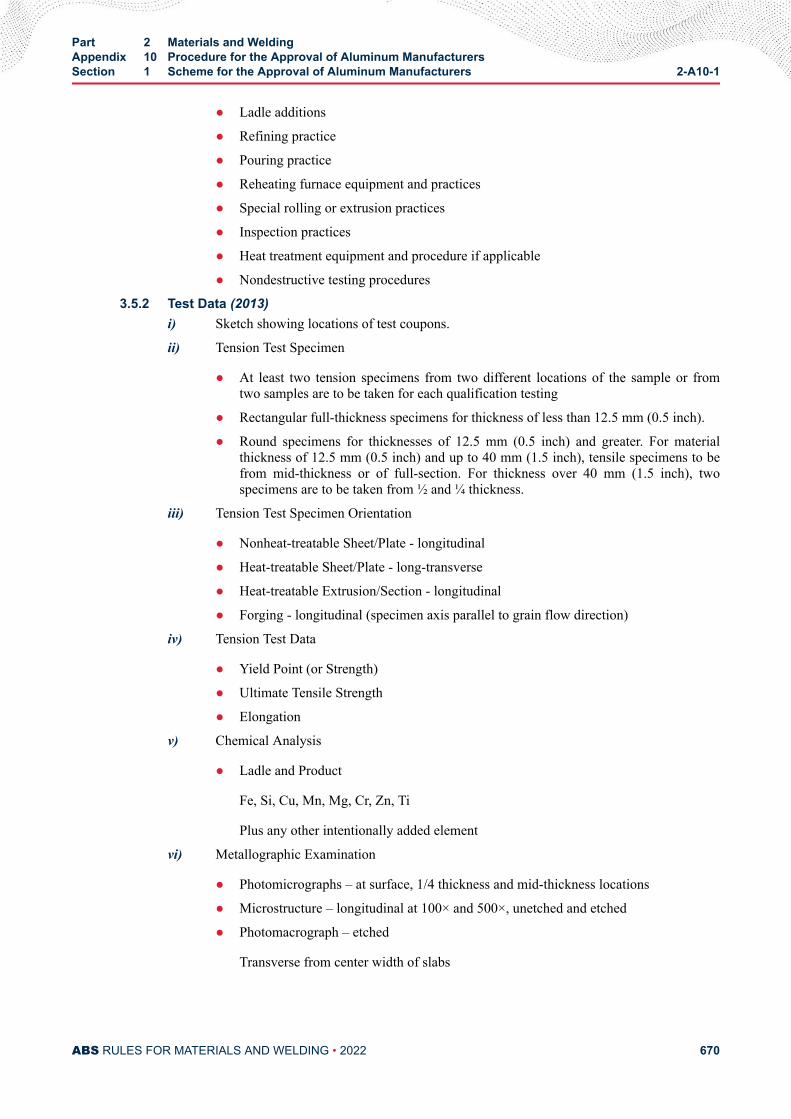
● Ladle additions
● Refining practice
● Pouring practice
● Reheating furnace equipment and practices
● Special rolling or extrusion practices
● Inspection practices
● Heat treatment equipment and procedure if applicable
● Nondestructive testing procedures
3.5.2 Test Data (2013)i) Sketch showing locations of test coupons.
ii) Tension Test Specimen
● At least two tension specimens from two different locations of the sample or fromtwo samples are to be taken for each qualification testing
● Rectangular full-thickness specimens for thickness of less than 12.5 mm (0.5 inch).
● Round specimens for thicknesses of 12.5 mm (0.5 inch) and greater. For materialthickness of 12.5 mm (0.5 inch) and up to 40 mm (1.5 inch), tensile specimens to befrom mid-thickness or of full-section. For thickness over 40 mm (1.5 inch), twospecimens are to be taken from ½ and ¼ thickness.
iii) Tension Test Specimen Orientation
● Nonheat-treatable Sheet/Plate - longitudinal
● Heat-treatable Sheet/Plate - long-transverse
● Heat-treatable Extrusion/Section - longitudinal
● Forging - longitudinal (specimen axis parallel to grain flow direction)
iv) Tension Test Data
● Yield Point (or Strength)
● Ultimate Tensile Strength
● Elongation
v) Chemical Analysis
● Ladle and Product
Fe, Si, Cu, Mn, Mg, Cr, Zn, Ti
Plus any other intentionally added element
vi) Metallographic Examination
● Photomicrographs – at surface, 1/4 thickness and mid-thickness locations
● Microstructure – longitudinal at 100× and 500×, unetched and etched
● Photomacrograph – etched
Transverse from center width of slabs
Part 2 Materials and WeldingAppendix 10 Procedure for the Approval of Aluminum ManufacturersSection 1 Scheme for the Approval of Aluminum Manufacturers 2-A10-1
ABS RULES FOR MATERIALS AND WELDING • 2022 670
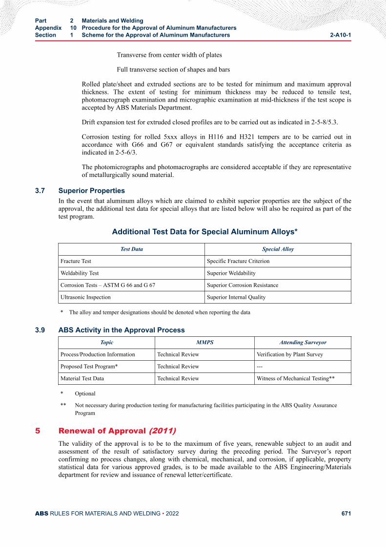
Transverse from center width of plates
Full transverse section of shapes and bars
Rolled plate/sheet and extruded sections are to be tested for minimum and maximum approvalthickness. The extent of testing for minimum thickness may be reduced to tensile test,photomacrograph examination and micrographic examination at mid-thickness if the test scope isaccepted by ABS Materials Department.
Drift expansion test for extruded closed profiles are to be carried out as indicated in 2-5-8/5.3.
Corrosion testing for rolled 5xxx alloys in H116 and H321 tempers are to be carried out inaccordance with G66 and G67 or equivalent standards satisfying the acceptance criteria asindicated in 2-5-6/3.
The photomicrographs and photomacrographs are considered acceptable if they are representativeof metallurgically sound material.
3.7 Superior PropertiesIn the event that aluminum alloys which are claimed to exhibit superior properties are the subject of theapproval, the additional test data for special alloys that are listed below will also be required as part of thetest program.
Additional Test Data for Special Aluminum Alloys*
Test Data Special Alloy
Fracture Test Specific Fracture Criterion
Weldability Test Superior Weldability
Corrosion Tests – ASTM G 66 and G 67 Superior Corrosion Resistance
Ultrasonic Inspection Superior Internal Quality
* The alloy and temper designations should be denoted when reporting the data
3.9 ABS Activity in the Approval ProcessTopic MMPS Attending Surveyor
Process/Production Information Technical Review Verification by Plant Survey
Proposed Test Program* Technical Review ---
Material Test Data Technical Review Witness of Mechanical Testing**
* Optional
** Not necessary during production testing for manufacturing facilities participating in the ABS Quality AssuranceProgram
5 Renewal of Approval (2011)The validity of the approval is to be to the maximum of five years, renewable subject to an audit andassessment of the result of satisfactory survey during the preceding period. The Surveyor’s reportconfirming no process changes, along with chemical, mechanical, and corrosion, if applicable, propertystatistical data for various approved grades, is to be made available to the ABS Engineering/Materialsdepartment for review and issuance of renewal letter/certificate.
Part 2 Materials and WeldingAppendix 10 Procedure for the Approval of Aluminum ManufacturersSection 1 Scheme for the Approval of Aluminum Manufacturers 2-A10-1
ABS RULES FOR MATERIALS AND WELDING • 2022 671

Manufacturers who have not produced the approved grades and products during the period preceding therenewal may be required to carry out approval tests, unless the results of production of similar grades ofproducts during the period are evaluated by ABS and found acceptable for renewal.
Part 2 Materials and WeldingAppendix 10 Procedure for the Approval of Aluminum ManufacturersSection 1 Scheme for the Approval of Aluminum Manufacturers 2-A10-1
ABS RULES FOR MATERIALS AND WELDING • 2022 672
A P P E N D I X 1 1Qualification for Welders and Welding Operators
CONTENTSSECTION 1 General..............................................................................................676
1 ....................................................................................................6763 ....................................................................................................6765 ....................................................................................................6767 ....................................................................................................6769 ....................................................................................................676
SECTION 2 Welders Qualification for Hull Structures*.................................... 6771 Scope..........................................................................................677
1.1 .......................................................................................6771.3 .......................................................................................6771.5 .......................................................................................6771.7 .......................................................................................677
3 General.......................................................................................6783.1 .......................................................................................6783.3 .......................................................................................6783.5 .......................................................................................6783.7 .......................................................................................678
5 Range of Qualification of Welders.............................................. 6785.1 .......................................................................................6785.3 .......................................................................................6785.5 .......................................................................................6785.7 .......................................................................................6795.9 .......................................................................................6795.11 .......................................................................................6805.13 .......................................................................................6805.15 .......................................................................................6805.17 .......................................................................................681
7 Test Assemblies..........................................................................6817.1 .......................................................................................6817.3 .......................................................................................681
PART 2
ABS RULES FOR MATERIALS AND WELDING • 2022 673
7.5 .......................................................................................6827.7 .......................................................................................6827.9 .......................................................................................682
9 Examination and Test................................................................. 6889.1 Types of Tests................................................................6889.3 Visual Examination........................................................ 6899.5 Bend Test.......................................................................6899.7 Radiographic Test.......................................................... 6899.9 Fracture Test (Butt Welds)............................................. 6899.11 Fracture Test (Fillet Welds)............................................6909.13 Macro Examination (Fillet Welds).................................. 690
11 Retest......................................................................................... 69011.1 .......................................................................................69011.3 .......................................................................................690
13 Certification.................................................................................69013.1 .......................................................................................69013.3 .......................................................................................69013.5 .......................................................................................69113.7 .......................................................................................691
15 Period of Validity of Initial Approval............................................ 69115.1 .......................................................................................69115.3 .......................................................................................69115.5 .......................................................................................691
17 Maintenance of the Approval......................................................69117.1 .......................................................................................69117.3 .......................................................................................692
TABLE 1 Welding Processes for Welder’s Qualification................... 679TABLE 2 Types of Welded Joint for Welder’s Qualification...............680TABLE 3 Plate Thicknesses for Welder’s Qualification.....................680TABLE 4 Qualified Welding Positions When Testing with Butt
Welding 2-A11-2/7.9 FIGURE 1......................................... 681TABLE 5 Qualified Welding Positions when Testing with Fillet
Welding 2-A11-2/7.9 FIGURE 1......................................... 681
FIGURE 1 Welding Positions...............................................................683FIGURE 2 Dimensions and Types of Test Assembly for Butt Welds
(T < 12 mm (0.5 in.)).......................................................... 684FIGURE 3 Dimensions and Types of Test Assembly for Butt Welds
(T ≥ 12 mm (0.5 in.)).......................................................... 685FIGURE 4 Dimensions and Types of Test Assembly for Fillet Welds..686FIGURE 5 Dimensions and Types of Test Assembly for Tack Butt
Welds................................................................................. 687
ABS RULES FOR MATERIALS AND WELDING • 2022 674
FIGURE 6 Dimensions and Types of Test Assembly for Tack FilletWelds................................................................................. 688
SECTION 3 Welding Operators Qualification.................................................... 6931 ....................................................................................................6933 ....................................................................................................6935 ....................................................................................................6937 ....................................................................................................693
SECTION 4 Certification Process....................................................................... 6941 ....................................................................................................6943 ....................................................................................................694
ANNEX 1 Example of Welder’s Qualification Certificate...............................695
ABS RULES FOR MATERIALS AND WELDING • 2022 675
A P P E N D I X 1 1Qualification for Welders and Welding Operators
S E C T I O N 1General (1 July 2018)
1The general guidelines and requirements defined in the ABS Rules for Materials and Welding (Part 2) areto be applied. This Appendix covers the qualification for welders and welding operators for structuralwelding of marine and offshore vessels.
3These requirements apply to ABS’s acceptance of welders and welding operators for welding of steel andnon-ferrous metals.
5This Appendix specifies the requirements for welder and operator qualifications including:
● Ship hull structure and other ship structure
● Offshore hull and other offshore structure
7The training of welders and welding operators, control of their qualification, and maintenance of theirskills are the responsibility of the builders and subcontractors. When requested, these are to be documentedand demonstrated to the satisfaction of ABS.
9The certified welders and welding operators are to be recorded by builders and subcontractors withwelders’ training, as well as date and documents of qualification tests. The qualification documents are toinclude the information about the base metal, type of welding consumable, welding process, type ofwelded joint, material thickness, welding position, and destructive and nondestructive test results. Oneexample is shown in 2-A11-A1.
PART 2
ABS RULES FOR MATERIALS AND WELDING • 2022 676
A P P E N D I X 1 1Qualification for Welders and Welding Operators
S E C T I O N 2Welders Qualification for Hull Structures* (2019)
Note: This Appendix specifies an alternative welder qualification process per 2-4-3/11.3.
1 Scope
1.1The general requirements for weld tests defined in Section 2-4-3 are to be applied.
1.3This Section gives requirements for a qualification scheme for welders intended to be engaged in thefusion welding of steels for hull structures as specified in the ABS Rules for Materials and Welding (Part2) as follows:
● Section 2-1-2: Ordinary-Strength Hull Structural Steel
● Section 2-1-3: Higher-Strength Hull Structural Steel
● Section 2-1-5: Hull Steel Castings
● Section 2-1-6: Hull Steel Forgings
● Section 2-1-7: Ordinary and Higher Strength Steels with Enhanced Corrosion Resistance Propertiesfor Cargo Oil Tanks
● Section 2-1-8: Extra High Strength Steels
and other steels, at the discretion of ABS, such as:
● H47 and H36/H40/H47 BCA (Brittle Crack Arrest) Steel.
1.5This qualification scheme does not cover welders engaged in oxy-acetylene welding.
1.7This qualification scheme does not cover welding of pipes or structural tubulars.
PART 2
ABS RULES FOR MATERIALS AND WELDING • 2022 677
3 General
3.1Those welders intended to be engaged in welding of hull structures in shipyards, manufacturers, andsubcontractor are to be tested and qualified in accordance with this scheme and issued with a qualificationcertificate endorsed by ABS.
3.3This Appendix is applicable to welding of hull structures during new construction, conversion, and therepair of vessels or offshore structures.
3.5Welders or welding operators qualified in accordance with recognized national or international welderqualification standards may also be engaged in welding of hull structures at the discretion of ABS,provided that the qualification testing, range of approval, and revalidation requirements are considered tomeet the technical intent of this Section.
3.7If the production weld has restricted access the ABS Surveyor is to verify the welder has the necessaryskill to achieve a satisfactory production weld under the anticipated production conditions.
5 Range of Qualification of Welders
5.1A welder is to be qualified in relation to the following variables:
i) Base metal
ii) Welding consumables type
iii) Welding process
iv) Type of welded joint
v) Plate thickness
vi) Welding position
5.3In case of steels, base metals for qualification of welders or welding operators are divided into two groups.Steels with a specified minimum yield strength ReH ≤ 460 N/mm2 (67 ksi) are considered Group 1. Steelswith a specified minimum yield strength 460 (67) < ReH ≤ 690 N/mm2 (100 ksi) are considered Group 2.Welding of any one metal in a group covers qualification of the welder or welding operator within thegroup.
Steels with a specified minimum yield strength ReH > 690 N/mm2 (100 ksi) are to be specially considered.
Depending upon the welders experience and level of skill, additional qualification test may be required, atthe discretion of the ABS Surveyor, if the welder is only qualified in welding ordinary strength steel and isrequired to weld higher strength grades.
5.5For Shielded/Manual metal arc welding, qualification tests are required using basic, acid or rutile coveredelectrodes. Basic (B) electrode covers basic (B), acid (A) and rutile (R) electrodes. Acid (A) or rutile (R)
Part 2 Materials and WeldingAppendix 11 Qualification for Welders and Welding OperatorsSection 2 Welders Qualification for Hull Structures* 2-A11-2
ABS RULES FOR MATERIALS AND WELDING • 2022 678
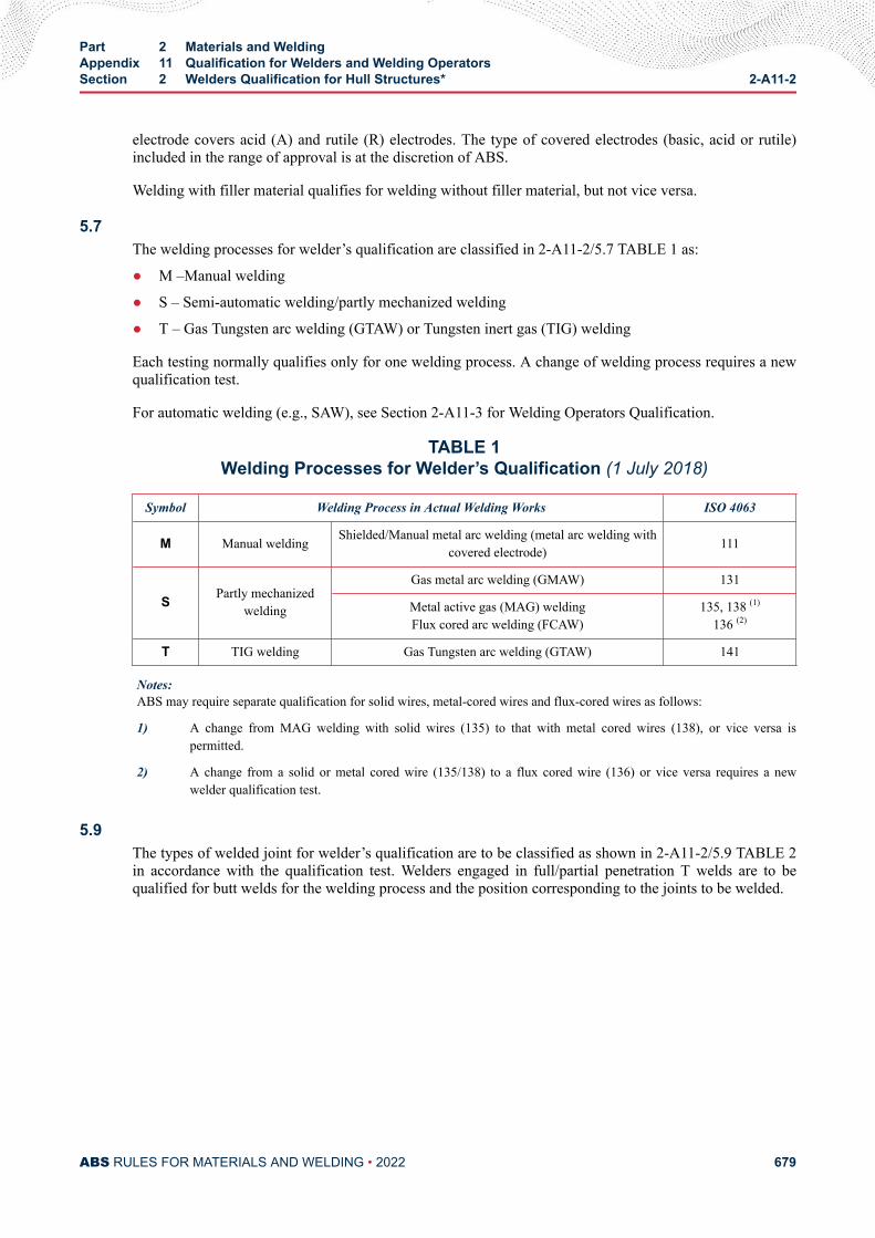
electrode covers acid (A) and rutile (R) electrodes. The type of covered electrodes (basic, acid or rutile)included in the range of approval is at the discretion of ABS.
Welding with filler material qualifies for welding without filler material, but not vice versa.
5.7The welding processes for welder’s qualification are classified in 2-A11-2/5.7 TABLE 1 as:
● M –Manual welding
● S – Semi-automatic welding/partly mechanized welding
● T – Gas Tungsten arc welding (GTAW) or Tungsten inert gas (TIG) welding
Each testing normally qualifies only for one welding process. A change of welding process requires a newqualification test.
For automatic welding (e.g., SAW), see Section 2-A11-3 for Welding Operators Qualification.
TABLE 1Welding Processes for Welder’s Qualification (1 July 2018)
Symbol Welding Process in Actual Welding Works ISO 4063
M Manual welding Shielded/Manual metal arc welding (metal arc welding withcovered electrode) 111
S Partly mechanizedwelding
Gas metal arc welding (GMAW) 131
Metal active gas (MAG) weldingFlux cored arc welding (FCAW)
135, 138 (1)
136 (2)
T TIG welding Gas Tungsten arc welding (GTAW) 141
Notes:ABS may require separate qualification for solid wires, metal-cored wires and flux-cored wires as follows:
1) A change from MAG welding with solid wires (135) to that with metal cored wires (138), or vice versa ispermitted.
2) A change from a solid or metal cored wire (135/138) to a flux cored wire (136) or vice versa requires a newwelder qualification test.
5.9The types of welded joint for welder’s qualification are to be classified as shown in 2-A11-2/5.9 TABLE 2in accordance with the qualification test. Welders engaged in full/partial penetration T welds are to bequalified for butt welds for the welding process and the position corresponding to the joints to be welded.
Part 2 Materials and WeldingAppendix 11 Qualification for Welders and Welding OperatorsSection 2 Welders Qualification for Hull Structures* 2-A11-2
ABS RULES FOR MATERIALS AND WELDING • 2022 679
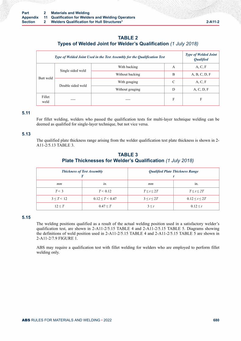
TABLE 2Types of Welded Joint for Welder’s Qualification (1 July 2018)
Type of Welded Joint Used in the Test Assembly for the Qualification Test Type of Welded JointQualified
Butt weld
Single sided weldWith backing A A, C, F
Without backing B A, B, C, D, F
Double sided weldWith gouging C A, C, F
Without gouging D A, C, D, F
Filletweld ---- ---- F F
5.11For fillet welding, welders who passed the qualification tests for multi-layer technique welding can bedeemed as qualified for single-layer technique, but not vice versa.
5.13The qualified plate thickness range arising from the welder qualification test plate thickness is shown in 2-A11-2/5.13 TABLE 3.
TABLE 3Plate Thicknesses for Welder’s Qualification (1 July 2018)
Thickness of Test AssemblyT
Qualified Plate Thickness Ranget
mm in. mm in.
T < 3 T < 0.12 T ≤ t ≤ 2T T ≤ t ≤ 2T
3 ≤ T < 12 0.12 ≤ T < 0.47 3 ≤ t ≤ 2T 0.12 ≤ t ≤ 2T
12 ≤ T 0.47 ≤ T 3 ≤ t 0.12 ≤ t
5.15The welding positions qualified as a result of the actual welding position used in a satisfactory welder’squalification test, are shown in 2-A11-2/5.15 TABLE 4 and 2-A11-2/5.15 TABLE 5. Diagrams showingthe definitions of weld position used in 2-A11-2/5.15 TABLE 4 and 2-A11-2/5.15 TABLE 5 are shown in2-A11-2/7.9 FIGURE 1.
ABS may require a qualification test with fillet welding for welders who are employed to perform filletwelding only.
Part 2 Materials and WeldingAppendix 11 Qualification for Welders and Welding OperatorsSection 2 Welders Qualification for Hull Structures* 2-A11-2
ABS RULES FOR MATERIALS AND WELDING • 2022 680
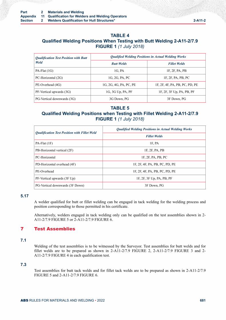
TABLE 4Qualified Welding Positions When Testing with Butt Welding 2-A11-2/7.9
FIGURE 1 (1 July 2018)
Qualification Test Position with ButtWeld
Qualified Welding Positions in Actual Welding Works
Butt Welds Fillet Welds
PA-Flat (1G) 1G, PA 1F, 2F, PA, PB
PC-Horizontal (2G) 1G, 2G, PA, PC 1F, 2F, PA, PB, PC
PE-Overhead (4G) 1G, 2G, 4G, PA, PC, PE 1F, 2F, 4F, PA, PB, PC, PD, PE
PF-Vertical upwards (3G) 1G, 3G Up, PA, PF 1F, 2F, 3F Up, PA, PB, PF
PG-Vertical downwards (3G) 3G Down, PG 3F Down, PG
TABLE 5Qualified Welding Positions when Testing with Fillet Welding 2-A11-2/7.9
FIGURE 1 (1 July 2018)
Qualification Test Position with Fillet WeldQualified Welding Positions in Actual Welding Works
Fillet Welds
PA-Flat (1F) 1F, PA
PB-Horizontal vertical (2F) 1F, 2F, PA, PB
PC-Horizontal 1F, 2F, PA, PB, PC
PD-Horizontal overhead (4F) 1F, 2F, 4F, PA, PB, PC, PD, PE
PE-Overhead 1F, 2F, 4F, PA, PB, PC, PD, PE
PF-Vertical upwards (3F Up) 1F, 2F, 3F Up, PA, PB, PF
PG-Vertical downwards (3F Down) 3F Down, PG
5.17A welder qualified for butt or fillet welding can be engaged in tack welding for the welding process andposition corresponding to those permitted in his certificate.
Alternatively, welders engaged in tack welding only can be qualified on the test assemblies shown in 2-A11-2/7.9 FIGURE 5 or 2-A11-2/7.9 FIGURE 6.
7 Test Assemblies
7.1Welding of the test assemblies is to be witnessed by the Surveyor. Test assemblies for butt welds and forfillet welds are to be prepared as shown in 2-A11-2/7.9 FIGURE 2, 2-A11-2/7.9 FIGURE 3 and 2-A11-2/7.9 FIGURE 4 in each qualification test.
7.3Test assemblies for butt tack welds and for fillet tack welds are to be prepared as shown in 2-A11-2/7.9FIGURE 5 and 2-A11-2/7.9 FIGURE 6.
Part 2 Materials and WeldingAppendix 11 Qualification for Welders and Welding OperatorsSection 2 Welders Qualification for Hull Structures* 2-A11-2
ABS RULES FOR MATERIALS AND WELDING • 2022 681
7.5Testing materials and welding consumables are to conform to one of the following requirements or to be ofequivalent grade approved by ABS:
7.5.1 Testing Materials● Section 2-1-2: Ordinary-Strength Hull Structural Steel
● Section 2-1-3: Higher-Strength Hull Structural Steel
● Section 2-1-5: Hull Steel Castings
● Section 2-1-6: Hull Steel Forgings
● Section 2-1-7: Ordinary and Higher Strength Steels with Enhanced Corrosion ResistanceProperties for Cargo Oil Tanks
● Section 2-1-8: Extra High Strength Steels
and other steels, at the discretion of ABS, such as:
● H47 and H36/H40/H47 BCA (Brittle Crack Arrest) Steel.
7.5.2 Welding Consumables● Consumables for hull structural steels specified in Part 2, Appendix 2 and Part 2, Appendix 3,
or
● Other consumables, such as for BCA steels, at the discretion of ABS.
7.7The welder qualification test assembly is to be welded according to a welding procedure specification(WPS or pWPS).
7.9Root run and capping run are each to have a minimum of one stop and restart. The welders are allowed toremove minor imperfections in the stop by grinding before restarting welding.
Part 2 Materials and WeldingAppendix 11 Qualification for Welders and Welding OperatorsSection 2 Welders Qualification for Hull Structures* 2-A11-2
ABS RULES FOR MATERIALS AND WELDING • 2022 682
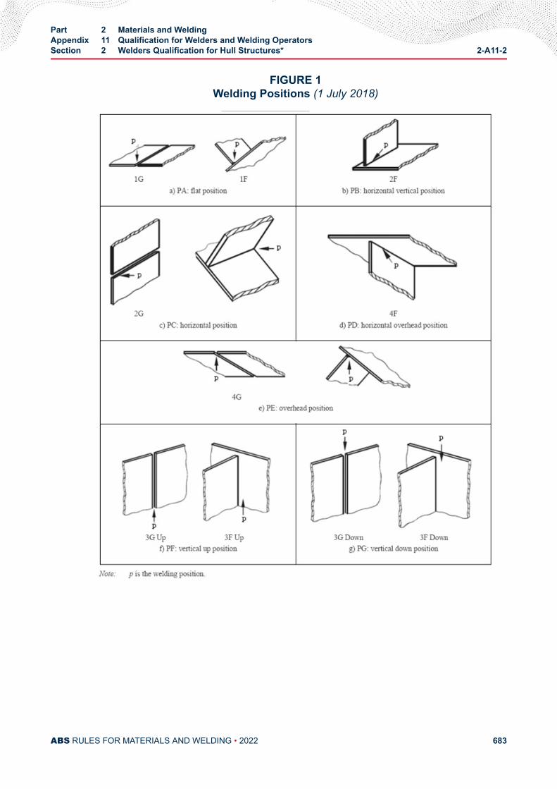
FIGURE 1Welding Positions (1 July 2018)
Part 2 Materials and WeldingAppendix 11 Qualification for Welders and Welding OperatorsSection 2 Welders Qualification for Hull Structures* 2-A11-2
ABS RULES FOR MATERIALS AND WELDING • 2022 683
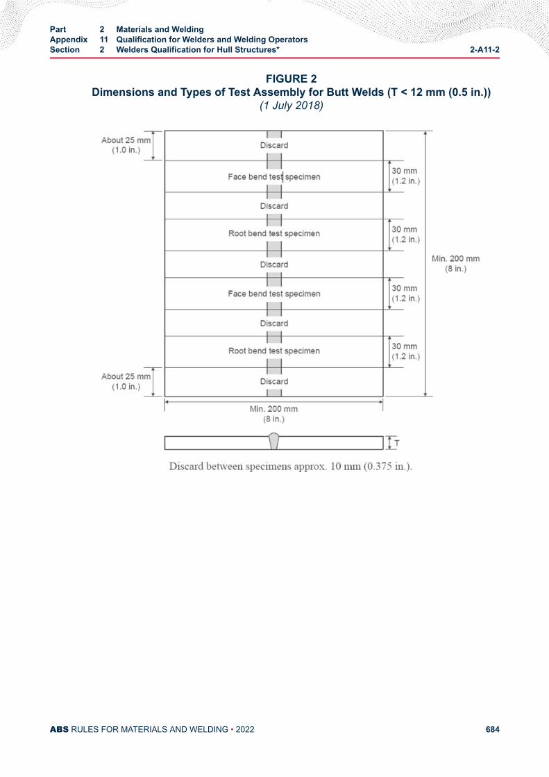
FIGURE 2Dimensions and Types of Test Assembly for Butt Welds (T < 12 mm (0.5 in.))
(1 July 2018)
Part 2 Materials and WeldingAppendix 11 Qualification for Welders and Welding OperatorsSection 2 Welders Qualification for Hull Structures* 2-A11-2
ABS RULES FOR MATERIALS AND WELDING • 2022 684
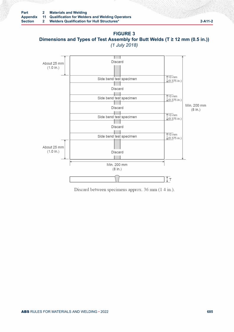
FIGURE 3Dimensions and Types of Test Assembly for Butt Welds (T ≥ 12 mm (0.5 in.))
(1 July 2018)
Part 2 Materials and WeldingAppendix 11 Qualification for Welders and Welding OperatorsSection 2 Welders Qualification for Hull Structures* 2-A11-2
ABS RULES FOR MATERIALS AND WELDING • 2022 685
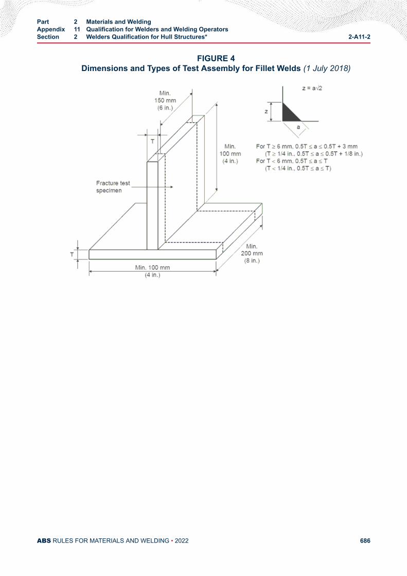
FIGURE 4Dimensions and Types of Test Assembly for Fillet Welds (1 July 2018)
Part 2 Materials and WeldingAppendix 11 Qualification for Welders and Welding OperatorsSection 2 Welders Qualification for Hull Structures* 2-A11-2
ABS RULES FOR MATERIALS AND WELDING • 2022 686
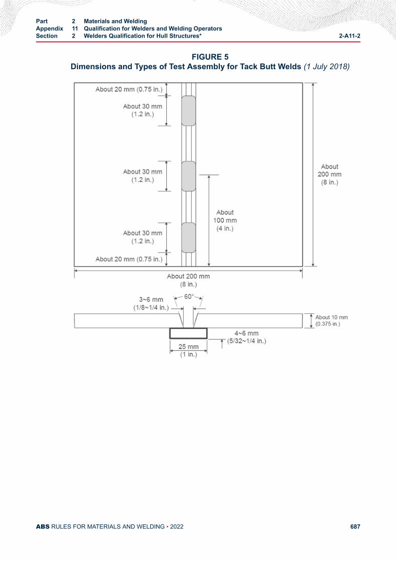
FIGURE 5Dimensions and Types of Test Assembly for Tack Butt Welds (1 July 2018)
Part 2 Materials and WeldingAppendix 11 Qualification for Welders and Welding OperatorsSection 2 Welders Qualification for Hull Structures* 2-A11-2
ABS RULES FOR MATERIALS AND WELDING • 2022 687
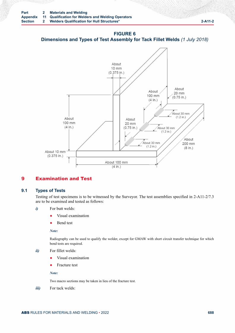
FIGURE 6Dimensions and Types of Test Assembly for Tack Fillet Welds (1 July 2018)
9 Examination and Test
9.1 Types of TestsTesting of test specimens is to be witnessed by the Surveyor. The test assemblies specified in 2-A11-2/7.3are to be examined and tested as follows:
i) For butt welds:
● Visual examination
● Bend test
Note:
Radiography can be used to qualify the welder, except for GMAW with short circuit transfer technique for whichbend tests are required.
ii) For fillet welds:
● Visual examination
● Fracture test
Note:
Two macro sections may be taken in lieu of the fracture test.
iii) For tack welds:
Part 2 Materials and WeldingAppendix 11 Qualification for Welders and Welding OperatorsSection 2 Welders Qualification for Hull Structures* 2-A11-2
ABS RULES FOR MATERIALS AND WELDING • 2022 688
● Visual examination
● Fracture test
9.3 Visual ExaminationThe welds are to be visually examined prior to the cutting of the test specimen for the bend test andfracture test. The result of the examination is to show the absence of cracks or other serious imperfections.
Imperfections detected are to be assessed in accordance with quality level B in ISO 5817, except for thefollowing imperfection types for which level C applies:
● Excess weld metal
● Excess penetration
● Excessive convexity
● Excessive throat thickness
9.5 Bend TestTransverse bend test specimens are to be in accordance with 2-4-3/11.5 FIGURE 5.
The mandrel diameter to thickness ratio (i.e., D/T) is to be as follows,
Ordinary Strength Four times the thickness of the specimen
Y and Y400 Four times the thickness of the specimen
YQ420, YQ460 & YQ500 Five times the thickness of the specimen
YQ550, YQ620 & YQ690 Six times the thickness of the specimen.
For normal and high strength steels, forgings, and castings, the test specimens are to be bent on a mandrelwith diameter 4t, where t is the thickness of the specimen. For extra high strength steels with H47 grade,the mandrel diameter is to be 5t.
Two face bend test and two root bend test specimens are to be tested for initial qualification test, and oneface and one root bend test specimens for extension of approval. For thickness 12 mm (0.5 in.) and over,four side specimens (two side specimens for extension of approval) with 10 mm (0.375 in.) in thicknessmay be tested as an alternative.
At least one bend test specimen is to include one stop and restart in the bending part, for root run or for caprun.
The test specimens are to be bent through 180 degrees shown in 2-4-3/11.5 FIGURE 7. After the test, thetest specimens are not to reveal any open defects in any direction greater than 3 mm (0.125 in.). Defectsappearing at the corners of a test specimen during testing are to be investigated on a case-by-case basis.
9.7 Radiographic TestWhen radiographic testing is used for butt welds, imperfections detected are to be assessed in accordancewith ISO 5817, level B.
9.9 Fracture Test (Butt Welds)When fracture test is used for butt welds, full test specimen in length is to be tested in accordance with ISO9017. Imperfections detected are to be assessed in accordance with ISO 5817, level B.
Part 2 Materials and WeldingAppendix 11 Qualification for Welders and Welding OperatorsSection 2 Welders Qualification for Hull Structures* 2-A11-2
ABS RULES FOR MATERIALS AND WELDING • 2022 689
9.11 Fracture Test (Fillet Welds)The fracture test is to be performed by folding the upright plate onto the through plate.
Evaluation is to concentrate on cracks, porosity and pores, inclusions, lack of fusion, and incompletepenetration. Imperfections that are detected are to be assessed in accordance with ISO 5817, level B.
9.13 Macro Examination (Fillet Welds)When macro examination is used for fillet welds, two test specimens are to be prepared from differentcutting positions. At least one macro examination specimen is to be cut at the position of one stop andrestart in either root run or cap run. These specimens are to be etched on one side to clearly reveal the weldmetal, fusion line, root penetration, and the heat affected zone.
Macro sections are to include at least 10 mm (0.375 in.) of unaffected base metal.
The examination is to reveal a regular weld profile, through fusion between adjacent layers of weld andbase metal, sufficient root penetration, and the absence of defects such as cracks, lack of fusion, etc.
11 Retest
11.1When a welder fails a qualification test, the following is to apply.
i) In cases where the welder fails to meet the requirements in part of the tests, a retest may be weldedimmediately, consisting of another test assembly of each type of welded joint and position that thewelder failed. In this case, the test is to be done for duplicate test specimens of each failed test.
All retest specimens are to meet all of the specified requirements.
ii) In cases where the welder fails to meet the requirements in all parts of the required tests or in theretest, the welder is to undertake further training and practice.
iii) When there is specific reason to question the welder’s ability or the period of effectiveness haslapsed, the welder is to be requalified.
11.3Where any test specimen does not comply with dimensional specifications due to poor machining, areplacement test assembly is to be welded and tested.
13 Certification
13.1Qualification certificates are normally issued when the welder has passed the qualification test by ABS.Each Shipyard, Manufacturer and Subcontractor is to be responsible for the control of the validity of thecertificate and the range of the approval.
13.3The following items are to be specified in the certificate:
i) Range of qualification for base metal, welding processes, filler metal type, types of welded joint,plate thicknesses, and welding positions
ii) Expiry date of the validity of the qualification
iii) Name, identification, and the photograph of the welder
iv) Name of shipbuilder/manufacturer/subcontractor
Part 2 Materials and WeldingAppendix 11 Qualification for Welders and Welding OperatorsSection 2 Welders Qualification for Hull Structures* 2-A11-2
ABS RULES FOR MATERIALS AND WELDING • 2022 690
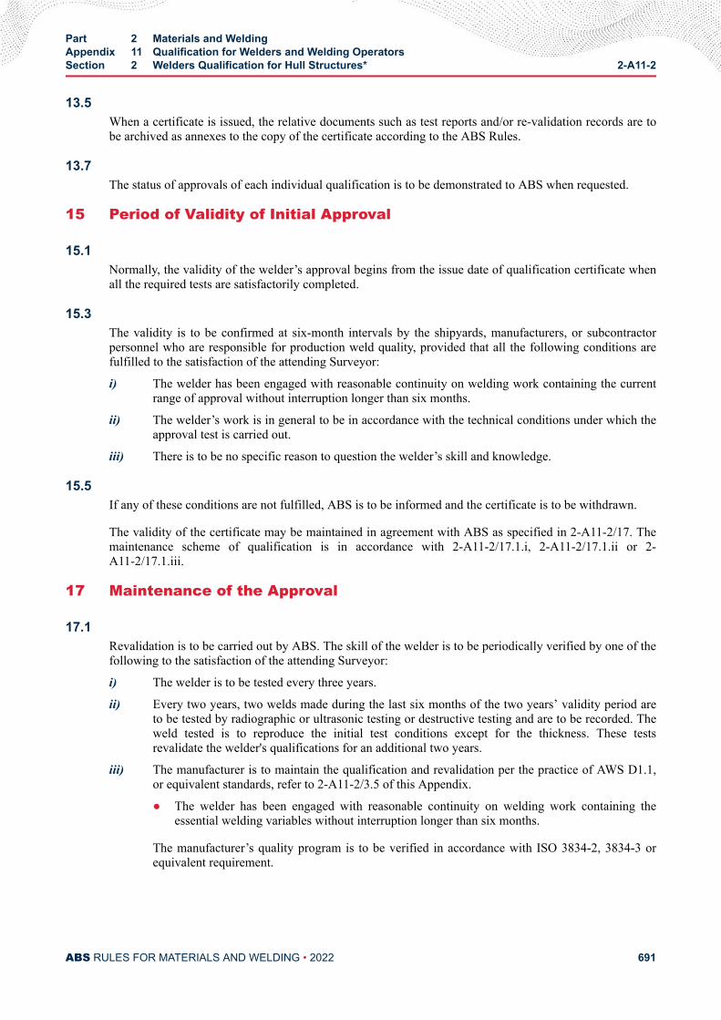
13.5When a certificate is issued, the relative documents such as test reports and/or re-validation records are tobe archived as annexes to the copy of the certificate according to the ABS Rules.
13.7The status of approvals of each individual qualification is to be demonstrated to ABS when requested.
15 Period of Validity of Initial Approval
15.1Normally, the validity of the welder’s approval begins from the issue date of qualification certificate whenall the required tests are satisfactorily completed.
15.3The validity is to be confirmed at six-month intervals by the shipyards, manufacturers, or subcontractorpersonnel who are responsible for production weld quality, provided that all the following conditions arefulfilled to the satisfaction of the attending Surveyor:
i) The welder has been engaged with reasonable continuity on welding work containing the currentrange of approval without interruption longer than six months.
ii) The welder’s work is in general to be in accordance with the technical conditions under which theapproval test is carried out.
iii) There is to be no specific reason to question the welder’s skill and knowledge.
15.5If any of these conditions are not fulfilled, ABS is to be informed and the certificate is to be withdrawn.
The validity of the certificate may be maintained in agreement with ABS as specified in 2-A11-2/17. Themaintenance scheme of qualification is in accordance with 2-A11-2/17.1.i, 2-A11-2/17.1.ii or 2-A11-2/17.1.iii.
17 Maintenance of the Approval
17.1Revalidation is to be carried out by ABS. The skill of the welder is to be periodically verified by one of thefollowing to the satisfaction of the attending Surveyor:
i) The welder is to be tested every three years.
ii) Every two years, two welds made during the last six months of the two years’ validity period areto be tested by radiographic or ultrasonic testing or destructive testing and are to be recorded. Theweld tested is to reproduce the initial test conditions except for the thickness. These testsrevalidate the welder's qualifications for an additional two years.
iii) The manufacturer is to maintain the qualification and revalidation per the practice of AWS D1.1,or equivalent standards, refer to 2-A11-2/3.5 of this Appendix.
● The welder has been engaged with reasonable continuity on welding work containing theessential welding variables without interruption longer than six months.
The manufacturer’s quality program is to be verified in accordance with ISO 3834-2, 3834-3 orequivalent requirement.
Part 2 Materials and WeldingAppendix 11 Qualification for Welders and Welding OperatorsSection 2 Welders Qualification for Hull Structures* 2-A11-2
ABS RULES FOR MATERIALS AND WELDING • 2022 691

17.3ABS or the builder, manufacturer, or subcontractor is to verify compliance with the above conditions andsign the maintenance of the welder’s qualification certificate.
Part 2 Materials and WeldingAppendix 11 Qualification for Welders and Welding OperatorsSection 2 Welders Qualification for Hull Structures* 2-A11-2
ABS RULES FOR MATERIALS AND WELDING • 2022 692
A P P E N D I X 1 1Qualification for Welders and Welding Operators
S E C T I O N 3Welding Operators Qualification (1 July 2018)
1The welding operator responsible for setting up and/or adjustment of fully mechanized and automaticequipment, such as submerged arc welding, gravity welding, electro-gas welding, and MAG welding withauto-carriage, etc., must be qualified.
3ISO 14732 can be referred as the qualification test and approval range for the welding operator. At thediscretion of ABS, the records for welder operator are to give the evidence with adequate regular trainingto set up, program, and operate welding equipment in accordance with the applicable WPS (weldingprocedure specification).
5In addition to the above requirements, the welding operator qualification is to include, but not limited to,the following training and skills for:
i) Groove dimension
ii) Groove cleanliness
iii) Weather and wind
iv) Storing and handling of welding consumables
7Appropriate records are to be maintained by shipbuilder, manufacturer, or subcontractor and are to beprovided at the Surveyor’s request.
At the discretion of ABS, the alternative welder operator certificate maybe accepted, per the applicablestandards such as ISO 14732, AWS D1.1, ASME IX, or equivalent standards.
PART 2
ABS RULES FOR MATERIALS AND WELDING • 2022 693
A P P E N D I X 1 1Qualification for Welders and Welding Operators
S E C T I O N 4Certification Process (1 July 2018)
1Test assemblies welding and testing are to be witnessed by the Surveyor. On the client’s request, ABS willcertify the welder after the welder passes the qualification tests.
3At the discretion of ABS, a welder or operator certified by other classification society or independentorganization can be evaluated and accepted on a case-by-case basis. ABS reserves the right to re-validate,which may include testing prior to production, additional NDT and/or welding production tests may berequired.
PART 2
ABS RULES FOR MATERIALS AND WELDING • 2022 694
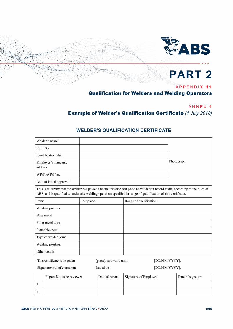
A P P E N D I X 1 1Qualification for Welders and Welding Operators
A N N E X 1Example of Welder’s Qualification Certificate (1 July 2018)
WELDER’S QUALIFICATION CERTIFICATE
Welder’s name:
Photograph
Cert. No:
Identification No.
Employer’s name andaddress
WPS/pWPS No.
Date of initial approval
This is to certify that the welder has passed the qualification test [/and re-validation record audit] according to the rules ofABS, and is qualified to undertake welding operation specified in range of qualification of this certificate.
Items Test piece Range of qualification
Welding process
Base metal
Filler metal type
Plate thickness
Type of welded joint
Welding position
Other details
This certificate is issued at [place], and valid until [DD/MM/YYYY].
Signature/seal of examiner: Issued on [DD/MM/YYYY].
Report No. to be reviewed Date of report Signature of Employee Date of signature
1
2
PART 2
ABS RULES FOR MATERIALS AND WELDING • 2022 695
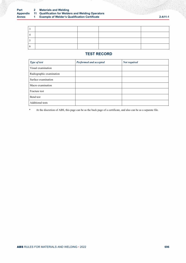
3
4
5
6
TEST RECORD
Type of test Performed and accepted Not required
Visual examination
Radiographic examination
Surface examination
Macro examination
Fracture test
Bend test
Additional tests
* At the discretion of ABS, this page can be as the back page of a certificate, and also can be as a separate file.
Part 2 Materials and WeldingAppendix 11 Qualification for Welders and Welding OperatorsAnnex 1 Example of Welder’s Qualification Certificate 2-A11-1
ABS RULES FOR MATERIALS AND WELDING • 2022 696
A P P E N D I X 1 2Comparison of Existing Materials and Welding Rules vs. 2018 Materials
and Welding Rules
CONTENTSSECTION 1 Comparison of Existing Materials and Welding Rules vs. 2018
Materials and Welding Rules.......................................................... 698
PART 2
ABS RULES FOR MATERIALS AND WELDING • 2022 697
A P P E N D I X 1 2Comparison of Existing Materials and Welding Rules vs. 2018 Materials
and Welding Rules
S E C T I O N 1Comparison of Existing Materials and Welding Rules vs. 2018 Materials
and Welding Rules
Rules for Materials and Welding
PART 2
ABS RULES FOR MATERIALS AND WELDING • 2022 698
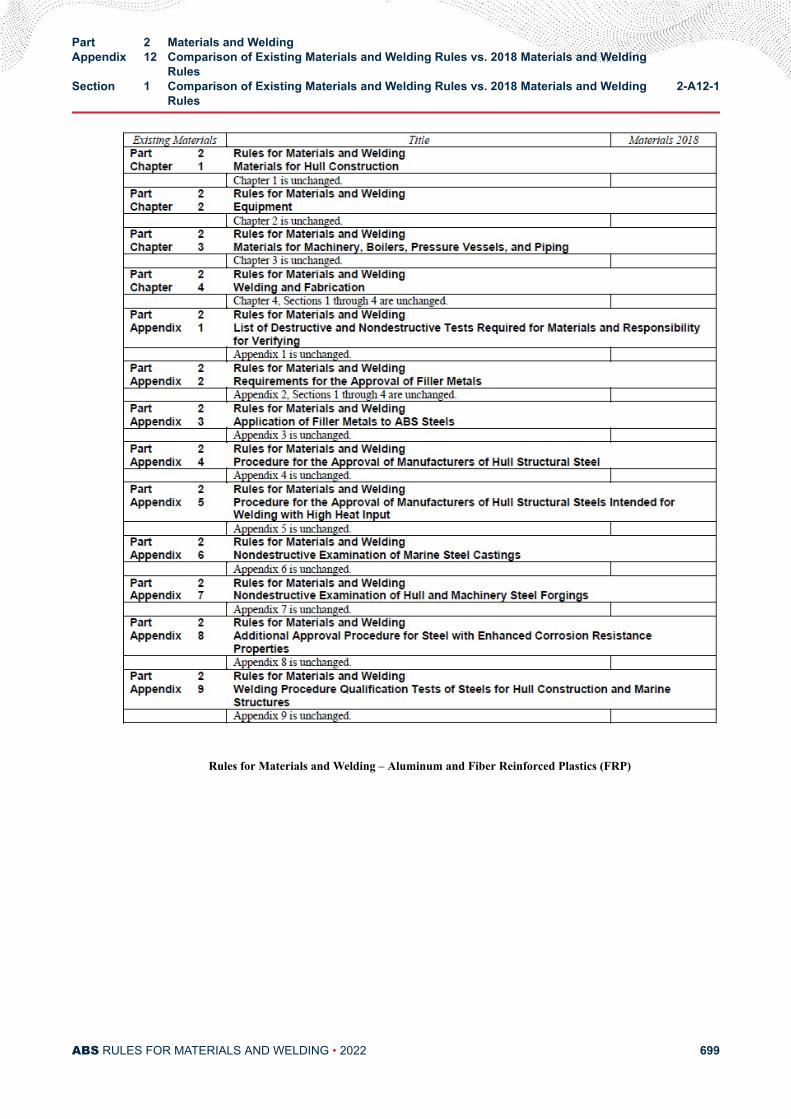
Rules for Materials and Welding – Aluminum and Fiber Reinforced Plastics (FRP)
Part 2 Materials and WeldingAppendix 12 Comparison of Existing Materials and Welding Rules vs. 2018 Materials and Welding
RulesSection 1 Comparison of Existing Materials and Welding Rules vs. 2018 Materials and Welding
Rules2-A12-1
ABS RULES FOR MATERIALS AND WELDING • 2022 699
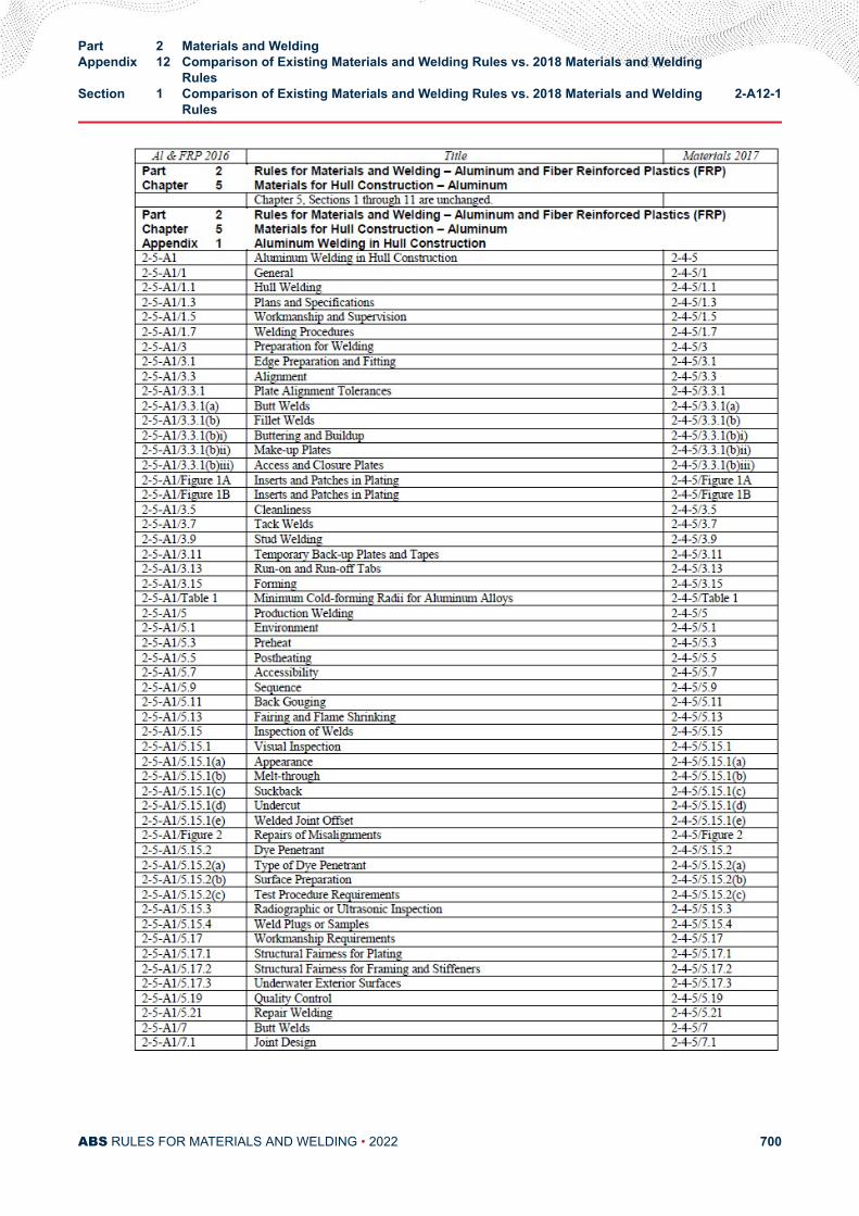
Part 2 Materials and WeldingAppendix 12 Comparison of Existing Materials and Welding Rules vs. 2018 Materials and Welding
RulesSection 1 Comparison of Existing Materials and Welding Rules vs. 2018 Materials and Welding
Rules2-A12-1
ABS RULES FOR MATERIALS AND WELDING • 2022 700
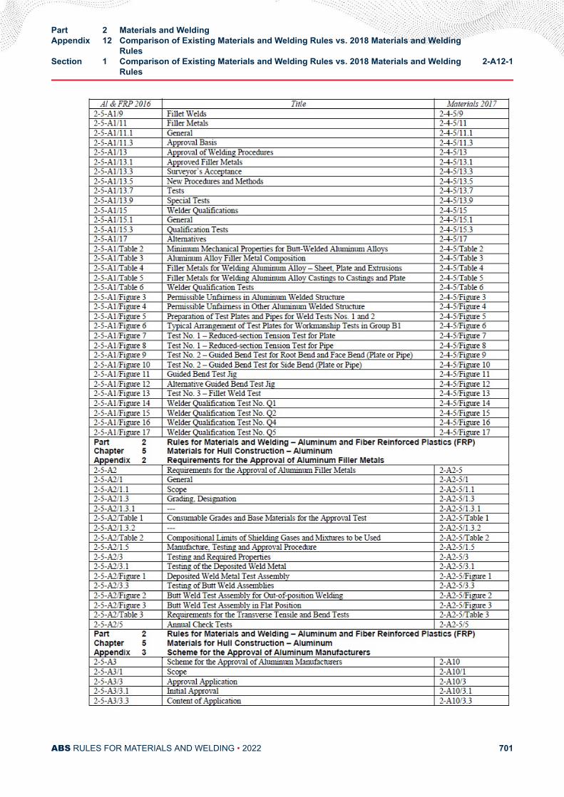
Part 2 Materials and WeldingAppendix 12 Comparison of Existing Materials and Welding Rules vs. 2018 Materials and Welding
RulesSection 1 Comparison of Existing Materials and Welding Rules vs. 2018 Materials and Welding
Rules2-A12-1
ABS RULES FOR MATERIALS AND WELDING • 2022 701
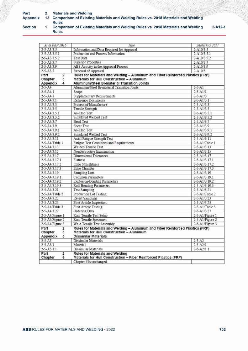
Part 2 Materials and WeldingAppendix 12 Comparison of Existing Materials and Welding Rules vs. 2018 Materials and Welding
RulesSection 1 Comparison of Existing Materials and Welding Rules vs. 2018 Materials and Welding
Rules2-A12-1
ABS RULES FOR MATERIALS AND WELDING • 2022 702
Related Documents