Civil and Environmental Research www.iiste.org ISSN 2224-5790 (Paper) ISSN 2225-0514 (Online) Vol.3, No.8, 2013 32 Groundwater Research and Development Potential in Auchi Polytechnic-Philipa Idogho Campus Abdulasisi Titi UMORU*, Edwin .O. OYATHELEMI,Tunde, Usman Nurudeen SULE. Dept. of Mineral Resources Engineering Tech., School of Engineering Technology, Auchi Polytechnic, Auchi. E-mail: [email protected] , [email protected] . [email protected] This Research is Initiated & Co-Ordinated by DR. (Mrs) Philipa .O. Idogho, the Rector of Auchi Polytechnic, We acknowledge her kind support and negotiation with the research sponsor- ETF research and development for underground water potential in Nigeria (2010). Abstract The immediate need of water is very vital to every organism therefore its availability and provision becomes very essential to life. As a result this study focused on the provision of quality ground water for sustainability of staff and students of Auchi polytechnic and its environs. It carried out conduction of resistivity sounding at the site and interpretation of the field Vertical Electrical Sounding (VES) data to obtain geo-electric parameters. Determination of the hydrogeological characteristics of the subsurface at the site based on geo-electric and available geologic information reveal the possible of water availability. It recommended that a suitable drilling rig that can effectively drill to the required specifications and depth should be mobilized to site for subsequent projects. Keywords: Lithology, Depth, Geological survey, Ground water, ETF, Campus 1. Heading 1 Introduction The basic need and sustenance of man is water. As a result of its immediate needs to animal, plant and others, water availability and provision becomes very essential to life. According to Mulla, Syed, Abed and Pardhan (2011) observed that water is essential for life on the earth and any other planet and further explained that it is the fundamental right to get pollution free water to the every individual. The pollution of surface water can be treated with different techniques. It is very difficult to get purified ground water. In the Marathwada region from ancient times the people were using ground water for day-to-day use and drinking purpose. Groundwater resource development is a very viable means of meeting the ever increasing needs of our teeming population for potable water. Groundwater abstraction is more commonly done through borehole drilling. The amazing rates of failure recorded in the past drilling works have necessitated the absolute need for pre-drilling investigations (Fasunwon, Ayeni and Lawal, 2010). Geophysical methods have been very useful in determining the geological sequence and structure of the subsurface rocks by the measurement of their physical properties. Although there are varieties of geophysical techniques, which could be used in groundwater exploration, electrical resistivity method has proved reliable in delineating zones of relatively low resistivity signatory of saturated strata in various geologic terrains (Odejobi, 1999). Some chemical constituents are expected of ground water. For instance in the study of Majolagbe, Kasali and Ghaniyu (2011), the following chemical observations were recorded and helped to shape the study in Lagos suburban for ground water project. The chemicals are Cd, Fe, Cu Zn Mg and Na which were determined using Flame Atomic Absorption Spectrophotometer (Buck scientific 210VGP model). The study confirmed that concentration of Pb, Fe and Cd found in Isolo study area were higher than WHO health based guideline values, indicating possible impact of landfill on the groundwater quality. This raises the question of toxicities of these elements, hence pose potential threat to man. Most of the nutritive metals analysed (Na, Zn, and Cu) in Isolo samples maintained strong positive correlation with r values ≥ 0.8 showing possible common source, unlike Ifo water samples that had all the metals analysed found within the WHO standards for drinking water. Ifo groundwater is soft with pH within the WHO acceptable range for drinking water while Isolo water is moderately hard, acidic in nature; hence require further treatment for it to be potable. In the ground water study of the Auchi Polytechnic presents a different view point based on the location, depth, geophysical analysis and Lethological laboratory test conducted before embarking on the project in the survey site. In addition, the total field operations and data acquisition at the site lasted for two days and follow the execution of the ground water project. 1.1Research Objective The primary objective of this investigation focuses on the followings: • Conduction of Resistivity sounding at the site and interpretation of the field Vertical Electrical Sounding (VES) data to obtain geo-electric parameters.

Groundwater research and development potential in auchi polytechnic philipa idogho campus
Aug 20, 2015
Welcome message from author
This document is posted to help you gain knowledge. Please leave a comment to let me know what you think about it! Share it to your friends and learn new things together.
Transcript

Civil and Environmental Research www.iiste.org
ISSN 2224-5790 (Paper) ISSN 2225-0514 (Online)
Vol.3, No.8, 2013
32
Groundwater Research and Development Potential in Auchi
Polytechnic-Philipa Idogho Campus
Abdulasisi Titi UMORU*, Edwin .O. OYATHELEMI,Tunde, Usman Nurudeen SULE.
Dept. of Mineral Resources Engineering Tech., School of Engineering Technology, Auchi Polytechnic, Auchi.
E-mail: [email protected], [email protected]. [email protected]
This Research is Initiated & Co-Ordinated by DR. (Mrs) Philipa .O. Idogho, the Rector of Auchi Polytechnic,
We acknowledge her kind support and negotiation with the research sponsor- ETF research and development for
underground water potential in Nigeria (2010).
Abstract
The immediate need of water is very vital to every organism therefore its availability and provision becomes
very essential to life. As a result this study focused on the provision of quality ground water for sustainability of
staff and students of Auchi polytechnic and its environs. It carried out conduction of resistivity sounding at the
site and interpretation of the field Vertical Electrical Sounding (VES) data to obtain geo-electric parameters.
Determination of the hydrogeological characteristics of the subsurface at the site based on geo-electric and
available geologic information reveal the possible of water availability. It recommended that a suitable drilling
rig that can effectively drill to the required specifications and depth should be mobilized to site for subsequent
projects.
Keywords: Lithology, Depth, Geological survey, Ground water, ETF, Campus
1. Heading 1 Introduction
The basic need and sustenance of man is water. As a result of its immediate needs to animal, plant and others,
water availability and provision becomes very essential to life. According to Mulla, Syed, Abed and Pardhan
(2011) observed that water is essential for life on the earth and any other planet and further explained that it is
the fundamental right to get pollution free water to the every individual. The pollution of surface water can be
treated with different techniques. It is very difficult to get purified ground water. In the Marathwada region from
ancient times the people were using ground water for day-to-day use and drinking purpose. Groundwater
resource development is a very viable means of meeting the ever increasing needs of our teeming population for
potable water. Groundwater abstraction is more commonly done through borehole drilling. The amazing rates of
failure recorded in the past drilling works have necessitated the absolute need for pre-drilling investigations
(Fasunwon, Ayeni and Lawal, 2010). Geophysical methods have been very useful in determining the geological
sequence and structure of the subsurface rocks by the measurement of their physical properties. Although there
are varieties of geophysical techniques, which could be used in groundwater exploration, electrical resistivity
method has proved reliable in delineating zones of relatively low resistivity signatory of saturated strata in
various geologic terrains (Odejobi, 1999). Some chemical constituents are expected of ground water. For
instance in the study of Majolagbe, Kasali and Ghaniyu (2011), the following chemical observations were
recorded and helped to shape the study in Lagos suburban for ground water project. The chemicals are Cd, Fe,
Cu Zn Mg and Na which were determined using Flame Atomic Absorption Spectrophotometer (Buck scientific
210VGP model). The study confirmed that concentration of Pb, Fe and Cd found in Isolo study area were higher
than WHO health based guideline values, indicating possible impact of landfill on the groundwater quality. This
raises the question of toxicities of these elements, hence pose potential threat to man. Most of the nutritive
metals analysed (Na, Zn, and Cu) in Isolo samples maintained strong positive correlation with r values ≥ 0.8
showing possible common source, unlike Ifo water samples that had all the metals analysed found within the
WHO standards for drinking water. Ifo groundwater is soft with pH within the WHO acceptable range for
drinking water while Isolo water is moderately hard, acidic in nature; hence require further treatment for it to be
potable.
In the ground water study of the Auchi Polytechnic presents a different view point based on the location, depth,
geophysical analysis and Lethological laboratory test conducted before embarking on the project in the survey
site. In addition, the total field operations and data acquisition at the site lasted for two days and follow the
execution of the ground water project.
1.1Research Objective
The primary objective of this investigation focuses on the followings:
• Conduction of Resistivity sounding at the site and interpretation of the field Vertical Electrical
Sounding (VES) data to obtain geo-electric parameters.
Civil and Environmental Research www.iiste.org
ISSN 2224-5790 (Paper) ISSN 2225-0514 (Online)
Vol.3, No.8, 2013
33
• Determination of the hydrogeological characteristics of the subsurface at the site based on geo-electric
and available geologic information.
• Making an appropriate recommendations for the planning and execution of a viable groundwater
abstraction project (at the site) through borehole drilling
• Production of groundwater and quality distribution in the study area.
• Installation of a treatment plant unit.
1.2 Study Area: Site location and description
The geophysical exploration was carried out within Auchi Polytechnic, Auchi, Edo State, Nigeria. VES 1 is
approximately defined by the geographical coordinates of latitude N070 02’44.4” and Longitude E0060 16’11.8”.
The observed elevation above the mean sea level is 213 m.
TUNDE
MAP OF AUCHI, IGARRA, OSOSO AND ENVIRONS
NIGERIA
AUCHI
NIGERIA
AUCHI
0 3 6 9 12 151.5
Kilometers
Legend
") Major_Settlements
Settlements
Major_Roads
River
Contours
River
")
")
")
")
")
900
River
Orle
Riv
er O
jo
River Ubo
River Ekafe
River O
wan
River E
kpeshi
Oyanmi
900700
500
600
400
800
1000
1200
300
1100
1500
1300
1400
1700
1500
1200
1000
1100
1500
1000
900
1000
700
800
1000
500
1500
700
700
1200
1000
1200
1000
800
1500
1500
700
1400
700
1500
1000
1000
500
1100
900
500
600
1500
900
400
1000
1500
1000
1000
900
1000
500
900
1000
1100
1000
1000
1500
600
600
800
1000
1000
1000
1100
400
800
1000
1000
1000
1100
700
1100
1500
OSOSO
AUCHI
IBILLO
IGARRA
WARRAKE
Oja
Oke
Oku
Ate
Isa
Ake
Ogbe
Iddo
Otuo
Afua
AviaMeke
Igwe
Med.
Jeda
Usun
Ugba
Sebe
Igwe
Ajayo
Onumu
Ogugu
Egene
Akuku
Owan Eturu
Ogute
Ogute
Oloma
Iyemu
Afana
Yelwa
Jettu
Iyuku
Ohama
Iyaba
Uokha
Mekeke
Akpama
Ekpesa
Ekpesa
Eshawa
Okpoto
Utejie
Ogriga
Isokwi
Okugbe
Ogbido
Sasaro
Suberu
Ikao I
Ogbona
Ogbona
Ugbeno
Uruoke
Ogbida
Irelli
Ekperi
OkpemiEvoike
Egboto
Ugieda
Iyakpe
Ubiane
Ebetse
Ekpeye
Ugboha
Egbetua
Dagbala
Ojirami
Udiegua
Awuyami
Awuyemi
Kominio
Imiagba
Imiekwi
GbagereIkao II
Ayuguri
Irukpai
Iviotha
Afashio
AzukalaUgbekpe
UbunekeOvbiomu
Ille-Aro
Oja-Sale
Ogbe-Oke
Ogbe-Oke
Ayegunle
Aiyetoro Somorika
Imiegele
ImiakebuEgbigele
Ikabigbo
Ineme-Osa
Ogbe-Cane
Sale-Ogbe
Afokpilla
Sebe-Ogbe
Ago-Isame
Ibia-NafeObie Sebe
Okpokhumi
Ineme-Ekpe
Onumu-Sale
Ebune-Ugbo
Jimoh Camp
Saliu Camp
Ugboshi-Afe
Unemenekhua
Ugboshi Oke
Sanunu Camp
Utejie Camp
Salami Camp
Ojirami-Ogbo
Ugboshi-Sale
Semorika Afeke
Okpilla Cement
6°20'0"E
6°20'0"E
6°15'0"E
6°15'0"E
6°10'0"E
6°10'0"E
6°5'0"E
6°5'0"E
6°0'0"E
6°0'0"E
6°25'0"E
6°25'0"E
7°25'0"N7°25'0"N
7°20'0"N7°20'0"N
7°15'0"N7°15'0"N
7°10'0"N7°10'0"N
7°5'0"N7°5'0"N
7°0'0"N7°0'0"N
Source: Authors’ Extract of Auchi and its environments, 2012.

Civil and Environmental Research www.iiste.org
ISSN 2224-5790 (Paper) ISSN 2225-0514 (Online)
Vol.3, No.8, 2013
34
TUNDE
MAP OF AUCHI, IGARRA, OSOSO AND ENVIRONS
NIGERIA
AUCHI
NIGERIA
AUCHI
0 3 6 9 12 151.5
Kilometers
Legend
") Major_Settlements
Settlements
Major_Roads
River
Contours
River
")
")
")
")
")
90
0
R iver O
r le
Ri v
er O
jo
R iver Ubo
River Ekafe
Rive r O
w an
Rive r E kpe shi
Oyanmi
900700
500
6 0 0
40
0
80
0
10001200
300
1100
1500
13
00
14
00
1700
1500
1200
1 00 0
11 00
1500
1000
9 0 0
1000
70 0
800
10
00
50 0
15 00
70
0
7 00
1200
10 0
0
1200
1000
80
0
1500
1500
70
0
1400
70 0
15
00
1000
1000
500
110 0
900
50
0
6 00
15
00
90 0
4 00
1000
1500
1000
100 0
900
1000
50
0
900
10
00
1 10
0
1000
1000
1500
600
600
8001
00
0
10 00
1 0 0 0
110 0
400
80 0
10
00
1000
1000
1100
7 00
11 00
15
00
OSOSO
AUCHI
IBILLO
IGARRA
WARRAKE
Oja
amp
Oke
Oku
Ate
Isa
Ake
Ogbe
Iddo
Otuo
Afua
AviaMeke
Igwe
Med.
Jeda
Usun
Ugba
Sebe
Igwe
Ogori
Ajayo
Onumu
Ogugu
Egene
Akuku
Owan Eturu
Ogute
Ogute
Oloma
Iyemu
Afana
Yelwa
Jettu
Iyuku
Ohama
Iyaba
Uokha
Mekeke
Akpama
Ekpesa
Ekpesa
Eshawa
Okpoto
Utejie
Ogriga
Isokwi
Okugbe
Ogbido
Sasaro
Suberu
Ikao I
Ogbona
Ogbona
Ugbeno
Uruoke
Ogbida
Irelli
Ekperi
OkpemiEvoike
Egboto
Ugieda
Iyakpe
Ubiane
Ebetse
Ekpeye
Ugboha
Egbetua
Dagbala
Ojirami
Udiegua
Awuyami
Awuyemi
Kominio
Imiagba
Imiekwi
GbagereIkao II
Ayuguri
Irukpai
Iviotha
AzukalaUgbekpe
UbunekeOvbiomu
Ille-Aro
Oja-Sale
Ogbe-Oke
Ogbe-Oke
Adaira C
Ayegunle
Aiyetoro Somorika
Imiegele
ImiakebuEgbigele
Ikabigbo
Ineme-Osa
Ogbe-Cane
Sale-Ogbe
Lankpeshe
Afokpilla
Sebe-Ogbe
Ago-Isame
Ibia-NafeObie Sebe
Okpokhumi
Ineme-Ekpe
Onumu-Sale
Ebune-Ugbo
Jimoh Camp
Saliu Camp
Ugboshi-Afe
Unemenekhua
Ugboshi Oke
Sanunu Camp Utejie Camp
Salami Camp
Ojirami-Ogbo
Ugboshi-Sale
Semorika Afeke
Okpilla Cement
6°25'0"E
6°25'0"E
6°20'0"E
6°20'0"E
6°15'0"E
6°15'0"E
6°10'0"E
6°10'0"E
6°5'0"E
6°5'0"E6°0'0"E
7°25'0"N7°25'0"N
7°20'0"N7°20'0"N
7°15'0"N7°15'0"N
7°10'0"N7°10'0"N
7°5'0"N7°5'0"N
7°0'0"N7°0'0"N
Source: Authors’ Geological Map of Auchi and its environments, 2012.
2. Material and Method of Study
In this project, most materials employ involve geophysical survey, site clearing, mud pit construction,
mobilization of equipment/personnel, drilling operation, excavation for tank foundation, chain design for tank
foundation, casing of the borehole, gravel packing of the borehole, pump installation/pump testing, fabrication of
the tank/stanchion , excavation for pipe laying, distribution points/reticulation, fetching points, treatment unit,
painting of the stanchion/Tank, fencing of borehole perimeter, diagrams/pictures, financial breakdown,
geophysical results, Some of our challenges/constrains. For illustrative purpose see the features below:
Civil and Environmental Research www.iiste.org
ISSN 2224-5790 (Paper) ISSN 2225-0514 (Online)
Vol.3, No.8, 2013
35
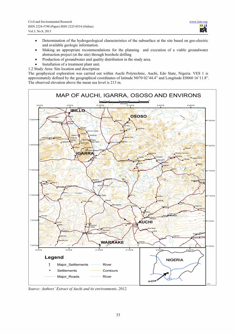
The Physical diagram of the project execution
Figure 2 a and b Terrameter and reels
Figure 2 a and b Terrameter and mud pit
2.1 Field procedure
The groundwater exploration carried out at the site was done using electrical resistivity sounding techniques
(VES). This was achieved with the aid of ABEM AC Terrameter and other field accessories. Geographical
coordinates and elevations were obtained from the GARMIN GPS map 76CSx’ set.
Three Vertical electrical sounding (VES) were done at the site using Schlumberger array. The total spread length
(i.e. AB/2) attained for the three VES points within the limit of the available space were 500m, 350m, and 150m.
However, the artificially generated electrical signal can hardly go beyond AB>2Km. This is why resistivity
sounding is best suited for groundwater and not petroleum exploration (Kearey and Brooks, 1988).
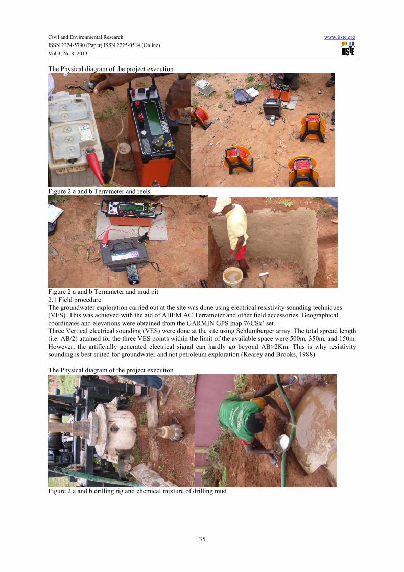
The Physical diagram of the project execution
Figure 2 a and b drilling rig and chemical mixture of drilling mud
Civil and Environmental Research www.iiste.org
ISSN 2224-5790 (Paper) ISSN 2225-0514 (Online)
Vol.3, No.8, 2013
36
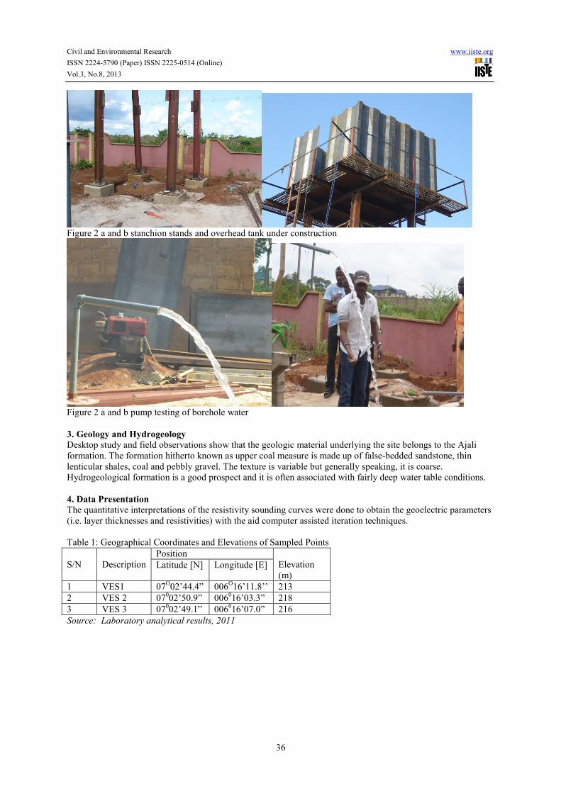
Figure 2 a and b stanchion stands and overhead tank under construction
Figure 2 a and b pump testing of borehole water
3. Geology and Hydrogeology Desktop study and field observations show that the geologic material underlying the site belongs to the Ajali
formation. The formation hitherto known as upper coal measure is made up of false-bedded sandstone, thin
lenticular shales, coal and pebbly gravel. The texture is variable but generally speaking, it is coarse.
Hydrogeological formation is a good prospect and it is often associated with fairly deep water table conditions.
4. Data Presentation
The quantitative interpretations of the resistivity sounding curves were done to obtain the geoelectric parameters
(i.e. layer thicknesses and resistivities) with the aid computer assisted iteration techniques.
Table 1: Geographical Coordinates and Elevations of Sampled Points
S/N
Description
Position
Elevation
(m) Latitude [N] Longitude [E]
1 VES1 07O02’44.4” 006
O16’11.8’’ 213
2 VES 2 07002’50.9” 006
016’03.3” 218
3 VES 3 07002’49.1” 006
016’07.0” 216
Source: Laboratory analytical results, 2011
Civil and Environmental Research www.iiste.org
ISSN 2224-5790 (Paper) ISSN 2225-0514 (Online)
Vol.3, No.8, 2013
37
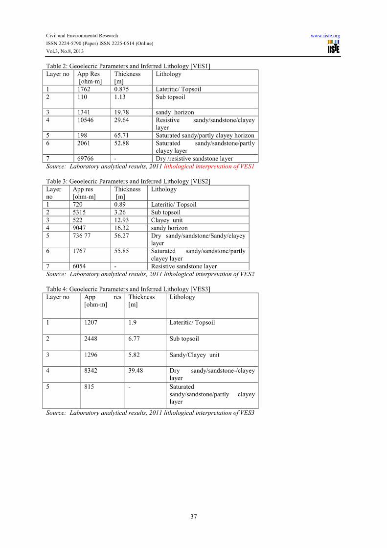
Table 2: Geoelecric Parameters and Inferred Lithology [VES1]
Layer no App Res
[ohm-m]
Thickness
[m]
Lithology
1 1762 0.875 Lateritic/ Topsoil
2 110 1.13 Sub topsoil
3 1341 19.78 sandy horizon
4 10546 29.64 Resistive sandy/sandstone/clayey
layer
5 198 65.71 Saturated sandy/partly clayey horizon
6 2061 52.88 Saturated sandy/sandstone/partly
clayey layer
7 69766 - Dry /resistive sandstone layer
Source: Laboratory analytical results, 2011 lithological interpretation of VES1
Table 3: Geoelecric Parameters and Inferred Lithology [VES2]
Layer
no
App res
[ohm-m]
Thickness
[m]
Lithology
1 720 0.89 Lateritic/ Topsoil
2 5315 3.26 Sub topsoil
3 522 12.93 Clayey unit
4 9047 16.32 sandy horizon
5 736 77 56.27 Dry sandy/sandstone/Sandy/clayey
layer
6 1767 55.85 Saturated sandy/sandstone/partly
clayey layer
7 6054 - Resistive sandstone layer
Source: Laboratory analytical results, 2011 lithological interpretation of VES2
Table 4: Geoelecric Parameters and Inferred Lithology [VES3]
Layer no App res
[ohm-m]
Thickness
[m]
Lithology
1 1207 1.9 Lateritic/ Topsoil
2 2448 6.77 Sub topsoil
3 1296 5.82 Sandy/Clayey unit
4 8342 39.48 Dry sandy/sandstone-/clayey
layer
5 815 - Saturated
sandy/sandstone/partly clayey
layer
Source: Laboratory analytical results, 2011 lithological interpretation of VES3

Civil and Environmental Research www.iiste.org
ISSN 2224-5790 (Paper) ISSN 2225-0514 (Online)
Vol.3, No.8, 2013
38
Table 5:
VES-1Depth (m) VES-2 Depth (m) VES-3 Depth (m)
-0.89 A Top Soil -0.875 A Top Soil -1.9 A Top Soil
-4.18 B Subsoil -2.01 B Subsoil -8.67 B Subsoil
-17.08 C Clayey Layer -21.79 C Sandy Layer -14.5 C Sandy/Clayey
Layer
-33.41 D Sandy Layer -51.44 D Resistive
Layer
-53.98 D Dry
Sandy/SSt
-90.08 E Dry
Sandy/SSt
-117.1 E Saturated
Sandy
∞ E Saturated
Layer
-145.9 F Saturated
Sandy
-170.0 F Saturated SSt
∞ G Resistive SSt ∞ G Resistive SSt
Source: Field analytical results, 2011.
Table 6: Physical Characteristic Combined Standards Results of Chemical Analysis
S/N Parameter Philipa
Idogho
Campus
Borehole
NAFDAC
Maximum
Allowed
Limits
SON
Standard
WHO
Standard
Highest
Desirable
Maximum
Permissible
1 Colour 2.0 TCU 3.0 TCU 3.0 TCU 3.0 TCU 15.0 TCU
2 Odour NS-Bent N.S N.S N.S N.S
3 Taste tasteless N.S N.S N.S N.S
4 PH at 200C 6.7 6.50-8.5 6.50-8.5 7.0-8.9 6.90-9.50
5 Turbidity ND 5.0 NTU 5.0 NTU 5.0 NTU 5.0 NTU
6 Conductivity 43.3(µS/cm) 1000(µS/cm) 1000(µS/cm) 100(µS/cm) 1200(µS/cm)
7 Total Solid 20.5mg/l 500mg/l 500mg/l 500mg/l 1500mg/l
8 Total Alkalinity 8.2mg/l 100mg/l 100mg/l 100mg/l 100mg/l
9 Phenolphthalein
Alkalinity
- 100mg/l 100mg/l 100mg/l 100mg/l
10 Chloride 53.1mg/l 100mg/l 100mg/l 200mg/l 250mg/l
11 Fluoride - 1.0mg/l 1.0mg/l 1.0mg/l 1.5mg/l
12 Copper ND 1.0mg/l 1.0mg/l 0.5mg/l 2.0mg/l
13 Iron 0.25mg/l 0.3mg/l 0.3mg/l 1mg/l 3mg/l
14 Nitrate (NO3) 0.45mg/l 10mg/l 10mg/l 10mg/l 50mg/l
15 Nitrate (NO2) 0.15mg/l 0.02mg/l 0.02mg/l 0.2mg/l 3mg/l
16 Manganese 0.06mg/l 2.0mg/l 0.05mg/l 0.1mg/l 1.0mg/l
17 Magnesium 0.02mg/l 20mg/l 0.20mg/l 20mg/l 20mg/l
18 Zinc 0.01mg/l 5.0mg/l 5.0mg/l 0.01mg/l 3.0mg/l

Civil and Environmental Research www.iiste.org
ISSN 2224-5790 (Paper) ISSN 2225-0514 (Online)
Vol.3, No.8, 2013
39
19 Selenium - 0.0mg/l N/S 0.01mg/l 0.01mg/l
20 Silver - - - N/S N/S
21 Cyanide ND 0.01mg/l 0.01mg/l 0.01mg/l 0.07mg/l
22 Sulphate 1.54mg/l 100mg/l 100mg/l 250mg/l 500mg/l
23 Calcium 0.88mg/l 75mg/l 75mg/l N/S N/S
24 Aluminium ND 0.5mg/l N/S 0.2mg/l 0.2mg/l
25 Potassium 0.09mg/l 10.0mg/l 10.0mg/l N/S N/S
26 Lead ND 0.01mg/l 0.01mg/l 0.01mg/l 0.01mg/l
27 Chromium ND 0.05mg/l 0.05mg/l 0.05mg/l 0.05mg/l
28 Cadmium 0.01mg/l 0.003mg/l 0.003mg/l 0.003mg/l 0.003mg/l
29 Arsenic - 0.01mg/l 0.01mg/l 0.01mg/l 0.01mg/l
30 Barium - 0.05mg/l 0.05mg/l 0.05mg/l 0.07mg/l
31 Mercury - 0.001mg/l 0.001mg/l 0.001mg/l 0.001mg/l
32 Antimony - N/S N/S - 0.02mg/l
33 Tin - - - - 1.2µg/l
34 Nickel ND - - - 0.02mg/l
35 Total
Hardness(CaCO3)
100mg/l 100mg/l 100mg/l 500mg/l
36 Vinyl Chloride - 0mg/l 0mg/l 0mg/l 0mg/l
Source: Martlet Environmental Research Laboratory Limited Results of Chemical Analysis
5. Results and discussion
The interpreted result is presented as sounding curves and descriptive geo-electric logs/Section. Seven geo-
electric layers were resolved for VES1. Layer 1 and 2 stand for lateritic topsoil and subsoil with thicknesses
0.875m and 1.13m and Layers 3 is the sandy horizon. Layer 4 is designated as the resistive
sandy/sandstone/clayey layer. The fifth layer is the saturated sandy/ partly clayey horizon. Layer 6 is also
saturated sandy/sandstone/partly clayey unit. The seventh layer of unknown thickness is designated as the
dry/resistive sandstone horizon. VES 2 and 3 are of the same trend.
Two distinct saturated layers (i.e. Aquifers) were identified from the interpreted VES results. The first is layer 5
while the second is layer 6. The calculated thicknesses of layers 5 and 6 are 65.71m and 52.88m respectively.
Furthermore the depth to the to the base of layer 6 is 170m (561ft)
The apparent resistivity values for the saturated layers are fairly low, indicating good aquifers. In view of the
above hydrogeological and hydro-geophysical analysis, it can be deduced that groundwater resource
development through borehole drilling at the site is feasible.
Therefore the borehole at the site, a maximum drilled depth of 197m (650ft) is recommended and VES 1 is the
recommended drilling point. It is advised that the terminal drilled depth of the borehole at the site should be left
at the discretion of the site geologist and hydro-geologist, who should document and supervise the borehole
construction work in it’s entirely.
6. Conclusion and Recommendation The on-going research work is currently on phase IV with a successful completion of phase I – III. The result of
the pre-drilling geophysical investigations for groundwater resource development (through borehole construction)
carried out within Auchi Polytechnic campus, Auchi Edo State is presented in this report. Hydrogeological and
hydro-geophysical deductions made from the interpreted VES data establish the feasibility of a viable
groundwater abstraction project at the site. A total drilled depth of 197m (650ft) is recommended. In addition,
a suitable drilling rig that can effectively drill to the required specifications and depth should be mobilized to the
Civil and Environmental Research www.iiste.org
ISSN 2224-5790 (Paper) ISSN 2225-0514 (Online)
Vol.3, No.8, 2013
40
site for the project. The entire (On-the-site) drilling process should be supervised and documented by a
competent and professional geologist and hydro-geologist who should also determine the final/terminal depth of
the borehole at the site.
Well design and completion processes should be anchored on the downhole lithological assessment of cuttings.
To establish water quality and portability, a full analysis of the water sample from the developed borehole should
be done at a reputable laboratory for physio-geo-chemical and biological analysis, in order to ascertain the
hydro-geochemical impurity determination of the groundwater, so as to pin-point the exalt type of water
treatment plant-unit to be installed. In addition to the pump testing a 5.5HP submersible pump was installed.
Reference
Abdulrafiu O. M, Adeleke A. K and Lateef .O G (2011) Quality assessment of groundwater in the vicinity of
dumpsites in Ifo and Lagos, Southwestern Nigeria, Advances in Applied Science Research Pelagia Research
Library[Online], 2 (1): 289-298. [Accessed 23 June 2013]. Available at: www.pelagiaresearchlibrary.com
Anozie A.N., and Odejobi O.J (2009). Evaluation of Heat Exchanger Network Design and Energy Efficiency in
the Crude Distillation Units of Nigerian Refineries. JNSChE, 24, No. 1&2: 48-59
Mullaa, J. G, Syed, A., Abedc,S. and Pardhand, V (2011). Ground water quality assessment of babalgaon,
district Latur. Journal of Chemical, Biological and Physical Sciences, [Online], Vol.2.No.1, 501-504. [Accessed
23 March 2012]. Available at: www.scribed.com
Fasunwon, O.O., Ayeni, A.O. and Lawal, A.O. (2010). A Comparative Study of Borehole Water Quality from
Sedimentary Terrain and Basement Complex in South-Western, Nigeria. Research Journal of Environmental
Sciences [Online] 4(3): 327-335. [Accessed 23 April 2013]. Available at:
http://scialert.net/qredirect.php?doi=rjes.2010.327.335&linkid=pdf

This academic article was published by The International Institute for Science,
Technology and Education (IISTE). The IISTE is a pioneer in the Open Access
Publishing service based in the U.S. and Europe. The aim of the institute is
Accelerating Global Knowledge Sharing.
More information about the publisher can be found in the IISTE’s homepage:
http://www.iiste.org
CALL FOR PAPERS
The IISTE is currently hosting more than 30 peer-reviewed academic journals and
collaborating with academic institutions around the world. There’s no deadline for
submission. Prospective authors of IISTE journals can find the submission
instruction on the following page: http://www.iiste.org/Journals/
The IISTE editorial team promises to the review and publish all the qualified
submissions in a fast manner. All the journals articles are available online to the
readers all over the world without financial, legal, or technical barriers other than
those inseparable from gaining access to the internet itself. Printed version of the
journals is also available upon request of readers and authors.
IISTE Knowledge Sharing Partners
EBSCO, Index Copernicus, Ulrich's Periodicals Directory, JournalTOCS, PKP Open
Archives Harvester, Bielefeld Academic Search Engine, Elektronische
Zeitschriftenbibliothek EZB, Open J-Gate, OCLC WorldCat, Universe Digtial
Library , NewJour, Google Scholar
Related Documents