Grounding Simulation using FEA Software Camilo Chaves Electrical Engineer and Physicist https://de.linkedin.com/pub/camilo-chaves/11/323/a72

Grounding simulation slides
Jul 16, 2015
Welcome message from author
This document is posted to help you gain knowledge. Please leave a comment to let me know what you think about it! Share it to your friends and learn new things together.
Transcript

Grounding Simulationusing FEA Software
Camilo ChavesElectrical Engineer and Physicist
https://de.linkedin.com/pub/camilo-chaves/11/323/a72

Ground modeling in Low Frequencies
Model of a filamentar conductor on the ground per unit length
For low frequencies
• For low frequencies, the principal parameter to be considered is the conductivity of the soil

Consider a copper semi-spherical electrode
-Consider also a homogeneous soil (same resistivity in all directions)-The layers drawn in the soil are the voltage equipotentials, produced when the current passes througheach layer of soil.-The total current in each surface layer is the same, but the current densities gets smaller when theprobe gets away from the current injection point (J= Current I /Surface Area of the layers of soil)-The Ground Diference of Potential is therefore higher in the proximity of the conductor (Higher J)

Potential profile on the soil for the semi-sphere
The higher Rt , thehigher Vt for thesame current I
Potential
Radius Distance (m)
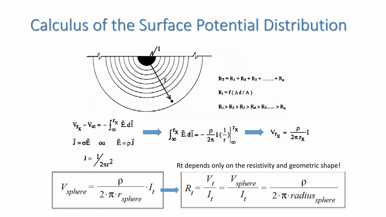
Calculus of the Surface Potential Distribution
Rt depends only on the resistivity and geometric shape!

Ground Resistance Formulas for simple types of electrodes
Semi-Spherical Electrode
Error of 0.01% fromFEA Simulation
Calculated RESULTSRadius of 1m, ρ = 500 Ω.m
Rtot = 79.57 Ω
FEA RESULTSRtot = 74.26 Ω + 5.3 Ω (R Adj.)
Rtot = 79.56 Ω
R Adjust CalculationSize of the modeled soil = 15m radius
R adjust = R of a semi-sphere of 15m of radiusR = 5.3 Ω
All FEA simulations were donewith a soil model of 15m of radius
For any electrode configuration, in a homogeneous soil , after 10-15 times the electrode size, the equipotentialsbehave like if they were produced by a semi-spherical electrode.When the equipotentials start to become semi-spherical, from this point on, the rest of the soil resistance can be computed using the semi-spherical electrode formula, using the radius from this point in the formula.
Error of 0.01% fromFEA Simulation
Current of 1A injected

Ground Resistance Formulas for simple types of electrodes
Horizontal Electrode, Length L, burriedat a distance d from the surface, radius r
Calculated RESULTSL=3m, ρ = 500 Ω.m, d=0.5m, radius of the rod r = 0.008m
Rtot = 186.35 Ω
FEA RESULTSRtot = 172.23Ω + 5.3 Ω (R Adj.)
Rtot = 177.53 Ω
Vertical Electrode, Length L, radius a
Calculated RESULTSL=3m, ρ = 500 Ω.m
radius of the rod a = 0.008mRtot = 167.46 Ω
FEA RESULTSRtot = 160.5 Ω + 5.3 Ω (R Adj.)
Rtot = 165.8 Ω
Error of 4.96% fromFEA Simulation
Error of 1% fromFEA Simulation
For a 100V on the electrode
on the ground
Current of 1A injected

Horizontal ring at distance h from the surface, radius r
Vertical square
Same resistance of a ring with same area, burried at the same distance (d) from the
surface
Ground Resistance Formulas for simple types of electrodes
Calculated RESULTSRadius r=1m, ρ = 500 Ω.m, h=1m,
diam. of cable (d)= 1.6e-2 mRtot = 105.04 Ω
FEA RESULTSRtot = 98.77 Ω + 5.3 Ω (R Adj.)
Rtot = 104.07 Ω
Error of 0.93% fromFEA Simulation
Calculated RESULTSRadius r=1m, ρ = 500 Ω.m, h=2m
Rtot = 93.17 Ω
FEA RESULTSRtot = 92.4 Ω + 5.3 Ω (R Adj.)
Rtot = 97.7 Ω
Error of 4.63% fromFEA Simulation
100V on theelectrode
Vertical ring at distance h from the surface. h is taken from the center of the ring

Ground Resistance Formulas for simple types of electrodes
Sphere (d≈r)
Calculated RESULTSRadius r=1m, ρ = 500 Ω.m, d=2m,
Rtot = 79.57 Ω
FEA RESULTSRtot = 44.26 Ω + 5.3 Ω (R Adj.)
Rtot = 49.56 Ω
Error of 60.55% fromFEA Simulation

Ground Resistance Formulas for simple types of electrodes
Sphere (d>>r)
Calculated RESULTSRadius r=1m, ρ = 500 Ω.m, d=10m,
Rtot = 47.74 Ω
FEA RESULTSRtot = 35.16 Ω + 5.3 Ω (R Adj.)
Rtot = 40.46 Ω
Error of 17.99% fromFEA Simulation
Condition to use the formula: d>>r

Comparative Analysis for Simple electrodes
Electrode ConfigurationRt(Ω)
FormulaFEA Rt(Ω)
SimulationAdjustm.
ΩRt (Ω)
FEA final% error
Horizontal Electrode of Length L, Diameter Dburried at distance h
186.35 172.23 5.3 177.53 4.96%
Vertical Electrode with Length L, Diameter D 167.46 160.5 5.3 165.8 1%
Horizontal Ring at depth R with Radius R 105.04 98.77 5.3 104.07 0.93%
Vertical Ring at depth 2xR with Radius R 93.17 92.4 5.3 97.7 4.63%
Semi-Sphere with Radius R at the surface 79.57 74.26 5.3 79.56 0.01%
Sphere at Depth R with Radius 10xR (use only if d>>>r) 47.74 35.16 5.3 40.46 17.99%
Parameters for the formulas=500 Ω.m , L= 3m, D= 1.6cm, h = 50cm, R= 1m, Size of the modeled soil: 30m of diameter.
The size of the soil implies an automatic adjustment of the FEA resistance. The final simulated resistance must bethe FEA resistance plus 5.3Ω, which is the resistance of a semi-spheric electrode of 15m of radius.
From the results the conclusion is clear. The bigger the surface area , the lesser is the resistance.
Ground Resistance Formulas for multiple electrodes
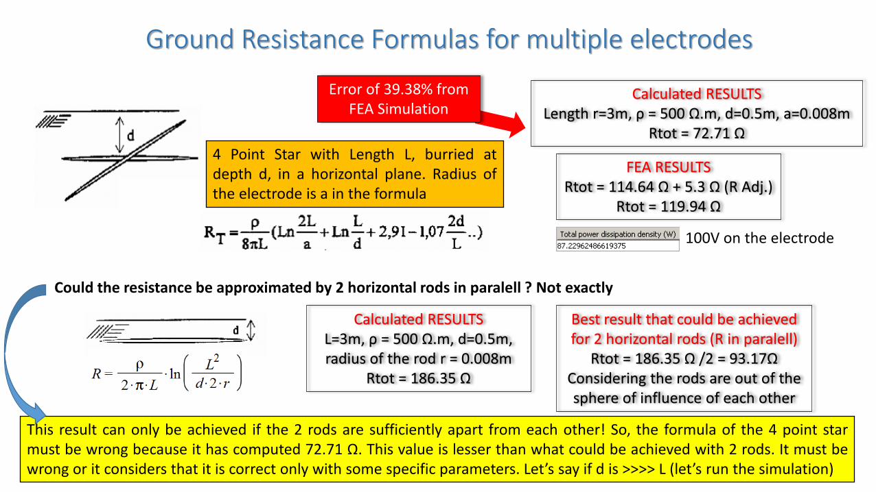
4 Point Star with Length L, burried atdepth d, in a horizontal plane. Radius ofthe electrode is a in the formula
Calculated RESULTSLength r=3m, ρ = 500 Ω.m, d=0.5m, a=0.008m
Rtot = 72.71 Ω
FEA RESULTSRtot = 114.64 Ω + 5.3 Ω (R Adj.)
Rtot = 119.94 Ω
100V on the electrode
Error of 39.38% fromFEA Simulation
Could the resistance be approximated by 2 horizontal rods in paralell ? Not exactly
Calculated RESULTSL=3m, ρ = 500 Ω.m, d=0.5m, radius of the rod r = 0.008m
Rtot = 186.35 Ω
Best result that could be achievedfor 2 horizontal rods (R in paralell)
Rtot = 186.35 Ω /2 = 93.17ΩConsidering the rods are out of thesphere of influence of each other
This result can only be achieved if the 2 rods are sufficiently apart from each other! So, the formula of the 4 point starmust be wrong because it has computed 72.71 Ω. This value is lesser than what could be achieved with 2 rods. It must bewrong or it considers that it is correct only with some specific parameters. Let’s say if d is >>>> L (let’s run the simulation)

Ground Resistance Formulas for multiple electrodes
Simulating the resistance of 2 horizontal rods in parallel, sufficiently apart from each other
Calculated RESULTS for 1 rodL=3m, ρ = 500 Ω.m, d=0.5m, radius of the rod r = 0.008m
Rtot = 186.35 Ω
Best calculated result that could beachieved for 2 horizontal rodsRtot = 186.35 Ω /2 = 93.17Ω
Considering the rods are out of thesphere of influence of each other
FEA RESULTS for 2 RodsRtot = 87.19 Ω + 5.3 Ω (R Adj.)
Rtot = 92.49 Ω
2 rods out of the sphere of influence of each other
So, the 2 rods in parallel agrees
with the simulation. But
again, what about the 4 point star if
d>>>L?
Error of 0.73% fromFEA Simulation
1 rod formula

Ground Resistance Formulas for multiple electrodes
4 Point Star Simulation when d=10m and L=3m
FEA RESULTS for a 4 Point StarRtot = 88.53 Ω + 5.3 Ω (R Adj.)
Rtot = 93.83 Ω
4 Point Star when d>>>L
Calculated RESULTS when d>>>LLength L=3m, ρ = 500 Ω.m, d=10m, a=0.008
Rtot = 7.909 Ω
It is better to approximate the value using two rods in parallel until a better formula for a 4 point star is found. If you know it, please
send it to me.
Interesting result!It almost reached the minimum
allowed value for 2 rods in paralell, on the last slide
(as it should be!)
Error of 91.57% fromFEA Simulation

Ground Resistance Formulas for multiple electrodesConclusion for 4 point star electrode configuration
• Close to the surface, the formula in comparison to FEApresented and error of 39.38%. When d>>>L, the formulapresented an error of 91.57% from FEA
• Prior formulas of simple electrodes achieved close proximity toFEA, within an error of 1%, so a condition was set in order forthem to be used, which is, install the electrodes sufficientlyapart from each other.
• The calculated results and the FEA results for 2 electrodes apartfrom each other differs has only 0.73% of error, thus confirmingthat for simple electrodes, the formulas can be used.
• A FEA analysis of a deep 4 point star (d>>>L) showed that itsvalue differs from the value of 2 electrodes for only 1.44%. As itshould be, because the minimum resistance is to be found werethe 2 horizontal electrodes are set far apart, off the sphere ofinfluence of each other.
• Conclusion: For the parameters chosen, the formula has failedto return a value closed to a simulated one.

Ground Resistance Formulas for multiple electrodes
Calculated RESULTSn=4, ρ = 500 Ω.m, d=0.5m,
a=0.008m,L=0.5mRtot = 217.09 Ω
FEA RESULTS (radius of circle 3.18m)Rtot = 37.72 Ω + 5.3 Ω (R Adj.)
Rtot = 43.02 Ω
Error of 404.6% fromFEA Simulation
N vertical rods with Length L in a circleRestriction: S >> L

Ground Resistance Formulas for multiple electrodes
FEA RESULTS (radius of circle 3.18m)Rtot = 37.72 Ω + 5.3 Ω (R Adj.)
Rtot = 43.02 Ω
N vertical rods with Length L in a circleRestriction: S >> L
Could the final resistance be approximated by the equivalent resistanceof a horizontal circle of 3.18m in parallel with the resistance of 4 rods ?
1 vertical rod of L=0.5m, a=0.008m, ρ = 500 Ω.m
Rrod= 719.61 Ω
4 rods out of the sphere ofinfluence of each other
Rrods= 719.61/4=179.9 Ω
1 horizontal ring, ofh=0.5m, d=1.6e-2m,
ρ = 500 Ω.m , r=3.18mRring = 45 Ω
Calculated RESULTSRtot=(1/Rring+1/Rrods)^-1
Rtot= 35.99 Ω
Error of 16.34% fromFEA Simulation
This is the best value that could ever beachieved in this configuration!
The diference is because of the mutual resistance between the elements
Alternative method for calculation

Ground Resistance Formulas for multiple electrodesConclusion for N vertical rods with Length L in a circle
• Close to the surface, the formula in comparison to FEApresented and error of 404.6%.
• Since S >>> L, and L<< Perimeter of the ring, an alternativemethod was applied. The calculated result achieved a closeproximity to the FEA Simulation within an error of 16.4%
• Conclusion:• For the parameters chosen, the formula has failed to return a
value closed to a simulated one (an alternative method wasprovided within certain restrictions of use)

Ground Resistance Formulas for multiple electrodes
3 Rods in a triangular shape(4 steps to calculation)
1
2
3
4
Calculated RESULTSS=3m, L=3m, d=0.008m,
ρ = 500 Ω.mRt = 73.5 Ω FEA RESULTS (S=3)
Rt = 48.91 Ω+5.3 ΩRt=54.21 Ω
Error of 35.58% fromFEA Simulation
The elements from thisconfiguration are too close in
order to estimate the minimumresistance using paralell
resistances.Let’s try S=50m and L=3

Ground Resistance Formulas for multiple electrodes
3 Rods in a triangular shape(4 steps to calculation)
4
Graph ParametersL=3m, d=0.008m, ρ = 500 Ω.m
FEA Results (S=10)Rt=23.62 Ω+5.3 Ω
Rt=28.92 Ω
Error of111% fromFEA Simulation
But now, the elements are sufficiently apart for us totry an alternative method

Ground Resistance Formulas for multiple electrodes
3 Rods in a triangular shape(4 steps to calculation)
FEA Results (S=10)Rt=23.62 Ω+5.3 Ω
Rt=28.92 ΩAlternative Method using sameparameters, but diferent method
3 vertical rods with L=3m in parallel: Rrods= 55.82 Ω
3 horizontal electrodes with S=10m (S is L in the formula) in parallel:Rhoriz = 75.06 Ω
Final equivalent ResistanceRt=(1/Rrods+1/Rhoriz)^-1
Rt=32.01 Ω
Again, when the elements are close to be off the sphere of influence ofeach other, the global resistance can be approximated by simple
electrodes configuration in paralell
Error of 10.7% from FEA
Simulation

Ground Resistance Formulas for multiple electrodesConclusion for 3 Rods in a triangular shape
• Close to the surface, the formula in comparison to FEApresented and error of 35.58%, considering S=3m andL=3m.
• When S=10m, the error increased to 111%
• In the alternative method, the same calculation wasperformed using well known formulas for simpleelectrodes, and error reduced to 10.7%
• Conclusion:• For the parameters chosen, the formula has failed to return a
value closed to a simulated one (an alternative method wasprovided within certain restrictions of use)

Ground Resistance Formulas for multiple electrodes
Error of 209.1% fromFEA Simulation FEA RESULTS
Rtot = 24.36 + 5.3(Adj)= 29.66Ω
Rods with length L, radius a, burrieddepth d, in line. Restriction: s >> L
Calculated RESULTS for 3 rods in line (n=3) in a soil with 500 Ω.mL=3m (length of the rod), S=6m, a=0.008m, d=0.5m (depth)
Rtot = 91.67 Ω

Ground Resistance Formulas for multiple electrodes
FEA RESULTSRtot = 24.36 + 5.3(Adj)= 29.66Ω
Calculated Results for 3 rods in parallelL=3m, a=0.008m, ρ = 500 Ω.mRtot = 167.46 Ω/3 = 55.82 Ω
Calculated Results for 1 horizontal electrode of 12mL=12m, r=0.008m, d=0.5m, ρ = 500 Ω.m
Rtot = 64.97 Ω
Calculated EquivalentResistance of the configuration
Rt=(1/Rrods+1/Rhor)^-1Rt=30.02 Ω
Error of 1.21% fromFEA Simulation
Alternative method for calculation

Ground Resistance Formulas for multiple electrodesConclusion for 3 Rods in line
• Close to the surface, the formula in comparison to FEApresented and error of 209.1%
• In the alternative method, the same calculation wasperformed using well known formulas for simpleelectrodes, and error reduced to 1.21%
• Conclusion:• For the parameters chosen, the formula has failed to return a
value closed to a simulated one (an alternative method wasprovided within certain restrictions of use)

Ground Resistance Formulas for multiple electrodesSimple Mesh without Rods
FEA SIMULATIONA Potencial of 100V was set for the mesh
Rtot = 37.83 + 5.3(Adj)=43.13 ΩError of 38.48% from
FEA Simulation
Error of 24.87% fromFEA Simulation
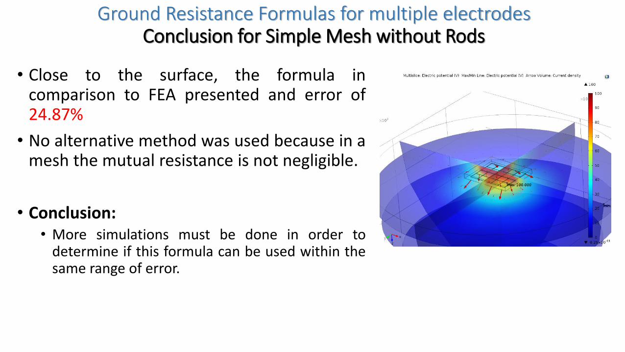
Ground Resistance Formulas for multiple electrodesConclusion for Simple Mesh without Rods
• Close to the surface, the formula incomparison to FEA presented and error of24.87%
• No alternative method was used because in amesh the mutual resistance is not negligible.
• Conclusion:• More simulations must be done in order to
determine if this formula can be used within thesame range of error.

Ground Resistance Formulas for multiple electrodesMesh with Rods
Error of 24.87% fromFEA Simulation
This is theMesh withoutrods formula

Ground Resistance Formulas for multiple electrodes
Mesh with Rods
FEA RESULTSRtot = 20.55 + 5.3(Adj)= 25.83Ω
Error of 102.94% from FEA Simulation
Error of 1% from FEA Simulation
Error of 27% fromFEA Simulation

Ground Resistance Formulas for multiple electrodesConclusion for Simple Mesh with Rods
• Close to the surface, the formula incomparison to FEA presented and error of27% using Visacro formula.
• No alternative method was used because in amesh the mutual resistance is not negligible.
• Conclusion:• More simulations must be done in order to
determine if this formula can be used within thesame range of error.

Final Conclusion
For simple electrodes, all the expressions presented agree with FEA.
For complex electrodes, none of the expressions presented, agree with FEA,
with exception of Mesh without rods, and Mesh with rods using Visacros
expression, that has an error of 27%.
Subsequent studies will determine the precise expression to take account the
mutual resistance between complex electrodes, using FEA as tool to model
this equations.

Thank you for your time
Please, let me know if you have any other expressions for the grounding
electrodes configurations. I will test them and insert them in another
presentation
Any errors you found, incorrect expressions you find, wrong calculations,
suggestions that you want to share, please, leave a comment on my post.
https://de.linkedin.com/pub/camilo-chaves/11/323/a72
Related Documents