Grant agreement No. EIE/06/248/SI2.448127 Intelligent Energy – Europe (IEE) COOPENER Acronym RENDEV Title Reinforcing provision of sustainable ENergy services in Bangladesh and Indonesia for Poverty alleviation and sustainable DEVelopment D4-D5: Solar Home System Toolkits for end users and installers WP2: Development of solar system toolkits for monitoring and evaluation, end-users and solar business development Date of submission: January 2009 Organizations accountable for the deliverables: IT Power Ltd. / Rahimafrooz Solar Date of start of the project: 01 / 01 / 2007 Duration: 36 months Organizations accountable for the deliverables: PlaNet Finance / Pascale Geslain

Welcome message from author
This document is posted to help you gain knowledge. Please leave a comment to let me know what you think about it! Share it to your friends and learn new things together.
Transcript

Grant agreement No. EIE/06/248/SI2.448127
Intelligent Energy – Europe (IEE) COOPENER
Acronym RENDEV
Title Reinforcing provision of sustainable ENergy services in Bangladesh and Indonesia for Poverty alleviation and sustainable DEVelopment
D4-D5: Solar Home System Toolkits for end users and installers
WP2: Development of solar system toolkits for
monitoring and evaluation, end-users and solar business development
Date of submission:
January 2009
Organizations accountable for the deliverables:
IT Power Ltd. / Rahimafrooz Solar
Date of start of the project:
01 / 01 / 2007
Duration:
36 months
Organizations accountable for the deliverables: PlaNet Finance / Pascale Geslain

Development of solar system toolkits for monitoring and evaluation, end-users and solar business development
Authors
Syed Ishtiaque Ahmed, Rahimafrooz Solar (Bangladesh) and Greg Seed and Samantha Cook, IT Power Ltd (UK)
With the collaboration of : Himel Barua, Rahimafrooz Solar (Bangladesh) Mark Draeck, IT Power Ltd, UK Drona Upadhyay, IT Power Ltd, UK
PU Public
x PP Restricted to all participants of the project (including
EU Services) RE Restricted to a special group of participants of the
project (including EU services) CO Confidential, only for members of the consortium
(including services of EU)
Disclaimer: The project "Reinforcing provision of sustainable ENergy services in Bangladesh and Indonesia for Poverty alleviation and sustainable DEVelopment (RENDEV)” is supported by the European Commission through the EIE programme (Grant agreement no. EIE/06/248). The sole responsibility for the content of this report lies with the authors. It does not represent the opinion of the European Communities. The European Commission is not responsible for any use that may be made of the information contained therein.
1
Contents
Paragraph Page No.
1 Scope and objective ............................................................................................................................ 2
2 Solar Home System Case Studies ................................................................................................... 3
3 Introduction to Electricity .................................................................................................................. 5
4 Solar Electricity .................................................................................................................................... 8
5 Multimeters .......................................................................................................................................... 11
6 Design Calculations for SHS Equipment ........................................................................................ 13
7 Indicative Investment, Operation and Maintenance costs ....................................................... 15
8 Installation of a Solar Module .......................................................................................................... 16
9 Charge Controller Installation ......................................................................................................... 18
10 Battery Installation ............................................................................................................................ 22
11 Wiring & Interconnection ................................................................................................................. 28
12 Installation and Comissioning of the Solar Home System ..................................................... 32
13 Testing the Solar Home System (SHS) ........................................................................................... 35
14 Appendix 1 – Dos and Don’ts ......................................................................................................... 39
15 Appendix 2 - Rule of Thumb Equipment Combinations .......................................................... 41

2
1 Scope and objective
This document, written by Rahimafrooz Solar and IT Power Ltd outlines the information and knowledge required to be able to select, install and maintain an off-grid (Battery Storage) Solar Photovoltaic (PV) system. This document is specifically aimed at the Bangladesh community, for retrofitting PV systems onto existing dwellings that do not have easy access to a local source of electicity. Simple purchase and maintenance costs are included and Appendices of ‘Dos and Don’ts’ are provided in Bengali.

3
2 Solar Home System Case Studies
The following case studies outline how solar home systms have been of benefit to their users ;
Mr Abdul Karim, a grocery shop owner in Shoronkhola, Barisal received a solar home system in February 2006 which he pays for through monthly installments. The system has provided a huge boost to his business as he is able to keep his shop open until 10pm, when most of the people in Kalibari bazaar buy their goods. Without the solar home system Abdul wasn’t able to stay open in the evenings as he couldn’t afford to run a diesel generator for
lighting. The longer opening hours have resulted in increased earnings from the shop and an improved living standard for Abdul and his family. Rony and Jony are two sons of a family living in Paikgacha Khulna village, they are studying at the high school and their father who is a farmer wants his sons to train as doctors or engineers. There is no electricity in the village so the family used to use hurricane or wick lamps for lighting in the evenings. This made study difficult due to the poor levels of light and smoke from the lamps. The family now have a solar home system allowing Rony and Jony to study in the evenings with a tube light and they passed their final exams with merit.

4
Mr Mamun is the owner of Hira Medical Store in Bhetkhali Bazaar, Satkhira which is the only source for medicines in the locality as there are not other medical facilities. Mamun used to use a hurricane lamp for lighting in the evenings which made it difficult to find the correct medicine due to the low level of light available. However since have a solar home system installed (paid for in installments) which provides light in the evening Mamun is able to provide medicine quickly and accurately. The provision of electricity has also resulted in a doctor coming to the store in the evenings and prescribing the patients with proper medicine.
5
3 Introduction to Electricity
Electricity is a form of energy. The other forms of energy include Atomic Energy, Heat Energy, Mechanical Energy and Chemical Energy. Electrical energy transfer from one place to another is done through wires. The flow of electrical energy is the flow of electrons.
Voltage
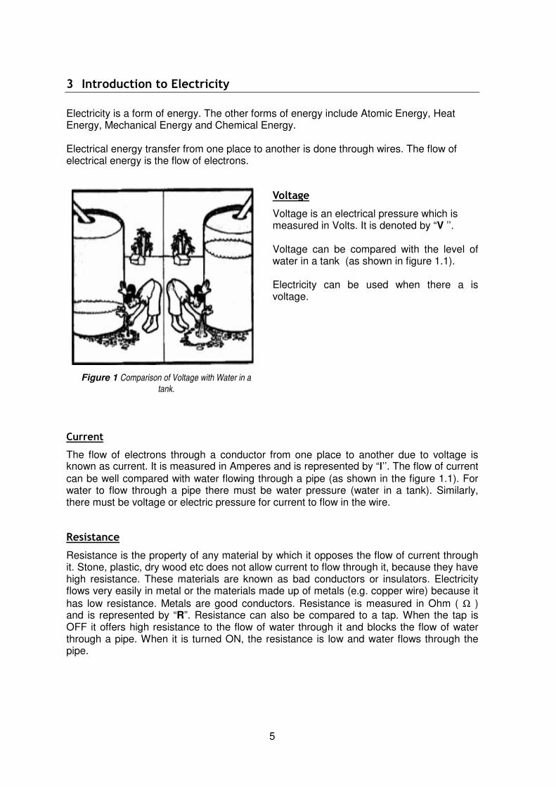
Voltage is an electrical pressure which is measured in Volts. It is denoted by “V ’’. Voltage can be compared with the level of water in a tank (as shown in figure 1.1). Electricity can be used when there a is voltage.
Current
The flow of electrons through a conductor from one place to another due to voltage is known as current. It is measured in Amperes and is represented by “I’’. The flow of current can be well compared with water flowing through a pipe (as shown in the figure 1.1). For water to flow through a pipe there must be water pressure (water in a tank). Similarly, there must be voltage or electric pressure for current to flow in the wire.
Resistance
Resistance is the property of any material by which it opposes the flow of current through it. Stone, plastic, dry wood etc does not allow current to flow through it, because they have high resistance. These materials are known as bad conductors or insulators. Electricity flows very easily in metal or the materials made up of metals (e.g. copper wire) because it
has low resistance. Metals are good conductors. Resistance is measured in Ohm ( Ω ) and is represented by “R”. Resistance can also be compared to a tap. When the tap is OFF it offers high resistance to the flow of water through it and blocks the flow of water through a pipe. When it is turned ON, the resistance is low and water flows through the pipe.
Figure 1 Comparison of Voltage with Water in a
tank.

6
Ohm’s Law
Voltage, Current & Resistance is related to each other by Ohm’s Law as follows (as shown in Fig 1.2: I = V/R Or V = IR Or R = V/I
Types of Electricity
There are two types of electricity: Alternating Current (AC) & Direct Current (DC). In an alternating current circuit there is no permanent positive or negative terminals. An alternating current flows through a wire with quick changes of its value from positive to negative. If this variation is 50 times in 1 second then the AC is said to have a frequency of 50 Hz. Generally, the power supply in our region is AC. Electricity available in our households is 220 V and of the alternating type. Direct current has permanent positive and negative terminals. Direct current flows through a wire when one terminal is positive and the other is always negative. Current available from batteries is always DC type, that is why batteries have positive and negative terminals.
Figure 2 The value of Resistance (R), Voltage (E) &
Current (I) can be easily determined from this figure
Example ( A ): Small batteries used in our daily life are the source of voltage and current. For example some Ssmall batteries have 1.5V written on them. When a battery is connected to a bulb, current flows through the interconnecting wire. The amount of current flowing depends upon the resistance of the bulb. The two terminals of a battery are named as positive (+) and negative (-) terminals and on most batteries + and - are written on the terminals. If the bulb resistance is 1 ohm, then from the above example;
Current I = V/R = 1.5 V / 1 Ω = 1.5 A. Example ( B ):
The battery used in solar electricity is a 12 V battery. If a bulb of 6 Ω is connected with a 12 V battery then the current flow is,
I = V/R = 12 V / 6 Ω = 2 A
7
Sources of Electricity Generation
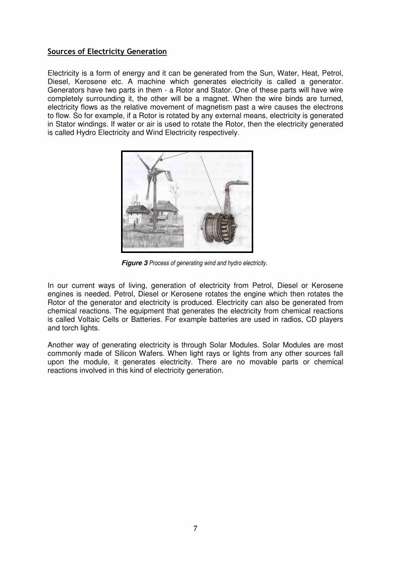
Electricity is a form of energy and it can be generated from the Sun, Water, Heat, Petrol, Diesel, Kerosene etc. A machine which generates electricity is called a generator. Generators have two parts in them - a Rotor and Stator. One of these parts will have wire completely surrounding it, the other will be a magnet. When the wire binds are turned, electricity flows as the relative movement of magnetism past a wire causes the electrons to flow. So for example, if a Rotor is rotated by any external means, electricity is generated in Stator windings. If water or air is used to rotate the Rotor, then the electricity generated is called Hydro Electricity and Wind Electricity respectively. In our current ways of living, generation of electricity from Petrol, Diesel or Kerosene engines is needed. Petrol, Diesel or Kerosene rotates the engine which then rotates the Rotor of the generator and electricity is produced. Electricity can also be generated from chemical reactions. The equipment that generates the electricity from chemical reactions is called Voltaic Cells or Batteries. For example batteries are used in radios, CD players and torch lights. Another way of generating electricity is through Solar Modules. Solar Modules are most commonly made of Silicon Wafers. When light rays or lights from any other sources fall upon the module, it generates electricity. There are no movable parts or chemical reactions involved in this kind of electricity generation.
Figure 3 Process of generating wind and hydro electricity.
8
4 Solar Electricity
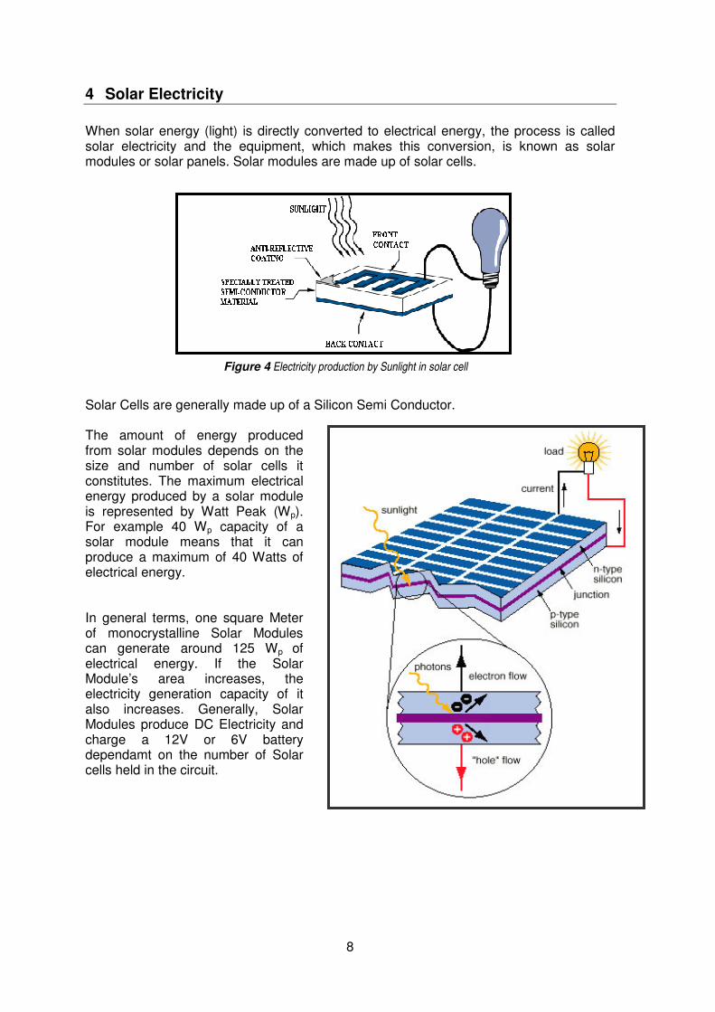
When solar energy (light) is directly converted to electrical energy, the process is called solar electricity and the equipment, which makes this conversion, is known as solar modules or solar panels. Solar modules are made up of solar cells. Solar Cells are generally made up of a Silicon Semi Conductor. The amount of energy produced from solar modules depends on the size and number of solar cells it constitutes. The maximum electrical energy produced by a solar module is represented by Watt Peak (Wp). For example 40 Wp capacity of a solar module means that it can produce a maximum of 40 Watts of electrical energy. In general terms, one square Meter of monocrystalline Solar Modules can generate around 125 Wp of electrical energy. If the Solar Module’s area increases, the electricity generation capacity of it also increases. Generally, Solar Modules produce DC Electricity and charge a 12V or 6V battery dependamt on the number of Solar cells held in the circuit.
Figure 4 Electricity production by Sunlight in solar cell
Figure 1.4.2: Working system of solar panel producing DC current.
9
Solar Module Construction
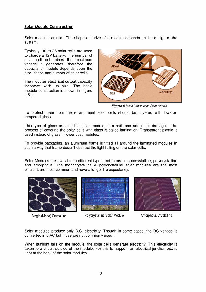
Solar modules are flat. The shape and size of a module depends on the design of the system. Typically, 30 to 36 solar cells are used to charge a 12V battery. The number of solar cell determines the maximum voltage it generates, therefore the capacity of module depends upon the size, shape and number of solar cells. The modules electrical output capacity increases with its size. The basic module construction is shown in figure 1.5.1. To protect them from the environment solar cells should be covered with low-iron tempered glass. This type of glass protects the solar module from hailstone and other damage. The process of covering the solar cells with glass is called lamination. Transparent plastic is used instead of glass in lower cost modules. To provide packaging, an aluminum frame is fitted all around the laminated modules in such a way that frame doesn’t obstruct the light falling on the solar cells. Solar Modules are available in different types and forms : monocrystalline, polycrystalline and amorphous. The monocrystalline & polycrystalline solar modules are the most efficient, are most common and have a longer life expectancy. Solar modules produce only D.C. electricity. Though in some cases, the DC voltage is converted into AC but those are not commonly used. When sunlight falls on the module, the solar cells generate electricity. This electricity is taken to a circuit outside of the module. For this to happen, an electrical junction box is kept at the back of the solar modules.
Figure 5 Basic Construction Solar module.
Single (Mono) Crystalline Polycrystalline Solar Module Amorphous Crystalline

10
Fig 1.6 :Solar Home System
Solar Panel
Charge Controller
FTL Light
Battery
B/W Television
Wires coming out from solar cells and the junction box can not be seen by eye. There is a connector inside the junction box to connect the outside wire and there is a + sign and – sign on it.
Solar Home Systems
Solar Home System (SHS) can be used to power electrical items, including bulbs, DC Fan and TV. Generally one SHS is used for one house. Depending on the panel capacity, 2-6 lights and/or a Black and White TV can be powered. The Electrical energy stored in a battery must always be greater than the electrical energy used in a day. Solar Modules generate electricity only in the daytime. This kind of Electricity can be stored for future use using a battery. So batteries are an essential part of a SHS. A charge controller or charge regulator is used to protect the solar modules and battery. The Charge Controller also protects battery from excessive charging from solar modules. For SHS, the type of generated electricity is D.C. Normally CFL (Compact Fluorescent Light) are used, which are efficient. The lights that are normally used are 12volt DC (to run well with the system). To switch ON and OFF the lights, an electric path should be connected or disconnected. A switch is used for this purpose in SHS. When the switch is closed, the electric circuit is completed and the lights turn ON, when the switch is open the circuit disconnected and lights turn OFF. In SHS a separate switch is used for each lamp. Good wires are needed to bring the electricity from solar modules to battery and from battery to lights or other loads.
11
5 Multimeters
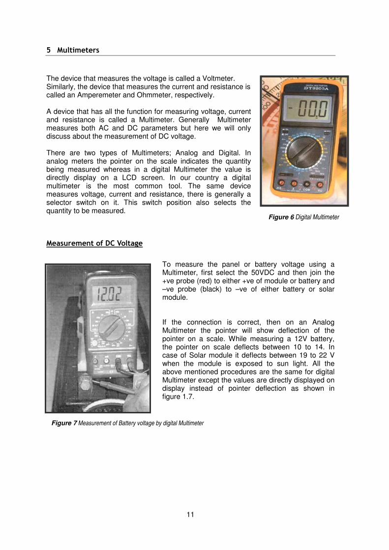
The device that measures the voltage is called a Voltmeter. Similarly, the device that measures the current and resistance is called an Amperemeter and Ohmmeter, respectively. A device that has all the function for measuring voltage, current and resistance is called a Multimeter. Generally Multimeter measures both AC and DC parameters but here we will only discuss about the measurement of DC voltage. There are two types of Multimeters; Analog and Digital. In analog meters the pointer on the scale indicates the quantity being measured whereas in a digital Multimeter the value is directly display on a LCD screen. In our country a digital multimeter is the most common tool. The same device measures voltage, current and resistance, there is generally a selector switch on it. This switch position also selects the quantity to be measured.
Measurement of DC Voltage
To measure the panel or battery voltage using a Multimeter, first select the 50VDC and then join the +ve probe (red) to either +ve of module or battery and –ve probe (black) to –ve of either battery or solar module. If the connection is correct, then on an Analog Multimeter the pointer will show deflection of the pointer on a scale. While measuring a 12V battery, the pointer on scale deflects between 10 to 14. In case of Solar module it deflects between 19 to 22 V when the module is exposed to sun light. All the above mentioned procedures are the same for digital Multimeter except the values are directly displayed on display instead of pointer deflection as shown in figure 1.7.
Figure 6 Digital Multimeter
Figure 7 Measurement of Battery voltage by digital Multimeter

12
Testing a Solar Module
Electrical and Physical testing should be done before installing a solar module. The following care points should be taken when performing the physical check; Check whether the glass on the module is ok Check Solar cells are interconnected to each other Check whether the Aluminum frame is twisted or disfigured Check the junction box Check the the screw inside the junction box If modules are found to have any defects as mentioned in A, B or C , modules need to be replaced. If module have any defects as mentioned in D or E then it can be repaired. For critical testing the module has to be placed in full sunlight its output voltage measured. For this, select the DC voltage more than 20 volts in Multimeter and touch the +ve of solar module with +ve probe and –ve of solar module with –ve probe. If the module is sound and perfect then the multimeter shows voltage between 18v to 22v. If the module is defective then multimeter will not show the above voltage. Then appropriate corrective action has to be taken.
Figure 8 Measuring Panel Voltage

13
6 Design Calculations for SHS Equipment
In order to indentify the correct technology to use with a specific situation we must work through a few calculations. To give us an idea of other similar systems ‘Appendix 2 - Rule of Thumb Equipment Combinations’ of this document incorporates a table from which we can browse. A calculation example is explained below. Let’s consider a home requirement as follows:
Item Quantity Rated
Power(W) Total
Power(W) Operating Hours (hrs)
Estimated Demand (Watt-hr)
Tube Light 5 8 40 4 160
Small DC Fan 2 20 40 2 80
TV 150 1 150 1 150
Total 390
Calculation - Battery Capacity
Since in SHS we use 12 Volts batteries ; Daily load demand from Battery = (Watt-hr/Voltage) = (390/12) Ah = 32.5 Ah
Required Battery Capacity =(demand x No.of daysI)/(Max.DODIIxTcxRf)
III IV =(32.5 x 3) / (0.7 x 0.9 x 1.05 ) = 147.40 Ah
I No. of days used = 3 (Arbitrary Figure) II DOD = Depth of discharge III Tc=Temperature Correction Factor IV Rf = Rate Factor

14
Calculation - Panel Capacity
Using the following table to obtain each panels average current; we can calculate the amount of panels required.
PV Panel Type - Wp Average Current (Imp) -70% of Peak Current -
Amps
40 2.33
50 2.92
60 3.5
75 4.35
Assuming we are to use 75Wp panels in this example, an average output current is 4.35 Amps
Panel Output = Daily Load Demand from Panel
= Imp x Insolation Time x Derating Factor V VI
= 4.35 x 4.3 x 0.9 = 16.83 Ah Using 75Wp panels for this application, we can determine how many panels are required to produce 16.83 Ah Number of 75Wp Panels Required = Daily Load Demand (Ah) / Panel Output (Ah)
= (32.5/16.83) = 2 (Rounded up)
Therefore two 75 Wp panels are required for the example dwelling.
Calculation - Charge Controller Capacity
The maximum electrical current produced by an array is generally taken to be 30% greater than the maximum current produced by the Solar Circuit (Isc). Therefore the rating of the charge controller for the example dwelling is; Charge Controller Rating = Isc * 1.3 VII
(4.75 x 1.3) = 6.175 A
V Imp= Average Current through a Solar panel (eg. 4.35 Amps for 75 Wp panel) VI Derate - lowering the rated electrical capability of electrical apparatus VII For a 75 Wp panel, Isc = 4.75 Amps
15
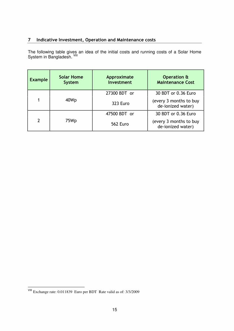
7 Indicative Investment, Operation and Maintenance costs
The following table gives an idea of the initial costs and running costs of a Solar Home System in Bangladesh. VIII
Example Solar Home System
Approximate Investment
Operation & Maintenance Cost
1 40Wp
27300 BDT or 30 BDT or 0.36 Euro
323 Euro (every 3 months to buy
de-ionized water)
2 75Wp
47500 BDT or 30 BDT or 0.36 Euro
562 Euro (every 3 months to buy
de-ionized water)
VIII Exchange rate: 0.011839 Euro per BDT Rate valid as of: 3/3/2009

16
8 Installation of a Solar Module
After selection of the correct parts and successful physical and Electrical test a module is ready for installation.
To fit the module
Modules can be installed directly onto a building or onto a strong pole. First of all, a suitable place to position the module or erect a strong pole needs to be found. The place must have the sunlight falling over it from dawn to dusk (not shaded by trees or other buildings) and also must be out of reach of children or large animals. To locate a suitble place it is useful to discuss with the client and then install the module either directly onto a building or onto a free-standing pole.
The figure on the left shows a module with different support structure for different place of use like for ground application or roof or for a pole mounted installation.
Open the junction box. Connect one end of the cable to the junction box whose other end is connected up to the charge controller. The other end should be of exact length so that it can be taken up to the charge controller via wiring. The following figures show a module with a cable connected to the junction box.
Figure 9 Solar modules with different support structure
For 75Wp & 50Wp (BP-275 and BP-250 models) there is a diagram in the cover of the junction box, the connection should
be made as shown.

17
Use the angle selector to set the panel in 23-degree angle properly with ground in the south direction
After connecting the wires in the junction box, fit the module on the pole/structure. The nut and bolts of the pole/structure should be hand tight. Now locate the south direction with compass. For this put the compass on the ground and draw a line parallel to the pointer of compass. Now rotate the solar module and put in parallel with the drawn line and tighten the nut and bolts of the pole, with a tool. Lastly, locate the bolts which join the module’s frame and support structure, and loosen them, then tilt the module 23 degrees from the horizontal with the help of the angle selector (as shown below) and then tighten the bolts.
Figure 10 Junction boxes with wires connected in it
For 30, 40, 50Wp (Model SX-30U, 40U, 50U models) the connection has to be made as in the diagram in the sticker below the panel.

18
9 Charge Controller Installation
- Objective: After completion of this lesson, the SHS trainee should be able to install a charge controller/regulator in the correct place. - Required materials: 1) Different types of charge controller 2) Hand tools set (with drill machine) 3) Nail screws
Background Information - Charge controller
The main function of the charge controller is to protect the battery and solar module. Also it acts as a junction box for the wires going to the battery and lights. The battery shouldn’t be charged more than its capacity and also the discharge shouldn’t be more than 60% of its capacity. If this is not followed the battery life will be reduced. So the Charge Controller continuously monitors the battery, and charge input. If a battery is overcharged, the chemicals in the battery will boil. Evaporating the water and the acidity will increase inside the battery, which melts the plates of the battery, ultimately reducing the battery’s life. To prevent this phenomenon the Charge Controller monitors the battery charging state and if the battery is fully charged, the charge controller blocks the flow of charge from the panel to the battery. Similarly in the evenings which the loads have drawn the maxiumum available charge from the battery the charge controller cuts of the loads connect to the battery to prevent the battery from being drained. There are terminals for the electrical loads, solar modules and batteries in a Charge Controller. The following figures show the different sections of charge controller:

19
Figure 11 Charge controllers with terminals
Indicating LED
Panel Connection Battery
Connection Load
Connection
Holes for Mounting
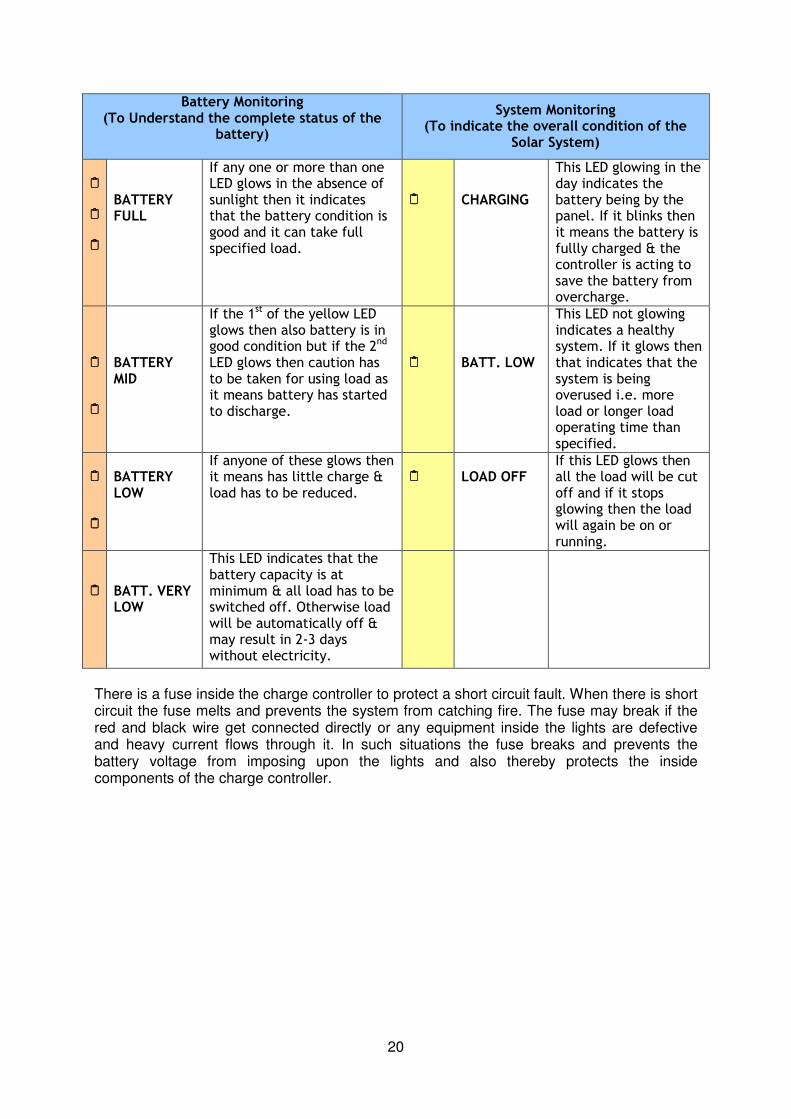
There are LED indicators to show the charge stored in the battery. Generally green LEDs indicate the charge in the battery is enough to use in loads. The red LED indicates the state of charge whne it’s below a good level. Similarly there are other LEDs to indicate different charging states. The following table explains the different LEDs and their meanings.
20
Battery Monitoring (To Understand the complete status of the
battery)
System Monitoring (To indicate the overall condition of the
Solar System)
BATTERY FULL
If any one or more than one LED glows in the absence of sunlight then it indicates that the battery condition is good and it can take full specified load.
CHARGING
This LED glowing in the day indicates the battery being by the panel. If it blinks then it means the battery is fullly charged & the controller is acting to save the battery from overcharge.
BATTERY MID
If the 1st of the yellow LED
glows then also battery is in good condition but if the 2
nd
LED glows then caution has to be taken for using load as it means battery has started to discharge.
BATT. LOW
This LED not glowing indicates a healthy system. If it glows then that indicates that the system is being overused i.e. more load or longer load operating time than specified.
BATTERY LOW
If anyone of these glows then it means has little charge & load has to be reduced.
LOAD OFF If this LED glows then all the load will be cut off and if it stops glowing then the load will again be on or running.
BATT. VERY LOW
This LED indicates that the battery capacity is at minimum & all load has to be switched off. Otherwise load will be automatically off & may result in 2-3 days without electricity.
There is a fuse inside the charge controller to protect a short circuit fault. When there is short circuit the fuse melts and prevents the system from catching fire. The fuse may break if the red and black wire get connected directly or any equipment inside the lights are defective and heavy current flows through it. In such situations the fuse breaks and prevents the battery voltage from imposing upon the lights and also thereby protects the inside components of the charge controller.

21
Installation of Charge controller
Before installing the charge controller, it is good to find out the proper place to install it. The charge controller should be installed in such a place where sun light and rain doesn’t fall, where it is easily seen, out of reach of children and preferebly mounted on a wall (card board or wooden board is preferred). The distance between the charge controller and battery should be kept at a minimum. Considering all these factors, the proper place for charge controller should be chosen. It is useful to take suggestions from the SHS users too. There are holes at each side of the charge controller to screw it to the wall. Steps to follow :
⇒ At the place where controller has to be installed, put the Charge Controller over it, make a mark (with a pencil) in the screw holes of the Controller. and remove the controller.
⇒ Make holes by hand drill at those marked points.
⇒ Insert the Nylon grip inside the holes with the help of hammer.
⇒ Put up the charge controller and screw it in the grip until it feels secure. Try to push it out gently. If it comes out, change the place for this Controller.
⇒ Connect the wires to the Charge Controller. When connecting the wires from the solar module to charge controller, the module should be covered with cloth (if exposed to the sunlight).
⇒ After the completion of wire connection the cloth can be removed. (Doing this will protect the charge controller).
22
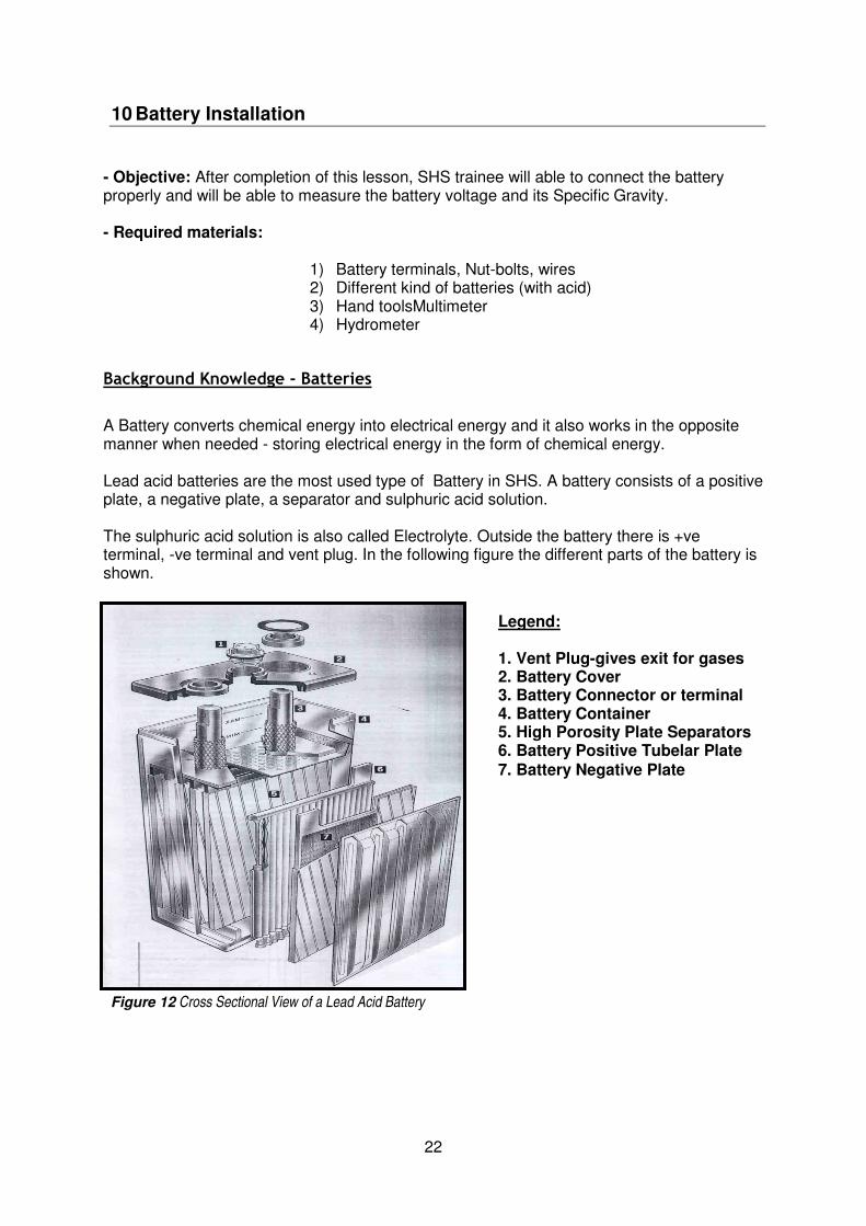
Figure 12 Cross Sectional View of a Lead Acid Battery
10 Battery Installation
- Objective: After completion of this lesson, SHS trainee will able to connect the battery properly and will be able to measure the battery voltage and its Specific Gravity. - Required materials:
1) Battery terminals, Nut-bolts, wires 2) Different kind of batteries (with acid) 3) Hand toolsMultimeter 4) Hydrometer
Background Knowledge - Batteries
A Battery converts chemical energy into electrical energy and it also works in the opposite manner when needed - storing electrical energy in the form of chemical energy. Lead acid batteries are the most used type of Battery in SHS. A battery consists of a positive plate, a negative plate, a separator and sulphuric acid solution. The sulphuric acid solution is also called Electrolyte. Outside the battery there is +ve terminal, -ve terminal and vent plug. In the following figure the different parts of the battery is shown.
Legend: 1. Vent Plug-gives exit for gases 2. Battery Cover 3. Battery Connector or terminal 4. Battery Container 5. High Porosity Plate Separators 6. Battery Positive Tubelar Plate 7. Battery Negative Plate

23
Electrical energy produced by solar panels during the day time is stored in the battery. This process of storing electrical energy in a battery is called charging. At night, the stored energy is used to run the connected load. This process of using the stored energy from battery is called discharging. Generally, it is recommended to use 20% of the energy stored in a battery. If more is used then a battery’s life will decrease. If only 20% is used and same amount is stored back in the battery daily then an ordinary battery may last for several years. A battery where 80% of energy can be used at a time is called Deep Cycle Battery. If 20% of the total capacity is used from deep cycle battery and charging it daily to its full capacity then this kind of battery may last for 10 years or even more. It is not good practice to keep a battery unused for more than a month after filling the acid water or electrolyte. If the battery is to be kept unused for more than one month, it is necessary to charge the battery once a month due to its own discharging nature. Batteries have a definite life. When the battery life finishes, it charges quickly and discharges even more quickly and shuts OFF all the loads. In this condition a battery needs repairing or full replacement. Old batteries can be put in use after recycling. So it is best not to spill the acid.
Capacity of batteries
The capacity of battery is put in terms of ampere rate, and is expressed in Ampere-hour (AH). And also for different charging processes, the charging current varies with AH rating, eg. for a Boost Charge Current = Capacity/10 or Equalizing Charge = Capacity/20. For example, 100AH battery can supply a 1 amp current for 100 hours, or can supply a 10 amp. current for 10 hrs. or if a 70AH battery is fully charged then it can not store more energy in it. But if it is previously used and its capacity is reduced say to 50AH, then it can be charged to 70AH.
Physical Testing of batteries
Prior to physical tests, a battery should be cleaned with a dry cloth to remove the dust from it. The battery water level should be checked every 3 months. If the water level falls below the lower level then the water level should be topped up by removing the cap and pouring in battery water, distilled water or de-ionized water up to the upper level. Thereafter all caps should be tightened. While filling with water, the level of water should be checked every second, so that it can be carefully made to reach the upper line. If any green or white powder is seen on the battery terminal, it should be removed by cloth soaked either in soda water or hot water. Once done, the battery terminals should be sealed with Vaseline or petroleum jelly. The Battery container should be checked for any cracks. If found or any possibility then it should be replaced with new one.

24
Battery Voltage and its measurement
When measuring the voltage of a battery, a value around 12.6 volts indicates that more than 90% of its AH is stored. If battery voltage is less than 11.5 Volts then the stored energy is 50% of its rated capacity. This way the probability of battery damage will be high when the battery voltage drops below 11.5 V. If battery voltage is less than 11.0V then the battery is considered to be fully damaged. To measure the battery voltage select 20 VDC range in digital multimeter. Now connect the (red) +ve probe of multimeter to battery +ve terminal and (black) –ve probe of the multimeter to the battery –ve terminal. The value displayed in LCD display screen on the multimeter will show the battery voltage. The procedure is similar for analog multimeters, except the result is through index deflection.
Hydrometer and Its Use to Measure Specific Gravity
The battery is manufactured dry charged, and can be brought into operation quickly after addition of acid. Before charging from sunlight, sulphuric acid of 1.240 grade is added to the battery container. A funnel is recommended to use when pouring the acid or water inside the battery. After the addition of acid and water hands should be washed with clean water. There are two lines on a battery container, written as upper level and lower level. When filling the acid up for the first time the level of acid should be higher than the lower level and should not exceed upper level. After that it is hardly needed to fill with acid. But due to continuous charging and discharging battery acid level may decrease down to lower level after 2-3 months. Care should be taken that the acid level doesn’t fall below lower level. If it happens, then water (distilled) should be added instantly untill the level reaches the upper level. The battery plate should be well dipped in acid when seen from above after the removal of caps. With the help of acid’s specific gravity, the stored energy in the battery can be more precisely known. The equipment used in measuring the specific gravity is called Hydrometer.
25
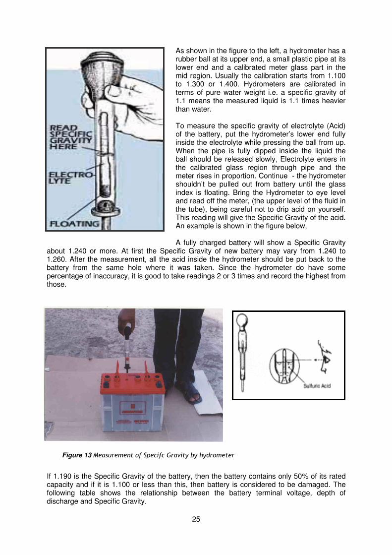
Figure 13 Measurement of Specifc Gravity by hydrometer
As shown in the figure to the left, a hydrometer has a rubber ball at its upper end, a small plastic pipe at its lower end and a calibrated meter glass part in the mid region. Usually the calibration starts from 1.100 to 1.300 or 1.400. Hydrometers are calibrated in terms of pure water weight i.e. a specific gravity of 1.1 means the measured liquid is 1.1 times heavier than water. To measure the specific gravity of electrolyte (Acid) of the battery, put the hydrometer’s lower end fully inside the electrolyte while pressing the ball from up. When the pipe is fully dipped inside the liquid the ball should be released slowly, Electrolyte enters in the calibrated glass region through pipe and the meter rises in proportion. Continue - the hydrometer shouldn’t be pulled out from battery until the glass index is floating. Bring the Hydrometer to eye level and read off the meter, (the upper level of the fluid in the tube), being careful not to drip acid on yourself. This reading will give the Specific Gravity of the acid. An example is shown in the figure below, A fully charged battery will show a Specific Gravity
about 1.240 or more. At first the Specific Gravity of new battery may vary from 1.240 to 1.260. After the measurement, all the acid inside the hydrometer should be put back to the battery from the same hole where it was taken. Since the hydrometer do have some percentage of inaccuracy, it is good to take readings 2 or 3 times and record the highest from those.
If 1.190 is the Specific Gravity of the battery, then the battery contains only 50% of its rated capacity and if it is 1.100 or less than this, then battery is considered to be damaged. The following table shows the relationship between the battery terminal voltage, depth of discharge and Specific Gravity.

26
Diluted sulphuric acid is inside the battery. There are around 6 caps on top of the battery. The water level inside the battery decreases as the battery charges and discharges. When the level of water passes the lower level, de-ionized water should be added from all the six holes untill the water level reaches the upper level. The water level must be at the same level in every cell. The water level should be checked every 3 to 4 months. Acid used in a battery is harmful - if by any chance acid gets in contact with your hands, wash them with water immediatly. Any contact of parts of the body with acid is dangerous. If acid gets into the eyes, blindness may result, so never touch eyes with acid contaminated hands. Keep children away when adding acid or water to the battery. Due to there being water inside the battery, it can freeze if in low temperature climates which will cause the battery to stop working. So it is recommended not to put the battery where temperature is below than 5 degree centigrade. In cold climates, it is best to keep the battery inside a room.
Depth of Discharge
Battery Voltage (Open Circuit)
Battery Load Voltage (During the Load Running
Condition)
Specific Gravity
0 % 12.60 V 12.40 V 1.250
20 % 12.50 V 12.15 V 1.230
40 % 12.40 V 12.05 V 1.220
45 % 12.25 V 12.00 V 1.200
50 % 12.10 V 11.90 V
(LVD-Low Voltage Disconnect) 1.185
60 % 12.00 V 11.50 V 1.170
80 % 11.90 V 11.20 V 1.160
100 % 11.35 V <11.00 V Not Applicable

27
Battery Installation and Storage Batteries should be kept in open space where there is no sunlight, and out of the each of children. Keep the battery in an upright position. It is not necessary to cover the battery. It is not good to short the terminals by placing anything metalic accross them as this causes the battery to get very hot, and eventually boil. After checking the battery voltage and its Specific Gravity, connect the battery red +ve wire to the charge controller’s +ve terminal and battery’s black –ve wire to charge controller’s –ve terminal and bolt it up tightly. After positioning and working on a battery, ensure the screws are tight, and Vaseline or petroleum jelly has been put on the battery terminals to prevent corrosion. Hydrogen gas emerges during charging and discharging, so it is strictly prohibited to smoke or light a match around the battery, and not to keep it where there is high risk of fire.
Battery Life Cycle & Depth of Discharge
The total process of discharging the battery and again recharging is known as a Battery Cycle. The lifetime of the battery depends on the number of Battery Cycles. The number of Battery Cycles depends on the depth of discharge (DOD) of the battery. The relation of the lifetime with the DOD of solar battery is shown below.
Depth of Discharge-DOD-%
No. Of Battery Life Cycles produced
Battery life time taking one battery cycle in one day throughout the year
80% 1200 1200/365 = 3.28 Year
50% 2400 2400/365 = 6.57 Year
20% 3600 3600/365 = 9.86 Year
Here we see the less the DOD percentage the more the battery cycle number & more the battery life time. We usually discharge ~15% of the battery capacity each day with an autonomy of 3 days resulting in maximum ~45% discharge of the battery.

28
Figure 14 Bare and Insulated Wires
Insulator This is a 70/0.0076 cable, which has 70 Nos. of copper wire each with a diameter of 0.0076 inch in both red &
black part
This is a 40/0.0076 cable, which has 40 Nos. of copper wire each with a diameter
of 0.0076 inch in both red & black part
11 Wiring & Interconnection
- Objective: After completion of this lesson, SHS trainee will able to do the wiring, connect the switches, junction boxes and lights used in SHS. - Required materials:
a) Hand tool set (hand drill) b) Junction Box, switch and lights c) Wires d) Clip and nails e) Plumb line.
Type and size of wire in Solar Home Systems (SHS)
Since DC voltage is used in SHS, there is +ve and –ve terminal for which red and black wires are used respectively. The wire used in SHS is insulated. The outer layer of this wire is made up of PVC insulator, inside which there is a naked wire. The main function of the insulator is to protect short-circuiting between the wires. The use of thicker wire is good in practice and also the resistance losses is less in thicker wire. But thicker wire costs are higher. The current capacity and distance of wire determines the proper size of wire. The wire used in our SHS system has been shown in the diagram here.
29
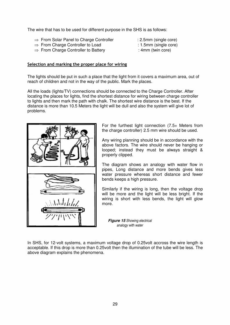
Figure 15 Showing electrical
analogy with water
The wire that has to be used for different purpose in the SHS is as follows:
⇒ From Solar Panel to Charge Controller : 2.5mm (single core)
⇒ From Charge Controller to Load : 1.5mm (single core)
⇒ From Charge Controller to Battery : 4mm (twin core)
Selection and marking the proper place for wiring
The lights should be put in such a place that the light from it covers a maximum area, out of reach of children and not in the way of the public. Mark the places. All the loads (lights/TV) connections should be connected to the Charge Controller. After locating the places for lights, find the shortest distance for wiring between charge controller to lights and then mark the path with chalk. The shortest wire distance is the best. If the distance is more than 10.5 Meters the light will be dull and also the system will give lot of problems.
For the furthest light connection (7.5+ Meters from the charge controller) 2.5 mm wire should be used. Any wiring planning should be in accordance with the above factors. The wire should never be hanging or looped; instead they must be always straight & properly clipped. The diagram shows an analogy with water flow in pipes, Long distance and more bends gives less water pressure whereas short distance and fewer bends keeps a high pressure. Similarly if the wiring is long, then the voltage drop will be more and the light will be less bright. If the wiring is short with less bends, the light will glow more.
In SHS, for 12-volt systems, a maximum voltage drop of 0.25volt accross the wire length is acceptable. If this drop is more than 0.25volt then the illumination of the tube will be less. The above diagram explains the phenomena.

30
Figure 16 Fluorescent Light with tube, Frame & Inverter
Hole in the frame
Inverter & its Circuit
Tube
Frame
Wiring:
After selecting of place for lights, wiring of switches can be started. The following tools and materials are required for wiring. Tools: Wire cutter used to cut the wire.
Wire stripper used to take off the insulator.
Flat screwdriver used to screw in the nuts.
Star (Crosshead) Screwdriver used to screw the charge controller’s nuts.
Hammer Medium used to hammer wiring clips
Hand Drill used to make a hole on the wood.
Combination Plier used to cut the wires, bring out the nails etc.
Crimping Tool used to screw cable shoes in wire.
Multimeter used as testing equipment.
During wiring put all the above tools in your bag or a half jacket with multiple pockets. With this there won’t be any chance of losing it and is readily available when needed. Materials Clips, which can accommodate two wires for Solar Module- charge controller, charge controller-battery. Clips that accommodate two wires for the lights. Small nails to insert the clip. Screws of different sizes. Red and black insulation tape. Torch Light.
31
Start laying down the wires. It is good practice not to cut the wire before measuring the required length or laying it down because sometimes it may be too short, or too long. To prevent this lay the wire along the position where it twill be fixed, section by section, allowing the wire to droop either side of yourself, ensure the wire is of sufficient length and then cut accurately. This way, any extra or unwanted amount of wires can be avoided. Method There are usually two slot shaped holes at the both ends of the light’s frame. First place the light in the desired place (wall, bamboo etc) and mark the hole with a pencil etc. Then based on the mounting place apply iron nails or wooden screw as applicable (in a wooden wall use wooden screw, in case of wall made of soil place the light in the supporting bamboo or wood and nail it). There are (+) and (-) terminals on the lights for the wires coming from the junction box. Connect the red wire coming from the junction box (or the wire connected to +ve terminal of the battery) to the +ve terminal of the light and the black wire coming from junction box (or the wire connected to the –ve terminal of the battery) to the –ve terminal of the lights. If you reverse the connection intentionally or mistakenly then the light may not work and it may be damaged. So be careful when connecting the wires to the lights. To connect the wire pull off ½ inch of insulator, as mentioned below, loosen the electrical screws above the terminals of the light. Insert the wires in the hole and look whether the naked part is pertruding out of the hole or not. If it is, then proceed to cut the length equal to the pertruding part from the top of the wire and then insert it again, screw it tightly and check the security of it by pulling the wires gently.
Installation & Wiring of a Switch:
The type of switches that are used in the SHS are permanently mounted on the wall and are called Wall Mounted Switches. Like the light frame these switches also have to be nailed or screwed to appropriate places. The switch should always be linked to the red wire or positive wire. The switch should be mounted in the place where marked previously.
- Cut at the middle of the red loop with the help of cutter then pull out ½ inch of its insulator
- To take off the insulation use the Wire Stripper and be careful that you do not cut any strands of the wire inside or make any kind of damage to it
- Then twist the strands 2-3 times after pulling out the insulator - Unscrew the nuts above the hole where the wire is to connect inside the switch - Insert the wire in the two holes (one by one) and then tighten the nuts above it firmly
and check the firmness by pulling gently on the wires. The switch has to be of good quality or it may cause high voltage drop. Extra and unnecessary switching should be avoided.

32
12 Installation and Comissioning of the Solar Home System
- Objective: After completion of this lesson, the SHS trainee will able to install all the components of SHS together and can put SHS in operation. - Required materials: All the components of a SHS Hand tool set (hand drill) Multimeter
Connecting wires to the controller
After installing the main components of Solar Home system such as the solar module, charge controller, battery and lights the followings procedures should be followed to connect them:
- Connect the wires from charge controller to the battery - Look at the indicator on the controller to ensure the battery is connected to charge
controller and is working - Connect the wires from the solar module to the controller - Look at the LEDs on the controller to ensuring the module is charging the battery. Connect the loads to the controller.
Connecting wire to the battery from controller
Usually 6mm – 10mm cable is used for the wires connecting the charge controller and battery. Generally a round cable shoe/lug is attached to the wire at the battery and pin clip is attached at the charge controller end. This connection should be performed with great care as any mistake in this connection can damage the controller. First find the +ve terminal on the battery. There should be a + and – marked beside each terminal of the battery.
- Connect one cable with the positive terminal of the battery by fixing it’s cable lug (round lug) with nut-bolt (properly tighten)
- Connect the pin clip in the charge controller where the Battery ’+’ is marked and tighten it with the help of the screwdriver. Similarly the negative terminal also has to be connected
- After this connection, check the LED on the controller shows the battery Charge State. If the LED is lit, the connection of the charge controller and battery is correct . If the Led doesn’t light properly then the wire connection between the controller and battery should be check once again
- After completion of this wiring put some petroleum jelly or grease at the battery terminals. If after correct connection the LED in controller doesn’t light properly, there may be a problem with either the battery or the Controller. In this case first replace the controller and if the fault still persists then replace the battery.

33
Connecting a wire to the controller from the Module
Before connecting the wires from module to the controller, measure the voltage at the wire end;
- Select 50 VDC in Multi meter and then put the red probe in + and black probe in – in charge controller
- Now pull off 1/2 inch of the insulation of the wire from module - Touch the red probe with naked part of the red wire and black probe with naked part
of the black wire from the module using both hands. During this be careful that the red wire and black wire from module doesn’t touch each other
- Now if the module is perfect and is placed in the sunlight then the multi meter will show the voltage above 12volt (Usually in the range of 13-16 volt).
If the multi meter shows negative values then the connection is reversed. If this happens then check the junction box of the solar module for the proper connection. If everything is correct then put a cloth accross the panel, this covering will protect the panel during the connection of the wires in the controller since the panel doesn’t produce electricity when covered.
- Insert the red wire from module to the hole marked as + on the controller with the module sign above it and;
- Insert black wire from module to the hole marked as – on the controller with the module sign above it;
- Tighten the screws above both holes, after the connection of the wires, check the tightness by gentle pulling.
If the connection is correct then the LED which shows the charging state of battery from the module should be lit.

34
Connecting wires to the controller from the loads
- Switch off each light before wiring - Thereafter pull off the ½ inch of the insulation (from the wires coming from the loads) - Now take the red wire from the load and insert it in the controller terminal marked as
Load + sign - Tighten the screw of the terminal - Be very careful when connecting the black wire, because if the wires from the lights
are in contact with each other by any chance then there will be a big spark (a short circuit) when connecting the black wire to the controller and the fuse inside the controller may be blown. So first: Touch the – terminal of the controller with the black wire from the junction box for the fraction of second and look for any sparks. If there is a spark then find out the cause producing it
- To check for short circuits; disconnect the red wire from the controller. Now select
X1Ω on the multimeter and then put the red probe in v/Ω or the (+) port and black probe in (-) or COM (COM is written in Digital Multimeter) port. If a digital multimeter is used then it shows 1 or OL.
- After this, join the two probes in this condition to the analog meter and it will show its
full deflection and the needle will rest on OΩ and (a digital meter will show O (or 1-2)). These procedures ensure that the multimeter is working well. Now join the red probe with the red wire from junction box and black probe with black wire from junction box. If there is no short circuit fault in the wiring then analog meter will show
∞Ω and digital meter will show 1 or OL. This is the right condition. If the multimeter
shows different than ∞Ω, 1 or OL then the switches and the short circuit fault should
be checked. Until the meters show∞Ω, 1 or OL the black wire shouldn’t be connected to the controller until this has been rectified
- Now take the black wire from the load and insert it in the controller terminal marked as Load-sign
- Tighten the screw of the terminal.

35
Figure 17 Showing Panel- Voltage checks
13 Testing the Solar Home System (SHS)
- Objective: After completion of this lesson, the SHS trainee will able to perform the basic test of SHS. Procedures:
- Take the verbal or written instruction from the SHS user - Collect the required tools and equipment - Measure the voltage at the solar panel, battery and load terminal of the controller - Test the ON/OFF switch of the charge controller - Check all the LED indicators at controller - Check the wires connected to the charge controller terminals for proper and correct
connection and its tightness - Test the tightness ofthe battery terminal connections and ensure the petroleum jelly
or grease is at its terminals - Test each light and respective switches for the proper operation - Test whether the voltage is at power socket - Check the stiffness of the pole and the security of the module connection to the pole.
Required materials: Multimeter. Hand tool set (hand drill). Paper and pen or pencil.
Measuring voltage at a solar module, battery and load terminal:
At the end of Section 12 all the installation should be completed. Now the installed system should be checked and tested to ensure perfect operation.
- First select DC 50 on the Multimeter
- Put the red wire of the probe in (+) or VΩ and black wire of the probe in to the COM port
- Join the red probe with the Modules (+) terminal and black probe with the modules (-) terminal to the charge controller. (During day time a reading of around 13-16volt will be shown)
- Make sure the conducting part of the probes don’t touch each other. Then remember the position where the needle stays (or the reading display in the case of digital meter)
- Now note down the reading on the paper.
Next, measure the voltage at the load terminal in the charge controller and note it down on the paper. This voltage is called load voltage and it goes to all the lights.

36
Figure 6.1.2: Showing the Battery Voltage Figure 6.1.3: Showing the Load Voltage
At full and sound working condition the load voltage is same as battery voltage or is less by 0.1-0.4 volt. In a similar manner note the voltage at the battery terminal in the charge controller. Generally the voltage from the solar module (at full daylight) is greater than the voltage at the battery by 0.7-1 volt (as previously mentioned, the voltage at battery should be 12 to 14 V at good condition).
Testing LED indicators of the charge controller
Generally, the batteries used in SHS are new and are in the state of full charge, There are three LEDs to check the state of the battery in the controller when the battery is fully charged. So as soon as the new battery’s terminals are connected to the charge controller one of these must glow. Otherwise the battery has to be checked manually through use of a multimeter & hydrometer. If the LED is out and the battery is good, then the Charge controller has to be changed. If the battery is not fully charged then it should be fully charged before connecting to the new system.
- First connect one cable with the positive terminal of the battery by fixing it’s cable lug (round lug) with nut-bolt (properly tighten)
- Connect the pin clip in the charge controller where the Battery ’+’ is marked and tighten it with the help of the screwdriver. Similarly the negative terminal also has to be connected
- After this connection, check the LED on the controller shows the battery Charge State. If the LED is lit, the connection of the charge controller and battery is correct. If the Led doesn’t light properly then the wire connection between the controller and battery should be checked once again. After completion of this wiring put some petroleum jelly or grease at the battery terminals.
37
If after connecting the LED in controller doesn’t light properly, the reason may be a problem with either the battery or the Controller. In this case first replace the controller and if the fault still persists then replace the battery. Also in the nightime when there is no sunlight the charging LED should not glow.
Testing wire connections in the controller
Whilst performing this test pull gently on all of the wires connected to the controller (one by one). If the naked part of the wire or the wire itself comes out then connect the wires again and tighten the screws with the wire’s naked part fully inserted inside the hole. Now pull the wires again and if it comes out again then assume that the connector is damaged. You should also look if during the wire pulling the LED indication in the charge controller changes or not. If any change of indication happens due to wire pulling then there might be some loose connection inside the controller and it may have to be checked and changed if necessary.
Testing the battery fitting
If the cable shoes at the battery terminals are not connected properly then there will be a spark. Ultimately the wire may get disconnected from the battery or there will be resistance in between the cable shoe, and battery terminal. If this happens then the battery will not be charged efficiently or can’t be charged and the battery will eventually be damaged. So this connection should be checked thoroughly. Try to rotate the cable shoe with bare hands and if it rotates then loosen the bolts and tighten it again. Similarly, check the connection between the cable shoe and wire. To do this, pull the wire connected to the cable shoe with bare hands, and if the wire comes loose from the Crimp or the naked portion comes out then the connection is considered to be imperfect. Otherwise the connection is perfect.
- Ensure petroleum jelly or grease is on the terminals. Testing for First connect one cable with the positive terminal of the battery by fixing it’s cable lug (round lug) with nut-bolt (properly tighten)
- Connect the pin clip in the charge controller where the Battery ’+’ is marked and tighten it with the help of the screwdriver. Similarly the negative terminal also has to be connected
- After this connection, check the LED on the controller shows the battery Charge State. If the LED is lit, the connection of the charge controller and battery is correct .If the Led doesn’t light properly then the wire connection between the controller and battery should be check once again
- After completion of this wiring put some petroleum jelly or grease at the battery terminals
- If after correct connection the LED in controller doesn’t light properly, there may be a problem with either the battery or the Controller. In this case first replace the controller and if the fault still persists then replace the battery.
- First connect one cable with the positive terminal of the battery by fixing it’s cable lug
(round lug) with nut-bolt (properly tighten)
38
- Connect the pin clip in the charge controller where the Battery ’+’ is marked and tighten it with the help of the screwdriver. Similarly the negative terminal also has to be connected
- After this connection, check the LED on the controller shows the battery Charge State. If the LED is lit, the connection of the charge controller and battery is correct .If the Led doesn’t light properly then the wire connection between the controller and battery should be check once again
- After completion of this wiring put some petroleum jelly or grease at the battery terminals.
If after correct connection the LED in controller doesn’t light properly, the reason may be a problem with either the battery or the Controller. In this case first replace the controller and if the fault still persists then replace the battery.
Operation of switches and lights
It is necessary to test all the lights after you put the bulbs into each light fitting. For this :
- Turn ON and OFF each switch one by one. When the switch is turned ON, the light should come on a couple of second afterwards
- If the light doesn’t illuminate or blinks or the two ends of the light become red after turning the switch ON then turn OFF the respective switch
- If the lights remains in lit condition or in OFF condition even after turning the switch ON and OFF then it is assumed that the switch or the light is not working properly
- Ideally the voltage difference between the charge controller’s output point (load output) and the inverter’s input point has to be checked with a multimeter. The controllers voltage will be marginally higher, the difference must not exceed the permitted voltage drop value as this may cause problems in future
- Testing the erection of the pole and the installation of module Ensure all the nuts and bolts which connect the module to the support structure are tight once again
- Try to rotate the structure. If it rotates then tighten the clamp that joins the structure and pole once again
- Lastly, It is good to put some grease on all nuts and bolts to prevent them from rusting.

39
14 Appendix 1 – Dos and Don’ts

40
41
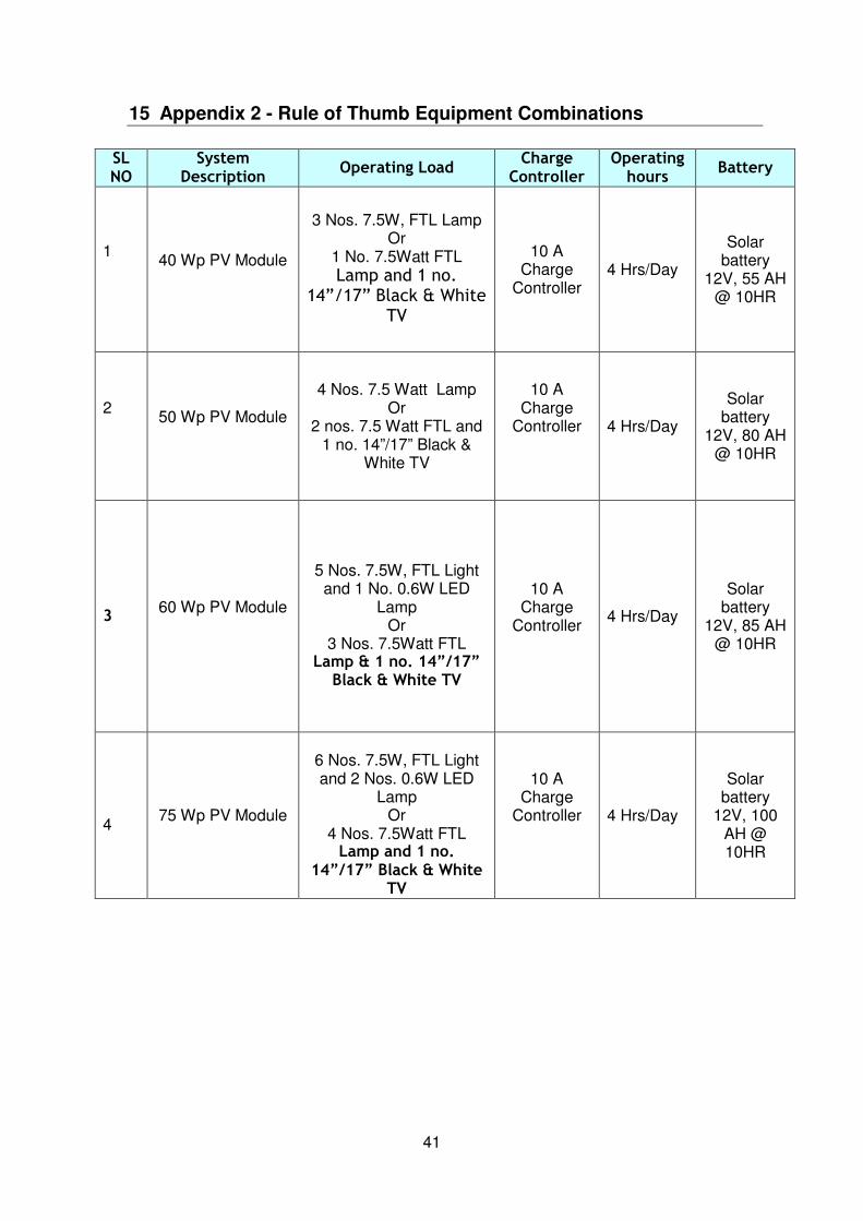
15 Appendix 2 - Rule of Thumb Equipment Combinations
SL NO
System Description
Operating Load Charge Controller
Operating hours
Battery
1
40 Wp PV Module
3 Nos. 7.5W, FTL Lamp
Or 1 No. 7.5Watt FTL Lamp and 1 no.
14”/17” Black & White TV
10 A
Charge Controller
4 Hrs/Day
Solar
battery 12V, 55 AH
@ 10HR
2
50 Wp PV Module
4 Nos. 7.5 Watt Lamp
Or 2 nos. 7.5 Watt FTL and
1 no. 14”/17” Black & White TV
10 A
Charge Controller
4 Hrs/Day
Solar
battery 12V, 80 AH
@ 10HR
3 60 Wp PV Module
5 Nos. 7.5W, FTL Light and 1 No. 0.6W LED
Lamp Or
3 Nos. 7.5Watt FTL Lamp & 1 no. 14”/17” Black & White TV
10 A
Charge Controller
4 Hrs/Day
Solar
battery 12V, 85 AH
@ 10HR
4
75 Wp PV Module
6 Nos. 7.5W, FTL Light and 2 Nos. 0.6W LED
Lamp Or
4 Nos. 7.5Watt FTL Lamp and 1 no.
14”/17” Black & White TV
10 A
Charge Controller
4 Hrs/Day
Solar
battery 12V, 100
AH @ 10HR
Related Documents