GLSCENE User Tutorials - Build a basic scene From here on we assume the GLScene library has been installed properly. We are ready to take our first steps into the 3D openGL universe. In GLScene the universe or 3D world is called a scene. Hence the name. We are going to create our first application that will contain a 3D cube. We will learn how to start a basic GLScene application and how to control the layout by manipulating the design time properties. Start a new application in Delphi Set the form width to 640 and the height to 480 - Go to the GLScene tab on the VCL palette

Welcome message from author
This document is posted to help you gain knowledge. Please leave a comment to let me know what you think about it! Share it to your friends and learn new things together.
Transcript

GLSCENE
User Tutorials - Build a basic scene
From here on we assume the GLScene library has been installed properly. We are ready to
take our first steps into the 3D openGL universe. In GLScene the universe or 3D world is
called a scene. Hence the name. We are going to create our first application that will contain
a 3D cube. We will learn how to start a basic GLScene application and how to control the
layout by manipulating the design time properties.
Start a new application in Delphi
Set the form width to 640 and the height to 480
- Go to the GLScene tab on the VCL palette

- Place a TGLScene and a TGLSceneViewer viewer on the form
The TGLSceneViewer is the window which will give us a view into the 3D scene we are about
to build. The TGLSene is the master of the scene. Everything that happens is managed
through the TGLScene control.
Let’s introduce you to the most important dialog in GLScene. The scene editor.
Right click on the TGLScene icon on the form and select “Show scene
editor”

As a result the scene editor dialog will appear.
The world managed by TGLScene is still a blank canvas. You can add objects
such as shapes, camera’s and lights to build your world in this editor.
Let’s start by adding a 3D cube to the scene.
Right click on “Scene Objects” and select a “Cube” from “Basic geometry”

You can see there are a lot of objects you can choose from. Leave those for what they are for
now. We will visit other objects later in the tutorial.
The popup menu will collapse once you click on the Cube object. The cube is now added to
the scene.

Let’s close the scene editor and check out wat we see.
???? Nothing! Why can’t you see the cube? Well that would be correct. There is a whole bunch of things that need to be considered before you will see anything.

In the previous topic you build a GLScene application but so far you could not see any results.
Why can’t you see the cube? Well in order for you to see anything at all you will need to
create a way to view the scene. This is done using a camera. We are now going to add a
camera to the scene.
Need to know
The scene editor doesn’t always know where you click on. A work around is to select any
other node in the editor and then select the node you want. Only then will the object
inspector (F10) and the context popup menu be correct.
Left click on "Scene objects" to make that option active
Left click on "Cameras" to make that option active
This weird toggle action will sort out the Scene editor if it get’s confused. Use this trick
whenever the object inspector or context menu fails to show the correct information.
Open the scene editor again. Right click on the TGLScene icon on the
form and select “Show scene editor”
Right click on “Cameras” and select “Add camera”
You now have a camera but don’t bother to go and check out your creation on the form.
There is still nothing there!
Need to know
Every new object that is created is always placed in the center of the scene by default.
So you can see that the camera occupies the same space as the cube. Besides the camera
points at some default direction and chances are that it is not pointing to the cube anyway.
Well that is easy to fix. We are going to tell the camera to look at the cube
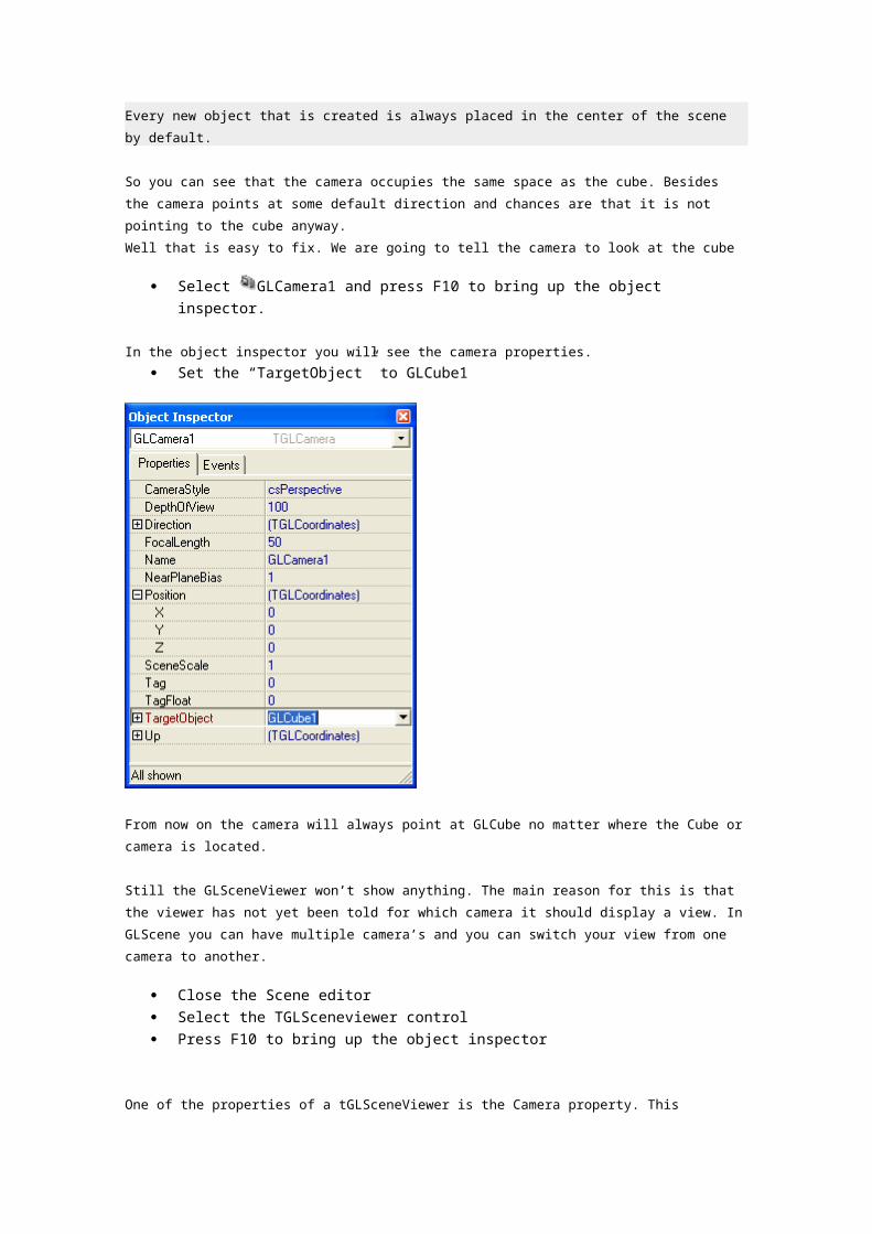
Select GLCamera1 and press F10 to bring up the object inspector.
In the object inspector you will see the camera properties.
Set the “TargetObject” to GLCube1
From now on the camera will always point at GLCube no matter where the Cube or camera is
located.
Still the GLSceneViewer won’t show anything. The main reason for this is that the viewer has
not yet been told for which camera it should display a view. In GLScene you can have
multiple camera’s and you can switch your view from one camera to another.
Close the Scene editor
Select the TGLSceneviewer control
Press F10 to bring up the object inspector
One of the properties of a tGLSceneViewer is the Camera property. This property defines wich
camera should be used to render the 3D view for the viewer.
Set the “Camera” property to GLCamera1

Still nothing to see. Let’s summarize what we have done and see if we can identify what we
have missed.
We created a cube and a camera.
We told the camera to look at the cube.
We told the viewer to use camera1.
However, we never told the camera and cube where to go!
The camera is located in exactly the same spot as the cube so basically were too close to see
anything at all. For now let’s just get this thing working. After that we need to spend some
time to talk about 3D coordinates.
Right click on the TGLScene icon on the form and select “Show scene
editor”
Select GLCamera1 and press F10 to bring up the object inspector.
Set the position coordinates to X=1, Y=1 and Z=1

Finally, something appears on the screen. It looks pretty bad but at least it’s something right?
What you see is the silhouette of a 3D cube as seen from an angle. It is all black because…
There are no lights! Every scene needs lights. Without lights you can’t see anything. So let’s
add a light.
Right click on the TGLScene icon on the form and select “Show scene
editor”
Right click on “Scene Objects” and select a “Lightsource”

Nothing changed. The new light is added to the center of the scene and in our case the light
would end up in the inside of the cube. We need to move the light up to get it out of the
cube.
Select the new light in the scene editor and press F10 to bring up the object
inspector.
Change the position of the light as shown below.

And finally the cube is shown in all it’s glory.
Congratulations you have mastered the very basics of GLScene. We have created an
application containing a TGLScene and a TGLSceneViewer We have added a cube, a
camera and a light. We told the viewer to use our new camera. We made the camera look at
the cube and placed the camera away from the cube so it can look at it. We added a light and
placed it above the cube and presto we are done! So the minimum requirements in order for
you to see anything in GLScene are:
TGLScene component (The scene master object)
TGLSceneViewer (To see stuff)
TGLCamera (were to see stuff from)
TGLLight (So we can see stuff)
TGLCube (Stuff to see)
Obviously these objects need to be configured in such a way that the camera can actually see the cube and the light can shine on the outside of the cube.
Although we have achieved to display a 3D object in Delphi, we need to be able to manipulate the object in 3D space. Gain control so to speak. Save this project and name it

"glscenebase.dpr" or something. You will find that it will come in handy every time you want to try something. Also you will need this project for the next tutorial. The Control Objects tutorial will teach you how to control objects in space.
Control Objects
So we know how to move thing around in 3D space but we still need to learn how to manage
their orientation. This topic will explain the do's and don't of Object orientation.
Object orientation is basically the art of rotating an object around it's X, Y and Z axis.
So far we have explained every step in detail. Before we continue we will list knowledge we
assume from now on. We assume you know how to:
* Open the scene editor
* Add objects to the scene
* How to select objects
* How to access the objects properties.
Now we have a 3D cube in a viewer we can start messing around with the cubes position. The
coordinate system in GLScene uses three axis that are perpendicular to each other. The
manage placement in X, Y and Z direction.
Let’s illustrate this by turning on the “Show Axis property of the cube.
* Select the cube in the object inspector and set the “Show axis” property to True
A 3 colored axis system is now shown.

The three axis you see here are the X, Y and Z axis.
X axis is Red
Y axis is Green
Z axis is Blue
The intersection of these three axis is coordinate X=0.0, Y=0.0 and Z=0.0 which is where the
cube is currently placed. We call this system of coordinates a coordinate system. Now here is
where things may become confusing:
Every object has it’s own coordinate system!
For now just accept this as a fact. Later you will find out the incredible power that can be
gained from having this feature.
By default objects created in GLScene have a size of 1 unit. Therefore the cube is 1 unit wide,
1 unit height and 1 unit deep. You may wonder how large a unit is but in our 3D world a unit
is whatever you want it to be as long as you are consistent. A unit can be an inch, a furlong, a
centimeter or the length of your little pinky.

Let’s move the cube along the x axis by changing the position.x property of the cube from 0
to 1. This should move the cube along the red X axis by exactly the width of the cube.
Set the Position.X property of GLCube1 to 1

The result won’t be what you expected:
What happened? Well the cube moved along the X axis as intended but the camera is
programmed to keep looking at GLCube1. So the camera turned to follow GLCube1 and the
above image is the result.
We need to give the camera a fixed reference that does not move. A quick and easy way is to
use another object that stays in place while the cube moves around.
Introducing the “Dummy cube”. This cube can be seen during design-time as a wireframe
cube but is not rendered during run-time. The cube however is still very much part of the
object structure. Let’s try this
Open the scene editor and add a dummycube
Select the camera and set its “Target” property to GLdummyCube1

Have a look at the form now.
The camera orientation has gone back to what it was before we changed the GLCube1
position.X coordinate. The white dashed wireframe shows the position of the
GLDummyCube1. That is where the GLCube1 used to be.
Now play with the coordinates of GLCube1 a little. Change Position.X Y and Z and see if you
can place the cube in the lower left corner of the viewer.
Coordinates in GLScene are of type Single. You can therefore enter fractions such as 0.43 and
so on. Try both positive values and negative values.
Need to know:
The default values for a camera define a “NearPlaneBias” with a value of 1. When object
come close to the camera they get clipped by this plane. This is the reason that the Cube in
the above picture has a corner missing.
You can make this clipping go away by decreasing the “NearPlaneBias” from 1 to say 0.1

Once you feel familiar with the position coordinates you can go-ahead and move the cube to
it’s final position:
Set the GLCube1.position.x = 0
Set the GLCube1.position.y = -0.5
Set the GLCube1.position.z = 0
We are now going to do some more work with coordinates. This time we will use a TGLLines
object. TGLLines can draw a polyline in 3D space. The final line drawn can be made up of
straight line segments or a spline can be drawn through its points.
Open the Scene editor and add a “Lines” object.

The form will look like this:
As you can see the GLCube1 has moved down half a unit but there is no line anywhere in
sight. This makes sense because we have yet to define the points that make up the line.
We are going to create the outline of a simple house shape. The points of a TGLLines object
are called nodes. Let’s add a few nodes and keep an eye on the form to see where they end
up.
To make identification of the node points easier we will set a few properties first.
Select the GLLines1 object in the scene editor and press F10 to get the
object inspector.
Set the Linecolor to clrAquamarine
Set LineWidth to 4
Set NodesAspect to lnaCube
Set NodeSize to 0.1

We have now told GLLines1 to draw it’s lines in aqua marine color 4 pixels wide and mark
every node in the polyline with a cube with a size of 0.1 units wide, high and deep.
Let’s get to work and add some nodes.
In the above object inspector click on Nodes to bring up the nodes collection
dialog
Click on the familiar “Add” button to add a node. Each node can be given a color and an X,Y,Z
coordinate. Lets start with the top of the roof of our house shape:
Enter 0.5 for the Z coordinate

Add nodes until you have the following collection:
Try not to look and figure out the coordinates for yourself to obtain this shape:
Need to know:
Note how all Y values have been left to 0. In GLScene the Y axis is going “up”. The above
GLLines1 object is flat with all it’s Y coordinates set to zero.
Can you create a set of nodes that allows the house to stand upright? I bet you are bored

with coordinates. Same here, let’s see if we achieve this upright house in a different way.
There are two things that define an object in space. Position and Orientation. We know about position now. The next tutorial will teach you how to manage an objects orientation through rotation. Make sure you save the work you have done so far because the next tutorial is based on it.
Control Objects
So we know how to move thing around in 3D space but we still need to learn how to manage
their orientation. This topic will explain the do's and don't of Object orientation.
Object orientation is basically the art of rotating an object around it's X, Y and Z axis.
So far we have explained every step in detail. Before we continue we will list knowledge we
assume from now on. We assume you know how to:
* Open the scene editor
* Add objects to the scene
* How to select objects
* How to access the objects properties.
Now we have a 3D cube in a viewer we can start messing around with the cubes position. The
coordinate system in GLScene uses three axis that are perpendicular to each other. The
manage placement in X, Y and Z direction.
Let’s illustrate this by turning on the “Show Axis property of the cube.
* Select the cube in the object inspector and set the “Show axis” property to True
A 3 colored axis system is now shown.

The three axis you see here are the X, Y and Z axis.
X axis is Red
Y axis is Green
Z axis is Blue
The intersection of these three axis is coordinate X=0.0, Y=0.0 and Z=0.0 which is where the
cube is currently placed. We call this system of coordinates a coordinate system. Now here is
where things may become confusing:
Every object has it’s own coordinate system!
For now just accept this as a fact. Later you will find out the incredible power that can be
gained from having this feature.
By default objects created in GLScene have a size of 1 unit. Therefore the cube is 1 unit wide,
1 unit height and 1 unit deep. You may wonder how large a unit is but in our 3D world a unit
is whatever you want it to be as long as you are consistent. A unit can be an inch, a furlong, a
centimeter or the length of your little pinky.

Let’s move the cube along the x axis by changing the position.x property of the cube from 0
to 1. This should move the cube along the red X axis by exactly the width of the cube.
Set the Position.X property of GLCube1 to 1
The result won’t be what you expected:
What happened? Well the cube moved along the X axis as intended but the camera is
programmed to keep looking at GLCube1. So the camera turned to follow GLCube1 and the
above image is the result.
We need to give the camera a fixed reference that does not move. A quick and easy way is to
use another object that stays in place while the cube moves around.
Introducing the “Dummy cube”. This cube can be seen during design-time as a wireframe
cube but is not rendered during run-time. The cube however is still very much part of the
object structure. Let’s try this
Open the scene editor and add a dummycube
Select the camera and set its “Target” property to GLdummyCube1

Have a look at the form now.
The camera orientation has gone back to what it was before we changed the GLCube1
position.X coordinate. The white dashed wireframe shows the position of the
GLDummyCube1. That is where the GLCube1 used to be.
Now play with the coordinates of GLCube1 a little. Change Position.X Y and Z and see if you
can place the cube in the lower left corner of the viewer.
Coordinates in GLScene are of type Single. You can therefore enter fractions such as 0.43 and
so on. Try both positive values and negative values.
Need to know:
The default values for a camera define a “NearPlaneBias” with a value of 1. When object
come close to the camera they get clipped by this plane. This is the reason that the Cube in
the above picture has a corner missing.
You can make this clipping go away by decreasing the “NearPlaneBias” from 1 to say 0.1

Once you feel familiar with the position coordinates you can go-ahead and move the cube to
it’s final position:
Set the GLCube1.position.x = 0
Set the GLCube1.position.y = -0.5
Set the GLCube1.position.z = 0
We are now going to do some more work with coordinates. This time we will use a TGLLines
object. TGLLines can draw a polyline in 3D space. The final line drawn can be made up of
straight line segments or a spline can be drawn through its points.
Open the Scene editor and add a “Lines” object.

The form will look like this:
As you can see the GLCube1 has moved down half a unit but there is no line anywhere in
sight. This makes sense because we have yet to define the points that make up the line.
We are going to create the outline of a simple house shape. The points of a TGLLines object
are called nodes. Let’s add a few nodes and keep an eye on the form to see where they end
up.
To make identification of the node points easier we will set a few properties first.
Select the GLLines1 object in the scene editor and press F10 to get the
object inspector.
Set the Linecolor to clrAquamarine
Set LineWidth to 4
Set NodesAspect to lnaCube
Set NodeSize to 0.1

We have now told GLLines1 to draw it’s lines in aqua marine color 4 pixels wide and mark
every node in the polyline with a cube with a size of 0.1 units wide, high and deep.
Let’s get to work and add some nodes.
In the above object inspector click on Nodes to bring up the nodes collection
dialog
Click on the familiar “Add” button to add a node. Each node can be given a color and an X,Y,Z
coordinate. Lets start with the top of the roof of our house shape:
Enter 0.5 for the Z coordinate

Add nodes until you have the following collection:
Try not to look and figure out the coordinates for yourself to obtain this shape:
Need to know:
Note how all Y values have been left to 0. In GLScene the Y axis is going “up”. The above
GLLines1 object is flat with all it’s Y coordinates set to zero.
Can you create a set of nodes that allows the house to stand upright? I bet you are bored

with coordinates. Same here, let’s see if we achieve this upright house in a different way.
There are two things that define an object in space. Position and Orientation. We know about position now. The next tutorial will teach you how to manage an objects orientation through rotation. Make sure you save the work you have done so far because the next tutorial is based on it.
Related Documents