GLIDER EVO CLA 19632013 fiftycool years • RCGROUP SpA • G_CHL_RCW8.4 83 fifty cool years 1 9 6 3 2 0 1 3 rcgroupairconditioning A C R134a SHELL A CLASS GLIDER EVO CLA HIGHEFFICIENCY ACLASS GLIDER EVO CLA GLIDER EVO CLA: Packaged air cooled liquid chillers in “A” class energy efficiency for outdoor installation, equipped with screw compressors and axial fans Cooling Capacity: 282 ÷ 1513 kW MAIN FEATURES • Air cooled liquid chiller. • 26 models available, for a wide selection opportunity. • Average step of 50kW. • EER up to 3,39. • ESEER up to 4,03. • Twin-Screw compressors. • R134a Refrigerant charge. • Double refrigerant circuit. • Shell and tube evaporator.. • AC Axial fans. • Double air circuit. • Electronic expansion valve. • Suitable for outdoor installation. MAIN BENEFITS • High EER, A class energy efficiency. • Availability of kit for the reduction and the extreme reduction of the noise. • Availability of pumping groups. • Availability of total or partial heat recovery system. • Availability of EC fans for a higher efficiency. • Components dedicated to the safety of the unity. • Eurovent Certification. ELECTRONIC EXPANSION VALVE The electronic expansion valves are synonymous of an higher energy efficiency and stability of the system. A CLASS ENERGY EFFICIENCY The best and most accurate components applied to the chillers. WORKING LIMITS IN COOLING MODE Chilled water outlet temperature: -10÷15°C Ambient temperature: -20÷45°C

Welcome message from author
This document is posted to help you gain knowledge. Please leave a comment to let me know what you think about it! Share it to your friends and learn new things together.
Transcript
GLIDER EVO CLA
19632013 fiftycoolyears • RCGROUP SpA • G_CHL_RCW8.4 83
f i f t y c o o l y e a r s
1 9 6 3 2 0 1 3
rcgroupairconditioning A CR134a SHELLA
CLASS
GLIDER EVO CLA
HIGHEFFICIENCY
ACLASS
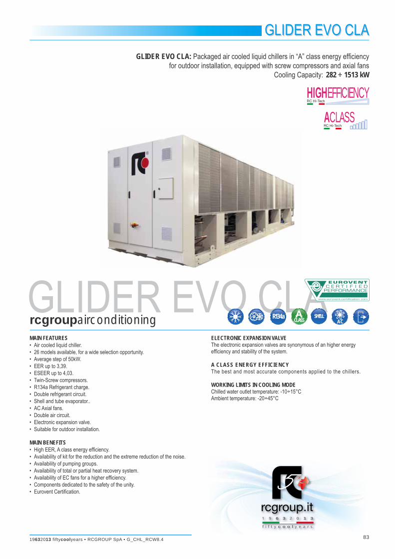
GLIDER EVO CLAGLIDER EVO CLA: Packaged air cooled liquid chillers in “A” class energy effi ciency
for outdoor installation, equipped with screw compressors and axial fansCooling Capacity: 282 ÷ 1513 kW
MAIN FEATURES• Air cooled liquid chiller.• 26 models available, for a wide selection opportunity.• Average step of 50kW.• EER up to 3,39.• ESEER up to 4,03.• Twin-Screw compressors.• R134a Refrigerant charge.• Double refrigerant circuit.• Shell and tube evaporator..• AC Axial fans.• Double air circuit.• Electronic expansion valve.• Suitable for outdoor installation.
MAIN BENEFITS• High EER, A class energy effi ciency.• Availability of kit for the reduction and the extreme reduction of the noise.• Availability of pumping groups.• Availability of total or partial heat recovery system.• Availability of EC fans for a higher effi ciency.• Components dedicated to the safety of the unity.• Eurovent Certifi cation.
ELECTRONIC EXPANSION VALVEThe electronic expansion valves are synonymous of an higher energy effi ciency and stability of the system.
A CLASS ENERGY EFFICIENCYThe best and most accurate components applied to the chillers.
WORKING LIMITS IN COOLING MODEChilled water outlet temperature: -10÷15°CAmbient temperature: -20÷45°C

G_CHL_RCW8.4 • RCGROUP SpA • 19632013 fiftycoolyears84
GLIDER EVOGLIDER EVO CLA Chillers
MAIN COMPONENTSFRAMEWORK• Base, self supporting frame and panelling in steel plate with protective
surfaces treatment in compliance with UNI ISO 9227/ASTMB117 and ISO 7253, and painted with epoxy powders.
• Colour: RAL 9002
COMPRESSORS• Twin screw semi-hermetic compressors with highly effi cient screw profi le
and high peripheral speed, optimized for R134a refrigerant.• Integrated discharge check valve.• Flanged-on oil separator.• Integrated safety relief valve (overpressure inner valve).• Replaceable cartridge oil fi lter.• Valves for oil fi lling and discharge.• Oil sight glass.• Electronic protection device that includes:
- Electric motor thermal protection via internal winding temperature sensors.
- Phase sequence electronic relay.- Sensor on refrigerant discharge for temperature monitoring,
• 2-pole 3-phase electric motor with Part-Winding starting from model 290 V2 F06 to model 570 V2 F10 included.
• 2-pole 3-phase electric motor with Star / Delta starting from model 620 V2 F10 to model 1510 V2 F24 included.
• Stepless capacity control, 50÷100% for each compressor.• Crankcase heater.• Terminal box with IP54 enclosure class.• Rubber supports.
EVAPORATOR• Single pass type shell and tube evaporator, optimized for R134a refrigerant.• Tubes with a helical rifl ed internal surface.• Intermediate baffl es positioned to ensure optimum speed of the fl uid and
low pressure drops.• Single circuit on water side and independent circuits, one for each
compressor, on refrigerant side.• Shell, header, tube sheets, made of carbon steel, tubes in Cu.• Anticondensate insulation made of polyurethane.• Temperature sensors on water inlet and outlet.• Antifreeze heater.• Hydraulic connections with grooved end complete with fl exible joint and
adapter pipe for solder connection.
CONDENSING COIL• Heat exchanger coil with high effi ciency aluminium fi ns, specifi cally
developed to provide high heat transfer and lower pressure drops. The combination of two factors, special tubes and fi ns, allow to optimally combine the following aspects:- Maximum capacity relative to the size of the exchanger.- Minimum charge of refrigerant.- Reduction of the air fl ow required for the heat exchange.
• Frame in galvanized steel.
FANS SECTION• Axial fans with sickle-shaped blades, fan guard and optimized for low noise
levels.• External rotor AC type electric motor with stepless variable speed for
condensing pressure control, with phase-cut electronic controller.• IP54 enclosure class.
REFRIGERANT CIRCUITComponent for each refrigerant circuit:• Electronic expansion valve that allows high performance and system
effi ciency thanks to a timely and accurate response to changes in temperature and pressure.
• Energy reserve module for the electronic expansion valve to allow the closure of the valve in the event of lack of power supply.
• Sight glass.• Filter dryer on liquid line.• Service valves on liquid line.• Service valves on compressor gas discharge.• Double safety valve (only one in function) on high and low pressure side.
The system include two safety valves with manual changeover system.• Pressure transducers with indication, control and protection functions, on
low and high refrigerant pressure and oil pressure.• High pressure safety switch with manual reset.• Pressure gauge on high and low pressure.• Refrigerant circuit with copper tubing with anticondensate insulation of the
suction line.• Plastic capillary hoses for pressure sensors connection.• R134a refrigerant charge.
ELECTRICAL PANELIn accordance with EN60204-1 norms, suitable for outdoor installation,complete with:• Main switch with door lock safety.• Fuses for each compressor.• Magnetothermic switches for fans.• Fuses for water pumps (if scheduled).• Contactors for each load.• Compressor Part-Winding starting system from model 290 V2 F06 to model
570 V2 F10 included.• Compressor Star / Delta starting system from model 620 V2 F10 to model
1510 V2 F24 included.• Transformer for auxiliary circuit and microprocessor supply.• Panel with machine controls.• Power supply 400/3/50.
CONTROL SYSTEM• MP.COM microprocessor system with graphic display for control and
monitor of operating and alarms status. The system includes:- Voltage free contact for remote general alarm.- Main components hour-meter.- Nonvolatile “Flash” memory for data storage.- Menu with protection password.- LAN connection.
19632013 fiftycoolyears • RCGROUP SpA • G_CHL_RCW8.4 85
F06 F08 F10 F12 F14 F16 F18 F20 F22 F24● ● ● ● - - - - - -● ● ● ● - - - - - -- - - - ● ● ● ● ● ●- - - - ● ● ● ● ● ●● ● ● ● ● ● ● ● ● ●● ● ● ● ● ● ● ● ● ●● ● ● ● ● ● ● ● ● ●● ● ● ● ● ● ● ● ● ●● ● ● ● ● ● ● ● ● ●● ● ● ● ● ● ● ● ● ●● ● ● ● ● ● ● ● ● ●● ● ● ● ● ● ● ● ● ●● ● ● ● ● ● ● ● ● ●● ● ● ● ● ● ● ● ● ●● ● ● ● ● ● ● ● ● ●● ● ● ● ● ● ● ● ● ●● ● ● ● ● ● ● ● ● ●● ● ● ● ● ● ● ● ● ●● ● ● ● ● ● ● ● ● ●● ● ● ● ● ● ● ● ● ●● ● ● ● ● ● ● ● ● ●● ● ● ● ● ● ● ● ● ●● ● ● ● ● ● ● ● ● ●● ● ● ● ● ● ● ● ● ●● ● ● ● ● ● ● ● ● ●● ● ● ● ● ● ● ● ● ●● ● ● ● ● ● ● ● ● ●● ● ● ● ● ● ● ● ● ●● ● ● ● ● ● ● ● ● ●● ● ● ● ● ● ● ● ● ●● ● ● ● ● ● ● ● ● ●● ● ● ● ● ● ● ● ● ●● ● ● ● ● ● ● ● ● ●● ● ● ● ● ● ● ● ● ●● ● ● ● ● ● ● ● ● ●● ● ● ● ● ● ● ● ● ●● ● ● ● ● ● ● ● ● ●● ● ● ● ● ● ● ● ● ●● ● ● ● ● ● ● ● ● ●● ● ● ● ● ● ● ● ● ●● ● ● ● ● ● ● ● ● ●● ● ● ● ● ● ● ● ● ●● ● ● ● ● ● ● ● ● ●● ● ● ● ● ● ● ● ● ●● ● ● ● ● ● ● ● ● ●● ● ● ● ● ● ● ● ● ●● ● ● ● ● ● ● ● ● ●● ● ● ● ● ● ● ● ● ●
GLIDER EVO CLAChillers
OPTIONAL ACCESSORIES
● available accessory; - not available accessory
GLIDER EVO CLASIZE739 - Pumping group (1 pump)769 - Pumping group (1+1stby)740 - Pumping group (2 pumps)770 - Pumping group (2+1stby)1004 - Antifreeazing heater for pumping group118 - Kit brine A (for glycol solution production up to -6°C)119 - Kit brine B (for glycol solution production up to -12°C)786 - Pipes antifreezing kit79 - Electrical panel heating system150 - LNO kit (noise reduction)151 - ELN kit (extremely noise reduction)170 - Spring antivibration holders (kit)171 - Rubber antivibration holders (kit)101 - EC fan450 - Partial heat recovery449 - Voltage free contact for partial heat recovery water pump activation451 - 100% heat reclaim454 - Voltage free contact for total heat recovery water pump activationSelection switch for operation mode for total heat recovery351 - Coils with pre-painted fi nsCondensing coil in special execution250 - Coils protection nets (kit)731 - Safety water fl ow switch1005 - Oil fl ow switch650 - Compressor thermal relay605 - Compr. power factor capacitor - 0,9Supply network control relay83 - Compressor operation indicator550 - Stop valve on compressor suction line85 - Demand limit88 - Analog set point compensation 1003 - Analogic fl owmeter1005 - Power supply analyzer1009 - Multimeter kit919 - Clock card923 - RC-Com MBUS/JBUS Serial board926 - LON Serial board931 - BACnet Ethernet - SNMP - TCP/IP Serial board932 - BACnet MS/TP Serial board934 - MP.COM expansion card942 - Serial card for GSM Modem943 - Data LoggerAmbient temperature sensor962 - Kit modem GSM957 - Plantwatch without modem930 - Remote graphic terminal kit889 - Master plant SEQUENCERRC CLOUD PLATFORM

G_CHL_RCW8.4 • RCGROUP SpA • 19632013 fiftycoolyears86
290 V2 300 V2 320 V2 340 V2 360 V2 400 V2 450 V2 480 V2F06 F06 F08 F08 F08 F08 F10 F10282 299 319 339 358 398 445 47189,0 95,2 102,9 107,6 113,3 125,6 141,7 149,148,4 51,4 54,8 58,2 61,4 68,3 76,4 81,036 17 18 20 17 7 12 12
twin-screw twin-screw twin-screw twin-screw twin-screw twin-screw twin-screw twin-screw2 2 2 2 2 2 2 2
25... 100% 25... 100% 25... 100% 25... 100% 25... 100% 25... 100% 25... 100% 25... 100%6 6 8 8 8 8 10 10
131388 127614 153286 175184 170152 170152 212690 2126902 2 2 2 2 2 2 2
R134a R134a R134a R134a R134a R134a R134a R134a74 74 96 96 96 145 120 1812 2 2 2 2 2 2 2
400/3/50 400/3/50 400/3/50 400/3/50 400/3/50 400/3/50 400/3/50 400/3/50165 181,8 193,2 204,6 204,6 232,4 259,6 282
251,4 230,4 265,9 293,2 293,2 335,2 381,2 366,5400,4 388,4 422,2 445,2 445,2 525,2 624,0 633,03,17 3,14 3,10 3,15 3,16 3,17 3,14 3,163,26 3,76 3,79 3,78 3,79 3,79 3,73 3,7792,0 92,5 92,7 92,9 91,5 91,9 92,1 96,272,3 72,8 72,5 72,7 71,3 71,7 71,4 75,53738 4109 4515 4520 4697 4902 5428 5662
139,7 139,7 139,7 139,7 139,7 139,7 139,7 139,7
56,1 59,6 63,5 67,5 71,2 79,2 88,6 93,8
348 378 402 426 451 506 564 5975,5 5,5 5,5 5,5 5,5 5,5 5,5 5,5282 299 319 339 358 398 445 47189,0 95,2 100,9 107,6 113,3 125,6 141,7 149,1
131388 127614 153286 175184 170152 170152 212690 2126903,17 3,14 3,16 3,15 3,16 3,17 3,14 3,1690,0 90,5 90,7 90,9 89,5 89,9 90,1 94,270,3 70,8 70,5 70,7 69,3 69,7 69,4 73,5278 294 314 334 352 392 439 46588,8 95,5 100,6 107,4 112,5 126,0 142,1 149,0
111680 108472 130293 148906 144629 144629 180787 1807873,13 3,08 3,12 3,11 3,13 3,11 3,09 3,1289,0 89,5 89,7 89,9 88,5 88,9 89,1 93,269,3 69,8 69,5 69,7 68,3 68,7 68,4 72,5272 286 307 327 345 383 430 45589,2 96,3 101,3 107,6 117,3 127,7 141,9 150,7
91972 89330 107300 122629 119106 119106 148883 1488833,05 2,97 3,03 3,04 2,94 3,00 3,03 3,0286,0 86,5 86,7 86,9 85,5 85,9 86,1 90,266,3 66,8 66,5 66,7 65,3 65,7 65,4 69,5272 286 307 327 345 383 430 45589,2 96,3 101,3 107,6 117,3 127,7 141,9 150,7
91972 89330 107300 122629 119106 119106 148883 1488833,05 2,97 3,03 3,04 2,94 3,00 3,03 3,0283,0 83,5 83,7 83,9 82,5 82,9 83,1 87,263,3 63,8 63,5 63,7 62,3 62,7 62,4 66,5
GLIDER EVOGLIDER EVO CLA Chillers
1. Referred to chilled water temperature 12/7°C – 0% glycol solution; air temperature to the condenser 35°C. Fouling factor of the exchangers 0,043 m²°K/kW.2. Sound power level [Lw] according to ISO EN 9614 – 2.3. Average sound pressure level [LPm] 1m far according to ISO EN 3744.4. Hydraulic connection with grooved end complete with fl exible joint and adapter pipe for solder connection.5. Referred to chilled water temperature 12/7°C – 0% glycol solution; air temperature to the condenser 35°C; water temperature heat recovery 40/45°C – 0% glycol solution.
Fouling factor of the exchangers 0,043 m²°K/kW.6. Referred to chilled water temperature 12/7°C – 0% glycol solution; water temperature heat recovery 40/45°C – 0% glycol solution; Fouling factor of the exchangers 0,043 m²°K/kW.
TECHNICAL DATA GLIDER EVOGLIDER EVO CLASIZECooling capacity (1) kW
Unit power input kWEvaporator water fl ow rate m³/hEvaporator pressure drop kPa
CompressorsQuantity n.Capacity control %
Axial fans n.Total air fl ow m³/hAir circuits n.
RefrigerantTotal refrigerant charge (optional excluded) kg
Gas circuits n.Power supply V/Ph/Hz Max operating current (MOC) A
Max unit operating current (FLA) AUnit starting current (LRA) A
EER (1) kW/kWESEERSound power level [Lw] (2) dB(A)Average sound pressure level [Lpm] (3) dB(A)Net weight kgHydraulic connections
Evaporator IN/OUT - OD (4) Ø mmPartial heat recovery (5)
Heating capacity kWTotal heat recovery (6)
Heating capacity kWPumping group - Power input kWCooling capacity (1) kW
Unit power input kWTotal air fl ow m³/hEER (1) kW/kWSound power level [Lw] (2) dB(A)Average sound pressure level [Lpm] (3) dB(A)Cooling capacity (1) kW
Unit power input kWTotal air fl ow m³/hEER (1) kW/kWSound power level [Lw] (2) dB(A)Average sound pressure level [Lpm] (3) dB(A)Cooling capacity (1) kW
Unit power input kWTotal air fl ow m³/hEER (1) kW/kWSound power level [Lw] (2) dB(A)Average sound pressure level [Lpm] (3) dB(A)Cooling capacity (1) kW
Unit power input kWTotal air fl ow m³/hEER (1) kW/kWSound power level [Lw] (2) dB(A)Average sound pressure level [Lpm] (3) dB(A)
STAN
DARD
OPTI
ONAL
LNO
KIT
100%
LNO
KIT
85%
LNO
KIT
70%
ELN
KIT

19632013 fiftycoolyears • RCGROUP SpA • G_CHL_RCW8.4 87
520 V2 570 V2 620 V2 660 V2 700 V2 760 V2 830 V2 870 V2F10 F10 F10 F12 F12 F14 F14 F14518 564 615 656 696 762 828 873
163,9 179,6 192,8 205,6 220,3 241,1 261,2 277,188,9 96,9 106,0 113,0 120,0 131,0 142,0 150,011 20 49 37 38 51 51 62
twin-screw twin-screw twin-screw twin-screw twin-screw twin-screw twin-screw twin-screw2 2 2 2 2 2 2 2
25... 100% 25... 100% 25... 100% 25... 100% 25... 100% 25... 100% 25... 100% 25... 100%10 10 10 12 12 14 14 14
212690 212690 212690 244303 262776 284674 306572 3021692 2 2 2 2 2 2 2
R134a R134a R134a R134a R134a R134a R134a R134a181 181 181 217 217 252 252 295
2 2 2 2 2 2 2 2400/3/50 400/3/50 400/3/50 400/3/50 400/3/50 400/3/50 400/3/50 400/3/50
304,4 326,8 369,4 393,7 418,0 443,0 468,0 492,0394,8 423,2 452,6 475,5 498,5 571,9 645,3 676,8714,0 741,0 549,0 579,9 601,8 700,7 770,6 800,63,16 3,14 3,19 3,19 3,16 3,16 3,17 3,153,76 3,77 3,76 3,82 3,76 3,74 3,74 3,7296,4 96,7 96,7 99,3 100,4 101,1 101,7 101,675,8 76,0 76,0 78,2 79,4 79,7 80,3 80,15999 6121 6112 6733 6743 7404 8139 8341,5
139,7 139,7 139,7 139,7 139,7 168,3 168,3 168,3
103,0 112,0 122,0 130,0 139,0 152,0 165,0 174,0
658 719 782 836 887 971 1053 11155,5 5,5 5,5 5,5 5,5 11,0 11,0 11,0518 564 615 656 696 762 828 873
163,9 179,6 192,8 205,6 220,3 241,1 261,2 277,1212690 212690 212690 244303 262776 284674 306572 302169
3,16 3,14 3,19 3,19 3,16 3,16 3,17 3,1594,4 94,7 94,7 97,3 98,4 99,1 99,7 99,673,8 74,0 74,0 76,2 77,4 77,7 78,3 78,1509 554 604 643 684 748 813 856
164,7 180,5 194,8 208,1 221,4 242,9 263,1 279,7180787 180787 180787 207658 223360 241973 260586 256844
3,09 3,07 3,10 3,09 3,09 3,08 3,09 3,0693,4 93,7 93,7 96,3 97,4 98,1 98,7 98,672,8 73,0 73,0 75,2 76,4 76,7 77,3 77,1497 540 588 626 666 729 791 832
166,8 183,1 198,6 212,9 225,8 248,0 268,1 285,9148883 148883 148883 171012 183943 199272 214600 211518
2,98 2,95 2,96 2,94 2,95 2,94 2,95 2,9190,4 90,7 90,7 93,3 94,4 95,1 95,7 95,669,8 70,0 70,0 72,2 73,4 73,7 74,3 74,1497 540 588 626 666 729 791 832
166,8 183,1 198,6 212,9 225,8 248,0 268,1 285,9148883 148883 148883 171012 183943 199272 214600 211518
2,98 2,95 2,96 2,94 2,95 2,94 2,95 2,9187,4 87,7 87,7 90,3 91,4 92,1 92,7 92,666,8 67,0 67,0 69,2 70,4 70,7 71,3 71,1
GLIDER EVO CLAChillers
GLIDER EVO CLASIZECooling capacity (1) kW
Unit power input kWEvaporator water fl ow rate m³/hEvaporator pressure drop kPa
CompressorsQuantity n.Capacity control %
Axial fans n.Total air fl ow m³/hAir circuits n.
RefrigerantTotal refrigerant charge (optional excluded) kg
Gas circuits n.Power supply V/Ph/Hz Max operating current (MOC) A
Max unit operating current (FLA) AUnit starting current (LRA) A
EER (1) kW/kWESEERSound power level [Lw] (2) dB(A)Average sound pressure level [Lpm] (3) dB(A)Net weight kgHydraulic connections
Evaporator IN/OUT - OD (4) Ø mmPartial heat recovery (5)
Heating capacity kWTotal heat recovery (6)
Heating capacity kWPumping group - Power input kWCooling capacity (1) kW
Unit power input kWTotal air fl ow m³/hEER (1) kW/kWSound power level [Lw] (2) dB(A)Average sound pressure level [Lpm] (3) dB(A)Cooling capacity (1) kW
Unit power input kWTotal air fl ow m³/hEER (1) kW/kWSound power level [Lw] (2) dB(A)Average sound pressure level [Lpm] (3) dB(A)Cooling capacity (1) kW
Unit power input kWTotal air fl ow m³/hEER (1) kW/kWSound power level [Lw] (2) dB(A)Average sound pressure level [Lpm] (3) dB(A)Cooling capacity (1) kW
Unit power input kWTotal air fl ow m³/hEER (1) kW/kWSound power level [Lw] (2) dB(A)Average sound pressure level [Lpm] (3) dB(A)
1. Referred to chilled water temperature 12/7°C – 0% glycol solution; air temperature to the condenser 35°C. Fouling factor of the exchangers 0,043 m²°K/kW.2. Sound power level [Lw] according to ISO EN 9614 – 2.3. Average sound pressure level [LPm] 1m far according to ISO EN 3744.4. Hydraulic connection with grooved end complete with fl exible joint and adapter pipe for solder connection.5. Referred to chilled water temperature 12/7°C – 0% glycol solution; air temperature to the condenser 35°C; water temperature heat recovery 40/45°C – 0% glycol solution.
Fouling factor of the exchangers 0,043 m²°K/kW.6. Referred to chilled water temperature 12/7°C – 0% glycol solution; water temperature heat recovery 40/45°C – 0% glycol solution; Fouling factor of the exchangers 0,043 m²°K/kW.
TECHNICAL DATA GLIDER EVO
STAN
DARD
OPTI
ONAL
LNO
KIT
100%
LNO
KIT
85%
LNO
KIT
70%
ELN
KIT

G_CHL_RCW8.4 • RCGROUP SpA • 19632013 fiftycoolyears88
920 V2 980 V2 1020 V2 1090 V2 1150 V2 1280 V2 1350 V2 1430 V2F14 F16 F16 F18 F20 F20 F20 F20919 977 1024 1083 1154 1279 1356 1434
290,8 306,3 320,0 341,6 364,0 398,4 425,1 452,4158,0 168,0 176,0 186,0 198,0 220,0 233,0 246,0
61 68 76 79 79 54 44 44twin-screw twin-screw twin-screw twin-screw twin-screw twin-screw twin-screw twin-screw
2 2 2 2 2 2 2 225... 100% 25... 100% 25... 100% 25... 100% 25... 100% 25... 100% 25... 100% 25... 100%
14 16 16 18 20 20 20 20297766 350368 350368 401014 451660 437960 431670 425380
2 2 2 2 2 2 2 2R134a R134a R134a R134a R134a R134a R134a R134a
337 290 290 326 362 362 412 4622 2 2 2 2 2 2 2
400/3/50 400/3/50 400/3/50 400/3/50 400/3/50 400/3/50 400/3/50 400/3/50516,0 612,0 612,0 651,0 690,0 776,0 811,0 846,0708,3 737,5 737,5 787,7 837,9 949,2 984,9 1020,6829,6 968,4 968,4 1040,2 1088,0 1296,0 1408,0 1442,03,16 3,19 3,20 3,17 3,17 3,21 3,19 3,173,71 3,72 3,74 3,74 3,72 3,80 3,83 3,81
101,4 99,9 99,9 101,7 103,9 103,9 104,1 104,280,0 78,1 78,1 79,5 81,5 81,5 81,7 81,88544 9195 9318 10274 11180 11362 11972 12292
168,3 168,3 168,3 168,3 168,3 168,3 168,3 168,3
183,0 194,0 204,0 216,0 230,0 255,0 270,0 285,0
1176 1244 1307 1386 1466 1630 1736 184411,0 11,0 11,0 11,0 11,0 11,0 11,0 11,0919 977 1024 1083 1154 1279 1356 1434
290,8 306,3 320,0 341,6 364,0 398,4 425,1 452,4297766 350368 350368 401014 451660 437960 431670 425380
3,16 3,19 3,20 3,17 3,17 3,21 3,19 3,1799,4 97,9 97,9 99,7 101,9 101,9 102,1 102,278,0 76,1 76,1 77,5 79,5 79,5 79,7 79,8900 959 1005 1063 1136 1255 1328 1403
294,1 310,4 324,2 345,1 367,6 402,2 431,2 460,0253101 297813 297813 340862 383911 372266 366920 361573
3,06 3,09 3,10 3,08 3,09 3,12 3,08 3,0598,4 96,9 96,9 98,7 100,9 100,9 101,1 101,277,0 75,1 75,1 76,5 78,5 78,5 78,7 78,8873 933 977 1035 1109 1220 1288 1360
301,0 317,3 331,2 353,2 377,2 412,2 442,6 472,2208436 245258 245258 280710 316162 306572 302169 297766
2,90 2,94 2,95 2,93 2,94 2,96 2,91 2,8895,4 93,9 93,9 95,7 97,9 97,9 98,1 98,274,0 72,1 72,1 73,5 75,5 75,5 75,7 75,8873 933 977 1035 1109 1220 1288 1360
301,0 317,3 331,2 353,2 377,2 412,2 442,6 472,2208436 245258 245258 280710 316162 306572 302169 297766
2,90 2,94 2,95 2,93 2,94 2,96 2,91 2,8892,4 90,9 90,9 92,7 94,9 94,9 95,1 95,271,0 69,1 69,1 70,5 72,5 72,5 72,7 72,8
GLIDER EVOGLIDER EVO CLA Chillers
TECHNICAL DATA GLIDER EVO
1. Referred to chilled water temperature 12/7°C – 0% glycol solution; air temperature to the condenser 35°C. Fouling factor of the exchangers 0,043 m²°K/kW.2. Sound power level [Lw] according to ISO EN 9614 – 2.3. Average sound pressure level [LPm] 1m far according to ISO EN 3744.4. Hydraulic connection with grooved end complete with fl exible joint and adapter pipe for solder connection.5. Referred to chilled water temperature 12/7°C – 0% glycol solution; air temperature to the condenser 35°C; water temperature heat recovery 40/45°C – 0% glycol solution.
Fouling factor of the exchangers 0,043 m²°K/kW.6. Referred to chilled water temperature 12/7°C – 0% glycol solution; water temperature heat recovery 40/45°C – 0% glycol solution; Fouling factor of the exchangers 0,043 m²°K/kW.
GLIDER EVO CLASIZECooling capacity (1) kW
Unit power input kWEvaporator water fl ow rate m³/hEvaporator pressure drop kPa
CompressorsQuantity n.Capacity control %
Axial fans n.Total air fl ow m³/hAir circuits n.
RefrigerantTotal refrigerant charge (optional excluded) kg
Gas circuits n.Power supply V/Ph/Hz Max operating current (MOC) A
Max unit operating current (FLA) AUnit starting current (LRA) A
EER (1) kW/kWESEERSound power level [Lw] (2) dB(A)Average sound pressure level [Lpm] (3) dB(A)Net weight kgHydraulic connections
Evaporator IN/OUT - OD (4) Ø mmPartial heat recovery (5)
Heating capacity kWTotal heat recovery (6)
Heating capacity kWPumping group - Power input kWCooling capacity (1) kW
Unit power input kWTotal air fl ow m³/hEER (1) kW/kWSound power level [Lw] (2) dB(A)Average sound pressure level [Lpm] (3) dB(A)Cooling capacity (1) kW
Unit power input kWTotal air fl ow m³/hEER (1) kW/kWSound power level [Lw] (2) dB(A)Average sound pressure level [Lpm] (3) dB(A)Cooling capacity (1) kW
Unit power input kWTotal air fl ow m³/hEER (1) kW/kWSound power level [Lw] (2) dB(A)Average sound pressure level [Lpm] (3) dB(A)Cooling capacity (1) kW
Unit power input kWTotal air fl ow m³/hEER (1) kW/kWSound power level [Lw] (2) dB(A)Average sound pressure level [Lpm] (3) dB(A)
STAN
DARD
OPTI
ONAL
LNO
KIT
100%
LNO
KIT
85%
LNO
KIT
70%
ELN
KIT

19632013 fiftycoolyears • RCGROUP SpA • G_CHL_RCW8.4 89
1470 V2 1510 V2F22 F241471 1513449,8 446,3253,0 260,0
34 35twin-screw twin-screw
2 225... 100% 25... 100%
22 24467918 510456
2 2R134a R134a
530 5782 2
400/3/50 400/3/50846,0 846,0
1028,8 1037,01449,8 1457,6
3,27 3,393,92 4,03
104,2 104,281,6 81,3
12931 13090
168,3 168,3
293,0 301,0
1869 189611,0 11,01471 1513449,8 446,3
467918 5104563,27 3,39
102,2 102,279,6 79,31442 1486454,9 450,3
397730 4338883,17 3,30
101,2 101,278,6 78,31400 1447466,7 459,4
327543 3573193,00 3,1598,2 98,275,6 75,31400 1447466,7 459,4
327543 3573193,00 3,1595,2 95,272,6 72,3
GLIDER EVO CLAChillers
TECHNICAL DATA GLIDER EVO
1. Referred to chilled water temperature 12/7°C – 0% glycol solution; air temperature to the condenser 35°C. Fouling factor of the exchangers 0,043 m²°K/kW.2. Sound power level [Lw] according to ISO EN 9614 – 2.3. Average sound pressure level [LPm] 1m far according to ISO EN 3744.4. Hydraulic connection with grooved end complete with fl exible joint and adapter pipe for solder connection.5. Referred to chilled water temperature 12/7°C – 0% glycol solution; air temperature to the condenser 35°C; water temperature heat recovery 40/45°C – 0% glycol solution.
Fouling factor of the exchangers 0,043 m²°K/kW.6. Referred to chilled water temperature 12/7°C – 0% glycol solution; water temperature heat recovery 40/45°C – 0% glycol solution; Fouling factor of the exchangers 0,043 m²°K/kW.
GLIDER EVO CLASIZECooling capacity (1) kW
Unit power input kWEvaporator water fl ow rate m³/hEvaporator pressure drop kPa
CompressorsQuantity n.Capacity control %
Axial fans n.Total air fl ow m³/hAir circuits n.
RefrigerantTotal refrigerant charge (optional excluded) kg
Gas circuits n.Power supply V/Ph/Hz Max operating current (MOC) A
Max unit operating current (FLA) AUnit starting current (LRA) A
EER (1) kW/kWESEERSound power level [Lw] (2) dB(A)Average sound pressure level [Lpm] (3) dB(A)Net weight kgHydraulic connections
Evaporator IN/OUT - OD (4) Ø mmPartial heat recovery (5)
Heating capacity kWTotal heat recovery (6)
Heating capacity kWPumping group - Power input kWCooling capacity (1) kW
Unit power input kWTotal air fl ow m³/hEER (1) kW/kWSound power level [Lw] (2) dB(A)Average sound pressure level [Lpm] (3) dB(A)Cooling capacity (1) kW
Unit power input kWTotal air fl ow m³/hEER (1) kW/kWSound power level [Lw] (2) dB(A)Average sound pressure level [Lpm] (3) dB(A)Cooling capacity (1) kW
Unit power input kWTotal air fl ow m³/hEER (1) kW/kWSound power level [Lw] (2) dB(A)Average sound pressure level [Lpm] (3) dB(A)Cooling capacity (1) kW
Unit power input kWTotal air fl ow m³/hEER (1) kW/kWSound power level [Lw] (2) dB(A)Average sound pressure level [Lpm] (3) dB(A)
STAN
DARD
OPTI
ONAL
LNO
KIT
100%
LNO
KIT
85%
LNO
KIT
70%
ELN
KIT

G_CHL_RCW8.4 • RCGROUP SpA • 19632013 fiftycoolyears90
a
c
b
a b c
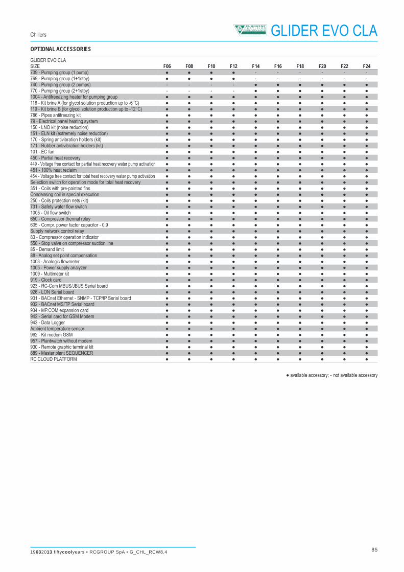
F06 3520 2260 2550 F08 4490 2260 2550 F10 5460 2260 2550 F12 6430 2260 2550 F14 7400 2260 2550 F16 8720 2260 2550 F18 9690 2260 2550 F20 10660 2260 2550 F22 11630 2260 2550 F24 12600 2260 2550
GLIDER EVOGLIDER EVO CLA Chillers
SIZE F
DIMENSIONS (mm)
Related Documents