SDMS DocID 2088134 FIVE YEAR REVIEW FOR GIRARD POINT MANAGEMENT AREA AT PHILADELPHIA NAVAL BUSINESS CENTER PHILADELPHIA, PENNSYLVANIA BASE REALIGNMENT AND CLOSURE (BRAC) COMPREHENSIVE LONG-TERM ENVIRONMENTAL ACTION NAVY (CLEAN) H CONTRACT CONTRACT NUMBER N62467-92-D-1296 CONTRACT TASK ORDER0081 Prepared for: Department of the Navy Engineering Field Activity North East Environmental Branch Code EV2 Naval Facilities Engineering Command 10 Industrial Highway, Mail Stop #82 Lester, Pennsylvania 19113-2090 APPRO Captain Robe^B. Commanding Officer EFANE Date

Welcome message from author
This document is posted to help you gain knowledge. Please leave a comment to let me know what you think about it! Share it to your friends and learn new things together.
Transcript
SDMS DocID 2088134
FIVE YEAR RE VIEWFOR
GIRARD POINT MANAGEMENT AREAAT
PHILADELPHIA NAVAL BUSINESS CENTERPHILADELPHIA, PENNSYLVANIA
BASE REALIGNMENT AND CLOSURE (BRAC)COMPREHENSIVE LONG-TERM
ENVIRONMENTAL ACTION NAVY (CLEAN) H CONTRACT
CONTRACT NUMBER N62467-92-D-1296CONTRACT TASK ORDER 0081
Prepared for:Department of the Navy
Engineering Field Activity North EastEnvironmental Branch Code EV2
Naval Facilities Engineering Command10 Industrial Highway, Mail Stop #82
Lester, Pennsylvania 19113-2090
APPRO
Captain Robe^B.Commanding Officer EFANE
Date
DEPARTMENT OF THE NAVYENGINEERING FIELD ACTIVITY, NORTHEAST
NAVAL FACILITIES ENGINEERING COMMAND
10 INDUSTRIAL HIGHWAY
MAIL STOP, #82
LESTER, PA 19113-2090 IN REPLY REFER TO
5090EV21/MDJune 21, 2004
Mr. Harry Harbold 3H550Hazardous Site Cleanup DivisionEPA Region IIIPhiladelphia, PA 19103-2029
Dear Mr. Harbold:
SUBJECT: FINAL FIVE YEAR REVIEW FOR GIRARD POINTDRIVE; JULY 15, 2003, PHILADELPHIA NAVAL BUSINESSCENTER, PHILADELPHIA, PA
A copy of the subject report is submitted for your records.The Navy will now proceed with implementing the remainingrecommendations as listed in this report.
If you should need additional information or have anyquestions please contact Michele DiGeambeardino at 610-595-0567extension 117.
Sincerely,
MICHELE DIGEAMBEARDINORemedial Project ManagerBy direction of theCommanding Officer
FIVE YEAR REVIEWFOR
GIRARD POINT MANAGEMENT AREAAT
PHILADELPHIA NAVAL BUSINESS CENTERPHILADELPHIA, PENNSYLVANIA
Preparedfor:Department of the Navy
EFA North EastNaval Facilities Engineering Command
10 Industrial HighwayMail Stop No. 82
Lester, Pennsylvania 19113-2090
Prepared by:Stone & Webster, Inc., A Shaw Group Company
3 Executive CampusCherry Hill, NJ 08002
(856) 482-3000
Under contract with:EA Engineering, Science, and Technology
11019McCormickRoadHunt Valley, Maryland 21031
(410)584-7000
Contract No. N62472-92-D-1296Contract Task Order No. 0081
November 2003FINAL
EA Project No. 296.0081Shaw Project No. 04291.18.50
FIVE YEAR REVIEWFOR
GIRARD POINT MANAGEMENT AREAAT
PHILADELPHIA NAVAL BUSINESS CENTERPHILADELPHIA, PENNSYLVANIA
Contract No. N62472-92-D-1296Contract Task Order No. 0081
Dtte
".:.'.:.'" 0*eProgram rnsoigcr .. •
Novnuber2003FINAL
EAPngcct No. 296.0081Shaw Project No. 04291.1830
Project J.O. 04291.18.50Table of Contents
Revision: FinalPageiv
TABLE OF CONTENTS
1.0 PURPOSE AND SITE BACKGROUND 11.1 Purpose 11.2 Site Background 11.3 Human Health and Ecological Risk Assessments 2
2.0 REMEDIAL OBJECTIVES 42.1 Long Term Ground-Water Monitoring Program 5
3.0 FIVE-YEAR RE VIEW 83.1 Site Inspection and Photo-documentation 83.2 Bank Stabilization 83.3 Permeable and Vegetated Cover 93.4 Restricted Access and Institutional Controls 103.5 Long Term Ground-Water Monitoring 10
4.0 CONCLUSIONS AND RECOMMENDATIONS 14
5.0 STATEMENT OF PROTECTIVENESS 14
6.0 REFERENCES 15
Project J.O. 04291.18.50Table of Contents
Revision: FinalPage iv
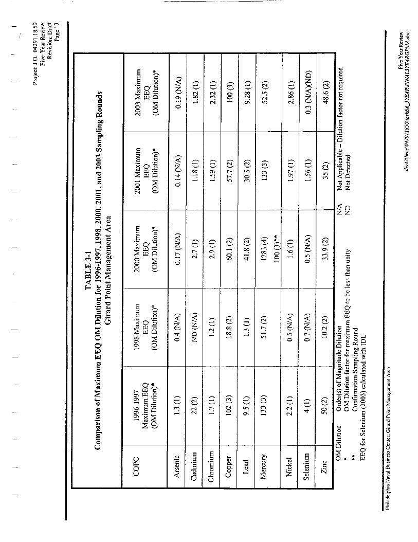
LIST OF TABLESNo. Table Name3-1 Comparison of Maximum EEQ OM Dilution for 1996-1997, 1998, 2000,2001, and 2003 Sampling
Rounds - Girard Point Management Area
LIST OF FIGURES
No. Figure Name1-1 Site Plan
1 -2 Site Location Map
LIST OF APPENDICES
Appendix TitleA Record of DecisionB Goals PaperC Photo Log - 2003 Five Year ReviewD GPMA LTM Trend Lines - 2003 Five Year Review
Project J.O. 04291.18.50Five-Year Review
Revision: FinalPagel
1.0 PURPOSE AND SITE BACKGROUND
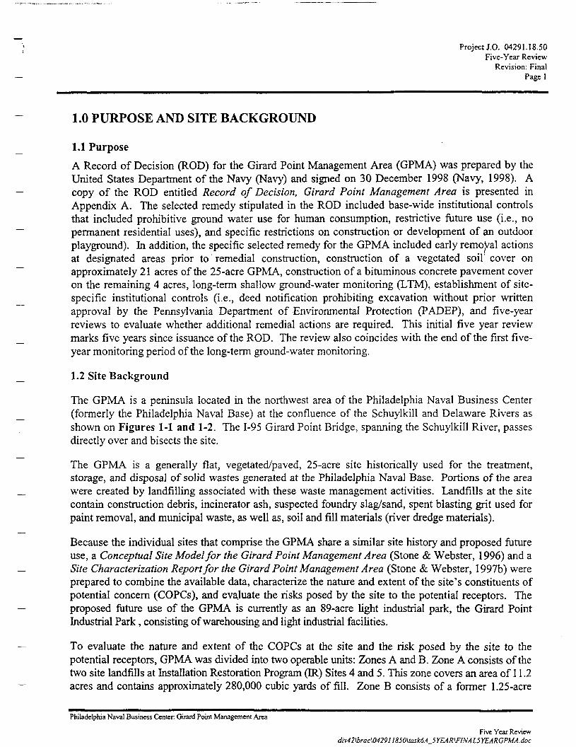
1.1 Purpose
A Record of Decision (ROD) for the Girard Point Management Area (GPMA) was prepared by theUnited States Department of the Navy (Navy) and signed on 30 December 1998 (Navy, 1998). Acopy of the ROD entitled Record of Decision, Girard Point Management Area is presented inAppendix A. The selected remedy stipulated in the ROD included base-wide institutional controlsthat included prohibitive ground water use for human consumption, restrictive future use (i.e., nopermanent residential uses), and specific restrictions on construction or development of an outdoorplayground). In addition, the specific selected remedy for the GPMA included early removal actionsat designated areas prior to remedial construction, construction of a vegetated soil' cover onapproximately 21 acres of the 25-acre GPMA, construction of a bituminous concrete pavement coveron the remaining 4 acres, long-term shallow ground-water monitoring (LTM), establishment of site-specific institutional controls (i.e., deed notification prohibiting excavation without prior writtenapproval by the Pennsylvania Department of Environmental Protection (PADEP), and five-yearreviews to evaluate whether additional remedial actions are required. This initial five year reviewmarks five years since issuance of the ROD. The review also coincides with the end of the first five-year monitoring period of the long-term ground-water monitoring.
1.2 Site Background
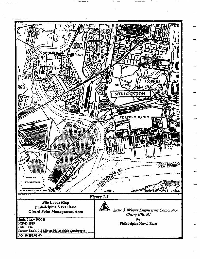
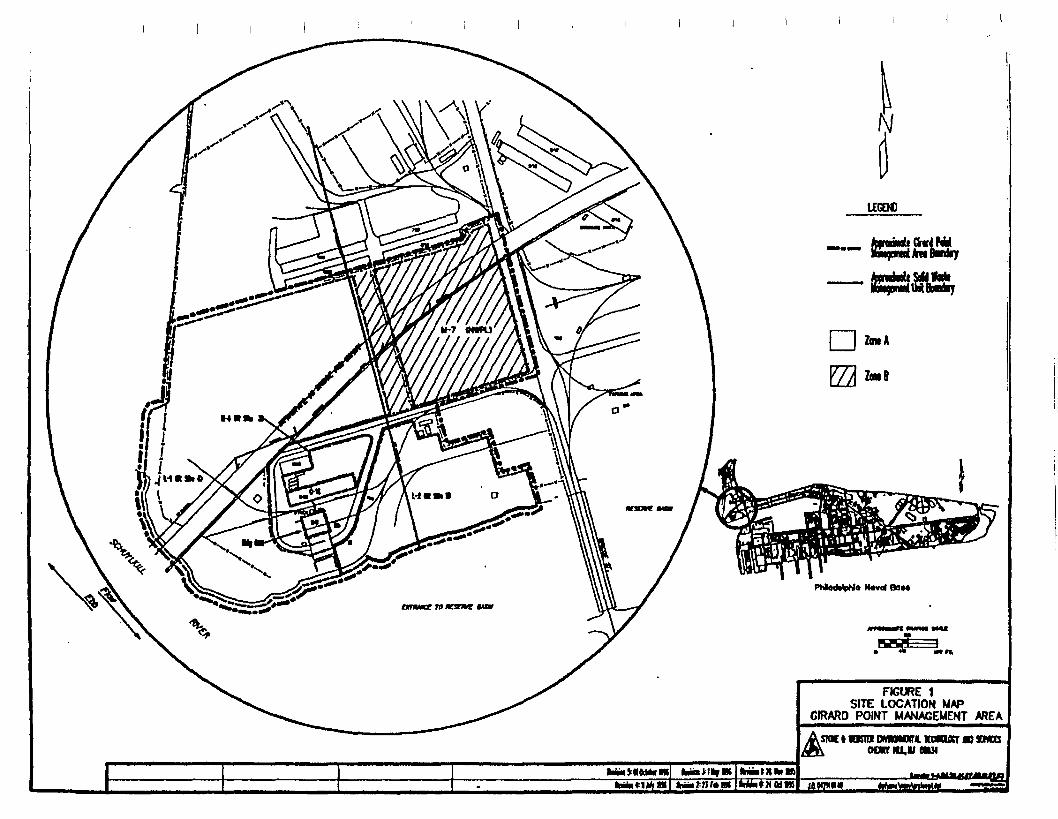
The GPMA is a peninsula located in the northwest area of the Philadelphia Naval Business Center(formerly the Philadelphia Naval Base) at the confluence of the Schuylkill and Delaware Rivers asshown on Figures 1-1 and 1-2. The 1-95 Girard Point Bridge, spanning the Schuylkill River, passesdirectly over and bisects the site.
The GPMA is a generally flat, vegetated/paved, 25-acre site historically used for the treatment,storage, and disposal of solid wastes generated at the Philadelphia Naval Base. Portions of the areawere created by landfilling associated with these waste management activities. Landfills at the sitecontain construction debris, incinerator ash, suspected foundry slag/sand, spent blasting grit used forpaint removal, and municipal waste, as well as, soil and fill materials (river dredge materials).
Because the individual sites that comprise the GPMA share a similar site history and proposed futureuse, a Conceptual Site Model for the Girard Point Management Area (Stone & Webster, 1996) and aSite Characterization Report for the Girard Point Management Area (Stone & Webster, 1997b) wereprepared to combine the available data, characterize the nature and extent of the site's constituents ofpotential concern (COPCs), and evaluate the risks posed by the site to the potential receptors. Theproposed future use of the GPMA is currently as an 89-acre light industrial park, the Girard PointIndustrial Park , consisting of warehousing and light industrial facilities.
To evaluate the nature and extent of the COPCs at the site and the risk posed by the site to thepotential receptors, GPMA was divided into two operable units: Zones A and B. Zone A consists of thetwo site landfills at Installation Restoration Program (IR) Sites 4 and 5. This zone covers an area of 11.2acres and contains approximately 280,000 cubic yards of fill. Zone B consists of a former 1.25-acre
Philadelphia Naval Business Center Girard Point Management Area
Five Year Reviewdiv42\brac\042911850\task6A_5YEAR\FINALSYEARGPMA.doc
Project J.O. 04291.18.50Five-Year Review
Revision: FinalPage 2
transformer storage area (IR Site 3), a former 4-acre Resource Conservation and Recovery Act (RCRA)storage facility (the North West Parking Lot (NWPL)), the former Girard Point incinerator (Building668), and a 7-acre area formally used to store spent blasting grit (referred to as the area west of theNWPL). Zone B covers an area of 13.2 acres and contains approximately 86,000 cubic yards of fill.
The zones, as described above, were delineated for risk assessment purposes. Prior to issuance of theROD, the site was divided into zones for purpose of remedial alternative discussion. This wifl bediscussed further in Section 2.0.
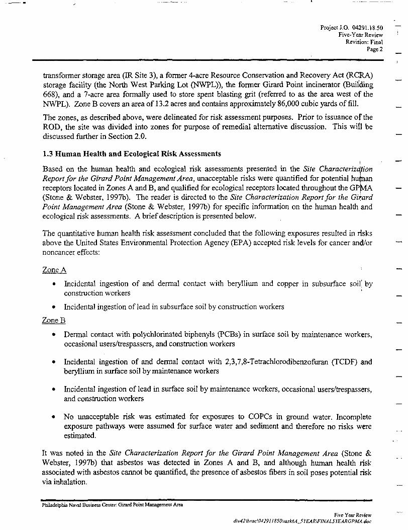
1.3 Human Health and Ecological Risk Assessments
Based on the human health and ecological risk assessments presented in the Site CharacterizationReport for the Girard Point Management Area, unacceptable risks were quantified for potential huftianreceptors located in Zones A and B, and qualified for ecological receptors located throughout the GPp/LA(Stone & Webster, 1997b). The reader is directed to the Site Characterization Report for the Gir,ardPoint Management Area (Stone & Webster, 1997b) for specific information on the human health andecological risk assessments. A brief description is presented below.
The quantitative human health risk assessment concluded that the following exposures resulted in risksabove the United States Environmental Protection Agency (EPA) accepted risk levels for cancer and/ornoncancer effects:
Zone A '
• Incidental ingestion of and dermal contact with beryllium and copper in subsurface soil' byconstruction workers
• Incidental ingestion of lead in subsurface soil by construction workers
ZoneB
• Dermal contact with polychlorinated biphenyls (PCBs) in surface soil by maintenance workers,occasional users/trespassers, and construction workers
• Incidental ingestion of and dermal contact with 2,3,7,8-Tetrachlorodibenzofuran (TCDF) andberyllium in surface soil by maintenance workers
• Incidental ingestion of lead in surface soil by maintenance workers, occasional users/trespassers,and construction workers
• No unacceptable risk was estimated for exposures to COPCs in ground water. Incompleteexposure pathways were assumed for surface water and sediment and therefore no risks wereestimated.
It was noted in the Site Characterization Report for the Girard Point Management Area (Stone &Webster, 1997b) that asbestos was detected in Zones A and B, and although human health riskassociated with asbestos cannot be quantified, the presence of asbestos fibers in soil poses potential riskvia inhalation.
Philadelphia Naval Business Center Girard Point Management Area
Five Year Reviewdiv42\brac\042911850\task6A_5 YEAR\FINAL5 YEARGPMA.doc
Project J.O. 04291.18.50Five-Year Review
Revision: FinalPage 3
The qualitative ecological risk assessment performed throughout the GPMA concluded that there was isthe potential for unacceptable risk resulting from the following exposures:
• Ingestion of metals in surface soil, plant material, and insects by insectivorous birds
• Ingestion of metals in surface soil and plant material by granivorous birds
• Ingestion of, and dermal contact with metals, semivolatile organic compounds (SVOCs),including polycyclic aromatic hydrocarbons (PAHs), pesticides, and PCBs in surface soil andplant material by herbivorous small mammals.
No complete exposure pathways were identified for ecological receptors to subsurface soil, groundwater, surface water, or sediment.
Philadelphia Naval Business Center Girard Point Management Area
Five Year Review<liv42\brac\0429I1850\task6A_S YEAR\F!NAL5 YEARCPMA.doc
. OUADHANGLE tOCATtON
nire 1-1Site Locus Map
Philadelphia Naval BaseGirard Point Management Area
Scale: 1 in.* 2000 ftNGVD 1929Date: 1994Source: USGS 7.5 Minute Philadelphia QuadrangleJ.O. 04291.01.40
Stone & Webster Engineering CorporationCherry Hill, NJ
forPhiladelphia Naval Base
"•"^"VrJLJt
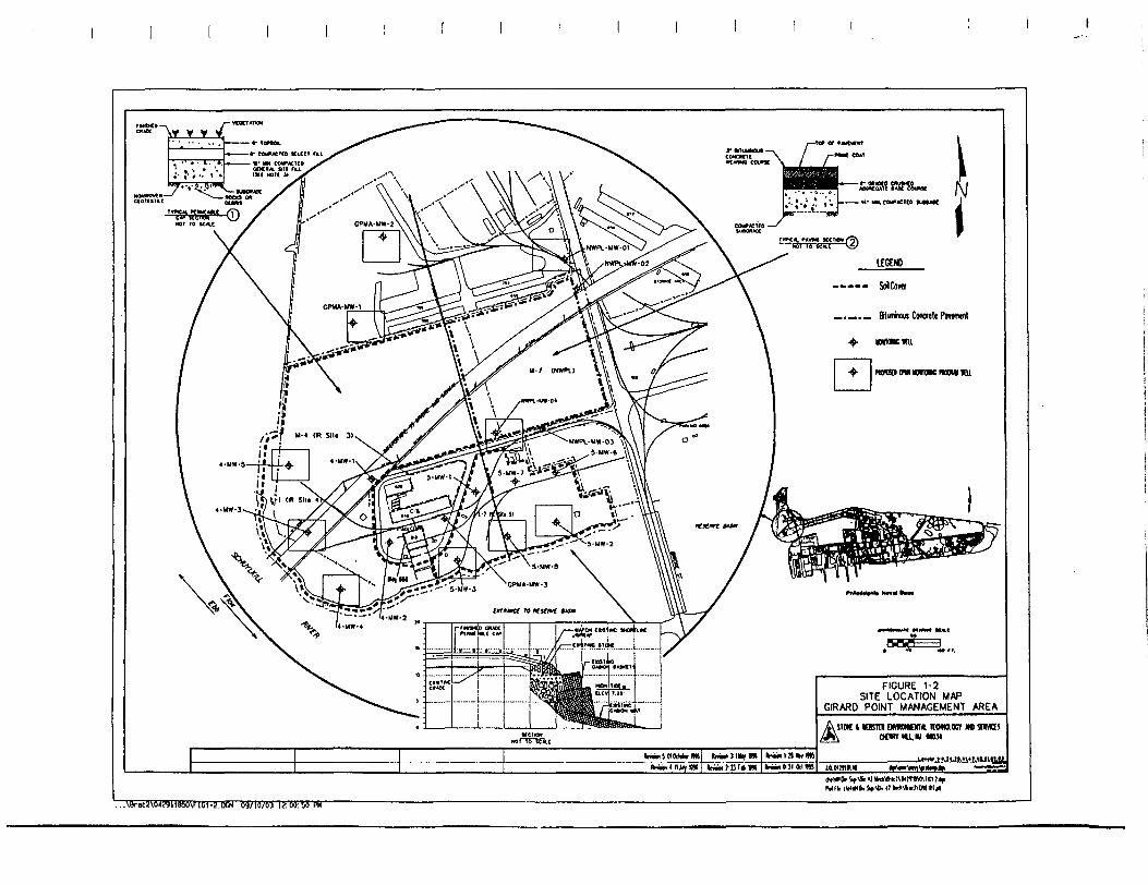
l£GJNO
..... SoJCom
_._._ Stuninom Concrete Powncnl
MMCKU
NtMa M moM now nL
FIGURE 1-2SITE LOCATION MAP
GIRARO POINT MANAGEMENT AREA
A STOC t KKTCI OMNNMTA llOmOCT Ml 3IVO!/>»\ ontr »t« DOM
ABrK;^HH6MVP|Ct-5.IKiH 89/18/63 I?:M:M PU
Project J.O. 04291.18.50Five-Year Review
Revision: FinalPage 4
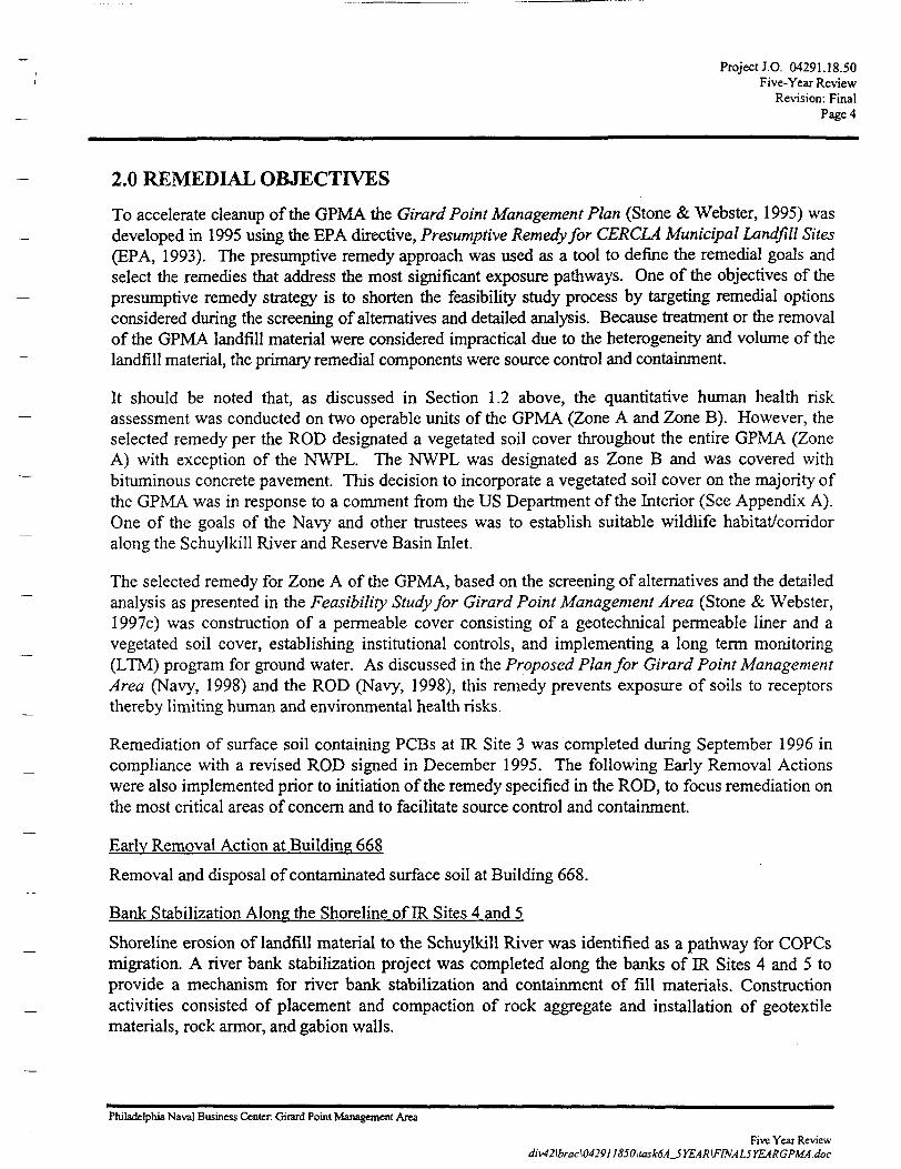
2.0 REMEDIAL OBJECTIVES
To accelerate cleanup of the GPMA the Girard Point Management Plan (Stone & Webster, 1995) wasdeveloped in 1995 using the EPA directive, Presumptive Remedy for CERCLA Municipal Landfill Sites(EPA, 1993). The presumptive remedy approach was used as a tool to define the remedial goals andselect the remedies that address the most significant exposure pathways. One of the objectives of thepresumptive remedy strategy is to shorten the feasibility study process by targeting remedial optionsconsidered during the screening of alternatives and detailed analysis. Because treatment or the removalof the GPMA landfill material were considered impractical due to the heterogeneity and volume of thelandfill material, the primary remedial components were source control and containment.
It should be noted that, as discussed in Section 1.2 above, the quantitative human health riskassessment was conducted on two operable units of the GPMA (Zone A and Zone B). However, theselected remedy per the ROD designated a vegetated soil cover throughout the entire GPMA (ZoneA) with exception of the NWPL. The NWPL was designated as Zone B and was covered withbituminous concrete pavement. This decision to incorporate a vegetated soil cover on the majority ofthe GPMA was in response to a comment from the US Department of the Interior (See Appendix A).One of the goals of the Navy and other trustees was to establish suitable wildlife habitat/corridoralong the Schuylkill River and Reserve Basin Inlet.
The selected remedy for Zone A of the GPMA, based on the screening of alternatives and the detailedanalysis as presented in the Feasibility Study for Girard Point Management Area (Stone & Webster,1997c) was construction of a permeable cover consisting of a geotechnical permeable liner and avegetated soil cover, establishing institutional controls, and implementing a long term monitoring(LTM) program for ground water. As discussed in the Proposed Plan for Girard Point ManagementArea (Navy, 1998) and the ROD (Navy, 1998), this remedy prevents exposure of soils to receptorsthereby limiting human and environmental health risks.
Remediation of surface soil containing PCBs at IR Site 3 was completed during September 1996 incompliance with a revised ROD signed in December 1995. The following Early Removal Actionswere also implemented prior to initiation of the remedy specified in the ROD, to focus remediation onthe most critical areas of concern and to facilitate source control and containment.
Early Removal Action at Building 668
Removal and disposal of contaminated surface soil at Building 668.
Bank Stabilization Along the Shoreline of IR Sites 4 and 5
Shoreline erosion of landfill material to the Schuylkill River was identified as a pathway for COPCsmigration. A river bank stabilization project was completed along the banks of IR Sites 4 and 5 toprovide a mechanism for river bank stabilization and containment of fill materials. Constructionactivities consisted of placement and compaction of rock aggregate and installation of geotextilematerials, rock armor, and gabion walls.
Philadelphia Naval Business Center Guard Point Management Area
Five Year Reviewdiv42\brac\0429J1850\task6A_5Y£AR\FrNAL5YEARGPMA.doc
Project J.O. 04291.18.50Five-Year Review
Revision: FinalPage 5
Decontamination of Building 668 and Demolition of the Adjoining Incinerator Stack
Samples of incinerator ash were reported to contain concentrations of cadmium in excess of theregulatory waste classification limits. Removal and disposal of the ash material and the inoperableincinerator units, and demolition and disposal of the incinerator stack were completed.
Storm- Water Sewer Engineering Survey Including Line Cleaning
A possible migratory pathway identified in the Conceptual Site Model for the Girard PointManagement Area (Stone & Webster, 1996) was the storm water sewer system and the surroundingporous fill. The system discharges directly to the Schuylkill River and the entrance to, thePhiladelphia Naval Base Reserve Basin and is subject to tidal influence and potential ground-waterinfiltration. An engineering survey was performed to evaluate the physical condition of the system. Inaddition, line cleaning was conducted to facilitate a closed circuit television survey with videotaping.
Underground Storage Tank Removal
Removal and closure of a 12,000-gallon fuel product underground storage tank, located at thenortheast corner of Building 668, was completed in 1997.
2.1 Long Term Ground-Water Monitoring Program
A LTM program was implemented, as a component of the selected remedy, to address potentialenvironmental concern related to leaching of landfill material and the potential discharge of COPCsfrom the shallow ground water to the Schuylkill River and the entrance to the Philadelphia NavalBase Reserve Basin. The existing eighteen GPMA ground-water monitoring wells were divided intotwo groups; four wells located in the upgradient flow direction (i.e., upgradient wells) and fourteenwells located in the GPMA and downgradient flow direction (i.e., downgradient wells). Quarterlyground-water sampling of the eighteen shallow wells, using EPA low-flow sampling procedures wasconducted during the weeks of 8 July 1996, 4 October 1996, 24 February 1997, and 5 May 1997.Ground-water samples were collected using peristaltic pumps and analyzed for EPA Target CompoundList/Target Analyte List (TCL/TAL) parameters. TCLTAL analyses included volatile organiccompounds (VOCs), SVOCs, pesticides, PCBs, cyanide, and total (unflltered) metals. Analysis for totaldissolved solids was also performed. Based on the results of the first round of ground-water samples, itwas concluded that the dissolved (filtered) metals and asbestos analyses were unwarranted.
A letter report dated 17 July 1997 presented a one year status report detailing the quarterly samplingresults (i.e., baseline), and recommendations addressing future ground- water monitoring (Stone &Webster, 1997a). Ground- water data from the four quarterly sampling rounds were compared to EPARegion in human health Risk Based Concentration (RBC) tap water screening criteria and EPAfreshwater chronic Ambient Water Quality Criteria (AWQC). As discussed in the Site CharacterizationReport for the Girard Point Management Area (Stone & Webster, 1 997b), the quantitative healthhuman risk assessment concluded that no unacceptable human health risk was estimated for exposuresto COPCs in ground water. Incomplete exposure pathways were assumed for surface water andsediment. As a result, no associated human health risks were estimated. Therefore, comparison to RBCtap water screening criteria was assumed to be non-essential for future ground-water monitoring needs.
Eleven metals were identified as the primary COPCs hi ground water based on that the baselinecomparison to the AWQC (EPA, 1993c). Maximum Environmental Effect Quotient (EEQ) values
Philadelphia Naval Business Center Girard Point Management Area
Five Year Reviewdiv42\brac\042911850\task6A_SYEAR\FINAL5YEARGPMA.doc
Project J.O. 04291.18.50Five-Year Review
Revision: FinalPage 6
were calculated to aid in the comparison and review of the results. Each maximum EEQ wascalculated by dividing the maximum reported concentration by the associated AWQC. According to theEEQ screening approach, if the EEQ exceeds unity, a potential for ecological risk exists.
However, dilution factors associated with ground-water discharge to the Schuylkill River were notconsidered during the preliminary comparison to AWQC and calculation of the EEQs. These dilutionfactors which were estimated to be one to five orders of magnitude (Stone & Webster, 1997b) reduceconcentrations of COPCs to below the AWQC screening levels and EEQs to less than unity.
Based on conclusions presented in the Site Characterization Report for the Girard Point ManagementArea (Stone & Webster, 1997b), a Goals Paper (Stone & Webster, 1998c) was prepared to discussoverall objectives of the LTM,program, how these objectives were consistent with the Proposed Planfor Girard Point Management Area (Navy, 1998), ROD, and exit strategies for the LTM program. Acopy of the Goals Paper is presented in Appendix B.
Data Quality Objectives (DQOs) were developed in accordance with EPA Guidance for the DataQuality Objectives Process (EPA, 1994) as part of the Goals Paper (Stone & Webster, 1998c). Basedon use of the DQOs development process and the data evaluation presented in the Goals Paper (Stone& Webster, 1998c), the number of wells sampled and list of COPCs were reduced to ten monitoringwells and nine metals (arsenic, cadmium, chromium, copper, lead, mercury, nickel, selenium, and zinc),respectively. The following decision rule and recommendations were established to verify that the ninemetals remain at concentrations that do not pose a potential for ecological risk:
• Evaluate the existing ground-water data baseline for seasonality.
• If discernible seasonality is not present, maximum concentrations of the July and October 1996sampling rounds and February and May 1997 sampling rounds will be used to represent 1996and 1997 annual concentrations, respectively.
• Annual sampling of the ten monitoring wells and analysis of nine metals for duration of fiveyears. This approach is consistent with conclusions presented in the Feasibility Study (Stone &Webster, 1997d) and the Proposed Plan (Navy, 1998), and federal and state regulations
• The .monitoring endpoint will therefore be based on consensus by the Base Realignment andClosure Act (BRAC) Cleanup Team (BCT) that the decision rule stated in the Goals Paper(Stone & Webster, 1998c) has been satisfied. That rule says: "If maximum EEQs for ninemetals (arsenic, cadmium, chromium, copper, lead, mercury, nickel, selenium, and zinc) remainbelow unity (when considering dilution factors of one to five orders of magnitude) during a five-year period, then the GPMA ground-water monitoring program will be terminated."
• Confirmation sampling will be conducted on any of the ten monitoring wells sampled duringthe annual sampling rounds, if a maximum EEQ exceeds unity (considering a dilution factor ofthree orders of magnitude). If confirmation sampling EEQs exceed unity (considering adilution factor of three orders of magnitude), then the EEQs will be evaluated consideringdilution factors of four and five orders of magnitude. PADEP will be contacted if confirmationsampling is conducted.
Philadelphia Naval Business Center Girard Point Management Area
Five Year Reviewdiv42\brac\0429II850\task6A_5YEAR\FrNAL5YEARGPMA.doc
Project J.O. 04291.18.50Five-Year Review
Revision: FinalPage?
• If the decision rule is not met, PADEP will be contacted, ground-water monitoring will beconducted beyond the initial five-year period, and a ground-water monitoring decision tree willbe developed.
Philadelphia Naval Business Center Girard Point Management Area
Five Year Reviewdiv42\brac\04291I850\task6A
Project J.O. 04291.18.50Five-Year Review
Revision: FinalPageS
3.0 FIVE-YEAR REVIEW
3.1 Site Inspection and Photo-documentation
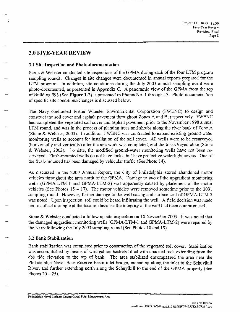
Stone & Webster conducted site inspections of the GPMA during each of the four LTM programsampling rounds. Changes in site changes were documented in annual reports prepared for theLTM program. In addition, site conditions during the July 2003 annual sampling event werephoto-documented, as presented in Appendix C. A panoramic view of the GPMA from the topof Building 993 (See Figure 1-2) is presented in Photos No. 1 through 13. Photo-documentationof specific site conditions/changes is discussed below.
The Navy contracted Foster Wheeler Environmental Corporation (FWENC) to design andconstruct the soil cover and asphalt pavement throughout Zones A and B, respectively. FWENChad completed the vegetated soil cover and asphalt pavement prior to the November 1998 annualLTM round, and was in the process of planting trees and shrubs along the river bank of Zone A(Stone & Webster, 2003). In addition, FWENC was contracted to extend existing ground-watermonitoring wells to account for installation of the soil cover. All wells were to be resurveyed(horizontally and vertically) after the site work was completed, and the locks keyed-alike (Stone& Webster, 2003). To date, the modified ground-water monitoring wells have not been re-surveyed. Flush-mounted wells do not have locks, but have protective watertight covers. One ofthe flush-mounted has been damaged by vehicular traffic (See Photo 14).
As discussed in the 2000 Annual Report, the City of Philadelphia stored abandoned motorvehicles throughout the area north of the GPMA. Damage to two of the upgradient monitoringwells (GPMA-LTM-1 and GPMA-LTM-2) was apparently caused by placement of the motorvehicles (See Photos 15 - 17). The motor vehicles were removed sometime prior to the 2001sampling round. However, further damage to the well casing and surface seal of GPMA-LTM-2was noted. Upon inspection, soil could be heard infiltrating the well. A field decision was madenot to collect a sample at the location because the integrity of the well had been compromised.
Stone & Webster conducted a follow up site inspection on 10 November 2003. It was noted thatthe damaged upgradient monitoring wells (GPMA-LTM-1 and GPMA-LTM-2) were repaired bythe Navy following the July 2003 sampling round (See Photos 18 and 19).
3.2 Bank Stabilization
Bank stabilization was completed prior to construction of the vegetated soil cover. Stabilizationwas accomplished by means of wire gabion baskets filled with quarried rock extending from theebb tide elevation to the top of bank. The area stabilized encompassed the area near thePhiladelphia Naval Base Reserve Basin inlet bridge, extending along the inlet to the SchuylkillRiver, and further extending north along the Schuylkill to the end of the GPMA property (SeePhotos 20 - 25).
Philadelphia Naval Business Center. Girard Point Management Area
Five Year Reviewdiv42\brac\04291I8SO\task6A_5YEAR\FlNAL5YEARGPMA.doc
Project J.O. 04291.18.50Five-Year Review
Revision: FinalPage 9
The purpose of the stabilization was to prevent contaminated sediments from eroding along the Tshoreline and deposition into the Schuylkill River. To prevent migration of soil through thebaskets, the baskets are lined on the land side by geofabric. _
Visual inspection of the bank stabilization was performed at the time of each annual ground-water sampling event. The 2001 inspection revealed two missing baskets at the toe of the bank _under the 1-95 Girard Point Bridge; the location where the baskets are missing can only be seen atebb tide (See Photo 26). The baskets were probably dislodged or torn apart by ice flows orfloating debris (See Photo 27). The Navy will replace these gabion baskets as part of bank —stabilization maintenance.
In addition, a guide for the trash gate cable, located at the eastern portion of IR Site 5 was never —installed. The absence of the guide has caused damage to the top of the gabion wall and the cable(See Photos 28 and 29). However, it was noted during the 10 November 2003 site inspectionthat the Navy has addressed this site condition by placement of a protective steel sheet on top of —the gabion wall (See Photo 30).
Despite the small amount of damage, the bank stabilization continues to be in an overall good ~~state of repair with no other signs of instability. The goal of preventing contaminated sedimentfrom being transported into the Schuylkill River is being accomplished.
3.3 Permeable and Vegetated Cover
In 1998, IR Sites 4 and 5 were covered with a geotextile/permeable liner and a vegetated soil _cover. The liner acts as a boundary between the then existing landfill cover and clean fill. Thelandfill liner is covered by a minimum of twenty four inches of soil suitable to supportvegetation. (See Figure 1-2). The landfill liner and vegetated soil cover encompass an area of —approximately 21 acres. Within fifty feet of the river bank, the site was graded landward toreduce flow of sediment from the landfill to the river.
A visual inspection of the vegetated soil cover and bituminous concrete pavement was performedeach annual ground-water sampling. The soil cover is well vegetated with tall weeds, new treeplantings, wildflowers, and grass (See Photos 1-13, and 31 - 34). No outward signs of erosion ~~were observed in the drainage swales (See Photos 31 and 32) or damage or cracks in thebituminous concrete pavement. However, the tall weeds prevented a thorough inspection at thetime of the 2003 inspection. A few deciduous trees planted in the 50-foot zone adjacent to theriver bank have died and should be replaced (See Photo 35). There were no areas observedwhich indicated that the integrity of the permeable soil cap was at risk.
Mowing of the area has not been performed to maintain the wildlife habitat. However, it wasnoted during the July 2003 annual inspection that the tall vegetation has obstructed the gas linewarning sign (See Photo 36). The underground gas line crosses the Philadelphia Naval BaseReserve Basin Inlet at the former IR Site 5. Periodic mowing adjacent to this sign and debrisremoval from drainage swales to prevent blockage of the outfall pipe (See Photo 37) are required. —
Philadelphia Naval Business Center Girard Point Management Area
Five Year Review —div42\brac\0429U850\task6A_SYEAR\F[NAL5YEARGPMA.doc
Project J.O. 04291.18.50Five-Year Review
Revision: FinalPage 10
3.4 Restricted Access and Institutional Controls
The GPMA was transferred to the City of Philadelphia under the Base Realignment and ClosureAct on 30 March 2000. Access to the GPMA is limited by a locked fence (See Photo 13) thatextends along the eastern, northern, and northwestern perimeters, and the Schuylkill River, andPhiladelphia Naval Base Reserve Basin Inlet (See Figure 1-2). However, an uncontrolledopening to the GPMA exists at a railroad access north of the NWPL. Vehicular traffic is unlikelyto maneuver over the track, but the GPMA is accessible by pedestrians.
As stipulated in the ROD, the selected remedy was based on the following base-wide and site-specific institutional controls: /
Base-wide Institutional Controls
• Ground water withdrawn from wells shall not be used or made available for humanconsumption.
• GPMA shall not be used or developed for any permanent residential uses.
• Any construction or development of an outdoor childcare playground will include theplacement of two feet of clean fill material, or other cover as approved by thePennsylvania Department of Environmental Protection (PADEP), between the underlyingsoil and the surface of the childcare playground prior to commencement of any use of theoutdoor area as a playground.
Site-specific Institutional Controls
• An Institutional Control such that excavation shall not be accomplished without priorwritten approval of PADEP.
3.5 Long Term Ground-Water Monitoring
Pursuant to the base-line ground-water sampling performed during 1996-1997; four subsequentsampling events have occurred: November 1998, May 2000, August 2001, and July 2003. Thefollowing reports were prepared to show the results of the sampling:
• 1998 Annual Report — Long Term Monitoring Program for Girard Point ManagementArea at Philadelphia Naval Business Center, Philadelphia Pennsylvania.
• 2000 Annual Report - Long Term Monitoring Program for Girard Point ManagementArea at Philadelphia Naval Business Center, Philadelphia Pennsylvania
• 2001 Annual Report - Long Term Monitoring Program for Girard Point ManagementArea at Philadelphia Naval Business Center, Philadelphia Pennsylvania
Philadelphia Naval Business Center Girard Point Management Area
Five Year Reviewdiv42\brac\0429118SO\task6A_5YE.AR\F!NAL5YEARGPMA.doc
Project J.O. 04291.18.50Five-Year Review
Revision: FinalPage 11
• 2003 Annual Report - Long Term Monitoring Program for Girard Point ManagementArea at Philadelphia Naval Business Center, Philadelphia Pennsylvania
A summary of the maximum detected EEQs of each of the sampling rounds for the suite of wellsis shown in Table 3-1. See the 2003 Annual Report for a more complete discussion.
As can be observed in the table, the decision rule, agreed upon by the Navy and stated in theGoals Paper (Stone & Webster, 1998) and Section 2.1, has been met. Therefore, the monitoringprogram can be concluded.
In addition, the following observations were noted in the 2003 Annual Report, in reference to thefive years of ground water monitoring:
• Maximum concentrations of arsenic, cadmium, chromium, nickel, and selenium neverrequired more than one order of magnitude dilution to achieve an EEQ of less than unitysubsequent to the base line sampling period.
• Maximum lead concentrations required one order of magnitude dilution to achieve anEEQ of less than unity for the most recent round of sampling and never required morethan two orders of magnitude dilution during the five-year period.
• Maximum zinc concentrations required two orders of magnitude dilution to achieve anEEQ of less than unity for each sampling period during the five-year period.
• Maximum copper concentrations required three orders of magnitude dilution to achievean EEQ of less than unity for the first time since the base line sampling event. All othersampling rounds required two orders of magnitude dilution to achieve an EEQ of lessthan unity for the maximum copper concentration.
• Maximum mercury concentrations required two orders of mercury dilution to achieve anEEQ of less than unity. Mercury was the only metal to require more than three orders ofmagnitude dilution for a particular sampling event (May 2000) to achieve an EEQ of lessthan unity, though the subsequent confirmation round only required three orders ofmagnitude dilution to achieve an EEQ of less than unity.
• Based on the baseline and five-year data, definitive increasing or decreasing maximumconcentration trend cannot be interpreted for arsenic, cadmium, chromium, lead, mercury,and selenium.
• Subsequent to the baseline period, maximum concentrations of copper, nickel, and zinchave increased; it is not certain if the increase is a trend or if the values are within theexpected range of maximum concentrations.
Philadelphia Naval Business Center Girard Point Management Area
Five Year Reviewdiv42\brac\042911850\task6A_5YEAR\FlNAL5YEARGPM4.doc
Project J.O. 04291.18.50Five-Year Review
Revision: FinalPage 12
• Nickel and chromium have maximum concentrations detected in the most recent roundthat were reported above the baseline detected concentrations. Each of these metals onlyrequired one order of magnitude dilution to achieve an EEQ of less than unity.
• Except for arsenic (GPMA-LTM-3) and chromium (GPMA-LTM-4), maximumconcentrations of the metals were detected in downgradient well GPMA-LTM-5. This isconsistent with the August 2001 results, except that maximum concentration of lead wasfound in downgradient well GPMA-LTM-7 and selenium was detected in downgradientwell GPMA-LTM^.
• Trend analysis performed for the maximum EEQ of each metal for a particular samplingevent and the year of the sampling event is included as Appendix D. As can be seen fromthe analysis, in particular the coefficient of determination (R2), very little of the variationof the EEQ can be explained by the year of the sampling event. Only the trend analysesfor arsenic and selenium have significant values. That is to say, a portion of the variance(58% for arsenic and 48% for Selenium) for the EEQ can be explained by the year inwhich the sampling took place. The remainder of the trend analyses show very littlecorrelation between time and maximum EEQ. Both arsenic and selenium indicate adeclining trend.
Ftntaddpba Nival Btsioss Center Girmrd Point Management Area
Rve Year Review
•o' Cs'1OJ3
a£C*3
C/Df^oo
cw
^f*
oo
o
1 sof •<ON "c*H Q
~ of i
^ ON g
L_ 1- C~ ^ •—
C ^^
•- "25 £Q G
Oawu£s£*x«
<M
O
oVI
'Ca£0U
1 ~C Q
" ^*^J '"^
S w 'om ^*O **>O O
E *-,P C£ °'x Cx'"3
Ctf rTT »*-r
SlSao §o O(N - — -
I ~P C£ .2•gas* (jj rpS W Qo >5o >^CM •—
£ *P C
.E -25 w •=S w Q00 *J
ON O
cx*r-. W "c1
ON W °
2 E 1S.I 5^_| X "^
ia
U
o
s
asi— o
^ .
.
^1o
<JJ
r~o
^§
o
—1
2
1 A
rsen
ic
—<N00T— (
»— C
OO
S~**\
t-~<N
^t
^Q
r?
CN
1 C
adm
ium
<-<
P!f\i
— 'ON
y^^\
ONfN
CT(N
-H
r-
1 C
hrom
ium
rn"
o0^-^
(N
r-;
, ,(N-
0VO
^^^
CSoo06
CO
<NO
o.n.oU
"-ootNON
(N
O
^ ,
OO
^ri
—
ON
3
(N
10
*n
rn"
en
/ — . *
^ {r^00 o'~ 2
s~^(N
S
C3-m
3ao
^^
^00
C^J
^^^— 1
Ov
vq
^5
0
Z?
^j
o
jz
6"ZO
c^m0
/(_ N
— i
£
^
0
"$
0
^5
I S
elen
ium
^^Ci-VOoo^~
<N
s^
ON
^ ^cso
r^o
N
1'BCT*
|j^oo
o
5i
—pO "rtre 4>
•— 00. BC- U< D"o o^ ^
<Q2 2
'c
c(S
s
oCXWU
E.HiIlls^ o 2*l1!^^P £ E"SEh u re S« (2 c/2 w
| § | |
•§ ^ *H o1: 2 o <N0 0 U
3
C J0 U
1 s2 a2 » wO * * w
isII£5E31
a;g
">,
cs3
I<N
U
|
S
I
•2eo
S%
c.
1
Project: J.O. 04291.18.50Conclusions and Recommendations
Revision: FinalPage 14
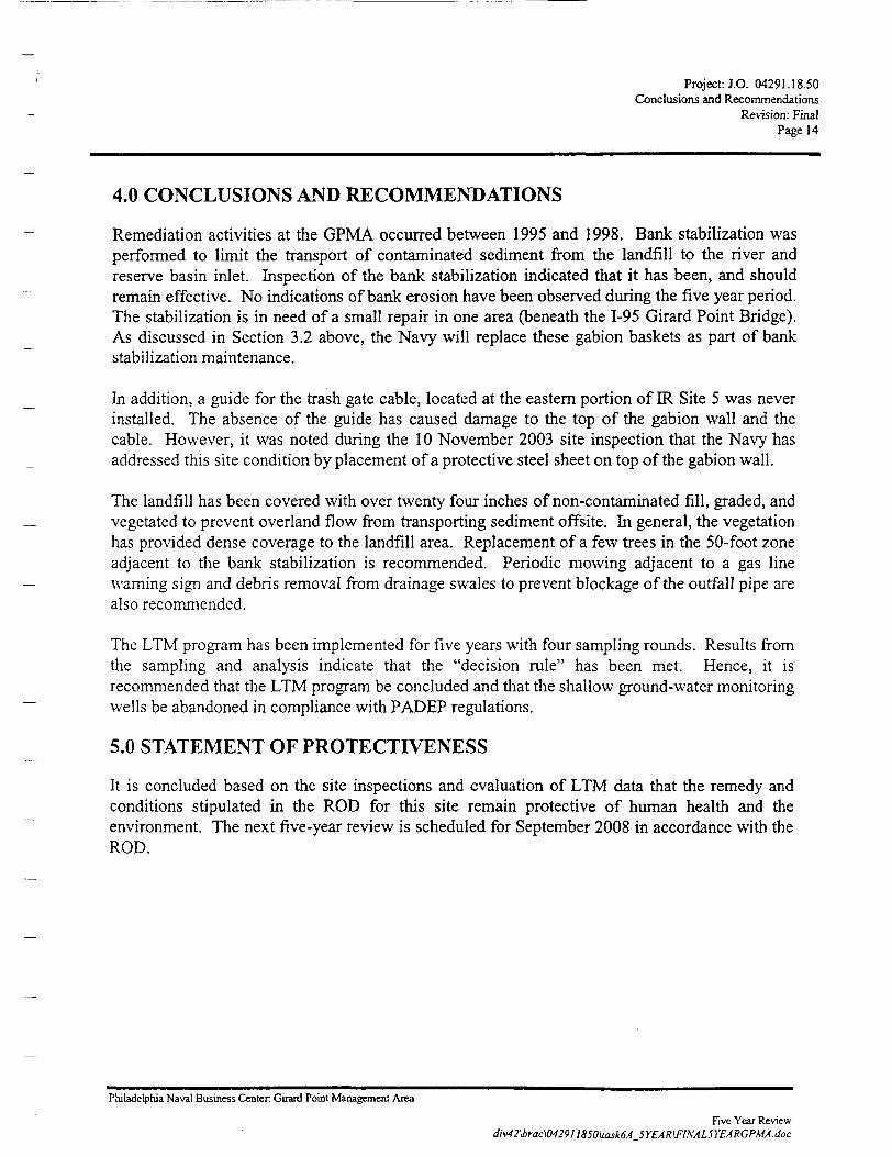
4.0 CONCLUSIONS AND RECOMMENDATIONS
Remediation activities at the GPMA occurred between 1995 and 1998. Bank stabilization wasperformed to limit the transport of contaminated sediment from the landfill to the river andreserve basin inlet. Inspection of the bank stabilization indicated that it has been, and shouldremain effective. No indications of bank erosion have been observed during the five year period.The stabilization is in need of a small repair in one area (beneath the 1-95 Girard Point Bridge).As discussed in Section 3.2 above, the Navy will replace these gabion baskets as part of bankstabilization maintenance.
In addition, a guide for the trash gate cable, located at the eastern portion of IR Site 5 was neverinstalled. The absence of the guide has caused damage to the top of the gabion wall and thecable. However, it was noted during the 10 November 2003 site inspection that the Navy hasaddressed this site condition by placement of a protective steel sheet on top of the gabion wall.
The landfill has been covered with over twenty four inches of non-contaminated fill, graded, andvegetated to prevent overland flow from transporting sediment offsite. In general, the vegetationhas provided dense coverage to the landfill area. Replacement of a few trees in the 50-foot zoneadjacent to the bank stabilization is recommended. Periodic mowing adjacent to a gas linewarning sign and debris removal from drainage swales to prevent blockage of the outfall pipe arealso recommended.
The LTM program has been implemented for five years with four sampling rounds. Results fromthe sampling and analysis indicate that the "decision rule" has been met. Hence, it isrecommended that the LTM program be concluded and that the shallow ground-water monitoringwells be abandoned in compliance with PADEP regulations.
5.0 STATEMENT OF PROTECTIVENESS
It is concluded based on the site inspections and evaluation of LTM data that the remedy andconditions stipulated in the ROD for this site remain protective of human health and theenvironment. The next five-year review is scheduled for September 2008 in accordance with theROD.
Philadelphia Naval Business Center. Girard Point Management Area
Five Year Reviewdiv42\brac\0429n850\uak6A 5YEAR\FlNAL5YEARGPMA.doc
Project: J.O. 04291.18-50References
Revision: FinalPage 15
6.0 REFERENCESDepartment of the Navy, 1998a. Proposed Plan for Girard Point Management Area, PhiladelphiaNaval Complex, Philadelphia, Pennsylvania. June 1998.
. 1998b. Record of Decision.
Stone & Webster. 1996. Conceptual Site Model for the Girard Point Management Area,Philadelphia Naval Base, Philadelphia, Pennsylvania. April 1996.
, 1997a. Site Characterization Report for the Girard Point Management Area atPhiladelphia Naval Base, Philadelphia, Pennsylvania. September 1997.
. 1997b. Feasibility Study for Girard Point Management Area at Philadelphia Naval Base,Philadelphia, Pennsylvania. October 1997.
. 1998a. Goals Paper Ground-Water Monitoring Program for Girard Point ManagementArea at Philadelphia Naval Base, Philadelphia, Pennsylvania. 30 June 1998.
. 1998b. Long Term Ground-Water Monitoring Plan for Girard Point Management Area atPhiladelphia Naval Base, Philadelphia, Pennsylvania. 9 December 1998.
1999. 1998 Annual Report - Long Term Ground-Water Monitoring Program for GirardPoint Management Area at Philadelphia Naval Business Center, Philadelphia, Pennsylvania. 6August 1999.
. 2000. Draft 2000 Annual Report - Long Term Ground-Water Monitoring Program forGirard Point Management Area at Philadelphia Naval Business Center, Philadelphia,Pennsylvania. 25 September 2000.
. 2001. Draft 2001 Annual Report - Long Term Ground-Water Monitoring Program forGirard Point Management Area at Philadelphia Naval Business Center, Philadelphia,Pennsylvania. 25 November 2001.
. 2003. Draft 2003 Annual Report - Long Term Ground-Water Monitoring Program forGirard Point Management Area at Philadelphia Naval Business Center, Philadelphia,Pennsylvania. September 2003.
United States Environmental Protection Agency (EPA), 1993, Office of Solid Waste andEmergency Response, Directive No. 9355.049FS, Presumptive Remedy for CERCLA MunicipalLandfill Sites. EPA/540/F93/035. September, 1993.
. 1994. USEPA Office of Research and Development, Guidance for the Data QualityObjectives Process. EPA/600/R96/055. September, 1994.
Philadelphia Naval Business Center Girard Point Management Area
Five Year Reviewdiv42\brac\042911850\task6A_5YEAR\FlNAL5YEARGPMA.doc
PtojectJ.O. 04291.1850Appendix A
Revision: Final
APPENDIX A
RECORD OF DECISION
Naval Business Coder CSrard Point!
Hve Year Review
EPA/ROD/R03-99/1081999
EPA SuperfundRecord of Decision:
USN PfflLA NAVAL SHIPYARDEPA ID: PA4170022418OU01PHILADELPHIA, PA12/30/1998
\J
,'\
1 2 - • ; • • ; = • /
RECORD OF DECISION
GIRARD POINTMANAGEMENT AREA
PHILADELPHIA NAVAL COMPLEX
DECEMBER 1998
U.S. Department of the Navy - Northern DivisionPagei
November 1998
RECORD OF DECISIONGirard Point Management Area
Philadelphia Naval BasePhiladelphia, Pennsylvania
TABLE OF CONTENTS
ContentsDECLARATION FOR THE RECORD OF DECISION
1) SITE NAME, LOCATION AND DESCRD7TTON
2) SITE HISTORY AND ENFORCEMENT ACITVTnESa. Site Use and Response Historyb. Enforcement History
3) COMMUNITY PARTICD7ATTON
4) SCOPE AND ROLE OF OPERABLE UNIT OR RESPONSE ACTION
5) SUMMARY OF SITE CHARACTERISTICSa. Nature and Extentb. Fate and Transport
6) SUMMARY OF SITE RISKS
7) DEVELOPMENT AND SCREENING OF ALTERNATIVES
8) DESCRIPTION OF ALTERNATIVES
9) SUMMARY OF THE COMPARATIVE ANALYSIS OF ALTERNATIVES
10) THE SELECTED REMEDY
11) STATUARY DETERMINATIONS
12) STATE ROLE
13) RESPONSIVENESS SUMMARY
14) REFERENCES
Page Numberi
3
4
5
555
7
10
12
14
16
17
20
LIST OF FIGURES
Figure No.
1
Title
GPMA - Site Location Map
Philadelphia Naval Complex Girard Point Management Area - Record of Decision
•' ~ "V in.
FIGURE 1SITE LOCATION MAP
CIRARD POINT MANAGEMENT AREA
A srac i ami DMmarc Konor » SDMCQoanriu,UMM
It 0*7X11 •
Page iiU.S. Department of the Navy - Northern Division November 1998
RECORD OF DECISION
DECLARATION
SITE NAME AND LOCATION
Girard Point Management AreaPhiladelphia Naval ComplexPhiladelphia, Philadelphia County, Pennsylvania
STATEMENT OF BASIS AM) PURPOSE
This decision document presents the selected remedial action for the Girard Point ManagementArea (GPMA), at the Philadelphia Naval Complex in Philadelphia, Pennsylvania which waschosen in accordance with the Comprehensive Environmental Response, Compensation andLiability Act of 1980 (CERCLA), as amended by the Superfund Amendments andReauthorization Act of 1986 (SARA) and to the extent possible the National Oil and HazardousSubstances Pollution Contingency Plan (NCP). This decision is based upon the contents of theadministrative record for this site.
Both the United States Environmental Protection Agency (EPA) and the PennsylvaniaDepartment of Environmental Protection (PADEP) concur with the selected remedy.
DESCRIPTION OF THE SELECTED REMEDY
The Navy has identified the selected remedy at the Girard Point Management Area at thePhiladelphia Naval Complex in Philadelphia, PA (Figure 1). The Navy's selected remedy is basedon the following already established Base-wide Institutional Controls:
••'• Ground water withdrawn from wells shall not be used or made available for humanconsumption (Base-wide Institutional Control)GPMA shall not be used or developed for any permanent residential uses (Base-wideInstitutional Control).
v/» Any construction or development of an outdoor childcare playground will include theplacement of 2 ft of clean fill material, or other cover as approved by PADEP, between theunderlying soil and the surface of the childcare playground prior to commencement of anyuse of the outdoor area as a playground (Base-wide Institutional Control).
Philadelphia Naval Complex Girard Point Management Area - Record of Decision
Page iiiU.S. Department of the Navy - Northern Division November 1998
The following remedy has been selected specifically for the Girard Point Management Area:
• A vegetative cover of the landfill area (Zone A). This will consist of a permeable geomembraneand a minimum two feet soil cover to reduce dermal and inhalation pathway. Vegetation willprovide a buffer from between the Schuylkill River and any industrial activity, and will consistof native grasses and shrubs.
• Asphalt paving of an adjacent parking lot to reduce dermal and inhalation pathway. (Zone B).
• Removal of surface soils surrounding the incinerator.
• Dismantle the incinerator stack incinerator units and decontaminate and the incineratorbuilding.
• Long Term Shallow Ground Water monitoring in accordance with an EPA and PADEPreviewed Long Term Monitoring Plan
An Institutional Control such that excavation shall not be accomplished without prior writtenapproval of PADEP.
Five-year reviews will be conducted to evaluate whether additional remedial actions are requiredA report will be generated detailing each five-year review evaluation.
DECLARATION STATEMENT
Pursuant to the duly delegated authority, I hereby determine, pursuant to Section 106 of CERCLA,42 U.S.C. § 9606 that this remedial action is necessary to ensure protection of human health and theenvironment, and that this alternative complies with federal and state requirements that are legallyapplicable or relevant and appropriate to the site.
Joseph M. Roche DateBRAC Environmental Coordinator
Philadelphia Naval Complex Girard Point Management Area - Record of Decision
PagelU.S. Department of the Navy - Northern Division November 1998
1) SITE NAME, LOCATION AND DESCRIPTION
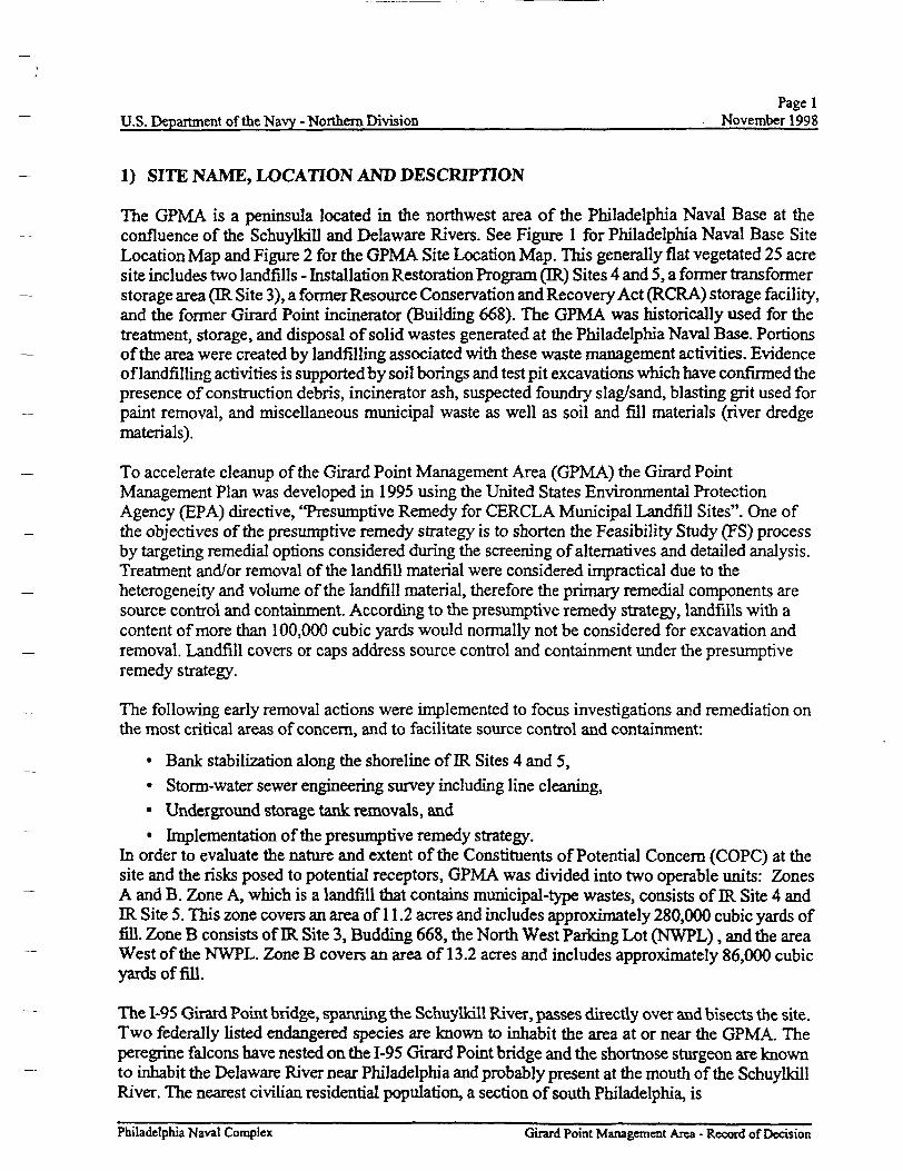
The GPMA is a peninsula located in the northwest area of the Philadelphia Naval Base at theconfluence of the Schuylkill and Delaware Rivers. See Figure 1 for Philadelphia Naval Base SiteLocation Map and Figure 2 for the GPMA Site Location Map. This generally flat vegetated 25 acresite includes two landfills - Installation Restoration Program (IR) Sites 4 and 5, a former transformerstorage area (IR Site 3), a former Resource Conservation and Recovery Act (RCRA) storage facility,and the former Girard Point incinerator (Building 668). The GPMA was historically used for thetreatment, storage, and disposal of solid wastes generated at the Philadelphia Naval Base. Portionsof the area were created by landfilling associated with these waste management activities. Evidenceof landfilling activities is supported by soil borings and test pit excavations which have confirmed thepresence of construction debris, incinerator ash, suspected foundry slag/sand, blasting grit used forpaint removal, and miscellaneous municipal waste as well as soil and fill materials (river dredgematerials).
To accelerate cleanup of the Girard Point Management Area (GPMA) the Girard PointManagement Plan was developed in 1995 using the United States Environmental ProtectionAgency (EPA) directive, "Presumptive Remedy for CERCLA Municipal Landfill Sites". One ofthe objectives of the presumptive remedy strategy is to shorten the Feasibility Study (FS) processby targeting remedial options considered during the screening of alternatives and detailed analysis.Treatment and/or removal of the landfill material were considered impractical due to theheterogeneity and volume of the landfill material, therefore the primary remedial components aresource control and containment. According to the presumptive remedy strategy, landfills with acontent of more than 100,000 cubic yards would normally not be considered for excavation andremoval. Landfill covers or caps address source control and containment under the presumptiveremedy strategy.
The following early removal actions were implemented to focus investigations and remediation onthe most critical areas of concern, and to facilitate source control and containment:
• Bank stabilization along the shoreline of IR Sites 4 and 5,
• Storm-water sewer engineering survey including line cleaning,• Underground storage tank removals, and
• Implementation of the presumptive remedy strategy.In order to evaluate the nature and extent of the Constituents of Potential Concern (COPC) at thesite and the risks posed to potential receptors, GPMA was divided into two operable units: ZonesA and B. Zone A, which is a landfill that contains municipal-type wastes, consists of IR Site 4 andIR Site 5. This zone covers an area of 11.2 acres and includes approximately 280,000 cubic yards offill. Zone B consists of IR Site 3, Budding 668, the North West Parking Lot (NWPL), and the areaWest of the NWPL. Zone B covers an area of 13.2 acres and includes approximately 86,000 cubicyards of fill.
The 1-95 Girard Point bridge, spanning the Schuylkill River, passes directly over and bisects the site.Two federally listed endangered species are known to inhabit the area at or near the GPMA. Theperegrine falcons have nested on the 1-95 Girard Point bridge and the shortnose sturgeon are knownto inhabit the Delaware River near Philadelphia and probably present at the mouth of the SchuylkillRiver. The nearest civilian residential population, a section of south Philadelphia, is
Philadelphia Naval Complex Girard Point Management Area - Record of Decision
Page 2U.S. Department of the Navy - Northern Division November 1998
located approximately 1-1/2 miles to the northeast. Also located to the northeast are a public golfpark and a city park, Roosevelt Park. The park and golf course are located within 1/2 mile of the site.
The site was marshlands until it was covered with fill material between 1940 to 1970. The generalland area surrounding the GPMA is densely populated within one mile to the northeast and heavilyindustrialized within one mile to the north with oil refining and petrochemical plants. The 100 yearflood elevation line is 10 ft above mean sea level (msl) referenced to the National Geodetic VerticalDatum of 1929 (NGVD 1929). Elevations of the riverbank along the GPMA range from 15-18 ftabove msl along the southwest portion of the GPMA at IR Site 4 to 10-12 ft msl along the southportion of the GPMA at IR Site 5. In 1994, wetlands were delineated at the Philadelphia Naval Base.Wetland locations were identified along the northwest comer of the GPMA during a 1994 study.
A more complete description of the sites can be found in the Site Characterization Report (Stone &Webster, 1997).
Philadelphia Naval Complex Girard Point Management Area - Record of Decision
Page 3U.S. Department of the Navy - Northern Division November 1998
2) SITE HISTORY AND ENFORCEMENT ACTIVITIES
Site Use and Response History
IR Site 4 comprises a landfill area of approximately 6 acres. Site history and aerial photographyreviews indicated waste disposal activities occurred between 1940 and 1970. Construction of theGirard Point Incinerator (i.e., Building 668) at the eastern border of IR Site 4 in the early 1940smarked the beginning of waste management operations within the GPMA. Incinerator ash and debrisgenerated at Building 668 were reportedly disposed by filling within the immediate area of Building668. Solid wastes that could not be incinerated, such as metal debris and concrete, were also placedin IR Site 4. These fill materials were identified in the Remedial Investigations (RT) as the main sourceof COPC. Stone & Webster issued the Final RI report for ER. Site 4 in May 1997. An early removalaction consisting of a bank stabilization project was completed at IR Site 4 to mitigate potentialhuman health and ecological risks.
An initial concern identified at the site was the alleged disposal of 50 to 60 pallets of gas cylindersof unknown contents just after World War H A former shipyard employee who was part of theworking crew assigned to the burial of the cylinders identified their potential existence. Afterextensive review of records, interviews, and geophysical investigations in the area, excavation wasaccomplished at the most likely burial area in September 1992. This area was excavated and fieldinspected, but no cylinders were found. Upon completion of the excavation activities and fieldinspection, the Navy concluded, "there are no cylinders buried at IR Site 4 and according to theagreement (with the EPA), the Navy will no longer pursue the search for cylinders at the site."
IR Site 5 is a landfill that covers approximately 5 acres and contains mostly waste blasting grit, alongwith construction debris, miscellaneous debris that was not incinerated at Building 668, andincinerator ash. IR Site 5 shares a similar landfilling history with IR Site 4 in that filling operationsoccurred from the early 1940s until 1970. Fill material at IR Site 5 was found to range in depth from7 to 14 ft below ground surface (bgs). Stone & Webster issued the Final RI report in May 1997. Bankstabilization for IR Site 5 was completed in 1997. Other than IR Sites 4 & 5, the remaining of GirardPoint was used for waste storage.
A detailed description of the site use and response histories can be found in the Final RemedialInvestigation Report IR Site 4 (Stone & Webster, 1997a), Final Remedial Investigation Report(Stone & Webster, 1997b), and the Final Site Characterization Report (Stone & Webster, 1997c).A list of the previous reports can be found in Table 1-1 Summary of Previous Reports in the FinalSite Characterization Report.
ENFORCEMENT HISTORY
The U.S. Navy is responsible for addressing environmental concerns at the Philadelphia NavalComplex, pursuant to Section 120 of CERCLA. Investigation and cleanup of DOD sites, such as thePhiladelphia Naval Complex, are funded through the Department of Defense.
Philadelphia Naval Complex Girard Point Management Area - Record of Decision
Page 4U.S. Department of the Navy - Northern Division November 1998
3) COMMUNITY PARTICIPATION
The Navy has kept the community and other interested parties apprised of site activities throughRestoration Advisory Board (RAB) meetings, which involve community representatives in theclean-up program. The Navy released a community relations plan which outlined a program toaddress community concerns and keep citizens informed. Public participation requirements ofCERCLA Section 113(k)(2)(B)(i-v) and 117 were met in the remedy selection process.
The administrative record is available for public review at the Philadelphia Naval Business Center,Building 501. The Navy published a notice and brief analysis of the Proposed Plan in the PhiladelphiaInquirer May 28, 1998, South Philadelphia review on May 28, 1998 and Southwest PhiladelphiaReview on May 29,1998.
On June 25,1998, the Navy held an informational poster session to present the results of the RI andthe cleanup alternatives presented in the FS and to present the Proposed Plan and answer anyquestions. The session was held at the Holy Spirit Parish house, 1900 Greary Street, Philadelphia.The Navy held a 30 day public comment period which ended July 2,1998 to accept public commenton the alternatives presented in the FS and the Proposed Plan and on any other documents previouslyreleased to the public.
This Record of Decision presents the selected remedial action for GPMA of the Philadelphia NavalComplex in Philadelphia, Pennsylvania, chosen in accordance with the procedures established byCERCLA, as amended by SARA. The decision for the site is based on the Administrative Record,which was available for public review at the Philadelphia Naval Business Center, Building 501 (passOffice) South Broad Street, Philadelphia Pennsylvania.
Philadelphia Naval Complex Girard Point Management Area - Record of Decision
Page 5U.S. Department of the Navy - Northern Division November 1998
4) SCOPE AND ROLE OF OPERABLE UNIT OR RESPONSE ACTION
The selected remedy was developed by combining components of different source control andmanagement of mitigation alternatives to obtain a comprehensive approach for site remediation. Theselected remedy for Zone A consists of a permeable cover, which consists of a geotextile/permeableliner and a vegetated soil cover. The liner will mark the location of the waste, but not eliminateinfiltration of water. The cover will consist of two feet of soil, which will be vegetated with nativegrasses and shrubs. This remedy prohibits exposure with the soil to protect human health and theenvironment. It also provides a vegetated buffer between the Schuylkill River (and its ecology) andthe area adjacent to GPMA, which is proposed for heavy industrial reuse in the City of Philadelphia'sReuse Plan dated September 1994. The selected remedy for Zone B, which consists of paving returns,the area to its former use as a parking lot and prohibits exposure with the soil to protect human healthand the environment. Within Zone B, the removal of soils and decontamination of the incineratorremove possible source areas and eliminate exposure to these areas.
The institutional controls, five-year reviews and long term monitoring plan will ensure that theremedy, will continue to be protective of human health and the environment.
5) SUMMARY OF SITE CHARACTERISTICS
The Final Site Characterization Report contains an overview of the site investigation conducted atthe GPMA. The notable findings of the site investigation are summarized below.
Nature and ExtentCOPC weir, identified in surface soil, subsurface soil and ground water samples collected throughoutthe GPM.A. COPC were identified as those analytes detected above media specific human andecological risk-based concentrations as presented in the Final Site Characterization Report. COPCidentified for human health and ecological risk assessment at the GPMA included semi-volatileorganic compounds (SVOC), pesticides, polychlorinated biphenyls (PCB), metals, dioxins, andasbestos. SVOC, PCB, metals, dioxins, and asbestos were detected in surface and subsurface soilsamples at concentrations above screening levels. Pesticides were only detected at concentrationsabove screening levels in surface soil. The main source of COPC is landfill material, although in thishighly industrialized area sources from other industries cannot be ruled out Differences betweenvertically adjacent samples and the absence of similar COPC in nearby and/or downgradientground-water samples suggest that the COPC are being retained in the fill and are not migratingthrough soil to the ground water or off-site.
COPC identified in ground water included SVOC, pesticides, PCB, and metals. Maximum detectedconcentrations were detected in wells located throughout the GPMA - both upgradient and withinthe landfilled area, Zones A and B.
Fate and Transport
As part of the Final Site Characterization Report, a risk assessment was conducted to estimate thepotential risks to human health posed by the waste attributable to the GPMA. The report alsoestimated the ecological risks from GPMA. The physical-chemical characteristics of the COPC and
Philadelphia Naval Complex Girard Point Management Area - Record of Decision
Page 6 yU.S. Department of the Navy - Northern Division November 1998 /
site conditions identified the potential for site COPC migration. The site COPC will likely adhere or jadsorb to soil particles reducing their mobility in the environment and the potential for migration ofCOPC offsite. According to the Final Site Characterization Report, transport of COPC may be _possible via the following pathways:
• surface soil to surface water via erosion, _• ground water to surface water via ground-water discharge,• surface soil to shallow aquifer ground water to deep aquifer ground water via infiltration, and• Surface and subsurface soil to air via fugitive dust generation.
COPC transported through erosion of surface soil to the Schuylkill River or the Reserve Basin Inlet _is no longer likely to occur due to the implementation of bank stabilization at Zone A. In addition,the site topography slopes away from the Schuylkill River and Reserve Basin Inlet therefore, COPCwould likely be transported toward the interior of the site. __
Transport of the COPC via ground-water movement may discharge COPC into the Schuylkill River.However, transport via ground-water movement are impeded by mechanisms such as natural _attenuation and dispersion.
The potential for downward migration of COPC via water infiltration through surface soil to ground —water would be limited by the low permeability of the native soil, native soil thickness, and lowhydraulic gradients across the native soil. As indicated in ground water and constituent transportmodels presented in the Site Characterization Report, COPC are not likely to migrate to the deep —aquifer over the next 100 years.
The most significant pathway for COPC transport away from the GPMA is fugitive dust migration, —which may potentially be inhaled. COPC may migrate as they adsorb to soil particles, which maybecome airborne as a result of on-site construction or excavation.
A complete discussion of site characteristics can be found in the Remedial investigation Report: IRSite 4, the Remedial Investigation Report: IR Site 5, and the Site Characterization Report.
Philadelphia Naval Complex. Girard Point Management Area - Record of Decision
Page?U.S. Department of the Navy - Northern Division November 1998
6) SUMMARY OF SITE RISKS
The Site Risks were estimated based on the following already established Base-Wide InstitutionalControls:
! Ground water withdrawn from wells shall not be used or made available for humanconsumption (Base-wide Institutional Control)
! GPMA shall not be used or developed for any permanent residential uses (Base-wideInstitutional Control).
! Any construction or development of an outdoor childcare playground will include theplacement of 2 ft of clean fill material, or other cover as approved by PADEP, between theunderlying soil and the surface of the childcare playground prior to commencement of anyuse of the outdoor area as a playground (Base-wide Institutional Control).
Human Health
The quantitative human health risk evaluation for the GPMA considered two zones, Zone Awhich considered the presumptive remedy of a cover and Zone B which assumed no cover. Bothzones were evaluated independently to determine quantitative risks to human health as a result ofexposure to soil. Risk associated with exposure to ground water was evaluated for the entireGPMA. The HHRA assessed the toxicity, or degree of hazard, posed by contaminants related tothe site and involved describing the routes by which humans and the environment could come incontact with these substances. Separate calculations were made for those substances that cancause cancer (carcinogenic) and for those than can cause non-cancerous, but adverse, healtheffects.
The National Oil and Hazardous Substances Pollution Contingency Plan (NCP) establishedacceptable levels of carcinogenic risk ranging from one excess cancer case per 10,000 peopleexposed to one excess cancer case per 1,000,000 people exposed. This translates to a risk rangebetween one in 10,000 and one in 1,000,000 additional cancer cases. Expressed as a scientificnotation, this risk range is between 1 .OE-04 and 1 .OE-06. Remedial action may be warranted at asite when the calculated cancer risk level exceeds 1.OE-04. However, since EPA's clean-up goal isgenerally to reduce the risks to 1 .OE-06 or less, EPA may take action where the risk is within therange between 1 .OE-04 and 1 .OE-06.
The NCP also states that sites could pose a health threat due to a non-cancerous, but otherwisehazardous, substance. EPA defines non-carcinogenic threat by the ratio of the contaminantconcentration at the site that a person may encounter to the established safe concentration. If theratio, called the Hazard Index (HI), exceeds one (1.0), there may be concern for potential non-carcinogenic health effects associated with exposure to the chemicals. The HI identifies thepotential for the most sensitive individuals to be adversely affected by the non-carcinogenic effectsof chemicals. As a rule, the greater the value of the HI, the greater the level of concern.
Potential human health risks associated with exposure to the COPC were estimated quantitativelythrough the development of several hypothetical exposure pathways. These pathways were developedto reflect the potential for exposure to COPC based on the potential future uses and location of theGPMA. The most foreseeable uses are warehousing of light industrial activities. Zone A exposureswere not evaluated under a current use scenario since it was assumed that the presumptive remedy,which includes a cover, would be implemented. The future use scenario
Philadelphia Naval Complex Girard Point Management Area - Record of Decision
rPage?
U.S. Department of the Navy - Northern Division November 1998
assumes the presumptive remedy has been implemented, RI data were used to characterize the humanhealth risks. Exposure parameters for each exposure route and receptor were estimated under averageexposure (AE) and reasonable maximum exposure (RME) assumptions.
Zone A
For Zone A, it was assumed the presumptive remedy of a landfill cover was installed andinstitutional controls would be in place. With this remedy assumed to be in place, only the risk toconstruction workers was evaluated. The exposure routes evaluated in the HHRA included
! Incidental ingestion of surface soil! Inhalation of suspended particulate from the surface soil during excavation and
construction work.
All TCL and TAL data were validated and used for the HHRA. The analytical results werescreened using current EPA Region III Risk-Based Concentration (RBC) screening levels.Representative concentrations for each contaminant of potential concern (CoPC) were calculatedusing the latest risk assessment guidance from EPA.
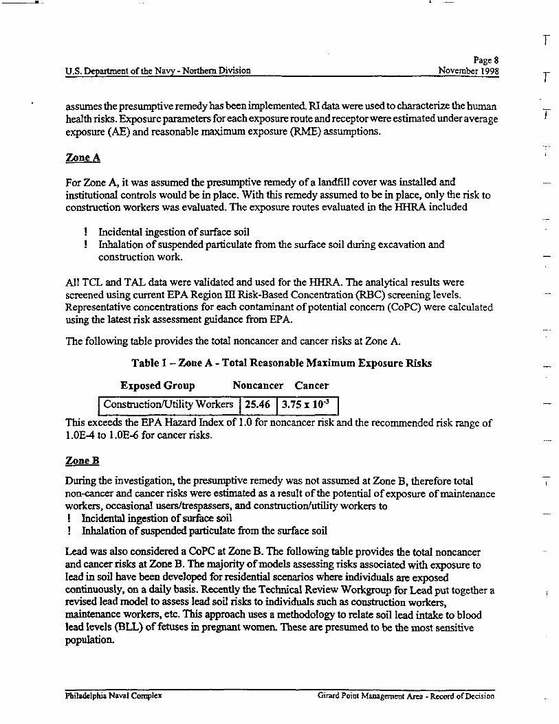
The following table provides the total noncancer and cancer risks at Zone A.
Table 1 - Zone A - Total Reasonable Maximum Exposure Risks
Exposed Group Noncancer Cancer
Construction/Utility Workers 25.46 3.75 x ID'3
This exceeds the EPA Hazard Index of 1.0 for noncancer risk and the recommended risk range of1 .OE-4 to 1 .OE-6 for cancer risks.
ZoneB
During the investigation, the presumptive remedy was not assumed at Zone B, therefore totalnon-cancer and cancer risks were estimated as a result of the potential of exposure of maintenanceworkers, occasional users/trespassers, and construction/utility workers to! Incidental ingestion of surface soil! Inhalation of suspended particulate from the surface soil
Lead was also considered a CoPC at Zone B. The following table provides the total noncancerand cancer risks at Zone B. The majority of models assessing risks associated with exposure tolead in soil have been developed for residential scenarios where individuals are exposedcontinuously, on a daily basis. Recently the Technical Review Workgroup for Lead put together arevised lead model to assess lead soil risks to individuals such as construction workers,maintenance workers, etc. This approach uses a methodology to relate soil lead intake to bloodlead levels (BLL) of fetuses in pregnant women. These are presumed to be the most sensitivepopulation.
Philadelphia Naval Complex Girard Point Management Area - Record of Decision
U.S. Department of the Navy - Northern DivisionPage 9
November 1998
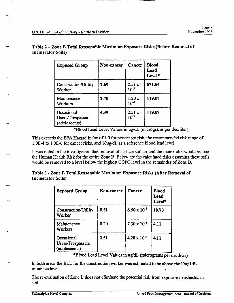
Table 2 - Zone B Total Reasonable Maximum Exposure Risks (Before Removal ofIncinerator Soils)
Exposed Group
Construction/UtilityWorker
MaintenanceWorkers
OccasionalUsers/Trespassers(adolescents)
Non-cancer
7.69
2.70
439
Cancer
2.51 xio-5
1.20x10⁴
2.51 xio-5
BloodLeadLevel*
571.54
119.07
119.07
*Blood Lead Level Values in ug/dL (micrograms per deciliter)
This exceeds the EPA Hazard Index of 1.0 for noncancer risk, the recommended risk range of1 .OE-4 to l.OE-6 for cancer risks, and lOug/dL as a reference blood lead level.
It was noted in the investigation that removal of surface soil around the incinerator would reducethe Human Health Risk for the entire Zone B. Below are the calculated risks assuming these soilswould be removed to a level below the highest COPC level in the remainder of Zone B.
Table 3 - Zone B Total Reasonable Maximum Exposure Risks (After Removal ofIncinerator Soils)
Exposed Group
Construction/UtilityWorker
MaintenanceWorkers
OccasionalUsers/Trespassers(adolescents)
Non-cancer
0.51
0.20
0.51
Cancer
6.50 xlO'5
7.30 xlO"4
4.28 x 10'5
BloodLeadLevel*
19.70
4.11
4.11
*Blood Lead Level Values in ug/dL (micrograms per deciliter)
In both areas the BLL for the construction worker was estimated to be above the lOugl dLreference level.
The re-evaluation of Zone B does not eliminate the potential risk from exposure to asbestos insoil.
Philadelphia Naval Complex Girard Point Management Area - Record of Decision
IPage 10
U.S. Department of the Navy - Northern Division November 1998 T
Ecological T
A qualitative ecological risk assessment considered the GPMA as a whole. Potential receptorsconsidered in this assessment included insectivorous birds, granivorous birds, and herbivorous Tsmall mammals. Exposure to CoPC resulted in unacceptable risk to ecological receptors. Risk to :
insectivorous birds resulted from exposure to CoPC through dermal contact with surface soil, and __ingestion of surface soil, plant material and insects. Exposure pathways for granivorous birdswere included dermal contact with surface soil & ingestion of surface soil and plant materials,especially seeds, nuts and fruit. The majority of potential excess risk resulted from exposure to ^other CoPC, such as PAH and pesticides via dermal contact or ingestion of soil. ' ;
; :
Herbivorous small mammals are exposed to CoPC through ingestion of surface soil and plantmaterial, dermal contact with surface soil and ingestion and inhalation of fugitive dust from "surface soil.
Erosion control measures have been implemented along the banks of GPMA. These control -r-measures consist of riprap and gabions, which extend horizontally beyond the limit of low tide and \vertically to the top of the steep slopes of the riverbank The riprap and gabions provide minimalhabitat for invertebrates and limit access to river sediment. Access to the inter-tidal zone by —terrestrial animals is also limited by the barren, vertical nature of the gabions. Therefore, direct iconstituent release from site surface soils to sediment has been eliminated.
In summary the ecological assessment identified the surface soil as posing unacceptable riskthrough incidental ingestion, dermal contact, and inhalation of dust as well as ingestion of plantmaterial and insects. y
7) DEVELOPMENT AND SCREENING OF ALTERNATIVES
Statutory Requirements/Response Objectives
Under its legal authorities, EPA's primary responsibility for Superfund is to undertake remedialactions that are protective of human health and the environment. Section 121 of CERCLA establishedseveral other statuary requirements and preferences, including: a requirement that an EPA sponsored -remedial action, when complete, must comply wi A all federal and more stringent state environmentalstandards, requirements, criteria or limitations, unless a waiver is invoked; a requirement that EPAselect a remedial action that is cost-effective and that utilizes permanent solutions and alternative —treatment technologies or resource recovery technologies to the maximum extent practicable; and apreference for remedies in which treatment which permanently and significantly reduces the volume,toxicity or mobility of the COPC is a principal element over remedies not involving such treatment.Response alternatives were developed to be consistent with these Congressional mandates. i
Based on the reported results and physical characteristics of the GPMA, the principal migrationpathways to potential exposures of COPC are limited to soil. Remedial action obj ecti ves (RAO) wereidentified based on the COPC, environmental media, exposure routes, and potential for risk to humanand/or ecological receptors. RAOs were identified for both Zones A & 6 as those which:
Philadelphia Naval Complex Girard Point Management Area - Record of Decision
Page 11U.S. Department of the Navy - Northern Division November 1998
1. Prevent direct contact and ingestion of soils;2. Prevent inhalation of airborne asbestos from soil; and3. Prevent direct contact and ingestion of COPC by ecological receptors.
Response actions were developed to meet the RAO. Technologies and process options identified toaddress the response actions were, then screened considering effectiveness, implementability,and cost associated with achieving the RAO. Remedial technologies and process options wereconsidered in each of three general response action categories: No Action with Monitoring,Limited Action, and Containment
Technology and Alternative Development and ScreeningCERCLA and the NCP set forth the process by which remedial actions are evaluated and selected.In accordance with these requirements, a range of alternatives were developed for the site.
Section 2 of the FS, identified, assessed and screened technologies based on implementability,effectiveness, and cost These technologies were combined into source control and management ofmigration alternatives. Section 3 of the FS presented remedial alternatives developed by combiningthe technologies identified in the previous screening process in the categories identified in Section300.430 (e) (3) of the NCP. The purpose of the initial screening was to narrow the number ofpotential remedial actions for further detailed analysis while preserving a range of options. Eachalternative was then evaluated and screened in Section 4 of the FS.
In summary, five of the remedial alternatives screened in Section 2 were retained for detailed analysisTable identifies the five alternatives that were retained through the screening process, as well as thosethat were eliminated from further consideration.
Philadelphia Naval Complex Girard Point Management Area - Record of Decision
Page 12U.S. Department of the Navy - Northern Division November 1998
8) DESCRIPTION OF ALTERNATIVES
This Section provides a narrative summary of each alternative evaluated. A detailed tabularassessment of each alternative can be found in Table 4.1 of the FS. Long-term shallow ground-watermonitoring, as well as site and security inspections are included in all five alternatives. Institutionalcontrols mat provide legal notification of property condition are specified in all but Alternative 1.Long-term shallow ground water monitoring is included in Alternatives 1 and 2. Brief descriptionsof each remedial alternative are presented below. It is assumed removal of the incinerator soils andincinerator decontamination will be accomplished to remove source areas in Alternatives 3,4 & 5.
Alternative 1: No Action with MonitoringThe No Action alternative consists of maintaining current site conditions. However, long-termground-water monitoring and site inspection will be performed. No remedial actions will beundertaken to reduce potential human health and ecological risk. This alternative serves as acomparative baseline (i.e., existing conditions) alternative, as required by CERCLA. Monitoringprograms include ground water sampling on a quarterly basis for the first year and annually thereafter,periodic air monitoring, site and security inspections, and 5-year reviews to evaluate whetheradditional remedial actions or continued monitoring are required. A report would be generateddetailing each five-year review evaluation.
This alternative would not meet any of the RAOs.
Alternative 2: Limited ActionThe Limited Action alternative consists of developing and implementing institutional controls, inaddition to the monitoring programs described in Alternative 1. Institutional controls (i.e., legalnotification of property condition) will be implemented to limit future deterioration of site conditionsand to restrict access.
This alternative would meet RAOs for 1) direct contact and ingestion of soils and 2) preventinhalation of airborne asbestos from soil, but would not 3) prevent direct contact or ingestion ofCOPCs by ecological receptors. This action would also make the area useable for future use.
Alternative 3: Permeable CoverThe Permeable Cover alternative consists of a geotextile/permeable liner and a vegetated soil cover.The liner will mark the location of the waste, but not eliminate infiltration of water. The cover willconsist of two feet of soil which will be vegetated with native grasses and shrubs. This remedyprohibits exposure with the soil to protect human health and the environment. This alternativeconsists of the following remedial actions:
! Site preparation and modifications to the existing storm-water sewer system and utilities;
! Minor site grading and placement of a geotextile/permeable liner to establish a boundarybetween existing surface soil and clean fill. This liner will be covered by a 24 inch layer of soil;
! Establishment of institutional controls to restrict access and to minimize deterioration of siteconditions; and
Philadelphia Naval Complex Girard Point Management Area - Record of Decision
Page 13U.S. Department of the Navy-Northern Division November 1998
! Implementation of long-term monitoring and site inspection programs, as described inAlternative 1.
This alternative would meet all RAOs.
Alternative 4: Impermeable Cap/Asphalt Layer
An impermeable cap which consists of a 12-inch layer of clean fill/soil, covered by a 4-inch asphaltlayer. The impermeable asphalt cap would isolate the soil from potential receptors. This alternativeconsists of the following remedial actions:
! Site preparation, and re-construction of existing storm-water sewer system;
! Construction of additional storm-water sewer lines;! Minor site grading, supplemental soil filling, and placement of binding and wearing asphalt
layers;
! Implementation of institutional controls to restrict access and to minimize deterioration of siteconditions; and,
! Implementation of long-term monitoring and site inspection programs, as described inAlternative 1.
This alternative would meet all RAOs.
Alternative 5: Impermeable Cap/GeomembraneAn impermeable cap, which consists of a geomembrane liner and a 2.5 ft soil cover, required for frostprotection, will be placed over Zone A. This impermeable cap would isolate COPC in surface andsubsurface soil from potential receptors. This alternative consists of the following remedial actions:
! Site preparation, and re-construction of storm-water sewer system;! Installation of new storm-water sewer lines;
! Minor site grading and placement of a 6-inch support layer, a geomembrane, a 30-inch layerof sandy soil for drainage, frost protection, and revegetation. Environmental restorationwould consist of grass and shallow-rooted shrubs since the geomembrane would prohibitinstallation of deep-rooted trees. Therefore, natural succession to a mature forest would beprohibited since tree roots may impair the geomembrane. Environmental restoration reduceslabor cost associated with mowing grass cover and the use of pesticides;
! Implementation of institutional controls to restrict access and to minimize or preventdeterioration of site conditions; and
! Implementation of long-term monitoring and site inspection programs., as described inAlternative 1.
This alternative would meet all RAOs.
Philadelphia Naval Complex Girard Point Management Area - Record of Decision
Page 14U.S. Department of the Navy - Northern Division November 1998
9) SUMMARY OF THE COMPARATIVE ANALYSIS OF ALTERNATIVESSection 121 (b) (1) of CERCLA presents several factors that at a minimum EPA is required toconsider in its assessment of alternatives. Building upon these specific statuary mandates, the NCParticulates nine evaluation criteria to be used in assessing the individual remedial alternatives.
A detailed analysis was performed on the alternatives using the nine evaluation criteria in order toselect a site remedy. The first two threshold criteria described below must be met in order for thealternatives to be eligible for selection in accordance with the NCP. The next five criteria are utilizedto compare and evaluate the elements of one alternative to another that meet the threshold criteria,The last two are the modifying criteria used on the final evaluation of remedial alternatives generallyafter EPA has received public comment on the PJ/FS and Proposed Plan. The following is a summaryof the comparison of each alternative's strength and weakness with respect to the nine evaluationcriteria. These criteria are given below and summarized in Table 6:
Overall Protection of Human Health and the Environment -addresses whether remedies areprotective of human health and the environment. A remedy is protective if it adequately eliminates,reduces, or controls all current and potential site risks posed through each exposure pathway at thesite.
Compliance with ARAR - is one of the statutory requirements for remedy selection. However,CERCLA allows selecting a remedy that will not attain applicable or relevant and appropriaterequirements (ARARs) if certain conditions exist
Long-term Effectiveness and Permanence - refers to the magnitude of residual risk and the abilityof a remedy to maintain reliable protection of human health and the environment over time aftercleanup goals have been met.
Reduction of Toxicity, Mobility, or Volume - addresses remedies that employ treatment as aprincipal element by ensuring that the relative performance of the treatment technologies will beassessed. This criterion examines the magnitude, significance, and irreversibility of reductions.
Cost - includes capital costs and annual operations and maintenance costs incurred over the life of theremedial action. The present worth cost of the five alternatives are: Alternative 1 $511,000,Alternative 2 $812,000, Alternative 3 $4,429,000, Alternative 4 $5, 257,000, and Alternative 5$7,404,000.
Short-term Effectiveness -refers to the short-term impacts of the remedy on the neighboringcommunity, workers, or surrounding environment This includes potential threats to human healthand the environment associated with the removal, treatment, and transportation of hazardoussubstances.
Implementability - is the technical and administrative feasibility of a remedy, as well as theavailability of materials and services needed to implement the selected solution.
State Acceptance - indicates whether the State concurs with, opposes, or has no comment on thepreferred remedy.
Philadelphia Naval Complex Girard Point Management Area - Record of Decision
Page 15U.S. Department of the Navy - Northern Division November 1998
Community Acceptance - will be addressed in the Responsiveness Summary.
For a more detailed comparative analysis of remedial alternatives see Table 4-1 in the FS, (Stone &Webster 1997d).
Philadelphia Naval Complex Girard Point Management Area - Record of Decision
Page 16U.S. Department of the Navy - Northern Division November 1998
10) THE SELECTED REMEDY
The selected remedy was developed by combining components of different source control andmanagement of mitigation alternatives to obtain a comprehensive approach for site remediation. Theselected remedy for Zone A, Alternative 3, consists of a permeable cover, which consists of ageotextile/permeable liner and a vegetated soil cover. The selected remedy for Zone A consists of apermeable cover, which consists of a geotextile/permeable liner and a vegetated soil cover. The linerwill mark the location of the waste, but not eliminate infiltration of water. The cover will consist oftwo feet of soil, which will be vegetated with native grasses and shrubs. This remedy prohibitsexposure with the soil to protect human health and the environment. It also provides a vegetatedbuffer between the Schuylkill River (and its ecology) and the area adjacent to GPMA, which isproposed for heavy industrial reuse in the City of Philadelphia's Reuse Plan dated September 1994.The selected remedy for Zone B, Alternative 4, which consists of paving the area returns, the areato its former use as a parking lot and prohibits exposure with the soil to protect human health and theenvironment. The removal of soils and decontamination of the incinerator remove possible sourceareas and eliminate exposure to these areas.
The institutional controls, five-year reviews, and long term monitoring plan will ensure that theremedy will continue to be protective of human health and the environment. Based on currentinformation, this alternative appears to provide the best balance of the nine evaluation criteriaspecified by the EPA and outlined above.
Description of Remedial ComponentsThis Alternative Involves the installation and long-term maintenance of a permeable cover at ZoneA and paving at Zone B to mitigate potential risks to potential human and ecological receptors. Theinstallation will consist of the following activities:
! The existing storm-water sewer system will be upgraded. Catch basins and manholes will becleaned and repaired as necessary. The inlet of catch basins will be raised to the groundsurface. Enlargement of the inlet collecting surface area of the catch basins may also berequired. Temporary sediment control measurements around the catch basin will be installedto rninimize sediment transport into the existing sewer system.
! Temporary staging areas will be constructed and vegetation, cover material (asphalt, concrete,etc.), and/or debris will be removed, as necessary for design.
! A geotextile/permeable liner will be placed over the existing soil. This liner will be coveredby a minimum of 24 inches of soil suitable for supporting vegetation.
! The site will be graded and a vegetative cover (i.e., grass seeding and trees) will be added.
! Institutional controls will consist of placing legal notification of site conditions and limiton-site activities and minimize deterioration of site conditions.
! The following Institutional Controls
Ground water withdrawn from welts shall not be used or made available for humanconsumption (Base-wide Institutional Control)GPMA shall not be used or developed for any permanent residential uses (Base-wideInstitutional Control).
Philadelphia Naval Complex Guard Point Management Area - Record of Decision
Page 17U.S. Department of the Navy - Northern Division November 1998
Any construction or development of an outdoor childcare playground will include theplacement of 2 ft of clean fill material, or other cover as approved by PADEP,between the underlying soil and the surface of the childcare playground prior tocommencement of any use of the outdoor area as a playground (Base-wideInstitutional Control).Excavation shall not be accomplished without prior written approval of PADEP.
! A long-term shallow ground water monitoring program will be implemented
Installation of the covering systems at Zone A will take approximately six to eight months tocomplete, following design and construction contract award. The ground water monitoring programwill involve collecting developing a long term monitoring program, which will be reviewed by EPAand PADEP. Maintaining the permeable cover and individual zone conditions will take two to threeweeks per year, which will include repairs to the permeable cover and inspection and maintenanceof the existing bank stabilization. To the extent required by law, the Navy will review the site at leastonce every five years after the initiation of remedial action at the site, since COPC will remain at thesite to assure that the remedial action continues to protect human health and the environment.
11) STATUARY DETERMINATIONSThe remedial action selected for implementation at the GPMA is consistent with CERCLA and, tothe extent practicable, the NCP. The selected remedy is protective of human health and theenvironment, attains ARARs to the extent practicable and is cost effective. The selected remedy doesnot satisfy the statutory preference for treatment that permanently and significantly reduces themobility, toxicity or volume of COPC as a principal element.
The Selected Remedy is Protective of Human Health and the EnvironmentThe remedy will mitigate the risks posed to human health and the environment by controllingexposures to human and environmental receptors through engineering and institutional controls suchas: a permeable cover, access restrictions, institutional controls, and site inspections and monitoring.
The Selected Remedy and ARARsThis remedy will not attain applicable or relevant and appropriate federal and state requirements thatapply to GPMA, since soil that reportedly contains concentrations of COPC above the cleanupstandards will not be removed.. However, ARARs were attained to the extent practicableEnvironmental laws from which ARARs for the selected remedial action are derived, and the specificARARs are listed in Tables 2-2,2-3, and 2-4 in the FS. These tables are also found in the back of thisdocument. A discussion of why these requirements are applicable or relevant and appropriate maybe found in the FS Report in Section 2.0.
The primary location-, chemical-, and action-specific ARAR are summarized below:
Location-Specific! Soil - This alternative will not comply with the ARAR in terms of mitigating the presence
ofCPC4
! Wildlife - This alternative will comply with the requirements of the Endangered Species Actof 1973. This alternative will provide preventative measures to protect native biota from the
Philadelphia Naval Complex Girard Point Management Area - Record of Decision
Page 18U.S. Department of the Navy - Northern Division November 1998 T
potential effects of exposure to COPC. Remedial activities for the site will be designed to T
protect against adverse effects to the biota and sensitive habitats.
! Floodplains - The 100-year flood elevation line is 10 ft. Elevations of the river bank along _the GPMA range from 15 to 18 ft along the southwestern portion of the GPMA at IR Site4 to 11 to 12 ft along the southern portion of the GPMA at IR Site 5 after bank stabilization.This alternative will meet protection from water of the 100 year flood _
! Ground -water - ARAR for water quality will be used to evaluate monitoring data generatedby the implementation of mis alternative.
Chemical-Specific
! Soil - Pennsylvania's Act 2 Statewide Human Health Standards for Non-residential soil are _the primary chemical-specific ARAR. Tie Permeable Cover alternative will not comply withthis ARAR, as soil that reportedly exceeds these clean-up standards will not be removed.
Action-Specific :
! Action-specific ARAR identified during the development of this alternative, focus ondistributing information to workers and the community before implementing this alternative. —Other action-specific ARAR applicable to this alternative include the federal Clean Air Actand the Pennsylvania Air Pollution Control Act and Regulations, which outline standards ofair pollution control. Concentrations of airborne fugitive dust and asbestos may exceed —standards during construction.
Since the presumptive remedy was utilized, all of the ARARs were not met.
The Selected Remedial Action is cost-effectivehi the Navy's judgment, the selected remedy is cost effective, (i.e., the remedy affords overalleffectivenessproportional to its costs). In selecting this remedy, the Navy identified alternatives thatare protective of human health and the environment, and will attain ARARs to the extent practical.The Navy evaluated the overall effectiveness of each alternative by assessing the relevant threecriteria: long term effectiveness and permanence, reduction in toxicity, mobility, and volume through __treatment, and short-term effectiveness, in combination. The relationship of the overall effectivenessto this remedial alternative was determined to be proportional to its costs. The principal capital costcomponents for the Permeable Cover alternative, $2,278,000, will be associated with the installation _of the permeable geotextile cover and fence, and the legal notification of site conditions and/or deedrestrictions. The O&M costs incurred by implementing this alternative will be for performingmonitoring and site inspection programs, and maintaining the fence and the vegetation cover. Theannual cost for the initial two years was estimated to be $ 167,000, followed by annual costs for eachof the remaining years of $ 117,000. The total present worth for this alternative was calculated usingan interest rate of 5 percent and assuming that O&M activities will extend for a period of 30 years.This resulted hi a present worth cost of $4,429,000.
The Selected Remedy Utilizes Permanent Solutions and Alterative Treatment or ResourceRecovery Technologies to the Maximum Extent PracticableThe selected remedy was evaluated using the best balance of trade-offs among alternatives in termsof: 1) long-term effectiveness and permanence, 2) reduction of toxicity, mobility or volumethrough treatment, 3) short-term effectiveness, 4) implementability, and 5) cost. The selected
Philadelphia Naval Complex Girard Point Management Area -Record of Decision
Page 19U.S. Department of the Navy - Northern Division November 1998
remedy provides the best balance of trade-offs among the alternatives. Listed below is a summary ofthe five criteria used to evaluate the alternatives:
Long-term Effectiveness and PermanenceImplementation of the selected Alternative will reduce risk to potential receptors. COPC will becontained by a permeable covering, thereby minimizing contact between COPC and human andecological receptors. The long-term monitoring and site inspection programs will document thecontinued effectiveness of this alternative. The long-term effectiveness of this alternative is expectedto be high, but the permanence of this alternative will depend upon continual maintenance of thepermeable covering system.
Reduction of To3ricity, Mobility, or Volume Through TreatmentThe Permeable Cover alternative does not include any treatment or removal and off-site disposalactivities, rather this alternative is designed to isolate soil from receptors. Consequently, thisalternative will not reduce the toxicity, mobility, or volume of COPC through treatment However,the toxicity of COPC will be reduced over time through attenuation and degradation. Overall, thePermeable Cover alternative will not satisfy the regulatory preference for treatment as a possiblecomponent of a remedial actioa
Short-term EffectivenessWhile implementing mis alternative, mere may be elevated risks to workers and to the environment.Potential elevated risk to workers will result from inhalation of fugitive dust To reduce this risk,workers performing the installation activities may be required to utilize personal protective equipmentand/or minimize their exposure to COPC in fugitive dust. Short-term risks to the community will beminimal due to the distance from the site to residential housing. Additional protection measures (e.g.dust control) would be used to mitigate the risks. Short-term impacts to the environment will beminimized, to the extent possible, through the use of common erosion controls such as sedimentationbarriers. Concentrations of COPC will not be reduced to a level protective of potential receptors andmis alternative will not provide the controls necessary to reduce the concentrations of COPC in soil.
ImplementabilityTechnical Feasibility - Construction of a permeable covering will be moderately difficult toimplement The implementation of this alternative will require the use of equipment and servicescommercially available from local vendors. Components and items associated with this alternative arecommonly available. Accessibility to the site by the necessary vehicles is also available. The PermeableCover alternative will not limit or interfere with potential future remedies.
Administrative Feasibility - Implementation of the Permeable Cover alternative, includinginstallation of the cover and the supervision of the monitoring programs, will require approval andclose coordination with local, state and federal agencies. The implementation of institutional controlsand access restrictions associated with this alternative will require administrative and regulatorysupport from local, state and federal agencies. No administrative difficulties are expected with theimplementation of the Permeable Cover alternative.
Philadelphia Naval Complex Girard Point Management Area - Record of Decision
Page 20U.S. Department of the Navy - Northern Division November 1998
CostCapital Cost - The principal capital cost components for the Permeable Cover alternative,$2,278,000, will be associated with the installation of the permeable geotextile cover, and thedevelopment and installation of deed notifications and/or zoning restrictions.
O&M Cost - The O&M costs incurred by implementing this alternative will be for performingground-water monitoring and site inspection programs, and maintaining the fence and the vegetationcover. The annual cost for the initial two years was estimated to be $167,000, followed by annualcosts for the remaining years of $117,000.
Present Worth - The total present worth for this alternative was calculated using an interest rate of5 percent and assuming that O&M activities will extend for a period of 30 years. This resulted in apresent worth cost of $4,429,000. A summary of costs and assumptions for this alternative arepresented in the FS.
The Selected Remedy does not Satisfy the Preference for Treatment which Permanently andSignificantly Reduces the Toiicity, Mobility, or Volume of the COPC as a Principal ElementThe principal element of the selected remedy is source control, which addresses soil. Since thepresumptive remedy is utilized, the selected remedy does not satisfy the statutory preference fortreatment as a principal element. Treatment and/or removal of the landfill material were consideredimpractical due to the heterogeneity and volume of the landfill material, therefore the primaryremedial components are source control and containment
12) STATE ROLEPADEP has reviewed the various alternatives and has indicated its support for the selected remedy.State has also reviewed the IR Site 4 RI Report, IR Site 5 Report, IR Site 3 ROD , SiteCharacterization Report, and FS to determine if the selected remedy is in compliance with applicableor relevant and appropriate state environmental laws and regulations. PADEP concurs with theselected remedy for the GPMA.
Philadelphia Naval Complex Girard Point Management Area - Record of Decision
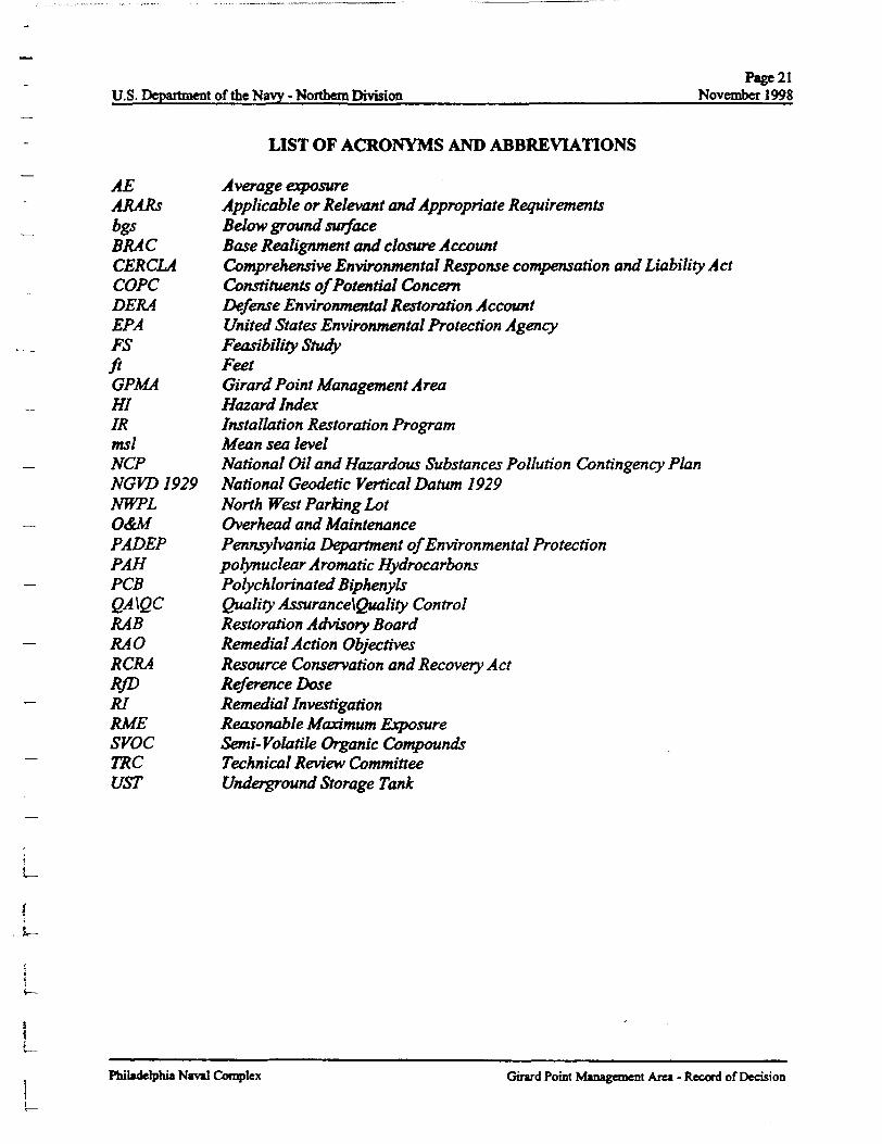
U.S. Department of the Navy - Northern DivisionPage21
November 1998
LIST OF ACRONYMS AND ABBREVIATIONS
AE Average exposureARARs Applicable or Relevant and Appropriate Requirementsbgs Below ground surfaceBRA C Base Realignment and closure AccountCERCLA Comprehensive Environmental Response compensation and Liability ActCOPC Constituents of Potential ConcernDERA Defense Environmental Restoration AccountEPA United States Environmental Protection AgencyFS Feasibility Studyft FeetGPMA Girard Point Management AreaHI Hazard IndexIR Installation Restoration Programmsl Mean sea levelNCP National Oil and Hazardous Substances Pollution Contingency PlanNGVD1929 National Geodetic Vertical Datum 1929NWPL North West Parking LotO&M Overhead and MaintenancePADEP Pennsylvania Department of Environmental ProtectionPAH pofynuclear A romatic HydrocarbonsPCS Polychlorinated BiphenylsQA\QC Quality Assurance\Quality ControlRAB Restoration Advisory BoardRAO Remedial Action ObjectivesRCRA Resource Conservation and Recovery ActRfD Reference DoseRI Remedial InvestigationRME Reasonable Maximum ExposureSVOC Semi-Volatile Organic CompoundsTRC Technical Review CommitteeUST Underground Storage Tank
L-
t
Philadelphia Naval Complex Girard Point Management Area - Record of Decision
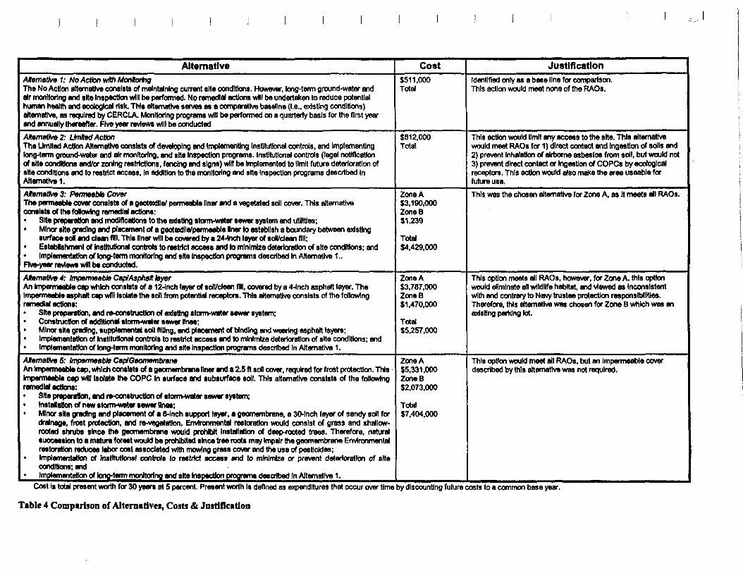
Alternative Cost JustificationAtemativ* 1: No Action with MonitoringThe No Action alternative consists of maintaining current site conditions. However, long-term ground-water andair monitoring and site Inspection will be performed. No remedial actions wfll be undertaken to reduce potentialhuman health and ecological risk. This alternative serves as a comparative baseline (I.e., existing conditions)alternative, as required by CERCLA. Monitoring programs will be performed on a quarterly basis for the first yearand annually thereafter. Five year reviews will be conducted
$511,000Total
Identified only as a base line for comparison.This action would meet none of the RAOs.
Alternative 2: Umltod ActionThe Limited Action Alternative consists of developing and Implementing institutional controls, and Implementinglong-term ground-water and air monitoring, and site Inspection programs. Institutional controls (legal notificationof site conditions and/or zoning restrictions, fencing and signs) win be Implemented to limit future deterioration ofsite conditions and to restrict access, In addition to the monitoring and site Inspection programs described InAlternative 1.
$812,000Total
This action would limit any access to the site. This alternativewould meet RAOs for 1) direct contact and Irtgmtlon of soils and2) prevent Inhalation of airborne asbestos from soil, but would not3) prevent direct contact or Ingestlon of COPCs by ecologicalreceptors. This action would also make the area useable forfuture use.
AMemaUve 3: Permeable CoverThe permeable cover consists of a geotexHIe/ permeable liner and a vegetated soil cover. This alternativeconsists of the fotowing remedial actions:
Site preparation and modifications to the existing storm-water sewer system and utilities;• Minor site grading and placement of a geotaxtHa/permeable liner to establish a boundary between existing
surface toll and dean fid. This liner wHI be covered by a 24-Inch layer of son/dean fill;• Establishment of Institutional controls to restrict access and to minimize deterioration of site conditions; and
Implementation of long-term monitoring and site Inspection programs described In Alternative 1..Five-year reviews wHI be conducted.
Zone A$3.190.000ZoneB$1,239
Total$4.429,000
This was the chosen alternative for Zone A, as It meets all RAOs.
Atematko 4: Impermeable Cap/Asphalt layerAn Impermeable cap which consists of a 12-Inch layer of son/clean fill, covered by a 4-Inch asphalt layer. TheImpermeable asphalt cap will Isolate the soil from potential receptors. This alternative consists of the followingremedial actions:
Site preparation, and re-construction of existing storm-water sewer system;Construction of additional storm-water sewer lines;Minor site grading, supplemental soil filling, and placement of binding and wearing asphalt layers;Implementation of Institutional controls to restrict access and to minimize deterioration of site conditions; andImplementation of long-term monitoring and site Inspection programs described In Alternative 1.
Zone A$3.787.000ZoneB$1.470,000
Total$5.257.000
This option meets all RAOs, however, for Zone A. this optionwould eliminate all wildlife habitat, and viewed as Inconsistentwith and contrary to Navy trustee protection responsibilities.Therefore, this alternative was chosen for Zone B which was anexisting parking lot.
ARemettoeS: Impermeable CaplOeomembmneAn Impermeable cap, which consists of a geomembrane liner and a 2.5 ft son cover, required for frost protection. ThisImpermeable cap wilt Isolate the COPC In surface and subsurface soil. This alternative consists of the followingremedial actions:
Site preparation, and re-construction of storm-water sewer system;• Installation of new storm-water sewer tinea;• Minor site grading and placement of a 6-Inch support layer, a geomembrane, a 30-Inch layer of sandy soil for
drainage, frost protection, and re-vegetation. Environmental restoration would consist of grass and shallow-rooted shrubs since the geomembrane would prohibit Installation of deep-rooted trees. Therefore, naturalsuccession to a mature forest would be prohibited since tree roots may Impair the geomembrane Environmentalrestoration reduces labor cost associated with mowing grass cover and the use of pesticides;Implementation of Institutional controls to restrict access and to minimize or prevent deterioration of siteconditions; andImplemerrtation of lonortenn monitoring and site Inspection programs described In Alternative 1.
Zone A$5,331.000ZoneB$2.073,000
Total$7.404,000
This option would meet all RAOs, but an Impermeable coverdescribed by this alternative was not required.
Cost Is total present worth for 30 years at 5 percent. Present worth Is defined as expenditures that occur over time by discounting future costs to a common base year.
Table 4 Comparison of Alternatives, Costs & Justification
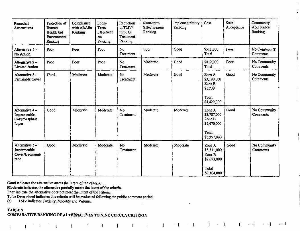
RemedialAlternatives
Alternative 1 -No Action
Alternative 2 -Limited Action
Alternative 3 -Permeable Cover
Alternative 4 -ImpermeableCover/AsphaltLayer
Alternative 5 -ImpermeableCover/Geomembrane
Protection ofHumanHealth andEnvironmentRanking
Poor
Poor
Good
Good
Good
CompliancewithARARsRanking
Poor
Poor
Moderate
Moderate
Moderate
Long-TermEffectivenessRanking
Poor
Poor
Moderate
Moderate
Moderate
ReductioninTMVw
throughTreatmentRanking
NoTreatment
NoTreatment
NoTreatment
NoTreatment
NoTreatment
Short-termEffectivenessRanking
Poor
Moderate
Moderate
Moderate
Moderate
ImplementabilityRanking
Good
Good
Good
Moderate
Moderate
Cost
$511,000Total
$812,000Total
Zone A$3,190,000ZoneB$1,239
Total$4,429,000
Zone A$3,787,000ZoneB$1,470,000
Total$5,257,000
Zone A$5,331,000ZoneB$2,073,000
Total$7,404,000
StateAcceptance
Poor
Poor
Good
Good
Good
CommunityAcceptanceRanking
No CommunityComments
No CommunityComments
No CommunityComments
No CommunityComments
No CommunityComments
Good indicates the alternative meets the intent of the criteria.Moderate indicates the alternative partially meets the intent of the criteria.Poor indicate the alternative does not meet the intent of the criteria.To be Determined indicates this criteria will be evaluated following the public comment period.(a) TMV indicates Toxicity, Mobility and Volume.
TABLE 5COMPARATIVE RANKING OF ALTERNATIVES TO NINE CERCLA CRITERIA
I I
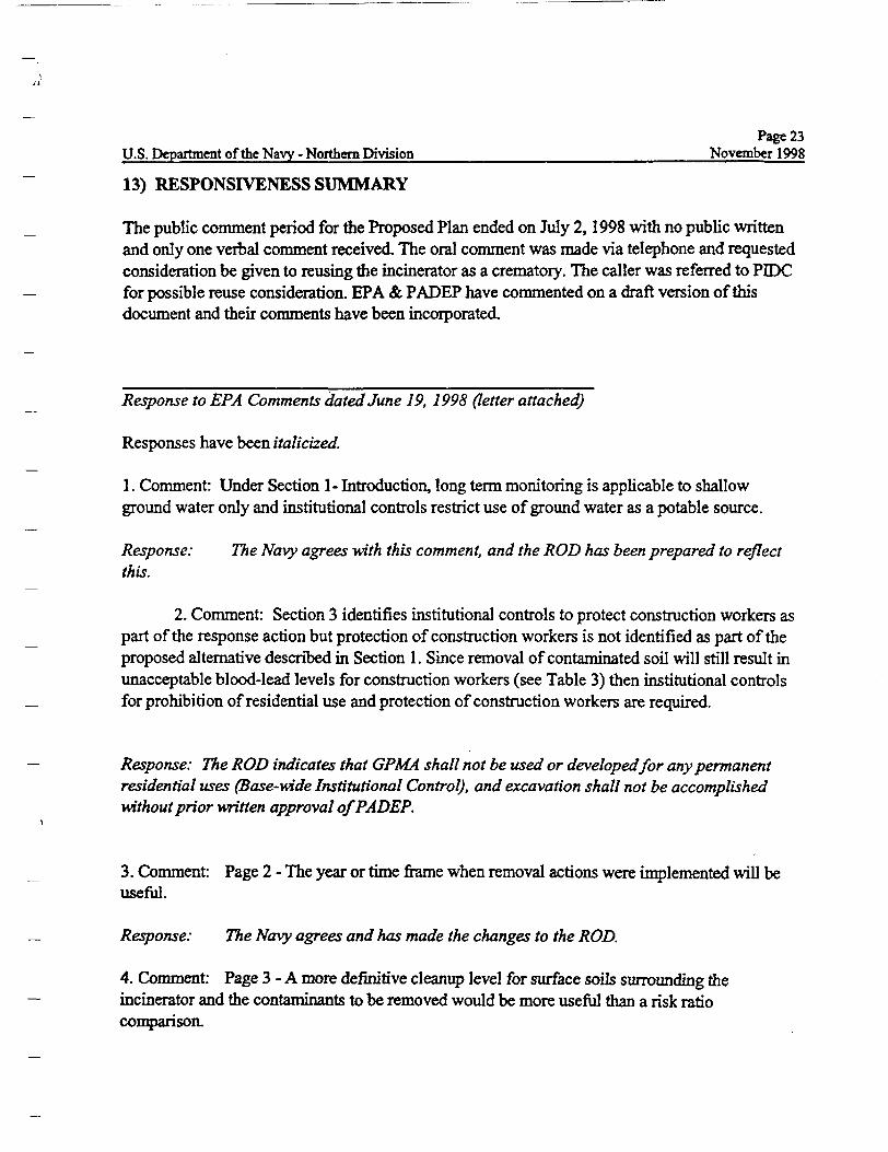
Page 23U.S. Department of the Navy - Northern Division November 1998
13) RESPONSIVENESS SUMMARY
The public comment period for the Proposed Plan ended on July 2,1998 with no public writtenand only one verbal comment received. The oral comment was made via telephone and requestedconsideration be given to reusing the incinerator as a crematory. The caller was referred to PEDCfor possible reuse consideration. EPA & PADEP have commented on a draft version of thisdocument and their comments have been incorporated.
Response to EPA Comments dated June 19, 1998 (letter attached)
Responses have been italicized.
1. Comment: Under Section 1- Introduction, long term monitoring is applicable to shallowground water only and institutional controls restrict use of ground water as a potable source.
Response: The Navy agrees with this comment, and the ROD has been prepared to reflectthis.
2. Comment: Section 3 identifies institutional controls to protect construction workers aspart of the response action but protection of construction workers is not identified as part of theproposed alternative described in Section 1. Since removal of contaminated soil will still result inunacceptable blood-lead levels for construction workers (see Table 3) then institutional controlsfor prohibition of residential use and protection of construction workers are required.
Response: The ROD indicates that GPMA shall not be used or developed for any permanentresidential uses (Base-wide Institutional Control), and excavation shall not be accomplishedwithout prior written approval of PADEP.
3. Comment: Page 2 - The year or time frame when removal actions were implemented will beuseful.
Response: The Navy agrees and has made the changes to the ROD.
4. Comment: Page 3 - A more definitive cleanup level for surface soils surrounding theincinerator and the contaminants to be removed would be more useful than a risk ratiocomparison.
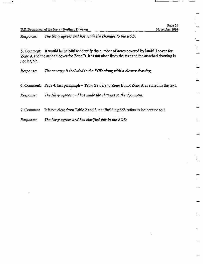
Page 24U.S. Department of the Navy - Northern Division November 1998
Response: The Navy agrees and has made the changes to the ROD.
5. Comment: It would be helpful to identify the number of acres covered by landfill cover forZone A and the asphalt cover for Zone B. It is not clear from the text and the attached drawing isnot legible.
Response: The acreage is included in the ROD along with a clearer drawing.
6. Comment: Page 4, last paragraph - Table 2 refers to Zone B, not Zone A as stated in the text.
Response: The Navy agrees and has made the changes to the document.
7. Comment It is not clear from Table 2 and 3 that Building 668 refers to incinerator soil.
Response: The Navy agrees and has clarified this in the ROD.
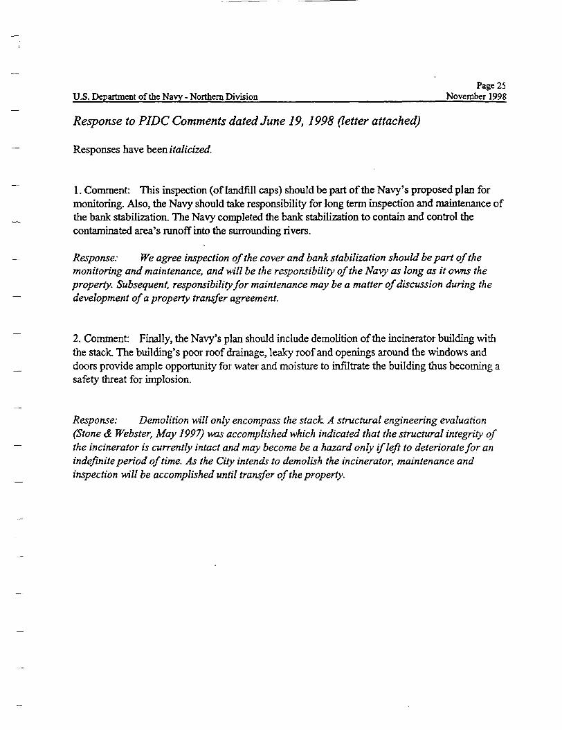
Page 25U.S. Department of the Navy Northern Division November 1998
Response to PIDC Comments dated June 19, 1998 (letter attached)
Responses have been italicized.
1. Comment: This inspection (of landfill caps) should be part of the Navy's proposed plan formonitoring. Also, the Navy should take responsibility for long term inspection and maintenance ofthe bank stabilization. The Navy completed the bank stabilization to contain and control thecontaminated area's runoff into the surrounding rivers.
Response: We agree inspection of the cover and bank stabilization should be part of themonitoring and maintenance, and will be the responsibility of the Navy as long as it owns theproperty. Subsequent, responsibility for maintenance may be a matter of discussion during thedevelopment of a property transfer agreement.
2. Comment: Finally, the Navy's plan should include demolition of the incinerator building withthe stack. The building's poor roof drainage, leaky roof and openings around the windows anddoors provide ample opportunity for water and moisture to infiltrate the building thus becoming asafety threat for implosion.
Response: Demolition will only encompass the stack. A structural engineering evaluation(Stone & Webster, May 1997) was accomplished which indicated that the structural integrity ofthe incinerator is currently intact and may become be a hazard only if left to deteriorate for anindefinite period of time. As the City intends to demolish the incinerator, maintenance andinspection will be accomplished until transfer of the property.
I I
T
Page 26U.S. Department of the Navy - Northern Division November 1998
Response to DOI Comments dated June 18, 1997 (letter attached)
Responses have been italicized.
Comment: Recently, the U.S. Fish and Wildlife Service's representative to the EPA Region 3Biological Technical Assistance Group informed us that the Navy is re-considering it's initialthoughts about the landfill cover and may propose to place asphalt over the entire landfill areas.You would agree that replacing the vegetative cover in the landfill areas with an asphalt coverwould eliminate all wildlife habitat, and further that this could be viewed as inconsistent with andcontrary to our joint protection responsibilities [NCP Section 300.600(b)(2) and (3)] as co-trustees for natural resources (e.g., migratory birds) affected by this decision.
Response: Only the area previously a parking lot, will have an asphalt cover. The remainderof the landfill cover -will be a vegetative cover.
Page 27U.S. Department of the Navy - Northern Division November 1998
Response to PADEP Comments dated May 28,1998 (e-mail attached)
1. Comment: Page 1: "Restriction on Excavation without Prior Pennsylvania Department ofEnvironmental Protection (PADEP) Approval". Please rewrite as: "Restriction on Excavationwithout Prior Approval in Writing by the Pennsylvania Department of Environmental Protection(PADEP)".
Response: The wording has been revised as requested.
2. Comment: Please rewrite the sentence to say that "The general land area surrounding theGPMA is NOT densely populated. "Please correct this statement in the Site Background section.The area IS heavily industrialized.
Response: This section has been corrected.
3. Comment: "The site was initially marshlands and was reclaimed by extensive filling between1940 to 1970". Please rewrite this sentence in the Site Background section. How about" The sitewas marshlands until it was covered with fill material" ?
Response: The wording has been revised as suggested
4. Comment: How and where will the incinerator stack and incinerator units be removed anddisposed off-site?
Response: First all the ash will be removed form the stack and incinerator units. The units willthen be cut-up in place and disposed The exterior of the stack will be completely wetted with awater spray. A crane with grapple or clamshell attachments shall be used to dismantle the stackin sections from the top down. The stack debris will be immediately placed in trucks for off-sitedisposal.
rPage 28
U.S. Department of the Navy - Northern Division November 1998
14) REFERENCES
Remedial Investigation Report: ER. Site 4 at Philadelphia Naval Base, Stone & WebsterEnvironmental Technology & Services, Final, May 1997 (Stone & Webster 1997a)
Remedial Investigation Report: IR Site 5 at Philadelphia Naval Base, Stone & WebsterEnvironmental Technology & Services, Final, May 1997 (Stone & Webster 1997b)
Site Characterization Report Girard Point Management Area at Philadelphia Naval Base, Stone &Webster Environmental Technology & Services, Final, September 1997 (Stone & Webster 1997c)
Feasibility Study for Girard Point Management Area at Philadelphia Naval Base, Stone & WebsterEnvironmental Technology & Services, Final, October 1997 (Stone & Webster 1997d)
Engineering Evluation/Cost Analysis for Building Decontamination/Demolition Girard PointIncinerator - Building 668, Stone & Webster Environmental Technology & Services, Final, May1997 (Stone & Webster 1997e)
UNITED STATES ENVIRONMENTAL PROTECTION AGENCYREGION III
841 Chestnut Building* ****• Philadelphia, Pennsylvania 19107-4431
June 2,1998
Mr. Emil KlawitterNorthern DivisionNaval Facilities Engineering Command10 Industrial HighwayMail Stop m2Lester, Pennsylvania 19113-2090
Dear Mr. Klawitter:
As we discussed today by telephone, EPA has the following comments regarding the draftProposed Plan for the Girard Point Management Area:
1. Under Section 1-Introduction, long term ground water monitoring is applicable to shallowground water only and institutional controls restrict use of ground water as a potable source.
2. Section 3 identifies institutional controls to protect construction workers as part of theresponse action but protection of construction workers is not identified as part of the proposedalternative described in Section 1. Since removal of contaminated soil will still result inunacceptable blood-lead levels for construction workers (see Table 3) then institutional controlsfor prohibition of residential use and protection of construction workers are required.
3. Page 2-The year or time frame when the removal actions were implemented would be useful.
4. Page 3-A more definitive cleanup level for surface soils surrounding the incinerator and thecontaminants to be removed would be more useful than reference to a risk ratio comparison.
5. It would be helpful to identify the number of acres covered by landfill cover for Zone A and theasphalt cover for Zone B. It is not clear from the text and the attached drawing is not legible.
6. Page 4, last paragraph-Table 2 refers to Zone B, not Zone A as stated in the text.
7. It is not clear from Table 2 and 3 that Building 668 refers to incinerator soil.
Customer Service Hotline: 1-800-438-2474
You may contact me at 215-566-3203 if you wish to discuss these comments further.
Sincerely,
Harry HafooldFederal Facilities Branch
cc: Sarah Pantemidou
OFFICE OF DEFENSE CONVERSION
PMKfeipMi IndustrialDmtopmrf Corporation
June 19,1998
Mr. Emil Klawittcr, Project ManagerNorthern Division, Naval Facilities Engineering CommandEnvironmental Division, Code 182110 Industrial Highway, Mail Stop 82Lester, PA 19113-2090
Dear Mr. Klawitter:
The City of Philadelphia is pleased to have the opportunity to comment on theProposed Plan Girard Point Management Area. The City of Philadelphia has concerns withthe Navy's preferred alternative because it does not correctly specify that the Navy isresponsible for the integrity of the 2 caps and the bank stabilization. The Proposed Planindicates that EPA's presumptive remedy guidance for the closure of CERCLA MunicipalWaste Land Fills has been utilized. As I'm sure your are aware, this guidance requires theinspection and maintenance of land fill caps. This inspection and maintenance programshould be part of the Navy's proposed plan for monitoring. Also, the Navy should takeresponsibility for long term inspection and maintenance of the bank stabilization. The Navycompleted the bank stabilization to contain and control the contaminated area's runoff intothe surrounding rivers.
Finally, the Navy's plan should include demolition of the incinerator building withthe stack. The building's poor roof drainage, leaky roof and openings around windows anddoors provides ample opportunity for water and moisture to infiltrate the building thusbecoming a safety threat for implosion.
2600 Ontre Square West, 1500 Market Street Philaddphia, PA 19102 21W96-8Q20 215-977-9618(0
Mr. Emil KlawitterJune 19,1998Page two
Please feel free to contact me at (215) 496-8184 with any questions.
Sincerely yours,
Naomi A.RobinsonEnvironmental Specialist
cc: Julie Van NosternLoriFlynnSarah Pantelidou, PADEPHarry Harbold, EPA
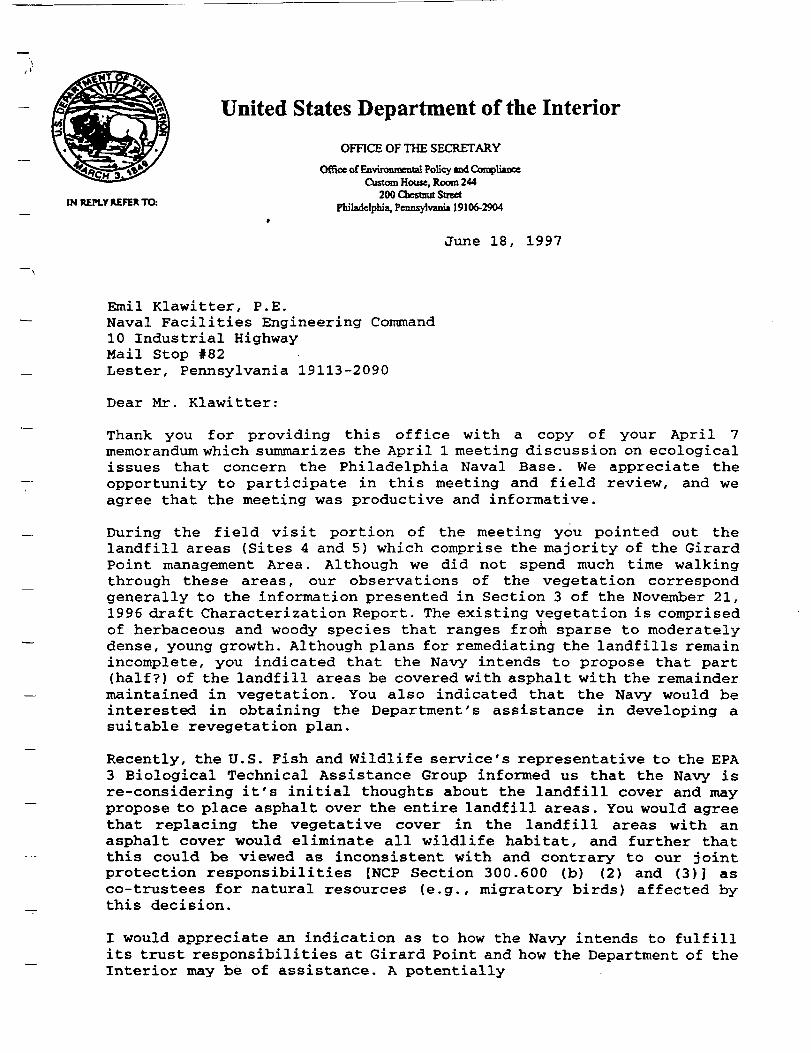
United States Department of the Interior
OFFICE OF THE SECRETARY
Office of Environmental Policy and ComplianceCustom House, Room 244
200 Chestnut StreetIN REPLY REFER TO Philadelphia, Pennsylvania 19106-2904
9
June 18, 1997
Emil Klawitter, P.E.Naval Facilities Engineering Command10 Industrial HighwayMail Stop #82Lester, Pennsylvania 19113-2090
Dear Mr. Klawitter:
Thank you for providing this office with a copy of your April 7memorandum which summarizes the April 1 meeting discussion on ecologicalissues that concern the Philadelphia Naval Base. We appreciate theopportunity to participate in this meeting and field review, and weagree that the meeting was productive and informative.
During the field visit portion of the meeting you pointed out thelandfill areas (Sites 4 and 5) which comprise the majority of the GirardPoint management Area. Although we did not spend much time walkingthrough these areas, our observations of the vegetation correspondgenerally to the information presented in Section 3 of the November 21,1996 draft Characterization Report. The existing vegetation is comprisedof herbaceous and woody species that ranges from sparse to moderatelydense, young growth. Although plans for remediating the landfills remainincomplete, you indicated that the Navy intends to propose that part(half?) of the landfill areas be covered with asphalt with the remaindermaintained in vegetation. You also indicated that the Navy would beinterested in obtaining the Department's assistance in developing asuitable revegetation plan.
Recently, the U.S. Fish and Wildlife service's representative to the EPA3 Biological Technical Assistance Group informed us that the Navy isre-considering it's initial thoughts about the landfill cover and maypropose to place asphalt over the entire landfill areas. You would agreethat replacing the vegetative cover in the landfill areas with anasphalt cover would eliminate all wildlife habitat, and further thatthis could be viewed as inconsistent with and contrary to our jointprotection responsibilities [NCP Section 300.600 (b) (2) and (3)] asco-trustees for natural resources (e.g., migratory birds) affected bythis decision.
I would appreciate an indication as to how the Navy intends to fulfillits trust responsibilities at Girard Point and how the Department of theInterior may be of assistance. A potentially
useful contact in this matter is LCDR Dave Fields, Special Assistant forShip and Air Systems, Environmental Protection Division, Chief of NavalOperations (Code N452), Crystal Plaza Five, Room 654, 2211 South ClarkPlace, Arlington, Virginia, 222445108, telephone: 703-604-5419,telefax: 703-602-5364. We are informed that LCDR Fields has been taskedto prepare guidance on the Navy's trustee role in such situations.
Thank you for your assistance in this matter.
Sincerely,
Don Henne 'Regional Environmental Officer
cc:D. Rosenberger, NRTR, OEPC, WASOD. Densmore, FWS, State College, PAT. Fannin, FWS, Hadley, MA
c:\wp51doc\philnav.tru
To:To:
From:Cc:Bcc:
Subject:Attachment:
Date:
JOE M ROCHE,EMIL E KLAWITTERPANTELIDOU.SARAHOal.pader.govSMTPGATEWAYSNORTHDIVCOM[<[email protected]>]
Review of Proposed Plan, GPMA, PhiladelphiaHeaders .8225/28/98 9:35 AM
I have reviewed the draft Proposed Remedial Action Plan for theGirard Point Management Area, Philadelphia Naval Complex,Philadelphia, Pennsylvania. I have the following comments:
1. Page 1: "Restriction on Excavation without Prior PennslyvaniaDepartment of Environmental Protection (PADEP) Approval". Pleaserewrite as' "Restriction on Excavation without Prior Approval inWriting by the Pennsylvania Department of Environmental Protection(PADEP)*.
2. Page 2 : Please rewrite the sentence to say that "The generalland area surrounding the GPMA is NOT densely populated." Pleasecorrect this statement in the Site Background section. The area ISheavily industrialized.
3. Page 2: "The site was initially marshlands and was reclaimed byextensive filling between 1940 to 1970". Please rewrite thissentence in the Site Background section. How about "The site wasmarshlands until it was covered with fill material" ?
4. Page 3: Fourth paragraph: How and where will the incineratorstack and incinerator units be removed and sidposed off-site?
This concludes my comments.
APPENDIX B
GOALS PAPER
Philadelphia Naval Business Center Girard Point Management Area
Five Year Reviewdiv42\brac\042911850\task6A 5YEAR\FINAL5YEARGPMA.doc
LONG TERM GROUND-WATER MONITORING PLANFOR
GIRARD POINT MANAGEMENT AREAAT
PHELADELPfflANAVAL BASEPHILADELPHIA, PENNSYLVANIA
Preparedfor:Department of the Navy
Northern DivisionNaval Facilities Engineering Command
10 Industrial HighwayMaiiStopNo. 82
Lester, Pennsylvania 19113-2090
Preparedly:Stone & WebsterEnvironmental Technology & Services
3 Executive Campus, P.O. Box 5200Cherry Hill, NJ 08034
(609)482-3000
Under contract with:EA Engineering, Science, and Technology
15 Loveton CircleSparics, Maryland 21152-9201
(410)771-4950
ContractNo. N62472-92-D-1296Contract Task Order No. 0081
9 December 1998FINAL
EA Project No. 296.0081S&WProjectNo. 04291.18.10
LONG TERM GROUND-WATER MONITORING PLANFOR
GIRARD POINT MANAGEMENT AREAAT
PHILADELPHIA NAVAL BASEPHILADELPHIA, PENNSYLVANIA
Contract No. N62472-92-D-1296Contract Task Order No. 0081
cyuDavid S.Doyle y DateCTO Manager
98Charles R. Flynn, Jr. PR.D..PH Date
9 December 1998FINAL
EA Project No. 296.0081S&W Project No. 04291.18.10
Project J.O. 04291.18.10Table of Contents
Revision: FinalPigcTOC-1
Stone & Webster Envtroomcntal Technotojy A Services
1. PURPOSE AND SITE BACKGROUND 1-1
1.1 PURPOSE ,. - l-i12 SITE BACKGROUND „ : _ „ 1 -l
1.2.1 Human Health and Ecological Risk Assessments - 1-213 SUMMARY OF OPTIMIZATION CONCEPTS .. _ — - —1-3
1.3.1 Remedial Goals. - : ~ 1-31.3.2 Ground-Water Data Baseline _ ~ 1-31.3.3 Goals Paper „„ - - ..-1-4
2. GROUND-WATER MONITORING PLAN 2-1
2.1 GENERAL „ „„.... .~...~ „ - „ ...... ~~ 2-12.2 MONITORING WELL SELECTION — ™ — ~ 2-12.3 SAMPLING FREQUENCY. - - 2-12.4 ANALYTES™ _ 2-22.5 PRE-SAMPLING ACTIVITIES _ ~ - , 2-2
2.5.1 Coordination with Laboratory. 2-22.5.2 Equipment „ _ 2-22.5.3 Monitoring Well Inspection, Security, and Access.„ 2-3
2.6 SAMPLING METHODOLOGY - 2-32.6.7 Documentation 2-42.6.2 Initial Well Opening 2-42.6.3 Water Level Measurements 2-42.6.4 Well Purging 2-42.6.5 Field Analyses. , 2-52.6.6 Sample Containers. Preservatives, and Holding Times 2-52.6.7 Sample Collection 2-62.6.8 Sample Labels '. _ 2-62.6.9 Chain of Custody 2-72.6.10 Shipping 2-72.6.11 Decontamination 2-7
2.7 QUALITY ASSURANCE/QUALTTY CONTROL ;2-82.8 REPORTING REQUIREMENTS „ _ 2-8
2.8.1 Data Management 2-82.8.2 LTM Report Format. 2-9
3. EVALUATION OF GROUND-WATER DATA 3-1
3.1 EVALUATION OF 1996-1997 GROUND-WATER DATA BASELINE „....;. 3-13.1.1 Seasonally. 3-13.1.2 Evaluation. 3-23.1.3 Confirmation Sampling. „ 3-3
32 MONITORING ENDPCHNT AND OPTIMIZATION 3-44. REFERENCES 4-1
Plaladdiihk N«nl Bate: Gtiwl Point Mm(c«nea( Aica
Long Tenn Ground-Water Monkaring PUn
Project; J.O. 04291.18.10TaMe of Contents
Revision: FinalP»gcTOC-2
T f
Stone * Webster Environmental Technology & Services
ACRONYMS AND ABBREVIATIONS
AWQC EPA Ambient Water Quality CriteriaBCT BRAC Cleanup TeamBGS Below Ground SurfaceBRAC Base Realignment and Closure Act .CERCLA Comprehensive Environmental Response, Compensation, and Liability ActCLP EPA Contract Laboratory ProgramCOC Chain of CustodyCOPCs Constituents of Potential ConcernCRDLs Contract Required Detection LimitsCTO Contract Task OrderDOW Depth of WellDQOs Data Quality ObjectivesDTW Depth of WellDUP DuplicateEA EA Engineering, Science and TechnologyEEQ Environmental Effect QuotientEPA United States Environmental Protection AgencyFT FeetGPMA Girard Point Management AreaHN03 Nitric AcidDDLs Instrument Detection LimitsIR Installation Restoration ProgramLTM Long Term Ground-Water MonitoringLTMP Long Term Ground-Water Monitoring PlanMS Matrix SpikeMSD Matrix Spike DuplicateNFESC Naval Facilities Engineering Service CenterNWPL Northwest Parking LotORP Oxidation Reduction PotentialPADEP PennsylvaniaDepartment of Environmental ProtectionPAHs Polycyclic Aromatic HydrocarbonsPCBs PoIychlorinatedBipbenylspH Chemical Measurement
Philadelphia Naval B*sc Gtnrf Point Management Ana
Long Tcnn Ground-Water Monitoring Wan
Project: J.O. 04291.18.10Tabfe of Contents
Revision: FinalPageTOC-l
Stone a Webster Environment Technotefy A Services
LIST OF TABLES/
No. Table Name Location in Plan ' -r1-1 DQOs for the GPMALTM Program Section!2-1 Ground- Water Monitoring Well Information Section 22-2 Analytical Methods Section 2 -2-3 Laboratory Reporting Limits Section 22-4 Field QC Samples Section 2
MV
LIST OF FIGURES
No. Figure Name Location in Plan ~1-1 Site Locus Map, Girard Point Management Area Section 11-2 Site Location Map, Girard Point Management Area Section 12-1 Ground-Water Monitoring Well Location Plan Section 2
LIST OF APPENDICESI
Appendix TitleA USEPA Contract Laboratory Program Statement of Work for Inorganics Analysis,
Multi-Media Multi-ConcentrationB USEPA Region I - Low Stress (low flow) Purging and Sampling Procedures for the
Collection of Ground Water Samples from Monitoring WellsC Ground-Water Sampling ChecklistD Examples of Ground-Water Field Analysis FormsE Examples of Evaluation Tables
Philadelphia Nivit Base Girard Point Mtwgement Area
tone Tom Grou»J-W«ler Mooaorint Pirndt*42\brac\M29Uttoa&4. MtmprSMoc
Stone A Web
Project: J.O. 0429l.IS.IOTable of Contents
Revision: FindP»geTOC-3
ottTectaolocy ft Services
proPVCQA/QCRB
RBCRCRARODStone & WebsterSVOCs
TALTCLVOCs
Pbotoionization Detector
Polyvinyl ChorideQuality Assurance/Quality ControlEquipment Rinsate BlankEPA Region HI Human Health Risk Based ConcentrationsResource Conservation and Recovery ActRecord of DecisionStone & Webster Environmental Technology & ServicesSemi-Volatile Organic CompoundsEPA Target Analyte ListEPA Target Compound ListVolatile Organic Compoundsmicrograms per liter
PMaddpKt tovri Bar GwJ ft** Mw^onaK Am
LM« Tenn Ground- V/»a Maahara« ftoi
;! ' Project J.O. W291.18.10', _ Purpose and Site Background
" Revision: Final
_ . , ' Page 1-1
AStone fcWtbsterEnvironn*iiU>Tecftnototyfc Services
I. PURPOSE AND SITE BACKGROUND
_ ., 1.1 Purpose
Stone & Webster Environmental Technology & Services (Stone & Webster), under contract to EA_ . , Engineering, Science and Technology (EA), developed this Long Term Ground-Water Monitoring Plan
(LTMP) for the Girard Point Management Area (GPMA). Implementation of a Long Term Ground-Water Monitoring (LTM) program was identified in the Conceptual Site Model for the Girard Point
_ < •- Management Area1 as one of the remedial goals for the GPMA (Stone & Webster, 1996a). Theobjectives of the monitoring plan, were identified in the Goals Paper, Ground-Water MonitoringProgram for Girard Point Management Area3 (Stone & Webster, 1998c).
The purpose of this LTMP is to document the wells selected for monitoring, analytical parameters,monitoring frequency, and the methods of data acquisition, handling, reporting, analysis, and
_ ' • interpretation. This LTMP also presents a framework for future modifications based on the results ofmonitoring and data trends. It was prepared under the terms of Contract Number N62472-92-D-1296and the Navy's Statement of Work for Contract Task Order (CTO)No. 0081.
' 1.2 Site Background
_ The GPMA is a peninsula located in the northwest area of the Philadelphia Naval Base3 at theconfluence of the Schuylkill and Delaware Rivers as shown on Figures 1-1 and 1-2. The 1-95 GirardPoint bridge, spanning the Schuylkill River, passes directly over and bisects the site.
\The GPMA is a generally flat, vegetated, 25-acre site, historically used for the treatment, storage, anddisposal of solid wastes generated at the Philadelphia Naval Base. Landfilling created portions of the
_ f' area associated with these waste management activities. Landfills at the site contain constructiondebris, incinerator ash, suspected foundry slag/sand, spent blasting grit used for paint removal, andmunicipal waste as well as soil and fill materials (river dredge materials).
The individual sites that comprise the GPMA share a similar site history and proposed future use.Therefore, a Conceptual Site Model (Stone & Webster, 1996a) and a Site Characterization Report for
— the Girard Point Management Area4 (Stone & Webster, 1997c) were prepared to combine theavailable data, characterize the nature and extent of constituents of potential concern (COPCs)throughout the GPMA, and evaluate the risks posed to potential receptors. The future use of the
~ GPMA is light industrial, consisting of warehousing and light industrial facilities; as part of theproposed 89-acre Girard Point Industrial Park.
1 Hereinafter referred to as the Conceptual Site Model2 Hereinafter referred to as the Goals Paper3 Renamed as the Philadelphia Naval Business Center. Formerly referred to as die Philadelphia Naval Base, PhiladelphiaNaval Shipyard, and Philadelphia Naval Complex.4 Hereinafter referred to as the Site Characterization Report
PhUaddphU Nivil Bee: GimxJ Point Mmccment Area
Long Tenn Ground-Wtfcr Monitoring Man
Project: J.O. 04291.18.10 'Purpose and Site Background
Revision: Fina'Page I-; T
AStone & Webster Envircmiiieml Technology & Soviets ______^__
In order to evaluate the. nature and extent of the COPCs at the site and the risk posed to potentialreceptors, GPMA was divided into two operable units: Zones A and B. Zone A, consists of the two sitelandfills at Installation Restoration Program (IR) Sites 4 and 5 and a 7-acre area formally used to store —
. spent blasting grit (referred to as the area west of the Northwest Parking Lot [NWPL]). This zonecovers ah area of approximately 19 acres. Zone B consists of a former transformer storage area (IR Site3), former Resource Conservation and Recovery Act (RCRA) storage facility (the NWPL], and the —former Girard Point incinerator (Building 668). Zone B covers an area of approximately 6 acres.Landfilling created portions of Girard Point associated with these waste management activities. ZonesA and B contained approximately 366,000 cubic yards of fill. ~~
1.2.1 Human Health and Ecological Risk Assessments
Based on the human health and ecological risk assessments, presented in the Site CharacterizationReport (Stone & Webster, 1997c), unacceptable risks were quantified for potential human receptors inZones A and B and qualified for ecological receptors throughout the GPMA. It was assumed as part of ~"the human health risk assessment presented in the Site Characterization Report (Stone & Webster,1997c) that the selected presumptive remedy was implemented at Zone A5. Human health risksassociated with Zone A surface soil were not addressed since the presumptive remedy included ~"installation of an effective soil cover.
The quantitative human health risk assessment concluded that the exposure to beryllium, copper, and ~"lead concentrations hi Zone A soil resulted in risks above the United States Environmental ProtectionAgency (EPA) accepted risk levels for cancer and/or noncancer effects. No unacceptable risk wasestimated for exposures to COPCs in ground water. Incomplete exposure pathways were assumed forsurface water and sediment, therefore no risks were estimated.
The majority of risk-driving concentrations of COPCs at Zone B were located in the vicinity of Building ""668, the former incinerator. The human health risk assessment was re-evaluated at Zone B assuming thecompletion of an Early Removal Action including the excavation of surface soil along the northern and _eastern perimeter of Building 668 (Stone & Webster, 1997c). The re-evaluation resulted in theestimation of no significant risk to human receptors with the exception of potential for exposure toairborne asbestos from the NWPL and the area west of me NWPL. • _
The qualitative ecological risk assessment throughout the GPMA concluded that there is potential forunacceptable risk resulting exposure to COPCs (metals, semivolatile organic compounds (SVOCs)including polycyclic aromatic hydrocarbons (PAHs), polychlorinatedbiphenyls (PCBs), and pesticides)in surface soil. No complete exposure pathways were identified for ecological receptors to subsurfacesoil, ground water, surface water, or sediment -
The presumptive remedy approach was used as a too! to define the remedial goals and select remedies that address themost significant exposure pathways. This approach was developed using die EPA directive, Presumptive Remedy forCERCLA Municipal Landfill Sites (EPA, 1993b).
Philadelphia N«val Base: CBntrd Point Mtnagemeat Arc*
Long Tom Ground-WMer Monitoring Plan
i ' Page 1-3
i AStone ft Wcbaer Environmental Technology ft Services
f1 13 Summary of Optimization Conceptsi 4
7.5.7 Remedial Goals
I, The selected remedy for Zone A of the GPMA, based on screening of alternatives and the detailedanalysis as presented in the Feasibility Study for Girard Point Management Area6 (Stone & Webster,
7' 1997d) and the Proposed Plan for Girard Point Management Area' (Navy, 1998) is construction of a: permeable cover consisting of geotechnical permeable liner, a vegetated soil cover, establishing
institutional controls, and implementing a LTM program. This remedy prevents exposure of soil to' ' receptors therefore prohibiting human and environmental health risks. Treatment and/or removal of
the GPMA landfill material were considered unpractical due to the heterogeneity and volume of the, t landfill material, therefore the primary remedial components were source control and containment] (Stone & Webster, 1997d).
Remediation of surface soil containing PCBs at IR Site 3 was completed during September 1996 incompliance with a revised ROD signed in December 1995. Early Removal Actions were alsoimplemented to focus remediation on the most critical areas of concern, and to facilitate sourcecontrol and containment. Removal and disposal of surface soil at Building 668 and installation ofasphalt pavement at the NWPL and a portion of the area west of the NWPL have been initiated toaddress the potential exposure to airborne asbestos and surface soil COPCs..
7.5.2 Ground-Water Data Baseline
A ground-water monitoring program had been implemented, as a component of the selected remedy,to address potential environmental concern related to leaching of landfill material and discharge ofCOPCs from the shallow ground water to the Schuylkill River and the entrance to the Philadelphia
. Naval Base Reserve Basin. The existing 18 GPMA ground-water monitoring wells were divided into 2groups; 4 wells located in the upgradient flow direction (i.e., upgradient wells) and 14 wells located inthe GPMA and downgradient flow direction (i.e., downgradient wells). Quarterly ground-watersampling of the 18 shallow wells, using EPA low-flow sampling procedures was conducted during theweeks of 8 July 1996,4 October 1996,24 February 1997, and 5 May 1997. Ground-water sampleswere collected using peristaltic pumps and analyzed for EPA Target Compound List/Target AnalyteList(TCL/TAL) parameters. TCL/TAL analyses included volatile organic compounds (VOCs), SVOCs,pesticides, PCBs, cyanide, and total (unfiltered) metals. Analysis for total dissolved solids was alsoperformed. Based on the results of the first round of ground-water samples, it was concluded thatdissolved (filtered) metals and asbestos analyses were unwarranted.
A letter report dated 17 July 1997 presented a one year status report detailing the quarterly sampling •results (i.e., baseline), and recommendations addressing future ground-water monitoring (Stone &Webster, 1997a). Ground-water data from the four quarterly sampling rounds were compared to EPARegion III human health Risk Based Concentration (RBC) tap water screening criteria and EPAfreshwater chronic Ambient Water Quality Criteria (AWQC). As discussed in Section 12.1, the
6 Hereinafter referred to as the Feasibility Study7 Hereinafter referred to as the Proposed Plan
UtiUddphia Naval Btse: Girard Point Maugoneht Aitm
Long Tern Ground-Waer Monitoring Plw
Stone ft Webster Environments! Technology A Soviets
quantitative health human risk assessment concluded that no unacceptable human health risk wasestimated for exposures to COPCs in ground water. Incomplete exposure pathways were assumed forsurface water and sediment, therefore no associated human health risks were estimated. Therefore,comparison to RBC tap water screening criteria was assumed to be unessential for future ground-watermonitoring needs.
Eleven (11) metals were identified as the primary COPCs in ground water based on that comparisonto the AWQC (EPA, 1993c). Maximum Environmental Effect Quotient (EEQ) values werecalculated to aid hi comparison and review of the results. Each maximum EEQ is calculated bydividing the maximum reported concentration by the associated AWQC. According to the EEQscreening approach, if the EEQ exceeds unity, a potential for ecological risk exists.
However, dilution factors associated with ground-water discharge to the Schuylkill River were notconsidered during the preliminary comparison to AWQC and calculation of the EEQs. These dilutionfactors which were estimated to be one to five orders of magnitude (Stone & Webster, 1997b) reduceconcentrations of COPCs to below the AWQC screening levels and EEQs to less than unity.
J.3.3 Goals Paper
Data Quality Objectives (DQOs) were developed in accordance with EPA Guidance for the DataQuality Objectives Process (EPA, 1994), as part of the Goals Paper (Stone & Webster, 1998c).Table 1-1 presents a brief description of each step and how it was addressed as part of the GPMAground-water monitoring program. Based on use of the DQOs development process and dataevaluation presented in the Goals Paper (Stone & Webster, 1998c), the number of wells sampled andlist of COPCs were reduced to 10 monitoring wells arid 9 metals (arsenic, cadmium, chromium, copper,lead, mercury, nickel, selenium, and zinc), respectively. As stated in Table 1-1, the following decisionrule and recommendations were established to verify that the nine metals remain at concentrations thatdo not pose a potential for ecological risk:
• Evaluate the existing ground-water data baseline for seasonality.
• If discernible seasonality is not present, maximum concentrations of the July and October 1996sampling rounds and February and May 1997 sampling rounds will be used to represent 1996and 1997 annual concentrations, respectively.
• Annual sampling of the 10 monitoring wells and analysis of 9 metals for a duration of 5 years.This approach is consistent with conclusions presented in the Feasibility Study (Stone &Webster, 1997d) and the Proposed Plan (Navy, 1998), and federal and state regulations
• The monitoring endpoint will therefore be based on consensus by the Base Realignment andClosure Act (BRAC) Cleanup Team (BCT) that the decision rule stated in Table 5-1 has beensatisfied. That rule says: "If maximum EEQs for nine metals (arsenic, cadmium, chromium,copper, lead, mercury, nickel, selenium, and zinc) remain below unity (when considering dilutionfactors of one to five orders of magnitude) during a five-year period, then the GPMA ground-water monitoring program will be terminated."
/Philadelphia Ncvd Btse: Cinrd Point Mmgement Area
Long Tom Ground-W«erMoohorin| Pl«
r *
. i
Project; J.O. 04291.18.10Purpose and She Background
Revision: Rn*JPage 1-5
AStooe & Webster Environmental Technology i Services .
]. • Confirmation sampling will be conducted on any of the 10 monitoring wells sampled during• ' the annual sampling rounds, if a maximum EEQ exceeds unity (considering a dilution factor of
3 orders of magnitude). If confirmation sampling EEQs exceed unity (considering a dilution| factor of 3 orders of magnitude), then the EEQs will be evaluated considering dilution factors
: of four and five orders of magnitude. PADEP will be contacted if confirmation sampling ist. conducted.
• If the decision rule is not met, PADEP will be contacted, ground-water monitoring will be,, conducted beyond the initial five-year period, and a ground-water monitoring decision tree will
be developed.
PhOadelphU Naval Bate: Gkard Pofatt Management Area
Long Tenn Ground-Water Monitoring Plan
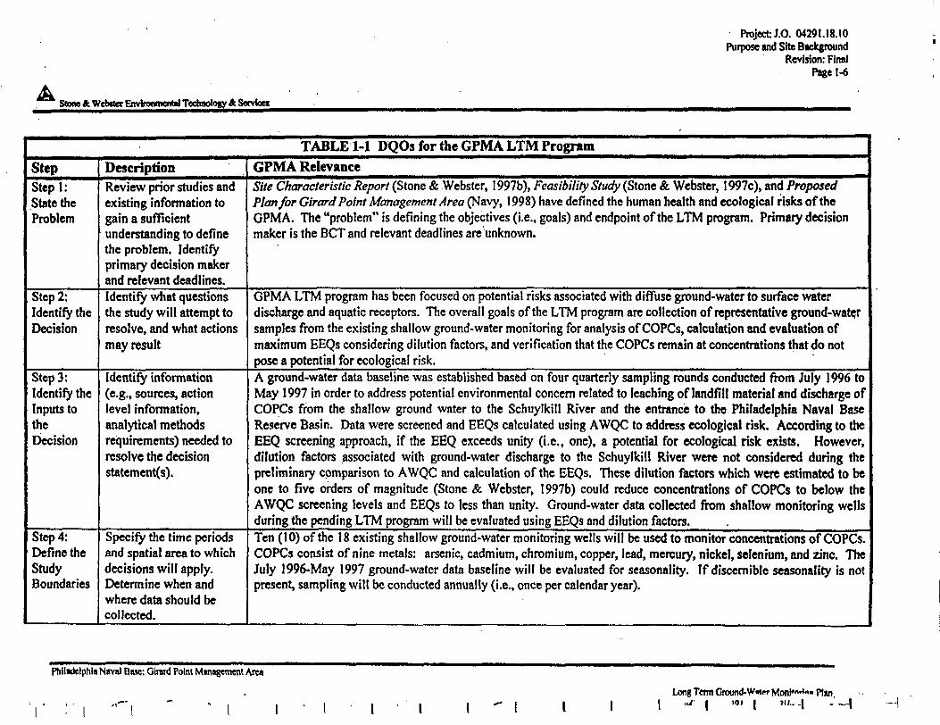
Project J.O. 04291.18.10Purpose and Site Background
Revision: FinalPage 1-6
Stone ft Webster Environmental Technology A Senrtoei
TABLE M DQOs for the GPMA LTM Program
Step Description GPMA Relevance
Stepl:State theProblem
Review prior studies andexisting information togain a sufficientunderstanding to definethe problem. Identifyprimary decision makerand relevant deadlines.
Site Characteristic Report (Stone & Webster, 1997b), Feasibility Study (Stone & Webster, 1997c), and ProposedPlan for Girard Point Management Area (Navy, 1998) have defined the human health and ecological risks of theGPMA. The "problem" is defining the objectives (i.e., goals) and endpoint of the LTM program. Primary decisionmaker is the BCT and relevant deadlines are unknown.
Step 2:Identify theDecision
Identify what questionsthe study will attempt toresolve, and what actionsmay result
GPMA LTM program has been focused on potential risks associated with diffuse ground-water to surface waterdischarge and aquatic receptors. The overall goals of the LTM program arc collection of representative ground-watersamples from the existing shallow ground-water monitoring for analysis of COPCs, calculation and evaluation ofmaximum EEQs considering dilution factors, and verification that the COPCs remain at concentrations that do notpose a potential for ecological risk. '
Step 3:Identify theInputs totheDecision
Identify information(e.g., sources, actionlevel information,analytical methodsrequirements) needed toresolve the decisionstatements).
A ground-water data baseline was established based on four quarterly sampling rounds conducted from July 1996 toMay 1997 in order to address potential environmental concern related to leaching of landfill material and discharge ofCOPCs from the shallow ground water to the Schuylkill River and the entrance to the Philadelphia Naval BaseReserve Basin. Data were screened and EEQs calculated using AWQC to address ecological risk. According to theEEQ screening approach, if the EEQ exceeds unity (i.e., one), a potential for ecological risk exists. However,dilution factors associated with ground-water discharge to the Schuylkill River were not considered during thepreliminary comparison to AWQC and calculation of the EEQs. These dilution factors which were estimated to beone to five orders of magnitude (Stone & Webster, 1997b) could reduce concentrations of COPCs to below theAWQC screening levels and EEQs to less than unity. Ground-water data collected from shallow monitoring wellsduring the pending LTM program will be evaluated using EEQs and dilution factors.
Step 4:Define theStudyBoundaries
Specify the time periodsand spatial area to whichdecisions will apply.Determine when andwhere data should becollected.
Ten (10) of the 18 existing shallow ground-water monitoring wells will be used to monitor concentrations of COPCs.COPCs consist of nine metals: arsenic, cadmium, chromium, copper, lead, mercury, nickel, selenium, and zinc. TheJuly 1996-May 1997 ground-water data baseline will be evaluated for seasonally. If discernible seasonality is notpresent, sampling will be conducted annually (i.e., once per calendar year).
Philadelphia Naval Base: Girwd Point Management Area
Long Term Groond-Wmpr Mon!"*4"- Plan,',' - — { — j
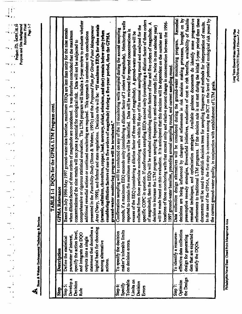
^ " = T?
£ « .2 § '=
811 n.ll
f
II
: o>
II
l|II
{
C
£
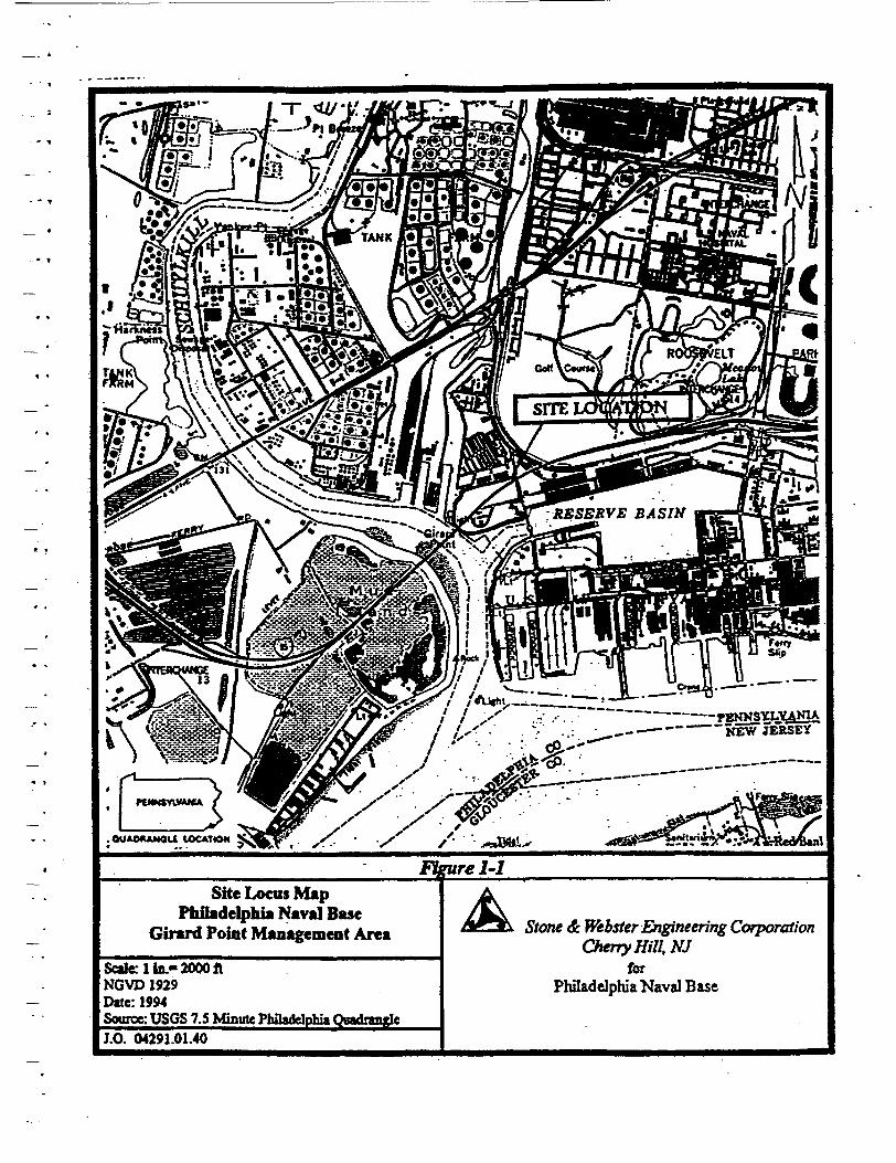
/ X>,Jr X X ^^EFT X / /• • - -JJM
wre 1-1Site Locus Map
Philadelphia Naval BaseGirard Point Management Area
Scale; 1 In.- 2000 ftNGVD 1929Date: 1994Source: USGS 7.S Minute Philadelphia QgadrangleI.O. 04291.01.40
Stone & Webster Engineerir% CorporationCherry Hill, NJ
forPhiladelphia Naval Base
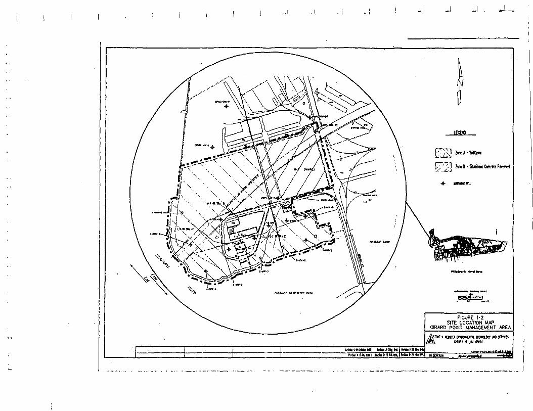
J--,
LECtKO
' ' vj Im 8 • Bkirinow Concrete Pwmwl' 'i
FIGURE 1-2SITE LOCATION MAP
GIRARD POINT MANAGEMENT AREA
i msra twwMW* itoiawf /«sown/l>V\ MWt HU.W OMM
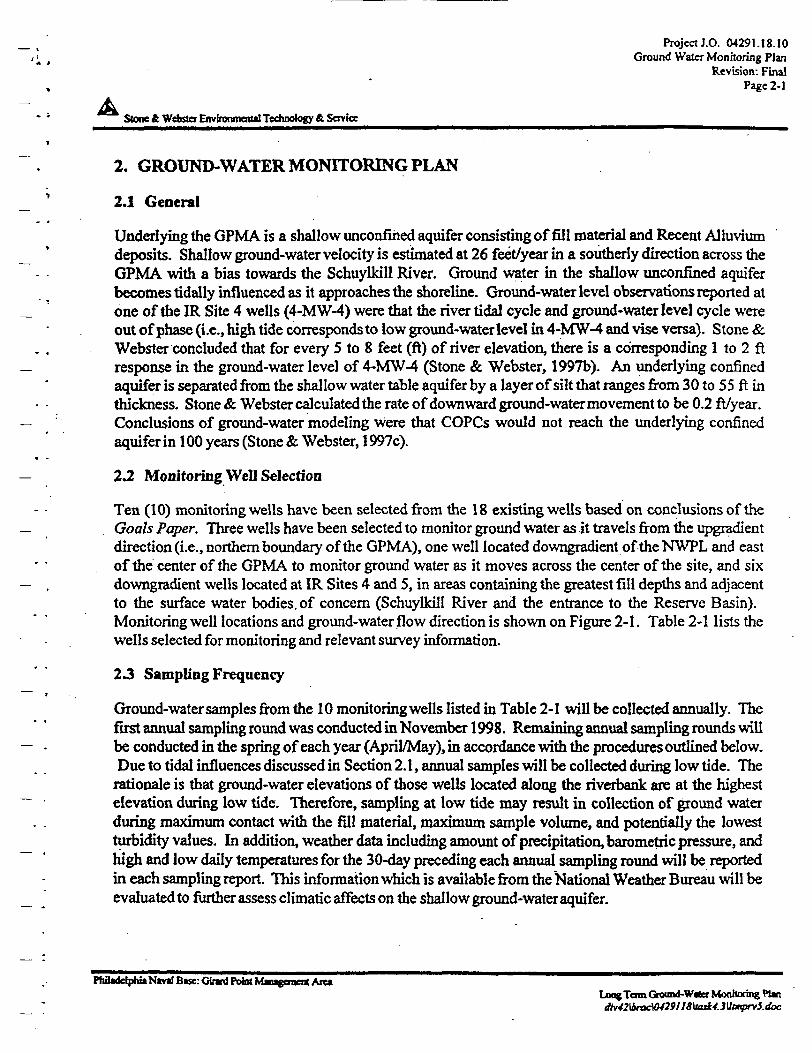
Project J.O. 04291.18.10Ground Water Monitoring Plan
Revision: FinalPage 2-1
A Stone & Webster Environment*! Technology & Service
2. GROUND-WATER MONITORING PLAN
2.1 General
Underlying the GPMA is a shallow unconfihed aquifer consisting of fill material and Recent Alluviumdeposits. Shallow ground-water velocity is estimated at 26 feet/year in a southerly direction across theGPMA with a bias towards the Schuylkill River. Ground water in the shallow unconfined aquiferbecomes tidally influenced as it approaches the shoreline. Ground-water level observations reported atone of the IR Site 4 wells (4-MW-4) were that the river tidal cycle and ground-water level cycle wereout of phase (i.e., high tide corresponds to low ground-water level in 4-MW-4 and vise versa). Stone &Webster concluded that for every 5 to 8 feet (ft) of river elevation, there is a corresponding 1 to 2 ftresponse in the ground-water level of 4-MW-4 (Stone & Webster, 1997b). An underlying confinedaquifer is separated from the shallow water table aquifer by a layer of silt that ranges from 30 to 55 ft inthickness. Stone & Webster calculated the rate of downward ground-water movement to be 0.2 ft/year.Conclusions of ground-water modeling were that COPCs would not reach the underlying confinedaquifer in 100 years (Stone & Webster, 1997c).
23, Monitoring Well Selection
Ten (10) monitoring wells have been selected from the 18 existing wells based on conclusions of theGoals Paper. Three wells have been selected to monitor ground water as it travels from the upgradientdirection (i.e., northern boundary of the GPMA), one well located downgradient of the NWPL and eastof the center of the GPMA to monitor ground water as it moves across the center of the site, and sixdowngradient wells located at IR Sites 4 and 5, in areas containing the greatest fill depths and adjacentto the surface water bodies, of concern (Schuylkill River and the entrance to the Reserve Basin).Monitoring well locations and ground-water flow direction is shown on Figure 2-1. Table 2-1 lists thewells selected for monitoring and relevant survey information.
23 Sampling Frequency
Ground-water samples from the 10 monitoring wells listed in Table 2-1 will be collected annually. Thefirst annual sampling round was conducted in November 1998. Remaining annual sampling rounds willbe conducted in the spring of each year (April/May), in accordance with the procedures outlined below,Due to tidal influences discussed in Section 2.1, annual samples will be collected during low tide. The
rationale is that ground-water elevations of those wells located along the riverbank are at the highestelevation during low tide. Therefore, sampling at low tide may result in collection of ground waterduring maximum contact with the fill material, maximum sample volume, and potentially the lowestturbidity values. In addition, weather data including amount of precipitation, barometric pressure, andhigh and low daily temperatures for the 30-day preceding each annual sampling round will be reportedin each sampling report. This information which is available from the National Weather Bureau will beevaluated to further assess climatic affects on the shallow ground-water aquifer.
PhBwlelphttNcval Base: Gwri Pofot Maageracnt Are*Long Tom Ground-W*cr Monhoring W«JtvJ2\lmKW29U8\tajtJ.3\ltmprvS.doc
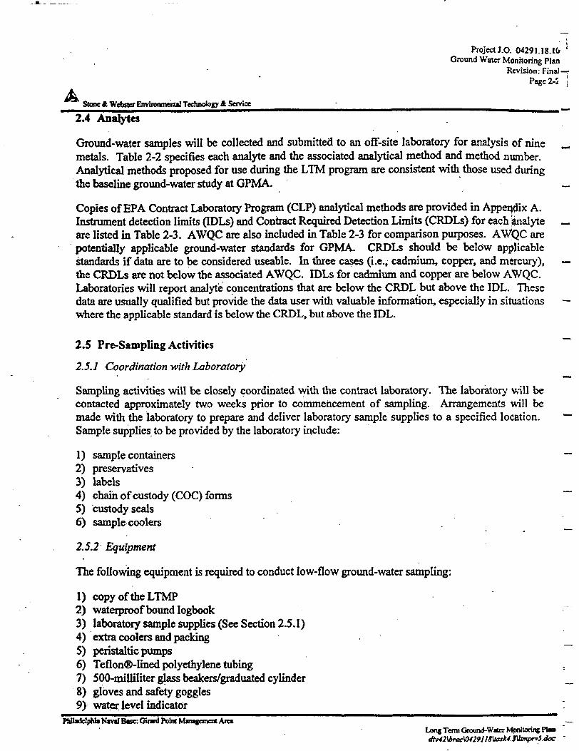
Project J.O, 04291.18.10 l
Ground Water Monitoring PlanRevision: Final—r
Page 2-1 !
AStone & Webster Environmental Technology & Service
2.4 Anatytea
Ground-water samples will be collected and submitted to an off-site laboratory for analysis of nine —
metals. Table 2-2 specifies each analyte and the associated analytical method and method number.Analytical methods proposed for use during the LTM program are consistent with those used duringthe baseline ground-water study at GPMA. _
Copies of EPA Contract Laboratory Program (CLP) analytical methods are provided in Appendix A.Instrument detection limits (IDLs) and Contract Required Detection Limits (CRDLs) for each ianalyte _are listed in Table 2-3. AWQC are also included in Table 2-3 for comparison purposes. AWQC arepotentially applicable ground-water standards for GPMA. CRDLs should be below applicablestandards if data are to be considered useable. In three cases (i.e., cadmium, copper, and mercury), —the CRDLs are not below the associated AWQC. IDLs for cadmium and copper are below AWQC.Laboratories will report analyte concentrations that are below the CRDL but above the IDL. Thesedata are usually qualified but provide the data user with valuable information, especially in situations —where the applicable standard is below the CRDL, but above the IDL.
2.5 Pre-Sampling Activities
2.5.7 Coordination with Laboratory
Sampling activities will be closely coordinated with the contract laboratory. The laboratory will becontacted approximately two weeks prior to commencement of sampling. Arrangements will bemade with the laboratory to prepare and deliver laboratory sample supplies to a specified location. ~Sample supplies to be provided by the laboratory include:
1) sample containers ~~2) preservatives3) labels4) chain of custody (COC) forms ~5) custody seals6) sample coolers . _
2.5.2 Equipment
The following equipment is required to conduct low-flow ground-water sampling:
1) copy of the LTMP2) waterproof bound logbook3) laboratory sample supplies (See Section 2.5.1)4) extra coolers and packing5) peristaltic pumps6) Teflon®-lined polyethylene tubing :
7) 500-milliliter glass beakers/graduated cylinder _8) gloves and safety goggles9) water, level indicator -
Philadelphia N*vaIB«se:CHrwd Pobit Mmtemct* Aict —Long Term Ground-Water Monitoring Pba
/? Project J.O. 04291. J8.IO«•„ . Ground W«cr Monitoring Plan
Revision: FraaJ_ _ ' , • " Page2-3
Stone A Webster Environment!! Technology & Service
10) flow through cell equipped with:pH meterthermometerconductivity meteroxidation reduction potential (ORP) meterdissolved oxygen meterturbidity meter
1 l)photoionization detection (PID) meter12) deionized water13) decontamination supplies14) graduated purge water container (minimum 5 gallons)15) keys to well locks16) ice or blue ice packs17)ziplocbags18) indelible marker19) tape
2.5.5 Monitoring Well Inspection, Security, and Access
Monitoring well locations are shown on Figure 2-1. Monitoring wells will be inspected for evidenceof damage or tampering. Observations will be recorded in the field logbook.
Each well has a keyed-alike lock. Monitoring wells are located on property owned by the UnitedStates Navy. Access to the property is controlled and arrangements must be made for entry throughNorthern Division.
2.6 Sampling Methodology
Typically, ground-water sampling entails two phases: 1) monitoring well evacuation (i.e., purging)procedures to allow representative ground water to enter the well followed by; 2) ground-watersampling procedures. Conventional purging and ground-water sampling procedures were designed withemphasis on assessment of water quality of highly productive homogeneous drinking water aquifers. Incontrast, remedial investigation monitoring wells are typically installed in low-yield heterogeneousgeologic formations. One of the concerns of conventional high-flow water well purging and samplingprocedures was increased turbidity within the well. EPA therefore established the low-flow (minimaldrawdown) ground-water sampling procedures for collection of representative samples at remedialinvestigation sites that present a variety of hydrogeologic settings. Details, as well as advantages anddisadvantages of low-flow (minimum drawdown) sampling procedures are discussed in the EPAdocument, Low-Flow (Minimal Drawdown) Ground-Water Sampling Procedures (EPA, 1996).
As discussed in Section 1.3.2, the GPMA ground-water data baseline was established using peristalticpumps and EPA low-flow sampling procedures. Stone & Webster prepared a memorandum report(Stone & Webster, 1998b) describing advantages and disadvantages of available LTM samplingequipment. The Navy decided that non-dedicated peristaltic pumps be used for the ground-waterprogram at the GPMA.
Philadelphia N*v«t Best: Ginrd Point Management A^aLong Term Ground-Wafer Monitoring Plan
Project J.O. 04291.18.10Ground Wacr Monitoring Plan
Revision: FinalPsgc2-4
AStone &Webgtf Environmental Tcchno>Q8y& Service
The wells to be sampled are listed in Table 2-1. Each well will be sampled in accordance witi EPARegion I, Low Stress (Low Flow) Purging and Sampling Procedure for the Collection of GroundWater Sampled from Monitoring Wells' (EPA, 1996b), and the requirements of this LTMP. The EPALow Flow Procedure is included in Appendix B. A checklist of sampling steps to be followed isincluded in Appendix C.
2.6.1 Documentation
Data collected in the field shall be recorded in a waterproof, bound, field logbook. Data will berecorded in the logbook using black indelible ink. Refer to Section VII Field Logbook of the EPALow Flow Procedure (See Appendix B) for a summary of information that should be recorded in thelogbook. Data will be transferred from the logbook to Field Analysis Forms (See Appendix D) forinclusion in the yearly report.
2.6.2 Initial Well Opening
Upon removing the well casing protective cover and the locking cap, any odors noted will berecorded. Immediately upon removing the well cover, the headspace of the well shall be monitoredfor total VOCs using a PID.
2.6.3 Water Level Measurements
Prior to well purging or sampling, ground-water elevation measurements will be made usipg anelectronic water level indicator. Water levels will be recorded from a known reference point on thetop of the well (i.e., polyvinyl chloride (PVC) casing) and will be recorded to the nearest 0.01 ft. Theprobe will be decontaminated using distilled water between sample points.
The depth to water will be measured in each well using the decontaminated water-level indicator.Depth to water will be determined with as little physical disturbance of the water in the wells aspossible (i.e., do not lower the probe below the water surface any iurther than necessary). Water levelmeasurements for all monitoring wells included in the program shall be taken on the same day duringlow tide. Due to tidal influences, depth to water should be measured in the six wells located alongthe shoreline in as short a time period as reasonably possible. It is recommended that two peoplemeasure the depth to water in these wells simultaneously (i.e., each person collects water levelmeasurement from three wells).
2.6.4 Well Purging
Prior to sampling, each well will be purged in accordance with Section IV Purging and SamplingProcedures, Subsections I through 3, of the EPA Low Flow Sampling Procedure (See Appendix B)The purpose of well purging is to remove stagnant well water so that a representative sample can beobtained. Water drawdown during purging shall be less than 0.3 ft.
* Hereinafter referred to as the EPA Law Flow Sampling Procedure
Phn«driphl«N«vilB«sc:Girwd Point Mmttanca Are*Long Term Ground-Wrta Monitoring Pfan
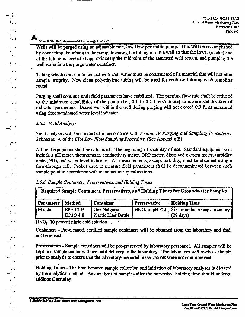
ProjectJ.O. 04291.18.10Ground Water Monitoring Plan
Revision: FinalPage 2-5
Stone & Webster Environment*! Technology & Service
Wells will be purged using an adjustable rate, low flow peristaltic pump. This will be accomplishedby connecting the tubing to the pump, lowering the tubing into the well so that the lower (intake) endof the tubing is located at approximately the midpoint of the saturated well screen, and pumping thewell water into the purge water container.
Tubing which comes into contact with well water must be constructed of a material that will not altersample integrity. New clean polyethylene tubing will be used for each well during each samplinground.
Purging shall continue until field parameters have stabilized. The purging flow rate shall be reducedto the minimum capabilities of the pump (i.e., 0.1 to 0.2 liters/minute) to ensure stabilization ofindicator parameters. Drawdown within the well during purging will not exceed 0.3 ft, as measuredusing decontaminated water level indicator.
2.6.5 Field Analyses
Field analyses will be conducted in accordance with Section IV Purging and Sampling Procedures,Subsection 4, of the EPA Low Flow Sampling Procedure. (See Appendix B).
All field equipment shall be calibrated at the beginning of each day of use. Standard equipment willinclude a pH meter, thermometer, conductivity meter, ORP meter, dissolved oxygen meter, turbiditymeter, PID, and water level indicator. All measurements, except turbidity, must be obtained using aflow-through cell. Probes used to measure field parameters shall be decontaminated between eachsample point in accordance with manufacturer specifications.
2.6.6 Sample Containers, Preservatives, and Holding Times
Required Sample Containers, Preservatives, and Holding Times for Groundwater Samples
ParameterMetals
MethodEPA CLPILMO 4.0
ContainerOne NalgenePlastic Liter Bottle
PreservativeHNO3topH<2
Holding TimeSix months except mercury(28 days)
HNOj 10 percent nitric acid solution
Containers - Pre-cleaned, certified sample containers will be obtained from the laboratory and shallnot be reused.
Preservatives - Sample containers will be pre-preserved by laboratory personnel. All samples will bekept in a sample cooler with ice until delivery to the laboratory. The laboratory will re-check the pHprior to analysis to ensure that the laboratory-prepared preservatives were not compromised.
Holding Times - The time between sample collection and initiation of laboratory analyses is dictatedby the analytical method. Any analysis of samples after the prescribed holding time should undergoadditional scrutiny.
Philadelphia Ntvil Base Ginrd Point Mwjemeat Are*Long Terra Ground-Wtfer Monitoring PUo
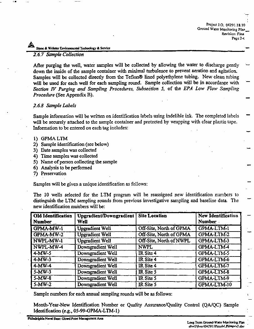
A
Project J.O. 04291.18.10Ground Water Monitoring PIan—
Revision: FinaPage2-<
Stone ft Webster Environmental Technology ft Service
2.6.7 Sample Collection
After purging the well, water samples will be collected by allowing the water to discharge gently '—down the inside of the sample container with minimal turbulence to prevent aeration and agitation.Samples will be collected directly from the Teflon® lined polyethylene tubing. New clean tubingwill be used for each well for each sampling round. Sample collection will be in accordance with ~Section IV Purging and Sampling Procedures, Subsection 5, of the EPA Low Flow SamplingProcedure (See Appendix B). ^
2.6.8 Sample Labels
Sample information will be written on identification labels using indelible ink. The completed labels ""will be securely attached to the sample container and protected by wrapping with clear plastic tape.Information to be entered on each tag includes:
1) GPMALTM2) Sample identification (see below)3) Date samples was collected ~~4) Time samples was collected5) Name of person collecting the sample6) Analysis to be performed ~~7) Preservation
Samples will be given a unique identification as follows:
The 10 wells selected for the LTM program will be reassigned new identification numbers todistinguish the LTM sampling rounds from previous investigative sampling and baseline data. Thenew identification numbers will be:
Old IdentificationNumber ,.GPMA-MW-1GPMA-MW-2NWPL-MW-1NWPL-MW-44-MW-54-MW-34-MW-45-MW-35-MW-85-MW-2
Upgradient/DowngradientWellUpgradicnt WellUpgradient WellUpgradient WellDowngradient WellDowngradient WellDowngradient WellDowngradient WellDowngradient WellDowngradient WellDowngradient Well
Site Location
Off-Site, North of GPMAOff-Site, North of GPMAOff-Site, North of NWPLNWPLIRSite4IRSite4IRSite4IRSiteSIRSiteSIRSiteS
New IdentificationNumberGPMA-LTM-1GPMA-LTM-2GPMA-LTM'-SGPMA-LTMUGPMA-LTM-5GPMA-LTM-6GPMA-LTM-7GPMA-LTM^8GPMA-LTM-9GPMA-LTM-1 0
Sample numbers for each annual sampling rounds will be as follows:
Month-Year-New Identification Number or Quality Assurance/Quality Control (QA/QC) SampleIdentification (e.g., 05-99-GPMA-LTM-l)
FhiUddpUi Nivri B«e: Gbwd Point Mvuvement AreaLong Term Ground-W«tcr Monitoring Pttn
J •
ProjcctJ.O. 04291.J8.IOGround Water Monitoring Plan
Revision: FinalPage 2-7
Stone ft Webster Environment*! Technology & Service
QA/QC Sample IdentificationDuplicate - DUPMatrix Spike- MSMatrix Spike Duplicate- MSD ,Equipment Rinsate Blank RB
2.6.9 Chain of Custody
The purpose of COC procedures is to document the identity of the sample and its handling from itsfirst existence as a sample until analysis and data reduction are completed. Custody records trace asample from its collection through aU transfers of custody until the analytical laboratory receives it.Internal laboratory records then document the custody of the sample through its final disposition. Anexample of a COC form is included in Appendix D.
Adherence to COC procedures is required for all sampling events. A sample is considered to beunder a person's custody if it is in a person's physical possession, in view of the person after takingpossession, and secured by that person so that no one can tamper with it, or secured by that person inan area that is restricted to authorized personnel. As few individuals as possible will handle eachsample to reduce the possibility of error, confusion, and/or damage.
COC seals shall be completed by the sampling team and placed across the top of the cooler in amanner that would require breaking the seal in order to remove the lid. The laboratory will supplythe seal.
The laboratory normally supplies the COC record. A COC will be secured to the inside lid of thecooler. When transferring the possession of samples, the individuals, relinquishing and receiving thesamples will sign, date, and note the tune on the COC. This record documents transfer of custody ofsamples from the sampler to another person or to the laboratory.
2.6.10 Shipping
Sample containers will be securely packed in insulated coolers containing ice and packing material.Shipment to the laboratory will be in a manner that ensures timely receipt and maintenance ofappropriate sample preservation conditions. Samples shall be logged in at the laboratory no later than48 hours after being collected from the monitoring well.
2.5.77 Decontamination
Reusable equipment, such as the water level indicator and flow through cell, will be decontaminatedwith potable water and deionized water, or in accordance with manufacturer specifications.
New clean tubing will be used for each well for each sampling round, therefore, decontamination willnot be required for the tubing.
Water used for decontamination will be deposited on the ground surface away from catch basins,drains, and surface waters. Decontamination water shall be minimal.
Naval Btsc Gktri Mm Management AreaLong Term Groimd-WaCcr Monitoring Plan
Project J.O. 04291.18.10Ground Wetcr Monitoring Plan
Revision: Final-Page 2-8
AStone fcWtfartefEnvifocmcnm Technology A Savkx
2.7 Quality Assurance/Quality Control
Quality assurance/quality control (QA/QC) samples will be collected through the LTM program toensure that high quality data are collected. Data quality is evaluated with respect to accuracy,representativeness, completeness, and comparability. QA/QC requirements for laboratory analysesinclude:
• Collection and analysis of QC samples• Use of a Naval Facilities Engineering Service Center (NFESC) laboratory for analysis
Table 2-4 identifies field QC samples that will be used during the LTM program at GPMA.
The selected off-site laboratory will also perform internal QC procedures to ensure that high qualitydata are produced. Laboratory QC will be consistent with CLP.
2.8 Reporting Requirements
Ground-water data will be collected and summarized hi a report format on a yearly basis. The yearlyground-water monitoring report will satisfy the following objectives:
• present sampling and analytical methodologies;• present data in a concise tabular format;• verify that the nine metals remain at concentrations that do not pose a potential for ecological
risk;• optimize the LTM program; and• present other recommendations and conclusions regarding the LTM program.
Once every five years data will be collectively summarized and presented in a 5-year report.
2.8.1 Data Management
Data collected during the sampling rounds will meet the DQOs specified in Section 1.3.3. Collecteddata will be converted into an electronic format. The following commercially available software, willbe used during data processing:
Word ProcessingData Tables and GraphingSpreadsheet ApplicationsDrafting/Computer Aided Design
Microsoft Word for Windows 95 Version 7.0a or currentMicrosoft Access for Windows 95 Version 7.0 or currentMicrosoft Excel for Windows 95 Version 7.0 or currentAutoCAD Release 13.0 or MicroStation Release or current
PMIadelpHtNavii Btse: Giwd Pofat Mmtgement AmLong Term Ground-Wtfer Monitoring Plan _
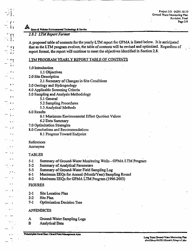
. ; 1 ProjectJ.O. 0429J.JS.JO'• I . Ground Water Monitoring Plan
Revision: Final• f t Page 2-9
• i i .AStone & Webster EnvifoorocnUl Technology A Soviet _______^
' p 2. A 2 LTM Report Format
A proposed table of contents for the yearly LTM report for GPMA is listed below. It is anticipatedr »-j that as the LTM program evolves, the table of contents will be revised and optimized. Regardless of
- ]; report format, the report will continue to meet the objectives identified in Section 2.8.
- »'i LTM PROGRAM YEARLY REPORT TABLE OF CONTENTS
1.0 Introduction: • • 1.1 Objectives
- . . 2.0 Site Description2.1 Summary of Changes in Site Conditions
* * 3.0 Geology and Hydrogeologyi . 4.0 Applicable Screening Criteria
5.0 Sampling and Analysis Methodology5.1 General
* * 5.2 Sampling Procedures5.3 Analytical Methods
6.0 Results6.1 Maximum Environmental Effect Quotient Values6.2 Data Summary
7.0 Optimization Strategies8.0 Conclusions and Recommendations
8.1 Progress Toward Endpoint
ReferencesAcronyms
TABLES
5-1 Summary of Ground-Water Monitoring Wells - GPMA LTM Program-. • 5-2 Summary of Analytical Parameters
5-3 Summary of Ground-Water Field Sampling Log6-1 Maximum EEQs for Annual (Month/Year) Sampling Round
- • 6-2 Maximum EEQs for GPMA LTM Program (1996-2003)
FIGURES
2-1 Site Location Plan2-2 Site Plan
_ . 7-1 Optimization Decision Tree
APPENDICES
A Ground-Water Sampling Logs* . B Analytical Data
, . Fhiladetphb*^B*M:Gtf*4ftMXMttafeii)a«Ait»_ Long Terra Ground-Vtocr Monitoring PIw
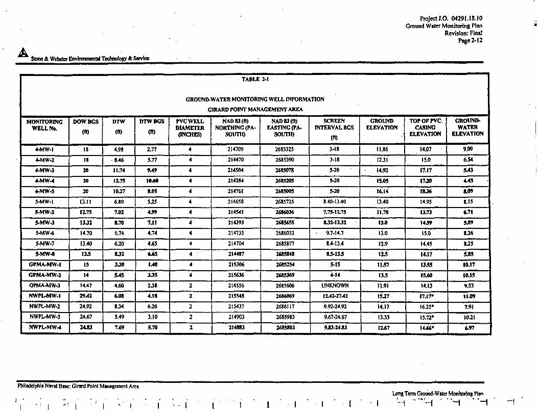
A Stone & Webster Environmental Technology & Service
Project J.O. 04291.18.10Ground Water Monitoring Plan
Revision: FinalPage 2-12
TABLE 2-1
GROUND-WATER MONITORING WELL INFORMATION
GIRARD POINT MANAGEMENT AREA
MONITORINGWELL No.
4-MW-l
4-MW-2
4-MW-3
4-MW-4
4-MW-5
5-MW-l
5-MW-2
S-MW-3
5-MW-6
5-MW-7
5-MW-8
GPMA-MW-I
CPMA-MW-2
OPMA-MW-3
NWPL-MW-I
NWPL-MW-2
NWPUMW-3
NWPL-MW-4
DOWBGS
(«)
18
IS
20
20
20
13.11
1X75
13J2
14.70
13.40
13.5
IS
14
14.47
29.42
24.92
24.67
2443
DTW
(ft)
4.98
8.46
11.74
1175
10.27
6.80
7.01
170
6.74
6.20
SJ2
3M
MS
4.60
6.08
834
5.49
7^9
DTWBGS
(ft)
2.77
5.77
9A9
10.60
8JH
SIS
439
7.11
4.74
4.65
<j6S
1.40
3.35
2.38
4.18
6J6
3.10
5.70
PVCWELLDIAMETER(INCHES)
4
4
4
4
4
4
4
4
4
4
4
4
4
2
2
2
2
2
NAD 83 (ft)NORTHING (PA-
SOUTH)
214709
214470
214504
214284
214761
21 4658
214541
214393
214735
214704
214487
215306
215636
214556
215548
215437
214903
214883
NAD 83 (ft)EASTING (PA-
SOUTH)
2685325
2685390
2685078
2685205
2685005
2685725
2686036
2685655
2686032
2685877
2685848
2685254
2685369
2685606
2686069
26S6II7
2685983
2685803
SCREENINTERVAL BGS
(ft)
3-18
3-18
5-20
5-20
5-20
8.40-13.40
7.75-1X75
8J2-13J2
• 9.7-14.7
8.4-13.4
8.5-13.5
5-15
4-14
UNKNOWN
1X42-27.42
9.92-24.92
9.67-24.67
943-24 J3
GROUNDELEVATION
11.86
12 Jl
1452
15.05
16.14
13.40
11.70
13.0
13.0
12.9
1X5
1157
\3S
11.91
15.27
14.17
13.33
1X67
TOPOFPVC.CASING
ELEVATION
14.07
15.0
17.17
17.20
18J6
14.95
13.73
1439
15.0
14.45
14.17
13.55
15.60
14.13
17.17*
16.25*
15.72*
14.66*
GROUND-WATER
ELEVATION
9.09
634
5v43
4.45
8.W
8.15
6,71
5J9
8.26
8.25
545
10.17
10.15
9.53
11.09
7.91
10.21
«.»7
PMIadelphii Nival Base: Girard Point Management AresLong Term Ground-Water Monitoring Plan
'-1 "'"H 'H "~
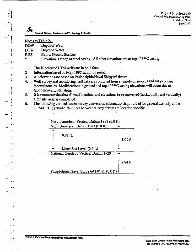
- i.r *
- i i
- . ' j '
T ?
* .
f •
• ;
_ !
Project J.O. 04291.18.10Ground Water Monitoring Plan
Revision: FinalPage 2-13
Stone & Webster Environmental Technology & Service
Notes to Table 2-1DOW Depth of WellDTW Depth to WaterBGS Below Ground Surface* Elevation is at top of steel casing. All other elevations are at top of PVC casing
1. The 10 selected LTM wells are in bold face.2 Information based on May 1997 sampling round.3. All elevations are based on PhiladelphiaNaval Shipyard datum.4. Well survey and monitoring well data are compiled from a variety of sources and may contain
inconsistencies. Modifications to ground and top of PVC casing elevations will occur due tolandfill cover installation.
5. It is recommended that all well locations and elevations be re-surveyed (horizontally and vertically)after site work is completed.
6. The following vertical datum survey conversion information is provided for general use only at theGPMA. The actual differences between survey datura are location specific.
North American Vertical Datum 1998 (0.0 ft)North American Datum 1983 (0.0 ft)
0.98 ft.
Mean Sea Level (0.0 ft)
1.09ft.
National Geodetic Vertical Datum 1929
Philadelphia Naval Shipyard Datum (0.0 ft)
2.84 ft.
PHladdpKt N«wl Btse: Gmrt Point Mamjeroent AreaLong Term Ground-Wtter Monitoring PlandM2torttcW2911Steak4.3\itmprv5.doc
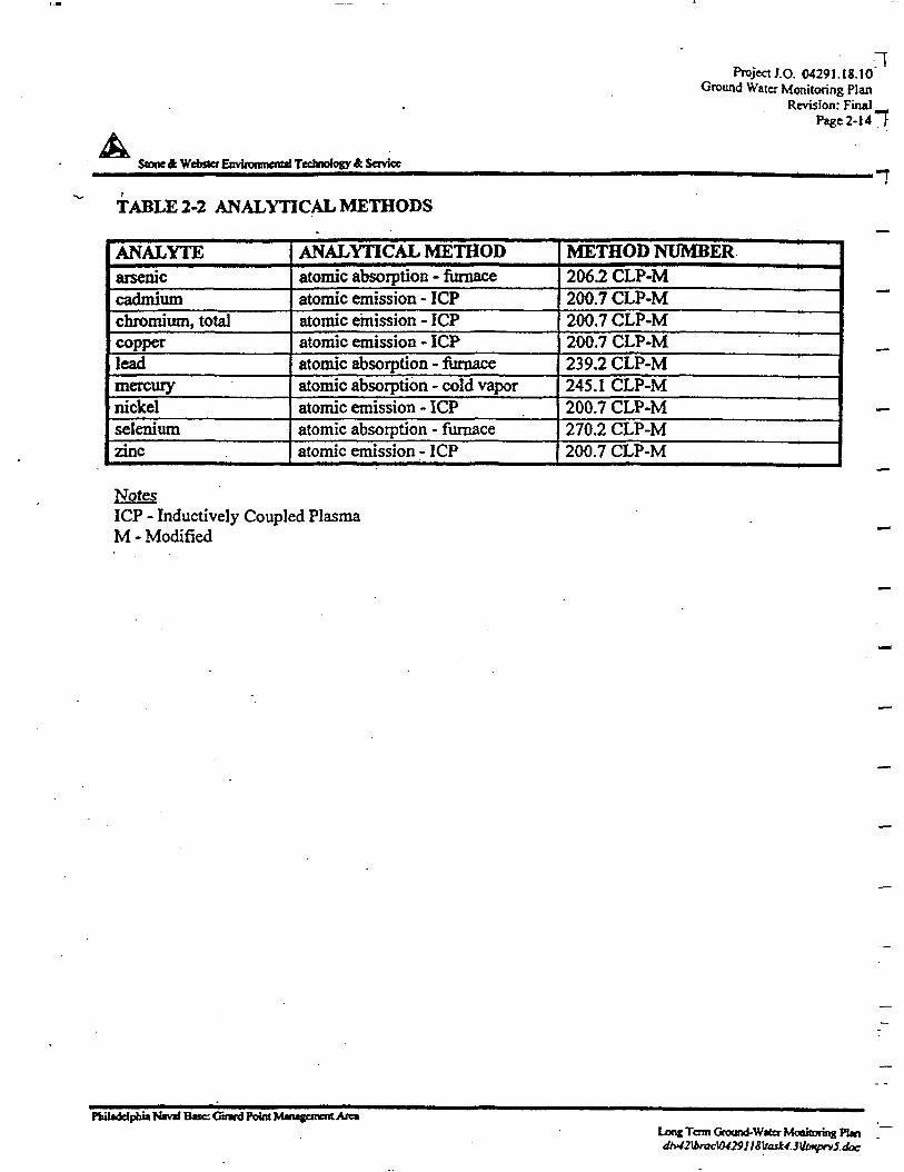
Stone A Wcbfler Enviimuiiciiut Technology A Service
Project J.O. 04291.18.10Ground Water Monitoring Plan
Revision: FinalPage 2-14 "1
TABLE 2-2 ANALYTICAL METHODS
ANALYTEarseniccadmiumchromium, totalcopperleadmercurynickelseleniumzinc
ANALYTICAL METHODatomic absorption - furnaceatomic emission - ICPatomic emission - ICPatomic emission - ICPatomic absorption - furnaceatomic absorption - cold vaporatomic emission - ICPatomic absorption - furnaceatomic emission - ICP
METHOD NUMBER2062 CLP-M '200.7 CLP-M200.7 CLP-M200.7 CLP-M239.2 CLP-M245.1 CLP-M200.7 CLP-M270.2 CLP-M200.7 CLP-M
NotesICP - Inductively Coupled PlasmaM - Modified
Pbiladelpbia Nivd B»e: (nmd Poim Mntgemeiit AreaLong Tom Ground-Water Monitoring Plan
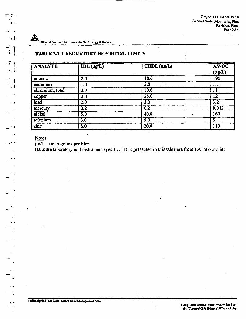
Project J.O. 04291.18.10Ground Water Monitoring Plan
Revision: FinalPage 2-15
. 1
1.1
•J.
. r
Stone £ Webster Environment^ Technology & Service
TABLE 2-3 LABORATORY REPORTING LIMITS
ANALYTE
arseniccadmiumchromium, totalcopperleadmercurynickelseleniumzinc
IDL(ng/L)
2.01.02.02.02.00.25.03.08.0
CRDLQig/L)
10.05.010.025.03.00.240.05.020.0
AWQC(Hg/L)1901.111123.20,0121605110
NotesHg/1 micrograms per literIDLs are laboratory and instrument specific. IDLs presented in this table are from EA laboratories
Philadelphia Nival B«e: Gtrard Point Mwgonent Arc*Lone Term Gn>ua<f-V'0er Monitoring Fbn
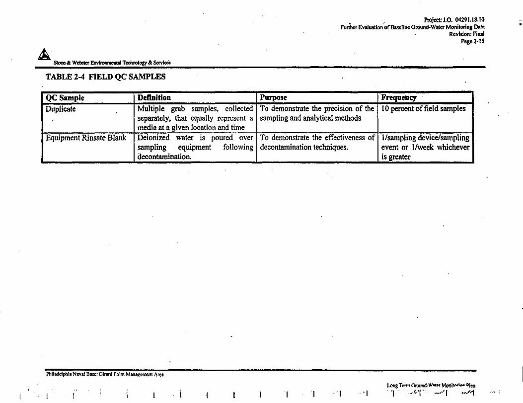
Project: J.O. 04291.18.10Further Evaluation of Baseline Ground-Water Monitoring Data
Revision: FinalPage 2-16
Stone ft Webster Environmental Technology & Services
TABLE 2-4 FIELD QC SAMPLES
QC SampleDuplicate
Equipment Rinsate Blank
DefinitionMultiple grab samples, collectedseparately, that equally represent amedia at a given location and timeDeionized water is poured oversampling equipment followingdecontamination.
PurposeTo demonstrate the precision of thesampling and analytical methods
To demonstrate the effectiveness ofdecontamination techniques.
Frequency10 percent of field samples
I/sampling device/samplingevent or I/week whicheveris greater
Philadelphia Naval Base: Girard Point Management Area
i ' • i" i i iLong Term Ground-Wan* Monl»iw<wt Plan
i
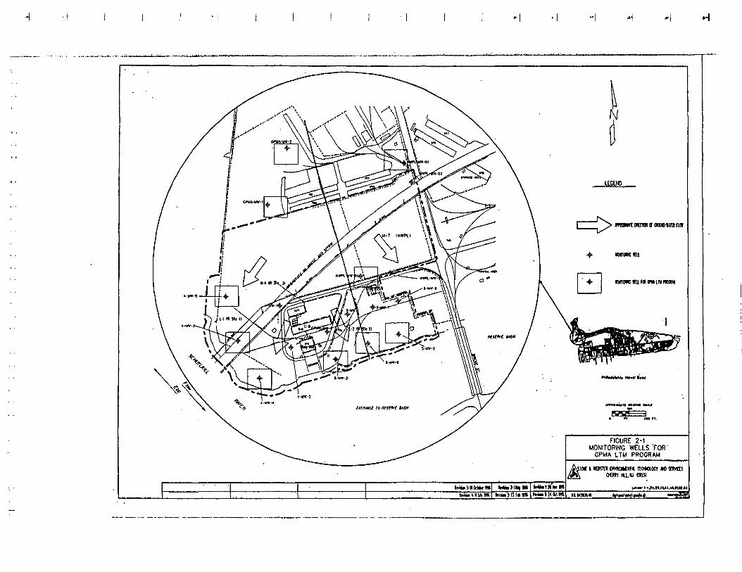
ntwt won <r awe-lira nn
BJ'Lp I» "^ !M ft.
rfi.VMtrtt.im • INI
FIGURE 2-1MONITORING WELLS 'FOR'
GPMA LTM PROGRAM
OK »«mrn wwioin nnaocr M aims
Irani t: II Ur»»
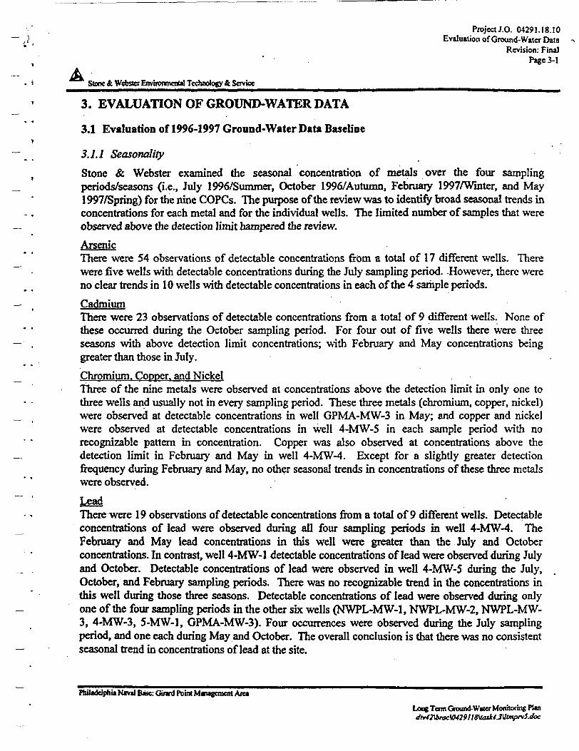
Project J.O. 04291.18.10Evaluation of Ground-Water Data
Revision: FinalPage3-l
AStore & Webster Environmental Technology & Service _^____________
3. EVALUATION OF GROUND-WATER DATA
3.1 Evaluation of 1996-1997 Ground-Water Data Baseline
3.1.1 Seasonally
Stone & Webster examined the seasonal concentration of metals over the four samplingperiods/seasons (i.e., July 1996/Summer, October 1996/Autumn, February 1997/Winter, and May1997/Spring) for the nine COPCs. The purpose of the review was to identify broad seasonal trends inconcentrations for each metal and for the individual wells. The limited number of samples that wereobserved above the detection limit hampered the review.
ArsenicThere were 54 observations of detectable concentrations from a total of 17 different wells. Therewere five wells with detectable concentrations during the July sampling period. However, there wereno clear trends in 10 wells with detectable concentrations in each of the 4 sample periods.
CadmiumThere were 23 observations of detectable concentrations from a total of 9 different wells. None ofthese occurred during the October sampling period. For four out of five wells there were threeseasons with above detection limit concentrations; with February and May concentrations beinggreater than those hi July.
Chromium. Copper, and NickelThree of the nine metals were observed at concentrations above the detection limit in only one tothree wells and usually not in every sampling period. These three metals (chromium, copper, nickel)were observed at detectable concentrations in well GPMA-MW-3 in May; and copper and nickelwere observed at detectable concentrations in well 4-MW-5 in each sample period with norecognizable pattern in concentration. Copper was also observed at concentrations above thedetection limit in February and May in well 4-MW-4. Except for a slightly greater detectionfrequency during February and May, no other seasonal trends in concentrations of these three metalswere observed.
There were 19 observations of detectable concentrations from a total of 9 different wells. Detectableconcentrations of lead were observed during all four sampling periods in well 4-MW-4. TheFebruary and May lead concentrations in this well were greater than the July and Octoberconcentrations. In contrast, well 4-MW-l detectable concentrations of lead were observed during Julyand October. Detectable concentrations of lead were observed in well 4-MW-5 during the July,October, and February sampling periods. There was no recognizable trend in the concentrations inthis well during those three seasons. Detectable concentrations of lead were observed during onlyone of the four sampling periods in the other six wells (NWPL-MW-1, NWPL-MW-2, NWPL-MW-3, 4-MW-3, 5-MW-l, GPMA-MW-3). Four occurrences were observed during the July samplingperiod, and one each during May and October. The overall conclusion is that there was no consistentseasonal trend in concentrations of lead at the site.
Philadelphia Naval Base: Gtnrd Point Management Area
Long Term Ground-Water Monitoring Plan
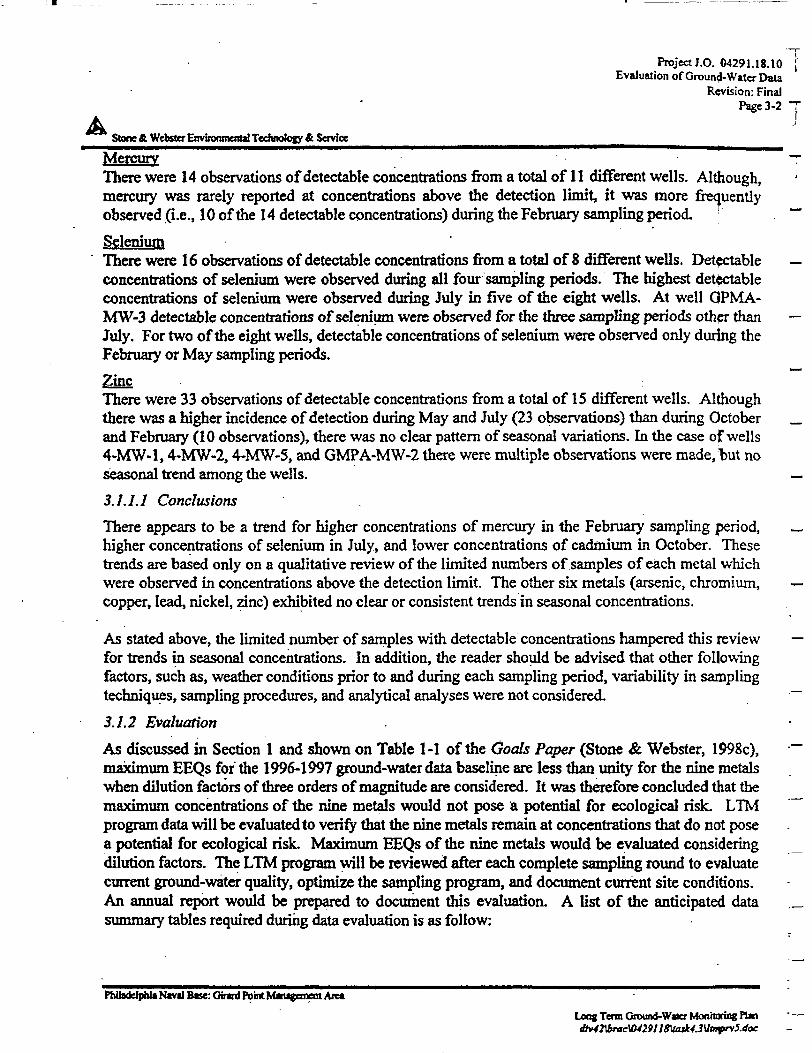
Project J.O. 04291.18.10Evaluation of Ground- Wtter Data
Revision: FinalPage 3-2
AStone ftWtbster Environmental Technology A Sqvice ________^____
MercuryThere were 14 observations of detectable concentrations from a total of 11 different wells. Although,mercury was rarely reported at concentrations above the detection limit, it was more frequentlyobserved (i.e., 10 of the 14 detectable concentrations) during the February sampling period. '
SeleniumThere were 16 observations of detectable concentrations from a total of 8 different wells. Detectableconcentrations of selenium were observed during all four sampling periods. The highest detectableconcentrations of selenium were observed during July in five of the eight wells. At well QPMA-MW-3 detectable concentrations of selenium were observed for the three sampling periods other thanJuly. For two of the eight wells, detectable concentrations of selenium were observed only during theFebruary or May sampling periods.
Zinc :There were 33 observations of detectable concentrations from a total of 15 different wells. Althoughthere was a higher incidence of detection during May and July (23 observations) than during Octoberand February (10 observations), there was no clear pattern of seasonal variations. In the case of wells4-MW-l, 4-MW-2,4-MW-5, and GMPA-MW-2 there were multiple observations were made, but noseasonal trend among the wells.
3.J.1.1 Conclusions
There appears to be a trend for higher concentrations of mercury in the February sampling period,higher concentrations of selenium in July, and lower concentrations of cadmium in October. Thesetrends are based only on a qualitative review of the limited numbers of samples of each metal whichwere observed in concentrations above the detection limit. The other six metals (arsenic, chromium,copper, lead, nickel, zinc) exhibited no clear or consistent trends in seasonal concentrations.
As stated above, the limited number of samples with detectable concentrations hampered this reviewfor trends in seasonal concentrations. In addition, the reader should be advised that other followingfactors, such as, weather conditions prior to and during each sampling period, variability in samplingtechniques, sampling procedures, and analytical analyses were not considered.
3.1.2 Evaluation
As discussed in Section 1 and shown on Table 1-1 of the Goals Paper (Stone & Webster, 1998c),maximum EEQs for the 1996-1997 ground-water data baseline are less than unity for the nine metalswhen dilution factors of three orders of magnitude are considered. It was therefore concluded that themaximum concentrations of the nine metals would not pose a potential for ecological risk. LTMprogram data will be evaluated to verify that the nine metals remain at concentrations that do not posea potential for ecological risk. Maximum EEQs of the nine metals would be evaluated consideringdilution factors. The LTM program will be reviewed after each complete sampling round to evaluatecurrent ground-water quality, optimize the sampling program, and document current site conditions.An annual report would be prepared to document this evaluation. A list of the anticipated datasummary tables required during data evaluation is as follow:
PhUadc IphitNivil tec: Gtrerd Point NUrugetnent Area
Loos Tenn Ground-Wuer Monitoring Plan • —
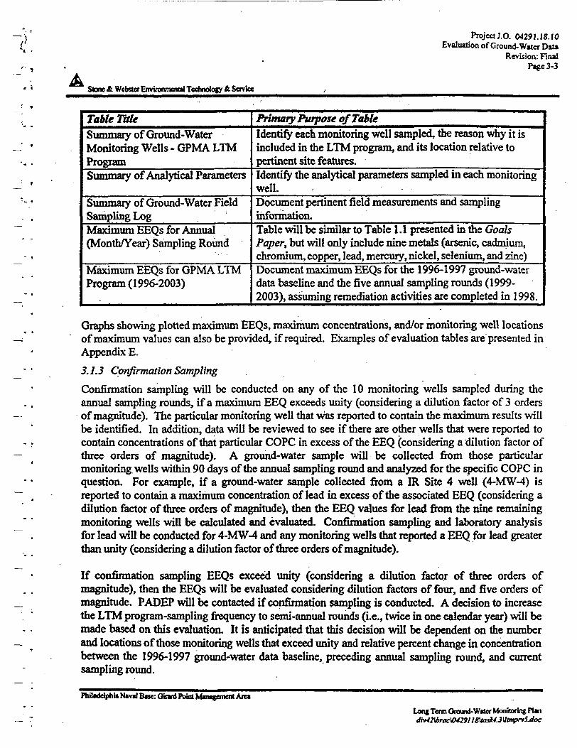
Project J.O. 04291.1*. f'OEvaluation of Ground-Water Data
Revision: FinalPage 3-3
Stone & Webster Environmental Technology ft Service
Table TaleSummary of Ground-WaterMonitoring Wells - GPMA LTMProgramSummary of Analytical Parameters
Summary of Ground-Water FieldSampling LogMaximum EEQs for Annual(Month/Year) Sampling Round
Maximum EEQs for GPMA LTMProgram (1996-2003)
Primary Purpose of TableIdentify each monitoring well sampled, the reason why it isincluded in the LTM program, and its location relative topertinent site features.Identify the analytical parameters sampled in each monitoringwell.Document pertinent field measurements and samplinginformation.Table will be similar to Table 1.1 presented in the GoalsPaper, but will only include nine metals (arsenic, cadmium,chromium, copper, lead, mercury, nickel, selenium, and zinc)Document maximum EEQs for the 1996-1997 ground-waterdata baseline and the five annual sampling rounds (1999-2003), assuming remediation activities are completed in 1998.
Graphs showing plotted maximum EEQs, maximum concentrations, and/or monitoring well locationsof maximum values can also be provided, if required. Examples of evaluation tables are presented inAppendix E.
3.1.3 Confirmation Sampling
Confirmation sampling will be conducted on any of the 10 monitoring wells sampled during theannual sampling rounds, if a maximum EEQ exceeds unity (considering a dilution factor of 3 ordersof magnitude). The particular monitoring well that was reported to contain the maximum results willbe identified. In addition, data will be reviewed to see if there are other wells that were reported tocontain concentrations of that particular COPC in excess of the EEQ (considering a dilution factor ofthree orders of magnitude). A ground-water sample will be collected from those particularmonitoring wells within 90 days of the annual sampling round and analyzed for the specific COPC inquestion. For example, if a ground-water sample collected from a IR Site 4 well (4-MW-4) isreported to contain a maximum concentration of lead in excess of the associated EEQ (considering adilution factor of three orders of magnitude), then the EEQ values for lead from the rune remainingmonitoring wells will be calculated and evaluated. Confirmation sampling and laboratory analysisfor lead will be conducted for 4-MW-4 and any monitoring wells that reported a EEQ for lead greaterthan unity (considering a dilution factor of three orders of magnitude).
If confirmation sampling EEQs exceed unity (considering a dilution factor of three orders ofmagnitude), then the EEQs will be evaluated considering dilution factors of four, and five orders ofmagnitude. PADEPwill be contacted if confirmation sampling is conducted. A decision to increasethe LTM program-sampling frequency to semi-annual rounds (i.e., twice in one calendar year) will bemade based on this evaluation. It is anticipated that this decision will be dependent on the numberand locations of those monitoring wells that exceed unity and relative percent change in concentrationbetween the 1996-1997 ground-water data baseline, preceding annual sampling round, and currentsampling round.
Philadelphia Naval Base: Gtnri Point Management Aiea
Long Term Ground-Water Monitoring Plan
ProjectJ.O. 04291.18.1C.!Evaluation of Ground-Water Data
Revision: FinalPage 3-4 —
Stone & Webster Environmental Technology * Senrfce
33, Monitoring Endpoint and Optimization
The monitoring endpoint will be based on consensus by the BCT that the decision rule stated 14 Table4-1 has been satisfied. That rule says: "If maximum EEQs for nine metals (arsenic, cacjmium,chromium, copper, lead, mercury, nickel, selenium, and zinc) remain below unity (when consideringdilution factors of one to five orders of magnitude) during a five-year period, then the GPMA ground-water monitoring program will be terminated,"
If the decision rule is not met, PADEP will be contacted, ground-water monitoring will be conductedbeyond the five-year period, and a ground-water monitoring decision tree will be developed. Thedecision tree is a logic diagram comprised of decision rules. The purpose of the decision tree will beto provide a standardized and appropriate method for optimizing future data collection activities. Ifsampling is extended beyond the five-year period, data collected as part of the ground-watermonitoring program will be reviewed periodically using the decision tree to determine whichelements are appropriate to maintain and continue. It is assumed that additional research andguidance documents addressing optimization issues will become available during the monitoringperiod. At a minimum the ground-water monitoring decision tree will be developed using thefollowing guidance documents:
• Final Long-Term Monitoring Optimization Guide, Version J.I; prepared by the Air ForceCenter for Environmental Excellence (AFCEE) - Consultant Operations Division; October1997; and
• Ridley, M.N., V;M. Johnson, and R.C. Tuckfield, 1995. Cost Effective Sampling of GroundWater Monitoring Wells; prepared for submittal to HAZMACON 1995, San Jose, CA, April 4-6,1995; February 1995.
Decision rules used to build the decision tree specify the conditions under which a specific action tocontinue or modify the ground-water monitoring program will be taken or a decision made. Decisionrules evoke a "yes" or "no" answer and will be used to optimize the following parameters:
• number of wells sampled;• location of wells sampled relative to important site features;• analytical parameters selected; and• sampling frequency.
Decision rules will take into account DQOs and the end-use of data. The decision rules developed forthe GPMA will also specify a ground-water monitoring endpoint that is consistent with the originaldecision rule.
To facilitate use of the ground-water monitoring program decision tree, data collected as part ofground-water monitoring program will need to be reduced and evaluated. The form that reduced datatake will be critical to a streamlined evaluation. It is anticipated that tables similar to those identifiedin Section 3.1.2 will play a major role hi facilitating data evaluation.
Ftribddpbu Naval Bex: Guard Point Management Area
Long Term Ground-Water Monitoring Pint<Hv42\bracW29] lS\tasl4.3Mtnyrv5.doc
\ Project J.O. 04291. 1«.IOReferences
Revision: FBU!
A Steoe&Wcb$iefEnvgoomenUlTedmok>gy& Services
4. REFERENCESAFCEE, 1997. Final Long-Term Monitoring Optimization Guide, Version LI; prepared by the AirForce Center for Environmental Excellence (AFCEE) - Consultant Operations Division. October1997.
EA Engineering, Science, and Technology (EA), 1998. Base-Wide Ground-Water Study, PhiladelphiaNaval Base, Philadelphia, Pennsylvania, 14 January 1998.
Ridley, MR, V.M. Johnson, and R.C. Tuckfield, 1995. Cost Effective Sampling of Ground WaterMonitoring Wells; prepared for submittal to HAZMACON 1995, San Jose, CA, April 4-6, 1995;February 1995.
Stone & Webster. 1996a. Conceptual Site Model for the Girard Point Management Area, PhiladelphiaNaval Base, Philadelphia, Pennsylvania. April 1996.
- . 1997a. July 1996, October 1996, February 1997 and May 1997 Ground-Water SamplingMemorandum Report (BRACL-96). 17 July 1997.
- . 1997b. Remedial Investigation Report: IR Site 4 at Philadelphia Naval Base, Philadelphia,Pennsylvania. May 1997.
-- . 1997c. Site Characterization Report for the Girard Point Management Area at PhiladelphiaNaval Base, Philadelphia, Pennsylvania. September 1997.
- . 1997d. Feasibility Study for Girard Point Management Area at Philadelphia Naval Base,Philadelphia, Pennsylvania. October 1997.
-- . 1998a. Long Term Monitoring (LTM) Methods and Strategies Memorandum Report (BRACL-108). 6 April 1998.
- . 1998b. Final Long Term Monitoring (LTM) Ground-Water Sampling EquipmentMemorandum Report (BRAC L-l 09). 7 April 1 998.
- . 1998c. Goals Paper Ground-Water Monitoring Program for Girard Point Management Areaat Philadelphia Naval Base, Philadelphia, Pennsylvania. 30 June 1998.
United States Department of the Navy, 1998. Proposed Plan Girard Point Management Area,Philadelphia Naval Complex, Philadelphia, Pennsylvania. June 1998.
United States Environmental Protection Agency (EPA), 1 993a. The USEPA Region III Modifications tothe Laboratory Data Validation Functional Guidelines for Evaluating Inorganic Analyses. April 1993.
-- . I993b. USEPA Office of Solid Waste and Emergency Response, Directive No. 9355.049FS,Presumptive Remedy for CERCLA Municipal Landfill Sites. EPA/540/F93/035. September, 1993.
- . 1993c. USEPA Office of Science and Technology, Office of Water, Water Quality Criteria,September, 1993.
- . 1994. USEPA Office of Research and Development, Guidance for the Data Quality ObjectivesProcess. EPA/600/R96/055. September, 1994.
- . 1 995a. USEPA Contract Laboratory Program, Statement of Work for Inorganics Analysis, Multi-media Multi-concentrationlLMO 4.0. EPA/540/R95/121.
PfcaadelphtaNtvrf Base: Ginrd Point Management Ait*LtrngTennGfound-Wtfer Monitoring ?ba
Project: J.O. 04291.18.10References
Revision: FinalPage 4-2
T
Stone ft Webster Environment!! Technology & Soviets
-. 1995b. USEPA Region III, Innovative Approaches to Data Validation. June, 1995. j
-. 1996a. USEPA Office of Solid Waste and Emergency Response, Low-Flow (MinimalDrawdown) Ground-Water Sampling Procedures. EPA/540/S95/504. April, 1996. _
. 1996b. USEPA Region I, Low Stress (low flow) Purging and Sampling Procedure for theCollection of Ground Water Samples from Monitoring Wells. 3 0 July 1996 Revision 2.
Philadelphia Naval Bate: Girard Point Management AreaLong Term Ground-Water Monitoring Plan
APPENDIX A
USEPA
CONTRACT LABORATORY PROGRAMSTATEMENT OF WORK FOR INORGANICS ANALYSIS,
MULTI-MEDIA MULTI-CONCENTRATIONILMO4.0
EPA/540/R95/121
PhiJ*ldp»u*N«vd Base: Gtnrd Point MmtffmeM AreaLoogTenn Oound-W*er Moottoring Pto
i
I .
OffiotofEnvreormnU Protection oldWtelt«nd
•upofund
USEPA CONTRACTI LABORATORY PROGRAM
Statement of Work for InorganicsAnalysis, Multi-mediaMulti-concentation
* •. *
ILM04.0
REPROOUCEO BYU.S. DEPARTMENT OF COMMEflCE
NATIONAL TECHNICALINFORMATION SERVICESPRINGFIELD, VA 22161
Exhibit 0 ZCr-ACS
»AKT A » mPgCTtVgLY g-* *tA8MX-ATOKTe PtttlTOM gMCTKOMSTKTC METHOD
Method 200.7 CLP-M*IKDUCTIVZLY COUWJED PLASMA-ATOMIC KMZISZOH *KCTKOH£TRZC HZTHOD
FOR TftACX XLXKENT AMALTSZS OF VATXA AMD WASTM
1. Scene and Application
1.1 Dissolved elements are determined in filtered and acidified staple*.Appropriate steps oust be taken in all analyses to ensure that potentialinterferences are taken into account. This is especially true when dissolvedsolids exceed 1500 »g/L. (See 4.)
1.2 Total elements are determined after appropriate digestion procedures areperforated. Since digestion techniques increase the dissolved solids contentof the sanples, appropriate steps anist be taken to correct for potentialinterference effects. (See 4.)
1.3 Table 1 lists elements along with recommended wavelengths and typicalestimated instrumental detection limits using conventional pneumaticnebulization. Actual working detected limits are sample dependent and as thesample matrix varies, these concentrations Bay also vary. In tine, otherelements may be added as more information becomes available and as required.
1.4 Because of the differences between various makes and models of satisfactoryinstruments, no dstailed instrumental operating instructions can be provided.Instead, the analyst is referred to the instructions provided by themanufacturer of the particular instrument.
2. Summary of Method
The method describes a technique for the simultaneous or sequentialmultielement determination of trace elements in solution. The basis of themethod is the measurement of atomic emission by an optical spectroscopictechnique. Samples are nebulired and the aerosol that is produced is
, transported to the plasma torch where excitation occurs. Characteristicatonic-line emission spectra are produced by a radio-frequency inductivelycoupled plasma (ICP). The spectra are dispersed by a grating spectrometer andthe intensities of the lines are monitored by a photosensitive device. Thephotoeurrents from the photosensitive device are processed and controlled by acomputer system. A background correction technique is required to compensatefor variable background contribution to the determination of trace elements.Background must be measured adjacent to analyte lines on samples duringanalysis. The position selected for the background intensity measurement, oneither or both sides of the analytical line, will be determined by thecomplexity of the spectrum adjacent to the analyte line. The position usedmust be free of spectral interference and reflect the same change inbackground intensity as occurs at the analyte wavelength measured. Backgroundcorrection is not required in cases at Jin* broadening where a backgroundcorrection measurement would actually degrade the analytical result. The
CLP-M modified for the Contract Laboratory Program.
0-16 ILH04.0
exhibit 0 XCF-ACS
possibility of additional interferences named in 4.1 (and tests for theirpresence ss described ia 4.2) should also b« recognized and appropriatecorrections made.
4.1
The toxicity or carcinogenlcity of each reagent used la this method has notbeen precisely defined; however, each chemical compound should be treated as apotential health hazard. The laboratory is responsible for Maintaining acurrent awareness file of OSHA regulations regarding the safe handling of thechemicals specified in this method. A reference file of material handlingdata sheets should be made available to all personnel involved in the chemical .analysis.
Interference^
Several types of interference effects may contribute to inaccuracies in thedetermination of trace elements. they can be summarized as follow* i
4.1.1 Spectral interferences can be categorized as 1} overlap of a spectralline fron another element; 2) unresolved overlap of molecular bandspectra; 3} background contribution from continuous or recombinationphenomena} and 4) background contribution from stray light from theline emission of high concentration elements. The first of theseeffects can be compensated by utilizing a computer correction of theraw data, requiring the monitoring and measurement of the interferingelement- The second effect may require selection of an altsrnatewavelength. The third and fourth effects can usually be compensatedby a background correction adjacent to the analyte line. In addition,users of simultaneous multi-element instrumentation must assume theresponsibility of verifying the absence of spectral interference froman element that could occur in a sample but for which there is nochannel in the instrument array.
Listed in Table 2 are some interference effects .for the recommendedwavelengths given in Table 1. The data in Table 2 are intended toruse only as a rudimantary guide for the indication of potentialspsctral interferences, for this purpose, linear relations betweenconcentration and intensity for the analytas and the interferents canbe assumed. The interference information, which was collected at theAmes Laboratory**, is expressed as analyte concentration equivalents(i.e., false analyte concentrations) arising from 100 mg/L of theinter fersnt element.
The suggested uee of this information is as follows t Assume thatarsenic (at 193.696 nm> is to be determined in a sample containingapproximately 10 mg/t of aluminum. According to Table 2, 100 mg/t ofaluminum would yield a false signal for arsenic equivalent to.approximately 1.3 mg/t. Therefore, -10 mg/L of aluminum would resultin a false signal for arsenic equivalent to approximately 0.13 mg/t.The reader i« cautioned that other analytical systems may exhibitsomewhat different levels of interference than those shown in Table
"Ames Laboratory, USOOE, Iowa State University, Ames, Iowa 50011.
0-17 ILM04.0
Cxhlblt 0 ICP-ATS
Wetting the argon prior to nebulization, the use of a tip washer, orsample dilution has been used to control this problem. Also, it ha*
' been reported that better control of the argon flow rat* improvesinstrument performance. This is accomplished with the use of otassflow controllers.
.,
T•y
2, and that the interference affects must be evaluated for eachindividual system. Only those interferents listed were Investigated . —and the blank spaces in Table 2 indicate that measurable interferenceswere not observed fro* the interfarent concentration* listed in Table '3. Generally, interferences were discernible if they produced peaksor background shifts corresponding to 2-5% of the peaks generated by —the analyte concentrations also listed in Table 3.
At present, information on the listed silver and potassium wavelengthsis not available but it has been reported that second order energy —from the magnesium 363.231 na wavelength interferes with the listedpotassium line at 766.491 am. • '
4.1.2 Physical interferences are generally considered to be effects •—associated with the sample nebulitation and transport processes. Such '.properties as change in viscosity and surface tension can cause *significant inaccuracies especially in samples which may contain highdissolved solids and/or acid concentrations. The use of a peristaltic '.—pump may lessen these interferences. Zf these types of interferences [are operative, they must be reduced by dilution of the sample and/orutilization of standard addition techniques. Another problem whichcan occur from high dissolved solids is salt buildup at the tip of the 1—nebulizer. This affects aerosol flow rate causing instrumental drift. *L
L:4.1.3 Chemical interferences are characterized by molecular compound (^
formation, ionization effects and solute vaporization effects.Normally these effects are not pronounced with the ZCf technique,however, if observed they can be minimized by careful selection of f—operating conditions (that is, incident power, observation position, L,and so forth), by buffering of the sample, by matrix matching, and by.standard addition procedures. These types of interferences can be rhighly dependent on matrix type and the specific analyte element. \—'
t>4.2 Prior to reporting concentration data for the analyte elements, the Contractor
shall analyze and report the results of the JCP Serial Dilution Analysis. The • .ZCP Serial Dilution Analysis shall be performed on a sample from each group of {"—samples of a similar matrix type (i.e., water, soil) and concentration (i.e.low, medium} or for each Sample Delivery Group, whichever is more frequent.Samples identified as field blanks cannot be used for Serial DilutionAnalysis.
.| —ta
Zf the analyte concentration is sufficiently high (minimally a factor of 50above the instrumental detection limit in the original sample), the serial ,dilution (a five fold dilution) shall then agree within 10% of the original 1 —determination after correction for dilution. Zf the dilution analysis for one • L»or more analytes is not within lOt, a chemical or physical interference effectmust be suspected, and the data for all affected analyses in the samplesreceived associated with that serial dilution must be flagged with an "E" onFORM IX-ZN and FORK I-IN. t
0-18 IW04.0 |_
•CO-coCO
o
--0
-rfl.
Ixhibit 0 ICT-AM
5. Apparatus
S.I Inductively Coupled flasma-Atoaic Saiesion Spectrometer.
t\f\ "• ' S.I.I Computer controlled atomic emission spectrometer with backgroundtil correction. -
5.1.2 Radio frequency generator.
5.1.3 Argon gas supply, welding grade or better.*.
5.2 Operating conditions — Because of the differences between various makes andf i i Models of satisfactory instruments, no detailed operating instructions can be
provided. Instead, the analyst should follow the instructions provided by themanufacturer of the particular instrument. Sensitivity, instrumentaldetection limit, precision, linear dynamic range, and interference effectsmust be investigated and established for each individual analyte line on thatparticular instrument. All measurements must be within the instrument linearranoe where correction factors era valid. It is the responsibility of theanalyst to verify that the instrument configuration end operating condition*used satisfy the analytical requirements and to maintain quality control dataconfirming instrument performance and analytical results.
6. Reaoents and Standards,
6.1 Acids used in the preparation of standards and for sample processing must beultra-high purity grade or equivalent. Redistilled acids are acceptable.
6.1.1 Acetic acid, cone, (sp gr 1.06).
6.1.2 Hydrochloric acid, cone, (sp gr 1.19).
6.1.3 Hydrochloric acid, (1+1): Add 500 mL cone. HC1 (sp gr 1.19) to 400mL deionited, distilled water and dilute to 1 liter.
6.1.4 Nitric acid, cone, (sp gr 1.41).
6.1.5 Kitric acid, (1+1) * Add 500 mL cone. BNO3 (sp gr 1.41) to 400 mLdeionised, distilled water and dilute to 1 liter.
r\ 1 6.2 Deionited, distilled watert Prepare by passing distilled water through e—I LJ mixed bed of cation and anion exchange resins. Ose deionited, distilled water
'- for the preparation of all reagents and calibration standards and as dilutionrf water. " The purity of this water must be equivalent to ASTK Type II reagent
I * I water of Specification 0 1193.~ J
I - 6.3 Standard atock solutions may be purchased or prepared from ultra high purityf i grade chemicals or metals. All salts must be dried for 1 hour at 105° C
,* If unless otherwise specified.
H?[ J . . D-19 ILM04.0
IT
exhibit 0 XCT-AES
(CAOTXOM: Xany metal ealta are extremely toxic and Bay be fatal if •wallowed.Mash bands thoroughly after handling.) Typical atock aolutibn preparation .procedure* follow:
€.3.1
6.3.2
(.3.3
6.3.4
Aluminum solution* etock, I mL. • 100 ug Alt Dissolved 0.100 9 ofaluminum metal in an acid mixture of 4 mL of (1*1) BC1 and 1 mL ofcone. . HNOj in a beaker. Van gently to effect solution. Whensolution is complete, transfer quantitatively to a liter flask, add anadditional 10 mL of (1*1) BC1 and dilute to 1000 mL with deionixed,distilled water.
Antimony solution stock, 1 mL « 100 ug Sot Dissolve 0.26CT gK(6bO)C4R4oG in deionized distilled water, add 10 mL (1+1) BCl anddilute to 1000 mi with deionixed, distilled water.
Arsenic solution, Stock, 1 mL • 100 ug ABI Dissolve 0.1320 g of As Ojin 100 mL of deionized, distilled water containing 0.4 g Kaoa.Acidify the solution with 2 aL cone. HKO3 and dilute to 1,000 aL withdeionized, distilled water.'
Barium solution, stock, 1 aL * 100 ug Bat Dissolve 0.1516 g(dried at 250°c for 2 hrs} in 10 mL deionixed, distilled water with 1mL (1*1) HC1. Add 10.0 mL (1+1) KC1 and dilute to 1,000 nL withdeionited, distilled water.
6.3.5 Beryllium solution, stock, 1 aL • 100 uc Bet Do not dry. Dissolve1.966 g B«S04'4H20, in deionixed, distilled water, add 10.0 'ml cone.HN03 and dilute to 1,000 mL with deionixed, distilled water.
6.3.6 Boron solution, stock, 1 mL • 100 ug B: Do not dry'. Dissolve O.S716g anhydrous H3BO3 in deionixed, distilled water and dilute to 1,000nL. U»t a reagent meeting ACS specifications, keep the bottle tightlystoppered and store in a desiccator to prevent the entrance ofatmospheric moisture.
6.3.7 Cadmium solution, stock, 1 mL • 100 ug Cd: Dissolve 0.1142 g CdO in aminimum amount of (1+1) HNOj. Heat to increase rate of dissolution.Add 10.0 mL cone. HN03 and dilute to 1,000 nL with deionixed,distilled water.
€.3.8 Calcium solution, stock, 1 mL • 100 ug Cat Suspend 0.2498 g CaCO3dried at 180°c for 1 h before weighing in deionixed, distilled waterand dissolve cautiously with a minimum amount of (1+1) HHO3. Add10.0 mL cone. HH03 and dilute to 1,000 mL with deionixed, distilledwater.
6.3.9 Chromium solution, stock, 1 nL » 100 ug Crt Dissolve 0.1923 g of CrO3in deionized, distilled water. When solution is complete acidify with10 mL cone. KNO3 and dilute to 1,000 mL with deionixed, distilledwater.
6.3.10 Cobalt solution stock, 1 oL * 100 ug Coi Dissolve 0.1000 g of cobaltmetal in a minimum amount of (1+11 HKO3. Add 10.0 mL (1+1) HCl anddilute to 1,000 mL with deionized, distilled water.
0-20 ILM04.0
:RT
i
m-
*'II JCxhiblt 0 ZCP>AXS
**
6.3.11 Copper solution, stock, 1 mL • 100 ug Cut Dissolve 0.1252 7 CuO in aminimum amount of (1+1) HN03. Add 10.0 mL cone. HHO3 and dilute to1,000 mL with deionized, distilled water.
6.3.12 Iron solution, stock, 1 ml. * 100 ug fet Dissolve 0.1430 g f*2°3 •If warm mixture of 20 *L {!•*>!> HC1 and 1 at. at cone. BNO3. Cool, add anl| additional S mi of cone. MW3 and dilute to 1,000 mL with deionized,-, distilled water.
6.3.13 Lead solution, stock, 1 mL • 100 ug fbt Dissolve 0.1599 g Pb(N03}2 ina minimum amount of (1+1) BHO3. Add 10.0 mL of cone. HN03 and diluteto 1,000 mL with delonized, distilled water.
, 6.3.14 Magnesium solution, stock, 1 mL • 100 ug Hgt Dissolve 0.16S8 y HgO ina mlnimua amount of (l-»-l) KMOj. Add 10.0 «L cone. HHOj and dilute to1,000 to. with deionixed, distilled water.
6.3.15 Kanganes* solution, stock, 1 otL - 100 ug Knt Dissolve 0.1000 g ofmanganese until in the acid mixture, 10 ml cone. HC1 and 1 ol cone.KNO3, and dilute to 1,000 mi with deionizcd, distilled water.
6.3.16 Molybdenum solution, stock, 1 n£. - 100 ug Mo: Dissolve 0.2043 g(KH4)2Ko04 in deionized, distilled water and dilute to 1,000 nL.
6.3.17 Nickel solution, stock, 1 ml - 100 ug Hi: Dissolve 0.1000 g of nickelmetal in 10 aL hot cone. HH03, cdol and dilute to 1,000 oL withdeionized, distilled water.
6.3.IB Potassium solution, stock, 1 ml. - 100 ug Ki Dissolve 0.1907 g KC1,dried at 110°C, in deionized, distilled water. Dilute to 1,000 mL.
6.3.19 Selenium solution, stock, 1 al. • 100 ug Set Do not dry. Dissolve0.1727 g H2S«03 (actual assay 94.6%) in deionizad, distilled water anddilute to 1,000 mL.
6.3.20 Silica solution, stock, 1 mL - 100 ug SiOjt Do not dry. Ditcolve6.4730 g K«2Si03-9H2O in deionized, distilled water. Add 10.0 mLcone. HM03 and dilute to 1,000 mL with deionized, distilled water.
6.3.21 Silver solution, stock, 1 wl - 100 ug Agt Dissolve 0.1S75 g AgK03 in100 mL of deionized, distilled water and 10 «L cone. H»O3. Diluteto 1,000 mL with deionized, distilled water.
6.3.22' Sodium solution, stock, 1 mL • 100 ug Nat Dissolve 0.2542 g Had indeionized, distilled water. Add 10.0 mL cone. KNO3 and dilute to1,000 mL with deionized, distilled water.
6.3.23 Thalliun solution, stock, 1 mL * 100 ug Tit Dissolve 0.1303 g T1NO3in deionized, distilled water. Add 10.0 mL cone. HNO3 and dilute to1,000 mL with deionized, distilled water.
D-21 1LH04.0
txhibit C ICT-AIS
6.3.24 Vanadium eolution, stock, 1 mL • 100 wg V» Dissolve 0.2297 KH4VO3 ina minimum amount of cone. WOj. Beat to increase rate of r"^dissolution. Add 10.0 mL cone. KNOj and dilute to i,OOO mL withdeionixed, distilled water.
6.3.25 Sine eolation, stock, 1 mL • 100 «g tnt Dissolve 0.1245 g tnO in a '—minimum amount of dilute KNOj. Add 10.0 mL cone. BHOj and dilute tol.OOO mL with deioniced, dietilled water.
6.4 Mixed calibration standard solutions — Prepare mixed calibration standard "~"solutions by combining appropriate volumes of the stock solutions involumetric flasks. (See 6.4.1 thru 6.4.5.) Add 3 mL of (1+1) KMOj'and 10 sL jof (1+1) BCl and dilute to 100 mL with deioniced, distilled water. (See ironin 6.4.8.) Prior to preparing the mixed standards, each stock solution should ~~be analyzed separately to determine possible spectral interference or thepresence of impurities. Care should be taken when preparing the mixedstandards that the elements are compatible and stable. Transfer the mixedstandard solutions to a FIP fluorocarbon or unused polyethylene bottle for ' ~~storage. Fresh mixed standards should be prepared as needed with therealization that concentration cm change on aging. Calibration standards \
• must be initially verified using a quality control sample and monitored weeklyfor stability (see 6.6.3). Although not specifically required, some typical ~calibration atandard combination* follow when using those specific wavelengths (listed in Table 1. J
6.4.1 Mixed standard solution I — Manganeee, beryllium, cadmium, lead, and ~sine. |
6.4.2 Mixed standard solution II — Barium, copper, iron, vanadium, and Jcobalt. -
6.4.3 Mixed standard solution III — Molybdenum, silica, arsenic, and . (selenium.
\£.4.4 Mixed standard solution IV — Calcium, sodium, potassiun, aluminum, \
chromium and nickel. V
6.4.5 Mixed standard solution V — Antimony, boron, magnesium, silver, and i~thallium. |
XOTSi If the addition of silver to the recommended acid combinationresults in an initial precipitation, add 15 mL of deionixed distilled • "water and warm the flaek until the eolution clears. Cool and dilate rto 100 mL with deionixed, distilled water. For this acid combination V.the silver concentration should be limited to 2 mg/L. Silver underthese conditione is stable in a tap water matrix for 30 days. Higher *concentrations of silver require additional HCl. 5
6.5 Two types of blanks are required for the analysis. The calibration blank («••Exhibit E) is used in establishing the analytical curve while the reagent 'blank (preparation blank, Exhibit E) is used to correct for poseible . 'contamination resulting from varying amounts of the acids used in the sample *•processing.
D-22 ' ILM04.0
txhibit 0 ICP-MS
6.5.1 The calibration blank is prepared by diluting 2 ml of (1+1) BXO3 and10 «£. of (1+1) RC1 to 100 mL with deionixed, distilled water. Preparea sufficient quantity to be used to flush the syste* between standardsand samples.
6.5.2 The reagent blank (or preparation blank - see exhibit I) mat containall the reagents and in the same volumes as used in the processing ofthe samples. The reagent blank must be carried through the completeprocedure and contain the same acid concentration in the finalsolution as the sample solution used for analysis.
6.6 Zn addition to the calibration standards, an instrument check standard, aninterference check sample and a quality control sample are also required forthe analyses (see Exhibit C).
6.6.1 The instrument check standard for continuing calibration verificationis prepared by the analyst by combining compatible elements at aconcentration equivalent to the mid-points of their respectivecalibration curves.
6.6.2 The interference check sample is prepared by the analyst, or obtainedfrom £PA A* available.
6.6.3 The quality control sample for the initial calibration verificationshould be prepared in the same acid matrix aa the calibrationstandards and in accordance with the instructions provided by thesupplier.
7. Proeedurf
7.1 Set up instrument with proper operating parameters established in Section 5.2.The instrument must be allowed to becosne thermally stable before beginning.This usually requires at leait 30 rain, of operation prior to calibration.
7.2 Initiate appropriate operating configuration of computer. '
7.3 Profile and calibrate instrument according to instrument manufacturer'srecommended procedures, using mixed calibration standard solutions such asthose described in Section 6.4. flush the system with the calibration blank(6.5.1) between each standard. (MOTZt Tor boron concentrations greater than500 ug/L extended flush times of 1 to 2 minute* may be required.)
7.4 Begin-the sample run flushing the system with the calibration blank solution(6.5.1) between each sample. (See HOTt in 7.3.) Analyze the Instrument checkstandard (6.6.1) and the calibration blank (6.5.1) each 10.analytical samples.
7.5 A minimum of two replicate exposures is required for standardization and allQC and cample analyses. The average result of the multiple exposures for thestandardization and all QC and sample analyses shall be used.
0-23 . tLK04.0
f
txhlbit D ICT-JUCJ
8. Calculation
8.1 Reagent blanks (preparation blank*} (hall be treated at specified In exhibitX.
5.2 If dilation! were perforated, the appropriate factor. shall be applied to eaaplevalue*.
8.3 Unit* shall "be clearly specified.
9. pyalitv Control
9.1 Quality control shall be performed a* specified in Xxhibit X.
1:
I
0-24 XLX04.0
I*•••
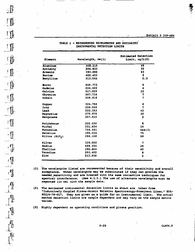
Exhibit 0 ICP-AZS
TABU 1 - MCOKHEWDEO KAVtUEHCTHS AMD ESTIMATEDINSTRUMENTAL DETECTION LDUTS
Estimated DetectionElement Wavelength, na(l) Limit, ug/L(2)
Mum in urnAntimonyArsenicBariuaBeryllium
BoronCadmiumCalciumChromiumCobalt
CopperIronLeadMagnesiumManganese
MolybdenumNickelPotassiumSeleniumSilica (Si02)
SilverSodiumThalliumVanadiumtine
308.215206.833193.696455.403313.042
249.773226.502317.933267.716228.616
324.754259.940220.353279.079257.610
202.030231.604766.491196.026266.158
328.068588.995190.864292.402213.856
4532S320.3
S41077
6742302
8ISSee(3)7558
7294082 -
(1) The wavelengths listed are recommended because of their sensitivity and overallacceptance. Other wavelengths may be substituted if they can provide theneeded sensitivity and are treated with the same corrective techniques forspectral interference. (See 4.1.1.) The use of alternate wavelengths must bereported (in run) with the sample data.
(2} The estimated instrumental detection limits as shown are taken from•Inductively Coupled Plasma-Atomic Emission Spectroscopy-Prominent Lines," EPA-600/4-79-017. They are given as a guide for an instrumental limit. The actualmethod detection limits are sample dependent and may vary as the sample matrixvaries.
(3) Highly dependent on operating conditions and plasma position.
0-25 ILH04.0
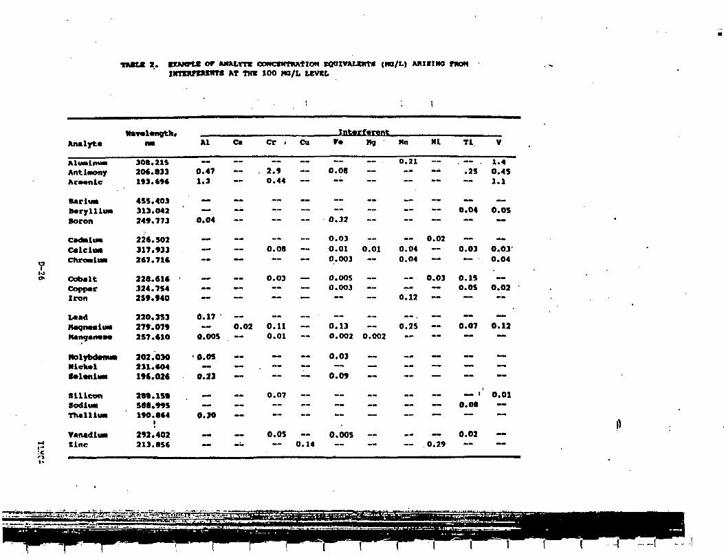
TMXX 2. KXAMPV or MUU.TTC cotfCKNTiwrioN EQUIVAUHT* <ra/L) AKISIWO nton •IHimrtlUCHTB AT TOT 100 HO/L UEVXL
1 • I
Analyt*
MtMMlfMMI
Antimony
BarltMB*rylllu«Boron
CadMltM
calclwa7 Chro»i«*too* Cobalt
CopparIron
L*adlfftQfMa*at iLlMI
KAlHf AIW09
HolybdMiMNlelMlf*l«nU*
SiliconSOdiWM
ThallltM
VartadliM
na
308.21%
193.696
455.403313.042249.773
226.502317.933267.716
228.616324.754259.940
220.353279.0792S7.610
202.030231.604196.026
28«. 151588.995190.864
I
292.402213.856
- 51 ft-. <A-rr^1''k'i
Al Ca Cr . Cu
—0.47 — . 2.91.3 ~ 0.44
.
0.04
~.— — 0.08
— — 0.03~— *"" "*"" "
0.17— 0.02 0.11
0.005 — 0.01
• O.OS_ — . — —
0.2J — —
_ .. 0.07_ ~.
0.30
~ — 0.05 —-- — 0.14
Int«rf.r.«tr» Mq Mn Ml Tl V
~- 0.21 — . — . 1.40.08 — — -- .25 0.45
— "" ~" ~" ™~ ~~ 1.1
~ — — -- — _~0.04 O.OS
0.32 — — — — —
0.03 — — 0.02 — ~-O.01 0.01 0.04 -- 0.03 0.030.003 — 0.04 — — - O.O4
O.OOS — — 0.03 0.15 —0.003 — r- — 0.05 O.02
0.12 — — —
— — —0.13 — 0.25 — 0.07 0.12O.OOJ O.002 — — ~ —
0.03 — . .« . — —— _ _ « — . _ _ —
0.09 — .- — — ~
— i' 0.01~ 0.06 —
— __ — — — «-.
O.OOS — — ~ 0.02 —__ o,29 — —
-I ~-(
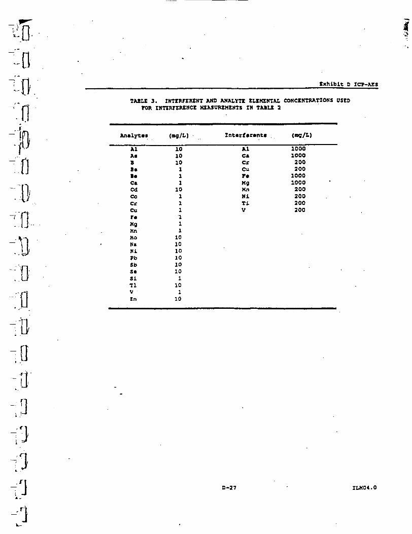
-0-
txhibit D ICT-AIS
TABLI 3. IKTtRTEWEHT AHO AKALYTX ELtMINTM. CONCSRISATIONS OStDTOR IHTtRTOMMCt XXXSUTtXMZNTS IM TABLt 2
An*lyt«« (ag/L) Int«rf«r«nt«
n
Al 10 Al 1000As 10 C* 1000B 10 Cr 2008 * 1 C u 2 0 0B« 1 F* 1000C* 1 Kg 1000Cd 10 Hn 200Co 1 Hi 200Cr 1 Ti 200Cu 1 V 200r« iKg 1Kn 1Mo 10Na 10Hi 10Pb 10Sb 10S* 10Si 111 10V 1Zn 10
D-27 ' ILM04.0
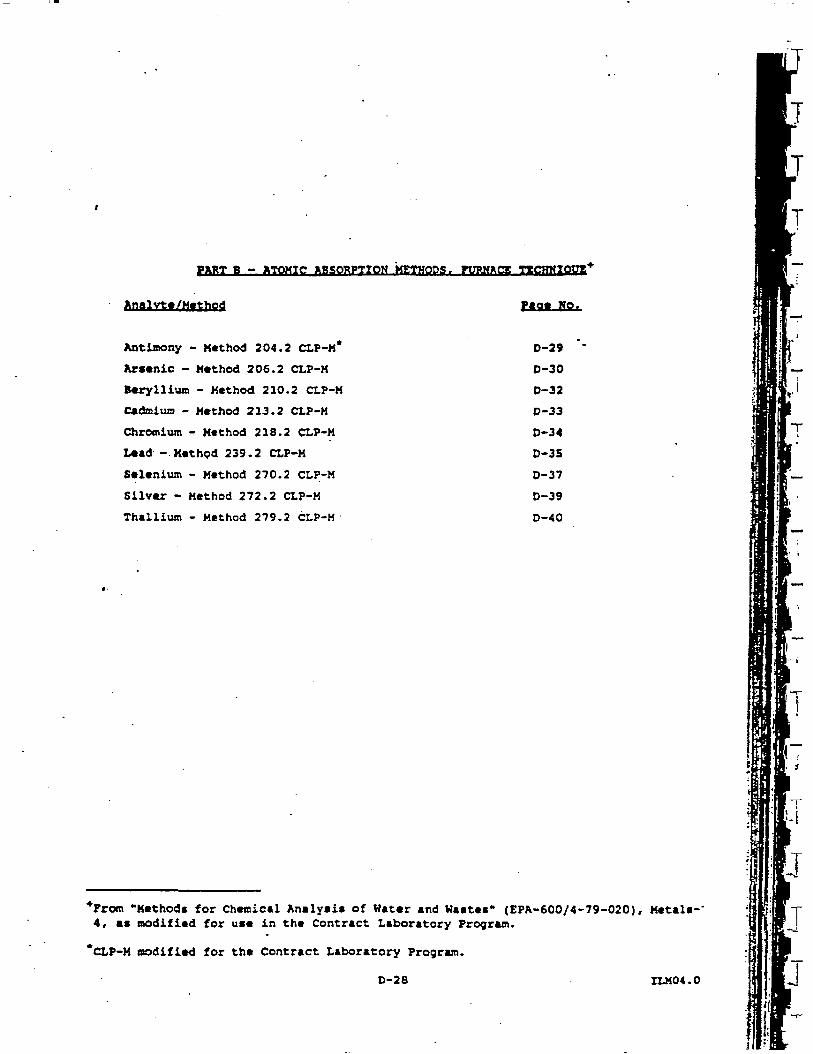
Analvte/Method
r-LJlTQMIC HBSOSITYON METHODS. FURNACE TTCHKIQgg
Pace No.
Antimony - Method 204.2 CLP-M*
Arsenic - Method 206.2 CLP-M
Beryllium - Method 210.2 CLP-M
Cadmium - Method 213.2 CLP-M
Chromium - Method 218.2 CLP-H
Lead - Method 239.2 CLP-M
Selenium - Method 270.2 CLP-H
Silver - Method 272.2 CLP-H
Thallium - Method 279.2 CLP-H
D-29
0-30
D-32
D-33
D-34
D-3S
0-37
D-39
D-40
*From "Methods for Chemical Analysis of Hater and Wastes" (EPA-600/4-79-020), Metals-'4, as modified for use in the Contract Laboratory Program.
CLP-M modified for the Contract Laboratory Program.
D-28 IZJ404.0
j
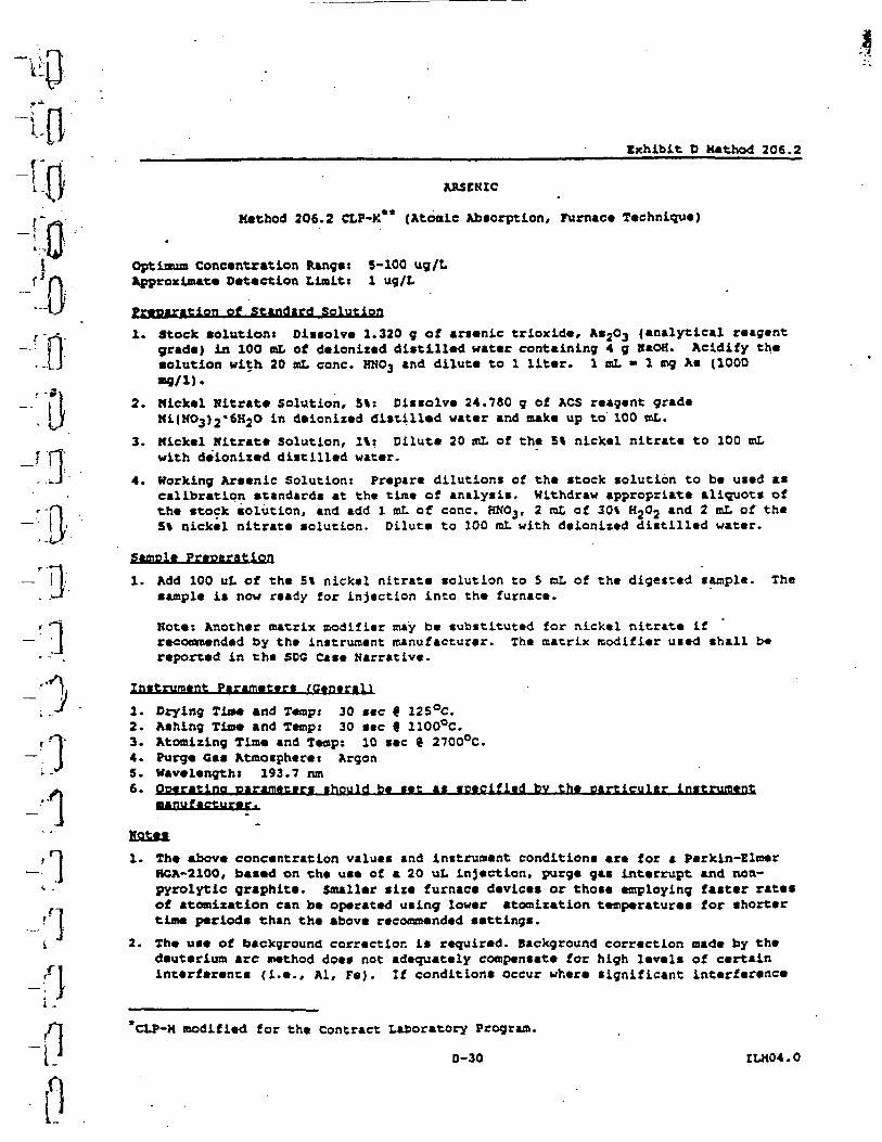
ifl
)
A
-ft
Exhibit O Kethod 206.2
ARSENIC
Method 206.2 CLF-K** (Atonic Absorption, Furnace Technique)
1 Optimum Concentration Range» 5-100 ug/LHi Approximate Detection Limit t 1 ug/L
of Standard Solution
1. Stock solution: Dissolve 2.320 9 of arsenic trioxide, As2O3 {analytical reagentgrade) in 100 mL of deionized distilled water containing 4 g HaOH. Acidify theeolation with 20 ml, cone. HNO3 and dilute to 1 liter. 1 mL - 1 «ng Ae (1000
2. Nickel Nitrate Solution, 5%: Dissolve 24.780 g of ACS reagent gradeNi(HO3)2'6H2O in deionized distilled water and make up to 100 mL.
3. Nickel Kitrate Solution, It: Dilute 20 mL of the 5% nickel nitrate to 100 mLwith deionized distilled water.
4. Working Arsenic Solution: Prepare dilutions of the stock solution to be used ascalibration standards at the tin* of analysis. Withdraw appropriate aliquot* ofthe stock solution, and add 1 mL of cone. RN03, 2 mL of 30% HjOj and 2 mL of theS% nickel nitrate solution. Dilute to 100 raL with deionized distilled water.
Prearation
1. Add 100 uL of the 5% nickel nitrate solution to S mL of the digested sample. Thesample is now ready for injection into the furnace.
Note: Another matrix modifier may b« substituted for nickvl nitrat* ifrecommended by the instrument manufacturer. The matrix modifier used shall b*reported in the SDC Case Narrative.
Instrument Parameters fGeneral!
1. Drying Time and Temp: 30 sec 9 125°C.2. Ashing Time and Temp: 30 sec 9 1100°C.3. Atomizing Time and Teap: 10 sec 9 2700°C.4. Purge Gas Atmosphere: Argon5. Wavelength! 193.7 run6. Operating parameters should be set as specified bv the particular instrument
1. The above concentration values and instrument conditions are for a Parkin-ElmerHCA-2100, based on the use of a 20 uL injection, purge gas interrupt and non-pyrolytic graphite. Smaller sire furnace devices or those employing faster ratesof atomixation can be operated using lower atomization temperatures for shortertime periode than the above recommended settings.
2. Th« use of background correction is required. Background correction made by thedeuterium arc method does not adequately compensate for high levels of certaininterference (i.e., Al, Fe). Zf conditions occur where significant interference
*CLP-M modified for the Contract Laboratory Program.
0-30 ILM04.0
Exhibit D Method 206.2
is suspected, the l*b Bust switch to an alternate wavelength or take otherappropriate actions to compensate for the interference effects.
3. For every cample analyzed, verification is necessary to determine that ee.thod ofstandard addition is not required (see Exhibit X).
4. If Mtbod of standard addition is required, follow the procedure given inExhibit I.
5. The use of the Electrodeless Discharge Lamps (COL) for the light source isrecommended.
ril;I»L'3'
Iv-'.
1<
rii1&.:'!?
D-31 ILK04.0
IIi .1
t
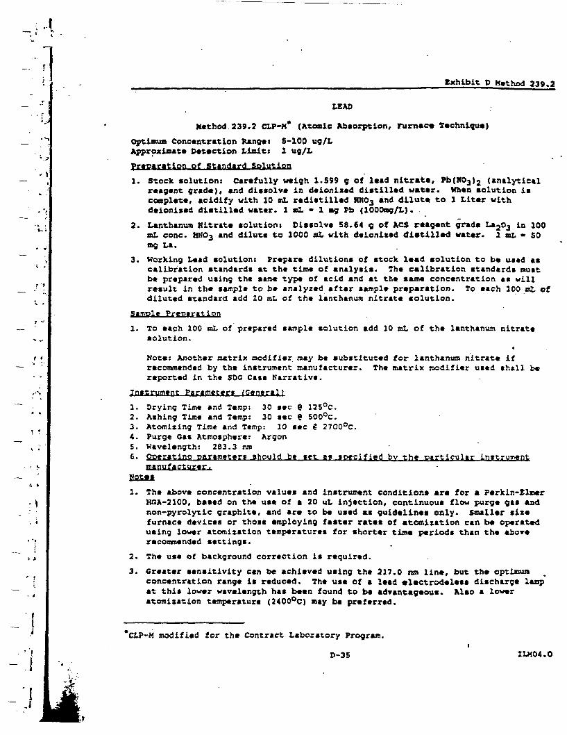
:1
-.1
Exhibit O Hethod 239.2
LEAD
Method 239.2 CtP-H* (Atomic Absorption, Furnace Technique)
optimum Concentration Range: 5-100 ug/LApproximate Detection Limitt 1 ug/L
preparation ef Standard Solution
1. Stock solution: Carefully weigh 1.599 g of lead nitrate, Pb(K03}2 (analyticalreagent grade), and dissolve in deionixed distilled water. When solution iscomplete, acidify with 10 mL redistilled BRO3 and dilute to 1 Liter withdeionixed distilled vater. 1 siL - 1 my Pb (lOOOng/L).
2. Lanthanum Nitrate solutions Dissolve 58.64 g of ACS reagent grade La2Oj in 100«L cone. BNC-3 and dilute to 1000 mL with deionixed distilled water, a »L - SOtag La.
3. Working Lead solution: Prepare dilutions of stock lead solution to be used ascalibration standard* at the time of analysis. The calibration standards mustbe prepared using the sane type of acid and at the same concentration as willresult in the sample to be analyzed after sample preparation. To each 100 ml ofdiluted standard add 10 mL of the lanthanum nitrate solution.
pimple Preparation
1. To each 100 mL of prepared sample solution add 10 mL of the lanthanum nitratesolution.
•Mote: Another matrix modifier nay be substituted for lanthanum nitrate ifrecommended by the instrument manufacturer. The matrix modifier used shall bereported in the SDG Cats Narrative.
Instrument Parameter* fGeneral)
1. Drying Time and Temp: 30 sec 9 125°C.2. Ashing Time and Temp: 30 sec 9 SOO°C.3. Atomizing Time and Temp: 10 sec € 2700°C.4. Purge Gas Atmosphere: Argon5. Wavelength: 283.3 run6. Operating parameters should be set ac specified bv the particular instrument
manufacturer.fotes
1. The above concentration values and instrument conditions are for a Parkin-linerHGA-2100, based on the use of a 20 uL injection, continuous flow purge gas andnon-pyroly-tic graphite, and are to be used as guidelines only. Smaller sizefurnace devices or those employing faster rates of atomitation can be operatedusing lower atomization temperatures for shorter tine periods than the aboverecommended settings.
2. The use of background correction is required.
3. Greater sensitivity can be achieved using the 217.0 ran line, but the optimumconcentration range is reduced. The use of a lead electrodeless discharge lampat this lower wavelength has been found to be advantageous. Also a loweratomization temperature (2400°C) nay be preferred.
"CLP-M modified for the Contract Laboratory Program.i
D-35 ILK04.0
J
exhibit D Method 239.2
4. To suppress sulfate interference (up to 1500 ppm), lanthanum Is added as thenitrate to both sample* and calibration standards. <Atomic AbsorptionHewsletter Vol. IS. No. 3, p. 71, May-June 1976.)
5. Sine* glassware contamination i* a severe problen in lead analysis, allglassware should be cleaned immediately prior to use, and once cleaned, shouldnot be open to the atmosphere except when necessary.
6. For every sample analyzed, verification is necessary to determine that method ofstandard addition is not required (see Exhibit E).
7. If method of standard addition is required, follow the procedure given inExhibit X.
5-36 ILK04.0
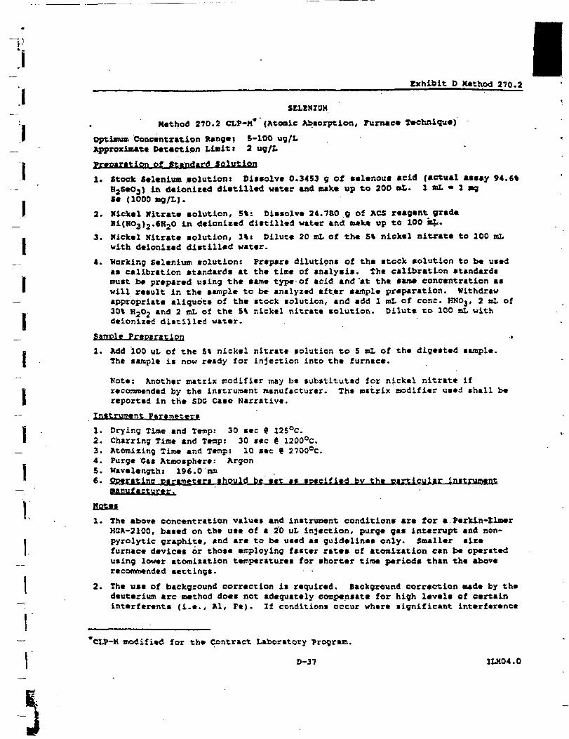
iiiiiiiiiii:ii
exhibit D Kethod 270.2
SELENIUM
Method 270.2 CLP-M* {Atomic Absorption, Furnace Technique)
Optimum Concentration Rangei 5-100 ug/LApproximate Detection Limits 2 ug/l
preparation ef Standard Solution
1. Stock Selenium eolation: Dissolve 0.3453 g of selenoue acid (actual aeeay 94.6%B2SeOa) in deionited dietilled water and make up to 200 oL. 2 ml. • 1 agSe (1000 ag/L).
2. Hickel Hitrate solution, 5%: Dissolve 24.760 g of ACS reagent gradeRi(H03)2.€H2O in deionized dietilled water and make up to 100 kL.
3. nickel Hitrate solution, 1%« Dilute 20 tut of the 5% nickel nitrate to 100 mLwith deionized distilled water.
4. Working Selenium solution: Prepare dilutions of the stock solution to be usedas calibration standards at the time of analysis. The calibration standardsmust be prepared using the same type of acid and'at the same concentration aswill result in the sample to be analyzed after sample preparation. Withdrawappropriate aliquot* of the stock solution, and add 1 mL of cone. HNO^, 2 mL of30% H2O2 and 2 ml. of the 5% r.ickcl nitrate solution. Dilute to 100 ml. withdeionized distilled water.
Sample Preparation •»
1. Add 100 uL of the 5% nickel nitrate solution to 5 mL of the digested sample.The sample i> now ready for injection into the furnace.
Note: Another matrix modifier rosy be substituted for nickel nitrate ifrecommended by the instrument manufacturer. The matrix modifier used shall bereported in the SDC Case Narrative.
Instrument Parameters
1. Drying Time and Temp: 30 sec 0 125°C.2. Charring Time and Temp: 30 sec £ 1200°C.3. Atomizing Time and Temp: 10 sec % 2700°C.4. Purge Cas Atmosphere: Argon5. Wavelength* 196.0 nm6. Operating parameters should be se,t a> specified bv the particular instrument
manufacturer.
Hotes
1. The above concentration values and instrument conditions are for a Parkin-ElmerHCA-2100, based on the use of a 20 ut injection, purge gas interrupt and non-pyrolytic graphite, and are to be used as guidelines only. Smaller sitefurnace devices or those employing faster rates of atomization can be operatedusing lower atomization temperatures for shorter time periods than the aboverecommended settings.
2. The use of background correction is required. Background correction made by thedeuterium arc method does not adequately compensate for high levels of certaininterferents (i.e., Al, Fe). If conditions occur where significant interference
*CtP-M modified for the Contract Laboratory Program.
D-37 ILK04.0
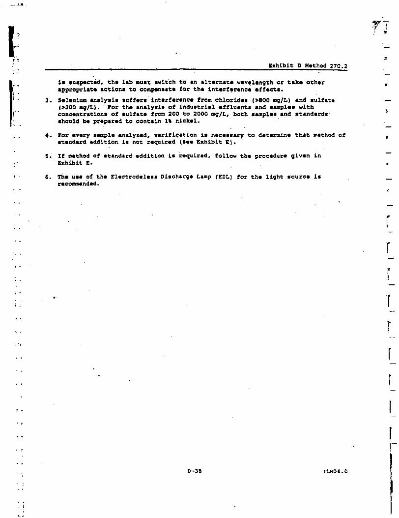
r *._ Exhibit D Method 270.2
is suspected, the lab must switch to an alternate wavelength or take otherappropriate actions to compensate for the interference effects.
3. Selenium analysis suffers interference from chlorides (>600 ng/L) and sulfate(>200 mg/L). For the analysis of industrial effluents and samples withconcentrations of sulfate from 200 to 2000 mg/L, both samples and standardsshould be prepared to contain 1% nickel.
4. for every sample analyzed, verification is .necessary to determine that method atstandard addition is not required (see Exhibit E).
5. If method of standard addition is required, follow the procedure given inExhibit E.
6. The use of the Clectrodelesi Discharge Lamp (EOL) for the light source isrecommended.
f
r
0-38 ILK04.0
exhibit P Method 245.1
j;
j;,4
.1
HgRCCTY AHALY^IS II? WATER 8Y KAKITAL COLD V*POp
KCfcCOWfMethod 245.1 CLP-M* (Manual Cold Vapor Technique)
1. fteoce and Apolicatipn
1.1 In addition to inorganic forma of mercury, organic mercurials nay alcobe present. Theee ergano-mercury compounds will not respond to the coldvapor atomic absorption technique unless they are first broken down andconverted to mercuric ions. Potassium permanganate oxidizes many ofthese compounds, but recent studies have shown that a number, of organicmercurials, including phenyl mercuric acetate and methyl mercuric
. chloride, are only partially oxidized by this reagent. Potassiumpersulfate has been found to give approximately 100% recovery when usedas the oxidant with these compounds. Therefore, a persulfate oxidationstep following the addition of the permanganate has been included toensure that organo-mercury compounds, if present, will be oxidized tothe mercuric ion before measurement. A heat step is required for methylmercuric chloride when present in, or spiked to, a natural system.
1.2 The range of the method may be varied through instrument and/or recorderexpansion. Using a 100 ml. sample, a detection limit of 0.2 ug Hg/L canbe achieved (see 10.1).
•2. Summary of Method
2.1 The flatneless AA procedure is a physical method based on the absorptionof radiation at 253. 7 rue by mercury vapor. Organic nercury compoundsare oxidized and the mercury is reduced to the elemental state andaerated from solution in a closed system. The mercury vapor passes.through a cell positioned in the light path of an atomic absorptionspectrophotometer. Absorbance (peak height) is measured as a functionof mercury concentration and recorded in the usual manner.
3. Sample Handling and Preservation
3.1 Until more conclusive data are obtained, samples are preserved byacidification with nitric acid to a pH of 2 or lower immediately at thetime of collection (Exhibit D, Section II).
4. Interference
4.1 Possible interference from sulfide is eliminated by the addition ofpotassium permanganate. Concentrations as high as 20 mg/L of sulfide assodium sulfide do not interfere 'with the recovery of added inorganicmercury from distilled water (Exhibit 0, Section IX).
4.2 Copper has also been reported to interfere; however, copperconcentrations as high as 10 mg/L had no effect on recovery of mercuryfrom spiked samples.
*CLP-M modified for the contract Laboratory Program.
D-47 ILM04.0
I4.3
5.
5.1
5.2
5.3
5.4
5.5
T
Exhibit 0 Method 245.1
Sea waters, brine* and industrial effluents high in chlorides requireadditional permanganate (as much as 25 mL). During the oxidation step,chlorides are converted to free chlorine which will also absorbradiation at 2S3 nre. Care must be taken to assure that free chlorine isabsent before the mercury is reduced and swept into the cell. This maybe accomplished by using an excess of hydroxylamine sulfate reagent (2Sat). Both inorganic and organic nercury spikes have been quantitativelyrecovered from the sea water using this technique.
Apparatus
Atomic Absorption Spectrophotometen (See Note 1) Any atomic absorptionunit having an open sample presentation area in which to mount theabsorption cell is suitable. Instrument settings recommended by theparticular manufacturer should be followed.
NOTE Is Instruments designed specifically for the measurement ofmercury using the cold vapor technique are commercially available andmay be substituted for the atomic absorption spectrophotometer.
Mercury Hollow Cathode Lamp:equivalent.
Westinghouse WL-22847, argon filled, or
Recorder: Any multi-range variable speed recorder that is compatiblewith the 0V detection system is suitable.
Absorption Cellt Standard spectrophotometer calls 10 cm long, havingguartr end windows may be used. Suitable cells may be constructed frontplexiglass tubing, 1* O.D. X 4*1/2". The ends are ground perpendicularto the longitudinal axis and quartz windows (I' diameter X 1/16"thickness) are cemented in place.
The cell is strapped to a burner for support and aligned in the lightbeam by use of two 2" by 2" cards. One inch diameter holes are cut inthe middle of each card; the cards are then placed over each end of th«cell. The cell is then positioned and adjusted vertically andhorizontally to find the maximum transmittance.
Air Pump: Any peristaltic pump capable of delivering 1 liter of air perminute may be used. A Kasterflex pump with electronic speed control hasbeen found to be satisfactory.
5.6 Flowmeterr. Capable of measuring an air flow of 1 liter per minute.
5.7 Aeration Tubing: A straight glass frit having a coarse porosity. Tygontubing is used for passage of the mercury vapor from the sample bottleto the absorption cell and return.
5.8 Drying Tube: 6" X 3/4" diameter tube containing 20 g of magnesiumperchlorate (see Rote 2).
NOTE 2i In place of the magnesium perchlorate drying tube, a smallreading lamp with 60W bulb may be used to prevent condensation ofmoisture inside the cell. The lamp is positioned to shine on theabsorption cell maintaining the air temperature in the cell about 10°cabove ambient.
0-48 ILM04.0
exhibit D Method 245.1
6. Reagents
6.1 Sulfuric Acid, Cone: Reagent grade.
6.1.1 Sulfuric acid, O.S Ki Dilute 14.0 aL of cone, sulfuric acidto 1.0 liter.
6.2 Kitric Acid, Concj Reagent grade of low mercury content (see Koto 3).
KOTE 3: Zf a high reagent blank is obtained, it may be necessary to *,distill the nitric acid. |[
6.3 Stannous Sulf ate i Add 25.g stannous sulfate to 250 aL of O.S. M sulfuricacid. This mixture is a suspension and should be stirred continuouslyduring use. (Stannous chloride may be used in place of stannoussulfate.)
6.4 Sodium Chloride-Kyroxylamine Sulfate Solution: Dissolve 12 g of sodiumchloride and 12 g of hydroxylamine sulfate in distilled water and diluteto 100 mL. (Hydroxylamine hydrochloride may be used in place ofhydroxylamine sulfate.)
I
6.5 Potassium Permanganate (KHnO ): 5% solution, w/v. Dissolve 5 g ofpotassium permanganate in 100 mL of distilled water.
6.6 Potassium Persulfate: 5% solution, w/v. Dissolve 5 g of potassiumpersulfate in 100 mL of distilled water.
6.7 Stock Mercury Solution: Dissolve 0.1354 g of mercuric chloride in 75 mLof distilled water. Add 10 mL of cone, nitric acid and adjust the
•• volume to 100.0 mL. 1-mL • 1 mg Hg.
6.6 Working Mercury .Solution: Make successive dilutions of the stockmercury solution to obtain a working standard containing 0.1 ug per mL.This working standard and the dilutions of the stock mercury solutionshould be prepared fresh daily. Acidity of the working standard shouldbe maintained at 0.15% nitric acid. This acid should be added to theflask as needed before the addition of the aliquot.
7. Calibration
7.1 Transfer 0, 0.2, O.S, 1.0, 5.0 and 10.0 mL aliquots of the workingmercury solution containing 0 to 1.0 ug of mercury to a series of 300 mLBOO bottles. Add enough distilled water to each bottle to make a totalvolume of 100 mL. Mix thoroughly and add 5 mL of cone, sulfuric acid(6.1) and 2.5 mL of cone, nitric acid (6.2) to each bottle. Add 15 mLof XMn04 (6.5) solution to each bottle and allow to stand at least 15minutes. Add 8 mL of potassium persulfate (6.6) to each bottle and heatfor 2 hours in a water bath maintained at 9S°C. Alternatively, coverthe BOD bottles with foil and heat in an autoclave for 15 alnutes at120°C and 15 PSI. Cool and add 6 mL of sodium chloride-hydroxylaminesulfate solution (6.4) to reduce the excess permanganate. When the :;solution has been decolorized wait 30 seconds, add 5 mL of the stannous . ;: •sulfate solution (6.3) and immediately attach the bottle to the aeration ;';. Iapparatus forming a closed system. At this point the sample is allowed I •to stand quietly without manual agitation. .[' '
•i) - ,
D-49 ILK04.0
Exhibit D Method 245.1
8.
8.1
•9.
9.1
Th* circulating pump, which has previously been adjusted to a rat* of 1liter p*r minute, I* allowed to run continuously (see Not* 4). Th*absorbence will increase and reach maximum within 30 seconds. Ac soona« the recorder pen levels off, approximately 1 minute, open the bypassvalv* and continue the aeration until the absorbanca returns to itsminimum value (see Mote 3). Close the bypass valve, remove the. stopperand frit from the BOO bottle and continue the aeration. Proceed withthe standards and construct a standard curve by plotting peak heightversus microgran* of mercury.
MOTE 4t An open system where the mercury vapor is passed through theabsorption cell only once may be used instead of the closed system.
MOTE Si Because of the toxic nature of mercury vapor precaution must betaken to avoid its inhalation. Therefore, a bypass has been included inth* system to either vent the mercury vapor into an exhaust hood or passthe vapor through some absorbing media, such as equal volumes of 0.1 HKMnO4, and 10% H2SO4 or 0.25% iodine in a 3% a KI solution. A speciallytreated charcoal that will adsorb mercury vapor is commerciallyavailable.
Procedure
Transfer 100 cnL, or an aliquot diluted to 100 mL, containing not aorethan 1.0 u? of mercury, to a 300 mL BOO bottle. Add S mL of cone.sulfuric acid (6.1) and 2.5 mL of cone, nitric acid (£.2) .mixing aftereach addition. Add IS mi. of potassium permanganate solution (6.5) toeach sample pottle (see Note 6). For sewage samples additionalpermanganate may be required. Shake and add additional portions ofpotassium permanganate solution, if necessary, until the purple colorpersists for at least 15 minutes. Add 8 mL of potassium persulfate(6.6) to each bottle and heat for 2 hours in a water bath at 9S°C.
NOTE.- 6: The same amount of KMnO^ added to the samples should be presentin standards and blanks.
Cool and add 6 mL of sodium chloride-hydroxylamine sulfate (6.4} toreduce the excess permanganate (see Note 7). Purge the headspace in theBOO bottle for at least 1 minute and add 5 mL of stannous sulfate (6.3)and immediately attach the bottle to the aeration apparatus. Continueas described under Calibration.
NOTE 7 1 -Add reductant in 6 mL increments until KMn04 is completelyreduced. -
Determine the peak height of the unknown from the chart and read themercury value from the standard curve.
9.2 Calculate the mercury concentration in the sample by the formula:
uy Hy/L Hg, curvevolume. mL
1000 tati L
0-50 ILM04.0
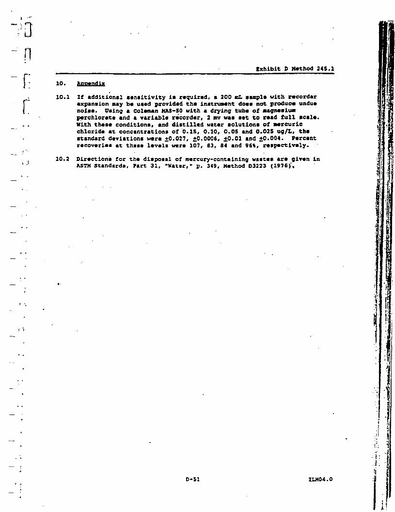
nnr
10.
10.1
Ixhibit O Kethod 245.1
10.2
If additional sensitivity is required, a 200 mL sample with recorderexpansion aay be used provided the instrument does not produce unduenoise. Using a Coleman M&S-50 with a drying tube of stagnesiuaperchlorete and a variable recorder, 2 mv was set to read full scale.With these conditions, and distilled water solutions of mercuricchloride at concentrations of 0.15, 0.10, 0.05 and 0.025 ug/t, thestandard deviations were ±0.027, ±0.0006, ±0.01 and ±0.004. Percentrecoveries at thtse levels were 107, 83, 84 and 96%, respectively.
Directions for the disposal of mercury-containing wastes are given inASTH Standards, Part 31, *Watsr, " p. 349, Method D3223 (1976)',
1
D-51 ILM04.0
n1
fl-1'1 APPENDIX B
USEPAT] REGION I
H LOW STRESS (low flow) PURGING AND SAMPLING PROCEDURE FOR_'J THE COLLECTION OF GROUND WATER SAMPLES FROM-e MONITORING WELLS
•0 July 30,1996^ Revision!
1
11
1Ptuliddphia Nwil B«se: Gtnrd Po'tt Mmgonem Area
LongTennOouod-WMcrManitDrinjPUndM2VH29U8basU.3UtBpnS.doc
ILS, ENVIRONMENTAL PROTECTION AGENCYREGION I
LOW STRESS (low flow) PURGING AND SAMPLINGPROCEDURE FOR THE COLLECTION OF
GROUND WATER SAMPLESFROM MONITORING
WELLS
July 30,1996Revision 2
SOP #: GW 0001Region I Low Stress
(Low Flow} 80PRevision Humbert 2Date: July 30, 1996Page 1 of 13
\U.S. INVXROHMSNTAL PROTECTION AGENCY
RIOION I
LOW STRESS (low flow)" PUROIHO AMD MMPLXNQ 3KOMBURETOR TBS COLLECTION CT GROtWD WATS* SAMPLES
FROK KONITORINO WELLS
I. SCOPE & APPLICATION
This standard operating procedure (SOP) provides * general frameworkfor collecting ground water sample* that are indicative of mobileorganic and inorganic loads at ambient flow condition! (both thedissolved fraction and the fraction associated with mobileparticulates). The SOP emphasizes the need to minimize stress by lowwater-level drawdowns, and low pumping rates (usually less than 1liter/rain) in order to collect samples with minimal alterations towater chemistry. This SOP is aimed primarily at sampling monitoringwells that can accept a submersible pump and have a screen, or openinterval length of 10 feet or less (this is the most commonsituation). However, this procedure is flexible and can be used in avariety of well construction and ground-water yield situations.Samples thus obtained are suitable for analyses of ground watercontaminants (volatile and stmi-volatile organic analytes,pesticides, PCBs, metals and other inorganics), or other naturallyoccurring analytes.
This procedure does not address the collection of samples from wellscontaining light or denae non-aqueous phase liquids (LNAPLs andDNAPLs). For this the reader may wish to check: Cohen, R.M. and J.w.Mercer, 1993, DNAPL Site Evaluation; C.K. Sraoley (CRC Press), BocaRaton, Florida and U.S. Environmental Protection Agency, 1992, RCRAGround-Water Monitoringi Draft Technical Guidance; Washington, DC(2PA/530-R-93-001).
The screen, or open interval of the monitoring well should beoptimally located (both laterally and vertically) to interceptexisting contaminant plume(s) or along flowpaths of potentialcontaminant releases. It is presumed that the analytes of interestmove (or potentially move) primarily through the more permeable toneswithin the screen, or open interval.
Use of trademark names does not imply"endorsement lay U.S. EPAbut is intended only to assist in identification of a specifictype of device. '_ :__.
SOP #: GW 0001Region Z Low Stress
(Low Flow) sopRevision Number; 2Datej July 30, 1996Page 2 of J.3
Proper well construction and development cannot be overemphasized,ilnee the uee of installation techniques that are appropriate to thehydrogeologic setting often prevents "problem well" situations fromoccurring. It is also recommended that as part of development orredevelopment the well should be tested to determine the appropriatepumping rate to obtain stabilization of field indicator parameter awith minimal drawdown in shortest amount of time. With thisinformation field crews can then conduce purging and sampling in amore expeditious manner.
The mid-point of the saturated screen length (which should not exceed10 feet) is used by convention as the location of the pump intake.However, significant chemical or permeability contrast(s) within thescreen may require additional field work to determine the optimumvertical location(s) for the intake, and appropriate pumping rate(s)for purging and sampling more localized target zone(s). Primary flowzones (high(er) permealability and/or high (er) chemicalconcentrations) should be identified in wells with screen lengthslonger than 10 feet, or in wells with open boreholes in bedrock.Targeting these tones for water sampling will help insure that thelow stress procedure will not underestimate contaminantconcentrations. The Sampling and Analysis Plan must provide clearinstructions on how the pump intake depth (s) will be selected, andreason(s) for the depth(s) selected.
Stabilization of indicator field parameters is used to indicate thatconditions are suitable for sampling to begin. Achievement ofturbidity levels of less than 5 NTU and stable drawdowns of less than0.3 feet, while desirable, are cot mandatory. Sample collection maystill take place provided the remaining criteria in this procedureare met. Zf after 4 hours of purging indicator field parameters havenot stabilized, one of 3 optional courses of action may be taken: a)continue purging until stabilization is achieved, b) discontinuepurging, do not collect any samples, and record in log book thatstabilization could not be achieved (documentation must describeattempts to achieve stabilization) c} discontinue purging, collectsamples and provide full explanation of attempts to achievestabilization (notes there is a risk that the analytical dataobtained, especially metals and strongly hydrophobic organicanalyces, may not meet the sampling objectives).
Changes to this SOP should be proposed and discussed when the siteSampling and Analysis Plan is submitted for approval. Subsequentrequests for modifications of an approved plan must include adequatetechnical justification fot proposed changes. All changes andmodifications must be approved before implementation in field.
i <
so? #? cw 0001Rtgion I Low Street
(Low Flow) SOPRevision Number; 2Date: July 30, 1996Page 3 of 13
II.IQUIPKEHT
A. Extraction devict
Adjustable rate,-submersible pumps are preferred (for example,centrifugal or bladder pump conitructed of stainless steel orTeflon). ' ;
Adjustable rate, peristaltic pumps (suction) may be used withcaution. Note that EPA guidance states: "Suction pumps are not ,recommended because they may cause degassing,. pH modification, anilloss of volatile compounds* (EPA/540/P-67/001, 1987, page 8.5-11).
The use of inertial pumps is discouraged. These devices frequentlycause greater disturbance during purging and sampling and are leaseasily controlled than the pumps listed above. This can lead tosampling results that are adversely affected by purging and samplingoperations, and a higher degree of data variability.
B. Tubing
Teflon or Teflon lined polyethylene tubing are preferred whensampling is to include VOCs, SVOCs, pesticides, PCBs and inorganics.
PVC, polypropylene or polyethylene tubing may be used when collectingsamples for inorganics analyses. However, these materials should beused with caution .when sampling for organic*. If these materials areused, the equipment blank (which includes the tubing) data must showthat these materials do not add contaminants to the sample,
Stainless steel tubing may be used when sampling for VOCs, SVOCs,pesticides, and PCBs. However, it should be used with caution when ~sampling for metals.
The use of 1/4 inch or 3/8 inch (inner diameter) tubing is preferred.This will help ensure the tubing remains liquid filled when operatingat very low pumping rates.
Pharmaceutical grade (Pharmed) tubing should be used for the sectionaround the rotor head of a peristaltic pump, to minimize gaseousdiffusion.
C. Water level measuring device(s), capable of measuring to -0.01foot accuracy (electronic 'tape1, pressure transducer). Recordingpressure transducers, mounted above the pump, are especially helpfulin tracking water levels during pumping operations, but their use
' j SCP #: GW 0001Region I Low Stress
(Low Flow) SOP~~ ; Revision Number: 2
Datei July 30, 1996., Page 4 of 13
- ./must include check measurements with a water level 'tape* at the1' Bcart and end of each record.
—' I'D. Flow measurement supplies (e.g., graduated cylinder and stop' watch).
_ [' E. Interface probe, if needed.I. F. Power source (generator, nitrogen tank, etc.). If a gasoline- • generator ie used, it must be located downwind and at least 30 feet
~ . from the well so that the exhaust fumes do not contaminate thesamples.
» • • „
- • 0. Indicator field parameter monitoring instruments - pR, Eh," dissolved oxygen (DO), turbidity, specific conductance, and, , temperature. Use of a flow-through-cell is required when measuring
- all listed parameters, except turbidity. Standards to perform field- • calibration of instruments. Analytical methods are listed in 40 CFR. 136, 40 CFR 141, and SW-846. For Eh measurements, follow
__ . ' manufacturer's instructions.
H. Decontamination supplies (for example, non-phosphate detergent,*' distilled/deionized water, icopropyl alcohol, etc.).j t
I. Logbook(s), and other forms (for example, well purging forms}.
— J. Sample Bottles.
r . X. Sample preservation supplies (as required by the analytical__ / methods).
* *
,. L. Sample tags or labels.
~ • M. Well construction data, location map, field data from lastsampling event.
- . . H. Hell keys.
v 0. Site specific Sample and Analysis Plan/Quality Assurance Project- " , Plan.
.- ?. PID or FID instrument (if appropriate) -co detect VOCs for health
_ and safety purposes, and provide qualitative field evaluations.
SOP *tRegion I Low Stress
(Low Flow) SOPRevision Number: 2Date: July 30, 1996Page 5 of 13
ZZZ.FRZLZMZHARY SITS ACKVZTZtt
Check well for security damage or evidence of tampering, recordpertinent observations.
Lay out sheet of clean polyethylene for monitoring and camplingequipment.
Remove well cap and immediately measure VOCs at the rim of the wellwith a PID or FID instrument and record the reading in the fieldlogbook.
If the well casing does not have a reference point (usually & V-cutor indelible mark in the well casing), make one. Describe itslocation and record the date of the mark in the logbook.
A synoptic water level measurement round should be performed (in theshortest possible time) before any purging and sampling activitiesbegin. Zt is recommended that water level depth (to 0.01 ft.) andtotal well depth (to 0.1 ft.) be measured the day before, in order toallow for re-settlement of any particulates in the water column, ifmeasurement of total well depth is not made the day before, it shouldnot be measured until after sampling of the well is complete. Allmeasurements must be taken from the established referenced point. 'Care should be taken to minimize water column disturbance.
Check newly constructed wells for the presence of LNAPLs or DNAPLsbefore the initial sampling round. If none are encountered,subsequent check measurements with an interface probe are usually notneeded unless analytical data or field head space information signala worsening situation. Notet procedures for collection of LNAPL andD27APL samples are not addressed in this SOP.
zv.proazxa AND SAKFLZKO PROCXDTCSSampling wells in order of increasing chemical concentrations (knownor anticipated) is preferred.
1. Install Pump
.Lower pump, safety'cable, tubing and electrical lines slowly (tominimize disturbance) into the well to the midpoint of the zone to besampled. The Sampling and Analysis Plan should specify the samplingdepth, or provide criteria for selection of intake depth for eachwell (see Section I). If possible keep the pump intake at least two
SOP ft: GW 0001Region I Low Str««i
(Low Flew) SOPRevision Dumber: 2Datet July 30, 1996Page 6 of 13
feet Above the bottom of the wtll, to minimize mobilization ofparticulars present in the bottom of the well. Collection of turbid
• free water samples may be especially difficult if there is two feetor less of standing water in the well.
• 2. Measure Water Level
' Before starting pump, measure water level. If recording pressuretransducer is used-initializt starting condition.
• 3, Purge Well
3a» Initial Low Stress Sampling Event
Start the pump at its lowest speed setting and slowly increase thespeed until discharge occurs. Check water level. Adjust pump speeduntil there is lictle or no water level drawdown (less than 0.3feet). Ii the minimal drawdown that can be achieved exceeds 0.3 feetbuz remains stable, continue purging until indicator field parametersstabilize.
Monitor ar.d record water level and pumping rate every three to fiveminutes (cr as appropriate) during purging. Record any pumping rateadjustments (both time and flow rate). Pumping rates should, asneeded, be reduced to the minimum capabilities of the pump (forexample, 0.1 - 0.4 1/min) to ensure stabilization of indicatorparameters. Adjustments are best made in the first fifteen minutesof pumping in order to help minimize purging time. During pumpstart-up,"drawdown may exceed the 0.3 feet target and then •recover"as pump flow adjustments are made. Purge volume calculations shouldutilize stabilized drawdown value, not the initial drawdown. Do not -allow the water level to fall to the intake level (if the staticwater level is above the well screen, avoid lowering the water levelinto the screen). The final purge volume must be greater than thestabilized drawdown volume plus the extraction tubing volume.
Wells with low recharge rates may require the use of special pumpscapable of attaining very low pumping rates (bladder, peristaltic),and/or the use of dedicated equipment. If the recharge rate of thewell is lower than.extraction rat• capabilities of currently.manufactured pumps and the well is essentially dewatersd duringpurging, then the well should be sampled as soon as the water levelhas recovered sufficiently to collect the appropriate volume neededfor all anticipated samples (ideally the intake should not be movedduring this recovery period). Samples may then be collected eventhough the indicator field parameters have not stabilized.
SOP #: OH 0001Region I Low Serais
(Low Flow) SOPRevision Number: 2Datet July 30, 1996Page 7 of 13
3b. Subsequent Low Stress Sampling Events
After synoptic water level measurement round, check intake depth anddrawdown information from previous'campling event(0) for each well.Duplicate, to the extent practicable, the intake depth and extractionrate (use final pump dial setting information) from previousevent (s). Perform purging operations as above.
4. Monitor Indicator Field Parameters
During well purging, monitor indicator field parameters (turbidity,temperature, specific conductance, pK, Eh, DO) every three to fiv*minutes (or less frequently, if appropriate). Note: during the earlyphase of purging emphasis ahould be put on minimizing and stabilisingpumping stress, and recording those adjustments. Purging isconsidered complete and sampling may begin when all the aboveindicator field parameters have stabilized. Stabilization isconsidered to be achieved when three consecutive readings, taken atthree (3) to five (5) minute intervals, are within the followinglimits:
turbidity (10% for values greater than 1 NTU) ,DO (10%),specific conductance ( 3 V ) , 'temperature (3%) ,pH (± 0,1 unit),ORP/Eh (± 10 millivolts) .
All measurements, except turbidity, must be obtained using a flow-through-cell. Transparent flow-through-cells are preferred, becausethey allow field personnel to watch for particular build-up withinthe cell. This build-up may affect indicator field parameter valuesmeasured within the cell and may also cause an underestimation ofturbidity values measured after the cell. Zf the call needs to becleaned during purging operations, continue pumping and disconnectcell for cleaning, then reconnect after cleaning and continuemonitoring activities.
The flow-through-cell must be designed in a way that prevents airbubble entrapment in the cell. Whan the pump is turned off orcycling on/off (when using a bladder pump), water in the cell mustnot drain out. Monitoring probes must be submerged in water at alltimes. Zf two flow-through-eel Is are used in series, the onecontaining the dissolved oxygen probe should come first (thisparameter is most susceptible to error if air leaks into the system).
SOP #: GW 0001Region I tow Stress
{Low Flow) SOPRevision Humbari 2Date: July 30, 1996Page 8 of 13
5. Collect Water Samples
Hater samples for laboratory analyses must be collected before waterhas passed through the flow-through-cell (use a by-pass assembly ordisconnect cell to obtain sample).
VOC samples should be collected first and directly into pre-preeervedsample containers. Fill all sample containers by allowing the pumpdischarge to flow gently down the inside of the container withminimal turbulence.
During purging ar.d sampling, the tubing should remain filled withwater so as to minimize possible changes in water chemistry uponcontact with the atmosphere. It is recommended that 1/4 inch or 3/8inch (inside diameter) tubing be used to help insure that the sampletubing remains water filled. If the'pump tubing is not completelyfilled to the sampling point, use.one of the following procedures tocollect samples: "(1) add clamp, connector (Teflon or stainlesssteel) or valve .to constrict sampling end of tubing; (2) insert smalldiameter Teflon tubing ir.to water filled portion of pump tubingallowing the end to protrude beyond the end of the pump tubing,collect sample from email diameter tubing/ (3) collect non-VOCsamples first, then increase flow rate slightly until the watercompletely fills the tubing, collect sample and record new drawdown,flow rate and new indicator field parameter values.
Add preservative, as required by analytical methods, to samplesimmediately after they are collected if the sample containers are notpre-preserved. check analytical methods (e.g. EPA SW-846, watersupply, etc.) for additional information on preservation. Check pHfor all samples requiring pH adjustment to assure proper pH value.For VOC samples, this will require that a test sample be collectedduring purging to determine the amount of preservative that needs tobe added to the sample containers prior to sampling.
If determination of filtered metal concentrations is a samplingobjective, collect filtered water samples using the same low flowprocedures. The use of an in-line filter is required, and the filtersize (0.45 urn is commonly used) should be based on the samplingobjective. Pre-rinse the filter with approximately 25 • 50 ml ofground water prior to sample collection. Preserve filtered water•ample immediately. Note: filtered water samples are not anacceptable substitute for unfiltered samples when the monitoringobjective is to obtain chemical concentrations of total mobilecontaminants in ground water for human health risk calculations.
SOP #: GW 0001Region Z Low Stress
(Low Flow) SOPRe via ion Number: 2Date: July 30, 1996Page $ of 13
Label each cample ae collected. Samples requiring cooling (volatileorganic*, cyanide, etc.) will be placed into a cooler with ice orrefrigerant for delivery to the laboratory. Metal camples afteracidification to a pH less than 2 do not need to be cooled.
6. Pose Sampling Activities
If recording pressure transducer is used, remeasure water level withtape. . i
After collection of the samples, the pump tubing may either bededicated to the well for resampling (by hanging the tubing insidethe well), decontaminated, or properly discarded. .
Sefore securing the well, measure and record the well depth (to 0.1ft.), if not measured the day before purging began. Note:measurement of total well depth is optional after the initial low ;•tress sampling event. However, it is recommended if the well has; a•silting" problem or if confirmation of well identity is needed.
Secure the well.
V.DECONTAMINATION i
Decontaminate campling equipment prior to use in the first well andfollowing sampling of each subsequent well. Pumps will not beremoved between purging and sampling operations. The pump and tubing(including support cable and electrical wires which are in contactwith the well) will be decontaminated by one of the procedures listedbelow.
Procedure 1
The decontaminating solutions can be pumped from either buckets orshort PVC casing sections through the pump or the pump can bedisassembled and flushed with the decontaminating solutions, it isrecommended that detergent and isopropyl alcohol be used sparinglyin the decontamination process and water flushing steps be extendedto ensure that any sediment trapped in the pump is removed. Thepump exterior and electrical wires must be rinsed with the
• decontaminating solutions, as well. The procedure is as follows:
Flush the equipment/pump with potable water.
Flush with non-phosphate detergent solution. If the solution is
BOP #.- GW oooiRegion I Low Screes. (Low Flow) SOPRevision Number: 2Datei July 3d 1996page 10 Of 13
recycled, the solution must bt changed periodically.
« • Flush with potable or distilled/deionizad water to remove all ofthe detergent solution. If the water is recycled, the water mustbe changed periodically.
i •Flush with isopropyl alcohol (pesticide grade). If equipment1 blank data from the previous campling event show that the level of
,. contaminants is insignificant, then this itep may be skipped.
Flush with distilled/deionized water. The final water rinse trustnot be recycled.
• . pjrpeftdure 2
Steam clean the outside of the submersible pump.
Pump hot potable water frsm the steam cleaner through the inside ofthe pump. This can be accomplished by placing the pump inside athree or four inch diamettr PVC pipe with end cap. Hot water fromthe steam cleaner jet will be directed inside the PVC pipe and thepump exterior will be cleaned. . The hot water from the steamcleaner will then be pumpad from the PVC pipe through the pump end
• • collected into another container. Note: additives or solutionsshould not bt added to the steam cleaner.
• • . Pump non-phoiphate detergtnt solution through the inside of thepump. If the solution is recycled, the solution must be changedperiodically.
• •
Pump potable water through the inside of the pump to remove all of -' ' • the detergent solution. If the solution is recycled, the solution
must be changed periodically.
Pump distillcd/deionized water through the pump. The final waterrinse must not be recycled.
VT.71ZLD QUALITY CONTROL
. .Quality control samples are required to verify that the samplecollection and handling process has not compromised the quality ofthe ground water samples. All field quality control sample* must beprepared the same as regular investigation samples with regard tosample volume, containers, and preservation. The following quality
; control samples shall be collected for each batch of samples (a batch
SOP #J GW 0001Region Z Low Serena
(Low Flow) SOPRevision Number: 2Date: July 30, 1956Page 11 of 13
may not exceed 20 samples). Trip blanki are required for the voccamples at a frequency of one set per VOC sample cooler.
Field duplicate.
Matrix spike.
Matrix spike duplicate.
Equipment blank.
Trip blank (VOCs).
Temperature blank (one per cample cooler).
Equipment blank shall include the pump and the pump's tubing. Iftubing ie dedicated to the well, the equipment blank will onlyinclude the pump in subsequent sampling rounds.
* *
Collect samples in order from wells with lowest contaminantconcentration to highest concentration. Collect equipment blanksafter sampling from contaminated wells and not after backgroundwells.
Field duplicates are collected to determine precision of samplingprocedure. For this procedure, collect duplicate for each analytegroup in consecutive order (VOC original, VOC duplicate, SVOCoriginal, flVOC duplicate, etc.).
If split samples are to be collected, collect split for each analytegroup in consecutive order (VOC original, VOC split, etc.). Splitsample should be as identical as possible to original sample.
All monitoring instrumentation shall be operated in accordance withEPA analytical methods and manufacturer's operating instructions.EPA analytical methods are listed in 40 CFR 136, 40 CFR 141, and SW-846 with exception of Eh, for which the manufacturer's instructionsare to be followed. Instruments shall be calibrated at the beginningof each day. Zf a measurement falls outside the calibration range,the instrument should be re-calibrated so that all measurement* railwithin the calibration range. At the end of each day, checkcalibration to verify that instruments remained in calibration.Temperature measuring equipment, thermometers and thermistors, neednot be calibrated to the above frequency. They should be checked foraccuracy prior to field use according to EPA Methods and themanufacturer's instructions.
SOP #: OW 0001Region Z Low Stress
(Low Flow) SOPRevision Number: 2Date: July 30, 1996Page 12 of 13
VZX.FXZLD LOGBOOK
A field log ahall be kept to document all ground water fieldmonitoring activititfi (see attached example matrix} , and record allof the following:
Well identification.
Well depth, and measurement technique.
Static water level depth, date, time and measurement techniqut.
Presence and thickness of immiscible liquid (KAPL) layers anddetection method.
Pumping rate, drawdown, indicator parameters values, and clocktime, at the appropriate time intervals; calculated or measuredtotal volume pumped.
Well sampling sequence and time of each sample collection.
Types of sample bottles used and sample identification numbers,
Preservatives used.
Parameters requested for analysis.
Field observations during sampling event.
Kama of sample collector(s).
Weather conditions.
QA/QC data for field instruments.
Any problems encountered should be highlighted.
Description of all sampling equipment used, including trade names,model number, diameters, material composition, etc.
•
"VTII. DATA REPORT
Data reports are to include laboratory analytical results, QA/QCinformation, and whatever field logbook information is needed toallow for a full evaluation of data useability.
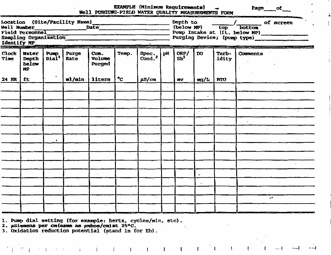
EXAMPLE (Minimum Requirementa) ^Hell PURQIHG-PIBLO HATER QUALITY MEASUREMENTS FORM
Page ot
Location (Site/Facility Name)Well Number Date_Field Personnel ~"Sampling OrganizationIdentify MP
Depth to /(below MP) top bottom"I'uwp Intake at (£L. below HP)Purging Device; (pump type) ]
of screen
ClockTime
24 HR
BJHffErTi**^
MaterDepthbelowMP
ft
PumpDial1
•
*
PurgeRate
«l/odn
Cum.VolunePurged
liters
, , ,"' \ 1.!
Temp.
*C
Spec.Cond.2
ftS/cm
=J a
pH ORP/Eh5
«v
'"DO
«g/L
•
*•
t-
SJT ^ ^ B!
Turb-idity
RTO
OooimentB
.'•
1. Pump dial setting (for example: hertz, cycles/min, etc)2. jfSienens per cmt&ane an ftrnhoo/cni) at 25*0.3. Oxidation reduction potential (ptand in for Eh).
—I
APPENDIX C
GROUND-WATERSAMPLING CHECKLIST
Ftiibdetpbit N«vil Base: <Snrd PMM M«U(ancnt AmLong Tenn Orouod-W«to Monitoring Plan
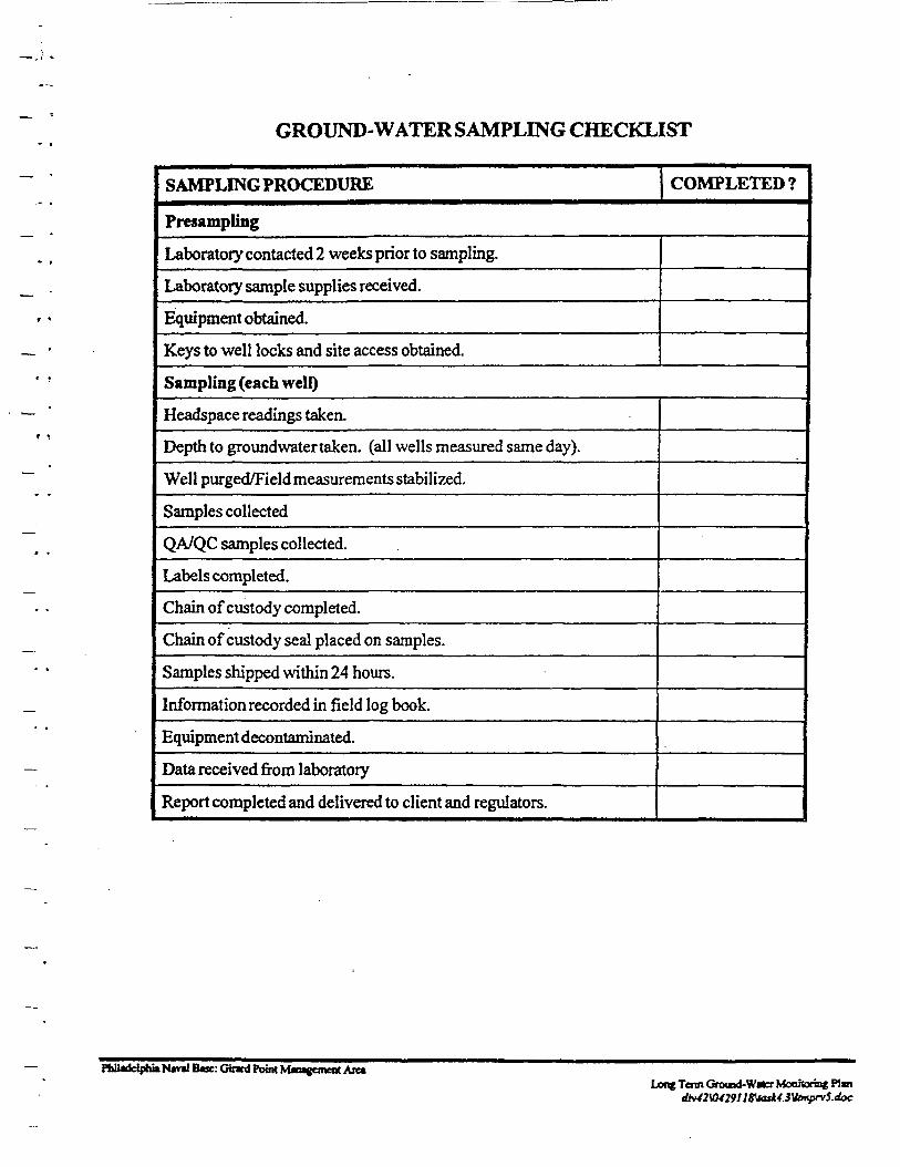
GROUND-WATER SAMPLING CHECKLIST
SAMPLING PROCEDURE COMPLETED?
Presampling
Laboratory contacted 2 weeks prior to sampling.
Laboratory sample supplies received.
Equipment obtained.
Keys to well locks and site access obtained.
Sampling (each well)
Headspace readings taken.
Depth to ground water taken, (all wells measured same day).
Well purged/Field measurements stabilized.
Samples collected
QA/QC samples collected.
Labels completed.
Chain of custody completed.
Chain of custody seal placed on samples.
Samples shipped within 24 hours.
Information recorded in field log book.
Equipment decontaminated.
Data received from laboratory
Report completed and delivered to client and regulators.
FfaiteffeiphiaNml Bwe: Cinrd Point Mnagemef* AnaLong Tcnn Ground-Water Monitoring Pin
4W7Utt29nSUaxU.3Umiprv5.4ac
APPENDIXD
EXAMPLES OF GROUND-WATER FIELD ANALYSIS FORMS
:: Girard Point Management Are*UmgTcnnGrouKf-WatcrMonhqringPbn —
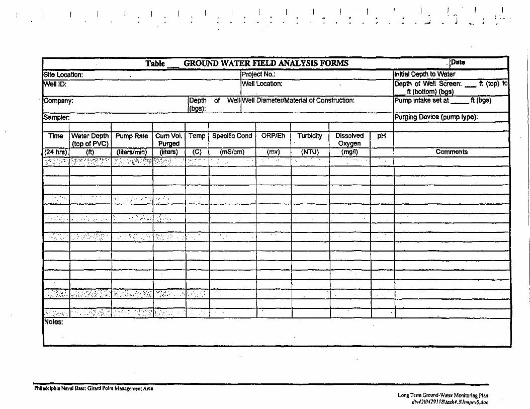
Table GROUND WATER FIELD ANALYSIS FORMS DateSite Location:Well ID:
Company: Depth of Well(bgs):
Sampler
Time
(24 hrs)•: ••* ;••:• ;•••;•{:.•
.-'• • ^ '">•••.. .
:^ V
•.:/;•.. •.',•, v :•.
..••.'/./"/v':.1'1.'
Water Depth(topofPVC)
(ft); "fH^?-"
' • ' . . •
:•' •'. •'• • i~ •• " • ' : • • •
\ : J; -':•/;•. '::V;v'.
•' ' • . <",<;.. '..''': ' :'.•' ? • • < • ' • ' • • • ' ' < > : ' ^ '';;-
• '.' r' ':; '/"^-'- *
Pump Rate
(liters/min)
T-ty*' ffi.^'.
'-,,' ••; ;.V:-:r"v ;:
.• . • . ; . . . ..... ..-.,•;
.'"" • '•'. i:'i:'." ' , ' . ' • ' .
'": .'•." »;''!•: '••' ',•".-; VN**.;.
'.•'."' ' • • • . . ' . •••'.
Cum Vol.Purged(liters)
1 ;; • • • • - . : •
• . ' ' • . . '• : .-
••*.-•;':• '.;"'.'•' .' •.
••''•' .V ;,'•''•''
' • . ' • « • '
Temp
(C)>.-. ^".-- •• .
'••.' ', : .'.•
Project No.:Well Location:
Well Diameter/Material of Construction:
Specific Cond
(mS/cm)
ORP/Eh
(mv)
Turbidity
(NTU). -.
DissolvedOxygen(mg/1)
pH
'• ••
nitial Depth to WaterDepth of Well Screen: ft (top) to
ft (bottom) (bgs)Pump intake set at ft (bgs)
Purging Device (pump type):
Comments
Notes:
Philadelphia Naval Base: Girard Point Management AreaLong Term Ground-Water Monitoring Plan
dM2\(H29l I8\ttuk4.3\ltmpn5.doc
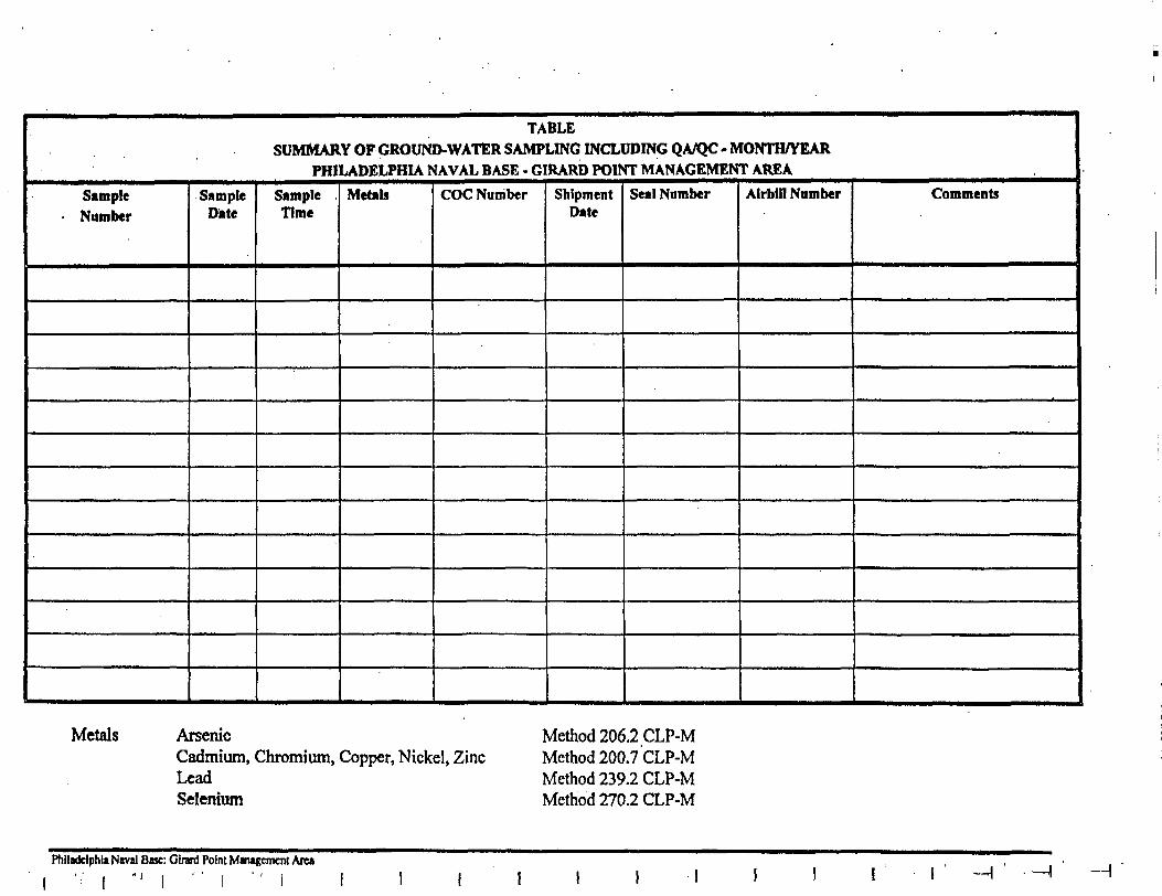
TABLESUMMARY OF GROUND-WATER SAMPLING INCLUDING QA/QC - MONTH/YEAR
PHILADELPHIA NAVAL BASE - GIRARD POINT MANAGEMENT AREA
Sample• Number
SampleDate
Sample .Time
Metals COC Number ShipmentDate
Seal Number Airbill Number Comments
Metals ArsenicCadmium, Chromium, Copper, Nickel, ZincLeadSelenium
Method 206.2 CLP-MMethod 200.7 CLP-MMethod 239.2 CLP-MMethod 270.2 CLP-M
Philadelphia Naval Base: Glrard Point Management Area
' ; ' i " ' l " ' I ' ' I -H
APPENDIX E
EXAMPLES OF EVALUATION TABLES
Gnri Point M»*ement AittLong Tom Ground-W«cr Monitoring Pbn
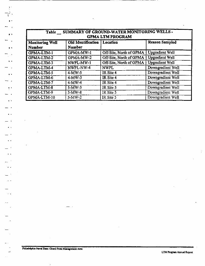
Table SUMMARY OF GROUND-WATER MONITORING WELLS -GPMA LTM PROGRAM
Monitoring WellNumberGPMA-LTM-1GPMA-LTM-2GPMA-LTM-3GPMA-LTM-4GPMA-LTM-5GPMA-LTM-6GPMA-LTM-7GPMA-LTM-8GPMA-LTM-9GPMA-LTM-1 0
Old IdentificationNumberGPMA-MW-1GPMA-MW-2NWPL-MW-1NWPL-NW-44-MW-54-MW-34-MW-45-MW-35-MW-85-MW-2
Location
Off-Site, North of GPMAOff-Site, North of GPMAOff-Site, North of GPMANWPLIR Site 4IRSite4IR Site 4IR Site 5IR Site 5IR Site 5
Reason Sampled
Upgradient WellUpgradient WellUpgradient WellDowngradient WellDowngradient WellDowngradient WellDowngradient WellDowngradient WellDowngradient WellDowngradient Well
Philadelphia N«vil Btse: Ginrt Point Maugonent AretLTM Program Annual Report
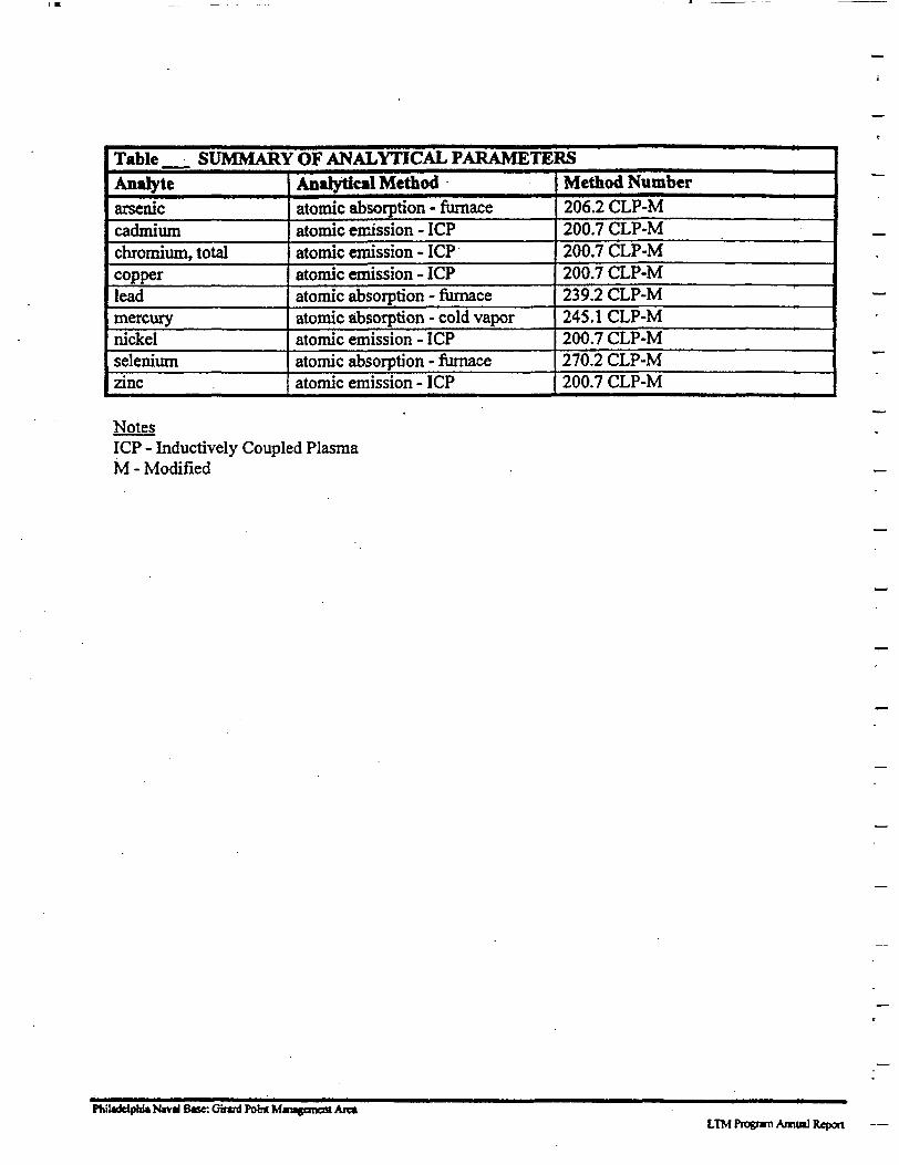
Table SUMMARY OF ANALYTICAL PARAMETERSAnatytearseniccadmiumchromium, totalcopperleadmercurynickelseleniumzinc
Analytical Methodatomic absorption - furnaceatomic emission - ICPatomic emission - ICPatomic emission - ICPatomic absorption - furnaceatomic absorption - cold vaporatomic emission - ICPatomic absorption - furnaceatomic emission - ICP
Method Number206.2 CLP-M200.7 CLP-M200.7 CLP-M200.7 CLP-M239.2 CLP-M245.1 CLP-M200.7 CLP-M270.2 CLP-M200.7 CLP-M
NotesICP - Inductively Coupled PlasmaM - Modified
PhiladdpbU N«vil Base: Gmrd Point Mmwemeat Are«LTM Program Anm«l Report —
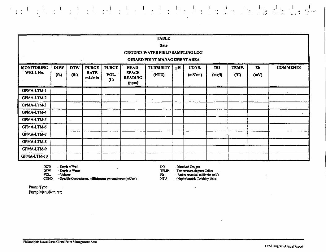
TABLE
Date
GROUND-WATER FIELD SAMPLING LOG
GIRARD POINT MANAGEMENT AREA
MONITORINGWELL No.
GPMA-LTM-I
GPMA-LTM-2
GPMA-LTM-3
GPMA-LTM-4
GPMA-LTM-5
GPMA-LTM-6
GPMA-LTM-7
GPMA-LTM-8
GPMA-LTM-9
GPMA-LTM-10
DOW
(ft.)
DTW
(ft.)
PURGERATE
tnL/min
PURGE
VOL.(L)
HEAD-SPACE
READING(ppm)
TURBIDITY
(NTU)
pH COND.
(mS/cm)
DO
(mg/1)
TEMP.
CQEh
(mV)
COMMENTS
•
DOW - Depth of WellDTW -Depth to W*CTYOU -VolumeCOND. - Specific Conductance, millbiemera per centimeter (mS/cm)
DO - Dissolved OxygenTEMP. - Temperature, degrees CdimEh - Rcdox potential, millivolts (mV)NTU - Nephelometric Turbidity Units
Pump Type:Pump Manufacturer
Philadelphia Naval Base: Girard Point Management AreaLTM Program Annual Report
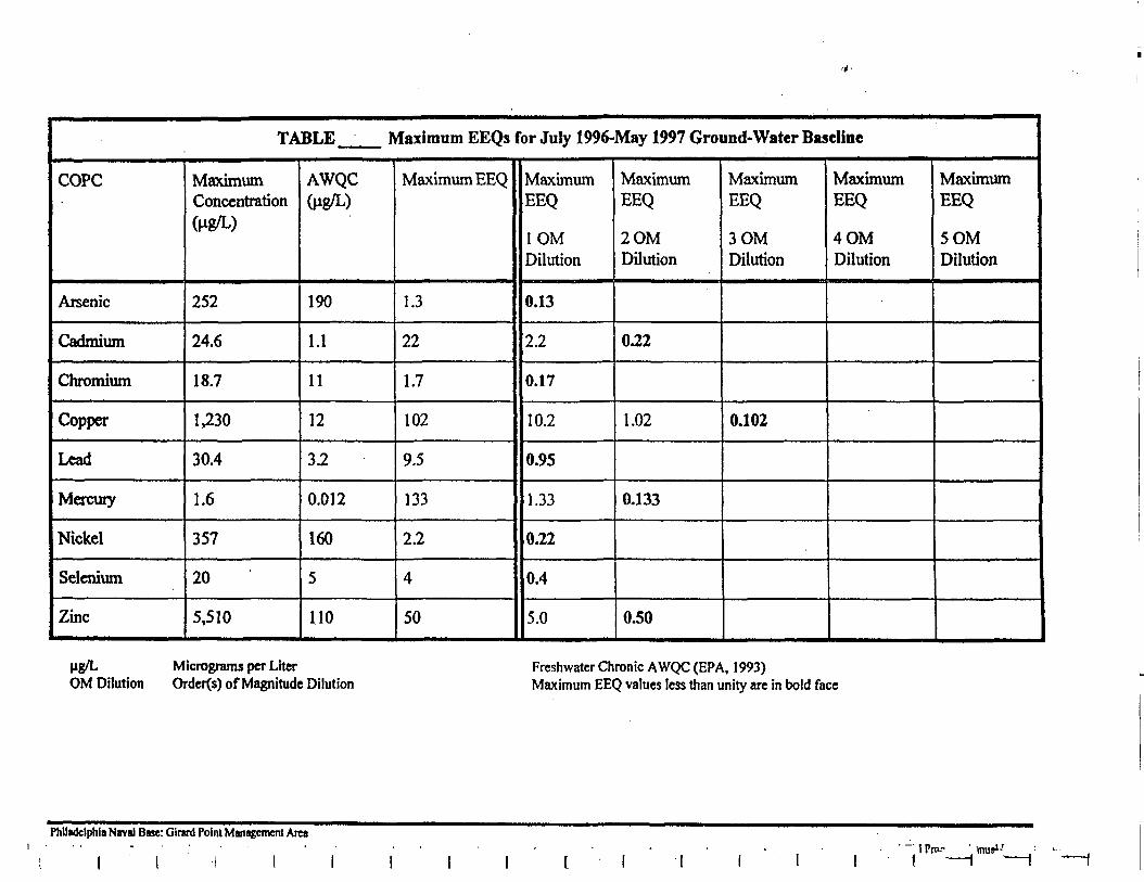
TABLE_ Maximum EEQs for July 1996-May 1997 Ground-Water Baseline
COPC
Arsenic
Cadmium
Chromium
Copper
Lead
Mercury
Nickel
Selenium
Zinc
MaximumConcentration(Hg/L)
252
24.6
18.7
1,230
30.4
1.6
357
20
5,510
AWQC(Mg/L)
190
1.1
11
12
3.2
0.012
160
5
110
Maximum EEQ
1.3
22
1.7
102
9.5
133
2.2
4
50
MaximumEEQ
1OMDilution
0.13
2.2
0.17
10.2
0.95
1.33
0.22
0.4
5.0
MaximumEEQ
2OMDilution
0.22
1.02
0.133
0.50
MaximumEEQ
3OMDilution
0.102
MaximumEEQ
4OMDilution
MaximumEEQ
5OMDilution
ug/L Micrograms per LiterOM Dilution Order(s) of Magnitude Dilution
Freshwater Chronic AWQC (EPA, 1993)Maximum EEQ values less than unity arc in bold face
Philadelphia Naval Base: Ginrd Point Management Area" 1 Pro-- ' mu»>-'f
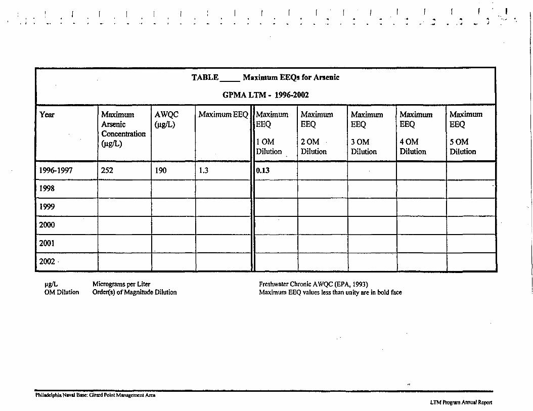
TABLE Maximum EEQs for Arsenic
GPMALTM- 1996-2002
Year
1996-1997
1998
1999
2000
2001
2002
MaximumArsenicConcentration(W?/L)
252
AWQCfog/L)
190
Maximum EEQ
1.3
MaximumEEQ
1OMDilution
0.13
MaximumEEQ
20MDilution
MaximumEEQ
3OMDilution
MaximumEEQ
4OMDilution
MaximumEEQ
5OMDilution
•
ug/L Micrograms per LiterOM Dilution Ordcr(s) of Magnitude Dilution
Freshwater Chronic AWQC (EPA, 1993)Maximum EEQ values less than unity are in bold face
Philadelphia Naval Base: Glratd Point Management AreaLTM Program Annual Report
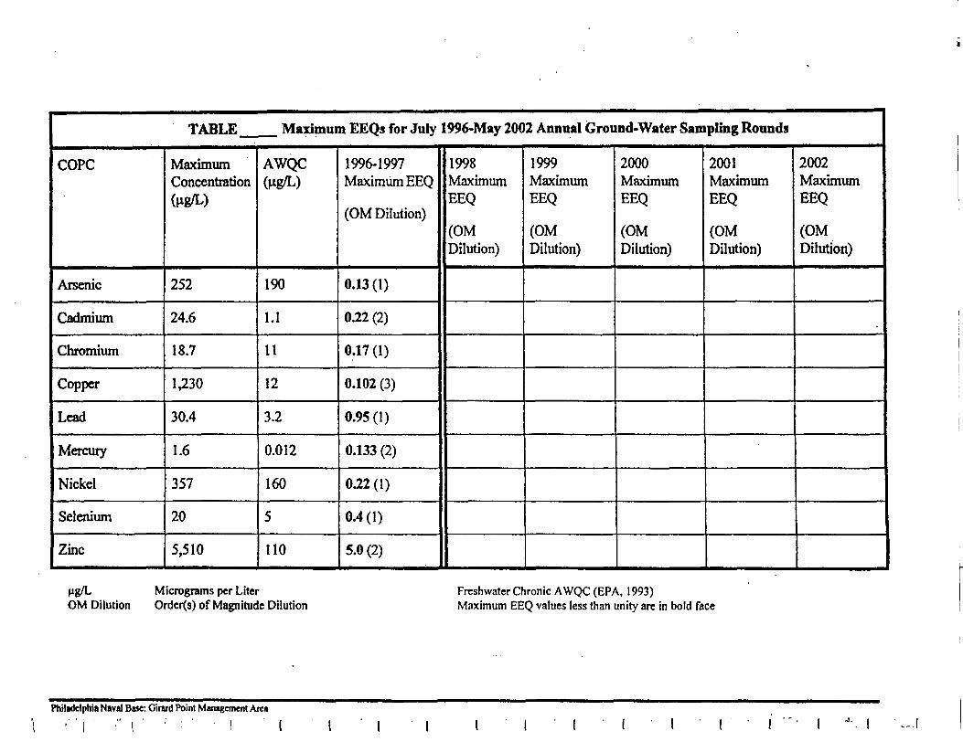
TABLE Maximum EEQs for July 1996-May 2002 Annual Ground-Water Sampling Rounds
COPC
Arsenic
Cadmium
Chromium
Copper
Lead
Mercury
Nickel
Selenium
Zinc
MaximumConcentration(W5/L)
252
24.6
18.7
1,230
30.4
1.6
357
20
5,510
AWQC(W?/L)
190
1.1
11
12
3.2
0.012
160
5
110
1996-1997Maximum EEQ
(OM Dilution)
0.13(1)
0.22 (2)
0.17 (1)
0.102 (3)
0.95(1)
0.133 (2)
0.22(1)
0.4(1)
5.0 (2)
1998MaximumEEQ
(OMDilution)
1999MaximumEEQ
(OMDilution)
2000MaximumEEQ
(OMDilution)
2001MaximumEEQ
(OMDilution)
2002MaximumEEQ
(OMDilution)
Hg/L Micrograms per LiterOM Dilution Orders) of Magnitude Dilution
Freshwater Chronic AWQC (EPA, 1993)Maximum EEQ values less than unity are in bold face
Philadelphia Naval Base: Girard Point Management Area
Project J.O. 04291.18.50Appendix C
Revision: Final
APPENDIX C
PHOTO LOG
2003 FIVE YEAR REVIEW
Philadelphia Naval Business Center Guard Point Management Area
Five Year Reviewdiv42\brac\0429II8SO\task6A_5YEAR\FINAL5YEARGPM4.doc
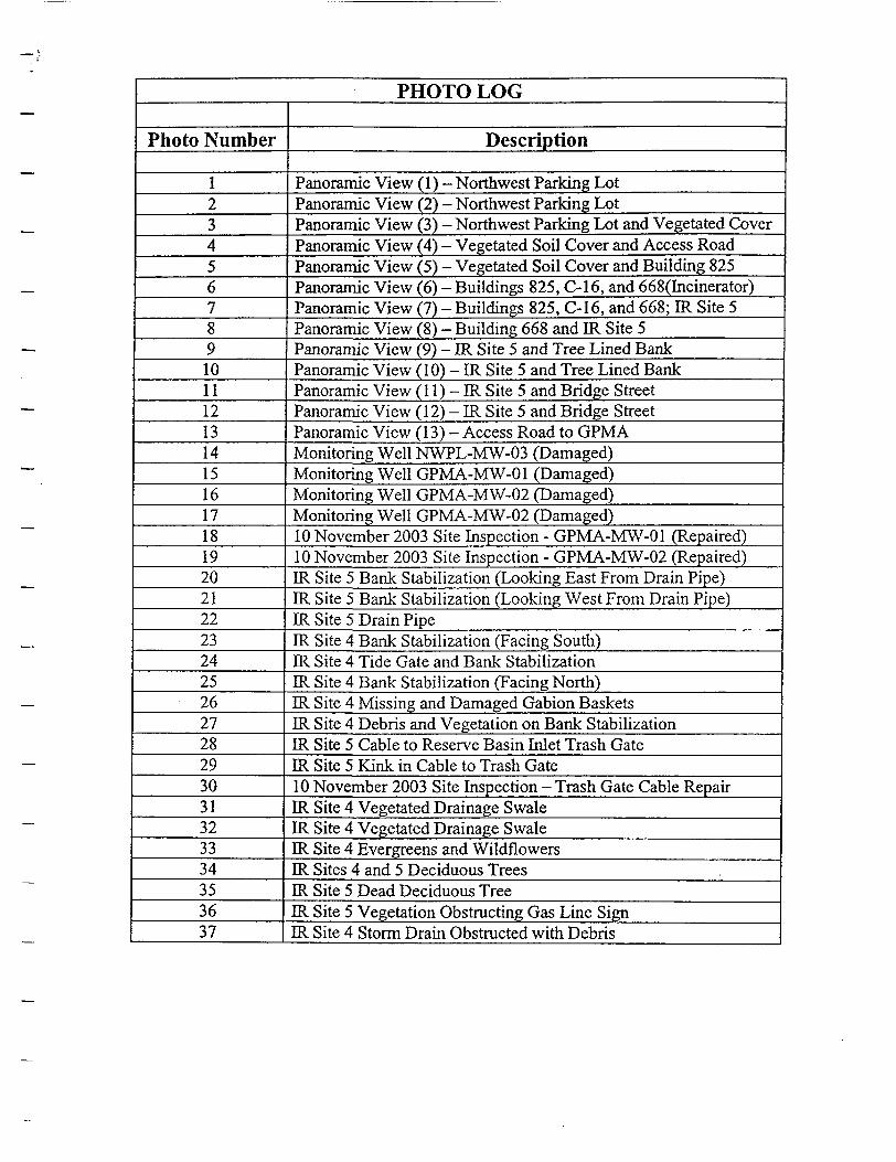
PHOTO LOG
Photo Number
12345678910111213141516171819202122232425262728293031323334353637
Description
Panoramic View (1) - Northwest Parking LotPanoramic View (2) - Northwest Parking LotPanoramic View (3) - Northwest Parking Lot and Vegetated CoverPanoramic View (4) - Vegetated Soil Cover and Access RoadPanoramic View (5) - Vegetated Soil Cover and Building 825Panoramic View (6) - Buildings 825, C-16, and 668(Incinerator)Panoramic View (7) - Buildings 825, C-16, and 668; ER Site 5Panoramic View (8) - Building 668 and IR Site 5Panoramic View (9) - IR Site 5 and Tree Lined BankPanoramic View (10) - IR Site 5 and Tree Lined BankPanoramic View (1 1) - IR Site 5 and Bridge StreetPanoramic View (12) - IR Site 5 and Bridge StreetPanoramic View (13) - Access Road to GPMAMonitoring Well NWPL-MW-03 (Damaged)Monitoring Well GPMA-MW-01 (Damaged)Monitoring Well GPMA-MW-02 (Damaged)Monitoring Well GPMA-MW-02 (Damaged)10 November 2003 Site Inspection - GPMA-MW-01 (Repaired)10 November 2003 Site Inspection - GPMA-MW-02 (Repaired)ER Site 5 Bank Stabilization (Looking East From Drain Pipe)ER Site 5 Bank Stabilization (Looking West From Drain Pipe)IR Site 5 Drain PipeER Site 4 Bank Stabilization (Facing South)ER Site 4 Tide Gate and Bank StabilizationER Site 4 Bank Stabilization (Facing North)ER Site 4 Missing and Damaged Gabion BasketsER Site 4 Debris and Vegetation on Bank StabilizationER Site 5 Cable to Reserve Basin Inlet Trash GateER Site 5 Kink in Cable to Trash Gate10 November 2003 Site Inspection - Trash Gate Cable RepairER Site 4 Vegetated Drainage SwaleER Site 4 Vegetated Drainage SwaleER Site 4 Evergreens and WildflowersER Sites 4 and 5 Deciduous TreesER Site 5 Dead Deciduous TreeER Site 5 Vegetation Obstructing Gas Line SignER Site 4 Storm Drain Obstructed with Debris
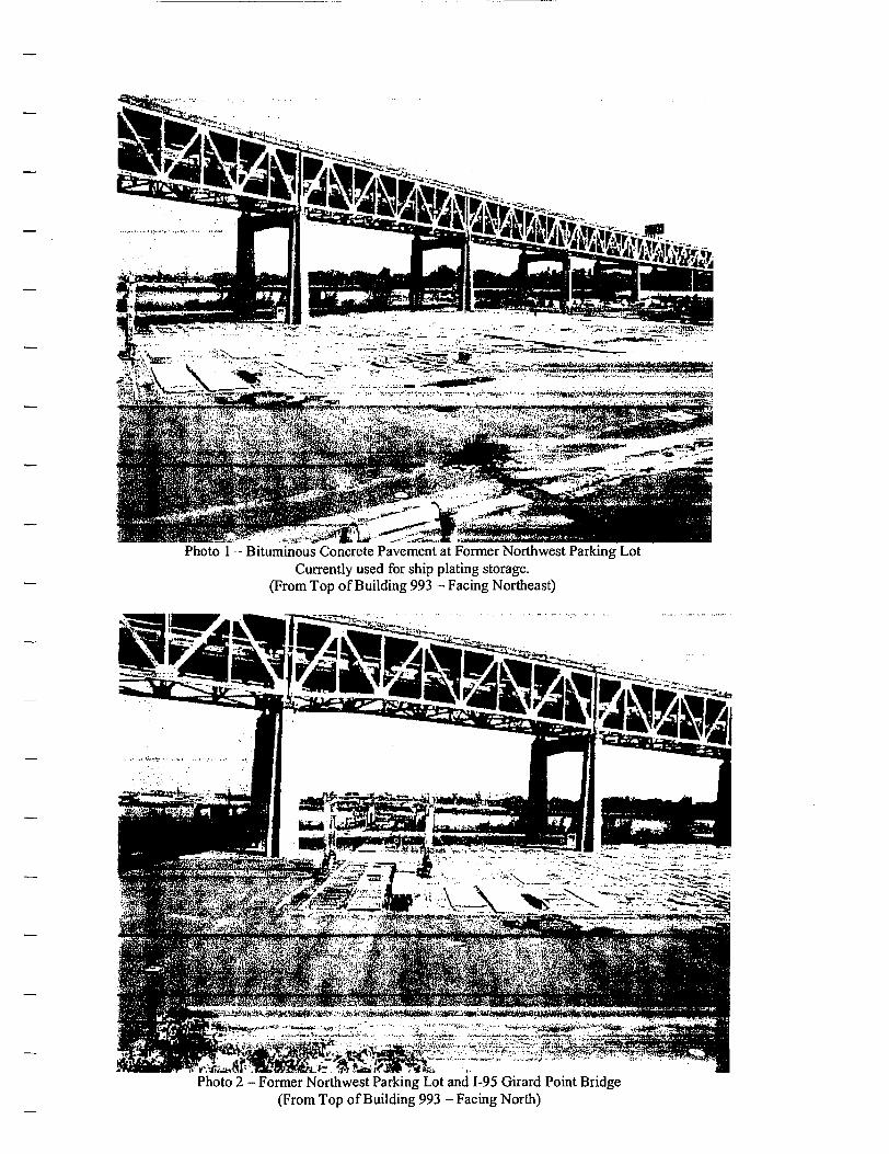
Photo 1 - Bituminous Concrete Pavement at Former Northwest Parking LotCurrently used for ship plating storage.
(From Top of Building 993 - Facing Northeast)
Photo 2 - Former Northwest Parking Lot and 1-95 Girard Point Bridge(From Top of Building 993 - Facing North)
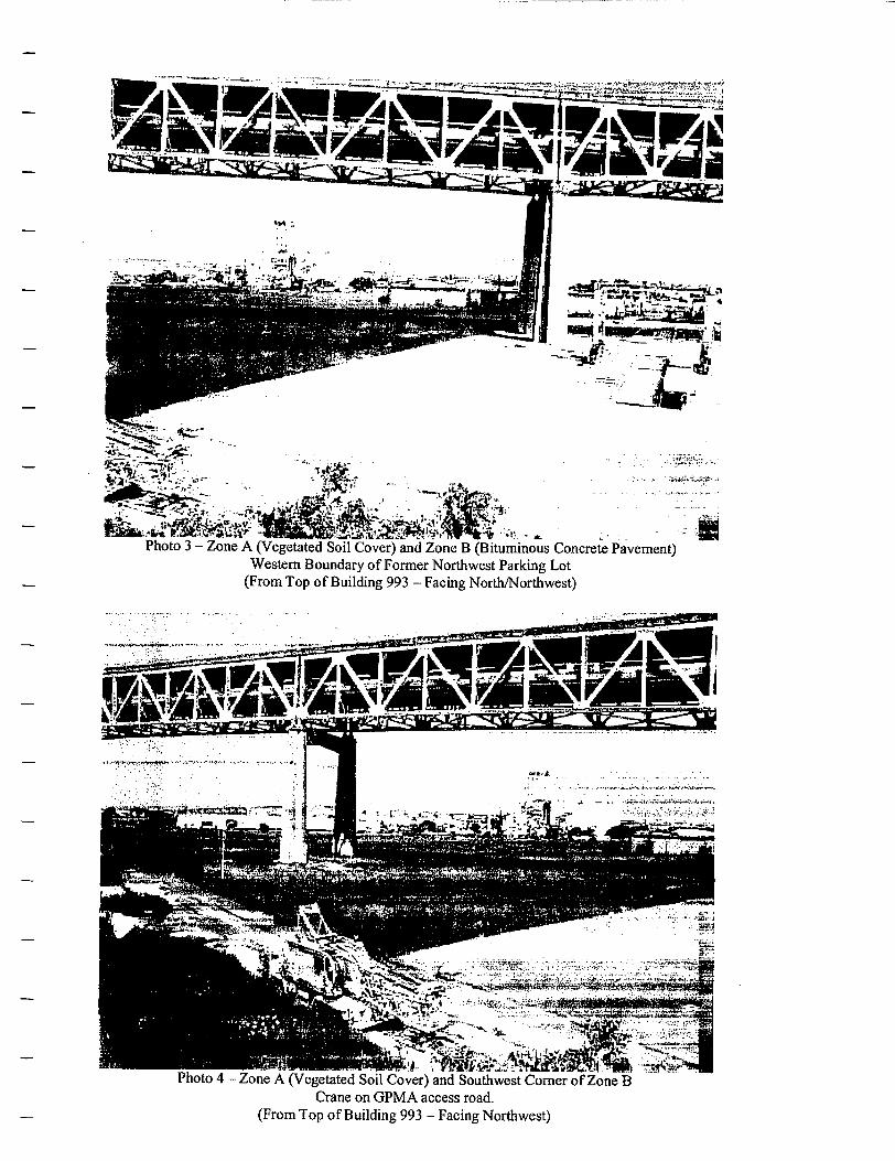
^S&alMH*',*Photo 3 - Zone A (Vegetated Soil Cover) and Zone B (Bituminous Concrete Pavement)
Western Boundary of Former Northwest Parking Lot(From Top of Building 993 - Facing North/Northwest)
Photo 4 - Zone A (Vegetated Soil Cover) and Southwest Corner of Zone BCrane on GPMA access road.
(From Top of Building 993 - Facing Northwest)
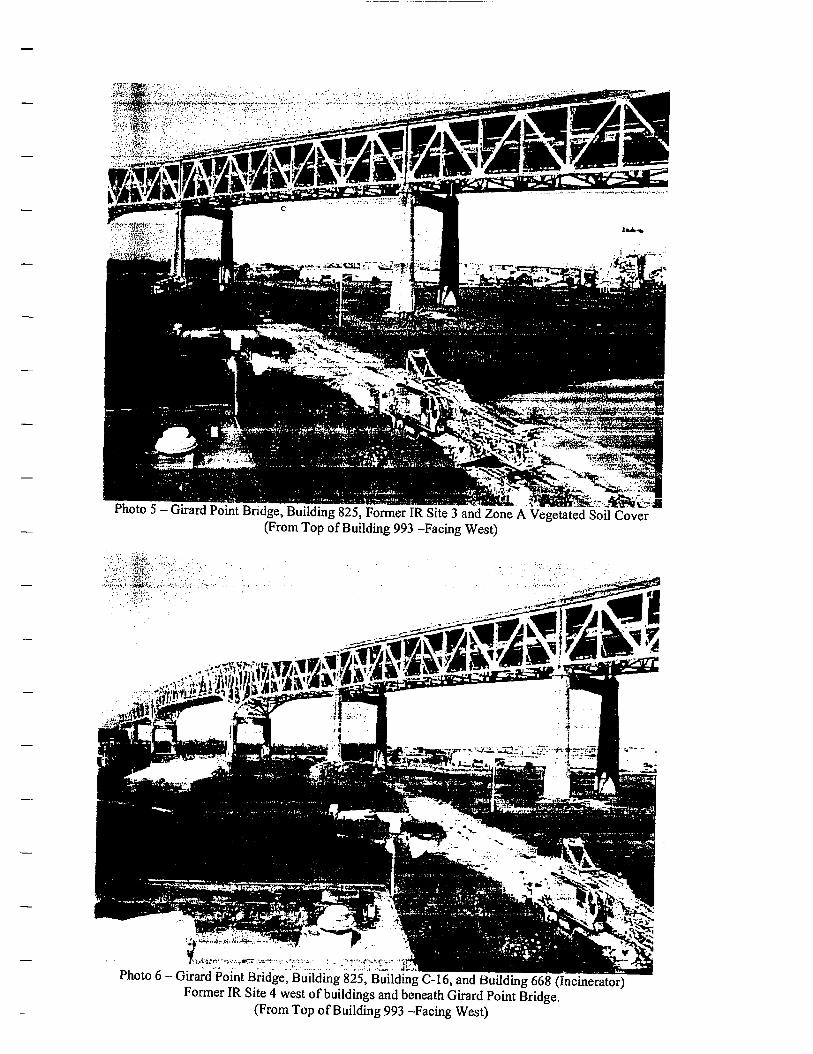
Photo 5 - Girard Point Bridge, Building 825, Former IR Site 3 and Zone A Vegetated Soil Cover'(From Top of Building 993 -Facing West)
"If
Photo 6 - Girard Point Bridge, Building 825,'Building C-16, and Building 668 (Incinerator)Former IR Site 4 west of buildings and beneath Girard Point Bridge.
(From Top of Building 993 -Facing West)
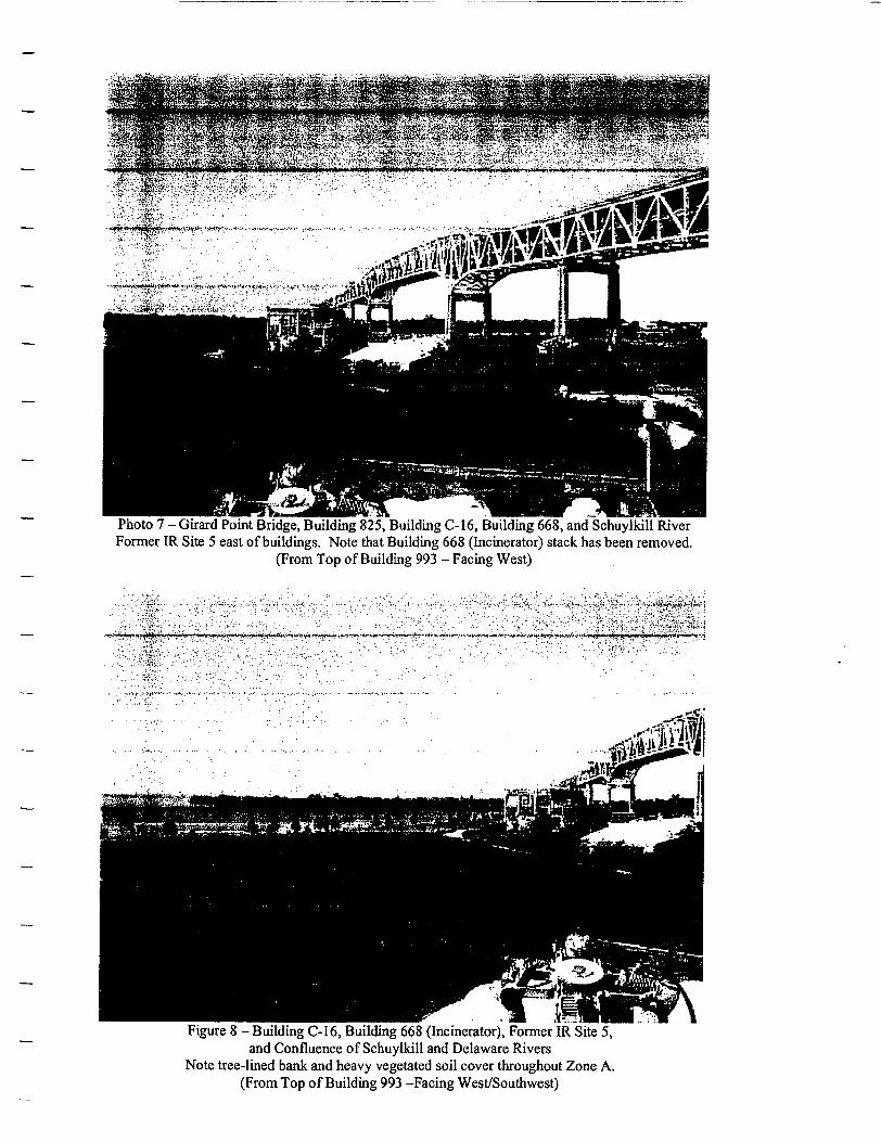
Photo 7 - Girard Point Bridge, Building 825, Building C-16, Building 668, and Schuylkill RiverFormer IR Site 5 east of buildings. Note that Building 668 (Incinerator) stack has been removed.
(From Top of Building 993 - Facing West)
Figure 8 - Building C-16, Building 668 (Incinerator), Former IR Site 5,and Confluence of Schuylkill and Delaware Rivers
Note tree-lined bank and heavy vegetated soil cover throughout Zone A.(From Top of Building 993 -Facing West/Southwest)
.• crim *! **!- * --*,**-• <"•> *
Photo 9 - Former IR Site 5, Reserve Basin Inlet, Schuylkill River, and Delaware RiverNote heavy vegetated soil cover and tree-lined bank along Reserve Basin Inlet.
(From Top of Building 993 - Facing South)
Photo 10 - Former IR Site 5, Reserve Basin Inlet, Schuylkill River, and Delaware RiverNote heavy vegetated soil cover and tree-lined bank along Reserve Basin Inlet
(From Top of Building 993 -Facing South)
Figure 11 - Former IR Site 5, Reserve Basin Inlet, and Bridge Street (bridge open)Kvaerner Shipyard in background.
(From Top of Building 993 -Facing South/Southeast)
Photo 12 - Former IR Site 5 and opened bridge at Bridge Street(From Top of Building 993 - Facing East/Southeast)
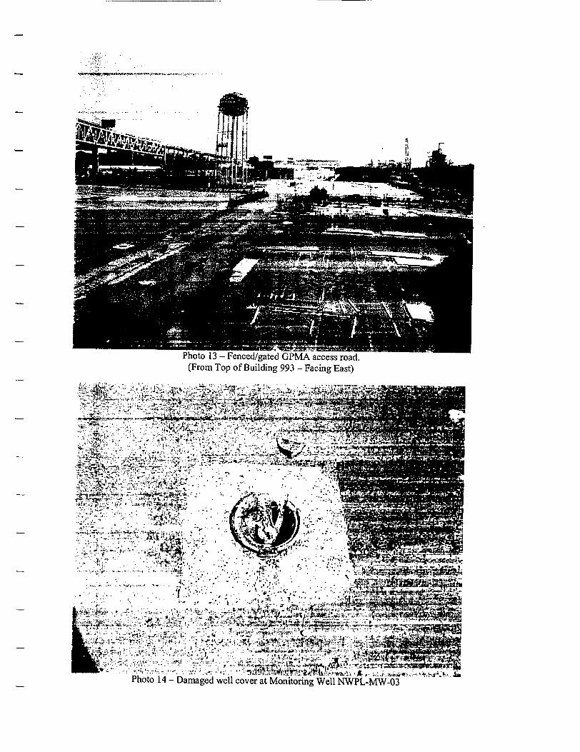
Photo 13 - Fenced/gated GPMA access road.(From Top of Building 993 - Facing East)
• V ;-" • ££^&^Ji%&i£iti&**iT£ijei££3!**4wv<*-r~
<;«-:^\:w Ji.-'.v.r.-y*-.* .-xA, V--. • t:!v'.- i>**^i^S,wW^i(-ij*tfc^w*»-^Si-.;;;---,..:.•«"» ""•••"-'* '•''"- :fe ..*r'"'';:1 '•*--t:-'*.-^y-': •.- ;: ---v-'>/ v**i'*!rs . .Tf5»faS|!S^[-!»•.••>•';-,1 •".•-•Viij- •,•..[».-,>'.• ;•-• -- :•• •-:--l--»«*>j^-~'9ftl^'Si!i': <• •' ,'• " ' ' '* ' , " -" ' , ^^"'^^^^y$f*^i5%i&^^^
../.-..:,';..,^,,,-, ..,-.«•'-.,-; .^.',- ••:-5^^^aJ^\i«SU^m,a.A.;. p^^iir.^.i.-K^-ViPhoto 14 - Damaged well cover at Monitoring Well NWPL-MW-03
i.
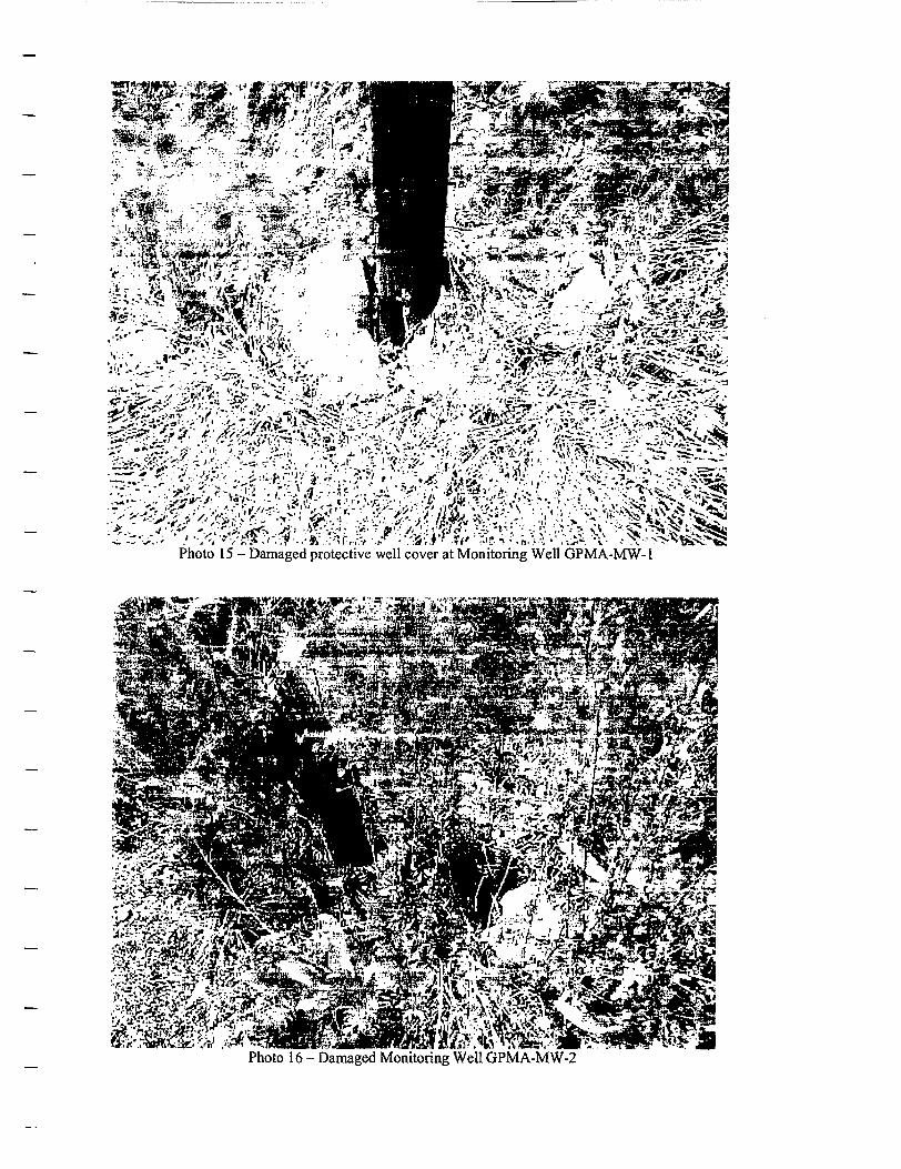
- i • >;'•/. ->®t r i' •»'•'''•'•••!•. •• •' " '''?\< ?'* ' c"m>i• ' ' • ^'.•' "'"i -'^ '-^>i
Photo 15 - Damaged protective well cover at Monitoring Well GPMA-MW
Photo 16 - Damaged Monitoring Well GPMA-MW-2
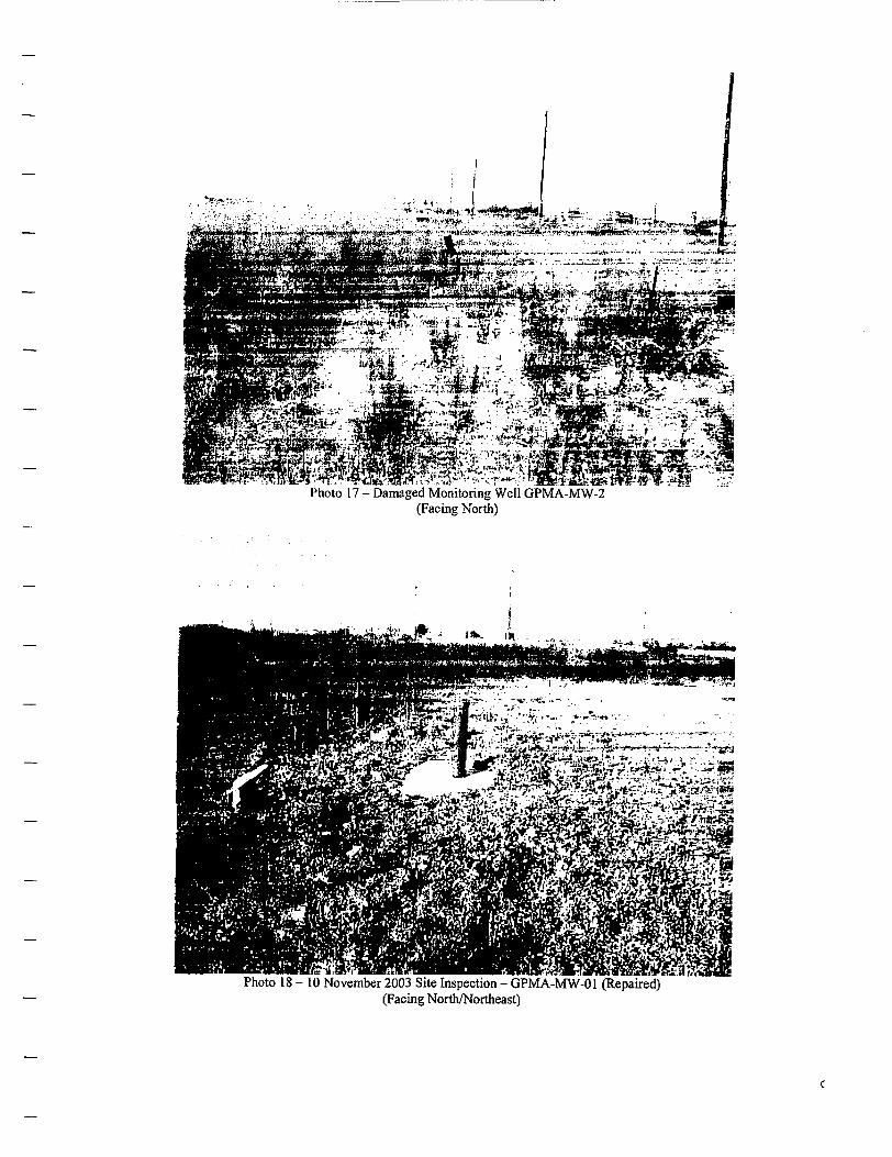
**&!: '',- 3»k....... ;. .,;
Photo 17 - Damaged Monitoring Well GPMA-MW-2(Facing North)
*'t %?~.>BWB^.tJLii»'fV«..«^ ,->"7-Xti.: ."Ji iii
Photo 18-10 November 2003 Site Inspection - GPMA-MW-01 (Repaired)(Facing North/Northeast)
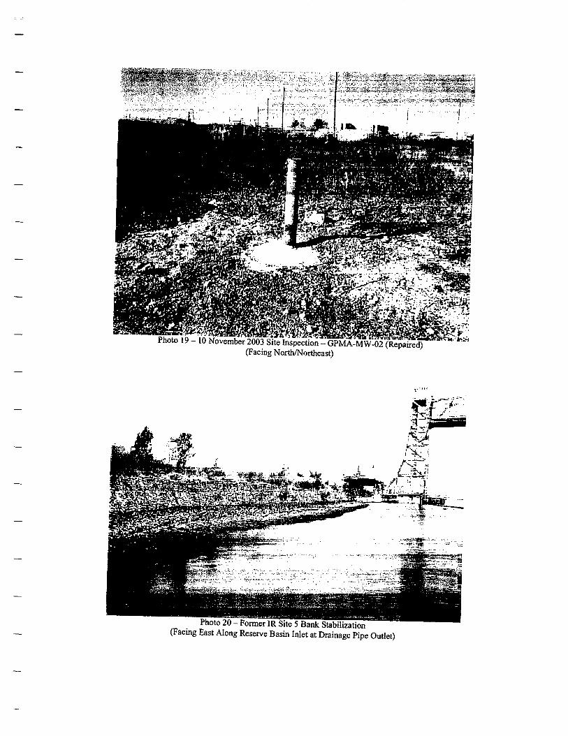
s,-^^^^^^••^m
-pK-r-,o ' ^^^^S^Sfm^^Photo 19-10 November 2003 Site Inspection -
(Facing North/Northeast)
Photo 20 - Former IR Site 5 Bank Stabilization(Facing East Along Reserve Basin Inlet at Drainage Pipe Outlet)
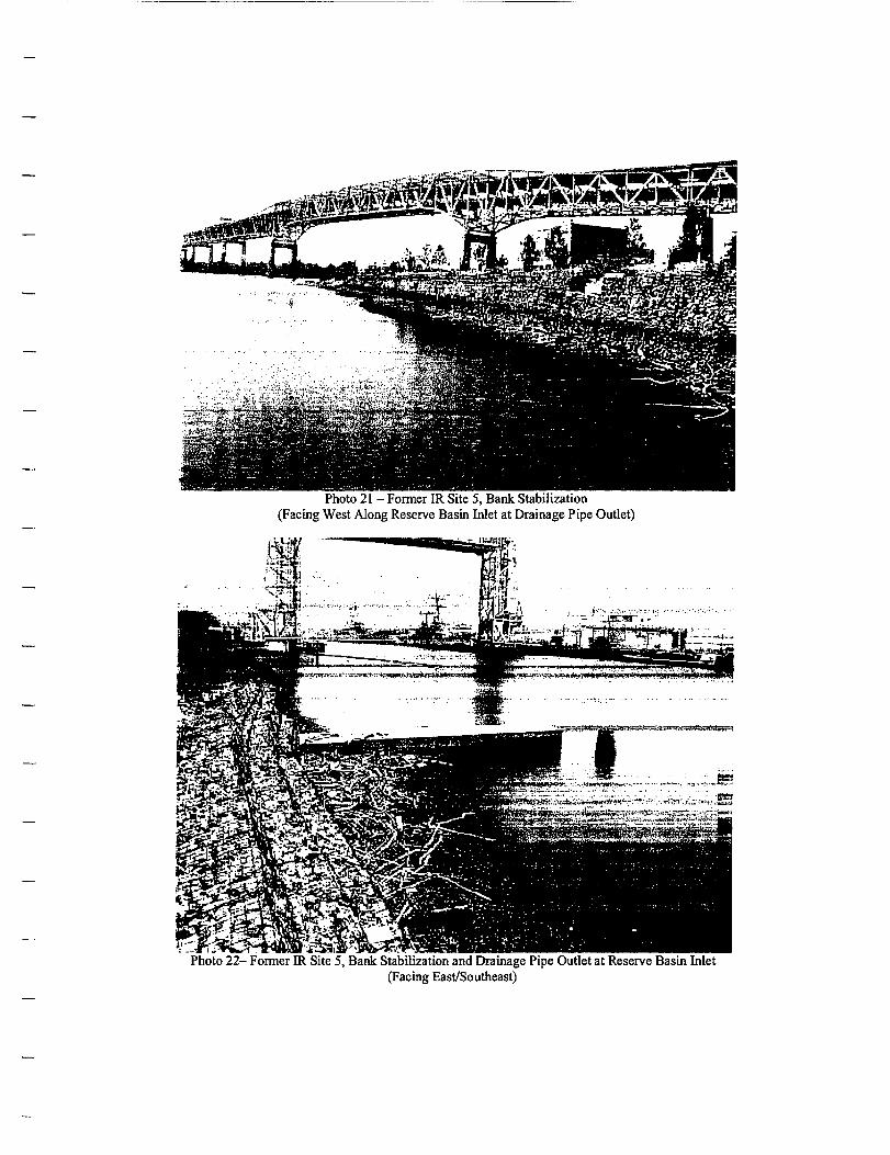
Photo 21 - Former IR Site 5, Bank Stabilization(Facing West Along Reserve Basin Inlet at Drainage Pipe Outlet)
Photo 22- Former IR Site 5, Bank Stabilization and Drainage Pipe Outlet at Reserve Basin Inlet(Facing East/Southeast)
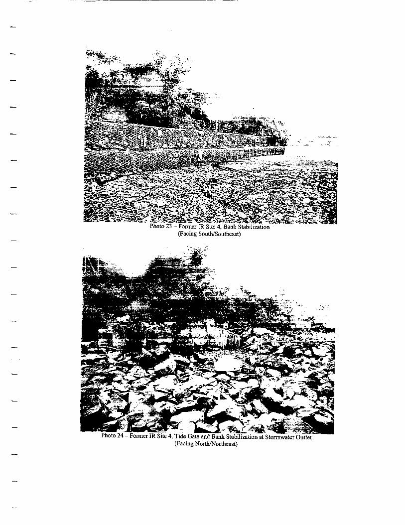
i•s-r»***'3a: •* -~«H5j»• W-*t£^-3a*;Sil«T: %Jf^fe-*»>
£iS*|fe&i$*&N^
Photo 23 - Former FR Site 4, Bank Stabilization(Facing South/Southeast)
Photo 24 - Former IR Site 4, Tide Gate and Bank Stabilization at Stormwater Outlet(Facing North/Northeast)
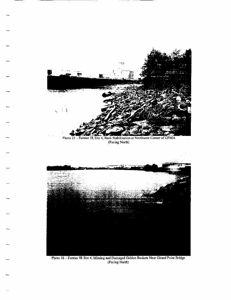
Photo 25 - Former IR Site 4, Bank Stabilization at Northwest Corner of GPMA(Facing North)
Photo 26 - Former IR Site 4, Missing and Damaged Gabion Baskets Near Girard Point Bridge(Facing North)
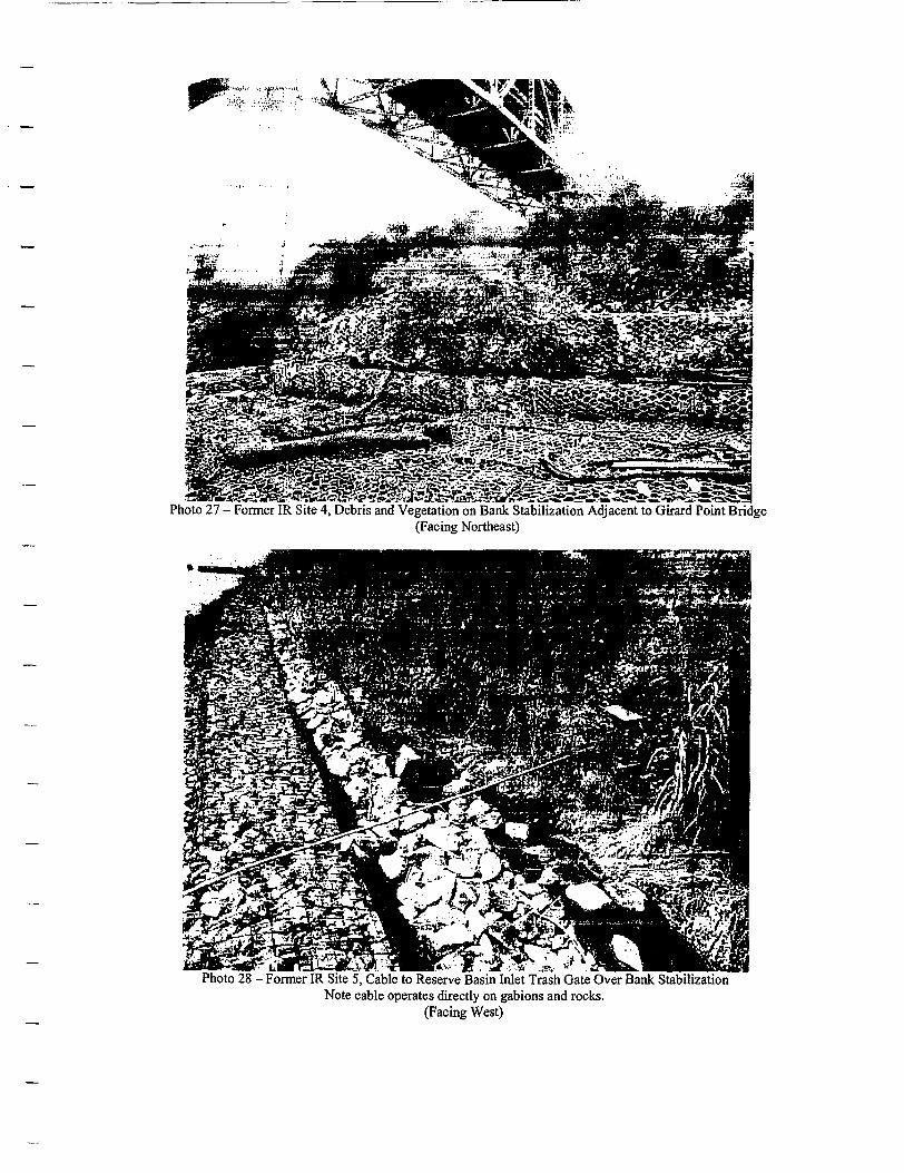
?9«>&&tf*'iPhoto 27 - Former IR Site 4, Debris and Vegetation on Bank Stabilization Adjacent to Girard Point Bridge
(Facing Northeast)
Photo 28 - Former IR Site 5, Cable to Reserve Basin Inlet Trash Gate Over Bank StabilizationNote cable operates dkectly on gabions and rocks.
(Facing West)
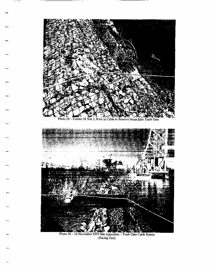
Photo 29 - Former IR Site 5, Kink in Cable to Reserve Basin Inlet Trash Gate
Photo 30 - 10 November 2003 Site Inspection - Trash Gate Cable Repair(Facing East)
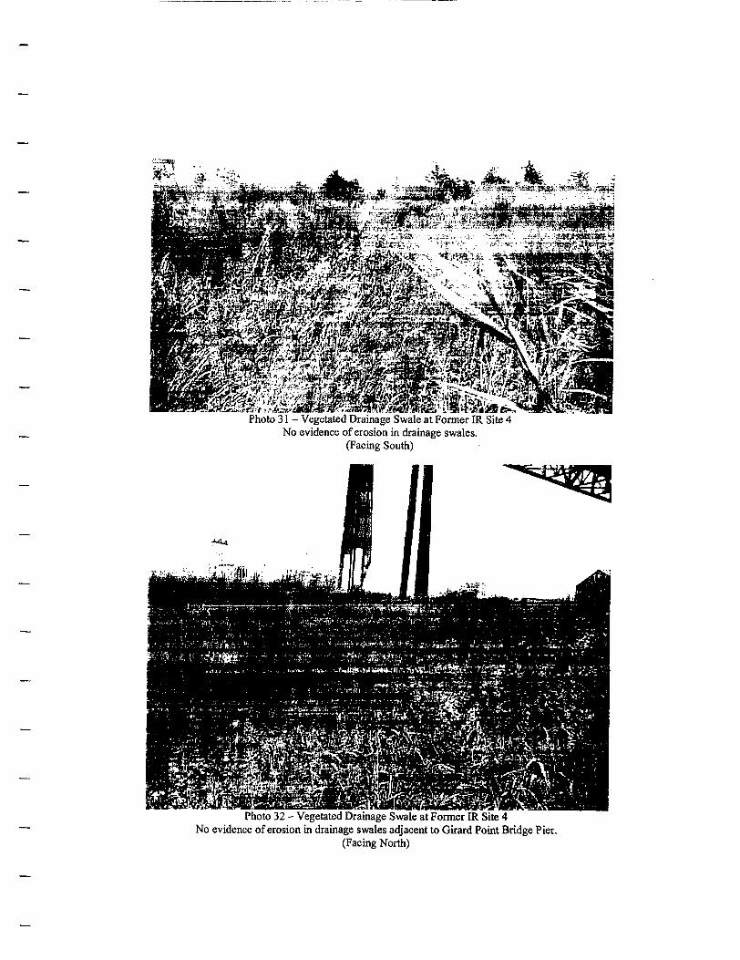
Photo 31 - Vegetated Drainage Swale at Former IR Site 4No evidence of erosion in drainage swales.
(Facing South)
Photo 32 - Vegetated Drainage Swale at Former IR Site 4No evidence of erosion in drainage swales adjacent to Girard Point Bridge Pier.
(Facing North)
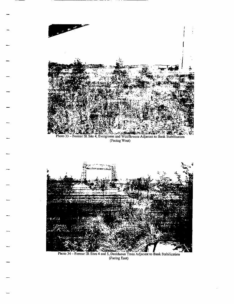
_._Photo 33 - Former IR Site 4, Evergreens and Wildflowers Adjacent to Bank Stabilization
(Facing West)
Photo 34 - Former IR Sites 4 and 5, Deciduous Trees Adjacent to Bank Stabilization(Facing East)
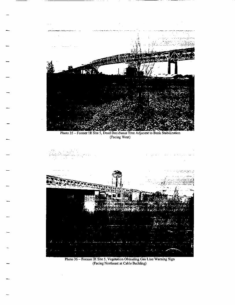
Photo 35 - Former IR Site 5, Dead Deciduous Tree Adjacent to Bank Stabilization(Facing West)
Photo 36 - Fonner IR Site 5, Vegetation Obtruding Gas Line Warning Sign(Facing Northeast at Cable Building)
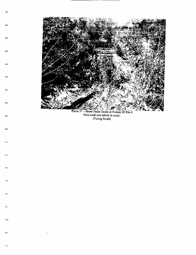
iS^P SS^v^ .i *l ?^-*%m•W*;&&&$. \*~i,r .-*-&&£
> - . . N i i ' . ..,.Photo 37 - Stonn Drain Outlet at Former IR Site 4
Note trash and debris in swale.(Facing South)
Project: J.O. 04291.18.50Appendix D
Revision: Final
APPENDIX
GPMA LTM TREND LINES
2003 FIVE YEAR REVIEW
Philadelphia Naval Business Center, Guard Point Management Area
Five Year Reviewdiv42\brac\04291I850\task6A_5YEAR\FNAL5YEARGPM.doc
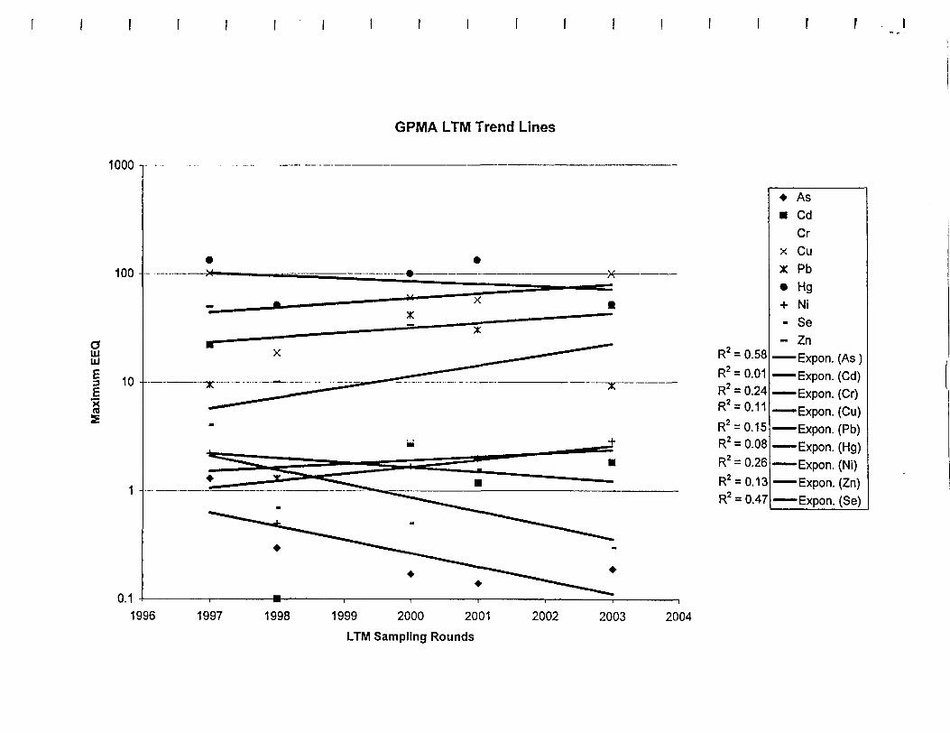
GPMA LTM Trend Lines
1000
aUJUJE
1996 1997 1998 1999 2000 2001
LTM Sampling Rounds
2002 2003 2004
R2 = 0.58
R2 = 0.01R2 = 0.24R2 = 0.11
R2 = 0.15R2 = 0.08
R2 = 0.26
R2 = 0.13R2 = 0.47
«• As• Cd
Crx Cux Pb
• Hg+ Ni- Se- Zn
Expon. (As )—Expon. (Cd)—Expon. (Cr)—Expon. (Cu)
Expon. (Pb)Expon. (Hg)
—Expon. (Ni)Expon. (Zn)
——Expon. (Se)
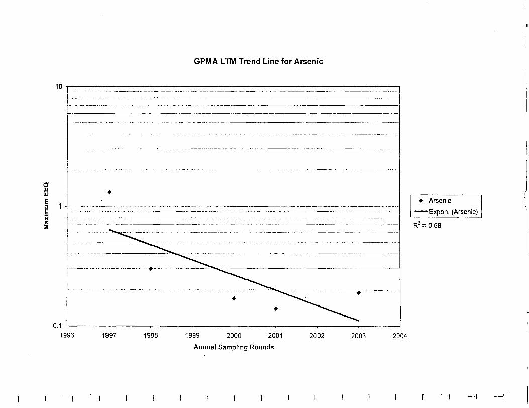
GPMA LTM Trend Line for Arsenic
10
aaiLU
I 1
XTO
0.1
Arsenic
Expon. (Arsenic)
R2 = 0.58
1996 1997 1998 1999 2000 2001
Annual Sampling Rounds
2002 2003 2004
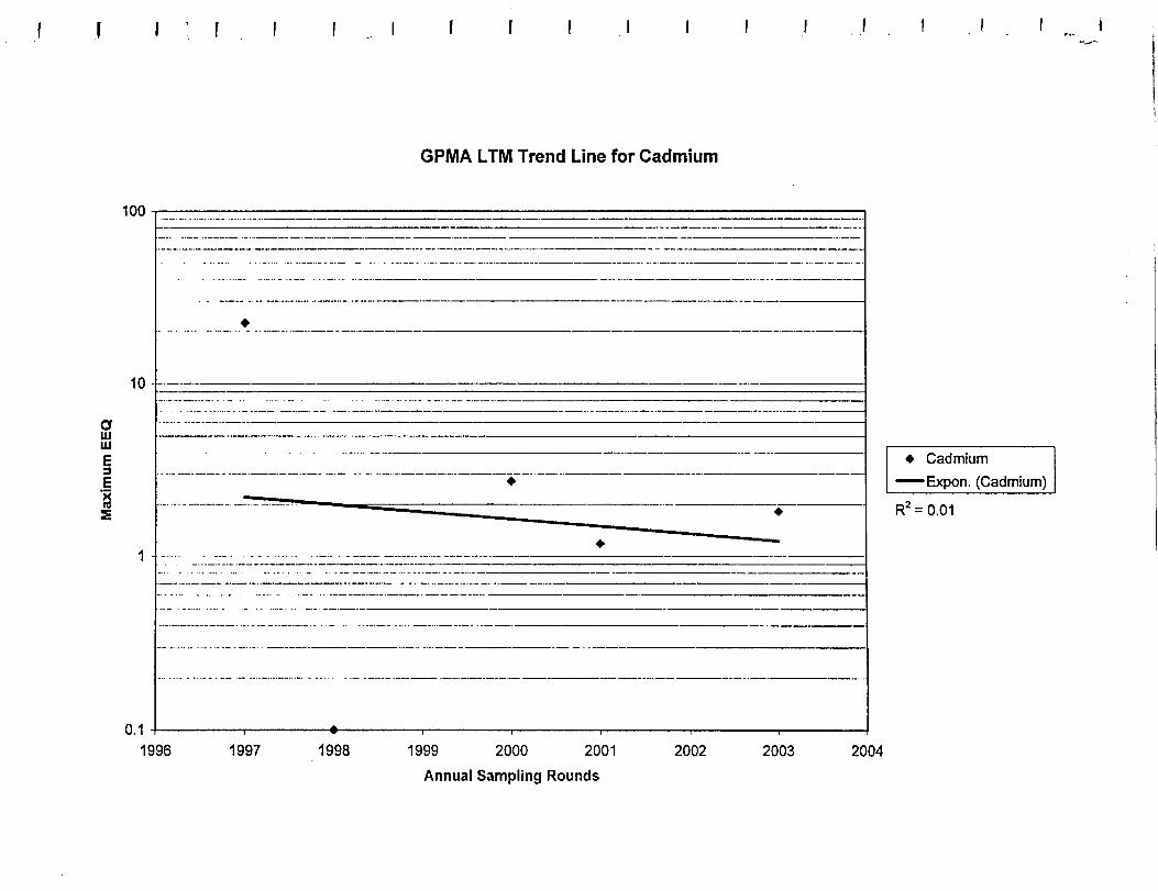
GPMA LTM Trend Line for Cadmium
100
10-
oaiLU
1 -
0.1
* Cadmium
——Expon. (Cadmium)
R2 = 0.01
1996 1997 1998 1999 2000 2001
Annual Sampling Rounds
2002 2003 2004
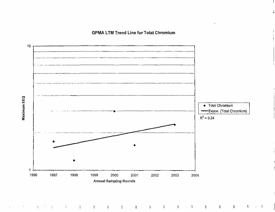
GPMA LTM Trend Line for Total Chromium
10
o111uiE
ia
Total Chromium
Expon. (Total Chromium)
R2 = 0.24
1996 1997 1998 1999 2000 2001
Annual Sampling Rounds
2002 2003 2004
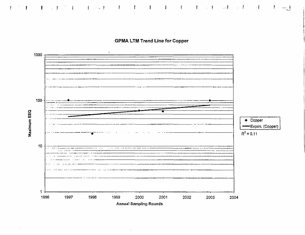
GPMA LTM Trend Line for Copper
1000
100 - •
UJ
Ii'xra5
10
CopperExpon. (Copper)
R2 =
1996 1997 1998 1999 2000 2001
Annual Sampling Rounds
2002 2003 2004
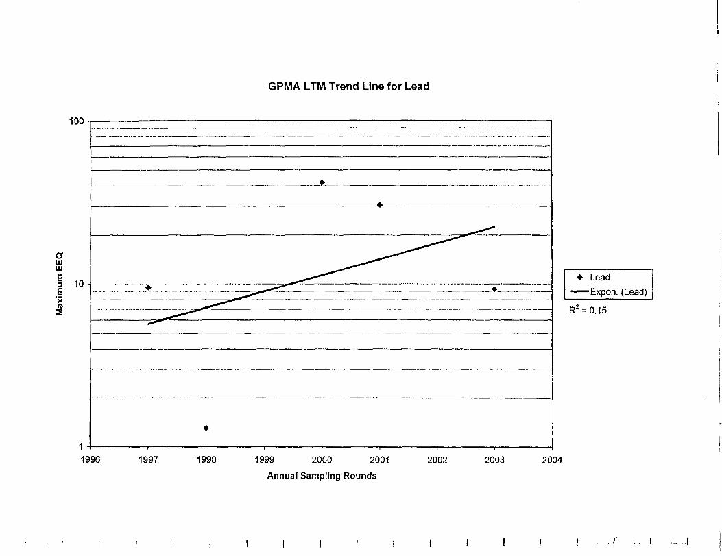
GPMA LTM Trend Line for Lead
1996
Lead
Expon. (Lead)
Rx = 0.15
1997 1998 1999 2000 2001
Annual Sampling Rounds
2002 2003 2004
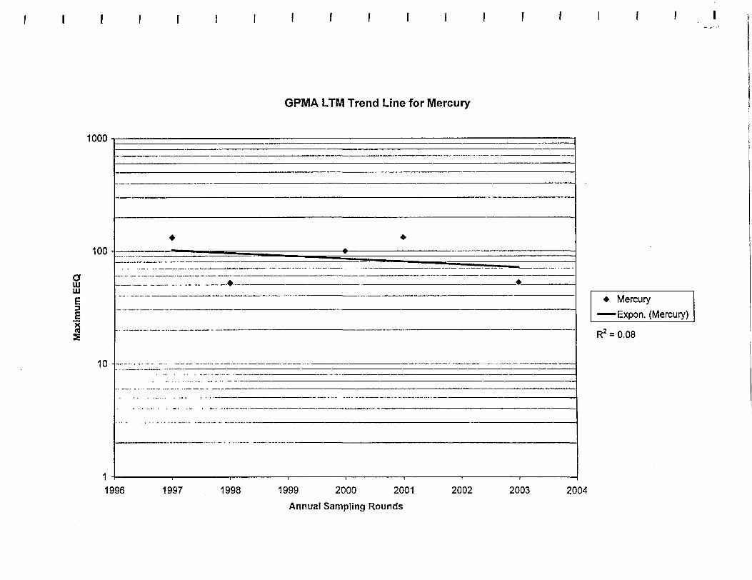
GPMA LTM Trend Line for Mercury
1000
oUJUJ
E3
10 -
* Mercury
Expon. (Mercury)
R2 = 0.08
1996 1997 1998 1999 2000 2001
Annual Sampling Rounds
2002 2003 2004
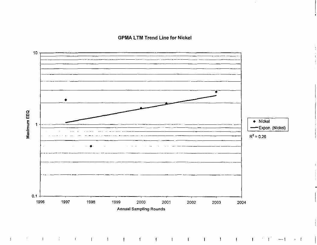
GPMA LTM Trend Line for Nickel
10
oin111
xra
0.1
• Nickel
Expon. (Nickel)
R2 = 0.26
1996 1997 1998 1999 2000 2001
Annual Sampling Rounds
2002 2003 2004
f ! ! I I I
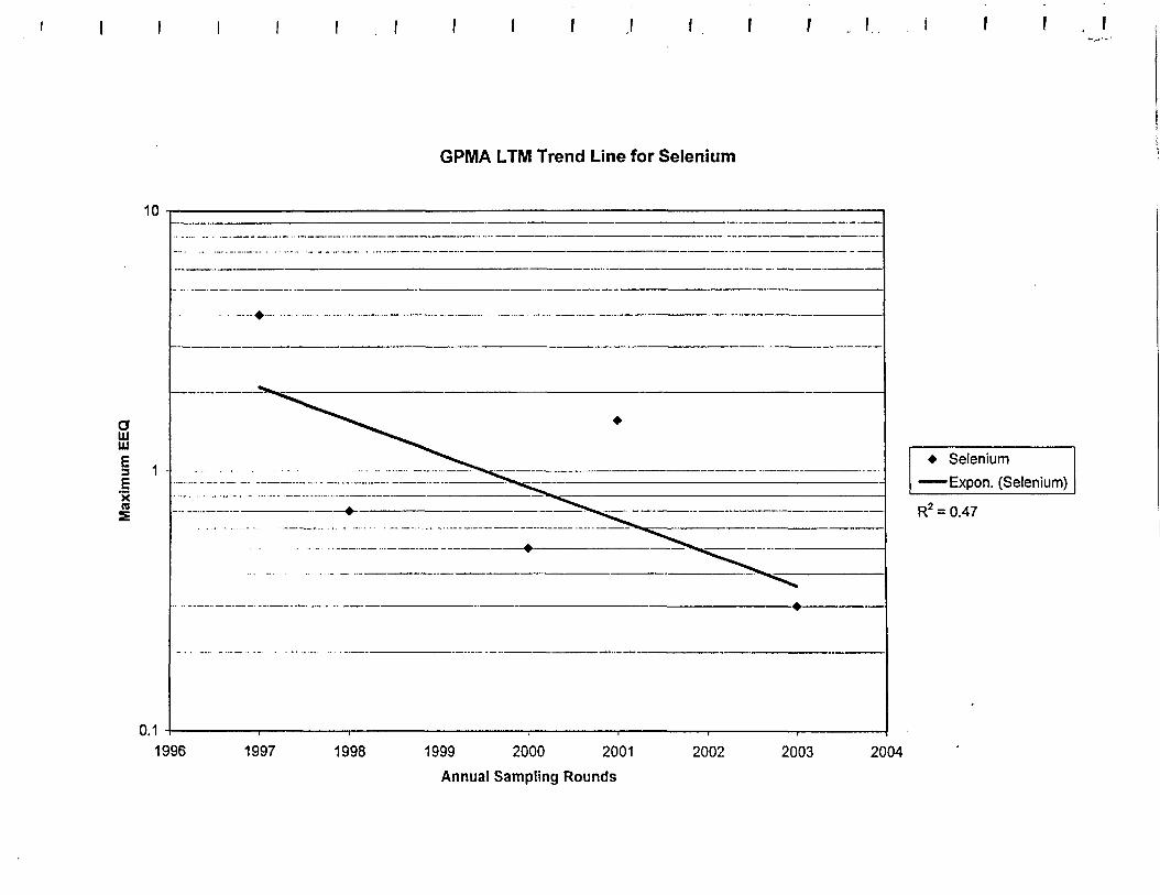
I I I f I 1 , 1
GPMA LTM Trend Line for Selenium
10
aUJUJ
I 1Xn
0.1
* Selenium
—— Expon. (Selenium)
R2 = 0.47
1996 1997 1998 1999 2000 2001
Annual Sampling Rounds
2002 2003 2004
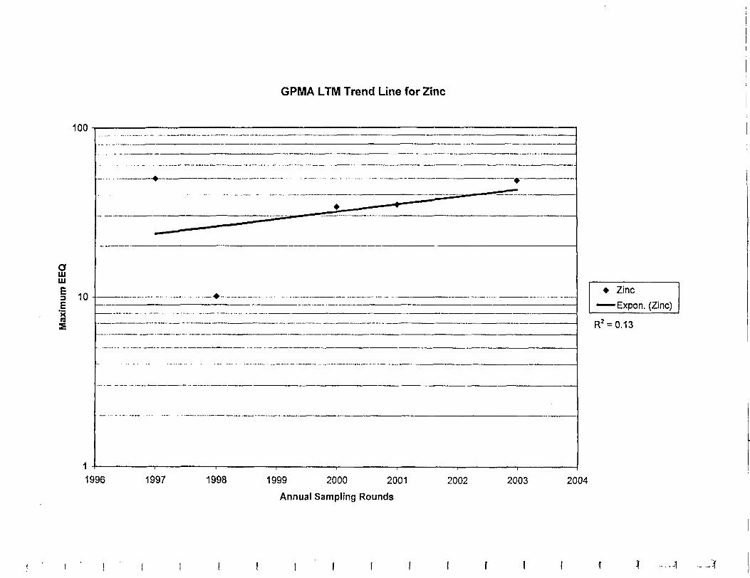
GPMA LTM Trend Line for Zinc
100
aUJaiE3 10
Zinc
Expon. (Zinc)
R2 = 0.13
1996 1997 1998 1999 2000 2001
Annual Sampling Rounds
2002 2003 2004
Related Documents