URB 2 Installation Instructions 81860100 Operating & display unit URB 2 GESTRA Steam Systems

Welcome message from author
This document is posted to help you gain knowledge. Please leave a comment to let me know what you think about it! Share it to your friends and learn new things together.
Transcript

�
URB 2Installation Instructions 81860100Operating & display unit URB 2
GESTRA Steam Systems

2
Contents
Usage for the intended purpose ..............................................................................................................5Safety note .............................................................................................................................................5ATEX (Atmosphère Explosible) .................................................................................................................5
Important NotesPage
Explanatory Notes
Scope of supply ......................................................................................................................................5System description ............................................................................................................................. 5, 6Function .................................................................................................................................................6
Factory setting ......................................................................................................................................�2
Basic Settings
Wiring
Bus cable, cable length and size ...........................................................................................................��Wiring the connecting sockets ..............................................................................................................��Wiring diagram URB 2 ..........................................................................................................................��Wiring diagram for CAN bus system – example – .................................................................................�2Attention ..............................................................................................................................................�2
URB 2 .....................................................................................................................................................7Name plate / Marking .............................................................................................................................7Dimensions ............................................................................................................................................8
Technical Data
URB 2 .....................................................................................................................................................9
Installation
URB 2 ............................................................................................................................................... 9, �0Key .......................................................................................................................................................�0
Functional Elements
Operator interface .................................................................................................................................�3 Note .....................................................................................................................................................�3Attention ..............................................................................................................................................�3Menus ..................................................................................................................................................�4Specification of keys and navigation wheel ..........................................................................................�5Specification of the symbol bar ....................................................................................................... �5, �6Menu structure .....................................................................................................................................�6
Operation

3
Start logo ..............................................................................................................................................�7Home ...................................................................................................................................................�7Language .............................................................................................................................................�8System configuration ............................................................................................................................�8Baud rate .............................................................................................................................................�9Brightness ............................................................................................................................................�9About URB 2 .........................................................................................................................................20 Service menu .......................................................................................................................................20Service – Lock URB ..............................................................................................................................20 Service – Unlock URB ...........................................................................................................................2�Service – Key check .............................................................................................................................22
Contents – continued –
Menu StartPage
At a glance ...........................................................................................................................................22Control .................................................................................................................................................23Overview ........................................................................................................................................ 24, 25Status report ........................................................................................................................................25Sensitivity .............................................................................................................................................26Measuring range ..................................................................................................................................26Switchpoints ........................................................................................................................................27Switchpoints, proportional range ..........................................................................................................28Switchpoints, output 4-20 mA ..............................................................................................................28Switching times ...................................................................................................................................29Control valve ........................................................................................................................................30Control param .......................................................................................................................................3�Temperature .........................................................................................................................................3�Blowdown valve ...................................................................................................................................32MIN/Blowdown .....................................................................................................................................33
Menu Control
Causes .................................................................................................................................................36Systematic fault finding procedure for system malfunctions .................................................................37Restart .................................................................................................................................................38Status messages ..................................................................................................................................39
Malfunctions
Limiter ..................................................................................................................................................34Note .....................................................................................................................................................34Control unit ..........................................................................................................................................35Limiter Lx .............................................................................................................................................35
Menu Limiter

4
CAN bus ...............................................................................................................................................40Factory set node IDs .............................................................................................................................40Decommissioning .................................................................................................................................40Disposal ...............................................................................................................................................40Declaration of Conformity .....................................................................................................................4�Glossary .......................................................................................................................................42 – 44
Annex
Contents – continued –
Page
5
Important Notes
Usage for the intended purpose
The operating & display unit URB 2 may only be used in conjunction with GESTRA CAN bus devices.Any type of use differing from the usage described above must be considered as improper. The resulting risk will have to be borne by the user alone. The manufacturer hereby expressly rejects any claims for any damage resulting from improper usage.
Safety note
The equipment must only be installed and commissioned by qualified and competent staff. Retrofitting and maintenance work must only be performed by qualified staff who – through adequate training – have achieved a recognised level of competence.
Explanatory Notes
Scope of supply
URB 2� Operating & display unit URB 2 � Connecting socket type M �2, with 5 poles, A-coded� Connecting socket type M�2, with 5 poles, A-coded, with terminating resistor �20 Ω� Installation manual� Sticker with password
System description
The URB 2 is an operating & display unit for all GESTRA CAN bus devices that uses the CANopen protocol to register all the data telegrams coming from the sensors, control units and actuators that are provided by the CAN bus.The following readings, parameters and settings can be displayed and – with the exception of the actual values – also be changed by means of the URB 2.
ATEX (Atmosphère Explosible)
According to the European Directive 94/9/EC the equipment must not be used in explosion risk areas.

6
Explanatory Notes – continued –
System description – continued –
Level Conductivity Temperature
Actual value bar chart X
Actual value, numerical X X X
MIN limit X X X
MAX limit X X X
Switchpoints X X X
Relay (de)energizing times X X
Actual-value output 4-20 mA X
Measuring range X X
Setpoint X X X
Control parameters X X
Valve position of level control valve X
Unit (μS/cm or ppm) X
Stand-by X
Continuous blowdown valve Operating position of the valve
X
Purging pulse 24 h X
Intermittent blowdown interval X
Duration of intermittent blowdown X
Manual/Automatic operation X X
Function
The operating & display unit URB 2 evaluates at regular intervals the data telegrams of all sensors, controllers and actuators in a CAN bus system. The readings, parameters, settings and messages are indicated in plain text. When used as second water level indicator in boiler plants (TRD 40�, EN �2952 / ...53), the level is also indicated in the form of a bar graph.Several languages can be selected for plain text display. The password protection prevents unauthorized persons from changing parameters and settings. If other menu levels are selected via the start window and neither a button nor the navigation wheel is then actuated, the operating & display unit URB 2 will automatically return to the start window after 5 minutes. The time-out function is not effective during manual operation or in the parameterization mode.The help function in the various operating levels offers additional information on how to operate the equipment.

7
URB 2
Technical Data
Input/output CAN bus interface with power supply �8-36 V DC, short circuit protected
Data exchange CAN bus to ISO��898, CANopen protocol
Indicators and adjustors � Graphic display, resolution 320 x 240 pixels, illuminated 4 Pushbuttons � Control knob with integrated pushbutton (navigation wheel)
Wiring 2 Connecting sockets type M �2, with 5 poles, A-coded
Power consumption 5.2 VA
Protection Front face: IP 54 to EN 60529 Rear panel: IP �0 to EN 60529
Admissible ambient temperature 0 – 55°C
Case materials Front face: Ultramid A3K Enclosure: Sheet metal type DC0�-A, surface yellow chromatized
Weight approx. �.� kg
Name plate / Marking
Equipment designation
Fig. 1
Characteristics Output / Voltage,
current
Betriebsanleitung beachtenSee installation instructionsVoir instructions de montage
GESTRA AG Münchener Straße 77 D-28215 Bremen
Software version
Disposal note
Protection Pressure/temp. range
CE marking
Manufacturer
8
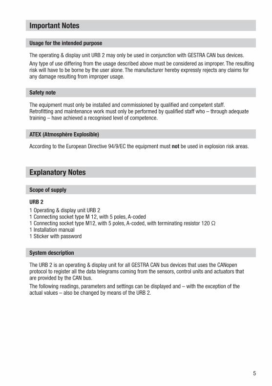
Dimensions
Technical Data – continued –
Fig. 2
IP 54
MAX 55 °C
MAX 55 %
E [mm]
F [mm]
�74 �45PUSH
30
max. 1
0
E
Home Control Limiter
Level45 %
PressureMAXACT. bar
TemperatureMAX 300ACT. 150 °C
Conductivity StdByMAX 6000ACT. 4800 µS/cm
GESTRA URB 2
180
E
F
150
54

9
Installation
URB 2
Fig. 3
Functional Elements
URB 2
The operating and display unit URB 2 is designed for installation in control cabinets.�. Provide cut out in control cabinet, dimensions �74 x �45 mm, max. sheet thickness �0 mm.2. Unscrew the white fixing nuts D and remove the back of the housing C. If necessary you can also
unscrew the stud but not more than 35 mm.3. Put the operating and display unit URB 2 A into the cut-out, replace the back of the housing C,
screw in and tighten the fixing nuts D.
GESTRA URB 2
PUSH
Home Control Limiter
Level45 %
Conductivity StdByMAX 6000ACT. 4800 µS/cm
PressureMAXACT. bar
TemperatureMAX 300ACT. 150 °C
1 2 1
A3

�0
Functional Elements – continued –
URB 2 – continued –
Fig. 4
B C D
1 Pushbutton
2 Navigation wheel
3 Illuminated LCD display, resolution 320 x 240 pixels
AFrame with indicators and adjustors
B Connector, 5poles
C Back of housing
D Fixing studs and nuts for installation in control cabinet
Key
��
Wiring
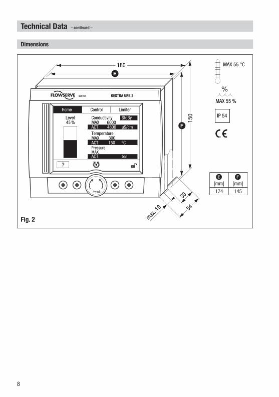
Bus cable, cable length and size
To connect the equipment use the supplied M�2 connecting sockets.Note that screened multi-cored twisted-pair control cable is required as Bus line, e. g. UNITRONIC® BUS CAN 2 x 2 x ...mm² or RE-2YCYV-fl 2 x 2 x ...mm². Control cable assemblies (cable with plug and connector) of various lengths are available as add-on equipment.The cable length dictates the baud rate (data transfer rate) between the bus nodes, and the total power consumption of the sensor dictates the conductor size.
Baud rate Cable lengthNumber of pairs
and conductor size [mm²]
250 kBit/s �25 m 2 x 2 x 0.34
�25 kBit/s 250 m 2 x 2 x 0.5
�00 kBit/s 335 m 2 x 2 x 0.75
50 kBit/s 500 mavailable on demand
(depends on bus configuration) 20 kBit/s �000 m
�0 kBit/s �000 m
Wiring the connecting sockets
Wire the connecting sockets in accordance with the wiring diagram.
Wiring diagram URB 2
UNITRONIC® is a registered trademark of LAPP Kabelwerke GmbH, Stuttgart.
Fig. 5
3 234512 154 Key1 Screen2 Voltage supply
24 V DC+3 Voltage supply
24 V DC–4 CAN data line CH
5 CAN data line CL
6 Terminating resistor �20 Ω
6

�2
Wiring – continued –
Wiring diagram for CAN bus system – example –
Attention
■ Wire equipment in series. Star-type wiring is not permitted!■ Connect screens of the bus cables once to the central earthing point (CEP).■ If two or more system components are connected in a CAN bus system, the first and
the last device must be provided with a terminating resistor of �20 Ω (terminal CL/CH). We recommend that you use the URB 2 with a connecting socket equipped with terminating resistor either as first or as last device.
■ Only one operating and display unit URB 2 may be used per CAN bus network.■ The CAN bus system must not be interrupted during operation.
In the event of an interruption a malfunction alarm is raised.■ The operating and display unit URB 2 must not be applied in parallel with the operating,
display & automatic control device SPECTORcontrol.
Basic Settings
Factory setting
Operating & display unit URB 2The operating and display unit URB 2 unit features the following factory set default values:■ Node ID: 60■ Baud rate: 250 kBit/s (�25 m cable length)
Fig. 6
Connecting socket with terminating resistor �20 Ω
Plug with terminating resistor �20 Ω
Central earthing point
CEP Control unit NRS �-4x NRS 2-40 NRR 2-40 LRR �-40 TRS 5-40
Operating device URB 2
Level electrode Conductivity
electrode NRG x6-4x LRG xx-4x
Temperature transmitter TRV 5-40

�3
Operation
Operator interface
The operating and display unit URB 2 shows parameters, operating conditions and other operating data. The menus can be selected and all inputs can be made by using the four pushbuttons and the navigation wheel.The operator interface of the operating and display unit URB 2 consists of four areas:
Title bar
Display field
Symbol bar
Operating bar
The title bar lists the menus. The selected menu is highlighted by a black background. Due to the limited space of the display not all menus can be shown.
Note
Current alarm indicators are indicated in the title bar. The equipment that raised the alarm is flashing.
The display field changes its appearance according to the indicated menu.The symbol bar shows the available functions of the activated menu. The operating bar consists of four pushbuttons and a navigation wheel. The symbol bar indicates the functions assigned to the pushbuttons and the control of the navigation wheel.
Attention
Do not press several pushbuttons at the same time or when using the navigation wheel. Incorrect data input may occur.To ensure correct entries press the respective pushbutton or use the navigation wheel for one second.
PUSH
Home Control Limiter
GESTRA URB 2

�4
Operation – continued –
Menus
The start window in the display shows all possible indications and readings. Note that the system configuration determines what is actually indicated.
Level controller NRR 2-40, manual operation, level 45 % Conductivity controller LRR�-40, manual operation*) Conductivity controller LRR�-40, stand-by operation*)
Conductivity MAX limit setting 6000 μS/cm Conductivity Actual value setting 4800 μS/cm Temperature MAX limit setting 300°C Temperature Actual value �50°C
*) Both indications at the same time are not possible during operation.
�. To select a menu turn the navigation wheel to the left or right. The selected menu is highlighted in the title bar and the overview display of the menu is indicated.
2. To call up the selected menu press the navigation wheel.
3. To select the value to be set or the equipment in question turn the navigation wheel. The selection will be highlighted.
4. To call up the menu of the parameter or equipment press the navigation wheel. The selected menu will be shown.
5. Only applicable for the menu Control: To get the full listing of all devices repeat items 3 and 4.
■ Press button to quit the currently active menu.
Home Control Limiter
Level45 %
Conductivity StdByMAX 6000ACT. 4800 µS/cm
PressureMAXACT. bar
TemperatureMAX 300ACT. 150 °C
Function
NRG 16-42 - LevelNRG 26-40 - LevelLRG 1x-4x - ConductivityTRV 5-40 - Temperature
Status
ONONONON
Home Control Limiter
Home Control Limiter
Choice
�5
Operation – continued –
Specification of keys and navigation wheel
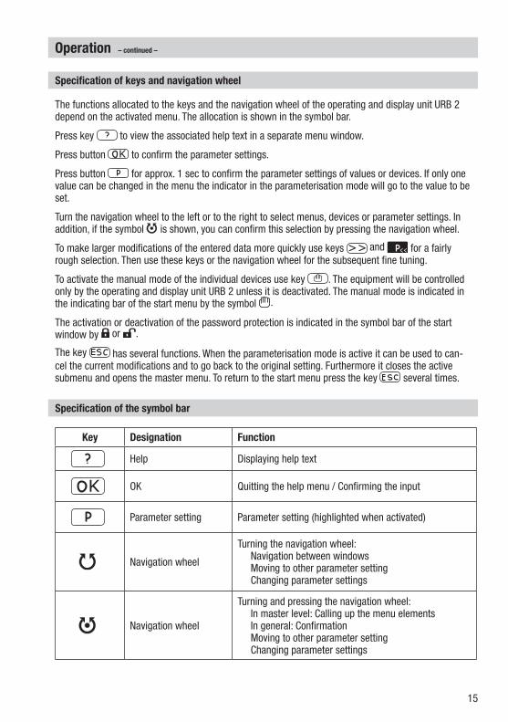
The functions allocated to the keys and the navigation wheel of the operating and display unit URB 2 depend on the activated menu. The allocation is shown in the symbol bar.
Press key to view the associated help text in a separate menu window.
Press button to confirm the parameter settings.
Press button for approx. � sec to confirm the parameter settings of values or devices. If only one value can be changed in the menu the indicator in the parameterisation mode will go to the value to be set.
Turn the navigation wheel to the left or to the right to select menus, devices or parameter settings. In addition, if the symbol is shown, you can confirm this selection by pressing the navigation wheel.
To make larger modifications of the entered data more quickly use keys and for a fairly rough selection. Then use these keys or the navigation wheel for the subsequent fine tuning.
To activate the manual mode of the individual devices use key . The equipment will be controlled only by the operating and display unit URB 2 unless it is deactivated. The manual mode is indicated in the indicating bar of the start menu by the symbol .
The activation or deactivation of the password protection is indicated in the symbol bar of the start window by or .
The key has several functions. When the parameterisation mode is active it can be used to can-cel the current modifications and to go back to the original setting. Furthermore it closes the active submenu and opens the master menu. To return to the start menu press the key several times.
Specification of the symbol bar
Key Designation Function
Help Displaying help text
OK Quitting the help menu / Confirming the input
Parameter setting Parameter setting (highlighted when activated)
Navigation wheel
Turning the navigation wheel: Navigation between windows Moving to other parameter setting Changing parameter settings
Navigation wheel
Turning and pressing the navigation wheel: In master level: Calling up the menu elements In general: Confirmation Moving to other parameter setting Changing parameter settings

�6
Operation – continued –
Specification of the symbol bar – continued –
Key Designation Function
Forward Proportional increase of values
Backward Proportional decrease of values
Manual operation Manual mode (highlighted when activated)
Disabled Password protection is turned OFF
Enabled Password protection is turned ON
Escape Cancel input and quit menu, press the key several times to call up the start window
Menu structure
Home
Limiter
Control
Choice Language System configuration Baud rate Brightness About URB 2 Service menu
Choice NRG 16-42 - Level NRG 26-40 - Level LRG 1x-4x - Conductivity TRV 5-40 - Temperature
Choice Device name
Service – Lock URBService – Unlock URBService – Key check
Control unit Limiter Lx
Choice Device name Overview
Status reportSensitivityMeasuring rangeSwitchpointsSwitching timesControl valveControl param.TemperatureBlowdown valveMIN/BlowdownFig. 7

�7
Menu Start
Start logo
The start logo appears for approx. 2 minutes after restarting the equipment. During this period the parameters of the equipment connected via CAN bus are downloaded.
Device: URB2Version: 311.131.xxDate: July 2005
Operational
Home Control Limiter
Level45 %
Conductivity StdByMAX 6000ACT. 4800µS/cm
PressureMAXACT. bar
TemperatureMAX 300ACT. 150°C
Home Control Limiter
Choice
Language System configurationBaud rateBrightness
About URB 2 Service menu
GESTRA
Home
The start window in the display shows all possible indications and readings. Note that the system configuration determines what is actually indicated.
�. To select the basic settings press the navigation wheel. The selection of the menus will be indicated.
2. To select a menu turn the navigation wheel and then press it to confirm the selection.
■ To choose another language select menu Language.
■ If you want to update the node IDs of the connected equipment or to activate equipment for viewing select the menu System Configuration.
■ To update the baud rate select the menu Baud Rate.
■ To change the properties of the display select the menu Brightness.
■ To view information on the equipment select the menu About URB 2.
■ To disable equipment settings or to carry out the key test select the menu Service menu.

�8
Menu Start – continued –
Language
�. To set the parameter press button . The activated item is highlighted in the symbol bar. The background of the selected item is flashing.
2. To enter a new value turn the navigation wheel and confirm the input by pressing the navigation wheel. The flashing stops.
Language
German
English
old:
new:
Used language
System configuration
Control (2) Limiter Others
NRS 1-40 001 OFFNRS 1-41 006 OFFNRS 1-40.1 001 ON------------- 127 OFF------------- 127 OFF------------- 127 OFF
System configuration
The URB 2 is delivered with GESTRA set default values. Check that the node ID settings of the connected equipment agree with the factory settings (for more information see the installation manuals of the respective devices).
�. Turn the navigation wheel to select the equipment group to be configured.
2. To set the individual parameters press button . The activated item is shown in the symbol
bar.
3. To set the desired parameter turn the navigation wheel and confirm the input by pressing the navigation wheel. The background of the selected item is flashing.
4. To enter a new value turn the navigation wheel and confirm the input by pressing the navigation wheel. The flashing stops.
5. To obtain more available elements repeat items 3 and 4 and press button .
Language
German
English
old:
new:
Used language
System configuration
Control (2) Limiter Others
NRS 1-40 001 OFFNRS 1-41 006 OFFNRS 1-40.1 001 ON------------- 127 OFF------------- 127 OFF------------- 127 OFF

�9
Baud rate
250kBd
125kBd
old:
new:
Used baud rate
Brightness
Background illuminationMIN MAX
Contrast of the screenMIN MAX
Menu Start – continued –
Baud rate
�. Check the baud rate of the connected equipment. If necessary adapt the baud rate of the URB 2 to the baud rate setting of the CAN bus.
2. To set the parameters press button . The activated item is shown in the symbol bar. The background of the selected item is flashing.
3. To enter a new value turn the navigation wheel and confirm the input by pressing the navigation wheel. The flashing stops.
Brightness
�. To set the individual parameters press button . The activated item is shown in the symbol
bar.
2. To set the desired parameter turn the navigation wheel and confirm the input by pressing the navigation wheel. The background of the selected item is flashing.
3. To enter a new value turn the navigation wheel and confirm the input by pressing the navigation wheel. The flashing stops.
4. To obtain more available elements repeat items 2 and 3 and press button .
Note
Make sure that all bus nodes feature the same baud rate settings.If a baud rate setting is incorrect an acoustic signal will be given.

20
About URB 2
Device: URB2Version: 311.131.xxDate: July 2005
Home Control Limiter
Service menu
Lock URB Unlock URB Key check
Service – Lock URB
Lock URB now?(Yes = OK , No = ESC)
UnlockedStatus:
GESTRA
Menu Start – continued –
About URB 2
The menu About URB 2 shows the information on the equipment.
Service menu
■ To disable the functions of the keys select the menu Lock URB.
■ To enable the function of the keys select the menu Unlock URB.
■ To check the functions of the keys select the menu Key check.
Service – Lock URB
�. To disable the equipment press the navigation wheel. The symbol “Equipment disabled” appears in the symbol bar of the start menu.

2�
Menu Start – continued –
Service – Unlock URB
�. To enable the functions of the keys enter your password and press the navigation wheel. The message whether the password is valid or invalid will be indicated. The password is supplied separately.
2. If the password is valid press the navigation wheel to confirm the entry. The symbol “Equipment enabled” appears in the symbol bar of the start menu.
3. If the password is invalid enter the correct password or cancel the operation. To enter the correct password repeat items � and 2. Note that the equipment remains disabled if the operation is cancelled.
Note
After entering three incorrect passwords the equipment will interrupt the input function for 3 minutes.
Service – Unlock URB
Locked 000Status:
00Wrong input:
00 / 03 minutesWaiting time:
–––––Password:
Service – Unlock URB
Locked 000Status:
00Wrong input:
00 / 03 minutesWaiting time:
–––––Password:
Password is valid. Status: Unlocked
Service – Unlock URB
Locked 000Status:
00Wrong input:
00 / 03 MinutenWaiting time:
–––––Password:
Password is invalid! Try again ? (Yes = OK , No = ESC)
Service – Unlock URB
Locked 000Status:
00Wrong input:
00 / 03 minutesWaiting time:
–––––Password:
Service – Unlock URB
Locked 000Status:
00Wrong input:
00 / 03 minutesWaiting time:
–––––Password:
Password is valid. Status: Unlocked
Service – Unlock URB
Locked 000Status:
00Wrong input:
00 / 03 MinutenWaiting time:
–––––Password:
Password is invalid! Try again ? (Yes = OK , No = ESC)

22
Menu Start – continued –
Service – Key check
�. To check the function of the keys press (and hold down for some time) one key after the other. While the key is being pressed down the respective button will be highlighted in the display.
2. When the key is released the display goes back to the previous mode.
3. To check the function of the navigation wheel turn it slowly to the left and to the right. Each time an item is activated (the snapping in place is slightly perceptible) the symbol in the display changes its colour.
4. Press the navigation wheel to go to the start menu and finish the test of the keys.
Service – Key check
Press any key ...
Menu Control
At a glance
TRV 540 TRS 540
NRG 1642 NRS 142
NRG 2640 NRS 240
NRG 2640 NRR 240
LRG 1x4x LRR 140 Page
Status report X X X X X 25
Sensitivity X 26
Switchpoints proportional range Actual-value output 4-20mA
X X
X
X X
27 28 28
Switching times X X X 29
Measuring range X X 26
Control valve X 30
Control param. X 3�
Temperature X 3�
Blowdown valve X 32
MIN/Blowdown X 33

23
Menu Control – continued –
Control
Function
NRG 16-42 - LevelNRG 26-40 - LevelLRG 1x-4x - ConductivityTRV 5-40 - Temperature
Status
ONONONON
Home Control Limiter
Home Control Limiter
Choice
NRG 16-42 - Level NRG 26-40 - Level LRG 1x-4x - Conductivity TRV 5-40 - Temperature
Home Control Limiter
Choice
Device name
The monitored functions together with their configuration status are indicated in the display.
�. To select the controlled variable press the navigation wheel. The selection of the menus will be indicated.
2. To select the desired control function turn the navigation wheel and then press it to confirm the selection.
3. To select the equipment turn the navigation wheel until the desired item is marked and then press the navigation wheel.

24
NRS 2-40
Overview Status report Measuring range
045%1: 080 %
2: 060 %
3: 040 %
4: 020 %
LRR 1-40
Overview Status report Control param.
µS/cm
000%
VOp.: 000 %
MAX: 6000,0W: 5000,0MIN: 4000,0
24h-rinsing
StdBy
NRR 2-40
Overview Status report Measuring range
XP: 020 %X: 045 %W: 050 %XW: -05 %
045%080
020050%
Menu Control – continued –
Overview
Concerning:■ Level control NRG �6-42 and NRS �-42■ Level control NRG 26-40, NRS 2-40 and
NRR 2-40■ Conductivity control LRG �x-4x and LRR �-40 The menu “Overview” shows current para-
meters such as the current readings and the adjusted limits.
Note
When the conductivity control is switched off during stand by operation of the boiler plant an optical signal is shown in the display. The Min/Max limits and the monitoring functions of the equipment remain active.For more information on standby operation (conductivity control) see chapter Glossary page 42.
Only applicable for manual operation:�. To operate the controllers NRR 2-40 and
LRR �-40 manually press the button “Hand”. The activated item is shown in the symbol bar.
2. Turn the navigation wheel to the left or to the right to OPEN or CLOSE the valve. The opening degree of the valve is indicated and the symbol OPEN or CLOSED is flashing.
3. Press the navigation wheel to stop the valve. The flashing of the symbol stops.
4. Press button to open the input window. Here you can choose whether the manual operation can be deactivated and the system can go back to normal operation or whether the manual operation shall be continued. If manual operation is selected the symbol “Hand” is shown in the display.

25
TRS 5-40 - Temperature switch
Overview Control Switchpoints
Channel 1:Alarm:
Channel 2:Control MAX:Control MIN:Alarm:
000 °C000 °C
000 °C000 °C000 °C000 °C
Device name
Overview Status report Measuring range
ON––––––––––––––––––––––––––––––––No errors
Control unitDevice name:SW-version:Status:
ON––––––––––––––––––––––––––––––––No errors
ElectrodeDevice name:SW-version:Status:
Control unitDevice name:SW-version:Status:
Device name
Overview Status report Measuring range
ON––––––––––––––––––––––––––––––––No errorsON––––––––––––––––––––––––––––––––No errorsNo errors
ElectrodeDevice name:SW-version:Channel 1:Channel 2:
Menu Control – continued –
Overview – continued –
Concerning:■ Temperature control TRV 5-40 and TRS 5-40
Status report
Concerning:■ Level control NRG �6-42 and NRS �-42■ Level control NRG 26-40, NRS 2-40 and
NRR 2-40■ Conductivity control LRG �x-4x and LRR �-40■ Temperature control TRV 5-40 and TRS 5-40
The menu “Status Report” shows the current parameters of the equipment.
Note
For a list of all status messages for the equipment refer to chapter Status messages Control unit (see page 39).
26
Device name
Status report Sensitivity Switching times
Sensitivity
0.5 µS/cm 10 µS/cm
Device name
Status report Measuring range Switchpoints
Calibration100 %
** %
0 %
Menu Control – continued –
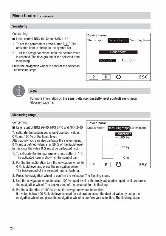
Sensitivity
Concerning:■ Level control NRG �6-42 and NRS �-42�. To set the parameters press button . The
activated item is shown in the symbol bar.2. Turn the navigation wheel until the desired value
is reached. The background of the selected item is flashing.
Press the navigation wheel to confirm the selection. The flashing stops.
Note
For more information on the sensitivity (conductivity level control) see chapter Glossary page 42.
Measuring range
Concerning:■ Level control NRG 26-40, NRS 2-40 and NRR 2-40To calibrate the system you should use both values 0 % and �00 % of the liquid level. Alternatively you can also calibrate the system using 0 % and a defined value, e. g. 50 % of the liquid level. In this case the value 0 % must be calibrated first.�. To calibrate the first parameter press button .
The activated item is shown in the symbol bar.2. For the first calibration turn the navigation wheel to
0 % liquid level and press the navigation wheel. The background of the selected item is flashing.
3. Press the navigation wheel to confirm the selection. The flashing stops.4. Use the navigation wheel to select �00 % liquid level or the freely adjustable liquid level and press
the navigation wheel. The background of the selected item is flashing.5. For the calibration of �00 % press the navigation wheel to confirm.
If a value below �00 % liquid level is used for calibration select the desired value by using the navigation wheel and press the navigation wheel to confirm your selection. The flashing stops.

27
Device name
Measuring range Switchpoints Switching times
045%1: 080 %
2: 060 %
3: 040 %
4: 020 %
Device name
Status report Switchpoints Output 4-20mA
Channel 1:Alarm:
Channel 2:Control MAX:Control MIN:Alarm:
ON000 °C
ON000 °C000 °C000 °C
Menu Control – continued –
Switchpoints
Concerning:■ Level control NRG 26-40 and NRS 2-40
Concerning:■ Temperature control TRV 5-40 and TRS 5-40�. To set the individual parameters press button
. The activated item is shown in the symbol bar.
2. To set the desired parameter turn the navigation wheel and confirm the input by pressing the navigation wheel. The background of the selected item is flashing.
3. To enter a new value turn the navigation wheel and confirm the input by pressing the navigation wheel. The flashing stops.
4. To obtain more available elements repeat items 2 and 3 and press button .
Note
The adjustment range of the respective switchpoint is limited by the switchpoints above or below it as well as the 0 % and �00 % (level) values or 0°C and 650°C (temperature).

28
Menu Control – continued –
Switchpoints, proportional range
Note
The adjustment range of the respective switchpoint is limited by the switchpoints above and below it as well as 0 % and �00 %.For more information on the proportional range Xp (capacitance level control) see chapter Glossary page 42.
Concerning:■ Level control NRG 26-40 and NRR 2-40�. To set the individual parameters press button
. The activated item is shown in the symbol bar.
2. To set the desired parameter turn the navigation wheel and confirm the input by pressing the navigation wheel. The background of the selected item is flashing.
3. To enter a new value turn the navigation wheel and confirm the input by pressing the navigation wheel. The flashing stops.
4. To obtain more available elements repeat items 2 and 3 and press button .
Switchpoints, output 420 mA
Note
The adjustment range of the respective switchpoint is limited by the switchpoints above and below it as well as 0°C and 650°C.
Concerning:■ Temperature control TRV 5-40 and TRS 5-40�. To set the individual parameters press button
. The activated item is shown in the symbol bar.
2. To set the desired parameter turn the navigation wheel and confirm the input by pressing the navigation wheel. The background of the selected item is flashing.
3. To enter a new value turn the navigation wheel and confirm the input by pressing the navigation wheel. The flashing stops.
4. To obtain more available elements repeat items 2 and 3 and press button .
Device name
Measuring range Switchpoints Switching times
045%1: 080 %2: 060 %
W:050% XP:020%
3: 040 %4: 020 %
Device name
Status report Switchpoints Output 4-20mA
Channel 1:Temperature 4mA:Temperature 20mA:
000 °C000 °C
Channel 2:Temperature 4mA:Temperature 20mA:
000 °C000 °C
Device name
Measuring range Switchpoints Switching times
045%1: 080 %2: 060 %
W:050% XP:020%
3: 040 %4: 020 %
Device name
Status report Switchpoints Output 4-20mA
Channel 1:Temperature 4mA:Temperature 20mA:
000 °C000 °C
Channel 2:Temperature 4mA:Temperature 20mA:
000 °C000 °C

29
Menu Control – continued –
Switching times
Note
For more information on energising and deenergising times (conductivity and capacitance level control) see chapter Glossary, page 42.
Concerning:■ Level control NRG �6-42 and NRS �-42■ Level control NRG 26-40, NRS 2-40 and
NRR 2-40�. To set the individual parameters press button
. The activated item is shown in the symbol bar.
2. To set the desired parameter turn the navigation wheel and confirm the input by pressing the navigation wheel. The background of the selected item is flashing.
3. To enter a new value turn the navigation wheel and confirm the input by pressing the navigation wheel. The flashing stops.
4. To obtain more available elements repeat items 2 and 3 and press button .
Device name
Status report Sensitivity Switching times
045%
03,0 s00,0 s00,0 s03,0 s
Relay0->1
00,0 s00,0 s00,0 s00,0 s
1->0

30
Menu Control – continued –
Control valve
Note
For more information on the CANopen actuator see chapter Glossary page 42.
Concerning:■ Level control NRG 26-40 and NRR 2-40 �. To set the individual parameters press button
. The activated item is shown in the symbol bar.
2. To select the CANopen actuator turn the naviga-tion wheel and confirm the input by pressing the navigation wheel. The background of the selec-ted item is flashing.
3. Turn the navigation wheel to select YES if the control valve is fitted with a CANopen actuator or NO if it is equipped with another type of actuator.
4. Press the navigation wheel. The flashing stops. 5. To calibrate the control valve turn the navigation wheel to the first value to be adjusted. 6. Press the navigation wheel. The background of the selected item is flashing. 7. Turn the navigation wheel to the left or to the right. The valve closes or opens. 8. Press the navigation wheel for approx. � sec. to stop the valve. The position of the valve is shown
in the display. 9. If necessary correct the valve position by turning the navigation wheel.�0. Once the desired position of the valve has been established press button to calibrate the
equipment. The value is accepted and the flashing stops.��. For the second calibration repeat items 5 to �0 and finish the input by pressing button .�2. After the calibration procedure the current position of the control valve will be indicated in the
display.
Device name
Switchpoints Control valve Switching times
020%
0% 100%
CANopen actuator: NO

3�
Menu Control – continued –
Control param.
Note
For more information on continuous boiler blowdown, measuring range (conductivity control), proportional range Xp (conductivity control) and switching hysteresis Hyst (conductivity control) see chapter Glossary page 42.
Concerning:■ Conductivity control LRG �x-4x and LRR �-40�. To set the individual parameters press button
. The activated item is shown in the symbol bar.
2. To set the desired parameter turn the navigation wheel and confirm the input by pressing the navigation wheel. The background of the selected item is flashing.
3. Turn the navigation wheel until the new value is reached. Alternatively you can use the button
to increase the value proportionally or use button to decrease the value.
Press the navigation wheel to confirm the selection. The flashing stops.4. To obtain more available elements repeat items 2 and 3 and press button .
Temperature
Note
For more information on temperature compensation (conductivity control), TK (Linear), TK (Norm), TK (Auto) and cell constant (conductivity control) see chapter Glossary page 42.
Concerning:■ Conductivity control LRG �x-4x and LRR �-40�. To set the individual parameters press button .
The activated item is shown in the symbol bar.2. To set the desired parameter turn the navigation
wheel and confirm the input by pressing the navigation wheel. The background of the selected item is flashing.
3. To enter a new value turn the navigation wheel and confirm the input by pressing the navigation wheel. The flashing stops.
4. To obtain more available elements repeat items 2 and 3 and press button .
Device name
Status report Control param. Temperature
µS/cm0,5 – 6000 µS/cm
Unit:Range:
6000,0 µS/cm0000,0 µS/cm0000,0 µS/cm
MAX:W:MIN:
000 %000 %
Xp:Hyst:
Device name
Control param. Temperature Blowdown valve
OFF
0,0 %/°CNaOH+H20 260µSStop
000,0 °C0,000
Compensation
TK [LINEAR]:TK [NORM]:TK [AUTO]:
Temperature:Cell constant:
Device name
Status report Control param. Temperature
µS/cm0,5 – 6000 µS/cm
Unit:Range:
6000,0 µS/cm0000,0 µS/cm0000,0 µS/cm
MAX:W:MIN:
000 %000 %
Xp:Hyst:
Device name
Control param. Temperature Blowdown valve
OFF
0,0 %/°CNaOH+H20 260µSStop
000,0 °C0,000
Compensation
TK [LINEAR]:TK [NORM]:TK [AUTO]:
Temperature:Cell constant:

32
Menu Control – continued –
Blowdown valve
Note
For more information on the operating position of the continuous blowdown valve, 24hours purging pulse (conductivity control) and CANopen actuator see chapter Glossary page 42.
Concerning:■ Conductivity control LRG �x-4x and LRR �-40 �. To set the individual parameters press button
. The activated item is shown in the symbol bar.
2. To select the CANopen actuator turn the navigation wheel and confirm the input by pressing the navigation wheel. The background of the selected item is flashing.
3. Turn the navigation wheel to select YES if the continuous blowdown valve is fitted with a CANopen actuator or NO if it is equipped with another type of actuator.
4. Press the navigation wheel. The flashing stops. 5. To calibrate the continuous blowdown valve turn the navigation wheel to the first value to be
adjusted. 6. Press the navigation wheel. The background of the selected item is flashing. 7. Turn the navigation wheel to the left or to the right. The valve closes or opens. 8. Press the navigation wheel to stop the valve. The position of the valve is shown in the display. 9. If necessary correct the valve position by turning the navigation wheel.�0. Once the desired position of the valve has been established press button to calibrate the
equipment. The value is accepted and the flashing stops.��. For the second calibration repeat items 5 to �0 and finish the input by pressing button .�2. After the calibration procedure the current position of the continuous blowdown valve will be
indicated in the display.�3. To set further parameters press button . The activated item is highlighted in the symbol bar.�4. To set the desired parameter turn the navigation wheel and confirm the input by pressing the
navigation wheel. The background of the selected item is flashing.�5. To enter a new value turn the navigation wheel and confirm the selection by pressing the
navigation wheel. The flashing stops.�6. To obtain more available elements repeat items �3 to �5 and press button .
Device name
Temperature Blowdown valveMIN/Blowdown
020%
0% 100%
Operating position: 000 %24h-rinsing: OFFCANopen actuator: NO
33
Menu Control – continued –
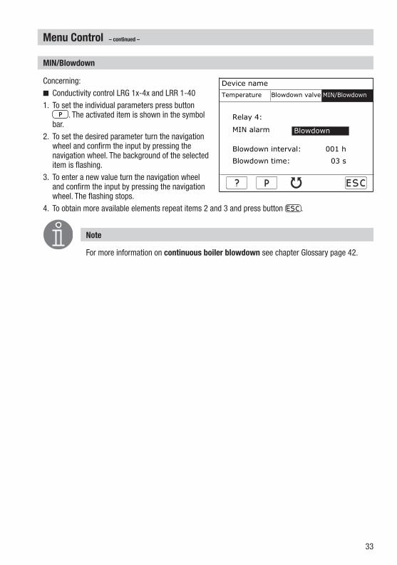
MIN/Blowdown
Note
For more information on continuous boiler blowdown see chapter Glossary page 42.
Concerning:■ Conductivity control LRG �x-4x and LRR �-40�. To set the individual parameters press button
. The activated item is shown in the symbol bar.
2. To set the desired parameter turn the navigation wheel and confirm the input by pressing the navigation wheel. The background of the selected item is flashing.
3. To enter a new value turn the navigation wheel and confirm the input by pressing the navigation wheel. The flashing stops.
4. To obtain more available elements repeat items 2 and 3 and press button .
Device name
Temperature Blowdown valve MIN/Blowdown
Relay 4:
MIN alarm
Blowdown interval: 001 h
Blowdown time: 03 s
Blowdown
34
Menu Limiter
Limiter
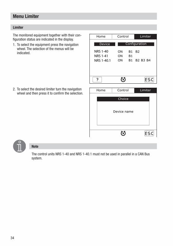
Note
The control units NRS �-40 and NRS �-40.� must not be used in parallel in a CAN Bus system.
The monitored equipment together with their con-figuration status are indicated in the display.�. To select the equipment press the navigation
wheel. The selection of the menus will be indicated.
2. To select the desired limiter turn the navigation wheel and then press it to confirm the selection.
Home Control Limiter
Configuration
ON B1 B2ON B1ON B1 B2 B3 B4
Device
NRS 1-40NRS 1-41NRS 1-40.1
Home Control Limiter
Choice
Device name
35
Menu Limiter – continued –
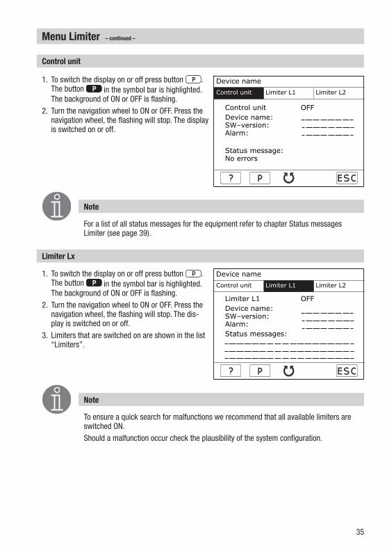
Control unit
Note
For a list of all status messages for the equipment refer to chapter Status messages Limiter (see page 39).
�. To switch the display on or off press button . The button in the symbol bar is highlighted. The background of ON or OFF is flashing.
2. Turn the navigation wheel to ON or OFF. Press the navigation wheel, the flashing will stop. The display is switched on or off.
Limiter Lx
Note
To ensure a quick search for malfunctions we recommend that all available limiters are switched ON.Should a malfunction occur check the plausibility of the system configuration.
�. To switch the display on or off press button . The button in the symbol bar is highlighted. The background of ON or OFF is flashing.
2. Turn the navigation wheel to ON or OFF. Press the navigation wheel, the flashing will stop. The dis-play is switched on or off.
3. Limiters that are switched on are shown in the list “Limiters”.
Device name
Control unit Limiter L1 Limiter L2
Control unit OFFDevice name:SW–version:Alarm:
Status message:No errors
Device name
Control unit Limiter L1 Limiter L2
Limiter L1 OFFDevice name:SW–version:Alarm:Status messages:
Device name
Control unit Limiter L1 Limiter L2
Control unit OFFDevice name:SW–version:Alarm:
Status message:No errors
Device name
Control unit Limiter L1 Limiter L2
Limiter L1 OFFDevice name:SW–version:Alarm:Status messages:

36
Malfunctions
Causes
Note
Before carrying out the systematic fault finding procedure please check:Wiring: Is the wiring in accordance with the wiring diagram? Is the polarity of the bus line always correct? Is the bus line of each of the end nodes provided with a �20 Ω resistor?Node ID: Are the node IDs set correctly? Note that a node ID must only be used for one item of equipment!Baud rate: Is the length of the cable in accordance with the adjusted baud rate? (The URB 2 gives an acoustic signal if the baud rate setting is incorrect.) Is the baud rate the same for all devices?
Malfunctions occur if CAN bus components have been mounted or configured incorrectly or if electronic component parts are defective, or in the event of excessive heat in the equipment or electrical interference in the supply system.Further malfunctions are:■ Faulty communication within the CAN-Bus system■ Overloading of the 24 V power supply unit in the controller
Attention
For more information on system malfunctions refer to the installation manuals of the connected equipment.

37
Systematic fault finding procedure for system malfunctions
The sources of malfunctions occurring in CAN bus systems operating with several bus-based stations must be analysed systematically since faulty components or incorrect settings can give rise to negative interactions with intact bus devices in the CAN bus system. These unwanted interactions can cause error messages in fully functional bus devices, which will make fault detection even more difficult.We recommend the following systematic fault finding procedure:
Malfunctions – continued –
Step 1 (Start)Detach terminal strips in all Bus sensors.
Level electrodeConductivity electrodePressure sensorTemperature sensoretc.
Step 3Apply mains voltage to bus devices of the system e. g. NRS ...and NRG ...
Step 2Plug in terminal strip of the sensor of the system e. g. NRS ...and NRG ... (electrodes)
System O.K.Detach terminal strips between bus devices of the system e. g. NRS ...and NRG ...
System FaultUse fault-finding list to identify the fault(s)!
Cut off power supply to the equipment!
CheckUse fault-finding list to identify the fault(s)!
Final test Have all faults been eliminated?
Check next system

38
Malfunctions – continued –
Restart
Note
All values indicated by the URB 2 will be updated within 2 minutes.
�. Press the navigation wheel to restart the system.2. After the restart the start window will be dis-
played.
Attention
If it is not possible to restart the system automatically interrupt the voltage supply (unplug the connecting socket). After approx. 5 minutes re-commission the URB 2 in accordance with the installation instructions.
Device: URB2Version: 311.131.xxDate: August 2005
Operational
START

39
Malfunctions – continued –
Status messages
Note
The system message “T MAX exceeded” is given when the ambient temperature is excessively high. Note that the temperature of the boiler is not monitored.
If faults occur that are not listed above or cannot be corrected, please contact our service centre or authorized agency in your country.
Control unit TRV 540
TRS 540
NRS 142
NRG 1642
NRS 240
NRR 240
NRG 2640
LRR 140
LRG 1x4x
No communication X X X X X X X X X
Collective bit channel �and 2 X
T MAX exceeded X X X X X X X X X
Plausibility error X X
Electrode lost X X X X
Electrode defective X
PT �000 defective X
Sensor defective X
A/D converter X
Limiter TRV 540
NRS 14x
NRG 1x4x
Faulty communication X
No communication X X X
Collective bit, self-checking routine
X X X
T MAX exceeded X X

40
Annex
CAN bus
All devices (level, conductivity, temperature) are interconnected via CAN bus. The CANopen protocol is used for the data exchange between the equipment groups. All devices have an electronic address – the node ID. The four-core bus cable serves as power supply and data highway for high-speed data exchange.The CAN address (nodeID) can be set between � and �23.The operating and display unit URB 2 has already been configured at our works for operation with other GESTRA components and can be used straight away without having to set the node ID.
Decommissioning
First cut off power supply to the operating and visual display unit URB 2 and then remove the connecting socket. De-install the operating and display unit.
Factory set node IDs
Individual node IDs must be set manually in the respective equipment. Please observe the pertinent installation instructions.
Disposal
Dismantle the operating and display unit and separate the waste materials, using the specifications in the table “Materials” as a reference. Electronic component parts such as the circuit board must be disposed of separately! For the disposal of the control unit observe the pertinent legal regulations concerning waste disposal.
Control Units SensorsURB 2 ID:060NRS 140 ID:001NRS 141 ID:006NRS 141.1 ID:001NRS 142 ID:020NRS 240 ID:039NRR 240 ID:040LRR 140 ID:050
NRG 1x40 ID:002NRG 1x41.1 ID:004TRV 540 ID:005NRG 1642 ID:021NRG 2640 ID:041LRG 1x40 ID:051

4�
Declaration of Conformity
Annex – continued –
We hereby declare that the operating and display unit URB 2 conforms to the following European guidelines:■ LV guideline 73/23/eec version 93/68/eec■ EMC guideline 89/336/eec version 93/68/eecThis declaration is no longer valid if modifications are made to the equipment without consultation with us.
Bremen, �st July 2005GESTRA AG
Dipl.-Ing. Lars BohlQuality Assurance Representative
Dipl.-Ing. Uwe BledschunHead of Design Dept.

42
Glossary
Continuous boiler blowdown (“top blowdown”): As the boiler water evaporates, the concentration of non-volatile dissolved solids (TDS) left behind in the boiler increases over time as a function of steam consumption. If the TDS (= total dissolved solids) concentration exceeds the limit defined by the boiler manufacturer, foaming and priming occurs as the density of the boiler water increases, resulting in a carry-over of solids with vapor into steam lines and superheaters. As a consequence, the operational safety is impaired and severe damage to boiler and tubes may occur. To keep the TDS concentration within admissible limits, a certain portion of boiler water must be removed continuously or periodically (by means of a blowdown valve) and fresh make-up water must be added to the boiler feed to compensate for the water lost through blowdown.Intermittent boiler blowdown (“bottom blowdown”): During the evaporation process fine sludge deposits settle on heating surfaces and in the lowest part of the steam boiler. The accumulated sludge sediments form a thermally insulating layer and can damage the boiler walls due to excessive heat. To perform a bottom blowdown the intermittent blowdown valve must be opened abruptly. The resulting suction effect occurs only at the moment when the valve is being opened, the opening time should therefore not exceed 2 seconds. Longer blowdown periods will merely waste boiler water. The timed pulse/interval control of the intermittent blowdown valve optimises sludge removal while minimising loss of boiler water.Sensitivity (conductivity level control): The level electrode NRG �6-42 works only when used in water with a minimum electrical conductivity. If the electrical conductivity of the boiler water is < �0 μS/cm at 75°C set the sensitivity to 0.5 μS/cm.Operating position of the continuous blowdown valve: It is common pratice to use the continuous blowdown valve to remove water from the boiler in order to keep the TDS level within certain predefined limits. This means that the valve must be permanently open so that a steady flow of water is ensured (the valve is in the operating position). The operating position is adjustable between 0 and 25 %. For the corresponding amount of boiler blowdown refer to the capacity charts of the continuous blowdown valve.CANopen actuator: The control valve is equipped with a CANopen actuator. For more information see installation manual URZ 40.Measuring range (conductivity control): The measuring range setting establishes the actual value output 4-20 mA of the control equipment LRR �-40.Proportional band Xp (conductivity control): If the controller is to work as a proportional controller, the proportional band can be set between � and �50 %. It refers to the adjusted setpoint w. If Xp = 0 is set, the controller is configured as two-position controller.Proportional band Xp (capacitance level control): Switchpoint 2 marks the upper limit and switchpoint 3 the lower limit of the proportional band. The difference between switchpoint 2 and switchpoint 3 gives the magnitude of the proportional range Xp.Switching hysteresis Hyst (conductivity control): If Xp = 0 is set, the controller is configured as 2-position controller, which means that the valve will open if there is a positive deviation (X > w). The conductivity must then decrease until a new value that is lower than the setpoint minus the adjusted hysteresis is reached. Once this value is reached the valve will be motored into the operating position.
43
Glossary – continued –
Energizing times (conductivity and capacitance level control): For each of the four output relays individual time delays for energizing and de-energizing can be set.Standby mode (conductivity control): To avoid loss of water, the continuous blowdown control and the programme-controlled intermittent boiler blowdown (if activated) can be de-activated during stand-by operation or when the burner is switched off. An external control command will be triggered and as a result the continuous blowdown valve will be closed. During stand-by operation the MIN/MAX limits and the monitoring function remain active. Once returned to normal operation the continuous blowdown valve is motored into the OPERATING position or the control position. In addition an intermittent blowdown pulse is triggered off (provided that automatic intermittent boiler blowdown has been activated and an interval period and pulse duration has been set).Temperature compensation (conductivity control): The electrical conductivity changes as the temperature falls or rises. To obtain meaningful readings it is therefore necessary that the measurements are based on the reference temperature of 25°C and that the measured conductivity values are corrected by the temperature coefficient factor α (Tk). For automatic temperature compensation the following three settings are available: TK Linear, TK Norm or TK Auto.TK (Linear): To ensure that the readings are based on 25°C set the TK value between 0 and 5.0 %/°C (default setting 2.� %/°C). This setting permits the linear temperature compensation of the measured value over the whole measuring range. This method is usually applied for steam boilers operating at constant service pressure. After the TK is set and the service pressure is reached use a calibrated conductivity meter to measure the conductivity of the boiler water and compare the reading with the indicated conductivity value. If the reading differs from the indicated conductivity change the TK setting until they tally.TK (Norm): Since conductivity is not a linear function of temperature over a larger temperature range, various conditioning agents and different basic conductivities were used in order to ascertain empirical conductivity/temperature curves. These curves are stored as standard curves and can be used for temperature compensation. TK (NORM) is suitable for boilers operating with variable pressure, which means that the boiler does not have a fixed working pressure (e. g. low load �0 bar, full load �5 bar).TK (Auto): For this method a characteristic conductivity-/ temperature curve of the plant (Auto curve) is used for temperature compensation. However, first a characteristic Auto curve must be recorded. For this purpose turn the navigation wheel at TK (AUTO) to start and then press the navigation wheel in order to start recording the curve. Apply the max. service pressure to the steam boiler. During heating up every �0°C above �00°C temperature and conductivity values are recorded and the current temperature is indicated. After having recorded 25 values or if STOP is selected the equipment stops recording and saves the Auto curve. TK (AUTO) is suitable for steam boilers operating with variable pressures. When the compensation is switched OFF the absolute conductivity will be indicated.

44
Glossary – continued –
Cell constant (conductivity control): The cell constant is a geometric quantity characteristic of the level electrode and is taken into account when calculating the conductivity. However, in the course of time this constant may chance, e. g. due to dirt deposits accumulated on the measuring electrode. If a reference measurement yields a result that differs from the indicated conductivity value check the temperature compensation first. Only if the temperature coefficient setting is no longer sufficient for a correct compensation should you modify the cell constant. In this case change the cell constant until the reading and the indicated conductivity agree.24hour purging pulse (conductivity control): To prevent blocking of the continuous blowdown valve a purging pulse is triggered when the mains voltage is switched on. The continuous blowdown valve is actuated and opens for 2 minutes. After this period the valve is motored into the CLOSED position where it remains for 2 minutes. Then the valve is motored into the OPERATING position or into the required control position. This process is repeated every 24 hours. During stand-by operation the time interval continues without triggering off the purging pulse. Note that during the purging process the MIN limit is not active. The 24 hour purging pulse can be switched ON or OFF.

45
For your notes

46
For your notes

47
For your notes

488�860�-00/806cm · 2005 GESTRA AG · Bremen · Printed in Germany
Great Britain
Flowserve Flow Control (UK) Ltd.Burrel Road, Haywards HeathWest Sussex RH �6 �TLTel. 00 44 �4 44 / 3� 44 00Fax 00 44 �4 44 / 3� 45 57E-mail: [email protected]
Italia
Flowserve S.p.A.Flow Control DivisionVia Prealpi, 30l-20032 Cormano (MI)Tel. 00 39 02 / 66 32 5�Fax 00 39 02 / 66 32 55 60E-mail: [email protected]
GESTRA ESPAÑOLA S.A.Luis Cabrera, 86-88E-28002 MadridTel. 00 34 9� / 5 �5 20 32Fax 00 34 9� / 4 �3 67 47; 5 �5 20 36E-mail: [email protected]
España
Flowserve GESTRA U.S.234� Ampere DriveLouisville, KY 40299Tel.: 00 �5 02 / 502 267 2205Fax: 00 �5 02 / 502 266 5397E-mail: [email protected]
USA
Portugal
Flowserve Portuguesa, Lda.Av. Dr. Antunes Guimarães, ��59Porto 4�00-082Tel. 0 03 5� 22 / 6 �9 87 70Fax 0 03 5� 22 / 6 �0 75 75E-mail: [email protected]
Polska
GESTRA POLONIA Spolka z.o.o.Ul. Schuberta �04PL - 80-�72 GdanskTel. 00 48 58 / 3 06 �0 -02 od �0Fax 00 48 58 / 3 06 33 00E-mail: [email protected]
Agencies all over the world:
www.gestra.de
GESTRA AGP. O. Box �0 54 60, D-28054 Bremen Münchener Str. 77, D-282�5 BremenTelephone +49 (0) 42� 35 03 - 0 Fax +49 (0) 42� 35 03 - 393E-Mail [email protected] Internet www.gestra.de
GESTRA
Related Documents