TRS 5-50 Installation & Operating Instructions 819226-03 Temperature Switch TRS 5-50 GESTRA Steam Systems GESTRA EN English

Welcome message from author
This document is posted to help you gain knowledge. Please leave a comment to let me know what you think about it! Share it to your friends and learn new things together.
Transcript
1
TRS 5-50 Installation & Operating Instructions 819226-03Temperature Switch TRS 5-50
GESTRA Steam Systems
GESTRA
ENEnglish
2
ContentsPage
Important notes
Usage for the intended purpose ...............................................................................................................4Function ..................................................................................................................................................4Safety note ..............................................................................................................................................5
Directives and standards
EC Pressure Equipment Directive 97/23/EC .............................................................................................5Functional Safety acc. to IEC 61508 ........................................................................................................5DIN EN 14597 .........................................................................................................................................5Approvals for Marine Applications ...........................................................................................................5LV (Low Voltage) Directive and EMC (Electromagnetic Compatibility) ........................................................6ATEX (Atmosphère Explosible) .................................................................................................................6UL / cUL (CSA) Approval ..........................................................................................................................6Note on the Declaration of Conformity / Declaration by the Manufacturer ..........................................6
Functional Safety acc. to IEC 61508
Safety characteristics of the subsystem TRG 5-6.. / TRS 5-50 .................................................................7Terms and abbreviations .........................................................................................................................7Determination of the Safety Integrity Level (SIL) for safety-related systems .............................................8
Technical data
TRS 5-50 ................................................................................................................................................9Name plate / marking ...........................................................................................................................10
In control cabinet: Mounting temperature switch
Dimensions TRS 5-50 ...........................................................................................................................11Key .......................................................................................................................................................11Installation in control cabinet .................................................................................................................11Scope of supply ....................................................................................................................................11
In control cabinet: Wiring temperature switch
Wiring diagram for temperature switch TRS 5-50 ..................................................................................12Key .......................................................................................................................................................12Connection of supply voltage .................................................................................................................13Connection of safety circuit ...................................................................................................................13Equipment used as safety temperature monitor .....................................................................................13Equipment used as safety temperature limiter, connection of reset/test input ........................................13Connecting the temperature sensor .......................................................................................................13Connection for actual-value output (optional) .........................................................................................14

3
Contents - continued -
Page
In the plant: Wiring temperature sensor
Connection for temperature sensor .......................................................................................................15Wiring diagram for temperature sensor .................................................................................................15
Factory setting ....................................................................................................................................16
Changing factory settings
Changing the configuration ...................................................................................................................16
Commissioning procedure
Start and adjustment of MAX limit .........................................................................................................17
Operation, alarm and test
Indicators and adjustors ........................................................................................................................18
Troubleshooting
Indication, diagnosis and remedy ..........................................................................................................19Measure fluid temperature ....................................................................................................................20
Check installation and performance
Checking switch-off function at TMAX .....................................................................................................20
Further Notes
Action against high frequency interference ............................................................................................21Decommissioning / replacing the equipment .........................................................................................21Disposal ................................................................................................................................................21
4
Important notes
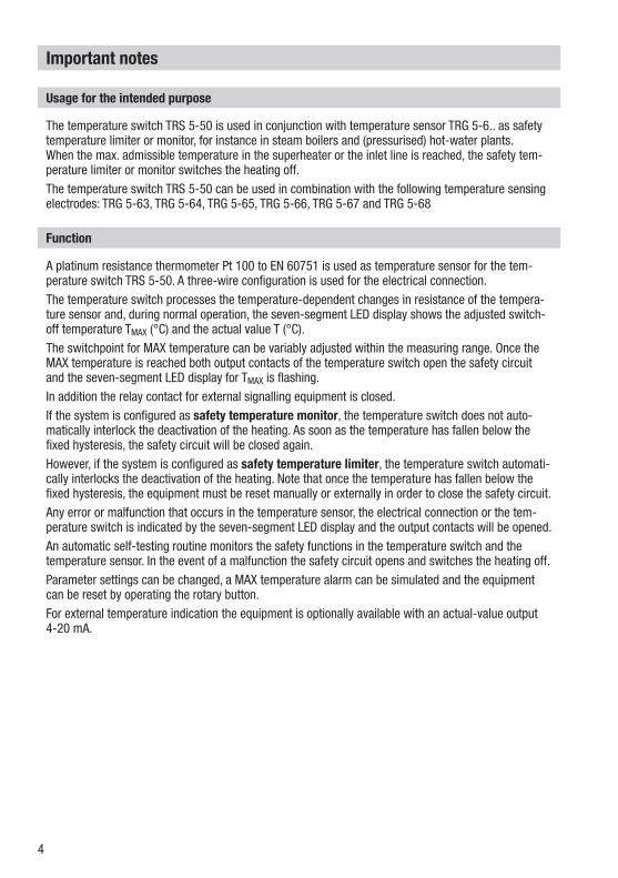
Usage for the intended purpose
The temperature switch TRS 5-50 is used in conjunction with temperature sensor TRG 5-6.. as safety temperature limiter or monitor, for instance in steam boilers and (pressurised) hot-water plants. When the max. admissible temperature in the superheater or the inlet line is reached, the safety tem-perature limiter or monitor switches the heating off. The temperature switch TRS 5-50 can be used in combination with the following temperature sensing electrodes: TRG 5-63, TRG 5-64, TRG 5-65, TRG 5-66, TRG 5-67 and TRG 5-68
Function
A platinum resistance thermometer Pt 100 to EN 60751 is used as temperature sensor for the tem-perature switch TRS 5-50. A three-wire configuration is used for the electrical connection. The temperature switch processes the temperature-dependent changes in resistance of the tempera-ture sensor and, during normal operation, the seven-segment LED display shows the adjusted switch-off temperature TMAX (°C) and the actual value T (°C). The switchpoint for MAX temperature can be variably adjusted within the measuring range. Once the MAX temperature is reached both output contacts of the temperature switch open the safety circuit and the seven-segment LED display for TMAX is flashing. In addition the relay contact for external signalling equipment is closed.If the system is configured as safety temperature monitor, the temperature switch does not auto-matically interlock the deactivation of the heating. As soon as the temperature has fallen below the fixed hysteresis, the safety circuit will be closed again.However, if the system is configured as safety temperature limiter, the temperature switch automati-cally interlocks the deactivation of the heating. Note that once the temperature has fallen below the fixed hysteresis, the equipment must be reset manually or externally in order to close the safety circuit.Any error or malfunction that occurs in the temperature sensor, the electrical connection or the tem-perature switch is indicated by the seven-segment LED display and the output contacts will be opened.An automatic self-testing routine monitors the safety functions in the temperature switch and the temperature sensor. In the event of a malfunction the safety circuit opens and switches the heating off.Parameter settings can be changed, a MAX temperature alarm can be simulated and the equipment can be reset by operating the rotary button.For external temperature indication the equipment is optionally available with an actual-value output 4-20 mA.
5
Directives and standards
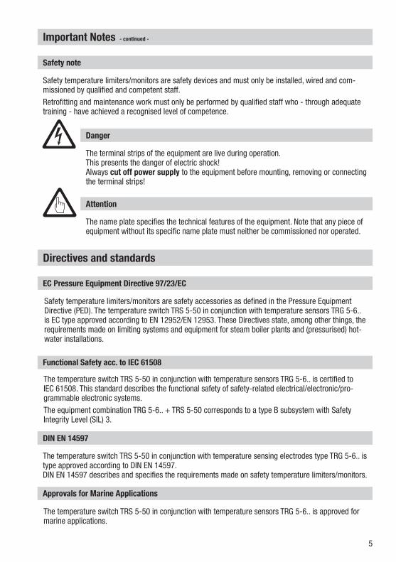
EC Pressure Equipment Directive 97/23/EC
Safety temperature limiters/monitors are safety accessories as defined in the Pressure Equipment Directive (PED). The temperature switch TRS 5-50 in conjunction with temperature sensors TRG 5-6.. is EC type approved according to EN 12952/EN 12953. These Directives state, among other things, the requirements made on limiting systems and equipment for steam boiler plants and (pressurised) hot-water installations.
Functional Safety acc. to IEC 61508
The temperature switch TRS 5-50 in conjunction with temperature sensors TRG 5-6.. is certified to IEC 61508. This standard describes the functional safety of safety-related electrical/electronic/pro-grammable electronic systems.The equipment combination TRG 5-6.. + TRS 5-50 corresponds to a type B subsystem with Safety Integrity Level (SIL) 3.
DIN EN 14597
The temperature switch TRS 5-50 in conjunction with temperature sensing electrodes type TRG 5-6.. is type approved according to DIN EN 14597. DIN EN 14597 describes and specifies the requirements made on safety temperature limiters/monitors.
Approvals for Marine Applications
The temperature switch TRS 5-50 in conjunction with temperature sensors TRG 5-6.. is approved for marine applications.
Safety note
Safety temperature limiters/monitors are safety devices and must only be installed, wired and com-missioned by qualified and competent staff.Retrofitting and maintenance work must only be performed by qualified staff who - through adequate training - have achieved a recognised level of competence.
Danger
The terminal strips of the equipment are live during operation.This presents the danger of electric shock!Always cut off power supply to the equipment before mounting, removing or connecting the terminal strips!
Attention
The name plate specifies the technical features of the equipment. Note that any piece of equipment without its specific name plate must neither be commissioned nor operated.
Important Notes - continued -

6
Directives and Standards - continued -
ATEX (Atmosphère Explosible)
According to the European Directive 94/9/EC the temperature switch TRS 5-50 must not be used in potentially explosive areas.
LV (Low Voltage) Directive and EMC (Electromagnetic Compatibility)
The temperature switch TRS 5-50 meets the requirements of the Low Voltage Directive 2006/95/EC and the EMC Directive 2004/108/EC.
Note on the Declaration of Conformity / Declaration by the Manufacturer
For details on the conformity of our equipment according to the European Directives see our Declaration of Conformity or our Declaration of Manufacturer.The current Declaration of Conformity / Declaration of Manufacturer are available in the Internet under www.gestra.com/documents or can be requested from us.
UL / cUL (CSA) Approval
The equipment meets the requirements of the Directives: UL 508 and CSA C22.2 No. 14-13, Standards for Industrial Control Equipment. File E243189.

7
Functional Safety acc. to IEC 61508
Safety characteristics of the subsystem TRG 5-6.. / TRS 5-50
The temperature switch TRS 5-50 in conjunction with temperature sensors TRG 5-6.. is certified to IEC 61508. The equipment combination TRG 5-6.. / TRS 5-50 corresponds to a type B subsystem with Safety Integ-rity Level (SIL) 3. Type B means that the behaviour under fault conditions of the used components cannot be completely determined. The functional safety of the equipment combination refers to the detection and evaluation of the temperature and, as a consequence, the contact position of the output relays. The design of the equipment combination TRG 5-6.. / TRS 5-50 corresponds to the architecture 1oo2. This architecture consists of two channels that detect and diagnose faults in each other. If a fault is detected, the equipment combination TRG 5-6.. / TRS 5-50 will go to the safe state, which means that the contacts of both output relays will open the safety circuit.The equipment is suitable for machines and installations up to performance level "e".
Safety characteristics SIL Architecture Lifetime (a)
Proof Test Interval (a)
General 3 1oo2 20 20
SFF PFDav PFHav λDU
Temperature switch TRS 5-50 alone 99.6 % 2.69* x 10-5 3.07 x 10⁻⁹ 2.95 x 10⁻⁹/h
Temperature switch TRS 5-50 in combination with temperature sensor TRG 5-6..
98.2 % 1.71* x 10-4 1.96 x 10⁻⁸ 1.95 x 10⁻⁸ /h
* if required once a year
Fig. 1
Terms and abbreviations
Terms Abbreviations
Description
Safety Integrity Level SIL
Classification of the Safety Integrity Level acc. to IEC 61508
Lifetime (a) Functional safety: Lifetime in years
Safe Failure Fraction SFF Percentage of failures without the potential to put the safety-related system into a dangerous state
Probability Failure per Demand (Low Demand) PFDav
Average probability of failure on demand for low demand mode (once a year)
Probability Failure per HourPFHav
Probability failure per hour
λDU Failure rate for all dangerous undetected failures (per hour) of a channel of a subsystem
Fig. 2

8
Functional safety acc. to IEC 61508 - continued -
Determination of the Safety Integrity Level (SIL) for safety-related systems
Temperature sensor, temperature switch and actuators (auxiliary contactor in safety circuit) are sub-systems and together constitute a safety-related system that executes a safety function. The specification of the safety-related characteristics Fig. 1 refers to the temperature sensor and the temperature switch including the output contacts. The actuator (e. g. an auxiliary contactor in the safety circuit) is installation specific and, according to IEC 61508, must be considered separately for the whole safety-related system.Table Fig. 3 shows the dependence of the Safety Integrity Level (SIL)on the average probability of failure on demand of a safety function for the whole safety-related system (PFDsys). The "Low demand mode" is here considered for a safety temperature limiter, which means that the frequency of demands for operation of the safety-related system is no greater than one per year.
Low demand mode PFDsys Safety Integrity Level (SIL)
≥ 10 -5 ... < 10 -4 4
≥ 10 -4 ... < 10 -3 3
≥ 10 -3 ... < 10 -2 2
≥ 10 -2 ... < 10 -1 1
Fig. 3The table in Fig. 4 indicates the attainable Safety Integrity Level (SIL) as a function of the Safe Failure Fraction (SFF) and the Hardware Fault Tolerance (HFT) for safety-related systems.
Hardware Fault Tolerance (HFT) for type B Safe Failure Fraction (SFF)
0 1 2
SIL 1 SIL 2 < 60 %
SIL 1 SIL 2 SIL 3 60 % – < 90 %
SIL 2 SIL 3 SIL 4 90 % – < 99 %
SIL 3 SIL 4 SIL 4 ≥ 99 %
Fig. 4
9
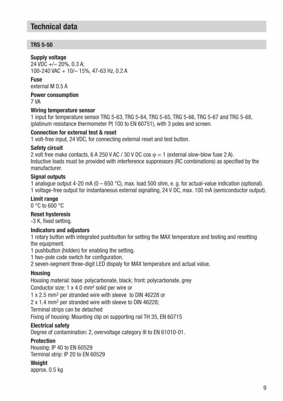
TRS 5-50
Supply voltage 24 VDC +/– 20%, 0.3 A; 100-240 VAC + 10/– 15%, 47-63 Hz, 0.2 AFuseexternal M 0.5 APower consumption 7 VAWiring temperature sensor 1 input for temperature sensor TRG 5-63, TRG 5-64, TRG 5-65, TRG 5-66, TRG 5-67 and TRG 5-68, (platinum resistance thermometer Pt 100 to EN 60751), with 3 poles and screen.Connection for external test & reset 1 volt-free input, 24 VDC, for connecting external reset and test button.Safety circuit 2 volt free make contacts, 6 A 250 V AC / 30 V DC cos ϕ = 1 (external slow-blow fuse 2 A).Inductive loads must be provided with interference suppressors (RC combinations) as specified by the manufacturer.Signal outputs1 analogue output 4-20 mA (0 – 650 °C), max. load 500 ohm, e. g. for actual-value indication (optional). 1 voltage-free output for instantaneous external signalling, 24 V DC, max. 100 mA (semiconductor output).Limit range0 °C to 600 °CReset hysteresis -3 K, fixed setting.
Indicators and adjustors1 rotary button with integrated pushbutton for setting the MAX temperature and testing and resetting the equipment. 1 pushbutton (hidden) for enabling the setting. 1 two-pole code switch for configuration. 2 seven-segment three-digit LED dispaly for MAX temperature and actual value.
HousingHousing material: base: polycarbonate, black; front: polycarbonate, grey Conductor size: 1 x 4.0 mm² solid per wire or 1 x 2.5 mm2 per stranded wire with sleeve to DIN 46228 or 2 x 1.4 mm2 per stranded wire with sleeve to DIN 46228;Terminal strips can be detached Fixing of housing: Mounting clip on supporting rail TH 35, EN 60715Electrical safety Degree of contamination: 2, overvoltage category III to EN 61010-01.Protection Housing: IP 40 to EN 60529 Terminal strip: IP 20 to EN 60529Weight approx. 0.5 kg
Technical data

10
TRS 5-50 - continued -
Ambient temperaturewhen system is switched on: 0 ° ... 55 °C during operation: -10 ... 55 °CTransport temperature–20 ... +80 °C (<100 hours), defrosting time of the de-energized equipment before it can be put into operation: 24 hours: 24 hours.Storage temperature–20 ... +70 °C, defrosting time of the de-energized equipment before it can be put into operation: 24 hours.Relative humidity max. 95%, no moisture condensationSite altitudemax. 2000 mApprovals:EC Type approval PED Pressure Equipment Directive 97/23/EC, EN 12952-11, EN 12953-09:
Requirements made on limiting equipment for boilers.Functional Safety acc. to EN 61508: Functional safety of safety-related electrical/ SIL 3 electronic/programmable electronic systems Type approval DIN EN 14597:
Requirements made on safety temperature limiters/monitors DIN Registration number DIN STW/STB 1230
Marine applications Rules and guidelines of classification societies, GL 47399-12 HHUL /cUL (CSA) Approval ApprovalUL 508 and CSA C22.2 No. 14-13, Standards for Industrial Control
Equipment. File E243189.
Technical data - continued -
Name plate / marking
Tamb = 55°C (131°F)
TMAX = °C
Wirkweise Typ 2BK+ JPV
IP 40 (IP20)
7 VA
Betriebsanleitungbeachten
See installationinstructions
Voir instructions demontage
250VT 2,0A
20 21
L N
6 7
Reset/Test24VDC
Funktionale SicherheitFunctional safetySécurité fonctionnelleIEC 61508SIL 3
14 1615 17 23 24 26 27
TRS 5-50
100-240V~-15/+10%
+ - + M 0,5A-
TemperaturschalterTemperature switchCommutateur de température
Alarm100 mA24VDC
OUT /4-20mA +-
TRS 5-50
Sicherheitstemperaturbegrenzer / - wächterSelf-monitoring temperature limiter/monitorLimiteur de température de sécurité /Dispositif de surveillance de température de sécurité
DIN STW / STB 1230
0525
GESTRA AGMünchener Str. 77D-28215 Bremen
STB STW
1 2 3
+ +-
Pt10
0
1 2 3
Fig. 5
Type designation
Supply voltage / Power consumption
Manufacturer
Wiring diagram
Safety noteAmbient temperature Protection
Wire link, provided on site
Safety circuit
Fuse, provided on site
Please enter limit value.
DIN registrations no.
Disposal noteSerial number

11
In control cabinet: Mounting temperature switch
Dimensions TRS 5-50
Fig. 6
1 Upper terminal strip
2 Lower terminal strip
Key
Installation in control cabinet
The temperature switch TRS 5-50 is clipped onto the support rail type TH 35, EN 60715 in the control cabinet. Fig. 6 4Please enter the defined limit value on the nameplate before mounting the equipment.
3 Housing
4 Supporting rail type TH 35, EN 60715
4
3
1
2
100
74
120 15
Scope of supply
TRS 5-50 1 Temperature switch TRS 5-50 1 Installation & operating manual
12
In control cabinet: Wiring temperature switch
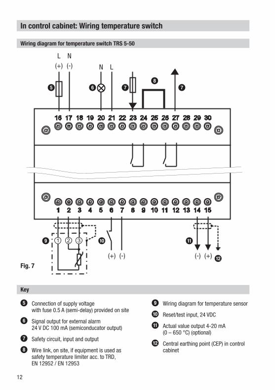
Wiring diagram for temperature switch TRS 5-50
5 Connection of supply voltage with fuse 0.5 A (semi-delay) provided on site
6 Signal output for external alarm24 V DC 100 mA (semiconducator output)
7 Safety circuit, input and output
8 Wire link, on site, if equipment is used as safety temperature limiter acc. to TRD, EN 12952 / EN 12953
Key
9 Wiring diagram for temperature sensor
0 Reset/test input, 24 VDC
a Actual value output 4-20 mA (0 – 650 °C) (optional)
b Central earthing point (CEP) in control cabinet
2716
1 2 3 4 5 6 7 8
17 18 19 20 21 22 23 24
9
25
10
26
11 12
28
13
29
14
30
15
L
(+) (-)
N
N L
(+)(+) (-)(-)
1 2 3
5 6 78
7
a09
bFig. 7
13
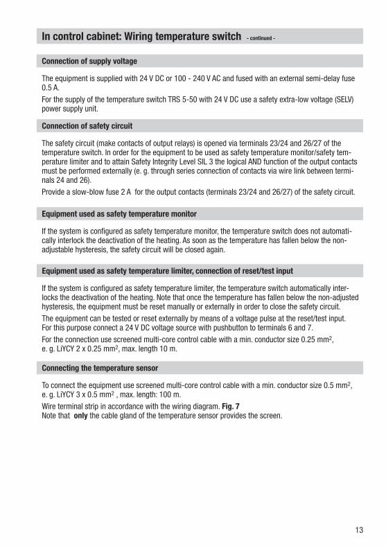
Connection of supply voltage
The equipment is supplied with 24 V DC or 100 - 240 V AC and fused with an external semi-delay fuse 0.5 A.For the supply of the temperature switch TRS 5-50 with 24 V DC use a safety extra-low voltage (SELV) power supply unit.
In control cabinet: Wiring temperature switch - continued -
The safety circuit (make contacts of output relays) is opened via terminals 23/24 and 26/27 of the temperature switch. In order for the equipment to be used as safety temperature monitor/safety tem-perature limiter and to attain Safety Integrity Level SIL 3 the logical AND function of the output contacts must be performed externally (e. g. through series connection of contacts via wire link between termi-nals 24 and 26). Provide a slow-blow fuse 2 A for the output contacts (terminals 23/24 and 26/27) of the safety circuit.
Connection of safety circuit
Equipment used as safety temperature monitor
If the system is configured as safety temperature monitor, the temperature switch does not automati-cally interlock the deactivation of the heating. As soon as the temperature has fallen below the non-adjustable hysteresis, the safety circuit will be closed again.
Equipment used as safety temperature limiter, connection of reset/test input
If the system is configured as safety temperature limiter, the temperature switch automatically inter-locks the deactivation of the heating. Note that once the temperature has fallen below the non-adjusted hysteresis, the equipment must be reset manually or externally in order to close the safety circuit.The equipment can be tested or reset externally by means of a voltage pulse at the reset/test input. For this purpose connect a 24 V DC voltage source with pushbutton to terminals 6 and 7. For the connection use screened multi-core control cable with a min. conductor size 0.25 mm2, e. g. LiYCY 2 x 0.25 mm2, max. length 10 m.
Connecting the temperature sensor
To connect the equipment use screened multi-core control cable with a min. conductor size 0.5 mm2,e. g. LiYCY 3 x 0.5 mm2 , max. length: 100 m. Wire terminal strip in accordance with the wiring diagram. Fig. 7Note that only the cable gland of the temperature sensor provides the screen.

14
To connect external signalling equipment use screened multi-core control cable with a min. conductor size 0.5 mm2, e. g. LiYCY 2 x 0.5 mm2, max. length: 100 m. In the event of an alarm or error message, the signal output (terminals 20, 21) closes. Do not use this output for activating safety circuits.
Connection for signal output
In control cabinet: Wiring temperature switch - continued -
Tools
n Screwdriver for slotted screws, size 3.5 x 100 mm, completely insulated according to VDE 0680-1.
Attention
n Fuse the temperature switch TRS 5-50 with an external semi-delay fuse 0.5 A.n Any item of equipment that you want to connect to the terminals 6/7, 14/15 and
20/21 of the temperature switch must be electrically isolated from dangerous contact voltages as per DIN EN 61140, e. g. through double or reinforced isolation according to DIN EN 61010-1 or DIN EN 60730-1 or DIN EN 60950-1.
n To protect the relay contacts fuse safety circuit with 2 A (slow blow).n When switching off inductive loads, voltage spikes are produced that may impair
the operation of control and measuring systems. Connected inductive loads must be provided with suppressors such as RC combinations as specified by the manufacturer.
n When used as safety temperature monitor/ safety temperature limiter according to TRD, EN 12952 / EN 12953 connect terminals 24 and 26 by adding a wire link.
n Make sure that connecting cables leading to the temperature sensor and/or any other external equipment are segregated and run separately from power cables.
n Do not use unused terminals as support point terminals.
Connection for actual-value output (optional)
For the connection use screened multi-core control cable with a min. conductor size 0.5 mm2, e. g. LiYCY 2 x 0.5 mm2, max. length 100 m. The current output 4 - 20 mA corresponds to a temperature of 0 – 650 °C.Please observe the max. load of 500 ohm.Wire terminal strip (terminals 14/15) in accordance with the wiring diagram. Fig. 7Do not use this output for activating safety circuits.Connect the screen only once to the central earthing point (CEP) in the control cabinet.
15
In the plant: Wiring temperature sensor
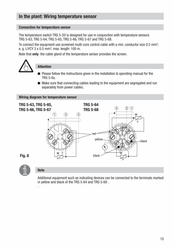
Connection for temperature sensor
The temperature switch TRS 5-50 is designed for use in conjunction with temperature sensors TRG 5-63, TRG 5-64, TRG 5-65, TRG 5-66, TRG 5-67 and TRG 5-68.To connect the equipment use screened multi-core control cable with a min. conductor size 0.5 mm2, e. g. LiYCY 3 x 0.5 mm2, max. length: 100 m. Note that only the cable gland of the temperature sensor provides the screen.
Attention
n Please follow the instructions given in the installation & operating manual for the TRG 5-6x.
n Make sure that connecting cables leading to the equipment are segregated and run separately from power cables.
Wiring diagram for temperature sensor
Note
Additional equipment such as indicating devices can be connected to the terminals marked in yellow and black of the TRG 5-64 and TRG 5-68 . .
Fig. 8
5
3
2
6
�
�
23 1
yellow black
red
TRG 5-63, TRG 5-65, TRG 5-66, TRG 5-67
TRG 5-64 TRG 5-68
�
5
3 6
31 2
black

16
Factory settingTemperature Switch TRS 5-50n MAX limit = 25 °Cn Reset hysteresis: -3 K (fixed setting)n Configuration: Safety temperature monitorn Code switch c : S1, S2 OFF
Changing factory settings
The upper terminal strip of the equipment is live during operation.This presents the danger of electric shock!Always cut off power supply to the equipment before mounting, removing or connecting the terminal strips!
Danger
Changing the configuration
The code switch c setting determines the configuration of the temperature switch (safety temperature monitor or limiter). If you want to configure the temperature switch as safety temperature limiter please proceed as follows: n Cut off supply voltage.n Lower terminal strip: Unscrew left and right fixing screws and remove the terminal strip. Fig. 9n Set S1 and S2 of the code switch c to ON = safety temperature limiter.n Attach lower terminal strip and fasten fixing screws. n Apply supply voltage. Equipment is restarted.
Fig. 9
c
Please indicate on the nameplate whether the temperature switch is used as safety temperature monitor or as safety temperature limiter.
Note

17
Commissioning procedure
Start and adjustment of MAX limit
Fig. 10Rotary button with integrated push-button
Indication of actual value / error code
Indication of limit value
543Pushbutton (hidden) for enabling the setting. Hole 3 mm ∅
520
Start
Status and action Display Function
Switch on supply voltage.
All segments and decimal points of the displays for TMAX andT are tested one after another. They all light up once and then go out.
System and segment test, takes approx. 15 sec.The system then switches back to normal oper-ating mode.
Please observe the system and segment test. If segments or points are missing replace the temperature switch.
Actual value T (°C) below limit TMAX (°C)
Display TMAX (°C) Indication of the adjusted limit
Display T (°C) Actual value Indication of the actual value
Actual value T (°C) above limit TMAX (°C)
Display TMAX (°C) is flashing Safety temp. monitor: Safety circuit open, signal output closed
Display T (°C) Actual value Safety temp. limiter: Safety circuit open and interlocked, signal output closed
Adjusting the MAX limit
Activity Seven-segment displays Function
Use a 2.5 mm pin to press the (hidden) pushbutton
TMAX (°C): Indication of limit value, first digit (000) is flash-ing. Enables the setting of the limit values.
T (°C): Indication of limit value
During input both displays (Tmax and T) show the limit value. Should these two indicated values differ from each other replace the temperature switch.
Turn rotary button. First digit (0000) flashing. Set the limit value. To increase the value turn rotary button to the right, to decrease turn it to the left.
Press push-button. Each time you press the but-ton the system moves to the next digit.
Second or third digit is flashing. (from left to right)
Press push-button.
TMAX (°C): Indication of limit value Confirm your input. Enter the limit value on the
nameplate.T (°C): Indication of the actual value
If no operation is performed: After 10 sec. the system switches back to normal operating mode.

18
Operation, alarm and test
Indicators and adjustors
Operation
Status and action Display Function
Actual value T (°C) below limit TMAX (°C)
Display TMAX (°C) Indication of the adjusted limit
Display T (°C) Actual value Indication of the actual value
Alarm
Actual value T (°C) above limit TMAX (°C)
Display TMAX (°C) is flashing Safety temp. monitor: Safety circuit open, signal output closed
Display T (°C) Actual value Safety temp. limiter: Safety circuit open and interlocked, signal output closed
Safety temperature limiter: Reset alarm
Actual value T (°C) must be 3 °C below limit TMAX (°C)Press the pushbutton of the ro-tary button of the temperature switch or the external reset/test button.
Display TMAX (°C) is flashing
Safety circuit closed, signal output open.Display T (°C) Actual value
Safety temperature monitor: Test
Press the pushbutton of the rotary button of the temperature switch or the external reset/test button. When you release the button the system switches back to normal operating mode.
TMAX (°C): Indication of limit value is flashing.
While pushbutton is held down: Safety circuit open, signal output closed
T (°C): Indication of limit value Replace the temperature switch if the test does not finish successfully.
Safety temperature limiter: Test
Press the pushbutton of the rotary button of the temperature switch or the external reset/test button. Press again the push-button or the external reset/test button to reset the system.
TMAX (°C): Indication of limit value is flashing.
Safety circuit open and interlocked, signal output closed. After pressing the button twice: Safety circuit closed, signal output open.
T (°C): Indication of limit value Replace the temperature switch if the test does not finish successfully.
Fig. 10Rotary button with integrated push-button
Indication of actual value / error code
Indication of limit value
543Pushbutton (hidden) for enabling the setting. Hole 3 mm ∅
520
19
Attention
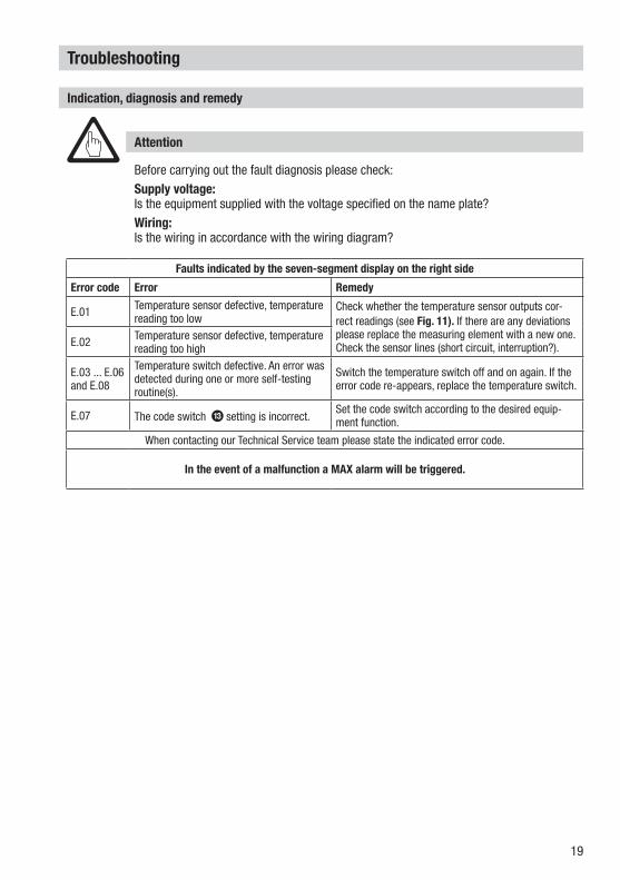
Before carrying out the fault diagnosis please check:Supply voltage: Is the equipment supplied with the voltage specified on the name plate? Wiring: Is the wiring in accordance with the wiring diagram?
Troubleshooting
Indication, diagnosis and remedy
Faults indicated by the seven-segment display on the right side
Error code Error Remedy
E.01 Temperature sensor defective, temperature reading too low
Check whether the temperature sensor outputs cor-rect readings (see Fig. 11). If there are any deviations please replace the measuring element with a new one. Check the sensor lines (short circuit, interruption?).E.02 Temperature sensor defective, temperature
reading too high
E.03 ... E.06 and E.08
Temperature switch defective. An error was detected during one or more self-testing routine(s).
Switch the temperature switch off and on again. If the error code re-appears, replace the temperature switch.
E.07 The code switch c setting is incorrect.Set the code switch according to the desired equip-ment function.
When contacting our Technical Service team please state the indicated error code.
In the event of a malfunction a MAX alarm will be triggered.
20
Troubleshooting - continued -
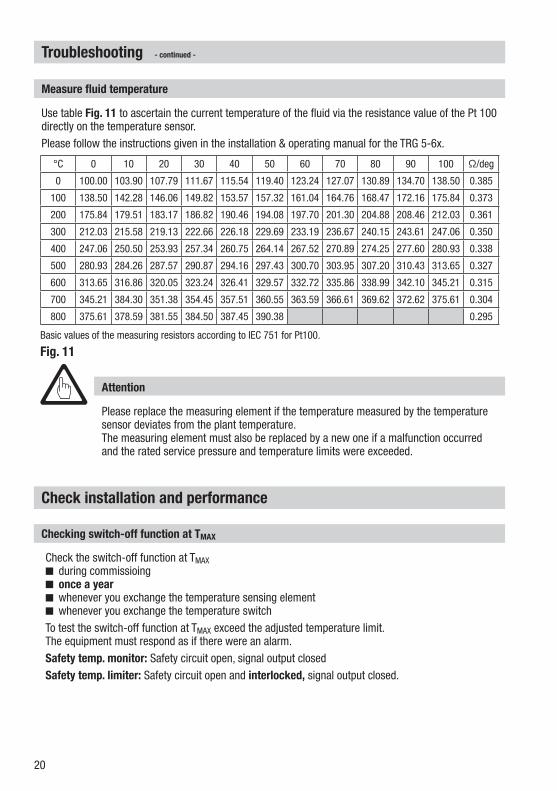
Use table Fig. 11 to ascertain the current temperature of the fluid via the resistance value of the Pt 100 directly on the temperature sensor. Please follow the instructions given in the installation & operating manual for the TRG 5-6x.
Measure fluid temperature
°C 0 10 20 30 40 50 60 70 80 90 100 Ω/deg
0 100.00 103.90 107.79 111.67 115.54 119.40 123.24 127.07 130.89 134.70 138.50 0.385
100 138.50 142.28 146.06 149.82 153.57 157.32 161.04 164.76 168.47 172.16 175.84 0.373
200 175.84 179.51 183.17 186.82 190.46 194.08 197.70 201.30 204.88 208.46 212.03 0.361
300 212.03 215.58 219.13 222.66 226.18 229.69 233.19 236.67 240.15 243.61 247.06 0.350
400 247.06 250.50 253.93 257.34 260.75 264.14 267.52 270.89 274.25 277.60 280.93 0.338
500 280.93 284.26 287.57 290.87 294.16 297.43 300.70 303.95 307.20 310.43 313.65 0.327
600 313.65 316.86 320.05 323.24 326.41 329.57 332.72 335.86 338.99 342.10 345.21 0.315
700 345.21 384.30 351.38 354.45 357.51 360.55 363.59 366.61 369.62 372.62 375.61 0.304
800 375.61 378.59 381.55 384.50 387.45 390.38 0.295
Basic values of the measuring resistors according to IEC 751 for Pt100.
Fig. 11
Attention
Please replace the measuring element if the temperature measured by the temperature sensor deviates from the plant temperature.The measuring element must also be replaced by a new one if a malfunction occurred and the rated service pressure and temperature limits were exceeded.
Check installation and performance
Checking switch-off function at TMAX
Check the switch-off function at TMAXn during commissioingn once a year n whenever you exchange the temperature sensing elementn whenever you exchange the temperature switchTo test the switch-off function at TMAX exceed the adjusted temperature limit. The equipment must respond as if there were an alarm. Safety temp. monitor: Safety circuit open, signal output closedSafety temp. limiter: Safety circuit open and interlocked, signal output closed.

21
Action against high frequency interference
Further Notes
High frequency interference can occur for example as a result of out-of-phase switching operations. Should such interference occur and lead to sporadic failures, we recommend the following actions in order to suppress any interference.n Provide inductive loads with RC combinations according to manufacturer's specification to ensure
interference suppression.n Make sure that all connecting cables leading to the conductivity electrode or to the conductivity
transmitter are segregated and run separately from power cables.n Increase the distance to sources of interference. n Check the connection of the screen of the temperature sensor.n HF interference suppression by means of hinged-shell ferrite rings.
Disposal
For the disposal of the equipment observe the pertinent legal regulations concerning waste disposal.
If faults occur that are not listed above or cannot be corrected, please contact our service centre or authorized agency in your country.
Decommissioning / replacing the equipment
n Switch off supply voltage and cut off power supply to the equipment! n Lower and upper terminal strips: Unscrew left and right fixing screws and remove the terminal strip.
Fig. 12n Release the white fixing slide at the bottom of the equipment and take the equipment off the
supporting rail.
Fig. 12

22
For your Notes

23
For your Notes

24819226-03/03-2014cm (808885-03) · GESTRA AG · Bremen · Printed in Germany
GESTRA
GESTRA AGP. O Box 10 54 60, D-28054 Bremen Münchener Str. 77, D-28215 BremenTel. 0049 (0) 421 / 35 03-0 Fax 0049 (0) 421 / 35 03-393E-mail [email protected] Web www.gestra.com
Agencies all over the world:
www.gestra.com
Singapore
Flowserve Pte. Ltd.12 Tuas Avenue 20Singapore 63882Tel. 0065 / 68 79 89 00Fax 0065 / 68 62 49 40E-Mail [email protected] www.gestra.com
Flowserve GB LimitedAbex RoadNewbury, Berkshire RG14 5EYTel. 0044 16 35 / 46 99 90Fax 0044 16 35 / 3 60 34E-Mail [email protected] www.flowserve.com
Great Britain
USA
Flowserve GESTRA U.S.2341 Ampere DriveLouisville, KY 40299Tel. 001 502 / 267-22 05Fax 001 502 / 266-53 97E-Mail [email protected]
South Africa
Flowserve SA (Pty) Ltd.Unit No. 1Director RoadSpartan Extension 2Kempton Park 1613Tel. 0027 11 / 9 23 73 00Fax 0027 11 / 9 74 64 20E-Mail [email protected] www.flowserve.com
Related Documents