Offices: Colorado Wyoming Montana Arizona North Dakota Oregon Washington Alaska GEOTECHNICAL REPORT CITY OF MONTROSE 534 SOUTH 1 st STREET MONTROSE, COLORADO October 30, 2015 Prepared for: City of Montrose c/o Mark Armstrong P.O. Box 790 Montrose, CO 81402

Welcome message from author
This document is posted to help you gain knowledge. Please leave a comment to let me know what you think about it! Share it to your friends and learn new things together.
Transcript

Offices:
Colorado
Wyoming
Montana
Arizona
North Dakota
Oregon
Washington
Alaska
GEOTECHNICAL REPORT CITY OF MONTROSE
534 SOUTH 1st STREET MONTROSE, COLORADO
October 30, 2015
Prepared for: City of Montrose c/o Mark Armstrong P.O. Box 790 Montrose, CO 81402
Introduction DOWL conducted an evaluation of subsurface and site conditions on September 4, 2015 at the proposed building envelope on 534 South 1st Street in the City of Montrose. Our services were performed at the request of Mark Armstrong, Facilities Manager for the City. The purpose of our services was to evaluate soil conditions in the vicinity of the existing structure at this address. The building was inspected by DOWL on July 17, 2015 and we concluded that the existing foundation is not capable of supporting the structure, insulating the structure or keeping out pests beneath the structure. In addition, we understand that the use of the structure will change from residential to office space and load distributions will also change. Therefore, DOWL has undertaken a geotechnical evaluation of the site to provide recommendations for remedial foundation support. Our evaluation consisted of a site reconnaissance, drilling of two boreholes, observation, logging and testing of representative materials found, and analysis of available data. This report presents the findings of our evaluation and our geotechnical engineering recommendations for foundation support, site preparation, and management of drainage. Site Conditions The house at 534 South 1st Street is located on the south side of 1st Street between South Uncompahgre and South Park Avenues. The historic structure is conventionally framed with 2 stories above a partial basement. The following photograph was taken of the building site from the alley on the south side of the property.
Looking northwest across the site, shows the existing house (center), garage (left), adjacent structure to the east (right), vegetative cover, the local topography, the location of one of our boreholes, and the conditions at the time of our site visit. A second borehole was on the north side of the house.
BH#1
City of Montrose 534 S 1st Street geotech report.docx Project #7121.74325.01 Page 2 of 10
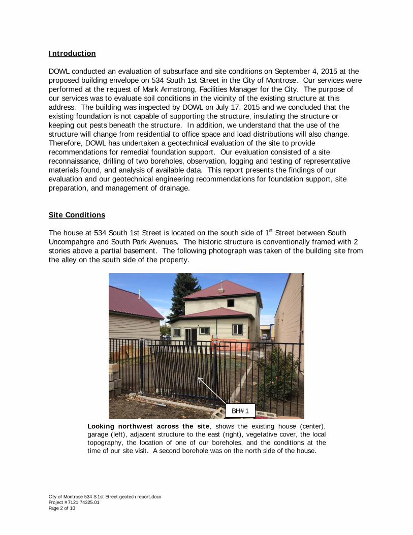
We drilled two boreholes at the site, one at the south side of the house (BH#1) and one on the north side (BH#2), as seen on the aerial photograph below. The results of our field and laboratory testing are discussed in the Soil Characteristics Section of this report.
Aerial photograph shows the subject house, garage, surrounding structures and locations of our boreholes.
Geologic Setting According to the Geologic Map of the Montrose East Quadrangle (Colorado Geological Survey Open-File Report 07-02, by Noe et al 2007), the subject property is mapped as alluvial mudflow and fan valley fill deposits (Qamf). These fine-grained (silt, clay and fine sand) deposits are derived from the weathering of the Mancos Shale outcrops on the east side of the Uncompahgre River valley. They are often susceptible to consolidation, especially when saturated, due to the presence of salts and the predominance of fines. Specific soil conditions at this site are discussed in the Soil Characteristics section of this report. Geologic Hazards This section of the report is included so that the potential building owner is aware that construction in the area comes with certain risks. Modern development in the region can be considered to be only about 40 years old, with most occurring in the past 25 years. Because of this relatively short period of time, useful empirical data are limited. Some buildings and roadways throughout the local mountains and valleys have experienced negative impacts due to slope movement, sensitive soils, and shallow groundwater. Typical accepted structural engineering practice for design and construction of buildings and roadways can be used to reduce the potential for undesirable performance related to troublesome climate and soil
BH#1
BH#2
City of Montrose 534 S 1st Street geotech report.docx Project #7121.74325.01 Page 3 of 10
conditions. However, because of the overall dynamic characteristics of the area, almost every structure is subject to at least some degree of potential risk. These risks are discussed below.
Runoff & Erosion Drainage at this site is relatively poor. Standing water was observed in the gutter on the north side of the house and we understand that, during an intense thunderstorm in July of this year when the police station was damaged due to rain, water ponded in the street in this portion of South 1st Street.
Shallow Groundwater We found groundwater at depths of 14.5 feet in BH#1 and 15 feet in BH#2 during our drilling. Shallow groundwater can be problematic as it weakens foundation soils, creates hydraulic pressure, and can seep into the interior of the structure if foundation components are not properly waterproofed. Consequently, aggressive management of surface and subsurface water at this site is very important for the long-term performance of the foundation components and slope stability. The low topographic position of this site makes it difficult to drain. A comprehensive site drainage plan, in tandem with grading and landscape plans, should be designed to intercept surface and subsurface water and remove it from the foundation area. Specific recommendations for grading and foundation preparation are given below in the Recommendations Section of this report.
Expansive and Compressible Soil and Rock Soil materials containing some types of clay, especially bentonite (montmorillonite), can expand in volume with water absorption and then shrink upon drying. In some areas of Colorado these expansive soils cause serious damage to foundations, roadways, pavements, and embankments. The geology of swelling soils, the effects of moisture on these soils, and construction and landscaping on swelling soils are discussed in the Colorado Geological Survey publication, A Guide to Swelling Soils for Colorado Homebuyers and Homeowners (Special Publication #43: Noe et al., 2nd Ed. 2007). In the Montrose area, these clays are derived from such parent material as Mancos Shale. Compressible soils are generally soils that have been laid down rapidly, have a weak matrix containing voids, and/or are not naturally in a dense or compacted state. Compressible soils typically have a large proportion of fine-grained materials, especially silt, but they can also contain a mixture of material if deposited in a chaotic manner. For example, alluvial mudflow deposits are often laid down rapidly and are composed of materials that are not sorted or reworked, leaving behind voids and a loose matrix of rocks, soil, and possibly organic debris. Clayey soils can also be compressible if they are saturated when loads are applied. Mancos Shale and its residual soil can be very sensitive to variations in moisture, being quite strong when dry but either expansive or losing strength rapidly when wetted. Additionally, wetting and drying cycles can weaken the shale so that it becomes highly erodible. When in a dry and dense state, the shale and its residual soil can exert expansive pressures when moisture is absorbed. Conversely, when in a loose, highly fractured state, the material can
City of Montrose 534 S 1st Street geotech report.docx Project #7121.74325.01 Page 4 of 10

consolidate when wetted under moderate loads. The expansive and compressive characteristics of the shale and soil are discussed in detail in the Soil Characteristics Section of this report. The potential hazard from expansive and compressible soil is the differential movement of foundation soils under loads applied through the foundation. This hazard can be partly reduced by managing on-site drainage so that water accumulation, ponding or penetration into the soil in the vicinity of foundations and slab/pavement areas is reduced to as great a degree as practical. Further reduction of hazards can be attained through design of foundation systems that extend to firmer material or which have sufficient strength to resist differential movements. The removal of problematic soil and replacement with structural fill is another option. These methods are discussed in further detail below in the Recommendations Section. Colorado Geologic Survey Special Publication #43 gives general explanations and illustrations of design and drainage options on swelling soils.
Seismicity Montrose is located in the Colorado Plateau Seismotectonic Province in Colorado, where maximum credible earthquakes are estimated to be on the order of magnitude 5.5 to 6.5, equivalent to Modified Mercalli (MM) V to VIII (CGS Bulletin #43). Please refer to the Seismic Design Criteria Section of the Recommendations section for site-specific seismic design recommendations interpreted from the 2006/2009 International Building Code (IBC).
Radon Gas Radon gas is produced by decay of radioactive minerals contained in subsurface rock and soil. The U.S. Environmental Protection Agency (EPA) has determined that radon is the second leading cause of lung cancer and that radon can accumulate in buildings and homes if the gas is not properly ventilated. The EPA map of Radon Zones indicates that virtually all of western Colorado, including Montrose County, is in Zone 1 (www.epa.gov/radon/zonemap.html). Although there is no known safe level of radon, Zone 1 is the zone of highest risk for exposure to radon gas [i.e., greater than 4 picoCuries per Liter (pCi/L)]. Additional information about radon gas can be found on the EPA radon website www.epa.gov/radon/ or the CDPHE radon website www.cdphe.state.co.us/hm/rad/radon. A radon canister was set at the center of the first floor on September 16 and analyzed by Rocky Mountain Radon Control, Inc. The results of the study indicated a value of at the time of the test. Although this test falls below the EPA recommended maximum of 4 pCi/L, it is only a snap shot valid at the time of the test. Other geologic hazards are not known to be present in the vicinity of 534 South 1st Street. Soil Characteristics Two borings (BH#1 and BH#2) were drilled to depths of 25.4 feet and 29.8 feett using a CME 55 H.S. track-mounted drill rig at the locations noted on the attached Site Plan. The locations of the borings were selected prior to the evaluation based on accessibility and to gather data on two sides of the building. The boreholes were drilled with a 4¼-inch solid stem continuous
City of Montrose 534 S 1st Street geotech report.docx Project #7121.74325.01 Page 5 of 10

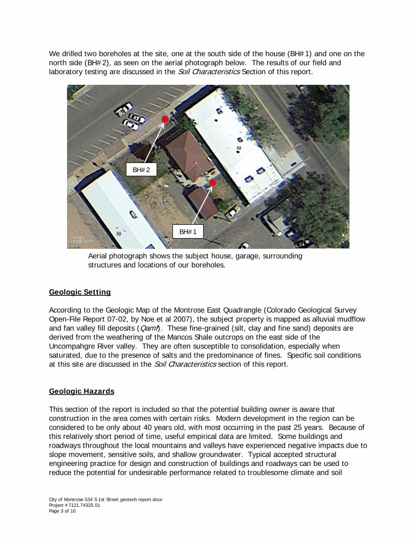
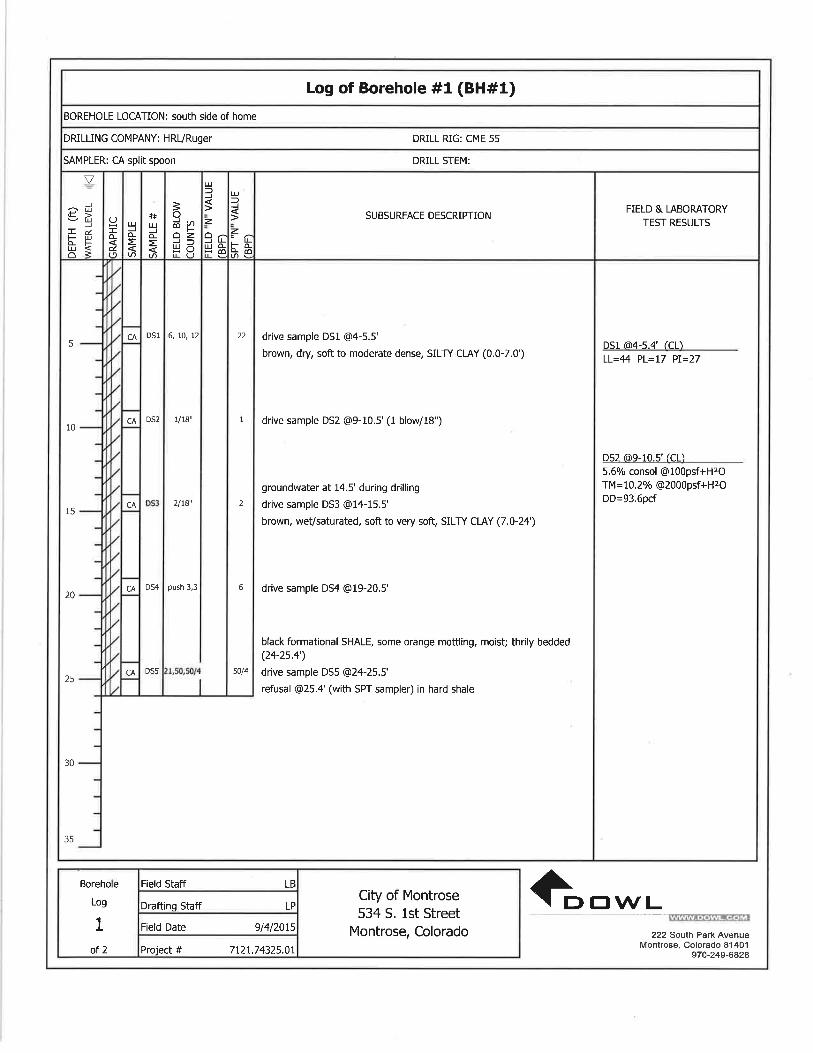
flight auger. Soil samples were obtained at discrete depths by withdrawing the 4¼-inch drill string and inserting either a standard 1.375-inch inside diameter (I.D.) split-spoon sampler without liners or a 2-inch I.D. split-spoon “California” sampler to perform in-situ Standard Penetration Tests (SPTs) in general accordance with ASTM Standard D-1586. The number of blows required to drive the sampler 12 inches in 6-inch increments were recorded (SPT “N” penetration resistance values) and, when properly evaluated, indicate the relative density or consistency of the soils. The soil, bedrock, and groundwater conditions were logged, and representative samples of subsurface materials were tested in our laboratory. The subsurface conditions found in the borings and laboratory results are shown on the attached Borehole Logs. In the building site boreholes, we found 15 to 20 feet of soft to stiff silty clay. Hard shale was contacted at about 25 feet in each boring. Groundwater was estimated at about 15 feet in the boreholes.
Soft soil conditions encountered in the boreholes
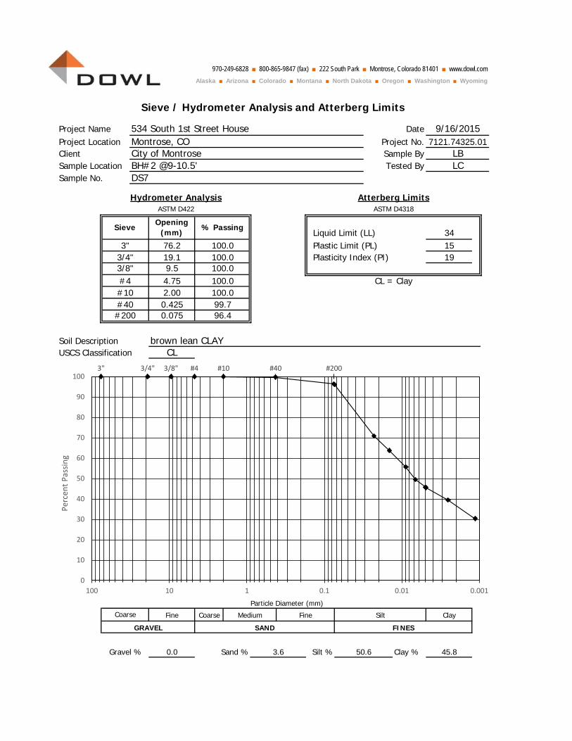
Laboratory tests were performed on the predominant native soil types to evaluate the range of plasticity and particle size characteristics (see attached Sieve Analysis and Atterberg Limits laboratory results). Atterberg limits tests indicated the material to be a lean to moderately expansive clay with Plasticity Indices ranging from 19 to 27. A soil with a PI of less than 15 is considered to have a low potential for swelling when wetted and shrinking when dried, while a soil with a PI of between 15 and 30 is considered to have moderate potential for swelling or shrinking.
City of Montrose 534 S 1st Street geotech report.docx Project #7121.74325.01 Page 6 of 10
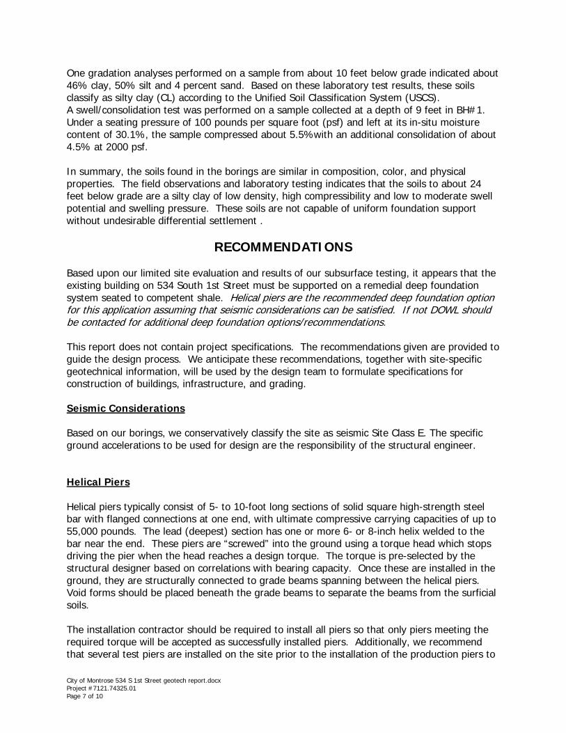
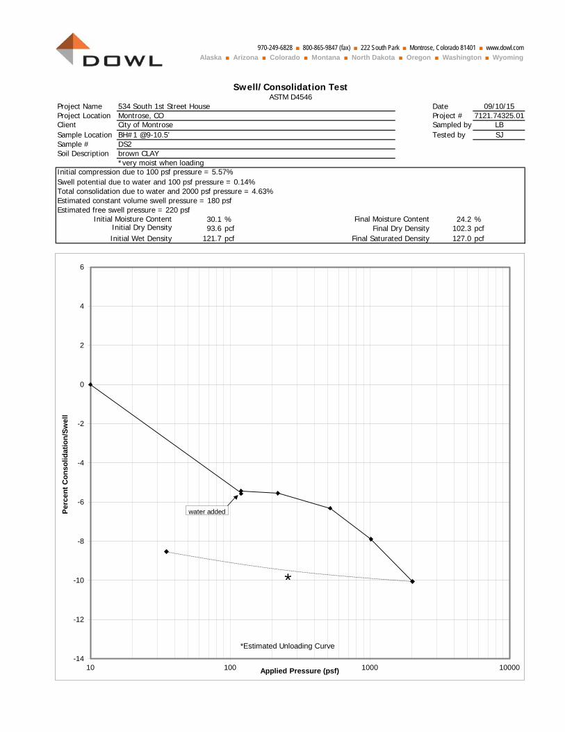
One gradation analyses performed on a sample from about 10 feet below grade indicated about 46% clay, 50% silt and 4 percent sand. Based on these laboratory test results, these soils classify as silty clay (CL) according to the Unified Soil Classification System (USCS). A swell/consolidation test was performed on a sample collected at a depth of 9 feet in BH#1. Under a seating pressure of 100 pounds per square foot (psf) and left at its in-situ moisture content of 30.1%, the sample compressed about 5.5%with an additional consolidation of about 4.5% at 2000 psf. In summary, the soils found in the borings are similar in composition, color, and physical properties. The field observations and laboratory testing indicates that the soils to about 24 feet below grade are a silty clay of low density, high compressibility and low to moderate swell potential and swelling pressure. These soils are not capable of uniform foundation support without undesirable differential settlement .
RECOMMENDATIONS Based upon our limited site evaluation and results of our subsurface testing, it appears that the existing building on 534 South 1st Street must be supported on a remedial deep foundation system seated to competent shale. Helical piers are the recommended deep foundation option for this application assuming that seismic considerations can be satisfied. If not DOWL should be contacted for additional deep foundation options/recommendations. This report does not contain project specifications. The recommendations given are provided to guide the design process. We anticipate these recommendations, together with site-specific geotechnical information, will be used by the design team to formulate specifications for construction of buildings, infrastructure, and grading. Seismic Considerations Based on our borings, we conservatively classify the site as seismic Site Class E. The specific ground accelerations to be used for design are the responsibility of the structural engineer. Helical Piers Helical piers typically consist of 5- to 10-foot long sections of solid square high-strength steel bar with flanged connections at one end, with ultimate compressive carrying capacities of up to 55,000 pounds. The lead (deepest) section has one or more 6- or 8-inch helix welded to the bar near the end. These piers are “screwed” into the ground using a torque head which stops driving the pier when the head reaches a design torque. The torque is pre-selected by the structural designer based on correlations with bearing capacity. Once these are installed in the ground, they are structurally connected to grade beams spanning between the helical piers. Void forms should be placed beneath the grade beams to separate the beams from the surficial soils. The installation contractor should be required to install all piers so that only piers meeting the required torque will be accepted as successfully installed piers. Additionally, we recommend that several test piers are installed on the site prior to the installation of the production piers to
City of Montrose 534 S 1st Street geotech report.docx Project #7121.74325.01 Page 7 of 10

verify adequacy of this foundation option. Certification by the helical pier manufacturer should be obtained specifying that the piers will maintain their integrity in the region’s mineralized groundwater and corrosive soil for the design life of the structure. A helical pier contractor with demonstrated successful experience installing helical piers with qualified personnel in similar conditions should be chosen to perform the installations. Continuous observation of the installation should be performed by Buckhorn Geotech as a representative of the owner. A log should be maintained detailing the depth and final torque of each pier installation. Foundation Drainage and Ventilation It is important to minimize moisture penetration into the soil beneath or adjacent to the structure. Moisture can accumulate as a result of such items as: poor surface drainage, drywell and infiltration systems, over-irrigation of landscaped areas, waterline leaks, melting snow, subsurface seepage, or condensation from vapor transport. 1. Provisions should be made to direct water away from foundations and under slabs. This
may be accomplished using conventional footing drains in tandem with a positively-vented moisture and radon control system.
2. Roof drainage should be captured by eave gutters. Downspouts should be fitted with extensions to discharge a minimum of 10 feet away from the structure or piped into a closed underground drain system and evacuated off-site. In no case should the downspouts be directed into the perforated foundation drain system
3. The existing crawl spaces should be well ventilated to allow for the release of radon gas, a known carcinogen. Recommendations for design and construction techniques found effective in the reduction of radon gas can be found in the pamphlet entitled, Building Radon Out: A Step-by-Step Guide on How to Build Radon-Resistant Homes (USEPA Office of Air and Radiation EPA/402-K-01-002, April 2001). This publication can be obtained from the CDPHE in Denver by calling (303) 692-3420. Other recommendations for passive and active design and construction techniques for reducing radon gas can be found on the websites www.epa.gov/radon/ or www.cdphe.state.co.us/hm/rad/radon.
Concrete Because of the potential sulfates in the soil and their corrosive qualities, we recommend that the cementitious material requirements for Class 2 sulfate exposure in Section 601.04 of the latest edition of the CDOT Specifications for Road and Bridge Construction be consulted and followed. Exterior Concrete Flatwork 1. Flatwork adjacent to buildings should be placed on properly compacted fill. To minimize
future settlement and damage to the flatwork and/or adjacent foundations, the fill should consist of approved material placed and compacted per project specifications.
City of Montrose 534 S 1st Street geotech report.docx Project #7121.74325.01 Page 8 of 10
2. Flatwork adjacent to exterior doorways should be dowelled into the foundation to reduce
long-term differential movement between the flatwork and structure. 3. Exterior concrete flatwork should be designed and constructed so that it drains freely
away from the structure. Concrete flatwork adjacent to the foundation should slope away at a grade of at least ¼-inch per foot.
4. All concrete used at this site in contact with native soil should comply with the
recommendations in the Concrete Section of these recommendations. Closing Considerations
Standard of Care and Interpretation of Subsurface Data This report has been prepared in a manner consistent with local standards of professional geotechnical engineering practice. Evaluation of environmental contaminants was not part of our scope of services performed at this site. The classification of soils and interpretation of subsurface conditions is based on our training and years of experience, but is necessarily based on limited subsurface observation and testing. As such, inferred ground conditions cannot be guaranteed to be exact. No other warranty, express or implied, is made. Observation of the installation of helical piers is an integral part of these recommendations. If subsurface conditions differing from those described herein are discovered during pier, construction should be stopped until the situation has been assessed by a representative of DOWL. Construction should be resumed only when remedies or design adjustments, as necessary, have been prescribed.
Use of This Report This report is intended for use by the design team specifically to address the site and subsurface conditions as they relate to the proposed structure(s) described in the Construction Plans Section. Changes to the site or proposed development plans may alter or invalidate the recommendations contained herein. DOWL retains an ownership and property interest in this report. Consistent with the industry, copies of this document that may be relied upon by the design team are limited to those that are signed and sealed by the Geotechnical Engineer (Standard Form of Agreement Between Owner and Geotechnical Engineer for Professional Services, Engineer’s Joint Contract Documents Committee, 1996). This report together with ancillary data, analyses, test results, and other components and/or supporting parts are not intended or represented to be suitable for reuse by the design team or others on extensions to this project or on any other project. Any such reuse or modification invalidates all aspects of the report and excuses the Geotechnical Engineer for all responsibility and liability or legal exposure. This report is considered valid for a period of two years from the date of issue provided the site conditions and development plans have not changed from what is referenced in this report.
City of Montrose 534 S 1st Street geotech report.docx Project #7121.74325.01 Page 9 of 10

Changes to the site may occur due to development or natural processes. Additionally, technological advances made in construction and changes in legislation may alter the recommendations made herein. Depending upon the site and proposed development changes, DOWL may require additional evaluation (at additional cost) to update the recommendations contained herein.
Retention of Samples Samples of soil and rock collected during the course of our geotechnical evaluation(s) are routinely held in our laboratory for a period of three months from the date of the evaluation and then are discarded. A written request by the client or design team is required for samples to be stored for a longer period. Additional Services To provide continuity and consistency from project start to finish, we should be retained to make observations and carry out material testing as a service to the owner. As noted above, we recommend the owner contact us to discuss required services and scheduling in advance of the construction phase. DOWL is a full-service engineering firm providing foundation, on-site wastewater system, site drainage, structural and retaining structure design services, as well as surveying, construction materials testing, and inspections. Please visit www.dowl.com for a full description of our services. Thank you for the opportunity to perform this geotechnical evaluation for you. If you require any of the above services or have any questions regarding this report, please contact us. Respectfully Submitted ELECTRONICALLY, DOWL, LLC Wayne Pandorf, P.E. Senior Geotechnical Engineer Enclosures: Borehole Logs, Sieve/Hydrometer Analysis and Atterberg Limits results,
Swell/Consolidation graph
City of Montrose 534 S 1st Street geotech report.docx Project #7121.74325.01 Page 10 of 10


970-249-6828 ■ 800-865-9847 (fax) ■ 222 South Park ■ Montrose, Colorado 81401 ■ www.dowl.comAlaska ■ Arizona ■ Colorado ■ Montana ■ North Dakota ■ Oregon ■ Washington ■ Wyoming
Project Name DateProject Location Project No.Client Sample BySample Location Tested BySample No. Soil Description ASTM 2488
*salts present
CL = Clay
Plasticity Index (PI)
17
27
Liquid Limit (LL) 44
Plastic Limit (PL)
brown CLAY
City of Montrose LBBH#1 @4-5.4' LCDS1
Atterberg Limits
534 South 1st Street House 9/15/2015Montrose, CO 7121.74325.01
ASTM D4318
0
10
20
30
40
50
60
0 1 0 2 0 3 0 4 0 5 0 6 0 7 0 8 0 9 0 1 0 0 1 1 0
PLAS
TICI
TY IN
DEX
(PI)
LIQUID LIMIT (LL)
CL-ML
MH or OH
ML or OL
970-249-6828 ■ 800-865-9847 (fax) ■ 222 South Park ■ Montrose, Colorado 81401 ■ www.dowl.comAlaska ■ Arizona ■ Colorado ■ Montana ■ North Dakota ■ Oregon ■ Washington ■ Wyoming
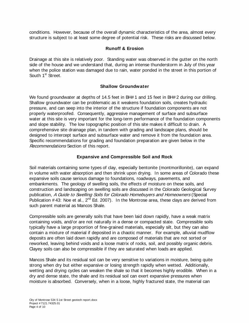
Project Name 534 South 1st Street House Date 09/10/15Project Location Montrose, CO Project # 7121.74325.01Client City of Montrose Sampled by LBSample Location BH#1 @9-10.5' Tested by SJSample # DS2Soil Description brown CLAY
*very moist when loadingInitial compression due to 100 psf pressure = 5.57%Swell potential due to water and 100 psf pressure = 0.14%Total consolidation due to water and 2000 psf pressure = 4.63%Estimated constant volume swell pressure = 180 psfEstimated free swell pressure = 220 psf
Initial Moisture Content 30.1 % Final Moisture Content 24.2 % Initial Dry Density 93.6 pcf Final Dry Density 102.3 pcf Initial Wet Density 121.7 pcf Final Saturated Density 127.0 pcf
Swell/Consolidation TestASTM D4546
-14
-12
-10
-8
-6
-4
-2
0
2
4
6
10 100 1000 10000
Perc
ent C
onso
lidat
ion/
Swel
l
Applied Pressure (psf)
water added
*
*Estimated Unloading Curve
970-249-6828 ■ 800-865-9847 (fax) ■ 222 South Park ■ Montrose, Colorado 81401 ■ www.dowl.comAlaska ■ Arizona ■ Colorado ■ Montana ■ North Dakota ■ Oregon ■ Washington ■ Wyoming
Project Name DateProject Location Project No.Client Sample BySample Location Tested BySample No.
Liquid Limit (LL) 34 Plastic Limit (PL) 15 Plasticity Index (PI) 19
Soil Description brown lean CLAYUSCS Classification
Coarse Clay
Sand % Silt % Clay % 45.8
3"
Sieve / Hydrometer Analysis and Atterberg Limits
9/16/20157121.74325.01
LBLC
534 South 1st Street HouseMontrose, COCity of MontroseBH#2 @9-10.5'
100.0
DS7
Sieve
Gravel %
GRAVEL SAND FINES
Fine Medium Fine SiltCoarse
50.63.6
CL = Clay
#200#40
#4#10
Opening (mm)
96.4
Hydrometer AnalysisASTM D422
Atterberg LimitsASTM D4318
100.0100.0100.0100.099.7
% Passing
3/4"76.2
CL
0.0
Particle Diameter (mm)
3/8"19.19.54.752.000.4250.075
#40 3" 3/4" 3/8" #4 #10 #200
0
10
20
30
40
50
60
70
80
90
100
0.0010.010.1110100
Perc
ent P
assin
g
0
10
20
30
40
50
60
70
80
90
100
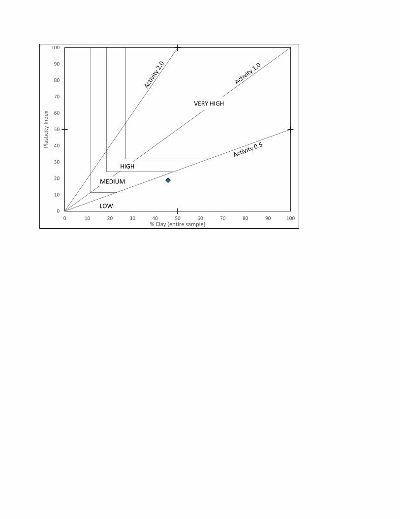
0 10 20 30 40 50 60 70 80 90 100
Plas
ticity
Inde
x
% Clay (entire sample)
HIGH
VERY HIGH
MEDIUM
LOW
Related Documents