Geotechnical Engineering Report Farrelly Pool Reconstruction San Leandro, Alameda, California July 30, 2018 Terracon Project No. ND185031 Prepared for: City of San Leandro San Leandro, California Prepared by: Terracon Consultants, Inc. Concord, California

Welcome message from author
This document is posted to help you gain knowledge. Please leave a comment to let me know what you think about it! Share it to your friends and learn new things together.
Transcript

REPORT C OVER PAGE
Geotechnical Engineering Report Farrelly Pool Reconstruction
San Leandro, Alameda, California
July 30, 2018
Terracon Project No. ND185031
Prepared for:
City of San Leandro
San Leandro, California
Prepared by:
Terracon Consultants, Inc.
Concord, California

Terracon Consultants, Inc. 5075 Commercial Circle, Suite E Concord, California 94520
P (925) 609 7224 F (925) 609 6324 terracon.com
REPORT C OVER LETTER TO SIGN
July 30, 2018
City of San Leandro
835 E. 14th Street
San Leandro, California 94577
Attn: Mr. Mark Goralka
P: (510) 577 3329
Re: Geotechnical Engineering Report
Farrelly Pool Reconstruction
864 Dutton Avenue
San Leandro, Alameda, California
Terracon Project No. ND185031
Dear Mr. Goralka:
We have completed the Geotechnical Engineering services for the above referenced project. This
study was performed in general accordance with Terracon Proposal No. PND185031 dated
February 26, 2018. This report presents the findings of the subsurface exploration and provides
geotechnical recommendations concerning earthwork and the design and construction of a new
swimming pool and foundations for the proposed project.
We appreciate the opportunity to be of service to you on this project. If you have any questions
concerning this report, or if we may be of further service, please contact us.
Sincerely,
Terracon Consultants, Inc.
Hoda Alinasabbaboli, E.I.T. Noah T. Smith, P.E., G.E.
Staff Geotechnical Engineer Senior Associate
halinasabbaboli
Stamp

Responsive Resourceful Reliable
REPORT TOPICS
REPORT TOPICS
REPORT SUMMARY ....................................................................................................... I INTRODUCTION ............................................................................................................. 1
SITE CONDITIONS ......................................................................................................... 1 PHOTOGRAPHY LOG ................................................................................................... 2 PROJECT DESCRIPTION .............................................................................................. 4 GEOTECHNICAL CHARACTERIZATION ...................................................................... 5 GEOTECHNICAL OVERVIEW ....................................................................................... 6
EARTHWORK ................................................................................................................ 8 SHALLOW FOUNDATIONS ......................................................................................... 15 POOL RECOMMENDATIONS ...................................................................................... 17 SEISMIC CONSIDERATIONS ...................................................................................... 18
LIQUEFACTION ........................................................................................................... 19 FLOOR SLABS ............................................................................................................ 20
CORROSIVITY ............................................................................................................. 23 GENERAL COMMENTS ............................................................................................... 24
Note: This report was originally delivered in a web-based format. Orange Bold text in the report indicates a referenced
section heading. The PDF version also includes hyperlinks which direct the reader to that section and clicking on the
logo will bring you back to this page. For more interactive features, please view your project online at
client.terracon.com.
ATTACHMENTS
EXPLORATION AND TESTING PROCEDURES
SITE LOCATION AND EXPLORATION PLANS
EXPLORATION RESULTS (Boring/CPT Logs and Laboratory Data)
SUPPORTING INFORMATION (General Notes and Unified Soil Classification System,
CPT General Notes, and Liquefaction Analysis)

Geotechnical Engineering Report
Farrelly Pool Reconstruction San Leandro, Alameda, California
July 30, 2018 Terracon Project No. ND185031
Responsive Resourceful Reliable i
REPORT SUMMARY
Topic 1 Overview Statement
2
Project Description
Demolition of the existing pool, construction of two new pools, and a building expansion along the eastern side of the equipment room. The new pools will consist of a children’s pool varying in depth from 2 to 3 feet and a recreation pool varying in depth from 3.5 to 6 feet. The building expansion will be approximately 10 by 20 feet in size. The pools will consist of shotcrete construction shot against vertical cuts. We anticipate the building expansion will consist of wood frame construction with a slab-on-grade floor
Maximum Loads (Assumed) Walls: 2-3 kips per linear foot (klf)
Geotechnical Characterization
Soft to very stiff sandy lean clay in the upper 16½ feet with a layer of medium dense silty sand encountered at depths ranging from 12½ to 14 feet bgs in borings B1 and B3. Groundwater was encountered in our CPT at a depth of 32 feet bgs.
Earthwork Up to 7 feet of cut and fill is anticipated, mainly associated with backfill of the existing pools and construction of the new pools. Grading should be conducted in accordance with the Earthwork section of this report.
Swimming Pool The swimming pool may be constructed utilizing conventional in-ground construction. We have assumed the new pool shells will extend the same depth or deeper than the existing pool shells.
Shallow Foundations
The building expansion may be supported by Shallow Foundations. Allowable bearing pressure = 1,500 lbs/sq ft Expected settlements: < 1 inch total, < ½ inch differential
Slabs on-Grade Interior and exterior concrete slabs-on-grade should be underlain by a minimum 18 inches of LVC material.
General Comments
This section contains important information about the limitations of this geotechnical engineering report.
1. If the reader is reviewing this report as a pdf, the topics above can be used to access the appropriate section of the report by simply clicking on the topic itself.
2. This summary is for convenience only. It should be used in conjunction with the entire report for design purposes.

Responsive Resourceful Reliable 1
INTRODUCTION
Geotechnical Engineering Report
Farrelly Pool Reconstruction
864 Dutton Avenue
San Leandro, Alameda, California Terracon Project No. ND185031
July 30, 2018
INTRODUCTION
This report presents the results of our subsurface exploration and geotechnical engineering
services performed for the proposed swimming pool and building expansion to be located at 864
Dutton Avenue in San Leandro, Alameda, California. The purpose of these services is to provide
information and geotechnical engineering recommendations relative to:
Subsurface soil conditions Foundation design and construction
Groundwater conditions Floor slab design and construction
Site preparation and earthwork
Swimming pool design and
construction
Seismic site classification per 2016
CBC
Liquefaction analysis
Soil corrosivity
The geotechnical engineering scope of services for this project included the advancement of five
test borings to depths ranging from approximately 11½ to 16½ feet below existing site grades
(bgs) and one shallow percolation test. Additionally, one Cone Penetration Test (CPT) sounding
was advanced to a depth of 94 feet bgs.
Maps showing the site and boring/CPT locations are shown in the Site Location and Exploration
Plan sections, respectively. The results of the laboratory testing performed on soil samples
obtained from the site during the field exploration are included on the boring logs as separate
graphs in the Exploration Results section of this report.
SITE CONDITIONS
The following description of site conditions was derived from our site visit in association with the
field exploration and our review of publicly available geologic and topographic maps.

Geotechnical Engineering Report
Farrelly Pool Reconstruction San Leandro, Alameda, California
July 30, 2018 Terracon Project No. ND185031
Responsive Resourceful Reliable 2
Item Description
Parcel Information
The project is located at 864 Dutton Avenue in San Leandro, Alameda,
California.
37.7349° N 122.1464° W (approximate) See Site Location
Existing
Improvements
The property is developed with the existing Roosevelt Elementary School and
City of San Leandro Farrelly swimming pool facility. Development includes
several classroom buildings, a field, blacktop, asphalt paving, and associated
hardscapes. The swimming pool facility consists of a 3,200 square foot (sf)
locker/equipment room building, a 20 by 30 foot children’s pool and a 33 by
100-foot recreation pool.
Current Ground
Cover Concrete hardscape and asphalt paving.
Existing Topography The area of proposed re-development is relatively level.
Geology Local geologic maps indicate the subsurface conditions consist of Holocene
age alluvial fan and fluvial deports consisting of clay, sand and gravel. 1
PHOTOGRAPHY LOG
Photo 1 – Benches on the east side of the pool (facing southwest)
1 Graymer, R.W., 2000, Geologic map and map database of the Oakland metropolitan area, Alameda, Contra Costa, and San
Francisco Counties, California: U.S. Geological Survey, Miscellaneous Field Studies Map MF-2342, scale 1:50,000

Geotechnical Engineering Report
Farrelly Pool Reconstruction San Leandro, Alameda, California
July 30, 2018 Terracon Project No. ND185031
Responsive Resourceful Reliable 3
Photo 2 – Benches on the east side of the pool (facing west)
Photo 3 – Northeast corner of the pool (facing southwest)

Geotechnical Engineering Report
Farrelly Pool Reconstruction San Leandro, Alameda, California
July 30, 2018 Terracon Project No. ND185031
Responsive Resourceful Reliable 4
Photo 4 - North side of the pool (facing south)
PROJECT DESCRIPTION
Our initial understanding of the project was provided in our proposal and was discussed in the
project planning stage. A period of collaboration has transpired since the project was initiated,
and our final understanding of the project conditions are as follows:
Item Description
Information Provided As-built plans of the pool area were provided to Terracon by Glass Architects via email.
Project Description The project will consist of the demolition of the existing pools, construction of two new pools, and a building expansion along the eastern side of the equipment room.
Proposed Structure The new pools will consist of a children’s pool varying in depth from 2 to 3 feet and a recreation pool varying in depth from 3.5 to 6 feet. The building expansion will be approximately 10 by 20 feet in size.
Proposed Construction The pools will consist of shotcrete construction shot against vertical cuts. We anticipate the building expansion will consist of wood frame construction with a slab-on-grade floor
Maximum Loads
(Assumed) Walls: 2-3 kips per linear foot (klf)
Grading Up to 7 feet of cut and fill, mainly associated with backfill of the existing pools and construction of the new pools.
Estimated Start of Construction
Fall 2018

Geotechnical Engineering Report
Farrelly Pool Reconstruction San Leandro, Alameda, California
July 30, 2018 Terracon Project No. ND185031
Responsive Resourceful Reliable 5
GEOTECHNICAL CHARACTERIZATION
Subsurface Profile
We have developed a general characterization of the subsurface soil and groundwater conditions
based upon our review of the data and our understanding of the geologic setting and planned
construction. The following table provides our geotechnical characterization.
The geotechnical characterization forms the basis of our geotechnical calculations and evaluation
of site preparation and foundation options. As noted in General Comments, the characterization
is based upon widely spaced exploration points across the site, and variations are likely.
Stratum Approximate Depth to
Bottom of Stratum (feet) Material Description Consistency/Density
11 3-inch thick Asphalt N/A
21 4-inch thick Aggregate base N/A
32 8-inch thick Concrete N/A
43 12½ to Undetermined Sandy lean clay Soft to very stiff
54,5
17 to Undetermined Silty sand Medium dense
1. Stratum encountered in Boring B1 only.
2. Stratum encountered in Borings B2 through B5.
3. Borings B2 and B4 terminated within this stratum.
4. Stratum encountered in Borings B1 and B3. Boring B1 and B3 terminated within this stratum.
5. The CPT indicated the sand layer extended to depth of about 17 feet.
Conditions encountered at each boring/CPT locations are indicated on the individual boring/CPT
logs shown in the Exploration Results section and are attached to this report. Stratification
boundaries on the boring logs represent the approximate location of changes in native soil types;
in situ, the transition between materials may be gradual.
Groundwater Conditions
Groundwater was encountered in the CPT at a depth of 32 feet bgs at the time of our field
exploration. The boreholes were observed while drilling and after completion for the presence and
level of groundwater. Groundwater was not observed in the borings while drilling, or for the short
duration the borings could remain open. However, this does not necessarily mean the borings
terminated above groundwater. Due to the low permeability of the soils encountered in the borings,
Geotechnical Engineering Report
Farrelly Pool Reconstruction San Leandro, Alameda, California
July 30, 2018 Terracon Project No. ND185031
Responsive Resourceful Reliable 6
a relatively long period may be necessary for a groundwater level to develop and stabilize in a
borehole. Long term observations in piezometers or observation wells sealed from the influence of
surface water are often required to define groundwater levels in materials of this type. Based on the
review of local groundwater data approximately ½ mile from the project site, recorded minimum and
maximum depths to groundwater were approximately 21 and 32 feet bgs respectively.1 The site
where groundwater was encountered a depth of 21 feet is approximately 12 feet lower in elevation
than the subject site.
Groundwater level fluctuations occur due to seasonal variations in the amount of rainfall, runoff
and other factors not evident at the time the borings were performed. Therefore, groundwater
levels during construction or at other times in the life of the structure may be higher or lower than
the levels indicated on the boring logs. The possibility of groundwater level fluctuations should be
considered when developing the design and construction plans for the project.
GEOTECHNICAL OVERVIEW
The subject site has several geotechnical considerations that will affect the construction and
performance of the proposed swimming pool and building expansion. The following geotechnical
considerations have been identified at the subject site:
Moderately plastic clay considerations
Swimming pool considerations
Moderately Plastic Clay Considerations
The surficial soils within the footprint of the planned pool and building expansion generally consist
of soft to very stiff sandy lean clay. Based on laboratory testing these soils are moderately plastic.
Additional areas of localized moderately to highly plastic soils may be present in the areas of
proposed improvements where borings were not performed.
The soft to very stiff subgrade soils should be suitable to support the proposed improvements.
However, these plastic soils are prone to volume change with changes in moisture which may
lead to excessive shrinking and swelling of slabs. Special measures should be taken to protect
the interior floor slabs and exterior decking from the swelling pressures of the soils. In order to
address the effects of the moderate to high volume change soils on the building expansion, we
recommend the expansion be supported by Shallow Foundations that extend a minimum 18
inches below lowest adjacent grade and bear on a minimum 18 inches of low volume change
(LVC) material and the floor slab be underlain by a minimum of 18 inches of LVC material. In
1 The State Water Resources Control Board, Division of Water Quality Groundwater Ambient Monitoring and Assessment Program
(GAMA)

Geotechnical Engineering Report
Farrelly Pool Reconstruction San Leandro, Alameda, California
July 30, 2018 Terracon Project No. ND185031
Responsive Resourceful Reliable 7
addition, the exterior decking should bear on a minimum 18 inches of LVC material. Using an LVC
zone as recommended in this report may not eliminate all future subgrade volume change and
resultant slab movements. If elected, the procedures outlined herein should help to reduce the
potential for subgrade volume change. Areas within the building expansion footprint where
moderately to highly plastic soils are present will require over-excavation to facilitate the
placement of the required LVC material. Details regarding this LVC zone are provided in
Earthwork.
This report provides recommendations to help mitigate the effects of soil shrinkage and
expansion. However, even if these procedures are followed, some movement and cracking in the
building expansion should be anticipated. The severity of cracking and other (cosmetic) damage
such as uneven slabs will likely increase if any modification of the site results in excessive wetting
or drying of the expansive soils. Eliminating the risk of movement and distress may not be feasible,
but it may be possible to further reduce the risk of movement if significantly more extensive
measures are used during construction. We would be pleased to discuss other construction
alternatives with you upon request.
All grades must provide effective drainage away from the improvements during and after
construction. Water permitted to pond next to the improvements can result in greater soil
movements than those discussed in this report. These greater movements can result in
unacceptable differential slab and pool shell movements, cracked slabs and walls, and roof leaks.
The recommendations made in this this report are based on effective drainage for the life of the
improvements and cannot be relied upon if effective drainage is not maintained.
Pool Considerations
Given the native soils encountered within the area of the swimming pool, the pool may be
constructed using a conventional pool shell provided the pool bears into the underlying medium
stiff to very stiff clay soil. We have assumed the new pool depths will be as deep or deeper than
the existing pool depths. Terracon should be contacted to provide additional recommendations, if
needed, if this is not the case.
Additional geotechnical design considerations for the swimming pool and items that may affect
the future geotechnical stability of the pool system are listed below.
Isolate pool shell – The proposed pools should be isolated from any source that could
cause additional settlement of the pools. Foundations from buildings and other structures
related to the pools should be kept a minimum distance equal to the depth of the pools
from the pools’ edge to reduce the effect of the foundation on the pool shells. Additionally,
pool decks should not be tied into the pool shells.

Geotechnical Engineering Report
Farrelly Pool Reconstruction San Leandro, Alameda, California
July 30, 2018 Terracon Project No. ND185031
Responsive Resourceful Reliable 8
Groundwater concerns – The presence of groundwater could cause the pool shells to
float if the pools are emptied. No shallow groundwater was encountered in our borings at
the time of our field exploration. However, careful observation of groundwater levels
should be performed before and after pool construction to identify if water levels will rise
to the depth of the pool shells. If groundwater or seepage is encountered during
construction, a hydrostatic pressure relief valve should be installed in the deep end of the
pools and an underdrain should be placed below the floor of the pools in accordance with
the recommendations provided in the Pool Recommendations section of this report.
Avoid fill material below the pool – Fill material placed below the pools is to be avoided
due to the potential for excessive differential settlements within the fill material. This
includes documented fills that have been placed correctly.
Avoid surcharge loading on pool shell – The addition of surcharge loads on the pool
shells either during construction or after construction should be avoided to limit the
possibility of damaging the pool walls.
The General Comments section provides an understanding of the report limitations.
EARTHWORK
We anticipate grading for this project may consist of cuts and fill up to 7 feet mainly associated
with backfill of the existing pools and construction of the new pools. If greater cuts and fills are
required, Terracon should be contacted to provide supplemental recommendations. Earthwork
will include demolition of existing pool, clearing and grubbing, excavations and fill placement. The
following sections provide recommendations for use in the preparation of specifications for the
work. Recommendations include critical quality criteria as necessary to render the site in the state
considered in our geotechnical engineering evaluation for swimming pools, foundations and slabs.
Site Preparation
Prior to placing fill, all existing debris, debris generated from demolition of the existing pool shells
and hardscape, underground utilities, existing vegetation and root mat, debris, and any otherwise
unsuitable material should be removed. Complete stripping of the topsoil should be performed in
the proposed pool and building expansion areas.
The subgrade should be proof-rolled with an adequately loaded vehicle such as a fully loaded
tandem axle dump truck. The proof-rolling should be performed under the direction of the
Geotechnical Engineer. Areas excessively deflecting under the proof-roll should be delineated
and subsequently addressed by the Geotechnical Engineer. Such areas should either be removed
or modified by stabilizing as noted in the following section Soil Stabilization. Excessively wet or

Geotechnical Engineering Report
Farrelly Pool Reconstruction San Leandro, Alameda, California
July 30, 2018 Terracon Project No. ND185031
Responsive Resourceful Reliable 9
dry material should either be removed or moisture conditioned and recompacted. Exposed
surfaces should be free of mounds and depressions which could prevent uniform compaction.
Subgrade Preparation
After clearing any required cuts and over-excavation of the slab areas should be made. Once any
required cuts and over-excavations have been made, and prior to placing any fill, the subgrade
soil should be scarified and compacted. The depth of scarification of subgrade soils and moisture
conditioning of the subgrade is highly dependent on the time of year of construction and the site
conditions that exist immediately prior to construction. If construction occurs during the winter or
spring, when the subgrade soils are typically already in a moist condition, scarification and
compaction may only be 12 inches. If construction occurs during the summer or fall when the
subgrade soils have been allowed to dry out deeper, the depth of scarification and moisture
conditioning may be as much as 18 inches. A representative from Terracon should be present to
observe the exposed subgrade and specify the depth of scarification and moisture conditioning
required.
The moisture content of the near surface soils within the building pad and hardscape areas were
somewhat elevated and may be unstable under construction equipment traffic. We recommend
the contractor evaluate the condition of the subgrade prior to the start of grading operations to
determine if stabilization of the near surface soils will be required to begin grading. Terracon is
available to assist in the evaluation of the condition of the near surface soils.
The moisture content and compaction of subgrade soils should be maintained until
poo/foundation/slab construction. Care should be taken to prevent wetting or drying of the bearing
materials during construction.
Soil Stabilization
Methods of subgrade improvement, as described below, could include scarification, moisture
conditioning and recompaction, and removal of unstable materials and replacement with granular
fill (with or without geosynthetics). The appropriate method of improvement, if required, would be
dependent on factors such as schedule, weather, the size of the area to be stabilized, and the
nature of the instability. More detailed recommendations can be provided during construction as
the need for subgrade stabilization occurs. Performing site grading operations during warm
seasons and dry periods would help to reduce the amount of subgrade stabilization required.
If the exposed subgrade is unstable during proof rolling operations, it could be stabilized using
one of the methods outlined below.

Geotechnical Engineering Report
Farrelly Pool Reconstruction San Leandro, Alameda, California
July 30, 2018 Terracon Project No. ND185031
Responsive Resourceful Reliable 10
Scarification and Compaction – It may be feasible to scarify, dry, and compact the exposed
soils. The success of this procedure would depend primarily upon favorable weather and
sufficient time to dry the soils. Stable subgrades likely would not be achievable if the thickness
of the unstable soil is greater than about 1 foot, if the unstable soil is at or near groundwater
levels, or if construction is performed during a period of wet or cool weather when drying is
difficult.
Aggregate Base – The use of Caltrans Class II aggregate base is the most common
procedure to improve subgrade stability. Typical undercut depths would be expected to range
from about 6 to 18 inches below finished subgrade elevation with this procedure. The use of
high modulus geotextiles (i.e., engineering fabric or geogrid) could also be considered after
underground work such as utility construction is completed. Prior to placing the fabric or
geogrid, we recommend that all below-grade construction, such as utility line installation, be
completed to avoid damaging the fabric or geogrid. Equipment should not be operated above
the fabric or geogrid until one full lift of aggregate base is placed above it. The maximum
particle size of granular material placed over geotextile fabric or geogrid should meet the
manufacturer’s specifications.
Further evaluation of the need and recommendations for subgrade stabilization can be provided
during construction as the geotechnical conditions are exposed.

Geotechnical Engineering Report
Farrelly Pool Reconstruction San Leandro, Alameda, California
July 30, 2018 Terracon Project No. ND185031
Responsive Resourceful Reliable 11
Fill Material Types
Fill required to achieve design grade should be classified as structural fill and general fill.
Structural fill is material used below, or within 5 feet of structures, hardscape, pavements. General
fill is material used to achieve grade outside of these areas. Earthen materials used for structural
and general fill should meet the following material property requirements:
Fill Type1 USCS Classification Acceptable Location for Placement
Lean Clay CL
(LL<40)
All locations and elevations, except as
LVC material unless material explicitly
meets LVC requirements.
Moderate to High
Plasticity Material2
CH or CL
(LL≥40 or PI≥25) General fill locations
Well-graded
Granular3
GM, GC, SM All structural and general fill locations and elevations
Low Volume
Change (LVC)
Material4
CL, SC (LL<30 &
PI<10) or
Well-graded Granular
Material 3
All structural and general fill locations and elevations
On-site Soils5 CL, SM As indicated above
1. Compacted structural fill should consist of approved materials that are free of organic matter and debris. A
sample of each material type should be submitted to Terracon for evaluation at least 2 weeks prior to
construction.
2. Delineation of moderate to highly plastic clays should be performed in the field by a qualified geotechnical
engineer or their representative, and could require additional laboratory testing.
3. Caltrans Class II aggregate base may be used for this material.
4. Low plasticity cohesive soil or granular soil having low plasticity fines. Material should be approved by the
geotechnical engineer.
5. This material should be removed and recompacted if used as an engineered or structural fill as described in
section Fill Compaction Requirements.
Geotechnical Engineering Report
Farrelly Pool Reconstruction San Leandro, Alameda, California
July 30, 2018 Terracon Project No. ND185031
Responsive Resourceful Reliable 12
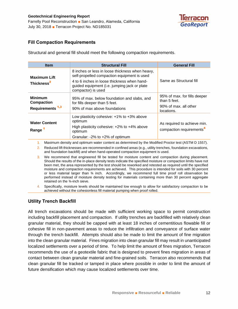
Fill Compaction Requirements
Structural and general fill should meet the following compaction requirements.
Item Structural Fill General Fill
Maximum Lift
Thickness2
8 inches or less in loose thickness when heavy, self-propelled compaction equipment is used
4 to 6 inches in loose thickness when hand-guided equipment (i.e. jumping jack or plate compactor) is used
Same as Structural fill
Minimum Compaction
Requirements 1,3
95% of max. below foundation and slabs, and for fills deeper than 5 feet.
90% of max above foundations
95% of max. for fills deeper than 5 feet.
90% of max. all other locations.
Water Content
Range 1
Low plasticity cohesive: +1% to +3% above optimum
High plasticity cohesive: +2% to +4% above optimum
Granular: -2% to +2% of optimum
As required to achieve min.
compaction requirements4
1. Maximum density and optimum water content as determined by the Modified Proctor test (ASTM D 1557).
2. Reduced lift thicknesses are recommended in confined areas (e.g., utility trenches, foundation excavations, and foundation backfill) and when hand-operated compaction equipment is used.
3. We recommend that engineered fill be tested for moisture content and compaction during placement. Should the results of the in-place density tests indicate the specified moisture or compaction limits have not been met, the area represented by the test should be reworked and retested as required until the specified moisture and compaction requirements are achieved. This procedure is intended for soils with 30 percent or less material larger than ¾ inch. Accordingly, we recommend full time proof roll observation be performed instead of moisture density testing for materials containing more than 30 percent aggregate retained on the ¾-inch sieve.
4. Specifically, moisture levels should be maintained low enough to allow for satisfactory compaction to be achieved without the cohesionless fill material pumping when proof rolled.
Utility Trench Backfill
All trench excavations should be made with sufficient working space to permit construction
including backfill placement and compaction. If utility trenches are backfilled with relatively clean
granular material, they should be capped with at least 18 inches of cementitious flowable fill or
cohesive fill in non-pavement areas to reduce the infiltration and conveyance of surface water
through the trench backfill. Attempts should also be made to limit the amount of fine migration
into the clean granular material. Fines migration into clean granular fill may result in unanticipated
localized settlements over a period of time. To help limit the amount of fines migration, Terracon
recommends the use of a geotextile fabric that is designed to prevent fines migration in areas of
contact between clean granular material and fine-grained soils. Terracon also recommends that
clean granular fill be tracked or tamped in place where possible in order to limit the amount of
future densification which may cause localized settlements over time.

Geotechnical Engineering Report
Farrelly Pool Reconstruction San Leandro, Alameda, California
July 30, 2018 Terracon Project No. ND185031
Responsive Resourceful Reliable 13
Utility trenches are a common source of water infiltration and migration. Utility trenches
penetrating beneath the building should be effectively sealed to restrict water intrusion and flow
through the trenches, which could migrate below the building and the expansion. The trench
should provide an effective trench plug that extends at least 5 feet from the face of the building
exterior. The plug material should consist of cementitious flowable fill or low permeability clay.
The trench plug material should be placed to surround the utility line. If used, the clay trench plug
material should be placed and compacted to comply with the water content and compaction
recommendations for structural fill stated previously in this report.
Grading and Drainage
All grades must provide effective drainage away from the building and swimming pools during
and after construction and should be maintained throughout the life of the structures. Water
retained next to the improvements can result in soil movements greater than those discussed in
this report. Greater movements can result in unacceptable differential slab and/or foundation/pool
shell movements, cracked slabs and walls, and roof leaks. The roof should have gutters/drains
with downspouts that discharge onto splash blocks at a distance of at least 10 feet from the
building.
Exposed ground should be sloped and maintained at a minimum 5 percent away from the building
for at least 10 feet beyond the perimeter of the building. Locally, flatter grades may be necessary
to transition ADA access requirements for flatwork. After building construction and landscaping,
final grades should be verified to document effective drainage has been achieved. Grades around
the structure should also be periodically inspected and adjusted as necessary as part of the
structure’s maintenance program. Where paving or flatwork abuts the structure a maintenance
program should be established to effectively seal and maintain joints and prevent surface water
infiltration.
Planters or bio-swales located within 10 feet of the improvements should be self-contained or
lined with an impermeable membrane to prevent water from accessing subgrade soils. Sprinkler
mains and spray heads should be located a minimum of 5 feet away from the building lines.
Trees or other vegetation whose root systems have the ability to remove excessive moisture from
the subgrade and foundation soils should not be planted next to the structures. Trees and
shrubbery should be kept away from the exterior of the structures a distance at least equal to their
expected mature height.
Earthwork Construction Considerations
Shallow excavations for the proposed structures are anticipated to be accomplished with
conventional construction equipment. Upon completion of filling and grading, care should be taken
to maintain the subgrade water content prior to construction of floor and exterior slabs.
Geotechnical Engineering Report
Farrelly Pool Reconstruction San Leandro, Alameda, California
July 30, 2018 Terracon Project No. ND185031
Responsive Resourceful Reliable 14
Construction traffic over the completed subgrades should be avoided. The site should also be
graded to prevent ponding of surface water on the prepared subgrades or in excavations. Water
collecting over, or adjacent to, construction areas should be removed. If the subgrade freezes,
desiccates, saturates, or is disturbed, the affected material should be removed, or the materials
should be scarified, moisture conditioned, and recompacted, prior to floor slab construction.
As a minimum, excavations should be performed in accordance with OSHA 29 CFR, Part 1926,
Subpart P, “Excavations” and its appendices, and in accordance with any applicable local, and/or
state regulations. In addition, contractor is responsible for maintaining the stability of adjacent
structures during construction.
Construction site safety is the sole responsibility of the contractor who controls the means,
methods, and sequencing of construction operations. Under no circumstances shall the
information provided herein be interpreted to mean Terracon is assuming responsibility for
construction site safety, or the contractor's activities; such responsibility shall neither be implied
nor inferred.
Construction Observation and Testing
The earthwork efforts should be monitored under the direction of the Geotechnical Engineer.
Monitoring should include documentation of adequate removal of hardscape, vegetation and top
soil, proof-rolling and mitigation of areas delineated by the proof-roll to require mitigation.
Each lift of compacted fill should be tested, evaluated, and reworked as necessary until approved
by the Geotechnical Engineer prior to placement of additional lifts. Each lift of fill should be tested
for density and water content at a frequency of at least one test for every 2,500 square feet of
compacted fill. One density and water content test per lift should be performed for every 20 linear
feet of compacted utility trench backfill.
In areas of pool and foundation excavations, the bearing subgrade and foundation excavations
should be evaluated under the direction of the Geotechnical Engineer. In the event that
unanticipated conditions are encountered, the Geotechnical Engineer should prescribe mitigation
options.
In addition to the documentation of the essential parameters necessary for construction, the
continuation of the Geotechnical Engineer into the construction phase of the project provides the
continuity to maintain the Geotechnical Engineer’s evaluation of subsurface conditions, including
assessing variations and associated design changes.

Geotechnical Engineering Report
Farrelly Pool Reconstruction San Leandro, Alameda, California
July 30, 2018 Terracon Project No. ND185031
Responsive Resourceful Reliable 15
SHALLOW FOUNDATIONS
If the site has been prepared in accordance with the requirements noted in Earthwork, the
building expansion can be supported by spread footings designed per following design
parameters.
Design Parameters – Compressive Loads
Item Description
Maximum Net Allowable Bearing
pressure 1, 2
1,500 psf
Required Bearing Stratum Firm native soil
Minimum Foundation Width
Maximum Foundation Width
12 inches
30 inches
Ultimate Passive Resistance 3,7
(equivalent fluid pressures) 300 pcf
Ultimate Coefficient of Sliding Friction 4,7
0.30
Minimum Embedment below
Finished Grade 5
18 inches
Estimated Total Settlement from
Structural Loads 1
Less than about 1 inch
Estimated Differential Settlement 1, 6
About 1/2 of total settlement
1. The maximum net allowable bearing pressure is the pressure in excess of the minimum surrounding overburden pressure at the footing base elevation. An appropriate factor of safety has been applied. These bearing pressures can be increased by 1/3 for transient loads unless those loads have been factored to account for transient conditions. Values assume that exterior grades are no steeper than 20% within 10 feet of structure.
2. Values provided are for maximum loads noted in Project Description.
3. Use of passive earth pressures require the sides of the excavation for the spread footing foundation to be nearly vertical and the concrete placed neat against these vertical faces or that the footing forms be removed and compacted structural fill be placed against the vertical footing face.
4. Can be used to compute sliding resistance where foundations are placed on suitable soil/materials. Should be neglected for foundations subject to net uplift conditions.
5. Embedment necessary to minimize the effects of seasonal water content variations. For sloping ground, maintain depth below the lowest adjacent exterior grade within 5 horizontal feet of the structure.
6. Differential settlements are as measured over a span of 40 feet. 7. Passive pressure and sliding friction may be combined to resist sliding provided the passive pressure is
reduced by 50 percent.
Construction Adjacent to Existing Building
Differential settlement between the building expansion and the existing building is expected to
approach the magnitude of the total settlement of the addition. Expansion joints should be
provided between the existing building and the proposed expansion to accommodate differential

Geotechnical Engineering Report
Farrelly Pool Reconstruction San Leandro, Alameda, California
July 30, 2018 Terracon Project No. ND185031
Responsive Resourceful Reliable 16
movements between the structures. Underground piping between the two structures should be
designed with flexible couplings and utility knockouts in foundation walls should be oversized, so
minor deflections in alignment do not result in breakage or distress. Care should be taken during
excavation adjacent to existing foundations, to avoid disturbing existing foundation bearing soils.
New footings should bear at or near the bearing elevation of immediately adjacent existing
foundations. Depending upon their locations and current loads on the existing footings, footings
for the new expansion could cause settlement of adjacent walls. To reduce this concern and risk,
clear distances at least equal to the new footing widths should be maintained between the
expansion’s footings and footings supporting the existing building.
Foundation Construction Considerations
As noted in Earthwork, the footing excavations should be evaluated under the direction of the
Geotechnical Engineer. The base of all foundation excavations should be free of water and loose
soil, prior to placing concrete. Concrete should be placed soon after excavating to reduce bearing
soil disturbance. Care should be taken to prevent wetting or drying of the bearing materials during
construction. Excessively wet or dry material or any loose/disturbed material in the bottom of the
footing excavations should be removed/reconditioned before foundation concrete is placed.
To ensure foundations have adequate support, special care should be taken when footings are
located adjacent to trenches. The bottom of such footings should be at least 1 foot below an
imaginary plane with an inclination of 1½ horizontal to 1 vertical extending upward from the
nearest edge of the adjacent trench.
If unsuitable bearing soils are encountered at the base of the planned footing excavation, the
excavation should be extended deeper to suitable soils, and the footings could bear directly on
these soils at the lower level or on lean concrete backfill placed in the excavations. This is
illustrated on the sketch below.

Geotechnical Engineering Report
Farrelly Pool Reconstruction San Leandro, Alameda, California
July 30, 2018 Terracon Project No. ND185031
Responsive Resourceful Reliable 17
Over-excavation for structural fill placement below footings should be conducted as shown below.
The over-excavation should be backfilled up to the footing base elevation, with structural fill
placed, as recommended in the Earthwork section.
POOL RECOMMENDATIONS
The pool shell may be constructed as a conventional pool shell provided the pool bears into the
underlying native medium stiff to very stiff soils. We have assumed the new pool depths will be
as deep or deeper than the existing pool depths. Pool walls that will be placed against engineered
fill should be designed for both retaining and free-standing conditions.

Geotechnical Engineering Report
Farrelly Pool Reconstruction San Leandro, Alameda, California
July 30, 2018 Terracon Project No. ND185031
Responsive Resourceful Reliable 18
Pool walls should be designed to resist a lateral earth pressure of 60 pounds per cubic foot (pcf)
equivalent fluid pressure for walls with flat backfill.
If groundwater or seepage is encountered in the pool excavation, the pool should be underlain by
a 6-inch thick layer of 3/4-inch clean gravel underlain by Mirafi 140N filter fabric or Caltrans Class
II permeable material. A 4-inch diameter perforated Schedule 40 PVC or ABS pipe should be
installed in the gravel at the deepest point. The perforated pipe should slope at a 2 percent
minimum grade to a tight line at the edge of the pool that carries the drainage to an existing
drainage system or to an observation well where water can be removed by pumping.
SEISMIC CONSIDERATIONS
The seismic design requirements for buildings and other structures are based on Seismic Design
Category. Site Classification is required to determine the Seismic Design Category for a structure.
The Site Classification is based on the upper 100 feet of the site profile defined by a weighted
average value of either shear wave velocity, standard penetration resistance, or undrained shear
strength in accordance with Section 20.4 of ASCE 7-10.
Description Value
2016 California Building Code Site Classification (CBC) 1 D
2
Site Latitude 37.7349°N
Site Longitude 122.1464°W
Ss, Spectral Acceleration for a Short Period3 2.401g
S1, Spectral Acceleration for a 1-Second Period3 0.999g
Fa, Site Coefficient3 1.0
Fv, Site Coefficient (1-second period)3 1.5
SDS, Spectral Acceleration for a Short Period3 1.601g
SD1, Spectral Acceleration for a 1-Second Period3
0.999g
1. Seismic site classification in general accordance with the 2016 California Building Code.
2. The 2016 California Building Code (CBC) requires a site soil profile determination extending a depth of 100
feet for seismic site classification. A CPT was extended to a maximum depth of approximately 94 feet. 3. These values were obtained using online seismic design maps and tools provided by the USGS
(http://earthquake.usgs.gov/hazards/designmaps/).
Faulting and Estimated Ground Motions
The site is located in the San Francisco Bay Area of California, which is a relatively high seismicity
region. The type and magnitude of seismic hazards affecting the site are dependent on the
Geotechnical Engineering Report
Farrelly Pool Reconstruction San Leandro, Alameda, California
July 30, 2018 Terracon Project No. ND185031
Responsive Resourceful Reliable 19
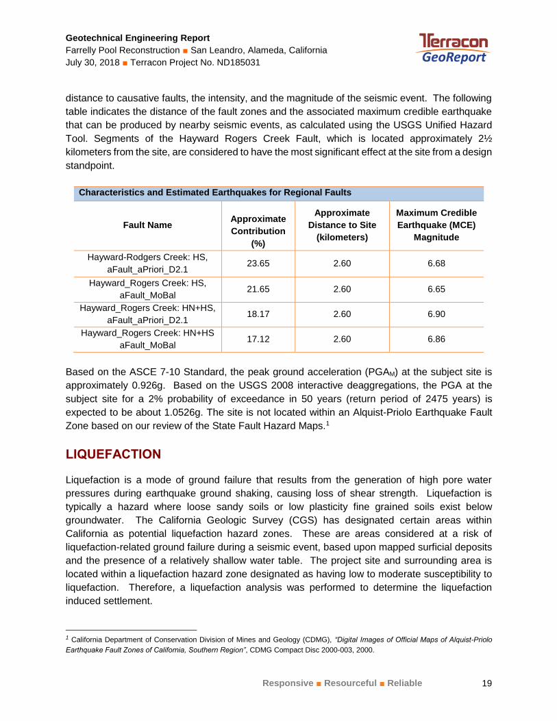
distance to causative faults, the intensity, and the magnitude of the seismic event. The following
table indicates the distance of the fault zones and the associated maximum credible earthquake
that can be produced by nearby seismic events, as calculated using the USGS Unified Hazard
Tool. Segments of the Hayward Rogers Creek Fault, which is located approximately 2½
kilometers from the site, are considered to have the most significant effect at the site from a design
standpoint.
Characteristics and Estimated Earthquakes for Regional Faults
Fault Name
Approximate
Contribution
(%)
Approximate
Distance to Site
(kilometers)
Maximum Credible
Earthquake (MCE)
Magnitude
Hayward-Rodgers Creek: HS,
aFault_aPriori_D2.1 23.65 2.60 6.68
Hayward_Rogers Creek: HS,
aFault_MoBal 21.65 2.60 6.65
Hayward_Rogers Creek: HN+HS,
aFault_aPriori_D2.1 18.17 2.60 6.90
Hayward_Rogers Creek: HN+HS
aFault_MoBal 17.12 2.60 6.86
Based on the ASCE 7-10 Standard, the peak ground acceleration (PGAM) at the subject site is
approximately 0.926g. Based on the USGS 2008 interactive deaggregations, the PGA at the
subject site for a 2% probability of exceedance in 50 years (return period of 2475 years) is
expected to be about 1.0526g. The site is not located within an Alquist-Priolo Earthquake Fault
Zone based on our review of the State Fault Hazard Maps.1
LIQUEFACTION
Liquefaction is a mode of ground failure that results from the generation of high pore water
pressures during earthquake ground shaking, causing loss of shear strength. Liquefaction is
typically a hazard where loose sandy soils or low plasticity fine grained soils exist below
groundwater. The California Geologic Survey (CGS) has designated certain areas within
California as potential liquefaction hazard zones. These are areas considered at a risk of
liquefaction-related ground failure during a seismic event, based upon mapped surficial deposits
and the presence of a relatively shallow water table. The project site and surrounding area is
located within a liquefaction hazard zone designated as having low to moderate susceptibility to
liquefaction. Therefore, a liquefaction analysis was performed to determine the liquefaction
induced settlement.
1 California Department of Conservation Division of Mines and Geology (CDMG), “Digital Images of Official Maps of Alquist-Priolo
Earthquake Fault Zones of California, Southern Region”, CDMG Compact Disc 2000-003, 2000.

Geotechnical Engineering Report
Farrelly Pool Reconstruction San Leandro, Alameda, California
July 30, 2018 Terracon Project No. ND185031
Responsive Resourceful Reliable 20
Groundwater was observed in the CPT at the time of field exploration at depth of 32 feet bgs.
A liquefaction analysis was performed in general accordance with California Geologic Survey
Special Publication 117. The liquefaction study utilized the software “CLiq” by GeoLogismiki
Geotechnical Software. This analysis was based on the soil data from the CPT sounding. A Peak
Ground Acceleration (PGA) of 0.926g and a mean magnitude of 6.76 for the project site was used.
Analysis were performed on data obtained from CPT1. CPT calculations were assessed using
the Robertson (NCEER 2001), Robertson (2009), Idriss & Boulanger (2008), and Boulanger &
Idriss (2014) methods.
A liquefaction potential analysis was calculated from a depth of 32 to 50 feet below the ground
surface. Based on the analysis, liquefiable layers most susceptible to liquefaction potential were
encountered between the depths of approximately 32 to 45 feet bgs. Due to the cohesive nature
and thickness of non-liquefiable soils across the surface of the site, we believe the probability for
liquefaction to manifest at the surface is low. However, based on our review of the calculations
by the various methods, the anticipated potential total liquefaction-induced settlement is on the
order of 1
3 inches. Actual settlement could vary by a factor of 2. The differential liquefaction-
induced settlement may be considered to be half the total liquefaction induced settlement. Since
the project site is relatively level ground, the potential for lateral spreading is considered to be
low.
FLOOR SLABS
We understand that the building expansion will be constructed with a concrete slab-on-grade floor.
The surficial soils are comprised of moderately plasticity sandy lean clay exhibiting the potential for
volume change with changes in moisture. Changes in water content could cause the subgrade soils
to shrink and swell damaging the slabs. In order to help mitigate the effects of the moderately plastic
soils on the building slabs we recommend an 18 inch, low volume change (LVC) zone be
constructed beneath the at-grade slabs. Using an 18 inch, LVC zone as recommended in this
report may not eliminate all future subgrade volume change and resultant slab movements.
However, the procedures outlined herein should help to reduce the potential for subgrade volume
change. LVC fill should meet the specifications and be placed and compacted as recommended
in Earthwork section of this report.
Due to the potential for significant moisture fluctuations of subgrade material beneath floor slabs
supported at-grade, the Geotechnical Engineer should evaluate the material within 12 inches of
the bottom of the LVC zone immediately prior to placement of additional fill or floor slabs. Soils
below the specified water contents within this zone should be moisture conditioned or replaced
with structural fill as stated in our Earthwork section.

Geotechnical Engineering Report
Farrelly Pool Reconstruction San Leandro, Alameda, California
July 30, 2018 Terracon Project No. ND185031
Responsive Resourceful Reliable 21
Design parameters for floor slabs assume the requirements for Earthwork have been followed.
Specific attention should be given to positive drainage away from the structure.
Floor Slab Design Parameters
Item Description
Floor Slab Support 1
At least 18 inches of low volume change (LVC) material as described for
structural fill in the Fill Material Types section
Estimated Modulus of
Subgrade Reaction 2
80 pounds per square inch per inch (psi/in) for point loads
Capillary Break Layer
Thickness 3, 4
Minimum 4 inches of free-draining (less than 6% passing the U.S. No. 200
sieve) crushed aggregate compacted to at least 95% of ASTM D 698
1. Floor slabs should be structurally independent of building foundations or walls to reduce the possibility of
floor slab cracking caused by differential movements between the slab and foundation.
2. Modulus of subgrade reaction is an estimated value based upon our experience with the subgrade
condition, the requirements noted in Earthwork, and the floor slab support as noted in this table. It is
provided for point loads.
3. Free-draining granular material should have less than 5 percent fines (material passing the #200 sieve).
Other design considerations such as cold temperatures and condensation development could warrant more
extensive design provisions.
4. These granular materials are in addition to the LVC zone.
The use of a vapor retarder should be considered beneath concrete slabs on grade covered with
wood, tile, carpet, or other moisture sensitive or impervious coverings, or when the slab will
support equipment sensitive to moisture. When conditions warrant the use of a vapor retarder,
LVC Material
Drainage Layer
Concrete Slab-on-Grade
4 inches
Minimum
18 inches
Minimum
22 inches
Minimum

Geotechnical Engineering Report
Farrelly Pool Reconstruction San Leandro, Alameda, California
July 30, 2018 Terracon Project No. ND185031
Responsive Resourceful Reliable 22
the slab designer should refer to ACI 302 and/or ACI 360 for procedures and cautions regarding
the use and placement of a vapor retarder.
Saw-cut control joints should be placed in the slab to help control the location and extent of
cracking. For additional recommendations refer to the ACI Design Manual. Joints or cracks should
be sealed with a water-proof, non-extruding compressible compound specifically recommended
for heavy duty concrete pavement and wet environments.
Where floor slabs are tied to perimeter walls or turn-down slabs to meet structural or other
construction objectives, our experience indicates differential movement between the walls and
slabs will likely be observed in adjacent slab expansion joints or floor slab cracks beyond the
length of the structural dowels. The Structural Engineer should account for potential differential
settlement through use of sufficient control joints, appropriate reinforcing or other means.
Floor Slab Construction Considerations
Finished subgrade within and for at least 10 feet beyond the floor slab should be protected from
traffic, rutting, or other disturbance and maintained in a relatively moist condition until floor slabs are
constructed. If the subgrade should become damaged or desiccated prior to construction of floor
slabs, the affected material should be removed and structural fill should be added to replace the
resulting excavation. Final conditioning of the finished subgrade should be performed immediately
prior to placement of the floor slab support course.
The Geotechnical Engineer should approve the condition of the floor slab subgrades immediately
prior to placement of the floor slab support course, reinforcing steel and concrete. Attention should
be paid to high traffic areas that were rutted and disturbed earlier, and to areas where backfilled
trenches are located.
Exterior Slab and Flatwork Design and Construction
Exterior slabs-on-grade, exterior architectural features, and utilities founded on, or in backfill may
experience some movement due to the volume change of the backfill. To reduce the potential for
damage caused by movement, we recommend:
Slabs underlain by a minimum 18 inches of compacted LVC material
Minimizing moisture increases in the backfill;
Controlling moisture-density during placement of backfill;
Using designs which allow vertical movement between the exterior features and
adjoining structural elements;
Placing effective control joints on relatively close centers.
Ensure clay subgrade soils are in a moist condition prior to slab construction.

Geotechnical Engineering Report
Farrelly Pool Reconstruction San Leandro, Alameda, California
July 30, 2018 Terracon Project No. ND185031
Responsive Resourceful Reliable 23
Reinforce exterior slabs and flatwork with a minimum No. 4 bars at 12 inches on
center.
Maintain slabs structurally independent from the swimming pool shells.
CORROSIVITY
The table below lists the results of laboratory soluble sulfate, soluble chloride, electrical resistivity,
and pH testing. The values may be used to estimate potential corrosive characteristics of the on-
site soils with respect to contact with the various underground materials which will be used for
project construction. These test results are provided to assist in determining the type and degree
of corrosion protection that may be required for the project. We recommend that a certified
corrosion engineer determine the need for corrosion protection and design appropriate protective
measures.
Corrosivity Test Results Summary
Boring
Sample
Depth
(feet)
Soil Description
Soluble
Sulfate
(ppm)
Soluble
Chloride
(ppm)
Electrical
Resistivity
(Ω-cm)
pH
B-3 2 Sandy lean clay 151 105 2037 9.89
Resistivity
The resistivity test results indicate that the samples tested exhibit a moderate corrosive potential
to buried metal pipes. Evaluation of the test results is based upon the guidelines of J.F. Palmer,
“Soil Resistivity Measurements and Analysis”, Materials Performance, Volume 13, January 1974.
The following table outlines the guidelines for soil resistivity for corrosion potential.
Corrosion Potential of Soil on Steel
Soil Resistivity (ohm-cm) Corrosion Potential
0 to 1,000 Very High
1,000 to 2,000 High
2,000 to 5,000 Moderate
> 5,000 Mild
Sulfates
Results of soluble sulfate testing indicate samples of the on-site soils tested possess moderate
sulfate concentrations when classified in accordance with Table 19.3.1.1 of the ACI Design
Manual. Concrete should be designed in accordance with the provisions of the ACI Design

Geotechnical Engineering Report
Farrelly Pool Reconstruction San Leandro, Alameda, California
July 30, 2018 Terracon Project No. ND185031
Responsive Resourceful Reliable 24
Manual, Section 318, Chapter 19. For Exposure Class S1, ACI 318-14, Section 19.3 requires the
use of Type II cement, a maximum water/cement ratio of 0.50, and a minimum compressive
strength of 4,000 psi.
Laboratory pH
Data suggests the soil pH should not be the dominant soil variable affecting soil corrosion if the
soil has a pH in the 5 to 8 range. Based on our laboratory pH test, the soil sample tested has a
pH value of 9.89. The pH of the sample is outside the recommended range, and therefore should
be considered when determining soil corrosion potential.
GENERAL COMMENTS
As the project progresses, we address assumptions by incorporating information provided by the
design team, if any. Revised project information that reflects actual conditions important to our
services is reflected in the final report. The design team should collaborate with Terracon to
confirm these assumptions and to prepare the final design plans and specifications. This facilitates
the incorporation of our opinions related to implementation of our geotechnical recommendations.
Any information conveyed prior to the final report is for informational purposes only and should
not be considered or used for decision-making purposes.
Our analysis and opinions are based upon our understanding of the project, the geotechnical
conditions in the area, and the data obtained from our site exploration. Natural variations will occur
between exploration point locations or due to the modifying effects of construction or weather.
The nature and extent of such variations may not become evident until during or after construction.
Terracon should be retained as the Geotechnical Engineer, where noted in the final report, to
provide observation and testing services during pertinent construction phases. If variations
appear, we can provide further evaluation and supplemental recommendations. If variations are
noted in the absence of our observation and testing services on-site, we should be immediately
notified so that we can provide evaluation and supplemental recommendations.
Our scope of services does not include either specifically or by implication any environmental or
biological (e.g., mold, fungi, bacteria) assessment of the site or identification or prevention of
pollutants, hazardous materials or conditions. If the owner is concerned about the potential for
such contamination or pollution, other studies should be undertaken.
Our services and any correspondence or collaboration through this system are intended for the
sole benefit and exclusive use of our client for specific application to the project discussed and
are accomplished in accordance with generally accepted geotechnical engineering practices with
no third party beneficiaries intended. Any third party access to services or correspondence is
solely for information purposes to support the services provided by Terracon to our client. Reliance
upon the services and any work product is limited to our client, and is not intended for third parties.

Geotechnical Engineering Report
Farrelly Pool Reconstruction San Leandro, Alameda, California
July 30, 2018 Terracon Project No. ND185031
Responsive Resourceful Reliable 25
Any use or reliance of the provided information by third parties is done solely at their own risk. No
warranties, either express or implied, are intended or made.
Site characteristics as provided are for design purposes and not to estimate excavation cost. Any
use of our report in that regard is done at the sole risk of the excavating cost estimator as there
may be variations on the site that are not apparent in the data that could significantly impact
excavation cost. Any parties charged with estimating excavation costs should seek their own site
characterization for specific purposes to obtain the specific level of detail necessary for costing.
Site safety, and cost estimating including, excavation support, and dewatering
requirements/design are the responsibility of others. If changes in the nature, design, or location
of the project are planned, our conclusions and recommendations shall not be considered valid
unless we review the changes and either verify or modify our conclusions in writing. This report
should not be used after 3 years from the date of this report without written authorization from
Terracon.

ATTACHM ENTS
ATTACHMENTS

Geotechnical Engineering Report
Farrelly Pool Reconstruction San Leandro, Alameda, California
July 30, 2018 Terracon Project No. ND185031
Responsive Resourceful Reliable
EXPLORATION AND TESTING PROCEDURES
Field Exploration
Number of Borings/CPTs Boring/CPT Depth (feet) Planned Location
4 11½ to 16½ Planned pool footprints
1 16½ Planned building expansion area
1 CPT1 94 West of swimming pool area
1. Cone Penetration Test
Boring/CPT Layout: The boring/CPT layout was performed by Terracon. Coordinates were
obtained with a handheld GPS unit (estimated horizontal accuracy of about ±20 feet). If a more
precise boring/CPT layout are desired, we recommend borings/CPTs be surveyed following
completion of fieldwork.
Subsurface Exploration Procedures: We advanced the borings with a truck-mounted and
Superman portable drill rig using continuous flight, solid stem augers. Two to three samples were
obtained in the upper 10 feet of each boring and at intervals of 5 feet thereafter. Soil sampling was
performed using split-barrel sampling procedure. In the split-barrel sampling procedure, a standard
2-inch outer diameter split-barrel sampling spoon was driven into the ground by a 140-pound
automatic hammer falling a distance of 30 inches. The number of blows required to advance the
sampling spoon the last 12 inches of a normal 18-inch penetration was recorded as the Standard
Penetration Test (SPT) resistance value. The SPT resistance values, also referred to as N-values,
are indicated on the boring logs at the test depths. The values provided on our boring logs are
uncorrected. Additionally, we observed and recorded groundwater levels during drilling and
sampling. Per the requirements of the local environmental health department and for safety
purposes, all borings and the CPT were backfilled with grout after their completion. Pavements
were patched with cold-mix asphalt.
For the cone penetrometer testing, the CPT hydraulically pushed an instrumented cone through
the soil while nearly continuous readings were recorded to a portable computer. The cone is
equipped with electronic load cells to measure tip resistance and sleeve resistance and a
pressure transducer to measure the generated ambient pore pressure. The face of the cone has
an apex angle of 60° and an area of 15 cm2. Digital Data representing the tip resistance, friction
resistance, pore water pressure, and probe inclination angle were recorded about every 2
centimeters while advancing through the ground at a rate between 1½ and 2½ centimeters per
second. These measurements were correlated to various soil properties used for geotechnical
design. No soil samples are gathered through this subsurface investigation technique. CPT
testing was conducted in general accordance with ASTM D5778 “Standard Test Method for
Performing Electronic Friction Cone and Piezocone Penetration Testing of Soils.”

Geotechnical Engineering Report
Farrelly Pool Reconstruction San Leandro, Alameda, California
July 30, 2018 Terracon Project No. ND185031
Responsive Resourceful Reliable
The sampling depths, penetration distances, and other sampling information were recorded on the
field boring logs. The samples were placed in appropriate containers and taken to a Terracon soil
laboratory for testing and classification by a geotechnical engineer. Our exploration team prepared
field boring logs as part of the drilling operations. These field logs include visual classifications of
the materials encountered during drilling and our interpretation of the subsurface conditions
between samples. Final boring logs were prepared from the field logs. The final boring logs
represent the geotechnical engineer's interpretation of the field logs and include modifications
based on observations and tests of the samples in our laboratory.
Laboratory Testing
The project engineer reviewed the field data and assigned various laboratory tests to better
understand the engineering properties of the various soil strata as necessary for this project.
Procedural standards noted below are for reference to methodology in general. In some cases,
variations to methods are applied because of local practice or professional judgment. Standards
noted below include reference to other, related standards. Such references are not necessarily
applicable to describe the specific test performed.
ASTM D2216 Standard Test Methods for Laboratory Determination of Water (Moisture)
Content of Soil and Rock by Mass
ASTM D4318 Standard Test Methods for Liquid Limit, Plastic Limit, and Plasticity Index of
Soils
ASTM D1140 Standard Test Method for Determining the Amount of Material Finer than
No. 200 Sieve by Soil Washing
ASTM G162 – 99 Standard Practice for Conducting and Evaluating Laboratory Corrosion
Tests in Soils
The laboratory testing program often includes examination of soil samples by an engineer. Based
on the material’s texture and plasticity, we describe and classify the soil samples in accordance
with the Unified Soil Classification System.

SITE LOC ATION AND EXPLOR ATION PLAN S
SITE LOCATION AND EXPLORATION PLANS

SITE LOCATION and NEARBY GEOTECHNICAL DATA
Farrelly Pool Reconstruction San Leandro, Alameda, California
July 30, 2018 Terracon Project No. ND185031
SITE LOC ATION PLAN
DIAGRAM IS FOR GENERAL LOCATION ONLY, AND IS NOT INTENDED FOR CONSTRUCTION PURPOSES MAP PROVIDED BY MICROSOFT BING MAPS

EXPLORATION PLAN
Farrelly Pool Reconstruction San Leandro, Alameda, California
July 30, 2018 Terracon Project No. ND185031
EXHIB IT E LAND SC APE
DIAGRAM IS FOR GENERAL LOCATION ONLY, AND IS NOT INTENDED FOR CONSTRUCTION PURPOSES MAP PROVIDED BY MICROSOFT BING MAPS

EXPLOR ATION RESULTS
EXPLORATION RESULTS

16
19
18
18
16
93
101
104
7-8-11
9-12-15
7-11-18
9-12-16
9-9-8
0.30.6
6.5
12.5
16.5
ASPHALT, 3" thickAGGREGATE BASE COURSE, 4" thickSANDY LEAN CLAY (CL), fine grained, dark brown, stiff to very stiff
SANDY LEAN CLAY (CL), fine grained, brown, very stiff
SILTY SAND (SM), fine to medium grained, brown, medium dense
Boring Terminated at 16.5 Feet
4.5+(HP)
4.5+(HP)
3.0(HP)
GR
AP
HIC
LO
G
Hammer Type: Rope and CatheadStratification lines are approximate. In-situ, the transition may be gradual.
TH
IS B
OR
ING
LO
G IS
NO
T V
ALI
D IF
SE
PA
RA
TE
D F
RO
M O
RIG
INA
L R
EP
OR
T.
G
EO
SM
AR
T L
OG
-NO
WE
LL N
D18
5031
FA
RR
ELL
Y P
OO
L R
EC
.GP
J T
ER
RA
CO
N_D
AT
AT
EM
PLA
TE
.GD
T 7
/24/
18
PE
RC
EN
T F
INE
S
WA
TE
RC
ON
TE
NT
(%
)
DR
Y U
NIT
WE
IGH
T (
pcf)
LL-PL-PI
ATTERBERGLIMITS
WA
TE
R L
EV
EL
OB
SE
RV
AT
ION
S
DE
PT
H (
Ft.)
5
10
15
SA
MP
LE T
YP
E
FIE
LD T
ES
TR
ES
ULT
S
DEPTH
LOCATION See Exploration Plan
Latitude: 37.735° Longitude: -122.1462°
Page 1 of 1
Advancement Method:4" Solid stem Auger
Abandonment Method:Boring backfilled with cement-bentonite grout uponcompletion.
5075 Commercial Cir Ste EConcord, CA
Notes:
Project No.: ND185031
Drill Rig: B-24
Boring Started: 06-29-2018
BORING LOG NO. B1City of San LeandroCLIENT:San Leandro, CA
Driller: CG
Boring Completed: 06-29-2018
PROJECT: Farrelly Pool Reconstruction
See Exploration and Testing Procedures for adescription of field and laboratory proceduresused and additional data (If any).
See Supporting Information for explanation ofsymbols and abbreviations.
864 Dutton Avenue San Leandro, CASITE:
Groundwater not encounteredWATER LEVEL OBSERVATIONS
LAB
OR
AT
OR
YH
P (
tsf)

6925
18
18
87
99
103
29-15-141-2-3
7-10-15
6-11-13
0.7
5.0
11.5
CONCRETE, 8" thick
SANDY LEAN CLAY (CL), fine grained, dark brown, soft to mediumstiff
SANDY LEAN CLAY (CL), fine grained, brown, very stiff
Boring Terminated at 11.5 Feet
0.5(HP)
4.5(HP)
3.0(HP)
GR
AP
HIC
LO
G
Hammer Type: Rope and CatheadStratification lines are approximate. In-situ, the transition may be gradual.
TH
IS B
OR
ING
LO
G IS
NO
T V
ALI
D IF
SE
PA
RA
TE
D F
RO
M O
RIG
INA
L R
EP
OR
T.
G
EO
SM
AR
T L
OG
-NO
WE
LL N
D18
5031
FA
RR
ELL
Y P
OO
L R
EC
.GP
J T
ER
RA
CO
N_D
AT
AT
EM
PLA
TE
.GD
T 7
/24/
18
PE
RC
EN
T F
INE
S
WA
TE
RC
ON
TE
NT
(%
)
DR
Y U
NIT
WE
IGH
T (
pcf)
LL-PL-PI
ATTERBERGLIMITS
WA
TE
R L
EV
EL
OB
SE
RV
AT
ION
S
DE
PT
H (
Ft.)
5
10
SA
MP
LE T
YP
E
FIE
LD T
ES
TR
ES
ULT
S
DEPTH
LOCATION See Exploration Plan
Latitude: 37.735° Longitude: -122.1463°
Page 1 of 1
Advancement Method:4" Solid stem Auger
Abandonment Method:Boring backfilled with cement-bentonite grout uponcompletion.
5075 Commercial Cir Ste EConcord, CA
Notes:
Project No.: ND185031
Drill Rig: Superman
Boring Started: 06-29-2018
BORING LOG NO. B2City of San LeandroCLIENT:San Leandro, CA
Driller: CG
Boring Completed: 06-29-2018
PROJECT: Farrelly Pool Reconstruction
See Exploration and Testing Procedures for adescription of field and laboratory proceduresused and additional data (If any).
See Supporting Information for explanation ofsymbols and abbreviations.
864 Dutton Avenue San Leandro, CASITE:
Groundwater not encounteredWATER LEVEL OBSERVATIONS
LAB
OR
AT
OR
YH
P (
tsf)

24
19
22
18
88
103
100
102
3-4-7
8-13-18
6-7-9
5-7-8
0.7
5.0
8.5
14.0
16.5
CONCRETE, 8" thick
SANDY LEAN CLAY (CL), fine grained, dark brown, medium stiff tostiff
SANDY LEAN CLAY (CL), fine grained, dark brown, very stiff
SANDY LEAN CLAY (CL), fine grained, brown, stiff
SILTY SAND (SM), fine to medium grained, brown, medium dense
Boring Terminated at 16.5 Feet
0.5(HP)
3.25(HP)
GR
AP
HIC
LO
G
Hammer Type: Rope and CatheadStratification lines are approximate. In-situ, the transition may be gradual.
TH
IS B
OR
ING
LO
G IS
NO
T V
ALI
D IF
SE
PA
RA
TE
D F
RO
M O
RIG
INA
L R
EP
OR
T.
G
EO
SM
AR
T L
OG
-NO
WE
LL N
D18
5031
FA
RR
ELL
Y P
OO
L R
EC
.GP
J T
ER
RA
CO
N_D
AT
AT
EM
PLA
TE
.GD
T 7
/24/
18
PE
RC
EN
T F
INE
S
WA
TE
RC
ON
TE
NT
(%
)
DR
Y U
NIT
WE
IGH
T (
pcf)
LL-PL-PI
ATTERBERGLIMITS
WA
TE
R L
EV
EL
OB
SE
RV
AT
ION
S
DE
PT
H (
Ft.)
5
10
15
SA
MP
LE T
YP
E
FIE
LD T
ES
TR
ES
ULT
S
DEPTH
LOCATION See Exploration Plan
Latitude: 37.735° Longitude: -122.1465°
Page 1 of 1
Advancement Method:4" Solid stem Auger
Abandonment Method:Boring backfilled with cement-bentonite grout uponcompletion.
5075 Commercial Cir Ste EConcord, CA
Notes:
Project No.: ND185031
Drill Rig: Superman
Boring Started: 06-29-2018
BORING LOG NO. B3City of San LeandroCLIENT:San Leandro, CA
Driller: CG
Boring Completed: 06-29-2018
PROJECT: Farrelly Pool Reconstruction
See Exploration and Testing Procedures for adescription of field and laboratory proceduresused and additional data (If any).
See Supporting Information for explanation ofsymbols and abbreviations.
864 Dutton Avenue San Leandro, CASITE:
Groundwater not encounteredWATER LEVEL OBSERVATIONS
LAB
OR
AT
OR
YH
P (
tsf)

65
18
19
21
24
100
104
98
96
26-14-12
5-6-7
12-13-15
5-4-4
4-5-6
0.7
5.0
16.5
CONCRETE, 8" thick
SANDY LEAN CLAY (CL), fine grained, dark brown, stiff
SANDY LEAN CLAY (CL), fine grained, brown, medium stiff to verystiff
Boring Terminated at 16.5 Feet
1.75(HP)
3.0(HP)
1.5(HP)
1.5(HP)
GR
AP
HIC
LO
G
Hammer Type: Rope and CatheadStratification lines are approximate. In-situ, the transition may be gradual.
TH
IS B
OR
ING
LO
G IS
NO
T V
ALI
D IF
SE
PA
RA
TE
D F
RO
M O
RIG
INA
L R
EP
OR
T.
G
EO
SM
AR
T L
OG
-NO
WE
LL N
D18
5031
FA
RR
ELL
Y P
OO
L R
EC
.GP
J T
ER
RA
CO
N_D
AT
AT
EM
PLA
TE
.GD
T 7
/24/
18
PE
RC
EN
T F
INE
S
WA
TE
RC
ON
TE
NT
(%
)
DR
Y U
NIT
WE
IGH
T (
pcf)
LL-PL-PI
ATTERBERGLIMITS
WA
TE
R L
EV
EL
OB
SE
RV
AT
ION
S
DE
PT
H (
Ft.)
5
10
15
SA
MP
LE T
YP
E
FIE
LD T
ES
TR
ES
ULT
S
DEPTH
LOCATION See Exploration Plan
Latitude: 37.7347° Longitude: -122.1463°
Page 1 of 1
Advancement Method:4" Solid stem Auger
Abandonment Method:Boring backfilled with cement-bentonite grout uponcompletion.
5075 Commercial Cir Ste EConcord, CA
Notes:
Project No.: ND185031
Drill Rig: Superman
Boring Started: 06-29-2018
BORING LOG NO. B4City of San LeandroCLIENT:San Leandro, CA
Driller: CG
Boring Completed: 06-29-2018
PROJECT: Farrelly Pool Reconstruction
See Exploration and Testing Procedures for adescription of field and laboratory proceduresused and additional data (If any).
See Supporting Information for explanation ofsymbols and abbreviations.
864 Dutton Avenue San Leandro, CASITE:
Groundwater not encounteredWATER LEVEL OBSERVATIONS
LAB
OR
AT
OR
YH
P (
tsf)

20
19
21
100
104
100
3-3-4
2-12-15
6-6-7
0.7
5.0
11.5
CONCRETE, 8" thick
SANDY LEAN CLAY (CL), fine grained, dark brown, medium stiff,with pockets of well graded sand with gravel
SANDY LEAN CLAY (CL), fine grained, brown, stiff to very stiff
Boring Terminated at 11.5 Feet
1.0(HP)
3.0(HP)
1.25(HP)
GR
AP
HIC
LO
G
Hammer Type: Rope and CatheadStratification lines are approximate. In-situ, the transition may be gradual.
TH
IS B
OR
ING
LO
G IS
NO
T V
ALI
D IF
SE
PA
RA
TE
D F
RO
M O
RIG
INA
L R
EP
OR
T.
G
EO
SM
AR
T L
OG
-NO
WE
LL N
D18
5031
FA
RR
ELL
Y P
OO
L R
EC
.GP
J T
ER
RA
CO
N_D
AT
AT
EM
PLA
TE
.GD
T 7
/24/
18
PE
RC
EN
T F
INE
S
WA
TE
RC
ON
TE
NT
(%
)
DR
Y U
NIT
WE
IGH
T (
pcf)
LL-PL-PI
ATTERBERGLIMITS
WA
TE
R L
EV
EL
OB
SE
RV
AT
ION
S
DE
PT
H (
Ft.)
5
10
SA
MP
LE T
YP
E
FIE
LD T
ES
TR
ES
ULT
S
DEPTH
LOCATION See Exploration Plan
Latitude: 37.7347° Longitude: -122.1465°
Page 1 of 1
Advancement Method:4" Solid stem Auger
Abandonment Method:Boring backfilled with cement-bentonite grout uponcompletion.
5075 Commercial Cir Ste EConcord, CA
Notes:
Project No.: ND185031
Drill Rig: Superman
Boring Started: 06-29-2018
BORING LOG NO. B5City of San LeandroCLIENT:San Leandro, CA
Driller: CG
Boring Completed: 06-29-2018
PROJECT: Farrelly Pool Reconstruction
See Exploration and Testing Procedures for adescription of field and laboratory proceduresused and additional data (If any).
See Supporting Information for explanation ofsymbols and abbreviations.
864 Dutton Avenue San Leandro, CASITE:
Groundwater not encounteredWATER LEVEL OBSERVATIONS
LAB
OR
AT
OR
YH
P (
tsf)

0
10
20
30
40
50
60
0 20 40 60 80 100
CH o
r
OH
CL o
r
OL
ML or OL
MH or OH
"U" L
ine
"A" L
ine
ATTERBERG LIMITS RESULTSASTM D4318
PLASTICITY
INDEX
LIQUID LIMIT
5075 Commercial Cir Ste EConcord, CA
PROJECT NUMBER: ND185031
SITE: 864 Dutton Avenue San Leandro, CA
PROJECT: Farrelly Pool Reconstruction
CLIENT: City of San Leandro San Leandro, CA
LAB
OR
AT
OR
Y T
ES
TS
AR
E N
OT
VA
LID
IF S
EP
AR
AT
ED
FR
OM
OR
IGIN
AL
RE
PO
RT
.
AT
TE
RB
ER
G L
IMIT
S N
D18
5031
FA
RR
ELL
Y P
OO
L R
EC
.GP
J T
ER
RA
CO
N_D
AT
AT
EM
PLA
TE
.GD
T 7
/12/
18
1 - 2.5
10 - 11.5
29
26
15
14
14
12
69
65
CL
CL
SANDY LEAN CLAY
SANDY LEAN CLAY
DescriptionUSCSFinesPIPLLLBoring ID Depth
B2
B4
CL-ML

Project Number:
Service Date:
Report Date:
Task:
Client
Date Received:
B3-1
B3
2.0-3.5
9.89
151
Nil
105
+651
538
2037
Analyzed By:
The tests were performed in general accordance with applicable ASTM, AASHTO, or DOT test methods. This report is exclusively for the use of the client
indicated above and shall not be reproduced except in full without the written consent of our company. Test results transmitted herein are only applicable to
the actual samples tested at the location(s) referenced and are not necessarily indicative of the properties of other apparently similar or identical materials.
ND185031
Terracon (ND)Sample Submitted By: 7/10/2018
Results of Corrosion Analysis
Chemist
07/16/18
San Leandro, CA
Lab No.: 18-0852
Sample Number
Sample Location
Sample Depth (ft.)
07/19/18
750 Pilot Road, Suite F
Las Vegas, Nevada 89119
(702) 597-9393
Project
CHEMICAL LABORATORY TEST REPORT
Trisha Campo
pH Analysis, AWWA 4500 H
Water Soluble Sulfate (SO4), ASTM C 1580
(mg/kg)
Sulfides, AWWA 4500-S D, (mg/kg)
Chlorides, ASTM D 512, (mg/kg)
Red-Ox, AWWA 2580, (mV)
Total Salts, AWWA 2540, (mg/kg)
Resistivity, ASTM G 57, (ohm-cm)
City of San Leandro Farrelly Pool Reconstruction

Depth(ft)
0
5
10
15
20
25
30
35
40
45
50
55
60
65
70
75
80
85
90
95
Depth(ft)
0
5
10
15
20
25
30
35
40
45
50
55
60
65
70
75
80
85
90
95
TH
IS B
OR
ING
LO
G IS
NO
T V
ALI
D IF
SE
PA
RA
TE
D F
RO
M O
RIG
INA
L R
EP
OR
T.
C
PT
RE
PO
RT
ND
1850
31 F
AR
RE
LLY
PO
OL
RE
C.G
PJ
TE
RR
AC
ON
_DA
TA
TE
MP
LAT
E.G
DT
7/3
1/18
10 20 30 40Tip Resistance, qt
(tsf)
100 200 300 400
Friction Ratio, Fr
(%)
2 4 6
0.22 0.44 0.66 0.88Sleeve Friction, fs
(tsf)
2.2 4.4 6.6 8.8
WATER LEVEL OBSERVATION
4 Silt mixtures - clayey silt to silty clay5 Sand mixtures - silty sand to sandy silt6 Sands - clean sand to silty sand
1 Sensitive, fine grained2 Organic soils - clay3 Clay - silty clay to clay
Project No.: ND185031
CPT Started: 6/29/2018
Rig: CPT
Probe no. DDG1284 with net area ratio of 0.8U2 pore pressure transducer locationManufactured by VertekTip and sleeve areas of 15 cm2 and 225 cm2
Ring friction reducer with O.D. of 1.875 in
7 Gravelly sand to dense sand8 Very stiff sand to clayey sand9 Very stiff fine grained
CPT Completed: 6/29/2018
Operator: Middle Earth
Dead weight of rig used as reaction force.
CPT sensor calibration reports available upon request.
5075 Commercial Cir Ste EConcord, CA
SITE: 864 Dutton AvenueSan Leandro, CA
CPT LOG NO. CPT-01CLIENT: City of San Leandro
San Leandro, CAPROJECT: Farrelly Pool Reconstruction TEST LOCATION:
Page 1 of 1
Latitude:Longitude:
37.73493971°-122.1466149°
See Exploration Plan
See Exploration and Testing Procedures for a description of field and laboratory procedures used and additional data (If any).
(used in normalizations and correlations;See Supporting Information)
32 ft estimated water depth
MaterialDescription
Normalized CPTSoil Behavior Type1 2 3 4 5 6 7 8
Pore Pressure, u2
(tsf)
1.5 4.0 6.5 9.0 11.5 14.0 16.5 19.0 21.5
Hydrostatic Pressure
Dissipation Test
Refusal at 94.2 Feet
>>>>>>>>>>>>>>>>
>>

SUPPORTING INFORM ATION
SUPPORTING INFORMATION

UNIFIED SOIL CLASSIFICATION SYSTEM
Farrelly Pool Reconstruction San Leandro, Alameda, California
July 30, 2018 Terracon Project No. ND185031
UNIFIED SOIL C LASSIFIC ATION SYSTEM
Criteria for Assigning Group Symbols and Group Names Using Laboratory Tests A Soil Classification
Group
Symbol Group Name B
Coarse-Grained Soils:
More than 50% retained
on No. 200 sieve
Gravels:
More than 50% of
coarse fraction
retained on No. 4 sieve
Clean Gravels:
Less than 5% fines C
Cu 4 and 1 Cc 3 E GW Well-graded gravel F
Cu 4 and/or 1 Cc 3 E GP Poorly graded gravel F
Gravels with Fines:
More than 12% fines C
Fines classify as ML or MH GM Silty gravel F, G, H
Fines classify as CL or CH GC Clayey gravel F, G, H
Sands:
50% or more of coarse
fraction passes No. 4
sieve
Clean Sands:
Less than 5% fines D
Cu 6 and 1 Cc 3 E SW Well-graded sand I
Cu 6 and/or 1 Cc 3 E SP Poorly graded sand I
Sands with Fines:
More than 12% fines D
Fines classify as ML or MH SM Silty sand G, H, I
Fines classify as CL or CH SC Clayey sand G, H, I
Fine-Grained Soils:
50% or more passes the
No. 200 sieve
Silts and Clays:
Liquid limit less than 50
Inorganic: PI 7 and plots on or above “A”
line J
CL Lean clay K, L, M
PI 4 or plots below “A” line J ML Silt K, L, M
Organic: Liquid limit - oven dried
0.75 OL Organic clay K, L, M, N
Liquid limit - not dried Organic silt K, L, M, O
Silts and Clays:
Liquid limit 50 or more
Inorganic: PI plots on or above “A” line CH Fat clay K, L, M
PI plots below “A” line MH Elastic Silt K, L, M
Organic: Liquid limit - oven dried
0.75 OH Organic clay K, L, M, P
Liquid limit - not dried Organic silt K, L, M, Q
Highly organic soils: Primarily organic matter, dark in color, and organic odor PT Peat
A Based on the material passing the 3-inch (75-mm) sieve
B If field sample contained cobbles or boulders, or both, add “with cobbles
or boulders, or both” to group name.
C Gravels with 5 to 12% fines require dual symbols: GW-GM well-graded
gravel with silt, GW-GC well-graded gravel with clay, GP-GM poorly graded gravel with silt, GP-GC poorly graded gravel with clay.
D Sands with 5 to 12% fines require dual symbols: SW-SM well-graded
sand with silt, SW-SC well-graded sand with clay, SP-SM poorly graded sand with silt, SP-SC poorly graded sand with clay
E Cu = D60/D10 Cc =
6010
2
30
DxD
)(D
F If soil contains 15% sand, add “with sand” to group name.
G If fines classify as CL-ML, use dual symbol GC-GM, or SC-SM.
H If fines are organic, add “with organic fines” to group name.
I If soil contains 15% gravel, add “with gravel” to group name.
J If Atterberg limits plot in shaded area, soil is a CL-ML, silty clay.
K If soil contains 15 to 29% plus No. 200, add “with sand” or “with
gravel,” whichever is predominant.
L If soil contains 30% plus No. 200 predominantly sand, add
“sandy” to group name.
M If soil contains 30% plus No. 200, predominantly gravel, add
“gravelly” to group name.
N PI 4 and plots on or above “A” line.
O PI 4 or plots below “A” line.
P PI plots on or above “A” line.
Q PI plots below “A” line.

Farrelly Pool Reconstruction San Leandro, CA
7/30/2018 Terracon Project No. ND185031
0.25 to 0.50
> 4.00
2.00 to 4.00
1.00 to 2.00
0.50 to 1.00
less than 0.25
Unconfined Compressive StrengthQu, (tsf)
ModifiedCaliforniaRingSampler
Trace
PLASTICITY DESCRIPTION
Water levels indicated on the soil boring logs arethe levels measured in the borehole at the timesindicated. Groundwater level variations will occurover time. In low permeability soils, accuratedetermination of groundwater levels is notpossible with short term water levelobservations.
DESCRIPTION OF SYMBOLS AND ABBREVIATIONSGENERAL NOTES
> 30
11 - 30
1 - 10Low
Non-plastic
Plasticity Index
#4 to #200 sieve (4.75mm to 0.075mm
Boulders
12 in. to 3 in. (300mm to 75mm)Cobbles
3 in. to #4 sieve (75mm to 4.75 mm)Gravel
Sand
Passing #200 sieve (0.075mm)Silt or Clay
Particle Size
Water Level Aftera Specified Period of Time
Water Level After aSpecified Period of Time
Water InitiallyEncountered
Soil classification is based on the Unified Soil Classification System. Coarse Grained Soils have more than 50% of theirdry weight retained on a #200 sieve; their principal descriptors are: boulders, cobbles, gravel or sand. Fine Grained Soilshave less than 50% of their dry weight retained on a #200 sieve; they are principally described as clays if they are plastic,and silts if they are slightly plastic or non-plastic. Major constituents may be added as modifiers and minor constituentsmay be added according to the relative proportions based on grain size. In addition to gradation, coarse-grained soils aredefined on the basis of their in-place relative density and fine-grained soils on the basis of their consistency.
GRAIN SIZE TERMINOLOGY
RELATIVE PROPORTIONS OF FINESRELATIVE PROPORTIONS OF SAND AND GRAVEL
DESCRIPTIVE SOIL CLASSIFICATION
LOCATION AND ELEVATION NOTES
SAMPLING WATER LEVEL FIELD TESTSN
(HP)
(T)
(DCP)
UC
(PID)
(OVA)
Standard Penetration TestResistance (Blows/Ft.)
Hand Penetrometer
Torvane
Dynamic Cone Penetrometer
Unconfined CompressiveStrength
Photo-Ionization Detector
Organic Vapor Analyzer
Medium
0Over 12 in. (300 mm)
>12
5-12
<5
Percent ofDry Weight
TermMajor Component of Sample
Modifier
With
Trace
Descriptive Term(s) ofother constituents
>30Modifier
<15
Percent ofDry Weight
Descriptive Term(s) ofother constituents
With 15-29
High
Unless otherwise noted, Latitude and Longitude are approximately determined using a hand-held GPS device. Theaccuracy of such devices is variable. Surface elevation data annotated with +/- indicates that no actual topographicalsurvey was conducted to confirm the surface elevation. Instead, the surface elevation was approximately determined fromtopographic maps of the area.
Descriptive Term(Consistency)
0 - 6
Standard Penetration orN-Value
Blows/Ft.
CONSISTENCY OF FINE-GRAINED SOILS
Hard
Very Loose
Loose
Medium Dense
Dense
Very Dense
Descriptive Term(Density)
Standard Penetrationor N-ValueBlows/Ft.
Ring SamplerBlows/Ft.
0 - 3
4 - 9 7 - 18
10 - 29 19 - 58
30 - 50 59 - 98
> 30
> 50 > 99 Very Stiff
Stiff
Medium Stiff
Soft
Very Soft
(50% or more passing the No. 200 sieve.)Consistency determined by laboratory shear strength testing, field visual-manual
procedures or standard penetration resistance
STRENGTH TERMS
RELATIVE DENSITY OF COARSE-GRAINED SOILS
(More than 50% retained on No. 200 sieve.)Density determined by Standard Penetration Resistance
0 - 1
2 - 4
4 - 8
8 - 15
15 - 30

Farrelly Pool Reconstruction San Leandro, CA
7/30/2018 Terracon Project No. ND185031
REFERENCES
1000
7 Gravelly sand to dense sand
8 Very stiff sand to clayey sand
9 Very stiff fine grained
1 Sensitive, fine grained
2 Organic soils - clay
3 Clay - silty clay to clay
4 Silt mixtures - clayey silt to silty clay
5 Sand mixtures - silty sand to sandy silt
6 Sands - clean sand to silty sand
NO
RM
ALI
ZE
D C
ON
E R
ES
IST
AN
CE
, q t
/ a
tm
10.1 10
Kulhawy, F.H., Mayne, P.W., (1997). "Manual on Estimating Soil Properties for Foundation Design," Electric Power Research Institute, Palo Alto, CA.Mayne, P.W., (2013). "Geotechnical Site Exploration in the Year 2013," Georgia Institue of Technology, Atlanta, GA.Robertson, P.K., Cabal, K.L. (2012). "Guide to Cone Penetration Testing for Geotechnical Engineering," Signal Hill, CA.Schmertmann, J.H., (1970). "Static Cone to Compute Static Settlement over Sand," Journal of the Soil Mechanics and Foundations Division, 96(SM3), 1011-1043.
WATER LEVEL
Over Consolidation Ratio, OCR
Constrained Modulus, M
Permeability, k
Effective Friction Angle, '
REPORTED PARAMETERS
DESCRIPTION OF MEASUREMENTSAND CALIBRATIONS
CONE PENETRATION SOIL BEHAVIOR TYPE
Low Reliability High Reliability
1
NORMALIZED FRICTION RATIO, Fr
100
10
atm = atmospheric pressure = 101 kPa = 1.05 tsf
Unit Weight,
RELATIVE RELIABILITY OF CPT CORRELATIONS
Relative Density, Dr
Small Strain Modulus, G0* andElastic Modulus, Es*
Sensitivity, St
Undrained Shear Strength, Su
* improves with seismic Vs measurements
Reliability of CPT-predicted N60 values ascommonly measured by the StandardPenetration Test (SPT) is not provided dueto the inherent inaccuracy associated withthe SPT test procedure.
DESCRIPTION OF GEOTECHNICAL CORRELATIONS
DESCRIPTION OF SYMBOLS AND ABBREVIATIONSCPT GENERAL NOTES
Typically, silts and clays have high Fr values andgenerate large excess penetration porewaterpressures; sands have lower Fr's and do notgenerate excess penetration porewater pressures.The adjacent graph (Robertson et al.) presents thesoil behavior type correlation used for the logs. Thisnormalized SBT chart, generally considered the mostreliable, does not use pore pressure to determineSBT due to its lack of repeatability in onshore CPTs.
3
2
4
1
5
Small Strain Shear Modulus, G0
G0 (1) = Vs2
G0 (2) = 0.015 x 10(0.55Ic + 1.68)(qt - V0)
Normalized Tip Resistance, Qtn
Qtn = ((qt - V0)/Pa)(Pa/ 'V0)n
n = 0.381(Ic) + 0.05( 'V0/Pa) - 0.15
69
87
The groundwater level at the CPT location is used to normalize the measurements for vertical overburden pressures and as a result influences thenormalized soil behavior type classification and correlated soil parameters. The water level may either be "measured" or "estimated:"
Measured - Depth to water directly measured in the field Estimated - Depth to water interpolated by the practitioner using pore pressure measurements in coarse grained soils and known site conditionsWhile groundwater levels displayed as "measured" more accurately represent site conditions at the time of testing than those "estimated," in either casethe groundwater should be further defined prior to construction as groundwater level variations will occur over time.
CPT logs as provided, at a minimum, report the data as required by ASTM D5778 and ASTM D7400 (if applicable). Thisminimum data include qt, fs, and u. Other correlated parameters may also be provided. These other correlatedparameters are interpretations of the measured data based upon published and reliable references, but they do notnecessarily represent the actual values that would be derived from direct testing to determine the various parameters.To this end, more than one correlation to a given parameter may be provided. The following chart illustrates estimatesof reliability associated with correlated parameters based upon the literature referenced below.
Shear Wave Velocity, Vs
Measured in a Seismic CPT and provides direct measure of soil stiffness
To be reported per ASTM D7400, if collected:
Normalized Friction Ratio, Fr
The ratio as a percentage of fs to qt, accounting for overburden pressure
Sleeve Friction, fs Frictional force acting on the sleeve divided by its surface area
Pore Pressure, u Pore pressure measured during penetration u1 - sensor on the face of the cone u2 - sensor on the shoulder (more common)
Where a is the net area ratio, a lab calibration of the cone typically between 0.70 and 0.85
Corrected Tip Resistance, qt
Cone resistance corrected for porewater and net area ratio effects qt = qc + u2(1 - a)
Uncorrected Tip Resistance, qc
Measured force acting on the cone divided by the cone's projected area
To be reported per ASTM D5778:
Relative Density, Dr
Dr = (Qtn / 350)0.5 x 100
The estimated stratigraphic profiles included in theCPT logs are based on relationships betweencorrected tip resistance (qt), friction resistance (fs),and porewater pressure (u2). The normalizedfriction ratio (Fr) is used to classify the soil behaviortype.
Clay and Silt
Clay and Silt
SandClay and Silt
Sand
SandClay and Silt
Clay and Silt
Clay and Silt
Sand
Clay and Silt
Sand
SandClay and Silt
Sand
Unit Weight, = (0.27[log(Fr)]+0.36[log(qt/atm)]+1.236) x water
V0 is taken as the incremental sum of the unit weightsHydraulic Conductivity, k For 1.0 < Ic < 3.27 k = 10(0.952 - 3.04Ic)
For 3.27 < Ic < 4.0 k = 10(-4.52 - 1.37Ic)
Effective Friction Angle, ' ' (1) = tan-1(0.373[log(qt/ 'V0) + 0.29]) ' (2) = 17.6 + 11[log(Qtn)]
Constrained Modulus, M M = M(qt - V0) For Ic > 2.2 (fine-grained soils)
M = Qtn with maximum of 14 For Ic < 2.2 (coarse-grained soils)
M = 0.0188 x 10(0.55Ic + 1.68)
Sensitivity, St
St = (qt - V0/Nkt) x (1/fs)
Undrained Shear Strength, Su
Su = Qtn x 'V0/Nkt
Nkt is a soil-specific factor (shown on Su plot)
Elastic Modulus, Es (assumes q/qultimate ~ 0.3, i.e. FS = 3) Es (1) = 2.6 G0 where = 0.56 - 0.33logQtn,clean sand
Es (2) = G0
Es (3) = 0.015 x 10(0.55Ic + 1.68)(qt - V0) Es (4) = 2.5qt
Over Consolidation Ratio, OCR OCR (1) = 0.25(Qtn)
1.25
OCR (2) = 0.33(Qtn)
SPT N60
N60 = (qt/atm) / 10(1.1268 - 0.2817Ic)
Soil Behavior Type Index, Ic Ic = [(3.47 - log(Qtn)
2 + (log(Fr) + 1.22)2]0.5

Terracon Consultants, Inc.
5075 Commercial Cir., Suite E
Concord, CA 94520
www.terracon.com
Overall Parametric Assessment MethodAnalysis
:: CPT main liquefaction parameters details ::
GWT in situ(ft)
CPT Name EarthquakeMag.
EarthquakeAccel.
GWT earthq.(ft)
CPT-01 6.76 0.92 32.00 32.00
CLiq v.2.0.6.89 - CPT Liquefaction Assessment Software - Report created on: 7/30/2018, 11:52:50 AMProject file:
1

Terracon Consultants, Inc.
5075 Commercial Cir., Suite E
Concord, CA 94520
www.terracon.com
Project: Farrelly Pool Reconstruction
O v e r l a y N o r m a l i z e d P l o t s
1CLiq v.2.0.6.89 - CPT Liquefaction Assessment Software - Report created on: 7/30/2018, 11:57:34 AM
Project file:

Terracon Consultants, Inc.
5075 Commercial Cir., Suite E
Concord, CA 94520
www.terracon.com
Project: Farrelly Pool Reconstruction
O v e r l a y I n t e r m e d i a t e R e s u l t s
2CLiq v.2.0.6.89 - CPT Liquefaction Assessment Software - Report created on: 7/30/2018, 11:57:34 AM
Project file:

Terracon Consultants, Inc.
5075 Commercial Cir., Suite E
Concord, CA 94520
www.terracon.com
Project: Farrelly Pool Reconstruction
O v e r l a y C y c l i c L i q u e f a c t i o n P l o t s
3CLiq v.2.0.6.89 - CPT Liquefaction Assessment Software - Report created on: 7/30/2018, 11:57:34 AM
Project file:

Terracon Consultants, Inc.
5075 Commercial Cir., Suite E
Concord, CA 94520
www.terracon.com
Project: Farrelly Pool Reconstruction
O v e r l a y S t r e n g t h L o s s P l o t s
4CLiq v.2.0.6.89 - CPT Liquefaction Assessment Software - Report created on: 7/30/2018, 11:57:34 AM
Project file:
Related Documents