GEOTECHNICAL ENGINEERING REPORT Palmyra High School Additions 425 F Street Palmyra, Nebraska 68418 PREPARED FOR District OR-1 Public Schools 425 F Street Palmyra, Nebraska 68418 January 21, 2016

Welcome message from author
This document is posted to help you gain knowledge. Please leave a comment to let me know what you think about it! Share it to your friends and learn new things together.
Transcript

GEOTECHNICAL ENGINEERING REPORT
Palmyra High School Additions
425 F Street Palmyra, Nebraska 68418
PREPARED FOR
District OR-1 Public Schools 425 F Street Palmyra, Nebraska 68418 January 21, 2016

00111343.00 Palmyra_HS_Addtion_GEOTECH_RPT
January 21, 2016
Mr. Rob Hanger, Superintendent
District OR-1 Public Schools
425 F Street
Palmyra, Nebraska 68418
REFERENCE: Geotechnical Engineering Report
Palmyra High School Additions
425 F Street
Palmyra, Nebraska 68418
Dear Mr. Hanger:
Alfred Benesch & Company (Benesch) is pleased to submit the enclosed report that summarizes the
findings of a geotechnical engineering study and provides recommendations related to the design and
construction of the foundation for the referenced project.
If any questions arise concerning this report or if additional information is needed about soil conditions at
this site, please contact Benesch for assistance.
Respectfully yours,
Brandon L. Desh, P.E.
Project Manager
Enclosures
Electronic Copy: District OR-1 Public Schools; Attn: Mr. Rob Hanger, Superintendent
The Clark Enersen Partners; Attn: Mr. Tim Ripp, AIA

1.0 EXECUTIVE SUMMARY ...................................................................................... 1
2.0 SUBSURFACE EXPLORATION ............................................................................. 3
3.0 LABORATORY ANALYSES ................................................................................... 4
4.0 GEOLOGY AND SITE CONDITIONS ..................................................................... 5
5.0 DISCUSSION AND RECOMMENDATIONS .......................................................... 6
1. Suitable Floor and Pavement Subgrade Material.............................................. 6
2. Settlement of Embankment-East Addition ....................................................... 6
3. Suitable Foundation Material ............................................................................ 6
4. Existing Utility Lines ........................................................................................... 7
5. Minimum Depth of Footings ............................................................................. 8
6. Allowable Bearing Pressure ............................................................................... 8
7. Settlement ......................................................................................................... 8
8. Vertical Modulus of Subgrade Reaction ............................................................ 8
9. Preparation of the Building Area and Areas to be Paved .................................. 8
10. OSHA Excavation Requirements ...................................................................... 10
11. Stepping and Benching of Existing Slopes ....................................................... 10
12. Lateral Earth Pressure and Retaining Wall Design .......................................... 10
13. Foundation, Retaining-Wall and Underfloor Drains ........................................ 12
14. Protective Slopes Around the Building ............................................................ 13
15. Types of Soils to be Used as Fill and Backfill ................................................... 13
16. Placement of Fill and Backfill ........................................................................... 14
17. Site Seismicity .................................................................................................. 14
18. Grading Observation ....................................................................................... 15
19. Subgrade Observation ..................................................................................... 15
20. Applicability of Recommendations.................................................................. 15
6.0 CONCLUSIONS ................................................................................................. 16
TABLE OF CONTENTS
APPENDIX A. VICINITY MAP AND BORING LOCATION PLAN
APPENDIX B. DUTCH FRICTION-CONE PENETRATION DIAGRAMS
APPENDIX C. BORING LOGS
APPENDIX D. CRITERIA USED FOR SOIL CLASSIFICATION
APPENDIX E. CONSOLIDATION TEST REPORT

1.0 EXECUTIVE SUMMARY
PROJECT OVERVIEW
The Clark Enersen Partners has indicated that the proposed project will consist of the following:
Structure Type: East Addition: 5,600 ft.2, single-story, slab on grade addition
for class rooms and commons. The existing grade on the
east side of the school slopes down approximately 4 feet
towards the east, therefore the east and south walls of the
east addition will be constructed as retaining walls.
West Addition: 24,000 ft.2, two-story addition for a
gymnasium, stage, commons and class rooms including a
hardened room for storm protection. The existing grade on
the west side of the school slopes down approximately 14
feet towards the east, therefore the west and south walls of
the west addition will be constructed as retaining walls.
The structural systems for the additions include a typical
roof framing system of open web steel joists bearing on a
combination of exterior precast walls and interior post and
beam construction. The typical floor framing (including the
framing over the hardened room) will be concrete slab on
steel deck bearing on a combination of concrete masonry or
precast walls and post and beam construction.
Type of Foundation(s) Being Considered: Shallow Footings and Grade Beams
Estimated Maximum Column Load: East Addition: 15 kip (Dead Load) + 12 kip (Live Load)
West Addition: 95 kip (Dead Load) + 105 kip (Live Load)
Estimated Maximum Wall Load: East Addition: 2,500 lb/ft. (Dead Load) + 1,000 lb/ft. (Live
Load)
West Addition: 7,500 lb/ft, (Dead Load) + 3,600 lb/ft. (Live
Load)
Settlement Criteria: Total: 1 inch
Differential: ½ inch in 30 ft.
Finished Floor Elevations [Architectural
Datum]:
East Addition: North End First Floor: 1176.35 ft. [100.0 ft.]
South End First Floor: 1173.65 ft. [97.3 ft.]
West Addition: First Floor: 1176.35 ft. [100.0 ft.]
Minimum Bottom of Footing Depth from
Finished Exterior Grade:
Exterior Frost Depth: 40 inches
Estimated Fill Height: Up to 5 ft.
1 kip = 1,000 lbf

District OR-1 Public Schools | Palmyra High School Additions|2
FACTORS AFFECTING SITE PREPARATION
Unsuitable floor and pavement subgrade materials extend to a depth of 0.5 feet.
Utilities are known to be within the building area. The existing utility backfill is likely unsuitable
foundation and floor/pavement subgrade material.
Some onsite soils are very wet and will required drying prior to use as fill.
An existing two story building with a basement is to be removed from the west addition area. All of the
existing structure should be removed including footings, walls, and floor slabs. In addition, the remaining
underlying floor and foundation subgrade soils that been disturbed by the demolition operations should
be removed and replaced or reworked to conform to the recommendations provided in this report.
FACTORS AFFECTING FOUNDATION AND BUILDING DESIGN
Suitable natural foundation material was encountered at elevations of 1190.7 to 1164.3 feet (1.0 to 6.6 feet
below existing grade).
Existing foundations are present in the vicinity of the proposed building area and could be affected by
new footing loads.
An underfloor drainage system is suggested to prevent wet lower (below exterior grade) level conditions.

District OR-1 Public Schools | Palmyra High School Additions|3
2.0 SUBSURFACE EXPLORATION
A program of Dutch friction-cone soundings, test borings and soil sampling was performed at the project site
from December 28th through the 31st, 2015. Eight (8) Dutch friction-cone soundings were made at the site. The
results of the soundings were used to determine the depths for obtaining undisturbed soil samples from an
exploratory boring made immediately adjacent to each sounding. Eight (8) exploratory borings were taken to
depths of 15 to 35 feet below the existing grade to establish the general subsurface conditions of the area under
consideration.
The Dutch friction-cone soundings were performed with a mechanical penetrometer in accordance with ASTM
D 3441, Standard Method for Deep, Quasi-Static, Cone, and Friction Cone Penetration Tests of Soil. The plot of
the data from this test identifies the relative positions and thicknesses of hard and soft layers of soil.
The borings were made in accordance with ASTM D 1452, Standard Practice for Soil Investigation and Sampling
by Auger Borings. A machine-driven, continuous-flight auger having a diameter of 6 inches used to advance the
holes for split-barrel and thin-walled tube sampling. The bore holes were stable and casing was not required.
Penetration tests were performed with a CME Automatic Free-Fall SPT Hammer (hammer efficiency
approximately 80%) in accordance with ASTM D 1586, Standard Method for Penetration Test and Split-Barrel
Sampling of Soils. Representative samples of soil were obtained for identification purposes. The resistance of
the soil to penetration of the sampler, measured in blows per foot (N), is an indication of the relative density of
cohesionless soil and of the consistency of cohesive soil.
Undisturbed soil samples were recovered for visual observation and laboratory testing in accordance with ASTM
D 1587, Standard Method for Thin-Walled Tube Sampling of Soil, utilizing an open-tube sampler having an
outside diameter of 3.0 inches.
The vicinity map and the boring location plan are presented in Appendix A. The penetration diagrams (see
Appendix B) present the results of the Dutch friction-cone soundings. The boring logs (see Appendix C) present
the data obtained in the subsurface exploration. The logs include the surface elevations, the approximate depths
and elevations of major changes in the character of the subsurface materials, visual descriptions of the materials
in accordance with the criteria presented in Appendix D, groundwater data, the penetration resistance recorded in
blows per 0.5-ft increments of depth, and the locations of undisturbed samples of soil.
The locations of the soundings and borings were determined by tape measurements from the nearest existing
building corner. Elevations (approximate) at the sounding and boring locations were determined by survey with
reference to the finished floor elevation of the existing school at the 2 sets of double gym doors on the south side
of school. The Clark Enersen Partners indicated that the elevation of this benchmark is 1176.35 feet (NAVD88)
or 100.00 feet (Architectural).

District OR-1 Public Schools | Palmyra High School Additions|4
3.0 LABORATORY ANALYSES
The split-barrel and undisturbed soil samples obtained during the subsurface exploration were examined in the
laboratory by a member of Benesch’s professional engineering staff to supplement the field identification.
Standard tests were performed on selected samples to determine the engineering properties of the foundation
materials.
The moisture contents and dry unit weights of selected undisturbed soil samples were determined in the
laboratory. These test results are presented in the boring logs opposite the respective sample locations. The
moisture contents were determined in accordance with either ASTM D 4643, Standard Test Method for
Determination of Water (Moisture) Content of Soil by the Microwave Oven Method, or ASTM D 2216, Standard
Test Method for Determination of Water (Moisture) Content of Soil and Rock by Mass. The dry unit weights
were determined in accordance with the Displacement Method of the Corps of Engineers, EM1110-2-1906,
Appendix II, Unit Weights, Void Ratio, Porosity, and Degree of Saturation. These data correlate with the strength
and compressibility of the soil. High moisture content and low density usually indicate low strength and high
compressibility.
The unconfined compressive strengths of several undisturbed samples were estimated in the laboratory with a
calibrated hand penetrometer. These strengths are presented on the boring logs and are estimates only. Actual
values are generally lower than the estimated values indicated on the boring logs.
The compressibility of undisturbed samples of Loveland lean clay foundation soils was determined in accordance
with ASTM D 2435, Standard Test Method for One-Dimensional Consolidation Properties of Soils, except that
time-rate readings were not obtained. The data from the consolidation test can be used to develop an estimate of
the maximum amount of settlement of the structure. A brief summary of the test data is presented in Table 1, and
the complete test report is presented in Appendix E.
TABLE 1 CONSOLIDATION TEST DATA
Boring No.
Depth, ft.
Initial Void Ratio
Overburden Pressure, tons/ft2
Preconsolidation Pressure, tons/ft2
Compression Index
Recompression Index
B-6 7.5-8.1 0.87 0.47 1.7 0.33 0.018
District OR-1 Public Schools | Palmyra High School Additions|5
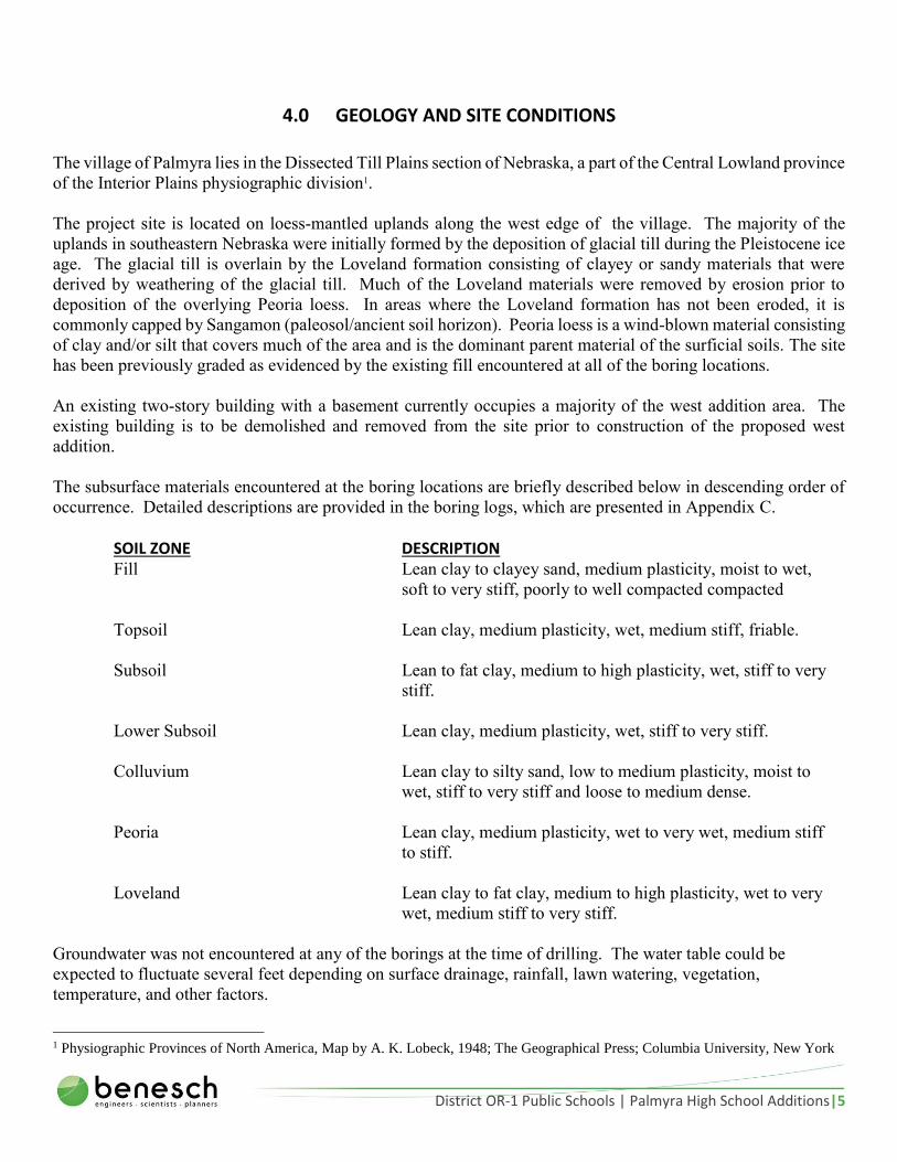
4.0 GEOLOGY AND SITE CONDITIONS
The village of Palmyra lies in the Dissected Till Plains section of Nebraska, a part of the Central Lowland province
of the Interior Plains physiographic division1.
The project site is located on loess-mantled uplands along the west edge of the village. The majority of the
uplands in southeastern Nebraska were initially formed by the deposition of glacial till during the Pleistocene ice
age. The glacial till is overlain by the Loveland formation consisting of clayey or sandy materials that were
derived by weathering of the glacial till. Much of the Loveland materials were removed by erosion prior to
deposition of the overlying Peoria loess. In areas where the Loveland formation has not been eroded, it is
commonly capped by Sangamon (paleosol/ancient soil horizon). Peoria loess is a wind-blown material consisting
of clay and/or silt that covers much of the area and is the dominant parent material of the surficial soils. The site
has been previously graded as evidenced by the existing fill encountered at all of the boring locations.
An existing two-story building with a basement currently occupies a majority of the west addition area. The
existing building is to be demolished and removed from the site prior to construction of the proposed west
addition.
The subsurface materials encountered at the boring locations are briefly described below in descending order of
occurrence. Detailed descriptions are provided in the boring logs, which are presented in Appendix C.
SOIL ZONE DESCRIPTION Fill Lean clay to clayey sand, medium plasticity, moist to wet,
soft to very stiff, poorly to well compacted compacted
Topsoil Lean clay, medium plasticity, wet, medium stiff, friable.
Subsoil Lean to fat clay, medium to high plasticity, wet, stiff to very
stiff.
Lower Subsoil Lean clay, medium plasticity, wet, stiff to very stiff.
Colluvium Lean clay to silty sand, low to medium plasticity, moist to
wet, stiff to very stiff and loose to medium dense.
Peoria Lean clay, medium plasticity, wet to very wet, medium stiff
to stiff.
Loveland Lean clay to fat clay, medium to high plasticity, wet to very
wet, medium stiff to very stiff.
Groundwater was not encountered at any of the borings at the time of drilling. The water table could be
expected to fluctuate several feet depending on surface drainage, rainfall, lawn watering, vegetation,
temperature, and other factors.
1 Physiographic Provinces of North America, Map by A. K. Lobeck, 1948; The Geographical Press; Columbia University, New York

District OR-1 Public Schools | Palmyra High School Additions|6
5.0 DISCUSSION AND RECOMMENDATIONS
Four basic requirements for a satisfactory foundation of a structure are as follows:
A. The base of the foundation must be located below the depth to which the soil is subject to frost action
and seasonal volume change caused by alternate wetting and drying.
B. The foundation (including the earth beneath it) must be stable or safe from failure.
C. The foundation must not settle or deflect enough to disfigure or damage the structure.
D. The foundation structure must be properly located with respect to any future influence that could
adversely affect its performance.
The following recommendations for design and construction of the foundation for the proposed additions are
based upon site conditions, the engineering properties of the subsurface materials, and the requirements of the
proposed structure.
1. SUITABLE FLOOR AND PAVEMENT SUBGRADE MATERIAL
The existing structures including all existing footings, walls, floor slabs, and pavement should be removed from
the building addition areas and areas to be paved. In addition, any subgrade soils disturbed from the demolition
and removal operation and the upper 0.5 feet of existing soils should not be used to support the floor slab,
pavement structure, or new fill. The remaining underlying suitable existing fill and natural soils may be left in the
building area and areas to be paved if these soils are "wet" and prove stable under a loaded dump truck or similar
piece of equipment. By Benesch’s definition, a "wet" cohesive soil contains sufficient moisture to be rolled into
a 1/8-inch-diameter thread without crumbling. A "moist" cohesive soil would crumble when being rolled to form
a 1/8-inch-diameter thread.
2. SETTLEMENT OF EMBANKMENT-EAST ADDITION
Approximately 5 feet of new fill is expected to be placed behind the proposed foundation retaining walls for the
east addition at the project site. The weight of the new fill is expected to cause the underlying natural soils to
consolidate as much as 0.25 inches. The anticipated time for the consolidation of the compressible soils to occur
is approximately 3 to 4 weeks once the full height of fill has been placed behind the foundation retaining walls
on for the east addition. The construction of settlement-sensitive elements of the proposed structure should be
delayed a minimum of 45 days after placing the new fill.
3. SUITABLE FOUNDATION MATERIAL
The existing fill is considered unsuitable foundation material due to variability and poor compaction in some of
the layers. In addition the topsoil (encountered at B-3 only) is considered unsuitable foundation material. The
remaining underlying natural soils are considered suitable foundation material. The minimum depth at each boring
location to suitable natural foundation material for column footings and footings supporting load-bearing walls is
presented in Table 2.

District OR-1 Public Schools | Palmyra High School Additions|7
TABLE 2 LOCATION OF SUITABLE NATURAL FOUNDATION MATERIAL
Boring No. (Addition) Architectural Elevation, ft
Civil Elevation (NAVD88), ft.
Depth Below Existing Grade, ft
1 (West) 113.2 1189.5 3.0
2 (West) 114.4 1190.7 1.5
3 (West) 109.1 1185.4 4.3
4 (West) 112.7 1189.0 1.3
5 (West) 111.2 1187.5 1.0
6 (West) 104.2 1180.5 4.5
7 (East) 85.3 1166.4 6.6
8 (East) 92.6 1164.3 4.0
The bottoms of a normal-depth exterior footings would be seated as much as 3.3 feet above the upper surface of
suitable foundation material for the east addition. It should be noted, the bottoms of normal-depth footings for
the west addition would be seated below the upper surface of the suitable foundation materials. The suggested
alternative foundation plans for the east addition are as follows (see Recommendation 9 for further details on each
alternative):
A. Deep Footings. Seat column footings and footings supporting load-bearing walls on the firm natural
materials located at or below the depths shown in Table 2, which would require lowering some
footings for the east addition as much as 3.3 feet, respectively, below normal footing depths. Footings
supporting non-load-bearing walls could be seated at normal depths on the soils that are considered
suitable floor subgrade material (refer to Recommendation 1).
B. Undercut along Footing Lines. Remove or rework the unsuitable foundation materials located along
the load-bearing footing lines and seat all footings at conventional depths in either controlled earth
fill or firm natural materials.
C. Undercut the Entire Building Area. Remove or rework the unsuitable foundation materials located
within the entire building area and seat all footings at normal depths in either controlled earth fill or
firm natural materials.
Controlled earth fill is defined as earth fill that is designed, compacted, and tested in accordance with generally
accepted good practice and placed with observation by the Geotechnical Engineer.
4. EXISTING UTILITY LINES
Existing utilities are currently located within the proposed building addition areas. The utility line backfill is not
considered suitable foundation material. Wall footings that intercept the backfill materials of these utilities could
be designed to bridge over the backfill. For column footings, the difference in elevation between the bottom of a
column footing and the bottom of an existing utility trench should not be greater than the horizontal distance
District OR-1 Public Schools | Palmyra High School Additions|8
between the nearest edge of the utility trench and the closest edge of the footing. Column footings might need to
be lowered below plan footing depth to meet this recommendation.
An alternative to bridging over the backfill or lowering footings would be to remove all utility backfill, relocate
the utilities outside the building area, and backfill the excavations with controlled earth fill. A second alternative
would be to remove all existing utility backfill and recompact the backfill into the resulting excavation in
accordance with the moisture content and compaction recommendations presented in Table 5 if the utility lines
can withstand the stresses imposed by the compacted fill and footing loads.
5. MINIMUM DEPTH OF FOOTINGS
The bottoms of all exterior footings should be placed at a minimum depth of 40 inches below finished exterior
grade to provide reasonable protection against frost action and seasonal volume change. In addition, the bottom
of a proposed footing should be constructed so that either (a) the elevation of the proposed footing and an existing
footing are the same or (b) the horizontal distance between the nearest edge of the proposed footing and nearest
edge of the existing footing is equal to or greater than the difference in elevation between the footings.
6. ALLOWABLE BEARING PRESSURE
The allowable net bearing pressure on the natural materials located at or below the depths shown in Table 2 or on
controlled earth fill is 3,000 lbf/ft2. The net bearing pressure is the contact pressure at the base of the foundation
in excess of the pressure at the same level due to the surrounding surcharge. The surcharge pressure is equal to
the total weight of a column of soil that extends from the lowest immediately adjacent ground surface to the
bottom of the foundation divided by the soil column's area.
7. SETTLEMENT
Settlement of the building additions is expected to be less than the allowable total and differential settlement of 1
inch and ½-inch in 30 feet, respectively, if (a) the fill materials are properly placed (see Recommendation 16), (b)
and the recommendations in this report are carried out.
8. VERTICAL MODULUS OF SUBGRADE REACTION
The suggested value of the vertical modulus of subgrade reaction to be used in the design of footings and pavement
structure is 100 lbf/in3.
9. PREPARATION OF THE BUILDING AREA AND AREAS TO BE PAVED
Brief descriptions of the following alternatives are provided in Recommendation 3.
Alternative A. (Deep Footings) All vegetation, existing structures, and the upper 0.5 feet of existing soils should be removed from the building
area and areas to be paved. Thereafter, the exposed ground located in areas that have been "cut" to the proposed
subgrade elevations and areas to be filled should be proofrolled with a loaded dump truck or similar piece of
equipment (in the presence of the Geotechnical Engineer) to locate unstable materials. Any unstable material
should be either removed and replaced with controlled earth fill or reworked to conform to the moisture content
and compaction recommendations presented in Table 5.
District OR-1 Public Schools | Palmyra High School Additions|9
The Geotechnical Engineer should observe the building area and areas to be paved to verify that all unsuitable
and unstable soils have been stabilized. Upon approval of the site by the Geotechnical Engineer, any exposed
ground surface that has not been previously reworked should be scarified to a minimum depth of 6 inches and
reworked to conform to the moisture content and compaction recommendations presented in Table 5. Areas to
be filled should then be raised to the desired elevation with controlled earth fill.
Immediately prior to placement of the pavement structure, the subgrade in cut and fill sections should be scarified
to a minimum depth of 6 inches and reworked to a uniform condition conforming to the moisture content and
compaction recommendations presented in Table 5.
The footing excavations should extend into the suitable natural foundation materials located at or below the depths
presented in Table 2. The Geotechnical Engineer should observe the foundation excavations to verify that the
footings will be seated in suitable natural foundation material.
Alternative B. (Undercut Along Footing Lines) Preparation of the building area and areas to be paved should be the same as in Alternative A. In addition, all
unsuitable foundation soils (located above the depth presented in Table 2) along load-bearing footing lines should
be either removed and replaced with controlled earth fill or reworked to conform to the moisture content and
compaction recommendations presented in Table 5.
If the unsuitable foundation materials will be removed and replaced with controlled earth fill or reworked, the
bottoms of the trench excavations should extend beyond the edges of the proposed footings a minimum horizontal
distance of 3.0 feet or two-thirds the distance between the bottom-of-footing elevation and the surface of the
suitable natural foundation material, whichever is greater. However, the excavations should not encroach on the
foundation soils of existing footings, which are defined as soils located inside a line drawn downward and outward
from the outside edge of the existing footing on a slope of 1.0 horizontal to 1.0 vertical. The sides of the excavation
should be sloped to permit the controlled earth fill to be placed against the sides of the excavations to the
recommended degree of compaction.
If the unsuitable foundations materials will be removed and replaced with lean concrete, the excavations do not
need to extend beyond the edges of the proposed footings. Lean concrete, also referred to as flowable fill, is
defined as a lower strength, self-consolidating concrete material that has a minimum compressive strength of 100
psi.
The Geotechnical Engineer should observe the building area and areas to be paved to verify conformance to the
above recommendations. Upon approval of the building area and areas to be paved by the Geotechnical Engineer,
the site should be filled to the desired elevations with controlled earth fill. Footings can then be constructed at
conventional depths, seated within either controlled earth fill or suitable natural foundation soils. The
Geotechnical Engineer should observe the foundation excavation to verify that the footings will be seated in
suitable foundation materials.
Alternative C. (Undercut the Entire Building Area) The areas to be paved should be prepared as in Alternative A. In addition, all unsuitable foundation materials in
the building area (located above the depths presented in Table 2) should be either removed and replaced with
controlled earth fill or reworked to conform to the moisture content and compaction recommendations presented

District OR-1 Public Schools | Palmyra High School Additions|10
in Table 5. The removal or reworking of these materials should extend beyond the outside edges of the proposed
footings a minimum horizontal distance of 3.0 feet or two-thirds the distance between the bottom-of-footing
elevation and the surface of the suitable natural foundation material, whichever is greater. However, the
excavations should not encroach on the foundation soils of existing footings, which are defined as soils located
inside a line drawn downward and outward from the outside edge of the existing footing on a slope of 1.0
horizontal to 1.0 vertical. The sides of the excavation should be sloped to permit the controlled earth fill to be
placed against the sides of the excavations to the recommended degree of compaction.
The Geotechnical Engineer should observe the building area and areas to be paved to verify conformance to the
above recommendations. Upon approval of these areas by the Geotechnical Engineer, the site should be filled to
the desired elevation with controlled earth fill. Footings can then be constructed at conventional depths, seated
within either controlled earth fill or suitable natural foundation soils. The Geotechnical Engineer should observe
the foundation excavation to verify that the footings will be seated in suitable foundation materials.
10. OSHA EXCAVATION REQUIREMENTS
Excavations that will be occupied by personnel should be made in accordance with the Occupational Safety and
Health Administration (OSHA) Construction Standards-29 CFR Part 1926, Subpart P-Excavations as published
in the Federal Register, Vol. 54, 209, Tuesday, October 31, 1989, Rules and Regulations. OSHA states that a soil
should be reclassified if the properties, factors, or conditions affecting the soil's classification change in any way.
Sheet piling and/or shoring will be necessary if the sides of the excavations cannot be sloped to meet OSHA
regulations.
11. STEPPING AND BENCHING OF EXISTING SLOPES
The existing embankment slopes that will receive new fill for the east addition should be stepped and benched in
order to bond the new fill materials with the existing soils. The base of each step should be cut as nearly horizontal
as possible and the face of each step should be cut no steeper than 0.5[H]:1.0[V]. Slopes flatter than 4.5[H]:1.0[V]
need not be stepped and benched.
12. LATERAL EARTH PRESSURE AND RETAINING WALL DESIGN
Any basement-type wall or retaining wall should be designed to withstand the pressure from the backfill. The
pressure exerted by the backfill against the walls should be computed on the basis of the equivalent-fluid theory,
by which the lateral pressure is considered to be caused by a fluid having a unit weight such that the total pressure
of the soil and the so-called equivalent fluid are the same. The equivalent fluid unit weights of the various
recommended backfill materials, placed in accordance with Recommendation 16, are shown in Table 3. For the
portion of the wall backfilled with sandy soil, in order for the equivalent fluid unit weights of sandy soils to be
applicable, the sand should occupy the area presented in Figure 1. The clay cap (if needed) will not significantly
affect the magnitude of lateral pressures on the wall if the clay cap comprises less than 20% of the total soil
column in-front or behind the wall, and as such the clay soil can be assumed to have the same properties as the
granular materials below. The active and passive fluid weights are based on the assumption that the ground
surface is level in front and behind walls.

District OR-1 Public Schools | Palmyra High School Additions|11
TABLE 3 RECOMMENDED LATERAL EARTH PRESSURE PROPERTIES
Soil Type
Equivalent-Fluid Unit Weight (lbf/ft3) Wet Unit
Weight (lbf/ft3)
Base Friction
Coefficient Unsaturated Saturated
(Includes Hydrostatic Pressures)
Active At Rest Passive Active At Rest Passive
Clays
and Silts 50 70 240 75 85 140 120 0.351
Silty and
Clayey
Sands2
35 55 280 75 85 155 125 0.45
Sand3 30 50 300 75 85 170 115 0.55 1Base friction resistance should also be evaluated for adhesion. Recommended adhesional friction is 700 lbf/ft2. 2More than 10% silt and clay. 3Less than 10% silt and clay.
FIGURE 1. REQUIRED AREA FOR SAND PLACED IN FRONT AND BEHIND BASEMENT AND RETAINING WALLS

District OR-1 Public Schools | Palmyra High School Additions|12
It should be noted that the active fluid weights in Table 3 are based on the assumption that the ground level behind
the wall is level. If the ground level behind the wall is sloped, the equivalent fluid unit weights for the active
condition are shown in Table 4.
TABLE 4 RECOMMENDED ACTIVE EQUIVALENT FLUID UNIT WEIGHT FOR SLOPED BACKFILL
Soil Type
Backfill Slope
4:1 3:1 2:1
Unsaturated Saturated Unsaturated Saturated Unsaturated Saturated
Clay and Silts 60 80 70 85 105 115
Silty and Clay Sands 40 75 45 80 55 85
Sand 35 75 40 75 45 80
In calculating the passive-earth-pressure resistance, the upper 40 inches (from finished grade) should not be
assumed to contribute resistance against horizontal movement if exposed to frost action or seasonal
moisture/volume change of the soil. The suggested equivalent-fluid unit weight for calculating the passive-earth-
pressure resistance is shown in Table 3.
Additional resistance to horizontal movement will be provided by frictional resistance between the base of the
footing and the foundation soil. The recommended base friction coefficients are shown in Table 3. In order to
assume the higher base friction coefficients for the granular soils, the granular soils should extend to a depth of
at least 1.0 times the foundation width below the bottom of foundation. For clays and silts, the base friction might
be controlled by either the undrained shear strength of the foundation soil (adhesional friction) or the drained
friction angle of the foundation soil (friction coefficient). The adhesional friction is independent of the footing
load, and as such, might control for design of heavily loaded footings. The minimum (dead) load on the footing
should be used with the friction coefficient to calculate drained frictional resistance. The lesser of either the
undrained or drained frictional resistance should be used for design. If a keyed retaining wall foundation is being
considered to increase sliding resistance, Benesch should be contacted for further recommendations.
The backfill above a retaining wall footing will help resist overturning of the wall. Wet unit weights shown in
Table 3 should be used in calculating the weights of backfill above a retaining-wall footing. A minimum factor
of safety of 1.5 should be applied to the overall retaining-wall design. The maximum soil pressure beneath a
retaining-wall footing should not exceed the bearing pressure presented in Recommendation 6.
13. FOUNDATION, RETAINING-WALL AND UNDERFLOOR DRAINS
A drainage system (consisting of a slotted drainpipe encased in granular filter material) should be installed around
any floor slab that will be below finished grade and behind any retaining wall to intercept surface water that might
enter the backfill. The 4-inch-diameter drainpipes (with 1/8-in. slots) should be backfilled with fine aggregate for
State of Nebraska "47B" concrete (hereinafter referred to as "sand-gravel"). The pipes should have a minimum
of 4 inches of sand-gravel encasing the bottoms and sides, and the sand-gravel should extend to within 2 feet of
finished grade. It is recommended that the last 2 feet of backfill consist of compacted clay, especially when

District OR-1 Public Schools | Palmyra High School Additions|13
located outside the proposed building additions. The drainage lines around the floor slab should be installed on
the outside of the foundation walls and should be located below the floor elevation, but the bottoms of the lines
should be at least 4 inches above the bottom level of the footings.
To help protect against a wet basement, Benesch also suggests that an underfloor drainage system be installed
beneath the basement (below grade lower level) floor slab. The underfloor system should consist of a perimeter
drain and underfloor laterals. The perimeter drain should be placed on the inside of the foundation walls. The
maximum spacing of the underfloor laterals should be 12 feet. The 4-inch-diameter pipes should have a minimum
of 4 inches of sand-gravel encasing the bottoms and sides. In addition, at least 6 inches of sand-gravel should be
placed (a) beneath the entire floor slab and (b) atop the underfloor lines.
The drains should discharge (a) into a sump from which the water can be pumped to a positive outfall, such as a
drainage ditch, swale or storm sewer, or (b) by gravity to the low areas. An alternative to encasing the pipes with
sand-gravel would be to wrap the lines with a geotextile. Fine sand could then be used in lieu of the sand-gravel.
Any granular backfill placed outside the proposed building should be capped with at least 2 feet of clay.
14. PROTECTIVE SLOPES AROUND THE BUILDING
The site should be graded in a manner that will divert water away from the building. The protective slopes around
the building should meet the following requirements:
A. Slope downward from the building to lower areas or drainage swales.
B. Minimum horizontal length of 10 feet, minimum vertical fall of 6 inches (5 percent).
C. Minimum gradient (beyond 10 feet from building):
1. Impervious surface; 1/8 inch per foot (1 percent).
2. Pervious surface; 1/4 inch per foot (2 percent).
15. TYPES OF SOILS TO BE USED AS FILL AND BACKFILL
Controlled earth fill placed within the building area and areas to be paved should be constructed of inorganic CL2,
ML3, SM4, and/or SC5 materials (all with a liquid limit less than 50 and a plasticity index less than 30). The
existing lean clay and clayey sand fill and lean clay, silt, and silty and clayey sand natural soils encountered at
the project site are considered suitable for use as fill within the building area and areas to be paved.
The materials used as fill and backfill outside the building area and areas to be paved may consist of CL, ML,
SM, SC, and/or CH (fat clay, fat clay with sand, and/or sandy fat clay). Proposed fill and backfill materials should
be subject to approval by the Geotechnical Engineer. Representative samples of the proposed fill and backfill
materials should be submitted to the Geotechnical Engineer at least five days prior to placement so the necessary
laboratory tests can be performed.
2 Lean clay, lean clay with sand and sandy lean clay. 3 Silt, silt with sand and sandy silt. 4 Silty sand. 5 Clayey sand.
District OR-1 Public Schools | Palmyra High School Additions|14
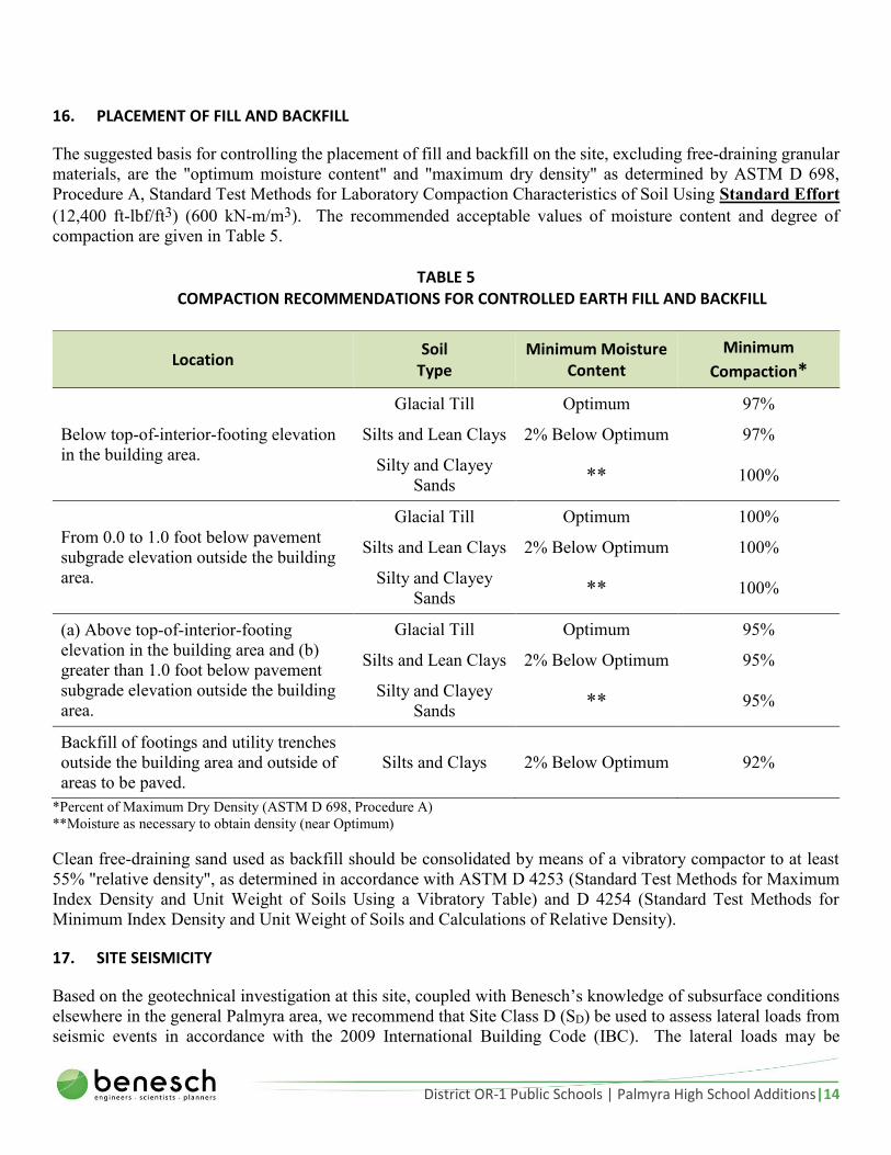
16. PLACEMENT OF FILL AND BACKFILL
The suggested basis for controlling the placement of fill and backfill on the site, excluding free-draining granular
materials, are the "optimum moisture content" and "maximum dry density" as determined by ASTM D 698,
Procedure A, Standard Test Methods for Laboratory Compaction Characteristics of Soil Using Standard Effort
(12,400 ft-lbf/ft3) (600 kN-m/m3). The recommended acceptable values of moisture content and degree of
compaction are given in Table 5.
TABLE 5 COMPACTION RECOMMENDATIONS FOR CONTROLLED EARTH FILL AND BACKFILL
Location Soil
Type Minimum Moisture
Content
Minimum
Compaction*
Below top-of-interior-footing elevation
in the building area.
Glacial Till Optimum 97%
Silts and Lean Clays 2% Below Optimum 97%
Silty and Clayey
Sands ** 100%
From 0.0 to 1.0 foot below pavement
subgrade elevation outside the building
area.
Glacial Till Optimum 100%
Silts and Lean Clays 2% Below Optimum 100%
Silty and Clayey
Sands ** 100%
(a) Above top-of-interior-footing
elevation in the building area and (b)
greater than 1.0 foot below pavement
subgrade elevation outside the building
area.
Glacial Till Optimum 95%
Silts and Lean Clays 2% Below Optimum 95%
Silty and Clayey
Sands ** 95%
Backfill of footings and utility trenches
outside the building area and outside of
areas to be paved.
Silts and Clays 2% Below Optimum 92%
*Percent of Maximum Dry Density (ASTM D 698, Procedure A)
**Moisture as necessary to obtain density (near Optimum)
Clean free-draining sand used as backfill should be consolidated by means of a vibratory compactor to at least
55% "relative density", as determined in accordance with ASTM D 4253 (Standard Test Methods for Maximum
Index Density and Unit Weight of Soils Using a Vibratory Table) and D 4254 (Standard Test Methods for
Minimum Index Density and Unit Weight of Soils and Calculations of Relative Density).
17. SITE SEISMICITY
Based on the geotechnical investigation at this site, coupled with Benesch’s knowledge of subsurface conditions
elsewhere in the general Palmyra area, we recommend that Site Class D (SD) be used to assess lateral loads from
seismic events in accordance with the 2009 International Building Code (IBC). The lateral loads may be

District OR-1 Public Schools | Palmyra High School Additions|15
transmitted from the structure to the surrounding soils by a combination of base friction and passive resistance on
the footings. Overturning loads may be reacted by the dead weight of the structure and bearing resistance of the
foundation soils. The allowable bearing capacity given previously may be increased by one third to assess
stability from transient seismic forces.
18. GRADING OBSERVATION
Observation and frequent testing by the Geotechnical Engineering Firm during compaction of fill and backfill are
necessary to verify proper moisture content and degree of compaction. A professional opinion should be obtained
from the Geotechnical Engineer that the site has been properly prepared, that all footings will be seated on suitable
foundation materials, and that all fill, backfill, and subgrade materials conform to the moisture content and
compaction recommendations presented above. If these testing and observation services are not performed, the
allowable bearing pressure stated in Recommendation 6 might be invalid. As the Geotechnical Engineer for this
project, Benesch has interpreted the results of the subsurface exploration and laboratory tests to arrive at the
recommendations presented in this report. Consequently, Benesch is in the best position to relate actual observed
conditions to those assumed for this report and to provide revised recommendations if differences are found during
grading operations and construction of the foundation for the referenced project.
19. SUBGRADE OBSERVATION
The floor subgrade, pavement subgrade and foundation materials should be observed by the Geotechnical
Engineer immediately prior to placement of the concrete or paving components. Severe changes in the condition
of these materials can occur after initial preparation as the result of rain, drying, freezing, and construction
activities. Any subgrade or foundation material that becomes disturbed, desiccated, or does not conform to the
moisture content and compaction recommendations previously presented should either be removed and replaced
or reworked to meet these recommendations.
20. APPLICABILITY OF RECOMMENDATIONS
The recommendations presented in this report are based in part upon Benesch’s analyses of the data from the
Dutch friction-cone soundings and soil borings. The penetration diagrams, boring logs, and related information
depict subsurface conditions only at the specific sounding and boring locations and at the time of the subsurface
exploration. Soil conditions might differ between the soundings and exploratory borings and might change with
the passage of time. The nature and extent of any variations between the sounding and boring locations or of any
changes in soil conditions (e.g., drying of soil) might not become evident until grading operations and construction
of the foundation for the referenced project have begun. If variations and changes in the soil conditions then
appear, it will be necessary to re-evaluate the recommendations stated in this report.

District OR-1 Public Schools | Palmyra High School Additions|16
6.0 CONCLUSIONS
Benesch concludes, on the basis of the findings of the subsurface exploration at the project site and the evaluation
of the engineering properties of samples of the foundation materials, that the proposed building additions can be
supported by spread footings seated on either firm natural materials or controlled earth fill.
This report has been prepared in accordance with generally accepted soil and foundation engineering practices
for exclusive use by District OR-1 Public Schools and The Clark Enersen Partners for specific application to the
proposed high school building additions. The recommendations of this report are not valid for any other purpose.
Benesch should be contacted if any questions arise concerning this report or if changes in the nature, design or
location of the structure are planned. If any such changes are made, the conclusions and recommendations
contained in this report shall not be considered valid unless the changes are reviewed by Benesch and the
conclusions of this report are modified or verified in writing. This report shall not be reproduced, except in full,
without the written approval of Alfred Benesch & Company.
Prepared By: Reviewed By:
Taylor C. Reinsch Brandon L. Desh, P.E.

APPENDIX A. VICINITY MAP AND BORING LOCATION PLAN


Vicinity Map
Palmyra High School Addition
Legend
3000 ftN
➤➤
N© 2016 Google
© 2016 Google
© 2016 Google

Boring Location Plan
Palmyra High School Addition
Legend Borings
300 ftN
➤➤
N© 2016 Google
© 2016 Google
© 2016 Google

APPENDIX B. DUTCH FRICTION-CONE PENETRATION DIAGRAMS


Project Name: Sounding No: S-1 Date:
Project Location: Location: B-1 Tested By:
Project Number: Surface Elevation: 1192.5 feet Recorded By:
825 M Street, Suite 100
Lincoln, NE 68508
(402) 479-2200
www.benesch.com
Figure B
-1a
Palmyra High School
Palmyra, NE
111343
12/29/2015
CL
GW
PENETRATION DIAGRAM OF
FRICTION CONE PENETROMETERASTM D3441
Page 1 of 2
0
2
4
6
8
10
12
14
16
18
20
0 1 2 3 4 5
Dep
th B
elo
w E
xist
ing
Gra
de
(fee
t)
Local Friction (fs), kg/cm2
0 20 40 60 80 100 120
Cone Bearing (qc), kg/cm2
0
2
4
6
8
10
12
14
16
18
20
0246810
De
pth
Bel
ow
Exi
stin
g G
rad
e (
fee
t)
Friction Ratio (Rf), %

Project Name: Sounding No: S-1 Date:
Project Location: Location: B-1 Tested By:
Project Number: Surface Elevation: 1192.5 feet Recorded By: GW
Figure B
-1b
825 M Street, Suite 100
Lincoln, NE 68508
(402) 479-2200
www.benesch.com
12/29/2015
CL
PENETRATION DIAGRAM OF
FRICTION CONE PENETROMETERASTM D3441
Page 2 of 2
Palmyra High School
Palmyra, NE
111343
20
22
24
26
28
30
32
34
36
38
40
0 1 2 3 4 5
Dep
th B
elo
w E
xist
ing
Gra
de
(fee
t)
Local Friction (fs), kg/cm2
0 20 40 60 80 100 120
Cone Bearing (qc), kg/cm2
20
22
24
26
28
30
32
34
36
38
40
0246810
De
pth
Bel
ow
Exi
stin
g G
rad
e (
fee
t)
Friction Ratio (Rf), %

Project Name: Sounding No: S-2 Date:
Project Location: Location: B-2 Tested By:
Project Number: Surface Elevation: 1192.2 feet Recorded By:
825 M Street, Suite 100
Lincoln, NE 68508
(402) 479-2200
www.benesch.com
Figure B
-2a
Palmyra High School
Palmyra , NE
111343
12/28/2015
CL
GW
PENETRATION DIAGRAM OF
FRICTION CONE PENETROMETERASTM D3441
Page 1 of 2
0
2
4
6
8
10
12
14
16
18
20
0 1 2 3 4 5
Dep
th B
elo
w E
xist
ing
Gra
de
(fee
t)
Local Friction (fs), kg/cm2
0 20 40 60 80 100 120
Cone Bearing (qc), kg/cm2
0
2
4
6
8
10
12
14
16
18
20
0246810
De
pth
Bel
ow
Exi
stin
g G
rad
e (
fee
t)
Friction Ratio (Rf), %
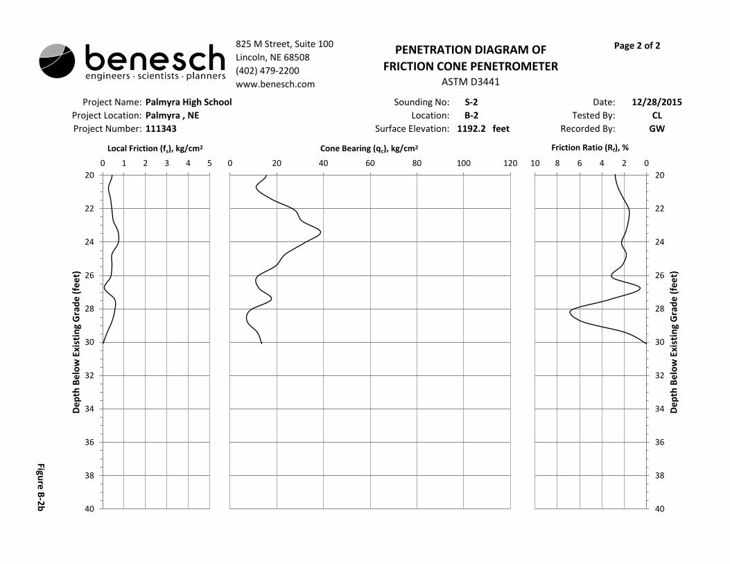
Project Name: Sounding No: S-2 Date:
Project Location: Location: B-2 Tested By:
Project Number: Surface Elevation: 1192.2 feet Recorded By: GW
Figure B
-2b
825 M Street, Suite 100
Lincoln, NE 68508
(402) 479-2200
www.benesch.com
12/28/2015
CL
PENETRATION DIAGRAM OF
FRICTION CONE PENETROMETERASTM D3441
Page 2 of 2
Palmyra High School
Palmyra , NE
111343
20
22
24
26
28
30
32
34
36
38
40
0 1 2 3 4 5
Dep
th B
elo
w E
xist
ing
Gra
de
(fee
t)
Local Friction (fs), kg/cm2
0 20 40 60 80 100 120
Cone Bearing (qc), kg/cm2
20
22
24
26
28
30
32
34
36
38
40
0246810
De
pth
Bel
ow
Exi
stin
g G
rad
e (
fee
t)
Friction Ratio (Rf), %
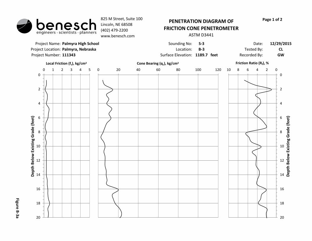
Project Name: Sounding No: S-3 Date:
Project Location: Location: B-3 Tested By:
Project Number: Surface Elevation: 1189.7 feet Recorded By:
825 M Street, Suite 100
Lincoln, NE 68508
(402) 479-2200
www.benesch.com
Figure B
-3a
Palmyra High School
Palmyra, Nebraska
111343
12/29/2015
CL
GW
PENETRATION DIAGRAM OF
FRICTION CONE PENETROMETERASTM D3441
Page 1 of 2
0
2
4
6
8
10
12
14
16
18
20
0 1 2 3 4 5
Dep
th B
elo
w E
xist
ing
Gra
de
(fee
t)
Local Friction (fs), kg/cm2
0 20 40 60 80 100 120
Cone Bearing (qc), kg/cm2
0
2
4
6
8
10
12
14
16
18
20
0246810
De
pth
Bel
ow
Exi
stin
g G
rad
e (
fee
t)
Friction Ratio (Rf), %

Project Name: Sounding No: S-3 Date:
Project Location: Location: B-3 Tested By:
Project Number: Surface Elevation: 1189.7 feet Recorded By: GW
Figure B
-3b
825 M Street, Suite 100
Lincoln, NE 68508
(402) 479-2200
www.benesch.com
12/29/2015
CL
PENETRATION DIAGRAM OF
FRICTION CONE PENETROMETERASTM D3441
Page 2 of 2
Palmyra High School
Palmyra, Nebraska
111343
20
22
24
26
28
30
32
34
36
38
40
0 1 2 3 4 5
Dep
th B
elo
w E
xist
ing
Gra
de
(fee
t)
Local Friction (fs), kg/cm2
0 20 40 60 80 100 120
Cone Bearing (qc), kg/cm2
20
22
24
26
28
30
32
34
36
38
40
0246810
De
pth
Bel
ow
Exi
stin
g G
rad
e (
fee
t)
Friction Ratio (Rf), %

Project Name: Sounding No: S-4 Date:
Project Location: Location: B-4 Tested By:
Project Number: Surface Elevation: 1190.3 feet Recorded By:
825 M Street, Suite 100
Lincoln, NE 68508
(402) 479-2200
www.benesch.com
Figure B
-4a
Palmyra High School
Palmyra, NE
111343
12/29/2015
CL
GW
PENETRATION DIAGRAM OF
FRICTION CONE PENETROMETERASTM D3441
Page 1 of 2
0
2
4
6
8
10
12
14
16
18
20
0 1 2 3 4 5
Dep
th B
elo
w E
xist
ing
Gra
de
(fe
et)
Local Friction (fs), kg/cm2
0 20 40 60 80 100 120
Cone Bearing (qc), kg/cm2
0
2
4
6
8
10
12
14
16
18
20
0246810
De
pth
Bel
ow
Exi
stin
g G
rad
e (
fee
t)
Friction Ratio (Rf), %

Project Name: Sounding No: S-4 Date:
Project Location: Location: B-4 Tested By:
Project Number: Surface Elevation: 1190.3 feet Recorded By: GW
Figure B
-4b
825 M Street, Suite 100
Lincoln, NE 68508
(402) 479-2200
www.benesch.com
12/29/2015
CL
PENETRATION DIAGRAM OF
FRICTION CONE PENETROMETERASTM D3441
Page 2 of 2
Palmyra High School
Palmyra, NE
111343
20
22
24
26
28
30
32
34
36
38
40
0 1 2 3 4 5
Dep
th B
elo
w E
xist
ing
Gra
de
(fe
et)
Local Friction (fs), kg/cm2
0 20 40 60 80 100 120
Cone Bearing (qc), kg/cm2
20
22
24
26
28
30
32
34
36
38
40
0246810
De
pth
Bel
ow
Exi
stin
g G
rad
e (
fee
t)
Friction Ratio (Rf), %
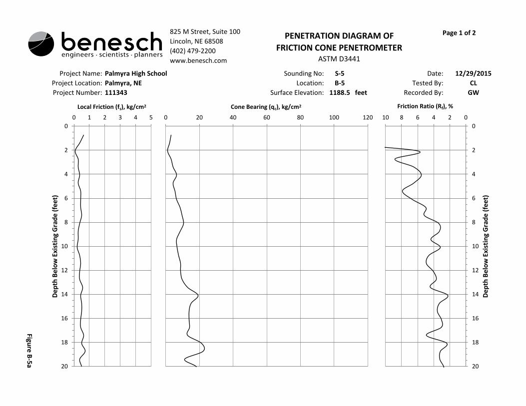
Project Name: Sounding No: S-5 Date:
Project Location: Location: B-5 Tested By:
Project Number: Surface Elevation: 1188.5 feet Recorded By:
825 M Street, Suite 100
Lincoln, NE 68508
(402) 479-2200
www.benesch.com
Figure B
-5a
Palmyra High School
Palmyra, NE
111343
12/29/2015
CL
GW
PENETRATION DIAGRAM OF
FRICTION CONE PENETROMETERASTM D3441
Page 1 of 2
0
2
4
6
8
10
12
14
16
18
20
0 1 2 3 4 5
Dep
th B
elo
w E
xist
ing
Gra
de
(fee
t)
Local Friction (fs), kg/cm2
0 20 40 60 80 100 120
Cone Bearing (qc), kg/cm2
0
2
4
6
8
10
12
14
16
18
20
0246810
De
pth
Bel
ow
Exi
stin
g G
rad
e (
fee
t)
Friction Ratio (Rf), %

Project Name: Sounding No: S-5 Date:
Project Location: Location: B-5 Tested By:
Project Number: Surface Elevation: 1188.5 feet Recorded By: GW
Figure B
-5b
825 M Street, Suite 100
Lincoln, NE 68508
(402) 479-2200
www.benesch.com
12/29/2015
CL
PENETRATION DIAGRAM OF
FRICTION CONE PENETROMETERASTM D3441
Page 2 of 2
Palmyra High School
Palmyra, NE
111343
20
22
24
26
28
30
32
34
36
38
40
0 1 2 3 4 5
Dep
th B
elo
w E
xist
ing
Gra
de
(fee
t)
Local Friction (fs), kg/cm2
0 20 40 60 80 100 120
Cone Bearing (qc), kg/cm2
20
22
24
26
28
30
32
34
36
38
40
0246810
De
pth
Bel
ow
Exi
stin
g G
rad
e (
fee
t)
Friction Ratio (Rf), %
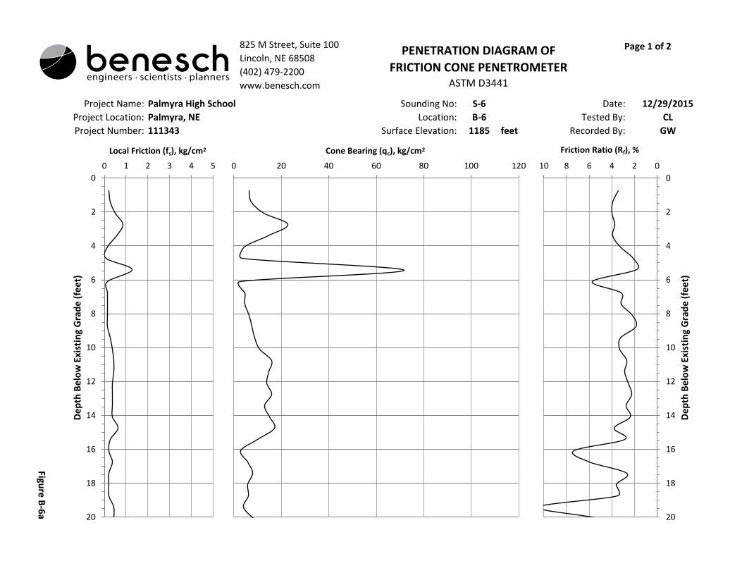
Project Name: Sounding No: S-6 Date:
Project Location: Location: B-6 Tested By:
Project Number: Surface Elevation: 1185 feet Recorded By:
12/29/2015
CL
GW
PENETRATION DIAGRAM OF
FRICTION CONE PENETROMETERASTM D3441
Page 1 of 2825 M Street, Suite 100
Lincoln, NE 68508
(402) 479-2200
www.benesch.com
Figure B
-6a
Palmyra High School
Palmyra, NE
111343
0
2
4
6
8
10
12
14
16
18
20
0 1 2 3 4 5
Dep
th B
elo
w E
xist
ing
Gra
de
(fee
t)
Local Friction (fs), kg/cm2
0 20 40 60 80 100 120
Cone Bearing (qc), kg/cm2
0
2
4
6
8
10
12
14
16
18
20
0246810
De
pth
Bel
ow
Exi
stin
g G
rad
e (
fee
t)
Friction Ratio (Rf), %

Project Name: Sounding No: S-6 Date:
Project Location: Location: B-6 Tested By:
Project Number: Surface Elevation: 1185 feet Recorded By: GW
Figure B
-6b
825 M Street, Suite 100
Lincoln, NE 68508
(402) 479-2200
www.benesch.com
12/29/2015
CL
PENETRATION DIAGRAM OF
FRICTION CONE PENETROMETERASTM D3441
Page 2 of 2
Palmyra High School
Palmyra, NE
111343
20
22
24
26
28
30
32
34
36
38
40
0 1 2 3 4 5
Dep
th B
elo
w E
xist
ing
Gra
de
(fee
t)
Local Friction (fs), kg/cm2
0 20 40 60 80 100 120
Cone Bearing (qc), kg/cm2
20
22
24
26
28
30
32
34
36
38
40
0246810
De
pth
Bel
ow
Exi
stin
g G
rad
e (
fee
t)
Friction Ratio (Rf), %

Project Name: Sounding No: S-7 Date:
Project Location: Location: B-7 Tested By:
Project Number: Surface Elevation: 1173 feet Recorded By:
825 M Street, Suite 100
Lincoln, NE 68508
(402) 479-2200
www.benesch.com
Figure B
-7a
Palmyra High School
Palmyra, NE
111343
12/29/2015
CL
GW
PENETRATION DIAGRAM OF
FRICTION CONE PENETROMETERASTM D3441
Page 1 of 1
0
2
4
6
8
10
12
14
16
18
20
0 1 2 3 4 5
Dep
th B
elo
w E
xist
ing
Gra
de
(fee
t)
Local Friction (fs), kg/cm2
0 20 40 60 80 100 120
Cone Bearing (qc), kg/cm2
0
2
4
6
8
10
12
14
16
18
20
0246810
De
pth
Bel
ow
Exi
stin
g G
rad
e (
fee
t)
Friction Ratio (Rf), %

Project Name: Sounding No: S-8 Date:
Project Location: Location: B-8 Tested By:
Project Number: Surface Elevation: 1168.3 feet Recorded By:
825 M Street, Suite 100
Lincoln, NE 68508
(402) 479-2200
www.benesch.com
Figure B
-8a
Palmyra High School Additions
Palmyra, NE
111343
12/29/2015
CL
GW
PENETRATION DIAGRAM OF
FRICTION CONE PENETROMETERASTM D3441
Page 1 of 1
0
2
4
6
8
10
12
14
16
18
20
0 1 2 3 4 5
Dep
th B
elo
w E
xist
ing
Gra
de
(fee
t)
Local Friction (fs), kg/cm2
0 20 40 60 80 100 120
Cone Bearing (qc), kg/cm2
0
2
4
6
8
10
12
14
16
18
20
0246810
De
pth
Bel
ow
Exi
stin
g G
rad
e (
fee
t)
Friction Ratio (Rf), %

APPENDIX C. BORING LOGS


0.00.5
3.0
4.4
14.0
15.0
16.9
6" thick asphalt
CL - LEAN CLAY; 5-15% fine to coarse sand; medium plasticity; very dark graywith brown; wet; soft to medium stiff. (Fill)
CL - LEAN CLAY; medium plasticity; olive brown mottled with gray slightlymottled with black; wet; stiff. (Peoria)
CL - LEAN CLAY; medium plasticity; light olive brown slightly mottled withyellowish red gray, and black; very wet; medium stiff. (Peoria)
CL - LEAN CLAY; medium plasticity; dark reddish brown; wet; medium stiff.(Loveland)
CL - LEAN CLAY; 5-15% fine sand; medium plasticity; dark reddish brownmottled with reddish brown slightly mottled with black; wet; medium stiff.(Loveland)
CL - LEAN CLAY; medium plasticity; dark brown; wet; stiff. (Loveland)
94.1
90.1
27.92
23.87
1192.51192.0
1189.5
1188.1
1178.5
1177.5
1175.6
1.5*
1.7*
2.1*
1.8*2.2*
BORING LOG
BORING No.: B-1
SHEET 1 of 2
DATE: 12-30-2015
Figure C - 1a
LOCATION: Palmyra, NE
825 M Street, Suite 100Lincoln, NE 68508402-479-2200 * Fax: 402-479-2276www.benesch.com No groundwater encountered to the depth of boring.
PROJECT: Palmyra HS Additions
JOB NO.:RIG / METHOD:CREW:
00111343.00CME 75HT / Straight AugerCL & GBW
WATER LEVELS
* Unconfined compressive strength was estimated using a calibrated hand penetrometer.
BO
RIN
G L
OG
PA
LMY
RA
_HS
_LO
GS
.GP
J H
WS
.GD
T 1
/21/
16
DE
PT
H(f
eet) LITHOLOGY DESCRIPTION
DR
YD
EN
SIT
Y(p
cf)
DE
PT
H
(fee
t)
MO
IST
UR
E(%
)
SA
MP
LE
LOG
ELE
V(P
roje
ct)
SP
T
qu (
tsf)
11
12
0.0
2.5
5.0
7.5
10.0
12.5
15.0
17.5
20.0

21.0
23.5
25.0
26.5
32.0
35.0
CH - FAT CLAY; high plasticity; yellowish brown slightly mottled with yellowish redand black; wet; stiff. (Loveland)
CL - LEAN CLAY; medium plasticity; yellowish brown; wet; stiff. (Loveland)
CL - LEAN CLAY; 5-15% fine sand; medium plasticity; light brown slightly mottledwith black; wet; stiff. (Loveland)
CL - LEAN CLAY; medium plasticity; yellowish brown; wet; medium stiff to stiff.(Loveland)
CL - LEAN CLAY; medium plasticity; yellowish brown with light yellowish brown;very wet; stiff; 1/2"-thick sandy silt + silty sand seams. (Loveland)
Boring Terminated at: 35.0ft
97.9 25.09
1171.5
1169.0
1167.5
1166.0
1160.5
1157.5
477
(14)
1.1*
1*
BORING LOG
BORING No.: B-1
SHEET 2 of 2
DATE: 12-30-2015
Figure C - 1b
LOCATION: Palmyra, NE
825 M Street, Suite 100Lincoln, NE 68508402-479-2200 * Fax: 402-479-2276www.benesch.com No groundwater encountered to the depth of boring.
PROJECT: Palmyra HS Additions
JOB NO.:RIG / METHOD:CREW:
00111343.00CME 75HT / Straight AugerCL & GBW
WATER LEVELS
* Unconfined compressive strength was estimated using a calibrated hand penetrometer.
BO
RIN
G L
OG
PA
LMY
RA
_HS
_LO
GS
.GP
J H
WS
.GD
T 1
/21/
16
DE
PT
H(f
eet) LITHOLOGY DESCRIPTION
DR
YD
EN
SIT
Y(p
cf)
DE
PT
H
(fee
t)
MO
IST
UR
E(%
)
SA
MP
LE
LOG
ELE
V(P
roje
ct)
SP
T
qu (
tsf)
13
20.0
22.5
25.0
27.5
30.0
32.5
35.0
37.5
40.0
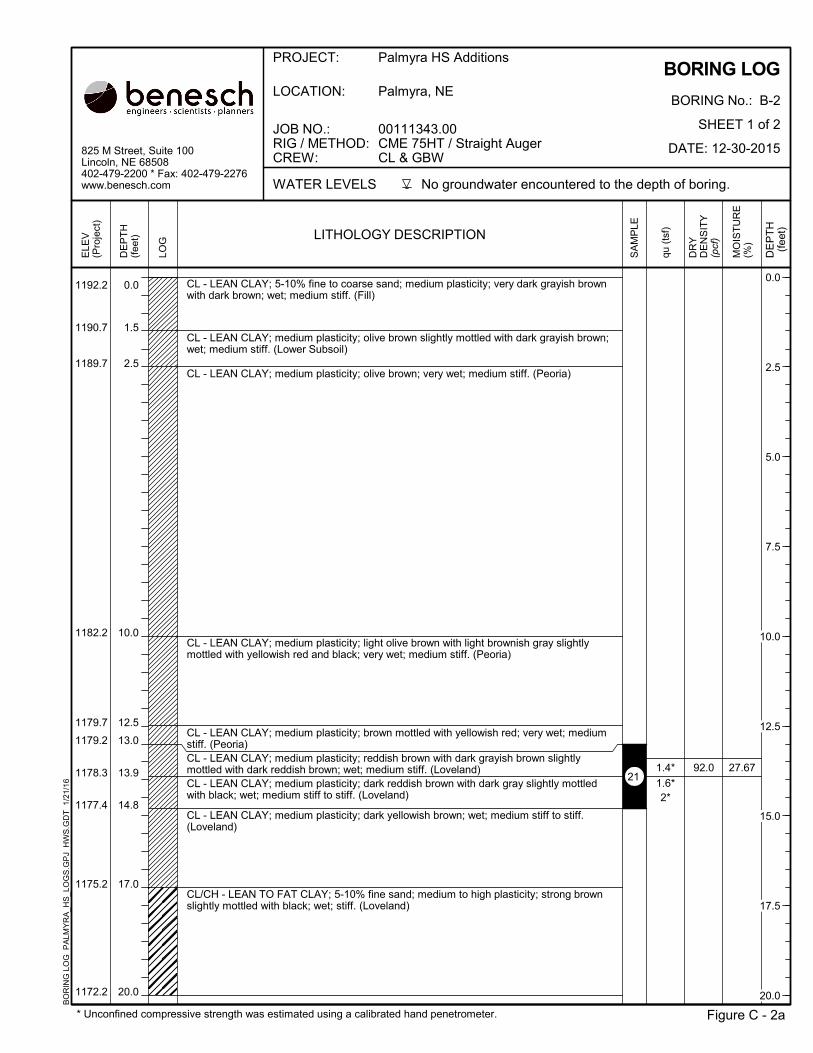
0.0
1.5
2.5
10.0
12.5
13.0
13.9
14.8
17.0
20.0
CL - LEAN CLAY; 5-10% fine to coarse sand; medium plasticity; very dark grayish brownwith dark brown; wet; medium stiff. (Fill)
CL - LEAN CLAY; medium plasticity; olive brown slightly mottled with dark grayish brown;wet; medium stiff. (Lower Subsoil)
CL - LEAN CLAY; medium plasticity; olive brown; very wet; medium stiff. (Peoria)
CL - LEAN CLAY; medium plasticity; light olive brown with light brownish gray slightlymottled with yellowish red and black; very wet; medium stiff. (Peoria)
CL - LEAN CLAY; medium plasticity; brown mottled with yellowish red; very wet; mediumstiff. (Peoria)CL - LEAN CLAY; medium plasticity; reddish brown with dark grayish brown slightlymottled with dark reddish brown; wet; medium stiff. (Loveland)CL - LEAN CLAY; medium plasticity; dark reddish brown with dark gray slightly mottledwith black; wet; medium stiff to stiff. (Loveland)
CL - LEAN CLAY; medium plasticity; dark yellowish brown; wet; medium stiff to stiff.(Loveland)
CL/CH - LEAN TO FAT CLAY; 5-10% fine sand; medium to high plasticity; strong brownslightly mottled with black; wet; stiff. (Loveland)
92.0 27.67
1192.2
1190.7
1189.7
1182.2
1179.7
1179.2
1178.3
1177.4
1175.2
1172.2
1.4*
1.6*2*
BORING LOG
BORING No.: B-2
SHEET 1 of 2
DATE: 12-30-2015
Figure C - 2a
LOCATION: Palmyra, NE
825 M Street, Suite 100Lincoln, NE 68508402-479-2200 * Fax: 402-479-2276www.benesch.com No groundwater encountered to the depth of boring.
PROJECT: Palmyra HS Additions
JOB NO.:RIG / METHOD:CREW:
00111343.00CME 75HT / Straight AugerCL & GBW
WATER LEVELS
* Unconfined compressive strength was estimated using a calibrated hand penetrometer.
BO
RIN
G L
OG
PA
LMY
RA
_HS
_LO
GS
.GP
J H
WS
.GD
T 1
/21/
16
DE
PT
H(f
eet) LITHOLOGY DESCRIPTION
DR
YD
EN
SIT
Y(p
cf)
DE
PT
H
(fee
t)
MO
IST
UR
E(%
)
SA
MP
LE
LOG
ELE
V(P
roje
ct)
qu (
tsf)
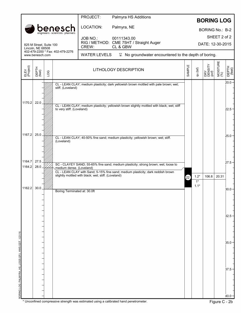
21
0.0
2.5
5.0
7.5
10.0
12.5
15.0
17.5
20.0
22.0
25.0
27.5
28.0
30.0
CL - LEAN CLAY; medium plasticity; dark yellowish brown mottled with pale brown; wet;stiff. (Loveland)
CL - LEAN CLAY; medium plasticity; yellowish brown slightly mottled with black; wet; stiffto very stiff. (Loveland)
CL - LEAN CLAY; 40-50% fine sand; medium plasticity; yellowish brown; wet; stiff.(Loveland)
SC - CLAYEY SAND; 55-65% fine sand; medium plasticity; strong brown; wet; loose tomedium dense. (Loveland)CL - LEAN CLAY with Sand; 5-15% fine sand; medium plasticity; dark reddish brownslightly mottled with black; wet; stiff. (Loveland)
Boring Terminated at: 30.0ft
106.8 20.31
1170.2
1167.2
1164.7
1164.2
1162.2
1.2*
1*1.1*
BORING LOG
BORING No.: B-2
SHEET 2 of 2
DATE: 12-30-2015
Figure C - 2b
LOCATION: Palmyra, NE
825 M Street, Suite 100Lincoln, NE 68508402-479-2200 * Fax: 402-479-2276www.benesch.com No groundwater encountered to the depth of boring.
PROJECT: Palmyra HS Additions
JOB NO.:RIG / METHOD:CREW:
00111343.00CME 75HT / Straight AugerCL & GBW
WATER LEVELS
* Unconfined compressive strength was estimated using a calibrated hand penetrometer.
BO
RIN
G L
OG
PA
LMY
RA
_HS
_LO
GS
.GP
J H
WS
.GD
T 1
/21/
16
DE
PT
H(f
eet) LITHOLOGY DESCRIPTION
DR
YD
EN
SIT
Y(p
cf)
DE
PT
H
(fee
t)
MO
IST
UR
E(%
)
SA
MP
LE
LOG
ELE
V(P
roje
ct)
qu (
tsf)
22
20.0
22.5
25.0
27.5
30.0
32.5
35.0
37.5
40.0
0.0
3.0
4.3
5.5
6.5
9.0
11.0
12.0
14.0
15.0
16.5
20.0
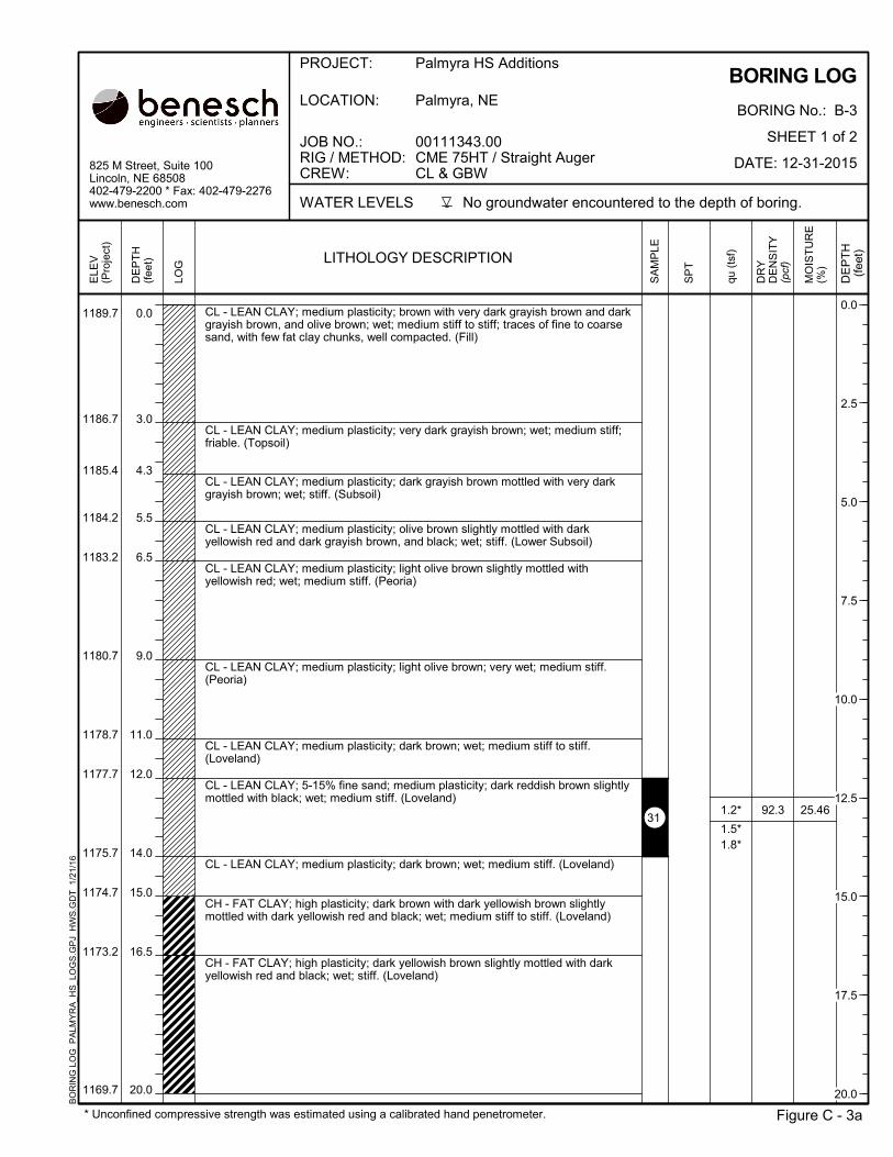
CL - LEAN CLAY; medium plasticity; brown with very dark grayish brown and darkgrayish brown, and olive brown; wet; medium stiff to stiff; traces of fine to coarsesand, with few fat clay chunks, well compacted. (Fill)
CL - LEAN CLAY; medium plasticity; very dark grayish brown; wet; medium stiff;friable. (Topsoil)
CL - LEAN CLAY; medium plasticity; dark grayish brown mottled with very darkgrayish brown; wet; stiff. (Subsoil)
CL - LEAN CLAY; medium plasticity; olive brown slightly mottled with darkyellowish red and dark grayish brown, and black; wet; stiff. (Lower Subsoil)
CL - LEAN CLAY; medium plasticity; light olive brown slightly mottled withyellowish red; wet; medium stiff. (Peoria)
CL - LEAN CLAY; medium plasticity; light olive brown; very wet; medium stiff.(Peoria)
CL - LEAN CLAY; medium plasticity; dark brown; wet; medium stiff to stiff.(Loveland)
CL - LEAN CLAY; 5-15% fine sand; medium plasticity; dark reddish brown slightlymottled with black; wet; medium stiff. (Loveland)
CL - LEAN CLAY; medium plasticity; dark brown; wet; medium stiff. (Loveland)
CH - FAT CLAY; high plasticity; dark brown with dark yellowish brown slightlymottled with dark yellowish red and black; wet; medium stiff to stiff. (Loveland)
CH - FAT CLAY; high plasticity; dark yellowish brown slightly mottled with darkyellowish red and black; wet; stiff. (Loveland)
92.3 25.46
1189.7
1186.7
1185.4
1184.2
1183.2
1180.7
1178.7
1177.7
1175.7
1174.7
1173.2
1169.7
1.2*
1.5*1.8*
BORING LOG
BORING No.: B-3
SHEET 1 of 2
DATE: 12-31-2015
Figure C - 3a
LOCATION: Palmyra, NE
825 M Street, Suite 100Lincoln, NE 68508402-479-2200 * Fax: 402-479-2276www.benesch.com No groundwater encountered to the depth of boring.
PROJECT: Palmyra HS Additions
JOB NO.:RIG / METHOD:CREW:
00111343.00CME 75HT / Straight AugerCL & GBW
WATER LEVELS
* Unconfined compressive strength was estimated using a calibrated hand penetrometer.
BO
RIN
G L
OG
PA
LMY
RA
_HS
_LO
GS
.GP
J H
WS
.GD
T 1
/21/
16
DE
PT
H(f
eet) LITHOLOGY DESCRIPTION
DR
YD
EN
SIT
Y(p
cf)
DE
PT
H
(fee
t)
MO
IST
UR
E(%
)
SA
MP
LE
LOG
ELE
V(P
roje
ct)
SP
T
qu (
tsf)
31
0.0
2.5
5.0
7.5
10.0
12.5
15.0
17.5
20.0
21.9
27.0
30.0
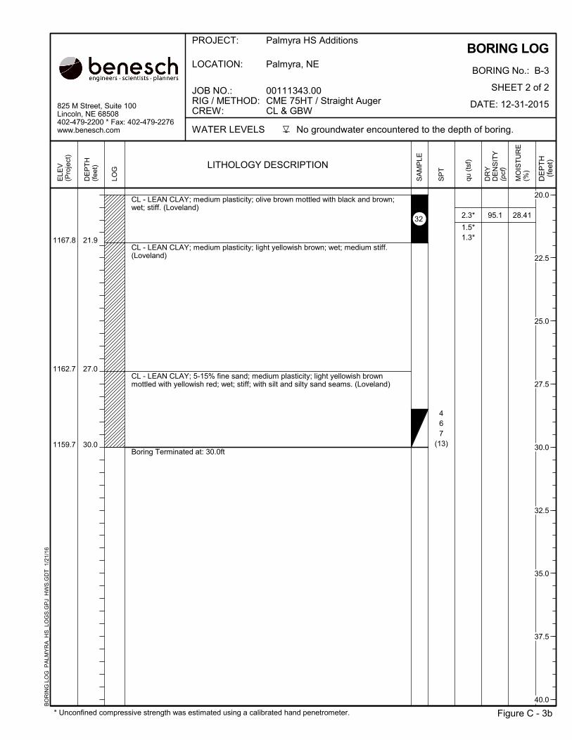
CL - LEAN CLAY; medium plasticity; olive brown mottled with black and brown;wet; stiff. (Loveland)
CL - LEAN CLAY; medium plasticity; light yellowish brown; wet; medium stiff.(Loveland)
CL - LEAN CLAY; 5-15% fine sand; medium plasticity; light yellowish brownmottled with yellowish red; wet; stiff; with silt and silty sand seams. (Loveland)
Boring Terminated at: 30.0ft
95.1 28.41
1167.8
1162.7
1159.7
467
(13)
2.3*
1.5*1.3*
BORING LOG
BORING No.: B-3
SHEET 2 of 2
DATE: 12-31-2015
Figure C - 3b
LOCATION: Palmyra, NE
825 M Street, Suite 100Lincoln, NE 68508402-479-2200 * Fax: 402-479-2276www.benesch.com No groundwater encountered to the depth of boring.
PROJECT: Palmyra HS Additions
JOB NO.:RIG / METHOD:CREW:
00111343.00CME 75HT / Straight AugerCL & GBW
WATER LEVELS
* Unconfined compressive strength was estimated using a calibrated hand penetrometer.
BO
RIN
G L
OG
PA
LMY
RA
_HS
_LO
GS
.GP
J H
WS
.GD
T 1
/21/
16
DE
PT
H(f
eet) LITHOLOGY DESCRIPTION
DR
YD
EN
SIT
Y(p
cf)
DE
PT
H
(fee
t)
MO
IST
UR
E(%
)
SA
MP
LE
LOG
ELE
V(P
roje
ct)
SP
T
qu (
tsf)
32
20.0
22.5
25.0
27.5
30.0
32.5
35.0
37.5
40.0

0.0
1.3
2.0
10.5
11.0
12.7
16.0
17.0
18.9
20.0
CL - LEAN CLAY; medium plasticity; dark grayish brown with very dark grayishbrown and olive brown; wet; soft to medium stiff. (Fill)
CL - LEAN CLAY; medium plasticity; olive brown; wet; medium stiff. (Peoria)
CL - LEAN CLAY; medium plasticity; light olive brown; very wet; medium stiff.(Peoria)
CL - LEAN CLAY; medium plasticity; dark reddish brown; wet; medium stiff.(Loveland)CL - LEAN CLAY; 5-15% fine sand; medium plasticity; dark reddish brown heavilymottled with dark grayish brown; wet; medium stiff. (Loveland)
CL - LEAN CLAY; medium plasticity; dark brown; very wet; medium stiff to stiff.(Loveland)
CL - LEAN CLAY; medium plasticity; dark grayish brown; wet; stiff. (Loveland)
CL - LEAN CLAY; 5-15% fine sand; medium plasticity; dark reddish brown withreddish brown slightly mottled with black; wet; stiff. (Loveland)
CH - FAT CLAY; high plasticity; yellowish brown slightly mottled with black; wet;stiff to very stiff. (Loveland)
94.9
101.6
25.12
23.49
1190.3
1189.0
1188.3
1179.8
1179.3
1177.6
1174.3
1173.3
1171.4
1170.3
1.3*
1.7*
2.8*
2.2*3*
BORING LOG
BORING No.: B-4
SHEET 1 of 2
DATE: 12-30-2015
Figure C - 4a
LOCATION: Palmyra, NE
825 M Street, Suite 100Lincoln, NE 68508402-479-2200 * Fax: 402-479-2276www.benesch.com No groundwater encountered to the depth of boring.
PROJECT: Palmyra HS Additions
JOB NO.:RIG / METHOD:CREW:
00111343.00CME 75HT / Straight Auger & Boll SamplerCL & GBW
WATER LEVELS
* Unconfined compressive strength was estimated using a calibrated hand penetrometer.
BO
RIN
G L
OG
PA
LMY
RA
_HS
_LO
GS
.GP
J H
WS
.GD
T 1
/21/
16
DE
PT
H(f
eet) LITHOLOGY DESCRIPTION
DR
YD
EN
SIT
Y(p
cf)
DE
PT
H
(fee
t)
MO
IST
UR
E(%
)
SA
MP
LE
LOG
ELE
V(P
roje
ct)
SP
T
qu (
tsf)
41
42
0.0
2.5
5.0
7.5
10.0
12.5
15.0
17.5
20.0
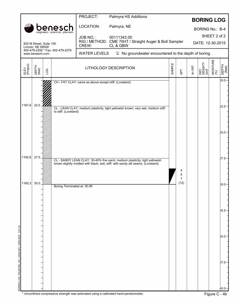
22.5
27.5
30.0
CH - FAT CLAY; same as above except stiff. (Loveland)
CL - LEAN CLAY; medium plasticity; light yellowish brown; very wet; medium stiffto stiff. (Loveland)
CL - SANDY LEAN CLAY; 30-40% fine sand; medium plasticity; light yellowishbrown slightly mottled with black; wet; stiff; with sandy silt seams. (Loveland)
Boring Terminated at: 30.0ft
1167.8
1162.8
1160.3
457
(12)
BORING LOG
BORING No.: B-4
SHEET 2 of 2
DATE: 12-30-2015
Figure C - 4b
LOCATION: Palmyra, NE
825 M Street, Suite 100Lincoln, NE 68508402-479-2200 * Fax: 402-479-2276www.benesch.com No groundwater encountered to the depth of boring.
PROJECT: Palmyra HS Additions
JOB NO.:RIG / METHOD:CREW:
00111343.00CME 75HT / Straight Auger & Boll SamplerCL & GBW
WATER LEVELS
* Unconfined compressive strength was estimated using a calibrated hand penetrometer.
BO
RIN
G L
OG
PA
LMY
RA
_HS
_LO
GS
.GP
J H
WS
.GD
T 1
/21/
16
DE
PT
H(f
eet) LITHOLOGY DESCRIPTION
DR
YD
EN
SIT
Y(p
cf)
DE
PT
H
(fee
t)
MO
IST
UR
E(%
)
SA
MP
LE
LOG
ELE
V(P
roje
ct)
SP
T
qu (
tsf)
20.0
22.5
25.0
27.5
30.0
32.5
35.0
37.5
40.0

0.0
1.0
2.2
8.5
9.5
11.0
11.8
12.8
17.5
CL - LEAN CLAY; medium plasticity; olive brown with dark grayish brown; wet; soft. (Fill)
CL - LEAN CLAY; medium plasticity; olive brown; wet; soft to medium stiff. (Peoria)
CL - LEAN CLAY; medium plasticity; light olive brown; very wet; medium stiff. (Peoria)
CL - LEAN CLAY; medium plasticity; brown; very wet; medium stiff to stiff. (Loveland)
CL - LEAN CLAY; medium plasticity; dark brown; wet; medium stiff to stiff. (Loveland)
CL - LEAN CLAY; medium plasticity; dark reddish brown mottled with dark gray slightlymottled with black; wet; stiff. (Loveland)
CL/CH - LEAN TO FAT CLAY; medium to high plasticity; dark reddish brown slightlymottled with black; wet; stiff. (Loveland)
CL - LEAN CLAY; medium plasticity; dark brown slightly mottled with black; wet; stiff.(Loveland)
CH - FAT CLAY; high plasticity; yellowish brown mottled with dark yellowish red andblack; wet; stiff. (Loveland)
96.1 23.62
1188.5
1187.5
1186.3
1180.0
1179.0
1177.5
1176.7
1175.7
1171.0
1.9*
2.5*
BORING LOG
BORING No.: B-5
SHEET 1 of 2
DATE: 12-30-2015
Figure C - 5a
LOCATION: Palmyra, NE
825 M Street, Suite 100Lincoln, NE 68508402-479-2200 * Fax: 402-479-2276www.benesch.com No groundwater encountered to the depth of boring.
PROJECT: Palmyra HS Additions
JOB NO.:RIG / METHOD:CREW:
00111343.00CME 75HT / Straight Auger & Boll SamplerCL & GBW
WATER LEVELS
* Unconfined compressive strength was estimated using a calibrated hand penetrometer.
BO
RIN
G L
OG
PA
LMY
RA
_HS
_LO
GS
.GP
J H
WS
.GD
T 1
/21/
16
DE
PT
H(f
eet) LITHOLOGY DESCRIPTION
DR
YD
EN
SIT
Y(p
cf)
DE
PT
H
(fee
t)
MO
IST
UR
E(%
)
SA
MP
LE
LOG
ELE
V(P
roje
ct)
qu (
tsf)
51
0.0
2.5
5.0
7.5
10.0
12.5
15.0
17.5
20.0
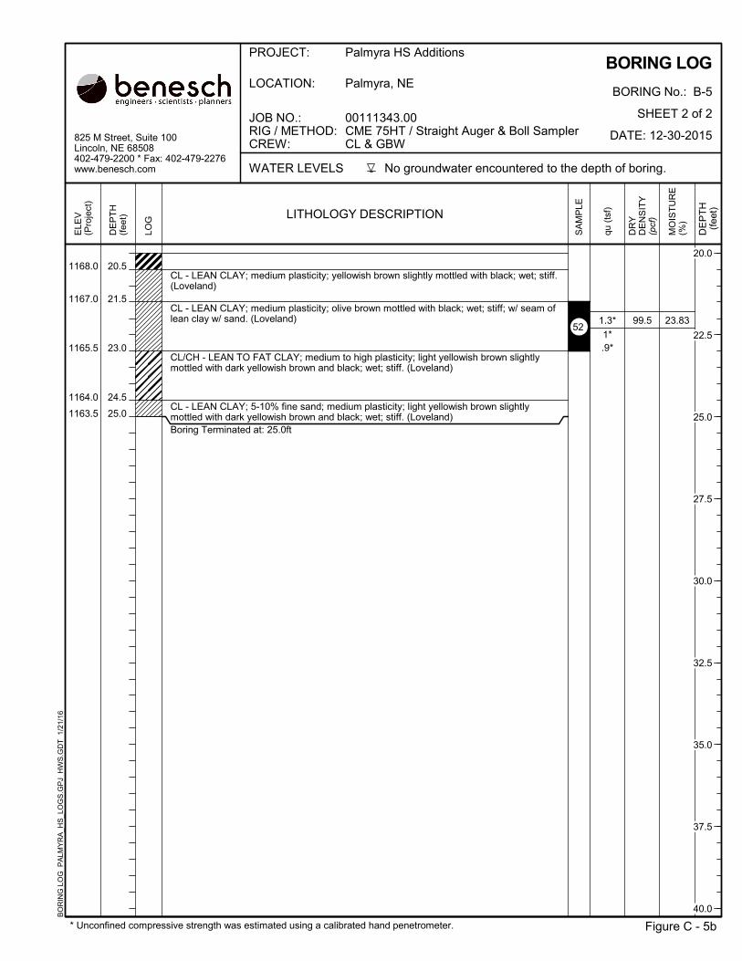
20.5
21.5
23.0
24.5
25.0
CL - LEAN CLAY; medium plasticity; yellowish brown slightly mottled with black; wet; stiff.(Loveland)
CL - LEAN CLAY; medium plasticity; olive brown mottled with black; wet; stiff; w/ seam oflean clay w/ sand. (Loveland)
CL/CH - LEAN TO FAT CLAY; medium to high plasticity; light yellowish brown slightlymottled with dark yellowish brown and black; wet; stiff. (Loveland)
CL - LEAN CLAY; 5-10% fine sand; medium plasticity; light yellowish brown slightlymottled with dark yellowish brown and black; wet; stiff. (Loveland)Boring Terminated at: 25.0ft
99.5 23.83
1168.0
1167.0
1165.5
1164.0
1163.5
1.3*
1*.9*
BORING LOG
BORING No.: B-5
SHEET 2 of 2
DATE: 12-30-2015
Figure C - 5b
LOCATION: Palmyra, NE
825 M Street, Suite 100Lincoln, NE 68508402-479-2200 * Fax: 402-479-2276www.benesch.com No groundwater encountered to the depth of boring.
PROJECT: Palmyra HS Additions
JOB NO.:RIG / METHOD:CREW:
00111343.00CME 75HT / Straight Auger & Boll SamplerCL & GBW
WATER LEVELS
* Unconfined compressive strength was estimated using a calibrated hand penetrometer.
BO
RIN
G L
OG
PA
LMY
RA
_HS
_LO
GS
.GP
J H
WS
.GD
T 1
/21/
16
DE
PT
H(f
eet) LITHOLOGY DESCRIPTION
DR
YD
EN
SIT
Y(p
cf)
DE
PT
H
(fee
t)
MO
IST
UR
E(%
)
SA
MP
LE
LOG
ELE
V(P
roje
ct)
qu (
tsf)
52
20.0
22.5
25.0
27.5
30.0
32.5
35.0
37.5
40.0

0.0
1.5
4.5
6.0
7.0
8.0
8.8
10.0
15.0
15.5
16.8
CL - LEAN CLAY; medium plasticity; very dark grayish brown mottled with dark brown andolive brown; wet; stiff; traces of fine to coarse sand. (Fill)
CL - LEAN CLAY; medium plasticity; olive brown with very dark grayish brown; wet; stiff.(Fill)
CL - LEAN CLAY; medium plasticity; olive brown; very wet; medium stiff. (Peoria)
CL - LEAN CLAY; medium plasticity; strong brown; wet; medium stiff. (Loveland)
CL - LEAN CLAY; 5-15% fine sand; medium plasticity; dark reddish brown; wet; mediumstiff; slightly friable. (Loveland)
CL - LEAN CLAY; medium plasticity; dark red slightly mottled with black; wet; mediumstiff to stiff. (Loveland)
CL - LEAN CLAY; medium plasticity; strong brown; wet; stiff. (Loveland)
CH - FAT CLAY; high plasticity; dark yellowish brown; wet; stiff. (Loveland)
CL - LEAN CLAY; medium plasticity; brown with yellowish brown and reddish brown,slightly mottled with black; wet; stiff. (Loveland)CL - LEAN CLAY; medium plasticity; yellowish brown mottled with brown heavily mottledwith black; wet; medium stiff to stiff. (Loveland)
CL - LEAN CLAY; medium plasticity; yellowish brown; wet; medium stiff. (Loveland)
90.2 24.83
1185.0
1183.5
1180.5
1179.0
1178.0
1177.0
1176.2
1175.0
1170.0
1169.5
1168.2
.5*
.75*1*
.75*1.25*2.75*2.25*
BORING LOG
BORING No.: B-6
SHEET 1 of 2
DATE: 12-31-2015
Figure C - 6a
LOCATION: Palmyra, NE
825 M Street, Suite 100Lincoln, NE 68508402-479-2200 * Fax: 402-479-2276www.benesch.com No groundwater encountered to the depth of boring.
PROJECT: Palmyra HS Additions
JOB NO.:RIG / METHOD:CREW:
00111343.00CME 75HT / Straight Auger & Boll SamplerCL & GBW
WATER LEVELS
* Unconfined compressive strength was estimated using a calibrated hand penetrometer.
BO
RIN
G L
OG
PA
LMY
RA
_HS
_LO
GS
.GP
J H
WS
.GD
T 1
/21/
16
DE
PT
H(f
eet) LITHOLOGY DESCRIPTION
DR
YD
EN
SIT
Y(p
cf)
DE
PT
H
(fee
t)
MO
IST
UR
E(%
)
SA
MP
LE
LOG
ELE
V(P
roje
ct)
qu (
tsf)
61
62
0.0
2.5
5.0
7.5
10.0
12.5
15.0
17.5
20.0

22.5
23.0
23.5
25.0
CL - LEAN CLAY; medium plasticity; light yellowish brown; wet; stiff; with silt seams.(Loveland)ML - SILT; 10-15% fine sand; low plasticity; light yellowish brown; very wet; loose.(Loveland)CL - LEAN CLAY; 5-15% fine sand; medium plasticity; light yellowish brown mottled withblack; very wet; stiff to very stiff; with silt and silty sand seams. (Loveland)
Boring Terminated at: 25.0ft
1162.5
1162.0
1161.5
1160.0
BORING LOG
BORING No.: B-6
SHEET 2 of 2
DATE: 12-31-2015
Figure C - 6b
LOCATION: Palmyra, NE
825 M Street, Suite 100Lincoln, NE 68508402-479-2200 * Fax: 402-479-2276www.benesch.com No groundwater encountered to the depth of boring.
PROJECT: Palmyra HS Additions
JOB NO.:RIG / METHOD:CREW:
00111343.00CME 75HT / Straight Auger & Boll SamplerCL & GBW
WATER LEVELS
* Unconfined compressive strength was estimated using a calibrated hand penetrometer.
BO
RIN
G L
OG
PA
LMY
RA
_HS
_LO
GS
.GP
J H
WS
.GD
T 1
/21/
16
DE
PT
H(f
eet) LITHOLOGY DESCRIPTION
DR
YD
EN
SIT
Y(p
cf)
DE
PT
H
(fee
t)
MO
IST
UR
E(%
)
SA
MP
LE
LOG
ELE
V(P
roje
ct)
qu (
tsf)
20.0
22.5
25.0
27.5
30.0
32.5
35.0
37.5
40.0
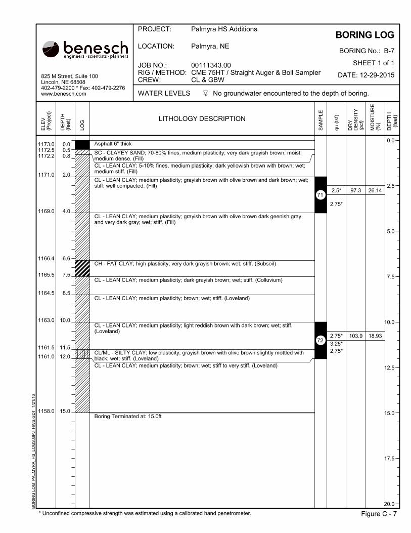
0.00.50.8
2.0
4.0
6.6
7.5
8.5
10.0
11.5
12.0
15.0
Asphalt 6" thick
SC - CLAYEY SAND; 70-80% fines, medium plasticity; very dark grayish brown; moist;medium dense. (Fill)CL - LEAN CLAY; 5-10% fines, medium plasticity; dark yellowish brown with brown; wet;medium stiff. (Fill)
CL - LEAN CLAY; medium plasticity; grayish brown with olive brown and dark brown; wet;stiff; well compacted. (Fill)
CL - LEAN CLAY; medium plasticity; grayish brown with olive brown dark geenish gray,and very dark gray; wet; stiff. (Fill)
CH - FAT CLAY; high plasticity; very dark grayish brown; wet; stiff. (Subsoil)
CL - LEAN CLAY; medium plasticity; dark grayish brown; wet; stiff. (Colluvium)
CL - LEAN CLAY; medium plasticity; brown; wet; stiff. (Loveland)
CL - LEAN CLAY; medium plasticity; light reddish brown with dark brown; wet; stiff.(Loveland)
CL/ML - SILTY CLAY; low plasticity; grayish brown with olive brown slightly mottled withblack; wet; stiff. (Loveland)CL - LEAN CLAY; medium plasticity; brown; wet; stiff to very stiff. (Loveland)
Boring Terminated at: 15.0ft
97.3
103.9
26.14
18.93
1173.01172.51172.2
1171.0
1169.0
1166.4
1165.5
1164.5
1163.0
1161.5
1161.0
1158.0
2.5*
2.75*
2.75*
3.25*2.75*
BORING LOG
BORING No.: B-7
SHEET 1 of 1
DATE: 12-29-2015
Figure C - 7
LOCATION: Palmyra, NE
825 M Street, Suite 100Lincoln, NE 68508402-479-2200 * Fax: 402-479-2276www.benesch.com No groundwater encountered to the depth of boring.
PROJECT: Palmyra HS Additions
JOB NO.:RIG / METHOD:CREW:
00111343.00CME 75HT / Straight Auger & Boll SamplerCL & GBW
WATER LEVELS
* Unconfined compressive strength was estimated using a calibrated hand penetrometer.
BO
RIN
G L
OG
PA
LMY
RA
_HS
_LO
GS
.GP
J H
WS
.GD
T 1
/21/
16
DE
PT
H(f
eet) LITHOLOGY DESCRIPTION
DR
YD
EN
SIT
Y(p
cf)
DE
PT
H
(fee
t)
MO
IST
UR
E(%
)
SA
MP
LE
LOG
ELE
V(P
roje
ct)
qu (
tsf)
71
72
0.0
2.5
5.0
7.5
10.0
12.5
15.0
17.5
20.0
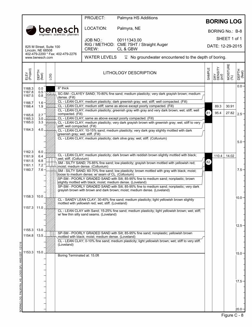
0.00.50.8
1.61.9
2.73.03.3
4.0
6.06.46.87.27.6
10.0
11.0
13.0
13.5
15.0
6" thick
SC-SM - CLAYEY SAND; 70-80% fine sand; medium plasticity; very dark grayish brown; mediumdense. (Fill)CL - LEAN CLAY; medium plasticity; dark greenish gray; wet; stiff; well compacted. (Fill)CL - LEAN CLAY; medium stiff; same as above except poorly compacted. (Fill)CL - LEAN CLAY; medium plasticity; greenish gray with gray and very dark brown; wet; stiff; wellcompacted. (Fill)CL - LEAN CLAY; same as above except poorly compacted. (Fill)CL - LEAN CLAY; medium plasticity; very dark grayish brown with greenish gray; wet; stiff to verystiff; well compacted. (Fill)CL - LEAN CLAY; 10-15% sand; medium plasticity; very dark gray slightly mottled with darkgreenish gray; wet; stiff. (Fill)CL - LEAN CLAY; medium plasticity; dark olive gray; wet; stiff. (Colluvium)
CL - LEAN CLAY; medium plasticity; dark brown with reddish brown slightly mottled with black;wet; stiff. (Colluvium)SM - SILTY SAND; 75-85% fine sand; low plasticity; grayish brown mottled with yellowish red;moist; medium dense. (Colluvium)SM - SILTY SAND; 60-70% fine sand; low plasticity; brown mottled with gray with black; moist;loose to medium dense; w/ seam of CL. (Colluvium)SP-SM - POORLY GRADED SAND with Silt; 85-95% fine to medium sand; nonplastic; brownslightly mottled with black; moist; medium dense. (Loveland)SP-SM - POORLY GRADED SAND with Silt; 85-95% fine to medium sand; nonplastic; very darkgrayish brown with brown and dark brown; moist; medium dense. (Loveland)
CL - SANDY LEAN CLAY; 30-40% fine sand; medium plasticity; light yellowish brown slightlymottled with yellowish red; wet; stiff. (Loveland)
CL - LEAN CLAY with Sand; 15-25% fine sand; medium plasticity; light yellowish brown; wet; stiff;w/ few thin silty sand seams. (Loveland)
SP-SM - POORLY GRADED SAND with Silt; 85-95% fine sand; nonplastic; yellowish brownmottled with black; moist; medium dense. (Loveland)CL - LEAN CLAY; 0-10% fine sand; medium plasticity; light yellowish brown; wet; stiff to very stiff.(Loveland)
Boring Terminated at: 15.0ft
89.3
95.4
110.4
30.91
27.82
14.02
1168.31167.81167.5
1166.71166.4
1165.61165.31165.0
1164.3
1162.31161.91161.51161.11160.7
1158.3
1157.3
1155.3
1154.8
1153.3
BORING LOG
BORING No.: B-8
SHEET 1 of 1
DATE: 12-29-2015
Figure C - 8
LOCATION: Palmyra, NE
825 M Street, Suite 100Lincoln, NE 68508402-479-2200 * Fax: 402-479-2276www.benesch.com No groundwater encountered to the depth of boring.
PROJECT: Palmyra HS Additions
JOB NO.:RIG / METHOD:CREW:
00111343.00CME 75HT / Straight AugerCL & GBW
WATER LEVELS
BO
RIN
G L
OG
PA
LMY
RA
_HS
_LO
GS
.GP
J H
WS
.GD
T 1
/21/
16
DE
PT
H(f
eet) LITHOLOGY DESCRIPTION
DR
YD
EN
SIT
Y(p
cf)
DE
PT
H
(fee
t)
MO
IST
UR
E(%
)
SA
MP
LE
LOG
ELE
V(P
roje
ct)
81
82
0.0
2.5
5.0
7.5
10.0
12.5
15.0
17.5
20.0

APPENDIX D. CRITERIA USED FOR SOIL CLASSIFICATION .

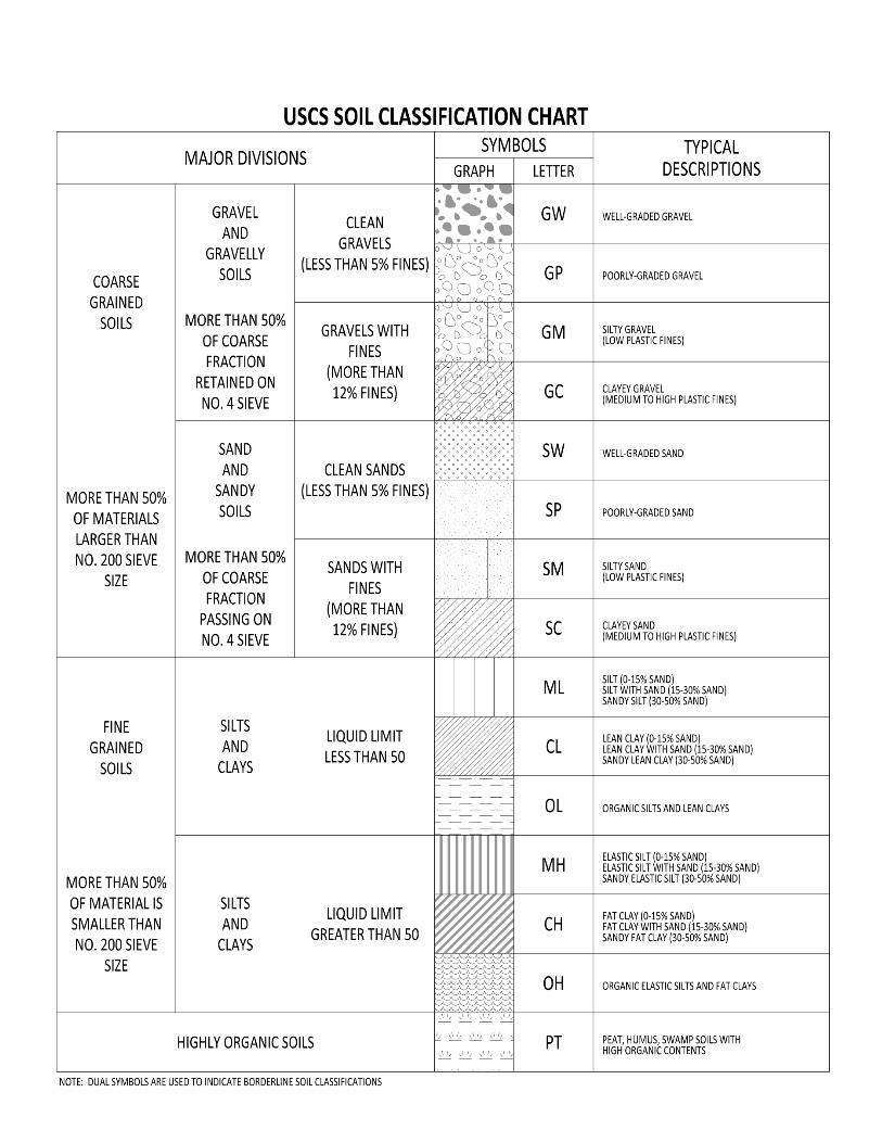

GENERAL NOTES
CRITERIA FOR DESCRIBING CLAY SOILS
MOISTURE CONDITION
Description Criteria
Dry Absence of moisture, dusty,
dry to touch.
Moist Damp, slightly wet, moisture
content below plastic limit.
Wet Moisture content above the
plastic limit.
Saturated Very wet. Usually soil is
below the water table.
CONSISTENCY
Description Penetration Resistance, N60 (blows/ft)1
Very Soft Less than 3
Soft 3 to 4
Medium Stiff 5 to 8
Stiff 9 to 16
Very Stiff 16 to 32
Hard Greater than 32
CRITERIA FOR DESCRIBING GRANULAR SOILS
MOISTURE CONDITION
Description Criteria
Dry Absence of moisture, dry to
the touch.
Moist Damp but no visible free
water.
Wet Visible free water.
Saturated Usually soil is below water
table.
DENSITY
Description Penetration Resistance, N60 (blows/ft)1
Very Loose Less than 5
Loose 5 to 10
Medium Dense 11 to 30
Dense 31 to 50
Very Dense Greater than 50
CRITERIA FOR DESCRIBING ROCK
STRENGTH/HARDNESS
Description Criteria
Very Soft Permits denting by moderate pressure of the fingers.
Soft Resists denting by the fingers, but can be abraded and pierced to a shallow depth by a
pencil point.
Moderately Soft Resists a pencil point, but can be scratched and cut with a knife blade.
Moderately Hard Resistant to abrasion or cutting by a knife blade, but can be easily dented or broken by
light blows of a hammer.
Hard Can be deformed or broken by repeated moderate hammer blows.
Very Hard Can be broken only by heavy, and in some rocks, repeated hammer blows.
1Blow counts shown on the boring logs are those recorded directly in the field and have not been corrected for hammer efficiency.
The boring log blow counts must be corrected to an equivalent hammer efficiency of 60% in order to use the criteria in this table.

ROCK QUALITY DESIGNATION (RQD)
This is a general method by which the quality of the rock at a site is obtained based on the relative amount of
fracturing and alteration.
The Rock Quality Designation (RQD) is based on a modified core recovery procedure that, in turn, is based
indirectly on the number of fractures (except those due directly to drilling operations) and the amount of
softening or alteration in the rock mass as observed in the rock cores from a drill hole. Instead of counting the
fractures, an indirect measure is obtained by summing the total length of core recovered by counting only those
pieces of hard and sound core which are 4 inches or greater in length. The ratio of this modified core recovery
length to the total core run length is known as the RQD.
An example is given below from a core run of 60 inches. For this particular case, the total core recovery is 50
inches yielding a core recovery of 83 percent. On the modified basis, only 38 inches are counted the RQD is
63 percent.
CORE
RECOVERY, in MODIFIED CORE
RECOVERY, in
10 10
2 -
2 -
3 -
4 4
5 5
3 -
4 4
6 6
4 4
2 -
5 5
----- -----
50 38
% Core Recovery = 50/60 = 83%; RQD = 38/60 = 63%
A general description of the rock quality can be made for the RQD value as follows:
RQD DESCRIPTION OF ROCK
QUALITY
0 – 25 Very Poor
25 – 50 Poor
50 – 75 Fair
75 – 90 Good
90 – 100 Excellent


APPENDIX E. CONSOLIDATION TEST REPORT


Project: Project No.:
Boring No.: Depth: Lab No.:
Type of Specimen: Date:
Remarks: Classification:
Initial Saturation: % Overburden Pressure: ton/ft2
Final Saturation: % Preconsolidation Pressure: ton/ft2
Initial Dry Density: lb/ft3
Compression Index:
Initial Water Content: % Recompression Index:
Liquid Limit: Specific Gravity:
Plastic Limit: Initial Void Ratio:
Plasticity Index: Final Void Ratio:
CONSOLIDATION TESTASTM D2435
825 M Street, Suite 100
Lincoln, NE 68508
(402) 479-2200
www.benesch.com
70.2 0.47
1.7
7.5'-8.1'B-6
Palmyra High Scool Addition
3" Shelby Tube
Saturated Test
00111343.00
37573
T-611
CL-Lean Clay
2.70
0.87
0.54
98.1
0.33
0.018
90.1
22.6
0.46
0.50
0.54
0.58
0.62
0.66
0.70
0.74
0.78
0.82
0.86
0.90
0.01 0.1 1 10
VO
ID R
ATI
O
Pressure, ton/ft2
2 3 5 20 320.50.030.02 0.2 0.30.05
00111343-00-Con-B06-078-LN37573 1/19/2016

Related Documents