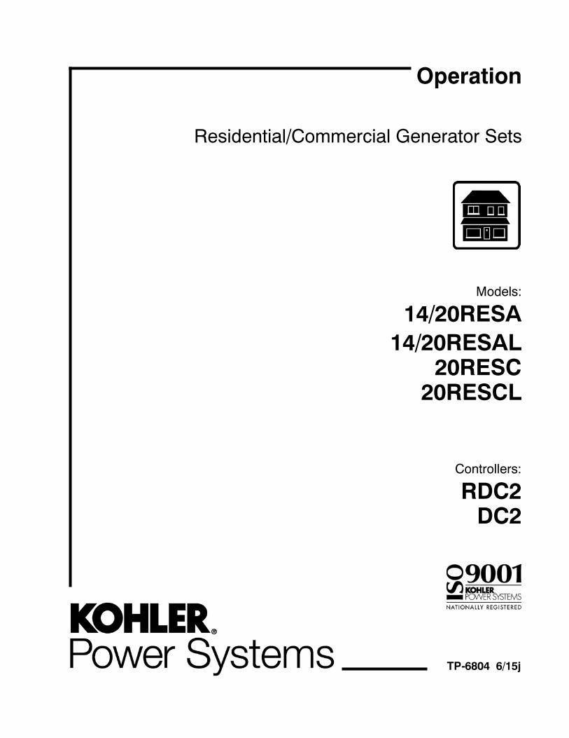
Residential/Commercial Generator Sets Models: 14/20RESA 14/20RESAL 20RESC 20RESCL Controllers: RDC2 DC2 TP-6804 6/15j Operation

Welcome message from author
This document is posted to help you gain knowledge. Please leave a comment to let me know what you think about it! Share it to your friends and learn new things together.
Transcript
Residential/Commercial Generator Sets
Models:
14/20RESA14/20RESAL
20RESC20RESCL
Controllers:
RDC2DC2
TP-6804 6/15j
Operation
Engine exhaust from this product contains chemicalsknown to the State of California to cause cancer, birthdefects, or other reproductive harm.
WARNINGCalifornia Proposition 65
Kohler strongly recommendsthat only factory-authorizeddistributors or dealers installand service the generator.
Product Identification Information
Product identification numbers determine service parts.Record the product identification numbers in the spacesbelow immediately after unpacking the products so thatthe numbers are readily available for future reference.Record field-installed kit numbers after installing thekits.
Generator Set Identification NumbersRecord the product identification numbers from thegenerator set nameplate(s).
Model Designation
Specification Number
Serial Number
Accessory Number Accessory Description
Controller Identification
Record the controller description from the generator setoperation manual, spec sheet, or sales invoice.
Controller Description
Engine IdentificationRecord the product identification information from theengine nameplate.
Manufacturer
Model Designation
Serial Number
Table of Contents
TP-6804 6/15 Table of Contents
Product Identification Information 2. . . . . . . . . . . . . . . . . . . . . . . . . . . . . . . . . . . . . . . . . . . . . . . . . . . . . . . . . . . . .
Safety Precautions and Instructions 7. . . . . . . . . . . . . . . . . . . . . . . . . . . . . . . . . . . . . . . . . . . . . . . . . . . . . . . . .
Introduction 11. . . . . . . . . . . . . . . . . . . . . . . . . . . . . . . . . . . . . . . . . . . . . . . . . . . . . . . . . . . . . . . . . . . . . . . . . . . . . . .
Service Assistance 13. . . . . . . . . . . . . . . . . . . . . . . . . . . . . . . . . . . . . . . . . . . . . . . . . . . . . . . . . . . . . . . . . . . . . . . . .
Section 1 Descriptions and Service Views 15. . . . . . . . . . . . . . . . . . . . . . . . . . . . . . . . . . . . . . . . . . . . . . . . . . .1.1 Introduction 15. . . . . . . . . . . . . . . . . . . . . . . . . . . . . . . . . . . . . . . . . . . . . . . . . . . . . . . . . . .1.2 Engine 15. . . . . . . . . . . . . . . . . . . . . . . . . . . . . . . . . . . . . . . . . . . . . . . . . . . . . . . . . . . . . . .1.3 Alternator 15. . . . . . . . . . . . . . . . . . . . . . . . . . . . . . . . . . . . . . . . . . . . . . . . . . . . . . . . . . . . .1.4 Generator Set Enclosure 15. . . . . . . . . . . . . . . . . . . . . . . . . . . . . . . . . . . . . . . . . . . . . . .1.5 Transfer Switch 15. . . . . . . . . . . . . . . . . . . . . . . . . . . . . . . . . . . . . . . . . . . . . . . . . . . . . . . .1.6 Controllers 15. . . . . . . . . . . . . . . . . . . . . . . . . . . . . . . . . . . . . . . . . . . . . . . . . . . . . . . . . . . .1.7 Accessories 18. . . . . . . . . . . . . . . . . . . . . . . . . . . . . . . . . . . . . . . . . . . . . . . . . . . . . . . . . . .
1.7.1 Carburetor Heater 18. . . . . . . . . . . . . . . . . . . . . . . . . . . . . . . . . . . . . . . . . . . . .1.7.2 Fuel Regulator Heater (20kW models only) 18. . . . . . . . . . . . . . . . . . . . . . . .1.7.3 OnCue Plus Generator Management System 18. . . . . . . . . . . . . . . . . . . . . .1.7.4 Programmable Interface Module (PIM) 18. . . . . . . . . . . . . . . . . . . . . . . . . . .1.7.5 Load Management 18. . . . . . . . . . . . . . . . . . . . . . . . . . . . . . . . . . . . . . . . . . . . .1.7.6 Concrete Mounting Pads 19. . . . . . . . . . . . . . . . . . . . . . . . . . . . . . . . . . . . . . .1.7.7 Emergency Stop Kit 19. . . . . . . . . . . . . . . . . . . . . . . . . . . . . . . . . . . . . . . . . . . .1.7.8 Battery Heater Kit 19. . . . . . . . . . . . . . . . . . . . . . . . . . . . . . . . . . . . . . . . . . . . . .
1.8 Service Views 20. . . . . . . . . . . . . . . . . . . . . . . . . . . . . . . . . . . . . . . . . . . . . . . . . . . . . . . . .
Section 2 Generator Set Operation 21. . . . . . . . . . . . . . . . . . . . . . . . . . . . . . . . . . . . . . . . . . . . . . . . . . . . . . . . . .2.1 Prestart Checklist 21. . . . . . . . . . . . . . . . . . . . . . . . . . . . . . . . . . . . . . . . . . . . . . . . . . . . . .2.2 Exercising the Generator Set 21. . . . . . . . . . . . . . . . . . . . . . . . . . . . . . . . . . . . . . . . . . . .2.3 Generator Set Operation 21. . . . . . . . . . . . . . . . . . . . . . . . . . . . . . . . . . . . . . . . . . . . . . . .
2.3.1 Local Starting and Stopping 22. . . . . . . . . . . . . . . . . . . . . . . . . . . . . . . . . . . . .2.3.2 Automatic Operation 22. . . . . . . . . . . . . . . . . . . . . . . . . . . . . . . . . . . . . . . . . . .2.3.3 Remote Starting and Stopping 22. . . . . . . . . . . . . . . . . . . . . . . . . . . . . . . . . . .2.3.4 Engine Start Crank Cycle 22. . . . . . . . . . . . . . . . . . . . . . . . . . . . . . . . . . . . . . .2.3.5 Engine Cooldown 22. . . . . . . . . . . . . . . . . . . . . . . . . . . . . . . . . . . . . . . . . . . . . .2.3.6 Automatic Operation with Model RXT Transfer Switch 22. . . . . . . . . . . . . .2.3.7 Automatic Operation with Other Transfer Switches 22. . . . . . . . . . . . . . . . .
2.4 Exercise 23. . . . . . . . . . . . . . . . . . . . . . . . . . . . . . . . . . . . . . . . . . . . . . . . . . . . . . . . . . . . . .2.4.1 Setting the Exerciser 23. . . . . . . . . . . . . . . . . . . . . . . . . . . . . . . . . . . . . . . . . . .2.4.2 Unloaded Cycle Exercise with Complete System Diagnostics 23. . . . . . . .2.4.3 Unloaded Full-Speed Exercise 24. . . . . . . . . . . . . . . . . . . . . . . . . . . . . . . . . .2.4.4 Loaded Full-Speed Exercise (with RXT only) 24. . . . . . . . . . . . . . . . . . . . . .2.4.5 Power Failure During Exercise Cycle 24. . . . . . . . . . . . . . . . . . . . . . . . . . . . .
2.5 Faults 25. . . . . . . . . . . . . . . . . . . . . . . . . . . . . . . . . . . . . . . . . . . . . . . . . . . . . . . . . . . . . . . .2.5.1 Warnings 25. . . . . . . . . . . . . . . . . . . . . . . . . . . . . . . . . . . . . . . . . . . . . . . . . . . . .2.5.2 Shutdowns 25. . . . . . . . . . . . . . . . . . . . . . . . . . . . . . . . . . . . . . . . . . . . . . . . . . . .2.5.3 ATS Communication Errors 25. . . . . . . . . . . . . . . . . . . . . . . . . . . . . . . . . . . . .2.5.4 Resetting the Controller after a Fault Shutdown 25. . . . . . . . . . . . . . . . . . . .2.5.5 Faults Related to Paralleling 28. . . . . . . . . . . . . . . . . . . . . . . . . . . . . . . . . . . .
Section 3 RDC2 Controller Operation 31. . . . . . . . . . . . . . . . . . . . . . . . . . . . . . . . . . . . . . . . . . . . . . . . . . . . . . .3.1 RDC2 Generator Set/Transfer Switch Controller 31. . . . . . . . . . . . . . . . . . . . . . . . . . .3.2 Controls and Indicators 31. . . . . . . . . . . . . . . . . . . . . . . . . . . . . . . . . . . . . . . . . . . . . . . . .
3.2.1 Controller Keypad 32. . . . . . . . . . . . . . . . . . . . . . . . . . . . . . . . . . . . . . . . . . . . .3.2.2 LED Indicators 32. . . . . . . . . . . . . . . . . . . . . . . . . . . . . . . . . . . . . . . . . . . . . . . .3.2.3 LCD Display 33. . . . . . . . . . . . . . . . . . . . . . . . . . . . . . . . . . . . . . . . . . . . . . . . . .
3.3 Controller Power 34. . . . . . . . . . . . . . . . . . . . . . . . . . . . . . . . . . . . . . . . . . . . . . . . . . . . . . .3.4 Battery Charging 34. . . . . . . . . . . . . . . . . . . . . . . . . . . . . . . . . . . . . . . . . . . . . . . . . . . . . .
Table of Contents, continued
TP-6804 6/15Table of Contents
3.5 Changing Settings 34. . . . . . . . . . . . . . . . . . . . . . . . . . . . . . . . . . . . . . . . . . . . . . . . . . . . .3.6 Setting the Exerciser 36. . . . . . . . . . . . . . . . . . . . . . . . . . . . . . . . . . . . . . . . . . . . . . . . . . .
3.6.1 Setting the Exerciser at Controller Power-up 36. . . . . . . . . . . . . . . . . . . . . .3.6.2 Changing the Exercise Settings 36. . . . . . . . . . . . . . . . . . . . . . . . . . . . . . . . . .
3.7 RDC2 Controller Menus 38. . . . . . . . . . . . . . . . . . . . . . . . . . . . . . . . . . . . . . . . . . . . . . . .3.8 Main Menu 38. . . . . . . . . . . . . . . . . . . . . . . . . . . . . . . . . . . . . . . . . . . . . . . . . . . . . . . . . . . .3.9 Overview Menu 40. . . . . . . . . . . . . . . . . . . . . . . . . . . . . . . . . . . . . . . . . . . . . . . . . . . . . . . .3.10 Engine Metering Menu 40. . . . . . . . . . . . . . . . . . . . . . . . . . . . . . . . . . . . . . . . . . . . . . . . .3.11 Generator Metering Menu 41. . . . . . . . . . . . . . . . . . . . . . . . . . . . . . . . . . . . . . . . . . . . . . .3.12 Generator Set Information Menu 42. . . . . . . . . . . . . . . . . . . . . . . . . . . . . . . . . . . . . . . . .3.13 Genset Run Time Menu 42. . . . . . . . . . . . . . . . . . . . . . . . . . . . . . . . . . . . . . . . . . . . . . . .3.14 Genset System Menu 43. . . . . . . . . . . . . . . . . . . . . . . . . . . . . . . . . . . . . . . . . . . . . . . . . .3.15 ATS Status Menu 44. . . . . . . . . . . . . . . . . . . . . . . . . . . . . . . . . . . . . . . . . . . . . . . . . . . . . .3.16 ATS Configuration Menu 45. . . . . . . . . . . . . . . . . . . . . . . . . . . . . . . . . . . . . . . . . . . . . . . .3.17 Date and Time Menu 46. . . . . . . . . . . . . . . . . . . . . . . . . . . . . . . . . . . . . . . . . . . . . . . . . . .3.18 Networking Information Menus 46. . . . . . . . . . . . . . . . . . . . . . . . . . . . . . . . . . . . . . . . . .
3.18.1 Networking Status Submenu 47. . . . . . . . . . . . . . . . . . . . . . . . . . . . . . . . . . . .3.18.2 Networking Configuration Submenu (OnCue Password) 48. . . . . . . . . . . .3.18.3 RBUS Information 50. . . . . . . . . . . . . . . . . . . . . . . . . . . . . . . . . . . . . . . . . . . . .3.18.4 Remote Devices Submenu 51. . . . . . . . . . . . . . . . . . . . . . . . . . . . . . . . . . . . . .
3.19 Programmable Interface Module (PIM) Status Menu 52. . . . . . . . . . . . . . . . . . . . . . . .3.20 Load Control Menus 53. . . . . . . . . . . . . . . . . . . . . . . . . . . . . . . . . . . . . . . . . . . . . . . . . . .3.21 Event Log 54. . . . . . . . . . . . . . . . . . . . . . . . . . . . . . . . . . . . . . . . . . . . . . . . . . . . . . . . . . . .
Section 4 DC2 Controller Operation 55. . . . . . . . . . . . . . . . . . . . . . . . . . . . . . . . . . . . . . . . . . . . . . . . . . . . . . . . .4.1 DC2 Generator Set/ Transfer Switch Controller 55. . . . . . . . . . . . . . . . . . . . . . . . . . . .4.2 Controls and Indicators 55. . . . . . . . . . . . . . . . . . . . . . . . . . . . . . . . . . . . . . . . . . . . . . . . .
4.2.1 Controller Keypad 56. . . . . . . . . . . . . . . . . . . . . . . . . . . . . . . . . . . . . . . . . . . . .4.2.2 LED Indicators 56. . . . . . . . . . . . . . . . . . . . . . . . . . . . . . . . . . . . . . . . . . . . . . . .4.2.3 LCD Display 57. . . . . . . . . . . . . . . . . . . . . . . . . . . . . . . . . . . . . . . . . . . . . . . . . .
4.3 Controller Power 57. . . . . . . . . . . . . . . . . . . . . . . . . . . . . . . . . . . . . . . . . . . . . . . . . . . . . . .4.4 Battery Charging 57. . . . . . . . . . . . . . . . . . . . . . . . . . . . . . . . . . . . . . . . . . . . . . . . . . . . . .4.5 Exercise 58. . . . . . . . . . . . . . . . . . . . . . . . . . . . . . . . . . . . . . . . . . . . . . . . . . . . . . . . . . . . . .
4.5.1 Exercise Modes 58. . . . . . . . . . . . . . . . . . . . . . . . . . . . . . . . . . . . . . . . . . . . . . .4.5.2 Setting the Exerciser 58. . . . . . . . . . . . . . . . . . . . . . . . . . . . . . . . . . . . . . . . . . .4.5.3 Exerciser Reset 58. . . . . . . . . . . . . . . . . . . . . . . . . . . . . . . . . . . . . . . . . . . . . . .
4.6 Event Log 58. . . . . . . . . . . . . . . . . . . . . . . . . . . . . . . . . . . . . . . . . . . . . . . . . . . . . . . . . . . .4.7 Maintenance Timer 59. . . . . . . . . . . . . . . . . . . . . . . . . . . . . . . . . . . . . . . . . . . . . . . . . . . .4.8 OnCue Password 59. . . . . . . . . . . . . . . . . . . . . . . . . . . . . . . . . . . . . . . . . . . . . . . . . . . . . .
Section 5 Scheduled Maintenance 61. . . . . . . . . . . . . . . . . . . . . . . . . . . . . . . . . . . . . . . . . . . . . . . . . . . . . . . . . .5.1 Scheduled Maintenance 61. . . . . . . . . . . . . . . . . . . . . . . . . . . . . . . . . . . . . . . . . . . . . . . .
5.1.1 Service Schedule, 14 kW Models 62. . . . . . . . . . . . . . . . . . . . . . . . . . . . . . . .5.1.2 Service Schedule, 20 kW Models 63. . . . . . . . . . . . . . . . . . . . . . . . . . . . . . . .
5.2 Lubrication System 64. . . . . . . . . . . . . . . . . . . . . . . . . . . . . . . . . . . . . . . . . . . . . . . . . . . .5.2.1 Low Oil Pressure Shutdown 64. . . . . . . . . . . . . . . . . . . . . . . . . . . . . . . . . . . . .5.2.2 Oil Check 64. . . . . . . . . . . . . . . . . . . . . . . . . . . . . . . . . . . . . . . . . . . . . . . . . . . . .5.2.3 Engine Oil Recommendation 64. . . . . . . . . . . . . . . . . . . . . . . . . . . . . . . . . . . .5.2.4 Oil Change Procedure 65. . . . . . . . . . . . . . . . . . . . . . . . . . . . . . . . . . . . . . . . . .5.2.5 Resetting the Maintenance Timer 66. . . . . . . . . . . . . . . . . . . . . . . . . . . . . . . .5.2.6 Oil Cooler (20RESA/RESAL only) 66. . . . . . . . . . . . . . . . . . . . . . . . . . . . . . . .
5.3 Spark Plugs 66. . . . . . . . . . . . . . . . . . . . . . . . . . . . . . . . . . . . . . . . . . . . . . . . . . . . . . . . . . .5.4 Air Cleaner Service 67. . . . . . . . . . . . . . . . . . . . . . . . . . . . . . . . . . . . . . . . . . . . . . . . . . . .
5.4.1 Air Cleaner, 14 kW Models 67. . . . . . . . . . . . . . . . . . . . . . . . . . . . . . . . . . . . . .5.4.2 Air Cleaner, 20 kW Models 68. . . . . . . . . . . . . . . . . . . . . . . . . . . . . . . . . . . . . .
5.5 Cooling System 69. . . . . . . . . . . . . . . . . . . . . . . . . . . . . . . . . . . . . . . . . . . . . . . . . . . . . . .
Table of Contents, continued
TP-6804 6/15 Table of Contents
5.6 Exhaust System 69. . . . . . . . . . . . . . . . . . . . . . . . . . . . . . . . . . . . . . . . . . . . . . . . . . . . . . .5.7 Fuel Regulator Vent Tubes 69. . . . . . . . . . . . . . . . . . . . . . . . . . . . . . . . . . . . . . . . . . . . . .5.8 Battery 70. . . . . . . . . . . . . . . . . . . . . . . . . . . . . . . . . . . . . . . . . . . . . . . . . . . . . . . . . . . . . . .
5.8.1 Cleaning the Battery 70. . . . . . . . . . . . . . . . . . . . . . . . . . . . . . . . . . . . . . . . . . .5.8.2 Checking Electrolyte Level 70. . . . . . . . . . . . . . . . . . . . . . . . . . . . . . . . . . . . . .5.8.3 Checking Specific Gravity 71. . . . . . . . . . . . . . . . . . . . . . . . . . . . . . . . . . . . . . .
5.9 Storage Procedure 72. . . . . . . . . . . . . . . . . . . . . . . . . . . . . . . . . . . . . . . . . . . . . . . . . . . . .5.9.1 Lubricating System 72. . . . . . . . . . . . . . . . . . . . . . . . . . . . . . . . . . . . . . . . . . . .5.9.2 Fuel System 72. . . . . . . . . . . . . . . . . . . . . . . . . . . . . . . . . . . . . . . . . . . . . . . . . .5.9.3 Cylinder Lubrication 72. . . . . . . . . . . . . . . . . . . . . . . . . . . . . . . . . . . . . . . . . . . .5.9.4 Exterior Preparation 72. . . . . . . . . . . . . . . . . . . . . . . . . . . . . . . . . . . . . . . . . . . .5.9.5 Battery 72. . . . . . . . . . . . . . . . . . . . . . . . . . . . . . . . . . . . . . . . . . . . . . . . . . . . . . .
Section 6 Troubleshooting 73. . . . . . . . . . . . . . . . . . . . . . . . . . . . . . . . . . . . . . . . . . . . . . . . . . . . . . . . . . . . . . . . .6.1 Introduction 73. . . . . . . . . . . . . . . . . . . . . . . . . . . . . . . . . . . . . . . . . . . . . . . . . . . . . . . . . . .6.2 Fault Messages 73. . . . . . . . . . . . . . . . . . . . . . . . . . . . . . . . . . . . . . . . . . . . . . . . . . . . . . .6.3 Circuit Protection 73. . . . . . . . . . . . . . . . . . . . . . . . . . . . . . . . . . . . . . . . . . . . . . . . . . . . . .
6.3.1 Controller Internal Circuit Protection 73. . . . . . . . . . . . . . . . . . . . . . . . . . . . . .6.3.2 Line Circuit Breaker 73. . . . . . . . . . . . . . . . . . . . . . . . . . . . . . . . . . . . . . . . . . . .
6.4 USB Port and Auxiliary Winding Mini-Breaker 73. . . . . . . . . . . . . . . . . . . . . . . . . . . . .6.5 Thermostat 74. . . . . . . . . . . . . . . . . . . . . . . . . . . . . . . . . . . . . . . . . . . . . . . . . . . . . . . . . . .6.6 Troubleshooting 75. . . . . . . . . . . . . . . . . . . . . . . . . . . . . . . . . . . . . . . . . . . . . . . . . . . . . . .
Appendix A Abbreviations 77. . . . . . . . . . . . . . . . . . . . . . . . . . . . . . . . . . . . . . . . . . . . . . . . . . . . . . . . . . . . . . . .

TP-6804 6/156
Notes
TP-6804 6/15 7Safety Precautions and Instructions
Safety Precautions and Instructions
IMPORTANTSAFETY INSTRUCTIONS.Electromechanical equipment,including generator sets, transferswitches, switchgear, and accessories,can cause bodily harm and poselife-threatening danger whenimproperly installed, operated, ormaintained. To prevent accidents beaware of potential dangers and actsafely. Read and follow all safetyprecautions and instructions. SAVETHESE INSTRUCTIONS.
Thismanual has several types of safetyprecautions and instructions: Danger,Warning, Caution, and Notice.
DANGER
Danger indicates the presence of ahazard that will cause severepersonal injury, death, orsubstantialproperty damage.
WARNING
Warning indicates the presence of ahazard that can cause severepersonal injury, death, orsubstantialproperty damage.
CAUTION
Caution indicates the presence of ahazard that will or can cause minorpersonal injury or property damage.
NOTICENotice communicates installation,operation, or maintenance informationthat is safety related but not hazardrelated.
Safety decals affixed to the equipmentin prominent places alert the operatoror service technician to potentialhazards and explain how to act safely.The decals are shown throughout thispublication to improve operatorrecognition. Replace missing ordamaged decals.
Accidental Starting
Accidental starting.Can cause severe injury or death.
Disconnect the battery cables beforeworking on the generator set.Remove the negative (--) lead firstwhen disconnecting the battery.Reconnect the negative (--) lead lastwhen reconnecting the battery.
WARNING
Disabling the generator set.Accidental starting can causesevere injury or death. Beforeworking on the generator set orequipment connected to the set,disable the generator set as follows:(1) Press the generator set off/resetbutton to shut down the generator set.(2) Disconnect the power to the batterycharger, if equipped. (3) Remove thebattery cables, negative (--) lead first.Reconnect the negative (--) lead lastwhen reconnecting the battery. Followthese precautions to prevent thestarting of the generator set by theremote start/stop switch.
Battery
Sulfuric acid in batteries.Can cause severe injury or death.
Wear protective goggles andclothing. Battery acid may causeblindness and burn skin.
WARNING
Explosion.Can cause severe injury or death.Relays in the battery chargercause arcs or sparks.
Locate the battery in a well-ventilatedarea. Isolate the battery charger fromexplosive fumes.
WARNING
Battery electrolyte is a dilutedsulfuric acid. Battery acid cancausesevere injury or death. Battery acidcan cause blindness and burn skin.Always wear splashproof safetygoggles, rubber gloves, and bootswhen servicing the battery. Do notopen a sealed battery or mutilate thebattery case. If battery acid splashes inthe eyes or on the skin, immediatelyflush the affected area for 15 minuteswith large quantities of clean water.Seek immediatemedical aid in the caseof eye contact. Never add acid to abattery after placing the battery inservice, as this may result in hazardousspattering of battery acid.
Battery acid cleanup. Battery acidcan cause severe injury or death.Battery acid is electrically conductiveand corrosive. Add 500 g (1 lb.) ofbicarbonate of soda (baking soda) to acontainer with 4 L (1 gal.) of water andmix the neutralizing solution. Pour theneutralizing solution on the spilledbattery acid and continue to add theneutralizing solution to the spilledbattery acid until all evidence of achemical reaction (foaming) hasceased. Flush the resulting liquid withwater and dry the area.
TP-6804 6/158 Safety Precautions and Instructions
Battery gases. Explosion can causesevere injury or death. Battery gasescan cause an explosion. Do not smokeor permit flames or sparks to occur neara battery at any time, particularly whenit is charging. Do not dispose of abattery in a fire. To prevent burns andsparks that could cause an explosion,avoid touching the battery terminalswith tools or other metal objects.Remove all jewelry before servicing theequipment. Discharge static electricityfrom your body before touchingbatteries by first touching a groundedmetal surface away from thebattery. Toavoid sparks, do not disturb the batterycharger connections while the batteryis charging. Always turn the batterycharger off before disconnecting thebattery connections. Ventilate thecompartments containing batteries toprevent accumulation of explosivegases.
Battery short circuits. Explosioncan cause severe injury or death.Short circuits can cause bodily injuryand/or equipment damage.Disconnect the battery beforegenerator set installation ormaintenance. Remove all jewelrybefore servicing the equipment. Usetools with insulated handles. Removethe negative (--) lead first whendisconnecting the battery. Reconnectthe negative (--) lead last whenreconnecting the battery. Neverconnect the negative (--) battery cableto the positive (+) connection terminalof the starter solenoid. Do not test thebattery condition by shorting theterminals together.
Engine Backfire/FlashFire
Risk of fire.Can cause severe injury or death.
Do not smoke or permit flames orsparks near fuels or the fuel system.
WARNING
Servicing the air cleaner. A suddenbackfire can cause severe injury ordeath. Do not operate the generatorset with the air cleaner removed.
Servicing the fuel system. A flashfire cancausesevere injuryor death.Do not smoke or permit flames orsparks near the carburetor, fuel line,fuel filter, fuel pump, or other potentialsources of spilled fuels or fuel vapors.Catch fuels in an approved containerwhen removing the fuel line orcarburetor.
Combustible materials. A fire cancause severe injury or death.Generator set engine fuels and fuelvapors are flammable and explosive.Handle these materials carefully tominimize the risk of fire or explosion.Equip the compartment or nearby areawith a fully charged fire extinguisher.Select a fire extinguisher rated ABC orBC for electrical fires or asrecommended by the local fire code oran authorized agency. Train allpersonnel on fire extinguisheroperation and fire preventionprocedures.
Exhaust System
Carbon monoxide.Can cause severe nausea,fainting, or death.
The exhaust system must beleakproof and routinely inspected.
WARNING
Generator set operation. Carbonmonoxide can cause severe nausea,fainting, or death. Carbon monoxideis an odorless, colorless, tasteless,nonirritating gas that can cause death ifinhaled for even a short time. Avoidbreathing exhaust fumeswhenworkingon or near the generator set. Neveroperate the generator set inside abuilding. Never operate the generatorset where exhaust gas could seepinside or be drawn into a potentiallyoccupied building through windows, airintake vents, or other openings.
Carbon monoxide detectors.Carbon monoxide can cause severenausea, fainting, or death. Installcarbon monoxide detectors on eachlevel of any building adjacent to thegenerator set. Locate the detectors toadequately warn the building’soccupants of the presence of carbonmonoxide. Keep the detectorsoperational at all times. Periodicallytest and replace the carbon monoxidedetectors according to themanufacturer’s instructions.
Carbon monoxide symptoms.Carbon monoxide can cause severenausea, fainting, or death. Carbonmonoxide is a poisonous gas present inexhaust gases. Carbonmonoxide is anodorless, colorless, tasteless,nonirritating gas that can cause death ifinhaled for even a short time. Carbonmonoxide poisoning symptoms includebut are not limited to the following:D Light-headedness, dizzinessD Physical fatigue, weakness injoints and muscles
D Sleepiness, mental fatigue,inability to concentrateor speak clearly, blurred vision
D Stomachache, vomiting, nauseaIf experiencing any of these symptomsand carbon monoxide poisoning ispossible, seek fresh air immediatelyand remain active. Do not sit, lie down,or fall asleep. Alert others to thepossibility of carbon monoxidepoisoning. Seek medical attention ifthe condition of affected persons doesnot improvewithinminutes of breathingfresh air.
TP-6804 6/15 9Safety Precautions and Instructions
Fuel System
Explosive fuel vapors.Can cause severe injury or death.
Use extreme care when handling,storing, and using fuels.
WARNING
The fuel system. Explosive fuelvapors can cause severe injury ordeath. Vaporized fuels are highlyexplosive. Use extreme care whenhandling and storing fuels. Store fuelsin a well-ventilated area away fromspark-producing equipment and out ofthe reach of children. Never add fuel tothe tank while the engine is runningbecause spilled fuel may ignite oncontact with hot parts or from sparks.Do not smoke or permit flames orsparks to occur near sources of spilledfuel or fuel vapors. Keep the fuel linesand connections tight and in goodcondition. Do not replace flexible fuellines with rigid lines. Use flexiblesections to avoid fuel line breakagecausedby vibration. Donot operate thegenerator set in the presence of fuelleaks, fuel accumulation, or sparks.Repair fuel systems before resuminggenerator set operation.
Gas fuel leaks. Explosive fuelvapors can cause severe injury ordeath. Fuel leakage can cause anexplosion. Check the LPG vapor ornatural gas fuel system for leakage byusing a soap and water solution withthe fuel system test pressurized to6--8 ounces per square inch(10--14 inches water column). Do notuse a soap solution containing eitherammonia or chlorine because bothprevent bubble formation. A successfultest depends on the ability of thesolution to bubble.
Hazardous Noise
Hazardous noise.Can cause hearing loss.
Never operate the generator setwithout a muffler or with a faultyexhaust system.
CAUTION
Engine noise. Hazardous noise cancause hearing loss. Generator setsnot equipped with sound enclosurescan produce noise levels greater than105 dBA. Prolonged exposure to noiselevels greater than 85 dBA can causepermanent hearing loss. Wear hearingprotection when near an operatinggenerator set.
Hazardous Voltage/Moving Parts
Hazardous voltage.Will cause severe injury or death.
This equipment must be installed andserviced by qualified electricalpersonnel.
DANGER
Hazardous voltage.Can cause severe injury or death.
Operate the generator set only whenall guards and electrical enclosuresare in place.
Moving parts.
WARNING
Hazardous voltage.Backfeed to the utility system cancause property damage, severeinjury, or death.
If the generator set is used forstandby power, install an automatictransfer switch to prevent inadvertentinterconnection of standby andnormal sources of supply.
WARNING
Welding the generator set.Can cause severe electricalequipment damage.
Never weld components of thegenerator set without firstdisconnecting the battery, controllerwiring harness, and engine electroniccontrol module (ECM).
CAUTION
Grounding electrical equipment.Hazardous voltage can causesevere injury or death. Electrocutionis possible whenever electricity ispresent. Ensure you comply with allapplicable codes and standards.Electrically ground the generator set,transfer switch, and related equipmentand electrical circuits. Turn off themaincircuit breakers of all power sourcesbefore servicing the equipment. Nevercontact electrical leads or applianceswhen standing in water or on wetground because these conditionsincrease the risk of electrocution.
TP-6804 6/1510 Safety Precautions and Instructions
Welding on the generator set. Cancause severe electrical equipmentdamage. Before welding on thegenerator set perform the followingsteps: (1) Remove the battery cables,negative (--) lead first. (2) Disconnectall engine electronic control module(ECM) connectors. (3) Disconnect allgenerator set controller and voltageregulator circuit board connectors.(4) Disconnect the engine battery-charging alternator connections.(5) Attach the weld ground connectionclose to the weld location.
Connecting the battery and thebattery charger. Hazardous voltagecan cause severe injury or death.Reconnect the battery correctly,positive to positive and negative tonegative, to avoid electrical shock anddamage to the battery charger andbattery(ies). Have a qualifiedelectrician install the battery(ies).
Short circuits. Hazardousvoltage/current can cause severeinjury or death. Short circuits cancause bodily injury and/or equipmentdamage. Do not contact electricalconnections with tools or jewelry whilemaking adjustments or repairs.Remove all jewelry before servicing theequipment.
Electrical backfeed to the utility.Hazardous backfeed voltage cancause severe injury or death. Installa transfer switch in standby powerinstallations to prevent the connectionof standby and other sources of power.Electrical backfeed into a utilityelectrical system can cause severeinjury or death to utility personnelworking on power lines.
Heavy Equipment
Unbalanced weight.Improper lifting can cause severeinjury or death and equipmentdamage.
Do not use lifting eyes.Lift the generator set using lifting barsinserted through the lifting holes onthe skid.
WARNING
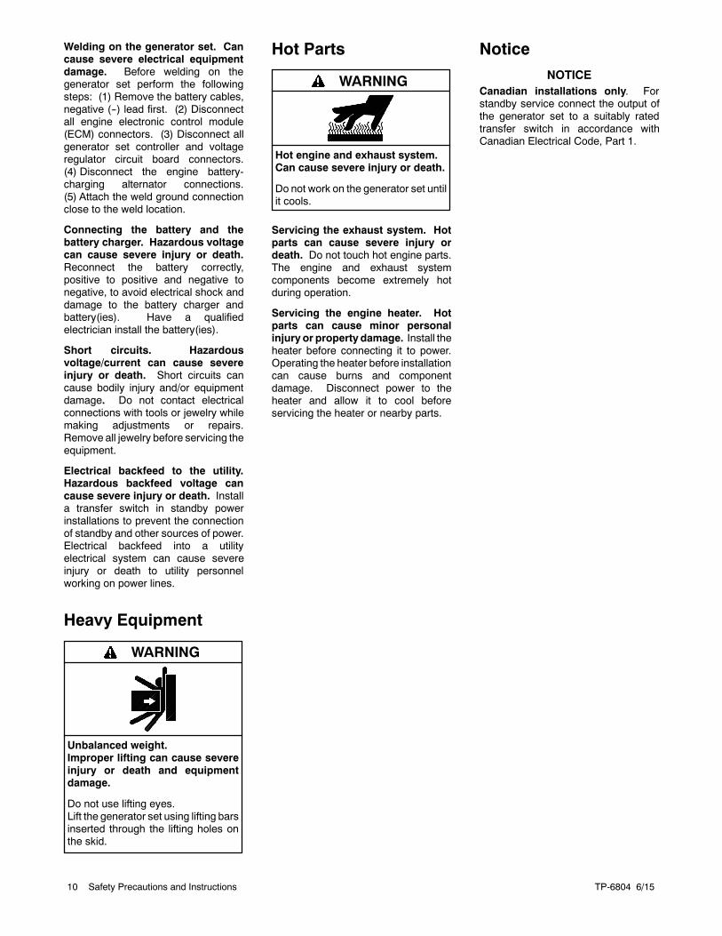
Hot Parts
Hot engine and exhaust system.Can cause severe injury or death.
Do not work on the generator set untilit cools.
WARNING
Servicing the exhaust system. Hotparts can cause severe injury ordeath. Do not touch hot engine parts.The engine and exhaust systemcomponents become extremely hotduring operation.
Servicing the engine heater. Hotparts can cause minor personalinjury or property damage. Install theheater before connecting it to power.Operating the heater before installationcan cause burns and componentdamage. Disconnect power to theheater and allow it to cool beforeservicing the heater or nearby parts.
NoticeNOTICE
Canadian installations only. Forstandby service connect the output ofthe generator set to a suitably ratedtransfer switch in accordance withCanadian Electrical Code, Part 1.
TP-6804 6/15 11Introduction
Introduction
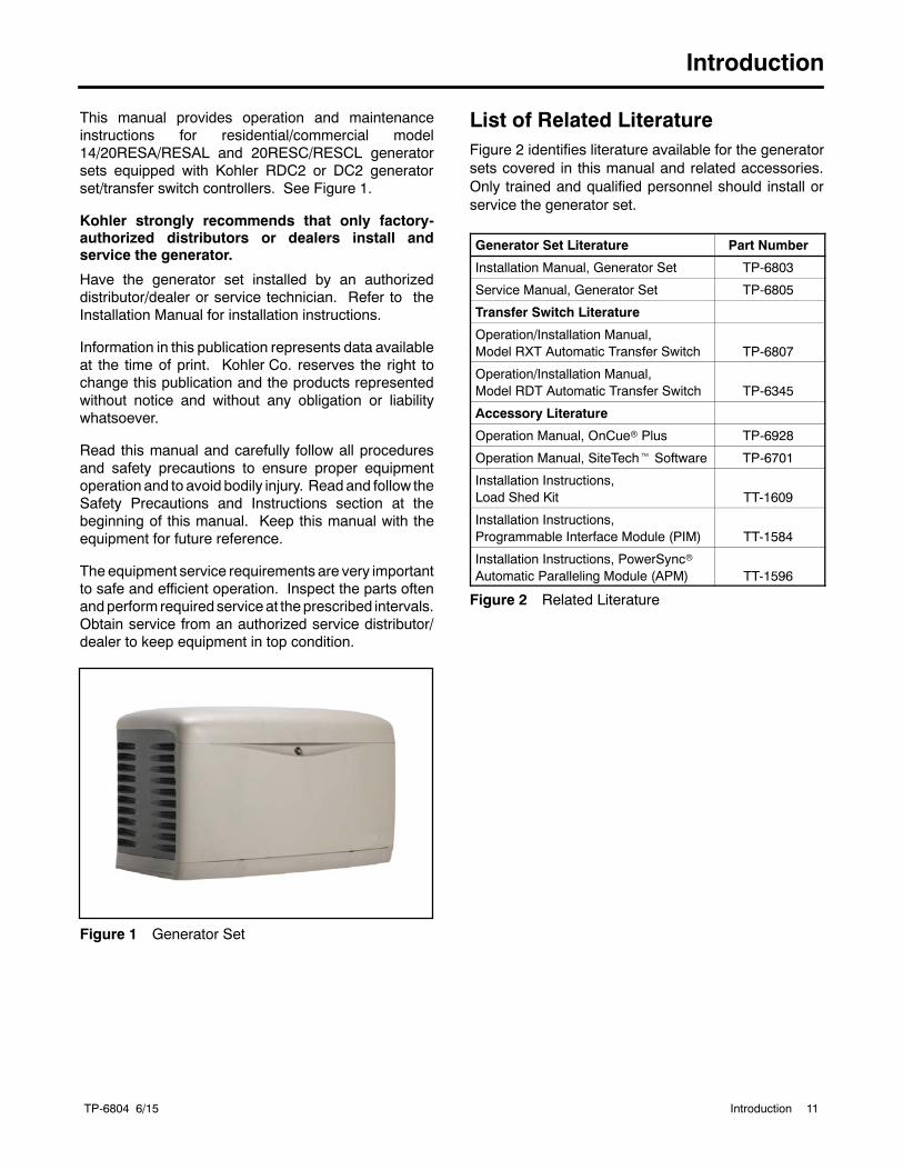
This manual provides operation and maintenanceinstructions for residential/commercial model14/20RESA/RESAL and 20RESC/RESCL generatorsets equipped with Kohler RDC2 or DC2 generatorset/transfer switch controllers. See Figure 1.
Kohler strongly recommends that only factory-authorized distributors or dealers install andservice the generator.
Have the generator set installed by an authorizeddistributor/dealer or service technician. Refer to theInstallation Manual for installation instructions.
Information in this publication represents data availableat the time of print. Kohler Co. reserves the right tochange this publication and the products representedwithout notice and without any obligation or liabilitywhatsoever.
Read this manual and carefully follow all proceduresand safety precautions to ensure proper equipmentoperation and to avoid bodily injury. Readand follow theSafety Precautions and Instructions section at thebeginning of this manual. Keep this manual with theequipment for future reference.
The equipment service requirements are very importantto safe and efficient operation. Inspect the parts oftenandperform requiredserviceat theprescribed intervals.Obtain service from an authorized service distributor/dealer to keep equipment in top condition.
Figure 1 Generator Set
List of Related LiteratureFigure 2 identifies literature available for the generatorsets covered in this manual and related accessories.Only trained and qualified personnel should install orservice the generator set.
Generator Set Literature Part Number
Installation Manual, Generator Set TP-6803
Service Manual, Generator Set TP-6805
Transfer Switch Literature
Operation/Installation Manual,Model RXT Automatic Transfer Switch TP-6807
Operation/Installation Manual,Model RDT Automatic Transfer Switch TP-6345
Accessory Literature
Operation Manual, OnCuer Plus TP-6928
Operation Manual, SiteTecht Software TP-6701
Installation Instructions,Load Shed Kit TT-1609
Installation Instructions,Programmable Interface Module (PIM) TT-1584
Installation Instructions, PowerSyncrAutomatic Paralleling Module (APM) TT-1596
Figure 2 Related Literature
TP-6804 6/1512 Introduction
NameplateThe following illustration shows a typical generator setnameplate. Copy the model, serial, and specificationnumbers from thenameplate into thespacesprovided inthe product information section on the inside front coverof this manual. See the service views in Section 1.8 forthe nameplate location.
GM12070
Service Duty
Voltage
Alt Model
Insulation
MFG Date
Amps
Phase
RPM
Battery
Fuel
kW
kVA
PF
Hz
Genset Model
Spec Number
Serial Number
Material Number
Emission InformationThe Kohlerr Model CH740 engine used on the14RESA/RESAL generator set is certified to operateusing natural gas or propane fuel.
The Kohlerr Model CH1000 engine used on the20RESA/RESAL and 20RESC/RESCL generator setsis certified to operate using natural gas or propane fuelfor emergency standby use only. This generator set iscertified by the U.S. EPA for emergency standbyoperation backing up a reliable utility source. Operationoutside these guidelines is a violation of national EPAregulations.
The Emission Compliance Period referred to on theEmissionControl orAir Index label indicates thenumberof operating hours for which the engine has been showntomeet CARB or EPA emission requirements. Figure 3provides the engine compliance period (in hours)associated with the category descriptor, which may befound on the certification label.
Emission Compliance Period
EPACategory C250 hours
Category B500 hours
Category A1000 hours
CARBModerate125 hours
Intermediate250 hours
Extended500 hours
Figure 3 Emission Compliance Period
Refer to the certification label for engine displacement.
The exhaust emission control system for the CH740engines (14RESA/RESAL) is EM for U.S. EPA,California, and Europe.
The exhaust emission control system for the CH1000engine (20RESA/RESAL and 20RESC/RESCL) is EMfor U.S. EPA, California, and Europe.
Generator Set Application
Kohlerr Power Systems (KPS) ensures that all Kohlerrgenerator sets are certified to applicable standards fortheir intended application. It is the owner/operator’sresponsibility to operate Kohlerr generator setsexclusively according to the directions provided in theaccompanying operation manuals.
Kohlerr generator sets designated as StationaryStandby, Emergency or Emergency Standby may onlybe operated for emergency power generation and formaintenance/testing. Emergency power generation islimited to power production when electric power from alocal utility (or the normal power source, if the facilityruns on its own power production) is interrupted.
The US Clean Air Act explicitly prohibits usingEmergency Standby generators as a primary electricpower source regardless of whether a site is connectedto the electrical grid. Emergency Standby generatorsmay NOT be used to power sites which are notconnected to an electric utility. The U.S. Clean Air Actauthorizes owner/operator fines of up to $3,750 per dayof operation in violation of the generator set’scertification.
Owners/operators should familiarize themselves withand perform all testing, maintenance, notification,reporting and record keeping as required by the CleanAir Act. In most cases, performance testing is notrequired if the generator is operated and maintainedaccording to the operation manual. However,owners/operators must retain maintenance records.
TP-6804 6/15 13Service Assistance
Service Assistance
For professional advice on generator set powerrequirementsandconscientiousservice, pleasecontactyour nearest Kohler distributor or dealer.
D Consult the Yellow Pages under the headingGenerators—Electric.
D Visit the Kohler Power Systems website atKOHLERPower.com.
D Look at the labels and decals on your Kohler productor review the appropriate literature or documentsincluded with the product.
D Call toll free in the US and Canada 1-800-544-2444.
D Outside theUSandCanada, call the nearest regionaloffice.
Headquarters Europe, Middle East, Africa(EMEA)Kohler Power Systems Netherlands B.V.Kristallaan 14761 ZC ZevenbergenThe NetherlandsPhone: (31) 168 331630Fax: (31) 168 331631
Asia PacificPower Systems Asia Pacific Regional OfficeSingapore, Republic of SingaporePhone: (65) 6264-6422Fax: (65) 6264-6455
ChinaNorth China Regional Office, BeijingPhone: (86) 10 6518 7950
(86) 10 6518 7951(86) 10 6518 7952
Fax: (86) 10 6518 7955
East China Regional Office, ShanghaiPhone: (86) 21 6288 0500Fax: (86) 21 6288 0550
India, Bangladesh, Sri LankaIndia Regional OfficeBangalore, IndiaPhone: (91) 80 3366208
(91) 80 3366231Fax: (91) 80 3315972
Japan, KoreaNorth Asia Regional OfficeTokyo, JapanPhone: (813) 3440-4515Fax: (813) 3440-2727
Latin AmericaLatin America Regional OfficeLakeland, Florida, USAPhone: (863) 619-7568Fax: (863) 701-7131

TP-6804 6/1514 Service Assistance
Notes
TP-6804 6/15 15Section 1 Descriptions and Service Views
Section 1 Descriptions and Service Views
1.1 Introduction
The generator set specification sheets provide specificgenerator and engine information. Refer to the specsheet for data not supplied in this manual. Consult thegenerator set servicemanual, engineoperationmanual,and engine servicemanual for additional specifications.Obtain copies of the latest spec sheets, manuals,diagrams, and drawings from your local distributor/dealer.
1.2 Engine
The generator set has a four-cycle, twin cylinder, air-cooled Kohlerr engine. The engine operates on clean-burning natural gas or LPG. Engine features include:
D Efficient overhead valve design and full pressurelubrication for maximum power, torque, and reliabilityunder all operating conditions.
D Dependable, maintenance-free electronic ignition.
D Precision-formulated cast iron construction of partssubjected to the most wear and tear.
D Field-convertible multi-fuel systems that allow fuelchangeover fromnatural gas to LPG(andvice- versa)while maintaining emissions certification.
D Digital spark advance optimizes ignition timing for theselected fuel.
1.3 Alternator
The generator uses Kohler’s unique PowerBoosttvoltage regulation system, which provides instantresponse to load changes.
PowerBoostt ensures reliable motor starting andconsistent voltage levels. PowerBoostt utilizes avoltage excitation system that employs a windingindependent of the main output windings to provideexcitation voltage.
1.4 Generator Set Enclosure
The generator set is housed in an exclusive engineeredcomposite enclosure that is corrosion-proof, even inharsh seaside environments, and impact-resistant,even in cold weather. The enclosure has a hinged,locking roof that allows easy access to the generator setcontroller when required, but locks securely to preventunauthorized access.
To open the roof, insert the key provided with theenclosure and turn counterclockwise 1/4 turn. Then justraise the roof. The roof stays open until you are ready toclose it.
Be sure to close and lock the enclosure, and keep thekey in a secure location.
1.5 Transfer Switch
The RDC2 and DC2 controllers are designed tointerface with and control the Kohler Model RXTAutomatic Transfer Switch (ATS). Do not use theKohlerModel RRT transfer switch with the RDC2 or DC2controller.
If the power system uses a different model transferswitch, theRDC2andDC2controllerswill not control thetransfer switch. An ATS other than theModel RXTmustbe equippedwith a transfer switch controller and enginestart contacts that connect to the remote engine startterminals on the generator set.
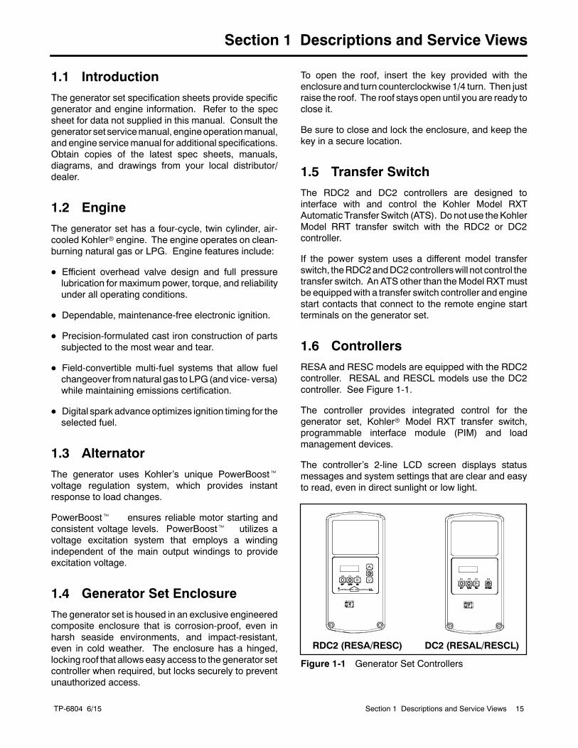
1.6 Controllers
RESA and RESC models are equipped with the RDC2controller. RESAL and RESCL models use the DC2controller. See Figure 1-1.
The controller provides integrated control for thegenerator set, Kohlerr Model RXT transfer switch,programmable interface module (PIM) and loadmanagement devices.
The controller’s 2-line LCD screen displays statusmessages and system settings that are clear and easyto read, even in direct sunlight or low light.
RDC2 (RESA/RESC) DC2 (RESAL/RESCL)
Figure 1-1 Generator Set Controllers
TP-6804 6/1516 Section 1 Descriptions and Service Views
RDC2 Controller Features
D Six-button keypad
d OFF, AUTO, and RUN pushbuttons
d Select and arrow buttons for access to systemconfiguration and adjustment menus
D LED indicators for OFF, AUTO, and RUN modes
D LED indicators for utility power and generator setsource availability and ATS position (Model RXTtransfer switch required)
D LCD display
d Two lines x 16 characters per line
d Backlit display with adjustable contrast forexcellent visibility in all lighting conditions
D Scrolling system status display
d Generator set status
d Voltage and frequency
d Engine temperature
d Oil pressure
d Battery voltage
d Engine runtime hours
D Date and time displays
D Smart engine cooldown senses engine temperature
D Digital isochronous governor to maintainsteady-state speed at all loads
D Digital voltage regulation: ±0.5% RMS no-load tofull-load
D Automatic start with programmed cranking cycle
D Programmable exerciser can be set to startautomatically on any future day and time, and runevery week or every two weeks
D Exercise modes
d Unloaded weekly exercise with complete systemdiagnostics
d Unloaded full-speed exercise
d Loaded full-speed exercise (Model RXT ATSrequired)
D Front-access mini USB connector for KohlerrSiteTecht connection
D Integral Ethernet connector for the Kohlerr OnCuerPlus Generator Management System
D Built-in battery charger
D Remote two-wire start/stop capability for connectionof Model RDT or other transfer switches
D Diagnostic messages
d Displays diagnostic messages for the engine,generator, Model RXT transfer switch,programmable interface module (PIM), and loadmanagement device
d Over 70 diagnostic messages can be displayed
D Maintenance reminders
D System settings
d System voltage, frequency, and phase
d Voltage adjustment
d Measurement system, English or metric
D ATS status (Model RXT ATS required)
d Source availability
d ATS position (normal/utility oremergency/generator)
d Source voltage and frequency
D ATS control (Model RXT ATS required)
d Source voltage and frequency settings
d Engine start time delay
d Transfer time delays
d Voltage calibration
d Fixed pickup and dropout settings
D Programmable Interface Module (PIM) statusdisplays
d Input status (active/inactive)
d Output status (active/inactive)
D Load control menus
d Load status
d Test function
TP-6804 6/15 17Section 1 Descriptions and Service Views
DC2 Controller Features
D Four-button keypad: OFF, AUTO, RUN, andEXERCISE pushbuttons
D LED indicators for OFF, AUTO, and RUN modes
D LCD display:
d Two lines x 16 characters per line
d Backlit display with adjustable contrast forexcellent visibility
D Scrolling system status display
d Generator set status
d Voltage and frequency
d Engine temperature
d Oil pressure
d Battery voltage
d Engine runtime hours
d Maintenance reminders
d OnCuer status (connected/disconnected)
D Date and time displays
D Smart engine cooldown senses engine temperature
D Digital isochronous governor to maintainsteady-state speed at all loads
D Digital voltage regulation: ±0.5% RMS no-load tofull-load
D Automatic start with programmed cranking cycle
D Exercise modes
d Unloaded weekly exercise with complete systemdiagnostics
d Unloaded full-speed exercise
d Loaded full-speed exercise (Model RXT ATSrequired)
D Front-access mini USB connector for SiteTechtconnection
D Integral Ethernet connector for KohlerrOnCuerPlus
D Built-in 2.5 amp battery charger
D Remote two-wire start/stop capability for connectionof Model RDT or other transfer switches
D Diagnostic messages
d Displays diagnostic messages for the engine,generator set, model RXT transfer switch, andoptional programmable interface module (PIM)and load management device
d Over 70 diagnostic messages can be displayed
D A laptop computer and Kohlerr SiteTecht softwarecan be used to change system settings or upgradecontroller firmware.
TP-6804 6/1518 Section 1 Descriptions and Service Views
1.7 Accessories
The following optional accessories are offered for thegenerator sets.
1.7.1 Carburetor Heater
An optional carburetor heater is recommended forimproved cold starting in locations where the ambienttemperature drops below 0_C (32_F). The carburetorheater preventscondensationandcarburetor icing. Theheater requires a continuous source of AC power.
See the generator set Installation manual for moreinformation.
1.7.2 Fuel Regulator Heater (20kWmodels only)
An optional fuel regulator heater for the20RESA/20RESAL and 20RESC/RESCL isrecommended for improved cold starting in locationswhere the ambient temperature drops below --18_C(0_F). The heater requires a continuous source of ACpower.
See the generator set Installation manual for moreinformation.
1.7.3 OnCue Plus GeneratorManagement System
The Kohlerr OnCuer Plus Generator ManagementSystem allowsmonitoring and control of your generatorset from your home or other location with Internetaccess using a computer or mobile device.OnCuer Plus can be configured to send email or textmessage notifications in the event of a generator setfault.
OnCue Plus Wireless is also available. OnCue PlusWireless works with the customer’s wireless Ethernetrouter and does not require the installation of a networkcable between the generator set and the customer’srouter/modem.
1.7.4 Programmable Interface Module(PIM)
The optional Programmable Interface Module (PIM)provides two programmable inputs and sixprogrammable dry contact outputs for connection tocustomer-supplied equipment. The outputs arecontrolled by the RDC2or DC2 controller, and can alsobe controlled remotely using OnCue Plus.
ThePIM ismounted inaNEMA3Raluminumenclosure,which can be mounted indoors or outdoors. See theinstallation instructions provided with the PIM.
1.7.5 Load Management
Two optional load management devices are availablefor use with single-phase generator sets and a modelRXT or RDT transfer switch.
D The optional Load Shed Kit mounts inside a modelRDT or RXT transfer switch.
D The combined interface/ load management board isavailable for the Model RXT transfer switch.
The load management devices provide an automaticload management system to comply with Section 702.5of NEC 2008. The installer is responsible for ensuringthat the power system installation complies with allapplicable state and local codes.
Note: The load management devices are onlycompatible with single-phase generator sets.
The load management device automatically managesup to six residential loads. Two relays are provided tocontrol two independent air conditioner loads. Up to fourpower relay modules can be connected formanagement of non-essential secondary loads.
The load management device is controlled by theRDC2or DC2 controller. The load on the generator setismonitored, and loads are added or shed in the order oftheir priority. See the installation instructions providedwith the load shed kit or the Model RXT Operation andInstallation Manual for more information.
TP-6804 6/15 19Section 1 Descriptions and Service Views
1.7.6 Concrete Mounting Pads
Kohler offers optional concrete mounting pads that arecustom-designed for Model 14RESA/RESAL,20RESA/RESAL, and 20RESC/RESCL generator sets.Three-inch and four-inch thick pads are available.Four-inch pads are recommended for storm-proneareas.
1.7.7 Emergency Stop Kit
An emergency stop button is available as a loose kit.Pressing the emergency stop button causes the
generator set to shut down immediately. The generatorcontroller displays an emergency stop shutdownmessage after the button is pressed.
1.7.8 Battery Heater Kit
The battery heater kit includes a thermostatically-controlled battery heating wrap to warm the battery incold weather. Battery heater kits are recommended forgenerator installed in regions where the temperatureregularly falls below 0_C (32_F).
TP-6804 6/1520 Section 1 Descriptions and Service Views
1.8 Service Views
19
2223
1
3
12 13
18
21
ADV-8424ADV-8754
1514
24
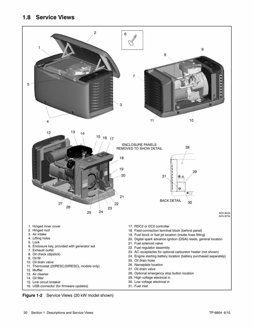
1. Hinged inner cover2. Hinged roof3. Air intake4. Lifting holes5. Lock6. Enclosure key, provided with generator set7. Exhaust outlet8. Oil check (dipstick)9. Oil fill10. Oil drain valve11. Thermostat (20RESC/20RESCL models only)12. Muffler13. Air cleaner14. Oil filter15. Line circuit breaker16. USB connector (for firmware updates)
17. RDC2 or DC2 controller18. Field-connection terminal block (behind panel)19. Fuel block or fuel jet location (inside hose fitting)20. Digital spark advance ignition (DSAI) leads, general location21. Fuel solenoid valve22. Fuel regulator assembly23. AC receptacles for optional carburetor heater (not shown)24. Engine starting battery location (battery purchased separately)25. Oil drain hose26. Nameplate location27. Oil drain valve28. Optional emergency stop button location29. High voltage electrical in30. Low voltage electrical in31. Fuel inlet
25
1716
26
ENCLOSURE PANELSREMOVED TO SHOW DETAIL
7
89
2
5
6
20
BACK DETAIL
31
28
29
30
114 10
27
Figure 1-2 Service Views (20 kW model shown)
TP-6804 6/15 21Section 2 Generator Set Operation
Section 2 Generator Set Operation
2.1 Prestart Checklist
To ensure continued satisfactory operation, perform thefollowing checks or inspections before or at eachstartup, as designated, and at the intervals specified inthe service schedule. In addition, some checks requireverification after the unit starts.
Air Cleaner. Check for a clean and installed air cleanerelement to prevent unfiltered air from entering theengine.
Air Inlets. Check for clean and unobstructed air inlets.
Battery. Check for tight battery connections. Consultthe battery manufacturer’s instructions regardingbattery care and maintenance.
Exhaust System. Check for exhaust leaks andblockages. Check the muffler condition.
D Inspect the exhaust system components for cracks,leaks, and corrosion. Check for tight exhaust systemconnections.
D Check for corrodedor brokenmetal parts and replacethem as needed.
D Check that the exhaust outlet is unobstructed.
Oil Level. Check the oil level before starting thegenerator set and at the intervals given in Section 5,Scheduled Maintenance. Maintain the oil level at ornear, not over, the full mark on the dipstick.
Operating Area. Check for obstructions that couldblock the flow of cooling air. Keep the air intake areaclean. Do not leave rags, tools, or debris on or near thegenerator set.
2.2 Exercising the Generator Set
Operate the generator set without load once each weekfor 20 minutes. See Section 2.4 for information aboutloaded and unloaded exercise modes. For instructionsto set the exerciser, see:
D Section 3.6 for the RDC2 controller
D Section 4.5 for the DC2 controller
2.3 Generator Set Operation
Hazardous voltage.Can cause severe injury or death.
Operate the generator set only whenall guards and electrical enclosuresare in place.
Moving parts.
WARNING
Carbon monoxide.Can cause severe nausea,fainting, or death.
The exhaust system must beleakproof and routinely inspected.
WARNING
Generator set operation. Carbon monoxide can causesevere nausea, fainting, or death. Carbon monoxide is anodorless, colorless, tasteless, nonirritating gas that can causedeath if inhaled for even a short time. Avoid breathing exhaustfumes when working on or near the generator set. Neveroperate the generator set inside a building. Never operate thegenerator set where exhaust gas could seep inside or bedrawn into a potentially occupied building throughwindows, airintake vents, or other openings.
Carbon monoxide symptoms. Carbon monoxide cancause severe nausea, fainting, or death. Carbonmonoxideis a poisonous gas present in exhaust gases. Carbonmonoxide is an odorless, colorless, tasteless, nonirritating gasthat can cause death if inhaled for even a short time. Carbonmonoxide poisoning symptoms include but are not limited tothe following:D Light-headedness, dizzinessD Physical fatigue, weakness injoints and muscles
D Sleepiness, mental fatigue,inability to concentrateor speak clearly, blurred vision
D Stomachache, vomiting, nauseaIf experiencing any of these symptoms and carbon monoxidepoisoning is possible, seek fresh air immediately and remainactive. Do not sit, lie down, or fall asleep. Alert others to thepossibility of carbon monoxide poisoning. Seek medicalattention if the condition of affected persons does not improvewithin minutes of breathing fresh air.
TP-6804 6/1522 Section 2 Generator Set Operation
2.3.1 Local Starting and Stopping
Start: Press the RUN button to immediately start thegenerator set.
Stop: Press the OFF button. The engine stops.
Run the generator set with no load for at least 2 minutesto ensure adequate engine cooldown.
2.3.2 Automatic Operation
An automatic transfer switch monitors the utility powerand signals the generator set to start when utility poweris lost. The ATS then transfers the load to the generatorset.
When utility power is restored, the transfer switchtransfers the load back to utility, runs the generator setwith no load to cool down the engine, and then stops thegenerator set.
SeeSections 2.3.6 and 2.3.7 formore information aboutautomatic operation.
2.3.3 Remote Starting and Stopping
A remote switch connected to terminals 3 and 4 can beused to start and stop the generator set. Close theswitch to start and run the generator set. Open theswitch to stop the generator set.
Run the generator set with no load for at least 2 minutesto ensure adequate engine cooldown.
2.3.4 Engine Start Crank Cycle
The controller attempts to start the generator set threetimes (three crank cycles, 15 seconds crank and15 seconds off). If the generator set does not start inthree attempts, the system shuts down on an overcrankfault. See Section 2.5.
Cranking 1, 2, and 3 are displayed during the crankcycle. Pressing the OFF button during the crank cyclestops the cranking. No other buttons are acknowledgedduring the crank cycle.
2.3.5 Engine Cooldown
The engine cooldown time delay allows the engine torun after the loads have been removed.
The engine cooldown time delay is set to 5minutes. Theengine stops before the cooldown time delay expires ifthe temperature drops below the cooled-downtemperature level, or if the temperature rises above thehigh limit during the cooldown cycle.
If a transfer switch other than theModel RXT is used, anadditional engine cooldown time delay may beprogrammed on the transfer switch. To allow the smartengine cooldown on the RDC2 controller to operatemost efficiently, set the cooldown time on the transferswitch controller to zero or the minimum time allowed.Refer to the instructions provided with the transferswitch for more information.
2.3.6 Automatic Operation with ModelRXT Transfer Switch
The Model RXT transfer switch connects to the RDC2controller through the ATS interface board on thetransfer switch. Also see the Model RXT TransferSwitch Operation/Installation Manual for moreinformation about transfer switch operation.
The controller must be in AUTO mode for automatictransfer switch operation.
Automatic Start
The RDC2 controller receives utility source voltagesensing data from the Model RXT transfer switch.
1. If the utility source voltage falls below anacceptable level, the controller starts the enginestart time delay.
2. If the utility source is not restored before the timedelay expires, the generator set starts.
3. After the Normal-to-Emergency time delay, theATS is signaled to transfer the load to theemergency source.
Automatic Stop with Engine Cooldown
1. When the utility source is restored, theEmergency-to-Normal time delay starts.
2. When the Emergency-to-Normal time delayexpires, the load is transferred to the utility.
3. The generator set runs through the enginecooldown cycle and then stops.
2.3.7 Automatic Operation with OtherTransfer Switches
If a transfer switch other than the Model RXT (such as aKohler Model RDT) is used, the engine start contactsfrom the ATSmust be connected to engine start leads 3and 4 on the generator set.
The controller must be in AUTO mode to respond toremote start/stop signals from an ATS or remote switch.
TP-6804 6/15 23Section 2 Generator Set Operation
Press the AUTO button to put the controller intoautomatic mode.
Automatic Start
The engine start contacts on the ATS close to signal thegenerator set to start, and remain closed while thegenerator set is running.
Automatic Stop
The engine start contacts on the ATS open to signal thegenerator set to stop.
2.4 Exercise
TheRDC2 or DC2 controller can be set to automaticallyrun the generator set at the same time and day eachweek. Exercising the generator set weekly or every twoweeks is required to keep the engine and alternator ingood operating condition.
Three exercise modes are available: unloaded cycle,unloaded full speed, and loaded full speed. SeeSections 2.4.2 through 2.4.4 for information about theexercise modes. A loaded exercise can be set at theRDC2 controller only if a Model RXT transfer switch isconnected.
Note: With transfer switches other than theModel RXT,it is possible to have two exercise settings (oneunloaded exercise set at the generator setcontroller, and another exercise set at the ATScontroller). If the exercise times overlap, the ATSexercise setting takes priority.
If a transfer switch other than the Model RXT is used,refer to the instructions providedwith the transfer switchto set a loaded exercise at the ATS, if desired.
2.4.1 Setting the Exerciser
When power is applied to the RDC2 controller (that is,when the battery is connected), you will be prompted toset the date and time, and then to set the exerciser.
The first settingwill flash. Press theUp andDownarrowbuttons to change the setting. Press Select to save thesetting and move on to the next. See Section 3.5 formore detailed instructions to change settings on theRDC2. SeeSection 3.6 formore detailed instructions toset the exerciser or change the exercise settings.
The DC2 controller does not prompt you to set theexerciser. See Section 4.5 for instructions to set theexerciser on the DC2.
2.4.2 Unloaded Cycle Exercise withComplete System Diagnostics
An unloaded exercise runs the generator set withoutsignalling the transfer switch to transfer the electricalload from the utility source to the generator set. TheUnloaded Cycle exercise with diagnostics is therecommended exercise mode and is the defaultexercise setting.
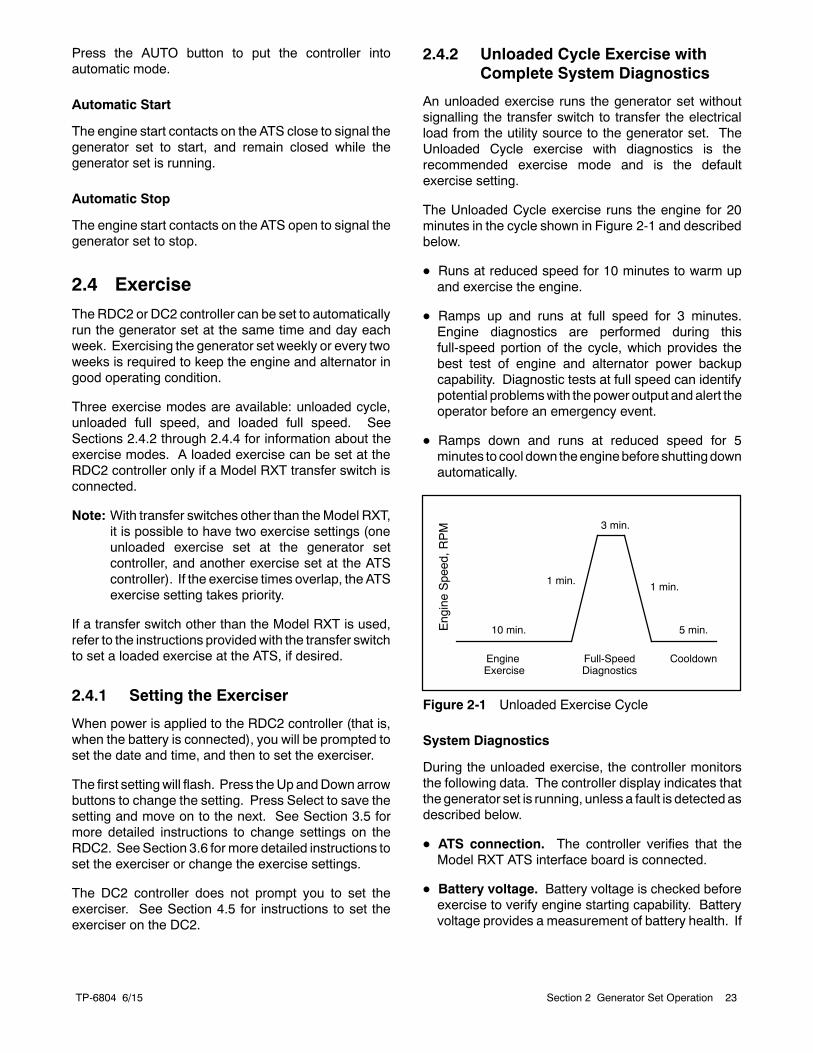
The Unloaded Cycle exercise runs the engine for 20minutes in the cycle shown in Figure 2-1 and describedbelow.
D Runs at reduced speed for 10 minutes to warm upand exercise the engine.
D Ramps up and runs at full speed for 3 minutes.Engine diagnostics are performed during thisfull-speed portion of the cycle, which provides thebest test of engine and alternator power backupcapability. Diagnostic tests at full speed can identifypotential problemswith the power output and alert theoperator before an emergency event.
D Ramps down and runs at reduced speed for 5minutes to cool down theenginebefore shuttingdownautomatically.
EngineSpeed,R
PM
EngineExercise
Full-SpeedDiagnostics
Cooldown
3 min.
1 min.1 min.
10 min. 5 min.
Figure 2-1 Unloaded Exercise Cycle
System Diagnostics
During the unloaded exercise, the controller monitorsthe following data. The controller display indicates thatthe generator set is running, unless a fault is detected asdescribed below.
D ATS connection. The controller verifies that theModel RXT ATS interface board is connected.
D Battery voltage. Battery voltage is checked beforeexercise to verify engine starting capability. Batteryvoltage provides a measurement of battery health. If
TP-6804 6/1524 Section 2 Generator Set Operation
the controller detects low battery voltage, thecondition is indicated on the display.
D Communication integrity tests. J1939, RBUS,Ethernet, and USB are monitored for messagesindicating that the controller and wiring are reliable.
D Engine speed. Engine speed is measured atreduced speed and full speed. An overspeed orunderspeed condition will result in a fault conditionand shutdown.
D Generator output frequency and voltage.Operating the generator at full speed allows theRDC2/DC2 controller to check the output power forcorrect voltage, frequency, and stability. When theengine is running at full speed, the controller verifiesthat the voltage and frequency are within acceptablelimits. A fault message is displayed if the voltage orfrequency is out of range.
D Oil pressure. Oil pressure is verified to ensureproper lubrication of critical engine components.Pressure is monitored at both reduced and fullspeeds. If theoil pressure is low, theLowOilPressuremessage is displayed and the generator set shutsdown.
2.4.3 Unloaded Full-Speed Exercise
Theunloaded full-speedexercise runs thegenerator setat full speed for 20minuteswithout transferring the load.
To set an unloaded full-speed exercise, follow theprocedure in Figure 3-8 and select Exercise Mode:Unloaded Full.
2.4.4 Loaded Full-Speed Exercise (withRXT only)
A loaded exercise starts the generator set, ramps up tofull speed, and then transfers the electrical load from theutility source to the generator set. After 20 minutes, theload is transferred back to the utility source. The engineruns without load for 5 minutes or until cool, and thenshuts down automatically.
Note: With a loaded exercise, power to the building islost for up to 10 seconds during load transfer.
For a loaded exercise controlled by the RDC2 or DC2controller, a Model RXT transfer switch must beconnected to the generator set. To set a loadedexercise, follow the procedure in Figure 3-8 and selectExercise Type: Loaded.
For a loaded exercise with a transfer switch other than aKohlerr Model RXT, program the exercise at thetransfer switch controller. Refer to the transfer switchoperation manual for instructions.
2.4.5 Power Failure During ExerciseCycle
If the utility power is lost during an unloaded exercise,theATS transfers to theemergencysource, theexerciseis ended and the control remains in the AUTO mode.
If the utility power is lost during a loaded exercise, theexercise is ended. The ATS remains in the emergencyposition and the control goes into the AUTO mode.
The generator set continues to run and supply power tothe load for the duration of the utility power outage.WhenUtility power is restored, theATSwill re-transfer tothe utility source through normal timing sequences.
TP-6804 6/15 25Section 2 Generator Set Operation
2.5 Faults
TheRDC2orDC2controller displays faultmessages forgenerator set warnings and shutdowns. Selected faultmessages are shown in Figure 2-3. Contact anauthorized distributor/dealer for service, if necessary.
2.5.1 Warnings
The controller displays a fault message but thegenerator set does not shut down on a warning. Thecontroller resets automatically after a warning conditionis corrected.
2.5.2 Shutdowns
Under a fault shutdown condition, the generator setshuts down automatically and the controller displays afault message. The OFF LED flashes. In some cases,the engine cooldown cycle runs before the engine shutsdown. See Figure 2-3.
Shutdown switches (such as the low oil pressure switchor high engine temperature switch) on the generator setwill automatically reset when the problem is corrected.However, the fault condition at the controller does notclear until the controller is reset.
The generator set cannot be restarted until the faultcondition is corrected and the controller is reset. SeeSection 2.5.4 for instructions to reset the controller aftera fault shutdown.
2.5.3 ATS Communication Errors
When aModel RXT transfer switch is used, an ATS faultindicates that the connection to the interface board onthe transfer switch has been lost. Check the connectionto the ATS interface board.
2.5.4 Resetting the Controller after aFault Shutdown
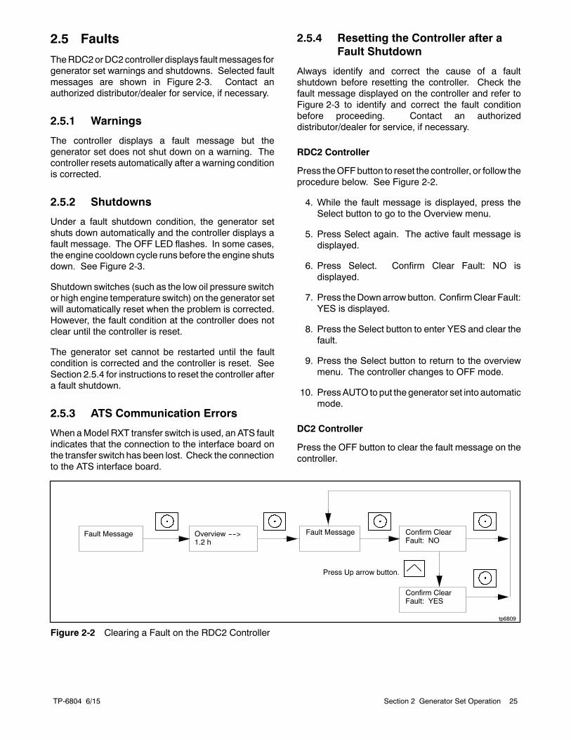
Always identify and correct the cause of a faultshutdown before resetting the controller. Check thefault message displayed on the controller and refer toFigure 2-3 to identify and correct the fault conditionbefore proceeding. Contact an authorizeddistributor/dealer for service, if necessary.
RDC2 Controller
Press theOFFbutton to reset the controller, or follow theprocedure below. See Figure 2-2.
4. While the fault message is displayed, press theSelect button to go to the Overview menu.
5. Press Select again. The active fault message isdisplayed.
6. Press Select. Confirm Clear Fault: NO isdisplayed.
7. Press theDownarrowbutton. ConfirmClear Fault:YES is displayed.
8. Press the Select button to enter YES and clear thefault.
9. Press the Select button to return to the overviewmenu. The controller changes to OFF mode.
10. PressAUTO to put the generator set into automaticmode.
DC2 Controller
Press the OFF button to clear the fault message on thecontroller.
Overview ---->1.2 h
Fault Message
tp6809
Confirm ClearFault: NO
Confirm ClearFault: YES
Fault Message
Press Up arrow button.
Figure 2-2 Clearing a Fault on the RDC2 Controller
TP-6804 6/1526 Section 2 Generator Set Operation
Fault MessageWarning (W) orShutdown (SD) Condition Check
AC Sens Loss W (1 sec.)
SD (3 sec.) *
AC sensing lost. In Auto mode, generator outputAC sensing is lost. Detection begins10 secondsafter crank disconnect.
Warning: after 1 second if no output detectedafter crank disconnect.
Shutdown: after 3 seconds if voltage waspresent and then lost.
Contact an authorizeddistributor/dealer for service.
Accy PwrOverWarning
W Accessory Power Overload. An over currentfault (short circuit) on the accessory controllerpower output.
Contact an authorizeddistributor/dealer for service.
ATS ComError W ATS communication error. Warning is displayedif ATS interface connection is lost.See Section 2.5.3.
Check communication wiring betweentransfer switch interface board andgenerator set.
ATS PhaseRot W ATS phase rotation mismatch. Transfer switchphase rotation does not match, ATS will nottransfer.
Correct the ATS connection. Refer tothe ATS Installation manual, wiringdiagrams, and labels on the transferswitch.
Aux Input SD * Auxiliary input. An optional customer-connectedinput is closed. (Digital input from optional PIM.)
Check customer-supplied equipment.
Batt Chg Flt W Battery charger fault. Input to PIM from anexternal battery charger (not the built-in batterycharger).
Check external battery charger.
Battery CrLoWarning
W Engine starting battery voltage falls below11 VDC for more than 10 seconds. Inhibitedduring the engine crank cycle.
Clears when the battery voltage returns to anacceptable level.
Check the battery rating andcondition.
Check the battery charger operation.
Charge or replace the battery.
Battery High W Engine starting battery voltage rises above 16VDC for more than 10 seconds. Inhibited duringthe engine crank cycle.
Clears when the battery voltage returns to anacceptable level.
Check the battery rating andcondition.
Check the battery charger operation.
Battery VoltageLow
W Engine starting battery voltage falls below 12.5VDC for more than 90 seconds when the engineis not running. Not operative during the enginecrank cycle.
Clears when the battery voltage returns to anacceptable level.
Check the battery rating andcondition.
Check the battery charger operation.
Charge or replace the battery.
Eng SpeedHigh
SD * Engine speed exceeds 115% of the normalrunning speed for more than 0.3 seconds.
Contact an authorizeddistributor/dealer for service.
Eng Speed Low SD * Engine speed drops below 85% of the normalrunning speed for more than 3 seconds.
Reduce the load.
Model 20RESC/20RESCL only:Check enclosure thermostat andreset if tripped. See Section 6.5.
Contact an authorizeddistributor/dealer for service.
Exer Not Sch W Exercise not scheduled. No exercise isscheduled on the controller.
See Section 3.6 or 4.5 for instructionsto set the exerciser.
Frequency High SD * Governed frequency exceeds 110% of thesystem’s frequency setpoint for more than 10seconds. Function becomes active 10 secondsafter engine start (10 second inhibit).
Contact an authorizeddistributor/dealer for service.
* Engine cooldown runs before shutting down.
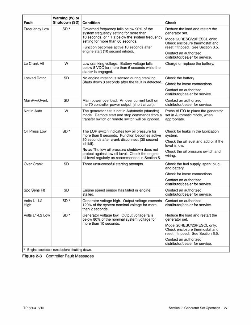
TP-6804 6/15 27Section 2 Generator Set Operation
FaultWarning (W) orShutdown (SD) Condition Check
Frequency Low SD * Governed frequency falls below 90% of thesystem frequency setting for more than10 seconds, or 1 Hz below the system frequencysetting for more than 60 seconds.
Function becomes active 10 seconds afterengine start (10 second inhibit).
Reduce the load and restart thegenerator set.
Model 20RESC/20RESCL only:Check enclosure thermostat andreset if tripped. See Section 6.5.
Contact an authorizeddistributor/dealer for service.
Lo Crank Vlt W Low cranking voltage. Battery voltage fallsbelow 8 VDC for more than 6 seconds while thestarter is engaged.
Charge or replace the battery.
Locked Rotor SD No engine rotation is sensed during cranking.Shuts down 3 seconds after the fault is detected.
Check the battery.
Check for loose connections.
Contact an authorizeddistributor/dealer for service.
MainPwrOverL SD Main power overload. An over current fault onthe 70 controller power output (short circuit).
Contact an authorizeddistributor/dealer for service.
Not in Auto W The generator set is not in Automatic (standby)mode. Remote start and stop commands from atransfer switch or remote switch will be ignored.
Press AUTO to place the generatorset in Automatic mode, whenappropriate.
Oil Press Low SD * The LOP switch indicates low oil pressure formore than 5 seconds. Function becomes active30 seconds after crank disconnect (30 secondinhibit).
Note: The low oil pressure shutdown does notprotect against low oil level. Check the engineoil level regularly as recommended in Section 5.
Check for leaks in the lubricationsystem.
Check the oil level and add oil if thelevel is low.
Check the oil pressure switch andwiring.
Over Crank SD Three unsuccessful starting attempts. Check the fuel supply, spark plug,and battery.
Check for loose connections.
Contact an authorizeddistributor/dealer for service.
Spd Sens Flt SD Engine speed sensor has failed or enginestalled.
Contact an authorizeddistributor/dealer for service.
Volts L1-L2High
SD * Generator voltage high. Output voltage exceeds120% of the system nominal voltage for morethan 2 seconds.
Contact an authorizeddistributor/dealer for service.
Volts L1-L2 Low SD * Generator voltage low. Output voltage fallsbelow 80% of the nominal system voltage formore than 10 seconds.
Reduce the load and restart thegenerator set.
Model 20RESC/20RESCL only:Check enclosure thermostat andreset if tripped. See Section 6.5.
Contact an authorizeddistributor/dealer for service.
* Engine cooldown runs before shutting down.
Figure 2-3 Controller Fault Messages
TP-6804 6/1528 Section 2 Generator Set Operation
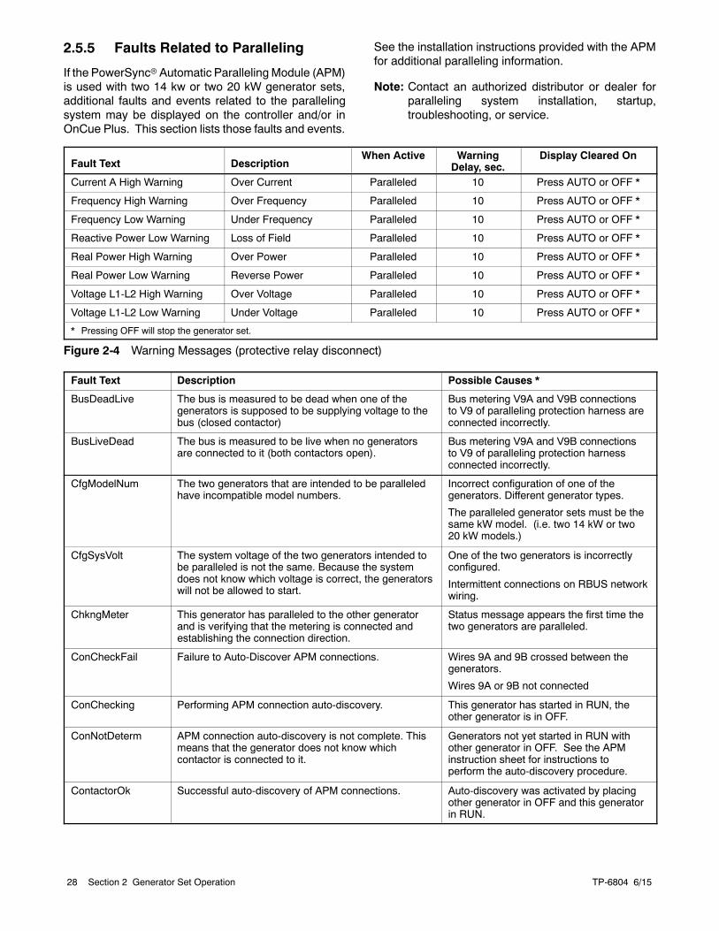
2.5.5 Faults Related to Paralleling
If the PowerSyncrAutomatic Paralleling Module (APM)is used with two 14 kw or two 20 kW generator sets,additional faults and events related to the parallelingsystem may be displayed on the controller and/or inOnCue Plus. This section lists those faults and events.
See the installation instructions provided with the APMfor additional paralleling information.
Note: Contact an authorized distributor or dealer forparalleling system installation, startup,troubleshooting, or service.
Fault Text DescriptionWhen Active Warning
Delay, sec.Display Cleared On
Current A High Warning Over Current Paralleled 10 Press AUTO or OFF *
Frequency High Warning Over Frequency Paralleled 10 Press AUTO or OFF *
Frequency Low Warning Under Frequency Paralleled 10 Press AUTO or OFF *
Reactive Power Low Warning Loss of Field Paralleled 10 Press AUTO or OFF *
Real Power High Warning Over Power Paralleled 10 Press AUTO or OFF *
Real Power Low Warning Reverse Power Paralleled 10 Press AUTO or OFF *
Voltage L1-L2 High Warning Over Voltage Paralleled 10 Press AUTO or OFF *
Voltage L1-L2 Low Warning Under Voltage Paralleled 10 Press AUTO or OFF *
* Pressing OFF will stop the generator set.
Figure 2-4 Warning Messages (protective relay disconnect)
Fault Text Description Possible Causes *
BusDeadLive The bus is measured to be dead when one of thegenerators is supposed to be supplying voltage to thebus (closed contactor)
Bus metering V9A and V9B connectionsto V9 of paralleling protection harness areconnected incorrectly.
BusLiveDead The bus is measured to be live when no generatorsare connected to it (both contactors open).
Bus metering V9A and V9B connectionsto V9 of paralleling protection harnessconnected incorrectly.
CfgModelNum The two generators that are intended to be paralleledhave incompatible model numbers.
Incorrect configuration of one of thegenerators. Different generator types.
The paralleled generator sets must be thesame kW model. (i.e. two 14 kW or two20 kW models.)
CfgSysVolt The system voltage of the two generators intended tobe paralleled is not the same. Because the systemdoes not know which voltage is correct, the generatorswill not be allowed to start.
One of the two generators is incorrectlyconfigured.
Intermittent connections on RBUS networkwiring.
ChkngMeter This generator has paralleled to the other generatorand is verifying that the metering is connected andestablishing the connection direction.
Status message appears the first time thetwo generators are paralleled.
ConCheckFail Failure to Auto-Discover APM connections. Wires 9A and 9B crossed between thegenerators.
Wires 9A or 9B not connected
ConChecking Performing APM connection auto-discovery. This generator has started in RUN, theother generator is in OFF.
ConNotDeterm APM connection auto-discovery is not complete. Thismeans that the generator does not know whichcontactor is connected to it.
Generators not yet started in RUN withother generator in OFF. See the APMinstruction sheet for instructions toperform the auto-discovery procedure.
ContactorOk Successful auto-discovery of APM connections. Auto-discovery was activated by placingother generator in OFF and this generatorin RUN.
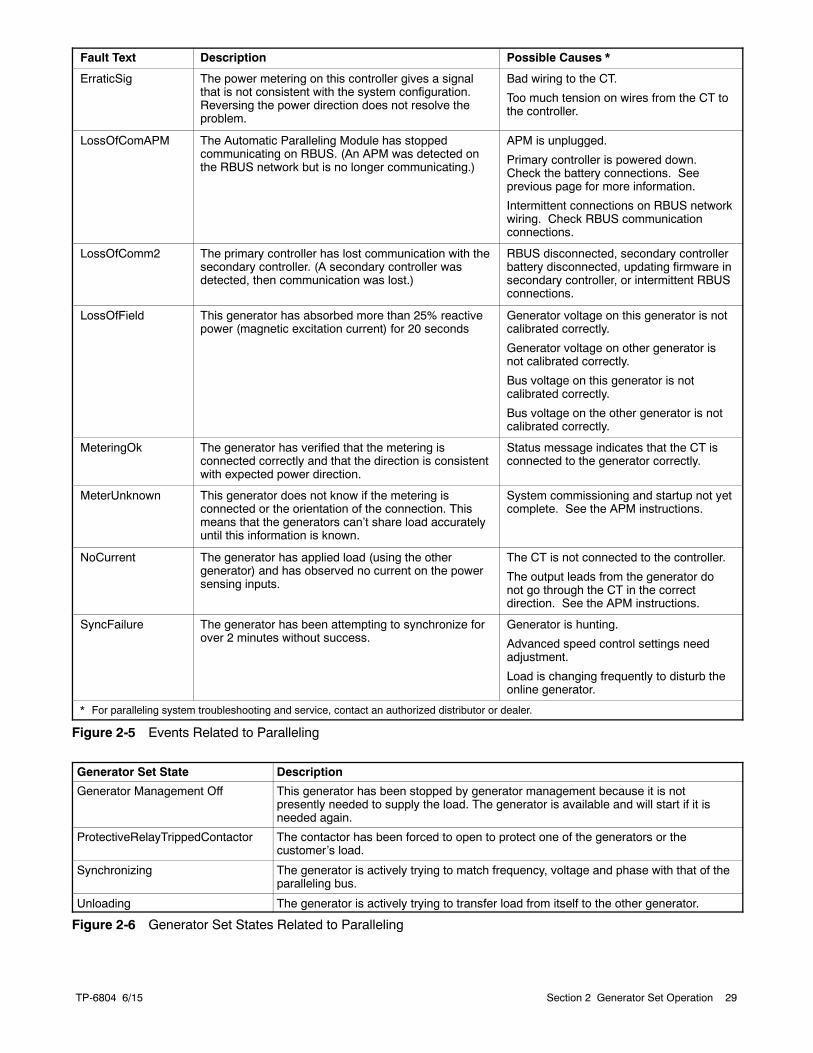
TP-6804 6/15 29Section 2 Generator Set Operation
Fault Text Description Possible Causes *
ErraticSig The power metering on this controller gives a signalthat is not consistent with the system configuration.Reversing the power direction does not resolve theproblem.
Bad wiring to the CT.
Too much tension on wires from the CT tothe controller.
LossOfComAPM The Automatic Paralleling Module has stoppedcommunicating on RBUS. (An APM was detected onthe RBUS network but is no longer communicating.)
APM is unplugged.
Primary controller is powered down.Check the battery connections. Seeprevious page for more information.
Intermittent connections on RBUS networkwiring. Check RBUS communicationconnections.
LossOfComm2 The primary controller has lost communication with thesecondary controller. (A secondary controller wasdetected, then communication was lost.)
RBUS disconnected, secondary controllerbattery disconnected, updating firmware insecondary controller, or intermittent RBUSconnections.
LossOfField This generator has absorbed more than 25% reactivepower (magnetic excitation current) for 20 seconds
Generator voltage on this generator is notcalibrated correctly.
Generator voltage on other generator isnot calibrated correctly.
Bus voltage on this generator is notcalibrated correctly.
Bus voltage on the other generator is notcalibrated correctly.
MeteringOk The generator has verified that the metering isconnected correctly and that the direction is consistentwith expected power direction.
Status message indicates that the CT isconnected to the generator correctly.
MeterUnknown This generator does not know if the metering isconnected or the orientation of the connection. Thismeans that the generators can’t share load accuratelyuntil this information is known.
System commissioning and startup not yetcomplete. See the APM instructions.
NoCurrent The generator has applied load (using the othergenerator) and has observed no current on the powersensing inputs.
The CT is not connected to the controller.
The output leads from the generator donot go through the CT in the correctdirection. See the APM instructions.
SyncFailure The generator has been attempting to synchronize forover 2 minutes without success.
Generator is hunting.
Advanced speed control settings needadjustment.
Load is changing frequently to disturb theonline generator.
* For paralleling system troubleshooting and service, contact an authorized distributor or dealer.
Figure 2-5 Events Related to Paralleling
Generator Set State Description
Generator Management Off This generator has been stopped by generator management because it is notpresently needed to supply the load. The generator is available and will start if it isneeded again.
ProtectiveRelayTrippedContactor The contactor has been forced to open to protect one of the generators or thecustomer’s load.
Synchronizing The generator is actively trying to match frequency, voltage and phase with that of theparalleling bus.
Unloading The generator is actively trying to transfer load from itself to the other generator.
Figure 2-6 Generator Set States Related to Paralleling

TP-6804 6/1530 Section 2 Generator Set Operation
Notes
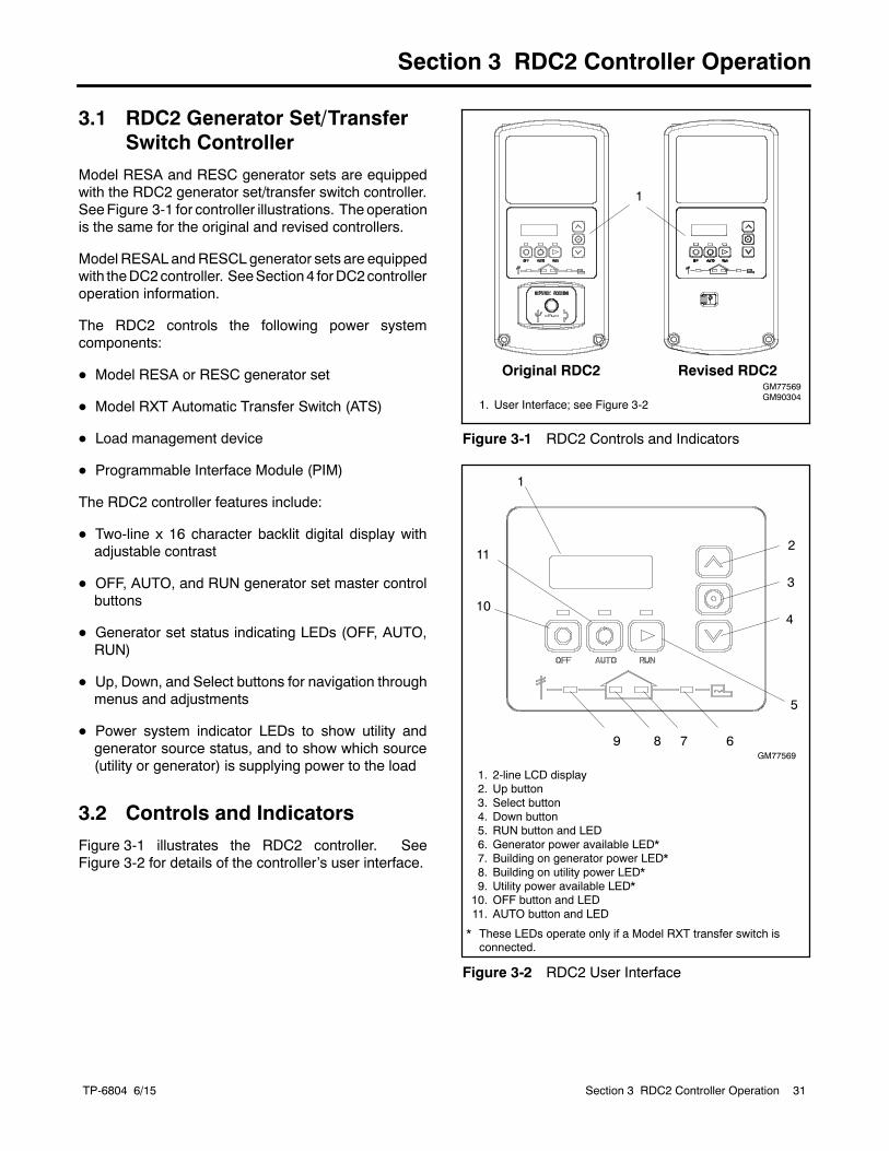
TP-6804 6/15 31Section 3 RDC2 Controller Operation
Section 3 RDC2 Controller Operation
3.1 RDC2 Generator Set/TransferSwitch Controller
Model RESA and RESC generator sets are equippedwith the RDC2 generator set/transfer switch controller.SeeFigure 3-1 for controller illustrations. Theoperationis the same for the original and revised controllers.
Model RESAL andRESCL generator sets are equippedwith theDC2controller. SeeSection4 forDC2controlleroperation information.
The RDC2 controls the following power systemcomponents:
D Model RESA or RESC generator set
D Model RXT Automatic Transfer Switch (ATS)
D Load management device
D Programmable Interface Module (PIM)
The RDC2 controller features include:
D Two-line x 16 character backlit digital display withadjustable contrast
D OFF, AUTO, and RUN generator set master controlbuttons
D Generator set status indicating LEDs (OFF, AUTO,RUN)
D Up, Down, and Select buttons for navigation throughmenus and adjustments
D Power system indicator LEDs to show utility andgenerator source status, and to show which source(utility or generator) is supplying power to the load
3.2 Controls and Indicators
Figure 3-1 illustrates the RDC2 controller. SeeFigure 3-2 for details of the controller’s user interface.
1. User Interface; see Figure 3-2
1
GM77569GM90304
Original RDC2 Revised RDC2
Figure 3-1 RDC2 Controls and Indicators
9
1. 2-line LCD display2. Up button3. Select button4. Down button5. RUN button and LED6. Generator power available LED*7. Building on generator power LED*8. Building on utility power LED*9. Utility power available LED*10. OFF button and LED11. AUTO button and LED
* These LEDs operate only if a Model RXT transfer switch isconnected.
1
10
3
2
5
11
4
GM77569
68 7
Figure 3-2 RDC2 User Interface
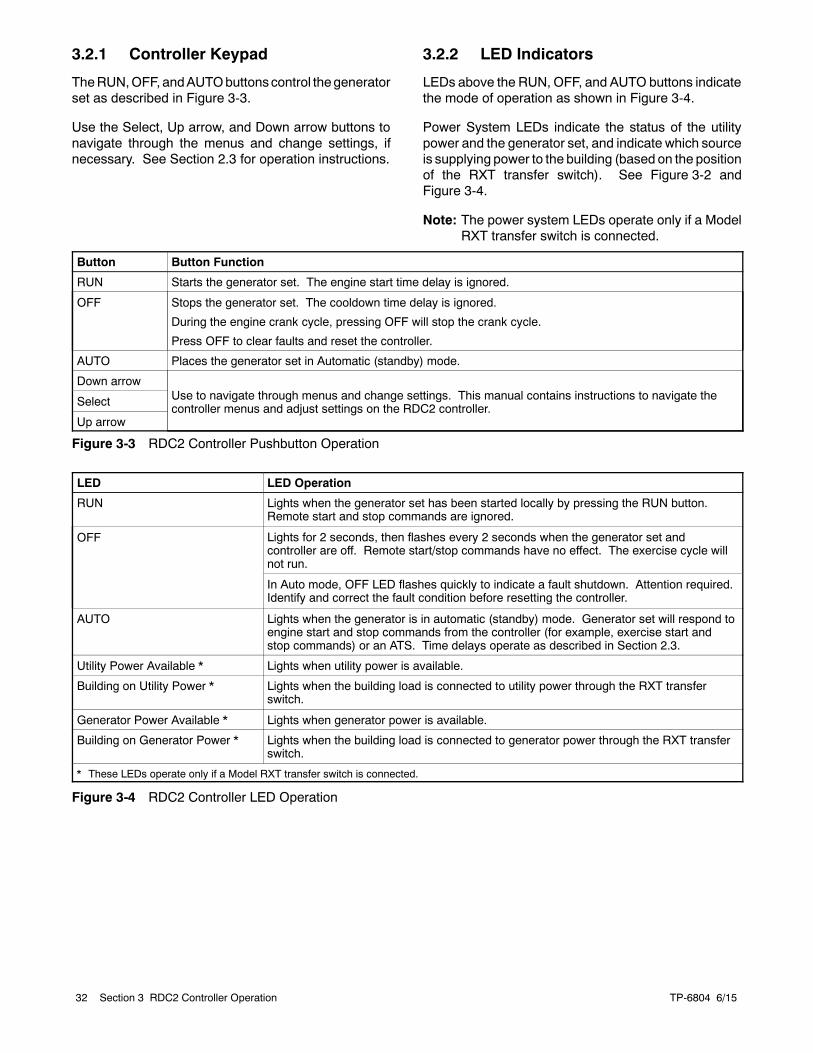
TP-6804 6/1532 Section 3 RDC2 Controller Operation
3.2.1 Controller Keypad
TheRUN,OFF, andAUTObuttonscontrol thegeneratorset as described in Figure 3-3.
Use the Select, Up arrow, and Down arrow buttons tonavigate through the menus and change settings, ifnecessary. See Section 2.3 for operation instructions.
3.2.2 LED Indicators
LEDs above the RUN, OFF, and AUTO buttons indicatethe mode of operation as shown in Figure 3-4.
Power System LEDs indicate the status of the utilitypower and the generator set, and indicate which sourceis supplying power to the building (based on the positionof the RXT transfer switch). See Figure 3-2 andFigure 3-4.
Note: The power system LEDs operate only if a ModelRXT transfer switch is connected.
Button Button Function
RUN Starts the generator set. The engine start time delay is ignored.
OFF Stops the generator set. The cooldown time delay is ignored.
During the engine crank cycle, pressing OFF will stop the crank cycle.
Press OFF to clear faults and reset the controller.
AUTO Places the generator set in Automatic (standby) mode.
Down arrowUse to navigate through menus and change settings. This manual contains instructions to navigate thecontroller menus and adjust settings on the RDC2 controller.
Select
Up arrow
Figure 3-3 RDC2 Controller Pushbutton Operation
LED LED Operation
RUN Lights when the generator set has been started locally by pressing the RUN button.Remote start and stop commands are ignored.
OFF Lights for 2 seconds, then flashes every 2 seconds when the generator set andcontroller are off. Remote start/stop commands have no effect. The exercise cycle willnot run.
In Auto mode, OFF LED flashes quickly to indicate a fault shutdown. Attention required.Identify and correct the fault condition before resetting the controller.
AUTO Lights when the generator is in automatic (standby) mode. Generator set will respond toengine start and stop commands from the controller (for example, exercise start andstop commands) or an ATS. Time delays operate as described in Section 2.3.
Utility Power Available * Lights when utility power is available.
Building on Utility Power * Lights when the building load is connected to utility power through the RXT transferswitch.
Generator Power Available * Lights when generator power is available.
Building on Generator Power * Lights when the building load is connected to generator power through the RXT transferswitch.
* These LEDs operate only if a Model RXT transfer switch is connected.
Figure 3-4 RDC2 Controller LED Operation
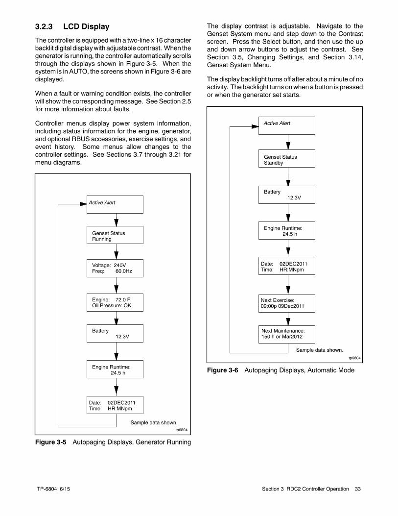
TP-6804 6/15 33Section 3 RDC2 Controller Operation
3.2.3 LCD Display
The controller is equipped with a two-line x 16 characterbacklit digital displaywithadjustable contrast. When thegenerator is running, the controller automatically scrollsthrough the displays shown in Figure 3-5. When thesystem is in AUTO, the screens shown in Figure 3-6 aredisplayed.
When a fault or warning condition exists, the controllerwill show the corresponding message. See Section 2.5for more information about faults.
Controller menus display power system information,including status information for the engine, generator,and optional RBUS accessories, exercise settings, andevent history. Some menus allow changes to thecontroller settings. See Sections 3.7 through 3.21 formenu diagrams.
tp6804
Genset StatusRunning
Voltage: 240VFreq: 60.0Hz
Engine: 72.0 FOil Pressure: OK
Battery12.3V
Engine Runtime:24.5 h
Date: 02DEC2011Time: HR:MNpm
Active Alert
Sample data shown.
Figure 3-5 Autopaging Displays, Generator Running
The display contrast is adjustable. Navigate to theGenset System menu and step down to the Contrastscreen. Press the Select button, and then use the upand down arrow buttons to adjust the contrast. SeeSection 3.5, Changing Settings, and Section 3.14,Genset System Menu.
The display backlight turns off after about aminute of noactivity. The backlight turns onwhen abutton is pressedor when the generator set starts.
tp6804
Battery12.3V
Engine Runtime:24.5 h
Date: 02DEC2011Time: HR:MNpm
Next Exercise:09:00p 09Dec2011
Next Maintenance:150 h or Mar2012
Sample data shown.
Genset StatusStandby
Active Alert
Figure 3-6 Autopaging Displays, Automatic Mode
TP-6804 6/1534 Section 3 RDC2 Controller Operation
3.3 Controller Power
The RDC2 controller is powered by the generator setengine starting battery and the built-in battery charger.
Note: To disconnect controller power, disconnect theutility power to the generator set and disconnectthe battery.
If controller power is disconnected and reconnected,youwill be prompted to set the language, time, date, andexerciser. The first setting will flash. Press the Up andDownarrowbuttons to change the setting. PressSelectto save the setting andmoveon to the next. Repeat untilall settings are saved and the controller returns to themain menu. See Section 3.5 for more detailedinstructions to change settings on the RDC2. SeeSection 3.6 for more detailed instructions to set theexerciser or change the exercise settings.
3.4 Battery Charging
The controller includes a built-in battery charger tomaintain the engine starting battery. The RDC2controller monitors the battery voltage and provides aconstant 14.0 ±2% VDC voltage and maximum 2.5amps to charge the battery.
The installer must connect utility power provided fromthe building on a breaker-protected circuit for the built-inbattery charger as described in the generatorInstallation Manual.
3.5 Changing Settings
Some settings can be changed from the controllerkeypad. The controller settings and generator setoutput are factory-set and should not require fieldadjustment under normal circumstances. Check andadjust the settings and/or output when:
D The controller has been replaced.
D The voltage requires adjustment for a particularapplication.
D Troubleshooting generator set problems.
Havecontroller setupandadjustmentperformedonlybyan authorized distributor/dealer or authorizedrepresentative.
The following procedure explains how to changesettings. See Figure 3-7 for an example using the Dateand Time settings.
Note: Use caution when navigating the controllermenus. In some menus, pressing the Selectbutton can enable editing of the controllersettings. Changing the settings to incorrectvalues can adversely affect generator setoperation or render the unit inoperable.
Procedure to Change Settings
1. Press the Select button to enter the main menu.
2. Press thedownarrowbuttonuntil thedesiredmenuis displayed. TheGenset Systemmenu is used forthis example. See Figure 3-9.
3. Press the Select button to enter the genset systemdisplays. See Figure 3-7.
4. Press the down arrow button to step through thegenerator set system settings.
5. To changeanyof the genset systemsettings, pressthe Select button. The selected setting flashes.
6. Press the up or down arrow buttons to increase ordecrease the setting.
7. When the desired setting is shown, press Select.The value stops flashing. If there are additionaladjustable settings on the screen, the next settingflashes. For example, in the date menu, the day,month, and year can be adjusted.
8. Repeat steps 6 and 7 for each setting on thescreen.
9. Press the down arrow to step to the next screen.
10. To exit, press the down arrow button until Return isdisplayed. Press the Select button to exit themenu.
11. Press the AUTO or OFF button to exit the mainmenu.
Note: If no buttons are pushed, the controller exits themenus and returns to the generator set statusdisplay after 5 minutes.
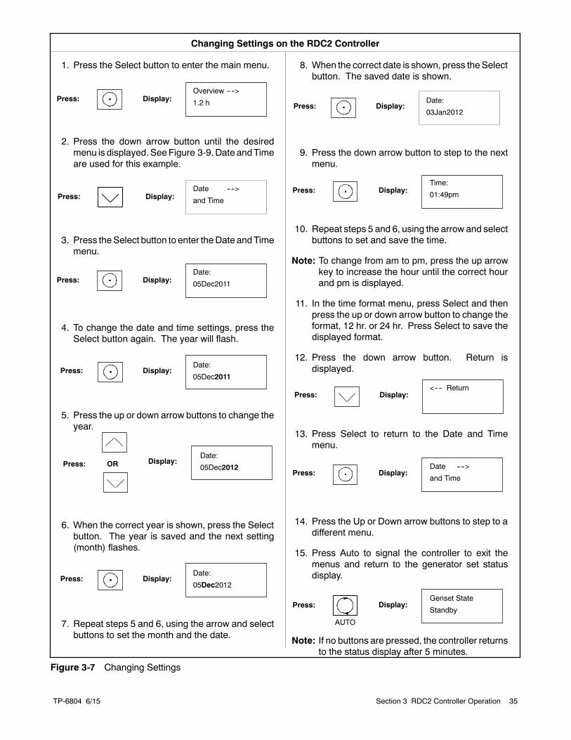
TP-6804 6/15 35Section 3 RDC2 Controller Operation
1. Press the Select button to enter the main menu.
2. Press the down arrow button until the desiredmenu is displayed. SeeFigure 3-9.Date andTimeare used for this example.
3. Press theSelect button to enter theDate andTimemenu.
4. To change the date and time settings, press theSelect button again. The year will flash.
5. Press the up or down arrow buttons to change theyear.
6. When the correct year is shown, press the Selectbutton. The year is saved and the next setting(month) flashes.
7. Repeat steps 5 and 6, using the arrow and selectbuttons to set the month and the date.
Press:
Changing Settings on the RDC2 Controller
Press: Display:Overview ---->
1.2 h
Display:
Press: Display:
Press: Display:
Date ---->
and Time
Date:
05Dec2011
8. When the correct date is shown, press the Selectbutton. The saved date is shown.
9. Press the down arrow button to step to the nextmenu.
10. Repeat steps 5 and 6, using the arrow and selectbuttons to set and save the time.
Note: To change from am to pm, press the up arrowkey to increase the hour until the correct hourand pm is displayed.
11. In the time format menu, press Select and thenpress the up or down arrow button to change theformat, 12 hr. or 24 hr. Press Select to save thedisplayed format.
12. Press the down arrow button. Return isdisplayed.
13. Press Select to return to the Date and Timemenu.
14. Press the Up or Down arrow buttons to step to adifferent menu.
15. Press Auto to signal the controller to exit themenus and return to the generator set statusdisplay.
Note: If no buttons are pressed, the controller returnsto the status display after 5 minutes.
Press: Display:OR
Press: Display:
Press: Display:<---- Return
Press: Display:
Time:
01:49pm
Date ---->
and Time
AUTO
Press: Display:Genset State
Standby
Date:
05Dec2011
Date:
05Dec2012
Press: Display:Date:
05Dec2012
Press: Display:Date:
03Jan2012
Figure 3-7 Changing Settings
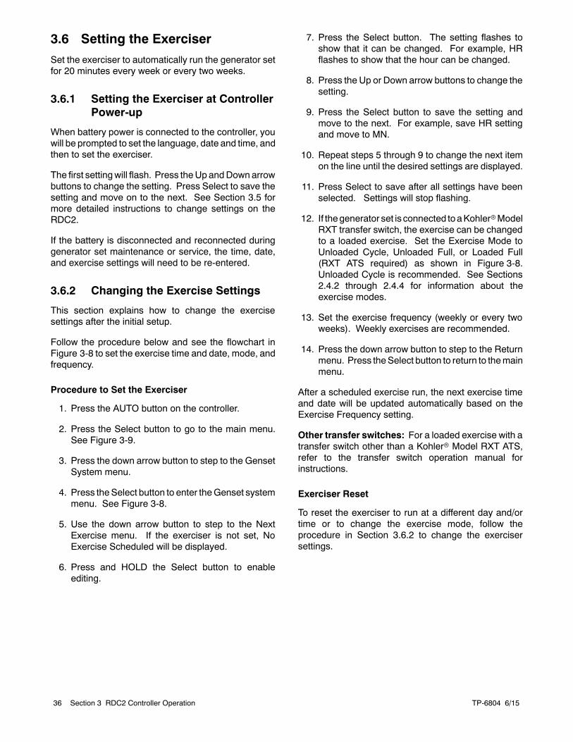
TP-6804 6/1536 Section 3 RDC2 Controller Operation
3.6 Setting the Exerciser
Set the exerciser to automatically run the generator setfor 20 minutes every week or every two weeks.
3.6.1 Setting the Exerciser at ControllerPower-up
When battery power is connected to the controller, youwill be prompted to set the language, date and time, andthen to set the exerciser.
The first settingwill flash. Press theUp andDownarrowbuttons to change the setting. Press Select to save thesetting and move on to the next. See Section 3.5 formore detailed instructions to change settings on theRDC2.
If the battery is disconnected and reconnected duringgenerator set maintenance or service, the time, date,and exercise settings will need to be re-entered.
3.6.2 Changing the Exercise Settings
This section explains how to change the exercisesettings after the initial setup.
Follow the procedure below and see the flowchart inFigure 3-8 to set the exercise time and date, mode, andfrequency.
Procedure to Set the Exerciser
1. Press the AUTO button on the controller.
2. Press the Select button to go to the main menu.See Figure 3-9.
3. Press the down arrow button to step to the GensetSystem menu.
4. Press theSelect button to enter theGenset systemmenu. See Figure 3-8.
5. Use the down arrow button to step to the NextExercise menu. If the exerciser is not set, NoExercise Scheduled will be displayed.
6. Press and HOLD the Select button to enableediting.
7. Press the Select button. The setting flashes toshow that it can be changed. For example, HRflashes to show that the hour can be changed.
8. Press the Up or Down arrow buttons to change thesetting.
9. Press the Select button to save the setting andmove to the next. For example, save HR settingand move to MN.
10. Repeat steps 5 through 9 to change the next itemon the line until the desired settings are displayed.
11. Press Select to save after all settings have beenselected. Settings will stop flashing.
12. If thegenerator set is connected toaKohlerrModelRXT transfer switch, the exercise can be changedto a loaded exercise. Set the Exercise Mode toUnloaded Cycle, Unloaded Full, or Loaded Full(RXT ATS required) as shown in Figure 3-8.Unloaded Cycle is recommended. See Sections2.4.2 through 2.4.4 for information about theexercise modes.
13. Set the exercise frequency (weekly or every twoweeks). Weekly exercises are recommended.
14. Press the down arrow button to step to the Returnmenu. Press theSelect button to return to themainmenu.
After a scheduled exercise run, the next exercise timeand date will be updated automatically based on theExercise Frequency setting.
Other transfer switches: For a loaded exercise with atransfer switch other than a Kohlerr Model RXT ATS,refer to the transfer switch operation manual forinstructions.
Exerciser Reset
To reset the exerciser to run at a different day and/ortime or to change the exercise mode, follow theprocedure in Section 3.6.2 to change the exercisersettings.
TP-6804 6/15 37Section 3 RDC2 Controller Operation
tp6804
System Freq:
XX.X Hz
Genset ---->
System
System Volt
System Battery
HOLD:
Next Exercise
HR:MN PM MM/DD/YY
HOLD:
Exercise Freq:
Weekly/Bi-Weekly
System Phase
Language:
<---- Return
Next Exercise *
HR:MN PM MM/DD/YY
Exercise Freq:
Weekly
Exercise Mode:
Loaded
HOLD:
Exercise Mode:
Unloaded Cycle/UnloadedFull/ Loaded Full
Contrast:
50
* If the exerciser has not been set, No Exercise Sch will be displayed.
Fuel Type
Figure 3-8 Procedure to Set the Exerciser on the RDC2 Controller
TP-6804 6/1538 Section 3 RDC2 Controller Operation
3.7 RDC2 Controller Menus
Controller menus display power system information,including status information for the engine, generator,and optional RBUS accessories, exercise settings, andevent history. Some menus allow changes to thecontroller settings. Status information, including theengine runtime, cannot be changed by the operator.
Diagrams in the followingsectionsshowhow tonavigatethrough the menus. The diagrams show samplesettings. Settings for your application may vary.
Note: Use caution when navigating the controllermenus. In some menus, pressing the Selectbutton can enable editing of the controllersettings. Changing the settings to incorrectvalues can adversely affect generator setoperation or render the unit inoperable.
If a setting on the controller display is flashing, editmodehas been enabled. Press the OFF or AUTO button toexit the edit mode.
3.8 Main Menu
Press theSelect button once to bring up themainmenu.Overview is displayed. See Figure 3-9. Press the downarrow button to step to the next menu, EngineMetering.Use the UP and DOWN arrow buttons to step up anddown through the menus shown in Figure 3-9.
The controller will exit the main menu after 5 minutes ifno buttons are pressed. To exit the main menuimmediately, press the controller’s OFF or AUTObutton.
TP-6804 6/15 39Section 3 RDC2 Controller Operation
Overview ---->1.2 h
Engine ---->Metering
tp6804
Generator---->Metering
Genset ---->Information
Genset ---->Run Time
Date ---->and Time
ATS ---->Configuration *
Genset ---->System
Event Log---->
Load ---->Control ]
PIM ---->Status [
Network ---->Information
StatusDisplays
ATS ---->Status
* ATS Configuration appears only if a Model RXT transfer switch is connected.[ PIM Status appears only if a programmable interface module is connected.] Load Control appears only if a load management device is connected.
Press the Up and Down arrow buttonsto move between menus.Press OFF or AUTO to exit the menus.
Figure 3-9 RDC2 Main Menu
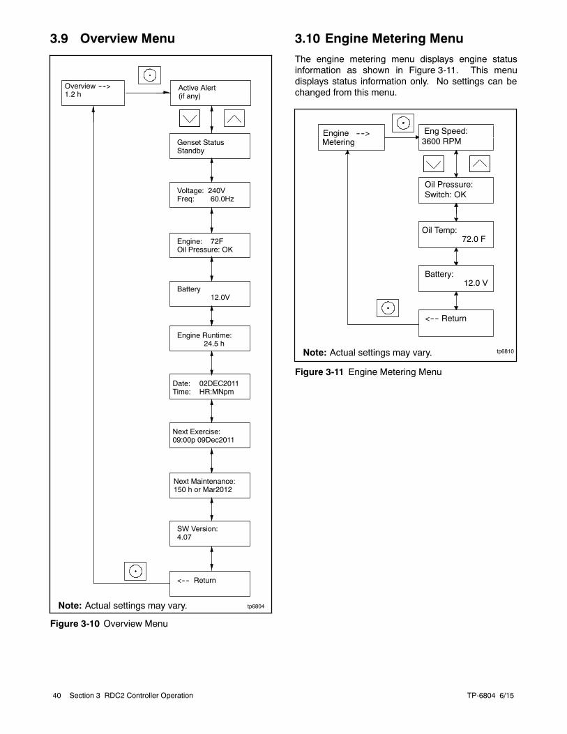
TP-6804 6/1540 Section 3 RDC2 Controller Operation
3.9 Overview Menu
Overview ---->1.2 h
Active Alert(if any)
tp6804
Genset StatusStandby
Voltage: 240VFreq: 60.0Hz
Engine: 72FOil Pressure: OK
Battery12.0V
Engine Runtime:24.5 h
Date: 02DEC2011Time: HR:MNpm
Next Exercise:09:00p 09Dec2011
Next Maintenance:150 h or Mar2012
SW Version:4.07
<---- Return
Note: Actual settings may vary.
Figure 3-10 Overview Menu
3.10 Engine Metering Menu
The engine metering menu displays engine statusinformation as shown in Figure 3-11. This menudisplays status information only. No settings can bechanged from this menu.
tp6810
Eng Speed:3600 RPM
Battery:12.0 V
<---- Return
Engine ---->Metering
Oil Pressure:Switch: OK
Oil Temp:72.0 F
Note: Actual settings may vary.
Figure 3-11 Engine Metering Menu
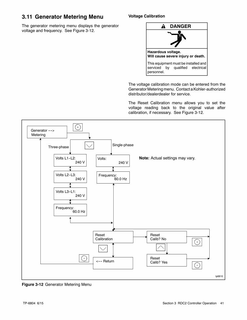
TP-6804 6/15 41Section 3 RDC2 Controller Operation
3.11 Generator Metering Menu
The generator metering menu displays the generatorvoltage and frequency. See Figure 3-12.
Voltage Calibration
Hazardous voltage.Will cause severe injury or death.
This equipment must be installed andserviced by qualified electricalpersonnel.
DANGER
The voltage calibration mode can be entered from theGeneratorMeteringmenu. Contact aKohler-authorizeddistributor/dealerdealer for service.
The Reset Calibration menu allows you to set thevoltage reading back to the original value aftercalibration, if necessary. See Figure 3-12.
Volts L1--L2:240 V
Volts L2--L3:240 V
Volts L3--L1:240 V
Generator ---->Metering
ResetCalibration
<---- Return
ResetCalib? No
Volts:240 V
Three-phase Single-phase
tp6810
ResetCalib? Yes
Frequency:60.0 Hz
Frequency:60.0 Hz
Note: Actual settings may vary.
Figure 3-12 Generator Metering Menu
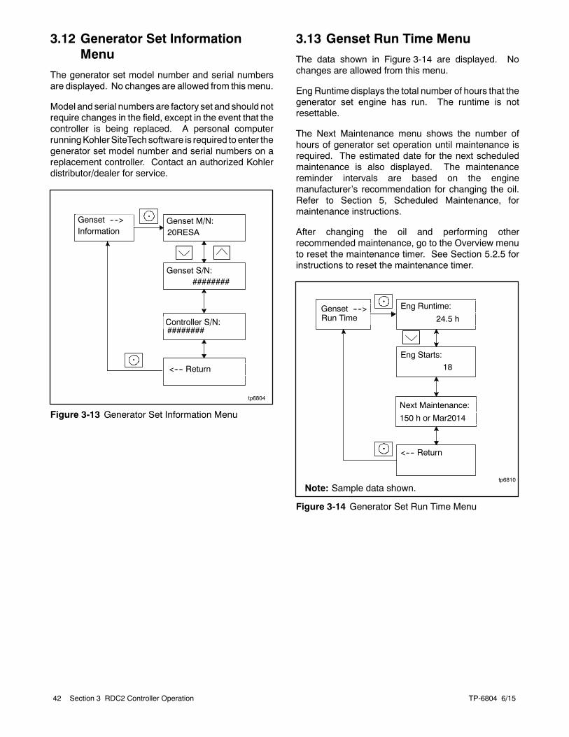
TP-6804 6/1542 Section 3 RDC2 Controller Operation
3.12 Generator Set InformationMenu
The generator set model number and serial numbersare displayed. No changes are allowed from thismenu.
Model and serial numbers are factory set and should notrequire changes in the field, except in the event that thecontroller is being replaced. A personal computerrunningKohlerSiteTechsoftware is required to enter thegenerator set model number and serial numbers on areplacement controller. Contact an authorized Kohlerdistributor/dealer for service.
tp6804
Genset M/N:20RESA
Genset S/N:
Controller S/N:
<---- Return
Genset ---->Information
########
########
Figure 3-13 Generator Set Information Menu
3.13 Genset Run Time Menu
The data shown in Figure 3-14 are displayed. Nochanges are allowed from this menu.
Eng Runtime displays the total number of hours that thegenerator set engine has run. The runtime is notresettable.
The Next Maintenance menu shows the number ofhours of generator set operation until maintenance isrequired. The estimated date for the next scheduledmaintenance is also displayed. The maintenancereminder intervals are based on the enginemanufacturer’s recommendation for changing the oil.Refer to Section 5, Scheduled Maintenance, formaintenance instructions.
After changing the oil and performing otherrecommended maintenance, go to the Overview menuto reset the maintenance timer. See Section 5.2.5 forinstructions to reset the maintenance timer.
tp6810
Eng Runtime:
24.5 h
Eng Starts:
18
<---- Return
Genset ---->Run Time
Next Maintenance:
150 h or Mar2014
Note: Sample data shown.
Figure 3-14 Generator Set Run Time Menu
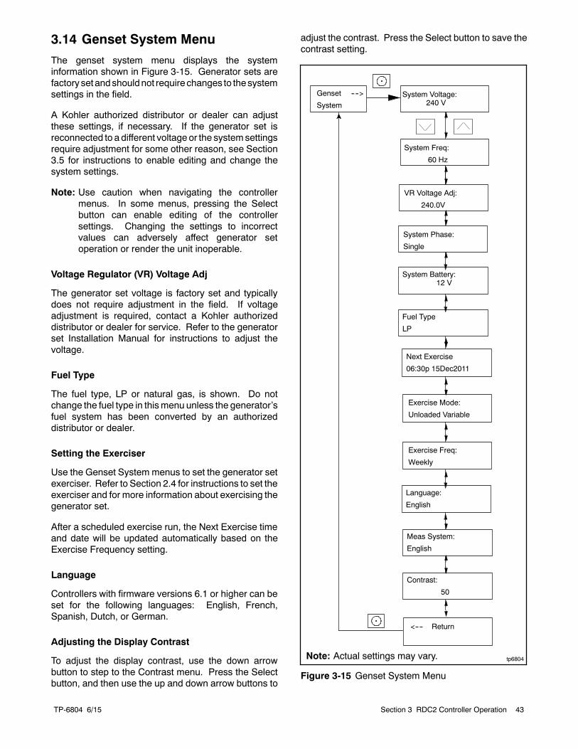
TP-6804 6/15 43Section 3 RDC2 Controller Operation
3.14 Genset System Menu
The genset system menu displays the systeminformation shown in Figure 3-15. Generator sets arefactorysetandshouldnot require changes to thesystemsettings in the field.
A Kohler authorized distributor or dealer can adjustthese settings, if necessary. If the generator set isreconnected to a different voltage or the systemsettingsrequire adjustment for some other reason, see Section3.5 for instructions to enable editing and change thesystem settings.
Note: Use caution when navigating the controllermenus. In some menus, pressing the Selectbutton can enable editing of the controllersettings. Changing the settings to incorrectvalues can adversely affect generator setoperation or render the unit inoperable.
Voltage Regulator (VR) Voltage Adj
The generator set voltage is factory set and typicallydoes not require adjustment in the field. If voltageadjustment is required, contact a Kohler authorizeddistributor or dealer for service. Refer to the generatorset Installation Manual for instructions to adjust thevoltage.
Fuel Type
The fuel type, LP or natural gas, is shown. Do notchange the fuel type in thismenu unless the generator’sfuel system has been converted by an authorizeddistributor or dealer.
Setting the Exerciser
Use the Genset System menus to set the generator setexerciser. Refer to Section 2.4 for instructions to set theexerciser and for more information about exercising thegenerator set.
After a scheduled exercise run, the Next Exercise timeand date will be updated automatically based on theExercise Frequency setting.
Language
Controllers with firmware versions 6.1 or higher can beset for the following languages: English, French,Spanish, Dutch, or German.
Adjusting the Display Contrast
To adjust the display contrast, use the down arrowbutton to step to the Contrast menu. Press the Selectbutton, and then use the up and down arrow buttons to
adjust the contrast. Press the Select button to save thecontrast setting.
tp6804
Genset ---->
SystemSystem Voltage:
240 V
System Battery:12 V
System Phase:
Single
<---- Return
Next Exercise
06:30p 15Dec2011
Exercise Freq:
Weekly
Exercise Mode:
Unloaded Variable
System Freq:
60 Hz
Meas System:
English
Contrast:
50
VR Voltage Adj:
240.0V
Note: Actual settings may vary.
Fuel Type
LP
Language:
English
Figure 3-15 Genset System Menu
TP-6804 6/1544 Section 3 RDC2 Controller Operation
3.15 ATS Status Menu
ATS menus appear if a Model RXT transfer switch isconnected to the generator set. If no transfer switch isconnected, or another model ATS is connected to theengine start connections, Remote ATS is displayed onthe ATS Status screen.
The ATS Status menu displays Model RXT transferswitch and source information.
The voltage shown in these menus can be calibrated.Follow the safety precautions at the beginning of thismanuals. Use a voltmeter to measure the line-to-linevoltage and follow the instructions in Figure 3-16 tocalibrate the voltage readings.
Emerg Volts:
tp6810
Normal Voltage:L1--L2 240 V
Normal Voltage:L2--L3 240 V
Normal Voltage:L3--L1: 240 V
ATS ---->Status
Normal Freq.:60.0 Hz
ATS Position:Normal
Normal Status:Not/Acceptable
Emerg. Status:Standby
Three-phaseSingle-phase
ResetCalibration
<---- Return
ResetCalib? No
ResetCalib? Yes
Note: If there is no Model RXT transferswitch connected to the generator set,RemoteATS isdisplayedand theotherscreens on this page do not appear.
Normal Freq.:60.0 Hz
Normal Volts:240.0 V
Emerg. Freq.:60.0 Hz
240.0 V
Similar screens appear forthe emergency source.
Normal Rotation:
Note: Sample data shown.
Figure 3-16 ATS Status Menu, with Calibration
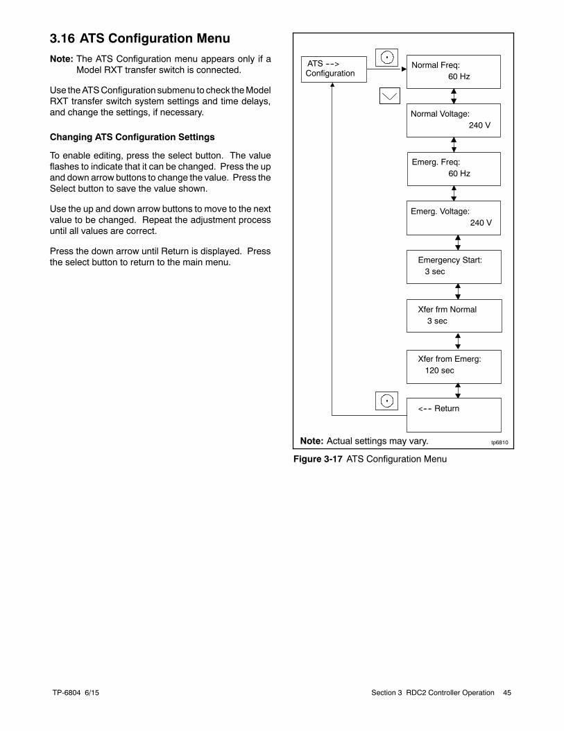
TP-6804 6/15 45Section 3 RDC2 Controller Operation
3.16 ATS Configuration Menu
Note: The ATS Configuration menu appears only if aModel RXT transfer switch is connected.
Use theATSConfiguration submenu to check theModelRXT transfer switch system settings and time delays,and change the settings, if necessary.
Changing ATS Configuration Settings
To enable editing, press the select button. The valueflashes to indicate that it can be changed. Press the upand down arrow buttons to change the value. Press theSelect button to save the value shown.
Use the up and down arrow buttons to move to the nextvalue to be changed. Repeat the adjustment processuntil all values are correct.
Press the down arrow until Return is displayed. Pressthe select button to return to the main menu.
tp6810
Normal Freq:60 Hz
<---- Return
Normal Voltage:240 V
ATS ---->Configuration
Emerg. Freq:60 Hz
Emerg. Voltage:240 V
Emergency Start:3 sec
Xfer frm Normal3 sec
Xfer from Emerg:120 sec
Note: Actual settings may vary.
Figure 3-17 ATS Configuration Menu
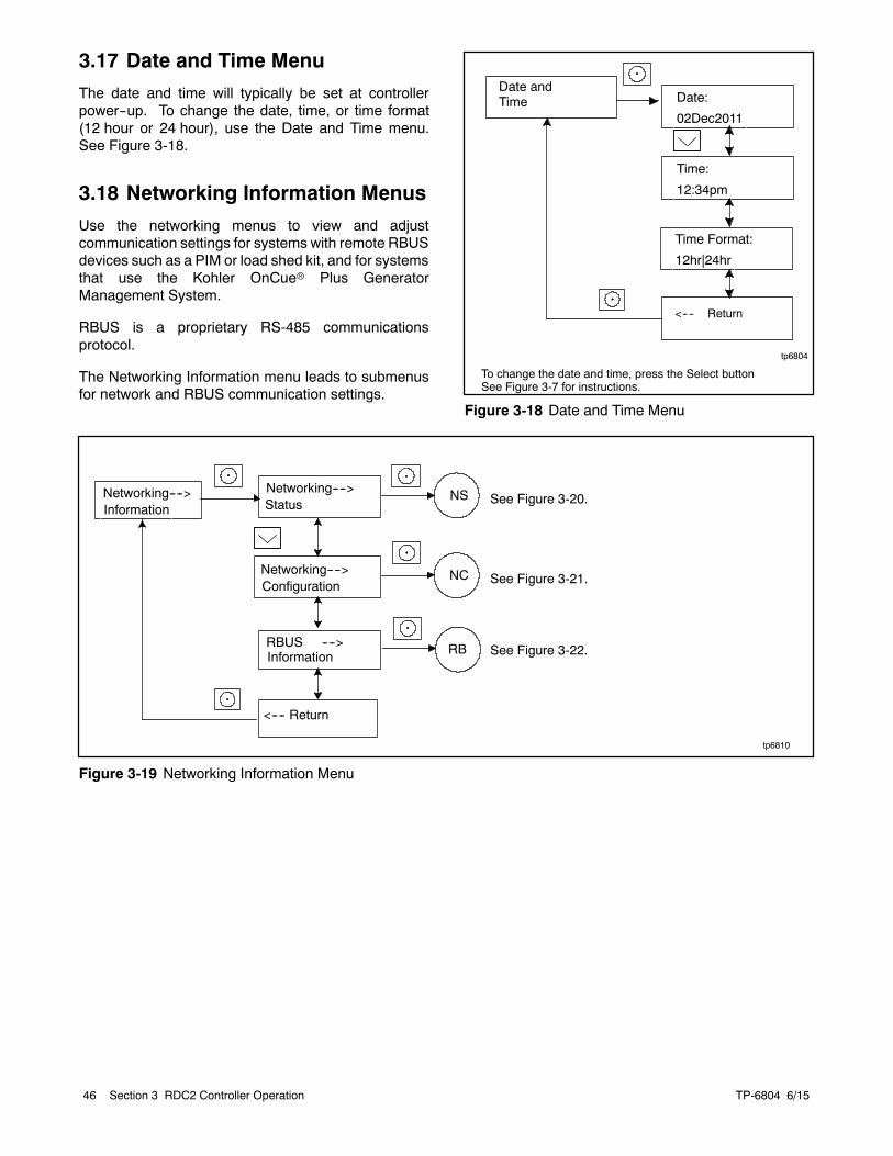
TP-6804 6/1546 Section 3 RDC2 Controller Operation
3.17 Date and Time Menu
The date and time will typically be set at controllerpower--up. To change the date, time, or time format(12 hour or 24 hour), use the Date and Time menu.See Figure 3-18.
3.18 Networking Information Menus
Use the networking menus to view and adjustcommunication settings for systems with remote RBUSdevices such as a PIM or load shed kit, and for systemsthat use the Kohler OnCuer Plus GeneratorManagement System.
RBUS is a proprietary RS-485 communicationsprotocol.
The Networking Information menu leads to submenusfor network and RBUS communication settings.
tp6804
Date:
02Dec2011
Time:
12:34pm
Time Format:
12hr|24hr
Date andTime
To change the date and time, press the Select buttonSee Figure 3-7 for instructions.
<---- Return
Figure 3-18 Date and Time Menu
tp6810
Networking---->Information
Networking---->Status
NS
RBUS ---->Information
RB
<---- Return
Networking---->Configuration
NC
See Figure 3-20.
See Figure 3-21.
See Figure 3-22.
Figure 3-19 Networking Information Menu
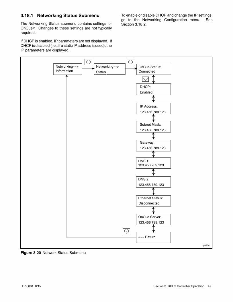
TP-6804 6/15 47Section 3 RDC2 Controller Operation
3.18.1 Networking Status Submenu
The Networking Status submenu contains settings forOnCuer. Changes to these settings are not typicallyrequired.
If DHCP is enabled, IP parameters are not displayed. IfDHCP is disabled (i.e., if a static IP address is used), theIP parameters are displayed.
To enable or disable DHCP and change the IP settings,go to the Networking Configuration menu. SeeSection 3.18.2.
tp6804
IP Address:
123.456.789.123
Gateway:
123.456.789.123
<---- Return
Subnet Mask:
123.456.789.123
DHCP:
Enabled
Ethernet Status:
Disconnected
DNS 1:123.456.789.123
DNS 2:
123.456.789.123
OnCue Server:
123.456.789.123
OnCue Status:Connected
Networking---->
Status
Networking---->Information
Figure 3-20 Network Status Submenu
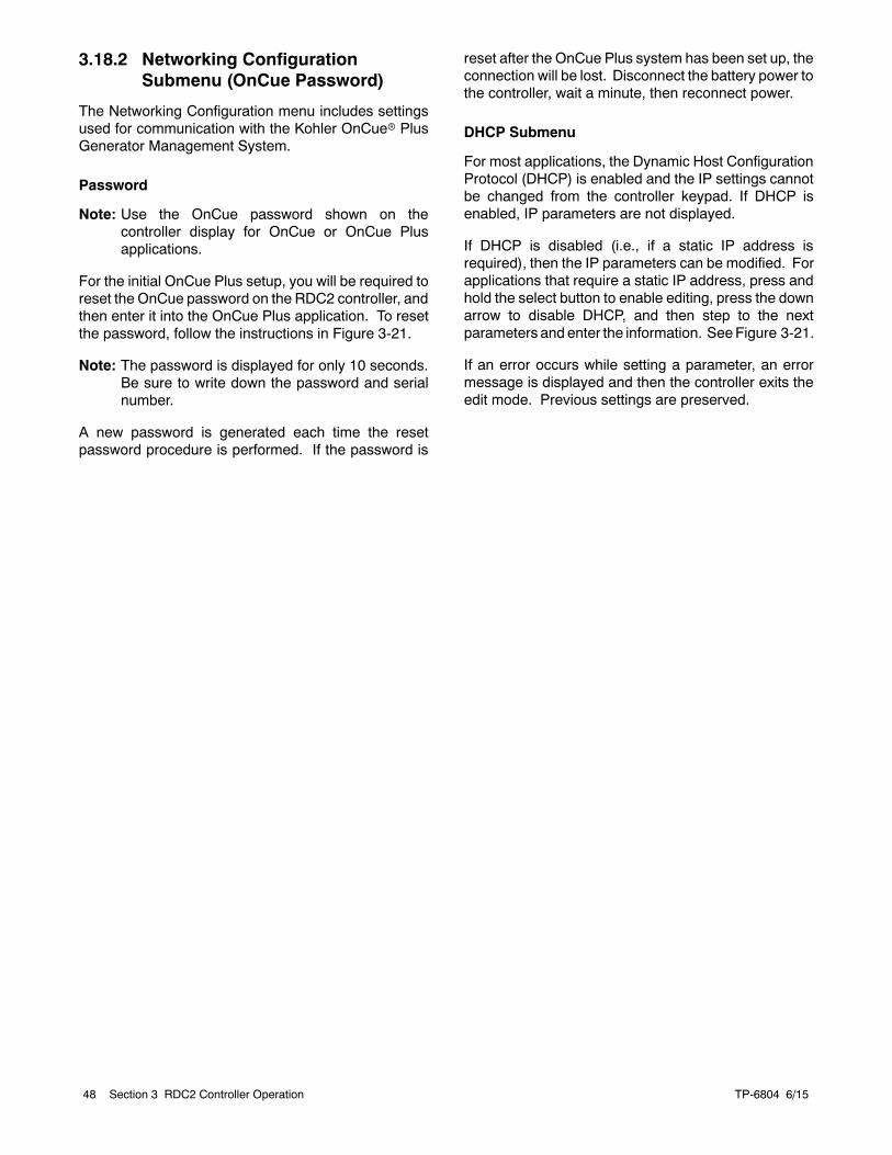
TP-6804 6/1548 Section 3 RDC2 Controller Operation
3.18.2 Networking ConfigurationSubmenu (OnCue Password)
The Networking Configuration menu includes settingsused for communication with the Kohler OnCuer PlusGenerator Management System.
Password
Note: Use the OnCue password shown on thecontroller display for OnCue or OnCue Plusapplications.
For the initial OnCue Plus setup, you will be required toreset the OnCue password on the RDC2 controller, andthen enter it into the OnCue Plus application. To resetthe password, follow the instructions in Figure 3-21.
Note: The password is displayed for only 10 seconds.Be sure to write down the password and serialnumber.
A new password is generated each time the resetpassword procedure is performed. If the password is
reset after the OnCue Plus system has been set up, theconnection will be lost. Disconnect the battery power tothe controller, wait a minute, then reconnect power.
DHCP Submenu
For most applications, the Dynamic Host ConfigurationProtocol (DHCP) is enabled and the IP settings cannotbe changed from the controller keypad. If DHCP isenabled, IP parameters are not displayed.
If DHCP is disabled (i.e., if a static IP address isrequired), then the IP parameters can be modified. Forapplications that require a static IP address, press andhold the select button to enable editing, press the downarrow to disable DHCP, and then step to the nextparameters and enter the information. SeeFigure 3-21.
If an error occurs while setting a parameter, an errormessage is displayed and then the controller exits theedit mode. Previous settings are preserved.
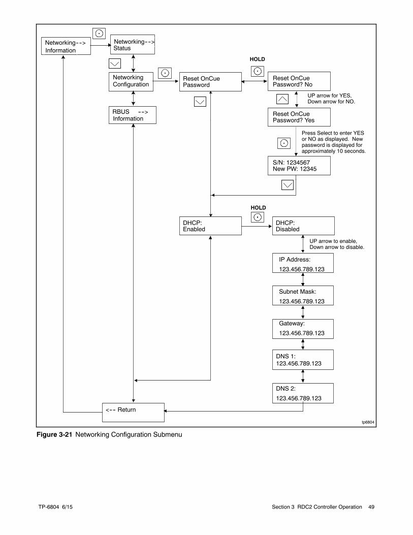
TP-6804 6/15 49Section 3 RDC2 Controller Operation
DNS 2:
123.456.789.123
tp6804
<---- Return
DHCP:Enabled
Reset OnCuePassword
Reset OnCuePassword? No
S/N: 1234567New PW: 12345
Press Select to enter YESor NO as displayed. Newpassword is displayed forapproximately 10 seconds.
NetworkingConfiguration
HOLD
Reset OnCuePassword? Yes
UP arrow for YES,Down arrow for NO.
Networking---->Information
Networking---->Status
IP Address:
123.456.789.123
Gateway:
123.456.789.123
Subnet Mask:
123.456.789.123
DNS 1:123.456.789.123
DHCP:Disabled
HOLD
UP arrow to enable,Down arrow to disable.
RBUS ---->Information
Figure 3-21 Networking Configuration Submenu
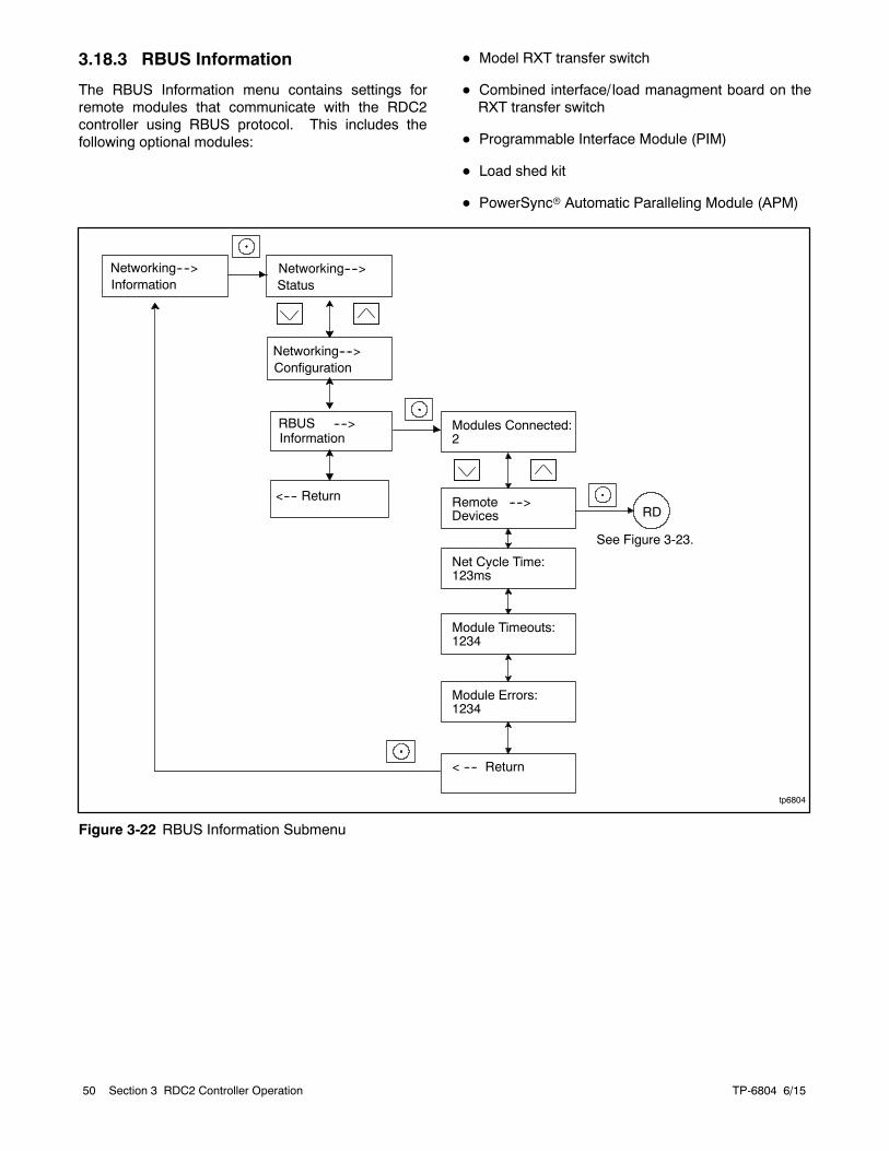
TP-6804 6/1550 Section 3 RDC2 Controller Operation
3.18.3 RBUS Information
The RBUS Information menu contains settings forremote modules that communicate with the RDC2controller using RBUS protocol. This includes thefollowing optional modules:
D Model RXT transfer switch
D Combined interface/ load managment board on theRXT transfer switch
D Programmable Interface Module (PIM)
D Load shed kit
D PowerSyncr Automatic Paralleling Module (APM)
tp6804
Modules Connected:2
Module Timeouts:1234
Net Cycle Time:123ms
Module Errors:1234
< ---- Return
RDRemote ---->Devices
See Figure 3-23.
Networking---->Information
Networking---->Status
RBUS ---->Information
<---- Return
Networking---->Configuration
Figure 3-22 RBUS Information Submenu
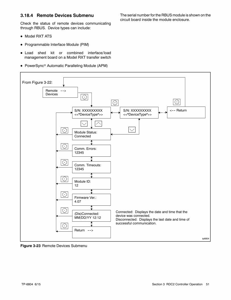
TP-6804 6/15 51Section 3 RDC2 Controller Operation
3.18.4 Remote Devices Submenu
Check the status of remote devices communicatingthrough RBUS. Device types can include:
D Model RXT ATS
D Programmable Interface Module (PIM)
D Load shed kit or combined interface/ loadmanagement board on a Model RXT transfer switch
D PowerSyncr Automatic Paralleling Module (APM)
The serial number for theRBUSmodule is shown on thecircuit board inside the module enclosure.
tp6804
Module Status:Connected
Firmware Ver.:4.07
Module ID:12
S/N: XXXXXXXXX<<*DeviceType*>>
Return ---->
S/N: XXXXXXXXX<<*DeviceType*>>
Comm. Errors:12345
Comm. Timeouts:12345
(Dis)Connected:MM/DD/YY 12:12
<---- Return
Connected: Displays the date and time that thedevice was connected.Disconnected: Displays the last date and time ofsuccessful communication.
Remote ---->Devices
From Figure 3-22:
Figure 3-23 Remote Devices Submenu
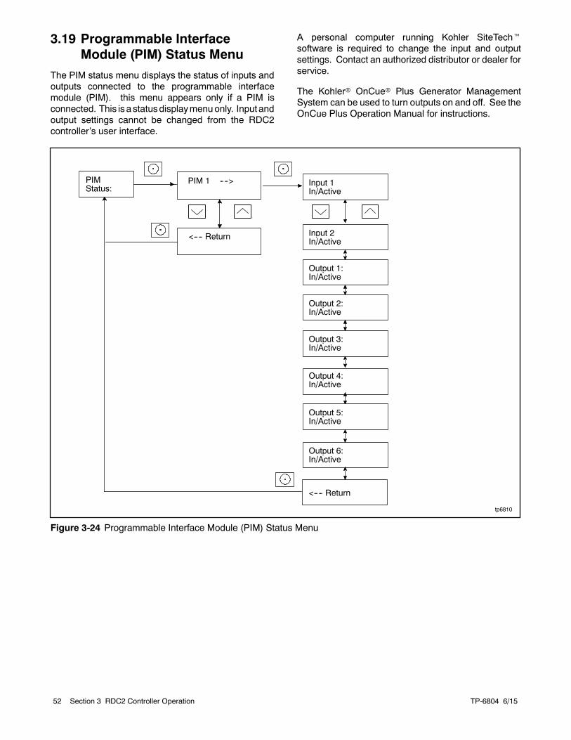
TP-6804 6/1552 Section 3 RDC2 Controller Operation
3.19 Programmable InterfaceModule (PIM) Status Menu
The PIM status menu displays the status of inputs andoutputs connected to the programmable interfacemodule (PIM). this menu appears only if a PIM isconnected. This is a statusdisplaymenuonly. Input andoutput settings cannot be changed from the RDC2controller’s user interface.
A personal computer running Kohler SiteTechtsoftware is required to change the input and outputsettings. Contact an authorized distributor or dealer forservice.
The Kohlerr OnCuer Plus Generator ManagementSystem can be used to turn outputs on and off. See theOnCue Plus Operation Manual for instructions.
tp6810
PIMStatus:
PIM 1 ---->
<---- Return
Input 1In/Active
Output 1:In/Active
Input 2In/Active
Output 2:In/Active
Output 3:In/Active
Output 4:In/Active
Output 5:In/Active
Output 6:In/Active
<---- Return
Figure 3-24 Programmable Interface Module (PIM) Status Menu
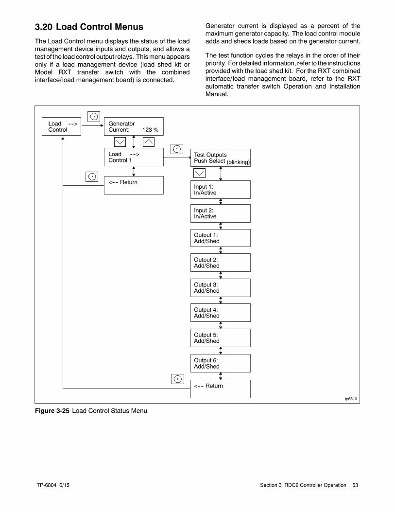
TP-6804 6/15 53Section 3 RDC2 Controller Operation
3.20 Load Control Menus
The Load Control menu displays the status of the loadmanagement device inputs and outputs, and allows atest of the loadcontrol output relays. Thismenuappearsonly if a load management device (load shed kit orModel RXT transfer switch with the combinedinterface/ load management board) is connected.
Generator current is displayed as a percent of themaximum generator capacity. The load control moduleadds and sheds loads based on the generator current.
The test function cycles the relays in the order of theirpriority. For detailed information, refer to the instructionsprovided with the load shed kit. For the RXT combinedinterface/ load management board, refer to the RXTautomatic transfer switch Operation and InstallationManual.
Input 1:In/Active
Output 1:Add/Shed
Input 2:In/Active
Output 2:Add/Shed
Output 3:Add/Shed
Output 4:Add/Shed
Output 5:Add/Shed
Output 6:Add/Shed
Test OutputsPush Select (blinking)
<---- Return
tp6810
Load ---->Control
Load ---->Control 1
<---- Return
GeneratorCurrent: 123 %
Figure 3-25 Load Control Status Menu
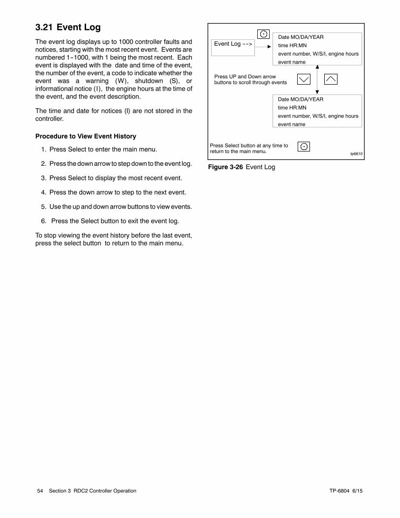
TP-6804 6/1554 Section 3 RDC2 Controller Operation
3.21 Event Log
The event log displays up to 1000 controller faults andnotices, starting with the most recent event. Events arenumbered 1--1000, with 1 being the most recent. Eachevent is displayed with the date and time of the event,the number of the event, a code to indicate whether theevent was a warning (W), shutdown (S), orinformational notice ( I), the engine hours at the time ofthe event, and the event description.
The time and date for notices (I) are not stored in thecontroller.
Procedure to View Event History
1. Press Select to enter the main menu.
2. Press thedownarrow to stepdown to theevent log.
3. Press Select to display the most recent event.
4. Press the down arrow to step to the next event.
5. Use the up and down arrow buttons to viewevents.
6. Press the Select button to exit the event log.
To stop viewing the event history before the last event,press the select button to return to the main menu.
tp6810
Event Log ---->Date MO/DA/YEAR
time HR:MN
event number, W/S/I, engine hours
event name
Press UP and Down arrowbuttons to scroll through events
Date MO/DA/YEAR
time HR:MN
event number, W/S/I, engine hours
event name
Press Select button at any time toreturn to the main menu.
Figure 3-26 Event Log
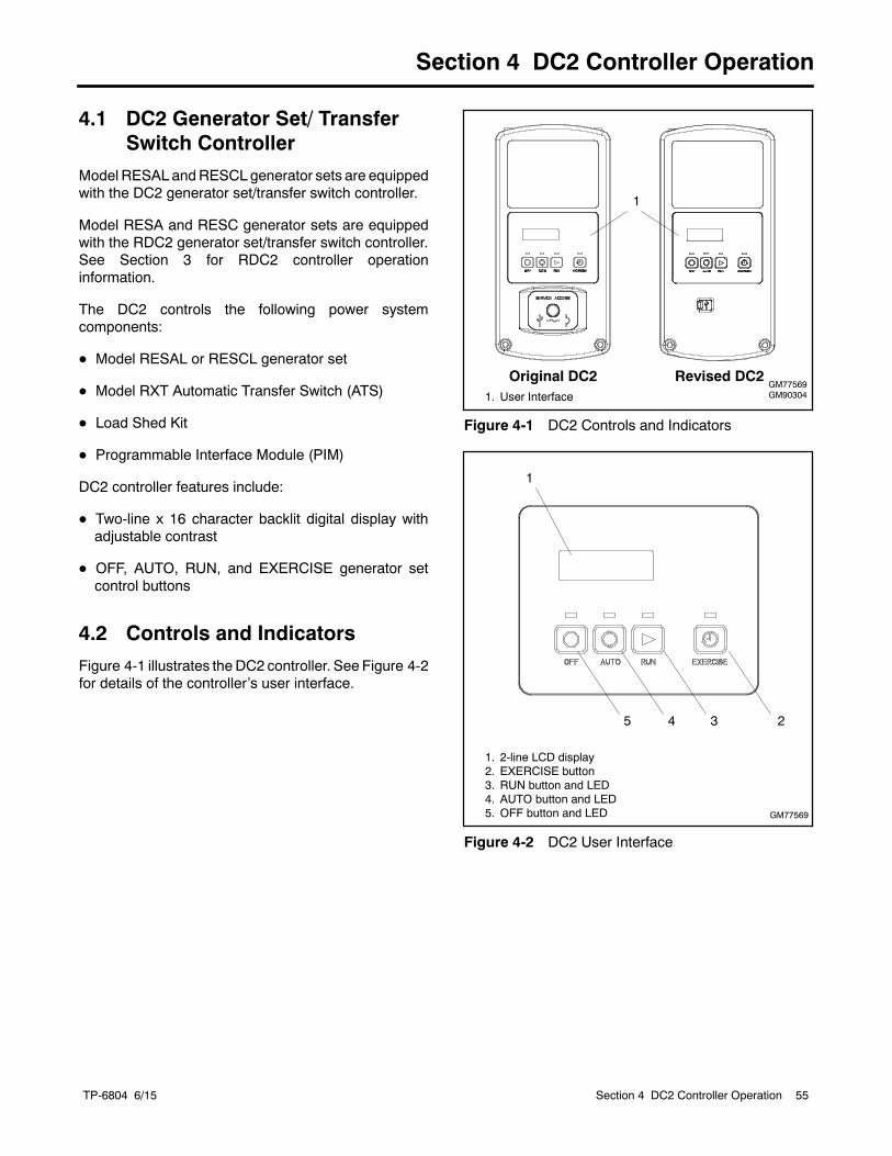
TP-6804 6/15 55Section 4 DC2 Controller Operation
Section 4 DC2 Controller Operation
4.1 DC2 Generator Set/ TransferSwitch Controller
Model RESAL andRESCL generator sets are equippedwith the DC2 generator set/transfer switch controller.
Model RESA and RESC generator sets are equippedwith the RDC2 generator set/transfer switch controller.See Section 3 for RDC2 controller operationinformation.
The DC2 controls the following power systemcomponents:
D Model RESAL or RESCL generator set
D Model RXT Automatic Transfer Switch (ATS)
D Load Shed Kit
D Programmable Interface Module (PIM)
DC2 controller features include:
D Two-line x 16 character backlit digital display withadjustable contrast
D OFF, AUTO, RUN, and EXERCISE generator setcontrol buttons
4.2 Controls and Indicators
Figure 4-1 illustrates the DC2 controller. See Figure 4-2for details of the controller’s user interface.
1. User InterfaceGM77569GM90304
1
Original DC2 Revised DC2
Figure 4-1 DC2 Controls and Indicators
1. 2-line LCD display2. EXERCISE button3. RUN button and LED4. AUTO button and LED5. OFF button and LED
1
4 35 2
GM77569
Figure 4-2 DC2 User Interface
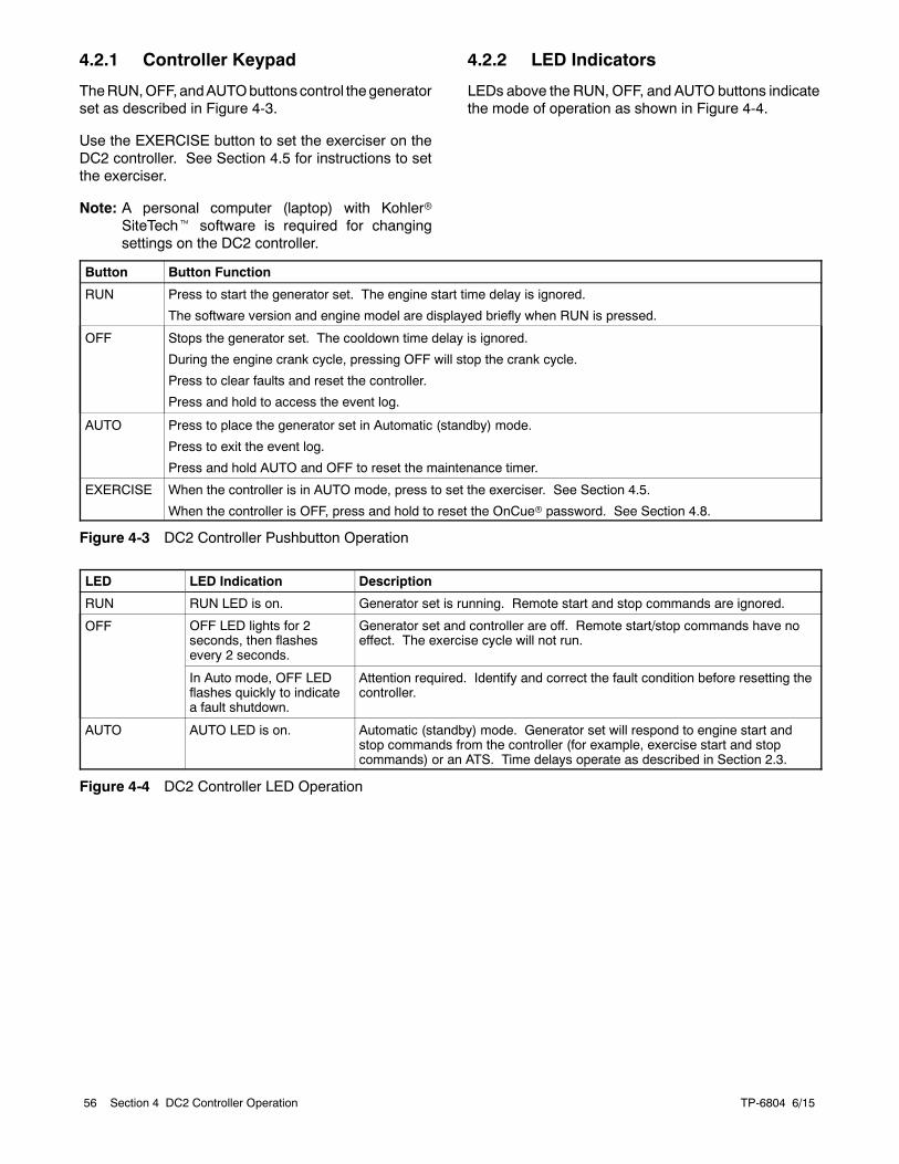
TP-6804 6/1556 Section 4 DC2 Controller Operation
4.2.1 Controller Keypad
TheRUN,OFF, andAUTObuttonscontrol thegeneratorset as described in Figure 4-3.
Use the EXERCISE button to set the exerciser on theDC2 controller. See Section 4.5 for instructions to setthe exerciser.
Note: A personal computer (laptop) with KohlerrSiteTecht software is required for changingsettings on the DC2 controller.
4.2.2 LED Indicators
LEDs above the RUN, OFF, and AUTO buttons indicatethe mode of operation as shown in Figure 4-4.
Button Button Function
RUN Press to start the generator set. The engine start time delay is ignored.
The software version and engine model are displayed briefly when RUN is pressed.
OFF Stops the generator set. The cooldown time delay is ignored.
During the engine crank cycle, pressing OFF will stop the crank cycle.
Press to clear faults and reset the controller.
Press and hold to access the event log.
AUTO Press to place the generator set in Automatic (standby) mode.
Press to exit the event log.
Press and hold AUTO and OFF to reset the maintenance timer.
EXERCISE When the controller is in AUTO mode, press to set the exerciser. See Section 4.5.
When the controller is OFF, press and hold to reset the OnCuer password. See Section 4.8.
Figure 4-3 DC2 Controller Pushbutton Operation
LED LED Indication Description
RUN RUN LED is on. Generator set is running. Remote start and stop commands are ignored.
OFF OFF LED lights for 2seconds, then flashesevery 2 seconds.
Generator set and controller are off. Remote start/stop commands have noeffect. The exercise cycle will not run.
In Auto mode, OFF LEDflashes quickly to indicatea fault shutdown.
Attention required. Identify and correct the fault condition before resetting thecontroller.
AUTO AUTO LED is on. Automatic (standby) mode. Generator set will respond to engine start andstop commands from the controller (for example, exercise start and stopcommands) or an ATS. Time delays operate as described in Section 2.3.
Figure 4-4 DC2 Controller LED Operation
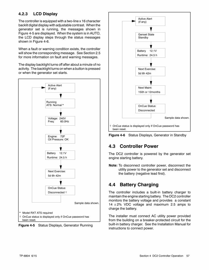
TP-6804 6/15 57Section 4 DC2 Controller Operation
4.2.3 LCD Display
The controller is equipped with a two-line x 16 characterbacklit digital displaywithadjustable contrast. When thegenerator set is running, the messages shown inFigure 4-5 are displayed. When the system is in AUTO,the LCD display steps through the status messagesshown in Figure 4-6.
When a fault or warning condition exists, the controllerwill show the corresponding message. See Section 2.5for more information on fault and warning messages.
The display backlight turns off after about aminute of noactivity. The backlight turns onwhen abutton is pressedor when the generator set starts.
RunningATS: Normal *
Voltage: 240VFreq: 60.0Hz
Engine: 72FOil Pressure: OK
Battery 12.1V
Runtime: 24.5 h
Next Exercise:
5d 6h 42m
Sample data shown.
Active Alert(if any)
OnCue Status:
Disconnected [
* Model RXT ATS required[ OnCue status is displayed only if OnCue password hasbeen reset.
Figure 4-5 Status Displays, Generator Running
Genset StateStandby
Battery 12.1V
Runtime: 24.5 h
Next Exercise:
5d 6h 42m
Sample data shown.
Active Alert(if any)
Next Maint:
150h or 12months
OnCue Status:
Disconnected
[ OnCue status is displayed only if OnCue password hasbeen reset.
Figure 4-6 Status Displays, Generator in Standby
4.3 Controller Power
The DC2 controller is powered by the generator setengine starting battery.
Note: To disconnect controller power, disconnect theutility power to the generator set and disconnectthe battery (negative lead first).
4.4 Battery Charging
The controller includes a built-in battery charger tomaintain the engine starting battery. TheDC2 controllermonitors the battery voltage and provides a constant14±2% VDC voltage and maximum 2.5 amps tocharge the battery.
The installer must connect AC utility power providedfrom the building on a breaker-protected circuit for thebuilt-in battery charger. See the Installation Manual forinstructions to connect power.
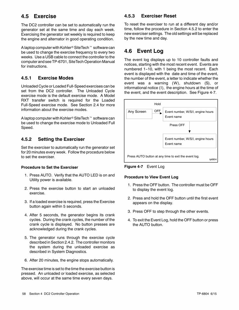
TP-6804 6/1558 Section 4 DC2 Controller Operation
4.5 Exercise
The DC2 controller can be set to automatically run thegenerator set at the same time and day each week.Exercising the generator set weekly is required to keepthe engine and alternator in good operating condition.
A laptopcomputerwithKohlerrSiteTechtsoftware canbe used to change the exercise frequency to every twoweeks. Use aUSB cable to connect the controller to thecomputer andseeTP-6701,SiteTechOperationManualfor instructions.
4.5.1 Exercise Modes
UnloadedCycle or LoadedFull-Speedexercises canbeset from the DC2 controller. The Unloaded Cycleexercise mode is the default exercise mode. A ModelRXT transfer switch is required for the LoadedFull-Speed exercise mode. See Section 2.4 for moreinformation about the exercise modes.
A laptopcomputerwithKohlerrSiteTechtsoftware canbe used to change the exercise mode to Unloaded FullSpeed.
4.5.2 Setting the Exerciser
Set the exerciser to automatically run the generator setfor 20minutes every week. Follow the procedure belowto set the exerciser.
Procedure to Set the Exerciser
1. Press AUTO. Verify that the AUTO LED is on andUtility power is available.
2. Press the exercise button to start an unloadedexercise.
3. If a loaded exercise is required, press the Exercisebutton again within 5 seconds.
4. After 5 seconds, the generator begins its crankcycles. During the crank cycles, the number of thecrank cycle is displayed. No button presses areacknowledged during the crank cycles.
5. The generator runs through the exercise cycledescribed inSection 2.4.2. The controllermonitorsthe system during the unloaded exercise asdescribed in System Diagnostics.
6. After 20 minutes, the engine stops automatically.
The exercise time is set to the time the exercise button ispressed. An unloaded or loaded exercise, as selectedabove, will occur at the same time every seven days.
4.5.3 Exerciser Reset
To reset the exerciser to run at a different day and/ortime, follow the procedure in Section 4.5.2 to enter thenewexerciser settings. Theold settingswill be replacedby the new time and day.
4.6 Event Log
The event log displays up to 10 controller faults andnotices, starting with the most recent event. Events arenumbered 1--10, with 1 being the most recent. Eachevent is displayed with the date and time of the event,the number of the event, a letter to indicate whether theevent was a warning (W), shutdown (S), orinformational notice ( I), the engine hours at the time ofthe event, and the event description. See Figure 4-7.
tp6804
Any Screen Event number, W/S/I, engine hours
Event name
Press AUTO button at any time to exit the event log.
Hold
OFF
Press OFF
Event number, W/S/I, engine hours
Event name
Figure 4-7 Event Log
Procedure to View Event Log
1. Press theOFF button. The controller must beOFFto display the event log.
2. Press and hold the OFF button until the first eventappears on the display.
3. Press OFF to step through the other events.
4. To exit the Event Log, hold theOFF button or pressthe AUTO button.
TP-6804 6/15 59Section 4 DC2 Controller Operation
4.7 Maintenance Timer
The maintenance timer keeps track of the time until thenext recommended maintenance according to themaintenanceschedule for the14kWor20 kWgeneratorset. Reset the maintenance timer after changing the oiland performing the other maintenance tasksrecommended in Section 5.
To reset the maintenance timer:
1. Press and hold the OFF and AUTO buttonstogether until Maintenance Timer Reset isdisplayed.
2. Release the OFF and AUTO buttons.
4.8 OnCue Password
For the initial OnCuerPlus setup, youwill be required toreset the OnCue password on the DC2 controller, andthen enter it into the OnCue Plus application. To resetthe password, follow the instructions below.
Note: Use the OnCue password shown on thecontroller display for OnCue or OnCue Plusapplications.
1. Press the OFF button and verify that the generatorset is not running.
2. Press and hold the Exercise button until PressAgain to Reset OnCue PW is displayed.
3. Release the Exercise button and press it againwithin 5 seconds.
Note: If the Exercise button is not pressed within 5seconds, the controller exits the passwordreset mode.
4. The genset serial number and newpassword (PW)will be displayed for 10 seconds. Record thepassword for entry into the OnCue Plusapplication.

TP-6804 6/1560 Section 4 DC2 Controller Operation
Notes
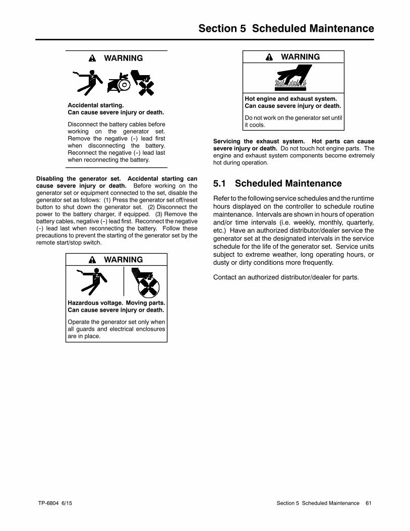
TP-6804 6/15 61Section 5 Scheduled Maintenance
Section 5 Scheduled Maintenance
Accidental starting.Can cause severe injury or death.
Disconnect the battery cables beforeworking on the generator set.Remove the negative (--) lead firstwhen disconnecting the battery.Reconnect the negative (--) lead lastwhen reconnecting the battery.
WARNING
Disabling the generator set. Accidental starting cancause severe injury or death. Before working on thegenerator set or equipment connected to the set, disable thegenerator set as follows: (1) Press the generator set off/resetbutton to shut down the generator set. (2) Disconnect thepower to the battery charger, if equipped. (3) Remove thebattery cables, negative (--) lead first. Reconnect the negative(--) lead last when reconnecting the battery. Follow theseprecautions to prevent the starting of the generator set by theremote start/stop switch.
Hazardous voltage.Can cause severe injury or death.
Operate the generator set only whenall guards and electrical enclosuresare in place.
Moving parts.
WARNING
Hot engine and exhaust system.Can cause severe injury or death.
Do not work on the generator set untilit cools.
WARNING
Servicing the exhaust system. Hot parts can causesevere injury or death. Do not touch hot engine parts. Theengine and exhaust system components become extremelyhot during operation.
5.1 Scheduled Maintenance
Refer to the following service schedules and the runtimehours displayed on the controller to schedule routinemaintenance. Intervals are shown in hours of operationand/or time intervals (i.e. weekly, monthly, quarterly,etc.) Have an authorized distributor/dealer service thegenerator set at the designated intervals in the serviceschedule for the life of the generator set. Service unitssubject to extreme weather, long operating hours, ordusty or dirty conditions more frequently.
Contact an authorized distributor/dealer for parts.
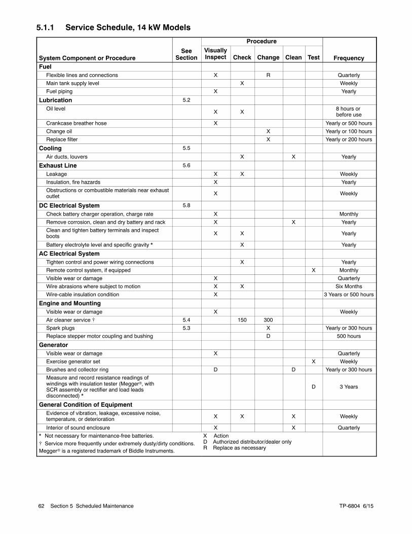
TP-6804 6/1562 Section 5 Scheduled Maintenance
5.1.1 Service Schedule, 14 kW Models
System Component or ProcedureSee
Section
Procedure
FrequencyVisuallyInspect Check Change Clean Test
FuelFlexible lines and connections X R Quarterly
Main tank supply level X Weekly
Fuel piping X Yearly
Lubrication 5.2
Oil levelX X
8 hours orbefore use
Crankcase breather hose X Yearly or 500 hours
Change oil X Yearly or 100 hours
Replace filter X Yearly or 200 hours
Cooling 5.5
Air ducts, louvers X X Yearly
Exhaust Line 5.6
Leakage X X Weekly
Insulation, fire hazards X Yearly
Obstructions or combustible materials near exhaustoutlet X Weekly
DC Electrical System 5.8
Check battery charger operation, charge rate X Monthly
Remove corrosion, clean and dry battery and rack X X Yearly
Clean and tighten battery terminals and inspectboots X X Yearly
Battery electrolyte level and specific gravity * X Yearly
AC Electrical SystemTighten control and power wiring connections X Yearly
Remote control system, if equipped X Monthly
Visible wear or damage X Quarterly
Wire abrasions where subject to motion X X Six Months
Wire-cable insulation condition X 3 Years or 500 hours
Engine and MountingVisible wear or damage X Weekly
Air cleaner service [ 5.4 150 300
Spark plugs 5.3 X Yearly or 300 hours
Replace stepper motor coupling and bushing D 500 hours
GeneratorVisible wear or damage X Quarterly
Exercise generator set X Weekly
Brushes and collector ring D D Yearly or 300 hours
Measure and record resistance readings ofwindings with insulation tester (Meggerr, withSCR assembly or rectifier and load leadsdisconnected) *
D 3 Years
General Condition of EquipmentEvidence of vibration, leakage, excessive noise,temperature, or deterioration X X X Weekly
Interior of sound enclosure X X Quarterly
* Not necessary for maintenance-free batteries.[ Service more frequently under extremely dusty/dirty conditions.Meggerr is a registered trademark of Biddle Instruments.
X ActionD Authorized distributor/dealer onlyR Replace as necessary
TP-6804 6/15 63Section 5 Scheduled Maintenance
5.1.2 Service Schedule, 20 kW Models
System Component or ProcedureSee
Section
Procedure
FrequencyVisuallyInspect Check Change Clean Test
FuelFlexible lines and connections X R Quarterly
Main tank supply level X Weekly
Fuel piping X Yearly
Fuel regulator vent tubes, if equipped X X Yearly
Lubrication 5.2
Oil level X 8 hours orbefore each use
Change oil X Yearly or 150 hours
Replace filter X Yearly or 150 hours
Crankcase breather hose X Yearly or 500 hours
Oil cooler X X Yearly or 150 hours
Cooling 5.5
Air ducts, louvers X X Yearly
Exhaust System 5.6
Leakage X X Weekly
Insulation, fire hazards X Yearly
Obstructions or combustible materials nearexhaust outlet
XWeekly
DC Electrical System 5.8
Check battery charger operation, charge rate X Monthly
Remove corrosion, clean and dry battery and rack X X Yearly
Clean and tighten battery terminals and inspectboots
X XYearly
Battery electrolyte level and specific gravity * X Yearly
AC Electrical SystemTighten control and power wiring connections X Yearly
Remote control system, if equipped X Monthly
Visible wear or damage X Quarterly
Wire abrasions where subject to motion X X Six Months
Wire-cable insulation condition X 3 Years or 500 hours
Engine and MountingVisible wear or damage X Weekly
Air cleaner service [ 5.4 150 300 Yearly or hoursshown
Spark plugs 5.3 150 300 Yearly or hoursshown
Replace stepper motor coupling and bushing D 500 hours
GeneratorVisible wear or damage X Quarterly
Exercise generator set W Weekly
Brushes and collector ring D D Yearly or 300 hours
Measure and record resistance readings ofwindings with insulation tester (Meggerr, withSCR assembly or rectifier and load leadsdisconnected)
D 3 Years
General Condition of EquipmentEvidence of vibration, leakage, deterioration,unusual or excessive noise or temperature X X X Weekly
Interior of sound enclosure X X Quarterly
* Not necessary for maintenance-free batteries.[ Service more frequently under extremely dusty/dirty conditions.Meggerr is a registered trademark of Biddle Instruments.
X ActionD Authorized distributor/dealeronlyR Replace as necessary
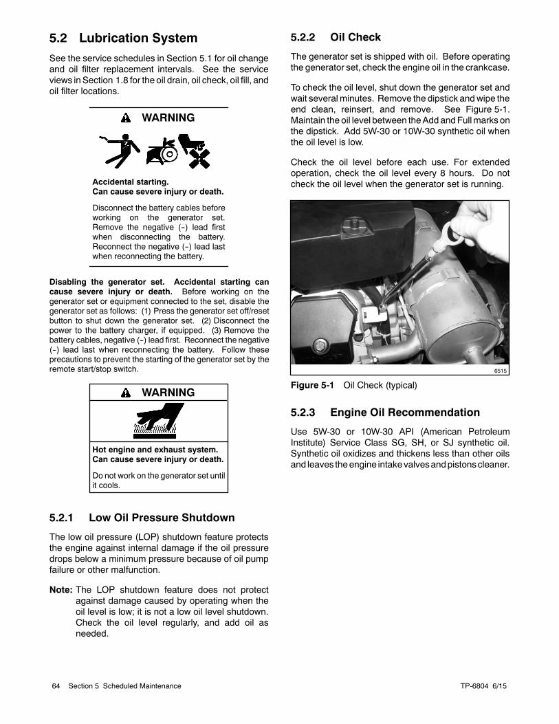
TP-6804 6/1564 Section 5 Scheduled Maintenance
5.2 Lubrication System
See the service schedules in Section 5.1 for oil changeand oil filter replacement intervals. See the serviceviews inSection 1.8 for the oil drain, oil check, oil fill, andoil filter locations.
Accidental starting.Can cause severe injury or death.
Disconnect the battery cables beforeworking on the generator set.Remove the negative (--) lead firstwhen disconnecting the battery.Reconnect the negative (--) lead lastwhen reconnecting the battery.
WARNING
Disabling the generator set. Accidental starting cancause severe injury or death. Before working on thegenerator set or equipment connected to the set, disable thegenerator set as follows: (1) Press the generator set off/resetbutton to shut down the generator set. (2) Disconnect thepower to the battery charger, if equipped. (3) Remove thebattery cables, negative (--) lead first. Reconnect the negative(--) lead last when reconnecting the battery. Follow theseprecautions to prevent the starting of the generator set by theremote start/stop switch.
Hot engine and exhaust system.Can cause severe injury or death.
Do not work on the generator set untilit cools.
WARNING
5.2.1 Low Oil Pressure Shutdown
The low oil pressure (LOP) shutdown feature protectsthe engine against internal damage if the oil pressuredrops below a minimum pressure because of oil pumpfailure or other malfunction.
Note: The LOP shutdown feature does not protectagainst damage caused by operating when theoil level is low; it is not a low oil level shutdown.Check the oil level regularly, and add oil asneeded.
5.2.2 Oil Check
The generator set is shipped with oil. Before operatingthe generator set, check the engine oil in the crankcase.
To check the oil level, shut down the generator set andwait several minutes. Remove the dipstick andwipe theend clean, reinsert, and remove. See Figure 5-1.Maintain the oil level between theAdd andFullmarks onthe dipstick. Add 5W-30 or 10W-30 synthetic oil whenthe oil level is low.
Check the oil level before each use. For extendedoperation, check the oil level every 8 hours. Do notcheck the oil level when the generator set is running.
6515
Figure 5-1 Oil Check (typical)
5.2.3 Engine Oil Recommendation
Use 5W-30 or 10W-30 API (American PetroleumInstitute) Service Class SG, SH, or SJ synthetic oil.Synthetic oil oxidizes and thickens less than other oilsand leaves theengine intakevalvesandpistonscleaner.
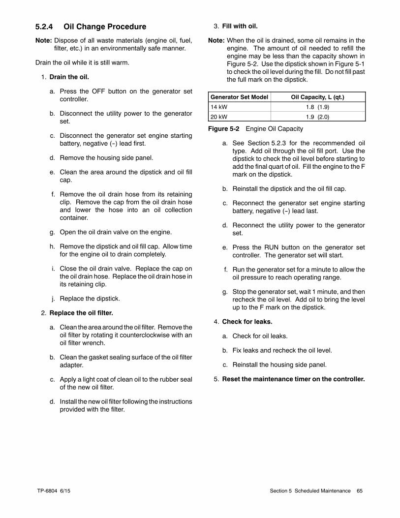
TP-6804 6/15 65Section 5 Scheduled Maintenance
5.2.4 Oil Change Procedure
Note: Dispose of all waste materials (engine oil, fuel,filter, etc.) in an environmentally safe manner.
Drain the oil while it is still warm.
1. Drain the oil.
a. Press the OFF button on the generator setcontroller.
b. Disconnect the utility power to the generatorset.
c. Disconnect the generator set engine startingbattery, negative (--) lead first.
d. Remove the housing side panel.
e. Clean the area around the dipstick and oil fillcap.
f. Remove the oil drain hose from its retainingclip. Remove the cap from the oil drain hoseand lower the hose into an oil collectioncontainer.
g. Open the oil drain valve on the engine.
h. Remove the dipstick and oil fill cap. Allow timefor the engine oil to drain completely.
i. Close the oil drain valve. Replace the cap onthe oil drain hose. Replace the oil drain hose inits retaining clip.
j. Replace the dipstick.
2. Replace the oil filter.
a. Clean the area around the oil filter. Remove theoil filter by rotating it counterclockwise with anoil filter wrench.
b. Clean the gasket sealing surface of the oil filteradapter.
c. Apply a light coat of clean oil to the rubber sealof the new oil filter.
d. Install the newoil filter following the instructionsprovided with the filter.
3. Fill with oil.
Note: When the oil is drained, some oil remains in theengine. The amount of oil needed to refill theengine may be less than the capacity shown inFigure 5-2. Use the dipstick shown in Figure 5-1to check the oil level during the fill. Do not fill pastthe full mark on the dipstick.
Generator Set Model Oil Capacity, L (qt.)
14 kW 1.8 (1.9)
20 kW 1.9 (2.0)
Figure 5-2 Engine Oil Capacity
a. See Section 5.2.3 for the recommended oiltype. Add oil through the oil fill port. Use thedipstick to check the oil level before starting toadd the final quart of oil. Fill the engine to the Fmark on the dipstick.
b. Reinstall the dipstick and the oil fill cap.
c. Reconnect the generator set engine startingbattery, negative (--) lead last.
d. Reconnect the utility power to the generatorset.
e. Press the RUN button on the generator setcontroller. The generator set will start.
f. Run the generator set for a minute to allow theoil pressure to reach operating range.
g. Stop the generator set, wait 1 minute, and thenrecheck the oil level. Add oil to bring the levelup to the F mark on the dipstick.
4. Check for leaks.
a. Check for oil leaks.
b. Fix leaks and recheck the oil level.
c. Reinstall the housing side panel.
5. Reset the maintenance timer on the controller.
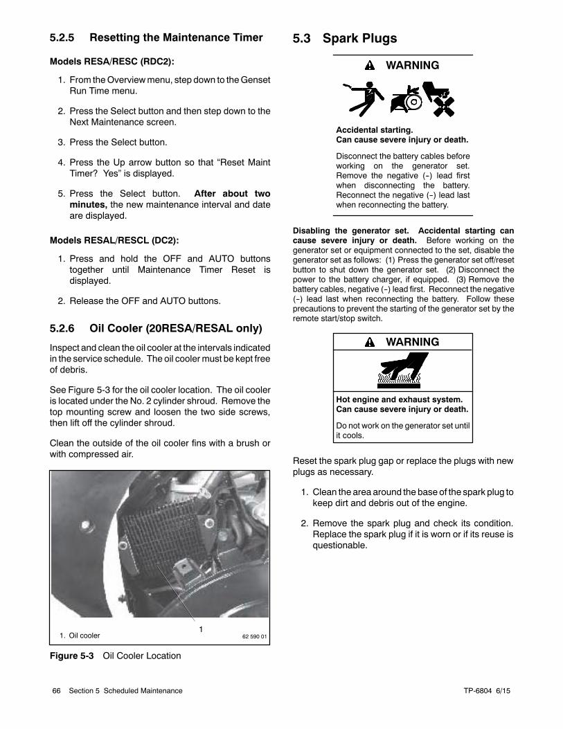
TP-6804 6/1566 Section 5 Scheduled Maintenance
5.2.5 Resetting the Maintenance Timer
Models RESA/RESC (RDC2):
1. From theOverviewmenu, step down to theGensetRun Time menu.
2. Press the Select button and then step down to theNext Maintenance screen.
3. Press the Select button.
4. Press the Up arrow button so that “Reset MaintTimer? Yes” is displayed.
5. Press the Select button. After about twominutes, the new maintenance interval and dateare displayed.
Models RESAL/RESCL (DC2):
1. Press and hold the OFF and AUTO buttonstogether until Maintenance Timer Reset isdisplayed.
2. Release the OFF and AUTO buttons.
5.2.6 Oil Cooler (20RESA/RESAL only)
Inspect and clean the oil cooler at the intervals indicatedin the service schedule. The oil coolermust be kept freeof debris.
See Figure 5-3 for the oil cooler location. The oil cooleris located under the No. 2 cylinder shroud. Remove thetop mounting screw and loosen the two side screws,then lift off the cylinder shroud.
Clean the outside of the oil cooler fins with a brush orwith compressed air.
162 590 011. Oil cooler
Figure 5-3 Oil Cooler Location
5.3 Spark Plugs
Accidental starting.Can cause severe injury or death.
Disconnect the battery cables beforeworking on the generator set.Remove the negative (--) lead firstwhen disconnecting the battery.Reconnect the negative (--) lead lastwhen reconnecting the battery.
WARNING
Disabling the generator set. Accidental starting cancause severe injury or death. Before working on thegenerator set or equipment connected to the set, disable thegenerator set as follows: (1) Press the generator set off/resetbutton to shut down the generator set. (2) Disconnect thepower to the battery charger, if equipped. (3) Remove thebattery cables, negative (--) lead first. Reconnect the negative(--) lead last when reconnecting the battery. Follow theseprecautions to prevent the starting of the generator set by theremote start/stop switch.
Hot engine and exhaust system.Can cause severe injury or death.
Do not work on the generator set untilit cools.
WARNING
Reset the spark plug gap or replace the plugs with newplugs as necessary.
1. Clean the area around the base of the spark plug tokeep dirt and debris out of the engine.
2. Remove the spark plug and check its condition.Replace the spark plug if it is worn or if its reuse isquestionable.
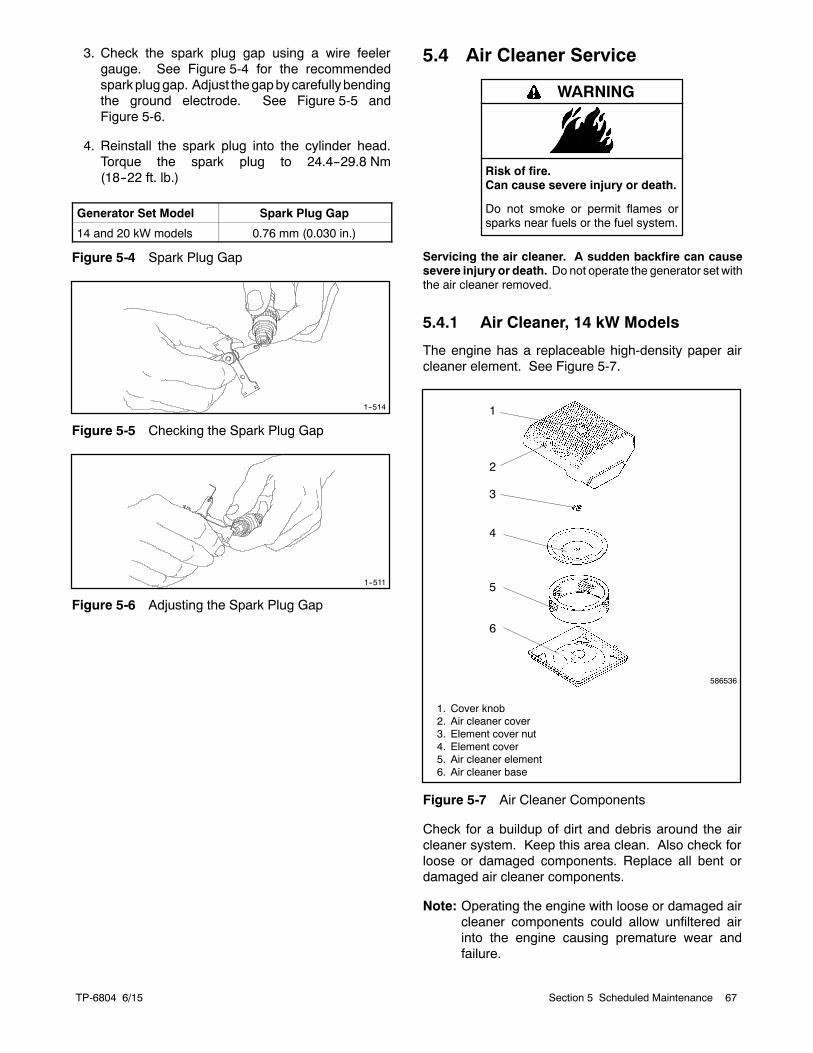
TP-6804 6/15 67Section 5 Scheduled Maintenance
3. Check the spark plug gap using a wire feelergauge. See Figure 5-4 for the recommendedsparkpluggap. Adjust thegapbycarefullybendingthe ground electrode. See Figure 5-5 andFigure 5-6.
4. Reinstall the spark plug into the cylinder head.Torque the spark plug to 24.4--29.8 Nm(18--22 ft. lb.)
Generator Set Model Spark Plug Gap
14 and 20 kW models 0.76 mm (0.030 in.)
Figure 5-4 Spark Plug Gap
1--514
Figure 5-5 Checking the Spark Plug Gap
1--511
Figure 5-6 Adjusting the Spark Plug Gap
5.4 Air Cleaner Service
Risk of fire.Can cause severe injury or death.
Do not smoke or permit flames orsparks near fuels or the fuel system.
WARNING
Servicing the air cleaner. A sudden backfire can causesevere injury or death. Do not operate the generator set withthe air cleaner removed.
5.4.1 Air Cleaner, 14 kW Models
The engine has a replaceable high-density paper aircleaner element. See Figure 5-7.
1
2
3
4
5
6
586536
1. Cover knob2. Air cleaner cover3. Element cover nut4. Element cover5. Air cleaner element6. Air cleaner base
Figure 5-7 Air Cleaner Components
Check for a buildup of dirt and debris around the aircleaner system. Keep this area clean. Also check forloose or damaged components. Replace all bent ordamaged air cleaner components.
Note: Operating the engine with loose or damaged aircleaner components could allow unfiltered airinto the engine causing premature wear andfailure.
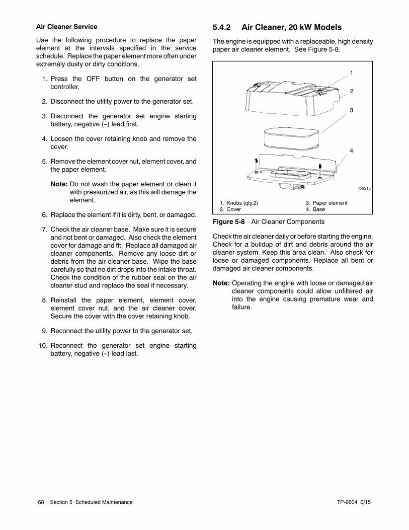
TP-6804 6/1568 Section 5 Scheduled Maintenance
Air Cleaner Service
Use the following procedure to replace the paperelement at the intervals specified in the serviceschedule. Replace the paper elementmore often underextremely dusty or dirty conditions.
1. Press the OFF button on the generator setcontroller.
2. Disconnect the utility power to the generator set.
3. Disconnect the generator set engine startingbattery, negative (--) lead first.
4. Loosen the cover retaining knob and remove thecover.
5. Remove theelement cover nut, element cover, andthe paper element.
Note: Do not wash the paper element or clean itwith pressurized air, as this will damage theelement.
6. Replace the element if it is dirty, bent, or damaged.
7. Check the air cleaner base. Make sure it is secureand not bent or damaged. Also check the elementcover for damage and fit. Replace all damaged aircleaner components. Remove any loose dirt ordebris from the air cleaner base. Wipe the basecarefully so that no dirt drops into the intake throat.Check the condition of the rubber seal on the aircleaner stud and replace the seal if necessary.
8. Reinstall the paper element, element cover,element cover nut, and the air cleaner cover.Secure the cover with the cover retaining knob.
9. Reconnect the utility power to the generator set.
10. Reconnect the generator set engine startingbattery, negative (--) lead last.
5.4.2 Air Cleaner, 20 kW Models
The engine is equipped with a replaceable, high densitypaper air cleaner element. See Figure 5-8.
1
tp6515
1. Knobs (qty.2)2. Cover
3. Paper element4. Base
3
2
4
Figure 5-8 Air Cleaner Components
Check the air cleaner daily or before starting the engine.Check for a buildup of dirt and debris around the aircleaner system. Keep this area clean. Also check forloose or damaged components. Replace all bent ordamaged air cleaner components.
Note: Operating the engine with loose or damaged aircleaner components could allow unfiltered airinto the engine causing premature wear andfailure.
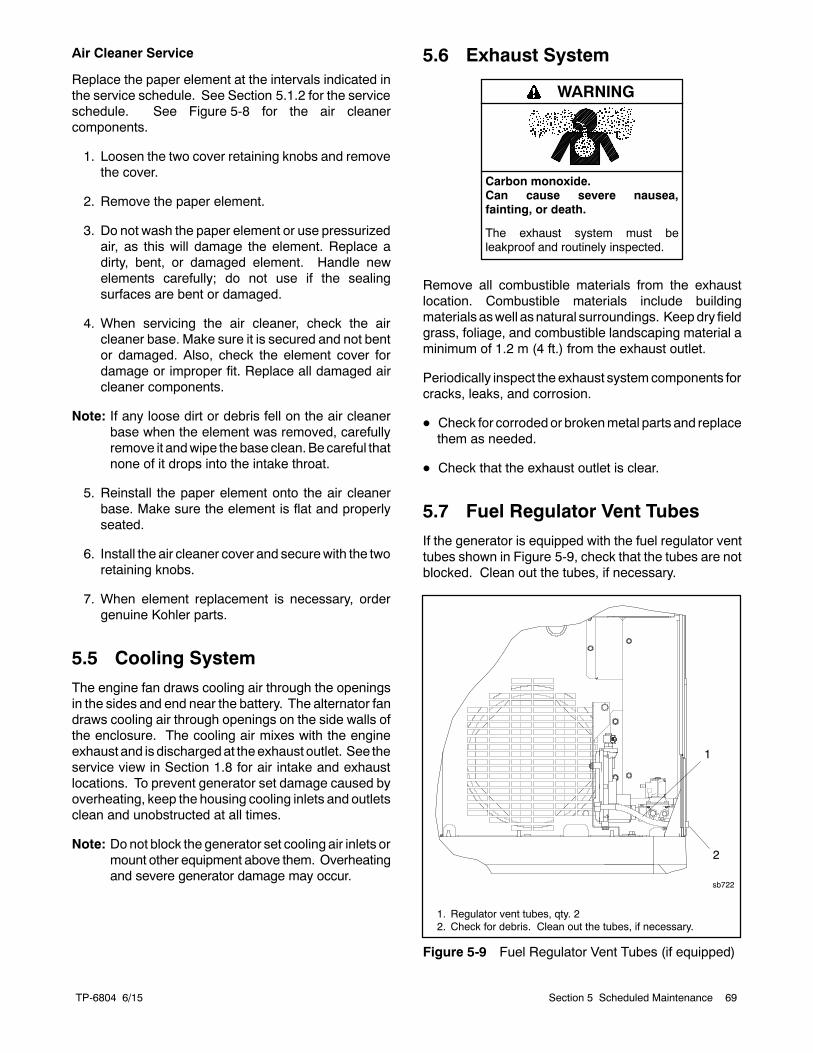
TP-6804 6/15 69Section 5 Scheduled Maintenance
Air Cleaner Service
Replace the paper element at the intervals indicated inthe service schedule. See Section 5.1.2 for the serviceschedule. See Figure 5-8 for the air cleanercomponents.
1. Loosen the two cover retaining knobs and removethe cover.
2. Remove the paper element.
3. Do not wash the paper element or use pressurizedair, as this will damage the element. Replace adirty, bent, or damaged element. Handle newelements carefully; do not use if the sealingsurfaces are bent or damaged.
4. When servicing the air cleaner, check the aircleaner base. Make sure it is secured and not bentor damaged. Also, check the element cover fordamage or improper fit. Replace all damaged aircleaner components.
Note: If any loose dirt or debris fell on the air cleanerbase when the element was removed, carefullyremove it andwipe thebase clean.Becareful thatnone of it drops into the intake throat.
5. Reinstall the paper element onto the air cleanerbase. Make sure the element is flat and properlyseated.
6. Install the air cleaner cover and securewith the tworetaining knobs.
7. When element replacement is necessary, ordergenuine Kohler parts.
5.5 Cooling System
The engine fan draws cooling air through the openingsin the sides and end near the battery. The alternator fandraws cooling air through openings on the side walls ofthe enclosure. The cooling air mixes with the engineexhaust and is dischargedat theexhaust outlet. See theservice view in Section 1.8 for air intake and exhaustlocations. To prevent generator set damage caused byoverheating, keep the housing cooling inlets and outletsclean and unobstructed at all times.
Note: Donot block the generator set cooling air inlets ormount other equipment above them. Overheatingand severe generator damage may occur.
5.6 Exhaust System
Carbon monoxide.Can cause severe nausea,fainting, or death.
The exhaust system must beleakproof and routinely inspected.
WARNING
Remove all combustible materials from the exhaustlocation. Combustible materials include buildingmaterials aswell asnatural surroundings. Keepdry fieldgrass, foliage, and combustible landscaping material aminimum of 1.2 m (4 ft.) from the exhaust outlet.
Periodically inspect the exhaust systemcomponents forcracks, leaks, and corrosion.
D Check for corrodedor brokenmetal parts and replacethem as needed.
D Check that the exhaust outlet is clear.
5.7 Fuel Regulator Vent Tubes
If the generator is equipped with the fuel regulator venttubes shown in Figure 5-9, check that the tubes are notblocked. Clean out the tubes, if necessary.
1. Regulator vent tubes, qty. 22. Check for debris. Clean out the tubes, if necessary.
2
sb722
1
Figure 5-9 Fuel Regulator Vent Tubes (if equipped)
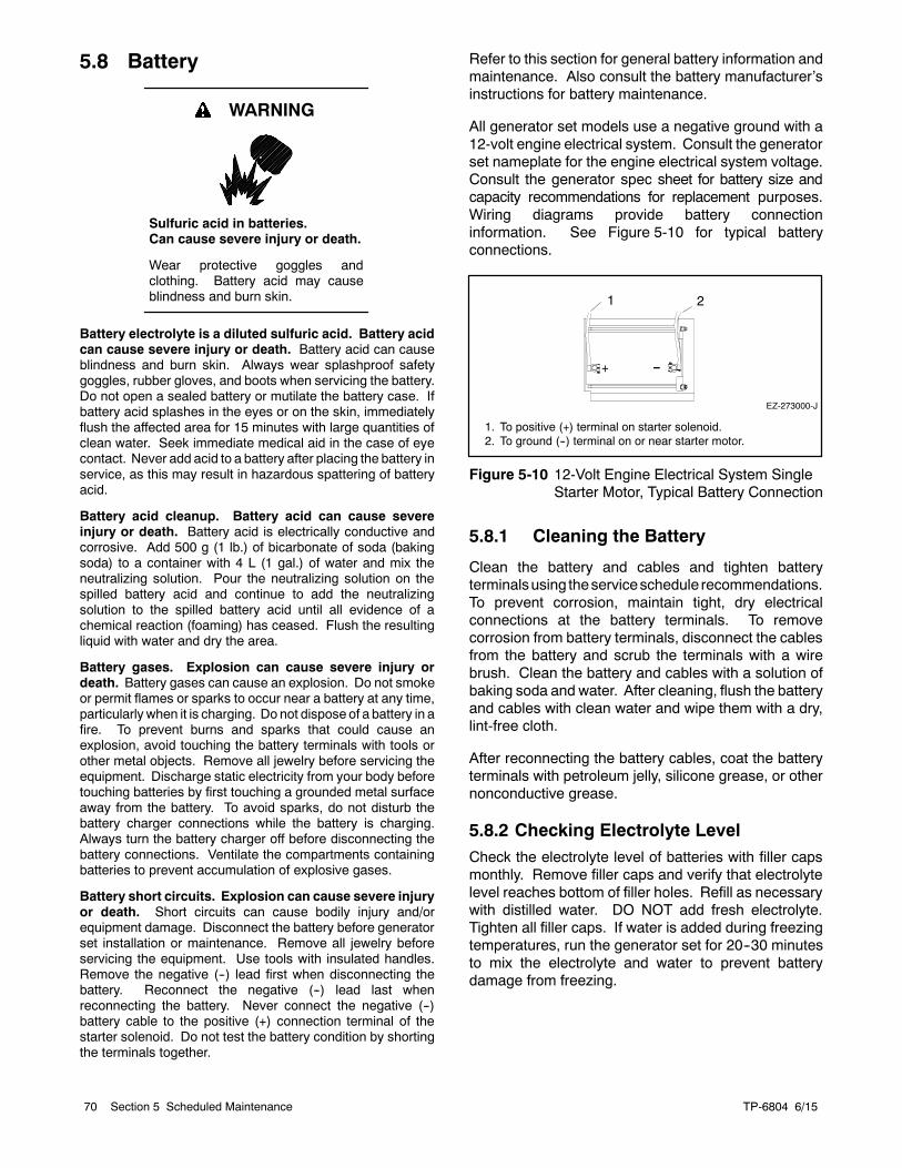
TP-6804 6/1570 Section 5 Scheduled Maintenance
5.8 Battery
Sulfuric acid in batteries.Can cause severe injury or death.
Wear protective goggles andclothing. Battery acid may causeblindness and burn skin.
WARNING
Battery electrolyte is a diluted sulfuric acid. Battery acidcan cause severe injury or death. Battery acid can causeblindness and burn skin. Always wear splashproof safetygoggles, rubber gloves, and boots when servicing the battery.Do not open a sealed battery or mutilate the battery case. Ifbattery acid splashes in the eyes or on the skin, immediatelyflush the affected area for 15 minutes with large quantities ofclean water. Seek immediate medical aid in the case of eyecontact. Never add acid to a battery after placing the battery inservice, as this may result in hazardous spattering of batteryacid.
Battery acid cleanup. Battery acid can cause severeinjury or death. Battery acid is electrically conductive andcorrosive. Add 500 g (1 lb.) of bicarbonate of soda (bakingsoda) to a container with 4 L (1 gal.) of water and mix theneutralizing solution. Pour the neutralizing solution on thespilled battery acid and continue to add the neutralizingsolution to the spilled battery acid until all evidence of achemical reaction (foaming) has ceased. Flush the resultingliquid with water and dry the area.
Battery gases. Explosion can cause severe injury ordeath. Battery gases can cause an explosion. Do not smokeor permit flames or sparks to occur near a battery at any time,particularly when it is charging. Do not dispose of a battery in afire. To prevent burns and sparks that could cause anexplosion, avoid touching the battery terminals with tools orother metal objects. Remove all jewelry before servicing theequipment. Discharge static electricity from your body beforetouching batteries by first touching a grounded metal surfaceaway from the battery. To avoid sparks, do not disturb thebattery charger connections while the battery is charging.Always turn the battery charger off before disconnecting thebattery connections. Ventilate the compartments containingbatteries to prevent accumulation of explosive gases.
Battery short circuits. Explosion can cause severe injuryor death. Short circuits can cause bodily injury and/orequipment damage. Disconnect the battery before generatorset installation or maintenance. Remove all jewelry beforeservicing the equipment. Use tools with insulated handles.Remove the negative (--) lead first when disconnecting thebattery. Reconnect the negative (--) lead last whenreconnecting the battery. Never connect the negative (--)battery cable to the positive (+) connection terminal of thestarter solenoid. Do not test the battery condition by shortingthe terminals together.
Refer to this section for general battery information andmaintenance. Also consult the battery manufacturer’sinstructions for battery maintenance.
All generator set models use a negative ground with a12-volt engine electrical system. Consult the generatorset nameplate for the engine electrical system voltage.Consult the generator spec sheet for battery size andcapacity recommendations for replacement purposes.Wiring diagrams provide battery connectioninformation. See Figure 5-10 for typical batteryconnections.
EZ-273000-J
1 2
1. To positive (+) terminal on starter solenoid.2. To ground (--) terminal on or near starter motor.
Figure 5-10 12-Volt Engine Electrical System SingleStarter Motor, Typical Battery Connection
5.8.1 Cleaning the Battery
Clean the battery and cables and tighten batteryterminalsusing theserviceschedule recommendations.To prevent corrosion, maintain tight, dry electricalconnections at the battery terminals. To removecorrosion from battery terminals, disconnect the cablesfrom the battery and scrub the terminals with a wirebrush. Clean the battery and cables with a solution ofbaking soda and water. After cleaning, flush the batteryand cables with clean water and wipe them with a dry,lint-free cloth.
After reconnecting the battery cables, coat the batteryterminals with petroleum jelly, silicone grease, or othernonconductive grease.
5.8.2 Checking Electrolyte LevelCheck the electrolyte level of batteries with filler capsmonthly. Remove filler caps and verify that electrolytelevel reaches bottom of filler holes. Refill as necessarywith distilled water. DO NOT add fresh electrolyte.Tighten all filler caps. If water is added during freezingtemperatures, run the generator set for 20--30 minutesto mix the electrolyte and water to prevent batterydamage from freezing.
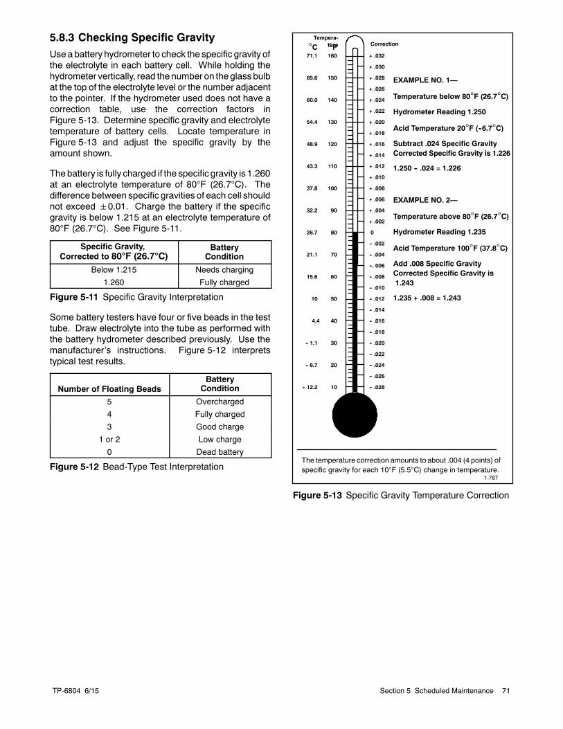
TP-6804 6/15 71Section 5 Scheduled Maintenance
5.8.3 Checking Specific GravityUseabattery hydrometer to check the specific gravity ofthe electrolyte in each battery cell. While holding thehydrometer vertically, read thenumber on the glassbulbat the top of the electrolyte level or the number adjacentto the pointer. If the hydrometer used does not have acorrection table, use the correction factors inFigure 5-13. Determine specific gravity and electrolytetemperature of battery cells. Locate temperature inFigure 5-13 and adjust the specific gravity by theamount shown.
Thebattery is fully charged if the specific gravity is 1.260at an electrolyte temperature of 80F (26.7C). Thedifference between specific gravities of each cell shouldnot exceed 0.01. Charge the battery if the specificgravity is below 1.215 at an electrolyte temperature of80F (26.7C). See Figure 5-11.
Specific Gravity,Corrected to 80F (26.7C)
BatteryCondition
Below 1.215 Needs charging
1.260 Fully charged
Figure 5-11 Specific Gravity Interpretation
Some battery testers have four or five beads in the testtube. Draw electrolyte into the tube as performed withthe battery hydrometer described previously. Use themanufacturer’s instructions. Figure 5-12 interpretstypical test results.
Number of Floating BeadsBattery
Condition
5 Overcharged
4 Fully charged
3 Good charge
1 or 2 Low charge
0 Dead battery
Figure 5-12 Bead-Type Test Interpretation
10
20
30
40
50
60
70
80
90
100
110
120
130
140
150
160
-- 12.2
-- 6.7
-- 1.1
4.4
10
21.1
26.7
32.2
37.8
43.3
48.9
54.4
60.0
65.6
71.1
15.6
+ .032
+ .030
+ .028
+ .026
+ .024
+ .022
+ .020
+ .018
+ .016
+ .014
+ .012
+ .010
+ .008
+ .006
+ .004
+ .002
0
-- .002
-- .004
--. 006
-- .008
-- .010
-- .012
-- .014
-- .016
-- .018
-- .020
-- .022
-- .024
-- .026
-- .028
C F
EXAMPLE NO. 1—
Temperature below 80F (26.7C)
Hydrometer Reading 1.250
Acid Temperature 20F (--6.7C)
Subtract .024 Specific GravityCorrected Specific Gravity is 1.226
1.250 -- .024 = 1.226
EXAMPLE NO. 2—
Temperature above 80F (26.7C)
Hydrometer Reading 1.235
Acid Temperature 100F (37.8C)
Add .008 Specific GravityCorrected Specific Gravity is1.243
1.235 + .008 = 1.243
The temperature correction amounts to about .004 (4 points) ofspecific gravity for each 10F (5.5C) change in temperature.
Correction
1-787
Tempera-ture
Figure 5-13 Specific Gravity Temperature Correction
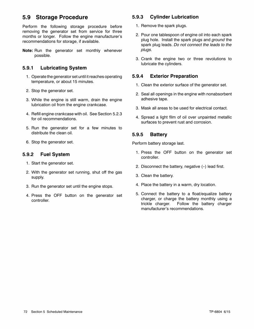
TP-6804 6/1572 Section 5 Scheduled Maintenance
5.9 Storage Procedure
Perform the following storage procedure beforeremoving the generator set from service for threemonths or longer. Follow the engine manufacturer’srecommendations for storage, if available.
Note: Run the generator set monthly wheneverpossible.
5.9.1 Lubricating System
1. Operate thegenerator set until it reachesoperatingtemperature, or about 15 minutes.
2. Stop the generator set.
3. While the engine is still warm, drain the enginelubrication oil from the engine crankcase.
4. Refill engine crankcase with oil. See Section 5.2.3for oil recommendations.
5. Run the generator set for a few minutes todistribute the clean oil.
6. Stop the generator set.
5.9.2 Fuel System
1. Start the generator set.
2. With the generator set running, shut off the gassupply.
3. Run the generator set until the engine stops.
4. Press the OFF button on the generator setcontroller.
5.9.3 Cylinder Lubrication
1. Remove the spark plugs.
2. Pour one tablespoon of engine oil into each sparkplug hole. Install the spark plugs and ground thespark plug leads. Do not connect the leads to theplugs.
3. Crank the engine two or three revolutions tolubricate the cylinders.
5.9.4 Exterior Preparation
1. Clean the exterior surface of the generator set.
2. Seal all openings in the engine with nonabsorbentadhesive tape.
3. Mask all areas to be used for electrical contact.
4. Spread a light film of oil over unpainted metallicsurfaces to prevent rust and corrosion.
5.9.5 Battery
Perform battery storage last.
1. Press the OFF button on the generator setcontroller.
2. Disconnect the battery, negative (--) lead first.
3. Clean the battery.
4. Place the battery in a warm, dry location.
5. Connect the battery to a float/equalize batterycharger, or charge the battery monthly using atrickle charger. Follow the battery chargermanufacturer’s recommendations.
TP-6804 6/15 73Section 6 Troubleshooting
Section 6 Troubleshooting
6.1 Introduction
Use the troubleshooting charts in this section todiagnoseandcorrect commonproblems. First check forsimple causes such as a dead engine starting battery,loose connections, or an open circuit breaker. Thecharts include a list of common problems, possiblecauses of the problem, and recommended correctiveactions.
If the procedures in this manual do not explain how tocorrect the problem, contact an authorizeddistributor/dealer. Maintain a record of repairs andadjustments performed on the equipment. Use therecord to help describe the problem and repairs oradjustments made to equipment.
6.2 Fault Messages
The controller displays fault messages to aid introubleshooting. Selected fault messages andrecommended checks are listed in Figure 2-3.
Identify and correct the cause of the fault condition.Then reset the controller after a fault shutdown. SeeSection 2.5.4.
6.3 Circuit Protection
If the generator set circuit breaker trips repeatedly,contact an authorized distributor/ dealer for service.
6.3.1 Controller Internal CircuitProtection
The controller is equipped with internal circuitprotection. A fault message, Accy PwrOver Warning orMainPwrOverL Shutdown, is displayed if this internalprotection is activated. PressOFF to reset. Contact anauthorized Kohler distributor/dealer for service.
6.3.2 Line Circuit Breaker
The line circuit breaker interrupts thegenerator output inthe event of a fault in the wiring between the generatorand the load. If the circuit breaker trips, reduce the loadand switch the breaker back to the ON position.
6.4 USB Port and AuxiliaryWinding Mini-Breaker
On original RDC2/DC2 controllers, the USB port andalternator winding mini circuit breaker are located in theservice access area as shown in Figure 6-1.
Revised controllers have the USB port located under asmall rubber cover as shown in Figure 6-2. Thealternator winding circuit breaker is located as shown inFigure 6-3. If an original (green board) controller hasbeen replaced with a revised (red board) controller, thecircuit breaker may be located inside the controllertrough, under the controller.
A personal computer (laptop) with Kohlerr SiteTechtsoftware can be used to view the event history andadjust controller settings. UseaUSBcablewithamini-Bconnector to connect the controller’s USB port to yourPC.
See TP-6701, SiteTecht Software Operation Manual,for software operation instructions.
1. USB port (for service)2. Alternator winding circuit breaker
1 2
Figure 6-1 Controller Service Access (coverremoved)
TP-6804 6/1574 Section 6 Troubleshooting
1. USB port
1
GM90304
Figure 6-2 Revised Controller USB Port Location
11. Alternate mini-breaker location (access through air intake
area)
Figure 6-3 Auxiliary Winding Mini-Breaker Location
6.5 Thermostat
Accidental starting.Can cause severe injury or death.
Disconnect the battery cables beforeworking on the generator set.Remove the negative (--) lead firstwhen disconnecting the battery.Reconnect the negative (--) lead lastwhen reconnecting the battery.
WARNING
Disabling the generator set. Accidental starting cancause severe injury or death. Before working on thegenerator set or equipment connected to the set, disable thegenerator set as follows: (1) Press the generator set off/resetbutton to shut down the generator set. (2) Disconnect thepower to the battery charger, if equipped. (3) Remove thebattery cables, negative (--) lead first. Reconnect the negative(--) lead last when reconnecting the battery. Follow theseprecautions to prevent the starting of the generator set by theremote start/stop switch.
Hot engine and exhaust system.Can cause severe injury or death.
Do not work on the generator set untilit cools.
WARNING
Servicing the exhaust system. Hot parts can causesevere injury or death. Do not touch hot engine parts. Theengine and exhaust system components become extremelyhot during operation.
Model 20RESCand 20RESCL generator sets include aresettable thermostat. See Figure 6-4 for thethermostat location. The thermostat detects excessheat inside the enclosure. If the thermostat trips, thegenerator will shut down and the controller will display afault (underspeed, underfrequency, or undervoltage).Check for blocked air inlets and exhaust outlets. Thenfollow these steps to reset the thermostat.
TP-6804 6/15 75Section 6 Troubleshooting
Procedure to Reset the Thermostat
1. Disconnect the utility power to the generator byopening (turning OFF) the corresponding circuitbreaker at the building’s distribution panel.
2. Disconnect the generator set engine startingbattery(ies), negative (--) lead first.
3. Open the enclosure roof and secure it with the roofstay on the left side of the enclosure.
4. To gain access to the thermostat, remove the frontenclosure panel. See Figure 6-4.
a. Remove one screw near the controller area.
b. From inside of the enclosure, remove four nutsthat secure the front panel.
c. Lift the panel up and off.
5. Press the button on the thermostat to reset it.
6. Replace the front panel.
7. Reconnect the generator set engine startingbattery, negative (--) lead last.
8. Reconnect utility power to the generator set byclosing the circuit breaker in the distribution panel.
9. Reset the fault on the controller. Refer to Section2.5 for instructions, if necessary.
1. Thermostat2. Locations of nuts and screws that secure the front panel
GM938971 2
Figure 6-4 Thermostat Location, Model20RESC/RESCL
6.6 Troubleshooting
Figure 6-5 contains generator set troubleshooting,diagnostic, and repair information. Check for looseconnections before replacing parts.
Troubleshooting Table
Problem Possible Cause Corrective Action
Controllerdisplaybacklight is off.
Backlight turns off after about 1 minute with noactivity.
Backlight will turn on when a button is pressed or thegenerator set starts.
Controllerdisplay is off.
Low or no battery voltage. Check connections.Check generator set battery. See Figure 6-5.
The generatorset does notcrank.
Battery weak or dead. Recharge or replace the battery.
Battery connections reversed or poor. Check the connections.
Fault shutdown. Check the controller display for fault messages. SeeSection 2.5. Correct the fault condition and reset thecontroller.
Generator set in the OFF mode. Press the RUN button to start the engine or press AUTOto allow remote starting.
Generator thermostat tripped. Check for obstructed air inlets and outlets. Reset thethermostat. See Section 6.5.
The generatorset cranks butdoes not start,starts hard,lacks power, oroperateserratically.
Air cleaner clogged. Clean and/or replace the air cleaner.
Battery weak or dead. Recharge or replace the battery.
Battery connection poor. Clean and tighten the battery connections.
Spark plug wire connection loose. Check the spark plug wires.
Low oil pressure shutdown. Check for oil leaks. Check the oil level and add oil ifnecessary.
Fuel pressure insufficient. Check the fuel supply and valves.
Engine malfunction. Contact an authorized distributor/dealer.
TP-6804 6/1576 Section 6 Troubleshooting
Problem Possible Cause Corrective Action
No AC output. Line circuit breaker in the OFF position. Place the circuit breaker in the ON position.
Line circuit breaker tripping because ofoverload.
Reduce the load on the generator set.
Line circuit breaker tripping because of shortcircuit.
Contact an authorized distributor/dealer for service.
Auxiliary winding circuit breaker tripped. Reset the circuit breaker (located in controller’s serviceaccess area). Contact an authorized distributor/dealerfor service if breaker trips repeatedly.
Low output orexcessive dropin voltage.
Generator set overloaded. Reduce the load.
Generator setstops suddenly.
Low oil pressure shutdown. Check for oil leaks. Check the oil level and add oil ifnecessary.
No fuel. Check fuel valves and fuel supply.
Model 20RESC/20RESCL only: Check enclosurethermostat and reset if tripped. See Section 6.5. Checkand clear air inlets and exhaust outlets.
Overcrank shutdown. Reset the controller. If the overcrank fault occurs again,contact an authorized distributor/dealer.
Auxiliary winding circuit breaker tripped. Reset the auxiliary winding circuit breaker. Contact anauthorized distributor/dealer for service if breaker tripsrepeatedly.
Fault shutdown. Check the controller display for fault messages. SeeSection 2.5. Correct the fault condition and reset thecontroller.
Generator set in the OFF mode. Press the RUN button to start the engine or press AUTOto allow remote starting.
Remote stop command received from a remoteswitch, ATS, or OnCuerPlus.
Check the remote switch position. Check OnCuerPlus.
Generator thermostat tripped. Check for obstructed air inlets and outlets. Reset thethermostat. See Section 6.5.
Engine malfunction. Contact an authorized distributor/dealer.
Figure 6-5 General Troubleshooting
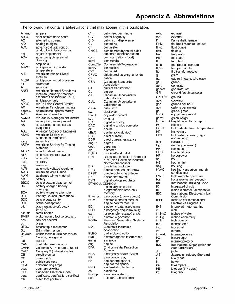
TP-6804 6/15 Appendix 77
Appendix A Abbreviations
The following list contains abbreviations that may appear in this publication.
A, amp ampereABDC after bottom dead centerAC alternating currentA/D analog to digitalADC advanced digital control;
analog to digital converteradj. adjust, adjustmentADV advertising dimensional
drawingAh amp-hourAHWT anticipatory high water
temperatureAISI American Iron and Steel
InstituteALOP anticipatory low oil pressurealt. alternatorAl aluminumANSI American National Standards
Institute (formerly AmericanStandards Association, ASA)
AO anticipatory onlyAPDC Air Pollution Control DistrictAPI American Petroleum Instituteapprox. approximate, approximatelyAPU Auxiliary Power UnitAQMD Air Quality Management DistrictAR as required, as requestedAS as supplied, as stated, as
suggestedASE American Society of EngineersASME American Society of
Mechanical Engineersassy. assemblyASTM American Society for Testing
MaterialsATDC after top dead centerATS automatic transfer switchauto. automaticaux. auxiliaryavg. averageAVR automatic voltage regulatorAWG American Wire GaugeAWM appliance wiring materialbat. batteryBBDC before bottom dead centerBC battery charger, battery
chargingBCA battery charging alternatorBCI Battery Council InternationalBDC before dead centerBHP brake horsepowerblk. black (paint color), block
(engine)blk. htr. block heaterBMEP brake mean effective pressurebps bits per secondbr. brassBTDC before top dead centerBtu British thermal unitBtu/min. British thermal units per minuteC Celsius, centigradecal. calorieCAN controller area networkCARB California Air Resources BoardCAT5 Category 5 (network cable)CB circuit breakerCC crank cyclecc cubic centimeterCCA cold cranking ampsccw. counterclockwiseCEC Canadian Electrical Codecert. certificate, certification, certifiedcfh cubic feet per hour
cfm cubic feet per minuteCG center of gravityCID cubic inch displacementCL centerlinecm centimeterCMOS complementary metal oxide
substrate (semiconductor)com communications (port)coml commercialComl/Rec Commercial/Recreationalconn. connectioncont. continuedCPVC chlorinated polyvinyl chloridecrit. criticalCSA Canadian Standards
AssociationCT current transformerCu coppercUL Canadian Underwriter’s
LaboratoriesCUL Canadian Underwriter’s
Laboratoriescu. in. cubic inchcw. clockwiseCWC city water-cooledcyl. cylinderD/A digital to analogDAC digital to analog converterdB decibeldB(A) decibel (A weighted)DC direct currentDCR direct current resistancedeg., degreedept. departmentdia. diameterDI/EO dual inlet/end outletDIN Deutsches Institut fur Normung
e. V. (also Deutsche IndustrieNormenausschuss)
DIP dual inline packageDPDT double-pole, double-throwDPST double-pole, single-throwDS disconnect switchDVR digital voltage regulatorE2PROM, EEPROM
electrically-erasableprogrammable read-onlymemory
E, emer. emergency (power source)ECM electronic control module,
engine control moduleEDI electronic data interchangeEFR emergency frequency relaye.g. for example (exempli gratia)EG electronic governorEGSA Electrical Generating Systems
AssociationEIA Electronic Industries
AssociationEI/EO end inlet/end outletEMI electromagnetic interferenceemiss. emissioneng. engineEPA Environmental Protection
AgencyEPS emergency power systemER emergency relayES engineering special,
engineered specialESD electrostatic dischargeest. estimatedE-Stop emergency stopetc. et cetera (and so forth)
exh. exhaustext. externalF Fahrenheit, femaleFHM flat head machine (screw)fl. oz. fluid ounceflex. flexiblefreq. frequencyFS full scaleft. foot, feetft. lb. foot pounds (torque)ft./min. feet per minuteftp file transfer protocolg gramga. gauge (meters, wire size)gal. gallongen. generatorgenset generator setGFI ground fault interrupter
GND, groundgov. governorgph gallons per hourgpm gallons per minutegr. grade, grossGRD equipment groundgr. wt. gross weightH x W x D height by width by depthHC hex capHCHT high cylinder head temperatureHD heavy dutyHET high exhaust temp., high
engine temp.hex hexagonHg mercury (element)HH hex headHHC hex head capHP horsepowerhr. hourHS heat shrinkhsg. housingHVAC heating, ventilation, and air
conditioningHWT high water temperatureHz hertz (cycles per second)IBC International Building CodeIC integrated circuitID inside diameter, identificationIEC International Electrotechnical
CommissionIEEE Institute of Electrical and
Electronics EngineersIMS improved motor startingin. inchin. H2O inches of waterin. Hg inches of mercuryin. lb. inch poundsInc. incorporatedind. industrialint. internalint./ext. internal/externalI/O input/outputIP internet protocolISO International Organization for
StandardizationJ jouleJIS Japanese Industry Standardk kilo (1000)K kelvinkA kiloampereKB kilobyte (210 bytes)kg kilogram
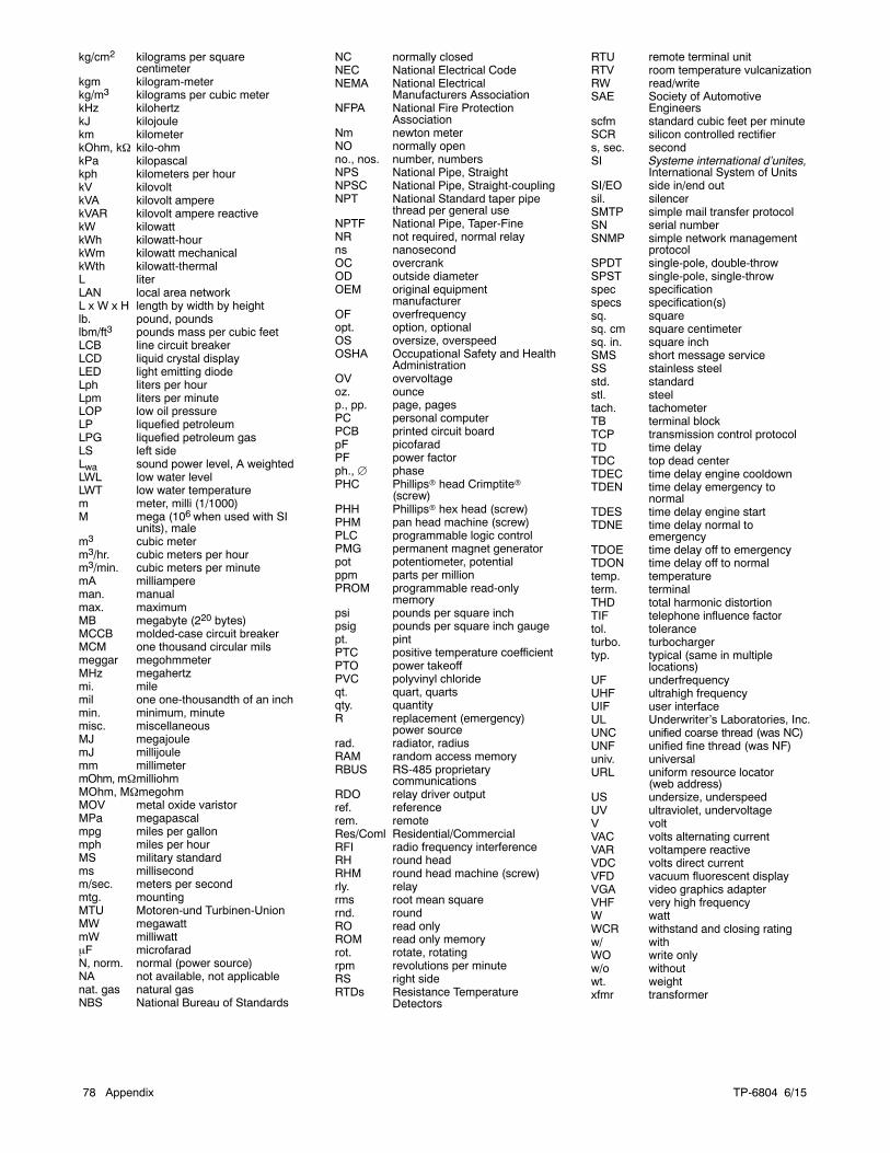
TP-6804 6/1578 Appendix
kg/cm2 kilograms per squarecentimeter
kgm kilogram-meterkg/m3 kilograms per cubic meterkHz kilohertzkJ kilojoulekm kilometerkOhm, k kilo-ohmkPa kilopascalkph kilometers per hourkV kilovoltkVA kilovolt amperekVAR kilovolt ampere reactivekW kilowattkWh kilowatt-hourkWm kilowatt mechanicalkWth kilowatt-thermalL literLAN local area networkL x W x H length by width by heightlb. pound, poundslbm/ft3 pounds mass per cubic feetLCB line circuit breakerLCD liquid crystal displayLED light emitting diodeLph liters per hourLpm liters per minuteLOP low oil pressureLP liquefied petroleumLPG liquefied petroleum gasLS left sideLwa sound power level, A weightedLWL low water levelLWT low water temperaturem meter, milli (1/1000)M mega (106 when used with SI
units), malem3 cubic meterm3/hr. cubic meters per hourm3/min. cubic meters per minutemA milliampereman. manualmax. maximumMB megabyte (220 bytes)MCCB molded-case circuit breakerMCM one thousand circular milsmeggar megohmmeterMHz megahertzmi. milemil one one-thousandth of an inchmin. minimum, minutemisc. miscellaneousMJ megajoulemJ millijoulemm millimetermOhm, mmilliohmMOhm, MmegohmMOV metal oxide varistorMPa megapascalmpg miles per gallonmph miles per hourMS military standardms millisecondm/sec. meters per secondmtg. mountingMTU Motoren-und Turbinen-UnionMW megawattmW milliwattF microfaradN, norm. normal (power source)NA not available, not applicablenat. gas natural gasNBS National Bureau of Standards
NC normally closedNEC National Electrical CodeNEMA National Electrical
Manufacturers AssociationNFPA National Fire Protection
AssociationNm newton meterNO normally openno., nos. number, numbersNPS National Pipe, StraightNPSC National Pipe, Straight-couplingNPT National Standard taper pipe
thread per general useNPTF National Pipe, Taper-FineNR not required, normal relayns nanosecondOC overcrankOD outside diameterOEM original equipment
manufacturerOF overfrequencyopt. option, optionalOS oversize, overspeedOSHA Occupational Safety and Health
AdministrationOV overvoltageoz. ouncep., pp. page, pagesPC personal computerPCB printed circuit boardpF picofaradPF power factorph., phasePHC Phillipsr head Crimptiter
(screw)PHH Phillipsr hex head (screw)PHM pan head machine (screw)PLC programmable logic controlPMG permanent magnet generatorpot potentiometer, potentialppm parts per millionPROM programmable read-only
memorypsi pounds per square inchpsig pounds per square inch gaugept. pintPTC positive temperature coefficientPTO power takeoffPVC polyvinyl chlorideqt. quart, quartsqty. quantityR replacement (emergency)
power sourcerad. radiator, radiusRAM random access memoryRBUS RS-485 proprietary
communicationsRDO relay driver outputref. referencerem. remoteRes/Coml Residential/CommercialRFI radio frequency interferenceRH round headRHM round head machine (screw)rly. relayrms root mean squarernd. roundRO read onlyROM read only memoryrot. rotate, rotatingrpm revolutions per minuteRS right sideRTDs Resistance Temperature
Detectors
RTU remote terminal unitRTV room temperature vulcanizationRW read/writeSAE Society of Automotive
Engineersscfm standard cubic feet per minuteSCR silicon controlled rectifiers, sec. secondSI Systeme international d’unites,
International System of UnitsSI/EO side in/end outsil. silencerSMTP simple mail transfer protocolSN serial numberSNMP simple network management
protocolSPDT single-pole, double-throwSPST single-pole, single-throwspec specificationspecs specification(s)sq. squaresq. cm square centimetersq. in. square inchSMS short message serviceSS stainless steelstd. standardstl. steeltach. tachometerTB terminal blockTCP transmission control protocolTD time delayTDC top dead centerTDEC time delay engine cooldownTDEN time delay emergency to
normalTDES time delay engine startTDNE time delay normal to
emergencyTDOE time delay off to emergencyTDON time delay off to normaltemp. temperatureterm. terminalTHD total harmonic distortionTIF telephone influence factortol. toleranceturbo. turbochargertyp. typical (same in multiple
locations)UF underfrequencyUHF ultrahigh frequencyUIF user interfaceUL Underwriter’s Laboratories, Inc.UNC unified coarse thread (was NC)UNF unified fine thread (was NF)univ. universalURL uniform resource locator
(web address)US undersize, underspeedUV ultraviolet, undervoltageV voltVAC volts alternating currentVAR voltampere reactiveVDC volts direct currentVFD vacuum fluorescent displayVGA video graphics adapterVHF very high frequencyW wattWCR withstand and closing ratingw/ withWO write onlyw/o withoutwt. weightxfmr transformer


E 2011, 2012, 2013, 2014, 2015 by Kohler Co. All rights reserved.
TP-6804 6/15j
KOHLER CO. Kohler, Wisconsin 53044Phone 920-457-4441, Fax 920-459-1646
Kohler Power SystemsAsia Pacific Headquarters7 Jurong Pier RoadSingapore 619159Phone (65) 6264-6422, Fax (65) 6264-6455
For the nearest KOHLER authorizedinstallation, service, and sales dealer inthe US and Canada:Call 1-800-544-2444 or visitKOHLERPower.com
Related Documents


