Abstract—This paper presents a recent study on robotic con- trol of a continuum manipulator. In view of nonlinear dynamic characteristics of its model, we propose a fuzzy logic controller that is designed based on state-feedback control of the system linearizations. First, a unified kinematic model and the Jacobi- ans are described. Then, we derive the state-space model form and linearize it at six operating points. Next, we design a con- troller for each linearized local model. Last, a fuzzy logic methodology is utilized to smoothly blend the six designed local controllers. The proposed controller is verified in MATLAB simulation and manipulator tip is autonomously navigated to the designated target. Besides, a comparison result for the optimized controller and the non-optimized counterpart is presented. I. INTRODUCTION Bio-inspired continuum manipulators resemble elephant trunks and octopus tentacles and exhibit a lot of unique and appealing features compared to conventional rigid-link ma- nipulators. Due mainly to their absence of rigid links, con- tinuum manipulators have the characteristics of continuously bending, infinite degree-of-freedom and compliant structures [1]. These features enable a wide range of maneuverability, especially for confined working environments. Therefore, there has been an increased interest in the specific problems pertaining to continuum manipulators for surgical applica- tions. Continuum-style robotic devices, such as active cathe- ters [2], flexible endoscopy [3] and robotic needles [4], have been developed and greatly boost the advancement of mini- mally invasive surgery (MIS) techniques. However, on the other hand, the added complexity and multi-functionality of bio-inspired design present many challenges that may not be present in the conventional rigid-link manipulator case. Cur- rent research interests are to explore novel continuum me- chanical design, integration of sensing techniques, optimal control strategies and intelligent motion planning/cognitive development. Research into continuum manipulators facing the different scenarios and the design level has led to more diverse actua- tion strategies than modular discrete manipulators [5]. One common style uses remotely actuated tendons to bend a con- tinuum structure. The prominent feature of tendon-based continuum manipulator design is implementation simplicity. In particular, it has been widely found in medical applications. *Resrach supported by European Commission's Seventh Framework Programme under grant agreement 287728 in the framework of EU project STIFF-FLOP, Postdoc Fund No. 138420 and the China Scholarship Council. P. Qi, C. Liu, H.-K. Lam and K. Althoefer are with the Centre for Robotics Research, Department of Informatics, King’s College London, WC2R 2LS, United Kingdom. (e-mail: [email protected]). L. Zhang and S. Wang are with the School of Mechanical Engineering, Tianjin University, Nankai District, Tianjin City, P. R. China. Most commercial catheters [6] integrate a single or groups of tendons that are routed along the body and produce torques at the maneuverable tip. Other flexible instruments including forceps, colonoscopes, endoscopes, etc. are realized in similar actuation mode for diagnostic and interventional purposes. While conventional manually operated procedures require the surgeons with extensive training to operate a continuum flexible instrument. Most often, the procedures also require holding the instrument for a long time, and in many instances expose the medical staff to high radiation dose. Thus, robotic solution to navigate the continuum manipulator inside the human body is of interest and has the potential to make a revolutionary impact in medicine. In the last two decades, there have been seen many new mechanisms emerged for continuum instrument based robotic surgery [7], [8]. Historically, a commercialized master-slave surgical telerobot – Sensei ® X robotic catheter system (Han- sen Medical) – has been designed to facilitate the access of ablation catheter to heart with pull-wire actuation and in- stinctive 3D control [6]. Despite the diversity in mechanical realization of actuation platforms, there exists the same pur- pose that is to replace the surgeons’ hands in manipulation. With regard to robotic control for continuum manipulators, researchers have proposed in-vivo feedback control to im- prove system performance during autonomous execution of command tracking tasks [9], [10]. A variety of intraoperative sensing techniques like electromagnetic tracking or intra- vascular ultrasound [11] are used to provide manipulator’s real-time pose, shape or other information, and based on that, closed-loop control strategies are investigated [12]. On the other hand, researchers have done a lot of research in kine- matic/dynamic modeling in order to predict continuum structure behavior [2], [13]. From the perspective of control theory, this model-based prediction acts as feedforward component of a closed loop. And the more precise the pre- diction of catheter behavior is, the better the feedback control performance will be. However, in contrast, considering that continuum manipulator articulates due to inherent compliance and conforms based on unknown constraints and obstacles the authors of [14] firstly utilize a task-space closed-loop con- troller that is only based on empirical estimates of the re- al-time Jacobian but without using a model. In this paper we investigate the feasibility of fuzzy logic control methodology that combines multiple state-feedback controllers to regulate the tip position of a catheter-like con- tinuum manipulator. Firstly, a unified constant-curvature based kinematic model and its Jacobians are derived in Sec- tion III, which later will be converted to state-space model form. Secondly in Section IV, we carry out an off-line line- arization of the state-space represented model at several tip Fuzzy Logic Control of a Continuum Manipulator for Surgical Applications Peng Qi, Chuang Liu, Linan Zhang, Shuxin Wang, Hak-Keung Lam, Kaspar Althoefer P. Qi, C. Liu, L. Zhang, S. Wang, H. K. Lam, K. Althoefer. “Fuzzy Logic Control of a Continuum Manipulator for Surgical Applications”, in IEEE International Conference on Robotics and Biomimetics (ROBIO’14), Bali, Indonesia, 2014

Welcome message from author
This document is posted to help you gain knowledge. Please leave a comment to let me know what you think about it! Share it to your friends and learn new things together.
Transcript
�
Abstract—This paper presents a recent study on robotic con-trol of a continuum manipulator. In view of nonlinear dynamic characteristics of its model, we propose a fuzzy logic controller that is designed based on state-feedback control of the system linearizations. First, a unified kinematic model and the Jacobi-ans are described. Then, we derive the state-space model form and linearize it at six operating points. Next, we design a con-troller for each linearized local model. Last, a fuzzy logic methodology is utilized to smoothly blend the six designed local controllers. The proposed controller is verified in MATLAB simulation and manipulator tip is autonomously navigated to the designated target. Besides, a comparison result for the optimized controller and the non-optimized counterpart is presented.
I. INTRODUCTION
Bio-inspired continuum manipulators resemble elephant trunks and octopus tentacles and exhibit a lot of unique and appealing features compared to conventional rigid-link ma-nipulators. Due mainly to their absence of rigid links, con-tinuum manipulators have the characteristics of continuously bending, infinite degree-of-freedom and compliant structures [1]. These features enable a wide range of maneuverability, especially for confined working environments. Therefore, there has been an increased interest in the specific problems pertaining to continuum manipulators for surgical applica-tions. Continuum-style robotic devices, such as active cathe-ters [2], flexible endoscopy [3] and robotic needles [4], have been developed and greatly boost the advancement of mini-mally invasive surgery (MIS) techniques. However, on the other hand, the added complexity and multi-functionality of bio-inspired design present many challenges that may not be present in the conventional rigid-link manipulator case. Cur-rent research interests are to explore novel continuum me-chanical design, integration of sensing techniques, optimal control strategies and intelligent motion planning/cognitive development.
Research into continuum manipulators facing the different scenarios and the design level has led to more diverse actua-tion strategies than modular discrete manipulators [5]. One common style uses remotely actuated tendons to bend a con-tinuum structure. The prominent feature of tendon-based continuum manipulator design is implementation simplicity. In particular, it has been widely found in medical applications.
*Resrach supported by European Commission's Seventh Framework
Programme under grant agreement 287728 in the framework of EU project STIFF-FLOP, Postdoc Fund No. 138420 and the China Scholarship Council.
P. Qi, C. Liu, H.-K. Lam and K. Althoefer are with the Centre for Robotics Research, Department of Informatics, King’s College London, WC2R 2LS, United Kingdom. (e-mail: [email protected]).
L. Zhang and S. Wang are with the School of Mechanical Engineering, Tianjin University, Nankai District, Tianjin City, P. R. China.
Most commercial catheters [6] integrate a single or groups of tendons that are routed along the body and produce torques at the maneuverable tip. Other flexible instruments including forceps, colonoscopes, endoscopes, etc. are realized in similar actuation mode for diagnostic and interventional purposes. While conventional manually operated procedures require the surgeons with extensive training to operate a continuum flexible instrument. Most often, the procedures also require holding the instrument for a long time, and in many instances expose the medical staff to high radiation dose. Thus, robotic solution to navigate the continuum manipulator inside the human body is of interest and has the potential to make a revolutionary impact in medicine.
In the last two decades, there have been seen many new mechanisms emerged for continuum instrument based robotic surgery [7], [8]. Historically, a commercialized master-slave surgical telerobot – Sensei® X robotic catheter system (Han-sen Medical) – has been designed to facilitate the access of ablation catheter to heart with pull-wire actuation and in-stinctive 3D control [6]. Despite the diversity in mechanical realization of actuation platforms, there exists the same pur-pose that is to replace the surgeons’ hands in manipulation.
With regard to robotic control for continuum manipulators, researchers have proposed in-vivo feedback control to im-prove system performance during autonomous execution of command tracking tasks [9], [10]. A variety of intraoperative sensing techniques like electromagnetic tracking or intra-vascular ultrasound [11] are used to provide manipulator’s real-time pose, shape or other information, and based on that, closed-loop control strategies are investigated [12]. On the other hand, researchers have done a lot of research in kine-matic/dynamic modeling in order to predict continuum structure behavior [2], [13]. From the perspective of control theory, this model-based prediction acts as feedforward component of a closed loop. And the more precise the pre-diction of catheter behavior is, the better the feedback control performance will be. However, in contrast, considering that continuum manipulator articulates due to inherent compliance and conforms based on unknown constraints and obstacles the authors of [14] firstly utilize a task-space closed-loop con-troller that is only based on empirical estimates of the re-al-time Jacobian but without using a model.
In this paper we investigate the feasibility of fuzzy logic control methodology that combines multiple state-feedback controllers to regulate the tip position of a catheter-like con-tinuum manipulator. Firstly, a unified constant-curvature based kinematic model and its Jacobians are derived in Sec-tion III, which later will be converted to state-space model form. Secondly in Section IV, we carry out an off-line line-arization of the state-space represented model at several tip
Fuzzy Logic Control of a Continuum Manipulator for Surgical Applications
Peng Qi, Chuang Liu, Linan Zhang, Shuxin Wang, Hak-Keung Lam, Kaspar Althoefer
P. Qi, C. Liu, L. Zhang, S. Wang, H. K. Lam, K. Althoefer. “Fuzzy Logic Control of a Continuum Manipulator for Surgical Applications”, in IEEE International Conference on Robotics and Biomimetics (ROBIO’14), Bali, Indonesia, 2014
x y
z (zb)
xb
yb
p
zd
ε
α
yd
r=1/k
O
s
positions. And then we design specific linear controller for each local model. At last, fuzzy logic methodology is em-ployed to smoothly blend those designed local controllers to obtain a nonlinear controller. Simulation results and analysis are reported in Section V. Section VI gives conclusion and plan for future work. Below we begin with Section II by giving a brief overview of common robotic actuation platform.
II. SYSTEM OVERVIEW
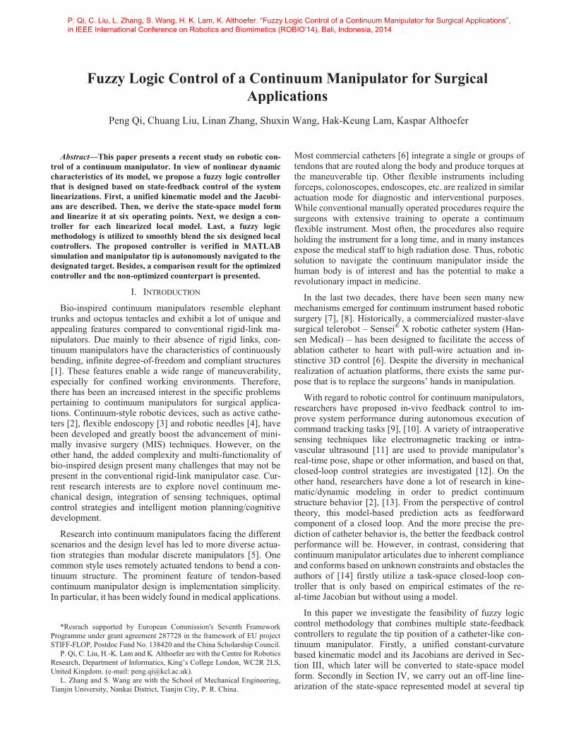
In order to steer a continuum manipulator, an exemplary robotic platform prototype is shown in Fig. 1. It is a general design in function used for tendon-driven surgical continuum instruments. This platform can be described as an arrangement of three decoupled degrees of freedom (3-DOF): The con-tinuum manipulator is mounted on the upper deck of the ro-botic platform. Here only a single tendon is routed along the continuum manipulator and driven by a Maxon brushless motor (DC motor EC-max 16, 8W) with the bending knob. It achieves one DOF to bend the flexible manipulator; another rotary motor is used to axially rotate the continuum manipu-lator mounted deck, which gives the manipulator an extra rotational DOF; the third DOF is to realize the translational shifting of the continuum manipulator via a ball screw.
Rotation
Translation
Bending KnobContinuum Maniuptor
Figure 1. 3-DOF robotic platform with a surgical manipulator attached.
III. KINEMATICS AND JACOBIANS
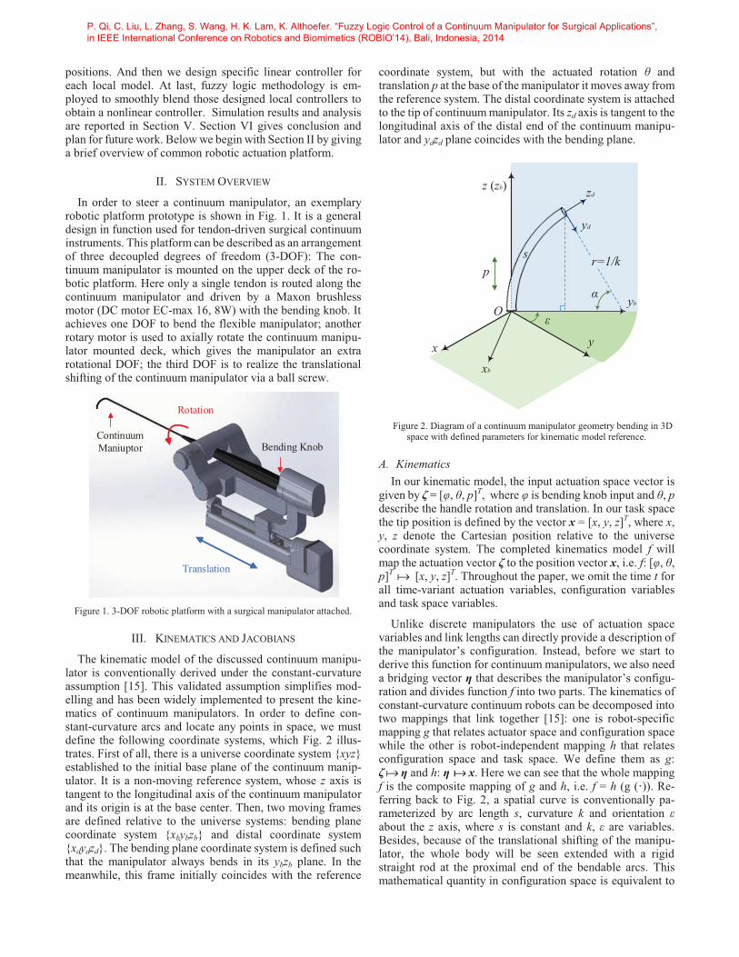
The kinematic model of the discussed continuum manipu-lator is conventionally derived under the constant-curvature assumption [15]. This validated assumption simplifies mod-elling and has been widely implemented to present the kine-matics of continuum manipulators. In order to define con-stant-curvature arcs and locate any points in space, we must define the following coordinate systems, which Fig. 2 illus-trates. First of all, there is a universe coordinate system {xyz} established to the initial base plane of the continuum manip-ulator. It is a non-moving reference system, whose z axis is tangent to the longitudinal axis of the continuum manipulator and its origin is at the base center. Then, two moving frames are defined relative to the universe systems: bending plane coordinate system {xbybzb} and distal coordinate system {xdydzd}. The bending plane coordinate system is defined such that the manipulator always bends in its ybzb plane. In the meanwhile, this frame initially coincides with the reference
coordinate system, but with the actuated rotation θ and translation p at the base of the manipulator it moves away from the reference system. The distal coordinate system is attached to the tip of continuum manipulator. Its zd axis is tangent to the longitudinal axis of the distal end of the continuum manipu-lator and ydzd plane coincides with the bending plane.
Figure 2. Diagram of a continuum manipulator geometry bending in 3D space with defined parameters for kinematic model reference.
A. Kinematics In our kinematic model, the input actuation space vector is
given by ζ = [φ, θ, p]T, where φ is bending knob input and θ, p describe the handle rotation and translation. In our task space the tip position is defined by the vector x = [x, y, z]T, where x, y, z denote the Cartesian position relative to the universe coordinate system. The completed kinematics model f will map the actuation vector ζ to the position vector x, i.e. f: [φ, θ, p]T [x, y, z]T. Throughout the paper, we omit the time t for all time-variant actuation variables, configuration variables and task space variables.
Unlike discrete manipulators the use of actuation space variables and link lengths can directly provide a description of the manipulator’s configuration. Instead, before we start to derive this function for continuum manipulators, we also need a bridging vector η that describes the manipulator’s configu-ration and divides function f into two parts. The kinematics of constant-curvature continuum robots can be decomposed into two mappings that link together [15]: one is robot-specific mapping g that relates actuator space and configuration space while the other is robot-independent mapping h that relates configuration space and task space. We define them as g: ζ η and h: η x. Here we can see that the whole mapping f is the composite mapping of g and h, i.e. f = h (g (·)). Re-ferring back to Fig. 2, a spatial curve is conventionally pa-rameterized by arc length s, curvature k and orientation ε about the z axis, where s is constant and k, ε are variables. Besides, because of the translational shifting of the manipu-lator, the whole body will be seen extended with a rigid straight rod at the proximal end of the bendable arcs. This mathematical quantity in configuration space is equivalent to
P. Qi, C. Liu, L. Zhang, S. Wang, H. K. Lam, K. Althoefer. “Fuzzy Logic Control of a Continuum Manipulator for Surgical Applications”, in IEEE International Conference on Robotics and Biomimetics (ROBIO’14), Bali, Indonesia, 2014
the translation variable p in actuation space. Therefore, our bridging vector comprises variable terms η = [k, ε, p]T. In our defined coordinate systems, curvature k can only be positive values (k > 0) such that the continuum manipulator produces bending toward the +y axis about the +z axis, and orientation ε starts from the +y axis. We use this convention throughout the paper.
In order to derive h, we start by looking at Fig. 2. Given radius r = 1/k and bending angle α = ks, we calculate the tip position on the ybzb plane to be
0(1 cos ) /
sin /
xy kz k
��
� � � �� � � �� � � � �� � � � � �
(1)
After that, we rotate the planar model toward anticlockwise direction about the z axis and obtain a spatial model as shown in Fig. 2. The derivation of spatial position coordinates is obtained by rotating the yz positions about the z axis using the rotation matrix Rz (ε). It is noted that for single tendon steered manipulator the orientation ε of arc parameters is directly equal to the actuated handle rotation θ.
In the next step we consider the displacement p of the prismatic joint. Since the prismatic joint translates the ma-nipulator along the z axis we simply add p to the z coordinate such that z = (sin α)/k + p. We finally obtain the pose vector x as a function of the bridging parameters k, ε, p, thus com-pleting the h mapping.
sin (1 cos( ))1 cos (1 cos( ))
sin( )
x ksy ks
kz ks pk
��
� � � �� � � �� � � � �� � � � � �
(2)
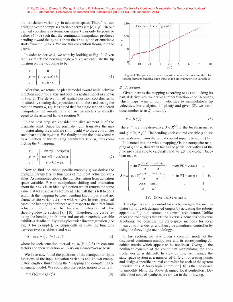
Now to find the robot-specific mapping g we derive the bridging parameters as functions of the input actuation vari-ables. As mentioned above, the transformation from actuation space variables θ, p to manipulator shifting and orientation about the z axis is an identity function which returns the same value that was used as its argument. Then all that’s left to do is establish the mapping between bending knob input φ and arc characteristic variable k (or α with α = ks). In most practical cases, the bending is nonlinear with respect to the direct knob actuation input due to backlash behavior of the sheath-guidewire system [8], [10]. Therefore, the curve re-lating the bending knob input and arc characteristic variable exhibits a deadband. By using piecewise linear regression (see Fig. 3 for example), we empirically estimate the functions between two variables φ and α as
l lm n� �� , l= 1, 2, 3 (3)
where for each actuation interval, ml, nl (l= 1,2,3) are constant factors and their selection will vary on a case-by-case basis.
We have now found the positions of the manipulator tip as functions of the input actuation variables and known manip-ulator length s, thus finding the f mapping and completing the kinematic model. We could also use vector notion to write it
x = f (ζ) = h (g (ζ)) (4)
Figure 3. The piecewise linear regression curves for modeling the rela-
tionship between bending knob input φ and arc characteristic variable α.
B. Jacobians Given there is the mapping according to (4) and taking its
partial derivatives, we derive another function – the Jacobians, which maps actuator input velocities to manipulator’s tip velocities. For analytical simplicity and given (3), we intro-duce another term �̂� to satisfy
ˆ ˆ( )� ˆ( )� ˆx J �� � (5)
where (˙) is a time derivative, 3 3��J R is the Jocabian matrix and �̂� = [α, θ, p]T. The bending knob control variable φ at last can be derived from the virtual control input α based on (3).
It is noted that the whole mapping f is the composite map-ping of g and h, thus when taking the partial derivatives of the f we use chain rule to calculate, and we get the explicit Jaco-bian matrix
2
2
2
sin 1 cossin ( ) cos (1 cos ) 0
sin 1 coscos ( ) sin (1 cos ) 0
cos sin 10
s
s
� �� � �� �� �� � �
� �� �
� �
� � � �� �
� �� � �� �� �� � �
J (6)
IV. CONTROL SYNTHESIS
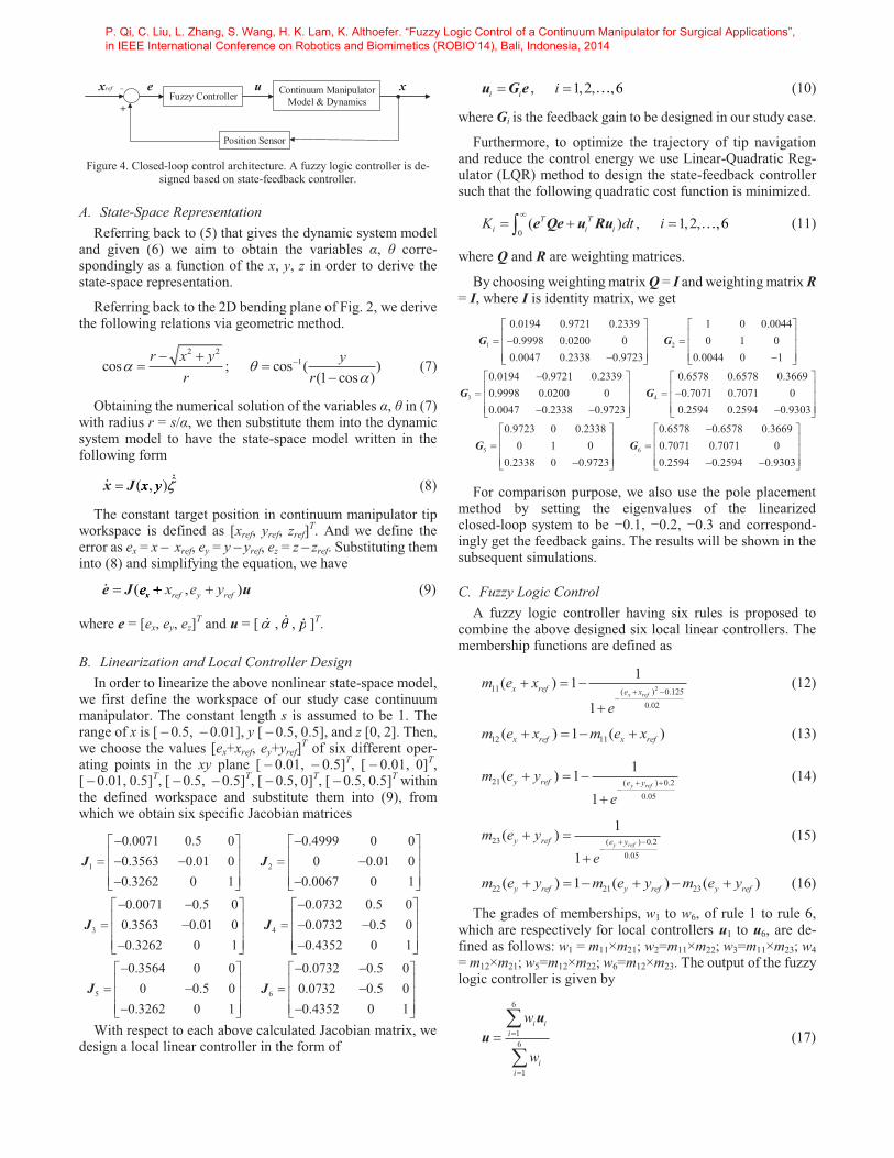
The objective of the control task is to navigate the manip-ulator tip to reach designated targets by actuating the robotic apparatus. Fig. 4 illustrates the control architecture. Unlike other control designs that utilize inverse kinematics or inverse Jacobians, we consider the state-space methods for local linear controller design and then give a nonlinear controller by using the fuzzy logic methodology.
In last section, we have given a common model of the discussed continuum manipulator and its corresponding Ja-cobian matrix which appear to be nonlinear. Owing to the nonlinear dynamic of the continuum manipulator, the con-troller design is difficult. In view of this, we linearize the state-space system at a number of different operating points and design a specific optimal controller for each of the system linearizations. A fuzzy logic controller [16] is then proposed to smoothly blend the above designed local controllers. De-tails about control synthesis are shown in the following.
0 10 20 30 40 50 60 70 800
50
100
150
,(/
)
'(/)
Piecewise linear regression
P. Qi, C. Liu, L. Zhang, S. Wang, H. K. Lam, K. Althoefer. “Fuzzy Logic Control of a Continuum Manipulator for Surgical Applications”, in IEEE International Conference on Robotics and Biomimetics (ROBIO’14), Bali, Indonesia, 2014
Position Sensor
Continuum ManipulatorModel & Dynamics
x−
+
uFuzzy Controller
xref e
Figure 4. Closed-loop control architecture. A fuzzy logic controller is de-
signed based on state-feedback controller.
A. State-Space Representation Referring back to (5) that gives the dynamic system model
and given (6) we aim to obtain the variables α, θ corre-spondingly as a function of the x, y, z in order to derive the state-space representation.
Referring back to the 2D bending plane of Fig. 2, we derive the following relations via geometric method.
2 21cos ; cos ( )
(1 cos )r x y y
r r� �
�
� �
(7)
Obtaining the numerical solution of the variables α, θ in (7) with radius r = s/α, we then substitute them into the dynamic system model to have the state-space model written in the following form
ˆ( , )x y� ˆ( , )y,�x J �� (8)
The constant target position in continuum manipulator tip workspace is defined as [xref, yref, zref]T. And we define the error as ex = x xref, ey = y yref, ez = z zref. Substituting them into (8) and simplifying the equation, we have
( , )x ref y refe x e y� ( xx� (e J u (9)
where e = [ex, ey, ez]T and u = [�� ,�� , pp ]T.
B. Linearization and Local Controller Design In order to linearize the above nonlinear state-space model,
we first define the workspace of our study case continuum manipulator. The constant length s is assumed to be 1. The range of x is [ 0.5, 0.01], y [ 0.5, 0.5], and z [0, 2]. Then, we choose the values [ex+xref, ey+yref]T of six different oper-ating points in the xy plane [ 0.01, 0.5]T, [ 0.01, 0]T, [ 0.01, 0.5]T, [ 0.5, 0.5]T, [ 0.5, 0]T, [ 0.5, 0.5]T within the defined workspace and substitute them into (9), from which we obtain six specific Jacobian matrices
1 2
3 4
5
0.0071 0.5 0 0.4999 0 00.3563 0.01 0 0 0.01 00.3262 0 1 0.0067 0 1
0.0071 0.5 0 0.0732 0.5 00.3563 0.01 0 0.0732 0.5 00.3262 0 1 0.4352 0 1
0.3564 0 00 0.5 0
0.3262
� � � �� � � �� � � � � �� � � � � �
� � � �� � � �� � � � � �� � � � � �
�
J J
J J
J 6
0.0732 0.5 00.0732 0.5 0
0 1 0.4352 0 1
� � � �� � � �� � � � �� � � � � �
J
With respect to each above calculated Jacobian matrix, we design a local linear controller in the form of
, 1,2, ,6i i i� � ,6u G e (10)
where Gi is the feedback gain to be designed in our study case.
Furthermore, to optimize the trajectory of tip navigation and reduce the control energy we use Linear-Quadratic Reg-ulator (LQR) method to design the state-feedback controller such that the following quadratic cost function is minimized.
0( ) , 1,2, ,6T T
i i iK dt i�
� �� ,6e Qe u Ru (11)
where Q and R are weighting matrices.
By choosing weighting matrix Q = I and weighting matrix R = I, where I is identity matrix, we get
1 2
3 4
0.0194 0.9721 0.2339 1 0 0.00440.9998 0.0200 0 0 1 0
0.0047 0.2338 0.9723 0.0044 0 1
0.0194 0.9721 0.2339 0.6578 0.6578 0.36690.9998 0.0200 0 0.7071 0.7071 00.0047 0.2338 0.9723 0.2
� � � �� � � �� �� � � �� � � � � �
� �� �� � � �� � �
G G
G G
5 6
594 0.2594 0.9303
0.9723 0 0.2338 0.6578 0.6578 0.36690 1 0 0.7071 0.7071 0
0.2338 0 0.9723 0.2594 0.2594 0.9303
� �� �� �� � �
� � � �� � � �� �� � � �� � � � � �
G G
For comparison purpose, we also use the pole placement method by setting the eigenvalues of the linearized closed-loop system to be −0.1, −0.2, −0.3 and correspond-ingly get the feedback gains. The results will be shown in the subsequent simulations.
C. Fuzzy Logic Control A fuzzy logic controller having six rules is proposed to
combine the above designed six local linear controllers. The membership functions are defined as
211 ( ) 0.1250.02
1( ) 1
1x ref
x ref e xm e x
e
�
(12)
12 11( ) 1 ( )x ref x refm e x m e x � (13)
21 ( ) 0.20.05
1( ) 11
y refy ref e ym e ye
�
(14)
23 ( ) 0.20.05
1( )1
y refy ref e ym e ye
�
(15)
22 21 23( ) 1 ( ) ( )y ref y ref y refm e y m e y m e y � (16)
The grades of memberships, w1 to w6, of rule 1 to rule 6, which are respectively for local controllers u1 to u6, are de-fined as follows: w1 = m11×m21; w2=m11×m22; w3=m11×m23; w4 = m12×m21; w5=m12×m22; w6=m12×m23. The output of the fuzzy logic controller is given by
6
16
1
i ii
ii
w
w
�
�
��
�
uu (17)
P. Qi, C. Liu, L. Zhang, S. Wang, H. K. Lam, K. Althoefer. “Fuzzy Logic Control of a Continuum Manipulator for Surgical Applications”, in IEEE International Conference on Robotics and Biomimetics (ROBIO’14), Bali, Indonesia, 2014
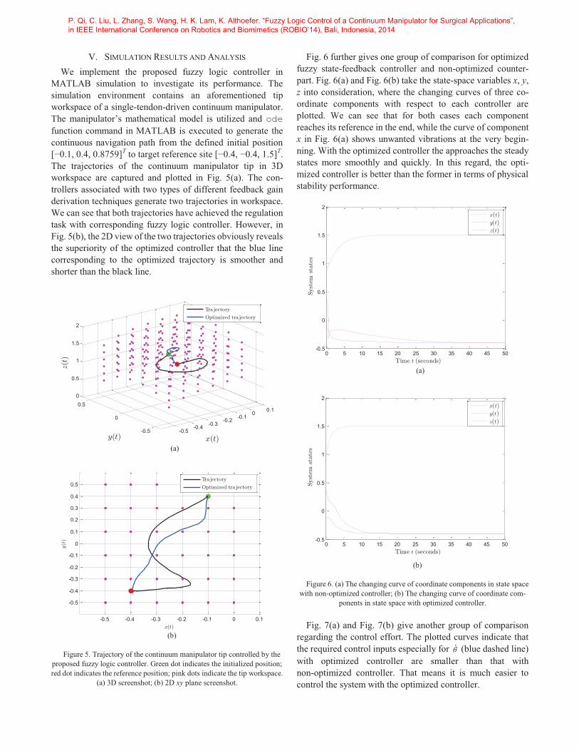
V. SIMULATION RESULTS AND ANALYSIS We implement the proposed fuzzy logic controller in
MATLAB simulation to investigate its performance. The simulation environment contains an aforementioned tip workspace of a single-tendon-driven continuum manipulator. The manipulator’s mathematical model is utilized and ode function command in MATLAB is executed to generate the continuous navigation path from the defined initial position [−0.1, 0.4, 0.8759]T to target reference site [−0.4, −0.4, 1.5]T. The trajectories of the continuum manipulator tip in 3D workspace are captured and plotted in Fig. 5(a). The con-trollers associated with two types of different feedback gain derivation techniques generate two trajectories in workspace. We can see that both trajectories have achieved the regulation task with corresponding fuzzy logic controller. However, in Fig. 5(b), the 2D view of the two trajectories obviously reveals the superiority of the optimized controller that the blue line corresponding to the optimized trajectory is smoother and shorter than the black line.
-0.5-0.4 -0.3
-0.2 -0.10 0.1
-0.5
0
0.50
0.5
1
1.5
2
x(t)y(t)
z(t)
Tra jectory
Optimized tra jectory
(a)
-0.5 -0.4 -0.3 -0.2 -0.1 0 0.1
-0.5
-0.4
-0.3
-0.2
-0.1
0
0.1
0.2
0.3
0.4
0.5
x(t)
y(t
)
Tra jectory
Optimized tra jectory
(b)
Figure 5. Trajectory of the continuum manipulator tip controlled by the
proposed fuzzy logic controller. Green dot indicates the initialized position; red dot indicates the reference position; pink dots indicate the tip workspace.
(a) 3D screenshot; (b) 2D xy plane screenshot.
Fig. 6 further gives one group of comparison for optimized fuzzy state-feedback controller and non-optimized counter-part. Fig. 6(a) and Fig. 6(b) take the state-space variables x, y, z into consideration, where the changing curves of three co-ordinate components with respect to each controller are plotted. We can see that for both cases each component reaches its reference in the end, while the curve of component x in Fig. 6(a) shows unwanted vibrations at the very begin-ning. With the optimized controller the approaches the steady states more smoothly and quickly. In this regard, the opti-mized controller is better than the former in terms of physical stability performance.
0 5 10 15 20 25 30 35 40 45 50-0.5
0
0.5
1
1.5
2
Syst
emst
ate
s
Time t (seconds)
x(t)
y(t)
z(t)
(a)
0 5 10 15 20 25 30 35 40 45 50-0.5
0
0.5
1
1.5
2
Syst
emst
ate
s
Time t (seconds)
x(t)
y(t)
z(t)
(b)
Figure 6. (a) The changing curve of coordinate components in state space with non-optimized controller; (b) The changing curve of coordinate com-
ponents in state space with optimized controller.
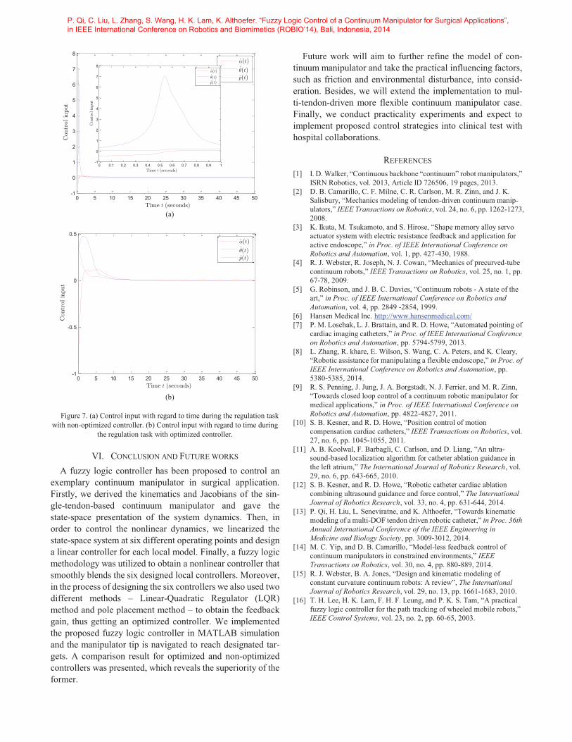
Fig. 7(a) and Fig. 7(b) give another group of comparison regarding the control effort. The plotted curves indicate that the required control inputs especially for �� (blue dashed line) with optimized controller are smaller than that with non-optimized controller. That means it is much easier to control the system with the optimized controller.
P. Qi, C. Liu, L. Zhang, S. Wang, H. K. Lam, K. Althoefer. “Fuzzy Logic Control of a Continuum Manipulator for Surgical Applications”, in IEEE International Conference on Robotics and Biomimetics (ROBIO’14), Bali, Indonesia, 2014
0 5 10 15 20 25 30 35 40 45 50
-1
0
1
2
3
4
5
6
7
8
Contr
olin
put
Time t (seconds)
_,(t)_3(t)_p(t)
(a)
0 5 10 15 20 25 30 35 40 45 50
-1
-0.5
0
0.5
Contr
olin
put
Time t (seconds)
_,(t)_3(t)_p(t)
(b)
Figure 7. (a) Control input with regard to time during the regulation task with non-optimized controller. (b) Control input with regard to time during
the regulation task with optimized controller.
VI. CONCLUSION AND FUTURE WORKS A fuzzy logic controller has been proposed to control an
exemplary continuum manipulator in surgical application. Firstly, we derived the kinematics and Jacobians of the sin-gle-tendon-based continuum manipulator and gave the state-space presentation of the system dynamics. Then, in order to control the nonlinear dynamics, we linearized the state-space system at six different operating points and design a linear controller for each local model. Finally, a fuzzy logic methodology was utilized to obtain a nonlinear controller that smoothly blends the six designed local controllers. Moreover, in the process of designing the six controllers we also used two different methods – Linear-Quadratic Regulator (LQR) method and pole placement method – to obtain the feedback gain, thus getting an optimized controller. We implemented the proposed fuzzy logic controller in MATLAB simulation and the manipulator tip is navigated to reach designated tar-gets. A comparison result for optimized and non-optimized controllers was presented, which reveals the superiority of the former.
Future work will aim to further refine the model of con-tinuum manipulator and take the practical influencing factors, such as friction and environmental disturbance, into consid-eration. Besides, we will extend the implementation to mul-ti-tendon-driven more flexible continuum manipulator case. Finally, we conduct practicality experiments and expect to implement proposed control strategies into clinical test with hospital collaborations.
REFERENCES [1] I. D. Walker, “Continuous backbone “continuum” robot manipulators,”
ISRN Robotics, vol. 2013, Article ID 726506, 19 pages, 2013. [2] D. B. Camarillo, C. F. Milne, C. R. Carlson, M. R. Zinn, and J. K.
Salisbury, “Mechanics modeling of tendon-driven continuum manip-ulators,” IEEE Transactions on Robotics, vol. 24, no. 6, pp. 1262-1273, 2008.
[3] K. Ikuta, M. Tsukamoto, and S. Hirose, “Shape memory alloy servo actuator system with electric resistance feedback and application for active endoscope,” in Proc. of IEEE International Conference on Robotics and Automation, vol. 1, pp. 427-430, 1988.
[4] R. J. Webster, R. Joseph, N. J. Cowan, “Mechanics of precurved-tube continuum robots,” IEEE Transactions on Robotics, vol. 25, no. 1, pp. 67-78, 2009.
[5] G. Robinson, and J. B. C. Davies, “Continuum robots - A state of the art,” in Proc. of IEEE International Conference on Robotics and Automation, vol. 4, pp. 2849 -2854, 1999.
[6] Hansen Medical Inc. http://www.hansenmedical.com/ [7] P. M. Loschak, L. J. Brattain, and R. D. Howe, “Automated pointing of
cardiac imaging catheters,” in Proc. of IEEE International Conference on Robotics and Automation, pp. 5794-5799, 2013.
[8] L. Zhang, R. khare, E. Wilson, S. Wang, C. A. Peters, and K. Cleary, “Robotic assistance for manipulating a flexible endoscope,” in Proc. of IEEE International Conference on Robotics and Automation, pp. 5380-5385, 2014.
[9] R. S. Penning, J. Jung, J. A. Borgstadt, N. J. Ferrier, and M. R. Zinn, “Towards closed loop control of a continuum robotic manipulator for medical applications,” in Proc. of IEEE International Conference on Robotics and Automation, pp. 4822-4827, 2011.
[10] S. B. Kesner, and R. D. Howe, “Position control of motion compensation cardiac catheters,” IEEE Transactions on Robotics, vol. 27, no. 6, pp. 1045-1055, 2011.
[11] A. B. Koolwal, F. Barbagli, C. Carlson, and D. Liang, “An ultra-sound-based localization algorithm for catheter ablation guidance in the left atrium,” The International Journal of Robotics Research, vol. 29, no. 6, pp. 643-665, 2010.
[12] S. B. Kesner, and R. D. Howe, “Robotic catheter cardiac ablation combining ultrasound guidance and force control,” The International Journal of Robotics Research, vol. 33, no. 4, pp. 631-644, 2014.
[13] P. Qi, H. Liu, L. Seneviratne, and K. Althoefer, “Towards kinematic modeling of a multi-DOF tendon driven robotic catheter,” in Proc. 36th Annual International Conference of the IEEE Engineering in Medicine and Biology Society, pp. 3009-3012, 2014.
[14] M. C. Yip, and D. B. Camarillo, “Model-less feedback control of continuum manipulators in constrained environments,” IEEE Transactions on Robotics, vol. 30, no. 4, pp. 880-889, 2014.
[15] R. J. Webster, B. A. Jones, “Design and kinematic modeling of constant curvature continuum robots: A review”, The International Journal of Robotics Research, vol. 29, no. 13, pp. 1661-1683, 2010.
[16] T. H. Lee, H. K. Lam, F. H. F. Leung, and P. K. S. Tam, “A practical fuzzy logic controller for the path tracking of wheeled mobile robots,” IEEE Control Systems, vol. 23, no. 2, pp. 60-65, 2003.
0 0.1 0.2 0.3 0.4 0.5 0.6 0.7 0.8 0.9 1-1
0
1
2
3
4
5
6
7
8
Contr
olin
put
Time t (seconds)
_,(t)_3(t)_p(t)
P. Qi, C. Liu, L. Zhang, S. Wang, H. K. Lam, K. Althoefer. “Fuzzy Logic Control of a Continuum Manipulator for Surgical Applications”, in IEEE International Conference on Robotics and Biomimetics (ROBIO’14), Bali, Indonesia, 2014
Related Documents