Welcome message from author
This document is posted to help you gain knowledge. Please leave a comment to let me know what you think about it! Share it to your friends and learn new things together.
Transcript
I 1 This report has been reproduced directly from the best available copy.
Available to DOE and DOE contractors from the Office of Scientific and Techni- cal Information, P.O. Box 82. Oak Ridge, TN 37631; prices available from (815) 576-8401. FTS 828-8401.
Available to the public from the National Technical Informetion Service. U S Department of Commerce. 5285 Port Royal Rd. S ringfield. VA 22181.
NTlS price codes-Printed Copy: ~ Microfiche A01
I
A18
This report was prepared as an account of work sponsored by an agency of the United States Government. Neither the United States Government mn any agency thereof. nor any of their employees, makes any warranty, express or implied. or assumes any legal liability or responsibility for the accuracy, corn pleteness. or usefulness of any information, apparatus. product, or process dis- closed. or represents that its use would no1 infringe privately owned rights. Reference herein to any specific commercial product, process, or service by trade name, trademark, manufacturer. or otherwise. does not necessarily consti- tute or imply its endorsement, recommendation, or favoring by the United States Government or any agency thereof. The views and opinions of authors expressed herein do not necessarily state or reflect those of the United States Government or any agency thereof.
WE/ER-03 13/6 Distribution
UC-423, -424 categories
FUSION REACTOR MATERIALS SEMIANNUAL PROGRESS REPORT
FOR THE PERIOD ENDING MARCH 31, 1989
Date Published:
Prepared for WE W c e of Fusion Energy
(AT 15 02 03 A)
Prepared by OAK RIDGE NATIONAL LABORATORY
Oak R i e . Tennessee 37831 operated by
MARTIN MARIETTA ENERGY SYSTEMS, INC. for the
U.S. DEPARTMENT OF ENERGY under Contract DE-AC05-840R2 1400
Reports previously listed in this series are as follows:
DOE/ER-0313/1
DOE/ER0313/2
DOE/ER-03 13/3
DOE/ER-03 13/4
DOE/ER-0313/5
Period Ending September 30, 1986
Period Ending March 31, 1987
Period Ending September 30, 1987
Period Ending March 3 1, 1988
Period Ending September 30, 1988
.. I1
FOREWORD
This is the sixth in a series of semiannual technical progress reports on fusion reactor materials. This repon combines research and development activities which were previously reported separately in the following technical pmgress reports:
Special Purpose Materials
Alloy Development for Irradiation Performance
Damage Analysis and Fundamental Studies
These activities are concerned principally with the effects of the neutronic and chemical environment on the properties and performance of reactor materials; together they form one element of the overall materials program being conducted in support of the Magnetic Fusion Energy Program of the U.S. Department of Energy. The other major element of the program is con- cerned with the interactions between reactor materials and the plasma and is reported separateiy.
The purpose of this series of reports is to provide a working technical record for the use of the program participants, and to provide a means of communicating the efforts of materials scientists to the rest of the fusion community. both nationally and worldwide.
This report has been compiled and edited under the guidance of A. F. RowclHe, Oak Ridge National Laboratory, and D. G. Doran, Battelle-Pacific Northwest Laboratory. Their efforts, and the efforts of the many persons who made technical contribu- tions, are gratefully acknowledged. T. C. Reuther, Reactor Technologies Branch, has responsibilii within WE for the programs reported on in this document.
The Fusion Reactor Materials Program is a national effort involving several national laboratories, universities, and industries.
R. Price, Chief Reactor Technologies Branch Office of Fusion Energy
iii

TABLE OF CONTENTS
FOREWORD . . . . . . . . . . . . . . . . . . . . . . . . . . . . . . . . . . . . . . . . . . . . . . . . . . . . . . . . . . . . . . . . . . . . . . . . . . . . . . . . . . . . . . . . . .
1. IRRADIATION FACILITIES, TEST MATRICES, AND EXPERIMENTAL METHODS . . . . . . . . . . . . . . . . . . . . . . . . . . . . . . . . . . . 1
1.1 Design and Fabrication of HFIR-MFE RE* Spectrally Tailwed Irradiation Capsules-A. W. Longest (Oak Ridge National Laboratory), J. E. C o r m (Midwest Technical, Inc.), and 0. W. Heatherb (Oak Ridge National Laboratory) . . . . . . . . . . . . . . . . . . . . . . . . . . . . . . . . . . . . . . . . . . . . . . . . . . . . . . . . . . . . . . . . . . . 3
D&gn and fsbrication of fwr HFIRMFE RB. cap^ (60, ZW, 330. and WCJ m Smwnmodsm MFE spaimsns pimdatnd in -by t a m axpmimnts in ths ORR (and d t e d raifirv pmpmtims) (UO ~alhfsclrxr3r Thase wpsub dasi@m inmfpmnta provisions for remod, exmnbtion, and rbencapwbtion of ths M E spamaur at inter- mediate exposws IS* em mun, toa rsrgst enpcawe bvdof 24 ( h ~ t ~ 3 0 ) exc8plion of the 6WC capsub, when, the tastswdmns d b s in dbstcmrsct wim ths nvlcmaxhg water, ths qsci- men WnpsaMSs ( m o n i t o r e d by 21 fhemrocwyesl wiw ts contmwsd by r@on bshvan ths spechmw hoMsrand ths confsinmsnt rube. Hefniwn km-s wiwts ussd m tailor ths nnmon specmn, m clmsiymtch ths hsklKnprc&stkmtoam dispraanwntmtin (14 ~ / + 4 rurpscndin a fusion reactor %sr d.
psr a m IC43a). w i ths
ths tfmrmel condursna, of a smal gap
AssemMy of ths 60and33WCcaph is cmnplam andimn*stion of both wi#begkr when ths HF1Rreun-m to M p o w opwstion. D€=sign of the nmayling two 12W and W C ) c%Js&s is cmnplam, endiawe Of fsbriumbn as* is near. Fabrkation of parts andsssemMy of ths 2W and 4LWC capsubs is .qdmd&j for canpletion by ths end ofN 19m; omwetion of mssS two capsub WM fcfbw ths first two (60 and 3 3 0 0
1.2 Image Calculation of Tilted Contamination Deposit for the Thickness Measurement of specimen Foil- T. Sawai [Japan Atomic Energy Research Institute (JAERI), assigned to ORNL] and M. Suzuki, JAERI
A new inwing modelhas bnm to exdah sonm fwMSs ofthsiMgs lfommdbv msdconen*lation decvm microsmps OEM). The cslculstan mwsl that is ussd m determine the spechmw thick- h a !nnmmon
assum ths Utms with c b r contrast in ths imqie appsar when, ths surfwe oftlmncmntdnabon is parahi m ths imaging dsctron beam. The cakulafed rasUn expbina sonm features of ths scruel imqie re% d. Abo, the cakxlation shows the image shin. h k h lswls to an ovarestimabon of ths pardbx bsfwaa, two conmminabon ccfms, whkh lea& m ths overartimtion of the foil midinesr.
. .
1.3 Small-Scale Bending Fatigue specimen Development-6. A. Chin, G. R. Ron (Auburn University), and E. H. Lee (Oak Ridge National Laboratwy) . . . . . . . . . . . . . . . . . . . . . . . . . . . . . . . . . . . . . .
Two emakcale M n g fatigue teat apsdmens were dsdqmd. The first spechmw. tm-nmd ths -rectmg&f qsci- m n , has oversU diimnsioM of 30.1625 x 4.7625 x 0.762 m, wim e wuge renSa, of 6.35 mm. 7he unirraaated me mngukr spedmsns were tasted at both r m fmnpsrarwe and at 6WC.
The SecMdspeOimsn is a %-mrs-dk*spechmw with om% dimarsims of a 3- damster TraMmission Else won Mlcmswps spechmw and8 reducsdgs-senion fomad by two circular radii of 1.6 mm. The thidvn*rs is
0.264 mm. The mhisture specimsns w e fakicated whg three dafwsm tschnques: 11) punchinB fobwed by slectrp polishicg, 12) ekmriul di8charg.s mschining. and 131 punching fcfbwed by antmob. The three mts of miniamrs-dk specimens were tasted swmxdv at r m tanpasture.
rests were psrfmned wicg a m k d rvps 316 srainlsss snn~ I R & ~ ~ a s t 6092297). he rarohs WIYO found m conform m ths c o f f i r r ~ s ~ o n rebbonship, whae ths vehn, of the exponsnt was fwnd m k bstmwn 0.1 and 0.25. ~hsre was scum degradelion in fa- life for ths rscrsngulsr spsckna, at 6WC annpnred with ths roarrtempersrwe fa- dsta. The ministursdisc specimens pvs higher than sxpscted vahn#r of fa- &arm fw all thra, sets of spamaur. Both specimen a m r m be suits& fw sropine h&md spedmsns for farigus prqmrtk.
7
13
2. DOSIMETRY. DAMAGE PARAMETERS, AND ACTIVATION CALCULATIONS . . . . . . . . . . . . . . . . . . . . . . . . . . . . . . . . . . . . . 2 1
2.1 Neutron Dosimetry and Damage Calculations for the ORR-MFE 7 J Experiment-L. R. Greenwood (Argonne National Laboratory) . . . . . . . . . . . . . . . . . . . . . . . . . . . . . . . . . . . . . . . . . . . . . . . . . . . . . . . . . . . . . . . . . . . . . 23
Neutron nmoaurmts and damage cakuktions have bnm compbtad for dm jdnt U.S.-Japmmas 7J axpmimnt in the Oek Rid@ Research Reactor. Tensile and E M spsdmwnr WIYO irradiated from June 28, 1983, m 1475 fulkpower days) in papition C3 at mpsraturm behvan 3 W - W C . The mximum fast w o n fluenoe was 9.5 x d’ n/cn?. which produced 7.4 dpa and 102 appm M u m in 316 stainlass sresl.
26, 1967
V
2.2 Production of %, %o, and 03"'Nb near 14.7 MeV- L. R. Greenwood. D. L. Bowers, and A. I n t a m (Argonne National Laboratory) . . . . . . . . . . . . . . . . . . . . . . . . . . . . . . . . . . . . . . . . . . . . . . . . . . . . . . . . . . . . . . .
Results are m M for the produdon of -V (331 d), "MO (3500 y). 8nd93mNb 176 y) by 74 MeV new trons. Samples ware irrdiated at RTNS 11. Chemical separations were performed to remove impurities and to separate the MeNb fractions. Thin samples were then X-ray mnted. Resuhs predict that we will produce 28 mCi/cc of " V in vanadium and 2.8 mCi/cc of e3M0 and 108 mCi/cc of 03"'Nb in m-um in a fushm first-wall, assuming the STARFIRE reactor w.
2.3 Dosimetry and Damage Calculations for the ORR-MFE 4A/48 Spectral Tailoring Experiments- L. R. Greenwood (Argonne National Laboratory) . . . . . . . . . . . . . . . . . . . . . . . . . . . . . . . . . . . .
R& WEWWM for me MFE 4 A . h spectd arrpaimnar in me osx R- R- Reacnw. Thge
a m t s started with an alumhum mre- fikd with water, switdwd to a SOlidahdrwm me pats. and rkMv sddsd M i u m h s to suppress the themrsl nnmM Uux. The mxhm e m m for MFE 4A at 107.0 FPO 1223.1 FPD undar HFl was 4.2 x l d 2 n/&, r w in 13.1 dpa and243sppm IWwn for 318seinlslg sfsal. ~ f ~ ~ ~ ~ ~ 8 t 9 s 6 . 6 ~ ~ ~ / i z i . 8 ~ ~ ~ u n d e r ~ ~ 1 m n e 4 . o x r#n/&. - i n 1 2 . 0 d p a s n d ~ l e a p p n M u m for 3 16 stahJe9s s d .
2.4 Neutron Spectral Calculations for the REAL88 Exercisg-L. R. Greenwood and A. Intasorn (Argonne National Laboratory) . . . . . . . . . . . . . . . . . . . . . . . . . . . . . . . . . . . . . . . . . . . . .
Nsumn spxtral analpas and d a w cnlcubths haw bm mmpbred for six referems data sets dstrhted by the IAEA in Vhna. This interbboratwy inter- is hsbfmd to stamlndhs dosimeby t dm iwss and dsMos mlinatss for va- spscva induding fush reschw sim&tims, pressure vas-& swvdmm. *% fission. and f ~ n - r~amn.
The dam w'U bs reviswed at a mtiw in ECN P a m , The Nathmiands, in octobw 1988.
3.
4. FUNDAMENTAL MECHANICAL BEHAVIOR . . . . . . . . . . . . . .
MATERIALS ENGINEERING AND DESIGN REWIREMENTS
4.1 Grain Size Effect on Radiation Hardening in Neutron-Irradiated Pdycrystalline Copper4. Kqima, S. J. Zinkle (Oak Ridge National Laboratory). and H. L. Heinisch (Pacific Nwthwest Laboratory)
skclra, Micrmtructural c h n m in 14 MeV nnmorritradintui plwwtsh ~opplv were cbsrvaj by tmmmwon micrasropy and correlated w'th me vari&m of yitw mess. cm~ar t io~ l thwy of rsrlistwn hadsing was fawrd to bs mt
~ a p p l i c s M e t o p d y c r y s t a / s . ~a&tic+indwudporind&ctdustenrarec.ms&radmbemnsobsmdssmt&yto me motwn Of deha=ltimsOn thepil&upsid,ofapin, but& to thegsnerstwn ofc%sJoc8tiomrm t h e n s x t m . Gm? era&, applwbk simplikd wuatwns for p l w w t s / s are p r w . By .%dying me wueths to the @Wmd ensib teDt resub. the maibution of mtrk hnrddng was fwnd to bs fairlv low.
Spectral Effects-H. L. Heinisch (Pacific Northwest laboratory) . . . . . . . . .
. . . . . . . . . . . . . . . .
4.2 Correlation of Mechanical Propeny Changes in Neutron-Irradiated Pressure Vessel Steels on the Basis of
Defectprodircaon funcths daivsd from atomistic nwd&g were eMNvrM for use in Corrsrsling WsmrSS
140- 9PC) and low dosss KO. 1 dp) . The Yradinths m pafamed in RTNSII, O M , ORR. and the HFlR pr6asura vas-& s u w & ~ p i t i o n s . The data h n RTNSII, O M , and O R R m mrebtsd fairly d o n the beis of-, buf
from HFlR show thst m l y one hnth as m y dpa era nadsd to prcdme the yyne r e d a t i c + M ,.+& s t r e chmgm as in ttm othwneuTron qXXW.9. Abou? 96% of fhe mwvmas in the HFlRmwdnmxpDsirion are mWmal nwmnS, and a SW h n t frsction of* displaamenm ispmducsd byrewils from th.mnslnamon captures. The beat Corrsrsth of aU the data is schisved whsn t h e h s c h a w are ccmpmdon defats, which bsm represents the d a m parthipat@ in the rSllbtic+svm$hsnhl-.
c h e w of AZ 128 and A3028 WWUW WSSd St& W t e d h 8 wids VWbW Of nSUVm SpeCrrs 8t low fanpashWW
data
of thep-o&mon ' of h s t y m&,9fhg self-htenrfifid
5. RADIATION EFFECTS MECHANISTIC STUDIES, THEORY, MODELING . . . ,
5.1 Tensile Behavior and Swelling of Ternary Austenitic Alloys Irradiated in Different Neutron Spectra- M. L. Hamilton (Pacific Northwest Laboratory.) A. Okada (Hokkaido University), and F. A. Garner lPacific Northwest Laboratory) . . . . . . . . . . . . . . . . . . . . . . . . . . . . . . . . . . . . . . . . . .
rim rate on the microswucturai dsvslopment and tensile propshes of FeCI-Ni aUow are currently UnderBOng ' awmiMbon. hn, of fhese, conducted in the ORR at a hi&r He/& rete and a lower aspracemat tratacompsred with the otha
Two nominal& idantical experimsnts &sipad 10 sluly the effms of nidrsl level. chmnium l ed , and hMm gsnrs-
. . . .
. . . . .
. . . .
27
29
. . . . 37
39
41
43
51
5 7
5 9
vi
expxinmnt in EBRII, show substanfiaXy mon s t r m # t h W ' andadf fwar t ranpastumrsngsofsm. Theeffscnof irradiation mnpsratws, neutron rsUx. and mutrm epstra sppasr m bs krger than thare of the " I M l i S b b n S S *
died. TrsMmireion skntron rnkrmxpy (7EMJamninstion k inprogreap m dsfwmna the origin of the observsdchenges.
5.2 Radiation-Induced Spinodal-Like Decomposition of FeCr-Ni Allow and Its Influence on Electropolishing of Microscwy Disks-J. M. McCarthy and F. A. Garner (Pacific Northwest Laboratory) . . . . . . . . . . . . . . . . . . . . . . . . . . 73
Scanning skntron m i c r m x p y was used as a fool ro inveatinate the dspsndencs on nickel content of radiatkm induced spinodscliks - i t h in Fs- 160-XNi alloys. It appesrs that the relativs rapisfsnce ro sw&l~ observsd in the
pmkxgicg the loopdominsred phase of dislocstion svoMiDn end also suppresekg the DnDer of mxsixand wid growth hss nor yer ban demmined.
lnvar mnpo&bml reginw ar 6 1 0 C is murrent with winod&Iike dscompasmon " . T h e i n l 9 u s n m o f t h i s ~ i n
5.3 Microstructural Examination of a Reactor-Irradiated Dilute Copper-Boron Alloy-S. J. tinkle (Oak Ridge National Laboratory) . . . . . . . . . . . . . . . . . . . . . . . . . . . . . . . . . . . . . . . . . . . . . . . . . . . . . . . . . . . . . . . . . . . 77
irmdistmj with fission I W U ~ ro - 1.2 dpa ar a &- rare o f 2 x 1 0 - ~ d p a / ~ . A MIOM- disuitmion ofcsvitas was obswvsd for the irr&ation rempers~slr of 182 mmgh 6 W C e a a result of the gsnsrah of lOOappm He dwho the h&lion. stecking faun rerrawa were also observsd at an irradialion tempsranrss. Common ' withpuremppa SPedmeM imrdiend in the earns cspsurs n w ssvwsl inmesling dwwmcss in the micms-m, a e w t
An initial micmstrmtwd mamination has ban pafomwd on mppa spschms contahbo -20 wtppn 8 that wmn
snhsnawnenr in the SFTdsnsirv at an rsmpastwes and the presence of voids at 187C h the mPp%boron spnchms.
5.4 Radiation Damage in Binary Ceramic Oxides: A Preliminary ModeCRcger E. Stoller (Oak Riw National Laboratory) . . . . . . . . . . . . . . . . . . . . . . . . . . . . . . . . . . . . . . . 85
A prdmhry modsl of r&& &- in Lhwy ceramic ox& hss ban d e w . Ths modsl dsscnbrlhere Bccwnrs in an approxime w y for a m of the mslw Mfemnms bnmnm rnstanic.4wa andcmmnim thet are bdavsd to be res& for the fact rhat ceramic materia$ are observsd m behave dffs~sntlv than r n s W &p whw, expmsd to dspkdve irr&lion. The modsl considsrs the in- of mS sxisrena, of a d k t h and the -1 m~treim of sr&hicmsbicpoint defect absorption bydislocstion rwpS on the m + w m t r S h ofpoint dsfscrs that M b s obssrndat s ~ s t a m in an irmdated oersmic. base point dsfscr m+wmfraW are then used m cornpufe vsriws nmnsura of the ean&vity of masS mmkh m the type of microsmchml evolution thet is observbd in irradiend metab. Initial r e d m obreined with the prassnr modsl indicsre that both the lsrtics and stoichiomstry effscrs can hsfp m mirigam reaStion dam age in amwnics. Howsver, the effect is not rmca&W large; in sgreemnr with m t data, the reslJts thar at kist BIYIY) mamic oxidss m y s x h i ~ t a senri~i i ty m ckdamnm t
Ratio-J. F. Stubbins and J. E. Nevling (University of Illinois). F. A. Garner (Pacific Northwest
mSt is simitar m rnstab.
5.5 Microstructural Evolution of Neutron-Irradiated FeCr-Ni Allow at 495% in Response to Changes in He/dpa
Laboratory). and R. L. Simons Westinghouse Hanford Company) . . . . . . . . . . . . . . . . . 93
A swkw of three Fe-16Cr-XNiahys in both s m e a l s d a n d c d d w o r l i e d ~ WM hadatedin the Fast F h Text Fadityst 4 9 e C m 14 dpa. Ths expedmmr was &- m &aVmina rhe sspsrste mw.isynewb& .ff&ts o f M d and phosphonrs mtenr, &work. and ~ m / @ ratio. l'm aqminmnt WM conckmd withart inuc&c& nuisrims h dpbamwrt ne. a vsriabk, known to strmgly inffume miuoSmrctvrsl e d l t h . E& &y CCdtkNl w(18 kda ted h two verianta, OM) with mmrsl &el snd (ne snhanced with the50Nibrotops. The !am &t pmdmea h d h n h m ntDs typical of fusion reactor8pmtra, while the fmnw * a much lower kval0flmbn. The resLJts show rtrahs&inn slhws the micrwtructural evolution (KVnBWhdt ar 495T. bur its eflect is re la t idy mnpsred with the inRxnces of the othsr VariaMes sW. lrrcrssses in stnrtiw dislocstion density, nickel content, w phosphonu, led aU retard SWM~Q tanporwjV. whh higher nrm of helium genaation, usush'f, bur not alwsys, sccskrse s m . Phosphonrs SdrMiOn of 0.04 wt % nor onh/ decnssed swelling hi lead m refinarwnr of diskcation bop micmsrmctum and srebikation of ddocation nstwwks crested by rold wotking. PhospM pscipitafis dd not fwm at this ternpasture and dars kval.
5.6 Precipitation at Grain Boundaries in Irradiated Austenitic F e C r M n Alloys-J. M. McCarthy (Pacific Northwest Laboratory) . . . . . . . . . . . . . . . . . . . . . . . . . . . . . . . . . . . . . . . . . . . . . . . 103
simp43 binsriss. silnpl8 mmh. and ianmmdw ' prcdumd &y3. Thsss lowectivstion alloy3 are tmhg Eonsidered for In prwixm wcfk, the phsM stability of Fe-Cr-Mn alloys &hg irr&tion was invest&9pStsd in a studv thet inclrnled
fusion reacror wwim in the first wall and in other smrctwal arwbcations s+t to high neutron dosa9. In sddition m phnss instaLMh obsaved within the grains, p i n bwndsrws m suscepW m v a m kvds of wedintation dspsndart upm a h v wmposmon ' ' , displeanumr dose. and in&tion fsmpaslws. mk repon deraibss the grain boundwy microsmcrum
rhat dsvdopal in masS Fe-Cr-Mn a h p durino irr&tion.
vii
5.7 The Effect of Phosphorus on Microstructures of Fe-15Cr-25Ni Alloys Irradiated with Fast Neutrons- T. Muroga (Kyushu University). F. A. Garner, and J. M. McCarthy (Pacific Northwest Laboratory) . .
F+ 16Cr-26Ni auannitic alloys with w h phosphorus m m wmn inndated with fsst nsuuom in the EBRll rBBcmr at rwnperetures ranging hom 399 to 649DC snd - betwean 8.2 and 14.3 -. olhpwarrrns '
Nres andlowphosphorus mmts, whers nopre&mts formstion WM observad. ma phosphorus ranwnsd '
andhsda mmg but VariaMS huumce on swsling and voiddensity. However, the res&s wg@aSt thatmw, msn (XI0
of&- and &odmmblanaIysm wmn carriedwr to denumim the mriom rolas ofphosphorus. At b w brn&tion rarpab
hsduiim
mechanism involving p!m@orwpdntdefsf innrmcoOn was opastkgand that the net sffscr was8 r d of the ampti-
fion of several m e c h a n b . PhospMde prscipitates were obssrved m form at lighsr inndation ranpaahves sndpha, phorus kW, The f r n f i o n of these precipitates then exmmd a f v r r t a r m w on ma voiddensitysnddstrhlial.
6. DEVELOPMENT OF STRUCTURAL ALLOYS
6.1 Ferritic Steels
6.1.1 Void Formation and Helium Effects in 9Cr-1MoVNb end 12Cr-1MoW St& Irradiated in HFlR and FFTF at 4ooDc-P. J. Maziasz and R. L. Klueh (Oak R i e National Laboratory) . . . . . . . . . .
M a m & / m 9Cr-lMoVNb and 120-lMoWStbsbr dopal with q~ to 2 w i % Mhsw qI r0 460 appm He after HFlRirrsdiation to - 38 dpa, but only 6 eppm He afnn 4 7 - in FFTF. No I%U h&m bubbbs and few or no !arw voidp w e obswsbk in any of these smds a* FFlF irradnfion at 4OPC. BY mm, m n y voids were found in the undopedsteels (30-90 sppm He) irrsdiated in HFlR at W C , WMe voids @a many more line M b m bubMep w e fwnd in mS nickddopal smds 1400-460 sppn Hel. Ir&ation in both
rwctom et - W C woduced s i s n ~ t chewen in the sbranpned bth/suLwah bandsry. debcation, and prsdpitstion m N r e s that w e sensitiw, to a b y composmon " , hchdllg dopine with nickEd. HOWeva. formdl SpLCmc alloy ?he insdietiorrWoducsd chscges were ex.9cliy the as-, cc.npam samprsa irrsdisted h FFTF and HFIR, par6culsrly ma nicxddwsd SW. hsrefore, the roaased void formation a-rn sddy du, m ma k d h&m m f n n fwnd in HFIR. While the IeW of voids- are & t i d y low afnn 37 m 39 in HF/R 10.1-0.4%), &mils of the &osmrcnmrl evduiion suggest that void nuckvltion is sM rmameku, and adl ing cwldincnvrss with dose. The e k t of hekm on voids- rwnsins a wM- for fwim apprC cation that requires higher-dose expsrinmnts.
6.1.2 Tensile PropeRies of 9Cr-1MoVNb and 1 2 0 - 1 M o W Steels Irradiated to 23 dpa at 390 to 5500C-R. L. Klueh (Oak Ridge National Laboratory) . . . . . . . . . . . . . . . . . . . . . .
Normkdandtempered 9Cr- lMoVNb and 120- lMoW steels w e hsdiated in the Ewmhsntd B& Rsscror 11 lEBR//l at 390.460, 600, and 66CPC to dkdncmw t d w n 4 ~ e k W o f w t o Z 6 ~ . Tarsk
rests were made at the ime&fnn tsmpwstures on three typss of epmhnms: inndated spsdmars. nanw&& andtsmpwal specimens, and spdnmns themMv aged 10.000 h et rtn, inn&fion rsmpsranxas. OlbsavsCknm fran these tmts were rompsred with m u h on thesessme mteris$ inn&tedin EBRUat the IUMW) ranpab
hves up 13 dpa and therm#y aged 6000 h. Res& were inraprered in temu of the pre&mte snd ddccaDbn microslrucnmg ded& dufing hest m u r m t , thmn9l agku, and kr&.Ytion.
and D. J. Alexander (Oak Ridge National Laboratory) 6.1.3 lmpect Behavior of 9Cr-1MoVNb and 12Cr -1MoW Steels Irradiated in HFIR-R. L. Klueh
. . . . . . .
lmpsn w s of 9Cr- lMoVNb and 120- 7 M o W steals w e irr&fed in the High Flux kOotcps
RBBcmr IHFIR) at 300 end W C to as hish as 42 dpa. Irrsdiation caused laws bumses h the -hittie rmnsition rsmpsraiure iD8m of both amds, with 6% irrxsare teing mter at W C then et 3 W C . At W C , shihs in DBTT of 204 and 24TC wmn obwmsd for Ih 90- 7MoVNb snd 12Cr- 1MoW Steals, e. These are the isrgestshifts ever observedfw these steels and are amibund to Hn, higtwhskinn mnesn!ntion generared during irrsdintion in HFIR.
. . .
6.1.4 The Fracture Toughness Data Base for HT9 and Modified 9Cr-1Mo Irradiated in Several Reactors up to -100 dpa-F. H. Huang (Westinghouse Hanfwd Company). and M. L. Hamilton (Pacific Northwest Laboratory) . . . . . . . . . . . . . . . . . . . . . . . . . . . . . . . . . . . . . . . . . . . . . . . . . . . . . . .
viii
110
123
125
127
145
155
161
pre-ly in rests condircted on spscimsna imKkbted in E6R-If, dsspite cWm-mcm in orientation bsfmrn the EBRII and FFTF spenmsns.
6.1.6 Effect of Specimen Size on the Upper SheM Energy of Ferritic Steels-A. S. Kumar (University of Missouri-Rolla) and F. A. Garner and M. L. Hamilton (Pacific Northwest Laboratory) 177
A prsviWs e m led 10 fhe dsmbpnmnt of Sirs effect welstimkv for the duc&4witds mmsitiOn tmm peramre iosm and upper SM enww ius) of feniric stds. ~n improvsd mmodolcgy is pmposed msr ~1
bs used to W p r & the USEbassd on subsin, specnwn data. Theprc,=usedmmodolcgy utikm the part+
rionin~ of the USE to enwgisa rewired for crack iniriStiw, and crack plopsgetion. Notcha%onh, Charpy Spat m t ~ s are used in cmjunctiw, with pracrncked spsdmsns to separafs the two ~omponenrs. An uniradsfed fw& ric sW, HT-9, was wed to demonstrata the validly of the m m m b l q y . U&e previous mrrslsnbm that wwe hnited in thsir appbbiliy to drhw h@dy dwfik or brink, mrwisl. the proposed mmodolcgy is ewxted m bs applicsbb over a wids rew of ducMtyand to be ,mrtbdady upeM formtwisla whbh hsrden s+n%=andydu- ing irradation.
6.1.6 Processing of Two IronChromium Oxide Dispersion Strengthened Steels by Mechanical Alloying-A. N. N m i , M. G. McKimpson (Michigan Technology Institute). and D. S. Gelles (Pacific Northwest Laboratory) . . . . . . . . . . 187
Two lowscrivation ferntic 00s alloys haw bwn manufscnnsd. Usirg meahsncal ' anooying p rccdm, inm extrudsd bar. The alloy compadtimkv in weight pwDenf m: F% 1 4 0 - l.0Tt0.6W0.26Yz@ and Fb9Cr-2.OwO.3V-O.~GO..26v,4. Dispwsoid phase WtahWtv is inchnd in the F b 9 0 c a r t € + r m ~ alloy, but the 14Cralloy appwrs to offsra r w v e f m ~ l which m y bs aritaMs for first deppwCaaarS and werranta fwther study.
6.1.7 Microstructural Examination of HT-9 Irradiated in the FFTFlMOTA to 1 10 dpa-D. S. Gelles (Pacific Northwest Laboratory) and Akira Kohyama (University of Tokyo) . . . . . . . . . . . . . . . . . . . . . . . 193
HT-9 in two hsst t r w m f conditions has bwn mmhsd fcflowino imKkbtiw, at 42PC to 114 43s. Ths irradiations w a perfom& in the Fasf Flux Twf FsCimV Matwisla Open Tesf AssanMy IFFTF/MTAJ. Void s & h ~ is W i n both cc&timkv, with s w l h g vsluar as h@h as 0.9% in Lsolntedregioms. Voidr showa wids r a w of mnwtion hstwean cubic and ocmh&a/ s h a ~ . voidswening sppssn m vwy as a fonction ofp-nkm dietion heat t r e s m t , wherssa the &!ucation Structure and preckritstion thet dsvsloped duhg h&tion is uneffecred. (luanfifatiw micrastructural nmaswmta are in g c d sgreemsm with re&m m similar simpla alloys.
6.1.8 Irradiation Creep of Ferritic (and other BCC) Alloys-R. J. Puigh (Westinghouse Hartford Compny) and D. S. Gelles (Pacific Northwest Laboratory) . . . . . . . . . . . . . . . . . . . . . . . . . . . . . . . . . . . . . . . . . . . . . . . . . . 201
Ferr i l ic /mm'r jc alloys are row t e h g used as srmctwal mrerisls in d rwcm s p m snd are bdcg rmsidaredes smnrwalmMials for W e fu3.k~ remcfs. The imKkbfion assp rsspags ofbody an wed cubic l6CC) alloys b s bwn SW for o w 20 years; however, only in the k t 10 yaw0 has the e m m m o d to mncsntram on the hadation crisp bshavior of feniric/m- alloys. This - revisws ou current unaustandcg of irradiatiw, assp bshsVnr m h i n t Suoys by redwing the h N r s and
detaontheropic. nrw
6.2 Austenitic Stainless Steels . . . . . . . . . . . . . . . . . . . . . . . . . . . . . . . . . . . . . . . . 226
6.2.1 The Development of Austenitic Stainless Steels for Fast Inducd-Radionctivitv Dewy- R. L. Klueh and P. J. Maziasz (Oak Riie National Laboratory)
Previws work has shown thet an aupmitestabk &y should bs pc&%Ms with a bau, compasm~n "
b20MR 12Cr-0.26C. T m ' k Pmpwws ' forthi~bau,mmpapitionmm,compsrsMemmarsofryps316s~ leas s W . To impmw snenort, and i r rd t ion rsaistsms, c,bsefy mntrcfkd quMtiDbs of W, Ii, V, C, 6, and P were swsd to this bau,. Such a&ticm rasuftmfin impmved tmskpmperanr ' o m those for hlps 318 stsinkss S W in both the sdutiorrenmled Md 20% coldworkd condwcm.
. . . . 227
A pmgrsm is undsr way to devsrOp a nkk&fra, a u s W stahkas SW for fwiDRrasclor SppliCsaarS.
of
6.2.2 Development of Tensile Property Relations for ITER Data Bas-M. L. Grossbeck (Oak Ridge National Laboratory) . . . . . . . . . . . . . . . . . . . . . . . . . . . . . . . . . . . . . .
Ten& data from the Oak Ri& Matrix (Fusion l n w k n m n ~ Agr-t Annex If), the U.S. JSPM mUs bwsrion, and the avahL#a firerame were reviswed. Tvps 316 stairks sW, in both &worked and amwbd
243
ix
cm&icm and PCA (both U.S. and Ja- hssts) wen inchdd. Eqmtans w e davsbpsd for W d sVan@.
unifwm dmgntion. and tom1 ebr&mim. In many cases, cim expresdw muM be mad for ebys and omdkbw; in othws, mparnm equntims hsd io be used. In aU cass m a m f WM mads io provids a c(lgBTylldL. expresdw rafkr thsn fo have ths best /if fo rim dam. Espsdanvin the cdsd of a m . the vskn, WM nUmf inseMitivs rn eN0y composition.
6.2.3 Tensib Properties of Austenitic Stainless Steels Irradiated in the ORR Spectral Tailoring Experiment ORR-MFE-6J and -7J-M. L. Grossbeck (Oak R i i National Laboratory). T. Sawai. S. Jitsukawa (Japan Atomic Energy Research Institute, assigned to ORNU. and L. T. Gibson (Oak Ridge National Laboratory) . . . . . . . . . . . . . . . . . 259
T m & p r m m a found to be cxmdsmnt with iluse of pr- irrdatia0 h mixsdSp&.mm ~ ( ~ a c
tors. The #ddsvmgth af 6PC was found rn Lm kw dun thsiat 33PC. but LM cdn bs undanmdh nm9
of hardsning bydiskcatkm !cops. T h s p r c w r i h of & mere found rn rapembls mosS of snnsslsdbsse msis/
whefkr or wr ihe wskl was mads in anneslal or &worked matwial.
6.2.4 Development of Low Activation Fe-Mn and Fe-MnCr Alloys for Fusion Servke-L. D. Thompson (San Dwo State University) and T. Lechtenbarg (General Atomics)
R m r smntkm in the bkm materials resear& cwmnwnw ' hss banr fmnredon a n a r l p a io dsms
. . . . . . . . . . . . . . . . . . . . . . . . . . . . . . . . . . . 269
m b l requirements for low-acrivatim 8 - M snal &ys for h i wsl and blanher svuciwns of Mua fusion r w m s . Alby derrign efforrs have Lwn initisnd by rtw, NIM, es well as h 0th- f w h manrLJs Pre grams, io davelcp mareriels and microsvwes intwentty r&mnf to nsiitron damrip. Mors rasrmY. m address the conam about expcfej pasi-servkx neutron aclivation chsrscnuipfics. chs basabha v
and davslopment of lowactivatim structural sfeelr anmining ~~ (Refs. 1 4 . Iron ebys cmcahg 25.60% Mn and m r y allow conis- 10-20116 Mn with 5.20% Cr are inc(uded in ths a k y ClMeS behg s a d i d
Dspsrmxnf of
Energy DOE), was inrerested in dsvekwing atiermrivs ausnmitiC srainbss steels which rrarld dy kw on stre mgk and e-'ve ah& elements for msir pr-. Thsy srxnsaed a subsfanrial &y dss+ dfa? du*lo the 1970s drscnd at invsstigating du prwe-ika of FbMn and FbMRCr d a y mnposrnns " for .ayqld2spplc cations (such 118 liquid natural gas unnainmsnr simmms) which w e simibr io ihc-s.3 of inLaesi in ths fusion marerials program. Whik ihe dambsse for ths Fe-Mn and FbMRCr s y s m s is hinifed, tb dam o b t h d in dmse earliar studias are ussfu( in U n a K s m m the &y d&m cnpabibtiw of this swim and for pmv*hg 8Uc dam io the currmf program. Many of the compmmons ' ' prs~invwtigetedmmplemarriluseintheNIM program and the data we will rspon WM tmip ffltaMsh vends in Lmtmvicf. Msdvmcd ' propaiss.9ndmiapsmrp
rural chamteniadm dam and msir cvrrebtia0 are prarand for iluse &y s w m of gma-d mfsresr m the p r m i NIM pmgram and ITER alloy d9-r efforts.
focuwusedprhk9yon d a m nsiitrm damgn r&mni ma& ham mjlmisd rn hcbzkl me inbwl@ilm
The former U.S. Energy Rssesrd, and Devsrcpment AdnMsVafiOn lERON, and w w
6.2.5 Effects of Low-Temperature Neutron Irradiation on the Properties of 300 %is Stainless S t e e l s 4 . R. Odette and G. E. Lucas (University of California. Santa Barbara) . . . . . . . . 313
Neuua, irradiation of ausmiik stainless analr can resuti in sigdbnf pmpsrry drsngss. P m p a v dation sppears m be g"msf for irr&tkm tmmsrafwes land mmpwsbls mi tanpasnnffl) naw W C . Has. hardming and loas of ductiliiy may r& fracrws twghne# vahrss io as low as45 M P d m b y expimwe k w ds of 6 dpe. Thsse dam (lugassf an wmrimmtal mipmgrsm cWgmd fo evskn,m m i t d n k m u w h d snd mechanical properry changes in ausimiik staidass SM ai low irradiation tanpaswffl.
6.3 Vanadium Alloys . . . . . . . . . . . . . . . . . . . . . . . . . . . . . . . . . . . . . . . . . . . . . . . . . . . . . . . . . . . . . . . . . . . . . 337
339 6.3.1 Swelling of Neutron-Irradiated Vanadium Alloys- B. A. Lwmis and D. L. Smith (Argonne
National Laboratory) and F. A. Garner (Pacific Northwest Laboratory) . . . . . . . . . . . . . . . . .
Theswdlicg of V-lO.OCr-O.IAl, V-14.10-0.3AI. V-3.ITt0.3Si. V-4.977, V-9.8Ti. V-14.4Ti. V -17 .m V-20.077, V- 14.4Cr-O.3T~0.3Al. V- 14.1Cr- I.OTl0.3Al, V- 13.7Cr-4.877, V-9.CXr-3.3Fe 1 . W Wmstw-7/, V-14.6rC7.2Cr. V-8.6W. V-4.OMo. a n d V - 1 2 . 3 N i e N 0 y s a n d ~ ~ y s d V w s s ~ ~ s m * - ~ i r r a d b tim ai 42PC and 6 W C io ikradistion damrip lev& rn- from 17 io 77 @ in dm FFTFMOTA r a a m Mi),. The swelling of dms.9 alloys WM obminaj fmm a &itmnimtion of me dalEiiv for ms mimdsndad imcbred alloys on immsrsion in CU,. The swelling of UMroVsd V ai 6 W C ww substsntisxv inumssd bv me 6dMm of Cr. The &tkm of aimw M, W, OT Mo rn V W e &wm eMn on the m w k g of V. Ths
X
(I- of ths v-e-n ayop w w w dspsndsnt on ths ~i -baticn. he (I- of me v-3.ir i .si
auoy wdrvmnt rsroa 8- mm me v-nand v-e-n slow. or ths binsrv v-n abp and me tansrv v- 0-n slow, ths
Wall/Blenket Applications-C. A. Marsh and A. B. Hull (Argonne National Laboratory) . . . . . . . . . . . 347
and V- 14.4Ti &ys at B W C w ~ysafa than that sxhibitsd by tim othabMIy V-Tidoya llm Vmwar-7
of.- on me l ~ w m of-& dsmsos w <o. i % -pa e. 6.3.2 Literature Review of Research on Vanadium and Vanadium Base Alloys for Use in Fusion Reactor First
llm litasma !ms r e v i s d for r(g(uuch on ths fsbricstion of vwmdum bMs Suop and dm sffscts of chsmkdlsnvimnwm. hslium ilwhnmtion, andnamon irmdation on meflwchmMPmpa0SS ' ,microsmrctus. andcormion behavior of vansdiun and v m d h boas slop. ~ h s rownt materid was mnd~sd inn, an M~KT
mted biMioorsphy of more dun IW rsprtmnrntin, mfmncas. Thsae referemas adr*ess ths mpics " i g h t e d mthisnpwr.
6.4 Copper Alloys . . . . . . . . . . . . . . . . . .
6.4.1 Overview of Copper Irradiation Programs-F. A. Garner, M. L. Hamilton (Pacific Northwest Laboratory), K. R. Anderson, J. F. Stubbins (University of Illinois). 6. N. Singh. A. Horsewell (RISO National Laboratory), and W. F. Sommer (Loa Alamos National Labwatory) . . . . . . . . . . . . . . . . . . . 351
Rssearchas (It P& Ncflhwst Lsbwstcfy are cobborn- wirt, scrbntists fmn RISO Nstiond Labor& tory, Los A b r m Nstimwl Lsbwstcfy, snd th8 Univarsih,of I b i s m gsnm-arn dso on ths respo~s toradation ofmppwalop innmdsd for um in ITER, NET. and longterm fusion devices. An overview of meSe exprimmu is p r m e d .
6.4.2 Electrical Resistivity Changes Induced in Copper Alloys by Fast Neutron Irradiation-K. R. Anderson (NORCUS Program, University of Illinois), F. A. Garner, M. L. Hamilton (Pacific Northwest Laboratory), and J. F. Stubbins (University of Illinois) . . . . . . . . . . . . . . . . . . . . . . . . . . . . . . . . 357
Thirtwn soppsr-boas &ya were kradmnd m FFfF/MOlA to dawmins rssponss of various slloy dssses m nwtron hadation. This SffMis dmtedrowards tha selscdbn of mppw days m s a v u ~ s h;gh hsst f7ux mrrponsnts in both nasr-tsfm end -rem fusion devices. Posthadation ~ u r m n e n r n s h o d that a wids vsrisryofrsapoMes was observedin ths nmiV~in&cdchnn@s m &tricalredsrivity. Tensib tesm are in m s s , SM'micmsmPy exsmination w i x b , initiated Soon.
6.5 Environmental Effects on Structural Alloys . . . . . . . . . . . . . . . . . . . . . . . . . . . . . . . . . . . . . . . . . . . . . . . . . . . . . . . . . . . 37 1
6.5.1 Design of an Electrochemical Testing System to Evaluate Sensitization of Austenitic Stainless Steels Using Miniaturized Specimens-T. lnazumi [Japan Atomic Energy Research Institute (JAERI). assigned to ORNL] and G.E.C. Bell (Oak R i e Associated Universities) . . . . . . . . . . . . . . . . . . . . . . . . . 373
An elecrmchtrmM ' I tasting s p t m was devdoped m evelusrn ths serrpilhstion of a u s m smirks smds using ministwheddisl-type specimns. 3 mm &m by0.26 mm n*c*. Ths spdmam (KO slpo
examhsfion using wanmi- &won mkrmccpy ITEM) a h elsctrochanical res-. The sppsraNa consists
o fa sp8cinmn hoMKm which a ministurizedqwcimm is mountedes ths W i n g dncrrods, a test Oevdavgnsd ro ha& rsdioscbLs materisls end waste, and a ponntiasmt/gabmnostst. sensithstion of ttnmvlxy agsd ( I W ~
itic staimks steal SpeCimsM was smcessWv detected by mS siwlskop kfmdnnnu, ' Ipomnti&hticraw- tivation (SI-EPRI m s W .
fa
6.5.2 Aqueous Stress Corrosion of Austenitic Steels-H. Khalak, A. 6. Hull, and T. F. Kassner (Argonne National Laboratory) . . . . . . . . . . . . . . . . . . . . . . . . . . . . . . . . . . . . . . . . . . . . . .
S V w wnosion cracking ISCC) of austenitic staideas steal in water is considered a key mmwhud issw for ths U.S. ITER shieldandblanlrst &&n activitk. A -wads has been developsd m dsmmh ths maxnvation of rcuWytic spsdss pmducsd in mS squeour sn&ciwmnt in variahs subsystems of a fusion r w tor in wdsr to artimsrn ths subsepwnt likafihocd of strew cMo8ion crackhg. This mds also senus as (I vatw aMs precunor m skm-atmir+rsrn tests to derwmine the SCC susceptMdy of austenitk soinkfa steds. The ads b knchmarked with mmamaticms of mdkulsr species in hilhg water reactors.
Samples of caddate sW, primarily Tvpe 316 NGSS, are prapard to Mate lowsnsirrrere tesm.
379
xi
6.5.3 Corrosion and C m p a t i b i l i Studies in Flowing Lithium Environments-A. E. Hull and 0. K. Chopre (Argonne National Laboratory) . . . . . . . . . . . . . . . . . . . . . . . . . . . . . . . .
The A r g o w Lithim h & o n ElrpenimKli IAUCEI. a mRowvalodfy fsnitic snal forad dmL&"I ' mi facilify, is m w I%/& cpersiional and is hicg used io ad&ess the sffsca, of truid 170w vsbdrv and namwmk dementa on m m h , mes vansfw, and &w&im in IiW nmml syasms. Hwircwn dstribuba, data w m obtained fmm the ausnmiik steel Faiigun and Failure TesW in Lithiwn IFm-3) facW in whid, the bw &a&
f r h t a s befwsen lithium and vanadium aUow in scmdsna, with the memwdyMmic dmkuiim cwfhxn ' is. & WIOCily p r o w only for impurity Control Of the k7lM W: a M W Of meSe data W t S S h i h m
385
389 6.5.4 Assessment of SvessCorrosion Cracking in a WaterCooled ITER-R. H. Jones and
S. M. h e m m e r (Pacific Northwest Laboratory) . . . . . . . . . . . . . . . . . . . . . . . . . . . . . . . . . . . . . . . . . . . . .
Wam-cdad, nsar-term rBBctw8 will opwata undw .mkMms ai witch SCC is m: howava, cormd of mterisl pni fy and procsssing and mdanr chemiotry can eimer ehinsta a- g r ~ f j v nrkn, the probsb*ty '. this tvps of s v m r a l failure. Ais evaluation has f c c d on an aaPaPBrmni of water impuirv effecm on SCC of
ausnmitic stainless si& ai mpsratures bslow 1 W C and on the cmdtims cmtrdhg sauitiration in tha f u s h hssi of Tvpe 316 SS and the fusion mWIs hssr of rodilied Tvpe 316 SS &n&Wal M EA. This assesMHmi iamtilias the h i n a n i effeci of small a n a m v a b of hwitiss in ~ m r i i v water on SX wch mSt crack growth ram ai 25- 760C in water with M link M 6- 16 ppm 0- ma equsl to the crsdr wowth rates at 200- 3WC in highpurify water. These effecm are primaibf for SeMibiSd Tvpe 304 SS, so mwlwis of
sensick#& behavior of fusion austenilk akys was a b undertaken. An SSDas rnc& developbd ai PNL was usad io m k e these assesrnmnts, and correlation fo e.rrpeninsntal nrurl*l for Tvpe 316 SS was wry gmd. Born the fusion hsst of Tvpe 316 SS and PCA can be sevwsh. osnsipbed. bur with p r m Hwvmal mmi, if shwM be poMiMe io avoid sensitization.
of
7. SOLID BREEDING MATERIALS . . . . . . . . . . . . . . . . . . . . . . . . . . . . . . . . . . . . . . . . . . . . . . . . . . . . . . 397
7.1 A Fast Neutron, In Situ Tritium Recovery Experiment on So l i Breeder Ma te r ia l s4 . W. Hdlenberg (Pacific Northwest Laboratory). T. Kurasawa and H. Watanabe (Japan Atomic Energy Research Institute) S. E. Berk (US. WE/OFE), Institute), I. J. Hastings and J. Miller (Atomic Energy of Canada Research Company), D. E. Baker. R. E. Eauer. and R. J. Puigh (Westinghwse Hanford Company) 399
An in situ vitium recovary awmrinmnr has bean dssklned and is Lming fabricsfed for the irradation of 4 0 in the Fsst Flux Test Faclity IFFTFj. Two in SIN m'iium recovery canisiws d be irmrLirnd wirh lithiun amn bwnops to 4%. One cam
" ,andRowrarn. The i s m will provids fundamti1 data on Viiium refsass as a func& of imwwaNre, gas composmon other canisisr mil contain solid @lar specinmns with large 1430C) r&l tanwmra~re g r d m t s in order to p r o w integrated psrfcfmanca data.
7.2 Interfacial Roughness and the Thermal Conductivity of a SpherePac Bed-S. W. Tam and C. E. Johnson (Argonne National Laboratory) . . . . . . . . . . . . . . . . . . . . . . . . . . . . . . . . . . .
VariWS ConfigUreikHW for [ha S d i d breedsr (e.@, 40) @US (i.6.. &) mnlwnsm hRS ban sidered for Wlnkar applimrion in hsim r w c m iechdcgv. One possiMe option is the rphsr%psc mnf9ureobn. Thig un- sism of the d d cornpanen1 In the form of smallpartick (idsaUvss sphms)put togeihsrin a Win a dus%mcked m n w , In order io achisve high packing dsnsify. partidas of sevwal diffweni sires nad to be used. The intsrsW spscsa b e m partidas of a given size are packed with particks of the nem smaller size and so on in a heirachicd mmnmr. The packing procsss can be achieved by vibnriwy CwnpsCtiOn. Much cwparhm has ban g n b d on ihb anmriOn h kk.7
mcfor &md technology. In panicular axiensive dam bar bean gamered vis fision-&md m r c h M weU 8s fran
sysims posseas unusual chsranerisiks dun to the mvolured intarwen- biwnb'nwu9 MNra of the solid mmpaani snd
are found to be dspendnet on the gas preuure P. TnnbM!!, KO incra%ss rap+ by 50- 100%. when Pis raiasd by M bi-
thwghi thei such sub& behavior m y be a- io the sdvsnaage ofWlm4ai fsdKldqn M a sphae pac ann5,wnriOn is utilized in the brwaK-plusmuldplier mmponeni. Howavw, svaightfaward emspolsbbn from ksim and thsmrd and kw ah& ischnological experience to a fusion blanker e n n r o n m t SW be m t e d wirh care sirm quite Mfnrwt m~ cheracterisiks are i n v M . It turns out that a careful analysis of the physics of the sinration revenIs ihet a ga9 pasours-
. . . thsrml insulation rechnolcgy work on ihe tlmnnal mdwfmim KO of such sysim. The h t mndlrnm pmpatas '
the pororirv phsw. For mmple, when spherbpsc L 4 s are immersed in a gsr (a.g., Hs, Ad, the meM1 ,w&mmlm Km
fle as a MPa and fh6n changes much more slowly tharaahw lses Fig. 1 a n d d k w s m ' in the towom &). h m y bs
of
. . .
407
xii
sensitivs thermal conduclivitv is a much lsss prominmt effect thsn would hsve ban suggssted fmm omsr fechrolooy e- a h . In OrkK to umbnrtand this. om, needs to fKstapwedam the r w s m why suchprarure affem rn dramtk in fission snd mwmsl insation mnnis$.
7.3 Tritium Transport Modeling-J. P. Kopasl and C. E. Johnson (Argonne National Laboratory) . . . . . . . . . . . . . . . . . . . . 4 1 1
Tlw, fncddhg effort for this pedal WM focogedon the desorptimprocess. Ths desorptionprocess mMists o f a sur-
Slnfacs nsction and ths snergstka of the sllffacs nsction anddesorption stsp. In mOSt o f o c u p r s ~ u5fk, desorption of hra, raaction anddesorption ofswfscebwnd tritium in the fcfm of HTO, T20. HT. or Tp Mwncem rn the or& of the
tritium was oonsidwsd to be fint or& in tritium dw to the expbctsd ex- of h- in the spm. Equaims fw
desorption wtkh are eawndorkuin tritium were dsrived fw Smurriwrs whers the hyrhpn commmtion M the breeder
andcahwl#tions W(KO pmfcfnmd to &termins ths grain r&s whsn, desorption wouldbe expsctsd to be the rem contrcflina rsksseprocw. In wr previous work we have fwndevidsncs thet the desorption enwpaica m a s a fmc- tion of swfscs cowwe. We b&w that this is dw to thepmmce ofmu- sirss for dssm-ption of tritium fmm the caramic. To suppon this visw wa haw ~MW constant-rem h c h g wMum r & w exp-imnts fmn ths b a n n s to
swfscs WWM be low and COmpsraMe to ths sxpctsd tritium conantration. Exjn-essiMs for tritium innnrtolv w a derivsd
detennirm the numbr Of dssorption eitas and to obtain ustifn.st.98 Of the desorption actiwtion mmr@es. EStimYt.98 of sciivb tion mmr@es for dssm-ption Of tritium from y o and Li4sio, were obtaic6d
7.4 Adsorption, Dissolution, and Desorption Characteristics of the LiA102-H20(g) System-Albert K. Fischer . . . . . . . . . . . . . . . . . . . . . . . . . . . and Carl E. Johnson (Argonne National Laboratory) 419
Adsorption of hWg1, dissolution of O K , and rates of evolution of HzWg1 ara being measured for the LiAQ-&Wg) system. These thermodynamic and kinetic data for these processes relate to the issues of tritium retention and release, and, hence, to concerns about tritium inventory in ceramic m.tium breeder materials. The information will enable (11 cornperison of candidate breeder materials. (21 cekulation of opersting conditions, and (31 elucidation of the principles underlying the behavior of tritium in breedar mater&.
8. CERAMICS . . . . . . . . . . . . . . . . . . . . . . . . . . . . . . . . . . . . . . . . . . . . . . . . . . . . . . . . . . . . . . . . . 423
xiii

1. I R R A D I A T I O N F A C I L I T I E S , T E S T M A T R I C E S , A N D E X P E R I M E N T A L M E T H O D S

DESIGN AND FABRICATION OF HFIR-MFE RB* SPECTRALLY TAILORED IRRADIATION CAPSULES - A . W. Longest (Oak Ridge Nat ional Laboratory), J. E. Carum (Midwest Technical, Inc.), and 0. W. Heather ly (Oak Ridge Nat i anal Laboratory)
OBJECTIVE
The o b j e c t i v e of t h i s work i s t o design and f a b r i c a t e i r r a d i a t i o n capsules f o r t e s t i n g magnetic fus ion energy (MFE) f i r s t - w a l l ma te r ia l s i n t h e High Flux Iso tope Reactor (HFIR) removable b e r y l l i u m (RE*) pos i t i ons . d i a t i o n t o 7.5 dpa a t temperatures of 60, 200, 330, and 400°C i n Oak Ridge Research Reactor (ORR) exper i- ments ORR-MFE-6J and -75.
Japanese and U.S. MFE specimens are being t rans fe r red t o RB* pos i t i ons f o l l o w i n g i r r a -
SUMMARY
Oesign and f a b r i c a t i o n of four HFIR-MFE RB* capsules (60, 200, 330, and 400°C) t o accommodate MFE specimens p r e i r r a d i a t e d i n s p e c t r a l l y t a i l o r e d experiments i n t h e ORR (and associated f a c i l i t y prepara- t i o n s ) are proceeding s a t i s f a c t o r i l y . t i o n , and re- encapsulat ion o f t h e MFE specimens a t in termedia te exposure l e v e l s en rou te t o a t a r g e t exposure l e v e l o f 24 ( former ly 30) displacements per atom (dpa). where t h e t e s t specimens w i l l be i n d i r e c t contact w i t h t h e reac to r coo l i ng water, t h e specimen tem- peratures (monitored by 21 thermocouples) w i l l be c o n t r o l l e d by vary ing t h e thermal conductance o f a small gap reg ion between t h e specimen ho lder and t h e containment tube. Hafnium l i n e r s w i l l be used t o
These capsule designs incorporate p rov i s ions fo r removal, examina-
With t h e except ion o f t h e 60°C capsule,
t a i l o r - t h e neutron spectrum to. c lose l y match t h e hel ium product ion- to-atom displacement r a t i o (14 appml dpa) expected i n a fusion reac to r f i r s t wa l l .
Assembly of t h e 60 and 330°C capsules i s complete and i r r a d i a t i o n of both w i l l begin when t h e HFIR
Fabr i ca t i on of p a r t s and assembly of t h e 200 and 400°C capsules re tu rns t o f u l l power operation. i ssue of f a b r i c a t i o n drawings i s near. i s scheduled fo r completion by t h e end of F Y 1990; operat ion of these two capsules w i l l f o l l ow t h e f i r s t two (60 and 33OOC).
Oesign of t h e remaining two (200 and 400°C) capsules i s complete and
PROGRESS AND STATUS
I n t r o d u c t i o n
A se r i es of s p e c t r a l l y t a i l o r e d i r r a d i a t i o n capsules are being designed and fab r i ca ted as p a r t of t h e U.S./Japan c o l l a b o r a t i v e program f o r t e s t i n g MFE f i r s t - w a l l ma te r ia l s i n mixed-spectrum f i s s i o n reac- t o r s .
The f i r s t four HFIR-MFE RB* capsules are designed t o accommodate Japanese and U.S. MFE specimens p r e i r r a d i a t e d t o 7.5 dpa a t temperatures o f 60, 200, 330, and 4OOOC i n t h e ORR i n s p e c t r a l l y t a i l o r e d experiments ORR-MFE-6J and -75. D e t a i l s o f these ORR experiments, i n c l u d i n g desc r ip t i ons o f t h e t e s t mat r ix , mechanical proper ty specimens, and techniques o f spect ra l t a i l o r i n g , have been repor ted e l ~ e w h e r e . ~ , ~
Spectral t a i l o r i n g of the neutron f l u x t o s imulate i n a u s t e n i t i c s t a i n l e s s s tee l s t h e expected
The t e s t specimens w i l l be i r r a d i a t e d i n t h e new RB* f a c i l i t y ’ o f t h e HFIR.
he l ium product ion- to- atom displacement r a t i o o f 14 appmldpa i n t h e fusion reactor f i r s t wa l l i s accomplished by vary ing t h e amount o f neutron moderator and thermal neutron absorber ma te r ia l s surrounding t h e capsule. Th is con t ro l s t h e two-step 5 s N i thermal neutron reac t i on producing helium, wh i l e fas t neutrons are simultaneously producing atomic displacements. spectrum must be hardened as t h e i r r a d i a t i o n progresses; t h i s requ i res ongoing neut ron ics ana lys is sup- p o r t as provided fo r t h e ORR experiment^.^
The HFIR-MFE RB* capsules are designed f o r i n s e r t i o n i n t o any of t h e e igh t large-diameter holes (46 mm) of t h e HFIR RB* f a c i l i t y . 7.4 dpalyear i n t h e HFIR RB* f a c i l i t y (based on 85 MW HFIR power).
I n general, t h e neutron energy
Damage ra tes w i l l increase from about 4 dpalyear i n t h e ORR experiments t o
Test specimen nominal loadings fo r t h e f i r s t f o u r capsules are given i n Table 1. Beginning w i t h r e t u r n of t h e HFIR t o f u l l power i n FY 1989, these capsules w i l l be i r r a d i a t e d i n p a i r s ( f i r s t t h e 60 and 330°C capsules, then t h e 200 and 4 0 0 T capsules) t o a damage l e v e l o f 16 dpa. A f t e r these fou r i r r a - d i a t i o n s , t h e t e s t specimens w i l l be removed, examined, and approximately one-half o f them re- encapsulated fo r i r r a d i a t i o n t o 24 dpa. Target exposure l e v e l s were former ly 20 and 30 dpa; however, because of t h e unexpected length of t h e HFIR shutdown, i t was decided t o decrease t h e exposure l e v e l s t o s tay c lose t o t h e o r i g i n a l schedule fo r these experiments.
3
Table 1. Test specimen nominal loadings fo r the HFIR-MFE RB* capsules
Number o f specimens i n capsule
Specimen Type
Pressurized tube Tube blank
Transmission e lec t ron microscopy tube
Length (mm) 16.5 19.1 25.4
S S - l t e n s i l e SS-3 t e n s i l e Grodzinski f a t i g u e Crack growth Rod t e n s i l e Hourglass f a t i g u e
60'C
39 9
2 0 5
90 54 56 30
0 0
!OO"C 330'C
26 45 9 9
2 0 0 4 1 6
83 16 54 15 24 56 30 10
0 4 0 0
400°C
39 9
__
0 4 6
64 15 40 10 0 4
60°C Capsule- The 60°C capsule, designated HFIR-MFE-60J-1, i s an uninstrumented capsule w i th the t e s t specimens i n contact w i t h the reactor coolant water. Pred ic ted specimen temperatures are w i t h i n ? l O ° C o f 60°C.
Assembly of the 60°C capsule and d e t a i l s o f the specimen load ing were described p r e v i o ~ s l y . ~ This capsule i s i n dry storage a t t he HFIR where i t w i l l remain u n t i l t he reactor re tu rns t o f u l l power.
330°C Capsule - The 330°C capsule, designated HFIR-MFE-330J-1. i s an instrumented - and s ing ly contained capsule where the specimen temperatures w i l l be monitored by 21 t h e r - mocouples and c o n t r o l l e d by ad jus t ing the t h e r - mal conductance of a small gas gap reg ion between the specimen ho lder outer sleeve and the containment tube. Th is capsule w i l l be cooled w i t h 49'C reactor coolant water f lowing downward over the containment tube surface. Calcu la ted temperature d i s t r i b u t i o n s i n d i c a t e t h a t specimen temperatures w i l l be w i t h i n 225'C o f 330"C, which s a t i s f i e s the temperature c r i - t e r i o n f o r these experiments. The 330°C cap- su le design was described i n d e t a i l prev ious ly .b
Assembly o f the 330°C capsule and d e t a i l s of the specimen load ing were descr ibed i n the preceding progress repor t . ' f u l l power.
This capsule i s i n the HFIR pool where i t w i l l remain u n t i l t he reac to r re turns t o
200 and 400°C Capsules - The 200 and 400°C capsule designs are b a s i c a l l y the same as t h a t of t he 330°C capsule descr ibed prev ious ly ." w i t h (1 ) the number and spacing o f the specimen ho lder s l o t s and holes t o accommodate the d i f f e r e n t spec- imen loadings, (2 ) t he w id th o f the temperature c o n t r o l gas gap reg ion between t h e specimen ho lder ou te r sleeve and containment tube t o ob ta in the des i red specimen temperatures, and ( 3 ) t he t e s t piece inc luded i n the aluminum p lug and ho lder above the t e s t specimen ho lder t o ob ta in e x t r a in format ion.
The main d i f f e rences i n the th ree capsule designs are associated
V e r t i c a l sect ions through the 200 and 400°C capsules, designated HFlR-MFE-200J-1 and HFlR-MFE-400J-1, are shown i n Figs. 1 and 2, respec t i ve l y . I n a d d i t i o n t o accommodating the planned t e s t specimen loadings, a simulated packet of t ransmission e lec t ron microscopy (TEM) specimens i n the 200OC capsule and a s imulated hourglass f a t i g u e specimen i n t h e 400°C capsule are located i n the aluminum p lug and ho lde r above the t e s t specimen ho lder and instrumented w i t h th ree thermocouples t o ob ta in temperature r i s e data f o r these respect ive specimen-specimen ho lder conf igurat ions.
Issue of f a b r i c a t i o n drawings fo r both capsules i s near. Fabr i ca t ion of pa r t s and assembly of the capsules are scheduled f o r completion by the end o f FY 1990. the f i r s t two (60 and 330'C).
HFIR-MFE RB* FACILITIES (MIF-3 AND MIF-4)
Operation of these two capsules w i l l f o l l ow
F a c i l i t y preparat ions requi red fo r operat ion o f the HFIR-MFE RB* capsules are i n var ious stages of completion. Preparat ions completed inc lude issue o f instrument a p p l i c a t i o n and w i r i n g diagrams fo r Ma te r ia l s I r r a d i a t i o n F a c i l i t y No. 3 (MIF-3) and MIF-4, which are t o be used f o r the HFIR- MFE RB* cap- sules; i n s t a l l a t i o n o f remaining MIF-3 and MIF-4 components; assembly of the in-pool f l e x i b l e hose sec- t i o n fo r connection of the instrumented 300°C capsule t o MIF-3; preparat ion o f d e t a i l e d i n s t a l l a t i o n and operat ing procedures; and preparat ion o f an experiment in format ion and safety ana lys is document f o r the 60 and 330°C capsules, which was submitted w i t h a request fo r approval t o operate these capsules i n the H F I R . Preparat ions i n progress inc lude i n s t a l l a t i o n o f a storage rack f o r H F I R RB* capsules a t t he west end o f the HFIR m o l and checkout o f the MIF-3 and MIF-4 f a c i l i t i e s .
F U l U R E WORK
I n s t a l l a t i o n of the MIF-3 in-pool f l e x i b l e hose sect ion, connection of the HFIR-MFE-330-J-I capsules t.c t h e f l e x i b l e hose assembly, and f i n a l preparat ions fo r s ta r t - up of the 60 and 330°C capsules w i l l be c m p l e t e d dur ing the next repor t per iod.
4
5
F a b r i c a t i w :if udr ts and assembly of t h e 200 and 400°C capsules w i l l cont inue i n t o F Y 1990. Capsule design and p r e c e v a t i o n {If f a b r i c a t i o n drawings f o r re-encapsulat ion of t h e MFE specimens a f t e r 16 dpa are scheduled :a be completed i n F Y 1990.
REFERENCES
1. K. R. Thoms e t a l . , " H F I R I r r a d i a t i o n F a c i l i t i e s Improvements - Completion o f t h e HIFI Pro jec t , "
2 . J . L. Scot t e t a l . , pp. 12-20 i n A D I P Semiann. Prog. Rep., March 31, 1985, DOE/ER-0045/14, U.S.
J . Nucl. Mater. 155-157 (1988) 1340-45.
DOE, Off ice of Fusion Energy.
3. J . L. Scot t e t a l . , Second Annual Prog. Rep. on United States-Japan Co l labora t i ve Test ing i n t h e
4. R. A. L i l l i e , pp. 36-38 i n Fusion Reactor Mate r ia ls Semiann. Prog. Rep., Sept. 30, 1986,
High F lux Isotope Reactor and t h e Oak Ridge Research Reactor, Sept. 30, 1985, ORNL/TM-10102.
DOE/ER-0313/1, U.S. DOE, O f f i c e o f Fusion Energy.
5 . A. W. Longest e t a l . , "Design and Fabr ica t ion of HFIR-MFE RB* Spec t ra l l y T a i l o r e d I r r a d i a t i o n Capsules," i n Fusion Reactor Mate r ia ls Semiann. Prog. Rep., March 31, 1988, DOE/ER-0313/4, U.S. DOE, O f f i ce o f Fusion Energy.
6 . A. W. Longest e t a l . , "Design and Fabr ica t ion o f HFIR-MFE RB* S p e c t r a l l y Ta i lo red I r r a d i a t i o n Capsules," i n Fusion Reactor Mate r ia ls Semiann. Prog. Rep., Sept. 30, 1987, DOE/ER-0313/3, U.S. DOE, O f f i c e o f Fusion Energy.
7. A. W. Longest e t al . , "Design and Fabr ica t ion of HFIR-MFE RB* Spec t ra l l y Ta i lo red I r r a d i a t i o n Capsules," i n Fusion Reactor M a t e r i a l s Semiann. Prog. Rep., Sept. 30, 1988, DOE/ER-0313/5, U.S. DOE, O f f i c e of Fusion Energy.
6
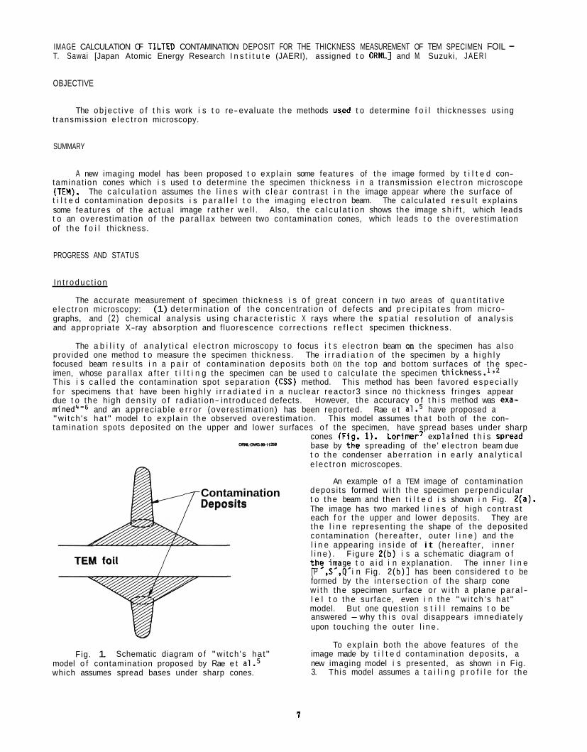
IMAGE CALCULATION OF TILTED CONTAMINATION DEPOSIT FOR THE THICKNESS MEASUREMENT OF TEM SPECIMEN FOIL - T. Sawai [Japan Atomic Energy Research I n s t i t u t e (JAERI), assigned t o ORNLl and M. Suzuki, J A E R I
OBJECTIVE
The ob jec t i ve o f t h i s work i s t o re-evaluate t he methods us.ed t o determine f o i l thicknesses us ing t ransmiss ion e l ec t r on microscopy.
SUMMARY
A new imaging model has been proposed t o exp la in some features of t he image formed by t i l t e d con-
The c a l c u l a t i o n assumes t he l i n e s w i t h c l e a r con t ras t i n t he image appear where t he sur face of taminat ion cones which i s used t o determine t he specimen th ickness i n a t ransmiss ion e l ec t r on microscope (TEN). t i l t e d contaminat ion deposi ts i s p a r a l l e l t o t he imaging e l ec t r on beam. The ca lcu la ted r e s u l t expla ins some features of t he actual image ra the r we l l . Also, the c a l c u l a t i o n shows t he image s h i f t , which leads t o an overest imat ion o f t he pa ra l l ax between two contaminat ion cones, which leads t o the overest imat ion of t he f o i l thickness.
PROGRESS AND STATUS
I n t r oduc t i on
The accurate measurement o f specimen th ickness i s o f great concern i n two areas of q u a n t i t a t i v e (1) determinat ion of t he concentrat ion o f defects and p r e c i p i t a t e s from micro- e l ec t r on microscopy:
graphs, and (2 ) chemical analys is us ing c h a r a c t e r i s t i c X rays where t he s p a t i a l r eso lu t i on of ana lys is and appropr ia te X-ray absorpt ion and f luorescence cor rec t ions r e f l e c t specimen thickness.
The a b i l i t y of a n a l y t i c a l e l ec t r on microscopy t o focus i t s e l ec t r on beam on the specimen has a lso provided one method t o measure t he specimen thickness. The i r r a d i a t i o n of t he specimen by a h i g h l y focused beam r e s u l t s i n a p a i r of contaminat ion deposi ts both on t he top and bottom surfaces of t he spec- imen, whose pa ra l l ax a f t e r t i l t i n g the specimen can be used t o ca l cu l a te t he specimen This i s c a l l e d t he contaminat ion spot separat ion (CSS) method. This method has been favored espec ia l l y f o r specimens t h a t have been h i g h l y i r r a d i a t e d i n a nuc lear reac to r3 s ince no th ickness f r inges appear due t o t he h igh dens i t y o f rad ia t ion- in t roduced defects. However, the accuracy o f t h i s method was exa- mined*-6 and an apprec iab le e r r o r (overest imat ion) has been reported. Rae e t a l e 5 have proposed a "w i tch 's ha t" model t o exp la in t he observed overest imation. tamina t ion spots deposited on t he upper and lower surfaces o f the specimen, have spread bases under sharp
This model assumes t h a t both of the con-
cones (Fia. 1 ) . Lorimer? exDlained t h i s SDread
Contamination
Fig. 1. Schematic diagram o f "w i tch 's ha t" model o f contaminat ion proposed by Rae e t a1.5 which assumes spread bases under sharp cones.
base by t 6e spreading of the ' e l ec t r on beam due t o t he condenser aber ra t ion i n e a r l y a n a l y t i c a l e l ec t r on microscopes.
An example o f a TEM image of contaminat ion deposi ts formed w i t h t he specimen perpendicu lar t o t he beam and then t i l t e d i s shown i n Fig. 2(a). The image has two marked l i n e s of h igh con t ras t each f o r t he upper and lower deposits. They are t he l i n e represent ing t he shape of t he deposited contaminat ion (herea f te r , outer l i n e ) and t he l i n e appearing i n s i d e of i t (hereaf ter , i nne r l i n e ) . F igure 2(b) i s a schematic diagram o f t h $ t o a i d i n explanat ion. The inner l i n e [P ,S ,Q i n Fig. 2 (b ) ] has been considered t o be formed by t he i n t e r s e c t i o n o f t he sharp cone w i t h the specimen surface o r w i t h a plane pa ra l - l e l t o t he surface, even i n t he " w i t ch ' s ha t" model. But one quest ion s t i l l remains t o be answered -why t h i s oval disappears imnediate ly upon touching t he outer l i n e .
To exp la in both t he above features of t he image made by t i l t e d contaminat ion deposi ts , a new imaging model i s presented, as shown i n Fig. 3. Th is model assumes a t a i l i n g p r o f i l e f o r t he
7
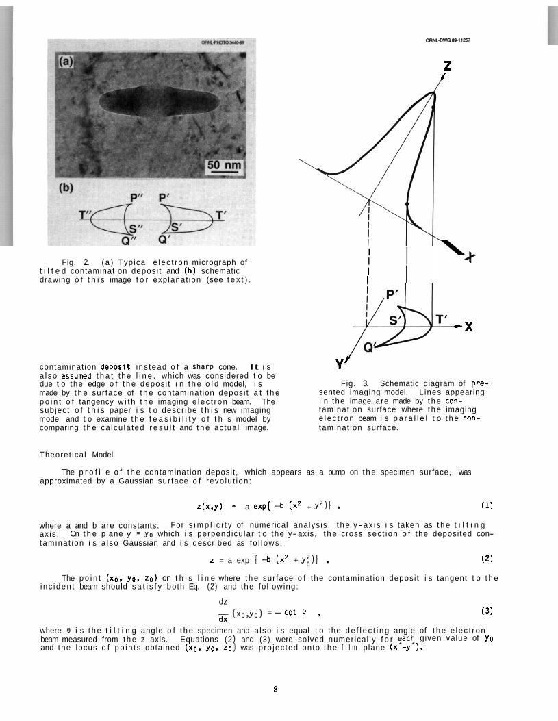
Fig. 2. ( a ) Typ ica l e l e c t r o n micrograph of t i l t e d contaminat ion depos i t and (b) schematic drawing o f t h i s image f o r exp lanat ion (see t e x t ) .
contaminat ion deoos i t i ns tead o f a Sham cone. It i s Y J
I I I I I I
z 4
\ +
r t - X
a l s o assumed t h a t the l i n e , which was considered t o be due t o the edge o f t h e depos i t i n t h e o l d model, i s made by t h e sur face of t h e contaminat ion depos i t a t t h e p o i n t o f tangency w i t h t h e imaging e l e c t r o n beam. sub ject o f t h i s paper i s t o descr ibe t h i s new imaging model and t o examine t h e f e a s i b i l i t y o f t h i s model by comparing t h e ca lcu la ted r e s u l t and t h e actua l image. taminat ion surface.
Fig. 3. Schematic diagram of pre- sented imaging model. L ines appearing i n the image are made by t h e con- taminat ion surface where t h e imaging e l e c t r o n beam i s p a r a l l e l t o t h e con-
The
Theoret ica l Model
The p r o f i l e o f t h e contaminat ion deposi t , which appears as a bump on t h e specimen surface, was approximated by a Gaussian sur face o f revo lu t i on :
z(x,y) = a exp[ 4 (x2 + r2)1 I (1)
where a and b are constants. ax is . t am ina t ion i s a l so Gaussian and i s descr ibed as fo l l ows :
For s i m p l i c i t y of numerical ana lys is , t h e y - a x i s i s taken as t h e t i l t i n g On t h e plane y = y o which i s perpendicu lar t o the y-axis, t h e cross sec t ion o f the deposi ted con-
z = a exp { -b (x2 + y;)] . (2)
The p o i n t (xo , yo, zo) on t h i s l i n e where t h e sur face o f the contaminat ion depos i t i s tangent t o t h e i n c i d e n t beam should s a t i s f y both Eq. (2) and the fo l lowing:
dz
dx - (xo,yo) = - c o t e , (3 )
where 8 i s t h e t i l t i n g angle o f t h e specimen and a l so i s equal t o the d e f l e c t i n g angle of t h e e l e c t r o n beam measured from t h e z-axis. Equations (2 and (3 ) were solved numer ica l ly f o r and the locus o f p o i n t s obtained ( X O . yo, zo was p ro jec ted onto t h e f i l m plane (x -y ).
given value of yo
8
The coordinates of t h e t i p s of cusps i n t h e image - p o i n t s P'and Q' i n Fig. 2(b), which a re impor- t a n t p o i n t s i n t h e ac tua l measurement of p a r a l l a x - c a n a l s o be obtained by an a n a l y t i c a l so lu t i on . Usual ly two tangents are poss ib le t o t h e Gaussian curve fo r a given value of 0 which i s s u f f i c i e n t l y large. cave upward, p r o j e c t onto t h e image plane and form t h e ou te r l i n e and t h e inner l i n e , respect ive ly . p o i n t s on t h e contaminat ion surface which make the t i p s of cusps i n t h e p ro jec ted image are t h e i n f l e c - t i o n p o i n t s of the Gaussian curve represented by Eq. (2) where t h e grad ient o f t h e curve i s - c o t 9 Ci.e., t h e coord inate of t h e p o i n t s should s a t i s f y Eqs. (2) and (3) and fo l l ow ing Eq. (4 ) l .
Two tangent po in ts , one on t h e curve where i t i s concave downward and t h e o the r where i t i s con- The
d2r
dx2 - (X0,YO) = 0 . ( 4 )
And t h e s o l u t i o n i s :
x p = m ;
zp = Z(XP.YP) .
(5.1)
(5.2)
(5.3)
An example of a ca lcu la ted image i s shown i n Fig. 4, w i t h t h e parameters used i n t h e ca lcu la t i on . The he igh t parameter A and t i l t i n g angle correspond t o t h e constants a i n Eq. (1) and 0 i n Eq. (3). The w id th parameter B i s used ins tead of t h e constant b i n Eq. (1) fo r eas ie r understanding of contaminat ion width, where
b = 1/B2 . (6)
The x--y' p lane shown i n Fig. 4 i s t h e p r o j e c t i o n of t h e x-y plane of t h e specimen sur face on t h e f i l m plane, and t h e o r i g i n of t h e coord inate x.-y' ( p o i n t 0') corresponds t o t h e center o f t he con- tamina t ion deposi t .
A s ide view of t h e contaminat ion depos i t shown i n Fig. 4 i s shown i n Fig. 5, and t h e curve where t h e surface of contaminat ion i s tangent t o t h e i n c i d e n t beam i s included. Th is l i n e makes i n n e r and ou te r l i n e s i n t h e image a f t e r p ro jec t ion .
: : : : : : : : : : : : : : : : : I.
Fig. 4. Calcu la ted c o n t r a s t l i n e s i n t h e Fig. 5. Side view of the contaminat ion depos i t used i n t h e ca lcu la t i on . Th is diagram a l s o inc ludes t h e l i n e which forms h igh con t ras t l i n e s i n t h e image, where t h e surface of t h e t i l t e d contaminat ion depos i t i s tangent t o t h e imaging beam. The p o i n t marked P i s the p o i n t which makes a t i p of t h e cusps i n t h e image.
image o f a t i l t e d contaminat ion cone (on upper: s i d e sur face of specimen). Coordinate axes x and y. are on t h e f i l m plane and p ro jec t ions of specimen surface coord inate axes x and y.
9
DISCUSSION
It i s apparent t h a t t h e ca lcu la ted image (Fig. 4) yel l- resembles t h e actua l image [Fig. 2(a) l . A p o r t i o n o f t h e i?n$r-ova l l i n e appears i n Fig. 4 (P’, S , Q ). t h a t the curve P S Q i n Fig. 4 should be a p o r t i o n o f a t r u e e l l i p s e , al though i t i s w e l l approximated by t h e e l l i p s e wi th a r a t i o o f major and minor axes o f cos 9, where e i s t h e angle of specimen tilt.
The whole image o f t h e contaminat ion depos i t appears f a r o f f t h e i d e a l p ro jec ted center, 0’. c l e a r t h a t a s i g n i f i c a n t overest imat ion o f p a r a l l a x and thus f o i l th ickness w i l l occur if t h e p a r a l l a x i s measured between t h e t i p s of cusps i n t h i s image. The t r u e p a r a l l a x should be measured between t h e p ro jec ted centers o f both contaminat ion deposi ts, which are hard t o l o c a t e i n t h e image.
S t r i c t l y speaking, the re i s no reason
It i s
P o i n t P i n Fig. 5 i s t h e p o i n t on t h e sur face o f t h e contaminat ion depos i t which corresponds t o t h e t i p s o f cusps i n t h e p ro jec t ion . coord inate) , s t i l l h igher than t h e p o i n t S where t h e grad ient of t h e Guassian curve i s - c o t 9. i s l oca ted o f f t he y- z plane (i.e., i t s x coord inate i s g rea te r than 0). t i p s o f cusps P’ and Q’ i n Fig. 4 appear w e l l o f f - cen te r a f t e r p ro jec t ion .
Th is imaging model exp la ins t h e experienced overest imat ion o f the specimen thickness. It assumes a smooth p r o f i l e o f t h e deposi ted contaminat ion r a t h e r than a two-stepped w i t c h ’ s hat p r o f i l e , whose sharp step seems t o be l e s s l i k e l y i f beam spreading and t h e d r i f t o f t h e beam and/or t h e specimen are considered.
Although t h e c a l c u l a t i o n assumes a Gaussian p r o f i l e of depos i t w i t h i n f i n i t e t a i l i n g , t h e ou te r l i n e (P’T-Q. i n Fig. 4) i n t h e image, which represents the shape o f t h e contamination, looks as if t h e con- tamina t ion depos i t stands s teeply on t h e specimen surface w i t h l i t t l e t a i l i n g . observed i n an actua l TEN image. Because of t h e h igh p o s i t i o n o f p o i n t P i n Fig. 5, t h e l i n e on t h e con- tamina t ion surface which makes t h e ou te r l i n e i n the p ro jec ted image e x i s t s on ly on t h e upper p o r t i o n of t h e contaminat ion depos i t where t h e spread o f the Gaussian curve i s r e l a t i v e l y small. i s a l so an impor tant r e s u l t of t h i s c a l c u l a t i o n along w i t h the apprec iab le image s h i f t a l ready mentioned. Th is mis lead ing feature may have l e d many microscopists, who have observed t h i s image, t o assume t h a t t h i s image can r e s u l t on ly from a very steep p r o f i l e o f contaminat ion w i t h l i t t l e t a i l i n g . A steep image does not always mean a steep contaminat ion deposi t .
Th is p o i n t i s l oca ted a t a r a t h e r h igh p o s i t i o n ( l a r g e value of t h e z Po in t P
Th is i s t h e reason t h a t t h e
Th is fea tu re i s o f ten
Th is observat ion
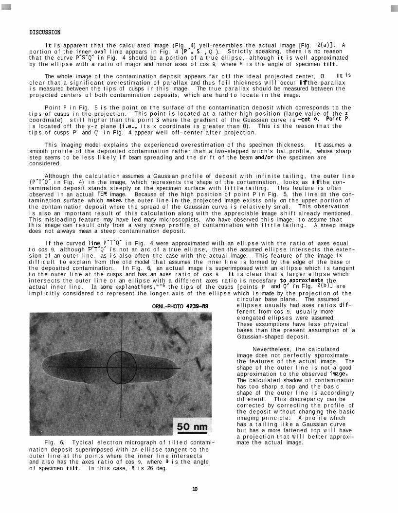
I f t h e curved l!n$ P’T*Q’ i n Fig. 4 were approximated w i th an e l l i p s e w i t h the r a t i o of axes equal t o cos 9, al though P T Q i s not an a rc o f a t r u e e l l i p s e , then t h e assumed e l l i p s e i n t e r s e c t s t h e exten- s i o n o f an ou te r l i n e , as i s a l so o f ten t h e case w i th t h e actua l image. d i f f i c u l t t o exp la in from t h e o l d model t h a t assumes t h e inner l i n e i s formed by t h e edge of t h e base Of t h e deposi ted contamination. I n Fig. 6, an ac tua l image i s superimposed w i t h an e l l i p s e which i s tangent t o t h e ou te r l i n e a t t h e cusps and has an axes r a t i o of cos 9. i n t e r s e c t s the ou te r l i n e o r an e l l i p s e w i t h a d i f f e r e n t axes r a t i o i s necesfary to,approximate t h e ac tua l i n n e r l i n e . i m p l i c i t l y considered t o represent the longer ax i s of the e l l i p s e which i s made by t h e p r o j e c t i o n of t h e
c i r c u l a r base plane. The assumed e l l i p s e s u s u a l l y had axes r a t i o s d i f - f e r e n t from cos 9; usua l l y more elongated e l l i p s e s were assumed. These assumptions have l e s s phys ica l bases than t h e present assumption of a Gaussian-shaped deposi t .
Nevertheless, t h e ca lcu la ted image does not p e r f e c t l y approximate t h e features o f t h e actua l image. The shape o f t h e ou te r l i n e i s not a good approximation t o t h e observed image. The ca lcu la ted shadow o f contaminat ion has t o o sharp a top and t h e bas ic shape of the ou te r l i n e i s accord ing ly d i f f e r e n t . Th is discrepancy can be cor rected by c o r r e c t i n g t h e p r o f i l e of t h e depos i t w i thout changing t h e bas ic imaging p r i n c i p l e . A p r o f i l e which has a t a i l i n g l i k e a Gaussian curve but has a more fat tened top w i l l have a p r o j e c t i o n t h a t w i l l b e t t e r approxi-
F ig . 6. Typ ica l e l e c t r o n micrograph o f t i l t e d contami- mate t h e actua l image. na t ion depos i t superimposed w i t h an e l l i p s e tangent t o the ou te r l i n e a t t h e p o i n t s where the inner l i n e i n t e r s e c t s and a l s o has the axes r a t i o o f cos 9, where 9 i s t h e angle o f specimen tilt. I n t h i s case, 9 i s 26 deg.
Th is fea tu re o f the image i s
It i s c l e a r t h a t a l a r g e r e l l i p s e which
In some explanation^,^-^ t h e t i p s of t h e cusps [po in ts P and Q i n Fig. 2 ( b ) l are
ORNL-PHOTO 4239-89
10
CONCLUSIONS
A new image i n t e r p r e t a t i o n of t i l t e d contaminat ion deposi ts i s presented. It assumes t h a t the l i n e s i n the image are made by the p r o j e c t i o n o f the tangent po in ts on a smooth and t a i l i n g p r o f i l e o f t he con- taminat ion deposi t . This model has s u f f i c i e n t advantages over the convent ional imaging model t o make a s i g n i f i c a n t c o r r e c t i o n t o specimen thickness measurement. measurement us ing the contamination spot separat ion method i s a lso demonstrated w i t h t h i s model.
The i n e v i t a b l e overest imat ion i n th ickness
REFERENCES
1. G. W. Lorimer, G. C l i f f , and J. N. Clark, Developments i n E lec t ron Microscopy and Analysis, (ed., J. A. Venables), Academic Press, London, 1976.
2. W. A. Knox, Ul tramicroscopy 1 (1976) 175.
3. A. Hishinuma and S. Jitsukawa, t o be publ ished i n Journal of Nuclear Mater ia ls .
4. N. Stenton, M. R. Not is, J. I. Goldstein, and D. 6. Wil l iams, Q u a n t i t a t i v e Microanalys is w i t h High Spacial Resolut ion, (eds., G. W. Lorimer, M. H. Jacobs, and P. Doig), The Metal Society, London, 1981.
D. A. Rae, V. D. Scot t , and G. Love, ib id . , p. 57. 5.
6. 2. Hor i ta , K. I c h i t a n i , T. Sano, and M. Nemoto, Sc r ip ta Met. 20 (1986) 381.
7. G. W. Lorimer, E lec t ron Microscopy and Analysis 1981, London: I s t i t u t e o f Physics, 1982, p. 147.
11

SMALL-SCALE BENDING FATIGUE SPECIMEN DEVELOPMENT - 8 . A. Chin. G. R. Rao (Auburn University) and E. H . Lee (ORNL)
OBJECTIVES
The objective of this study is to develop and evaluate small-scale fatigue specimen The immediate objective is to test and compare designs for testing irradiated specimens.
results obtained using unirradiated specimens.
SUMMARY
Two small-scale bending fatigue test specimens were developed. The first specimen,
The unirradiated rectangular specimens were tested at both room termed the *,rectangular" specimen, has overall dimensions of 30.1625 x 4.1625 x 0.762 mm with a gauge length of 6.35 mm. temperature as well as at 600'C.
The second specimen is a "miniature-disc'' specimen with Outer dimensions of a 3 mm diameter Transmission Electron Microscope specimen and a reduced guage section formed by two circular radii of 1.5 mm. The thickness is 0 . 2 5 4 mm. The miniature specimens were fabricated using three different techniques: (1) Punching followed by electropolishing, ( 2 ) electrical discharge machining and ( 3 ) punching fallowed by annealing. specimens were tested separately at room temperature.
The three sets of miniature-disc
Tests were performed using annealed type 316 stainless steel (Reference Heat 8092297) . The results were found to conform to the Coffin-Manson relationship where the value of the exponent was found to lie between 0.1 and 0 . 2 5 . There was some degradation in fatigue life f o r the rectangular specimen at 600°C as compared to the room temperature fatigue data. The miniature-disc specimens gave higher than expected values of fatigue endurance for all three sets o f specimens. Both specimen designs appear to be suitable for scoping irradiated specimens for bending fatigue properties.
PROGRESS AND STATUS
Introduction
Small-scale specimens have received considerable attention for extraction of mechanical properries of irradiated materials. Size constraints within the reactor is one reason for the development of miniaturized specimens. Apart from that, considerable savings in irradiation time and cost due to smaller volume, the availability of a greater number of samples far testing and temperature control Considerations have spurred the development of miniaturized specimens. Minimal irradiation hazard to personnel during handling of the specimens is also an important consideration.
Ihis report describes the investigation of fatigue properties of metals using two sma:l- scale ~pecimen designs. The two nom-standard fatigue specimen designs have been tested and results using these Specimens are reported. One specimen design is for a subsized-rectangular specimen. The other design is for a miniature-disc specimen with dimensions of a transmission electron microscope specimen. well as at 600'C while the miniature-disc specimens were tested only at room temperature. The results obtained using both specimens are compared and feasibility of further development of the miniature-disc specimen is discussed.
SDecimrns
The rectangular specimens were tested at room temperature as
The specimens were made from type 316 stainless steel (Reference Heat 8092297) . The composition is given in table 1.
The rectangular specimen is shown in figure 1. The specimens were fabricated by cutting rectangular pieces of material from the parent sheet metal. dimensions of the specimen. The reduced gauge section was also formed by milling. The specimens were hand polished using polishing papers of different grades in sequence. The final step involved electropolishing using a 90% ethanol - 10% perchloric acid electrolyte far a minute at -2.5-C to + 2 . 5 " C .
These were then milled to the
13
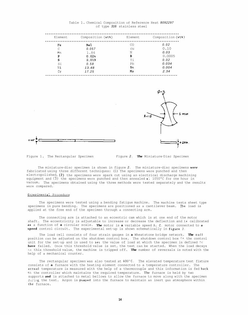
Table 1. Chemical Composition of Reference Heat 8092297 of type 316 stainless steel
............................................................................ Element Composition (wt%) Element Composition (wt%)
............................................................................ Fe Bal CO 0 . 0 2 C 0 . 0 5 7 cu 0.10 Mn 1.86 N 0.03 P 0 . 0 2 4 B 0.0005 S 0 .019 Ti 0 . 0 2 Si 0 . 5 8 Pb 0.034 Ni 13.48 Sn 0.004 Cr 1 7 . 2 5 MO 2.34
...........................................................................
Figure 1. The Rectangular Specimen Figure 2 . The Miniature-Disc Specimen
The miniature-disc specimen is shown in figure 2 . The miniature-disc specimens were fabricated using three different techniques: (1) The specimens were punched and then electropolished, equipment and ( 3 ) the specimens were punched and then annealed at 1050°C for one hour in vacuum. were compared.
( 2 ) the specimens were spark cut using an electrical discharge machining
The specimens obtained using the three methods were tested separately and the results
Emerimental Procedure
The specimens were tested using a bending fatigue machine. The machine tests sheet type specimens in pure bending. The specimens are positioned as a cantilever beam. The load is applied at the free end of the specimen through a connecting arm.
The connecting arm is attached to an eccentric cam which is at one end of the motor shaft. The eccentricity is adjustable to increase or decrease the deflection and is calibrated a s a function of a circular scale. speed control circuit.
The motor is a variable speed A. C . motor connected to a
The load cell consists of four strain gauges in a Wheatstone bridge network. The n u l l position can be adjusted on the shutdown control box. The shutdown control box is the control unit for the set-up and is used to set the value of load at which the specimen is defined to have failed. Once this threshold value is set, the test can be started. When the load decays co this threshold value, the machine is tripped off. The number of reversals is noted with the help of a mechanical counter.
The experimental set-up is shown schematically in figuze 3 .
The rectangular specimen was also tested at 600'C. The elevated temperature test fixture consists of a furnace with the heating element connected to a temperature controller. The a c t u a l temperature is measured with the help of a thermocouple and this information is fed back to the controller which maintains the required temperature. The furnace is held by two supports and is attached to metal bellows to allow the furnace to move along with the specimen .idring the test. Argon is pumped into the furnace to maintain an inert gas atmosphere within t h e furnace.
14
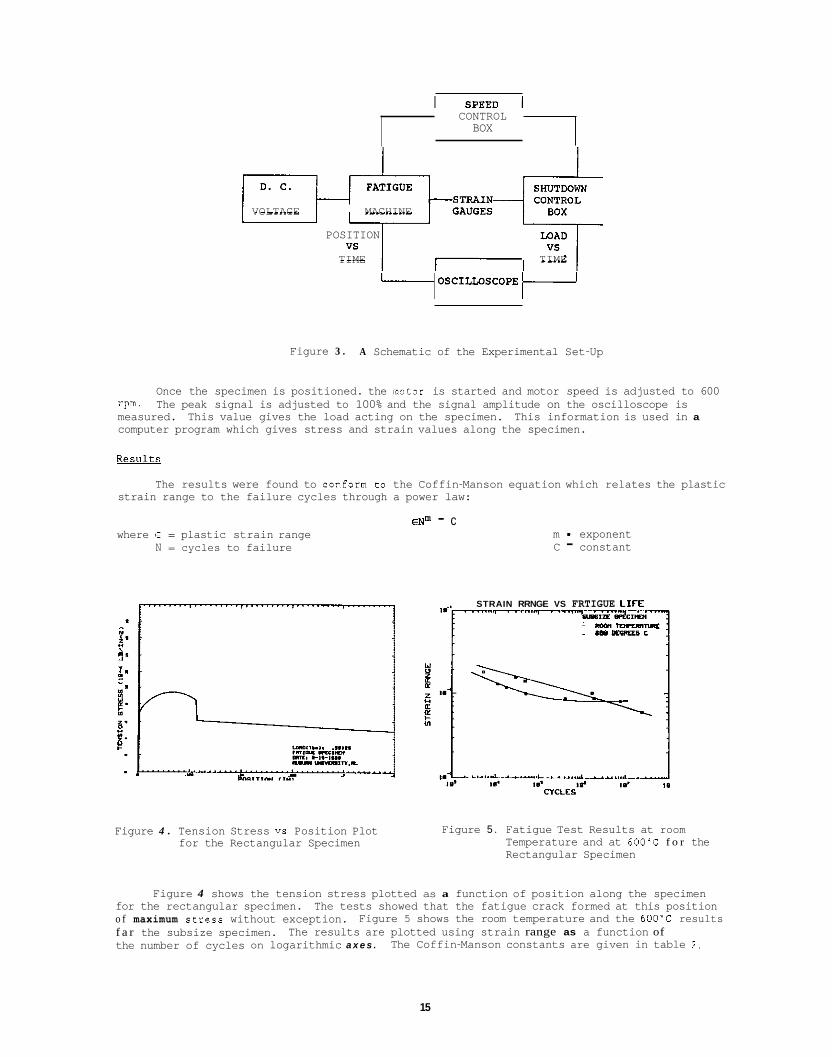
CONTROL BOX
VOLTAGE MACHINE
POSITION
TIME TIME
I oSCILLOSCoPE t- Figure 3 . A Schematic of the Experimental Set-Up
Once the specimen is positioned. the motor is started and motor speed is adjusted to 600 The peak signal is adjusted to 100% and the signal amplitude on the oscilloscope is rpm.
measured. computer program which gives stress and strain values along the specimen.
Results
This value gives the load acting on the specimen. This information is used in a
The results were found to conform to the Coffin-Manson equation which relates the plastic strain range to the failure cycles through a power law:
where t = plastic strain range N = cycles to failure
ENm - c m - exponent C - constant
STRAIN RRNGE VS FRTIGUE LIFE
mmroanr ..s - c
Figure 4 . Tension Stress vs Position Plot for the Rectangular Specimen
Figure 5 . Fatigue Test Results at room Temperature and at 6OO'C f o r the Rectangular Specimen
Figure 4 shows the tension stress plotted as a function of position along the specimen for the rectangular specimen. o f maximum StKeSS without exception. f a r the subsize specimen. the number of cycles on logarithmic a x e s .
The tests showed that the fatigue crack formed at this position Figure 5 shows the room temperature and the 6OO'C results
The results are plotted using strain range as a function of The Coffin-Manson constants are given in table 2 .
15
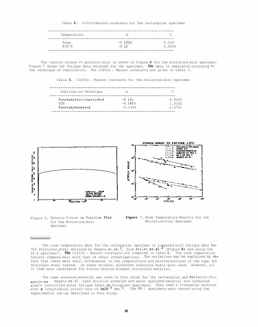
Table 2 . Coffin-Manson constants for the rectangular specimen
.................................................................... Temperature m C
.................................................................... Room -0,1306 0.059 600'C -0 18 0.0696
.....................................................................
The tension stress vs position plot is shown in figure 6 for the miniature-disc specimen. Figure 7 shows the fatigue data obtained for the specimen. The data is separated according to the technique of fabrication. The Coffin - Manson constants are given in table 3.
Table 3 . Coffin - Manson constants for the miniature-disc specimen
..................................................................... Fabrication Technique m C
..................................................................... Punched/electropolished -0.195 EDM -0,1806
4.9545 1.6282
Punched/Annealed -0.1995 2.9791 ....................................................................
Figure 6. Tension Stress VS Position Plot for the Miniature-disc Specimen
Figure 7. Room Temperature Results for the Miniature-Disc Specimen
Discussion
The room temperature data for the rectangular specimen is compared with fatigue data f o r 316 stainless steel obtained by Nagata et.al.l, from Boller et.al.2 (Figure 8 ) and using the SS-1 specimen3. results compare well with that of other investigations. fact that there were small differences in the compositions and microstructures of the type 316 stainless steel tested. In these studies, different reference heats were used. However, all of them were candidates for fusion reactor blanket structural material.
The Coffin - Manson constants are compared in table 4. The room temperature The variations may be explained by t h e
The same annealed material was used in this study for the rectangular and miniature-diic
They used a triangular waveform s p e c i i i , , ~ n s . stl-airt controlled axial fatigue tests on hourglass specimens. with a longitudinal strain rate of 5 ~ 1 0 . ~ sec-l. experimental set-up described in this study.
Nagata et.al. used solution annealed and water quenched material and conducted
The SS-1 specimens were tested using the
16
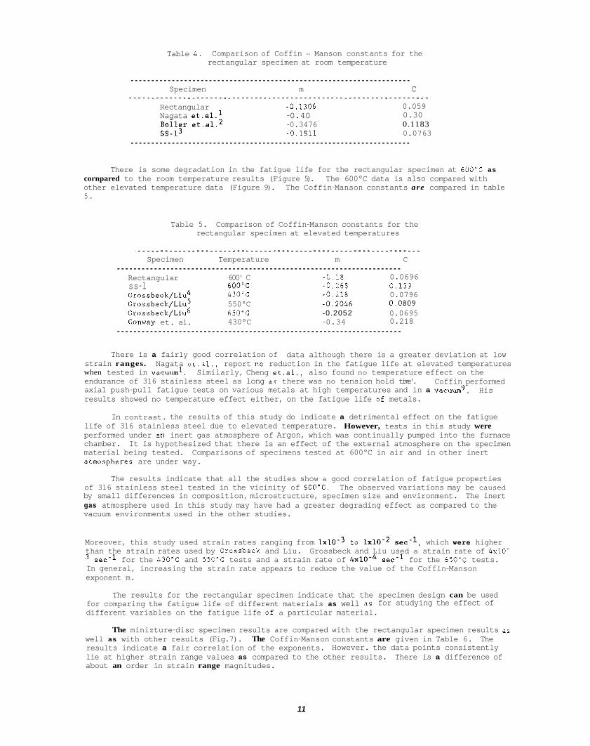
Table 4. Comparison of Coffin - Manson constants for the rectangular specimen at room temperature
.................................................................... Specimen m c
Rectangular -0,1306 Nagata st.al.l -0.40
-0.3476 -0.1811
0.059 0.30 0.1183 0.0763
....................................................................
There is some degradation in the fatigue life for the rectangular specimen at 600'C as cornpared to the room temperature results (Figure 5). The 600°C data is also compared with other elevated temperature data (Figure 9). The Coffin-Manson constants are compared in table 5.
Table 5. Comparison of Coffin-Manson constants for the rectangular specimen at elevated temperatures
Specimen Temperature m C .....................................................................
Rectangular 600' C -0.18 0.0696 ss-l 600'C -0.268 0,139 Grossbeck/Liu4 430'C -0.218 0.0796
Grossbeck/Liu6 650'C -0.2052 0.0695 Grossbeck/Liu5 550°C -0,2046 0.0809
Conway et. al. 430°C -0.34 0.218 .....................................................................
There is a fairly good correlation of data although there is a greater deviation at low strain ranges. when tested in vacuum'. endurance of 316 stainless steel as long as there was no tension hold time'. axial push-pull fatigue tests on various metals at high temperatures and in a vacuum9. results showed no temperature effect either, on the fatigue life of metals.
Nagata et.al., report no reduction in the fatigue life at elevated temperatures Similarly, Cheng et.al., also found no temperature effect on the
Coffin performed His
In contrast. the results of this study do indicate a detrimental effect on the fatigue life of 316 stainless steel due to elevated temperature. performed under an inert gas atmosphere of Argon, which was continually pumped into the furnace chamber. It is hypothesized that there is an effect of the external atmosphere on the specimen material being tested. Comparisons of specimens tested at 600°C in air and in other inert atmospheres are under way.
However, tests in this study were
The results indicate that all the studies show a good correlation of fatigue properties of 316 stainless steel tested in the vicinity of 600'C. The observed variations may be caused by small differences in composition, microstructure, specimen size and environment. The inert gas atmosphere used in this study may have had a greater degrading effect as compared to the vacuum environments used in the other studies.
Moreover, this study used strain rates ranging from 1 ~ 1 0 . ~ to 1 ~ 1 0 - ~ sec-l, which were higher than the strain rates used by Grossheck and Liu. Grossbeck and Liu used a strain rate of 4x10-
sec-l for the 430'C and 550'C tests and a strain rate of 4 ~ 1 0 - ~ sec-l for the 650'C tests. In general, increasing the strain rate appears to reduce the value of the Coffin-Manson exponent m.
The results for the rectangular specimen indicate that the specimen design can be used for comparing the fatigue life of different materials as well as for studying the effect of different variables on the fatigue life of a particular material.
The minizture-disc specimen results are compared with the rectangular specimen results aa well as with other results (Fig.7). The Coffin-Manson constants are given in Table 6. The results indicate a fair correlation of the exponents. lie at higher strain range values as compared to the other results. There is a difference of about an order in strain range magnitudes.
However. the data points consistently
11
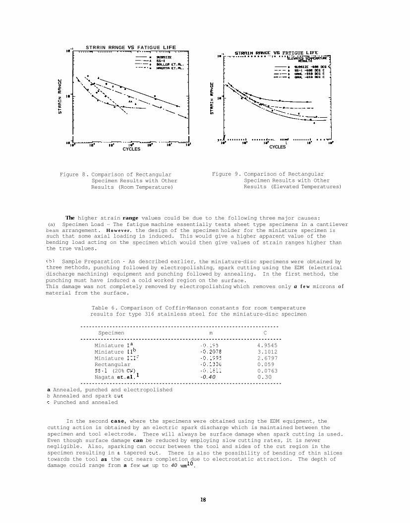
S T R R I N RRNGE VS FATIGUE LIFE ...... ........ . -.. . . ..._ . . S T W I N RRNGE VS FRTIGUE LIF_E,. .......... -- ....... ..-. !-%%L*=
,.I ......... I ......... I L a ~ .... ," ......... I .... 6 1 ' ""'"~ ' ".'- ' .",_ '""" '~ ' .-.A I.. I.. I.. I.. 8.' I..
CYCLES I.. ,e' I.' I.' I.. 1.) t d CYCLES
Figure 8. Comparison of Rectangular Specimen Results with Other Results (Room Temperature)
Figure 9. Comparison of Rectangular Specimen Results with Other Results (Elevated Temperatures)
The higher strain range values could be due to the following three major causes: (a) Specimen Load - The fatigue machine essentially tests sheet type specimens in a cantilever beam arrangement. H o w e v e r . the design of the specimen holder for the miniature specimen is such that some axial loading is induced. This would give a higher apparent value of the bending load acting on the specimen which would then give values of strain ranges higher than the true values.
(b) Sample Preparation - As described earlier, the miniature-disc specimens were obtained by three methods, punching followed by electropolishing, spark cutting using the EDM (electrical discharge machining) equipment and punching followed by annealing. In the first method, the punching must have induced a cold worked region on the surface. This damage was not completely removed by electropolishing which removes only a f e w microns o f material from the surface.
Table 6. Comparison of Coffin-Manson constants for room temperature results for type 316 stainless steel for the miniature-disc specimen
.................................................................... Specimen m C
..................................................................... Miniature Ia -0,195 4.9545 Miniature IIb -0 ,2078 3.1012 Miniature 111' -0.1995 2.6797 Rectangular -0 .1306 0.059 s s - 1 (20% CW) -0.1811 0.0763 Nagata et.al.l -0 .40 0.30
..................................................................... a Annealed, punched and electropolished b Annealed and spark cut c Punched and annealed
In the second case, where the specimens were obtained using the EDM equipment, the cutting action is obtained by an electric spark discharge which is maintained between the specimen and tool electrode. Even though surface damage can be reduced by employing slow cutting rates, it is never negligible. specimen resulting in a tapered cut. towards the tool as the cut nears completion due to electrostatic attraction. The depth of damage could range from a few um up to 40 uml0,
There will always be surface damage when spark cutting is used.
Also, sparking can occur between the tool and sides of the cut region in the There is also the possibility of bending of thin slices
18
To avoid inducing significant damage to the surface. a very precise tool could be used with a very slow cutting rate (on the order of 0.004 mm/min). be to use the so called "travelling wire EDM" method. A 3 oun diameter rod is used as the starting material. The grooves can be machined onto the rods. A very fine wire , 0,002 to 0 , 0 0 4 inches in diameter can then be used in conjunction with the EDM equipment. The wire is continuously unreeled and drawn over the specimen. Once the disk specimen is obtained, it would then be precision lapped to obtain the final thickness.
( c ) Strain Rate - Strain rates may influence the fatigue properties of miniature-disc specimens. This is high compared to strain rates of l ~ l O - ~ to 1 ~ 1 0 - ~ sec-l for the rectangular specimens and 4~10.3 to 4 ~ 1 0 - ~ sec-l for the axial specimens used by Grossbeck and Liu. rates may be partially responsible for the higher load values and the low Coffin-Manson exponents obtained for the miniature-disc specimens.
A more preferable method would
In this study very high strain rates were used, ranging from 5x10-I to 5 sec-l.
The high strain
CONCLUSIONS
The results obtained using the rectangular specimen design conform to the Coffin-Manson relationship. The value of the exponent was found to lie between -0.1 and -0.2. The repeatability of the position of crack formation was found to agree with that predicted by theoretical calculations. The results indicate that the specimen design can be used to study the effects of irradiation on the fatigue properties of alloys. amount of degradation in the fatigue life at elevated temperatures.
The 600°C tests indicate some
The miniature-disc specimen results also conform to the Coffin-Manson relationship with the exponent having values ranging from -0.19 to -0.21, The values of the exponent compare favorably with other results but overall strain range values are about an order higher than results obtained by other investigators. including specimen preparation techniques and the specimen not being subjected purely to bending loads. The results, however, do indicate that the miniature-disc specimen can be used to test irradiated specimens with some improvements.
This could be due to a combination of factors
FUTURE WORK
The specimen holding fixture for the miniature-disc specimen will be modified EO that the specimen is a true cantilever beam. theoretical calculations. after modification has been completed.
Finite element analysis will be used to improve Further comparison tests with other size specimens will be conducted
REFERENCES
1.
2 .
3 .
4 .
5.
6 .
7.
8.
9.
10.
N.Nagata, K. Furuya and R. Watanabe, Low cycle fatigue behavior of blanket structural materials', J. of Nuclear Materials, 85 h 86, pp.839-843, (1981). C. Bollar and T. Seeger, Materials data for cvclic loadine. Part C: Hieh allov steels, Materials science monographs, 42C. Elsevier publishers, p.155, 1987. R. H. Wong. Metal fatieue for fusion aoolications, M. S . Thesis. Auburn University, (1986). M. L. Grossbeck and K. C. Liu, "Low-cycle fatigue behavior of 20% cold worked type 316 stainless steel after irradiation in the HFIR", O W L Remrt, pp.42-47, (1979). M. L. Grossbeck and K. C. Liu, "High temperature fatigue life of 316 stainless steel containing irradiation induced helium", J. of Nuclear Materials. 103 h 104, pp.853- 858, (1981). M. L. Grossbeck and K. C. Liu. "Fatigue life at 650'6 of 20% cold worked type 316 stainless steel irradiated in the HFIR at 550'C", O W L ReDort, pp.136-140, (1982). V. B. Conway, R . H. Stentz and J. T. Berling, "Fatigue, tensile and relaxation behavior of stainless steels", TID-26135. p.39, (1975). C. F. Cheng. C. Y. Cheng, D . R. Diercks and R. W. Weeks, "Low cycle fatigue behavior of 304 and 316 S . S . at LMFBR Operating temperatures", Fatieue at Elevated Temperatures, ASTM STP 520, (1973). L. F. Coffin."High temperature fatigue life of 316 stainless steel containing Irradiation Induced Helium", Metallureical Transactions, 3 , pp.1777-1788. (1972). A. Szirmae and R . M. Fisher,"Specimen damage during cutting and grinding", Electron microscoov. diffraction and microorobe snalvsis. pp.3-9.
19

2 . D O S I M E T R Y , DAMAGE P A R A M E T E R S , A N D A C T I V A T I O N C A L C U L A T I O N S
21

NEUTRON DOSIMETRY AND DAMAGE CALCULATIONS FOR THE ORR-MFE 75 EXPERIMENT - L. R. Greenwood (Argonne Nat ional Laboratory)
OBJECTIVE
To prov ide dosimetry and damage ana lys is f o r fus ion reac to r mater ia ls i r r a d i a t i o n experiments.
SUMMARY
Neutron measurements and damage ca l cu la t i ons have been completed fo r t he j o i n t U.S.-Japanese 75 experiment i n the Oak Ridge Research Reactor. Tensi le and TEM specimens were i r r a d i a t e d from June 28, 1983 t o March 26, 1987 (475 f u l l The maximum f a s t neutron f luence was 9.5x10²p n/c$ which producmed 7.4 dpa and 102 appm helium i n 316 s ta in less s tee l .
PROGRESS AND STATUS
Neutron fluence and energy spectral measurements and damage ca l cu la t i ons have been completed f o r the MFE-7J experiment i n the Oak Ridge Research Reactor a t Oak Ridge National Laboratory. conducted j o i n t l y w i t h Japanese experimenters and contained a v a r i e t y o f t e n s i l e and TEM specimens.1 experiment was i r r a d i a t e d a t temperatures between 300-400°C i n core p o s i t i o n C3 from June 28, 1983, t o March 26, 1987. The t o t a l exposure was 341,806 MWH or 475 f u l l power days a t 30 MW. were placed throughout the sample area. Four capsules measuring 7 cm i n length were placed i n l eve l 1 and two capsules measuring 4.5 cm were placed i n l eve l 3 f o r each temperature region. Each capsule measured 1.6 m 00 and contained wires of Fe, T i , and 0.1% Co-AI. Due t o required coo l i ng times and shipping delays, the samples were not received f o r analysis u n t i l September 1988.
Each capsule was opened i n a hot c e l l a t Argonne and ind i v idua l wires were segmented, wei hed. and umunted
measured a c t i v a t i o n ra tes are l i s t e d i n Table 1. product a c t i v i t y , decay dur ing and a f t e r i r r a d i a t i o n , and gama sel f-absorpt ion. represent averages of several d i f f e ren t samples a t each leve l . were less than 5%. l ess than 3% f r o m the averages i n Table 1. (l+bx+cx2), where A i s the a c t i v i t y a t height x. d i f f e r e n t react ions are b = -1.015~10-2 and c = -7.614~10-4. t o be a t about -6.7 cm below midplane.
The maximum a c t i v i t i e s we re used as i npu t t o the STAY'SL computer code t o ad jus t t he f l u x spectrum. input spectrum was taken from previous spectral measurements i n ORR.2 i n t e g r a l s are l i s t e d i n Table 2. resu l tan t dpa and helium values are l i s t e d f o r var ious elements i n Table 3. The values i n Tables 2 and 3 a r e given a t the maximum f l u x pos i t i on . To obta in values a t o ther heights, simply use the equation given above. The on ly exception t o t h i s p resc r ip t i on i s f o r n i cke l or 31655 where the thermal e f f e c t i n n i c k e l depends non- l inear ly on the thermal neutron fluence.4 Consequently, hel ium and dpa values f o r 31655 are l i s t e d as a func t i on o f height i n Table 4.
ower days) i n p o s i t i o n C3 a t temperatures between 300-400°C.
This experiment was The
Twelve dosimetry capsules
f o r gama spectroscopy. Oue t o the long decay t i m e , we were on ly able t o analyze 46Sc, 5 ! Mn, and COCO. The The a c t i v i t i e s were cor rec ted f o r burnup o f t a r g e t and
The values i n the t a b l e I n a l l cases, these r a d i a l f l u x gradients
A more d e t a i l e d r a d i a l f l u x map was not determined since a l l measured values deviated by
The average values o f the parameters b and c f o r the three A l l o f t he data are w e l l f i t by the equation A(x) = A(0)
The maximum a c t i v i t y p o s i t i o n was determined
The The resu l tan t neutron fluence
Damage parameters were than ca lcu la ted w i th the SPECTER3 computer code and
FUTURE WORK
The MFE-6J experiment was run a t the same time as the 75 experiment. the 60OC par t of t h i s run and they are now being analyzed. shor t ly . These experiments were the f i n a l runs i n ORR s ince t h i s reactor has now been deconmissioned.
REFERENCES
Dosimetry samples were received from Dosimeters from the 200OC reg ion are expected
1. Descr ip t ion o f the U.S.-Japanese Spect ra l- Ta i lo r ing Experiment i n ORR, J. L. Scott , L. K. Mansur, M. L. Grossbeck, E. H. Lee, K. F a r e l l , L. L. Horton, A. F. Rowcliffe, M. P. Tanaka, and H. Hishinama, A l l oy Development f o r I r r a d i a t i o n Perfonance, Semiannual Progress Report, DOE/ER-0045/15, pp. 22-40, Sept. 1985.
L. R. Greenwood, A l l o y Development f o r I r r a d i a t i o n Performance, Semiannual Progress Report, DOE/ER-0045115, pp. 4-14. Sept. 1985.
3. L. R. Greenwood and R. K. Sni ther, ANL/FPP/TM-197, SPECTER: Neutron Damage Calcu la t ions f o r Mater ia ls I r r a d i a t i o n s , January 1985.
L. R. Greenwood, D. W. Kneff, and R. P. Skowronski, Journ. o f Nucl. Mater. E. pp. 1002-1010 (1984).
2 .
4.
Heiaht, cm
2.3
0.4
-0.8
-1.0
-1.5
-3.2
-5.5
-9.5 -11.8
-14.0
-18.8
-21.6
Table 1. Measured Ac t i va t i on Rates f o r ORR-MFE 75 (Values normalized t o 30 MW; accuracy 22%)
Ac t i va t i on Rate (atom/atom-s)a
59~o(n ,7&60~0 54Fe (n, p154Mn 46Ti (n,p]46~c (x10- ) (x10- 1) (x10- 2)
6.38 6.77
7.07
6.87 -
6.87
6.87
6.94
6.62
6.52
6.12
5.51
- 1.30
1.30
1.31
1.33
1.35
1.36
1.33
1.29
1.22
1.15
- 1.70
1.72
1.73
1.74
1.73
1.73
1.76
1.74
1.70
1.61
1.50
V a l u e s represent averages o f r a d i a l f l u x monitors; r a d i a l gradients <5%.
Table 2. Neutron Fluences f o r ORR-MFE 75 (Maximum values a t -6.7 cm below midplane)
Energy F1 uence Uncerta inty ( ~ 1 0 2 1 n/cm*)
Total 27.0
Thermal (<.5 eV) 8.07
0.5 eV - 0.1 MeV 9.46
>O.l MeV 9.47
>1 MeV 5.14
7. 7.
12.
10.
12.
24
Table 3. (Maximum values a t -6.7 cm: Use g rad ien t equation elsewhere)
Damage Parameters f o r ORR-MFE 75
Element DPA He, appm
A1 12.6 5.7 Ti 8.0 4.3 V 8.9 0.21 Cr 8.0 1.4 Mn 8.5 1.2 Fe 7.1 2.4 co 8.1 1.2
Fast 7.5 34. Ni Thermal 1.3 736.
Total 8.8 770. cu 6.8 2.1 Nb 6.8 0.45 Mo 5.0 316SSa 7.4 102.
-
a316 SS: Fe(.645), N i ( . l3 ) , Co(.18), Mn(.019), Mo(.026)
Table 4. Damage Parameter Gradients f o r 316 SS ORR-MFE7J
Heiaht, cm 0
-4 -8
-12 -16 -20 -24
DPA
7.19 7.40 7.43 7.28 6.95 6.45 5.77
- He, appm
97. 101. 102. 99. 91. 80. 66.

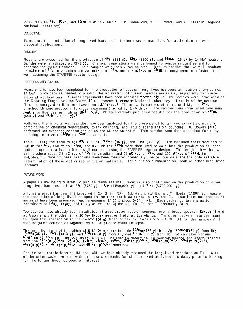
PRODUCTION OF 49V, 93M0, and 93mNb NEAR 14.7 MeV - L. R. Greenwood, 0. L. Bowers, and A. In tasorn (Argonne Nat i onal Laboratory)
OBJECTIVE
To measure the product ion of long- l i ved isotopes i n fus ion reac to r mate r ia ls f o r a c t i v a t i o n and waste d isposal app l i ca t ions .
SUMMARY
Results are presented f o r the product ion o f 4% (331 d) , 93Mo (3500 y), and 93mNb (16 y) by 14 MeV neutrons. Samples were i r r a d i a t e d a t RTNS 11. Chemical separat ions were performed t o remove i m p u r i t i e s and t o separate the Mo-Nb f ract ions. Thin samples were then x-ray counted. 28 mCi1cc o f 4% i n vanadium and 2.8 mci lcc o f 93Mo and 106 mc i l cc of 93mNb i n molybdenm i n a fus ion f i r s t - wa l l assuming the STARFIRE reac to r design.
PROGRESS AND STATUS
Measurements have been completed f o r the product ion o f several long- l i ved isotopes a t neutron energies near 14 MeV. mater ia l app l i ca t ions . the Rota t ing Target Neutron Source I1 a t Lawrence L i v e m r e Nat ional Laboratory. f l u x and energy d i s t r i b u t i o n s have been publ ished.1 The m e t a l l i c samples of V , na tu ra l Mo, and 94Mo enriched Mo were pressed i n t o d iscs measuring 3 m od by 1 nm t h i c k . nmnths t o fluences as h igh as 1018 nlcmz. (650 y) and 94Nb (20,300 y).1
Fol lowing the i r r a d i a t i o n , samples have been analyzed f o r the presence o f l ong- l i ved a c t i v i t i e s us ing a combination of chemical separations, x- ray counting, and l i q u i d s c i n t i l l a t i o n counting. 0. Bowers (ACL) performed ion-exchange separat ions of Mo and Nb and Mn and V. count ing r e l a t i v e t o 55Fe and 93mNb standards.
Table 1 l i s t s the r e s u l t s f o r 4% (331 d ) , 93mNb 16 y), and 93Mo (3500 y). 258 mb f o r 49V, 550 mb f o r 93M0, and 0.75 mb f o r 43mNb were then used t o ca l cu l a te the product ion o f these rad io isotopes i n a fus ion f i r s t - w a l l mater ia l us ing t he STARFIRE r eac to r design. The r e s u l t s show t h a t we w i l l produce about 2.8 mCi/cc o f 4% i n vanadium, and 28 mCi/cc of 93Mo and 106 mCi/cc o f 93mNb i n molybdenum. determinat ion o f these a c t i v i t i e s i n fus ion mater ia ls . isotooes.
Results p r e d i c t t h a t we w i l l produce
Such data i s needed t o p red i c t the a c t i v a t i o n o f fus ion reac to r mater ia ls , espec ia l l y f o r waste
D e t a i l s o f the neutron
We have already publ ished r e s u l t s f o r the product ion o f 91mNb
S im i l a r experiments have been repor ted previously.1-3 The samples were i r r a d i a t e d a t
The samples were i r r a d i a t e d over many
Thin samples were then deposited for x-ray
The measured cross sect ions o f
None o f these react ions have been measured prev ious ly : hence, our data a r e t he on ly r e l i a b l e Table 1 a l so summarizes our work on o ther long- l i ved
FUTURE WORK
A paper i s now being w r i t t e n t o pub l i sh these resu l t s . l ong- l i ved isotopes such as 14C (5730 y ) , 9 3 Z r (1,500,000 y), and g2Nb (3,700,000 y).
Work i s a lso con t inu ing on the product ion o f o ther
A j o i n t p r o j e c t has been i n i t i a t e d w i t h Don Smith (EP), Bob Haight (LANL), and Y. Ikeda (JAERI) t o measure the product ion o f long- l i ved isotopes i n the ra re- ear th m a t e r i a l s Tb, Hf. and Eu. Four i d e n t i c a l packets o f mater ia l have been assembled, each measuring 1" OD x about 518" t h i ck . conta iners o f Hf02, TbqO7, and Eu203 as w e l l as Ag and N i , Cu, Fe, and T i dosimetry f o i l s .
TWO packets have already been i r r a d i a t e d a t acce le ra to r neutron sources, one i n broad-spectrum Be(d,n) f i e l d a t Argonne and t he o ther i n a 10 MeV H(p.n) neutron f i e l d a t Los Alamos. t o Japan f o r i r r a d i a t i o n i n the 14 MeV T(d,n) f i e l d a t the FNS f a c i l i t y a t JAERI. then be gama counted a t Argonne, w i t h a dup l i ca te count i n Japan.
Each packet conta ins p l a s t i c
The o the r packets have been sent A l l o f the samples w i l l
The l ong- l i ved a c t i v i t i e s which we Ian t o measure inc lude lOBmAg(127 y ) from Ag: 178mZHf(31 y) from Hf; !!'0mEu(36 Y), 152E~(13.3 y) , and l5!Eu(8.8 y) from Eu: and 158Tb(150 y) f rom Tb. We can a l so measure b3Ni(100 The dosimetr f o i l s w i l l be used t o determine the neutron fluence and ener y spectra
46Ti(n,p)46Sc, 4 9 ~ i (n,p)47Sc, and %i(n,p) 8% react ions.
For t he two i r r a d i a t i o n s a t ANL and LANL, we have already measured the l ong- l i ved reac t ions on Eu. o f the o the r cases, we must wa i t a t l eas t s i x months f o r sho r t e r - l i ved a c t i v i t i e s t o decay p r i o r t o look ing f o r t he longer- l i ved isotopes o f i n t e r e s t .
from Cu. from the x iFe(n )54Mn, 54Fe(n,o)5$r, 63Cu4n,a)60Co, 5 8 N i ( n , ~ ) ~ ~ C o , 58Ni(n,pn)57Co, 58Ni(n,2n)5 9 N i ,
I n a l l
n
References
1.
2 .
3.
L. R. Greenwood, ASTM-STP956, pp. 743-749 (1988).
L. R. Greenwood and D. L. Bowers, Measurement o f Long-Lived Radionuclides i n Fusion Mater ials, ASTM-STP1001, pp. 508-514 (1989).
L. R. Greenwood, D. G. Doran, and H. L. Heinisch, Phys. Rev. 35J 76-80 (1987).
Table 1. Production o f Long-Lived Isotopes Near 14 MeV
Reaction u,mb TII2,y Activity,mCi/cc'
50V(n,2n)49V 258539 0.90 2.8
56Fe(n,2n)55Fe 454*35 2.7 25,000.
63C~(n,p)63Ni 54*4 100. 1795.
64Ni(n,2n)63Ni 9583.54 100. 227.
60Ni(n,2n)59Ni 1043~25 7 . 5 ~ 1 0 ~ 1 .o
9"lvLo(n,p)94Nb 55+6 2.0~104 -
Na'iVIo(n,x)g"Nb 7.8It0.8 2 . 0 ~ 1 0 ~ 0.77
92iVIo(n,2n)91Nb 6035119 350.1 243.
g4bIo(n,2n)B3M~ 550f136 3500. 28.
941vlo(n,x)93"Nb 5.71t0.9 16.1 -
95~10(~~ ,x)93"Nb 1.3650.27 16.1 -
Na'Mo(n,x)93"Nb 0.75It0.11 16.1 106.
"STARFIRE reactor; first wall spectrum; 21.6 MW-y/mZ; 3000 day cooling; production from natural element
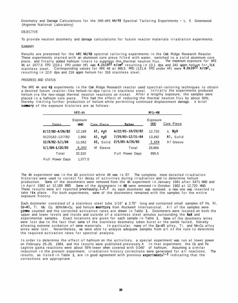
Dosimetry and Damage Calcu lat ions f o r the ORR-MFE 4A/48 Spectral T a i l o r i n g Experiments - L. R. Greenwood (Argonne Nat ional Laboratory)
OBJECTIVE
To p rov ide neutron dosimetry and damage ca l cu l a t i ons f o r f us i on r eac to r mate r ia ls i r r a d i a t i o n experiments.
SUMMARY
Results are presented f o r the MFE 4Al48 spec t ra l t a i l o r i n g experiments i n the Oak Ridge Research Reactor. These experiments s t a r t ed w i t h an aluminum core p iece f i l l e d w i t h water, switched t o a s o l i d aluminum core piece, and f i n a l l y added hafnium l i n e r s t o suppress the thermal neutron f l u x . 4A a t 1077.0 FPD (223.1 FPO under HF) was 4.2~1022 n/cm2 r e s u l t i n g i n 13.1 dpa and 243 appm hel ium f o r 316 s ta i n l ess s tee l . r e s u l t i n g i n 12.0 dpa and 216 appm hel ium f o r 316 s ta i n l ess s tee l .
PROGRESS AND STATUS
The MFE 4A and 48 experiments i n the Oak Ridge Research r eac to r used s p e c t r a l - t a i l o r i n g techniques t o ob ta i n a des i red fusion r e a c t o r - l i k e helium-to-dpa r a t i o i n s t a i n l ess s tee l . hel ium v i a the two-stage thermal neutron react ions on n i cke l . placed i n a hafnium core piece. This had the e f f e c t of reducing t he thermal neutron f l u x by about 50%. thereby l i m i t i n g f u r t h e r product ion o f hel ium wh i le p e r m i t t i n g cont inued displacement damage. A b r i e f sumary o f the exposure h i s t o r i e s are as fo l lows :
The maximum exposure f o r MFE
Corresponding values f o r MFE 48 a t 995.5 FPD (121.8 FPD under HF) were 4.0~1022 n/cm2,
I n i t i a l l y the experiments produced A f t e r a lengthy exposure, the samples were
MFE-4A MFE-4B
Exposure Exposure MWD Core Piece Dates MWD Core Piece Dates -
6/12/80-4/26182 12,189 A l , H2O 4/22/81-10/20/82 12,720 A, HzD
9123182-12/7/82 1,866 A l , H20 7/29183-12/31-64 13,492 A l , S o l i d 12/8/82-5/1184 11,562 A1 I S o l i d 2/5185-6/26185 3.654 H f Sleeve
511/84-1120185 6.693 Hf Sleeve Tota l 29,866
Tota l 32,310 F u l l Power Days 995.5
F u l l Power Days 1,077.0
The 4A experiment was i n t he E3 p o s i t i o n wh i l e 48 was i s E7. h i s t o r i e s were used t o co r rec t f o r decay o f a c t i v i t i e s dur ing i r r a d i a t i o n and t o determine hel ium product ion. i n A p r i l 1982 a t 12,189 MWD. These r e s u l t s were a l l repor ted p r e v i o u s l y . 1 ~ 2 ~ 3 take i t s place. exposure h i s t o r y .
Each dosimeter consis ted o f a s t a i n l ess s tee l tube 1/16" x 2.75" long and contained small samples o f Fe, N i , Co-AI. T i . Nb. Cu. 80% Mn-Cu, and hel ium nmnitors from Rockwell I n t e rna t i ona l . A l l o f t he samples were g a m counted and t he corrected a c t i v a t i o n r a tes a re shown i n Table 1. upper and lower l e v e l s and i n s i d e and ou ts ide o f a s t a i n l ess s tee l annulus surrounding the NaK and experimental samples. Exact l o ca t i ons are g iven f o r each sample i n Table 1. Some o f t he dosimetry wi res were l o s t due t o t he f ac t t h a t some o f t he s t a i n l ess dosimetry tubes bu rs t o r the welds f a i l e d , thereby a l l ow ing extreme ox i da t i on o f some mater ia ls . I n p a r t i c u l a r , many o f the Co-AI a l l o y , T i , and Mn-Cu a l l o y wi res were l o s t . Nevertheless, we were ab le t o analyze adequate samples from a l l o f the runs t o determine t he requ i red a c t i v a t i o n ra tes f o r spec t ra l analys is .
I n o rder t o determine t he e f f e c t o f hafnium on the a c t i v i t i e s , a specia l experiment was run a t lower power on February 25-26, 1984, and the r e s u l t s were publ ished previously.4 I n t h a t experiment, the Co and Fe cap t i ve gama reac t ions were about 56% lower when covered w i t h 0.040' of hafnium. Assuming a s i m i l a r reduc t ion i n t he present experiment, i r r a d i a t i o n h i s t o r y cor rec t ions were generated f o r a l l react ions. The resu l t s , as l i s t e d i n Table 1, are i n good agreement w i t h previous experimentsl-3 i n d i c a t i n g t h a t t he cor rec t ions are appropr ia te.
The complete, more d e t a i l e d i r r a d i a t i o n
Some o f the dosimeters were removed from the 4A experiment i n January 1981 a f t e r 5471 MWD and
As each dosimeter was removed. a new one was i nse r t ed t o Some o f the dosimeters i n 48 were removed i n October 1982 a t 12,720 MWD.
For both experiments, some of t he dosimeters remained w i t h the samples f o r the e n t i r e
Dosimeters were loca ted on bo th the
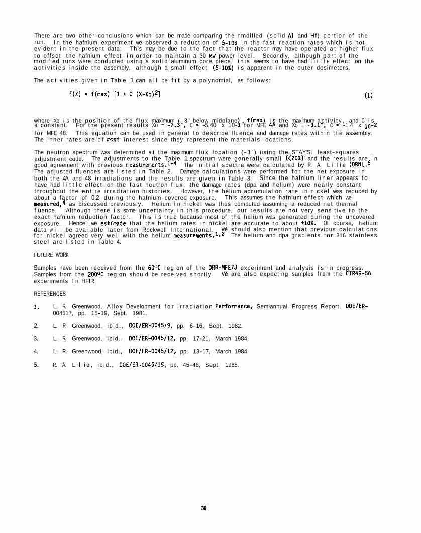
There a re two o ther conclusions which can be made comparing the nmdif ied ( s o l i d A1 and Hf) p o r t i o n of the run. ev ident i n the present data. This may be due t o the fac t t h a t the reac to r may have operated a t h igher f l u x t o o f fse t the hafnium ef fect i n o rder t o mainta in a 30 MIJ power leve l . Secondly, al though p a r t o f t he modi f ied runs were conducted us ing a s o l i d aluminum core piece, t h i s seems t o have had l i t t l e e f fec t on the a c t i v i t i e s i n s i d e the assembly, al though a small e f fec t ( 5 1 0 % ) i s apparent i n the ou te r dosimeters.
The a c t i v i t i e s g iven i n Table 1 can a l l be f i t by a polynomial, as fo l lows :
I n the hafnium experiment we observed a reduc t ion of 5 1 0 % i n the f as t r eac t i on ra tes which i s not
f ( z ) - f(max) [1 + c ( x - X O ) ~ ] (1)
where Xo i s the p o s i t i o n of the f l u x maximum (-3" below midplane , f(max) i s the maximum a c t i v i t y , and C i s
f o r MFE 48. This equation can be used i n general t o descr ibe f luence and damage ra tes w i t h i n the assembly. The i nne r ra tes a re o f mst i n t e r e s t s ince they represent the ma te r i a l s loca t ions .
The neutron spectrum was determined a t the maximum f l u x l oca t i on (- 3 ") using the STAY'SL least- squares adjustment code. good agreement w i t h previous measurements.1-4 The i n i t i a l spect ra were ca lcu la ted by R. A. L i l l i e (ORNL.5 The adjusted f luences a r e l i s t e d i n Table 2. Damage ca l cu l a t i ons were performed f o r the ne t exposure i n bo th the 4A and 48 i r r a d i a t i o n s and the r e s u l t s are g iven i n Table 3. have had l i t t l e e f fect on the f a s t neutron f l u x , t he damage ra tes (dpa and hel ium) were near ly constant throughout the e n t i r e i r r a d i a t i o n h i s t o r i e s . However, the hel ium accumulation r a t e i n n i cke l was reduced by about a fac to r of 0.2 dur ing the hafnium-covered exposure. measured.4 as discussed prev ious ly . Helium i n n i cke l was thus computed assuming a reduced ne t thermal fluence. Although there i s some uncer ta in ty i n t h i s procedure, our r e s u l t s a re no t very sens i t i ve t o the exact hafnium reduct ion fac to r . This i s t r u e because most of the hel ium was generated dur ing the uncovered exposure. data w i l l be ava i lab le l a t e r from Rockwell I n t e rna t i ona l . f o r n i cke l agreed very we l l w i t h the hel ium measurewnts.l.2 s t ee l a re l i s t e d i n Table 4.
FUTURE WORK
Samples have been received from the 6OOC reg ion of the ORR-MFE7J experiment and ana lys is i s i n progress. Samples from the 2OOOC reg ion should be received sho r t l y . experiments I n HFIR.
REFERENCES
a constant. For the present r e s u l t s Xo = -2.3". C = -5.40 x 10- J f o r MFE 413 and Xo = -3.1", C = -1.4 x
The adjustments t o the Table 1 spectrum were genera l l y small (<20%) and the r e s u l t s are i n
Since t he hafnium l i n e r appears t o
This assumes t he hafnium e f f e c t which we
Hence, we esttrnate t ha t the hel ium ra tes i n n i c k e l are accurate t o about 210%. Of course, hel ium We should a lso mention t h a t previous ca l cu l a t i ons
The hel ium and dpa g rad ien ts for 316 s ta i n l ess
We are a l so expect ing samples f r o m the CTR49-56
1 . L. R. Greenwood, A l l o y Development f o r I r r a d i a t i o n Performance, Semiannual Progress Report, DOEIER- 004517, pp. 15-19, Sept. 1981.
2. L. R. Greenwood, i b i d . , DOE/ER-0045/9, pp. 6-16, Sept. 1982.
3. L. R. Greenwood, ib id . , DOE/ER-0045/12, pp. 17-21, March 1984.
4. L. R. Greenwood, ib id . , DOE/ER-0045/12, pp. 13-17, March 1984.
5. R. A. L i l l i e , i b i d . , DOE/ER-0045/15. pp. 45-46, Sept. 1985.
Reaction
58Fe(n, a ) 59Fe
55Mn (n, 2n) 54Mn
Table 1A. Ac t i va t i on Rates - ORR - MFE 4A3 1078 FPD (entire run) , 30 MW
A c t i v i t y , a t f a t s
-0.63
-2.53
-3.69
-3.94
-5.84
-4.25
-1.00
-1.81
-4.44
-5.13
-0.63
-2.53
-3.69
-3.94
-5.84
-1.59
-4.91
-2.06
-4.06
-5.38
-0.81
-3.88
-4.13
Inner
1.74-10
1.76-10
-
1.65.10
1.57-10
3.08-10
2.96-10
2.73-10
1.10-11
1.11-11
1.09-11
1.01-11
1.58-12
1.46-12
7.29-14
6.85-14
3.32-14
3.21-14
Outer - 1.90-10
1.76-10
1.82-10
1.67-10
4.41-9
2.74-10
3.03-10
2.85-10
1.18-11
1.14-11
1.21-11
1.15-11
1.67-12
1.64-12
7.21-14
9.02-14
7.33-14
3.61-14
4.66
ai
Table 18. Activation Rates - ORR - 4A - Mod 672 FPO (9/23/82 to 1/21/85]. 30 MW
Reaction
5aFe (n, 7) 59Fe
59~0(n,7)60~0
g3Nb(n,7)94Nb
54Fe(n,p)54Mn
R T ~ (n,p)%c
63~u(n,a) 6 0 ~ 0
Reaction
58Fe(n,7)59Fe
59Co (n, 7) 6oCo
g3Nb(n,7)94Nb
54Fe (n .p) 54Mn
46Ti (n,p)4%c
63~u(n,a)60~0
55Mn(n,Zn)54Mn
-0.53
-2.56
-3.84
-5.88
-0.69
-2.19
-5.28
-0.53
Activity, atlats
- Inner Outer
1.75-10 1.87-10
1.80'10
1.76-10
1.47-1°
4.07-g 4.34-9
2.86-1° 2.99-10
2.74-1°
1.09-'11 1.17-11
-2.56 1.09-11
-3.84 1.06-11
-5.88 0.97-11
-2.06 1.65-12
-2.31 8.20-14
Table 1C. Activation Rates - ORR - MFE 4812 Entire Run 996 FPD, 30 MW
Activity, atlats
-0.72
-2.41
-4.03
-5.72
-4.20
-5.37
-4.8a
-0.72
-2.41
-4.03
-5.72
-4.63
-5.38
-1.81
-5.13
React 1 on
58Fe (n , I ) 5%
54Fe(n, p) 54Mn
Table 10. Activation Rates - ORR - MFE 48/Mod 572 FPO (7/29/83 to 6/26/85), 30 MW
Activlty, a t l a t s
Inner - -0.53
-2.63
-3.84
-4.94
-5.94
-4.00
-2.19
-2.88
-4.19
-5.50
-0.53
-2.63
-3.84
-4.94
-5.94
-2.06
-4.44
-5.38
-2.31
-4.69
-5.63
1.87-10
1.89-10
1.76-10
1.79-10
1.56-10
3.94-9
2.95-10
2.75-10
2.70-10
2.72-10
1.09-11
1.09-11
1.09-11
1.07-1 1
1.00-11
1.48-12
1.41-12
1.39-12
7.21-14
6.95-14
6.92-14
Outer
1.83'1O
1.83-1O
1.95-1O
1.73-10
4.27-9
3.04-10
3.08-10
3.01-10
1.15-11
1.14-11
1.20-11
1.10-11
1.56-12
1.56-12
7.79-14
8.12-14
33
Table 2. Neutron Fluences f o r OUR - MFR 4AJ48 Values i n s i d e the assembly a t maximum f l u x
Fluence x 1022 nJcm2
Energy
Exposure (FPD) 1078.4 995.5
Tota l 4.23 3.96
Thermal (<.5 eV) 1.28 1.24
0.5 eV-0.11 MeV 1.33 1.26
x.11 MeV 1.62 1.46
>1 MeV 0.91 0.83
V a l u e s assume 223.1 FPD under Hf f o r 4A and 121.8 FPD f o r 48.
Table 3. Damaqe Parameters f o r ORR - MFE 4AI48 Values a t maximum f l u x l oca t ion , -2.3" f o r A, -3.1" f o r 8
MFE 4A MFE 48 He, appm DpA He, appm DPA
A1 9.95 21.80 8.84 T i 7.75 14.00 7.06 V 0.35 15.50 9.31 C r 2.49 13.94 2.23 Mna 2.07 14.79 1.84 Fe 4.34 12.40 3.88 coa 2.06 14.01 1.83
Fast 63.03 13.01 56.84 N i 59Ni 1781 3.14 1580
Tota l 1844 16.15 1637
3.04 11.92 2.81, cu E;: 0.49 _ _ 0.46
Tota l 3.53 11.92 3.27 - -
Z r Nb
0.38 12.85 0.33 0.82 11.85 0.73
Ma _ _ 8.69 _ _ l a ._ 5.99 _ _ 316SSb 243 13.12 216
He/DPA 18.5 18.0
aThermal neutron s e l f - s h i e l d i n g may reduce damage (dpa).
h316SS : Fe (0.645) , N i (0.13), C r (0. 18), Mn (0.019), Ma (0.026) .
19.90 12.82 14.17 12.76 13.53 11.34 12.81 11.89 2.79 14.68
10.89
10.89
11.73 10.82 7.93 5.48 12.00
_ _ -
34
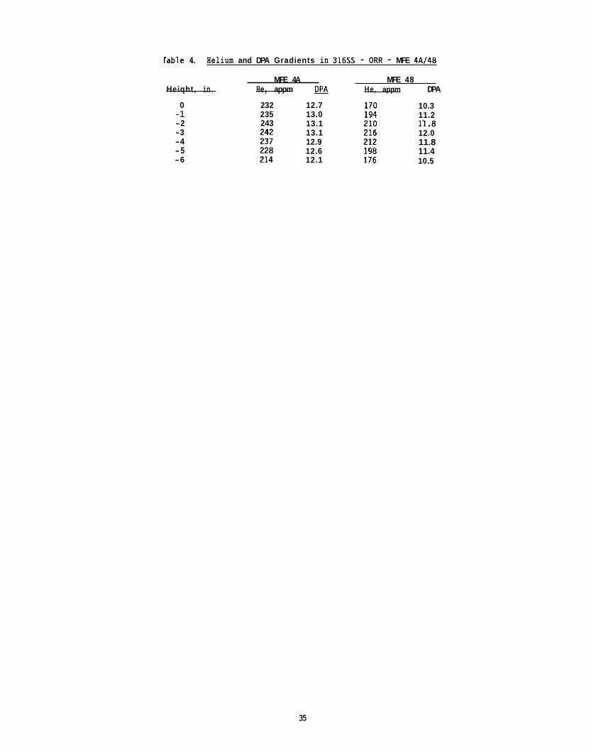
lable 4. Helium and DPA Gradients in 3 1 6 s - ORR - MFE 4A/4B
MFE 4A MFE 48 Heiqht, in. He, appm opn He, appm DPA
0 -1 -2 -3 -4 - 5 -6
232 235 243
12.7 13.0 13.1 13.1 12.9 12.6 12.1
10.3 11.2 11 .8 12.0 11.8 11.4 10.5
35

NEUTRON SPECTRAL CALCULATIONS FOR THE REAL88 EXERCISE - L. R. Greenwood and A. In tasorn (Argonne Nat ional Laboratory)
OBJECTIVE
To standardize nuclear data and techniques used t o measure neutron f l u x spect ra and t o ca l cu l a te r a d i a t i o n damage i n mater ia ls .
SUMMARY
Neutron spec t ra l analyses and damage ca l cu l a t i ons have been completed f o r s i x reference data sets d i s t r i b u t e d by the I A E A i n Vienna. dosimetry techniques and damage estimates f o r var ious spect ra i n c l u d i n g fus ion r eac to r simulat ions, pressure vessel su rve i l l ance , 23% f i s s i on , and f a s t f i s s i o n reactors. The data w i l l be reviewed a t a meeting i n ECN Petten, The Netherlands, i n October, 1988.
PROGRESS AND STATUS
We are p a r t i c i p a t i n g i n a p ro j ec t t o compare neutron spec t ra l adjustment codes and damage p red ic t ions sponsored by the I n te rna t i ona l Atomic Energy Agency i n Vienna, Austr ia . Neutron a c t i v a t i o n data were co l l ec ted and d i s t r i b u t e d by the I A E A f o r s i x d i s t i n c t l y d i f f e r e n t neutron spect ra i nc l ud i ng a pressure vessel su rve i l l ance capsule from the Arkansas Nuclear One power reac to r , two pressure vessel s imulator e x p e r i m n t s i n the Oak Ridge Research Reactor, a 23% f i s s i o n spectrum, t he Coupled Fast Reac t i v i t y Measurement F a c i l i t y a t Idaho Nuclear Engineering Laboratory, and a fus ion- s imu la t ion spectrum measured a t RTNS I1 (provided by the author).
The REAL88 exercise fo l lowed the previous REAL801 and REAL842 exercises. placed t i g h t e r r e s t r i c t i o n s on the q u a l i t y o f the i n p u t data, knowledge of covariance information, nuc lear data, and types o f computer codes which a re allowed. The goal i s t o standardize procedures and t o es tab l i sh reference data sets.
Over f i f t e e n d i f f e r e n t l abo ra to r i es are expected t o p a r t i c i p a t e i n e i g h t d i f f e r e n t countr ies. We have submitted our r e s u l t s t o the ECN labora to ry i n Petten, The Netherlands, where a l l r e s u l t s w i l l be compared.
FUTURE WORK
A meeting w i l l then be he ld i n Petten i n l a t e October, 1988, t o assess t he p re l im ina ry r e s u l t s o f the comparison and t o p lan f u t u r e work. The exercise i s scheduled t o be completed i n t ime t o issue a f i n a l r epo r t a t the Seventh ASTM-Euratom Symposium on Reactor Dosimetry i n August 1990 i n Strasbourg, France.
This i n t e r l abo ra to r y intercomparison i s designed t o standardize
Each successive exerc ise has
REFERENCES
1. W. L. Z i j p , E. M. Zsolnay, H. J. Nolthenius, E. J. Szondi, 6. C. Verhaag, 0. E. Cul len, and C. Ertek. F i na l Report on the REAL-80 Exercise. INDCCNED)-7, 1983.
2. E. M. Zsolnay, H. J. Nolthenius, and W. L. Z i j p , F i f t h Progress Report on t he REAL84 Exercise, ECN- 87-045, A p r i l 1987.

.
3 . M A T E R I A L S E N G I N E E R I N G AND D E S I G N R E Q U I R E M E N T S
N o c o n t r i b u t i o n s .


4. F U N D A M E N T A L M E C H A N I C A L B E H A V I O R
41

GRAIN S I Z E EFFECT ON RADIATION HARDENING I N NEUTRON-IRRADIATED POLYCRYSTALLINE COPPER - S. Kojima, S. J. Z ink le (Oak Ridge Nat ional Laboratory) and H. L. Heinisch ( P a c i f i c Northwest Laboratory)
OBJECTIVE
The o b j e c t i v e o f t h i s study i s t o ob ta in fundamental knowledge of t h e c o r r e l a t i o n between micro- s t r u c t u r a l change and the v a r i a t i o n of y i e l d s t ress i n neu t ron- i r rad ia ted metals.
SUMMARY
M ic ros t ruc tu ra l changes i n 14 MeV neu t ron- i r rad ia ted p o l y c r y s t a l l i n e copper were observed by t rans- miss ion e l e c t r o n microscopy and c o r r e l a t e d w i t h the v a r i a t i o n o f y i e l d s t ress. r a d i a t i o n hardening was found t o be not d i r e c t l y app l i cab le t o po lyc rys ta l s . defect c l u s t e r s are considered t o become obstacles not only t o t h e motion o f d i s l o c a t i o n s on the p i l i n g - up s ide o f a gra in , but a l so t o t h e generat ion o f d i s l o c a t i o n s on t h e next gra in . Generally, app l i cab le s i m p l i f i e d equations f o r p o l y c r y s t a l s are proposed. t e s t resu l t s , t he c o n t r i b u t i o n o f ma t r i x hardening was found t o be f a i r l y low.
Conventional theory of Radiat ion- induced p o i n t
By apply ing t h e equations t o the publ ished t e n s i l e
PROGRESS ANB STATUS
In t roduc t ion
The study o f neutron i r r a d i a t i o n damage a t a very low fluence reveals the c h a r a c t e r i s t i c s of i n d i v i d - ua l cascade damage s ince l i t t l e i n t e r a c t i o n e x i s t s between o the r cascade damages. The gradual increase o f the neutron f luence makes i t poss ib le t o fea tu re t h e i n t e r a c t i o n between cascades which p lays an important r o l e i n h igh f luence i r r a d i a t i o n . One of the f r u i t f u l r e s u l t s obtained from e a r l i e r s tud ies of RTNS-I1 i r r a d i a t i o n us ing e l e c t r o n microscopy i s the observat ion t h a t the number dens i t y of p o i n t defect c l u s t e r s var ies from a l i n e a r dependence on neutron f luence t o a one-half power dependence as the f luence increases.'-3 This change of f luence dependence i s an i n d i c a t i o n of the i n t e r a c t i o n of f r e e l y m ig ra t ing p o i n t defects w i t h i r rad ia t ion- produced defect c lus te rs . dence does not occur u n t i l a c e r t a i n amount of defect c l u s t e r s comparable t o t h e permanent s ink con- c e n t r a t i on are accumulated. +'
The swi tch from l i n e a r t o square r o o t depen-
The present study inves t iga tes the v a r i a t i o n o f the y i e l d s t ress change a t low fluences i n 14 MeV neu t ron- i r rad ia ted copper. t i o n between d i s l o c a t i o n s and defect c l u s t e r s i s a l so expected t o be observed s t a r t i n g from very low fluences where on ly a few defect c l u s t e r s e x i s t . M i t c h e l l 8 has shown a r e s u l t t h a t t h e y i e l d s t ress change i n 14 MeV neu t ron- i r rad ia ted copper ab rup t l y increases a t about 3 x I O z o n/m2. a c e r t a i n abrupt change has occurred i n the m ic ros t ruc tu re and/or t h e i n t e r a c t i o n between d is loca t ions and defect c l u s t e r s a t t h i s f luence. s t reng th o f defects may be f luence dependent. Th is p o s s i b i l i t y was obtained from a comparison of e lec- t r o n microscopy and e l e c t r i c a l r e s i t i v i t y measurementsg w i t h M i t c h e l l ' s resu l t s . However, t h e comparison su f fe red a ser ious drawback i n t h a t d i f f e r e n t heats o f copper were used i n t h e two studies. I n the p r e r - en t experiment, m ic ros t ruc tu ra l observat ion by e lec t ron microscopy has been performed on specimens pre- pared and i r r a d i a t e d a t t he same t ime as t h e specimens used f o r t e n s i l e t o avo id t h e ambigui ty a r i s i n g from specimen d i f ferences.
The conclusion o f the present study i s t h a t the abrupt increase of y i e l d s t ress i s due t o t h e par- t i c i p a t i o n o f "source hardening" i n a d d i t i o n t o the i n i t i a l " l a t t i c e hardening."I2 t h e d is tance between rad ia t ion- induced defect c l u s t e r s and the s i z e of Frank-Read-type source i s con- s idered t o be c o n t r o l l i n g t h i s phenomenon. The l a r g e c o n t r i b u t i o n of t h e "source hardening" i s thought t o be a ser ious problem from a p r a c t i c a l v iewpoint s ince i t means most of t he s t ress i s concentrated a t t h e head o f p i led- up d i s loca t ions (i.e., g ra in boundaries). We propose a s i m p l i f i e d equat ion which expresses t h i s c o n t r i b u t i o n of "source hardening" according t o the v a r i a t i o n of g ra in s ize.
L i k e the i n t e r a c t i o n between p o i n t defects and defect c lus te rs , t he i n t e r a c-
This imp l ies t h a t
A previous repor t g suggested the p o s s i b i l i t y t h a t the b a r r i e r
The r e l a t i o n between
Experimental Procedure
M in ia tu re sheet- type t e n s i l e specimens were prepared from pure (Marz grade) copper. The specimens
The speci- were punched from 0.25 nn sheet stock, de-burred, l a s e r engraved, then annealed a t 723 K f o r 15 min i n argon. mens were i r r a d i a t e d w i t h 14 MeV neutrons a t 363 K i n t h e RTNS-I1 f a c i l i t y t o f luences of 0.62 t o 20.0 x 10²' n/m2.
The r e s u l t a n t g ra in s i z e was ASTM 7 which corresponds t o a diameter o f about 36 urn.
43
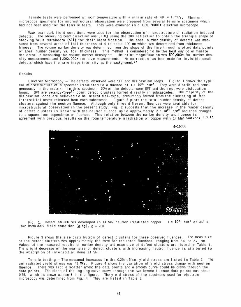
Tens i le t e s t s were performed a t room temperature w i t h a s t r a i n r a t e of 4.9 x lO-'+/s. microscope specimens f o r m ic ros t ruc tu ra l observat ion were prepared from several t e n s i l e specimens which had not been used f o r t h e t e n s i l e t es t s .
E lec t ron
They were examined i n a JEOL 2OOOFX e lec t ron microscope.
Weak beam dark f i e l d cond i t ions were used f o r t h e observat ion o f m ic ros t ruc tu re of rad ia t ion- induced The observing beam d i r e c t i o n was [ l l O ] us ing t h e 200 r e f l e c t i o n t o ob ta in t h e t r i a n g l e shape of
The volume number dens i t y was determined from t h e slope of t h e l i n e through p l o t t e d data po in t s
The p r i n t magn i f i ca t i on was 500,000~ fo r number den-
defects . s tack ing f a u l t te t rahedra (SFT) f o r t h e i r i d e n t i f i c a t i o n . The areal number dens i ty of defects was mea- sured from several areas o f f o i l th ickness o f 0 t o about 100 nm which was determined from th ickness f r i nges . o f areal number dens i ty vs. f o i l th ickness. Th is method i s considered t o be t h e best way t o e l i m i n a t e t h e e r r o r i n measuring t h e volume number density." s i t y measurements and 1,000,000~ f o r s i ze measurements. defec ts which have t h e same image i n t e n s i t y as t h e b a ~ k g r 0 u n d . l ~
No c o r r e c t i o n has been made fo r i n v i s i b l e small
Resul ts
E lec t ron Microscopy - The defects observed were SFT and d i s l o c a t i o n loops. F igure 1 shows t h e t y p i - ca l m ic ros t ruc tu re of a specimen i r r a d i a t e d t o a f luence o f 1 x loz1 n/m2. geneously i n t h e ma t r i x . I n t h i s specimen, 70% o f t h e defects were SFT and t h e r e s t were d i s l o c a t i o n loops. d i s l o c a t i o n loops are be l ieved t o be i n t e r s t i t i a l - t y p e , presumably formed from t h e c l u s t e r i n g of f ree i n t e r s t i t i a l atoms released from each subcascade. F igure 2 p l o t s t h e t o t a l number dens i ty of defect c l u s t e r s against t h e neutron f luence. m ic ros t ruc tu ra l observat ion i n t h e present study, F ig . 2 suggests t h a t t h e increase i n t h e number dens i t y of defect c l u s t e r s i s l i n e a r w i t h t h e neutron f luence up t o approximately 2 x loz1 n/mZ and then changes t o a square roo t dependence on f luence. agreement w i t h prev ious r e s u l t s on t h e room temperature i r r a d i a t i o n o f copper w i t h 14 MeV neutrons.1'3*16
They were d i s t r i b u t e d homo-
SFT are v a c a n ~ y - t y p e ' ~ p o i n t defect c l u s t e r s formed d i r e c t l y i n subcascades. The m a j o r i t y of the
Although on l y th ree d i f f e r e n t f luences were a v a i l a b l e f o r
Th is r e l a t i o n between t h e number dens i ty and f luence i s i n
5-15336
Fig. 1. Defect s t ruc tu res developed i n 14 MeV neutron i r r a d i a t e d copper. 1 x loz1 n/m2 a t 363 K. bleak beam dark f i e l d cond i t i on (9,691, g = 200.
F igure 3 shows t h e s i z e d i s t r i b u t i o n of defect c l u s t e r s f o r t h ree observed fluences. The mean s i z e o f the defec t c l u s t e r s was approximately t h e same f o r t h e th ree f luences, ranging from 2.4 t o 2.7 nm. Values o f t h e measured r e s u l t s of number dens i ty and mean s i z e o f defec t c l u s t e r s are l i s t e d i n Table 1. The s l i g h t decrease o f t h e mean s i ze of defect c l u s t e r s w i t h increas ing neutron f luence i s a t t r i b u t e d t o t h e absorpt ion o f i n t e r s t i t i a l atoms a t SFT.
Tens i le t e s t i n g - The measured increases i n t h e 0.2% o f f s e t y i e l d s t ress are l i s t e d i n Table 2. The u n i r r a d i a t e d y i e l d s t ress was 49 MPa. F igure 4 shows the v a r i a t i o n of y i e l d s t ress change w i t h neutron f luence. data po in t s . The slope o f t h e l og- log curve drawn through t h e two lowest f luence data po in t s was about 0.75, which i s shown as tan 8 i n the f igure. The y i e l d s t ress of t h e specimens used fo r e l e c t r o n microscopy was determined from Fig. 4.
There was l i t t l e s c a t t e r among t h e data po in t s and a smooth curve could be drawn through the
They are l i s t e d i n Table 3.
44
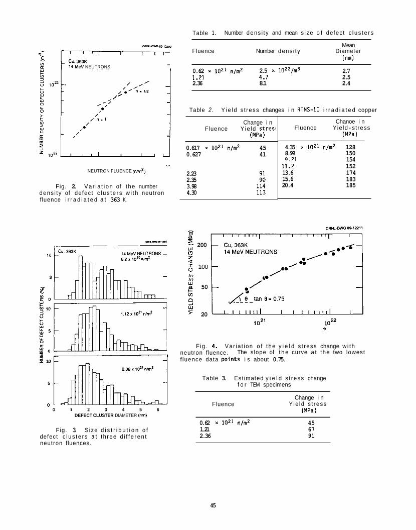
Table 1. Number dens i t y and mean s i ze o f defect c l u s t e r s
w m 5
mm.ow 6u,nos
Cu. 363K 14 MeV NEUTRONS
0.617 x loz1 n/m2 45
Mean Fluence Number dens i t y Diameter
(nm)
1022 I I l l I I I 1
0.62 x loz1 n/m2 1 ~ 7 1 4.7
2.5 x l O Z 2 / m 3
0.627 41
2.7 2.5 _.--
2.36 8.1 2.4
Table 2 . Y i e l d s t ress changes i n RTNS-I1 i r r a d i a t e d copper
Change i n Fluence Y ie ld s t res '
W a )
." NEUTRON FLUENCE (nm2)
Fig. 2. V a r i a t i o n of the number dens i t y of defect c l u s t e r s w i t h neutron fluence i r r a d i a t e d a t 363 K.
10
s I ac
z " . I 2 10
5
n " 0 1 2 3 4 5 6
DEFECT CLUSTER DIAMETER lnm)
Fig. 3. Size d i s t r i b u t i o n o f defect c l u s t e r s a t t h ree d i f f e r e n t neutron fluences.
2.23 2.35 3.98 4.30
- m a 5. 200 2 6 100
w
Q
In In w + In
a 50
9 w > 20
Chanoe i n Fluence Yie ld- st ress
(MPa)
4.35 x 10²¹ n/m2 128 8.99 150 9.21 154 11.2 13.6 15.6
152 174 183 ~~ ~
20.4 185
loz1 1 OZ2 9
Fig. 4. Var ia t i on o f the y i e l d s t ress change w i t h neutron fluence. f luence data Doints i s about 0.75.
The slope of t h e curve a t the two lowest
Table 3. Estimated y i e l d s t ress change f o r TEM specimens
Fluence Change i n
Y ie ld s t ress W a )
0.62 x loz1 n/m2 45 1.21 67 2.36 91
45
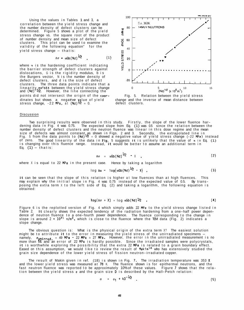
100 Using t h e values i n Tables 1 and 3, a
c o r r e l a t i o n between t h e y i e l d s t ress change and t h e number dens i t y of defect c l u s t e r s can be
s t ress change vs. the square roo t of the product
c lus te rs . This p l o t can be used t o examine t h e v a l i d i t y of the fo l l ow ing equation” f o r t h e
- 80 m determined. F igure 5 shows a p l o t of t h e y i e l d a 2
of number dens i ty and mean s i ze o f defec t
4 y i e l d s t ress change - t h a t i s : Lo
; 6o
40 u1 w
A 0 = aGb(Nd)’/’ , (1) E 20 where a i s the hardening c o e f f i c i e n t i n d i c a t i n g t h e b a r r i e r s t rength of defect c l u s t e r s against d i s loca t i ons , G i s t h e r i g i d i t y modulus, b i s t h e Burgers vector, N i s t h e number dens i ty of defect c lus te rs , and d i s t h e s i z e o f defec t c lus te rs . The th ree data po in t s i n d i c a t e t h a t a
Fig. 5. Re la t i on between t h e y i e l d s t ress p o i n t s d i d not i n t e r s e c t the o r i g i n o f t h e coor- d inates but shows a negat ive l u e o f y i e l d change and t h e inverse of mean distance between s t ress change, - 2 2 MPa, a t (Nd)@ = 0.
l i n e a r i t y x i s t s between t h e y i e l d s t ress change 0 5 10 15 (Nd)l ’* (x 106ni’) and (Nd)- s 2. However, t h e l i n e connecting t h e
defect c lus ters .
---,m.,
I I I I ’ I ’ I I ’ /*’
I I I I
Cu. 363K - 1 4 M e V N E U T R O N S -
/’ - - - -
, - , , 7
Discussion
Two s u r p r i s i n g r e s u l t s were observed i n t h i s study. F i r s t l y , t h e slope of t h e lower f luence har- dening data i n Fig. 4 was 0.75. number dens i ty of defect c l u s t e r s and t h e neutron f luence was l i n e a r i n t h i s dose regime and t h e mean s i ze of defects was almost constant as shown i n Figs. 2 and 3. F ig . 5 from t h e data po in t s t o (Nd) lh = 0 showed a negat ive value of y i e l d s t ress change (- 22 MPa) i ns tead o f zero. The good l i n e a r i t y of t h e data i n Fig. 5 suggests i t i s u n l i k e l y t h a t t h e value of o i n Eq. (1) i s changing over t h i s f luence range. Eq. (1) - t h a t i s :
The expected slope from Eq. (1) was 0.5 s ince t h e r e l a t i o n between t h e
Secondly, t h e ext rapo la ted l i n e i n
Instead, i t would be b e t t e r t o assume an add i t i ona l term i n
Ao = aGb(Nd)”2 - X , (2)
where X i s equal t o 22 MPa i n t h e present case. Hence by t a k i n g a l oga r i t hm
l o g Aa = log[aGb(Nd)” - X ) , ( 3 )
i t can be seen t h a t t h e slope of t h i s r e l a t i o n i s h igher a t low f luences than a t h igh f luences. This may exp la in why t h e i n i t i a l slope i n Fig. 4 was 0.75 i ns tead of t h e expected value of 0.5. By t rans- posing t h e e x t r a term X t o t h e l e f t s i de of Eq. (2) and t a k i n g a logar i thm, t h e fo l l ow ing equat ion i s obtained:
( 4 ) log(Ao + X ) = l o g aGb(Nd) Ih . Figure 6 i s t h e r e p l o t t e d vers ion of Fig. 4 which simply adds 22 MPa t o t h e y i e l d s t ress change l i s t e d i n Table 2. dence of neutron f luence t o a one- fourth power dependence. s lope i s around 2 x lo2’ n/m2, which i s c lose t o t h e f luence where t h e TEM data (Fig. 2) i nd i ca tes a s lope change.
might be t o a t t r i b u t e i t t o t h e e r r o r i n measuring t h e y i e l d s t ress of t h e u n i r r a d i a t e d specimens - namely, o nirrad. = 49 MPa - 22 MPa = 27 MPa. However, t h e e r r o r i n t h e un i r rad ia ted measurement i s no more than E% and an e r r o r of 22 MPa i s ha rd l y poss ib le . Since t h e i r r a d i a t e d samples were po lyc rys ta l s , i t i s worthwhi le exp lo r i ng t h e p o s s i b i l i t y t h a t t h e e x t r a 22 MPa i s r e l a t e d t o a g r a i n boundary ef fect . Eased on t h i s assumption, we would l i k e t o review t h e r e s u l t of Makinla who has extens ive ly s tud ied t h e g r a i n s i ze dependence o f t h e lower y i e l d s t ress o f f i s s i o n neu t ron- i r rad ia ted copper.
The r e s u l t of Makin given i n ref . (18) i s shown i n Fig. 7. and t h e lower y i e l d s t ress was measured a t 70 K. The fluence shown i s f o r epi thermal neutrons, and t h e f a s t neutron f luence was repor ted t o be approximately 10% of these values. t i o n between t h e y i e l d s t ress a and t h e g ra in s i ze D i s descr ibed by t h e Hal l-Petch r e l a t i o n :
It c l e a r l y shows t h e expected tendency of t h e r a d i a t i o n hardening from a one-half power depen- The fluence corresponding t o t h e change i n
The obvious quest ion i s : What i s the phys ica l o r i g i n of t h e ex t ra term X ? The eas ies t s o l u t i o n
The i r r a d i a t i o n temperature was 353 K
Figure 7 shows t h a t the r e l a -
46
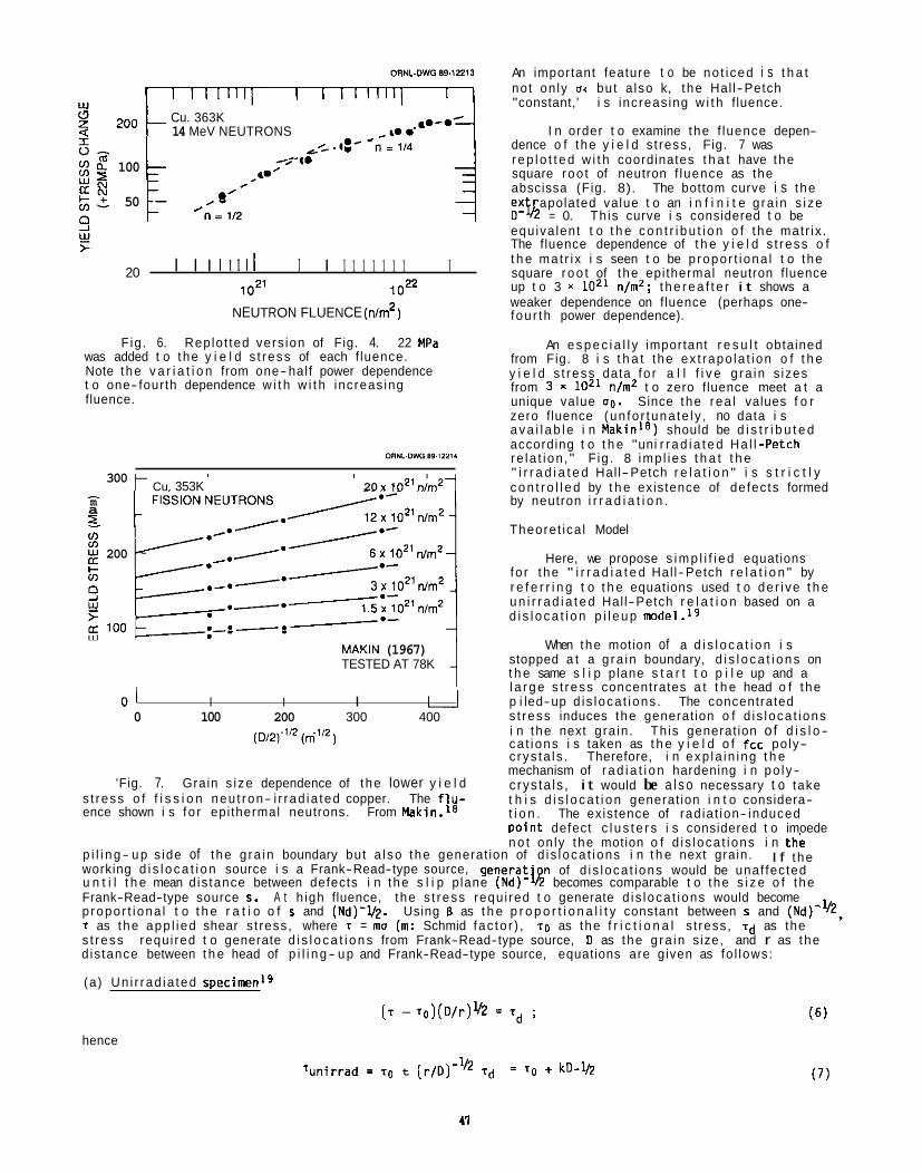
200
100
50
20
Cu. 363K t 14 MeV NEUTRONS .,E- -
I I I I1111 I I I 1 1 1 1 1 1 I 1021 1022
NEUTRON FLUENCE ( n d )
F ig . 6. Replo t ted vers ion of Fig. 4. 22 MPa was added t o the y i e l d s t ress of each f luence. Note the v a r i a t i o n from one-half power dependence t o one- fourth dependence w i t h w i t h increas ing fluence.
300 I m a z m m
k + 200
t Cu. 353K ' I 20 x 1021 " A 1
MAKIN (1967) TESTED AT 78K
0 1 I I I I I 0 100 200 300 400
'Fig. 7. Grain s i ze dependence of the lower y i e l d s t ress o f f i s s i o n neu t ron- i r rad ia ted copper. The f l u - ence shown i s fo r epi thermal neutrons. From Makin.'*
An important feature t o be no t i ced i s t h a t not on ly 0. but a lso k, t he Hal l-Petch "constant,' i s increas ing w i t h f luence.
I n order t o examine the f luence depen- dence o f the y i e l d s t ress, Fig. 7 was r e p l o t t e d w i t h coordinates t h a t have the square roo t of neutron f luence as the abscissa (Fig. 8). The bottom curve i s the ex D - Q = 0. Th is curve i s considered t o be equiva lent t o t h e c o n t r i b u t i o n o f the matr ix . The fluence dependence of t h e y i e l d s t ress o f t h e mat r i x i s seen t o be p ropor t i ona l t o the square r o o t of t he epi thermal neutron fluence up t o 3 x lo2' n/m2; t h e r e a f t e r i t shows a weaker dependence on fluence (perhaps one- fou r th power dependence).
An e s p e c i a l l y important r e s u l t obtained from Fig. 8 i s t h a t the ex t rapo la t ion o f t h e y i e l d s t ress data fo r a l l f i v e g ra in s izes from 3 x 10²¹ n/m2 t o zero fluence meet a t a unique value 00. Since the rea l values f o r zero f luence (un fo r tuna te l y , no data i s a v a i l a b l e i n Mak in la ) should be d i s t r i b u t e d according t o t h e "uni r r a d i a t e d Ha l l -Petch re la t i on , " F ig . 8 imp l ies t h a t t h e " i r r a d i a t e d Hal l-Petch r e l a t i o n " i s s t r i c t l y c o n t r o l l e d by t h e existence of defects formed by neutron i r r a d i a t i o n .
Theoret ica l Model
fo r the " i r r a d i a t e d Hal l-Petch r e l a t i o n " by r e f e r r i n g t o t h e equations used t o de r i ve t h e u n i r r a d i a t e d Hal l-Petch r e l a t i o n based on a d i s l o c a t i o n p i l e u p model.lg
When the motion of a d i s l o c a t i o n i s stopped a t a g ra in boundary, d i s l o c a t i o n s on t h e same s l i p plane s t a r t t o p i l e up and a l a r g e s t ress concentrates a t t h e head o f the p i led-up d i s loca t ions . The concentrated s t ress induces the generat ion o f d i s loca t ions i n the next gra in . Th is generat ion of d i s l o - ca t ions i s taken as t h e y i e l d o f fcc po ly- c rys ta l s . Therefore, i n exp la in ing t h e mechanism of r a d i a t i o n hardening i n po ly- crys ta ls , i t would be a l s o necessary t o take t h i s d i s l o c a t i o n generat ion i n t o considera- t i o n . The existence of rad ia t ion- induced Doin t defect c l u s t e r s i s considered t o imoede
apolated value t o an i n f i n i t e g ra in s i ze
Here, we propose s i m p l i f i e d equations
n o t on ly the motion o f d i s loca t ions i n the - - p i l i n g- u p s ide of the g ra in boundary but a l so the generat ion of d i s loca t ions i n t h e next grain. working d i s l o c a t i o n source i s a Frank-Read-type source, generat ' n of d i s loca t ions would be unaf fected
Frank-Read-type source s. A t h igh fluence, the s t ress requi red t o generate d i s loca t ions would become p ropor t i ona l t o t h e r a t i o o f s and (Nd)-l/2. T as the app l ied shear s t ress, where T = ma (m: Schmid fac to r ) , T O as the f r i c t i o n a l s t ress, I d as the s t ress d is tance between t h e head of p i l i n g- u p and Frank-Read-type source, equations are given as fo l lows:
I f the
u n t i l t h e mean d is tance between defects i n the s l i p plane (Nd)- % becomes comparable t o the s i z e o f the
Using 13 as t h e p r o p o r t i o n a l i t y constant between s and (Nd)-
requ i red t o generate d i s l o c a t i o n s from Frank-Read-type source, D as the g ra in size, and r as the
(a) Un i r rad ia ted specimenLg
( T - r o ) ( D / r ) M = T~ ;
hence
Tun i r rad I TO t [r /D)- ' Td = To kD -Y2
300 - m a E v)
n I- v)
2 200
9 Y E 100
E) 3
0 1 4 9 16 25 x lo2’ NEUTRON FLUENCE (n/m2)
Fig. 8. Replotted vers ion of Fig. 7. Square r o o t o f neutron fluence i s taken as the abscissa.
(b ) s < (Nd)-”
( c ) s > (Nd)‘l‘
[T - [ T O i aGb(Nd)’/2]](D/r]’/2 = Erd s/(Nd)-” ; (11)
(12) r = T O i aGb(Nd)V2 i Es(Nd) UZ kD -42 .
A T = (aGb i BskD-lh)(Nd)” - kO-’* . (13)
Equation (12) c l e a r l y descr ibes the fea tu re o f Fig. 8, and Eq. (13) successfu l ly demonstrates the appearance o f the e x t r a term X i n Eq. (2) - namely,
X = kD -1h (14)
Equations (8)--(13) may be used t o analyze y i e l d s t ress measurements on 14 MeV neu t ron- i r rad ia ted copper repor ted by M i t c h e l l . 8 F igure 9 p l o t s M i t c h e l l ’ s r e s u l t s by tak ing the y i e l d s t ress change as the o r d i - nate and the square roo t o f neutron f luence as the abscissa. It shows t h a t the y i e l d s t ress changes a t low f luences (up t o 3 x 10” nlm’) e x h i b i t a square r o o t dependence on neutron f luence as p red ic ted by Eq. (10). The slope of the r a d i a t i o n hardening curve increases fo r f luences above 3 x 10²⁰ n/m2. According t o Eq. (13), t h i s i s an i n d i c a t i o n t h a t the defect c l u s t e r spacing i s l ess than t h e s i ze of the Frank-Read d i s l o c a t i o n source. (Nd)-%’ = 0.2 um, which i s a p h y s i c a l l y reasonable value fo r the s i z e of Frank-Read-type sources. s i m p l i f i e d Eqs. (8)-(13) are thus we l l supported by the experimental resu l t s .
It i s considered t h a t Eq. (10) and the second term of Eji2(12) correspond t o so- ca l led “ l a t t i c e har- dening” and the t h i r d term o f (12) i s the “source hardening. The slope a t very low fluences i n Fig. 9 i n d i c a t e s t h a t the c o n t r i b u t i o n o f “ l a t t i c e hardening“ i s f a i r l y low. Recent r e s u l t s by OkadaZ0 us ing RTNS-I1 i r r a d i a t e d copper specimens o f l a rge g ra in s i ze comparable t o the specimen th ickness a l so sup- p o r t s t h i s low slope “ l a t t i c e hardening.” Another fac tor t o consider i s t h a t the “ l a t t i c e hardening” i s temperature sens i t i ve , whereas the “source hardening“ i s temperature insens i t i ve . ”
The mean d is tance between defect c l u s t e r s i n copper a t 3 x 10²⁰ n/m2 i s The
120
100
w 80
60 0 u) 40
- z
2
9 0 Y
6 20 -20
-40
DRWL Dwcm 12218
I l l I I I l l I I Cu. 298K 14MeV NEUTRONS
DRWL Dwcm 12218
- I l l I I I I I I I Cu. 298K 14MeV NEUTRONS
-
- ,/- .’*
MITCHELL (1978) - GRAIN SIZE 55pm
.,...- /*’ --*K!--/ , ,
I
I I
f I I I I I I I I I I 0.16 0.64 1.44 2.56 4 00
($t)’Q (1021nd)lQ
1’1 I I I I I I I I I 0.16 0.64 1.44 2.56 4.00
($t)’Q (1021nd)lQ
Fig. 9. V a r i a t i o n of the y i e l d s t ress “source change” w i t h t h e square roo t o f neutron fluence. Tens i le data from M i t c h e l l .
CONCLUSIONS
The proposed s i m p l i f i e d equations f o r neu t ron- i r rad ia ted p o l y c r y s t a l s are considered t o g ive a s a t i s f a c t o r y exp lanat ion o f t h e observed v a r i a t i o n of y i e l d s t ress w i t h neutron f l uence.
FUTURE WORK
The present equations assume t h a t t h e p o i n t de fec t c l u s t e r s are un i fo rm ly d i s t r i b u t e d throughout the specimen. However, i t i s o f ten t h e case t h a t the number dens i t y o f defect c l u s t e r s i s increased o r decreased i n the v i c i n - i t y of s inks such as g ra in boundaries. sequently, if the source o f d i s l o c a t i o n- generat ion e x i s t s i n these region, (Nd) on the r i g h t s ide o f Eq. (11) should be modified. Eqs. (8)-(13! t o var ious experimental s i t u a t i o n s w i l l be invest igated.
Con-
42
A p l i c a t i o n o f modi f ied versions o f
ACNOWLEDGEMENTS
The authors would l i k e t o thank N. H. Rouse and E. L. Ryan fo r t h e i r he lp i n the experiments and Frances Scarboro f o r manuscript arrangement.
REFERENCES
1. 2. 3. 4. 5. 6. 7. 8.
9. 10. 11. 12. 13. 14. 15. 16. 17. 18. 19. 20.
N. Yoshida, Y. Akashi, K. K i ta j ima and M. K i r i t a n i , J. Nucl. Mater. 133EL134 (1985) 405. M. K i r i t a n i , T. Yoshi ie and S. Kojima, J. Nucl. Mater. 141-143 (1986) 625. S. J. Zink le , J. Nucl. Mater. 150 (1987) 140. L. Thompson, G. Youngblood and A. Sosin, Rad. E f f e c t s 20 (1973) 111. S . J. Zinkle, J. Nucl. Mater. 155-157 (1988) 1201. M. K i r i t a n i , Ma te r ia l s Science Forum 15-18 (1987) 1023. S . Kojima, Y. Satoh, T. Yoshiie and M. K i r i t a n i , t o be submit ted t o ICFRM-4, Kyoto, 1989. J. 8. M i t c h e l l , Lawrence Livermore Laboratory Report, UCRL-52388 (January 1978); a l so J. 8. M i t c h e l l e t al., p. 172 i n Radia t ion E f f e c t s and T r i t i u m Technology for Fusion Reactors, Vol. 11, eds., J. 5. Watson and F. W. Wiffen, Gat l inburg, TN (1975). S. J. Zinkle, Fusion Reactor Ma te r ia l s Semiann. Prog. Rep. March 31, 1987, DOE/ER-0313/2 (1987) 99. H. L. Heinisch, S. 0. A t k i n and C. Martinez, J. Nucl. Mater. 141-143 (1986) 807. H. L. Heinisch and C. Martinez, J. Nucl. Mater. 141-143 (1986) 883. M. A. Adams and P. R. B. Higgins, Phi los. Mag. 4 (1959) 777. N. Yoshida, M. K i r i t a n i and F. E. F u j i t a , J. Phys. SOC. Japan, 39 (1975) 170. Y. Satoh, Ph.0. thes is , Hokkaido U n i v e r s i t y (1989). S . Kojima, Y. Satoh, H. Taoka, 1. Ishida, T. Yoshi ie and M. K i r i t a n i , Phi los. Mag. A59 (1989) 519. Y. Satoh, I. Ishida, T. Yoshi ie and M. K i r i t a n i , J. Nucl. Mater. 155-157 (1988) 443. A. L. Bement, Jr., i n : 2nd I n t . Conf. on Strength of Metals and Al loys, (ASM, 1970) p. 693. M. J. Makin, i n : Radia t ion Ef fec ts , Ed. W. F. Sheely (Gordon and Breach, New York, 1967) p . 627. G. E. D ie ter , Mechanical Meta l lurgy, (McGraw-Hill, 1976). A. Okada, unpublished.
49

CORRELATION OF MECHANICAL PROPERTY CHANGES I N NEUTRON IRRADIATED 7FpSURE VESSEL STEELS ON THE BASIS OF SPECTRAL EFFECTS - H. L. Heinisch, ( P a c i f i c Northwest Laboratory)
WJECTIVE
To i n v e s t i g a t e t h e e f fec ts o f t h e neutron spectrum on mechanical property changes i n metals.
SUMMARY
Defect p roduc t ion func t ions der ived fran a t a n i s t i c modeling were evaluated f o r use i n c o r r e l a t i n g y i e l d s t ress changes o f A2126 and A3026 pressure vessel s t e e l s i r r a d i a t e d i n a wide v a r i e t y o f neutron spec t ra a t l o w temperatures (40-90.C) and l o w doses ( < 0.1 dpa). The i r r a d i a t i o n s were performed i n RTNS-11, OWR. ORR and t h e HFIR pressure vessel su rve i l l ance pos i t ions . The data from RTNS-11. WR and ORR are co r re la ted f a i r l y we l l on t h e bas is o f dpa, bu t t h e data fran HFIR show t h a t only one ten th as many dpa a re needed t o produce t h e same radiat ion- induced y i e l d s t ress changes as i n t h e o ther neutron spectra. About 96% o f t h e neutrons i n t h e HFIR su rve i l l ance p o s i t i o n a r e thermal neutrons. and a s i g n i f i c a n t f r a c t i o n o f t h e displacements i s produced by r e c o i l s from thermal neutron captures. of a l l t h e data i s achieved when t h e property changes a re compared on t h e bas i s o f t h e product ion of f r ee l y m ig ra t i ng s e l f - i n t e r s t i t i a l defects, which b e t t e r represents t h e defects p a r t i c i p a t i n g i n t h e r a d i a t i o n st rengthening process.
The bes t c o r r e l a t i o n
PROGRESS AND STATUS
Introduction
The e f f e c t s of t h e neutron spectrum on t e n s i l e property changes of metals a t r e l a t i v e l y l o w doses ( < 0.1 dpa) and i r r a d i a t i o n temperatures from 25 - 450°C have been s tud ied i n an ongoing se r i es o f experiments t h a t inc ludes A3028 pressure vessel Steel’. Rota t ing Target Neutron Source (RTNS-11) and w i t h pool type reac to r neutrons a t t h e Omega West Reactor (WRI. A2128 pressure vessel s tee l was l a t e r included2 i n OWR i r r a d i a t i o n s t o extend t h e data base f o r t h e pressure vessel s tee l o f t h e High F lux Iso tope Reactor (HFIR)
I r r a d i a t i o n s were performed w i t h 14 MeV neutrons a t t h e
which had been observed t o undergo embr i t t lement much sooner than o r i g i n a l p ro jec t i ons had p red i c ted I . A2126 and A3026 have very s i m i l a r compositions. espec ia l l y w i t h respect t o t h e elements suspected of a f f ec t i ng embr i t t lement. i n OWF?. and it i s reasonable t o assume they w i l l harden t h e same i n any neutron spectrum. assumption e f f e c t i v e l y broadens the data base f o r low-dose radiat ion- induced y i e l d s t ress changes of A3026 and A2128 t o inc lude fou r very d i f f e r e n t neutron spectra. Tens i l e data have been obtained f o r A2128 i r r a d i a t e d a t 50°C i n t h e HFIR pressure vessel su rve i l l ance pos i t i ons and i n t h e Oak Ridge Reactor (ORRI3, f o r A2126 a t 90°C i n Wg and fo r A3028 a t 9O’C i n OWR and RTNS-II1.
I n t h i s r e p o r t t h e radiat ion- induced changes i n y i e l d s t ress occur r ing i n a l l f o u r neutron spec t ra w i l l be compared on t h e bas i s of several damage parameters. i nc lud ing defect product ion func t ions der ived frm a t a n i s t i c modeling resu l t s . I n making these comparisons it i s assumed t h a t A3028 and A2126 behave s i m i l a r l y i n low-dose. low- temperature i r r a d i a t i o n s and t h a t any d i f ferences i n behavior due t o t h e d i f ferences i n i r r a d i a t i o n temperatures (9O’C and 50’C) are small .
A2126 and A3028 s t e e l s d isplayed t h e same i r r a d i a t i o n hardening when i r r a d i a t e d Th i s
- C h a r a c t e r i s t i c s of t h e f ou r neutron spectra used i n t h e computations a re l i s t e d i n Table 1. and ORR spec t ra were supp l ied by K. F a r r e l l of Oak Ridge Nat iona l Laboratory (ORNL). i s a ca l cu la ted spectrum. where A2126 Charpy specimens were i r r ad ia ted . PB. where t h e neutron spectrum i s s i m i l a r a t h i gh energies, b u t has about 713 more thermal neutrons. add i t i ona l thermal neutron c o n t r i b u t i o n was added t o t h e A9 spectrum. which was then used i n t h e computations. (ANL). The v a r i a t i o n i n neutron spectra i s q u i t e extreme: t h e HFIR pressure vessel su rve i l l ance f l u x i s dominated by thermal neutrons, wh i l e t h e RTNS-I1 f l u x c o n s i s t s e n t i r e l y o f 14 MeV neutrons. I1 t h e magnitude o f t h e neutron f l u x decreases w i t h d is tance from t h e source. so doses vary ing by about a f a c t o r o f 100 were achieved by p lac ing specimens a t inc reas ing distances from the source dur ing t h e same run. Damage r a t e s i n RTNS-I1 var ied frm 3 x t o 3 x dpa/s. p l ac ing t h e damage r a t e of RTNS-I1 between t h a t of HFIR and t h e o ther reactors.
The HFIR
The ORR spectrum i s a m o d i f i c a t i o n o f t h a t f o r p o s i t i o n A9 w i t h i n t h e core. The HFIR spectrum
The t e n s i l e specimens were i r r a d i a t e d ou ts ide t h e core a t An
The RTNS-I1 and OWR spectra were suppl ied by L. R. Greenwood of Argonne Nat ional Laboratory
I n RTNS-
(a ) Operated f o r t h e U.S. Department o f Energy by B a t t e l l e Memorial I n s t i t u t e under Cont rac t DE-AC06-76RLO 1830.
51

TPgLE 1 Charac te r i s t i c s o f Neutron Spectra
HFIRa ORRb OWRC RTNS-lld
To ta l F lux (nlcm2ls) 1.2e+10f 1.8e+14 1.9e+14 1.0e+12
Thermal Flux F rac t i on 0.96 0.56 0.42 0.0
Flux F rac t i on ( E > 0.1 MeV) 0.022 0.15 0.32 1.0
F lux F rac t i on ( E > 1.0 MeV) 0.015 0.072 0.17 1.0
Damage Rate i n I ron (dpals) 3.9e-13 1.9e-8 5.7e-8 3.0e-9 t o 3.0e-11
a su rve i l l ance p o s i t i o n , key 7 , l o c a t i o n 7, a t pressure vessel b l o c a t i o n PB. outs ide core (based on i n- co re spectrum a t A9) c i n core d peak f lux; f luxes i n R T N S - I 1 vary w i t h d is tance from the source f "e+10" should be read " x 1010"
on Par t e r s
Meaningful comparison of mechanical p roper ty changes of ma te r i a l s i r r a d i a t e d i n d i f f e r e n t neutron environments requ i res a damage c o r r e l a t i o n parameter t h a t accounts f o r t he e f f e c t s o f t h e spectrum of neutron energies i n t h e mater ia ls . f luence (e.g. E > 1 MeV) i s one at tempt a t i nco rpo ra t i ng spec t ra l s e n s i t i v i t y , recogn iz ing t h a t more defects per neutron are produced by h igher energy neutrons. How we l l t h i s works depends on t h e neutron spectra involved. C lear ly , damage i n a l a r g e l y t h e n a l neutron spectrum, which can produce r e c o i l atoms through thermal neutron-gamma capture react ions, i s poor ly represented by t h e f a s t neutron f l u x .
Opa i s i n wide use as an exposure index and as a c o r r e l a t i o n parameter. number of t imes an atom of t h e ma te r i a l can be displaced t o a s tab le defect p o s i t i o n dur ing an i r r a d i a t i o n , and it takes i n t o account t h e energy l o s t t o i n e l a s t i c processes t h a t cannot produce displacement damage. The displacement c ross sec t i on o r displacement energy c ross sec t ion i s ca l cu la ted f o r t h e g iven neutron spectrum and mater ia l4 . Ca l cu la t i on of dpa requ i res a neutron spectrum, a s e t o f neutron reac t i on c ross sections, a model of t h e k inemat ics of t h e reac t ions t h a t produce primary a t a n i c r e c o i l s . a model f o r t h e d i s s i p a t i o n of t h e primary r e c o i l energy as e l e c t r o n i c e x c i t a t i o n and damage energy, and a model f o r t h e convers ion of damage energy i n t o dpa.
Opa i s a measure of t h e p o t e n t i a l t o c rea te p o i n t defects. It i s n o t necessar i l y equal to , o r even p ropo r t i ona l to, t h e ac tua l number of res idua l p o i n t defects. The actual number o f p o i n t de fec ts present i n a ma te r i a l a t any t ime depends on t h e temperature and t h e m a t e r i a l ' s h i s to r y . i nc l ud ing t h e neutron fluence. I t a l so depends on t he number of de fec ts produced dur ing primary damage product ion i n t h e r e c o i l events. which i s dependent on t h e r e c o i l energy5.
W i th i n a c o l l i s i o n cascade created by a high-energy r e c o i l , a s i g n i f i c a n t f r a c t i o n o f t h e hundreds of i n i t i a l l y produced p o i n t defect p a i r s (Frenkel p a i r s o f vacant s i t e s and s e l f - i n t e r s t i t i a l atoms, re fe r red t o here as "vacancies" and " i n t e r s t i t i a l s " ) w i l l recombine as t h e l o c a l l y h i gh energy dens i ty i n t h e cascade reg ion d iss ipa tes . depends on t h e c r y s t a l temperature), w h i l e a small f r a c t i o n escapes t h e cascade region, becoming f r ee l y m ig ra t i ng defects. The f r a c t i o n s o f i n i t i a l l y produced defec ts t h a t recombine o r become f ree l y m ig ra t i ng de fec ts a re constant above a minimum r e c o i l energy (on t h e order of 10-100 keV). t h e energy scale, low-energy r e c o i l s t h a t can c rea te on ly a few i s o l a t e d defect p a i r s do n o t have h i g h enough energy dens i ty t o d r i v e s i g n i f i c a n t co r re la ted recombination o r c l us te r i ng ; near ly a l l t h e defects produced become f r e e l y m ig ra t i ng defects. Thus, t h e e f f i c i e n c y o f de fec t product ion r e l a t i v e t o ca l cu la ted dpa values i s a f u n c t i o n o f r e c o i l energy, becoming constant a t h igher energies.
Dpa can be an e f f e c t i v e damage c o r r e l a t i o n parameter f o r i r r a d i a t i o n i n d i f f e r e n t neutron environments on ly i f t h e property change of i n t e r e s t i s in f luenced by a q u a n t i t y t h a t i s p ropor t iona l t o dpa. P r o p o r t i o n a l i t y o f t h e damage t o dpa can be in f luenced by t h e r a t e o f damage product ion as w e l l as t h e spectrum. Since environments w i t h d i f f e r e n t neutron spectra usua l ly have d i f f e r e n t damage rates, f a i l u r e t o c o r r e l a t e data on t h e bas i s o f dpa has o f t e n been a t t r i b u t e d t o r a t e ef fects.
For example, i n i t i a l comparison3 o f HFIR pressure vessel su rve i l l ance Charpy data wi th reference data a t h igher damage r a t e s was made on t h e bas i s of f a s t neutron f luence.
Comparing property changes on t h e bas i s o f t h e measured f a s t neutron
It i s a measure of t h e average
O f t h e rana in ing defects, most form i n t o c l u s t e r s ( t h e s t a b i l i t y of which
A t t he o ther end of
The ordero f -magn i tude " accelerated
52
m b r i t t l m e n t " of t h e HFIR pressure vessel s tee l was a t t r i b u t e d t o unsp c i f i e d r a t e e f fec ts . Comparison o f t h e HFIR data w i t h recent low- fluence t e s t s by Nanstad e t a l . i n OR$ showed t h e same accelerated m b r i t t l m e n t i n both t e n s i l e and Charpy t e s t s when canpared on t h e bas i s of f a s t f luence (and dpa obtained f r a t h e f a s t f luence). spec t ra l effects, b u t n o t unambiguously, s ince t h e e f fec ts a re concurrent and inseparable i n t h i s case.
F a i l u r e of data t o c o r r e l a t e on t h e bas i s of dpa can be due t o t h e importance o f t h e more d e t a i l e d spec t ra l effects. Property changes a r e l i k e l y t o be s e n s i t i v e t o t h e number o f res idua l p o i n t defects. t h e numbers of f r ee l y m ig ra t i ng defects. o r t h e numbers of de fec t c l u s t e r s contained i n col lapsed d i s p l a c m e n t cascades. A l l o f these q u a n t i t i e s vary w i t h t h e r e c o i l spectrum and a re propor t iona l t o dpa on ly a t h i gh r e c o i l energies.
The ex is tence o f t e n s i l e data f o r these pressure vessel s t e e l s over a wide range o f neutron spectra and damage rates. from RTNS-I1 t o HFIR. provides an oppor tun i ty t o i nves t i ga te o the r s p e c t r a l l y s e n s i t i v e q u a n t i t i e s as c o r r e l a t i o n parameters. I n an e a r l i e r cons idera t ion o f these data wi th respect t o damage rat&. it was found t h a t t he re was no apparent e f f e c t o f damage r a t e f o r t h e WR. ORR and RTNS-I1 i r r a d i a t e d mater ia l . Furthermore. if t h e "accelerated m b r i t t l e m e n t " o f t h e HFIR su rve i l l ance ma te r i a l is due t o a r a t e e f fec t , then t h i s e f f e c t would be important on ly below a very l o w f l u x . We w i l l examine here poss ib le spec t ra l e f fec ts on these steels. based on damage product ion f unc t i ons der ived from a t a n i s t i c modeling r e s u l t s f o r f r e e l y m ig ra t i ng vacancies. f r e e l y m ig ra t i ng i n t e r s t i t i a l s , and t o t a l res idua l p o i n t de fec t pai rs.
They concluded t h a t t h e r e s u l t s cou ld be expla ined by e i t h e r r a t e e f fec ts o r
Comoutatlons
Greenwood's SPECTER computer code7 was used t o generate t h e primary r e c o i l spectra f o r i r o n i n t o which t he damage c o r r e l a t i o n f unc t i ons were folded. discussed. The SPECTER code i s n o t p a r t i c u l a r l y we l l su i t ed t o cases where thermal neutrons p lay a l a r g e r o l e i n t h e damage process. For most cases f o r which t h e code was developed, thermal neutrons have been thought t o have l i t t l e ef fect . Thus. i n c a l c u l a t i n g s m e quan t i t i es . i nc lud ing t h e r e c o i l spectra. t h e code a n i t s t h e con t r i bu t i ons due t o thermal neutron captures. They can e a s i l y be added manually. a t l e a s t t o t h e l e v e l of p rec i s i on necessary f o r t h e present i nves t i ga t i on . Another more ser ious d i f f i c u l t y i n t h e computations is t h a t t h e i n t e g r a t i o n schmes f o r ob ta in i ng and u t i l i z i n g t h e r e c o i l spectra l ead t o e r r o r s on t h e order of 20-30% i n c a l c u l a t i n g t h e q u a n t i t i e s frm which they were derived. The e f f e c t of t h i s f o r our a p p l i c a t i o n is t h a t t h e c r i t e r i a f o r " co r re la t i on" must be smewhat looser than i f these q u a n t i t i e s cou ld be ca l cu la ted exact ly . d i f f e r e n t t h a t t h e e f f ec t s a re large, and t h e main po in t s o f t h i s r e p o r t a re wel l- establ ished.
The damage c o r r e l a t i o n func t ions reported i n reference 8 were used. although they were o r i g i n a l l y der ived fran s imula t ions of cascades i n copper. mod i f ied according t o Simons' p resc r i p t i on5 t o r e f l e c t more appropr ia te values f o r i ron. The r e c o i l energy-dependent damage func t ions t h a t descr ibe t h e p a r t i t i o n i n g o f t h e res idua l de fec ts i n t o f r ee l y m ig ra t i ng defects and c l u s t e r s were taken t o be t h e same f o r i r o n as f o r copper. are expected t o be smewhat d i f f e r e n t f o r copper and i ron. t h e r e c o i l energy dependence o f these func t ions should be q u a l i t a t i v e l y t h e same f o r both metals.
RQsuu3
Sane issues w i t h regard t o using t h i s code should be
Nevertheless. t h e e x t r m e cases o f neutron spectra are so
Parameter values i n t h e expression f o r res idua l de fec ts were
While t h e magnitudes
I r r a d i a t i o n tenperatures for HFIR and ORR were 4 9 ' C and 43"C, respec t ive ly . w h i l e t h e RTNS-I1 and CWR i r r a d i a t i o n s were a t 9 0 ° C . a t OWL f o r HFIR and ORR were about four t imes l a r g e r i n cross- sect ional area than those f o r t h e RTNS-I1 and CWR t e s t s done a t PNL.
I n Fig. 1 t h e radiat ion- induced y i e l d s t ress changes a t roan temperature i n A3028 and A2128 pressure vessel s t e e l s are p l o t t e d as a f unc t i on of f a s t neutron f luence ( E > 1 MeV) i n t h e var ious i r r a d i a t i o n environments. v i sua l organizat ion.
( A t t h e h ighes t dose i n ORR t h e y i e l d s t ress changes a re s i g n i f i c a n t l y smal ler than i n CWR. t h a t t h i s d i f fe rence may be due t o t h e i r r a d i a t i o n environment. contac t w i t h t h e reac to r coo lan t water, and it was found3 tha t , desp i te being anodized t o reduce rus t ing , those specimens i r r a d i a t e d f o r more than a fen days d isplayed considerable rus t ing . were i r r a d i a t e d i n he l i um- f i l l ed capsules. However. i n several o f t h e e a r l i e r CWR runs t h e capsules developed leaks. and t h e specimens were exposed t o reac tor coo lan t water f o r several days o r more, becaning rus ty . The i r r a d i a t i o n s were redone, and both t h e c lean and rus t y specimens were tested. The rus t y Specimens a t t h ree f luences uni formly y i e l ded a t 70-80 MPa l e s s than t h e c lean specimens. No f u r t h e r t e s t s have been done t o determine t h e cause o f these d i f fe rences . t o t h e specimen surface, one expects t h e smal le r CWR specimens t o be more a f f ec ted than t h e ORR specimens. Nevertheless. t h e ORR r e s u l t s w i t h rus t y specimens may r e s u l t i n smewhat lower values than expected f o r c lean specimens.)
A l l t he t e n s i l e t e s t s were done on m in ia tu re t e n s i l e specimens. Those used
Each p o i n t is t h e r e s u l t of an i nd i v i dua l t es t . The hand-drawn curve i s simply t o a i d It is reproduced i n t h e same p o s i t i o n r e l a t i v e t o t h e CWR data i n each f i gu re .
It is poss ib le The ORR specimens were i r r a d i a t e d i n
The CWR specimens
Assuming t h e d i f ferences a re r e l a t e d
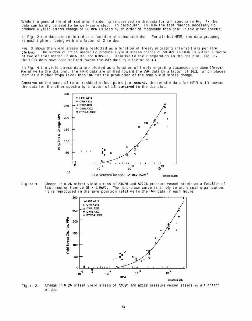
While t h e general t r e n d of r a d i a t i o n hardening i s observed i n t h e data f o r a l l spect ra i n Fig. 1. t h e data can ha rd ly be sa id t o be wel l- corre la ted. produce a y i e l d s t ress change of 50 MPa i s l e s s by an order of magnitude than t h a t i n t h e o the r spectra.
I n F ig . 2 t h e data a re r e p l o t t e d as a f u n c t i o n o f ca lcu la ted dpa. i s much t i g h t e r , be ing w i t h i n a fac to r of 2 i n dpa.
Fig. 3 shows t h e y i e l d s t r e s s data r e p l o t t e d as a f u n c t i o n of f r e e l y m ig ra t ing i n t e r s t i t i a l s per a t m ( fmipa l . o f two o f t h a t needed i n WR, ORR and RTNS-11. R e l a t i v e t o t h e i r separat ion i n t h e dpa p lo t , F ig . 2, t h e HFIR data have been s h i f t e d toward t h e WR data by a f a c t o r o f 4.4.
I n F ig . 4 t h e y i e l d s t r e s s data are p l o t t e d as a f u n c t i o n o f f r e e l y m ig ra t ing vacancies per atom (fmvpal. R e l a t i v e t o t h e dpa p lo t , t h e HFIR data are sh i f t ed toward t h e WR data by a fac to r o f 14.2, which places them a t a h igher fmvpa l e v e l than WR f o r t h e product ion o f t h e same y i e l d s t ress change.
Compared on t h e bas is o f t o t a l res idua l defect p a i r s ( n o t shownl, t h e t e n s i l e data f o r HFIR s h i f t toward t h e data f o r the o the r spect ra by a f a c t o r o f 1.5 c a p a r e d t o the dpa p l o t .
I n p a r t i c u l a r , i n HFIR t h e f a s t f luence necessary t o
For a l l b u t HFIR, t h e data grouping
The number of fmipa needed t o produce a y i e l d s t r e s s change of 50 MPa i n HFIR i s w i t h i n a fac to r
300
250
E = 200 6 m a 150 0
m C
v) UI
s ln 100 9 E
50
10
HFlRAZ12 0 ORRA212 .A OWR A212 V OWR A302 0 RTNSll A302
011
" / ; , , , , , / , 1, v
18 IO" 10
Fast Neutron Fluence (E >1 MeV) nlcmz
1111 19
10
38905069.1 Ma
F i g u r e 1. Change i n 0.2% o f f s e t y i e l d s t r e s s o f A3026 and A2128 pressure vessel s t e e l s as a func t ion o f f a s t neutron f l uence ( E > 1 MeV). The hand-drawn curve i s simply t o a i d v i s u a l organizat ion. It i s reproduced i n t h e same p o s i t i o n r e l a t i v e t o t h e WR data i n each f igure.
300 . HFlRA212 o ORRA212
-a OWR A212 v OWR A302
250
RTNSll A302 2 200 - oi
m 0 C
6 150 -
/ .-
38905069.1M.
F igure 2. Change i n 0.2% o f f s e t y i e l d s t r e s s of A3028 and A2128 pressure vessel s t e e l s as a f u n c t i o n o f dpa.
54
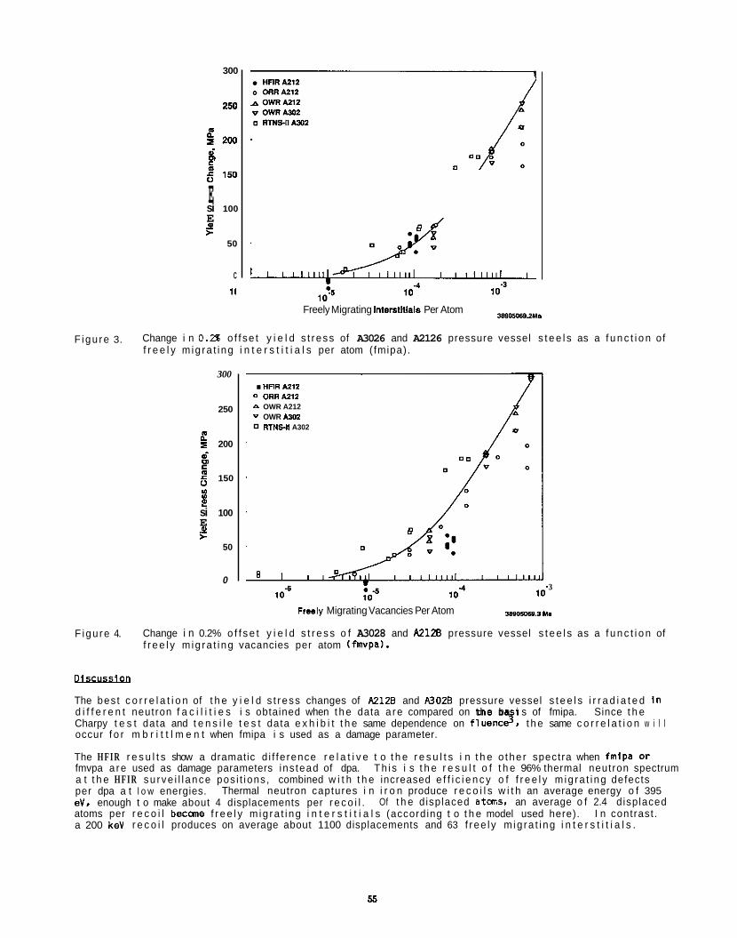
300
250
4 2w
E
d rn c
0 e 150
si 100 E F a2
50
C
11
380ME3.2Y. Freely Migrating Interstitlalo Per Atom
F igu re 3. Change i n 0.2% o f f se t y i e l d s t ress of A3026 and A2126 pressure vessel s t e e l s as a f u n c t i o n of f r e e l y m ig ra t i ng i n t e r s t i t i a l s per atom ( fmipa).
300
250
g 200 a? P 6 150
D E! si 100 E F
m
0
50
0
. HFlRAZi2 0 ORRA212 P OWR A212 v OWR Am2
RTNEll A302
3
Freely Migrating Vacancies Per Atom mwy160.3 M.
F igu re 4. Change i n 0.2% o f f s e t y i e l d s t r e s s o f A3028 and A2126 pressure vessel s t e e l s as a f u n c t i o n of f r e e l y m ig ra t i ng vacancies per atom (fmvpa).
Olscusslcn
The bes t c o r r e l a t i o n of t h e y i e l d s t ress changes of A2120 and A3028 pressure vessel s t e e l s i r r a d i a t e d I n d i f f e r e n t neutron f a c i l i t i e s i s obtained when t h e data a re compared on t h e ba i s of fmipa. Charpy t e s t data and t e n s i l e t e s t data e x h i b i t t h e same dependence on f l u e n c 3 , t h e same c o r r e l a t i o n w i l l occur f o r m b r i t t l m e n t when fmipa i s used as a damage parameter.
The H F I R r e s u l t s show a dramatic d i f fe rence r e l a t i v e t o t h e r e s u l t s i n t h e o the r spectra when fmlpa or fmvpa a re used as damage parameters ins tead of dpa. a t t h e H F I R su rve i l l ance pos i t ions , combined w i t h t h e increased e f f i c i e n c y o f f r e e l y m ig ra t i ng defects per dpa a t l o w energies. eV, enough t o make about 4 displacements per r e c o i l . atoms per r e c o i l becane f r e e l y m ig ra t i ng i n t e r s t i t i a l s (according t o t h e model used here). a 200 keV r e c o i l produces on average about 1100 displacements and 63 f r ee l y m ig ra t i ng i n t e r s t i t i a l s .
Since t h e
Th i s i s t h e r e s u l t o f t h e 96% thermal neutron spectrum
Thermal neutron captures i n i r o n produce r e c o i l s w i t h an average energy o f 395
I n contrast . Of t h e d isplaced a tms , an average o f 2.4 d isplaced
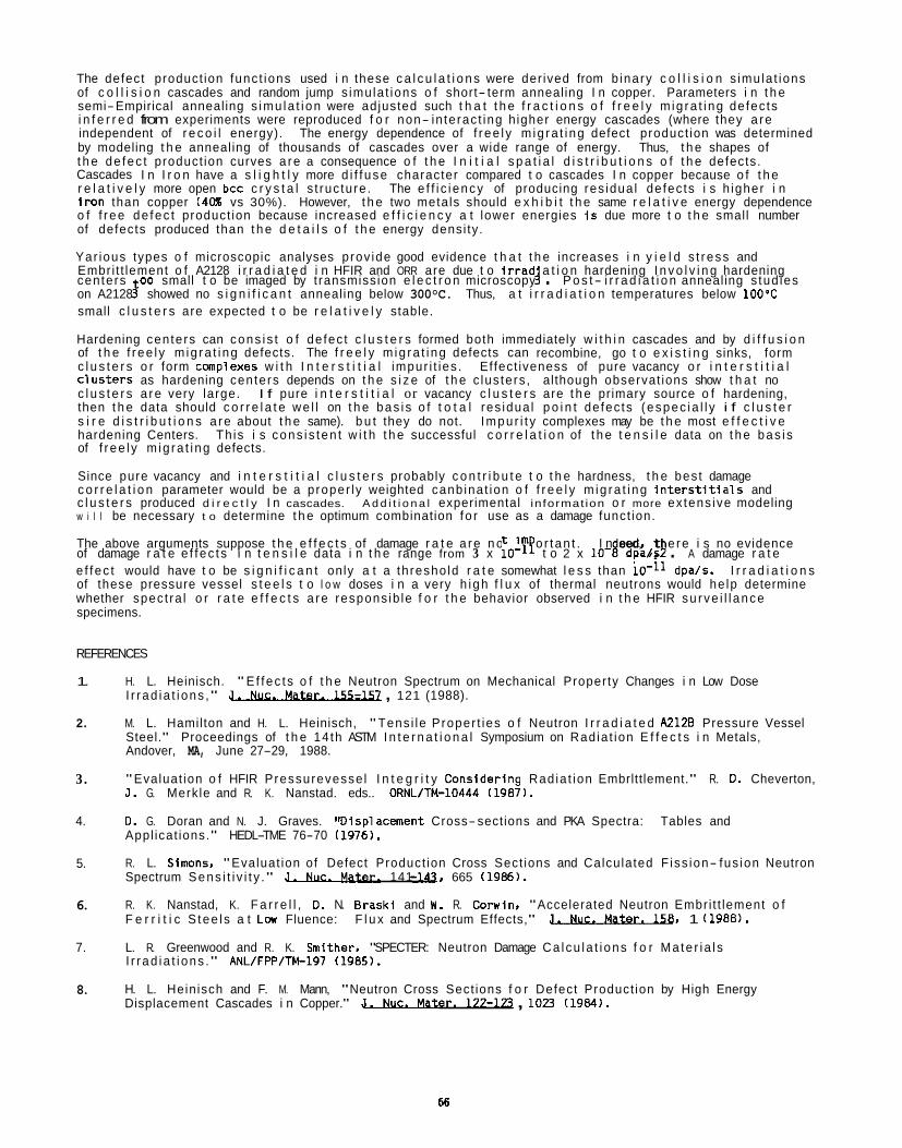
The defect product ion func t ions used i n these c a l c u l a t i o n s were der ived from b inary c o l l i s i o n s imu la t ions of c o l l i s i o n cascades and random jump s imu la t ions o f short- term annealing I n copper. Parameters i n t h e semi-Empirical annealing s imu la t i on were adjusted such t h a t t h e f r a c t i o n s o f f r e e l y m ig ra t i ng de fec ts i n f e r r e d from experiments were reproduced f o r non- in terac t ing h igher energy cascades (where they a re independent of r e c o i l energy). The energy dependence of f r ee l y m ig ra t i ng defect product ion was determined by modeling t h e annealing of thousands of cascades over a wide range of energy. Thus, t h e shapes of t h e de fec t product ion curves a re a consequence o f t h e I n i t i a l s p a t i a l d i s t r i b u t i o n s o f t h e defects. Cascades I n I r o n have a s l i g h t l y more d i f f use character compared t o cascades I n copper because o f t h e r e l a t i v e l y more open bcc c r y s t a l s t ruc ture . The e f f i c i ency of producing res idua l de fec ts i s h igher i n i r o n than copper (4UX vs 30%). However, t h e two metals should e x h i b i t t h e same r e l a t i v e energy dependence o f f r ee de fec t product ion because increased e f f i c i e n c y a t lower energies I s due more t o t h e small number of defects produced than t h e d e t a i l s o f t h e energy densi ty .
Yar ious types o f microscopic analyses prov ide good evidence t h a t t h e increases i n y i e l d s t ress and Embri t t lement o f A2128 i r r a d i a t e d i n HFIR and ORR are due t o l r r a d a t i o n hardening I n v o l v i n g hardening centers 00 small t o be imaged by t ransmission e l e c t r o n microscopy 4 . P o s t - i r r a d i a t i o n annealing s tud ies on A2128 3 showed no s i g n i f i c a n t annealing below 300°C. Thus, a t i r r a d i a t i o n temperatures below 1OO'C small c l u s t e r s are expected t o be r e l a t i v e l y stable.
Hardening centers can cons i s t o f de fec t c l u s t e r s formed both immediately w i t h i n cascades and by d i f f u s i o n of t h e f r ee l y m ig ra t i ng defects. The f r e e l y m ig ra t i ng defects can recombine, go t o e x i s t i n g sinks, form c l u s t e r s o r form complexes w i t h I n t e r s t i t i a l impur i t ies . Ef fect iveness of pure vacancy o r i n t e r s t i t i a l C lus te rs as hardening centers depends on t h e s i z e of t h e c lus ters , although observat ions show t h a t no c l u s t e r s a re very large. I f pure i n t e r s t i t i a l or vacancy c l u s t e r s are t h e primary source o f hardening, then t h e data should c o r r e l a t e we l l on t h e bas i s o f t o t a l res idua l p o i n t de fec ts (espec ia l l y i f c l u s t e r s i r e d i s t r i b u t i o n s a re about t h e same). b u t they do not. Impu r i t y complexes may be t h e most e f f e c t i v e hardening Centers. Th is i s cons i s ten t w i t h t h e successful c o r r e l a t i o n of t h e t e n s i l e data on t h e bas i s of f r ee l y m ig ra t i ng defects.
Since pure vacancy and i n t e r s t i t i a l c l u s t e r s probably c o n t r i b u t e t o t h e hardness, t h e bes t damage c o r r e l a t i o n parameter would be a proper ly weighted canb ina t ion o f f r e e l y m ig ra t i ng i n t e r s t i t i a l 5 and c l u s t e r s produced d i r e c t l y I n cascades. A d d i t i o n a l experimental informat ion o r more ex tens ive modeling w i l l be necessary t o determine t h e optimum combination f o r use as a damage funct ion.
The above arguments suppose t h e e f f e c t s of damage r a t e a re n o t i m o r t an t .
e f f ec t would have t o be s i g n i f i c a n t only a t a th resho ld r a t e somewhat l e s s than of these pressure vessel s t e e l s t o l o w doses i n a very h igh f l u x of thermal neutrons would he lp determine whether spec t ra l o r r a t e e f f e c t s a re respons ib le f o r t h e behavior observed i n t h e HFIR su rve i l l ance specimens.
I n eed, t e re i s no evidence of damage r a t e e f f ec t s i n t e n s i l e data i n t h e range from 3 x ,,-le t o 2 x 10- d 9 dpa/s . A damage r a t e
dpa/s. I r r a d i a t i o n s
REFERENCES
1.
2.
3.
4.
5.
6.
7.
8.
H. L. Heinisch. " E f fec t s o f t h e Neutron Spectrum on Mechanical Property Changes i n Low Dose I r r ad ia t i ons ," - , 121 (1988).
M. L. Hamilton and H. L. Heinisch, " Tens i le Proper t ies o f Neutron I r r a d i a t e d A2126 Pressure Vessel Steel." Proceedings of t h e 14 th ASTM I n t e r n a t i o n a l Symposium on Rad ia t ion E f f e c t s i n Metals, Andover, MA, June 27-29, 1988.
"Evaluat ion o f HFIR Pressurevesse l I n t e g r i t y Consider ing Rad ia t ion Embrlttlement." R. D. Cheverton, J . G. Merk le and R. K. Nanstad. eds.. ORNL/TM-10444 11987).
D. G. Doran and N. J. Graves. "O isp lacment Cross-sections and PKA Spectra: Tables and Appl icat ions." HEDL-TME 76-70 11976).
R. L. Slmons. "Evaluat ion of Defect Product ion Cross Sect ions and Calculated F iss ion- fus ion Neutron Spectrum Sens i t i v i t y ." J . Nuc. W r . 141 -141, 665 (1986).
R. K. Nanstad, K. F a r r e l l , D. N. Brask l and W . R. Corwln, "Accelerated Neutron Embri t t lement o f F e r r i t i c S tee l s a t Lw Fluence: F l u x and Spectrum Effects," -, 1 11988).
L. R. Greenwood and R. K. Smither. "SPECTER: Neutron Damage Ca l cu la t i ons f o r Ma te r i a l s I r r ad ia t i ons ." ANL/FPP/TM-197 (1985).
H. L. Hein isch and F. M. Mann, "Neutron Cross Sect ions f o r Defect Product ion by High Energy Displacement Cascades i n Copper." 3 . r . 122-173 , 1023 (1984).
66

5. R A D I A T I O N E F F E C T S : M E C H A N I S T I C S T U D I E S , T H E O R Y , A N D M O D E L I N G

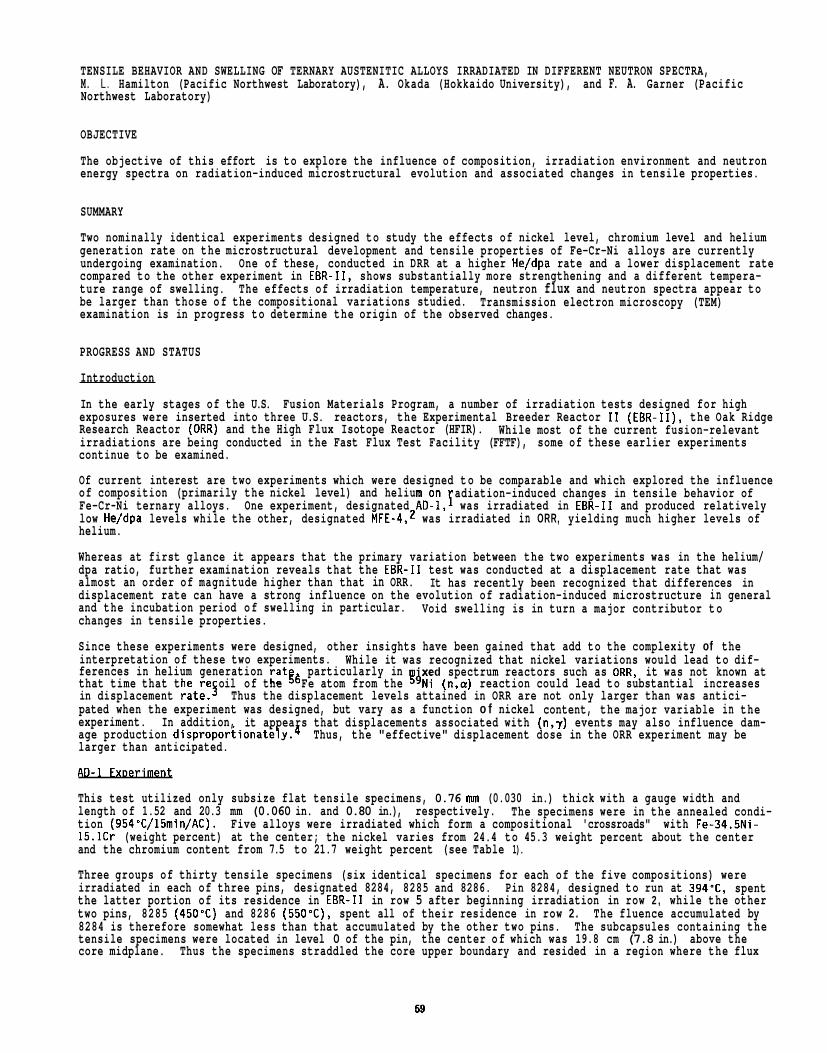
TENSILE BEHAVIOR AND SWELLING OF TERNARY AUSTENITIC ALLOYS IRRADIATED IN DIFFERENT NEUTRON SPECTRA, M. L. Hamilton (Pacific Northwest Laboratory), A. Okada (Hokkaido University), and F. A. Garner (Pacific Northwest Laboratory)
OBJECTIVE
The objective of this effort is to explore the influence of composition, irradiation environment and neutron energy spectra on radiation-induced microstructural evolution and associated changes in tensile properties.
SUMMARY
Two nominally identical experiments designed to study the effects of nickel level, chromium level and helium generation rate on the microstructural development and tensile properties of Fe-Cr-Ni alloys are currently undergoing examination. One of these, conducted in DRR at a higher He/dpa rate and a lower displacement rate compared to the other experiment in EBR-11, shows substantially more strengthening and a different tempera- ture range of swelling. The effects of irradiation temperature, neutron flux and neutron spectra appear to be larger than those of the compositional variations studied. examination is in progress to determine the origin of the observed changes.
Transmission electron microscopy (TEM)
PROGRESS AND STATUS
Introduction
In the early stages of the U.S. Fusion Materials Program, a number of irradiation tests designed for high exposures were inserted into three U.S. reactors, the Experimental Breeder Reactor I 1 (EBR-11). the Oak Ridge Research Reactor (ORR) and the High Flux Isotope Reactor (HFIR). irradiations are being conducted in the Fast Flux Test Facility (FFTF), some of these earlier experiments continue to be examined.
Of current interest are two experiments which were designed to be comparable and which explored the influence of composition (primarily the nickel level) and helium on Fe-Cr-Ni ternary alloys. One experiment, designated AD-l,F was irradiated in EBR-I1 and produced relatively low He/dpa levels while the other, designated MFE-4,2 was irradiated in ORR, yielding much higher levels of helium.
Whereas at first glance it appears that the primary variation between the two experiments was in the helium/ dpa ratio, further examination reveals that the EBR-I1 test was conducted at a displacement rate that was almost an order of magnitude higher than that in ORR. displacement rate can have a strong influence on the evolution of radiation-induced microstructure in general and the incubation period of swelling in particular. changes in tensile properties.
Since these experiments were designed, other insights have been gained that add to the complexity of the interpretation of these two experiments. While it was recognized that nickel variations would lead to dif- ferences in helium generation rat$& particularly in that time that the re oil of the Fe atom from the 54Ni (n,a) reaction could lead to substantial increases in displacement rate.5 Thus the displacement levels attained in ORR are not only larger than was antici- pated when the experiment was designed, but vary as a function o f nickel content, the major variable in the experiment. age production dispr~portionately.~ Thus, the "effective" displacement dose in the ORR experiment may be larger than anticipated.
AD-1 ExDeriment
This test utilized only subsize flat tensile specimens, 0.76 mm (0.030 in.) thick with a gauge width and length of 1.52 and 20.3 mm (0.060 in. and 0.80 in.), respectively. tion (954'C/15min/AC). Five alloys were irradiated which form a compositional 'crossroads" with Fe-34.5Ni- 15.1Cr (weight percent) at the center; the nickel varies from 24.4 to 45.3 weight percent about the center and the chromium content from 7.5 to 21.7 weight percent (see Table 1).
Three groups of thirty tensile specimens (six identical specimens for each of the five compositions) were irradiated in each of three pins, designated 8284, 8285 and 8286. Pin 8284, designed to run at 394'C, spent the latter portion of its residence in EBR-I1 in row 5 after beginning irradiation in row 2 , while the other two pins, 8285 (450'C) and 8286 (550'C), spent all of their residence in row 2 . The fluence accumulated by 8284 is therefore somewhat less than that accumulated by the other two pins. The subcapsules containing the tensile specimens were located in level 0 of the pin, the center of which was 19.8 cm (7.8 in.) above the core midplane. Thus the specimens straddled the core upper boundary and resided in a region where the flux
While most of the current fusion-relevant
adiation-induced changes in tensile behavior of
It has recently been recognized that differences in
Void swelling is in turn a major contributor to
xed spectrum reactors such as OUR, it was not known at
In addition, it appears that displacements associated with (n,y) events may also influence dam-
The specimens were in the annealed condi-
69
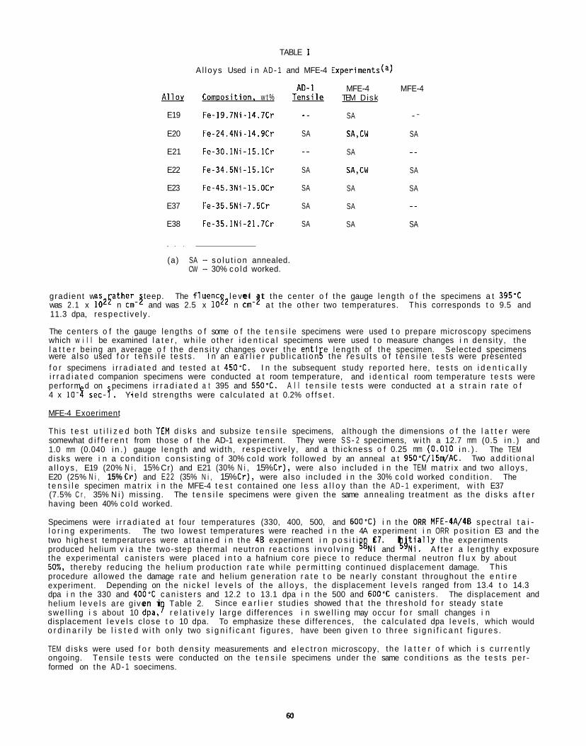
TABLE 1
A l loys Used i n AD- 1 and MFE-4 Experiments(a)
Allov E19
E20
E21
E22
E23
E37
E38
-
Comoosition. w t %
Fe-19.7Ni-14.7Cr
Fe-24.4Ni-14.9Cr
Fe-30.1Ni-15.1Cr
Fe-34.5Ni-15.1Cr
Fe-45.3Ni-15.OCr
Fe-35.5Ni-7.5Cr
Fe-35.1Ni-21.7Cr
A D - 1 Tensile -.
SA
..
SA
SA
SA
SA
MFE-4 TEM Disk
SA
SA,CW
SA
SA,CW
SA
SA
SA
MFE-4
.-
SA
..
SA
SA
_ _ SA
(a) SA - s o l u t i o n annealed. CW - 30% c o l d worked.
grad ient was ather teep. The f luenc l e v e l t the center o f t he gauge leng th o f the specimens a t 395'C was 2.1 x l oz5 n cm-$ and was 2.5 x 1 0 j 2 n cm-? a t the o the r two temperatures. Th is corresponds t o 9.5 and 11.3 dpa, respec t i ve l y .
The centers o f the gauge lengths o f some o f the t e n s i l e specimens were used t o prepare microscopy specimens which w i l l be examined l a t e r , w h i l e o the r i d e n t i c a l specimens were used t o measure changes i n dens i ty , t he l a t t e r being an average o f the dens i t y changes over the e n t i e l eng th of the specimen. Selected specimens
f o r specimens i r r a d i a t e d and tes ted a t 450'C. I n the subsequent study repor ted here, t e s t s on i d e n t i c a l l y i r r a d i a t e d companion specimens were conducted a t room temperature, and i d e n t i c a l room temperature t e s t s were perform d on pecimens i r r a d i a t e d a t 395 and 550%.
MFE-4 Exoeriment
This t e s t u t i l i z e d both TEM d i s k s and subsize t e n s i l e specimens, al though the dimensions o f the l a t t e r were somewhat d i f f e r e n t from those o f the AD-1 experiment. 1.0 mm (0.040 i n . ) gauge leng th and wid th , respec t i ve l y , and a th ickness o f 0.25 mm (0.010 i n . ) . d i sks were i n a cond i t i on c o n s i s t i n g o f 30% c o l d work fol lowed by an anneal a t 950'C/15m/AC. a l l o y s , E19 (20% N i , 15% Cr) and E21 (30% N i , 15% Cr), were a l so inc luded i n the TEM m a t r i x and two a l l oys , E20 (25% N i , 15% Cr) and E22 (35% N i , 15% Cr) , were a lso inc luded i n the 30% c o l d worked cond i t i on . The t e n s i l e specimen m a t r i x i n the MFE-4 t e s t contained one l e s s a l l o y than the A D- 1 experiment, w i t h E37 (7.5% C r , 35% N i ) missing. The t e n s i l e specimens were g iven the same anneal ing treatment as the d i s k s a f t e r having been 40% c o l d worked.
Specimens were i r r a d i a t e d a t four temperatures (330, 400, 500, and 600'C) i n the ORR MFE-4A/4B spec t ra l t a i - l o r i n g experiments. The two lowest temperatures were reached i n the 4A experiment i n ORR p o s i t i o n E3 and the two h ighest temperatures were a t t a i n e d i n the 48 experiment i n p o s i t i produced hel ium v i a the two-step thermal neutron reac t ions i n v o l v i n g %i and R 4 N i . A f t e r a l eng thy exposure the experimental can is te rs were placed i n t o a hafnium core p iece t o reduce thermal neutron f l u x by about 50%, thereby reducing the he l ium product ion r a t e wh i le p e r m i t t i n g cont inued displacement damage. procedure al lowed the damage r a t e and hel ium generat ion r a t e t o be near l y constant throughout the e n t i r e experiment. dpa i n the 330 and 400'C c a n i s t e r s and 12.2 t o 13.1 dpa i n the 500 and 600'C can is te rs . hel ium l e v e l s are g iven i swe l l i ng i s about 10 dpa,? r e l a t i v e l y l a r g e di f ferences i n s w e l l i n g may occur f o r small changes i n displacement l e v e l s c lose t o 10 dpa. o r d i n a r i l y be l i s t e d w i t h on ly two s i g n i f i c a n t f i gu res , have been g iven t o th ree s i g n i f i c a n t f i g u r e s .
TEM d i sks were used f o r both dens i t y measurements and e l e c t r o n microscopy, the l a t t e r o f which i s c u r r e n t l y ongoing. Tens i l e t e s t s were conducted on the t e n s i l e specimens under the same cond i t i ons as the t e s t s pe r - formed on the AD- 1 soecimens.
were a lso used f o r t e n s i l e t e s t s . I n an e a r l i e r p u b l i c a t i o n 5 t he r e s u l t s o f t e n s i l e t e s t s were presented
4 x 10- 2 sec -I . A l l t e n s i l e t e s t s were conducted a t a s t r a i n r a t e o f Y i e l d ' s t rengths were ca lcu la ted a t 0.2% o f f s e t .
They were S S - 2 specimens, w i t h a 12.7 mm (0.5 i n . ) and The TEM
Two a d d i t i o n a l
€ 7 . I ' t i a l l y the experiments
Th is
Depending on the n i c k e l l e v e l s of the a l l o y s , the displacement l e v e l s ranged from 13.4 t o 14.3
Since e a r l i e r s tud ies showed t h a t the th resho ld f o r steady s t a t e The displacement and
Table 2.
To emphasize these di f ferences, the ca lcu la ted dpa l e v e l s , which would
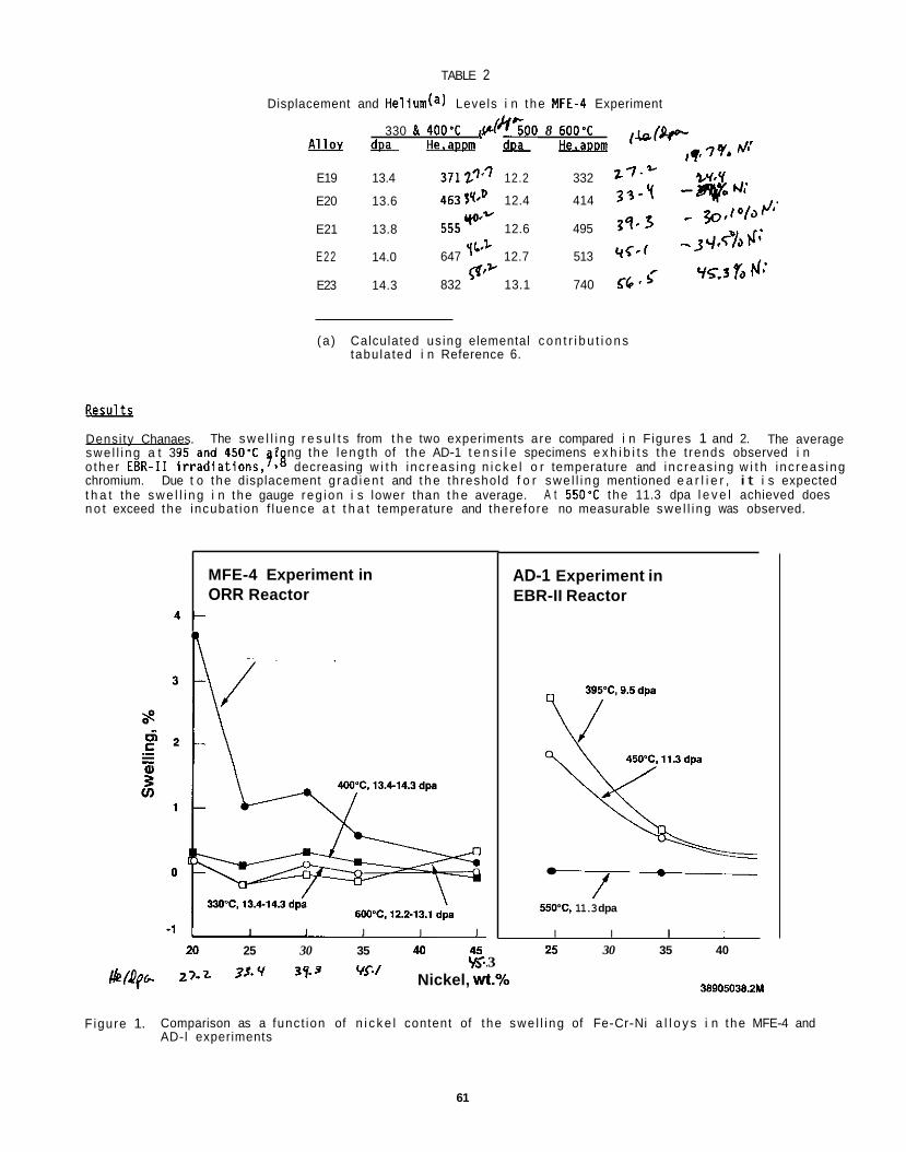
TABLE 2
Displacement and Helium(a) Levels i n the WE-4 Experiment
330 & 400'C p l h ' ; O O 8 600% ,&(e ,q,7Q. f l - & & - & & -
E19 13.4 37127'' 12.2 332 z7.* %Y.Y -qo cl; ~,/wJl.
-.JL/.cw;
v5.3 6 FI:
E20 13.6 4633q*D 12.4 414 3 3 - y
E21 13.8 555yQ'y 12.6
E22 14.0 647 yL'' 12.7 513 'icef
E23 14.3 832 13.1 740 56*5'
495 3 9 - 3
v-
4 -
(a ) Calculated us ing elemental c o n t r i b u t i o n s tabu la ted i n Reference 6.
MFE-4 Experiment in ORR Reactor
Density Chanaes. The average swe l l i ng a t 395 and 450'C 1 ng the leng th of the AD-1 t e n s i l e specimens e x h i b i t s the t rends observed i n o the r E B R - I 1 i r r a d i a t i o n s , ? i g decreasing w i t h i nc reas ing n i c k e l o r temperature and inc reas ing w i t h i nc reas ing chromium. Due t o the displacement g rad ien t and t h e threshold f o r swe l l i ng mentioned e a r l i e r , i t i s expected t h a t the s w e l l i n g i n the gauge reg ion i s lower than t h e average. A t 550'C the 11.3 dpa l e v e l achieved does n o t exceed the incubat ion f luence a t t h a t temperature and therefore no measurable swe l l i ng was observed.
The s w e l l i n g r e s u l t s from t h e two experiments are compared i n Figures 1 and 2.
I I I I I
20 25 30 35 40 45
AD-1 Experiment in EBR-II Reactor
f -
550% 11.3 dpa
I I I I 25 30 35 40
3 ys.. 2,.z 3S.Y 39.3 WI WQp Nickel, wt.% 38905038.2M
Figure 1. Comparison as a funct ion of n i c k e l content of t he swe l l i ng of Fe-Cr-Ni a l l o y s i n the MFE-4 and AD-l experiments
61
2.0 I MFE-4 Experiment in ORR Reactor
1'5 t MO'C. 12.2-13.1 dpa
400% 13.4-14.3 dpa
330'C, 13.4-14.3 dpa SOO"C, 12.2-13.1 dpa
-0.5 I I I
5 ' 10 15 20
AD-1 Experiment in EBR-II Reactor Fe
450'C. 11.3dpa
550'C, 11.3 dpa
25 15 20 10
Chromium, wt.% 38905038.1M
Figure 2 . Comparison as a funct ion of chromium content o f t h e s w e l l i n g o f Fe-Cr-Ni a l l o y s i n t h e MFE-4 and AD-1 experiments
The MFE-4 r e s u l t s are somewhat d i f f e r e n t , however. suooressed fo r both h iuher and lower temoeratures. A t 500'C t h e s w e l l i n u i n qeneral decreased as expected
S i g n i f i c a n t s w e l l i n g was found o n l y a t 500'C and was
w i i h n i c k e l . q t i c i p a t e d non-monotonic response was observed arouna 30%-nickel a t a l l four temperatures and i s t he re fo re p r d h y no t an a r t i f a c t , r e f l e c t i n g poss id l y 3 m di f ferences i n chromium l e v e l o r i n minor so lu tes
The data g iven i n Table 3 show t h e i n f l uence o f c o l d work on swe l l i ng . c l e a r l y occurr ing, c o l d work reduced s w e l l i n g i n Fe-15Cr-25Ni from 1.04 t o 0.21% and i n Fe-15Cr-35Ni f rom 0.55 t o -0.11%. (f0.16%), t h e e f f e c t o f c o l d work i s n o t w e l l def ined. the Fe-15Cr-35Ni a l l o y , yay r e f l e c t d e n s i f i c a t i o n associated w i t h s p i n o d a l - l i k e decomposit ion r a t h e r than measurement unce r ta in t y .
Tens i le Proper t ies . d u c t i l i t y data are shown as a f u n c t i o n o f composit ion i n Figures 3 and 4 fo r both t h e AD-1 and MFE-4 exper i - ments. Each p l o t shows t h e response t o both n i c k e l and chromium v a r i a t i o n s . The e f f e c t o f n i c k e l and chromium are a l so shown separate ly i n subsequent comparisons o f t h e MFE-4 and A D- 1 data.
The s t reng th o f these a l l o y s (F igure 3) i n t h e u n i r r a d i a t e d c o n d i t i o n increases s l i g h t l y w i t h both increas ing n i cke l and chromium. Th is t r e n d i s reproduced w i t h o n l y two except ions i n t h e i r r a d i a t e d c o n d i t i o n i n t h e A D- 1 specimens: 1) a t t h e lowest chromium l e v e l and an i r r a d i a t i o n temperature o f 550'C t h e y i e l d (bu t n o t the u l t i m a t e ) s t reng th i s somewhat h ighe r than what would be expected from t h e t rends e x h i b i t e d by t h e r e s t o f t h e data, and 2) t h e y i e l d s t reng th t r e n d i s a c t u a l l y reversed as a func t i on o f n i c k e l f o r i r r a d i a t i o n a t 394%. Such a reve rsa l i s more f r e q u e n t l y observed i n t h e s t reng th data f rom t h e MFE-4 experiment, where i t appears i n both t h e y i e l d and u l t i m a t e s t rengths fo r a l l except t h e h ighest i r r a d i a t i o n temperature. s t reng th data e x h i b i t a '"knee" i n t h e v i c i n i t y of t h e 35Ni l e v e l , where something i s apparent ly changing i n t h e response o f these a l l o y s t o increased n i c k e l content du r ing i r r a d i a t i o n i n ORR. (F igure 4) a l so e x h i b i t a "knee" a t t h e in termedia te n i c k e l l e v e l , a t a l l i r r a d i a t i o n temperatures i n MFE-4 and i n both t h e i r r a d i a t e d and u n i r r a d i a t e d cond i t i ons i n A D - I .
A t 500'C, where s w e l l i n g i s very
A t t h e o the r temperatures, where t h e s w e l l i n g i s low and near t h e r e s o l u t i o n l i m i t Negat ive values o f dens i t y change, p a r t i c u l a r l y f o r
The t e n s i l e data from t h e two experiments are g iven i n Tables 4 and 5 . The s t reng th and
The
The d u c t i l i t y data
62
TABLE 3
Dens i ty Data from t h e MFE-4 Experiment
Swel l inq. %
Fe-25Ni-15Cr Fe-35Ni-15Cr TemDeratUre. 'C SA __ cw - SA ~ cw
330 0.21 0.15 -0.05 -0.10
400 0.04 0.04 0.14 -0.06
500 1.04 0.29 0.55 -0.11
600 -0.21 0.16 -0.14 -0.07
The d u c t i l i t y o f t he specimens i r r a d i a t e d i n t h e AD-1 experiment (F igure 4) remained r e l a t i v e l y h igh a f t e r i r r a d i a t i o n , the on ly except ion being fo r i r r a d i a t i o n a t the lowest temperature, 394'C. Conversely, i n the MFE-4 experiment, on ly specimens i r r a d i a t e d a t the h ighest temperature (600'C) r e t a i n e d s i g n i f i c a n t d u c t i l i t y a f t e r i r r a d i a t i o n . Almost every i r r a d i a t i o n c o n d i t i o n i n MFE-4 a t temperatures below 600'C produced c lose t o a t o t a l l o s s i n d u c t i l i t y .
The d i f ference between uniform and t o t a l e longat ion appears t o be a f a i r l y constant value, roughly 5%, f o r a l l specimens i r r a d i a t e d i n the AD-1 experiment, regard less o f composit ion and i r r a d i a t i o n temperature. cont rast , t he d i f f e r e n c e between the uniform and t o t a l e longat ion values i n the specimens i r r a d i a t e d i n MFE-4 i s genera l l y smal ler, vary ing from values approaching zero t o on ly as much as 2 o r 3%. observed i n t h e da ta obtained on u n i r r a d i a t e d specimens tes ted as c o n t r o l s fo r each experiment.
Since the on ly d i f f e r e n c e i n the c o n t r o l data between the two experiments i s t h e specimen geometry, p a r t i c u - l a r l y the specimen th ickness, the d u c t i l i t y da ta r a i s e a quest ion about the v a l i d i t y o f t he t h i n n e r specimens used i n the MFE-4 experiment. obtained from t h e two types of c o n t r o l specimens are roughly equal, suggesting t h a t t h e d u c t i l i t y da ta from the MFE-4 specimens are indeed v a l i d , a t l e a s t where r e l a t i v e l y l a r g e l e v e l s of d u c t i l i t y are invo lved. I t i s nonetheless poss ib le t h a t fo r low l e v e l s of d u c t i l i t y , f o r example f o l l o w i n g i r r a d i a t i o n under cond i t i ons which induce s i g n i f i c a n t m ic ros t ruc tu ra l hardening, t h a t t h e geometry o f the MFE-4 specimens predisposes e a r l y f a i l u r e s due t o the s e n s i t i v i t y of b r i t t l e ma te r ia l s t o any t ype of s t ress concent ra t ion.
The i r r a d i a t i o n - i n d u c e d increase i n y i e l d s t reng th i s shown i n F igure 6 as a funct ion of n i c k e l and chromium l e v e l s f o r both t h e MFE-4 and the AD- 1 experiments. increases i n the change i n y i e l d s t rength, p a r t i c u l a r l y w i t h decreased i r r a d i a t i o n temperature, i n both experiments, w h i l e the effect of n i c k e l i s j u s t the opposi te.
The y i e l d s t reng th changes observed i n AD-1 a t 394 and 550'C are almost i d e n t i c a l t o those produced a t 500 and 600% i n MFE-4 (F igure 7), suggesting t h a t s i g n i f i c a n t l y more s t rengthening i s produced dur ing i r r a d i a - t i o n i n ORR than i n EBR-11. shown t o be l i n e a r as a func t ion of i r r a d i a t i o n temperature i n AD- 1 and s t r o n g l y nonl inear i n MFE-4.
Discussion
It appears t h a t i r r a d i a t i o n va r iab les such as temperature, neutron f l u x and spectra l ead t o l a r g e r v a r i a t i o n s i n a l l o y response than do the composit ional va r iab les i n these two experiments. It i s d i f f i c u l t a t t h i s t ime t o determine the reasons f o r e i t h e r these di f ferences o r t h e a d d i t i o n a l s t rengthening observed i n the MFE-4 experiment r e l a t i v e t o the AD-1 experiment. l eve ls , i t s s w e l l i n g l e v e l s are n o t l a r g e r . induced strengthening, cannot therefore be s o l e l y respons ib le f o the di f ferences.fb The d i s l o c a t i o n m ic ros t ruc tu re i s known t o sa tu ra te r e l a t i v e l y q u i c k l y a t -5OOaCr1 and one would not expect l a r g e di f ferences i n d i s l o c a t i o n d e n s i t y i n the 11 t o 14 dpa range. While the h igher he l ium l e v e l s o f the MFE-4 experiment may c o n t r i b u t e t o a refinement of the vo id and Frank loop microst ructures, thereby causing more strengthening, the lower displacement r a t e o f MFE-4 would tend t o produce l e s s ref inement. the a d d i t i o n a l s t rengthening a r i ses from some p rev ious ly unforeseen aspect of t he damage created by (n,a) r e c o i l events. performed.
Only the 45Ni l e v e l a t 500'C e x h i b i t e d more than about 5% d u c t i l i t y .
I n
S i m i l a r behavior i s
F igure 5, however, demonstrates t h a t both the un i form and t o t a l e longat ions
Increases i n the chromium l e v e l g e n e r a l l y produce
Th is i s shown more d e f i n i t i v e l y i n F igure 8, where changes i n y i e l d s t reng th are
While the MFE-4 experiment reached s l i g h t l y h igher displacement Void swel l ing, known t o be a major co r i b u t o r t o r a d i a t i o n -
The p o s s i b i l i t y may e x i s t t h a t
These and o the r issues can on ly be addressed a f t e r e l e c t r o n microscopy examinations are
63
TABLE 4
Tens i l e Data from t h e MFE-4 Experiment
c - 4 x 10⁻⁴ sec-1
Test True Temp YS UTS UTS UE TE Q C l (MPa) (MPa) (MPa) (%) 0
I r r a d i a t i o n Average AYS
(MPa) Specimen Temp
I D ('C)
2 5 N i - 15Cr
..
.. JL28 JL29
RT 125 422 623 47.5 49.0 ..
640
567
472
106
RT 147 448 661 47.5 48.5 Ave: 136 43 5 642 47.5 48.8
RT 776 777 780 0.4 2.0 JLOO 330 JL03 330 RT 776 811 814 0.4 2.2
Ave: 776 794 797 0.4 2.1
JL06 400 JLlO 400
RT 690 715 718 0 . 4 2.2 RT 716 750 753 0.4 2.4
Ave: 703 733 736 0.4 2.3
RT 61 2 655 672 2.6 3.0 JL13 500 JL15 500
... RT 604 673 689 2.4 3.2
Ave: 608 664 681 2.5 3.1
JL19 600 JL21 600
RT 241 451 632 40.0 42.0 RT 243 479 646 35.0 37.5
Ave: 242 465 639 37.5 39.8
35Ni - 15Cr
JN25 _ _ JN28 ..
RT 142 461 676 46.5 46.5 ..
617
565
475
RT 142 457 663 45.0 48.0 Ave: 142 459 668 45.7 47.2
RT 759 776 778 0.3 2.2 JNOO 330 JN04 330
... . .. RT 759 773 776 0.4 2.4
Ave: 759 774 777 0.4 2.3
JN06 400 JN09 400
RT 690 715 718 0.4 2 . 4 RT 724 750 753 0.4 2.2
Ave: 707 733 736 0.4 2.3
JN13 500 JN15 500
RT 629 683 701 2.6 3.6 RT 604 663 690 4.0 6.0
Ave: 617 673 696 3.3 4.8
JN19 600 JN20 600 JN22(a) 600
RT 237 439 525 19.5 20.0 487 666 36.8 37.5 RT
RT Ave: 244 463 596 28.6 28.8
.- .. .. .. 250 .. 102
JP16 .. RT 151 479 682 42.5 46.0 RT 155 457 651 42.5 45.0 RT 147 461 4 . o 45.5
Ave: 151 466 664 42.7 45.5
..
.. JPl8 JP27 .-
599 RT 750 793 796 0.4 3.0 JPOl 330
( a ) Test i n v a l i d .
64
TABLE 4
(continued)
True YS UTS UTS UE TE IMPa) (MPa) IMPa) (%) 1%)
Irradiation Specimen Temp
IO f 'C)
45Ni-15Cr. (continued)
JP04 400 JP06 400
JPO9 500 JPlO 500
JP13 600 JP15 600
35Ni - 20Cr
JR25 _ _ JR29 _.
JROO 330
JR07 400 JRlO 400
JR13 500 JR14 500
JR19 600 JR21 600
Test Temp m
RT RT
Ave:
RT RT
Ave:
RT RT
Ave:
RT RT
Ave:
RT
RT RT
Ave:
RT RT
Ave:
RT RT
Ave:
669 697 757 8.6 9.0 672 707 728 3.0 4.4 671 702 743 5.8 6.7
586 656 708 8.0 9.6 552 638 702 10.0 12.8 569 647 705 9.0 11.2
248 474 607 28.0 29.0 259 502 648 29.0 29.5 254 488 628 29.0 29.3
181 535 762 42.5 43.5 185 535 759 42.0 43.0 183 535 760 42.3 43.3
931 965 969 0.4 2.2
862 863 866 0.4 2.0 897 896 900 0.4 2.0 880 880 883 0.4 2.0
724 785 813 3.6 5.2 698 768 806 5.0 6.2 711 777 810 4.3 5.7
322 591 783 32.5 33.5 323 560 668 19.3 19.5 323 576 726 25.9 26.5
Average AYS
(MPa)
520
418
103
..
748
697
528
140
Specimen IO
2 5 N i - 15Cr
X06 x12
X50
XI3
X14
X25
35Ni - 15Cr
AA15 AA11
AA47
AA27
AA02
AA12
AA24
45Ni - 15Cr
AB21
AB03
AB30
35Ni - 20Cr
AN09 AN15
AN35
I r r a d i a t i o n Test Temo Temo
TABLE 5
Tens i le D a t a f rom t h e AD-1 Experiment
6 - 4 x 10⁻⁴ sec-1
True YS UTS UTS UE TE
-. RT 138 441 636 44.3 48.7 .. RT 134 450 665 47.7 52.7
Ave: 136 446 651 46.0 50.7
394 RT 619 627 630 0.5 5.2
550 RT 212 453 611 34.9 38.7
.. 450 96 319 421 31.9 36 .0
450 450 373 373 374 0 .3 4.2
.. RT 140 449 631 40.6 44.6
.. RT 139 445 643 44.5 47.4 Ave: 140 447 637 42.6 46.0
394 RT 607 634 675 6.2 10.3
450 RT 457 547 632 15.6 20.0
550 RT 226 472 636 34.9 38.1
.. 450 90 375 509 35.8 38.5
450 450 384 422 426 1.0 1.7
.. RT 190(a) 473 675 42.7 46.8
.. RT 153 474 675 42.4 46.2 Ave: 153 474 675 42.6 46.5
394 RT 584 670 733 9.4 13.5
550 RT 238 500 686 37.1 41.2
.. 450 103 374 497 32.8 36.3 ~~
.. 450 102 397 528 33.0 35.8 Ave: 103 386 513 32.9 36.1
450 450 413 486 526 8.3 11.4
.. RT 177 491 699 42.4 45.9
.. RT 182 506 708 39.9 43.7 Ave: 180 499 705 41.2 44.8
394 RT 670 737 783 6.2 10.2
Average aY s
(MPa)
483
76
..
277
467
317
86
..
294
431
85
.-
310
_ _
490
( a ) YS value probably i n v a l i d .
66
TABLE 5
(continued)
True YS UTS UTS UE TE
JMPa) (MPal (MPa) f % ) (%)
509 614 728 18.6 23.1
292 546 723 32.5 36.8
Specimen I O
AN54
AN28 AN06 AN17
AN61
35Ni - 7Cr
AE16 AE21
AE34
AE26
AE09
AE60
I r r a d i a t i o n Temp ( ' C )
450
550 _ _ ..
450
..
..
394
550
..
450
Test Temp m
RT
RT 450 450
Ave:
450
RT RT
Ave:
RT
RT
450
450
129 412 556 35.0 37.5 132 420 560 33.4 36.5 131 416 558 34.2 37.0
418 473 508 7.5 9.8
142(a) 408 574 40.6 45.5 126 407 576 41.5 46.5 126 408 575 41.1 46.0
540 598 636 6.4 10.2
244 430 540 25.6 29.3
62 303 387 27.7 30.6
350 512 525 2.5 5.9
Average AY S
(MPa)
329
112
_ _
287
414
118
_ _ 288
(a) YS value probably i n v a l i d
CONCLUSIONS
Two nominal ly s i m i l a r experiments d i r e c t e d toward assessing the e f f e c t s o f composit ion and he l ium were i r r a d i a t e d i n reac to rs which possessed d i f f e r e n t neutron spect ra and displacement r a t e s . D i f ferences a t t r i b u t a b l e t o the reac to r environment were seen i n both the b u l k s w e l l i n g and the t e n s i l e p roper t i es . e f f e c t s o f i r r a d i a t i o n temperature, neutron f l u x and neut ron spect ra appear t o be l a r g e r than those o f the composit ional v a r i a t i o n s s tud ied. The most s u r p r i s i n g r e s u l t i s t h a t a s i g n i f i c a n t l y h igher l e v e l of rad ia t i on- induced s t rengthening was found i n the ORR experiment. The exp lanat ion f o r such behavior i s n o t obvious and awaits examination o f the m ic ros t ruc tu re .
The
FUTURE WORK
Comparison w i l l be made between the t e n s i l e and d i s k bulge t e s t s conducted on t h e MFE-4 specimens. copy on both the AD-1 and MFE-4 specimens w i l l be completed.
Micros-
67
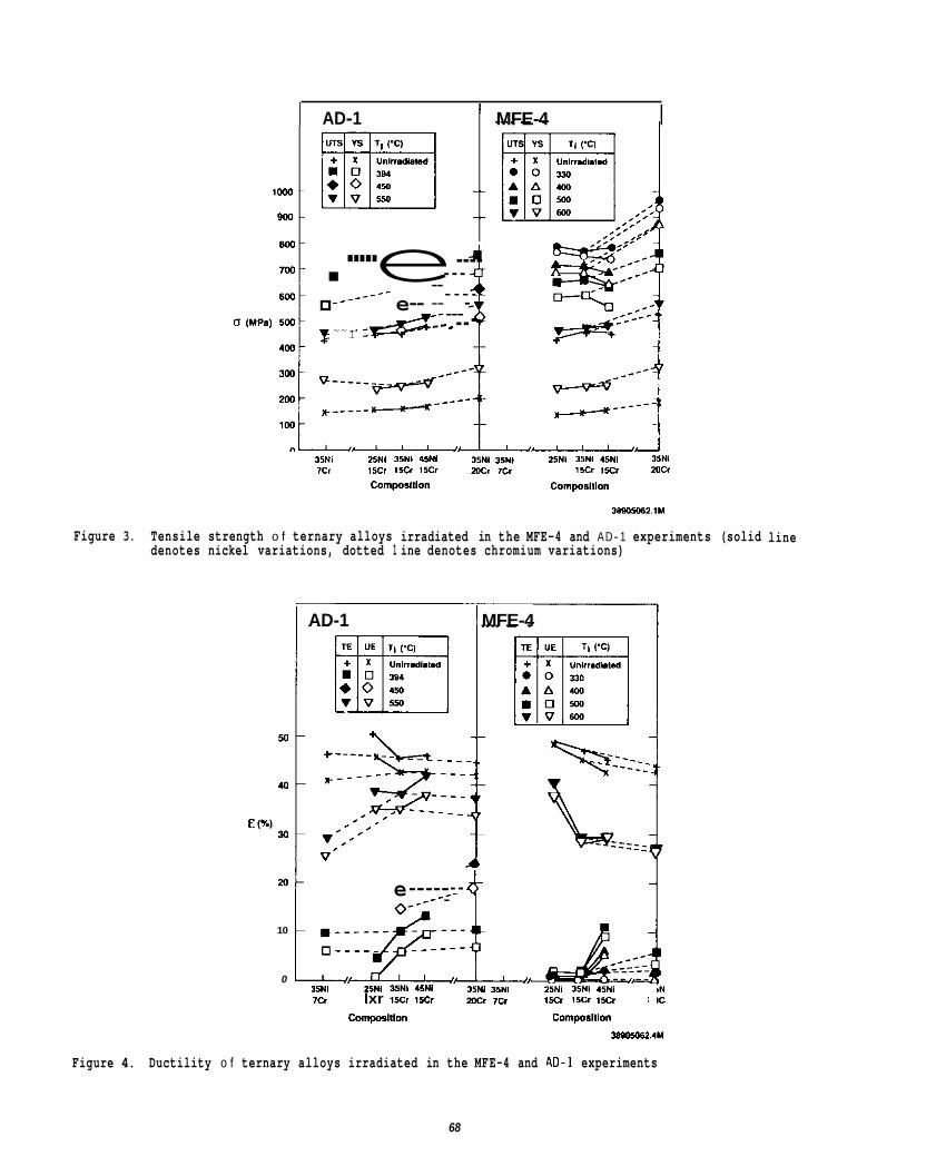
Figure 3.
AD-1
!l .----- e---- __- - - _ _ _ _ _ - -- __- - - - - e-- ___- ~~I :&:: - --
MFE-4 I
35Ni 25NI 35NI 15NI 35NI 35NI 25Nl 3941 45NI 35NI 7cr (IC. 15cr t5cr wcr IC, i x r ,so mcr
CornpOslllon CDrnpOSlllO”
30805062.11(
Tensile strength o f ternary alloys irradiated in the MFE-4 and AD- 1 experiments (solid denotes nickel variations, dotted 1 ine denotes chromium variations)
I AD-1 I MFE-4
e----- _- - 8 10
0 35NI Z5NI 35NI 45NI 35NI WI 25N1 35NI 45Nl 7- lxr lso 15.3 2w 7 a l x r 1 5 0 1 x r :
Cmpalllo” Cornpalllon
line
- 2 .M
Figure 4. Ductility o f ternary alloys irradiated in the MFE-4 and A D - 1 experiments
68
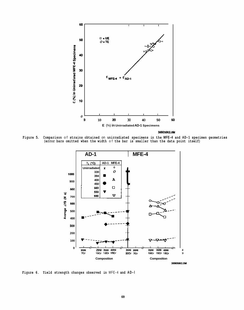
I I I
Unirradialed 330 394 400 450
0 =UE 0 =TE
‘ M F N = ‘AD1
t Y + 0
A
I I I I I 0
0 10 20 30 40 50 60 E (%) in Unirradiated AD-1 Specimens
3890M62.8M
Figure 5. Comparison o f strains obtained on unirradiated specimens in the MFE-4 and AD- 1 specimen geometries (error bars omitted when the width o f the bar is smaller than the data point itself)
loo0
900
800
700
ul > 600 U (Y
m 500
4 400
300
200
100
0
z
:
AD-1 I MFE-4
TI (‘C) I AD-1 MFE-4 I
I,
3JNI 25NI 35NI 45NI ” 35NI 35NI 7cr i5Cr 15CI 15Cr 20Cr 7Cr 15Cr 15cr 15cr
Composition Composition
I1 :r
Figure 6. Yield strength changes observed in MFE- 4 and A D - l
69
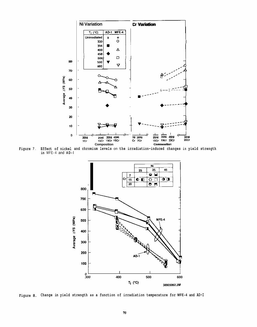
Ni Variation
500
4/-+ 35Ni 25NI 35Ni 45NI 7 r r 1scr 15cr 15cr
Cr Variation I I
_--- *---
h' ,: :::::: 1 _----
&==I----
I' Ni 35NI 2bNl 3kNI 45NI I ' 4 5 N l cr 7cr l5Cr 1 5 0 15Cr 20Cr
Commsition . _.
Composition Figure 7 . Effect of nickel and chromium levels on the irradiation-induced changes in yield strength
in MFE- 4 and A D - l
800 I
0 300 400 500 600
I I I
38905062.2M TI W )
Figure 8. Change in yield strength as a function of irradiation temperature for MFE-4 and AD-I
IO

References
1.
2.
3.
4.
0. T. Peterson and J. A. Sprague, "Status of the AD-1 Irradiation Test," Damage Analysis and Fundamental Studies Quarterly Progress Report, January-March 1980, DDE/ER-0046/1, pp. 238-241.
0. T. Peterson and R. W. Powell, "OAFS Specimen Matrix for the ORR MFE-IV Test," ibid, pp. 242-245.
L . R . Greenwood, J. Nucl. Mater., 115 (1983) pp. 137-142.
F. A. Garner, H. L. Heinisch, R . L. Simons and F. M. Mann, "Implications of Neutron Spectrum and Flux Differences in Fission and Fusion Correlations at High Neutron Fluence," PNL-SA-l5704A, presented at a Workshop on Effects of Recoil Spectrum and Nuclear Transmutations on the Evolution o f Microstructure, Lugano, Switzerland, March 24-29, 1988.
H. R . Brager, F. A. Garner, and M. L . Hamilton, J. Nucl. Mater., 133 & 134 (1985). pp. 594-598. 5 .
6 . Letter report, "Displacement and Helium Levels for DRR-MFE-4A/4B," from L. R . Greenwood to M. Grossbeck dated July 8, 1987.
7. F. A. Garner and H. R . Brager, in Effects of Radiation on Materials: ASTM STP 870, F. A. Garner and J. S. Perrin, Eds., American Society for Testings and Materials, Philadelphia, 1985, pp. 187-201.
Twelfth International Symposium,
8. F. A. Garner and A. S. Kumar, in Radiation-Induced Changes in Microstructure: Symposium (Part l ) , ASTM STP 955, F. A. Garner, N. H. Packan and A. S. Kumar, Eds., American Society for Testing and Materials, Philadelphia, 1987, pp. 289-314.
F. A. Garner, H. R . Brager, and J. M. McCarthy in Ref. 8, pp. 775-787.
F. A. Garner, M. L. Hamilton, N. F. Panayotou and 6. D. Johnson, J. Nucl. Mater., 103 & 104 (1981), pp. 803-808.
T. Muroga, F. A. Garner and S. Ohnuki, "Microstructural Investigation of the Mechanism of Swelling Dependence on Nickel Content in Fast Neutron-Irradiated Fe-Cr-Ni Austenitic Ternaries," Annual Progress Report for Fusion Year 1988, Monbush-DOE Collaboration in Fundamental Studies of Irradiation Effects in Fusion Materials Utilizing Fission Reactors, in press.
13th International
9.
10.
11.

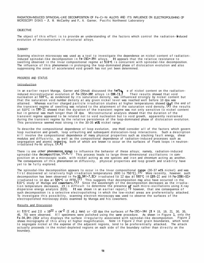
RADIATION-INDUCED SPINODAL-LIKE DECOMPOSITION OF Fe-Cr-Ni ALLOYS AND ITS INFLUENCE ON MICROSCOPY DISKS - J . M. McCarthy and F. A. Garner, P a c i f i c Northwest Laboratory
OBJECTIVE
The ob jec t o f t h i s e f f o r t i s t o p rov ide an understanding of t he f a c t o r s which con t ro l evo lu t ion o f m i c ros t r uc tu re i n s t r u c t u r a l a l l o ys .
ELECTROPOLISHING OF
the r a d i a t i o n - i nduced
SUMMARY
Scanning e l ec t r on microscopy was used as a t o o l t o i nves t i ga te t he dependence on n i c k e l content o f r a d i a t i o n - induced sp i noda l - l i ke decomposition i n Fe-15Cr-XNi a l l oys . swe l l i ng observed i n t he I nva r composit ional regime a t 510% i s concurrent w i t h sp i noda l - l i ke decomposition. The in f luence o f t h i s phenomenon i n pro longing the loop-dominated phase o f d i s l o c a t i o n evo lu t i on and a l so suppressing t he onset o f accelerated vo id growth has no t y e t been determined.
It appears t h a t t he r e l a t i v e res is tance t o
PROGRESS AND STATUS
I n t r oduc t i on
I n an e a r l i e r r e p o r t Muroga, Garner and Ohnuki discussed t he i n f l u e of n i c k e l content on t he r a d i a t i o n - induced m ic ros t r uc tu ra l evo lu t i on of Fe-15Cr-XNi a l l o y s i n EBR-11. !!? The i r r e s u l t s showed t h a t vo i d nuc lea t ion a t 510.C. as evidenced by i t s sa tu ra t i on dens i ty , was in f luenced s t r ong l y by n i c k e l content bu t t h a t t he sa tu ra t i on vo i d number dens i t y a t any g iven n i c k e l l e v e l was reached we l l before 10 dpa was at ta ined. Whereas e a r l i e r charged p a r t i c l e i r r a d i a t i o n s tud ies a t h igher temperatures showed
a t 510°C i n EBR-I1 showed t h a t t he du ra t i on o f t he t r a n s i e n t regime was no t on l y s e n s i t i v e t o n i c k e l content bu t i n general was much longer than 10 dpa. M i c ros t r uc tu ra l ana lys is showed t h a t t he du ra t i on o f t he t r a n s i e n t regime appeared t o be r e l a t e d no t t o vo i d nuc lea t ion bu t t o vo i d growth, apparent ly r es t r a i ned dur ing t he t r a n s i e n t regime by t he r e l a t i v e pers is tence of t he loop-dominated phase of d i s l o c a t i o n evo lu t ion . This pers is tence seemed most s t rong i n the 30-35 wtX n i c k e l range.
To descr ibe t he composit ional dependence o f loop evolut ion, one must consider a l l of t he fac to rs which govern loop nuc lea t ion and growth, loop u n f a u l t i n g and subsequent d i s l oca t i on - l oop i n t e rac t i ons . Such a desc r i p t i on w i l l i nvo lve the composit ional dependence of many physica l p rope r t i e s such as s tack ing f a u l t energy, shear modulus and d i f f u s i v i t y , as we l l as the composit ional dependence of rad ia t ion- induced processes such as segregat ion and atomic o e ng, both of which are known t o occur on t he surfaces of Frank loops i n neutron-
There i s one o ther phenomeno k o sp i noda l - l i ke d e c o m p o ~ i t i o n . ~ ~ ~ ~ ~ ~ ~ This process leads t o l a r g e three-dimensional o s c i l l a t i o n s i n com- p o s i t i o n on a microscopic scale, w i t h n i cke l ac t i ng as one species and i r o n and chromium ac t i ng as another. The consequences o f t h i s phenomenon on d i f f u s i v i t y , phys ica l p rope r t i es and loop growth and s t a b i l i t y have y e t t o be f u l l y explored.
The sp i noda l - l i ke decomposition appears t o occur i n t he I nva r composit ional I f y e (30-37 w t % n i c k e l ) and was f i r s t discovered a t r e l a t i v e l y h igh i r r a d i a t i o n temperatures (600 t o 750'C). More recen t l y , however, such decomposition has been observed i n Fe- 5Ni-7.5Cr i r r a d i a t e d t o 12 dpa a t 550% i n EBR-I1 and i n Fe-35Ni-OCr i r r a d i a t e d t o 14 dpa a t 520'C i n FFTF f 5 j This suggests t h a t decomposition may a l so have occurred i n t he 510'C study of Muroga and coworkers.( l ) Since t he wavelength o f t he decomposition decreases as t he i r r a d i a - t i o n temperature decreases, i t i s d i f f i c u l t t o determine t he presence such m i c r o - o s c i l l a t i o n s us ing X-ray
such decomposition i s a s e l e c t i v e e l ec t r opo l i sh i ng i n which t he low-n icke l areas are p r e f e r e n t i a l l y attacked. To i nves t i ga te t h i s p o s s i b i l i t y , scanning e l ec t r on microscopy was used t o observe t he surfaces o f t he e lec t ropo l i shed microscopy d isks examined by Muroga and h i s coworkers.
Results and Discussion
A t 510% and 2.0 x l o z 2 n 45, 75) were observed. A l l specimens were po l i shed us ing the same procedure. As shown i n F igure 1, on ly t he Fe-34.5Ni-15Cr a l l o y d isp lays t he surface i r r e g u l a r i t y associated w i t h sp i noda l - l i ke decomposition. F igure 2 shows micrographs of t h i s a l l o y a t h igher magni f icat ion. Note i n F igure 2 t h a t g r a i n boundaries, which tend t o segregate n i c k e l a t the expense of t he adjacent regions, tend t o be p r e f e r e n t i a l l y attacked. The a t t ack a c t u a l l y proceeds i n t he n icke l - dep le ted regions on each s ide o f the boundary r a t h e r than d i r e c t l y on t he boundary.
t the end o f t he t r a n s i e n t regime of swe l l i ng was r e l a t e d t o t he at ta inment o f t he sa tu ra t i on vo i d densi ty , 19 t he r e s u l t s
i r r a d i a t e d Fe-Ni a l l oys . I W t o i n f l uence the behavior of these a l loys ; namely, rad ia t ion- induced
d ispers ive energy ana lys is (EDS). It was shown i n an e a r l i e r repor t , ( sf however, t h a t one consequence o f
(E >0.1 MeV) o r -10 dpa t he surfaces o f Fe-15Cr-XNi (X = 15, 19, 21, 30, 35,
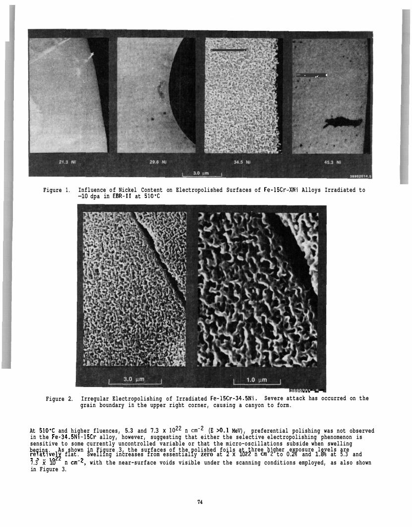
. .
.I . ,, .
Figure 1. Influence of Nickel Content on Electropolished Surfaces of Fe-15Cr-XNi Alloys Irradiated to -10 dpa in EBR-I1 at 510'C
...-I- Figure 2. Irregular Electropolishing of Irradiated Fe-15Cr-34.5Ni.
grain boundary in the upper right corner, causing a canyon to form. Severe attack has occurred on the
At 510% and higher fluences, 5.3 and 7.3 x loz2 n c N Z (E >0.1 MeV), preferential polishing was not observed in the Fe-34.5Ni-15Cr alloy, however, suggesting that either the selective electropolishing phenomenon is sensitive to some currently uncontrolled variable or that the micro-oscillations subside when swelling begins.
7.3 x 10 in Figure 3.
As shown in Figure 3, the surfaces of the polished foils at hree h'gher exposure levels are relative13 flat. Swelling increases from essentially zero at 2 x 10 2h n cm- 3 to 0.2% and 1.8% at 5.3 and
n cm-2, with the near-surface voids visible under the scanning conditions employed, as also shown
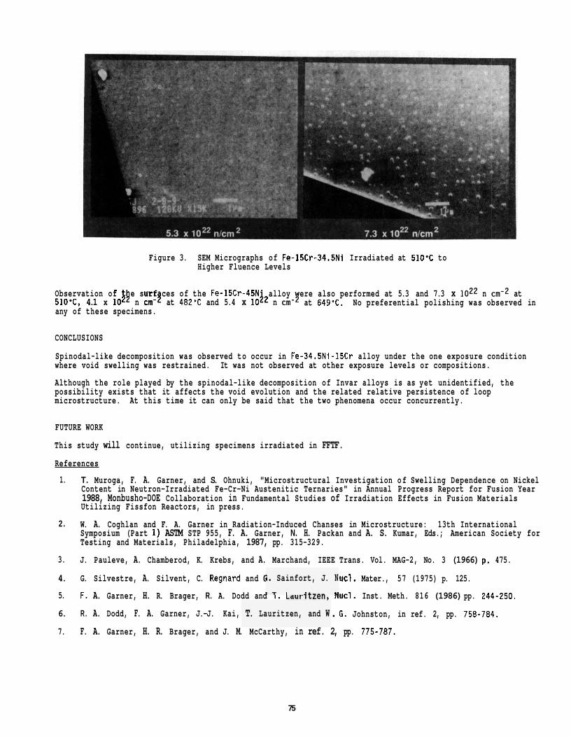
Figure 3. SEM Micrographs of Fe-15Cr-34.5Ni Irradiated at 510% to Higher Fluence Levels
Observation of 510'C, 4.1 x 1 8 n cm-j at 482'C and 5.4 x 10j2 n any of these specimens.
e surf ces of the Fe-15Cr-45N alloy ere also performed at 5.3 and 7.3 x loz2 n cnr2 at at 649%. No preferential polishing was observed in
CONCLUSIONS
Spinodal-like decomposition was observed to occur in Fe-34.5Ni-15Cr alloy under the one exposure condition where void swelling was restrained. It was not observed at other exposure levels or compositions.
Although the role played by the spinodal-like decomposition of Invar alloys is as yet unidentified, the possibility exists that it affects the void evolution and the related relative persistence of loop microstructure. At this time it can only be said that the two phenomena occur concurrently.
FUTURE WORK
This study will continue, utilizing specimens irradiated in FFTF.
References
1. T. Muroga, F. A. Garner, and S. Ohnuki, "Microstructural Investigation of Swelling Dependence on Nickel Content in Neutron-Irradiated Fe-Cr-Ni Austenitic Ternaries" in Annual Progress Report for Fusion Year 1988, Monbusho-DOE Collaboration in Fundamental Studies of Irradiation Effects in Fusion Materials Utilizing Fissfon Reactors, in press.
W. A. Coghlan and F. A. Garner in Radiation-Induced Chanses in Microstructure: 13th International 2. Symposium (Part 1) ASTM STP 955, F. A. Garner, N. H. Packan and A. S. Kumar, Eds.; American Society for Testing and Materials, Philadelphia, 1987, pp. 315-329.
3.
4. G. Silvestre, A. Silvent, C. Regnard and C
5.
6. R . A. Dodd, F. A. Garner, J.-J. Kai,
7.
J. Pauleve, A. Chamberod, K. Krebs, and A. Marchand, IEEE Trans. Vol. MAG-2, No. 3 (1966) p. 475.
lucl. Mater., 57 (1975) p. 125.
F. A. Garner, H. R. Brager, R. A. Dodd and I. LdurILLen, ducl. Inst. Meth. 816 (1986) pp. 244-250.
. 6. Johnston, in ref. 2, pp. 758-784.
F. A. Garner, H. R. Brager, and J. M. McCarthy, in ref. 2, pp. 775-787.
i. Sainfort, J. N I - I 1 I ___ .I
T. Lauritzen, and W
75

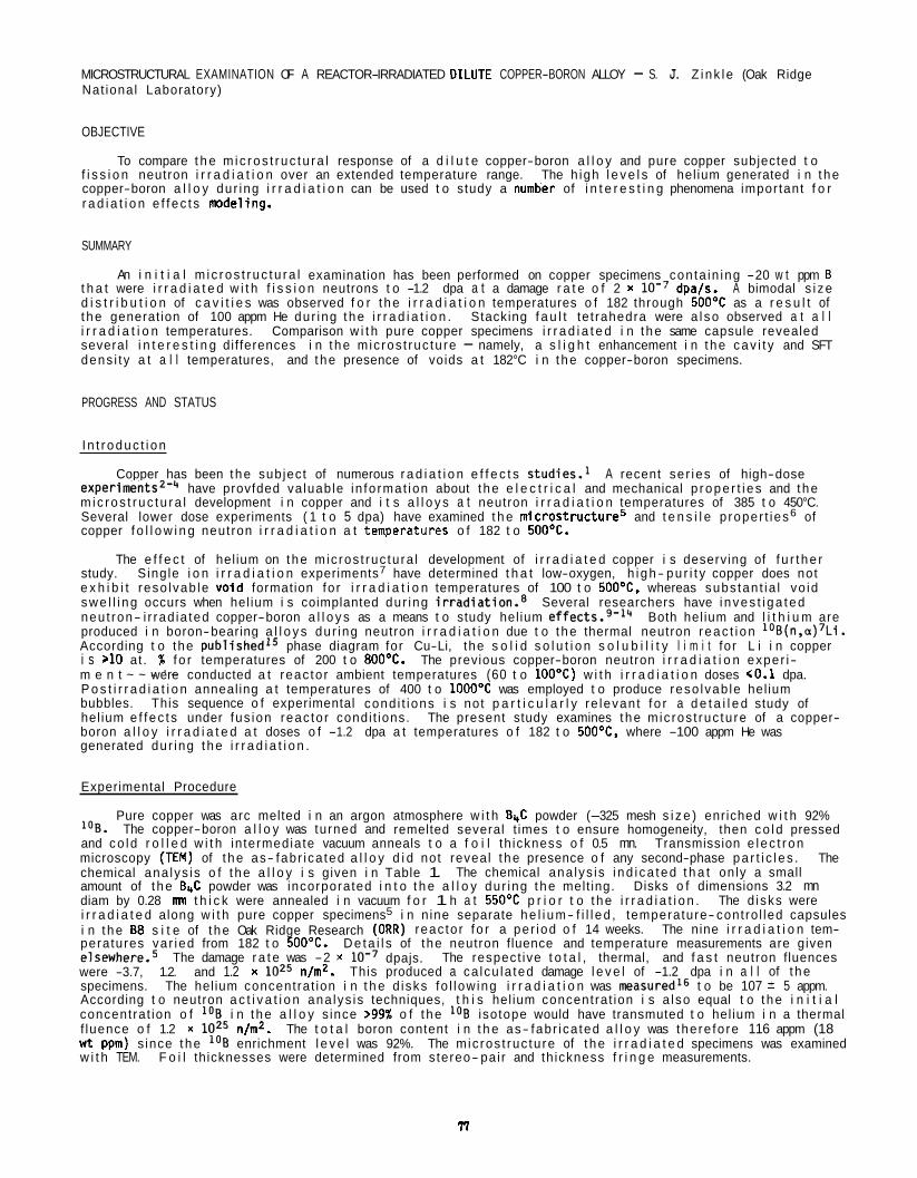
MICROSTRUCTURAL EXAMINATION OF A REACTOR-IRRADIATED DILUTE COPPER-BORON ALLOY - S. J. Z ink l e (Oak Ridge Nat ional Laboratory)
OBJECTIVE
To compare t h e m i c ros t r uc tu ra l response of a d i l u t e copper-boron a l l o y and pure copper subjected t o f i s s i o n neutron i r r a d i a t i o n over an extended temperature range. The h igh l e v e l s of hel ium generated i n t he copper-boron a l l o y dur ing i r r a d i a t i o n can be used t o study a numker of i n t e r e s t i n g phenomena impor tant f o r r a d i a t i o n e f f ec t s modeling.
SUMMARY
An i n i t i a l m i c ros t r uc tu ra l examination has been performed on copper specimens con ta in ing -20 w t ppm B t h a t were i r r a d i a t e d w i t h f i s s i o n neutrons t o -1.2 dpa a t a damage r a t e o f 2 x dpajs. A bimodal s i ze d i s t r i b u t i o n of c a v i t i e s was observed f o r t he i r r a d i a t i o n temperatures o f 182 through 50OoC as a r e s u l t of t he generat ion of 100 appm He dur ing t he i r r a d i a t i o n . Stacking f a u l t te t rahedra were a l so observed a t a l l i r r a d i a t i o n temperatures. Comparison w i t h pure copper specimens i r r a d i a t e d i n t he same capsule revealed several i n t e r e s t i n g di f ferences i n t he mic ros t ruc tu re - namely, a s l i g h t enhancement i n t he cav i t y and SFT dens i ty a t a l l temperatures, and t he presence of voids a t 182°C i n t he copper-boron specimens.
PROGRESS AND STATUS
I n t r oduc t i on
Copper has been t he subject of numerous r a d i a t i o n e f f e c t s s tud ies . l A recent se r ies of high-dose e x ~ e r i m e n t s ~ - ~ have provfded va luable in fo rmat ion about t he e l e c t r i c a l and mechanical p rope r t i es and t he m i c ros t r uc tu ra l development i n copper and i t s a l l o y s a t neutron i r r a d i a t i o n temperatures of 385 t o 450°C. Several lower dose experiments ( 1 t o 5 dpa) have examined t h e mic ros t ruc tu re5 and t e n s i l e p roper t ies6 of copper f o l l o w i n g neutron i r r a d i a t i o n a t tenvperatures o f 182 t o 5OO0C.
study. S ingle i o n i r r a d i a t i o n experiments7 have determined t h a t low-oxygen, h i gh- pu r i t y copper does not e x h i b i t reso lvab le vo ld formation fo r i r r a d i a t i o n temperatures of 100 t o 5OOOC. whereas subs tan t ia l vo id swe l l i ng occurs when hel ium i s coimplanted dur ing i r r a d i a t i o n . 8 Several researchers have i nves t i ga ted neu t ron- i r rad ia ted copper-boron a l l o y s as a means t o study hel ium effect^.^-'^ Both hel ium and l i t h i u m are produced i n boron-bearing a l l o y s dur ing neutron i r r a d i a t i o n due t o t he thermal neutron reac t i on 'OB(II,~)~L~. According t o the published15 phase diagram for Cu-Li, the s o l i d s o l u t i o n s o l u b i l i t y l i m i t for L i i n copper i s >10 at . % f o r temperatures of 200 t o 800'C. The previous copper-boron neutron i r r a d i a t i o n exper i- m e n t ~ ~ - ' ~ were conducted a t reac to r ambient temperatures (60 t o 100'C) w i t h i r r a d i a t i o n doses (0.1 dpa. P o s t i r r a d i a t i o n anneal ing a t temperatures of 400 t o 1000°C was employed t o produce reso lvab le hel ium bubbles. This sequence o f experimental cond i t ions i s not p a r t i c u l a r l y re levan t f o r a d e t a i l e d study of hel ium e f f ec t s under fus ion reac to r condi t ions. The present study examines t he mic ros t ruc tu re of a copper- boron a l l o y i r r a d i a t e d a t doses o f -1.2 dpa a t temperatures o f 182 t o 5OO0C, where -100 appm He was generated dur ing t he i r r a d i a t i o n .
The e f f e c t of hel ium on t he mic ros t ruc tu ra l development of i r r a d i a t e d copper i s deserving of f u r t he r
Experimental Procedure
log. The copper-boron a l l o y was turned and remelted several t imes t o ensure homogeneity, then co ld pressed and co ld r o l l e d w i t h in termediate vacuum anneals t o a f o i l th ickness o f 0.5 mn. Transmission e l ec t r on microscopy (TEM) of t he as- fabr i ca ted a l l o y d i d not reveal t he presence o f any second-phase pa r t i c l es . The chemical ana lys is o f t he a l l o y i s given i n Table 1. The chemical ana lys is i nd i ca ted t h a t on ly a small amount of t he BrC powder was incorporated i n t o t h e a l l o y dur ing t he melt ing. Disks o f dimensions 3.2 mn diam by 0.28 mn t h i c k were annealed i n vacuum f o r 1 h a t 550'C p r i o r t o t he i r r a d i a t i o n . The d isks were i r r a d i a t e d along w i t h pure copper specimens5 i n n ine separate he l i um- f i l l ed , temperature- contro l led capsules i n t he E8 s i t e of t he Oak Ridge Research (ORR) reac to r f o r a per iod o f 14 weeks. The nine i r r a d i a t i o n tem- peratures var ied from 182 t o 500'C. De ta i l s of the neutron fluence and temperature measurements are given elsewhere.5 The respect ive t o t a l , thermal, and f a s t neutron fluences were -3.7, 1.2. and 1.2 x l o z 5 n/m2. This produced a ca lcu la ted damage l e v e l of -1.2 dpa i n a l l of t he specimens. The hel ium concentrat ion i n t h e d isks fo l low ing i r r a d i a t i o n was measured16 t o be 107 f 5 appm. According t o neutron a c t i v a t i o n ana lys is techniques, t h i s hel ium concentrat ion i s a lso equal t o t he i n i t i a l concentrat ion o f 1°B i n t he a l l o y s ince >99% o f t he isotope would have transmuted t o hel ium i n a thermal f luence o f 1.2 x l o z 5 nfm2. The t o t a l boron content i n t h e as- fabr i ca ted a l l o y was there fo re 116 appm (18 w t ppm) s ince t he 1°B enrichment l e v e l was 92%. The mic ros t ruc tu re of t he i r r a d i a t e d specimens was examined w i t h TEM. F o i l thicknesses were determined from stereo- pai r and th ickness f r i n g e measurements.
Pure copper was arc melted i n an argon atmosphere w i t h B4C powder (-325 mesh s i z e ) enriched w i t h 92%
The damage r a t e was -2 x dpajs.
n
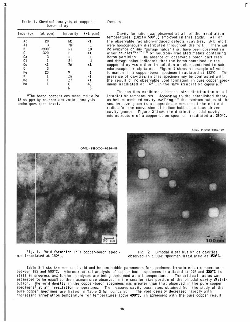
1
analys is of copper- a l l o y
Impur i t y (wt ppm)
Mo <1 Na 1 N i 10 P <1 S 1 s i 1 T i Sn <l 3
V 1 Zn <i Z r <l 0 48 N 6
ent was measured t o be a c t i v a t i o n analys is
).
f
Results
Cavi ty formation was observed a t a l l o f t he i r r a d i a t i o n temperatures (182 t o 500'C) employed i n t h i s study. A l l o f t he observable rad iat ion- induced defects ( cav i t i e s , SFT. etc.) were homogeneously d i s t r i b u t e d throughout t he f o i l . There was no evidence o f an o ther s t ~ d i e s " + * ~ ~ * ~ ~ o f neu t ron- i r rad ia ted metals con ta in ing boron p a r t i c l e s . and damage halos ind ica tes t h a t t he boron contained i n t he copper a l l o y was e i t h e r i n so l u t i on o r e l se contained i n sub- microscopic p rec i p i t a t es . F igure 1 shows an example o f vo id formation i n a copper-boron specimen i r r a d i a t e d a t 182°C. presence o f c a v i t i e s i n t h i s specimen may be contrasted w i t h t he r e s u l t of no observable vo id formation i n pure copper spec- imens i r r a d i a t e d a t 182OC i n t he same i r r a d i a t i o n c a p ~ u l e . ~
"damage halos" t h a t have been observed i n
The absence of observable boron p a r t i c l e s
The
The c a v i t i e s exh ib i t ed a bimodal s i ze d i s t r i b u t i o n a t a l l i r r a d i a t i o n temperatures. Accordin t o the establ ished theory on hel ium-assisted c a v i t y swell ing,qg t he maximum radius of t he smal ler s i ze group i s an approximate measure o f t he c r i t i c a l rad ius f o r the conversion o f hel ium bubbles t o b ias- dr i ven c a v i t y growth. F igure 2 shows t he d i s t i n c t bimodal c a v i t y m ic ros t ruc tu re o f a copper-boron specimen i r r a d i a t e d a t 350OC.
OWL-PHOTO-0626-88
l rmat ion i n a copper-boron speci- Fig. 2. Bimodal d i s t r i b u t i o n o f c a v i t i e s !OC. observed i n a Cu-B specimen i r r a d i a t e d a t 35OOC.
i e measured vo id and hel ium bubble parameters f o r specimens i r r a d i a t e d a t temperatures :. Mic ros t r uc tu ra l analys is of copper-boron specimens i r r a d i a t e d a t 275 and 3OO0C i s 1 f u r t he r analyses are being performed a t a l l temperatures. The c r i t i c a l rad ius was I t o t he maximum s i ze observed i n t he smal ler s i ze p o r t i o n of t he bimodal c a v i t y d i s t r i - i s i t y i n t he copper-boron specimens was greater than t h a t observed i n t h e pure copper "ad ia t ion temperatures. The measured c a v i t y parameters obtained from t h e study of t he i are l i s t e d i n Table 3 for comparison. The void dens i t y decreased r a p i d l y w i t h )n temperature f o r temperatures above 4OO0C, i n agreement w i t h the pure copper r esu l t .
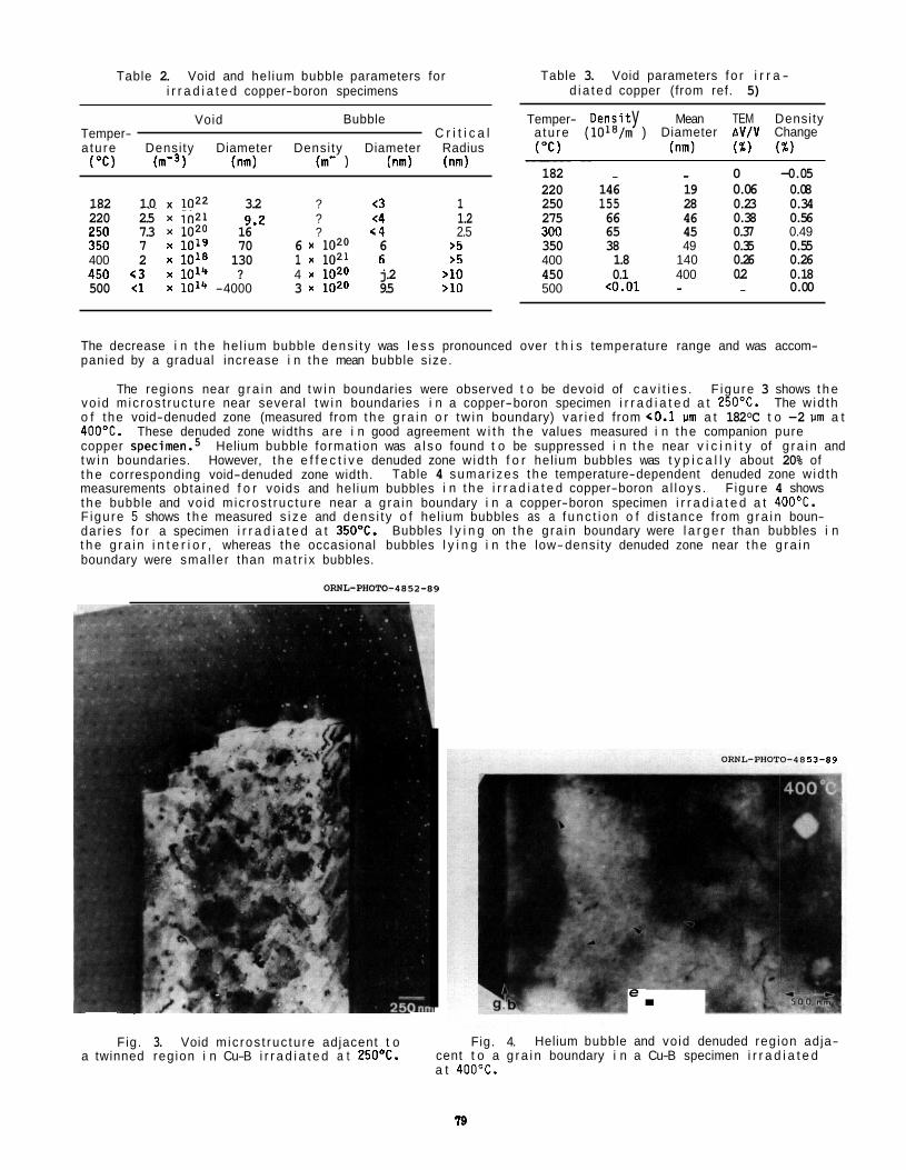
Table 2. Void and hel ium bubble parameters for i r r a d i a t e d copper-boron specimens
Table 3. Void parameters f o r i r r a - d i a ted copper (from ref. 5)
Void Bubble Temper- C r i t i c a l a tu re Density Diameter Density Diameter Radius
( " c l ( m - 9 (nm) (m- 1 (nm) (nm)
182 1.0 x loz2 3.2 ? <3 1 ~~~ ~~~
220 2.5 250 7.3 x i o 2 0 350 7 x 10¹⁹ 400 2 x 10l8 130 1 x .. 450 t 3 x 10¹⁴ ? 4 x 10²⁰ j.2 >10 500 <1 x 10'" -4000 3 x 10²⁰ 9.5 >10
in21 9.2 ? <4 1.2 16 ? < 4 2.5 70 6 x lozo 6 >5
in21 6 >5
Temper- Densi t y Mean TEM Density a tu re (10lB/m ) Diameter A V / V Change ("C) (nm) (%) (%)
~~~ ~~
182 - - 0 -0.05 220 146 19 0.06 0.08 250 155 28 0.23 0.34 275 66 46 0.38 0.56 300 65 45 0.37 0.49 350 38 49 0.35 0.55 400 1.8 140 0.26 0.26 450 0.1 400 0.2 0.18 500 <0.01 - - 0.00
The decrease i n t he hel ium bubble dens i t y was l ess pronounced over t h i s temperature range and was accom- panied by a gradual increase i n t he mean bubble s ize.
The regions near g ra i n and t w i n boundaries were observed t o be devoid of cav i t i e s . F igure 3 shows t h e vo id m ic ros t ruc tu re near several t w i n boundaries i n a copper-boron specimen i r r a d i a t e d a t 250'C. The w id th o f the void-denuded zone (measured from the g ra i n o r tw in boundary) va r ied from r0.1 vm a t 182°C t o -2 vm a t 4OO0C. These denuded zone widths are i n good agreement w i t h t he values measured i n t he companion pure copper ~ p e c i m e n . ~ Helium bubble format ion was a l so found t o be suppressed i n t h e near v i c i n i t y of g ra i n and t w i n boundaries. However, t he e f f e c t i v e denuded zone w id th f o r hel ium bubbles was t y p i c a l l y about 20% of t h e corresponding void-denuded zone width. measurements obtained f o r voids and hel ium bubbles i n t he i r r a d i a t e d copper-boron a l loys . F igure 4 shows t he bubble and void m ic ros t ruc tu re near a g ra in boundary i n a copper-boron specimen i r r a d i a t e d a t 400'C. Figure 5 shows t h e measured s i ze and dens i t y o f hel ium bubbles as a f unc t i on o f d is tance from g ra i n boun- dar ies f o r a specimen i r r a d i a t e d a t 35OoC. Bubbles l y i n g on t he g ra in boundary were l a r g e r than bubbles i n t h e g ra i n i n t e r i o r , whereas the occasional bubbles l y i n g i n t he low-density denuded zone near t he g ra i n boundary were smal ler than ma t r i x bubbles.
Table 4 sumar izes t he temperature-dependent denuded zone w id th
OWL-WOM-4852-89
Fig. 3. Void mic ros t ruc tu re adjacent t o a twinned region i n Cu-B i r r a d i a t e d a t 25OOC.
53-89
e . Fig. 4. Helium bubble and void denuded region adja-
cent t o a g ra i n boundary i n a Cu-B specimen i r r a d i a t e d a t 400'C.
I 9
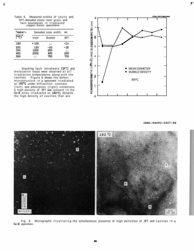
7 F
oRLDvIo.pyoII a Table 4. Measured widths of c a v i t y and I I I I I I SFT-denuded zones near g ra i n and -
E copper-boron specimens - tw in boundaries i n i r r a d i a t e d
a: 7m-
m n z
E
- 2 3 MEAN DIAMETER BUBBLE DENSITY
W ::/ 350°C 0 U W m l
- .\,/= L I'.c ./*-. -
W Tenper- Denuded zone width, nm a tu re I ("C) Void Bubble SFT 2 6
250 120 -20 - 20 350 1200 200 -_ 400 2000 400 600 500 -- 700 700
/ 182 < 100 -- <lo 5 m m-- -
- - 0
R' - E 9 2
5
-
Stacking f a u l t te t rahedra (SFT) and d i s l o c a t i o n loops were observed a t a l l i r r a d i a t i o n temperatures along w i t h t he cav i t i e s .
a t 182OC under d i f f r a c t i o n con t ras t ( l e f t ) and absorpt ion ( r i g h t ) cond i t ions
F igure 6 shows the defect m ic ros t ruc tu re i n a specimen i r r a d i a t e d
A h igh dens i t y of SFT was present i n t he Cu-B a l l o y i r r a d i a t e d a t 182°C; desp i te t he h igh dens i t y o f c a v i t i e s t h a t are
-
z 0 I I I I I I
ORNL-PHOTO-0627-88
Fig. 6. Micrographs i l l u s t r a t i n g the simultaneous presence of h igh dens i t i e s of SFT and c a v i t i e s i n a Cu-B specimen.
so
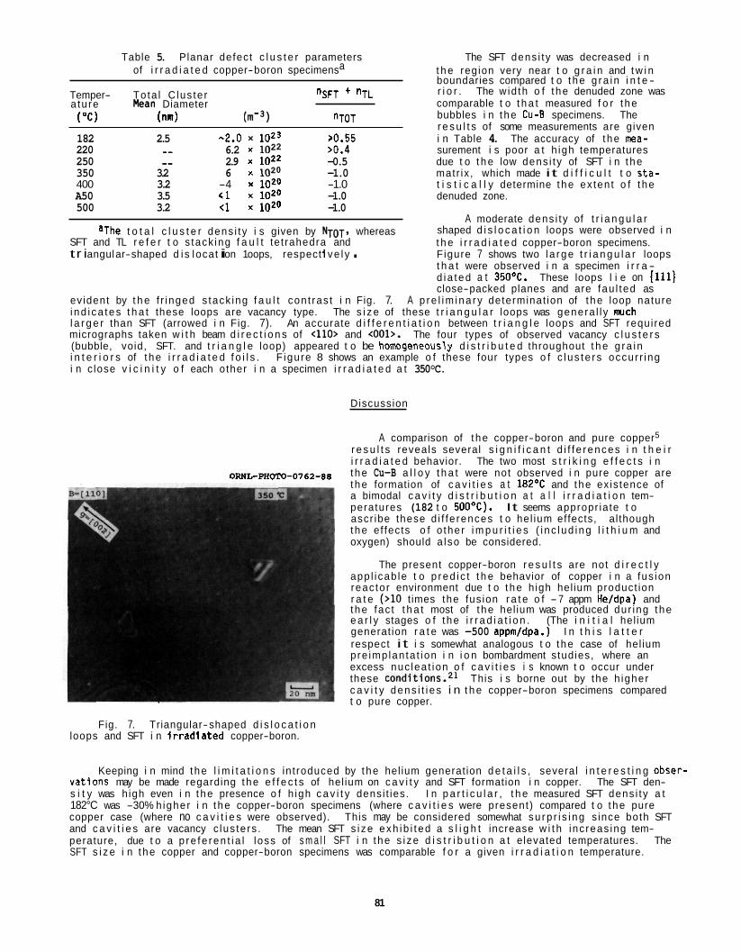
Table 5. Planar defect c l u s t e r parameters The SFT dens i ty was decreased i n of i r r a d i a t e d copper-boron specimensa t h e region very near t o g r a i n and t w i n
boundaries compared t o t he g ra i n i n t e - r i o r . The w id th o f t he denuded zone was comparable t o t h a t measured f o r t he bubbles i n t he Cu-B specimens. The r e s u l t s of some measurements are given
Temper- Tota l C lus te r ~ S F T + ~ T L a tu re &an Diameter ("C) (nm) W3) nTOT
182 2.5 -2.0 1023 >0.55 i n Table 4. The accuracy of t he mea- 220 -- 6.2 x l0z2 >0.4 surement i s poor a t h igh temperatures 250 -- 2.9 x 10²² -0.5 due t o t h e low dens i t y of SFT i n t he 350 3.2 6 x lozo -1.0 matr ix , which made it d i f f i c u l t t o s t a - 400 3.2 -4 x 10²⁰ -1.0 t i s t i c a l l y determine t he ex ten t o f t he A50 3.5 61 x 1020 -1.0 denuded zone. 500 3.2 tl x 1020 -1.0
A moderate dens i t y of t r i a n g u l a r shaped d i s l o c a t i o n loops were observed i n t h e i r r a d i a t e d copper-boron specimens. F igure 7 shows two l a rge t r i a n g u l a r loops t h a t were observed i n a specimen i r r a - d ia ted a t 35OoC. These loops l i e on 1111) close-packed planes and are fau l ted as
ev ident by t h e f r inged s tack ing f a u l t con t ras t i n Fig. 7. A p re l im ina ry determinat ion of t he loop nature i nd i ca tes t h a t these loops are vacancy type. The s i z e of these t r i a n g u l a r loops was genera l l y w c h l a r g e r than SFT (arrowed i n Fig. 7). An accurate d i f f e r e n t i a t i o n between t r i a n g l e loops and SFT requi red micrographs taken w i t h beam d i r e c t i o n s of t110> and <001>. The four types of observed vacancy c l u s t e r s (bubble, void, SFT. and t r i a n g l e loop) appeared t o be homogeneously d i s t r i b u t e d throughout t h e g ra i n i n t e r i o r s of t he i r r a d i a t e d f o i l s . F igure 8 shows an example o f these four types o f c l us te r s occur r ing i n c lose v i c i n i t y o f each other i n a specimen i r r a d i a t e d a t 350°C.
aThe t o t a l c l u s t e r dens i t y i s given by NTOT. whereas SFT and TL r e f e r t o s tack ing f a u l t te t rahedra and t r i angul ar-shaped d i s l ocat i on 1 oops, respect i ve l y .
ORNL-PHOTO-0762-88
Fig. 7. Triangular-shaped d i s l o c a t i o n loops and SFT i n i r r a d f a t e d copper-boron.
Discussion
A comparison of t he copper-boron and pure copper5
r e s u l t s reveals several s i g n i f i c a n t d i f f e rences i n t h e i r i r r a d i a t e d behavior. The two most s t r i k i n g e f f e c t s i n t he Cu-B a l l o y t h a t were not observed i n pure copper are t he formation of c a v i t i e s a t 182OC and t he ex is tence of a bimodal c a v i t y d i s t r i b u t i o n a t a l l i r r a d i a t i o n tem- peratures (182 t o 50OoC). ascr ibe these d i f fe rences t o he l ium effects, al though t he ef fects o f o ther i m p u r i t i e s ( i nc l ud ing l i t h i u m and oxygen) should a lso be considered.
The present copper-boron r e s u l t s are not d i r e c t l y app l i cab le t o p red i c t t h e behavior of copper i n a fus ion reac to r environment due t o t he h igh hel ium product ion r a t e (>lo t imes the fus ion r a t e o f - 7 appm He/dpa) and the fac t t h a t most of t he hel ium was produced dur ing the e a r l y stages o f t he i r r a d i a t i o n . (The i n i t i a l hel ium generat ion r a t e was -500 appm/dpa.) respect i t i s somewhat analogous t o t he case of hel ium pre imp lan ta t ion i n i o n bombardment s tud ies, where an excess nuc lea t ion o f c a v i t i e s i s known t o occur under these conditions.21 This i s borne out by the h igher c a v i t y dens i t i e s i n t h e copper-boron specimens compared t o pure copper.
It seems appropr ia te t o
I n t h i s l a t t e r
Keeping i n mind t he l i m i t a t i o n s in t roduced by t he hel ium generat ion d e t a i l s , several i n t e r e s t i n g obser- va t lons may be made regarding t he e f f e c t s of hel ium on c a v i t y and SFT formation i n copper. The SFT den- s i t y was h igh even i n t he presence o f h igh c a v i t y densi t ies. I n p a r t i c u l a r , t h e measured SFT dens i ty a t 182°C was -30% h igher i n t he copper-boron specimens (where c a v i t i e s were present) compared t o t he pure copper case (where no c a v i t i e s were observed). This may be considered somewhat su rp r i s i ng s ince both SFT and c a v i t i e s are vacancy c lus te rs . The mean SFT s i ze exh ib i t ed a s l i g h t increase w i t h inc reas ing tem- perature, due t o a p re fe ren t i a l loss of s m a l l SFT i n t he s i ze d i s t r i b u t i o n a t elevated temperatures. The SFT s i z e i n t he copper and copper-boron specimens was comparable f o r a given i r r a d i a t i o n temperature.
81
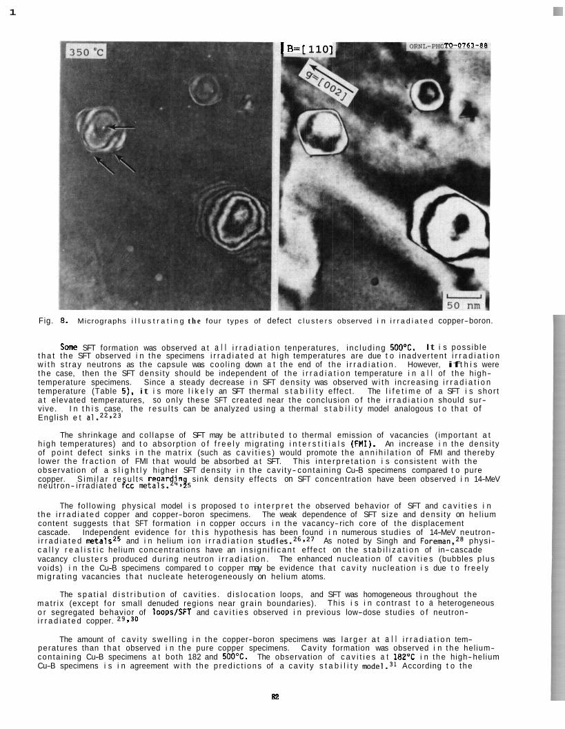
1
TO-0763-88 1 B= [ 1 10 1
Fig. 8. Micrographs i l l u s t r a t i n g t h e four types of defect c l u s t e r s observed i n i r r a d i a t e d copper-boron.
Sane SFT formation was observed a t a l l i r r a d i a t i o n tenperatures, i n c l ud i ng 500'C. It i s poss ib le t h a t t he SFT observed i n t he specimens i r r a d i a t e d a t h igh temperatures are due t o inadver ten t i r r a d i a t i o n w i t h s t r ay neutrons as t he capsule was coo l ing down a t t he end of t he i r r a d i a t i o n . However, if t h i s were t he case, then t he SFT dens i t y should be independent of t he i r r a d i a t i o n temperature i n a l l of t he h igh- temperature specimens. Since a steady decrease i n SFT dens i t y was observed w i t h inc reas ing i r r a d i a t i o n temperature (Table 5). i t i s more l i k e l y an SFT thermal s t a b i l i t y e f fect . The l i f e t i m e of a SFT i s shor t a t elevated temperatures, so on ly these SFT created near t he conclusion o f t he i r r a d i a t i o n should sur- vive. Engl ish e t a1.22*23
h i gh temperatures) and t o absorpt ion o f f r e e l y m ig ra t ing i n t e r s t i t i a l s (FMI). An increase i n t he dens i t y of po in t defect s inks i n t he ma t r i x (such as c a v i t i e s ) would promote t he a n n i h i l a t i o n of FMI and thereby lower t he f r a c t i o n of FMI t h a t would be absorbed a t SFT. This i n t e r p r e t a t i o n i s consis tent w i t h t he observat ion of a s l i g h t l y higher SFT dens i t y i n t he cav i t y- con ta in ing Cu-B specimens compared t o pure copper. S i m i l a r r e s u l t s regard in s ink dens i t y e f fects on SFT concentrat ion have been observed i n 14-MeV
I n t h i s case, the r e s u l t s can be analyzed us ing a thermal s t a b i l i t y model analogous t o t h a t o f
The shrinkage and co l lapse of SFT may be a t t r i b u t e d t o thermal emission of vacancies ( impor tant a t
neu t ron- i r rad ia ted fcc metals.24* 9 The fo l low ing physica l model i s proposed t o i n t e r p r e t t he observed behavior of SFT and c a v i t i e s i n
t h e i r r a d i a t e d copper and copper-boron specimens. The weak dependence of SFT s ize and dens i t y on hel ium content suggests t h a t SFT formation i n copper occurs i n t he vacancy-rich core of t he displacement cascade. Independent evidence f o r t h i s hypothesis has been found i n numerous s tudies of 14-MeV neutron- i r r a d i a t e d metalsz5 and i n hel ium i o n i r r a d i a t i o n s t ~ d i e s . ~ ~ , ~ ~ As noted by Singh and Foreman.28 phys i- c a l l y r e a l i s t i c hel ium concentrat ions have an i n s i g n i f i c a n t e f fec t on t he s t a b i l i z a t i o n of in-cascade vacancy c l u s t e r s produced dur ing neutron i r r a d i a t i o n . The enhanced nuc lea t ion of c a v i t i e s (bubbles p l us vo ids) i n t he Cu-B specimens compared t o copper may be evidence t h a t c a v i t y nuc lea t ion i s due t o f r ee l y m ig ra t i ng vacancies t h a t nuc leate heterogeneously on hel ium atoms.
ma t r i x (except f o r small denuded regions near g ra i n boundaries). This i s i n con t ras t t o a heterogeneous o r segregated behavior of 1oopsISFT and c a v i t i e s observed i n previous low-dose studies o f neutron- i r r a d i a t e d copper. 29 I 30
The amount of c a v i t y swe l l i ng i n t he copper-boron specimens was l a r g e r a t a l l i r r a d i a t i o n tem- peratures than t h a t observed i n t he pure copper specimens. Cavi ty formation was observed i n t h e hel ium- con ta in ing Cu-B specimens a t both 182 and 500'C. The observat ion of c a v i t i e s a t 182'C i n t he high-hel ium Cu-B specimens i s i n agreement w i t h t he p red i c t i ons of a cav i t y s t a b i l i t y model.31 According t o t he
The s p a t i a l d i s t r i b u t i o n of cav i t i e s . d i s l o c a t i o n loops, and SFT was homogeneous throughout t he
82
model, copper i r r a d i a t e d a t 182°C a t a damage r a t e of 2 x lo-' dpals requires a hel ium concentrat ion greater than -0.2 appm t o s t a b i l i z e the nucleated cav i t i es . This may exp la in the absence of observable c a v i t i e s a t 182°C i n copper (0.2 appm He) and t h e presence of c a v i t i e s i n copper-boron (100 appm He). t h e o ther hand, t h e e f f e c t s o f o ther so lu te atoms must a lso be considered.
On
Some cav i t y formation was observed i n t h e copper-boron specimens i r r a d i a t e d a t 5OO0C, but the calcu- l a t e d amount o f swe l l i ng (AVlV -0.02%) was i n s i g n i f i c a n t fo r t h e 1.2 dpa i r r a d i a t i o n dose. It i s uncer- t a i n whether appreciable amounts of cav i t y swe l l ing could occur. i n specimens i r r a d i a t e d t o h igher doses. A ser ies of high-dose i r r a d i a t i o n experiments a t temperatures of 373 t o 529'C u t i l i z i n g t h e FFTF reac tor are cu r ren t l y i n progress.32 These studies should es tab l i sh t h e upper temperature l i m i t f o r void f o r - mation i n copper.
CONCLUSIONS
Cavi ty and SFT formation was observed i n the copper-boron a l l o y a t a l l i r r a d i a t i o n temperatures o f 182 t o 500°C. A bimodal s i ze d i s t r i b u t i o n was observed fo r t h e cav i t i es , presumably due t o t h e genera- t i o n of -100 appm He dur ing the i r r a d i a t i o n . Regions imnediate ly adjacent t o g ra in and t w i n boundaries were denuded of voids, hel ium bubbles, and SFT. t o the case of pure copper. The resu l t s suggest t h a t hel ium accelerates t h e development o f c a v i t i e s i n copper, i n p a r t i c u l a r a t the low-temperature l i m i t of the void swe l l i ng regime. The present r e s u l t s are not d i r e c t l y app l icab le t o t h e fusion reac tor environment due t o the h igh amounts of generated helium. The dens i ty .o f SFT a t 182°C was s l i g h t l y enhanced i n t h e cav i ty- conta in ing copper-boron a l l o y compared t o pure copper. Th is observat ion may be used t o ob ta in fundamental in format ion about the r e l a t i v e ro l es of f r e e l y migra t ing p o i n t defects and c l us te r s produced i n the displacement cascade.
Void formation was enhanced a t a l l temperatures compared
FUTURE WORK
The mic ros t ruc ture of copper-boron specimens i r r a d i a t e d a t 275 and 300°C w i l l be examined and den- s i t y changes w i l l be measured fo r a l l i r r a d i a t i o n temperatures. A de ta i l ed comparison of the microstruc- tu res i n the i r r a d i a t e d copper and copper-boron specimens w i l l be made a t a l l i r r a d i a t i o n temperatures.
ACKNOWLEDGMENTS
The author would l i k e t o acknowledge K. F a r r e l l fo r supplying the i r r a d i a t e d specimens, N. H. Rouse, L. T. Gibson and E. L. Ryan fo r experimental assistance, and Frances Scarboro fo r manuscript preparation.
REFERENCES
1. S. J. Zink le and R. W. Kno l l , A L i t e r a t u r e Review of Radiat ion Damage Data f o r Copper and Copper A l loys , Un i ve rs i t y o f Wisconsin Fusion Technology I n s t i t u t e Report UWFDM-578, 1984.
2. R. J. Livak, T. G. Zocco, and L. W. Hobbs, J. Nucl. Mater. 144 (1987) 121.
3. 0. K. Ha r l i ng e t al., J. Mater. Res. 2 (1987) 568.
4. H. R. Brager and F. A. Garner, p. 254 i n Fusion Reactor Mater ia ls Semiannu. Prog. Rep. Sept. 30, 1987, DOE-ER-031313, U.S. DOE, O f f i ce o f Fusion Energy.
5. S. J. Zink le and K. F a r r e l l , J. Nucl. Mater., 1989, i n press; a lso see Fusion Reactor Mater ia ls Semiannu. Prog. Rep. Sept. 30, 1987, DOE-ER-031313, p. 90.
6. W. Vandermeulen e t al., 14th Symp. on Fusion Technology, September 1986, Avignon, France, Comn. Eur. Communities, Pergamon Press, 1986, p. 1031.
7. S. J. Zinkle, G. L. Kulc inski , and R. W. Knol l , J. Nucl. Mater. 138 (1986) 46.
8. S. J. Zinkle, p. 86 i n Fusion Reactor Mater ia ls Semiannu. Prog. Rep. Sept. 30, 1987, DOE-ER-031313, U.S. DOE, Off ice of Fusion Energy.
9. P. Vela and E. Russell , J. Nucl. Mater. 19 (1966) 312.
10. P. Vela and E. Russell , J. Nucl. Mater. 19 (1966) 327.
83
11.
12.
13.
14.
15.
16.
17.
18.
19.
20.
21.
22.
23.
24.
25.
26.
27.
28.
29.
30.
31.
32.
G.J.C. Carpenter and R. B. Nicholson, p. 383 i n Radia t ion Damage i n Reactor Mater ia ls , Val. 2, I A E A , Vienna, 1966.
G.J.C. Carpenter and R . B. Nicholson, Report AECL-3331, Chalk River, Ontar io, 1969.
D. E. Barry and B. L. Eyre, P h i l . Mag. 22 (1970) 717.
D. E. Barry, P h i l . Mag. 23 (1971) 495.
M. L. Mendelsohn, D. M. Green, and A. R . Krauss, J . Nucl. Mater. 141-143 (1986) 184.
B. M. O l i ve r , Rockwell I n t e r n a t i o n a l , Canoga Park, C A , 1988, personal communication.
D. A. Woodford, J . P. Smith, and J . Motef f , J . I r o n E Steel I ns t . (1969) 70.
R . C. Lau and R. L. Ladd, J . Appl. Phys. 40 (1969) 2899.
L. K. Mansur, J . Nucl. Mater. 150 (1987) 105.
S. J . Z ink le and R. L. Sindelar, J. Nucl. Mater. 155157 (1988) 1196.
K. F a r r e l l , Rad. Ef fec ts 53 (1980) 175.
C. A. Engl ish, 8. L. Eyre, and J . Summers, P h i l . Mag. 34 (1976) 603.
J . W. Muncie, 8. L. Eyre, and C. A. Engl ish, P h i l . Mag. A 52 (1985) 309.
N. Yoshida, Y . Akashi, K. K i t a j ima , and M. K i r i t a n i , J. Nucl. Mater. 133&134 (1985) 405.
M. K i r i t a n i . T. Yoshiie, and S . Kojima, J . Nucl. Mater. 141-143 (1986) 625.
A. A. Gadalla, W . Jgger, and P. Ehrhart . J. Nucl. Mater. 137 (1985) 73.
P. Ehrhart , A. A. Gadalla, W. Jager, and N. Tsukuda, Acta Me ta l l . 35 (1987) 1929.
B. N. Singh and A.J.E. Foreman, J . Nucl. Mater. 155157 (1988) 1258.
C. A. Engl ish, J . Nucl. Mater. 108&109 (1982) 104.
8. N. Singh, T. Lef fers , and A. Horsewell, P h i l . Mag. A 53 (1986) 233.
S. J. Zink le , W . G. Wolfer, G. L. Ku lc insk i , and L. E. Seitzman, Ph i l . Mag. A 55 (1987) 127.
K. R. Anderson, F. A . Garner, M. L. Hamilton, and J. F. Stubbins, t h i s volume (DOE/ER-0313/6).
RADIAT ION DAMAGE I N B I N A R Y CERAMIC OXIDES: A PRELIMINARY MODEL - Roger E. S t o l l e r (Oak Ridge Nat ional Laboratory)
OBJECTIVE
To develop a p h y s i c a l l y based, t h e o r e t i c a l model of p o i n t defect and extended defect behavior i n ceramic mate r ia l s and t o use t h i s model t o improve our understanding of the response of these mate r ia l s t o d i so lac i ve i r r a d i a t i o n .
SUMMARY
A p re l im ina ry model of r a d i a t i o n damage i n b ina ry ceramic oxides has been developed. The model descr ibed here accounts i n an approximate way fo r some of the major di f ferences between m e t a l l i c a l l o y s and ceramics t h a t are be l ieved t o be responsible fo r the f a c t t h a t ceramic mate r ia l s are observed t o behave d i f f e r e n t l y than m e t a l l i c a l l o y s when exposed t o d i s p l a c i v e i r r a d i a t i o n . in f luence o f the existence of a second l a t t i c e and the a d d i t i o n a l cons t ra in t of s to i ch iomet r i c p o i n t defect absorpt ion by d i s l o c a t i o n loops on t h e concent ra t ions o f p o i n t defects t h a t would be observed a t s teady- sta te i n an i r r a d i a t e d ceramic. var ious measures of the s e n s i t i v i t y of these mate r ia l s t o t h e t h e t ype of m ic ros t ruc tu ra l e v o l u t i o n t h a t i s observed i n i r r a d i a t e d metals. I n i t i a l r e s u l t s obtained w i t h the present model i n d i c a t e t h a t both the l a t t i c e and s to ich iometry e f fec ts can help t o m i t i g a t e r a d i a t i o n damage i n ceramics. However, t he e f f e c t i s not necessar i ly l a rge ; i n agreement w i t h recent data, the r e s u l t s i n d i c a t e t h a t a t l e a s t some ceramic oxides may e x h i b i t a s e n s i t i v i t y t o displacement damage t h a t i s s i m i l a r t o metals.
The model considers the
These p o i n t defect concent ra t ions are then used t o compute
PROGRESS AND STATUS
In t roduc t ion
The use of ceramic mate r ia l s i n fus ion reac to r components has been discussed f o r some time.'+ pr imary app l i ca t ions proposed fo r these mate r ia l s inc lude: as e l e c t r i c a l i n s u l a t o r s i n rf heaters and neu t ra l beam i n j e c t o r s , as rf windows, and i n t h e f i r s t wa l l t h a t provides a vacuum b a r r i e r f o r the plasma. The ceramics m s t f requen t l y discussed i n the context of fus ion reac to r designs are magnesia (MgD), alumina (A lz03) , sp ine l (MgA12DU), s i l i c o n carbide (S ic ) and s i l i c o n n i t r i d e (S i3N4) , l i t h i u m oxide (L izD) and graphi te ( C ) . References 1 t o 8 prov ide a good overview of some of the mate r ia l s and t h e i r app l i ca t ions .
sequence of m ic ros t ruc tu ra l evo lu t i on t h a t i s s i m i l a r t o t h a t observed i n i r r a d i a t e d metal^.^-'^ Unfortunately, t he s t ra ight forward a p p l i c a t i o n of the theory developed t o descr ibe r a d i a t i o n damage i n m e t a l l i c a l l o y s i s precluded by several subs tan t ia l d i f f e rences between these two types o f ma te r ia l s . The major di f ferences are due t o the fac t t h a t ceramics e x h i b i t chemical (both i o n i c and cova lent ) r a t h e r than m e t a l l i c bonding. As a r e s u l t , a theory of r a d i a t i o n damage i n ceramics must be concerned w i t h t h e preservat ion of s to ich iometry , m u l t i p l e (anion and c a t i o n ) l a t t i c e s , and the charge s t a t e of t h e var ious p o i n t defects t h a t can e x i s t . I n add i t ion, atomic displacements w i l l no t occur i n a s t o i c h i o m e t r i c r a t i o i n ma te r ia l s i n which the atomic mass and the displacement energy i s d i f f e ren t f o r one chemical species than f o r t h e o the r (s ) . Atomic displacements can a l s o be generated i n some compound mate r ia l s due t o r a d i o l y s i s , 8 al though t h i s mechanism i s thought t o be n e g l i g i b l e i n most of t h e mate r ia l s mentioned above
The
Both s t r u c t u r a l and p r o t e c t i v e funct ions are proposed i n t h e f i r s t wa l l app l i ca t ions .
I n t h e presence of d i s p l a c i v e neutron o r charged p a r t i c l e i r r a d i a t i o n , ceramic mate r ia l s d i sp lay a
The work descr ibed here represents a f i r s t step i n t h e development of a model of r a d i a t i o n damage i n
Because of the complex i t ies o f t h e phys i- ceramics. The r a t e theory desc r ip t i on t h a t has been successfu l ly app l ied t o a range o f problems i n m e t a l ~ ~ l * * ~ ~ prov ides the s t a r t i n g p o i n t f o r the present work. c a l system mentioned above, the model i nvo lves many approximations. Therefore, the r e s u l t s should be viewed as being p re l im ina ry i n nature. The c a l c u l a t i o n s prov ide some i l l u s t r a t i o n s o f the poss ib le behavior of i r r a d i a t e d ceramics and some comparisons w i t h i r r a d i a t e d metals.
Model Desc r ip t i on
form: A general equat ion f o r the p o i n t defect concent ra t ions of a multicomponent ceramic would be of t h e
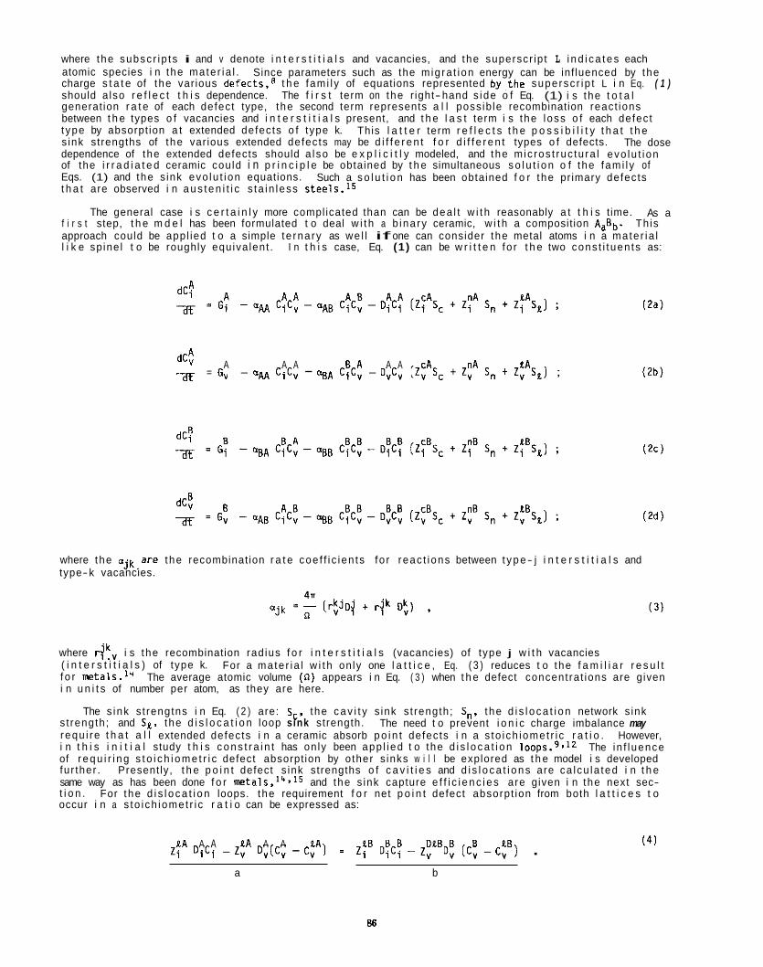
where the subsc r ip ts i and v denote i n t e r s t i t i a l s and vacancies, and the superscr ip t L i n d i c a t e s each atomic species i n the mate r ia l . charge s t a t e of the var ious defects,B t h e fami l y of equations represented by. the supersc r ip t L i n Eq. ( 1 ) should a lso r e f l e c t t h i s dependence. The f i r s t term on the r ight- hand s ide o f Eq. (1) i s the t o t a l generat ion r a t e of each defect type, the second term represents a l l poss ib le recombination react ions between t h e types o f vacancies and i n t e r s t i t i a l s present, and t h e l a s t term i s the loss o f each defect t ype by absorpt ion a t extended defects o f type k. s ink strengths of the var ious extended defects may be d i f f e r e n t f o r d i f f e r e n t types o f defects. dependence of the extended defects should a l so be e x p l i c i t l y modeled, and the m ic ros t ruc tu ra l evo lu t i on of the i r r a d i a t e d ceramic cou ld i n p r i n c i p l e be obtained by t h e simultaneous s o l u t i o n o f the fami l y of Eqs. (1) and the s ink evo lu t i on equations. t h a t are observed i n a u s t e n i t i c s ta in less ~ t e e 1 s . l ~
Since parameters such as the m ig ra t ion energy can be inf luenced by the
This l a t t e r term r e f l e c t s t h e p o s s i b i l i t y t h a t t h e The dose
Such a s o l u t i o n has been obtained f o r the pr imary defects
The general case i s c e r t a i n l y more compl icated than can be dea l t w i t h reasonably a t t h i s t ime. As a f i r s t step, t h e m d e l has been formulated t o deal w i t h a b ina ry ceramic, w i t h a composition AaBb. Th is approach could be appl ied t o a simple te rna ry as we l l if one can consider the metal atoms i n a mate r ia l l i k e sp ine l t o be roughly equiva lent . I n t h i s case, Eq. (1) can be w r i t t e n fo r t h e two cons t i t uen ts as:
A A A A A cA nA t A dC: af = G, - GW CiC, - %A C $ C t - DvCv ( Z v Sc + Z, Sn t Z, S t ) ;
where the ojk,are the recombinat ion r a t e coe f f i c ien ts fo r reac t ions between t y p e- j i n t e r s t i t i a l s and type-k vacancies.
where r ikv i s the recombination rad ius f o r i n t e r s t i t i a l s (vacancies) of type j w i t h vacancies ( i n t e r s t i t i a l s ) of type k. f o r metals.14 i n u n i t s of number per atom, as they are here.
s t rength; and SL. t he d i s l o c a t i o n loop sink strength. requ i re t h a t a l l extended defects i n a ceramic absorb p o i n t defects i n a s to i ch iomet r i c r a t i o . i n t h i s i n i t i a l study t h i s c o n s t r a i n t has on ly been app l ied t o the d i s l o c a t i o n loop^.^.^^ of r e q u i r i n g s t o i c h i o m e t r i c defect absorpt ion by o ther s inks w i l l be explored as t h e model i s developed fur ther . Present ly, t h e p o i n t defect s ink strengths o f c a v i t i e s and d i s l o c a t i o n s are ca lcu la ted i n t h e same way as has been done f o r and the s ink capture e f f i c i e n c i e s are given i n the next sec- t i o n . For the d i s l o c a t i o n loops. the requirement f o r net p o i n t defect absorpt ion from both l a t t i c e s t o occur i n a s to i ch iomet r i c r a t i o can be expressed as:
For a mate r ia l w i t h on ly one l a t t i c e , Eq. ( 3 ) reduces t o the f a m i l i a r r e s u l t The average atomic volume (n) appears i n Eq. ( 3 ) when t h e defect concent ra t ions are given
The s ink s t rengtns i n Eq. ( 2 ) are: S c , t he c a v i t y s ink s t rength; 5,. t he d i s l o c a t i o n network s ink The need t o prevent i o n i c charge imbalance may
However, The in f l uence
t A A A t A A A EA LB B B D t B B B t B Z i D i C i - Z, D v ( C v - C, 1 Z i D i C i - Z, D, ( C v - C, ] . ( 4 )
a b
86
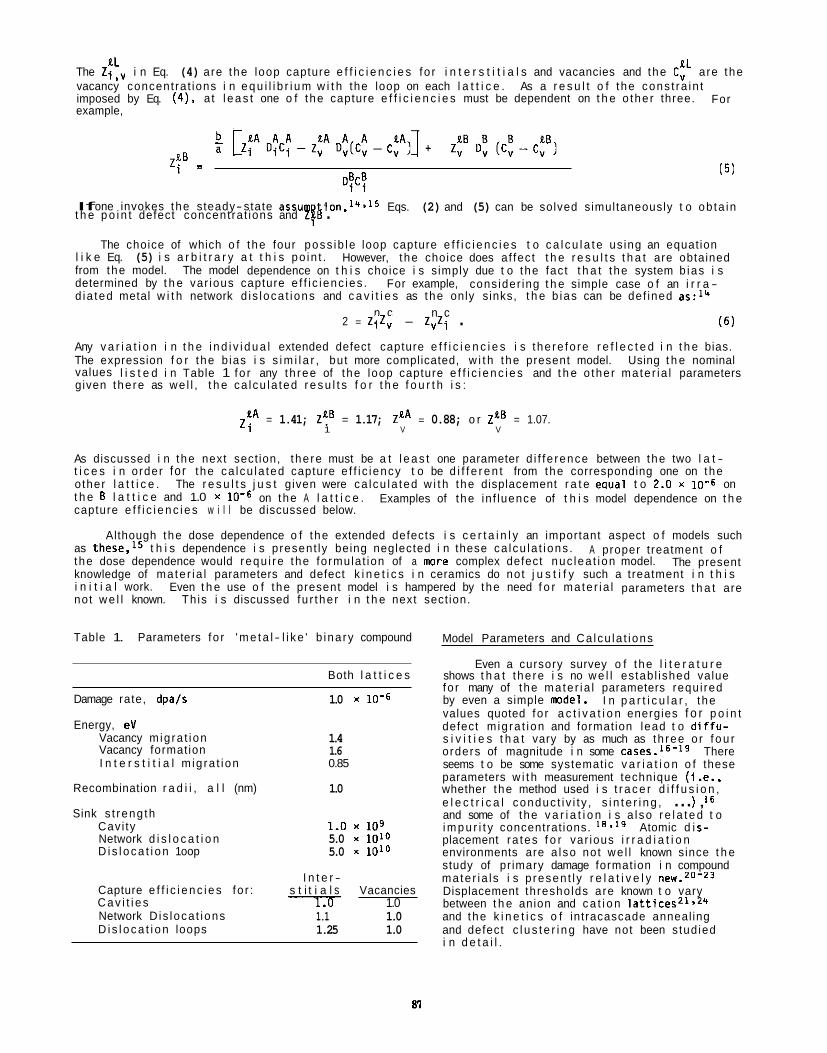
The Z;bV i n Eq. (4) are the loop capture e f f i c i e n c i e s fo r i n t e r s t i t i a l s and vacancies and the C t L a re the vacancy concent ra t ions i n e q u i l i b r i u m w i t h the loop on each l a t t i c e . As a r e s u l t o f t he cons t ra in t imposed by Eq. (41, at l e a s t one o f the capture e f f i c i e n c i e s must be dependent on t h e o the r three. example,
For
L . - 1 -
D$C$ (5)
If one invokes the steady- state assum Eqs. (2) and (5) can be solved simultaneously t o ob ta in t h e p o i n t defect concent ra t ions and Zi @ .
The choice of which o f the four poss ib le loop capture e f f i c i e n c i e s t o c a l c u l a t e us ing an equat ion l i k e Eq. (5) i s a r b i t r a r y a t t h i s po in t . from the model. The model dependence on t h i s choice i s s imply due t o the fac t t h a t the system b ias i s determined by t h e var ious capture e f f i c ienc ies . d ia ted metal w i t h network d i s loca t ions and c a v i t i e s as the only s inks, t h e b ias can be def ined as:14
However, t he choice does af fec t t h e r e s u l t s t h a t are obtained
For example, cons ider ing t h e simple case o f an i r r a -
(6)
Any v a r i a t i o n i n t h e i n d i v i d u a l extended defect capture e f f i c i e n c i e s i s the re fo re r e f l e c t e d i n t h e bias. The expression f o r the b ias i s s i m i l a r , but more complicated, w i t h the present model. Using t h e nominal values l i s t e d i n Table 1 fo r any th ree of the loop capture e f f i c i e n c i e s and t h e o the r ma te r ia l parameters given the re as we l l , t h e ca lcu la ted r e s u l t s f o r t h e f o u r t h i s :
n c n c 2 = 272, - 2,Zi .
= 1.41; 2'i.B = 1.17; ZEA = 0.88; o r 2" = 1.07. 2 i 1 V V
As discussed i n the next sect ion, the re must be a t l e a s t one parameter d i f f e rence between the two l a t - t i c e s i n order fo r the ca lcu la ted capture e f f i c iency t o be d i f f e r e n t from the corresponding one on the o ther l a t t i c e . The r e s u l t s j u s t given were ca lcu la ted w i t h the displacement r a t e eaual t o 2.0 x on t h e B l a t t i c e and 1.0 x capture e f f i c i e n c i e s w i l l be discussed below.
on the A l a t t i c e . Examples of the in f luence of t h i s model dependence on t h e
Although the dose dependence o f the extended defects i s c e r t a i n l y an important aspect o f models such as these,15 t h i s dependence i s present ly being neglected i n these ca lcu la t i ons . the dose dependence would requ i re the formulat ion of a m r e complex defect nuc lea t ion model. The present knowledge of ma te r ia l parameters and defect k i n e t i c s i n ceramics do not j u s t i f y such a treatment i n t h i s i n i t i a l work. Even t h e use o f the present model i s hampered by the need f o r ma te r ia l parameters t h a t are not w e l l known. Th is i s discussed fu r the r i n t h e next sect ion.
A proper t reatment o f
Table 1. Parameters fo r ' m e t a l - l i k e ' b ina ry compound
Both l a t t i c e s
Damage rate, dpals
Energy, eV Vacancy m ig ra t ion Vacancy formation I n t e r s t i t i a l m ig ra t ion
Recombination r a d i i , a l l (nm)
Sink s t reng th Cav i ty Network d i s l o c a t i o n D i s l o c a t i o n 1 oop
Capture e f f i c i e n c i e s fo r : C a v i t i e s Network D is loca t ions D i s l o c a t i o n loops
1.0 x 10⁻⁶
1.4 1.6 0.85
1.0
1.0 x 10⁹ 5.0 x 1D1O 5.0 x 1Olo
I n t e r - s t i t i a l s Vacancies l.D 1.0
1.1 1.0 1.25 1.0
Model Parameters and Ca lcu la t i ons
Even a cursory survey o f the l i t e r a t u r e shows t h a t the re i s no w e l l es tab l ished value fo r many of the mate r ia l parameters requ i red by even a simple rode l . values quoted fo r a c t i v a t i o n energies f o r p o i n t defect m ig ra t ion and formation lead t o d i f f u - s i v i t i e s t h a t vary by as much as th ree o r f o u r orders of magnitude i n some cases. l6- lg There seems t o be some systematic v a r i a t i o n o f these parameters w i t h measurement technique ( i . e . , whether the method used i s t r a c e r d i f f u s i o n , e l e c t r i c a l conduc t i v i t y , s i n t e r i n g , . . . ) , l6 and some of the v a r i a t i o n i s a l so r e l a t e d t o i m p u r i t y concentrat ions. 3 l9 Atomic d i s- placement ra tes f o r var ious i r r a d i a t i o n environments are a l so not we l l known since t h e study of pr imary damage formation i n compound mate r ia l s i s p resen t l y r e l a t i v e l y new.20-23 Displacement thresholds are known t o vary between t h e anion and c a t i o n l a t t i c e s Z 1 > 2 4 and the k i n e t i c s o f intracascade anneal ing and defect c l u s t e r i n g have not been s tud ied i n d e t a i l .
I n p a r t i c u l a r , t he
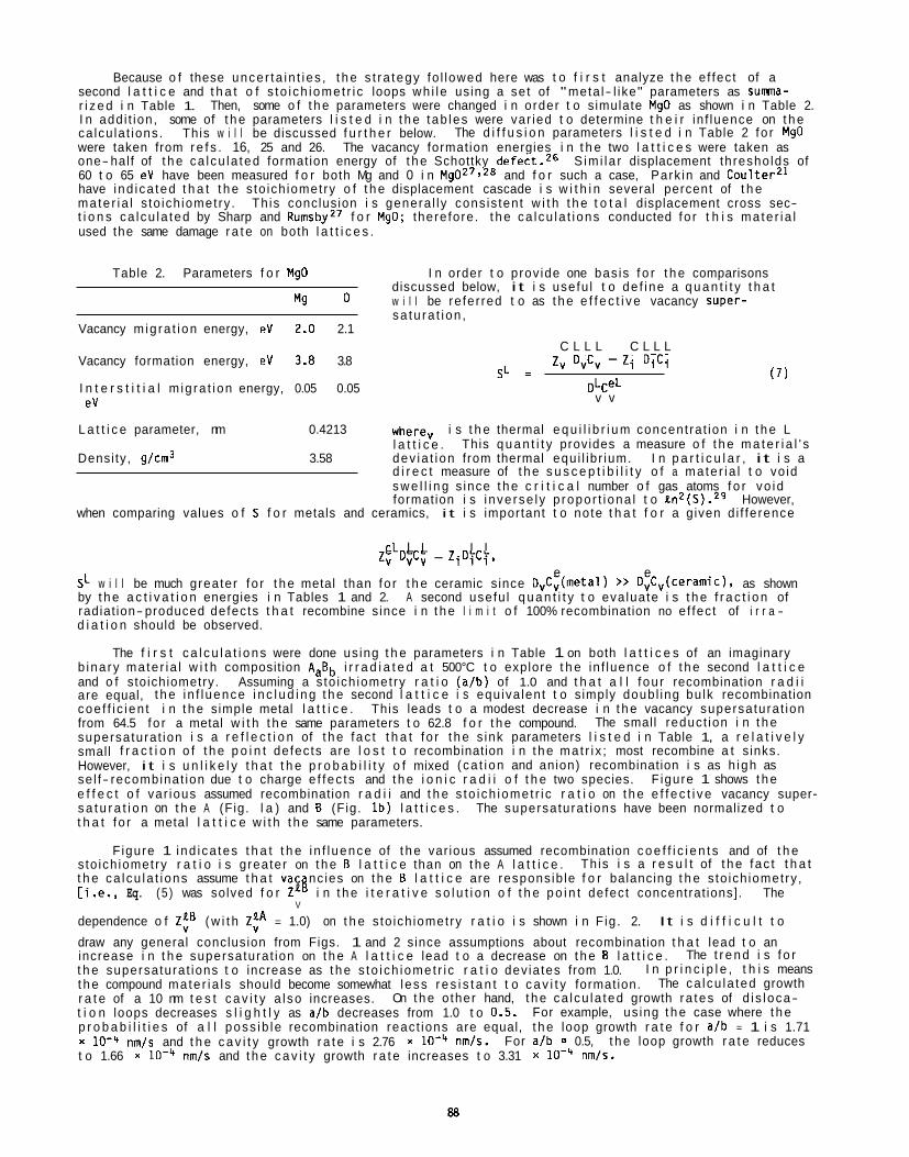
Because o f these unce r ta in t i es , t h e s t ra tegy fo l lowed here was t o f i r s t analyze t h e e f fec t of a second l a t t i c e and t h a t o f s to i ch iomet r i c loops wh i l e using a se t of "meta l- l ike" parameters as suma- r i z e d i n Table 1. I n add i t ion , some of t h e parameters l i s t e d i n t h e tab les were var ied t o determine t h e i r in f luence on t h e ca lcu la t ions. The d i f f u s i o n parameters l i s t e d i n Table 2 fo r MgO were taken from r e f s . 16, 25 and 26. The vacancy format ion energies i n t h e two l a t t i c e s were taken as one-half of t h e ca l cu la ted format ion energy of t h e Schottky defect.26 60 t o 65 eV have been measured f o r both Mg and 0 i n Mg027,28 and f o r such a case, Park in and CoulterZ1 have i nd i ca ted t h a t t h e s to ich iometry o f t h e displacement cascade i s w i t h i n several percent of t h e ma te r i a l s to ich iometry . Th is conclusion i s genera l ly cons is tent w i t h t h e t o t a l displacement cross sec- t i o n s ca l cu la ted by Sharp and RumsbyZ7 f o r MgO; there fore . t h e ca l cu la t i ons conducted fo r t h i s ma te r i a l used the same damage r a t e on both l a t t i c e s .
Then, some o f t h e parameters were changed i n order t o s imulate MgO as shown i n Table 2.
This w i l l be discussed f u r t h e r below.
S im i la r displacement thresho lds of
Table 2. Parameters f o r MgO I n order t o prov ide one bas is f o r t h e comparisons discussed below, i t i s usefu l t o de f i ne a q u a n t i t y t h a t
sa tu ra t i on , "g 0 w i l l be re fer red t o as t h e e f f e c t i v e vacancy super-
Vacancy m ig ra t i on energy, eV 2.0 2.1
Vacancy formation energy, eV 3.8 3.8
I n t e r s t i t i a l m ig ra t i on energy, 0.05 0.05 eV
C L L L C L L L zv OvCv - Z i D i C i
SL = DLCeL
v v
(7)
L a t t i c e parameter, nm 0.4213 where, i s t h e thermal e q u i l i b r i u m concent ra t ion i n t h e L
Densi ty, g/cm3 3.58 dev ia t i on from thermal equ i l ib r ium. I n p a r t i c u l a r , i t i s a l a t t i c e .
d i r e c t measure of t h e s u s c e p t i b i l i t y o f a ma te r i a l t o vo id s w e l l i n g s ince t h e c r i t i c a l number o f gas atoms f o r vo id format ion i s i nve rse l y p ropo r t i ona l t o en2(S).29 However,
when comparing values o f S f o r metals and ceramics, i t i s important t o note t h a t f o r a given d i f fe rence
This q u a n t i t y provides a measure o f t h e m a t e r i a l ' s
CL L L L L 2, DvCv - Z i D i C i ,
e e SL w i l l be much greater f o r t h e metal than fo r t h e ceramic s ince DvCv(metal) >> OvCv(CeramiC), as shown by t h e a c t i v a t i o n energies i n Tables 1 and 2. A second usefu l q u a n t i t y t o eva luate i s t h e f r a c t i o n of radiat ion- produced defects t h a t recombine since i n t h e l i m i t o f 100% recombination no e f fec t of i r r a - d i a t i o n should be observed.
The f i r s t c a l c u l a t i o n s were done us ing t h e parameters i n Table 1 on both l a t t i c e s of an imaginary b ina ry ma te r i a l w i t h composit ion AaBb i r r a d i a t e d a t 500°C t o explore t h e in f luence o f t h e second l a t t i c e and o f stoichiometry. Assuming a s to ich iometry r a t i o (a/b) of 1.0 and t h a t a l l f ou r recombination r a d i i are equal, t h e i n f l uence i n c l u d i n g t h e second l a t t i c e i s equ iva lent t o s imply doubl ing bu lk recombination coe f f i c i en t i n t h e simple metal l a t t i c e . This leads t o a modest decrease i n t h e vacancy supersatura t ion from 64.5 fo r a metal w i t h t h e same parameters t o 62.8 f o r t h e compound. supersatura t ion i s a r e f l e c t i o n of t h e fac t t h a t f o r t h e s ink parameters l i s t e d i n Table 1, a r e l a t i v e l y small f r a c t i o n o f t h e p o i n t defec ts are l o s t t o recombination i n t h e ma t r i x ; most recombine a t s inks. However, i t i s u n l i k e l y t h a t t h e p r o b a b i l i t y o f mixed ( ca t i on and anion) recombination i s as h igh as se l f- recombinat ion due t o charge e f fec ts and t h e i o n i c r a d i i o f t h e two species. F igure 1 shows t h e e f f e c t o f var ious assumed recombination r a d i i and t h e s to i ch iomet r i c r a t i o on t h e e f f e c t i v e vacancy super- s a t u r a t i o n on t h e A (Fig. l a ) and B (Fig. l b ) l a t t i c e s . The supersatura t ions have been normalized t o t h a t f o r a metal l a t t i c e w i t h t h e same parameters.
The small reduct ion i n t h e
F igure 1 ind i ca tes t h a t t h e i n f l uence of t h e var ious assumed recombination c o e f f i c i e n t s and of t h e s to ich iometry r a t i o i s greater on t h e B l a t t i c e than on t h e A l a t t i c e . t h e ca l cu la t i ons assume t h a t vac nc ies on t h e B l a t t i c e are respons ib le f o r balancing t h e s to ich iometry , [i.e., Eq. (5 ) was solved f o r ZE8 i n t h e i t e r a t i v e s o l u t i o n o f t h e p o i n t defec t concentrat ions]. The
dependence o f Z t B ( w i t h Z t A = 1.0) on t h e s to ich iometry r a t i o i s shown i n F ig . 2. It i s d i f f i c u l t t o
draw any general conclusion from Figs. 1 and 2 s ince assumptions about recombination t h a t lead t o an increase i n t h e supersatura t ion on t h e A l a t t i c e lead t o a decrease on t h e B l a t t i c e . t h e supersatura t ions t o increase as t h e s to i ch iomet r i c r a t i o dev ia tes from 1.0. t h e compound mate r ia l s should become somewhat l ess r e s i s t a n t t o c a v i t y format ion. r a t e of a 10 nm t e s t c a v i t y a l so increases. t i o n loops decreases s l i g h t l y as a/b decreases from 1.0 t o 0.5. p r o b a b i l i t i e s of a l l poss ib le recombination react ions are equal, t h e loop growth r a t e f o r a/b = 1 i s 1.71 x lo+ nm/s and t h e c a v i t y growth r a t e i s 2.76 x t o 1.66 x nm/s and t h e c a v i t y growth r a t e increases t o 3.31 x nmis.
Th is i s a r e s u l t of t h e fac t t h a t
V
The t r e n d i s f o r I n p r i n c i p l e , t h i s means
The ca l cu la ted growth On t h e o ther hand, t h e ca l cu la ted growth ra tes of d i s loca-
For example, us ing t h e case where t h e
nm/s. For a/b = 0.5, t h e loop growth r a t e reduces
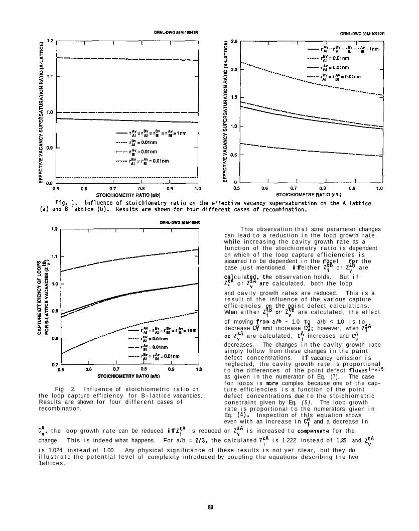
STOlCHlOMETRY RATK) (ab)
Fig. 2. I n f l uence of s to i ch iomet r i c r a t i o on the loop capture e f f i c iency fo r B - l a t t i c e vacancies. Results are shown fo r four d i f f e r e n t cases o f recombination.
Th is observat ion t h a t some parameter changes can lead t o a reduct ion i n the loop growth r a t e w h i l e increas ing t h e c a v i t y growth r a t e as a func t ion of the s to ich iometry r a t i o i s dependent on which o f t h e loop capture e f f i c i e n c i e s i s assumed t o be dependent i n the m e l . F r t h e case j u s t mentioned. if e i t h e r Zi o r ZtB are ca c u l a t e the observat ion holds. But i f Z$ o r Z$'are ca lcu la ted, both the loop
and c a v i t y growth ra tes are reduced. Th is i s a r e s u l t of t he in f l uence o f the var ious capture e f f i c i e n c i e s i n t defect ca lcu la t i ons . When e i t h e r Zi! :?Z!' are ca lcu la ted, t h e e f f e c t
of moving i r o m a!b = 1.0 t i decrease C, and increase C v ; however, when Z y A or Z t A a r e ca lcu la ted, C: increases and CA
decreases. The changes i n t h e c a v i t y growth r a t e simply fo l l ow from these changes i n the p a i n t defect concentrat ions. neglected, t h e c a v i t y growth r a t e i s p ropor t i ona l t o the di f ferences of the p o i n t defect f l u x e ~ ~ ~ ~ ~ ~ as given i n t h e numerator o f Eq. (7 ) . The case f o r loops i s m r e complex because one o f the cap- t u r e e f f i c i e n c i e s i s a func t ion o f the p o i n t defect concent ra t ions due t o t h e s t o i c h i o m e t r i c c o n s t r a i n t given by Eq. ( 5 ) . The loop growth r a t e i s p ropor t i ona l t o the numerators given i n Eq. ( 4 ) . Inspect ion of t h ' s equat ion shows even w i t h an increase i n C; and a decrease i n
?Ll
a/b < 1.0 i s t o
V
I f vacancy emission i s
A C t , t h e loop growth r a t e can be reduced if Z f A i s reduced o r Z t A i s increased t o comiensate f o r the
change. Th is i s indeed what happens. For a/b = 2 /3 , t h e c a l c u l a t e d Z t A i s 1.222 ins tead o f 1.25 and Z t A
i s 1.024 ins tead of 1.00. Any phys ica l s i g n i f i c a n c e of these r e s u l t s i s not y e t c lea r , but they do i l l u s t r a t e t h e p o t e n t i a l l e v e l of complexi ty in t roduced by coupl ing t h e equations descr ib ing t h e two 1 a t t i c e s .
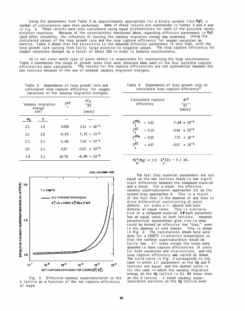
Using t he parameters from Table 2 as approximately appropr iate f o r a b inary ceramic l i k e MgO, a number o f ca l cu la t i ons were then performed. i n F i g . 3. b i n a t i o n react ions. (and other ceramics), t he in f luence of vary ing t he vacancy migra t ion energy was examined. ca l cu la ted values o f t he loop growth r a t e and t he loop capture e f f i c i ency f o r oxygen vacancies as met r i cs , Table 3 shows t h a t t he s e n s i t i v i t y t o t he assumed d i f f u s i o n parameters i s very high, w i t h the loop growth r a t e vary ing from f a i r l y l a rge p o s i t i v e t o negat ive values. oxygen vacancies changes by a f a c t o r o f about 350 i n order t o balance sto ichiometry.
It i s not c l e a r which type o f po in t defect i s responsib le f o r ma in ta in ing t he loop sto ichiometry. Table 4 summarizes t he range of growth ra tes t h a t were obta ined when each o f t he four poss ib le capture e f f i c i e n c i e s were calculated. two l a t t i c e s because o f t he use o f unequal vacancy migra t ion energies.
Some o f these r e s u l t s a re summarized i n Tables 3 and 4 and
Because of t he unce r ta i n t i es mentioned above regarding d i f f u s i o n parameters i n MgO These r e s u l t s were a l so ca lcu la ted using equal p r o b a b i l i t i e s f o r each o f t he poss ib le recom-
Using t h e
The loop capture e f f i c i e n c y f o r
The r e s u l t s f o r t he capture e f f i c i e n c i e s are no t symmetrical between t he
T=1250'C
- ALL PARAMETERS EQUAL
E:(A) = ZOeV, E:@) I 2.leV
Table 3. Dependence o f loop growth r a t e and ca lcu la ted loop capture e f f i c iency f o r oxygen
vacancies on t he vacancy migra t ion energies
-
I I I
d r Q - d t Vacancy migra t ion z'O
V energy (ev) (nmls)
_ _ _ _ _ A 0 2.1 1.9 0.055 2.21 x 10⁻⁴
2.1 2.0 0.23 7.72 10-5
2.0 2.1 4.37 -3.57 10-5
1.9 2.1 18.78 -9.99 x 10⁻⁵
2.1 2.1 1.00 7.10 x
ORNL-DWG 69U.11253
I I I I I
10" 1 0 4 1 0 ' ~ 1 0 4 1 0 . ~ 10.2
NET CAPTURE EFFICIENCY OF LOOPS (zf-z?)
Table 4. Dependence o f loop growth r a t e on ca lcu la ted loop capture e f f i c iencya
Calculated capture dra __
d t (nmls)
e f f i c iency
Z.eMg = 3.42 7.64 10-5
Zqo = 0.13 -3.64 10-5
ZQO = 4.37 -3.57 x 10⁻⁵
1
ZaMg = 0.23 7.72 x V
V
aEi(Mg) = 2.0; Ev(0) - 2.1 eV. m
The f ac t t h a t mater ia l parameters are no t equal on t he two l a t t i c e s leads t o one s i g n i f - i c a n t d i f f e rence between t he compound mater ia l and a metal. For a metal, t he e f f ec t i ve vacancy supersaturat ion approaches 1.0 as t he system b ias approaches 0. This i s a r e s u l t of t he f a c t t h a t i n t he absence of any b ias t o d r i v e d i f f e r e n t i a l p a r t i t i o n i n g of po in t defects, a l l s inks w i l l absorb and emit defects a t equal rates. This i s s i m i l a r l y t r u e o f a compound mater ia l if each parameter has an equal value on both l a t t i c e s . However, parametr ica l asymmetries g ive r i s e t o what cou ld be termed an e f f e c t i v e low "bias," even i n t he absence o f s ink biases. This i s shown i n Fig. 3. The ca l cu la t i ons shown here were done f o r a 125OOC i r r a d i a t i o n temperature so t h a t t he nominal supersaturat ion would be f a i r l y low. A l l s inks except t he loops were assumed t o have capture e f f i c i enc ies of u n i t y f o r both vacancies and i n t e r s t i t i a l s , and t he loop capture e f f i c i e n c y was var ied as shown. The s o l i d curve i n Fig. 3 corresponds t o t he case i n which a l l parameters on t he Mg and 0 l a t t i c e s are equal, and t he dashed curve i s f o r t he case i n which t he vacancy m ig ra t i on energy on t h e Mg l a t t i c e i s 0.1 e V lower than
sa tu ra t i on p e r s i s t s on t h e Mg l a t t i c e even Fig. 3. E f f e c t i v e vacancy supersaturat ion on t he on t h e 0 l a t t i c e . A small vacancy super-
A l a t t i c e as a f unc t i on o f the net capture e f f i c i e n c y o f loops.
when t h e net loop capture e f f i c i e n c y (and hence t h e system b i a s ) approaches zero. shown i n F ig . 3, a comparable subsaturat ion (S: < 1) of vacancies e x i s t s on t h e 0 l a t t i c e .
Although i t i s not
DISCUSSION AND SUMMARY
A simple, f i r s t m d e l of r a d i a t i o n damage i n ceramics has been developed and some p re l im ina ry calcu- l a t i o n s have been completed. The r e s u l t s obtained fo r a "meta l- l ike" b ina ry compound i n d i c a t e t h a t t h e presence o f m u l t i p l e l a t t i c e s w i l l lead t o somewhat greater bulk recombination than i n metals. Th is e f fec t w i l l be small if mixed (an ion- cat ion) recombination does not occur a t an appreciable ra te . The in f luence o f s to ich iometry was inc luded i n t h e m d e l by c a l c u l a t i n g one of t h e four poss ib le loop capture e f f i c i e n c i e s i n terms of the o the r th ree i n order t o mainta in a net s t o i c h i o m e t r i c absorpt ion o f p o i n t defects by the loops. Th is cons t ra in t acts t o reduce t h e loop growth r a t e when the s to ich iometry r a t i o dev ia tes from 1.0. This same dev ia t i on can lead t o e i t h e r an increase o r a decrease i n the c a v i t y growth ra te , depending on which th ree o f the four loop capture e f f i c i e n c i e s are f i x e d and which one i s calcu- l a t e d t o mainta in s to ich iometry . smal ler values o f the s to ich iometry r a t i o . able, i t i s not poss ib le t o make d i r e c t comparisons w i t h rea l ceramics (e.g., MgO vs A1203). s ince o the r ma te r ia l parameters a l so vary.
e t e r s was examined. The r e s u l t s were q u i t e s e n s i t i v e t o v a r i a t i o n s i n d i f f u s i o n parameters and t o which t ype of defect was assumed t o be responsible fo r balancing the s to ich iometry of t h e loop. A p e r s i s t e n t e f fec t of parameter asymnetry was an e f fec t i ve "b ias" of the mate r ia l as evidenced by the vacancy super- s a t u r a t i o n remaining greater than 1.0 even when t h e convent ional, sink-based b ias approached 0. Th is " b ias" was the on ly observat ion i n the work t o date t h a t i n d i c a t e d some inherent d i f f e r e n c e i n behavior between compound mate r ia l s and metals. The major i n fe rence t h a t can be drawn from these c a l c u l a t i o n s i s t h a t t h a t as m r e data i s obtained from experiments a t h igher doses, ceramic mate r ia l s are l i k e l y t o e x h i b i t behavior s i m i l a r t o metals. and of o the r experiments t o ob ta in b e t t e r measurements of key mate r ia l parameters.
I n general, t he parameter s e n s i t i v i t y o f t h e r e s u l t s increases f o r Although t h i s e f f e c t o f s to ich iometry i s p h y s i c a l l y reason-
Using mate r ia l parameters t h a t are reasonable fo r MgO, t h e in f l uence of asymmetry i n ma te r ia l param-
This po in ts out the importance of f u r t h e r i r r a d i a t i o n experiments
FUTURE WORK
Fur ther work w i t h the model descr ibed above w i l l i nc lude a t e s t o f t he v a l i d i t y of t h e s teady- sta te approximation by e x p l i c i t l y i n t e g r a t i n g the p o i n t defect equations [Eq. 2 (a ) -Z (d ) I . me t r i c s tud ies w i l l be conducted and d i r e c t comparisons w i t h data w i l l be made where possible.
Add i t i ona l para-
REFERENCES
1. 0. Ste iner , Nucl. Sci. and Engr. 58 (1975) 107-165.
2. G. L. Ku lc insk i , "Radiat ion Damage: The Second Most Serious Obstacle t o Commercial izat ion o f Fusion Power," i n Radia t ion E f f e c t s and T r i t i u m Technology f o r Fusion Reactors, CONF-750989-1, U.S. ERDA, 1976, pp. 17-72.
3. F . W. Clinard, G. F. Hurley and R. W. K la f f ky , Res Mech. 8 (1983) 207-234.
4. G. P. Pe l l s , J. Nucl. Mater. 122 & 123 (1984) 1338-1351.
5. N. I t o h and K. Mor i ta , J. Nucl. Mater. 155-157 (1988) 58-66.
6. G. P. Pe l l s , J. Nucl. Mater. 155-157 (1988) 67-76.
7. C. E. Johnson, K. R. Kummerer and E. Roth, J. Nucl. Mater. 155-157 (1988) 188-201.
8. F. W. C l i n a r d and L. W. Hobbs, "Radiat ion Effects i n Non-Metals," i n Physics of Radia t ion E f f e c t s i n Crysta ls , R. A. Johnson and A. N. Orlov, Eds., E lsev ie r Science Publ ishers, 1986, pp. 387-471.
F. W. Cl inard, G. F. Hurley and L. W. Hobbs, J. Nucl. Mater. 108 & 109 (1982) 655-670. 9.
10. M. D. Rechtin, Rad. E f f . 42 (1979) 129-144.
11.
12.
C. K inosh i ta , K. Hayashi and S. K i ta j ima, Nucl. I n s t r . and Meth. i n Phys. Res. B 1 (1984) 209-218.
A. Y. Stathopoulos and G. P. Pe l ls , P h i l . Mag. A 47 (1983) 381-394.
91
13. S. J . Zink le , " Ion I r r a d i a t i o n Studies o f Oxide Ceramics," i n S t ruc tu re Property Rela t ionsh ips i n Surface Modif ied Ceramics, C. J . McHargue, e t a1 ., Eds., Kluwer Academic Publ ishers, Dordrecht, Netherlands, 1989, pp. 215-225.
Nonhomogeneous Processes, G. F. Freeman, ed., Wiley and Sons, New York, 1987. 14. L . K. Mansur, "Mechanisms and K i n e t i c s o f Radia t ion E f f e c t s i n Metals and Al loys," i n K ine t i cs of
15. R. E. S t o l l e r and G. R. Odette, "A Composite Model o f M ic ros t ruc tu ra l Evo lu t ion i n A u s t e n i t i c Sta in less Steel Under Fast Neutron I r rad ia t i on , " i n Radiat ion Induced Changes i n Microst ruc ture , ASTM STP 955, F. A. Garner, N. H. Packan and A. 5. Kumar, Eds., ASTM, Ph i lade lph ia , 1987, pp. 371-392.
16. J . M. V i e i r a and B. J. Brook, "Lat t ice- , Grain-Boundary-, Surface-, and Gas-Dif fusion Constants i n Magnesium Oxide," i n S t ruc tu re and Proper t ies of MgO and A1203 Ceramics, W . D. Kingery, Ed., American Ceramic Society, Columbus, 1984, pp. 438-463.
17. F. A. Kroger, "Experimental and Calculated Values o f Defect Parameters and t h e Defect S t ruc tu re of a-A1203. i n St ruc ture and Proper t ies of MgO and A1203 Ceramics, W . 0. Kingery, Ed., American Ceramic Society, Columbus, 1984, pp. 100-118.
18. B. J. Wuensch, "On t h e I n t e r p r e t a t i o n o f L a t t i c e Oi f fus ion i n Magnesium Oxide," i n Mass Transport Phenomena i n Ceramics, A. R. Cooper and A. H. Heuer, Eds., Plenum Press, New York, 1975, pp. 211-231.
Y . Oishi and K. Ando, "Oxygen Di f fus ion i n MgO and A1203," i n St ruc ture and Proper t ies of MgO and A1203 Ceramics, W. D. Kingery, Ed., American Ceramic Society, Columbus, 1984, pp. 379-393.
19.
20. M. T. Robinson, Phys. Rev. B 27 (1983) 5347-5359.
21. D. M. Park in and C. A. Coul ter, J. Nucl. Mater. 117 (1983) 340-344.
22. L. R. Greenwood, "Radiat ion Damage Calcu la t ions f o r Compound Mater ia ls ." i n E f f e c t s of Radia t ion on Mater ia ls , ASTM STP 1046, N. H. Packan, R. E. S t o l l e r and A. S . Kumar, Eds., ASTM, Ph i lade lph ia , 1989 ( i n press) .
23. N. M. Ghoniem and S. P. Chou, "Binary C o l l i s i o n Monte Carlo Simulat ions o f Cascades i n Polyatomic Ceramics," i n Fusion Reactor Ma te r ia l s Semiannual Progress Report, DOE/ER-0313/3, U.S. DOE, March 1988, pp. 143-148.
24. G. P. P e l l s and A. Y . Stathopoulos, Rad. E f f . 74 (1983) 181-191.
25. W. C. Mackrodt, "Calculated Po in t Defect Formation, Associat ion and M ig ra t i on Energies i n MgO and a-A1203," i n S t r u c t u r e and Proper t i es o f MgO and A1203 Ceramics, W. 0. Kingery, Ed., American Ceramic Society, Columbus, 1984, pp. 62-78.
26. C. K inosh i ta , K. Hayashi and T. E. M i t c h e l l , "Migra t ion Energies o f I n t e r s t i t i a l s and Vacancies i n MgO," i n S t ruc tu re and Proper t ies of MgO and A1203 Ceramics, W. 0. Kingery, Ed., American Ceramic Society, Columbus, 1984, pp. 490-505.
27. J. V. Sharp and D. Rumsby, Rad. E f f . 17 (1973) 65-68.
28. Y . Chen, 0. L. Trueblood, 0. E. Schow and H. T. Tohver, J . Phys. C : S o l i d Sta te Phys. 3 (1970) 2501-2508.
29. R. E. S t o l l e r and G. R. Odette, J. Nucl. Mater. 131 (1985) 118-125.
92
MICROSTRUCTURAL EVOLUTION OF NEUTRON IRRADIATED Fe-Cr-Ni ALLOYS AT 495% IN RESPONSE TO CHANGES IN He/dpa RATIO, J. F. Stubbins and J. E. Nev l ing (Un ive rs i t y o f I l l i n o i s ) , F. A. Garner (Pac i f i c Northwest Laboratory) and R. L. Simons (Westinghouse Hanford Company)
QBJECTIVE
The o b j e c t i v e o f t h i s study i s t o prov ide m ic ros t ruc tu ra l data t h a t w i l l p rov ide i n fo rma t ion on t h e separate and s y n e r g i s t i c r o l e s o f helium, composit ion, thermal-mechanical t reatment and i r r a d i a t i o n va r iab les on t h e evo lu t i on o f rad ia t ion- induced microst ruc ture .
SUMMARY
A se r i es o f t h ree Fe-15Cr-XNi a l l o y s i n both annealed and cold-worked cond i t i ons was i r r a d i a t e d i n t h e Fast Flux Test F a c i l i t y a t 495'C t o 14 dpa. The experiment was developed t o determine t h e separate and syner- g i s t i c ef fects of n i c k e l and phosphorus content, cold-work, and helium/dpa r a t i o . Th is experiment was conducted w i thou t i n t roduc ing v a r i a t i o n s i n displacement r a t e , a v a r i a b l e known t o s t r o n g l y i n f l uence micro- s t r u c t u r a l e v o l u t i Each a l l o y cond i t i on was i r r a d i a t e d i n two va r ian ts , one w i t h na tu ra l n i c k e l and one enhanced w i t h t h e !!Ni i so tope. The l a t t e r v a r i a n t produces helium/dpa r a t i o s t y p i c a l o f f us ion r e a c t o r spectra wh i l e t h e former y i e l d s a much lower l e v e l o f helium. m ic ros t ruc tu ra l e v o l u t i o n somewhat a t 495'C bu t i t s e f f e c t i s r e l a t i v e l y small compared t o t h e inf luences o f t h e o the r va r iab les s tud ied. Increases i n s t a r t i n g d i s l o c a t i o n dens i t y , n i c k e l content, o r phosphorus l e v e l a l l r e t a r d s w e l l i n g tempora r i l y w h i l e h igher r a t e s o f he l ium generat ion, usua l l y , bu t n o t always, acce lera te swel l ing . Phosphorus a d d i t i o n o f 0.04 wtX n o t o n l y decreased s w e l l i n g b u t l ead t o ref inement o f d i s l o c a t i o n l oop m ic ros t ruc tu re and s t a b i l i z a t i o n o f d i s l o c a t i o n networks created by c o l d working. t a t e s d i d n o t form a t t h i s temperature and dose l e v e l .
The r e s u l t s show t h a t he l ium a l t e r s t h e
Phosphide p r e c i p i -
PROGRESS AND STATUS
I n t r o d u c t i o n
There has been con t inu ing concern about t h e e f f e c t s o f he l ium product ion i n neutron environments du r ing e levated temperature i r r a d i a t i o n . Th is i n t e r e s t stems from t h e f a c t t h a t he l ium can h e l p i n i t i a t e and grow voids formed du r ing i r r a d i a t i o n . It a l so has t h e p o t e n t i a l f o r causing embr i t t lement o f a l l o y s a t e levated temperatures where i t i s mobi le enough t o segregate t o g r a i n boundaries. dependent n o t o n l y on t h e l e v e l s of hel ium bu t a l so on t h e r a t e a t which i t i s produced and t h e t ime du r ing t h e i r r a d i a t i o n h i s t o r y a t which i t i s produced. Th is concern i s p a r t i c u l a r l y acute f o r m a t e r i a l s f o r p o t e n t i a l f us ion app l i ca t i ons s ince t h e amounts o f he l ium generated i n most ma te r ia l s through t ransmutat ion reac t i ons are s i g n i f i c a n t l y h igher than those generated i n thermal and f a s t reac to rs . f a c t t h a t t h e t ransmutat ion cross-sect ion fo r oroducinq hel ium normal lv e x h i b i t s an enerav th resho ld which i s
The ex ten t o f t h e e f f e c t i s
Th i s i s due t o t h e
above t h e average neut ron energy found i n f i ss ' ion specira, bu t w e l l w i t h i n t h e range o f k u t r o n energies expected i n fus ion environments.
The s ign i f i cance of t h i s problem was recognized many years ago, b u t t h e study o f t h e e f f e c t has been l i m i t e d due t o t h e l a c k of a h igh f l u x source of h igh energy neutrons. While sur rogate spect ra are a v a i l a b l e f o r purposes o f s imulat ion, i t i s no t a lways poss ib le t o s imu l taneous ly achieve h igh i r r a d i a t i o n doses and con- comitant h igh hel ium l e v e l s expected f o r technolog ica l app l i ca t i ons . Other experimental approaches have been pursued t o g a i n some i n s i g h t i n t o t h i s p o t e n t i a l problem. These approaches inc lude t h e use o f m a t e r i a l s w i t h pre- implanted helium, ma te r ia l i n fused w i t h t r i t i u m which decays t o helium, ma te r ia l a l l oyed w i t h boron o r n i c k e l which have l a r g e r (n,a) c ross-sect ions a t low neutron energies, o r ma te r ia l s w i t h he l ium i n j e c t e d simultaneously du r ing i o n o r e l e c t r o n i r r a d i a t i o n . These approaches, w h i l e use fu l , a l l have drawbacks which l i m i t t h e i r e f fec t i veness f o r cha rac te r i z ing hel ium e f f e c t s i n an t i c ipa ted fus ion environments. These experimental techniques, along w i t h several o the r aspects o f t h e e f f e c t s o f hel ium on fus ion r e a c t o r s t r u c - t u r a l ma te r ia l s have been reviewed recent ly ' .
One measure o f t h e re levan t hel ium product ion r a t e i s t h e r a t i o o f t h e r a t e o f he l ium product ion t o t h e atomic displacement r a t e . Since t h i s i s a r a t i o o f ra tes , i t i s expressed as t h e he l ium t o dpa r a t i o , no r - ma l l y atomic p a r t s pe r m i l l i o n (appm) He/dpa. i r r a d i a t i o n i n fus ion environments bu t can vary s t r o n g l y i n ma te r ia l s i r r a d i a t e d i n f i s s i o n neutron spectra. I n some cases, where l i t t l e o r no t ransmutat ion occurs, t h e r a t i o w i l l approach zero. But, i n others, e s p e c i a l l y those where n i c k e l i s present i n ma te r ia l s i r r a d i a t e d i n mixed spect ra reactors , t h e r a t i o i s i n i t i a l l y low, then b u i l d s up t o a s i g n i f i c a n t l e v e l . which has a s i g n i f i c a n t n , a ) cross-sect ion f o r thermal neutrons i s no found i n t u r a l l y occu r r i ng n i c k e l . Instead, t h i s isotope, 54Ni, i s formed b t h e capture o f a neut ron by hi. The ggNi, once formed, can cap-
r e a f u r t h e r neutron, t o b r i e f l y form g o N i . Th is iso tope decays by t h e emission o f an alpha p a r t i c l e t o &e. The alpha p a r t i c l e acquires t h e two e lec t rons necessary t o n e u t r a l i z e i t du r ing t h e slowing down process and becomes a s tab le he l ium atom.
Th is r a t i o i s expected t o remain r e l a t i v e l y constant du r ing
Th is i s due t o t h e f a c t t h a t the iso tope o f n i c k e l
Since t h i s i s a two-step process, t h e amounts o f he l ium produced
93
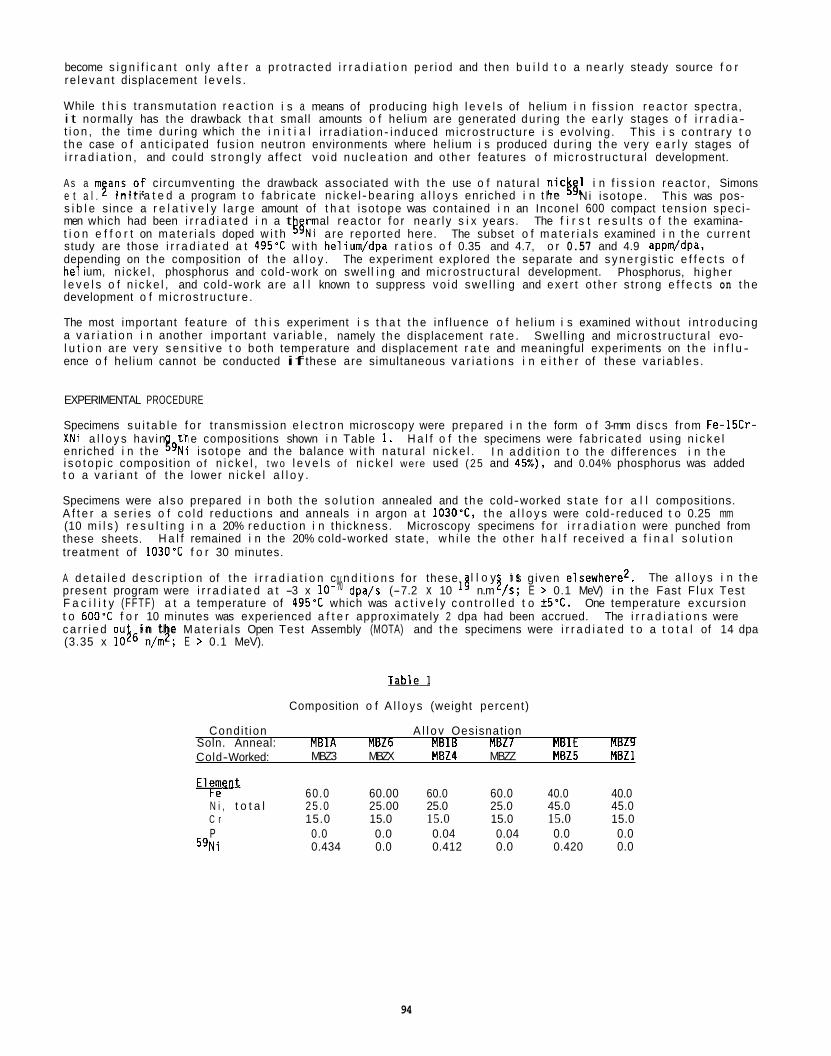
become s i g n i f i c a n t on l y a f t e r a p ro t rac ted i r r a d i a t i o n pe r iod and then b u i l d t o a nea r l y steady source f o r re levan t displacement l e v e l s .
While t h i s t ransmutat ion r e a c t i o n i s a means of producing h igh l e v e l s of hel ium i n f i s s i o n r e a c t o r spectra, i t normal ly has the drawback t h a t small amounts o f hel ium are generated du r ing t h e e a r l y stages o f i r r a d i a - t i o n , the t ime du r ing which t h e i n i t i a l i r rad ia t i on- induced m ic ros t ruc tu re i s evo lv ing. Th is i s con t ra ry t o t h e case o f an t i c ipa ted fus ion neutron environments where hel ium i s produced du r ing t h e very e a r l y stages of i r r a d i a t i o n , and cou ld s t r o n g l y a f fec t vo id nuc lea t i on and o the r features o f m ic ros t ruc tu ra l development.
A s a m$ans,of c i rcumvent ing the drawback associated w i t h t h e use o f na tu ra l n ick61 i n f i s s i o n reac to r , Simons e t a l . N i i so tope. Th is was pos- s i b l e s ince a r e l a t i v e l y l a r g e amount of t h a t iso tope was contained i n an Inconel 600 compact t ens ion spec i - men which had been i r r a d i a t e d i n a t rmal reac to r f o r nea r l y s i x years. The f i r s t r e s u l t s o f t h e examina- t i o n e f f o r t on ma te r ia l s doped w i t h k5N i a re repor ted here. The subset o f m a t e r i a l s examined i n t h e cu r ren t study are those i r r a d i a t e d a t 495'C w i t h helium/dpa r a t i o s o f 0.35 and 4.7, o r 0.57 and 4.9 appm/dpa, depending on t h e composit ion of t h e a l l o y . The experiment explored t h e separate and s y n e r g i s t i c e f f e c t s o f he1 ium, n i cke l , phosphorus and cold-work on swel l i n g and m ic ros t ruc tu ra l development. l e v e l s o f n i c k e l , and cold-work are a l l known t o suppress vo id swe l l i ng and exe r t o the r s t rong e f f e c t s on t h e development o f m ic ros t ruc tu re .
The most important feature of t h i s experiment i s t h a t t h e in f luence o f he l ium i s examined w i thou t i n t roduc ing a v a r i a t i o n i n another important va r iab le , namely t h e displacement r a t e . l u t i o n are very s e n s i t i v e t o both temperature and displacement r a t e and meaningful experiments on t h e i n f l u - ence o f hel ium cannot be conducted if these are simultaneous v a r i a t i o n s i n e i t h e r of these va r iab les .
i n i t i a t e d a program t o fab r i ca te n i cke l - bea r ing a l l o y s enr iched i n t h e
Phosphorus, h ighe r
Swel l ing and m ic ros t ruc tu ra l evo-
EXPERIMENTAL PROCEDURE
Specimens s u i t a b l e f o r t ransmiss ion e l e c t r o n microscopy were prepared i n t h e form o f 3-mm d iscs from Fe-15Cr- X N i a l l o y s hav in t h e composit ions shown i n Table 1. enr iched i n t h e 39N i i so tope and the balance w i t h na tu ra l n i c k e l . i s o t o p i c composit ion o f n i c k e l , t w o l e v e l s o f n i c k e l were used (25 and 45%). and 0.04% phosphorus was added t o a v a r i a n t of t h e lower n i c k e l a l l o y .
Specimens were a l so prepared i n both t h e s o l u t i o n annealed and t h e cold-worked s t a t e f o r a l l composit ions. A f t e r a se r ies o f c o l d reduct ions and anneals i n argon a t 1030'C, t h e a l l o y s were cold- reduced t o 0.25 mm (10 m i l s ) r e s u l t i n g i n a 20% reduc t i on i n th ickness. these sheets. H a l f remained i n the 20% cold-worked s ta te , w h i l e t h e o the r h a l f rece ived a f i n a l s o l u t i o n treatment of 1030'C f o r 30 minutes.
A d e t a i l e d d e s c r i p t i o n of t h e i r r a d i a t i o n c n d i t i o n s fo r these present program were i r r a d i a t e d a t -3 x 10- dpa/s (-7.2 x 10 18 n.m / s , E > 0.1 MeV) i n t h e Fast F lux Test F a c i l i t y (FFTF) a t a temperature of 495'C which was a c t i v e l y c o n t r o l l e d t o + 5 T . One temperature excurs ion t o 6 0 0 T f o r 10 minutes was experienced a f t e r approximately 2 dpa had been accrued. c a r r i e d ou (3.35 x 1046'n/m2; E > 0.1 MeV).
H a l f o f t h e specimens were fab r i ca ted us ing n i c k e l I n a d d i t i o n t o t h e di f ferences i n t h e
Microscopy specimens fo r i r r a d i a t i o n were punched from
l l o y i s g iven elsewherez. The a l l o y s i n t h e % 3 . The i r r a d i a t i o n s were
i n the Ma te r ia l s Open Test Assembly (MOTA) and t h e specimens were i r r a d i a t e d t o a t o t a l of 14 dpa
w Composition o f A l l o y s (weight percent)
Condi t ion A l l o v Oesisnat ion Soln. Anneal: MBlA MBZ6 MBlB MBZ7 MBlE MBZ9
MBZ3 MBZX MBZ4 MBZZ MBZ5 MBZl Cold- Worked:
Element Fe 60.0 60.00 60.0 60.0 40.0 40.0 N i , t o t a l 25 .0 25.00 25.0 25.0 45.0 45.0 C r 15.0 15.0 15.0 15.0 15.0 15.0 P
59N i 0.0 0.0 0.04 0.04 0.0 0.0 0.434 0.0 0.412 0.0 0.420 0.0
94
Specimens were analyzed for macroscopic volume changes as well as microstructural parameters. Immersion density measurements accurate to M.16% change in volume were carried out on all specimens to determine the bulk density change. identical specimens. The microstructural information was obtained using a JEM JEOL IOOCX scanning trans- mission electron microscope (STEM) operated at 100 kV. stage for large angle tilting.
Each reported density is the average o f three separate measurements on nominally
This microscope was equipped with a double tilt
The helium levels of the various alloys were determined within 1% uncertainty by Brian Oliver of Rockwell International, yielding He/dpa ratios of 0.35 and 4 . 7 for the l~ow and high helium cases of Fe-25Ni-15Cr. Fe-45-Ni-I5Cr, the He/dpa ratios were 0.57 and 4.9; the increase is due to the (n ,a) contribution of the natural nickel.
For
.RESULTS
The results of the immersion density measurements are shown in Figure 1. data. The cold-worked material always shows lower bulk swelling than does the corresponding solution annealed material ; the phosphorus-doped low nickel compositions show lower swelling than do their undoped counterparts; and the higher nickel alloys show lower swelling than do their lower nickel counterparts. Another trend is also found with one exception. The bulk swelling increases a small to moderate amount from low to high helium content except for the solution annealed, low nickel alloy with no phosphorus. In all cases, however, the change due to increased helium is less than 0.8% swelling.
The immersion density measurements indicate in two cases that densification took place during irradiation. In the high nickel case, the apparent densification is within the range of uncertainty of the density mea- surement technique. (Densification is commonly observed in solute-free Fe-Cr-Ni alloys at such nickel levels). In the case of the phosphorus-doped, cold-worked, low helium, low nickel alloy, a substantial net densification is quite clearly indicated, however.
Microstructural analysis was carried out on all specimens, but it was possible to obtain only a limited amount of information on the high helium, cold-worked, low nickel alloy without phosphorus. In all cases, voids were found after irradiation, even in specimens which exhibited a net densification in the immersion density measurements. frequently exhibited a bimodal distribution. in Table 2.
Several trends are clear from the
The results of void and dislocation measurements are reported in Table 2 . The loops Loops with diameters small than 6 nm are described as "small"
Fe-25NI-15Cr Fe-25Ni-15Cr-0.04P Fe-45Ni-15Cr
-A
PO
3
2
% 1
0
-0.5
Cold- Worked
Ann a a 1 ad
N I ~ O
Cold- Annealed Worked
Nl"
Figure 1. Density Changes Observed in the Twelve Alloy Conditions Irradiated in this Experiment.
.- ? ?"I 7 N N
? ?? N *-
g *a " V
"I ?k c 00
? ? ? - u c N N N
? ?"I * * N
? G Y " I E'0.z
N ? ? ? N Q O a N N N N
F y F ? -.-r.-,-
N Y )
o c - 0 ?"?
N ? Y ? - - N -
96
I n every s o l u t i o n annealed specimen, the measured v o i d s w e l l i n g underpred ic ts t h e b u l k s w e l l i n g measured by immersion dens i t y . For t h e h igh n i c k e l a l l oys , t h i s underpred ic t ion i s w i t h i n the range o f u n c e r t a i n t y f o r both measurements. I n t h e o the r cases, the re i s a c l e a r di f ference between the s w e l l i n g measured from t h e m ic ros t ruc tu re and t i i a t measured by immersion. microscopy are the same as those observed i n t h e d e n s i t y measurements. t h a t n e i t h e r the microscopy no r immersion measurements are i n e r r o r . The reason f o r t h e d i f f e r e n c e i n t h e absolute values produced by the two measurement techniques w i l l be addressed i n the Discussion sect ion.
Figures 2, 3, and 4 show a comparison o f the vo id s i z e versus number dens i t y d i s t r i b u t i o n fo r each s e t o f samples. F igure 2 shows t h a t the h igher l e v e l of he l ium acce lerates v o i d nuc lea t ion i n Fe-25Ni-15Cr as evidenced by t h e extension of the d i s t r i b u t i o n t o h igher vo id s izes. leads t o more swel l ing, w h i l e i n the annealed case, i t leads t o l e s s swe l l i ng . t h a t the c r i t i c a l r a d i u s fo r b ias- d r i ven vo id growth a t 495'C i n Fe-25N-15Cr i s r a t h e r small s ince no bimodal s i z e popu la t ion was observed i n e i t h e r the low he l ium o r h igh he l ium cond i t i on .
The e f f e c t of phosphorus a d d i t i o n t o Fe-25Ni-15Cr i s t o r e t a r d tempora r i l y the s w e l l i n g i n t h e s o l u t i o n annealed a l l oys . smal ler as are t h e vo id number dens i t i es . l e v e l s o f helium. cold-worked i r r a d i a t i o n however. are more re f i ned i n the case of a l l o y s con ta in ing phosphorus. was observed.
The 45% n i c k e l , s o l u t i o n annealed a l l o y s e x h i b i t very s i m i l a r s w e l l i n g behavior. e f f e c t of he l ium on the s i ze d i s t r i b u t i o n of vo ids found i n these a l l o y cond i t i ons i s r a t h e r s l i g h t . cold-worked c o n d i t i o n a t 45% n i c k e l presents a q u i t e d i f f e r e n t p i c t u r e however. combined inf luence of cold-work and h igh n i c k e l content has made i t s u f f i c i e n t l y d i f f i c u l t a t 495% t o nuc leate vo ids t h a t , f o r the f i r s t t ime i n t h i s experiment, t he operat ion of a c r i t i c a l r a d i u s can be e a s i l y observed, as evidenced by the presence o f a bimodal c a v i t y popula t ion. the re i -3 x 1051 m - 5 .
Cold working was shown i n the immersion dens i t y r e s u l t s t o have a d i s t i n c t r e t a r d i n g e f f e c t on s w e l l i n g i n a l l o f t he a l l o y groups, e s p e c i a l l y fo r the low n i c k e l a l l o y groups. The s w e l l i n g values determined by microscopy fo r the h igh n i c k e l a l l o y s are a l l s i m i l a r regard less o f p r i o r c o n d i t i o n o r n i c k e l i s o t o p i c make- up. The vo id s i z e d i s t r i b u t i o n s are peaked toward l a r g e r diameters, but smal ler number dens i t i es , f o r t h e cold-worked specimens i n t h i s group (see Figure 4 ) . However, t he numbers of vo ids were smal l , r e s u l t i n g i n l e s s than normal accuracy i n the count ing s t a t i s t i c s .
However, t he t rends observed f o r v o i d s w e l l i n g determined by It was found by repeated measurements
I n the cold-work case, however, t h i s These d i s t r i b u t i o n s i n d i c a t e
F igure 3 shows t h a t , f o r the phosphorus-bearing a l l oys , the average vo id s i zes are somewhat
The s h i f t t o smal ler v o i d s izes w i t h h igh he l ium l e v e l s i s p d r t i c u l a r l y pronounced f o r the I n add i t i on , TEM ana lys i s i n d i c a t e s t h a t t h e loop and d i s l o c a t i o n s t r u c t u r e
No p r e c i p i t a t i o n of phosphides o r o the r phases
F igure 4 i n d i c a t e s t h a t the
The r e t a r d a t i o n o f s w e l l i n g i s counterbalanced somewhat by h igher
The Note i n F igure 4 t h a t t h e
When imaged a t h igh magni f ica t ion, a s cond popu la t ion of c a v i t i e s w i t h smal ler s i zes ranging from 1 t o 4 nm a t a t o t a l dens i t y o f
The d i s l o c a t i o n and loop s t ruc tu res are s i m i l a r i n a l l cases.
Annealed
/4 \ b :\ High Helium --
Fe-15Cr-25NI 1 o2
10;
I O Z
10'
Cold Worked
High Helium
IO
Cavity Diameter. A
Void Size D i s t r i b u t i o n i n Four Var iants of Fe-15Cr-25Ni. values ca lcu la ted from vo id measurements are 0.42% f o r the cold-worked, low He case; 1.2% f o r the cold-worked, h igh He case; 1.1% f o r the annealed, low He case; and 0.65% f o r the annealed, h igh He case.
F igure 2. Theswe l l i ng
Fe-lSCi
Cold Worked
IO2'
1020
0 100 200 300 400
-0.04P
Annealed
High Helium I p\
0 \
L - 0 100 200 300 1 10
Cavity Diameter, A
Void Size D i s t r i b u t i o n i n Four Var iants o f Fe-15Cr-25Ni-0.04P. The s w e l l i n g values ca lcu la ted from vo id measurements are 0.08% f o r the cold-worked, low He case; 0.25% f o r the cold-worked, h igh He case; 0.41% f o r the annealed, low He case; and 0.51% f o r the annealed, h igh He case.
Figure 3.
1 02* Fe-1
Cold Worked
I O 1 @ 0 100 200 300 400
:r-45NI
Annealed
High Heliun
,fi 0 100 200 300
Cavity Diameter. A
Figure 4. Void S ize D i s t r i b u t i o n s i n Four Var iants o f Fe-15Cr-45Ni. No c a v i t i e s were found i n the cold-worked h igh he l ium case i n the 50-150A range. The s w e l l i n g values ca lcu la ted from vo id measurements are 0.04% f o r the cold-worked, low He case; 0.09% f o r the cold-worked, h igh He case; 0.09% f o r the annealed, low He case; and 0.11% f o r the annealed, h igh He case.
I n the case o f the phosphorus-doped a l l o y s , c o l d working has the e f f e c t o f suppressing swe l l i ng . unevenly d i s t r i b u t e d , o f t e n grouped i n patches e x h i b i t i n g l a r g e r s i zes and number dens i t i es , surrounded by volumes o f lower number d e n s i t i e s and smal ler vo id s izes. over a wide range of volumes and should be rep resen ta t i ve
fo l lows the same t rend, again w i t h very s i m i l a r average vo id s izes i n the two cases.
The behavior i s l e s s c l e a r fo r the low n i c k e l , cold-worked specimens w i thou t phosphorus doping due t o the d i f f i c u l t y i n examining one o f the two condi t ions. It i s c lea r , however, t h a t the vo id s izes are l a r g e r on average as are the v o i d number d e n s i t i e s i n t h e cold-worked specimens w i thou t phosphorus add i t i ons . I n add i t ion, the d i s l o c a t i o n s t ruc tu res are much coarser than i n the case o f the phosphorus-containing a l l o y s . I n the cold-worked specimens, the i n i t i a l l y h igh dens i t y of d i s l o c a t i o n s i s maintained w i t h phosphorus; but, i n the absence o f phosphorus, the network re laxes t o the s i g n i f i c a n t l y lower l e v e l s t y p i c a l o f t h a t developed i n annealed specimens.
Voids are
The swe l l i ng values were taken from an average the volume average. F igure 3 i n d i c a t e s t h a t the
vo id number d e n s i t i e s are h igher i n the specimen w i t h the -28 N i a d d i t i o n but t h a t the s i ze d i s t r i b u t i o n
( I n s u f f i c i e n t t h i n area was produced i n those specimens.)
98
DISCUSSION
Helium Effects
With one exception, cavity size distributions in Fe-15Cr-25Ni and Fe-15Cr-45Ni at 495% do not appear to be strongly affected by the simultaneous generation of significant levels of helium. (The exception is the bimodal population observed in the cold-worked 45% nickel specimens at high helium levels.) The immersion density data indicate, in all cases but one, that the higher helium content results in larger values of bulk swelling but in no cases are the absolute differences in swelling very large, being always less than 1%. These steels are known to swell at -I%/dpa after a transient period on the order of 10 dpa or greater, the duration of the transient depending on the nickel content, displacement rate and temperature. Therefore, all helium-induced swelling differences observed in this study could be explained by a shift in incubation period of only 1 dpa or less.
On the other hand, the microstructural data regarding numbers and sizes of voids show that the visible void population is often very similar between the low and high helium conditions. Exceptional care was taken in looking for small voids or bubbles, but only in the cold-worked, 45% nickel, high helium case was it possible to identify a large population of small cavities. Nor was there a significant population of cavities found at grain boundaries, which might also have explained the differences in swelling measurements between the microscopy and immersion techniques.
The role of helium in cavity f rmation has been modelled by several investigators and reviewed in refer- ence 1. Recent calculation^^*^ made with material parameters representative of the present Fe-Ni-Cr alloys indicate that helium in sufficient quantities can reduce the critical diameter for void formation by more than 10% or, alternately, reduce the dose required to attain significant void formation by a factor o f more than ten. larger quantities of helium were required than at a temperature only 50'C lower. Thus the present experi- mental results, where only marginally larger swelling was found in the high helium specimens, are not sur- prising. In addition, the very similar void size distributions found for several of the pairs of alloy conditions with high/low helium indicate that, while the helium may facilitate the nucleation of voids initially, this head-start does not have significant long-term consequences. The presence o f a few larger diameter voids in the high helium specimens would also indicate that nucleation occurs slightly more rapidly in those alloy conditions but in no way prohibits the growth of the early void/embryo population beyond the critical size.
The bimodal population found in the cold-worked, 45% nickel, high helium alloy shows clearly that helium was accumulating in small subcritical bubbles but conditions were not favorable for easy promotion to voids. combined suppressing effect of cold-work and high nickel level must have significantly increased the size of the critical radius. At 25% nickel, the conditions were sufficiently favorable (even in the cold-worked condition) throughout the irradiation that bubbles were quickly promoted to voids.
This beha ior is very similar to the observation of Lee and Mansur on ion-irradiated Fe-15Cr-15Ni and Fe-
cavity promotion. study that the critical radius for cold-worked 45% nickel alloy at 4 9 5 T is -4 nm.
Effects of Cold Workinq
The cold-worked specimens showed lower swelling in general than the solution annealed material. This sup- pression is usually attributed to the higher initial sink density for point defects, reducing the supersa- turations driving cluster nucleation. In the two alloy conditions (25 and 45% Ni) without phosphorus, the cold-work dislocation structure had largely disappeared during irradiation, and a dislocation and loop structure similar to the solution annealed material was present. modelled previously in all ys irradiated at similar temperatures6.
both solution annealed and 20% cold-worked material irradiated at 500'C. and dislocation densities are auantitativelv identical reaardless o f startina dislocation valuesl,i.
Nevertheless, at irradiation temperatures o f 5 0 0 T (very similar to the 4 9 5 T in this study), much
The
15Cr-35Ni 8 . These authors noted that one could use bimodal distributions to define the critical size for Based on the largest size cavity in the smaller size population, it would appear in this
This phenomenon has been reported and It is also in line with predictions in
In addition, the satur t'on loop more recent modelling work 1 that a saturation loop and dislocation structure is reached prior to 10 dpa for
The lower swelling in the cold-worked conditioiprobably stem; from the temporary suppression of void formation during the initial period of dislocation restructuring under irradiation.
It was also noted that two of the cold-worked conditions showed densification upon irradiation when measured using an immersion technique while voids were clearly fou d in both cases.
as found here could not fully account for even the slight densification found in the higher nickel cold- worked alloy. pitation was observed, some kind of segregation or short range ordering must be occurring on a very fine scale.
Very slight increases in volume due to cold working of stainless steel have been reported 9 , but a recovery in the dislocation structure such
This suggests that the lattice parameter of the alloy is being reduced. Since no preci-
99
The cold-worked d i s l o c a t i o n dens i t y i n the phosphorus-containing a l l o y d i d not s u b s t a n t i a l l y recover du r ing i r r a d i a t i o n . d i s l o c a t i o n microst ructuresg 'and t o a ref inement of loop microst ructures i n annealed specimens4Yi0.
Phosphorus E f f e c t s
The e f f e c t o f phosphorus add i t i ons was t o r e t a r d s w e l l i n g somewhat, w i t h the maximum change being about 1.7% swe l l i ng . a l l o y c o n d i t i o n wi thout phosphorus. I n e a r l i e r work t o s i m i l a r doses but a t lower temperatures, 399 t o 427*C, phosphorus was observed t o fir?! increase swe l l i ng i n Fe-25Ni-15Cr a t low phosphrous l e v e l s , then t o decrease i t s t r o n g l y a t h igher l e v e l s I n f a c t , no pronounced e f f e c t o f phosphorus was found f o r i r r a d i a t i o n temperatures s l i g h t l y above and below the i r r a d i a t i o n temperature of the present study.
Radiat ion- induced phosphide p r e c i p i t a t i o n has a l so been proposed t o i n f l uence swe l l i ng i n both simple and moder t 1 complex a l l o y s , p r i m a r i l y by p r i d i n g s i t e s f o r hel ium p r e c i p i t a t i o n a t s u b c r i t i c a l c a v i t y s izes g , g , y z . Previous i r r a d i a t i o n studiesPY on more complex s t e e l s have a l so found voids associated w i t h phosphides a t temperatures o f 525°C but on ly f o r doses i n excess o f 30 dpa. (Phosphides were a l so i d e n t i f i e d a t lower doses but a t much h igher i r r a d i a t i o n temperatures.) t h i s study show no t race o f the development o f phosphides, e i t h e r through an i d e n t i f i a b l e p r e c i p i t a t e morphology o r as e x t r a spots ( r e f l e c t i o n s ) i n se lected area d i f f r a c t i o n pat terns. While the re i s obvious m e r i t t o the phosphide-helium i n t e r a c t i o n model, i t cannot exp la in the r e s u l t s o f t h i s study.
Phosphorus has a l so been proposed t o r e t a r d vo id nuc lea t ion by s t r o n g l y b ind ing w i t h vacancies, r a i s i n g t h e i r e q u i l i b r i u m concent ra t ion and s t r o n g l y decreasing the supersaturat ion o f vacancies This mechanism operates most s t r o n g l y a t h igher i r r a d i a t i o n temperatures w i t h a r e l a t i v e l y moderate in f l uence p red ic ted a t 495'C. This model i s , therefore, cons is ten t w i t h the r e s u l t s o f t he present study.
It does seem c l e a r from the d i s l o c a t i o n and loop morphologies t h a t phosphorus acts t o s t a b i l i z e t h e d i s l o c a - t i o n s t ruc tu re . Th is i s e s p e c i a l l y c l e a r i n the cold-worked mate r ia l where the d i s l o c a t i o n d e n s i t i e s were s t i l l q u i t e h igh a f t e r i r r a d i a t i o n . The r e l a t i v e s t a b i l i t y o f t h i s h igh s ink dens i t y should a l so c o n t r i b u t e t o the reduc t ion i n swe l l i ng r e l a t i v e t o t h a t of t he phosphorus-free a l l o y s . ma te r ia l , t he d i s l o c a t i o n loop s t ruc tu res are much f i n e r than i n the corn a b l e cond i t i ons w i thou t phospho-
d coworkers a t t r i - bute the ref inement t o a r i s e from a s t rong b ind ing o f phosphorus w i t h i n t e r s t i t i a l atoms . Th is mechanism would exe r t i t s s t rongest i n f l uence a t r e l a t i v e l y low i r r a d i a t i o n temperatures.
N icke l Concentrat ion E f f e c t s
A s expected, the 45% n i c k e l a l l o y s a l l e x h i b i t e d low s w e l l i n g r e l a t i v e t o t h a t a t 25% n i c k e l . The increased swe l l i ng res i s tance a t l a r g e r n i c k e l l e v e l s i s 1 e ab l ished and has been r e l a t e d t o the increased l e v e l rp,16-?6. Th is resu l i n an increase i n the c r i t i c a l r a d i u s o f vacancy d i f f u s i v i t y a t h igher n i c k e l content f o r vo id formation and a delay i n the onset of s teady-s ta te swe l l i ng
I n the composit ional regime of 25 t o 45% n i c $ & l , t he re has a l so been observed a rad ia t i on- induced hardening component tha increased w i t h n i c k e l con n Th is hardening i s thought t o be associated w i t h spinodal decomposi tionil'accelerated by r a d i a t i o n 8!-84.' A t t h i s i r r a d i a t i o n temperature, however, t he wavelength of the spinodal decomposition i s expected t o be below the l i m i t of r e s o l u t i o n associated w i t h the EDX technique employed. Indeed, i n the present case, the existence o f s p i n o d a l - l i k e microsegregat ion cou ld n o t be estab- l i s h e d us ing an EDX technique whose r e s o l u t i o n l i m i t i s on the order of 30 nm.
We are presented i n t h i s study w i t h several i n d i c a t i o n s of p o s i t i v e o r negat ive l a t t i c e parameter changes r e s u l t i n g from i r r a d i a t i o n t h a t cannot be a t t r i b u t e d t o observable p r e c i p i t a t i o n . The f i r s t o f these was found i n several cold-worked a l l o y s and was discussed e a r l i e r . :he swe l l i ng determined by microscopy and immersion dens i t y , p a r t i c u l a r l y a t 25% n i c k e l , a r i ses due t o some microsegregat ion process. cxperiments i n v o l v i n g the same a l l o y s . ddals, the 25% n i c k e l a l l o y e x h i b i t s more d e n s i t y change than can be exp la ined i n terms o f measured voidage. I t should be noted t h a t the s p i n o d a l - l i k e decomposition mentioned e a r l i e r was discovered because a m change of 1% i n dens i t y occurred i n a Fe-7.5Cr-35Ni s o l u t e - f r e e a l l o y p r i o r t o the onset of swelling!'. The p o s s i b i l i t y of segregat ion- induced l a t t i c e parameter changes i n i r r a d i a t e d Fe-25Ni-15Cr w i l l be explored using x - r a y d i f f r a c t i o n and anomalous x - ray absorpt ion.
Once again, we consider i t important t o note t h a t t h i s study was conducted under cond i t i ons which invo lve no inf luence o f displacement r a t e . the d u r a t i o n o f t he t r a n s i e n t regime t h a t precedes the onset o f s teady-s ta te swe l l i ng .
Phosphorus ad i t i o n s have been shown i n o the r s tud ies t o lead t o r e t e n t i o n o f co d worked
I n every case studied, a phosphorus a d d i t i o n o f 0.04% r e s u l t e d i n lower swe l l i ng than the same
.
However, t he m ic ros t ruc tu res found i n
I n the s o l u t i o n annealed
88 rus . Once again, t h i s i s i n agreement w i t h the r e s u l t s o f o the r s tud ies R-18 . Watanabe
I$, '
It i s a l so proposed t h a t the mismatch between
This proposal i s supported by some soon-to-be publ ished work on two r e l a t e d I n each experiment, w i t h microscopy conducted by d i f f e r e n t i n d i v i -
sured
This v a r i a b l e has been shown t o have a very l a r g e in f luence i n determin ing
CONCLUSIONS
A se r ies o f th ree Fe-Ni-Cr a l l o y compositions i n both the annealed and cold-worked condi t ions, and each w i t h two v a r i a n t s i n he l ium generat ion ra te , have been examined a f t e r i r r a d i a t i o n i n FFTF t o approximately 14 dpa a t 495'C. Other important va r iab les i n t h i s experiment were the n i c k e l and phosphorus contents and the i n i - t i a l d i s l o c a t i o n d e n s i t i e s . The major conclusions o f t h i s study are as fo l l ows :
Th is e f fec t , i n a l l cases b u t one, was t o moderately increase 1. Under the cond i t i ons examined, the generat ion o f he l ium has on ly a minor, b u t never the less observable,
e f f e c t on v o i d induced swe l l i ng . swe l l i ng .
I n most cases, the d i s t r i b u t i o n i n vo id s i zes and vo id number d e n s i t i e s was a f f e c t e d on ly t o a minor degree by t h e presence o f h igh he l ium generat ion r a t e s . l e v e l s and cold-work acted together t o s t r o n g l y suppress swe l l i ng . hel ium generat ion r e s u l t e d i n a bimodal vo id s i z e d i s t r i b u t i o n and al lowed a determinat ion o f the minimum c r i t i c a l rad ius .
Phosphorus add i t i ons of 0.04% decrease swe l l i ng i n a l l cases when compared t o the same composit ional and m ic ros t ruc tu ra l a l l o v cond i t i on w i thou t ohosohorus. Th is e f f e c t mav be l i n k e d t o the s t a b i l i z i n a
2 . The s i n g l e except ion was when h igh n i c k e l
I n t h i s s i t u a t i o n , a h igh r a t e o f
3.
i n f l uence phosphoruc has on the d i s l o c a t i o n popula t ion and t o the s t rong b ind ing o f phosphorus atoms w i t h vacancies. It was n o t r e l a t e d t o p r e c i p i t a t e format ion i n t h i s study.
4. An increase in n i c k e l concent ra t ion from 25 t o 45% caused a no tab le decrease i n vo id swel l ing, cons is- t e n t w i t h the r e s u l t s o f e a r l i e r s tud ies. Higher l e v e l s o f hel ium do n o t g r e a t l y a l t e r t h e impact of n i c k e l on vo id nuc lea t ion a t 495'C.
I n a l l cases, p r i o r c o l d working t o l e v e l s o f 20% caused lower s w e l l i n g than was observed i n the same a l l o y i n the s o l u t i o n annealed s ta te .
I n general, t he e f f e c t o f he l ium i s small a t 495'C compared t o the inf luence of t h e o the r va r iab les s tud ied i n t h i s experiment.
5.
6.
FUTURE WORK
Analysis o f t h e 59Ni experiment w i l l cont inue, focus ing on specimens i r r a d i a t e d t o h igher displacement l e v e l s .
REFERENCES
1. Ul lmaier , H., Nuclear Fusion, Vol . 24, 1984, pp. 1039-1083
2. Simons, R . L . , H. R. Brager, and W. Y . Matsumoto, Journa l o f Nuclear Ma te r ia l s , Vols. 141-143, 1986, pp. 1057-1060.
3. S t o l l e r , R. E., and G. R . Odette, i n Radiat ion- Induced Changes i n M ic ros t ruc tu re : 13th I n t e r n a t i o n a l Symposium (Par t 1) . ASTM STP 955, F . A. Garner, N. H. Packan and A. S . Kumar, Eds., Ph i lade lph ia , PA, 1987, pp. 358-370.
4. S t o l l e r , R . E., and G. R. Odette, i n Reference 3, pp. 371-392.
5 . Lee, E. H. and L. K. Mansur, Ph i losophica l Magazine A, Vol . 52, 1985, pp. 493-508.
6. Garner, F. A. and W. G. Wolfer, i n E f f e c t s o f Radia t ion on Mate r ia l s : 11th Conference, ASTM STP 782,
7. Garafalo, F . and H. A. Wriedt, Acta Meta l l u rg i ca , Val . 10, 1962, p. 1007.
8. l t o h , M., S. Onose, and S. Yuhara, i n Reference 3, pp. 114-126.
9. Lee, E. H. and N. H. Packan, "Swel l ing Suppresion i n Phosphorus-Modified Fe-Cr-Ni A l l oys During Neutron
H. R . Brager and J . S. Perr in , Eds., Ph i lade lph ia , PA, 1982, pp. 1073-1087.
I r r a d i a t i o n , ' ' accepted f o r p u b l i c a t i o n i n ASTM-STP.
10. Watanabe, H., A. Aoki, H. Murakami, T. Muroga and N. Yoshida, Journal o f Nuclear Ma te r ia l s , Vols. 155
11. Garner, F. A,, and A. 5 . Kumar, i n Reference 3, pp. 289-314.
12. Lee, E. H. and L. K . Mansur, Journal o f Nuclear Ma te r ia l s , Vols. 141-143, 1986, pp. 695-702.
157, 815-822.
101
13.
14.
15.
16.
17.
18.
19.
20.
21.
22.
23.
24.
Pedraza, 0. F., and P. J . Maziasz, in Reference 3, pp. 161-194.
Garner, F . P.. and H. R. Erager, Journal of Nuclear Materials, Vols. 133 and 134, 1985, pp. 511-514.
Garner, F. A. and H. R. Brager, Journal of Nuclear Materials, Vols. 155-157, 1988, pp. 833-837.
Esmailzadeh, 6 . and A. S. Kumar, in Effects o f Radiation on Materials: ASTM STP 870, F . A . Garner and J . S. Perrin, Eds., Philadephia, PA, 1985, pp. 468-480.
Garner, F . A,, and W. G. Wolfer, Journal of Nuclear Materials, Vols. 122 and 123 (1984) pp. 201-206.
Garner, F. A,, Journal of Nuclear Materials, Vols. 122 and 123 (1984) pp. 459-471
Coghlan, W. A. and F. A. Garner, in Reference 3, pp. 315-329.
12th International Symposium,
Brager, H. R . , F. A. Garner, and M. L. Hamilton, Journal of Nuclear Materials, Vols. 133 and 134, 1985, pp. 594-598.
Russell, K. C. and F. A. Garner, "High Temperature Phase Separation in Fe-Ni and Fe-Ni-Cr Invar Alloys," submitted to Acta Metallurgica.
Garner, F. A., H. R. Brager, and J . M. McCarthy, in Reference 3, pp. 775-787.
Garner, F. A., H. R. Brager, R . A. Dodd and 7. Lauritzen, Nuclear Instruments and Methods in Physics Research, Val. 168, 1986, pp. 244-250.
Dodd, R. A., F. A. Garner, J . J . Kai, 7. Lauritzen and W. G . Johnston, in Reference 3, pp. 788-804.
102
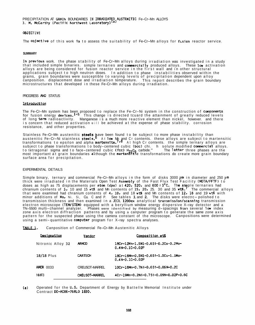
PRECIPITATION AT GRAIN BOUNDARIES IN IRRADIATE~lAUSTENITIC Fe-Cr-Mn ALLOYS 3 . M. HcCarthy (Pac i f I C hor thwest Laboratory)
WECTIVE
The o o j e c t l v e o f t h i s work i s t o assess t h e s u i t a b i l i t y o f Fe-Cr-Mn a l l o y s f o r f Ls ion reac tor serv ice.
SUMMARY
I n previous work. t h e phase s t a b i l i t y of Fe-Cr-Mn a l l o y s dur ing i r r a d i a t i o n was i nves t i ga ted i n a study t h a t inc luded s imple b inar ies . simple t e r n a r i e s and c m e r c i a l l y produced a l loys . These l o v a c t i v a t i o n a l l o y s a re being considered f o r fus ion reac to r se rv i ce i n t h e f i r s t w a l l and i n o the r s t r u c t u r a l app l i ca t i ons sub jec t t o h igh neutron doses. i n s t a b i l i t i e s observed w i t h i n t h e grains, g r a i n boundaries were suscept ib le t o vary ing l e v e l s o f p r e c i p i t a t i o n dependent upon a l l o y canposi t ion. displacement dose and i r r a d i a t i o n temperature. mic ros t ruc tures t h a t developed i n these Fe-Cr-Mn a l l o y s du r i ng i r r a d i a t i o n .
I n a d d i t i o n t o phase
Th i s r e p o r t descr ibes t h e g r a i n boundary
PROGRESS AN0 STATUS
Iotroductlon The Fe-Cr-Mn system has been proposed t o replace t h e Fe-Cr-Ni system i n t h e cons t ruc t i on o f components for fus ion energy devices.ld Th is change i s d i r ec ted t cua rd t h e at ta inment o f g r e a t l y reduced l e v e l s of l ong term r a d i o a c t i v i t y . Manganese i s a much more r e a c t i v e element than n icke l , however. and the re i s concern t h a t reduced a c t i v a t i o n w i l l be achieved a t t h e expense of phase s t a b i l i t y . co r ros ion resistance, and o the r propert ies.
S ta in l ess Fe-Cr-Mn a u s t e n i t i c s t e e l s a u s t e n i t i c Fe-Cr-Ni s t a i n l e s s steels.& A t l c u Mn and C r contents. these a l l o y s a re sub jec t t o m a r t e n s i t i c t ransformat ions t o eps i l on and alpha m a r t e n ~ i t e . ~ @ ~ A t h i gh C r contents. t h e simple t e rna ry a l l o y s a re sub jec t t o phase t rans format ions t o body-centered cub ic (bcc) chi . h s o l u t e mod i f ied comnercial a l loys . t o te t ragona l sigma and t o face-centered cub ic (fcc) M C carbide.’” The l a t t e r t h ree phases a re t h e most impor tan t a t g r a i n boundaries a1 though t h e marten?ItTc t rans format ions do c rea te more g r a i n boundary sur face area f o r p r e c i p i t a t i o n .
ave been found t o be sub jec t t o more phase i n s t a b i l i t y than
EXPERIMENTAL DETAILS
Simple binary, t e rna ry and commercial Fe-Cr-Mn a l l o y s i n t h e form of d isks 3000 p m i n diameter and 250 pin t h i c k were i r r a d i a t e d i n t h e Ma te r i a l s Open Test Assmbly of t h e Fas t F l u x Test F a c i l i t y (MOTA/FFTF) t o doses as h igh as 75 displacements per a t m (dpa) a t 420. 520. and 600i5’C. chranium contents of 5. 10 and 15 wM and Mn contents o f 15. 20. 25. 30 and 35 W W . ~ The commercial a l l o y s t h a t were examined had chranium contents of 4. 10. and 18 ut% and Mn contents o f 12. 18 and 19 WM w i t h minor add i t i ons of Mor N i . S i , Cu. C and P. See t a b l e s 1 and 2. The d i sks were e lectrc- pol ished t o t ransmiss ion th ickness and then examined i n a JEOL 1200ex a n a l y t i c a l transmission/scanning t ransmiss ion e l e c t r o n microscope (TEWSTEM) equipped w i t h a b e r y l l i u m window energy d i spe rs i ve X-ray de tec tor and a TN-5500 mult i- channel analyzer. Phases were i d e n t i f i e d by measuring d-spacings fran several la index zone a x i s e l e c t r o n d i f f r a c t i o n pa t t e rns and by using a canputer program t o generate t h e same zone a x i s p a t t e r n f o r t h e suspected phase using t h e camera constant of t h e microscope. us ing a semi- quant i ta t i ve computer program f o r X-ray spec t ra analyses.
IBBLU. Canposi t ion o f Commercial Fe-Cr-Mn A u s t e n i t i c A l l o y s
The s i p l e t e r n a r i e s had
Canposi t ions were determined - yanppr v N i t r o n i c A l l o y 32 ARMCO 18Cr-12Mn-l.5N1-0.6Si-0.2Cu-0.2Mo-
0.4N-0.1C-0.02P
18/18 P lus CARTEQI 18Cr-18Mn-0.5N1-0.6Si-l.OC~-l.1Mo- 0.4N-0.lC-0.02P
AMCR 0033 CREUSOT-MARREL 10Cr-18Mn-O.7Ni-0.6Si-O.06N-0.2C
NMF3 CREUSOT-MARREL 4Cr-19Mn-0.2Ni-0.7Si-0.09N-0.02P-0.6C
(a) Operated f o r t h e U.S. Department of Energy by B a t t e l l e Memorial I n s t i t u t e under Cont rac t DE-AC06-76RLO 1830.
103
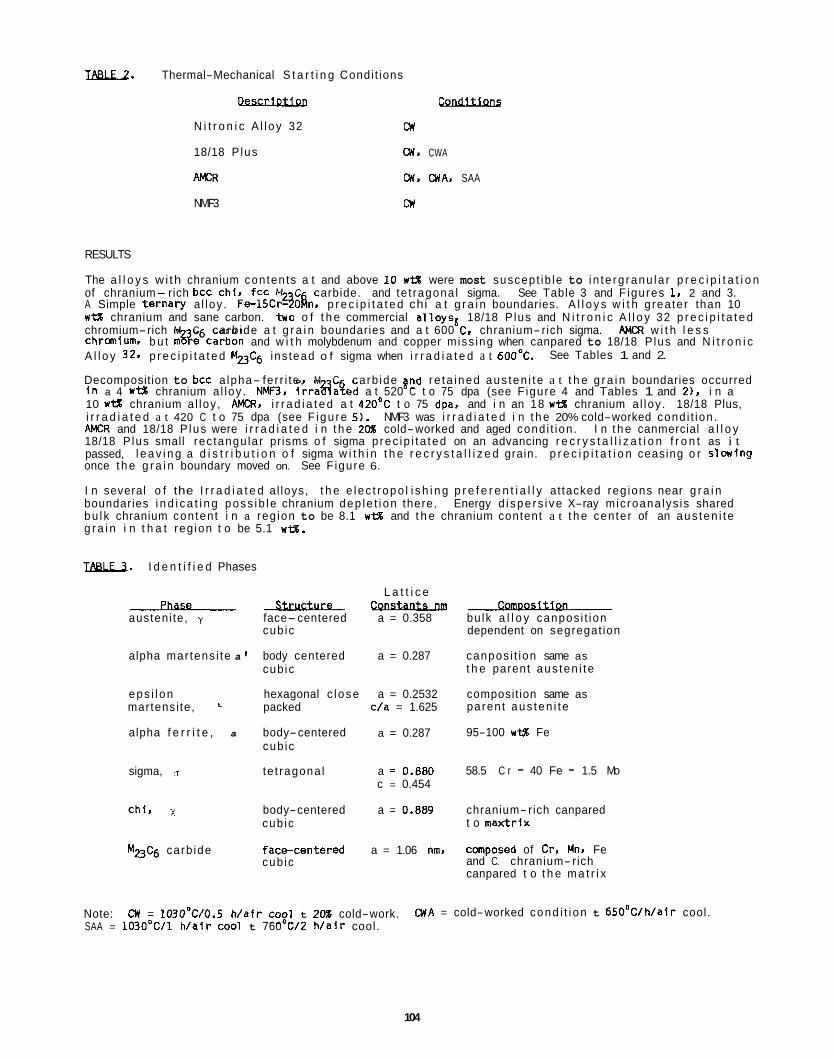
IBBIL2. Thermal-Mechanical S t a r t i n g Condi t ions
Descrlotlon Condltlons N i t r o n i c A l l oy 32 CW
18/18 P lus CW, CWA
AMCR CW. CWA. SAA
NMF3 CW
RESULTS
The a l l o y s wi th chranium contents a t and above 10 w t g were most suscept ib le to i n t e rg ranu la r p r e c i p i t a t i o n of chranium- rich bcc chi, fcc M C carbide. and te t ragona l sigma. See Table 3 and F igures 1. 2 and 3. A Simple t e rna ry a l loy . Fe-15CrgOfin. p r e c i p i t a t e d chi a t g r a i n boundaries. A l l o y s w i t h g rea ter than 10 wt% chranium and sane carbon. two o f t h e commercial a l l oysd 18/18 P lus and N i t r o n i c A l l o y 32 p r e c i p i t a t e d chromium-rich M C carb ide a t g r a i n boundaries and a t 600 C. chranium- rich sigma. AMCR w i t h l e s s chranium, b u t m%e6carbon and w i t h molybdenum and copper miss ing when canpared to 18/18 P lus and N i t r o n i c A l l o y 329 p r e c i p i t a t e d MZ3C6 ins tead o f sigma when i r r a d i a t e d a t 600OC.
Decomposition to bcc a lpha- fer r i te , M C carb ide gnd re ta ined aus ten i t e a t t h e g r a i n boundaries occurred i n a 4 w t g chranium a l loy . NMF3. i r r a a a t e d a t 520 C t o 75 dpa (see F igure 4 and Tables 1 and 2). i n a 10 w t g chranium a l loy , PMCR. i r r a d i a t e d a t 42O0C t o 75 dpa. and i n an 18 wt% chranium a l loy . 18/18 Plus, i r r a d i a t e d a t 420 C t o 75 dpa (see F igu re 5) . NMF3 was i r r a d i a t e d i n t h e 20% cold-worked cond i t ion . AMCR and 18/18 P lus were i r r a d i a t e d i n t h e 20% cold-worked and aged cond i t ion . I n t h e canmercial a l l o y 18/18 P lus small rec tangu lar prisms o f sigma p rec ip i t a ted on an advancing r e c r y s t a l l i z a t i o n f r o n t as i t passed, l e a v i n g a d i s t r i b u t i o n o f sigma w i t h i n t h e r e c r y s t a l l i z e d grain. p r e c i p i t a t i o n ceasing o r s lowing once t h e g r a i n boundary moved on. See F igure 6.
I n several o f the I r r a d i a t e d al loys, t h e e lec t ropo l i s h i n g p r e f e r e n t i a l l y at tacked reg ions near g r a i n boundaries i n d i c a t i n g poss ib le chranium dep le t i on there. Energy d i spe rs i ve X-ray mic roana lys is shared bu l k chranium content i n a reg ion to be 8.1 w t % and t h e chranium content a t t h e center of an aus ten i t e g r a i n i n t h a t reg ion t o be 5.1 w e .
See Tables 1 and 2.
I8811l. I d e n t i f i e d Phases
Phase- austeni te, y face-centered
cub ic
body centered cub ic
alpha mar tens i te a 1
eps i l on hexagonal c l ose martensi te, packed
alpha f e r r i t e , a body-centered cub ic
sigma, te t ragona l
chi , x body-centered cub ic
M23Cg carb ide f acecen te red cub ic
L a t t i c e - a = 0.358
a = 0.287
a = 0.2532 c/a = 1.625
a = 0.287
a = 0.880 c = 0.454
a = 0.889
a = 1.06 nm.
- bulk a l l o y canpos i t ion dependent on segregat ion
canpos i t ion same as t h e parent aus ten i t e
composit ion same as parent aus ten i t e
95-100 w t g Fe
58.5 C r - 40 Fe - 1.5 Mo
chranium- rich canpared t o max t r i x
composed of Cr. Mn. Fe and C. chranium- rich canpared t o t h e m a t r i x
Note: SAA = 1O3O0C/1 h / a i r cool t 760 C/Z W a i r cool.
CW = 1O3O0C/0.5 h / a i r cog1 t 20% cold-work. M A = cold-worked cond i t i on t 650°C/h/air cool.
104
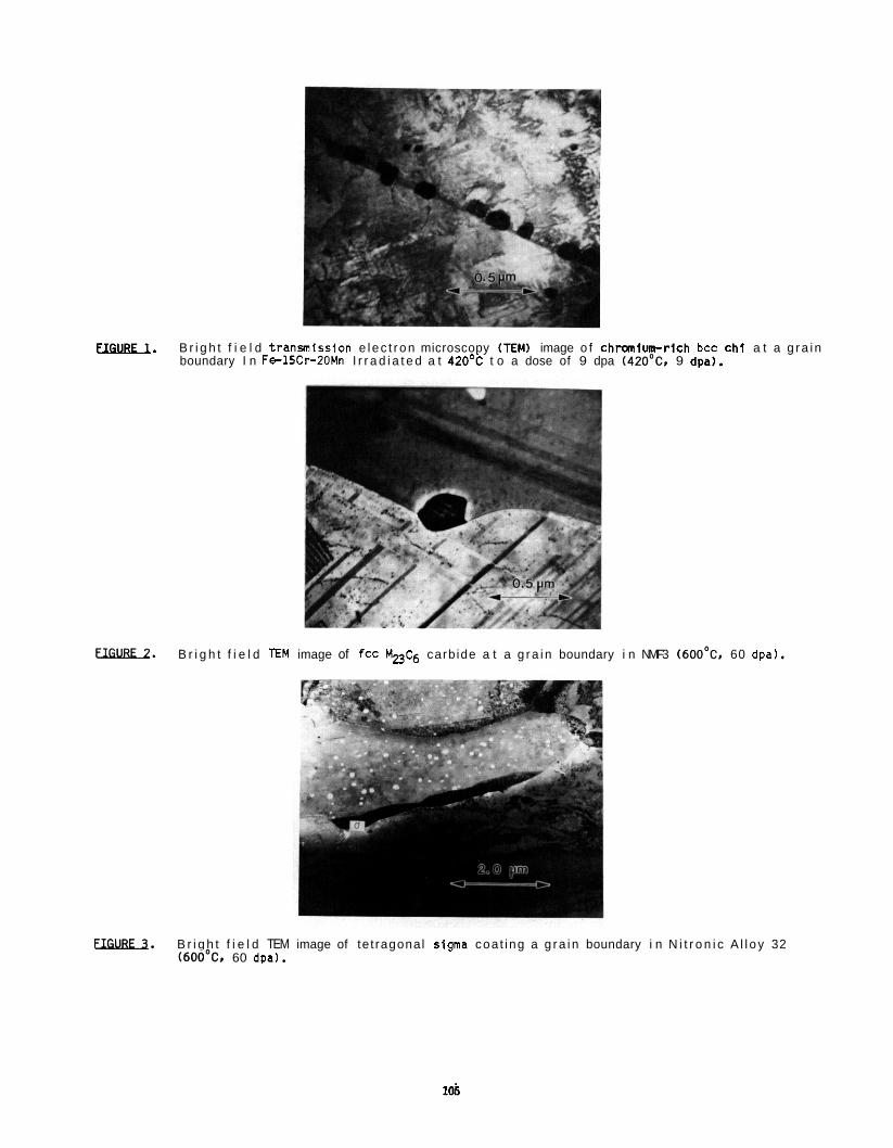
UGUBU. B r i g h t f i e l d t ransmission e l e c t r o n microscopy (TEM) image o f c h r m i u n r r i c h bcc c h i a t a g r a i n boundary I n Fe-15Cr-20Mn I r r a d i a t e d a t 420% t o a dose of 9 dpa (42OoC. 9 dpa).
EWBE-2. B r i g h t f i e l d E M image of fcc MpC6 carb ide a t a g r a i n boundary i n NMF3 (6OO0C. 60 dpa).
UIilLBIl. B r i g h t f i e l d TEM image of te t ragonal slgma coa t ing a g r a i n boundary i n N i t r o n i c A l l o y 32 (600'C1 60 dDa).
lob
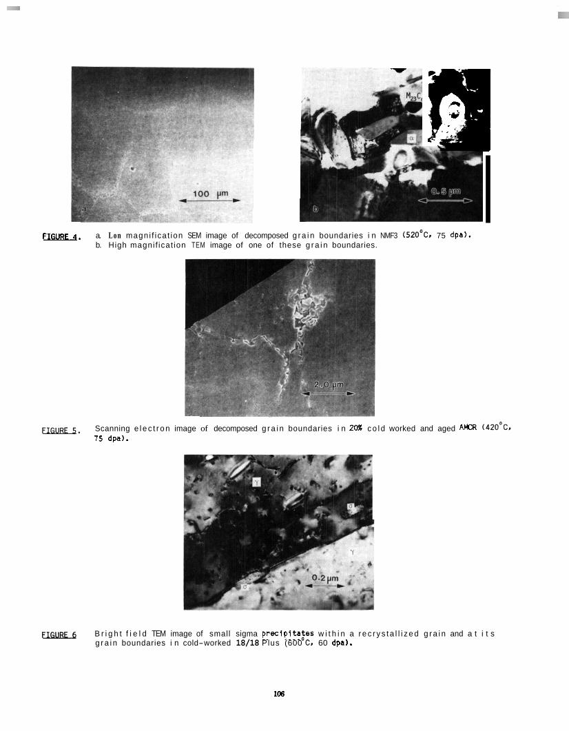
7.c.
--1 F-. a. L o n magni f ica t ion SEM image of decomposed g r a i n boundaries i n NMF3 (520'C. 75 dpa).
b. High magni f icat ion TEM image of one of these g r a i n boundaries.
EIIXBCt. Scanning e l e c t r o n image of decomposed g r a i n boundaries i n 20% c o l d worked and aged AMCR (420'C. 75 dpa).
I
EURE-6 B r i g h t f i e l d TEM image of small sigma p rec ip i t azes w i t h i n a r e c r y s t a l l i z e d g r a i n and a t i t s g r a i n boundaries i n cold-worked 18/18 Plus (600 '2, 60 dpa).
106
DISCUSSION
During i r r a d i a t i o n a l a r g e supersaturat ion o f vacancies i s created and these vacancies move t o s inks such as g r a i n boundaries causing an equal and opposi te movement o f atoms away fran t h e sinks. movement i n t u r n leads t o segregat ion o f t h e slowest d i f f u s i n g elements t hese sinks. d l f fuser and. therefore. concentrates Fe and C r a t t h e g r a i n boundaries. g*lh This mechanism i s r e f e r r e d t o as t h e Inverse K i rkenda l l Effect. T h i s e f f e c t creates small reg ions which have canposi t ions t h a t are very d l f f e r e n t fran t h e bu lk canposi t ion o f t h e a l l oy . compositions a t which m u l t i p l e phases a re l i k e l y t o ex is t .
I n a d d i t i o n t o d i f f u s i o n through t h e l a t t i c e . the re i s another major rou te by whlch atans a re t ranspor ted t o p r e c i p i t a t e s a t g r a l n boundaries and t h a t i s along t h e g r n boundaries. here i s orders o f magnitude greater than t h a t i n t h e matr ix .? I Th is even tua l l y leads t o t h e coarsening of t h e g r a i n boundary p r e c i p i t a t e s and f i n a l l y t o a coated g r a i n boundary i n sane regions. boundary i s movlng as a r e s u l t o f a r e c r y s t a l l i z a t i o n process, i t s d i f f u s i o n c o e f f i c i e n t i s Increased even more.12.13 a t 6OO0C t o 60 dpa i n t h l s study and i n thermal ly aged Fe-10.09 Cr-28.4Mn-0.46Si-0.01s-0.002P-0.0060- 0.005N i n a study by Garner. Abe and Noda.14
Chranium-rich phases such as bcc chl. fcc M C6, and te t ragonal sigma e m b r i t t l e a l l o y s by a c t i n g as nuc leat ion s i t e s f o r cracks whlch can i n i t i g e in te rg ranu la r f a i l u r e when these p r e c i p i t a t e s a re loca ted a t g r a i n boundaries. a l l o y s r m a i n r e l a t i v e l y f ree o f these b r i t t l e phases t o preserve acceptable mechanlcal proper t ies . The p r e c i p i t a t i o n o f chranium-rlch phases a lso depletes t h e m a t r i x o f chranlum. This reduces t h e co r ros ion res is tance of t h e a l l o y as a whole and. coupled w i th t h e dep le t ion of manganese a t t h e g r a i n boundaries due t o t h e Inverse K i rkenda l l Ef fect , increases t h e m a t r i x i r o n content a t t h e g r a l n boundaries and subsequently can cause phase t ransformat ions t o bcc a lpha- ferr i te .
I n a d d i t i o n t o t h e i n s t a b i l i t l e s caused by segregatlon, c o l d work increases t h e d i s l o c a t i o n dens i ty i n t h e l a t t i c e adding t o t h e f r e e energy o f these a l loys, making them l e s s s t a b l e and phase changes more l i k e l y .
a l l o y s a re l i k e l y s i t e s f o r t h e nuc leat ion o f a r e c r y s t a l l i z a t i o n process d r i ven by segregat ion and h igh f r e e energy.
I n t h i s study reg ions near g r a i n boundaries i n a u s t e n i t i c Fe-Cr-Mn a l l o y s decompose by a l o w temperature mechanism and a h igh temperature mechanism. Both mechanisms Invo lve t h e p r e c i p i t a t i o n of a chrmium- r i c h phase dep le t ing t h e aus ten i te m a t r i x of chranium. A t l o w temperatures (420'C and 520'C) g r a i n boundaries were observed t o decompose t o a lpha- ferr i te . M C carbide. and re ta ined aus ten i te as a r e s u l t of thermal aging and i r r a d i a t i o n . A t h igh temperature. 6 6 8 O 8 . sigma o r MuC6 forms and coarsens t o approach coa t ing g r a i n boundaries. The chranium and carbon contents o f t h e canmercial a l l o y s appears t o determlne whether sigma o r MZ3C p r e c i p i t a t e s a t 600°C. p r e c i p i t a t e d sigma and a l l o y s wqth 10 w i 3 chranium and h igher carbon p r e c i p i t a t e d M2&.
Th is Mn i s a f a s t
The d i f fus ion c o e f f i c i e n t
If t h e g r a i n
Sigma was observed t o p r e c i p i t a t e by t h i s mechanism i n co ld worked 18/18 Plus i r r a d i a t e d
Therefore, it i s des i red t h a t t h e g r a i n boundaries i n these a u s t e n i t i c Fe-Cr-Mn
carb ides as g r a t h proceeds. Therefore. reg ions near t h e g r a i n boundaries i n t h e cold-worked The i n i t i a l d i s l o c a t i o n dens i ty due t o c o l d work i s increased by t h e l a t t i c e m i s f l t of t h e
A l l o y s w i t h 18 w t % chranium and lower carbon
CONCLUSIONS
A u s t e n i t i c Fe-Cr-Mn a l l o y s a r e suscept ib le t o g r a l n boundary decomposition dur ing i r r a d i a t i o n . boundaries were observed t o decompose by a la and h igh temperature mechanism t o b r i t t l e phases such as chi . Sigma and M C carb ide t h a t can adversely change t h e mechanical p roper t ies of t h e bu lk a l l o y . Th is d e c m p o s i t i g qeads t o a chranium depleted aus ten i te m a t r i x and a t la temperatures t h e format ion o f alpha i r o n f e r r i t e , both having poor co r ros ion resistance.
Gra in
FUTURE WORK
De ta i led X-ray microanalys is needs t o be done on var ious g r a i n boundaries: v / ~ . Y/M23Cjr y / rrand y/o i n both l o w and h igh temperature specimens. t h i s w i l l p rov ide d e t a i l e d charac te r i za t ion o segregation and a l l a b e t t e r understanding o f t h e d r i v i n g mechanisms.
TO a t t a i n more d e t a i l e d character izat ion. a STEM microscope t h a t can produce an in tense 2 nm spo t w l l l be used. The small in tense spot w i l l g i v e compositions fran smal ler volumes than conventional STEMS. Corrosion and mechanical property t e s t s on these Fe-Cr-Mn a l l o y s need t o be performed and t h e r e s u l t s r e l a t e d t o microst ructure.
1M
REFERENCES
1.
2.
3 .
4.
5.
6. 7.
8.
9.
10.
11.
12.
13.
14.
H. R.Brager, F. A.Garner. 0. S.Gelles and M. L.Hamilton, J . Nuc. Mat. 133-134. 907 (1985).
F. A. Garner and H. R. Brager, Radiat ion Induced Changes i n Microstructure. ASTM STP 955. Eds. F. A. Garner. N. H. Packan and A. S . Kumar (ASTM, Phl ladelphia, 1987). p.195.
R. L.Klueh and E. E.Blom I n Opt imlz ing Ma te r i a l s f o r Nuclear Appl lcat lons, Eds. F. A. Garner, 0. S . Gel les and F. W. Wl f fen (The Me ta l l u rg i ca l Society, AIME. Warrendale, PA.. 1985). p.73.
A. H. Bott, F. B. P i cke r i ng and G. J . Butterworth, J . Nuc. Mat. 141-143. 294 (1986).
M. Snykers and E. Ruedl. J . Nucl. Mat. 103-104, 1075 (1981).
F. A. Garner, H. R. Brager, 0. S. Ge l les and J . M. McCarthy. J . Nuc. Mat. 148, 294 (1987). J . M. McCarthy and F. A. Garner, J . Nuc. Mat. 155-157, 877 (1988); Fuslon Reactor Ma te r i a l s COWER- 0313/4, 146 March (1988).
J . M. McCarthy. Fusion Reactor Ma te r i a l s DOE/ER-0313/5, i n press (1988).
H. Oikawa, Tech. Reports, Tohoku Un i ve rs l t y 47, 251 (1982); 48. 7 (1983).
H. Takahashi, F. A. Garner, H. I toh, B. Hu and S. Ohnuki Radlat lon Induced Changes i n Microstructure. ASTM STP 955. Eds. F. A. Garner, N. H. Packan and A. S. Kumar (ASTM. Phi ladelphia. 1987). p.268.
0. Lazarus, So l l d S ta te Physics 10, 7 1 (1960).
M. H i l l e r t and G. R. Purdy, Acta. Met. 26. 333. (1978).
K. Smidoda, C. Gottschalk and H. G l le fe r , Met. Scl.. 13 (1979) p.146.
F. A. Garner. F. Abe and T. Noda. J . NUC. Mat. 155-157. 870, (1988).
THE EFFECT OF PHOSPHORUS ON MICROSTRUCTURES OF Fe-15Cr-25Ni ALLOYS IRRADIATED WITH FAST NEUTRONS, T. Muroga (Kyushu U n i v e r s i t y ) , F. A. Garner and J. M. McCarthy (Pac i f i c Northwest Laboratory)
OBJECTIVE
The o b j e c t i v e o f t h i s study i s t o prov ide m ic ros t ruc tu ra l data t o demonstrate the operat ion of t h e var ious r o l e s proposed f o r phosphorus and assess the r e l a t i v e c o n t r i b u t i o n o f some of these r o l e s i n model a u s t e n i t i c Fe-Cr-Ni a l l o y s .
SUMMARY
Fe-15Cr-25Ni a u s t e n i t i c a l l o y s w i t h var ious phosphorus contents were i r r a d i a t e d w i t h f a s t neutrons i n the EBR-11 r e a c t o r a t temperatures ranging from 399 t o 6 4 9 T and doses between 8.2 and 14.3 dpa. m ic ros t ruc tu re and microchemical analyses were c a r r i e d ou t t o determine the var ious r o l e s o f phosphorus. A t lower i r r a d i a t i o n temperatures and lower phosphorus contents, where no p r e c i p i t a t e format ion was observed, the phosphorus remained i n s o l u t i o n and had a s t rong b u t v a r i a b l e in f luence on s w e l l i n g and vo id dens i t y . However, t he r e s u l t s suggest t h a t more than one mechanism i n v o l v i n g phosphorus-point defect i n t e r a c t i o n were operat ing and t h a t the n e t e f fec t was a r e s u l t of t h e compet i t ion of several mechanisms. Phosphide p r e c i p i - t a t e s were observed t o form a t h igher i r r a d i a t i o n temperatures and phosphorus l e v e l s . p r e c i p i t a t e s then exer ted a fu r the r in f luence on t he vo id d e n s i t y and d i s t r i b u t i o n .
Observations of
The formation of these
PROGRESS AND STATUS
I n t r o d u c t i o n
Recently, phosphorus a d d i t i o n t o a u s t e n i t i c s t e e l s has b e examined f o r the purpose o f reducing vo id swel- l i n g and i r r a d i a t i o n creep du r ing d i s p l a c i v e i r r a d i a t i ~ n ~ - ~ ~ . Under most cond i t i ons , phosphorus has been observed t o de lay t h e onset of swel l ing, b u t i n some expe i e t i t was shown t h a t under c e r t a i n cond i t i ons the a d d i t i o n o f phosphorus can a c t u a l l y increase s w e l l i n g y,y717i4. In o ther cases, the e f f e c t o f phosphorus i n reducing s w e l l i n g ranged from very s a l l t o very large, s t r o n g l y dependent on va r iab les such as tempera- t u r e and the composit ion o f the steel2-!. Such v a r i a b i l i t y i n response t o phosphorus suggests t h a t t h i s element p lays more than one r o l e and t h a t the spec i f i c r e s u l t s depend on a compet i t ion o f each o f these r o l e s i n response t o the environmental and composit ional va r iab les operat ing i n each experiment.
With the except ion of the work of Watanabe e t al.14318, no s tud ies t o date have advanced mechanisms which might account fo r an increase i n swe l l i ng . element when i n s o l u t i o n and, i n c e r t a i n condi t ions, can produce phosphide p r e c i p i t a t e s a t ve ry h igh dens i- t i e s j a d e ry small s izes. atoms ,2y, r e s u l t i n g i n r a d i a t ' n ' n ced segregat ion o f phosph r u and a s t rong increase i n the r a t e of format ion of i n t e r s t i t i a l loops 1y,id*ji. Watanabe and coworker^^^?^^ a l so demonstrated a s ong i n t e r a c t i o n between vacancies and phosphorus. A s i m i l a r conc lus ion was reached by Azarian and Kheloufi): us ing p o s i t r o n a n n i h i l a t i o n . and aging experiments conducted on phosphorus-containin s
There are a number o f consequences of these var ious i n t e r a c t i o n s o f phosphorus w i t h p o i n t defects, and d i f - ferent researchers tend t o focus on d i f f e r e n t aspects of these consequences whe m ic ros t ruc tu ra l response of phosphorus-containing a l l o y s . Garner and coworkers9-I focus p r i m a r i l y on the compet i t ive r o l e s o f phosphorus w h i l e i n s o l u t i o n as w e l l as the consequence on the m a t r i x chemistry when phosphorus i s removed by segregat ion o r p r e c i p i t a t i o n . p o i n t defects w i t h phosphorus but a l so the m o d i f i c a t i o n of the m a t r i x composit ion t h a t occurs when phosphides
! li,iUi . I t o h and are formed. Phosphides are known t o delay the formation o f rad ia t i on- induced phases r i c n i c k e l , b t h of which are a l so known t o s t r o n g l y r e t a r d v o i d nuc lea t ion when i n s o l u t i o n coworkers a lso emphasized the r e t a r d a t i o n by phosphide format ion of these phases, and they f u r t h e r noted t h a t phosphorus add i t i ons tend t o r e t a r d the recovery of d i s l o c a t i o n networks induced by c o l d working. High i n i t i a l d i s l o c a t i o n d e n s i t i e s are a l so known t o r e t a r d the onset o f vo id formation.
The s tud ies and theor ies o f Lee and Mansur and t h e i r coworkers7-9.17.33~34 are more d i r e c t e d toward the r o l e o f phosphorus i n forming p r e c i p i t a t e s . than chemical sense. The surfaces o f these p r e c i p i t a t e s serve i n several models as recombinat ion centers f o r p o i n t defects and c o l l e c t o r s fo r i m p u r i t y atoms. The l a t t e o 1 i n p a r t i c u l a r was developed t o account f o r the in f l uence o f phosphorus i n the presence of he l ium atoms y - g i f T . I n t h i s model, t he p r e c i p i t a t e s serve as c o l l e c t i o n surfaces fo r he l ium atoms, producing a profus ion o f small s u b c r i t i c a l bubbles which cannot be e a s i l y promoted i n t o b ias- d r i ven vo id growth.
I t i s q u i t e probable, however, t h a t a l l of these models, both chemical and phys ica l , are opera t ing t o one extent o r another a t d i f f e r e n t stages i n the m ic ros t ruc tu ra l evo lu t i on .
Phosphorus i s known t o be a subsize and very chemica l ly a c t i v e
Phosphorus has been shown t o i n t e r a c t very s t r o n g l y w i t h i n t e r s t i t i a l
The same conclusion i s a lso supported by the obs v i o n of vo id format ion du r ing quenching Phosphorus has a l so been shown t o
increase the i n t e r d i f f u s i o n coe f f i c ien t of Fe-Ni a l l o y s 47,5% , which imp l ies some i n t e r a c t i o n w i t h vacancies.
t t empt ing t o model t h e
Th is approach considers n o t on ly the i n t e r a c t i o n o f
l i c o n and
P r e c i p i t a t e s are seen i n t h e i r approach t o ac t i n a phys ica l r a t h e r
The net outcome o f the many r o l e s o f
109
phosphorus i s determined by the environmental and composit ional va r iab les dominating the p a r t i c u l a r exper i - ment being analyzed. It has been p rev ious ly d i f f i c u l t t o d i sc r im ina te between the s t reng th o f the var ious p o t e n t i a l r o l e s o f phosphorus since most e a r l i e r s tud ies concentrated on a l i m i t e d se t o f experimental condi t ions, a l l ow ing on ly one and sometimes two o f the p o t e n t i a l outcomes t o develop from the compet i t ion.
I n the study chosen f o r t h i s paper, a se t o f neu t ron- i r rad ia ted specimens was se lected f o r m i c r o s t r u c t u r a l observat ion because t h e i r dens i t y changes ind ica ted a wide range o f behavior i n response t o i r r a d i a t i o n temperature, displacement l e v e l and phosphorus content. The l e v e l o f o the r so lu tes i n these a l l o y s was a l so low, a l l ow ing phosphorus t o e x h i b i t i t s in f luence w i thou t s y n e r g i s t i c i n t e r a c t i o n s t h a t might obscure i t s in f luence. The o b j e c t i v e o f t h i s study was t o prov ide m ic ros t ruc tu ra l data t o demonstrate the operat ion of the var ious r o l e s proposed f o r phosphorus and h o p e f u l l y assess the r e l a t i v e s t reng th o f some of these r o l e s .
Experimental D e t a i l s
The mate r ia l s used i n t h i s study were nomina l ly Fe-lSCr-ZSNi a u s t e n i t i c a l l o y s w i t h var ious phosphorus l e v e l s . diameter by 12.7-mm long) and were i r r a d i a t e d i n the A A I X experiment i n the EBR-I1 reac to r4 . i r r a d i a t i o n temperatures va r ied from 399 (f5-C) t o 650 (t15'C). The i r r a d i a t i o n dose f o r each temperature was d i f f e r e n t ( rang ing from 2 t o 14.3 dpa), r e f l e c t i n g a x i a l d i f f e rences i n the displacement r a t e , which
The dens i t y o f each specimen was determined us ing an immersion dens i t y technique demonstrated t o be accurate t o M.16%. study, f i v e o f the e i g h t i r r a d i a t i o n temperatures were chosen f o r f u r t h e r study u t i l i z i n g e l e c t r o n microscopy and microchemical ana lys is as ind ica ted by a s t e r i s k s i n F igure 1 and l i s t e d i n Table 2. were sect ioned t o produce microscopy d i s k s and e lec t ropo l i shed t o p e r f o r a t i o n . t u r a l analyses were performed on a JEM-100CX e l e c t r o n microscope. I n some cases, microchemical analyses were performed using a JEM-l200EX e l e c t r o n microscope equipped w i t h a TN-5500 energy d i spers i ve X-ray spectrometer (EDS) w i t h an e f f e c t i v e probe diameter o f about 20 nm.
The compositions o f these a l l o y s are shown i n Table 1. The specimens were i n the form of rods (3-mm The e i g h t
va r ied from 0 . 6 t o 1.1 x 10- !. dpa/s.
The r e s u l t s were repor ted by Garner and Kumar4 and are reproduced i n F igure 1. I n the present
The r o d specimens I n most cases, m ic ros t ruc -
RESULTS
399'C and 8.2 dDa
No p r e c i p i t a t i o n was observed a t any phosphorus l e v e l a t 399-C. works a t r e l a t i v e l y constant d e n s i t y were observed. Bragg cond i t i on . i n dens i t y g radua l l y w i t h i nc reas ing phosphorus. t h e r e a f t e r w i t h increas ing phosphorus, m i r r o r i n g the t rend observed i n the rad ia t ion- induced change i n b u l k dens i t y shown i n F igure 1. The var ious m i c r o s t r u c t u r a l parameters as in f luenced by phosphorus l e v e l are shown i n F igure 3.
4 2 7 T and 11.2 dpa
I n t h i s j y a f i a t i o n cond i t i on , the measured vo id volume a t 0% phosphorus w 1 06% w i t h a vo id d e n s i t y o f
8.2 dpa) case, the vo id dens i t y was lower a t both phosphorus l e v e l s even though t h e displacement l e v e l a t 427% was h igher .
A t 0.1% hos horus, a low d e n s i t y o f t he n e e d l e - l i k e p r e c i p i t a t e s was observed.
those observed a l so a t 5 1 O T and above. deduced from the l i m i t e d observat ions whether the p r e c i p i t a t i o n a t 427°C a r i ses simply as a r e s u l t of t he increase i n temperature o r whether the increase i n dose i s p a r t i a l l y o r t o t a l l y respons ib le .
510'C and 13.2 dDa
The m ic ros t ruc tu res developed a t t h i s temperature are i l l u s t r a t e d i n Figures 4 and 5, and the m i c r o s t r u c t u r a l parameters are shown i n F igure 6. phosphorus add i t i on , once again i n d i c a t i n g an e f f e c t of phosphorus unre la ted t o p r e c i p i t a t i o n . p r e c i p i t a t e s were observed on ly a t the two h ighest phosphorus l e v e l s . p i t a t e s a t 0.1% phosphorus y & r e l a r g e r than t h a t observed i n t h i s a l l o y a t 427'C and 11.2 dpa. p i t a t e dens' y
Voids as w e l l as tang led d i s l o c a t i o n n e t -
The vo ids were d i s t r i b u t e d r e l a t i v e l y homogeneously a t a l l phosphorus l e v e l s b u t decreased
The network d i s l o c a t i o n s were found t o be tang led w i t h very few loops remaining.
The l a t t e r are shown i n F igure 2 imaged i n the o f f -
The s w e l l i n g increased i n i t i a l l y , however, and dec l i ned
5.9 x 10 /m and a t 0.1% phosphorus was 1.10% w i t h a dens i t y of 1.75 x 10 31 /m 3 . R e l a t i v e t o the (399'C,
2.9 x 10 Yo /m 5 . i n d e n s i t y and 45 nm i n average leng th . These were o r i e n t e d along < l o o > d i r e c t i o n s , t y p i c a l of These p r e c i p i t a t e s were
Compared t o the absence o f p r e c i p i t a t e s a t 399'C, i t cannot be
A t t he lower phosphorus l e v e l , t he vo id dens i t y s t r o n g l y decreased w i t h Need le - l i ke
The p r e c i - The dens i t y and s i ze of the p r e c i -
as 3 3 x 10 /m3 w i t h an average s i ze of 105 nm a t the 0.055% phosphorus l e v e l and a dens i t y o f 7.4 x 10 36 /m 4 w i t h " an average leng th o f 185 nm a t the 0.1% phosphorus l e v e l . As p r e c i p i t a t i o n develops
110
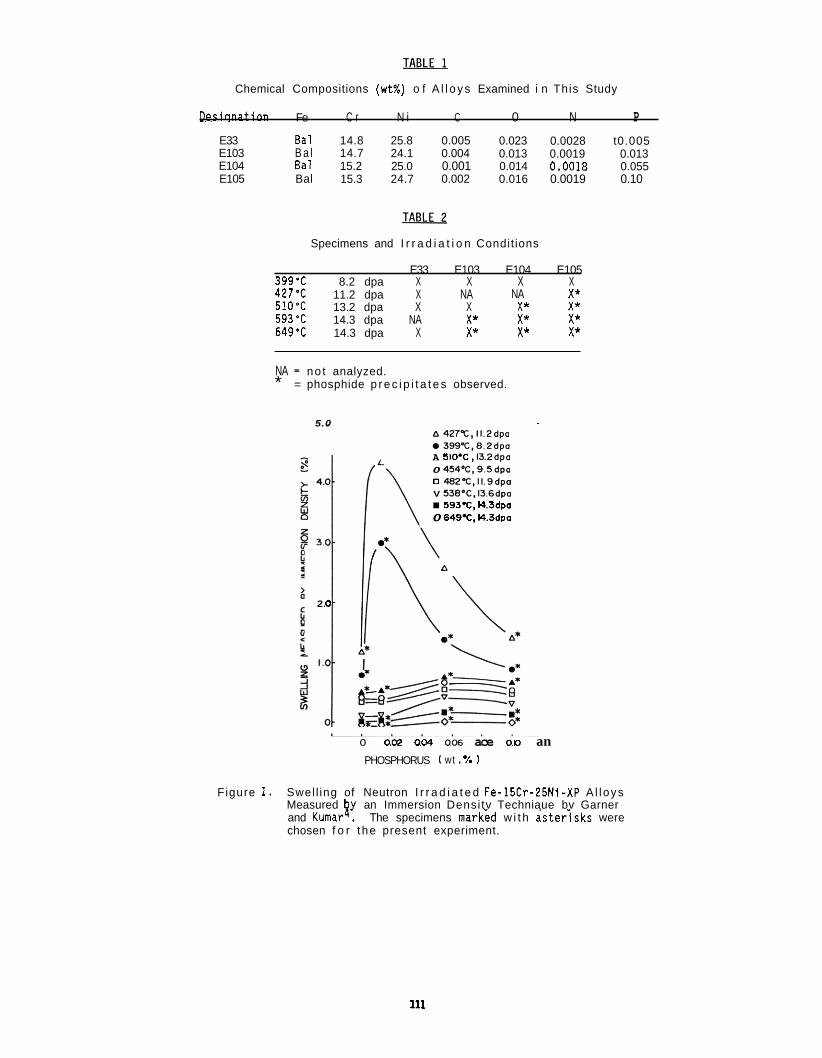
Chemical Compositions (wt%) o f A l l o y s Examined i n This Study
Desiqnation Fe C r N i C 0 N P E33 Bal 14.8 25.8 0.005 0.023 0.0028 t0.005 E103 B a l 14.7 24.1 0.004 0.013 0.0019 0.013 E104 Bal 15.2 25.0 0.001 0.014 0.0018 0.055 E105 Bal 15.3 24.7 0.002 0.016 0.0019 0.10
Specimens and I r r a d i a t i o n Condit ions
E33 E103 E104 E105 399'C 8.2 dpa X X X X 427'C 11.2 dpa X NA NA X* 510% 13.2 dpa X X X* X* 593'C 14.3 dpa NA X* X* X* 649% 14.3 dpa X X* X* X*
NA = no t analyzed. * = phosphide p r e c i p i t a t e s observed.
5.0 A 427TC,11.2dpa 0 3 9 9 T . 8 . 2 d p a A 510% ,13.2dpa 0 454%,9.5dpa 0 48ZT.11.9dpa V 538.C,136dpo
593.C. 14.3dpa 0 649T. 14.3dpo
2 a
o 0.02 aw a s ace 0.10 an PHOSPHORUS ( wt . 7. I
Figure 1. Swel l ing of Neutron I r r a d i a t e d Fe-15Cr-25Ni-XP A l l oys Measured by an Immersion Densi tv Techniaue bv Garner and Kumar? The specimens markid w i t h aster;sks were chosen f o r t he present experiment.
111
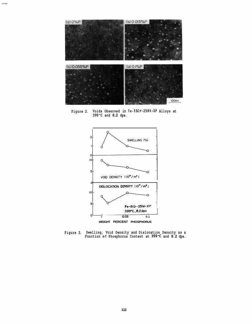
Figure 2. Voids Observed in Fe-1SCr-2SNi-XP Alloys at 399% and 8.2 dpa.
0 DISLOCATION DEWTY 1 IO"/ m' I
Fe-SCr-ZSNi-XP
399'C. 8.2dPa
0.05 0.1 I
WEIGHT PERCENT PHOSPHORUS
Figure 3. Swelling, Void Density and Dislocation Density as a Function o f Phosphorus Content at 399'C and 8.2 dpa.
112
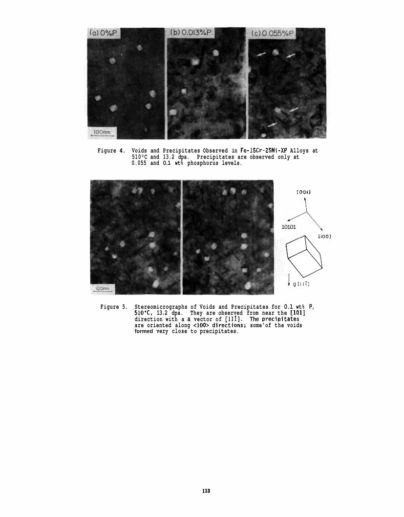
Figure 4. Voids and Precipitates Observed in Fe-15Cr-Z5Ni-XP Alloys at 510°C and 13.2 dpa. 0.055 and 0.1 wt% phosphorus levels.
Precipitates are observed only at
[ O O I I
10101
I l O O l
Figure 5. Stereomicrographs of Voids and Precipitates for 0.1 wt% P, 510'C, 13.2 dpa. They are observed from near the [loll direction with a a vector of I11I1. The Drecioitates are oriented along d00> direitions; some'of the voids formed very close to precipitates.
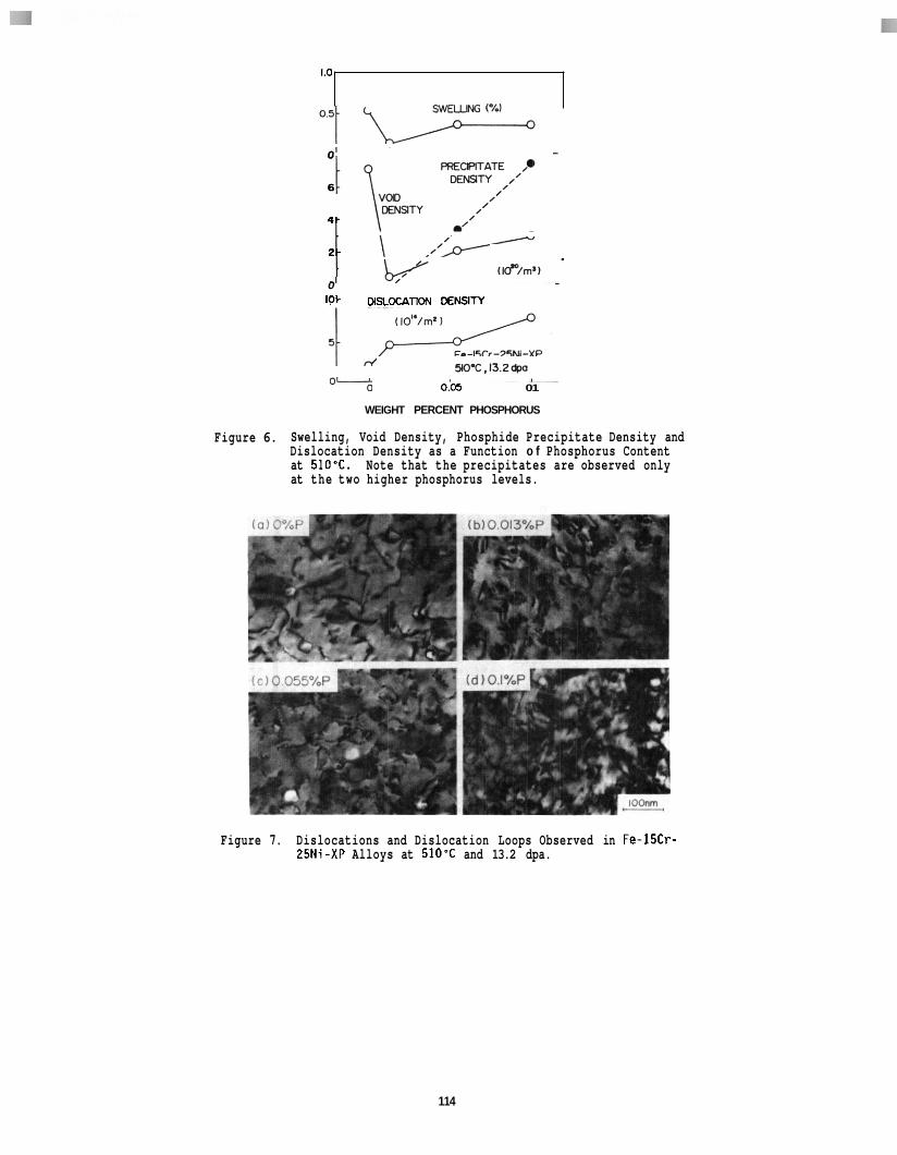
10
WELLW (%I
0
6
4 .
2 -
(ld"/rn'l - 0 10- mmm DENSITY
W-C,l3.2W
0 0 O C 6 01
WEIGHT PERCENT PHOSPHORUS
Figure 6. Swelling, Void Density, Phosphide Precipitate Density and Dislocation Density as a Function o f Phosphorus Content at 510%. Note that the precipitates are observed only at the two higher phosphorus levels.
Figure 7. Dislocations and Dislocation Loops Observed in Fe-15Cr- Z5Ni-XP Alloys at 510% and 13.2 dpa.
114
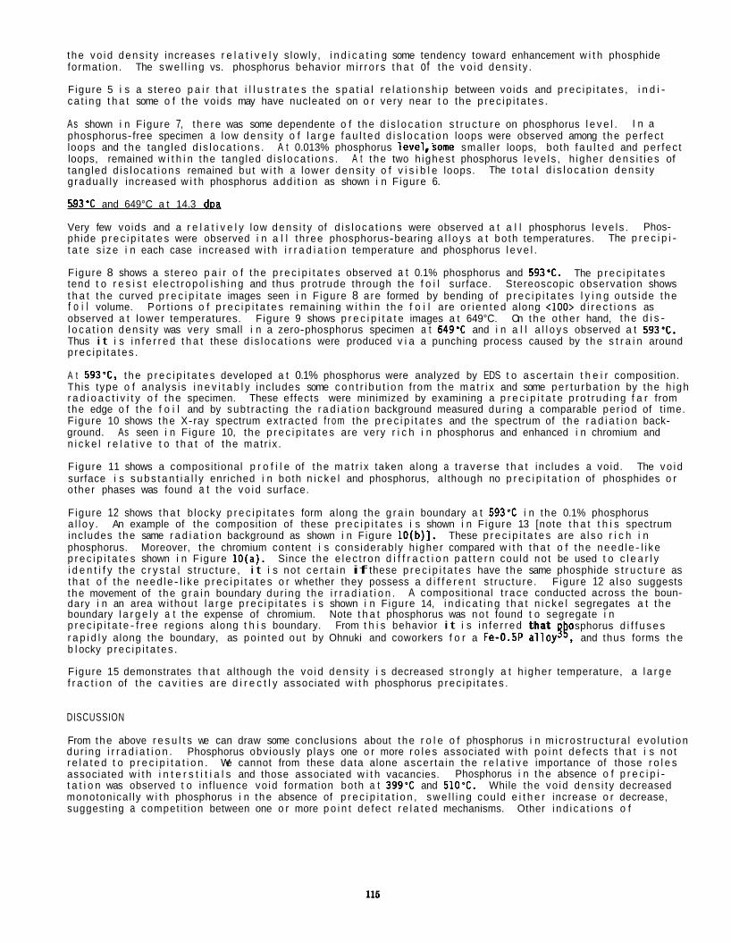
t he vo i d dens i t y increases r e l a t i v e l y s lowly, i n d i c a t i n g some tendency toward enhancement w i t h phosphide format ion. The swe l l i ng vs. phosphorus behavior m i r r o r s t h a t of t he vo i d dens i ty .
F igure 5 i s a s tereo p a i r t h a t i l l u s t r a t e s t he s p a t i a l r e l a t i o n s h i p between voids and p rec i p i t a t es , i n d i - ca t i ng t h a t some o f t he vo ids may have nucleated on o r very near t o the p rec i p i t a t es .
As shown i n F igure 7, t he re was some dependente o f t he d i s l o c a t i o n s t r u c t u r e on phosphorus l e v e l . phosphorus-free specimen a low dens i t y o f l a r g e f a u l t e d d i s l o c a t i o n loops were observed among t he per fec t loops and t he tangled d i s l oca t i ons . A t 0.013% phosphorus leve1,some smal ler loops, both f a u l t e d and per fec t loops, remained w i t h i n the tangled d i s l oca t i ons . A t t he two h ighes t phosphorus l eve l s , h igher dens i t i e s of tangled d i s l oca t i ons remained bu t w i t h a lower dens i t y o f v i s i b l e loops. g radua l l y increased w i t h phosphorus add i t i on as shown i n F igure 6.
I n a
The t o t a l d i s l o c a t i o n dens i t y
593% and 649°C a t 14.3 dDa
Very few voids and a r e l a t i v e l y low dens i t y of d i s l oca t i ons were observed a t a l l phosphorus l eve l s . phide p r e c i p i t a t e s were observed i n a l l th ree phosphorus-bearing a l l o y s a t bo th temperatures. t a t e s i ze i n each case increased w i t h i r r a d i a t i o n temperature and phosphorus l e v e l .
F igure 8 shows a s tereo p a i r o f t he p r e c i p i t a t e s observed a t 0.1% phosphorus and 593'C. tend t o r e s i s t e l ec t r opo l i sh i ng and thus prot rude through t he f o i l surface. Stereoscopic observat ion shows t h a t t he curved p r e c i p i t a t e images seen i n F igure 8 a re formed by bending of p r e c i p i t a t e s l y i n g ou ts ide t he f o i l volume. observed a t lower temperatures. F igure 9 shows p r e c i p i t a t e images a t 649°C. l o c a t i o n dens i t y was very small i n a zero-phosphorus specimen a t 649% and i n a l l a l l o y s observed a t 593-C. Thus i t i s i n f e r r e d t h a t these d i s l oca t i ons were produced v i a a punching process caused by t he s t r a i n around p rec i p i t a t es .
A t 593% the p r e c i p i t a t e s developed a t 0.1% phosphorus were analyzed by EDS t o ascer ta in t h e i r composition. This type o f ana lys is i n e v i t a b l y inc ludes some c o n t r i b u t i o n from the ma t r i x and some pe r t u rba t i on by the h i gh r a d i o a c t i v i t y o f t he specimen. These effects were minimized by examining a p r e c i p i t a t e p ro t r ud i ng f a r from the edge o f t he f o i l and by sub t rac t ing the r a d i a t i o n background measured dur ing a comparable per iod of t ime. F igure 10 shows t he X-ray spectrum ex t rac ted f r o m the p r e c i p i t a t e s and t he spectrum of t he r a d i a t i o n back- ground. As seen i n F igure 10, the p r e c i p i t a t e s are very r i c h i n phosphorus and enhanced i n chromium and n i c k e l r e l a t i v e t o t h a t of the mat r i x .
F igure 11 shows a composit ional p r o f i l e of t he ma t r i x taken along a t raverse t h a t inc ludes a vo id. surface i s s u b s t a n t i a l l y enriched i n both n i c k e l and phosphorus, al though no p r e c i p i t a t i o n of phosphides o r o ther phases was found a t the vo i d surface.
F igure 12 shows t h a t b locky p r e c i p i t a t e s form along the g r a i n boundary a t 593'C i n the 0.1% phosphorus a l l oy . An example of the composition of these p r e c i p i t a t e s i s shown i n F igure 13 [note t h a t t h i s spectrum inc ludes t he same r a d i a t i o n background as shown i n F igure 10(b)]. These p r e c i p i t a t e s are a l so r i c h i n phosphorus. Moreover, the chromium content i s cons iderably h igher compared w i t h t h a t o f t he need le - l i ke p r e c i p i t a t e s shown i n F igure lO(a). Since t he e l ec t r on d i f f r a c t i o n p a t t e r n could no t be used t o c l e a r l y i d e n t i f y t he c r y s t a l s t ruc tu re , i t i s no t c e r t a i n if these p r e c i p i t a t e s have t he same phosphide s t r u c t u r e as t h a t o f t he need le - l i ke p r e c i p i t a t e s o r whether they possess a d i f f e r e n t s t ruc tu re . F igure 12 a lso suggests t he movement of t he g r a i n boundary dur ing t he i r r a d i a t i o n . A composit ional t r ace conducted across t he boun- dary i n an area w i thou t l a r g e p r e c i p i t a t e s i s shown i n F igure 14, i n d i c a t i n g t h a t n i c k e l segregates a t t he boundary l a r g e l y a t t he expense of chromium. p r e c i p i t a t e - f r e e regions along t h i s boundary. r a p i d l y along the boundary, as po in ted ou t by Ohnuki and coworkers f o r a Fe-O.5P a l loygk, and thus forms t he b l ocky p rec i p i t a t es .
F igure 15 demonstrates t h a t al though t he vo i d dens i t y i s decreased s t r ong l y a t h igher temperature, a l a r g e f r a c t i o n of t he c a v i t i e s a re d i r e c t l y associated w i t h phosphorus p rec i p i t a t es .
Phos- The p r e c i p i -
The p r e c i p i t a t e s
Por t ions o f p r e c i p i t a t e s remaining w i t h i n t he f o i l are o r i en ted along <loo> d i r e c t i o n s as On t he o ther hand, t he d i s -
The vo id
Note t h a t phosphorus was no t found t o segregate i n From t h i s behavior i t i s i n f e r r ed t h a t osphorus d i f f u s e s
DISCUSSION
From the above r e s u l t s we can draw some conclusions about t he r o l e o f phosphorus i n m i c ros t r uc tu ra l evo l u t i on dur ing i r r a d i a t i o n . r e l a t e d t o p r e c i p i t a t i o n . associated w i t h i n t e r s t i t i a l s and those associated w i t h vacancies. t a t i o n was observed t o in f luence vo id formation both a t 399% and 510'C. While the vo id dens i t y decreased monotonica l ly w i t h phosphorus i n t he absence of p r e c i p i t a t i o n , swe l l i ng could e i t h e r increase o r decrease, suggest ing a compet i t ion between one o r more p o i n t de fec t r e l a t e d mechanisms. Other i nd i ca t i ons o f
Phosphorus obv ious ly p lays one o r more r o l e s associated w i t h p o i n t de fec ts t h a t i s no t We cannot from these data alone ascer ta in the r e l a t i v e importance of those r o l e s
Phosphorus i n t he absence o f p r e c i p i -
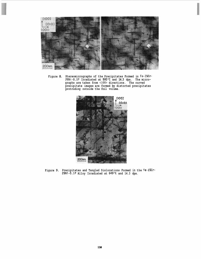
Figure 8. Stereomicrographs of the Precipitates Formed in Fe-15Cr- 25Ni-0.1P Irradiated at 593% and 14.3 dpa. The micro- graphs are taken from t100> directions. precipitate images are formed by distorted precipitates protruding outside the foil volume.
The curved
I
rtoo1 t roto1
Figure 9. Precipitates and Tangled Dislocations Formed in the Fe-15Cr- 25Ni-0.1P Alloy Irradiated at 649'C and 14.3 dpa.
116
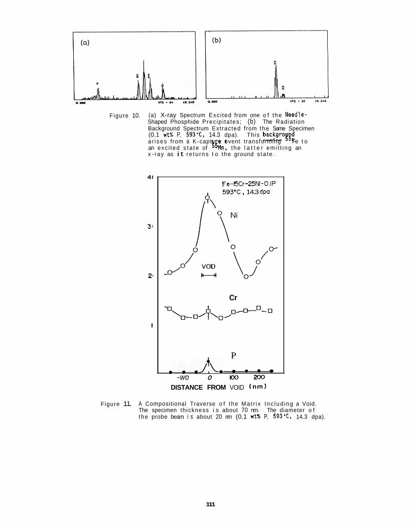
Figure 10. (a) X-ray Spectrum Exc i ted from one o f t he Needle- Shaped Phosphide Prec ip i ta tes ; (b) The Radiat ion Background Spectrum Extracted from the Same Specimen (0.1 w t % P, 593T, 14.3 dpa). a r i ses from a K-capt e event transforming Fe t o an exc i ted s t a t e of %n, t he l a t t e r em i t t i ng an x- ray as i t re tu rns t o t he ground s ta te .
This backgrotyd
41
31
2'
I
Fe-ECr-25Ni-O.IP 593'C, 14.3 dpa
A
Cr
P
IW XK)
DISTANCE FROM VOID ( n m )
-.A* 2 * 2 -wo 0
Figure 11. A Compositional Traverse o f t he Ma t r i x I nc l ud i ng a Void. The specimen th ickness i s about 70 nm. The diameter o f t he probe beam i s about 20 nm (0.1 wtX P, 593'C, 14.3 dpa).
111
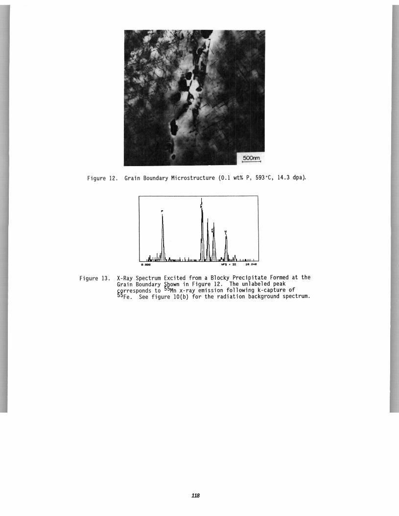
118
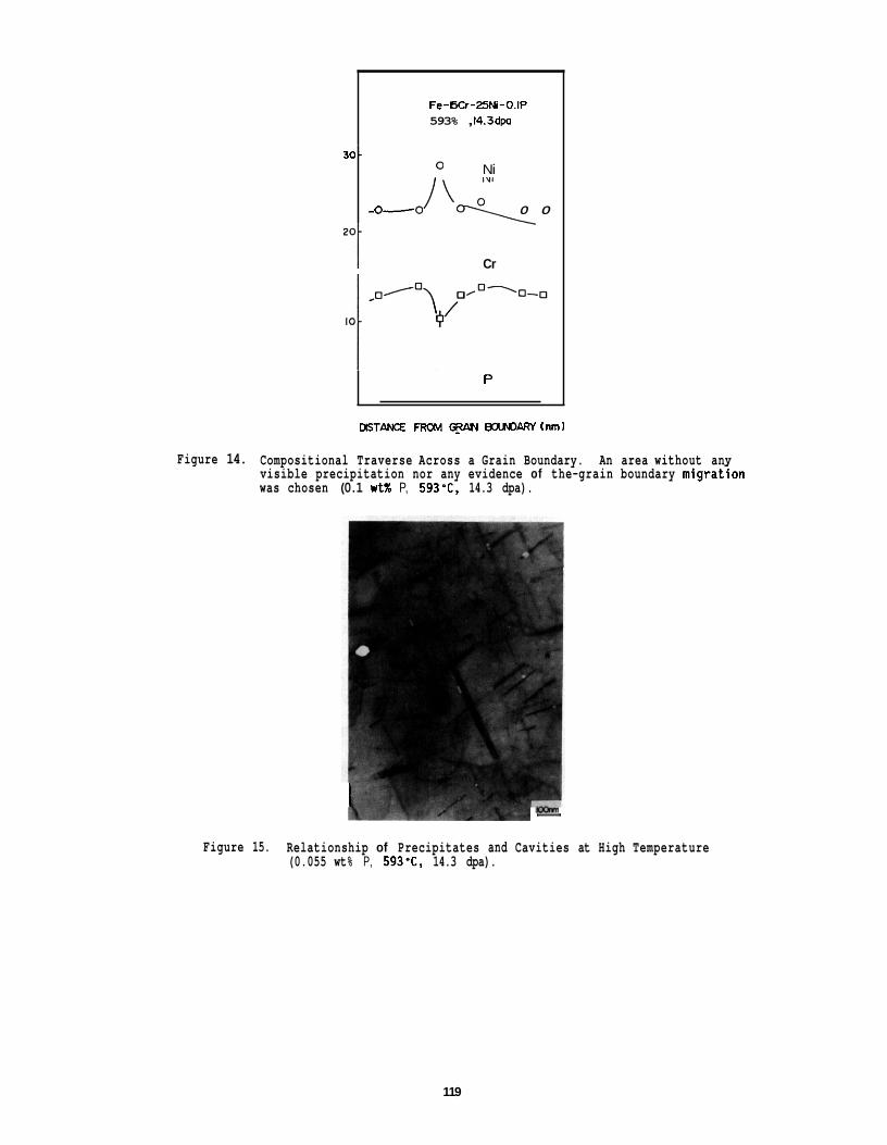
Fe-SO-25Ni-O.IP 593% , 14.3dpa
30. Ni
-0- .//% 0 0
zot Cr
P
mm FROM AN gchaesn Inml
Figure 14. Compositional Traverse Across a Grain Boundary. An area without anv visible precipitation nor any evidence of the-grain boundary migrat;on was chosen (0.1 wtX P, 593-C, 14.3 dpa).
I
1 Figure 15. Relationship of Precipitates and Cavities at High Temperature
(0.055 wt% P, 593'C, 14.3 dpa).
119
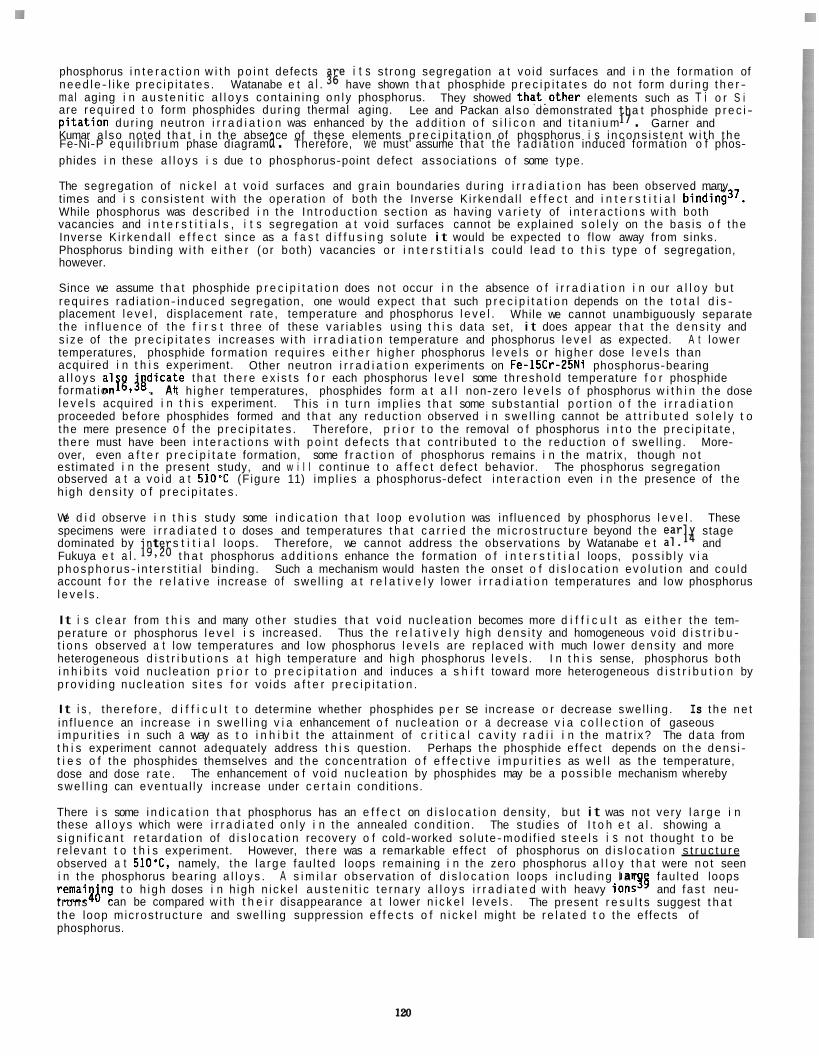
phosphorus i n t e r a c t i o n w i t h p o i n t defects $!e i t s s t rong segregat ion a t vo id surfaces and i n t he format ion of need le - l i ke p rec i p i t a t es . Watanabe e t a l . have shown t h a t phosphide p r e c i p i t a t e s do no t form du r i ng t h e r - mal aging i n a u s t e n i t i c a l l o y s con ta in ing on l y phosphorus. They showed t ha t , o t he r elements such as T i o r S i are requ i red t o form phosphides dur ing thermal aging. a t phosphide p r e c i - p i t a t i o n dur ing neutron i r r a d i a t i o n was enhanced by t he add i t i on o f s i l i c o n and t i t a n i u m . Kumar a lso noted t h a t i n t he abse ce of these elements p r e c i p i t a t i o n of phosphorus i s i n cons i s t en t w i t h t he
phides i n these a l l o y s i s due t o phosphorus-point defect associat ions o f some type.
The segregat ion of n i c k e l a t vo i d surfaces and g r a i n boundaries dur ing i r r a d i a t i o n has been observed many times and i s cons is ten t w i t h the operat ion of both t he Inverse K i rkenda l l e f f e c t and i n t e r s t i t i a l binding3'. While phosphorus was described i n t he I n t r oduc t i on sec t ion as having v a r i e t y of i n t e r a c t i o n s w i t h both vacancies and i n t e r s t i t i a l s , i t s segregat ion a t vo id surfaces cannot be explained s o l e l y on t he bas is o f t he Inverse K i rkenda l l e f f e c t s ince as a f a s t d i f f u s i n g so lu te i t would be expected t o f low away from sinks. Phosphorus b ind ing w i t h e i t h e r (o r both) vacancies o r i n t e r s t i t i a l s could lead t o t h i s type o f segregation, however.
Since we assume t h a t phosphide p r e c i p i t a t i o n does no t occur i n t he absence o f i r r a d i a t i o n i n our a l l o y bu t requ i res rad ia t ion- induced segregat ion, one would expect t h a t such p r e c i p i t a t i o n depends on t he t o t a l d i s - placement l e v e l , displacement ra te , temperature and phosphorus l e v e l . the i n f l uence of t he f i r s t th ree of these var iab les us ing t h i s data set, i t does appear t h a t t he dens i t y and s i ze of the p r e c i p i t a t e s increases w i t h i r r a d i a t i o n temperature and phosphorus l e v e l as expected. temperatures, phosphide format ion requ i res e i t h e r h igher phosphorus l e v e l s o r h igher dose l e v e l s than acquired i n t h i s experiment. a l l o y s a l fg , jgd ica te t h a t t he re e x i s t s f o r each phosphorus l e v e l some th resho ld temperature f o r phosphide format ion . A t h igher temperatures, phosphides form a t a l l non-zero l e v e l s o f phosphorus w i t h i n t he dose l e v e l s acquired i n t h i s experiment. This i n t u r n imp l ies t h a t some subs tan t ia l p o r t i o n o f t he i r r a d i a t i o n proceeded before phosphides formed and t h a t any reduc t ion observed i n swe l l i ng cannot be a t t r i b u t e d s o l e l y t o the mere presence o f t he p rec i p i t a t es . Therefore, p r i o r t o t he removal o f phosphorus i n t o t he p rec i p i t a t e , there must have been i n t e r a c t i o n s w i t h p o i n t de fec ts t h a t con t r ibu ted t o the reduc t ion o f swe l l i ng . More- over, even a f t e r p r e c i p i t a t e formation, some f r a c t i o n of phosphorus remains i n the matr ix , though no t est imated i n t he present study, and w i l l cont inue t o a f f e c t de fec t behavior. observed a t a vo i d a t 510'C (F igure 11) imp l ies a phosphorus-defect i n t e r a c t i o n even i n t he presence of t he h igh dens i t y o f p rec i p i t a t es .
We d i d observe i n t h i s study some i n d i c a t i o n t h a t loop evo lu t i on was in f luenced by phosphorus l e v e l . These specimens were i r r a d i a t e d t o doses and temperatures t h a t c a r r i e d t he m i c ros t r uc tu re beyond t he ear dominated by Fukuya e t a l . lg,Fb t h a t phosphorus add i t i ons enhance the formation o f i n t e r s t i t i a l loops, poss i b l y v i a phospho rus - i n t e r s t i t i a l b ind ing. account f o r t he r e l a t i v e increase o f swe l l i ng a t r e l a t i v e l y lower i r r a d i a t i o n temperatures and low phosphorus l e v e l s .
It i s c l e a r from t h i s and many o ther s tud ies t h a t vo i d nuc lea t ion becomes more d i f f i c u l t as e i t h e r t he tem- perature o r phosphorus l e v e l i s increased. Thus the r e l a t i v e l y h igh dens i t y and homogeneous vo id d i s t r i b u - t i o n s observed a t low temperatures and low phosphorus l e v e l s are rep laced w i t h much lower dens i t y and more heterogeneous d i s t r i b u t i o n s a t h igh temperature and h igh phosphorus l eve l s . I n t h i s sense, phosphorus bo th i n h i b i t s vo id nuc lea t ion p r i o r t o p r e c i p i t a t i o n and induces a s h i f t toward more heterogeneous d i s t r i b u t i o n by p rov i d i ng nuc lea t ion s i t e s f o r vo ids a f t e r p r e c i p i t a t i o n .
It i s , the re fo re , d i f f i c u l t t o determine whether phosphides p e r se increase o r decrease swe l l i ng . Is t he ne t in f luence an increase i n swe l l i ng v i a enhancement o f nuc lea t ion o r a decrease v i a c o l l e c t i o n of gaseous impu r i t i e s i n such a way as t o i n h i b i t t he attainment of c r i t i c a l c a v i t y r a d i i i n the ma t r i x? The da ta from t h i s experiment cannot adequately address t h i s quest ion. Perhaps t he phosphide e f fec t depends on t h e dens i - t i e s o f the phosphides themselves and t he concentrat ion o f e f f e c t i v e i m p u r i t i e s as we l l as t he temperature, dose and dose ra te . swe l l i ng can even tua l l y increase under c e r t a i n condi t ions.
There i s some i n d i c a t i o n t h a t phosphorus has an e f f e c t on d i s l o c a t i o n densi ty , bu t i t was no t very l a r g e i n these a l l o y s which were i r r a d i a t e d on l y i n the annealed cond i t ion . s i g n i f i c a n t r e t a rda t i on of d i s l o c a t i o n recovery o f cold-worked so lu te-mod i f ied s t ee l s i s no t thought t o be re levan t t o t h i s experiment. However, there was a remarkable ef fect of phosphorus on d i s l o c a t i o n s t r u c t u r e observed a t 510'C, namely, the l a rge fau l ted loops remaining i n the zero phosphorus a l l o y t h a t were no t seen i n the phosphorus bear ing a l l o y s . fau l ted loops r e m a i a p g t o h i gh doses i n h igh n i cke l a u s t e n i t i c t e rna ry a l l o y s i r r a d i a t e d w i t h heavy ionss4 and f as t neu- t rons the loop mic ros t ruc tu re and swe l l i ng suppression e f f e c t s o f n i c k e l might be r e l a t e d t o t he ef fects of phosphorus.
Lee and Packan a lso demonstrated I9 Garner and
Fe-Ni-P equ i l i b r i um phase diagram a . Therefore, we must assume t h a t t he r a d i a t i o n induced formation o f phos-
While we cannot unambiguously separate
A t lower
Other neutron i r r a d i a t i o n experiments on Fe-15Cr-25Ni phosphorus-bearing
The phosphorus segregat ion
stage t s t i t i a l loops. Therefore, we cannot address the observat ions by Watanabe e t a1.li and
Such a mechanism would hasten t he onset o f d i s l o c a t i o n evo lu t i on and cou ld
The enhancement o f vo id nuc lea t ion by phosphides may be a poss ib le mechanism whereby
The studies of I t o h e t a l . showing a
A s i m i l a r observat ion of d i s l o c a t i o n loops i nc l ud i ng l a r
can be compared w i t h t h e i r disappearance a t lower n i c k e l l e ve l s . The present r e s u l t s suggest t h a t
There i s one aspect o f these s tud ies t h a t s t i l l remains t o be addressed. between t h e values o f s w e l l i n g measured by microscopy and immersion dens i t y . dens i t y and microscopy measurements were made, one would a n t i c i p a t e more vo ids than were a c t u a l l y found, al though i n every case t h e vo id s w e l l i n g measurement m i r ro red t h a t of t h e dens i t y change except f o r a per - s i s t e n t o f f s e t . Th i s discrepancy was observed i n a o both w i thou t and w i t h phosphorus. I t was also
parameter of t h e m a t r i x i s p resen t l y under study. discrepancy are a l so being sought.
There i s a p e r s i s t e n t discrepancy I n every case where both
observed i n several o the r s tud ies on s i m i l a r a l l o y s lb.33 . The o r i g i n o f t h i s apparent change i n l a t t i c e The r e l a t i v e c o n t r i b u t i o n s o f m a t r i x and phosphide t o t h i s
CONCLUSIONS
I n s imple Fe-Cr-Ni-P a l l o y s it has been shown t h a t phosphorus when i n s o l u t i o n has a st rong impact on vo id nuc lea t i on du r ing neutron i r r a d i a t i o n . i r r a d i a t i o n temperature suggest t h a t more than one mechanism i n v o l v i n g p o i n t de fec t i n t e r a c t i o n i s operat ing and t h a t t h e n e t e f f e c t i s determined by t h e compet i t ion of these mechanisms i n response t o t h e i r r a d i a t i o n var iab les . vacancies and those associated w i t h i n t e r s t i t i a l s .
Other s tud ies have shown t h a t phosphorus a d d i t i o n i n these simple a l l o y s does n o t l ead t o phosphide format ion i n t h e absence o f r a d i a t i o n . ever, increas ing s t r o n g l y w i t h i r r a d i a t i o n temperature and phosphorus l e v e l . p r e c i p i t a t e s , t he re are f u r t h e r i n t e r a c t i o n s t h a t a f f e c t t h e v o i d d e n s i t y and d i s t r i b u t i o n and a l so d i s - l o c a t i o n evo lu t i on .
The dependence of vo id behavior on m a t r i x phosphorus l e v e l and
It i s n o t poss ib le w i t h these data alone t o d i s c r i m i n a t e between i n t e r a c t i o n s associated w i t h
Segregation of phosphorus i n t o phosphides does occur du r ing i r r a d i a t i o n , how- Upon t h e format ion o f these
Th is p r e c i p i t a t e - r e l a t e d e f f e c t increases w i t h i r r a d i a t i o n temperature.
FUTURE WORK
The e f f e c t o f f u r t h e r add i t i ons o f t i t a n i u m and/or s i l i c o p r e c i p i t a t e s t ruc tu res w i l l be examined. The e f f e c t s of !OB a d d i t i o n w i l l a l so be i nves t i ga ted t o determine the e f f e c t o f he l ium on t h e e v o l u t i o n o f de fec ts and p r e c i p i t a t e s . are scheduled t o be i r r a d i a t e d i n FFTF c y c l e 11 and beyond.
t o Fe-Cr-Ni-P a u s t e n i t i c a l l o y s on de fec t and
The a l l o y s designed f o r these purposes
REFERENCES
1.
2 .
3 .
4.
5.
6.
7.
8.
9.
10.
11.
12.
13.
J. F. Bates, R. W. Powell and E. R. G i l b e r t , ASTM-STP 625, eds. D. Kramer, H. R. Brager and J. S. P e r r i n (ASTM 1981) 713.
F. A. Garner and H. R. Brager, J . Nucl. Mater., 133 & 134 (1985) 511.
F. A. Garner and H. R. Brager, J . Nucl. Mater., 155-157 (1988) 833.
F. A. Garner and A. S. Kumar, ASTM-STP 955, eds. F. A . Garner, N . H. Packan and A. S. Kumar (ASTM 1987) 289.
M. I t oh , S. Onose and S. Yuhara, ASTM-STP 955, eds. F . A. Garner, N . H . Packan and A. S. Kumar (ASTM 1987) 114.
J . F . Bates and W . G. Johnston, Proc. A I M E I n t . Conf. on Radia t ion E f f e c t s i n Breeder Reactor S t r u c t u r a l Ma te r ia l s (TMS- A IME 1977) 625.
E. H. Lee and L. K. Mansur, J. Nucl. Mater., 141-143 (1986) 695.
E . H. Lee, P. J . Maziasz and A. F. Rowcliffe, i n Phase S t a b i l i t y Dur ing I r r a d i a t i o n , eds. J . R. Hol land, L. K. Mansur and D. I . P o t t e r (TMS-AIME 1981) 219.
E. H. Lee, L. K. Mansur and A. F. Rowcl i f fe, J . Nucl. Mater., 122 & 123 (1984) 299.
M. Terasawa, M. Shimada, T. Kakuma, T. Yuk i tosh i , K. S h i r a i s h i and K. Uematsu, Proc. AIME I n t . Conf. on Radia t ion Effects i n Breeder Reactor S t r u c t u r a l Ma te r ia l s (TMS-AIME 1977) 687.
M. L. Hamilton, G. D. Johnson, R. J. Puigh, F. A. Garner, P. J. Maziasz, W. J . S. Yang, and N. Abraham, The e f f e c t s o f Phosphorus and Boron on t h e Behavior of a T i tan ium- Stab i l i zed A u s t e n i t i c S ta in less Stee l Developed f o r Fast Reactor Service, PNL-SA-15303, B a t t e l l e , P a c i f i c Northwest Laboratory, 1988.
W. J . S. Yang, ASTM-STP 955, eds. F . A. Garner, N. H. Packan and A. S. Kumar (ASTM 1987) 888.
M. Fuj iwara, H. Uchida, S. Ohta, S . Yuhara, S. Tani, and Y. Sato, ASTM-STP 955, eds. F. A. Garner, N. H. Packan and A . S . Kumar (ASTM 1987) 127.
121
14.
15. E. H. Lee and L. K . Mansur, P h i l . Mag., accepted f o r pub l i ca t i on .
16.
H . Watanabe, A. Aoki, H. Murakami, T. Muroga and N. Yoshida, J. Nucl. Mater., 155-157 (1988) 815.
J . F . Stubbins, J . E. Nevl ing, F. A. Garner and R. L. Simons, M ic ros t ruc tu ra l Evo lu t ion o f Neutron I r r a d i a t e d Fe-Cr-Ni A l l oys a t 4 9 5 T i n Response t o Changes i n He/dpa Rat io, accepted fo r p u b l i c a t i o n i n ASTM-STP; a lso i n t h i s r e p o r t .
E . H . Lee and N. H. Packan, Swel l ing Suppression i n Phosphorus-Modified Fe-Cr-Ni A l l o y s During Neutron I r r a d i a t i o n , accepted fo r p u b l i c a t i o n i n ASTM-STP.
17.
18. H. Watanabe, E. Kuramoto and N. Yoshida, Trans. Japan I n s t . Metals, 29 (1988) 769.
19. K. Fukuya, 5 . Nakahigashi, S . Ozaki, M. Terasawa and S . Shima, Proc. Th i rd I n t . Symp. on Environmental Degradation of Ma te r ia l s i n Nuclear Power Systems--Water Reactors (Traverse C i t y 1987).
20. K . Fukuya, S. Nakahigashi and M. Terasawa, S c r i p t a Met., 19 (1985) 959.
21. J . M. Perks, C . A . Engl ish, and M. L. Jenkins, Radiat ion- Induced Segregation o f Phosphorus i n N icke l and Fe-Cr-Ni A l l oys , accepted f o r p u b l i c a t i o n i n ASTM-STP.
2 2 . A . Azar ian and K . Khelouf i , J . Nucl. Mater. 97 (1981) 2 5 .
23. A . F. Rowc l i f f e and A . B. Nicholson, Acta Met., 20 (1972) 143.
24. A . F. Rowcliffe and E. L. Eyre, J. Phys. F ,1 (1971) 771.
2 5 . L . Boulanger, S c r i p t a Met., 14 (1980) 67.
26.
27. 0. C . Dean and J . I . Goldstein, Met. Trans., 17A (1986) 1131.
28. T . R . Heyward and J. I. Goldstein, Met. Trans., 4 (1973) 2335.
29. H. R . Brager and F . A . Garner, J. Nucl . Mater., 73 (1978) 9.
30. F. A . Garner and W . G. Wolfer, J. Nucl. Mater., 102 (1981) 143.
31. F. A. Garner and W . G. Wolfer, J . Nucl. Mater. , 122 & 123 (1984) 201.
32.
A . Azarian, M. DaCunha Belo, and J . Leteut re , S c r i p t a Met., 9 (1975) 185.
E. N. Singh, T. Leffers, M. J. Makin, G . P . Walters, and A. J . E . Foreman, J. Nucl . Mater., 103 & 104 (1981) 1041.
33. A . D. B r a i l s f o r d , and L. K. Mansur, J . Nucl. Mater., 103 & 104 (1981) 1403.
34. L. K . Mansur, M. H. Hayns, and E . H . Lee, i n Phase S t a b i l i t y Dur ing I r r a d i a t i o n , eds. J. R. Hol land, L . K. Mansur, and 0. 1. Po t te r (TMS- A IME 1981) 359.
S. Ohnuki, H. Takahashi, and T. Takeyama, Proc. l n t . Symp. on Behavior of L a t t i c e Imperfect ions i n Mater ia ls , (1985) 261.
H. Watanabe, Doctoral Thesis, Mar. 1989, Kyushu Univ.; H. Watanabe, A. Aoki, T. Muroga, N. Yoshida, Engineering Sciences Reports, Kyushu Univ., Vol. 10 (1988) 193 ( i n Japanese).
37. A . D. Marwick, R . C . P i l l a r , and M. E. Horton, i n Dimensional S t a b i l i t y and Mechanical Behavior of I r r a d i a t e d Metals and A l loys , BNES (London 1984) 11.
38. H . Kawanishi and F . A . Garner, Fusion S t r u c t u r a l Ma te r ia l s Semiannual Progress Report, t h i s r e p o r t .
39. E . H. Lee and L. K . Mansur, P h i l . Mag., A52 (1985) 493.
40.
35.
36.
T. Muroga, F . A . Garner, and S. Ohnuki, Annual Progress Report f o r MONBUSHO-DOE Co l labo ra t i on i n Fundamental Studies of I r r a d i a t i o n E f f e c t s i n Fusion Ma te r ia l s U t i l i z i n g F i ss ion Reactors, Fusion Year 1988, a l s o i n t h i s r e p o r t .
122
6 . D E V E L O P M E N T OF STRUCTURAL ALLOYS
123

6 . 1 F e r r i t i c S t a i n l e s s S t e e l s
125

V O I O FORMATION AND HELIUM EFFECTS I N 9Cr-1MoVNb AND 12Cr-1MoVW STEELS IRRADIATED I N HFIR AND FFTF AT 400°C - P. J. Maziasz and R. L. Klueh (Oak Ridge Nat ional Laboratory)
OBJECTIVE
The o b j e c t i v e o f t h i s experiment i s t o eva luate t h e e f f e c t s of increased He:dpa r a t i o on t h e m ic ros t ruc tu ra l e v o l u t i o n and vo id swe l l i ng behavior o f 9 C r and 12 Cr comnercial m a r t e n s i t i c l f e r r i t i c s tee ls . s tee ls i r r a d i a t e d i n FFTF i s -0.1 appmldpa, whereas t h a t r a t i o i n the nickel-doped s tee ls i s 10 t o 12 appmldpa i n HFIR, about t h e same as expected f o r fusion.
S tee ls doped w i t h up t o 2 wt % N i were i r r a d i a t e d i n both FFTF and HFIR. The He:dpa f o r a l l t h e
SUMMARY
M a r t e n s i t i c l f e r r i t i c 9Cr-1MoVNb and 12Cr-1MoVW s tee ls doped w i t h up t o 2 w t % N i have up t o 450 appm He a f t e r HFIR i r r a d i a t i o n t o -38 dpa, but on ly 5 appm He a f t e r 47 dpa i n FFTF. and few o r no l a r g e r voids were observable i n any of these s t e e l s a f t e r FFTF i r r a d i a t i o n a t 407°C. cont rast , many voids were found i n the undoped s tee ls (30-90 appm He) i r r a d i a t e d i n HFIR a t 4OO0C, wh i le voids p lus many m r e f i n e he l ium bubbles were found i n t h e nickel-doped s tee ls (400-450 appm He). I r r a d i a t i o n i n both reactors a t -400°C produced s i g n i f i c a n t changes i n t h e as-tempered l a t h l s u b g r a i n boundary, d i s l o c a t i o n , and p r e c i p i t a t i o n s t ruc tu res t h a t were s e n s i t i v e t o a l l o y composition, i n c l u d i n g doping w i t h n i c k e l . However, f o r each s p e c i f i c a l l o y the i r rad ia t ion- produced changes were exac t l y t h e same comparing samples i r r a d i a t e d i n FFTF and HFIR, p a r t i c u l a r l y t h e nickel-doped s tee ls . increased vo id formation appears s o l e l y due t o the increased he l ium generat ion found i n HFIR. While t h e l e v e l s of vo id s w e l l i n g are r e l a t i v e l y low a f t e r 37 t o 39 dpa i n HFIR (0.1-0.4%), d e t a i l s of t he m ic ros t ruc tu ra l e v o l u t i o n suggest t h a t vo id nuc leat ion i s s t i l l progressing, and s w e l l i n g cou ld increase w i t h dose. requ i res h igher dose experiments.
No f i n e hel ium bubbles By
Therefore, t h e
The e f f e c t o f hel ium on vo id swe l l i ng remains a v a l i d concern f o r fus ion a p p l i c a t i o n t h a t
PROGRESS AND STATUS
In t roduc t ion
M a r t e n s i t i c l f e r r i t i c s tee ls are a t t r a c t i v e candidate s t r u c t u r a l f i r s t wa l l ma te r ia l s f o r magnetic fus ion reac to r (MFR) app l i ca t ions . together w i t h exce l len t r a d i a t i o n resistance. t ype o f s tee l r e l a t i v e t o e i t h e r type 316 o r advanced T i-modi f ied a u s t e n i t i c s t a i n l e s s s t e e l s a f t e r fas t breeder reac to r (FER) i r r a d i a t i o n t o 100 dpa o r m ~ r e . l - ~ However, he l ium generat ion du r ing FER i r r a - d i a t i o n i s very low i n m a r t e n s i t i c J f e r r i t i c s tee ls , as shown i n F ig . l ( b ) , but w i l l be much h igher du r ing MFR i r r a d i a t i o n t o s i m i l a r displacement-damage doses. Helium i s known t o a f fec t vo id s w e l l i n g i n auste- n i t i c s t a i n l e s s ~ t e e l s , ~ , 6 and i t has been shown t o increase vo id formation i n m a r t e n s i t i c l f e r r i t i c s t e e l s as Helium generat ion i n n i cke l bear ing s tee ls i s increased when they are i r r a d i a t e d i n t h e High F lux Isotope Reactor (HFIR), w i t h a mixed f a s t and thermal neutron spectrum, r e l a t i v e t o an FBR l i k e t h e Fast F lux Test F a c i l i t y (FFTF), w i t h on ly fas t neutrons. from t ransmutat ion reac t ions w i t h n i cke l atoms. M a r t e n s i t i c / f e r r i t i c s tee ls o f ten conta in minor amounts (0.1-0.5 wt %) o f n i c k e l t o s t a b i l i z e them against 6 - f e r r i t e formation du r ing normal iz ing treatments. This increases the He:dpa r a t i o s l i g h t l y when a s tee l l i k e 9Cr-1MoVNb (mod. 9Cr-1Mo or T-91) i s irra- d i a t e d i n HFIR, as shown i n Fig. l ( b ) . w i t h about 2 w t % N i , then the r a t i o of He:dpa generat ion du r ing i r r a d i a t i o n i n HFIR increases i n t o the same range expected du r ing i r r a d i a t i o n i n an MFR f i r s t w a l l , as a l so shown i n F ig . l ( b ) .
has been devoted t o s tudy ing the s e n s i t i v i t y o f p roper t i es and m ic ros t ruc tu re dur ing i r r a d i a t i o n t o h e l i ~ m . ' ~ - ~ ~ I n i t i a l s tud ies have mainly compared t h e 9Cr-1MoVNb and 12Cr-1MoVW s tee ls i r r a d i a t e d i n HFIR w i t h and w i thou t nickel- doping, t o d i sce rn the e f fec ts o f increased He:dpa r a t i o s . doping in t roduces no obvious m ic ros t ruc tu ra l e f f e c t on e i t h e r 9Cr-1MoVNb o r 12Cr-1MoVW (HT-9) s t e e l s p r i o r t o i r r a d i a t i o n , o the r than t h e need t o temper a t lower temperatures f o r longer t imes ( n i c k e l lowers the A, temperature), i t does af fec t p r e c i p i t a t i o n somewhat du r ing i r r a d i a t i o n a t 400 t o 500"C, p a r t i c u- l a r l y i n 9 C r - l M 0 V N b - 2 N i . l ~ , ~ ~ A b e t t e r comparison would be obtained by i r r a d i a t i n g the same mate r ia l i n HFIR and FFTF t o ob ta in d i f f e r e n t He:dpa r a t i o s a t s i m i l a r temperatures and f luxes. Therefore, t h e sub- j e c t of t h i s paper i s a comparison of s w e l l i n g and m ic ros t ruc tu re o f 9 Cr and 12 Cr s tee ls w i t h and w i t h - ou t n icke l- doping i r r a d i a t e d i n HFIR and FFTF a t about 400"C, the temperature o f maximum vo id formation.
They o f f e r good thermal c o n d u c t i v i t y and lower thermal expansion F igure l ( a ) shows the very low swe l l i ng observed i n t h i s
The thermal neutrons produce hel ium
I f , however, a m a r t e n s i t i c l f e r r i t i c s t e e l i s d e l i b e r a t e l y a l l oyed
For several years, a p o r t i o n of the MFR mate r ia l s program a t the Oak Ridge Nat ional Laboratory (ORNL)
While n i c k e l -
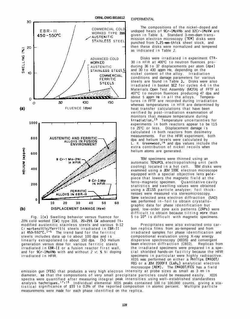
ORNL-DWG 8816612 EXPERIMENTAL
The composit ions o f t h e nickel-doped and undoped heats o f 9Cr-1MoVNb and 12Cr-1MoVW are g iven i n Table 1. Standard 3-mm-diam t rans- mission e l e c t r o n microscopy (TEM) d i sks were punched from 0.25-mn-thick sheet stock, and then these d isks were normalized and tempered as i nd i ca ted i n Table 2 .
Disks were i r r a d i a t e d i n experiment CTR- 30 i n H F I R a t 400°C t o neutron f luences pro- ducing 36 t o 37 displacements per atom (dpa) and 30 t o 430 appm He, depending on t h e n i cke l content o f t h e a l l o y . I r r a d i a t i o n cond i t ions and damage parameters f o r var ious s tee l s are found i n Table 3. Disks were a l so i r r a d i a t e d i n basket 1E2 f o r cycles 4-6 i n t h e Ma te r ia l s Open Test Assembly (MOTA) of FFTF a t 407°C t o neutron f luences producing 47 dpa and about 5 appm He i n a l l t h e a l l oys . Tempera- t u r e s i n FFTF are recorded dur ing i r r a d i a t i o n whereas temperatures i n H F I R are determined by heat t rans fe r ca l cu la t i ons t h a t have been v e r i f i e d by p o s t - i r r a d i a t i o n examination of monitors t h a t measure temperature dur ing i r r a d i a t i o n . I 5 Temperature u n c e r t a i n t i e s f o r experiments i n both reactors appear t o be t15 t o 25°C o r less . Displacement damage i s ca l cu la ted i n both reactors from dosimetry measurements. For t h e HFIR experiment, both dpa and hel ium l e v e l s were ca l cu la ted by L. R. Greenwood,16 and dpa values i nc lude t h e e x t r a c o n t r i b u t i o n o f n i c k e l r e c o i l s when he l ium atoms are generated.
TEM specimens were th inned us ing an automatic TENUPOL e l e c t r o p o l i s h i n g u n i t ( w i t h coo l i ng ) l oca ted i n a ho t c e l l . TEM d i sks were examined us ing a JEM l O O C e l e c t r o n microscope equipped w i t h a special o b j e c t i v e lens po le- p iece t h a t lowers t h e magnetic f i e l d a t t h e ferro-magnet ic specimen. Q u a n t i t a t i v e c a v i t y s t a t i s t i c s and s w e l l i n g values were obtained us ing a ZEISS p a r t i c l e analyzer; f o i l t h i c k - nesses were measured v i a stereomicroscopy. Some se lec ted area e lec t ron d i f f r a c t i o n (SAD) was performed i n - f o i l t o ob ta in c r y s t a l l o - graphic data fo r phase i d e n t i f i c a t i o n bu t good, low-order zone ax i s pa t te rns (ZAPS) were d i f f i c u l t t o ob ta in because t i l t i n g more than 5 t o 10' i s d i f f i c u l t w i t h magnetic specimens.
P r e c i p i t a t e s were a l so ex t rac ted onto car- bon r e p l i c a f i lms from as-tempered and from i r r a d i a t e d samples f o r phase i d e n t i f i c a t i o n and composi t ional eva lua t i on us ing X-ray energy d i spe rs i ve spectroscopy (XEDS) and convergent beam e l e c t r o n d i f f r a c t i o n (CBED). Repl icas from t h e i r r a d i a t e d specimens were prepared i n a spe- c i a l sh ie lded hands-on f a c i l i t y because t h e HFIR specimens i n p a r t i c u l a r were h i g h l y rad ioac t i ve . XEDS was performed on e i t h e r a P h i l i p s EM400Tf FEG o r a JEM 2OOOFX (LaB,) a n a l y t i c a l e l e c t r o n microscope (AEM). The EM4OOTfFEG has a f i e l d
COMMERCIAL COLD WORKED T Y P E 316 i STAINLESS S T E E L
/ A U S T E N I T I C
E B R - I I 450 - 55QT
ADVANCED COLD
AUSTENIT IC STAINLESS S T E E
0
1000
8 0 0
600
400
200
0
50 4 0 0 150
F L U E N C E (dpol
AUSTENITIC AND FERRITIC ALLOYS I N FUSION
ENVIRONMENT
8 Cr-1 MO
1 ..... ?..L .... 10 20 30 4 0 50 60
DISPLACEMENT DAMAGE (dpal
Fig . l ( a ) Swel l ing behavior versus f luence fo r 20% co ld worked (CW) t ype 316, 2 0 4 5 % CW advanced T i - modi f ied a u s t e n i t i c s t a i n l e s s s tee l s and var ious 9-12 C r m a r t e n s i t i c / f e r r i t i c s tee l s i r r a d i a t e d i n EBR-I1 a t 450-550°C.1-6 s t e e l s inc ludes data up t o about 100 dpa and i s l i n e a r l y ex t rapo la ted t o about 150 dpa. ( b ) Helium generat ion versus dose f o r var ious f e r r i t i c s tee l s i r r a d i a t e d i n EBR-I1 o r a fus ion reac to r f i r s t wa l l , and f o r 9Cr-1MoVNb w i t h and w i thou t 2 wt % N i doping i r r a d i a t e d i n HFIR.
The t r e n d band f o r t h e f e r r i t i c
emission gun (FEG) t h a t produces a very h igh e lec t ron i n t e n s i t y a t probe s izes as small as 3 nm i n diameter, so t h a t t h e composit ions o f very small p r e c i p i t a t e p a r t i c l e s could be measured e a s i l y . XEDS spectra were q u a n t i f i e d a f t e r measuring i n t e g r a l peak i n t e n s i t i e s us ing wel l- estab l ished standardless ana lys is technique^.",^^ t i s t i c a l s i g n i f i c a n c e of C10 t o 0.3% of the repor ted composit ion i n atomic percent. M u l t i p l e p a r t i c l e measurements were made fo r each phase i d e n t i f i e d on t h e rep l i ca .
I n d i v i d u a l elemental XEDS peaks contained 100 t o 100,000 counts, g i v i n g a s ta-
128
Table 1. Compositions o f 9Cr-1MoVNb and 12Cr-1MoVW heats of s tee l w i t h and wi thout n i cke l doping
Concentration,a w t % A1 1 oy Heat
Designat ion No. Cr Mo N i Mn C S i V Nb T i W N
9Cr-1MoVNb (XA 3590) 8.6 1.0 0.1 0.36 0.09 0.08 0.21 0.063 0.002 0.01 0.05
9Cr-1MoVNb-2Ni (XA 3591) 8.6 1.0 2.2 0.36 0.064 0.08 0.22 0.066 0.002 0.01 0.05
12Cr-1MoVW (XAA 3587) 12 0.9 0.4 0.5 0.2 0.18 0.27 0.018 0.003 0.54 0.02
12Cr-1MoVW-2Ni (XAA 3589) 11.7 1.0 2.3 0.5 0.2 0.14 0.31 0.015 0.003 0.54 0.02
aBalance i ron .
Table 2. Normal iz ing and tempering cond i t i ons RESULTS f o r var ious s tee l s
A1 1 oy Normal iza t ion Tempering Cav i ty Evo lu t ion and Swel l inq - FFTF I r r a d i a t i o n
9Cr-1MoVNb 0.5 h a t 1040°C 1 h a t 760°C b ias- dr iven growth), no detectab le bubbles (very small c a v i t i e s , gas-driven growth) and, there-
9Cr-1MoVNb-2Ni 0.5 h a t 1040°C 5 h a t 700°C fore, n e g l i g i b l e c a v i t y s w e l l i n g i n any of t h e 9 Cr and 12 Cr s tee l s i r r a d i a t e d i n FFTF t o
12Cr-1MoVW 0.5 h a t 1050°C 2.5 h a t 780°C 47 dpa a t 407°C. Cav i ty behavior and s t a t i s t i c s are descr ibed i n Table 4, and TEM microst ruc-
12Cr-1MoVW-2Ni 0.5 h a t 1050°C 5 h a t 7OO0C t u r e s o f 9 C r and 12 C r s t e e l s w i t h and wi thout n i c k e l doping are shown i n F ig . 2 . Some l a r g e m a t r i x voids ( 7 4 3 nm i n diameter) can be seen i n t h e 9Cr-1MoVNb s tee l [Fig. 2 ( a ) l , and some are occas iona l ly observed w i t h i n x phase p a r t i c l e s i n t h e 9Cr-1MoVNb-2Ni s tee l . Large voids ( 1 W 3 nm i n diameter) are found on l y occas iona l ly i n t h e 12Cr-1MoVW o r 12Cr-1MoVW-2Ni s tee ls .
There were very few voids ( l a rge c a v i t i e s ,
Table 3. Damage parameters and hel ium l e v e l s f o r nickel-doped and undoped 9Cr-1MoVNb and
12Cr-1MoVW s tee l s i r r a d i a t e d i n FFTF and HFIR
I r r a d i a- t i o n Damage Helium
A1 1 oy Reactor Temp. (dpa)a Content Cav i ty Evo lu t ion and Swel l inq - HFIR I r r a d i a t i o n ( " C ) ( w m ) Abundant vo id (7-30 nm i n diameter) forma-
t i o n was found i n both t h e 9Cr-1MoVNb and 12Cr- 9Cr-1MoVNb FFTF 407 47 - 5 lMoVW s tee l s and those doped w i t h 2 w t % N i
HFIR 400 36.5 30.5 a f t e r HFIR i r r a d i a t i o n a t 400°C t o 36 t o 37 dpa, as shown i n Fig. 3. Previous work on HFIR i r r a -
HFIR 400 37.2 402.5 l i s h e d t h a t vo id format ion was maximum'0 a t 9Cr-1MoVNb-2Ni FFTF 407 47 -5 d i a t i o n of these s tee l s a t 300 t o 600°C estab-
about 400°C. Very few f i n e he l ium bubbles 12Cr-1MoVW FFTF 407 47 - 5 (2-5 nm i n diameter) were detected i n t h e un-
HFIR 400 36.4 85.3 doped 9 C r and 12 Cr s tee l s desp i te increased vo id formation r e l a t i v e t o FFTF, as shown f o r
12Cr-1MoVW-2Ni FFTF 407 47 - 5 9Cr-1MoVNb a t h igher magni f ica t ion i n Fig. 4. HFIR 400 37.1 429.0 Since t h e TEM r e s o l u t i o n l i m i t f o r bubbles i s
about 1.5 nm, these s tee l s cou ld con ta in sub- c r i t i c a l bubbles. By cont ras t , t h e n i c k e l - doped s t e e l s w i t h much more helium, a l so had much h igher concentrat ions o f f i n e bubbles than found than found i n FFTF, as shown fo r 9Cr-
allisplacement - dpa c a l c u l a t i o n inc ludes t h e e f f e c t o f n i cke l reco i l s .
1MoVNb-2Ni i n F ig . 5. Cav i ty behavior i s descr ibed and q u a n t i t a t i v e m ic ros t ruc tu ra l data are presented i n Table 4.
Swel l ing due t o c a v i t i e s was 0.3 t o 0.35% i n t h e 9Cr-1MoVNb and 9Cr-1MoVNb-2Ni s tee l s , and s l i g h t l y less, 0.23 t o 0.25%. i n t h e 12Cr-1MoVW and 12Cr-1MoVW-2Ni s tee ls . l e v e l s of swel l ing , c lose r i nspec t i on of m ic ros t ruc tu ra l d e t a i l s suggests add i t i ona l i n s i g h t i n t o t h e ac tua l stage o f vo id evo lu t i on t h a t each specimen i s exper iencing, which i n t u r n i s important t o any pro- j e c t i o n s of behavior a t h igher doses.
While these are no t a larming ly h igh
The s w e l l i n g i n t h e 9Cr-1MoVNb and 12Cr-1MoVW s tee l s i s p r i m a r i l y
Table 4. Quan t i t a t i ve c a v i t y s t a t i s t i c s determined v i a TEM fo r 9Cr and 12Cr s tee l s i r r a d i a t e d i n HFIR and FFTF
Cav i ty S t a t i s t i c s Tota l Cav i ty Character (Average) Cav i ty
Volume Ra t io A l l o y Diameter Densi ty Comnents Swell i ng
(nm) W3) ( a )
9Cr-1MoVNb 9Cr-1MoVNb-2Ni 12Cr-1MoVW 12Cr-1MoVW-2Ni
9Cr-1MoVNb
9Cr-1MoVNb-2Ni
12Cr-1MoVW
12Cr-1MoVW-2Ni
9.2
3.8 12
12.5
3.5 9
FFTF I r r a d i a t i o n a t 407°C t o 47 dpa
A few detectab le voids ( 7 4 3 nm diam) A few detectab le voids ( 7 4 3 nm diam) A few detectab le voids (1-3 nm diam) A few detectab le voids ( 1 W 3 nm diam)
HFIR I r r a d i a t i o n a t 400°C t o -37 dpa
2.71 x l o z 1
1.6 x IOz2 2.5 x l oz1
2.2 x 10²¹
3.5 x 10²² 1.6 x IOz1
Few f i n e c a v i t i e s below -3 nm diam, somewhat nonuniform s p a t i a l d i s t r i - but ion. Many 10 t o 20-nm-diam voids
F ine bubbles Larger voids
Abundant f i n e c a v i t i e s and a smal ler popu la t ion of l a r g e r voids. C r i t i c a l s i z e appears t o be about -5 nm (diam). Voids range up t o 22 um i n diameter, bu t many are i n t h e 10 t o 1 5 pm range.
-0.3 0.04
0.35 0.33
Some f i n e cav i t i es , but many 8 t o 20 nm (diam) voids, w i t h some i n t h e 20 t o 30 nm range i n l a r g e r subgrains. Some- 0.23 0.13 what nonuniform d i s t r i b u t i o n w i t h most voids i n l a r g e s t subgrains, bu t a l l subgrains have some voids.
Fine bubbles Larger voids
Abundant f i n e c a v i t i e s and a sparse, non- uni form d i s t r i b u t i o n o f l a r g e r voids, many w i t h i n l a r g e r subgrains.
0.25 0.45
due t o voids. show broad t a i l s a t l a r g e r s izes i n these undoped s tee l s (Fig. 6 ) . Ca lcu la t ions account ing f o r t h e hel ium needed t o fill these c a v i t i e s ( c a v i t y character r a t i o - generated appm Helca lcu la ted appm He fo r e q u i l i b r i u m bubbles) i n d i c a t e t h a t these c a v i t i e s are q u i t e empty, suggesting t h a t they are voids; any accommodation of hel ium i n unresolved bubbles would fu r the r support t h i s assessment. 9Cr-1MoVNb-2Ni and 12Cr-1MoVW-2Ni s tee l s i s due t o t h e abundant popula t ions of both f i n e hel ium bubbles and voids. Bubbles cause about 50 t o 66% of t h e measured s w e l l i n g i n t h e nickel-doped s tee ls . While t h e generated hel ium can be accommodated i n t h e v i s i b l e c a v i t y microst ruc ture , a l l t h e hel ium cou ld e a s i l y f it i n t o t h e smal les t c a v i t i e s as e q u i l i b r i u m hel ium bubbles, again suggesting t h a t t h e l a r g e r c a v i t i e s are probably voids.
The nickel-doped 9 Cr and 12 C r s tee l s w i t h 400 t o 430 appm He both have h igh concentrat ions o f f i n e bubbles ( 2- 5 nm diam, 1.6-3.5 x 10” w i t h much lower concentrat ions ( 6 and 22 t imes less , respec- t i v e l y ) of l a r g e r voids (see Table 4). Void formation i n t h e presence of these dense popula t ions of f i n e bubbles appears t o be s i m i l a r o r somewhat re tarded i n t h e nickel-doped r e l a t i v e t o t h e undoped s tee ls . Cav i ty s i ze d i s t r i b u t i o n s i n both nickel-doped s tee l s [Fig. 6(b) and 6 ( d ) l show s h i f t s i n t h e s i z e d i s - t r i b u t i o n s toward smal ler s izes. The 9Cr-1MoVNb-2Ni s tee l i n p a r t i c u l a r has fewer voids i n t h e 17-35-nm- diam s i z e range than does t h e 9Cr-1MoVNb s tee l . nonuni formi ty i n t h e undoped s t e e l ) are s i m i l a r i n t h e 9 C r s tee l s w i t h and wi thout n i cke l , bu t t he re are no t i ceab ly fewer voids i n t h e 12 C r s tee l w i t h n i c k e l as compared t o t h e one wi thout . there fore , t h a t t h e increased dens i t y of bubble-sinks was a f fec t i ng vo id formation and growth i n t h e N i - doped s tee l s w i t h t h e h ighest hel ium contents.
Cav i ty s i ze d i s t r i b u t i o n s p l o t t e d from t h e l a r g e r c a v i t i e s observed i n t h e m ic ros t ruc tu res
Swel l ing i n t h e
The vo id dens i t i es (neg lec t i ng t h e patchy, s p a t i a l
It would appear,
GitNL-PHOTO 10464-88 ORNL-PHOTO 1046548
Fig. 2. Mic ros t ruc ture o f var ious 9 C r and 12 C r m a r t e n s i t i c l f e r r i t f c s tee ls i r r a d i a t e d i n FFTF a t 407"C, t o a dose of 47 dpa and hel ium l e v e l o f 7-5 appm. (a) 9Cr-1MoVNb (b ) 9Cr- 1MoVNb-2Ni , ( c ) 12Cr-lMoVW, and (d) 12Cr-IMoVW- 2Ni.
Fig. 3. Mic ros t ruc ture of var ious 9 C r and 12 C r m a r t e n s i t i c l f e r r i t i c s tee l s i r r a d i a t e d i n HFIR a t 40OoC t o a dose of -37 dpa and hel ium l e v e l s t h a t depend on n i cke l content. (a) 9Cr- lMoVNb (30.5 appm), (b) 9Cr-1MoVNb-PNi (402.5 appm), ( c ) 12Cr-1MoVW (85.3 appm), and (d ) 12Cr-1MoVW- 2Ni (429 appm)
Fig. 4. Mic ros t ruc ture a t h igher magn i f i ca t ion i n k inemat ical con t ras t i s used t o show f i n e hel ium bubbles, when present, and l a r g e r voids i n 9Cr-1MoVNb i r r a d i a t e d i n (a) FFTF a t 407OC t o 47 dpa and 5 appm He and (b ) HFIR a t 4OO0C t o 36.5 dpa and 30.5 appm He.
181
ORNL-PHOTO 10467-88 Cav i ty s i ze d i s t r i b u t i o n s determined from higher magn i f i ca t ion p i c t u res t h a t inc lude bo t t f i n e bubbles and l a rge voids from the 9Cr- 1MoVNb-2Ni and 12Cr-1MoVW-2Ni s t e e l s are shown i n Fig. 7. These d i s t r i b u t i o n s w i t h t h e i r l a rge peaks a t small s i zes and broad t a i l s t o l a r g e r s izes emp i r i ca l l y suggest t h a t t he c r i - t i c a l c a v i t y s i ze i s about 5 nm i n diameter i n t h e 9Cr-1MoVNb-ENi s tee l , and i s about 5 t o 6 nm i n diameter i n t he 12Cr-1MoVW-2Ni s tee l . Cav i t i e s below t h i s s i ze would be s table, sub- c r i t i c a l bubbles, wh i l e t he l a r g e r c a v i t i e s would have converted from bubbles t o unstable, rap id ly- growing voids. By con t ras t t o t he s t ee l s w i t h m r e helium, c r i t i c a l c a v i t y s izes i n t he undoped s tee l s i r r a d i a t e d i n HFIR o r an3 of t he s t ee l s i r r a d i a t e d i n FFTF appear t o be below t he TEM reso lu t i on l i m i t , o r less than 1.5 nm i n diameter.
To sumnarize, t he e f f ec t s o f increased hel ium generat ion on vo id and bubble formation
Fig. 5. M ic ros t ruc tu res of 9Cr-1MoVNb-2Ni i r r a - can best be seen by comparing FFTF and HFIR d i a ted i n (a ) FFTF a t 407OC t o 47 dpa and 5 appm He i r r a d i a t i o n f o r each heat of s tee l . I n t he and (b) HFIR a t 400Y t o 37.2 dpa and 402.5 appm He. 9 C r and 12 C r s t ee l s w i thou t n i cke l doping, a Higher magn i f i ca t ion i n k inemat ica l con t ras t shows modest increase i n hel ium generat ion causes a
rnnciAm*ahln i n r r m a c a in u n i A fnmnxt inn In
I I I I I I 9Cr - lMoVNb - 2Ni HFIR. 400'C. 37dpa
(b) - (LARGER CAVITIES)
I
I
3 t
20
10
z Q e- 3 E O IT + 9 30 0
b 8
20
10
0
9Cr - IMoVNb HFIR. 4W'C. 37dpa (LARGER CAVITIES)
I I I I I I I
12Cr - lMoVW ~
HFIR. 400'C. 37dpa (LARGER CAVITIES)
50 40 0 10 20 30
c"I,*I "" ,.. , ,,.,, cy_.c , ,, ." ." . ", ,,,"". "... . ...
I I I I I I I
Id1 12Cr-1MoVW-2Ni 1-1
HFIR. 400°C. 37dpa (LARGER CAVITIES)
0 10 20 30 40 50 CAVITY DIAMETER (nm)
Fig. 6. Cav i t y s i ze d i s t r i b u t i o n histograms f o r var ious s t ee l s i r r a d i a t e d i n HFIR, from quan- t i t a t i v e analys is o f low magn i f i ca t ion photomicrographs which inc lude t he l a rges t c a v i t i e s (very f i ne bubbles would be obscure).
1SZ
50 30
40 z
2 30 z Y
0 10 ae
E 20
LL 020
+
IO
0 0
0 10 20 0 10 2u CAVITY DIAMETER (nm)
Fig. 7. Cav i t y s i ze d i s t r i b u t i o n histograms from q u a n t i t a t i v e analys is o f h igher magn i f i ca t ion photomicrographs which inc lude t he smal lest v i s i b l e hel ium bubbles.
t h e 9 C r and 12 C r s t ee l s w i thou t n i c k e l doping, a m d e s t increase i n hel ium generat ion causes a con- s iderab le increase i n vo id formation. I n t he 9 C r and 12 C r s tee ls w i t h n i cke l doping, a l a r g e increase i n hel ium generat ion not on ly increases vo id format ion i n HFIR r e l a t i v e t o FFTF, bu t a l so g rea t l y increases f i n e bubble nuc leat ion. Both groups of samples appear t o be s t i l l i n t he e a r l y stages o f vo id formation. The c r i t i c a l c a v i t y s i ze appears t o be below t he r eso lu t i on l i m i t o f the microscope i n a l l o f t he FFTF- i r rad iated s tee l s as we l l as i n t he HFIR- i r rad iated s tee l s w i thou t n i cke l . I f t h i s c r i t i c a l s i z e does not change. then i t i s easy f o r m r e voids t o form as m r e hel ium i s generated. I n t he n i c k e l doped s tee l s i r r a d i a t e d i n HFIR, however, t he c r i t i c a l c a v i t y s i ze becomes much l a r g e r wh i l e vo id f o r - mation becomes somewhat more d i f f i c u l t . These observat ions cons i s t en t l y suggest t h a t t he h igher t o t a l dens i t i e s of hel ium bubbles are becoming dominant s inks t o h inder vo id formation.
D i s l oca t i on and Subqrain Boundary S t ruc tu re Evo lu t ion - FFTF and HFIR I r r a d i a t i o n
t he re i s l i t t l e o r no d i f ference i n t he d i s l o c a t i o n of subgrain s t r uc tu re evo lu t i on o f a given s tee l i r r a d i a t e d i n FFTF and HFIR. m ic ros t ruc tu re among t he var lous heats o f s tee l t h a t depend on a l l o y composition and/or tempering con- d i t i ons .
A l l of t he i r r a d i a t e d s tee l s had moderately t o densely tangled d i s l o c a t i o n networks t h a t were spa- t i a l l y q u i t e uniform, w i t h a few l a r g e r loops v i s i b l e . The 9Cr-1MoVNb s tee l i r r a d i a t e d i n HFIR a t 400'C had a t o t a l d i s l o c a t i o n dens i t y ( A ) of 6 x 10¹³ m+, wh i l e t he 9Cr-1MoVNb-PNi had a h igher A o f 4 x lo1" K2. un i fo rm from g ra i n t o gra in, w i t h t he degree o f non- uni formi ty depending on t he tempering condi t ions. The 9Cr-1MoVNb s tee l tempered f o r 1 h a t 76OoC was m s t non-uniform. This s t ee l had a network d is loca- t i o n dens i t y ( A ) t h a t va r ied from 1 t o 7 x 10¹³ m+ w i t h i n l a r g e r subgrains o f t he tempered martens i te l a t h s t ruc tu re . h igh w i t h i n t he p lanar honeycomb arrays of d i s l o c a t i o n network t h a t def ined most o f t he subgrain boun- dar ies. Subgrains were somewhat smaller, bu t s t i l l had s i m i l a r o r h igher d i s l o c a t i o n concentrat ions i n 9Cr-1MoVNb-2Ni tempered f o r 5 h a t 700°C.la d i s l o c a t i o n s t ruc tu re , as can be seen i n Fig. 8 f o r 9Cr-1MoVNb-2Ni i r r a d i a t e d i n FFTF. This invo lves bo th some recovery of t he as-tempered s t r u c t u r e as we l l as t he format ion o f new d i s l oca t i ons dur ing i r r a - d i a t i on . Although a de ta i l ed Burger 's vector ana lys is was not done i n t h i s work, o thers have shown t h a t un i r r ad i a ted f e r r i t i c mater ia l has network segments o f aof2 <ill>, wh i l e such mater ia l i r r a d i a t e d a t 400 t o 500°C develops a s t r u c t u r e w i t h a m ix tu re of a012 <lib and a0 (100, Burger 's v e c t ~ r s . ~ * l g Dis loca- t i o n concentrat ions i n t he 9 C r s tee ls are e i t h e r s i m i l a r o r s l i g h t l y h igher a f t e r i r r a d i a t i o n a t 400"C, bu t they are a l so s p a t i a l l y much m r e uniform compared t o un i r r ad i a ted mater ia l . Th is i s m s t l i k e l y r e l a t ed t o t he s i g n i f i c a n t coarsening of t he as-tempered l a t h sub-grain boundary s t r uc tu re t h a t a lso occurred i n t he 9 C r s t ee l s i r r a d i a t e d a t 400°C (Figs. 8 and 9).
The as-tempered g ra i n and subgrain s t r uc tu re i n var ious s t ee l s cons is ts o f l a rge p r i o r aus ten i te g ra i n boundaries and packet boundaries around groups of s i m i l a r l y a l igned martens i te la ths , w i t h both boundaries con ta in ing coarse M23C6 p r e c i p i t a t e s along them, and low-angle l a t h subgrain boundaries, which occas iona l l y have coarse M23C6 o r MC p a r t i c l e s a t j u n c t i o n po in ts . The l a t h subgrain boundaries w i t h i n t h e packet boundaries are almost completely removed dur ing i r r a d i a t i o n of t he 9 Cr s tee l s i r r a d i a t e d i n
By con t ras t t o t he la rge di f ferences i n c a v i t y behavior between s tee l s i r r a d i a t e d i n FFTF and HFIR,
There are, however, d i f fe rences i n t he evo lu t ion o f t h i s p o r t i o n o f t he
The d i s l o c a t i o n s t r uc tu re i n t he as-tempered mater ia l was, by comparison, s p a t i a l l y q u i t e non-
The d i s l o c a t i o n dens i t y was rmch l ess i n many o f t he smal ler subgrains, bu t A was q u i t e
I n both 9 C r s tee ls , i r r a d i a t i o n obv ious ly a l t e r e d t he
ORNL-PHOTO 10463-88
Fig. 8. Lower magni f icat ion TEM of 9Cr-1MoVNb- 2Ni showing p r i o r aus ten i te g ra i n s i z e and l a t h packet and subgrain boundary s t ruc tu res i n (a ) as-tempered, and i n (b ) FFTF i r r a d i a t e d (407°C. 47 dpa, -5 appm He mater ia l .
ORNL-PHOTO 10462-88
Fig. 9. Higher magn i f i ca t ion TEM o f 9Cr-1MoVNb- 2Ni showing l a t h subgrain boundary and i n t r a - l a t h d i s l o c a t i o n s t ruc tu res i n (a) as-tempered, and ( b ) FFTF i r r a d i a t e d (407"C, 47 dpa, -5 appm He) mater ia l .
e i t h e r HFIR o r FFTF a t about 4OO0C, as seen f o r 9Cr-1MoVNb-ZNi i n Figs. 8 and 9. This can e a s i l y be seen i n TEM because la rge regions of i r r a d i a t e d mater ia l have uniform contrast , whereas t h e as- tempered s tee l has a speckled appearance because con t ras t cond i t ions change w i t h t he s l i g h t angular m isor ien ta t ions from l a t h t o l a t h (Figs. 8 and 9).
d i a t ed 9 C r s tee ls , t he as-tempered l a t h subgrain boundary s t r u c t u r e i n both of t he 12 C r s t ee l s remains q u i t e s t ab le dur ing i r r a d i a t i o n i n e i t h e r FFTF o r HFIR a t 400'C. Wi th in t he l a r g e r sub- gra ins o f 12Cr-1MoVW tempered f o r 2.5 h a t 780°C, A i s very low, <I x 10 l2 M - ~ . A f t e r i r r a d i a t i o n i n HFIR a t 4OO0C, A i s 3.5 x 10¹⁴ K2, so t h a t t he d i s l o c a t i o n concentrat ion i n t h i s s t ee l has increased considerably dur ing i r r a d i a t i o n , as shown i n Fig. 10. The 12Cr-1MoVW-2Ni s t ee l tem- pered f o r 5 h a t 7OO0C had a f i n e r subgrain s i ze and h igher d i s l o c a t i o n content w i t h i n t h e sub- gra ins p r i o r t o i r r a d i a t i o n , so t h a t i r r a d i a t i o n produced on ly a modest increase. if any, i n t he d i s l oca t i on content of t h i s mate r ia l .
I n comparison t o t he behavior of t he i r r a -
I n sumnary, i r r a d i a t i o n a t about 4 0 0 T c l e a r l y increases t he d i s l o c a t i o n concentrat ion i n t h e I2Cr-IMoVW s tee l t h a t had a low d i s l o c a t i o n content before-hand by v i r t u e of i t s tempering cond i t ions (h igher temperature, longer t ime). I r r a d i a t i o n d i d no t produce l a rge increases i n d i s l o c a t i o n content of t he other s t ee l s (12Cr-1MoVW-PNi, gCr-lMoVNb, 9Cr-1MoVNb-PNi), which had higher as-tempered d i s l o c a t i o n contents t o begin wi th . I r r a d i a t i o n d id, however, evolve a more un i fo rm d i s l o c a t i o n network s t r u c t u r e t h a t inc ludes some loops and probably a m ix tu re of Burger 's vectors. I r r a d i a t i o n appeared t o cause almost complete recovery o f t he as-tempered l a t h subgrain boundary s t r uc tu re i n both t he 9 C r s tee ls , wh i l e such subgrain boundaries remained s tab le i n t he 12 C r s t ee l s dur ing i r r a d i a t i o n . A l l aspects of d i s l oca t i on l subg ra i n boundary evo- l u t i o n were i d e n t i c a l when comparing the same s t e e l s i r r a d i a t e d i n HFIR and FFTF.
Phase Formation and S t a b i l i t y - As-Tempered P r e c i p i t a t i o n
Tempering f o r t he range o f cond i t ions shown i n Table 2 produced carb ide p r e c i p i t a t i o n t h a t d i f f e red between 9 C r and 12 C r s tee ls , but was not a f f ec ted by n i cke l doping. Table 5 l i s t s phases and t h e i r r e l a t i v e abundances, wh i l e Tables 6 and 7 g ive t h e compositions of the M23C6 and MC phases, respec t i ve ly , as determined by XEDS ana lys is on carbon f i l m e x t r a c t i o n rep l i cas .
The 9Cr-1MoVNb and 9Cr-1MoVNb-2Ni s t ee l s have abundant coarse M23C6 and some f i n e r MC d i s t r i b u t e d along t he p r i o r aus ten i te g ra i n boundaries, along some o f t he l a t h subgrain boundaries, and a t j u n c t i o n po in ts . The Mz& phase conta ins p r i m a r i l y C r w i t h some Fe and l esse r amounts of Mo and V (Table 6). Most o f t he f i n e r MC phase p a r t i c l e s are mainly r i c h i n V ( S O w t %) w i t h some C r and Nb. A few MC par- t i c l e s have more Nb ( % O X ) than V (26-333) w i t h some C r (Table 7). Bulk ex t r ac t i on techniques measured 1.4 wt % o f t o t a l carb ide p r e c i p i t a t e s i n t he 9Cr-1MoVNb (refs . 7.8) and broad-beam AEM ana lys is of r e l a - t i v e phase f r a c t i o n s on e x t r a c t i o n r ep l i cas i nd i ca tes t h a t 85% of t he p r e c i p i t a t e i s M23C6 and 15% i s MC. P r e c i p i t a t e phases, f rac t ions , and compositions were about t he same i n 9Cr-1MoVNb and 9Cr-1MoVNb-ZNi s teels .
I
I
Fig. 10. Higher magni f ica t ion TEM o f 12Cr- lMoVW showing l a t h subgrain boundary and i n t r a - l a t h d i s l o c a t i o n s t ruc tures i n (a) as-tempered, and (b) HFIR i r r a d i a t e d (4OO0C, 36 dpa. 85 appm He) mater ia l .
The 12Cr-1MoVW s tee l contains more carbide pre- c i p i t a t i o n (3.5 wt %) a f t e r tempering than the 9 C r s tee ls , w i t h r e l a t i v e amounts o f 99% M23C6 and 1% MC. A l l t he MC i s V- r ich because these s t e e l s conta in no Nb. Although a lower tempering temperature re f ines the MZ3C6 s i ze d i s t r i b u t i o n somewhat i n the 12Cr- lMoVW-2Ni. t h e r e i s otherwise no obvious e f f e c t o f n i c k e l doping on t h e p r e c i p i t a t i o n .
Phase Formation and S t a b i l i t y - Evolu t ion of M2& Dur ing FFTF and HFIR I r r a d i a t i o n
The as-tempered, coarse M& p r e c i p i t a t i o n appears t o become unstable dur ing i r r a d i a t i o n of 9 Cr-1MoVNb and 9Cr-1MoVNb-PNi a t 400 t o 410'C i n FFTF and HFIR, d i sso l v ing a t l a t h subgrain boundaries and somewhat along packet boundaries. Th is phase i n s t a b i l i t y i s co inc ident w i t h the coarsening of t he subgrain boundary s t r u c t u r e noted above. While no add i t i ona l p r e c i p i t a t i o n occurs i n the 9Cr-1MoVNb s tee l dur ing i r r a d i a t i o n [see Figs. 2(a), 3(a), and 41, abundant formation of new, coarse M23C6 p a r t i c l e s occurs un i formly w i t h i n the l a rge ma t r i x regions o f t he 9Cr-1MoVNb-2Ni s tee l t h a t are f ree o f p r i o r
Table 5. P rec iD i ta te ohase i d e n t i f i c a t i o n for 9Cr and 12Cr s t e e l s i r r a d i a t e d i n HFIR and FFTF
Phases a f t e r I r r a d i a t i o n a
Phases a f t e r A l l o y Tempering HFIR FFTF
(400'C. (407OC, 37 dpa) 47 dpa)
Phases a f t e r A l l o y Tempering- HFIR FFTF
(400'C. (407OC, 37 dpa) 47 dpa)
Connnents
9Cr-1MoVNb M23C6 (85%)b ~ 2 3 ~ 6 ~ 2 3 ~ 6 P a r t i a l d i s s o l u t i o n of coarse M ~ ~ c ~ p a r t i c l e s and coarsen-
ac i cu la r needles are found only i n FFTF- irradiated mater ia l . MC composition i s modif ied - more C r , l ess V.
MC (15%) MC Mc i n g of f i n e r MC p a r t i c l e s . Traces o f very f i n e M2X MzX
9Cr-1MoVNb-PNi M& Some d i s s o l u t i o n and coarsening o f o r i g i n a l as-tempered MgC (TI) M23Cg p a r t i c l e s and abundant p r e c i p i t a t i o n o f new M23C6 MC p a r t i c l e s w i t h s l i g h t l y modif ied composition. MC evo lu t ion
and modi f ica t ion are s i m i l a r t o t h a t mentioned above. Many f i ne M6C p a r t i c l e s form i n both reactors, but l a rge M6C
MzX
p a r t i c l e s are a l so found i n FFTF- irradiated mater ia l . Some la rge M2X p a r t i c l e s are a l so found a t boundaries i n FFTF- i r r a d i a t e d mater ia l , bu t no f i ne needles.
12Cr-1MoVW M23C6 (99%) M23C6 M23C6 As-tempered M23C6 i s s tab le wh i l e MC content increases dur- MC (1%) M6C (n)c M6C TI)^ i n g i r r a d i a t i o n . MC composition i s modif ied. Abundant,
MC MC f i n e p a r t i c l e s are found throughout the matr ix , s i m i l a r t o M6C mentioned above. I n HFIR, these p a r t i c l e s are very r i c h i n S i and Cr , but i n FFTF they have somewhat more C r and less S i .
12Cr-1MoVW-PNi M23C6 (99%) M23C6 M2& P a r t i a l d i s s o l u t i o n of as-tempered M23C6 occurs and some M6C (1%) M6C (n) M6C (TI) coarse M6C forms t o replace it, more so i n HFIR than i n
MC MC FFTF. Abundant, f i n e M6C forms i n both reactors and m r e MC develops dur ing i r r a d i a t i o n w i t h the same composit ional modi f i cat ions mentioned above.
aXEOS ana lys is on ex t rac t i on rep l i cas p lus some SAD and CBED analysis.
bRela t ive phase f rac t i ons determined v i a broad-beam XEOS measurements.
CMainly C r - and S i- r ich .
185
1.6 0.6 62.6 16.6 2.3 2.3 33 9.2
9Cr-lMoVNb-ZNi, As-Tempered, 5 h a t 700'C
0.8 n.d. n.d. 14.0 0.8 7 0.8 n.d. n.d. 62.4 0.5 2
gCr-lMoVNb, FFTF, 407"C, 47 dpa
4.8 0.5 n.d. 2.9 1.2 4 6.5 0.4 n.d. 3.0 1.0 3 5.3 0.6 n.d. 40.3 1.1 4
9Cr-lMoVNb-PNi, FFTF, 407'C. 47 dpa
8.7 3.6 n.d. 7.4 1.5 4 6.3 3.0 n.d. 13.2 1.3 3 5.0 6.2 n.d. 45.5 1.5 3
9Cr-IMoVNb, HFIR, 400°C, 36.5 dpa
5.5 0.4 n.d. 7.4 1.4 9 4.5 0.8 n.d. 46.1 3.5 2
9Cr-lMoVNb-ZNi, HFIR, 400'C, 37 dpa
5.5 6.9 n.d. 5.6 1.4 4 6.3 2.5 n.d. 9.6 1.6 4
0.3 0.6 69.2 14.0 1.3 2.1 26.5 5.3
V-rich, small, 17-60 nm Nb-rich, same
V-rich, large, 7M-160 nm V- rich. small, 17-50 nm Nb-rich, small
V-rich, large, >30 nm V-rich, small, 9-25 nm Nb-rich, large, >90 nm
V-rich, 30-120 nm Nb-rich. same
V-rich, large, 40-80 nm V-rich, small, I M 5 nm
2.3 n.d. 33.7 52.7 2.8 0.1 35.1 49.4 0.1 0.1 14.9 35.8
4.4 0.2 37.5 35.0 ~.~ ~.~ ~~~~
3;7 0.4 38.5 31.1 3.2 1.1 9.8 21.6
3.2 0.5 34.9 46.5 0.4 1.2 8.8 34.2
1.4 0.2 44.5 38.7 1.6 0.5 35.3 41.3
1.6 1.1
I gCr-lMoVNb, As-Tempered. 1 h a t 760'C
!xtracted
nmnents
150 nm diam L50 nm diam
I50 nm diam. along
?O(MOO-nm l ong la ths , i t r i x
!S
150 nm diam. along !S !00-500-nm long la ths , i t r i x
b C r s t e e l specimens
mnnentsb
n.d. 0.1
n.d. 14.2 n.d. 49
1.1 1.3
6 2
V-rich, small, 17-60 nm Nb-rich, same I
acornposition o f m e t a l atoms heavier than A I . b p a r t i c l e s ize, e i t h e r diametre fo r equiaxed o r l a r g e r dimension fo r other morphologies.
196
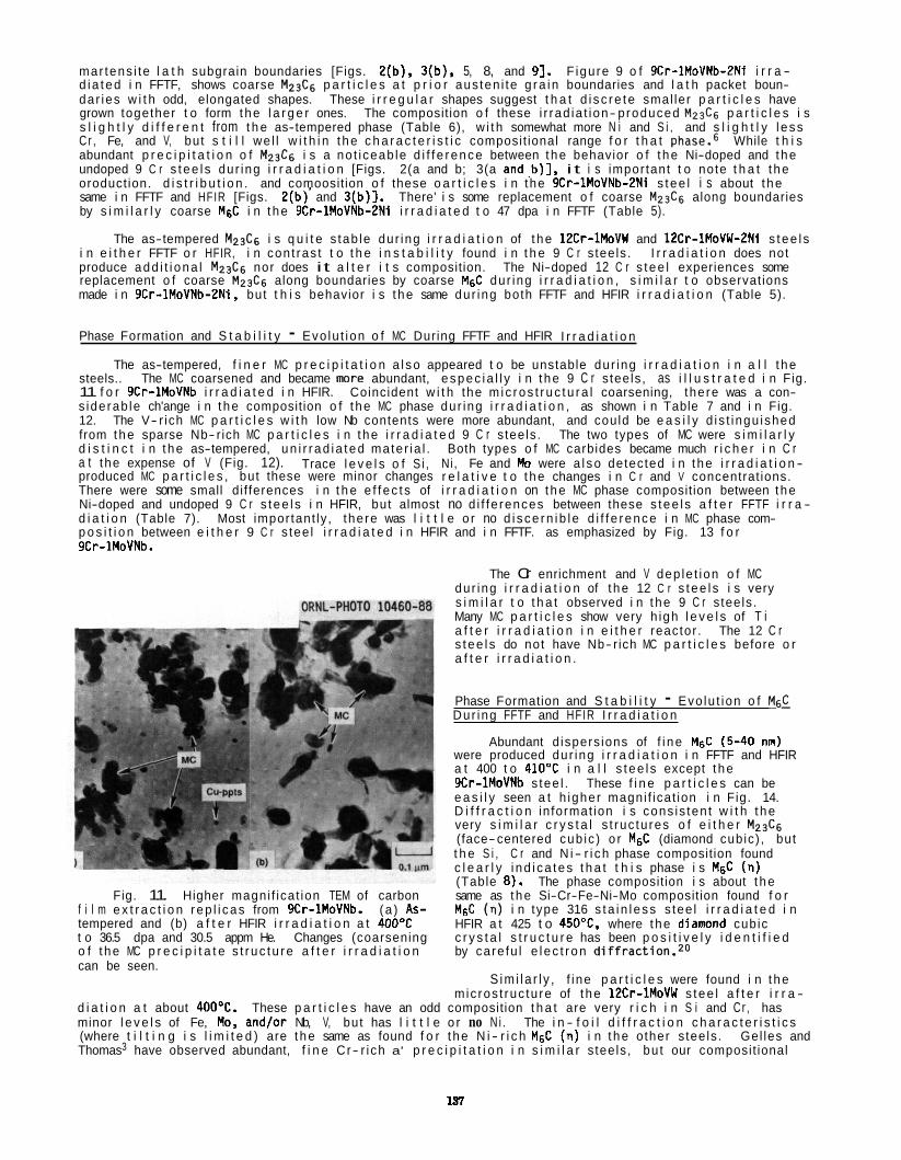
mar tens i te l a t h subgrain boundaries [Figs. 2(b), 3(b), 5, 8, and 91. F igure 9 o f 9Cr-1MoVNb-2Ni i r r a - d ia ted i n FFTF, shows coarse M23Cg p a r t i c l e s a t p r i o r aus ten i te g ra i n boundaries and l a t h packet boun- dar ies w i t h odd, elongated shapes. These i r r e g u l a r shapes suggest t h a t d i s c re te smal ler p a r t i c l e s have grown together t o form t he l a r g e r ones. s l i g h t l y d i f f e r e n t from t h e as-tempered phase (Table 6), w i t h somewhat more N i and S i , and s l i g h t l y l ess C r , Fe, and V, but s t i l l we l l w i t h i n t he c h a r a c t e r i s t i c composit ional range f o r t h a t phase.6 While t h i s abundant p r e c i p i t a t i o n o f M23C6 i s a no t i ceab le d i f f e rence between t he behavior o f t he Ni-doped and t he undoped 9 C r s t ee l s dur ing i r r a d i a t i o n [Figs. 2(a and b; 3(a and,b) l , i t i s impor tant t o note t h a t t he oroduct ion. d i s t r i b u t i o n . and comoosition o f these o a r t i c l e s i n the 9Cr-1MoVNb-PNi s t ee l i s about t he
The composition o f these i r rad ia t ion- produced M2& p a r t i c l e s i s
same i n FFTF and HFIR [Figs. 2(b) ' and 3 (b ) l . There' i s some replacement o f coarse M23Cg along boundaries by s i m i l a r l y coarse MgC i n t he 9Cr-1MoVNb-2Ni i r r a d i a t e d t o 47 dpa i n FFTF (Table 5).
The as-tempered M23C6 i s q u i t e s tab le dur ing i r r a d i a t i o n of t he 12Cr-1MoVW and 12Cr-1MoVW-ZNi s t ee l s i n e i t h e r FFTF o r HFIR, i n con t ras t t o t h e i n s t a b i l i t y found i n t h e 9 C r s tee ls . I r r a d i a t i o n does not produce add i t i ona l M2& nor does i t a l t e r i t s composition. The Ni-doped 12 C r s t ee l experiences some replacement o f coarse M23C6 along boundaries by coarse MgC dur ing i r r a d i a t i o n , s i m i l a r t o observat ions made i n 9Cr-lMoVNb-ZN1, but t h i s behavior i s t he same dur ing both FFTF and HFIR i r r a d i a t i o n (Table 5).
Phase Formation and S t a b i l i t y - Evo lu t ion o f MC During FFTF and HFIR I r r a d i a t i o n
The as-tempered, f i n e r MC p r e c i p i t a t i o n a l so appeared t o be unstable dur ing i r r a d i a t i o n i n a l l t he steels.. The MC coarsened and became more abundant, espec ia l l y i n t he 9 C r s tee ls , as i l l u s t r a t e d i n Fig. 11 f o r 9Cr-1MoVNb i r r a d i a t e d i n HFIR. Coincident w i t h the m i c ros t r uc tu ra l coarsening, there was a con- s iderab le ch'ange i n t he composition o f t he MC phase dur ing i r r a d i a t i o n , as shown i n Table 7 and i n Fig. 12. The V- r ich MC p a r t i c l e s w i t h low Nb contents were more abundant, and could be e a s i l y d is t ingu ished from the sparse Nb- rich MC p a r t i c l e s i n t he i r r a d i a t e d 9 C r s tee ls . The two types of MC were s i m i l a r l y d i s t i n c t i n t he as-tempered, un i r r ad i a ted mater ia l . Both types o f MC carbides became much r i c h e r i n C r a t the expense of V (Fig. 12). Trace l e v e l s o f S i , Ni , Fe and Mo were a l so detected i n t he i r r a d i a t i o n - produced MC p a r t i c l e s , but these were minor changes r e l a t i v e t o t he changes i n C r and V concentrat ions. There were some small di f ferences i n t h e e f f ec t s of i r r a d i a t i o n on t he MC phase composition between t he Ni-doped and undoped 9 C r s t ee l s i n HFIR, but almost no d i f fe rences between these s tee l s a f t e r FFTF i r r a - d i a t i o n (Table 7). Most impor tant ly , the re was l i t t l e o r no d i sce rn i b l e d i f f e rence i n MC phase com- p o s i t i o n between e i t h e r 9 C r s tee l i r r a d i a t e d i n HFIR and i n FFTF. as emphasized by Fig. 13 f o r 9Cr-1MoVNb.
Fig. 11. Higher magni f icat ion TEM of carbon f i l m e x t r a c t i o n r ep l i cas from 9Cr-1MoVNb. (a ) As- tempered and (b) a f t e r HFIR i r r a d i a t i o n a t 4 0 0 T t o 36.5 dpa and 30.5 appm He. Changes (coarsening o f t he MC p r e c i p i t a t e s t r uc tu re a f t e r i r r a d i a t i o n can be seen.
The Cr enrichment and V dep le t ion o f MC dur ing i r r a d i a t i o n of t he 12 C r s t ee l s i s very s i m i l a r t o t h a t observed i n t he 9 C r s tee ls . Many MC p a r t i c l e s show very h igh l e v e l s of T i a f t e r i r r a d i a t i o n i n e i t h e r reactor . The 12 C r s t ee l s do not have Nb- rich MC p a r t i c l e s before o r a f t e r i r r a d i a t i o n .
Phase Formation and S t a b i l i t y - Evo lu t ion o f M& Dur ing FFTF and HFIR I r r a d i a t i o n
Abundant d ispers ions of f i ne MgC (5-40 nn) were produced dur ing i r r a d i a t i o n i n FFTF and HFIR a t 400 t o 410'C i n a l l s t ee l s except t he 9Cr-1MoVNb s tee l . These f i n e p a r t i c l e s can be e a s i l y seen a t h igher magni f icat ion i n Fig. 14. D i f f r a c t i o n in format ion i s cons is ten t w i t h t he very s i m i l a r c r y s t a l s t ruc tu res o f e i t h e r M23Cg (face-centered cub ic ) o r MgC (diamond cubic) , but t h e S i , C r and N i- r i ch phase composition found c l e a r l y i nd i ca tes t h a t t h i s phase i s M6C (n) (Table 8). The phase composition i s about t he same as t he Si-Cr-Fe-Ni-Mo composition found f o r M6C (11) i n type 316 s ta i n l ess s tee l i r r a d i a t e d i n HFIR a t 425 t o 450% where t he dianond cubic c r y s t a l s t r u c t u r e has been p o s i t i v e l y i d e n t i f i e d by care fu l e l ec t r on d i f f r a c t i o n . 2 0
S im i l a r l y , f i ne p a r t i c l e s were found i n t he mic ros t ruc tu re of t he 12Cr-1MoVW s tee l a f t e r i r r a -
d i a t i o n a t about 400'C. These p a r t i c l e s have an odd composition t h a t are very r i c h i n S i and Cr , has minor l e v e l s of Fe, No, and/or Nb, V, but has l i t t l e o r no N i . The i n - f o i l d i f f r a c t i o n c h a r a c t e r i s t i c s (where t i l t i n g i s l i m i t e d ) are t he same as found f o r t he N i - r i c h MgC (n) i n t he other s teels . Thomas3 have observed abundant, f i n e Cr- r i ch a' p r e c i p i t a t i o n i n s i m i l a r s tee ls , bu t our composit ional
Gel les and
137
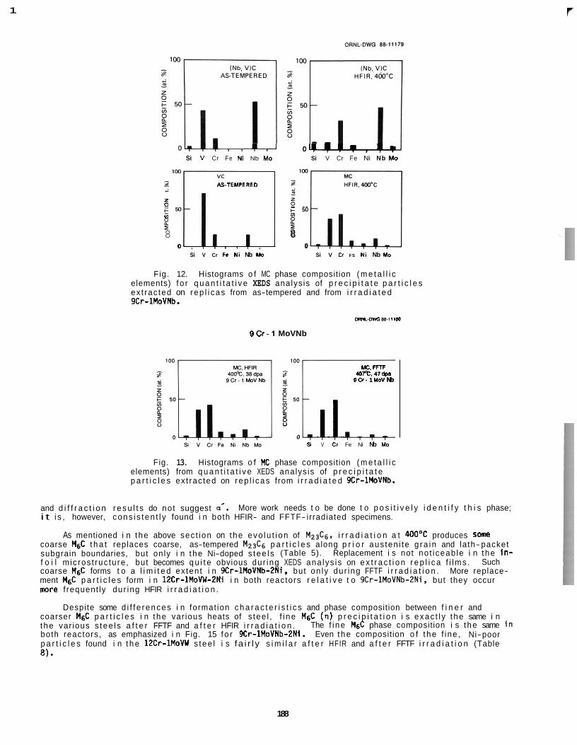
1 P
-4.4 o w . . . , . . Si V Cr Fe Ni Nb Mo Si V Cr Fe Ni Nb Mo
- ASTEMPERE0 :I,C! E 5 0
5 E "
8 8
(0
g 0 0
Si V Cr Fe Ni Nb Mo Si V Cr FS Ni Nb Mo
Fig. 12. Histograms o f MC phase composition ( m e t a l l i c elements) f o r q u a n t i t a t i v e XEDS analys is of p r e c i p i t a t e p a r t i c l e s ex t rac ted on rep l i cas from as-tempered and from i r r a d i a t e d 9Cr-1MoVNb.
ORM-DIIG m-3 ltdD
9 C r - 1 MoVNb
Mc. FFTF 407%. 47 apa
9Cr - 1 MoV Nb
ll 407%. 47 apa
9Cr - 1 MoV Nb
8 0
Y V Cr Fe Ni Nb Mo
Fig. 13. Histograms o f MC phase composition ( m e t a l l i c elements) from q u a n t i t a t i v e XEDS analys is of p r e c i p i t a t e p a r t i c l e s ex t rac ted on rep l i cas from i r r a d i a t e d 9Cr-1MoVNb.
and d i f f r a c t i o n r e s u l t s do no t suggest a*. i t i s , however, cons i s t en t l y found i n both HFIR- and FFTF- irradiated specimens.
As mentioned i n t he above sec t ion on t he evo lu t i on of M23C6. i r r a d i a t i o n a t 400OC produces s m e coarse M6C t h a t replaces coarse, as-tempered M23C6 p a r t i c l e s along p r i o r aus ten i te g ra i n and la th- packet subgrain boundaries, but on ly i n t he Ni-doped s tee l s (Table 5). Replacement i s not no t i ceab le i n t he i n - f o i l m ic ros t ruc tu re , but becomes q u i t e obvious dur ing XEDS ana lys is on e x t r a c t i o n r e p l i c a f i lms . coarse MgC forms t o a l i m i t e d ex ten t i n 9Cr-1MoVNb-ZNi, but on ly dur ing FFTF i r r a d i a t i o n . More replace- ment M6C p a r t i c l e s form i n 12Cr-1MoVW-2Ni i n both reactors r e l a t i v e t o 9Cr-lMoVNb-PNi, but they occur rrmre f requent ly dur ing HFIR i r r a d i a t i o n .
Despite some d i f f e rences i n format ion c h a r a c t e r i s t i c s and phase composition between f i n e r and coarser M6C p a r t i c l e s i n t he var ious heats of s tee l , f i ne M6C (n) p r e c i p i t a t i o n i s exac t l y t he same i n t he var ious s t ee l s a f t e r FFTF and a f t e r HFIR i r r a d i a t i o n . both reactors, as emphasized i n Fig. 15 f o r 9Cr-1MoVNb-2Ni. Even t he composition o f t he f ine , Ni-poor p a r t i c l e s found i n t h e 12Cr-1MoVW s tee l i s f a i r l y s i m i l a r a f t e r HFIR and a f t e r FFTF i r r a d i a t i o n (Table
More work needs t o be done t o p o s i t i v e l y i d e n t i f y t h i s phase;
Such
The f i ne M6C phase composition i s t he same i n
8 ) .
188
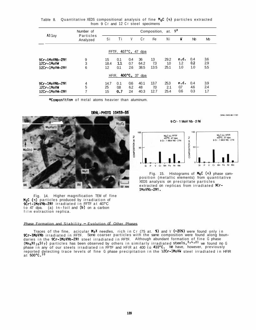
Table 8. Q u a n t i t a t i v e XEDS composit ional ana lys is o f f i ne M6C (n) p a r t i c l e s ex t rac ted from 9 C r and 12 C r s tee l specimens
Number of Composition, at . %a A1 1 oy P a r t i c l e s
S i T i V C r Fe N i W Nb Mo Analyzed
FFTF, 407OC, 47 dpa
9Cr-1MoVNb-2Ni 9 15 0.1 0.4 36 13 29.2 n.d. 0.4 3.6 12Cr-1MoVW 3 18.4 1.1 0.7 64.2 7.3 1.0 1.2 0.2 2.9 12Cr-1MoVW-ZNi 6 12 0.1 2.6 38.5 13.5 25.1 1.0 1.0 5.5
HFIR, 4OO0C, 37 dpa
9Cr-1MoVNb-ZNi 4 14.7 0.1 0.6 40.1 13.7 25.3 n.d. 0.4 3.9 1 I C r - 1 MnVW 5 25 0.8 6.2 48 7.0 2.1 0.7 4.6 2.4 12Cr-1MoVW-2Ni 7 15 0.7 2.4 40.3 12.7 25.4 0.6 0.3 1.7
aComposition o f m e t a l atoms heavier than aluminum.
Ea--- 7
MNL-PHOTO 10159-W
9 0 - 1 MoVNb-2Ni
Fig. 15. Histograms of MF,C (n) phase com- p o s i t i o n ( m e t a l l i c elements) from q u a n t i t a t i v e XEDS analysis on p r e c i p i t a t e p a r t i c l e s ex t rac ted on rep l i cas from i r r a d i a t e d 9Cr- 1MoVNb-2Ni.
Fig. 14. Higher magni f icat ion TEM of f i n e M6C ( 0 ) p a r t i c l e s produced by i r r a d i a t i o n of 9Cri-1MoVNb-2Ni i r r a d i a t e d i n FFTF a t 407°C t o 47 dpa. (a) I n - f o i l and (b) on a carbon f i l m e x t r a c t i o n rep l i ca .
Phase Formation and S t a b i l i t y - Evolu t ion of Other Phases
9Cr-1MoVNb i r r a d i a t e d i n FFTF. dar ies i n the 9Cr-1MoVNb-2Ni s tee l i r r a d i a t e d i n FFTF. (Mn6Ni16Si7) p a r t i c l e s has been observed by others i n s i m i l a r l y i r r a d i a t e d steel^,^.^.^^ we found no G phase i n any o f our s tee l s i r r a d i a t e d i n FFTF and HFIR a t 400 t o 410OC. reported detec t ing t r a c e l e v e l s of f i ne G phase p r e c i p i t a t i o n i n the 12Cr-1MoVW stee l i r r a d i a t e d i n HFIR a t 500°C.'0
Traces o f t he f ine, ac i cu la r M2X needles, r i c h i n C r (75 a t . %) and V (-20%) were found on ly i n Some coarser p a r t i c l e s w i t h the same composition were found along boun-
Although abundant format ion o f f i n e G phase
We have, however, p rev ious ly
DISCUSSION
The f i r s t p o r t i o n of t he d iscuss ion w i l l compare t he present swel l ing. m d m ic ros t r uc tu ra l data w i t h data of o thers on s i m i l a r s tee ls , mainly from neutron experiments. The remainder w i l l focus on t h e c l e a r r o l e t h a t increased hel ium generat ion p lays t o enhance vo id formation i n these m a r t e n s i t i c l f e r r i t i c Steels, and t he imp l i ca t i ons of such ef fects on t he mechanism a f f ec t i ng o r c o n t r o l l i n g vo id formation. Results on t h e evo lu t i on of o ther m ic ros t ruc tu ra l components w i l l be discussed i n t h e context o f t h e i r r e l a t i o n s h i p t o t he c a v i t y microst ructure. I n general, except f o r cav i t i e s , m i c ros t r uc tu ra l evo lu t i on was s i m i l a r f o r FFTF and HFIR i r r a d i a t i o n s of t he same s tee l and, therefore, r e l a t i v e l y unaffected by changes i n hel ium l eve l . Thus, these experiments can be i n t e rp re ted as e f f e c t i v e l y s t ra ight forward, s ing le- var iab le experiments of hel ium ef fects on c a v i t y evolut ion, even i n t h e s tee ls doped w i t h n icke l .
The FFTF vo id- swe l l i ng behavior o f t he 9 C r and 12 C r s tee ls (T91 and HT-9 base compositions, r espec t i ve l y ) used i n t h i s work are genera l ly consis tent w i t h t he growing body o f h igh- f luence FBR data on t he ma r tens i t i c c lass of f e r r i t i c ~ t e e l s . ~ ~ . ~ ~ (9Cr-ZMoVNb, France), FV448 (lPCr-O.5MoVNb. Uni ted Kingdom), and D I N 1.4914 (lZCr-O.5MoVNb. West Germany). These s tee l s have very good vo id- swel l ing resistance, w i t h ~0.6% swe l l i ng a t doses of 100 t o 125 dpa. Some coarse voids were seen i n EM-12 a t -100 dpa by Gel les a f t e r EBR-I1 i r r a d i a t i ~ n . ~ ) Our FFTF resu l ts , which show a few voids i n t he 9 C r s tee l and almost none i n t he 12 C r s tee l , are cons is ten t w i t h these observations.
specimens i r r a d i a t e d i n HFIR a t 400oC t o -37 dpa by Vi tek and K lueh7* i and by Gel les and Thomas3*" on a s i m i l a r heat of 12Cr-1MoVW (but w i t h a d i f f e r e n t heat t reatment) i r r a d i a t e d i n HFIR a t 400°C t o 10 and 39 dpa. Gel les and Thomas a l so compared EBR-I1 i r r a d i a t e d HT-9 w i t h t h e i r HFIR r e s u l t s t o analyze f o r poss ib le hel ium effects. For t he 9Cr-1MoVNb s tee l , we found m r e of t he smal ler cav i t es and s l i g h t l y more swe l l i ng than Vi tek and Klueh,8 but otherwise t h e c a v i t y r e s u l t s are s im i l a r . For t h e 12Cr-1MoVW steels , we measured several t imes more swe l l i ng and almost 10 t imes more c a v i t i e s (mainly smal ler ones) than Vi tek and K l ~ e h . ~ but such d i f ferences are not unexpected, given t he m i c ros t r uc tu ra l heterogenei ty of these steels . Gel les and Thomas3 found no e f f e c t of hel ium a f t e r 10 dpa i n HFIR r e l a t i v e t o EER-I1 i r r a d i a t i o n . On t he other hand, Gel lesg found t h a t cav i t y formation i s enhanced a f t e r 39 dpa i n HFIR. bu t observed fewer and smal ler c a v i t i e s than we did, and about 4 times l ess swel l ing. Our reac to r da ta on t he nickel-doped s tee ls are unique.
There have a l so been dual- ion i r r a d i a t i o n experiments on these o r s i m i l a r s t ee l s t o i nves t i ga te hel ium e f fec ts on c a v i t y f o r m a t i ~ n . ~ ~ - ~ ~ Work by Ayrault ,26 us ing t he dual- ion beam f a c i l i t y a t t h e Argonne National Laboratory (ANL), showed t h a t hel ium was essen t ia l t o vo id formation a t 410 t o 470'C a f t e r 25 dpa i n t he same heats of 12Cr-1MoVW and 1PCr-1MoVW-2Ni used i n t he present work. The n i c k e l - doping a c t u a l l y suppressed void swe l l i ng a t 470'C. F a r r e l l and Lee,27*28 us ing t h e dual i o n f a c i l i t y a t ORNL, found t h a t b ias- dr i ven voids could form a t 450 t o 550Y i n 9Cr-1MoVNb ( t he same heat as used i n t h i s work) and 10Cr-6MoNb s tee l s a f t e r 100 dpa. duce maximum swel l ings of 0.4% and 0.75%, respec t i ve ly , i n t he two steels . Horton and B e n t l e ~ , ~ ~ a lso us ing t he ORNL f a c i l i t y , found t h a t dual- and t r i p l e - (deuterium + t r i t i u m ) i on beam i r r a d i a t i o n s of a b inary Fe-1OCr a l l o y a t 58OoC produced a s i g n i f i c a n t enhancement i n vo id swe l l i ng a f t e r i r r a d i a t i o n t o 100 dpa (1.2 and 2.5% swel l ing, respec t i ve ly ) .
There a re few data ava i l ab l e on t he d i s l o c a t i o n dens i t y i n neu t ron- i r rad ia ted 9Cr-1MoVNb o r 12Cr-1MoVW steels . Our 4 0 0 T values of A f o r 9Cr-1MoVNb are considerably l ess than t he values measured a f t e r i o n i r r a d i a t i o n a t 400 t o 500OC by F a r r e l l and Lee.27 The range of A observed i n our var ious s t ee l s i r r a d i a t e d i n d i f f e r e n t reac to rs a t 400 t o 410'C (0.6 t o 3.5 x lo1" m-Z) i s a l so s i g n i f i c a n t l y l ess than t he values observed by Gel les30 f o r b inary Fe-9Cr and -12Cr a l l o y s i r r a d i a t e d i n EBR-I1 a t 400 t o 45O0C, o r those observed by Horton and Bentley i n i o n - i r r a d i a t e d Fe-1OCr a t -58OOC. Besides our data, t he re appear t o be no other observat ions on subgrain s t r u c t u r a l i n s t a b i l i t y dur ing i r rad ia t ion .1°
rad iat ion- induced so lu te segregat ion has been made elsewhere.'0,21 Our observat ions o f f i n e M6C (n) i n i r r a d i a t e d HT-9 are cons is ten t w i t h f i nd i ngs by L i t t l e and StoterS1 on FV 448. Our r e s u l t s d i f f e r con- s iderab ly from those o f Gel les and c o - ~ o r k e r s , ~ . g who repor t abundant p r e c i p i t a t i o n o f f i ne G and d phases i n 12Cr-1MoVW i r r a d i a t e d i n EBR-I1 and HFIR a t 400 t o 5OOOC. Our observat ions o f r ad i a t i on- produced M23C6 i n t he nickel-doped 9 C r s t ee l and composit ional m d i f i c a t i o n of t he MC phase i n t he var ious s t ee l s appear t o be new f indings.
nisms t h a t con t ro l vo id formation and swe l l i ng i n f e r r i t i c s tee ls , p a r t i c u l a r l y dur ing FER i r r a d i a t i o n , where t h e res is tance t o vo id swe l l i ng i s so obvious r e l a t i v e t o a u s t e n i t i c s t a i n l ess s teels . Two recent reviews h i g h l i g h t t he important mechanisms t o cons ider :25*32
s t r u c t u r e of t he mater ia l . Sniegowski and Wolfe+ proposed t h a t t he p re fe ren t i a l a t t r a c t i o n o f d is loca- t i o n s f o r i n t e r s t i t i a l s r e l a t i v e t o vacancies (b ias ) i s lower i n ECC than i n FCC mate r ia ls because s e l f - i n t e r s t i t i a l s have smal ler r e l axa t i on volumes i n BCC mater ia l . Odette32 a lso pointed out t h a t
This c lass inc ludes such o ther s t ee l s as EM-12
There have been previous m i c ros t r uc tu ra l observat ions made on du l i c a t e 9 Cr-1MoVNb and 12Cr-1MoVW
They found t h a t hel ium enhanced vo id formation t o pro-
Comparison o f our p r e c i p i t a t i o n r e s u l t s w i t h the r e s u l t s of others and d iscuss ion about t he r o l e o f
There has been a considerable amount of t h e o r e t i c a l work d i r ec ted toward understanding t h e mecha-
(a) Low i n t r i n s i c b ias - This ef fect inc ludes f ac to r s suggested t o be inherent t o t he BCC c r y s t a l
140
se l f- d i f fus ion ra tes are considerably h igher i n BCC r e l a t i v e t o FCC i ron , which would enhance defect recombination.
( b ) Low b ias due t o d i s l o c a t i o n nature - Bul lough and c o - ~ o r k e r s ~ ~ . 3 5 proposed t h a t ao<100> loops w i t h a s t rong i n t e r s t i t i a l b ias cause t h e more neu t ra l ao/2<111> d i s l o c a t i o n s inks t o absorb vacancies, thus competing w i t h c a v i t i e s t o reduce t h e net b ias o f the system.
of p o i n t defects by s o l u t e atoms i n ECC s tee ls . L i t t l e 3 6 a l s o suggested t h a t s u b s t i t u t i o n a l so lu tes segregat ing t o d i s loca t ions can reduce t h e i r b ias fo r i n t e r s t i t i a l s and i n h i b i t cl imb. Both e f f e c t s enhance p o i n t defect recombination. G e l l e ~ ~ ~ has recen t l y observed reduced s w e l l i n g w i t h overs ize m i s f i t so lu te atoms i n d i l u t e b ina ry a l l o y s and suggested rad ia t ion- induced segregat ion t o d i s loca t ions and vo id surfaces was responsible.
study of c a v i t y growth ra tes and c r i t i c a l c a v i t y s i ze , i n d i c a t e d tha t domination o f t h e m ic ros t ruc tu re by e i t h e r d i s l o c a t i o n o r c a v i t y s inks a lso con t r i bu tes t o the low s w e l l i n g observed i n BCC mate r ia l s . Imbalanced p a r t i t i o n i n g leads t o enhanced p o i n t defect recombination a t t h e dominant s ink. Thei r Fe-1OCr r e s u l t s suggest cavity-dominated microst ructures, whereas s i m i l a r i n t e r p r e t a t i o n of r e s u l t s on 9-10Cr s t e e l s i nd ica ted dis locat ion-dominated microst ructures a t low gas leve ls , and c a v i t y dominated s t ruc tu res a t h igh gas leve ls .
( c ) So lu te e f fec ts - L i t t l e 3 6 * 3 7 and have suggested t h a t the re i s s u b s t i t u t i o n a l t rapp ing
( d ) M ic ros t ruc tu ra l s ink balance e f f e c t s - Horton and M a n ~ u r l * ~ i n the context of a r a t e theory
( e ) M i c r o s t r u c t u r a l l a th /subgra in boundary e f fec ts - Ayrau l tZ6 and Maziasz e t a1 . lo have suggested t h a t these boundaries are s t rong neu t ra l s inks which enhance p o i n t defect recombination and lower the vacancy supersaturat ion i n t h e as-tempered commercial s tee ls .
( f) M i c r o s t r u c t u r a l p r e c i p i t a t i o n e f f e c t s - Gel les and Thomas3 suggested t h a t t h e f i n e G and a' p r e c i p i t a t e s t h a t have been observed under i r r a d i a t i o n con t r i bu te t o vo id s w e l l i n g res is tance.
(9) Gas e f fec ts - F e r r i t i c s tee ls wi thout n i cke l have lower he l ium generat ion ra tes du r ing FBR i r r a d i a t i o n than a u s t e n i t i c s tee ls because n i c k e l has a much h igher ( n , a ) cross- sect ion than Fe o r C r . A l l of t he s tud ies on the e f fec t of helium7'10,19,26-29 p o i n t t o i t s s t i m u l a t i o n o f void nucleat ion. T r i p l e- i o n beam experiments a l so show an enhanced e f fec t o f hel ium and hydrogen t ~ g e t h e r . ~ ~ , ~ ~ - ~ ~
growth. b ias- dr iven v o i d S 2 ~ 4 0 ~ ~ 1 are most re levan t t o vo id nuc leat ion, which i s the major issue addressed by our data. res is tance observed i n these s tee ls dur ing FBR i r r a d i a t i o n , our data suggest t h a t mechanisms (d ) and (e ) are most important t o vo id growth du r ing i r r a d i a t i o n a t h igher he l ium generat ion leve ls .
helium, and t h a t increased hel ium generat ion g r e a t l y enhances vo id nucleat ion. i n a u s t e n i t i c s t a i n l e s s s tee ls even wi thout any hel ium present due t o oxygen effect^,^^,"^ and elemental N i used fo r a l l o y i n g can have very h igh oxygen contents, usua l l y h igher than the C r o r Fe s t a r t i n g stock used t o produce a u s t e n i t i c a l l o y s and The m a r t e n i s t i c l f e r r i t i c s tee ls conta in l i t t l e N i and much h igher C contents (C i s a very e f f i c i e n t deox id i z ing element, as are S i and T i ) compared t o aus- t e n i t i c s tee ls and a l l o y s , so t h a t they mast l i k e l y have less oxygen a v a i l a b l e fo r vo id nuc lea t ion and are more dependent on hel ium generated dur ing i r r a d i a t i o n .
regime o r i ncuba t ion per iod, fo l lowed by a s teady- sta te regime of much more rap id swel l ing.6,20 nuc leate and grow dur ing the low- swel l ing t r a n s i e n t regime, and usua l l y r a p i d vo id growth andlor coalescence cause the onset of r a p i d swel l ing. era ted vo id nuc lea t ion t o shorten the incuba t ion per iod, perhaps by 75 t o 100 dpa o r more, none o f our m ic ros t ruc tu res appear t o be a t t h e end o f t h e t r a n s i e n t regime and c e r t a i n l y not i n t o the rap id- swe l l i ng regime.
number of gas atoms, n , whose mathematical equations are descr ibed by O d e t t ~ ? ~ ~ and Mansur and C ~ g h l a n , ~ ' he lp t o i n t e r p r e t our m ic ros t ruc tu ra l data. d i f f i c u l t t o estimate, but can be r e l a t e d t o t h e du ra t ion of t h e incubat ion per iod. undoped 9 C r and 12 C r s tee ls i n t h i s work appears t o be t0.75 nm a t 400 t o 41OoC i n both FFTF and HFIR, whereas i n t h e Ni-doped s t e e l s rc increases from t h a t value i n FFTF t o 2.5 t o 3 nm i n HFIR.
formation i n 9Cr-1MoVNb i n FFTF may a l so i n d i c a t e a very low value of n i i n t h a t s tee l . both rc and n:, mare he l ium would r e a d i l y lead t o more voids, as we observe f o r the undoped 9 C r and 12 C r s tee ls i r r a d i a t e d i n HFIR. Void formation appears more d i f f i c u l t i n the nickel-doped s tee ls i n
Most of these mechanisms r e l a t e t o the vacancy supersaturat ion a v a i l a b l e fo r vo id nuc lea t ion and However gas e f fec ts (9 ) and t h e c r i t i c a l s ize, rC, fo r conversion of a s tab le gas bubble i n t o a
While most of t he above-mentioned mechanisms probably c o n t r i b u t e i n concert t o t h e vo id- swel l ing
Our data i n d i c a t e s t h a t vo id nuc lea t ion i s very d i f f i c u l t du r ing FBR i r r a d i a t i o n w i t h l i t t l e o r no Void nuc lea t ion can occur
Macroscopic swe l l i ng w i t h increas ing f luence can be descr ibed i n terms of a low- swel l ing t r a n s i e n t Voids
Our data suggest t h a t , w h i l e hel ium appears t o have acce l -
Two c l o s e l y r e l a t e d c r i t i c a l parameters from r a t e theory, t h e c r i t i c a l radius, rc, and t h e c r i t i c a l
9 Our data suggest empi r ica l est imates f o r rc; $ i s more
The r fo r the
The vo id
A t low values of
141
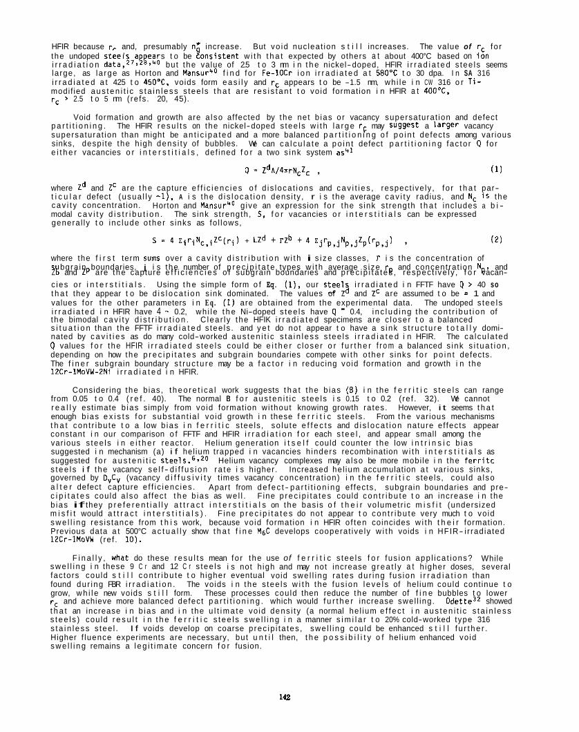
HFIR because rr and, presumably n* increase. But vo id nuc leat ion s t i l l increases. The value of r, fo r the undoped s tee ls a ears t o be zons is tent w i t h t h a t expected by others a t about 400°C based on ih i r r a d i a t i o n data,27.gi,ro but the value of 2.5 t o 3 nm i n t h e nickel-doped, HFIR i r r a d i a t e d s tee ls seems large, as l a rge as Horton and Mansurro f i n d fo r Fe-1OCr i o n i r r a d i a t e d a t 580'C t o 30 dpa. I n SA 316 i r r a d i a t e d a t 425 t o 450"C, voids form e a s i l y and rc appears t o be -1.5 nm, wh i le i n CW 316 o r T i - modif ied a u s t e n i t i c s t a i n l e s s s tee ls t h a t are r e s i s t a n t t o vo id formation i n HFIR a t 4OO0C, rc > 2.5 t o 5 nm ( re fs . 20, 45).
Void formation and growth are a l so affected by the net b ias o r vacancy supersaturat ion and defect
We can c a l c u l a t e a p o i n t defect p a r t i t i o n i n g fac to r 4 fo r
p a r t i t i o n i n g . supersaturat ion than might be a n t i c i p a t e d and a more balanced p a r t i t i o n i n g o f p o i n t defects among var ious sinks, desp i te the h igh dens i t y of bubbles. e i t h e r vacancies o r i n t e r s t i t i a l s , def ined f o r a two s ink system as41
The HFIR r e s u l t s on the nickel-doped s tee ls w i t h l a r g e rF may Suggest a l a r g e r vacancy
9 = ZdA/4nrNcZc , ( 1 )
where Zd and Zc are t h e capture e f f i c i e n c i e s o f d i s loca t ions and c a v i t i e s , respect ive ly , f o r t h a t par- t i c u l a r defect (usua l l y - l ) , A i s t he d i s l o c a t i o n dens i ty , r i s the average c a v i t y radius, and NC i s the c a v i t y concentrat ion. modal c a v i t y d i s t r i b u t i o n . The s ink s t rength, 5, f o r vacancies o r i n t e r s t i t i a l s can be expressed genera l ly t o i nc lude o the r s inks as fo l lows,
Horton and Mansur40 g ive an expression fo r the s ink s t rength t h a t inc ludes a b i -
S = 4 xiriNc,iZC(ri) + LZd + rzb + 4 zjrp,jNp,jZp(rp,j)
Z L! and Zp are the capture e f f i c i e n c i e s o f subgrain boundaries and p r e c i p i t a t e s , respec t i ve l y , f o r vacan-
, ( 2 )
where the f i r s t term sums over a c a v i t y d i s t r i b u t i o n w i t h i s i z e classes, 1' i s t he concent ra t ion of s bgra in boundaries, j i s the number of p r e c i p i t a t e types w i t h average s i ze rp and concent ra t ion Np. and
c ies o r i n t e r s t i t i a l s . Using t h e simple form o f Eq. ( l ) , our s tee l2 i r r a d i a t e d i n FFTF have Q > 40 so t h a t they appear t o be d i s l o c a t i o n s ink dominated. values for the o ther parameters i n E q . (1) are obtained from the experimental data. The undoped s tee ls i r r a d i a t e d i n HFIR have 4 -. 0.2, wh i le t h e Ni-doped s tee ls have Q - 0.4, i n c l u d i n g the c o n t r i b u t i o n of the bimodal c a v i t y d i s t r i b u t i o n . C lea r l y the HFIK i r r a d i a t e d specimens are c lose r t o a balanced s i t u a t i o n than the FFTF i r r a d i a t e d s tee ls . and y e t do not appear t o have a s ink s t r u c t u r e t o t a l l y domi- nated by c a v i t i e s as do many cold-worked a u s t e n i t i c s t a i n l e s s s tee ls i r r a d i a t e d i n HFIR. The ca lcu la ted Q values f o r the HFIR i r r a d i a t e d s tee ls cou ld be e i t h e r c lose r o r f u r t h e r f r o m a balanced s ink s i t u a t i o n , depending on how the p r e c i p i t a t e s and subgrain boundaries compete w i t h o the r s inks f o r p o i n t defects. The f i n e r subgrain boundary s t r u c t u r e may be a f a c t o r i n reducing vo id formation and growth i n the 12Cr-1MoVW-2Ni i r r a d i a t e d i n HFIR.
The values of Z and Zc are assumed t o be = 1 and
Consider ing the b ias , t h e o r e t i c a l work suggests t h a t the b ias (B) i n the f e r r i t i c s t e e l s can range from 0.05 t o 0.4 ( r e f . 40). The normal B f o r a u s t e n i t i c s tee ls i s 0.15 t o 0.2 ( re f . 32). We cannot r e a l l y est imate b ias simply from vo id formation wi thout knowing growth ra tes. However, i t seems t h a t enough b ias e x i s t s f o r subs tan t ia l vo id growth i n these f e r r i t i c s tee ls . From t h e var ious mechanisms t h a t con t r i bu te t o a low b ias i n f e r r i t i c s tee ls , so lu te e f f e c t s and d i s l o c a t i o n nature e f fec ts appear constant i n our comparison o f FFTF and HFIR i r r a d i a t i o n f o r each s t e e l , and appear small among the var ious s tee ls i n e i t h e r reactor . Helium generat ion i t s e l f could counter the low i n t r i n s i c b ias suggested i n mechanism (a) i f hel ium trapped i n vacancies h inders recombination w i t h i n t e r s t i t i a l s as suggested f o r a u s t e n i t i c s tee ls .6 '2D Helium vacancy complexes may a l so be more mobi le i n the f e r r i t c s t e e l s i f the vacancy s e l f - d i f f u s i o n r a t e i s higher. Increased he l ium accumulation a t var ious sinks, governed by D v C v (vacancy d i f f u s i v i t y t imes vacancy concent ra t ion) i n t h e f e r r i t i c s tee ls , cou ld a l so a l t e r defect capture e f f i c ienc ies . c i p i t a t e s cou ld a l so a f fec t t h e b ias as we l l . b ias if they p r e f e r e n t i a l l y a t t r a c t i n t e r s t i t i a l s on the bas is o f t h e i r vo lumetr ic m i s f i t (undersized m i s f i t would a t t r a c t i n t e r s t i t i a l s ) . F ine p r e c i p i t a t e s do not appear t o c o n t r i b u t e very much t o vo id s w e l l i n g res is tance from t h i s work, because vo id formation i n HFIR o f ten coincides w i t h t h e i r formation. Previous data a t 500°C a c t u a l l y show t h a t f i n e M6C develops cooperat ive ly w i t h voids i n HFIR- i r rad ia ted 12Cr-IMoVW (re f . IO).
Apart from d e f e c t - p a r t i t i o n i n g e f fec ts , subgrain boundaries and pre- F ine p r e c i p i t a t e s could c o n t r i b u t e t o an increase i n the
F i n a l l y , what do these r e s u l t s mean fo r the use of f e r r i t i c s tee ls f o r fus ion app l i ca t ions? While s w e l l i n g i n these 9 C r and 12 C r s tee ls i s not h igh and may not increase g r e a t l y a t h igher doses, several fac tors cou ld s t i l l c o n t r i b u t e t o h igher eventual void swe l l i ng ra tes du r ing fus ion i r r a d i a t i o n than found du r ing FBR i r r a d i a t i o n . The voids i n the s tee ls w i t h the fus ion l e v e l s of hel ium could cont inue t o grow, w h i l e new voids s t i l l form. rc and achieve more balanced defect p a r t i t i o n i n g . which would f u r t h e r increase swel l ing. 0de t te3* showed t h a t an increase i n b ias and i n the u l t i m a t e vo id dens i t y (a normal he l ium e f f e c t i n a u s t e n i t i c s t a i n l e s s s t e e l s ) cou ld r e s u l t i n t h e f e r r i t i c s t e e l s s w e l l i n g i n a manner s i m i l a r t o 20% cold-worked type 316 s t a i n l e s s s tee l . I f voids develop on coarse p rec ip i ta tes , swe l l i ng cou ld be enhanced s t i l l f u r t h e r . Higher f luence experiments are necessary, but u n t i l then, t h e p o s s i b i l i t y o f hel ium enhanced vo id s w e l l i n g remains a l e g i t i m a t e concern f o r fusion.
These processes cou ld then reduce the number of f i n e bubbles t o lower
112
CONCLUSIONS
1. By comparing nickel-doped and undoped 9Cr-1MoVNb and 12Cr-1MoVW s t e e l s i r r a d i a t e d i n FFTF (47 dpa. -5 appm He) and HFIR (-37 dpa, 400-430 appm He), it was found t h a t increases i n He:dpa r a t i o cause s i g n i f i c a n t increases i n the formation of l a r g e (7-30 nm diam), b ias- dr iven voids a t 400 t o 41OOC. t h e nickel-doped s t e e l s i r r a d i a t e d i n HFIR w i t h 400 ap m He o r m r e had v i s i b l e hel ium bubbles, which were very f i n e (2-5 nm diam) and abundant ( 1 t o 4 x log2 ~ n - ~ ) .
I r r a d i a t i o n i n both reactors produced a s a t i a l l y uniform network of tang led d i s l o c a t i o n s and some l a r g e r loops, w i t h A being 0.6 t o 4 x lo1" md. I r r a d i a t i o n produced a s t r u c t u r e t h a t was d i f f e r e n t than t h e i n i t i a l as-tempered, s p a t i a l l y non-uniform s t r u c t u r e i n which A var ied from < l o l l t o 7 x 10¹³ K2. I r r a d i a t i o n s i g n i f i c a n t l y increased A on ly i n the 12Cr-1MoVW stee l f o r which A was i n i t i a l l y very low ( d o l 1 N 2 ) . I r r a d i a t i o n a t 400 t o 410°C produced almost complete recovery of the as-tempered l a t h subgrain boundary s t r u c t u r e i n t h e 9Cr-1MoVNb and 9Cr-1MoVNb-2Ni s tee ls . Such boundaries remained s tab le i n s i m i l a r l y i r r a d i a t e d 12Cr-1MoVW and 12Cr-1MoVW-PNi s tee ls .
i r r a d i a t e d a t 400 t o 410°C i n both reactors. There was d i s s o l u t i o n of many o f t h e coarse, as-tempered M23C6 p a r t i c l e s du r ing i r r a d i a t i o n of both 9 C r s tee ls , whereas s i m i l a r p a r t i c l e s were r e l a t i v e l y more s tab le i n the 12 C r s tee ls . I r r a d i a t i o n produced an abundant d ispers ion of new coarse M& p a r t i c l e s on ly i n the 9Cr-1MoVNb-2Ni s tee l . F ine r MC p r e c i p i t a t e p a r t i c l e s , present i n a l l t he s tee ls , experienced some coarsening and composit ional changes (Cr enrichments and V dep le t i ons ) du r ing i r r a d i a t i o n . I r r a d i a - t i o n produced abundant d ispers ions of f i n e MgC (TI) i n a l l t he s tee ls except 9Cr-1MoVNb. These p a r t i c l e s were S i , C r and N i r i c h i n t h e nickel-doped s tee ls , but had an odd composition w i t h only S i and C r i n t h e 12Cr-1MoVW stee l . Some coarse M6C (TI) (Si , C r and N i r i c h ) was found t o replace coarse as-tempered M23C6 du r ing i r r a d i a t i o n i n both nickel-doped 9 C r and 12 C r s tee ls .
g ra in boundary and t h e p r e c i p i t a t e components of the m ic ros t ruc tu re i n a l l t he s tee ls , these changes were near l y the same comparing i r r a d i a t i o n i n FFTF and HFIR f o r each heat of s tee l .
t h a t the re i s a s u f f i c i e n t b ias fo r vo id growth i n f e r r i t i c l m a r t e n s i t i c s tee ls i r r a d i a t e d a t about 4OOOC if there i s enough hel ium fo r voids t o nucleate. Our data i n d i c a t e s t h a t t h e c r i t i c a l s i z e and c r i t i c a l gas content fo r the conversion of s tab le gas c l u s t e r s o r bubbles ( r c and n* respec t i ve l y ) t o voids are q u i t e small ( r c (0.75 nm) i n t h e 9Cr-1MoVNb and 12Cr-1MoVW s tee ls i r rad ia tg ; i n both reactors , because more he l ium causes more voids wi thout producing reso lvab le bubbles. The h igher he l ium content o f t he nickel-doped s tee ls i r r a d i a t e d i n HFIR produces many resolvable, but s u b c r i t i c a l , hel ium bubbles, which increases rc t o 2.5 t o 3 nm; however, voids s t i l l form and grow i n d i c a t i n g t h e presence o f some b ias. A l l of t he s tee ls i r r a d i a t e d i n FFTF appear t o have p o i n t defect a n n i h i l a t i o n dominated by the s ink s t reng th of t h e d i s loca t ions . By cont rast , t he increased dens i t y of bubbles t o ac t as s inks i n the s t e e l s i r r a d i a t e d i n HFIR appears t o cause more balanced defect p a r t i t i o n i n g . Our data suggest t h a t subgrain boundaries, and poss ib ly p r e c i p i t a t e p a r t i c l e s , may a lso be important s inks i n t h e system as w e l l .
Only
2.
3. I r r a d i a t i o n produced some s i g n i f i c a n t changes i n t h e p r e c i p i t a t e s t r u c t u r e on a l l o f t he s tee ls
4. Although i r r a d i a t i o n a t 400 t o 410°C had considerable e f f e c t s on both t h e d i s l o c a t i o n and sub-
5. I n t e r p r e t a t i o n of our data w i t h i n t h e framework of e x i s t i n g r a t e theory and modeling ind ica tes
6 . Our data c l e a r l y shows hel ium enhanced vo id formation where the low- swel l ing t r a n s i e n t regime could be shortened by as much as 75 t o 100 dpa. than 0.5%. However, m ic ros t ruc tu ra l d e t a i l s suggest t h a t vo id formation i s i n t h e e a r l y stages o f deve- lopment, and t h a t several mechanisms could e a s i l y lead t o more vo id nuc lea t ion and growth as dose increases. The p o s s i b i l i t y of hel ium enhanced vo id s w e l l i n g remains a l e g i t i m a t e concern f o r fus ion t h a t h igher f luence experiments need t o address.
The l e v e l s of c a v i t y s w e l l i n g observed are smal l . l ess
REFERENCES
1. J. J. Huet e t al., Proc. I r r a d i a t i o n Behavior of M e t a l l i c Ma te r ia l s f o r Fast Reactor Core
2. J. E r l e r e t al., Proc. I r r a d i a t i o n Behavior o f M e t a l l i c Ma te r ia l s f o r Fast Reactor Core
3.
4. 0. S. Gelles, J. Nucl. Mater. 122-123 (1984) 207. 5 . P. J. Maziasz, J. Nucl. Mater. 122-123 (1984) 472. 6. P. J. Maziasz and C. J. McHargue, I n t e r n a t i o n a l Ma te r ia l s Reviews 32 (1987) 190. 7. J. M. V i tek and R. L. Klueh, Proc. Topical Conference on F e r r i t i c A l l oys fo r Use i n Nuclear
8. J. M. Vi tek and R. L. Klueh, J. Nucl. Mater. 122-123 (1984) 254. 9. 0. S . Gelles, A D I P Semiannual Progress Report, March 31, 1985, DOE/ER-0045114, (Off ice of Fusion
Components, Ajaccio, France (CEA, 1979). p. 5.
Components, Ajaccio, France (CEA, 1979). p. 11.
Energy Technologies, eds. J.W. Davis and D.J. Michel (The M e t a l l u r g i c a l Society of AIME, 1984). p. 559. 0. S. Gel les and L. E. Thomas, Proc. Topical Conference on F e r r i t i c A l l oys fo r Use i n Nuclear
Energy Technologies, eds. J. W. Davis and D. J. Michel (The M e t a l l u r g i c a l Society of AIME, 1984) p. 551.
Energy, U.S. Oepartment of Energy, 1985) p. 129.
148
10. P. J. Maziasz, R. L. Klueh, and J . M. V i tek , J. Nucl. Mater. 141-143 (1986) 929. 11. R. L. Klueh, J . M. V i tek , and M. L. Grossbeck, J . Nucl. Mater. 1038104 (1981) 887. 12. R. L. Klueh. J. M. Vi tek. and M. L. Grossbeck. E f f e c t s o f Radia t ion on Mate r ia l s : Eleventh
Conference, ASTM STP-782, eds., H:R. Brager and J. 5. Per r in , Am. Sac. f o r Test ing and Matls., Ph i lade lph ia (1982), p. 648.
13. R. L. Klueh and J. M. V i tek . J . Nucl. Mater. 117 (1983) 295. 14.
15. M. L. Grossbeck, J . W. Woods, and G. A. Po t te r , A D I P Q u a r t e r l y Progress Report, Sept. 30, 1980.
16. L. R. Greenwood, A D I P Semiannual Progress Report, March 31, 1985, DOE/ER-O045/14 (O f f i ce of
R. L. Klueh and P. J . Maziasz, "Helium Effects on Neutron- I r rad ia ted Cr-Mo F e r r i t i c Stee ls : A Review of Recent Results," elsewhere i n t h i s repor t .
DDE/ER-0045/4 (O f f i ce o f Fusion Energy, U.S. Department o f Energy, 1981) p. 36.
Fusion Enerov. U.S. DeDartment o f Enerav. 1981). 0 . 22. I. I . .
17.
18. P. J. Maziasz and R. L. Klueh. A D I P Semiannual Proaress Reoort. March 31. 1985. DOE/ER-0045/14
N..:: Zaluzec', I n t roduc t ion t o Ana ly t i ca l E lec t ron Microscopy, eds. J. J. Hren, J. I . Goldstein, and 0. C. Joy, Plenum Press, New York, NY, 1979, p. 121.
. . (Off ice of Fusion Energy, U S . Department o f Energy, 19Bl),-p. 74.
19. L.L.S. Horton, A Transmission E lec t ron Microscopy Study o f Fusion Environment Radia t ion Damage i n I r o n and Iron-Chromium Al loys, Oak Ridge Nat ional Laboratory Report, ORNL/TM-8303 (Ju ly 1982).
20. P. J . Maziasz, E f f e c t s o f Helium Content on M ic ros t ruc tu ra l Development i n Type 316 Sta in less Steel During Neutron I r r a d i a t i o n , Oak Ridge Nat ional Laboratory Report, ORNL-6121 (November, 1985).
21. P. J . Maziasz, Ma te r ia l s f o r Nuclear Reactor Core Appl icat ions ( B r i s t o l Meeting, Oct. 27-29, 19871, vo l . 2, B r i t i s h Nucl. Energy SOC., London (1988), p. 61.
22. 0. R. Harr ies , Proc. Topcial Conference on F e r r i t i c A l l oys fo r Use i n Nuclear Energy Technologies, eds. J . W. Davis and D. J. Michel (The M e t a l l u r g i c a l Society o f AIME, 1984), p. 141.
23. D. S. Gelles, J. Nucl. Mater. 148 (1987) 136. 24. K. 0. Bagley e t al., Ma te r ia l s f o r Nuclear Reactor Core App l i ca t ions ( B r i s t o l Meeting, Oct.
27-29, 1987). vol . 2, B r i t i s h Nucl. Energy SOC., London (1988), p. 37. 25. E. A. L i t t l e , Ma te r ia l s fo r Nuclear Reactor Core Appl icat ions ( B r i s t o l Meeting, Dct. 27-29,
1987), vol. 2, B r i t i s h Nucl. Energy SOC., London (1988). p. 47. 26. G. Ayrau l t , DAFS Quart . Progr. Rept., February, 1982, DOE/ER-0046/8, vo l . 1 (Of f i ce of Fusion
Energy, U.S. Department o f Energy), p. 182. 27. K . F a r r e l l and E. H. Lee, Effects o f I r r a d i a t i o n on Mater ia l s : Twe l f th I n t e r n a t i o n a l Symposium,
ASTM STP-870, eds. F. A. Garner and J. S. Perr in . Am. SOC. f o r Test ing and Matls., Ph i lade lph ia , PA (1985), p. 383.
28. K. F a r r e l l and E. H. Lee, Radiation- Induced Changes i n Microst ructure: 13th Symposium (Par t I ) , ASTM STP-955, eds. F. A. Garner, N. H. Packan, and A. S. Kumar, Am. Sac. f o r Test ing and Matls., Ph i lade lph ia , PA (1987). p. 498.
29. L. L. Horton and J . Bentley, Proc. Topcial Conference on F e r r i t i c A l l oys f o r Use i n Nuclear Energy Technologies, eds. J . W. Davis and 0. J. Michel (The M e t a l l u r g i c a l Society of AIME, 1984) p. 569.
30. D. S. Gelles, J . Nucl. Mater. 103ElD4 (1981) 975. 31. L. P. S to te r and E. A. L i t t l e , Advances i n Physical Meta l lurgy and App l i ca t ions of Steels, The
Metals Society, London, U.K. (1981) p. 369. 32. G. R. Odette, J. Nucl. Mater. 155-157 (1988) 921. 33. J . J . Sniegowski and W. G. Wolfer, Proc. Topical Conference on F e r r i t i c A l l oys f o r Use i n
Nuclear Energy Technologies, eds. J . W. Davis and D. J. Michel (The M e t a l l u r g i c a l Society of AIME, 1984).
34. R. Bullough, H. M. Wood, and E. A. L i t t l e , E f f e c t s o f Radia t ion on Mate r ia l s : Tenth Conference, ASTM STP-725. eds. D. Kramer, H. R. Brager and J. 5. Per r in . Am. SOC. f o r Test ing and Matls., Ph i lade lph ia , PA (19811, p. 593.
35. E . A. L i t t l e , R. Rullough, and H. M. Wood, Proceedings o f the Royal Society, A372 (1980) 565. 36. E . A. L i t t l e , J. Nucl. Mater. 87 (1979) 11. 37. E. A. L i t t l e and D. Stow. J . Nucl. Mater. 87 (1979) 25.
p. 579.
38. 39. D. S. Gelles, Fusion Reactor Ma te r ia l s Semiannual Progress Report, September 30, 1986,
M. R. Hayns and T. M. Wi i l iams, J . Nucl. Mate;. 74'(1978) 151.
OOE/ER-0313/1. ( O f f i c e o f Fusion Enerav. DeDartment of Enerov. 1987). D. 150. '40. L.'L: Horton and L. K . MansuK'Effects o f I r r a d i a t h i on Matek ia ls : Twel f th I n t e r n a t i o n a l
Symposium, ASTM STP-870, eds. F. A. Garner and J. 5. Per r in , Am. Sac. fo r Test ing and Matls., Ph i lade lph ia , PA (1985), p. 344.
41. L. K. Mansur and W. A. Coghlan, J . Nucl. Mater. 119 (1983) 1. 42. R. S. Nelson and D. J . Mazey, Radia t ion Damage i n Reactor Ma te r ia l s , IAEA-SM-120, vol . 2,
I n t e r n a t i o n a l Atomic Energy Agency, Vienna, Aus t r i a (1969), p. 157 43. E. H. Lee and L. K. Mansur, " E f fec t of Residual and In jec ted Oxygen on Swel l ing i n I r r a d i a t e d
Fe-Ni-Cr A l l o y s - Part 11," submit ted t o Phi losophica l Magazine, 1988. 44, Chemical analyses on s tee ls melted a t DRNL, 1986-1988. 45. P. J . Maziasz and D. N. Rraski , J . Nucl. Mater. 1228123 (1984) 311.
144
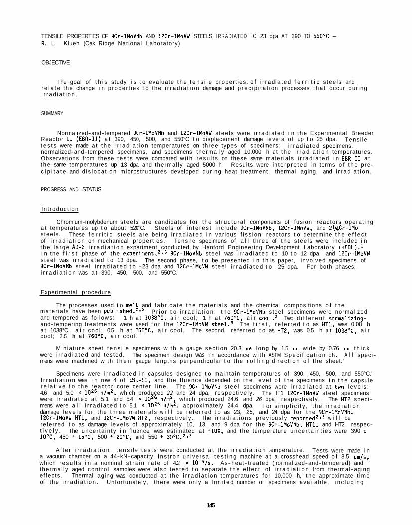
TENSILE PROPERTIES OF 9Cr-1MoVNb AND 12Cr-1MoVW STEELS IRRADIATED TO 23 dpa AT 390 TO 550'C - R. L. Klueh (Oak Ridge Nat ional Laboratory)
OBJECTIVE
The goal of t h i s study i s t o evaluate t h e t e n s i l e proper t ies . o f i r r a d i a t e d f e r r i t i c s tee ls and r e l a t e the change i n p roper t i es t o the i r r a d i a t i o n damage and p r e c i p i t a t i o n processes t h a t occur dur ing i r r a d i a t i o n .
SUMMARY
Normalized-and-tempered 9Cr-1MoVNb and 12Cr-1MoVW s tee ls were i r r a d i a t e d i n t h e Experimental Breeder Reactor 11 (EBR-11) a t 390, 450, 500, and 550°C t o displacement damage l e v e l s o f up t o 25 dpa. t e s t s were made a t t h e i r r a d i a t i o n temperatures on th ree types of specimens: normalized-and-tempered specimens, and specimens thermal ly aged 10,000 h a t t h e i r r a d i a t i o n temperatures. Observations from these t e s t s were compared w i t h r e s u l t s on these same mate r ia l s i r r a d i a t e d i n EBR-I1 a t t h e same temperatures up 13 dpa and thermal ly aged 5000 h. Results were i n t e r p r e t e d i n terms o f t h e pre- c i p i t a t e and d i s l o c a t i o n microst ructures developed dur ing heat treatment, thermal aging, and i r r a d i a t i o n .
Tens i l e i r r a d i a t e d specimens,
PROGRESS AND STATUS
In t roduc t ion
Chromium-molybdenum s tee ls are candidates fo r the s t r u c t u r a l components of fusion reactors operat ing a t temperatures up t o about 520°C. Stee ls of i n t e r e s t inc lude 9Cr-lMoVNb, 12Cr-lMaVW, and 21/4Cr-lMo s tee ls . These f e r r i t i c s tee ls are being i r r a d i a t e d i n var ious f i s s i o n reactors t o determine t h e e f f e c t of i r r a d i a t i o n on mechanical proper t ies . Tens i le specimens of a l l t h ree of t h e s tee ls were inc luded i n t h e l a r g e A D 4 i r r a d i a t i o n experiment conducted by Hanford Engineering Development Laboratory (HEDL).l I n the f i r s t phase of the e x ~ e r i m e n t , ~ , ~ 9Cr-1MoVNb s tee l was i r r a d i a t e d t o 10 t o 12 dpa, and 12Cr-1MoVW s tee l was i r r a d i a t e d t o 13 dpa. The second phase, t o be presented i n t h i s paper, invo lved specimens of 9Cr-1MoVNb s tee l i r r a d i a t e d t o -23 dpa and 12Cr-1MoVW s tee l i r r a d i a t e d t o -25 dpa. For both phases, i r r a d i a t i o n was a t 390, 450, 500, and 550°C.
Experimental procedure
mate r ia l s have been p u b l i ~ h e d . ~ . ~ and tempered as fo l lows: and-tempering treatments were used f o r t h e 12Cr-1MoVW stee l .3 The f i r s t , r e f e r r e d t o as HT1, was 0.08 h a t 1038°C. a i r coo l ; 0.5 h a t 760"C, a i r cool . The second, re fer red t o as HT2, was 0.5 h a t 1038"C, a i r cool ; 2.5 h a t 760"C, a i r cool .
M in ia tu re sheet t e n s i l e specimens w i t h a gauge sec t ion 20.3 mn long by 1.5 m wide by 0.76 mn t h i c k were i r r a d i a t e d and tes ted. The specimen design was i n accordance w i t h ASTM S p e c i f i c a t i o n E8. A l l speci- mens were machined w i t h t h e i r gauge lengths perpendicu lar t o the r o l l i n g d i r e c t i o n o f the sheet.'
Specimens were i r r a d i a t e d i n capsules designed t o mainta in temperatures of 390, 450, 500, and 550°C.' I r r a d i a t i o n was i n row 4 o f EBR-11, and the f luence depended on the l e v e l o f t he specimens i n t h e capsule r e l a t i v e t o t h e reac to r core center l i n e . 4.6 and 5.0 x l o z 6 n/mZ, which produced 22 and 24 dpa, respec t i ve l y . were i r r a d i a t e d a t 5.1 and 5.4 x l o z 6 n/mZ, which produced 24.6 and 26 dpa, respect ive ly . mens were a l l i r r a d i a t e d t o 5.1 x l o z 6 n/m2, approximately 24.4 dpa. damage l e v e l s fo r the th ree mate r ia l s w i l l be r e f e r r e d t o as 23, 2 5 , and 24 dpa fo r the gCr-lMoVNb, 12Cr-1MoVW HT1, and 12Cr-1MoVW HT2, respect ive ly . The i r r a d i a t i o n s p rev ious ly r e p ~ r t e d ~ , ~ w i l l be re fer red t o as damage l e v e l s of approximately 10, 13, and 9 dpa f o r the gCr-lMoVNb, HT1, and HT2, respec- t i v e l y . 10°C, 450 * 15°C. 500 2O"C, and 550 * 30°C.2,3
The processes used t o mel t and f a b r i c a t e t h e mate r ia l s and the chemical compositions o f the P r i o r t o i r r a d i a t i o n , t h e 9Cr-1MoVNb s tee l specimens were normal ized
Two d i f f e r e n t normal iz ing- 1 h a t 1038"C, a i r cool ; 1 h a t 760"C, a i r ~ 0 0 1 . ~
The 9Cr-1MoVNb s tee l specimens were i r r a d i a t e d a t two l e v e l s : The HT1 12Cr-1MoVW s tee l specimens
For s i m p l i c i t y , t h e i r r a d i a t i o n The HT2 speci-
The uncer ta in ty i n f luence was estimated a t +lo%, and the temperature u n c e r t a i n t i e s were 390 t
A f t e r i r r a d i a t i o n , t e n s i l e t e s t s were conducted a t the i r r a d i a t i o n temperature. Tests were made i n a vacuum chamber on a 44-kN-capacity I n s t r o n un ive rsa l t e s t i n g machine a t a crosshead speed o f 8.5 um/s, which r e s u l t s i n a nominal s t r a i n r a t e of 4.2 x lO-"/s. As-heat- treated (normalized-and-tempered) and the rma l l y aged con t ro l samples were a l so tes ted t o separate t h e e f fec t of i r r a d i a t i o n from thermal-aging ef fec ts . Thermal aging was conducted a t the i r r a d i a t i o n temperatures fo r 10,000 h, t h e approximate t ime of the i r r a d i a t i o n . Unfortunately, t he re were on ly a l i m i t e d number of specimens ava i lab le , i n c l u d i n g
145
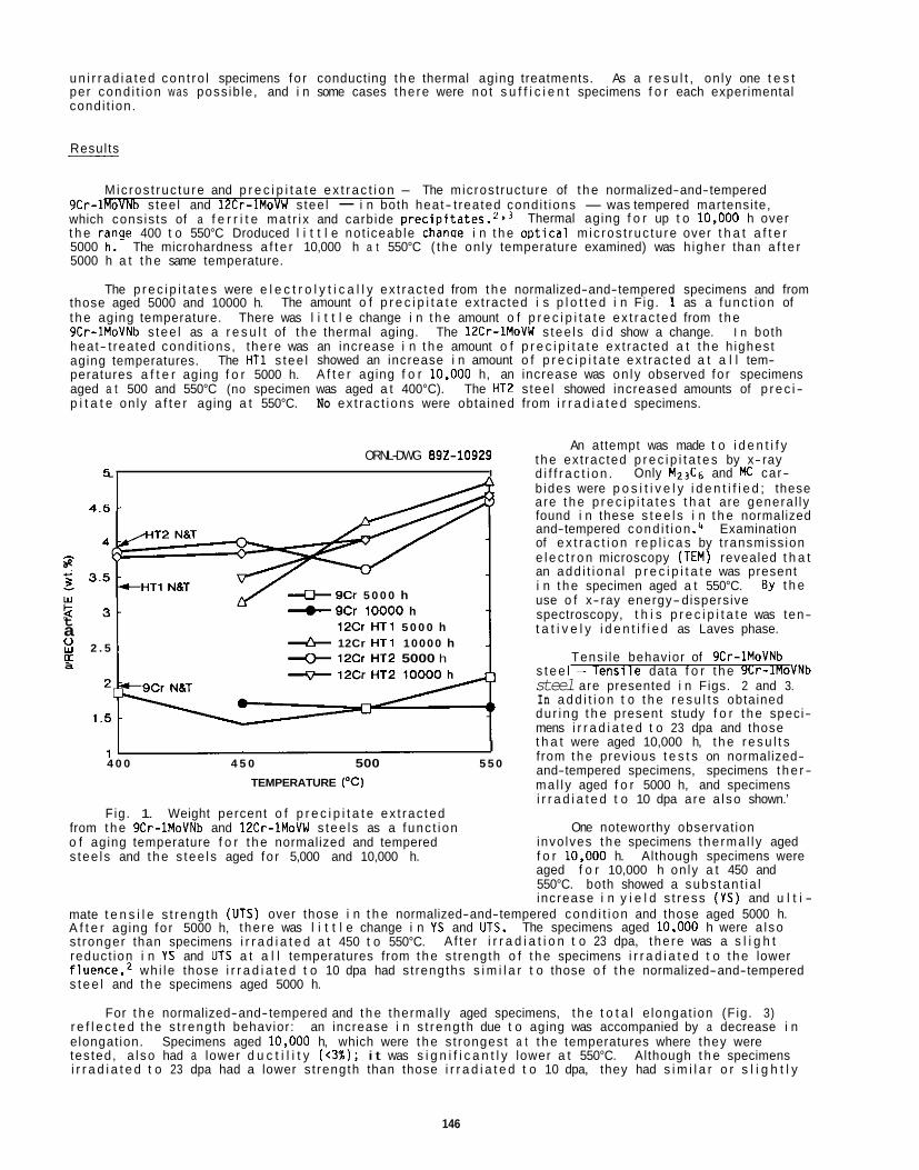
u n i r r a d i a t e d con t ro l specimens fo r conducting t h e thermal aging treatments. As a r e s u l t , on ly one t e s t per cond i t i on was poss ib le , and i n some cases the re were no t s u f f i c i e n t specimens f o r each experimental cond i t ion .
Resul ts __
Micros t ruc tu re and p r e c i p i t a t e e x t r a c t i o n - The microst ruc ture of t h e normalized-and-tempered 9Cr- lRoVh s tee l and 12Cr-1MoVW stee l - i n both heat- t reated cond i t ions - was tempered martensi te, which cons is ts of a f e r r i t e ma t r i x and carbide precipitate^.'.^ Thermal aging f o r up t o 10.000 h over t h e ranae 400 t o 550°C Droduced l i t t l e not iceab le chanqe i n t h e oD t i ca l m ic ros t ruc tu re over t h a t a f t e r 5000 h.- The microhardness a f t e r 10,000 h a t 550°C ( the on ly temperature examined) was h igher than a f t e r 5000 h a t t h e same temperature.
The p r e c i p i t a t e s were e l e c t r o l y t i c a l l y ex t rac ted from t h e normalized-and-tempered specimens and from those aged 5000 and 10000 h. t h e aging temperature. There was l i t t l e change i n t h e amount o f p r e c i p i t a t e ex t rac ted from t h e 9Cr-1MoVNb s tee l as a r e s u l t of t h e thermal aging. The 12Cr-1MoVW s tee l s d i d show a change. I n both heat- t reated cond i t ions, t he re was an increase i n t h e amount o f p r e c i p i t a t e ex t rac ted a t t h e h ighest aging temperatures. The HT1 s tee l showed an increase i n amount o f p r e c i p i t a t e ex t rac ted a t a l l tem- peratures a f t e r aging f o r 5000 h. A f t e r aging f o r 10.000 h, an increase was on l y observed fo r specimens aged a t 500 and 550°C (no specimen was aged a t 400°C). The HT2 s tee l showed increased amounts of p r e c i - p i t a t e on ly a f t e r aging a t 550°C. No ex t rac t i ons were obtained from i r r a d i a t e d specimens.
The amount o f p r e c i p i t a t e ex t rac ted i s p l o t t e d i n Fig. 1 as a func t i on of
ORNL-DWG 892-10929 6 , I .
4 . 5 -
& 9Cr 5 0 0 0 h + 9Cr 10000 h t a 2 2 . 5 rr
12Cr HT1 5 0 0 0 h + 12Cr HT1 10000 h + 12Cr HT2 5000 h
1 .5
a
I 4 0 0 4 5 0 500 5 5 0
TEMPERATURE (“C)
Fig. 1. Weight percent o f p r e c i p i t a t e ex t rac ted from t h e 9Cr-1MoVNb and 12Cr-1MoVW s tee l s as a func t i on o f aging temperature f o r t h e normalized and tempered s tee l s and t h e s tee l s aged fo r 5,000 and 10,000 h.
An attempt was made t o i d e n t i f y
Only M23Cg and K car- t h e ex t rac ted p r e c i p i t a t e s by x- ray d i f f r a c t i o n . b ides were p o s i t i v e l y i d e n t i f i e d ; these are t h e p r e c i p i t a t e s t h a t are genera l ly found i n these s t e e l s i n t h e normalized and-tempered cond i t i on .4 Examination of e x t r a c t i o n r e p l i c a s by t ransmiss ion e l e c t r o n microscopy (TEM) revealed t h a t an add i t i ona l p r e c i p i t a t e was present i n t h e specimen aged a t 550°C. use o f x- ray energy- dispersive spectroscopy, t h i s p r e c i p i t a t e was ten- t a t i v e l y i d e n t i f i e d as Laves phase.
Tens i le behavior of 9Cr-1MoVNb s t e e l - T e n s i l e data f o r t h e 9Cr-1MoVNb steel are presented i n Figs. 2 and 3. In a d d i t i o n t o t h e r e s u l t s obtained du r ing t h e present study f o r t h e speci- mens i r r a d i a t e d t o 23 dpa and those t h a t were aged 10,000 h, t h e r e s u l t s f rom t h e previous t e s t s on normalized- and-tempered specimens, specimens t h e r - ma l l y aged f o r 5000 h, and specimens i r r a d i a t e d t o 10 dpa are a l so shown.’
One noteworthy observat ion invo lves t h e specimens the rma l l y aged f o r 10.000 h. aged f o r 10,000 h on ly a t 450 and 550°C. both showed a subs tan t i a l
By t h e
Although specimens were
increase i n y i e l d s t ress ( Y S ) and u l t i - mate t e n s i l e s t reng th (UTS) over those i n t h e normalized-and-tempered cond i t i on and those aged 5000 h. A f t e r aging fo r 5000 h, t he re was l i t t l e change i n YS and UTS. s t ronger than specimens i r r a d i a t e d a t 450 t o 550°C. reduct ion i n YS and UTS a t a l l temperatures from t h e s t rength o f t h e specimens i r r a d i a t e d t o t h e lower f luence,2 wh i l e those i r r a d i a t e d t o 10 dpa had s t rengths s i m i l a r t o those o f t h e normalized-and-tempered s t e e l and t h e specimens aged 5000 h.
For t h e normalized-and-tempered and t h e thermal ly aged specimens, t h e t o t a l e longat ion (Fig. 3)
The specimens aged 10.000 h were a l so A f te r i r r a d i a t i o n t o 23 dpa, t he re was a s l i g h t
r e f l e c t e d t h e s t reng th behavior: e longat ion. tes ted, a l so had a lower d u c t i l i t y ( < 3 % ) ; i t was s i g n i f i c a n t l y lower a t 550°C. Although t h e specimens i r r a d i a t e d t o 23 dpa had a lower s t rength than those i r r a d i a t e d t o 10 dpa, they had s i m i l a r o r s l i g h t l y
an increase i n s t reng th due t o aging was accompanied by a decrease i n Specimens aged 10.000 h, which were t h e s t rongest a t t h e temperatures where they were
146
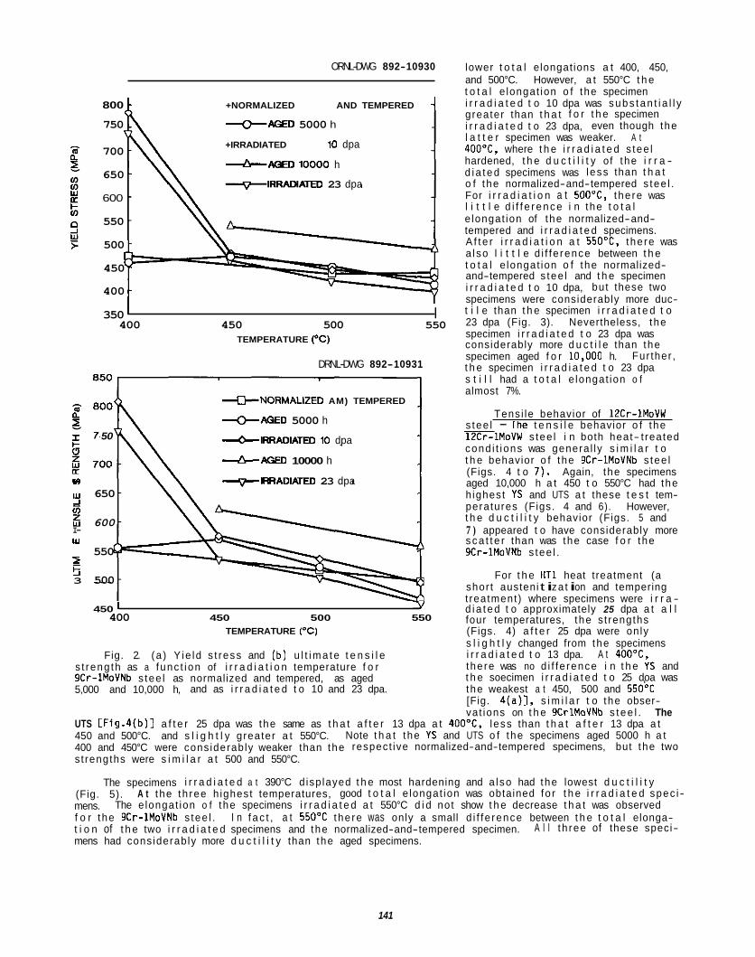
ORNL-DWG 892-10930
800 f +NORMALIZED AND TEMPERED 1 750 +AGED 5000 h
700
650
600
550
500
450
400
+IRRADIATED 10 dpa
&AGED ID000 h
*IRRADIATED 23 dpa
350 I 400 450 500 550
TEMPERATURE ("C)
DRNL-DWG 892-10931
NORMALIZED AM) TEMPERED
+AGED 5000 h
&IRRADIATED 10 dpa 50
&AGED 10000 h
I- (0 -IRRADIATED 23 dpa w 650
5 600 ii I- w
550 2 5 3 500
450 ' Y 400 450 500 550
TEMPERATURE ("C)
Fig. 2. (a ) Y ie ld s t ress and (b) u l t i m a t e t e n s i l e s t reng th as a func t ion of i r r a d i a t i o n temperature f o r 9Cr-1MoVNb s tee l as normalized and tempered, as aged 5,000 and 10,000 h, and as i r r a d i a t e d t o 10 and 23 dpa.
lower t o t a l elongat ions a t 400, 450, and 500°C. However, a t 550°C t h e t o t a l e longat ion o f the specimen i r r a d i a t e d t o 10 dpa was s u b s t a n t i a l l y greater than t h a t f o r t h e specimen i r r a d i a t e d t o 23 dpa, even though the l a t t e r specimen was weaker. A t 400"C, where t h e i r r a d i a t e d s tee l hardened, t h e d u c t i l i t y of t he i r r a - d i a t e d specimens was less than t h a t o f t he normalized-and-tempered s tee l . For i r r a d i a t i o n a t 5OO0C, the re was l i t t l e d i f f e r e n c e i n the t o t a l e longat ion of the normalized-and- tempered and i r r a d i a t e d specimens. A f t e r i r r a d i a t i o n a t 550°C, the re was a l so l i t t l e d i f f e rence between t h e t o t a l e longat ion o f the normalized- and-tempered s tee l and t h e specimen i r r a d i a t e d t o 10 dpa, but these two specimens were considerably more duc- t i l e than t h e specimen i r r a d i a t e d t o 23 dpa (Fig. 3). Nevertheless, the specimen i r r a d i a t e d t o 23 dpa was considerably more d u c t i l e than the specimen aged f o r 10.000 h. t h e specimen i r r a d i a t e d t o 23 dpa s t i l l had a t o t a l e longat ion o f almost 7%.
Fur ther ,
Tens i le behavior of 12Cr-1MoVW s tee l - Ihe t e n s i l e behavior o f t he -1MoVW s tee l i n both heat- t reated cond i t i ons was genera l ly s i m i l a r t o t h e behavior o f t he 9Cr-1MoVNb s tee l (Figs. 4 t o 7 ) . Again, the specimens aged 10,000 h a t 450 t o 550°C had the h ighest YS and UTS a t these t e s t tem- peratures (Figs. 4 and 6). However, t h e d u c t i l i t y behavior (Figs. 5 and 7 ) appeared t o have considerably more s c a t t e r than was the case f o r the 9Cr-1MoVNb s tee l .
For t h e HT1 heat t reatment (a shor t austeni t i za t i on and tempering t reatment) where specimens were i r r a - d i a t e d t o approximately 25 dpa a t a l l four temperatures, the s t rengths (Figs. 4) a f t e r 25 dpa were on ly s l i g h t l y changed from the specimens i r r a d i a t e d t o 13 dpa. A t 4OO0C, the re was no d i f f e rence i n t h e YS and t h e soecimen i r r a d i a t e d t o 25 doa was the weakest a t 450, 500 and 550'C [Fig. 4 ( a ) l , s i m i l a r t o the obser- vat ions on t h e 9CrlMoVNb s t e e l . The
UTS CFig.4(b)l a f t e r 25 dpa was the same as t h a t a f t e r 13 dpa a t 400"C, l ess than t h a t a f t e r 13 dpa a t 450 and 500°C. and s l i g h t l y greater a t 550°C. 400 and 450°C were cons iderab ly weaker than the respect ive normalized-and-tempered specimens, but the two s t rengths were s i m i l a r a t 500 and 550°C.
Note t h a t the YS and UTS o f the specimens aged 5000 h a t
The specimens i r r a d i a t e d a t 390°C d isp layed t h e most hardening and a l so had the lowest d u c t i l i t y (Fig. 5). mens. f o r the 9Cr-1MoVNb s tee l . I n f a c t , a t 55OOC the re was only a small d i f f e rence between t h e t o t a l elonga- t i o n of t h e two i r r a d i a t e d specimens and the normalized-and-tempered specimen. mens had cons iderab ly more d u c t i l i t y than the aged specimens.
A t t he th ree h ighest temperatures, good t o t a l e longat ion was obtained fo r t h e i r r a d i a t e d spec i - The e longat ion o f t he specimens i r r a d i a t e d a t 550°C d i d not show t h e decrease t h a t was observed
A l l t h ree of these speci-
141
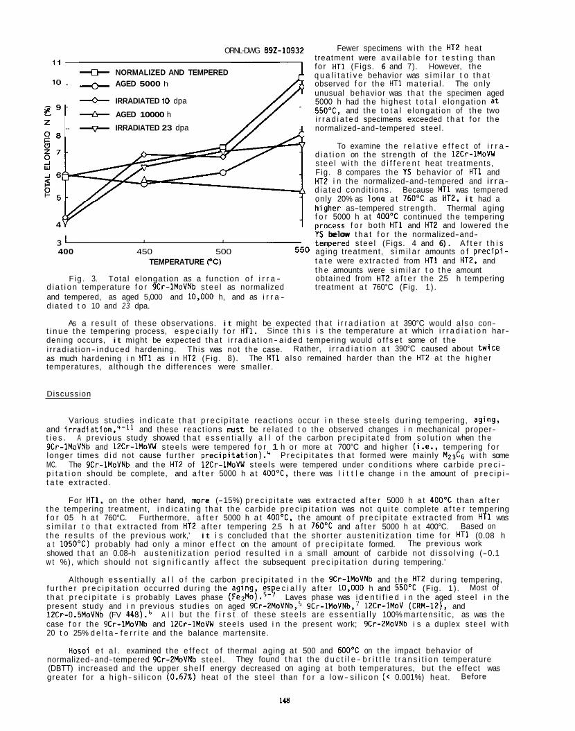
Fewer specimens w i t h the HT2 heat t reatment were a v a i l a b l e f o r t e s t i n g than fo r HT1 (Figs. 6 and 7). However, the 11
q u a l i t a t i v e behavior was s i m i l a r t o t h a t 10 AGED 5000 h observed f o r the HT1 mate r ia l . The on ly
unusual behavior was t h a t the specimen aged 5000 h had the h ighest t o t a l e longat ion a t 550"C, and the t o t a l e longat ion of the two i r r a d i a t e d specimens exceeded t h a t fo r the normalized-and-tempered s tee l .
ORNL-DWG 892-10932
+ NORMALIZED AND TEMPERED
IRRADIATED 10 dpa
--b AGED 10000 h
- IRRADIATED 23 dpa
E 9 - z 2 8
To examine the r e l a t i v e e f f e c t of i r r a - d i a t i o n on the s t rength of the 12Cr-1MoVW s tee l w i t h the d i f f e r e n t heat t reatments, Fig. 8 compares the YS behavior of HT1 and HT2 i n the normalized-and-tempered and irra- d i a t e d condi t ions. Because HT1 was tempered onlv 20% as lono a t 760OC as HT2. i t had a
4 fv hidher as-tempered s t rength. Thermal aging f o r 5000 h a t 4OOOC continued the tempering orocess f o r both HTl and HT2 and lowered t h e YS below t h a t f o r the normalized-and- iempered s tee l (Figs. 4 and 6). A f t e r t h i s
t a t e were ex t rac ted from HT1 and HT2, and t h e amounts were s i m i l a r t o t h e amount obtained from HT2 a f t e r the 2.5 h tempering
3 400 450 500 550 aging treatment, s i m i l a r amounts o f p r e c i p i -
TEMPERATURE ("C)
Fig. 3. Tota l e longat ion as a funct ion o f i r r a - d i a t i o n temperature f o r 9Cr-1MoVNb s tee l as normalized treatment a t 760°C (Fig. 1) . and tempered, as aged 5,000 and 10.000 h, and as i r r a - d ia ted t o 10 and 23 dpa.
As a r e s u l t of these observat ions. i t might be expected t h a t i r r a d i a t i o n a t 390°C would a l so con- t i n u e t h e tempering process, e s p e c i a l l y f o r HT1. dening occurs, i t might be expected t h a t i r r a d i a t i o n- a i d e d tempering would o f f s e t some of the i r rad ia t i on- induced hardening. as much hardening i n HT1 as i n HT2 (Fig. 8). temperatures, al though t h e di f ferences were smal ler.
Since t h i s i s the temperature a t which i r r a d i a t i o n har-
This was not the case. Rather, i r r a d i a t i o n a t 390°C caused about tw ice The HT1 a lso remained harder than the HT2 a t the h igher
Discussion
Various s tud ies i n d i c a t e t h a t p r e c i p i t a t e react ions occur i n these s tee ls du r ing tempering, aging, and i r rad ia t ion, ' - " and these react ions rmst be r e l a t e d t o the observed changes i n mechanical proper- t i e s . A prev ious study showed t h a t e s s e n t i a l l y a l l o f t he carbon p r e c i p i t a t e d from s o l u t i o n when t h e 9Cr-1MoVNb and 12Cr-1MoVW s tee ls were tempered f o r 1 h o r more a t 700°C and h igher (i.e., tempering f o r longer t imes d i d not cause fu r the r p r e ~ i p i t a t i o n ) . ~ P r e c i p i t a t e s t h a t formed were mainly M,,C6 w i t h some MC. The 9Cr-1MoVNb and the HT2 of 12Cr-1MoVW s tee ls were tempered under cond i t i ons where carb ide p r e c i - p i t a t i o n should be complete, and a f t e r 5000 h a t 400"C, the re was l i t t l e change i n t h e amount of p r e c i p i - t a t e ext racted.
For HT1, on the o ther hand, more (-15%) p r e c i p i t a t e was ex t rac ted a f t e r 5000 h a t 40OoC than a f t e r t h e tempering treatment, i n d i c a t i n g t h a t the carb ide p r e c i p i t a t i o n was not q u i t e complete a f t e r tempering f o r 0.5 h a t 760°C. Furthermore, a f t e r 5000 h a t 400"C, the amount o f p r e c i p i t a t e ex t rac ted from HT1 was s i m i l a r t o t h a t ex t rac ted from HT2 a f t e r tempering 2.5 h a t 76OOC and a f t e r 5000 h a t 400°C. t h e r e s u l t s o f t he prev ious work,' i t i s concluded t h a t the shor te r a u s t e n i t i z a t i o n t ime fo r HT1 (0.08 h a t 1050T) probably had on ly a minor e f f e c t on the amount o f p r e c i p i t a t e formed. showed t h a t an 0.08-h a u s t e n i t i z a t i o n per iod resu l ted i n a small amount of carbide not d i s s o l v i n g (-0.1 w t %), which should not s i g n i f i c a n t l y a f f e c t the subsequent p r e c i p i t a t i o n du r ing tempering.'
f u r t h e r p r e c i p i t a t i o n occurred du r ing the aging, es e c i a l l y a f t e r 10.000 h and 550OC (Fig. 1) . t h a t p r e c i p i t a t e i s probably Laves phase ( F ~ ~ M O ) . ~ - ? Laves phase was i d e n t i f i e d i n the aged s tee l i n the present study and i n previous s tud ies on aged 9Cr-2MoVNb,S 9Cr-lMoVNb,' 12Cr-1MoV (CRM-12), and 12Cr-0.5MoVNb (FV 448)." case f o r the 9Cr-1MoVNb and 12Cr-1MoVW s tee ls used i n the present work; 9Cr-2MoVNb i s a duplex s tee l w i t h 20 t o 25% d e l t a - f e r r i t e and the balance martensi te.
Based on
The previous work
Although e s s e n t i a l l y a l l o f t he carbon p r e c i p i t a t e d i n t h e 9Cr-1MoVNb and t h e HT2 dur ing tempering, Most of
A l l bu t the f i r s t of these s tee ls are e s s e n t i a l l y 100% mar tens i t i c , as was the
Hosoi e t a l . examined the e f f e c t o f thermal aging a t 500 and 600OC on the impact behavior of normalized-and-tempered 9Cr-2MoVNb s tee l . (DBTT) increased and the upper s h e l f energy decreased on aging a t both temperatures, but the e f fec t was greater fo r a h i g h- s i l i c o n (0.67%) heat o f the s tee l than f o r a l o w- s i l i c o n ( < 0.001%) heat.
They found t h a t the d u c t i l e - b r i t t l e t r a n s i t i o n temperature
Before
148
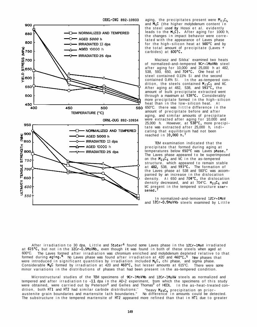
ORNL-DWG 892-10933
* NORMALIZED AND TEMPERED
AGED 5000 h IRRADIATED 13 dpa AGED 10000 h
IRRADIATED 25 dpa
TEMPERATURE ("C)
ORNL-DUG 892-10934 950
AGED 5000 h a 900 a '850 IRRADIATED 13 dpa I I- 0 800 -7- IRRADIATED 25 dpa a: 750
5 700
I- 850
2 600 550
AGED 10000 h
5
Y 5 W
5 .
and 12Cr-0.5MoVNb s tee ls examined by L i t t l e
aging, the p r e c i p i t a t e s present were M,& and MgC ( the h igher molybdenum content i n t h e s t e e l used b Hosoi e t a l . e v i d e n t l y leads t o the MrjCJ. A f t e r aging f o r 1000 h, t h e changes i n impact behavior were co r re- l a t e d w i t h t h e appearance o f Laves phase fo r t h e h i g h- s i l i c o n heat a t 500OC and by t h e t o t a l amount of p r e c i p i t a t e (Laves + carb ides) a t 600'C.
Maziasz and Sikka' examined two heats of normalized-and-tempered 9Cr-1MoVNb s tee l a f t e r aging f o r 10,000 and 25,000 h a t 482, 538, 593, 650, and 704OC. One heat o f s t e e l contained 0.11% S i and t h e second contained 0.4% S i . d i t i o n , t h e s tee ls contained M23C6 and MC. A f te r aging a t 482, 538, and 593"C, t h e amount of bulk p r e c i p i t a t e ex t rac ted went through a maximum a t 538'C. Considerably more p r e c i p i t a t e formed i n the h i g h- s i l i c o n heat than i n the l o w- s i l i c o n heat. A t 650°C. the re was l i t t l e d i f f e rence i n the amount of p r e c i p i t a t e before and a f t e r aging, and s i m i l a r amounts of p r e c i p i t a t e were ex t rac ted a f t e r aging f o r 10,000 and 25,000 h. However, a t 538"C, more p r e c i p i - t a t e was ex t rac ted a f t e r 25,000 h, i n d i - c a t i n g t h a t e q u i l i b r i u m had not been reached i n 10.000 h.'
TEM examination ind ica ted t h a t the p r e c i p i t a t e t h a t formed dur ing aging a t temperatures below 65OoC was Laves phase.7 The Laves phase appeared t o be superimposed on the MZ3C6 and MC i n the as-tempered s t ruc tu re , which appeared t o remain s tab le a t 482, 538, and 593'C. The format ion o f t h e Laves phase a t 538 and 593°C was accom- panied by an increase i n t h e d i s l o c a t i o n dens i ty . A t 650 and 704OC, the d i s l o c a t i o n dens i t y decreased, and a t 704°C. M Z 3 C 6 and MC present i n t h e tempered s t r u c t u r e coar- sened.7
I n the as-tempered con-
I n normalized-and-temoered 12Cr-1MoV
A f te r i r r a d i a t i o n t o 30 dpa, L i t t l e and S to te r6 found some Laves phase i n t h e 12Cr-1MoV i r r a d i a t e d
No Laves phase was found a f t e r i r r a d i a t i o n a t 420 and 460"C.6
a t 615OC. but not i n t h e lECr-O.SMoVNb, even though i t was found i n both of these s tee ls when aged a t 600°C. formed dur ing aging.6 New phases t h a t were in t roduced i n s i g n i f i c a n t q u a n t i t i e s by i r r a d i a t i o n inc luded M&, c h i phase, and sigma phase. Considerable M& formed by i r r a d i a t i o n a t 420 and 460"C, but l esse r amounts a t 615°C. minor v a r i a t i o n s i n the d i s t r i b u t i o n s of phases t h a t had been present i n the as-tempered cond i t i on .
tempered and a f t e r i r r a d i a t i o n t o -11 dpa i n t h e AD-2 experiment, from which the specimens o f t h i s study were obtained, were c a r r i e d out by Peterson8 and Gel les and Thomasg o f HEDL. d i t i o n , both HT1 and HT2 had s i m i l a r carbide d i s t r i b u t i o n s : ' aus ten i te g r a i n boundaries and mar tens i te l a t h boundaries." No d i f ference i n amounts could be detected. The subst ructure i n t h e tempered mar tens i te of HT2 appeared more re f i ned than t h a t i n HT1 due t o greater
The Laves formed a f t e r i r r a d i a t i o n was chromium enriched and molybdenum depleted r e l a t i v e t o t h a t
There were some
Mic ros t ruc tu ra l s tud ies of the TEM specimens of 9Cr-1MoVNb and 12Cr-1MoVW s tee ls as normalized and
I n the as- heat- t reated con- "heavy Mz3C6 p r e c i p i t a t i o n on p r i o r -
149
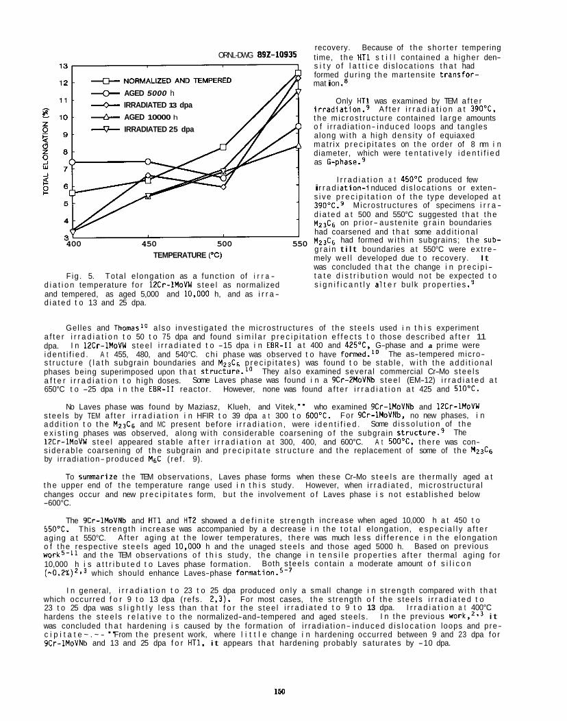
ORNL-DWG 892-10935
+ AGED 5000 h IRRADIATED 13 dpa
& AGED 10000 h
+ IRRADIATED 25 dpa
400 450 500 550 TEMPERATURE ("C)
Fig . 5. Tota l e longat ion as a funct ion of i r r a - d i a t i o n temperature fo r 12Cr-1MoVW s tee l as normalized
recovery. Because of t h e sho r te r tempering t ime, t h e HT1 s t i l l contained a h igher den- s i t y o f l a t t i c e d i s loca t i ons t h a t had formed du r ing t h e mar tens i te t rans fo r - mat i on . e
Only HT1 was examined by TEM a f t e r i r r a d i a t i o n . 9 A f t e r i r r a d i a t i o n a t 390"C, t h e m ic ros t ruc tu re contained l a r g e amounts o f i r rad ia t i on- induced loops and tang les along w i t h a h igh dens i t y o f equiaxed ma t r i x p r e c i p i t a t e s on t h e order of 8 nm i n diameter, which were t e n t a t i v e l y i d e n t i f i e d as G-phase.9
I r r a d i a t i o n a t 450OC produced few i r r a d i a t i o n - i nduced d i s loca t i ons o r exten- s i v e p r e c i p i t a t i o n o f t h e type developed a t 390"C.9 Microst ruc tures of specimens i r r a - d i a t e d a t 500 and 550°C suggested t h a t t h e M Z 3 C 6 on p r io r- aus ten i te g r a i n boundaries had coarsened and t h a t some add i t i ona l M z 3 C 6 had formed w i t h i n subgrains; t h e sub- g r a i n t i l t boundaries a t 550°C were ex t re- mely we l l developed due t o recovery. It was concluded t h a t t h e change i n p r e c i p i - t a t e d i s t r i b u t i o n would no t be expected t o s i g n i f i c a n t l y a1 t e r bu lk p roper t i es .9
and tempered, as aged 5,000 and 10.000 h, and as i r r a - d i a t e d t o 13 and 25 dpa.
Gel les and Thomaslo a l so i nves t i ga ted t h e microst ruc tures of t h e s tee l s used i n t h i s experiment
I n 12Cr-1MoVW s tee l i r r a d i a t e d t o -15 dpa i n EBR-I1 a t 400 and 425'C, G-phase and a prime were
They a lso examined several commercial Cr-Mo s tee l s
However, none was found a f t e r i r r a d i a t i o n a t 425 and 510'C.
No Laves phase was found by Maziasz, Klueh, and Vitek," who examined 9Cr-1MoVNb and 12Cr-1MoVW
a f t e r i r r a d i a t i o n t o 50 t o 75 dpa and found s i m i l a r p r e c i p i t a t i o n e f f e c t s t o those descr ibed a f t e r 11 dpa. i d e n t i f i e d . The as-tempered micro- s t r u c t u r e ( l a t h subgrain boundaries and M z 3 C 6 p r e c i p i t a t e s ) was found t o be s tab le , w i t h t h e a d d i t i o n a l phases being superimposed upon t h a t structure.'O a f t e r i r r a d i a t i o n t o h igh doses. 650°C t o -25 dpa i n t h e EBR-I1 reactor.
A t 455, 480, and 540°C. c h i phase was observed t o have forrned.'O
Some Laves phase was found i n a 9Cr-2MoVNb s tee l (EM-12) i r r a d i a t e d a t
s tee l s by TEM a f t e r i r r a d i a t i o n i n HFIR t o 39 dpa a t 300 t o 600°C. a d d i t i o n t o t h e M23C6 and MC present before i r r a d i a t i o n , were i d e n t i f i e d . e x i s t i n g phases was observed, along w i t h considerable coarsening o f the subgrain s t r u ~ t u r e . ~ 12Cr-1MoVW s tee l appeared s tab le a f t e r i r r a d i a t i o n a t 300, 400, and 600°C. A t 500°C. the re was con- s ide rab le coarsening of t h e subgrain and p r e c i p i t a t e s t r u c t u r e and t h e replacement of some of t h e M23C6 by i r rad ia t ion- produced M6C ( re f . 9).
To summarize t h e TEM observat ions, Laves phase forms when these Cr-Mo s t e e l s are thermal ly aged a t
For gCr-lMoVNb, no new phases, i n Some d i s s o l u t i o n of t h e
The
t h e upper end of t h e temperature range used i n t h i s study. However, when i r r a d i a t e d , m ic ros t ruc tu ra l changes occur and new p r e c i p i t a t e s form, bu t t h e involvement o f Laves phase i s no t es tab l ished below -600°C.
The 9Cr-1MoVNb and HT1 and HT2 showed a d e f i n i t e s t reng th increase when aged 10,000 h a t 450 t o 550'C. aging a t 550°C. o f t h e respect ive s t e e l s aged 10.000 h and t h e unaged s tee l s and those aged 5000 h. work5-11 and t h e TEM observat ions o f t h i s study, t h e change i n t e n s i l e p rope r t i es a f t e r thermal aging fo r 10,000 h i s a t t r i b u t e d t o Laves phase format ion. ( - 0 . 2 % ) 2 9 3 which should enhance Laves-phase
which occurred f o r 9 t o 13 dpa ( re fs . 2,3). For most cases, t h e s t rength o f t h e s tee l s i r r a d i a t e d t o 23 t o 25 dpa was s l i g h t l y l ess than t h a t f o r t h e s tee l i r r a d i a t e d t o 9 t o 13 dpa. hardens the s t e e l s r e l a t i v e t o t h e normalized-and-tempered and aged s tee ls . was concluded t h a t hardening i s caused by t h e format ion of i r rad ia t i on- induced d i s l o c a t i o n loops and pre- c i p i t a t e ~ . ~ - " From t h e present work, where l i t t l e change i n hardening occurred between 9 and 23 dpa fo r 9Cr-1MoVNb and 13 and 25 dpa f o r HT1, it appears t h a t hardening probably satura tes by -10 dpa.
This s t reng th increase was accompanied by a decrease i n t h e t o t a l e longat ion, e s p e c i a l l y a f t e r
Based on previous A f te r aging a t t h e lower temperatures, t he re was much l ess d i f f e r e n c e i n t h e e longat ion
Both s tee l s conta in a moderate amount o f s i l i c o n
I n general, i r r a d i a t i o n t o 23 t o 25 dpa produced on l y a small change i n s t reng th compared w i t h t h a t
I n t h e previous ~ o r k , ~ . ~ i t I r r a d i a t i o n a t 400°C
1W
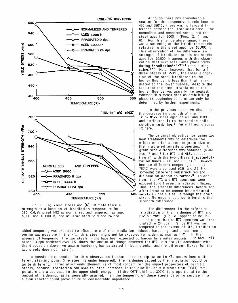
ORNL-DUG 892-10936 680
NORMALIZED AND TEMPERED
AGED 5000 h IRRADIATED 9 dpa
640
600 & AGED 10000 h
E IRRADIATED 24 dpa a
560
$ 520
0
5 460 d
440
400 400 450 500 550
TEMPERATURE ( O C )
ORNL-DWG 892-10937 760 1 1
+NORMALIZED AND
+AGED 5000 h 520 - *IRRADIATED 9 dpa
A AGED 10000 h
*IRRADIATED 24 dpa
Although the re was considerable s c a t t e r f o r t h e respect ive s tee ls between 450 and 550"C, the re was no l a r g e d i f - ference between the i r r a d i a t e d s tee l , t he normalized-and-tempered s tee l , and the s t e e l aged fo r 5000 h (Figs. 2, 4, and 6). For t h i s temperature range, the re was a so f ten ing of the i r r a d i a t e d s tee ls r e l a t i v e t o t h e s tee l aged fo r 10.000 h. Th is observat ion of t h e di f ference i n s t reng th o f i r r a d i a t e d s tee ls and s t e e l s aged f o r 10,000 h agrees w i t h t h e obser- va t ion t h a t much less Laves phase forms dur ing i r r a d i a t i ~ n ~ ~ ~ ~ ~ ~ " than du r ing
Note, however, t h a t fo r a l l t h ree s t e e l s a t 550"C, t h e t o t a l elonga- t i o n of the s tee l i r r a d i a t e d t o the h igher f luence i s l e s s than t h a t i r r a - d i a t e d t o the lower f luence, desp i te the fac t t h a t the s tee l i r r a d i a t e d t o the h igher f luence was u s u a l l y the weakest. Whether t h i s means t h a t an e m b r i t t l i n g phase i s beginning t o f o r m can only be determined by fu r the r experiments.
I n the prev ious paper, we discussed t h e decrease i n s t reng th of the 12Cr-1MoVW s tee l aged a t 400 and 450°C and a t t r i b u t e d i t t o i n t e r a c t i o n s o l i d - s o l u t i o n hardening.3 i t here.
We w i l l no t discuss
The o r i g i n a l o b j e c t i v e fo r us ing two heat t reatments was t o determine t h e e f f e c t o f p r i o r - a u s t e n i t e g r a i n s i z e on t h e i r r a d i a t e d t e n s i l e proper t ies . ' A g ra in s i z e d i f f e r e n c e was obtained (ASTM Nos. 7 and 5 f o r HT1 and HT2, respec- t i v e l y ) w i t h the two d i f f e r e n t a u s t e n i t i - z a t i o n t imes (0.08 and 0.5 h).3 However, because d i f f e r e n t tempering t imes a t 760°C were a l so used (0.5 and 2.5 h) , somewhat d i f f e r e n t subst ructures and d i s l o c a t i o n d e n s i t i e s formed.8 I n addi- t i o n , the HT1 and HT2 specimens were exposed t o d i f f e r e n t i r r a d i a t i o n f luxes. Thus. the s t rena th di f ferences before and
460 I u a f t e r i r r a d i a t i o n cannot be a t t r i b u t e d 400 450 500 550 sole ly t o g r a i n size, al though the g ra in
s i z e d i f f e rence should c o n t r i b u t e t o t h e s t reng th d i f ference.
TEMPERATURE ("C)
Fig. 6. (a ) Y ie ld s t ress and (b ) u l t i m a t e t e n s i l e s t reng th as a funct ion of i r r a d i a t i o n temperature fo r 12Cr-1MoVW s t e e l HT2 as normalized and tempered, as aged i r r a d i a t i o n on the hardening of HT1 and 5,000 and 10,000 h, and as i r r a d i a t e d t o 9 and 24 dpa.
The di f ferences i n the e f f e c t o f
HT2 a t 390°C (F ig . 8 ) appear t o be un- usual (note t h a t no HT2 specimen was i r r a - d i a t e d t o 24 dpa). Since HT1 was n o t tempered t o the extent o f HT2, i r r a d i a t i o n -
aided tempering was expected t o o f fset some of the i r rad ia t i on- induced hardening, and s ince more tem- per ing was poss ib le i n t h e HT1, t h i s s tee l might not be expected t o harden as much as HT2. absence o f tempering, t h e two s tee ls might have been expected t o harden by s i m i l a r amounts. a f t e r 13 dpa hardened over 1.5 t imes the amount of change observed f o r HT2 i n 9 dpa ( i n accordance w i t h t h e d iscuss ion above, we assume hardening has saturated i n both s tee ls , and the d i f f e r e n t f luxes fo r the two s t e e l s does not ma t te r ) .
f e r e n t s t a r t i n g p o i n t ( t h e s tee l i s under tempered), t h e hardening caused by the i r r a d i a t i o n cou ld be q u i t e d i f f e r e n t . s t e e l s , because i r r a d i a t i o n can lead t o l a r g e increases i n the d u c t i l e - b r i t t l e t r a n s i t i o n (OBTT) tem- pera tu re and a decrease i n t h e upper shel f energy. I f the OBTT s h i f t a t 390°C i s p ropor t i ona l t o the amount of hardening, as i s genera l ly assumed, then the tempering o f these s tee ls p r i o r t o se rv i ce i n a fus ion reac to r cou ld prove t o be of considerable importance.
I n the I n fac t , HT1
A poss ib le exp lanat ion fo r t h i s observat ion i s t h a t s ince p r e c i p i t a t i o n i n HT1 occurs from a d i f -
I r r a d i a t i o n embri t t lement i s of most concern f o r t h e impact p roper t i es of f e r r i t i c
161
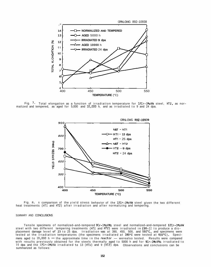
ORNL-DWG 892-10938 .- 14 NORMALIZED AND TEMPERED
13 AGED 5000 h
12 + IRRADIATED 9 dpa
d- AGED 10000 h
+ IRRADIATED 24 dpa 5 11
!z 10 9 9 9
s e 7
W J 8
6
5
4 400 450 500 550
TEMPERATURE ("C)
F ig . 7. Tota l e longat ion as a funct ion of i r r a d i a t i o n temperature fo r 12Cr-1MoVW stee l , HT2, as nor- mal ized and tempered, as aged fo r 5,000 and 10.000 h, and as i r r a d i a t e d t o 9 and 24 dpa.
ORNL-OWG 692-10939 900,
N8T - HT1
800 + HTI - 13 dpa
HT1 - 25 dpa - d NBT - HT2 + HT2 - 9 dpa
m a ~ 700
E HT2 - 24 dpa IL
r
: 9 e
600
500
400 450 500 550 TEMPERATURE ("C)
Fig. 8. A comparison of the y i e l d s t ress behavior of t he 12Cr-IMoVW s tee l given the two d i f f e r e n t heat t reatments (HT1 and HT2) a f t e r i r r a d i a t i o n and a f t e r normal iz ing and tempering.
SUMMARY AND CONCLUSIONS
Tens i le specimens o f normalized-and-tempered 9Cr-1MoVNb s tee l and normalized-and-tempered 12Cr-1MoVW s t e e l w i t h two d i f f e ren t tempering treatments (HT1 and HT2) were i r r a d i a t e d i n E B R - I 1 t o produce a d i s - placement damage l e v e l of 23 t o 25 dpa. I r r a d i a t i o n was a t 390, 450, 500, and 550"C, and specimens were tes ted a t the i r r a d i a t i o n temperatures ( the specimens i r r a d i a t e d a t 390°C were tes ted a t 400OC). Speci- mens aged t o 10.000 h - the approximate t ime i n t h e reac to r - were a l so tes ted. Results were compared w i t h r e s u l t s p rev ious ly obtained f o r the s tee ls thermal ly aged t o 5000 h and f o r 9Cr-1MoVNb i r r a d i a t e d t o 10 dpa and the 12Cr-1MoVW i r r a d i a t e d t o 13 (HT1) and 9 (HT2) dpa. summarized as fo l l ows :
Observations and conclusions can be
152
1. Thermal aging fo r 10,000 h a t 450 t o 55OOC caused an increase i n s t rength and a decrease i n t o t a l e longat ion r e l a t i v e t o t h e normalized-and-tempered specimen. This change i s probably r e l a ted t o t h e formation o f Laves phase.
mater ia l ; there was l i t t l e change r e l a t i v e t o the s tee l s i r r a d i a t e d t o 9 t o 13 dpa. This hardening was accompanied by a loss i n d u c t i l i t y . p rec ip i t a t i on .
cimens. There was l i t t l e d i f f e rence between t h e two d i f f e r e n t i r r a d i a t i o n leve ls . The greatest loss of d u c t i l i t y occurred f o r the specimens aged 10,000 h at 55OOC. This embrit t lement was a t t r i b u t e d t o Laves phase formation dur ing aging. t e n s i l e t e s t s a f t e r i r r a d i a t i o n t h a t i t does on specimens thermal ly aged a t the same temperature.
L i t t l e change was observed a f t e r aging fo r 5000 h.
I r r a d i a t i o n t o 23 t o 25 dpa caused an increase i n s t rength a t 39OoC r e l a t i v e t o aged and unaged
Hardening was a t t r i b u t e d t o radiat ion- induced damage s t ruc tures and
2.
3. I r r a d i a t i o n caused a decrease i n s t rength a t 450, 500, and 55OoC r e l a t i v e t o thermal ly aged spe-
Ind ica t ions are t h a t Laves phase does not have t h e e m b r l t t l i n g r o l e i n
REFERENCES
1.
2.
3.
4.
5.
6.
7.
8.
9.
10.
11.
R. J. Puigh and N. F. Panayotou, US Oepartment of Energy Report OOE/ER-0045/3 (Off ice of Fusion Energy, Washington, DC, 1980). p . 260.
R. L. Klueh and J. M. Vitek, 3. Nucl. Mater. 132 (1985) 27.
R. L. Klueh and J. M. V i tek, J. Nucl. Mater. 137 (1985) 44.
J . M. Vi tek and R. L. Klueh, Met. Trans. A 14A (1983) 1047.
Y. Hosoi, N. Wade, S . Kunimitsu, and T. U r i t a , J. Nucl. Mater. 141-143 (1986) 461.
E. A. L i t t l e and L. P. Stoter , E f f ec t s of Radiat ion on Mater ia ls : Proceedings of Eleventh I n te rna t i ona l Symposium, ASTM STP 782, Eds. H. R. Brager and J. S. Pe r r i n (American Society f o r Test ing and Mater ia ls , Phi ladelphia, 1982), pp. 207.
P. J. Maziasz and V. K. Sikka, US Oepartment o f Energy Report DOE/ER-0045/15 (Off ice of Fusion Energy, Washington, DC, 1985). p. 102.
D. T. Petersen, US Department of Energy Report DOE/ER-0045/5 (O f f i ce of Fusion Energy, Washington, DC, 1980), p. 212.
D. S . Gelles and L. E. Thomas, US Department of Energy Report DOE/ER-0045/8 (Off ice of Fusion Energy, Washington, OC, 1982). p. 343.
0. S. Gelles and L. E. Thomas, F e r r i t i c A l loys fo r use i n Nuclear Energy Technologies, Eds. J. W. Davis and 0. J. Michel (The Me ta l l u rg i ca l Society o f AIME, Warrendale, Pennsylvania, 1984). pp. 559.
P. J. Maziasz, R. L. Klueh, and J. M. Vitek, J. Nucl. Mater. 141-143 (1986) 929.

IMPACT BEHAVIOR OF 9Cr-1MoVNb AND 12Cr-1MoVW STEELS IRRADIATED I N HFIR - R. L. Klueh and 0. J. Alexander (Oak Ridge Nat ional Laboratory)
OBJECTIVE
The goal o f t h i s study i s t o evaluate t h e impact behavior of i r r a d i a t e d f e r r i t i c s tee l s and r e l a t e t h e change i n p roper t i es t o t h e i r r a d i a t i o n damage.
SUMMARY
Impact specimens of 9Cr-1MoVNb and 12Cr-1MoVW s tee l s were i r r a d i a t e d i n t h e High F lux Iso tope Reactor (HFIR) a t 300 and 400°C t o as high as 42 dpa. I r r a d i a t i o n caused l a r g e increases i n t h e d u c t i l e - b r i t t l e t r a n s i t i o n temperature (DBTT) o f both s tee ls , w i t h t h e increase being greater a t 400°C than a t 3OOOC. A t 4OO0C, s h i f t s i n DBTT o f 204 and 242°C were observed f o r t h e 9Cr-1MoVNb and 12Cr-1MoVW stee ls , respect ive ly . These are t h e l a rges t s h i f t s ever observed f o r these s tee l s and are a t t r i b u t e d t o t h e h igher he l ium concent ra t ion generated dur ing i r r a d i a t i o n i n HFIR.
PROGRESS AND STATUS
In t roduc t i on
A major concern w i t h t h e f e r r i t i c s tee l s f o r f us ion reactor app l i ca t i ons invo lves t h e e f fec t of i r r a d i a t i o n on t h e impact proper t ies . s i t i o n temperature (DBTT) and decreases i n t h e upper- shel f energy (USE) . Even i f t h e DBTT i s below room temperature before i r r a d i a t i o n , i t can be we l l above room temperature a f t e r i r r a d i a t i ~ n . ' - ~
I r r a d i a t i o n can cause l a r g e increases i n t h e d u c t i l e - b r i t t l e t r a n-
Neutron i r r a d i a t i o n o f 12Cr-1MoVW s tee l i n t h e Experimental Breeder Reactor 11 (EBR-11) and t h e High F lux Iso tope Reactor (HFIR) up t o 6 x l o z 6 n/m2 a t 50 t o 55OOC has i nd i ca ted t h a t t h e s h i f t i n DBTT (ADBTT), as measured by Charpy impact t es t s , can vary, depending on i r r a d i a t i o n cond i t ions. I n many cases s h i f t s of over 100°C have been observed,'+ and i n some instances they approach 200°C.5 There i s some i n d i c a t i o n t h a t t h e s h i f t i n DBTT satura tes a f t e r i r r a d i a t i o n t o -13 dpa i n EBR- I I . 3 A maximum i n t h e ADBTT w i t h i r r a d i a t i o n temperature was found t o occur f o r 12Cr-1MoVW s tee l a t -400"C.5 Below t h e maximum, the re was a f a i r l y l a r g e s h i f t , and above 400°C t h e magnitude of t h e s h i f t decreased r a p i d l y t o q u i t e low value^.^ No such maximum was observed f o r i r r a d i a t e d 9Cr-1MoVNb al though l ess data were a v a i l a b l e fo r t h i s s tee l . Instead, t h e l i m i t e d data f o r t h e 9Cr-1MoVNb s tee l i nd i ca ted t h a t t h e ADBTT decreased s lowly between 50 and 400"C, a f t e r which i t decreased r a p i d l y t o a low value.7
neutrons from t h e fusion react ion. I n add i t ion , l a r g e amounts of t ransmutat ion hel ium w i l l form i n t h e ma te r ia l . To study t h e e f f e c t o f s imultaneously produced displacement damage and t ransmutat ion helium, n i cke l has been added t o t h e 9Cr-1MoVNb and 12Cr-1MoVW steel^.^ When these nickel-doped s tee l s are i r r a - d i a t e d i n a mixed-spectrum reactor , such as HFIR, displacement damage i s produced by t h e fas t neutrons i n t h e spectrum, and he l ium i s produced by a two-step t ransmutat ion reac t i on of s 8 N i w i t h t h e thermal neutrons i n t h e spectrum. proper tie^.^,'^ and a previous paper considered t h e e f f e c t o f hel ium on t h e impact p rope r t i es a f t e r i r r a - d i a t i o n a t -50"C.7 produced i n t h e standard 9Cr-1MoVNb and 12Cr-1MoVW s tee l s when i r r a d i a t e d i n HFIR, because o f t h e n i c k e l present i n t h e composit ions of these s tee ls .
4 0 0 T up t o 42 dpa w i l l be presented. 12Cr-1MoVW s tee l should a l l ow a b e t t e r comparison o f t h e e f f e c t o f i r r a d i a t i o n on t h e two s tee ls .
A s tee l i n a fus ion reac to r f i r s t wa l l w i l l experience displacement damage from t h e high-energy
This technique has been used t o examine t h e e f fec t of hel ium on t h e t e n s i l e
Although nickel-doped s t e e l s w i l l not be discussed i n t h i s repo r t , hel ium i s a lso
I n t h i s repo r t , impact p rope r t i es o f 9Cr-1MoVNb and 12Cr-1MoVW s tee l s i r r a d i a t e d i n HFIR a t 300 and Such high- f luence data i n t h e v i c i n i t y o f t h e observed peak fo r
Experimental Procedure
Charpy impact specimens were obtained from 25-kg e lec t ros lag- remel ted heats o f standard 9Cr-1MoVNb (heat XA 3590) and standard 12Cr-1MoVW (heat XAA 3587) s t e e l prepared by Combustion Engineering, Inc., Chattanooga, Tennessee. The chemical composit ion of these s tee l s i s given i n Table 1.
Specimens were obtained from h o t - r o l l e d p l a t e i n t h e normalized-and-tempered cond i t i on . The nor- m a l i z i n g treatment f o r t h e 9Cr-1MoVNb s tee l was 0.5 h a t 1040°C and f o r t h e 12Cr-1MoVW s tee l was 0.5 h
155
Ele- 9Cr-1MoVNb ment (Heat XAA 3590)
C 0.09 T i 0.002 Mn 0.36 Co 0.013 P 0.008 cu 0.03 S 0.004 A1 0.013 S i 0.08 B <0.001 N i 0.11 w 0.01 C i . 8.62 As <0.001 No 0.98 Sn 0.003 V 0.209 Z r <0.001 Nb 0.063 N 0.050
0 0.007
upper-shelf energy (USE), impact energy- temperature 'curves were generated by f i t t i n g the data w i t h a hyperbo l i c tangent funct ion.
Ele- 12Cr-1MoVW microst ructures were obtained by such heat ment (Heat XA 3587) treatments. D e t a i l s on heat t reatment and
c 0.21 T i 0.003 Mn 0.50 Mn 0.017 M in ia tu re Charpy V-notch (C,) speci- P 0.011 Cu 0.05 mens were machined from the heat- t reated S 0.004 A1 0.030 p l a t e i n the l o n g i t u d i n a l (LT) o r i e n t a t i o n . S i 0.18 B <0.001 The subsize specimens were e s s e n t i a l l y N i 0.43 W 0.54 one-half t he standard size. They measured C r 11.99 As <0.001 5 by 5 by 25.4 m and contained a 0.76-m- Mo 0.93 Sn 0.002 deep 30' V-notch w i t h a 0.05- t o 0.08-m- V 0.27 Z r tO.OO1 roo t radius. Such m in ia tu re specimens show Nb 0.018 N 0.020 impact behavior s i m i l a r t o t h a t found i n
0 0.005 f u l l - s i z e d C v specimens."slz
m ic ros t ruc tu re have been p u b l i ~ h e d . ~
Because of space l i m i t a t i o n s i n the HFIR i r r a d i a t i o n capsules, only f i v e specimens were a v a i l a b l e f o r each s tee l . The major o b j e c t i v e of these s tud ies was the determinat ion o f the s h i f t i n DBTT, and the USE o f ten had t o be determined based on a l i m i t e d number of specimens. The DBTT was ca lcu la ted fo r t h e energy corresponding t o one-half o f t he USE and a t f i xed energy l e v e l s of 5.5 and 9.2 J (analogous t o t h e 41 and 68 J o f t e n used f o r f u l l - s i z e Charpy specimens). used.
For t h i s repor t , t he k - U S E value w i l l be
Results and Discussion
Charpy impact r e s u l t s are given i n Table 2. he l ium concent ra t ions f o r each set o f specimens. t o 42 dpa, wh i le those i r r a d i a t e d a t 300°C had l e v e l s of 20 t o 34 dpa. s ide rab ly d i f f e r e n t i n the 9Cr-1MoVNb and 12Cr-1MoVW stee ls , because o f the greater n i c k e l content o f the 12Cr-1MoVW (0.43% i n t h e 12Cr-1MoVW compared t o 0.11% N i i n 9Cr-1MoVNb).
Also given are t h e displacement-damage l e v e l s and Specimens i r r a d i a t e d a t 400°C had damage l e v e l s of 38
Helium concent ra t ions were con-
Figures 1 and 2 show the Charpy curves fo r each s t e e l i n t h e i r r a d i a t e d and u n i r r a d i a t e d cond i t i on . Values f o r ADBTT determined us ing t h e DBTT determined as 1/2 USE are shown i n Table 2. increases i n OBTT o f over 100°C occurred a t 300°C and over 200°C a t 400°C.
For both s tee ls ,
Comin, Vi tek, and Klueh6 i r r a d i a t e d h a l f - s i z e specimens of the same heat o f 12Cr-1MoVW s tee l used i n t h i s experiment t o 12 dpa a t 390°C i n EBR-I1 and found a ADBTT o f 122'C. Charpy r e s u l t s f o r 12Cr-1MoVW s tee l i r r a d i a t e d a t 390°C i n EBR- I1 t o 13 and 26 dpa and observed ADBTT changes of 124 and 144°C. respec t i ve l y , which i s s i m i l a r i n magnitude t o the change observed by Corwin, V i tek , and Klueh.6 Smidt e t al . ' i r r a d i a t e d 12Cr-1MoVW s tee l a t a somewhat h igher temperature (419°C) t o about 6 dpa ( re f . 1). They observed a AOBTT of -108'C. As discussed above, the AOBTT decreases a t i r r a d i a t i o n temperatures above about 400"C,4 so a lower ADBTT might be expected a t t he h igher i r r a d i a t i o n temperature.
Hu and Gel les3 repor ted
156
Table 2. Impact p roper t ies o f Cr-Mo s tee ls i r r a d i a t e d i n HFIR
Condit ions T rans i t i on Temperature, "C
Temper- Displacement Helium A D B T T ~ USE a tu re @pa) (appm) 1/2 USE 5.5 J 9.2 J ("C) ( J ) ("C)
12Cr-1MoVW (Heat XAA 3587)
Control 0 0 -18 4 8 -35 26 300 20-34 51-90 87 86 87 105 15 400 3-42 9%111 224 226 -- 242 8
9Cr-1MoVNb (Heat XA 3590)
Control 0 0 -29 -49 -37 25 300 20-34 1&27 138 136 138 167 20 400 37-42 3&34 175 114 182 204 12
aca lcu la ted from $'z USE DBTT.
DaYL-OK. OS-12YL
9 C r - l MoVNb ( H e a t X A A 35901
0 NORMALIZED AND TEMPERED A 20-34 dpo. 300 OC. HFIR V 37-42 dpo. 400 OC. HFIR
30
0 -200
TEMPERATURE ( O C )
F ig. 1. Charpy impact p roper t ies of 9Cr-1MoVNb s tee l i n t h e un i r r ad ia ted cond i t ion and a f t e r i r r a - d i a t i o n t o 20 t o 34 dpa ( 1 W 7 appm He) a t 30OoC and t o 37 t o 42 dpa (30-34 appm He) a t 400°C i n HFIR.
Hu and Gel les3 a lso i r r a d i a t e d 9Cr-1MoVNb t o 13 and 26 dpa and found ADBTTs of 52 and 54"C, respec- t i v e l y . These r e s u l t s were taken t o i nd i ca te t h a t a sa tura t ion i n ADBTT must occur a f t e r i r r a d i a t i o n t o -13 dpa. Likewise, sa tura t ion apparently a lso occurred f o r the 12Cr-1MoVW s tee l , because the d i f f e rence between 124 and 144°C f o r 13 and 26 dpa ( r e f . 3), respect ively, i s probably w i t h i n experimental e r ro r .
are s i g n i f i c a n t l y d i f f e r e n t from those obtained when these s tee l s are i r r a d i a t e d a t 390°C i n EBR-11. change observed f o r the 9Cr-1MoVNb a f t e r -40 dpa i n t h e present experiment was 204°C compared t o 54°C i n E B R - I 1 a f t e r 26 dpa. a f t e r 26 dpa i n EBR-11. specimens i r r a d i a t e d i n HFIR. HFIR than the sa tu ra t i on values found i n t h e s tee ls i r r a d i a t e d i n EBR-11.
Results from the present s tudies on the 9Cr-1MoVNb and 12Cr-1MoVW s tee ls i r r a d i a t e d i n HFIR a t 400°C The
For the 12Cr-1MoVW s tee l , a 242°C s h i f t was found i n HFIR, compared t o only 144°C Thus, the sa tura t ion i nd i ca ted a f t e r i r r a d i a t i o n i n EBR-I1 does not apply t o
Furthermore, t h e s h i f t i n DBTT i s considerably h igher when i r r a d i a t e d i n
167
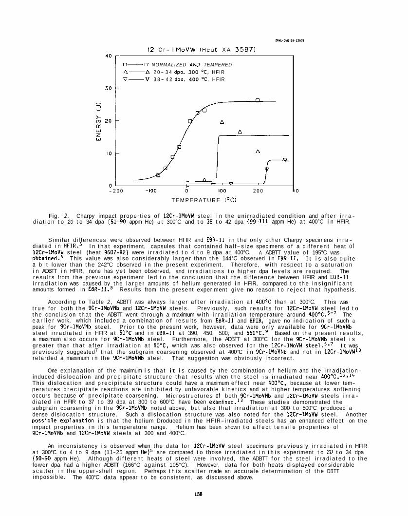
12 C r - l M o V W ( H e a t X A 3 5 8 7 )
0- 0 NORMALIZED A N 0 TEMPERED A- A 2 0 - 3 4 dpo. 300 "C. HFIR V- V 3 8 - 4 2 dpo. 400 OC. HFIR
A
01 c ,-. - 2 0 0 -100 0 100 2 0 0
T E M P E R A T U R E ('C) I O
Fig. 2 . Charpy impact p roper t i es o f 12Cr-1MoVW stee l i n the u n i r r a d i a t e d cond i t i on and a f t e r i r r a - d i a t i o n t o 20 t o 34 dpa (51-90 appm He) a t 300°C and t o 38 t o 42 dpa ( 9 9 4 1 1 appm He) a t 400°C i n HFIR.
S i m i l a r d i f ferences were observed between HFIR and EBR-I1 i n t h e on ly o the r Charpy specimens i r r a - d i a t e d i n HFIR.5 12Cr-1MoVW s tee l (heat 9607-R2) were i r r a d i a t e d t o 4 t o 9 dpa a t 400°C. ~ b t a i n e d . ~ a b i t lower than t h e 242°C observed i n t h e present experiment. Therefore, w i t h respect t o a s a t u r a t i o n i n ADBTT i n HFIR, none has y e t been observed, and i r r a d i a t i o n s t o h igher dpa l e v e l s are required. The r e s u l t s from t h e prev ious experiment l e d t o the conclusion t h a t the d i f f e r e n c e between HFIR and EBR-I1 i r r a d i a t i o n was caused by the l a r g e r amounts o f hel ium generated i n HFIR, compared t o t h e i n s i g n i f i c a n t amounts formed i n EBR-II.5 Results from the present experiment g i v e no reason t o r e j e c t t h a t hypothesis.
According t o Table 2 , ADBTT was always l a r g e r a f t e r i r r a d i a t i o n a t 400OC than a t 300°C. t r u e fo r both t h e 9Cr-1MoVNb and 12Cr-1MoVW stee ls . Previously, such r e s u l t s fo r 12Cr-1MoVW s tee l l e d t o t h e conclusion t h a t the ADBTT went through a maximum w i t h i r r a d i a t i o n temperature around 400"C.s'7 e a r l i e r work, which inc luded a combination o f r e s u l t s from EBR-I1 and HFIR, gave no i n d i c a t i o n of such a peak fo r 9Cr-1MoVNb s tee l . s tee l i r r a d i a t e d i n HFIR a t 50°C and i n EBR-I1 a t 390, 450, 500, and 550°C.9 a maximum a lso occurs f o r 9Cr-1MoVNb s tee l . Furthermore, the ADBTT a t 300°C f o r t h e 9Cr-1MoVNb s t e e l i s greater than t h a t a f t e r i r r a d i a t i o n a t 50"C, which was a l so observed f o r the 12Cr-1MoVW prev ious ly suggested7 t h a t the subgrain coarsening observed a t 400°C i n 9Cr-1MoVNb and not i n 12Cr-1MoVW13 re tarded a maximum i n the 9Cr-1MoVNb s tee l .
One exp lanat ion of the maximum i s t h a t i t i s caused by the combination o f he l ium and t h e i r r a d i a t i o n -
I n t h a t experiment, capsules t h a t contained h a l f - s i z e specimens o f a d i f f e r e n t heat of
I t i s a l s o q u i t e A ADBTT value o f 195°C was
This value was a l so cons iderab ly l a r g e r than t h e 144°C observed i n EBR-11.
This was
The
P r i o r t o the present work, however, data were on ly a v a i l a b l e fo r 9Cr-1MoVNb Based on the present r e s u l t s ,
It was
That suggestion was obv ious ly i nco r rec t .
induced d i s l o c a t i o n and p r e c i p i t a t e s t r u c t u r e t h a t r e s u l t s when t h e s tee l i s i r r a d i a t e d near 400°C.13,14 Th is d i s l o c a t i o n and p r e c i p i t a t e s t r u c t u r e cou ld have a maximum e f f e c t near 400"C, because a t lower tem- peratures p r e c i p i t a t e react ions are i n h i b i t e d by unfavorable k i n e t i c s and a t h igher temperatures sof ten ing occurs because of p r e c i p i t a t e coarsening. d i a t e d i n HFIR t o 37 t o 39 dpa a t 300 t o 600°C have been examined.13 subgrain coarsening i n t h e 9Cr-1MoVNb noted above, but a l so t h a t i r r a d i a t i o n a t 300 t o 500°C produced a dense d i s l o c a t i o n s t ruc tu re . Such a d i s l o c a t i o n s t r u c t u r e was a lso noted fo r the 12Cr-1MoVW s tee l . Another DoSSible exDlanat ion i s t h a t the hel ium Droduced i n the HFIR- irradiated s t e e l s has an enhanced ef fec t on the
M ic ros t ruc tu res of both 9Cr-1MoVNb and 12Cr-1MoVW s tee ls i r r a - These s tud ies demonstrated the
impact p roper t i es i n t h i s temperature range. 9Cr-1MoVNb and 12Cr-1MoVW s t e e l s a t 300 and 400°C.
Helium has been shown t o a f f e c t t e n s i l e p roper t i es of
An incons is tency i s observed when the data fo r 12Cr-1MoVW stee l specimens p rev ious ly i r r a d i a t e d i n HFIR a t 300°C t o 4 t o 9 dpa (11-25 appm He)5 are compared t o those i r r a d i a t e d i n t h i s experiment t o 20 t o 34 dpa (50-90 appm He). Although d i f f e r e n t heats o f s tee l were involved, the ADBTT f o r the s tee l i r r a d i a t e d t o t h e lower dpa had a h igher ADBTT (166°C against 105°C). s c a t t e r i n the upper-shelf region. impossible.
However, data f o r both heats d isp layed considerable
The 400°C data appear t o be cons is tent , as discussed above. Perhaps t h i s s c a t t e r made an accurate determinat ion of t h e DBTT
I f hel ium i s the cause o f t h e l a r g e AOBTT f o r t h e s tee l i r r a d i a t e d i n HFIR, the s h i f t f o r the 12Cr- lMoVW and 9Cr-1MoVNb s tee ls would appear incongruous. Although the 9Cr-1MoVNb s t e e l contained consider- ab ly l ess hel ium than the 12Cr-1MoVW stee l , t he ADBTT of the 9Cr-1MoVNb a f t e r i r r a d i a t i o n a t 300°C exceeded t h a t fo r the 12Cr-1MoVW. The AOBTT f o r the 12Cr-1MoVW exceeded t h a t f o r 9Cr-1MoVNb a f t e r i r r a - d i a t i o n a t 400"C, but the d i f f e rence (38°C) was q u i t e small, cons ider ing t h a t the 12Cr-1MoVW contained about th ree t imes as much hel ium a f t e r i r r a d i a t i o n a t t h i s temperature. It should be noted, however, t h a t t h i s observat ion on the poss ib le r e l a t i v e e f f e c t o f hel ium i n these two s tee ls i s i n agreement w i t h the observat ion t h a t the amount o f swe l l i ng was no t i ceab ly greater i n 9Cr-1MoVNb than 12Cr-1MoVW when i r r a d i a t e d t o -39 dpa i n HFIR (0.19% vs. 0.07%).15*16 s tee ls . l5SL6 s tee ls were i r r a d i a t e d a t 50°C.7
these s tee ls are i r r a d i a t e d i n HFIR, the ADBTT o f 204 and 242°C f o r the 9Cr-1MoVNb and 12Cr-1MoVW s tee ls , respec t i ve l y , are t h e l a r g e s t s h i f t s ever observed f o r these s tee ls .
Helium was found t o enhance swe l l i ng i n these Further, t he ADBTT fo r 9Cr-1MoVNb was a l so greater than t h a t f o r 12Cr-1MoVW when t h e two
Regardless o f whether the e f f e c t o f hel ium i s accepted t o exp la in the enhanced embri t t lement when
CONCLUSIONS
Charpy impact s tud ies were conducted on specimens o f 9Cr-1MoVNb and 12Cr-1MoVW s tee ls i r r a d i a t e d a t 300 and 400°C i n HFIR t o displacement-damage l e v e l s of up t o 42 dpa. t h e s tee ls , i r r a d i a t i o n i n HFIR produced up t o -110 appm He i n the 12Cr-1MoVW and -35 appm He i n t h e 9Cr-1MoVNb. ADBTT-temperature r e l a t i o n s h i p a t 400°C. The ADBTT observed f o r 9Cr-1MoVNb and 12Cr-1MoVW s tee ls i r r a - d i a t e d a t 400'C i n HFIR were the l a r g e s t values ever observed. s h i f t observed a f t e r i r r a d i a t i o n i n a f a s t reactor , where a sa tu ra t ion o f the s h i f t i n OBTT of 54OC was observed f o r 9Cr-1MoVNb and 144OC fo r 12Cr-1MoVW a f t e r 13 dpa. poss ib le exp lanat ion f o r the di f ference between H F I R and EBR-I1 i r r a d i a t i o n . A l a r g e r amount o f hel ium i s generated i n these specimens when i r r a d i a t e d i n HFIR. displacement-damage l e v e l i s requ i red t o determine i f a s a t u r a t i o n of AOBTT occurs under t e s t cond i t i ons present i n HFIR.
Because of the n i cke l present i n
For both s tee ls , t he AOBTT a t 400°C was greater than a t 300"C, r e s u l t i n g i n a maximum i n the
They were considerably l a r g e r than any
An e f f e c t of he l ium was proposed as a
I r r a d i a t i o n i n HFIR t o a s t i l l - l a r g e r
REFERENCES
1. F. A. Smidt, Jr., J. R. Hawthorne, and V. Provenzano, i n : E f f e c t s of Radia t ion on Mate r ia l s , STP 725. Eds. D. Kramer. H. R. Braqer, and J. S. P e r r i n (American Society f o r Test ing and Mate r ia l s , Ph i ladefph ia , 1981), p.-269.
Davis and D. J. Michel, Eds. (Me ta l l u rg i ca l Society o f AIME, Warrendale, PA, 1984). p. 631.
I n t e r n a t i o n a l Symposium (Par t 11), ASTM STP 956, F. A. Garner, C. H. Henager, Jr., and N. Igata, Eds. (American Society f o r Test ing and Mater ia ls , Ph i lade lph ia , 1987), p. 83.
2 . W. L. Hu and D. S. Gelles, i n :
3. W. L. Hu and D. S. Gelles, i n : In f luence o f Radia t ion on Mate r ia l Proper t ies : 13th
F e r r i t i c A l l oys for Use i n Nuclear Energy Technologies, J. W.
4. D. S . Gelles, J. Nucl. Mater. 149 (1987) 192. 5. 6. 7. 8. J. R. Hawthorne, J. R. Reed, and J. A. Sprague, i n : E f f e c t of Radia t ion on Mate r ia l s : Twelf th
I n t e r n a t i o n a l Symposium, ASTM STP 870, F. A. Garner and J. S. Pe r r in , Eds. (American Society fo r Test ing and Mater ia ls , Ph i lade lph ia , 1985), p. 580.
Eleventh Conference, ASTM STP 782, H. R. Erager and J. S. Perr in , Eds. (American Soc ie ty f o r Test ing and Mate r ia l s , Ph i lade lph ia , 1982). p. 648.
J. M. V i tek , W. R. Corwin, R. L. Klueh, and J. R. Hawthorne, J. Nucl. Mater. 141-143 (1986) 948. W. R. Corwin, J. M. Vi tek, and R. L. Klueh, J. Nucl. Mater. 149 (1987) 312. R. L. Klueh, J. M. Vi tek, W. R. Corwin. and D. J. Alexander, J. Nucl. Mater. 155-157 (1988) 973.
9. R. L. Klueh, J. M. V i tek , and M. L. Grossbeck, i n : E f fec ts o f I r r a d i a t i o n on Mate r ia l s :
10. 11. 12.
R. L. Klueh and J. M. Vi tek, J. Nucl. Mater. 150 (1987) 272. W. R. Corwin, R. L. Klueh, and J. M. Vi tek, J. Nucl. Mater. 122 & 123 (1984) 343. W. R. Corwin and A. M. Hougland, i n :
Ma te r ia l , ASTM STP 888, W. R. Corwin and G. E. Lucas, Eds., (American Society f o r Test ing and Mater ia ls , Ph i lade lph ia , 1986). p. 325.
P. J. Maziasz, R. L. Klueh, and J. M. V i tek , J . Nucl. Mater. 141-143 (1986) 929.
J. W. Oavis and 0. J. Michel, Eds. (Me ta l l u rg i ca l Society o f AIME, Warrendale, PA, 1984), p. 559.
J. W. Davis and D. J. Michel, Eds. (The M e t a l l u r g i c a l Society of AIME, Warrendale, PA, 1984). p. 551.
The Use o f Small-Scale Specimens fo r Test ing I r r a d i a t e d
13. 14. 0. 5. Gelles and L. K. Thomas, i n :
15. J. M. V i tek and R. L. Klueh, i n :
16.
F e r r i t i c A l l oys f o r Use i n Nuclear Energy Technologies,
F e r r i t i c A l l oys f o r Use i n Nuclear Energy Technologies,
J. M. V i tek and R. L. Klueh, J. Nucl. Mater. 122 & 123 (1987) 272.
159

THE FRACTURE TOUGHNESS DATA BASE FOR HT9 AN0 MODIFIED 9Cr-1Mo IRRADIATED IN SEVERAL REACTORS UP TO -100 DPA - F. H. Huang, Westinghouse Hanford Company and M. L . Hamilton, Pacific Northwest Laboratory
OBJECTIVE
The purpose of this work was to determine the fracture toughness behavior of HT9 and modified 9Cr-1Mo fer ritic steels after neutron exposure to high doses.
SUMMARY
A summary is presented of the entire fracture toughness database for HT9 and 9Cr-1Mo generated at Hanford. Fracture toughness tests were recently performed on miniature specimens of HT9 and modified 9Cr-1Mo irradiated in FFTF to exposures ranging from 35 to about 100 dpa. At test temperatures ranging from 20 to 430'C values of toughness and tearing modulus at 35 to 100 dpa were no lower than those obtained previously in tests conducted on specimens irradiated in EBR-11, despite differences in orientation between the EBR-I1 and FFTF specimens.
PROGRESS AN0 STATUS
Introduction
The ferritic alloys HT9 and modified 9Cr-1Mo are candidates for the fusion first wall and blanket due to their swelling resistance and low thermal expansion. Fracture behavior following irradiation, however, is of concern for these alloys since they are known to embrittle with neutron irradiation, particularly at low temperatures. irradiation fracture behavior due to the large amount of irradiation space required and the large associated temperature and neutron gradients. A miniature compact tension spe 'm was therefore developed and the validity of the data obtained using this specimen was demonstrated. t1-g')' A single specimen, electropotential technique was subsequently developed using the miniature specimens. ( 5 - 7 ) eral heats of both alloys irradiated in both fast and mixed spectrum reactors. provided in Table 1 for HT9 and in Table 2 for modified 9Cr-1Mo. separate identification code. Tables 1 and 2. The database is summarized in Tables 3 and 4. The results of the most recent tests, on specimens irradiated in FFTF to between 35 and -100 dpa, are presented here and compared to data obtained previously.
ExDerimental Procedure
Miniature compact tension specimens of HT9 and modified 9Cr-1Mo were irradiated in MOTA 16, lC, 10 and 1 E in the FFTF. The specimen descriptions are given in Tables 1 and 2 under code 7 and code 11, respectively. Irradiation temperatures ranged from 411 to 600'C; neutron damage levels ranged from 35 to approximately 100 dpa.
Results
The fracture toughness data obtained recently for HT9 and modified 9Cr-1Mo are listed by specimen code in Tables 3 and 4, respectively. The entire database has been included to facilitate future considerations of the data. A brief discussion of the database followed by a discussion of the current results at 100 dpa is given in the next section.
Conventional compact tension specimens are not feasible for the determination of post-
Tests have been conducted on sev- Specimen descriptions are
Each different type of specimen has a Figure 1 provides the geometry of the miniature specimens referred to in
Fracture toughness tests were recently performed on these specimens at test temper u s ranging from 33 to 430% using the single specimen, electropotential technique developed previously. 8M
Discussion
Inspection of Tables 1 and 2 show that data have been generated for a variety of specimen sizes, alloy heats, specimen orientations and heat treatments. included in Tables 1 and 2. and the electropotential technique. with heat treatment variations designed to modify grain size or temper TIG welds. various heats are given in Table 5. parallel or perpendicular to the rolling direction and delta ferrite stringers known to exist in the material, or to determine the effect of the fusion or heat affected zones (HAZ) on crack propagation. Strain rate variations have also been studied to evaluate the '"transition temperature" phenomenon more typically examined using Charpy impact data.
Each parameter variation investigated will be discussed briefly below. each data set are included in Tables 1 and 2, they are not repeated in the text. miniature specimens satisfy the size criterion for the production of valid Jlc data.
The appropriate publication references for each data set are Several specimen sizes were used to validate the use of the miniature specimens
Three heats each of HT9 and modified 9Cr-1Mo have been investigated,
Orientation differences were designed to force crack propagation either The compositions of the
Since the publication references for All data reported for
161
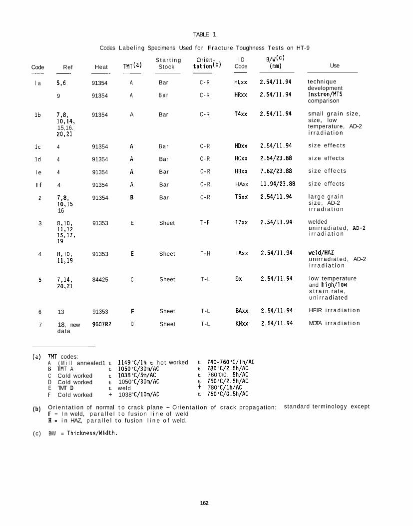
TABLE 1
Codes Label ing Specimens Used fo r Fracture Toughness Tests on HT-9
S t a r t i n g Stock
Orien- t a t i on (b )
I D Code
B/W(c) (mm)
2.54/11.94
2.54/11.94
Code
l a
- Ref Heat Use
technique development Instron/MTS comparison
small g r a i n size, size, low temperature, AD-2 i r r a d i a t i o n
s ize e f f ec t s
s i ze effects
s i ze e f f e c t s
s i ze ef fects
l a r g e g r a i n s ize, AD-2 i r r a d i a t i o n
welded
5,6
9
91354
91354
A
A
Bar
B a r
C - R
C- R
HLxx
HRxx
I b 7,8, 10.14, 15.16.
91354 Bar C-R T4xx 2.54/11.94 A
. . 20,21
4
4
4
4
2.54/11.94
2.54/23 .BE
7.62/23.88
11.94/23.88
2.54/11.94
91354
91354
91354
91354
91354
B a r
Bar
Bar
Bar
Bar
C- R
C- R
C - R
C - R
C- R
HDxx
HCxx
HBxx
HAxx
T5xx
I C
I d
l e
I f
2 7,8, 10,15 16
2.54/11.94 3 91353 E Sheet T-F T7xx un i r rad ia ted , AD-2 i r r a d i a t i o n
2.54/11.94 weld/HAZ un i r rad ia ted , AD-2 i r r a d i a t i o n
low temperature and high/low s t r a i n ra te , u n i r r a d i a ted
HFIR i r r a d i a t i o n
MOTA i r r a d i a t i o n
91353 E Sheet T - H TAxx 4
84425 C Sheet T-L Dx 2.54/11.94 5
6
7
13
18, new data
91353
9607R2
F
D
Sheet
Sheet
T-L
T-L
BAxx
KNxx
2.54/11.94
2.54/11.94
TMT codes: A ( M i l l annealed1 t 1149'C/lh t hot
1050aC/30m/AC 1038'C/5m/AC 1050 'C/30m/AC
worked t 740-760 ' C / l h/AC t 780'C/2 .5h/AC t 760 'C/O. 5h/AC t 760"C/2. 5h/AC + 780 'C/1 h/AC t 760°C/0.5h/AC
B TMT A t C Cold worked t D Cold worked t E TMT D t F Cold worked +
weld 1038 'C/ lOm/AC
( b ) Or ien ta t i on of normal t o crack plane - Or ien ta t ion of crack propagation: F = I n weld, p a r a l l e l t o fus ion l i n e of weld H = i n HAZ, p a r a l l e l t o fusion l i n e o f weld.
standard terminology except
(c) B/W = Thickness/Width.
162
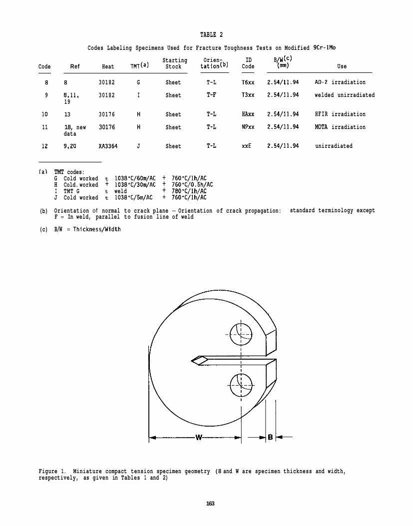
TABLE 2 Codes Labeling Specimens Used for Fracture Toughness Tests on Modified 9Cr-1Mo
Starting Code Ref Heat TMT(a) Stock
8 8 30182 G Sheet
9 8.11. 30182 I Sheet
10 13 30176 H Sheet
11 18, new 30176 H Sheet
12 9.20 XA3364 J Sheet
19
data
Orien- ID B / W W tation(b) Code (m) Use
-
T-L T6xx 2.54/11.94 AD-2 irradiation
T-F T3xx 2.54/11.94 welded unirradiated
T-L HAxx 2.54/11.94 HFIR irradiation
T-L NPxx 2.54/11.94 MOTA irradiation
T-L xxE 2.54/11.94 unirradiated
(a) TMT codes: G Cold worked t 1038'C/60m/AC + 760'C/lh/AC H Cold. worked + 1038'C/30m/AC + 76O0C/0.5h/AC I TMT G t weld + 780'C/lh/AC J Cold worked t 1038T/5m/AC + 760°fjlh/AC
(b) Orientation of normal to crack plane - Orientation of crack propagation: F = In weld, parallel to fusion line of weld
(c) B/W = Thickness/Width
standard terminology except
Figure 1. respectively, as given in Tables 1 and 2)
Miniature compact tension specimen geometry (8 and W are specimen thickness and width,
163
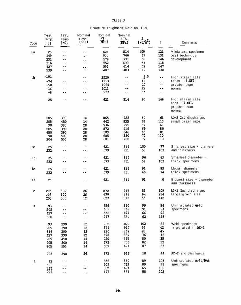
TABLE 3
Fracture Toughness Data on HT-9
Nominal Nominal Nominal Dose YS UTS (dp-4 ( M W (MPa) (k&) T Comments
~ _ _ _ _ _ _ _ - .. 621 814 100 121 Min ia tu re specimen .- 600 766 67 131 t e s t technique .. 579 731 59 146 development .. 552 690 53 118 .. 503 614 72 147 .- 407 483 112 130
Test Irr. Temp. Temp.
Code ("C) ( O C ) . . ~. - _ _ _ _ .. l a 25
149 232 316 427 539
..
.- _ _ -. ..
-191 .. ..
I b -74 -58 -36 -6
25
..
.. _ _
.-
2520 1113 1064 1011 937
2.5 .. High s t r a i n r a t e t e s t s - 1.5E3 grea ter than
_ _ ..
i i 17 22 .. normal
621 814 97 166 High s t r a i n r a t e t e s t - 1.OE3 grea ter than normal
AD-2 2nd discharge, small g r a i n s ize
205 390 205 450 90 390 205 390 450 390 90 500 206 500
.. IC 25 232
I d 25 232
le 25 232
..
.-
..
..
..
14 14 28 28 28 28 28
_ _ ..
865 642 936 872 509 685 601
621 579
621 579
621 579
621
928 835 995 916 646 880 780
814 731
814 731
814 73 1
814
67 61 61 113 ~~
57 61 69 80 65 81 72 110 72 110
100 77 50 103
96 63 52 103
91 83 46 74
91 0
Smallest s i ze - diameter and th ickness
Smallest diameter - t h i c k specimens
Medium diameter t h i c k specimens
Biggest s i ze - diameter and th ickness
AD-2 2nd discharge, l a rge g r a i n s i ze
If 25
26 872 916 53 109 64 214 55 142
26 12
630 627
818 813
Uni r r a d i a ted we1 d specimens
.. 3 93 205 427 538
._ _ _ -.
656 609 552 447
860 769 674
99 86 91 94 66 92
53 1 62 193
102 38 12 12 12 12 14 14
962 874 820 698
1022 917 862 887
Weld specimens i r r a d i a t e d i n AD-2
93 390 205 390 316 390 ~~
427 390 205 450 205 500 205 550
205 390
.- 4 93 205 .-
427 538 .-
_ _
76 48 ~~~
720 673 639
755 706 671
80 35 82 32 87 65 14
26 872 916 58 44 AD-2 2nd discharge
Un i r rad ia ted weld/HAZ specimens
656 609
860 769 674 531
89 105 89 98 65 106 58 202
.-
..
..
.. 552 447
164
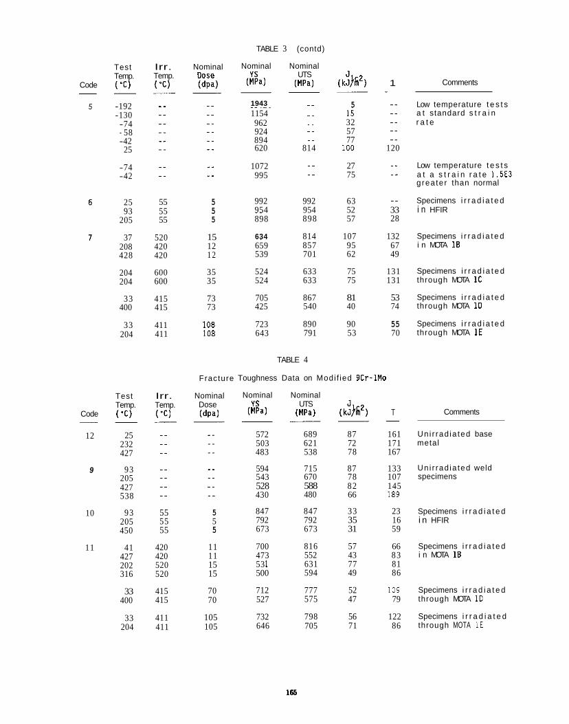
TABLE 3 (contd)
Nominal Nominal YS UTS
W a ) (MPa) (k$'h2) 1
Test Temp. ( ' C )
Irr. Temp. ( 'C)
Nominal Dose (dpa) Code
5
- Comments
Low temperature t e s t s a t standard s t r a i n r a t e
-192 -130
_ _ 5 1943 .. .. .. .. ..
1154 -. 15
.. _ _ 32
57 77 _ _ ._
962 924 894 620 814 100 120
..
-74 - 58 -42
25
-74 -42
.- 27 75
.. 1072 995 .- ..
Low temperature t e s t s a t a s t r a i n r a t e 1.5E3 grea ter than normal
25 55 55 55
520 420 420
600 600
415 415
411 411
5 5 5
_ _ 992 992 63 954 954 52 33
Specimens i r r a d i a t e d i n HFIR 93
205
37 208 428
~~
898 898 57 28
634 814 107 132 15 12 1 2
Specimens i r r a d i a t e d i n MOTA 1B
~. 659 857 95 67 539 701 62 49
524 633 75 131 524 633 75 131
Specimens i r r a d i a t e d through MOTA 1C
Specimens i r r a d i a t e d through MOTA I D
Specimens i r r a d i a t e d through MOTA 1E
204 204
35 35
73 73
108 108
705 867 81 53 425 540 40 74
33 400
33 204
723 890 90 55 643 791 53 70
TABLE 4
Toughness Data on Modi f ied 9Cr-1Mo Fracture
Nominal Dose ( d p d
Nominal Nominal YS UTS
(MPa) (MPa) (k$@) T
Test Temp. ( ' C )
Irr. Temp. ( ' C ) Comments Code
12
- 25
232 427
572 689 87 161 503 621 72 171 483 538 78 167
Uni r rad ia ted base metal
594 715 87 133 543 670 78 107 528 588 82 145 430 480 66 189
Uni r rad ia ted weld specimens
9 93 205 427 538
10 93 205 450
41 427 202 316
55 55 55
420
5 5 5
847 847 33 23 Specimens i r r a d i a t e d 792 792 35 16 i n HFIR 673 673 31 59
11 11 11 15 15
700 816 57 66 473 552 43 83 53 1 63 1 77 81 500 594 49 86
Specimens i r r a d i a t e d i n MOTA 1B 420
520 520
415 415
Specimens i r r a d i a t e d through MOTA 1D
33 400
70 70
712 777 52 109 527 575 47 79
732 798 56 122 646 705 71 86
Specimens i r r a d i a t e d through MOTA 1 E
33 204
411 411
105 105
165
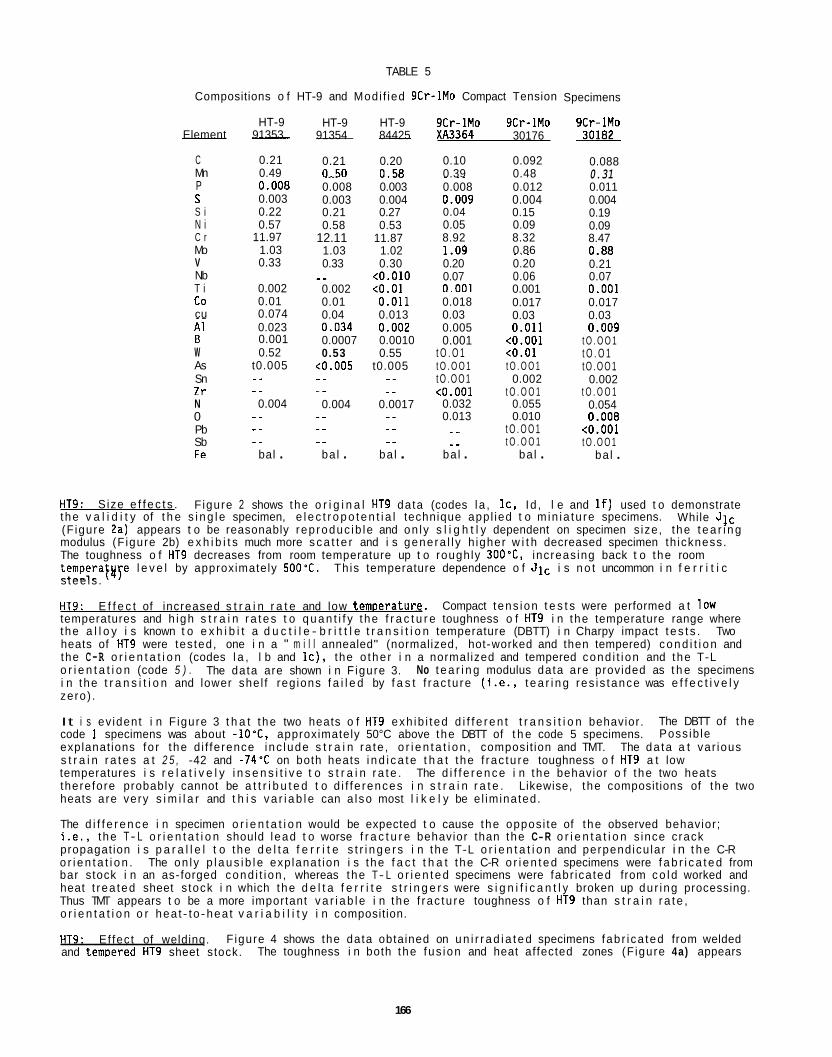
TABLE 5
Compositions o f HT-9 and Modi f ied 9Cr-1Mo Compact Tension
HT-9 ~- Element 91353
C 0.21 Mn 0.49 P 0.008 S 0.003 S i 0.22 N i 0.57 C r 11.97 Mo 1.03 V 0.33 Nb T i 0.002 co 0.01 cu 0.074
HT-9 HT-9 ~- 91354 84425
0.21 0.20 0.50 0.58 .... 0.008 0.003 0.003 0.004 0.21 0.27 0.58 0.53
12.11 11.87 1.03 1.02 0.33 0.30 _ _ to.010 0.002 to .01 0.01 0.011 0.04 0.013 .~
A1 0.023 0.034 0.002 B 0.001 0.0007 0.0010
0.53 0.55 W 0.52 As t0.005
.- Sn l r N 0.004 0 Pb Sb Fe bal .
..
.. -. _ _
~ ~~
t0.005 t0.005 .. -. _ _ ..
0.004 0.0017 .. _ _ .- .. .. _.
bal . ba l .
9Cr-1Mo 9Cr-1Mo XA3364 30176
0.10 0.092 0.39 0.48 ~ ~~
0.008 0.012 0.009 0.004 0.04 0.15 ~~
0.05 0.09 8.92 8.32 1.09 0.86
~~
0.20 0.20 0.07 0.06 0.001 0.001 0.018 0.017 0.03 0.03 0.005 0.011 0.001 to.001
t O . O 1 to .01 t O . O O 1 t O . O O 1 t O . O O 1 0.002 to.001 t O . O O 1
0.032 0.055 0.013 0.010 _ _ t O . O O 1 _ _ t O . O O 1 ba l . ba l .
Specimens
9Cr-1Mo 30182
0.088 0.31 0.011 0.004 0.19 0.09 8.47 0.88 0.21 0.07 0.001 0.017 0.03 0.009
t O . O O 1 t O . O 1 t O . O O 1
0.002 t O . O O 1
0.054 0.008
to.001 t O . O O 1
ba l .
HT9: S ize e f f e c t s . F igure 2 shows the o r i g i n a l HT9 data (codes la , IC, Id, l e and I f ) used t o demonstrate the v a l i d i t y of t h e s i n g l e specimen, e l e c t r o p o t e n t i a l technique appl ied t o m in ia tu re specimens. (F igure 2a) appears t o be reasonably rep roduc ib le and on ly s l i g h t l y dependent on specimen s ize, the t e a r i n g modulus (F igure 2b) e x h i b i t s much more s c a t t e r and i s genera l l y h igher w i t h decreased specimen th ickness. The toughness o f HT9 decreases from room temperature up t o roughly 3OO0C, increas ing back t o the room temperatvye l e v e l by approximately 500'C. Th is temperature dependence o f J lc i s n o t uncommon i n f e r r i t i c s tee ls .
HT9: temperatures and h igh s t r a i n r a t e s t o q u a n t i f y the f r a c t u r e toughness o f HT9 i n the temperature range where the a l l o y i s known t o e x h i b i t a d u c t i l e - b r i t t l e t r a n s i t i o n temperature (DBTT) i n Charpy impact t e s t s . heats of HT9 were tes ted, one i n a " m i l l annealed" (normalized, hot-worked and then tempered) c o n d i t i o n and the C-R o r i e n t a t i o n (codes l a , l b and I C ) , the o the r i n a normal ized and tempered cond i t i on and the T-L o r i e n t a t i o n (code 5 ) . i n the t r a n s i t i o n and lower she l f reg ions f a i l e d by f a s t f rac tu re ( i . e . , t e a r i n g res i s tance was e f f e c t i v e l y zero) .
While J l c
E f f e c t of increased s t r a i n r a t e and low temoerature. Compact tens ion t e s t s were performed a t low
Two
The data are shown i n F igure 3. No t e a r i n g modulus data are provided as t h e specimens
It i s ev ident i n F igure 3 t h a t the two heats o f HT9 exh ib i ted d i f f e r e n t t r a n s i t i o n behavior. code 1 specimens was about -lOmC, approximately 50°C above the DBTT of t h e code 5 specimens. explanat ions fo r the d i f ference inc lude s t r a i n ra te , o r i e n t a t i o n , composit ion and TMT. s t r a i n r a t e s a t 2 5 , -42 and -74'C on both heats i n d i c a t e t h a t the f rac tu re toughness o f HT9 a t low temperatures i s r e l a t i v e l y i n s e n s i t i v e t o s t r a i n r a t e . therefore probably cannot be a t t r i b u t e d t o d i f f e rences i n s t r a i n r a t e . heats are very s i m i l a r and t h i s v a r i a b l e can a l so most l i k e l y be e l iminated.
The d i f f e r e n c e i n specimen o r i e n t a t i o n would be expected t o cause the oppos i te of the observed behavior; i . e . , t he T- L o r i e n t a t i o n should l ead t o worse f r a c t u r e behavior than the C-R o r i e n t a t i o n s ince crack propagat ion i s p a r a l l e l t o the d e l t a f e r r i t e s t r i n g e r s i n the T-L o r i e n t a t i o n and perpendicu lar i n t h e C-R o r i e n t a t i o n . The on ly p l a u s i b l e exp lanat ion i s the f a c t t h a t the C-R o r i e n t e d specimens were f a b r i c a t e d from bar stock i n an as-forged cond i t i on , whereas the T- L o r i e n t e d specimens were fabr icated from c o l d worked and heat t rea ted sheet s tock i n which the d e l t a f e r r i t e s t r i n g e r s were s i g n i f i c a n t l y broken up du r ing processing. Thus TMT appears t o be a more important v a r i a b l e i n the f rac tu re toughness o f HT9 than s t r a i n r a t e , o r i e n t a t i o n o r hea t - to -hea t v a r i a b i l i t y i n composition.
HT9: Ef fec t of weldinq. and temDered HT9 sheet stock.
The DBTT of the Poss ib le
The da ta a t var ious
The d i f f e r e n c e i n the behavior o f the two heats Likewise, the compositions of the two
F igure 4 shows the data obtained on u n i r r a d i a t e d specimens fab r i ca ted from welded The toughness i n both the fus ion and heat af fected zones (F igure 4a) appears
166
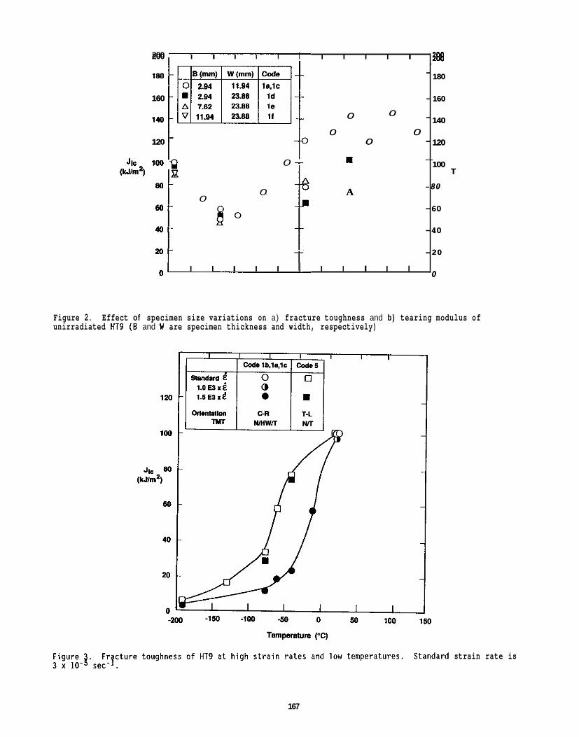
200 I I I I I I I I I I
-
160 -
0 - 0
0 0 - 120 0 - -
- m 100 Q 0 --
8 0 -
60-
40-
2 0 -
0
0 A 0
_ _
I I I I I I I I I I
200
180
160
140
120
100 T
-80
-60
-40
- 20
0
I I I I I I I I I I I 200 I
Figure 2. unirradiated HT9 ( 6 and W are specimen thickness and width, respectively)
Effect of specimen size variations on a) fracture toughness and b) tearing modulus of
I200
strain
-
160 -
0 - 0
0 0 120 0 - -
- m
A
I I I I I I I I I I I 0 ’
rate is
180
160
140
120
100 T
-80
-60
-40
- 20
0
167
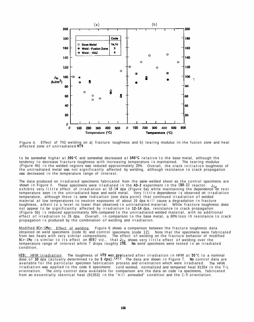
200
180
160
1 40
120
60
40 1 M 0
0 100 200 300 4w 5M) 0 100 200 300 400 500 600 Temperature (“C) Temprelure (“C)
Figure 4. a f fec ted zone o f u n i r r a d i a t e d HT9
Effect of TIG welding on a) f rac tu re toughness and b) t e a r i n g modulus i n t h e fus ion zone and heat
t o be somewhat h ighe r a t 205’C and somewhat decreased a t 540’C r e l a t i v e t o t h e base metal , a l though t h e tendency t o decrease f r a c t u r e toughness w i t h increas ing temperature i s maintained. The t e a r i n g modulus (F igure 4b) i n t h e welded reg ions was reduced approximately 25%. t h e un i r rad ia ted metal was n o t s i g n i f i c a n t l y af fected by welding, al though res is tance t o crack propagat ion was decreased i n t h e temperature range of i n t e r e s t .
The data produced on i r r a d i a t e d specimens fabr ica ted from t h e same welded sheet as t h e c o n t r o l specimens are shown i n F igure 5 . e x h i b i t s very l i t t l e e f fec t of i r r a d i a t i o n a t 12-14 dpa (F igure 5a) wh i l e main ta in ing t h e dependence on t e s t temperature seen i n the u n i r r a d i a t e d base and weld metal. Very l i t t l e dependence i s observed on i r r a d i a t i o n temperature, al though the re i s some i n d i c a t i o n (one data p o i n t ) t h a t cont inued i r r a d i a t i o n o f welded mater ia l a t low temperatures t o neutron exposures of about 26 dpa w i l l cause a degradat ion i n f rac tu re toughness, a l b e i t t o a l e v e l no lower than observed i n u n i r r a d i a t e d m a t e r i a l . While f r a c t u r e toughness does no t appear t o be s i g n i f i c a n t l y a f fec ted by i r r a d i a t i o n t o 12-14 dpa, res i s tance t o crack propagat ion (F igure 5b) i s reduced approximately 50% compared t o t h e u n i r r a d i a t e d welded ma te r ia l , w i t h no a d d i t i o n a l e f f e c t o f i r r a d i a t i o n t o 26 dpa. propagat ion i s produced by t h e combination o f welding and i r r a d i a t i o n .
Overa l l , t h e crack i n i t i a t i o n toughness of
These specimens were i r r a d i a t e d i n t h e AD-2 experiment i n t h e EER-I1 reac to r . J l c
Overa l l , i n comparison t o t h e base metal , a 60% l o s s i n res i s tance t o crack
Modi f ied 9Cr-1Mo: obtained on weld specimens (code 9) and c o n t r o l specimens (code 12). from two heats w i t h very s i m i l a r composit ions. The e f fec t o f welding on t h e f r a c t u r e behavior of modif ied 9Cr-1Mo i s s i m i l a r t o i t s e f fec t on HT9: v i z . , t h a t J temperature range of i n t e r e s t w h i l e T drops roughly 2k No weld specimens were tes ted i n an i r r a d i a t e d
Effect of weldinq. F igure 6 shows a comparison between t h e f r a c t u r e toughness da ta Note t h a t t h e specimens were f a b r i c a t e d
shows very l i t t l e e f fec t o f welding over t h e
cond i t i on .
HT9: HFIR i r r a d i a t i o n . The toughness of HT9 was dose o f 10 dpa ( a c t u a l l y determined t o be 5 dpa).(5rT The data are shown i n F igure 7. No c o n t r o l data are a v a i l a b l e f o r t h e p a r t i c u l a r specimen f a b r i c a t i o n process and o r i e n t a t i o n which were i r r a d i a t e d . i r r a d i a t i o n was app l i ed t o t h e code 6 specimens: o r i e n t a t i o n . from an e s s e n t i a l l y i d e n t i c a l heat (91353) i n t h e “ m i l l annealed” cond i t i on and t h e C - R o r i e n t a t i o n .
l u a t e d a f t e r i r r a d i a t i o n i n HFIR a t 55’C t o a nominal
The HFIR c o l d worked, normal ized and tempered heat 91354 i n t h e T-L
The o n l y c o n t r o l data a v a i l a b l e fo r comparison are t h e data on code l a specimens, f a b r i c a t e d
168
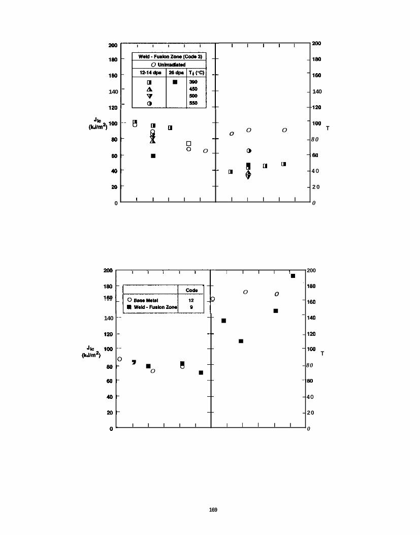
200 I I I I I I I I I I
180 - 0 unkndhud
-
140 -
120 -
- 550 -
_- - 0 0
Jk*lOO - 0 0 -_
0 0 _ _ a
W m )
8 0 -
w -
40-
2 0 -
0
_ _ _ _
I I I I I I I I I I
200
180
1w
140
120
100 T
- 8 0
- w
-40
- 2 0
0
169
I I I I I I I I I 200 Im
-
0 0 - Iw
m W M - m h n h _ _ - 140 -
120 - - _ _ _ _ Jk 100 - -
(urn2) , _ _ 8 0 - 0
0 _ _ w -
40-
2 0 -
0 .
_ _
_ _
I I I I I I I I I I
200
180
1w
I40
120
100 T
-80
-50
-40
- 20
0
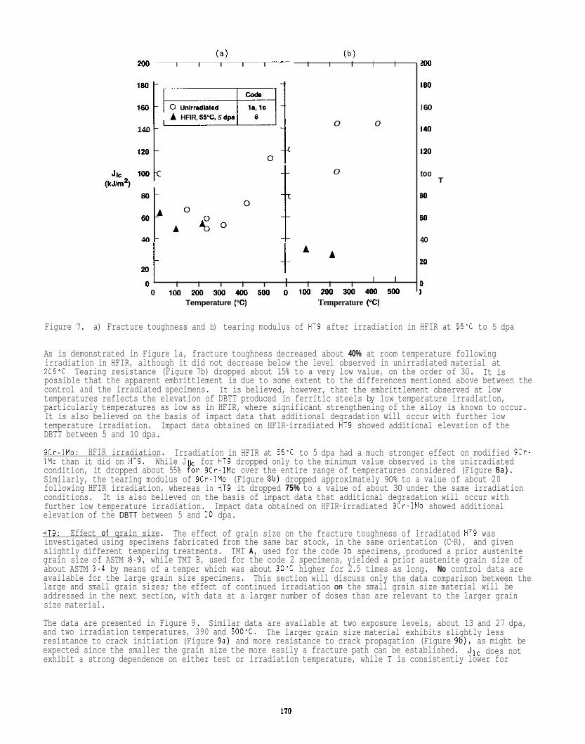
(a) (b) 200 I I I I I I I I I I
0 0 A HFIR. 55%. 5 d p
140
JIC 100 (kJ/mZ)
0 t
20 t t ' ' 0 ' I I I I I I I I I
I I
0 1 0 0 2 0 0 3 0 0 4 w m 0 1 w 2 0 0 3 0 0 4 o o 5 0 0 Temperature ("C) Temperature ("C)
m
180
I 60
140
I20
too
Bo
60
40
20
0 1
T
Figure 7. a) Fracture toughness and b) tearing modulus of HT9 after irradiation in HFIR at 55'C to 5 dpa
As is demonstrated in Figure la, fracture toughness decreased about 40% at room temperature following irradiation in HFIR, although it did not decrease below the level observed in unirradiated material at 205-C. Tearing resistance (Figure 7b) dropped about 15% to a very low value, on the order of 30. possible that the apparent embrittlement is due to some extent to the differences mentioned above between the control and the irradiated specimens. It is believed, however, that the embrittlement observed at low temperatures reflects the elevation of DBTT produced in ferritic steels by low temperature irradiation, particularly temperatures as low as in HFIR, where significant strengthening of the alloy is known to occur. It is also believed on the basis of impact data that additional degradation will occur with further low temperature irradiation. DBTT between 5 and 10 dpa.
9Cr-1Mo: HFIR irradiation. 1Mo than it did on HT9. While J for HT9 dropped only to the minimum value observed in the unirradiated condition, it dropped about 55% For 9Cr-1Mo over the entire range of temperatures considered (Figure sa). Similarly, the tearing modulus of 9Cr-1Mo (Figure 8b) dropped approximately 90% to a value of about 20 following HFIR irradiation, whereas in HT9 it dropped 75% to a value of about 30 under the same irradiation conditions. further low temperature irradiation. elevation of the DBTT between 5 and 10 dpa.
HT9: investigated using specimens fabricated from the same bar stock, in the same orientation (C-R), and given slightly different tempering treatments. TMT A , used for the code Ib specimens, produced a prior austenite grain size of ASTM 8-9, while TMT B, used for the code 2 specimens, yielded a prior austenite grain size of about ASTM 3-4 by means of a temper which was about 30-C higher for 2.5 times as long. No control data are available for the large grain size specimens. large and small grain sizes; the effect of continued irradiation on the small grain size material will be addressed in the next section, with data at a larger number of doses than are relevant to the larger grain size material.
The data are presented in Figure 9. Similar data are available at two exposure levels, about 13 and 27 dpa, and two irradiation temperatures, 390 and 500~C. resistance to crack initiation (Figure 9a) and more resistance to crack propagation (Figure 9b), as might be expected since the smaller the grain size the more easily a fracture path can be established. exhibit a strong dependence on either test or irradiation temperature, while T is consistently lower for
It is
Impact data obtained on HFIR-irradiated HT9 showed additional elevation of the
Irradiation in HFIR at 55% to 5 dpa had a much stronger effect on modified 9Cr-
It is also believed on the basis of impact data that additional degradation will occur with Impact data obtained on HFIR-irradiated 9Cr-1Mo showed additional
Effect o f qrain size. The effect of grain size on the fracture toughness of irradiated HT9 was
This section will discuss only the data comparison between the
The larger grain size material exhibits slightly less
J l c does not
170
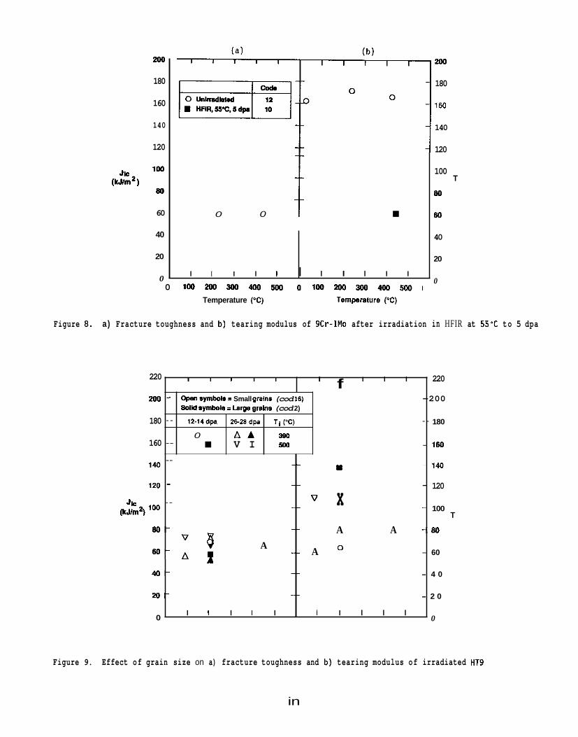
200
180
160
140
120
220
200
180
160
140
120
J g 2 100 (kJ/m )
8 0 -
4 0 -
2 0 -
0
60
40
20
0
I I I I I I I I I 220
- Cwn 8ymbols E Small graln8 (cod. 16) -200
- 12-l4dp 2628dp TI(%) - 180
- V I 500 - 160
f
SolM aymbols = Lam grains (cod. 2)
0 A A 380
_ _ - 140
- - 120 W
-
_ _
- 100 _ _ v x -
T _ _ A A - 8 0
-- A - 60
- 4 0
- 2 0
0
” 8 A 6 0 - A 1
_ _
_ _ I I I I I I I I I I
0 0 i I I I I I I I I I I I
200
180
160
140
120
100
80
80
40
20
0
T
0 1 0 0 2 0 0 3 0 0 4 M ) 5 W 0 1 0 0 2 M ) 3 w 4 0 0 5 0 0 1 Temperature (‘C) Temperamre (‘C)
Figure 8 . a) Fracture toughness and b) tearing modulus of 9Cr-1Mo after irradiation in HFIR at 5 5 % to 5 dpa
Figure 9. Effect of grain size on a) fracture toughness and b) tearing modulus of irradiated HT9
in
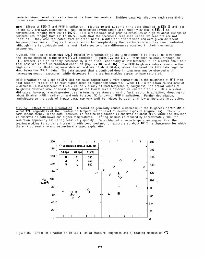
mater ia l strengthened by i r r a d i a t i o n a t the lower temperature. t o increased neutron exposure.
HT9: i n the A D- 2 and MOTA experiments. temperatures ranging from 390 t o 500'C. temperatures ranging from 411 t o 600'C. i d e n t i c a l : tempering treatments. al though t h i s i s obv ious ly n o t the most l i k e l y source o f any d i f f e rences observed i n t h e i r mechanical p roper t i es .
Overa l l , t he l o s s i n toughness (J c) induced by i r r a d i a t i o n a t any temperature i s t o a l e v e l no lower than the lowest observed i n the u n i r r a a l a t e d cond i t i on (Figures 10a and I l a ) . ( T ) , however, i s s i g n i f i c a n t l y decreased by i r r a d i a t i o n , e s p e c i a l l y a t low temperature, t o a l e v e l about h a l f t h a t observed i n the u n i r r a d i a t e d cond i t i on (Figures 10b and l l b ) . The FFTF toughness values remain on the h igh s ide of the EBR-I1 toughness data up t o doses o f about 30 dpa; above t h i s l e v e l the FFTF data begin t o drop below the EBR-I1 data. increas ing neutron exposures, wh i le decreases i n the t e a r i n g modulus appear t o have saturated.
H F I R i r r a d i a t i o n t o 5 dpa a t 55'C d i d n o t cause s i g n i f i c a n t l y more degradat ion i n the toughness of HT9 than fas t reac to r i r r a d i a t i o n t o much h igher doses a t h igher temperatures. a decrease i n low temperature ( i .e. , i n the v i c i n i t y o f room temperature) toughness, t h e actua l values of toughness observed were a t l e a s t as h igh as the lowest l e v e l s observed i n u n i r r a d i a t e d HT9. d i d cause, however, a much g rea te r l o s s i n t e a r i n g res i s tance than d i d f a s t r e a c t o r i r r a d i a t i o n , dropping t o about 30 a f t e r HFIR i r r a d i a t i o n and on ly t o about 50 fo l l ow ing FFTF i r r a d i a t i o n . a n t i c i p a t e d on the bas is of impact data, may very w e l l be induced by a d d i t i o n a l low temperature i r r a d i a t i o n .
Ne i the r parameter d i sp lays much s e n s i t i v i t y
E f f e c t of EBR-I1 and FFTF i r r a d i a t i o n . Figures 10 and 11 con ta in t h e data obtained i n EBR-I1 and FFTF Neutron exposure l e v e l s range up t o roughly 30 dpa i n EBR-I1 a t
FFTF i r r a d i a t i o n s have gone t o exposures as h igh as about 100 dpa a t Note t h a t the specimens i r r a d i a t e d i n t h e two reac to rs are n o t
they were fabr icated from d i f f e r e n t heats i n d i f f e r e n t o r i e n t a t i o n s and were g iven d i f f e r e n t They w i l l be re fe r red t o f o r s i m p l i c i t y by the r e a c t o r i n which they were i r r a d i a t e d ,
Resistance t o crack propagat ion
The data suggest t h a t a cont inued drop i n toughness may be observed w i t h
While HFIR i r r a d i a t i o n caused more of
HFIR i r r a d i a t i o n
Fur ther degradation,
200 I I I I I I I I I I
0 Unlrradlaled (Codes ls,lb, IC) -
160 -
140 -
120
0 0
0 0
-
- 0 A ~ ~ - S V 0
-
Jk 100 (kJ/m2)
- 0 0 80 -
60 -- A0 0
- - 0 " O B 0
9Cr-1Mo: I r r a d i a t i o n genera l l y causes a decrease i n the toughness o f 9Cr-lMo of about 35%, regard less of the i r r a d i a t i o n temperature o r l e v e l of neutron exposure (F igure E a ) . some incons is tency i n the data, however, i n t h a t no degradat ion i s observed a t about 200'C w h i l e the 35% l o s s i s observed a t both lower and h igher temperatures. reduct ion apparent ly s a t u r a t i n g r e l a t i v e l y qu ick l y . t e a r i n q modulus i s a c t u a l l y increas ing w i t h cont inued neutron exposure a t about 400"C, a phenomenon fo r which
E f f e c t of FFTF i r r a d i a t i o n . There i s
Tearing modulus i s reduced by approximately 50%. the Data obtained a t room temperature suggest t h a t the
2w
180
160
140
120
100 T
- 8 0
60
t he re 7 s c u r r e n t l y no m i c r o s t r u c t u r a l l y based explanat ion.
4 0 -
20
0
0 0 -
- 4 0
20
0
- - -
I I I I I I I I I I
F-gure 10. Effect of i r r a d i a t i o n i n EBR-I1 on a) f rac tu re toughness and b) t e a r i n g modulus o f HT9
172
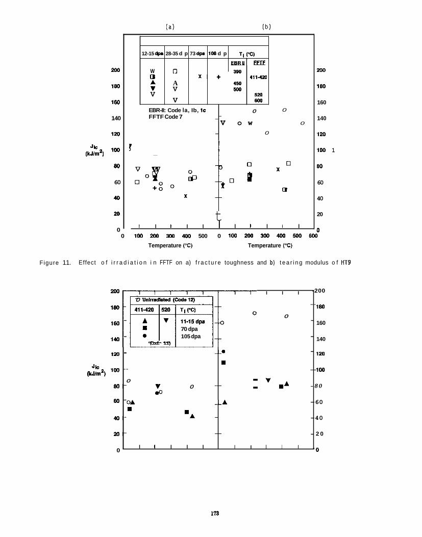
200
180
160
140
120
100
80
60
40
(kUm’)
M
0
12-15 dpa
W 0 A v V
28-35 d p 73 dp. 108 d p TI (%)
E B B l l F n E O 360
A 450 V 500
V wo
x + 411-424
52a
0 EBR-II: Code la, Ib, IC FFTF Code 7
- 0
0 _- v o w
0
t
I I I I I I I I I I 200 0 Unlmdlnted (Code12)
-
0 - 70 dpa 105 dpa -
160
140
120 -
-
(Cod. 11) -
- --. W
- J k 2 100 - -
8 0 - v 0 : WA
(IcJ/m 1 v -_ 0
.o 60 -0A --A
- ‘A W
40-
2 0 -
0
_-
I I I I I I I I I I
I I I I I I I I I I I
-200
180
160
140
120
100
- 8 0
-60
-40
- 2 0
- 0
200
180
160
140
120
100 1
80
60
40
20
n
0 100 200 300 400 500 0 100 200 300 400 5w 600”
Temperature (“C) Temperature (‘C)
Figure 11. Effect o f i r r a d i a t i o n i n FFTF on a) f r a c t u r e toughness and b) t e a r i n g modulus o f HT9
113
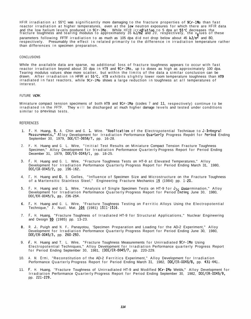
H F I R i r r a d i a t i o n a t 55°C was s i g n i f i c a n t l y more damaging t o the f r ac tu re proper t ies o f 9Cr-1Mo than f a s t reac tor i r r a d i a t i o n a t h igher temperatures, even a t the low neutron exposures f o r which there are H F I R data and the low hel ium l e v e l s produced i n 9Cr-1Mo. While H F I R i r r a i a t i o n t o 5 dpa a t 55'C decreases the
parameters fo l low ing FFTF i r r a d i a t i o n t o as much as 105 dpa d i d no t drop below about 45 kJ/m and 80, respec t ive ly . Presumably the e f f ec t i s r e l a t e d p r i m a r i l y t o the d i f f e rence i n i r r a d i a t i o n temperature ra the r than d i f fe rences i n specimen preparat ion.
3 f r ac tu re toughness and t ea r i ng modulus t o approximately 35 kJ/m F and ' 2 0 , respec t ive ly , the v lues o f these
CONCLUSIONS
While the ava i l ab le data are sparse, no add i t iona l loss o f f r a c t u r e toughness appears t o occur w i t h f a s t reac tor i r r a d i a t i o n beyond about 30 dpa i n HT9 and gCr-lMo, up t o doses as h igh as approximately 100 dpa. Tearing modulus values show more sca t te r , but w i t h i n the l i m i t s o f the data a s i m i l a r conclusion can be drawn. i r r a d i a t e d i n f a s t reactors, wh i le 9Cr-1Mo shows a l a rge reduct ion i n toughness a t a l l temperatures o f i n t e r e s t .
A f t e r i r r a d i a t i o n i n HFIR a t 55'C, HT9 e x h i b i t s s l i g h t l y lower room temperature toughness than HT9
FUTURE WORK
Min ia tu re compact tension specimens of both HT9 and 9Cr-1Mo (codes 7 and 11, respec t ive ly ) cont inue t o be i r r a d i a t e d i n the FFTF. They w i l l be discharged a t much higher damage l e v e l s and tes ted under cond i t ions s i m i l a r t o Drevious t es t s .
REFERENCES
1. F. H . Huana. El. A. Chin and G. L. Wire. "AoDl icat ion o f the E lec t roooten t ia l Techniaue t o J - I n teq ra l Measuremenis," A1 l o y Development fo r I r r a d i a t i o n Performance Quartei- ly Progress Repdrt f o r P e r i o i Ending September 30, 1979, DOE/ET-0058/7, pp. 16-28.
2 .
3.
4.
5.
6.
7.
8.
9.
10.
11.
F . H. Huang and G. L. Wire, " I n i t i a l Test Results on Min ia tu re Compact Tension Fracture Toughness Specimen," A l l o y Development f o r I r r a d i a t i o n Performance Q u a r t e r l y Progress Report f o r Period Ending December 31, 1979, DOE/ER-0045/1, pp. 18-25.
F. H. Huang and G. L . Wire, "Fracture Toughness Tests on HT-9 a t Elevated Temperatures," A l l o y Development f o r I r r a d i a t i o n Performance Qua r te r l y Progress Report f o r Period Ending March 31, 1980, DOE/ER-0045/2, pp. 156-162.
F . H. Huang and D. S. Gelles, " In f luence o f Specimen Size and Mic ros t ruc ture on the Fracture Toughness o f a Mar tens i t i c S ta in less Steel," Engineering Fracture Mechanics 19 (1984) pp. 1-20,
F . H . Huang and G. L. Wire, "Analys is o f S ing le Specimen Tests on HT-9 f o r J1 Development f o r I r r a d i a t i o n Performance Q u a r t e r l y Progress Report f o r Period Ending June 30, 1980, DOE/ER-0045/3, pp. 236-254.
F. H. Huang and G . L. Wire, "Fracture Toughness Test ing on F e r r i t i c A l loys Using the E lec t ropo ten t i a l Technique," J . Nucl. Mat. 104 (1981) 1511-1516.
F. H. Huang, "Fracture Toughness o f I r r a d i a t e d HT-9 f o r S t ruc tu ra l App l ica t ions , " Nuclear Engineering and Design 90 (1985) pp. 13-23.
Determination," A l l o y
R. J . Puigh and N. F. Panayotou, "Specimen Preparat ion and Loading f o r the AD-2 Experiment," A l l o y Development f o r I r r a d i a t i o n Performance Qua r te r l y Progress Report f o r Period Ending June 30, 1980, DOE/ER-0045/3, pp. 260-293.
F. H. Huang and T. L. Wire, "Fracture Toughness Measurements f o r Un i r rad ia ted 9Cr-1Mo Using E lec t ropo ten t i a l Techniques," A l l o y Development f o r I r r a d i a t i o n Performance qua r te r l y Progress Report f o r Period Ending September 30, 1981, (DOE/ER-0045/7, pp. 220-229.
A . M. E r m i , "Reconst i tu t ion o f the AD-2 F e r r i t i c s Experiment," A l l o y Development f o r I r r a d i a t i o n Performance Q u a r t e r l y Progress Report f o r Period Ending March 31, 1982, DOE/ER-0045/8, pp. 431-441.
F . H. Huang, ' "Fracture Toughness of Un i r rad ia ted HT-9 and Modi f ied 9Cr-1Mo Welds," A l l o y Development f o r I r r a d i a t i o n Performance Q u a r t e r l y Progress Report f o r Period Ending September 30, 1982, DOE/ER-0045/9, pp. 221-229.
114
12.
13.
14.
15.
16.
17.
18.
19.
20.
21.
F . H. Huang and 0. S. Gelles, "Fracture Toughness of Irradiated HT-9 Weld Metal," Alloy Development for Irradiation Performance Quarterly Progress Report for Period Ending March 31, 1983, DOE/ER-0045/10, pp. 125-130.
F. H. Huang, "The Fracture Toughness of Ferritic Alloys Irradiated in HFIR," Alloy Development for Irradiation Performance Quarterly Progress Report for Period Ending September 30, 1983, DOE/ER-0045/11, pp. 180-184.
F. H. Huang, "The J Fracture Toughness Transition Behavior of HT-9," Alloy Development for Irradiation Performance Quarterly Progress Report for Period Ending September 30, 1983, DOE/ER-0045/11, pp. 172-179.
F. H. Huang, "Fracture Toughness of Irradiated HT-9," Alloy Development for Irradiation Performance Quarterly Progress Report for Period Ending March 31, 1984, DOE/ER-0045/12, pp. 104-109.
F. H. Huang, "Effects of Irradiation on the Fracture Toughness of HT-9," Alloy Development for Irradiation Performance Quarterly Progress Report for Period Ending September 30, 1984, DOE/ER-0045/13, pp. 156-160.
F. H. Huang and D. S. Gelles, "Fracture Toughness of Irradiated HT-9 Weld Metal," J. Engineering Materials and Technology, 107 (1985) pp. 329-333.
F. H. Huang, "Fracture Toughness of Ferritic Alloys Irradiated in FFTF," Alloy Development for Irradiation Performance Quarterly Progress Report for Period Ending March 31, 1986, DOE/ER-0045/16, pp. 145-149.
F. H. Huang and 0. S. Gelles, "Fracture Behavior of Unirradiated HT-9 and Modified 9Cr-1Mo Welds," Proceedings of Topical Conference on Ferritic Alloys for Use in Nuclear Energy Technologies, 1983, pp. 337-346.
F . H. Huang, Measurements on Single Subsized Specimens of Ferritic Alloys," J. Test. Eval. 13 (1985) pp. 25;5&4.
U. S. Gelles and F. H. Huang, "Fractographic Examination of HT-9 Miniature Compact Tension Specimens Tested at Low Temperatures," A1 loy Development for Irradiation Performance Quarterly Progress Report for Period Ending September 30, 1983, DOE/ER-O045/11, pp. 128-135.
115

EFFECT OF SPECIMEN SIZE ON THE UPPER SHELF ENERGY OF FERRITIC STEELS, A S Kumar (University of Missouri- Rolla) and F.A. Garner and M.L. Hamilton (Pacific Northwest Laboratory)[aj
OBJEC.;IVE
The object of this effort is to provide methods which use subsize specimens to determine the changes induced by radiation in metals employed for fusion service.
SUMMARY
A previous effort led to the development of size effect correlations for the ductile-brittle transition temperature (DBTT) and upper shelf energy (USE) of ferritic steels. An improved methodology is proposed that can be used to better predict the USE based on subsize specimen data. The proposed methodology utilizes the partitioning of the USE into energies required for crack initiation and crack propagation. Charpy specimens are used in conjunction with precracked specimens to separate the two components. An unirradiated ferritic steel, HT-9, was used to demonstrate the validity of the methodology. Unlike previous correlations that were limited in their applicability to either highly ductile or brittle material, the proposed methodology is expected to be applicable over a wide range of ductility and to be particularly useful for materials which harden significantly during irradiation.
Notched-only
PROGRESS AND STATUS
Introduction
Ferritic steels are being considered as possible candidates for structural applicati n in fusion reactors.
the effects o f neutron exposure on the impact properties of this steel, studies are in progress using subsize specimens which are considerably smaller than the standard size specified in ASTM standard E23-86. While the use o f subsize specimens allows a larger number of specimens to be irradiated in the limited reactor space available, there are size-related consequences that influence the usefulness of the data.
Full-size specimens are designed to ensure that a state of plane strain exists below the notch root, a condi- tion that promotes brittle fracture. A reduction in size not only reduces the remaining load-bearing ligament but also alters the stress state under the notch.
Reduction of the specimen size eventually leads to a plane stress condition, which promotes a relatively ductile fracture compared to that of full-size specimens. This limits somewhat our ability to predict the upper shelf energy (USE) and ductile to brittle transition temperature (DBTT) of full-size specimens based on data derived from subsize specimens.
Ther mens5-$. In these studies, a normalized USE was defined as the ratio of the measured USE to a normalization factor. should be equal.
Past attempts to correlate USE values can be divided into two main categories. of correlations based
BbZ, where B is the specimen thickness and b is the ligament size below the notch root. on using the fracture volume as the normalization factor have been found to be satisfactory for relatively ductile steels having USE values larger than 200 J. It is important to note, however, that this type of normalization factor does not take into account either the length of the specimen or the geometry of the notch.
In the second category of correlations, the normalization factor includes all of the specimen dimensions as well as the stress concentration factor at the notch root, which incorporates the effect of notch geometry. Such a correlation was first proposed in an earlier stage of the present effort and has been found to work satisfactorily for steels 'n relatively brittle conditions (USE < 100 J) characteristic of irradiation to
success has also been obtained for DBTT correlations as a function of
The steel designated HT-9 (12 Cr-1Mo-VW) has been found to be particularly promising 7 . 3 . In order to assess
ave been a number of attempts to correlate the USE of full-size, half-size and third-size speci-
For the correlation to be valid, the normalized values of the USE for full- and subsize specimens
The first category consists n a normalization factor that is defined by th racture volume b low the notch root.
Correlations based In some inve~tigations~~~,8 the fracture volume is estimated as (Bb) 5 5 and in others6?$ it is estimated as
very igh neutron fluences 4 . Similar "
size. $ ' Neither of the above mentioned correlations would be suitable. however. when a normallv ductile material with USE > 200 J becomes embrittled by radiation such that its USE'falls considerably below200 J. rhe purpose of
(a) Operated for the U.S. Department of Energy by Battelle Memorial Institute under Contract DE-AC-06-76RLO 1830.
in
the current study is to develop a methodology for the correlation of full-size and subsize USE values that is applicable to a wide variety of steels irrespective of their USE value in either the irradiated or unirradi- ated state. To demonstrate the improved methodology, HT-9 steel was selected in the T - L orientation, having a full-size USE of 129 J:
The methodology is based on the partitioning of the USE into two contributions, i.e., that required for crack initiation and that for crack propagation. specimens were used. Whereas the USE of notched-only specimens is the sum of both crack initiation and propagation energies, the use of precracked specimens reflects only crack propagation. The difference in USE values for the two types of specimens is thus a measure of the crack initiation energy. the utility of this partition in later sections of the paper.
Exoerimental Procedure
All specimens used in this study were machined from HT-9 plate material of heat 9607R2, which was manufac- tured by Electralloy Corporation for the U.S. DOE fyaion materials program. tensile properties of this heat are given elsewhere . A series of heat treatments was performed on the plate stock to produce a tempered martensitic structure with a hardness of 255 DPH and a prior austenite grain size of ASTM 5 to 6 . tation, in which the long axis of the specimen lies perpendicular to the rolling direction and the direction of elongation of the grains is the same as the direction in which the crack propagates. orientation will have the least resistance to fracture and will therefore provide a minimum estimate of fracture energy.
Dimensions for both full-size and subsize specimens are given in Figure 1. are in accordance with ASTM standard E23-86. the dimensions
Precracked specimens were prepared by loading the notched specimen in a three-point-bend arrangement and subjecting it to an oscillating load in a closed-loop hydraulic system. the oscillations were determined in advance according to ASTM standard E399 modified for miniature specimens.
Adjustable anvils and interchangeable crossheads made possible the testing of different size specimens on the same instrumented drop tower. Data from each test were recorded on a digital oscilloscope and transferred to a desktop computer for storage and analysis.
Calibration of the instrumented hammer was performed by adjusting the load signal gain so that the maximum load obtained during dynamic testing was the same as the maximum load determined during the slow bend testing o f a strain-rate insensitive alloy (6061 aluminum in the T651 heat-treatment). bration of the load cell was performed to insure that its response was linear over the desired range.
The impact velocity of the crosshead was calibrated by attaching a I-cm-long flag to the crosshead, posi- tioned so that the flag passed an infrared sensor just prior to impact, causing a change in voltage during interruption by the flag. calculated.
Temperature control for full-size specimens was accomplished in a conditioning chamber where high tempera- tures were attained with a heated stream of air and low temperatures were reached by using cold nitrogen gas. Temperature control was achieved by adjusting the rate of gas flow into the conditioning chamber. specimen was kept at the test temperature for five to ten minutes prior to testing to ensure temperature stabilization to within 2-C. Temperature control for the subsize specimens used the same sources o f heated or cooled gas, but because the conditioning chamber was designed specifically for full-size Charpy specimens, the miniature specimens were manually placed and aligned in the testing position and the gas was directed across the specimen surface. A thermocouple spot-welded across from the notch (opposite the surface being impacted) was used to monitor the temperature for each test.
Specimen placement for full-size specimens was achieved by air-driven pistons that moved the specimen from its initial position, into and out of the conditioning chamber, and finally into the testing position using a rotary positioning arm. desired temperature and impacting the specimen. of the sample from the conditioning chamber and the impact was approximately 0.2 seconds. specimens, no specimen transfer was involved.
To accomplish this partition both precracked and notched-only
We will expand on
The chemical composition and
All specimens were taken from the base material in the transverse (T-L) orien-
Specimens in this
The full-size specimen dimensions While there are no standards available for subsize specimens,
s d in this study for half-size and third-size specimens are similar to those used in other investigations. 1,g
The minimum and maximum loads for
In addition, a static cali-
The duration of this change was measured on the oscilloscope and the velocity Velocity was calculated as the average o f at least ten calibration runs.
Each
ASTM standard E23-86 provides for a maximum 5-second delay between obtaining the For full-size specimens, the elapsed time between the exit
For subsize
178
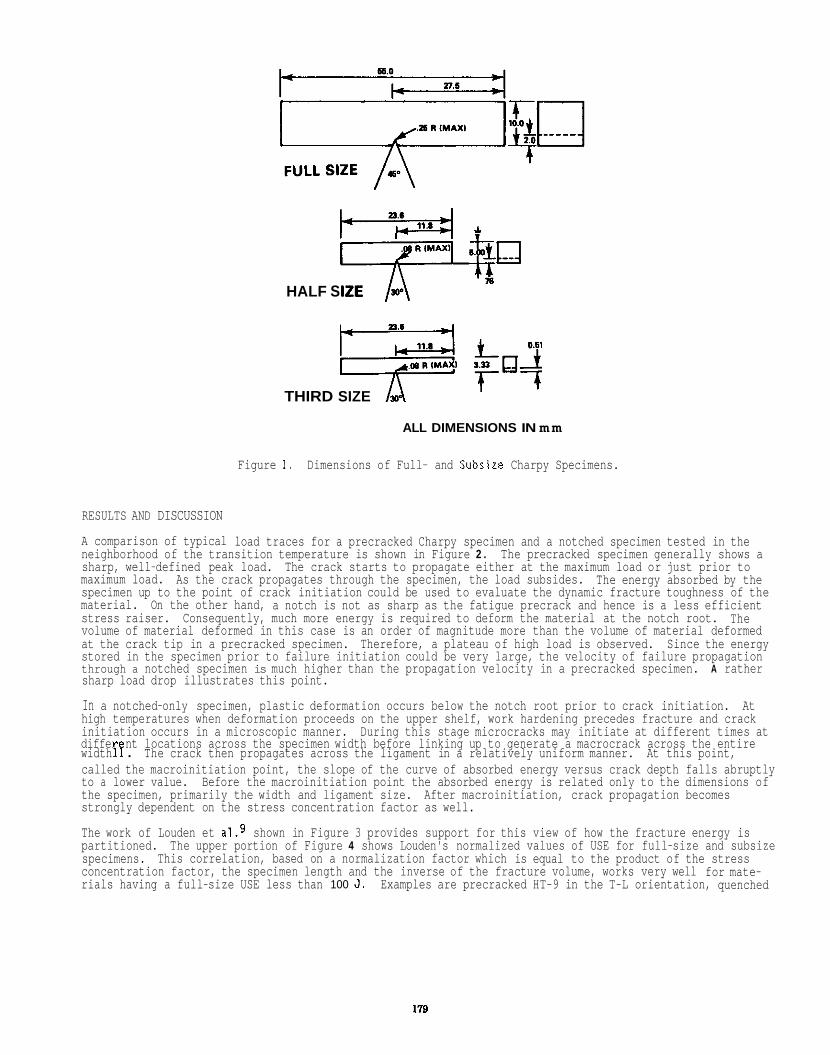
i r st" m
HALF SIZE
THIRD SIZE
ALL DIMENSIONS IN mm
Figure 1. Dimensions of Full- and Subsize Charpy Specimens.
RESULTS AND DISCUSSION
A comparison of typical load traces for a precracked Charpy specimen and a notched specimen tested in the neighborhood of the transition temperature is shown in Figure 2 . The precracked specimen generally shows a sharp, well-defined peak load. The crack starts to propagate either at the maximum load or just prior to maximum load. The energy absorbed by the specimen up to the point of crack initiation could be used to evaluate the dynamic fracture toughness of the material. On the other hand, a notch is not as sharp as the fatigue precrack and hence is a less efficient stress raiser. Consequently, much more energy is required to deform the material at the notch root. volume of material deformed in this case is an order of magnitude more than the volume of material deformed at the crack tip in a precracked specimen. Therefore, a plateau of high load is observed. stored in the specimen prior to failure initiation could be very large, the velocity of failure propagation through a notched specimen is much higher than the propagation velocity in a precracked specimen. A rather sharp load drop illustrates this point.
In a notched-only specimen, plastic deformation occurs below the notch root prior to crack initiation. At high temperatures when deformation proceeds on the upper shelf, work hardening precedes fracture and crack initiation occurs in a microscopic manner. differ nt locations across the specimen width before linking up to generate a macrocrack across the entire
called the macroinitiation point, the slope of the curve of absorbed energy versus crack depth falls abruptly to a lower value. the specimen, primarily the width and ligament size. strongly dependent on the stress concentration factor as well.
The work of Louden et a1.9 shown in Figure 3 provides support for this view of how the fracture energy is partitioned. specimens. This correlation, based on a normalization factor which is equal to the product of the stress concentration factor, the specimen length and the inverse of the fracture volume, works very well for mate- rials having a full-size USE less than 100 J.
As the crack propagates through the specimen, the load subsides.
The
Since the energy
During this stage microcracks may initiate at different times at width 17 . The crack then propagates across the ligament in a relatively uniform manner. At this point,
Before the macroinitiation point the absorbed energy is related only to the dimensions of After macroinitiation, crack propagation becomes
The upper portion of Figure 4 shows Louden's normalized values of USE for full-size and subsize
Examples are precracked HT-9 in the T-L orientation, quenched
1'19
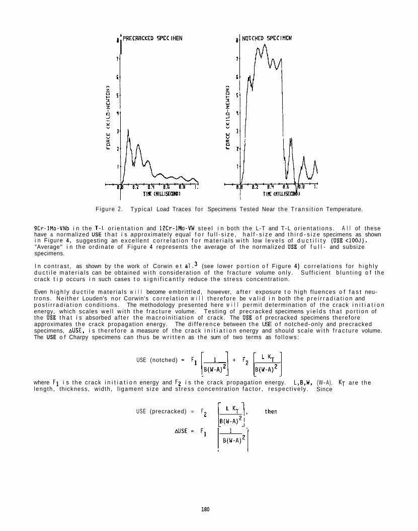
I PRECRRCKED 5PEC I HEN i
I TIK (niuisrcmm)
Figure 2 . Typ ica l Load Traces fo r Specimens Tested Near t h e T r a n s i t i o n Temperature.
9Cr-1Mo-VNb i n t h e 1 -L o r i e n t a t i o n and 12Cr-1Mo-VW s tee l i n both t h e L-T and T-L o r i e n t a t i o n s . A l l of these have a normal ized USE t h a t i s approximately equal f o r f u l l - s i z e , h a l f - s i z e and t h i r d - s i z e specimens as shown i n Figure 4 , suggesting an exce l l en t c o r r e l a t i o n f o r m a t e r i a l s w i t h low l e v e l s of d u c t i l i t y (USE <IOOJ). "Average" i n t h e o rd ina te of F igure 4 represents t h e average of t h e normal ized USE of f u l l - and subsize specimens.
I n con t ras t , as shown by t h e work o f Corwin e t a1 . 3 (see lower p o r t i o n o f F igure 4 ) c o r r e l a t i o n s fo r h i g h l y d u c t i l e m a t e r i a l s can be obtained w i t h cons iderat ion o f the f rac tu re volume on l y . crack t i p occurs i n such cases t o s i g n i f i c a n t l y reduce t h e s t ress concent ra t ion.
Even h i g h l y d u c t i l e ma te r ia l s w i l l become embr i t t l ed , however, a f t e r exposure t o h igh f luences o f f a s t neu- t rons . Ne i the r Louden's no r Corwin's c o r r e l a t i o n w i l l t he re fo re be v a l i d i n both t h e p r e i r r a d i a t i o n and p o s t i r r a d i a t i o n cond i t i ons . energy, which scales w e l l w i t h t h e f r a c t u r e volume. Test ing of precracked specimens y i e l d s t h a t p o r t i o n of the USE t h a t i s absorbed a f t e r t h e m a c r o i n i t i a t i o n of crack. The USE o f precracked specimens therefore approximates t h e crack propagat ion energy. specimens, AUSE, i s t he re fo re a measure of t h e crack i n i t i a t i o n energy and should sca le w i t h f r a c t u r e volume. The USE o f Charpy specimens can thus be w r i t t e n as t h e sum of two terms as fo l l ows :
Su f f i c i en t b l u n t i n g o f t h e
The methodology presented here w i l l pe rm i t determinat ion o f t h e crack i n i t i a t i o n
The d i f f e r e n c e between t h e USE o f notched-only and precracked
USE (notched) = F1 - [Ei(!4:A)2] ' F2 [B(i-:i2 1
where F1 i s t h e crack i n i t i a t i o n energy and F2 i s t h e crack propagat ion energy. length , th ickness, w id th , l igament s i ze and s t ress concent ra t ion f a c t o r , respec t i ve l y .
L,B,W, (W- A) , KT are t h e Since
USE (precracked) = F2
180
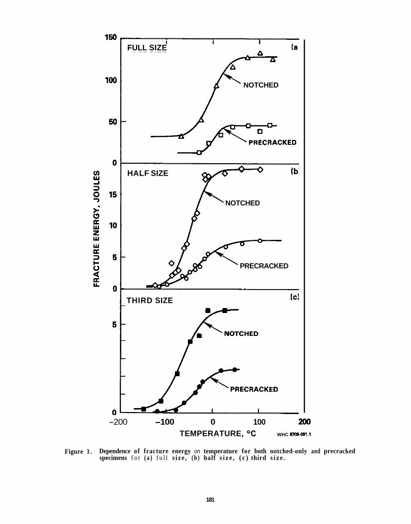
I I I FULL SIZE (a
NOTCHED P
HALF SIZE
NOTCHED k c s
PRECRACKED
(c1 THIRD SIZE
PRECRACKED x -200 -100 0 100 200
TEMPERATURE, OC WHC 87osOa1.1
Figure 3 . Dependence of fracture energy on temperature for both notched-only and precracked specimens f o r ( a ) f u l l s i z e , ( b ) half s i z e , ( c ) third s i z e .
181
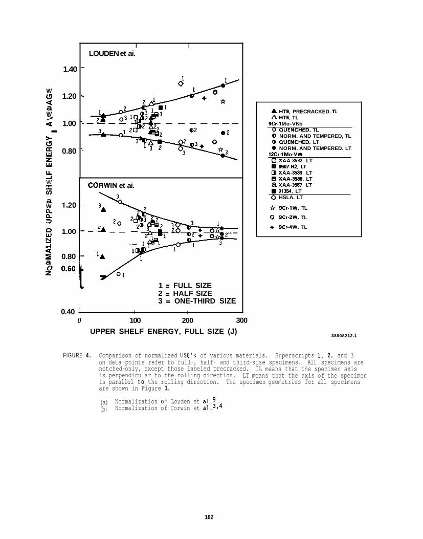
W c1 =l W > =l
>. c1 U W z w U A w I u)
W Ci. 0. 3 P w E
I a 0 z
a
.
a
2
1.40
I I LOUDEN et ai.
-
1.20
1.00
0.80
CORWiN et ai.
-
-
-
2 1.00 - - A - - -
0.80 - ‘A
1 = FULL SIZE 2 = HALF SIZE 3 = ONE-THIRD SIZE
Oo60 t ’ 0.40 I I I
0 100 200 300 UPPER SHELF ENERGY, FULL SIZE (J)
A HT9. PRECRACKED. TL A HT9. TL
9Cr-1 Mo-VN b 0 (1UENCHED. TL 0 NORM. AND TEMPERED, TL 0 (1UENCHED. LT 0 NORM. AND TEMPERED. LT
0 XAA-3592. LT
0 XAA-35%). LT B X A A - m . LT
12Cr-lM0-VW
a m 7 - ~ 2 . LT
a X A A - ~ ~ S I , LT 91354. LT
0 HSLA. LT
* 9Cr-1W. TL
0 9Cr-2W. TL
+ 9Cr-4W. TL
38808212.1
FIGURE 4 . Comparison of normalized USE’S of various materials. Superscripts 1, 2 , and 3 on data points refer to full-, half- and third-size specimens. All specimens are notched-only, except those labeled precracked. is perpendicular to the rolling direction. is parallel t o the rolling direction. The specimen geometries for all specimens are shown in Figure 1.
(a) (b)
TL means that the specimen axis LT means that the axis of the specimen
Normalization o f Louden et al.9 Normalization of Corwin et a1.314
182
Figure 3 shows Charpy data on t h e USE o f HT- 9 t es ted i n both notched-only and precracked cond i t ions. The USE values f o r notched-only specimens were 129 J, 19.1 J and 5.84 J f o r f u l l - , h a l f - and t h i r d - s i z e specimens. The USE o f precracked specimens, as shown i n Table 1, drops o f f sharp ly compared t o t h e notched-only specimens. The l igament s izes o f t h e precracked specimens were 62.5%, 68.3%, and 63.1% o f t h e respec t i ve l igament s i zes o f notched-only specimens. I f t h e l igament s i zes o f t h e precracked subsize specimens were smal ler such t h a t they were each 62.5% o f t h e respec t i ve notched-only specimens, t h e r e s u l t i n g precracked subsize USE would a l so be smal le r . t h i r d - s i z e precracked specimens would then be 7.32 J and 2.28 J. The ad jus ted va lue i s based on t h e premise t h a t if t h e f u l l - s i z e and subsize specimens were precracked t o t h e same f r a c t i o n o f t h e l igament s i z e o f t h e notched-only specimens, t h e USE would drop from t h e notched-only va lue t o t h e precracked va lue by t h e same f a c t o r f o r f u l l - , h a l f - and t h i r d - s i z e specimens. The assumption appears t o be reasonable since, as shown i n Table 2, t h e r a t i o s o f t h e notched-only and precracked USE values are roughly equal. normalized values o f AUSE, where t h e normal iza t ion f a c t o r i s t h e f r a c t u r e volume and AUSE i s t h e d i f f e r e n c e between t h e USE o f notched-only specimens and t h e ad jus ted USE value o f the precracked specimens. normalized values o f AUSE are w i t h i n L3% o f t h e average value, s i g n a l i n g an exce l l en t c o r r e l a t i o n .
Knowledge o f t h e AUSE and t h e r a t i o o f t h e USE and USEp provides t h e f o l l o w i n g th ree equations w i t h th ree unknowns t o determine t h e USE o f f u l l - s i z e specimens based on subsize data. f u l l - and subsize specimens, respec t i ve l y , and subsc r ip t p means crack propagat ion.
The "adjusted" va lue o f t h e USE ( f o r a 62.5% l igament) o f h a l f - s i z e and
Table 3 shows t h e
The
Superscr ip ts f and s represent
( A U S E / F . V . ) ~ = ( A U S E / F . V . ) ~
( U S E / U S E ~ ) ~ = ( U S E / U S E ~ ) S
USE^ = A U S E ~ t USE^^ where F.V. i s t h e f r a c t u r e volume. F.V. equals B(W-A)z, B being t h e th ickness and (W-A), t h e l igament s i ze .
CONCLUSION
The upper s h e l f energy (USE) o f f u l l - s i z e Charpy specimens can be p red ic ted based on subsize specimen data. USE i s a sum o f t h e crack i n i t i a t i o n energy (AUSE) and t h e crack propagat ion energy (USE ) upper s h e l f energy o f precracked specimens. The r a t i o s o f USE and USEp f o r f u l l - s i z e an! i u b s i z g specimens were found t o be equal. A normal ized va lue o f AUSE i s de f i ned as t h e product o f t h e ac tua l va lue and t h e rec ip roca l o f t h e f r a c t u r e volume. t o t h e subsize normal ized values. AUSE represents t h e d i f f e r e n c e between USE and USEp. Knowing both t h e d i f f e r e n c e and t h e r a t i o o f USE and USEp f o r f u l l - s i z e specimens based on subsize data, USE fo r f u l l - s i z e specimens can be ca lcu la ted.
USE equals t h e
Normalized values o f AUSE f o r f u l l - s i z e specimens were found t o be equal
FUTURE WORK
No f u r t h e r work i s planned u n t i l add i t i ona l data become ava i l ab le .
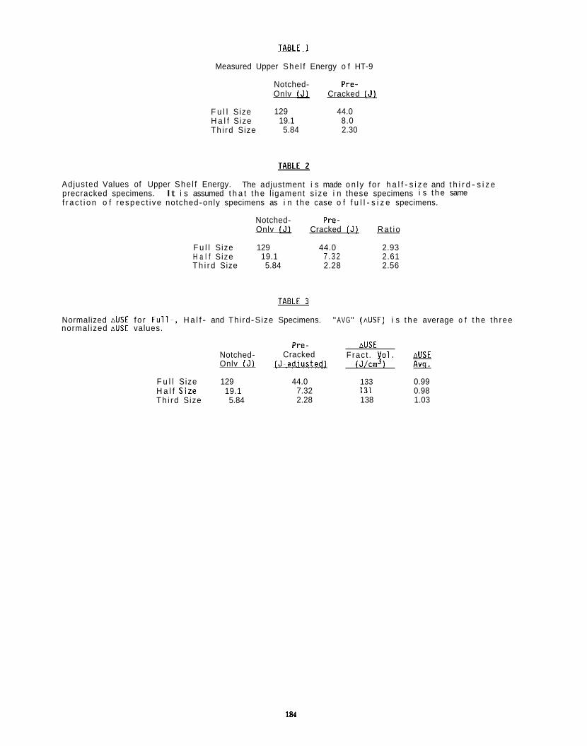
m Measured Upper She l f Energy o f HT-9
Notched- Pre- Onlv IJL Cracked 151
F u l l Size 129 44.0 H a l f Size 19.1 8.0 Th i rd Size 5.84 2.30
Adjusted Values of Upper She l f Energy. precracked specimens. f r a c t i o n o f respec t i ve notched-only specimens as i n t h e case o f f u l l - s i z e specimens.
The adjustment i s made o n l y f o r h a l f - s i z e and t h i r d - s i z e It i s assumed t h a t t h e l igament s i ze i n these specimens i s t h e same
Notched- Pre- Onlv IJL Cracked 151 ~ Ra t i o
F u l l Size 129 44.0 2.93 H a l f Size 19.1 7 . 3 2 2.61 T h i r d Size 5.84 2.28 2.56
Normalized AUSE f o r F u l l - , H a l f - and Th i rd-Size Specimens. "AVG" (AUSE) i s t h e average o f t h e th ree normal ized AUSL values.
Pre- AUSE Notched- Cracked Frac t . y o l . aUSE Onlv I J ) 1 J - a d j u s t e d l lJ/cm 1 &L
F u l l Size 129 44.0 133 0.99 ~~
H a l f S i I e 19.1 Th i rd Size 5.84
7.32 131 0.98 2.28 138 1.03
184
REFERENCES
1. W. L. Hu and 0. S. Gel les, Proc. Conf. on F e r r i t i c A l l oys fo r Use i n Nuclear Energy Technologies,
2 . R . W. Powell, G. 0. Johnson, M. L. Hamilton and F. A. Garner, i n t h e Proc. of t h e ANS In te rna t i ona l
3. W. R . Corwin, R. L. Klueh, and J . M. V i tek, J . Nucl. Mater. 122-123, (1984) p. 343.
4. W . R. Corwin and A . M. Hougland, ASTM STP 888, Eds., W. R . Corwin and G. E. Lucas, American Society f o r
5. G. E. Lucas, G. R. Odette, J. W . Sheckherd, P. McConnell, and J . Per r in , ASTM STP 888, eds., W. R.
6. G. E. Lucas, G. R. Odette, J . W. Sheckherd, and M. R. Krishnadev, Fusion Tech., 10 (1986) p. 728.
7.
8. F. Abe, T. Noda, H. Araki, M. Okada, M. Naraui and H. Kayano, Journal o f Nuclear Mater ia ls , 150 (1987)
Snowbird, UT, (June 1983) p. 631.
Conf. on Rel iab le Fuels for L i qu i d Metal Reactors, Tucson, AZ, (September 1986) pp. 4 - 1 1 .
Test ing and Mater ia ls (1986) p.325.
Corwin and G. E. Lucas, American Society f o r Testing and Ma te r i a l s (1986) p. 305.
6 . L. Ferguson, ASM Proc. o f A I M E Annual Meeting on "What Does t h e Charpy Test Rea l l y T e l l Us?", Denver, CO, Feb. 1978, Eds. A. R. Rosenfield, et a l . , pp. 90-107.
292-301.
9. 6. 5. Louden, A. 5. Kumar, F . A . Garner, M. L. Hamilton and W. L. Hu, Journal of Nuclear Mater ia ls , 155- 157 (1988) 662-667.
10. T. A. Lechtenberg, ADIP Semiannual Progress Report, DDE/ER-0045/8, p. 363
11. W . Server, D. Nor r i s , Jr. and M. Prado, ASM Proc. o f A I M E Annual Meeting on "What Does t h e Charpy Test Real ly T e l l Us?" , Denver, CO, Feb 27-28, 1978, Eds. A. R. Rosenf ie ld e t a l . , pp. 187-200.

PROCESSING OF TWO IRON-CHROMIUM OXIDE DISPERSION ?JRENGMENEO STEELS BY MECHANICAL ALLOYING - A. N N i e m i , M. G. McKimpson (Michigan Technology Institute), and D. S. Gel les (Pac i f i c Northwest
CBJECTIVE
The o b j e c t i v e of t h i s e f f o r t i s t o detennine if oxide d ispers ion strengthened (00s) a l l o y s produced by mechanical a l l o y i n g a re s u i t a b l e f o r f i r s t wal l app l ica t ions.
SUMMARY
Two l o w a c t i v a t i o n f e r r i t i c OOS a l l o y s have been manufactured. using mechanical a l l o y i n g procedures. i n t o extruded bar. Fe-9Cr-2.OW-0.3V-O.OBC-0.25Y 4. Dispersoid phase i n s t a b i l i t y i s i nd ica ted i n t h e Fe-9Cr carbon-containing a l loy . b u t t h e 14Cr a l l o y ap&ars t o o f f e r a novel ma te r ia l which may be s u i t a b l e for f l r s t wa l l app l i ca t ions and warrants f u r t h e r study.
The a l l o y canposi t ions i n weight percent are: Fe-14Cr-l.0Ti-0.5W-0.25Y2~ and
RlOGRESS AN0 STATUS
Iotroductlon An OOS a l l o y made by mechanical a l l o y i n g methods i s rece iv ing ont inued i n t e r n a t i o n a l cons iderat ion f o r l i q u i d metal', f a s t breeder reactor f ue l c ladd ing appl icat ions.E The a l l o y shcus e x c e l l e n t l ong term mic ros t ruc tu ra l s t a b i l i t y i n i r r a d i a t i o n environments and i s expected t o r e t a i n superb h igh temperature strength. The a l loy . c a l l e d MA957. has t h e canpos i t ion Fe-14Cr-1Ti-O.25Mo-0.25Y24 and i s made by a powder metal lurgy process i n v o l v i n g h igh energy b a l l m i l l i n g . The r e s u l t a n t microst ruc ture cons is ts of a metal m a t r i x w i t h a un i formly d i s t r i b u t e d y t t r i a d isperso id on t h e order o f 5 nm i n diameter. conta ins a h igh ly elongated subgrain s t r u c t u r e which is introduced by thennomechanical processing. Based on performance demonstrated t o date. t h i s technology should be considered f o r fus ion f i r s t wa l l app l ica t ions.
Therefore. an e f f o r t has been i n i t i a t e d t o consider t h e use o f mechanically a l loyed OOS a l l o y s f o r fusion by a l t e r i n g the a l l o y canpos i t ion t o be i n l i n e w i t h l o w a c t i v a t i o n c r i t e r i a . However. t h e manufacturer o f MA957. t h e INCOMAP d i v i s i o n o f t h e In te rna t iona l Nickel Canpany. Huntington. W. Va.. was u n w i l l i n g t o manufacture a l o w a c t i v a t i o n var iant . and therefore. a request was made and a responding proposal was submitted by The I n s t i t u t e of Ma te r la l s Processing (IMP). Michigan Technology Un ive rs i t y t o produce two ext rus ions from mechanically a l loyed powder. As accepted. t h e agreement c a l l e d f o r t h e product ion of ex t rus ions fran mechanically a l loyed powder of t h e fo l l ow ing composit ions ( i n weight percent) : Fe-14Crl.OTi-0.5W-0.25Y 4 and Fe-9Cr-2.OW-O.3V-O.OBC-0.25Y 4. composit ions and method o f processing were defined ay P a c i f i c Northwest Laboratory (PNL? so t h a t t h e q 4 C r a l l o y was a 1cu a c t i v a t i o n v a r i a n t o f MA957 and t h e 9Cr a l l o y was a mechanically a l loyed vers ion o f GIUX. w i t h t h e development o f appropr iate process parameters by IMP on a bes t e f f o r t basis. The ext rus lons were t o be suppl ied t o PNL w i t h a 19 mm (3/4 in.) diameter and a minimum 410 m (16 in.) length. Th is r e p o r t describes t h e manufacturing process used t o produce t h e requested mate r ia l s based on t h e IMP Pro jec t No. R-419 report . and provides sane pre l iminary measurements on t h e products.
7 The s t a r t i n g p w d e r composit ions and t h e maximum mesh s i zes are shown i n Table 1. Master alloy pcuders were used, where possible, i n an attempt t o minimize inhmogenei ty i n t h e f i n a l product. A 1s Szegvari a t t r i t o r w i t h a tank capac i ty of 9.5 L (2.5 gal.) was used f o r t h e mechanical a l loy ing. charged w i t h 27.3 kg (60 l b ) of 9.53 m (3/8 in.) 44OC s t a i n l e s s s tee l b a l l s and 1.82 kg (4 l b ) o f powder. Two batches of each c m p o s i t i o n were required. The a t t r i t o r was operated a t 350 rpm w i t h a pOSlt ive pressure, h igh p u r i t y argon purge r a t e of 5 L/min. Each batch was a t t r i t e d f o r 12 hr he ld overn ight under A, and a t t r i t e d f o r 8 h t h e next day. Dur ing a t t r i t i o n . t h e d r i v e torque and tank l i d t€mperature were monitored. The torque ran between 556 and 570 N-m (410 and 420 in.- lb) and t h e l i d temperature ran between 363 and 380K. The tank and discharge va lve were wiped c lean a f t e r each batch and t h e powder was screened t o -100 mesh t o remove any l a r g e chunks ( t h e r e were roughly 16 g o f +lo0 mesh per batch). sample of powder fran each a l l o y canpos i t ion was mounted, polished. and examined meta l l og raph ica l l y t o e s t a b l i s h t h a t s u f f i c i e n t a l l o y i n g had been achieved. As shcun i n t h e photanicrographs i n F igure 1. t h e powder p a r t i c l e s appear t o be q u i t e hanogeneous. Although n o t shown i n F igure 1. a fer pcuder p a r t i c l e s were observed which had no t been completely al loyed. Nevertheless. t h e a t t r i t i o n t ime was l i m i t e d t o 20 h i n order t o prevent caking of powder on t h e w a l l s and bottom o f t h e a t t r i t o r . develops. t h e p a d e r cont inues t o accumulate u n t i l it causes a motor s t a l l or a f r a c t u r e of sane of t h e s t i r r i n g components.
It a lso
The a l l
The tank was
A
Once t h i s problem
(a ) Operated f o r t h e U.S. Department of Energy by B a t t e l l e Memorial I n s t i t u t e under Cont rac t DE-ACM-76RLO 1830.
187
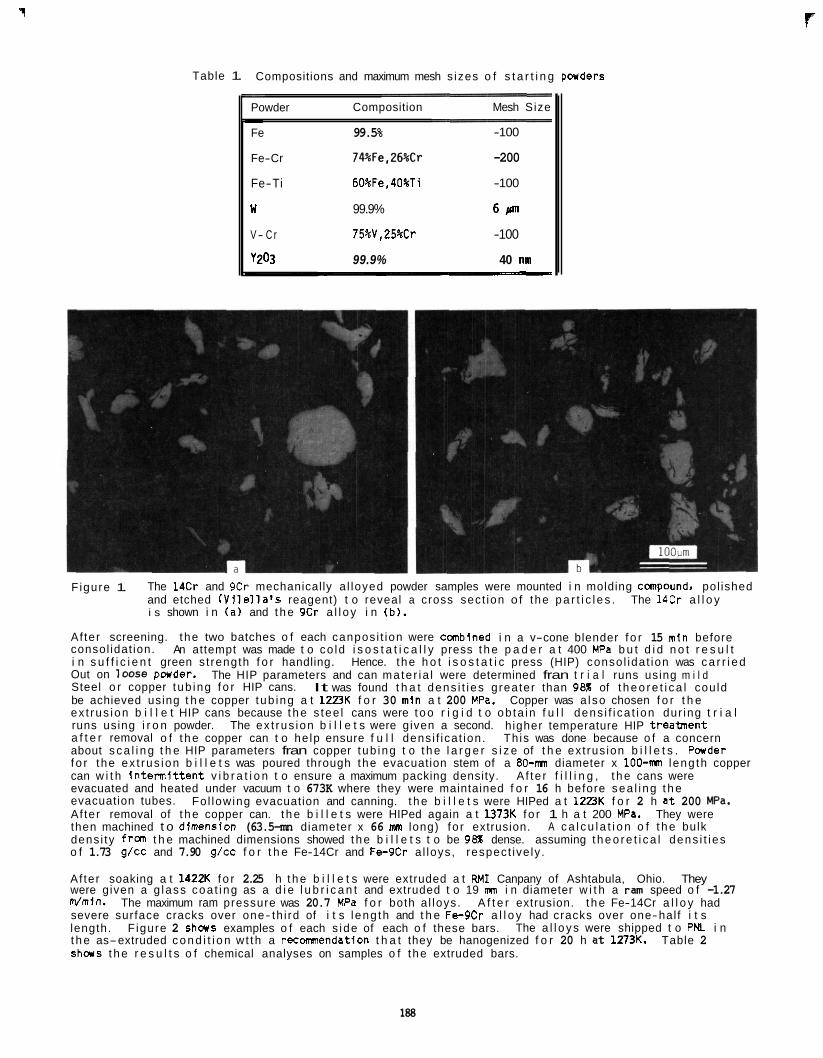
'1
Table 1. Compositions and maximum mesh s izes o f s t a r t i n g powders - Powder Composition Mesh Size
Fe 99.5% -100
Fe-Cr 74%Fe,26%Cr -200
Fe-Ti 60%Fe, 40%Ti -100
U 99.9% 61an
V- C r 75%V,25%Cr -100
t
y203 99.9% 40 nni 1
Figure 1. The 14Cr and 9Cr mechanically a l loyed powder samples were mounted i n molding canpound, pol ished and etched ( V i l e l l a ' s reagent) t o reveal a cross sect ion of the p a r t i c l e s . i s shown i n ( a ) and t h e 9Cr a l l o y i n (b) .
The 14Cr a l l o y
Af ter screening. the two batches o f each canpos i t ion were combined i n a v-cone blender f o r 15 min before consol idat ion. An attempt was made t o co ld i s o s t a t i c a l l y press t h e p a d e r a t 400 MPa b u t d i d n o t r e s u l t i n s u f f i c i e n t green s t rength f o r handling. Hence. the h o t i s o s t a t i c press (HIP) conso l idat ion was c a r r i e d Out on loose pwder . Steel o r copper tub ing f o r HIP cans. be achieved using t h e copper tub ing a t 12PK f o r 30 min a t 200 MPa. Copper was a l so chosen f o r t h e ex t rus ion b i l l e t HIP cans because t h e s tee l cans were t o o r i g i d t o ob ta in f u l l dens i f i ca t ion dur ing t r i a l runs using i r o n powder. The ex t rus ion b i l l e t s were given a second. higher temperature HIP t rea lment a f t e r removal o f t h e copper can t o he lp ensure f u l l dens i f ica t ion. Th is was done because o f a concern about s c a l i n g t h e HIP parameters fran copper tub ing t o t h e l a r g e r s i z e of t h e ext rus ion b i l l e t s . P a d e r f o r the ex t rus ion b i l l e t s was poured through the evacuation stem of a 80-mn diameter x 100-m l eng th copper can w i t h i n t e r m i t t e n t v i b r a t i o n t o ensure a maximum packing density. evacuated and heated under vacuum t o 673K where they were maintained f o r 16 h before sea l ing t h e evacuation tubes. Af ter removal of t h e copper can. t h e b i l l e t s were HIPed again a t 1373K f o r 1 h a t 200 MPa. They were then machined t o dlmension (63.5-mn diameter x 66 mn long) fo r extrusion. dens i ty fran t h e machined dimensions showed t h e b i l l e t s t o be 98% dense. assuming t h e o r e t i c a l dens i t i es o f 1.73 g/cc and 7.90 g/cc f o r t h e Fe-14Cr and Fe-9Cr a l loys, respect ive ly .
Af ter soaking a t 1422K f o r 2.25 h t h e b i l l e t s were extruded a t RMI Canpany of Ashtabula, Ohio. They were given a g lass coa t ing as a d i e l u b r i c a n t and extruded t o 19 mn i n diameter w i t h a ran speed o f -1.27 Wmin. severe surface cracks over one- th i rd of i t s l eng th and t h e Fe-9Cr a l l o y had cracks over one-hal f i t s length. The a l l o y s were shipped t o PNL i n t h e as-extruded c o n d i t i o n w t th a recomnendation t h a t they be hanogenized f o r 20 h a t l273K. Table 2 s h w s t h e r e s u l t s o f chemical analyses on samples o f the extruded bars.
The HIP parameters and can mate r ia l were determined fran t r i a l runs using m i l d It was found t h a t dens i t i es greater than 98% of t h e o r e t i c a l cou ld
A f te r f i l l i n g , t h e cans were
Fo l lowing evacuation and canning. t h e b i l l e t s were HIPed a t 123K f o r 2 h a t 200 P a .
A c a l c u l a t i o n o f t h e bulk
The maximum ram pressure was 20.7 MPa f o r both a l loys. A f t e r extrusion. t h e Fe-14Cr a l l o y had
F igure 2 s h a s examples o f each s ide of each o f these bars.
F
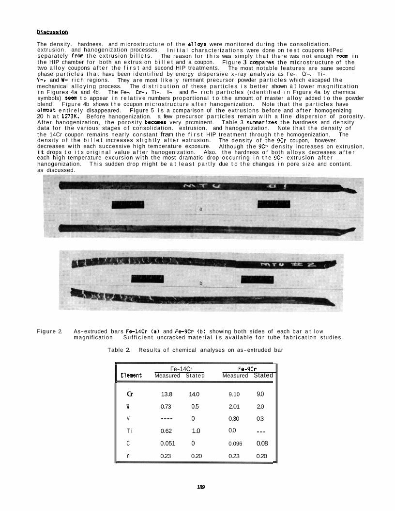
Dlscusslon
The density. hardness. and m ic ros t ruc tu re o f t h e a l l o y s were monitored dur ing t h e consol idat ion. extrusion. and hanogenization processes. separately from t h e ex t rus ion b i l l e t s . t h e HIP chamber f o r both an ext rus ion b i l l e t and a coupon. two a l l o y coupons a f t e r t h e f i r s t and second HIP treatments. phase p a r t i c l e s t h a t have been i d e n t i f i e d by energy d ispers ive x-ray ana lys i s as Fe-. Cr-. Ti-. V-e and If- r i c h regions. mechanical a l l o y i n g process. The d i s t r i b u t i o n o f these p a r t i c l e s i s b e t t e r shown a t lower magn i f i ca t i on i n Figures 4a and 4b. The Fe-. C r . Ti-. V-. and W- r i c h p a r t i c l e s ( i d e n t i f i e d i n F igure 4a by chemical symbols) 588111 t o appear i n r e l a t i v e numbers propor t iona l t o t h e amount o f master a l l o y added t o t h e powder blend. alnmst e n t i r e l y disappeared. F igure 5 i s a ccmparison of t h e ext rus ions before and a f t e r homogenizing 20 h a t 1273K. Before hanogenization. a few precursor p a r t i c l e s remain w i t h a f i n e d ispers ion of poros i ty . A f te r hanogenization, t h e po ros i t y becanes very prcminent. Table 3 sunmarires t h e hardness and dens i ty data f o r t h e var ious stages o f consol idat ion. extrusion. and hanogenlzation. Note t h a t t h e dens i ty o f t h e 14Cr coupon remains near ly constant fran t h e f i r s t HIP treatment through t h e hcmogenization. The dens i ty o f t h e b i l l e t increases s l i g h t l y a f t e r extrusion. decreases w i t h each successive h igh temperature exposure. i t drops t o i t s o r i g i n a l value a f t e r hanogenization. Also. t h e hardness o f both a l l o y s decreases a f t e r each h igh temperature excursion w i t h t h e most dramatic drop occurr ing i n t h e 9Cr ext rus ion a f t e r hanogenization. Th is sudden drop might be a t l e a s t p a r t l y due t o t h e changes i n pore s i z e and content. as discussed.
I n i t i a l character iza t ions were done on t e s t coupons HIPed The reason f o r t h i s was simply t h a t the re was n o t enough r m i n
F igure 3 compares t h e m ic ros t ruc tu re of t h e The most notable features are sane second
They a re most l i k e l y remnant precursor powder p a r t i c l e s which escaped t h e
F igure 4b shows t h e coupon m ic ros t ruc tu re a f t e r hanogenization. Note t h a t t h e p a r t i c l e s have
The densi ty o f the 9Cr coupon, however. Although t h e 9Cr dens i ty increases on extrusion,
F igu re 2. As-extruded bars F c l 4 C r (a) and Fe-9Cr (b ) showing both s ides of each bar a t l o w magnif icat ion. S u f f i c i e n t uncracked mate r ia l i s ava i l ab le f o r tube f a b r i c a t i o n studies.
Table 2. Resul ts o f chemical analyses on as-extruded bar
Fe-14Cr FeI9Cr 1 E l m n t Measured Sta ted Measured Stated
Cr 13.8 14.0 9.10 9.0
W 0.73 0.5 2.01 2.0
0 0.30 0.3 V
T i 0.62 1.0 0.0 --- C 0.051 0 0.096 0.08
Y 0.23 0.20 0.23 0.20
___-
~
189
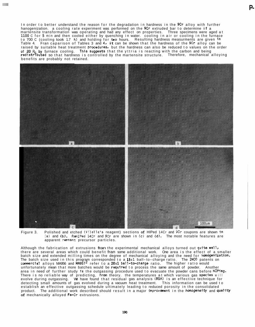
P-
I n order t o b e t t e r understand t h e reason f o r t h e degradation i n hardness i n t h e 9Cr a l l o y w i t h f u r t h e r hanogenization. a coo l i ng r a t e experiment was performed on t h e 9Cr extruded bar t o determine i f a mar tens i te t ransformat ion was operat ing and had any e f fec t on propert ies. Three specimens were aged a t 1100 C f o r 5 m i n and then cooled e i t h e r by quenching i n water. coo l i ng i n a i r o r coo l ing i n t h e furnace t o 700 C (coo l ing took 1.7 h) and ho ld ing f o r two hours. Table 4. ra ised bv s u i t a b l e heat t reatment orocedures. bu t t h e hardness can a l so be reduced t o values on t h e order
Resul t ing hardness measurments are given I n Fran c a p a r i s o n o f Tables 3 and 4. it can be shown t h a t t h e hardness o f t h e 9Cr a l l o y can be
of 20 R -by furnace cool ing. red is t rqbuted so t h a t hardness i s c o n t r o l l e d by t h e mar tens i te s t ruc ture.
Th i ssugges ts t h a t t h e y t t r i a i s reac t ing w i t h t h e carbon and being Therefore, mechanical a l l o y i n g
b e n e f i t s are probably no t retained.
F igure 3. Pol ished and etched ( V i l e l l a ' s reagent) sect ions of HIPed 14Cr and 9Cr coupons are shown I n (a1 and ( b l . ReHIPed 14Cr and 9Cr are shown i n (c) and (d). The most notab le features a re apparent r m n a n t precursor p a r t i c l e s .
Although t h e f a b r i c a t i o n of ex t rus ions fran t h e experimental mechanical a l l o y s turned ou t q u i t e Well, t h e r e are several areas which could b e n e f i t fran some add i t i ona l work. One area i s t h e e f f e c t of a smal ler batch s i z e and extended m i l l i n g t imes on t h e degree o f mechanical a l l o y i n g and t h e need f o r haogenizat ion . The batch s i z e used i n t h i s program corresponded t o a 15:l bal l- to- charge r a t i o . The INCO patents on c m r c i a l a l l o y s MA956 and MA9572 r e f e r t o a 2O:l b a l l - t e c h a r g e r a t i o . unfor tunate ly mean t h a t more batches would be requ i red t o process t h e same amount of powder. Another area i n need of f u r t h e r study 1s t h e outgassing procedure used t o evacuate t h e powder cans before HIPing. There i s no r e l i a b l e way of pred ic t ing, frm theory. the temperatures a t which var ious gas SpedeS w i l l evolve du r ing outgassing. We have found t h a t res idual gas ana lys i s (RGA) i s an e f f e c t i v e technique f o r detect ing small amounts of gas evolved dur ing a vacuum heat treatment. Th is in format ion can be used t o e s t a b l i s h an e f f e c t i v e outgassing schedule u l t i m a t e l y lead ing t o reduced poros i t y i n t h e consol idated product. of mechanically a l loyed F c C r extrusions.
The higher r a t i o would
The add i t i ona l work described should r e s u l t i n a major improvment i n the hanogeneity and q u a l i t y
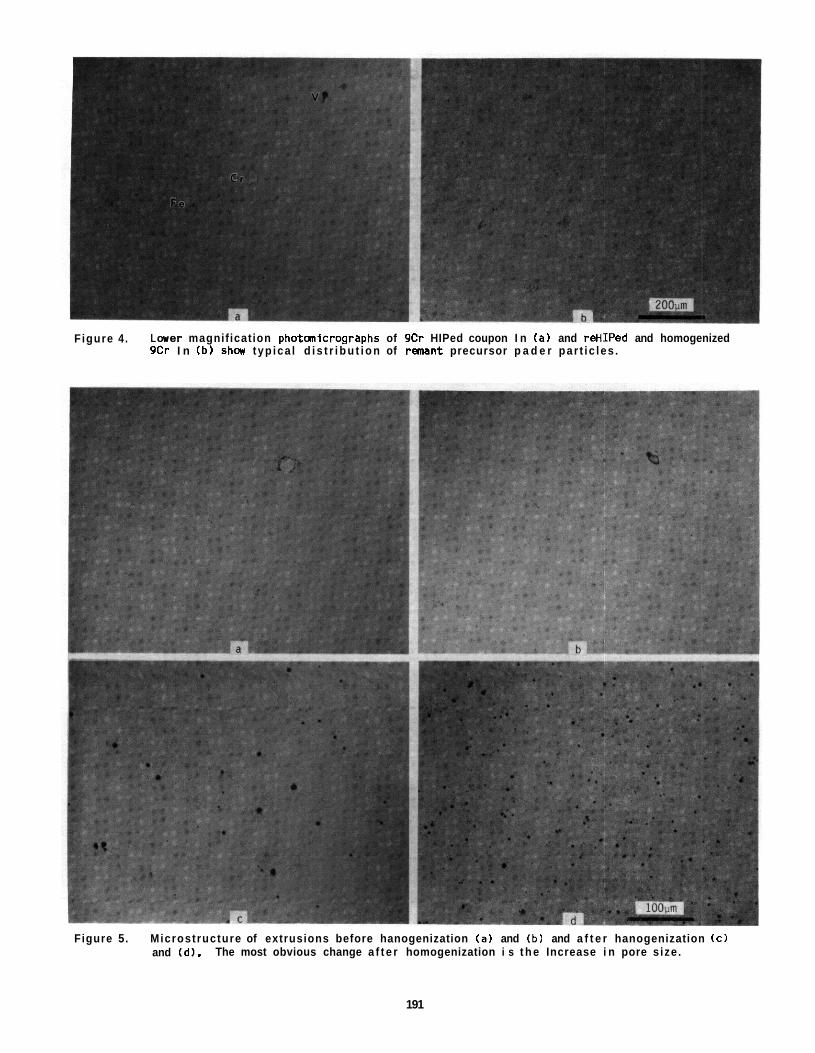
Figure 4 . L a w magnif ication photaicrographs of 9Cr HIPed coupon I n ( a ) and reHIPed and homogenized 9Cr I n (b ) s h a typ ica l d i s t r i b u t i o n of r m a n t precursor p a d e r par t ic les .
Figure 5. Microstructure of extrusions before hanogenization ( a ) and (b ) and a f t e r hanogenization ( c ) and (d) . The most obvious change a f t e r homogenization i s t h e Increase i n pore s ize.
191
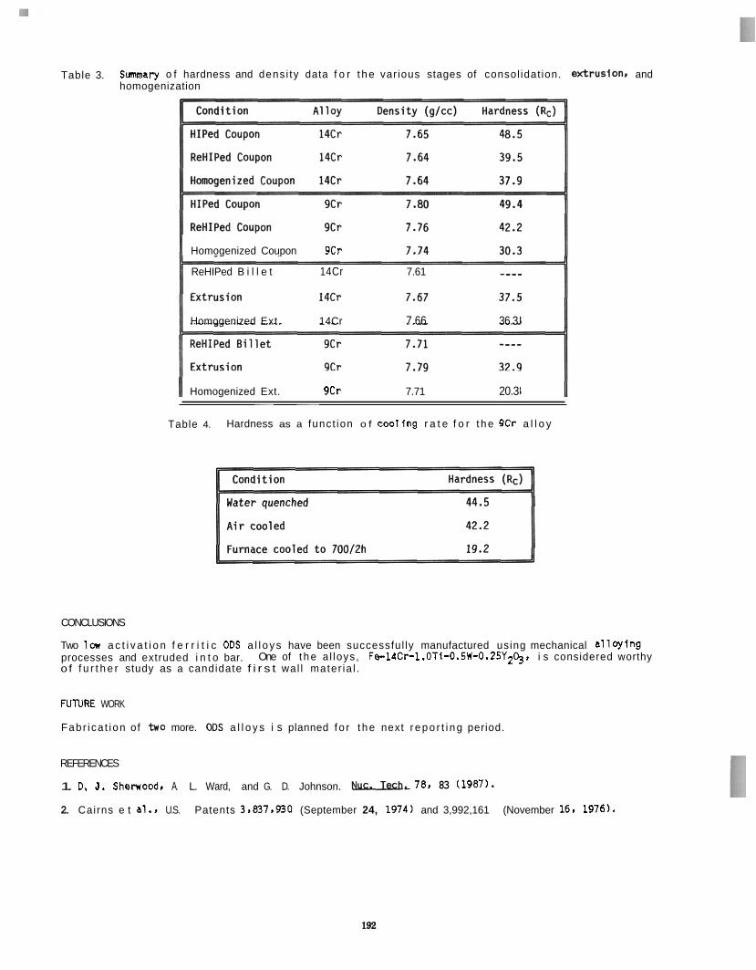
Table 3. S m a r y o f hardness and dens i ty data f o r t h e var ious stages of consol idat ion. eKtruslOns and homogenization
Homogenized Coupon 9Cr
ReHIPed B i l l e t 14Cr 7.61 ---_
Homogenized Ext. 14Cr 7.66 36.3
Homogenized Ext. 9Cr 7.71 20.3 ~ ~ ~ ~ ~ _ _ _ _ _ _ _ _ _ ~ ~
Table 4. Hardness as a funct ion o f coo l fng r a t e f o r t h e 9Cr a l l o y
CONCLUSIONS
Two la a c t i v a t i o n f e r r i t i c ODs a l l o y s have been successful ly manufactured using mechanical a l l o y i n g processes and extruded i n t o bar. o f f u r t h e r study as a candidate f i r s t wal l mater ia l .
One of t h e a l loys, Fe-14Cr-l.0Ti-D.5W-0.25Y2~. i s considered worthy
FUlURE WORK
Fabr i ca t ion of b o more. ODs a l l o y s i s planned f o r t h e next r e p o r t i n g period.
REFERENCES
1. D. J. Sherwood. A. L. Ward, and G. D. Johnson.
2. Cairns e t al.. U.S. Patents 3.837.930 (September 24, 1974) and 3,992,161 (November 16. 1976).
78. 83 (1987).
MICROSTRUCTURAL EXAM1 A ION OF HT-9 IRRADIATED I N THE FFTF/MOTA TO 110 OPA - 0. S. Gel les ( P a c i f i c Northwest LaboratoryIYaT and Ak i r a Kohyama (Un i ve rs i t y o f Tokyo)
OBJECTIVE
The o b j e c t i v e o f t h i s e f f o r t i s t o determine t h e a p p l i c a b i l i t y of ma r tens i t i c s t a i n l e s s s t e e l s f o r f i r s t wa l l app l i ca t ions .
SUMMARY
HT-9 i n two heat t reatment cond i t ions has been examined f o l l ow ing i r r a d i a t i o n a t 420'12 t o 114 dpa. i c r a d i a t i o n s were performed i n t h e Fast F l ux Test F a c i l i t y Ma te r i a l s Open Test Assmbly (FFTF/KITA). Void swe l l i ng i s found i n both condit ions, w I t h swe l l i ng values as h igh as 0.9% i n i s o l a t e d regions. Voids show a wide range o f t runcat ion, between cubic and octahedral shapes. vary as a f unc t i on o f p r e i r r a d i a t i o n heat treatment, whereas t h e d i s l o c a t i o n s t r u c t u r e and p r e c i p i t a t i o n t h a t developed dur ing i r r a d i a t i o n i s unaffected. agrement w i t h r e s u l t s on s i m i l a r simple a l loys .
The
Void swe l l i ng appears t o
Quan t i t a t i ve m ic ros t ruc tu ra l measurments are i n good
PROGRESS AND STATUS
Iotroductlon
Mar tens i t i c s t a i n l e s s s t e e l s a re rbce i v l ng increased cons idera t ion as s t r u c t u r a l ma te r i a l s f o r fus ion f i r s t wa l l app l i ca t ions . based i n l a r g e p a r t on good i r r a d i a t i o n creep and swe l l i ng res is tance p rope r t i es I n t h e temperature range 400 t o 6 0 0 T ~ ~ The mar tens i t i c s t a i n l e s s s tee l f o r which t h e g rea tes t i r r a d i a t i o n e f f e c t s data base e x i s t s i s HT-9, of canpos i t ion 12Cr-1Mo-0.X-WV. The present e f f o r t i s intended t o increase t h e data base by repo r t i ng on m ic ros t ruc tu ra l development f o r two heat t reatment cond i t i ons o f HT-9 f o l l o w i n g i r r a d i a t i o n t o 110 dpa a t 420"CI t he peak swe l l i ng t m p e r a t u r e f o r f e r r i t i c a l loys .
On several occasions. HT-9 was 8 r w i o u s l y examined f o r m i c ros t ruc tu ra l evo lu t i on f o l l o w i n g f a s t neutron i r r a d i a t i o n . Ge l les and Thomas repor ed behavior f o l l ow ing i r r a d i a t i o n i n t h e Experimental Breeder Reactor I1 (EBR-11) t o 1.4 x 1DZ n/c n J o r 70 dpa. They noted t h a t d i s l o c a t i o n loops and tang les formed i n t h e t m p e r a t u r e range 400 t o 450'C. b u t no vo ids formed. However. hel ium bubbles were found a t temperatures as low as 400'C. and p r e c i p i t a t i o n i n t h e form of a h igh dens i ty o f equiaxed pa r t i c l es . i d e n t i f i e d as c h r a n i u m r i c h at and n icke l s i l i c i d e Gphase. was recognized as t h e cause of i r r a d i a t i o n hardening. Also o f note was t h e observat ion o f molybdenum- conta in ing i n t e r m e t a l l i c c h i phase a t g r a i n boundaries.
Void swe l l i ng was i d e n t i f i e d i n HT-9 specimens i r r a d i a t e d I n t h e High F l u x Iso tope Reactor (HFIR)3s4 a t 4 0 0 T t o damage l e v e l s o f 36 o r 39 dpa. The swe l l i ng was lows l e s s than 0.B. whereas canpanion specimens i r r a d i a t e d i n EBR-I1 were found t o con ta i n no vo id swel l ing. t o r u l e ou t t h e p o s s i b i l i t y o f heat- to-heat var ia t ions . and t h e e f f e c t was t e n t a t i v e l y ascribed t o a hel ium e f f e c t on vo id nucleat ion. based on d i f f e rences i n hel ium product ion i n EBR-I1 and HFIR.
More recent ly . however. it has been shown t h a t v o i d swe l l i ng occurs i n HT-9 f o l l a l n g i r r a d i a t i o n i n FFTF a t 420'C t o 34 dpa. M ic ros t ruc tu ra l examinat ion reveal'ed several small. face t ted c a v l t l e s t y p i c a l o f i r rad ia t ion- induced vo ids i n f e r r i t i c a l loys. and equiaxed p r e c i p i t a t e s o f both a1 and Gphase type. Since hel ium generat ion i s l o w i n FFTF. it i s apparent ly no t necessary t o have s i g n i f i c a n t amounts o f hel ium present f o r v o i d swe l l i ng t o occur i n HT-9. t o be d i f f e r e n t i n d i f f e r e n t reactors.
Most recent ly , M a r i a u and K1ueh6 have summarized comparisons of r e s u l t s o f m i c ros t ruc tu ra l examinations i n HT-9 f o l l c u i n g i r r a d i a t i o n i n HFIR and FFTF. i n o rder t o prov ide a l a r g e r v a r i a t i o n i n hel ium production. i r r a d i a t i o n i n FFTF t o 47 dpa a t 407'C1 whereas abundant v o i d format ion was found i n t h e same s t e e l s f o l l ow ing i r r a d i a t i o n i n HFIR a t 400'C t o 37 dpa. abundant increases i n t h e formation o f l a r g e b ias- dr iven voids. s im i la r . w i t h l i t t l e d i f f e rence observed i n d i s l o c a t i o n s t r u c t u r e or p r e c i p i t a t e formation. i n t e r p r e t a t i o n of p r e c i p i t a t e development dur ing neutron i r r a d i a t i o n was proposed. me abundant d ispers ions of f i n e p r e d p i t a t e p a r t i c l e s t h a t formed both i n HFIR and FFTF a t 4DD'C were i d e n t i f i e d as %C (n), b u t w i t h an unusual canpos i t ion t h a t i s r i c h i n s i l l c o n . r i c h i n chromium. has minor l e v e l s of i ron . molybdenum and/or niobium and vanadium. b u t l i t t l e o r no n icke l . The p o s s i b i l i t y of t h e presence
The r e s u l t s were s u f f i c i e n t l y comprehensive
Instead. it could be argued t h a t t h e behavior appeared
The i r experiment inc luded v a r i a t i o n i n t h e n i c k e l content Very fed voids were found f o l l ow ing
It was concluded t h a t increases i n He/dpa r a t i o taus The mic ros t ruc tu res were otherwise
An a l t e r n a t e
(a) Operated f o r t h e U.S. Department of Energy by B a t t e l l e Memorial I n s t i t u t e under Cont rac t DE-AC06-76RLO 1830.
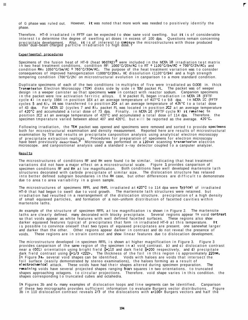
F
of G phase was r u l e d out. phase.
Therefore. HT-9 i r r a d i a t e d i n FFTF can be expected t o show sane vo id swel l ing. bu t it i s o f considerable i n t e r e s t t o determine t h e degree of swe l l i ng a t doses i n excess of 100 dpa. Quest ions remain concerning p r e c i p i t a t e development.
However, it was noted t h a t more work was needed t o p o s i t i v e l y i d e n t i f y t h e
Also, it i s of i n t e r e s t t o canpa e t h e mic ros t ruc tu res w i t h those produced under dual-beam charged p a r t i c l e i r r a d i a t i o n t o h igh dose. f - Specimens of t h e fus ion hea t of HT-9 (heat 9607R2)8 were inc luded i n t h e MOTA 1B i r r a d i a t i o n t e s t m a t r i x i n two heat t reatment condi t ions, cond i t i on RF: 1000"C/20h/AC t o RT + 1100"C/Sm/AC + 700*C/2h/AC; and cond i t i on RH: 1050'C/5m/AC + 760W30dAC. The purpose of t h e heat t reatment v a r i a t i o n was t o consider consequences o f improved hanogenization (1000"C/ZOh). WC d i s s o l u t i o n (1100WSm) and a h igh s t reng th tempering cond i t i on ( 7 0 0 W 2 h ) on m ic ros t ruc tu ra l evo lu t i on i n canparison t o a more standard condi t ion.
Dup l i ca te specimens of each of t h e two cond i t ions i n m u l t i p l e s of f i v e were i r r a d i a t e d as 0.008 in. t h i c k Transmission E lec t ron Microscopy (TEM) d isks s ide by s i de i n TEM packet FL. design i n a weeper c a n i s t e r so t h a t specimens were i n con tac t w i t h reac to r sodium. i n t h e packet were l o w a c t i v a t i o n f e r r i t i c a l loys . c y c l e 4) i n e a r l y 1984 i n p o s i t i o n 1E4 a t an average temperature o f 407'C t o 9.8 dpa. cyc les 5 and 6). it was t rans fe r red t o p o s i t i o n 2 c I a t an average temperature of 426'C t o a t o t a l dose o f 43 dpa. o f 420'C and accumulated a t o t a l dose o f 73 dpa. F i n a l l y . i n MOTA 1E (FFTF c y c l e 9) it r m a i n e d I n p o s i t i o n 2C2 a t an average temperature of 420°C and accumulated a t o t a l dose o f 114 dpa. specimen t m p e r a t u r e va r i ed between about 407 and 426°C. b u t w i l l be repor ted as t h e average. 420'C.
Fo l low ing i r r a d i a t i o n , t h e E M packet was opened and specimens were removed and sor ted t o p rov ide SpecfmenS both f o r m i c ros t ruc tu ra l examination and densi ty measurement. Reported here a r e r e s u l t s o f m i c ros t ruc tu ra l examination by TEM and r e s u l t s on p r e c i p i t a t e canposi t ion ana lys is us ing a n a l y t i c a l e l ec t ron microscopy of p r e c i p i t a t e e x t r a c t i o n rep l i cas . have been prev ious ly d e ~ c r i b e d . ~ Microscopy was performed on a lZOkeV scanning t ranwniss ion e l e c t r o n microscope. and canpos i t iona l ana lys is used a standard x-ray de tec to r coupled t o a canputer analyzer.
The packet was o f weeper Canpanion specimens
I n MOTA 1C (FFTF E M packet FL began i r r a d i a t i o n i n MOTA 1B (FFTF
For MOTA 1D (cyc les 7 and 8 ) . packet FL was loca ted i n p o s i t i o n 2C2 a t an average temperature
Therefore. t h e
Procedures f o r p repara t ion o f specimens f o r e l ec t ron microscopy
Flesuus The mic ros t ruc tu res of cond i t i ons RF and RH were found t o be s im i l a r . i n d i c a t i n g t h a t hea t t reatment v a r i a t i o n s d i d no t have a major e f f e c t on a m ic ros t ruc tu ra l scale. specimen cond i t i ons RF and RH a t l o w magnif icat ion. s t r uc tu res decorated w i t h carb ide p r e c i p i t a t e o f s i m i l a r size. i n t o b e t t e r defined subgrain boundaries i n t h e RH case, bu t o ther d i f ferences are d i f f i c u l t t o demonstrate due t o area t o area v a r i a b i l i t y i n a g iven sample.
The mic ros t ruc tu res of specimens RFFL and RHFL i r r a d i a t e d a t 420'C t o 114 dpa were t y p i c a l of i r r a d i a t e d HT-9 t h a t had begun t o swell due t o vo id growth. i r r a d i a t i o n had resu l t ed i n a rearrangement of t h e d i s l o c a t i o n st ructure. p r e c i p i t a t i o n o f a h igh dens i ty of small equiaxed pa r t i c l es , and formation of a non-uniform d i s t r i b u t i o n o f face t ted c a v i t i e s w i t h i n mar tens i te l a ths .
An example of t h e s t r u c t u r e of specimen RFFL a t l o w magn i f i ca t ion i s shown i n F igure 2. l a t h s a re c l e a r l y defined. many decorated w i t h blocky p rec ip i t a te . Several regions appear i n v o i d Contrast so t h a t vo ids appear as wh i t e fea tu res w i t h we l l def ined face t ted surfaces. These regions a l so show darker equiaxed features t y p i c a l of p r e c i p i t a t e s t h a t form i n i r r a d i a t e d HT-9 a t t h i s temperature. i s poss ib le t o convince oneself t h a t two types of equiaxed p r e c i p i t a t e s a re present. one sanewhat l a r g e r and darker than t h e other. voids.
The m ic ros t ruc tu re developed i n specimen RFFL i s shown a t h igher magn i f i ca t i on i n F igure 3. prov ides canparison of t h e same reg ion of t h e specimen i n a) vo id contrast . b ) and c) d i s l o c a t i o n con t ras t near a (001) o r i e n t a t i o n us ing b r i g h t f i e l d z-110 and dark f i e l d z-200 respect ive ly , and d) p r e c i p i t a t e dark f i e l d con t ras t us ing 5=1/3 <222>. The th ickness of t h e f o i l i n t h i s reg ion i s approximately 22Onm. I n F igure 3an several vo id shapes can be i den t i f i ed . Voids w i t h haloes are vo ids t h a t i n t e r s e c t t h e f o i l surface ( e a s i l y demonstrated by s te reo examinations), t h e haloes forming as a r e s u l t o f e lect rochemical at tack. These vo ids have had t h e i r shapes a l t e r e d dur ing specimen preparat ion. The r m a i n i n g vo ids have several p ro jec ted shapes ranging fran squares i n two or ien ta t ions . t o t runca ted shapes approaching octagons. t o c i r c u l a r p ro jec t ions . Therefore. vo id shape va r i es i n t h i s condit ion. t h e shapes corresponding t o t runca ted cubes and octahedra.
I n F igures 3b and C. many examples of d i s l o c a t i o n loops and l i n e segments can be i d e n t i f i e d . Canparison of these two micrographs prov ides s u f f i c i e n t in format ion t o evaluate Burgers vec to r d i s t r i b u t i o n s . F igure 3b i n 110 d i s l o c a t i o n con t ras t revea ls 213 of t h e d i s l oca t i ons w i t h a<100> Burgers vec to rs and ha l f t h e
F igure 1 provides canparison of Both cond i t i ons have we l l developed mar tens i te l a t h
The d i s l o c a t i o n s t r u c t u r e has re laxed
The mar tens i te l a t h s t r uc tu res were retained. b u t
The mar tens i te
It
Other regions appear darker i n con t ras t and do n o t reveal t h e presence o f These reg ions a re i n s t r a i n con t ras t and show l i n e a r features due t o d i s l o c a t i o n development.
F igure 3
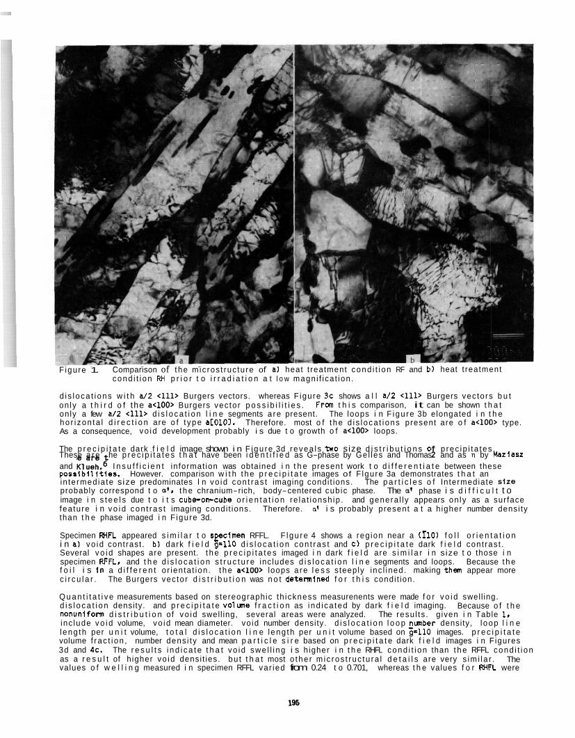
Figure 1.
d i s l oca t i ons w i t h a/2 <11D Burgers vectors. whereas F igure 3c shows a l l a/2 <111> Burgers vec to rs b u t on ly a t h i r d o f the a<100> Burgers vec to r p o s s i b i l i t i e s . only a few a/2 411, d i s l o c a t i o n l i n e segments a re present. ho r i zon ta l d i r e c t i o n are o f t ype aL0101. As a consequence, vo id development probably i s due t o growth o f a<100> loops.
The p r e c i p i t a t e dark f i e l d image shown i n F igu re 3d revea l s two size d i s t r i b u t i o n s 0 p rec ip i t a tes .
and Klueh.g I n s u f f i c i e n t in format ion was obtained i n t h e present work t o d i f f e r e n t i a t e between these p o s s l b i l l t i e s . in te rmed ia te size predominates I n vo id con t ras t imaging condi t ions. The p a r t i c l e s o f In termediate si re probably correspond t o a'. t h e chranium-rich, body-centered cub ic phase. The a@ phase i s d i f f i c u l t t o image i n s t e e l s due t o i t s cube-on-cube o r i e n t a t i o n re la t ionsh ip . and genera l l y appears on ly as a sur face fea tu re i n v o i d con t ras t imaging condi t ions. Therefore. d i s probably present a t a h igher number densi ty than t h e phase imaged i n F igure 3d.
Specimen WFL appeared s i m i l a r t o s p i m e n RFFL. F l gu re 4 shows a reg ion near a (110) f o l l o r i e n t a t i o n i n a) vo id contrast . b) dark f i e l d 9.110 d i s l o c a t i o n con t ras t and c) p r e c i p i t a t e dark f i e l d con t ras t . Several v o i d shapes are present. t h e p r e c i p i t a t e s imaged i n dark f i e l d are s i m i l a r i n s ize t o those i n specimen RFFL, and t h e d i s l o c a t i o n s t r u c t u r e inc ludes d i s l o c a t i o n l i n e segments and loops. Because t h e f o i l i s i n a d i f f e r e n t o r ien ta t ion . t h e a<100> loops a re l e s s steeply inc l ined . making them appear more c i r c u l a r . The Burgers vec to r d i s t r i b u t i o n was n o t detennined f o r t h i s condi t ion.
Q u a n t i t a t i v e measurements based on stereographic th ickness measurenents were made f o r v o i d swel l ing. d i s l o c a t i o n density. and p r e c i p i t a t e volune f r a c t i o n as i nd i ca ted by dark f i e l d imaging. Because o f t h e nonuniform d i s t r i b u t i o n of vo id swel l ing, several areas were analyzed. The resu l ts . g iven i n Table 1. inc lude v o i d volume, vo id mean diameter. vo id number density. d i s l o c a t i o n l o o p nmber density, l oop l i n e l eng th per u n i t volume, t o t a l d i s l o c a t i o n l i n e l eng th per u n i t volume based on 5110 images. p r e c i p i t a t e volume f r ac t i on , number dens i ty and mean p a r t i c l e s i r e based on p r e c i p i t a t e dark f i e l d images i n F igures 3d and 4c. The r e s u l t s i n d i c a t e t h a t vo id swe l l i ng i s h igher i n t h e RHFL cond i t i on than t h e RFFL cond i t i on as a r e s u l t of h igher vo id densi t ies. bu t t h a t most o the r m ic ros t ruc tu ra l d e t a i l s are very s im i l a r . The values o f w e l l i n g measured i n specimen RFFL var ied from 0.24 t o 0.701, whereas t h e values f o r FHFL were
Comparison of t he mic ros t ruc tu re of a) heat t reatment cond i t i on RF and b ) heat t reatment cond i t i on RH p r i o r t o i r r a d i a t i o n a t l o w magn i f i ca t ion .
From t h i s comparison, it can be shown t h a t The loops i n F i gu re 3b elongated i n t h e
Therefore. most o f t h e d i s l oca t i ons present are o f a<100> type.
These a r e he p r e c i p i t a t e s t h a t have been i d e n t i f i e d as G-phase by Ge l les and Thomas l and as n by Maziasz
However. comparison w i t h t h e p r e c i p i t a t e images of F lgure 3a demonstrates t h a t an
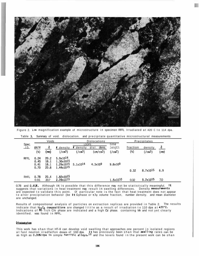
Figure 2. Lar magn i f i ca t i on example of m ic ros t ruc tu re i n specimen RFFL I r r a d i a t e d a t 420 C t o 114 dpa.
Table 1. Summary of void. d is loca t ion . and p r e c i p i t a t e q u a n t i t a t i v e m ic ros t ruc tu ra l measurements
Voids D is loca t ions P rec ip i t a tes Spec. LOOPS l i n e - I D 2 # dens i ty I dens i ty d i s l . dens. length f ract ion dens i ty a
()I) (nm) (/cm3) (/cm3) ( c m l c d ) (/cm*) (%) (/cm3) (nm)
RHFL 0.78 20.4 1.82x10¹⁵ 0.91 20.7 2.09~1015 1.5~1010 0.32 9.2~1015 7.0
0.78 and 0.9U. suggests t h a t v a r i a t i o n s i n heat t reatment may r e s u l t i n swe l l i ng d i f ferences. are expected t o v a l i d a t e t h i s point . Of p a r t i c u l a r note i s t h e f a c t t h a t heat t reatment does n o t appear t o a l t e r p r e c i p i t a t i o n behavior (be It Gphase o r n); volume f rac t ion , number density. and mean diameter are unchanged.
Resu l ts of composit ional ana lys is o f p a r t i c l e s on e x t r a c t i o n r e p l i c a s are provided i n Table 2. i n d i c a t e t h a t M C6 ccmposit ions a re changed l i t t l e as a r e s u l t o f i r r a d i a t i o n t o 110 dpa a t 420'C. I n d i c a t i o n s o f % r i c h Chi phase are i nd i ca ted and a h igh Cr phase. con ta in ing Mn and n o t y e t c l e a r l y i den t i f i ed . was found i n RFFL.
Although it i s poss ib le t h a t t h i s d i f f e rence may no t be s t a t i s t i c a l l y meaningful. it Densi ty meaSUr€mntS
The r e s u l t s
Discussion
Th is work has s h a n t h a t HT-9 can develop vo id swe l l i ng t h a t approaches one percent i n i s o l a t e d regions a t f a s t neutron i r r a d f a t f o n doses of 110 dpa. as h l gh as 0.06Wdpa i n simple ferritic and t h e l e v e l s found i n t h e present work can be s h a n
It has p rev ious ly been s h a n t h a t n e l l f n g r a t e s can be
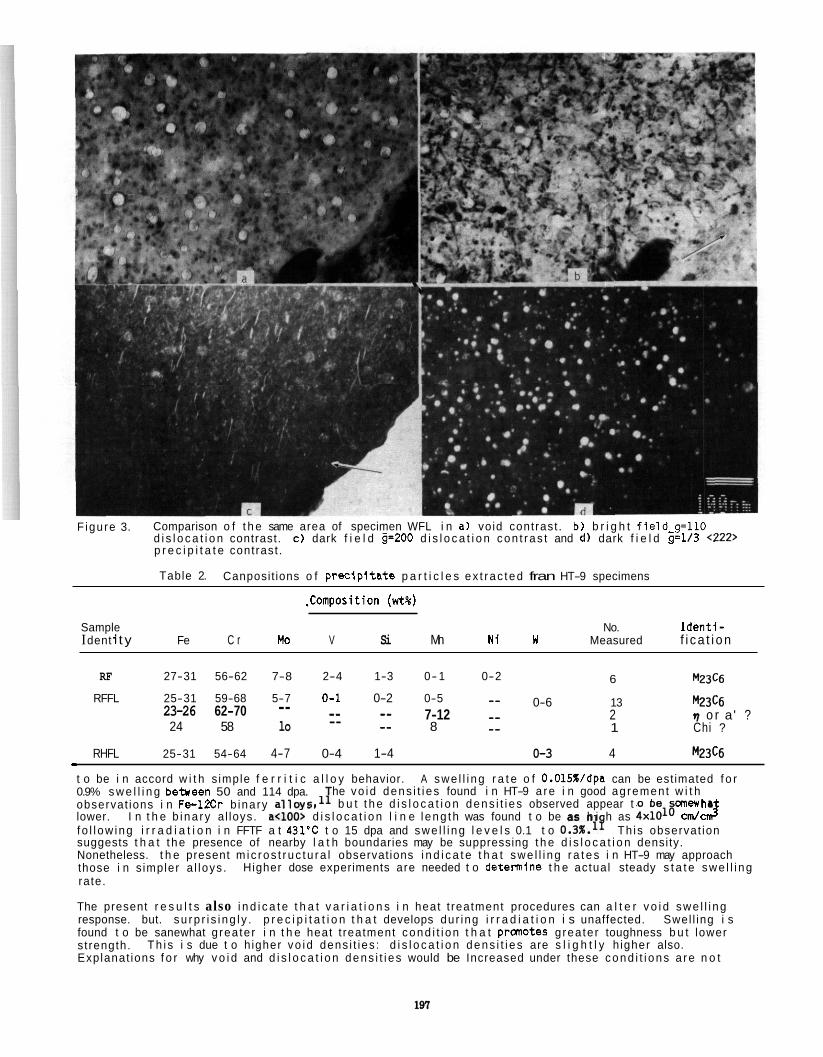
Figure 3. Comparison o f t h e same area of specimen WFL i n a) vo id contrast . b ) b r i g h t f i e l d -g= l lO d i s l o c a t i o n contrast. c ) dark f i e l d g=200 d i s l o c a t i o n con t ras t and d) dark f i e l d g=1/3 <222> p r e c i p i t a t e contrast .
Table 2. Canposit ions o f p r e c l p i t a t e p a r t i c l e s ex t rac ted fran HT-9 specimens
.Conposition (wt%)
Sample No. I d e n t i - I dent i t y Fe C r Mo V Si Mn N i w Measured f i ca t i on
RF 27-31 56-62 7-8 2-4 1-3 0- 1 0-2 6 M23c6
0-6 13 M23C6
8 _ _ 1 Chi ?
RHFL 25-31 54-64 4-7 0-4 1-4 0-3 4 w3c6
RFFL 25-31 59-68 5-7 0-1 0-2 0-5 -- 7-12 _ _ 2 7 o r a' ? 23-26 62-70 -- _- _- -- -- 24 58 lo
r
t o be i n accord w i t h s imple f e r r i t i c a l l o y behavior. A swe l l i ng r a t e o f O.OlS%/dpa can be est imated f o r 0.9% s w e l l i n g b e b e e n 50 and 114 dpa. observat ions i n Fe -1Xr b inary
f o l l ow ing i r r a d i a t i o n i n FFTF a t 431'C t o 15 dpa and swe l l i ng l e v e l s 0.1 t o 0.3%.1T Th is observat ion suggests t h a t t he presence of nearby l a t h boundaries may be suppressing t h e d i s l o c a t i o n density. Nonetheless. t h e present m i c ros t ruc tu ra l observat ions i n d i c a t e t h a t swe l l i ng r a t e s i n HT-9 may approach those i n s impler a l loys . rate.
The present r e s u l t s also i n d i c a t e t h a t v a r i a t i o n s i n heat t reatment procedures can a l t e r v o i d swe l l i ng response. but. su rp r i s i ng l y . p r e c i p i t a t i o n t h a t develops dur ing i r r a d i a t i o n i s unaffected. Swel l ing i s found t o be sanewhat g rea te r i n t h e heat t reatment cond i t i on t h a t pranotes g rea te r toughness b u t lower s t rength. Explanat ions f o r why v o i d and d i s l o c a t i o n dens i t i es would be Increased under these cond i t i ons a re n o t
he vo id dens i t i es found i n HT-9 a re i n good agrement w i t h b u t t h e d i s l o c a t i o n dens i t i es observed appear t o be anewha
lower. I n t h e b i na ry a l loys. a<100> d i s l o c a t i o n l i n e l eng th was found t o be as h i h as 4x1Ol8 cm/ C J
Higher dose experiments are needed t o detern ine t h e actual steady s t a t e swe l l i ng
Th i s i s due t o h igher vo id dens i t ies : d i s l o c a t i o n dens i t i es are s l i g h t l y h igher also.
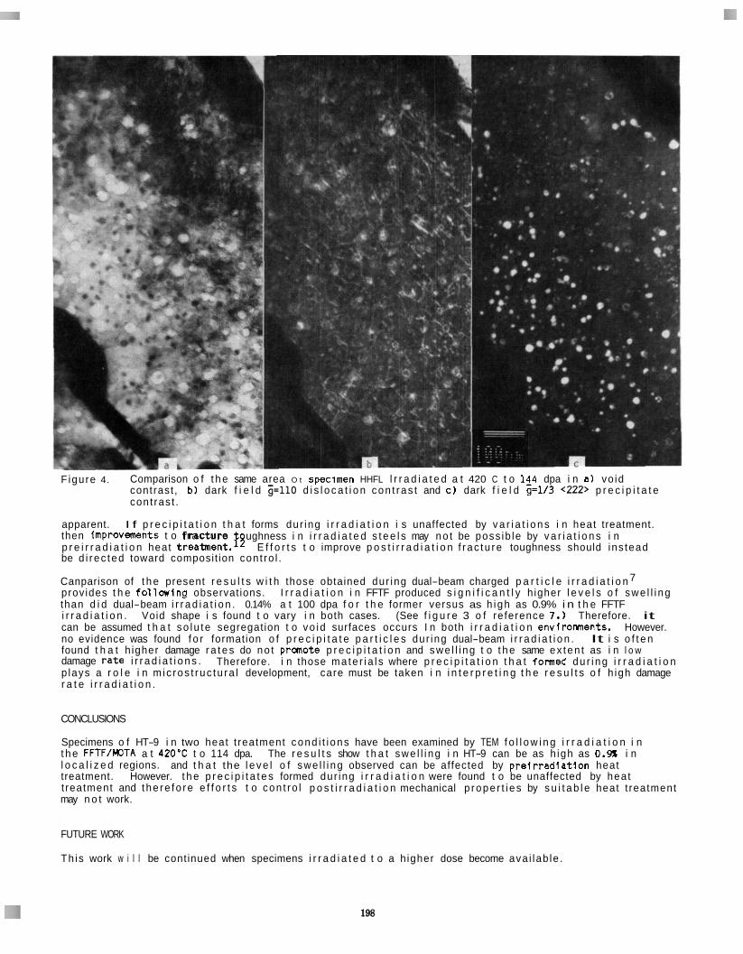
Figure 4. Comparison o f t h e same area O t speclmen HHFL l r r a d i a t e d a t 420 C t o 14_4 dpa i n a) vo id contrast , b ) dark f i e l d i = l l O d i s l o c a t i o n con t ras t and c ) dark f i e l d g=1/3 <222> p r e c i p i t a t e con t ras t .
I f p r e c i p i t a t i o n t h a t forms dur ing i r r a d i a t i o n i s unaffected by v a r i a t i o n s i n heat treatment. apparent. then improvefrants t o f r a c t u r e p r e i r r a d i a t i o n heat treatment.$ E f f o r t s t o improve p o s t i r r a d i a t i o n f r ac tu re toughness should ins tead be d i r ec ted toward composit ion con t ro l .
Canparison of t h e present r e s u l t s w i t h those obtained dur ing dual-beam charged p a r t i c l e i r r a d i a t i o n 7 prov ides t h e f o l l n i n g observat ions. than d i d dual-beam i r r a d i a t i o n . 0.14% a t 100 dpa f o r t h e former versus as h igh as 0.9% i n t h e FFTF i r r a d i a t i o n . Void shape i s found t o vary i n both cases. (See f i g u r e 3 o f re ference 7.) Therefore. it can be assumed t h a t so lu te segregation t o vo id surfaces occurs I n both i r r a d i a t i o n envirorments. no evidence was found f o r formation o f p r e c i p i t a t e p a r t i c l e s dur ing dual-beam i r r a d i a t i o n . It i s o f t e n found t h a t h igher damage r a t e s do no t pranote p r e c i p i t a t i o n and swe l l i ng t o t h e same ex ten t as i n l o w damage r a t e i r r a d i a t i o n s . p lays a r o l e i n m ic ros t ruc tu ra l development, care must be taken i n i n t e r p r e t i n g t h e r e s u l t s o f h igh damage r a t e i r r a d i a t i o n .
ughness i n i r r a d i a t e d s t e e l s may no t be poss ib le by v a r i a t i o n s i n
I r r a d i a t i o n i n FFTF produced s i g n i f i c a n t l y h igher l e v e l s o f swe l l i ng
However.
Therefore. i n those ma te r i a l s where p r e c i p i t a t i o n t h a t formed du r i ng i r r a d i a t i o n
CONCLUSIONS
Specimens o f HT-9 i n two heat t reatment cond i t i ons have been examined by TEM f o l l o w i n g i r r a d i a t i o n i n t h e FFTFIMOTA a t 420'C t o 114 dpa. The r e s u l t s show t h a t swe l l i ng i n HT-9 can be as h igh as 0.- i n l o c a l i z e d regions. and t h a t the l e v e l o f swe l l i ng observed can be affected by p r e i r r a d l a t i o n heat treatment. However. t h e p r e c i p i t a t e s formed dur ing i r r a d i a t i o n were found t o be unaffected by hea t t reatment and t he re fo re e f f o r t s t o con t ro l p o s t i r r a d i a t i o n mechanical p rope r t i es by s u i t a b l e heat t reatment may n o t work.
FUTURE WORK
Th is work w i l l be cont inued when specimens i r r a d i a t e d t o a h igher dose become ava i lab le .
REFERENCES
1.
2.
3.
4 .'
5.
6.
7.
8.
9.
10.
11.
12.
D. S. Gelles, "Effects o f I r r a d i a t i o n on F e r r i t i c A l l o y s and Imp l i ca t i ons f o r Fusion Reactor Applications," -, 149. 192-199 (1987).
D. S. Gel les and L. E. Thanas. "Effects o f Neutron I r r a d i a t i o n on Micros t ruc ture i n Experimental and Commercial F e r r i t i c Alloys." Proceedlnas of: Tooical Cnnfarence on F e r r i t i c A l l ovs f o r USB p, J. W. David and 0. J. Michel. Eds., AIME. Warrendale, PA. 1984.
J. M. Vi tek and R. L. Klueh, "Microstructure o f HFIR- Irradiated 12Cr-1MoVW F e r r i t i c Steel." Ib id .
559-568.
551-558.
D. S. Gelles. " Micros t ruc tura l Comparison o f HT-9 I r r a d i a t e d i n HFIR and EBR-II." & l m f o r lrradi-- f o r t he Period -. DOE/ER- 0045/14, 129-136.
C. Y. Hsu. D. S. Gelles. and T. A. Lechtenberg. " Micros t ruc tura l Examination of la C r Mar tens i t i c S ta in less Steel A f te r I r r a d l a t i o n a t Elevated Temperatures."
and A. S. Kumar. Eds.. ASTM. Phi ladelphia. 1987. 545-559.
P. J. Maziasz and R. L. Klueh. "Void Formation and Helium E f f e c t s i n 9Cr-1MoVNb and 12CrlMoVW Stee ls I r r a d i a t e d i n HFIR and FFTF a t 400°C." t o be publ ished i n t h e proceedings o f t h e 14 th In te rna t iona l Symposium on t h e E f f e c t s o f Radiat ion on Mater ia ls. held June 27-29. 1988 i n Andover. MA.
K. Asano. Y. Kohno. A. Kohyama, and G. Ayraul t , " Micros t ruc tura l Evo lu t i on o f HT9 Under Dual-Beam Charged P a r t i c l e I r rad ia t i on ."
T. A. Lechtenberg. "The Procurement and Character iza t ion o f t he E lec t ros lag Remelted Fusion Program Heat of 12Cr-1Mo Steel," I b i d reference 4, DOE/ER-0045/8. 3/1982. 363-369.
D. S. Ge l les and L. E. Thanas. "Micros t ruc tura l Examination of HT-9 and 9Cr-lMo Contained i n t h e AD-2 Experiment." I b i d reference 4, DOE/ER-0045/8, 12/1982. 343-361.
D. S. Ge l les and R. L. Meinecke E r m i , "Swell ing i n Simple F e r r i t i c A l l oys I r r a d i a t e d t o High F1 uence." I b i d reference 4, DOE/ER-0045/11. 7-9/1983, 103-107.
D. S. Gelles. " Micros t ruc tura l Examination of Fe-Cr Binary F e r r i t i c A l l oys Fo l l ow ing I r r a d i a t i o n t o 15 dpa i n FFTF." p Quarter l v ProaresGQpr t f o r the
on t h e E f f e c t s o f Radiat ion on Mater ia ls.
E. A. L i t t l e . 0. R. Har r i es and F. B. Picker ing. "Sane Aspects of t h e S t ruc tu reProper t y Re la t ionsh ips i n 12XCr Steels," E e r r i t i c Steels f o r Fast , S. F. Pugh and E. A. L i t t l e , Eds.. (BNES. London, 1978) 136-144.
( P a r t l), ASTM STP 955. F. A. Garner, N. H. Packan.
155-157. 912-915 (1988).
w i o d lo--, DOE/ER-0046/24. 10-12/19@6, 43-56, t o be published i n t h e ASTM 14th Symposium
199

IRRADIATION CREEP OF FERRITIC (AND OTHER BC 1 ALLOYS - R. J. Puigh (Westinghouse Hanford Company) and 0. S. Ge l l es ( P a c i f i c Northwest Laboratory) ?a )
OBJECTIVE
The o b j e c t i v e of t h i s work i s t o d e t e n i n e t he e f f ec t of i r r a d i a t i o n on creep deformat ion behavior of f e r r i t i c a l loys. based i n p a r t on a review of t h e l i t e r a t u r e . t o a i d i n determining o f t h e a p p l i c a b i l i t y of m a r t e n s i t i c s t a i n l e s s s t e e l s f o r f i r s t - w a l l app l ica t ions . a specia l volume on " I r r a d i a t i o n Creep" i n Data. -. It i s intended f o r p u b l i c a t t o n as p a r t of
SUMMARY
F e r r i t i c / m a r t e n s i t i c a l l o y s a re now being used as s t r u c t u r a l ma te r i a l s i n several reac tor systems and a re being considered as s t r u c t u r a l m a t e r i a l s f o r f u tu re f us ion reactors. o f body centered cub i c (BCC) a l l o y s has been s tud ied f o r over 20 years; however, only i n t h e l a s t 10 years has t h e e f f o r t narrowed t o concentrate on t h e i r r a d i a t i o n creep behavior o f f e r r i t i c / m a r t e n s i t i c a l loys . Th i s paper reviews our c u r r e n t understanding o f i r r a d i a t i o n creep behavior i n f e r r i t i c a l l o y s by reviewing t h e l i t e r a t u r e and repo r t i ng new data on t h e t op i c .
The i r r a d i a t i o n creep response
INTRODUCTION
The c u r r e n t h igh i n t e r e s t i n t h e i r r a d i a t i o n creep behavior of f e r r i t i c / m a r t e n s i t i c a l l o y s i s demonstrated by t h e l a r g e number of recent review papers which have inc luded a d iscussion o f t h e p u b l i c a t i o n s have been s t imu la ted by t h e increas ing use of f e r r i t i c and m a r t e n s i t i c s t e e l s as s t r u c t u r a l m a t e r i a l s i n l i q u i d metal f a s t breeder reac tors and by t h e cons idera t ion o f these a l l o y s f o r f us ion reac tor f i r s t wa l ls . Much o f t h e a t t r a c t i o n o f these s t e e l s l i e s i n t h e i r good i r r a d i a t i o n creep and swe l l i ng res is tance p rope r t i es i n t h e temperature range 400 to 600 C. I n concer t with t h i s increased i n t e r e s t h e number of papers t h a t provides i r r a d i a t i o n creep r e s u l t s f o r f e r r i t i c a l l o y s i s a l so increasing. Therefore, i t i s appropr ia te t o review t h i s body o f knovledge i n order t o b e t t e r understand t h e under ly ing behavior.
Although i r r a d i a t i o n creep data on f e r r i t i c a l l o y s have been co l l ec ted and s tud ied f o r over 10 years, t h e me ta l l u rg i ca l processes invo lved are n o t near ly as we l l understood as i n t h e a u s t e n i t i c c l a s s of a l loys . Most of t h e d iscussion o f i r r a d i a t i o n creep i n f e r r i t i c a l l o y s has been phenmenological ; l i t t l e a t t e n t i o n has been given t o t h e associated m ic ros t ruc tu ra l evo lu t ion . The present review w i l l t he re fo re be p r i m a r i l y a phenanenological t r e a t i s e .
I r r a d i a t i o n creep measurements have been performed on many er rous metals i nc lud ing pure i ron. m a r t e n s i t i c s teels, and a prec ip i ta t ion- s t rengthened f e r r i t i c i r r a d i a t i o n creep data e x i s t i s provided i n Table 1. g i v i n g composit ion and p r e- i r r a d i a t i o n heat t reatment informat ion. Fram Table 1. it can be seen t h a t several experiments have been performed on t h e same ma te r i a l w i t h d i f f e r e n t heat treatment, o r on s i m i l a r compositions, p rov id i ng t h e p o s s i b i l i t y o f cmpar i son t o determine t h e e f fec t o f vary ing heat t reatment and/or com o s i t i o n . Sme e f f o r t has been made t o develop oxide d ispers ion strengthened (ODs) f e r r i t i c alloys,8, 14, 28 predominantly i n support o f t h e L i q u i d Metal Reactor programs i n several countr ies. However, t h i s c l a s s o f a l l o y s w i l l be covered b r i e f l y i n t h i s review.
These
k 2 8
A l i s t i n g of t h e fe r rous a l l o y s f o r which
SUMMARY OF THE LITERATURE ON CREEP FOR NEUTRON IRRADIATION
Pub l i ca t i on o f i r r a d i a t i o n creep data f o r f e r r i t i c a l l o y s began i n 1979, w i t h data reported fran researchers a t t h ree l a b o r a t o r i e s dur ing t h e Conference on I r r a d i a t i o n Behavior o f M e t a l l i c Ma te r i a l s f o r Fas t Reactor Core Components i n A jacc io Corsica: Nuc lea i re (S.C.K.K.E.N.), Belgium,8 Herschbach e t a l . fran Karlsruhe, West GermanyB9 and L i t t l e e t a l . from Harwell . Eng1and.l composition, a m a r t e n s i t i c a l loy . and a duplex ( m a r t e n s i t e / f e r r i t e ) a l l oy . Specimens were l ong pressur ized tubes. 5.75 mm i n diameter w i t h 0.37 mm w a l l thickness, I r r a d i a t e d i n Rapsodie. a f a s t reactor . i n contac t w i t h s lowly f l ow ing reac to r sodium. and temperatures were i n t h e range frm 405 t o 502'C. creep of 11 pm or l e s s f o r s t ress l e v e l s o f 150 MPa and 29 pm o r l e s s a t 200 MPa. creep was so small. it was d i f f i c u l t t o i n t e r p r e t t h e r e s u l t s d e f i n i t i v e l y . t h a t t h e r e s u l t s were reproduc ib le and t h a t ODs a l l o y s were s i g n i f i c a n t l y more r e s i s t a n t i r r a d i a t i o n creep than m a r t e n s i t i c or duplex a l loys.
Vandermeulen e t a l . frm Centre d'Etude de 1'Energie
The Be lg ian e f f o r t compared ODs f e r r i t i c a l l o y s w i t h a f e r r i t i c a l l o y o f s i m i l a r
Maximum dose was 3.7 x loz2 n/cm2 ( E > 0.1 MeV). o r about 18 dpa. The r e s u l t s shoved de f l ec t i ons due t o i r r a d i a t i o n
Because t h e i r r a d i a t i o n However, it could be shown
(a ) Operated f o r t h e U.S. Department o f Energy by B a t t e l l e Memorial I n s t i t u t e under Contract DE-AC06-76RLO 1830.
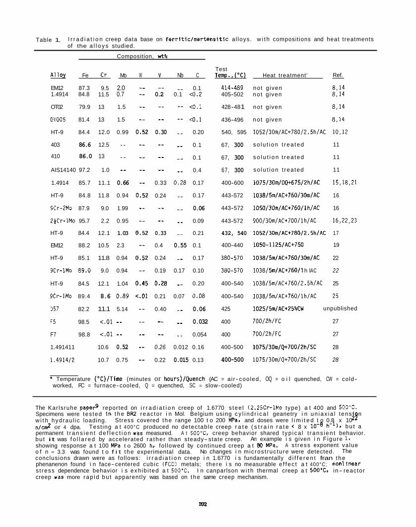
Table 1. I r r a d i a t i o n creep data base on f e r r i t i c / m a r t e n s i t i c a l loys. w i t h compositions and heat treatments of the a l l o y s studied.
Composition, w t %
Test Ref. - Alloy Fe C r Mo W V Nb C Temp.,("C) Heat treatment'
EM12 87.3 9.5 2.0 1.4914 84.8 11.5 0.7
OT02 79.9 13 1.5
OY005 81.4 13 1.5
HT-9 84.4 12.0 0.99
403 86.6 12.5 -- 410 86.0 13 _ _ AIS14140 97.2 1.0 -- 1.4914 85.7 11.1 0.66
HT-9 84.8 11.8 0.94
9Cr-2Mo 87.9 9.0 1.99
2fCr-1Mo 95.7 2.2 0.95
HT-9 84.4 12.1 1.03
EM12 88.2 10.5 2.3
HT-9 85.1 11.8 0.94
9Cr-1Mo 89.0 9.0 0.94
HT-9 84.5 12.1 1.04
9Cr-1Mo 89.4 8.6 0.89
057 82.2 11.1 5.14
F5 98.5 <.01 -- F7 98.8 <.01 -- 1.491411 10.6 0.52
1.491412 10.7 0.75
_ _ 0.2
_ _ - _ 0.30
-- -- -_
0.33
0.24
-- --
0.33
0.4
0.24
0.19
0.28
0.21
0.40
-- -_
0.26
0.22
_- 0.1 0.1 <0.2
-- <O.l
-- 4 . 1
_ _ 0.20
_ _ 0.1
_ _ 0.1
_ _ 0.4
0.28 0.17
_ _ 0.17
_ _ 0.06
_ _ 0.09
_. 0.21
0.55 0.1
_- 0.17
0.17 0.10
_- 0.20
0.07 0.08
_ - 0.06
_ _ 0.032
_ _ 0.054
0.012 0.16
0.015 0.13
414-489 405-502
428 -48 1
436-496
540, 595
67, 300
67, 300
67, 300
400-600
443-572
443-572
443-572
432, 540
400-440
380-570
380-570
400-540
400-540
425
400
400
400-500
400-500
no t g iven 8.14 n o t g iven 8,14
no t g iven 8.14
n o t g iven 8,14
1052/30m/AC+780/2. 5h/AC 10,12
s o l u t i o n t r e a t e d 11
s o l u t i o n t r e a t e d 11
s o l u t i o n t rea ted 11
1075/30m/OQ+675/2h/AC 15,18,21
1038/5m/AC+760/30m/AC 16
1050/30m/AC+760/lh/AC 16
900/30m/AC+700/lh/AC 16,22,23
1052/30m/AC+780/2.5h/AC 17
1050-1125/AC+750 19
1038/5m/AC+760/30m/AC 22
10381 5mIAC+76011 h l AC 22
1038/5m/AC+760/2 .5h/AC 25
1038/5m/AC+760/lh/AC 25
1025/5m/AC+25%CW
700/2h/FC 27
700/2h/FC 27
1075/3Om/Q+70012h/SC 28
1075/30m/Q+700/2h/SC 28
unpublished
* Temperature ("C)/Time (minutes or hours)/Quench (AC = a i r- cooled, OQ = o i l quenched, CW = cold- worked, FC = furnace-cooled, Q = quenched, SC = slow-cooled)
The Kar lsruhe paper9 reported on i r r a d i a t i o n creep of 1.6770 s tee l (2.2SCr-lMo type) a t 400 and SOO'C. Specimens were tes ted i n t h e BR2 reac to r i n Mol. Belgium using c y l i n d r i c a l geanetry i n u n i a x i a l tens on w i t h hydrau l i c loading. n / c d or 4 dpa. h - l ) , b u t a permanent t r a n s i e n t d e f l e c t i o n was measured. A t 500°C. creep behavior shared t y p i c a l t r a n s i e n t behavior. bu t it was f o l l a r e d by accelerated r a t h e r than steady- state creep. showing response a t 100 MPa t o 2600 h, fo l lowed by cont inued creep a t 80 MPa. o f n = 3.3 was found t o f i t t h e experimental data. conclusions drawn were as fol lows: i r r a d i a t i o n creep i n 1.6770 i s fundamentally d i f f e r e n t fran t h e phenanenon found i n face-centered cubic (FCC) metals; the re i s no measurable e f f e c t a t 400°C; nonl inear s t ress dependence behavior i s exh ib i ted a t 500'C. I n canparlson w i t h thermal creep a t 5OO0Cc. in- reactor creep was more r a p i d b u t apparent ly was based on t h e same creep mechanism.
42 Stress covered t h e range 100 t o 200 MPa, and doses were l i m i t e d t o 0.8 x 10 Test ing a t 400°C produced no detectab le creep r a t e ( s t r a i n r a t e < 8 x
An example i s given i n F igu re 1.
The A s t ress exponent va lue
No changes i n m ic ros t ruc tu re were detected.
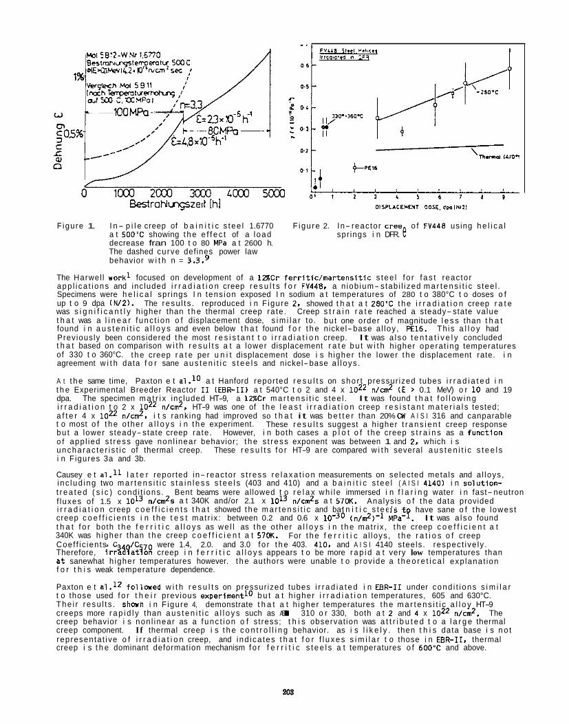
Figure 1. I n - p i l e creep of b a i n i t i c s tee l 1.6770 F igu re 2. In- reac tor Cree o f FV448 using h e l i c a l a t 5 0 0 T showing t h e e f f e c t of a l oad spr ings i n DFR. e decrease fran 100 t o 80 MPa a t 2600 h. The dashed curve defines power law behavior w i t h n = 3.3.9
The Harwel l work1 focused on development of a 1 Z C r f e r r i t i c / m a r t e n s i t i c s tee l f o r f a s t reac tor app l i ca t i ons and inc luded i r r a d i a t i o n creep r e s u l t s f o r FV448, a n iob ium- stab i l i zed m a r t e n s i t i c s tee l . Specimens were h e l i c a l spr ings I n tens ion exposed I n sodium a t temperatures of 280 t o 380°C t o doses o f up t o 9 dpa ( W Z ) . was s i g n i f i c a n t l y h igher than t h e thermal creep ra te . Creep s t r a i n r a t e reached a steady- state value t h a t was a l i n e a r f unc t i on o f displacement dose, s i m i l a r to. bu t one order o f magnitude l e s s than t h a t found i n a u s t e n i t i c a l l o y s and even below t h a t found f o r t h e nickel- base a l loy , PEE. Th is a l l o y had Previously been considered t h e most r e s i s t a n t t o i r r a d i a t i o n creep. It was a l so t e n t a t i v e l y concluded t h a t based on comparison w i t h r e s u l t s a t a lower displacement r a t e b u t w i t h h igher opera t ing temperatures of 330 t o 360°C. t h e creep r a t e per u n i t displacement dose i s h igher t h e lower t h e displacement rate. i n agreement w i t h data f o r sane a u s t e n i t i c s t e e l s and nickel- base a l l oys .
A t t h e same time, Paxton e t a1.I0 a t Hanford reported r e s u l t s on sho r t pressur ized tubes i r r a d i a t e d i n t h e Experimental Breeder Reactor I 1 (EEIR-11) a t 540°C t o 2 and 4 x loz2 n/cm2 (E > 0.1 MeV) o r 10 and 19 dpa. The specimen m a t r i x inc luded HT-9, a 128Cr m a r t e n s i t i c s tee l . It was found t h a t f o l l o w i n g i r r a d i a t i o n t o 2 x loz2 n/cm2, HT-9 was one of t h e l e a s t i r r a d i a t i o n creep r e s i s t a n t m a t e r i a l s tested; a f t e r 4 x loz2 nlcn?, i t s ranking had improved so t h a t it was b e t t e r than 20% CW A I S I 316 and canparable t o most o f t h e o ther a l l o y s i n t h e experiment. bu t a lower steady- state creep ra te . However, i n both cases a p l o t o f t h e creep s t r a i n s as a func t ion o f app l ied s t ress gave non l inear behavior; t h e s t ress exponent was between 1 and 2. which i s uncha rac te r i s t i c of thermal creep. These r e s u l t s f o r HT-9 are compared w i t h several a u s t e n i t i c s t e e l s i n Figures 3a and 3b.
Causey e t a1 .ll l a t e r reported in- reac tor s t ress r e l a x a t i o n measurements on selected metals and a l loys , i nc lud ing two m a r t e n s i t i c s t a i n l e s s s t e e l s (403 and 410) and a b a i n i t i c s tee l ( A I S I 4140) i n so lu t l on - t r e a t e d ( s i c ) cond i t ions . Bent beams were al lowed t o r e l a x wh i l e immersed i n f l a r i n g water i n fast- neutron f luxes of 1.5 x i r r a d i a t i o n creep c o e f f i c i e n t s t h a t showed t h e m a r t e n s i t i c and ba n i t i c s t e e l s t creep c o e f f i c i e n t s i n t h e t e s t mat r ix : between 0.2 and 0.6 x It was a l so found t h a t f o r both t h e f e r r i t i c a l l o y s as we l l as t h e o ther a l l o y s i n t h e mat r ix , t h e creep c o e f f i c i e n t a t 340K was h igher than t h e creep c o e f f i c i e n t a t 570K. Coef f i c ien ts C / C were 1.4, 2.0. and 3.0 f o r t h e 403. 410. and A I S I 4140 steels. respec t ive ly . Therefore, i r r % ? a t % creep i n f e r r i t i c a l l o y s appears t o be more r a p i d a t very low temperatures than a t sanewhat h igher temperatures however. t h e authors were unable t o p rov ide a t h e o r e t i c a l exp lanat ion f o r t h i s weak temperature dependence.
Paxton e t a1.I2 fo l lowed w i t h r e s u l t s on pressur ized tubes i r r a d i a t e d i n EBR-I1 under cond i t i ons s i m i l a r t o those used f o r t h e i r previous exper iment lo b u t a t h igher i r r a d i a t i o n temperatures, 605 and 630°C. The i r r esu l t s . shonn i n F igure 4, demonstrate t h a t a t h igher temperatures t h e m a r t e n s i t i c a l l o y HT-9 creeps more r a p i d l y than a u s t e n i t i c a l l o y s such as AISI 310 o r 330, both a t 2 and 4 x 10²² n/cm2. The creep behavior i s non l inear as a f unc t i on o f s t ress; t h i s observat ion was a t t r i b u t e d t o a l a r g e thermal creep component. If thermal creep i s t h e c o n t r o l l i n g behavior. as i s l i k e l y . then t h i s data base i s n o t representa t ive o f i r r a d i a t i o n creep, and i nd i ca tes t h a t f o r f l u x e s s i m i l a r t o those i n EBR-11, thermal creep i s t h e dominant deformation mechanism f o r f e r r i t i c s t e e l s a t temperatures o f 600'C and above.
The resu l t s . reproduced i n F igure 2, showed t h a t a t 280'C t h e i r r a d i a t i o n creep r a t e
These r e s u l t s suggest a h igher t r a n s i e n t creep response
n/cm?s a t 340K and/or 2.1 x l O I 3 n/cn?s a t 570K. Analys is o f t h e data provided have sane o f t h e lowest
( n / d ) - l MPa-?.
For t h e f e r r i t i c a l loys , t h e r a t i o s o f creep
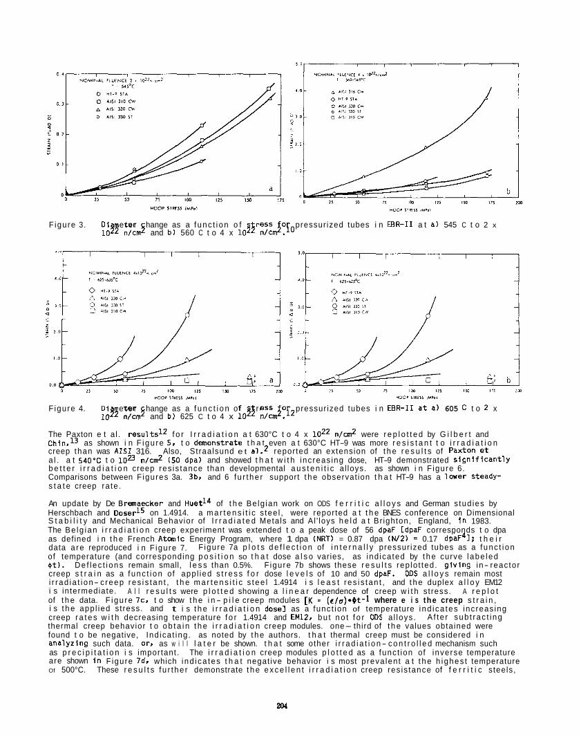
Figure 3. D i e t e r hange as a f unc t i on o f res5 o pressur ized tubes i n EEIR-I1 a t a ) 545 C t o 2 x n/c$ and b) 560 C t o 4 x n/cmJ.10
F igure 4. D i e t e r hange as a f u n c t i o n of ress o pressur ized tubes i n EBR-I1 a t a) 605 C t o 2 x losy n/cm5 and b) 625 C t o 4 x lo3$ n / J . f 2
The Paxton e t a l . r e s u l t s l Z f o r I r r a d i a t i o n a t 630°C t o 4 x loz2 n/cm2 were r e p l o t t e d by G i l b e r t and Chin,13 as shown i n F igu re 5 , t o demonstrate t h a t even a t 630°C HT-9 was more r e s i s t a n t t o i r r a d i a t i o n creep than was A I S 1 316. Also, Straalsund e t a1.2 reported an extension of t h e r e s u l t s of PaXtOn e t a l . a t 540'C t o 1DZ n/cm2 (50 dpa) and showed t h a t w i t h inc reas ing dose, HT-9 demonstrated S lgn i f iCant lY b e t t e r i r r a d i a t i o n creep res is tance than developmental a u s t e n i t i c a l loys. as shown i n F igure 6. Comparisons between F igures 3a. 3br and 6 f u r t he r support t h e observat ion t h a t HT-9 has a lower steady- s t a t e creep ra te .
An update by De Brmaecker and Huet14 of t h e Be lg ian work on ODS f e r r i t i c a l l o y s and German s tud ies by Herschbach and DoserlS on 1.4914. a m a r t e n s i t i c s tee l , were reported a t t h e BNES conference on Dimensional S t a b i l i t y and Mechanical Behavior of I r r a d i a t e d Metals and Al ' loys h e l d a t Br ighton, England, i n 1983. The Be lg ian i r r a d i a t i o n creep experiment was extended t o a peak dose of 56 dpaF CdpaF corresponds t o dpa as defined i n t h e French A t m i c Energy Program, where 1 dpa (NRT) = 0.87 dpa (N/2) = 0.17 dpaF41: t h e i r data a re reproduced i n F igure 7. of temperature (and corresponding p o s i t i o n so t h a t dose a l s o varies, as ind ica ted by t h e curve l abe led a t ) . De f l ec t i ons remain small, l e s s than 0.5%. F igure 7b shows these r e s u l t s rep lo t ted . g i v i n g in- reac tor creep s t r a i n as a f unc t i on of app l ied s t r e s s f o r dose l e v e l s of 10 and 50 dpaF. ODs a l l o y s remain most i r r ad ia t i on- c reep res i s tan t , t h e m a r t e n s i t i c s tee l 1.4914 i s l e a s t r es i s tan t , and t h e duplex a l l o y EM12 i s intermediate. A r e p l o t of t h e data. F igu re l c . t o show t h e i n - p i l e creep modules [K = (e/o).Ot-l where e i s the creep s t r a i n , i s t h e app l ied st ress. and creep r a t e s w i t h decreasing temperature f o r 1.4914 and EMU. bu t n o t f o r ODs a l loys . thermal creep behavior t o o b t a i n t h e i r r a d i a t i o n creep modules. one- third of t h e values obtained were found t o be negative, Ind ica t ing . as noted by t h e authors. t h a t thermal creep must be considered i n analyz ing such data. orr as w i l l l a t e r be shown. t h a t some other i r r a d i a t i o n- c o n t r o l l e d mechanism such as p r e c i p i t a t i o n i s important . The i r r a d i a t i o n creep modules p l o t t e d as a func t ion of inverse temperature are shown I n F igure 7d. which i nd i ca tes t h a t negat ive behavior i s most p reva len t a t t h e h ighes t temperature Of 500°C. These r e s u l t s f u r t he r demonstrate t h e e x c e l l e n t i r r a d i a t i o n creep res is tance of f e r r i t i c s teels,
F igure 7a p l o t s d e f l e c t i o n of i n t e r n a l l y pressur ized tubes as a f unc t i on
A l l r e s u l t s were p l o t t e d showing a l i n e a r dependence of creep w i t h st ress.
t i s t h e i r r a d i a t i o n dose1 as a func t ion of temperature i nd i ca tes increas ing A f te r sub t rac t i ng
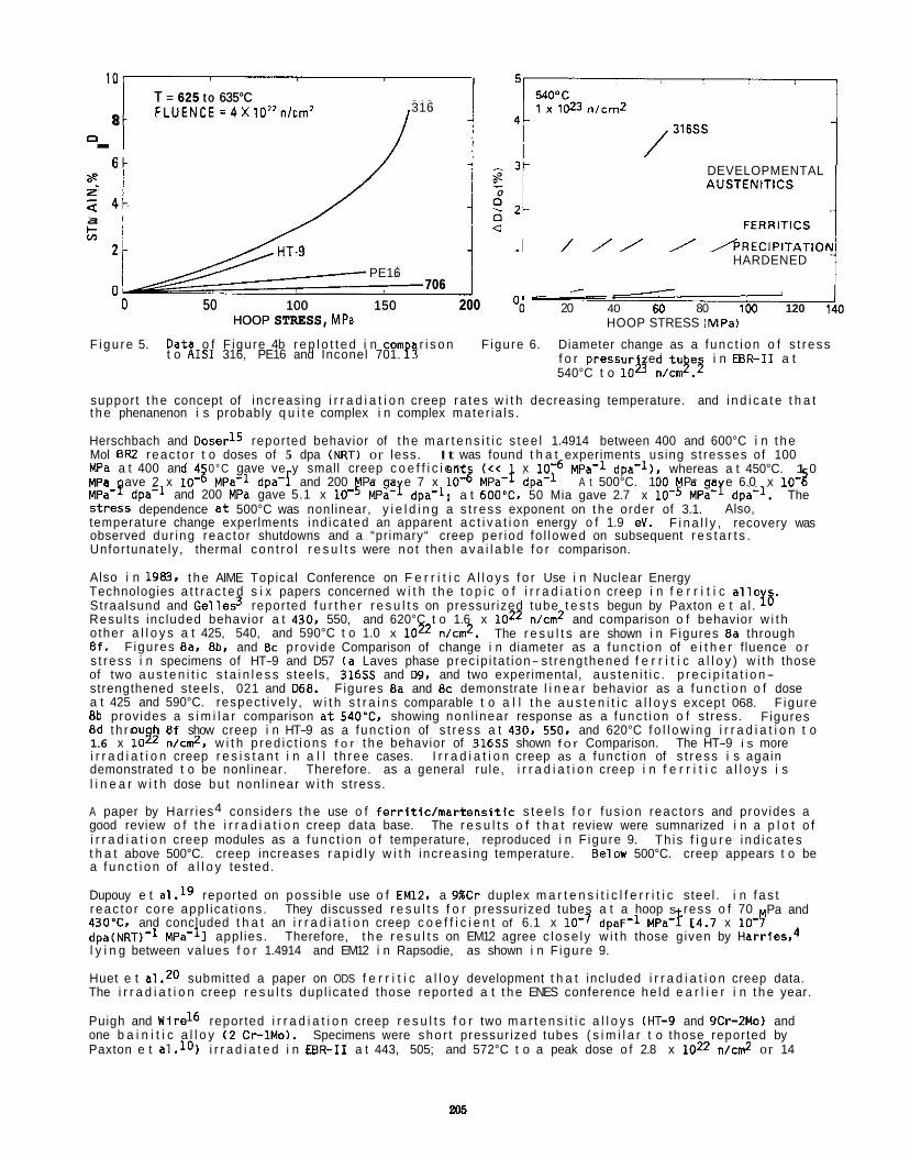
101 I
T = 625 t o 635°C FLUENCE=4X10”n/crn2 8
316 T = 625 t o 635°C FLUENCE=4X10”n/crn2 8 -
0 . a:
z- 0
a
6 -
2 4 - - 0
706 0 50 100 150 200
HOOP STRESS, MPa
HT.9 PE16
706 0 0 50 100 150 200
HOOP STRESS, MPa
2t&e???5
-
DEVELOPMENTAL AUSTENITICS
FERRlTlCS
HARDENED
‘0 20 40 60 80 100 120 140 HOOP STRESS IMPaI
F igu re 5. Data o f F igure 4b r e p l o t t e d i n com r i s o n F igure 6. Diameter change as a f unc t i on o f s t r ess f o r pressur zed t u e i n EER-I1 a t 540°C t o l oL n/cm9.5
t o A I S 1 316, PE16 and Inconel 701. u support t h e concept of inc reas ing i r r a d i a t i o n creep ra tes w i t h decreasing temperature. and i n d i c a t e t h a t t h e phenanenon i s probably q u i t e complex i n complex mater ia ls .
Herschbach and Ooser15 reported behavior of t h e m a r t e n s i t i c s tee l 1.4914 between 400 and 600°C i n t h e Mol ER2 reac to r t o doses of 5 dpa (NRT) or less. It was found t h a t experiments using s t resses of 100 MPa a t 400 and 4 0°C gave ve y small creep c o e f f i c i e n t (<< x
MPa-? dpa-l and 200 MPa gave 5.1 x Stress dependence a t 500°C was nonlinear, y i e l d i n g a s t ress exponent on t h e order of 3.1. temperature change experlments ind ica ted an apparent a c t i v a t i o n energy o f 1.9 eV. observed dur ing reac tor shutdowns and a “primary“ creep per iod fo l lowed on subsequent r e s t a r t s . Unfor tunately, thermal con t ro l r e s u l t s were no t then a v a i l a b l e f o r comparison.
Also i n 1983. t h e AIME Topical Conference on F e r r i t i c A l l o y s f o r Use i n Nuclear Energy Technologies a t t r a c t e d s i x papers concerned w i t h t h e t o p i c o f i r r a d i a t i o n creep i n f e r r i t i c a l l 0 Straalsund and Gel les3 reported f u r t h e r r e s u l t s on pressur ized tube t e s t s begun by Paxton e t a l . Resu l ts inc luded behavior a t 430, 550, and 620°C t o 1.6 x loz2 n/cm2 and comparison o f behavior w i t h o ther a l l o y s a t 425, 540, and 590°C t o 1.0 x loz2 n/cm2. 8 f . s t r ess i n specimens of HT-9 and D57 ( a Laves phase prec ip i ta t ion- s t rengthened f e r r i t i c a l l o y ) w i t h those of two a u s t e n i t i c s t a i n l e s s steels, 316SS and 09, and two experimental, aus ten i t i c . p r e c i p i t a t i o n- strengthened steels, 021 and 068. Figures 8a and 8c demonstrate l i n e a r behavior as a f u n c t i o n o f dose a t 425 and 590°C. respec t ive ly , w i t h s t r a i n s comparable t o a l l t h e a u s t e n i t i c a l l o y s except 068. F igure 8b provides a s i m i l a r comparison at540’C. showing non l inear response as a f unc t i on o f s t ress. 8d t h rou h 8 f show creep i n HT-9 as a f unc t i on of s t r ess a t 430. 550. and 620°C f o l l o w i n g i r r a d i a t i o n t o 1.6 x log2 n/c&, w i t h p red i c t i ons f o r t h e behavior of 31655 shown f o r Comparison. The HT-9 i s more i r r a d i a t i o n creep r e s i s t a n t i n a l l t h ree cases. demonstrated t o be nonlinear. Therefore. as a general ru le, i r r a d i a t i o n creep i n f e r r i t i c a l l o y s i s l i n e a r w i t h dose bu t non l inear w i t h st ress.
A paper by Harr ies4 considers t h e use o f f e r r i t i c / m a r t e n s i t i c s t e e l s f o r f us ion reac tors and provides a good review o f t h e i r r a d i a t i o n creep data base. The r e s u l t s o f t h a t review were sumnarized i n a p l o t o f i r r a d i a t i o n creep modules as a f unc t i on o f temperature, reproduced i n F igure 9. t h a t above 500°C. creep increases r a p i d l y w i t h inc reas ing temperature. Below 500°C. creep appears t o be a f u n c t i o n of a l l o y tested.
Dupouy e t al.19 reported on poss ib le use o f EM12. a 9%Cr duplex m a r t e n s i t i c l f e r r i t i c s teel . i n f a s t r eac to r core app l ica t ions . They discussed r e s u l t s f o r pressur ized tubes a t a hoop s ress o f 70
dpa(NRT)-l MPa-lI appl ies. Therefore, t h e r e s u l t s on EM12 agree c l ose l y w i t h those given by Harries,O l y i n g between values f o r 1.4914 and EM12 i n Rapsodie, as shown i n F igure 9.
Huet e t a1.20 submitted a paper on ODS f e r r i t i c a l l o y development t h a t inc luded i r r a d i a t i o n creep data. The i r r a d i a t i o n creep r e s u l t s dup l ica ted those reported a t t h e ENES conference he ld e a r l i e r i n t h e year.
Puigh and Wire16 reported i r r a d i a t i o n creep r e s u l t s f o r two m a r t e n s i t i c a l l o y s (HT-9 and 9Cr-2Mo) and one b a i n i t i c a l l o y ( 2 Cr-lMo). Specimens were sho r t pressur ized tubes ( s i m i l a r t o those reported by Paxton e t a l . lO) i r r a d i a t e d i n EBR-I1 a t 443, 505; and 572°C t o a peak dose o f 2.8 x loz2 n/cm2 or 14
MPa-l dpa-l l , whereas a t 450°C. 1 0 MPa ave 2 x l oJ MPa-l dpa- I and 200 Pa ga e 7 x lowz MPa-! dpa-l A t 500°C. 100 Pa ga e 6.0 x 10- 2
MPa-I dpa-l; a t 600”C, 50 Mia gave 2.7 x lo-! MPa-y dpa-l. The Also,
F i n a l l y , recovery was
18 The r e s u l t s are shown i n Figures 8a through
F igures Ea, 8b. and 8c prov ide Comparison of change i n diameter as a f unc t i on of e i t h e r f luence o r
Figures
I r r a d i a t i o n creep as a func t ion of s t r ess i s again
Th is f i g u r e i nd i ca tes
Pa and 430”CI and concluded t h a t an i r r a d i a t i o n creep c o e f f i c i e n t of 6.1 x dpaF-l MPa- f C4.7 x 10- $”
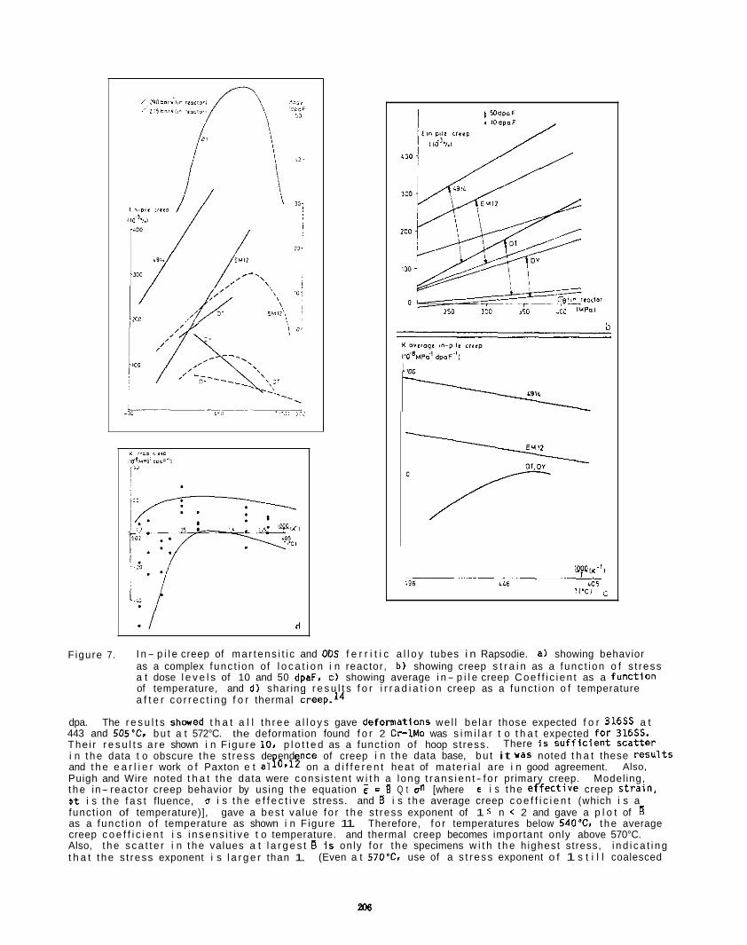
Figure 7. I n- p i l e creep of m a r t e n s i t i c and ODs f e r r i t i c a l l o y tubes i n Rapsodie. a) showing behavior as a complex func t ion of l o c a t i o n i n reactor, b) showing creep s t r a i n as a func t ion o f s t ress a t dose l e v e l s of 10 and 50 dpaF, c ) showing average i n - p i l e creep C o e f f i c i e n t as a func t ion of temperature, and d) sharing r e s u l t s f o r i r r a d i a t i o n creep as a func t ion o f temperature a f t e r c o r r e c t i n g f o r thermal creep.14
dpa. The r e s u l t s shwed t h a t a l l t h r e e a l l o y s gave deformations we l l be la r those expected f o r 316SS a t 443 and 505"C, b u t a t 572°C. the deformation found f o r 2 Cr-lMo was s i m i l a r t o t h a t expected f o r 316SS. The i r r e s u l t s a r e shown i n F igu re 10, p l o t t e d as a funct ion of hoop s t ress. i n t h e data t o obscure t h e s t ress de end nce of creep i n t h e data base, b u t it was noted t h a t these r e s u l t s and t h e e a r l i e r work o f Paxton e t a1 Also, Puigh and Wire noted t h a t t h e data were cons is ten t w i t h a long t r a n s i e n t - f o r primary creep. Model ing, t h e in- reactor creep behavior by using t h e equation F = B Q t on [where b t i s t h e f a s t fluence, 0 i s t h e e f f e c t i v e stress. and E i s t h e average creep c o e f f i c i e n t (which i s a funct ion of temperature)], gave a bes t va lue f o r t h e s t ress exponent of 1 5 n < 2 and gave a p l o t of B as a func t ion o f temperature as shown i n F igure 11. creep c o e f f i c i e n t i s i n s e n s i t i v e t o temperature. and thermal creep becomes important only above 570°C. Also, t h e s c a t t e r i n t h e values a t l a r g e s t B i s on ly fo r t h e specimens w i t h t h e h ighest stress, i n d i c a t i n g t h a t t h e s t ress exponent i s l a r g e r than 1. (Even a t 570'Cc, use of a s t r e s s exponent o f 1 s t i l l coalesced
There i s s u f f i c i e n t Scat ter
on a d i f f e r e n t heat of mate r ia l are i n good agreement.
E i s t h e e f f e c t l v e creep S t ra in ,
Therefore, f o r temperatures below 540"C, t h e average
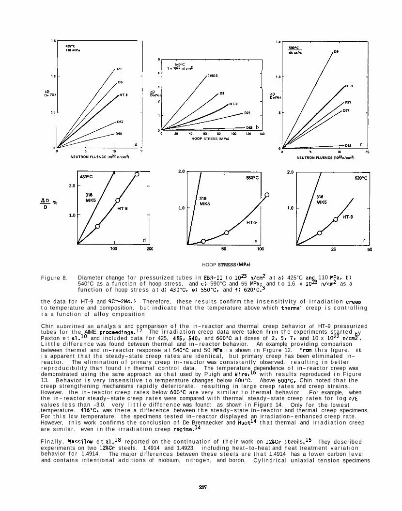
1.6 ,
I IOMP. I
& % D
2.0
1.0
HOOP STRESS IMP.,
1M 2w
2.0
1.0
HOOP STRESS IMPsl
F igu re 8. Diameter change f o r pressur ized tubes i n EBR-I1 t o loz3 n/cm2 a t a ) 425°C an 110 MPa, b ) 540°C as a f unc t i on o f hoop stress, and c ) 590°C and 55 MPa: and t o 1.6 x l o g n/cm2 as a f unc t i on o f hoop s t ress a t d) 430% e) 550°C. and f ) 620"12.~
t h e data f o r HT-9 and 9Cr-ZMo.) Therefore, these r e s u l t s conf i rm t h e i n s e n s i t i v i t v o f i r r a d i a t i o n creeD t o temperature and composition. bu t i n d i c a t e t h a t t h e temperature above which t h e r i a l creep i s c o n t r o l l i n g i s a f unc t i on of a l l o y cmpos i t i on .
Chin submit ted an ana lys is and comparison o f t h e in- reac tor and thermal creep behavior of HT-9 pressur ized tubes f o r t h e AIME proceed1ngs.l' Paxton e t L i t t l e d i f f e r e n c e was found between thermal and in- reac tor behavior. between thermal and in- reac tor response a t 540'C and 50 MPa i s shown i n F igure 12. i s apparent t h a t t h e steady- state creep r a t e s are i den t i ca l , b u t primary creep has been e l im ina ted in- reactor . r e p r o d u c i b i l i t y than found i n thermal con t ro l data. demonstrated using t h e same approach as t h a t used by Puigh and Wire.16 w i t h r e s u l t s reproduced i n F igure 13. creep strengthening mechanisms r a p i d l y de ter io ra te . r e s u l t i n g i n l a r g e creep r a t e s and creep s t ra i ns . However. t h e in- reac tor creep ra tes below 600'C a re very s i m i l a r t o thermal behavior. For example, when t h e i n- reac to r steady- state creep r a t e s were compared w i t h thermal steady- state creep r a t e s f o r l o g o/E values l e s s than -3.0. very l i t t l e d i f f e r e n c e was found: as shown i n F igure 14. temperature. 416'C, was t he re a d i f fe rence between t h e steady- state in- reac tor and thermal creep specimens. For t h i s l o w temperature. t h e specimens tes ted in- reac tor d isplayed an i r radiat ion- enhanced creep ra te . However, t h i s work conf i rms t h e conclusion o f De Bremaecker and Huet14 t h a t thermal and i r r a d i a t i o n creep are s im i l a r . even i n t h e i r r a d i a t i o n creep ragime.l4
F i n a l l y , Wass i lw e t a1.18 reported on t h e con t i nua t i on of t h e i r work on 1 2 g C r ~ t e e 1 s . l ~ experiments on two 1 Z C r s teels. 1.4914 and 1.4923, i nc lud ing heat- to-heat and heat t reatment v a r i a t i o n behavior f o r 1.4914. and conta ins i n t e n t i o n a l add i t i ons of niobium, n i t rogen, and boron.
The i r r a d i a t i o n creep data were taken frm t h e experiments s t a r t e d
An example prov id ing comparison
y and inc luded data f o r 425, 485. 540. and 600'C a t doses of 2. 5, 7. and 10 x loz2 n / m s .
Fran t h i s f igure . it
The e l i m i n a t i o n o f primary creep in- reac tor was cons i s ten t l y observed. r e s u l t i n g i n b e t t e r The temperature dependence o f in- reac tor creep was
Above 600"C, Chin noted t h a t t h e Behavior i s very i n s e n s i t i v e t o temperature changes below 600'C.
Only f o r t h e lowest
They descr ibed
The major d i f fe rences between these s t e e l s a re t h a t 1.4914 has a lower carbon l e v e l C y l i n d r i c a l un iax ia l tens ion specimens
207
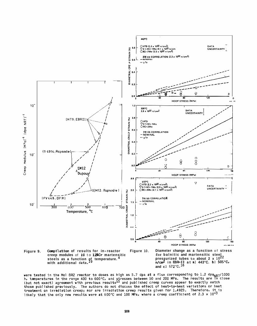
I I I r
I I I I 300 LOO 500 600
Temperoture, "C
J 700
316 5s CORREUTION 12.3 I t f l nism21
. - * , a
9
"'.at---;-------'
I
___--- /--- _--- 0 0 2
/--* _ _ _ - ---o- - --&?-- - - --__-- w 80 7 r n
0 0
..1 .. 0 HOOP STRESS IMP.)
0
HOOP STRESS IMPal 1.1 , I
0.0
3% 55 CORREUTION -NOMINAL -- *lO
Figure 9 . C m p i l a t i o n of r e s u l t s for in- reactor creep modules of 10 t o 1ZCr martensi t ic
4 s tee ls as a function of temperature. wi th addi t ional data.19
Figure 10. Diameter change as a funct ion o f stress for b a l n i t i c and martensi t ic steel pressurized tubes to about 2 x loz2 n/cm2 i n EER-I1 a t a ) 443°C. b ) 505 'C~. and c ) 572"C.16
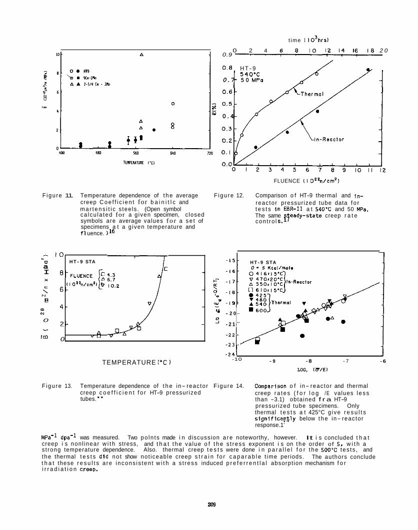
t ime I I 03hrs)
0 2 4 6 8 I O 12 14 16 18 2 0 0.9 I I I I
0 . 8 H T- 9 / I,
10
6 -
4 -
2 -
0
540 'C 0.7 5 0 MPo t
H T- 9 STA
' -FLUENCE -
c- I lO'2n/Crn' l v 10.2 LL
5: - \
, .IY . - a "
0 A -
A " U
/// 0.4
FLUENCE ( I ~ ' ' n / c r n ~ ~
F igu re 11. Temperature dependence of t h e average F igu re 12. Comparison o f HT-9 thermal and i n - creep C o e f f i c i e n t for b a i n i t l c and m a r t e n s i t i c s tee ls . (Open symbol t e s t s I n EBR-I1 a t 540.C and 50 MPa. ca l cu la ted for a g iven specimen, c losed symbols are average values for a s e t of specimens a t a g iven temperature and f l uence. )16
reac tor pressur ized tube data f o r
The same p a d y - s t a t e creep r a t e con t ro l 5.
I
c n a I x c \ N
E " m N
0 - -
im
- I 5 t H T - 9 STA 0 = 5 Kcol /mola 1
- 1 7 -
- 1 8 -
- 1 9 -
- 2 0 -
- 2 1
-2 2 - -
-2 3 -' - 2 4 1 J
- 9 - 8 - 7 - 6 -10 TEMPERATURE ("C I LOG, IU/El
F igu re 13. Temperature dependence of t h e in- reac tor F igu re 14. Cmpar lson o f in- reac tor and thermal creep r a t e s ( f o r l o g /E values l e s s than -3.1) obta ined f r a HT-9 pressur ized tube specimens. Only thermal t e s t s a t 425°C g i ve r e s u l t s s l g n i f i c a n t l y below t h e in- reac tor response.1'
creep c o e f f i c i e n t f o r HT-9 pressur ized tubes."
MPa-l dpa-l was measured. creep i s non l inear w i t h stress, and t h a t t h e va lue o f t h e s t ress exponent i s on t h e order o f 5 , w i t h a s t rong temperature dependence. Also. thermal creep t e s t s were done i n p a r a l l e l f o r t h e 500'C tes t s , and the thermal t e s t s d i d no t show not iceab le creep s t r a i n f o r c a p a r a b l e t ime periods. t h a t these r e s u l t s a re i ncons i s ten t w i t h a s t ress induced p r e f e r r e n t l a l absorpt ion mechanism f o r i r r a d i a t i o n creerr.
Two po ln t s made i n d iscussion a r e noteworthy, however. It i s concluded t h a t
The authors conclude
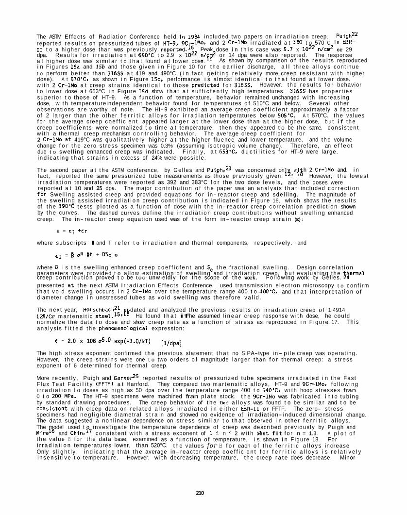
The ASTM E f fec t s of Rad ia t ion Conference he ld i n 1984 inc luded two papers on i r r a d i a t i o n creep. repor ted r e s u l t s on pressur ized tubes of HT-9. 9C 11 t o a h igher dose than was prev ious ly reported.E Peak dose i n t h i s case was 5.7 x 10'' n/cm2 or 29 dpa. Resu l ts f o r i r r a d i a t i o n a t 650'C t o 2.9 x loz2 "/?E2 o r 14 dpa were a l s o reported. The response a t h igher dose was s i m i l a r t o t h a t found a t lower dose. i n F igures 15a and 15b and those g iven i n F igu re 10 f o r t h e e a r l i e r discharge, a l l t h ree a l l o y s cont inue t o perform b e t t e r than 316SS a t 419 and 490°C ( i n f a c t g e t t i n g r e l a t i v e l y more creep r e s i s t a n t w i t h h igher dose). A t 57O0CC. as shown i n F igure 15c, performance i s almost i d e n t i c a l t o t h a t found a t lower dose. w i t h 2 C r l M o a t creep s t r a i n s i d e n t i c a l t o those pred lc ted f o r 316SS. t o lower dose a t 653°C i n F igure 15d show t h a t a t s u f f i c f e n t l y h igh temperatures. 316SS has p rope r t i es super io r t o those of HT-9. As a func t ion of temperature, behavior remained unchanged w i t h inc reas ing dose, w i t h temperatureindependent behavior found f o r temperatures o f 510°C and below. Several o ther observat ions a re worthy of note. of 2 l a r g e r than t h e o ther f e r r i t i c a l l o y s f o r i r r a d i a t i o n temperatures below 505'C. f o r t h e average creep c o e f f i c i e n t appeared l a r g e r a t t h e lower dose than a t t h e h igher dose, b u t i f t h e creep c o e f f i c i e n t s were normalized t o t ime a t temperature, then they appeared t o be t h e same. cons i s ten t w i t h a thermal creep mechanism c o n t r o l l i n g behavior. The average creep c o e f f i c i e n t f o r 2 Cr-1Mo a t 419°C was q u a l i t a t i v e l y h igher a t t h e h igher f luence and lower temperature. and t h e volume change f o r t h e zero s t ress specimen was 0.3% (assuming i s o t r o p i c volume change). Therefore, an e f f e c t due t o swe l l i ng enhanced creep was indicated. F i n a l l y , a t 653% d u c t i l i t i e s f o r HT-9 were large. i n d i c a t i n g t h a t s t r a i n s i n excess of 24% were possib le.
The second paper a t t h e ASTM conference. by Ge l les and PuighSD was concerned on fact, reported t h e same pressur ized tube measurements as those prev ious ly given. 1 3 9 1Q However, t h e lowest i r r a d i a t i o n temperatures were reported as 392 and 383°C f o r t h e two dose leve ls , and t h e doses were reported a t 10 and 25 dpa. f o r Swel l ing ass is ted creep and provided equations f o r in- reac tor creep and sde l l i ng . The magnitude o f t h e s w e l l i n g ass i s ted i r r a d i a t i o n creep c o n t r i b u t i o n i s i nd i ca ted i n F igu re 16, which shows t h e r e s u l t s of t h e 390'C t e s t s p l o t t e d as a f u n c t i o n o f dose w i t h t h e in- reac tor creep c o r r e l a t i o n p r e d i c t i o n shown by t h e curves. creep.
Puigh" lMo, and 2 Cr-1Mo i r r a d i a t e d a t 380 t o 570 C i n EBR-
As shown by comparison o f t h e r e s u l t s reproduced
However. t h e r e s u l t s f o r behavior
The Hi-9 exh ib i t ed an average creep c o e f f i c i e n t approximately a f a c t o r A t 570°C. t h e values
w i h 2 Cr-1Mo and. i n
The major c o n t r i b u t i o n o f t h e paper was an ana l ys i s t h a t inc luded c o r r e c t i o n
The dashed curves de f i ne t h e i r r a d i a t i o n creep con t r i bu t i ons w i thout swe l l i ng enhanced The in- reac tor creep equat ion used was of t h e form in- reac tor creep s t r a i n (E):
E = € 1 +ET
where subscr ip ts I and T r e f e r t o i r r a d i a t i o n and thermal components, respec t ive ly . and
e l = a e t + oso o
where 0 i s t h e swe l l i ng enhanced creep c o e f f i c f e n t and So t h e f r a c t i o n a l swe l l ing . parameters were provided t o a l low es t ima t i on o f swe l l i ng and i r r a d i a t i o n creep, b u t eva lua t i ng t h e
presented a t t h e nex t ASTM I r r a d i a t i o n Ef fec ts Conference, used t ransmission e lec t ron microscopy t o con f i rm t h a t v o i d swe l l i ng occurs i n 2 Cr-lMo over t h e temperature range 400 t o 480°C. and t h a t i n t e r p r e t a t i o n of diameter change i n unstressed tubes as v o i d swe l l i ng was there fore v a l i d .
The nex t year, HerschbachZ1 l i % / C r m a r t e n s i t i c normal ize t h e data t o dose and show creep r a t e as a f u n c t i o n of s t r ess as reproduced i n F igu re 17. ana l ys i s f i t t e d t h e phenaeno log ica l expression:
Design c o r r e l a t i o n hema l
creep c o n t r i b u t i o n proved t o be too unwield ly for t h e scope of t h e work. Fol lowing work by Gelles. 34
dated and analyzed t h e previous r e s u l t s on i r r a d i a t i o n creep o f 1.4914 He found t h a t if he assumed l i n e a r creep response w i t h dose, he cou ld
Th is
€ = 2.0 x 10⁶ 05.0 exp(-3.0/kT) [l /dpa]
The h igh s t ress exponent confirmed t h e previous statement t h a t no SIPA-type i n - p i l e creep was operat ing. However, t h e creep s t r a i n s were one t o two orders o f magnitude l a r g e r than f o r thermal creep: a s t ress exponent o f 6 determined f o r thermal creep.
More recent ly , Puigh and Game& reported r e s u l t s o f pressur ized tube specimens i r r a d i a t e d i n t h e Fas t F lux Tes t F a c i l i t y (FFTF) a t Hanford. They compared two m a r t e n s i t i c a l loys , HT-9 and 9Cr-lMo. f o l l ow ing i r r a d i a t i o n t o doses as h igh as 50 dpa over t h e temperature range 400 t o 540'C. w i t h hoop s t resses fran 0 t o 200 MPa. The HT-9 specimens were machined fran p l a t e stock. t h e 9Cr-1Mo was fabr ica ted i n t o t ub ing by standard drawing procedures. The creep behavior of t h e tno a l l o y s was found t o be s i m i l a r and t o be Cons is ten t w i t h creep data on r e l a t e d a l l o y s i r r a d i a t e d i n e i t h e r EBR-I1 o r FFTF. The zero- s t ress specimens had n e g l i g i b l e d iametra l s t r a i n and showed no evidence of i r rad ia t ion- induced dimensional change. The data suggested a non l inear dependence on s t ress s i m i l a r t o t h a t observed i n o ther f e r r i t i c a l loys . The model used t o i n v e s t i g a t e t h e temperature dependence of creep was described prev ious ly by Puigh and Wire'' and Chin,17 cons i s ten t w i t h a s t ress exponent of 1 2 n 2 w i t h best fit f o r n = 1.3. A p l o t o f t h e va lue B f o r t he data base, examined as a f u n c t i o n o f temperature, i s shown i n F igure 18. For i r r a d i a t i o n temperatures lower, than 520°C. t h e values for B f o r each o f t h e f e r r i t i c a l l o y s increase Only s l i g h t l y , i n d i c a t i n g t h a t t h e average in- reac tor creep c o e f f i c i e n t f o r f e r r i t i c a l l o y s i s r e l a t i v e l y i n s e n s i t i v e t o temperature. However, w i t h decreasing temperature, t h e creep r a t e does decrease. Minor
210
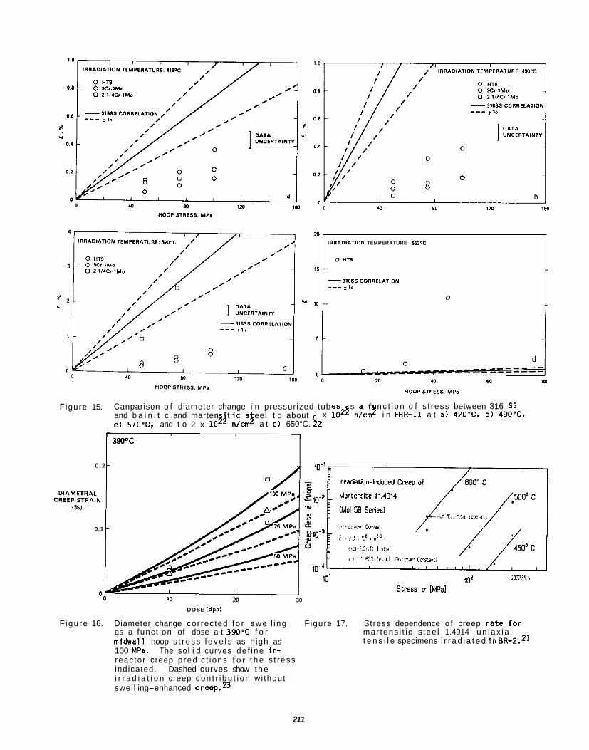
/Y
m
15
10
IRRAIDMTION TEMPERATURE 6 6 P C
0 "TP
- .
-31655 CORRELATION ---*I0
0 - .
Figure 15. Canparison o f diameter change i n pressur ized tubes and b a i n i t i c and marten t i c s eel t o about c ) 57OpC, and t o 2 x
s a f n c t i o n o f s t r ess between 316 SS x lo2$ n/cmy i n EBR-I1 a t a) 420"C1 b) 490-C,
n/cmJ a t d ) 650°C. $2
0.2 I
0.1
0 0 20 30
DOSE ldpal
F igu re 16. Diameter change cor rec ted f o r swe l l i ng F igure 17. Stress dependence o f creep r a t e f o r as a func t ion of dose a t 390'C f o r mar tens i t i c s tee l 1.4914 u n i a x i a l midwall hoop s t r e s s l e v e l s as h igh as 100 MPa. The sol i d curves de f i ne in- reac tor creep p red i c t i ons f o r t h e s t ress indicated. Dashed curves show t h e i r r a d i a t i o n creep c o n t r i b u t i o n w i thout swel l ing-enhanced creep.23
t e n s i l e specimens i r r a d i a t e d inBR-2.*]
211
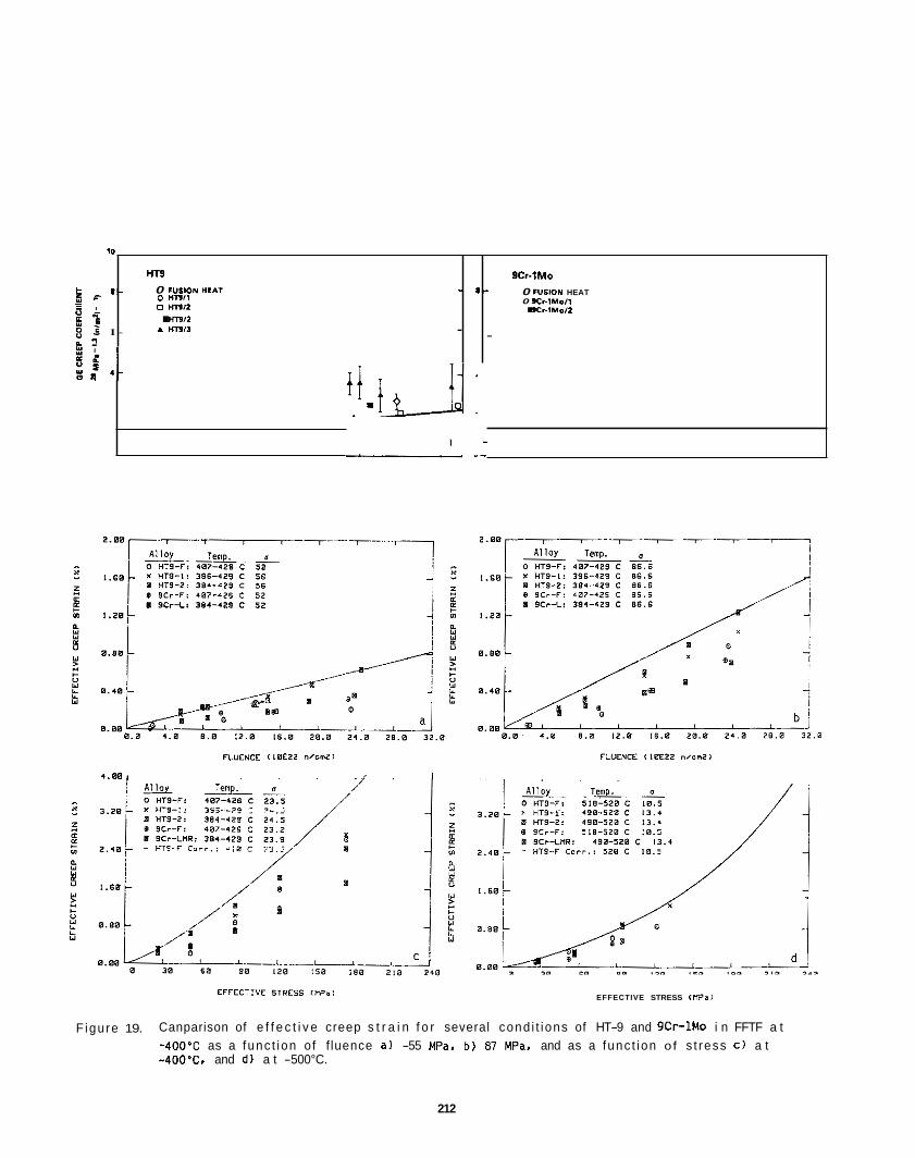
70
HT9 0 FUSlON "CAT - 8 - : 9 '- o w n , i
A w n i i : v s 5 I - - 2
0 mll - 2 . i . mn
-
FLUENCE <,BE22 n,sm21
1.00, I I
acr-iruo 0 f"IlON HEAT 0 sC..lMoll . l C r - l M d l
.
EFFECTIVE STRESS IMP.)
F igure 19. Canparison of e f f e c t i v e creep s t r a i n f o r several cond i t i ons of HT-9 and 9Cr-1Mo i n FFTF a t -4OO'C as a func t ion o f f luence a) -55 Wa, b) 81 MPa, and as a func t ion of s t ress c ) a t -4OO'C, and d) a t -500°C.
212
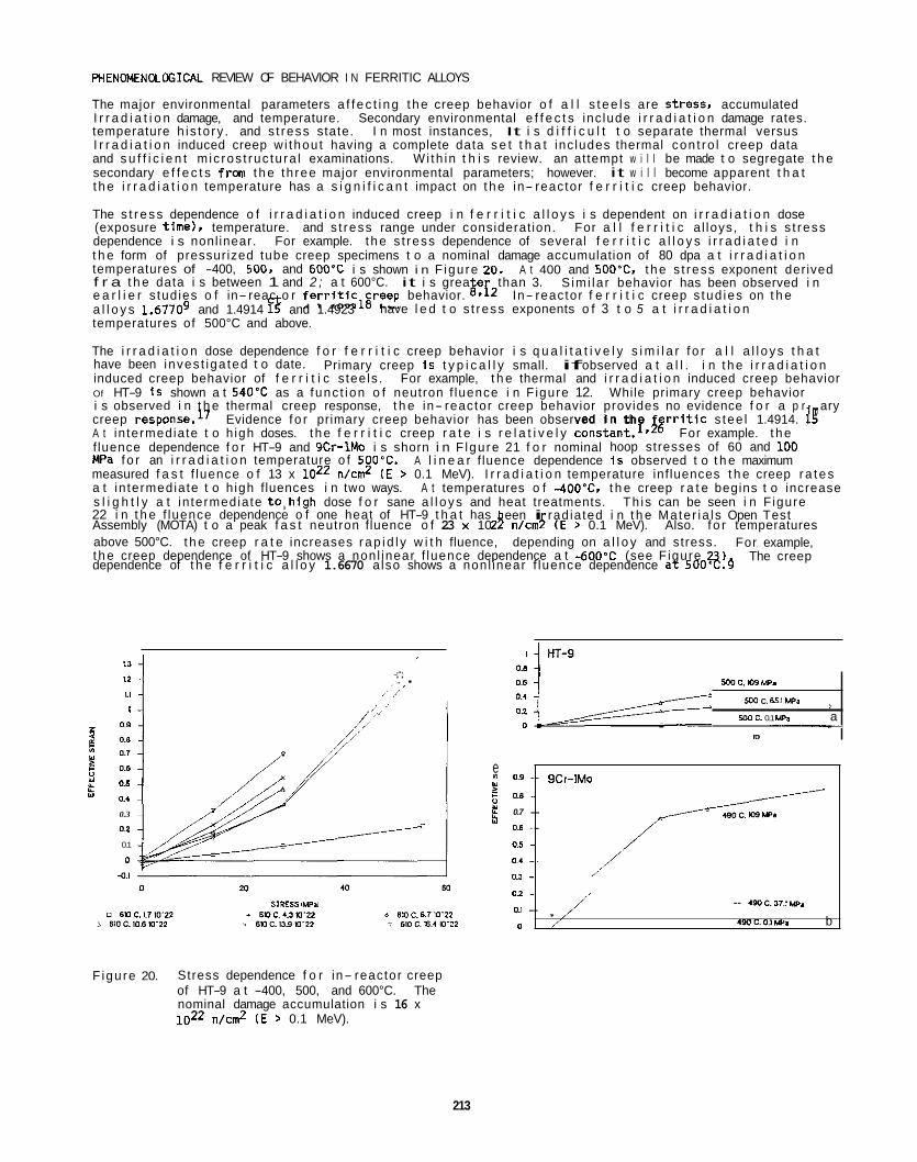
PHENOMENOLffiICAL REVIEW OF BEHAVIOR I N FERRITIC ALLOYS
The major environmental parameters a f f e c t i n g t h e creep behavior o f a l l s t e e l s are Stress, accumulated I r r a d i a t i o n damage, and temperature. Secondary environmental e f f e c t s inc lude i r r a d i a t i o n damage rates. temperature h is to ry . and s t ress state. I n most instances, It i s d i f f i c u l t t o separate thermal versus I r r a d i a t i o n induced creep w i thou t having a complete data s e t t h a t inc ludes thermal con t ro l creep data and s u f f i c i e n t m ic ros t ruc tu ra l examinations. Wi th in t h i s review. an attempt w i l l be made t o segregate t h e secondary e f f e c t s from t h e th ree major environmental parameters; however. it w i l l become apparent t h a t t h e i r r a d i a t i o n temperature has a s i g n i f i c a n t impact on t h e in- reactor f e r r i t i c creep behavior.
The s t r e s s dependence o f i r r a d i a t i o n induced creep i n f e r r i t i c a l l o y s i s dependent on i r r a d i a t i o n dose (exposure t ime), temperature. and s t ress range under considerat ion. For a l l f e r r i t i c a l loys, t h i s s t ress dependence i s nonl inear. For example. t h e s t ress dependence of several f e r r i t i c a l l o y s i r r a d i a t e d i n t h e form of pressurized tube creep specimens t o a nominal damage accumulation of 80 dpa a t i r r a d i a t i o n temperatures of -400, 500. and 600'C i s shown i n F igure 20. f r a t h e data i s between 1 and 2 ; a t 600°C. it i s grea e than 3. e a r l i e r s tud ies o f in- reac o r fer r i t ic lgreep behavior. Q*i2 In- reactor f e r r i t i c creep s tud ies on t h e
temperatures of 500°C and above.
The i r r a d i a t i o n dose dependence f o r f e r r i t i c creep behavior i s q u a l i t a t i v e l y s i m i l a r f o r a l l a l l o y s t h a t have been inves t iga ted t o date. induced creep behavior of f e r r i t i c s tee ls . For example, t h e thermal and i r r a d i a t i o n induced creep behavior Of HT-9 i s shown a t 540'C as a func t ion o f neutron f luence i n F igure 12. i s observed i n t h e thermal creep response, t h e in- reactor creep behavior provides no evidence f o r a p r ary
A t in termediate t o h igh doses. t h e f e r r i t i c creep r a t e i s r e l a t i v e l y constant . lPIg For example. t h e f luence dependence f o r HT-9 and 9Cr-lMo i s shorn i n F lgure 21 f o r nominal hoop stresses of 60 and 100 MPa f o r an i r r a d i a t i o n temperature o f 500'C. A l i n e a r f luence dependence I s observed t o t h e maximum measured f a s t f luence o f 13 x loz2 n/cm2 ( E > 0.1 MeV). I r r a d i a t i o n temperature inf luences t h e creep r a t e s a t in termediate t o h igh fluences i n two ways. A t temperatures o f -400°C. t h e creep r a t e begins t o increase s l i g h t l y a t in termediate t o , h i g h dose f o r sane a l l o y s and heat treatments. 22 i n t h e f luence dependence o f one heat of HT-9 t h a t has
above 500°C. t h e creep r a t e increases r a p i d l y w i t h fluence, depending on a l l o y and stress. t h e creep dependence of HT-9 shows a nonl inear f luence dependence a t -600°C (see F igure 23)
A t 400 and SOO'C, t h e s t ress exponent der ived S im i la r behavior has been observed i n
a l l o y s 1.67709 and 1.4914 13 and 1.4923 have l e d t o s t ress exponents o f 3 t o 5 a t i r r a d i a t i o n
Primary creep i s t y p i c a l l y small. if observed a t a l l . i n t h e i r r a d i a t i o n
While primary creep behavior
creep response.17 Evidence f o r primary creep behavior has been observed i n t h e r r l t i c s tee l 1.4914. IF
Th is can be seen i n F igure een i radiated i n t h e Mate r ia l s Open Test
Assembly (MOTA) t o a peak f a s t neutron fluence o f 23 x 10 A n/cm i ( E > 0.1 MeV). Also. f o r temperatures For example,
The creep dependence of t h e f e r r i t i c a l l o y 1.6670 also shows a nonl inear f luence dependence a t 500'C. 9
sooc. 104 w.
500 C. 65.1 UP.
YY) c. 0.1 u p 8 a __c
n
" I ;';- , I I . I ,,'
e 0.9 - E as - 0.7 - 0.6 - 0.5 - 0.1 - 0.3
02 : a, - 0
8 /, " ,' I' 0.9
0.8
0.7
0 ~ 6
0.5
01
0.3
02
0.1
0
9Cr-1Mo
190 c. as le* / /
/
- 4(XIC.,,.Iw. /" , .WC.OIWP. b
F igure 20. Stress dependence f o r in- reactor creep of HT-9 a t -400, 500, and 600°C. The nominal damage accumulation i s 16 x 1022 n/cn? ( E > 0.1 MeV).
213
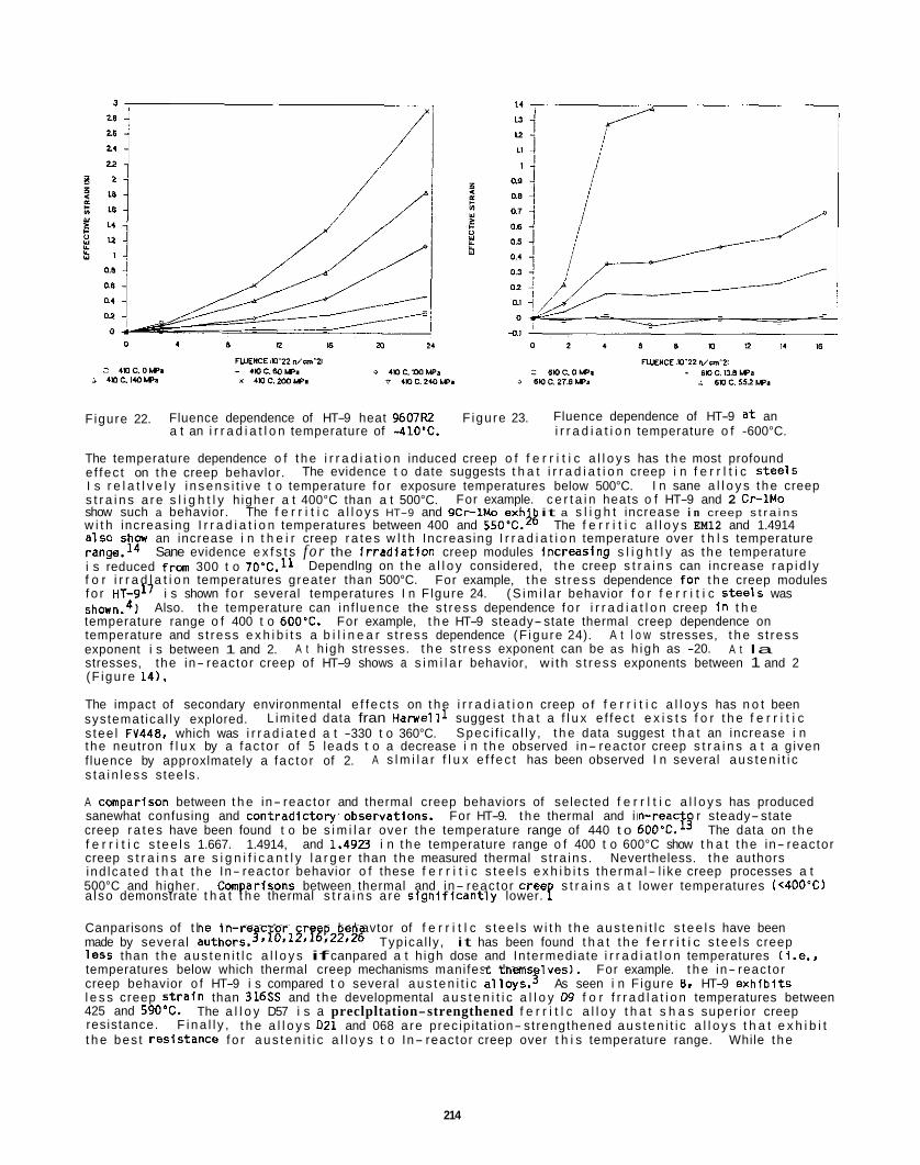
Figure 22.
The temperature dependence o f t h e i r r a d i a t i o n induced creep o f f e r r i t i c a l l o y s has t h e most profound e f fec t on t h e creep behavlor. I s r e l a t l v e l y i n s e n s i t i v e t o temperature f o r exposure temperatures below 500°C. s t r a i n s a r e s l i g h t l y h igher a t 400°C than a t 500°C. For example. c e r t a i n heats o f HT-9 and 2 Cr-1Mo show such a behavior. The f e r r i t i c a l l o y s HT-9 and 9 C r l M o exh it a s l i g h t increase i n creep s t r a i n s w i t h increas ing I r r a d i a t i o n temperatures between 400 and S S O T . 2 k The f e r r i t i c a l l o y s EM12 and 1.4914 a lso s h a an increase i n t h e i r creep r a t e s w l t h Increas ing I r r a d i a t i o n temperature over t h l s temperature range.I4 i s reduced frm 300 t o 70"C. l l f o r i r r a d l a t i o n temperatures greater than 500°C. f o r HT-917 i s shown f o r several temperatures I n F lgure 24. shown.4) temperature range o f 400 t o 600'C. For example, t h e HT-9 steady-state thermal creep dependence on temperature and s t ress e x h i b i t s a b i l i n e a r s t ress dependence (F igu re 24). A t l o w stresses, t h e s t ress exponent i s between 1 and 2. A t la stresses, the in- reactor creep of HT-9 shows a s i m i l a r behavior, w i th s t ress exponents between 1 and 2 (F igu re 14).
The impact of secondary environmental e f f e c t s on t h e i r r a d i a t i o n creep of f e r r i t i c a l l o y s has n o t been systemat ica l ly explored. s tee l FV448, which was i r r a d i a t e d a t -330 t o 360°C. the neutron f l u x by a fac to r of 5 leads t o a decrease i n t h e observed in- reactor creep s t r a i n s a t a g iven f luence by approxlmately a fac to r of 2. s t a i n l e s s s tee ls .
A cwnparison between t h e in- reactor and thermal creep behaviors of selected f e r r l t i c a l l o y s has produced sanewhat confusing and contradictory'observatlons. For HT-9. t h e thermal and in- reac o r steady-state creep r a t e s have been found t o be s i m i l a r over t h e temperature range of 440 t o 6O0"C.l3 The data on t h e f e r r i t i c s t e e l s 1.667. 1.4914, and 1.4923 i n t h e temperature range o f 400 t o 600°C show t h a t t h e in- reactor creep s t r a i n s a re s i g n i f i c a n t l y l a r g e r than t h e measured thermal s t ra ins . Nevertheless. t h e authors ind lca ted t h a t t h e In- reactor behavior o f these f e r r i t i c s t e e l s e x h i b i t s the rma l- l i ke creep processes a t 500°C and higher. Comparlsons between thermal and in- reactor Cree s t r a i n s a t lower temperatures (<40D"C)
Fluence dependence of HT-9 heat 9607R2 a t an i r r a d i a t l o n temperature of -41O'C.
F igu re 23. Fluence dependence of HT-9 a t an i r r a d i a t i o n temperature o f -600°C.
The evidence t o date suggests t h a t i r r a d i a t i o n creep i n f e r r l t i c s t e e l s I n sane a l l o y s t h e creep
Sane evidence e x f s t s f o r the i r r a d f a t i o n creep modules increas lng s l i g h t l y as t h e temperature
For example, t h e s t ress dependence f o r t h e creep modules
Also. the temperature can in f luence the s t ress dependence f o r i r r a d i a t l o n creep i n t h e
Dependlng on t h e a l l o y considered, t h e creep s t r a i n s can increase r a p i d l y
( S i m i l a r behavior f o r f e r r i t i c S tee ls was
A t h igh stresses. t h e s t ress exponent can be as h igh as -20.
L im i ted data fran H a r w e l l l suggest t h a t a f l u x e f fec t e x i s t s f o r t h e f e r r i t i c Spec i f i ca l l y , t h e data suggest t h a t an increase i n
A s l m i l a r f l u x e f f e c t has been observed I n several a u s t e n i t i c
a l so demonstrate t h a t t h e thermal s t r a i n s a re s i g n l f i c a n t l y lower. P Canparisons of t h e In- reactor c r e p behavtor of f e r r i t l c s t e e l s w i t h t h e a u s t e n i t l c s t e e l s have been made by several authors.3.10,12*1'r22t26 Typica l ly , it has been found t h a t t h e f e r r i t i c s t e e l s creep l e s s than t h e a u s t e n i t l c a l l o y s if canpared a t h igh dose and In termediate i r r a d i a t l o n temperatures (i.e., temperatures below which thermal creep mechanisms manifest thems l v e s ) . For example. t h e in- reactor creep behavior o f HT-9 i s compared t o several a u s t e n i t i c al loys.T As seen i n F igure 8. HT-9 e x h i b l t s l e s s creep s t r a i n than 316% and t h e developmental a u s t e n i t i c a l l o y W f o r f r r a d l a t i o n temperatures between 425 and 590'C. resistance. t h e bes t res is tance f o r a u s t e n i t i c a l l o y s t o In- reactor creep over t h i s temperature range.
The a l l o y D57 i s a preclpltation-strengthened f e r r i t l c a l l o y t h a t s h a s super ior creep F i n a l l y , t h e a l l o y s 021 and 068 a re prec ip i ta t ion- st rengthened a u s t e n i t i c a l l o y s t h a t e x h i b i t
While t h e
214
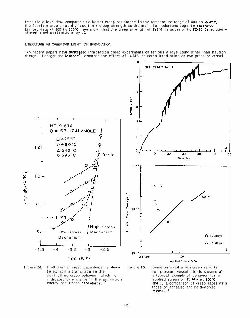
f e r r i t i c a l l o y s show comparable t o b e t t e r creep res is tance i n t h e temperature range o f 400 t o -550°C, t h e f e r r i t i c s t e e l s r a p i d l y l o s e t h e i r creep s t rength as thermal- l ike mechanisms begin t o dminate. L im i ted data a t 280 t o 350°C ha e shown t h a t t h e creep s t reng th of FV544 i s super ior t o E-16 ( a solution- strengthened a u s t e n i t i c a l l o y ) . 1
LITERATURE ON CREEP FOR LIGHT ION IRRAOIATION
Two recent papers have descr bed i r r a d i a t i o n creep experiments on fe r rous a l l o y s using other than neutron damage. Henager and Simoneng7 examined t h e e f f e c t o f 14-MeV deuteron i r r a d i a t i o n on two pressure vessel
I 2 -
I O -
a -
6 -
1 4 I I
H T- 9 STA I
-
-
-
- n
Q 6 7 KCAL/MOLE
425°C 0 4 6 0 ° C D 5 4 0 ° C 0 5 9 5 ° C
/ H i g h S t r e s s Low S t r e s s / M e c h a n i s m M e c h a n i s m u
-4.5 - 4 -3.5 - 3 -2 .5
LOG E/E)
Time. hrs
l o - '
t
/ 0 F 5 Alloys
a F l Alloys
b 1 0 - 3 I , , I
2 1 10' 1 0 2
Applied Stress. MPa
F igure 24. HT-9 thermal creep dependence i s shovn F igure 25. Deuteron i r r a d i a t i o n creep r e s u l t s f o r pressure vessel s t e e l s showing a) a t y p i c a l example of behavior f o r an appl ied s t r e s s o f 45 MPa a t 2OO"C, and b ) a comparison of creep r a t e s w i t h those of annealed and c o l d-worked
t o e x h i b i t a t r a n s i t i o n i n t h e c o n t r o l l i n g creep behavior, which i s i nd ica ted by a change i n t h e a c t i v a t i o n energy and s t ress dependence.17
215
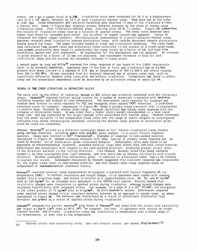
s tee ls . one w i h a copper l e v e l of 0.2%. r a t e of 6 x 10 dpa/s, fol lowed by 12 h of pos t i r r a d i a t i o n thermal creep. of 0.05 dpa. A t y p i c a l tes t , shown i n F igu re 25a. d isp lays primary behavior fol lowed by t h e onset o f s teady- state i r r a d i a t i o n creep. t h e r e s u l t s of i r r a d i a t i o n creep r a t e as a f unc t i on of app l ied s t ress . h igher than those f o r annealed pure n icke l , b u t no e f f ec t o f copper conten t was apparent. ( A l l o y F5 contained t h e h igher copper content.) specimen revealed small i r r a d i a t i o n induced d i s l o c a t i o n loops, w i t h carb ide decorated network d i s l o c a t i o n s bowing around t h e loops. used ca l cu la ted l w p growth r a t e s and d i s l o c a t i o n c l imb v e l o c i t i e s i n t h e contex t o f a c l imb- g l ide model. Loop g r a r t h p red i c t i ons were found t o underpredict t h e creep s t r a i n by a f a c t o r o f 10. b u t l oop Size p red i c t i ons agreed we l l w i t h experiment. i n g l i d e d is tance by a f ac to r of 10 was n o t p lausib le, and reasonable increases i n b i as f o r se l f- i n t e r s t i t i a l atoms d i d no t p rov ide t h e necessary increase i n creep s t r a i n .
A second paper by Jung and Af i fyZ8 examined t h e creep response of two heats o f D I N 1.4914 m a r t e n s i t i c s tee l i n an annealed cond l t ion . protons w i t h doses l i m i t e d t o a maximum of 0.76 dpa a t temperatures of 400 t o 500°C and s t ress ranging from 150 t o 480 MPa. s i g n i f i c a n t d i f fe rence between creep r a t e s w i t h and w l t hou t i r r a d i a t l o n . creep and t h e temperature dependence could be described by an a c t i v a t i o n energy of about 3.0 eV.
I r r a d i a t i o n t e s t s were conducted f o r 24 h a t a displacement Peak dose was on t h e order .f
Creep enhancement and r a d i a t i o n hardening were observed i n each o f t h e i r r a d i a t e d a l l oys .
Post i r r a d i a t i o n thermal creep, s t a r t i n g a f t e r 39 h, i s slower. F igure 25b SumnariZeS The creep r a t e s observed were
M ic ros t ruc tu ra l examinations of a p o s t i r r a d i a t i o n thermal creep
The paper inc luded models of creep and i r r a d i a t i o n hardening. The creep model
An explanat ion f o r t h e discrepancy was n o t apparent. An increase
Specimens were i n t h e form of f o i l s and i r r a d i a t i o n was by 6.2-MeV
It was concluded t h a t a l l behavior observed was of primary creep type. w i t h no Composition was found t o a f f e c t
REVIEW OF THE CREEP LITERATURE ON REFRACTORY ALLOYS
The e a r l y work on t h e e f f ec t of r a d i a t i o n damage on BCC a l l o y s was p r i m a r i l y concerned w i t h BCC r e f r a c t o r y a l loys . i nc lud ing tungsten and niobium a t roan temperature. niobium were s i m i l a r t o r a t e s reported f o r FCC and hexagonal close-packed (HCP) mater ia ls . extension curve f o r tungsten. reproduced i n F igu re 26. shows a primary creep t r a n s i e n t t h a t i s exponent ia l i n neutron dose; fol lowed by steady- state creep. co l lapse o f d i s l o c a t i o n loops. creep rate. and was expla ined by t h e l a r g e r cascade s i zes associated w i t h heavier atans. t h a t t h e small v a r i a t i o n i n t h e comparative creep r a t e s over t h e range of a tan i c weights he i nves t i ga ted i nd i ca ted t h a t normal m e t a l l u r g i c a l processes i n v o l v i n g t h e thermal creep process of d i s l o c a t i o n g l i d e could be r u l e d o u t canplete ly.
However, B ~ c k l e y ~ ~ a r r i v e d a t a d i f f e r e n t conclusion based on f o i l f l exu re i r r a d i a t i o n creep s tud ies us ing va r i ous mater ia ls . i n c l u d i n g co i r o n and BCC gama uranium, i n a r e c o i l f i s s i o n fragment spectrum. Doses were 1 im i t ed t o lOfPfissions/cn?. Examples o f response i n cold-worked mater ia l . reproduced i n F igure 27. showed non l inear behavior w i t h dose, t y p i c a l of primary creep response but. as noted by Buckley, n o t of d i s l oca t i on- g l ide- cont ro l led behavior. dependent on thermomechanical treatment: annealed ma te r i a l c r e p t more s lowly than 15% co ld- ro l l ed ma te r i a l . Deformation was an i so t rop i c w i t h respect t o t h e cold-working d i r e c t i o n . producing grea ter s t r a i n r a t e s i n t h e d i r e c t i o n p a r a l l e l t o t h e r o l l i n g d i r ec t i on . tended t o be more suscept ib le than l i g h t elements, and t h a t t he re was no obvious c o r r e l a t i o n w i t h c r y s t a l s t ruc ture . Buckley concluded t h a t d i s l o c a t i o n g l ide , i n a d d i t i o n t o d i s l o c a t i o n climb, had t o be invoked t o exp la in t h e resu l ts . f o r t h e h igher creep r a t e s i n cold-worked ma te r i a l , and t h a t steady- state creep response would be independent of thermanechanical t reatment h i s to r y .
PonsoyG1 reported u n i a x i a l creep measurments on tungsten i r r a d i a t e d w i t h f i s s i o n fragments a t l o w temperature (20K). loaded i n t o a s t r a i n i n g stage, and tes ted i n t ens ion a t 6 (approximately zero) . 60, 72. and 87 kg/mn? (and a t 120 k g / d f o r an uncoated w i r e specimen) i n t h e TRITON t e s t reactor . Resu l ts showed t h a t r e s i s t i v i t y changes were i n s e n s i t i v e t o app l ied s t ress dur ing i r r a d i a t i o n . whereas l eng th changes were increased s i g n i f i c a n t l y w i t h increased s t ress . i s 2.6 t imes greater a t 72 kg/mn? than a t 6 kg/mn?. under app l i ed s t ress showed i n i t i a l t r a n s i e n t behavior fol lowed by an approach t o steady state, as shown reproduced i n F igure 28. formation and g r w t h as a r e s u l t of app l ied s t ress dur ing i r r a d i a t i o n .
H e ~ k e t h ~ ~ compared h i s e a r l i e r resu l ts30 w i t h those of PonsoyeZ9 and noted t h a t t h e s t r a i n r a t e s e n s i t i v i t y was l a r g e r a t 253'C (14a) than a t 43'C (Ea) f o r tungsten. b u t tha t . i n agrement w i t h r e s u l t s on n icke l , uranium dioxide, and Z i rca loy , i r r a d i a t i o n creep was i n s e n s i t i v e t o temperature over a broad range o f l o w temperatures. o r even rose a t low temperature.
HeskethZ9 reported h e l i c a l spr ing r e s u l t s f o r a number of ma te r i a l s i r r a d i a t e d w i t h neutrons, The deformation r a t e s reported f o r tungsten and
A publ ished
Hesketh i d e n t i f i e d t h e steady-state response w i t h t h e It was noted t h a t a h igher a t a n i c weight corresponded t o a more r a p i d
Hesketh concluded
Deformation r a t e s were found t o be
L i k e Hesketh, Buckley noted t h a t heavy elements
Subsequent d iscussion by Hesketh suggested t h a t t r a n s i e n t response was respons ib le
To moni tor r es i s tance and l eng th change, s t r i p specimens were coated w i t h uranium,
For example, a t a dose of 5 x 10¹⁷ FF/c&. t h e e longat ion As w i t h Hesketh's resu l ts . deformation response
The behavior was i n t e r p r e t e d as a r e s u l t o f an i so t rop i c d i s l o c a t i o n l oop
(a) Natural s t r a i n r a t e s e n s i t i v i t y u n i t s , "per u n i t e l a s t i c s t r a i n , per atomic displacement"31
216
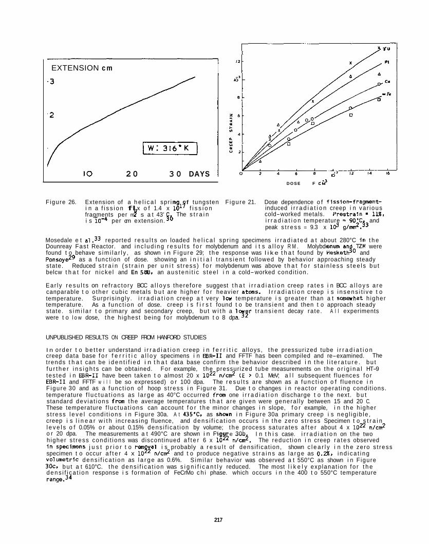
t
I EXTENSION c m
IO 20 3 0 DAYS I D O S E F C?
‘. / A
Figure 26. Extension of a h e l i c a l spr ing f tungsten F igu re 21. Dose dependence o f f iss ion- f ragment- induced i r r a d i a t i o n creep i n va r i ous cold-worked metals. P r e s t r a i n = 1l%, i r r a d i a t i o n temperature = 9O’C and peak s t r e s s = 9.3 x Id g/mr?.j3
Mosedale e t a1.33 reported r e s u l t s on loaded h e l i c a l sp r i ng specimens i r r a d i a t e d a t about 280°C i n t h e Dounreay Fas t Reactor. and i n c l u d i n g r e s u l t s f o r molybdenum and i t s a l l o y R M . Molybdenum an TZM were found t o behave s i m i l a r l y , as shown i n F igu re 29; t h e response was l i k e t h a t found by HesketJO and Ponsoyezg as a func t ion of dose. showing an i n i t i a l t r a n s i e n t fo l lowed by behavior approaching steady state. Reduced s t r a i n ( s t r a i n per u n i t s t r ess ) f o r molybdenum was above t h a t f o r s t a i n l e s s s t e e l s b u t belcw t h a t f o r n i cke l and En 588, an a u s t e n i t i c s tee l i n a cold-worked cond i t ion .
Ea r l y r e s u l t s on re f rac to ry BCC a l l o y s there fore suggest t h a t i r r a d i a t i o n creep r a t e s i n BCC a l l o y s a r e canparable t o o the r cub ic metals b u t are h igher f o r heavier atoms. I r r a d i a t i o n creep i s i n s e n s i t i v e t o temperature. temperature. s tate. s i m i l a r t o primary and secondary creep, bu t w i t h a logy t r a n s i e n t decay ra te . were t o l o w dose, t h e h ighes t being f o r molybdenum t o 8 dpa.
i n a f i s s i o n fl x o f 1.4 x 10’’ f i s s i o n
$b i s 10-4 per cm extension. fragments per m Y s a t 43’ The s t r a i n
Surpr is ing ly . i r r a d i a t i o n creep a t very l c w temperature i s g rea ter than a t saewha t h igher As a f unc t i on of dose. creep i s f i r s t found t o be t r a n s i e n t and then t o approach steady
A l l experiments
UNPUBLISHED RESULTS ON CREEP FROM HANFORD STUDIES
I n o rde r t o b e t t e r understand i r r a d i a t i o n creep i n f e r r i t i c a l loys , t h e pressur ized tube i r r a d i a t i o n creep data base f o r f e r r i t i c a l l o y specimens i n EBR-I1 and FFTF has been compiled and re-examined. t rends t h a t can be i d e n t i f i e d i n t h a t data base conf i rm t h e behavior described i n t h e l i t e r a t u r e . b u t f u r t h e r i n s i g h t s can be obtained. For example, t he pressur ized tube measurements on t h e o r i g i n a l HT-9 tes ted i n EBR-I1 have been taken t o almost 20 x l o z 2 n/cm2 (E > 0.1 MeV; a l l subsequent f luences f o r EBR-I1 and FFTF w i l l be so expressed) o r 100 dpa. The r e s u l t s are shown as a f u n c t i o n o f f luence i n F igu re 30 and as a f unc t i on of hoop s t ress i n F igure 31. temperature f l u c t u a t i o n s as l a r g e as 40°C occurred f ra one i r r a d i a t i o n discharge t o t h e next. b u t standard dev ia t i ons f r a t h e average temperatures t h a t a re g iven were genera l l y between 15 and 20 C. These temperature f l uc tua t i ons can account f o r t h e minor changes i n slope, f o r example, i n t h e h igher s t ress l e v e l cond i t i ons i n F igure 30a. A t 435% as s h w n i n F igu re 30a primary creep i s neg l i g i b l e , creep i s l i n e a r w i t h inc reas ing fluence, and d e n s i f i c a t i o n occurs i n t h e zero s t ress Specimen t o s t r a i n l e v e l s o f 0.05% o r about 0.15% dens i f i ca t i on by volume; t h e process sa tura tes a f t e r about 4 x loz2 n/cm2 o r 20 dpa. h igher s t ress cond i t i ons was discont inued a f t e r 6 x 10’’ n/c&. The reduc t ion i n creep r a t e s observed i n SpeClnWnS j u s t p r i o r t o rem0 a1 i s probably a r e s u l t of dens i f i ca t ion , shown c l e a r l y i n t h e zero s t ress specimen t o occur a f t e r 4 x 10” n/cm2 and t o produce negat ive s t r a i n s as l a r g e as 0.2%, i n d i c a t i n g Volumetr ic d e n s i f i c a t i o n as l a r g e as 0.6%. S im i l a r behavior was observed a t 550°C as shown i n F igure 30c. b u t a t 610°C. t h e d e n s i f i c a t i o n was s i g n i f i c a n t l y reduced. d e n s i f i c a t i o n response i s fo rmat ion of FeCrMo c h i phase. which occurs i n t h e 400 t o 550°C temperature range.34
The
Due t o changes i n reac tor opera t ing condi t ions.
The measurements a t 490°C are shown i n F igu e 30b I n t h i s case. i r r a d i a t i o n on t he two
The most l i k e l y exp lanat ion f o r t h e
217
F igure 28. Change i n l e n g t h as a f u n c t i o n o f f ission- fragment i r r a d i a t i o n t i m e f o r tungsten specimens tes ted a t 20K f o r low and h igh appl ied s t r e s s s ta tes. T r iang les denote p r e i r a d i a t i o n s t r a i n hardening treatments. 2§
3
:: 1 L1 -, u , *z5SCwVP.
, l
P 14 1 I I I I I I I I I I I I 13
El L E . 5 8 . cold-worked 10
m 8 -
$ 7
P- 6 - ? - 5
4
3 2
1
0 1 2 3 4 5 6 7 8 9 10 11 12 13;s
imonic P516
DOSE, dpa in Fe
m 8 -
$ 7
P- 6 - ? - 5
4
3 2
1
0 1 7 ? 4 5 6 7 8 9 10 11 12 13;s
imonic P516
- -~ DOSE, dpa in Fe
F igure 29. Creep of he l i ces va r ious m a t e r i a l s a t -280'C i n DFR. SI
I- 1 / 14
5 0 c. 17.6 wa
6W C. 13.8 * P a
Figure 30. Compi lat ion of creep s t r a i n r e s u l t s f o r pressur ized tube specimens o f HT-9 i n EBR-I1 as a func t ion of f luence a t a ) 435"C, b l 490°C. c ) 550°C. and d) 610'C. Note t h a t i n a l l cases d e n s i f i c a t i o n i s i nd ica ted i n t h e zero- stress cond i t i on .
218
450 470 190 5 0 530 550 570 590 610
Bo ~
en m Gn I 4 0 ,Bo
610 c. 8.7 10'22
/: 80 c. 4.3 a -a
0.8
07
0.6
0.5
0.4
0.3
02
0.1
0
6 0 c. 16.4 a -a
552 WI 552 W# W 6 D'22
T D P E Q A M E IC,
Figure 31. Compi lat ion o f creep s t r a i n r e s u l t s f o r pressur ized tube specimens of HT-9 i n EBR- I1 as a func t ion o f hoop s t ress a t a) 435'C, b ) 490'C. c ) 550°C. and d) 610°C and as a f u n c t i o n o f temperature e) a t 110 MPa and f ) at 55 MPa.
In- reac tor creep response i n HT-9 pressur ized tubes as a f u n c t i o n of s t r ess i s nonlinear, as shown i n F igures 31a through 31d. D e n s i f i c a t i o n canp l ica tes t h e i n te rp re ta t i on . b u t i n a l l cases. non l inear behavior is c l e a r l y seen. P l o t s o f creep s t r a i n as a f unc t i on o f temperature f o r t h i s data base were weakly a f u n c t i o n of temperature. except i n cases where a change i n creep mechanism was indicated. However, t h e dependence changed from negat ive t o p o s i t i v e s lope when t h e s t ress changed from 55 t o 110 MPa.
S i m i l a r response was observed i n pressur ized tube specimens i r r a d i a t e d a t FFTF. F igu re 32 a l l a s CanparlSOn of s i x s i m i l a r m a r t e n s i t i c s tee l condi t ions. f i v e canpositional/heat-treatment v a r i a t i o n s of HT-9. and one cond i t i on f o r 9Cr-1Mo; many of these t e s t r e s u l t s a re reported t o f luences of 2 x l oB n/cm2 o r 100 dpa.
The behavior can be seen i n Figures 31e and 31f.
F igure 32a shows r e s u l t s f o r t h e f us ion heat o f HT-9, which a re no tab le f o r several
219
1 m c x n w a *
lB - HEAT 9607R2 26 ~ / I
8 15 m 24
/ HEAT 91353 u - LI - /
E!
E 4 Y
Y
t
i
E! $ pr Y F Y
i
a
r M
; ; L
FLLWCE B J 7 2 dmll Figure 32. Comparison of pressur ized tube specimens of mar tens i t i c s t e e l s i n FFTF as a f unc t i on of f luence
a t 400°C: a) HT-9 fusion heat %07Wr b ) HT-9 heat M425r c ) HT-9 heat 91353. d ) 9 C r l M o heat 30394. e ) HT-9 heat 91353 i n a st ronger heat-treabnent condi t ion. and f ) HT-9 heat 92235 i n t h e s t ronger heat- treatment cond i t ion .
reasons. I1 shows t h a t t h e f us ion heat i s stronger. to- heat v a r i a t i o n s on p rec i i t a t i o n response. Also, diameter increase occurs i n t h e ze ro s t ress c o n d i t i o n a t f luences above 1.6 x los n/cm2, an i n d i c a t i o n of t h e onset of vo id swel l ing, w i t h l e v e l s of 1% vo lumet r ic swe l l i ng i nd i ca ted a t 2.4 x l oB n/cr&. a t t r i b u t e d t o swe l l i ng enhanced creep.
The e f f e c t o f heat- to-heat v a r i a t i o n s on creep can bes t be demonstrated by canparison o f F igures 32a. 32b and 32c. For example. a l l t h r e e f i gu res demonstrate s t r a i n s of j u s t under 3% a t 200 MPa and 2.4 x l oB n/cmZ, b u t t h e s t ress dependencies d i f f e r and creep s t r a i n s t he re fo re appear t o be f a i r l y I n s e n s i t i v e t o canpos i t ion va r i a t i ons . Much of t h e d i f fe rence between these curves can be ascr ibed t o v a r i a t i o n s i n
S t r a i n i s non l inear w i t h fluence. b u t canparison of s t r a i n s w i t h those f o r heat R74075 I n EBR- No evidence of d e n s i f i c a t i o n i s apparent. suggesting heat-
A t l e a s t a p a r t of t h e n o n l i n e a r i t y can there fore be
t h e f luence requ i red f o r t onse o f swel l ing. Also o f note i n F igure 32b i s t h e l i n e a resp nse found f o r heat 84425 t o 2.0 x 10% n/c&, fo l lowed by dev i a t i on from l i n e a r i t y above 2.0 x lod n/cm?. Th is dev ia t ion from l i n e a r i t y can be seen i n t he other two curves a t t h e f luence l e v e l j u s t before t he onset o f swel l ing. As a consequence, vo lumetr ic swe l l i ng can be expected i n specimens shown i n Figure 32b on t h e next discharge from reactor . enhanced creep must be taken i n t o account, and t h e onset of t h e e f f e c t can be i d e n t i f i e d p r i o r t o measurement o f t h e actual swel l ing.
Canparison o f t h e creep response i n 9 C r l M o (F igure 32d) w i t h those f o r HT-9 f u r t h e r shows heat- to-heat di f ferences. As demonstrated previously.22 9Cr-1Mo i s more creep r e s i s t a n t than HT-9. occurs a t a lower fluence, about 8 x lo2* n/cn?. d i f ferences i n i r r a d i a t i o n creep response, bu t t he d i f fe rences appear t o r e s u l t i n no more than a fac to r o f 2 v a r i a t i o n i n creep s t r a i n .
F i n a l l y , F igure 32 a l lows comparison o f t he e f f e c t of heat t reatment on creep res is tance. specimens were g iven heat treatments t o promote h igher t e n s i l e strength. p r i m a r i l y by lower ing t h e tempering temperature. Comparison o f F igures 32c and 32e shows a n e g l i g i b l e e f f e c t o f creep s t reng th due t o heat treatment: some d i f f e rences may be i d e n t i f i e d . however. vo lumetr ic swe l l i ng i n t h e zero s t r ess cond i t i on s t a r t i n g a t about 10 x loJp n/cm', w i t h a corresponding nonl inear e f fec t of f luence a t h igher s t r ess leve ls : t he lower s t reng th cond i t i on shows t h e s t a r t of swe l l i ng response a t about 18 x loz2 n/cn?. Heat 92235. shown i n F igure 32f. g ives s i m i l a r creep s t r a i n s a t comparable s t r ess and fluence. bu t shows d e n s i f i c a t i o n i n t h e zero s t r ess condi t ion. s i m i l a r t o t h a t observed i n heat R74075 tes ted i n EBR-I1 (F igure 30a). It i s concluded t h a t changes i n heat treatment. and there fo re d i f ferences i n microst ructure. do no t s i g n i f i c a n t l y change creep resistance. bu t they can a l t e r t h e onset of vo lumet r i c swel l ing.
A f u r t h e r example i s a l so i n s t r u c t i v e . I n t he so lu t ion- t rea ted and cold-worked cond i t i on i n FFTF (see F igure 33) . exce l l en t example of t h e consequences of dens i f i ca t i on due t o phase i n s t a b i l i t y on i r r a d i a t i o n creep.
Therefore. as had been shown w i t h 2 Cr-lMo. t h e e f f e c t o f swel l ing-
The 9 C r l M o and HT-9 specimens have s i m i l a r m ic ros t ruc tu res bu t q u i t e d i f f e r e n t compositions. Also, t h e onset o f swe l l i ng
Therefore, canposi t ional v a r i a t i o n s can r e s u l t i n
Two se t s o f
The h h s t r ngth cond i t i on i nd i ca tes
A Laves p r e c i p i t a t i o n strengthened a l loy . known as D57. was t es ted This experiment provides an
0 6 ~ 001
002 I
/ os - I
0 2 . e e w a H RUMCE m a d-%
~UQICE m a dm% Figure 33. Creep s t r a i n r e s u l t s f o r pressur ized tube specimens o f D57. a Laves prec ip i ta t ion- strengthened
d e l t a f e r r i t i c a l loy , tes ted i n t he so lu t ion- t rea ted and cold-worked cond i t i on a t a ) 420°C. b) 52O'C. c ) 550'C. and d) 670°C.
The i n s t a b i l i t y i s again due t o FeCrMo c h i phase formation, and t h e d e n s i f i c a t i o n i s as l a r g e as 0.3% s t r a i n corresponding t o a vo lumetr ic dens i f i ca t ion o f U . A t each i r r a d i a t i o n temperature, t h e creep response i s a f fec ted by dens i f i ca t ion , b u t t h e g rea tes t e f f e c t i s a t 520°C F i g u r 33b). where a l l b u t one o f t h e pressurized tubes shrank even up t o f luences as h igh as 10 x loz4 n/cm2. Also o f note i s t h e observat ion t h a t creep r a t e s decrease w i t h increas ing fluence, poss ib ly due t o hardening fran p r e c i p i t a t i o n .
CONCLUSIONS
As has been shown, the re i s now a l a r g e body of data descr ib ing i r r a d i a t i o n creep i n f e r r i t i c / m a r t e n s i t i c s t e e l s and a much l e s s canplete data base f o r o ther re f rac to ry a l loys. as fo l lows: pr imary creep i s o f ten absent, behavior i s o f ten l i n e a r w i t h dose bu t r a r e l y l i n e a r w i t h StreSS, and s t r a i n s t o f a i l u r e can be as l a r g e as 25%. 1 and 2. b u t o thers r e p o r t values near 6. (Values near 6 are expected t o correspond t o a thermal creep mechanism. 1
It has been shown t h a t composition v a r i a t i o n can a l t e r creep response, bu t v a r i a t i o n s i n heat treatment t h a t l e a d t o s i g n i f i c a n t changes i n y i e l d s t rength appear t o be o f l i t t l e consequence t o i r r a d i a t i o n creep rates. In-reaCtOr creep behavior o f d i f f e r e n t f e r r i t i c a l loys. Canposit ional modi f icat ions can extend t h e useful t m p e r a t u r e range f o r f e r r i t i c a l loys. Composition v a r i a t i o n no t on ly changes t h e e f f e c t i v e creep COEffiClent, b u t can a lso r e s u l t i n t h e enhancement o r delay o f o ther deformation mechanisms, such as swel l ing. As a resu l t . i f p r e d i c t i o n o f performance i s c r i t i c a l . experiments must employ t h e proper canposi t ion and t h e proper i r r a d i a t i o n environment.
The data base suggests t h e unexpected and unexplained r e s u l t t h a t i r r a d i a t i o n creep r a t e s can be h igher a t very l o w temperatures than a t in termediate temperatures. The re levan t data tend t o be on ly t o l o w doses. and the re fo re t h i s response may t u r n o u t t o be t rans ien t . t o rea l machines operat ing a t l o w temperatures necess i ta te t h e performance o f f u r t h e r l o w temperature tes ts .
The behavior can be sumnarized
Some researchers r e p o r t s t ress exponents between
The major impact o f composition i s on t h e onset o f thermal- l ike creep mechanisms i n t h e
Hmever. t h e consequences o f t h i s r e s u l t
ACKNCWLELXMENTS
The authors wish t o thank F. A. Garner f o r p rov id ing a copy of h i s manuscript p r i o r t o pub l i ca t ion .
REFERENCES
1.
2 .
3 .
4 .
5.
6.
7 .
8.
E. A. L i t t l e , D. R. A rke l l , D. R. Harries, G. R. Lewthwaite. and T. M. Wil l iams. "Development o f F e r r i t i c- M a r t e n s i t i c S tee ls f o r Fast Reactor Appl icat ions." pp. 31-37 i n t h e proceedings o f t h e i n t e r n a t i o n a l conference -ior of M e t a l l i c MOfer ia ls f o r Fast Repstor Core C~QQWI&, Ajaccio, Corsica. France, June 4-8. 1979.
J. L. Straalsund. R. W. Powell, and 8. A. Chin. "An Overvisw o f Neutron I r r a d i a t i o n Ef fects i n LMFBR Materials," 108-109 (1982) 299-305.
J . L. Straalsund and D. S. Gelles. "Assessment o f t h e Performance of t h e Mar tens i t i c a l l o y HT-9 f o r Fast Breeder Reactor Appl icat ions," presented a t t h e zppirnl Conference on F- f o r Use i n V r o v Te-. HEOL-SA-2771 FP. Snowbird, UT. June 19-23, 1983.
D. R. Harr ies. " F e r r l t i c / M a r t e n s i t i c Stee ls f o r Use i n Near-Term and Commercial Fusion Reactors," pp. 141-155 i n Proceedlnas o f ToDical C o n f e r w on F e r r i t i c A I iovs for Use i n -, J . W. Davis and 0. J. Michel. Eds.. AIME, Warrendale, Penn. (1984) .
T. Lechtenberg. " I r r a d i a t i o n E f fec ts i n F e r r i t i c Steels." 133-134. 149-155 (1985).
D. S. Gelles. " E f fec ts o f I r r a d i a t i o n on F e r r i t i c A l l o y s and I m p l i c a t i o n s f o r Fusion Reactor Appl icat ions." 149, 192-199 (1987).
K. Q. Bauley, L. E. L i t t l e . V. Levv. A. Almo. K. Ehr l i ch . K. Anderko. and A. Calza B i n i , "European Development-of Fer r i t i c -Mar tens i t i ; Stee ls f o r Fast Reactor Wrapper Appl icat ions." Nucl.; 77, 295-303 (1988) .
W. Vandermeulen, A. De Bremaecker, S. de Burbure. J . 4 . Huet. and P. Van Asbroeck. " I r r a d i a t i o n Creep i n F e r r i t i c Steels," pp. 1-4 ir t h e proceedings o f t h e i n t e r n a t i o n a l conference Irradlatlon
s f o r F a s t o r Core C-, Ajaccio, Corsica. France, June 4-89 1979.
9.
10.
11.
12.
13.
14.
15.
16.
K. Herschbach, K. Ehrl ich, and E. Materna, "Uber Das Kr iechverhal ten und Mik ros t ruc tu r de F e r r i t i s c h e n Werkstoffes Nr. 1.6770 un te r Bestrahlung." pp. 25-29 in the proceedings o f t h e i n t e r n a t i o n a l conference of M e t a l l i c t&&fals f o r Fast Canoonents. AJaCCio, Corsica, France. June 4-8, 1979.
M. M. Paxton. E. A Chin, E. R. G i lbe r t . and R. E. Nygren. "Comparison o f t h e In- reactor Creep of Selected F e r r i t i c . Sol i d So lu t ion Strengthened. and P r e c i p i t a t i o n Hardened Commercial Alloys." J..
A. R. Causey, G. J . C. Carpenter, and S. R. MacEwem. "In-Reactor Stress Relaxat ion of Selected Metals and A l l o y s a t Low Temperatures," L Nucl. U 90, 216-223 (1980).
M. M. Paxton. E. A. Chin. and E. R. Gi lber t , "The In-Reactor Creep of Selected F e r r i t i c , S o l i d So lu t ion Strengthened and P r e c i p i t a t i o n Hardened Alloys." 95. 185-192 (19801.
E. R. G i l b e r t and 8 . A. Chin. "In-Reactor Creep Measurenents.' NuL.J&L 52. 273-283 (1981).
A. De Erenaecker and J . 4 . Huet. " I r r a d i a t i o n Creep and Swel l ing of F e r r i t i c Stee ls I r r a d i a t e d i n Fast Reactors: New Results," pp. 117-120 i n and Me-
80s 144-151 (1979).
and Al l - . BNES. London (1983).
K. Herschbach. D. P. Ooser. and W. Doser, " I r r a d i a t i o n Creep of t h e Mar tens i t i c Steel No. 1.4914 Between 400% and 600°C (Mol 5E)." pp. 121-124 i n DImenslonal S t a b i l i t v and M-
and Al l - , ENES, London (1983).
R. J . Puigh and G. L. Wire, " In- reactor Creep Behavior of Selected F e r r i t i c Alloys," pp. 601-506 i n J. W. Davis and D. J . Michel. Eds.. AIME, Warrendale, Penn. (1984).
on F e r r i t i c A l l o v s f o r Use i n p,
17. E. A. Chin. "An Analys is o f t h e Creep Proper t ies o f a 1Xr-1Mo-WV Steel." pp. 593-599 i n Proceedlnas on F e r r i t U l l o v s fo r Use i n Nucl- J . W. Davis and
D. J . Michel, Eds., AIME, Warrendale. Penn. (1984).
18. C. Wassilew. K. Herschbach, E. Materna-Morris. and K. Ehr l ich. " I r r a d i a t i o n Behavior o f l a C r M a r t e n s i t i c Steels," pp. 607-614 i n -ce on F e r r i t i c A l l o v s f o r U a p J . W. Davis and D. J . Michel. Eds., AIME, Warrendale. Penn. (1984).
19. J . M. Dupouy, Y. Carteret, H. Aubert and J . L. Eoutard. "EM 12. A Poss ib le Fast Reactor Core Material.' ' pp 125-128 i n Fbx&bgs of Too-e on F e r r i t i c A l l o v s f o r Use i n t&.h.c EneravTechnoloales, J . W. Davis and D. J . Michel. Eds.. AIME, Warrendale, Penn. (1984).
20. 3 . 4 . Huet. L. Coheur, L. De Wilde, J . Gedopt. W. Hendrix. and W. Vandermeulen. " Fabr icat ion and Mechanical Proper t ies o f ODs F e r r i t i c A l l o y s Canning Tubes f o r Fast Reactor Fuel Pins." pp. 329- 334 i n Proceedinas o f T o o i c a l c e on F e r r i t i c A l l o v s f o r Use i n p. J . W. Davis and 0. J . Michel. Eds.. AIME, Warrendale. Penn. (1984).
21. K. Herschbach. " In- Pi le Creep of t h e Mar tens i t i c 1.4914: Some Fundamental Observations." a
22. R. J. Puigh. " In-Reartor Creep of Selected F e r r i t i c Alloys," pp. 7-18 i n E f f e c t s o f R-
M.&LQL 127, 239-241 (1985).
Twel f th I-, ASTM STP 870, F. A. Garner and J. S. Perr in. Eds., ASTM. Phi ladelphia, Penn. (1985).
23. 0. S. Gel les and R. J. Puigh, "Evaluat ion of F e r r i t i c A l l o y Fe-2 Cr-lMo A f te r Neutron I r r a d i a t i o n : I r r a d i a t i o n Creep and Swelling." pp. 19-37 i n E f f e c t s 0- .Twslfth VSvmoosium. ASTM STP 870. F. A. Garner and J . S. Perr in , Eds.. ASTM. Phi ladelphia, Penn. (1985).
24. 0. S. Gelles, "Evaluat ion o f F e r r i t i c A l l o y Fe-2 Cr-1Mo A f t e r Neutron I r r a d i a t i o n : M ic ros t ruc tu ra l
-slum ( P a r t U, ASTM STP 955. F. A. Garner, N. H. Packan, and A. S. Kumar, Eds.. ASTM. Phi ladelphia, Penn. (1987).
Development." pp 560-587 i n - .-
25. R. J . Puiqh and F. A. Garner. " I r r a d i a t i o n Creep Behavior o f t h e Fusion Heats o f HT-9 and Modi f ied - 9Cr-lMo," %omittea for p u b l i c a t i o n I n t h e proceedings o f p, PNL-SA-15472. P a c i f i c Northwest -aooratory. Ricnalana. Washington.
26. F. A. Garner and R. J . Puigh, " I r r a d i a t i o n Creep Observed i n FFTF-MOTA f o r HT-9. 9Cr-1Mo. A I S 1 316 and PCA" t o be submitted f o r p u b l i c a t i o n i n Fusion Reactor, DOE/ER-0313/6.
27.
28.
29.
30.
31.
32.
33.
34.
C. H. Henager and E. P. Sirnonen. " Light- Ion I r r a d i a t i o n CreeD and Hardening of Model F e r r i t i c Alloys." pp. 69-80 i n ID€l!&nce o f R a d i a t i o n r i a l s Prooer t ies : Thir- SqpnsUm ( P a r t 11). ASTM STP 956. F. A. Garner, C. H. Henager, J r . and N. Igata, Eds.. ASTMI Phi ladelph ia , Penn. (1987).
P. Jung and N. M. Af i fy. "Creep of D I N 1.4914 Mar tens i t i c S ta in less Steel Under Proton I r rad la t ion ,"
R. V. Hesketh, "Collapse of Vacancy Cascades t o D is loca t ion Loops," pp. 38Q-401 i n
155-157. 1019-1024 (1988).
on So l id -, A. N. Goland. Ed.. BNL-50083 (C-52) September 25-28. 1967.
S. N. Buckley. " I r r a d i a t i o n G r w t h and I r r a d i a t i o n Enhanced Creep i n F.C.C and B.C.C. Metals," pp. 547-565 i n P and P o i n t De- England. J u l y 4-12. 1968.
J . Ponsoye. " I r r a d i a t i o n de Tungstene sous Contra in te Un iax ia le a Basse Temperature." t r a n s l a t i o n AEC-tr-7451 8. 13-26, (1971).
R. V. Hesketh, " I r r a d i a t i o n Creep," pp. 221-231 i n
0. Mosedale, G. W. Lewthwaite. and I. Ramsay. " I r r a d i a t i o n Creep o f Fast Reactor Mater ials," pp. 132-135 I n o f R-or Fuel El.€m& , J . E. H a r r i s and E. C. Sykes, Eds., Berkeley. UK., September 2-7. 1973.
D. S. Gel les and L. E. Thaas. " E f fec ts o f Neutron I r r a d i a t i o n on M ic ros t ruc tu re i n Experimental and Commercial F e r r i t i c Alloys." pp. 329-334 i n
f o r Use I n -, J%?%-MIchel. Eds.. AIM€. Warrendale. Penn. (1984).
, AERE-R 5944 Vol 2 r H a n e l l ,
and Creeo of Fue l Core C-. London. BNES November 9-10, 1972
as of To C o n f e r m z
224

6 . 2 A u s t e n i t i c S t a i n l e s s S t e e l s

THE DEVELOPMENT OF AUSTENITIC STAINLESS STEELS FOR FAST INDUCED-RADIOACTIVITY DECAY -- R. L. Klueh and P. J . Maziasz (Oak Ridge Nat ional Laboratory)
OBJECTIVE
Induced r a d i o a c t i v i t y i n the f i r s t - w a l l and b lanket- s t ruc ture mater ia ls w i l l make these components h i g h l y rad ioac t i ve a f t e r t h e i r serv ice l i f e t i m e , leading t o d i f f i c u l t rad ioac t i ve waste-management problems. One way t o minimize t h e disposal problem i s t o use s t r u c t u r a l mater ia ls i n which rad ioac t i ve isotopes induced by i r r a d i a t i o n decay qu ick l y t o l e v e l s t h a t a l l o w s i m p l i f i e d disposal techniques. are assessing t h e f e a s i b i l i t y of developing such a u s t e n i t i c s ta in less steels.
We
SUMARY
A program i s under way t o develop a n i cke l - f ree a u s t e n i t i c s ta in less s tee l f o r fusion- reactor a p p l i - cations. Previous work has shown t h a t an austen i te- stab le a l l o y should be poss ib le w i t h a base com- p o s i t i o n o f Fe-20Mn-12Cr-0.25C. Tens i le proper t ies f o r t h i s base composition were comparable t o those of type 316 s ta in less s tee l . To improve s t rength and i r r a d i a t i o n resistance, c lose ly c o n t r o l l e d q u a n t i t i e s of W, T i , V. C, B, and P were added t o t h i s base. Such add i t ions resu l ted i n improved t e n s i l e p roper t i es over those f o r type 316 s ta in less s tee l i n both the solution-annealed and 20% cold-worked condi t ions.
PROGRESS AND STATUS
In t roduc t i on
An alloy-development program i s i n progress1 t o develop f a s t induced- rad ioact iv i ty decay (FIRD) a u s t e n i t i c s ta in less s tee ls t o replace the high-nickel s ta in less s tee ls t h a t are among the present can- d ida te a l l o y s f o r fus ion appl icat ions. These s tee ls are designed t o meet the c r i t e r i a fo r shallow land b u r i a l o f rad ioac t i ve isotopes, as decribed i n the Nuclear Regulatory Comnission Guidelines 10CFR61. According t o 10CFR61, N i , N, Nb, Mo. and Cu must be minimized. t o be used as a replacement fo r n i cke l .
However, n i t rogen i s o f ten used f o r austen i te s t a b i l i z a t i ~ n , ~ . ~ . ~ and i n other instances, some n icke l was
i n the present work.
f u l l y a u s t e n i t i c microstructure. ' This base composition could then be modif ied t o obta in s t rength and i r r a d i a t i o n res is tance a t l e a s t equal t o t h a t o f cur rent candidate fusion- reactor s t r u c t u r a l mater ia ls. By i n v e s t i g a t i n g a ser ies of Fe-Mn. Fe-Mn-Cr, and Fe-Mn-Cr-C a l loys , the austen i te- s tab le reg ion fo r t he Fe-Mn-Cr-C system was d e t e r ~ n i n e d . ~ The r e s u l t was a "modif ied Schaef f le r diagram" f o r high-manganese a l l oys , which d i f f e r e d from the standard diagram f o r h igh-nickel s tee l s conta in ing on ly small amounts of ~nanganese.~ manganese Fe-Mn-Cr-C a1 loy.
I n the present repor t a base composition was chosen and the t e n s i l e . p roper t i es were determined. That base was then a l loyed fo r s t rength and i r r a d i a t i o n resistance. The ob jec t i ve was an a l l o y w i t h s t rength and i r r a d i a t i o n resistance equivalent t o o r b e t t e r than t h a t of type 316 s ta in less s tee l , which i s considered a poss ib le fusion- reactor s t r u c t u r a l mater ia l .
For a FIRD s ta in less steel , manganese i s
Work t o develop high-manganese reduced-act ivat ion a u s t e n i t i c s tee ls i s a l so i n progress elsewhere.2-6
I n keeping w i t h lOCFR61, ne i the r n i t rogen nor n i cke l were used f o r austen i te s t a b i l i z a t i o n
It was proposed t h a t an e f f o r t be made t o f i r s t determine Fe-Mn-Cr-C compositions t h a t produce a
With t h e nmdif ied diagram i t was poss ib le t o p i ck a s tab le austen i te composition for a h igh- A composition range o f Fe-12/14%Cr-20/25%MnO.l/O.25%C was suggested.'
Experimental Procedure
base composition. This composition was a l loyed fo r s t rength and i r r a d i a t i o n resistance by adding T i , W, V. P. and B. A l l bu t tungsten have been successfu l ly used t o improve the proper t ies of n i c k e l - s t a b i l i z e d Sta in less steel^..**^ Tungsten was subs t i t u ted fo r rmlybdenum, which cannot be used i n a FIR0 s tee l .
Seven experimental a l loys , i nc lud ing t h e base composition, were obtained i n the form o f 600-9 but ton heats. Table 1 l i s t s the a l l o y s and t h e i r designations. By making elemental add i t ions t o the base com- p o s i t i o n (designated MnCrC), a l l o y s were obtained w i t h t i t a n i u m (MnCrCTi), tungsten (MnCrCW), a com- b i n a t i o n of t i t a n i u m and tungsten (MnCrCWTi), and combinations o f these elements w i t h V, B, and P (MnCrCTiBP. MnCrCTiVBP, and MnCrCWTiVBP). When add i t ions o f t he var ious elements were made. nominal l e v e l s of T i , W, V, B. and P of 0.1, 1, 0.1, 0.005, and 0.03, respect ive ly , were sought. Actual com- pos i t i ons are shown i n Table 1.
Based on the r e s u l t s of t he previous work.' a nominal ly Fe-20 Mn-12Cr-0.25C s tee l was chosen as a
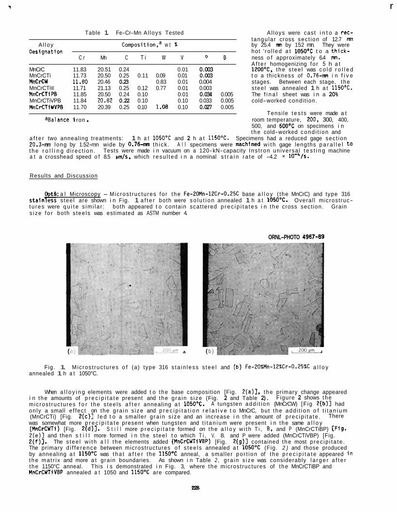
7 r
Table 1. Fe-Cr-Mn A l loys Tested A l loys were cast i n t o a rec- tangu la r cross sec t ion of 12.7 mn
A l l oy Composition,a w t % by 25.4 mn by 152 mn. They were hot ' r o l l ed a t 105OOC t o a t h i c k -
C r Mn C T i w v P B ness o f approximately 6.4 nm. A f t e r homogenizing f o r 5 h a t
Desi gnat ion
MnCrC 11.83 20.51 0.24 0.01 0.003 1200°C, t he s tee l was c o l d r o l l e d MnCrCTi 11.73 20.50 0.25 0.11 0.09 0.01 0.003 t o a th ickness of 0.76-mn i n f i v e MnCrCW 11.80 20.46 0.23 0.83 0.01 0.004 stages. Between each stage, t he MnCrCTi W 11.71 21.13 0.25 0.12 0.77 0.01 0.003 s tee l was annealed 1 h a t 1150OC. MnCrCTiPB 11.85 20.50 0.24 0.10 0.01 0.034 0.005 The f i n a l sheet was i n a 20% MnCrCTiVPB 11.84 20.82 0.22 0.10 0.10 0.033 0.005 cold-worked condi t ion. MnCrCTiWVPB 11.70 20.39 0.25 0.10 1.08 0.10 0.027 0.005
Tensi le t e s t s were made a t %a1 ance i ron . room temperature, 200. 300, 400,
500, and 60OoC on specimens i n t h e cold-worked cond i t i on and
a f t e r two anneal ing treatments: 20.3-mn long by 1.52-mn wide by 0.76-mn t h i ck . A l l specimens were mch ined w i t h gage lengths p a r a l l e l t o t h e r o l l i n g d i r ec t i on . a t a crosshead speed o f 8.5 Irmls, which resu l t ed i n a nominal s t r a i n r a t e of -4.2 x lO-'fS.
1 h a t 105OOC and 2 h a t 1150%. Specimens had a reduced gage sec t ion
Tests were made i n vacuum on a 120-kN-capacity I ns t r on un iversa l t e s t i n g machine
Results and Discussion
t i c a l Microscopy - Micros t ruc tu res f o r t he Fe-20Mn-12Cr-0.25C base a l l o y ( the MnCrC) and type 316 stainl?ss s tee l are shown i n Fig. 1 a f t e r both were s o l u t i o n annealed 1 h a t 1050'C. Overa l l microst ruc- tu res were q u i t e s im i l a r : s i ze f o r both s tee ls was est imated as ASTM number 4.
both appeared t o conta in scat tered p r e c i p i t a t e s i n t he cross sect ion. Grain
ORNL-PHOTO 4967-89 -.---
A
Fig. 1. Mic ros t ruc tu res o f (a) type 316 s ta i n l ess s tee l and (b ) Fe-ZO%Mn-lZ%Cr-O.Z5%C a l l o y annealed 1 h a t 1050°C.
When a l l o y i n g elements were added t o t he base composition [Fig. 2(a)], t he pr imary change appeared i n t he amounts of p r e c i p i t a t e present and t he g ra i n s i ze (Fig. 2 and Table 2). micros t ruc tu res f o r t he s tee ls a f t e r anneal ing a t 1050OC. on ly a small e f fec t on the g ra i n s i ze and p r e c i p i t a t i o n r e l a t i v e t o MnCrC, but t he add i t i on o f t i t a n i u m (MnCrCTi) [Fig. 2 (c ) ] l e d t o a smal ler g ra i n s i ze and an increase i n the amount of p rec i p i t a t e . was somewhat more p r e c i p i t a t e present when tungsten and t i t a n i u m were present i n t he same a l l o y (MnCrCWTi) [Fig. 2(d)] . S t i l l more p r e c i p i t a t e formed on t he a l l o y w i t h T i , E, and P (MnCrCTiBP) [Fig. 2 (e ) ] and then s t i l l more formed i n the s tee l t o which T i , V, 8. and P were added (MnCrCTiVBP) [Fig. 2 ( f ) ] . The s tee l w i t h a l l t he elements added (MnCrCWTiVBP) [Fig. 2(g) ] contained t he most p rec i p i t a t e . The pr imary d i f f e rence between microst ructures o f s t ee l s annealed a t 105OOC (Fig. 2 ) and those produced by anneal ing a t 1 1 5 O O C was t h a t a f t e r the 1150'C anneal, a smal ler po r t i on of t he p r e c i p i t a t e appeared i n t h e ma t r i x and more a t g ra in boundaries. As shown i n Table 2 , g ra in s i ze was considerably l a r g e r a f t e r t he 1150°C anneal. MnCrCWliVBP annealed a t 1050 and 1150'C are compared.
F igure 2 shows t he A tungsten add i t i on (MnCrCW) [F ig 2 ( b ) l had
There
This i s demonstrated i n Fig. 3, where t he microst ructures of t he MnCrCTiBP and
228
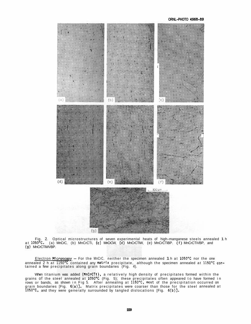
ORNL-PHOTO 4968-89
i
R 1
Fig. 2. Opt ica l micros t ruc tures of seven experimental heats of high-manganese s tee ls annealed 1 h a t 1050°C. (9) MnCrCTiWVBP.
(a ) MnCrC, (b) MnCrCTi, (c ) MnCrCW, (d) MnCrCTiW, (e) MnCrCTiBP. ( f ) MnCrCTiVBP, and
E lec t ron M i c r o s c o u - For t h e MnCrC, ne i the r t h e specimen annealed 1 h a t 1O5O0C nor the one annealed 2 h a t 115OOC contained any mtrix p rec ip i t a te , although t h e specimen annealed a t 115OOC con- ta ined a few p r e c i p i t a t e s along g ra in boundaries (Fig. 4).
When t i t a n i u m was added (MnCrCTI), a r e l a t i v e l y h igh dens i ty of p r e c i p i t a t e s formed w i t h i n the grains of the s tee l annealed a t 1O5O0C (Fig. 5); these p r e c i p i t a t e s of ten appeared t o have formed i n rows o r bands, as shown i n F i g 5. A f ter annealing a t 1150°C, nost of t he p r e c i p i t a t i o n occurred on g r a i n boundaries [Fig. 6(a)]. Ma t r i x p r e c i p i t a t e s were coarser than those fo r the s tee l annealed a t 1050°C, and they were genera l ly surrounded by tangled d i s loca t i ons [Fig. 6(b)].
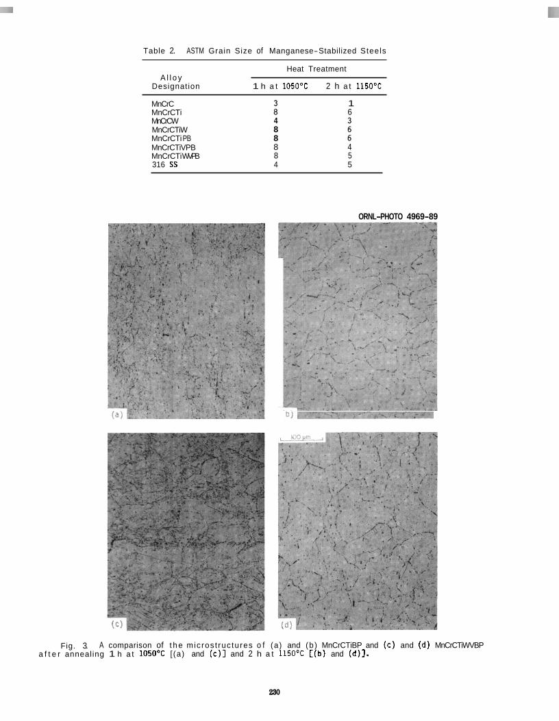
Table 2. ASTM Grain Size of Manganese-Stabilized Steels
Heat Treatment A l l o y
Designation 1 h a t 1O5O0C 2 h a t 115OOC
MnCrC MnCrCTi MnCrCW MnCrCTiW MnCrCTi PB
1 6
4 8 8
MnCrCTiVPB 8 4 MnCrCTi WVPB 8 5 316 SS 4 5
ORNL-PHOTO 4969-89
Fig. 3. A comparison of t h e mic ros t ruc tures o f (a) and (b ) MnCrCTiBP and ( c ) and (d ) MnCrCTiWVBP a f t e r annealing 1 h a t 105OOC [(a) and ( c ) ] and 2 h a t 1150'C [ (b) and (d)].
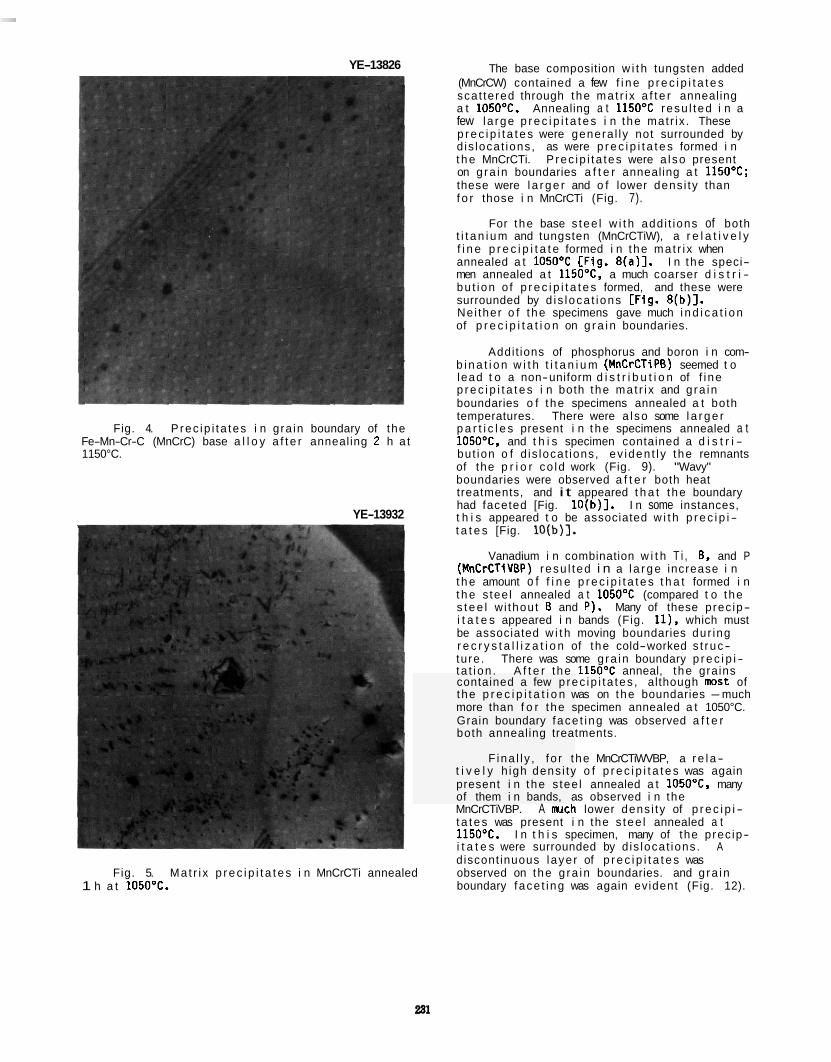
YE-13826
Fig. 4. P rec ip i t a tes i n gra in boundary of the Fe-Mn-Cr-C (MnCrC) base a l l o y a f t e r annealing 2 h a t 1150°C.
YE-13932
Fig. 5. Ma t r i x p r e c i p i t a t e s i n MnCrCTi annealed 1 h a t 1050'C.
The base composition w i t h tungsten added (MnCrCW) contained a few f i n e p r e c i p i t a t e s scat tered through the ma t r i x a f t e r annealing a t 105OOC. Annealing a t 115OOC resu l ted i n a few la rge p r e c i p i t a t e s i n the mat r ix . These p r e c i p i t a t e s were genera l ly not surrounded by d is locat ions, as were p r e c i p i t a t e s formed i n t h e MnCrCTi. P rec ip i t a tes were a l so present on g ra in boundaries a f t e r annealing a t 1150OC; these were l a r g e r and o f lower dens i ty than f o r those i n MnCrCTi (Fig. 7).
For the base s tee l w i t h add i t ions of both t i t a n i u m and tungsten (MnCrCTiW), a r e l a t i v e l y f i n e p r e c i p i t a t e formed i n the ma t r i x when annealed a t 1O5O0C CFig. 8 (a ) l . I n the speci- men annealed a t 1150°C, a much coarser d i s t r i - bu t ion o f p r e c i p i t a t e s formed, and these were surrounded by d i s loca t i ons [Fig. 8(b)]. Ne i ther o f t he specimens gave much i n d i c a t i o n of p r e c i p i t a t i o n on g r a i n boundaries.
b i n a t i o n w i t h t i t a n i u m (MnCrCTiPE) seemed t o lead t o a non-uniform d i s t r i b u t i o n of f i ne p r e c i p i t a t e s i n both the ma t r i x and g ra in boundaries o f t he specimens annealed a t both temperatures. There were a l so some l a r g e r p a r t i c l e s present i n t h e specimens annealed a t 1O5O0C, and t h i s specimen contained a d i s t r i - but ion o f d is locat ions, ev iden t l y the remnants of the p r i o r co ld work (Fig. 9). "Wavy" boundaries were observed a f t e r both heat treatments, and i t appeared t h a t t he boundary had faceted [Fig. 10(b) l . I n some instances, t h i s appeared t o be associated w i t h p r e c i p i - t a t e s [Fig. lO(b)].
Addi t ions of phosphorus and boron i n com-
Vanadium i n combination w i t h T i , B, and P (MnCrCTiVEP) resu l ted i n a l a r g e increase i n t h e amount o f f i n e p r e c i p i t a t e s t h a t formed i n t h e s tee l annealed a t 1050'C (compared t o the s t e e l w i thout B and P ) . Many of these prec ip- i t a t e s appeared i n bands (Fig. I l ) , which must be associated w i t h moving boundaries dur ing r e c r y s t a l l i z a t i o n of t he cold-worked s t ruc- ture . There was some g ra in boundary p r e c i p i - ta t i on . A f t e r t he 115OoC anneal, t he grains contained a few p rec ip i t a tes , although mst of the p r e c i p i t a t i o n was on the boundaries -much more than f o r t he specimen annealed a t 1050°C. Grain boundary face t i ng was observed a f t e r both annealing treatments.
F ina l l y , f o r t he MnCrCTiWVBP, a r e l a - t i v e l y h igh dens i ty o f p r e c i p i t a t e s was again present i n the s tee l annealed a t 1O5O0C, many of them i n bands, as observed i n the MnCrCTiVBP. A w c h lower dens i ty of p r e c i p i - t a t e s was present i n the s tee l annealed a t 1150OC. i t a t e s were surrounded by d is locat ions. A d iscont inuous laye r of p r e c i p i t a t e s was observed on the g ra in boundaries. and g ra in boundary face t i ng was again evident (Fig. 12).
I n t h i s specimen, many of the prec ip-
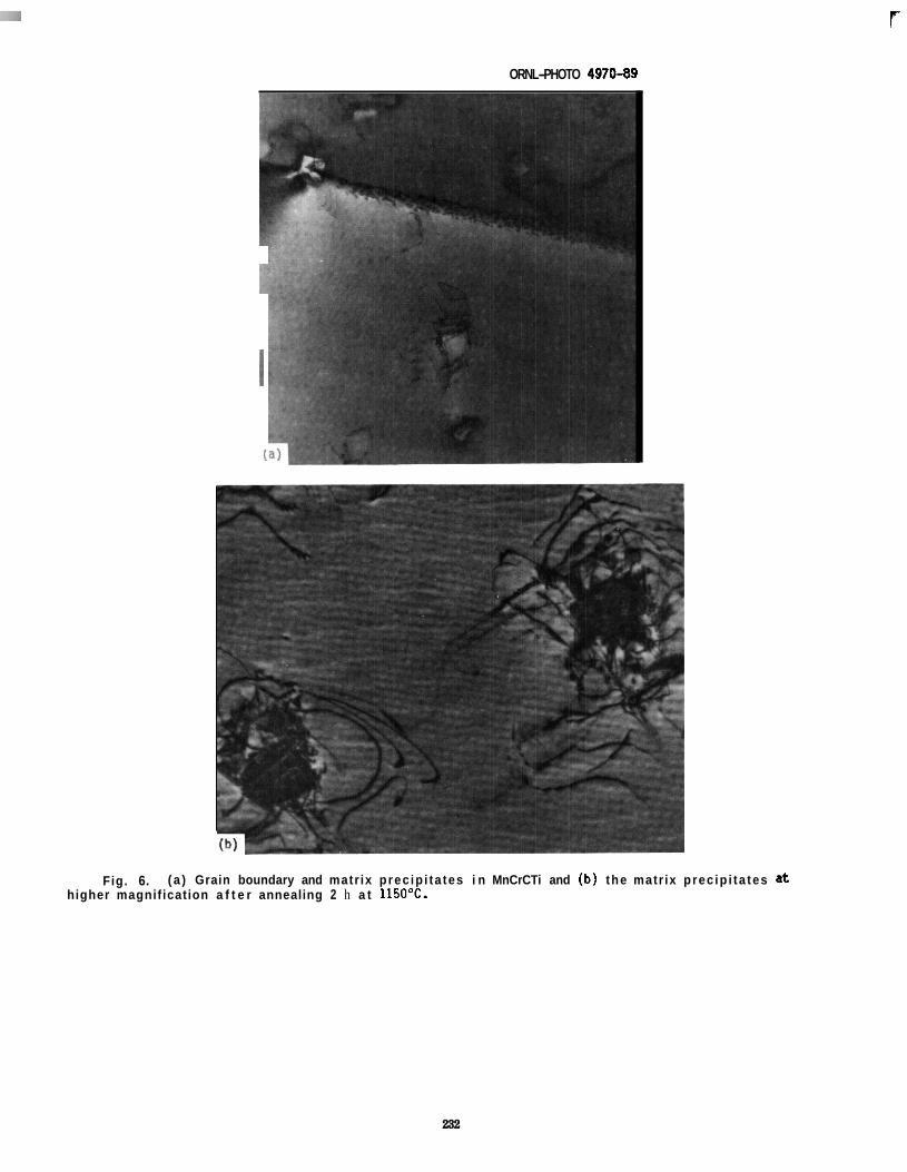
r ORNL-PHOTO 4970-09
Fig. 6. ( a ) Grain boundary and matr ix p rec ip i ta tes i n MnCrCTi and ( b ) the matr ix p rec ip i ta tes a t higher magnif ication a f t e r annealing 2 h a t 1150OC.
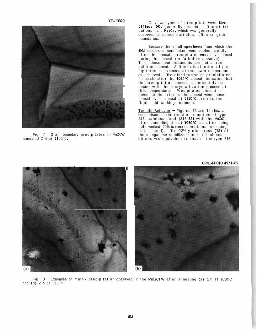
YE-13929
Fig. 7. Grain boundary p r e c i p i t a t e s i n MnCrCW annealed 2 h a t 1 1 5 O O C .
1
Fig. 8. Examples of ma t r i x p r e c i p i t a t i o n observed and (b ) 2 h a t 1150°C.
Only two types of p r e c i p i t a t e were iden- t l f l e d : MC. genera l l y present i n f i n e d i s t r i - but ions, and Mz&. which was genera l l y observed as coarse p a r t i c l e s , o f ten on g ra i n boundaries.
Because t he small specinens from which t he TEM specimens were taken were cooled r a p i d l y a f t e r t he anneal, p r e c i p i t a t e s m s t have formed dur ing t he anneal ( o r f a i l e d t o d issolve) . Thus, these heat treatments are not a t r u e s o l u t i o n anneal. A f i n e r d i s t r i b u t i o n o f pre- c i p i t a t e s i s expected a t t h e lower temperature, as observed. The d i s t r i b u t i o n of p r e c i p i t a t e s i n bands a f t e r t he 1050°C anneal i nd i ca tes t h a t t h e p r e c i p i t a t i o n process i s i n t i m a t e l y con- nected w i t h the r e c r y s t a l l i z a t i o n process a t t h i s temperature. P rec i p i t a t es present i n these s tee ls p r i o r t o t he anneal were those formed by an anneal a t 1150'C p r i o r t o t he f i n a l cold-working treatment.
Tens i le Behavior - Figures 13 and 14 show a comparison of t he t e n s i l e p roper t ies o f type 316 s ta i n l ess s tee l (316 SS) w i t h t he MnCrC a f t e r anneal ing 1 h a t 105OOC and a f t e r being co ld worked 20% (common cond i t ions f o r us ing such a s tee l ) . The 0.2% y i e l d s t ress (YS) o f t he manganese-stabil ized s tee l i n both con- d i t i o n s was equiva lent t o t h a t of t he type 316
ORNL-PHOTO 4971-89
i n t he MnCrCTiW a f t e r anneal ing (a ) 1 h a t 1050°C
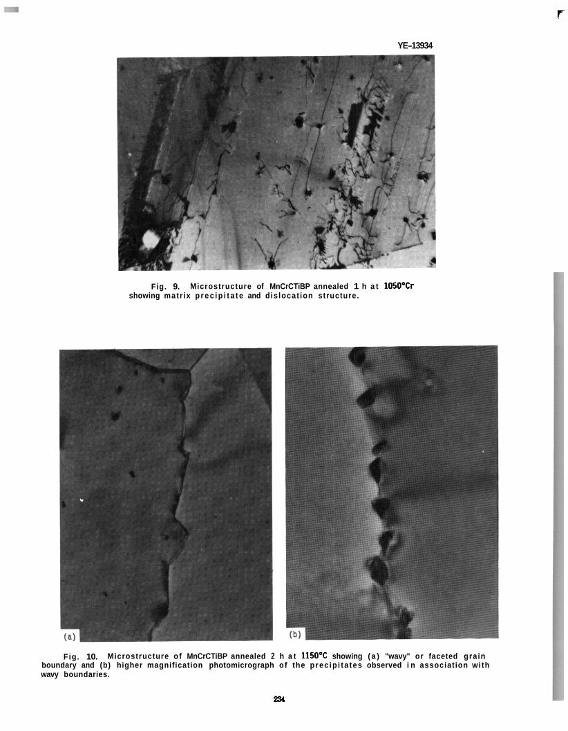
F
YE-13934
Fig. 9. Microstructure of MnCrCTiBP annealed 1 h a t 1050'Cr showing matr ix p r e c i p i t a t e and dis locat ion structure.
F ig . 10. Microstructure o f MnCrCTiBP annealed 2 h a t 1150'C showing ( a ) "wavy" or faceted grain boundary and (b) higher magnification photomicrograph o f the prec ip i ta tes observed i n association wi th wavy boundaries.
234
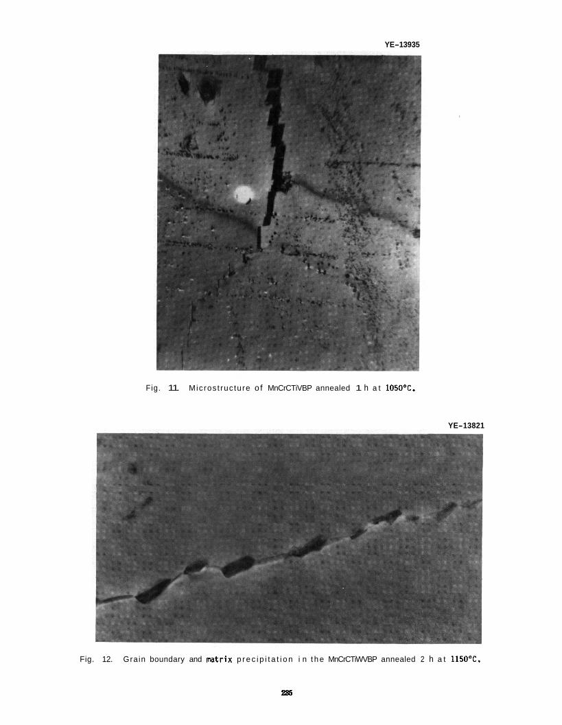
YE-13935
Fig. 11. Micros t ruc ture o f MnCrCTiVBP annealed 1 h a t 105OOC.
YE-13821
Fig. 12. Grain boundary and m t r i x p r e c i p i t a t i o n i n t h e MnCrCTiWVBP annealed 2 h a t 1150OC.
285
OINL-OWE 88-1118 900 , I I I I 1 I
COLD WORKED
I 6 0 0
500 8 MnCrC 316SS I
F SOLUTION ANNEALED
100
0 0 200 400 600
(a) TEMPERATURE ('C) ORNL-WO s8-7ns
0 200 400 600 (b) TEMPERATURE ('Cl
Fig. 13. ( a ) 0.2% y i e l d s t ress and (b) u l t i m a t e t e n s i l e s t reng th p l o t t e d against t e s t temperature f o r t he Fe-Mn-Cr-C a l l o y and type 316 s ta i n l ess s tee l i n t he 20% cold-worked cond i t i on and annealed 1 h a t 1050°C.
70
60
OIIWL-DIG 88-7220
*-*-I MnCrC 316 SS
0 ' I I I I 0 200 400 600
TEMPERATURE ('Cl
Fig. 14. Tota l e longat ion p l o t t e d against t e s t temperature f o r t he Fe-Mn-Cr-C (MnCrC) a l l o y and type 316 s ta i n l ess s tee l i n t he 20% cold-worked cond i t i on and annealed 1 h a t 1050'C.
SS [Fig. 13(a)]. Because manganese add i t i ons cause an increased work-hardening ra te , t h e MnCrC s t e e l achieved a h igher u l t i m a t e t e n s i l e s t reng th (UTS) for both thermo-mechanical cond i t i ons [Fig. 13(b)] . Despi te t h i s h igher work-hardening c a p a b i l i t y , t he high-manganese s tee l s t i l l had equiva lent o r b e t t e r d u c t i l i t y (as masured by t o t a l e longa t ion ) i n the solut ion-annealed and cold-worked cond i t i ons (Fig. 14).
obtained us ing t h e in format ion developed i n the modified Schae f f l e r diagram.' improvement i n t h e s t reng th of the new a l l o y s by making f u r t h e r minor element add i t ions. Th is was accomplished by adding T i , W, V, P, and B t o the Fe-ZOMn-12Cr-0.25C base composition (Table 1) .
Table 3 gives the room-temperature t e n s i l e p roper t i es fo r seven a l l oys , which inc ludes the MnCrC s tee l , a long w i t h s i m i l a r r e s u l t s fo r type 316 s t a i n l e s s s tee l . The manganese-stabil ized s t e e l s were t e s t e d i n two annealed cond i t i ons and i n t h e 20% cold-worked cond i t i on . The 316 SS was tes ted a f t e r t h e 1050'C anneal and a f t e r co ld working 20%.
These r e s u l t s i nd ica ted t h a t an a u s t e n i t i c base a l l o y w i t h subs tan t ia l s t rength and d u c t i l i t y can be The next o b j e c t i v e was an
Table 3. Room-temperature t e n s i l e p roper t i es o f manganese-stabil ized s t a i n l e s s s tee ls
~~~~~~~
S t rength, MPa Elongat ion, %
Desi qnat i on YS UTS Uniform Tota l A l l o y
MnCrCTi MnCrCW MnCrCTiW MnCrCTi PB MnCrCTi VPB MnCrCTi WVPB 316 SS
MnCrC MnCrCTi MnCrCW MnCrCTiW MnCrCTi PB MnCrCTi VP8 MnCrCTi WVPB
HnCrC MnCrCTi MnCrCW MnCrCTi W MnCrCTi PB MnCrCTiVPB MnCrCTi WVPB 316 SS
Annealed 1 h 1050°C
279 927 49.7 53.0 267 803 57.1 59.9 302 918 53.8 56.9 288 935 52.2 55.6 275 935 51.0 53.9 304 915 54.9 57.5 236 586 54.3 58.2
Annealed 2 h 1150°C
233 766 53.4 55.1 258 891 53.5 56.4 247 761 55.4 57;O 258 882 54.5 57.2 271 891 52.8 54.2 221 859 49.6 50.4 264 869 59.9 61.7
20% Cold Worked
815 1086 14.1 954 1160 10.7 784 1057 17.6 980 1168 6.6 946 1158 10.4 ~~~~ ~~. 862 1126 11.4 915 1114 11.3 739 807 11.5
16.0 13.0 20.0
9.5 12.1 13.1 13.6 17.4
The room-temperature r e s u l t s i n d i c a t e d t h a t f o r the high-manganese s t e e l s the st.rength a f t e r anneal ing 1 h a t 1050°C genera l ly exceeded t h a t o f t he same s t e e l annealed 2 h a t 1150°C. With one exception, the YS and UTS o f the manganese- s t a b i l i z e d s t a i n l e s s s t e e l s annealed a t 1O5O0C exceeded those of 316 SS annealed a t t h i s tem- perature. MnCrC s tee l annealed a t 1O5O0C was s l i g h t l y lower than the YS of 316 SS. t he YS values fo r t h e manganese-stabil ized s tee ls annealed a t 1150°C were less than t h a t o f t h e 316 SS annealed a t 1050°C.) S i m i l a r l y , t h e YS and UTS of t h e manganese-stabil ized s tee ls i n the 20% co ld- worked cond i t i on exceeded those f o r 316 SS i n t h a t condi t ion.
The except ion was t h a t t h e YS f o r the
(Note a l so t h a t only two o f
I n the annealed condi t ion, the un i form and t o t a l e longat ions of t h e manganese-stabil ized s tee ls a t room temperature were equiva lent t o those f o r 316 SS (Table 3). Equivalent d u c t i l i t y was a l so observed fo r most of t he a l l o y s i n t h e cold-worked condi t ion. The on ly except ion was the MnCrCTiW a l l o y , which had the lowest uniform and t o t a l elongat ions, al though these values s t i l l i n d i c a t e adequate d u c t i l i t y .
The a d d i t i o n of tungsten (MnCrCW) t o t h e base composit ion had the l e a s t e f fec t on t h e s t reng th o f the annealed s tee ls . An a d d i t i o n of t i t a n i u m by i t s e l f (MnCrCTi) had only a s l i g h t l y greater e f f e c t . A combination of Ti , 6 , and P (MnCrCTiBP) and these th ree elements p lus vanadium (MnCrCTiVBP) gave r i s e t o s t rengths s i m i l a r t o those f o r MnCrCTi. However, t he combination of t i t a n i u m and tungsten (MnCrCTiW) r e s u l t e d i n a subs tan t ia l s t reng th increase over t h e base composition. Adding V, P, and B t o t h i s l a s t combination had l i t t l e e f f e c t on t h e room- temperature s t reng th of t h e annealed s tee l over t h a t fo r MnCrCTi W.
I n the cold-worked cond i t i on tes ted a t room temperature, an approximately s i m i l a r r e l a t i v e s t reng th behavior was observed fo r t h e var ious combination of elements as observed f o r t h e annealed s tee ls . t h i s cond i t i on , t h e MnCrCTiW had h igher VS and UTS values than t h e MnCTiWVP8. s t reng th was accompanied by a lower un i form and t o t a l elongat ion.
I n Figs. 15 t o 20, t h e t e n s i l e p roper t i es fo r t h e f i v e s t rongest manganese-stabil ized s t e e l s (MnCrC and MnCrCW are not shown) a re compared w i t h t ype 316 SS. Results c l e a r l y i nd ica ted the s u p e r i o r i t y of t h e manganese-stabil ized s t e e l s a f t e r an anneal o f 1 h a t 105OOC (Figs. 16 and 18) , 2 h a t 115OOC (Figs. 17 and 18), and a f t e r c o l d working (Figs. 19 and 20). Despi te t h i s s t reng th s u p e r i o r i t y , d u c t i l i t y was equiva lent o r b e t t e r than t h a t fo r 316 SS i n the annealed cond i t i on (Figs. 14 and 16). I n t h e cold-worked condi t ion, 316 SS had a h igher t o t a l e longat ion below -200°C, but a t t h e h igher temperatures, the manganese-stabil ized s t e e l s had equiva lent o r b e t t e r d u c t i l i t y (Fig. 20). These observat ions on d u c t i l i t y are important,
For However, t h i s greater
Tens i l e t e s t s were conducted over t h e range o f room temperature t o 600°C.
280
120
- m r c n
o MnCrcrw 4 W C T I W
a MnC.CTiVP0 0 MnCrCTiWVPB
0 100 200 300 400 5M) B W (a) TEMPERATURE I'C)
loo0 , + MCrCTl
b MnCrCTiW 0 MnCrCTPB - MnCrCTlVm - -c- MncrcTiwvm 0 318SS
400 I I 0 IO0 200 300 400 500 800
(b) TEMPERATLRE PCI
F ig. 15. ( a ) 0.2% y i e l d s t ress and (b) u l t i m a t e t e n s i l e s t reng th p l o t t e d aga ins t t e s t temperature A l l s t e e l s were f o r f i v e heats of manganese-stabil ized s ta in less s t e e l s and t ype 316 s t a i n l e s s s tee l .
annealed 1 h a t 1050°C.
54
i y 42
b E!
38
P 0 100 200 300 400 600 600
TEMPERATURE PCI
F i g . 16. Tota l e longat ion p l o t t e d aga ins t t e s t temperature f o r f i v e heats o f manganese-stabil ized s t a i n l e s s s tee l s and t ype 316 s ta in less s tee l as a func t i on o f t e s t temperature. annealed 1 h a t 1O5O0C.
A l l s tee l s were
270
240 - h z 210
2
9
m
180
150
120
90 \;I 0 100 200 sca 400 500 800
__ (a) TEMPERATURE (“C) --- 800
- 850 2 - PhCrCTIW I 800 0. MnaCTim
$ 750 - MnCrCTNW
2 800
-0- MnCrCTlWVPB
6 318 55 700
Y 850 2 t;
+ Y 550 2 5 5w
460
400 0 100 2W 300 400 500 800
(b) TEIIPERATURE PC)
Fig. 17. ( a ) 0.2% y i e l d s t ress and ( b ) u l t i m a t e t e n s i l e s t reng th p l o t t e d against t e s t temperature f o r f i v e heats of manganese-stabil ized s t a i n l e s s s tee ls and type 316 s ta in less s tee l . s t e e l s were annealed 2 h a t 1150’C and the t ype 316 s ta in less s t e e l was annealed 1 h a t 1050°C.
The manganese
-a- 84 , BO
38
32 I f 0 100 200 300 400 6W BOO
TEMPERATURE PC)
Fig. 18. Tota l e longat ion as a funct ion of t e s t temperature fo r f i v e heats of manganese-stabil ized s t a i n l e s s s t e e l s and t ype 316 s t a i n l e s s s tee l . 316 s t a i n l e s s s t e e l was annealed 1 h a t 1050°C.
The manganese s t e e l s were annealed 2 h a t 1150°C and t ype
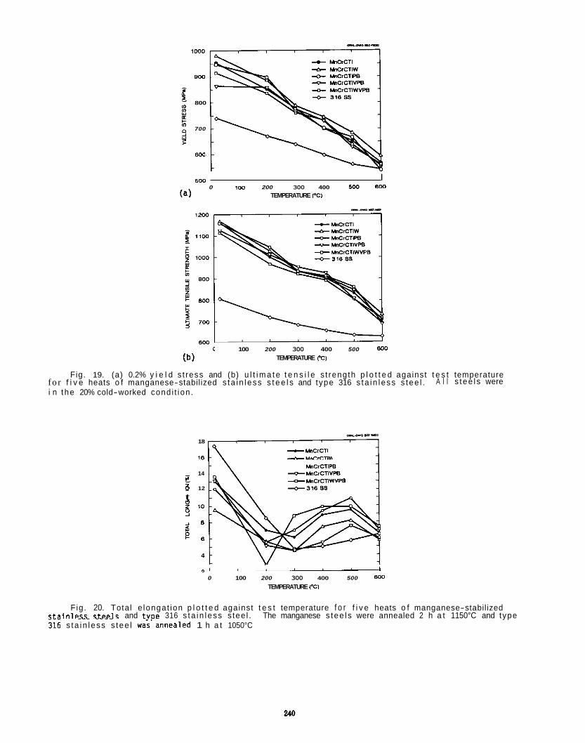
800
800
700
600
5w I 100 200 300 400 500 800 0
(a) TEMPERATURE I'CI --_-
100 200 300 400 500 800
TEMPERATURE PCI
Fig. 19. (a) 0.2% y i e l d s t ress and (b) u l t i m a t e t e n s i l e s t reng th p l o t t e d against t e s t temperature A l l s t ee l s were fo r f i v e heats o f manganese-stabilized s ta i n l ess s t e e l s and type 316 s ta i n l ess s t ee l .
i n t he 20% cold-worked cond i t ion .
18
16
14 - MnCrCTlVP8 HnCrCTiP8
z e M n C r C T I W V P B z 0 12 -318 ss t i? 10 s P e 8
2 8
4
I 0 100 200 300 400 500 800
TEMPERATURE PCI
Fig. 20. Tota l e longat ion p l o t t e d against t e s t temperature f o r f i v e heats o f manganese-stabilized c ta i n l pss s tpe l s and tvoe 316 s ta i n l ess s tee l . The manganese s tee l s were annealed 2 h a t 1150°C and type . . . . . . . ii, s ta i n l ess s t ee l w&'annealed 1 h a t 1050°C
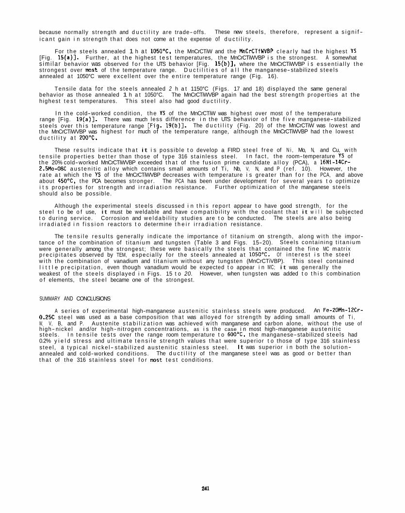
because normal ly s t reng th and d u c t i l i t y are trade-offs. i c a n t ga in i n s t reng th t h a t does not come a t the expense of d u c t i l i t y .
For t h e s tee ls annealed 1 h a t 1050"C, t h e MnCrCTiW and the MnCrCTiWVBP c l e a r l y had t h e h ighest YS [Fig. 15(a)]. Fur ther , a t t h e highest t e s t temperatures, the MnCrCTiWVBP i s the strongest. A somewhat s i m i l a r behavior was observed f o r t h e UTS behavior [Fig. 15(b)], where the MnCrCTiWVBP i s e s s e n t i a l l y t h e s t rongest over m s t of t h e temperature range. D u c t i l i t i e s o f a l l t h e manganese-stabil ized s t e e l s annealed a t 1050°C were exce l len t over the e n t i r e temperature range (Fig. 16).
Tens i l e data fo r the s tee ls annealed 2 h a t 1150°C (Figs. 17 and 18) d isp layed the same general behavior as those annealed 1 h a t 1050°C. h ighest t e s t temperatures. Th is s tee l a l so had good d u c t i l i t y .
range [Fig. 19(a)]. s tee ls over t h i s temperature range [Fig. 1 9 ( b ) l . t h e MnCrCTiWVBP was highest f o r much of the temperature range, al though t h e MnCrCTiWVBP had t h e lowest d u c t i l i t y a t 200°C.
These r e s u l t s i n d i c a t e t h a t i t i s poss ib le t o develop a FIRD s tee l f r e e of N i , Mo, N, and Cu, w i t h t e n s i l e p roper t i es b e t t e r than those of type 316 s ta in less s tee l . t h e 20% cold-worked MnCrCTiWVBP exceeded t h a t of t h e fus ion prime candidate a l l o y (PCA), a 16Ni-14Cr- 2.5Mo-08C a u s t e n i t i c a l l o y which contains small amounts o f T i , Nb, V, N, and P ( r e f . 10). However, t he r a t e a t which t h e YS of the MnCrCTiWVBP decreases w i t h temperature i s greater than f o r t h e PCA, and above about 450%. the PCA becomes stronger. i t s p roper t i es fo r s t reng th and i r r a d i a t i o n resistance. should a l s o be poss ib le .
Although t h e experimental s tee ls discussed i n t h i s repor t appear t o have good strength, f o r the s t e e l t o be o f use, i t must be weldable and have c o m p a t i b i l i t y w i t h the coo lant t h a t i t w i l l be subjected t o du r ing service. i r r a d i a t e d i n f i s s i o n reactors t o determine t h e i r i r r a d i a t i o n resistance.
These new s tee ls , therefore, represent a s i g n i f -
The MnCrCTiWVBP again had the best s t reng th p roper t i es a t the
I n t h e cold-worked condi t ion, t h e YS of the MnCrCTiW was h ighest over most o f t he temperature There was much less d i f ference i n the UTS behavior o f t he f i v e manganese-stabil ized
The d u c t i l i t y (Fig. 20) of the MnCrCTiW was lowest and
I n f a c t , t he room-temperature YS of
The PCA has been under development fo r several years t o opt imize Fur the r op t im iza t ion of the manganese s tee ls
Corrosion and w e l d a b i l i t y s tud ies are t o be conducted. The s tee ls are a l s o being
The t e n s i l e r e s u l t s genera l ly i n d i c a t e the importance o f t i t a n i u m on s t rength, along w i t h the impor- tance o f the combination of t i t a n i u m and tungsten (Table 3 and Figs. 15-20). were genera l ly among the s t rongest ; these were b a s i c a l l y t h e s tee ls t h a t contained the f i n e MC mat r i x p r e c i p i t a t e s observed by TEM, espec ia l l y fo r the s tee ls annealed a t 1050OC. Of i n t e r e s t i s t h e s tee l w i t h the combination of vanadium and t i t a n i u m wi thout any tungsten (MnCrCTiVBP). This s tee l contained l i t t l e p r e c i p i t a t i o n , even though vanadium would be expected t o appear i n MC; i t was genera l ly the weakest o f t h e s t e e l s d isp layed i n Figs. 15 t o 20. However, when tungsten was added t o t h i s combination o f elements, t h e s t e e l became one of the strongest.
S tee ls con ta in ing t i t a n i u m
SUMMARY AND CONCLUSIONS
A se r ies o f experimental high-manganese a u s t e n i t i c s t a i n l e s s s tee ls were produced. An Fe-2OMn-12Cr- 0.25C s tee l was used as a base composition t h a t was a l l oyed f o r s t reng th by adding small amounts of T i , W, V, B, and P. Austen i te s t a b i l i z a t i o n was achieved w i t h manganese and carbon alone, wi thout the use of h igh- nicke l and/or h igh- n i t rogen concentrat ions, as i s the case i n most high-manganese a u s t e n i t i c s tee ls . I n t e n s i l e t e s t s over the range room temperature t o 6OO0C, t h e manganese-stabil ized s tee ls had 0.2% y i e l d s t ress and u l t i m a t e t e n s i l e s t reng th values t h a t were super ior t o those of t ype 316 s t a i n l e s s s tee l , a t y p i c a l n i c k e l - s t a b i l i z e d a u s t e n i t i c s t a i n l e s s s tee l . annealed and cold-worked condi t ions. t h a t of t he 316 s t a i n l e s s s tee l f o r most t e s t condi t ions.
It was super ior i n both the s o l u t i o n- The d u c t i l i t y of t h e manganese s t e e l was as good o r b e t t e r than
REFERENCES
1. R. L. Klueh and E. E. Bloom, Opt imiz ing Mater ia ls f o r Nuclear Appl icat ions, F. A. Garner, D. S. Gelles, and F. W. Wiffen, Eds., The Me ta l l u rg i ca l Society, Inc., Warrendale, PA, 1985, pp. 73-85.
2. E. Ruedl, D. Rickerby, and T. Sasaki, Fusion Technology, Vol. 2, p. 1029, Pergamon Press, London, 1984.
3. E. Ruedl and T. Sasaki, J . Nucl. Mater. 122 h 123 (1984) 794-798. 4. H. R. Brager, F. A. Garner, 0. S . Gelles, and M. L. Hamilton, J . Nucl. Mater. 1336134 (1985)
5. A. H. Bo t t , F. B. Picker ing, and G. J . But temor th , J . Nucl. Mater. 141-143 (1986) 1088-1096. 6. M. Tamura, H. Hayakawa, M. Tanimura, A. Hishinuma, and T. Kondo, J. Nucl. Mater. 141-143 (1986)
7. R. L. Klueh, P. J . Maziasz, and E. A. Lee, Mater. Sci. Eng. 102 (1988) 115-124. 8. P. J . Maziasz and T. K. Roche, J . Nucl. Mater. 103h104 (1981) 797-802. 9. P. J . Maziasz e t al., J. Nucl. Mater. 1088109 (1982) 296-298.
10. P. J . Maziasz, Opt imizat ion of Processing, Propert ies, and Service Performance Through
907-911.
1067-1073.
Mic ros t ruc tura l Contro l , E. L. Bramf i t t , R. L. Benn, C. R. Brinkman, and G. F. Vander Voort, Eds., American Society f o r Test ing and Mater ia ls , Phi ladelphia, 1988, pp. 116-161.
DEVELOPMENT OF TENSILE PROPERTY RELATIONS FOR ITER DATA BASE -- M. L. Grossbeck (Oak Ridge Nat iona l Laboratory)
OBJECTIVE
This research i s d i r e c t e d toward developing equations t h a t express t e n s i l e p roper t i es o f i r r a d i a t e d a u s t e n i t i c s t a i n l e s s s tee ls , e s p e c i a l l y a t low temperatures. The equat ions are t o be used by designers o f the I n t e r n a t i o n a l Thermonuclear Experimental Reactor (ITER).
SUMMARY
Tens i le data from t h e Oak Ridge Mat r i x (Fusion Implementing Agreement Annex 11). t he U.S. Japan
Equations were co l l abora t ion , and from the a v a i l a b l e l i t e r a t u r e were reviewed. Type 316 s t a i n l e s s s t e e l , i n both co ld- worked and annealed cond i t i ons and PCA (both U S . and Japanese heats) were included. developed f o r y i e l d strength, uniform elongat ion, and t o t a l elongat ion. cou ld be used f o r a l l o y s and condi t ions, i n others, separate equations had t o be used. I n a l l cases an attempt was made t o prov ide a conservat ive expression ra the r than t o have t h e best fit t o t h e data. Espec ia l l y i n the case of s t rength, t h e value was ra the r i n s e n s i t i v e t o a l l o y composition.
I n many cases, one expression
PROGRESS AND STATUS
In t roduc t ion
I n order t o prov ide design data fo r t h e I T E R p ro jec t , data from i r r a d i a t i o n s i n mixed-spectrum reac- t o r s , where he l ium i s produced simultaneously w i t h displacement damage, were considered. Data from t h e U S . Fusion Program ORR (Oak Ridge Research Reactor) Spectral T a i l o r i n g Experiment was considered espe- c i a l l y re levan t s ince the fusion reactor He:dpa l e v e l was maintained. Fast reac to r data from type 316 s t a i n l e s s s tee l (316 S S ) i r r a d i a t e d i n t h e EBR-I1 have been inc luded i n an e f f o r t t o determine the impor- tance o f h igh l e v e l s o f he l ium on t e n s i l e proper t ies .
Since t h e data were o f t e n very l i m i t e d , were from d i f f e r e n t sources, and had t o be t r e a t e d s u b j e c t i v e l y i n r e l a t i v e impor- tance, a s t a t i s t i c a l f i t was not considered meaningful. I n some cases, however, a regress ion analys is program was used fo r ease of determining parameters. s ince they are o f t e n i l l - c o n d i t i o n e d , necess i ta t i ng t h e c a r r y i n g o f several s i g n i f i c a n t f igures i n the c o e f f i c i e n t s . I n a few cases, however, a quadrat ic o r cubic fit was t h e obvious choice.
I n most cases, the curve was f i t by eye r a t h e r than by a regression program.
Polynomial expressions were avoided when poss ib le
Although very elegant models f o r p r e d i c t i n g t e n s i l e behavior o f i r r a d i a t e d s t a i n l e s s s tee ls are available,'P2 they were found e i t h e r t o not extend t o low temperatures o r t o not f i t t h e recent data. I n d ismiss ing these models, t h e oppor tun i ty t o have a s i n g l e equat ion t o express t e n s i l e p roper t i es as func- t i o n s o f both damage l e v e l and temperature i s missed. func t ion o f temperature were developed fo r 10, 20, 30, and 50 dpa.
As a r e s u l t , expressions fo r each proper ty as a
Data Sources
Both publ ished and unpublished data were used fo r the analys is . A major source was the U.S. Japan
Both annealed and cold-worked t ype 316 s t a i n l e s s s tee l and PCA were inc luded Co l labora t i ve Fusion Mate r ia l s P r ~ g r a m . ~ - ~ The data from t h i s program, which appear i n Table 1, were used for several reasons: i n t h e program, i r r a d i a t i o n temperatures ranged from 50 t o 600°C. and damage l e v e l s as h igh as 50 dpa were a t ta ined . Since m s t of the specimens were i r r a d i a t e d i n t h e HFIR (High Flux Isotope Reactor), they con ta in h igh concent ra t ions of helium. As a r e s u l t , h igh temperature d u c t i l i t y must be considered a lower l i m i t t o the behavior expected i n a f u s i o n reactor .
I n cases of 50 dpa, t h e hel ium l e v e l s were as h igh as 3000 appm.
Data from t h e ORR Spectral T a i l o r i n g Experiment, ORR-MFE-4, were a v a i l a b l e f o r 316 SS and PCA a t i r r a d i a t i o n and t e s t temperatures from 330 t o 600°C ( re f . 6) (Table 2). Since these data were fo r speci- mens having a He:dpa l e v e l o f about 12, c h a r a c t e r i s t i c o f a fus ion reac to r w i t h a l i th ium- cooled s t a i n - l e s s s tee l blanket, they were p a r t i c u l a r l y re levant . A disadvantage i s t h a t they were i r r a d i a t e d t o a maximum damage l e v e l o f only 15 dpa.
Annex 11, was another important source of data. Japanese a l l o y s were a l l i r r a d i a t e d i n several research reactors. Data are now a v a i l a b l e from t h e HFIR, HFR (Pet ten) , and t h e BR-2 (Mol). Data from the HFIR and HFR a t 10 dpa a t temperatures of 250'C fo r the HFR (Table 3) and 250 t o 400°C for the HFIR (Table 4) were used i n the devel~pment . ' .~
These data were grouped w i t h the 10 dpa data.
The European Community/U.S./Japan program under t h e auspices o f the I E A Implementing Agreement, I n t h i s program, EC (European Community), U.S., and
Data from the
243
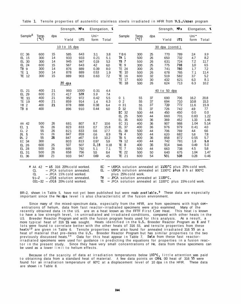
Table 1. Tens i le p r o p e r t i e s o f a u s t e n i t i c s t a i n l e s s s tee ls i r r a d i a t e d i n HFIR from U.S./Japan program . .
Strength, MPa Elongat ion, %
Samplea Temp. dpa Uni - ( " C ) Y ie ld UTS form Tota l
EC 36 EL 15 EL 30 EL 24 TB 9 TE 1 TE 12
EL 21 EL 29 TE 11 TE 19 TB 2 TB 8
AA 42 CL 1 CL 2 DL 1 OL 2 EC 34 EL 26 EL 28 EL 31 EL 36
600 300 300 600 300 300 300
400 600 400 400 400 400
500 55 55 55 55
300 600 500 500 300
15 14 14 15 14 14 15
21 21 21 21 21 21
26 26 26 26 26 25
25 26 26 25
10 t o 15 dpa
585 933 945 567 876 878 889 * 993 417 952 859 878 896
681 823 821 847 847 803 507 695 658 933
643 933 947 643 889 889 903
1000
972 914 888 910
528
807 833 833 859 a67 813 507 792 756 947
3.1 0.21 0.19 4.2 0.39 0.53 0.63
0.31 5.9 0.42 1.4 0.38 0.44
8.7 0.7 0.6 0.6 0.9 0.97 0.18 5.1 5.5 0.69
3.8 5.1 5.3 6.0 8.0 1.9 7.2
4.4 7.4 5.5 6.3 6.4 6.0
10.6 15.8 17.7 8.9
10.2 5.9 0.18 7.1 8.4 4.5
Strength, MPa Elongation, %
Sample Temp. dpa Uni - ( " C ) Yie ld UTS form To ta l
30 dpa (contd.)
T B 6 T B 1 E l 7 TE 9 TE 24 TE 10 TE 16 TE 17 TE 18
0 1 0 2 0 31 0 32 EC 32 EL 25 EL 35 EC 31 EL 37 EL 39 TB 4 TB 5 TB 12 TE 8 TE 7 TE 22 TE 21
300 500 500 300 300 500 600 600 500
55 55 55 55
500 500 600 400 400 500 500 400 430 400 500 500 600
25 770 789 26 650 732 26 631 724 25 775 798 25 741 180 26 678 765 32 519 582 30 432 621 26 624 713
40 t o 50 dpa
37 690 706 37 694 710 37 739 772 ~. 37 726 742 44 450 450 44 660 701 36 369 452 36 907 988 36 976 979 44 706 769 44 620 682 36 858 872 44 742 781 36 914 946 44 663 738 50 640 675 54 501 508
2.4 4.7 7.2 1.0 1.7 7.1 3.7 6.3 6.3
16.2 10.8 11.6 4.9 0.0 0.83 1.33 1.04 0.41 4.4 5.8 0.55 1.8 0.49 4.5 1.04 0.28
9.9 8.2
11.7 6.5 7.2
11.4 5.2 8.1
10.2
20.8 15.3 15.9 7.7 0.0 1.22 1.46 5.14 4.0 6.6 7.8 5.7 5.0 5.0 5.8 1.47 0.46 -
a AA 42 - US 316 20% c o l d worked. EC - USPCA s o l u t i o n annealed a t l l O O ° C p l u s 25% co ld work. CL - JPCA s o l u t i o n annealed. EL - USPCA s o l u t i o n annealed a t 1100°C p lus 8 h a t 800°C
~~
OL - JPCA 15% c o l d worked. p lus 25% c o l d work. 01-2 - 5316 s o l u t i o n annealed. TB - JPCA s o l u t i o n annealed a t 1100'C. 031-32 - 5316 20% c o l d worked. TE - JPCA s o l u t i o n annealed a t 1100°C p lus 15% c o l d work.
BR-2, shown i n Table 5, have not y e t been publ ished but were made ava i lab le .g impor tant s ince the He:dpa l e v e l i s a l so c h a r a c t e r i s t i c of t he fus ion environment.
These data are e s p e c i a l l y
Since many of the mixed-spectrum data, e s p e c i a l l y from t h e HFIR, are from specimens w i t h h igh con-
Th is heat i s known e n t r a t i o n s of helium, data from f a s t r e a c t o r - i r r a d i a t e d specimens were a l so examined. Many of the
recen t l y obtained data i n t h e U.S. are on a heat known as the FFTF F i r s t Core Heat. t o have a low s t reng th l e v e l , i n u n i r r a d i a t e d and i r r a d i a t e d condi t ions, compared w i t h o the r heats i n t h e U.S. Breeder Reactor Program and wi th the fus ion program heats used fo r t h i s ana lys is . more t y p i c a l heat o f 316 SS was sought. l o t s were found t o c o r r e l a t e b e t t e r w i t h the o ther heats o f 316 SS, and t e n s i l e p roper t i es from these hea ts la are given i n Table 6. Tens i le p roper t i es were a l s o found fo r annealed i r r a d i a t e d 316 SS on a heat o f ma te r ia l t h a t pre-dates the U.S. Breeder Reactor Program but has s i m i l a r p roper t i es t o the two p rev ious ly discussed heats." Oata fo r t h i s heat appear i n Table 7. i r r a d i a t e d specimens were used f o r guidance i n p r e d i c t i n g the equations fo r p roper t i es i n a fus ion reac- t o r i n the present study. Since they have very small concent ra t ions o f He, data from these specimens can be used as a lower l i m i t t o hel ium e f f e c t s .
As a r e s u l t , a Heats i d e n t i f i e d i n t h e U S . Breeder Reactor Program as N and T
Oata from these fas t reac to r-
Because o f the s c a r c i t y o f data a t i r r a d i a t i o n temperatures below 100°C, l i t t l e a t t e n t i o n was pa id
These data t o ob ta in ing data from a standard heat o f mater ia l . A few data po in ts on ORNL 00 heat of 316 SS were found f o r an i r r a d i a t i o n temperature of 60°C a t a displacement l e v e l of 10 dpa i n t h e HFIR. are shown i n Table 8.
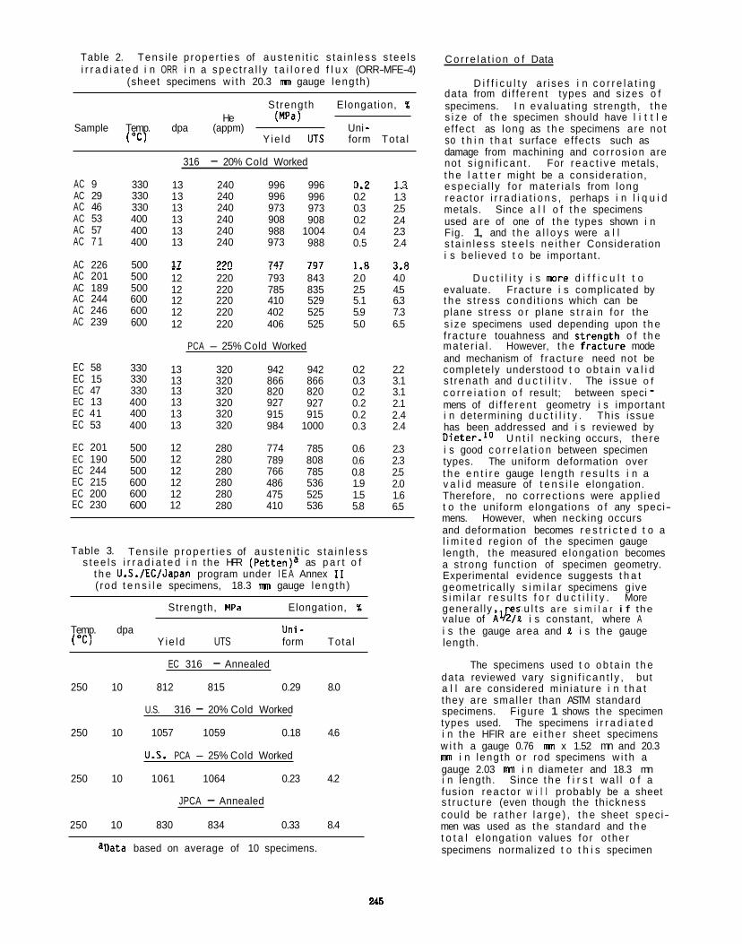
AC 9 AC 29 AC 46 AC 53 AC 57 AC 7 1
AC 226 AC 201 AC 189 AC 244 AC 246 AC 239
EC 58 EC 15 EC 47 EC 13 EC 41 EC 53
EC 201 EC 190 EC 244 EC 215 EC 200 EC 230
330 330 330 400 400 400
500 500 500 600 600 600
330 330 330 400 400 400
500 500 500 600 600 600
Table 2. Tens i l e p roper t i es of a u s t e n i t i c s t a i n l e s s s tee ls i r r a d i a t e d i n ORR i n a s p e c t r a l l y t a i l o r e d f l u x (ORR-MFE-4)
(sheet specimens w i t h 20.3 mn gauge leng th )
St rength Elongat ion, %
("C) Y ie ld UTS form Tota l
He (MPa) Sample Temp. dpa (appm) Uni -
316 - 20% Cold Worked
13 240 996 996 0.2 1.3 ~.~ ~~
13 240 996 996 0.2 1.3 13 240 973 973 0.3 2.5 13 240 908 908 0.2 2.4 13 240 988 1004 0.4 2.3 13 240 973 988 0.5 2.4
C o r r e l a t i o n o f Data
D i f f i c u l t y a r i ses i n c o r r e l a t i n g data from d i f fe ren t types and s izes o f specimens. I n eva lua t ing strength, t h e s i z e of t h e specimen should have l i t t l e e f fec t as long as t h e specimens are not so t h i n t h a t surface ef fec ts such as damage from machining and co r ros ion are not s i g n i f i c a n t . For r e a c t i v e metals, t h e l a t t e r might be a cons iderat ion, espec ia l l y fo r ma te r ia l s from long reac to r i r r a d i a t i o n s , perhaps i n l i q u i d metals. Since a l l o f t h e specimens used are of one of t h e types shown i n Fig. 1, and t h e a l l o y s were a l l s t a i n l e s s s t e e l s n e i t h e r Considerat ion i s be l ieved t o be important.
17 7711 747 747 1 R 7 R _ _ _ _ _ . . . -.- 1.-
12 220 793 843 2.0 4.0 D u c t i l i t y i s more d i f f i c u l t t o 12 220 785 835 2.5 4.5 evaluate. Fracture i s compl icated by 12 220 410 529 5.1 6.3 t h e s t ress cond i t i ons which can be 12 220 402 525 5.9 7.3 plane s t ress o r plane s t r a i n fo r the 12 220 406 525 5.0 6.5 s i z e specimens used depending upon t h e
f rac tu re touahness and s t renu th o f t h e PCA - 25% Cold Worked mate r ia l . However, t h e f r a c i u r e mode
and mechanism of f rac tu re need not be 13 320 942 942 0.2 2.2 completely understood t o o b t a i n v a l i d 13 320 866 866 0.3 3.1 s t rena th and d u c t i l i t v . The issue o f 13 13 13 13
12 12 12 12 12 12
320 320 320 320
280 280 280 280 280 280
820 927 915 984
774 789 766 486 475 410
820 927 915
1000
785 808 785 536 525 536
0.2 0.2 0.2 0.3
0.6 0.6 0.8 1.9 1.5 5.8
3.1 2.1 2.4 2.4
2.3 2.3 2.5 2.0 1.6 6.5
Table 3. Tens i l e p r o p e r t i e s of a u s t e n i t i c s t a i n l e s s s t e e l s i r r a d i a t e d i n the HFR (Pet ten)a as p a r t o f
t h e U.S./EC/Japan program under I E A Annex I 1 ( rod t e n s i l e specimens, 18.3 mn gauge leng th )
Strength, MPa Elongation, %
Temp. dpa hi - ("C) Y ie ld UTS form Tota l
EC 316 - Annealed
250 10 812 815 0.29 8.0
U.S. 316 - 20% Cold Worked
250 10 1057 1059 0.18 4.6
U S . PCA - 25% Cold Worked
250 10 1061 1064 0.23 4.2
JPCA - Annealed
250 10 830 834 0.33 8.4
aData based on average of 10 specimens.
c o r r e i a t i o n o f result; between speci - mens of d i f f e r e n t geometry i s important i n determining d u c t i l i t y . Th is issue has been addressed and i s reviewed by 0 i e t e r . l o U n t i l necking occurs, the re i s good c o r r e l a t i o n between specimen types. The uniform deformation over t h e e n t i r e gauge leng th r e s u l t s i n a v a l i d measure of t e n s i l e elongat ion. Therefore, no co r rec t ions were app l ied t o the uni form elongat ions o f any speci- mens. However, when necking occurs and deformation becomes r e s t r i c t e d t o a l i m i t e d reg ion of t h e specimen gauge length, the measured e longat ion becomes a s t rong funct ion of specimen geometry. Experimental evidence suggests t h a t geometr ica l ly s i m i l a r specimens g ive s i m i l a r r e s u l t s f o r d u c t i l i t y . More genera l ly , e s u l t s a r e s i m i l a r i f the value of A&& i s constant, where A i s the gauge area and & i s the gauge length.
The specimens used t o o b t a i n t h e data reviewed vary s i g n i f i c a n t l y , but a l l a re considered m in ia tu re i n t h a t they are smal ler than ASTM standard specimens. F igure 1 shows the specimen types used. The specimens i r r a d i a t e d i n the HFIR are e i t h e r sheet specimens w i t h a gauge 0.76 mn x 1.52 mn and 20.3 mn i n l eng th o r rod specimens w i t h a gauge 2.03 mn i n diameter and 18.3 mn i n length. Since t h e f i r s t w a l l o f a fus ion reac to r w i l l probably be a sheet s t r u c t u r e (even though the th ickness cou ld be r a t h e r l a r g e ) , t h e sheet spec i- men was used as the standard and t h e t o t a l e longat ion values fo r o the r specimens normalized t o t h i s specimen
246
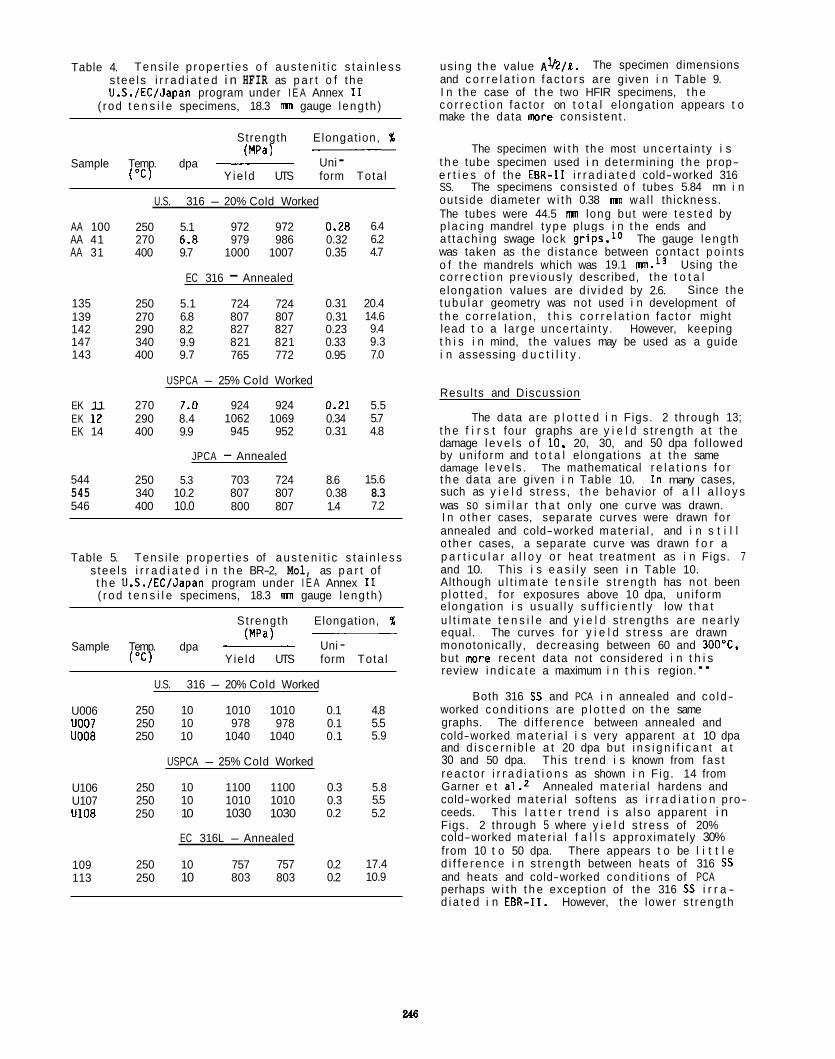
Table 4. Tens i l e p roper t i es o f a u s t e n i t i c s t a i n l e s s s tee ls i r r a d i a t e d i n HFIR as p a r t o f t he U.S./EC/Japan program under I E A Annex I1
( rod t e n s i l e specimens, 18.3 mn gauge leng th )
Strength Elongat ion, % ~
Uni - (MPa) Sample Temp. dpa ~
("C) Yie ld UTS form Tota l
U.S. 316 - 20% Cold Worked
AA 100 250 5.1 972 972 0.28 6.4 AA 41 270 6.8 979 986 0.32 6.2 AA 31 400 9.7 1000 1007 0.35 4.7
EC 316 - Annealed
135 250 5.1 724 724 0.31 20.4 139 270 6.8 807 807 0.31 14.6 142 290 8.2 827 827 0.23 9.4 147 340 9.9 821 821 0.33 9.3 143 400 9.7 765 772 0.95 7.0
USPCA - 25% Cold Worked
EK 11 270 7.0 924 924 0.21 5.5 EK 12 290 8.4 1062 1069 0.34 5.7 EK 14 400 9.9 945 952 0.31 4.8
JPCA - Annealed
544 250 5.3 703 724 8.6 15.6 545 340 10.2 807 807 0.38 8.3 546 400 10.0 800 807 1.4 7.2
Table 5. Tens i l e p roper t i es of a u s t e n i t i c s t a i n l e s s s tee ls i r r a d i a t e d i n t h e BR-2, Mol, as p a r t of t h e U.S./EC/Japan program under I E A Annex I 1 ( r o d t e n s i l e specimens, 18.3 mn gauge leng th )
St rength Elongation, % ____ ~ Uni - (MPa)
Sample Temp. dpa ("C) Yie ld UTS form Tota l
U006 U007 U008
U106 U107 U108
109 113
U.S. 316 - 20% Cold Worked
250 10 1010 1010 0.1 4.8 250 10 978 978 0.1 5.5 250 10 1040 1040 0.1 5.9
USPCA - 25% Cold Worked
250 10 1100 1100 0.3 5.8 250 10 1010 1010 0.3 5.5 250 10 1030 1030 0.2 5.2
EC 316L - Annealed
250 10 757 757 0.2 17.4 250 10 803 803 0.2 10.9
us ing t h e value A1/2/k. and c o r r e l a t i o n f a c t o r s are given i n Table 9. I n the case of t h e two HFIR specimens, t h e c o r r e c t i o n fac to r on t o t a l e longat ion appears t o make the data m r e cons is tent .
The specimen dimensions
The specimen w i t h the most uncer ta in ty i s
The specimens cons is ted o f tubes 5.84 mn i n
t h e tube specimen used i n determining t h e prop- e r t i e s o f the EBR-I1 i r r a d i a t e d cold-worked 316 SS. outs ide diameter w i t h 0.38 mn wa l l th ickness. The tubes were 44.5 mn long but were t e s t e d by p lac ing mandrel t ype plugs i n t h e ends and a t tach ing swage lock grips.1o The gauge leng th was taken as the d is tance between contact p o i n t s o f the mandrels which was 19.1 m.l3 Using the c o r r e c t i o n p rev ious ly described, the t o t a l e longat ion values are d i v ided by 2.6. t u b u l a r geometry was not used i n development of t h e co r re la t i on , t h i s c o r r e l a t i o n fac to r might lead t o a l a rge uncer ta in ty . However, keeping t h i s i n mind, the values may be used as a guide i n assessing d u c t i l i t y .
Since the
Results and Discussion
The data are p l o t t e d i n Figs. 2 through 13; t h e f i r s t four graphs are y i e l d s t reng th a t the damage l e v e l s o f 10, 20, 30, and 50 dpa fol lowed by un i form and t o t a l elongat ions a t the same damage l e v e l s . The mathematical r e l a t i o n s f o r t h e data are given i n Table 10. I n many cases, such as y i e l d s t ress, t h e behavior of a l l a l l o y s was so s i m i l a r t h a t on ly one curve was drawn. I n o the r cases, separate curves were drawn fo r annealed and cold-worked mate r ia l , and i n s t i l l o the r cases, a separate curve was drawn f o r a p a r t i c u l a r a l l o y o r heat t reatment as i n Figs. 7 and 10. This i s e a s i l y seen i n Table 10. Although u l t i m a t e t e n s i l e s t reng th has not been p lo t ted , fo r exposures above 10 dpa, un i form e longat ion i s usua l l y s u f f i c i e n t l y low t h a t u l t i m a t e t e n s i l e and y i e l d s t rengths are near l y equal. The curves fo r y i e l d s t ress are drawn monotonical ly, decreasing between 60 and 300'C. but more recent data not considered i n t h i s review i n d i c a t e a maximum i n t h i s region."
worked cond i t i ons are p l o t t e d on t h e same graphs. The d i f ference between annealed and cold-worked m a t e r i a l i s very apparent a t 10 dpa and d i s c e r n i b l e a t 20 dpa but i n s i g n i f i c a n t a t 30 and 50 dpa. Th is t rend i s known from fas t reac to r i r r a d i a t i o n s as shown i n F ig . 14 from Garner e t a1.2 Annealed mate r ia l hardens and cold-worked mate r ia l softens as i r r a d i a t i o n pro- ceeds. Th is l a t t e r t rend i s a l s o apparent i n Figs. 2 through 5 where y i e l d s t ress of 20% cold-worked mate r ia l f a l l s approximately 30% from 10 t o 50 dpa. There appears t o be l i t t l e d i f f e r e n c e i n s t reng th between heats of 316 SS and heats and cold-worked cond i t i ons of PCA perhaps w i t h t h e except ion of the 316 SS i r r a - d i a t e d i n EBR-11. However, t he lower s t reng th
Both 316 SS and PCA i n annealed and co ld-
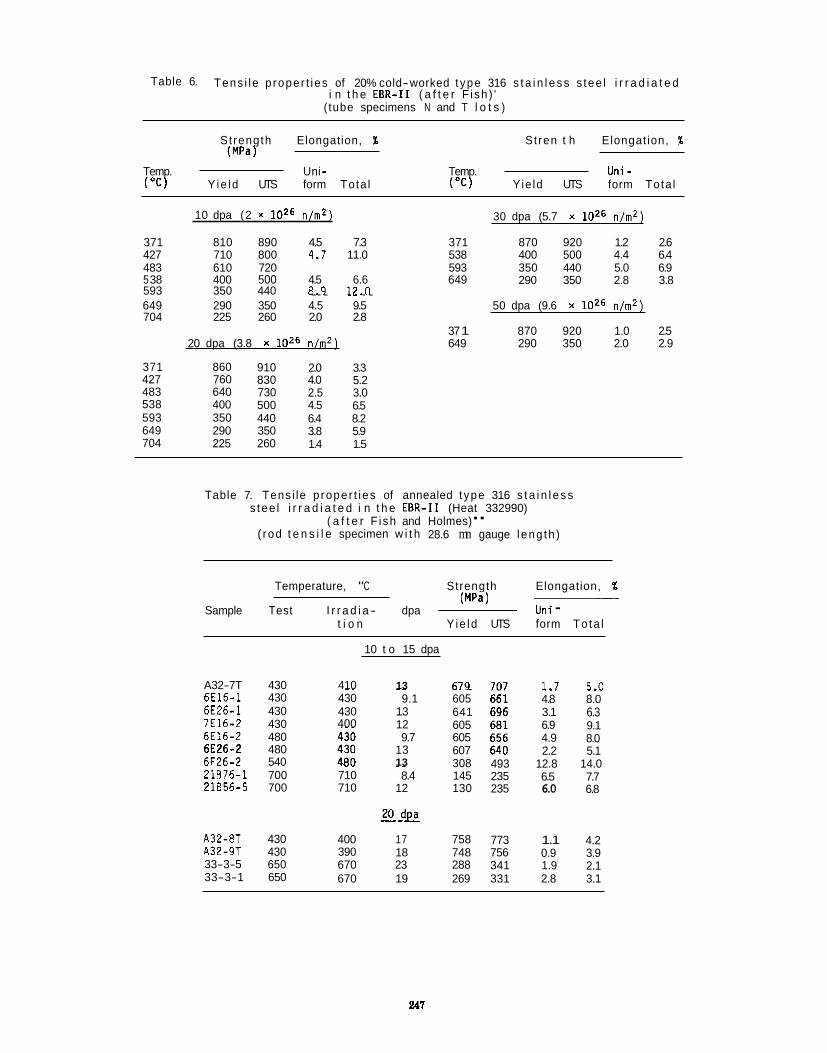
Table 6. Tens i l e p roper t i es of 20% cold-worked t ype 316 s t a i n l e s s s tee l i r r a d i a t e d i n t h e E B R - I 1 ( a f t e r F i sh ) '
( tube specimens N and T l o t s )
St rength Elongation, % St ren t h Elongat ion, % (MPa)
Temp. Uni - Temp. Uni - ( " C ) Yie ld UTS form Tota l ( " C ) Yie ld UTS form Tota l
10 dpa (2 x l o z 6 n/m2) 30 dpa (5.7 x l o z 6 n/m2)
371 810 890 4.5 7.3 371 870 920 1.2 2.6 427 710 800 4.7 11.0 538 400 500 4.4 6.4 483 610 720 593 350 440 5.0 6.9
290 350 2.8 3.8 5 38 400 500 4.5 6.6 649 593 350 440 8.9 i2.n . . . ._ . . 649 290 350 4.5 9.5 50 dpa (9.6 x l o z 6 n/m2) 704 225 260 2.0 2.8
37 1 870 920 1.0 2.5 20 dpa (3.8 x l o z6 n/mz) 649 290 350 2.0 2.9
371 860 910 2.0 3.3 427 760 830 4.0 5.2 483 640 730 2.5 3.0 538 400 500 4.5 6.5 593 350 440 6.4 8.2 649 290 350 3.8 5.9 704 225 260 1.4 1.5
Table 7. Tens i le p roper t i es of annealed t ype 316 s t a i n l e s s s tee l i r r a d i a t e d i n t h e EBR-I1 (Heat 332990)
( a f t e r F i sh and Holmes)" (rod t e n s i l e specimen w i t h 28.6 mn gauge leng th )
Temperature, "C Strength Elongation, % (MPa) ~
Sample Test I r r a d i a - dpa ~ Uni - t i o n Y ie ld UTS form To ta l
10 t o 15 dpa
A32-7T 430 410 13 1.7 s.n 6E16-1 6E26-1 7E16-2 6E16-2 6E26-2 6F26-2 21676-1 21656-5
430 430 430 480 480 540 ~~
700 700
~~
430 430 400
.. 710 710
~~
9.1 13 12
13 9.7
13 .. 8.4
12
.. . 605 641 605 605 607 308 145 130
493 235 235
4.8 3.1 6.9 4.9 2.2
12.8 6.5 6.0
_._ 8.0 6.3 9.1 8.0 5.1
14.0 7.7 6.8
A32-8T 430 400 17 758 773 1.1 4.2 A32-9T 430 390 18 748 756 0.9 3.9 33-3-5 650 670 23 288 341 1.9 2.1
670 19 269 331 2.8 3.1 33-3-1 650
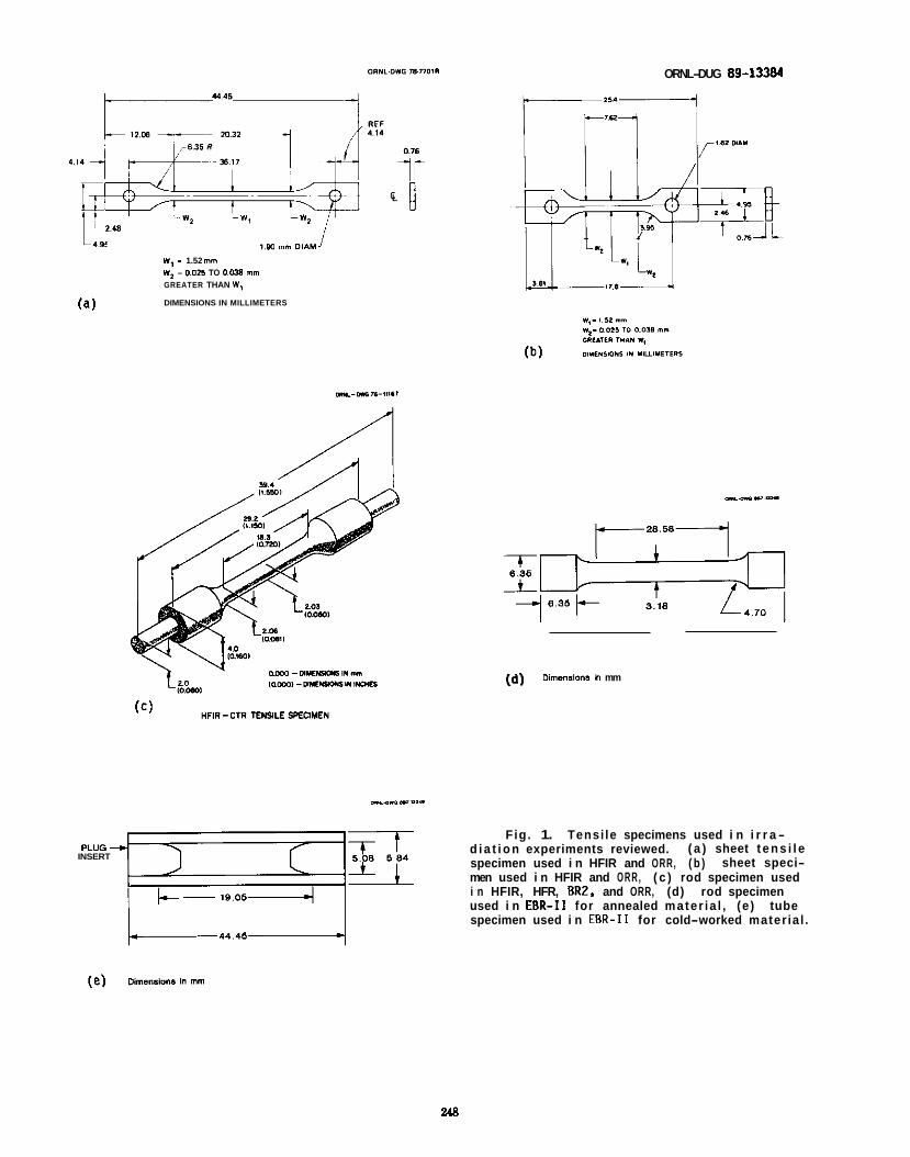
ORNL-DUG 89-13384
1.80 m m OlAM J W, - 1.52 mm W2 = 0.025 TO 0.038 m m GREATER THAN W,
DIMENSIONS IN MILLIMETERS (a)
(d) Dimensions h mm
--"a=_.
Fig. 1. Tensi le specimens used i n i r r a - d i a t i o n experiments reviewed. specimen used i n HFIR and ORR, ( b ) men used i n HFIR and ORR, ( c ) rod specimen used i n HFIR, HFR, BR2, and ORR, (d) rod specimen used i n EER-I1 for annealed mater ia l , (e ) tube specimen used i n EBR-I1 for cold-worked mater ia l .
( a ) sheet t e n s i l e sheet speci- INSERT
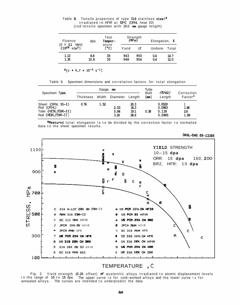
Table 8. Tens i le p roper t i es of t ype 316 s t a i n l e s s s tee la i r r a d i a t e d i n HFIR a t 55°C (ORNL heat DO)
( r o d t e n s i l e specimen w i t h 28.6 mn gauge leng th )
Test Strength Fluence dpa Temper- (MPa) Elongation, %
(W6 n/n2) ("C) Y ie ld UT Uniform Tota l (E > 0.1 MeV) a tu re
1.13 8.8 35 943 950 0.4 14.7 1.35 10.8 35 948 954 0.4 12.0
= 4.7 x 10⁻⁵ 5-11
Table 9. Specimen dimensions and c o r r e l a t i o n fac tors fo r t o t a l e longat ion
Gauge, mn Tu be Specimen TVpe Wall /KEG/ Correct ion ..
Thickness Width Diameter Length (mn) Length Factora
Sheet (ORNL SS-1) 0.76 1.52 20.3 0.0529 1 Rod (ORNL) 2.03 18.3 0.0983 1.86 Tube (HEDL/EBR-11) 5.84 19.1 0.38 0.138 2.6 Rod (HEDL/EBR-11) 3.18 28.6 0.0985 1.86
aMeasured t o t a l e longat ion i s t o be d i v ided by the c o r r e c t i o n fac to r t o normal ize data t o t h e sheet specimen resu l t s .
ORNL-DUG 89-13385
YIELD STRENGTH 10- 15 dpa ORR: 15 dpa 160, BR2, HFR: 1 0 dpa
1 1 0 0 - X
900 * -
- .. C 316 N-LOT 20% CW EBR-I1 o US PQI 25% 01 W I R
R F" 316 EBR- I1 8 US PCR 83 HFIR
u)
F EC 316 RNN HFIR x usPcR25xcwBR2 - J JPCR 15% CW H F I R B JPCA RNN H F I R - JPCR RNN HFR H EC 316 FINN HFR
c 300 + U S P C R 2 5 X ~ I C R # US 316 28% M HFR - a us 316 28x 01 BRZ I) US 316 28X M HFIR
D 316 28X CW DO H F I R 0 ~ p ( x I 2 5 X M M U I
B EC 316 RNN BR2 X M 316 26% CH ORR
-
2 00
1 0 0 1 . " I . " I . ' " " . " " " "
TEMPERATURE , C Fig. 2.
i n t h e range of 10 t o 15 dpa. annealed a l l o y s .
Y i e l d s t reng th (0.2% o f f se t ) e8 a u s t e n i t i c a l l o y s i r r a d i a t e d t o atomic displacement l e v e l s The upper curve i s fo r cold-worked a l l o y s and t h e lower curve i s f o r
The curves are intended t o underpredict t he data.
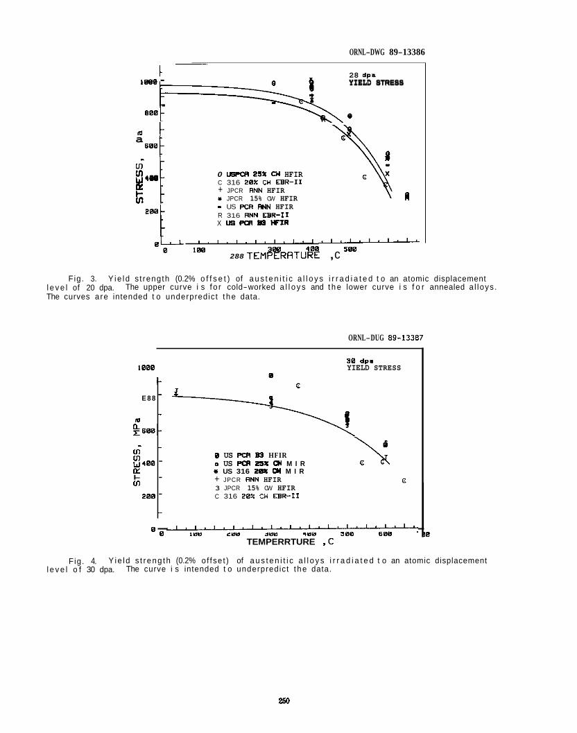
ORNL-DWG 89-13386
E 8 8
m g 6 0 8 -
cn cn W 488 iY I- cn
-
280
28 dpa YIELD STRESS
i- - -
-
- - - -
a 688
$ 4 8 0 IY t- " i (0
1880 - YIELD STRESS
.
R
0 USPPI ZSX 01 HFIR C 316 28% CH EBR-I1 + JPCR RNN HFIR I JPCR 15% CW HFIR - US PCR RNN HFIR R 316 RNN EBR-I1 X Us PCA 83 W I R
, . , , I . I . I . I . I - 1 00
288 TEMRRRATUF~! , c
Fig. 3. l e v e l of 20 dpa. The curves a re intended t o underpredict t he data.
Y i e l d s t reng th (0.2% o f f s e t ) of a u s t e n i t i c a l l o y s i r r a d i a t e d t o an atomic displacement The upper curve i s f o r cold-worked a l l o y s and t h e lower curve i s f o r annealed a l loys .
ORNL-DUG 89-13387
38 dpa 1888 YIELD STRESS
0 US PCR 83 HFIR o US PCR 2SX M M I R I US 316 20X M M I R + JPCR RNN HFIR 3 JPCR 15% CW HFIR C 316 28% CW EBR-I1
\N t
k
8 I 8 8 288 388 488 588 688 8 " ~ ~ " " " ' " ' ~ " " ~ " ' ' ~ ' ~ . TEMPERRTURE ,C
38
Fig. 4. l e v e l o f 30 dpa.
Y ie l d s t r eng th (0.2% o f fse t ) of a u s t e n i t i c a l l o y s i r r a d i a t e d t o an atomic displacement The curve i s intended t o underpredict t he data.
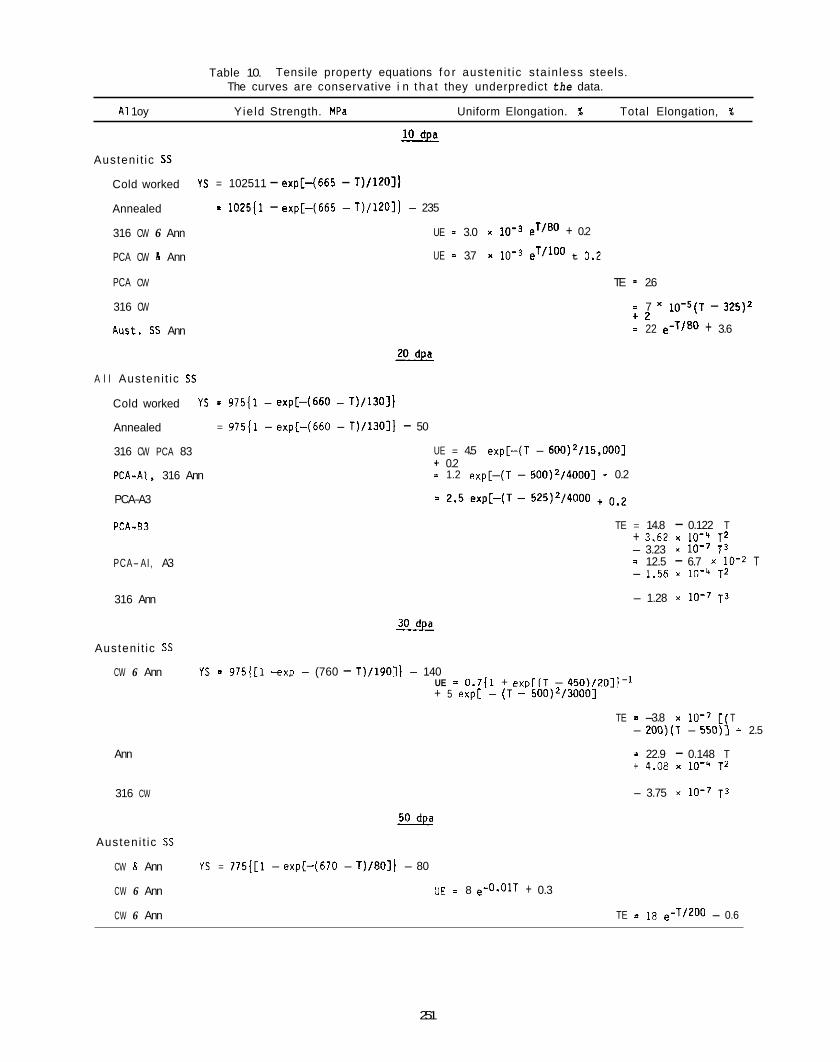
Table 10. Tensile property equations f o r austeni t ic s ta in less steels. The curves are conservative i n t h a t they underpredict the data.
A1 1 oy Yie ld Strength. HPa Uniform Elongation. % Total Elongation, %
Austeni t ic SS
Cold worked
Annealed
316 CW 6 Ann
YS = 102511 - expC-1665 - T)/1201)
= 102511 - exp[-(665 - T)/1201] - 235
UE - 3.0 x e'/" + 0.2
PCA CW h Ann UE - 3.7 x 10⁻³ eT/loo t 0.2
PCA CW TE = 2.6
316 CW = 7 i o - 5 ( ~ - 325)2 + 2 = 22 e-T/80 + 3.6 Rust. SS Ann *
A l l Austeni t ic SS
Cold worked
Annealed
316 CW PCA 83
PCA-AI. 316 Ann
YS = 97511 - expCH660 - T)/1301]
= 97511 - exp[-(660 - T)/1301] - 50
UE = 4.5 expr-(T - 600)2/15,0001 + 0.2 i 1.2 exp[-(T - 500)2/40001 + 0.2
PCA-A3
PCA-83
PCA- AI, A3
316 Ann
Austeni t ic SS
CW 6 Ann
Ann
316 CW
Austeni t ic SS
CW .8 Ann
CW 6 Ann
CW 6 Ann
TE = 14.8 - 0.122 T + 3.62 x 10⁻⁴ T Z - 3.23 x T 3 = 12.5 - 6.7 x 10⁻² T - 1.56 x 10⁻⁴ ~2
- 1.28 x T3
* YS = 975[[1 -exp - (760 - T)/1901\ - 140
UE = 0.7[1 + e x p [ ( T - 450)/201]-1 + 5 exp[ - (T - 500)2/30001
TE = -3.8 x 10⁻⁷ [ T - 20O)(T - 550)i i 2.5
= 22.9 - 0.148 T + 4.08 x 10⁻⁴ TZ
- 3.75 x T3
Ys = 775( [1 - exp[-(670 - T)/801/ - 80
UE i 8 e-o.olT + 0.3
TE = 18 e-T/200 - 0.6
251
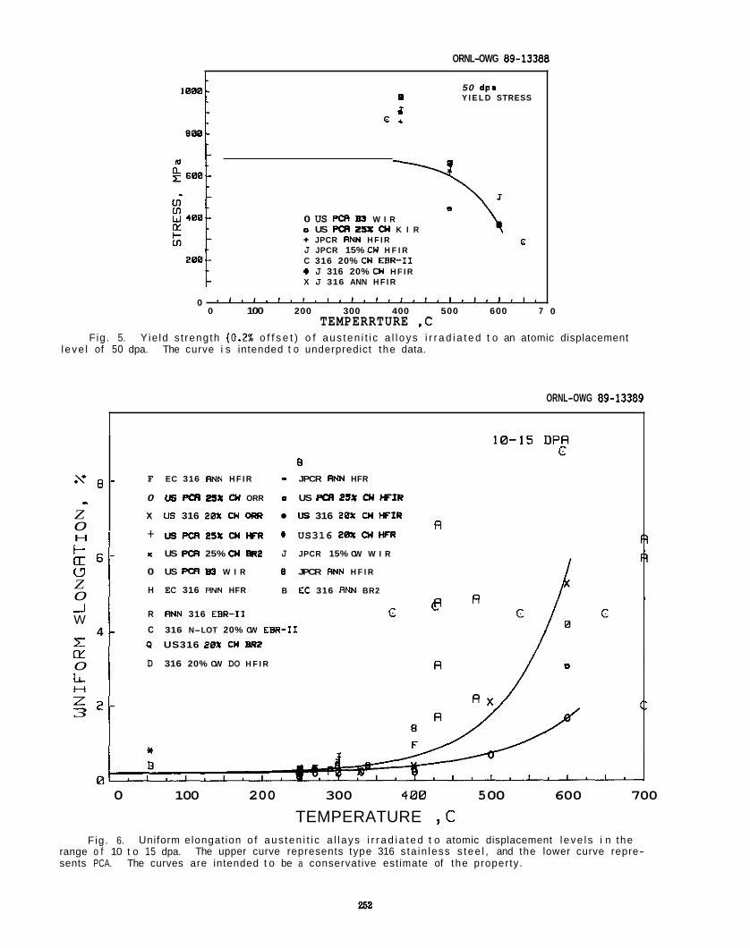
ORNL-OWG 89-13388
50 dpa 0 Y I E L D STRESS
d c +
0
0 US PQI 85 W I R o US PQI 2S% CU K I R + JPCR RNN H F I R J JPCR 15% CW H F I R C 316 20% CH EBR-11 + J 316 20% CU H F I R X J 316 ANN H F I R
c
0 ~ ' " " ' ~ ' " " ' ' " ' " ' ' ~ ' " ~ 0 100 200 300 400 500 600 7
TEMPERRTURE ,C 0
Fig. 5. Y ie ld s t rength (0.2% o f f s e t ) o f aus ten i t i c a l l oys i r r a d i a t e d t o an atomic displacement l eve l of 50 dpa. The curve i s intended t o underpredict the data.
ORNL-OWG 89-13389
s 8 ..
Z 0
F-
U Z 0 -.I W
1 w 0 L
3
H
a 6
4
n = 2
a - F EC 316 RNN H F I R - JPCR RNN HFR
0 u8 PQI .?S% CU ORR o US PQI 25% U # F I R
x us 316 20% cw ORR US 316 20% u WIR
+ U S P C R 2 5 X C U K R US316 2 0 X U HFR
- x US PCR 25% 01 -2 J JPCR 15% CW W I R
0 US PCR B3 W I R 0 JPCR ANN H F I R
H EC 316 RNN HFR B E t 316 RNN BR2
R RNN 316 EBR- I1 c - C 316 N-LOT 20% CW EBR-11
P US316 20% CUM2
D 316 20% CW DO H F I R
-
R
0 100 200 300 4 0 0 5 00 600 700
TEMPERATURE , C Fig. 6. Uniform elongat ion o f aus ten i t i c a l l ays i r r a d i a t e d t o atomic displacement l eve l s i n the
range o f 10 t o 15 dpa. sents PCA. The curves are intended t o be a conservative estimate of the property.
The upper curve represents type 316 s ta in less s tee l , and the lower curve repre-
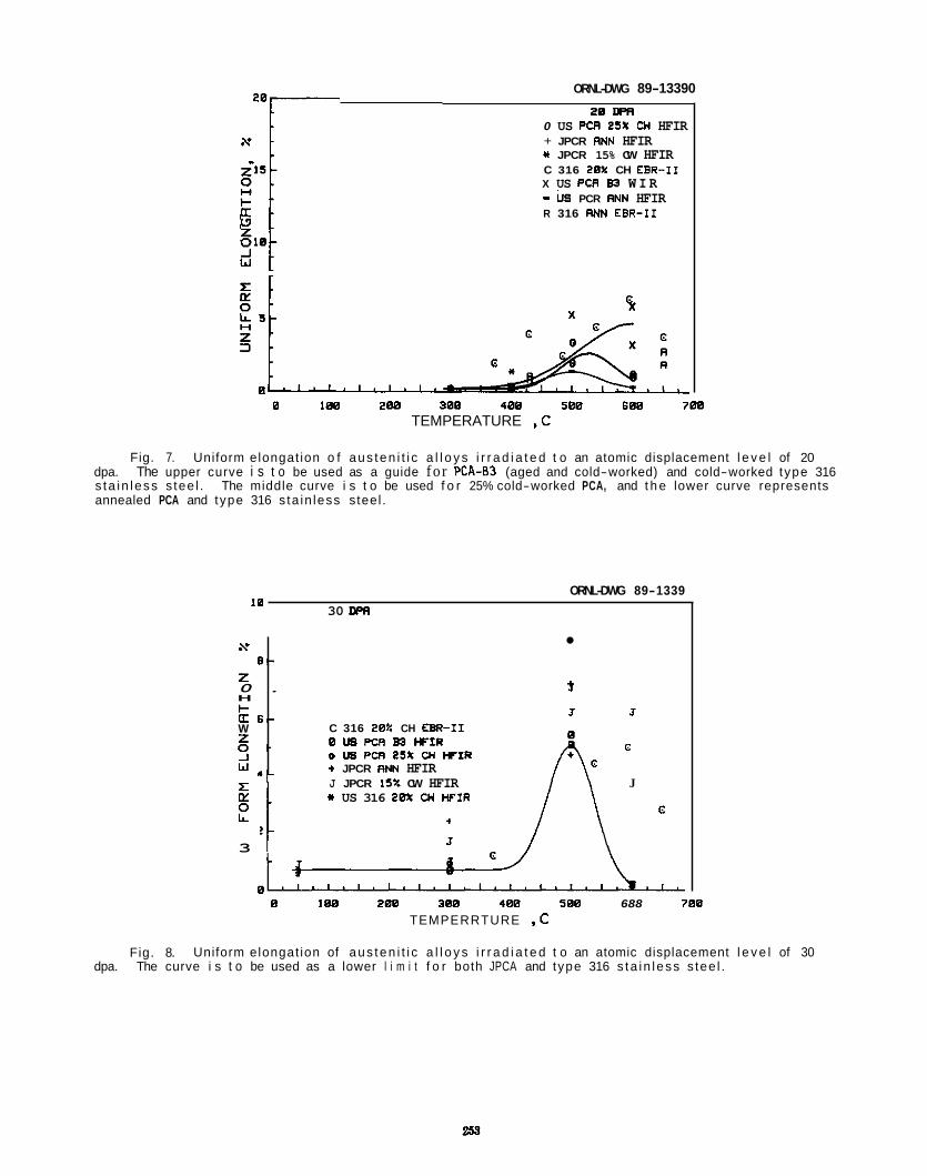
ORNL-DWG 89-13390
A* e -
z 0 . H I- U 6 - W z 0 . _I
4!-
H i-
Z 010 -1
s W r 20 DPR
0 US PCR ZSX CW HFIR + JPCR RNN HFIR * JPCR 15% CW HFIR C 316 20X CH EBR-I1 X US PVI W W I R - PCR R” HFIR R 316 RNN EBR-I1
0 1 8 8 288 300 400 580 6 8 8 700 TEMPERATURE ,C
Fig. 7. Uniform elongat ion o f aus ten i t i c a l l o y s i r r a d i a t e d t o an atomic displacement l e v e l of 20 dpa. The upper curve i s t o be used as a guide fo r PCA-63 (aged and cold-worked) and cold-worked type 316 s ta i n l ess s tee l . The middle curve i s t o be used f o r 25% cold-worked PCA, and t h e lower curve represents annealed PCA and type 316 s ta in less steel .
ORNL-DWG 89-1339
30 DPR 10
3 -1 t J J
C 316 20% CH EBR-11 0 LIS PCR B3 F I R D US PCR 25X Cn F I R t JPCR RNN HFIR J JPCR 15% CW HFIR II US 316 20% CW W I R
G
J
J / \
0 188 200 300 400 500 688 700 TEMPERRTURE ,C
Uniform elongat ion of aus ten i t i c a l l o y s i r r a d i a t e d t o an atomic displacement l e v e l of 30 Fig. 8. dpa. The curve i s t o be used as a lower l i m i t f o r both JPCA and type 316 s ta i n l ess s tee l .
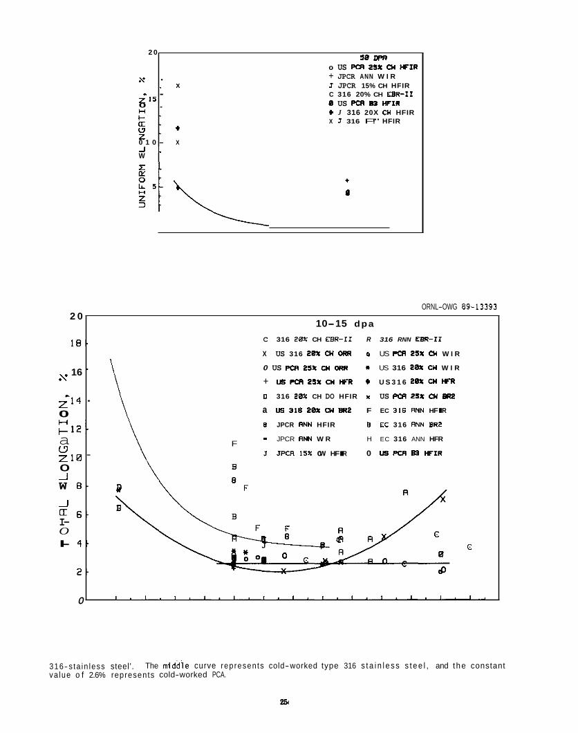
2 0
s
$15 0 . H I - ' O I . w . z 0 1 0 - A . W
50 m o US PCR 2SX o( W I R + JPCR ANN W I R
C 316 20% CH EBR-11 8 US PCR B3 W I R t J 316 20X CU HFIR X J 316 F!" HFIR
.
. x J JPCR 15% CH HFIR -
t
X
316- s ta in less steel'. va lue o f 2.6% represents cold-worked PCA.
The middie curve represen ts cold-worked type 316 s t a i n l e s s s t e e l , and the constant
2 0
1 8 .
16 s
z-14 0
a W z 1 0 0 _I W 8 -
_J
I- O
3 2 .
6 -
I- 4 -
2 -
0
ORNL-OWG 89-13393
10-15 dpa
C 316 20% CH EBR-I1 R 316 RNN EBR-I1
X US 316 20X CU ORR o US PCR 25X 01 W I R
0 US PCR 25% WI C+tR * US 316 20% WI W I R - + U B P C R Z S X c m H F R C U S 3 1 6 20XCMHF'R
I) 316 20% CH DO HFIR k US PCR t S X o( KU? . a US 318 em cm mz F EC 3 1 6 ANN HFIR
B JPCR RNN HFIR B EC 316 RNN BR2 - JPCR R" W R H EC 316 ANN HFR F
J JPCR 15): cw HFIR 0 US PCR m WIR -
c
, . I . l . I . I . , , I . l . / , I . I I J . I .
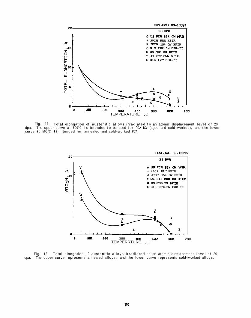
ORNL-DWG 89-13394 20
28 DPR
s .IS z . 0 + I - I - . u -
0 us PCR 2% 01 WIl
c 316 20% cn EBR-11 x us PCR 83 WIR - W PCR R" W I R
+ JPCR RNN HFIR * JPCR 15% CW HFIR
R 316 R" EBR-I1
. -
1 300 400 500 688 7 00 E 288
TEMPERATURE , C
Fig. 11. Tota l e longat ion of aus ten i t i c a l l o y s i r r a d i a t e d t o an atomic displacement l e v e l o f 20 dpa. The upper curve a t 5 0 0 ° C i s intended t o be used fo r P C A - 6 3 (aged and cold-worked), and t h e lower curve a t 5 0 0 ° C i S intended fo r annealed and cold-worked PCA.
ORNL-DWG 89-13395 20
38 DPR
\ 0 LIS PCR 2SX 01 WIR + JPCR R" HFIR J JPCR 15% CW HFIR I Us 316 28X 01 WCIR
C 316 20% CW EBR-I1 B us PCR Ea WIR
E E 0 " " " . ~ . ~ . I . I . I . I . , . , . I .
4 8 8 580 600 780 0 188 200 388 TEMPERRTURE , C
Fig. 12. To ta l e longat ion of aus ten i t i c a l l o y s i r r a d i a t e d t o an atomic displacement l e v e l o f 30 dpa. The upper curve represents annealed a l loys , and the lower curve represents cold-worked a l loys .
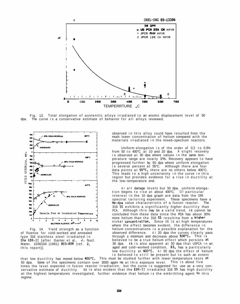
X ORNL-DWG 89-13396
s .
s0 m D US PQI 25% o( HFIR + JPCR RNN HFIR J JPCR 15% CW HFIR
c G
0 " " " " " " " " ~ " I .
0 1 00 200 300 400 500 600 700 TEMPERRTURE , C
Fig . 13. Tota l e longat ion o f a u s t e n i t i c a l l o y s i r r a d i a t e d t o an atomic displacement l e v e l of 50 dpa. The curve i s a conservat ive est imate o f behavior f o r a l l a l l o y s reviewed.
3 Tensile Test a t Irradiation Tenpcrsture
Fig. 14. Y ie ld s t reng th as a funct ion of f luence fo r cold-worked and annealed t voe 316 s ta in less s t e e l i r r a d i a t e d i n t i e EBR-I1 [ a f t e r Garner e t al., J. Nucl. Mater. 1036104 (1981) 80?-808 ( re f . 2, t h l s repor t ) ] .
observed i n t h i s a l l o y cou ld have r e s u l t e d from t h e much lower concent ra t ion o f hel ium compared w i t h the mate r ia l s i r r a d i a t e d i n t h e mixed-spectrum reactors.
Uniform e longat ion i s of t he order of 0.2 t o 0.3% from 50 t o 400°C a t 10 and 20 dpa. i s observed a t 30 dpa where values i n the same tem- perature range are near l y 1%. Recovery appears t o have progressed f u r t h e r by. 50 dpa where un i form e longat ion i s several percent a t 55°C. Although the re a re four data p o i n t s a t 55"C, the re are no o thers below 400°C. This leads t o a h igh uncer ta in ty i n t h e curve i n t h i s reg ion but provides evidence f o r a r i s e i n d u c t i l i t y a t t h e low-temperature end.
t i o n begins t o r i s e a t about 400°C. O f p a r t i c u l a r i n t e r e s t i n the 10 dpa graph are data from the ORR spect ra l t a i l o r i n g experiment. These specimens have a He:dpa value c h a r a c t e r i s t i c o f a fus ion reactor . The 316 SS e x h i b i t s a s i g n i f i c a n t l y h igher d u c t i l i t y than PCA. Although t h i s may be a v a l i d t rend, i t cannot be concluded from these data s ince the PCA has about 30% more hel ium than t h e 316 SS r e s u l t i n a from a h iqher
A s l i g h t recovery
A t a l l damage l e v e l s but 50 dpa, un i fo rm elonga-
n i c k e l concentration. Since i t i s a t h igh temperatures where the e f f e c t becomes evident, t h e d i f f e r e n c e i n hel ium concent ra t ions i s a poss ib le exp lanat ion fo r the observed di f ference. A t 20 dpa the curves c l e a r l y pass through a minimum and decrease above 500OC. be l ieved t o be a t r u e hel ium e f f e c t which p e r s i s t s a t 30 dpa. It i s a lso apparent a t 30 dpa t h a t USPCA i n an aged and cold-worked condit ion, 83, has a p a r t i c u l a r l y low d u c t i l i t y a t 600°C. A t 50 dpa t h e e f f e c t of hel ium i s be l ieved t o s t i l l be present but t o such an extent
Th is must be s tud ied f u r t h e r w i t h lower temperature t e s t s a t
This i s
t h a t low d u c t i l i t y has moved below 400OC. 50 dpa. Some o f the specimens conta in over 3000 appm He a t t h i s exposure l e v e l . t imes the l e v e l expected i n fus ion reactor i r r a d i a t i o n , but the curve i s suggested fo r use as a very con- se rva t i ve est imate of d u c t i l i t y . It i s a l so ev ident t h a t the E B R - I 1 i r r a d i a t e d 316 SS has h igh d u c t i l i t y a t t he h ighest temperatures invest igated, fu r the r evidence t h a t hel ium i s t h e e m b r i t t l i n g agent i n t h i s regime.
This i s about f i v e
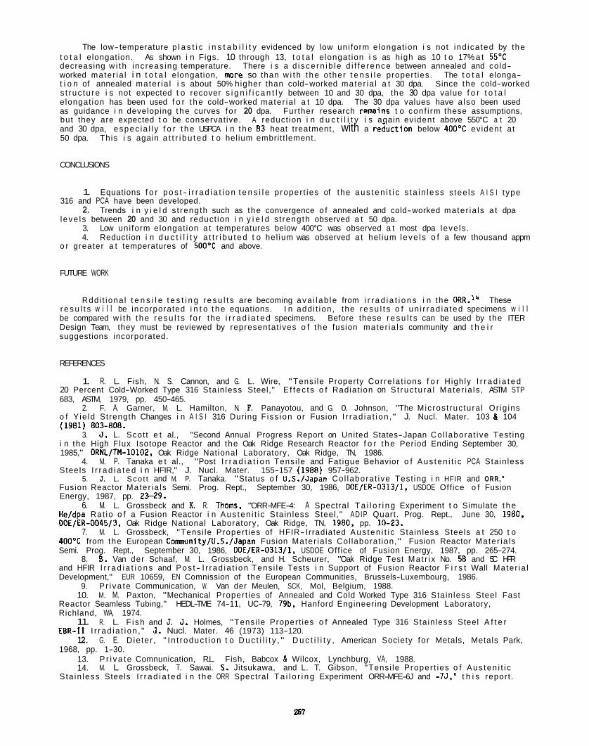
The low-temperature p l a s t i c i n s t a b i l i t y evidenced by low uni form elongat ion i s not ind ica ted by the t o t a l elongation. As shown i n Figs. 10 through 13, t o t a l e longat ion i s as h igh as 10 t o 17% a t 55OC decreasing w i t h inc reas ing temperature. worked mater ia l i n t o t a l elongation, m r e so than w i t h t h e o ther t e n s i l e propert ies. The t o t a l elonga- t i o n of annealed mater ia l i s about 50% higher than cold-worked mater ia l a t 30 dpa. s t r uc tu re i s not expected t o recover s i g n i f i c a n t l y between 10 and 30 dpa, the 30 dpa value f o r t o t a l e longat ion has been used f o r t h e cold-worked mater ia l a t 10 dpa. The 30 dpa values have a lso been used as guidance i n developing t h e curves fo r 20 dpa. Further research remains t o conf i rm these assumptions, but they are expected t o be conservative. A reduct ion i n d u c t i l i t y i s aqain evident above 550°C a t 20
There i s a d i sce rn ib l e d i f f e rence between annealed and cold-
Since the cold-worked
and 30 dpa, espec ia l l y f o r t h e USPCA i n t h e 83 heat treatment, with a r e i u c t i o n below 40OoC evident at 50 dpa. This i s again a t t r i b u t e d t o hel ium embrit t lement.
CONCLUSIONS
1.
2.
3. 4.
Equations f o r p o s t - i r r a d i a t i o n t e n s i l e p roper t ies of the a u s t e n i t i c s ta i n l ess s tee ls A I S I t ype
Trends i n y i e l d s t rength such as the convergence o f annealed and cold-worked mater ia ls a t dpa
Low uni form elongat ion a t temperatures below 400°C was observed a t most dpa leve ls . Reduction i n d u c t i l i t y a t t r i b u t e d t o hel ium was observed a t hel ium l eve l s o f a few thousand appm
316 and PCA have been developed.
l eve l s between 20 and 30 and reduct ion i n y i e l d s t rength observed a t 50 dpa.
o r greater a t temperatures of 5 0 0 T and above.
FUTURE WORK
Rdd i t iona l t e n s i l e t e s t i n g r e s u l t s are becoming ava i l ab le from i r r a d i a t i o n s i n the ORR.'* These r e s u l t s w i l l be incorporated i n t o t h e equations. I n add i t ion , the r e s u l t s o f un i r r ad ia ted specimens w i l l be compared w i t h t h e r e s u l t s fo r the i r r a d i a t e d specimens. Before these r e s u l t s can be used by the ITER Design Team, they must be reviewed by representat ives o f the fusion mater ia ls community and t h e i r suggestions incorporated.
REFERENCES
1. R. L. Fish, N. S. Cannon, and G. L. Wire, "Tensi le Property Cor re la t ions f o r Highly I r r a d i a t e d
2. F. A. Garner, M. L. Hamilton, N. F. Panayotou, and G. 0. Johnson, "The Mic ros t ruc tura l Or ig ins
3. J. L. Scot t e t al., "Second Annual Progress Report on United States-Japan Co l labora t ive Test ing
4. M. P. Tanaka e t al., "Post I r r a d i a t i o n Tensi le and Fat igue Behavior o f Aus ten i t i c PCA Sta in less
5. J. L. Sco t t and M. P. Tanaka. "Status o f U.S./Japan Co l labora t ive Test ing i n HFIR and ORR,"
20 Percent Cold-Worked Type 316 Stain less Steel," E f f ec t s o f Radiat ion on S t ruc tu ra l Mater ia ls , ASTM STP 683, ASTM, 1979, pp. 450-465.
o f Y ie ld Strength Changes i n A I S I 316 During F iss ion o r Fusion I r r ad ia t i on , " J. Nucl. Mater. 103 & 104 (1981) 803-808.
i n the High Flux Isotope Reactor and the Oak Ridge Research Reactor f o r t h e Period Ending September 30, 1985," DRNL/TM-10102, Oak Ridge National Laboratory, Oak Ridge, TN, 1986.
Steels I r r a d i a t e d i n HFIR," J. Nucl. Mater. 155-157 (1988) 957-962.
Fusion Reactor Mater ia ls Semi. Prog. Rept., September 30, 1986, DOE/ER-0313/1, USDOE Off ice o f Fusion Energy, 1987, pp. 2 W 9 .
6. M. L. Grossbeck and K. R. Thorns, "ORR-MFE-4: A Spectral T a i l o r i n g Experiment t o Simulate t h e He/dpa Rat io o f a Fusion Reactor i n Aus ten i t i c Sta in less Steel," ADIP Quart. Prog. Rept., June 30, 1980, DOE/ER-0045/3. Oak Ridge National Laboratory, Oak Ridge, TN, 1980, pp. 10-23.
7. M. L. Grossbeck, "Tensi le Propert ies of HFIR- Irradiated Aus ten i t i c Sta in less Steels a t 250 t o 400'C from the European Conunity/U.S./Japan Fusion Mater ia ls Col laborat ion," Fusion Reactor Mater ia ls Semi. Prog. Rept., September 30, 1986, DOE/ER-0313/1, USDOE Off ice of Fusion Energy, 1987, pp. 265-274.
8. 6. Van der Schaaf, M. L. Grossbeck, and H. Scheurer, "Oak Ridge Test Ma t r i x No. 5B and 5C HFR and HFIR I r r a d i a t i o n s and Pos t- I r r ad ia t i on Tens i le Tests i n Support of Fusion Reactor F i r s t Wall Mater ia l Development," EUR 10659, EN Comnission of the European Communities, Brussels-Luxembourg, 1986.
Reactor Seamless Tubing," HEDL-TME 74-11, UC-79, 79b, Hanford Engineering Development Laboratory, Richland, WA, 1974.
EBR-I1 I r r ad ia t i on , " J. Nucl. Mater. 46 (1973) 113-120.
1968, pp. 1-30.
S ta in less Steels I r r a d i a t e d i n t h e ORR Spectral T a i l o r i n g Experiment ORR-MFE-6J and -75," t h i s report .
9. P r i va te Communication, W. Van der Meulen, SCK, Mol, Belgium, 1988. 10. M. M. Paxton, "Mechanical Propert ies of Annealed and Cold Worked Type 316 Stain less Steel Fast
11. R. L. F i sh and J. J. Holmes, "Tensi le Propert ies o f Annealed Type 316 Stain less Steel A f t e r
12. G. E. D ie te r , " I n t roduc t i on t o D u c t i l i t y , " D u c t i l i t y , American Society fo r Metals, Metals Park,
13. P r i v a t e Comnunication, R.L. Fish, Babcox & Wilcox, Lynchburg, VA, 1988. 14. M. L. Grossbeck, T. Sawai. 5. Jitsukawa, and L. T. Gibson, "Tensi le Proper t ies o f Aus ten i t i c

TENSILE PROPERTIES OF AUSTENITIC STAINLESS STEELS IRRADIATED I N THE ORR SPECTRAL TAILORING EXPERIMENT ORR-MFE-6J AND -75 - M. L. Grossbeck (Oak Ridge Nat ional Laboratory), T. Sawai, S. Jitsukawa (Japan Atomic Energy Research I n s t i t u t e , assigned t o ORNL), and L. T. Gibson (Oak Ridge Nat ional Laboratory)
OBJECTIVE
The o b j e c t i v e of t h i s i n v e s t i g a t i o n i s t o determine t e n s i l e p roper t i es a t low temperatures f o l l o w i n g The e f f e c t o f i r r a d i a t i o n on weld j o i n t s was i r r a d i a t i o n in t roduc ing the fusion reactor value o f He:dpa.
a l s o inves t iga ted under these condi t ions.
SUMMARY
Tens i l e p r o p e r t i e s were found t o be cons is tent with those o f previous i r r a d i a t i o n s i n mixed-spectrum The y i e l d s t reng th a t 60°C was found t o be less than t h a t a t 330'C. but t h i s can be understood reactors .
i n terms of hardening by d i s l o c a t i o n loops. annealed base metal whether o r not the weld was made i n annealed o r cold-worked mater ia l .
The p roper t i es o f welds were found t o resemble those of
PROGRESS AND STATUS
In t roduc t ion
This experiment made con t r i bu t ions i n th ree areas where the re were weaknesses i n t h e prev ious data base. One area i s the low-temperature regime, below 4OOOC. I n t h i s experiment, specimens were i r r a - d i a t e d a t 60, 200, 330, and 400OC. The next area i s t h a t of welded mater ia ls . Both tungsten i n e r t gas (TIG) welded a l l o y s and e lec t ron beam (EB) welded a l l o y s were i r r a d i a t e d . base o f ma te r ia l s i r r a d i a t e d w i t h a neutron spectrum producing t h e fus ion reac to r value of the r a t i o of hel ium product ion t o atomic displacements. valuable con t r i bu t ion .
The t h i r d area was the data
The combination of these features made t h i s experiment a
Experimental Procedure
A l loys inves t iga ted were A I S 1 type 316 s t a i n l e s s s t e e l i n annealed, 15% cold-worked, and 20% co ld- worked condi t ions, JPCA i n annealed and 15% cold-worked condi t ions, and U.S. PCA i n 25% cold-worked, and aged cold-worked condi t ions. A few JPCA specimens were cold-worked t o 15%, then given a heat t reatment a t 800°C f o r 2 h i n order t o form un i fo rm ly d i s t r i b u t e d MC p r e c i p i t a t e s .
The specimens were i r r a d i a t e d i n t h e ORR (Oak Ridge Research Reactor) t o achieve an atomic d isp lace- The i r r a d i a t i o n temperature o f 60°C was achieved ment l e v e l of 7 t o 8 dpa and hel ium l e v e l s of 100 appm.
by having t h e specimens i n contact w i t h the reactor coo lant water. Temperatures of 330 and 400°C were achieved by having the specimens i n a NaK- f i l l ed capsule w i t h heat t rans fe r red across g a s- f i l l e d gaps, and 200°C was achieved by having t h e specimens attached t o an aluminum heat s ink and exposed t o helium. The e levated temperatures were c o n t r o l l e d by a l t e r i n g the composition of t h e m ix tu re of hel ium and argon gases i n the heat t rans fe r gaps.
mesh furnace and a vacuum chamber capable o f t e s t i n g a t e levated temperatures a t pressures i n t h e 10'' Pa range. l eng th o f 7.62 mn, and a s t r a i n r a t e of 4.2 x 5-l was used f o r the Japanese a l l o y s fo r which the specimens had a gauge leng th o f 20.3 mn. A l l specimens were made from sheet w i t h a th ickness of 0.762 mn. Specimens t h a t were i r r a d i a t e d a t 60°C were tes ted a t room temperature s ince no s i g n i f i c a n t d i f - ferences were expected i n t e s t i n g a t 60 o r 25'C. peratures as low as 60'C.
Specimens were tes ted on an Ins t ron un ive rsa l t e s t i n g machine Model 1122 equipped w i t h a tungsten
S t r a i n ra tes o f 5.6 x l o + 5-l were used f o r the U.S. a l l o y s f o r which t h e specimens had a gauge
I n addi t ion, temperature c o n t r o l i s d i f f i c u l t a t tem-
Results and Oiscussion
Results o f the t e n s i l e t e s t s are shown i n Table 1. The t a b l e i s s e l f explanatory except perhaps fo r t h e foo tno te t h a t i n d i c a t e s t h a t f o r two specimens t h e tabu la ted y i e l d s t ress i s not the 0.2% y i e l d s t ress. I n these two cases, p l a s t i c i n s t a b i l i t y was observed a t a deformation below 0.2%. s t ress a t which t h i s i n s t a b i l i t y occurred was so c lose t o the s t ress l e v e l when 0.2% s t r a i n was reached, the value a t 0.2% s t r a i n was tabu la ted i n order t o g ive an i n d i c a t i o n of t h e s t reng th o f the mate r ia l .
Since the
259
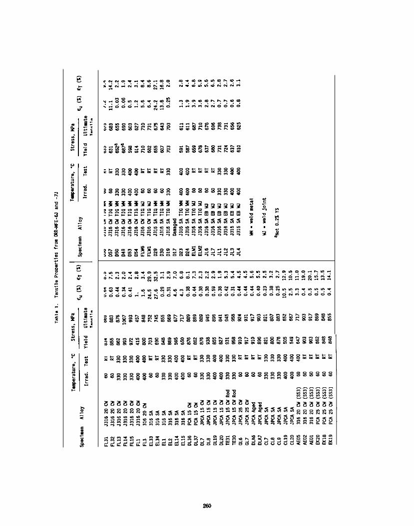
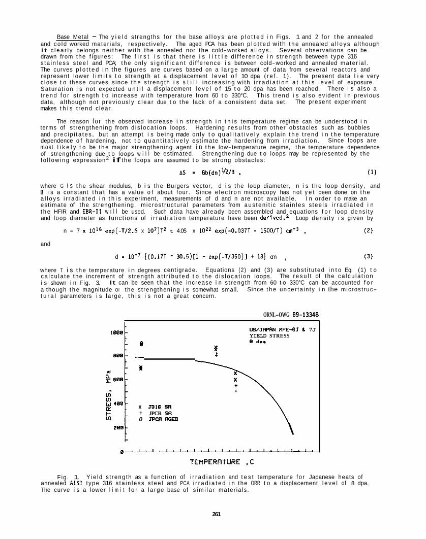
Base Metal - The y i e l d s t rengths fo r t h e base a l l o y s are p l o t t e d i n Figs. 1 and 2 fo r t h e annealed and c o l d worked mater ia ls , respect ive ly . The aged PCA has been p l o t t e d wi th t h e annealed a l l o y s al though i t c l e a r l y belongs n e i t h e r w i t h the annealed nor the cold-worked a l l oys . Several observat ions can be drawn from the f i gu res : s t a i n l e s s s tee l and PCA; t h e on ly s i g n i f i c a n t d i f f e rence i s between cold-worked and annealed mate r ia l . The curves p l o t t e d i n the f i gu res are curves based on a l a r g e amount of data from several reactors and represent lower l i m i t s t o s t reng th a t a displacement l e v e l o f 10 dpa ( r e f . 1) . The present data l i e very c lose t o these curves s ince t h e s t reng th i s s t i l l i nc reas ing w i t h i r r a d i a t i o n a t t h i s l e v e l of exposure. Sa tu ra t ion i s not expected u n t i l a displacement l e v e l o f 15 t o 20 dpa has been reached. There i s a l so a t r e n d f o r s t reng th t o increase w i t h temperature from 60 t o 330°C. data, al though not p rev ious ly c l e a r due t o the lack o f a cons is tent data set. makes t h i s t rend c lear .
The f i r s t i s t h a t the re i s l i t t l e d i f f e r e n c e i n s t reng th between t ype 316
This t rend i s a l so ev ident i n previous The present experiment
The reason f o r the observed increase i n s t reng th i n t h i s temperature regime can be understood i n terms of s t rengthening from d i s l o c a t i o n loops. Hardening r e s u l t s from o the r obstacles such as bubbles and p r e c i p i t a t e s , but an attempt i s be ing made on ly t o q u a l i t a t i v e l y exp la in t h e t r e n d i n t h e temperature dependence o f hardening, not t o q u a n t i t a t i v e l y est imate the hardening from i r r a d i a t i o n . most l i k e l y t o be t h e major strengthening agent i n t h e low-temperature regime, t h e temperature dependence of strengthening due t o loops w i l l be estimated. Strengthening due t o loops may be represented by the f o l l o w i n g expression2 if the loops are assumed t o be s t rong obstacles:
Since loops are
where G i s t h e shear modulus, b i s the Burgers vector, d i s the loop diameter, n i s t h e loop dens i ty , and E i s a constant t h a t has a value o f about four. Since e l e c t r o n microscopy has not y e t been done on t h e a l l o y s i r r a d i a t e d i n t h i s experiment, measurements of d and n are not ava i lab le . I n order t o make an est imate of the strengthening, m ic ros t ruc tu ra l parameters from a u s t e n i t i c s t a i n l e s s tee ls i r r a d i a t e d i n t h e HFIR and EBR-I1 w i l l be used. Such data have already been assembled and equations f o r loop dens i t y and loop diameter as func t ions of i r r a d i a t i o n temperature have been derived.2 Loop dens i t y i s given by
n = 7 x 1 0 l 6 exp(-T/2.6 x 107)T2 t 4.05 x l oz2 exp(-O.O37T - 1500/T) cm-' , (2)
and
d = lo- ' {(0.17T - 30.5)[1 - exp(-T/350)] + 131 cm , (3 )
where T i s t h e temperature i n degrees cent igrade. c a l c u l a t e the increment of s t reng th a t t r i b u t e d t o the d i s l o c a t i o n loops. i s shown i n Fig. 3. al though t h e magnitude Of t he s t rengthening i s somewhat small. t u r a l parameters i s la rge, t h i s i s not a great concern.
Equations (2) and (3) are subs t i t u ted i n t o Eq. (1) t o
Since t h e uncer ta in ty i n the microst ruc-
The r e s u l t of t he c a l c u l a t i o n It can be seen t h a t the increase i n s t reng th from 60 t o 330°C can be accounted f o r
ORNL-OWG 89-13348
UWJRPAN MFE-6J 7J YIELD STRESS 8 dp.
%
I
X J316 SR + JPCR SR 0 JPQIRCU)
\ 8 ~ ~ " " ' ' ' ~ " " " " " ' ' ' ' " '
TEMPERFITURE ,C
Fig. 1. Y i e l d s t reng th as a func t ion of i r r a d i a t i o n and t e s t temperature fo r Japanese heats of annealed A I S 1 t ype 316 s t a i n l e s s s t e e l and PCA i r r a d i a t e d i n the ORR t o a displacement l e v e l of 8 dpa. The curve i s a lower l i m i t f o r a l a r g e base of s i m i l a r mater ia ls .
261
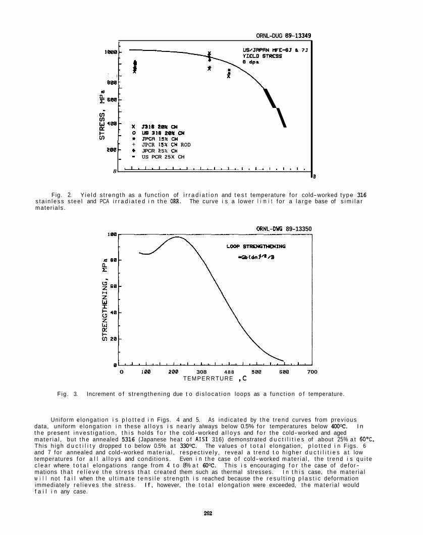
ORNL-DUG 89-13349
eOsL
8
e88 FI
+ JPCR 1SX C W ROD + JPCR 25X CH - - US PCR 25X CH
" " ~ ' " " ~ " ' ' " " ~ ' " " ~
L
\ \
B
Fig. 2. Y i e l d s t reng th as a funct ion of i r r a d i a t i o n and t e s t temperature fo r cold-worked t ype 316 s t a i n l e s s s tee l and PCA i r r a d i a t e d i n t h e ORR. The curve i s a lower l i m i t f o r a l a r g e base of s i m i l a r mater ia ls .
ORNL-0% 89-13350
0 188 288 308 488 5 8 8 688 700 TEMPERRTURE ,C
Increment o f s t rengthening due t o d i s l o c a t i o n loops as a func t ion o f temperature. F ig . 3.
Uniform e longat ion i s p l o t t e d i n Figs. 4 and 5. As i nd ica ted by t h e t rend curves from prev ious data, uniform e longat ion i n these a l l o y s i s near l y always below 0.5% fo r temperatures below 400°C. I n t h e present i n v e s t i g a t i o n , t h i s holds f o r t h e cold-worked a l l o y s and f o r the cold-worked and aged mate r ia l , but t h e annealed 5316 (Japanese heat o f A I S 1 316) demonstrated d u c t i l i t i e s of about 25% a t 6OoC, This h igh d u c t i l i t y dropped t o below 0.5% a t 330°C. and 7 for annealed and cold-worked mate r ia l , respec t i ve l y , reveal a t rend t o h igher d u c t i l i t i e s a t low temperatures f o r a l l a l l o y s and condi t ions. Even i n t h e case o f cold-worked mate r ia l , t he t rend i s q u i t e c l e a r where t o t a l elongat ions range from 4 t o 8% a t 60°C. This i s encouraging f o r t h e case of defor- mations t h a t r e l i e v e t h e s t ress t h a t created them such as thermal stresses. I n t h i s case, the mate r ia l w i l l no t f a i l when the u l t i m a t e t e n s i l e s t reng th i s reached because t h e r e s u l t i n g p l a s t i c deformation immediately r e l i e v e s the s t ress. I f , however, t he t o t a l e longat ion were exceeded, the mate r ia l would f a i l i n any case.
The values o f t o t a l elongat ion, p l o t t e d i n Figs. 6
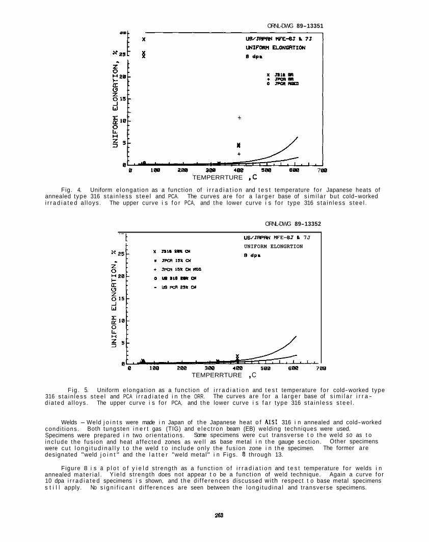
ORNL-DWG 89-13351
*25 I * *
. +
B 288 4 0 0 588 688 7 TEMPERRTURE ,C
B
Fig. 4. annealed type 316 s ta in l ess s tee l and PCA. i r r a d i a t e d a l loys .
Uniform e longat ion as a funct ion of i r r a d i a t i o n and t e s t temperature f o r Japanese heats of The curves are f o r a l a r g e r base of s i m i l a r bu t cold-worked
The upper curve i s f o r PCA, and t he lower curve i s f o r type 316 s ta in l ess s tee l .
ORNL-DWG 89-13352
UWJRPRN UFE-GJ b 7J - - t UNIFORM ELONGRTION 8 dp.
B 188 208 38% 4 8 8 SBB 608 788 TEMPERRTURE , C
F ig . 5. Uniform e longat ion as a func t ion of i r r a d i a t i o n and t e s t temperature f o r cold-worked type 316 s ta in l ess s tee l and PCA i r r a d i a t e d i n t he ORR. d i a ted a l loys . The upper curve i s f o r PCA, and t he lower curve i s f a r type 316 s ta in l ess s t e e l .
The curves are f o r a l a r g e r base of s i m i l a r i r r a -
Welds - Weld j o i n t s were made i n Japan of t he Japanese heat o f A IS1 316 i n annealed and cold-worked cond i t ions . Both tungsten i n e r t gas (TIG) and e lec t ron beam (EB) welding techniques were used. Specimens were prepared i n two or ien ta t ions . i nc lude the fus ion and heat a f fec ted zones as we l l as base metal i n t he gauge sect ion. were cu t l o n g i t u d i n a l l y t o t he weld t o inc lude on ly t he f us ion zone i n t h e specimen. designated "weld j o i n t " and the l a t t e r "weld metal" i n Figs. 8 through 13.
Figure 8 i s a p l o t o f y i e l d s t rength as a f unc t i on o f i r r a d i a t i o n and t e s t temperature f o r welds i n annealed ma te r i a l . 10 dpa i r r a d i a t e d specimens i s shown, and t h e d i f f e rences discussed wi th respect t o base metal specimens s t i l l apply. No s i g n i f i c a n t d i f fe rences are seen between the l ong i t ud ina l and t ransverse specimens.
Some specimens were cu t t ransverse t o t h e weld so as t o Other specimens
The former are
Y ie ld s t rength does no t appear t o be a func t ion of weld technique. Again a curve f o r
268
ORNL-DWG 89-13353
s = r
s 25 381
- US/JWRN nFEdJ i 7J
TOTRL ELONGATION
B dpa
US/JFPRN WE-SJ h 75 TOTRL ELONGRTION
B dpa
8 t " " . " I . ' . " " " ' ~ ' " " ' " _ 8 188 288 388 4 m 588 688
TEMPERATURE . C
Fig. 6. To ta l e longat ion as a func t ion o f i r r a d i a t i o n and t e s t temperature f o r Japanese heats of t ype 316 s ta in less s t e e l and PCA i r r a d i a t e d i n t h e ORR. The curve i s f o r a l a r g e r base of s i m i l a r i r r a - d i a t e d a l l o y s .
ORNL-DMG 89-13354
U z 15 0
W
Fig. 7. 316 s t a i n l e s s s t e e l and PCA i r r a d i a t e d i n t h e ORR. d i a t e d a l l oys .
To ta l e longa t ion as a funct ion of i r r a d i a t i o n and t e s t temperature f o r cold-worked t ype
The concave curve i s f o r t ype 316 s t a i n l e s s s t e e l and t h e s t r a i g h t l i n e i s f o r PCA. The curves are fo r a l a r g e r base of s i m i l a r i r r a -
264
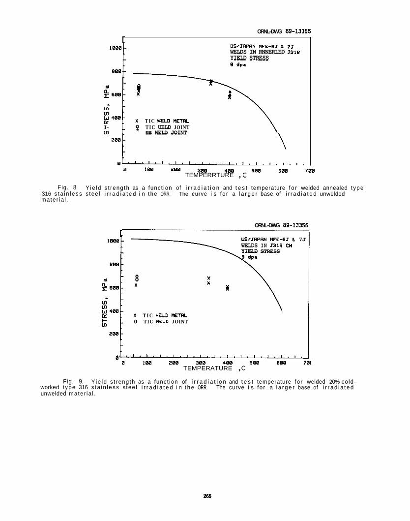
ORNL-DWG 89-13355
1
X TIC U M nETRL I- 0 TIC UELD JOINT ffl * EB WELD JOINT
2 4 8 0
US/JAPRN MFE-6J h 75 WELDS IN RNNERLED J316 YIELD STRESS
388 408 508 600 780 8 188 288 TEMPERRTURE ,C
Fig. 8. Y i e l d s t reng th as a funct ion of i r r a d i a t i o n and t e s t temperature f o r welded annealed t ype 316 s t a i n l e s s s tee l i r r a d i a t e d i n the ORR. The curve i s fo r a l a r g e r base of i r r a d i a t e d unwelded mate r ia l .
ORNL-DWG 89-13356
1 US/JRPRN MFE-6J b 7J WELDS IN J316 CW YIELD STRESS
X 8 X
X T I C YaD U R N 0 TIC nao JOINT
8 0 188 288 300 4 8 8 5 8 8 688 7
TEMPERATURE , C
Fig. 9. Y i e l d s t reng th as a funct ion of i r r a d i a t i o n and t e s t temperature fo r welded 20% co ld- worked t ype 316 s t a i n l e s s s tee l i r r a d i a t e d i n t h e ORR. The curve i s fo r a l a r g e r base of i r r a d i a t e d unwelded mate r ia l .
265
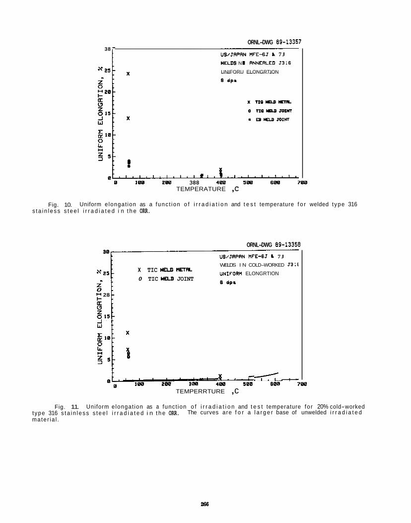
ORNL-DWG 89-13357 38 -
US/JRPRN HFE-GJ h 7J WELDS IN RNNERLED ~ 3 1 6
UNIFORU ELONGRTION
8 I 8 8 288 388 4 8 8 588 688 788 TEMPERATURE , C
Fig. 10. Uniform e longat ion as a func t ion o f i r r a d i a t i o n and t e s t temperature f o r welded t ype 316 s t a i n l e s s s t e e l i r r a d i a t e d i n t h e ORR.
ORNL-DWG 89-13358
UWJRPRN MFE-6J L 7J
WELDS I N COLD-WORKED J31€
UEIIFORU ELONGRTION x TIC HELn Ella
0 TIC WM JOINT z 0 l-4 28
I( , . , , ,<. , , 1W 288 388 488 588 688 788 8
8 TEMPERRTURE , c
Fig. 11. Uniform e longat ion as a funct ion o f i r r a d i a t i o n and t e s t temperature fo r 20% cold-worked t ype 316 s t a i n l e s s s t e e l i r r a d i a t e d i n t h e ORR. mater ia l .
The curves are f o r a l a r g e r base of unwelded i r r a d i a t e d
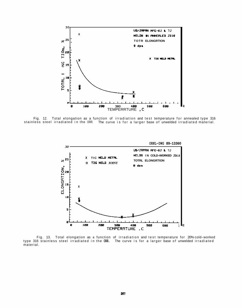
30
25 x
z .
I - .
" . 5320-
0 168 268 380 4 6 8 5 00 600 TEMPERRTURE ,C
UWJRPRN WFE-6J. L 7J nmm IN FINNERLED ~ 3 1 6
9 dpa
X
TOTR ELONGRTION - .
x ria 109 mn
a
Fig. 12. Tota l e longat ion as a funct ion of i r r a d i a t i o n and t e s t temperature f o r annealed t ype 316 The curve i s f o r a l a r g e r base o f unwelded i r r a d i a t e d mate r ia l . s t a i n l e s s s t e e l i r r a d i a t e d i n the ORR.
ORNL-DWG 89-13360 30
USJRPRN UFE-6J L 7J
X
x T IC YELDWETRL
0 T I C UELD JOINT
UELDS I N COLD-WORKED JJlE
TOTRL ELONGRTION
B dva
E
Fig. 13. Tota l e longat ion as a funct ion of i r r a d i a t i o n and t e s t temperature fo r 20% cold-worked t ype 316 s t a i n l e s s s t e e l i r r a d i a t e d i n t h e ORR. mater ia l .
The curve i s fo r a l a r g e r base o f unwelded i r r a d i a t e d
267
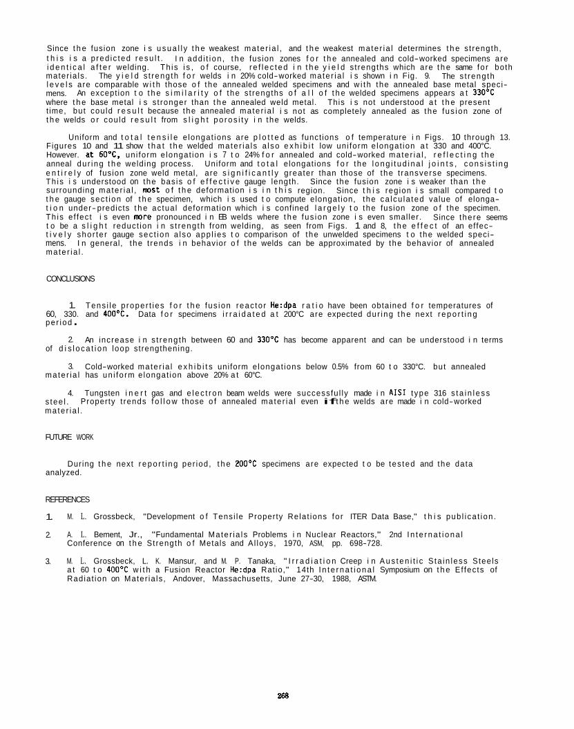
Since t h e fusion zone i s u s u a l l y t h e weakest ma te r ia l , and t h e weakest ma te r ia l determines t h e s t rength, t h i s i s a p red ic ted r e s u l t . I n add i t i on , t h e fusion zones f o r t h e annealed and cold-worked specimens are i d e n t i c a l a f t e r welding. mater ia ls . The y i e l d s t reng th f o r welds i n 20% cold-worked mate r ia l i s shown i n Fig. 9. l e v e l s are comparable w i t h those o f the annealed welded specimens and w i t h the annealed base metal speci- mens. where t h e base metal i s s t ronger than t h e annealed weld metal. t ime, but cou ld r e s u l t because the annealed mate r ia l i s not as completely annealed as the fus ion zone of t h e welds o r cou ld r e s u l t from s l i g h t p o r o s i t y i n the welds.
Figures 10 and 11 show t h a t t h e welded mate r ia l s a l so e x h i b i t low un i form e longat ion a t 330 and 400°C. However. a t 60OC. un i form e longat ion i s 7 t o 24% f o r annealed and cold-worked mate r ia l , r e f l e c t i n g t h e anneal du r ing t h e welding process. e n t i r e l y of fusion zone weld metal, are s i g n i f i c a n t l y greater than those of the t ransverse specimens. Th is i s understood on the bas is o f e f f e c t i v e gauge length. surrounding mate r ia l , m s t o f t h e deformation i s i n t h i s region. Since t h i s reg ion i s small compared t o t h e gauge sec t ion of t h e specimen, which i s used t o compute elongat ion, the ca lcu la ted value of elonga- t i o n under-predicts t h e actua l deformation which i s confined l a r g e l y t o the fusion zone o f the specimen. Th is e f fec t i s even m r e pronounced i n EB welds where t h e fus ion zone i s even smal ler. t o be a s l i g h t reduct ion i n s t reng th from welding, as seen from Figs. 1 and 8, t h e e f f e c t of an effec- t i v e l y shor te r gauge sec t ion a l so app l ies t o comparison of the unwelded specimens t o the welded speci- mens. I n general, t he t rends i n behavior o f t he welds can be approximated by the behavior of annealed mate r ia l .
Th is i s , o f course, r e f l e c t e d i n t h e y i e l d s t rengths which are t h e same fo r both The s t reng th
An except ion t o t h e s i m i l a r i t y o f t he s t rengths o f a l l o f t h e welded specimens appears a t 33OoC This i s not understood a t t h e present
Uniform and t o t a l t e n s i l e e longat ions are p l o t t e d as funct ions o f temperature i n Figs. 10 through 13.
Uniform and t o t a l elongat ions f o r the l o n g i t u d i n a l j o i n t s , c o n s i s t i n g
Since the fusion zone i s weaker than t h e
Since the re seems
CONCLUSIONS
1. 60, 330. and 400OC. pe r iod .
2. of d i s l o c a t i o n loop strengthening.
ma te r ia l has un i fo rm e longat ion above 20% a t 60°C.
Tens i l e p roper t i es f o r t h e fus ion reac to r He:dpa r a t i o have been obtained f o r temperatures of Data f o r specimens i r r a i d a t e d a t 200°C are expected du r ing t h e next r e p o r t i n g
An increase i n s t reng th between 60 and 330OC has become apparent and can be understood i n terms
3. Cold-worked mate r ia l e x h i b i t s uni form e longat ions below 0.5% from 60 t o 330°C. but annealed
4. Tungsten i n e r t gas and e l e c t r o n beam welds were successfu l ly made i n A I S 1 t ype 316 s t a i n l e s s s tee l . ma te r ia l .
Property t rends f o l l o w those o f annealed mate r ia l even if t h e welds are made i n cold-worked
FUTURE WORK
During t h e next r e p o r t i n g per iod, t h e 200°C specimens are expected t o be tes ted and the data analyzed.
REFERENCES
1.
2.
M. L. Grossbeck, "Development o f Tens i le Property Rela t ions fo r ITER Data Base," t h i s pub l i ca t ion .
A. L. Bement, Jr., "Fundamental Ma te r ia l s Problems i n Nuclear Reactors," 2nd I n t e r n a t i o n a l Conference on t h e St rength o f Metals and Al loys, 1970, ASM, pp. 698-728.
M. L. Grossbeck, L. K. Mansur, and M. P. Tanaka, " I r r a d i a t i o n Creep i n A u s t e n i t i c S ta in less Stee ls a t 60 t o 4 0 0 T w i t h a Fusion Reactor He:dpa Rat io," 14th I n t e r n a t i o n a l Symposium on t h e Ef fec ts of Radia t ion on Mater ia ls , Andover, Massachusetts, June 27-30, 1988, ASTM.
3.
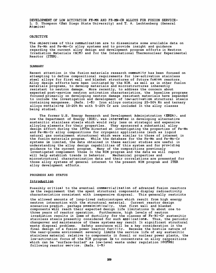
DEVELOPMENT OF LOW ACTIVATION FE-MN AND FE-MN-CR ALLOYS FOR FUSION SERVICE- L. D. Thompson (San Diego State University) and T. A. Lechtenberg (General AtanlCS)
OBJECTIVE
The obJectives of this cmunication are to disseminate some available data on the Fe-Mn and Fe-Mn-Cr alloy systems and to provide insight and guidance regarding the current alloy design and development program efforts in Neutron Irradiation Materials (NIM) and for the International Thermonuclear Experimental Reactor (ITER).
SUMMARY
Recent attention in the fusion materials research cornunity has been focused on attempting to define compositional requirements for low-activation stainless steel alloys for first wall and blanket structures of future fusion reactors. Alloy design efforts have been initiated by the NIM. as well as in other fuslon materials programs, to develop materials and microstructures inherently resistant to neutron damage. More recently, to address the concern about expected post-service neutron activation characteristics, the baseline programs focused primarily on developing neutron damage resistant materials have expanded to include the lnvestigatlon and development of low-activation structural steels containing manganese. (Refs. 1-5) Iron alloys containing 25-50% Mn and ternary alloys containlng 10-20% Mn with 5-20% Cr are included In the alloy classes being studied.
now the Department of Energy (DOE), was interested in developing alternative austenitic stainless steels which would rely less on strategic and expensive alloylng elements for their propertles. They sponsored a substantial alloy design effort durlng the 1970s directed at investigating the properties of Fe-Mn and Fe-Mn-Cr alloy compositions for cryogenic applications (such as liquid natural gas containment structures) which were similar to those of interest in the fusion materials program. While the database for the Fe-Mn and Fe-Mn-Cr systems is limited, the data obtained in these earlier studies are useful in understanding the alloy design capabilities of this system and for provldlng guidance to the current program. Many of the compositions previously investigated complement those In the NIM program and the data we will report will help establish trends in behavior. Mechanical properties and microstructural characterization data and their correlations are presented for those alloy systems of general interest to the present NIM program and ITER alloy development efforts.
The former U.S. Energy Research and Development Administration (ERDA), and
PROGRESS AND STATUS - Possibly crltlcai to the eventual comdnerclalization of advanced fusion reactors is the requirement that the spent structural components display radioactivity characteristics consistent with inexpensive disposal. This generally restricts the allowed amounts of long-lived radioisotopes which result from high energy neutron interaction with the structural material. Current reactor design scenarios predict. perhaps pesslmlsticaliy, that flrst wall and blanket components will reach their expected design life llmitations In about one to three years of reactor operation. Furthermore, high levels of neutron irradiation results in loss of ductility for the classes of Fe-NI-Cr austenitic stainless steels presently considered for such appilcatlons. Thus, the periodic changeover and maintenance of these systems may result In significant structural waste disposal problems. Safety assurance will be a key consideration in the final design of a fusion power reactor faciilty. Because the hostile nature of the near-plasma environment severely limits the service life of any austenltlc stainless material relative to components in fossil or nuclear power plants, the low-activation focus of the NIM program Is to concentrate on alloy canpositions which can be "surface-burled" as low-level waste under regulation lOCFR6l following reactor servlce. (Refs. 1-5)
The structural materials for the above mentioned components must be easlly fabricable into tubing and other relevant shapes, weldable, and also must exhibit adequate levels of corrosion reslstance. While the Internal plasma chamber components present the most serious deslgn challenges, Fe-Mn-Cr base stainless steels may be a sound alternative for other reactor canponents ae wei 1.
The constraint of surface burial places restrlctlons on the types of elements which can be considered for the developmental alloys. The control or elimination of some of the more comnon alloying elements for the AISI 300 series stainiesses. including, but not llmlted to nickel. molybdenum. niobium, etc.. complicates the task at hand. These elements would transnutate to form radloactive isotopes with either extremely long half-lives or which would emit unacceptably hiQh energy decay products. The development and characterlzatlon of several series of Fe-Mn-Cr alloys formed the basis of research at U. C. Berkeley in the 1970s. (Refs. 6 and 7) Many of the present NIM program compositions (Ref. 8 ) are slmllar to those investigated durlng thls earlier program. A recent review paper sumnarizes the mechanical behavior and microstructural characteristics of a series of Fe-16Mn-13Cr alloys which were included in the U. C. Berkeley study. (Ref. 9) This general class of alloys would seem to have wide appeal for future fusion reactor applications based on the canbinations of strength, ductility and toughness observed wlth many of the alloy formulations earlier explored.
- - lLpv Devel-
The obJective of the ERDWDOE Fe-Mn-Cr ai ioy development program was to develop nickel-free austenitic stainless steels wlth lower chromium concentrations than the AISI 300 series alloys. Much of thls work was performed at U. C. Berkeley under the tutelage of Parker and Zackay. (Refs. 6.7.9-18) The materials. once aufficientiy developed, were to compete with the standard AISI 300 serles alloys for a share of the marketplace. While the cryogenic applications being addressed dictated that the developmental steels had to display adequate low temperature strength and toughness, acceptable overall corrosion reslstance was also a maJor goal as it is in the NIM program.
The U. C. Berkeley program alloys most pertinent to the NIM and ITER research c m u n i t y are the Fe-Mn. Fe-Mn-C, Fe-Mn-Cr. and Fe-Mn-Cr base materials. (Refs. 6.7. 9-18) Much of the information generated In the Fe-Mn and Fe-Mn-C system studles (Refs. 15-18) was taken into consideration durlng the formulation of the Fe-Mn-Cr ternary and Fe-Mn-Cr base materials to be discussed in this paper.
Tensile, hardness. and impact toughness properties for many of these Fe-Mn-Cr base alloy systems were evaluated at room temperature (RT). 195K and 77K. The RT data were used to screen the alloys prior to extensive lower temperature testing. Alloy phase constituents, stabtlities and transformatlon behavior were correlated with the mechanical properties. Optlcal. scanning electron and transmission microscopy. dilatometry, and x-ray diffraction were used to characterize the evolution of microstructures and to provide correlations with the mechanlcal properties obtained. Sane corroslon experlments were also conducted where the behavlor of the most promising developmental alloys was compared with that of AISI 347 stainless steel, a grade slmllar to AISI 316L. but which contains nlobium to decrease susceptlbillty to sensltlzation reactions and stress corrosion cracking.
representatlve Iron-base cmosltlons are dlSCUSSed by the authors along wlth microstructural Correlations and the evolution of mlcrostructure In these materials. Details of the experimental procedures used durlng the course of these investlgatlons have been previously reported (Refs. 6.7. 9. 15 and 18) and W l l l not be repeated beyond a level necessary to effectively convey the Informatlon. The POSSlble appllcatlon of these or slmllar materlals for other fuslon reactor components. e.g.. the SuPerconducting magnet system relnforcement structure, may requlre cryogenlc performance SO some of the low-temperature data are Presented In conJunction wlth ambient temperature data. Informatlon on allOYS whlch are not SUltable for fuslon appllcatlons Is Included In certaln Instances to clarlfy a polnt or to illustrate a partlcular feature representatlve to the generic class of materials.
In this paper the effects of an and Cr concentratlons on the propertles of
As stated, Ref. 8 lists the nominal and, in some cases, actual chemical compositions of the materials Included In the NIM program. These alloy compositions were formulated based on the available Schaeffler diagram. (Ref. 19) There has been considerable variation between the predicted and observed phase constltuents. (Refs. 8 and 20) A screening study is underway and the mechanical properties of the most promlslng alloy systems are being evaluated in both the unlrradiated and irradlated conditions at temperatures representative of the application range. Many of the NIM materials are similar in composition to those of the previous studies which is why the present communication was believed to be valuable.
Comerclally available steels, the AIS1 200 series alloys. do substitute Mn for Ni: however, the substitution is generally not complete since the presence of some Ni improves the elevated temperature oxidation resistance. (Ref. 21) Also. one of the inherent limitations imposed by substantial manganese levels In austenitic iron is the high Mn vapor pressure at temperatures exceeding approximately 923-973K. Phase instabilities and mlcrostructural changes can occur as the Mn concentration decreases at the exposed surface, thus changing the mechanical properties and probably affecting the corrosion resistance. Fortunately, fusion structural reactor component temperatures will be limited to levels where both the absence of nickel and manganese surface vaporfzation are not expected to result in significant component degradation during service. The vaporization rates and other vapor pressure related effects will have to be clearly understood so that reactor operating conditions can be maintained in a manner such that quenching of the plasma does not occur. Thls vaporization could poze a safety hazard as Mn exhibits a hlgh level of short term radioactivity. (Ref. 22)
Discussion
The phase consituents and their respective stabilities are extremely sensitive to alloying in Fe-Mn and Fe-Mn-Cr alloy systems. The most c o m o n phases observed in these alloys have the FCC. HCP, and BCC crystal structures with the phase proportions dependent on the alloy chemistry and thermomechanical processing history. In alloys where all three phases can form the transformation sequence is from FCC to HCP to BCC. These transformations can occur athermally i f the temperature is reduced below the respective M temperatures or they can occur during plastic deformation via strain-Qnduced mechanisms I f the deformation temperature is below the respective Md temperatures. Typically, these reactions are martensitic. although it is possible to have BCC delta ferrite present i f the alpha Iron phase is strongly stabilized by alloylng. This has been observed in recent and earlier studies. (Refs. 6-8) The key to designing and optimizing the microstructures of these alloys lies, therefore, in ( 1 ) adjusting the chemistry to produce the desired Initial combination of phases, and (2) adjusting the phase stabilities to produce a stable microstructure during service temperature cycling and exposure to the fusion plasma environment. The methodology by which the initial phase Proportions is developed remains somewhat flexible because thermomechanical processing strongly Influences the degree of straln-induced transformatlon In these alloys. (Refs. 6.7 and 9) This impiles that the microstructural optimization for fusion applications will require a thorough understanding of the final microstructure(s) most likely to perform well In fusion reactors taking into account mechanical and neutron interactive behavior. The best use of alloy chemistry and thermomechanical processing as material optimization tools in the alloy design program directly depend on this information.
tural Ct~aracterlstlcs of Fe - Mn Aiiova Manganese additions to Iron-base alloys have been shown to stablllze the face-centered-cublc austenltlc phase. g a m a , although the effect 1s not as strong as wlth nlckel (Refs. 15 and 16) and also to signiflcantly decrease the stacking fault energy of the resultant austenite. (Ref. 23) The decrease in stacking fault energy promotes dislocation dissociation reactlons and the formatlon of partial dislocations whlch result in alloys somewhat more dlfflcult to mechanically process as compared wlth nickel-stabilized austenltlc alloys. Manganese concentrations In excess of about 104 decrease the stacking fault energy to an extent whereby an hexagonal-close-packed phase. epsllon. becomes metastable. (Refs. 15. 16, 23 and 24)
Figure 1 shows how the room-temperature tensile properties of Iron change wlth additions of manganese. (adapted from Ref. 16) Alpha is used to represent the
stable ferritic phase while alpha prime refers to the martensitically formed variant of the BCC phase. The stability of the ferrite decreases with increasing Mn and in binary alloys containing substantial Mn concentrations only epsilon and austenite are stable (or metastable). The yield strength decreases as these closely-packed phases stabilize related to the easier dislocation shear processes in the HCP and FCC phases. Note that at about 16% Mn a large increase in tensile strain hardening occurs as evidenced by the increase in ultimate to yield strength ratios and the marked increase in e 1 ongat 1 on.
the ERDWDOE Fe-Mn-Cr alloy design program (Refs. 6 and 7 ) were chosen to take advantage of this marked increase in ductility and toughness. Chromium levels for these experimental steels were maintained at 13 w/o. consistent with the minimum level to achieve passivity in an oxidizing environment, and 18 w/o. a level chosen to compare with many of the 300 series alloys. Nitrogen and carbon additions were made to enhance the stability of the austenitic phase while molybdenum and silicon additions were to provide improved corrosion resistance.
HCP (and then to BCC) and to BCC martensites, respectively. (Refs. 6.7. 9-14) The strain hardening/toughening effect associated with metastable phase transformations during deformation was originally used by Parker, Zackay, and colleagues to enhance the properties of a class of materials known as TRIP (TRansformation Induced Plasticity) steels. (Refs. 25-29) In addition to alloy chemistry, the degree to which phase transformations occur in metastable systems such as these depends on the prior thermomechanicai processing which establishes the initial microstructure, and the test temperature, specifically the test temperature relative to the critical temperatures for the strain-induced transformations. Obviously, alloy chemistry in these cases, only provides a basis in terms of available "phase space" with thermomechanical processing history actually controlling the initial proportions and morphologies of phase constituents. Thus, this system offers interesting and flexible opportunities that the alloy designer can use to produce an optimized combination of mechanical properties for fusion service.
The range of manganese concentrations (14-20 weight percent) included in
The FCC and HCP phases formed can transform during plastic deformation to
Figure 2 schematically illustrates an appropriate model for the FCC to HCP phase transformation in low stacking fault energy austenites. (Refs. 9. 30 and 31) Also shown is the mechanism of twinning under similar conditions. The metastable epsilon phase forms in response to the decrease in stacking fault energy. Partial dislocation mechanisms are responsible for both the twinning reaction and the formation of HCP phase from the parent austenite. Once the stacking fault energy decreases to an extent where widely separated partial dislocations occur, plastic deformation mechanisms involve the motion of that partlal (in a particular pair of partial dislocations) which is aligned most favorably with respect to the applied shear stresses. Some of the mechanical energy supplied during deformation can be absorbed by the material in expanding the area of stacking faults. Inevitably, as these faults expand on parallel sllp planes, fault overlapping occurs. An HCP band will evolve if the overlapping faults lie on alternating parallel slip planes whereas a twin will evolve if they lie on adjacent and consecutive planes as shown in Fig. 2.
Both of these transitions increase the strain hardenin rate of the material. fault energy materlais contrlbutes to straln hardening of the austenitic phase. Twinning of the austenite results in orientation shifts at the austenitic twin boundaries which act as slip barriers. The metastable HCP phase, when present as a phase of intermediate stability between the austenite and the ferrite. increases the strain hardening capacity by further increasing the crystallographic resistance imposed to slip. Slip dislocations passing along the (111) type slip planes in the austenite repeatedly encounter bands Of HCP phase which hinder an easy glide mechanism of motion. austenite is more stable the extent of strain hardening is reduced to a level consistent with the amount of twinning combined with the inherent austenite strain hardening contribution.
In addition, the planar sllp deformation associaTed with low stacking
In compositions where the
Alloy design studies were conducted to investigate these effects and to optimize conditions to enhance toughness and retain strength. (Refs. 6.7 and 9) Further discussion is provided In these references with additional useful data related to Fe-Mn and Fe-Mn-C materials. The remainder of this paper will be
used to comnunlcate results obtained In those alloy development studies emphaslzing Fe-Mn-Cr ternary alloys and Fe-Mn-Cr base alloys. Emphasis in these studies was placed on alloys having a minlmum of 13% Cr to achieve passivity in oxidizing environments and to obtain generally good corrosion resistance. <Ref. 32)
1 Pro~ertles and Microstructurai CorreIaLbw in Fe - - Mn Cr Tsrnarv Bllovs -e Allova - - Chromium, belng body-centered-cubic, stabilizes the BCC ferritlc and martensltic phases in Iron alloys, alpha and alpha prlme, respectively. A s interstitiais. both nitrogen and carbon are austenlte stabilizers in these composition ranges. (Ref. 7) Carbon additions to conventional austenitic stainless steels must be carefully controlled to prevent the precipltatlon of grain boundary chromium carbldes during component fabrication. The resultant sensitized microstructures are very susceptlble to stress corrosion cracking under some environmental conditions. (Ref. 33) Nitrogen does not precipitate out as readlly In Fe-Mn-Cr steels (Ref. 7) and i f used to optimlze austenite stablllty should produce steels which are more weldable and serviceable. There is also evldence that stabillzatlon of the HCP phase Increases with interstltial element additions, undoubtedly a result of the close-packed lattlce configuration.
Silicon and molybdenum are important alloying elements used to enhance corrosion reslstance. Molybdenum stabilizes the BCC phase in a manner similar to chromium. The behavior of the molybdenum-contalnlng steels will not be dlscussed at length since these composltIons would be unsultable for fuslon reactor components that must be surface buried following service. The effects of silicon depend on the other alloying elements in the steel, but generally silicon will slow down austenite decompositlon/precipltation reactlons by affecting lnterstltlal diffusion rates/precipltation nucleation rates and wlthln these composition ranges can be vlewed as an austenlte stabilizer I f present in small concentratlons wlth nitroge and carbon. (Refs. 6 and 7)
Work done by Schanfein (Refs. 15 and 16) and Haddick (Ref. 18) on Fe-Mn and Fe-Mn-Cr alloys and on Fe-Mn-C alloys, respectively, had established the basis for the alloy design approach employed wlth the Fe-Mn-Cr system. The ternary Fe-Mn-Cr alloys contained 14, 16. 18, or 20% Mn with elther 13 or 18% Cr. The 13 Cr alloys proved to be the most promlsing with both adequate strength and excellent ductlllty. The ternary composltlons contalned small amounts of titanlum and aluminum to getter interstltlal impurities. In order to investigate the interrelationships between the three primary phases in these alloys it was necessary to eliminate the confuslng contributlons of interstltial elements. Table I lists the alloys lnvestlgated and the transformation temperatures for the HCP to FCC transition on heating and the FCC to HCP transltion on cooling. Dilatometry was used to determine these critical temperatures. Two heat treatments ( A and B) were used to produce the inltial microstructures in these alloys. Following an initial austenitlzation treatment, heat treatment A Involved an alr cooling to room temperature and heat treament B involved an ice brlne quench and subsequent immersion in liquid nitrogen prior to air warming to RT. The latter treatment resulted in significantly greater amounts of transformation products since the LN temperature is lower than the critical temperatures for the athermal transformations Involved. The resultant phase proportions are presented In Table 11.
Table 1 1 1 llsts the Rockweli hardnesses for ail of the alloys Included In the study. Those data In the "gettered" column refer to the Fe-Mn-Cr ternary alloys. The abrupt increase in hardness associated with the Fe-20Mn-18Cr alloy Is the result of brittle sigma phase formatlon. (Ref. 6 ) The mechanical properties of this alloy were poor with the lntermetaillc sigma phase essentlaliy controlling the material response resuitlng In low ductilities and little energy absorptlon capacity during fracture.
Table IV summarizes the mechanical property data for the ternary alloys. The tenslle data represent the average value for two or three speclmens tested. A triplex microstructure conslsting of roughly equal proportions of the three possible phases was especially effective In strengthening by provldlng a high density of crystallographlc barriers to slip. Excellent toughness was also observed for alloys havlng this type of mlcrostructure. Figure 3 shows the Charpy V-notch impact energy curves obtained. The increase In Cr concentration from 13 to 18% was found to substantially increase the ductile-to-brittle transition temperature (DBTT) for 14-18% Mn materlals. This increase was
related to increased Proportions of BCC phase lnltlally present which has a cunparatively high DBTT. Figures 4-6 show the effects of manganese concentration on mechanical properties. The room temperature tensile data show that increased levels of toughening are related to increased presence of metastable phases in the microstructure. Manganese concentrations of 16% were found to exhibit the best overall Properties regardless of which heat treatment was used.
Figure 7 shows similar data as a functton of chromium concentration In an Fe-16Mn base material. The 0 and 8% Cr data from previous work (Ref. 15) are included to indicate overall trends. The Increase in Cr concentration f r m 13 to 18% was found to decrease tensile ductility and to produce a marked increase in DBTT. Unfortunately, a comparison similar to this for alloys which had not experienced a cooling cycle to LN temperature is not possible since those data are not currently available for the lower chromium alloys. Some of the NIM program data will be useful in improving the confidence of the property trend curves shown.
The behavior of the ternary alloys was used to establtsh the basis for further alloy development. It was decided to use 16 and 20% Mn alloys contalning either 13 or 18% Cr as base compositions. Alloying additions were then made to address particular aspects of the original program goals. Table V shows the alloy design scheme used for these materials. (Ref. 7 ) Table VI shows the nmlnai and actual chemistries for the alloys. Table VI1 lists the steps involved for the four heat treatments used to produce the Initial microstructures. Heat treatment A does not involve the LN exposure while for the remaining treatments the only difference was the austenltlzation temperature. Increasing the austenltization temperature resulted In an increase in grain size and, for the most part, austenltlzation temperatures of 900 or lOOOC produced microstructures with the greatest Inherent fracture resistance. The tensile and Impact properties are shown In Tables VIII and IX. respectlvely. The tenslle properties of only those alloys of particular relevance to fusion applications are included In Table VIII.
The microstructural phase constituents, before and after tensile testing at RT or LN temperature, are llsted in Table X . In several alloy compositions it was possible to decrease the athermal transformation temperatures on cooling to below 77K. Nttrogen and nitrogen plus silicon additions were found to produce fully austenitic structures. I t is difficult to estimate the amount of epsilon initially present from the optical micrographs since it appears simllar geometrically to twins. In both cases bands cross austenite gralns providing slip barriers as discussed above. Figures 9-11 show the mlcrostructures typlcal for fully austenitic. duplex and triplex phase mixtures. In Fig. 9(a) the heavy fault densltles show how austenites with low stacking fault energies result in a mlcrostructurally complex network of intersecting and overlapping faults. The lnteractlons of the partial dislocations boundlng these faults durlng slip Increase the resistance to slip and contribute to the inherent toughness of the FCC phase. Fig. 9(b> shows an example where the fault overlapping process involved in the twlnnlng and FCC to HCP transformation Is clearly indlcated. An overlap of faults is indicated when the fringe contrast changes. I t was not possible to determine which process was Involved in any of the overlap examples shown; however, this sort of analysis was performed and is discussed In an earlier paper. (Ref. 9)
The network of intersecting faults, ehown in Fig. 9(a). will develop into a network of Intersecting epsilon phase bands during plastic deformation. (Refs. 6.7 and 9) The phase dlstributlons are more easily Illustrated In alloy systems where the respsctlve M temperatures are high enough to achieve athermal reactions during heat Treatments. The heavy dislocation densltles obtained when deformation induced transformatlons are involved compllcates the microscoPY and the interpretation of the microstructures. As a result. athermal transformation sequences and examples of athermal transformatlon products will be used to dlscuss the important features of the materials In this paper.
Figure lO(a> shows the Interface between heavily faulted austenite and an HCP band. Note the faulted nature of the epsilon martensite where partial dislocations can be readily observed within the band. Figure lO(b) shows the three phases in a location near an austenite grain boundary. The HCP band terminates at the grain boundary and contalns an alpha martensitic iense crossing the field of view. The alpha martensite lenses nucleate preferentially at the intersections of either HCP bands or those of HCP bands and stacking
faults. The atomic configuration at these intersections is complicated and the atomic geometrical configurations conducive to alpha martensite nucleation and the subsequent mechanism of growth have not been studied in detail. The sequential phase transformations delayed mechanical instabilty and necking by strengthening the region being heavily deformed.
The change in orientation across the FCWHCP interface in conjunction with the crisscrossing network of fault bands produces a periodically dispersed three dimensional array of dislocation glide obstacles resulting in the high impact toughnesses and ductilities observed in these materials. Strain hardening by multiple dislocation interactions combines with that provided by strain-induced phase transformations to produce behavior akin to that observed in the TRIP steels developed in the 1960s. (Refs. 25-29) The TRIP steels have received relatively little further attention because of the complicated thermomechanical processing necessary to achieve the extraordinary properties displayed. The primary problem associated with complicated thermomechanical processing requirements Is the Inability to reproduce the characteristic properties in the weluheat-affected-zone at a joint. The weld Joints thus become the “weak ilnk” In an otherwise exceptionally strong and tough structural materirl. The Fe-Mn-Cr system alloys do not require such complicated processing, but the yield strengths developed are not as high as those observed with TRIP steels. Room temperature yield and ultimate strengths of 300-400MPa and 900-1100MPa. respectively, with elongations of 60-80% were obtained for the most promising Fe-Mn-Cr base alloy systems. These strength values, combined with the high levels of Impact toughness and fracture resistance, may translate to improved fusion component performance.
Figs. ll(a) and (b) show further examples of the morphology of epsilon and alpha martensitic phases formed athermally. The diffraction analysis was performed to supplement other information regarding the orlentation relationships present between the three phases. (Ref. 7 ) A more complete transmission electron mlcroscopy and diffraction analysis of phases and orientation relationships was included in the review paper. (Ref. 9) Fig. ll(c) shows a single example of the microstructures developed after tensile testing. This particular sample was tested to failure resuitlng in a heavy dislocation density throughout the microstructure. In the middle of the photograph sofne alpha lenses can be seen crossing a band of strain-induced epsllon martensite. Microstructures containing high dislocation densities with multiphase dispersions may be beneficial in delaying swelling in fusion components. Residual ductility levels could be controlled, at least in principle, by manipulating the thermomechanical processing of an alloy with excellent inherent toughness.
The presence of interstitial nitrogen or carbon was found to have a negative impact on low temperature ductility in those alloys where the strain-induced FCC to HCP transformation occurred. (Refs. 6 and 7 ) Note the impact toughness curves presented In Figure 12. As the concentration of interstitial element increased the upper shelf impact energies tended to decrease wlth a simultaneous Increase In DBTT. Much of t h i s low temperature reduction in ductility is related to cleavage of the HCP bands (the lattice of which is stralned by the interstitial atoms). Good ductility. even at -196C, was retained for similar compositions which were free of interstitial additions. Figure 13 shows impact curves for the Fe-Mn-Cr-Si-C alloys. The reduction in low temperature toughness is again apparent. Figure 14 shows the tensile properties of the Fe-Mn-133-Si-N alloys as a function of test temperature. The increase in slip resistance and decrease in ductlllty Is apparent at 77K. Reference 7 discusses these effects in greater detail.
temperature and alloy canposition. Note the transition to cleavage crack propagation mechanisms at decreased temperatures for alloys containing substantial concentratlons of interstitial atoms. In Fig. 15(b) the cleavage of adJacent epsilon bands resulted in the formation of the layerlike fracture surface morphology present in the upper portion of the photograph. Indivldual cleaved bands of epsilon are shown to be separated by austenite which still displays ductlllty resultlng In the cusps between the flat layerlike regions. In Figs. 15(e) and (f) the transition to a predominantly cleavage crack growth mode with decreasing temperature is clearly shown. An y ferrite which Is present in the microstructure will also cleave at low temperatures.
Fig. 15 Illustrates how the fracture modes change depending on test
Fig. 16 shows several graphs illustrating the improvements in mechanical
properties obtained for the Fe-16Hn base material through alloylng. (Refs. 6.7 and 9) Increases In yield and ultimate strengths wlth marked increases in uniform ductility (note the increase In elongation) were achieved. The ductilities at -196C do decrease for alloy compositions containing nitrogen for the reasons discussed above. Note that the ternary alloy elongation was actually higher at -196C. the result of Increased straln-Induced phase transformation actlvity In the absence of embrittllng Interstitial nitrogen.
Fig. 17 shows some tenslle data obtalned over a range of strain rates for the Fe-16Mn-13Cr-Si-C alloy. Elongation data are shown for AISI 304 stainless steel over the same range in strain rate. These limited data suggest that at least this composition, and likely many others, are less susceptlble to reductlons In ductility and toughness as a functlon of increased loadlng rates than the carmercial stainless steel. These data were obtalned as part of a paper study (Ref. 34) conducted to explore the deslgn advantages of uslng the Fe-Mn-Cr base alloys in nuclear fuel shipping cask appllcatlons. Hlgh strain rates, even beyond the range used In the evaluatlon. are pertinent to account for accldents. etc.. Hlgh strain rates can also occur during plasma Instabllltles In fusion systems. Impulse thermal loads generate hlgh straln rate stress Impulses and It wlll be Important to malntaln structural Integrity. The present data are not sufflclent to establish modes of behavlor at higher strain rates and thls would be an area of interest for future experimentation.
Flg. 18 shows a compilation of RT tensile data plotted against the re5peCtlve alloy DBTT. (Ref. 7) The only purpose of these curves Is to illustrate the very wlde range of properties attalnable in alloys where no optlmlzatlon of thermomechanlcal processing dlrected at fusion condltlons was consldered. Comnents specific to fuslon reactor applications will follow In a later section.
or of Fe Mn Cr Allova - - A series of corrosion experlments were performed In which the experimental alloys were compared wlth the behavlor exhiblted by AISI 347 stainless steel. Thls stablllzed grade contalns nloblum to reduce the carbide prectpitation at graln boundaries and resultant sensitlzatlon of the microstructure. The tests encompassed a range typlcally used to characterize and compare the corrosion resistance of austenitic stalnless steels. (Ref. 6) The results of these tests are tabulated in table X X I I . Fig. 19 shows these corrosion rate data plotted for vlsual comparison. The experimental alloys were found to be adequately corrosion reslstant over a range of testlng environments and frequently dlsplayed better corrosion resistance than the control material. Sensitlzatlon exposures dld not generally have a negatlve effect on the reslstance exhiblted. although in some cases there did appear to be some decrease in corrosion resistance. Interestingly, the 18 Cr alloys dld not seem to dlsplay significantly better corrosion resistance than 13 Cr alloys of simllar cmposltlon. Thls Is encouraging and system development can probably be concentrated on alloys wlth lower chromium concentrations. particularly since the current operating temperatures envlsloned for the plasma chamber components are at moderate levels.
turai ADDI icptipns
I t would be useful, prlor to closing. to discuss some of the features observed in Fe-Hn-Cr base alloy systems whlch warrant further development of thls Class of materials for future fuslon reactor appllcatlons. Inltlally, It is important to realize that the Properties obtained and the data provided are for laboratory-generated heats of roughly 40-45 kllogrms each. Some reduction in ductlllty would be expected I f the materlals were produced comnercially In larger amounta. Discusslons were held several years ago wlth a representative at ESCO Steel Cmpany In Portland. Oregon regarding the commerclal vlabillty Of melting large heats wlth cmposltlons slmilar to those Included in this Paper. (Ref. 35) The chemlstrles of the experimental alloys were not expected to cause slgnlflcant problems during melting and casting. The energy absorptlon capaclty of the alloys wlll influence the manner by whlch they are forged and formed Into product gemetries. I t was felt that these problems would be manageable given some experlence base wlth which to work. Also, the effects of trace lmpuritles have not been evaluated nor the effects of structural lnstabllitfes and preclpltatlon reactions during long term exposures. address these issues must be conducted to ensure commercial feaslbllity of these materials.
A complete program to
The elevated temperature data being collected in the NIM program, on both unirradiated and irradiated materials, will help establish service limitations and ultimately be useful in guldlng further optimization research. The longterm stability of these materials has not been systematically studied and documented. The effects of such exposures on phase stabilities and subsequent deformation characteristics would be an issue that should be addressed prior to service application. It has become clear from the preliminary elevated temperature data collected in the NIM program that precipitation of various phases will occur in certaln alloy chemistries. Signa and chi phases have been detected following elevated temperature exposures in the NIM program (Ref. 20) and signa phase was found to form in the Fe-20Mn-18Cr alloy previously studied. (Ref. 6) These lntermetalllc phases will cause embrittlement so the conditions under which they form must be well understood. Nonetheless, the low austenite stacking fault energies in these materials should increase the creep resistance by making cross slip more difficult in a manner slmllar to that observed in other austenitic stainless steels. (Ref. 36)
It will be important to define as exactly as possible the upper limit In acceptable nitrogen content, as well as other alloying elements, which will still result in a structure which can be surface buried. While detailed evaluation is still needed, preliminary estimates of the maximum concentration limlts of pertinent elements for some of the alloys studied are shown below:
l%kuw& wLLElU3
Iron 100 Manganese 100 Chromium 100 Ma 1 y bdenum 5 x 10⁻⁶ (5 ppm) Nitrogen 50 Si I Icon 25 Carbon 100
These estimates for fusion materials were prepared (Ref. 22) based on data included In the Paper by Fetter. Cheng and Mann (Ref. 37) and are consistent with fusion interpretation of regulation lOCFR61 for low level waste disposal. There are also stringent limits on some Impurities (e.g., niobium and silver) where maximum allowable concentrations are about 1 ppm. These estimates show that the chemistries of the Fe-Mn-Cr, Fe-Mn-Cr-N. Fe-Mn-Cr-Si-N and Fe-Mn-Cr-Si-C alloys discussed above should produce materials whlch can be surface buried after service In fusion applications provided that impurity limitations are carefully controlled. This latter requirement would apply to any structural material considered for these aPPlications. Other possible alloying elements and their respective allowable levels will influence both the initial phases present and the stabIlities/transformation characteristics during processing or deformation.
The large amounts of energy absorbed during tensile fracture, even at liquid nitrogen temperatures. are indicative of the extreme toughness of the microstructures. I f an initial high toughness results In a relatively higher toughness after service, then the high initial ductility could be useful in reactor design f o r components expected to experience radiation embrittlement. I t may be possible to obtain enhanced service lifetimes by delaying the time required to reach a critical level of residual ductility. The microstructures and phase mixtures can be controlled through the alloy chemistry and thermomechanical treatments with the additional beneflt that deformatlon treatments can be used to obtain work hardening combined with specific phase morphologies. The heavily dislocated martensitic structure of the martensitic 12 Cr steels has demonstrated improved resistance to swelling (Refs. 38-40) as compared to ferritic steels. whereas the austenitic structure of the present PCA alloy has advantages related to initial ductility and fabricability. (Ref. 41) There 1s reason to expect that an optimized microstructure could be developed for the Fe-Mn-Cr alloys which would have the inherent benefits of both of these materials.
The synergistic effects of thermomechanical processins have not been extensively studied and documented. Tailoring the dislocation density and substructure with a phase morphology to accomodate the fusion p l a m a environment has interesting possibilities. The three phase distribution could be designed to provide ductility and toughness with inherent swelling resistance. Alloy design efforts for fusion applications should be directed at optimizing the
m
relative stabilities of the three phases and obtaining transformation characteristics to produce mechanical behavlor consistent with particular canponent design goals. Combinatlons of these varlables with additional alloylng elements to promote other Strengthening mechanisns. e.g., precipitation hardening, provides another avenue open to enhance fusion reactor performance. The preclpltatlon of a fine dispersion of tltanium carbides has been shown to enhance swelling reslstance In AIS1 316 stainless steel. (Ref. 42)
Joining, and other fabrication-related Issues. related to these materials wlll be an important design Issue for the flrst wall and blanket structures. The air cooilng heat treatment included In these experiments did not lead to the precipitation of deleterious phases in the maJority of the promising formulations. This does not, of course, simulate a welding procedure; however. the observatlon certainly Is encouraglng.
K E Y ISSUES FOR Fe-Mn-Cr ALLOY STRUcTuluL APPLICATIONS IN FUSION REACTORS
1. Phase stabilities and transformation characteristics of Fe-Mn-Cr Alloys are likely to be affected by the neutron environment. The maintenance of adequate fracture reslstance depends on the strain-Induced phase transformatlon behavlor and heavlly faulted mlcrostructure that can be generated prior to service and durlng deformatlon In the event of an accident. 2. Optlmizatlon of initial mlcrostructure through the control of thermunechanical processing and alloy chemistry will ensure that the component initially has the maximum toughness and crack growth resistance. An understanding of how these properties decrease with neutron exposure is needed. 3. Studies should be initiated to investigate the inclusion of alloylng elements to promote additional strengthening mechanisms in the microstructures of Fe-Mn-Cr alloys and to evaluate the influence of the required chemistry adjustments on phase and microstructural stabilities. Sliicon and nltrogen have been used effectively as alloying elements In Fe-Mn-Cr steels to manipulate Initial microstructural constituents and phase stabilities. Further attention should be focused on Fe-16Mn-13Cr base alloys containing these and other alloylng elements to further enhance properties. 4. A methodology must be developed to malntain and service the Inner reactor chamber canponents and to perlodically test and examine structural components during operation to ensure adequate strength and toughness until a substantial database can be established. The transformatlon to the alpha phase can be detected uslng a magnemuneter since this phase is ferromagnetic. Development of a remote sensing apparatus for phase transformation detection would aid In the periodic evaluation of phase proportions present during service. 5. Fabrication issues particular to this class of hlsh energy-absorbing materials must be evaluated. Joining is one key aspect which has not been addressed. As the NIM program matures and results are obtalned further deflnitlon of approprlate dlrectlon for such an evaluation should become apparent. Also, design concepts continue to fluctuate and may change substantlally prior to actual reactor fabrlcation. The promlse of improved structural materlals wlll alleviate at least some of the concern that designers must have regardlng the current status of materlals for these critical components. 6. Post-service disposal of these materials must be investigated in detail. Alloying elements and even impurities can impact neutron activation and affect dlsposal requirements. These conslderations will have a strong effect on the choice of alloys for further development.
ACKNOWLEDGEMENTS
The authors appreciate the timely review, editorlal comnents and technical input and discussion obtalned from Dr. K. Schultz of General Atomics.
REFERENCES
1. H.R. Brager. F.A. Garner, D.S. Gelles and M.L. Hamilton. J. Nucl. Mat., 133 and 134. 1965. p. 907. 2. F.A. Garner and H.R. Brager. in W a t I o n - W c e d -, ASTM STP 955. Edited by F.A. Garner. N.H. Packan. and A.S. Kumar. American Society for Testing and Materials. Phila.. PA, 1986. P. 195.
3. R.L. Kl'euh and E.E. Bloom, in ODtimizina Materiala for Nuclear ADPliCatiOnS, Edited by F.A. Garner, D.S. Gelles and F.W. Wiffen, The Metallurgical Society of AIME. Warrendale. PA, 1985. p. 73. 4. A.H. Bott. F.B. Pickerins and G.J. Butterworth. J. Nucl. Mat., 141-143, 1986, - p. 294. 5. M. Snykers and E. Rued], J. Nucl. Mat., 103 and 104, 1981, p. 1075. 6. L.D. Thompson, " The Mechanical Properties and Microstructural Relationships in Iron-Manganese-Chromium Alloys." LBL-6234, M.S. Thesis. U. of California. Lawrence Berkeley Laboratory. Berkeley, CA. Jan. 1977. 7. L.D. Thompson, "An Investigation of New Nickel-Free Austenitic Stainless Steels." Ph.D. Thesis, U. of Callfornla. Lawrence Berkeley Laboratory, Berkeley, CA. May 1978. 8. R.L. Klueh and P.J. Mazlasz, W P Semiam. Pro. ReDOrt , DOE/ER-0313/2, March 1987. USDOE Office of Fusion Energy. P. 173. 9. L.D. Thompson, "The FCC to HCP to BCC Phase Transformation Sequence in Metastable Fe-Mn-Cr Alloys." In &&.wical ProDertles a-
Property Relationships. AIME Winter Annual Meeting, New Orleans. LA, March, 1986, p. 391. 10. L.D. Thompson, "New Nickel-Free Stainless Steels for AIS1 300 Series Stainless Applications," presented at the 1976 Westec Technology Conference, Los Angeles, CA, Oct., 1976. 11. L.D. Thompson, V.F. Zackay and E.R. Parker, "An Investigation of New Fe-Mn-Cr Alloys." ASME Winter Annual Meeting. Chicago, IL, Feb., 1976. 12. G.T. Haddick. L.D. Thompson, V.F. Zackay and E.R. Parker, "The Development of Nickel-Free Austenitic Stainless Steels for Ambient and Cryogenic Applications," presented at the A S W O T W F M S Conference: Availablllty. Energy and Environmental Factors, Chi., 11, Sept.. 1977. 13. G.T. Haddick. L.D. Thompson, V.F. Zackay and E.R. Parker, "The Development of Nickel Free Austenitic Stainless Steels for Ambient and Cryogenic Applications," DOE Report LBL-7397, Feb. 1978. 14. G.T. Haddick, L.D. Thompson, V.F. Zackay and E.R. Parker, " New Nickel-Free Austenitlc Stalnlesses for Ambient and Cryogenic Service," Metal Progress, Nov., 1978. 15. M.J. Schanfeln, "The Cryogenic Properties of Fe-Mn and Fe-Mn-Cr Alloys." LBL-2749, M.S. thesis. U. of California, Berkeley. CA. Aug.. 1974. 16. M.J. Schanfein, M.J. Yokota, V.F. Zackay, E.R. Parker and J.W. Morris, Jr., "The Cryogenic Properties of Fe-Mn and Fe-Mn-Cr Alloys." DOE Report LBL-2764, May, 1974. presented at the ASTM Symposium on Properties of Materials for Liquid Natural Gas Tankage, Boston, MA, 1974. 17. D.G. Atterldge, "An Investigation of the Structure and Properties of Iron-Manganese-Carbon Alloys," LBL-3574. D. Eng. thesis, U. of California. Berkeley, CA. May. 1975. 18. G.T. Haddick. "Optimization of Strength and Ductility in Fe-Mn TRIP Steels." LBL-3986, M.S. thesis, U. of California, Berkeley. CA, June, 1976. 19. H. Schnelder, Foundary Trade Journal. 108. 1960. pp. 563-564.
, DOE/ER-0313/3. 20. J.M. McCarthy and F.A. Garner, U P Semiann. Pro. ReDOrt
Materials. Proceedings of Earl R. Parker Symposium on Structure
Sept.. 1987. pp.115-122. 21. H.H. Uhlig, and Corrosion ControL , Second Edition. John Wiley a Sons. NY.NY. 1971. 22. K. Schuitz, General Atomics. private comnunicatlon, 1989. 23. V.H. Schumann. Arch. Eisenh.. 38. AUQ. 1967. PP. 647-656. 24. A. Holden, J.D. Bolten and E.R. Petti, .structure and Properties of Iron-Manganese Alloys," JISI. 1971. pp. 721-728. 25. V. F. Zackay. E.R. Parker, D. Fahr and R. Busch. ASM Trans. Quart., a, 2. 1967. pp. 252-259. 26. D. Bhandarkar. V.F. Zackay and E.R. Parker, DOE Report LBL-2775. August, 1974.
29. D. Fahr. Met. Trans., 2. 1971, pp. 1883-1892. 30. J.P. Hirthe and J. Lothe. W o r v of Rlslocatlons , McGraw-Hi 1 1 . NY.NY. 1968. DD. 228-233. .. 31. J. Frledel. Dlslocatlons. Addlson-Wesley. 1967. pp. 134-145. 32. Source Book on S t u e s s Steels American Society for Metals. Metals Park. Ohio. 1976. DD. 1-25. ~~, . . . . . . . -. . 33. R.M. Brlck. R.B. Gordon and A. Phllllps. Structure and ProDerties of Allovs. Third Edition. McGraw-Hi11 Book Co.. 1965. DD. 339-358. 34. V. Armbrust, Senlor ProJect Design Stud;.: "Appl lcatlon of Fe-Mn-Cr TRIP
Steel in the Deslgn of an Improved Nuclear Shlpplng Cask," San Diego State Univeralty. San Dlego, California. 92182-0191. May. 1983. 35. L. Venne. former technical director, ESCO Steel Co.. Portland, OR, prlvate carmunlcatlon. 1985. 36. R.W. Hertzberg, # , Second Edltlon. John Wiley B Sons. NY. NY, 1983, p. 81. 37. S . Fetter, E.T. Cheng and F.M. Mann. "Long-Term Radloactlvlty In Fusion Reactors.a Fuslon Engineering and Design. 6 , 1988. pp. 123-130. 38. D.S. Qelles and R.J. Pulgh. "Effects of Radiation on Materials." in ASTM STP-870. ASTM. Phlla.. PA, 1985. p.19. 39. G. Ayrault. J. Nuci. Mat., 114, 1983. p. 34. 40. P.J. Mazlasz, R.L. Klueh and J.M. Vitek. J. Nucl. Mat., 141-143. 1986. p. 929. 41. R.E. Gold, E.E. Bloom. F.W. Cllnard. Jr.. F.W. Smlth, D.L. Stevenson and W.G. Wolfer. "Materlals Technology for Fusion: Current Status and Future Requirements.' Nuclear Technology/Fuslon I , 1981. pp. 169-237. 42. P.J. Maziasz, J. Nucl. Mat., 122 and 123. 1984, p. 514.
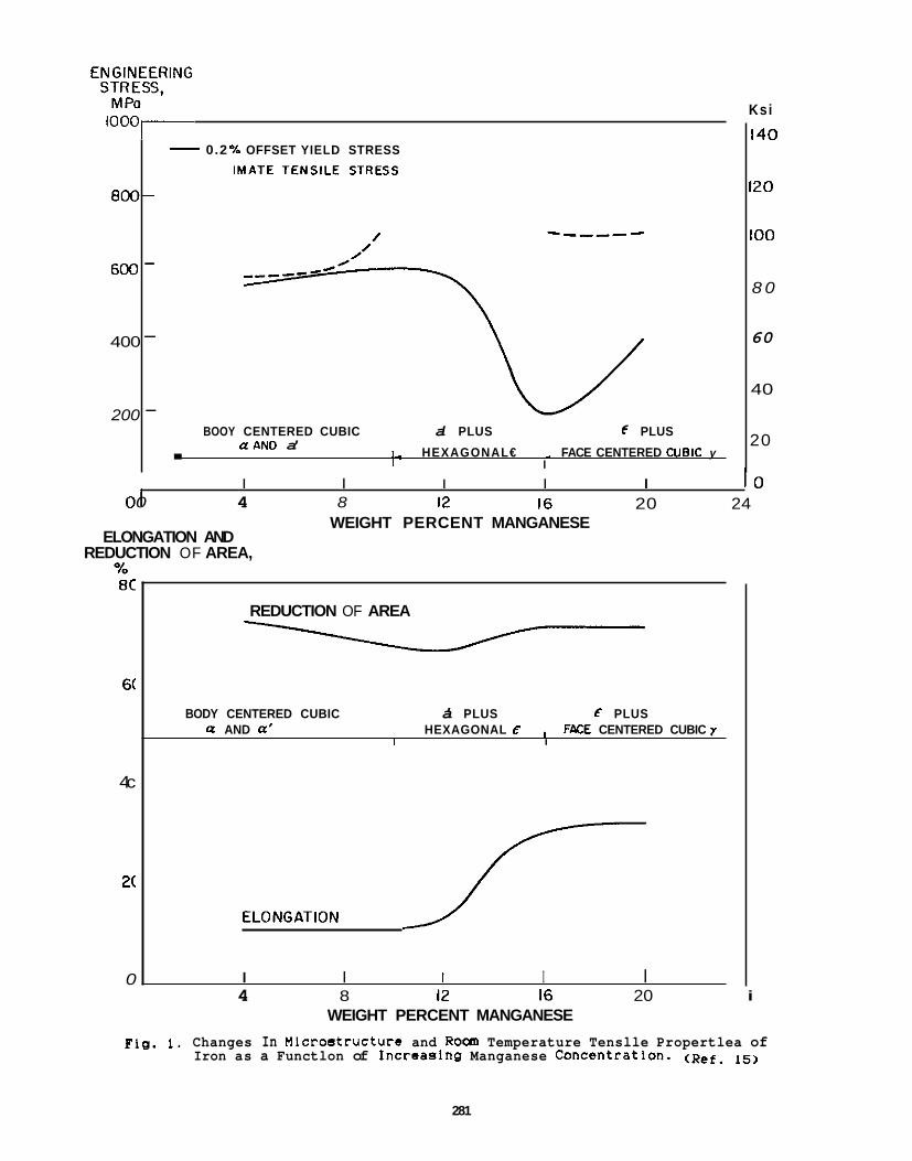
800-
600
400
200
0.2 % OFFSET YIELD STRESS -
-
-
- BOOY CENTERED CUBIC a' PLUS 6 PLUS
1 - HEXAGONAL€ FACE CENTERED CUBIC y a A N D a' .
1 - - I
Ksi
140
120
100
8 0
60
40
20
I I I I I I o 16 20 24 01 12 0 4 8
WEIGHT PERCENT MANGANESE ELONGATION AND
REDUCTION OF AREA, % 8C
6(
4c
2(
0
REDUCTION OF AREA
3 BODY CENTERED CUBIC a' PLUS E PLUS
U AND (I' HEXAGONAL € I FPCE CENTERED CUBIC y I I
I I I I I 4 8 12 16 20
WEIGHT PERCENT MANGANESE i
Fig. 1. Changes In Microstructure and Room Temperature Tenslle Propertlea of Iron as a Functlon of Incrcaslng Manganese Concentratlon. ( R ~ ~ .
281
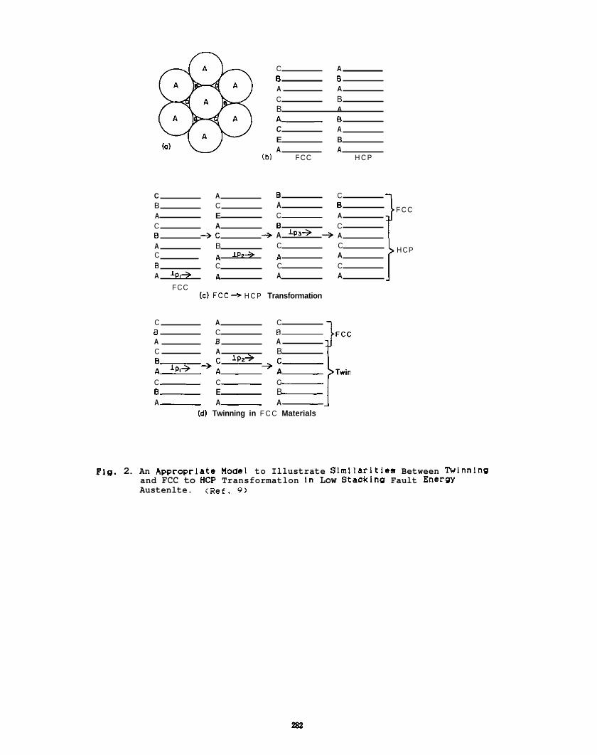
C A B B A A C B B A L a C A E B A A
(bl FCC H C P
F C C
H C P
C A B C B C A B A E C A C A B C B + C + A + A A B C C
B C C C C A l P Z + A A
A 'PI+ A A A FCC
(c) F C C + H C P Transformation
C A C B C E A B A C A B JFCC C C C B E B A A A
(dl Twinning in F C C Materials
Fig. 2. An Appropriate Model to Illustrate Slmllarltles Between WInnIng and FCC to H C P Transformatlon In Low Stacklng Fault Enerw Austenlte. (Ref. 9)
Table I. Phase Transformation Temperatures for PCWHCP Transformations In Pe-Mn-Cr Ternary Alloys as Determlned by Dilatometry. (Ref. 6 )
A1 l a y %signat ion On Heat ing On Cool inq
14Mn- 1 3Cr
14Mn- 18Cr c * y @ 1 4 5 " C y + ~ @ 6 0 ' C
16Mn-13Cr
E * y @ 150 "C y * E @ 140 "C
E * y @ 170 'C y * E @ 100 O C
16Mn-18Cr E * y @ 170 "C y * E @ 55 "C
1 8Mn- 13Cr s + y @ 165 "C y * E 8 100 "C
18Mn-18Cr E * y @ 160 "C y + E @ 85 "C
20Mn-13Cr E + y @ 150 O C y * E @ 80 "C
20Mn-18Cr No phase t r a n s i t i o n s observed
Table 11. Phases Observed Uslng X-Ray Dlffractlon Before and A f t e r Tenslle Testlng of Fe-Mn-Cr Ternary Alloys. (Ref. 6)
Af ter Tens i le Test ing A f t e r Tens i l e Test ing AI Heat Treated a t 23 'C a t -196 'C
A l l o y ne* t c__
Designat ion I E O ? ' 0 . Y 0
14Hn-13Cr 0 24 22 54 0 0 100 0 0 100
1 am-1 8cr B 16 5 79 0 5 95 0 3 91
16Hn-13Cr A 31 33 36 8 40 52 4 4 2 54
16M-lXr 0 18 33 49 6 43 51 -
1614"- 1 8 t r A 22 46 32 12 24 64 7 26 67
16nn-lBcr B 21 33 46 10 20 70 -
18Hn-13Cr A 47 46 7 16 33 51 9 24 67
18Hn-13tr B 51 39 10 7 28 65 5 26 69
lsnn-lscr 0 10 30 52 5 19 76 4 13 83
20m-13cr A 23 60 17 14 60 26 13 61 26
20nn-13cr B 37 48 15 26 51 23 -
Table 111. Rockwell "C" Hardness and Heat Treatments of Experimental Alloys (Ref. 7)
+Si+N +Si< Alloy Getrered(') +N +No W O + N - 16?(n-l3Cr (A)6.6 (A)8.2 (D)6.0 (B)15.3 (A)15.2 (C)13.2
(B)23.0 (C)ll.O (U)8.7 (C)15.5
(C)7.5 (D)6.5 (B)15.8 (C)14.0 (C)l5.5 16Mn-18Cr (A) 11.4 ( B ) l I . . 0 (D) 10.0 -
20Mn-13Cr W19.4 (C113.0 (D17.5 (D)17.2 tA)l0.5 (C)12.7 (B) 16.0 (C)6.0
~
(D)28.5 ( C ) 1 0 . 3 20M9-18Cr (A) 42.8 (C)9.8 - - (B)45.0
Note: letters adjacent to hardness values are indicative of the heat treatment.
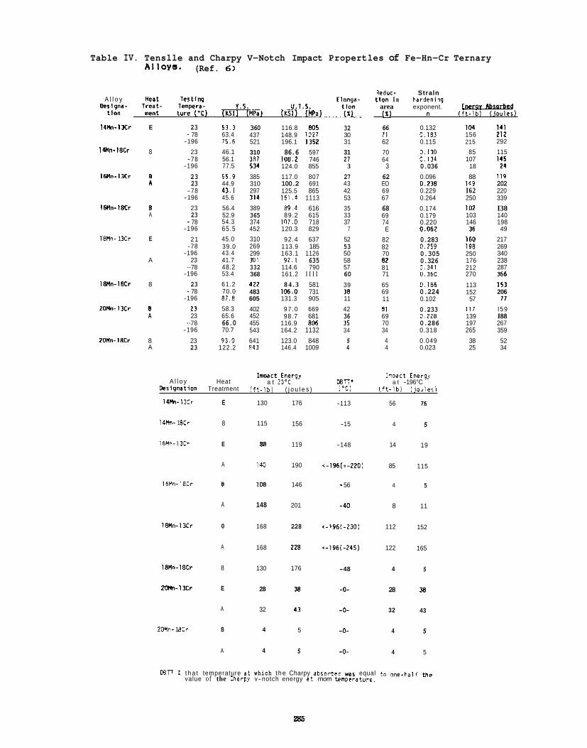
Table IV. Tenslle and Charpy V-Notch Impact Propertles of Fe-Hn-Cr Ternary AIloYs. (Ref. 6)
A l l o y oer19na-
110"
I4M-1 3cr
l4MMn-18Cr
16Mn-13Cr
I6Mwl8Cv
I8Hn- 1 I C r
18nn-18CP
2OHn- 13Cr
2OMn-18Cr
E
8
B n
B A
E
A
8
B A
8 A
23 - 78 -196
23 -78
-196
23 23
-78 -196
23 23 - 78
-196
21 -78
-196 23
- 78 -196
23 - 78 -196
23 23
- 78 -196
23 23
53.3 63.4 75.6 46.1 56.1 77.5
55.9 44.9 43. I 45.6
56.4 52.9 54.3 65 .5 45.0 39.0 43.4 41.7 48.2 53.4
61.2 70.0 87.0 58.3 65.6 66.0 70.7
93.0 122.2
360 437 521
310
534
385 310 297 314
389 365 374 452 310 269 299 Jo1 332 368 422 483 605
402 452 455 543
641 R41
3137
116.8 E05 148.9 I027 196.1 1352
86.6 597 108.2 746 124.0 855
117.0 807 100.2 691 125.5 865 161.4 1113
89.4 616 89.2 615
107.0 718 120.3 829
92.4 637 113.9 185 163.1 1126 92.1 635
114.6 790 161.2 I I I I 8 4 . 3 581
106.0 731 131.3 905
97 .0 669 98.7 681
116.9 806 164.2 1132 123.0 848 146.4 1009
32 30 31
31 2 7
3 27 43 42 53
35 33 37
7
52 53 50 58 57 60 39 38 11
42 36 35 34
5 4
Reduc- Straln t l on I n hardenlng
area exponent. [I ) " I f t - 1 b ) Uouler)
66 0.132 71 0.103 62 0.115
70 0.130 64 0.134
3 0.036 62 0.096 EO 0.238 69 0.229 67 0.264
68 0.174 69 0.179 74 0.220 E 0.062
82 0.283 82 0.259 70 0.305 82 0.326 81 0.141 71 0.360
65 0.186 69 0.224 11 0.102
91 0.233 69 0.228 70 0.286 34 0.318
4 0.049 4 0.023
1rnDact Energy 1moact Energy A l l o y Heat a t 23-C NTT' a t -196°C
Oerirlnation Treatment ( f t - l b ) ( j o u l e s ) I Y ) l f t - l b l ( j o u l e r )
14Mn-1 3Cr
I 4 h - 1 ECr
16Hn- 13Cr
16Mn- 18Cr
1 8 n n - l x r
1aNn-18Cr
2mn-13cr
2wn- 1 8Cr
E
8
E
A
0
A
0
A
8
E
A
B
A
130
115
88
140
108
148
168
168
130
28
32
4
4
176
156
119
190
146
201
228
220
176
38
43
5
5
OBTl ? t h a t temperature a t which t h e Charpy abrorbed w a s equal to ,,"+half me value of the Charpy v-notch energy a t mom temperature.
285
-113 56
-15 4
-148 14
~-1961=-220) 85
- 56 4
-40 8
<-196(-230) 112
<-196(-245) 122
-48 4
-0- 28
-0- 32
-0- 4
-0- 4
16
5
19
115
5
11
152
165
5
38
43
5
5
104 156 215
85 107
18
88 149 I62 250
I02 103 146
36 160 198 250 176 212 270
113 152
57 Ill 139 197 265 38 25
111 212 292
115 145 24
119 202 220 339
I38 140 198 49
217 269 340 238 287 366
I 5 3 206 11
I 59 I88 267 359
52 34
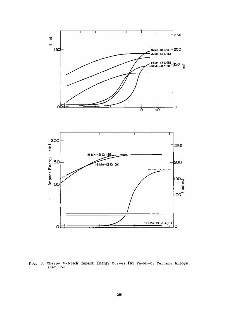
I I I I I I - - n - - - -
150- 16th-18CrW-200
250
Fig. 3. Charpy V-Notch Impact Energy Curves for Fe-Mn-Cr Ternary Alloys. (Ref. 6 )
I I I I I I I
200 - - -
n - - 250
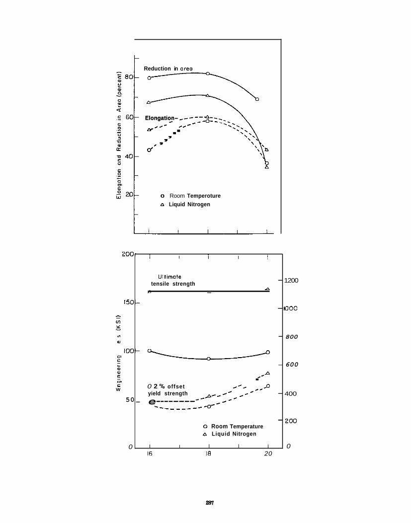
Reduction in area
200-
150-
- - u) Y - v1 "7
a% L
loo- c3 c
5
L m m
c CI,
W
50
0
Elongation- c- r .-- . &-- .
d'
, , ,
I I I I I
- 1200 UI timote tensile strength
P - A
- 1000
- 800
- 600 u
.SA
0 2 % offset .* / *D .
- 400 c- ./. .- yield strength c - c
-,A* - -- - - - - -- -0- - e-------- -
- 200 0 Room Temperature A Liquid Nitrogen
I I I I I 0 16 18 20
Elongation- c- r .-- . &-- . , , ,
d'
0 Room Temperoture A Liquid Nitrogen
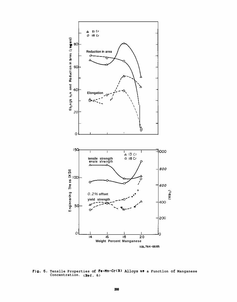
P I3 Cr 0 18 Cr
a- - Reduction in area
0 ? a
5 60- c ._ ._ - 0 3 v z v
E 40-
- 0
c 0 ._ m c 0
W -
20
0 .
- 0
- P-., I
I I
I I
Elongation \ \ - \ &.<--- I I -
\ -. - -
\ \ - \
\ \ \
I
-
- -
Q I I I
l5(x
2 fn
IM3- Y) Y)
& t ln 0 c m a-
.- L
f- 50- w
0 14 16 18 20
I I I I -'loo0 A 13 Cr
tensile ~ strength 0 18Cr
0.2% offset
- 800
- 600 , - , 0 , a z
P - 400
, - yield strength --&'
oI -I
H:;: z e-=- .' . =--- . - 200
Weight Percent Manganese
XBL764-6685
FIg. 5 . Tenslle Properties of Fe-Mn-Cr(B> Alloys as a Functlon of Manganese Concentration. ( ~ ~ f . 6)
e88
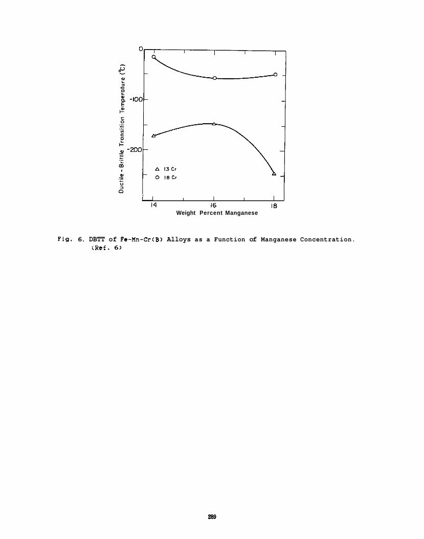
I 1 I I I I I 14 16 18
Weight Percent Manganese
Flg. 6. DBTT of Fe-Mn-CrCB) Alloys as a Function of Manganese Concentration. (Ref. 6 )
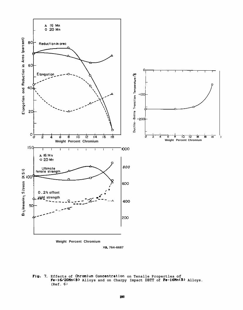
A 16 Mn - 0 20 Mn
01 I I I I I I I I I 0 2 4 6 8 10 12 14 16 18
Weight Percent Chromium
I I I I I I I I I 1000 I50
A 16Mn I 0 2 0 M n
Y 100 Ce Ce
L , I ,
I VI 0.2% offset . yield strength . a? c -- - - - - - - - -2 - - - - - -2:- - - - --A .- L -- --- .- ,-Q' a? *- w c *--
800
600
400
200
Weight Percent Chromium
XEL 764-6687
e -
0 I , , 1 1 ,
0 2 4 6 8 10 12 14 16 I8 Weight Percent Chromium
PIP. 7. Effects of Chraolum Concantratlon on Tenalle Propertlea of Pe-l6/20Mn(B) Alloys and on Charpy Impact DBTT of Fe-l6Mn(B) Alloys. (Ref. 6)
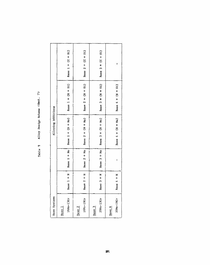
P
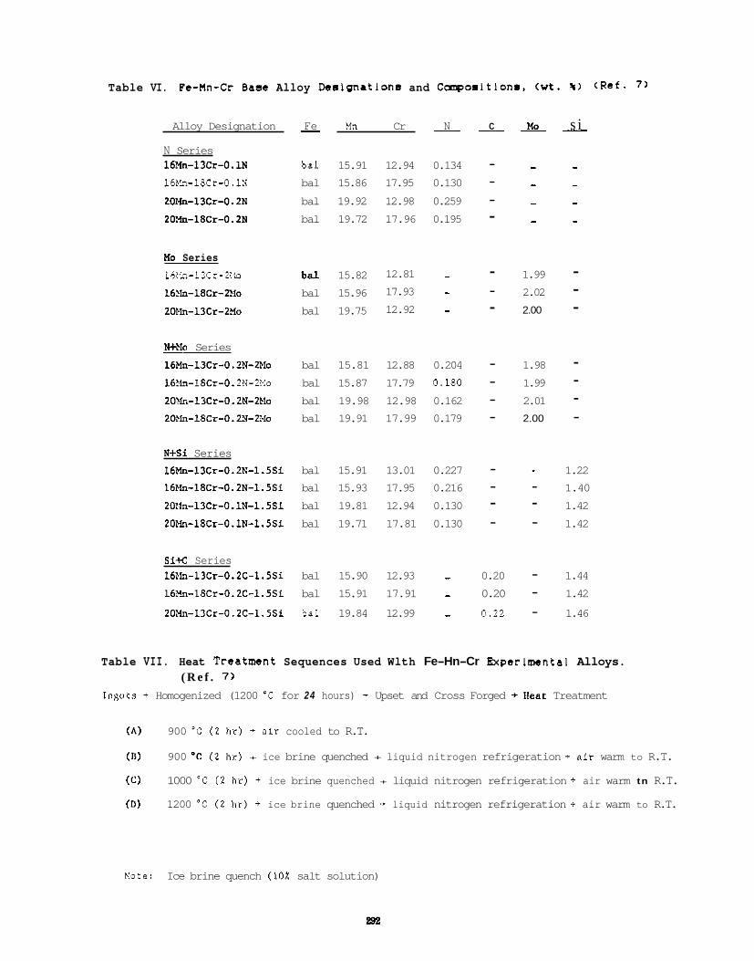
Table VI. Pa-Mn-Cr Baao Alloy Dealgnnatlons and Careoaltlons. < w t . % > (Ref- 7 )
Alloy Designation - Fe Mn Cr __ N - C - MO - s i
N Series 16?ln-13Cr-O.I.N bal 15.91 12.94 0.134 - - - 16Mn-18Cr-O.lN bal 15.86 17.95 0.130 - - - 20Xn-13Cr-0.2N bal 19.92 12.98 0.259 - - - 20Xn-18Cr-0.2N bal 19.72 17.96 0.195 - - -
plo Series 16Mn-13Cr-ZMo bal 15.82 12.81 - - 1.99 - 16>b-18Cr-2Mo bal 15.96 17.93 - 2.02 - 201.h-13Cr-2Mo bal 19.75 12.92 - 2.00 -
- -
Neb Series 16Mn-l3Cr-O.?N-2>10 bal 15.81 12.88 0.204 - 1.98 - 16!.h-1SCr-O. 2N-2Mo bal 15.87 17.79 0.180 - 1.99 - 20>k.-13Cr-O. 2N-2Ma bal 19.98 12.98 0.162 - 2.01 - 20>h-18Cr-0.211-2i~lo bal 19.91 17.99 0.179 - 2.00 -
-
N+Si Series 16Mn-13Cr-O.ZN-1.5Si bal 15.91 13.01 0.227 - - 1.22 16EIn-18Cr-O.ZN-l.SSi bal 15.93 17.95 0.216 - - 1.40 20:fn-13Cr-O.lN-l,5Si bal 19.81 12.94 0.130 - - 1.42 20EIn-18Cr-O.lN-1.5Si bal 19.71 17.81 0.130 - - 1.42
Si< Series 16EIn-13Cr-O.ZC-1.5Si bal 15.90 12.93 - 0.20 - 1.44 16?In-18Cr-O.ZC-1.5Si bal 15.91 17.91 - 0.20 - 1.42
20Nn-13Cr-O.2C-1.5Si bal 19.84 12.99 - 0.22 - 1.46
Table VII. Heat Treatment Sequences Used Wlth Fe-Hn-Cr Experimental Alloys. ( R e f . 7 )
Inguts + Homogenized (1200 'C for 24 hours) + Upset and Cross Forged + k a t Treatment
(A) 900 ' C ( 2 hr) + n i r cooled to R.T.
(11)
(C)
(D)
900 OC (2 h r ) + ice brine quenched + liquid nitrogen refrigeration + n i r warm to R.T.
1000 'C ( 2 h r ) + ice brine quenched + liquid nitrogen refrigeration + air warm tn R.T.
1200 "C ( 2 hr) + ice brine quenched -* liquid nitrogen refrigeration + air warm to R.T.
Kate: Ice brine quench (10% salt solution)
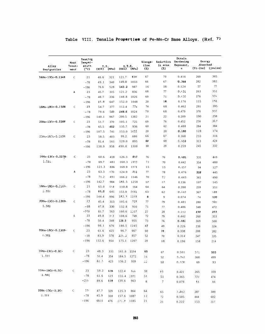
Table VIII. Tenslle Propertles of Pe-Mn-Cr Base Alloys. (Ref . 7 )
16Nn-13Cr-0.134N C 2 1
-78
-196
A 23
- 78
-196
16Mn-18Cr-0.13ON C 2 1
- 78
-196
2OEln-13Cr-O.259N C 23
-78
-196
20Mo-18Cr-0.195N C 23
-78
-196
16Eb-13Cr-O.227p-
1 . 5 S i
16bh-18Cr-0, 216N-
1 . 5 S i
2OPln-13Cr-0.130N-
1.5si
2Ulln-18Cr-O.130N-
1.5si
C 23
-78
-196
A 23
-78
-196
C 2 1
- 78
-196
C 23
-18
-195 A 23
-78
-196
C 23
-18
-196
46 .6 321
4 9 . 1 340
76.6 528
45.7 315
48 .7 336
9 3 . 8 647
54 .7 377
7 9 . 6 549 1 4 0 . 1 967
51.7 370
65.5 4 5 2
1 0 7 . 5 741
58 .5 403
81.4 561
1 3 8 . 9 958
60 .6
69.7
1 2 1 . 3
63 .3
71.2
142.7
6 5 . 0
9 3 . 0
144 .4
45.4
47 .8
81.7 49 .8
50 .4
9 8 . 1
61 .6
83 .9
132 .6
418
481
836
(836
491
984
(148
641
996
313
330
563 3,,1
348
676
425
578
914
121.7 839
149.8 1033
143.2 987
121 .2 836
1 4 8 . 8 1026
1 5 2 . 0 1048
112.4 77s 148.5 1024
200.5 1382
105 .1 725
135 .7 936
1 5 3 . 0 105s
99.2 686
1 2 9 . 0 895
4 9 0 . 0 1310
126 .3 851
1 6 0 . 3 1105
169 .9 1171
124 .9 861
166.2 1146
1 8 2 . 5 1258
110.8 164
153.9 1061
183.9 1268
105 .6 728
1 3 2 . 8 916
160 .6 1107 108 .6 749
138.5 955
180 .5 1245
96 .7 667
1 2 4 . 3 857
175 .1 1207
67 70
66 67
16 1 6
68 77
71 69
18 20
74 6 8
70 6 8
22 2 1
76 69
60 62
20 20
6 6 67
50 69
30 29
76
7 1
1 5
77
70
I 1
64
63
8
77
71
2 1
72
73
4 1
60
52
20
76
70
1 5
78
7 I
1 7
64
62
9
79
77
28 79
76
49
18
70
18
0 .416
0.368
0 .124
0 . 4 3 1
0 . 4 0 0
0 .176
0 .462
0.479
0.209
0.452
0 .488
0.180
0.368
0 .408
0 .259
0.l181
0.442
0.151
0 . 4 7 6
0 . 4 4 3
0.136
0.390
0 . 4 4 0
0 .074
0 . 4 8 1
0.486
0 . 2 1 2
0 .442
O . l , 8 1
0 .226
0.338
0.314
0 .196
269
282
57
263
276
115 291
370
190
256
284
1 2 8
233
313
245
331
354
94
318
361
107
259
367
7 4
280
348
1 5 0
260
369
239
208
247
158
365
382
77
351
374
I 5 6
395
507
258
31, 7
384
174
316
424
332
4 4 9
480
127
445
490
145
351
498
IUO
180
472
I"3
353
500
324
282
3J5
2 1 4
67 0 .501 371 503 52 0.3Y2 368 499
12 0.108 69 93
16Nn-13Cr-0.2C- C 23 4 8 . 3 331 1 6 1 . 6 I l l 4 6 5
1.5si -78 51.4 354 184.5 1272 56
-196 61.18 423 136 .2 939 11
RO 0.421 265 359
51 0 .365 3 5 0 474
8 7 0 .079 1, 5 61
65 0 . r,4 2 287 389
7 2 0.505 444 602
21 0 .222 1 5 3 2 U 7
I 6 ~ l n - 1 8 ~ ~ - 0 . 2 ~ - C 23 5 9 . 2 408 122.4 866 59 1 . S S L -78 61 .6 (25 155 .4 1071 51
-196 89 .6 618 13Y.6 963
20Nn-llCr-O.2C- C 2 1 47.7 329 1 2 5 . 3 864 64 1 . 5 s i -78 4 5 . 9 310 157 .6 1087 1 2
-196 69.11 476 1 7 1 . 8 1185 2 1
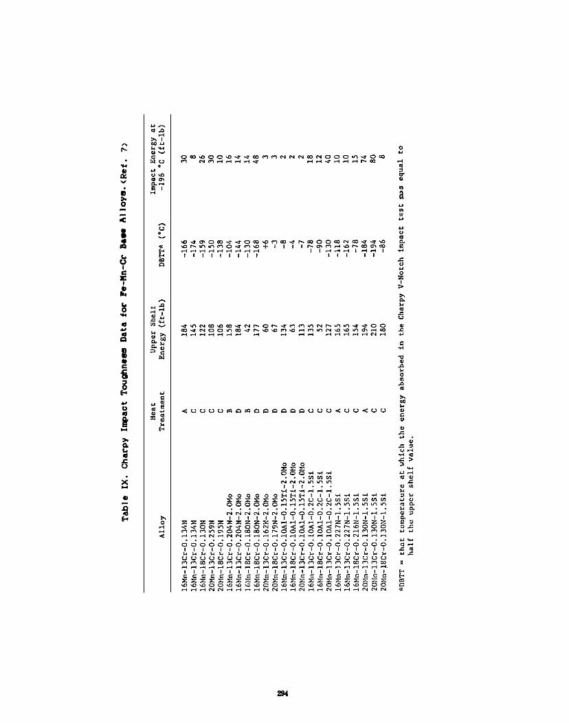
m a Y n W Y
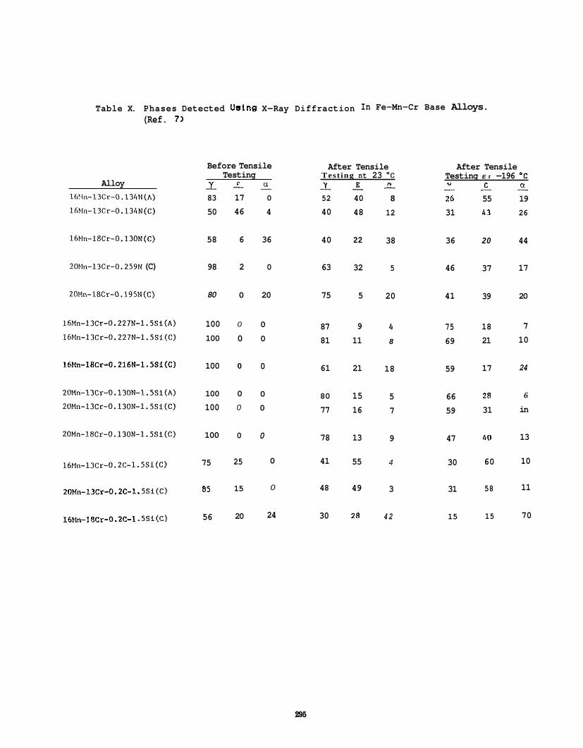
Table X. Phases Detected Ualng X-Ray Diffraction In Fe-Mn-Cr Base Alloys. (Ref. 7)
Alloy 16’1n-13Cr-0.134N(h) 16?ln-13Cr-O.I34N(C)
16Mn-18Cr-O.l30N(C)
20Mn-13Cr-0.259N (C)
20Mn-18Cr-O.I95N(C)
16Hn-13Cr-0.227N-1.5Si(A)
16Mn-13Cr-0.227N-1.5Si(C)
16Mn-18Cr-0.216N-1 .5Si(C)
20Mn-13Cr-0.130N-l..5Si(A) 20Mn-13Cr-0.130N-1.5Si(C)
20Mn-18Cr-0.130N-1.5Si(C)
16Mn-13Cr-0.2C-1.5Sl(C)
20Mn-13Cr-0.X-1. SSi(c)
16Mn-I 8Cr-0.2C-1 .5SI(C)
Y 83
50
-
58
98
80
100 100
100
100
100
100
75
85
56
a
0
4
-
36
0
20
0
0
0
0
0
0
0
0
24
Before Tensile Testing
F - - 17 46
6
2
0
0
0
0
0
0
0
25
15
20
Y 52
40
-
40
63
75
87 81
61
80
77
78
41
48
30
E
40
48
-
22
32
5
9 11
21
15 16
13
55
49
28
After Tensile After Tensile Test ing nt 23 OC Testing E t -196 ‘C
n Y r N - - - 26
12 31 8
38 36
5 46
20 41
4 75 8 69
18 59
5 66 7 59
9 47
4 30
3 31
42 15
., - 55 43
20
37
39
18 21
17
Z R 31
60
60
58
15
- 19 26
44
17
20
7 10
24
6
in
13
10
11
70
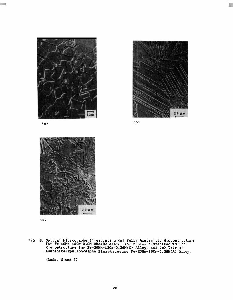
Flg. 8. Optlcal Mlcropraphs Illuetratlng (a) Fully Austenltlc Microstructure for Fe-16nn-13Cr-0.2N-2no(B) Alloy. (b) Duplex Austenlte/Epsllon Mlcroetructure for Fe-20Mn-13Cr-0.26N(C) Alloy, and <e) Trlplex AustenLte/~sllon/Alpha Hlcrwtructure Fe-20Hn-13Cr-0.26N(A) Alloy.
(Refs. 6 and 7 )
e98
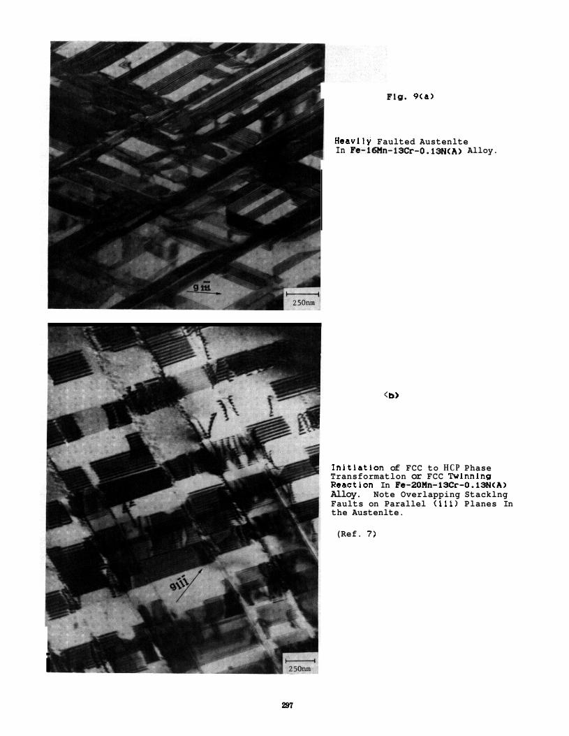
Fig. 9ta)
Heavlly Faulted Austenlte In Fe-lbMn-l3Cr-0.13N<AL) Alloy.
< b)
Inltlatlon of FCC to H C P Phase Transformatlon or FCC Twlnnlng Reactlon In Fe-20Mn-1Xr-O.ISN(A) Alloy. Note Overlapping Stacklng Faults on Parallel (111) Planes In the Austenlte.
(Ref. 7 )
i
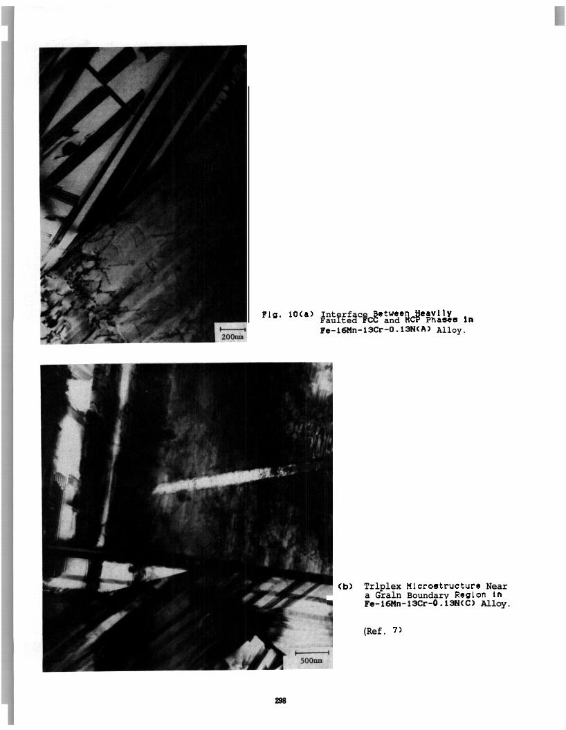
Flg. IOCa) Interface Betwen Heavlly Faulted FIX and HCP Phasss In Fe-l6Mn-13Cr-O.l3N<A) Alloy.
Cb) Trlplex Mlcrostructure Near a Graln Boundary Reglon In
.I Fe-l6Mn-lXr-O.lSN<C> Alloy.
(Ref. 7 )
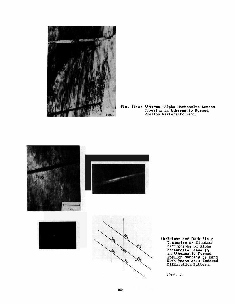
Flg. Athermal Alpha Martenslte Lenses Crosslng an Athermally Formed Epsllon Martenalto Band.
(b>Brl&t and Dark Field Tranmlsslon Electron Micrographs of Alpha Martenalto Len- In an Athermally Formed Epsllon Martenelto Band Wlth Assoclatcd Indexed Dlffractlon Pattern.
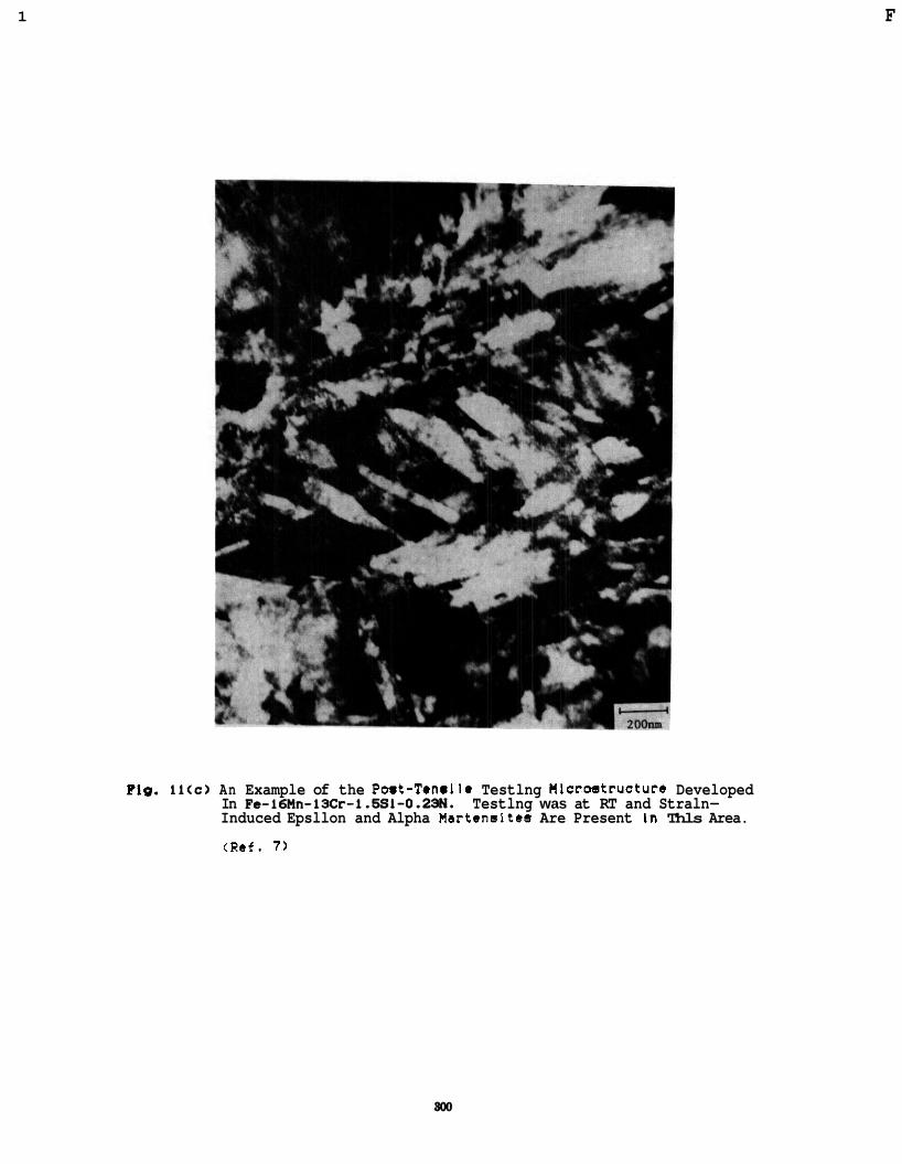
1 F
Flg. li<c) An Example of the Post-Tenslle Testlng Mlcrwtructure Developed In Fe-16Mn-IXr-i.SSL-O.23N. Testlng was at RT and Straln- Induced Epsllon and Alpha Hartensltes Are Present In Thls Area.
(Ref. 7 )
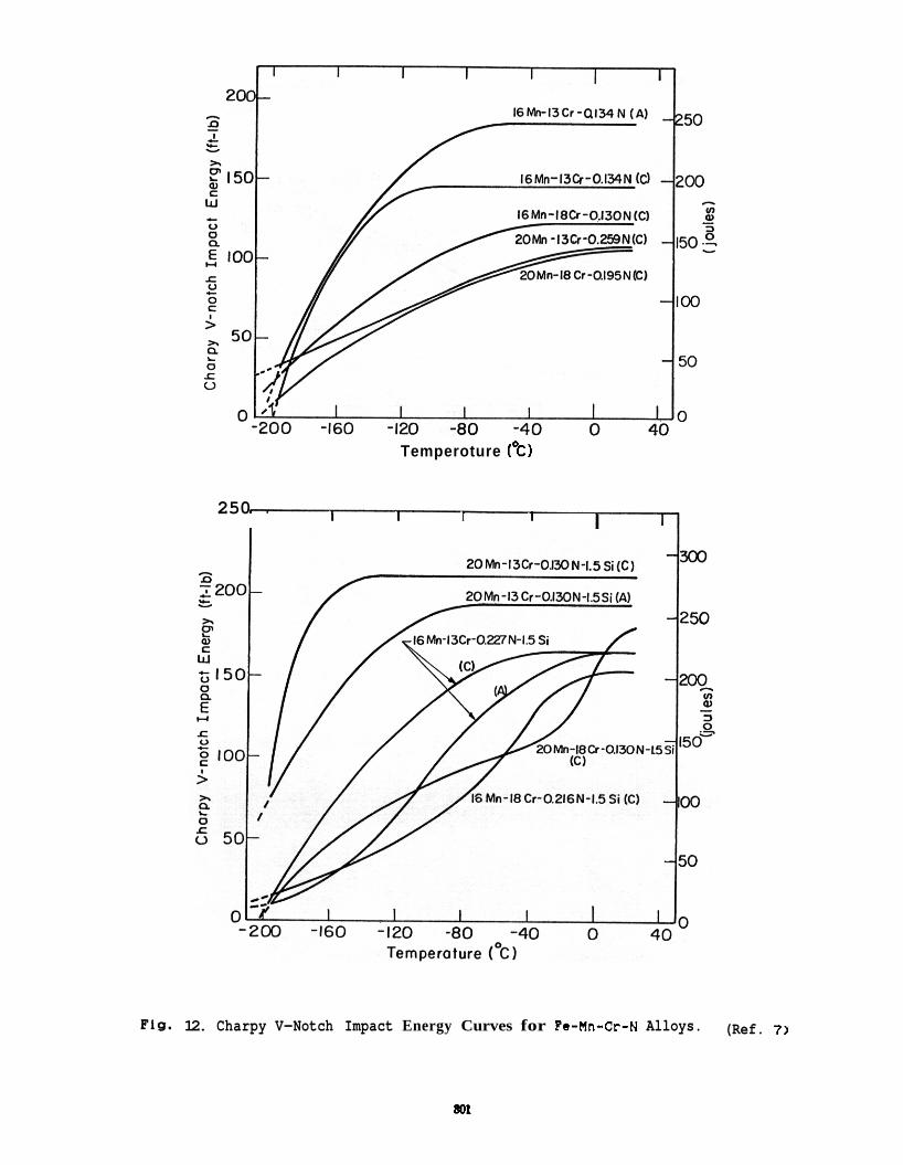
Temperoture (“cl
250 I I I I I
Fig. 12. Charpy V-Notch Impact Energy Curves for Fe-Mn-Cr-N Alloys. (Ref. 7)
801
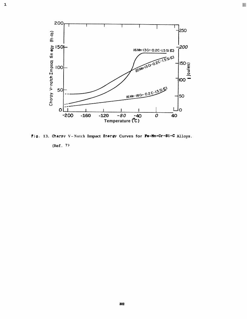
1
l e & I 2. 150- -200 F al I6Mn-l3Cr-OPC-I.SSi (c) C
W
u e
a 3
u 0 c 0 0
- .- - 100 - L
0 1 I I I I I I o -200 -160 -120 -80 -40 0 40
Temperature ('C)
110. 13. Charpy V- N o t c h Impact Energy Curves for ?e-nn-Cr-SI-C Alloys.
(Ref. 7 )
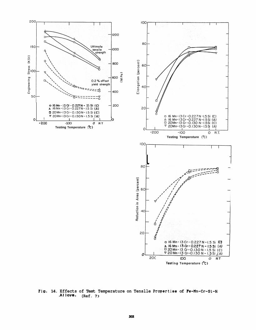
Too 0 16Mn - 13 Cr -0.227N - 1.5 Si IC1 A 16Mn-13Cr-O.227N-1.5Si ( A I 0 20Mn-13Cr-0.130N-1.5Si IC1 V 20Mn-13Cr-0.130N-1.5Si ( A I
01 I I I I 10 -200 -100 0 R T
Testing Temperature 1%)
t Testing Temperoture IT)
ioo-
0 16Mn-13Cr-O.227N-1.5Si IC1 A 16Mn- 13Cr-0.227N-1.5Si (AI
0 0 R T io0
Tesling Temperature ("C)
Flg. 14. Effects of Test Temperature on Tenslle Propertlea of Fe-Mn-Cr-SI-N .Al loys- (Ref. 7 )
808
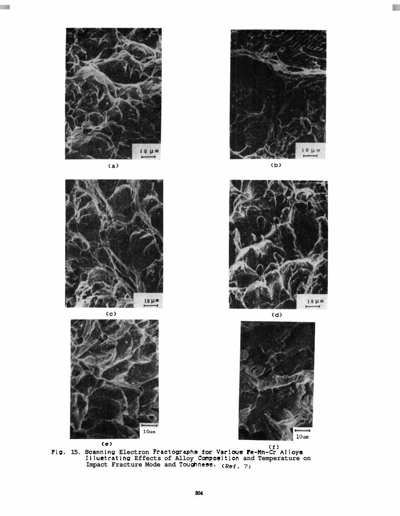
Flg. 15.
lOum - lOum
( f ) (e ) Scannlng Electron Fractographs for Varlous ?e-Mn-Cr Alloy5 Illustratlng Effects of Alloy Canposltlon and Temperature on Impact Fracture Mode and Toughnea. ( ~ ~ f . 7)
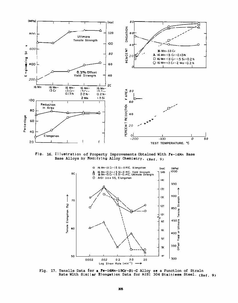
lksit
120 Ull imott
Tensile Strength 100
600
80
.I)
- In
- a 0
u c / -/ 60
c 0.2% Offset Y Yield Slrenglh 40
c"
200
O 1 6 M n - 1 3 C r - 2 M o - O . 2 N I I
0.13N 0 2 N - 0 2 N - 2 Ma 1 5 5
I O 0 I Reductton
I I I
I I I I
80
+ 6 0 U
z 0
4 0 -o--..-..d z 16 Mn-13 Cr
0 2 0 a A 16Mn- I3 Cr -O . I3N 0 1 6 M n - 1 3 C r - 1 5 S i - 0 . 2 N
w
w
2 80
60 z e' 0 0 /- 2 4 0 w R c , w 0 R
De t
c , , , 2 2 0 I ,
: 01 I I I -200 -100 0 5 0
TEST TEMPERATURE. *C
Flg. 16. Illustratlon of Property Improvements Obtalned Wlth Fe-16th Base Base Alloys by Modifying Alloy Chemlstry. ( ~ ~ f . 9)
kill 0 16 Mn-13 Cr-1,5 S i- 0 14C. Elongolion
A 16 Mn-13 Cr- I 5 Si-0 14C. Yield Strength 145 0 0 AIS1 3 0 4 SS. Elonpotion
16 M n - 1 3 0 - 1 . 5 Si-0.14C. Ullirnote Slranglh
0002 002 0 2 2 0 20 Log s t r o ~ n ROIL [ rn in-0 +
Flg. 17. Tenslle Data for a Po-16Mn-13Cr-SI-C Alloy as a Functlon of Straln Rate Wlth Slmllar Elongation Data for AIS1 304 Stalnlees Steel. ( ~ ~ f . 9)
805
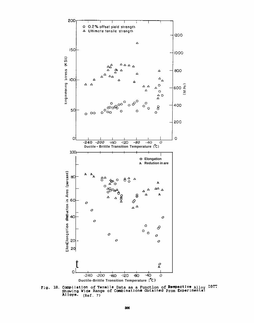
01 I I I I I I I I o -240 -200 -160 -120 -80 -40 0 Ductile - Brittle Transition Temperature CC)
100, I I I 1 I I I c
c 2 20 0 1 w
A A A
0
0
0
0 Elongation A Redution in are
A A
0
0
A
M A A
0
O L ?
0 0 0
0
0 t A
01 I I I I I I I -240 -200 -160 -120 -80 -40 0
Ductile-Brittle Tronsition Temperature ("C)
Flg. 18. CcrnpIlatIon of Tenalle Data aa a Functlon of Respective Alloy DBlT ShaJlng Wlde Range of Comblnatlons Obtalned Prom Experimental A1 lOYS- (Ref. 7 )
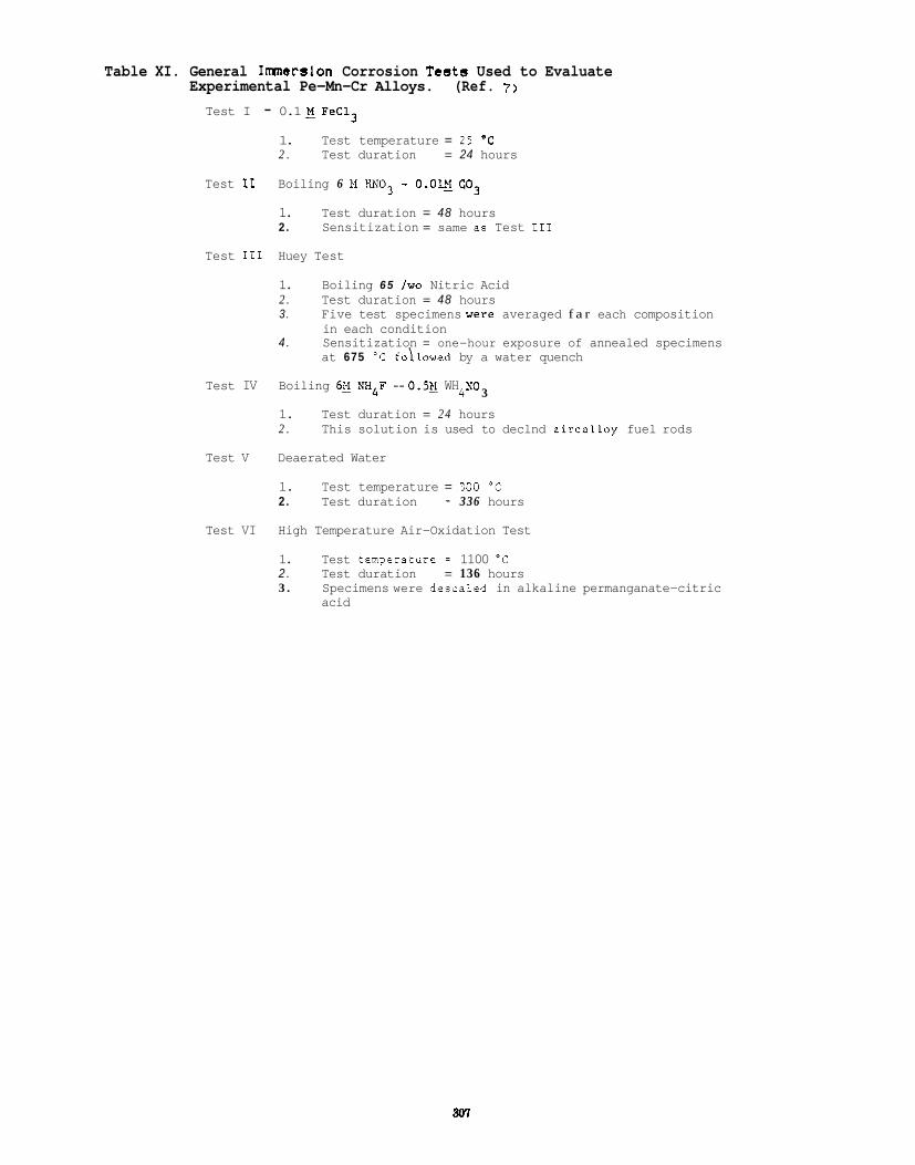
Table XI. General Imerslon Corrosion Tests Used to Evaluate Experimental Pe-Mn-Cr Alloys. (Ref. 7 )
Test I - 0.1 E FeC13
1. Test temperature = 25 "C 2 . Test duration = 24 hours
Boiling 6 N HN03 - 0.01s C03
1. Test duration = 48 hours 2. Sensitization = same as Test I11
Test I1
Test I11 Huey Test
1. 2 . Test duration = 48 hours 3. Five test specimens were averaged f a r each composition
in each condition 4 . Sensitization = one-hour exposure of annealed specimens
at 675 'C foilawed by a water quench
Boiling 6 5 two Nitric Acid
Test IV Boiling 6it W 4 F - 0.5g WH YO
1. Test duration = 24 hours 2 . This solution is used to declnd zircalloy fuel rods
4' 3
Test V Deaerated Water
1. Test temperature = :OO "C 2. Test duration = 336 hours
Test VI High Temperature Air-Oxidation Test
1. Test temperaturf = 1100 "C 2 . Test duration = 136 hours 3 . Specimens were descaled in alkaline permanganate-citric
acid
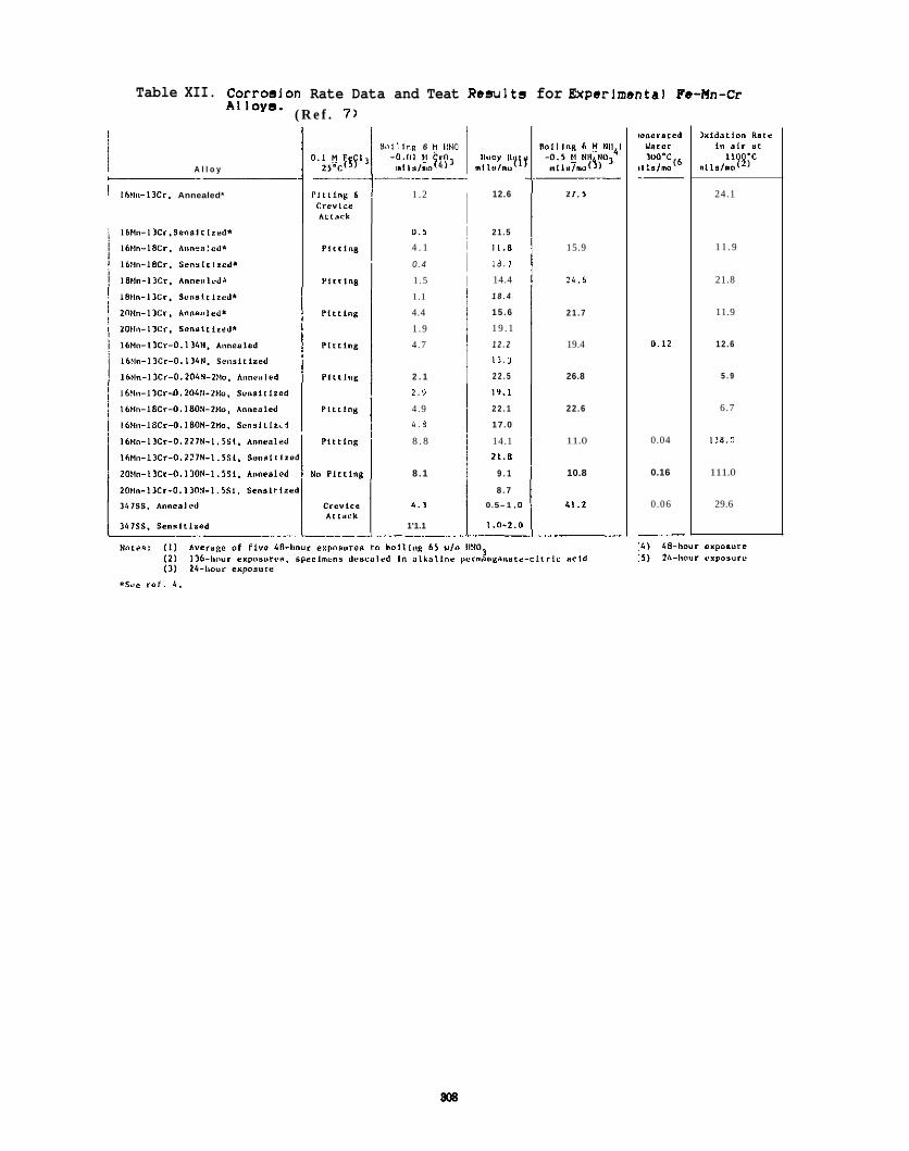
Table XII. Corroalon Rate Data and Teat Results for Experlmental Fa-Hn-Cr A I loya. ( R e f . 7 )
I A l l o y
I Ih?li,-IlCr. Annealed*
'dn l l lng 6 U llNO
1 . 2
0 . 5
4 . 1
0 .4
1 . 5
1.1
4.4
1 . 9
4 .7
2 . 1
2.9
4 .9 4 .8
8 . 8
8 .1
4.1
1'1.1 -
I laoy Ili , nllslno~'.
12.6
2 1 . 5
11.8
1 8 . 1
14.4
1 8 . 4
1 5 . 6
1 9 . 1
1 2 . 2
11.)
2 2 . 5
19.1
2 2 . 1
17.0
14.1 21.8
9 . 1
8 . 7
0.5-1 .o
1.0-2.0 ~
2 7 , 5
15.9
24.6
2 1 . 7
19.4
26.8
22 .6
11.0
10.8
11 .2
0.12
0.04
0.16
0.06
24.1
1 1 . 9
21.8
11.9
1 2 . 6
5 . 9
6.7
138.0
111.0
29.6
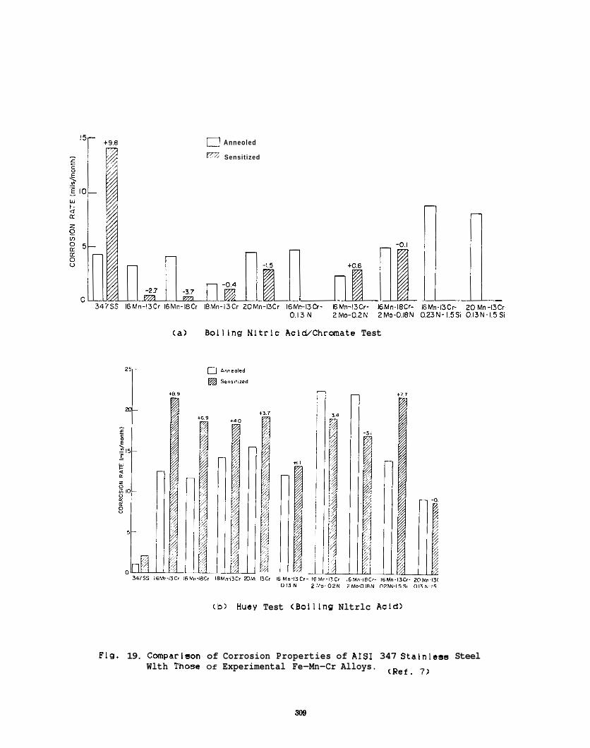
0 Anneoled
Sensitized
(a ) Bolllng Nltrlc AcIWChrmate Test
+3.7
I3Cr 16Mn-13Cr- I 0 1 3 N i
(b) Huey Test (Bolllng Nltrlc Acld)
Flg. 19. Cmparlson of Corrosion Properties of AIS1 347 Stalnless Steel Wlth Those Of Experimental Fe-Mn-Cr Alloys. (Ref. 7)
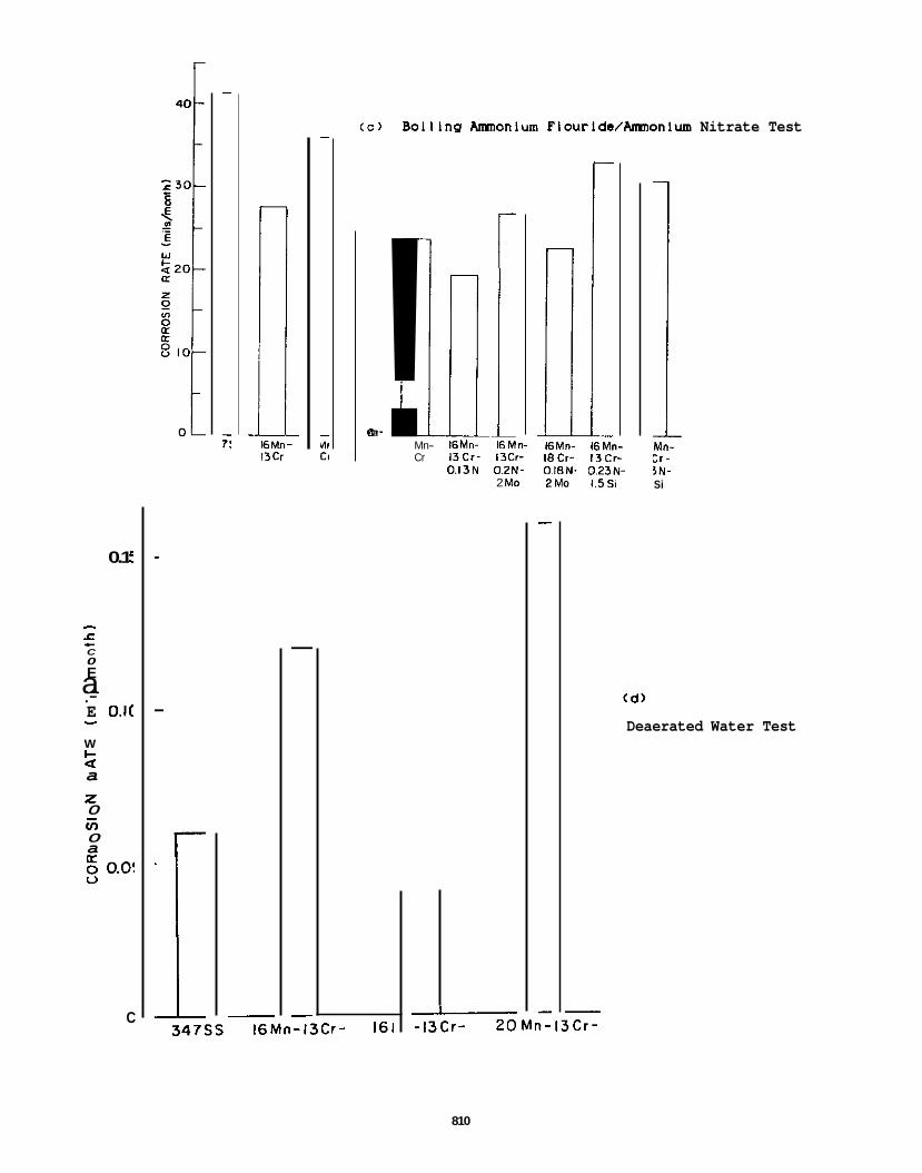
0.1 :
- f E
E O.l(
C 0
a - .- - W l- a
2 0 ul 0 a
V
a
-
5 O.O!
C I -13Cr - 2 0 M n - 1 3 C r - 347ss
-
16Mn- 13Cr
( c ) Boillng AmonIum Flourlde/Anmonlum Nitrate Test
! rln- Cr
16Mn-13Cr- 161
r
- Mn- 16Mn- 16Mn- Cr 13Cr- 13Cr-
0.13N 0.2N- 2 Mo
l6Mn- 16Mn- 18Cr- 13Cr- OI8N- 0.23N- ZMo 1.5Si
M"- :I- 3N- Si
(d )
Deaerated Water Test
810
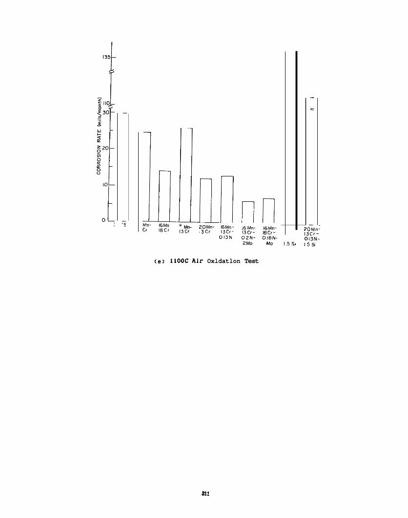
Mn- 2OMo- 16Mn- 16Mn- 16Mn- 130 13Cr 13Cr- 13Cr- 8Cr-
013N OZN- O18N- 2Mo Mo 1 5 %
2 0 M n I 13Cr- 0 13N- 1 5 3
( e ) llOOC Alr Oxldatlon Test

EFFECTS OF LOW TEMPERATURE NEUTRON iRR4DiATlON ON THE PROPERTIES OF 300 SERiES STAINLESS STEELS - G. R. Cdette and G. E. Lucas (University of California, Santa Barbara)
OBJECTIVE
To summarize the effects of neutron irradiation at intermediate temperatures (-300%) on the microstructure and mechanical properties of austenitic stainless steels.
SUMMARY
Neutron irradiation 01 austenitic stainless steels can result in significant property changes. Property degradation appears to be greatest for irradiation temperatures (and comparable test temperatures) near 300°C. Here, hardening and loss of ductility may reduce fracture toughness values to as low as 45 M P a G by exposure levels of 5 dpa. These data suggest an experimental test program designed to evaluate critical microstructural and mechanical property changes in austenitic stainless steels at low irradiation temperatures.
PROGFlESSANDSTATUS
While it is well known that neutron irradiation results in significant mechanical property changes and dimensional instability in materials in general, quantification of these changes is a costly but necessary part of materials development and qualification for reactor application. Much of the structural materials research to date in support of fusion technology development has focussed on the effects of irradiation at relatively high temperature (400-600'C) anticipated for long term fusion structures. However, designs of interim and near term machines have suggested utilization of low operating temperatures (1 00-3OO'C). and austenitic stainless steels have been identified as possible candidate materials for these structures.'
Consequently, we have reviewed the literature for the effects of irradiation at or near 300'C on austenitic stainless steels. We describe the results of this below. This is divided into a description of microstructural evolution, a description of mechanical property changes, and a suggested experimental program to augment the existing data.
al Fvolutlpn
There are only a few quantitative and reliable data in the older literature on microstructural evolution in austenitic stainless steels irradiated at around 300'C. This is largely due to earlier resolution limitations in transmission electron microscopy (TEM). In general, irradiation-induced microstructures were reported as being composed of black dot damage with some indications of Interstitial loops and bubbles at higher exposures. No void swelling or precipitation was observed (e.g. swelling was found to begin at about 350'C with high Incubation exposures and low swelling rates). Maziasz' has reviewed this literature. More recently, however, several higher exposure (5-60 dpa) irradiations near 300'C have been carried out in the mixed spectrum HFIR5-'0 reactor and one in the ORR reactor." High resolution anaiytical TEM techniques were used to characterize the microstructures. The alloys studied included both 316 and Ti-modified 316 type stainless steels in both cold-worked (CW) and solution annealed (SA) conditions. Further, a relevant data set for a 33 dpa irradiation in the mixed spectrum Advanced Test Reactor (ATR) Of a 348 stainless steel has been reported.12 The data from these studies are tabulated in Table 1.
These results show that the low temperature irradiation-induced microstructures are highly consistent for various alloys and a range of irradiation conditions. The microstructures are dominated by interstitial-type. Frank dislocation loops and small cavities. Table 2 summarizes average loop and cavity number density and diameter data for irradiations of the SA alloys near 300%. The density of loops appears to decline above 5-10 dpa at an approximately constant diameter. The cavities are probably subvisible at 5 dpa but have an approximately constant number density above I O dpa. The cavity diameter increases with exposure from about 1.1 nm at 10 dpa to 2.2 nm at 35 dpa. This can be attributed to the increased helium content (from about 400 to 2500 appm). The number density of cavities is about 10 times higher than for loops at 35 dpa. Irradiations of one alloy to 58 dpa showed a continued decline in the number of loops and a small decrease in their size. Surprisingly. the size and number density of bubbles also declined slightly. Some of these differences may be due to
813
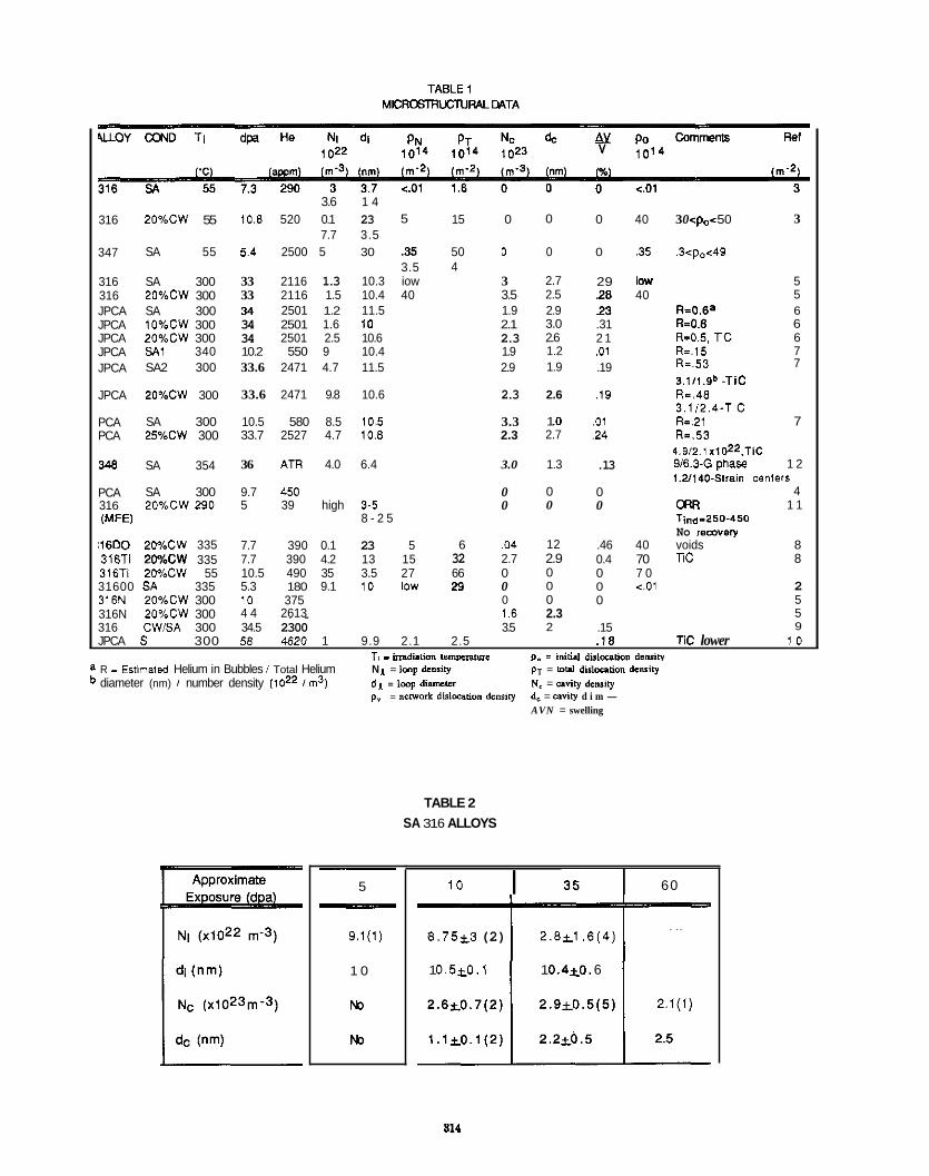
31 6
347
316 316 JPCA JPCA JPCA JPCA JPCA
JPCA
PCA PCA
343
PCA 31 6 W E 1
2O%CW 55
SA 55
SA 300 2O%CW 300 SA 300 1O%CW 300 2O%CW 300 SA1 340 SA2 300
2O%CW 300
SA 300 25%CW 300
SA 354
3.6 1 4 10.8 520 0.1 23
7.7 3.5 5.4 2500 5 30
33 2116 1.3 10.3 33 2116 1.5 10.4 34 2501 1.2 11.5 34 2501 1.6 10 34 2501 2.5 10.6 10.2 550 9 10.4 33.6 2471 4.7 11.5
33.6 2471 9.8 10.6
10.5 580 8.5 10.5 33.7 2527 4.7 10.8
36 ATR 4.0 6.4
SA 300 9.7 450 2O%CW 290 5 39 high 3-5
i16DO 2WbCW 335 316% ZO%CW 335 316T1 2WbCW 55 31600 SA 335 316N 2O%CW 300
5
3 5 3.5 iow 40
8 - 2 5
7.7 390 0.1 23 5 7.7 390 4.2 13 15 10.5 490 35 3.5 27 5.3 180 9.1 10 low 10 375 4 4 2613
15 0
50 0 4
3 3.5 1.9 2.1 2.3 1.9 2.9
2.3
3.3 2.3
3.0
0 0
6 .04 32 2.7 66 0 23 0
0 1.6
0
0
2.7 2.5 2.9 3.0 2.6 1.2 1.9
2.6
1 .o 2.7
1.3
0 0
12 2.9 0 0 0 2.3 2
0
0
29 28 23 .31 2 1 .01 .19
.I9
.01 2 4
.13
0 0
.46 0.4 0 0 0
40
.35
loW 40
40 70 7 0 <.Ol
3 0 < p < 5 0
.3<p.<49
3
5 5
R=O.6' 6 R.0.6 6 R=0.5. l i C 6 k . 1 5 7
3.1/1.9D - T i c R-.48 3.1/2.4-TiC R=.21 7 R=.53 6.9/2.1 x1OZ2.TiC W6.3-G phase 1 2 1.2I140-Strain Centers
4 m 1 1 Tln.p250-450 No remvery voids 8 Tic 8
k . 5 3 7
316N 2O%CW 300 ~. . 316 CWEA 300 34.5 2300 3.5 .15 JPCA S 300 56 4520 1 9.9 2.1 2.5 . I 8 Tic lower 1 0
T, - inadiation t c m ~ s ~ ~ m e De = initial dkloution dcolilv
2 5 5 9
. _ N 1 = Imp density pr = loa didoution dsority d l =Imp d i m m N. = uviry dsnaity pr = nerwork dislovition dcnsiry d, = cavity d i m -
AVN = swelling
a R - Estimated Helium in Bubbles i Total Helium diameter (nm) i number density ( loz2 i m3)
TABLE 2 SA 31 6 ALLOYS
5
9.1(1)
1 0
N3
N3
I ~
10 35-r- 60
8 . 7 5 ~ 3 (2) 2 . 8 ~ 1 . 6 ( 4 )
1 0 . 5 ~ 0 . 1 1 0.4kO. 6
2.1(1)
814
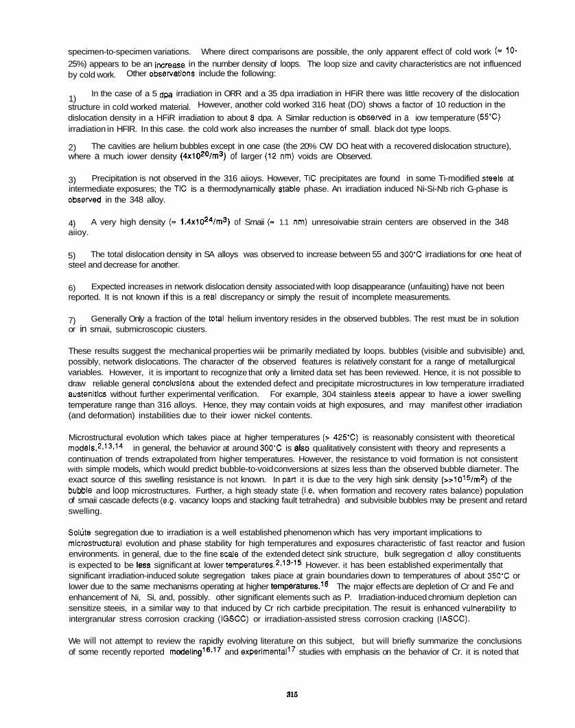
specimen-to-specimen variations. Where direct comparisons are possible, the only apparent effect of cold work (= 10- 25%) appears to be an iwrease in the number density of loops. The loop size and cavity characteristics are not influenced by cold work.
1) structure in cold worked material. However, another cold worked 316 heat (DO) shows a factor of 10 reduction in the dislocation density in a HFiR irradiation to about 8 dpa. A Similar reduction is observed in a iow temperature (55.c) irradiation in HFIR. In this case. the cold work also increases the number of small. black dot type loops.
2) where a much iower density (4xlOZ0/m3) of larger (12 nm) voids are Observed.
3) intermediate exposures; the TIC is a thermodynamically stable phase. An irradiation induced Ni-Si-Nb rich G-phase is observed in the 348 alloy.
4) aiioy.
5) steel and decrease for another.
6) reported. It is not known if this is a real discrepancy or simply the resuit of incomplete measurements.
7) or in smaii, submicroscopic ciusters.
These results suggest the mechanical properties wiii be primarily mediated by loops. bubbles (visible and subvisible) and, possibly, network dislocations. The character of the observed features is relatively constant for a range of metallurgical variables. However, it is important to recognize that only a limited data set has been reviewed. Hence, it is not possible to draw reliable general conciusions about the extended defect and precipitate microstructures in low temperature irradiated austenitics without further experimental verification. For example, 304 stainless steeis appear to have a iower swelling temperature range than 316 alloys. Hence, they may contain voids at high exposures, and may manifest other irradiation (and deformation) instabilities due to their iower nickel contents.
Microstructural evolution which takes piace at higher temperatures (> 425%) is reasonably consistent with theoretical modeis.2.13.14 in general, the behavior at around 300'C is also qualitatively consistent with theory and represents a continuation of trends extrapolated from higher temperatures. However, the resistance to void formation is not consistent with simple models, which would predict bubble-to-void conversions at sizes less than the observed bubble diameter. The exact source of this swelling resistance is not known. In part it is due to the very high sink density (>>i015/mz) of the bubble and loop microstructures. Further, a high steady state (i.e. when formation and recovery rates balance) population of smaii cascade defects (e.g. vacancy loops and stacking fault tetrahedra) and subvisible bubbles may be present and retard swelling.
Solljte segregation due to irradiation is a well established phenomenon which has very important implications to microstructurai evolution and phase stability for high temperatures and exposures characteristic of fast reactor and fusion environments. in general, due to the fine scale of the extended detect sink structure, bulk segregation c! alloy constituents is expected to be less significant at lower temperature^.^^' 3-i5 However. it has been established experimentally that significant irradiation-induced solute segregation takes piace at grain boundaries down to temperatures of about 350'C or lower due to the same mechanisms operating at higher temperatures.'o The major effects are depletion of Cr and Fe and enhancement of Ni, Si, and, possibly. other significant elements such as P. Irradiation-induced chromium depletion can sensitize steeis, in a similar way to that induced by Cr rich carbide precipitation. The resuit is enhanced vulnerability to intergranular stress corrosion cracking (iGSCC) or irradiation-assisted stress corrosion cracking (IASCC).
We will not attempt to review the rapidly evolving literature on this subject, but will briefly summarize the conclusions of some recently reported m0deiing1~f'~ and e~perimentail~ studies with emphasis on the behavior of Cr. it is noted that
Other ObseNatiOnS include the following:
In the case of a 5 dpa irradiation in ORR and a 35 dpa irradiation in HFiR there was little recovery of the dislocation
The cavities are helium bubbles except in one case (the 20% CW DO heat with a recovered dislocation structure),
Precipitation is not observed in the 316 aiioys. However, TIC precipitates are found in some Ti-modified steeis at
A very high density (- 1.4XiOZ4/m3) of Smaii (- 1.1 nm) unresoivabie strain centers are observed in the 348
The total dislocation density in SA alloys was observed to increase between 55 and 300'C irradiations for one heat of
Expected increases in network dislocation density associated with loop disappearance (unfauiting) have not been
Generally Only a fraction of the total helium inventory resides in the observed bubbles. The rest must be in solution
315
grain boundary chemistry can be characterized by a variety of advanced microchemical techniques, including high resoiution scanning TEM, the technique used in the study reviewed here:
1) to 0.4 bulk concentrations.
2) widths of about 2 i 1 nm at 300'C.
3)
4)
5) Fe or Ni. Conversely, Ni increases at the boundary because it exchanges less rapidly than Fe or Cr. This phenomenon has been called the inverse Kirkendaii effect. The rate differences are attributed to variations in the activation energy for vacancy-atom exchange for the aiioy constituents (rather than differences in the pre-exponential factor).
6)
7) evaluations of critical thermodynamic and diffusion parameters are needed. In addition, many complications in applying simple models exist, including microstructural evolution in the matrix and near boundary region, precipitation of nickel silicide and possibly other phases at the boundary, and boundary motion. In addition, other radiation induced or enhanced mechanisms may be important for segregation, particularly for elements such as SI and P.
The magnitude of Cr depletion is relatively constant in the range of 200 to 400'C; minimum Cr levels are about 0.35
Depleted zone widths decrease with decreasing temperature in the range of 300 to 500'C. Extrapolations suggest
Peak (steady-state) depletions can take piace in the range of 10 dpa.
Depleted zone widths increase and exposures to peak depletion decrease with decreasing displacement rate (or flux).
it is believed that Cr depletes because it exchanges more rapidly with the flux of vacancies going to the boundary than
The widths of Cr depleted zones have been found to correlate with the Strauss accelerated corrosion test.l6
Rate theory model predictions are in good semiquantitative agreement with ObSeNatiOn. However, better independent
Tensile Properties
There is a large amount of data in the literature on the tensile properties of 300 Series Stainless steels irradiated in both mixed and fast spectrum reactors at low to intermediate temperatures and exposures. We have examined these data to try to extract systematic trends. However. as discussed below. there is evidence that the condition which results in the maximum property degradation is at irradiation aad test temperatures around 300'C. Hence. the data tabulations given here will be restricted to experiments carried out near these conditions for SA 300 series stainless steels and welds.
Table 3 lists the data obtained at approximately 300'C. While there are exceptions, the overall trends discussed below are fairly consistent. The irradiated yield stress (YS) data are plotted in Figure 1 as a function of the square root of dpa. The YS rapidly increases at low exposures below about 5 dpa and saturates above this value. There is little apparent difference between fast and mixed spectrum behavior at high exposures or between various alloys. The YS saturates at a value of about 85M100 MPa. Comparisons based on changes in YS are slightly more consistent, with values saturating at an average of about 65M75 MPa.
The ultimate tensile strength (UTS) also increases with exposure, but at exposures above about 3 dpa the yield and ultimate stress values nearly coincide. as shown in Figure 2. This and subsequent tensile data plots do not distinguish among the various aiioys and irradiation spectra, since iittie systematic difference could be discerned from the data available. Figure 3 shows the UTSNS behavior is also reflected in the trends in the uniform elongation (UE) which approaches very low values (<1%) at high exposures. in this condition, the aiioys exhibit essentially no macroscopic strain hardening (i.e. for o = en, n-0). The total elongation (TE) also decreases as shown in Figure 4. Note that the definition of the ductility parameters varies in some cases. Fewer data have been reported on reduction-in-area (RA), but this is also observed to decrease with irradiation.
916
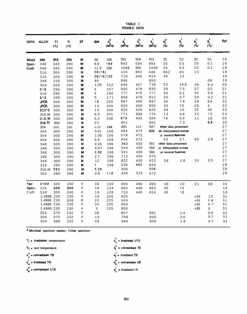
TABLE 3 TENSILE DATA -
Ret I U i e" eu (%) (%)
et (%)
DATA ALLOY TI Ti Sa ('C) ('C)
Mixed 348 343 290 Spec- 348 343 290 i rum 348 343 290
316 300 290 316 300 290 348 316 305 304 204 200 316 290 290 316 290 290 316 290 290 JPCA 300 300 JPCA 300 300 EC316 300 300 316.W 300 290 316,W 300 290 316-Ti 300 300 304 300 290 304 300 290 304 300 290 304 300 290 348 300 290 348 300 290 348 300 290 348 300 290 348 300 290 316 280 290 316.W 280 290 304 290 280
M M M M M M M M M M M M M M M M M M M M M M M M M M M M
4.8 186 8.9 186 11.9 186 38(18) 38(19)128 4 6 1.05 112 5 157 5 160 5 1 7 1 1 6 200 1 0 200 1 0 240 6.5 241 5.3 238 2 2 0.22 156 0.51 156 1.05 156 8.9 158 0.15 196 0.57 196 0.82 196 2.7 196 1 2 196 1 198 0.08 0.8 116
931 504 993 504 1048 504 124 862 710 445 846 645 427 830 479 777 475 806 479 887 450 800 450 825 525 771 333 675 443 851 400 413 484 473 578 473 834 473 363 430 544 430 531 430 713 430 822 430 535 460 306 448 375
931 25 0.2 993 2 5 0.3 1048 2 5 0.3 448 8 6 2 4 5 814 4 5 1 2 850 718 5 2 14.8 830 3 9 7.5 777 3 5 6.1 812 3 0 5 .? 887 3 6 7.9 800 3 6 1 0 825 3 3 1 0 775 1 3 4.9 694 I 6 5.4 851 7.3 547 Other data presented 633 as Interpolated culves
at several lluences 4 3 2.7
501 other data presented 563 as Interpolated culves 566 at several iluences 575 822 3 8 1.8 604 506 572
20 0.1 2 0 0.1 2 0 0.1 1 0
0.9 3 8 9.4 3 7 0.2 3 4 3.9 3 0 0.2 2 8 0.4 2 8 4 25 0.4 1 0 1 .o 1 1 1.6
0.3
4 0 0.9
3 0 0.5
1 8 1 8 1 8 1 8 1 8 1 9 2 0 2 1 2 1 2 1 2 2 2 2 2 3 2 4 2 5 2 6 2 7 2 7 2 7 2 7 2 7 2 7 2 7 2 7 2 7 2 8 2 8 2 9
FaSI 316M 300 290 F 3 8 1 6 0 890 490 890 3 8 1 0 2 1 0.8 3 0 Spec- 316 300 300 F 18 124 862 448 862 45 1 0 1 8 t r u m 318 300 240 F 1 9 128 710 445 814 45 1 2 1 8
1.4988 230 230 F 1 0 225 925 >30 1.3 31 1.4988 230 230 F 2 0 225 9 0 0 s30 0.8 3 1 1.4988 230 230 F 3 0 225 850 >30 0.7 3 1 1.4988 230 230 F 5 225 800 ~ 3 0 3 3 1 304 370 232 F 3 8 8 6 7 892 1.4 0.8 3 2
0.7 3 2 304 370 232 F 1 8 788 800 3.6 304 388 232 F 4 8 880 906 1.8 0.7 3 2
a M-rnlxed spectrum reanor; F-fast spectrum
Ti - lrredlatlon temperature
Ti - test temperature
s - unlrradlated YS
su - inadlaled YS
s: - unirraciiated UTS
U
U I
i su - Cradiated UTS
$ - unirradiatd TE
et - irradlated TE
e: - unirradiatd UE
e: - Irradiated UE
I
I 0
-UNEWUDThTED RANOE 0 1 I
D P A ~ / ~
0 8.6 8.0
Figure 1. Variation of yield Stress with Jdpa for 300 Serb Stainless steels irradiated and tested at approximately 300' at
approximately 300%.
4 I
S
-UNEWUDIAl'ED RANOE
1 b o a n m o o B o
0 0 8.0 7.6
I I I 0 a.6 8.0 7.6
Figure 2. Variation 01 ultimate tensile strength with@ for 300 series stainless steels irradiated ami tested at approximately 300' at approximately 300%.
0 0 0 0 I ~
O n n n n
8.0 7.8 1
0 0 0 8.8 ' ~ ~ ~ 1 1 8
Figure 3. Variation of uniform elongation with,& lor 300 series stainless steels irradiated and tested at approximately 300' at approximately 300'C.
Figure 4.
80
-UNlRRADIATED RANGE (SOLUTION--)
8
-UNlRRADIA!I'ED WNGE WELD) 8 4 8 8
W
0 0 8.8 8.0 7.8
D P A ~ / ~ Variation 01 total elongation withdp; for 300 series stainies steels irradiated and tested at approximately 300'C. at approximately 300'
319
Other trends established in a preliminary analysis of both this and other (untabulated) data sets are as follows:'
1)
2) is higher than near 300'C. A broad ductility minimum occurs at test temperatures between 200 and 400'C in both irradiated and unirradiated alloys.
3) to 400% than for 55'C irradiations. Above 400'C irradiation-induced changes in the tensile properties decrease with increasing temperature.
4) steel components operated near 300'C.
5) systematically smaller increases in YS. However, the absolute values of the YS are larger after irradiation. Ductility, which is much lower in CW alloys initially. is further reduced by irradiation. in contrast. very limited data on welds indicate slightly smaller increases in the YS and decreases in ductility.
6) (saturation) exposures, the changes occur at lower dpa in mixed spectrum irradiati0ns.3~ However, it is noted that classical high temperature helium embrittiement (associated with low ductility intergranular fracture) is not expected to be operative at temperatures below 500 to 600%.
7) large systematic difference beween behavior in the high flux HFiR reactor versus other lower flux test reactors.
irradiated yield stress values are higher in room temperature (RT) tests.
However, at RT the UTS stays above the YS to higher exposures, and ductility -- particularly uniform elongation -
At high exposures the increases in YS and decreases in ductility are larger at irradiation temperatures between 200
The combination of observations 2 and 3 suggest that irradiation effects will be maximum for austenik stainless
Most data on SA steels suggest relative insensitivity to metallurgical variables. Cold worked alloys have
There is some indication that while the tensile properties in mixed and fast spectrum reactors are similar at high
There are no systematic studies of damage rate (flux) effects. Limited comparisons (uncontrolled) do not indicate a
Simple models of dislocation-defect interactions can be used to estimate the strengthening associated with the void and loop structures described above. The YS change can be calculated from the relation34
where G is the shear modulus (= 70 MPa). and b the dislocation Burgers vector (- .25 nm). The factor of 2.5 is to convert critical resolved shear stresses to uniaxial YS. The computed yield stress Changes are about 440, 465 and 330 MPa at 5, 10 and 35 dpa respectively for the microstructural parameters given in Table 2. predict about 70% of the observed yield stress changes (= 650 MPa). At higher exposures softening is predkzed but has, with one exception,31 not been observed. These differences may be due to the inadequacy of the simple models (e.g. the strengths assigned to the loops and voids) or unresolved andlor otherwise unaccounted for microstructural features. As noted earlier, these features may include subvisible bubbles &e. the missing helium) and flne scale residual cascade damage. Network dislocations from unfauited loop may be important at high exposures. For example, a network dislocation density of 40% of the line length of loops which disappeared between 10 and 35 dpa would result in predicted yield stress increases of 650 MPa. Such network dislocation densities are consistent with trends extrapolated from higher temperatures, but have not been specifically reported in the studies reviewed. Applied stresses leading to irradiation creep might also affect the dislocation as well as other microstructural components, producing a form of creep embrittlement.
in addition to the large changes in mauoscopic tensile properties. irradiation also affects the basic characteristics of the tensile deformation process. in the unirradiated state deformation is homogeneous. The microstructure is characterized by dense dislocation tangles; and at higher deformation temperatures, a dislocation cell subgrain structure.35 in contrast after irradiation deformation becomes very heterogeneous, and is localized to submicron regions of intense shear, surrounded by relatively undeformed matrix.35-s7 These regions, known as dislocation channels. are believed to form due to strain softening mechanisms.38~39 it is postulated that the passage of the early slip dislocations progressively destroys
At lower exposures the calculations
See reference 32 for examples of observations 1-5 also seen in other studies.
a20
the loop and cavity hardening microstructure. Dislocation sources subsequently operate on the set of slip planes which are partially cleared of obstacles but not in the surrounding harder matrix. The surrounding defect structure also retards cross slip, and adiabatic heating In the channels may also contribute to strain softening. In alloys containing voids, dislocations appear to cut through and elongate them. This also reduces the ligament area between holes. The overall internal deformation pattern is a series of intersecting channels oriented favorably for slip to the tensile axis. Necking occurs at very low strains and macroscopic strain hardening is negligible.
At low-to-intermediate exposures final fracture is by a hole coalescence mechanism in the necked region, producing a ductile-dimpled fracture surface which is qualitatively similar to that found in unirradiated alloys. In this mode of fracture, large holes nucleate at Inclusions and precipitates and grow as a result of dilational deformation. This continues to a point of necking instability on the interhoie ligaments. The subsequent linking of holes gives rise to a dimpled fracture surface. In irradiated alloys there are indications that the dimples tend to be shallower and that post-necking fracture strains are reduced by irradiation.
At higher exposures there is a transition to a new and unique fracture mode known as channel fra~ture.35-3~ The channel fracture surface is characterized by flat, crystallographic type facets inclined at about 45' to the tensile axis. The facets contain evidence of very fine scale dimpling. Channel fracture is clearly associated with the highly localized flow discussed above; however, It occurs at exposures beyond the level needed for saturation of the YS and into the regime of void swelling. However, it is not known if irradiation-induced voids are a prerequisite to this fracture mode. Irradiation-induced voids would enhance the flow. instab es (localization), reduce tensile ligaments in sheared regions, and lower the strains needed to link deformation-induced holes. Further, it has been proposed that the segregation of nickel to growing voids results In loss of stability In the nickel poor austenite matrix.37 interconnected ferritic phase, which is brittle at low temperatures and high strain rates. Under less severe conditions of segregation, deformation-induced formation of e-martensite could also promote brittle type fracture. This type of transformation is consistent with gradual increases in the ultimate tensile strength of steels with increasing dpa at very high exposures.37
In summary, the effect of inadiation on the tensile properlies of austenitic stainless steels near 300'C and at exposures greater than a few dpa can be anticipated to be as follows: large increases (on the order of 650 MPa) in the YS and smaller increases in the UTS; nearly equal values of YS and UTS and very low values of UE of (< 1%) and strain hardening exponents; reduced TE (< 5.10% ) and RA (< 30-40%). Deformation would tend to be localized in dislocation channels. The fracture mode will probably be (deformation) hole coalescence leading to a dimpled fracture surface. However, the strains to final fracture would be reduced and the dimple morphology modified. If void swelling occurs at high exposures, channel fracture may occur.
Fracture Toughness
Available data show that irradiation ais0 results in reductions in fracture initiation toughness and crack growth resistance (tearing modulus) in austenitic stainless steels. Unfortunately, the data base is limited and there are few controlled studies 01 the eflects of irradiation and metallurgical variables. Further, there are few valid toughness data for either unirradiated (generally due to low strengthhigh toughness properties) or irradiated alloys (generally due to the limited amount of material and the use of small specimens and/or nonstandard test techniques).
Toughness is generally lower for tests above room temperature in both the irradiated and unirradiated states, following trends in tensile ductility. Hence, we will focus here on elevated temperature tests from 230 to 430% where toughness is at a minimum. The data are given in Table 4. Some other data for stainless steels in the cold-worked condition and other alloys (Inconel 600 and PE-16) have been examined but are not tabulated here. It is also noted that Lucas and Gelles have recently reviewed the effects of higher temperature irradiation on fract~re.~C
We have attempted to determine data trends by grouping the data according to the irradiation type and conditions (mixed versus fast spectrum, dpa and temperature), material condition (weld versus solution annealed) and test condition (statiddynamic and temperature).
There are 5 high exposure (> 29 dpa) data points for SA type alloys irradiated in mixed spectrum reactors between 275% and 375'C and at test temperatures below 43o'C. The average toughness for this data subset is 55-tl1 MPaG. A 316 alloy irradiated in a mixed spectrum to about 1 dpa had a high toughness of about 200 M P a G when tested at the irradiation
In extreme cases this could lead to the formation of an
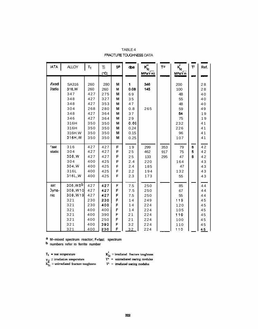
TABLE 4 FRACTURETCLGHNESS DATA
Ti LC)
280 260 275 327 353 280 364 364 350 350 350 350
427 427 427 425 425 425 425
lATA I ALLOY I Tt SB
M M M M M M M M M M M M
F F F F F F F
dixed static
=as1 static
as1 Iyna- nic
~
SA316 260 316,W 260 347 427 348 427 348 427 3 0 4 268 348 427 346 427 316H 350 316H 350 316H.W 350 316H.W 350
316 427 3 0 4 427 308,W 427 3 0 4 400 304,W 400 316L 400 316L,W 400
308.W5b 427 306,WlO 427 306.W19 427 321 230 321 230 321 400 3 2 1 400 3 2 1 400 32 1 400 321 400
400 390 250
dpa - 1 0.08 6 9 3 5 4 7 0.8 3 7 2 9 0.05 0.24 0.15 0.25
1 9 2 5 2 5 2.4 2.4 2.2 2.3
-
7.5 7.5 7.5 1 4 1 4 1 4 2 1 2 1 3 2 3 2 -
<C M P a G )
346 145
-
265
- 299 462 133 220 185 1 9 4 173
250 250 250 249 224 224 224 224 2 2 4 224
a M-mixed spectrum reactor; F-fast spectrum numbers refer to ferrite number
Tt =test tcmpaarure
TI , - . - madialion tsmpaature KYc = unirradiiud fracture toughness
K;, = imdiiled fracture toughness
Ti = irradi.tcdwringmodulu. r = unimdiusd luring
- TU -
- 353 917 295
- KlC
MP& - 200 100
48 55 48 59 54 75
232 226
96 107
79 75 47
164 47
1 3 2 55
-
85 67 55
119 1 2 0 1 0 5 110 100 110 1 1 0
- Ref. - 2 8 2 8 4 0 4 0 4 0 49 1 9 1 9 4 1 4 1 4 1 41
4 2 4 2 4 2 4 3 4 3 4 3 4 3
4 4 4 4 4 4 4 5 4 5 45 45 4 5 4 5
-
-
45
322
temperature of about 270'C. Tests and irradiation of another 316 alloy to about 0.17 dpa at 350% resulted in a toughness of about 228 M P a f i . In contrast, mixed spectrum irradiation of a 304 alloy to about 0.8 dpa resulted in a low toughness of 59 M P a G when tested at the irradiation temperature of about 270%.
Fast reactor irradiations of SA 304 and 316L to about 2.3 dpa at 42SC reduced toughness to about 148+16 M P a G for tests at the irradiation temperature. Higher exposure (= 22 dpa) fast reactor irradiations of SA 304 and 316 resulted in lower toughness levels of about 77- M P a f i at similar temperatures.
A SA 316 weld irradiated in a mixed spectrum and tested at about 270'C had a toughness level of about 100 M P a 6 at only about 0.08 dpa. Mixed spectrum reactor irradiation to abaut 0.7 dpa of a 316 MiG weld resulted in a toughness of about 102 M P a G for tests at the irradiation temperature of 350'C. Fast reactor irradiations of 304, 316L and weids at 427% to 2.3 dpa resulted in low toughness levels of about 524 M P a f i for tests at 400'C. Testing and fast reactor irradiations of a 308 SMA weid at 427% resulted in a toughness of 47 M P a G at 25 dpa.
A SA 321 alloy tested and irradiated in a fast reactor at about 240 -400% to 14 to 32 dpa gave dynamic toughness values of 110f10 M P a G . Fast reactor irradiations and tests at 427% to 7.5 dpa for a 308 SMA weld resulted in dynamic toughness levels which decreased with ferrite number (FN) as foilows: 85 M P a G for FN = 5.2; 67 M P a G for FN = 0.4; 55 M P a G for FN = 19.
The data are plotted against the square root of dpa in Figure 5a and for weids in Figure 5b. it is difficult to reach reliable conclusions from these data since the experiments are not controlled and the toughness values subject to considerable uncertainty. Nevertheless, it appears that:
1) little apparent difference between fast and mixed spectrum irradiations at high exposures. The lowest toughness levels in SA aiioys is for conditions where the tensile ductility parameters are low and YS increases have saturated near values of the UTS.
2) Static toughness values are less at low exposures for welds than for alloys in the SA condition. The toughness of weids approaches a value of about 50 M P a 6 at exposures above a few dpa in fast reactor irradiations (there are no data from mixed spectrum irradiations in this exposure regime). Low values of toughness can occur in welds prior to exposure levels corresponding to very low ductility and saturated yield stress. This raises the possibility of additional decreases in toughness levels at higher exposures. Notably, data at higher irradiation temperatures indicate that the saturation value of toughness in weids is lower than for wrought materiai.46
3) takes place at the maximum load in a dynamic test; this would be invalid if there is significant stable crack growth. Dynamic toughness of welds decreases with increasing delta ferrite content.
The above discussion has focussed on initiation toughness. However, it is well-established that irradiation has a greater embrinling effect on crack growth resistance as quantified by the tearing modulus (TR)
Static toughness of SA alloys decreases and approaches a value in the range of 50 M P a G at high exposures. There is
Dynamic toughness tends to be somewhat higher than static values. This may be due to the assumption that initiation
TR= [dJ/da][E/ao2)
where E is Youngs modulus and a. is the flow stress a. = (YS + UTS)R. Unirradiated austenitic alloys have values of TR of several hundred; high exposure fast reactor irradiations reduces this to values of 5-104*
Mechanistic analysis and modeling is useful for data interpretation, extrapolation of conclusions to conditions where data are not available and guiding additional research. Loading of structures or specimens containing sharp cracks (produced by fatigue or intergranular corrosion processes) resuits in concentrated (localized) stress and strain fields near the tip (i.e. a plastic zone).47 When a sufficient volume of material is strained beyond a critical value, the crack extends or initiates growth. Depending on the loading conditions, the crack may arrest or continue to grow stably. Final fracture occurs when unstable crack growth occurs. The deformation and fracture processes vary in tundamental ways from those taking piace during tensile deformation to fracture. Significant differences include the stress-strain and stress-state histories and the presence of strong field gradients in the vicinity of crack tips.
323
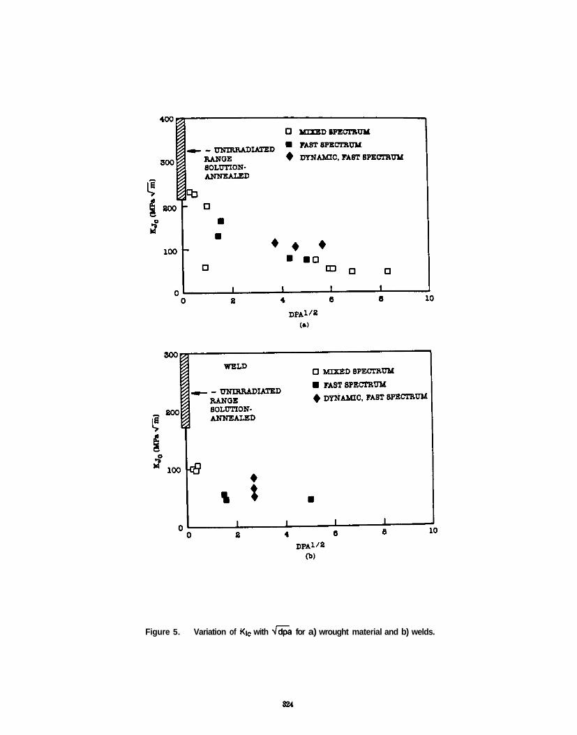
Figure 5. Variation of Klc with Jdpa for a) wrought material and b) welds.
In general the loads and displacements needed to Initiate crack growth depend in a complex way on the material properties and the crack-structure/specimen size and geometry. However, for well-defined conditions of plane strain (or stress) and well contained plasticity, or small scale yielding, the stress and strain fields of a blunting crack can be characterized by a single propartional loading parameter, namely the stress intensity parameter K, which can be computed from elasticity theory. It follows that fracture initiation takes place ai a critical value of this parameter; for Mode I loading under plane strain conditions this is Klc The size requirement for the application of linear elastic.fracture mechanics (LEFM) depends on material propedes; In general, the plastic zone size (rz = KI /2na ) must be less than about 1/50 the crack and ligament dimension. Plane strain conditions also place Similar size re&irements on the specimen thickness. Experimentally, Klc can be determined by measuring fracture loads on fatigue precracked specimens, subject to the size requirements noted above and evidence that stable crack growth is negligible, as determined from the linearity of the ioad- displacement curve.48
Even when the requirements of LEFM are violated by larger scale plasticity and crack growth, the crack tip fields can be characterized. within relaxed size requirements, by another singularity parameter J 47 Fracture initiation takes place at a critical value of J = Jlc In the small scale yielding limit Klc + K j c = -where E is Young's modulus and v Poisson's ratio. Experimentally. J can be determined from load, load-line displacement data, coupled with crack growth (aa) measurements to generate J-Aa curves. This curve is extrapolated to a crack blunting line to estimate Jlc . The size requirements for Jantroiled initiation depend on the geometry, or deformation pattern. as well as material properties. For loading conditions .dominated by bending moments -- hence, a Prandtl type flow field -_ the criteria is that all relevant specimen dimensions (unbroken ligament. crack length and specimen thickness) must be larger than 25-50J~/q,, where JQ is the apparent value of Jic49
The crack growth reslstance can be determined from the slope of the J-Aa curve (dJ/da) and is usually characterized in terms of the TR. However, there are very severe size requirements for unique measurements of TR due to the loss of proportional loading conditions, and crack growth is usually limited to small v a l ~ e s . 5 ~ . ~ ~
The concept of relating microscopic processes of deformation and damage accumulation to macroscopic toughness. Models of ductile fracture toughness postulate that crack growth initiates when the the strains near the tip of a crack exceed a critical value over a critical distance.50.55 Most models are based on the strain induced growth of holes in front of the crack, which link to cause crack extension. The critical distance (i) is often interpreted as the spacing between the large inclusions which are the nuclei of significant deformation-induced holes; experimentally this is often associated with the dimple size or spacing on a fracture surface. Alternately the distance has been characterized as the width or length of intense shear bands formed at the crack tip at high angles to the crack tip.5°.51 The failure process in this case is then associated with a shear decohesion in the deformation band.
In unirradlated austenitic alloys, holes nucleate at hard particles and grow to a size of about R = 1/2 where i is the inclusion spacing. Subsequent necking on the remaining ligament results in crack extension. The crack opening displacement (COD) S reaches a critical value of Stc at initiation. Theory indicates that the dimensionless parameter S1c/l is an increasing function of I/Ro where Ro is the inclusion radius.52 The ratio 6ldl varies from about 0.5 to 2-3 and is a weak function of the strain hardening exponent and the degree of plasticity. in small scale yielding the toughness is given by the expression
2 2
is important to understanding the micromechanics of fracture, since it permits . .
K = zjCGicooE/(i-v2) (3)
where C Is a parameter which depends on the strain hardening ~xponent and yield Stress. but typically has values of about 2.53
Data trends for tough ductile alloys with high strain hardening exponents are reasonably consistent with this model. The critical strain (E;) is the tensile strain required to nucleate the hole at the particle (nucleation may require combined conditions of both critical local stress and strain) and to grow it to final instability by internal necking and rupture of the ligament between the void and crack tip. For hole growth mechanisms E; is very sensitive to the stress state as determined by the ratio of the hydrostatic to effective shear stress. Specifically, triaxiai stresses lower €1' by increasing the rate of hole growth per unit strain and, also, probably, by lowering nucleation strains. Decreased strain hardening exponents also lower el..
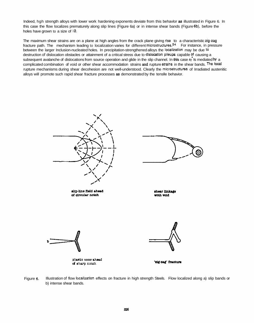
Indeed, hgh strength alloys with lower work hardening exponents deviate from this behavlor as illustrated in Figure 6. In this case the flow localizes prematurely along slip lines (Figure 6a) or in intense shear bands (Figure 6b). before the holes have grown to a size of 1/2.
The maximum shear strains are on a plane at high angles from the crack plane giving rise to a characteristic zig-zag fracture path. The mechanism leading to localization varies for different micro~tructllres.5~ between the larger Inclusion-nucleated holes. In precipitation-strengthened alloys the localiration may be due to destruction of dislocation obstacles or attainment of a critical stress due to dlslocation pileups capable ?f causing a subsequent avalanche of dislocations from source operation and glide in the slip channel. In thls case Ef Is mediated bY a complicated combination of void or other shear accommodation strains and rupture stralns in the shear bands. The local rupture mechanisms during shear decohesion are not well-understood. Clearly the mlcrostructures of Irradiated austenitic alloys will promote such rapid shear fracture processes as demonstrated by the tenslle behavior.
For instance, in pressure
plutio sone .bud of .harp notah
Figure 6. Illustration of flow localizatlon effects on fracture in high strength Steels. Flow localized along a) slip bands or b) intense shear bands.
Toughness can be generally expressed by an equation of the form
where C is a numerical parameter that depends on the fracture mechanisms and material parameters (e.9. the strain hardening exponent).
Various models propose different ways to define and/or measure e; and I*. The proper choice is not trivial and, as noted above, depends very much on the microscopic characteristics of the deformation and void nucleation- growth-linking process near the crack Up. A number of efforts have been made to relate the parameters in Eq. 4 to simple tensile properties, or more sophisticated measurements such as notch tensile tests. One of the earliest such models was proposed by Kra@5 which results in the expression
where I is the dimple spacing and q is the true fracture strain. Hamilton et. ai.56 have applied the Kraffl model to irradiated stainless steels using tensile properties, as suggested by Schwalbe and Backfi~h.5~ Hamilton et. al. assumed that the true fracture strain is the total elongation, n was derived from the ultimate tensile stress and uniform elongation, and I set equal the grain diameter. The calculations were compared to data for a 20% CW 316 alloy tested and irradiated to about 50 dpa at 379'C in a fast reactor. The predicted toughness was 76 M P a 6 consistent with observed value of about 60 MPaf i . Wolfer and Jones showed that this model was also reasonably consistent with unirradiated toughness trends.5E
Ritchie. Knott and Rice (RKR) used a more rigorous approach to relating critical parameters to singular crack fields. resulting in an expression similar to Eq. 4 with C approximately unity.59 Subsequently, Ritchie et. a1.60 used the RKR model to predict upper-sheif toughness changes in unirradiated pressure vessel steei, determining ef' from notched tensile tests and using I- as an adjustable fit parameter equal to a small multiple of the prior austenitic grain size. Similar tests could be carried out for irradiated specimens but such data were not available at the time of this work. The advantage of using notch tensile data is that the stress state more closely resembles that found at a crack tip.The disadvantage of this approach is the fact that the stress and strain and stress-state histories will be different in the notched tenslle and crack tip cases, the rather ambiguous definition of f, and statistical effects related to alloy homogeneity.
More recently, Thompson and AShbyS1 have proposed using the ratio of the dimple height (h) to width (W) ratio (M = hMI) to define local fracture strains. This geometry is illustrated in Figure 7. The true fracture strain can be computed from h and the void-nucleating particle diameter (Dp) as
E; = In(h/Dp). ( 6 )
Toughness can then be computed from the RKR model laking I* as the dimple spacing. Expressed in terms of the volume fraction (fp) of the particles
KiC - [0.33a,ln(M2/3fp)E/(1 -v*)]l/2. (7)
The fields in these models are for homogeneous deformation and the effect of volds and flow localization is not explicitly treated. Hahn and R~senf ie ld~~ have proposed a model which contains some elements of localization phenomena by treating shea; zones emanating from the crack with an inclination of 75' with finite widths of w. Taking the fracture strain as 1/3 Of the uniaxial fraclure RA (to account for stress-state effects) , toughness is given by the expression
Further, they noted that there was an empirical relation between the strain hardening exponent and the width of the shear band as W- c1 + c n2 For typical unirradiated stainless steel parameters (RA - 0.8, ay - 150, of about 180 MPa t. m are predicted. For irradiated alloys with very low values of strain hardening or uniform elongation (n - &" - 0) the shear zone width is a minimum of w=c1(-13 pm). In spite of the relatively large minimum shear band width am ared to measured values of dislocation channels (4 pm) this model predicts very low toughness levels of about
n-0.3) toughness values
22 MPa P " m for irradiated alloys (e.g. RA =0.4, ay - 850 MPa).
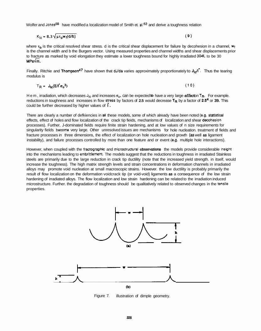
Wolfer and Jones= have modified a localization model of Smith et. a1.62 and derive a toughness relation
Kic - 8.3 dlrl,wt(dlb) ( 9 )
where r0 is the critical resolved shear stress. d is the critical shear displacement for failure by decohesion in a channel, wf is the channel width and b the Burgers vector. Using measured properties and channel widths and shear displacements prior to fracture as marked by void elongation they estimate a lower toughness bound for highly irradiated 304L to be 30 M P a h .
Finally. Ritchie and Thompson47 have shown that dJ/da varies approximately proportionately to JiC/l'. Thus the tearing modulus is
TR - Jlc(Ell'aO2) ( 1 0 )
H e m , irradiation, which decreases Jlc and increases ao, can be expected to have a very large effect on TR. For example. reductions in toughness and increases in flow s!ress by factors of 2.5 would decrease TR by a factor of 2.54 or 39. This could be further decreased by higher values of I .
There are clearly a number of defkiencies in ai1 these models, some of which already have been noted (e.g. statistical effects, effect of holes and flow localization of the crack tip fieids, mechanisms of localization and shear dewhesion processes). Further, J-dominated fields require finite strain hardening, and at low values of n size requirements for singularity fields become very large. Other unresolved issues are mechanisms fracture processes in three dimensions, the effect of localization on hole nucleation and growth (as well as ligament instability), and failure processes controlled by more than one feature and or event (e.g. multiple hole interactions).
However, when coupled with the fractographc and mkrostructurai obS0NatiOnS the models provide considerable insuht into the mechanisms leading to embritllement. The models suggest that the reductions in toughness in irradiated Stainless steels are primarily due to the large reduction in crack tip ductility (note that the increased yield strength. in itself, would increase the toughness). The high matrix strength levels and strain concentrations in deformation channels in irradiated alloys may promote void nucleation at small macroscopic strains. However. the low ductility is probably primarily the result of flow localization on the deformation voidcrack tip (or void-void) ligaments as a consequence of the low strain hardening of irradiated alloys. The flow localization and low strain hardening can be related to the irradiation induced microstructure. Further. the degradation of toughness should be qualitatively related to observed changes in the tenSile properties.
for hole nucleation. treatment of fields and
h
(b)
Figure 7. illustration of dimple geometry.
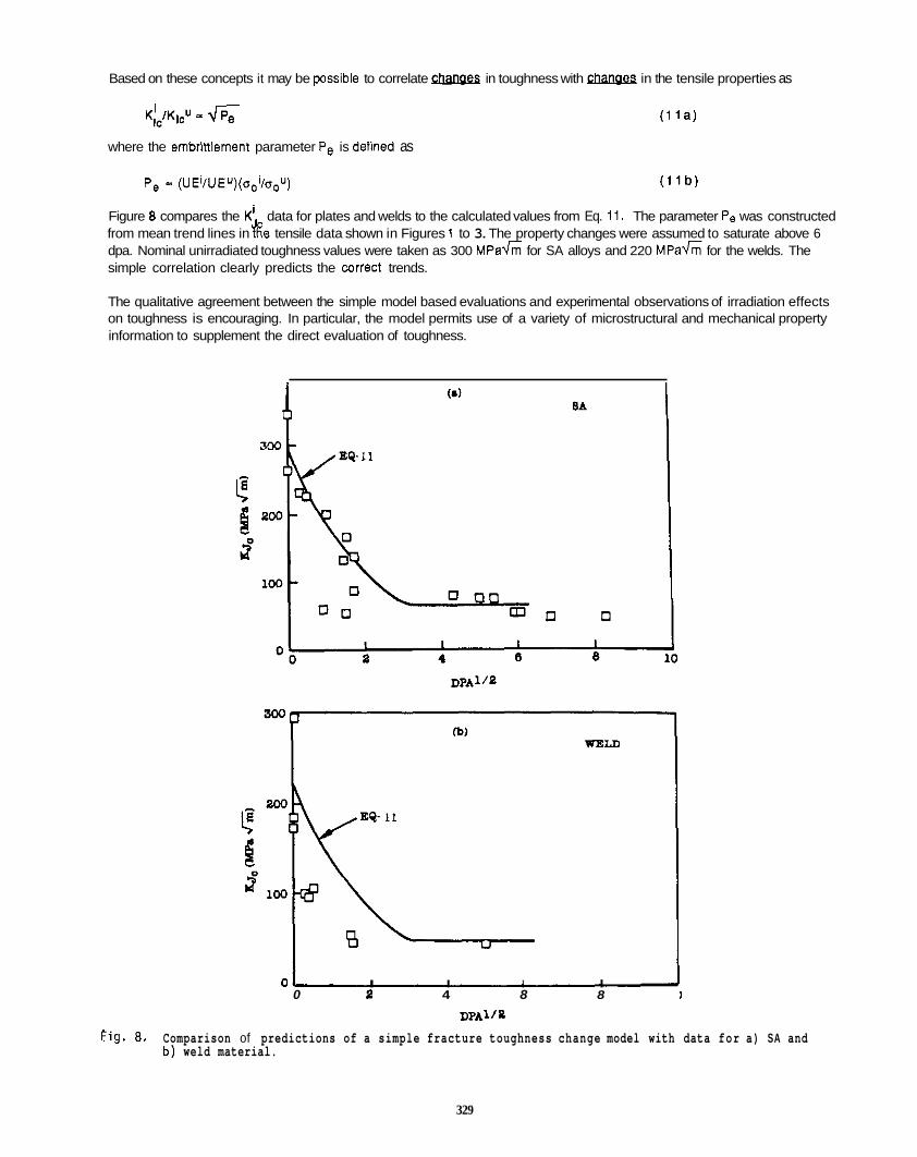
Based on these concepts it may be possible to correlate Gbllges in toughness with Ghangfa in the tensile properties as
K , ) W - 6 (ria)
where the embrinlement parameter Pe is defined as
P, = (UEilUEu)(ooi/o,'J) ( 1 l b )
Figure 8 compares the K: data for plates and welds to the calculated values from Eq. 11. The parameter Pe was constructed from mean trend lines in t6e tensile data shown in Figures 1 to 3. The property changes were assumed to saturate above 6 dpa. Nominal unirradiated toughness values were taken as 300 M P a G for SA alloys and 220 M P a G for the welds. The simple correlation clearly predicts the wrrect trends.
The qualitative agreement between the simple model based evaluations and experimental observations of irradiation effects on toughness is encouraging. In particular, the model permits use of a variety of microstructural and mechanical property information to supplement the direct evaluation of toughness.
1 Y
8A
01 I I I I 0 0 4 8 8
DPAllP I
Fig. 8 . Comparison of predictions of a simple fracture toughness change model with data for a) SA and b ) weld material.
329
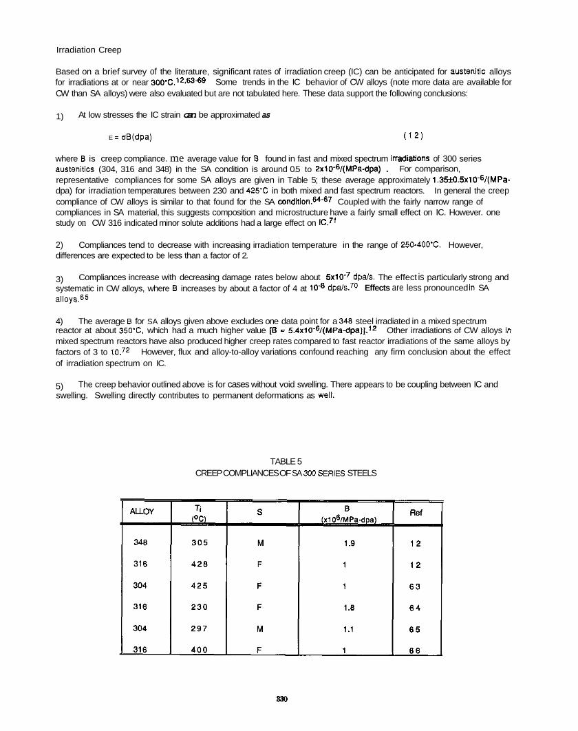
Irradiation Creep
Based on a brief survey of the literature, significant rates of irradiation creep (IC) can be anticipated for austenitic alloys for irradiations at or near 3oo'C.1*-63-69 Some trends in the IC behavior of CW alloys (note more data are available for CW than SA alloys) were also evaluated but are not tabulated here. These data support the following conclusions:
1) At low stresses the IC strain can be approximated as
E = aB(dpa) ( 1 2 )
where B is creep compliance. me average value for B found in fast and mixed spectrum iNadiatiOnS of 300 series austenitics (304, 316 and 348) in the SA condition is around 0.5 to ZxlO-6/(MPa-dpa) . representative compliances for some SA alloys are given in Table 5; these average approximately 1.35j?J.5~lO-~/(MPa- dpa) for irradiation temperatures between 230 and 425% in both mixed and fast spectrum reactors. In general the creep compliance of CW alloys is similar to that found for the SA conditi0n.6~-~7 Coupled with the fairly narrow range of compliances in SA material, this suggests composition and microstructure have a fairly small effect on IC. However. one study on CW 316 indicated minor solute additions had a large effect on
2) Compliances tend to decrease with increasing irradiation temperature in the range of 250-4Oo'C. However, differences are expected to be less than a factor of 2.
3) systematic in CW alloys, where B increases by about a factor of 4 at a11oys.65
4) The average B for SA alloys given above excludes one data point for a 348 steel irradiated in a mixed spectrum reactor at about 350-C. which had a much higher value [E = 5.4xlO-6/(MPa-dpa)l.l~ Other irradiations of CW alloys In mixed spectrum reactors have also produced higher creep rates compared to fast reactor irradiations of the same alloys by factors of 3 to iO.72 However, flux and alloy-to-alloy variations confound reaching any firm conclusion about the effect of irradiation spectrum on IC.
5) swelling. Swelling directly contributes to permanent deformations as Well.
For comparison,
Compliances increase with decreasing damage rates below about 5 ~ 1 0 . ~ dpals. The effect is particularly strong and dpals.70 Effects are less pronounced In SA
The creep behavior outlined above is for cases without void swelling. There appears to be coupling between IC and
TABLE 5 CREEP COMPLIANCES OF SA 3M) SERIES STEELS
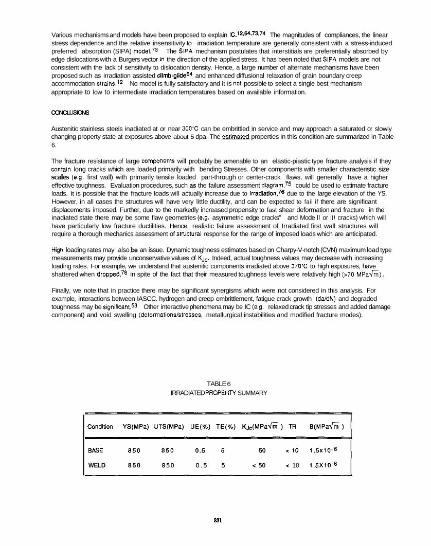
Various mechanisms and models have been proposed to explain lC.12,64.73,74 The magnitudes of compliances, the linear stress dependence and the relative insensitivity to irradiation temperature are generally consistent with a stress-induced preferred absorption (SIPA) model.73 The SlPA mechanism postulates that interstitials are preferentially absorbed by edge dislocations with a Burgers vector In the direction of the applied stress. It has been noted that SlPA models are not consistent with the lack of sensitivity to dislocation density. Hence, a large number of alternate mechanisms have been proposed such as irradiation assisted ~limb-glide6~ and enhanced diffusional relaxation of grain boundary creep accommodation strains.l* No model is fully satisfactory and it is not possible to select a single best mechanism appropriate to low to intermediate irradiation temperatures based on available information.
a3aJJxM
Austenitic stainless steels inadiated at or near 300% can be embrittled in service and may approach a saturated or slowly changing property state at exposures above about 5 dpa. The &mi&& properties in this condition are summarized in Table 6.
The fracture resistance of large Components will probably be amenable to an elastic-piastic type fracture analysis if they contain long cracks which are loaded primarily with bending Stresses. Other components with smaller characteristic size scales (e.g. first wall) with primarily tensile loaded part-through or center-crack flaws, will generally have a higher effective toughness. Evaluation procedures, such as the failure assessment diagram’s could be used to estimate fracture loads. It is possible that the fracture loads will actually increase due to irradiation,’e due to the large elevation of the YS. However, in all cases the structures will have very little ductility, and can be expected to fail if there are significant displacements imposed. Further, due to the markedly increased propensity to fast shear deformation and fracture in the inadiated state there may be some flaw geometries (e.g. asymmetric edge cracks” and Mode II or Ill cracks) which will have particularly low fracture ductilities. Hence, realistic failure assessment of Irradiated first wall structures will require a thorough mechanics assessment of StNctural response for the range of imposed loads which are anticipated.
High loading rates may also be an issue. Dynamic toughness estimates based on Charpy-V-notch (CVN) maximum load type measurements may provide unconservative values of K J ~ . Indeed, actual toughness values may decrease with increasing loading rates. For example, we understand that austenitic components irradiated above 370’C to high exposures, have shattered when dropped78 in spite of the fact that their measured toughness levels were relatively high (>70 MPadii).
Finally, we note that in practice there may be significant synergisms which were not considered in this analysis. For example, interactions between IASCC. hydrogen and creep embrittlement, fatigue crack growth (da/dN) and degraded toughness may be significant58 Other interactive phenomena may be IC (e.g. relaxed crack tip stresses and added damage component) and void swelling (deformationslstresses. metallurgical instabilities and modified fracture modes).
TABLE 6 IRRADIATED PROPERTY SUMMARY
WELD 8 5 0 850 0.5 5 < 50 < 10 1.5X10⁻⁶
831

M U R E W O R K
The following areas 01 research are suggested for an irradiation program to assess the response of austenitic steels in the low temperature regime.
1) Microstructural Characterization
a) Comprehensive TEM evaluation of irradiation-induced microstructures including loops. bubbles and network dislocations (and voids and precipitates if needed) should be used to characterize the key components of the hardening microstructures.
b) High resolution analytical TEM (AEM) should be used to characterize grain boundary segregation; other techniques such as Auger electron spectroscopy (AES) could also be used to complement the AEM.
c) TEM techniques (including replication studies) should be applied to evaluate deformation patterns (localization) in deformed tensile and other special specimen configurations.
d) Scanning electron microscopy (SEM) should be used to characterize fracture surface morphology (dimple size and height and the inclusion content) and crack tip field-microstructure interactions (in sectioned specimens).
e)
f )
Measurement of magnetic phases (ferrite and martenshe) and gross density changes should be carried Out.
Similar characterizations of unirradiated (archival) materials is necessary to interpret the effects Of
irradiation. Ideally thermally aged materials (or those with low exposures subject to a similar thermal history) should also be examined as controls. Further, measurements at several exposure levels would better detennine the eVOlUtiOn Of the microstructure.
2. Mechanical Properties - Tensile
a) should be given to using some round specimens of adequate size to provlde reliable measures of the ductility parameters of TE. UE and FA.
b)
Tensile tests using small specimens should give rellable measures of the YS and UTS. However, consideration
Evaluation of the strength and ductility parameters of notched (round with varying notch radii or plane Strain configurations) specimens would be vely useful and could provide an alternative approach to evaluating toughness.
c) Tensile evaluations should attempt to include archival and thermally aged controls where possible as well as multiple exposures.
3. Mechanical Properties - Toughness
a)
b)
Fracture toughness and tearing modulus data should be obtained at pertinent irradiation and test temperature
Fracture evaluations should attempt to include archival and thermally aged controls where possible as well as multiple exposures.
4. Modeling and Analysis
a) A thorough examination of relevant approaches to applying the mechanical propelty data to integrity analysis of first wall should be carried out.
b) Data from the program should be analyzed and modeled in the context of the evolving experimental and theoretical understanding of irradiation effects on austenitic stainless steels. In particular developments in other irradiation effects programs should be tracked and used to complement the results of this program.
1.
2.
3.
4.
5.
6.
7.
8.
9.
10.
11.
12.
13.
14.
15.
16.
17.
18.
19.
20.
21.
22.
23.
24:
25.
26.
27.
28.
29.
S. Amellnckx, J. NucI. Mater., 155-157 (1988) 3
P. Maziasz, Effects of Helium on Microstructural Development In Type 316 Stainless Steel Under Neutron Irradiation, ORNL-6121 (1985).
P. Maziasz, Alloy Dev. for Irrad. Perform. Prog. Rep. 14, DOE/ER-0045/8, (1982).250
P. Maziasz and D. Braski, Alloy Dev. for had. Perform. Prog. Rep. 16, DOE/ER-0045/9 (1983) 44.
S. Hamada, M. Tanaka and P.Maziasz, Alloy Dev. for Irrad. Perform. Prog. Rep. 22. DOE/ER-0045/15 (1985) 61.
S. Hamada. M. Tanaka and P.Maziasz, ibid. 15, 65.
M. Tanaka, S. Hamada and P.Maziasz, Alloy Dev. for Irrad. Perform. Prog. Rep. 23, DOE/ER-0045/16 (1986) 26.
P. Maziasz, Alloy Dev. for Irrad. Perform. Prog. Rep. 14, DOVER-0045n (1966) 54.
S. Hamada. M. Tanaka and P.Maziasz, Fusion Reactor Materials Prog. Rep.-1, DOE/ER-0313/1 (1987) 269.
M. Suzuki. S. Hamada and M. Tanaka, Fusion Reactor Materials Prog. Rep.2. DOE/ER-0313/2 (1987) 213.
P. Maziasz, ibid 19, 78.
J. Beeston and L. Thomas, Effects of Irradiation on Materials-11, ASTM-STP 782 (1982) 71.
G. Odette, P. Maziasz and J. Spitznagel. Journ. NUCI. Mat. 65886 (1979) 1289.
G. Odette. ibid 6, 127.
G. Odette. Journ. Nucl. Mat. 85886 (1979) 533.
D. Norris. C. Baker and J. Titchmarsh, Materials for Nuclear Reactor Core Applications-I, British Nuclear Energy Society (1987) 277.
J. Perks and S. Murphy, ibid 26, 165.
M. Kangilaski. Effects of Neutron Radiation on Materials. Mattelle Memorial Institute RElC Report No. 45 (1967).
J. M. Beeston, Effects of Irradiation on Materials-10, ASTM-STP 725 (1961) 303.
W. Martin and J. Weir, Flow and Fracture of Metals and Alloys in Nuclear Environments, ASTM-STP 380 (1964) 251.
R. KIueh. Alloy Dev. for Irrad. Perform. Prog. Rep.19, DOE/ER-0045/12 (1986) 45.
M. Tanaka. S. Hamada, P. Maziasz and M. Grossbeck, ibid 17,33.
M. Grossbeck, ibid 22. 254.
F. Wiffen, Alloy Dev. for Irrad. Perform. Prog. Rep. 7, DOE/ER-0058/7 (1980) 128.
F. Wiffen, Alloy Dev. for Irrad. Perform. Prog. Rep. 8. DOE/ER-0045/1 (1986) 28.
D. Braski and P. Maziasz, ibid 31, 61.
J. lrvin and A. Bement. Effects of Radiation on Structural Metals, ASTM-STP 428 (1967) 278.
F. Loss and R. Gray, Toughness of Irradiated Type 316 Forging and Weld Metal Using the J-Integral, NRL Report 2875 (1974).
F. Loss and R. Gray, J-Integral Charcaterization of Irradiated Stainless Steels, NRL Report 7565 (1973).
30.
31.
32.
33.
34.
35.
36.
37.
38.
39.
40.
41
42.
43.
44.
45.
46.
47.
48.
49.
50.
51.
52.
53.
54.
55.
56.
57.
58.
J. Bamaby, P. Barton, R. Boothby, A. Fraser. G. Slattery, Radiation Effects in Breeder Reactor Structural Materials. TMS-AIME (1977) 159.
K. Erllch, ibid 6, 127.
R. Fish and C. Hunter, Irradiation Effects on the Microstmcture and Properties of Metals, ASTP-STP 611 (1976) 119.
M. Grossbeck and P. Maziasz, Alloy Dev. for Irrad. Perform. Prog. Rep. 3, DOUER-0058i3 (1979) 32.
G. Odette and M. Frey. ibid (85), 817.
E. Bloom. Radiation Damage in Metals, ASM (1975) 295.
R. Fish, J. Straalsund, C. Hunter and J. Holmes. Effects of Irradiation of ther Substructure and Properties of Metals and Alloys, ASTM-STP 529 (1973) 149.
M. Hamilton, F. Huang and F. Gamer, lbid 23 a, 217.
M. Makin and J. Sharp, Phys. Stat. Solidi, 9 (1965) 109.
Mod and Mura, Matls. Science and Eng., 26 (1976) 89.
F. Haggag, W. Server, W. Reuter and J. Beeston, Effects of Irradiation on Materials-12, ASTM-STP 870 (1984) 548.
J. Bernard and G. Verzeletti, Proc. Syp. on Users Experience with Elastic-Plastic Fracture Toughness, April 20- 22, 1983. Lousville. KY (preprint).
W. Mills, Fractur Toughness of Irradiated Stainless Steel Alloys, HEDL-SA-3471 (1 986)
J. Dufrense. B. Henery. H. Larsson. Effects of Irradiation on Materials-9, ASTM-STP 683 (1979) 511
J. Hawthorne, Fatigue and Fracture Resitnace of Stainless Steel Weld Deposits After Elevated Temperature Irradiation. NRL Report-6451 (1980).
E. Little, lbid (870), 563.
G. Lucas and D. Gelles, The Influence of Irradiation on Fracture and Impact Properties of Fusion Reactor Materials. to be published Joum. Nucl. Mat.
R. Ritchie and A. Thompson, Met. Trans. A, 16A (1985) 233.
ASTM E399-83, "Standard Test Methods for Plane Strain Fracture Toughness of Metallic Materials', 1983 Annual Book of ASTM STandards, Section 3, ASTM (1983) 170.
ASTM E813-81, "Standard Test Method for Jlc. a Measure of Fracture Toughness', ibid. 762.
G. Hahn and A. Rosenfield. Applications Related Phenomena in Titanium Alloys, ASTM-STP 432 (1968) 5.
M. Stout and W. Gerberich. Closed Loop, 12-1, MTS Systems Corporation (1962) 12.
J. Rice and M. Johnson, Inelastic Behavior of Solids, McGraw Hill (1970) 641.
R. McMeeklng, J. Mech. Phys. Solids, 25 (1977) 357.
J. Knott. Met. Science, (1980) 327.
J. Krafft. Appl. Matls. Res..3 (1964) 88.
M. Hamilton, F. Garner and W. Wolfer. Journ. Nucl. Mat. 122/123 (1984) 106.
K. Schwalbe and W. Backfish. Fracture 1977, ICF4, Vol. 2 (1977) 77.
W. Wolfer and R. Jones, Journ. Nucl. Mats. 103/104 (1981) 1305.
59.
60.
61.
62.
63.
64.
65.
66.
67.
66.
69.
70.
71.
72.
73.
74.
75.
76.
77.
R. Ritchie, J. Knott and J. Rice, J. Mech Phys. Sol., 21 (1973) 395.
R. Ritchie, W. Server and W. Wullaert. Met. Trans., A10 (1979) 1557,
A. Thompson and M. Ashby. Scripta Met., 18 (1984) 127.
E. Smith, T. Cook and C. Rau. ibid 64, VoI. 1, 215.
K. Eriich. Journ. Nucl. Mat., 100 (1961) 149.
J. Boutard, Y. Carteret, R. Cauvin, Y. Gueron and A. Maillard, Dimen. Stabil. and Mech. Prop. of had. Me&. and Alloys, BNES (1983) 109.
G. Lewthwaite and D. Mosedale. ibid 75. 129.
J. L Straalsund, ibid 40, 191.
D. Mosedale. D. Harries, J. Hudson, G. Lewthwaite and R. McElroy, ibid 40, 209.
D. Causey, G. Carpenter and S. MacEwen, Journ. Nucl. Mat., 90 (1960) 223.
J. Lehmann. J. Dupouy, R. Brouder, J. Boutard ans A. Maillard. Proc. Conf. on Inad. Behav. of Metall. Mat. for Fast teact. Core Compts., Corsica, France (1 979).
G. Lewthwalte and D. Mosedale, Journ. Nucl. Mat. 90 (1980) 205.
J. Bates, R. Powell and E. Gilbert, ibid 29, 713.
M. Grossbeck and J. Horak, Irradiation Creep in Type 316 Stainless Steel and U S . PCA with Fusion He/dpa Levels, to be published Journ. Nucl. Mater.
W. Wolfer, ibid 79, 175.
R. Bullough., M. Finnis, J. Matthews and M. Wood, ibid 75, 125.
I. Milne. Mat. Sci and Engr., 39 (1979) 65.
R. Odette, R. Ritchie, P. McConnell and W. Server, Journ. Nucl. Mat. 103/104 (1981) 149.
J. Hancock and M. Cowling, Met. Sci.. Aug-Sept. (1980) 293.
78. Private communication, M. Hamilton.

6 . 3 V a n a d i u m Alloys

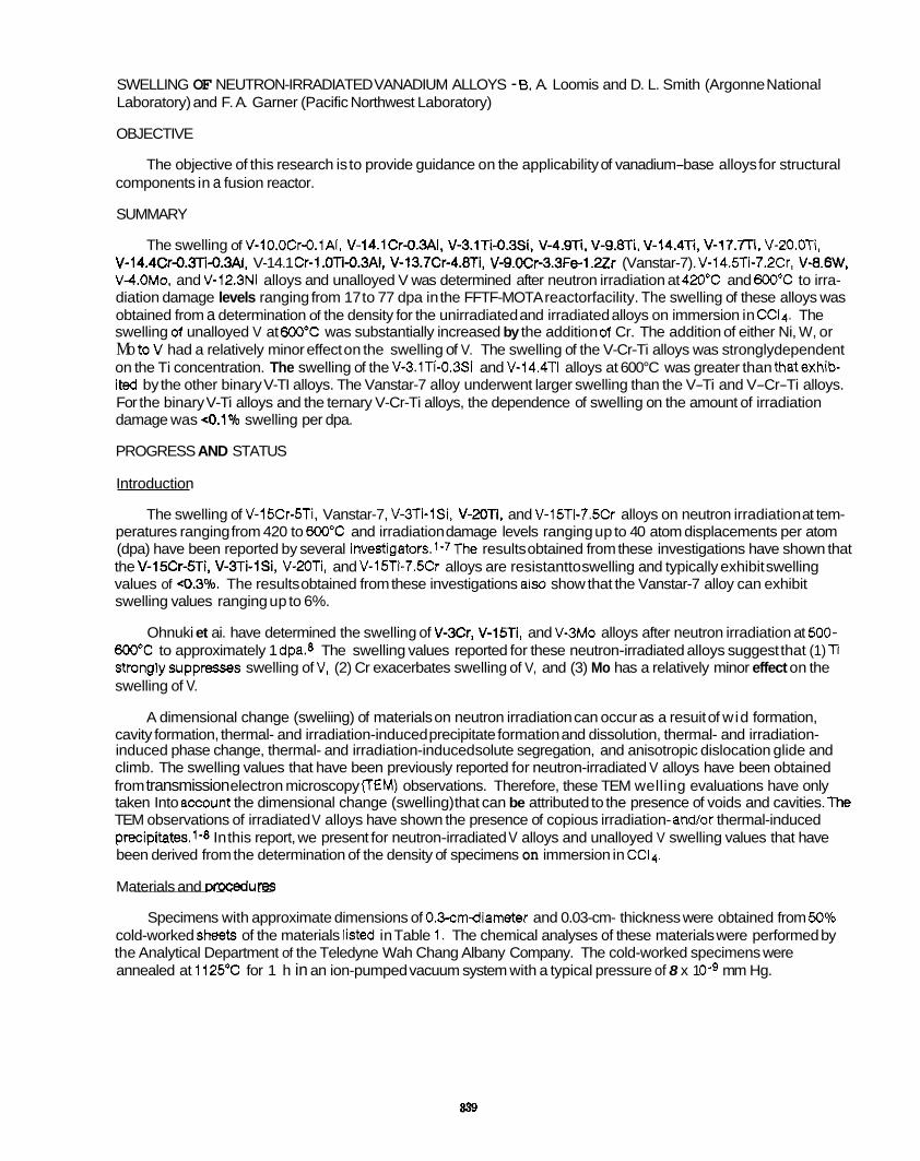
SWELLING OF NEUTRON-IRRADIATED VANADIUM ALLOYS - 8. A. Loomis and D. L. Smith (Argonne National Laboratory) and F. A. Garner (Pacific Northwest Laboratory)
OBJECTIVE
The objective of this research is to provide guidance on the applicability of vanadium-base alloys for structural components in a fusion reactor.
SUMMARY
The swelling of V-lO.OCr-O.lAI, V-14.1Cr-O.3AI, V-3.1Tid.3S1, V-4.9Ti, V-9.8Ti, V-l4.4Ti, V-17.7TL V-ZO.OTi, V-14.4Cr-0.3li-0.3Ai. V-14.1 Cr-1 .OTi-0.3AI, V-13.7Cr-4.8Ti, V-9.0Cr-3.3Fe-l.Zr (Vanstar-7). V-14.5Ti-7.2Cr. V-8.6W, V4OMo. and V-12.3Ni alloys and unalloyed V was determined after neutron irradiation at 420°C and 600°C to irra- diation damage levels ranging from 17 to 77 dpa in the FFTF-MOTA reactorfacility. The swelling of these alloys was obtained from a determination of the density for the unirradiated and irradiated alloys on immersion in CCi4. The swelling of unalloyed V at 600°C was substantially increased by the addition d Cr. The addition of either Ni, W, or Mo toV had a relatively minor effect on the swelling of V. The swelling of the V-Cr-Ti alloys was stronglydependent on the Ti concentration. The swelling of the V-3.1Ti-0.3Si and V-14.4Ti alloys at 600°C was greater than thatexhib- ited by the other binary V-TI alloys. The Vanstar-7 alloy underwent larger swelling than the V-Ti and V-Cr-Ti alloys. For the binary V-Ti alloys and the ternary V-Cr-Ti alloys, the dependence of swelling on the amount of irradiation damage was <0.1% swelling per dpa.
PROGRESS AND STATUS
Introduction
peratures ranging from 420 to 600°C and irradiation damage levels ranging up to 40 atom displacements per atom (dpa) have been reported by several investigators.l-7The results obtained from these investigations have shown that the V-15Cr-5Ti, V-3Ti-lSi, V-XTi. and V-15Ti-7.5Cr alloys are resistantto swelling and typically exhibit swelling values of <0.30/0. The results obtained from these investigations ais0 show that the Vanstar-7 alloy can exhibit swelling values ranging up to 6%.
Ohnuki et ai. have determined the swelling of V-3Cr, V-l5Ti, and V-3MO alloys after neutron irradiation at 500- 600°C to approximately 1 dpa.6 The swelling values reported for these neutron-irradiated alloys suggest that (1) Ti stronglysuppresses swelling of V. (2) Cr exacerbates swelling of V, and (3) Mo has a relatively minor effect on the swelling of V.
A dimensional change (sweliing) of materials on neutron irradiation can occur as a resuit of wid formation, cavity formation, thermal- and irradiation-induced precipitate formation and dissolution, thermal- and irradiation- induced phase change, thermal- and irradiation-induced solute segregation, and anisotropic dislocation glide and climb. The swelling values that have been previously reported for neutron-irradiated V alloys have been obtained from transmission electron microscopy (TEM) observations. Therefore, these TEM welling evaluations have only taken Into account the dimensional change (swelling) that can be attributed to the presence of voids and cavities. The TEM observations of irradiated V alloys have shown the presence of copious irradiation- and/or thermal-induced precipitates.1-8 In this report, we present for neutron-irradiated V alloys and unalloyed V swelling values that have been derived from the determination of the density of specimens on immersion in CC14.
Materials and ~rOcedure~
Specimens with approximate dimensions of 0.3-cmdiameter and 0.03-cm- thickness were obtained from 50Y0 cold-worked sheets of the materials listed in Table 1. The chemical analyses of these materials were performed by the Analytical Department of the Teledyne Wah Chang Albany Company. The cold-worked specimens were annealed at 1125°C for 1 h in an ion-pumped vacuum system with a typical pressure of 8 x 1 O g mm Hg.
The swelling of V-15Cr-5Ti. Vanstar-7, V-3Ti-13, V-2OTi, and V-15Ti-7.5Cr alloys on neutron irradiation at tem-
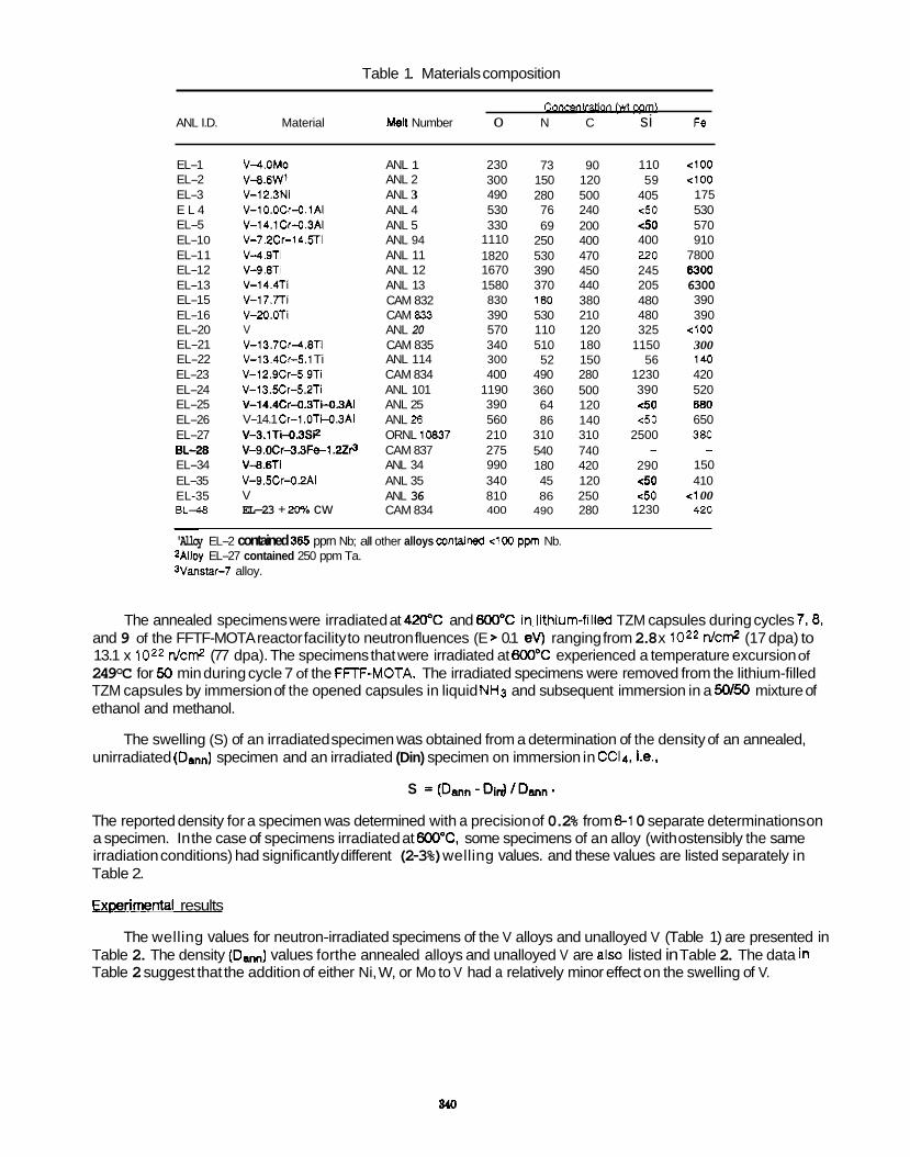
Table 1. Materials composition
co- ANL I.D. Material en Number 0 N C si Fe
EL-1 EL-2 EL-3 E L 4 EL-5 EL-1 0 EL-1 1 EL-1 2 EL-1 3 EL-1 5 EL-1 6 EL-20 EL-21 EL-22 EL-23 EL-24 EL-25 EL-26 EL-27 EL-= EL-34 EL-35 EL-35 BL-48
V-4.OMo
V-12.3Ni V-1O.OCr-O.lAI V-14.1Cr-O.3AI V-7.2Cr-14.5Ti V4.9Ti V-9.8Ti V-14.4Ti V-17.7Ti V-20.OTi V V-13.7Cr4.8Ti V-l3.4Cr-5.1 Ti V-12.9C-5.9Ti V-13.Xr-5.2Ti V-14.4Cr-O.3TM3AI V-14.1 Cr-1 .OTMJAI V-3.1Ti-O.3Si2 V-9.0Cr-3.3Fs1.22@ V4.BTi V-9.5Cr-OZAI V EL-23 + 20% cw
V-9.6W' ANL 1 ANL 2 ANL 3 ANL 4 ANL 5 ANL 94 ANL 11 ANL 12 ANL 13 CAM 832 CAM 833 ANL 20 CAM 835 ANL 114 CAM 834 ANL 101 ANL 25 ANL .B ORNL 10837 CAM 837 ANL 34 ANL 35 ANL 36 CAM 834
230 300 490 530 330
1110 1820 1670 1580 830 390 570 340 300 400
1190 390 560 210 275 990 340 810 400
73 90 150 120 280 500 76 240 69 200
250 400 530 470 390 450 370 440 1M) 380 530 210 110 120 510 180 52 150
490 280 360 500 64 120 86 140
310 310 540 740 180 420 45 120 86 250
490 280
110 59
405 <50 <50 400 220 245 205 480 480 325
1150 56
1230 390 e50 <50
2500
290 e50 c50
1230
-
4 0 0 4 0 0
175 530 570 910
7800 6300 6300 390 390
4 0 0 300 140 420 520 880 650 380
150 410
<1 00 420
-
~
'Alloy EL-2 contained 365 pprn Nb; all other alloys contarned 4 0 0 ppm Nb. 2Ailoy EL-27 contained 250 ppm Ta. %mar-7 alloy.
The annealed specimens were irradiated at 420°C and 600°C in.lithium-filled TZM capsules during cycles 7,8, and 9 of the FFTF-MOTA reactor facility to neutron fluences (E > 0.1 ev) ranging from 2.8 x 10²² n l c d (17 dpa) to 13.1 x 10²² n l c d (77 dpa). The specimens that were irradiated at 600°C experienced a temperature excursion of 249°C for 50 min during cycle 7 of the FFF-MOTA. The irradiated specimens were removed from the lithium-filled TZM capsules by immersion of the opened capsules in liquid NH3 and subsequent immersion in a 50/50 mixture of ethanol and methanol.
The swelling (S) of an irradiated specimen was obtained from a determination of the density of an annealed, unirradiated (Dann) specimen and an irradiated (Din) specimen on immersion in CC14, Le.,
S =(Dmn-Din)lDmn.
The reported density for a specimen was determined with a precision of 0.2% from 8-1 0 separate determinations on a specimen. In the case of specimens irradiated at 600"C, some specimens of an alloy (with ostensibly the same irradiation conditions) had significantly different (2-3%) welling values. and these values are listed separately in Table 2.
EL(Wrimenta1 results
Table 2. The density (Dan,,) values forthe annealed alloys and unalloyed V are also listed in Table 2. The data in Table 2 suggest that the addition of either Ni, W, or Mo to V had a relatively minor effect on the swelling of V.
The welling values for neutron-irradiated specimens of the V alloys and unalloyed V (Table 1) are presented in
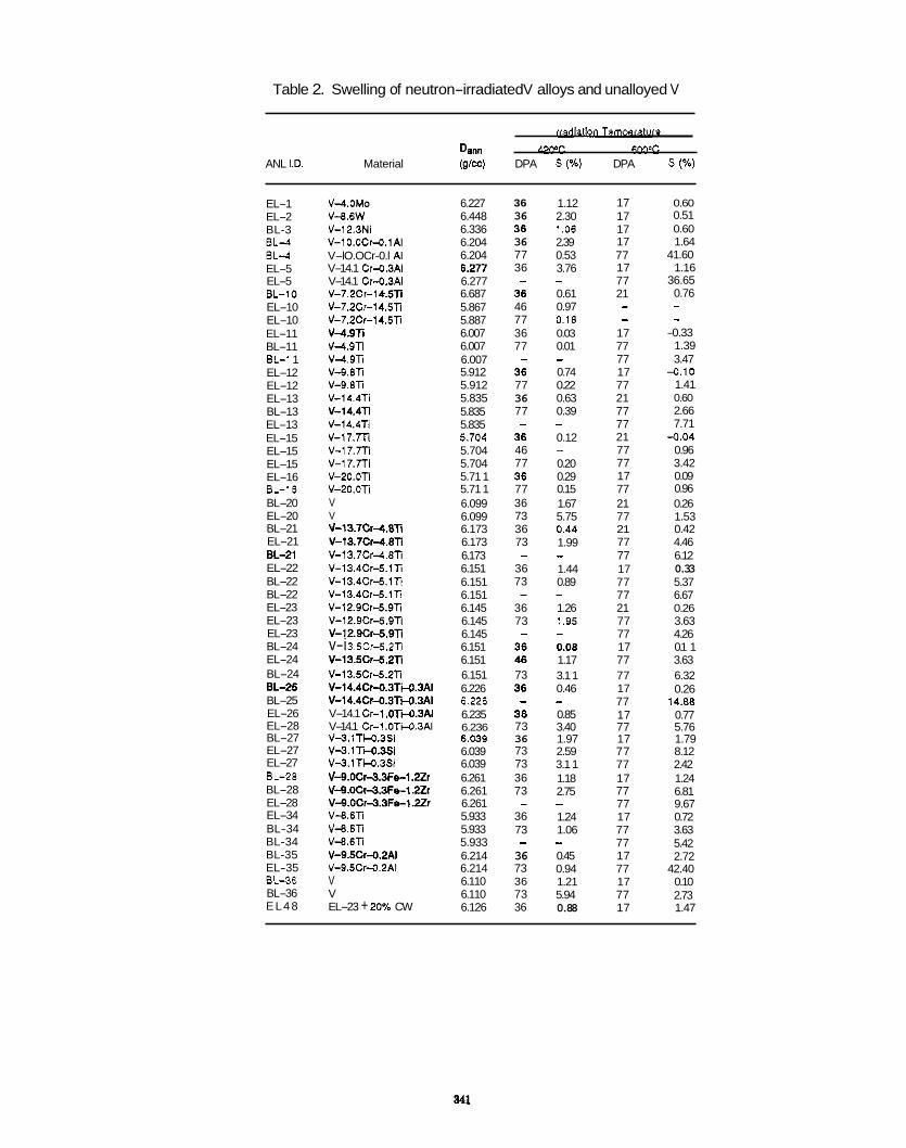
Table 2. Swelling of neutron-irradiated V alloys and unalloyed V
. . rrad-ure
Dan" 42PC 6W'C ANL I.D. Material (g/cc) DPA S (%) DPA S (%)
EL-1 EL-2 BL-3 E L 4 E L 4 EL-5 EL-5 BL-10 EL-10 EL-10 EL-11 BL-11 BL-1 1 EL-12 EL-12 EL-13 BL-13 EL-13 EL-15 EL-15 EL-15 EL-16 BL-16 BL-20 EL-20 BL-21 EL-21 EL41 EL-22 BL-22 BL-22 EL-23 EL-23 EL-23 BL-24 EL-24 BL-24 E L 2 5 BL-25 EL-26 EL-28 BL-27 EL-27 EL-27 EL-28 BL-28 EL-28 EL-34 BL-34 BL-34 BL-35 EL-35 BL-36 BL-36 E L 4 8
V4.OMO V-8.6W V-12.3Ni V-1 O.OCr-0.1AI V-lO.OCr-0.l AI V-14.1 Cr-0.3Ai V-14.1 Cr-0.3AI v-7.2~1-1 &.sn V-7.2Cr-14.5TI V-7.2Cr-14.5TI v4 .9n v4.9Ti v-4.m V-9.6Ti V-9.6TI V-14.4Ti
V-14.4h v-17.m V-17.m v-l7.7Ti
v-20.m V V V-13.7C1-4.8TI V-13.7Cr-4.6TI V-13.7Cr4.6TI V-13.4Crd.lh V-13.4Crd.lTi V-13.4Crd.lli V-12.9Cr-5.9TI V-12.9Crd.9Ti V-12.9Cr-5.9TI v-i 3.5cr-5.2~1 V-13.5Crd.2h V-13.5Crd.2Ti V-14.4Cr-0.3TM.3Ai V-14.4Cr-0.3TM.3AI V-14.1 Cr-1 .OTM.3AI V-14.1 Cr-l.OTM.3AI v-3.i r'c0.3~1 v-3.i m . 3 s i V-3.1TM.3SI V-9.OCr-3.3Fe-1.2Zr V-9.OCr-3.3Fel.2Zr V-9.OCr3.3Fe-1.2Zr V-8.6li V-9.6TI V-8.6TI V-9.5Cr-0.2AAI V-9.5Cr-0.2AI V V EL-23 + 20% CW
v-14.4n
v-20.0~1
6.227 6.448 6.336 6.204 6.204 6.277 6.277 6.687 5.867 5.887 6.007 6.007 6.007 5.912 5.912 5.835 5.835 5.835 5.704 5.704 5.704 5.71 1 5.71 1 6.099 6.099 6.173 6.173 6.173 6.151 6.151 6.151 6.145 6.145 6.145 6.151 6.151 6.151 6.226 6.226 6.235 6.236 6.039 6.039 6.039 6.261 6.261 6.261 5.933 5.933 5.933 6.214 6.214 6.110 6.110 6.126
36 36 36 36 77 36 - 46 77 36 77 - 77 36 77
36 46 77
-
77 36 73 36 73
36 73
36 73
-
-
-
73
- 36 73 36 73 73 36 73
36 73
36 73 36 73 36
-
-
1.12 2.30
2.39 0.53 3.76
0.61 0.97 0.18 0.03 0.01
0.74 0.22 0.63 0.39
0.12
0.20 0.29 0.15 1.67 5.75 0.44 1.99
1.44 0.89
1.26 1.95
0.08 1.17 3.1 1 0.46
0.85 3.40 1.97 2.59 3.1 1 1.18 2.75
1.24 1.06
0.45 0.94 1.21 5.94 0.88
i.oe
-
-
- -
- -
-
-
-
-
17 17 17 17 77 17 77 21 - -
17 77 77 17 77 21 77 77 21 77 77 17 77 21 77 21 77 77 17 77 77 21 77 77 17 77 77 17 77 17 77 17 77 77 17 77 77 17 77 77 17 77 17 77 17
0.60 0.51 0.60 1.64
41.60 1.16
36.65 0.76 - -
-0.33 1.39 3.47
-0.10 1.41 0.60 2.66 7.71
4 .04 0.96 3.42 0.09 0.96 0.26 1.53 0.42 4.46 6.12 0.33 5.37 6.67 0.26 3.63 4.26 0.1 1 3.63 6.32 0.26
0.77 5.76 1.79 8.12 2.42 1.24 6.81 9.67 0.72 3.63 5.42 2.72
42.40 0.10 2.73 1.47
14.88
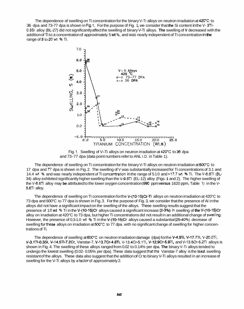
The dependence of swelling on Ti concentration for the binary V-Ti alloys on neutron irradiation at 420°C to 36 dpa and 73-77 dpa is shown in Fig.1. For the purpose of Fig. 1 I we consider that the Si content in the V- 3Ti- 0.39 alloy (BL-27) did not significantly affect the swelling of binary V-Ti alloys. The swelling of V decreased with the addition of Ti to a concentration of approximately 5 wt %, and was nearly independent of Ti concentration in the range of 5 to 20 wt % Ti.
7.0
6.0
5.0 r\
v 6?
Ln 4.0
$ 3.0 w 2.0 3 v)
- _1 _I
1.0
0.0
V- li Alloys 420 “C
0-0 73-77 DPA X-x 36 DPA
-1.0 0.0 5.0 10.0 15.0 20.0 25.0
TITANIUM CONCENTRATiON (Wt.w)
Fig. 1. Swelling of V-Ti alloys on neutron irradiation at 420T to 33 dpa and 73-77 dpa (data point numbers refer to ANL I.D. in Table 1).
The dependence of swelling on Ti concentration for the binary V-Ti alloys on neutron irradiation at 600°C to 17 dpa and 77 dpa is shown in Fig. 2. The swelling of V was substantially increased for Ti concentrations of 3.1 and 14.4 wt % and was nearly independent of Ti concerWation in the range of 510 and >17.7 wt % Ti. The V-8.61 (BL- 34) alloy exhibited significantly higher swelling than the V-9.8Ti (EL-12) alloy (Figs. 1 and 2). The higher swelling of the V-8.6Ti alloy may be attributed to the lower oxygen concentration (990 ppm versus 1620 ppm, Table 1) in the V- 8.6Ti alloy.
73 dpa and 600°C to 77 dpa is shown in Fig. 3. For the purpose of Fig. 3, we consider that the presence of AI in the alloys did not have a significant impact on the swelling of the alloys. These swelling results suggest that the presence of 1 .O wt % Ti in the V-(10-15)Cr alloys caused a significant increase (2-3Vo) In swelling of the V-(1@15)Cr alloy on irradiation at 420°C to 73 dpa, but higher Ti concentrations did not result in an additional change of Swelling. However, the presence of 0.3-1.0 wt % Ti in the V-(10-15)Cr alloys caused a substantial (2540%) decrease of swelling forthese alloys on irradiation at 600°C to 77 dpa. with no significant change of swelling for higher concen- trations of Ti.
The dependence of swelling on Ti concentration forthe V-(lO-15)Cr-Ti alloys on neutron irradiation at 420°C to
The dependence of swelling at 690°C on neutron irradiation damage (dpa) forthe V4.Wl. V-17.TTi, V-20.OTi. V-3.1Ti-O.3Si, V-14.5Ti-7.2Cr. Vanstar-7, V-l3.7Cr-4.8Ti, V-13.4Cr-5.1Ti. V-12.9Cr-5.9Ti, and V-13.5Cr-5.2Ti alloys is shown in Fig. 4. The swelling of these alloys ranged from 0.02 to 0.14% per dpa. The binary V-Ti alloys tended to undergo the lowest swelling (0.02- 0.05% per dpa). These data suggest thatthe Vanstar-7 alloy is the least swelling resistant of the alloys. These data also suggest that the addition of Cr to binary V-Ti alloys resulted in an increase of swelling for the V-Ti alloys by a factorof approximately 2.
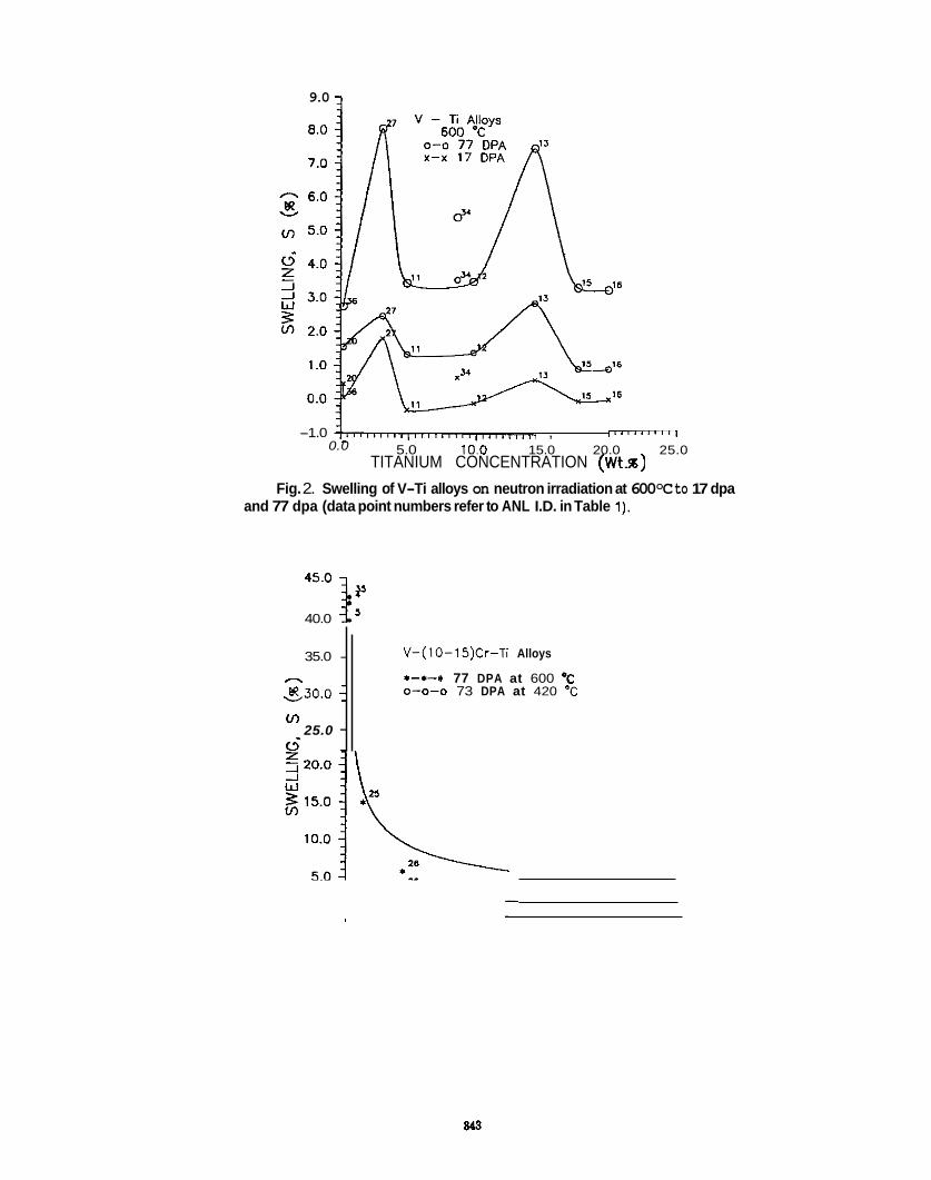
9.0 -l
35.0 - - s 3 0 . 0 i v)
25.0 - c.5 -
-1.0 . . . . . . . . . . . . . . . . . . . . . . . . . . . . . . , I ~ ~ ' ~ * I ~ ' ~ I
5.0 10.0 15.0 20.0 25.0 0.0 TITANIUM CONCENTRATION ( W t s )
Fig. 2. Swelling of V-Ti alloys on neutron irradiation at 600°C to 17 dpa and 77 dpa (data point numbers refer to ANL I.D. in Table 1).
V-(10-15)Cr-Ti Alloys
*-I-* 77 DPA at 600 'C 0-0-0 73 DPA at 420 "C
40.0 45.0 3:
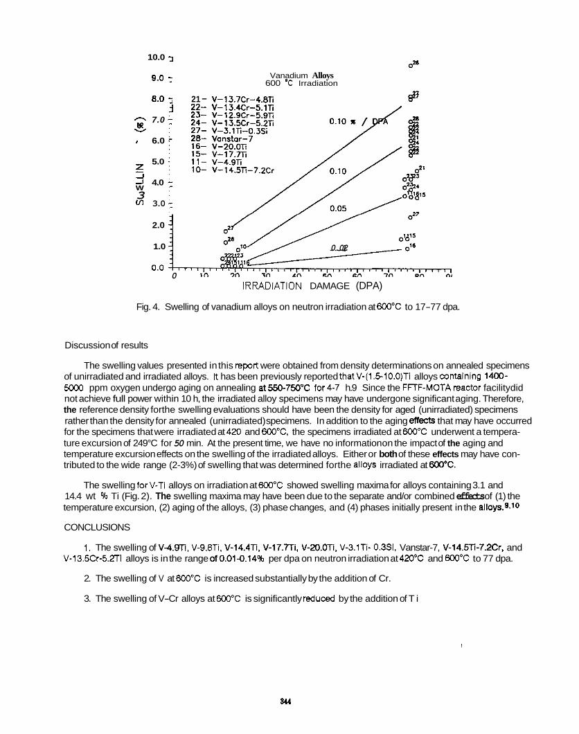
10.0 :
9.0 1
8.0 'j 3 - 7.0 1
6.0 - 5.0
R v
z
3
_I J 4.0 : W
v) 3.0 :
2.0 1
1.0 1
Vanadium Alloys 600 O C Irradiation
21 - 22- 23- 24- 27- 28- 16- 15- 11- 10-
0.02
0 IRRADiATiON DAMAGE (DPA)
Fig. 4. Swelling of vanadium alloys on neutron irradiation at 600°C to 17-77 dpa.
Discussion of results
of unirradiated and irradiated alloys. It has been previously reported thatV-(l.E-lO.O)Ti alloys containing 1400- 5Mu) ppm oxygen undergo aging on annealing at550-750"C for4-7 h.9 Since the FFTF-MOTAreactor facilitydid not achieve full power within 10 h, the irradiated alloy specimens may have undergone significant aging. Therefore, the reference density forthe swelling evaluations should have been the density for aged (unirradiated) specimens rather than the density for annealed (unirradiated) specimens. In addition to the aging eftects that may have occurred for the specimens that were irradiated at 4x) and 600°C. the specimens irradiated at 600°C underwent a tempera- ture excursion of 249°C for 50 min. At the present time, we have no information on the impact of the aging and temperature excursion effects on the swelling of the irradiated alloys. Either or both of these effects may have con- tributed to the wide range (2-3%) of swelling that was determined forthe alloys irradiated at B0o"C.
The swelling forV-Ti alloys on irradiation at 600°C showed swelling maxima for alloys containing 3.1 and 14.4 wt YO Ti (Fig. 2). The swelling maxima may have been due to the separate and/or combined effects of (1) the temperature excursion, (2) aging of the alloys, (3) phase changes, and (4) phases initially present in the alloy^.^^^^
CONCLUSIONS
V-13.5Cr-5.2Ti alloys is in the range ofO.01-0.14'?6 per dpa on neutron irradiation at 420°C and 600°C to 77 dpa.
The swelling values presented in this report were obtained from density determinations on annealed specimens
1. The swelling of V4.9Ti, V-9.8Ti. V-14.4Ti, V-17.7Ti, V-20.OTi, V-3.lTi- 0.3Si, Vanstar-7, V-14.5Ti-7.Xr, and
2. The swelling of V at 600°C is increased substantially by the addition of Cr.
3. The swelling of V-Cr alloys at 600°C is significantly reduced by the addition of T i
344
FUTURE WORK
1. The density of V-base alloys will be determined after receiving an aging treatment that is similar to the time- temperature schedule for the start-upof the FFTF-MOTA reactor facility.
the purpose devaluating the effect of the temperature excursion during cycles 7 and 8 on the swelling of V-base alloys.
2. The swelling of V-base alloys that were irradiated during cycle 10 of the FFTF-MOTA will be determined for
REFERENCES
1. D. N. Braski, "influence of Radiation on Material Properties: 13th International Symposium," ASTM STP 956, F. A. Garner, C. H. Henager. Jr.. and N. Igata, Eds., American Society forTesting Materials, Philadelphia, 1986. Pp. 271-290.
2. J. Bentley and F. W. Wiffen,Nuci. Technol, 30, 376-384 (1976).
3. H. Bohm. "Proceedings: International Conference on Defects and Defect Clusters in B.C.C. Metals and Their Alloys,"Gaithersburg, MD, R. J. Arsenauit, Ed., M. P. Graphics Inc.. Washington, D. C., 1973, pp. 163-175.
4. M. L. Grossbeck and J. A. Horak, "Influence of Radiation on Material Properties: 13th International Sympo- sium,"ASTM STP 956, F. A. Garner, C. H. Henager, Jr., and N. Igata. Eds., American Society forTesting Materials, Philadelphia, 1986, pp. 291-309.
5. R. Carlander, S . D. Harkness, and A.T. Santhanum, "Effectsof Radiation on Substructure and Mechanical Properties ot Metals and Alloys," ASTM STP 529. American Society for Testing Materials, Philadelphia, 1973, pp. 399-414.
6. M. P. Tanaka, E. E. Bloom, and J. A. Horak, J. Nucl. Mater. 103 & 104,895-900 (1981).
7. D. N. Braski, J. Nucl. Mater. 141 & 143, 11251131 (1986).
8. S. Ohnuki, H. Takahashi, H. Kinoshita, and R. Nagasaki, LNLE!&M~& 155-157, 936939 (1988)
9. S. Komjathy, J. I ess-Common Met. 3,468486 (1951).
10. J. L. Murray, Phase Diagrams of Binary Titanium Alloys, ASM Monograph Series on Alloy Phase Diagrams, 1987, pp. 314327.

LITERATURE RMRN OF RESEARCH ON VANADIUM AN0 VANADIUM RASE ALLOYS FOR USE IN FUSION REACTOR FIRST WAU/BLANKET APPUCATIONS - C. A Marsh and A 6. Hull (Atg0nt-e National LebaatDly)
OBJECTIVE
The objective of this review is to consolidate research information on vanadium and vanadium base alloys that pertains to their use as a reactor first-wall material.
SUMMARY
The literature was reviewed for research on the fabrication of vanadium base alloys and the effects of chemical environment. helium implantation, and neutron irradiation on the mechanical properties, microstructure. and corrosion behavior of vanadium and vanadium base alloys. The relevant material was compiled into an annotated bibliography of more than 100 reDresentative references. These references address the toDics highlighted in this report.
PROGRESS AND STATUS
__ Introduction __
intensified over the past 10 years in the hope of developing alloys that exhibit low induced radioactivity amenable to simplified disposal techniques. Vanadium alloy development has progressed to the point when? these materials ap,pear to offer an excellent option as a fusion energy source.
Since the research on vanadium and vanadium base alloys has been extensive and far ranging, a review of the existing literature and its presentation in the form of an annotated bibliography was deemed necessary.’ Research topics reviewed include the effects of helium implantation and irradiation on the mechanical properties and microstructureof vanadium and vanadium base alloys, and thecorrosion behavior of these materials in flowing lithium and in high-pressure water. A summary of each reference in the annotated bibliography provides information that is most pertinent to determining the composition of a vanadium base alloy with the optimum combination of swelling, corrosion resistance, and mechanical properties for use in fusion reactor first- walVblanket applications.
&%Its and Analysis
The dominant feasibility issue for the use of vanadium altoys in a fusion environment. as for all other alloy systems, is excessive embrittlement that can lead to failure. Thus the central theme of the vanadium alloy development effort has been to understand the dominant mechanisms that cause this embrittlement and to develop alloys that are least sensitive. Many of the resuits from the types of investigations mentioned above have profound implications forthis issue. Table 1 summarizes the types of vanadium alloys that have been produced and tested for these various characteristics.
Research on the applicability of vanadium base alloys for structuralcomponents in a fusion reactor has
CONCLUSION
The existing information on vanadium and vanadium base alloys, as it pertains to their use in fusion reactors, has been compiled into an annotated bibliography of more than 100 references. The bibliograDhv emDhasizeS fabrication history, chemical composition, and experimental investigations.
FUTURE WORK
Because the completed work is the subject of an ANL Technical Memorandum1 that contains more than IM) publications dealing with the topics highlighted above, no additional compilation of references is planned at this date.
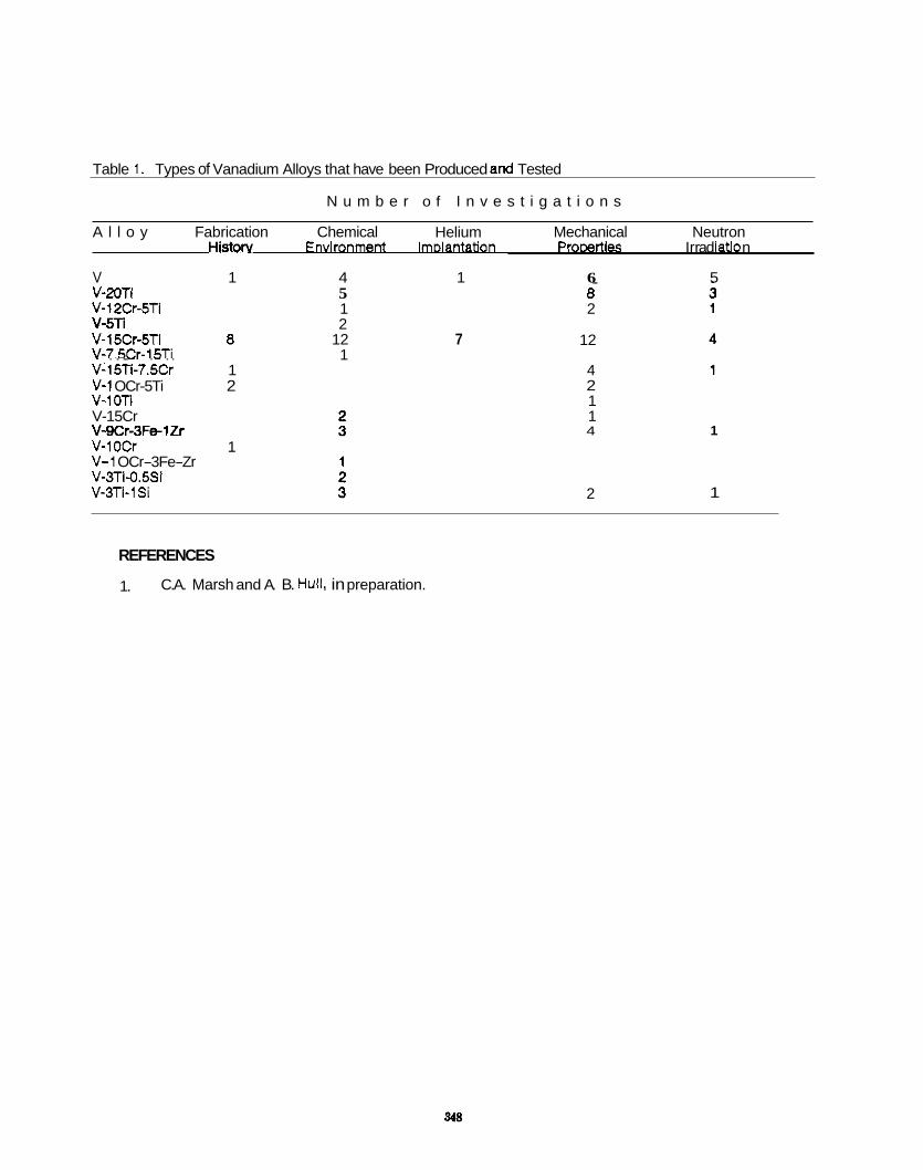
Table 1. Types of Vanadium Alloys that have been Produced and Tested
N u m b e r o f I n v e s t i g a t i o n s
HiStON Envlronment ImDlantation Prooerties Irr a d iaUo ' n A l l o y Fabrication Chemical Helium Mechanical Neutron
V 1 4 1 6 5 V-2OTi V-12Cr-5Ti v-5n V-l5Cr-5Ti 8 V-7.5Cr-15Ti
~ . . . -. . - . . V-15Ti-7.5Cr 1 V-1 OCr-5Ti 2 v-ion V-15Cr V-gCr-3FelZr V-1 OCr 1 V-1 OCr-3Fe-Zr v-3Ti-o.5si V-3Ti-1Si
5 1 2
12 1
7
. 8 2
12
4 2 1 1 4
2
1
1
REFERENCES
1. C.A. Marsh and A. B. Hull. in preparation.

6 . 4 Copper Alloys
349

OVERVIEW OF COPPER IRRADIATION PROGRAMS - F. A. Garner, M. L. Hamilton (Pacific Northwest Laboratory), K. R . Anderson, J. F. Stubbins (University of Illinois), E. N. Singh, A. Horsewell (RISa National Laboratory), W. F. Sommer (Los Alamos National Laboratory)
OBJECT I VE
The objective of this effort is to provide data on the radiation response of copper alloys intended for both near-term and long-term applications in fusion systems.
SUMMARY
Researchers at Pacific Northwest Laboratory(a) are collaborating with scientists from RISa National Labora- tory, Los Alamos National Laboratory and the University of Illinois to generate data on the response to radiation of copper alloys intended for use in ITER, NET and long-term fusion devices. experiments is presented.
An overview of these
PROGRESS AND STATUS
Introduction
For ITER applications, relatively pure copper and oxide dispersion strengthened (ODS) copper have been selected to serve as the high heat flux materials employed in the diverter assembly. mentioned as a possible backup material. The choice of these alloys was strongly influenced by irradiation data generated at Westinghouse Hanford Company and Pacific Northwest Laboratory (PNL) . Although there is some uncertainty in the possible range of design parameters, the current maximum tempera- ture anticipated for ITER applications is 475% and the anticipated target displacement levels are relatively low (<IO dpa). Data are therefore required for mechanical properties, thermal conductivity and dimensional stability of these alloys during irradiation in the range of 25'C to about 500°C. This report outlines the status of a series of irradiation experiments on copper alloys conducted jointly by Pacific Northwest Lab- oratory with the RISp National Laboratory in Denmark and the LASREF (Los Alamos Spallation Radiation Effects Facility) group in New Mexico. The University of Illinois is also participating under the sponsorship of the NORCUS (Northwest College and University Association For Science) program. participates in the ITER effort but is also the lead laboratory for copper studies in the Next European Turus (NET) program.
Since thermal conductivity values are not easily obtained with small radioactive specimens, electrical resis- tivity is measured and used to calculate an estimate of the thermal conductivity. Both properties change due to transmutation and radiation-induced microstructural components, particularly voids.
Previous Exoeriments in Fast Reactors
There were several studies conducted in the EBR-I1 reactor on copper alloys to 515 dp a temperatures of -4OOT. one of which was subsequently igygftigated at Los Alamos National Laboratory 7l-l) and another at Massachusetts Institute o f Technology. Where there was overlap in the specimen matrix, these EBR-I1 studies agreed fairly well with a "first generation" exploratory experiment conducted in FFTF/MOTA by Pacific Northwest Laboratory and W t' ghouse Hanford Company at roughly the same temperature to four dose levels ranging from 16 t o 98 dpa. f2-4! The latter study was directed toward both near-term (ITER) and long-term, high-fluence concerns.
Each of these fast reactor studies demonstrated the potential of various ODs copper alloys to resist void swelling. In all three of the earlier experiments, however, no data were generated at temperatures below 385% or above 425'C, leaving much of the ITER-relevant temperature range unexplored.
Onsoins ExDeriments in FFTF/MOTA
Based on the results of the "Generation 1" experiment, two successively more focussed experiments were designed. The "Generation 1.5" experiment contained many of the original Generation 1 alloys plus a variety of alloys strengthened by dispersoids, precipitates or spinodal decomposition. These alloys are listed in Table 1. Irradiation of TEM disks and miniature tensile specimens proceeded at 414% to 34 dpa and at 5 Z I " C to 32 dpa in MOTA-ID. levels of self-welding and interaction with the aluminum foils used as spacers, the Generation 1.5 specimens were separated with tantalum spacers and did not interact.
(a) Operated for the U.S. Department of Energy by Battelle Memorial Institute under
CuBeNi has also been
The RISp group not only
Whereas the Generation 1 specimens at higher fluence levels experienced increasing
Contract DE-AC06-76RLO 1830.
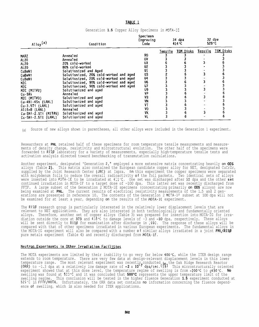
n&u Generation 1 . 5 Copper Alloy Specimens in MOTA-ID
(a) Source of new alloys shown in parentheses, all other alloys were included in the Generation 1 experiment.
Researchers at PNL retained half of these specimens for room temperature tensile measurements and measure- ments of density change, resistivity and microstructural evolution. The other half of the specimens were forwarded to RlSp laboratory for a variety of measurements, especially high-temperature tensile tests and activation analysis directed toward benchmarking of transmutation calculations.
Another experiment, designated "Generation 2," employed a more extensive matrix concentrating heavily on ODs alloys (Table 2 ) . This matrix also contained the European candidate copper alloy for NET, designated CuCrZr, supplied by the Joint Research Center (JRC) at Ispra. I n this experiment the copper specimens were separated with molybdenum foils to reduce the overall radioactivity o f the foil packets. Two identical sets of alloys were inserted into MOTA-1E to be irradiated at 411'C. One set was discharged after 50 dpa and the other s e t continued irradiation in MOTA-IF to a target dose of -100 dpa. This latter set was recently discharged from FFTF. being examined at PNL. The current results of electrical resistivity measurements of the 1.5 and 2 gen- erations are presented in reference 10. The contents of the Generation 2 MOTA-1F subset at 100 dpa will not be examined for at least a year, depending on the results of the MOTA-1E experiment.
The RISP research group is particularly interested in the relatively lower displacement levels that are relevant to NET applications. alloys. diation outside the core at 373 and 418% to damage levels of -3 and -10 dpa, respectively. will be sent directly to RISp for examination after discharge in 1990. compared with that of other specimens irradiated in various European experiments. the MOTA-IG experiment will also be compared with a number o f similar alloys irradiated in a joint PNL/RlSB pure metals experiment (Table 4) and recently discharged from MOTA-1F.
A large subset of the Generation 2 MOTA-1E specimens (concentrating primarily on ODS alloys) are now
They are also interested in both technologically and fundamentally oriented Therefore, another set of copper alloys (Table 3) was prepared for insertion into MOTA-IG for irra-
These alloys The response of these alloys will be
The fundamental alloys in
fl The MOTA experiments are limited by their inability to go very far below 400'C, while the ITER design range extends to room temperature. temperature range. the Oak Ridge Research Reactor
experiment showed that at this dose level, the temperature regime of swelling is from - 2 O O T to ~450'C. swelling was found at 500'C and it was concluded that 500°C represents the upper temperature limit of the swelling regime. 529% in FFTF/MOTA. ence of swelling, which is also needed for ITER applications.
There are very few data at design-relevant displacement levels in this lower The most relevant experiment was recently conducted
(ORR) to -1.3 dpa at a relatively low damage rate of -2 x lo-' dpa/sec.( iF This microstructurally oriented No
Unfortunately, the ORR data set contains no information concerning the fluence depend- This conclusion will be tested in the higher fluence Generation 1 . 5 experiment conducted at
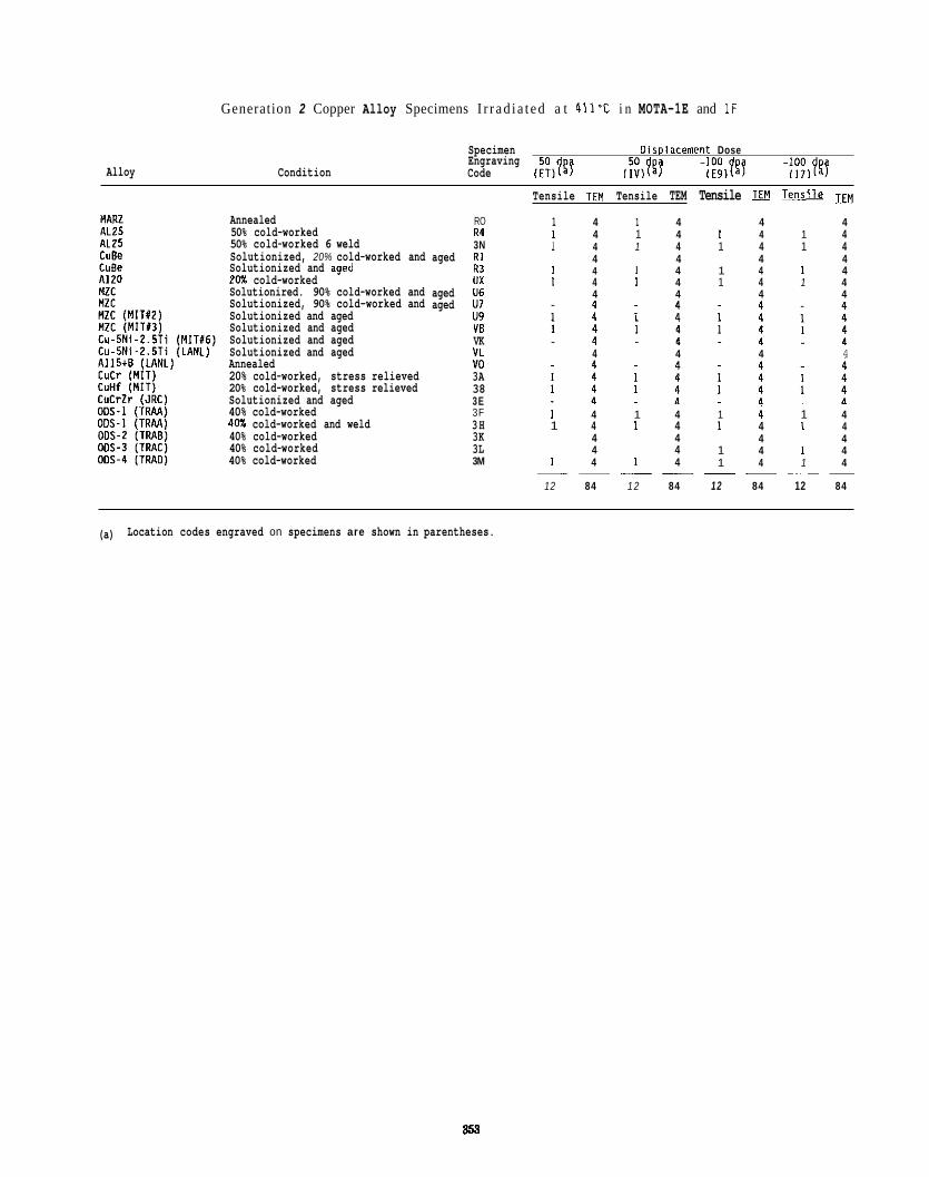
Alloy
Generation 2 Copper Alloy Specimens I r r ad i a t ed a t 411-C i n MOTA-1E and 1 F
Condition
Specimen Oimlacement Dose Engraving Code
- 100 p -100 (;;)ygj (E91faj 117)fg7
Annealed 50% cold-worked 50% cold-worked 6 weld Solutionized, 20% cold-worked and Solutionized and aaed 20% cold-worked I
Solutionired. 90% cold-worked and Solutionized, 90% cold-worked and Solutionized and aged Solutionized and aged Solutionized and aged Solutionized and aged Annealed 20% cold-worked, stress relieved 20% cold-worked, stress relieved Solutionized and aged 40% cold-worked 40% cold-worked and weld 40% cold-worked 40% cold-worked 40% cold-worked
RO R4 3N
aged R1 R3 ux
aged U6 aged U7
u9 VB VK VL YO 3A 38 3E 3F 3H 3K 3L 3M
Tensile TEM Tensile TEM Tensile E! I s d
1 4 1 4 4 4 1 4 1 4 I 4 1 4 1 4 1 4 1 4 1 4
4 4 4 4 1 4 1 4 1 4 1 4 1 4 1 4 1 4 1 4
4 4 4 4
4 4 4 4
1 4 1 4 1 4 1 4 1 4 1 4 1 4 1 4
4 4 4 4 4 4 1 4 1 4
1 4 1 4 1 4 1 4 -- -_ -_ - - 12 84 1 2 84 12 84 12 84
(a) Location codes engraved on specimens are shown in parentheses.
358
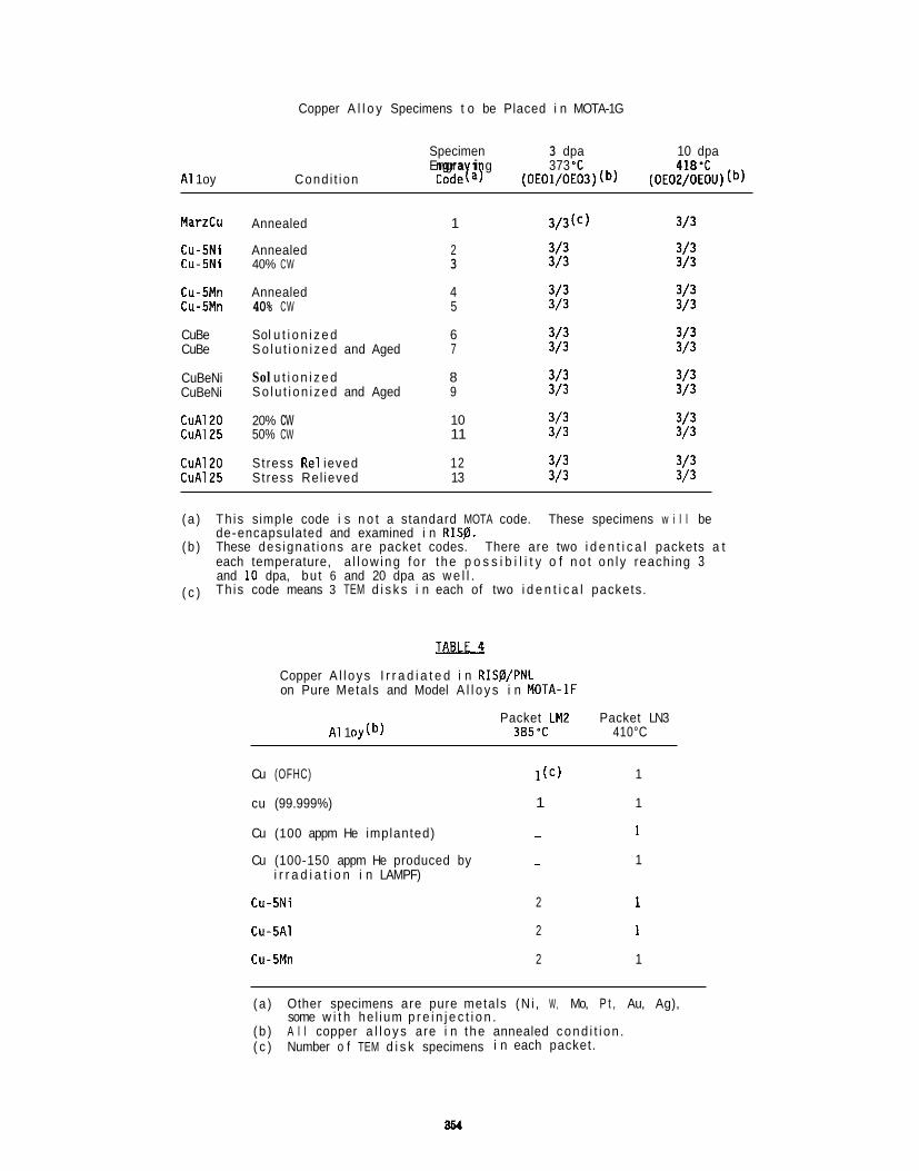
Copper A l l o y Specimens t o be Placed i n MOTA-1G
Specimen 3 dpa 10 dpa Engra i g 373 'C 418'C
A1 1 oy Cond i t ion Codeyay (OE01/OE03) (b) (OEOZ/OEOU) (b)
MarzCu
Cu-5Ni Cu-5Ni
Cu-5Mn Cu-5Mn
CuBe CuBe
CuBeNi CuBeNi
CuAl20 CuAl25
CuAl20 CuAl25
Annealed 1 3/3(C) 3/3
Annealed 2 3/3 3/3 40% CW 3 3/3 3/3
Annealed 4 3/3 3/3 40% CW 5 3/3 3/3
Sol u t i o n i z e d 6 3/3 3/3 So lu t i on i zed and Aged 7 3/3 3/3
Sol u t i o n i z e d 8 3/3 3/3 So lu t i on i zed and Aged 9 3/3 3/3
20% cw 10 3/3 3/3 50% CW 11 3/3 3/3
Stress Re1 ieved 12 3/3 3/3 Stress Rel ieved 13 3/3 3/3
( a ) Th is simple code i s n o t a standard MOTA code. These specimens w i l l be
( b ) These des ignat ions a re packet codes. There are two i d e n t i c a l packets a t
( c )
de-encapsulated and examined i n !?IS$.
each temperature, a l l ow ing f o r t he p o s s i b i l i t y o f n o t on l y reaching 3 and 10 dpa, bu t 6 and 20 dpa as w e l l . Th is code means 3 TEM d i s k s i n each of two i d e n t i c a l packets.
Copper A l l oys I r r a d i a t e d i n RISp/PNL on Pure Metals and Model A l l o y s i n MOTA-1F
A1 1 Packet LM2 Packet LN3 385'C 410°C
Cu (OFHC) I([) 1
cu (99.999%) 1 1
Cu (100 appm He implanted) - 1
Cu (100-150 appm He produced by - i r r a d i a t i o n i n LAMPF)
1
Cu-5Ni
Cu-SA1
2 1
2 1
Cu-5Mn 2 1
( a ) Other specimens are pure metals (N i , W, Mo, P t , Au, Ag), some w i t h he l ium p r e i n j e c t i o n .
( b ) A l l copper a l l o y s are i n t he annealed cond i t i on . ( c ) Number o f TEM d i s k specimens i n each packet.
I n an e f f o r t t o o b t a i n d a t a a t l ower temperatures, i r r a d i a t i o n s a r e a l s o proceeding i n o t h e r f a c i l i t i e s . Some o f these i r r a d i a t i o n s a re a l s o designed t o e x p l o r e t h e p o s s i b i l i t y t h a t neu t ron s p e c t r a l d i f f e r e n c e s have a s i g n i f i c a n t impact on t h e m i c r o s t r u c t u r a l and microchemical e v o l u t i o n o f copper a l l o y s .
The f i r s t of these exper iments i n v o l v e s t h e i r r a d i a on of OFHC and MARZ grades o f copper i n t h e DR-3 f i s s i o n r e t o r a RIS0 t o f luences o f 0.38, 2.5 and 5 x IOiA n/cm2 (-0.5 dpa maximum) a t 400°C and t o 0.5 and 5.0 x logs n/cmi a t 250'C. I r r a d i a t i o n t h e ORR d a t a of Z i n k l e and F a r r e l l i f l j and w i t h t h a t o f t h e MOTA-IF and MOTA-IG i r r a d i a t i o n s .
These d a t a w i l l a l s o be compared w i t h t h e r e s u l t s of an i r r a d i a t i o n t o 0.5-1.0 dpa j u s t completed i n t h e LASREF f a c i l i t y u s i n g s p a l l a t i o n neutrons a t 330 and 400T (Table 5 ) . Europe a w a i t i n g examinat ion and dos imet ry measurement. neutrons a t 9 0 - 1 0 0 T i s c u r r e n t l y i n Los Alamos a w a i t i n g removal f rom t h e i r r a d i a t i o n capsule p r i o r t o s h i p p i n g and examinat ion a t PNL. fus ion neu t rons . problems i n t h e i n t e r p r e t a t i o n o f t h e data. more comprehensive ITER-re levant i r r a d i a t i o n exper iment i n LASREF w i l l be designed t o cover t h e e n t i r e temperature range of i n t e r e s t , f o c u s i n g on t h e a l l o y s e x h i b i t i n g t h e b e s t behav io r i n Generat ion 2 o f t h e FFTF/MOTA exper iments.
o n t i n u i n g t o h i g h e r f luence l e v e l s . These d a t a w i l l be compared w i t h
These specimens a re c u r r e n t l y i n Another s e t o f specimens i r r a d i a t e d w i t h s p a l l a t i o n
T h i s i s t h e f i r s t use of s p a l l a t i o n neutrons as a p o s s i b l e su r roga te f o r The " h i g h energy t a i l " of t h e neu t ron spec t ra extends t o -300 MeV and may i n v o l v e s p e c i a l
I f t h e s p a l l a t i o n neu t ron experiment appears t o be success fu l , a
An e x t e n s i o n o f t h e s p e c t r a l e f f e c t s s t u d i e s of H. L. He in isch(12) dev ice t o t h a t o f LASREF and OR-3 i s now be ing planned.
from t h e Omega West Reactor and RTNS-11
Charsed P a r t i c l e F a c i l i t i e s
Some of t h e a l l o y s descr ibed p r e v i o u s l y have been o r w i l l soon be i r r a d i a t e d w i t h h igh-energy p r o t o n s i n t h e LAMPF (Los Alamos) and P IREX (Swi tze r land) f a c i l i t i e s . T h i s e f f o r t i s p r i m a r i l y o f i n t e r e s t o n l y t o European researchers, a l though PNL has s u p p l i e d some a l l o y s used i n t h e U.S. program f o r comparison purposes. t i o n a l comparison e f f o r t s between t h e e f fec ts of h igh-energy p r o t o n s and s p a l l a t i o n neu t rons a r e under way a t Los Alamos N a t i o n a l Labora to ry . PNL i s n o t c u r r e n t l y a p a r t i c i p a n t i n these s tud ies , b u t may become i n v o l v e d l a t e r .
The European program i s a l s o i n t e r e s t e d i n s t u d y i n g h igh- temperature, l o w- c y c l e f a t i g u e o f copper a l l o y s d u r i n g p r o t o n i r r a d i a t i o n i n P IREX. The development of these t e s t s i s proceeding a t RlSp and a l s o i n v o l v e s t h e p a r t i c i p a t i o n o f J. F. Stubbins o f t h e U n i v e r s i t y o f I l l i n o i s . s t u d i e s w i l l be conducted i n t h e f u t u r e u s i n g n e u t r o n - i r r a d i a t e d specimens.
FUTURE WORK
0. S. Gel les o f PNL w i l l serve a two-month assignment a t RISO and w i l l examine by microscopy t h e OR-3, LAMPF s p a l l a t i o n neu t ron and MOTA-10 specimens, r o u g h l y i n t h a t o r d e r o f p r i o r i t y . t h e h igh- tempera tu re mechanical p r o p e r t y s t u d i e s on MOTA specimens. M. L. Hami l ton w i l l c o n t i n u e t o examine t h e Generat ion 1.5 and 2 specimens a t PNL. i r r a d i a t e d specimens from t h e i r i r r a d i a t i o n capsules and shipped t o R ISP. l ower temperatures can be generated i n European r e a c t o r s i n Pe t ten and M o l . completed an assianment a t RlS0. w i l l a s s i s t F. A. Garner i n deve loo ino a nrnoram t.n nrnvide add l i t i nna l
Add i -
The p o s s i b i l i t y e x i s t s t h a t s i m i l a r
He w i l l a l s o become i n v o l v e d i n K. R. Anderson, F. A . Garner and
Examinat ion o f p r o t o n - LAMPF w i l l be conducted by R I S p personnel as soon as specimens a r e removed f rom
F. A. Garner w i l l e x p l o r e t h e p o s s i b i l i t y t h a t more d a t a a t J. F. Stubbins, who r e c e n t l y
~ ~~ ~~ ~ ~ r ~ ~ ~ _ . . .. .. p r o p e r t y d a t a neeaed f o r I T E R purposes. develop h igh- temperature, l o w- c y c l e f a t i g u e t e s t s f o r copper a l l o y s .
The RIS0 researchers, a long w i t h J. F. Stubbins, w i l l c o n t i n u e t o
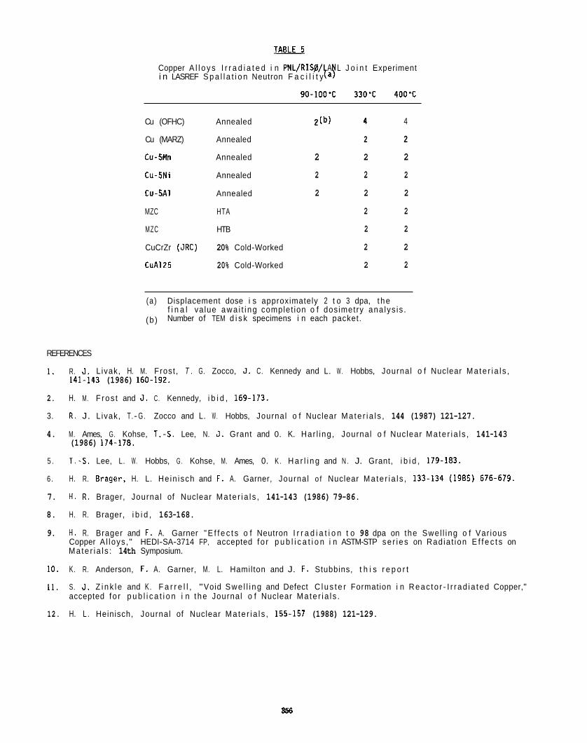
Copper A l l o y s I r r a d i a t e d i n PNL/RISg/ A L J o i n t Experiment i n LASREF S p a l l a t i o n Neutron F a c i l i t y
90-1OO'C 330'C 400'C
Cu (OFHC)
Cu (MARZ)
Cu-5Mn
Cu-5Ni
Cu-SAl
MZC
MZC
CuCrZr (JRC)
CuA125
Annealed
Annealed
Annealed
Annealed
Annealed
HTA
HTB
20% Cold-Worked
20% Cold-Worked
2(b) 4 4
2 2
2 2 2
2 2 2
2 2 2
2 2
2 2
2 2
2 2
(a) Displacement dose i s approximately 2 t o 3 dpa, t he
(b ) f i n a l va lue awa i t i ng complet ion o f dosimetry ana lys is . Number of TEM d i s k specimens i n each packet.
REFERENCES
1. R. J . Livak, H. M. Frost , T . G. Zocco, J . C. Kennedy and L. W . Hobbs, Journal o f Nuclear Ma te r i a l s , 141-143 (1986) 160-192.
2. H. M. F ros t and J . C. Kennedy, i b i d , 169-173.
3. R . J. L ivak, T.- G. Zocco and L. W . Hobbs, Journal o f Nuclear Ma te r i a l s , 144 (1987) 121-127.
4. M. Ames, G. Kohse, T.-S. Lee, N. J . Grant and 0. K. Har l ing , Journal o f Nuclear Ma te r i a l s , 141-143 (1986) 174.178.
5 . T:S. Lee, L. W. Hobbs, G . Kohse, M. Ames, 0. K . H a r l i n g and N . J. Grant, i b i d , 179-183.
6 . H. R. Wager, H. L. He in isch and F. A. Garner, Journal o f Nuclear Ma te r i a l s , 133-134 (1985) 676-679.
7. H. R . Brager, Journal of Nuclear Ma te r i a l s , 141-143 (1986) 79-86.
8. H. R. Brager, i b i d , 163-168.
9. H . R. Brager and F. A. Garner " E f f e c t s o f Neutron I r r a d i a t i o n t o 98 dpa on the Swel l ing o f Var ious Copper A l loys , " HEDI-SA-3714 FP, accepted f o r p u b l i c a t i o n i n ASTM-STP se r i es on Rad ia t ion E f f e c t s on Ma te r i a l s : 14th Symposium.
10. K. R. Anderson, F. A. Garner, M. L. Hamilton and J. F. Stubbins, t h i s r e p o r t
11. S. J . Z i n k l e and K . F a r r e l l , "Void Swe l l i ng and Defect C l u s t e r Formation i n Reac to r - I r r ad ia ted Copper," accepted f o r p u b l i c a t i o n i n t he Journal o f Nuclear Ma te r i a l s .
12. H. L . Heinisch, Journal of Nuclear Ma te r i a l s , 155-157 (1988) 121-129.
356
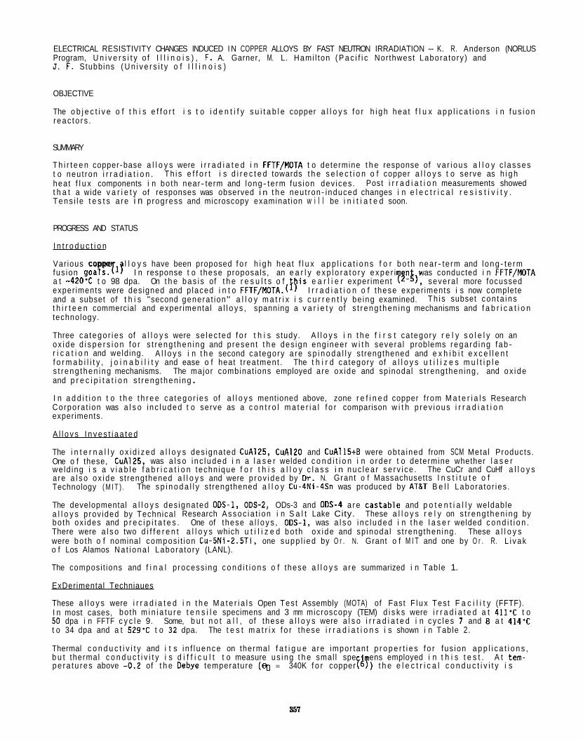
ELECTRICAL RESISTIVITY CHANGES INDUCED I N COPPER ALLOYS BY FAST NEUTRON IRRADIATION - K. R. Anderson (NORLUS Program, U n i v e r s i t y o f I l l i n o i s ) , F. A. Garner, M. L. Hami l ton ( P a c i f i c Nor thwest Labora to ry ) and J. F. Stubbins ( U n i v e r s i t y o f I l l i n o i s )
OBJECTIVE
The o b j e c t i v e o f t h i s e f f o r t i s t o i d e n t i f y s u i t a b l e copper a l l o y s f o r h i g h hea t f l u x a p p l i c a t i o n s i n f u s i o n r e a c t o r s .
SUMMARY
T h i r t e e n copper-base a l l o y s were i r r a d i a t e d i n FFTF/MDTA t o determine t h e response of v a r i o u s a l l o y c l a s s e s t o neu t ron i r r a d i a t i o n . hea t f l u x components i n bo th near- term and long- te rm fus ion dev ices . t h a t a wide v a r i e t y of responses was observed i n t h e neu t ron- induced changes i n e l e c t r i c a l r e s i s t i v i t y . T e n s i l e t e s t s a r e i n p rogress and microscopy examinat ion w i l l be i n i t i a t e d soon.
T h i s e f f o r t i s d i r e c t e d towards t h e s e l e c t i o n o f copper a l l o y s t o serve as h i g h Post i r r a d i a t i o n measurements showed
PROGRESS AND STATUS
I n t r o d u c t i o n
Var ious copper l l o y s have been proposed f o r h i g h hea t f l u x a p p l i c a t i o n s f o r b o t h near- te rm and l o n g - t e r m fus ion goals . ( '? I n response t o these proposals , an e a r l y e x p l o r a t o r y e x p e r i n was conducted i n FFTF/MOTA a t -420'C t o 98 dpa. On t h e b a s i s of t h e r e s u l t s o f 1 ) i s e a r l i e r exper iment ? -&) , severa l more focussed exper iments were des igned and p laced i n t o FFTF/MOTA.( I r r a d i a t i o n o f these exper iments i s now complete and a subset of t h i s "second genera t ion" a l l o y m a t r i x i s c u r r e n t l y be ing examined. t h i r t e e n commercial and exper imenta l a l l o y s , spanning a v a r i e t y of s t r e n g t h e n i n g mechanisms and f a b r i c a t i o n technology.
Three c a t e g o r i e s of a l l o y s were s e l e c t e d f o r t h i s s tudy. A l l o y s i n t h e f i r s t ca tegory r e l y s o l e l y on an o x i d e d i s p e r s i o n f o r s t r e n g t h e n i n g and p resen t t h e des ign eng ineer w i t h severa l problems r e g a r d i n g f a b - r i c a t i o n and weld ing. f o r m a b i l i t y , j o i n a b i l i t y and ease o f heat t rea tment . s t r e n g t h e n i n g mechanisms. The major combinat ions employed a re ox ide and sp inodal s t reng then ing , and o x i d e and p r e c i p i t a t i o n s t r e n g t h e n i n g . I n a d d i t i o n t o t h e t h r e e c a t e g o r i e s of a l l o y s mentioned above, zone r e f i n e d copper f rom M a t e r i a l s Research Corpora t ion was a l s o i n c l u d e d t o serve as a c o n t r o l m a t e r i a l f o r comparison w i t h p r e v i o u s i r r a d i a t i o n experiments.
A l l o v s I n v e s t i a a t e d
The i n t e r n a l l y o x i d i z e d a l l o y s des igna ted CuA125, CuA120 and CuA115tB were ob ta ined from SCM Meta l Products . One o f these, CuA125, was a l s o i n c l u d e d i n a l a s e r welded c o n d i t i o n i n o r d e r t o determine whether l a s e r we ld ing i s a v i a b l e f a b r i c a t i o n techn ique f o r t h i s a l l o y c l a s s i n n u c l e a r s e r v i c e . The CuCr and CuHf a l l o y s a re a l s o o x i d e s t rengthened a l l o y s and were p r o v i d e d by O r . N. Grant o f Massachusetts I n s t i t u t e o f Technology ( M I T ) . The s p i n o d a l l y s t rengthened a l l o y Cu-4Ni-4Sn was produced by AT&T B e l l Labora to r ies .
The developmental a l l o y s des igna ted 00s-I, ODS-2, ODs-3 and 00s-4 a r e c a s t a b l e and p o t e n t i a l l y weldable a l l o y s p rov ided by Technica l Research A s s o c i a t i o n i n S a l t Lake City. bo th ox ides and p r e c i p i t a t e s . There were a l s o two d i f f e r e n t a l l o y s which u t i l i z e d b o t h o x i d e and sp inoda l s t reng then ing . were b o t h o f nominal compos i t i on Cu-5Ni-2.5Ti. one s u p p l i e d by O r . N. Grant o f M I T and one by O r . R. L i v a k o f Los Alamos N a t i o n a l Labora to ry (LANL).
The composi t ions and f i n a l p rocess ing c o n d i t i o n s o f these a l l o y s a r e summarized i n Table 1.
ExDerimental Techniaues
These a l l o y s were i r r a d i a t e d i n t h e M a t e r i a l s Open Tes t Assembly (MOTA) of Fast F l u x Tes t F a c i l i t y (FFTF). I n most cases, bo th m i n i a t u r e t e n s i l e specimens and 3 mm microscopy (TEM) d i s k s were i r r a d i a t e d a t 411-C t o 50 dpa i n FFTF c y c l e 9. Some, b u t n o t a l l , of these a l l o y s were a l s o i r r a d i a t e d i n c y c l e s 7 and 8 a t 4 1 4 T t o 34 dpa and a t 529'C t o 32 dpa.
Thermal c o n d u c t i v i t y and i t s i n f l u e n c e on thermal f a t i g u e a re impor tan t p r o p e r t i e s f o r fus ion a p p l i c a t i o n s , b u t thermal c o n d u c t i v i t y i s d i f f i c u l t t o measure u s i n g t h e smal l spe ens employed i n t h i s t e s t . A t tem-
T h i s subset c o n t a i n s
A l l o y s i n t h e second ca tegory a r e s p i n o d a l l y s t rengthened and e x h i b i t e x c e l l e n t The t h i r d ca tegory of a l l o y s u t i l i z e s m u l t i p l e
These a l l o y s r e l y on s t r e n g t h e n i n g by One of these a l l o y s , 00s-1, was a l s o i n c l u d e d i n t h e l a s e r welded c o n d i t i o n .
These a l l o y s
The t e s t m a t r i x f o r these i r r a d i a t i o n s i s shown i n Table 2.
p e r a t u r e s above -0.2 of t h e Oebye temperature (q, = 340K f o r copper 18 ) t h e e l e c t r i c a l c o n d u c t i v i t y i s
351
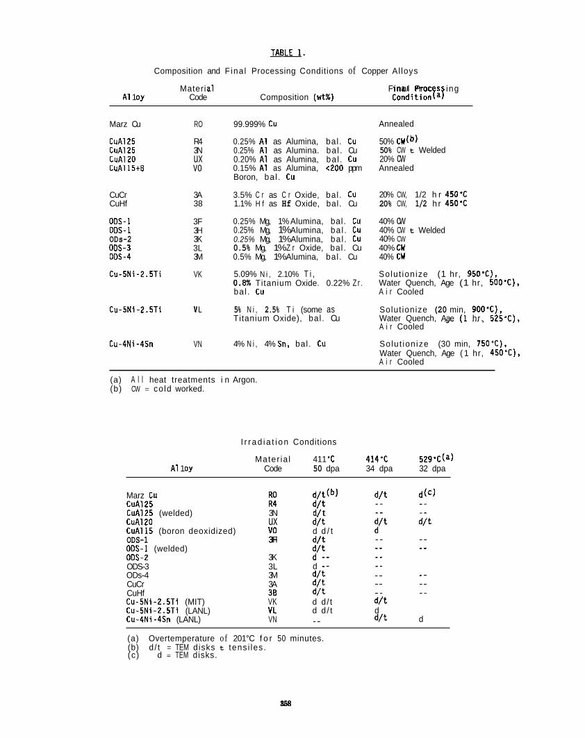
TABLE1. Composition and F ina l Processing Conditions of Copper Al loys
Materi a1 F ina l Proc s ing A1 1 oy Code Composition (wt%) Conditionfa!
Marz Cu
CuA125 CuAl25 CuAl20 CuAl15tB
CuCr CuHf
00s-l ODS-1 ODs-2 00s-3 00s-4
Cu-5Ni-2.5Ti
Cu-5Ni-2.5Ti
Cu-4Ni-4Sn
RO
R4 3N ux vo
3A 38
3F 3H 3K 3L 3M
VK
VL
VN
99.999% cu
0.25% A1 as Alumina, bal . Cu 0.25% A1 as Alumina. ba l . Cu 0.20% A1 as Alumina, ba l . Cu 0.15% A1 as Alumina, 0 0 0 ppm Boron, ba l . Cu
3.5% C r as C r Oxide, bal . Cu 1.1% H f as Hf Oxide, bal. Cu
0.25% Mg, 1% Alumina, bal. t u 0.25% Mg, 1% Alumina, ba l . Cu 0.25% Mg, 1% Alumina, ba l . Cu 0.5% Mg, 1% Z r Oxide, bal . Cu 0.5% Mg, 1% Alumina, bal . Cu
5.09% N i , 2.10% T i , 0 . B Titanium Oxide. 0.22% Zr . ba l . Cu
5% N i , 2.5% T i (some as Titanium Oxide), bal . Cu
4% N i , 4% Sn, bal. t u
Annealed
50% 50% CW t Welded 20% cw Annealed
20% CW, 1/2 h r 450'C 20% CW, 1/2 h r 450'C
40% cw 40% CW t Welded 40% CW 40% CW 40% CW
So lu t ion ize (1 hr, 950%). Water Quench, Age (1 hr, 500'C), A i r Cooled
Solut ionize (20 min, 9OO'C), Water Quench, Aae I1 hr. 525'Cl. A i r Cooled
Solu t ion ize (30 min, 750'C), Water Quench, Age ( 1 hr, 450'C), A i r Cooled
(a) A l l heat treatments i n Argon. (b) CW = co ld worked.
I r r a d i a t i o n Conditions
Mater ia l 411 'C 414% 529'C(a) A1 1 oy Code 50 dpa 34 dpa 32 dpa
Marz Cu CuA125 CuA125 (welded) CuAl20 CuAlI5 (boron deoxidized) ODS-1 ODs-1 (welded) 00s-2
3N ux YO 3F 3H
3K
d/ t d / t d d / t d / t d / t
~~. ~
-. d - - .- _.
ODS-3 3L ODs-4 3M d / t CuCr 3A d/ t CuHf 38 d / t Cu-5Ni-2.5Ti (MIT) VK d d / t d / t Cu-5Ni - 2 . 5 T i (LANL) VL Cu-4Ni-4Sn (LANL) VN
_ _ _ _ ._ -.
d d / t d .. d/ t d
(a) Overtemperature of 201°C f o r 50 minutes. (b) d / t = TEM disks t tens i les . (c ) d = TEM disks.
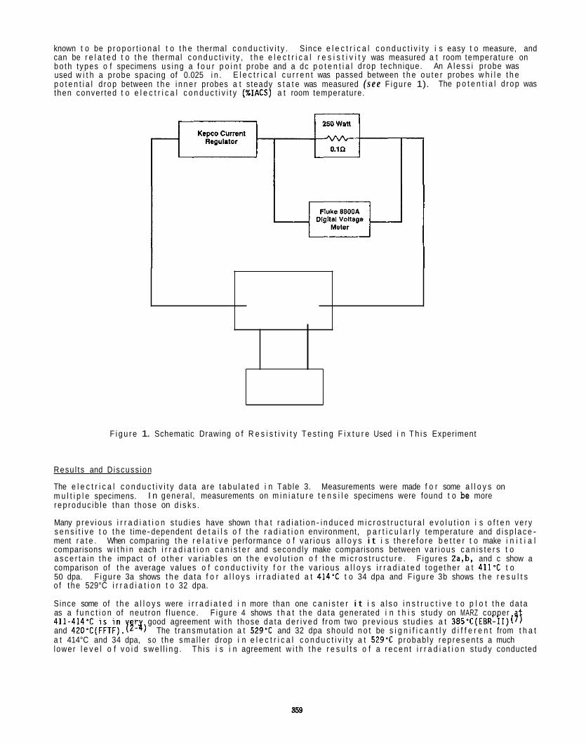
known t o be p r o p o r t i o n a l t o t h e thermal c o n d u c t i v i t y . can be r e l a t e d t o t h e thermal c o n d u c t i v i t y , t h e e l e c t r i c a l r e s i s t i v i t y was measured a t room temperature on b o t h t ypes o f specimens u s i n g a f o u r p o i n t probe and a dc p o t e n t i a l d rop technique. An A l e s s i probe was used w i t h a probe spacing of 0.025 i n . E l e c t r i c a l c u r r e n t was passed between t h e o u t e r probes w h i l e t h e p o t e n t i a l d r o p between t h e i n n e r probes a t s teady s t a t e was measured ( s e e F i g u r e 1). then conver ted t o e l e c t r i c a l c o n d u c t i v i t y (%IACS) a t room temperature.
S ince e l e c t r i c a l c o n d u c t i v i t y i s easy t o measure, and
The p o t e n t i a l d r o p was
F i g u r e 1. Schematic Drawing o f R e s i s t i v i t y T e s t i n g F i x t u r e Used i n T h i s Experiment
Resu l t s and D iscuss ion
The e l e c t r i c a l c o n d u c t i v i t y d a t a a re t a b u l a t e d i n Table 3. m u l t i p l e specimens. r e p r o d u c i b l e than those on d i s k s .
Many p r e v i o u s i r r a d i a t i o n s t u d i e s have shown t h a t r a d i a t i o n - i n d u c e d m i c r o s t r u c t u r a l e v o l u t i o n i s o f t e n v e r y s e n s i t i v e t o t h e t ime-dependent d e t a i l s o f t h e r a d i a t i o n environment, p a r t i c u l a r l y temperature and d i s p l a c e - ment r a t e . When comparing t h e r e l a t i v e performance o f v a r i o u s a l l o y s i t i s t h e r e f o r e b e t t e r t o make i n i t i a l comparisons w i t h i n each i r r a d i a t i o n c a n i s t e r and secondly make comparisons between v a r i o u s c a n i s t e r s t o a s c e r t a i n t h e impact o f o t h e r v a r i a b l e s on t h e e v o l u t i o n o f t h e m i c r o s t r u c t u r e . F igures 2a,b, and c show a comparison of t h e average va lues o f c o n d u c t i v i t y f o r t h e v a r i o u s a l l o y s i r r a d i a t e d t o g e t h e r a t 4 1 1 T t o 50 dpa. F i g u r e 3a shows t h e d a t a f o r a l l o y s i r r a d i a t e d a t 414'C t o 34 dpa and F i g u r e 3b shows t h e r e s u l t s o f t h e 529°C i r r a d i a t i o n t o 32 dpa.
S ince some of t h e a l l o y s were i r r a d i a t e d i n more than one c a n i s t e r i t i s a l s o i n s t r u c t i v e t o p l o t t h e d a t a as a f u n c t i o n of neu t ron f luence . 411-414'C i s i n r good agreement w i t h those d a t a d e r i v e d f rom two p r e v i o u s s t u d i e s a t 385'C(EBR-II)( and 420'C(FFTF).Yz-g) The t r a n s m u t a t i o n a t 529'C and 32 dpa shou ld n o t be s i g n i f i c a n t l y d i f f e r e n t from t h a t a t 414°C and 34 dpa, so t h e s m a l l e r drop i n e l e c t r i c a l c o n d u c t i v i t y a t 529-C probab ly r e p r e s e n t s a much lower l e v e l o f v o i d s w e l l i n g . T h i s i s i n agreement w i t h t h e r e s u l t s o f a r e c e n t i r r a d i a t i o n s tudy conducted
Measurements were made f o r some a l l o y s on I n genera l , measurements on m i n i a t u r e t e n s i l e specimens were found t o be more
sf F i g u r e 4 shows t h a t t h e d a t a generated i n t h i s s tudy on MARZ copper
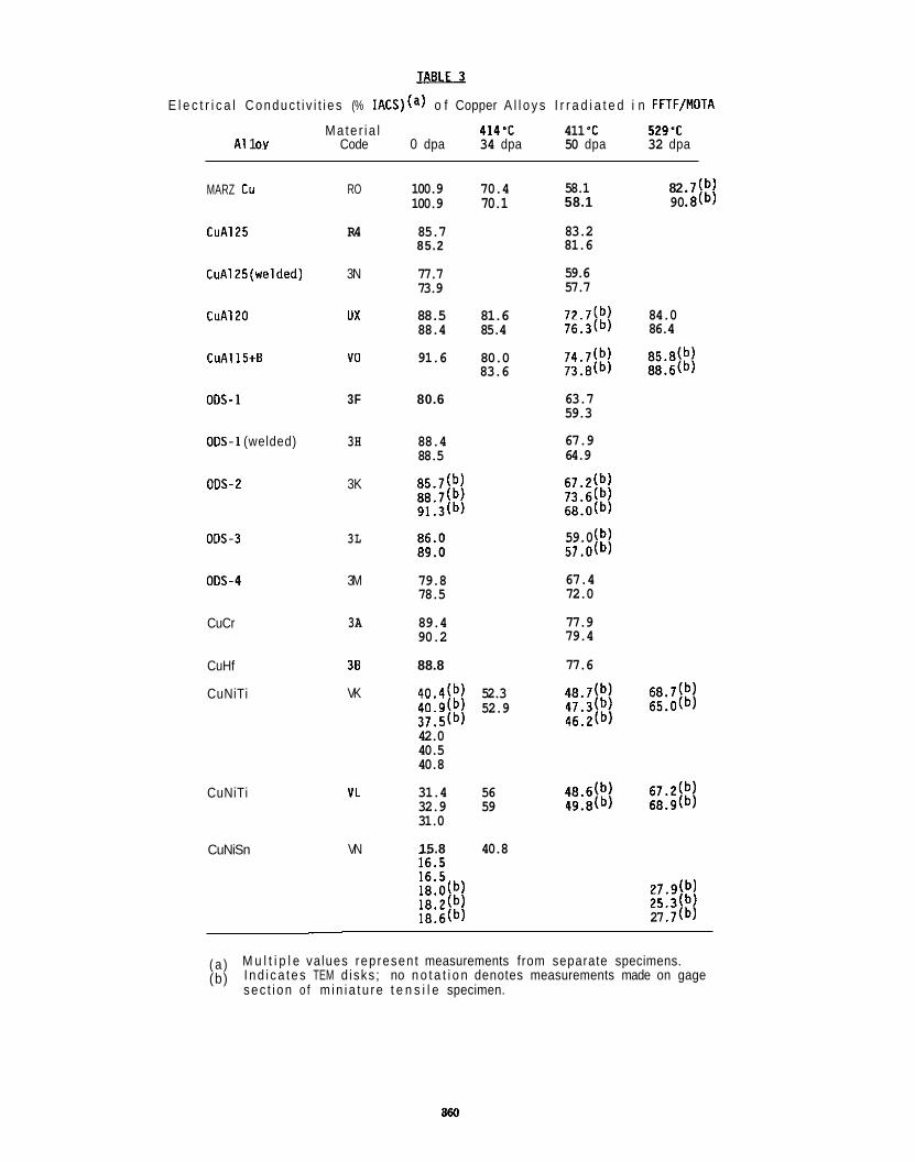
E l e c t r i c a l Conduc t i v i t i e s (% IACS)(a) o f Copper A l l o y s I r r a d i a t e d i n FFTF/MOTA
Ma te r i a l 414’C 411 ‘C 529’C A1 1 OY Code 0 dpa 34 dpa 50 dpa 32 dpa
MARZ t u
CuA125
CuAlZ(we1ded)
CuAl20
CuAl15t8
00s-1
O W 1 (welded)
00s-2
005-3
005-4
CuCr
CuHf
CuNiTi
CuNiTi
CuNiSn
RO
R4
3N
ux
YO
3F
3H
3K
3L
3M
3A
38
VK
VL
VN
100.9 70.4 100.9 70.1
58.1 82 .7(b) 58.1 90 .8( b,
85.7 85.2
77.7 73.9
88.5 81.6 88.4 85.4
91.6 80.0 83.6
80.6
88.4 88.5
79.8 78.5
89.4 90.2
88.8
40.4(b) 52.3 40.9(b) 52.9 37.5(b) 42.0 40.5 40.8
31.4 56 32.9 59 31.0
15.8 40.8
83.2 81.6
59.6 57.7
72.7(b) 84.0 76.3(b) 86.4
63.7 59.3
67.9 64.9
59.0 ( b, 57.0( b,
67.4 72.0
77.9 79.4
77.6
27.9(b) 25.3(b) 27 .7(b)
( a ) (b)
M u l t i p l e values represent measurements from separate specimens. I nd i ca tes TEM d isks ; no n o t a t i o n denotes measurements made on gage sec t i on o f m in i a tu re t e n s i l e specimen.
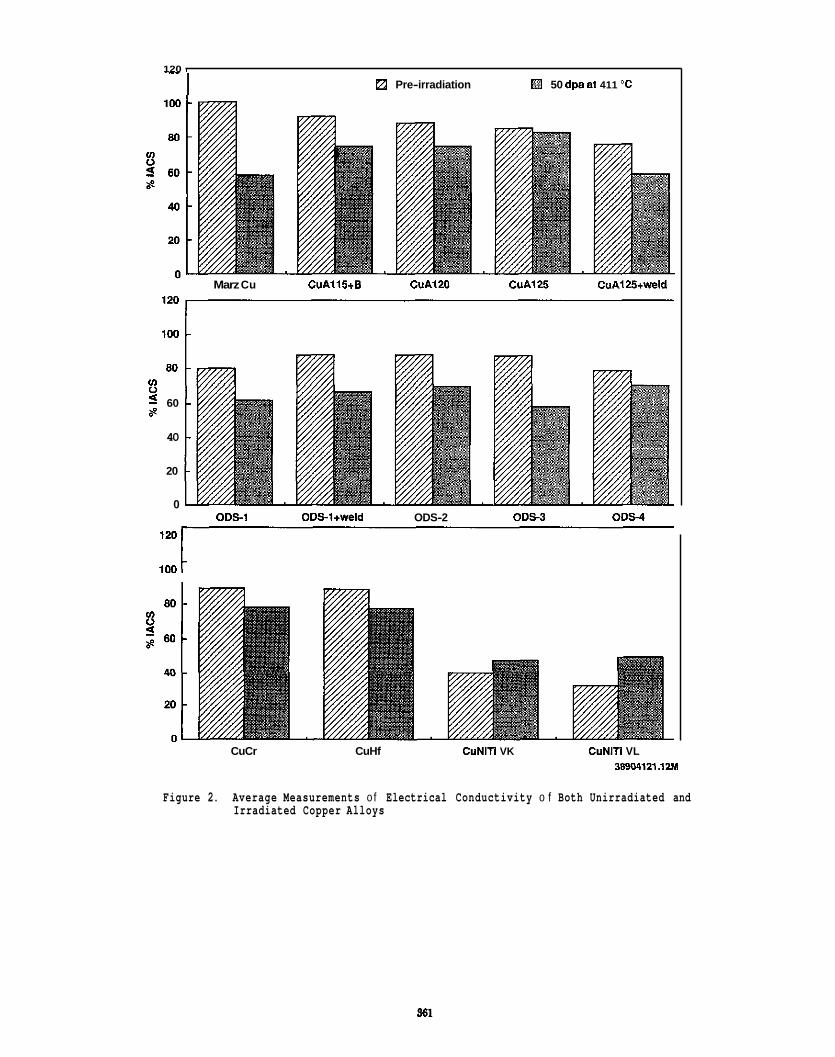
120 I
tZ Pre-irradiation 50 dpa at 411 "C I
Marz Cu CuA115+8 CuA120 CuA125 CuAI25+weld
100
80 u) 0 5 60 8
40
20
0 ODs-1 ODSl+weid ODS-2 ODs-3 008-4
1w c
CuCr CuHf CuNlTi VK CuNlTi VL 38904121.12M
Figure 2. Average Measurements o f Electrical Conductivity o f Both Unirradiated and Irradiated Copper Alloys
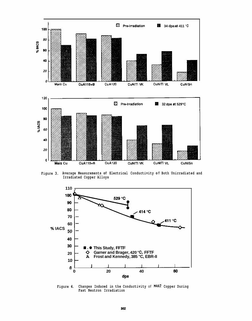
Prelrradlalion 34 dpa a1 411 "C 100 c m
80 u) V 9 a e w
40
20
0 Man Cu CuAllS+B CuA120 CuNlTl VK CuNiTl VL CuNlSn
120
1w
80 u) V
60 5 a?
40
20
(I
Pre-lrradlallon 32 dpa a1 529°C
Man Cu CuA1154 CuA120 CuNiTl VK CuNiTl VL CuNiSn
Figure 3. Average Measurements of Electrical Conductivity o f Both Unirradiated and Irradiated Copper Alloys
110 ,
70 - 60 - 50 - % IACS
m , 0 This Study, FFTF 0 Garner and Brager, 420 "C, FFTF A Frost and Kennedy, 385 "C, EBR-II
20
10 I I I I I I
0 20 40 60 dPa
Figure 4. Changes Induced in the Conductivity of MAR2 Copper During Fast Neutron Irradiation
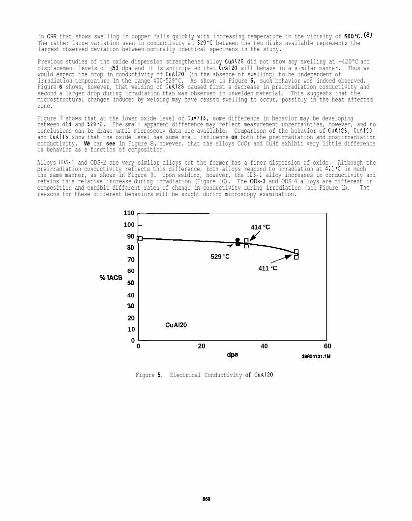
in ORR that shows swelling in copper falls quickly with increasing temperature in the vicinity of The rather large variation seen in conductivity at 529'C between the two disks available represents the largest observed deviation between nominally identical specimens in the study.
Previous studies of the oxide dispersion strengthened alloy CuA125 did not show any swelling at -420°C and displacement levels of 563 dpa and it is anticipated that CuA120 will behave in a similar manner. Thus we would expect the drop in conductivity of CuA120 (in the absence of swelling) to be independent of irradiation temperature in the range 400-529°C. As shown in Figure 5, such behavior was indeed observed. Figure 6 shows, however, that welding of CuA125 caused first a decrease in preirradiation conductivity and second a larger drop during irradiation than was observed in unwelded material. This suggests that the microstructural changes induced by welding may have caused swelling to occur, possibly in the heat affected zone.
Figure 7 shows that at the lower oxide level of CuAlI5, some difference in behavior may be developing between 414 and 529'C. The small apparent difference may reflect measurement uncertainties, however, and no conclusions can be drawn until microscopy data are available. and CuAlI5 show that the oxide level has some small influence on both the preirradiation and postirradiation conductivity. We can see in Figure 8, however, that the alloys CuCr and CuHf exhibit very little difference in behavior as a function of composition.
Alloys ODS-1 and ODS-2 are very similar alloys but the former has a finer dispersion of oxide. Although the preirradiation conductivity reflects this difference, both alloys respond to irradiation at 411% in much the same manner, as shown in Figure 9. Upon welding, however, the ODs-1 alloy increases in conductivity and retains this relative increase during irradiation (Figure 10). composition and exhibit different rates of change in conductivity during irradiation (see Figure 11). reasons for these different behaviors will be sought during microscopy examination.
Comparison of the behavior of CuA125, CuA120
The ODs-3 and ODS-4 alloys are different in The
110
100
90
80
70
60
40
30
20
10
0
414 "C
529 "C
411 "C
CuA120
~~
0 20 40 60 dpa 389O412i.l M
Figure 5 . Electrical Conductivity of CuAlZO
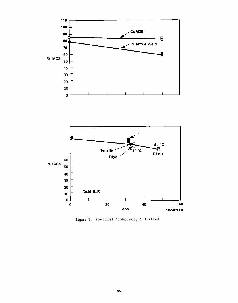
100 L
40
30
20
10
0
CuA125 81 Weld
60 - 50 - % IACS
- - - -
I I I I I
60 % IACS
50
40
30
20
10
- - - - -
CuAI15+B - 0 u
0 20 I
40 dPa
- 60
38804121.0M
Figure 7. Electrical Conductivity of CuA115tB
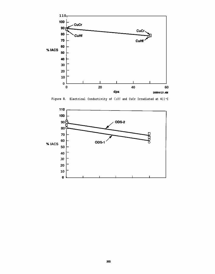
110,
40- 30
20
10
0
- - -
I I I I I 0
40
30
20
10
0 -
20 40 60 dpa 38904121.4M
- - - -
I I I I I
Figure 8. Electrical Conductivity of CuHf and CuCr Irradiated at 411’C
90
80
70
60
50 % IACS
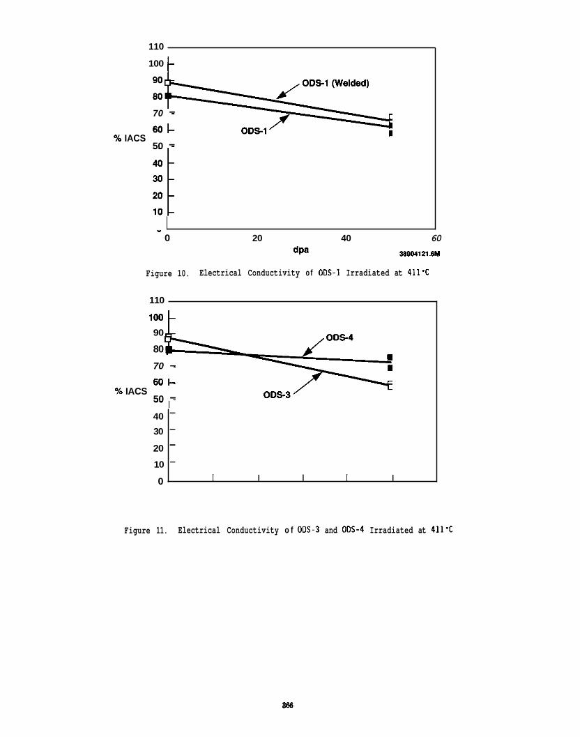
110
40
30
20
10
0
100 t-
- - - -
I I I I I
70 - % IACS
50 -
" 0 20 40 60
dpa 38BM121.6M
Figure 10. Electrical Conductivity o f ODs-1 Irradiated at 411'C
110
90
80
70 - 60-
50 - % IACS
Figure 11. Electrical Conductivity o f 00s-3 and 00s-4 Irradiated at 411'C
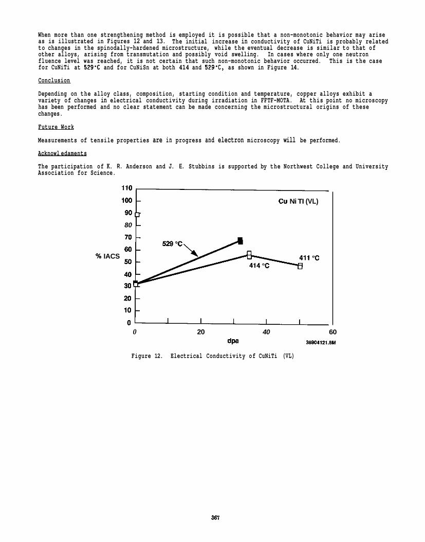
When more than one strengthening method is employed it is possible that a non-monotonic behavior may arise as is illustrated in Figures 12 and 13. to changes in the spinodally-hardened microstructure, while the eventual decrease is similar to that of other alloys, arising from transmutation and possibly void swelling. fluence level was reached, it is not certain that such non-monotonic behavior occurred. for CuNiTi at 529'C and for CuNiSn at both 414 and 529'C, as shown in Figure 14.
Conclusion
Depending on the alloy class, composition, starting condition and temperature, copper alloys exhibit a variety of changes in electrical conductivity during irradiation in FFTF-MOTA. At this point no microscopy has been performed and no clear statement can be made concerning the microstructural origins of these changes.
Future Work
Measurements of tensile properties are in progress and electron microscopy will be performed.
Acknowl edaments
The participation of K. R . Anderson and J. E. Stubbins is supported by the Northwest College and University Association for Science.
The initial increase in conductivity of CuNiTi is probably related
In cases where only one neutron This is the case
Cu Ni TI (VL)
80
% IACS
0 20 40 60 dpa 38904121.8M
Figure 12. Electrical Conductivity of CuNiTi (VL)
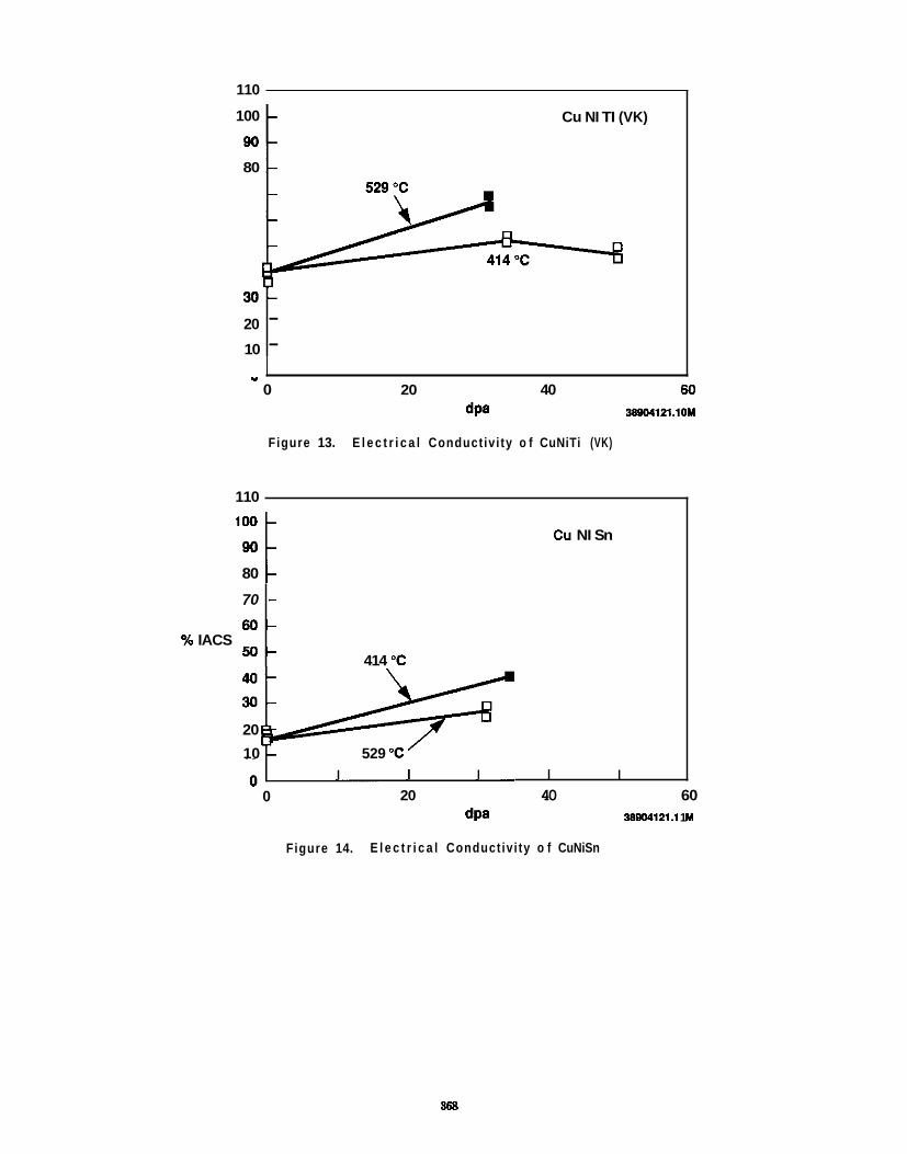
110
30-
20
10
100
80
- -
Cu NI TI (VK)
70
60.
5 0 ' % IACS
.
1
0 20 40 60 dPa 38904121.10M
Figure 13. E l e c t r i c a l Conduct iv i ty o f CuNiTi (VK)
110
100
80
Cu NI Sn
- - -
414 "C
20
10 529 "C I I I I I
0 20 40 60 dpa 38804121.1 1 M
Figure 14. E l e c t r i c a l Conduct iv i ty o f CuNiSn
868
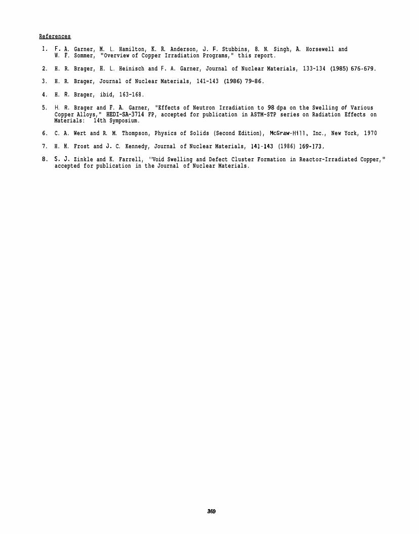
References
1. F. A. Garner, M. L. Hamilton, K. R. Anderson, J . F . Stubbins, 8. N. Singh, A. Horsewell and
2. H. R. Brager, H. L. Heinisch and F . A . Garner, Journal of Nuclear Materials, 133-134 (1985) 676-679.
3. H. R. Brager, Journal of Nuclear Materials, 141-143 (1986) 79-86.
4. H. R . Brager, ibid, 163-168.
5. H. R . Brager and F. A. Garner, "Effects of Neutron Irradiation to 98 dpa on the Swelling of Various
W . F. Sommer, "Overview of Copper Irradiation Programs," this report.
Copper Alloys," HEDI-SA-3714 FP, accepted for publication in ASTM-STP series on Radiation Effects on Materials: 14th Symposium.
6. C. A. Wert and R. M. Thompson, Physics of Solids (Second Edition), McGraw-Hill, Inc., New York, 1970
7. H. M. Frost and J . C. Kennedy, Journal of Nuclear Materials, 141-143 (1986) 169-173.
8. S. J . Zinkle and K. Farrell, '"Void Swelling and Defect Cluster Formation in Reactor-Irradiated Copper," accepted for publication in the Journal of Nuclear Materials.

6 . 5 E n v i r o n m e n t a l E f f e c t s on S t r u c t u r a l A l l o y s

DESIGN OF AN BLECTROCHENICAL TESTING SYSTEM TO EVALUATE SENSITIZATION OF AUSTENITIC STAINLESS STEELS USING MINIATURIZED SPECIMENS - T. Inazumi (Japan Atomic Energy Research Institute, assigned to ORNL) and G.E.C. Bell (Oak Ridge Associated Universities)
0 B J E C T I V E
The objective of this work is to evaluate the propensity for sensitization in neutron-irradiated austenitic stainless steels by electrochemical testing of miniaturized specimens.
SUHMARY
An electrochemical testing system was developed to evaluate the sensitization of austenitic stainless steels using miniaturized disk-type specimens, 3 mn d i m by 0.25 rn thick. The specimens are also suitable for examination using transmission electron microscopy (TEM) after electrochemical testing. The apparatus consists of a specimen holder in which a miniaturized specimen is mounted as the working electrode, a test cell designed to handle radioactive materials and waste, and a potentiostatigalvanostat. Sensitization of thermally-aged austenitic stainless steel specimens was successfully detected by the single-loop electrochemical potentiokinetic reactivation (SL-EPR) method.
PROGRESS AND STATUS
Introduction
Irradiation assisted stress corrosion cracking (IASCC) is a form of intergranular stress corrosion cracking (IGSCC) that has been considered one of the major environmental degradation processes of stainless steels in water-cooled nuclear power systems.’-3 fluence level above -5 x l o z o n/cm2 (ref. 1). It has been suggested that enrichment of impurities, such as phosphorus, sulfur, and silicon, to grain baundaries by radiation induced segregation ( R I S ) plays an impor- tant role in increasing susceptibility of stainless steels to IASCC. Lower susceptibility of high- purity stainless steels to IASCC supports such a mechanism.7,8 grain boundaries as a result of R I S 4 , 1 0 - 1 3 and has been suggested as a contributing factor for sensitization.1’ The chromium concentration at grain boundaries can be reduced by R I S to below 12 w t 2 , the minimum level to form protective films an austenitic steel In the case of water-cooled stainless steel components far fusion reactors, IASCC may again be a degradation process. In this case, R I S characteristics will be different from those in Sight water reactors because of the harder neutron spectrum and higher neutron flux (viz. higher damage rate and higher helium production).
IASCC occurs above a fast neutron (E > 1 MeV)
However, chromium is depleted along
In assessing the effects of RIS on corrosion resistance, it is necessary to develop miniaturized experimental techniques because of limited space in irradiation facilities (thus, requiring a small specimen size) and the need for low personnel radiation exposure from specimen handling and testing. For successful application of the miniaturized experimental techniques, it is essential that the corrosion test methods to be used have sufficient sensitivity to quantify results with small tested area of specimens. Furthermore, nondestructive corrosion testing techniques are preferable because corrosion properties can be directly related to the microstructure of the specimen by microstructural analysis of the same specimens.
The SL-EPR is a nondestructive, quantitative test method to evaluate the degree of sensitization of austenitic Stainless steels associated with chromium depletion near grain boundariee.15-21 SL-EPR is to detect the dissolution current caused by the breakdown of passive films on the chromium depleted areas during a controlled potential sweep from the passive to active regions (electrochemical reactivation).16*18 tional wet chemical tests (e.g., Practices A, B, and E of ASTM A262) particularly for the level of sen- sitization of practical importance for industrial application. 16,17,20s21 Therefore, for the detection of chromium depletion caused by RIS, the SL-EPR wthod seems to be an appropriate corrosion test technique to which miniaturized experimental techniques are applicable. In the present study, the electrochemical testing system using miniaturized specimens was developed to evaluate degree of sensitization associated with chromium depletion in neutron irradiated austenitic stainless steels by the SL-EPR method.
System description
The principle of
Previous studies have shown that the SL-EPR method was more sensitive than the conven-
The schematic diagram of the electrochemical testing system is shown in Fig. 1. The system consist8 of the potential/current measurement system, the polarization cell, and the specimen holder. The measurement System, EG&G PARC MODEL 3 4 2 , is a COmpUteK controlled patentiostat/galvanostat with Current resolution of 100 PA. The polarization cell was constructed as specified in ASTM 65-07 and was modified to have an exterior cooling jacket to control temperatures with circulating water. The remotely operated electric drain systems, salt bridge/calomel reference electrode adjusting system, and test solution supplyicell rinsing system were installed to minimize personnel exposure during handling of radioactive specimens and Waste.
ma
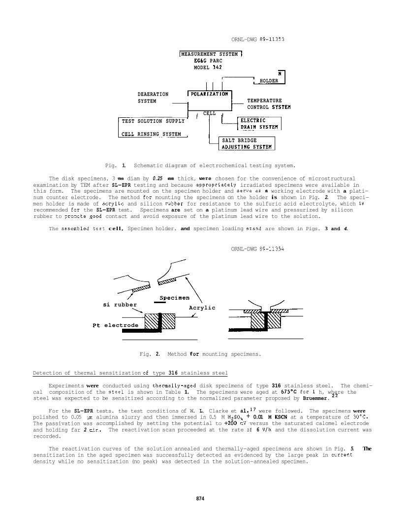
ORNL-DWG 89-11353
[MEASUREMENT SYSTEM 1 EGIG PARC MODEL 3 4 2
HOLDER
DEAERATION r ? d & i h TEMPERATURE CONTROL SYSTEn 7 , CELL ,
SYSTEM
TEST SOLUTION SUPPLY
CELL RINSING SYSTEM SALT BRIDGE
Pig. 1. Schematic diagram of electrochemical testing system.
The disk specimens, 3 mm diam by 0.25 mm thick, were chosen for the convenience of microstructural examination by TEM after SL-EPR testing and because appropriately irradiated specimens were available in this form. The specimens are mounted on the specimen holder and serve as a working electrode with a plati- num counter electrode. The method for mounting the specimens on the holder is shown in Pig. 2. The speci- men holder is made of acrylic and silicon rubber for resistance to the sulfuric acid electrolyte, which is recommended for the SL-EPR test. Specimens are set on a platinum lead wire and pressurized by silicon rubber to promote good contact and avoid exposure of the platinum lead wire to the solution.
The assembled test cel l , Specimen holder. and specimen loading stand are shown in Pigs. 3 and 4.
ORNL-DWG 89-11354
F
- \ Acrylic si rubber
Pt electrode
Fig. 2. Method for mounting specimens.
Detection of thermal sensitization of type 316 stainless steel
Experiments were conducted using thermally-aged disk specimens of type 316 stainless steel. The chemi- cal composition of the ateel is shown in Table 1. The specimens were aged at 675'C for 1 h, where the steel was expected to be sensitized according to the normalized parameter proposed by Bruemmer. 2 2
For the SL-EPR tests. the test conditions of W. L. Clarke et a1.17 were followed. The specimens were polished to 0.05 pm alumina slurry and then immersed in 0.5 M H2S0,, + 0.01 M KSCN at a temperature of 30'C. The passivation was accomplished by setting the potential to +ZOO mV versus the saturated calomel electrode and holding far 2 min. The reactivation scan proceeded at the rate of 6 Vlh and the dissolution current was recorded.
The reactivation curves of the solution annealed and thermally-aged specimens are shown in Pig. 5. The sensitization in the aged specimen was successfully detected as evidenced by the large peak in arrent density while no sensitization (no peak) was detected in the solution-annealed specimen.
874
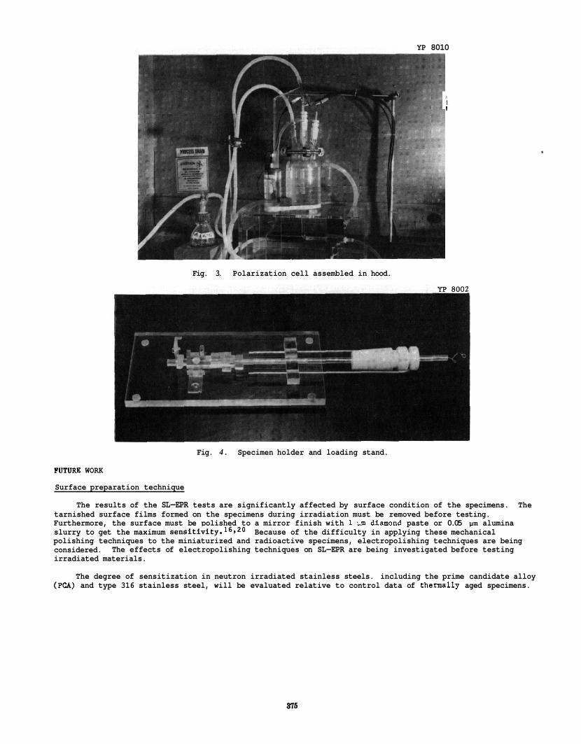
YP 8010
1 1 I
Fig. 3. Polarization cell assembled in hood.
Fig. 4 . Specimen holder and loading stand.
FUTURE WORK
Surface preparation technique
The results of the SL-EPR tests are significantly affected by surface condition of the specimens. The tarnished surface films formed on the specimens during irradiation must be removed before testing. Furthermore, the surface must be polished to a mirror finish with 1 pm diamond paste or 0.05 slurry to get the maximum sensitivity.l6,20 polishing techniques to the miniaturized and radioactive specimens, electropolishing techniques are being considered. irradiated materials.
alumina Because of the difficulty in applying these mechanical
The effects of electropolishing techniques on SL-EPR are being investigated before testing
The degree of sensitization in neutron irradiated stainless steels. including the prime candidate alloy (PCA) and type 316 stainless steel, will be evaluated relative to control data of thermally aged specimens.
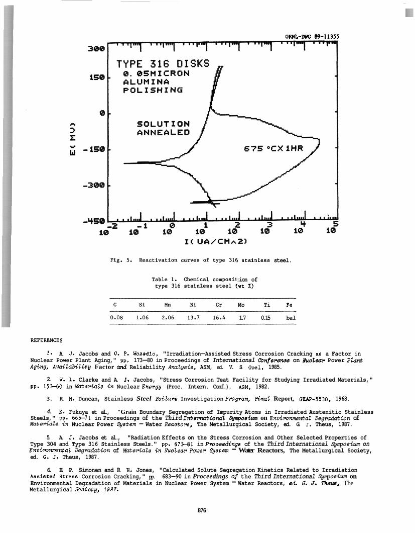
ORNL-GUG 89-11355
5 stainleas steel.
:ion of :wt X )
Mo Ti Fe
1.7 0.15 bal
RBPERSNCES
1. A. 3. Jacobs and G. P. Wasadlo, "Irradiation-Assisted Stress Corrosion Cracking aa a Factor in Nuclear Power Plant Aging," pp. 173-80 in Proceedings of International &nference on Uuclear Power Phnt Aging, Availability Factor and Reliability A~lysie, ASM, ed. V. S. Goel, 1985.
2. W. 1. Clarke and A. J. Jacobs, "Stress Corrosion Teat Facility for Studying Irradiated Materials," pp. 153-60 in Muterials in Nuclear Energy (Proc. Intern. Conf.). ASM, 1982.
3. R. N. Duncan, Stainless Steel Faiture Investigation Progman, PiMt Report, GEAP-5530, 1968.
4. K. Fukuya et al., "Grain Boundary Segregation of Impurity Atoms in Irradiated Austenitic Stainless Steels," pp. 665-71 in Proceedings of the Third Internatio~t Synposim on Enuironnental De-ion of W e r i a t s in Nuclear Power @Stem - Water Reactom, The Metallurgical Society, ed. G. J. Theus, 1987.
5. A. J. Jacobs et al., "Radiation Effects on the Stress Corrosion and Other Selected Properties of Type 304 and Type 316 Stainless Steels." pp. 673-61 in Pmcsedinga of the Third International 5pn~osium on Envirommtal Degmdztion of Mzteriak i n Xuclear Power &stem - Water Reactors, The Metallurgical Society, ed. G. J. Theus, 1987.
6. E. P. Simonen and R. 8. Jones, "Calculated Solute Segregation Kinetics Related to Irradiation Assisted Stresa Corrosion Cracking," pp. 683-90 in Proceedings of the Third International @nposim on Environmental Degradation of Materials in Nuclear Power System - Water Reactors, ed. G. d. Them, The Metallurgical .%society, 1987.
876
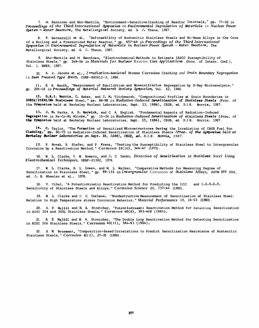
7. H. Hanninen and Aho-Mantila, "Environment-Sensitive Cracking of Reactor Internals," pp. 77-92 in Pmceedinge of the Third International Qnpoeiurn on Environmental Degradation of t&teriaZs i n Nuclear Power @stem -Water Reuctora, The Metallurgic84 Society, ed. G. J. Theus, 1987.
8 . P. Garzarolli et al., "Deformability of Austenitic Stainless Steels and Ni-Base Alloys in the Core of a Boiling and a Pressurized Water Reactor," pp. 657-64 in Pmceedings of the Third International Q,nposium on Envimnmental Degradation of W e r i a l a i n molar Power %stem - k r a t E r Rsactolg, The Metallurgical Society, ed. G. J. Theus, 1987.
9. Aho-Mantila and H. Hanninen, "Electrochemical Methods to Estimate IASCC Susceptibility of Stainless Steels," pp. 349-56 in Materials f o r Vuolar Reactor Core .@ppli&wns (Proc. of Intern. Conf.), Vol. 1, BNES, 1987.
10. A. J . Jacobs et al., Inurdiation-Assiatsd Stress Corrosion Cracking and GMin Boundary Segregation i n E& Treated T w e 9)4SS, CONP-880613-3, 1988.
11. E. A. Kenik, "Measurement of Equilibrium and Nonequilibrium Segregation by X-Ray Microanalysis," pp. 209-16 in Pmceedings of W e r i a l Retrearch Society Synposiurn, Vol. 62, 1986.
12. D.P.1. Norris, C. Baker, and J . M. Titchmarsh, "Compositional Profiles at Grain Boundaries in 20XCr/ZSXNiINb Stainleas Steel," pp. 86-98 in Radiation-Induced Sonsitiaation of Stainlaas S t a s h (Proc. of the Syrposium held at Berkeley Nuclear Laboratories, Sept. 23, 1986). CEGB, ed. D . I . R . Narria, 1987.
Sesrcgation in Pe-Cr-Ni Alloys,- pp. 15-34 in Radiation-Induoed Senaitiaation of stainless S t e ~ t s (proc. of thr Sy.posium held at Berkeley Nuclear Laboratories, Sept. 23. 1986). CEGB, ed. D.I .R . Norris, 1987.
13. J . M. Perks, A. D. Marwick, and C. A. English. "Fundamental Aspects of Radiation-Induced
14. C. Taylor, "The Pornstion of Sensitized f4iCKostruCtUres During the Irradiation of CAGR Fuel Pon Cladding,- pp. 60-73 in Radiation-Induced Sensitization of Stainless Steels (Proc. of the Synpoaiwn held at BerkEhy B d & W L U h W t O P h ort S e p t . 23. I S B B ) , CEGB, ad. D . I . R . Rorris, 1987.
1 5 . P. Novak, R. Stefec, and P. Pranz, "Testing the Susceptibility of Stainless Steel to Intergranular Corrosion by a Reactivation Method," Cormswn 31(10), 34-7 (1975).
16. W. L. Clarke, V. M. Romero, and J . C. Danko, Detection of Senei tkat ion in Staintess Steel Using Electmchemical Techniques, GEAP-21382, 1976.
17. W. L. Clarke, R. L. Cowan, and W. L. Walker, "Comparative Methods for Measuring Degree of Sensitization in Stainless Steel," pp. 9't132 in IntEPgMWtar Corrosion Of Sta<nhBS Alloys, ASTM STP 656, ed. J. B. Wheeler et al., 1978.
18. V. Cihal, '"A Potentiokinetic Reactivation Method for Predicting the I.C.C. and I.G.S.C.C. Sensitivity of Stainless Steels and Alloys," Cormsion Science 20, 737-44 (1980).
19. W. L. Clarke and D. C. Carlson, '"Nondestructive Measurement of Sensitization of Stainless Steel: Relation to High Temperature stress Corrosion Behavior," Material Performance 19, 1 6 2 3 (1980).
20. A. P. Majidi and H. A. Stretcher, "Potentlodynamic Reactivation Method for Detecting Sensitization in AISI 304 and 304L Stainless Steels," Cormswn 4D(8), 393-408 (1984).
21. A. P. bjidi and M. A. Streicher, "The Double Loop Reactivation Method for Detecting Sensitization in AISI 304 Stainless Steels," Corrosion 40(11), 584-93 (1984).
22. S. M. Bruemoner, "Composition-Based Correlations to Predict Sensitization Resistance of Austenitic Stainless Steels," Corrosion 42( 1). 27-35 (1986).

AQUEOUS SlRESS CORROSION OF AUSTENmC STEELS - H. Khalak. A E. Hull. and 1. F. Kassner (Argonne N a b i o n a l m
The objective of this study, which is part of the ITER validating R&D, is to provide baseline information on the stress corrosion cracking (SCC) susceptibility of candidate austenitic steels under conditions of interest for the ITER design. The initial focus here was to develop a computer model for radiolysis of fusion reactor water and assess the relevance of coolant chemistry to SCC of reactor structural components.
SUMMARY
Stress corrosion cracking (SCC) of austenitic stainless steel in water is considered a key unresolved issue for the U.S. ITER shield and blanket design activities.' A computer code has been developed to determine the concentration of radiolytic species produced in the aqueous environment in various subsystems of a fusion reactor in order to estimate the subsequent likelihood of stress corrosion cracking. This code also serves as a valuable precursor to slow-strain-rate tests to determine the SCC susceptibility of austenitic stainless steels. The code is being benchmarked with the concentrations of radiolytic molecular species in boiling water reactors. Samples of candidate steels, primarily Type 318 NGSS, are being prepared to initiate low-strain-ratetests.
PROGRESS AND STATUS
Introduction and Backa rou
Blanket cooling by means of circulating pressurized water is being considered in a fusion reactor configuration.1 A water coolant offers excellent heat transfer characteristics, and has a well-developed technology from commercial fission reactor experience. However, the susceptibility of austenitic steels to SCC under the anticipated conditions for a water-cooled fusion reactor has not been previously addressed in detail. The SCC of these steels in nuclear systems is thought to be caused by tensile stress, sensitization, and the environment,? in which radiolysis of coolant is a major factor in promoting the SCC. Irradiation-assisted stress corrosion cracking (WCC) may also occur under conditions in which fusion reactors are designed to operate.3 Radiolytically produced chemical species increase the open-circuit electrochemical corrosion potential (ECP) of the steel. The ECP is the major environmental parameter affecting IASCC. The influence of this factor, coupled with ionic impurities in the coolant, on IASCC is not always easily ascertained from the reactor design. Consequently, both computer and laboratory simulations will be addressed in this project and in other projects.4
with fusion reactors. A simulation thatcan quantify the equilibrium speciation according to gamma and neutron fluxes and temperatures expected in a fusion reactor is of great utility.
Computer_Shujation Procedures
Experience with fission reactors has led to various measures5 to mitigate SCC. However. such is not the case
The radiolytic chemisty in a low-temperature (-45OC) coolant system of a fusion reactor has been evaluated by means of a computer simulation. The computer program generates concentration values of certain chemical species, such as H202.02, and H2. in the irradiated environment at various points throughout each pertinent subsystem, e.g., the firstwail, breeding blankets, and supports.
constants, activation energies, and G-values for gamma and neutron radiation were incorporated into a system of chemical kinetics equations. Tables I and II contain the chemical equations and radiolysis G-values, respectively, derived from the earlier radiolysis studies of Burns and Moore8 and Willis et al.'
This computer code operates efficiently on DEC VAX 8700, running the VMS version 4.5 Fortran operating system. Existing numerical routines8 were incorporated to solve a system of differential equations in order to calculate time- dependent concentrations of the chemical species.
To ascertain the levels of dissolved 0 2 , H202, and other water species, a number of chemical reactions with rate
The WR87 computer code, used for reactor physics and design, was substantially modified forour radiolysis code.
379
Table 1. Chemical Reactions, Rate Constants, and Activation Energies Used for Predicting Concentrations of Radiolytically Produced Species in Reactor Coolant
K at 25'C Actlvation Energy Reactions (Umol-sec) (KcaVmol)
e- + e- + e- + e- + e- + H+ + H + H + OH + OH + OH + H + e- + H + H +
H+ + H02 +
HOz + H02 + OH + OH + H + e- + H + H20 +
HOz + e- +
OH- + HO; +
H+
3.0 3.0 3.0 3.0 3.0 3.0 3.0 3.0 3.0 7.0 4.5 4.5 3.0 3.0 3.0 3.0 3.0 4.5 3.0 3.0 3.0 3.0 3.0 3.0 3.0 3.0 4.5 4.5 3.0
Table 2. Radiolysis G 'alues Used for Predictir - Concentratic i of Radiolytically Produced Species in Reactor Coolant
Species H H+ H2 H20 H202 H02 02 OH OH- e-
G-values
y-ray 0.6 2.7 0.45 0.4 0.6 0.02 0.225 2.6 1 .o 2.6 neutron 0.5 0.93 0.66 0.66 0.99 - 0.44 1.09 1.0 0.93 at264YC 0.3 0.4 2.0 - 4.7 0.4
Input consists of the reactor Imp configuration, dose rate and type of radiation, specified chemical reactions, their rate constants, and the initial reactant concentrations. The code then calculates. as a function of time, the concentration of all chemical species (such as H2O. H2, 0 2 , H202, OH, H, e-, H02,02, H02-, OH-, H') from a set of radiation-induced chemical reactions with homogeneous kinetics. The m i a n t is pure water (conductance of < 10 mmho/cm).s Further details about the simulation logic can be obsefved in Figure 1.
380
Reactor qpsclflcations and loop configuration
Rcections of Interest, 1nItI.d concentrations Module ~
0, 0 0 0 0 0 0 0 0
\ I
T s S I I s
1). L i;
* e e e L
C
\I Dose rate andtype ofradiation
CU' .
no, i
* e e
CalNlatIllg Module
0; i 5 8 0.01
u I
i
i
t Extract data Por graphs Resultfng I Data + I I
t I I
Graphical Plot con=. vs. t h e I , I
Figure 1. Simulation Flowchart Diagram
Results and Analvsis
Code Benchma& i ng
The eftect of gamma and neutron radiation levels on the concentrations of several radiolytic species at 75% and an irradiation time of five seconds, when most species are approaching 3eady-state concentrations, is shown in Figure 2. The concentration of steady-state radiolytic species increases somewhat at higher energy loads. The effect of neutron radiation on equilibrium concentrations was greater than that of gamma radiation. For an energy loading of 1 WICK?, the concentration of H2@ was 0.02 ppb under both gamma and neutron radiation. However. far 10 Wlcm? me
~ ~~.~ ~ ~ ..... concentrations were 0.1 and 0.2.ppb, respective^. The concentrations of radiolytic species showed very little dependence on temperature (Figure 3).
881
0 . m 1 t 0 50 im 160 2m
T W O
Flg. 3. E M of Temperature on Um Concentrations of Selected Radioiyfic Species
m R S-
A compubr simulation was made forthe U.S. E R design ot a fusion reactor breeding-blankt coolant system.lo This desi n was for a lwtemperature water coolant (45%) and for gamma radiation of 0.8 W/cm' and neutron load of 32 W/c$ .I1 The concentrations d molecular species versus time of irradiation (0-so00 seconds) are shown in Figures 4 and 5. Forgamma radiation, the 02 concentration achieved a value of 32 ppb. Under neutron radiation, however, it rose to 50 ppb after so00 seconds and had not yet reached equilibrium at -5ooos. Peroxide levels under gamma radiation stayed under 10 ppb (max. -8 ppb), but reached concentrations slmilarto those of 02 under neutron nux.
100 O r
0 0 0 0
rm -
ac irm Bm
/
i 3aa 1" Sm
Figure 4. Molecular Concentrations Produced in E R Contiguration Under 0.8 W/cd y-radiation
Figure 5. Molecular Concentrations Produced in ITER Configuration Under a 3.2 W/cd Neutron Load
Discussion
Althoughthe resulD,fromthiscomputersimuiation are stili somewhat preliminary, they do provide insight into the contribution of radiolysis to the chemical environment that may be found in a water-cooled fusion reactor. Until such time thatfield data are available from operating fusion reactors. such a rodel is necessary to obtain parameters relevant to fusion reactor materials.
CONCLUSIONS
Preliminary results forthe concentrationsof radiolyticallyproduced species have been obtained from a new com uter code that was developed to slmulate the radiolysis of fusion reactor water coolant. The modeling work prov P des a useful precursor to laboratory studies of SCC of candidate alloys in the simulated coolant environments.
m R E WORK
The SCC susceptibiiityofseverai candidate stainless steels, including weldment specimens, will be determined in high-purltywater containing low concentrations of radiolysis products (02, Ha, and H202) obtained from computer simulations on fusion reactor coolant systems.
REFERENCES
1. 2.
3.
4.
5.
6.
7.
8.
9.
10.
11.
C. Baker, 'U.S. iTER Shield and Blanket Design Activities."Fusion Technoi. 15, 849-57 (1989). F. Farfaleni-Casali, "Systems Integration, Maintenance, Containment and Shielding." Nucl. Eng. DesJFusion 3, 383-98 (1986). R. H. Jones, 'Assessment of Stress-Corrosion Cracking for Near-Term Fusion Reactors," pp. 184-188 in Fusion Reactor Materials Semiannual Progress Report, DOE/ER-0313/4. March 31,1988. E. P. Simonen and R. H. Jones. "Modelina Grain Boundaw Microchemistw Related to IASCC", NACE DreDrint . . 580, Corrosion 89, New Orleans, LA. Apn'll7-21, 1989. . J. C. Danko, organizer, Proceedinas: Second Seminar on Countermeasures for PiDe Crackina in BWRs, Vols.1-3.
W. G. Bums and P. 8. Moore, "Water Radiolysis and Its Effect Upon In-Reactor Zircaloy Corrosion," Radiat. Eff., 30, EPRl NP-3684-SR (1984).
233-42 (19761. C. Willis,'A. W: Boyd, A. E. Rothweli. and 0. A. Miller, "Experimental and Calculated Yields in the Radiolysis of Water atvery High Dose Rates," Int. J. Radiat. Phys. Chsm. 1,373-81 (1969). K.H. Schmidt, 'A Computer Program forthe Kinetic Treatment of Radiation-Induced Simultaneous Chemical Reactions: A Rwised Version in Forban iv", ANL-7693 (1970). P.A. Finn pnd D. K. Sze, 'Impact of Radiolysis on the Design of Breeder Blanket Systems for ITER,"ANL Fusion Power Program Research report, October 1988. Y . Gohar, "Solid Breeder Blanket," Argonne National Laboratory, U.S. Contributions to the Homework for ITER, FebruaryMarch 1989. P.A. Finn and A. Llde, 'Water Coolant Conditions," Argonne National Laboratory, US. Contributionstothe Homework for ITER, Febfuary/March 1989.

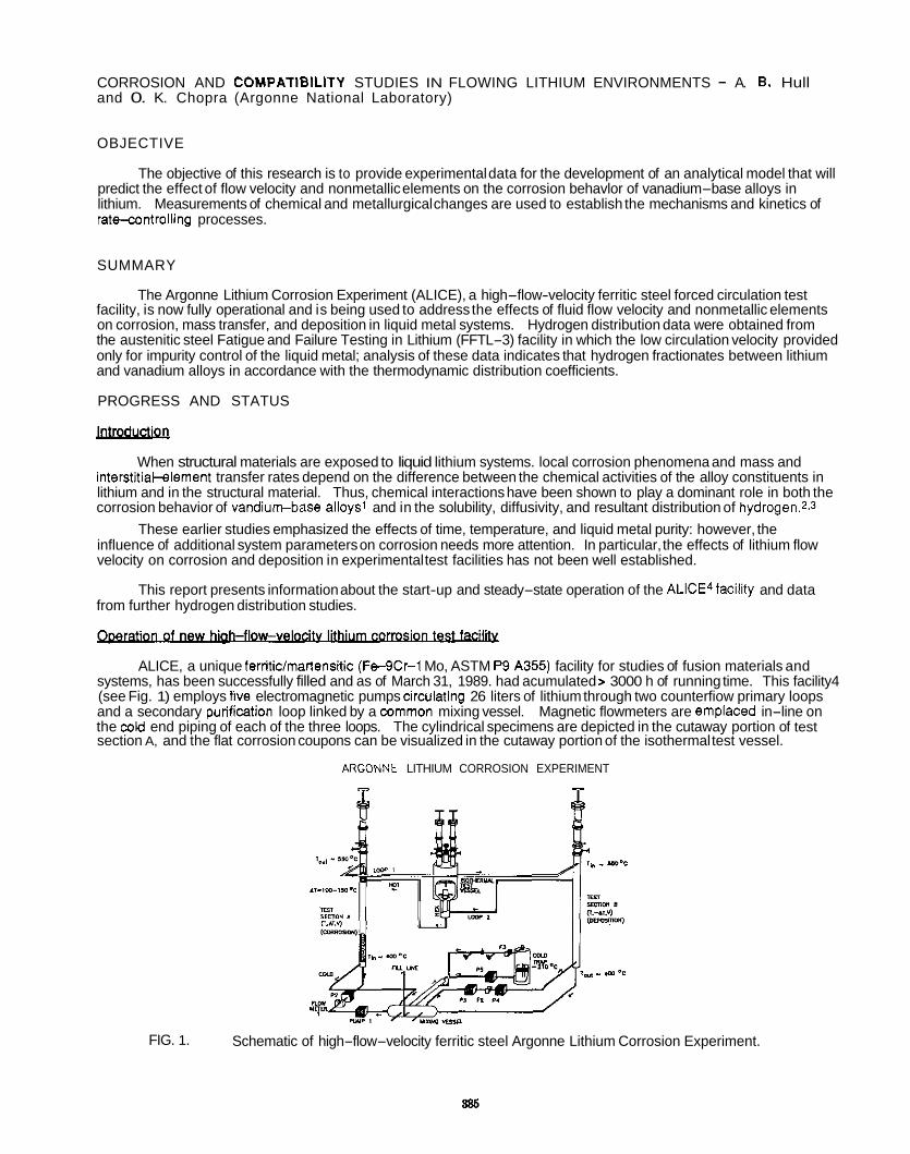
CORROSION AND COMPATlBlLlTY STUDIES IN FLOWING LITHIUM ENVIRONMENTS - A. B. Hull and 0. K. Chopra (Argonne National Laboratory)
OBJECTIVE
The objective of this research is to provide experimental data for the development of an analytical model that will predict the effect of flow velocity and nonmetallic elements on the corrosion behavlor of vanadium-base alloys in lithium. Measurements of chemical and metallurgical changes are used to establish the mechanisms and kinetics of rate-controlling processes.
SUMMARY
The Argonne Lithium Corrosion Experiment (ALICE), a high-flow-velocity ferritic steel forced circulation test facility, is now fully operational and is being used to address the effects of fluid flow velocity and nonmetallic elements on corrosion, mass transfer, and deposition in liquid metal systems. Hydrogen distribution data were obtained from the austenitic steel Fatigue and Failure Testing in Lithium (FFTL-3) facility in which the low circulation velocity provided only for impurity control of the liquid metal; analysis of these data indicates that hydrogen fractionates between lithium and vanadium alloys in accordance with the thermodynamic distribution coefficients.
PROGRESS AND STATUS
When structural materials are exposed to liquid lithium systems. local corrosion phenomena and mass and interstitiakelement transfer rates depend on the difference between the chemical activities of the alloy constituents in lithium and in the structural material. Thus, chemical interactions have been shown to play a dominant role in both the corrosion behavior of vandiumbase alioysl and in the solubility, diffusivity, and resultant distribution of hydrogen.2.3
These earlier studies emphasized the effects of time, temperature, and liquid metal purity: however, the influence of additional system parameters on corrosion needs more attention. In particular, the effects of lithium flow velocity on corrosion and deposition in experimental test facilities has not been well established.
This report presents information about the start-up and steady-state operation of the ALICE4facility and data from further hydrogen distribution studies.
ALICE, a unique ferritic/martensitic (Fe-9Cr-1 Mo, ASTM P9 A355) facility for studies of fusion materials and systems, has been successfully filled and as of March 31, 1989. had acumulated > 3000 h of running time. This facility4 (see Fig. 1) employs tive electromagnetic pumps circulating 26 liters of lithium through two counterfiow primary loops and a secondary purification loop linked by a common mixing vessel. Magnetic flowmeters are emplaced in-line on the coM end piping of each of the three loops. The cylindrical specimens are depicted in the cutaway portion of test section A, and the flat corrosion coupons can be visualized in the cutaway portion of the isothermal test vessel.
ARGONNE LITHIUM CORROSION EXPERIMENT
FIG. 1. Schematic of high-flow-velocity ferritic steel Argonne Lithium Corrosion Experiment.
Reactor grade lithium was transferred into the loop lrom a supply tank filled at the Lithium Corporation. During the initial stages of lilling. the loop was kept unaer vacuum until the secondary cold-trap loop was completely filled. This procedure prevented the trapping of argon gas in the System and insured against vanability of flow through different sections of the loop because 01 poor lithium wetting properties. The remainder 01 the test sections A and B and the isothermal vessel were filled with differential argon pressure ( a slightly higher pressure, i.e., 0.5 to 1 psi. in the supply tank) until lithum reacnea the specimen holding ledge in the three vessels. This dinerential pressure provided a slow and Controllea transfer of lithium.
outside surfaces of the system piping. Three instrumentation cabinets house the temperature controllers. two 3c- channel process recorders, timers. ana alarms for overheat, lithium llow, and cover gas pressure. There are three programmable micropmessor heater controllers. one each for the test sections and isothermal tank: and two controllers for the cold trap and maxing vessel. Twenty-two manual controllers are available for the line heaters. The electrical heaters are either a clamshell type used on the vessels or GE wire or a heating tape for the piping. The test sections. isothermal test vessei. ana mixing vessel are insulated witn 1-112 in.-thick rigid hydrous calcium silicate insulation. Additionally, the loop has been insulated with a 1000°C ceramic blanket-type insulation.
Temperature measurements are continuously obtained from 60 chromel-alumel thermocouples located on the
An automated argon blanketing system was designed and deployed to function as a reaction suppression system. Two independent argon blanketing systems are emplOye0. One is focused on the lower level of the test facility (F:g. 1) and the otner system traces along the lithium-containing piping and test vessels. In each system, two cylinoers 01 argon with separate solenoids are Connectea in parahel so that when there is a leak (causing a temperature excursion) or when preset temperature limits are exceeded. the main power supply will be tripped and the system will be flooded with an inert argon blanket. displacing air lrom the space around the loop piping, floor, and test vesses. Air for cooling the induction pumps is vented to the outsiae of the stainless steel enclosure. Temperature detectors rather than smoke detectors are employed as blanketing triggers immediately above the enclosure because of the quicker response.
(compared to austenitic) steel structural material 01 the loop creates a aecarbunzation effect with resultant high carbon content in the lithium. Additional chemical analyses will be performed to ensure that the lithium chemistry in the loop has staoil zeo belore actus corrosionlmass-transfer tests are initiated.
Checkout of all operational systems on the loop is continuing. The slightly higher carbon in the ferritic
The hyarogen distnbution tests were conaucted in the FFTL-3 forced-circulation lithium loop. This facility. constructed of Type 304 stainless steel. consists of a pnrnary loop equipped with three test vessels and with cold- and hot-trapp,ng purification capaoilities to control the concentration 01 nonmetallic elements. Various vanadium alloys were immersea in the flowing lithium in two separate tsothermal test vessels maintained at different temperatures. Followmg exposure, the specimens were gently cleaned in cnllled ethanollmethanol to avoid the introduction of hydrogen. For ail tests, Li was c rculated at - 1 liter/min in the primary loop, and the concentration 01 hydrogen in the Li was maintainea at -120 wppm.
Specimens of V, V-20Ti, V-15Cr-5Ti. and V-3Ti-O.5Si were immersed in the flowing lithium in two separate isothermai test vessels maintained at different temperatures. The speamens had approximate dimensions 01 1.9 x 1 .O x 0.09 cm and were mechanically polished before exposure to lithiurn. Total hydrogen in the specimens after lithium immersion was determine0 from 00th residual gas analysis and inert gas and vacuum fusion procedures. The Concentrat.ons of hydrogen in tne vanadium-base alloy specimens after exposure were all well under 5 wppm. Further details on these procedures and aetermination of hydrogen in the lithium are provided elsewhere.2.3
Hydrogen will fractionate between Li and various refractory metals as a function of temperature. coefficient. Kw, can be definea as the ratio of the H concentration in the V alloy to that in the liquid Li:
A distribution
K w = C v l C L i
where Cv and CL, are concentrations (W%) of H in the V alloy and Li. respectively, at constant hydrogen partial pressure. The theoretical temperature-dependent distributions3 of H between Li and several refractory metals are shown graphically in Fig. 2 as a function 01 temperalure. At a temperature 01 5OO0C, a hydrogen concentration of 100 wppm in lithium will establish a calculated hydrogen concentration of -3000 wppm in yttrium, 10 wppm in titanium, 0.3 wppm in vanadium, and <0.0001 wppm in chromium.
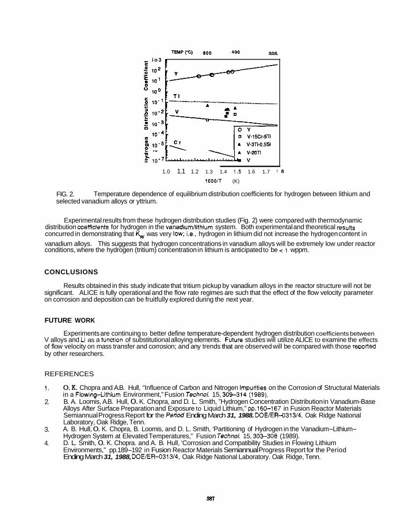
... - i o 3 e r
. V r .” I 10-7-s
1.0 1.1 1.2 1.3 1.4 1.5 1.6 1.7 1 8
1000IT (K)
FIG. 2. selected vanadium alloys or yttrium.
Temperature dependence of equilibrium distribution coefficients for hydrogen between lithium and
Experimental results from these hydrogen distribution studies (Fig. 2) were compared with thermodynamic distribution coefficients for hydrogen in the vanadium/lithium system. Both experimental and theoretical resuns concurred in demonstrating that K,,, was very low; i.e.. hydrogen in lithium did not increase the hydrogen content in vanadium alloys. This suggests that hydrogen concentrations in vanadium alloys will be extremely low under reactor conditions, where the hydrogen (tritium) concentration in lithium is anticipated to be c 1 wppm.
CONCLUSIONS
Results obtained in this study indicate that tritium pickup by vanadium alloys in the reactor structure will not be significant. ALICE is fully operational and the flow rate regimes are such that the effect of the flow velocity parameter on corrosion and deposition can be fruitfully explored during the next year.
FUTURE WORK
V alloys and Ll as a fundion of substitutional alloying elements. Future studies will utilize ALICE to examine the effects of flow velocity on mass transfer and corrosion; and any trends that are observed will be cornpared with those remrted by other researchers.
Experiments are continuing to better define temperature-dependent hydrogen distribution coefficients between
REFERENCES
1.
2.
0. K. Chopra and A.B. Hull, “Influence of Carbon and Nitrogen Impurities on the Corrosion of Structural Materials in a Flowing-Lithium Environment,” Fusion Techno/. 15, 309-314 (1989). B. A. Loomis, A.B. Hull, 0. K. Chopra, and D. L. Smith, ”Hydrogen Concentration Distribution in Vanadium-Base Alloys After Surface Preparation and Exposure to Liquid Lithium,” pp.160-167 in Fusion Reactor Materials Semiannual Progress Report for the Period Ending March 31, 1988. DOE/ER-0313/4, Oak Ridge National Laboratory, Oak Ridge, Tenn. A. B. Hull, 0. K. Chopra, B. Loomis, and D. L. Smith, ‘Partitioning of Hydrogen in the Vanadium-Lithium- Hydrogen System at Elevated Temperatures,” Fusion Techno/. 15, 303-308 (1989). D. L. Smith, 0. K. Chopra. and A. B. Hull, ‘Corrosion and Compatibility Studies in Flowing Lithium Environments,” pp.189-192 in Fusion Reactor Materials Semiannual Progress Report for the Period Ending March 31, 1988, DOE/ER-0313/4, Oak Ridge National Laboratory. Oak Ridge, Tenn.
3.
4.

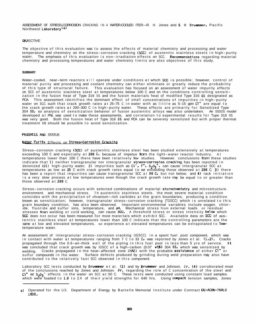
ASSESSMENT OF STRESS-CORROSION CRACKING I N A WATER-COOLED ITER--R. H. Jones and S. M. Eruemmer. Pac i f i c Northwest Laboratory(a)
CBJ ECTIVE
The ob jec t i ve o f t h i s evaluat ion was t o assess the e f f e c t s of mater ia l chemistry and processing and water temperature and chemistry on the stress-corrosion cracking (SCC) o f aus ten i t i c s ta in less s tee ls i n high- pur i ty water. Recommendations regarding mater ia l chemistry and processing temperatures and water chemistry l i m i t s are a lso object ives o f t h i s study.
The emphasis o f t h i s evaluat ion i s non- i r rad ia t ion e f fec ts on SCC.
SUMMARY
Water-cooled. near-term reactors w i l l operate under condi t ions a t which SCC i s possible; however, con t ro l o f mater ia l p u r i t y and processing and coolant chemistry can e i t h e r e l iminate or great ly reduce the p r o b a b i l i t y of t h i s type of s t ruc tu ra l f a i l u re . This evaluat ion has focused on an assessment o f water impuri ty ef fects on SCC o f aus ten i t i c s ta in less s tee l a t temperatures below 100 C and on the condi t ions c o n t r o l l i n g sens i t i- za t ion i n the fusion heat of Type 316 SS and the fusion mater ia ls heat of modif ied Type 316 SS designated as PCA. This assessment i d e n t i f i e s the dominant ef fect o f s m a l l concentrations o f impur i t i es i n high- pur i ty water on SCC such t h a t crack growth rates a t 25-75 C i n water w i th as l i t t l e as 5-15 ppm C1- are equal t o the crack growth ra tes a t 200-300 C i n high- pur i ty water. These e f fec ts are p r imar i l y f o r Sensit ized Type 304 SS, so analysis o f sens i t i za t i on behavior o f fusion aus ten i t i c a l l oys was a lso undertaken. An SSDOS model developed a t PNL was used t o make these assessments, and co r re la t i on t o experimental r e s u l t s f o r Type 316 SS was very good. Both the fus ion heat o f Type 316 SS and PCA can be severely sensi t ized but w i th proper thermal treatment it should be possible t o avoid sens i t iza t ion.
PRCGRESS AN0 STATUS
k i e r P u r i t v Effects on Stress-Corrosion C r W
Stress-corrosion cracking (SCC) o f aus ten i t i c s ta in less s tee l has been studied extensively a t temperatures exceeding 100 C and espec ia l ly a t 288 C, because of impetus from the l igh t- water reactor industry. temperatures lower than 100 C there have been r e l a t i v e l y few studies. i nd i ca te t h a t 1) ne i the r t ransgranular nor in tergranu lar stress-corrofion cracklng has been reported i n deionized ( D I ) h igh- pur i ty water; 2) impur i t ies such as C1-, F-. S24-, can cause in tergranu lar SCC a t temperatures as low as 25 C w i th crack growth ra tes equal t o or exceeding those observed a t 288 C; 3 ) there has been a repor t t h a t impur i t i es can cause transgranular SCC a t 98 C. but not below; and 4) rack i n i t i a t i o n i s a very slow process a t low temperatures even though the crack growth r a t e may be equal t o or greater than those observed a t 288 C.
Stress-corrosion cracking occurs w i th selected combinations of mater la l mlcrochemistry and mlcrostructure. environment. and mechanical stress. I n aus ten i t i c s ta in less steels. t he most severe mater ia l cond i t ion coincides w i th the p r e c i p i t a t i o n o f chranium-rich carbides a t the gra in boundaries, producing a condi t ion known as sens i t iza t ion; however, t ransgranular stress-corrosion cracking (TGSCC) which i s unrelated t o t h i s gra in boundary condit ion, has a lso been observed. Important environmental var iables include oxygen. chlor- ide. f l u o r i d e and su l fu r ions, temperature, and pH. Mechanical s t ress f rom external loads. or residual stresses fran welding o r co ld working, can cause SCC. A threshold s t ress or stress i n t e n s i t y beln, which SCC does n o t occur has been measured for most mater la ls which e x h i b i t SCC. Ava i lab le data on SCC of aus- t e n i t i c s ta in less s tee l a t temperatures lower than 100 C i nd i ca te t h a t the c o n t r o l l i n g parameters are the same a t low and elevated temperatures, so experience a t elevated temperatures can be extrapolated t o l o r temperature water.
An assessment of in tergranu lar stress-corrosion cracking (IGSCC) i n a spent fuel pool component. which was i n contact w i th water a t temperatures ranging from 7 C t o 33 C. was reported by Jones e t a l . (1,2). Cracks propagated through the 0.6-an-thick w a l l of t h e p ip lng i n t h i s fue l pool i n l e s s than 5 y r s o f service. It was concluded t h a t crack growth was by IGSCC o f a high-carbon (0.07 w t % ) 304 SS. which was sensi t ized by welding. su l fu r compounds i n the water. contr ibuted t o the r e l a t i v e l y f a s t SCC observed i n t h i s component.
Laboratory SCC t e s t s conducted by Bruemner e t a l . (3) and by B r u m e r and Johnson. J r . ( 4 ) corroborated most of t he conclusions reached by Jones and Johnson. J r . regarding the r o l e o f C concentration of the s tee l and C1- or S203- ef fects i n the water on SCC a t 30 C. These t e s t s were conducted using constant load samples. which were loaded t o 1.8 t o 2.4 of t h e i r y i e l d strengths fo r 640 hrs. Using canpact tension samples, Jones
A t However. conclusions from these studies
Cracks propagated i n the heat-affected zone (HAZ) wi th the probable assistance o f e i t h e r C1- o r Surface defects produced by gr ind ing dur ing weld preparation may a lso have
a) Operated fo r the U.S. Department of Energy by B a t t e l l e Memorial I n s t i t u t e under Contract DE-ACD6-76RLO 1830.
s89
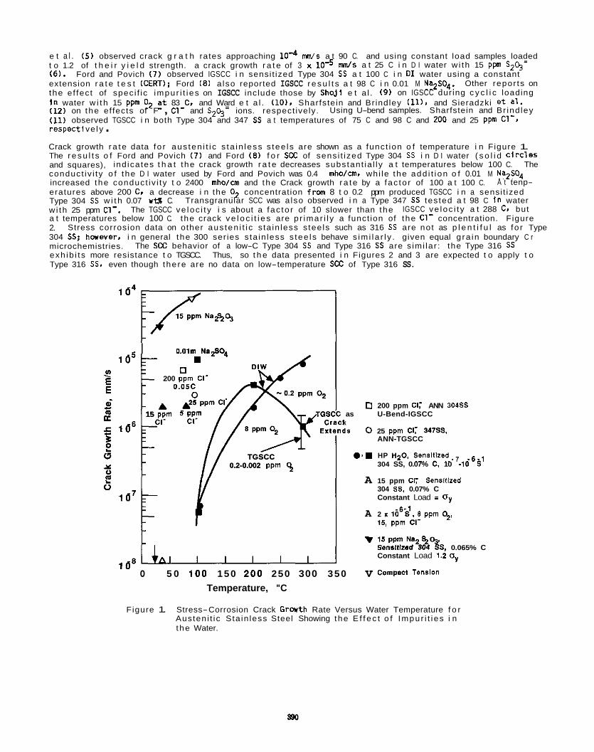
e t a l . ( 5 ) observed crack g r a t h rates approaching lo4 W s a t 90 C. and using constant load samples loaded t o 1.2 of t h e i r y i e l d strength. a crack growth r a t e of 3 x (6). Ford and Povich (7) observed IGSCC i n sensi t ized Type 304 SS a t 100 C i n DI water using a constant extension r a t e t e s t (CERT); Ford (8) also reported IGSCC r e s u l t s a t 98 C i n 0.01 M Na2S04. the e f fec t of spec i f ic impur i t i es on IGSCC inc lude those by Shoj i e t a l . (9) on IGSCC dur ing c y c l i c loading I n water w i t h 15 ppm O2 !t 83 C. and Ward e t a l . ( lo) , Sharfstein and Br indley (11). and Sieradzki e t a l . (12) on the ef fects of F , C1- and S24= ions. respect ively. Using U-bend samples. Sharfstein and Br ind ley (11) observed TGSCC i n both Type 304 and 347 SS a t temperatures of 75 C and 98 C and 200 and 25 ppm c1-t respect i ve l y . Crack growth r a t e data fo r aus ten i t i c s ta in less s tee ls are shown as a funct ion o f temperature i n Figure 1. The r e s u l t s o f Ford and Povich (7) and Ford (8) f o r SCC of sens i t ized Type 304 SS i n D I water ( s o l i d Circ leS and squares), ind icates t h a t the crack growth r a t e decreases substant ia l ly a t temperatures below 100 C. The conduct iv i ty o f t he D I water used by Ford and Povich was 0.4 mho/cm. whi le the add i t i on o f 0.01 M Na2S04 increased the conduct iv i ty t o 2400 mho/cm and the Crack growth r a t e by a fac to r of 100 a t 100 C. eratures above 200 C, a decrease i n the O2 concentration frm 8 t o 0.2 ppm produced TGSCC i n a sensi t ized Type 304 SS w i t h 0.07 ut% C. Transgranular SCC was a lso observed i n a Type 347 SS tes ted a t 98 C I n water w i th 25 ppm C1-. IGSCC ve loc i t y a t 288 C. but a t temperatures below 100 C. t he crack v e l o c i t i e s are p r imar i l y a funct ion of the C1- concentration. Figure 2. Stress corrosion data on other aus ten i t i c s ta in less s tee ls such as 316 SS are not as p l e n t i f u l as fo r Type 304 SS: haever, i n general t he 300 ser ies s ta in less s tee ls behave s im i la r l y . given equal g ra in boundary C r microchemistries. exh ib i t s more resistance t o TGSCC. Thus, so t h e data presented i n Figures 2 and 3 are expected t o apply t o Type 316 SS. even though the re are no data on low-temperature SCC of Type 316 SS.
d s a t 25 C i n D I water w i th 15 ppm S24=
Other repor ts on
A t tenp-
The TGSCC ve loc i t y i s about a fac to r of 10 slower than the
The SCC behavior of a low-C Type 304 SS and Type 316 SS are s imi lar : the Type 316 SS
0.0im Na2S04
15 ppm 5 PPm
E x 1
TGSCC 0.2-0.002 ppm 9
I 0.0im Na2.O.
200 ppm CI-
15 ppm 5 PPm
E x 1
TGSCC 0.2-0.002 ppm 9
0 200 ppm Cl,- ANN 304SS as U-Bend-IGSCC
k 4s 0 25 ppm Cl; 347SS.
ANN-TGSCC
0 3 . HP HzO, Senslllzed-, - 6 - 1 304 SS, 0.07% C. 10 .10 S
A 15 ppm CI; Sensitlred 304 SS, 0.07% C Constant Load = Oy
15, ppm CI-
v 15 ppm Na 0 Sensitized23% gS, 0.065% C Constant Load 1.2 oy
A 2 18s'~ 8 ppm 02,
I " o 5 0 100 150 200 250 300 350 v Compact Tension
Temperature, "C
Figure 1. Stress-Corrosion Crack Growth Rate Versus Water Temperature f o r Austen i t ic Sta in less Steel Showing the E f f e c t o f Impur i t i es i n the Water.
200 I 1 o5
H
ss
5 1 0 1 5 2 0 2 5 3 0 16'
Chloride Ion Concentration, at. ppm
Figure 2. Stress-Corrosion Crack Growth Rate Versus Chlor ide Ion Concentration i n Water fo r Austen i t ic Stainless Steel.
A key parameter t h a t cor re la tes the g ra in boundary microchemistries of aus ten i t i c s ta in less s tee ls w i t h t h e i r resistance t o IGSCC i s degree of sens i t i za t i on (DOS). t o co r re la te wi th IGSCC resistance. t o IGSCC. Bruemner e t a l . (13) have evaluated the DOS of Types 304L, 304. 316L. 316 and 316LN SS w i t h C
This electrochemically derived parameter has been shown A high DOS corresponds t o l o w IGSCC resistance or high s u s c e p t i b i l i t y
concentration ranging from 0.013 t o t i z e d much above 1 or 2
resu l t s i nd i ca te t h a t Type 316L SS wi th 0.014 w t g C could Type 316L w i th 0.02 w t g C was sensi t ized t o 10 a t 600 C
a t 700 C. A DOS value s u f f i c i e n t t o produce IGSCC. Also, a Type 316 SS wi th 0.035 w t g C was sens i t ized t o 20 and 50 C / c d a t 600 C and 700 C. Type 316L SS i s 0.035 w t g . c i e n t t o produce a sens i t ized mater ia l t h a t can undergo IGSCC.
The detrimental e f fec t of impur i t i es i n water i s c lea r l y shown by the data i n Figures 1 and 2. the e f fec t of concentrations, as low as 15 ppm o f C1- and S24= on the crack growth rate. i s apparent fran the reversal o f t he tmpera tu re dependence shown for D I water. modify the ra te- l im i t i ng step f o r crack growth i n DI water so t h a t v e l o c i t i e s equal t o o r exceeding those a t 280 C resu l t . 2 a lso i l l u s t r a t e s the detrimental e f f e c t o f water impur i t ies. t he dominance o f C r dep le t ion on crack growth ra te so t h a t both TGSCC and IGSCC data fit the same curve.
F luor ide ion concentrations as l o w as 0.5 ppm produced IGSCC a t stresses above 350 MPa. Residual 2 4 s resses ions. F luor ide ions are c l e a r l y more detrimental than C1- ions. and may be even more detrimental than S
usual ly do not substant ia l ly exceed the y i e l d strength o f a mater ia l (200-250 MPa f o r Type 304 SS). so stresses equal t o or exceeding 350 MPa generally requ i re an external load.
Stress thresholds f o r SCC are generally equal t o o r exceed the y i e l d strength of the mater ia l . low-temperature SCC there i s a scarc i ty o f data t o evaluate the s t ress dependence o f SCC. but the data given i n Figure 3 g i ve sane ind ica t ion of t h e i r magnitude. These r e s u l t s suggest t h a t the s t ress must be equal t o o r exceed the y i e l d strength o f the mater ia l fo r IGSCC i n low-temperature water. o f Jones and Wang (14) are shown only f o r canparison purposes. as t h i s t e s t i s conducted a% 155 C i n a con- centrated C1- environment, and are not considered t y p i c a l f o r aqueous SCC. The crack morphology i s trans- granular and the threshold i s considerably l e s s than the y i e l d strength. Crack advance i s probably due t o a hydrogen-induced process, un l i ke aqueous environments. which i s p r imar i l y an anodic d i sso lu t i on process. Stress i n t e n s i t y thresholds are another method fo r descr ib ing the l i m i t i n g mechanical loading condi t ion f o r SCC. I n D I water a t 97 C Ford ( 8 ) measured a s t ress i n t e n s i t y threshold o f about 12 MPa-m f o r sensi t ized Type 304 SS. whi le i n D I water w i th 15 ppm S 4=. Jones e t a l . ( 5 ) measured a threshold o f about 25 MPa-m . r e l a t i v e l y low values, as the d a c t u r e toughness of Type 304 SS exceeds 100 MPa-m .
The spec i f i ca t i on f o r C concentrat ion i n Clearly, C concentrations w i th in the spec i f i ca t i on f o r Type 316L SS are su f f i -
I n Figure 1
Impur i t ies such as C1- and S24- c l e a r l y
Their e f f e c t i s s u f f i c i e n t a lso t o overr ide The smooth increase i n the crack ve loc i t y w i th increasing C1- concentration shown i n Figure
Again, for
The MgCl data fran r e s u l t s
The s t ress in tens i t y i s a funct ion o f both the s t ress and the square roo t o f t he crack length.
These are

1 o4
1 o5 n z
: E a i L
g 1 b6 e 0 1 u E
10'
1 o*
Steady State Crack GroWh Rate Llmit From Compact Tension
15 ppm CI'
a
0
v
A I I I I I . A
0 100 2 0 0 300 400 500 600
Stress, MPa
55% MgCl 155% 304 SS. 0%7% C
55% MgCiZ, 155% 304 SS, 0.016% C
15 ppm Na2S2g. 25% 304 SS
15 ppm Cl: 30°C
5 ppm CI-
Figure 3. Stress-Corrosion Crack Growth Rate Versus Applied Stress f o r Austen i t ic Stainless Steel i n Various Environments.
Sens i t iza t ion Development i n Fusion Reactor Mater ia ls
Quan t i t a t i ve sens i t i za t i on development i n two aus ten i t i c SS heats from the fusion mater ia ls s tockp i l e was predicted using the model SSOOS (15,161. Compositions f o r the heats. X-15893 (316 SS) and K-280 (PCA), are l i s t e d below. SSDOS enables p red ic t i on o f chromium deplet ion and degree of sens i t i za t i on (DOSI as measured by the e lec t rochmica l po ten t lok ine t i c reac t i va t i on (Em) t e s t fran mater ia l composition and i n i t i a l condi- t ion . 316 SS heats (16,17).
The model has been shown t o accurately p red ic t sens i t i za t i on development i n a l a rge number o f 304 and
Table 1. Compositions o f Fusion Heats of Austen i t ic Sta in less Steels
&eat C C r N i Mo Mn s i Ti N
316 0.056 16.7 12.0 2.4 1.7 0.7 - - PCA 0.046 14.0 15.9 1.9 1.7 0.5 0.3 0.01
Isothermal sens i t i za t i on behavior f o r both heats was assessed f o r heat treatment temperatures between 500 and 1000 C. Pred ic t ions fo r the 316 heat showed rap id sens i t i za t i on a t temperatures fran 700 t o 850 C. SenSi- t i z a t i o n i s thermodynamically l i m i t e d a t higher temperatures and k i n e t i c a l l y l i m i t e d a t lower temperatures. Time-t p e r a t u r e s e n s i t i z a t i o n (TTS) behavior i s i l l u s t r a t e d i n Figure 4 using a c r i t i c a l EPR-DOS value o f 5 C/ 2 t o i nd i ca te the onset o f sens i t iza t ion.
A d i r e c t comparison can be made between measured and predicted EPR-OOS for t h i s heat, as shown i n Figure 5. L imi ted sens i t i za t i on measurements were performed previously (17) a f t e r so lu t i on annealing a t 1100 C. The q u a n t i t a t i v e nature of the p red ic t i ve capab i l i t y i s documented by canparing data a t 600. 700. and 800 C. Although pred ic t ions are not exact, EPR-DOS i s reasonably estimated a t most temperatures and times.
892
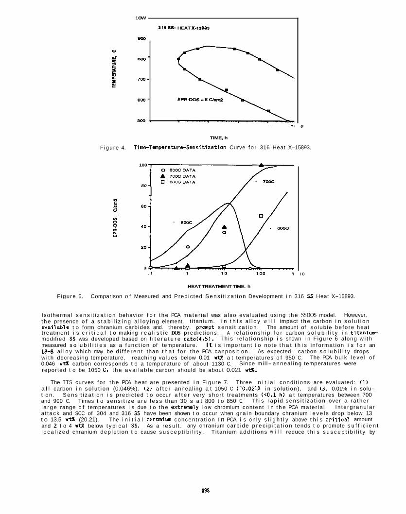
Figure 4.
800 - 7w - 800 -
5w .
1 ow
316 SS: HEAT X-IsPo
8M
0
TIME, h
Time-TemperaturcSensitlzation Curve f o r 316 Heat X-15893.
100 0 800CDATA A 700CDATA 0 BOKDATA
80
I O
HEAT TREATMENT TIME. h
Figure 5. Comparison o f Measured and Pred ic ted S e n s i t i z a t i o n Development i n 316 SS Heat X-15893.
Isothermal s e n s i t i z a t i o n behavior f o r t h e PCA ma te r i a l was a l so evaluated using t h e SSDOS model. However. t h e presence o f a s t a b i l i z i n g a l l o y i n g element. t i tanium. i n t h i s a l l o y w i l l impact t h e carbon i n s o l u t i o n a v a l l a b l s t o form chranium carbides and. thereby. pranpt sens i t i za t i on . The amount of soluble be fo re heat t reatment i s c r i t i c a l t o making r e a l i s t i c DOS pred ic t ions . A r e l a t i o n s h i p f o r carbon s o l u b i l i t y i n t i t a n i u n r modif ied SS was developed based on l i t e r a t u r e data(4,5). Th i s r e l a t i o n s h i p i s shown i n F igure 6 a long w i t h measured s o l u b i l i t i e s as a f unc t i on of temperature. 18-8 a l l o y which may be d i f f e r e n t than t h a t f o r t h e PCA canposi t ion. As expected, carbon s o l u b i l i t y drops w i t h decreasing temperature, reaching values below 0.01 wt% a t temperatures o f 950 C. 0.046 u t% carbon corresponds t o a temperature of about 1130 C. reported t o be 1050 C. t h e a v a i l a b l e carbon should be about 0.021 we.
It i s impor tan t t o no te t h a t t h i s in fo rmat ion i s f o r an
The PCA bu lk l e v e l o f Since mi l l- annea l ing temperatures were
The TTS curves f o r t h e PCA heat are presented i n F igure 7. Three i n i t i a l cond i t ions are evaluated: (1) a l l carbon i n s o l u t i o n (0.046%). (2 ) a f t e r annealing a t 1050 C (-0.021% i n so lu t ion) , and (3 ) 0.01% i n solu- t i on . S e n s i t i z a t i o n i s p red ic ted t o occur a f t e r very sho r t t reatments (<0.1 h) a t temperatures between 700 and 900 C. Times t o s e n s i t i z e a r e l e s s than 30 s a t 800 t o 850 C. l a r g e range o f temperatures i s due t o t h e extremely l o w chromium content i n t h e PCA mater ia l . a t t ack and SCC of 304 and 316 SS have been shown t o occur when g r a i n boundary chranium l e v e l s drop below 13 t o 13.5 wt% (20.21). The i n i t i a l chranfum concent ra t ion i n PCA i s on ly s l i g h t l y above t h i s c r l t l c a l amount and 2 t o 4 WW below t y p i c a l SS. As a resu l t . any chranium carb ide p r e c i p i t a t i o n tends t o promote s u f f i c i e n t l o c a l i z e d chranium dep le t i on t o cause s u s c e p t i b i l i t y . T i tan ium add i t i ons w i l l reduce t h i s s u s c e p t i b i l i t y by
Th is r a p i d s e n s i t i z a t i o n over a r a t h e r I n te rg ranu la r
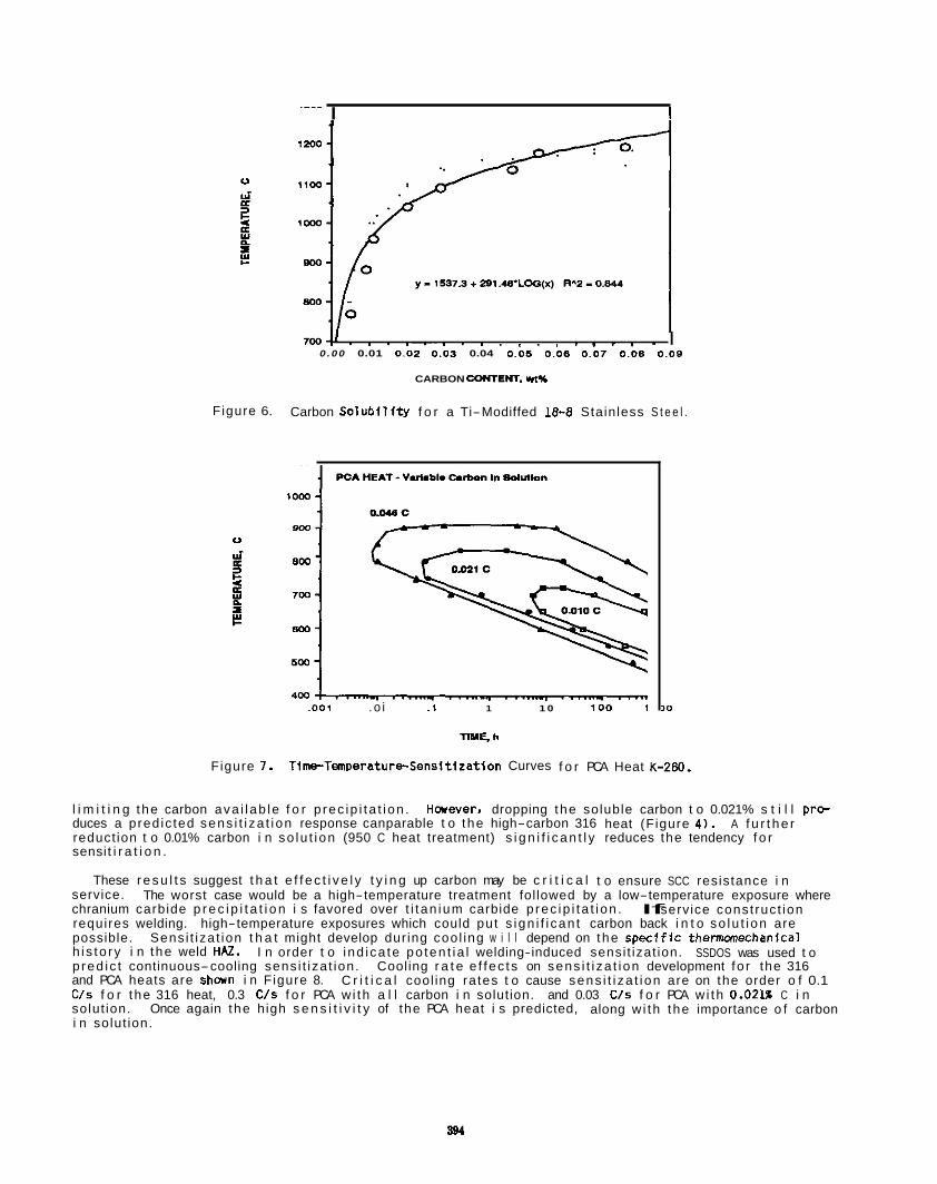
I I
Figure 6.
700# . , . . . , . , . . . , . . . , . I 0 . 0 0 0.01 0.02 0 .03 0.04 0.06 0.00 0.07 0 .08 0 . 0 0
CARBON COIYTENT. It%
Carbon S o l u b i l f t y f o r a Ti-Modiffed 18-8 Stainless S t e e l .
F igure 7.
gm-
800 - 700-
800-
500-
400 ,001 . o i .I 1 1 0 i o 0 1
TIME. h
>o
Time-Temperatur4.Sensitization Curves f o r PCA Heat K-280.
l i m i t i n g the carbon ava i l ab le f o r p rec ip i ta t i on . Harever. dropping the soluble carbon t o 0.021% s t i l l prc- duces a pred ic ted sens i t i za t i on response canparable t o the high-carbon 316 heat (Figure 4 ) . reduct ion t o 0.01% carbon i n so lu t i on (950 C heat treatment) s i g n i f i c a n t l y reduces the tendency f o r sensi t i r a t i o n .
A f u r t h e r
These r e s u l t s suggest t h a t e f f e c t i v e l y t y i n g up carbon may be c r i t i c a l t o ensure SCC resistance i n service. chranium carbide p r e c i p i t a t i o n i s favored over t i t an ium carbide p rec ip i ta t i on . If service const ruc t ion requires welding. high-temperature exposures which could put s ign i f i can t carbon back i n t o so lu t i on are possible. Sens i t iza t ion t h a t might develop dur ing coo l ing w i l l depend on the s p f x i f i c thennanechanical h i s to ry i n the weld HAZ. pred ic t continuous-cooling sens i t iza t ion. Cooling r a t e e f fec ts on sens i t i za t i on development fo r the 316 and PCA heats are shwn i n Figure 8. C/s f o r the 316 heat, 0.3 C/s f o r PCA w i th a l l carbon i n solution. and 0.03 C/s f o r PCA w i th 0.02H C i n solut ion. i n solut ion.
The worst case would be a high-temperature treatment fol lowed by a low-temperature exposure where
I n order t o i nd i ca te po ten t ia l welding-induced sensi t izat ion. SSDOS was used t o
C r i t i c a l cool ing ra tes t o cause sens i t i za t i on are on the order o f 0.1
Once again the high s e n s i t i v i t y of the PCA heat i s predicted, along w i th the importance o f carbon
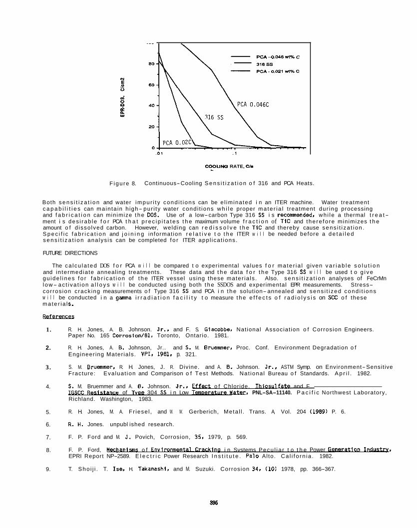
PCA - 0.046 W% C - 318SS
.01 . 1
COOUNQ RATE, CIS - F igu re 8. Continuous-Cooling S e n s i t i z a t i o n o f 316 and PCA Heats.
Both s e n s i t i z a t i o n and water impu r i t y cond i t i ons can be e l im ina ted i n an ITER machine. Water t reatment c a p a b i l i t i e s can main ta in h igh- pur i ty water cond i t ions w h i l e proper ma te r i a l t reatment dur ing processing and f a b r i c a t i o n can minimize t h e DOS. Use of a low-carbon Type 316 SS i s recmended, wh i l e a thermal t r e a t - ment i s des i rab le f o r PCA t h a t p r e c i p i t a t e s t h e maximum volume f r a c t i o n of TIC and the re fo re minimizes t h e amount o f d isso lved carbon. S p e c i f i c f a b r i c a t i o n and j o i n i n g informat ion r e l a t i v e t o t h e ITER w i l l be needed before a d e t a i l e d s e n s i t i z a t i o n ana lys is can be completed f o r ITER app l ica t ions .
FUTURE DIRECTIONS
However, weld ing can r e d i s s o l v e t h e TIC and thereby cause sens i t i za t i on .
The ca l cu la ted DOS f o r PCA w i l l be compared t o experimental values f o r ma te r i a l g iven v a r i a b l e s o l u t i o n and in te rmed ia te annealing treatments. These data and t h e data f o r t h e Type 316 SS w i l l be used t o g i v e gu ide l i nes f o r f a b r i c a t i o n of t h e ITER vessel us ing these mater ia ls . Also. s e n s i t i z a t i o n analyses of FeCrMn l ow- ac t i va t i on a l l o y s w i l l be conducted using both t h e SSDOS and experimental EPR measurements. Stress- cor ros ion c rack ing measurements o f Type 316 SS and PCA i n t h e solut ion- annealed and sens i t i zed cond i t i ons w i l l be conducted i n a gamma i r r a d i a t i o n f a c i l i t y t o measure t h e e f f e c t s o f r a d i o l y s i s on SCC o f these ma te r i a l s.
Refsrences
1.
2.
3.
4.
5.
6.
7.
8.
9.
R. H. Jones, A. B. Johnson. Jr., and F. S. Glacobbe, Nat ional Associat ion o f Corrosion Engineers. Paper No. 165 Corrosion/Bl, Toronto, Ontario. 1981.
R. H. Jones, A. 8. Johnson, Jr.. and S. M. Bruemmer, Proc. Conf. Environment Degradation o f Engineer ing Mater ia ls . VPI. 1981, p. 321.
S. M. Bruemmer. R. H. Jones, J. R. Divine. and A. 6 . Johnson. Jr.. ASTM Symp. on Environment-Sensit ive Fracture: Eva lua t ion and Comparison o f Tes t Methods. Nat iona l Bureau o f Standards. A p r i l . 1982.
S. M. Bruemmer and A. 8. Johnson. Jr.. W e G t o f Chloride. T h k u L f x L e and F-
Richland. Washington, 1983.
R. H. Jones, M. A. F r iese l , and W. W. Gerberich, Meta l l . Trans. A, Vol. 204 (1989) P. 6.
R. H. Jones. unpubl ished research.
F. P. Ford and M. J. Povich, Corrosion, 35, 1979, p. 569.
F. P. Ford, l k h m b m s o f Envir- i n Svstems Pecu l i a r t o t h e Power G V . EPRI Report NP-2589. E l e c t r i c Power Research I n s t i t u t e . Palo Al to. Ca l i f o rn ia . 1982.
T. Sho i j i . T. Ise, H. Takanashi, and M. Suzuki. Corrosion 34. (10) 1978, pp. 366-367.
t e of TvDe 304 SS i n Low T m D e r m , PNL-SA-11140. P a c i f i c Northwest Laboratory,
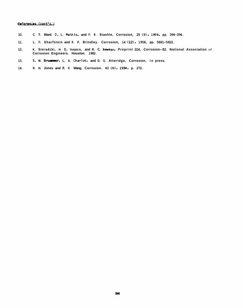
10. C. T. Ward. 0. L. Mathis. and R. W . Staehle, Corrosion, 25 (9), 1969. pp. 394-396.
11. L. R. Sharfstein and W . F. Brindley. Corrosion, 14 (12). 1958, pp. 5881-5922.
12. K. Sieradzki, H. 5. Isaacs, and R. C. Nwaan, Prepr int 224, Corrosion-82. National Association of Corrosion Engineers. Houston. 1982.
13. 5. M. Brusmmer. L. A. Charlot. and D. G. Atteridge, Corrosion. i n press.
14. R. H. Jones and R. W . Wang. Corrosion. 40 (6). 1984. p. 272.
396

7. S O L I D B R E E D I N G M A T E R I A L S
897

A FAST NEUTRON. I N S I N TRITIUM RECOVERY EXPERIMENT ON SOLID BREEDER MATERIALS - G. W. Hollenberg (Pac i f i c Northwest Laboratory)(a). T. Kurasawa and H . Watanabe (Japan Atanic Energy Research I ns t i t u t e ) , S. E. Berk (U.S. D.O.E./OFE). I. J. Hastings and J. M i l l e r (Atanic Energy o f Canada Research Canpany), D. E. Baker. R. E. Bauer and R. J. Puigh (Westinghouse Hanford Co.)
OBJECTIVE
The overa l l ob ject ive o f the BEATRIX-I1 experiment i s t o determine the i n s i t u t r i t i u m recovery character is t ics of L i 0 under f a s t neutron i r r ad i a t i on t o extended burnups under both isothermal and thermal gradient cond?tions.
SUMMARY
An i n s i t u t r i t i u m recovery experiment has been designed and i s being fabr icated f o r the i r r ad i a t i on o f L i 0 i n the Fast Flux Test F a c i l i t y (FFTF). Two i n s i t u t r i t i u m recovery canisters w i l l be i r rad ia ted w d h l i t h i u m atan burnups t o 4%. function o f temperature. gas composition. and f l o w rate. The other canister w i l l contain so l id p e l l e t specimens w i t h la rge (43DOC) rad ia l temperature gradients i n order t o provide integrated performance data.
One canis ter w i l l provide fundamental data on t r i t i u m release as a
PROGRESS AND STATUS
Introduction
I n the l a s t decade considerable progress has been made on the development o f so l i d breeder mater ials for t r i t i u m production i n fusion blankets. Experimenta f f o r t s i n fabr icat ion, i n property measure- ments. i n i r r ad i a t i on damage1, and i n t r i t i u m recovery have cont inual ly yielded pos i t i ve resul ts. The I n s i t u t r i t i u m recovery experiments thus f a r have been on r e l a t i ve l y small samples w i th modest l i t h i u m a t m burnup. Japan, Canada and t he U.S. have i n i t i a t e d an i n s i t u t r i t i u m recovery experiment i n t he FFTF reactor as administered by the In ternat ional Energy Agency's BEATRIX-I1 program. BEATRIX-I1 w i l l achieve high damage and t r i t i u m production ra tes i n two f u l l y instrumented. larger volume canisters w i th i n s i t u recovery i n 1989. This paper describes those two tests.
TEST DESIGN
The object ives o f the Cycle 11 experiment are t o quant i fy t r i t i u m release character is t ics and t o measure the thermal s t a b i l i t y Of L i z0 as a funct ion o f neutron exposure. tenperature, gas cunposition, and sweep gas f l o w rate. To accmpl ish these object ives one i n s i t u recovery canister w i l l contain a t h i n walled (1.5mm) r i n g specimen capable of incremental temperature change steps and another canis ter w i l l contain sol i d pe l l e t s w i th blanket-relevant tenperature gradients. breeder mater ials are important t o fusion blanket designs i n order t o assure rapid replenishment o f t r i t i u m for DT-fueled plasmas. beginning- of- l i fe blanket operating temperatures. The unique experimental parameters associated w i th the BEATRIX-I1 Cycle 11 tes t ing are:
1. High l i t h i u m a t m burnup. Essent ia l ly homogeneous l i t h i u m a t m burnups o f 4% w i l l be achieved
Tr i t ium release character is t ics of sol i d
Thermal s t a b i l i t y I s important i n order t o assure the maintenance of
i n the L i20 samples i r rad ia ted i n 1989. 1 rradiations.
Higher burnups (>S) are planned i n subsequent
2. High t o t a l t r i t i u m production. Over 7000 cur ies of t r i t i u m w i l l be produced. measured and
3. Reactor relevant t r i t i u m pa r t i a l pressures. The reference steady s ta te t r i t i u m pa r t i a l pressure
recovered during the 300 equivalent f u l l power days (EFPD) i r rad ia t ion .
w i l l be 50 ppm which i s much higher than most experiments (1 ppm). To increase the ef f ic iency of t r i t i u m recovery fran sweep gas streams. high t r i t i u m pa r t i a l pressures are projected f o r so l i d breeder blanket designs. Higher t r i t i u m pa r t i a l pressures should minimize experimental uncertainties, 1.e. i n i t i a l sweep gas contaminants and surface adsorption/desorption fran downstream tube walls.
Engineering-oriented test ing. production gradients t yp ica l o f Li20 prototypic condit ions t o r e l a t i ve l y high l i t h i u m atan burnup.
4. The s o l i d p e l l e t canis ter w i l l generate temperature and t r i t i u m
The FFTF reactor possesses several desirable features for t e t i n g The FFTF i s noted for i t s high, fast neutron f lux (4.8 x loLg n / d s CE>O.l MeV]) and i t s a b i l i t y t o eas i l y
andidate so l i d breeder materials.
(a) Operated for the U.S. Department o f Energy by Ba t t e l l e Memorial I n s t i t u t e under Contract DE-AC06-76RLO 1830.
acCo(llll0dats instrumented experiments. section for neutron reactions w i th l i t h ium-6 (1-2 barns) which i s s im i la r t o several s o l i d breeder blanket designs. cdn be achieved i n a simple test. Two canisters are contained w i th tn t h e Mater ials Open Test Assanbly
a standard FFTF instrumented i r r ad i a t i on vehicle, which was modified by the addit ton of weep gas l ines.
The temperature change canister (Figure 1) w i l l a l l a temper t re changes between 460.C and 650.C On a t h i n r i n g o f L i 0 i n a manner s im i la r t o e a r l i e r experiment&!. Temperature control i s obtained by computer cont rohed hel luwargon gas mixtures i n the gas gap between the specimen subcapsule and the reactor coolant. After an instantaneous increase/decrease i n tanperature, tritium w i l l be releasedl retained i n the ceramic u n t i l the t r i t i u m release r a te returns t o steady stdte. The exact shape and time constant associated w i t h t h i s t rans ient data can then be canpared w i th theoret i a1 models for analysis
canpositton (helium plus 0-l% hydrogen). neutron f l u x and a l l a normalization of the t r i t ium production rate. temperature gradient across the r i n g specimen t o ind icate t he ef fect ive thermal conductivity.
The neutron spectrum i n FFTF resu l t s i n a r e l a t i ve l y la cross
With essent ia l ly no self-shielding, larger sample volumes and high l i t h i um aton burnup leve ls
of mechanism. Simi lar parametric incrments are planned for flar ra te (10 - 1000 2 /n) and sweep gas A Self-Powered-Neutron-Detector (SFNO) w i l l measure t he loca l
T h e m o u p l e s w i l l measure the
Figure 1. Schmatic o f Temperature Change Canister Containing Ring Specimen
Figure 2. Schematic of Sol id P e l l e t Canister
I n the other canister, a column (Figure 2) of s o l l d L i 0 p e l l e t s w i l l be i r radiated. The specimen i s predicted t o have an i n i t i a l center1 lne temperature 0?900*C and outer clrcumference temperature o f 450.C. The purpose o f the s o l l d e l l e t can is ter I s t o monitor the t r i t i u m release from Li20 under thermal gradient condit ions t yp ica l of a byanket. The temperature gradient across the s o l i d p e l l e t w i l l be continuously measured w i th thermocouples. In part icular. t he la rge temperature gradlent provides an opportunity t o evaluate the upper temperature l i m i t i n g phenmenon of Li20. i.e. l i t h i um transport from high temperature t o colder temperature regions.
The major character is t ics of the L i 0 specimens and t h e i r ant ic ipated environment are summarized i n Table 1. The l i t h i u m 4 e n r l c h e n t ?or both specimens was chosen t o obtain a l i t h i um a t m burnup o f 4% a t 300 equivalent f u l l parer days (EFPO). Monte Carlo ca lcu la t ions were used t o optlmize the pos i t i on f o r maximum l i t h i um atan burnup and t he lowest pract ica l i r r ad i a t i on temperatures.
Table 1. Characterization of the L i20 Specimens and Anticipated Envlronment
Specimen
Physical Dimensions Outside Diameter (m) Wall Thickness (mn) Length (mn)
L i th iunr6 Enrichment ( X I Density (XTD) Graln Size (pm)
Sol I d RhLaaam fumdAmn
ia.57
aa.9
a5
1.50
61.0
5
I r r ad i a t l on Temperature Inner Radius P C ) 500 - 685 Outer Radius ( O C ) 460 - 651 Maximum Gradient PC) za
Total T r l t i um Production ( C i ) 2025
Sweep Gas System Gas Cmpos i t l o he1 iumt(O-l%H2) Flow Rates ( J . m l n ) 10-1000
17.02 -- aa.9
a9 61.0
5
ab3 430 433
5300
he1 iumt(O-lXH2) 10-1000
Dimensions of the r i ng geanetry specimen minlmize the rad ia l temperature gradient and the I r r ad i a t i on temperature whi le malntaining a temperature-control capab i l i t y and high t r i t i u m productlon levels. dimensions o f t he s o l l d p e l l e t specimen were chosen t o obtain an i n i t i a l center l lne temperature o f 9OO'C. The calculated rad ia l temperature gradients i n the &o specimen types are compared i n Figure 3.
The
BEATRIX-II Ring and Solid Specimens Temperature Predictions
0 0.2 0.4 0.6 0.8 1
Radial Poaltlon (cm) -1IM
Figure 3. Temperature Predict ions f o r the Ring and Sol id P e l l e t L i z0 Specimns.
401
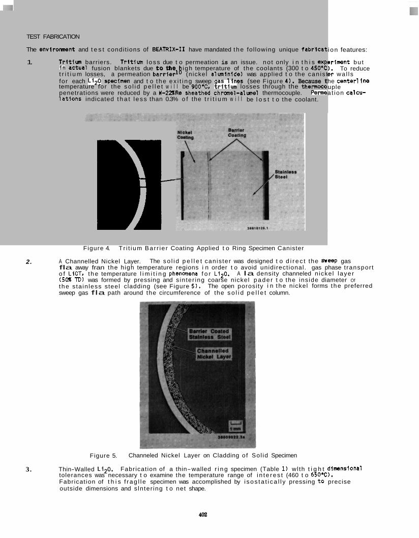
TEST FABRICATION
The enviromnent and t e s t condit ions of BEATRIX-I1 have mandated t he fol lowing unique f ab r i ca t
1. T r i t i u n barriers. T r i t i m l oss due t o permeation is an issue. no t only i n t h i s exp i n actual fusion blankets due t o the igh temperature of the coolants (300 t o 450.12 t r i t i u m losses, a permeation b a r r i e d (nickel a lm in i de ) was applied t o the can is t for each L i z0 spedmen and t o t he ex i t i ng sweep as l l n e s (see Figure 4 ) . Because t temperature for the so l i d p e l l e t w i l l be 900'CI & i t ium losses through the thermoco penetrations were reduced by a W-22XRe sheathed chranel-almel thermocouple. P B m l a t i o n s indicated t h a t l e ss than 0.3% o f the t r i t i u m w i l l be l o s t t o the coolant.
19 i on features:
eriment bu t 1. To reduce e r wa l l s he center1 ine uple a t ion calcu-
Figure 4. T r i t i um Bar r ie r Coating Applied t o Ring Specimen Canister
2. A Channelled Nickel Layer. fla away fran the high temperature regions i n order t o avoid unidirect ional. gas phase t ranspor t o f LiOT. t he temperature l i m i t i n g phenanena f o r Li20. A la density channeled n icke l l ayer (5oX TD) was formed by pressing and s in ter ing coarse nickel pade r t o the ins ide diameter Of t he s ta in less steel cladding (see Figure 5). The open porosi ty i n t he nickel forms t he preferred sweep gas fla path around the circumference of the s o l i d p e l l e t column.
The so l i d p e l l e t canis ter was designed t o d i r e c t the Sweep gas
Figure 5. Channeled Nickel Layer on Cladding of Sol id Specimen
3. Thin-Walled Li20. tolerances was necessary t o examine the temperature range of i n t e res t (460 t o 65WC). Fabricat ion of t h i s f r ag l l e specimen was accomplished by i sos ta t i ca l l y pressing t o precise outside dimensions and s ln ter ing t o net shape.
Fabricat ion of a thin-walled r i n g specimen (Table 1) wlth t i g h t dimnslonal
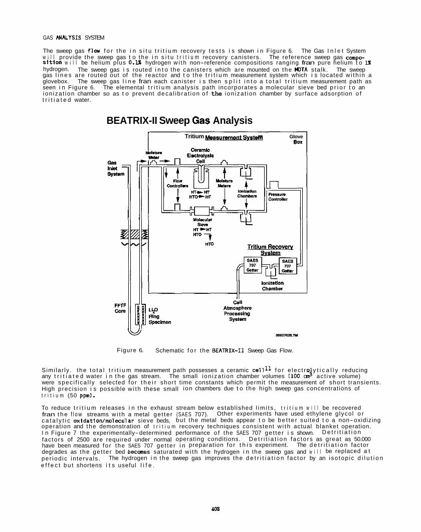
GAS ANALYSIS SYSTEM
The sweep gas f lw f o r the i n s i t u t r i t i u m recovery t e s t s i s shown i n Figure 6. The Gas I n l e t System w i l l provide the sweep gas t o the i n s i t u t r i t i u m recovery canisters. The reference sweep gas cmpc- s i t i o n w i l l be helium plus 0 . X hydrogen w i t h non-reference compositions ranging fran pure helium t o 1x hydrogen. The sweep gas i s routed i n t o the can is ters which are mounted on the WTA stalk. The sweep gas l i n e s are routed out of t he reactor and t o the t r i t i u m measurement system which i s located w i t h i n a glovebox. The sweep gas l i n e fran each can is ter i s then s p l i t i n t o a t o t a l t r i t i u m measurement path as seen i n Figure 6. The elemental t r i t i u m analysis path incorporates a molecular sieve bed p r i o r t o an ion iza t ion chamber so as t o prevent deca l i b ra t i on o f the i on i za t ion chamber by surface adsorption o f t r i t i a t e d water.
BEATRIX-II Sweep Gas Analysis Tritium rn Glove
BOX
38807m.1lA
Figure 6. Schematic f o r the BEATRIX-I1 Sweep Gas Flow.
S imi lar ly . t he t o t a l t r i t i u m measurement path possesses a ceramic c e l l l l f o r e lec t ro y t i c a l l y reducing
were spec i f i ca l l y selected fo r t h e i r shor t t ime constants which permit the measurement of shor t t ransients. High prec is ion i s possible w i t h these small ion chambers due t o the high sweep gas concentrations of t r i t i u m (50 ppm).
To reduce t r i t i u m releases i n the exhaust stream below establ ished l i m i t s , t r i t i u m w i l l be recovered fran t h e f l o w streams w i t h a metal ge t te r (SAES 707). c a t a l y t i c oxidation/molecular sieve beds, but the metal beds appear t o be b e t t e r su i ted t o a non-oxidizing operat ion and the demonstration of t r i t i u m recovery techniques consistent w i t h actual b lanket operation. I n Figure 7 the experimentally-determined performance o f the SAES 707 ge t te r i s shown. fac tors of 2500 are required under normal operating condit ions. D e t r i t i a t i o n fac to rs as great as 50.000 have been measured fo r the SAES 707 ge t te r i n preparation fo r t h i s experiment. The d e t r i t i a t i o n factor degrades as the ge t te r bed becanes saturated w i th the hydrogen i n the sweep gas and w i l l be replaced a t pe r iod ic in terva ls . e f f e c t b u t shortens i t s useful l i f e .
any t r i t i a t e d water i n t h e gas stream. The small i on i za t ion chamber volumes (100 c n J ac t i ve volume)
Other experiments have used ethylene g lyco l o r
D e t r i t i a t i o n
The hydrogen i n the sweep gas improves the d e t r i t i a t i o n fac to r by an i so top ic d i l u t i o n
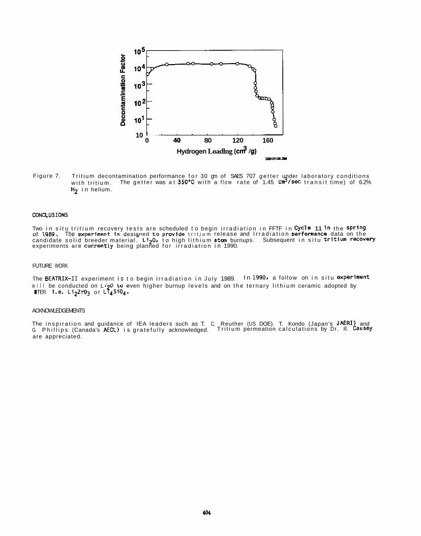
10 ' 0 40 80 120 160
Hydrogen Loadlng (cd /g) 1*11012am
Figure 7. T r i t i u m decontamination performance f o r 30 gm of SAES 707 g e t t e r under l abo ra to ry cond i t i ons w i t h t r i t i u m . H2 i n helium.
The g e t t e r was a t 350'C w i t h a f l o w r a t e of 1.45 c$/sec t r a n s i t t ime) of 6.2%
CONaUSIONS
Two i n s i t u t r i t i u m recovery t e s t s a r e scheduled t o begin i r r a d i a t i o n i n FFTF i n Cycle 11 I n t h e spr ing of 1989. The exaeriment I s desianed to orovide t r i t i u m re lease and I r r a d i a t i o n Derformance data on t h e r - ~ ~ ~ ~ .~ ~~ ~~ r~~~~ ~ ~~ .. .... . . . ~ ~~
candidate s o l i d breeder mater ia l . Li20. t o h i gh l i t h i u m atcm burnups. experiments a re cur , ren t ly being planned f o r i r r a d i a t i o n i n 1990.
Subsequent i n s i t u t r i t i u m recovery
FUTURE WORK
The BEATRIX-I1 experiment i s t o begin i r r a d i a t i o n i n J u l y 1989. w i l l be conducted on L i 0 t o even h igher burnup l e v e l s and on t h e t e rna ry l i t h i u m ceramic adopted by ITER. i.e. L i2zro3 o r L ? ~ S I O ~ .
I n 1990. a fo l low on i n s i t u experiment
ACKNOWLEDGEMENTS
The i n s p i r a t i o n and guidance of IEA leaders such as T. C. Reuther (US DOE). T. Kondo (Japan's JAERI) and G. P h i l l i p s (Canada's AECL) i s g r a t e f u l l y acknowledged. are appreciated.
T r i t i u m permeation c a l c u l a t i o n s by Dr . R. Causey
REFERENCES
1.
2.
3 .
4 .
5.
6.
7.
8.
9.
10.
11.
D. L. Baldwin and G. W. Hollenberg. "Measurements o f T r i t i u m and He1 ium i n Fast Neutron I r r a d i a t e d L i t h i um Ceramics Using High Temperature Vacuum Extract ion" , J . Nucl. Mat. w, 305 (1986). R. G. Clmmer . e t al., "The TRIO-1 Experiment: I n S i t u T r i t i u m Recovery Results" . J . Nucl. Mat. 122rlp. 80 (1984).
T. Kurasawa e t al.. "The Time Dependence of I n S i t u T r i t i u m Release fran L i t h i u m Oxide and L i t h i u m Aluminate (VOM-22H Experiment)". J . Nucl. Mat. W, 265 (1986).
R. A. Ve r ra l l . e t al., "CRITIC-1 I r r a d i a t i o n o f L i t h i um Oxide". presented a t t h e Th i rd I n t e r n a t i o n a l Conference on Fusion Reactor Mater ia ls . Kar l sruhe. FRG. October 1987 ( t o be publ ished J . Nucl. Mat.).
H. Werle e t al.. "The LISA1 Experiment: I n S i t u T r i t i u m Release Inves t iga t ions" , J . Nucl. Mat. lAkU3. 321 (1986).
E. Roth. e t al., " T r i t i um Recovery frm a Breeder Mater ia l : Gamma L i t h i u m Aluminate". J . Nucl. Mat. l4l343, 275 (1986).
M. Br iec. e t al.. " I n and Out-of-Pile T r i t i u m E x t r a c t i o n fran Samples of L i t h i um Aluminates". J. Nucl. Mat. l.4kLCl. 357 (1986).
H. Kwast. e t al.. " In- Pi le T r i t i u m Release from LiA102, L i 2 S i 4 and L i20 i n EXOTIC Experiments 1 and 2". J . Nucl. Mat. U L 4 1 . 300 (1986).
0. L. Greenslade, e t al.. "FFTF as an I r r a d i a t i o n Test Bed f o r Fusion Ma te r i a l s and Components". J . Nucl. Mat. 14L-141 1032 (1985).
J . C. McGuire. "Hydrogen Permeation Res is tan t Layers f o r L i q u i d Metal Reactors", Conference on T r i t i u m Technology i n Fiss ion, Fusion, and I s o t o p i c Appl icat ions, Dayton. OH. A p r i l 29. 1980.
A. Nishimura, e t al., "Operation of a Ceramic E l e c t r o l y t e C e l l (CEC) f o r Reduction of T r i t i a t e d Water a t Low Moisture Levels". JAERI-MEN 61-105, Japan Atan ic Energy Research I n s t i t u t e . Tokai- Mura, Ibaraki-Ken, Japan.

INTERFACIAL ROUGHNESS AND THE THERMAL CONDUCTIVITY OF A SPHERE-PAC BED - S. W. Tam and C. E. Johnson (Argonne National Laboratory)
OBJECTIVE
SUMMARY
Various configurations fo r the s o l i d breeder (e.g.. Li20) plus neutron m u l t i p l i e r (i.e., Be) component has been considered f o r blanket app l ica t ion i n fusion reactor technology.1 One possible opt ion i s the sphere- pac configuration. put together i n a bed i n a close-packed manner. I n order t o achieve high packing densi ty, p a r t i c l e s o f several d i f f e ren t s izes need t o be used. The i n t e r s t i t i a l spaces between p a r t i c l e s o f a given s ize are packed w i th p a r t i c l e s of the next smaller s ize and so on i n a he i rach ica l manner. be achieved by v ibra tory compaction.2 Much experience has been gained on t h i s conf igurat ion i n f i ss ion reactor re la ted technology.2 I n p a r t i c u l a r extensive data has been gathered v i a f i ss ion- re la ted research a? well as from high thermal i nsu la t i on technology work3 on the thermal conduct iv i t ies Ksp of such systems. The heat conduction propert ies of these systems possess unusual cha rac te r i s t i cs due t o the convoluted interweaving bicontinuous nature o f the s o l i d component and the po ros i t y phase. pac beds imnersed i n a gas (e.g., He, A r ) the thermal conduct iv i t ies KSp are found t o be dependent on the gas pressure P. then changes much more slowly fhereafterf2-6P (see Fig. 1 and discussion i n the fo l lowing section). It may be thought tha t such subt le behavior may he exp lo i ted t o the advantage of b lanket technology i f a sphere pac conf igurat ion i s u t i l i z e d i n the breeder-plus-mult ip l ier component. However, s t ra ight fornard extrapolat ion from f iss ion and thermal i nsu la t i on technological experience t o a fusion blanket environment should be t reated w i th care since qu i te d i f fe rent mater ia ls cha rac te r i s t i c are involved. It turns out tha t a careful analysis of the physics of the s i t u a t i o n reveals tha t a gas pressure-sensit ive thermal conduct iv i ty i s a much less prominent ef fect than would have been suggested from other technology experiences alone. t o understand t h i s one needs t o f i r s t appreciate the reasons why such pressure e f fec ts are so dramatic i n f i ss ion and thermal i nsu la t i on mater ia ls.
PROGRESS AND STATUS
Physical B a s i s
The Pressure dependence of thermal conduct iv i ty, Ks o f a sphere-pac bed ar ises from a dependence of KSp on K , the gas conduct iv i ty. i 8 u l a i o n re la ted experiments a l l have low s o l i d conduct iv i t ies KSp, as low as on ly 5-10 times la rge r than pf2-3f For these systems the heat f l u x densi ty i s expected t o be reasonably uni form and a substant ia l f act ion of the f l ux l i n e s passes t h r ugh the gas phase. Kg. I n fact, several of the theoriesq4-6) tha t have been successful ly appl ied t o describe Ksp and re la ted systems have been able t o e x p l o i t the s i m p l i f i c a t i o n r e s u l t i n g from t h i s uniform f l u x approximation.
Although Kg fo r the gas phase i n the bu lk i s wel l known t o be pressure-independent under ordinary condi t ions t h i s i s no longer t r u e when the gas i s confined t a bounded region whose l i n e a r dimension i s comparable o r smaller than lg, the mean free path of the g a s . d I n tha t case, heat t ransfer i s not v i a intermolecular c o l l i s i o n as i n the bu lk but ra ther i s accomplished through gas molecule-solid surface scatter ing. The r e l a t i v e inef f ic iency o f the l a t t e r heat conduction process gives r i s e t o a temperature di f ference between the s o l i d surface and the gas phase region imnediately above the surface. I t i s t h i s fac tor which leads t o the unusual pressure dependence o f $ ( i n a confined region) and u l t ima te l y tha t o f Ksp, the sphere-pac bed thermal conduct iv i ty.
Note tha t the c r i t i c a l parameters here are the r a t i o Ks/Q the s o l i d t o gas thermal conduct iv i t ies and the smoothness of the contact surfaces between s o l i d pa r t i c les . To maximize the influence o f
d i r e c t heat conductio i n f i ss ion technology72! s a t i s f y such c r i t e r i a and one should not be surprised t o see the gas pressure dependence of Ksp observed i n both experiments(2-3) and theoret ica l calculat ions. (4-6)
Sphere-Pac Bed w i t h Be Par t ic les
However, when one s t a r t s considering a sphere-pac system whose major s o l i d component i s a metal one needs t o proceed w i t h care. misleading. This i s the case fo r a bed wi th mainly Be p a r t i c l e s as neutron m u l t i l ' e r f o r fusion blanket appl icat ion. I n t h i s case the r a t i o Ks/Kg i s eas i l y o f the order o f 500 or more.l(Bj The heat f l u x l i n e s are fa r from uni form w i th most of them t r y i n g t o pass d i r e c t l y from one s o l i d p a r t i c l e t o the next through the l i m i t e d area of contact between the p a r t i c l e s (thus bypassing the gas phase).
This consists o f the s o l i d component i n the form o f small p a r t i c l e s ( i dea l l y as spheres)
The packing process can
For example, when sphere-
Typical ly, Ks increase r a i d l y by 50-loo%, when P i s raised by as l i t t l e as a MPa and
I n order
I n fac t , the mater ia ls u f i l i z e d for the s o l i d component i n f i ss ion and thermal
This gives r i s e t o a c r i t i c a l dependence of KSp on
on Ksp one needs a small r a t i o of Ks/ to, i n par t , ensure a high f l u x densi ty through the gas. Smo P h spherical surfaces fo r the s o l i d pa r t P c les would lead t o on ly po in t contacts between p a r t i c l e s and thus, minimize
etween s o l i d microspheres. The low conduct iv i ty so l i ds (e.g., UO2, Tho*) u t i l i z e d
Previous experience from f l s s i o n and thermal i n s u l a t i o n technologies may wel l be
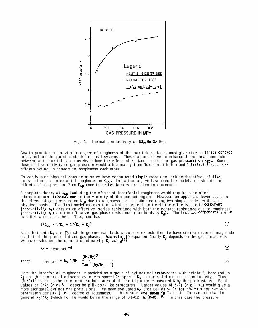
I T=1000K
Y I Legend P
1.5- HEMT 3-SIZE S P BED 3 z
0 MOORE ETC. 1982
I-siE sebed-hemt- -
0 .51 0 0
0 0.2 0.4 0.6 0.8 GAS PRESSURE IN MPo
Thermal conduct iv i ty o f U02/He Sp Bed. Fig. 1.
Now i n p rac t i ce an inev i tab le degree of roughness of the p a r t i c l e surfaces must give r i s e t o f i n i t e Contact areas and not the p o i n t contacts i n idea l systems. These factors serve t o enhance d i r e c t heat conduction between s o l i d p a r t i c l e and thereby reduce the ef fect of
e f f e c t s ac t ing i n concert t o complement each other.
To v e r i f y such physical considerat ion we have constructed s inp le models t o include the ef fect of f l ux cons t r i c t i on and i n t e r f a c i a l roughness on K, . e f f e c t s o f gas pressure P on Ksp once these ewo factors are taken i n t o account.
A conplete theory o f Ks inc lud ing the e f f e c t of i n t e r f a c i a l roughness would require a de ta i l ed microst ruc tura l informaeions i n the v i c i n i t y of the contact region. the ef fect o f gas pressure on K due t o roughness can be estimated using two simple models w i t h sound physical basis. The f i r s t modef assumes tha t w i t h i n a t yp i ca l u n i t c e l l the e f f e c t i v e s o l i d cowonent
p a r a l l e l w i th each other.
(and, hence, the gas pressure) on K . Such decreased s e n s i t i v i t y t o gas pressure would a r i se mainly P rom f l ux cons t r i c t i on and interfaciaTProughness
I n pa r t i cu la r , we have used the models t o estimate the
However, an upper and lower bound t o
acts as an e f fec t ive ser ies resistance w i th both the contact resistance due t o roughness and the e f fec t ive gas phase resistance (conduct iv i ty Q). The l a s t two cowonents are i n
Thus, one has
l/Ksp 1/Ks + 1/(Kc + Q) (1)
Note t h a t both K, and
We have estimated the contact conduct iv i ty Kc using
include geometrical factors but one expects them t o have s i m i l a r order of magnitude o equation 1 on ly Q depends on the gas pressure P.
Accordin?aF as tha t of the pure sol P d and gas phases.
Kc hcontact ~6 (2)
Here the i n t e r f a c i a l roughness i s modeled as a group of c y l i n d r i c a l protrusions w i th height 6, base radius R 1 and the centers o f adjacent cy l inders spaced R2 apart. K, i s the s o l i d component conduct iv i ty. Thus, (R /R2)2 measures the f rac t i ona l surface area of the s o l i d p a r t i c l e s covered 6 by the protrusions. Small values o f S/R (e.g.,<l) describe p i l l - b o x- l i k e structures. Larger values of 6/R1 (e.g., >1) would g ive a
pro t rus ion densi ty (i.e., degree of roughness). The resu l t s are shown i general Kc>>$ (which f o r He would be i n the range of 0.1-0.2 W/(H-K).(g! I n t h i s case the pressure
more elongate a c y l i n d r i c a l protrusions. We have evaluated Kc ( f o r Be) a t 5000K for S/R1=1,4 fo r Various Table 1. One can see tha t i n
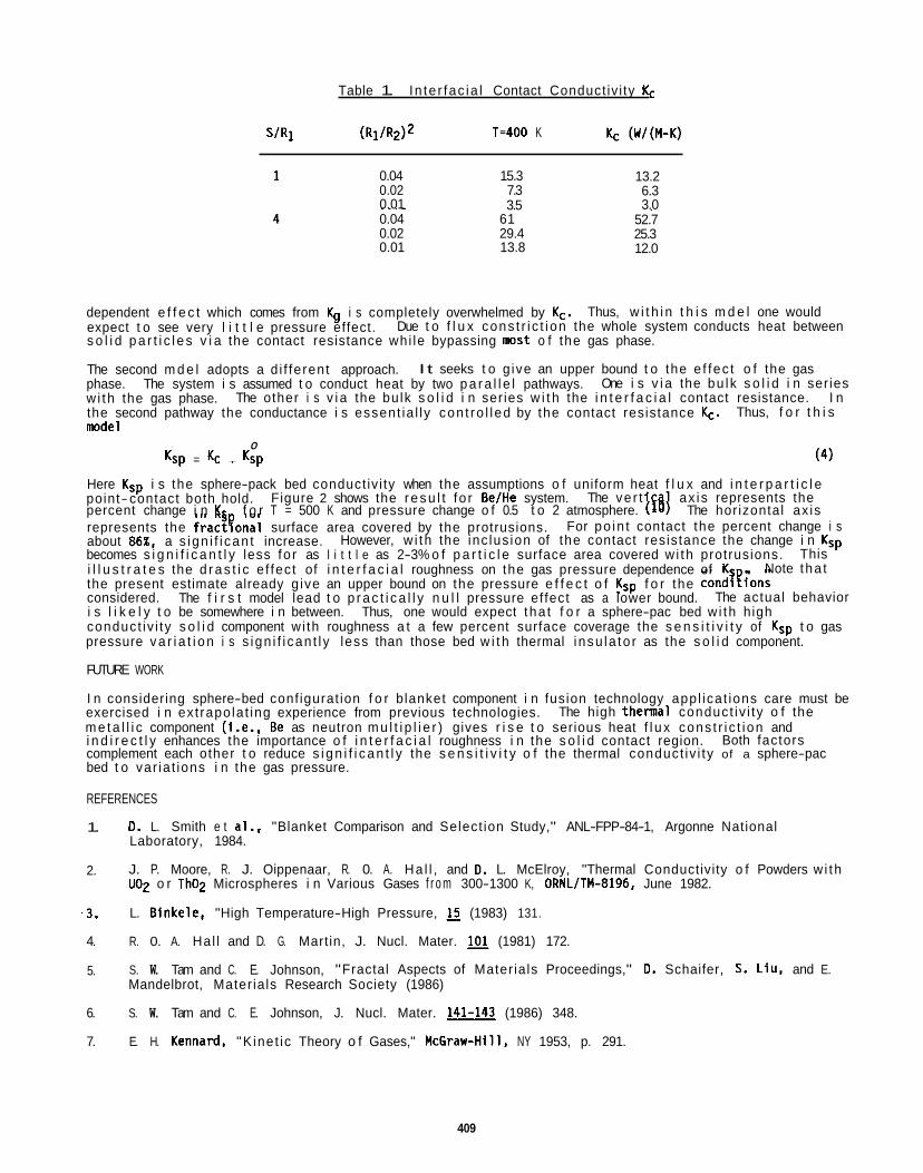
Table 1. In te r fac ia l Contact Conduct iv i ty Kc
S I R 1 T=400 K
0.04 0.02 0.01 0.04 0.02 0.01
15.3 7.3 3.5
61 29.4 13.8
13.2 6.3 3.0 ~.~
52.7 25.3 12.0
dependent e f f e c t which comes from Q i s completely overwhelmed by Kc. expect t o see very l i t t l e pressure effect. s o l i d p a r t i c l e s v i a the contact resistance whi le bypassing m s t o f the gas phase.
The second m d e l adopts a d i f fe rent approach. phase. w i th the gas phase. the second pathway the conductance i s essent ia l ly con t ro l l ed by the contact resistance Kc. m d e l
Thus, w i t h i n t h i s m d e l one would Due t o f l u x cons t r i c t i on the whole system conducts heat between
I t seeks t o g ive an upper bound t o the e f fec t o f the gas
The other i s v i a the bu lk s o l i d i n ser ies w i t h the i n t e r f a c i a l contact resistance. The system i s assumed t o conduct heat by two p a r a l l e l pathways. One i s v i a the bu lk s o l i d i n ser ies
I n Thus, f o r t h i s
(4) 0
Ksp = Kc + Ksp
Here Ksp i s the sphere-pack bed conduct iv i ty when the assumptions o f uniform heat f l u x and i n t e r p a r t i c l e point- contact both hold.
represents the fractyonal surface area covered by the protrusions. about 86%, a s ign i f i can t increase. becomes s i g n i f i c a n t l y less fo r as l i t t l e as 2-3% o f p a r t i c l e surface area covered w i th protrusions. i l l u s t r a t e s the d r a s t i c e f fec t of i n t e r f a c i a l roughness on the gas pressure dependence of KS . the present estimate already g ive an upper bound on the pressure e f f e c t o f Ksp f o r the condi l ions considered. i s l i k e l y t o be somewhere i n between. Thus, one would expect tha t f o r a sphere-pac bed w i th high conduct iv i ty s o l i d component w i th roughness a t a few percent surface coverage the s e n s i t i v i t y of Ksp t o gas pressure v a r i a t i o n i s s ign i f i can t l y less than those bed w i t h thermal i nsu la to r as the s o l i d component.
FUTURE WORK
I n considering sphere-bed conf igurat ion f o r b lanket component i n fusion technology app l ica t ions care must be exercised i n ex t rapo la t ing experience from previous technologies. m e t a l l i c component (i.e., Be as neutron m u l t i p l i e r ) gives r i s e t o serious heat f l u x cons t r i c t i on and i n d i r e c t l y enhances the importance o f i n t e r f a c i a l roughness i n the s o l i d contact region. complement each other t o reduce s i g n i f i c a n t l y the s e n s i t i v i t y o f the thermal conduct iv i ty of a sphere-pac bed t o var ia t ions i n the gas pressure.
REFERENCES
1.
Figure 2 shows the r e s u l t f o r BeIHe system. The ve r t ca ax i s represents the percent change i n K, f o r T = 500 K and pressure change o f 0.5 t o 2 atmosphere. l j 10 The hor izontal ax is
For po in t contact the percent change i s However, w i th the inc lus ion of the contact resistance the change i n Ksp
This Note tha t
The f i r s t model lead t o p r a c t i c a l l y n u l l pressure ef fect as a lower bound. The actual behavior
The high thema l conduct iv i ty o f the
Both factors
0. L. Smith e t al., "Blanket Comparison and Select ion Study," ANL-FPP-84-1, Argonne National Laboratory, 1984.
J. P. Moore, R. J. Oippenaar, R. 0. A. Ha l l , and D. L. McElroy, "Thermal Conductivity o f Powders w i th UO2 o r Tho2 Microspheres i n Various Gases f r o m 300-1300 K, ORNL/TM-8196, June 1982.
L. Binkele, "High Temperature-High Pressure, 15 (1983) 131.
2.
.3.
4. R. 0. A. Ha l l and D. G. Martin, J. Nucl. Mater. (1981) 172.
5. S. W. Tam and C. E. Johnson, "Fractal Aspects of Mater ia ls Proceedings," D. Schaifer, S. Liu. and E. Mandelbrot, Mater ia ls Research Society (1986)
6. S. W. Tam and C. E. Johnson, J. Nucl. Mater. 141-143 (1986) 348.
7. E. H. Kennard, "K inet ic Theory o f Gases," McGraw-Hill, NY 1953, p. 291.
409
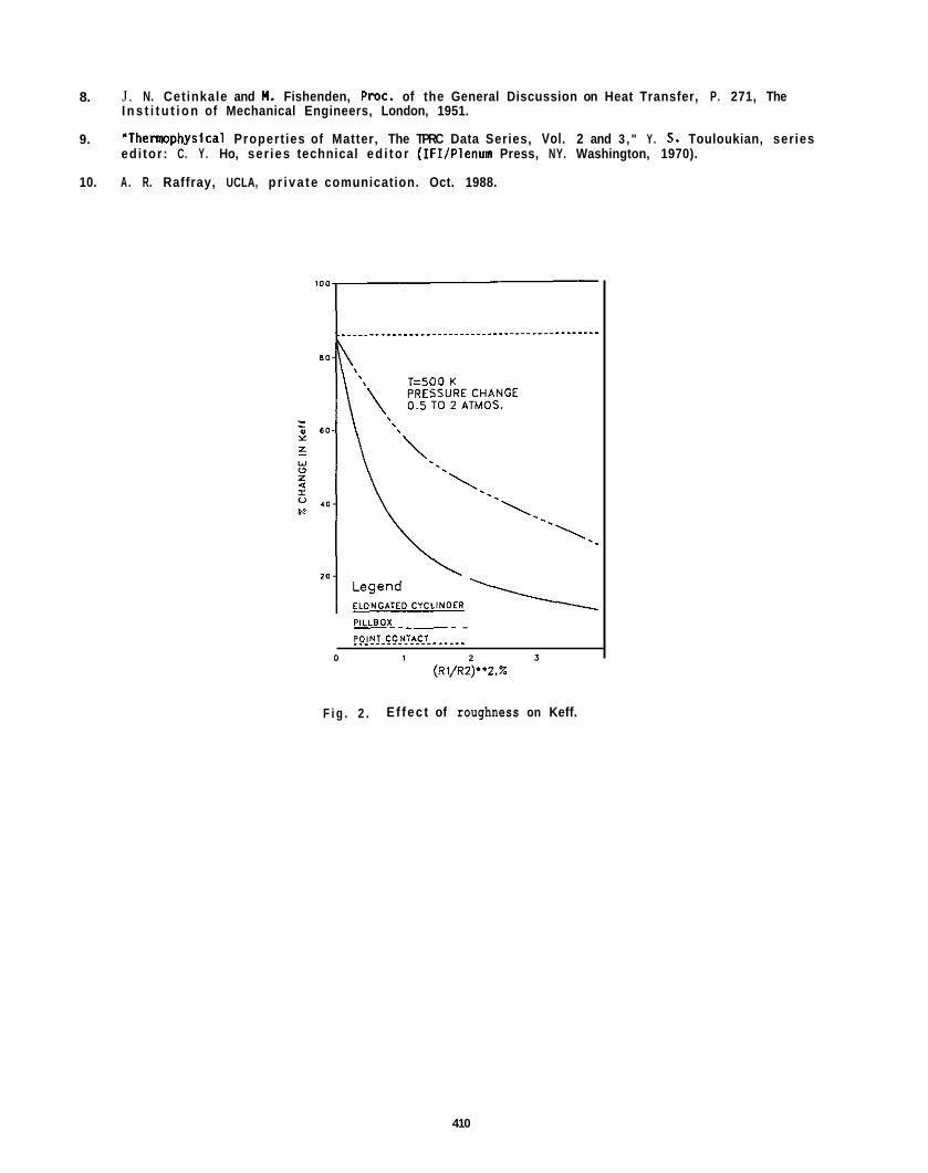
8. J. N. Cet inkale and M. Fishenden, Pmc. of the General Discussion on Heat Transfer, P. 271, The I n s t i t u t i o n of Mechanical Engineers, London, 1951.
"Themphysica l Propert ies of Matter, The TPRC Data Series, Vol. 2 and 3 , " Y. 5 . Touloukian, series edi tor : C. Y . Ho, ser ies technical ed i to r (IFI/Plenun Press, NY. Washington, 1970).
9.
10. A . R. Raffray, UCLA, p r i va te comunication. Oct. 1988.
PILLBOX- - - -. . !O!NI.FoN'nCr? ._...
0 1 2 3 (Rl/R2)**2.%
F i g . 2 . E f fec t of roughness on Keff.
410
T R I T I U M TRANSPORT MODELING - J. P. Kopasz and C. E. Johnson (Argonne National Laboratory)
OBJECTIVE
The ob jec t ive o f t h i s work i s t o develop a comprehensive model o f t r i t i u m t ranspor t i n a ceramic breeder blanket. i n blanket operat ing condit ions.
SUMMARY
The modeling e f f o r t f o r t h i s per iod was focused on the desorption process. o f a surface react ion and desorption of surface bound t r i t i u m i n the form o f HTO, T20, HT, o r T2. O f concern are the order of the surface react ion and the energetics o f the surface react ion and desorption step. t o the expected excess o f hydrogen i n the system. Equations f o r desorption which are second order i n t r i t i u m were derived for s i tuat ions where the hydrogen concentration on the breeder surface would be low and comparable t o the expected t r i t i u m concentration. Expressions f o r t r i t i u m inventory were derived and ca lcu la t ions were performed t o determine the g ra in radius regimes where desorption would be expected t o be the r a t e c o n t r o l l i n g release process. energetics change as a function of surface coverage. We be l ieve tha t t h i s i s due t o the presence o f m u l t i p l e s i t e s fo r desorption of t r i t i u m f r o m the ceramic. To support t h i s view we have analyzed constant r a t e heating t r i t i u m release experiments fmm the l i t e r a t u r e t o determine the number o f desorption s i t e s and t o obta in estimates o f the desorption ac t i va t i on energies. Estimates of ac t i va t i on energies for desorption o f t r i t i u m from L iz0 and Lids104 were obtained.
PROGRESS AND STATUS
The t r i t i u m transport modeling e f f o r t f o r the l a s t per iod has been focused on the t r i t i u m desorption process. surface bound molecule and desorption o f the surface bound molecule i n t o the gas phase. not handled separately due t o the d i f f i c u l t i e s i n separating the processes experimentally. Our current modeling e f for ts are re la ted t o (1)the k i n e t i c order of the surface react ions leading t o desorption under various condit ions, and (2) the energetics o f the surface react ions and the desorption step.
The react ions which we consider as l i k e l y candidates fo r those which lead t o desorption of t r i t i u m from the surface are:
The model w i l l enable one t o ca lcu la te the t rans ient t r i t i u m inventory i n the blanket f o r changes
The desorption process consists
I n most o f our previous work, desorption o f t r i t i u m was considered t o be f i r s t order i n t r i t i u m due
I n our previous work we have found evidence t h a t the desorption
The desorption process i s considered t o be the combination o f surface react ions leading t o a These processes are
Hsurf + OTsurf HTsurf Tsurf + Tsurf + Tzsurf
Of these, the react ions on the l e f t are f i r s t order i n t r i t i u m whi le those on the r i g h t are second order i n t r i t i u m . be l ieve that , due t o the presence of hydrogen and water i n the purge stream, the hydrogenic species on the surface w i l l be oresent a t a much hioher concentration than the t r i t i u m soecies a t the surface. We have now
Previously, our models were based on a desorption which was f i r s t order i n t r i t i u m since we
performed some ca lcu la t ions t o detenkne the release equations and inventory under condi t ions where release would be second order i n t r i t i u m or a combination o f f i r s t and second order.
Steady State T r i t i um Inventory
Case 1: Pure Desorption (instantaneous di f fusion)
A) F i r s t order desorption I=(4/3)ra3 Ga/(3K,jl)
B) Second order desorption hydrogen<<Tritium) I- (4/3)ra3 (Ga/ (3Q)) 1j2
C) mixed f i r s t and second order ( hydrogen t r i t i u m ) I= (4/3)ra3 [-C~+/-dsqrt (C$+4Ga/ (3~,4)) 1 /2 -. . .
l i m i t i n g cases o f t h i s are"
1) CH=o then 1=(4/3)ra3 (Ga/(3K,j))1/2
then 1=(4/3)ra3 Ga/(3K,j CH) 2) CH>)CT
t h i s i s the same as case B wi th K,jl=K,j CH
411
Case 2: Diffusion-desorption
A)psuedo-first order (C >>c ) I=(4/3)ra3GIa2/(15Dr+a/~3Q C H I }
I n order t o determine the phase space where d i f fus ion i s the dominant release mechanism, p l o t s of the f ract ion of the t o t a l inventory which i s due t o di f fusion versus the fac to r a /D were calculated. f i r s t order release, for values of a / O of less than 0.5, d i f f u s i on accounts Y o r less than 10% o f the
second order release, the t e aQ/O i s of l i t t l e value i n determining the ra te con t ro l l i ng mecha ism. One
than 0.5 d i f fus ion accounts for less than 10% of the inventory, while f o r values above 50 d i f fus lon accounts for over 90% o f the inventory.
I n most cases, we bel ieve the hydrogen surface concentration on the ceramic, (due t o hydrogenic i npu r i t i e s present as a r esu l t of ceramic fabr icat ion and f r o m adsorption o f hydrogenic impuri t ies o r added hydrogen f rom the purge gas), w i l l be much larger than the t r i t i u m surface concentration. This w i l l r esu l t i n psuedo-first-order k ine t i cs and t r i t i u m release w i l l be f i r s t order i n t r i t i um. This b e l i e f stems f rom the d i f f i c u l t i e s in.obtaining an ox id ic ceramic free of hydroxide impur i t ies and i n obtaining a purge f low wi th water contamination near the ppm range. Even f o r experiments employing u l t r a high pu r i t y helium as a purge gas desorption i s l i k e l y t o be f i r s t order i n t r i t i um . Commercially avai lable u l t r a high pu r i t y helium contains f r o m 1 t o 10 ppm of water. I n addit ion t o t h i s amount of water, i n the purge stream there w i l l be water present f r o m desorption of water adsorbed on the transport l ines. i n the ceramics as a resu l t of t h e i r preparation i n concentrations expected t o be around the order of 0.01 weight percent. One would expect the combination of these e f fec ts t o r esu l t i n concentrations o f hydrogen a t the surface greater than the t r i t i u m concentration.
We have also investigated the energetics of desorption f r o m ceramic breeder materials. determined t o be the ra te- l im i t ing process i n some t r i t i u m release experiments. Despite the importance o f t r i t i u m desorption i n determining the mer i ts o f candidate breeder materials, l i t t l e i s known about the t r i t i u m desorption process. desorption act ivat ion energy i n most cases. desorption, each wi th a corresponding act ivat ion energy.4-6
Evidence for Mu l t ip le Desorption Sites
For
inventory while f o r values o f aQ/D o 7 greater than 20 d i f fus ion accounts f o r 90% of the inventory. For
must use the value of (a3Q)72/D t o obtain the same type o f relat ionship. For values of ( a 3 ~ ) l 1 2 of less
F ina l ly , hydroxides w i l l be present
Desorption has been
Tr i t ium desorption has been treated as occurring from one s i t e wi th one Recent experiments suggest tha t there are several s i tes for
I n some o f the experiments on the adsorpt ion-solubi l i ty relat ionships for LiA102 performed by A. Fischer7, a f te r uptake of H20(g) was complete, the sample was heated t o a hlgher temperature i n a helium stream and the evolut ion of water vapor was recorded. observed t o go through several maxima. several types o f s i tes. adsorption processes w i th d i f f e ren t act ivat ion energies for adsorption.7 Fur themre , the heats of adsorption were found t o depend on the degree of surface coverage. Due t o the f ac t tha t the act ivat ion energy f o r desorption i s equal t o the sum o f the heat of adsorption and the act ivat ion energy of adsorption, the desorption ac t i va t ion energy w i l l exh ib i t the same trend as observed f o r the heat of adsorption. observed range o f values f o r the heat of adsorption indicates a range o f act ivat ion energies for desorption. Ea r l i e r work on alumina also indicated several types o f adsorption/desorption sites.8
Supporting evidence f o r mu l t ip le desorption s i tes on LiA102 was obtained i n the t r i t i u m release from the LILA-1 experiment. release followed by an increase t o a maximum then a decay t o steady state.9 Simi lar t r i t i u m release curves were observed for release from L iz0 i n the C R I T I C experiment.10 This type o f t r i t i u m release behavior could not be explained using a diffusion-desorption release model wi th one desorption act ivat ion energy, but could be modeled wi th a desorption ac t i va t ion energy which var ies wi th surface coverage.11
During the temperature ramp, the ra te of evolut ion of H20(g) was This was interpreted as showing that evolut ion proceeded f r o m
Isotherms and isobars derived f r o m Fischer's adsorption data revealed two
The
For several runs an increase i n temperature resul ted i n a small decrease i n t r i t i u m
A constant-rate heating experiment was performed by Tanifuj i e t a l . on i r rad ia ted L i 0.4 This experiment
and the quant i ty of desorbed species i s measured as a function o f temperature. a peak w i l l be observed i n a p l o t of the amount desorbed versus temperature.
i s , i n essence, a TPO study. I n TPO, a sample wi th adsorbed material on i t i s heate 5 a t a specif ied rate, For a constant heating rate,
The pos i t i on o f the peak i s
412
i n d i c a t i v e o f the desorption ac t i va t i on energy. The presence o f m r e than one peak ind icates m u l t i p l e desorption processes. Tan i fu j i e t a l . in terpre ted t h e i r resu l t s based on the presence of one broad desorption peak f o r each sample:4 however, if the data are examined more closely, one can recognize several overlapping peaks. An analysis o f these peaks indicates f i v e types o f s i t e s fo r desorption of t r i t i u m from Li20.
Supporting evidence fo r the presence of m u l t i p l e desorption s i t e s i n L iz0 was a lso observed i n the C R I T I C i n - p i l e t r i t i u m release experiment. sharp decrease i n t r i t i u m release fol lowed f i r s t by an increase t o maximum release and then decay t o steady state.10 This behavior was successfully modeled using a desorption ac t i va t i on energy which var ied w i th surface coverage: i t could not be modeled by a diffusion-desorption model w i th a s ing le desorption ac t i va t i on energy. 11
I n t h i s experiment, an increase i n sample temperature resu l ted i n a
Evidence fo r m u l t i p l e t y es of desorption s i t e s i n LiqSiO has been observed i n several out- of-pi le t r i t i u m release e x p e r i m e n t ~ . ~ t ~ * ~ The f i r s t suggestion of m u l t i p l e desorption s i t e types i n t h i s mater ia l came from attempts t o f i t t r i t i u m release data f r o m ou t - o f- p i l e annealing studies. Breitung e t a l . found tha t the best f it t o t h e i r data was obtained for a desorption node1 w i th two types o f desorption sites.3 More conclusive data have recent ly been reported. release f r o m TPD experiments ind icate mu l t i p le desorption ac t i va t i on energies.586 I n the f i r s t of these experiments, pre- i r rad ia ted samples of doped and undoped Li4SiO4 were heated a t a r a t e of 4.SoC/min, and the amount o f t r i t i u m released was measured as a funct ion of t e m p e r a t ~ r e . ~ Mu l t i p le desorption peaks were observed i n the TPD curve fo r a l l the samples, w i t h s i x desorption peaks present f o r the pure s i l i c a t e . The second study invest igated the desorption of water f r o m LiqSiO4.6 The TPD curve fo r water desorbed from LiqSiO4 powder stored i n a i r showed what appear t o be s i x overlapping peaks, i nd i ca t ing s i x types of desorption s i tes. desorption ac t i va t i on energies.
CALCULATIONS
The mathematics governing desorption i n TPD o r constant- rate heating experiments have been covered i n d e t a i l elsewhere12813 and are beyond the scope of t h i s report . A b r i e f descr ip t ion o f the relevant equations follows.
For f i r s t - o r d e r desorption i n t o a vacuum (or i n t o a r a p i d l y f lowing purge stream), the pressure of the desorbing s ecies i n the purge stream from one s i t e w i th desorption ac t i va t i on energy Ea can be calculated
Two separate studies descr ib ing t r i t i u m release and water
Both of these studies on LiqSi04 are consistent w i t h the presence of up t o s i x d i f fe rent
as fol lows 19 :
P = (u/C)exp{-up (Ea/R)I - Ea/RT)
where
I = exp(-e) [l - (211c ) + (3!/c*) - (41/c3) +...]/e2
and Y = desorption preexponential t e r m p = heat ing r a t e
C = the i n i t i a l concentration Ea = desorption ac t i va t i on energy
T = the temperature R = the gas constant
c = EaIRT
Second-order desorption gives the pressure as12
P = + & f a + 1 + up I Ea/R
(3)
The t o t a l release a t any t ime would be the sum of the release over a l l the ac t i ve desorption s i tes. Using these equations, one can ca lcu la te the t r i t i u m release p r o f i l e as a function o f tine o r temperature given the desorption ac t i va t i on energies, preexponential terms, and the heating rate.
Using the data f r o m constant- rate heating experiments, one can estimate the desorptlon ac t i va t i on energies f r o m the temperatures a t which the maxima i n p l o t s o f t r i t i u m release versus temperature occur. experiments where the flow ra te and heating r a t e are such tha t readsorption does not i n te r fe re , i f the desorption i s f i r s t order, then an estimate of the ac t i va t i on energy can be obtained by the following:13
For
Ea = RT[ln(u Tip) - 3.461 (4)
413
Using an estimate of 1 x l o 8 fo r the desorption preexponential, (a value i n agreement w i t h t r i t i u m release measurenents f r om L i 0 and k i n e t i c studies o f the decomposition of LiOT + LiOH14), we obtained estimates f o r
from LiqSi04 using Y = 1 x lo8 and the Skokan e t al.5 a n i Schauer and Schumacher data.6 These e s t i m t e s were then used as inpu t t o a program ca lcu la t i ng the t r i t i u m release as a funct ion of temperature using equation (1) o r (3). The i n i t i a l concentrations and ac t i va t i on energies fo r each s i t e were then var ied t o opt imize the f i t t o the data.
the a c t i v a t i o n energ f es of desorption o f t r i t i u m f r o m L i 0 f r o m the T a n i f u j i e t a l . data4 and f o r desorption
Estimates o f Act iva t ion Enemies of Desorption * Our analysis o f the data obtained by Tan i fu j i e t a l . f o r t h e i r constant heat ing r a t e experiment suggests t h a t there are s i x d i f f e ren t s i t e s f o r desorption of t r i t i u m from Li20. The estimates of the ac t i va t i on energies f r o m the f i r s t - o r d e r desorption equation are 140.6k0.4, 149.421.7, 162.821.7, 178.223.8 and 186.2t1.7 kJ/mol ( 33.620.1, 35.7+0.4, 38.920.4, 42.620.9 and 44.520.4 k c a l l m l ) . corresponding t o the highest ac t i va t i on energy, 186.2 kJImo1 (44.5 kcal lmol) , was o f low i n t e n s i t y and was not always seen. The r e l a t i v e populations o f the s i t e s responsible f o r the d i f fe rent desorption peaks were dependent on the h i s t o r y o f the sanple and the heating rate. For experinents w i th a heating ra te o f 1 Klmin the major desorption peak was due t o the process w i t h an ac t i va t i on energy of 149.4 k J / m l (35.7 kcal lmol) , wh i le the peak corresponding t o an ac t i va t i on energy o f 140.6 kJ1ml (33.6 kcallmol) was dominant when the heat ing r a t e was 10 Klmin. This suggests tha t there i s a r e d i s t r i b u t i o n i n the populat ion of the s i t e s as the sample i s heated. I n pa r t , a low heating r a t e al lows the mst ac t i ve s i t e s t o remain f i l l e d longer.
The t r i t i u m released f r o m L iz0 and co l l ec ted as HT was also determined as a funct ion o f temperature by Tan i fu j i e t al.4 These curves were analyzed using our model w i th m u l t i p l e desorption ac t i va t i on energies. Estimates of desorption a c t i v a t i o n energies of 139.7, 148.5, 159.4, 175.7, and 187 kJ/ml (33.4, 35.5, 38.1, 42.0, and 44.7 kcallmol) were obtained. These energies are i n good agreement w i t h those determined f r o m the curves of t o t a l t r i t i u m released. The amount of released t r i t i u m detected as HT was found t o be o f the order o f 1% o f the t o t a l t r i t i u m released.4 The agreement between the desorption ac t i va t i on energies f o r the t r i t i u m detected as HT and the t o t a l t r i t i u m released (detected as most ly HTO) suggests tha t t r i t i u m co l l ec ted as HT and tha t co l lec ted as HTO are released by the same mechanisms. Thus, the forin of t r i t i u m detected downstream i s probably not determined by the form i n which i t i s released f r o m the so l id , but by the gas phase chemistry.
I t i s of i n te res t t o compare our estimates of desorption ac t i va t i on energies w i th some reported i n the l i t e r a t u r e . The f i r s t i n the sequence o f desorption processes, w i th an estimated ac t i va t i on energy of 140.6 kJ1mol (33.6 kcallmol), i s expected t o be f o r desorption from a surface w i th a r e l a t i v e l y high surface coverage. This value i s i n ood agreement w i t h the desorption ac t i va t i on energy reported by Kudo and Okuno o f 129.7 kJ1mol (31 kcal Imolql4 and the ac t i va t i on energies reported by Quanci. ( f o r t r i t i u m release i n t o a helium purge stream containing 0.1 t o 1.0% added hydrogen), of 130.6 kJ/mol (31.2 kcal/mol).l5 The second energy (149.4 kJImol, 35.7 kcal lmol) i s expected t o correspond t o desorption f r om a s l i g h t l y more energet ic type of s ight . Desorption from t h i s s i t e would begin t o dominate when the populat ion o f a prev ious ly ac t i ve s i t e i s diminishing. This a c t i v a t i o n energy i s i n exce l lent agreement w i t h tha t reported by Quand ( f o r desorption i n t o a pure helium purge) o f 152.2 k J / m l (36.4 kcal/mol). l5 Bertone has reported lower ac t i va t i on energies than our estimates,(118.8 kj/ml, 28.4 k c a l / m l ) 2 as has Quanci (102.0 kJ/nnl, 24.4 k c a l l m l , f o r a purge gas of He +4.82% H2).15 There may be s i t e s fo r desorption f r o m Liz0 wi th even lower ac t i va t i on energies than those we estimated, but these are expected t o correspond t o samples w i t h a higher surface coverage than the samples studied by Tan i fu j i e t a l . As a possible l i m i t i n g case f o r h igh surface coverage, we note t h a t Kudo and Okuno reported the ac t i va t i on energy f o r thermal decomposition of LiOH as 123.4 kJ/mol (29.5 k c a l / m l ) . l 4 However, add i t iona l depression of the a c t i v a t i o n energy might r e s u l t from rad ia t i on e f f e c t s or react ion o f the surface w i t h H2 i n the purge.
The degree of surface coverage present a t any p a r t i c u l a r t i m e determines which ac t i va t i on energy w i l l cont ro l the desorption process a t t h a t tine. Unfortunately, we could not obta in estimates of surface coverage f r o m the T a n i f u j i e t a l . data so we can not determine what surface coverages our estimated ac t i va t i on energies r e l a t e to. gas, the resu l t s should be comparable w i th and relevant t o t r i t i u m release experiments t h a t were a lso performed w i t h pure helium purge streams. A de ta i l ed experimental study i s needed t o q u a n t i t a t i v e l y r e l a t e the hydrogen/tr i t ium surface coverage t o the desorption ac t i va t i on energies.
The desorption peak
Exanples o f the ca lcu la ted t r i t i u m release curves are i l l u s t r a t e d i n Fig. 1.
However, because these experiments were performed w i th pure helium purge
414
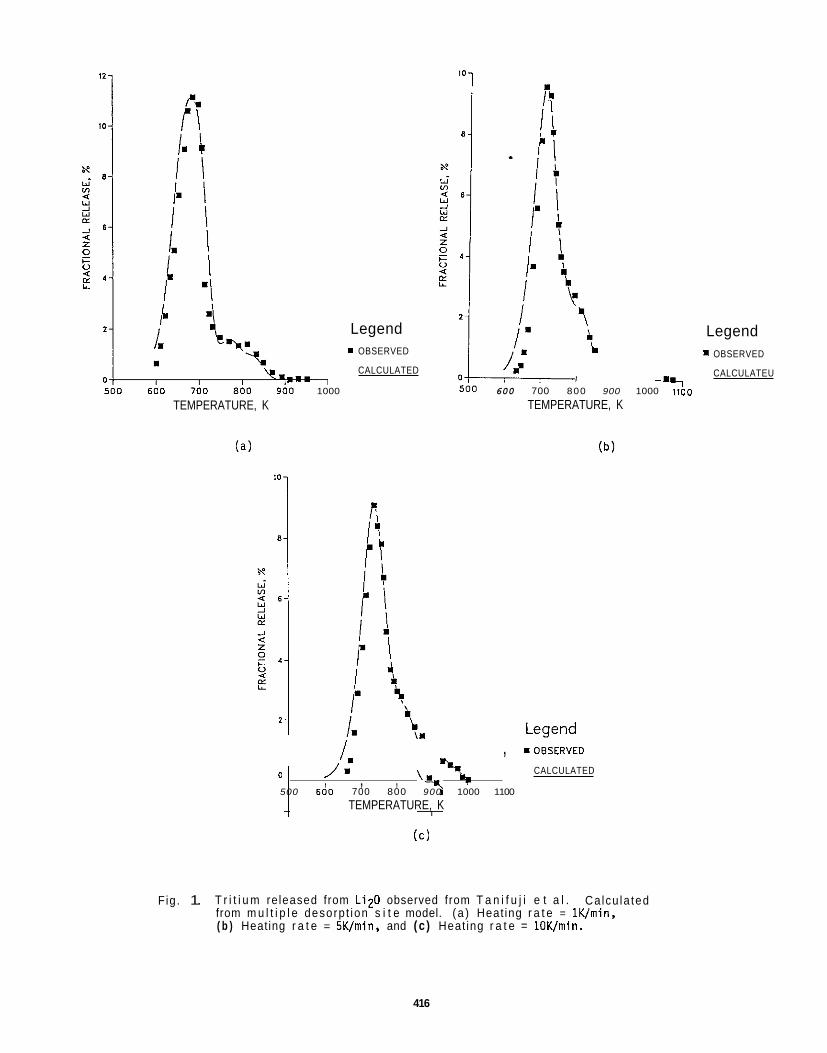
1 1000
Legend I OBSERVED
CALCULATED
TEMPERATURE, K
( a )
b ,
I 600 700 800 900 1000 1100
TEMPERATURE, K
1 , , , ': 500 600 700 800 900 1000 1100
TEMPERATURE, K
, I O B S E R V E D
%, CALCULATED 0 /. ( C )
Legend 1 OBSERVED
CALCULATEU
Fig. 1. T r i t i u m re leased from L i z 0 observed from T a n i f u j i e t a l . from m u l t i p l e desorp t ion s i t e model. ( a ) Heat ing r a t e = lK/min, ( b ) Heating r a t e = SK/min, and ( c ) Heat ing r a t e = 10K/min.
Ca lcu la ted
416
- _ LiqSiOq
We derived approximations f o r desorption ac t i va t i on energies for LiqSiO4 obtained f r o m the data of Skokan e t al.5 and Schauer and Schumacher6 using equation 4 and an estimated value o f the desorption preexponential t e r n of I x 108. Act ivat ion energies of 73.6, 96.7, 110.9, 143.1, 178.2, and 215.9 k J / m l (17.6, 23.1, 26.5, 34.2, 42.6, and 51.6 kcal/mol) were obtained f r o m Skokan e t a l . Values o f 83.3, 97.9, 112.1, 146.9, 171.1, 193.3 and 218.8 k J / m l (19.9, 23.4, 26.8, 35.1, 40.9, 46.2 and 52.3 kcal/mol) were obtained f r o m Schauer and Schumacher. The expected f i r s t - o rde r release was ca lcu la ted and compared t o the observed release of H 0 i n the Schauer and Schumacher experiment.6 The pos i t ions o f the ca lcu la ted peaks were found t o agree wel? w i t h the experimental data: however, the peak widths fo r the calculated curves were narrower than the observed peak widths. Calculations based on second-order desorption using a c t i v a t i o n energies of 83.3, 97.9, 112.1, 144.3, 171.5, and 194.1 kJ/mol (19.9,23.4,26.8,34.5 ,41.0, and 46.4 Kca l /m l ) provided a much b e t t e r f it t o the observed data. The agreement between the ac t i va t i on energies calculated f r o m the Skokan e t and Schauer and Schumacher6 data i s q u i t e good, with a maximum dev ia t ion o f less than 10 kJ/mol. One add i t iona l peak was observed i n the t r i t i u m release curve f r o m the Schauer paper. This peak may be masked by o ther m r e intense peaks i n the curves o f Skokan e t a l .
Our estimates o f these desorption ac t i va t i on energies can be conpared w i t h values ca lcu la ted by Breitung e t a l . f r o m a fit of LISA data t o a two-si te desorption m d e l of 53.6 and 90.9 k J / m l (12.8 and 21.7 kcal /ml) .3 The energy we calculated o f 97.9 k J / m l i s i n good agreement w i t h the second of t h e i r energies, suggesting t h a t we have made a reasonable choice fo r the preexponential term. Again, i t i s not possible t o determine the surface coverage from the data given i n the Schauer and Schumacher paper: thus, the surface coverages which correspond t o our estimates o f desorption ac t i va t i on energies are unknown.
Skokan et. a l . a lso studied the t r i t i u m release f r o m several doped samples o f Li4SiO4. showed d i f fe rent release character is t ics than the pure s i l i c a t e . L~4.05~~0.95A10.0504~ L i 3 . N 0. iS104. Lf3.9sio.gpo. 104, and Li3.3Po. 7Sfo. 304.
The mater ia l c reat ing L i vacancies by doping w i th aluminum, (Li3.7A10.1Si04), exh ib i ted b e t t e r t r i t i u m release than pure L i Si04.5 The TPO release curve showed a new desorption peak a t low temperature (near room temperature) a d the peak a t 73.6 k J / m l increased i n i n t e n s i t y r e l a t i v e t o t h a t f o r the pure s i l i c a t e whi le the peak a t 96.7 k J / m l i n the pure s i l i c a t e i s no longer observed. The o ther peaks appear t o be the same as for the pure s i l i c a t e . mechanism, improving the t r i t i u m release.
The mater ia l doped w i th P t o form Li3. S i 0 gPO.104 showed poorer t r i t i u m release than the pure Sl l iCate.5 The low temperature peak observed i n t%e A t doped L i de f i c ien t mater ia l i s a lso present f o r t h i s mater ia l : however, the peak a t 73.6 k J / m l i s decreased i n i n t e n s i t y r e l a t i v e t o the pure s i l i c a t e and the peaks a t 96.7 and 110.9 kJ/nwl are no longer v i s ib le . the pure s i l i c a t e and has a long t a i l t o the high energy s ide of the peak. The overa l l r e s u l t I S t o s h i f t the t r i t i u m release t o processes w i t h higher ac t i va t i on energies. Li3.3Po.7Si0.304 and Li4.05Sio g5A10.0504.5 For the P doped mater ia l three desorption peaks were observed a t 73.6, 110.9 and 143.1 k J / m i . t a i l . Again, the t r i t i u m release i s sh i f ted t o higher ac t i va t i on processes. mater ia l the peaks a t energies o f 73.6 and 96.7 kJ/mol are decreased i n i n t e n s i t y r e l a t i v e t o the pure s i l i c a t e whi le the peaks a t energies of 178.2 and 215.9 kJ/mol are increased i n i n tens i t y .
The ef fects of doping based on the most l i k e l y defects f o m d are as fol lows:
1)
2)
3)
These doped samples The mater ia ls studied had the compositions
The ove ra l l r e s u l t i s t o introduce a new low a c t i v a t i o n desorption
The peak a t 178.2 kJ/mol i s increased i n amplitude r e l a t i v e t o
A s i m i l a r e f f e c t was seen fo r
The peak a t 143.1 k J / m l was the mst intense peak and had a long t r a i l i n g For the aluminum doped
Creating a L i vacancy leads t o the a v a i l a b i l t y of a new low ac t i va t i on t r i t i u m desorpt ion process and improves t r i t i u m release.
Creating S i vacancies decreases the a v a i l a b i l t y of low ac t i va t i on desorption mechanisms and leads t o poorer t r i t i u m release.
Creating L i i n t e r s t i t i a l s decreases the a v a i l a b i l i t y o f low energy desorption mechanisms and leads t o poorer t r i t i u m release.
FUTURE WORK
The cur rent estimates o f desorption ac t i va t i on energies w i l l be used t o t r y t o ca lcu la te the observed t r i t i u m release f r o m i n - p i l e release experiments. Relationships between purge gas chemistry, Surface coverage, and desorption a c t i v a t i o n energies w i l l be derived f r o m laboratory experiments, i n - p i l e experiments, and modeling e f f o r t s .
REFERENCES
1) M. Briec, F. Botter, J. J. Abassin, R. Benoit, P. Chenebault, M. Masson, B. Rausner, P S d e r s , H. Werle. and E. Roth, " I n and Out-of-Pile T r i t i um Extract ion From Samples o f L i th ium Aluminates" J. Nucl. Mater. 141-143 (1986) 357-363.
416
2) P. C. Bertone, "The Kinet ics that Govern The Releaseof Tr i t ium f r o m Neutron- Irradiated Lithium Oxide," J. Nucl. Mater. 151 (1988)281-292.
7)
W. Breitung, H. Elbel, J. Lebkucher, 6. Schumacher, and H. Werle. "Out-of-pile Tr i t ium Extract ion From Lithium Si l icate, ' J. Nucl. Mater. 155-157 (1988) 507-512.
T. Tani fu j i , K. Noda, S. Nasu, and K. Uchida, "Tr i t ium Release f rom Neutron-Irradiated Li20: Constant Rate Heating Measurements," J. Nucl. Mater. 95 (1980) 108-118.
A. Skokan. D. Vollath, H. Wedemeyer. E. Gunther, H. Werle "Preparation, Phase Relationships and F i r s t I r r ad i a t i on Results o f Lithium Orthos i l icate Doped w i th Al3 ' and P5+ Ions," 15th Symp. on Fusion Technology, Utrecht, The Netherlands, Sept. 1988.
V. Schauer and 6. Schumacher, "Study of Adsorption and Desorption of Water on LiqSiOq." presented a t STNM-7, Chicago, IL, Sept. 1988 ( to be published i n J. o f Nucl. Mater.).
A. K. FIscher and C. E. Johnson, "Measurements of Adsorption i n the LiA102-HZO(g) System," Fusion Technology 15 (1989) 1212-1216.
J. 8. Peri,"A Model f o r the Surface o f 7-Alumina.' J. Phys. Chem. 69 (1965) 220.
M. Er iec and E. Roth, "Tr i t ium Extract ion Mchanisms from Lithium Aluminates During In- P i le I r r ad i a t i on Experiments," Proc. of Special ists ' Workshop on Modelling Tr i t ium Behavior i n Fusion Blanket Ceramics, Chalk River, Canada, pp 28-57 (1987).
J. M. M i l l e r , R. A. Verral l , 0. S . MacDonald, and S . R. Bokwa, "The C R I T I C I r r ad i a t i on o f Li2O-Tritium Release and Measurement," presented a t the Third Topical Meeting on Tr i t ium Technology i n Fission, Fusion and Isotopic Applications, Toronto, Canada, May 1988.
J . P. Kopasz, S. W. Tam, and R. A. Verral l , "Modeling Unusual Tr i t ium Release Behavior f r o m Li20," Fusion Technology 15 (1989) 1217-1222.
A. W. Smith andrS. Aranoff. "Thermdesorption o f Gases from Solids," 3. Phys. Chem. 62 (1958) 684-686.
0. A. King, "Thermal Desorption From Metal Surfaces: a Review," Surf. Sci. 47 (1975) 384-402.
14) H. Kudo and K. Okuno, ' "Kinetic Studies of the Tr i t ium Release Process i n Neutron-Irradiated L iz0 and LiOH," J. Nucl. Mater. 101 (1981) 38-43.
15) J. Quanci, "Tr i t ium Breeding and Release-Rate Kinet ics from Neutron- I r rad ia ted Lithium Oxide," Phd. Thesis, Dept. o f Chemical Engineering, Princeton University, January 1989.
417

ADSORPTION, DISSOLUTION, AND DESORPTION CHARACTERISTICS OF THE LiA102-H20(g) SYSTEM - A1 b e r t K. F i scher and Carl E. Johnson (Argonne National Laboratory)
OEJECTIVE
Adsorption of H20(g), d i sso lu t i on of OH-, and rates o f evo lu t ion o f H20(g) are being measured fo r the LiAlOz-HzO(g) system. t r i t i u m re ten t ion and release, and, hence, t o concerns about tritium inventory i n ceramic t r i t i u m breeder materials. The information w i l l enable (1) comparison o f candidate breeder mater ia ls, (2) ca l cu la t i on of operating condit ions, and (3) e luc idat ion of the p r inc ip les under ly ing the behavior of t r i t i u m i n breeder materials.
SUMMARY
Analysis of adsorption isotherms for the LiAlOZ-HZO(g) system has defined a range o f heats of adsorption f r o m 80 t o 360 k J / m l i n the region of 873 K; these heats are dependent on the f r a c t i o n o f surface coverage which ranges f r o m 0.1 t o 0.001, respect ively. Desorption ac t i va t i on energies fo l low these values c lose ly and are a lso dependent on coverage. Adsorption ac t i va t i on energies were estimated ( the values are small) and confirm the e a r l i e r repor t o f two d i f f e ren t l y ac t iva ted adsorption processes, depending on temperature. Modell ing t r i t i u m release f r o m i r r a d i a t i o n tes ts requires accurate values for desorption a c t i v a t i o n energies. Though such information can be derived from the adsorption isotherm measurements, a technique spec i f i ca l l y su i ted fo r desorption ac t i va t i on energy measurements i s avai lable: temperature programed desorption. Apparatus fo r such measurements has been constructed and the f i r s t measurements w i 11 continue w i th the LiA102-H20(g)-H2 system. The p a r t i c i p a t i o n of H2 i s important t o evaluate because i t has been found tha t H2 enhances t r i t i u m release i n i r r a d i a t i o n tests.
PROGRESS AND STATUS
Data Analysis
Further analysis o f the adsorption isotherms presented i n the l a s t repor t provided estimates o f the heats o f adsorption o f HZO(g) on LiA102 i n the region o f 873 K. two adsorption processes w i t h d i f f e r e n t ac t i va t i on energies operate i n t h i s system. 873 K range o f measurement, they cont r ibute together t o the adsorption process. range can one isotherm apparently be c l e a r l y i d e n t i f i e d w i th each process (the 573 and the 873 K isotherms). Consequently, ca l cu la t i on o f heats of adsorption by the Clausius-Clapeyron equation cannot be pursued r igorously. H20(g) as a funct ion o f temperature) suggest minimum values fo r the heat of adsorption i n the region o f 873 K. -2.5, and -3. general ly t rue, f o r the heat of adsorption t o increase as the surface coverage decreases.
Unfortunately, a s i m i l a r range of estimates i s not possible a t the lower temperature end of the range; measurements would be needed f o r temperatures below 573 K. h igh coverage a t 0 = 0.1, does suggest tha t the heat of adsorption i s about 40 kJ/mol f o r these condit ions.
For the condi t ions where heats o f adsorption may be estimated, values o f the ac t i va t i on energies of desorption may a l so be estimated. the sum o f the heat o f adsorption and the ac t i va t i on energy of adsorption. Because the ac t i va t i on energy of adsorption i s usua l ly small, even near ly zero, i t i s a useful approximation t o take the ac t i va t i on energy o f desorption as about equal t o the heat o f adsorption. a lso dependent on the degree o f surface coverage.
Though not designed as k i n e t i c experiments, the adsorption measurements were analyzed f u r t h e r t o ex t rac t information on the ra tes of adsorption. fo r a selected value of pH20(g) of 15 Pa. slopes a l low an estimate t o be made of the ac t i va t i on energy o f adsorption. deduction tha t two d i f f e ren t adsorption processes w i th d i f fe rent adsorption ac t i va t i on energies are involved i n d i f f e ren t temperature ranges, these curves suggest a 3 k J / m l adsorption ac t i va t i on energy i n the 573 t o 623 K range and a 15 k J / m l adsorption ac t i va t i on energy i n the 673 t o 773 K range. adsorption process i s probably d issoc ia t ive chemisorption and the low temperature process i s perhaps low a c t i v a t i o n energy chemisorption o r unimolecular physisorption. This f i gu re a lso i l l u s t r a t e s the p o s s i b i l i t y t h a t observed net ra tes of adsorption decrease w i th increasing temperature when d i f f e r e n t processes coexist which have d i f f e r e n t ac t i va t i on energies and d i f fe rent dependencies on coverage.
The coverage-dependent values of the desorption ac t i va t i on energy ind icated i n t h i s work are the r e s u l t of surface heterogeneity i n respect t o chemical d i f ferences between adsorption s i tes , c rys ta l lograph ic differences f o r exposed c rys ta l planes, and defects on the surface. Mu l t i p le types o f s i t e s are involved i n
These themdynamic and k i n e t i c data f o r these processes r e l a t e t o the issues of
As discussed i n tha t report , the data ind icate tha t I n most o f the 573 t o
Only a t the ends o f t h i s
However, the shapes o f the isosteres (plots, a t constant coverage, of the p a r t i a l pressure o f
The values are 80, 150, 220, 290, and 360 k J / m l , respect ively, f o r values of log(0) o f -1. -1.5, -2, The values fol low the trend, tha t i s (0 i s the f r a c t i o n of surface covered by adsorbate.)
However, one isostere, the one f o r r e l a t i v e l y
This i s possible because the ac t i va t i on energy of desorption i s equal t o
I t fol lows tha t the desorption ac t i va t i on energy i s
Figure 1 shows the r a t e o f adsorption as a funct ion of temperature I n the regions where t h i s r a t e increases w i th temperature, the
Confirming the e a r l i e r
The high temperature
419
19.0 r
17~0
C .- E
a j c m 13.0 I I
c 0 ._ c p 11 0 0 v)
2 9 0 0 I"
7.0
5.0
Ea= 3 kJ/mol I
I I I
) 350 450 550
Temperature, C IO
Fig. 1. Rates o f adsorption of H20(g) a t a p a r t i a l pressure o f 15 Pa on LiA102.
adsorption and desorption. (desorption) o f H20(g) from LiA102 obtained f r o m a rough temperature programed (TPD) experiment (see below fo r f u r t h e r discussion). l same complexity. alumina, characterized i n terms of the number of 02 nearest ne i hbors, showed f i v e types t o be present.
The above mater ia l i s p a r t o f a paper f o r the Apr i l meeting o f the American Ceramic Society, under the t i t l e , '"Oesorption Ac t i va t i on Energies f o r T r i t i um Release from Ceramic Breeders," by J. P. Kopasz, A. K. Fischer, and C. E. Johnson.
Imp1 ementation o f Temperature Proqramned Desorption Measurements
Recent work on modell ing t r i t i u m release observations from i r r a d i a t i o n tes ts has emphasized the need f o r data on surface proper t ies t o analyze dynamic inventory; f o r t h i s the ac t i va t i on energies o f desorption are o f primary importance. These ac t i va t i on energies can be supplied d l r e c t l y by the temperature programned desorption (TPD) technique which i s now being imlemented. adsorption, though not as w e l l as the f ronta l analysis technique tha t was used fo r the adsorption isotherms discussed above.
I n essence, the TPD technique consists of measuring the r a t e o f desorption o f a given species (i.e., i n the form o f the evolved species, not necessar i ly the surface species) i n t o a sweep gas dur ing an upward r a w of the sample temperature. The evo lu t ion r a t e goes through a maximum, g i v i n g a peak i n the curve. A number of theoret ica l treatments f o r analyzing the data e x i s t and requ i re e i t h e r s ing le o r mu l t i p le TPD curves, a t f l x e d o r var iab le i n i t i a l coverages, and fo r s ing le o r m u l t i p l e heat ing rates. Depending on treatment, the various outputs provide values fo r various combinations o f the preexponential factor, the ac t i va t i on energy fo r desorption, and the order of the evo lu t ion reaction.
This i s consistent w i th our own e a r l i e r evidence f o r s i t e dependent evo lu t ion
It i s also consistent w i th other reports on o ther mater ia ls tha t revealed the For example, a theoret ica l analysis of the types o f OH- s i t e s possible on the surface o f
These were re la ted t o experimentally measured in f ra red spectra. 9
TPD can a lso g ive informat ion on quan t i t i es o f
TPD and f ronta l analysis are complementary approaches t o studying surface processes.
A schematic diagram o f the TPD apparatus tha t has been constructed i s shown i n Fig. 2. The valves F, K, and 1 are high tenperature gas chromatographic switching valves so t h a t a l l gas t r a i n s car ry ing H20(g) can be maintained a t 473 K t o e l iminate holdup of t h i s species. Not shown i s a quadrupole mass spectrometer tha t samples e f f l u e n t gas between valves K and L. This instrument i s an important feature because data are needed not only fo r H20(g) evo lu t ion but a lso f o r H2(g) adsorption and evolution. This i s because i t has been found t h a t H i n the purge stream of i r r a d i a t i o n tes ts f a c i l i t a t e s release o f t r i t i u m . t h a t adsorbed H2 h o c k s energetic s i t e s t h a t would otherwise r e t a i n OH- and impede evolut ion o f H20(g). Data are needed f o r a quan t i t a t i ve evaluat ion o f t h i s process.
FUTURE WORK
Following proof- test ing and c a l i b r a t i o n of the TPD apparatus, measurements w i l l be made t o obtain ac t i va t i on energies for desorption of HZO(g)HZ(g) from LiA102. Substrates t o be studied a f t e r tha t include Li4SiO4, LizO, and Li2ZrO3.
REFERENCES
1.
I t i s bel ieved
A. K. Fischer and C. E. Johnson, "Adsorption, Dissolut ion, and Desorption Character ist ics o f the LiA102-H20 System," OOE/ER--0313/1. Fusion Reactor Mater ia ls Semiannual Progress Report f o r Period Ending September 30, 1986, p. 362.
J . B. Peri, 'A Model f o r the Surface o f 7-Alumina," J. Phys. Chem., 69 (1965) 220. 2.
Fig. 2. Schematic diagram for temperature programed desorption measurements.

8. C E R A M I C S
No c o n t r i b u t i o n s .

DOE/ER4313/8 Distribution
UC-423, 424 categories
DISTRIBUTION
1 - 18. Argonne National Laboratory. 9700 South Cass Avenue, Argonne, IL 80439 M. C. Billone 0. K. Chopra R. G. Clemmer D. R. Dercks P. A. Finn A. K. Fischer L. R. Greenwood C. E. Johnson H. Wedersich
Argonne National Laboratwy, EBR-II Division. Reactor Materials Section. P.O. Box 2528, Idaho
Y. Y. Liu E. A. Loomis R. F. Mattas L. A. N m r k D. L. Smi i S. W. Tam E. R. Van Deventer
17. Falls. ID 83403-2628
D. L. Porter
18. Arizona State University. Department of Mechanical and Aerospace Engineering, Tempe, A2 85281
19. Auburn University. Department of Mechanical Engineering, Auburn, AL 38849
20-34. BattalkPacific Northwest Laboratory, P.O. Box 999, Richland, WA 99352
W. A. Ccghlan
8. A. Chin
M. D. Freshley F. A. Garner (5) D. S. Galles M. L. Hamilton H. L. Heinisch G. W. Hdlenberg
R. H. Jones J. M. McCarthy 8. D. Shipp 0. D. Sagla J. L. Straalsund
35-38. Carnegie Institute of Techndogy. Carnegie-Mellon University, Schenley Park, Pmburgh. PA 15213
37. Department of Energy, Richland Operations office. Federal Building, MS A590. Richland, WA 99352
Department of Materials Science. University of Tokyo. 3-1, Hongo 7Chome BunkyoXu
W. M. Garrison, Jr. J. C. Williams
Paul Pak
38. Tokyo 1 13, Japan
Professor Akira Kohyama
39. Department of Nuclear Engineering, Nagoya University. Furo-Cho, ChikuskKu, Nagoya 484-01, Japan Professor Miihio Kiritani
40. Department of Nuclear Engineering. Tohoku University. Aoba, Aramaki, Sendai 980. Japan
41-42. Department of Nuclear Engineering. University of Tokyo. 3-1, Hongo 7Chome. BunkyoXu
Professor Katsunori Abe
Tokyo 1 13, Japan Professor Shiori lshino (21
D. F. Hdland 43. EG&G Idaho. Inc.. Fusion Safety Program. P.O. Box 1825, Idaho Falls. ID 834153623
Faculty of Engineering. Hokkai i University, Kita 13, Nishi 8, Kita-Ku, Sapporo 080. Japan 44. Professor Heishichiro Takahashi
45-47.
48.
49.
50.
51.
52.
53-54.
55-57.
58-66.
87.
68.
89.
70-71.
72-73.
74.
75-78.
77.
78-79.
80.
General Atomics, P.O. Box 85608, San Diego, CA 92138 J. Baur D. I. Roberts T. A. Lechtenberg
General Dynamics Corporation, 6001 Keamy Villa Road, San Diego. CA 92138 T. L. Cookson
Gewgia Institute of Technology, School of Textile Engineering, Atlanta, GA 30332
Grumman Aerospace Corporation, c/o TFT!4 Project. Princeton Plasma Physics Laboratory. Princeton
D. S. Tucker
University, A. Site, Building 1-E, Princeton, NJ 08540 R. G. Micich
Institute for Materials Research, Tohoku University, Katahira 2-1-1. Sendai 980. Japan Prof- Hideki Matsui
Institute for Materials Research, Oarai Branch, Tohoku University, Oarai, Hgashi-lbarakffiun, Ibaraki-Ken 31 1-13, Japan
Professor Hideo Kayano
Institute of Plasma Physics, Nagoya University, FuroCho, ChikusaXu, Nagoya 484-01, Japan Professor Akira Miyahara
E.N.C. Dalder J. Perkins M. Guinan
Dr. Chusei Namba
Lawrence Livermore National Laboratory, P.O. Box 808. Livermore, CA 94550
Lcm Alamos National Laboratory, P.O. Box 1663, Los Alamos, NM 87545 J. L. Andersen G. Hurley L. D. Caudill C. D. Kise D. J. Dudziak R. Liepens H. M. Frost T. Zocco F. W. Clinard
Manlabs, I'Ic., 231 Erie Street, Cambridge, MA 02139 D. Tognarelli
Massachusetts Institute of Technology, Department of Metallurgy and Materials Science. Cambridge. MA 02139
L. W. Hobbs
Massachusetts Institute of Technology, 138 Albany Street, Cambridge, MA 02139 0. K. Harling
Massachusetts Institute of Technology, 77 Massachusetts Avenue, Cambridge, MA 02139 I-Wei Chen N. J. Grant
Massachusetts Institute of Technology. Plasma Fusion Center Headquarters, Cambridge, MA 02139 H. D. Becker D. E. Montgomery
McDonnell-Douglas Astronautics Company, East, P.O. Box 518, Bldg. 92, St. Louis. MO 83186 J. W. Davis
National Institute of Standards and Techndogy. Boulder, CO 80302 F. R. Fickett M. E. Kasen
National Materials Advisow Board, 2101 Constitution Avenue, Washington, DC 20418 K. M. Zwilsky
National Research Institute for Metals. Tsukuba Branch, Sengen. Tsukuba-Shi, Ibaraki-Ken 305, Japan
Dr. Masatoshi Okada Dr. Haruki Shiraishi
Naval Research Laboratory, Washington, DC 20375 J. A. Sprague
426
81 - 118. Oak Riie National Laboratory, P.O. Box 2008, Oak R i i , TN 37831 Central Research Library Ea1 Lee Document Reference Section A. W. Longest Laboratory Records Department (2) L. K. Mansur Laboratory Records-RC P. J. Meziasz Patent Section T. K. Roche D. J. A!-axe.nder C. W. Baker J. ShMieId J. Bentley T. Sawai E. E. Bloom R. L. Senn D. N. Braski R. E. Stdler T. D. Burchell K. R. Thorns M. L. Grossbeck P. F. Twtorelli T. lnazumi F. W. Wffen R. L. Klueh S. J. Zinkle
A. F. R o w d i (10)
119-120. Princeton Pbsma Physics Laboratory, Princeton University, P.O. Box 451, Princeton, NJ 08540 H. Furth W P o e Ku
Research Institute for Applied Mechanics, Kyushu University, 6-1, Kasuga-Koen, Kasuga-Shi, 121. Fuku-Ken 816, Japan
Professor Take0 Muroga
122. Rensseber Polytechnic Institute, Troy, NY 12181
123. Rc&well International Corporation, NA02. Rocketdyne Division, 6633 Canoga Avenue, Canoga Park,
D. Steiner
CA 91304 D. W. Kneff
124-125. Sandia National Laboratories, P.O. Box 5800. Albuquerque, NM 87185 M. J. Davis W. B. Gauster
126-127. Sandiia National Laboratories, Livermore Division 8316, Livermore, CA 94550 W. Bauer W. G. Wder
128. San D i o State Univ., Mechanical Engineering Dept., San D i o , CA 921824191 L. D. Thompson
129- 132. Tokai Research Establishment, Japan Atomic Energy Research Institute, Tokaiura. Naka-gun, ibaraki-Ken 319-1 1, Japan
Dr. Tetsuo Kondo h. Akimichi Hishinuma (3)
133- 134. University of California, Department of Chemical and Nuclear Engineering, Santa Barbera, CA 93106
G. E. Lucas G. R. Odette
University of California, Department of Chemical, Nuclear and Thermal Engineering, Loa 135- 137. Angeles, CA 90024
M. A. Abdou R. W. Conn
N. M. G M i
138. University of California. Los Alamos National Laboretow, P.O. Box 1663, Loa Alamos, NM 87545 T. Zocco
139. University of Michigan, Department of Nuclear Engineering, Ann Arbor, MI 48109 T. Kammash
140. University of Missouri, Department of Nuclear Engineering, Rolla, MO 65401 A. Kumar
427
141. University of Wtsconsin, Nuclear Engineering Dapt.. 1600 Johnson Drive, Madison. WI 53706 G. L. Kulcinski
142- 147. Westinghouse Hanford Company, P.O. Box 1970, Rihland, WA 99352 H. R. Brager A. M. Ermi G. D. Johnson
F. M. Mann R. J. Puigh R. L. S m m
148. Department of Energy, Oak R i e Operations Office, P.O. Box 2001. Oak R i , TN 37831 Assistant Manager for Energy Research and Development
149-152. Department of Energy. Office of Fusion Energy. Washington. DC 20545 S. E. Berk M. M. Cohen A. Davies T. C. Reufher
Depanment of Energy, Office of Scientific and Technical Information, Office of lnfwmation
For distribution as shown in WE/TIC4500, Distribution Categories UC423 (Magnetic Fusion Reactor Materials) and UC424 (Magnetic Fusion Energy Systems)
153-202. Services, P.O. Box 62. Oak Ridge, TN 37831
Related Documents