Some Preliminaries for Structural Sizing Before we can start designing the fuselage, it is beneficial to know how it is likely to fail. The likely mode of failure is buckling as can be seen in the figures below and on the following page. Shown in the figures below is an idealization of the frame and skin- stringer combination. The frames act as springs to resist the displacement of the skin- stringer combination. In the case were the frames or ribs are themselves not stiff enough, the structure buckles in a global sense much like a long rod. If the frames or ribs are stiff enough, a node is enforced and a local type of buckling occurs. Theoretically, the minimum weight is achieved when both modes are likely to occur simultaneously. In practice, structures are designed so that the local buckling occurs first. The general type of failure is considered to be unacceptable for aerospace structures.

Welcome message from author
This document is posted to help you gain knowledge. Please leave a comment to let me know what you think about it! Share it to your friends and learn new things together.
Transcript
Some Preliminaries for Structural Sizing
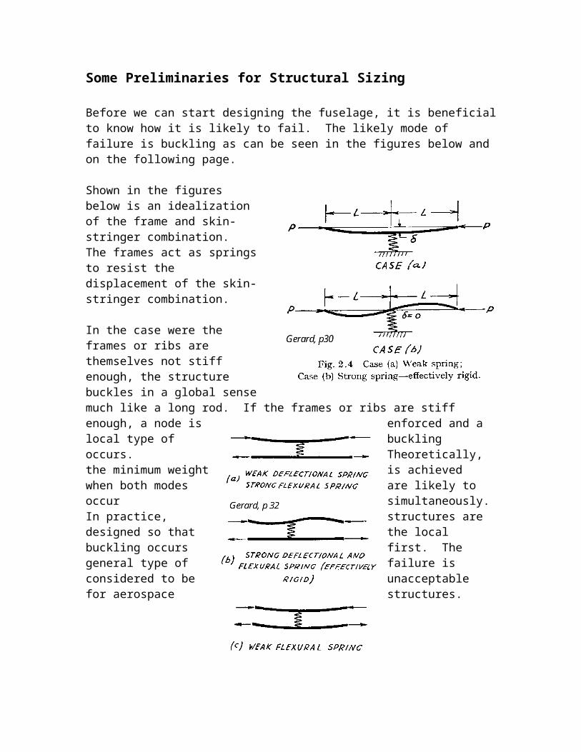
Before we can start designing the fuselage, it is beneficialto know how it is likely to fail. The likely mode of failure is buckling as can be seen in the figures below and on the following page.
Shown in the figuresbelow is an idealizationof the frame and skin-stringer combination.The frames act as springsto resist thedisplacement of the skin-stringer combination.
In the case were theframes or ribs arethemselves not stiffenough, the structurebuckles in a global sensemuch like a long rod. If the frames or ribs are stiff enough, a node is enforced and a local type of buckling occurs. Theoretically, the minimum weight is achieved when both modes are likely to occur simultaneously.In practice, structures are designed so that the local buckling occurs first. The general type of failure is considered to be unacceptable for aerospace structures.


Our job as structural designers is to prevent the skin-stringer combination from buckling and to make the frames stiff enough to prevent the global type of failure. It should be noted that there is nothing to gain by making the structure any more stiff than it needs to be.
Frames
The primary purpose of frames is to provide end restraints for the skin panels and to resist out of plane deflections when the skins “try” to buckle. The primary factor in buckling and resisting deflections in general is the stiffness, EI. The goal of frame or rib design is to selecta stiffness, that is a material and cross sectional area, and spacing to make the local buckling of the skins as likely as the global buckling of the entire structure (largespacing and low stiffness).
Shanley has shown that a proper model for this type of behavior is
(Insert Figure here)
When the panel buckles, it does so as if were hinged at the buckling point. The required spring constant to prevent buckling is
An applied bending moment causes the highest stresses at thetop and bottom of the structure and zero stress at the neutral axis. Therefore only a small portion of the structure supports the bending load. So if we assume that the load is applied over the top and bottom fraction of the structure, the fraction represented by c2, we can find an equivalent load by using the definition of torque or moment.
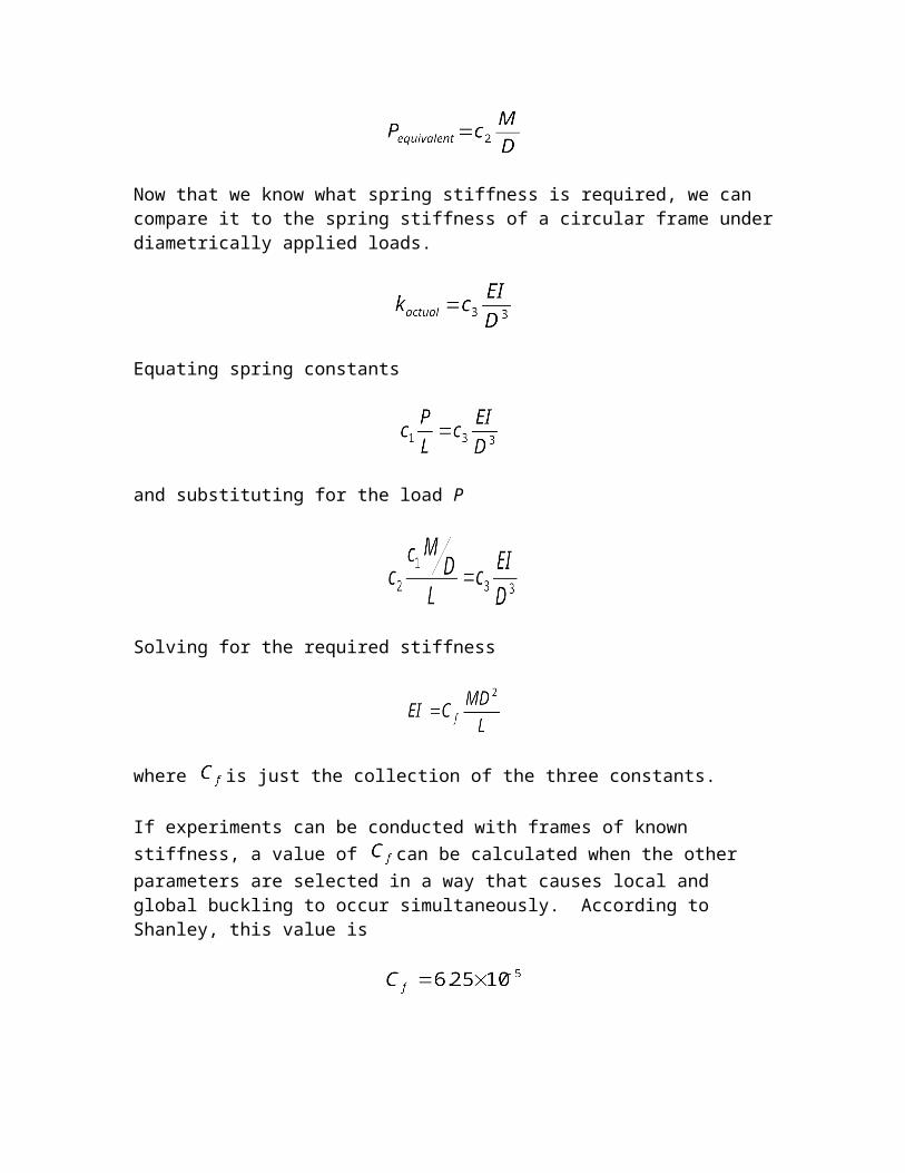
Now that we know what spring stiffness is required, we can compare it to the spring stiffness of a circular frame underdiametrically applied loads.
Equating spring constants
and substituting for the load P
Solving for the required stiffness
where is just the collection of the three constants.
If experiments can be conducted with frames of known stiffness, a value of can be calculated when the other parameters are selected in a way that causes local and global buckling to occur simultaneously. According to Shanley, this value is

Gerard in doing a similar calculation showed .The higher the value of this parameter, the more likely local buckling is to occur.
Recall which cross sectional area is used in the definition of the moment of inertia I of the frame. Because I containsgeometric information, we can use it to determine an area. This area swept around the circumference gives a volume.
If it is assumed that the frame cross section is rectangular(remember in conceptual design we aren’t too concerned with the actual shape), then
By definition,
where is the radius of gyration. If a typical value is known, then it is easy to find the frame area.
However, Shanley has shown that another parameter better captures the efficiency of the frame in bending.
For a rectangular cross section,
The height-to-width ratio can be thought of as an aspect ratio. For one of Shanley’s examples, the value of k was about 5. This gives

For a frame designed under optimal conditions, i.e. no cutouts, no point loads, this sounds about right.
Panels
Panels usually refer to a composite structure consisting of both skins and stiffeners (stringers). Sketches of panels were shown in the first couple of pages of this section. When it comes to sizing the skin and stringers, Bruhn in Analysis and Design of Missile Structures and Shanley both state or imply that it is difficult to treat the problem as two smaller problems: one for the skin and one for the stringers. Instead, their combination is studied.
Panels can be constructed from many types of materials and stringer cross sections. The choice of material is primarily based on cost or material properties depending on the types of loads the structure will see. The choice of stringer cross section is more of an art, but some statements can be made. There are several primary families of cross sections: Z, Hat, J, and Y.
Hat stringers are easy to construct, but when attached to the skin, they create a closed pocket of air that can hide corrosion. This can be overcome by using the hat stringers as fuel vents in wing structures.
Z stringers are also easily constructed, but have an offset shear center. When deflected, they also twist.
J stringers can be hard to form, but are useful for joining 2 panels together.

Y stringers were studied long ago by NACA. Although hard to form, NACA found that the Y stringer was the best of all of the stiffeners.
As I was implying, some stringers are better than others. This quality can be described by a panel efficiency factor that only depends on the type of stiffener used and not size. From experimental data in Gerard, the following efficiencies were obtained.
Type
Z 1.02Hat 0.985Y 1.15
The panel efficiency factor is used in many calculations such as finding the required effective skin thickness.
Another approach to the panel problem is given in Shanley. If various stringers, panel lengths, and materials are tested to failure, a plot of allowable stress vs. load per unit width per panel length is obtained and can be seen below. This q, also called the loading parameter, is simply the load divided by the dimension over which it is applied.
L q = P / width
t
P P

As can be seen, the shorter the panel length the higher the allowable stress. The reason why the panel does not developits full compressive yield stress before failure is that it buckles. This explains why shorter panels (closely spaced stiffeners) can develop higher stresses. The 75S-T materialdevelops much higher stresses and therefore lower weight, but that has to be weighed against other factors such as cost and fatigue properties. The dashed line represents theupper limit for 24S-T material.
An interesting twist that will be useful for sizing is by rearranging the data in the plot from Shanley. If the calculated value for allowable stress f is divided by the
corresponding value of , the average required thickness
per frame spacing is obtained.

This result is obtained from the definition of stress and the fact that the cross sectional area is for the stress is
, where w is the panel width.
When plotted for the 24S-T material this gives
References
1. Gerard, George. Minimum Weight Analysis of Compression Structures. 1956. Chapters 2, 3, and 7.
2. Gordon, J.E. Structures, or Why Things Don’t Fall Down. 1978. Chapters 13 and 14.
3. Shanley, F.R. Weight-Strength Analysis of Aircraft Structures. 1960. Chapters 2, 3, 4, and 15.
4. Bruhn, Elmer. Analysis and Design of Missile Structures.
Related Documents