International Journal of Electronics Communications and Electrical Engineering ISSN : 2277-7040 Volume 3 Issue 5 (May 2013) http://www.ijecee.com/ https://sites.google.com/site/ijeceejournal/ 54 Full Scale Converter Fed Induction Generator Based Wind Energy Conversion System Using Indirect Vector Control Strategy Umashankar S, Ambili Mathew, Kothari D P, Vijayalumar D School of Electrical Engineering, VIT University, Vellore - 632014, TamilNadu, India. Abstract:This paper presents the indirect vector control for induction generator driven by a variable speed wind turbine. In wind power induction generator as the input wind is not constant and is not controllable, the induction generator should be provided with specific control strategies so that the dc link voltage is maintained constant irrespective of the variation in wind speed. In this vector control method, direct axis current component is controlled by controlling flux and quadrature axis current component is controlled by controlling torque. A PI- controller is used to process the error values i.e. the difference between the reference values and the measured values. These direct and quadrature axis components of current are converted to three phase quantities with help of unit vector. This reference three phase currents is given to pwm converter which will produce the pulses. In this way, the dc bus voltage is maintained constant irrespective of variation in the wind speed. The proposed system is simulated using MATLAB/Simulink software. Keywords: cage induction generator, back to back converters, DC link control, vector control. 1. Introduction Squirrel cage induction motors are the most commonly used electrical machine in AC drives, because they are robust, cheap and have low maintenance cost. These advantages make the induction machine very attractive for wind power applications both for fixed and variable speed Operation [1]. To take advantage of the higher energy capture and increase in the system compliance resulting from variable speed operation a power electronic interface must be provided between the machine terminals and the grid. The back-to-back PWM inverter based power electronics interface is a suitable option for cage induction machine in wind power applications [5]. Vector control techniques are used to control the machine currents and therefore torque, dynamics and control of the excitation or flux of the machine [4]. The supply side converter currents are also controlled using a vector control approach leading to an independent control of active and reactive power flow between the supply converter and the grid. The power is therefore injected into the grid with low distortion currents and close to unity power factor. In this paper a control strategy is presented for a cage induction generator driven by wind turbine and supplying energy to the grid through a power electronics interface. 2 Open Loop Gird Connected Wind Energy Conversion System

Welcome message from author
This document is posted to help you gain knowledge. Please leave a comment to let me know what you think about it! Share it to your friends and learn new things together.
Transcript
International Journal of Electronics Communications and Electrical Engineering
ISSN : 2277-7040 Volume 3 Issue 5 (May 2013)
http://www.ijecee.com/ https://sites.google.com/site/ijeceejournal/
54
Full Scale Converter Fed Induction Generator Based Wind Energy
Conversion System Using Indirect Vector Control Strategy
Umashankar S, Ambili Mathew, Kothari D P, Vijayalumar D
School of Electrical Engineering, VIT University, Vellore - 632014, TamilNadu, India.
Abstract:This paper presents the indirect vector control for induction generator driven by a variable speed
wind turbine. In wind power induction generator as the input wind is not constant and is not controllable, the induction generator should be provided with specific control strategies so that the dc link voltage is maintained
constant irrespective of the variation in wind speed. In this vector control method, direct axis current component is controlled by controlling flux and quadrature axis current component is controlled by controlling torque. A PI-controller is used to process the error values i.e. the difference between the reference values and the measured values. These direct and quadrature axis components of current are converted to three phase quantities with help
of unit vector. This reference three phase currents is given to pwm converter which will produce the pulses. In this way, the dc bus voltage is maintained constant irrespective of variation in the wind speed. The proposed system is simulated using MATLAB/Simulink software.
Keywords: cage induction generator, back to back converters, DC link control, vector control.
1. Introduction
Squirrel cage induction motors are the most commonly used electrical machine in AC drives, because they are robust, cheap and have low maintenance cost. These advantages make the induction machine very attractive for
wind power applications both for fixed and variable speed Operation [1]. To take advantage of the higher energy capture and increase in the system compliance resulting from variable speed operation a power electronic interface must be provided between the machine terminals and the grid. The back-to-back PWM inverter based power electronics interface is a suitable option for cage induction machine in wind power applications [5]. Vector control techniques are used to control the machine currents and therefore torque, dynamics and control of the excitation or flux of the machine [4]. The supply side converter currents are also controlled using a vector control
approach leading to an independent control of active and reactive power flow between the supply converter and the grid. The power is therefore injected into the grid with low distortion currents and close to unity power factor. In this paper a control strategy is presented for a cage induction generator driven by wind turbine and supplying energy to the grid through a power electronics interface.
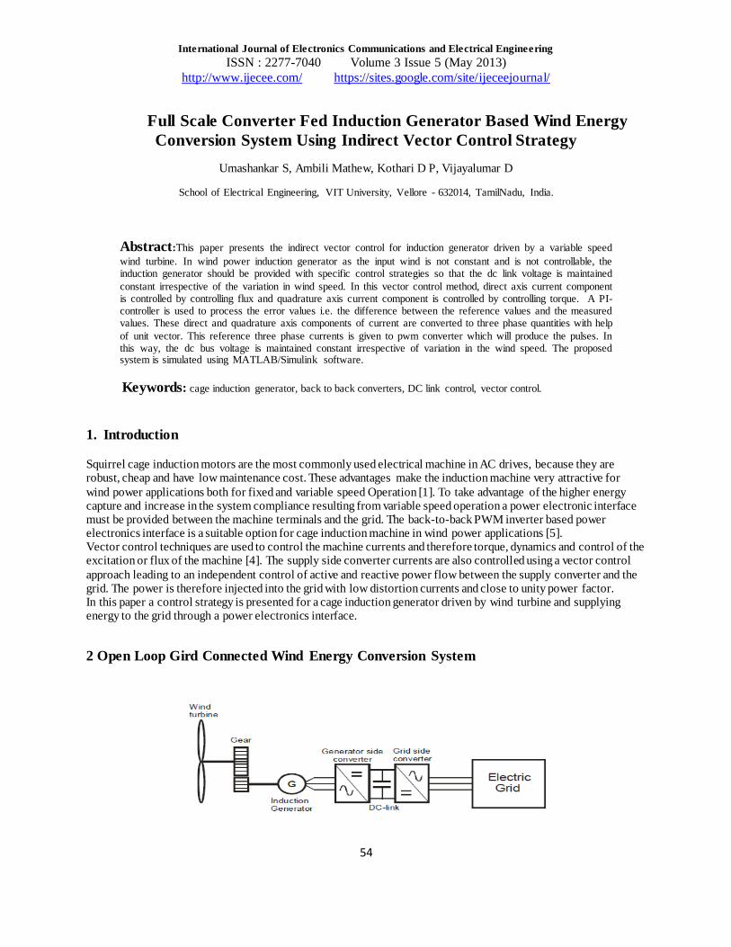
2 Open Loop Gird Connected Wind Energy Conversion System

International Journal of Electronics Communications and Electrical Engineering
ISSN : 2277-7040 Volume 3 Issue 5 (May 2013)
http://www.ijecee.com/ https://sites.google.com/site/ijeceejournal/
55
Fig.1 Schematic Representation of The Open Loop System
A variable speed electrical system has three main components. They are the generator, the rectifier and the inverter
as shown in the Figure1. In the process of generation, wind energy is converted in to kinetic energy by wind turbine and this kinetic energy is used as a mechanical input for the induction generator to generate electrical power. The generator is connected to the grid through back to back pwm converter. The reactive power required for the machine operation is supplied by the switching action of the pwm converter and machine delivers the active power to the grid when it is acting as generator [7].
3 Simulation Setup of Open Loop System
4 Simulation Results Of Open Loop System
Fig.2 Rotor Current Waveform
International Journal of Electronics Communications and Electrical Engineering
ISSN : 2277-7040 Volume 3 Issue 5 (May 2013)
http://www.ijecee.com/ https://sites.google.com/site/ijeceejournal/
56
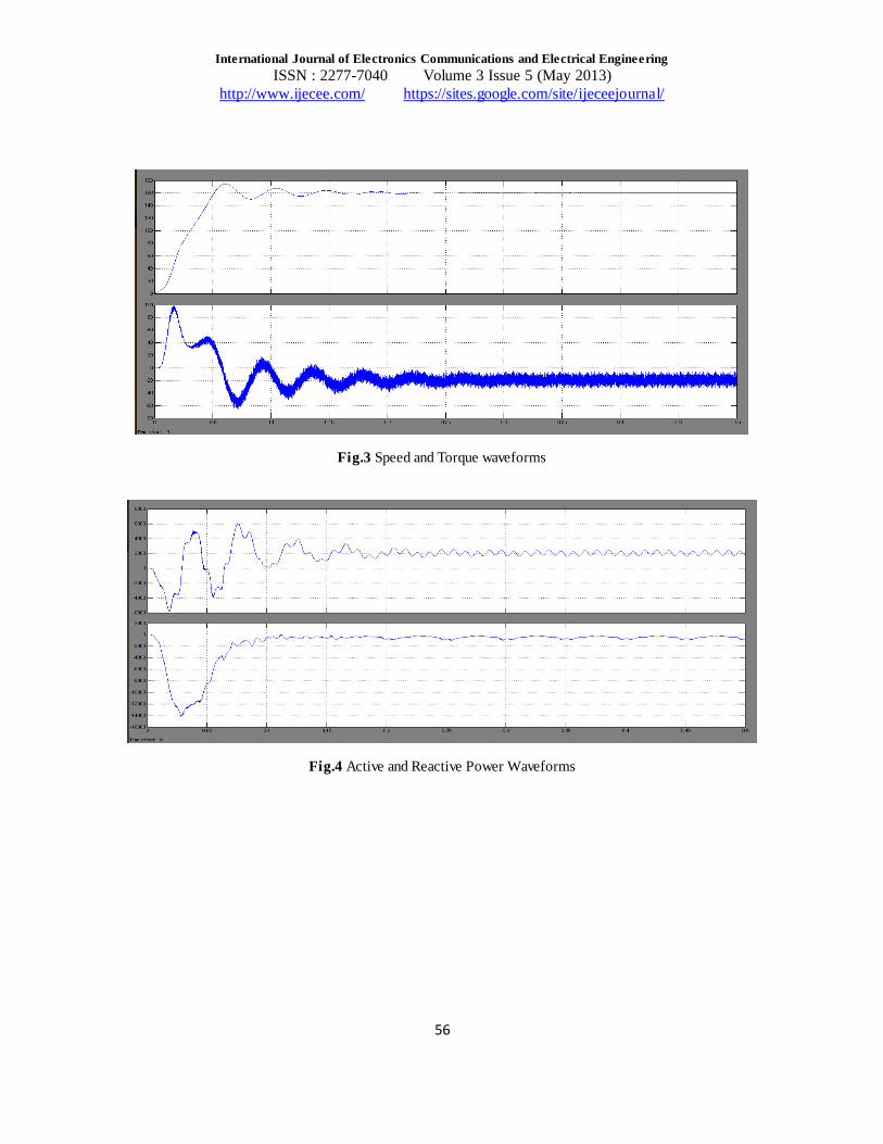
Fig.3 Speed and Torque waveforms
Fig.4 Active and Reactive Power Waveforms

International Journal of Electronics Communications and Electrical Engineering
ISSN : 2277-7040 Volume 3 Issue 5 (May 2013)
http://www.ijecee.com/ https://sites.google.com/site/ijeceejournal/
57
Fig.5 Voltage and Current Waveforms at Generator Side:
Fig.6 Voltage and Current Waveforms at Grid Side:
Fig.7 Pulse Generator Waveform

International Journal of Electronics Communications and Electrical Engineering
ISSN : 2277-7040 Volume 3 Issue 5 (May 2013)
http://www.ijecee.com/ https://sites.google.com/site/ijeceejournal/
58
Fig.8 Dc Link Voltage
5 Indirect Vector control
In general vector control techniques are implemented on both generator and grid side converters.On the generator
side converter we get decoupled control of electromagnetic torque and flux. On the grid side converter, we get decoupled control of active and reactive power[4][8]. The control of the DC link voltage is made in a coordinated fashion between generator and grid side converters. Independent control of the torque is achievable by control of the armature and field currents. In a separately excited DC machine, the armature and field currents can be controlled independently (as the currents are naturally decoupled). In the control of a dc machine, only the magnitude of the currents needs to be controlled in order to
control the output torque and field flux independently, which is simple when compared to the control required for ac machines [4]. The electromagnetic interaction between the field flux and the armature MMF results in two basic outputs:
An electromagnetic torque proportional to the armature current.
An induced voltage proportional to the rotor speed
In ac induction motor drives, a coordinated control of the stator current, magnitudes, frequencies, and phasors is required, hence the control is complex. Also in an induction machine, there is inherent coupling between the flux and torque. This is because the flux and torque are functions of the voltage or currents and frequency [4]. Therefore, the method of control of an induction machine is more complex.
6 Block Diagram Of Indirect Vector Control

International Journal of Electronics Communications and Electrical Engineering
ISSN : 2277-7040 Volume 3 Issue 5 (May 2013)
http://www.ijecee.com/ https://sites.google.com/site/ijeceejournal/
59
Fig.9 Indirect Vector Control
6 Principle of Vector Control
The principle of vector control can be explained by assuming that at all instants of time, the position of the rotor flux linkage phasor is known. The rotor flux is defined as λr, and the angle is defined as θf (field angle). The position is defined from a stationary reference [4][8].
The principle of vector control of an induction machine aims at developing a model of the machine that is similar to a dc machine so as to simplify the control. As explained in the previous section, the control of a dc machine is simple as the two currents (armature and field) are independent, hence allowing for independent control of the field flux and the torque (or power in the case if a generator) [4]. To simplify the model of an induction machine, the components of the stator current that produce the torque and field flux (rotor flux) need to be decoupled [8].
7 Closed Loop Wind Generation Simulation Setup

International Journal of Electronics Communications and Electrical Engineering
ISSN : 2277-7040 Volume 3 Issue 5 (May 2013)
http://www.ijecee.com/ https://sites.google.com/site/ijeceejournal/
60
8 Indirect Vector Control Simulation Circuit
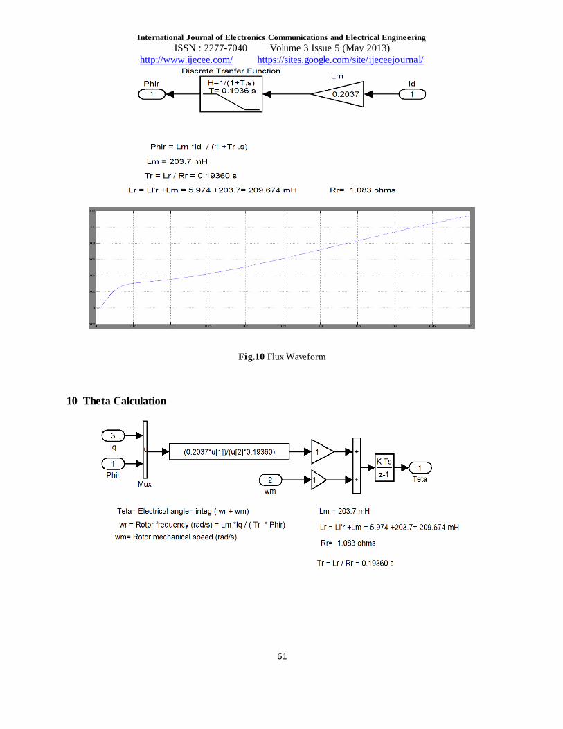
9 Flux Calculation
International Journal of Electronics Communications and Electrical Engineering
ISSN : 2277-7040 Volume 3 Issue 5 (May 2013)
http://www.ijecee.com/ https://sites.google.com/site/ijeceejournal/
61
Fig.10 Flux Waveform
10 Theta Calculation
International Journal of Electronics Communications and Electrical Engineering
ISSN : 2277-7040 Volume 3 Issue 5 (May 2013)
http://www.ijecee.com/ https://sites.google.com/site/ijeceejournal/
62
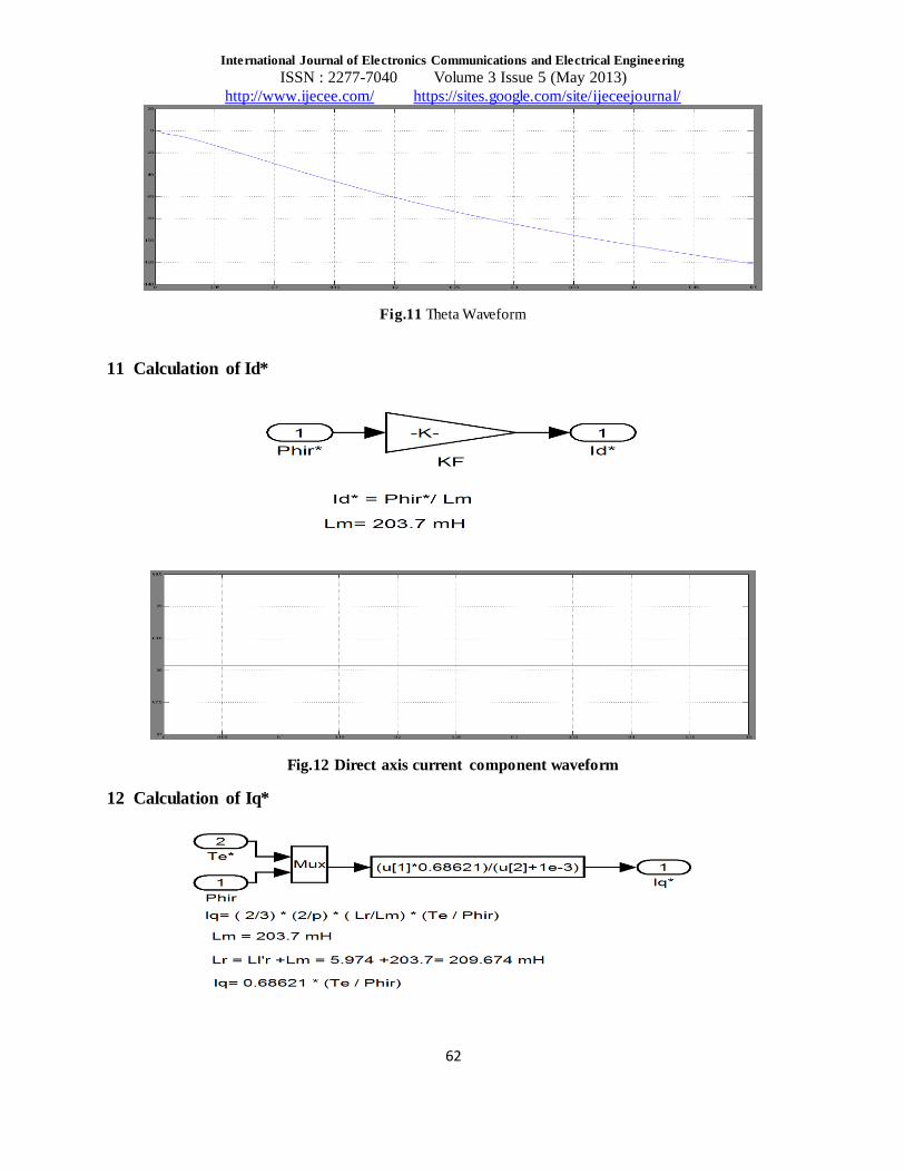
Fig.11 Theta Waveform
11 Calculation of Id*
Fig.12 Direct axis current component waveform
12 Calculation of Iq*

International Journal of Electronics Communications and Electrical Engineering
ISSN : 2277-7040 Volume 3 Issue 5 (May 2013)
http://www.ijecee.com/ https://sites.google.com/site/ijeceejournal/
63
Fig.13 Quadrature Axis Current Component Waveform
13 Simulation Results
Fig.14 Dc link voltage:
Fig.15 Rotor Current

International Journal of Electronics Communications and Electrical Engineering
ISSN : 2277-7040 Volume 3 Issue 5 (May 2013)
http://www.ijecee.com/ https://sites.google.com/site/ijeceejournal/
64
Fig.16 Current and Voltage Wave Forms Generator Side
Fig.17 Grid Side Voltage and Current Wave Forms

International Journal of Electronics Communications and Electrical Engineering
ISSN : 2277-7040 Volume 3 Issue 5 (May 2013)
http://www.ijecee.com/ https://sites.google.com/site/ijeceejournal/
65
Fig.18 Active and Reactive Power Wave Forms
Fig.19 Machine Side Pwm Pulses

International Journal of Electronics Communications and Electrical Engineering
ISSN : 2277-7040 Volume 3 Issue 5 (May 2013)
http://www.ijecee.com/ https://sites.google.com/site/ijeceejournal/
66
Fig.20 Speed and Torque Waveforms
14 Machine Parameters
Nominal power 3730 VA
VOLTAGE (line-line) 460 V
FREQUENCY 50 HZ
STATOR RESISTANCE 1.15 ohm
STATOR LEAKAGE INDUCTANCE 0.005974 H
ROTOR RESISTANCE 1.083 ohm
ROTOR LEAKAGE INDUCTANCE 0.005974 H
MUTUAL INDUCTANCE 0.2037 H
INERTIA 0.02 J
PAIR OF POLES 2
15 Conclusion
In this paper, indirect vector control is implemented for the generator side converter. The setup is simulated in MATLAB/SIMULINK software (32-bit). Here we can say that by using fully controlled VSC containing IGBT using the vector control strategy for the generator side converter we get the decoupled control of electromagnetic torque and flux. For the proposed system, the future work may be extended by implementing the vector control
technique for the grid side converter.
References

International Journal of Electronics Communications and Electrical Engineering
ISSN : 2277-7040 Volume 3 Issue 5 (May 2013)
http://www.ijecee.com/ https://sites.google.com/site/ijeceejournal/
67
1. Marta Molinas, Bjarne Naess, William Gullvik, Tore Undeland : Control of wind turbines with induction
generators interfaced to the grid with power electronics equipment . 2. Noriyuki Kimura, Tomoyuki Hamada, Toshimitsu Morizane and Katsunori Taniguchi: Control of PFC
Converter with Inverter Excited Induction Generator for Advanced Wind Power Generation System, IEEE 2008
3. Noriyuki Kimura, Mitsuhiro Hirao, Toshimitsu Morizane, Katsunori Taniguchi: Wind Power Generation System with Induction Machine and Diode Rectifier , EPE-PEMC 2006, 12th International Power
Electronics and Motion Control Conference, T12-115 (2006-8) 4. Jyoti Sastry : Vector control of induction generator 5. JhonSevnsson : Grid connected voltage source converter ,Chalmers University of Technology 6. Mukund .R .Patel :Wind and solar power systems 7. Anders Carlsson :The back to back converter control and design 8. Bimal K.Bose :Power electronics and motor drives .
Related Documents