Sensorless Control of Matrix Converter-Fed Synchronous Reluctance Motor Drives Arzhang Yousefi-Talouki 1 , Fausto Stella 1 , Shafiq Odhano 2 , Liliana de Lilo 2 , Andrew Trentin 2 , Gianmario Pellegrino 1 , and Pericle Zanchetta 2 1 Politecnico di Torino, Energy department 2 University of Nottingham Torino, Italy Department of Electrical and Electronic Engineering [email protected] Nottingham, UK Abstract—This paper presents a sensorless control technique based on direct flux vector control (DFVC) method for synchronous reluctance (SyR) motor drives fed by a three-phase to three-phase matrix converter (MC). Rotor position is estimated based on active flux (AF) concept down to 50 [rpm]. Furthermore, the effect of nonlinear voltage errors of the MC is compensated, and a self-commissioning method capable of identifying the voltage error before compensation is presented and tested. The proposed drive combines the advantages of matrix converters and SyR motors in sensorless fashion, for application into a number of fields, spanning from compact drives for aviation to line-supplied drives for industry applications. Experimental results are provided to prove the feasibility of the proposed technique. Keywords—Active flux; Matrix converter; self-commissioning; sensorless; synchronous reluctance. I. INTRODUCTION Synchronous reluctance motors feature high power density, high efficiency, and low manufacturing cost [1]. Furthermore, since SyR motors are inherently salient, they are good candidates for saliency tracking based sensorless control methods [2-3]. Conventionally, at standstill and low speed, rotor position estimation is achieved by high frequency signal injection and tracking of machine special saliencies, while at higher speed, rotor position estimation relies on model based techniques. At low speed, the rotor or flux position estimation based on fundamental model techniques becomes crucial, since the stator voltage is low at such speed level. Nonetheless, sensorless control techniques based on fundamental models are targeting lower speeds. However, an additional burdensome issue at low speed is converter nonlinear voltage error which is comparable with machine back-electromotive force (EMF). Therefore, this voltage error should be compensated appropriately. Matrix converters have emerged in the past two decades to become an alternative to traditional two level voltage source inverters (VSIs). Adjustable input power factor, bidirectional power flow, and high-quality power output waveforms are prominent features of MCs [5]. Furthermore, due to the absence of bulky dc-link capacitors, these converters are employed in applications where compactness and high reliability are demanded. The application of MCs is extended from variable speed AC drives to aerospace applications [6-7]. Dealing with SyR motors, various sensorless techniques proliferate in the literature for a wide speed range from standstill to flux weakening [2-4], [8]. However, despite the advantages of MCs and SyR motor drives, the combination of these converters and motors has not been studied extensively, hitherto [9-10]. In this paper, a sensorless control technique is presented for MC-fed SyR motor drives based on DFVC method. The stator flux amplitude and torque producing current which is quadrature to stator flux linkage are regulated at a constant switching frequency. Rotor position and speed are estimated based on AF method. In addition, MC nonlinear voltage error is studied and a self-commissioning algorithm is applied to identify this voltage error before compensation. The presented experimental results show that the proposed sensorless method is feasible. II. DIRECT FLUX VECTOR CONTROL A. SyR Motor equations in stator flux frame Fig.1 illustrates the special coordinates adopted in this work, where, ሺߚ,ߙሻ, ሺ, ݍሻ, and ሺ ௦ ݍ,௦ ሻ represent stationary frame, rotor flux frame, and stator flux frame, respectively. Motor model in stator flux frame is expressed as (1) where, ߣis the stator flux amplitude and ߜstands for load angle [2], [4]. ቐ ݒௗ௦ = ௦ ∙ ௗ௦ + ௗఒ ௗ௧ ݒ௦ = ௦ ∙ ௦ + ∙ߣቀ + ௗఋ ௗ௧ ቁ (1) ߙ ߚ ݍ ߜ ߠ ݏ ݏ ݍ ݏ ߠ ߣFig. 1. Explanation of adopted frames: Stationary (ߚ ,ߙ), rotor flux (d,q), and stator flux ( ௦ ݍ,௦ ) reference frames. Also, torque equation is obtained as (2) with cross product of flux linkage and current vectors in ௦ ݍ௦ frame, considering that flux component in ݍ௦ axis is zero as defined in Fig.1. is the number of pole pairs. = ଷ ଶ ∙∙λ∙ ௦ (2)

Welcome message from author
This document is posted to help you gain knowledge. Please leave a comment to let me know what you think about it! Share it to your friends and learn new things together.
Transcript
Sensorless Control of Matrix Converter-Fed Synchronous Reluctance Motor Drives
Arzhang Yousefi-Talouki1, Fausto Stella1, Shafiq Odhano2, Liliana de Lilo2, Andrew Trentin2, Gianmario Pellegrino1, and Pericle Zanchetta2
1Politecnico di Torino, Energy department 2University of Nottingham Torino, Italy Department of Electrical and Electronic Engineering [email protected] Nottingham, UK
Abstract—This paper presents a sensorless control technique
based on direct flux vector control (DFVC) method for synchronous reluctance (SyR) motor drives fed by a three-phase to three-phase matrix converter (MC). Rotor position is estimated based on active flux (AF) concept down to 50 [rpm]. Furthermore, the effect of nonlinear voltage errors of the MC is compensated, and a self-commissioning method capable of identifying the voltage error before compensation is presented and tested. The proposed drive combines the advantages of matrix converters and SyR motors in sensorless fashion, for application into a number of fields, spanning from compact drives for aviation to line-supplied drives for industry applications. Experimental results are provided to prove the feasibility of the proposed technique.
Keywords—Active flux; Matrix converter; self-commissioning; sensorless; synchronous reluctance.
I. INTRODUCTION
Synchronous reluctance motors feature high power density, high efficiency, and low manufacturing cost [1]. Furthermore, since SyR motors are inherently salient, they are good candidates for saliency tracking based sensorless control methods [2-3].
Conventionally, at standstill and low speed, rotor position estimation is achieved by high frequency signal injection and tracking of machine special saliencies, while at higher speed, rotor position estimation relies on model based techniques. At low speed, the rotor or flux position estimation based on fundamental model techniques becomes crucial, since the stator voltage is low at such speed level. Nonetheless, sensorless control techniques based on fundamental models are targeting lower speeds. However, an additional burdensome issue at low speed is converter nonlinear voltage error which is comparable with machine back-electromotive force (EMF). Therefore, this voltage error should be compensated appropriately.
Matrix converters have emerged in the past two decades to become an alternative to traditional two level voltage source inverters (VSIs). Adjustable input power factor, bidirectional power flow, and high-quality power output waveforms are prominent features of MCs [5]. Furthermore, due to the absence of bulky dc-link capacitors, these converters are employed in applications where compactness and high reliability are demanded. The application of MCs is extended from variable speed AC drives to aerospace applications [6-7].
Dealing with SyR motors, various sensorless techniques proliferate in the literature for a wide speed range from standstill to flux weakening [2-4], [8]. However, despite the advantages of MCs and SyR motor drives, the combination of these converters and motors has not been studied extensively, hitherto [9-10].
In this paper, a sensorless control technique is presented for MC-fed SyR motor drives based on DFVC method. The stator flux amplitude and torque producing current which is quadrature to stator flux linkage are regulated at a constant switching frequency. Rotor position and speed are estimated based on AF method. In addition, MC nonlinear voltage error is studied and a self-commissioning algorithm is applied to identify this voltage error before compensation. The presented experimental results show that the proposed sensorless method is feasible.
II. DIRECT FLUX VECTOR CONTROL
A. SyR Motor equations in stator flux frame
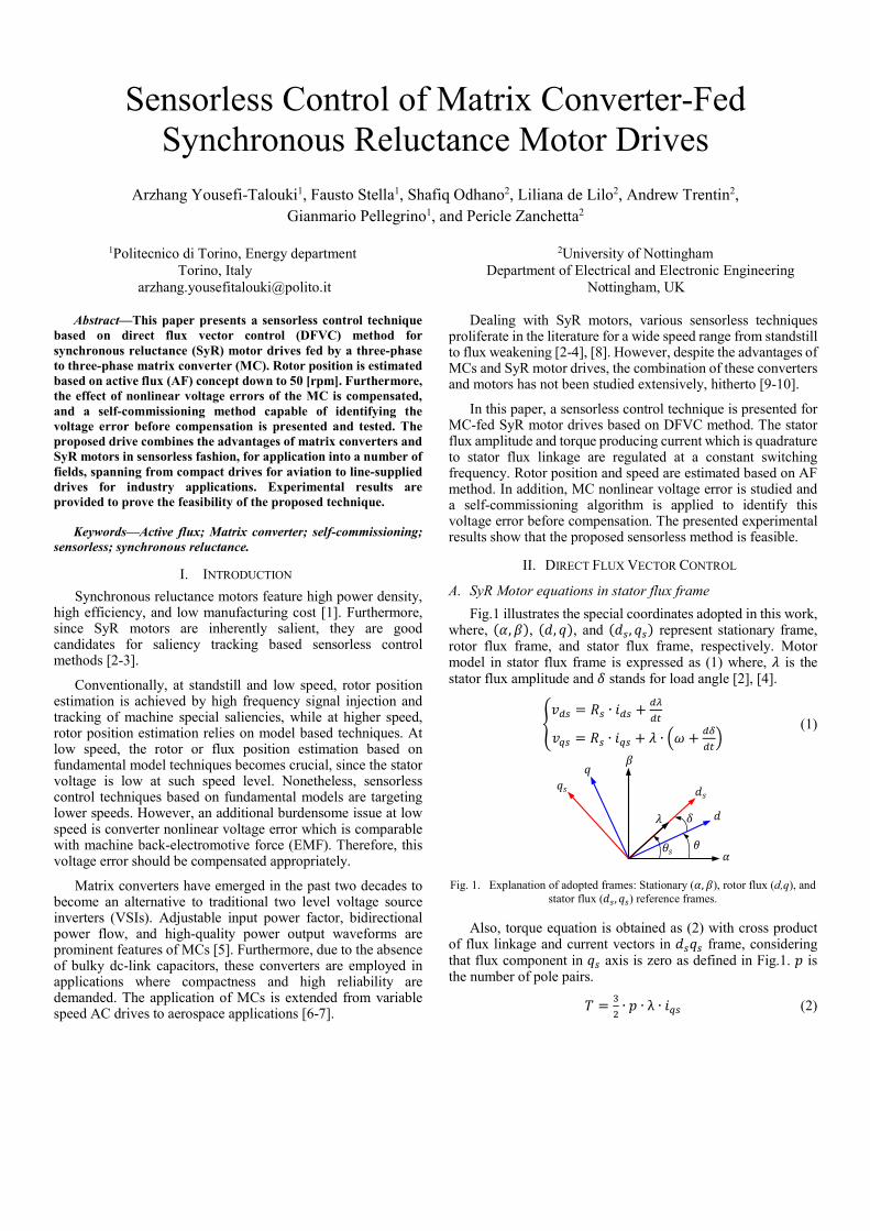
Fig.1 illustrates the special coordinates adopted in this work, where, , , , , and , represent stationary frame, rotor flux frame, and stator flux frame, respectively. Motor model in stator flux frame is expressed as (1) where, is the stator flux amplitude and stands for load angle [2], [4].
= ∙ + = ∙ + ∙ + (1)
Fig. 1. Explanation of adopted frames: Stationary ( , ), rotor flux (d,q), and
stator flux ( , ) reference frames.
Also, torque equation is obtained as (2) with cross product of flux linkage and current vectors in frame, considering that flux component in axis is zero as defined in Fig.1. is the number of pole pairs.
= ∙ ∙ λ ∙ (2)
∗ ∗13/2
∗∗
∗ ∗
∗
−abc
αβ
,,
∗ ,′
Fig. 2. Block diagram of sensorless DFVC of MC-fed SyR motor.
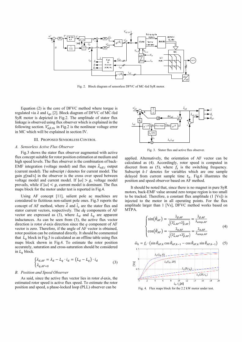
Equation (2) is the core of DFVC method where torque is regulated via and [2]. Block diagram of DFVC of MC-fed SyR motor is depicted in Fig.2. The amplitude of stator flux linkage is observed using flux observer which is explained in the following section. , in Fig.2 is the nonlinear voltage error in MC which will be explained in section IV.
III. PROPOSED SENSORLESS CONTROL
A. Sensorless Active Flux Observer
Fig.3 shows the stator flux observer augmented with active flux concept suitable for rotor position estimation at medium and high speed levels. The flux observer is the combination of back-EMF integration (voltage model) and flux maps , output (current model). The subscript i denotes for current model. The gain g[rad/s] in the observer is the cross over speed between voltage model and current model. If | | > , voltage model prevails, while if | | < , current model is dominant. The flux maps block for the motor under test is reported in Fig.4.
Using AF concept [11], salient pole ac machines are considered to fictitious non-salient pole ones. Fig.5 reports the concept of AF method, where and are the stator flux and stator current vectors, respectively. The dq components of AF vector are expressed as (3), where and are apparent inductances. As can be seen from (3), the active flux vector direction is rotor d-axis direction since the q component of AF vector is zero. Therefore, if the angle of AF vector is obtained, rotor position can be estimated directly. It should be commented that block in Fig.3 is calculated as an offline table using flux maps block shown in Fig.4. To estimate the rotor position accurately, saturation and cross-saturation should be considered in block.
, = − ∙ = − ∙, (3)
B. Position and Speed Observer
As said, since the active flux vector lies in rotor d-axis, the estimated rotor speed is active flux speed. To estimate the rotor position and speed, a phase-locked loop (PLL) observer can be
1
table
Flux maps − ,∆ ,
∗
Fig. 3. Stator flux and active flux observer.
applied. Alternatively, the orientation of AF vector can be calculated as (4). Accordingly, rotor speed is computed in discreet from as (5), where is the switching frequency. Subscript k-1 denotes for variables which are one sample delayed from current sample time . Fig.6 illustrates the position and speed observer based on AF method.
It should be noted that, since there is no magnet in pure SyR motors, back-EMF value around zero torque region is too small to be tracked. Therefore, a constant flux amplitude (1 [Vs]) is injected to the motor in all operating points. For the flux amplitude larger than 1 [Vs], DFVC method works based on MTPA.
sin = ,, , = , ,cos = ,, , = , , (4)
= ∙ sin , cos , − cos , sin , (5)
Fig. 4. Flux maps block for the 2.2 kW motor under test.
= −
Fig. 5. Active flux vector.
,,,
sincos−1−1
Fig. 6. Rotor position and speed observer.
IV. MATRIX CONVERTER NONLINEAR VOLTAGE ERROR
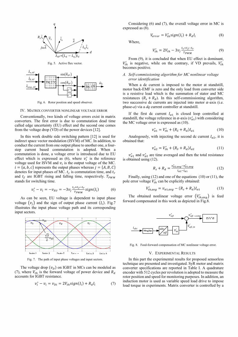
Conventionally, two kinds of voltage errors exist in matrix converters. The first error is due to commutation dead time called edge uncertainty (EU) effect and the second one comes from the voltage drop (VD) of the power devices [12].
In this work double side switching pattern [12] is used for indirect space vector modulation (ISVM) of MC. In addition, to conduct the current from one output phase to another one, a four-step current based commutation is adopted. When a commutation is done, a voltage error is introduced due to EU effect which is expressed as (6), where ∗ is the reference voltage used for ISVM and is the output voltage of the MC. = , , represents the output phases whereas = , , denotes for input phases of MC. is commutation time, and and are IGBT rising and falling time, respectively. stands for switching time.
∗ − = − = −3 (6)
As can be seen, EU voltage is dependent to input phase voltage and the sign of output phase current . Fig.7 illustrates the input phase voltage path and its corresponding input sectors.
Fig. 7. The path of input phase voltages and input sectors.
The voltage drop on IGBT in MCs can be modeled as (7), where is the forward voltage of power device and accounts for IGBT resistance.
∗ − = = 2 + (7)
Considering (6) and (7), the overall voltage error in MC is expressed as (8).
= + (8)
Where,
= 2 − 3 (9)
From (9), it is concluded that when EU effect is dominant, is negative, while on the contrary, if VD prevails,
becomes positive.
A. Self-commissioning algorithm for MC nonlinear voltage error identification
When a dc current is imposed to the motor at standstill, motor back-EMF is zero and the only load from converter side is a resistive load which is the summation of stator and MC resistances ( + ). In this self-commissioning algorithm, two successive dc currents are injected into motor -axis (i.e. phase-a) via a dq current controller at standstill.
If the first dc current is closed loop controlled at standstill, the voltage reference in -axis ( ∗ ) with considering the MC voltage error is expressed as (10).
∗ = + + (10)
Analogously, with injecting the second dc current , it is obtained that:
∗ = + + (11) ∗ and ∗ are time averaged and then the total resistance is obtained using (12).
+ = ,∗ ,∗ (12)
Finally, using (12) and one of the equations (10) or (11), the pole error voltage can be explicitly obtained:
, = , − + (13)
The obtained nonlinear voltage error , is feed forward compensated in this work as depicted in Fig.8.
′∗ −∗
,′
Fig. 8. Feed-forward compensation of MC nonlinear voltage error.
V. EXPERIMENTAL RESULTS
In this part the experimental results for proposed sensorless technique are presented and investigated. SyR motor and matrix converter specifications are reported in Table I. A quadrature encoder with 512 cycles per revolution is adopted to measure the rotor position and speed for monitoring purposes. In addition, an induction motor is used as variable speed load drive to impose load torque in experiments. Matrix converter is controlled by a
floating point microcontroller (TMS320C6713). The experimental test bench are shown in Fig.9 and Fig.10.
TABLE I - SyRM and matrix converter data SyRM under test
Number of poles/ Rated power 4/2.2 kW Rated Torque/ Nominal Speed 14 Nm /1500 r/min
Phase resistance 3.6 Ω Moment of inertia 0.005 .
Matrix Converter: SK 60GM123 module Input phase voltage 325 V
0.9 Switching frequency ( ) 12.5 kHz
Fig. 9. Controller board and MC.
Fig. 10. SyR motor coupled with an induction machine.
A. Self-commissioning Algorithm Results
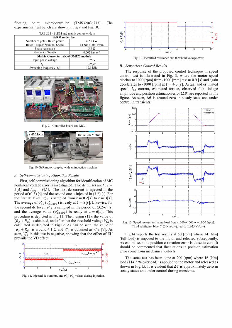
First, self-commissioning algorithm for identification of MC nonlinear voltage error is investigated. Two dc pulses are =5[ ] and = 9[ ]. The first dc current is injected in the period of (0-3) [s] and the second one is injected in (3-6) [s]. For the first dc level, ∗ is sampled from = 0.2[ ] to = 3[ ]. The average of ∗ ( ,∗ ) is ready at = 3[ ]. Likewise, for the second dc level, ∗ is sampled in the period of (3.2-6) [s] and the average value ( ,∗ ) is ready at = 6[ ]. This procedure is depicted in Fig.11. Then, using (12), the value of + is obtained, and after that the threshold voltage is calculated as depicted in Fig.12. As can be seen, the value of + is around 4.1 Ω and is obtained as -7.3 [V]. As seen, in this test is negative, showing that the effect of EU prevails the VD effect.
Fig. 11. Injected dc currents, and ∗ , ∗ values during injection.
Fig. 12. Identified resistance and threshold voltage error.
B. Sensorless Control Results
The response of the proposed control technique in speed control test is illustrated in Fig.13, where the motor speed reaches to 1000 [rpm] from -1000 [rpm] at = 0.9[ ] and again decelerates to -1000 [rpm] at = 4.5[ ]. Actual and estimated speed, current, estimated torque, observed flux linkage amplitude and position estimation error ∆ are reported in this figure. As seen, ∆ is around zero in steady state and under control in transients.
Fig. 13. Speed reversal test at no load from -1000→1000→ −1000 [rpm].
Third subfigure: blue: (5 Nm/div); red: (0.625 Vs/div).
Fig.14 reports the test results at 50 [rpm] where 14 [Nm] (full-load) is imposed to the motor and released subsequently. As can be seen the position estimation error is close to zero. It should be commented that fluctuations in position estimation error come from mechanical defects.
The same test has been done at 200 [rpm] where 16 [Nm] load (114.3 % overload) is applied to the motor and released as shown in Fig.15. It is evident that ∆ is approximately zero in steady states and under control during transients.
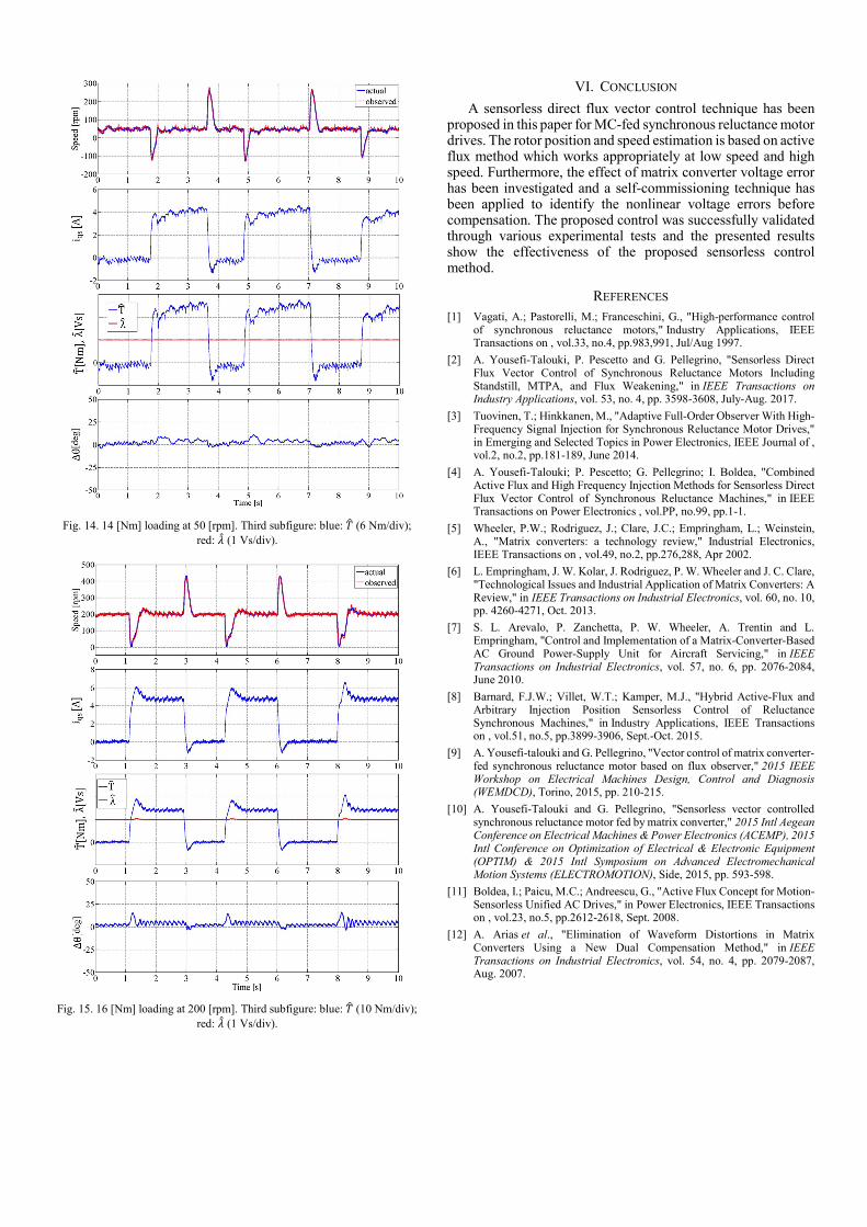
Fig. 14. 14 [Nm] loading at 50 [rpm]. Third subfigure: blue: (6 Nm/div); red: (1 Vs/div).
Fig. 15. 16 [Nm] loading at 200 [rpm]. Third subfigure: blue: (10 Nm/div); red: (1 Vs/div).
VI. CONCLUSION
A sensorless direct flux vector control technique has been proposed in this paper for MC-fed synchronous reluctance motor drives. The rotor position and speed estimation is based on active flux method which works appropriately at low speed and high speed. Furthermore, the effect of matrix converter voltage error has been investigated and a self-commissioning technique has been applied to identify the nonlinear voltage errors before compensation. The proposed control was successfully validated through various experimental tests and the presented results show the effectiveness of the proposed sensorless control method.
REFERENCES [1] Vagati, A.; Pastorelli, M.; Franceschini, G., "High-performance control
of synchronous reluctance motors," Industry Applications, IEEE Transactions on , vol.33, no.4, pp.983,991, Jul/Aug 1997.
[2] A. Yousefi-Talouki, P. Pescetto and G. Pellegrino, "Sensorless Direct Flux Vector Control of Synchronous Reluctance Motors Including Standstill, MTPA, and Flux Weakening," in IEEE Transactions on Industry Applications, vol. 53, no. 4, pp. 3598-3608, July-Aug. 2017.
[3] Tuovinen, T.; Hinkkanen, M., "Adaptive Full-Order Observer With High-Frequency Signal Injection for Synchronous Reluctance Motor Drives," in Emerging and Selected Topics in Power Electronics, IEEE Journal of , vol.2, no.2, pp.181-189, June 2014.
[4] A. Yousefi-Talouki; P. Pescetto; G. Pellegrino; I. Boldea, "Combined Active Flux and High Frequency Injection Methods for Sensorless Direct Flux Vector Control of Synchronous Reluctance Machines," in IEEE Transactions on Power Electronics , vol.PP, no.99, pp.1-1.
[5] Wheeler, P.W.; Rodriguez, J.; Clare, J.C.; Empringham, L.; Weinstein, A., "Matrix converters: a technology review," Industrial Electronics, IEEE Transactions on , vol.49, no.2, pp.276,288, Apr 2002.
[6] L. Empringham, J. W. Kolar, J. Rodriguez, P. W. Wheeler and J. C. Clare, "Technological Issues and Industrial Application of Matrix Converters: A Review," in IEEE Transactions on Industrial Electronics, vol. 60, no. 10, pp. 4260-4271, Oct. 2013.
[7] S. L. Arevalo, P. Zanchetta, P. W. Wheeler, A. Trentin and L. Empringham, "Control and Implementation of a Matrix-Converter-Based AC Ground Power-Supply Unit for Aircraft Servicing," in IEEE Transactions on Industrial Electronics, vol. 57, no. 6, pp. 2076-2084, June 2010.
[8] Barnard, F.J.W.; Villet, W.T.; Kamper, M.J., "Hybrid Active-Flux and Arbitrary Injection Position Sensorless Control of Reluctance Synchronous Machines," in Industry Applications, IEEE Transactions on , vol.51, no.5, pp.3899-3906, Sept.-Oct. 2015.
[9] A. Yousefi-talouki and G. Pellegrino, "Vector control of matrix converter-fed synchronous reluctance motor based on flux observer," 2015 IEEE Workshop on Electrical Machines Design, Control and Diagnosis (WEMDCD), Torino, 2015, pp. 210-215.
[10] A. Yousefi-Talouki and G. Pellegrino, "Sensorless vector controlled synchronous reluctance motor fed by matrix converter," 2015 Intl Aegean Conference on Electrical Machines & Power Electronics (ACEMP), 2015 Intl Conference on Optimization of Electrical & Electronic Equipment (OPTIM) & 2015 Intl Symposium on Advanced Electromechanical Motion Systems (ELECTROMOTION), Side, 2015, pp. 593-598.
[11] Boldea, I.; Paicu, M.C.; Andreescu, G., "Active Flux Concept for Motion-Sensorless Unified AC Drives," in Power Electronics, IEEE Transactions on , vol.23, no.5, pp.2612-2618, Sept. 2008.
[12] A. Arias et al., "Elimination of Waveform Distortions in Matrix Converters Using a New Dual Compensation Method," in IEEE Transactions on Industrial Electronics, vol. 54, no. 4, pp. 2079-2087, Aug. 2007.
Related Documents


