EB2013-NVH-018 FRICTIONAL COEFFICIENT DISTRIBUTION PATTERN ON BRAKE DISK-PAD CONTACT INTERFACE TO REDUCE SUSCEPTIBILITY OF BRAKE NOISE INSTABILITIES CAUSING BRAKE SQUEAL 1 Esgandari, Mohammad*, 1 Olatunbosun, Oluremi, 2 Taulbut, Richard 1 University of Birmingham, United Kingdom, 2 Jaguar Land Rover Ltd, United Kingdom KEYWORDS - Brake noise, squeal, friction material, Finite Element Analysis, Complex Eigenvalue Analysis ABSTRACT - After decades of investigating brake noise and despite the application of advanced tools and methods of investigation, brake squeal remains a general problem of the automotive industry. Finite Element Analysis (FEA) has been employed as the main tool in numerous studies recently, mainly using the Complex Eigenvalue Analysis (CEA) to predict the occurrence of brake instability and, hence, brake squeal. However it has been shown that not all instabilities predicted by CEA do occur in reality. The effective (negative) damping ratio (expressed in percentage terms) is used as a measure of the strength of instabilities. The level of effective damping ratio of the predicted instabilities below which the instability is not prone to cause noise is set at different levels by different researchers with 1% being an average value in the industry. However, in this study, the acceptable effective damping ratio percentage is set to be 0.5% and any instability predicted with an effective damping ratio of more than that is assumed to be prone to causing brake squeal when tested on the car. This study is based on the hypothesis that variation of frictional coefficient over the radius of the brake pad is effective in reducing the susceptibility of the brake instability to cause brake squeal. Various patterns of distribution of Coefficient Of Friction (COF) over the disc pad contact interface have been investigated, and results are illustrated in terms of four different scenarios. The successful scenario recommends that increasing the COF radially over the disc radius will lead to instabilities with an effective damping ratio in the acceptable range. Exaggerated variation in the COF in the disc-pad contact interface is set to cover the entire range of COF used in different analyses performed to examine noise level of a brake system, varying from μ=0.3 to μ=0.7. The proposed friction distribution pattern reduces the strength of all predicted instabilities over the frequency range to less than the target value of 0.5%. This suggests that instabilities predicted for the brake system using the proposed pad material design will not cause brake noise. INTRODUCTION Brake noise has been a topic of research since the early years of disc brake development, likewise the study of friction material properties. However work linking friction material properties to brake noise has not yet yielded a practical brake design solution. Frictional force caused by the brake pads is one of the most significant factors governing the braking power of the brake system, and hence the friction material used for this purpose is also of high significance. However, the frictional force caused by sliding the friction surface of the brake pads on the disc causes energy dissipation in different forms. One undesired form

Welcome message from author
This document is posted to help you gain knowledge. Please leave a comment to let me know what you think about it! Share it to your friends and learn new things together.
Transcript
EB2013-NVH-018
FRICTIONAL COEFFICIENT DISTRIBUTION PATTERN ON BRAKE
DISK-PAD CONTACT INTERFACE TO REDUCE SUSCEPTIBILITY
OF BRAKE NOISE INSTABILITIES CAUSING BRAKE SQUEAL
1Esgandari, Mohammad*,
1Olatunbosun, Oluremi,
2Taulbut, Richard
1University of Birmingham, United Kingdom,
2Jaguar Land Rover Ltd, United Kingdom
KEYWORDS - Brake noise, squeal, friction material, Finite Element Analysis, Complex Eigenvalue
Analysis
ABSTRACT - After decades of investigating brake noise and despite the application of
advanced tools and methods of investigation, brake squeal remains a general problem of the
automotive industry. Finite Element Analysis (FEA) has been employed as the main tool in
numerous studies recently, mainly using the Complex Eigenvalue Analysis (CEA) to predict
the occurrence of brake instability and, hence, brake squeal. However it has been shown that
not all instabilities predicted by CEA do occur in reality. The effective (negative) damping
ratio (expressed in percentage terms) is used as a measure of the strength of instabilities.
The level of effective damping ratio of the predicted instabilities below which the instability
is not prone to cause noise is set at different levels by different researchers with 1% being an
average value in the industry. However, in this study, the acceptable effective damping ratio
percentage is set to be 0.5% and any instability predicted with an effective damping ratio of
more than that is assumed to be prone to causing brake squeal when tested on the car.
This study is based on the hypothesis that variation of frictional coefficient over the radius of
the brake pad is effective in reducing the susceptibility of the brake instability to cause brake
squeal. Various patterns of distribution of Coefficient Of Friction (COF) over the disc pad
contact interface have been investigated, and results are illustrated in terms of four different
scenarios. The successful scenario recommends that increasing the COF radially over the disc
radius will lead to instabilities with an effective damping ratio in the acceptable range.
Exaggerated variation in the COF in the disc-pad contact interface is set to cover the entire
range of COF used in different analyses performed to examine noise level of a brake system,
varying from µ=0.3 to µ=0.7.
The proposed friction distribution pattern reduces the strength of all predicted instabilities
over the frequency range to less than the target value of 0.5%. This suggests that instabilities
predicted for the brake system using the proposed pad material design will not cause brake
noise.
INTRODUCTION
Brake noise has been a topic of research since the early years of disc brake development,
likewise the study of friction material properties. However work linking friction material
properties to brake noise has not yet yielded a practical brake design solution.
Frictional force caused by the brake pads is one of the most significant factors governing the
braking power of the brake system, and hence the friction material used for this purpose is
also of high significance. However, the frictional force caused by sliding the friction surface
of the brake pads on the disc causes energy dissipation in different forms. One undesired form

of energy dissipation is vibration, which leads to radiation of noise that is amplified by the
large flat surface of brake disc [1, 2].
Since a major source of brake noise is coupling of modes [2] which commonly occurs
between the disc and pad, and since the nature of this contact is relatively unstable due to
stick-slip phenomena [3], any control measure in this contact could be a potential help on
limiting the brake noise sources.
There are two conflicting factors to be considered in selecting friction materials. Firstly high
friction to give adequate brake performance [4, 5], and secondly low friction which promotes
low brake noise [6]. Hence, any variation in the COF should be carried out with further
attention, since decreasing it can affect the braking performance and increasing it can
introduce even more instabilities into the system, which means more brake noise [7].
Disc brake systems are conventionally designed using pads with a single friction material
throughout the frictional surface. The specific friction material is chosen based on the
specifications of the brake system, and the braking power required for the vehicle it is being
designed for. However, the uniform friction material will cause different frictional force and
slip rate in different parts of the contact interface. This arises from the tangential speed at that
specific radius and also the slight variation of the pad pressure producing the normal force in
the leading and trailing edges of the pad.
If the variation in frictional force over the contact surface is responsible for exciting the
vibration of the disc due to the uneven distribution of the frictional forces over the disc
surface which, at certain frequencies, results in instability of the brake system, then variation
of the friction material based on a pattern may counteract this effect by equalising the
distribution of frictional forces. This is the hypothesis tested in this study.
This is where the challenge of varying the friction material based on a “pattern” becomes
interesting, since simply changing the material over the entire pad surface merely changes the
force level at which stick-slip occurs which may not have the effect of reducing the vibration
exciting the instability.
Friction material development is already at a reasonably well advanced level [8, 9], from the
points of view of both knowledge of the friction material itself and the manufacturing
processes, whereby manufacturers can limit the frictional behaviour of the brake pad to a
certain value or range, within a reasonable margin of accuracy. Hence, manufacturing a brake
pad with a pattern of COF variation is a realistic proposition.
There are different analytical approaches to investigating brake noise. Complex Eigenvalue
Analysis (CEA) is usually preferred to the dynamic transient analysis, mainly because it
provides results more quickly [10]. In order to analyse the stability of the disc brake system,
CEA results are represented either in terms of the eigenvalue real part or the negative
damping ratio. There has been a debate as to whether the real part or the damping ratio is a
better measure of squeal propensity or the strength of instability. For example Ouyang et al.
[10, 11] have used real part as an indication of instabilities, while damping ratio is used by
Nouby et al. in [12] and correlated with the real part. AbuBakar has briefly explained how the
damping ratio can be recognized as a measure of the strength of instability, relating it to the
terms standing for the damping in the Coulomb friction [13]. Also, Wallner shows there is a
proportionality between them in [14]. It is therefore reasonable to assume that the propensity
for brake instability can be expressed in terms of either the complex eigenvalue real part or
the damping ratio.
Based on expectations and experience of designers or analysts, a certain level of damping
ratio is assumed to be an indication of the value below which brake instability is not likely to
occur. Therefore, in this study the damping ratio reported by the software is taken as an
indication of the level of instability, but assumes a very strict margin as the accepted level of
instability. In the industry, the acceptable level of damping ratio (expressed in percentage) is
usually assumed to be less than 1% or even 1.5%, however, in this study 0.5% is considered
as the maximum allowed value of the damping ratio below which potential instabilities are
suppressed.
Typical values of COF are in the range of 0.3 to 0.7 [15], and this is the range used by many
brake pad designers and analysts. This range of values has also been used in this study.
This study investigates the effect of varying the COF over the radius of the brake pad on the
propensity for brake system instability as indicated by the negative damping ratio determined
from CEA. A value of 0.5% is taken as the limit for the damping ratio below which brake
instability is assumed to be suppressed.
METHODOLOGY
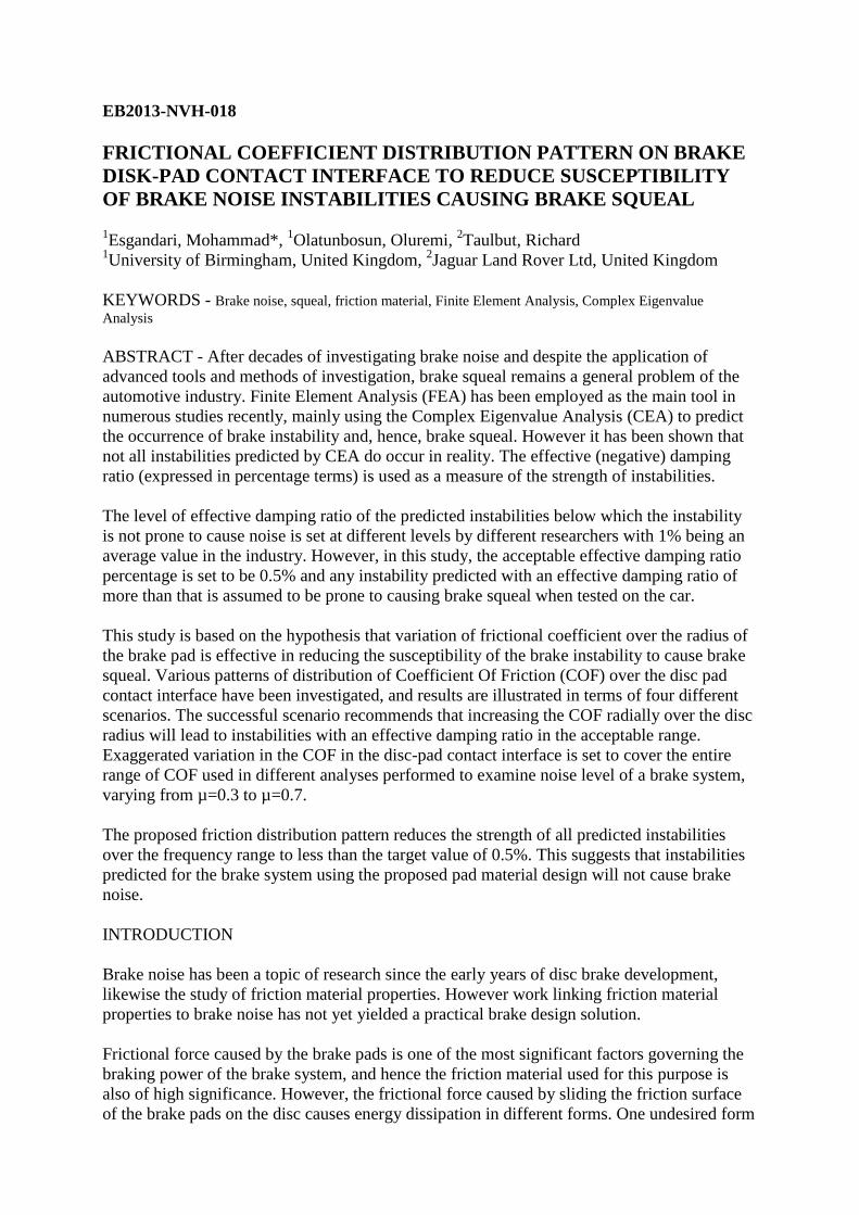
The analysis approach employed for this study is the Finite Element Analysis (FEA). The
brake unit is initially modelled using Computer Aided Design (CAD) software, and then
converted into a FEA model by assigning the appropriate material properties, boundary
conditions and required analysis steps. Figure 1 represents an isometric view of the brake unit
model. ABAQUS FEA package has been used for this study.
Figure 1, Brake corner unit, isometric view
Main components included in the brake corner unit are the disc, caliper housing including
pads and shims and pressurising pistons, the hub and knuckle. Also two mass blocks are
added to the caliper as a brake noise fix.
The squeal analysis is performed using CEA, to predict instabilities of the brake system which
are susceptible to develop brake noise. Then the strengths of predicted instabilities are

evaluated and ranked using the effective damping ratio reported as a result of the analysis,
converted into percentages.
In order to employ damping ratio to study the strength of instabilities a target value of 0.5% is
defined, such that instabilities with damping ratio of less than 0.5% are expected not to result
in brake squeal problems when the brake system is tested in the car or on the dynamometer.
This study looks at the problem only using CAE techniques, which are virtual tools employed
to predict instabilities of the system. An experimental investigation is also planned for the
continuation of the study.
Performance of the different configurations of the brake pad applied to each case of the study
and possible improvements are judged by comparing their results with the basic run, i.e.
uniform brake pad COF.
In the basic run the COF is assumed to be constant over the pad friction surface. The basic run
includes a set of analyses of the brake unit for uniform coefficients of friction of values of 0.3,
0.4, 0.5, 0.6 and 0.7. Analysis is carried out for each COF under brake pad pressures of 2, 5
and 10 bar, in both forward and reverse directions. Figure 2 and Figure 3 show instabilities
predicted under the basic run conditions as previously mentioned, highlighting instabilities in
the unacceptable damping ratio region in frequency neighbourhoods of 2.5, 3.0, 4.1 and 5.1
kHz.
Figure 2, CEA instability prediction for the basic run, sorted based on COF
0
0.2
0.4
0.6
0.8
1
1.2
1.4
1.6
1.8
2
0 1000 2000 3000 4000 5000 6000 7000
Dam
pin
g ra
tio
(%
)
Frequency (Hz)
Basic Run: COF
COF: 0.3 COF: 0.4 COF: 0.5 COF: 0.6 COF: 0.7

Figure 3, CEA instability prediction for the basic run, sorted based on pressure
A significant advantage of this study over most of the previous publications is that this is one
of the most comprehensive squeal analyses ever presented which includes 30 CEA squeal
runs. This covers all aforementioned COF and pressures in both reverse and forward
directions. Research institutions rarely have access to the required computing power to
perform such an analysis, which can be considered as an advantage of this study.
ANALYSIS
Assuming the brake disc to rotate at a constant rotational velocity, the local tangential
velocity at each point on the disc-pad contact interface varies based on the radius of the
chosen point from the centre of rotation. Since slip is known to cause instability [16], and it is
varying radially [17], one can understand that the uniform friction material undergoing this
different local slip over its surface can be a reason for the mentioned instabilities.
In order to address this problem, one possible solution is making the pad capable of handling
the aforementioned slip by providing different values of friction at radial partitions of the
contact interface.
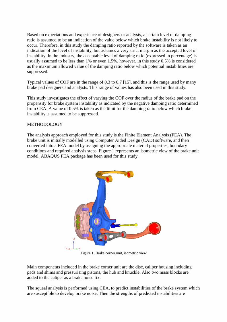
The concept of the partitioned pad can be implemented in the FEA model of the friction
material. In this study, the pad surface is divided into three and five partitions, and each
partition is assigned a different coefficient of friction. Figure 4 illustrates the partitioned pad,
demonstrating three and five partitions.
0
0.2
0.4
0.6
0.8
1
1.2
1.4
1.6
1.8
2
0 1000 2000 3000 4000 5000 6000 7000
Dam
pin
g ra
tio
(%
)
Frequency (Hz)
Basic Run: Pressure
2 bar 5 bar 10 bar
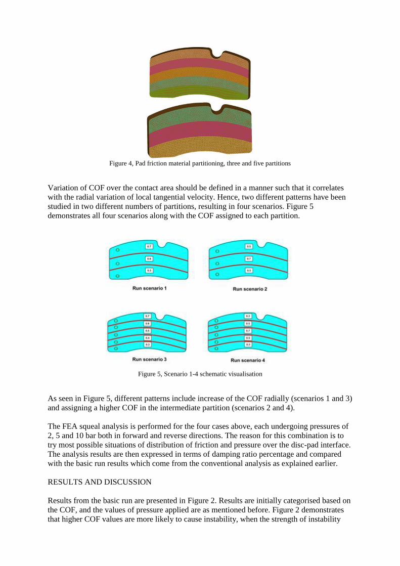
Figure 4, Pad friction material partitioning, three and five partitions
Variation of COF over the contact area should be defined in a manner such that it correlates
with the radial variation of local tangential velocity. Hence, two different patterns have been
studied in two different numbers of partitions, resulting in four scenarios. Figure 5
demonstrates all four scenarios along with the COF assigned to each partition.
Figure 5, Scenario 1-4 schematic visualisation
As seen in Figure 5, different patterns include increase of the COF radially (scenarios 1 and 3)
and assigning a higher COF in the intermediate partition (scenarios 2 and 4).
The FEA squeal analysis is performed for the four cases above, each undergoing pressures of
2, 5 and 10 bar both in forward and reverse directions. The reason for this combination is to
try most possible situations of distribution of friction and pressure over the disc-pad interface.
The analysis results are then expressed in terms of damping ratio percentage and compared
with the basic run results which come from the conventional analysis as explained earlier.
RESULTS AND DISCUSSION
Results from the basic run are presented in Figure 2. Results are initially categorised based on
the COF, and the values of pressure applied are as mentioned before. Figure 2 demonstrates
that higher COF values are more likely to cause instability, when the strength of instability

predicted for a specific frequency range is compared for different values of COF. However,
this does not necessarily mean a brake friction material with lower COF will be a good brake
pad, since changing the average COF of a friction material directly affects the braking power.
Hence lowering the COF is not necessarily the solution for a noisy brake in general.
Figure 3 also compares the same instabilities of the basic run, sorted based on the applied
pressure. Comparison of instabilities occurring at a certain frequency caused by different
levels of pressure reveals that although the applied pressure and strength of instability are not
directly related, strong instabilities mainly occurred at the low applied pressure of 2 bar.
Results from different scenarios are presented in this section, each compared with the basic
run results. Figure 6 and Figure 7 represent results for scenarios 1 and 2 (three partitions)
respectively while Figure 8 and Figure 9 represent the results of scenarios 3 and 4 (five
partitions) respectively. In all cases instabilities are predicted at five different frequency
neighbourhoods.
Figure 6, FEA results of the predicted instabilities - scenario 1 compared with the basic run
0
0.2
0.4
0.6
0.8
1
1.2
1.4
1.6
1.8
2
0 1000 2000 3000 4000 5000 6000 7000
Dam
pin
g ra
tio
%
Frequency (Hz)
Basic Run vs. Scenario 1
Scenario 1 Basic run
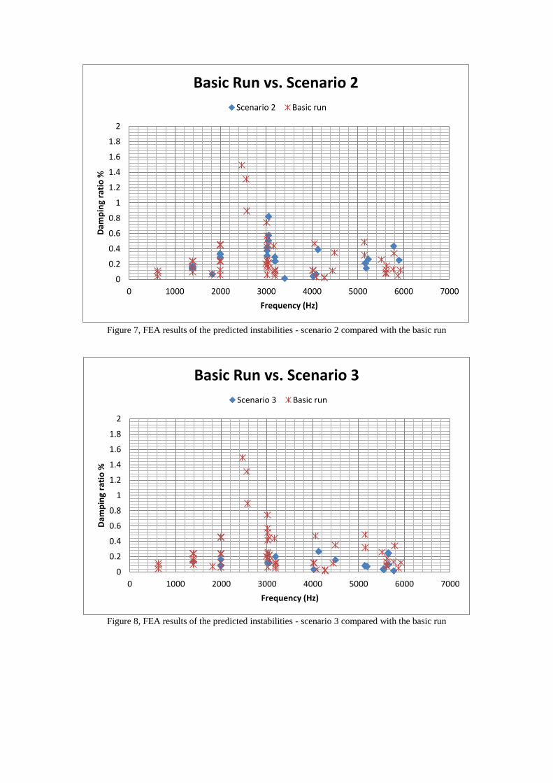
Figure 7, FEA results of the predicted instabilities - scenario 2 compared with the basic run
Figure 8, FEA results of the predicted instabilities - scenario 3 compared with the basic run
0
0.2
0.4
0.6
0.8
1
1.2
1.4
1.6
1.8
2
0 1000 2000 3000 4000 5000 6000 7000
Dam
pin
g ra
tio
%
Frequency (Hz)
Basic Run vs. Scenario 2
Scenario 2 Basic run
0
0.2
0.4
0.6
0.8
1
1.2
1.4
1.6
1.8
2
0 1000 2000 3000 4000 5000 6000 7000
Dam
pin
g ra
tio
%
Frequency (Hz)
Basic Run vs. Scenario 3
Scenario 3 Basic run

Figure 9, FEA results of the predicted instabilities - scenario 4 compared with the basic run
Comparing results from scenarios with three partitions with those of five partitions reveals
that the pads with five partitions are showing more stable behaviour, as the damping ratio
(strength of instabilities) is generally lower in scenarios 3 and 4. Both scenarios 3 and 4 show
instabilities with damping ratios not higher than the target set for the analysis. Also, scenario
4 has fewer instabilities in the higher frequencies of above 3 kHz, as seen in Figure 9.
However, although scenario 3 shows instabilities at more frequencies, the majority of them
have a low damping ratio, with the highest being 0.266% at a frequency of 4129.79 Hz.
Hence scenario 3 is selected as the most successful scenario, showing instabilities with
damping ratio mostly lower than half the target set, which was lower than the commonly
assumed level of 1%. Hence the partitioned pad with five partitions assigned a COF
increasing radially shows significantly lower strength of instability.
CONCLUSION
This study is based on the hypothesis that variation of the pattern of distribution of frictional
coefficient over the radius of the brake pad is effective in reducing the strength of the brake
instability.
The study suggests that variation of frictional coefficient over the radius of the brake pad is
effective in reducing the strength of brake instability.
More specifically, increasing the COF radially over the disc radius in the specified steps
produces instabilities with an effective damping ratio well within the acceptable range. This
low predicted damping ratio is an indication that there is less likelihood that noise will be
generated from the brake system, when tested as a prototype.
0
0.2
0.4
0.6
0.8
1
1.2
1.4
1.6
1.8
2
0 1000 2000 3000 4000 5000 6000 7000
Dam
pin
g ra
tio
%
Frequency (Hz)
Basic Run vs. Scenario 4
Scenario 4 Basic run

This study suggests that the uniform brake pad friction material is not the best approach from
a brake noise point of view. The proposed friction material distribution pattern can contribute
to reducing the fugitive nature of the brake noise problem, by reducing the strength of all
predicted instabilities to a value much lower than the target value of 0.5%, which is an
indication of less noise in the brake.
Although the proposed friction material patterns are not easy to manufacture compared to
conventional brake pads, there are manufacturing processes which make it possible, although
these are outside the context of this article. The intention is to carry out a comprehensive test
programme to confirm the hypothesis in a future study.
REFERENCES
1. Akay, A., Acoustics of friction. Acoustical Society of America, 2002. 111(4): p. 1525-
1548.
2. Papinniemi, A., et al., Brake squeal: a literature review. Applied acoustics, 2002.
63(4): p. 391-400.
3. Mottershead, J.E., Vibration- and friction-induced instability in disks. Shock and
Vibration Digest, 1998. 1(30): p. 17.
4. Liles, G.D., Analysis of disc brake squeal using finite element methods. Society of
Automotive Engineers, 1989. 891150: p. 1138-1146.
5. Spurr, R., A theory of brake squeal. Institution of Mechanical Engineers Automotive
Division, 1961/62(Proc No. 1): p. 30-40.
6. Day, P.A.J., Friction and Friction Materials, in Braking of Road Vehicles 2009, J.K.
A. J. Day, Editor. 2009, University of Bradford: UK.
7. Liu, P., et al., Analysis of disc brake squeal using the complex eigenvalue method.
Applied Acoustics, 2007. 68(6): p. 603-615.
8. Nishizawa, Y., et al., Influence of Pad Thickness and Surface Roughness on Pad
Stiffness, 2012, SAE International.
9. Hornig, S.A. and U. Von Wagner, Improvement of Brake Squeal Simulation
Reliability by Measurement and Identification of Friction Material Properties, 2012,
SAE International.
10. Ouyang, H., AbuBakar, A., Complex eigenvalue analysis and dynamic transient
analysis in predicting disc brake squeal. International Journal of Vehicle Noise and
Vibration, 2006. 2(2): p. 143-155.
11. Ouyang, H., et al., Numerical analysis of automotive disc brake squeal: a review. Int.
J. Vehicle Noise and Vibration, 2005. 1(3/4): p. 207-231.
12. Nouby, M. and K. Srinivasan, Parametric Studies of Disk Brake Squeal Using Finite
Element Approach. Jurnal Mekanikal, 2009. 29: p. 52-66.
13. Abubakar, A., Ph.D Thesis: Modelling and Simulation of Disc Brake Contact Analysis
and Squeal, in Department of Mechanical Engineering, Faculty of Engineering2005,
Liverpool, United Kingdom: University of Liverpool, Liverpool, United Kingdom.
14. Wallner, D., et al., Numerical and Experimental Parameter Studies on Brake Squeal.
2010.
15. Massi, F., et al., Brake squeal: Linear and nonlinear numerical approaches.
Mechanical Systems and Signal Processing, 2007. 21(6): p. 2374-2393.
16. Behrendt, J., C. Weiss, and N.P. Hoffmann, A numerical study on stick–slip motion of
a brake pad in steady sliding. Journal of Sound and Vibration, 2011. 330(4): p. 636-
651.
17. Wallner, D. and M. Meister, Elaborate Measuring System for Sensitivity Analyses and
In-Depth Investigations of a Squealing Brake System. SAE Int. J. Passeng. Cars -
Mech. Syst., 2012. 5(3): p. 1107-1115.
Related Documents


