Friction and multiple scratch behavior of polymerCmonomer liquid crystal systems Marı ´a Dolores Bermu ´dez a , Witold Brostow b,c, * , Francisco Jose ´ Carrio ´n-Vilches a,b , Juan Jose ´ Cervantes a , Dorota Pietkiewicz b a Grupo de Ciencia de Materiales e Ingenierı ´a Metalu ´rgica, Departamento de Ingenierı ´a de Materiales y Fabricacio ´n, Universidad Polite ´cnica de Cartagena, C/Doctor Fleming s/n, 30202 Cartagena, Spain b Laboratory of Advanced Polymers and Optimized Materials (LAPOM), Department of Materials Science and Engineering, University of North Texas 1 , Denton, TX 76203-5308, USA c Centro de Fisica Aplicada y Tecnologia Avanzada (CFATA), Universidad Nacional Auto ´noma de Mexico, A.P. 1-1010, Quere ´taro, Qro. 76001, Mexico Received 9 July 2004; received in revised form 27 October 2004; accepted 2 November 2004 Available online 26 November 2004 Abstract We have studied in turn: polystyrene (PS), styrene/acrylonitrile (SAN) and Polyamide 6 (PA6), adding each time to the polymer 1, 3, 5, 7 or 10 wt% of 4,4 0 -dibutylazobenzene (LC1) which is a monomer liquid crystal (MLC). LC1 reduces both static and dynamic friction of PS and SAN against stainless steels or polytetrafluoroethylene (PTFE). By contrast, friction values are lower for pure PA6 than for PA6 modified with various MLCs or with MoS 2 . Multiple scratching tests were carried out with a micro scratch tester on every system between 2.5 and 15 N. The presence of LC1 in PS reduces penetration depth and residual depth and increases the viscoelastic recovery. So far PS was the only polymer, which does not show strain hardening in multiple scratching. The present results confirms this, but it also shows that only 1 wt% of LC reduces the brittleness of PS so that strain hardening appears. This effect is maintained at all higher concentrations of LC1 investigated as well. For SAN or PA6, additions of LC1 reduce penetration depth values with respect to pure polymers, but do not have a significant effect on viscoelastic recovery. Scanning electron microscopy (SEM) was used to study the deformation and wear mechanisms, and to relate the data obtained in multiple scratch sliding wear tests. For PS we see in SEM that increasing the LC1 concentration causes a more ductile behavior, with less crack nucleation. For SAN the debris accumulation in sliding wear is mitigated by the presence of the liquid crystalline lubricant. No debris formation is observed in PA6, with or without a lubricant. q 2005 Elsevier Ltd. All rights reserved. Keywords: Scratch resistance; Sliding wear; Multiple scratching 1. Introduction and scope Tribology is still much better developed for metals than it is for polymers. An exhaustive book on tribology by Rabinowicz [1] deals with metals almost exclusively. The ongoing process in several industries of replacement of metal parts and components by polymeric ones is slowed down since polymeric surfaces undergo scratching and wear much more easily than metal surfaces. As pointed out by Rabinowicz [1], wear is a very serious economical problem, and thus even more acute for relatively ‘weak’ polymer surfaces. Some progress in polymer tribology has been made, as reviewed in Ref. [2]. Let us try to make a list of existing options. Lowering friction and/or increasing scratch resis- tance of polymeric surfaces can reduce wear. The options are: 1 Using fillers [3]—which is a two-edged sword: in certain 0032-3861/$ - see front matter q 2005 Elsevier Ltd. All rights reserved. doi:10.1016/j.polymer.2004.11.003 Polymer 46 (2005) 347–362 www.elsevier.com/locate/polymer * Corresponding author. Address: Laboratory of Advanced Polymers and Optimized Materials (LAPOM), Department of Materials Science and Engineering, University of North Texas, Denton, TX 76203-5308, USA. Tel.: C1 9405654358; fax: C1 9405654824. E-mail addresses: [email protected] (M.D. Bermu ´dez), [email protected] (W. Brostow), [email protected] (F.J. Carrio ´n- Vilches). 1 http://www.unt.edu/LAPOM

Welcome message from author
This document is posted to help you gain knowledge. Please leave a comment to let me know what you think about it! Share it to your friends and learn new things together.
Transcript
Friction and multiple scratch behavior of polymerCmonomer liquid
crystal systems
Marıa Dolores Bermudeza, Witold Brostowb,c,*, Francisco Jose Carrion-Vilchesa,b,Juan Jose Cervantesa, Dorota Pietkiewiczb
aGrupo de Ciencia de Materiales e Ingenierıa Metalurgica, Departamento de Ingenierıa de Materiales y Fabricacion, Universidad Politecnica de Cartagena,
C/Doctor Fleming s/n, 30202 Cartagena, SpainbLaboratory of Advanced Polymers and Optimized Materials (LAPOM), Department of Materials Science and Engineering, University of North Texas1,
Denton, TX 76203-5308, USAcCentro de Fisica Aplicada y Tecnologia Avanzada (CFATA), Universidad Nacional Autonoma de Mexico, A.P. 1-1010, Queretaro, Qro. 76001, Mexico
Received 9 July 2004; received in revised form 27 October 2004; accepted 2 November 2004
Available online 26 November 2004
Abstract
We have studied in turn: polystyrene (PS), styrene/acrylonitrile (SAN) and Polyamide 6 (PA6), adding each time to the polymer 1, 3, 5, 7
or 10 wt% of 4,4 0-dibutylazobenzene (LC1) which is a monomer liquid crystal (MLC). LC1 reduces both static and dynamic friction of PS
and SAN against stainless steels or polytetrafluoroethylene (PTFE). By contrast, friction values are lower for pure PA6 than for PA6 modified
with various MLCs or with MoS2.
Multiple scratching tests were carried out with a micro scratch tester on every system between 2.5 and 15 N. The presence of LC1 in PS
reduces penetration depth and residual depth and increases the viscoelastic recovery. So far PS was the only polymer, which does not show
strain hardening in multiple scratching. The present results confirms this, but it also shows that only 1 wt% of LC reduces the brittleness of PS
so that strain hardening appears. This effect is maintained at all higher concentrations of LC1 investigated as well. For SAN or PA6, additions
of LC1 reduce penetration depth values with respect to pure polymers, but do not have a significant effect on viscoelastic recovery. Scanning
electron microscopy (SEM) was used to study the deformation and wear mechanisms, and to relate the data obtained in multiple scratch
sliding wear tests. For PS we see in SEM that increasing the LC1 concentration causes a more ductile behavior, with less crack nucleation.
For SAN the debris accumulation in sliding wear is mitigated by the presence of the liquid crystalline lubricant. No debris formation is
observed in PA6, with or without a lubricant.
q 2005 Elsevier Ltd. All rights reserved.
Keywords: Scratch resistance; Sliding wear; Multiple scratching
1. Introduction and scope
Tribology is still much better developed for metals than it
is for polymers. An exhaustive book on tribology by
0032-3861/$ - see front matter q 2005 Elsevier Ltd. All rights reserved.
doi:10.1016/j.polymer.2004.11.003
* Corresponding author. Address: Laboratory of Advanced Polymers and
Optimized Materials (LAPOM), Department of Materials Science and
Engineering, University of North Texas, Denton, TX 76203-5308, USA.
Tel.: C1 9405654358; fax: C1 9405654824.
E-mail addresses: [email protected] (M.D. Bermudez),
[email protected] (W. Brostow), [email protected] (F.J. Carrion-
Vilches).1 http://www.unt.edu/LAPOM
Rabinowicz [1] deals with metals almost exclusively. The
ongoing process in several industries of replacement of
metal parts and components by polymeric ones is slowed
down since polymeric surfaces undergo scratching and wear
much more easily than metal surfaces. As pointed out by
Rabinowicz [1],wear is avery serious economical problem, and
thus even more acute for relatively ‘weak’ polymer surfaces.
Some progress in polymer tribology has been made, as
reviewed in Ref. [2]. Let us try to make a list of existing
options. Lowering friction and/or increasing scratch resis-
tance of polymeric surfaces can reducewear. The options are:
1
Using fillers [3]—which is a two-edged sword: in certainPolymer 46 (2005) 347–362
www.elsevier.com/locate/polymer
M.D. Bermudez et al. / Polymer 46 (2005) 347–362348
cases a filler enhances the scratch resistance; the usual
explanation is enhanced adhesion of the transfer film to
the counterface. Or else, the filler can weaken the scratch
resistance. Similarly, fillers can either lower or else
increase friction.
2
Using internal lubricants: the problem here is the rate atwhich the lubricant is oozing out from the bulk onto the
surface. Too fast a rate would exhaust the supply of the
lubricant from the bulk in less than the desired service
time of the component. Too slow a rate would provide
too weak effect on surface friction.
3
Converting polymers into heterogenous composites, forinstance by putting in fibers. However, in carbon-fiber
reinforced polymers the presence of fibers has been
reported to lower the wear resistance as compared to neat
polymers [4].
4
Formation of nanohybrids, either polymer matrixCceramic powder with the size of particles !100 nm, orelse analogous systems with metal powders.
5
External lubricants: in this case there exist a theorydeveloped by Binienda, Pindera and coworkers [5–8]
based on experiments with a well lubricated rigid punch
of a parabolic profile, assuming fully frictionless contact.
The theory is fairly general, tested for a variety of
surfaces. However, in the case of polymers an external
lubricant might cause swelling, and thus make the
situation worse than was the case for the surface without
a lubricant. We note here degradation of tribological
properties caused by water aging as studied by Hodzic
and coworkers [9,10]. At the same time, a judicious
choice of external lubricants appears possible—a moti-
vation for the present paper.
The present work represents a continuation of work on
external lubricants conducted in Cartagena [11–13,15,16],
work on friction [17], scratching and wear [18,19] at the
University of North Texas (UNT), and also joint work of
both groups [20,21]. Thus, the Cartagena group has
demonstrated that monomer liquid crystals (MLCs) in
base oils lower wear rates in steelCsteel and steelCaluminum contacts [11]. Similarly, tribological properties of
polystyrene (PS) and styrene/acrylonitrile (SAN) copolymer
[12,15] as well as polyamide 6 (PA6) [13] have been
modified using MLCs as lubricants. Ye and coworkers [14]
reported fairly low friction values obtained using a ball-on-
disk technique for metal pairs in the presence of fluorinated
alkylimidazole borates, which are MLCs. They concluded
that ‘ionic liquids exhbit superior tribological behavior’.
However, using a pin-on-disk technique, our Cartagena
group demonstrated that a non-ionic MLC provides at the
ambient temperature and up to 80 8C or so better results than
an ionic MLC lubricant [16]. A mixture of both kinds of
lubricants can lower the wear of aluminumCsteel even
more [16]. Pin-on-disk tests for PS and SAN show that
1 wt% of a MLC improves the wear resistance of these
polymers [12,15]. Similar results for PA6 [13] reveal a
similar or even superior antiwear property compared to the
well known solid lubricant MoS2.
In an earlier paper we have demonstrated lowering
friction of a commercial epoxy by a fluoropolymer additive
[17]. The results are strongly dependent, however, on the
curing temperature of the epoxy. The same epoxyCfluoropolymer system was studied using a single scratch
technique and a maximum in scratch resistance (shallowest
residual scratch) found at the same concentration [18] at
which the minimum friction is seen [17]. Sliding wear
determination led to a discovery of strain hardening in
multiple scratching [19] for three polymers. Recently the
UNT and Cartagena groups have determined jointly the
sliding wear multiple scratch resistance of pure PS, SAN,
PA6 and polysulfones [20,21]. Except for PS well known
for its brittleness, other polymers have also shown strain
hardening that is an asymptotic residual depth plotted as a
function of the number of tests performed. Thus, after 8–15
scratches, further scratching does not change the residual
depth of the groove.
The results for pure polymers reported in [20,21] are
followed in the present work by determination of static and
dynamic friction and of multiple scratch resistance of PS,
SAN and PA6 modified by the addition of variable
proportions (from 1 to 10 wt%) of a thermotropic MLC,
namely 4,4 0-dibutylazobenzene (LC1), the same as used
before [11,16]. In the case of PA6, the effect of 1 wt% LC1
has been compared with that of another MLC, namely
4-octyl 4 0-cyanobiphenyl (LC2) [16] and with MoS2.
2. Experimental
2.1. Materials
PS and PA6 were from Aldrich Chemicals Co. SAN was
from BASF, Ludwigshafen/Rhein, Germany, and is known
as Luranw. LC1 was synthesized [22], and purified [23] as
previously reported. LC2 was supplied by Merck, MoS2(99%, powder, !2 mm) by Aldrich.
After milling the polymers with the corresponding
proportion of MLC, PS and SAN samples were obtained
by pressing the powders at 22 MPa while heating them at
150 8C in a Buehler metallographic press as previously
described [13]. PA6 and PA6CMLC systems were injection
molded at 250 8C also as described in [13].
2.2. Friction testing
A SINTECH machine with a friction attachment was
used [17]. A 4.5 kg load cell and a sled with a nominal
weight of 700 g were used. The testing speed was 150 mm/
min. Polished AISI 52100 stainless steel or polytetrafluoro-
ethylene (PTFE, Teflon) surfaces were used. Resistance to
the initial and then continuous movement were measured to
determine static and dynamic friction, respectively. The
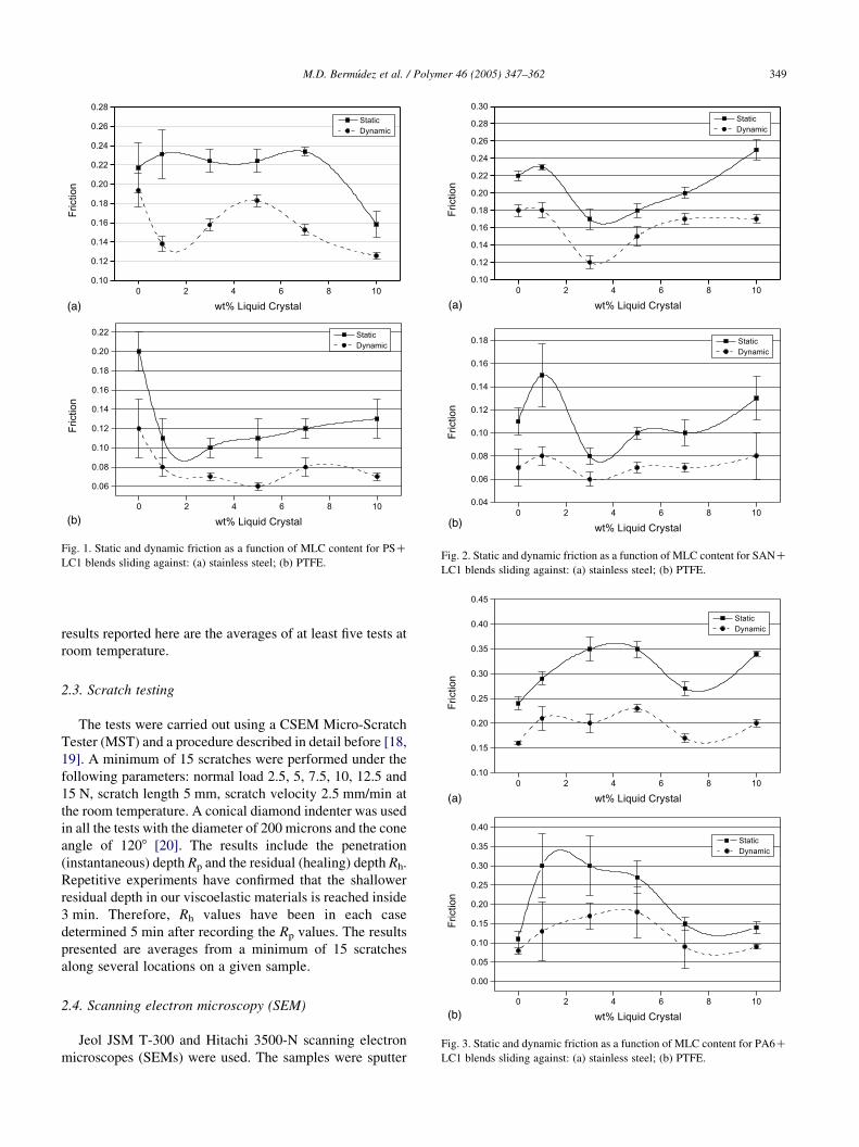
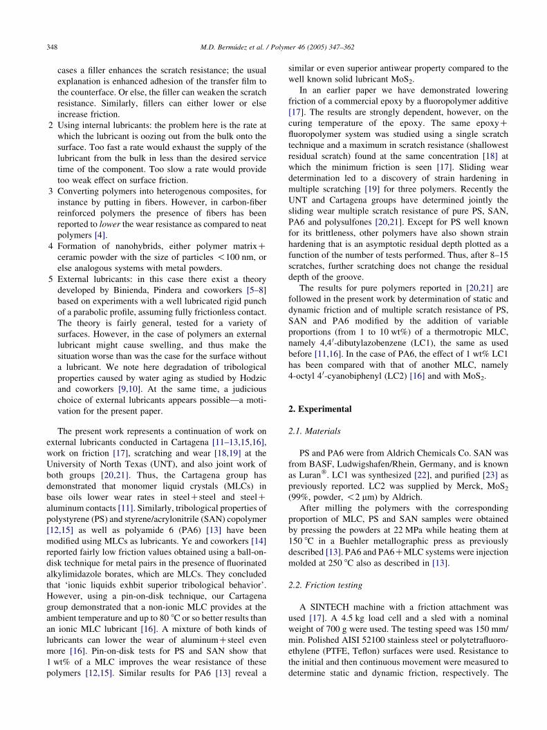
Fig. 1. Static and dynamic friction as a function of MLC content for PSC
LC1 blends sliding against: (a) stainless steel; (b) PTFE.Fig. 2. Static and dynamic friction as a function of MLC content for SANC
LC1 blends sliding against: (a) stainless steel; (b) PTFE.
M.D. Bermudez et al. / Polymer 46 (2005) 347–362 349
results reported here are the averages of at least five tests at
room temperature.
2.3. Scratch testing
The tests were carried out using a CSEM Micro-Scratch
Tester (MST) and a procedure described in detail before [18,
19]. A minimum of 15 scratches were performed under the
following parameters: normal load 2.5, 5, 7.5, 10, 12.5 and
15 N, scratch length 5 mm, scratch velocity 2.5 mm/min at
the room temperature. A conical diamond indenter was used
in all the tests with the diameter of 200 microns and the cone
angle of 1208 [20]. The results include the penetration
(instantaneous) depth Rp and the residual (healing) depth Rh.
Repetitive experiments have confirmed that the shallower
residual depth in our viscoelastic materials is reached inside
3 min. Therefore, Rh values have been in each case
determined 5 min after recording the Rp values. The results
presented are averages from a minimum of 15 scratches
along several locations on a given sample.
Fig. 3. Static and dynamic friction as a function of MLC content for PA6C
LC1 blends sliding against: (a) stainless steel; (b) PTFE.
2.4. Scanning electron microscopy (SEM)
Jeol JSM T-300 and Hitachi 3500-N scanning electron
microscopes (SEMs) were used. The samples were sputter
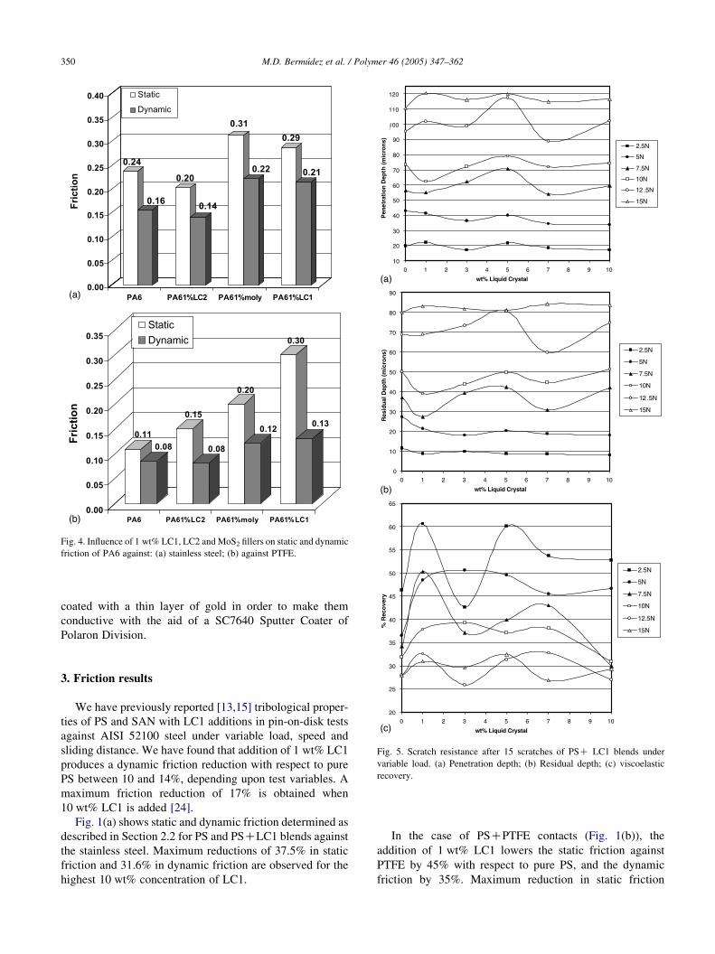
Fig. 4. Influence of 1 wt% LC1, LC2 andMoS2 fillers on static and dynamic
friction of PA6 against: (a) stainless steel; (b) against PTFE.
M.D. Bermudez et al. / Polymer 46 (2005) 347–362350
coated with a thin layer of gold in order to make them
conductive with the aid of a SC7640 Sputter Coater of
Polaron Division.
Fig. 5. Scratch resistance after 15 scratches of PSC LC1 blends under
variable load. (a) Penetration depth; (b) Residual depth; (c) viscoelastic
recovery.
3. Friction results
We have previously reported [13,15] tribological proper-
ties of PS and SAN with LC1 additions in pin-on-disk tests
against AISI 52100 steel under variable load, speed and
sliding distance. We have found that addition of 1 wt% LC1
produces a dynamic friction reduction with respect to pure
PS between 10 and 14%, depending upon test variables. A
maximum friction reduction of 17% is obtained when
10 wt% LC1 is added [24].
Fig. 1(a) shows static and dynamic friction determined as
described in Section 2.2 for PS and PSCLC1 blends against
the stainless steel. Maximum reductions of 37.5% in static
friction and 31.6% in dynamic friction are observed for the
highest 10 wt% concentration of LC1.
In the case of PSCPTFE contacts (Fig. 1(b)), the
addition of 1 wt% LC1 lowers the static friction against
PTFE by 45% with respect to pure PS, and the dynamic
friction by 35%. Maximum reduction in static friction
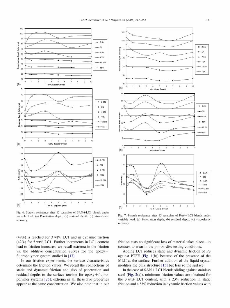
Fig. 6. Scratch resistance after 15 scratches of SANCLC1 blends under
variable load. (a) Penetration depth; (b) residual depth; (c) viscoelastic
recovery.
Fig. 7. Scratch resistance after 15 scratches of PA6CLC1 blends under
variable load. (a) Penetration depth; (b) residual depth; (c) viscoelastic
recovery.
M.D. Bermudez et al. / Polymer 46 (2005) 347–362 351
(49%) is reached for 3 wt% LC1 and in dynamic friction
(42%) for 5 wt% LC1. Further increments in LC1 content
lead to friction increases; we recall extrema in the friction
vs. the additive concentration curves for the epoxyCfluoropolymer system studied in [17].
In our friction experiments, the surface characteristics
determine the friction values. We recall the connections of
static and dynamic friction and also of penetration and
residual depths to the surface tension for epoxyCfluoro-
polymer systems [25]; extrema in all these five properties
appear at the same concentration. We also note that in our
friction tests no significant loss of material takes place—in
contrast to wear in the pin-on-disc testing conditions.
Adding LC1 reduces static and dynamic friction of PS
against PTFE (Fig. 1(b)) because of the presence of the
MLC at the surface. Further addition of the liquid crystal
modifies the bulk structure [15] but less so the surface.
In the case of SANCLC1 blends sliding against stainless
steel (Fig. 2(a)), minimum friction values are obtained for
the 3 wt% LC1 content, with a 23% reduction in static
friction and a 33% reduction in dynamic friction values with
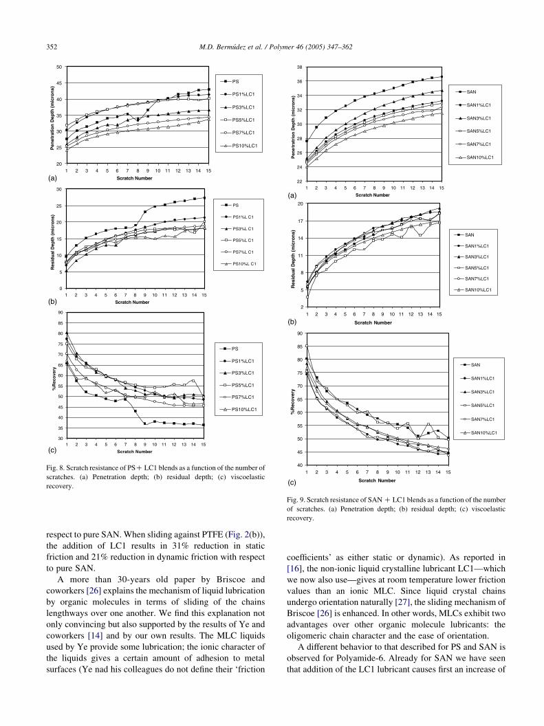
Fig. 8. Scratch resistance of PSC LC1 blends as a function of the number of
scratches. (a) Penetration depth; (b) residual depth; (c) viscoelastic
recovery.
Fig. 9. Scratch resistance of SANC LC1 blends as a function of the number
of scratches. (a) Penetration depth; (b) residual depth; (c) viscoelastic
recovery.
M.D. Bermudez et al. / Polymer 46 (2005) 347–362352
respect to pure SAN.When sliding against PTFE (Fig. 2(b)),
the addition of LC1 results in 31% reduction in static
friction and 21% reduction in dynamic friction with respect
to pure SAN.
A more than 30-years old paper by Briscoe and
coworkers [26] explains the mechanism of liquid lubrication
by organic molecules in terms of sliding of the chains
lengthways over one another. We find this explanation not
only convincing but also supported by the results of Ye and
coworkers [14] and by our own results. The MLC liquids
used by Ye provide some lubrication; the ionic character of
the liquids gives a certain amount of adhesion to metal
surfaces (Ye nad his colleagues do not define their ‘friction
coefficients’ as either static or dynamic). As reported in
[16], the non-ionic liquid crystalline lubricant LC1—which
we now also use—gives at room temperature lower friction
values than an ionic MLC. Since liquid crystal chains
undergo orientation naturally [27], the sliding mechanism of
Briscoe [26] is enhanced. In other words, MLCs exhibit two
advantages over other organic molecule lubricants: the
oligomeric chain character and the ease of orientation.
A different behavior to that described for PS and SAN is
observed for Polyamide-6. Already for SAN we have seen
that addition of the LC1 lubricant causes first an increase of
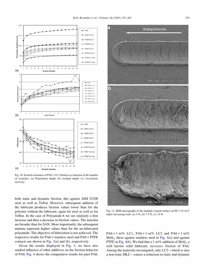
Fig. 10. Scratch resistance of PA6CLC1 blends as a function of the number
of scratches. (a) Penetration depth; (b) residual depth; (c) viscoelastic
recovery.
Fig. 11. SEM micrographs of the multiple scratch surface on PSC1% LC1
under increasing load: (a) 5 N; (b) 7.5 N; (c) 15 N.
M.D. Bermudez et al. / Polymer 46 (2005) 347–362 353
both static and dynamic friction, this against AISI 52100
steel as well as Teflon. However, subsequent addition of
the lubricant produces friction values lower than for the
polymer without the lubricant, again for steel as well as for
Teflon. In the case of Polyamide-6 we see similarly a first
increase and then a decrease in friction values. The maxima
are broader than for SAN. More importantly, the subsequent
minima represent higher values than for the un-lubricated
polyamide. The objective of lubrication is not achieved. The
respective results for PA6Cstainless steel and PA6CPTFE
contacts are shown in Fig. 3(a) and (b), respectively.
Given the results displayed in Fig. 3, we have also
studied influence of other additives on the friction behavior
of PA6. Fig. 4 shows the comparative results for pure PA6,
PA6C1 wt% LC1, PA6C1 wt% LC2 and PA6C1 wt%
MoS2, these against stainless steel in Fig. 4(a) and against
PTFE in Fig. 4(b). We find that a 1 wt% addition of MoS2, a
well known solid lubricant, increases friction of PA6.
Among the materials investigated, only LC2—which is also
a non-ionic MLC—causes a reduction in static and dynamic
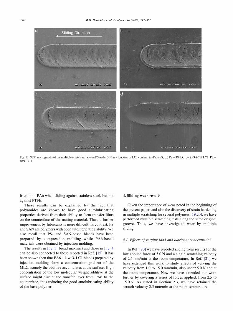
Fig. 12. SEMmicrographs of the multiple scratch surface on PS under 5 N as a function of LC1 content: (a) Pure PS; (b) PSC3% LC1; (c) PSC7% LC1; PSC
10% LC1.
M.D. Bermudez et al. / Polymer 46 (2005) 347–362354
friction of PA6 when sliding against stainless steel, but not
against PTFE.
These results can be explained by the fact that
polyamides are known to have good autolubricating
properties derived from their ability to form transfer films
on the counterface of the mating material. Thus, a further
improvement by lubricants is more difficult. In contrast, PS
and SAN are polymers with poor autolubricating ability. We
also recall that PS- and SAN-based blends have been
prepared by compression molding while PA6-based
materials were obtained by injection molding.
The results in Fig. 3 (broad maxima) and those in Fig. 4
can be also connected to those reported in Ref. [15]. It has
been shown then that PA6C1 wt% LC1 blends prepared by
injection molding show a concentration gradient of the
MLC, namely the additive accumulates at the surface. High
concentration of the low molecular weight additive at the
surface might disrupt the transfer layer from PA6 to the
counterface, thus reducing the good autolubricating ability
of the base polymer.
4. Sliding wear results
Given the importance of wear noted in the beginning of
the present paper, and also the discovery of strain hardening
in multiple scratching for several polymers [19,20], we have
performed multiple scratching tests along the same original
groove. Thus, we have investigated wear by multiple
sliding.
4.1. Effects of varying load and lubricant concentration
In Ref. [20] we have reported sliding wear results for the
low applied force of 5.0 N and a single scratching velocity
of 2.5 mm/min at the room temperature. In Ref. [21] we
have extended this work to study effects of varying the
velocity from 1.0 to 15.0 mm/min, also under 5.0 N and at
the room temperature. Now we have extended our work
further by covering a series of forces applied, from 2.5 to
15.0 N. As stated in Section 2.3, we have retained the
scratch velocity 2.5 mm/min at the room temperature.
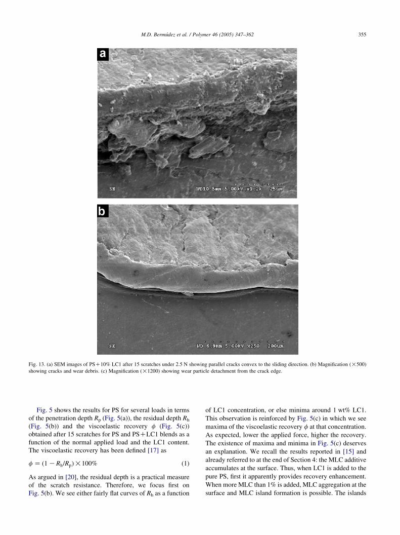
Fig. 13. (a) SEM images of PSC10% LC1 after 15 scratches under 2.5 N showing parallel cracks convex to the sliding direction. (b) Magnification (!500)
showing cracks and wear debris. (c) Magnification (!1200) showing wear particle detachment from the crack edge.
M.D. Bermudez et al. / Polymer 46 (2005) 347–362 355
Fig. 5 shows the results for PS for several loads in terms
of the penetration depth Rp (Fig. 5(a)), the residual depth Rh
(Fig. 5(b)) and the viscoelastic recovery f (Fig. 5(c))
obtained after 15 scratches for PS and PSCLC1 blends as a
function of the normal applied load and the LC1 content.
The viscoelastic recovery has been defined [17] as
fZ ð1KRh=RpÞ!100% (1)
As argued in [20], the residual depth is a practical measure
of the scratch resistance. Therefore, we focus first on
Fig. 5(b). We see either fairly flat curves of Rh as a function
of LC1 concentration, or else minima around 1 wt% LC1.
This observation is reinforced by Fig. 5(c) in which we see
maxima of the viscoelastic recovery f at that concentration.
As expected, lower the applied force, higher the recovery.
The existence of maxima and minima in Fig. 5(c) deserves
an explanation. We recall the results reported in [15] and
already referred to at the end of Section 4: the MLC additive
accumulates at the surface. Thus, when LC1 is added to the
pure PS, first it apparently provides recovery enhancement.
When more MLC than 1% is added, MLC aggregation at the
surface and MLC island formation is possible. The islands
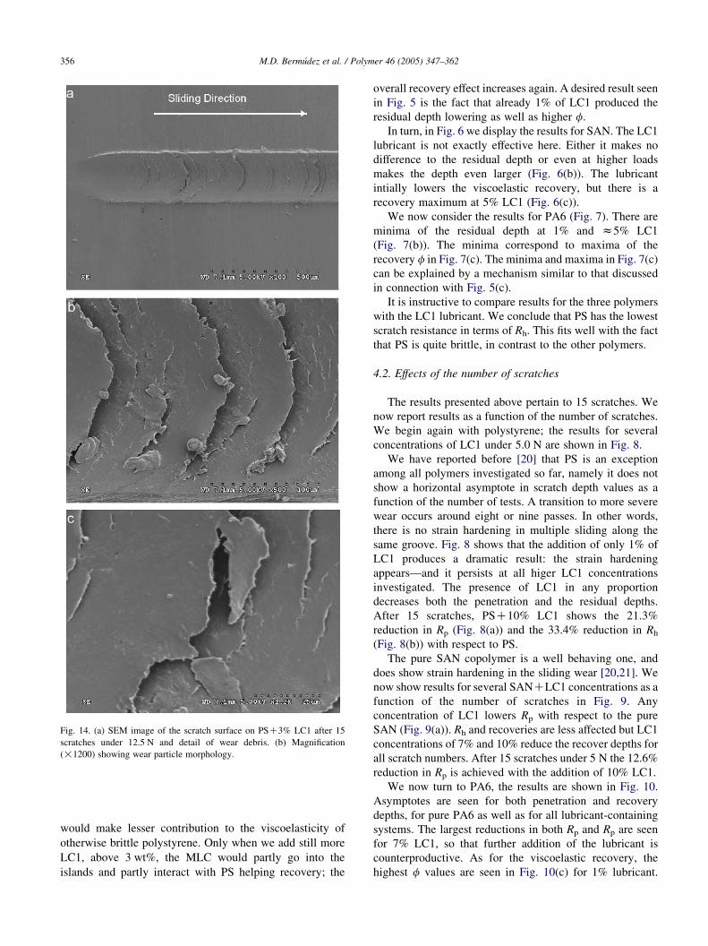
Fig. 14. (a) SEM image of the scratch surface on PSC3% LC1 after 15
scratches under 12.5 N and detail of wear debris. (b) Magnification
(!1200) showing wear particle morphology.
M.D. Bermudez et al. / Polymer 46 (2005) 347–362356
would make lesser contribution to the viscoelasticity of
otherwise brittle polystyrene. Only when we add still more
LC1, above 3 wt%, the MLC would partly go into the
islands and partly interact with PS helping recovery; the
overall recovery effect increases again. A desired result seen
in Fig. 5 is the fact that already 1% of LC1 produced the
residual depth lowering as well as higher f.
In turn, in Fig. 6 we display the results for SAN. The LC1
lubricant is not exactly effective here. Either it makes no
difference to the residual depth or even at higher loads
makes the depth even larger (Fig. 6(b)). The lubricant
intially lowers the viscoelastic recovery, but there is a
recovery maximum at 5% LC1 (Fig. 6(c)).
We now consider the results for PA6 (Fig. 7). There are
minima of the residual depth at 1% and z5% LC1
(Fig. 7(b)). The minima correspond to maxima of the
recovery f in Fig. 7(c). The minima and maxima in Fig. 7(c)
can be explained by a mechanism similar to that discussed
in connection with Fig. 5(c).
It is instructive to compare results for the three polymers
with the LC1 lubricant. We conclude that PS has the lowest
scratch resistance in terms of Rh. This fits well with the fact
that PS is quite brittle, in contrast to the other polymers.
4.2. Effects of the number of scratches
The results presented above pertain to 15 scratches. We
now report results as a function of the number of scratches.
We begin again with polystyrene; the results for several
concentrations of LC1 under 5.0 N are shown in Fig. 8.
We have reported before [20] that PS is an exception
among all polymers investigated so far, namely it does not
show a horizontal asymptote in scratch depth values as a
function of the number of tests. A transition to more severe
wear occurs around eight or nine passes. In other words,
there is no strain hardening in multiple sliding along the
same groove. Fig. 8 shows that the addition of only 1% of
LC1 produces a dramatic result: the strain hardening
appears—and it persists at all higer LC1 concentrations
investigated. The presence of LC1 in any proportion
decreases both the penetration and the residual depths.
After 15 scratches, PSC10% LC1 shows the 21.3%
reduction in Rp (Fig. 8(a)) and the 33.4% reduction in Rh
(Fig. 8(b)) with respect to PS.
The pure SAN copolymer is a well behaving one, and
does show strain hardening in the sliding wear [20,21]. We
now show results for several SANCLC1 concentrations as a
function of the number of scratches in Fig. 9. Any
concentration of LC1 lowers Rp with respect to the pure
SAN (Fig. 9(a)). Rh and recoveries are less affected but LC1
concentrations of 7% and 10% reduce the recover depths for
all scratch numbers. After 15 scratches under 5 N the 12.6%
reduction in Rp is achieved with the addition of 10% LC1.
We now turn to PA6, the results are shown in Fig. 10.
Asymptotes are seen for both penetration and recovery
depths, for pure PA6 as well as for all lubricant-containing
systems. The largest reductions in both Rp and Rp are seen
for 7% LC1, so that further addition of the lubricant is
counterproductive. As for the viscoelastic recovery, the
highest f values are seen in Fig. 10(c) for 1% lubricant.
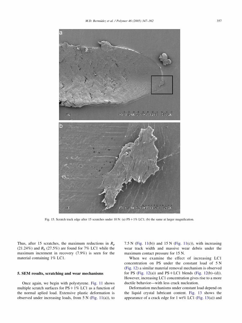
Fig. 15. Scratch track edge after 15 scratches under 10 N: (a) PSC1% LC1; (b) the same at larger magnification.
M.D. Bermudez et al. / Polymer 46 (2005) 347–362 357
Thus, after 15 scratches, the maximum reductions in Rp
(21.24%) and Rh (27.5%) are found for 7% LC1 while the
maximum increment in recovery (7.9%) is seen for the
material containing 1% LC1.
5. SEM results, scratching and wear mechanisms
Once again, we begin with polystyrene. Fig. 11 shows
multiple scratch surfaces for PSC1% LC1 as a function of
the normal aplied load. Extensive plastic deformation is
observed under increasing loads, from 5 N (Fig. 11(a)), to
7.5 N (Fig. 11(b)) and 15 N (Fig. 11(c)), with increasing
wear track width and massive wear debris under the
maximum contact pressure for 15 N.
When we examine the effect of increasing LC1
concentration on PS under the constant load of 5 N
(Fig. 12) a similar material removal mechanism is observed
for PS (Fig. 12(a)) and PSCLC1 blends (Fig. 12(b)–(d)).
However, increasing LC1 concentration gives rise to a more
ductile behavior—with less crack nucleation.
Deformation mechanisms under constant load depend on
the liquid crystal lubricant content. Fig. 13 shows the
appearance of a crack edge for 1 wt% LC1 (Fig. 13(a)) and
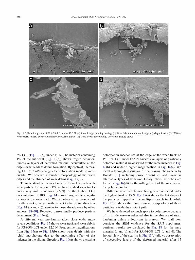
Fig. 16. SEMmicrographs of PSC3% LC1 under 12.5 N. (a) Scratch edge showing crazing. (b) Wear debris at the scratch edge. (c) Magnification (!2500) of
wear debris formed by the adhesion of succesive layers. (d) Wear debris morphology due to the rolling effect.
M.D. Bermudez et al. / Polymer 46 (2005) 347–362358
3% LC1 (Fig. 13 (b)) under 10 N. The material containing
1% of the lubricant (Fig. 13(a)) shows fragile behavior.
Succesive layers of deformed material accumulate at the
edge—what leads to debris formation. By contrast, increas-
ing LC1 to 3 wt% changes the deformation mode to more
ductile. We observe a rounded morphology of the crack
edges and the absence of wear debris (Fig. 13(b)).
To understand better mechanisms of crack growth with
wear particle formation in PS, we have studied wear tracks
under very mild conditons (2.5 N) for the highest LC1
concentration of 10%. Fig. 14 shows progressive magnifi-
cations of the wear track. We can observe the presence of
parallel cracks, convex with respect to the sliding direction
(Fig. 14 (a) and (b)), similar to those already seen by other
authors [28–30]. Repeated passes finally produce particle
detachment (Fig. 14(c)).
A different wear mechanism takes place under more
severe conditions. Fig. 15 shows wear track and wear debris
for PSC3% LC1 under 12.5 N. Progressive magnifications
from Fig. 15(a) to Fig. 15(b) show wear debris with the
‘chip’ morphology due to the machining effect of the
indenter in the sliding direction. Fig. 16(a) shows a crazing
deformation mechanism at the edge of the wear track on
PSC3% LC1 under 12.5 N. Successive layers of plastically
deformed material are observed for the same material in Fig.
16(b) and under a higher magnification in Fig. 16(c). We
recall a thorough discussion of the crazing phenomena by
Donald [31] including craze breakdown and shear as
alternative types of behavior. Finaly, fiber-like debris are
formed (Fig. 16(d)) by the rolling effect of the indenter on
the polymer surface.
Different wear particle morphologies are observed under
the highest load of 15 N. Fig. 17(a) shows the flat shape of
the particles trapped on the multiple scratch track, while
Fig. 17(b) shows the more rounded morphology of those
particles outside the contact path.
We have devoted so much space to polystyrene because
of its brittleness—as reflected also in the absence of strain
hardening unless a lubricant is present. We shall now
consider the SEM evidence for the SAN copolymer;
pertinent results are displayed in Fig. 18 for the pure
material (a and b) and for SANC3% LC1 (c and d). The
frontal view of the scar tip in Fig. 18(b) allows observation
of successive layers of the deformed material after 15
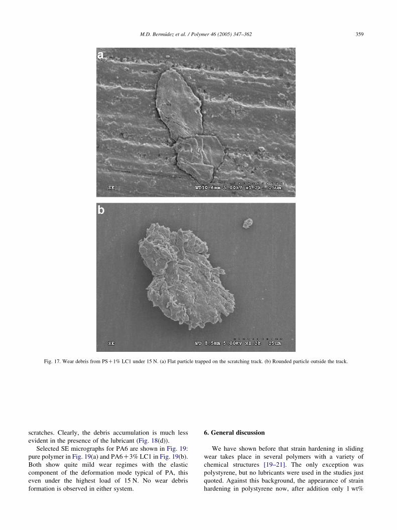
Fig. 17. Wear debris from PSC1% LC1 under 15 N. (a) Flat particle trapped on the scratching track. (b) Rounded particle outside the track.
M.D. Bermudez et al. / Polymer 46 (2005) 347–362 359
scratches. Clearly, the debris accumulation is much less
evident in the presence of the lubricant (Fig. 18(d)).
Selected SE micrographs for PA6 are shown in Fig. 19:
pure polymer in Fig. 19(a) and PA6C3% LC1 in Fig. 19(b).
Both show quite mild wear regimes with the elastic
component of the deformation mode typical of PA, this
even under the highest load of 15 N. No wear debris
formation is observed in either system.
6. General discussion
We have shown before that strain hardening in sliding
wear takes place in several polymers with a variety of
chemical structures [19–21]. The only exception was
polystyrene, but no lubricants were used in the studies just
quoted. Against this background, the appearance of strain
hardening in polystyrene now, after addition only 1 wt%
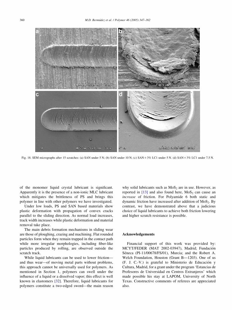
Fig. 18. SEM micrographs after 15 scratches: (a) SAN under 5 N; (b) SAN under 10 N; (c) SANC3% LC1 under 5 N. (d) SANC3% LC1 under 7.5 N.
M.D. Bermudez et al. / Polymer 46 (2005) 347–362360
of the monomer liquid crystal lubricant is significant.
Apparently it is the presence of a non-ionic MLC lubricant
which mitigates the brittleness of PS and brings this
polymer in line with other polymers we have investigated.
Under low loads, PS and SAN based materials show
plastic deformation with propagation of convex cracks
parallel to the sliding direction. As normal load increases,
track width increases while plastic deformation and material
removal take place.
The main debris formation mechanisms in sliding wear
are those of ploughing, crazing and machining. Flat rounded
particles form when they remain trapped in the contact path
while more irregular morphologies, including fiber-like
particles produced by rolling, are observed outside the
scratch track.
While liquid lubricants can be used to lower friction—
and thus wear—of moving metal parts without problems,
this approach cannot be universally used for polymers. As
mentioned in Section 1, polymers can swell under the
influence of a liquid or a dissolved vapor; this effect is well
known in elastomers [32]. Therefore, liquid lubricants for
polymers constitute a two-edged sword—the main reason
why solid lubricants such as MoS2 are in use. However, as
reported in [13] and also found here, MoS2 can cause an
increase of friction. For Polyamide 6 both static and
dynamic friction have increased after addition of MoS2. By
contrast, we have demonstrated above that a judicious
choice of liquid lubricants to achieve both friction lowering
and higher scratch resistance is possible.
Acknowledgements
Financial support of this work was provided by:
MCYT/FEDER (MAT 2002-03947), Madrid; Fundacion
Seneca (PI-11/00678/FS/01), Murcia; and the Robert A.
Welch Foundation, Houston (Grant B—1203). One of us
(F. J. C.-V.) is grateful to Ministerio de Educacion y
Cultura, Madrid, for a grant under the program ‘Estancias de
Profesores de Universidad en Centros Extranjeros’ which
made possible his stay at LAPOM, University of North
Texas. Constructive comments of referees are appreciated
also.
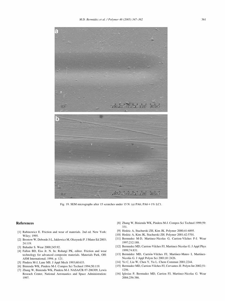
Fig. 19. SEM micrographs after 15 scratches under 15 N: (a) PA6; PA6C1% LC1.
M.D. Bermudez et al. / Polymer 46 (2005) 347–362 361
References
[1] Rabinowicz E. Friction and wear of materials. 2nd ed. New York:
Wiley; 1995.
[2] BrostowW, Deborde J-L, Jaklewicz M, Olszynski P. J Mater Ed 2003;
24:119.
[3] Bahadur S. Wear 2000;245:92.
[4] Fallon BD, Eiss Jr. N. In: Rohatgi PK, editor. Friction and wear
technology for advanced composite materials. Materials Park, OH:
ASM International; 1994. p. 121.
[5] Pindera M-J, Lane MS. J Appl Mech 1993;60:633.
[6] Binienda WK, Pindera M-J. Compos Sci Technol 1994;50:119.
[7] Zhang W, Binienda WK, Pindera M-J. NASA/CR-97-206309, Lewis
Reseach Center, National Aeronautics and Space Administration:
1997.
[8] Zhang W, Binienda WK, Pindera M-J. Compos Sci Technol 1999;59:
331.
[9] Hodzic A, Stachurski ZH, Kim JK. Polymer 2000;41:6895.
[10] Hodzic A, Kim JK, Stachurski ZH. Polymer 2001;42:5701.
[11] Bermudez M-D, Martinez-Nicolas G, Carrion-Vilches F-J. Wear
1997;212:188.
[12] Bermudez MD, Carrion-Vilches FJ, Martinez-Nicolas G. J Appl Phys
1999;74:831.
[13] Bermudez MD, Carrion-Vilches FJ, Martınez-Mateo I, Martınez-
Nicolas G. J Appl Polym Sci 2001;81:2426.
[14] Ye C, Liu W, Chen Y, Yu L. Chem Commun 2001;2244.
[15] Bermudez MD, Carrion-Vilches FJ, Cervantes JJ. Polym Int 2002;51:
1256.
[16] Iglesias P, Bermudez MD, Carrion FJ, Martinez-Nicolas G. Wear
2004;256:386.
M.D. Bermudez et al. / Polymer 46 (2005) 347–362362
[17] Brostow W, Cassidy PE, Hagg HE, Montemartini PE. Polymer 2001;
42:7971.
[18] BrostowW, Bujard B, Cassidy PE, Hagg HE, Montemartini PE. Mater
Res Innovat 2002;6:7.
[19] BrostowW, Damarla G, Howe J, Pietkiewicz D. e-Polymers 2004; no.
025.
[20] Bermudez MD, Brostow W, Carrion-Vilches FJ, Cervantes JJ,
Pietkiewicz D. e-Polymers, to be published.
[21] Bermudez MD, Brostow W, Carrion-Vilches FJ, Cervantes JJ,
Damarla G, Perez JM., e-Polymers, to be published.
[22] Vicente J, Bermudez MD, Carrion FJ, Martınez-Nicolas G.
J Organomet Chem 1994;480:103.
[23] Barrado I, Meseguer V, Bermudez MD, Martınez-Nicolas G.
J Supercrit Fluids 1997;11:73.
[24] Cervantes JJ, Carrion FJ, Bermudez MD. Smart surfaces in Tribology
Conference, Zurich, 2003, Book of Abstracts, p. 46; full paper to be
published.
[25] Brostow W, Cassidy PE, Macossay J, Pietkiewicz D, Venumbaka S.
Polym Int 2003;52:1498.
[26] Briscoe BJ, Scruton B, Willis FR. Proc Roy Soc Lond A 1973;333:99.
[27] Brostow W, editor. Mechanical and thermophysical properties of
polymer liquid crystals. London: Chapman and Hall; 1998.
[28] Ni BY, le Faou A. J Mater Sci 1996;31:3955.
[29] Briscoe BJ, Evans PD, Pelillo E, Sinha SK. Wear 1996;200:137.
[30] Zhang SL, Nishizoe K. Tribol Lett 2004;1–2:73.
[31] Donald AM. In: Brostow W, editor. Performance of plastics. Munich-
Cincinnati: Hanser; 2000. Chapter 13.
[32] Mark JE, Erman B. Rubberlike elasticity-a molecular primer. New
York: Wiley; 1988.
Related Documents