FREQUENCY AND TEMPERATURE DEPENDENCE IN ELECTROMAGNETIC PROPERTIES OF MARTIAN ANALOG MINERALS by David E. Stillman

Welcome message from author
This document is posted to help you gain knowledge. Please leave a comment to let me know what you think about it! Share it to your friends and learn new things together.
Transcript

FREQUENCY AND TEMPERATURE DEPENDENCE
IN ELECTROMAGNETIC PROPERTIES OF
MARTIAN ANALOG MINERALS
by
David E. Stillman

A thesis submitted to the Faculty and Board of Trustees of the Colorado School of
Mines in partial fulfillment of the requirements for the degree of Doctor of Philosophy
(Geophysics).
Golden, Colorado Date ___________
Signed: ________________ David E. Stillman
Approved: ________________ Dr. Gary R. Olhoeft
Thesis Advisor Golden, Colorado Date ___________
Approved: ________________ Dr. Terry K. Young Professor and Head
Department of Geophysics
ii

ABSTRACT
Over the past decade, much has been learned about the surface of Mars; however,
the subsurface of Mars still remains a mystery. Many surfaces on Mars are buried by
aeolian deposits or coated with dust and thus hidden from traditional imaging methods.
Ground penetrating radar (GPR) has the potential to image beneath these layers to give
geological context to drilling targets, locate potential subsurface rover hazards,
investigate stratigraphy, and most importantly, image subsurface water. The discovery of
Martian groundwater will have significant implications for a manned mission to Mars and
could reveal important clues about the possibility of extraterrestrial life. The Martian
subsurface appears to be a good radar environment because average subsurface
temperatures are below the freezing point of water (down to 1–5 km). However, GPR
depth of penetration is extremely dependent on the EM properties of the subsurface
which include dielectric permittivity, magnetic permeability, and DC resistivity. Martian
soil has a mineralogical composition that is unlike the majority of soils seen on Earth.
Furthermore, a magnetic dust layer blankets nearly every surface on the planet.
Consequently, attenuation mechanisms such as dielectric and magnetic relaxations losses
could cause significant attenuation of radar energy. Dielectric and magnetic relaxations
can also be temperature dependent, which is significant since the average temperature on
Mars is 213 K with planetary diurnal variations ranging from 154 – 300 K.
In order to understand the effect of EM losses on GPR depth of penetration on
Mars, the EM properties of Martian analog samples were measured versus frequency and
temperature using an HP8753D vector network analyzer. The measurements were also
acquired versus temperature over a range of 180 – 300 K to simulate the Martian
environment. Results from these measurements yielded several significant EM
relaxations in Martian analog minerals that had never been observed prior to this study.
iii

Grey hematite was found to possess a large temperature dependent dielectric relaxation
with a relaxation frequency at 230 and 450 MHz at 213 K in two samples. Magnetite was
found to possess a temperature independent magnetic relaxation with a relaxation
frequency at 200, 540, and 580 MHz in three samples. Plagioclase feldspar was found to
possess a temperature dependent dielectric relaxation over a very broad frequency range
in two samples.
Currently, two orbital radars, MARSIS and SHARAD, have been sent to
investigate the subsurface of Mars. The designers of MARSIS and SHARAD predicted
that their depths of penetration will be 5 km and 1 km, respectively. To demonstrate how
these temperature dependent EM losses can impact MARSIS, SHARAD, and future GPR
missions to Mars, the maximum GPR depth of penetration (DoP) was determined.
Assuming a radar system dynamic range of 50 dB and a Martian average temperature of
213 K, the DoP for MARSIS is 1.6 km for grey hematite, 510 m for magnetite, and 70 m
for plagioclase feldspar. Using the same assumptions, the DoP for SHARAD is 55 m for
grey hematite, 20 m for magnetite, and 15 m for plagioclase feldspar. The GPR depths of
penetration listed above represent the maximum limit because only dielectric and
magnetic losses were considered. Other losses (such as geometric spreading, scattering,
etc.) will only further reduce the depth of penetration. Results from this study illustrate
why it is important to understand the EM properties of Martian soils in the Martian
environment when designing a GPR to investigate the subsurface of Mars.
iv

TABLE OF CONTENTS
ABSTRACT................................................................................................................... iii LIST OF FIGURES ....................................................................................................... ix LIST OF TABLES......................................................................................................... xii LIST OF SYMBOLS ..................................................................................................... xiii ACKNOWLEDGEMENTS........................................................................................... xx CHAPTER 1 INTRODUCTION .................................................................................. 1
1.1 Introduction............................................................................................... 1 1.2 Evidence of Water on Mars ...................................................................... 2 1.3 The Martian EM Environment.................................................................. 6 1.4 Previous Measurements of EM Properties................................................ 10 1.5 Research Objectives.................................................................................. 13 1.6 MARSIS and SHARAD ........................................................................... 13 1.7 Overview................................................................................................... 15
CHAPTER 2 ELECTROMAGNETIC PROPERTIES OF MARTIAN ANALOG
MATERIALS..................................................................................................... 16
2.1 EM Theory ................................................................................................ 16 2.1.1 EM Propagation ............................................................................ 16 2.1.2 EM Reflection and Transmission.................................................. 24 2.1.3 Radar Equation.............................................................................. 25
2.2 Dielectric Permittivity............................................................................... 26 2.2.1 Types of Charge Separation Mechanisms..................................... 26 2.2.2 Frequency Dependence of Dielectric Permittivity........................ 28
2.3 Magnetic Permeability .............................................................................. 29 2.3.1 Types of Magnetism ..................................................................... 30 2.3.2 Martian Iron Oxides...................................................................... 33 2.3.3 Magnetic Domains ........................................................................ 38
v

2.3.4 Grain Size...................................................................................... 43 2.3.5 Magnetic Hysteresis...................................................................... 44 2.3.6 Frequency Dependence of Magnetic Permeability ....................... 48
2.4 Temperature and Frequency Dependence of Dielectric Permittivity and Magnetic Permeability .................................................................. 51
2.5 Mixing Formulas....................................................................................... 54 CHAPTER 3 MARTIAN ANALOG SAMPLES......................................................... 57
3.1 Observations of Martian Mineralogy........................................................ 57 3.1.1 Martian Meteorites........................................................................ 57 3.1.2 Martian Orbiters............................................................................ 59
3.1.2.1 Infrared and Visible Spectroscopy................................... 59 3.1.2.2 Magnetic Field ................................................................. 62 3.1.2.3 Gamma Ray Suite of Instruments .................................... 64
3.1.3 Martian Landers. ........................................................................... 66 3.1.3.1 Dust .................................................................................. 67 3.1.2.2 Meridiani Planum............................................................. 72 3.1.2.3 Gusev Crater .................................................................... 74
3.1.4 Summary of Martian Observations............................................... 74 3.2 Limitations of the Methods used to Map Mineralogy on Mars ................ 76
3.2.1 Limitations of Infrared and Visible Spectroscopy ........................ 76 3.2.2 Limitations of the Magnetic Field Measurements ........................ 79 3.2.3 Limitations of the Gamma Ray Suite of Instruments ................... 80 3.2.4 Limitations of the Mössbauer Spectroscopy................................. 85 3.2.5 Limitations of Alpha Proton X-ray Spectrometer......................... 87 3.2.6 Summary of the Limitations of the Methods used to Map
Mineralogy on Mars................................................................ 88 3.3 Sample Selection....................................................................................... 88 3.4 Sample Preparation ................................................................................... 89
CHAPTER 4 LABORATORY SETUP AND PROCEDURES ................................... 90
4.1 Measurement Apparatus, Environment, and Procedure ............................. 90 4.2 VNA Calibration......................................................................................... 93 4.3 Theory for Measuring EM Properties in a Coaxial Waveguide ................ 94 4.4 Accuracy and Error Analysis ...................................................................... 100
4.4.1 VNA Measurement Accuracy.................................................... 101 4.4.2 Incoherent and Coherent Sources of Noise................................ 110 4.4.3 Improper Apparatus Setup ......................................................... 112
4.5 Measurement, Accuracy and Quality Control of Temperature................... 113
vi

CHAPTER 5 EXPERIMENTAL AND MODEL RESULTS ...................................... 122
5.1 Introduction................................................................................................. 122 5.2 Data Modeling ............................................................................................ 122 5.3 Samples with No Measurable Losses ......................................................... 128 5.4 Samples with Dielectric Relaxation Losses................................................ 130 5.5 Samples with Magnetic Relaxation Losses................................................. 143
CHAPTER 6 DISCUSSION AND CONCLUSIONS .................................................. 148
6.1 Discussion ................................................................................................... 148 6.2 Grey Hematite............................................................................................. 148
6.2.1 Temperature Dependent Dielectric Relaxation Mechanism of Grey Hematite ............................................................................. 149
6.2.2 Implications of the Temperature Dependent Dielectric Relaxation of Grey Hematite for MARSIS, SHARAD, and Future GPR Missions .................................................................. 151
6.2.2.1 Thermal Modeling of the Martian Subsurface.............. 153 6.2.2.2 Dielectric Permittivity Modeling .................................. 156 6.2.2.3 Temperature Modeling Results..................................... 163
6.3 Magnetite .................................................................................................... 164 6.3.1 Temperature Independent Magnetic Relaxation Mechanism of
Magnetite..................................................................................... 166 6.3.2 Implications of the Temperature Independent Magnetic
Relaxation of Magnetite for MARSIS, SHARAD, and Future GPR Missions.............................................................................. 166
6.4 Implications of the EM Losses of Other Measured Samples for MARSIS, SHARAD, and Future GPR Missions ....................................... 168
6.5 Conclusion .................................................................................................. 170 CHAPTER 7 FUTURE WORK.................................................................................... 172
7.1 Introduction................................................................................................. 172 7.2 Temperature Range Improvements............................................................. 172 7.3 Additional Martian Analog EM Measurements.......................................... 173 7.4 EM Property Measurement Improvements................................................. 177 7.5 EM Property Measurements Versus Water/Ice Content............................. 176
vii

REFERENCES CITED.................................................................................................. 177 APPENDIX.................................................................................................................... 198
viii

LIST OF FIGURES
1.1. The phase diagram of water..................................................................................... 5 1.2. Daily surface temperature variations on Mars ......................................................... 9 2.1. Cubic inverse spinal structure of magnetite............................................................. 34 2.2. Rhombohedra corundum crystal structure of hematite............................................ 36 2.3. Magnetic domains.................................................................................................... 39 2.4. How super-exchange, demagnetization, and magnetocrystalline anisotropy
energy affect magnetic domains ...................................................................... 40 2.5. Magnetic domain wall.............................................................................................. 42 2.6. Temperature dependence of magnetic domains....................................................... 43 2.7. Magnetic hysteresis.................................................................................................. 45 2.8. Hysteresis curve of multidomain, singledomain, and superparamagnetic biotite
crystals containing magnetite............................................................................ 47 2.9. Frequency and temperature dependence of dielectric permittivity.......................... 53 3.1. Martian magnetic field............................................................................................. 63 3.2. Near surface distribution of water on Mars ............................................................. 66 3.3. MER-A sweep magnet............................................................................................. 68 3.4. Mars Pathfinder magnets ......................................................................................... 69 3.5. Hematite concretions on Mars ................................................................................. 73 3.6. Dust covered rocks................................................................................................... 77
ix

4.1. Apparatus used to measure the EM properties of Martian analogs versus temperature and frequency....................................................................................... 92
4.2. Electric and magnetic fields in a coaxial waveguide ............................................... 95 4.3. Signal flow chart of the VNA .................................................................................. 98 4.4. Difference in data and noise envelopes between the maximum manufacturer
listed precision and the actual precision ..............................................................104 4.5. Lower limit of conductivity for the VNA measuring system ..................................105 4.6. Data and noise envelopes as a function of the real part of the relative dielectric
permittivity and the real part of the relative magnetic permeability........................107 4.7. Data and noise envelopes for a frequency dependent dielectric permittivity and
magnetic permeability..............................................................................................108 4.8. Data and noise envelopes as a function of sample holder length ............................109 4.9. Standard deviation at each frequency versus number of external stacks.................111 4.10. Circuit used to find thermistor resistance ..............................................................113 4.11. Resistance vs temperature for thermistors .............................................................114 4.12. EM properties of air vs frequency and temperature...............................................119 4.13. Time constant of relaxation vs temperature...........................................................121 5.1. Inversion sensitivity analysis ...................................................................................125 5.2. The three temperature ranges of the 95.5% confidence interval of the time
constant at infinite temperature and the activation energy.......................................127 5.3. EM properties of a typical lossless and temperature independent sample...............129 5.4. Temperature and frequency dependent dielectric relaxation of GHKwMI .............133 5.5. Arrhenius plot of GHKwMI.....................................................................................134
x

5.6. Temperature and frequency dependent dielectric relaxation of GHSChp ...............136 5.7. Arrhenius plot of GHChp.........................................................................................137 5.8. Temperature and frequency dependent dielectric relaxation of JSC1 .....................139 5.9. Temperature and frequency dependent dielectric relaxation of PuNeHIC..............141 5.10. Arrhenius plot of PuNeHIC ...................................................................................142 5.11. Frequency dependent magnetic relaxation of MagRCh.........................................145 5.12. Frequency dependent magnetic relaxation of Magn..............................................146 5.13. Frequency dependent magnetic relaxation of Yuma .............................................147 6.1. Maximum depth of penetration of grey hematite samples.......................................152 6.2. Temperature versus depth profile for a diurnal variation at the Viking 1 landing
site ............................................................................................................................155 6.3. Temperature versus depth profile for seasonal and diurnal variations for three
latitudes on Mars ......................................................................................................156 6.4. Annual loss difference .............................................................................................158 6.5. Diurnal loss difference.............................................................................................159 6.6. Dielectric permittivity versus depth for annual variations.......................................160 6.7. Dielectric permittivity versus depth for diurnal variations ......................................161 6.8. Difference in two-way traveltime in grey hematite .................................................162 6.9. Difference in two-way traveltime in grey hematite mixed with Pu’u Nene Horizon C at the Martian equator ..........................................................163 6.10. Maximum depth of penetration for magnetite .......................................................167 6.11. Maximum depth of penetration for plagioclase feldspar samples .........................169
xi

LIST OF TABLES
2.1. Various mechanisms for charge separation ............................................................. 27 2.2. Various mechanisms for magnetic relaxations ........................................................ 50 3.1. The mean particle radius of atmospheric dust at Mars ............................................ 71 4.1. Typical error in temperature ....................................................................................117 5.1. EM properties of samples with no measurable losses .............................................128 5.2. Cole-Cole and Boltzmann temperature parameters for samples with temperature
dependent dielectric relaxations ...............................................................................131 5.3. Uncertainties in time constant of relaxation at infinite temperature........................132 5.4. Cole-Cole parameters for samples with temperature independent magnetic
relaxations ................................................................................................................144 6.1. Diurnal parameter values ..........................................................................................154 6.2. Diurnal and annual temperature parameter values....................................................155
xii

LIST OF SYMBOLS
Symbol Terminology SI unit [Sheriff, 1999] a Attenuation of EM energy dB
A Ampere A
a1 Output of energy from port 1 dB
a2 Output of energy from port 2 dB
B Magnetic induction T = Wb/m2 = kg/s2A
b1 Input of energy from port 1 dB
b2 Input of energy from port 2 dB
c Velocity of an EM wave in vacuum (2.99×10⁸) m/s
c Shape factor in the BHS equation unitless
C Coulomb As oC Centigrade -273.15 K
D Displacement currents C/m2
d Bulk Density g/cm3
d data unitless
dn Normalized Bulk Density (1.60) g/cm3
dB Decibels dB
E Electric field V/m = mkg/s3A
eV Electronvolt eV = 1.602 * 10-19 J
f Frequency Hz = 1/s
f Cole-Cole equation unitless
fr Relaxation frequency Hz = 1/s
fr Resonant frequency Hz = 1/s
F Farad C/m = s4A2/m2kg
xiii

Fe2+ Ferrous iron unitless
Fe3+ Ferric iron unitless
H Magnetic field A/m
H Henry Wb/A = m2kg/s2A2
Hc Coercivity A/m
Hz Frequency Hz = cycles/s
i 1− unitless
J Conduction current density A/m2
J Joule J=Ws=VAs=kgm2/s2
Js magnetic saturation normalized by density Am2/kg
Ms Saturation magnetization A/m
k Boltzmann constant (8.6176 × 10⁻⁵) eV/K
k Wavenumber 1/m
K Kelvin K
K mode of d1∞ε (1.92) unitless
L Sample holder length m
m Meter m
mho Inverse of electrical resistance 1/Ω
Mr Remanent magnetization A/m
Ms Magnetic saturation A/m
N Number of data points unitless
Np Nepers Np = 8.686 dB
O2- Oxygen anion unitless
ro Radius of the outer conductor of the sample holder (0.00700) m
ri Radius of the inner conductor of the sample holder (0.00305) m
xiv

s Second s
S11 Scattering (S) parameter from port 1 to port 1 dB
S12 Scattering (S) parameter from port 1 to port 2 dB
S21 Scattering (S) parameter from port 2 to port 1 dB
S22 Scattering (S) parameter from port 2 to port 2 dB
t Time s
T Tesla T = Wb/m2 = kg/s2A
TC Curie temperature K
Ti4+ Titanium cation unitless
V Volt V = m2kg/s3A
V Velocity m/s
VA Output reflected voltage wave V = m2kg/s3A
VB Output transmitted voltage wave V = m2kg/s3A
Vin Input voltage wave V = m2kg/s3A
W Watt W = J/s = kgm2/s2
Wb Weber Wb = Vs = m2kg/s2A
x mole% of the titanium in magnetite and maghemite percent
x modeled data points unitless
X Relative dielectric permittivity or relative magnetic
permeability unitless
X∞ Infinite or high frequency limit of X unitless
XDC Static, DC, or low frequency limit of X unitless
y mole% of the titanium in hematite percent
z Transmission coefficient dB
Z Complex impedance Ω
Zo Impedance of the cable (50) Ω
Vacancy in the lattice structure unitless
xv

α Attenuation coefficient Np/m
α Cole-Cole distribution parameter unitless
β Phase coefficient radians/m
∇ Del operator unitless
δD Dielectric loss tangent radians
δC Conduction loss tangent radians
δE Electrical loss tangent radians
δM Magnetic loss tangent radians
δEM Electromagnetic loss tangent radians
εo Dielectric permittivity of free space (8.854×10⁻¹²) F/m = s4A2/m3kg
*rε Complex relative dielectric permittivity unitless
'rε Real part of the relative dielectric permittivity unitless
"rε Imaginary part of the relative dielectric permittivity unitless
εDC Static, DC, or low frequency limit of the real part of the relative dielectric permittivity unitless
ε∞ Infinite or high frequency limit of the real part of the relative dielectric permittivity unitless
*1ε Complex relative dielectric permittivity for material
1 unitless
*2ε Complex relative dielectric permittivity for material
2 unitless
*mε Complex relative dielectric permittivity predicted
for mixture unitless
n*rε Complex relative dielectric permittivity normalized
to density unitless
xvi

φ2 Weighted normalized data misfit unitless
χ Magnetic susceptibility unitless
Γ Reflection coefficient dB
λ Wavelength m
μ o Magnetic permeability of free space (1.256×10⁻⁶) H/m = mkg/s2A2
*rμ Relative magnetic permeability unitless
'rμ Real part of the relative magnetic permeability unitless
"rμ Imaginary part of the relative magnetic
permeability unitless μDC Static, DC, or low frequency limit of the real part
of the relative magnetic permeability unitless
μ∞ Infinite or high frequency limit of the
real part of the relative magnetic permeability unitless
π Pi (3.14159) unitless
ρ Electric charge density C/m3
ρ Resistivity Ωm
σ Electrical conductivity 1/Ωm
σ Standard deviation unitless
σDC Static or DC electrical conductivity 1/Ωm
τ Time constant of relaxation s
τ∞ Time constant of relaxation at infinite temperature s
Ω Ohm Ω = V/A = m2kg/s3A2
Ω Volume fraction of material 2 in the mixture %
ω Angular (radian) frequency Hz = radians/s
ξ Radar cross section m2
xvii

Prefixes
T Tera 1012
G Giga 109
M Mega 106
k Kilo 103
c Centi 10-2
m Milli 10-3
μ Micro 10-6
n Nano 10-9
p Pico 10-12
Abbreviations EM Electromagnetic GPR Ground Penetrating MER Mars Exploration Rovers MER-A Mars Exploration Rover – Spirit MER-B Mars Exploration Rover – Opportunity MEX Mars Express MGS Mars Global Surveyor MO 2001 Mars Odyssey S Scattering SNC Shergottites, Nakhlites, and Chassigny TE transverse electric mode
xviii

TEM transverse electromagnetic mode TES Thermal Emission Spectrometer TM transverse magnetic mode THEMIS Thermal Emission Imaging System VNA Vector Network Analyzer
xix

ACKNOWLEDGEMENTS
This work was sponsored by NASA grant 20119458 NAG5-12754. I would like to thank
my advisor Gary Olhoeft for obtaining the funding so that I could explore my passions
for geophysics and Mars. I have been in the geophysics department at Mines for the last
decade and all of the professors have been great. Specifically, I’d like to thank Mike
Batzle, Adel Zhody, Yaoguo Li and Terry Young. I also received a lot of help from
outside CSM. Bob Horton and Rich Reynolds of the USGS helped out whenever I had a
problem. I also appreciate the help of Steve Sutley of the USGS Denver Federal Center
who conducted some of our XRD measurements.
I would also like to thank the graduate, undergrad, and highschool students who assited
with the experiment, programming, and rock crushing including Justin Modroo, Sjoerd de
Ridder, Brianne Douthit, Beau Winters, Andy Kass, Ross Wagle, Matt Hergert, Paul
Schwering, Jeremy Norman, and Francis Li. A special shout goes out to James Linse
who helped rescue files off of my hard drive, install the new hard drive a week before my
defense, and who produced the images of me doing GPR on Mars. I would also like to
thank the graduate students who helped me in my work including Beth Burton, Erin
Wallin, Kate McKinley, Sarah Shearer, Dave Sinex, Barry Kirkendall, Rich Krahenbuhl,
Marty Terrell, and Whitney Goodrich.
I could not have accomplished this work without the unwavering support from my wife,
parents, and sister. My wife also served as my unofficial advisor and helped transform
my writing into something that others could comprehend. Lastly, I would like to thank
my parents for encouraging me to follow my passions.
xx

1
CHAPTER 1
INTRODUCTION
1.1 Introduction
Over the past decade, much has been learned about the Martian surface; however,
the Martian subsurface still remains a mystery. Many surfaces on Mars are buried by
aeolian deposits or coated with dust and thus hidden from traditional imaging methods
[Bandfield et al., 2000; Johnson et al., 2002a]. Ground penetrating radar (GPR) has the
potential to image beneath these layers. Imaging the Martian subsurface is valuable
because it can be used to locate and give geological context to drilling targets, locate
potential subsurface rover hazards, investigate stratigraphy, and most importantly, image
subsurface water.
“Follow the water” is the guiding principle of NASA’s Mars Exploration
Program. It is a top priority because if any extraterrestrial life ever existed or currently
exists, it would most likely be found near a source of water. On August 7, 1996,
following the announcement that Martian fossils may have been found in a Martian
meteorite [McKay et al., 1996], President Clinton spoke about the importance of finding
life on Mars, “…it will surely be one of the most stunning insights into our universe that
science has ever uncovered. Its implications are as far reaching and awe inspiring as can
be imagined.” In 2004, the possibility of active Martian life was suggested as a possible
explanation for spatially varying small concentrations (10 parts per billion by volume) of
methane gas identified in the Martian atmosphere [Formisano et al., 2005].
The genesis of life on Earth is poorly understood. Nearly all of the evidence for
life’s beginning has been destroyed by plate tectonics or erosion. However, it appears
that rocks on Mars are billions of years old. If life did take hold on Mars, these rocks

2
may contain clues regarding the origins of life. Conversely, if life never existed on Mars
these rocks may constrain the environmental factors that lead to the beginning of life.
Discovering that life once existed or does exist on Mars would prove that the genesis of
life occurred at least twice in our solar system. With so many other solar systems in the
galaxy, the possibilities for life elsewhere become much greater.
Aside from the potential for extraterrestrial life, the discovery of water also will
have significant implications for a manned mission to Mars. Martian water could be used
for drinking and breathing, and to extract oxygen and hydrogen for rocket fuel. If an
acceptable source of water could be found on Mars, the overall weight of the payload that
needs to be transported from Earth would be reduced. This would allow for either
additional payload or a smaller and less expensive launch vehicle.
1.2 Evidence of Water on Mars
There is substantial evidence that water has been active on the surface of Mars.
This evidence includes the following:
• Images from the Mariner 9 and the Viking orbiters revealed giant flood
channels [Irwin et al., 2004], extensive valley networks with branching
tributaries [Carr, 1996], and dried up lake beds [Williams and Zimbelman,
1994].
• The Viking orbiters found that the northern perennial polar cap was composed
of water ice [Kieffer et al., 1976].
• The Viking orbiters also discovered the initial evidence for fluidized ejecta
around craters ranging from 5 – 50 km in diameter [Carr et al., 1977]. This is
significant since Mars is the only planetary body that has such craters [Barlow
et al., 2000]. Fluidized ejecta most likely forms when an impactor strikes a
subsurface that is rich in volatiles like water ice [Barlow et al., 2000]. The

3
mobility of the fluidized ejecta is influenced by crater latitude and altitude and
is found to be greatest at high latitudes and low elevations where water ice is
most stable [Mougins-Mark, 1979].
• The nakhlites group of Martian meteorites shows evidence of aqueous
alterations [Meyer, 2005].
• Mars Global Surveyor found evidence of gullies that are thought to have been
formed by water [Malin and Edgett, 2000; Christensen, 2003].
• Mars Global Surveyor and Mars Odyssey found sedimentary evidence that
may indicate that water did flow on Mars billions of years ago. Images
suggest a distributary, channelized flow that lasted long enough to produce
meandering and a delta [Malin and Edgett, 2003, Moore et al., 2003,
Bhattacharya, et al., 2005]
• Mars Odyssey found evidence of hydrogen that is believed to be in the form
of frozen water at latitudes poleward ±60o and at two mid-latitude locations
[Feldman et al., 2004].
• Mars Odyssey observations have also led to the discovery that a layer of water
ice exists under the southern perennial CO2 ice cap [Titus et al., 2003].
• Mars Global Surveyor found the spectral signature of grey hematite, which
can form in the presence of water [Christensen et al., 2001]. Opportunity
(MER-B) discovered that the spectral signature of grey hematite was caused
by grey hematite concretions that were likely precipitated by groundwater
[Squyres and Knoll, 2005]. The sedimentary layers that contained the grey
hematite concretions contained evidence suggesting that they were formed in
an acidic salty playa environment [Squyres and Knoll, 2005].
• Spirit (MER-A) found signs that rocks and soils near Husband Hill have been
altered by salty water [Ming et al., 2005].

4
• Mars Express has mapped hydrated phyllosilicates (clays) mineralogy and
hydrated sulfates (salts) on Mars – both require water to form [Bibring et al.,
2005].
Presently, liquid water can only exist on about 30% of the Martian surface due to
the low pressure (average pressure is 6.1 mbar) [Haberle et al., 2004]. Figure 1.1 shows
the phase diagram of water. At the highest Martian pressure of 12.5 mbar [Haberle et al.,
2004], liquid water can only exist at temperatures between 273 – 300 K. (Martian
temperatures range from 154 K – 300 K.) However, salts dissolved in water can
significantly reduce the freezing point of water at all pressures, thus reducing the triple
point (the point at the highest pressure where water can exist in three phases) to lower
temperatures and pressures. Spirit (MER-A) has found significant evidence of salts
[Arvidson et al., 2006]. All of the other landers and Mars Express have also found
evidence of salts [Bell III et al., 2000; Squyres and Knoll, 2005; Bibring et al., 2005].
Carr [1986] estimated that 100 – 500 m of a global equivalent layer (GEL) of
water was necessary to form the aqueous features found on Mars. It has been suggested
that 5 – 50 m of this GEL of water has been broken down by sunlight into hydrogen and
oxygen gas, which then escaped into space [Yung et al., 1988; Carr, 1990; Jakosky, 1991;
Luhman et al., 1992; Leshin, 2000]. Currently, the largest reservoir of water identified
on Mars is the polar residual water ice caps, which would create a GEL of water
approximately 30 m deep [Carr, 1986; Smith et al., 1999]. A much smaller water
reservoir with a GEL of about 10-5 m is found in the current atmosphere of Mars [Jakosky
and Farmer, 1982]. These two estimates suggest that a large portion of the Martian water
is locked in the subsurface.

5
Figure 1.1. This figure shows the phase diagram of water. The Martian pressure range is nearly centered on the triple point. The hatched area shows the range of pressures and temperatures where liquid water is stable on Mars. However, if salts are present in the water, the triple point is significantly lowered in both pressure and temperature. Figure modified from Haberle et al. [2001].

6
This ground ice was predicted to be within one meter of the Martian surface at
latitudes poleward of ±50o and becoming deeper at equatorial latitudes [Mellon and
Jakosky, 1993]. Recently, the gamma ray suite of instruments has found evidence of a
new water reservoir, ground ice at latitudes poleward of ±50o. While this reservoir can
only be measured to about one meter deep, it has a GEL of approximately 14 cm
[Feldman et al, 2004]. It is unknown if this ice rich layer extends deep into the
subsurface or if it is confined to the top 10s – 100s of meters [Mellon et al., 1997]. If the
ground ice does extend deep into the subsurface, it will melt into liquid water as the
geothermal gradient increases the temperature with depth [Clifford and Parker, 2001].
The geothermal gradient of Mars has never been measured, but theoretical modeling
suggests values ranging from 0.02 – 0.045 W/m2 [Fanale, 1976; Toksöz et al., 1978;
Stevenson et al., 1983; Schubert and Spohn, 1990; Spohn 1991]. Results from thermal
modeling predict that ground water may be present within 1-5 km of the surface at
equatorial latitudes, increasing in depth toward the poles [Clifford and Parker, 2001].
The presence of gullies suggests that some liquid water may be very near the Martian
surface [Malin and Edgett, 2000] but, due to the cold temperatures on Mars, it is unlikely
that large amounts of liquid water are stable in the near (<1 km) subsurface [Clifford and
Parker, 2001].
Hydrogen has also been mapped at mid-latitudes and low elevations by the
gamma ray suite of instruments. Mellon et al. [1997] and Jakosky et al. [2005] have
shown that water ice could be present, but currently unstable, within a meter of the
surface. This hydrogen could also be locked up in hydrated minerals such as jarosite,
which can contain as much as 10% water in its crystal structure [Rodionov et al., 2005].
1.3 The Martian Radar Environment
Before discussing the propagation of radar energy through the Martian
subsurface, two GPR targets will be discussed – water ice and liquid water. Water ice is

7
a difficult GPR target, even if it is within a meter of the Martian surface. At radar
frequencies, water ice possesses a dielectric permittivity near or equal to most dry rocks
or soils and therefore does not produce a significant contrast that can be identified in
GPR data. Even though the ice would increase the dielectric permittivity of the
subsurface by filling the pore space, a similar result could also occur due to compaction
of the soil.
Unlike water ice, liquid water is an ideal GPR target due to its large relative
dielectric permittivity. However, even though there is a large contrast between water’s
relative dielectric permittivity (about 80) and a dry porous media (about 4), this contrast
is decreased since water can only fill the porosity of the media. As depth increases, the
porosity will naturally decrease due to increased compaction. Capillary fringes
(boundary due to the capillary forces of the pores between the unsaturated and saturated
zone that is partially saturated) will produce a gradual change in the contrast of dielectric
material properties. Mars may have permafrost or an ice saturated zone above the water
table instead of an unsaturated zone. Between the permafrost and water table, a mixture
of liquid water and water ice may exist. This would also produce a gradual change in the
contrast of dielectric material properties. If the change in contrast is gradual enough, a
reflection may not be seen from a high frequency radar signal. As previously stated,
liquid water aquifers are predicted to be at least one kilometer deep [Clifford, 2001].
While liquid water is a good GPR reflector, it will significantly attenuate any
GPR energy propagating through it. Water causes both dielectric relaxation losses at
high frequencies and conduction losses at all frequencies [Olhoeft, 1998]. The
interaction of liquid water and mineralogical clay can cause large conductivity and
electrochemical losses at all frequencies [Olhoeft, 1998] and high dielectric losses at low
frequencies [Lockhart, 1980a, 1980b, Canan, 1999]. (However, finely crushed rock or
engineering rock flour, which has a clay designated grain size, does not possess high
losses like mineralogical clays.) GPR surveys on Earth can only achieve a depth of
penetration greater than a kilometer if there are low concentrations of water. Mars

8
appears to be a much better radar environment than Earth because the average subsurface
temperatures are below the freezing point of water. Without the EM losses caused by
liquid water, other loss mechanisms such as magnetic and dielectric relaxations and
scattering losses must be considered as the limiting factor for GPR depth of penetration
on Mars.
In this thesis, the dielectric and magnetic relaxations of Martian minerals will be
examined. Dielectric relaxation losses of Earth soils are typically overwhelmed by losses
associated with water and clays. However, the presence of magnetic minerals on Earth
has proven to create significant radar losses [Olhoeft and Capron, 1994]. Magnetic
relaxations rarely occur on Earth due to the lack of ferromagnetic and ferrimagnetic
minerals in Earth soils. Unlike Earth, Mars is known to contain an abundance of
ferrimagnetic minerals at its surface [Hargraves et al., 2000]. In fact, every particle of the
Martian global windblown dust layer is magnetic at DC (zero) frequency and is believed
to be composed of about 2% magnetite [Bertelsen et al., 2004]. Consequently, magnetic
and dielectric relaxation losses on Mars may be the dominant loss mechanisms and
therefore must be considered when predicting depth of penetration.
Dielectric and magnetic relaxations can also change as a function of temperature
[Olhoeft, 1976; Dunlop and Özdemir, 1997]. As shown in Figure 1.2, Mars has a wide
range of daily global temperature fluctuations (154 K – 300 K) with an average annual
surface temperature ranging from 154 K – 218 K as a function of latitude [Clifford,
2001]. Due to the wide temperature range on Mars, these temperature dependent
properties will change as a function of the time of day and have different values than
those measured in the typical Earth environment. Consequently, measurements of
electromagnetic (EM) properties (dielectric permittivity, magnetic permeability, and DC
conductivity) made at terrestrial room temperature (≈298 K) will not be representative for
Mars.

9
Figure 1.2. Daily surface temperature variations on Mars. The dots are Martian surface temperature as determined by Opportunity over the first 65 Martian days (sols) on Mars [Spanovich et al., 2006]. The solid line is the predicted Martian surface temperature at Opportunity’s landing site [Martin et al., 2003].
Pressure can also affect dielectric permittivity and magnetic permeability by
altering the crystal structure of the mineral [Böttcher, 1952]. However, pressure changes
that affect dielectric permittivity and magnetic permeability in dry samples are usually
generated by much higher pressures than those occurring at subsurface depths of a few
kilometers. Therefore, all measurements for this study were made at atmospheric Earth
pressures ≈1 bar.
If the subsurface of Mars is favorable to GPR penetration, the ability to image the
vertical extent of the groundwater becomes important to estimate its total water volume.
The ability of GPR energy to penetrate through a water saturated media strongly depends
on the concentrations of salts. The presence of dissolved salts increases the conduction
losses at all frequencies. There will also be a dielectric relaxation loss of water at high

10
frequencies. As discussed in Chapter 3, significant amounts of sulfur, bromide,
phosphorus and chloride salts have been found on Mars [Bibring et al., 2005; Squyres
and Knoll, 2005; Arvidson et al., 2006]. This leads to the conclusion that the
groundwater will most likely possess a high conductivity, which will severely limit any
GPR penetration through the aquifer at any radar frequency. Consequently, only
reflections from the top of the groundwater may be detected and thus, other methods such
as EM induction will be necessary to determine the aquifer’s thickness [Grimm, 2002].
In order to uniquely identify subsurface liquid water on Mars a combination of GPR, EM
induction, and seismic methods may be necessary [Olhoeft, 2003].
1.4 Previous Measurements of Martian EM Properties
The magnetic properties of Mars at DC frequencies have been studied by making
in situ measurements. These measurements have been made by attaching magnets on
every Martian lander and by measuring the remanent magnetic field from Martian
orbiters. The in situ measurements have found that Martian rocks, soils, and dust contain
significantly more magnetic minerals than Earth, and the Martian global dust layer has an
average saturation magnetization of 1-4 Am2/kg and a density magnetic susceptibility of
9-33×10-6 m3/kg [Morris et al., 2001]. This magnetization is caused by either magnetite
or titanomagnetite [Morris et al., 2004; Bertelsen et al., 2004; Goetz et al., 2005; Yen et
al., 2005]. Mars also possesses a remanent magnetic field that is 10 times greater than
Earth’s remanent magnetic field and is most likely caused by thermoremanent
magnetization of magnetite or titanomagnetite [Dunlop and Arkani-Hamed, 2005].
Laboratory measurements of the EM properties of Martian analogs at radar
frequencies have been made in the past [Olhoeft and Strangway, 1974; Olhoeft and
Capron, 1993, 1994; Leuschen, 1999; Heggy et al., 2001, 2003; Heggy and Pommerol,
2005; Williams and Greeley, 2004; Pettinelli et al., 2005]. A brief discussion of these
measurements follows.

11
Olhoeft and Strangway [1974] predicted that the electrical properties of the
Martian subsurface would be similar to the Moon, even though the Martian atmosphere
contains a small amount of water. This is because small amounts of water absorbed in
the soil do not affect dielectric permittivity at high frequencies [McIntosh, 1966]. The
water would also typically be in the form of ice, thus reducing its effects further. Other
than the water/ice transition, Olhoeft and Strangway [1974] state that temperature had no
effect on the electrical properties of the Moon soils and therefore should not have an
influence on Mars. However, Olhoeft [1976] later demonstrated that temperature does
have an effect on electrical properties of dry soils. Olhoeft and Strangway [1974] make
no mention of magnetic properties of the Martian subsurface. However, Olhoeft and
Capron [1993, 1994] found that a soil near Yuma, AZ, possessed a magnetic relaxation
that was the dominant loss mechanism in the soil. This demonstrates that magnetic losses
could be the dominant loss mechanism in the Martian subsurface.
Leuschen [1999] conducted measurements with a vector network analyzer (VNA)
and used a slotted line for the sample holder. These measurements were made from 10
MHz to 1 GHz and found that JSC Mars-1 possessed a frequency dependent dielectric
permittivity and a frequency dependent magnetic permeability. Slotted line
measurements can be more accurate than the waveguide measurements made in this
thesis, however they can only be made over a small frequency range. Leuschen’s
calculation of magnetic permeability is briefly described, but it is most likely incorrect.
Numerous measurements of Mars JSC-1 were conducted in this study and a magnetic
permeability above one was never recorded for Mars JSC-1. (This is further discussed in
Section 5.4.)
Heggy et al. [2001, 2003] and Heggy and Pommerol [2005] have conducted
measurements of dielectric permittivity versus frequency for Martian analogs with
impedance analyzers. Impedance analyzers cannot measure phase as accurately as the
VNA that was used in this thesis, thus VNAs can measure lower losses than impedance

12
analyzers. Heggy et al. [2001, 2003] and Heggy and Pommerol [2005] did not report any
magnetic permeability measurements.
Williams and Greeley [2004] measured the complex dielectric permittivity of JSC
Mars-1 and Carbondale red clay from 200 – 1300 MHz at room temperature. Exactly
how they measured this is not discussed. They also made microwave transmission
measurements on the same samples over a frequency range from 500 – 12,000 MHz.
They then assumed no magnetic losses and a magnetic permeability of one to calculate an
attenuation rate. Their attenuation rate is slightly larger than the attenuation rates for JSC
Mars-1 found in this thesis. (This is further discussed in Section 5.4.)
Pettinelli et al. [2005] conducted measurements of two magnetite samples with an
LCR meter from 500 Hz – 1 MHz and time domain reflectometry (TDR) from 1 – 500
MHz. The LCR meter was able to measure both complex dielectric permittivity and
complex magnetic permeability because two different sample holders were used to
measure each separately. However, these measurements are below the radar frequency
range, thus they were used to constrain the low frequency limit of both the dielectric
permittivity and magnetic permeability. The TDR measurements are sensitive to the EM
velocity of a material. Therefore, TDR measurements cannot uniquely measure complex
dielectric permittivity and complex magnetic permeability. However, the TDR
measurements showed that the EM velocity did not change from 1 – 500 MHz.
Therefore, Pettinelli et al. [2005] concluded that these two magnetite samples did not
possess any significant magnetic or dielectric relaxation below 500 MHz. In this thesis,
two out of three magnetite samples were found to possess magnetic relaxations at
frequencies greater than 500 MHz.
All of these previous measurements were conducted at room temperature (≈298
K). The surface temperature on Mars rarely reaches 298 K. Temperature must be
accounted for when measuring the EM properties of Martian analogs since EM properties
can vary as a function of temperature. Magnetic properties become temperature
dependent near and at the Curie, Néel, and Morin temperatures. Research done by Iben

13
et al. [1996] and Morris et al. [1997] have shown that the electrical properties of some
Martian analogs also change as a function of temperature. Iben et al. [1996] observed
that both magnetite and red hematite possess a temperature dependent dielectric
relaxation centered at 200 and 10 Hz, respectively, at 293 K. Morris et al. [1997]
observed that the reflectivity spectrum between 4.62 and 5.45 THz (650 and 550 nm) is
temperature dependent in a red hematite powder. These previous studies suggest that
powdered red hematite is temperature dependent at very high frequencies in the EM
spectrum, while magnetite and red hematite are temperature dependent at very low
frequencies in the EM spectrum. Consequently, the EM properties of these minerals
could be temperature dependent at radar frequencies.
1.5 Research Objective
The primary objective of this research was to evaluate the effect temperature
dependent dielectric and magnetic relaxation losses of Martian analogs have on the GPR
depth of penetration on Mars. This was done by measuring the complex dielectric
permittivity and complex magnetic permeability of Martian analogs as a function of
frequency (30 kHz – 3 GHz) and temperature (180 – 300 K). From these measurements,
the frequency and temperature dependent attenuation due to EM loss was calculated. By
assuming no geometric spreading, scattering, and polarization losses, a maximum depth
of penetration versus frequency and temperature for radar was determined.
1.6 MARSIS and SHARAD
Currently, two orbital radars have been sent to investigate the subsurface of Mars.
MARSIS, onboard the Mars Express orbiter, has been operational since June 2005 and
contains four frequency bands centered at 1.8, 3.0, 4.0, and 5.0 MHz each with a
bandwidth of 1 MHz [Safaeinili et al., 2001; Picardi et al., 2005]. SHARAD, onboard

14
Mars Reconnaissance Orbiter, has one band centered at 20 MHz with a bandwidth of 10
MHz and is expected to begin mapping Mars in late 2006 [Seu et al., 2004]. Safaeinili et
al. [2001] and Seu et al. [2004] have estimated the depth of penetration for MARSIS and
SHARAD at 5 km and 1 km, respectively, assuming an estimated dynamic range of 50
dB in the subsurface. The estimated depth of penetration for both orbital radars was
determined assuming very low material property losses, as well as zero subsurface
scattering losses. Based on the results of this research, the estimated depth of penetration
for both orbiters could be much less depending on the mineral composition of the
subsurface. This will be discussed further in Chapter 6.
Currently, MARSIS has proven that it can image through the northern ice cap
(northern polar layered deposits) at the 3 MHz and 5 MHz frequency bands to an
approximate depth of 1.8 km [Picardi et al., 2005]. This is the first time that the
subsurface of Mars has been directly measured and demonstrates the capability of GPR
on Mars. However, these polar layered deposits are primarily composed of ice, a very
low loss material.
With the exception of the ice rich polar caps, seeing through the Martian
subsurface (rock and soil) may be much more difficult than anticipated. However,
Picardi et al. [2005] believe they have detected a buried degraded crater on Mars,
although their evidence remains circumstantial. In one orbit (1903), the 4 MHz channel
detected out of plane reflections that can be modeled as reflections emanating from the
buried rim of a 250 km diameter crater. This same orbit also detected a planar reflection
with a delay of 29 μs from the surface reflection. This reflection has been interpreted as
the crater bottom [Picardi et al., 2005]. Assuming this reflection is not out of the plane
and a typical real part of the relative dielectric permittivity of 4, the crater bottom would
be about 2.2 km deep. In order to see this deep, the subsurface losses must be very low.
Therefore, Picardi et al. [2005] have suggested that this crater may be filled with ice and
covered with a thin layer of soil. However, in a nearly parallel orbit 50 km offset to the
east, the 3 MHz band detected similar out of plane reflections yielding a crater that is 250
15
km in diameter, but no detection of the crater floor. The 3 MHz channel should see
deeper due to its lower frequency, although ionospheric losses can be larger at lower
frequencies. Picardi et al. [2005] believe that increased amounts of overburden soil and
dust may be attenuating the GPR energy before entering the ice layer. Many other
degraded craters similar to this one have been detected by MARSIS. However, MARSIS
has been unable to image the base of any of these other degraded craters. Degraded
craters or quasi circular depressions have been discovered in the northern plains based on
their topographic features [Frey, 1999, 2000, 2001, 2002]. If these new degraded craters
are proven to exist, then the basement beneath the northern plains may be as old as the
southern highlands [Picardi et al., 2005]. However, none of the MARIS degraded craters
match these topographic identified degraded craters. Future MARSIS and SHARAD
data, as well as making the raw MARSIS data publicly available, will help to better
understand if the degraded craters are real.
1.7 Overview
The temperature dependent measurements that are made in this thesis can be used
to constrain the EM properties of Mars, thus allowing scientists to better plan future GPR
missions to Mars. The measurements will also aid in the modeling and interpretation of
the GPR data that will be collected.
The effects of EM properties on GPR, the selection of Martian analogs, the
measurement apparatus, modeling of the data, the causes of the relaxation losses,
implications for current and future GPR missions, and future work will be discussed in
the subsequent chapters of this thesis.

16
CHAPTER 2
ELECTOMAGNETIC PROPERTIES OF MARTIAN ANALOGS
2.1 EM Theory
In this chapter, electromagnetic (EM) theory has been broken into three
subsections: EM propagation (Section 2.1.1), EM reflection and transmission (Section
2.1.2), and the radar equation (Section 2.1.3). The EM propagation subsection will
mathematically describe how EM material properties affect the attenuation, velocity,
wavelength, frequency, and phase of an EM wave. The EM reflection and transmission
subsection will mathematically describe how EM material properties affect the amplitude
and angle of the reflection and transmission coefficients. The radar equation describes all
of the variables that affect EM energy as it transmitted and reflected back to the receiving
antenna. This background theory will be used to estimate the maximum depth of GPR
penetration due to the EM material properties of the Martian analogs.
2.1.1 EM Propagation
The EM properties of a material affect the way in which EM energy propagates
and attenuates through the material. Maxwell’s equations (Equation 2.1) along with the
constitutive equations (Equation 2.2) describe how electric and magnetic fields interact
with matter [Ward and Hohmann, 1988].

17
0
t
t
=•∇ρ=•∇
∂∂
+=×∇
∂∂
−=×∇
BD
DJH
BE
(2.1)
HBED
EJ
μ=ε=σ= DC
(2.2)
where
E = electric field (V/m) J = electric current density (A/m2) D = displacement currents (C/m2) H = magnetic field (A/m) B = magnetic induction (T) ρ = electric charge density (C/m3) σDC = DC conductivity (Siemens/m) ε = complex dielectric permittivity (F/m) μ = complex magnetic permeability (H/m)
The constitutive equations (Equation 2.2) are substituted into Maxwell’s
equations (Equation 2.1) to yield Equations 2.3. These equations show that electric
fields are created by the presence of electrical charges and the instantaneous change
of magnetic induction versus time, and that magnetic fields are created by the
conduction currents and the instantaneous change of the displacement currents versus
time [Kaufman, 1983].

18
0
t
t
DC
=•∇ερ
=•∇
∂∂
ε+σ=×∇
∂∂
μ−=×∇
H
E
EEH
HE
(2.3)
Taking the curl of Maxwell’s two curl equations (Equation 2.3) with the
assumption of no electrical charges (ρ = 0) and simplifying the result produces
Equation 2.4. These equations are called the Helmholtz time domain equations and
represent the way in which the electric and magnetic field diffuse and propagate
through a material. The left side of the equations represents how the electric and
magnetic fields change spatially in the material. The first term on the right side of the
equations represents diffusion and loss due to the movement of the electric and
magnetic fields in the media, while the second term on the right represents
propagation and storage due to the acceleration of the electric and magnetic fields in
the media.
2
2
DC2
2
2
DC2
tt
tt
∂
∂με+
∂∂
μσ=∇
∂
∂με+
∂∂
μσ=∇
HHH
EEE (2.4)
Assuming that the electric and magnetic fields vary sinusoidally with time as
shown in Equation 2.5, Equation 2.4 can be transformed (by substituting in the first and
second time derivates of Equation 2.5) into the frequency domain to yield the Helmholtz
frequency domain equations (Equation 2.6). The wavenumber, k, (Equation 2.7) can be
substituted into Equation 2.6 to yield Equation 2.8. The propagation constant, γ,
(Equation 2.9) can also be substituted into Equation 2.6 to yield Equation 2.10. Equation
2.11 shows how the wavenumber, k, and the propagation constant are related. Prior to

19
1990 when the IEEE standardized the definition of the wavenumber and propagation
constant, they were often inconsistently defined.
ti
ti
e
eω
ω
=
=
HH
EE (2.5)
( )( HH
EE2
DC2
2DC
2
i
i
μεω−ωμσ=∇
μεω−ωμσ=∇
) (2.6)
(2.7) DC22 ik ωμσ−μεω=
HH
EE22
22
k
k
−=∇
−=∇ (2.8)
μεω−ωμσ=γ 2DC
2 i (2.9)
HH
EE22
22
γ=∇
γ=∇ (2.10)
ik=γ (2.11)
where:
i = 1− ω = angular frequency (rad/s) k = wavenumber (m-1) γ = propagation constant (m-1) The wavenumber, k, can be broken into its real and imaginary parts as shown in
Equation 2.12. The real part of the wavenumber equals the phase parameter, β, while the
imaginary part of the wavenumber equals the attenuation parameter, α [Powers, 1995].
The complex dielectric permittivity and complex magnetic permeability can also be
separated into their real and imaginary parts as shown in Equations 2.13 and 2.14,
respectively. The real part of the complex dielectric permittivity and complex magnetic
permeability represents how much energy can be stored, while the imaginary part

20
represents how much energy can be lost. (This will be discussed in greater detail in
Section 2.2 and 2.3) It is assumed that the conductivity does not vary with frequency and
therefore it is referred to as DC conductivity. Since the DC conductivity does not vary as
a function of time, it only possesses a real component that represents how much energy
can be lost. The speed of light in a vacuum, c, is defined in Equation 2.15.
( )2DC22 iik α−β=ωμσ−μεω= (2.12)
( )"r
'ro
*ro
* iε−εε=εε=ε (2.13)
( )"r
'ro
*ro
* iμ−μμ=μμ=μ (2.14)
oo
1cμε
= (2.15)
where: β = phase coefficient (radians/m) α = attenuation coefficient (nepers/m) ε* = complex dielectric permittivity ε0 = dielectric permittivity of vacuum = 8.8541 × 10⁻¹² F/m
*rε = complex relative dielectric permittivity 'rε = real part of the relative dielectric permittivity "rε = imaginary part of the relative dielectric permittivity
μ* = complex magnetic permeability μo = magnetic permeability of vacuum = 4π μ 10-7 H/m
*rμ = complex relative magnetic permeability 'rμ = real part of the relative magnetic permeability
"rμ = imaginary part of the relative magnetic permeability
c = speed of light in a vacuum (2.99792458 × 10⁸ m/s)
The complex dielectric permittivity (Equation 2.13), complex magnetic
permeability (Equation 2.14), and the frequency independent DC conductivity, σDC, are
substituted into the wavenumber (Equation 2.12) to yield Equation 2.16. The complex
wavenumber is then broken into its real and imaginary parts to find the attenuation

21
parameter, α, (Equation 2.17) and phase parameter, β (Equation 2.18) [Powers, 1995].
For the dry Martian analog samples studied in this research, the DC conductivity was less
than 6.67 ×10⁻⁵ mho/m and was therefore neglected. However, it will be shown here for
completeness.
( )( ) ( ) ⎥⎦
⎤⎢⎣
⎡ωε
σμ−μ−ε−εμ−μ
ω=
o
DC"r
'r
"r
'r
"r
'r2
22 iiii
ck (2.16)
2ABA
c
22 −+ω=α (2.17)
2ABA
c
22 ++ω=β (2.18)
where:
⎟⎟⎠
⎞⎜⎜⎝
⎛ωεσ
+εμ−εμ=o
"r
"r
'r
'rA
⎟⎟⎠
⎞⎜⎜⎝
⎛ωεσ
+εμ+εμ=o
"r
'r
'r
"rB
Using Equation 2.19, the attenuation parameter, α, is converted into an
attenuation rate, a, with units of decibels per meter. The maximum depth of penetration
can then be found by dividing the dynamic range of the radar system by twice the
attenuation rate as shown in Equation 2.20. This is defined as the maximum depth of
penetration because only EM losses have been included. The addition of other loss
mechanisms such as scattering and geometrical spreading would further reduce the depth
of penetration. Using Equation 2.21, the phase parameter, β, is used to compute the EM
velocity, V, of the sample in meters per second. As the frequency dependence of the
phase parameter, β, increases, the dispersion of EM energy increases thus reducing the
GPR resolution.
α= 686.8a (2.19)

22
Maximum Depth of Penetrationa2
Range Dynamic= (2.20)
βω
=V (2.21)
fV
=λ (2.22)
As shown in Equation 2.17, the attenuation parameter, α, varies greatly with
frequency. To better illustrate the attenuation caused by the EM properties of the sample,
loss tangent graphs will be used in this thesis. The loss tangent, tan δ, quantifies the EM
energy lost per cycle. Equation 2.22 describes how the loss tangent is related to the phase
angle, θ, which is the angle between the stimulus or applied external field and the
response field.
( ) θ=θ−π=δ cot2tantan (2.22)
Equation 2.23 defines the conduction loss tangent, where the angle between the
external electric field, E, and the resulting current density, J, is the phase angle, θEJ.
Since the conductivity of the dry Martian analog samples was less than 6.67 ×10⁻⁵ mho/m
(see Section 4.4.1), this term was neglected for each sample because'0
DC'r
"r
εωεσ
>>ε
ε .
EJ0
DCEJ cot
'tan θ=
εωεσ
=δ (2.23)
Equation 2.24 defines the dielectric loss tangent, where the angle between the
external electric field, E, and the resulting displacement currents, D, is the phase angle,
θED.
ED'r
"r
ED cot tan θ=ε
ε=δ (2.24)
Equation 2.25 defines the total electrical loss tangent, which is equivalent to the
dielectric loss tangent when neglecting the conduction loss tangent.

23
EJDEDEJEJD cottantantan θ=δ+δ=δ (2.25)
Equation 2.26 defines the magnetic loss tangent, where the angle between the
external magnetic field, H, and resulting magnetic induction, B, is the phase angle, θHB.
HB'r
"r
HB cot tan θ=μ
μ=δ (2.26)
Equation 2.27 defines the total EM loss tangent, where the angle between the
external electric field, E, and the magnetic field, H, is the phase angle, θEH.
βα
=θ=⎟⎠⎞
⎜⎝⎛ δ+δ
=δ EHHBEJD
EH cot2
tantan (2.27)
The solution of the electric field traveling in a plane wave in the positive z
direction with an electric polarization in the x direction is given by Equation 2.28
[Balanis, 1989]. Equation 2.29 is the resulting magnetic field that is created by the
electric field given in Equation 2.28 [Balanis, 1989].
( ) ( )iE ˆeeEz ztizo
β−ωα−= (2.28)
( ) ( jH ˆeei
iEz ztizo
β−ωα−
ωμ)β+α
= (2.29)
where: i = unit vector in the x direction j = unit vector in the y direction
If the plane wave is traveling through a lossless media, then the attenuation
coefficient, α, is zero. This makes the oscillations of the electric and magnetic field
perpendicular and in phase. However, if the plane wave is traveling through a lossy
media, then the attenuation coefficient, α, is greater than zero. A lossy media creates an
attenuation envelope, or exponential decay of amplitude versus distance, and the electric
and magnetic field become out of phase with an angle equaling the phase angle, θEH. The
phase coefficient, β, is most affected by changes in the real part of the dielectric

24
permittivity and/or magnetic permeability. As the phase coefficient, β, increases, the
velocity and wavelength of the EM wave decrease.
2.1.2 EM Reflection and Transmission
When EM energy encounters a change in electric and/or magnetic properties, a
portion of the EM energy is reflected while the remaining EM energy is transmitted.
The direction and amount of EM energy that is reflected and transmitted is dependent
upon the EM property contrast. If the roughness of the contrast boundary is smooth, then
the direction of the reflected and transmitted energy is given by Snell’s law (Equations
2.30 and 2.31).
ri θ=θ (2.30)
i12
21t sin
kksin θ⎟⎟
⎠
⎞⎜⎜⎝
⎛μμ
=θ (2.31)
where:
θr = angle of reflection θi = angle of incidence θt = angle of transmission
The energy of the reflected and transmitted EM energy is given by the Fresnel
reflection coefficients in Equations 2.32 and 2.33, respectively. However, if either of the
media are lossy, the transmission angle, reflection, and transmission coefficients all
become complex. Additional information about reflection and transmission between two
lossy media can be found in Powers [1995], Adler et al. [1966], and Balanis [1989].
t21i12
t21i12coskcoskcoskcoskR
θμ+θμθμ−θμ
= (2.32)
t21i12
i12coskcosk
cosk2Tθμ+θμ
θμ= (2.33)

25
2.1.3 Radar Equation
Detecting reflected EM energy from the subsurface depends on more than just the
EM propagation and the transmission and reflection coefficients. Equation 2.34 is the
radar equation [Ulaby et al., 1982; Powers, 1995; Burton, 2004]. The parameter values
on the right side of the equation determine how much EM power, P, is detected from the
subsurface. Equation 2.35 is used to determine the radar cross section of the scatterer
[Powers, 1995; Burton, 2004].
⎟⎟⎠
⎞⎜⎜⎝
⎛πλ
ξ⎟⎟⎠
⎞⎜⎜⎝
⎛π⎟⎟
⎠
⎞⎜⎜⎝
⎛π
=4R4
1R41GGPP
2
2r
2t
rto (2.34)
∏−
=
α−=ξ1n
1j
2j
r2 Ke jj (2.35)
where: P = power received (W), Po = initial power (W), Gt = transmitting antenna gain, Gr = receiving antenna gain,
Rt = distance from the scatterer to the transmitting antenna (m), Rr = distance from the scatterer to the receiving antenna (m),
ξ = radar cross section of the scatterer (m2), n = the number of EM layers from the transmitter to the scatterer and back to the
receiver, rj = distance the propagating wavefront travels in the jth segment, αj = attenuation constant (Np/m),
Kj = complex reflection or transmission coefficient, λ = the wavelength of the received energy (m).
Equation 2.34 determines how the initial EM power, Po, is attenuated by the subsurface.
If the initial EM power is attenuated enough, then the received power will be less than the
dynamic range of the radar system and thus it will be undetectable. The transmitter and
receiver gain, Gt and Gr, are determined by the antenna pattern. The two R-2 terms
represent the geometric spreading losses. The radar cross section of the scatterer, ξ, is a
function of three parameters: the amount of attenuation in each layer (αj), the distance the
power travels in each layer(rj), and the complex reflection or transmission coefficient of

26
each layer (Kj). The amount of attenuation in each layer (αj) represents the attenuation of
EM energy due to conduction, dielectric relaxation, and magnetic relaxation losses. In
this study, conduction losses are neglected because the dry magnetic Martian analogs
measured all possessed resistivities greater than 15 kΩm. The dielectric relaxation and
magnetic relaxation losses will be discussed in the following subsections. The last term
of the equation represents the aperture of the antenna in the far field (the distance away
from the center of the antenna, where the distance traveled by energy radiated from any
two points on the antenna will differ by less than one sixteenth of a wavelength) [Ulaby
et al., 1982].
2.2 Dielectric Permittivity
For a material to possess a real part of the relative dielectric permittivity greater
than one, the charges in the material must be able to separate to oppose an external
electric field while storing energy. Dielectric permittivity is strongly frequency
dependent. Therefore, dielectric relaxations can strongly attenuate GPR energy. This
section will address the five types of charge separation mechanisms and frequency
dependence.
2.2.1 Types of Charge Separation Mechanisms
Dielectric permittivity is a material property that describes how energy is stored
through charge separation. It is proportional to the amount of charge and the distance
that the charge is moved from an equilibrium position by the application of an external
electrical field. Charges of opposite signs move in opposite directions in response to an
external field, so that the resultant internal field between the charges opposes the external

27
field. The charges move until the internal field cancels the external field. Energy is
stored in this internal field, and when the external field is removed, the internal field
decays as the charges revert back to their original positions. Table 2.1 defines the five
different principal mechanisms of charge separation that create a dielectric permittivity in
matter greater than that of vacuum [Olhoeft, 1989].
Table 2.1. Various mechanisms for charge separation [Olhoeft, 1989]. The frequency column represents the highest frequency at room temperature that these mechanisms can occur.
Type Frequency (Hz) Description
Electronic polarization < 1024
The electron cloud of a nucleus is distorted in response to an external electric field. This mechanism occurs in every material and is density dependent.
Molecular polarization < 1014 Molecules are distorted in response to an external
electric field.
Ionic polarization < 1014
Cations and anions are displaced from an equilibrium position in different directions in response to an external electric field.
Orientation polarization < 1012
A polar molecule rotates (without shape distortion) to align its internal electric dipole to oppose an external electric field. This mechanism is responsible for the large dielectric permittivity of water.
Interfacial polarization < 109
Charges accumulate at boundaries of the electrical properties at all scales of the material in response to an external electric field. This mechanism occurs in every material.

28
2.2.2 Frequency Dependence of Dielectric Permittivity
Frequency dependence of dielectric permittivity occurs because charge separation
does not happen instantaneously. Charges separate with finite velocities, thus if the
external field is reversing polarity too quickly the charges cannot move fast enough to
keep up. The time it takes for the charges to align from one polarity of the external
electric field to the next is twice the time constant of relaxation, τ. The relaxation
frequency, fr, is a function of τ and is defined by Equation 2.36.
21f r πτ
= (2.36)
If the frequency of the external field is much less than the relaxation frequency,
then the charges have enough time to fully separate before the external field switches
polarity. However, if the frequency of the external field is much larger than the
relaxation frequency, then the charges do not have enough time to fully separate and no
charge separation takes place. If the frequency of the external field is near the relaxation
frequency, then the charges are in constant motion and the internal electric field is out of
phase with the external electric field. The constant motion of charges results in energy
loss, as kinetic energy is converted into thermal energy of the material through
momentum transfer (collisions and/or electromagnetic interactions). Consequently, the
maximum energy loss occurs at the relaxation frequency because the charges are in
constant motion at the maximum separation distance.
Table 2.1 lists the maximum frequency at which the charge separation
mechanisms can respond [Olhoeft, 1989]. These mechanisms have different relaxation
frequencies because as mass and charge separation distance decrease, the mechanism can
react quicker. For example, the charge separation mechanism of interfacial polarization
can take place over a very broad frequency range. At frequencies below 1 kHz, charges
accumulate at boundaries between electrically distinct geologic layers (i.e. sandstone and

29
shale). At frequencies below 500 MHz, charges accumulate at boundaries between
electrically distinct minerals (i.e. sand and clay) [Canan, 1999].
If two or more charge separation mechanisms take place at the same frequency,
then these mechanisms are additive in polarization. As the frequency is increased, fewer
charge separation mechanisms can occur. Therefore, the dielectric permittivity of a
material will decrease with increasing frequency, eventually equaling that of vacuum.
2.3 Magnetic Permeability
This section will address different types of magnetism with an emphasis on the
magnetic properties of the three most common Martian iron oxides (magnetite,
maghemite, and hematite). Magnetic domains will be introduced, as well as grain size
effects, and hysteresis. Lastly, frequency dependence of magnetic permeability will be
discussed. Eddy current loss mechanisms are ignored because the dry magnetic Martian
analogs measured in this study all possessed resistivities greater than 15 kΩm.
In Section 2.1, the magnetic permeability was defined using the constitutive
equations (Equation 2.2) as the ratio of the magnetic induction to the magnetic field.
Physically, the relative complex magnetic permeability of a material is defined by the
strength of the material’s internal magnetic field or magnetization, M, in the presence of
an external magnetic field, H. As shown in Equation 2.37, the strength of the internal
magnetic field is a function of the magnetic susceptibility, χ*, (unitless in the SI system).
( ) ( )HMHHB *oo
*ro 1 χ+μ=+μ=μμ= (2.37)
In the literature, magnetic susceptibility is stated in various units in the SI system
(volume susceptibility (m-3), mass susceptibility (kg-1), and density susceptibility
(m3/kg)) and in the CGS-EMU system. Before converting to magnetic permeability, the
magnetic susceptibility must be in the SI system and unitless.

30
2.3.1 Types of Magnetism
The magnetic properties of Mars are believed to be the result of iron oxides
[Madison et al., 2005]. For the purpose of this research, the subsequent discussion of
magnetic properties will be limited to iron oxides. Goethite, an iron oxyhydroxide was
measured in this study, but did not posses any magnetic properties at radar frequencies
and therefore iron oxyhydroxides will not be discussed. Iron sulfates were not measured
in this study, but may be important on Mars. The iron cations that make up the iron
oxides are Fe2+ (ferrous) and Fe3+ (ferric) [Cornell and Schwertmann, 2003]. These
cations bond with oxygen (O2-) anions to form a molecule of the iron oxide. Molecules
are then arranged in a specific crystal structure depending on the mineral type.
In iron oxides, the magnetic properties are created by the angular momentum of
electrons [Dunlop and Özdemir, 1997]. Each electron possesses orbital and spin angular
momentum. Orbital angular momentum is created by the electron as it orbits the nucleus
thereby creating a current because it is a moving charged particle. This current creates an
orbital magnetic dipole moment. The spin of the electron itself creates an internal
angular momentum, which then creates a spin magnetic dipole moment. The origin of
electron spin is poorly understood [Tomonaga and Oka, 1998]. However, each electron
possesses a spin that is either up or down. This creates a spin magnetic dipole moment
that is either positive or negative. The paired electrons of a material are unimportant
because the Pauli exclusion principle states that electrons occupying the same suborbital
must have opposite spins. This results in the spin magnetic dipole moments of paired
electrons canceling each other out.
The electron configuration of the two iron cations that form the iron oxides are
Fe2+ ([Ar18]3d64s0) and Fe3+ ([Ar18]3d54s0) [Dunlop and Özdemir, 1997]. The d orbital
shell contains five sub-shells, each consisting of two paired electrons. However, both
iron cations do not possess enough electrons to fill the d orbital shell. Hund’s first rule
states that the vector sum of electron spins must be maximized when filling an orbital
shell [Dekker, 1957]. Therefore, the sub-shells are filled with one electron of the same

31
spin. Once all the sub-shells are half filled, the remaining d orbital electrons with
opposite spins will fill the sub-shells. This gives Fe2+ four unpaired electrons, while Fe3+
has five in its 3d shell. Therefore, Fe+3 is slightly more magnetic than Fe+2 because it
possesses one more unpaired electron. The effects of the orbital magnetic dipole moment
are dominated by the spin magnetic dipole moment in iron oxides [Dunlop and Özdemir,
1997]. This is because the orbital magnetic dipole moment cannot move as freely due to
a strong electrostatic field in the crystal structure [Dunlop and Özdemir, 1997].
Iron oxides do not consist of just iron cations, but also iron cations that are
bonded to oxygen anions. Therefore, the magnetic properties of iron oxides are
dominated by their crystal structure, more specifically the way the bonds between the
iron cations and the oxygen anions allow the iron’s unpaired electron spins to align.
When two iron cations (Fe2+ and Fe3+) bond with oxygen anions O2- (1s22s22p6), they
share a pair of 2p electrons with opposite spins. One of the oxygen electrons is
exchanged with a 3d electron from an iron cation, while the other 2p electron is
exchanged similarly with another iron cation. Since the 2p electrons possessed opposite
spins, the bonded iron cations must also posses opposite spins. This creates two magnetic
sublattices, A and B, that have opposite magnetic moments. If these sublattices are equal
in magnitude, the material is antiferromagnetic. If these sublattices are not equal in
magnitude, the material is ferrimagnetic. The energy that keeps these magnetic
sublattices antiparallel is called the super-exchange energy [Cornell and Schwertmann,
2003]. This energy depends strongly on the bond angle and is also affected by the bond
length. Oxygen bond angles of 180o give the maximum super-exchange energy because
this is where the probability of p electrons interacting with the iron cations is largest due
to the dumbbell shape of the p orbital [Morrish, 1965]. Likewise, super-exchange energy
is minimized when bond angles are 90o because this is where the probability of p
electrons interacting with the iron cations is smallest. Bond length affects the super-
exchange energy much less than the bond angle because as bond length increases, the

32
probability of p electrons interacting with iron cations decreases more slowly than it does
as a function of angle [Morrish, 1965].
Temperature in the crystal structure can significantly affect the magnetic
properties. While super-exchange energy works to keep the magnetic sublattices aligned,
temperature acts to randomize the magnetic moments of individual electrons. Eventually,
the temperature randomizing effects become greater than the super-exchange energy and
the magnetic sublattices become uncoupled. The temperature at which this occurs is
defined as the Curie temperature for ferrimagnetic materials and the Néel temperature for
antiferromagnetic materials. Above this temperature, there is a very slight alignment of
electron spins with an external magnetic field. This weak form of magnetism is called
paramagnetism. Below the Curie or Néel temperature, the electron spins of the crystal
can remain aligned without the influence of an external magnetic field. This is referred to
as magnetic remanence, or spontaneous magnetization. Magnetic remanence can occur
in a number of different ways, the most common natural process being thermoremanent
magnetization. This process occurs during the cooling of a magnetic mineral below its
Curie or Néel temperature in the presence of an external magnetic field [Dunlop and
Özdemir, 1997]. Another type of magnetization is chemical remanent magnetization,
which results from the formation of a new magnetic mineral in the presence of a
magnetic field [Dunlop and Özdemir, 1997].
Impurities in the crystal structure can also significantly affect the magnetic
properties. Titanium is a common impurity in iron oxides that significantly reduces the
Curie temperature [Hunt et al., 1995]. Similar to oxygen, titanium (Ti4+) does not have
any unpaired electrons and therefore is not a magnetic element. However, titanium
replaces an iron cation which reduces the super-exchange energy and affects the magnetic
properties. Magnetite and maghemite become less magnetic as the titanium
concentration increases, while hematite becomes more magnetic [Hunt et al., 1995]. This
will be discussed further in the sections below.

33
2.3.2 Martian Iron Oxides
The crystal structure of magnetite (Fe3O4) is a cubic inverse spinel structure
[Cornell and Schwertmann, 2003] (Figure 2.1(a) and 2.1(b)) that possesses the largest
saturation magnetization of any iron oxide at 92 Am2/kg [Hunt et al., 1995]. Saturation
magnetization is a magnetic property that describes the maximum magnitude of
magnetization in the presence of a large external magnetic field. To emphasize the
inverse spinel structure, magnetite can be described as . The Fe−+++ 24
323 O]FeFe[Fe 2+
and Fe3+ in brackets occupy the center of an oxygen octahedral, or B sublattice. The Fe3+
outside the brackets occupies the center of an oxygen tetrahedral, or A sublattice [Cornell
and Schwertmann, 2003]. When an external magnetic field is present below the Curie
temperature, the B sublattice aligns parallel to the direction of the external field, while the
A sublattice aligns antiparallel. Figure 2.1(c) shows the bond with the strongest super-
exchange energy, where the bond angle between the A and B sublattices is 125.25o. The
B sublattice contains one mole of Fe2+ and one mole of Fe3+, while the A sublattice only
contains one mole of Fe3+. This gives the B sublattice a larger magnetization by a factor
of about two, which makes magnetite ferrimagnetic below the Curie temperature [Dunlop
and Özdemir, 1997]. Since the A and B sublattice contain the same amount of Fe3+ and
their magnetizations are in opposite directions, they cancel each other out. This gives
magnetite a saturation magnetization aligned with the external magnetic field with a
magnitude approximately equal to Fe2+ [Dunlop and Özdemir, 1997].

34
Figure 2.1. This figure shows the cubic inverse spinel crystal structure of magnetite −+++ 2
4323 O]FeFe[Fe , where the A sublattice (both Fe2+ and Fe3+) is shown in yellow,
the B sublattice (only Fe3+) is shown in blue, and O2- is shown in green [Chan, 2005]. Part (a) emphasizes the cubic crystal structure by displaying 5×5×5 unit cells. Part (b) shows the unit cell of magnetite along the 1 1 1 axis. Part (c) shows the bond angles along the 0 0 1 axis. These bond angles control the super-exchange energy of the two magnetic sublattices.
Titanium (Ti4+) is a common impurity in magnetite and can significantly reduce
its Curie temperature and saturation magnetization by reducing the super-exchange
energy [Hunt et al, 1995]. The mineral is renamed titanomagnetite when titanium
impurities are present. Ti4+ can only replace Fe3+ in titanomagnetite. Due to charge
conservation, another Fe3+ must be converted into Fe2+ when this occurs [Dunlop and
Özdemir, 1997]. The formula of a titanomagnetite is where x is
the mole% of the titanium impurity [Dunlop and Özdemir, 1997]. Equations 2.38 and
2.39 are used to find the Curie temperature (T
( ) ( )−++
++−
24
4x
2x1
3x22 OTiFeFe
K) in Kelvin and saturation magnetization
(JS) in Am2/kg, respectively, versus titanium mole% for a titanomagnetite [Hunt et al,
1995]. On Earth, mid-oceanic ridge basalt contains titanomagnetite with a titanium
impurity of approximately 60 mole% [Dunlop and Arkani-Hamed, 2005], yielding a
Curie temperature that is 440 K (167o C). In order for titanomagnetites to have a Curie

35
temperature that varies as a function of year or day on Mars, the titanium mole% must
range from 77 to 92. 2
K x213x7.552848T −−= (2.38)
( )x23.1192JS −= (2.39)
Maghemite (γFe2O3) is similar to magnetite in that it is a ferrimagnetic mineral
with an inverse spinel structure [Cornell and Schwertmann, 2003] that possesses a large
saturation magnetization at 80 Am2/kg [Hunt et al., 1995]. To emphasize its inverse
spinel structure, maghemite can also be written as ++ 335
3 Fe[Fe −2431 O] , where octahedral
sites, or the B sublattice, are inside the brackets, where indicates an iron vacancy in the
B site, and where the Fe3+ outside the brackets occupies the tetrahedral sites, or the A
sublattice [Dunlop and Özdemir, 1997]. Even though maghemite has the same crystal
structure as magnetite, it possesses a weaker saturation magnetization because it contains
iron vacancies in its strongest B sublattice.
Maghemite is renamed titanomaghemite when titanium impurities are present.
Titanomaghemite has the following formula, ( ) ( )( ) ( )( )+
++
+−4
x9/8x3
x9/8x3 TiFe ( )( )( )−
+−24x9813 O ,
where x is the mole% of the titanium impurity [Dunlop and Özdemir, 1997]. As the
quantity of titanium in a titanomaghemite increases, its saturation magnetization
decreases along with its Curie temperature [Dunlop and Özdemir, 1997]. The Curie
temperature of maghemite is about 850 K [Dunlop and Özdemir, 1997]. This
temperature is difficult to measure since titanomaghemite and maghemite will oxidize to
hematite in air before reaching their Curie temperature [Dunlop and Özdemir, 1997].
Hematite ( )−+α 23
32 OFe consists of a rhombohedra corundum crystal structure
[Cornell and Schwertmann, 2003] as shown in Figure 2.2(a) that possesses a small (0.5%
of magnetite) saturation magnetization of 0.4 Am2/kg [Hunt et al., 1995]. In the
corundum crystal structure, the cations and anions are arranged hexagonally and stacked
in alternating basal planes as shown in Figure 2.2(b) and (c). Unlike an anion hexagon,

36
each cation hexagon contains two vacancies. The super-exchange energy creates two
sublattices (A and B) that correspond to the alternating cation hexagons as shown in
Figure 2.2(c) [Dunlop and Özdemir, 1997]. Both magnetic sublattices contain equal
amounts of Fe3+ [Cornell and Schwertmann, 2003]. Below the Néel temperature (953 K),
the magnetizations of the sublattices still align antiparallel to the external magnetic field,
but each sublattice’s magnetization is canted by an angle of 0.2o perpendicular to the
external magnetic field [Dunlop and Özdemir, 1997]. This gives hematite its canted
antiferromagnetic (parasitic ferromagnetic) properties [Cornell and Schwertmann, 2003;
Dunlop and Özdemir, 1997]. However, below ≈260 K, the magnetizations of the
sublattices no longer are canted and align perfectly antiparallel to the external magnetic
field. This is called the Morin temperature and is defined as the temperature where
hematite will transition from having canted antiferromagnetic properties to
antiferromagnetic properties [Dunlop and Özdemir, 1997].
Figure 2.2. This figure shows the rhombohedra corundum crystal structure of hematite ( )−+α 2
332 OFe , with Fe3+ shown in blue and the O2- shown in yellow [Chan,
2005]. Part (a) emphasizes the rhombohedra crystal structure. Part (b) shows the basal plane of the crystal structure. In this view, the iron cation hexagons are stacked on each other. Each hexagon actually contains two vacancies, which are not evident because of the stacking of multiple hexagons. Part (c) shows a section view of part (b). This view displays the vertical stacking of the cation hexagons and the two magnetic sublattices.

37
Titanium (Ti4+) is also a common impurity in hematite [Dunlop and Özdemir,
1997]. The mineral is renamed titanohematite or hemoilmenite when titanium impurities
are present. Similar to magnetite, when Ti4+ replaces a Fe3+, another Fe3+ must convert
into a Fe2+ to maintain charge balance. Titanohematite is described as
, where y is the mole% of titanium [Dunlop and Özdemir,
1997]. Unlike magnetite or maghemite, titanium can greatly increase hematite’s
saturation magnetization. For titanium concentrations of less than 45 mole%, the
saturation magnetization of titanohematite does not significantly change because titanium
randomly replaces iron [Hunt et al., 1995]. However, when the titanium concentration
exceeds 45 mole%, the replacement of iron becomes partially ordered, and the saturation
magnetization greatly increases from 0.4 to 33 Am
−++−
++ 23
32
3y22
2y
4y OFeFeFeTi
2/kg as titanohematite becomes
ferrimagnetic [Hunt et al., 1995]. This occurs because the titanium will fill every other
hexagon, while Fe+2 will fill those hexagons in between [Dunlop and Özdemir, 1997].
The titanium hexagons are not magnetic, but the Fe+2 hexagons are magnetic. This
creates an imbalance between the two magnetic sublattices that makes the material
ferrimagnetic. However, the presence of titanium also greatly reduces the Néel/Curie and
Morin temperatures [Hunt et al, 1995]. The Néel/Curie temperature of titanohematite is
significantly lower than pure hematite and is given by Equation 2.40 in Kelvin [Hunt et
al, 1995]. In order for titanohematites to have a Curie temperature that varies as a
function of year or day on Mars, the titanium mole%, y, must range from 74 to 90.
( )y928.01953TK −= (2.40)
The Morin temperature is also reduced with decreasing grain size and vanishes
when grain sizes are less than 0.01 μm [Dunlop and Özdemir, 1997]. As will be
discussed in Section 3.1.3 and Table 3.1, the mean grain size of the atmospheric dust
varies from 2.44 – 5 μm. The grain size of the homogenous dust layer is most likely
larger due to the settling of the larger heavier grains.

38
2.3.3 Magnetic Domains
Iron oxides not only contain magnetic sublattices where the magnetic moments
are ordered, but they also possess magnetic ordering at a macroscopic scale called
magnetic domains (Figure 2.3). Magnetic domains occur because the orientations of
magnetic moments are influenced by other forms of energy including super-exchange
energy, demagnetization energy, and magnetocrystalline anisotropy energy. If super-
exchange energy was the only energy affecting the orientation of the magnetic moments,
then the mineral would have all of its magnetic domains oriented in the same direction as
shown in Figure 2.4a. At small distances, magnetic moments align themselves parallel
due to the super-exchange energy. These parallel magnetic moments create an internal
magnetic field. As more parallel magnetic moments are added, the internal magnetic
field increases in size. Since magnetic field lines must close, internal magnetic fields are
created that are no longer parallel to the original magnetic moments. The
demagnetization energy, or magnetostatic energy, arises because magnetic moments try
to align themselves parallel to the internal magnetic field. Therefore, magnetic moments
remain parallel to the magnetic moments around them, until the demagnetization energy
overwhelms the super-exchange energy and the magnetic moments align with the internal
magnetic field as shown in Figure 2.4(b). Consequently, demagnetization energy
dominates over super-exchange energy at large distances and acts to reduce any
spontaneous magnetization [Dunlop and Özdemir, 1997].

39
Figure 2.3. (Left) Observations of magnetic domains in a magnetite crystal, where the thick black line represents a crack in the crystal and the thin black lines represent magnetic domain walls [Dunlop and Özdemir, 1997]. This image was created by polishing the surface of a magnetite crystal and then adding a colloidal suspension of ultra-fine magnetite particles. These particles collect at the domain walls and can be imaged with a scanning electron microscope [Dunlop and Özdemir, 1997]. (Right) A schematic describing the direction of the magnetic domains seen on the left side of the figure [Dunlop and Özdemir, 1997].

40
Figure 2.4. This figure shows how super-exchange, demagnetization, and magnetocrystalline anisotropy energy combine to create magnetic domains in magnetite. Part (a) shows the magnetic moments of the magnetite crystal if super-exchange energy was the only energy present. Part (b) shows the demagnetization field created by the magnetic moments in the center of the magnetite crystal. Part (c) shows the magnetite crystal if super-exchange and demagnetization energy were the only energies present. Part (d) depicts true magnetite magnetic domains. Figure modified from Dunlop and Özdemir [1997].

41
If only super-exchange and demagnetizing energy affected the orientation of
magnetic domains, they would appear like Figure 2.4(c). However, magnetocrystalline
anisotropy energy also affects the alignment of magnetic moments. This energy is
created by the anisotropy of the electrostatic crystalline field. This field creates easy axes
in which the orbital magnetic dipole moments can contribute to the total magnetization of
the mineral. Likewise, hard axes are created where the orbital magnetic dipole moments
cannot contribute to the total magnetization of the mineral. Magnetocrystalline
anisotropy energy is reduced when the magnetic moments are aligned with the easy axes
of the crystal. Therefore, magnetic domains typically only occur in distinct directions
that coincide with the direction of easy axes.
Overall, magnetic domains are created to reduce the super-exchange,
magnetocrystalline anisotropy, and demagnetization energy in ferromagnetic,
ferrimagnetic, and antiferromagnetic minerals as shown in Figure 2.4(d) [Dunlop and
Özdemir, 1997]. These magnetic domains are on the order of 0.50-1000 μm in width
[Dunlop and Özdemir, 1997]. Inside a magnetic domain, the net magnetic moments of
the two sublattices are all aligned in the same direction along an easy axis [Dunlop and
Özdemir, 1997]. This creates a saturation magnetization in the same direction in the
magnetic domain, as shown in Figure 2.3 or 2.4(d) [Dunlop and Özdemir, 1997]. In a
mineral that has no magnetic remanence, multiple magnetic domains are equally
distributed and cancel out each of the saturation magnetizations produced by the
individual magnetic domains [Dunlop and Özdemir, 1997].
Magnetic domain walls, or Bloch walls, occur at the boundary between two
magnetic domains with differing magnetization directions (Figure 2.5) [Dunlop and
Özdemir, 1997]. Within these walls, the net magnetic moments of the magnetic
sublattices rotate from the magnetic moment direction of one magnetic domain to the
magnetic moment direction of the neighboring magnetic domain [Dunlop and Özdemir,
1997]. The width of the walls varies depending on the super-exchange energy. Super-
exchange energy favors a broad wall compared to magnetocrystalline anisotropy energy,

42
which favors a narrow wall [Dunlop and Özdemir, 1997]. Since magnetic domains and
walls are formed to reduce the super-exchange, magnetocrystalline anisotropy, and
demagnetization energy, they can change as a function of temperature if any of these
forms of energy change as a function of temperature (Figure 2.6) [Dunlop and Özdemir,
1997].
Figure 2.5. (a) Example of the rotation of magnetic moments across a magnetic domain wall. (b) Example of magnetic domain wall displacement in the presence of an external magnetic field, H. Note that the magnetic domain shown on the left is larger since it is oriented along the same direction as the external magnetic field. Figure modified from Dunlop and Özdemir [1997].

43
Figure 2.6. Temperature dependence of magnetic domains in a 30 μm magnetite ating and cooling cycle [Dunlop and Özdemir, 1997]. (a)
ain structure at 293 K (20o C). (b) Shows the domain o C). (c) Shows the domain structure at 360 K (87o C). (d)
Shows the domain structure at 315 K (42o C). (e) Shows the domain structure after one complete heating and cooling cycle 293 K (20o C). (f) Shows the domain structure after a second complete heating and cooling cycle 293 K (20o C).
crystal during a heShows the original dom
structure at 350 K (77
2.3.4 Grain Size
As grain size decreases, the number of magnetic domains also decreases. Below
the critical grain size, the singledomain (SD) structure (only one magnetic domain per
grain) has a lower energy than the multidomain (MD) structure because the
demagnetization energy has been reduced. The critical grain size varies depending on its
shape and on the mineral’s saturation magnetization. Minerals that are more elongated
have a larger critical grain size due to the magnetocrystalline anisotropy energy. The
critical grain size also decreases as the saturation magnetization increases. This results in
the critical grain size of similar shaped particles of hematite (15 μm) being two orders of
magnitude larger than magnetite (0.06 μm) [Dunlop and Özdemir, 1997]. Since

44
saturation magnetization is temperature dependent near the Curie temperature, the critical
grain size decreases with increasing temperature near the Curie temperature.
SD particles usually have a magnetization direction that is parallel to the easy
axes of the crystal. An energy barrier keeps all of the magnetic moments of the electron
spins aligned parallel to the easy axes of the crystal. However, as the volume of the grain
size is reduced, this energy barrier decreases. The barrier can become so low that the SD
particles are no longer stable and the thermal energy of the electrons can cause the
magnetization energy to reorient to another easy axis every second to minute depending
on the temperature and grain size. This phenomenon is referred to as
superparamagnetism [Dunlop and Özdemir, 1997]. Superparamagnetism does not
significantly vary with different types of iron oxides since the magnetocrystalline
anisotropy energy is similar in all. Superparamagnetism typically occurs in grain sizes
less than 0.03 μm [Dunlop and Özdemir, 1997].
2.3.5 Magnetic Hysteresis
When an external magnetic field is applied to a magnetic mineral, it becomes
magnetized in the direction of the external magnetic field. The initial susceptibility is
defined as the increase in magnetization divided by the small external magnetic field that
produced this increase and is shown as point A in Figure 2.7. As the external magnetic
field increases, the susceptibility (slope of the line) changes. This is depicted as point B
in Figure 2.7. In this region, the mineral is being nonlinearly magnetized; this will cause
it to maintain a positive magnetic remanence when the external field is removed. If the
external magnetic field is increased so that every magnetic domain is aligned with the
external magnetic field, then any further increase in the external magnetic field will yield
no further change in the magnetization strength. This is shown as point C in Figure 2.7.
This point is referred to as the saturation magnetization (Ms). If the external magnetic

45
field is removed after the sample reaches saturation magnetization, it will be magnetized
to a value defined as the saturation remanence (Mr). This is shown as point D in Figure
2.7. To reduce the saturation remanence to yield a magnetization of zero, an external
magnetic field in the reverse direction must be applied. This is depicted as point E in
Figure 2.7 and is defined as the coercivity. If the external magnetic field is increased in
the reverse direction, all of the magnetic domains will align with the external magnetic
field. This is shown as point F in Figure 2.7. Point F possesses the same saturation
magnetization as point C, but in the opposite direction. If the external magnetic field is
then reduced to zero (point G) and then increased to saturation (point C), the
magnetization creates a loop defined as the hysteresis loop (CDEFGC) [Morrish, 1965].
Figure 2.7. This figure depicts magnetic hysteresis. Point A indicates the initial susceptibility, which is shown as the slope of line x. Point B shows the susceptibility becoming nonlinear and reaching its maximum value, which is shown as the slope of line y. At point C, the mineral has reached its saturation magnetization (Ms). Point D, shows the saturation remanence (Mr) when the external field is removed. Point E shows the coercivity (Hc), which is the external magnetic field required to reduce the saturation remanence back to zero. Figure modified from Morrish [1965].

46
The hysteresis curve is dependent on mineral type, temperature, impurities, and
grain size as shown in Figure 2.8. A multidomain (MD) magnetic mineral can respond to
an external magnetic field by shifting its domain walls, nucleation of new domains, and
rotating the direction of the domain magnetization [Dunlop and Özdemir, 1997]. Domain
wall displacement is the lowest energy mechanism and is responsible for the initial
susceptibility (Figure 2.7 point A). The magnetic domain walls displace, as shown in
Figure 2.5(b), to enlarge the magnetic domains that are nearest to the alignment of the
external magnetic field. Consequently, the magnetic domains that are not aligned with
the external magnetic field are shrunk [Dunlop and Özdemir, 1997]. It takes more energy
to shift the magnetic domain walls when they are near imperfections in the magnetic
structure. In the presence of large external magnetic fields, the domain walls can shift
around these imperfections. However, when the field is removed, the domain walls do not
have enough energy to shift back around these imperfections. This nonlinear process
leads to magnetic remanence and coercivity.
The nucleation of new domains takes more energy than linear domain wall
displacement. The nucleation process works by creating a new domain usually near an
imperfection in the crystal that has reduced the magnetocrystalline anisotropy energy or
near sharp corners where demagnetization energy is high. Once these new domains are
created, it takes a large external magnetic field to remove the domain since they were
nucleated in areas where domain wall displacement requires a lot of energy. Therefore,
this process also increases magnetic remanence and coercivity in the mineral.
Domain rotation requires the most energy and only occurs with external magnetic
fields near saturation magnetization in MD minerals. In this situation, the magnetic
domain walls have already displaced as much as they can and no additional magnetic
domains can nucleate. The only way to keep the internal magnetization proportional to
the external magnetic field is to rotate the direction of the magnetic domains so that they
align perfectly with the external magnetic field. This process requires more energy
because the rotation must overcome the magnetocrystalline anisotropy energy. As the

47
external field is increased, all of the domains will align. At this point, the external
magnetic field has produced one large domain in the same magnetic direction. If the
magnetic field increased further, the magnetization cannot increase. This is the saturation
magnetization which is shown as point C in Figure 2.7.
Figure 2.8. This figure shows the hysteresis curve of multidomain (MD), singledomain (SD), and superparamagnetic (SP) biotite crystals containing magnetite [Dunlop and Özdemir, 1997]. This shows that SP materials have the largest magnetic susceptibility and that SD materials contain the largest remanence, M.
Singledomain (SD) magnetic minerals can only be magnetized by domain
rotation. Therefore, only large magnetic fields can magnetize SD minerals since
magnetic domain rotation requires a lot of energy. Therefore, SD minerals are referred to
as magnetically “hard” as opposed to MD minerals which are magnetically “soft”.
However, this is not always the case, because the more spherical a SD grain is, the softer
it becomes. SD grains can actually be softer than MD grains because domain wall
displacement is limited by the demagnetization energy [Dunlop and Özdemir, 1997].

48
Since domain rotation is a nonlinear process, the SD grains will magnetize to their
nearest easy axis once the external magnetic field is removed. This gives SD grains the
largest magnetic remnance and coercivity of any grain size, as seen in Figure 2.10.
Like SD minerals, superparamagnetic (SP) minerals can only be magnetized by
domain rotation. In SP minerals, domain rotation is no longer a high energy process and
no longer nonlinear since domain sizes are so small. This gives SP minerals initial
susceptibilities that are two orders of magnitude larger than SD or MD minerals, as
shown in Figure 2.10 [Dunlop and Özdemir, 1997]. SP minerals possess very little
magnetic remanence, as shown in Figure 2.10, since the domains can reorient
magnetization due to thermal energy.
2.3.6 Frequency Dependence of Magnetic Permeability
The previous discussion about magnetic properties was limited to the magnetic
properties in a constant, or DC, magnetic field. This section will concentrate on the
behavior of magnetic properties at radar frequencies. Typical radar magnetic field
intensities are very low, thus the magnetic properties are assumed to behave linearly and
in a non-hysteretic manner.
The relative magnetic permeability is a measure of the number of magnetic
moments that are realigned parallel to an external magnetic field. These magnetic
moments store energy and represent the real part of the relative magnetic permeability.
When the external magnetic field is removed, these magnetic moments will realign to
their original locations, which converts stored energy into thermal energy through
momentum transfer (collisions and/or electromagnetic interactions). Frequency
dependence of magnetic permeability occurs when the magnetic moments can no longer
realign parallel to the external magnetic field before the field switches direction. This
can occur on a number of different scales that are described below and summarized in
Table 2.2.

49
The highest frequency at which the spin magnetic dipole moments can stay
aligned with an external magnetic field is near 10 GHz [Morrish, 1965]. Consequently,
magnetic materials have a magnetic permeability of free space at frequencies greater than
10 GHz. This temperature independent magnetic relaxation mechanism is known as
spin-spin and is a measure of how quickly an electron can align its spin magnetic dipole
moment with an external magnetic field [Morrish, 1965]. Orbital magnetic dipole
moments are also frequency dependent. This temperature dependent magnetic relaxation
is known as spin-lattice and occurs at lower frequencies than the spin-spin relaxations
[Morrish, 1965].
Frequency dependent magnetic permeability can occur in MD grains by magnetic
wall displacement. In this case, the magnetic domains that are aligned in the same
direction as the external magnetic field will expand while the magnetic domains not
aligned with the magnetic field will shrink. This causes the magnetic domain walls to
move when an external magnetic field is present. However, magnetic domain walls
move with a finite velocity. Therefore, frequency dependence will occur when the
magnetic domain walls cannot move fast enough to fully displace before the external
magnetic field switches direction.
SD grains cannot change their magnetization by increasing the size of domains
aligned with the external magnetic field. SD grains must either rotate the magnetization
of the domain (domain rotation) or rotate the entire grain to align their magnetic domain
(detrital rotation) with the external magnetic field. The magnetization mechanism the SD
grain follows depends on which one takes the least amount of energy. As discussed in
Section 2.2.5, domain rotation can be a high energy mechanism due to the shape and the
large magnetocrystalline anisotropy energy of iron oxides. Therefore, detrital rotation
typically occurs in rod-like shaped grains and domain rotation typically occurs in round
grains. Detrital rotation can only occur at radar frequencies when the grain size is small
because the entire grain must rotate to align the SD with the external magnetic field. If

50
the grains are too big, they cannot keep up with the external magnetic field. Therefore, at
radar frequencies, this process can only occur in the smallest SD or SP minerals.
SP domains are defined by their ability to flip directions along the easy axes of
the mineral. However, these changes generally occur over a time period of seconds to
minutes. At radar frequencies, the external magnetic field is alternating over a time
period of nanoseconds. Therefore, these spontaneous polarization changes are of no
effect at radar frequencies.
Table 2.2. Various mechanisms for magnetic relaxations. Type of Mechanism Type of Magnetism Description
Spin-Spin All The ability of the spin magnetic dipole moment to align with an external magnetic field.
Spin-Lattice All The ability of the orbital magnetic dipole moment to align with an external magnetic field.
Domain Wall Displacement Ferro-, Ferri-
The ability of the domain wall to move to enlarge the domains that are aligned with an external magnetic field.
Domain Rotation Ferro-, Ferri- The ability of the domain to rotate the magnetization of the domain to become aligned with an external magnetic field.
Detrital Rotation Ferro-, Ferri- The ability of the domain to rotate the orientation of the grain to become aligned with an external magnetic field.

51
2.4 Frequency and Temperature Dependence of Dielectric Permittivity and Magnetic
Permeability
Relative dielectric permittivity and relative magnetic permeability are each
defined as a complex number with the real part representing the amount of stored energy,
and the imaginary part representing the amount of energy converted to thermal energy.
Relative dielectric permittivity and relative magnetic permeability become frequency
dependent when the polarization mechanism or magnetization mechanism can no longer
move fast enough to completely polarize or magnetize before the external field switches
polarity. To model the frequency dependence of Martian analog samples, the data were
inverted (this is discussed in detail in Section 5.2) to determine the best-fit Cole-Cole
parameters, Equation 2.41 [Cole and Cole, 1941].
( )
i1XX
XiXXX DC"r
'r
*r α
∞∞
ωτ+
−+=−= (2.41)
where: *rX = relative dielectric permittivity or relative magnetic permeability
X∞ = high frequency limit of X XDC = low frequency limit of X ω = angular frequency (radians/second) τ = time constant of relaxation (second) α = Cole-Cole distribution parameter
The time constant of relaxation represents the period of the relaxation frequency
where the maximum loss occurs. The Cole-Cole equation assumes a log-normal
distribution of the time constants of relaxation, τ. The log-normal distribution is
described by the Cole-Cole distribution parameter, α, and the mode of the distribution is
the time constant of relaxation [Cole and Cole, 1941]. If the Cole-Cole distribution
parameter, α, is unity, then there is a single time constant of relaxation and the Cole-Cole
equation is reduced to the Debye equation [Debye, 1929]. Typically, the distribution
parameter is only equal to one in gases because they are perfectly homogeneous. Any

52
heterogeneity in the crystal structure or grain size will cause a soil sample to have a
distribution parameter less than one.
Kauzmann [1942] demonstrated that the generalized Boltzmann temperature
dependence could be used to predict how the time constant of relaxation, τ, changes as a
function of temperature, Equation 2.42. The generalized Boltzmann temperature
dependence is typically used to predict the probability of a chemical reaction to occur,
where the activation energy, E, is an energy barrier that the reaction must overcome to
take place. In this situation, the activation energy, E, represents an energy barrier that
must be overcome for the polarization or magnetization mechanisms to occur. As
temperature increases, the polarization or magnetization mechanisms can move faster
thereby shifting the time constant of relaxation to a smaller period. An Arrhenius plot
(natural log of the time constant of relaxation versus the inverse product of temperature
and the Boltzmann constant) was used to display this change (See Figure 2.9). In an
Arrhenius plot, the activation energy is determined by the slope and the y-axis crossing
represents the natural log of τ∞, as shown in Equation 2.43.
kTEe∞τ=τ (2.42)
∞τ+=τ lnkT1Eln (2.43)
where: τ∞ = time constant of relaxation at infinite temperature (sec) E = activation energy (eV) k = Boltzmann’s constant = 8.6176 × 10⁻⁵ eV/K T = temperature (K)

53
Figure 2.9. This figure shows the frequency and temperature dependence of the dielectric permittivity of grey hematite [Stillman and Olhoeft, 2005]. The left graph shows the real part of the dielectric permittivity versus log frequency while the right graph shows the log τ versus the inverse of the product of the Boltzmann constant and the temperature to make an Arrhenius plot.
( )( ) 0.861kT0.145
"r
'r
*r
eps 0.256iω1
6.952.91iεεε+
+=−=

54
The Néel model (Equation 2.44) is used to model the time constant of relaxation
for magnetic permeability where the activation energy is a function of particle volume,
saturation magnetization, and coercivity [Dunlop and Özdemir, 1997].
kT2HvM
ocso
e2
μτ
=τ (2.44)
τo ≈ 10-9 s = atomic reorganization time or interval between successive thermal excitations
v = magnetic grain volume (m3) Hc = coercivity (A/m) Ms = saturation remnance (A/m) k = Boltzmann’s constant (J/K)
To model both the temperature and frequency dependence of a sample, the
generalized Boltzmann temperature dependence can be inserted into the Cole-Cole
Equation (2.45) as shown in Figure 2.9. This equation can then be used to model the EM
properties of the material at any temperature and frequency. With this information, the
GPR depth of penetration can be calculated using Equation 2.20.
( )
ei1
XXXiXXX
kTE"r
'r
*r
DCα
∞
∞∞
ωτ+
−+=−= (2.45)
2.5 Mixing Formulas
In this research, most of the Martian analog samples measured were pure
mineralogical samples. To simulate mixing of these minerals that might be found on
Mars, the Bruggeman, Hanai, Sen (BHS) mixing equation was used to calculate the
resulting complex relative dielectric permittivity of the combination, Equation 2.46 [Sen
et al., 1981]. This formula assumes that both materials contribute equally to the
mixture’s total complex dielectric permittivity [Sihvola, 1999] and that the two materials
do not interact.

55
Ω=⎟⎟⎠
⎞⎜⎜⎝
⎛
ε
ε
ε−ε
ε−εc
*m
*2
*2
*1
*m
*1 (2.46)
where:
= complex relative dielectric permittivity for material 1 *1ε
= complex relative dielectric permittivity for material 2 *2ε
= complex relative dielectric permittivity predicted for mixture *mε
Ω = volume fraction of material 2 in the mixture c = shape factor (1/3 for spherical grains) assumed to be 1/3 in all cases.
Another important factor when comparing lab values to field values is the density
of the soil. Since the dielectric permittivity and magnetic permeability vary as a function
of density, they were normalized to a bulk density of 1.60 g/cm3. The high frequency
limit dielectric permittivity, or electronic polarization, can be found using a Lichtenecker
power law mixing formula, Equation 2.47 [Olhoeft and Strangway, 1975; Olhoeft, 1985].
To normalize the dielectric permittivity, Equation 2.48 was used. This equation only
normalizes the electronic polarization mechanism for density.
( ) ( )d92.1dK ==ε∞ (2.47)
( ) dd92.1 n*r
n*r
−ε=ε (2.48)
where:
ε∞ = high frequency limit of the real part of the relative dielectric permittivity
K = mode of 17.092.1d1
±=ε∞ . This was determined through measurements of 114 lunar samples, 261 pure minerals, and 367 rocks [Olhoeft, 1985]
n*rε = corrected complex relative dielectric permittivity
d = bulk density (g/cm3) dn = normalized bulk density of 1.60 g/cm3
*rε = uncorrected complex relative dielectric permittivity
Density corrections for magnetic permeability are more difficult than density
corrections for dielectric permittivity because magnetic particles interact with each other.

56
The most commonly used magnetic permeability mixing law was empirically derived and
is shown in Equation 2.49 [Strangway, 1967]. Equation 2.50 is the same as Equation
2.49, only the density ratio, dn/d, has been substituted for the volume, V. The volume, or
density ratio, cannot be greater than one, thus the magnetic permeability cannot be
density corrected if the measured density is less than the normalized density. This
problem occurred with only one sample, HEM. Therefore, this sample could not have its
magnetic permeability corrected for density.
1V1VV2
1 2M*
rM*
r
M*r*
r +−μ+μ−
−μ=μ (2.49)
1d
d
1d
dd
d2
1 2n
M*r
nM*r
n
M*rn*
r +⎟⎠⎞
⎜⎝⎛
−μ+μ−
−μ=μ (2.50)
where: n'rμ = corrected real part of the relative magnetic permeability 'rμ = uncorrected real part of the relative magnetic permeability M'rμ = real part of the relative magnetic permeability at a volume of 100% or density
that equals d. d = bulk density (g/cm3) dn = normalized bulk density of 1.60 g/cm3

57
CHAPTER 3
MARTIAN ANALOG SAMPLES
3.1 Observations of Martian Mineralogy
Our understanding of the mineralogical composition of Mars comes from
laboratory measurements of Martian meteorites and observations made by robotic
Martian orbiters and landers. Martian meteorites provide extremely detailed
mineralogical data, but limited geologic context since their location of origin on Mars is
unknown. Information about the global distribution of Martian mineralogy primarily
comes from infrared and visible spectroscopic data gathered by three orbiters: Mars
Global Surveyor (MGS), 2001 Mars Odyssey (MO), and Mars Express (MEX). More
detailed mineralogical data of the surface have been acquired by the five landers/rovers:
Viking 1, Viking 2, Mars Pathfinder, and two Mars Exploration Rovers (MER) – Spirit
(MER-A) and Opportunity (MER-B). The observations of the Martian meteorites,
orbiters, and landers listed above will be described in more detail in the sections which
follow.
3.1.1 Martian Meteorites
As of 2006, there are only 35 Martian samples available on Earth. All of the
samples are meteorites. (See Meyer [2005] for a review of Martian meteorites.) Before
these meteorites were believed to originate from Mars, they were named the SNC
meteorites because they can be broken into three mineralogical groups: the shergottites,
nakhlites, and chassigny. These meteorites are believed to be from Mars, and not
asteroids or any other planetary body, for two main reasons. First, the meteorites are

58
relatively young [Papanastassiou and Wasserburg, 1974; Meyer, 2005]. All but one of
the SNC meteorites are less than 1.3 billion years old, as compared to meteorites from
asteroids which are at least 4.5 billion years old [Meyer, 2005]. Second, the composition
of the gases trapped within the shock melted glass of the SNCs perfectly (within
experimental error) matches the current Martian atmosphere [Bogard and Johnson, 1982;
Leshin et al., 1996; Meyer, 2005]. The Martian atmosphere was captured in gas pockets
trapped in the melted glass of the rock as it was ejected off the planet. The Martian
meteorites are thought to have been ejected off Mars during 5-8 different impact events
and/or volcanic eruptions over the last 20 million years [Eugster et al., 2002; Meyer,
2005]. All of the Martian meteorites are primarily volcanic, but they do contain some
subtle and important differences.
The shergottites are the largest group of Martian meteorites with 24 total samples.
They resemble the spectroscopic Mars type 1 unit that will be discussed in Section 3.1.2.
This group has been classified into three mineralogical subgroups: basaltic, lherzolitic,
and olivine-phyric [Meyer, 2005]. The ten basaltic shergottites contain pyroxene and
plagioclase with small amounts of phosphates, sulfides, and titanomagnetite [Meyer,
2005]. The six lherzolitic shergottites contain mostly olivine, pyroxenes, and plagioclase
with minor amounts of chromite, phosphates and sulfides [Meyer, 2005]. The olivine and
chromite are poikilitically enclosed in large orthopyroxene crystals [Meyer, 2005]. The
eight olivine-phyric shergottites are similar to basaltic shergottites with the addition of
xenocrystals that resemble the lherzolitic shergottites [Meyer, 2005].
The second largest group of Martian meteorites is the nakhlites with seven total
samples. The nakhlites are clinopyroxenites that consist primarily of pyroxene and
olivine with minor amounts of plagioclase and titanomagnetite [Meyer, 2005]. The
nakhlites show evidence of aqueous alterations due to trace concentrations of secondary
minerals including clays, carbonates, salts, and sulfides [Meyer, 2005].
With only two samples, the chassignies are the smallest group of Martian
meteorites. The chassignies are dunite cumulates, composed almost entirely of olivine

59
[Meyer, 2005]. These samples are totally unaltered and therefore were formed from an
unfractionated magma.
Only one of the 34 meteorite samples, ALH84001, does not fit into the SNC
meteorite classification. This Martian meteorite is by far the oldest at 4.5 billion years. It
is classified as an orthopyroxenite, which is composed almost entirely of pyroxene with
minor amounts of carbonates and magnetite [Meyer, 2005]. ALH84001 is the subject of
much debate since some scientists believe that the meteorite’s small (< 10 nm) magnetite
crystals are Martian fossils produced by magnetotactic bacteria [McKay et al., 1996;
Tomas-Keprta et al., 2002].
3.1.2 Martian Orbiters
The scientific instruments on Mars Global Surveyor (MGS), 2001 Mars Odyssey
(MO), and Mars Express (MEX) have made discoveries about the global distribution of
minerals on Mars. Each of these instruments and their observations will be discussed in
the subsections below.
3.1.2.1 Infrared and Visible Spectroscopy
The Thermal Emission Spectrometer (TES) onboard MGS has been mapping
Mars since 1997 with 143 spectral bands over a wavelength range of 5.5 - 60 μm and a
spatial resolution of 3 km [Christensen et al., 1992]. Utilizing its superior spectral
resolution, TES has found that much of the Martian surface can be described by three
spectroscopic units: Martian dust, type 1, and type 2 [Bandfield et al., 2000]. The
Martian dust is spectroscopically homogeneous globally [Christensen et al., 1998]. This
is due to the global dust storms that frequent Mars every couple of years [Goetz et al.,
2005]. (Martian dust mineralogy is best characterized by the landers and is therefore
discussed in Section 3.1.3.) Mars surface type 1 is confined to the older southern
highlands and has a mineralogical composition that resembles basalt [Bandfield et al.,

60
2000, Wyatt and McSween, Jr., 2002]. Mars surface type 2 is confined to the younger
northern plains and has a mineralogical composition that resembles andesite [Bandfield et
al., 2000] or weathered basalt [Wyatt and McSween, Jr., 2002].
In localized areas on Mars, TES has discovered grey hematite [Christensen et al.,
2001] and high concentrations of olivine [Hoefen and Clark, 2003]. Grey hematite was
discovered in three areas on Mars and was believed to be associated with layered,
sedimentary units [Christensen et al., 2001]. Since grey hematite can form in the
presence of water on Earth [Cornell and Schwertmann, 2003] and is believed to be found
in areas of layered sedimentary units on Mars, NASA sent Opportunity (MER-B) to a
grey hematite rich area in hopes of finding evidence of water. Opportunity did find grey
hematite and evidence of water; this is discussed further in Section 3.1.3. TES also
observed olivine in small outcrops distributed globally over the Martian surface between
±60o latitude [Hoefen and Clark, 2003]. Concentrations of about 30% olivine were found
in the Nili Fossae region [Hoefen and Clark, 2003]. It is believed that this region has
been at the Martian surface for at least 3.6 billion years due to the amount of cratering
[Hiesigner and Head, 2002]. This is significant because olivine will alter into secondary
minerals in the presence of a warm wet environment.
The Thermal Emission Imaging System (THEMIS) onboard 2001 Mars Odyssey
(MO) has been mapping Mars since late 2001 with 5 visual bands and 10 infrared bands
with a spatial resolution of 18 m to 100 m, respectively [Christensen et al., 2004].
Utilizing its superior spatial resolution, THEMIS has been able to more accurately map
areas of grey hematite [Christensen et al., 2005a] and olivine [Hamilton et al., 2005] than
TES. It has also identified several different types of igneous rocks (basalt, dacite, and
granite) on Mars [Christensen et al., 2005b]. This evidence suggests that Martian
magmas have undergone crystallization fractionation [Bandfield et al., 2004]. This
process occurs when igneous rocks are partially reheated or when magma is partially
cooled, so that only minerals with a low melting point (as defined by the Bowen’s
reaction series) compose the new fractionated magma.

61
The OMEGA spectrometer onboard Mars Express (MEX) has been mapping
Mars since 2004 with 352 spectral bands ranging from 0.35 – 5.1 μm with a spatial
resolution of 0.3 – 5 km [Martin, 2003; Bibring et al., 2005]. Early results from OMEGA
have confirmed the TES observations of three major spectroscopic units (dust, type 1,
and type 2). However, utilizing its near infrared channels, OMEGA can map at a higher
spatial resolution than TES, which has revealed much more mineralogical diversity
[Bibring et al., 2005].
There are several key observations about this mineralogical diversity and its
relevance to water on Mars. Olivines and pyroxenes have been mapped in areas of
ancient lava flows in the southern highlands [Bibring et al., 2005]. More recent lava
flows in the northern plains do not contain any olivine or pyroxene and appear to be
altered [Bibring et al., 2005]. However, no alteration minerals (clays) have been mapped
at these locations [Bibring et al., 2005]. Nevertheless, olivine mineralogy has been found
in large (>20 km in diameter) craters in the northern plains [Bibring et al., 2005].
Hydrated sediments have not been found in the material ejected from the crater or inside
the crater itself, which suggests an unaltered crust at depth [Bibring et al., 2005]. If an
ocean existed in the northern plains, hydrated minerals would have been deposited in the
sediments above this unaltered volcanic layer [Bibring et al., 2005]. OMEGA has
mapped hydrated phyllosilicates (clays) mineralogy on Mars, but they are restricted to the
older southern highlands [Bibring et al., 2005]. Hydrated sulfates (salts) have been
detected in three regions of Mars: Valles Marineris, Terra Meridiani, and near the
northern polar cap [Bibring et al., 2005]. Both the phyllosilicates and sulfates require
water to form [Bibring et al., 2005].
In a CO2 atmosphere, carbonates would have likely formed on Mars if large
bodies of standing water had existed. The identification of carbonates on Mars has been
controversial. Their presence would represent an important sink for thicker CO2 in the
Martian atmosphere of the past, prove that water existed on the surface, and potentially
lead to evidence of Martian life [Bandfield et al., 2003]. Trace concentrations (<1%) of

62
carbonates have been found in Martian meteorites [Meyer, 2005] and small
concentrations (2-5%) of carbonates have been spectroscopically identified by TES in the
Martian dust layer [Bandfield et al., 2003]. However, only the 6.5 μm absorption band
was used by Bandfield et al. [2003] to identify this small concentration of carbonates.
The absorption at this wavelength is just above the noise level of TES, therefore the
evidence has been deemed inconclusive by Kirkland et al. [2003] because of the non-
detection of the carbonate absorption bands at 11.2 μm and 33 μm which contain a larger
signal to noise ratio. OMEGA has not observed carbonates on Mars as of early 2006
[Bibring et al., 2005].
3.1.2.2 Martian Magnetic Field
While spectroscopic data have yielded information about the global distribution of
the surface mineralogy of Mars, the magnetic field observations of MGS reveal
information about the global distribution of subsurface magnetic mineralogy [Connerney
et al., 2005]. Magnetic field data from MGS show that the field is strongest in the older
southern highlands while the younger northern plains contain a much weaker magnetic
field [Connerney et al., 2005]. (See Figure 3.1.) The magnetic field is absent in the
volcanic provinces of Tharsis and Elysium and the major impact crater basins of Hellas
and Argyre [Connerney et al., 2005]. These observations have resulted in the theory that
Mars possessed an internally driven global magnetic field for about 500 Myr after
accretion [Dunlop and Arkani-Hamed, 2005]. This ancient global magnetic field was
recorded in thermoremanent magnetization and/or the less likely chemical remanent
magnetization of the magnetic minerals of the Martian crust [Dunlop and Arkani-Hamed,
2005]. (Thermoremanent magnetization and chemical remanent magnetization were
discussed in Section 2.3.1.) The crustal remanent field in the southern highlands is 10
times greater than the remanent fields found on Earth [Dunlop and Arkani-Hamed, 2005].
The weak magnetic anomalies of the northern plains suggest a recent upper crust formed
after the internally driven global magnetic field turned off, underlain by a deeper

63
magnetic crust [Connerney et al., 2005]. The volcanic provinces of Tharsis and Elysium
are not magnetized because they formed after the global internal magnetic field shut off
[Acuña et al., 1999, 2001]. The impact crater basins of Hellas and Argyre have been
thermally and shock demagnetized [Arkani-Hamed, 2005]. Smaller impacts (crater
diameters of ≈50 km) can demagnetize the upper 10-20 km of the crust, while larger
impacts (crater diameters of ≈200 km) can demagnetize the entire crust beneath the
impact [Arkani-Hamed, 2005].
Figure 3.1. Radial Martian magnetic field at an altitude of ≈400 km with two Martian years of data overlaid on a shaded topography map [Connerney et al., 2005]. Notice the lack of magnetization at the volcanic provinces of Tharsis and Elysium and at the large impact basins of Hellas and Argyre.

64
The depth limit of the remanent magnetization depends on the thermal properties
of the crust and the Curie temperature of the magnetic mineral [Dunlop and Arkani-
Hamed, 2005]. The grain size of the remanent magnetization is limited by viscous
demagnetization in which the self-demagnetization field of the magnetic mineral
demagnetizes the mineral. The self-demagnetization field is large in multidomain (MD)
magnetite and pyrrhotite, but small in MD and singledomain (SD) hematite, SD
magnetite, and SD pyrrhotite at temperatures ≈100 K below their Curie temperatures
[Dunlop and Arkani-Hamed, 2005]. Therefore, the most likely magnetic minerals
causing the remanent magnetization, in order of likelihood based on the mineralogical
findings of landers and orbiters, are SD magnetite (0.2-0.4 volume% with a layer
thickness of 40-50 km), SD pyrrhotite (1-2 volume% with a layer thickness of 15-20 km),
and MD and/or SD hematite (1.5-3 volume% with a layer thickness of 50-60 km)
[Dunlop and Arkani-Hamed, 2005].
3.1.2.3 Gamma Ray Suite of Instruments
The gamma ray spectrometer, neutron spectrometer, and high energy neutron
detector instruments have been mapping Mars since late 2001 onboard the 2001 Mars
Odyssey (MO) spacecraft. The goal of this suite of instruments is to detect the hydrogen
concentration to a depth of one meter with a spatial resolution of 600 km [Feldman et al.,
2004] and measure the elemental composition of the surface to a depth of a few tens of
centimeters with a spatial resolution of 300 km [Boynton et al., 1992]. Hydrogen on
Mars could be in the form of water ice or hydrated minerals [Jakosky et al., 2005].
However, it is assumed this hydrogen is in the form of water ice because locations with
high hydrogen concentrations correspond to locations where water ice could have been
stable when the obliquity of Mars was much larger [Jakosky et al., 2005]. Figure 3.2
shows the global distribution of frozen water if hydrogen is in the form of water ice as
measured by the neutron spectrometer.

65
Data from the neutron spectrometer has been used to estimate the water ice
concentrations of 70-80% by volume at latitudes south of -60o, which is significantly
greater than the porosity of the material [Prettyman et al., 2004]. Similarly, data from the
high energy neutron detector estimated water ice concentrations greater than 50% near
the poles [Mitrofanov et al., 2004]. The formation of the ice rich layer is uncertain at this
time because the ice concentration is greater than the likely soil porosity [Prettyman et
al., 2004]. Therefore, the ice could not have formed solely by water vapor diffusing into
the subsurface [Prettyman et al., 2004]. Mid-latitude hydrogen concentrations are
between 2-3% at some locations and 10-16% at other locations [Mitrofanov et al., 2004].
There seems to be a very limited number of surfaces on Mars that are in between these
two hydrogen concentrations [Mitrofanov et al., 2004]. The low hydrogen concentration
locations have been normalized to 2-3% by mass because that is the amount of hydrogen
that was found at the Viking 1, Viking 2, and Pathfinder landing sites [Mitrofanov et al.,
2004; Feldman et al., 2004]. These areas of low hydrogen concentration are believed to
by caused be hydrated minerals. The areas of high hydrogen concentration have been
proposed as water ice [Jakosky et al., 2005] and/or hydrated minerals [Basilevsky et al.,
2003; Mitrofanov et al., 2004].
The gamma ray instrument has also detected variations in the elemental
composition (Cl, Fe, K, Si, and Th) of the top few tens of centimeters of the Martian
surface [Boynton et al., 2003]. This indicates that the homogenous global dust layer
could be relatively thin in depth and soils that are representative of the local geology are
located just beneath the dust layer. Of the elements mapped by the gamma ray
spectrometer, only iron has variations that match topography and/or spectral units. The
northern lowlands and spectral type 2 have an iron concentration of about 18%, while the
southern highlands and spectral type 1 have an iron concentration of about 12% [Taylor
et al., 2006].

66
Figure 3.2. A map of the water distribution on Mars assuming all hydrogen is in the form of water ice (Image Credit: NASA/JPL/UA). The five lander locations are also shown. Notice that the presence of water is predicted in the top meter at the Meridiani Planum and Gusev Crater. While no water has been found at these locations, hydrated minerals have been found (discussed in Section 3.1.3). However, the possibility of water cannot be ruled out since the rovers have no way of “seeing” into the subsurface.
3.1.3 Martian Landers
Martian landers have made numerous discoveries about the mineralogy of the
Martian dust, rocks, and soils found at Meridiani Planum and Gusev Crater. These
discoveries and their implications will be discussed in the subsections below.

67
3.1.3.1 Dust
While much has been learned about the global mineralogy of Mars from orbiters,
landers have provided detailed information about the global dust layer and mineralogical
data from their landing sites. The landers have confirmed a homogeneous dust layer
blanketing the Martian surface [Goetz et al., 2005]. Results from Viking 1 and Viking 2
[Hargraves, 1979], Pathfinder [Hviid et al., 1997, 1998; Madsen et al., 1999; Hargraves et
al., 2000; Morris et al., 2001], and Mars Exploration Rovers (MER-A and MER-B)
[Morris et al., 2004; Bertelsen et al., 2004; Madsen et al., 2003, 2005; Goetz et al., 2005;
Yen et al., 2005] have shown that every particle of the global Martian dust layer is
magnetic (>0.5×10⁻⁶ m3/kg) at DC (zero) frequency. (See Figure 3.3.) The magnetic
properties of the dust are estimated to have an average saturation magnetization of 1-4
Am2/kg and a density magnetic susceptibility of 9-33×10-6 m3/kg [Morris et al., 2001].
The capture (magnetic field of 0.46 T) and filter (magnetic field of 0.2 T) magnets
experiment on both MER landers has found that the dust does vary in magnetic
properties, with darker colored dust (magnetite rich) being more magnetic then lighter
colored dust [Madsen et al., 2003; Bertelsen et al., 2004]. The average saturation
magnetization of the dust is too weak for pure magnetite or maghemite, and too strong for
pure hematite. (See Figure 3.4.) Mössbauer spectroscopy on MER confirmed that the
mineral causing these magnetic properties is magnetite, which has a concentration of
about 2% by weight in the dust [Morris et al., 2004; Bertelsen et al., 2004; Goetz et al.,
2005; Yen et al., 2005]. The amount of oxidation of the magnetite is unknown, as is the
titanium content. The alpha proton X-ray spectrometer onboard Mars Pathfinder and
both MER landers and a similar X-ray fluorescence spectrometer on both Viking landers,
have determined that the homogenous dust layer has an elemental composition of 18%
iron, 0.8% titanium, and 640 ppm of nickel by weight [Bell III et al., 2000; Gellert et al.,
2004; Rieder et al., 2004]. The titanium in the dust could be in the form of
titanomagnetite and/or titanohematite, but this is unknown. If titanomagnetite does exist

68
in the dust, then its concentration would be greater than 2%. The nickel in the dust is
believed to originate from remnants of chondritic meteorite impacts [Yen et al., 2005].
Figure 3.3. (Left) This image (PIA07303 [LaVoie, 2006]) shows the panoramic camera calibration target and sweep magnet on Spirit (MER-A) on sol 357 (Jan. 3, 2005). Dust coats the entire surface of Spirit except at the bulls eye of the sweep magnet. In order for dust to coat the surface at the bulls eye, it must pass through a magnetic field. Any dust with a magnetic susceptibility of at least 0.5×10⁻⁶ m3/kg will be attracted to the ring around the bulls eye [Madsen et al., 2003]. (Right) This graph shows the greyscale pixel value (255 = black and 0 = white) across the long axis of the sweep magnet at a wavelength of 436 nm (2p158057470esfa269p2839r1c1.img [Arvidson and Slavney, 2006]). The inset image on the graph displays the long axis where the pixels were selected. The bulls eye of the sweep magnet is the cleanest/brightest part of the picture. The ring around the bulls eye of the sweep magnet has a greyscale value of about 210, while the center of the bulls eye is nearly 0. The edges of the aluminum plate have greyscale value ranges of about 150. This experiment proves that all Martian dust is magnetic.

69
Figure 3.4. This image, taken at a wavelength of 440 nm, is a time lapse of the magnetic properties experiment on Mars Pathfinder [Hviid et al., 1997]. The experiment consisted of five magnets (labeled in the sol 54 image) varying in magnetic field strength from 11, 23, 49, 70, 280 mT with the weakest magnet (#1) on the left and strongest magnet (#5) on the right [Hviid et al., 1997]. (The magnets are labeled in the Sol 54 image.) Note that only the four strongest magnets gathered dust. If the dust was composed of pure magnetite or maghemite, then it would have collected on all of the magnets. If the dust was composed of pure hematite, then the dust would have only collected on the strongest magnet. This dust possesses an average saturation magnetization of 1-4 Am2/kg, which is in between a pure magnetite or maghemite and a pure hematite [Morris et al., 2001]. The MERs found that the magnetic dust is composed of ≈2% magnetite [Morris et al., 2004; Bertelsen et al., 2004; Goetz et al., 2005; Yen et al., 2005].

70
The grain size (diameter) of the global homogenous dust layer can be estimated
by observing the light scattering of dust in the atmosphere [Pollack and Cuzzi, 1980].
Table 3.1 shows the mean particle radius of atmospheric dust as determined by the
Mariner 9 orbiter, Viking 1 lander and orbiter, Viking 2 lander and orbiter, Phobos
orbiter, Mars Pathfinder lander, Mars Global Surveyor (MGS) orbiter during normal
Mars conditions and during the 2001 global dust storm, Spirit (MER-A) rover, and
Opportunity (MER-B) rover. These measurements show that there is a large distribution
of dust particle sizes in the atmosphere. This distribution is difficult to constrain, but has
been estimated to have a particle radius variance of 0.80 μm [Tomasko et al., 1997;
Clancy et al., 1995]. In addition, the particle distribution is not Gaussian, but skewed to
lower particle radii thus yielding a mode particle radius near 0.20 μm [Clancy et al.,
1995]. The mean particle radius of the atmospheric dust increased during the 2001 global
dust storm because larger heavier grains were lifted into the atmosphere by high winds.
Several experiments, including the wheel abrasion experiment on Pathfinder’s
rover, have confirmed that the grain size (diameter) of the homogenous surface dust layer
is less than 20-40 μm [Ferguson et al., 1999]. The grain size of the dust layer was found
to be less than the maximum resolution of the microscopic imager, 30 μm per pixel, on
both MER landers [Herkenhoff et al., 2003]. Lastly, the texture of soils compacted by
the MER Mössbauer spectrometer and the MER airbags suggests the presence of very
fine grains in the dust layer [Arvidson et al., 2004].
Both MER Mössbauer instruments detected the presence of olivine and nanophase
iron oxide in the global dust layer [Klingelhöfer et al., 2004; Morris et al., 2004]. The
presence of olivine in the dust layer indicates that liquid water did not play a dominant
role in its formation [Goetz et al., 2005]. The nanophase iron oxide may be
superparamagnetic (defined in Chapter 2) and is most likely a nanophase hematite, which
can be formed in the presence of water and by physical erosion [Klingelhöfer et al., 2004;
Morris et al., 2004].

71
The formation of the global magnetic homogenous dust layer is complex [Goetz
et al., 2005]. The dust is believed to consist of a primary unaltered group, a secondary
hydrated group, and nickel remnants from chondritic meteorites [Goetz et al., 2005]. The
unaltered primary group consists of olivine, pyroxene, and magnetite (possibly
titanomagnetite) that was physically eroded from basaltic rock [Goetz et al., 2005]. The
secondary hydrated group consists of red nanophase hematite that may have been formed
by water [Goetz et al., 2005]. This nanophase hematite gives the dust its red color and
could be superparamagnetic [Goetz et al., 2005]. The primary and secondary group and
the nickel are believed to have formed separately and then bonded together by
electrostatic forces [Goetz et al., 2005].
Table 3.1. The mean particle radius of atmospheric dust as determined by the Mars orbiter and landers.
Spacecraft Mean Particle Radius (μm) Authors Mariner 9 1.80 Clancy et al., 1995 Viking 1 (lander) 1.52 ± 0.30 Pollack et al., 1995 Viking 2 (lander) 1.85 ± 0.30 Pollack et al., 1995 Viking 1 (orbiter) 1.80 Clancy et al., 1995 Viking 2 (orbiter) 1.80 Clancy et al., 1995 Phobos 1.80 Clancy et al., 1995 Pathfinder 1.60 ± 0.15 Tomasko et al., 1997 Pathfinder 1.71 + 0.29/ – 0.26 Markiewicz et al., 1999 MGS (normal) 1.50 ± 0.10 Clancy et al., 2003 MGS (storm) 2.15 ± 0.35 Clancy et al., 2003 Spirit 1.47 ± 0.21 Lemmon et al., 2004 Opportunity 1.52 ± 0.18 Lemmon et al., 2004

72
3.1.3.2 Meridiani Planum
Grey hematite that was believed to be formed in the presence of water was
discovered in Meridiani Planum by TES [Christensen et al., 2001]. Therefore, NASA
sent Opportunity (MER-B) to investigate. Opportunity’s Mössbauer instrument
determined that the spectral grey hematite signal at Meridiani Planum was caused by grey
hematite concretions, as seen in Figure 3.5 [Klingelhöfer et al., 2004]. Opportunity has
imaged thousands of these ubiquitous concretions. The rock abrasion tool on
Opportunity has cut through many of the concretions and confirmed that they are
composed entirely of grey hematite [Squyres and Knoll, 2005]. Although size statistics
have not been performed, the spherical concretions range in size from a few mm up to 1
cm [Calvin et al., 2004]. The distribution of the concretions that are embedded in the
bedrock is overdispersed (i.e. more uniform than random), and not along bedding planes
as would be the cause for lapilli or impact spherules [Calvin et al., 2004; Squyres and
Knoll, 2005]. Some of the concretions have formed so closely together that they are now
connected. The concretions do not deform the bedding planes of the bedrock, but rather
have formed by scavenging or dissolving surrounding material as they form [Calvin et al,
2004; Squyres and Knoll, 2005]. Opportunity’s (MER-B) Mössbauer instrument also
detected jarosite (a sulfur hydroxide that can contain up to 10% water by weight in its
crystal structure) in the bedrock at Meridiani Planum [Rodionov et al., 2005]. Jarosite
can only form in acidic conditions [Klingelhöfer et al., 2004].
The bedrock at Meridiani Planum in which the grey hematite concretions and
jarosite was found is sandstone that is composed of a mixture of altered siliciclastics and
sulfate salts. The sandstone was most likely formed by chemical weathering of olivine
basalt in sulfuric acid aqueous solution, which formed the jarosite, followed by the
evaporation of this aqueous solution, which left behind the sulfate salts. This process
most likely occurred in a playa lake. These grains were then reworked by wind to form
sand dunes and sand sheets, which were then cemented and buried. Finally, an iron rich
groundwater filled the pore spaces of the rock and precipitated the hematite concretions

73
[Squyres and Knoll, 2005]. Much of the sandstones at Meridiani Planum have eroded
away leaving a lag deposit that is heavily concentrated in grey hematite concretions
primarily because they are heavier and have not blown away. The lag deposit is also rich
in olivine and magnetite, which are not seen in the sandstone. The origin of the olivine
and magnetite in the lag deposit is most likely from the global homogenous dust layer.
Figure 3.5. (Left) This is a false color image of Stone Mountain rock taken by the panoramic camera onboard Opportunity (MER-B) (PIA05236 Image Credit: NASA/JPL/ Cornell/USGS [LaVoie, 2006]). In this image, the hematite concretions are shown in orange. (Right) This greyscale image was taken of the hematite concretions in the soil deposit above Stone Mountain by Opportunity’s (MER-B) microscopic imager (PIA05273 Image Credit: NASA/JPL/Cornell/USGS [LaVoie, 2006]).

74
3.1.3.3 Gusev Crater
Spirit (MER-A) landed in Gusev crater in hopes of finding evidence of vast
lacustrine deposits. However to date, no lacustrine deposits have been found. These
deposits are now thought to be buried by an olivine rich basaltic lava flow. Evidence of
water alteration was found when Spirit arrived at the west spur of Husband Hill. In this
area, Spirit’s Mössbauer detected an abundance of goethite (an iron oxyhydroxide) in
Clovis rock and a smaller abundance in four other rocks in the vicinity of Clovis rock.
Goethite can only be formed by water alteration [Ming et al., 2005]. Rocks and soils in
this area have an anomalously high concentration of sulfur, bromide, phosphorus and
chloride and are soft (factor of 10-20) in comparison to the unaltered basaltic rocks found
on the plains of Gusev crater [Ming et al., 2005]. The rocks and soils near Husband Hill
are volcaniclastic and/or impact ejecta deposits that have been altered by an aqueous
acid–sulfate condition [Arvidson et al., 2006a]. However, the mechanism of aqueous
alteration remains unclear [Ming et al., 2005].
3.1.4 Summary of Martian Observations
Overall, Mars is an iron rich, magnetic, impact cratered, volcanic planet which
has not had much of its surface minerals altered by water. The Martian subsurface
contains a significant remanent magnetization that is most likely caused by singledomain
titanomagnetite [Dunlop and Arkani-Hamed, 2005]. At large scales (>1 km), Mars can
be divided into three spectroscopic units consisting of dust, type 1 basalt (older southern
highlands), and type 2 weathered basalt or andesitic layer (younger northern plains)
[Bandfield et al., 2000; Wyatt and McSween, Jr., 2002]. The global magnetic dust layer
is remarkably homogenous due to global dust storms [Goetz et al., 2005]. This dust layer
is believed to have formed by electrostatic forces that bound together a primary unaltered
group (olivine, pyroxene, and magnetite), a secondary hydrated group (red nanophase
hematite), and nickel remnants from chondritic meteorites [Goetz et al., 2005]. The

75
atmospheric dust has a mean particle radius of ≈1.7 μm during normal conditions on
Mars. However, during the 2001 dust storm the mean particle radius of the atmospheric
dust increased to ≈2.1 μm. Other experiments have confirmed that the grain size
(diameter) of the homogenous surface layer is less than 20-40 μm. The depth of the
surface dust layer is believed to be thin since dust devils and rovers leave tracks with a
different albedo than dust that has not been disturbed [Arvidson et al., 2006a].
Below the kilometer scale, Mars reveals a greater diversity of minerals [Bibring et
al., 2005]. Water is believed to have formed or altered existing Martian minerals to form
grey hematite concretions [Squyres and Knoll, 2005], jarosite [Klingelhöfer et al., 2004],
goethite [Ming et al., 2005], sulfate salts [Bibring et al., 2005], clays [Bibring et al.,
2005], and carbonates in the Martian meteorites [Meyer, 2005]. As discussed in Chapter
1, there is also substantial visual evidence of water on Mars: giant flood channels [Irwin
et al., 2004], extensive valley networks with branching tributaries [Carr, 1996], dry lake
beds [Williams and Zimbelman, 1994], and gullies [Malin and Edgett, 2000; Christensen,
2003]. There is also evidence that water ice currently exists at both polar caps [Kieffer et
al., 1976; Titus et al., 2003] and within a meter of the surface on Mars at certain mid-
latitude locations and ubiquitous locations at latitudes poleward of ±60o [Feldman et al.,
2004; Prettyman et al., 2004].
There is mineralogical evidence that liquid water has never existed for long
periods of time on the Martian surface. This evidence includes the following: no
significant concentration of carbonates have ever been mapped on the Martian surface
[Bibring et al., 2005], water altered minerals are localized [Bibring et al., 2005], olivine
has been found globally in the rocks [Hoefen and Clark, 2003] and dust [Goetz et al.,
2005], and the nakhlites meteorites show only trace concentrations of aqueous alteration
minerals while the other Martian meteorites show no evidence of water [Meyer, 2005].
Consequently, water seems to have only been stable for short periods of time on the

76
Martian surface, and the planet may have been cold and dry for a long period since that
time [Hoefen and Clark, 2003].
3.2. Limitations of the Methods Used to Map Mineralogy on Mars
While many important discoveries about Martian mineralogy have been made, it
is important to understand the limitations of the observations made and the assumptions
made when interpreting the data. The limitations of infrared and visible spectroscopy,
Mössbauer spectroscopy, magnetic field measurements, gamma ray spectroscopy,
neutron spectroscopy, the high energy neutron detector, alpha proton spectroscopy, and
the X-ray spectroscopy measurements will be discussed.
3.2.1 Limitations of Infrared and Visible Spectroscopic Observations
Infrared and visible spectroscopy used by TES, THEMIS, and OMEGA both
suffer from similar problems. First, the Martian atmosphere absorbs part of the light
spectrum. For example, the TES instrument has a wavelength range of 5.5 – 60 μm, but
the Martian atmosphere, including atmospheric dust, absorbs nearly all of the energy
from 12 – 20 μm. Therefore, any mineral containing absorption bands from 12 – 20 μm
cannot be resolved by infrared spectroscopic instruments. Second, dust coats nearly all
of the surfaces on Mars. (See Figure 3.6.) At infrared frequencies, dust coatings as thin
as 10 - 20 μm can significantly reduce any spectral contrast from the surface [Johnson et
al., 2002a]. Consequently, as spectral contrast decreases, mineral identification becomes
more difficult. When the dust coating becomes thicker than 50 μm, the spectral contrast
from the surface can be completely reduced at infrared frequencies [Johnson et al.,
2002a]. Due to its smaller wavelength, the visible spectrum is more sensitive to dust
coatings than the infrared spectrum.

77
Figure 3.6. These images were taken by Spirit’s panoramic camera and are shown at approximate true color. (Left) This image (PIA05682 Image Credit: NASA/JPL/ Cornell [LaVoie, 2006]) is a close-up of a basaltic rock called Mazatzal. (Center) After a brushing (right hole) and a grinding (left hole) in Mazatzal rock, its true color was revealed after removing ≈1 mm of dust (PIA05684 Image Credit: NASA/JPL/Cornell [LaVoie, 2006; Arvidson et al., 2004]). (Right) This image (PIA05074 Image Credit: NASA/JPL/Cornell [LaVoie, 2006]) was taken after brushing a daisy pattern on a rock called Route 66. This daisy pattern allows for an infrared spectrometer (Mini-TES) on Spirit to get an accurate spectrum of the rock. The composition of Mazatzal and Route 66 could not be determined before brushing. However after brushing the dust off, they were shown to have slightly different compositions.
Another notable limitation for infrared and visible spectroscopy is that shock
effects from impact events can alter the spectra of minerals [Johnson et al., 2002b]. By
experimentally shocking anorthosite and pyroxenite, Johnson et al. [2202b] found that
small and large absorption bands are significantly reduced and can disappear altogether
as the pressure of the shock is increased. They also found that bands can shift in
wavelength as the pressure of the shock is increased [Johnson et al., 2002b]. As stated
previously, the Martian dust contains 640 ppm of nickel, which scientists believe came
from chondrite meteorite remnants. This, along with visual evidence of impact craters,
indicates that many Martian minerals have been shocked by impacts.
Lastly, the spectra from TES, THEMIS, and OMEGA can contain multiple
minerals in each pixel. Spectral linear mixing models have been created to identify the

78
mineral types and portions that fit each spectrum [Ramsey and Christensen, 1998]. These
models match mineral types through a library of laboratory spectra. The matches can be
ambiguous because many minerals are spectroscopically similar. This leads to ambiguity
in the mineralogical interpretation as is demonstrated by both weathered basalt and
andesite matching Mars surface type 2 [Wyatt and McSween, Jr., 2002]. Consequently,
the models are only as good as their libraries. Most laboratory spectra are generated from
smooth polished samples at certain grain sizes at room temperature (≈298 K). The
spectrum of a mineral can change based on surface roughness and grain size [Kirkland et
al., 2003]. These effects can be large enough to effectively hide large exposed areas of
the mineral and can also shift the wavelength of the absorption bands to lower
wavelengths [Kirkland et al., 2003]. As discussed in Chapter 1, the surface of Mars
rarely reaches 298 K and mineral spectra can be temperature dependent [Morris et al.,
1997]. The libraries are also limited to minerals found on Earth and the available Moon
samples. Since the Moon possesses minerals that had never been discovered on Earth, it
is likely that Mars also possesses undiscovered minerals.
The limitations of infrared and visible spectroscopy including Martian
atmospheric absorption, dust coating, shock alteration of minerals, surface roughness
dependence, grain size dependence, temperature dependence, and undiscovered Martian
minerals all increase the ambiguity in the interpretation of the Martian surface spectra.
This also leads to the conclusion that certain minerals may exist on Mars even though
they have never been detected [Kirkland et al., 2003]. For example, Martian carbonates
may possess rough surfaces or be covered in dust and therefore be spectroscopically
stealthy. An example of this stealth is exhibited by the deposit known as “White Rock”,
a proposed lacustrine deposit [Williams and Zimbelman, 1994] that contains no
mineralogical spectral signature [Ruff et al., 2001].

79
3.2.2 Limitations of the Magnetic Field Measurements
The three component magnetometer onboard Mars Global Surveyor takes
measurements of the Martian magnetic field. The latest released magnetic map of Mars
is based on measurements that were acquired over two Martian years (one Martian year
equals 687 Earth days) at an altitude of 370-438 km [Connerney et al., 2005]. Due to the
high altitude, these data do not provide detailed information about the shallow subsurface
and are only sensitive to regional areas of magnetization. In addition, at this altitude the
magnetic field is a combination of the internal Martian remnant magnetic field and the
external magnetic field created by the solar wind interaction with the Martian
magnetosphere [Connerney et al., 2005]. The remnant magnetic field can be as great as
220 nT and does not have a diurnal fluctuation. The external magnetic field can be as
large as 100 nT on the day side of the planet and as small as 10 nT on the night side
[Connerney et al., 2005].
The external magnetic field is not random and is greatest near the subsolar point
(the point on Mars which is closest to the Sun) [Connerney et al., 2005]. On the day side
of Mars, the variations in the external magnetic field contain a spatial frequency content
that is similar to the spatial frequency content of the remnant magnetic field of Mars
[Connerney et al., 2005]. Consequently, the external magnetic field data cannot be
removed and any magnetic field data acquired on the day side cannot be used [Connerney
et al., 2005]. On the night side of Mars, the external magnetic field is much smaller
because it is protected from the solar wind. Magnetic field data acquired on the night
side can be used because the external magnetic field is not as strong, and its spatial
frequency content is lower than the spatial frequency content of the remnant magnetic
field. Consequently, the external magnetic field data can be filtered out by removing the
low frequency content of the magnetic field data [Connerney et al., 2005]. While this
filtering is necessary, it can also remove deep trends in the internal magnetic field of
Mars. Acquiring additional night side data helps to more efficiently remove the effects of
the external magnetic field without removing true variations in the internal magnetic

80
field. Therefore, the Martian magnetic field maps made with two Martian years of data
reveal many more features than the Martian magnetic field maps made with only 0.73
Martian years of data [Connerney et al., 2001; 2005].
In the modeling of the Martian remnant magnetic field, it was assumed that only
magnetic minerals from Earth could be producing the remnant magnetic field on Mars.
Also, the initial strength of the Martian dipole field was assumed to be equal to that of
Earth’s. However, Bode’s law of magnetism states that the dipole magnetic field of
every planet in the solar system is directly related to its angular momentum [Merrill et al.,
1996]. Mars is known to have less angular momentum than Earth, therefore the Martian
magnetic dipole field should be less. Furthermore, a stronger external magnetic field will
create a larger remnant magnetization. Thus, the concentration of Martian magnetic
minerals predicted by Dunlop and Arkani-Hamed [2005] needs to be adjusted upward to
account for the smaller remnant magnetization on Mars.
3.2.3 Limitations of the Gamma Ray Suite of Instruments
Before the limitations of the gamma ray spectrometer, neutron spectrometer, and
the high energy neutron detector can be discussed, an explanation of how these
instruments work is necessary. This suite of instruments onboard the Mars Odyssey
(MO) spacecraft are used to detect the concentration of hydrogen in the top meter of the
Martian subsurface and the elemental concentration of the top few tens of centimeters of
the Martian subsurface. The gamma ray spectrometer records the number of gamma rays
versus energy from 0.2 – 10 MeV [Evans et al., 2002] to find the elemental composition
of the top few tens of centimeters with a spatial resolution of 300 km [Boynton et al.,
1992]. The elemental composition data, specifically Fe, Ti, and Cl, are needed to
interpret data from the neutron spectrometer and the high energy neutron detector.
The neutron spectrometer is used to determine the amount of neutron leakage
from the near surface of Mars in three different energy ranges: thermal (<0.4 eV),

81
epithermal (0.4 eV – 0.7 MeV), and fast (0.7 – 1.6 MeV) neutrons [Feldman et al., 2004].
The high energy neutron detector is similar to the neutron spectrometer in that it
measures the amount of neutron leakage at energies of 0.4 – 1000 eV, 0.4 eV – 100 keV,
and 10 eV – 1 MeV [Mitrofanov et al., 2002]. It can also measure high energy neutron
flux versus energy at 16 logarithmic channels from 0.85 – 15 MeV [Mitrofanov et al.,
2002]. Data from these instruments are then used to determine the concentration of
hydrogen in the top meter of the subsurface with a spatial resolution of 600 km. As
discussed in Section 3.1.2, this suite of instruments (gamma ray spectrometer, neutron
spectrometer, and the high energy neutron detector) has detected significant quantities of
hydrogen on Mars, even though the data are still preliminary [Boynton et al., 2002].
The MO passive suite of instruments is designed to measure the amount and
energy of gamma rays and neutrons that leak from the Martian surface. When a
radioactive element decays, it emits gamma rays with energies that are unique to that
element [Boynton et al., 1992]. Some gamma rays and all thermal, epithermal, and fast
neutrons are created when various elements of the Martian surface interact with galactic
cosmic rays (protons and alpha particles) [Feldman et al., 2004]. As galactic cosmic rays
interact with the subsurface of Mars, they create neutrons with energies from 0.1 – 20
MeV [Boynton et al., 1992]. The energies and number of neutrons are independent of the
composition of the subsurface. However, the manner in which the neutrons are scattered
and absorbed is highly dependent on the subsurface composition [Boynton et al., 1992].
The probability of a neutron scattering off a nucleus is not dependent upon its
composition, but the resulting energy of the neutron is dependent upon its composition
[Boynton et al., 1992]. This occurs because as the mass of the nucleus decreases, more
energy can be transferred from the neutron to the nucleus by nucleus recoil [Boynton et
al., 1992]. This energy loss, or moderation, is greatest in hydrogen since it is the lightest
element and is responsible for the formation of thermal neutrons from epithermal and fast
neutrons [Boynton et al., 1992]. Thermal neutrons can also be absorbed by nuclei such as
hydrogen, iron, titanium, and chlorine [Feldman et al., 2004]. These absorptions lead to

82
an excited state that causes a gamma ray to be emitted as the nucleus returns to a
deexcited state. The energy of the gamma ray is unique to the element [Mitrofanov et al.,
2003].
A portion of the neutrons and gamma rays leaks out of the subsurface and is
detected by the suite of instruments. Gamma rays and fast neutrons that originated from
as deep as a few tens of centimeters can leak out, while epithermal and thermal neutrons
can leak out from two to three times deeper, or approximately one meter [Boynton et al.,
2002]. A concentration of hydrogen will produce a gamma ray emission with an energy
of 2.223 MeV along with a reduction in fast and epithermal neutrons.
The gamma ray spectrometer is somewhat limited because quality gamma ray
spectra cannot be gathered by a single pass over Mars. Instead, quality spectra must be
generated by averaging multiple spectra taken over approximately the same Martian
subsurface location. The amount of spectral stacking that is required depends upon the
signal strength, which varies spatially and as a function of the element concentration. In
the polar orbit of Mars Odyssey, there is a lower spectra data density near the equator in
comparison to the poles. To account for this problem, the data are binned at larger spatial
resolutions until the statistics of the spectra improve enough for meaningful
interpretation. As more orbits are completed, the data can then be grouped into smaller
and smaller bins. Currently, these bins average 5o latitude by 5o longitude [Taylor et. al.,
2006], whereas in 2003 they were 10o latitude by 10o longitude [Boynton et al., 2003].
Another limitation that affects the entire suite of instruments is CO2 frost that
covers the surface near the poles (±50o) during the winter [Mitrofanov et al., 2004]. This
CO2 frost layer reduces the depth at which the neutrons and gamma rays can leak out
[Feldman et al., 2003]. Therefore, seasonal effects must be taken into account near the
poles.
The abundance of hydrogen in the top meter can be calculated from the neutron
spectrometer and the high energy neutron detector data if the soil’s elemental
composition (specifically Fe, Ti, and Cl) is known [Prettyman et al., 2004].

83
Unfortunately, the results from the gamma ray spectrometer do not provide a high enough
resolution. Even if the elemental composition could be determined from the gamma ray
spectrometer, it would only be sensitive to the top few tens of centimeters, while the
neutrons leak from as deep as a meter [Feldman et al., 2004]. Assumptions are necessary
to deal with this depth discrepancy. Since the elemental composition from the gamma
ray spectrometer is not available, the elemental composition of the dust layer measured at
the Pathfinder landing site is used to interpret the epithermal and fast neutron data
[Feldman et al., 2004]. The thermal neutron data can not be interpreted because slight
variations in Fe, Ti, and Cl, which can also absorb thermal neutrons, can lead to large
errors in the hydrogen concentration [Feldman et al., 2004]. The epithermal and fast
neutrons can be interpreted because they are not as sensitive to slight variations in Fe, Ti,
and Cl [Feldman et al., 2004]. While the dust layer has been found to be homogenous,
the thickness of the dust layer is unknown. Spirit (MER-A) dug a trench about 30
centimeters deep (by spinning its wheels), in the soil near Husband Hill and found a very
different composition than the global dust layer [Arvidson et al., 2006a]. Martian dust
devils leave albedo streaks along their paths as they remove the bright thin homogenous
dust layer and usually reveal a darker soil underneath [Edgett and Malin, 2000]. In
addition, preliminary data from the gamma ray spectrometer also show variations in
many element concentrations [Taylor et al., 2006, Boynton et al., 2003]. In conclusion,
the assumption that the elemental composition of the top meter of soil is equal to the
homogeneous dust layer is most likely violated in many places on Mars.
Another limitation of the neutron spectrometer and the high energy neutron
detector is that the spatial resolution of the instruments is immense at 600 km (the area of
Olympus Mons – the largest volcano in the solar system) [Feldman et al., 2004].
Therefore, spatial mixing of the observations must be accounted for [Prettyman et al.,
2004]. If water did exist in a Martian “oasis”, the data from this localized water source
would be severely reduced. This could lead to a false interpretation of low water content

84
over a large area instead of the true interpretation of large water content over a small
area.
The assumption that hydrogen is in the form of water and not hydrated minerals is
untested, and is one of the major goals of the 2007 Phoenix mission [Arvidson et al.,
2006b]. While scientists [Mellon and Jakosky, 1993; Mellon et al., 1997; Jakosky et al.,
2005] have proposed mechanisms to explain water in these hydrogen rich areas,
observations from the MER missions have discovered hydrated minerals in hydrogen rich
mid-latitude regions. In addition, Mars Express has detected hydrated sulfates (salts) in
three regions of Mars: Valles Marineris, Sinus Meridiani, and near the northern polar cap
[Bibring et al., 2005]. With the exception of Valles Marineris, these areas are mapped as
hydrogen rich areas by the neutron spectrometer. It should be noted that the non-
detection of hydrogen in Valles Marineris may be a result of the limited 600 km
resolution.
The limitations and interpretations of the gamma ray spectrometer, neutron
spectrometer, and the high energy neutron detector are summarized below:
• To date, the gamma ray spectrometer has not collected enough data, so
spatial stacking is necessary to determine the elemental composition of
Mars. Therefore, measurements used to determine the elemental
composition of Mars have a much larger spatial resolution than 300 km
(resolution of the gamma ray spectrometer).
• The elemental composition of the top meter of soil is necessary to interpret
the hydrogen concentration by measuring the flux of thermal, epithermal,
and fast neutrons. Since the gamma ray spectrometer data are not at a high
enough resolution to accurately determine the elemental composition, the
elemental composition of the homogenous dust layer is used to interpret
the neutron spectrometer data [Feldman et al, 2004]. This assumption is
most likely violated in many places on Mars. Since thermal neutrons are

85
very sensitive to the elemental composition of Fe, Ti, and Cl, they cannot
be used to estimate the hydrogen concentration.
• The spatial resolution of the neutron data is immense at 600 km (the area
of Olympus Mons) [Feldman et al., 2004]. Therefore, spatial mixing of
the observations must be accounted for [Prettyman et al., 2004]. This
could hide local sources that have a high concentration of hydrogen.
• The interpretation that most, if not all, of the hydrogen in the top meter of
the subsurface is in the form of water has not been proven by landers.
While mechanisms have been proposed to explain water in these hydrogen
rich areas, observations from the MER missions and Mars Express have
discovered hydrated minerals in the hydrogen rich mid-latitude regions.
One of the goals of the 2007 Phoenix mission is to determine if the
hydrogen concentrations near the Martian poles is indeed caused by water
ice.
3.2.4 Limitations of the Mössbauer Spectroscopy
The MER Mössbauer spectroscopy instrument works by using a 57Co radioactive
source to emit gamma rays with a precise energy of 14.4 keV [Wdowiak et al., 2003]. As
the gamma rays are directed into a sample (rock or soil) over an area of 1.5 cm2, they are
either absorbed into the sample or a resonance interaction occurs between the gamma ray
and a 57Fe nucleus (an isotope of iron with a natural abundance of 2.14% on Earth)
[Wdowiak et al., 2003]. This resonance interaction raises the 57Fe nucleus to an excited
state for 98 ns when it then deexcites by emitting a gamma ray in any direction of exactly
the same energy [Wdowiak et al., 2003]. The resonance interaction between the gamma
ray and a 57Fe nucleus can change as a function of the 57Fe nucleus valence state,
molecular structure due to the internal electric and magnetic fields produced by the
crystal structure, and external magnetic fields [Wdowiak et al., 2003]. To account for

86
this change, the energy of the 14.4 keV gamma ray must be slightly increased or
decreased [Wdowiak et al., 2003]. In order to produce this slight increase or decrease in
energy, the 57Co source is moved (±10 mm/s) in relation to the sample so that Doppler
shifting can produce a range of energies [Wdowiak et al., 2003].
In order for the Mössbauer instrument to acquire a detailed Mössbauer spectrum
on Mars, the measurement time is 6 – 12 hours at the beginning of the mission
[Klingelhöfer et al., 2003]. The 14.4 keV gamma ray source, 57Co, has a half-life of only
270 days [Wdowiak et al., 2003]. As the MERs approach 810 days (Spirit April 14th,
2006; Opportunity May 5th, 2006) on Mars, the initial 150 mCi source of 57Co
[Klingelhöfer et al., 2003] will decay to 37.5 mCi, which in turn will require longer
measurement times.
As discussed in Chapter 2, temperature, impurities, and grain size can all strongly
affect the internal magnetic fields of a mineral. Therefore, Mössbauer spectroscopy is
also dependent on temperature, impurities, and grain size. Daily temperature extremes on
Mars are much greater than on Earth. Thus the temperature on Mars varies much more
rapidly than on Earth. Since the temperature dependent spectra measurement times are so
long and the temperature variations so rapid, the temperature is recorded as the
measurements are made [Klingelhöfer et al., 2003].
Like infrared and visible spectroscopy, the Mössbauer spectrum can contain more
than one iron mineralogy in its 1.5 cm2 field of view. Therefore, an algorithm is used to
find the Mössbauer parameters from the raw data [Wdowiak et al., 2003]. These
Mössbauer parameters are characteristic of mineralogy and are only known for certain
Earth minerals at specific grain sizes and specific temperatures [Wdowiak et al., 2003].
However, when a mixture of iron mineralogies is present it can be difficult to uniquely
determine the mineralogy of the mixture [Dyar et al., 2006]. Mars may also possess iron
minerals that do not exist on Earth. Furthermore, if the minerals measured on Mars are
temperature dependent, their temperature dependent Mössbauer spectrum will be
“blurred” over the temperature varying measurement. Although temperature is recorded

87
as the measurement is made, the spectrum cannot be fragmented into quality spectra as a
function of temperature. Therefore, temperature dependent statistical models need to be
determined to more accurately interpret the data. Unfortunately, temperature dependent
laboratory studies are lacking [Dyar et al., 2006; Wdowiak et al., 2003].
Nearly all of the Mössbauer laboratory measurements on Earth are made with a
transmission geometry, which utilizes a thin section of the sample and places the gamma
ray source on one side of the sample and the detector on the other side. Transmission
geometry is used in the lab because it greatly reduces the measurement time. On Mars,
measurements are made with a backscatter geometry. This method places both the source
and detector on the same side of the sample since creating thin sections is not practical.
The problem with this method is that very few Mössbauer spectra have been acquired in
the lab utilizing the backscatter geometry and those that have been acquired do not
produce an inverse result of transmission geometry [Wdowiak et al., 2003].
Consequently, more backscatter spectroscopy must be completed as well as theoretical
modeling to reduce uncertainty in the interpretation of Mössbauer spectroscopy data from
Mars [Wdowiak et al., 2003].
In conclusion, the Mössbauer spectroscopy instrument was flown to Mars to
identify iron mineralogies. Although the instrument has many limitations, it did identify
the mineralogy of the grey hematite concretions and the magnetic dust layer. However, it
is important to recall these limitations when a mineral is identified using only Mössbauer
spectroscopy (i.e. jarosite and goethite).
3.2.5 Limitations of Alpha Proton X-ray Spectrometer
By using an alpha proton X-ray spectrometer onboard Mars Pathfinder and both
MER and a similar X-ray fluorescence spectrometer on both Viking landers, the
elemental compositions of the Martian homogeneous dust layer, soils, and rocks were
estimated. Attempts to constrain the mineralogy of these targets by using normative
88
calculations have been made, but have not yielded any acceptable solutions [Bell et al.,
2000]. Therefore, these findings were not discussed in Section 3.1.3.
3.2.6 Summary of the Limitations of the Methods Used to Map Mineralogy on Mars
In summary, any remote sensing method used to determine Martian mineralogy
suffers from ambiguity. Even so, these measurements can be used to constrain the
geologic, hydrologic, and even biologic events in Martian history. Assumptions based on
the non-detection of certain minerals can only be made if the limitations allow for it.
When discoveries are made, the limitations of these discoveries should be determined and
then examined during future missions for validation. A good example is the discovery of
grey hematite in Meridiani Planum by TES, which was then later confirmed by
Opportunity (MER-B).
3.3 Sample Selection
The collective information gathered from Martian meteorites, orbiters, and
landers was used to determine which minerals were used as Martian analogs for this
research. In particular, the minerals present in the global homogenous magnetic dust
layer were selected since any GPR survey would be required to see through this layer.
Minerals that had been found on Mars, or were thought to be on Mars, were measured if
they had the potential to possess high dielectric or magnetic losses. The study examined
many magnetic iron rich minerals and hydrated iron minerals such as goethite and
jarosite before they were even discovered on Mars.
A total of 57 Martian analog soil samples were gathered from around the world
for this study. These samples were selected based on their similarity to Martian dust and
mineral properties including visible and infrared spectra, saturation magnetization, X-ray
diffraction (XRD), chemical composition, and mineralogy. Johnson Space Center

89
distributes Mars JSC-1, Martian soil simulant mined from Pu’u Nene cinder cone, Hawaii
[Allen et al., 1997]. JSC-1 was selected as the best Martian analog on Earth due to its
similar spectral and magnetic properties to Martian soil [Allen et al., 1997, 1998, 1998b,
1999]. However, JSC-1 is not a perfect Martian analog because it lacks hematite,
contains particles that are nonmagnetic, and contains too much magnetite [Hargraves et
al., 1999]. Consequently, other Martian analog samples were gathered for this study.
Natural magnetic soils were collected from Hawaii. Samples of hematite, grey hematite,
maghemite, magnetite, jarosite, and olivine were gathered from Michigan, Utah,
Colorado, Russia, and Peru. All measured samples were characterized by XRD. A
detailed sample list can be found in Appendix A and XRD results are provided in
Appendix B.
3.4 Sample Preparation
A number of samples could not be collected in a soil form. In these cases, rock
specimens were crushed into a soil using a nonmetallic mortar and pestle. Each sample
was then vacuum dried before it was measured. Vacuum drying is necessary for two
reasons: soils on the surface of Mars are extremely dry [Head et al., 2003] and the
presence of water can significantly change the dielectric frequency dependence and the
DC conductivity of the sample [Olhoeft, 1985].

90
CHAPTER 4
EXPERIMENTAL SETUP AND PROCEDURES
4.1. Measurement Apparatus, Environment, and Procedure
Network analyzers have been used to acquire high frequency electromagnetic
(EM) measurements since the 1960’s. For this study, an HP 8753D vector network
analyzer (VNA) was used and controlled by a computer with custom software (see
DVD). Two phase matched cables were attached to two ports on the VNA. The cables
are both 0.61 m long, have an impedance of 50Ω, and have a 7 mm diameter connector
(APC-7). Each cable was attached to a 7 mm/14 mm adapter that has a 7 mm diameter
connector (APC-7) (on one end and a 14 mm diameter connector (GR-900) on the other
end. The 14 mm adapter connectors were then attached to either end of a 14 mm
diameter coaxial waveguide, which served as the sample holder. The coaxial waveguide
sample holder contains two conductors; the outer conductor has an inner diameter of 14
mm, while the inner conductor has an outer diameter of 6.1 mm. The impedance of an
empty coaxial waveguide sample holder is determined by the diameters of its two
conductors. The sample holders used in this experiment possessed an impedance of 50Ω
[Adams, 1969]. Three sample holder lengths of 3 cm, 5 cm, and 10 cm were utilized for
this research. Once the sample holder is connected, a waveguide is created from VNA
port 1 to VNA port 2. The 7 mm cables must be phase matched because the VNA
measures minute phase changes. Therefore, the electrical length from VNA port 1 to the
port 1 side of the sample holder must be exactly the same length as VNA port 2 to the
port 2 side of the sample holder.
To acquire measurements as a function of temperature, the sample holder was
placed in an insulated So-Low Ultra-Low freezer (model #C85-5). The temperature was
varied from 180 – 300 K with VNA measurements made at intervals of 5 – 20 K.

91
Computer fans were used to provide circulation, which maintained a uniform temperature
inside the freezer. The lowest measurement temperature was obtained by increasing the
amount of insulation inside the freezer, using an air-conditioner to maintain a cool room
temperature outside the freezer, and turning off all circulating fans in the freezer to
minimize heat contribution. Three YSI 44006 epoxy-encapsulated thermistors were
placed inside the freezer: one at the bottom of the freezer, one on the outside of the
sample holder, and one inside a duplicate sample holder that was packed with the same
material and placed next to the actual test sample holder. A VNA measurement was
taken once the temperature inside the duplicate sample holder remained within ±0.1 K of
the target temperature for approximately 15 minutes. Since the temperature inside the
actual test sample holder could not be measured, the temperature of the measurement was
determined by averaging the temperature measurements of the duplicate sample holder
for 15 minutes prior to the measurement and for 4 minutes during the measurement. The
measurement apparatus described above is depicted in Figure 4.1.

92
Figure 4.1. Experimental apparatus used to measure the EM properties of Martian analogs versus temperature and frequency.

93
4.2. VNA Calibration
Prior to measuring a sample, the VNA and associated cable connections had to be
calibrated. The phase matched cables along with the 7 mm/14 mm adapters act to extend
the VNA ports to the sample holder. In order to solve for the complex dielectric
permittivity and complex magnetic permeability, the electrical length from the sample
holder to the VNA port must be known. The 12 term two port calibration, which is
described below, was used to determine the electrical length, dynamic range of the
system, and crosstalk or leakage between the ports. This calibration was performed each
time a new sample was measured. The calibration was found to be stable for at least a
week if the cable was not moved, and the room temperature remained constant (±1 K).
The four connection points (two 7 mm phase matched cables to the 7 mm/14 mm
adapters, and two 7 mm/14 mm adapters to the sample holder) were all tested using an
open, short, and load as test standards. The open has infinite impedance, the short has an
impedance of zero, and the load has the same impedance as the cables. Therefore, the
impedance of the test reflectors should yield a reflection coefficient of one for the open,
negative one for the short, and zero for the load. The open and short were used to find
the range of the system because they represent the largest positive and negative
amplitudes, respectively. The load was used to find the lowest measurable amplitude.
Together these tests (open, short, and load) yield the dynamic range of the system. The
open and short were also used to determine the electrical length from the VNA port to the
sample holder.
One load-load calibration test was performed to calibrate the crosstalk or leakage
between the VNA ports. In this calibration, both 7 mm loads are connected to the two
cables at the same time. The VNA puts energy into port 1 and measures the response in
port 2, and vice versa. There should be no energy received in the measuring port because
this port is not physically connected to the port where the energy is being input. If any
energy is received in the measuring port, it is due to crosstalk or leakage of the other port.

94
Two through calibration tests were performed to determine the electrical length
from VNA port 1 to VNA port 2. The first through calibration is performed by
connecting the two phase matched cables to each other. The second through calibration
is performed by connecting all of the measurement components together, as shown in
Figure 4.1. The impedance contrast of both through measurements should be zero,
yielding a reflection coefficient of zero. Likewise, the transmission coefficient should
equal one if there are no impedance contrasts and no attenuation losses along the path.
Impedance contrast can result from loose connections or scattering due to scratches on
the sample holder. Attenuation losses are the result of the very low resistivity of the
cables, adapters, and sample holder.
4.3 Theory for Measuring EM Properties in a Coaxial Waveguide
When a sample is placed inside the coaxial waveguide sample holder, the
complex impedance of the sample holder changes as a function of the sample’s complex
relative dielectric permittivity, DC conductivity, and complex relative magnetic
permeability [Adams, 1969; Nicolson and Ross, 1970; Weir, 1974; Baker-Jarvis et al.,
1993]. To measure the EM properties of the sample, the VNA transmits a voltage wave
down the inner conductor of the coaxial waveguide. Since the outer conductor is
grounded, the voltage wave creates a changing electric field, which in turn produces a
changing magnetic field. This process is depicted in Figure 4.2.

95
Figure 4.2. Electric (blue) and magnetic (red) field distribution for the TEM in a 14 mm coaxial waveguide, or sample holder. The electric field is created by the difference in voltage between the inner conductor and outer conductor (always grounded). Since the voltage difference changes as a function of time, so too does the electric field. Consequently, a magnetic field is produced perpendicular to the changing electric field. The diagram on the left shows the cross section of the sample holder and depicts the direction of the electric and magnetic fields when the voltage wave is at its maximum value. At its minimum value, the direction of the electric and magnetic fields would be reversed. The diagram on the right shows the lengthwise cross-section of the sample holder and depicts the direction of the electric field as the voltage wave propagates through the sample holder. The magnitude and direction of the electric field is displayed by the thickness and direction of the arrow. The magnetic field is not shown because it is going into and out of the page. Figure modified from Adams [1969].
The electric and magnetic fields travel in a transverse electromagnetic mode
(TEM). Higher order modes such as transverse electric mode (TE) and transverse
magnetic mode (TM) can occur at higher frequencies. The wavelength where TEM mode
waves convert into TE and TM is known as the cutoff wavelength, λc, and is given by
Equation 4.1, assuming low loss materials [Adams, 1969]. If the relative dielectric
permittivity and relative magnetic permeability are equal to one, then the cutoff
frequency, fc, occurs at 24.2 GHz and does not decrease into the VNA frequency range

96
until the product of the relative dielectric permittivity and relative magnetic permeability
is greater than 65. Even when the TE and TM modes occur at the high frequency range
of the VNA, sample holder resonance occurs at much lower frequencies. The first
resonant frequency of the sample holder establishes the high frequency limit of the usable
data. Therefore, any affects from TE and TM waves can be ignored. At the connection
points between the sample holder and the 7 mm/14 mm adapters, the TEM wave
encounters a boundary in complex impedance which is determined by Equation 4.2
[Adams, 1969].
( ) rrioc rr με−π=λ (4.1)
i
o*r
*r
rr
log138Zε
μ= (4.2)
where: λc = cutoff wavelength ro = inner radius of the outer conductor of the sample holder (0.00700 m) ri = outer radius of the inner conductor of the sample holder (0.00305 m) Z = complex impedance of the sample
If relative complex dielectric permittivity and relative complex magnetic
permeability are equal to one, then the complex impedance of the sample holder is the
same as the impedance of the adapters (50Ω). In this case, an impedance boundary will
not be encountered at the interface of the adapter and the sample holder. If the complex
dielectric permittivity and complex magnetic permeability are not equal to one and are
complex, then the reflection and transmission coefficients of the impedance boundary are
complex, as shown in Equations 4.3 and 4.4. The amplitude and phase of the transmitted
and reflected TEM waves will be a function of the EM properties of the sample.
1
1ZZZZ
**
**
o
o
+εμ
−εμ=
+−
=Γ (4.3)
c**Liez εμω−= (4.4)
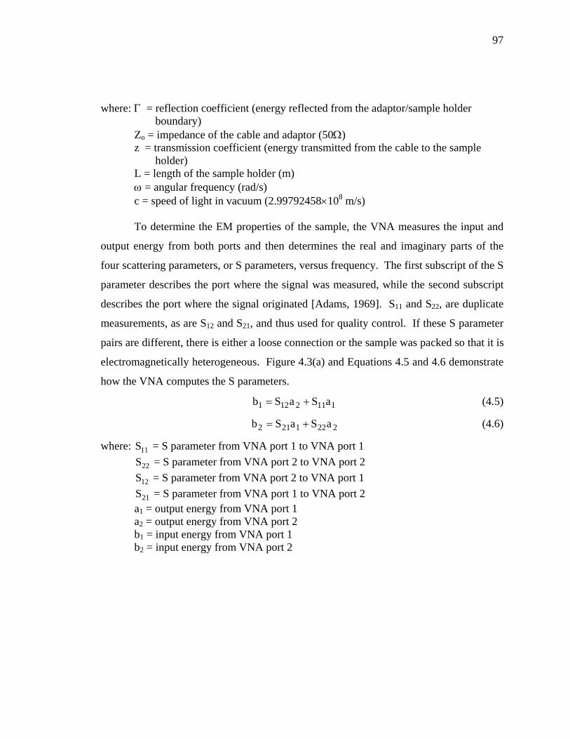
97
where: Γ = reflection coefficient (energy reflected from the adaptor/sample holder boundary)
Zo = impedance of the cable and adaptor (50Ω) z = transmission coefficient (energy transmitted from the cable to the sample
holder) L = length of the sample holder (m) ω = angular frequency (rad/s) c = speed of light in vacuum (2.99792458×10⁸ m/s)
To determine the EM properties of the sample, the VNA measures the input and
output energy from both ports and then determines the real and imaginary parts of the
four scattering parameters, or S parameters, versus frequency. The first subscript of the S
parameter describes the port where the signal was measured, while the second subscript
describes the port where the signal originated [Adams, 1969]. S11 and S22, are duplicate
measurements, as are S12 and S21, and thus used for quality control. If these S parameter
pairs are different, there is either a loose connection or the sample was packed so that it is
electromagnetically heterogeneous. Figure 4.3(a) and Equations 4.5 and 4.6 demonstrate
how the VNA computes the S parameters.
1112121 aSaSb += (4.5)
2221212 aSaSb += (4.6)
where: = S parameter from VNA port 1 to VNA port 1 11S
22S = S parameter from VNA port 2 to VNA port 2
12S = S parameter from VNA port 2 to VNA port 1
21S = S parameter from VNA port 1 to VNA port 2 a1 = output energy from VNA port 1 a2 = output energy from VNA port 2 b1 = input energy from VNA port 1 b2 = input energy from VNA port 2

98
Figure 4.3. Signal flow charts of the VNA. Box (a) shows the signal flow chart used to find the S parameters [Adams, 1969]. Box (b) shows the signal flow chart used to find the S parameters as a function of the reflection (Γ) and transmission (z) coefficients [Nicolson and Ross, 1979].
Once the VNA outputs the S parameters to the computer, the software then
computes the complex dielectric permittivity and complex magnetic permeability using
Equations 4.7-4.15. Before any calculations can be made, the phase of the S21 and S12
parameters must be corrected. The S parameters are output by the VNA assuming a
sample holder length of 0 cm. The phase differences caused by the finite sample holder
length are corrected for using Equation 4.7.
cLi
21cor21 eSS
ω−
= (4.7)
Figure 4.3(b) and Equations 4.8 and 4.9 describe the S parameters as a function of
the reflection and transmission coefficients [Nicolson and Ross, 1979, Agilent, 2000].
where: = corrected S parameter from port 1 to port 2 cor21S
( )22
2
1
111
z1z1
abS
Γ−
−Γ== (4.8)

99
( )22
2
1
2cor21
z11z
abS
Γ−
Γ−== (4.9)
Equations 4.8 and 4.9 can be rearranged to produce Equations 4.10 and 4.11,
which describe the reflection and transmission coefficients in terms of the S parameters.
Equations 4.2 and 4.3 can be rearranged to produce Equations 4.12 and 4.13. The
complex relative magnetic permeability (Equation 4.14) and the complex relative
dielectric permittivity (Equation 4.15) can then be found. Overall, the software outputs
two data sets (from measuring the sample holder in both directions), each including the
real part of the relative dielectric permittivity, the electrical loss tangent, the real part of
the complex relative magnetic permeability, and the magnetic loss tangent versus
frequency (30 kHz – 3 GHz).
1S2
1SSS2
1SS2
cor21
2cor21
211
cor21
2cor21
211 −
⎟⎟⎟
⎠
⎞
⎜⎜⎜
⎝
⎛ +−±
+−=Γ (4.10)
( )Γ+−
Γ−+=
11cor21
11cor21
SS1SS
z (4.11)
1
2
*r
*r c
11
=⎟⎠⎞
⎜⎝⎛
Γ−Γ+
=ε
μ (4.12)
2
2*r
*r c
z1ln
Lc
=⎟⎟⎠
⎞⎜⎜⎝
⎛⎟⎠⎞
⎜⎝⎛
⎟⎠⎞
⎜⎝⎛ω
−=εμ (4.13)
21*r cc=μ (4.14)
1
2*r c
c=ε (4.15)
There is a problem with the solution shown above. In Equation 4.13, the natural
log of the inverse of z is not unique and possesses an infinite number of roots [Baker-
Jarvis et al., 1993]. This occurs because the imaginary part of the natural log answer
equals the phase angle of the complex root. Since angles are not unique, the correct root

100
can be found by not allowing the angle to “wrap”, or only allowing it to vary from π to -π
radians.
Another problem with the solution is that it is very sensitive to noise at sample
holder resonance. Sample holder resonance occurs when the EM wave approaches half
wavelength multiples of the sample holder length as shown in Equation 4.16. Resonant
frequencies can be identified in the data at high frequencies where the real part of the
relative dielectric permittivity, real part of the relative magnetic permeability, electrical
loss tangent, and magnetic loss tangent all have a spike. Since the resonant frequency is a
function of wavelength, it is dependent on the EM properties of the sample.
Unfortunately, these resonant frequencies are a function of both complex magnetic
permeability and complex dielectric permittivity, so assumptions must be made in order
to solve for either parameter at resonant frequency. Resonant frequencies observed in the
data for this study are actually stronger and broader than the modeled responses predict,
though it is uncertain why.
( ) ( ) "r
"r
'r
'r
2"r
'r
'r
"r
2"r
"r
'r
'r
r
nL2
c2fμε−με+εμ+εμ+με−εμ
= (4.16)
where fr = frequency of the n’s resonant frequency n = number of harmonic 1, 2, 3, … '
rε = real part of the relative dielectric permittivity
"rε = imaginary part of the relative dielectric permittivity
'rμ = real part of the relative magnetic permeability
= imaginary part of the relative magnetic permeability "rμ
4.4. Error and Accuracy Analysis
Although the experimental apparatus was calibrated, the measurements were still
not perfect. The collected data were also affected by the finite precision of the VNA,

101
coherent and incoherent noise sources, and loose connections along the apparatus setup.
Each of these issues will be discussed in the sections below.
4.4.1. VNA Measurement Accuracy
One of the most significant limitations of the experiment apparatus was the finite
precision of the VNA. This was primarily caused by the 0.01o phase accuracy of the
HP8753D [Hewlett-Packard, 1994]. When the wavelength of the EM energy is
significantly greater than the length of the sample holder, only minute changes (<0.01o)
in phase are observed. Consequently, the VNA cannot accurately measure the EM
properties of a sample at low frequencies. (For the Martian analog samples measured in
this thesis with a 10 cm sample holder, this typically occurred near 1 MHz.) The
precision of the phase accuracy and amplitude accuracy can also be expressed as the
precision of the S parameters, which were found after calibrating with a stack of 16. The
manufacturer listed precision for the S11 and S22 parameters is ±0.001 dB at frequencies
less than 1.3 GHz and ±0.005 dB at frequencies greater than 1.3 GHz. Likewise, the
manufacturer listed precision for the S21 and S12 parameters is ±0.008 dB at less than 1.3
GHz and ±0.009 dB at greater than 1.3 GHz [Hewlett-Packard, 1994].
To display the effect of precision on the measurements, a data envelope and
measurable lower loss limit were modeled for each VNA measurement shown in this
thesis. The data envelope defines the boundaries where all of the data should reside
unless sources of noise are present. The maximum part of the measurable lower loss
limit represents the noise floor of the system, thus only data above the measurable lower
loss limit were used for modeling. In this thesis, the data envelope will always be shown
in a diagonally crosshatched pattern on graphs displaying the real part of the relative
dielectric permittivity and magnetic permeability and on loss tangent graphs that possess

102
loss tangents that are above the measurable lower loss limit. Likewise, the measurable
lower loss limit will be plotted on each loss tangent graph in a crosshatched pattern.
The data envelope was created by finding the electric and magnetic Cole-Cole
models. The Cole-Cole models were transformed into S parameters. The VNA precision
was added and subtracted to each of the S parameters for a total of 16 combinations. The
revised S parameters were then transformed into the real part of the relative dielectric
permittivity, electrical loss tangent, real part of the relative magnetic permeability, and
magnetic loss tangent. The maximum and minimum S parameter values for each of the
16 combinations at each frequency were then used to produce the data envelope.
The measurable lower loss limit was determined using a similar process as the data
envelope. First, the electric and magnetic Cole-Cole models were found. Then the Cole-
Cole models were transformed into S parameters assuming that the electrical and
magnetic loss tangents equaled zero. Next, the maximum VNA precision was added and
subtracted to each of the simulated S parameters for a total of 16 different combinations.
The S parameter combinations were then transformed into electrical and magnetic loss
tangents. The measurable lower loss limit is defined as the maximum loss tangent for
each of the 16 combinations at each frequency. The electrical and magnetic loss tangents
also possessed some error due to EM energy scattering off the minute imperfections of
the sample holder’s inner conductor and also due to resonance. This is shown in the data
in Figure 4.4 where the slope of the loss tangent increases before reaching the first
resonant frequency at 1.5 GHz. The error was due to scattering because the slope of the
loss tangent is proportional to the fourth power of the frequency. (Scattering is the only
mechanism that could produce such a positive slope.) To account for this error,
scattering was added to both the electric and magnetic measurable lower loss limit to
ensure that any temperature independent high frequency loss tangent curves were
considered noise.
In Figure 4.4, the manufacturer listed VNA precision was used to generate a
predicted data envelope and a measurable lower loss limit for a set of real data for an

103
empty (air-filled) 10 cm sample holder measured at room temperature at a stack of eight.
Since the real data do not approach the boundaries of the predicted data envelope and the
measurable lower loss limit, the actual noise in the measurement was less than the
predicted noise given by the manufacturer, Hewlett-Packard [1994]. The actual
measurement precision was found by adjusting the data envelope and measurable lower
loss limit to better match the variations observed in the data set. This led to a factor of
four increase in the actual precision. Consequently, the precision of the S11 and S22
parameters varied by ±0.00025 dB at less than 1.3 GHz and ±0.00125 dB at greater than
1.3 GHz. The precision of the S21 and S12 parameters varied by ±0.002 dB at less than
1.3 GHz and ±0.00225 dB at greater than 1.3 GHz. These precisions were used to
generate the data envelopes used in this thesis. Furthermore, the loss tangent graphs in
Figure 4.4 should have equaled zero because air contains no losses. However, the data
did contain electrical and magnetic loss tangents. Since the data were confined to the
measurable lower loss limit, the nonzero loss tangent data were due solely to the limited
accuracy of the experimental apparatus. The limited VNA accuracy also restricted the
lower limit of the DC conductivity (6.67 ×10⁻⁵ mho/m) or DC resistivity (15 kΩm) as
shown in Figure 4.5.

104
Figure 4.4. This figure shows real data from an empty 10 cm sample holder measured at room temperature at a stack of eight, along with the data envelopes and the measurable lower loss limits. The blue envelopes assume the manufacturer listed precision while the red envelopes depict the actual precision. In this figure and thesis, the data envelopes are diagonally crosshatched and the noise envelopes are crosshatched.

105
Figure 4.5. This figure shows the theoretical lower limit of DC conductivity (6.67 ×10⁻⁵ mho/m) or DC resistivity (15 kΩm) measured in a 10 cm sample holder assuming the actual VNA accuracy error.

106
Many VNA plots will be shown in this thesis. Each plot contains four graphs. The
top left graph displays the real part of the relative dielectric permittivity versus frequency,
where the ordinate is linear and the abscissa is logarithmic. The bottom left graph
displays the electrical loss tangent versus frequency where both the ordinate and abscissa
are logarithmic. The top right graph displays the real part of the relative magnetic
permeability versus frequency, where the ordinate is linear and the abscissa is
logarithmic. The bottom right graph displays the magnetic loss tangent where both the
ordinate and abscissa are logarithmic. Each loss tangent graph has a measurable lower
loss limit in a crosshatched pattern. All graphs have a data envelope in a diagonal
crosshatched pattern for the electric and magnetic Cole-Cole model that best fit the data.
The data envelope is only shown on the loss tangent graphs if it is greater than the
measurable lower loss limit.
As the errors in precision decrease, the data envelope contracts to the correct value
at lower frequencies and the measurable lower loss limit decreases (Figure 4.4). Figures
4.6, 4.7, and 4.8 show that the data envelope and the measurable lower loss limit change
as a function of the real part of the relative dielectric permittivity and the real part of the
relative magnetic permeability, frequency dependent complex dielectric permittivity and
frequency dependent magnetic permeability, and sample holder length, respectively.
Increasing the real part of the relative dielectric permittivity and the real part of the
relative magnetic permeability does not significantly change the data envelope, but it
does shift the measurable lower loss limit lower as shown in Figure 4.6. The measurable
lower loss limit is lowered because the electrical loss tangent is proportional to the
inverse of the real part of the relative dielectric permittivity, while the magnetic loss
tangent is proportional to the inverse of the real part of the relative magnetic
permeability. The data envelope is relatively unchanged because at low frequencies, only

107
Figure 4.6. This figure shows how the data envelopes (diagonal crosshatched pattern in top graphs) and measurable lower loss limit (crosshatched pattern in bottom graphs) vary as a function of the frequency independent real part of the relative dielectric permittivity and frequency independent real part of the relative magnetic permeability. As relative dielectric permittivity and relative magnetic permeability increase, the data envelopes do not significantly change. However, the measurable lower loss limit decreases and the resonant frequencies decrease.

108
Figure 4.7. This figure shows the theoretical data envelopes for a material with requency dependent dielectric permittivity and magnetic permeability measured in a
sample holder assuming the actual VNA accuracy error. f10 cm

109
Figure 4.8. This figure shows the data envelopes (top graphs) and measurable lower loss limit (bottom graphs) as a function of sample holder lengths of 3, 5, and 10 cm assuming the measured precision.

110
the EM energy inside the sample holder has a smaller wavelength than the EM energy
inside the cables. This difference in wavelength does not significantly enhance the data
envelope. However, as the real part of the relative dielectric permittivity and the real part
of the relative magnetic permeability increase, resonance occurs at lower frequencies.
If the sample possessed frequency dependence, then the loss tangent graphs
contain both a data envelope and a measurable lower loss limit as shown in Figure 4.7.
However, if the relaxation was too small or at a frequency where the measurable lower
loss limit was large, the data envelope may have been hidden by the larger measurable
lower loss limit.
As the sample holder length decreases, the data envelope and measurable lower loss
limit become larger at each frequency as shown in Figure 4.8. This occurs because as the
sample holder length decreases, the EM energy at each frequency travels through less of
the sample. Therefore, the purpose for using the smallest sample holder (3 cm) is to
increase the frequency at which the first resonant frequency occurs, so that the high
frequency limit of the usable measurements is greater.
4.4.2 Incoherent and Coherent Sources of Noise
Both incoherent and coherent sources of noise can exist that corrupt the data. The
difference between these two types of noise is that incoherent noise decreases as more
data are stacked while coherent noise increases as more data are stacked. Therefore,
these two types of noise must be addressed separately.
To test for incoherent and coherent noise, VNA measurements were repeatedly
made with a stack of one. These measurements were then combined with varying stacks
and a standard deviation for each measured frequency was calculated and plotted in
Figure 4.9. This figure shows that the various stacks essentially possess the same
standard deviation versus frequency. The large increase in the 1024 stack may be due to
drifting room temperature during the 19.3 hour measurement time. Since the standard
deviation does not improve or degrade with the amount of stacking, the majority of the

111
error causing the standard deviation is most likely due to the limited accuracy of the
VNA. Therefore, the incoherent noise levels of the measurements are extremely low.
Only one form of coherent noise, sample holder resonance, was found to affect the
measurements. This was discussed at the end of Section 4.3.
Figure 4.9. Standard deviation at each frequency versus number of external stacks.

112
4.4.3. Improper Apparatus Setup
The last form of measurement error is due to improper apparatus setup. These types
of errors typically obliterate data at all frequencies, although small apparatus errors can
mimic real data. Common apparatus errors include loose connections between the cables,
adapters, and sample holder, heterogeneous packing of the sample, and contaminating the
inside of the inner conductor of the sample holder and/or any connectors with the sample.
Loose connections between the cables, adapters, and sample holder will usually produce
data that is all noise because it creates a large impedance contrast. However, if there is
just a small connection problem, the S11 and S21 solution and the S22 and S12 solution will
be offset at all frequencies. Heterogeneity in the packing of a sample holder can lead to
internal scattering in the sample holder and/or different reflection coefficients, Γ, at both
ends of the sample holder. This causes the S11 and S12 solution and the S22 and S21
solution to diverge at high frequencies as the internal impedance boundary causes more
scattering.
The most difficult coherent noise source to identify is when the sample is inside or
on the ends of the sample holder’s inner conductor. This can lead to a false frequency
and temperature dependent dielectric permittivity or magnetic permeability measurement.
To ensure that temperature and frequency dependence is not produced by noise, the
sample holder must be disconnected from the waveguide. The inner conductor and the
14 mm part of the 7 mm/14 mm adapter are then cleaned with the sample still packed
inside. After cleaning, the sample holder is reattached to the waveguide and remeasured.
If the temperature and frequency dependence has not changed, it is most likely being
produced by the sample itself. Another way to prevent false frequency and temperature
dependent measurements is to unpack the sample, clean the sample holder, repack the
same sample, and remeasure. All temperature and frequency dependent relaxations
reported in this thesis have been verified using both of these methods.

113
4.5. Measurement, Accuracy, and Quality Control of Temperature
The circuit shown in Figure 4.10 was used to measure the resistance of the
thermistors, while accounting for input impedance of the voltmeters and joule heating of
the thermistors. Input impedance problems occur when the thermistor resistance
approaches the internal resistance of the voltmeter. This causes the voltmeter to have an
increased influence on the circuit as more current travels through the voltmeter instead of
the circuit. The voltmeters used for this research were Fluke 77 Series II Multimeters,
which were found to possess an input impedance of RV = 11 MΩ when measuring to
three decimal points. The resistance of the thermistors varied from 8.2 kΩ near 303 K
and 10 MΩ near 180 K as shown in Figure 4.11.
Figure 4.10. Circuit used to find the resistance of the thermistor where: VIN is the measured total voltage, VT is the measured voltage across the thermistor, RDB is the known resistance of the decade resistor, RT is the resistance of the thermistor, and RV is the resistance of the voltmeter. Decade resistances and power source voltages into the circuit can be found on the DVD.

114
Figure 4.11. Resistance versus temperature for the YSI 44006 epoxy-encapsulated thermistors. The curve is accurate to 0.2 K. The dashed portion of the curve is extrapolated from the lower temperature resistances.
Since the thermistor resistance approaches the input impedance of the voltmeter,
the input impedance of the voltmeter was compensated for when calculating the
thermistor resistance, RT. Another complication was that in order to determine the
resistance of the thermistor, current must flow through it. This current flow then causes
joule heating as the thermistor converts voltage to heat. The YSI 44006 epoxy-

115
encapsulated thermistors have a dissipation constant, D, of 0.001 W/K in still air [YSI,
2006]. In short, it takes 1 mW of power to increase the thermistor temperature by 1 K.
Joule heating cannot be avoided, therefore the power was limited by decreasing the
current so that the thermistor could only be heated by a maximum temperature of 0.2 K,
ΔT. The power of the joule heating, P, is found using Equation 4.17. The power can
then be used in Equation 4.18 to find the maximum allowable current to maintain the
temperature accuracy, ΔT.
DPT =Δ (4.17)
T2RIP = (4.18)
As shown in Figure 4.10, the total voltage put into the circuit, VIN, and the voltage
across the thermistor, VT, was measured. The resistance of the QuadTech decade resistor
(model #1433-26), RDB, and the internal resistance of the voltmeter, RV, were already
known. (The decade resistor is a resistor in which any resistance from 10 – 9,999,990 Ω
can be dialed in at intervals of 10 Ω and with an accuracy of 0.01%.) The thermistor
resistance was found using Equation 4.19. The input impedance of the voltmeter that is
measuring total voltage, VIN, is not included because the total voltage does not vary with
time or electrical load. To ensure the total voltage, VIN, did not vary, the total voltage
was measured at least twice during each EM property measurement at each temperature.
DBTIN
TV
VDBTIN
T
TR*
VVVR
R*R*VV
V
R
−−
−= (4.19)
If the temperature is above 193 K, the thermistor resistance can be converted into
temperature by interpolating manufacturer resistances versus Celsius temperatures using
the spreadsheet ThermR.xls, which can be found on the attached DVD, or by
downloading the manufactures spreadsheets R_vs_t.xls and ST&H_EQ.xls at the YSI
website. The temperature accuracy of the thermistors is ±0.2 K down to 193 K.

116
However, the So-Low Ultra-Low freezer’s lower temperature limit was found to be about
180 K at the bottom of the freezer. Consequently, at temperatures less than 193 K,
thermistor resistances were extrapolated using the spreadsheet ThermR.xls, which can be
found on the attached DVD.
The total accuracy of the thermistors versus temperature is shown in the last
column of Table 4.1. The total accuracy is the sum of the maximum joule heating and
the accuracy of the thermistors. The maximum joule heating was calculated using
Equation 4.20 with the parameter values that were typically used to find the temperature
of the thermistor (see DecadeR.xls on the attached DVD). The dissipation constant of
still air, 0.001 W/K, was used. Even though fans were circulating the air inside the
freezer, the thermistor that was used to find the actual temperature of the sample was
inside the duplicate sample holder.
D
R*R
RRRR
V
DR*IT
T
2
DBTV
TV
IN
T2T
⎟⎟⎟⎟
⎠
⎞
⎜⎜⎜⎜
⎝
⎛
++
==Δ (4.20)
Table 4.1. (next page) This table shows the typical error in temperature (total accuracy column) for the temperature range used in this research (178.15 K – 303.15 K or -95oC – 30oC). At temperatures above 260 K, the total voltage was varied to increase measurement accuracy. Below 260 K, the total voltage was held constant at 6.2 volts so that three decimal points could be read on the voltmeters. The thermistor accuracy decreases at temperatures greater than 193 K due to extrapolation errors. The upper limit of the total accuracy is found by adding joule heating to the upper limit of the thermistor accuracy. The lower limit of the total accuracy equals the lower limit of the thermistor accuracy because the value in the joule heating column is the maximum joule heating value. The table shows the typical error in temperature because the total voltage guidelines and decade resistor settings were not always followed. For the recommended voltage and decade resistor settings, see DecadeR.xls on the attached DVD. To see what values were actually used for each measurement, see the digital logbook which can be found on the attached DVD.

117
Temperature (K) Joule Heating (K) Therm. Accuracy (K) Total Accuracy (K) 178.15 0.00 ±0.25 ±0.25 183.15 0.00 ±0.23 ±0.23 188.15 0.00 ±0.21 ±0.21 193.15 0.00 ±0.20 ±0.20 198.15 0.00 ±0.20 ±0.20 203.15 0.01 ±0.20 -0.20, +0.21 208.15 0.01 ±0.20 -0.20, +0.21 213.15 0.01 ±0.20 -0.20, +0.21 218.15 0.01 ±0.20 -0.20, +0.21 223.15 0.02 ±0.20 -0.20, +0.22 228.15 0.03 ±0.20 -0.20, +0.23 233.15 0.04 ±0.20 -0.20, +0.24 238.15 0.05 ±0.20 -0.20, +0.25 243.15 0.07 ±0.20 -0.20, +0.27 248.15 0.09 ±0.20 -0.20, +0.29 253.15 0.11 ±0.20 -0.20, +0.31 258.15 0.15 ±0.20 -0.20, +0.35 263.15 0.19 ±0.20 -0.20, +0.39 268.15 0.17 ±0.20 -0.20, +0.37 273.15 0.14 ±0.20 -0.20, +0.34 278.15 0.17 ±0.20 -0.20, +0.37 283.15 0.12 ±0.20 -0.20, +0.32 288.15 0.15 ±0.20 -0.20, +0.35 293.15 0.18 ±0.20 -0.20, +0.38 298.15 0.10 ±0.20 -0.20, +0.30 303.15 0.12 ±0.20 -0.20, +0.32

118
In order to test the suitability of conducting measurements inside the freezer, a
quality control experiment was conducted using an air sample (empty sample holder).
The results of the quality control test confirmed that accurate data could be acquired
inside the freezer at the temperatures used in this study. (See Figure 4.12.) During the
quality control test, a VNA measurement was made every 10 K from 298 K to 193 K.
Air possesses a frequency independent dielectric permittivity and magnetic permeability
equal to one and no measurable electric or magnetic loss tangent. A slight change (20%)
was seen in the real part of the relative dielectric permittivity and magnetic permeability
in the quality control test. This change was due to thermal contraction of the cables
caused by the temperature decrease, and was not corrected for because it was easily
recognizable. The cable thermal contraction causes errors in the measurements because
the electrical lengths of the cables change as a function of temperature. Since each cable
has a different length inside the freezer, one cable will most likely contract more than the
other. Thus, the cables will have different electrical lengths as temperature decreases.
Smaller sample holder lengths are much more affected by the thermal contraction of the
cables than larger sample holder lengths because the change in the length of the cables is
a larger percentage of the total waveguide length. Therefore, it strongly affects the
measurement of phase. A 3 cm sample holder yields a maximum error of 80%; a 10 cm
sample holder’s maximum error is 20%.

119
Figure 4.12. The EM properties of air versus frequency and temperature were measured as a quality control test of the apparatus. Air should possess a frequency independent μr = εr = 1 and a loss tangent of zero. Five temperature measurements were made using a 10 cm sample holder. The data envelope and measurable lower loss limit are plotted assuming the measured precision (discussed in Section 4.4.1). The top two graphs contain data that are outside of the data envelope – these points are created by the contraction of the cable as temperature is decreased.

120
As shown in Figure 4.12, the thermal contraction of the cables can be recognized
in the real part of the relative dielectric permittivity graph by a higher value at low
frequencies that trends down to the original value and then slightly increases at high
frequencies. The thermal contraction of the cables can be recognized in the real part of
the magnetic permeability graph by a lower value at low frequencies that trends toward
the original value and then trends toward a higher value at high frequencies. The
electrical and magnetic loss tangents do not measurably change due to thermal
contraction. This is because both of the imaginary and real parts are changing in the
same manner. Each time the temperature is lowered, these discrepancies in the graphs
become larger as the cables continue to contract. The resulting change in the real part of
the relative dielectric permittivity and the real part of the magnetic permeability caused
by the thermal contraction of the cable is reduced as the impedance of the sample holder
increases. This occurs because greater impedance contrasts create reflections and
transmissions that have larger phase differences.
Since the temperature reading of the duplicate sample holder was used to deduce
the temperature reading of the measuring sample holder, a quality control test was
conducted using grey hematite to determine the accuracy of this method. Grey hematite
(GHKwMI sample) was used because it possesses a temperature dependent dielectric
permittivity relaxation (discussed further in Chapter 5). For this test, ten VNA
measurements were made using grey hematite at a temperature of 203.15 ± 0.20 K. The
time constant of relaxation was then found and plotted versus temperature as seen in
Figure 4.13. This figure shows that the uncertainty of the temperature measurement is
greater than the difference in temperature between the duplicate sample holder and the
measurement sample holder. Consequently, the method of using the temperature reading
in the duplicate sample holder was deemed acceptable.

121
Figure 4.13. This figure displays 10 measurements of the time constant of relaxation versus temperature. The dashed line is the predicted time constant of relaxation versus temperature found using the generalized Boltzmann temperature equation to fit the grey hematite (sample GHKwMI) data over a temperature range of 300 – 180 K (further discussed in Chapter 5). The temperature error bars represent the error in thermistor accuracy as shown in Table 4.1. Since the dashed line passes through the error bars of the data, no additional uncertainty is generated by measuring the temperature in a duplicate sample holder.

122
CHAPTER 5
EXPERIMENTAL AND MODEL RESULTS
5.1. Introduction
Both dielectric and magnetic relaxations were observed in some of the measured
Martian analog samples. In order to understand the nature of the relaxations, the data
were modeled using inversion. In this chapter, the Martian analogs are grouped into three
categories for discussion: samples with no measurable losses, samples with dielectric
relaxation losses, and samples with magnetic relaxation losses. Samples with no
measurable losses are favorable for GPR exploration. Consequently, the GPR depth of
penetration will be limited by losses such as scattering and geometric spreading and not
EM relaxation losses or electrical conduction losses. Samples with EM relaxation losses
are not favorable for GPR exploration. Therefore, the GPR depth of penetration will
likely be limited by the EM relaxation loss mechanism. Only limited amounts of data are
presented in this chapter. All of the data collected can be viewed on the attached DVD.
5.2. Data Modeling
If a Martian analog sample possessed temperature and/or frequency dependent
EM properties, the data were inverted to find the Cole-Cole parameters at each measured
temperature. Prior to inverting the data, any coherent noise, errors due to cable
contraction, and resonance were removed. A program was developed using
MATLAB®’s optimization toolbox (version 2.2) inversion to determine the best fit value
and confidence intervals for each of the four Cole-Cole parameters (εDC, ε∞, τ, α).
Similar data had been inverted before using a Levenberg-Marquardt routine [Canan,

123
1999]. The Levenberg-Marquardt [Levenberg, 1944, and Marquardt, 1963] inversion is
used by the MATLAB® optimization toolbox to determine the global minimum of a
weighted normalized data misfit, Equation 5.1, of the Cole-Cole equation.
( )∑ ⎟⎟
⎠
⎞⎜⎜⎝
⎛σ
ατεε−=φ
=
∞N
1i
2
i
DCii2 ,,,;xfdN1 (5.1)
where: φ2 = weighted normalized data misfit
d = data f = modeled data using the Cole-Cole equation (Equation 2.40) x = modeled data points N = number of data points σ = standard deviation
In order to calculate the data misfit using Equation 5.1, the standard deviation
must be determined for each frequency data point. This is done so that frequency data
points with large standard deviations will affect the misfit less than data with low
standard deviation. For a typical data set the standard deviation remains the same for
each measurement. However, this must be done because the standard deviation varies
over three orders of magnitude in this data as a function of frequency.
At the beginning of this study, the standard deviation of the data was found by
calculating the standard deviation of the nearest ten frequency data points. Later in the
study, the standard deviation for each frequency was determined by making multiple
measurements with a stack of one. The individual VNA measurements were then
combined to calculate the average value and standard deviation at each frequency data
point. This process was performed at both room temperature and the coldest temperature
(≈180 K) since these were the only two stable temperatures. It was shown in Section
4.5.2 that the standard deviation does not vary as a function of the number of stacks.
Therefore, the standard deviations from the warmest and coldest temperatures were
interpolated at each temperature in between to determine the standard deviation at each

124
frequency. This second method for determining the standard deviation was an
improvement over the first method and should be used for future work.
An inversion with no bounds on any of the Cole-Cole parameters was first applied
to the data collected at the temperature which contained the largest portion of the
relaxation with the least amount of cable contraction. This was done because as the
relaxation shifts with temperature, it often shifts outside the frequency range of useable
data. This initial inversion set the bounds for the Cole-Cole parameters, with the
exception of the time constant of relaxation (τ). Since the time constant of relaxation was
the only Cole-Cole parameter expected to change as a function of temperature, the
remaining temperature data sets were only inverted for τ with the other Cole-Cole
parameters fixed.
Once the global minimum of the weighted normalized data misfit, φ2, was found,
two adjusted data sets were created by adding and subtracting two standard deviations
from the original averaged data set. The adjusted φ2 values were found for each of the
adjusted data sets using the previous best fit model. The Cole-Cole model parameters
were then varied individually in a sensitivity analysis to match the adjusted φ2. This gave
the 95.5% confidence intervals for each Cole-Cole parameter. (See Figure 5.1.)

125
Figure 5.1. This figure shows a sensitivity analysis of the Cole-Cole parameters for the grey hematite sample, GHKwMI, at the coldest temperature (180.9 K). Both graphs contour the weighted normalized data misfit, φ2, as a function of the graph parameters with the global minimum of 3.53, a plus two standard deviation value of 4.41, and a minus two standard deviation value of 6.70. The 95.5% confidence intervals for each parameter were then found by keeping all other parameters constant and shifting the value to the appropriate φ2 contour line.

126
Once the time constant of relaxation (τ) for each temperature measurement was
determined, the generalized Boltzmann temperature dependence (Equation 2.41) was
used to find the activation energy, E, and time constant at infinite temperature, τ∞. Next,
the time constant of relaxation and the temperature were both varied within their 95.5%
confidence intervals to produce a range of activation energies and associated time
constants at infinite temperature. The activation energy and the time constant at infinite
temperature were found to possess three different 95.5% confidence interval ranges.
These ranges are associated with a range of temperatures. The three temperature ranges
found included: high temperature values that were extrapolated, median temperature
values that were interpolated, and low temperature values that were extrapolated. (See
Figure 5.2.)
Once the electric and magnetic Cole-Cole and generalized Boltzmann parameters
for the sample were found, they were substituted into the modified Cole-Cole equation,
Equation 2.44. This equation describes how complex dielectric permittivity and complex
magnetic permeability vary as a function of frequency and temperature. To calculate the
maximum GPR depth of penetration, the complex dielectric permittivity, and complex
magnetic permeability can be inserted into Equation 2.20. The GPR depth of penetration
will be discussed in Chapter 6.

127
Figure 5.2. This figure graphically demonstrates the how the 95.5% confidence interval of the time constant at infinite temperature, τ∞, and the activation energy, E, change in three temperatures ranges. The blue lines depict the error bars of the data. The red line is the model that fits the data points the best. The light black lines show four fits of data that has been adjusted within its 95.5% confidence intervals. The dark black lines show the maximum and minimum model error.

128
5.3. Samples with No Measurable EM Losses
Five of the measured samples possess no measurable EM losses. (This does not
mean that these samples do not possess any losses, since they may possess losses that are
less than the measurement limits of the apparatus.) Table 5.1 lists the real part of the
relative dielectric permittivity, real part of the relative magnetic permeability, and the DC
resistivity for these samples. Since they do not possess any measurable losses, they are
also frequency independent and therefore they do not possess any measurable imaginary
parts. Figure 5.3 shows a representative sample with no measurable EM losses from this
group of data. Data from the remaining samples can be found on the DVD.
Table 5.1. EM properties for samples possessing no measurable EM losses. The first row shows the modeled results of the measured data. In the second row, the modeled data was corrected for density using a Lichtenecker power law mixing formula, Equation 2.47.
Sample Density (g/cc)
Real Part of the Relative Dielectric
Permittivity, εr
DC Resistivity, σDC (kΩm)
Real Part of the Relative Magnetic Permeability, μr
1.47 2.57 ± 0.01 >15 1.00 ± 0.02 Sand (Sand) 1.60 2.80 ± 0.01 >15 1.00 ± 0.02
1.39 3.07 ± 0.02 >15 1.00 ± 0.02 Jarosite
(Jaro) 1.60 3.52 ± 0.02 >15 1.00 ± 0.02
0.68 1.70 ± 0.02 >15 1.00 ± 0.02 Ferric Oxide (FeOxd) 1.60 3.10 ± 0.04 >15 1.00 ± 0.02
2.00 3.61 ± 0.03 >15 1.00 ± 0.02 Green Sand
Beach (GSBHI) 1.60 2.78 ± 0.04 >15 1.00 ± 0.02
1.14 2.41 ± 0.02 >15 1.28 ± 0.02 Hematite
(Hem) 1.60 3.25 ± 0.03 >15

129
Figure 5.3. This figure shows the EM properties of a typical sample that contains no measurable EM losses. These samples possess no measurable frequency or temperature dependence. Therefore, the loss tangents are constrained to the measurable lower loss limit.

130
5.4. Samples with Dielectric Relaxation Losses
Four of the measured samples possess temperature dependent dielectric relaxation
losses. Their Cole-Cole and Boltzmann parameters are listed in Table 5.2. Four of these
samples (GHKwMI, GHSChp, JSC-1 and PuNeHIC) will be discussed in detail below.
The data from all of the samples with dielectric relaxation losses are provided on the
DVD.
Figure 5.4 shows the temperature dependent dielectric relaxation of sample
GHKwMI. This sample possesses the largest dielectric or magnetic loss of any sample
measured in this study. The sample was crushed from a rock that originated from the
Keweenaw Peninsula in Michigan and consists primarily of grey hematite (see XRD
results in Appendix A). The high frequency limit of the relative dielectric permittivity
could not be constrained until the temperature dropped below 182 K. At temperatures
less than 182 K, the frequency of relaxation is less than the resonant frequency, therefore
the peak of the dielectric relaxation in the loss tangent can be measured. This peak is
proportional to the difference between the high and the low frequency limits of the
relative dielectric permittivity. Figure 5.5 shows the Arrhenius plot for this sample. The
plot shows that the dielectric relaxation shifted out of the accurate frequency range at
temperatures greater than 227 K. Therefore, only temperatures in the range of 181 – 227
K were used to determine the Boltzmann parameters.

Tabl
e 5.
2.
Col
e-C
ole
and
Bol
tzm
ann
tem
pera
ture
par
amet
ers
for
sam
ples
with
tem
pera
ture
dep
ende
nt d
iele
ctric
rel
axat
ions
an
d fr
eque
ncy
inde
pend
ent m
agne
tic p
erm
eabi
lity.
Unc
erta
intie
s in
the
time
cons
tant
of r
elax
atio
n at
infin
ite te
mpe
ratu
re, τ
∞
(ns)
, and
act
ivat
ion
ener
gy, E
(eV
), ar
e gi
ven
in T
able
5.3
. Th
e fir
st ro
w s
how
s th
e m
odel
ed re
sults
of t
he m
easu
red
data
. In
th
e se
cond
row
, the
mod
eled
dat
a w
as c
orre
cted
for d
ensi
ty u
sing
a L
icht
enec
ker p
ower
law
mix
ing
form
ula,
Equ
atio
n 2.
42.
Sam
ple
Den
sity
(g
/cc)
ε D
Cε ∞
τ ∞ (n
s)
E (e
V)
α
σ DC
(kΩ
m)
μ r
3.11
27
.24
(±0.
21)
6.61
(±0.
18)
2.81
1 ×
10-4
0.14
34
0.84
3 (±
0.01
0)
>15
1.00
± 0
.02
Gre
y H
emat
ite,
Kew
eena
w P
en.
(GH
Kw
MI)
1.
60
10.1
7 (±
0.08
) 2.
47 (±
0.07
) 2.
811
× 10
-40.
1434
0.
843
(±0.
010)
>1
5 1.
00 ±
0.0
2
2.40
17
.0 (±
0.7)
4.
9 (+
3.5,
-3.9
) 2.
33 ×
10-4
0.13
4 0.
55 (+
0.14
,-0.0
8)
>15
1.22
± 0
.03
Gre
y H
emat
ite,
Cha
mpi
on M
ine
Soil
(GH
SChp
) 1.
60
10.1
(±0.
4)
2.9
(+2.
0,-1
.7)
2.33
× 1
0-40.
134
0.55
(+0.
14,-0
.08)
>1
5
1.
59
8.4
(+0.
6,-0
.5)
2.84
0.
0863
0.
111
0.29
1 (±
0.01
6)
>15
1.00
± 0
.02
Pu'u
Nen
e H
oriz
on C
(P
uNeH
IC)
1.60
8.
4 (+
0.6,
-0.5
) 2.
84
0.08
63
0.11
1 0.
291
(±0.
016)
>1
5 1.
00 ±
0.0
2
0.90
3.
4 (±
1.0)
1.
80
9.3
× 10
-50.
175
0.13
(+0.
01,-0
.05)
>1
5 1.
00 ±
0.0
2 JS
C M
ars-
1 (J
SC1)
1.
60
5.3
(±1.
0)
2.84
9.
3 ×
10-5
0.17
5 0.
13 (+
0.01
,-0.0
5)
>15
1.00
± 0
.02

132
Table 5.3. Uncertainties in the time constant of relaxation at infinite temperature, τ∞ (ns), and activation energy, E (eV), for selected samples with dielectric permittivity relaxations.
Sample Temperature Range τ∞ E
>227 K 2.811 (+0.393, -0.353) × 10-4 0.1434 (±0.023)
181 - 227 K 2.811 (+0.154, -0.159) × 10-4 0.1434 (±0.007) Grey Hematite, Keweenaw Pen.
(GHKwMI) <181 K 2.811 (+0.353, -0.393) × 10-4 0.1434 (±0.023)
>213 K 2.33 (+1.23, -0.96) × 10-4 0.134 (+0.009, -0.007) 184 - 213 K 2.33 (+0.46, -0.64) × 10-4 0.134 (+0.005, -0.003)
Grey Hematite, Champion Mine Soil
(GHSChp) <184 K 2.33 (+0.96, -1.23) × 10-4 0.134 (+0.007, -0.009)
Pu'u Nene Horizon C (PuNeHIC) 303 - 180 K 0.0863 (+0.0028, -0.0008) 0.111 (±0.005)
JSC Mars-1 (JSC1) 303 - 180 K 9.3 (+14.8, -5.9)× 10-5 0.175 (±0.021)

133
Figure 5.4. This figure shows the temperature dependent dielectric relaxation from 181 – 227 K for sample GHKwMI from the Keweenaw Peninsula in Michigan. The complete data set, temperature uncertainties, additional measurements using the same sample holder length, and other sample holder lengths are provided on the DVD.

134
Figure 5.5. This figure shows an Arrhenius plot of the grey hematite sample from the Keweenaw Peninsula (GHKwMI). The dark black line is the best fit line of data points with a temperature range from 181 – 227 K (black data points). The two light black lines are the boundaries of the minimum and maximum best fit. Only data from the coldest temperature measurements are shown since the relaxation shifted outside the range of usable data as the temperature increased. The error bars show the 95.5% confidence intervals of the time constant of relaxation (vertical) and temperature (horizontal).

135
Figure 5.6 shows the temperature dependent dielectric relaxation of sample
GHSChp. This sample was collected in soil form from the Champion Mine dump in
Michigan. The major mineralogical components are grey hematite (≈65% of the sample)
and magnetite (≈10% of the sample). (For detailed mineralogy see the XRD results in
Appendix A.) The large temperature dependent dielectric loss is most likely caused by
the grey hematite component. Unfortunately, even at the coldest temperature of ≈183 K,
the relaxation frequency is greater than the resonant frequency. Because of this, the high
frequency limit of the relative dielectric permittivity is poorly constrained. Figure 5.7
shows the Arrhenius plot for this sample. The plot shows that the dielectric relaxation
could not be accurately modeled at temperatures greater than 214 K. Therefore, only
temperatures in the range of 183 – 214 K were used to find the Boltzmann parameters.
GHSChp has a relative magnetic permeability greater than one. This is caused by
its magnetite component. Magnetite has a temperature independent magnetic relaxation
near 177 – 884 MHz. (Discussed in Section 5.5.) Although this sample was measured in
a 3 cm sample holder to obtain higher frequencies, the magnetic relaxation could not be
detected. The first resonant frequency occurs near 400 MHz with the 3 cm sample
holder. This is much lower in frequency than the other magnetite samples because this
sample possesses a much larger dielectric permittivity due to its grey hematite
component. Therefore, even though no magnetic relaxation is seen, this sample could
possess a magnetic relaxation at frequencies greater than 400 MHz. As discussed in
Section 5.5, two of the three samples containing magnetite did possess magnetic
relaxations at frequencies greater than 400 MHz

136
Figure 5.6. This figure shows the temperature dependent dielectric relaxation of the GHSChp sample (grey hematite soil from the Champion Mine dump in Michigan).
perature uncertainties and additional measurements using the same sample holder ple holder lengths are provided on the DVD.
Temlength and other sam

137
Figure 5.7. This figure shows an Arrhenius plot of the grey hematite from the Champion Mine dump (GHSChp). The dark black line is the best fit line of data points with a temperature range from 184 – 213 K (black data points). The two light black lines are the boundaries of the minimum and maximum best fit. Only data from the coldest temperature measurements are shown since the relaxation shifted outside the range of usable data as the temperature increased. The error bars show the 95.5% confidence intervals of the time constant of relaxation (vertical) and temperature (horizontal).

138
JSC Mars-1 possesses a small broad dielectric loss that is just above the
measurable lower loss limit of the apparatus. (See Figure 5.8.) This sample is distributed
by Johnson Space Center as the Earth soil that best represents a soil or regolith simulant
of Mars. It is composed primarily of plagioclase feldspar and minor amounts of
magnetite, hematite, olivine, pyroxene, and/or glass [Allen, 1997]. Approximately, 25%
of the sample is highly magnetic at DC frequency [Allen, 1997]. Two previous studies
have examined the EM properties of JSC Mars-1 at radar frequencies [Leuschen, 1999;
Williams and Greeley, 2004].
Leuschen [1999] measured the complex dielectric permittivity and complex
magnetic permeability of JSC Mars-1 at terrestrial room temperature with a vector
network analyzer (VNA), used a slotted line for the sample holder over a frequency range
from 10 – 1000 MHz. Williams and Greeley [2004] measured the complex dielectric
permittivity of JSC Mars-1 from 200 – 1300 MHz at room temperature. (Details of the
measurement procedure were not discussed.) They calculated an attenuation rate from
these measurements, assuming no magnetic losses and a magnetic permeability of one.
These previous measurements and the measurements acquired in this thesis are shown in
Figure 5.8. It appears that both Leuschen [1999] and Williams and Greeley [2004]
measured a JSC Mars-1 sample that was slightly more dense than the sample measured in
this research, as their real part of the relative dielectric permittivity are slightly greater
than those measured in this study. However, neither of the previous studies report sample
density.
The electrical loss tangents of the two previous and the ones reported in this thesis
are all different. Leuschen’s [1999] are believed to be incorrect because he used a Debye
model, which assumes a single relaxation, to fit his data. (The Cole-Cole model reduces
into the Debye model when the Cole-Cole distribution parameter, α, is equal to one.) It
is unclear why Williams and Greeley [2004] measured such a large loss tangent. It is
also unclear why Leuschen’s [1999] complex magnetic permeability measurements are so
different from the measurements made in this thesis.

139
Figure 5.8. This figure shows the broad temperature dependent dielectric relaxation of the JSC Mars-1 sample (JSC1) along with measurements made by Leuschen [1999] and Williams and Greeley [2004]. The complete data set, temperature uncertainties,
easurements using the same sample holder length, and other sample holder lengths are provided on the DVD. additional m

140
The Cole-Cole and the generalized Boltzmann temperature model of JSC Mars-1
was very difficult to constrain because both the low frequency and high frequency limit
of the real part of the dielectric permittivity could not be measured and the electrical loss
tangent was just above the measurable lower loss limit. Consequently, the high
frequency limit was assumed to have a real part of the relative dielectric permittivity of
1.80, which is the density controlled electronic polarization value as determined by a
Lichtenecker power law mixing formula, Equation 2.47. While the models are poorly
constrained, it is important to note that these models produce complex dielectric
permittivity values that mimic the data from 1 – 1000 MHz over a temperature range
from 298 – 180 K.
Figure 5.9 shows the temperature dependent dielectric relaxation of sample
PuNeHIC. This sample was collected at the cinder cone Pu’u Nene, which is located in
the saddle between Mauna Loa and Mauna Kea in Hawaii. More specifically, this sample
was collected from the plagioclase feldspar layer beneath the oxidized tephra layer where
NASA collected its JSC Mars-1. (For detailed mineralogy see the XRD results on the
DVD.) As shown in Figure 5.8, this sample possesses a broad dielectric permittivity loss
that is similar but stronger than JSC Mars-1. The relaxation was difficult to model since
neither the low nor high frequency limit could be measured. Consequently, the high
frequency limit was assumed to have a real part of the relative dielectric permittivity of
2.84, which is the density controlled electronic polarization value as determined by a
Lichtenecker power law mixing formula, Equation 2.47. Figure 5.10 shows the
Arrhenius plot for this sample.

141
Figure 5.9. This figure shows the broad temPuNeHIC s
perature dependent dielectric relaxation of ample (Pu’u Nene horizon C). Temperature uncertainties, additional
easurements using the same sample holder length and other sample holder lengths are mprovided on the DVD.

142
Figure 5.10. This figure shows an Arrhenius plot of Pu’u Nene horizon C (PuNeHIC). The dark black line is the best fit line of all the data points. The two light black lines are the boundaries of the minimum and maximum best fit. This data is provided on the DVD.

143
5.5. Samples with Magnetic Relaxation Losses
Three of the Mars analog samples possess temperature independent magnetic
relaxation losses. Table 5.4 lists the inverted Cole-Cole parameters for these samples.
Magnetite is believed to be causing the magnetic relaxations in all of these samples.
Unfortunately, the magnetic relaxations all have poorly constrained high frequency
limits, as the relaxation frequency is greater than the resonant frequency. The magnetic
relaxations possess narrow distribution of time constants of relaxation (high α). This
means that there are few variations in the mechanism that cause the magnetic relaxation.
Figure 5.11 shows the temperature independent magnetic permeability of sample
MagRCh. This sample was collected in rock form from the Champion Mine dump in
Michigan. The sample consists of about 73% magnetite (see XRD results on the DVD).
Figure 5.12 shows the temperature independent magnetic permeability of sample Magn.
This sample was collected from Peru by Universal Minerals and consists primarily of
magnetite (see XRD results on the DVD). Figure 5.13 shows the temperature
independent magnetic permeability of the Yuma sample, as well as the Cole-Cole model
that Olhoeft and Capron [1993, 1994] found. This sample was collected from a dry
stream bed near Yuma, Arizona, and was found to possess a magnetic relaxation by
Olhoeft and Capron [1993, 1994]. Olhoeft and Capron’s [1993, 1994] model fits the data
very well. The sample consists of nonmagnetic white grains and highly magnetic black
grains of magnetite (see XRD results on the DVD). The discrepancies in the model fit
are most likely because the sample was measured with more magnetic black grains of
magnetite in this thesis.

Tabl
e 5.
4. C
ole-
Col
e pa
ram
eter
s fo
r sa
mpl
es w
ith te
mpe
ratu
re in
depe
nden
t mag
netic
rela
xatio
ns a
nd fr
eque
ncy
inde
pend
ent
diel
ectri
c pe
rmitt
ivity
. Th
e fir
st r
ow s
how
s th
e m
odel
ed r
esul
ts o
f th
e m
easu
red
data
. In
the
seco
nd r
ow, t
he m
odel
ed d
ata
was
cor
rect
ed f
or d
ensi
ty u
sing
a L
icht
enec
ker
pow
er la
w m
ixin
g fo
rmul
a fo
r th
e di
elec
tric
perm
ittiv
ity, E
quat
ion
2.47
, and
us
ing
Equa
tion
2.49
for t
he m
agne
tic p
erm
eabi
lity.
Sam
ple
Den
sity
(g
/cc)
ε r
' μ D
Cμ ∞
τ (n
s)
α
σ DC
(kΩ
m)
2.56
10
.61
(±0.
11)
4.89
(+0.
05,-0
.12)
1.
66 (+
0.23
,-0.1
7)
0.80
(+0.
01,-0
.07)
0.
76 (+
0.04
,-0.0
5)
>15
Mag
netit
e C
ham
pion
M
ine
(Mag
ChR
) 1.
60
5.67
(±0.
06)
1.73
(+0.
02,-0
.04)
1.
29 (+
0.18
,-0.1
3)
0.80
(+0.
01,-0
.07)
0.
76 (+
0.04
,-0.0
5)
>15
1.88
6.
92 (±
0.10
) 2.
35 (+
0.02
,-0.0
1)
1.93
(+0.
18,-0
.25)
0.
28 (+
0.13
,-0.0
7)
1.00
>1
5 M
agne
tite
(Mag
n)
1.60
5.
76 (±
0.08
) 1.
93 (+
0.02
,-0.0
1)
1.68
(+0.
16,-0
.22)
0.
28 (+
0.13
,-0.0
7)
1.00
>1
5
2.
23
6.82
(±0.
10)
1.73
(+0.
01,-0
.03)
1.
24 (±
0.24
) 0.
30 (+
0.2,
-0.1
2)
0.75
(+0.
1,-0
.02)
>1
5 Y
uma
(Yum
a)
1.60
4.
52 (±
0.07
) 1.
41 (+
0.01
,-0.0
2)
1.16
(±0.
22)
0.30
(+0.
2,-0
.12)
0.
75 (+
0.1,
-0.0
2)
>15

145
Figure 5.11. This figure shows the magnetic relaxation of the MagRCh sample agnetite rich rock collected at the Champion mine dump). The complete data set
perature, as well as additional measurements using the same sample holder length, and other sample holder lengths are provided on the DVD.
(mversus tem

146
Figure 5.12. This figure shows the magnetic relaxation of the Magn sample (magnetite Peru). The complete data set versus temperature, as well as additional
easurements using the same sample holder length, and other sample holder lengths are frommprovided on the DVD.

147
Figure 5.13. This figure shows the magnetic relaxation of the Yuma sample (magnetite rich soil sample from Yuma, AZ) along with measurements made by Olhoeft and Capron [1993, 1994]. The complete data set versus temperature, as well as additional measurements using the same sample holder length, and other sample holder lengths are provided on the DVD.

148
CHAPTER 6
DISCUSSION AND CONCLUSIONS
6.1 Introduction
The dielectric and magnetic relaxations presented in Chapter 5 can all be
attributed to unique polarization and magnetization mechanisms, respectively. The
mechanisms, along with the implications of EM relaxations on current and future Mars
GPR missions, will be discussed in this chapter.
6.2 Grey Hematite
Christensen et al., [2001] spectroscopically identified grey hematite on Mars in
three different locations. Since grey hematite can form in the presence of water, NASA
sent Opportunity (MER-B) to explore one of these areas, Meridiani Planum. Opportunity
determined that the spectroscopic grey hematite signal at Meridiani Planum was caused
by grey hematite concretions that are believed to have precipitated from an iron rich
groundwater [Squyres and Knoll, 2005].
Two grey hematite samples (GHKwMI and GHSChp) were selected as Martian
analogs and their EM properties were measured. Both samples were found to possess a
temperature dependent dielectric relaxation and a temperature and frequency independent
magnetic permeability of one. The GHKwMI sample is composed largely of grey
hematite and it possesses a dielectric relaxation centered at 1.42 GHz at room
temperature (298 K) and 230 MHz at the average Martian temperature (213 K). Its
activation energy was determined to be 0.1434 (±0.0023) eV. The GHSChp sample is
composed of 65% grey hematite and 10% magnetite. It possesses a dielectric relaxation
centered at 2.52 GHz at terrestrial room temperature (298 K) and 450 MHz at the average

149
Martian temperature (213 K). Its activation energy was determined to be 0.134 (+0.009, -
0.007) eV. Previous studies had identified dielectric relaxations in red hematite, but a
temperature dependent dielectric relaxation had never been observed in grey hematite
prior to this study. The following sections will explain the cause of the temperature
dependent dielectric relaxation in grey hematite and the implications of this loss
mechanism for current and future Martian GPR missions.
6.2.1 Temperature Dependent Dielectric Relaxation Mechanism of Grey Hematite
As discussed in Section 2.2.1, there are five potential polarization mechanisms
that could cause a dielectric relaxation in grey hematite. Interfacial polarization is not
likely because the relaxation is large and centered at a frequency of 2.52 GHz at
terrestrial room temperature. (The difference between the low frequency limit and the
high frequency limit of the real part of the relative dielectric permittivity is 20.63.) Large
interfacial polarization relaxations do occur at frequencies less than 300 MHz at
terrestrial room temperature [Canan et al., 1999]. These relaxations are typically caused
by the electrical double layer (water adsorbed to the grains). Interfacial polarization
relaxations can occur in the GHz frequency range, but they are generally much smaller in
magnitude.
Ionic and orientation polarization are not a possibility since the sample was dry
and contained no surface charges. Electronic polarization did occur in the grey hematite
sample. However, this mechanism is always frequency independent at radar frequencies.
(The value of the electronic polarization is equal to the high frequency limit of the
relative dielectric permittivity, ε∞, minus one.) This leaves molecular polarization as the
most likely mechanism that caused the grey hematite dielectric relaxation.
The molecular polarization mechanism in grey hematite is caused by its
rhombohedra corundum crystal structure. This crystal structure creates parallel planes of
cation and anions as shown in Figure 2.2c. The application of an external electric field

150
causes the hematite crystal to distort by shifting the planes of cations and anions in
opposite directions. This shift creates charge separation. As the temperature is
decreased, the cations and anions possess less energy and can no longer polarize as
quickly. The activation energy describes how quickly this shift occurs with temperature
and represents the energy barrier that the charges must overcome in order to become
polarized. The grey hematite samples, GHKwMI and GHSChp, have activation energies
of 0.1434 (±0.0023) eV and 0.134 (+0.009, -0.007) eV, respectively.
Previous EM measurements of red hematite determined that it does not possess a
molecular polarization mechanism at radar frequencies (1 – 1000 MHz). Red hematite
has the same chemical formula and the same unit cell crystal structure as grey hematite.
The difference between the two is that red hematite is composed of randomly oriented
unit cell crystals, while grey hematite is composed of densely packed and aligned unit
cell crystals that are bonded together to form a coarse grained crystal. This change in
crystal packing strongly affects the relaxation frequency of the molecular polarization
mechanism. Iben et al., [1996] found that red hematite has a temperature dependent
dielectric relaxation centered at 20 kHz at 303 K.
It is no surprise that hematite possesses temperature dependent EM properties.
Iben et al. [1996] observed that red hematite possesses a temperature dependent dielectric
relaxation centered at 10 Hz at 293 K. Morris et al. [1997] found that the visible and
infrared spectrum of red hematite varies between 300 K and 140 K. Hematite possesses a
Morin temperature of approximately 263 K, where its magnetic properties change from
being canted antiferromagnetic to perfectly antiferromagnetic (as discussed in Section
2.3.1). However, as previously mentioned, this is the first time that a temperature
dependent dielectric relaxation has been observed in grey hematite.

151
6.2.2 Implications of the Temperature Dependent Dielectric Relaxation of Grey
Hematite for MARSIS, SHARAD, and Future GPR Missions
Figure 6.1 shows the maximum GPR depth of penetration of the two grey
hematite samples at their measured densities. The 160 K curve for GHKwMI becomes
less frequency dependent because the relaxation frequency of grey hematite at this
temperature is 17 MHz. The range in depth of penetration at MARSIS and SHARAD
frequencies varies by one and one-half orders of magnitude for GHKwMI. With such
large variations, the temperature dependent dielectric relaxation of grey hematite could be
used to map areas of grey hematite or remotely measure the temperature profile of a grey
hematite soil. However, the Martian subsurface would never experience the temperature
extremes shown in Figure 6.1. Therefore, thermal modeling and soil models that account
for density variations versus depth and concentration of grey hematite were used to better
describe how temperature may affect GPR loss and velocity.
6.2.2.1 Thermal Modeling of the Martian Subsurface
The Viking thermal model was used to constrain the Martian surface temperatures
[Kieffer, 1977; Jakosky, 1981]. Using this data, two sinusoids were determined, one to
match the period of a Martian day (sol) and the other to match the period of a Martian
year (669 sols). Equation 6.1 (diurnal variations) and Equation 6.2 (diurnal and annual
variations, hereafter referred to as annual variations) were then used to model the
temperature in the subsurface as a function of depth, z, and time, t, for a complete annual
cycle [Carlsaw and Jaeger, 1954]. The maximum and minimum subsurface temperatures
were determined as a function of depth to determine the hot and cold soil temperature
envelopes at latitudes of 35oN, 0o, and 35oS.

152
Figure 6.1. Maximum depth of penetration of the two measured grey hematite samples. The three temperature curves assume 100% grey hematite at a density of 3.11 g/cc and 2.40 g/cc for GHKwMI and GHSChp, respectively. The MARSIS and SHARAD radar systems were assumed to have a dynamic range of 50 dB. A perfect reflector at the maximum depth of penetration and no other losses other than the dielectric loss of grey hematite were assumed.

153
( ) ⎟⎟⎠
⎞⎜⎜⎝
⎛ ρ−ω+=ρ
kcnteTTtzT dk
cn
dod
2sin, 2 (6.1)
( ) ⎟⎟⎠
⎞⎜⎜⎝
⎛ ρ−ω+⎟⎟⎠
⎞⎜⎜⎝
⎛ ρ−ω+=ρρ
k2cntsineTk2
cntsineTTt,zT dk2cn
dak2
cn
aoda
(6.2)
where (units are given in parenthesis, while values or tables of values are given in square brackets): T = temperature as a function of depth and time (K) [Fig 7] To = average temperature (K) [Table 6.1 and 6.2] Ta = half of total annual variation (K) [Table 6.1] Td = half of total diurnal variation (K) [Table 6.1 and 6.2] na = number of cycles during the annual cycle [1] nd = number of cycles during the diurnal cycle [669] ρ = density (g/cc) [Equation 6.3] ω = frequency of the annual cycle (Hz) [1.0576×10⁻⁷] c = specific heat capacity (Jkg-1K-1) [0.1] k = surface thermal conductivity (Wm-1K-1) [800]
Since little is known about the density profile of the Martian subsurface, a density profile
was assumed based on Apollo 15 lunar cores, Equation 6.3 [Mitchell et al., 1972]. ρ−ρ− ××+××+−= 0602.04100429.04 109.11023.301.0 eez (6.3)
The three temperature parameters (To, Ta, Td) in Equations 6.1 and 6.2 are latitude
dependent. The values for these parameters were found using the Viking thermal model
[Jakosky, 1981]. Equations 6.1 and 6.2 assume that Martian surface temperatures vary as
a sinusoid, but in reality, and in the Viking thermal model, they do not. To accommodate
this assumption, the Ta and Td parameters were separated into minimum and maximum
values. (See Tables 6.1 and 6.2.) When calculating the cold temperature envelope, Tamin
and Tdmin values were used. Conversely, Ta
max and Tdmax were used to calculate the hot
temperature envelope. This method produced diurnal variation temperature envelopes
that closely matched Kieffer’s 1977 temperature envelopes using the Viking thermal
model as shown in Figure 6.2. Figure 6.3 depicts the two calculated envelopes at three
different latitudes: latitude 0o has the largest known concentration of grey hematite at the

154
Martian surface, latitude 35oN has geologic evidence of an ancient ocean basin, and
latitude 35oS is the location where the temperature varies the most over an annual cycle.
Table 6.1. Diurnal parameter values used in Equation 6.1. T occurs during the
summer while T occurs during the winter. All temperatures are in Kelvin.
maxo
mino
Latitude Data Set Tdmin Tave Td
max
maxoT 39 219 48 35oN min
oT 24 185 48 max
oT 43 224 63 0omin
oT 35 206 50 max
oT 47 235 58 35oS minoT 20 172 36
Latitude Tave Tamin Ta
max Tdmin Td
max
35oN 207 22 12 24 51 0o 215 9 9 36 63
35oS 204 32 31 20 58
Table 6.2. Diurnal and annual temperature parameter values used in Equation 6.2. All temperatures are in Kelvin.

155
Figure 6.2. Temperature versus depth profile for a diurnal variation at the Viking 1
la nding site (22oN). The black line shows Kieffer’s model and the green dashed line shows the diurnal model used in this study.

156
Figure 6.3. Temperature versus depth profile for seasonal and diurnal variations at three Martian latitudes.
6.2.2.2 Dielectric Permittivity Modeling
At Meridiani Planum (Latitude 5oN – 6oS), the concentration of grey hematite in
the lag deposits ranges from 5-15%, with the remaining composition being basaltic
sediments [Christensen, 2001]. To simulate this material, the Bruggeman, Hanai, Sen
(BHS) mixing equation (Equation 2.40) was used to simulate grey hematite combined
with basaltic sediments. The Cole-Cole model values of the GHKwMI sample were used
for grey hematite since it was a purer sample. For basaltic sediments, the Cole-Cole
model values of the PuNeHIC (Pu’u Nene horizon C) sample were used. Once the mixed

157
complex dielectric permittivity was found, it was then converted into radar loss using
Equation 6.5, which assumes a relative magnetic permeability of one.
( ) ( ) ( )2
,T,,T,,T,cz686.8A MP
2MP
2MP Ωωε′−Ωωε ′′+Ωωε′ω
= (6.5)
where: A = loss (dB) c = speed of light in vacuum
( Ωωε′ ,T,MP )
)
= real part of the relative dielectric permittivity predicted for Meridiani Planum which is dependent on angular frequency, temperature, and grey hematite concentration ( Ωωε ′′ ,T,MP = imaginary part of the relative dielectric permittivity predicted for Meridiani Planum which is dependent on angular frequency, temperature, and grey hematite concentration
Figure 6.4 (annual) and Figure 6.5 (diurnal) show the difference (between hot and
cold temperature envelopes) in two-way loss versus frequency of various grey hematite
and Pu’u Nene horizon C concentrations at three Martian latitudes. The cusp in the loss
difference curves is created because one temperature envelope (hot or cold) does not
always create more loss than the other. The cusp location changes as a function of grey
hematite percentage because the losses of the Pu’u Nene horizon C change the frequency
at which the losses from both temperature envelopes are equal.
Figure 6.6 (annual) and Figure 6.7 (diurnal) show the real part of the relative
dielectric permittivity profile at three frequencies and two latitudes at 100% and 20%
grey hematite concentrations. The dielectric relaxation at the average temperature, To,
causes the downward shift of the real part of the relative dielectric permittivity profile at
increasing frequency, while increasing density causes the sharp increase in dielectric
permittivity. EM properties also control the EM velocity in the ground. The EM velocity
was calculated using Equation 2.21, and Figures 6.8 (annual) and 6.9 (diurnal) show the
difference in two-way traveltime of a reflector that is below the subsurface zone of
varying temperature.

158
Figure 6.4. Difference in two-way loss with varying grey hematite concentrations mixed with Pu’u Nene horizon C at three different Martian latitudes with annual temperature variations.

159
Figure 6.5. Difference in two-way loss with varying grey hematite concentrations mixed with Pu’u Nene horizon C. Each latitude has two graphs; the left graph shows the diurnal variation during summer or max
oT , while the right graph is when during
winter or minoT .

160
Figure 6.6. (Right) Real part of relative dielectric permittivity profile with 100% grey hematite at three frequencies and two latitudes for annual temperature variations. (Left) Real part of relative dielectric permittivity profile with 20% grey hematite and 80% Pu’u Nene horizon C at three frequencies and two latitudes for annual temperature variations.

161
hem
grey hem diurnal tem
161
atite at three frequencies and two latitudes for diurnal temperature variations during summer or max
oT . (Left) Real part of relative dielectric permittivity profile with 20% atite and 80% Pu’u Nene horizon C at three frequencies and two latitudes for
perature variations during summer or maxoT .
Figure 6.7. (Right) Real part of relative dielectric permittivity profile with 100% grey

162
Figure 6.8. Difference in two-way traveltime in grey hematite versus latitude for annual variations (left) and diurnal variations during summer or max
oT (right).

163
Figure 6.9. Difference in two-way traveltime in grey hematite versus concentration for annual variations (left) and diurnal variations during summer or max
oT (right).
6.2.2.3 Thermal Modeling Results
Unfortunately, the diurnal temperature cycle only penetrates about 20 cm into the
subsurface while the annual cycle penetrates about 3 m. This means that radar
measurements must be sensitive to changes in the first 20 cm of the subsurface to detect
diurnal changes or 3 m to detect annual changes. Therefore, the frequencies of MARSIS
and SHARAD possess wavelengths that are two large to detect any diurnal or annual
subsurface temperature changes. As shown in Figures 6.4 and 6.5, the difference in loss
increases as frequency increases. This means the reflection strength will change as a

164
function of the subsurface temperature. Figures 6.6, and 6.7 show how the dielectric
permittivity of the subsurface can change as a function of the subsurface temperature.
This will produce a change in near surface reflectance as the contrast between near
surface layers changes as a function of the subsurface temperature. This effect will be
greatest at high frequencies due to the increased resolution (lower wavelength). If the
grey hematite is concentrated in concretions as it is at Meridiani Planum, then changes in
EM scattering off these concretions would be temperature dependent. Increased
scattering would occur at cold temperatures due to the larger dielectric contrast between
the bedrock material and the concretions. However, only EM energy with a frequency
greater than 3 GHz would have enough spatial resolution to resolve individual
concretions.
Since dielectric permittivity changes as a function of depth, so too does the EM
velocity. Consequently, the two-way traveltime of any reflection will change depending
on the temperature of the subsurface. Figures 6.8 and 6.9 show that change is maximized
in the frequency range from 215-345 MHz for the annual temperature cycle and 390-670
MHz for the diurnal temperature cycle. The subsurface EM property changes are small,
but measurable by GPR at the correct frequency. Overall, a radar frequency of about 650
MHz would maximize the differences seen in loss, near surface reflectance, and two-way
traveltime to measure diurnal temperature variations. Likewise, a lower frequency of
about 340 MHz would suffice to measure annual temperature variations.
6.3 Magnetite
Magnetite had been debated as the mineral causing the magnetic properties of the
global Martian dust layer since Viking [Hargraves, 1979; Hviid et al., 1997, 1998;
Madsen et al., 1999; Hargraves et al., 2000; Morris et al., 2001]. However, it was not
until the Mössbauer spectroscopy measurements were made by both Spirit (MER-A) and
Opportunity (MER-B) that magnetite was accepted as the mineral causing the magnetic

165
properties of the Martian dust [Morris et al., 2004; Bertelsen et al., 2004; Madsen et al.,
2005; Goetz et al., 2005; Yen et al., 2005]. Not only is magnetite in the dust layer, but it
has also been found in basaltic rocks at Gusev crater and it is the most likely mineral
causing the remnant magnetic field of Mars [Dunlop and Arkani-Hamed, 2005]. The
percentage of magnetite in the global Martian dust layer is about 2% by volume [Morris
et al., 2004; Bertelsen et al., 2004; Madsen et al., 2005; Goetz et al., 2005; Yen et al.,
2005], while the crust has been estimated at 0.2-0.4% by volume [Dunlop and Arkani-
Hamed, 2005]. The estimation of the crust only includes singledomain magnetite,
therefore the total magnetite concentration may be larger.
Magnetite samples measured in this study possess a temperature independent
magnetic relaxation at relatively high frequencies. The largest relaxation was observed in
a magnetite rich sample from the Champion mine dump in Michigan (MagRCh). This
sample has the lowest relaxation frequency at 199 (+22, -19) MHz. Magnetite from Peru
(Magn) possesses a relaxation frequency of 579 (±19) MHz. Magnetite found in a stream
bed near Yuma, Arizona (Yuma) possesses a relaxation frequency of 540 (+221, -345)
MHz. No magnetic relaxations were measured in the grey hematite sample from the
Champion mine dump (GHSChp), which also possesses about 10% magnetite and has a
magnetic permeability of 1.22 (±0.03). However, any magnetic relaxations occurring
with a frequency greater than 400 MHz would not have been detected due to resonance.
Magnetite also possesses a frequency independent dielectric permittivity that is
above its predicted density derived electronic polarization value. This indicates that
magnetite possesses a dielectric relaxation at frequencies greater than 800 MHz. The
following sections will explain the cause of the temperature independent magnetic
relaxation in magnetite and the implications of this loss mechanism for future GPR
missions.

166
6.3.1 Temperature Independent Magnetic Relaxation Mechanism of Magnetite
The magnetic relaxations observed in magnetite samples in this study are believed
to be caused by magnetic domain wall displacement. Evidence for this mechanism
include the following: the relaxations were temperature independent, the relaxations
possessed a relaxation frequency in the range of 177-884 MHz, and magnetite has
multidomain grains. While magnetic domains can change as a function of temperature
[Dunlop and Özdemir, 1997], the magnetic permeability measurements in this study were
only sensitive to the way magnetic domains move in response to an external magnetic
field as a function of temperature. The measurements in this study show that magnetic
domain displacement is not sensitive to temperature from 180 – 300 K. However, none
of the samples were measured near their Curie temperature where magnetic domain
displacement may be sensitive to temperature. Above the Curie temperature, no
magnetic relaxations could exist because the low frequency limit of the relative magnetic
permeability would be one. Therefore, magnetic relaxations must be temperature
dependent near the Curie temperature of the mineral and could be in the Martian
temperature range if enough titanium was present to lower their Curie temperatures.
6.3.2 Implications of the Temperature Independent Magnetic Relaxation of Magnetite
for MARSIS, SHARAD, and Future GPR Missions
Figure 6.10 shows the GPR maximum depth of penetration for the three magnetite
samples that contained measurable magnetic losses. The figure shows that the maximum
GPR depth of penetration significantly varies depending on the magnetite concentration.
The Magn and the MagRCh samples are composed of almost entirely magnetite. The
Magn sample may have a lower magnetic loss because it contains more titanium
impurities in its crystal structure or has a different grain size. The Yuma sample is not
only comprised of magnetite, but also has a sand component as well. This explains why
the Yuma sample has lower magnetic losses. Lastly, the Martian magnetic global dust

167
layer was modeled by mixing 2% by volume of the MagRCh sample with 98% by
volume of the synthetic hematite sample (FeOxd). At such a low concentration of
magnetite, the maximum GPR depth of penetration is greater than 5 km at all frequencies.
Figure 6.10. GPR maximum depth of penetration of the three magnetite samples that possessed measurable magnetic losses at their measured densities. The MARSIS and SHARAD radar systems were assumed to have a dynamic range of 50 dB. A perfect reflector at the maximum depth of penetration and no other losses other than the magnetic loss of magnetite were assumed.

168
6.4 Implication of EM Losses of Other Martian Analog Samples for MARSIS,
SHARAD, and Future GPR Missions
JSC Mars-1 and Pu’u Nene horizon C samples possess a small, broad, dielectric
relaxation. This relaxation is believed to be caused by an interfacial polarization
mechanism because of its large distribution in the time constant of relaxation. Both of
these samples are primarily composed of plagioclase feldspar. Plagioclase feldspar is not
a mineral type, but rather a combination of two minerals: albite (NaAlSi3O8) and
anorthite (CaAl2Si2O8). The composition of plagioclase feldspar becomes more albite
rich as the magma cools [Wenk and Bulakh, 2004]. This process is known as zoning, as
the concentration of albite and anorthite varies in concentric layers. The interfacial
polarization mechanism can arise from the electrical differences between these concentric
layers. Since this relaxation is small, it means that the contrast in electrical properties is
also small, which is consistent with this explanation. The large distribution in the time
constant of relaxation, which causes the broad dielectric relaxation, occurs because the
concentric layers of plagioclase feldspar vary in size.
Plagioclase feldspar is also a major component of both intrusive and extrusive
igneous rocks. On Earth, about 60% of the volume of the continental crust is composed
of plagioclase feldspar [Chernicoff and Venkatakrishnan, 1995]. Not only is the Martian
surface dominated by igneous flows, but spectral models of both surface type 1 and 2
have estimated plagioclase feldspar content to be between 30-60% by volume [Wyatt and
McSween, 2002]. Therefore, this small broad dielectric relaxation loss mechanism may
limit the maximum GPR depth of penetration on Mars as is shown in Figure 6.11. The
plagioclase in PuNeHIC gives a maximum GPR depth of penetration at MARSIS
frequencies of 70 m and 15 m at SHARAD frequencies. The plagioclase in JSC1 gives a
maximum GPR depth of penetration at MARSIS frequencies of 200 m and 30 m at
SHARAD frequencies. It is difficult to tell from the XRD results which sample possess
more plagioclase feldspar, but the EM measurements suggest PuNeHIC possess more.

169
Figure 6.11. GPR maximum depth of penetration for Mars JSC-1 (JSC1) and Pu’u Nene horizon C (PuNeHIC) at their measured densities. Both of these samples are primarily composed of plagioclase feldspar, which is believed to be responsible for a interfacial polarization loss mechanism.

170
The maghemite (Hem) sample measured in this study possesses a frequency
independent magnetic permeability of 1.28 ± 0.02 at radar frequencies. However, the
magnetic permeability high frequency limit must relax to a value of one at frequencies
greater than 1 GHz (highest frequency measured with this sample). Other Martian
analogs measured in this study including red hematite, jarosite, and olivine all possess no
measurable EM losses. Thus, GPR depth of penetration will likely be limited by other
factors such as scattering losses in these minerals.
6.5 Conclusion
Results from these measurements yielded several significant EM relaxations in
Martian analog minerals that had never before been observed. This study also found that
dielectric relaxations of Martian analogs do vary as a function of temperature. Therefore,
lab measurements of EM properties must be made at Martian temperatures. As shown in
Figure 6.1, there is a half order of magnitude difference between the maximum depth of
penetration at terrestrial room temperature (298 K) and at Martian average temperature
(213 K). Surprisingly, the magnetic relaxations that were measured did not vary as a
function of temperature. However, ferromagnetic and ferrimagnetic materials near their
Curie temperature must be temperature dependent. The GPR maximum depth of
penetration for Martian analog samples with EM relaxations is shown in Figures 6.1, 6.10
and 6.11. This reveals that the maximum depth of GPR penetration may be much less
than 5 km and 1 km as predicted for MARSIS and SHARAD, respectively.
The only magnetic relaxations that can significantly affect GPR are ferromagnetic
and ferrimagnetic minerals. This is because they are the only type of magnetic materials
that can have a magnetic permeability greater than 1.05. Magnetic relaxations were also
found to possess narrow (high α) relaxations. This is important because it means that
magnetic relaxations cause attenuation only over a narrow frequency range. These
magnetic relaxations were found to only occur at relatively high frequencies >200 MHz.

171
Lastly, because magnetic properties interact low concentrations of magnetite will not
cause significant attenuation. Therefore, EM energy at GPR frequencies should not
significantly be attenuated through the global magnetic dust layer.
Not all of Mars will be comprised of minerals that have large dielectric or
magnetic relaxation losses. However, plagioclase feldspar was found to possess a small,
broad, dielectric relaxation. Plagioclase feldspar is widespread on Mars due to the large
number of igneous rocks. Both surface type 1 and 2 have been modeled to contain
plagioclase feldspar anywhere from 30-60% by volume. Therefore, this small, broad,
dielectric relaxation loss mechanism may limit the maximum GPR depth of penetration
of Mars to 70– 200 m at MARSIS frequencies and 15 – 30 m at SHARAD frequencies as
is shown in Figure 6.11.
Other losses that were neglected in this study could become significant for a
Martian GPR mission including geometric spreading, scattering [Grimm et al., 2005],
ionospheric dispersion, attenuation, Faraday rotation [Farrell, 2005], and conduction
losses if clays are found in the subsurface. Furthermore, when searching for
groundwater, a gradual water/ice interface or large capillary fringe could also reduce the
depth at which radar could image a target [Beaty et al., 2001]. Even if a GPR signal is
received from a Martian aquifer, radar alone cannot uniquely identify this signal as a
reflection from a Martian aquifer. However, if other instruments also detect an aquifer
signal, this greatly increases the chance of a true Martian aquifer being identified. GPR
can be used to identify many other potential shallow targets including subsurface
stratigraphy and rover hazards. It can give geological context to these shallow drilling
targets.

172
CHAPTER 7
FUTURE WORK
7.1 Introduction
The EM properties of Martian soils will dictate if an EM (GPR or induction)
mission to Mars will succeed or fail. Before making the investment to send an EM
instrument to Mars, laboratory EM property measurements should be completed on
Earth. This study provides a good foundation for Martian analog EM property
measurements that can be expanded in a number of different ways. First, the temperature
range of the measurements could be increased. Second, additional hematite, magnetite,
and maghemite samples should be measured along with other recently discovered
Martian analogs including sulfates, clays, and salts. Third, other measurement techniques
(slotted lines, resonant chambers, and impedance analyzers) should be investigated to
increase the frequency range and accuracy of the EM property measurements. Lastly,
EM properties versus frequency, temperature, and water/ice content should be measured
so that the Martian subsurface can be better modeled. Each of these topics will be
addressed in this chapter.
7.2 Temperature Range Improvements
The temperature range of the current measurement apparatus is 180 – 300 K.
Measurements acquired over a broader temperature range could better constrain the Cole-
Cole and Boltzmann parameters. Surface temperatures near the north and south pole of
Mars are much colder (154 K) and may be of greater interest due to the near surface
ground ice in the poleward latitudes ±50o. In order to decrease the temperature in the

173
existing measurement apparatus, the So-Low Ultra-Low freezer could be used with liquid
nitrogen (77.2 K). However, accurately measuring temperature and maintaining a
constant cold temperature are both problems with this technique. To measure
temperatures below 193 K, platinum resistive temperature devices would have to be used.
These devices are similar to thermistors, but their resistance versus temperature does not
change as drastically as thermistors. Consequently, a voltmeter with a much larger
dynamic range (24 bit) would be necessary to measure the platinum resistive temperature
devices to the nearest 0.2 K.
As the measurement temperature decreases, thermal contraction of the cables
becomes a greater problem. Thermal contraction of the cables can be addressed by either
determining a way to process it out, or by changing the measurement apparatus. If the
complex magnetic permeability or the complex dielectric permittivity of a sample does
not change as a function of temperature, then it may be possible to calculate the change in
the cable’s electrical length with temperature and thus process this change out. It may
also be possible to alter the measurement apparatus so that only the sample holder’s
temperature is changed and not the cable’s temperature.
7.3 Additional Martian Analog EM Measurements
The iron oxide Martian analogs measured in this study were found to possess
relatively large EM attenuation mechanisms that could significantly hamper GPR depth
of penetration. Measurements of additional iron oxide samples are necessary to better
constrain the EM properties of grey hematite, magnetite, and maghemite. Improved
characterization (grain size, XRD, IR, chemistry, and Curie temperatures) of these
samples would also aid in understanding what causes the changes in the EM properties of
these minerals. To more effectively constrain the temperature dependent dielectric
relaxation of grey hematite, it would be interesting to measure additional hematites with
different crystal grain size (red and grey) and different formation mechanisms (low and

174
high temperature, water and volcanic). The magnetic relaxations observed in this study
were not temperature dependent. Measuring additional magnetite and maghemite
samples with large titanium impurities may show that magnetic relaxations are indeed
temperature dependent. For this study, only one maghemite sample was measured.
Additional maghemite sample measurements are needed to determine if all maghemites
possess magnetic relaxations at greater than 1 MHz. Magnetic interaction measurements
also need to be made so that more precise magnetic mixing formulas can be determined.
For this study, Martian analog selection was constrained to iron oxides because
they were believed to contain the greatest loss of any Martian analogs. However, recent
discoveries have shown that sulfates, clays, and salts (Mg, Br, and Cl) are present on
Mars. These new Martian analogs could also possess large EM attenuation mechanisms.
Therefore, additional Martian analogs should be measured to better understand how GPR
will perform on Mars and to improve GPR interpretation.
7.4 EM Property Measurement Improvements
To better constrain the potential EM losses of the samples that were found to
possess no measurable losses, a slotted line and/or resonant chambers could be used to
measure the EM losses to a loss tangent of about 10-4, which is about an order of
magnitude better than the current VNA apparatus. These measurements could also be
made as a function of temperature. However, they cannot maintain their high level of
accuracy over a broad frequency range unless many sample holders were constructed.
The EM losses of Martian analogs could be better constrained by making
measurements at frequencies larger than the first resonant frequency. This could be
accomplished by using the resonant frequencies as data points. These resonant
frequencies are a function of the complex dielectric permittivity and complex magnetic
permeability of the sample. Therefore, it is possible to measure the complex dielectric
permittivity at a resonant frequency by assuming the complex magnetic permeability or

175
vice versa. Baker-Jarvis [1990, 1993] has done this with high frequency VNA
measurements near 20 GHz. However, this method has a much larger error than non-
resonance measurements because resonant frequencies in the frequency range of the
8753D VNA are not as distinct as those seen in the Baker-Jarvis setup. (It is unknown
why the resonant frequencies measured in this study had such a broad frequency range.)
As discussed in Chapter 6, alternate geophysical methods such as EM induction
may be necessary to detect water on Mars [Grimm, 2002]. EM induction could be used
to search for the temperature dependent dielectric relaxation that is consistent with frozen
water (kHz range). It could also be used to detect a conductive layer of saline
groundwater under the ice rich subsurface. Unfortunately, the dielectric relaxation of
frozen water and conductive layers is not unique to water. Therefore, additional low
frequency EM property measurements of Martian analogs are necessary to determine if
any Martian analog minerals possess similar dielectric or magnetic relaxations in the
same frequency range as water. These low frequency EM property measurements will
most likely be made with impedance analyzers. In order to measure complex dielectric
permittivity and complex magnetic permeability at low frequencies (<1 MHz), different
sample holders have to be used. Currently, complex magnetic permeability
measurements are made using smaller sample sizes than those used in complex dielectric
permittivity measurements. Therefore, it is important to understand whether small
sample sizes bias the measurements. In order to be sure sample size does not influence
these measurements, larger sample holders may need to be created.
Some low frequency measurements were made concurrent with this study. The
magnetic susceptibility of 75 magnetite and 109 hematite (both red and grey) samples
from the Colorado School of Mines Geology Museum was measured at a frequency of
600 Hz. (These measurements can be found on the DVD or Stillman et al., 2006). The
magnetic susceptibility of the magnetite samples is very well constrained [Stillman et al.,
2006]. However, the magnetic susceptibility of the hematite samples varies over five
orders of magnitude [Stillman et al., 2006]. This variation could be caused by small

176
magnetite impurities, grain size differences, or formation differences. It is unknown if
these magnetic variations cause variation in the dielectric permittivity as well. The two
grey hematite samples measured in this study both possess a dielectric relaxation loss at
nearly the same frequency, but their formation and grain size were also similar.
7.5 EM Property Measurements Versus Water/Ice Content
While the EM properties of dry Martian analogs constrain the depth of penetration
of EM exploration, these measurements depend on mixing models to determine the EM
properties at the target zone of EM exploration. Mixing models are only accurate when
none of their assumptions are violated. Unfortunately, water almost always violates the
assumption of electromagnetic interactions. Therefore, to better understand the EM
properties of the Martian subsurface, Martian analog EM properties should also be
measured versus frequency, temperature, and water/ice content. It is also important to
understand how salts and capillary pressures affect EM properties by lowering the
freezing point of water. Hydrates have been theoretically predicted on Mars [Pellenbarg,
et al., 2003; Max and Clifford et al., 2003]; therefore their EM properties need to be
investigated.
177
REFERENCES CITED
Acuña M.H., J.E.P. Connerney, N.F. Ness, R.P. Lin, D. Mitchell, C.W. Carlson, J.
McFadden, K.A. Anderson, H. Rème, C. Mazelle, D. Vignes, P. Wasilewski, and P. Cloutier, 1999, Global Distribution of Crustal Magnetization Discovered by the Mars Global Surveyor MAG/ER Experiment, Science, v. 284, p. 790-793.
Acuña, M. H., J. E. P. Connerney, P. Wasilewski, R.P. Lin, D. Mitchell, K.A. Anderson,
C.W. Carlson, J. McFadden, H. Réme, C. Mazelle, D. Vignes, S.J. Bauer, P. Cloutier, N.F. Ness, 2001, Magnetic field of Mars: Summary of results from the aerobraking and mapping orbits, J. Geophys. Res., v. 106, p. 23403 – 23418.
Adams, S.F., 1969, Microwave Theory and Applications: Prentice-Hall, Inc., New Jersey,
513 p. Adler, R.B., Chu, L.J., and Fano, R.M., 1966, Electromagnetic energy transmission and
radiation, Wiley, NY, 621 p. Agilent, 2000, Agilent AN 154 S-Parameter Design, Agilent Application Note, 43 p. Allen, C.C., R.V. Morris, D.J. Lindstrom, M.M. Lindstrom, and J.P. Lockwood, 1997,
JSC Mars-1: Martian Regolith Simulant, 28th Lunar and Planetary Science Conference, March 17-21, 1997 Houston, Texas, abstract #1797.
Allen, C.C., R.V. Morris, K.M. Jager, D.C. Golden, D.J. Lindstrom, M.M. Lindstrom,
and J.P. Lockwood, 1998, Martian Regolith Simulant JSC Mars-1, 29th Lunar and Planetary Science Conference, March 16-20, 1998, Houston, Texas, abstract #1690.
Allen, C.C., K.M. Jager, R.V. Morris, D.J. Lindstrom, M.M. Lindstrom, and J.P.
Lockwood, 1998, Martian Soil Simulant Available for Scientific Educational Study, EOS, v. 79, p. 405, 408-409.
Allen, C.C. and R.V. Morris, 1999, Forum: Caution advised on Suitability of a Mars Soil
Simulant: Reply, EOS, v. 80, p. 169. Arkani-Hamed, Jafar, 2005, Magnetic Crust of Mars, J. Geophys. Res., v. 110, E08005.

178
Arvidson, R.E., R. C. Anderson, P. Bartlett, J. F. Bell III, D. Blaney, P. R. Christensen, P. Chu, L. Crumpler, K. Davis, B.L. Ehlmann, R. Fergason, M.P. Golombek, S. Gorevan, J.A. Grant, R. Greeley, E.A. Guinness, A.F.C. Haldemann, K. Herkenhoff, J. Johnson, G. Landis, R. Li, R. Lindemann, H. McSween, D.W. Ming, T. Myrick, L. Richter, F.P. Seelos IV, S.W. Squyres, R.J. Sullivan, A. Wang, J. Wilson, 2004, Localization and physical properties experiments conducted by Spirit at Gusev crater, Science, v. 305, p. 821–824.
Arvidson, R.E., S.W. Squyres, R.C. Anderson, J.F. Bell III, D. Blaney, J. Bruckner, N.A.
Cabrol, W.M. Calvin, M.H. Carr, P.R. Christensen, B.C. Clark, L. Crumpler, D.J. Des Marais, P.A. de Souza Jr., C. d’Uston, T. Economou, J. Farmer, W.H. Farrand, W. Folkner, M. Golombek, S. Gorevan, J.A. Grant, R. Greeley, J. Grotzinger, E. Guinness, B.C. Hahn, L. Haskin, K.E. Herkenhoff, J.A. Hurowitz, S. Hviid, J.R. Johnson, G. Klingelhöfer, A.H. Knoll, G. Landis, C. Leff, M. Lemmon, R. Li, M.B. Madsen, M.C. Malin, S.M. McLennan, H.Y. McSween, D.W. Ming, J. Moersch, R.V. Morris, T. Parker, J.W. Rice Jr., L. Richter, R. Rieder, D.S. Rodionov, C. Schröder, M. Sims, M. Smith, P. Smith, L.A. Soderblom, R. Sullivan, S.D. Thompson, N.J. Tosca, A. Wang,1 H. Wanke, J. Ward, T. Wdowiak, M. Wolff, and A. Yen, 2006a, Overview of the Spirit Mars Exploration Rover Mission to Gusev Crater: Landing site to Backstay Rock in the Columbia Hills, J. Geophys. Res., v. 111, E02S01, doi: 10.1029/2005JE002499.
Arvidson, R.E., L. Barge, J. Barnes, W. Boynton, J. Friedson, M.P. Golombek, J. Guinn,
D.M. Kass, R. Kirk, M. Malin, M. Mellon, T. Michaels, D. Paige, T.J. Parker, S. Rafkin, K. Seelos, M.D. Smith, P.H. Smith, L. Tamppari, and D. Tyler, 2006b, Overview of Mars Exploration Program 2007 Phoenix Mission Landing Site Selection, 37th LPSC, March 13-17, 2006, Houston, TX. abstract #1328.
Arvidson R.E. and S. Slavney, 2006, PDS Geoscience Node, Washington University, St.
Louis, Missouri, http://pds-geosciences.wustl.edu/, viewed on 4/5/06. Baker-Jarvis, J., M. Janezic, J. Grosvenor, and R. Geyer, 1993, Transmission/Reflection
and Short-Circuit Line Methods for Measuring Permittivity and Permeability, NIST Technical Note 1355-R, 112 p.
Balanis, C.A., 1989, Advanced engineering electromagnetics, Wiley, NY, 981 p. Bandfield, J.L., V.E. Hamilton, and P.R. Christensen, 2000, A Global View of Martian
Surface Compositions from MGS-TES, Science, v. 287, p. 1626-1630.

179
Bandfield, J.L., P.R. Christensen, and T.D. Glotch, 2003, Spectroscopic Identification of Carbonate Minerals in the Martian Dust, Science, v. 301, p. 1084-1087.
Bandfield, J.L., V.E. Hamilton, P.R.Christensen, and H.Y. McSween, Jr., 2004,
Identification of quartzofeldspathic materials on Mars, J. Geophys. Res., v. 109, E10009, doi: 10.1029/2004JE002290.
Basilevsky, A.T., M.L. Litvak, I.G. Mitrofanov, W.V. Boynton, R.S. Saunders, and J.W.
Head, 2003, Search for Traces of Chemically Bound Water in the Martian Surface Layer Based on HEND Measurements onboard the 2001 Mars Odyssey Spacecraft, Solar System Research, v. 37, p. 387-396.
Beaty, D.W., S. Clifford, P. Gogineni, R. Grimm, C. Leuschen, G.R. Olhoeft, K. Raney,
and A. Safaeinili, 2001, Report of the virtual instrument Science Definition Team on a Facility Orbital Radar Sounder Experiment for Mars Reconaissance Oribter 2005 (FORSE), from JPL to NASA Headquarters, April 9, 2001, 35p.
Bertelsen P., W. Goetz, M.B. Madsen, K.M. Kinch, S.F. Hviid, J.M. Knudsen, H.P.
Gunnlaugsson, P. Nornberg, S.W. Squyers, J.F. Bell III, K.E. Herkenhoff, S Gorevan, A.S Yen, T. Myrick, G. Klingelhöfer, R. Rieder, R. Gellert, 2005, Magnetic Properties Experiments on the Mars Exploration rover Spirit at Gusev Crater, Science, v. 305, p, 827-829.
Bell III, J.F., H.Y. McSween Jr., J.A. Crisp, R.V. Morris, S.L. Murchie, N.T. Bridges,
J.R. Johnson, D.T. Britt, M.P. Golombek, H.J. Moore, A. Ghosh, J.L. Bishop, R.C. Anderson, J. Brückner, T. Economou, J.P. Greenwood, H.P. Gunnlaugsson, R.M. Hargraves, S. Hviid, J.M. Knudsen, M.B. Madsen, R. Reid, R. Rieder, and L. Soderblom, 2000, Mineralogic and compositional properties of Martian soil and dust: Results from Mars Pathfinder, J. Geophys. Res., v. 105(E1), p. 1721-1756.
Bhattacharya, J.P., T.H.D. Payenberg, S.C. Lang, M. Bourke, 2005, Dynamic river
channels suggest a long-lived Noachian crater lake on Mars, Geophysical Research Letters, v. 32, L10201, doi:10.1029/2005GL022747.
Bibring, J.P., Y. Langevin, A. Gendrin, B. Gondet, F. Poulet, M. Berthe, A. Soufflot, R.
Arvidson, N. Mangold, J. Mustard, P. Drossart, and the OMEGA team, 2005, Mars Surface Diversity as Revealed by the OMEGA/Mars Express Observations, Science, v. 307, p. 1576-1581.
Bogard D.D., and P. Johnson, 1983, Martian gases in an Antarctic meteorite? Science v.
221, p. 651-654.

180
Böttcher, C.J.F., 1952, Theory of Electric Polarization, v. 1, Elsevier Publishing Company, New York, 492 p.
Böttcher, C.J.F. and P. Bordewijk, 1978, Theory of Electric Polarization: Dielectrics in
time-dependent fields, v. 2, Elsevier Scientific Publishing Company, Amsterdam, 561p.
Boynton, W.V., J.I. Trombka, W.C. Feldman, J.R. Arnold, P. Englert, A.E. Metzger, R.C.
Reedy, S.W. Squyres, H. Waenke, S.H. Bailey, J. BrÅckner, J.L. Callas, D.M. Drake, P. Duke, L.G. Evans, E.L. Haines, F.C. McCloskey, H. Mills, C. Shinohara, and R. Starr, 1992, Science Applications of the Mars Observer Gamma Ray Spectrometer, J. Geophys. Res., v. 97(E5), p. 7681-7698.
Boynton, W.V., W.C. Feldman, S.W. Squyres, T.H. Prettyman, J. Bru¨ckner, L.G. Evans,
R.C. Reedy, R. Starr, J.R. Arnold, D.M. Drake, P.A.J. Englert, A.E. Metzger, I. Mitrofanov, J.I. Trombka, C. d’Uston, H. Wa¨nke, O. Gasnault, D.K. Hamara, D.M. Janes, R.L. Marcialis, S. Maurice, I. Mikheeva, G.J. Taylor, R. Tokar, and C. Shinohara, 2002, Distribution of Hydrogen in the Near Surface of Mars: Evidence for Subsurface Ice Deposits, Science, v. 297, p. 81-85.
Boynton, W.V., G.J. Taylor, D. Hamara, K. Kerry, D. Janes, J. Keller, W. Feldman, T.
Prettyman, R. Reedy, J. Brückner, H. Wänke, L. Evans, R. Starr, S. Squyres, S. Karunatillake, and O. Gasnault, 2003, Compositional Diversity of the Martian Crust: Preliminary Data from the Mars Odyssey Gamma Ray Spectrometer, 34th Lunar and Planetary Science Conference, March 17-21, 2003, Houston, TX, abstract #2108.
Burton, B., 2004, Attenuation Analysis of Ground Penetrating Radar Data Acquired over
a Crude Oil Spill, Masters thesis, Dept. of Geophysics, Colorado School of Mines, Golden, 176 p. + CD-ROM.
Canan, B., 1999, Dielectric properties of clay-water-organic compounds, PhD thesis,
Dept. of Geophysics, Colorado School of Mines, Golden, 332 p. + CD-ROM. Carr, M.H., L. Crumpler, J. Cutts, R. Greeley, J. Guest, and H. Masursky, 1977, Martian
impact craters and emplacement of ejecta by surface flow, J. Geophys. Res., v. 82, p. 4055–4065.
Carr, M.H., 1990, D/H on Mars: Effects of floods, volcanism, impacts, and polar
processes, Icarus, 87, p. 210– 227. Carr, M.H., 1996, Water on Mars, Oxford Univ. Press, New York, 229 p.

181
Calvin W., S. Squyres, R. Arvidson, J. Bell, P. Christensen, K. Herkenhoff, B. Jolliff, G. Klingelhöffer, J. Farmer, W. Farrand, S. Gorevan, J. Grotzinger, A. Knoll, M. Madsen, R. Morris, S. McLennan, J. Rice, R. Rieder, L. Soderblom, P. de Souza, C. Weitz, A. Fallacaro, T. Glotch, W. Watters and the Athena Science Team, 2004, “Blueberries”: A Summary of the Hematite Concreations found at the Opportunity Landing Site, 2nd Conference on Early Mars, October 11-15, 2004, Jackson Hole, WY, abstract #8074.
Chan, W., 2005, Crystal Structures, http://home3.netcarrier.com/~chan/SOLIDSTATE/
CRYSTAL/ , viewed on 12/6/05. Chernicoff, S., and R. Venkatakrishnan, 1995, Geology, Worth Publishers, Inc., New
York, 593p. Chikazumi, S., 1964, Physics of Magnetism, John Wiley & Sons, Inc., New York, 554p. Christensen, P.R., D.L. Anderson, S.C. Chase, R.N. Clark, H.H. Kieffer, M.C. Malin,
J.C. Pearl, J. Carpenter, N. Bandiera, F.G. Brown, and S. Silverman, 1992, Thermal Emission Spectrometer Experiment: Mars Observer Mission, J. Geophys. Res., 97, p. 7719-7734.
Christensen, P.R., 1998, Variations in Martian surface composition and cloud occurrence
determined from thermal infrared spectroscopy: Analysis of Viking and Mariner 9 data, J. Geophys. Res., v. 103(E1), p. 1733-1746, doi: 10.1029/97JE02114.
Christensen, P.R., R.V. Morris, M.D. Lane, J.L. Bandfield, and M.C. Malin, 2001, Global
mapping of Martian hematite mineral deposits: Remnants of water-driven processes on early Mars, J. Geophys. Res., v. 106, p. 23,873-23,885.
Christensen, P.R., 2003, Formation of recent Martian gullies through melting of extensive
water-rich snow deposits, Nature, v. 422, p. 45-48, doi: 10.1038/nature01436. Christensen, P. R., B.M. Jakosky, H.H. Kieffer, M.C. Malin, H.Y. McSween Jr., K.
Nealson, G.L. Mehall, S.H. Silverman, S. Ferry, M. Caplinger and M.A. Ravine, 2004, The Thermal Emission Imaging System (THEMIS) for the Mars 2001 Odyssey Mission, Space Science Reviews, v. 110, p. 85-130.
Christensen, P.R., S.W. Ruff, R.L. Fergason, T.D. Glotch, N. Gorelick, B.M. Jakosky,
M.D. Lane, A.S. McEwen, H.Y. McSween, Jr., G.L. Mehall, K. Milam, J.E. Moersch, S.M. Pelkey, A.D. Rogers, and W.B. Wyatt, 2005, Mars Exploration Rover candidate landing sites as viewed by THEMIS, Icarus, 187, p. 12-43.

182
Christensen, P.R., H.Y. McSween, Jr., J.L. Bandfield, S.W. Ruff, A.D. Rogers, V.E. Hamilton, N. Gorelick, M.B. Wyatt, B.M. Jakosky, H.H. Kieffer, M.C. Malin, and J.E. Moersch, 2005, Evidence for igneous diversity and magmatic evolution on Mars from infrared observations, Nature, v. 436, p. 504-509.
Clancy, R.T., S.W. Lee, G.R. Gladstone, W.W. McMillan, and T. Rousch, 1995, A new
model for Mars atmospheric dust based upon analysis of ultraviolet through infrared observations from Mariner 9, Viking, and Phobos, J. Geophys. Res., v. 100, p. 5251-5263.
Clancy, R. T., M. J. Wolff, and P. R. Christensen, 2003, Mars aerosol studies with the
MGS TES emission phase function observations: Optical depths, particle sizes, and ice cloud types versus latitude and solar longitude, J. Geophys. Res., 108(E9), 5098, doi: 10.1029/2003JE002058.
Clifford S.M. and T.J. Parker, 2001, The Evolution of the Martian Hydrosphere:
Implications for the Fate of a Primordial Ocean and the Current State of the Northern Plains, Icarus, v. 154, 40-79.
Cole, K.S., and Cole, R.H., 1941, Dispersion and Absorption in Dielectrics: The Journal
of Chemical Physics, v. 9, p. 341-351. Connerney, J.E.P., M.H. Acuña, P.J. Wasilewski, G. Kletetschka, N.F. Ness, H. Rème,
R.P. Lin, and D.L. Mitchell, 2005, The Global Magnetic Field of Mars and Implications for Crustal Evolution, Geophysical Research Letters, v. 28, p. 4015-4018.
Connerney, J.E.P., M.H. Acuña, N.F. Ness, G. Kletetschka, D.L. Mitchell, R.P. Lin, and
H. Rème, 2005, Tectonic implications of Mars crustal magnetism, Proceedings of the National Academy of Sciences, v. 102, p. 14970-14975.
Cornell and Schwertmann, 2003, The Iron Oxides, Wiley-VCH, Weinheim, 664 p. Debye, P., 1929, Polar Molecules, New York: Chemical Catalog Company, 172 p. Dekker, A.J., 1957, Solid State Physics, Englewood Cliffs, N.J., Prentice-Hall, Inc.,
540 p. Delaney, A.J., S.A. Arcone, A. O’Bannon, J. Wright, 2004, Crevasse detection with GPR
across the Ross Ice Shelf, Antarctica, 10th International Conference on Ground Penetrating Radar, June 21-24, 2004, Delft, The Netherlands, p. 777-780.

183
Dunlop, D.J., and O. Özdemir, 1997, Rock Magnetism Fundamentals and Frontiers: Cambridge University Press, Cambridge, 573 p.
Dunlop, D.J. and J. Arkani-Hamed, 2005, Magnetic minerals in the Martian crust, J.
Geophys. Res., v. 110, E12S04. Dyar, M.D., Y. Rothstein, M.W. Schaefer, and D. Agresti, 2006, Mossbauer
Spectroscopy of Outcrop at the Meridiani Planum Site, 37th Lunar and Planetary Conference, March 13-17, 2006, Houston TX, abstract #2382.
Edgett, K.S., and M.C. Malin, 2000, Martian Dust raising and surface albedo controls:
Thin, dark (and sometimes bright) streaks and dust devils in MGS MOC high resolution images, 31st Lunar and Planetary Conference, March 13-17, 2000, Houston TX, abstract #1073.
Eugster O., Busemann H., Lorenzetti S. and Terribilini D., 2002, Ejection ages from
81Kr-83Kr dating and pre-atmospheric sizes of Martian meteorites. Meteoritics & Planet. Sci., v. 37, p. 1345-1360.
Evans, L.G., R. C. Reedy, R. D. Starr, W. V. Boynton, and J. I. Trombka, 2002,
Background lines in the Mars Odyssey 2001 gamma ray detector, Proc. of SPIE, July 29 – Aug. 1, 2002, Boston, MA, v. 4784, p. 31-44.
Fanale, F.P., 1976, Martian volatiles: Their degassing history and geochemical fate,
Icarus, v. 28, p. 179-202. Farrell, W.M., 2005, Ionospheric Transmission Losses Associated with Mars-Orbiting
Radars, Workshop on Radar Investigation of Planetary and Terrestrial Environments, February 7-10, 2005, Houston, Texas, abstract #6021.
Feldman, W.C., T.H. Prettyman, W.V. Boynton, J.R. Murphy, S. Squyres, S.
Karunatillake, S. Maurice, R.L. Tokar, G.W. McKinney, D.K. Hamara, N. Kelly, and K. Kerry, 2003, CO2 frost cap thickness on Mars during northern winter and spring, J. Geophys. Res., 108(E9), 5103, doi:10.1029/2003JE002101.
Feldman, W.C., T.H. Prettyman, S. Maurice, J.J. Plaut, D.L. Bish, D.T. Vaniman, M.T.
Mellon, A.E. Metzger, S.W. Squyres, S. Karunatillake, W.V. Boynton, R.C. Elphic, H.O. Funsten, D.J. Lawrence, and R.L. Tokar, 2004, Global Distribution of near-surface hydrogen on Mars, J. Geophys. Res., v. 109, E09006, doi: 10.1029/2003JE002160.

184
Ferguson D.C., J.C. Kolecki, M.W. Siebert, D.M. Wilt, and J.R. Matijevic, 1999, Evidence for Martian electrostatic chargin and abrasive wheel wear from the Wheel Abrasion Experiment on the Pathfinde Sojourner rover, J. Geophys. Res., v. 104(E4), p. 8747-8789.
Formisano, V., S. Atreya, T. Encrenaz, N. Ignatiev, and M. Giuranna, 2004, Detection of
Methane in the Atmosphere of Mars, Science, v. 306, p. 1758-1761. Frey, H., S.E.H. Sakimoto and J.H. Roark, 1999, Discovery of a 450km diameter,
multiring basin on Mars through analysis of MOLA topographic data, Geophys. Res. Lett., v. 26, p. 1657-1660.
Frey, H., L. Hutchison, S.E.H. Sakimoto and J.H. Roark, 2000, A large population of
possible buried impact basins on Mars revealed by MOLA topographic data, LPSC XXXI, March 13-17, Houston, TX, abstract #1736.
Frey, H., K.M. Shockey, J.H. Roark, E.L. Frey and S.E.H. Sakimoto, 2001, A very large
population of likely buried impact basins in the northern lowlands of Mars revealed by MOLA data, LPSC XXXII, March 12-16, Houston, TX, abstract #1680.
Frey, H., J.H. Roark, K.M. Shockey, E.L. Frey and S.E.H. Sakimoto, 2002, Ancient
lowlands on Mars, Geophys. Res. Lett., v. 29(10), doi:10.1029/2001GL013832. Gellert R., R. Rieder, R.C. Anderson, J. Brückner, B.C. Clark, G. Dreibus, T. Economou,
G. Klingelhöfer, G.W. Lugmair, D.W. Ming, S.W. Squyres, C. d'Uston, H. Wänke, A. Yen, J. Zipfel, 2004,
1
Chemistry of Rocks and Soils in Gusev Crater from the Alpha Particle X-ray Spectrometer, Science, v. 305, p. 829 – 832.
Grimm, R., 2002, Low-frequency electromagnetic exploration for groundwater on Mars,
J. Geophys. Res., v. 107(E2), 5006, doi: 10.1029/2001JE001504. Grimm, R., E. Heggy, S. Clifford, and C. Dinwinddie, 2005, Scattering Limits to Depth
of Radar Investigation: Lessons from the Bishop Tuff, Workshop on Radar Investigation of Planetary and Terrestrial Environments, February 7-10, 2005, Houston, Texas, abstract #6025.
Goetz, W., P.W. Bertelsen, C.S. Binau, H.P. Gunnlaugsson, S.F. Hviid, K.M. Kinch,
M.B. Madsen, M. Olsen, R. Gellert, G. Klingelhöfer, D. W. Ming, R.V. Morris, R. Rieder, D.S. Rodionov, P.A. de Souza Jr, C. Schröder, S.W. Squyers, T. Wdowiak, and A. Yen, 2005, Indication of drier periods on Mars from the chemistry and mineralogy of atmospheric dust, nature, v. 436, p. 62-64.

185
Haberle, R.M., C.P. McKay, J. Schaeffer, N.A. Cabrol, E.A. Grin, A.P. Zent, and R. Quinn, 2001, On the possibility of liquid water on present-day Mars, J. Geophys. Res., v. 106(E10), p. 23,317-23,326, doi:10.1029/2000JE001360.
Hamilton, V.E., and P.R. Christensen, 2005, Evidence for extensive olivine-rich bedrock
in Nili Fossae, Mars, Geology, v. 33, p. 433-436. Hargraves, R.B., D.W. Collinson, R.E. Arvidson, and P.M. Cates, 1979, Viking Magnetic
Properties Experiment: Extended Mission Results, J. Geophys. Res., v. 84, p. 8,379-8,384.
Hargraves, R.B., J.M. Knudsen and M.B. Madsen, 1999, Forum: Caution advised on
Suitability of a Mars Soil Simulant, EOS, v. 80, p. 168-169. Hargraves R.B., J.M. Knudsen, P. Bertelsen, W. Goetz, H.P. Gunnlaugsson, S.F. Hviid,
M.B. Madsen, and M. Olsen, 2000, Magnetic enhancement on the surface of Mars?, J. Geophys. Res., V. 105, p. 1819-1827.
Head, J.W. III, W.C. Feldman, K.R. Moore, and T.H. Prettyman, 2003, Correlation of
Neutron-Sensed Water Ice Margin with Topography Statistics, Sixth International Conference on Mars, July 20-25, 2003, CalTech., abstract #3181.
Heggy, E., P. Paillou, G. Ruffie, J.M. Malezieux, F. Costard, and G. Grandjean, 2001, On
Water Detection in the Martian Subsurface using Sounding Radar, Icarus, 154, p. 244-257.
Heggy, E., P. Paillou, F. Costard, N. Mangold, G. Ruffie, G. Grandjean, and J.M.
Malezieux, 2003, Local Geoelectric Models of the Martian Subsurface for shallow groundwater detection using Sounding Radars, J. Geophys. Res., 108(E4), 8030.
Heggy, E., and A. Pommerol, 2005, Dielectric Map of the Martian Surface, Workshop on
Radar Investigations, February 7-10, Houston, TX, 6028. Herkenhoff, K.E., S.W. Squyres, J.F. Bell III, J.N. Maki, H.M. Arneson, P. Bertelsen,
D.I. Brown, S.A. Collins, A. Dingizian, S.T. Elliott, W. Goetz, E.C. Hagerott, A.G. Hayes, M.J. Johnson, R.L. Kirk, S. McLennan, R.V. Morris, L.M. Scherr, M.A. Schwochert, L.R. Shiraishi, G.H. Smith, L.A. Soderblom, J.N. Sohl-Dickstein, and M.V. Wadsworth, 2003, Athena Microscopic Imager investigation, J. Geophys. Res., v. 108(E12), 8065, doi:10.1029/2003JE002076.

186
Hiesigner, H., and J.W. Head, 2002, 33th Lunar and Planetary Science Conference, March 11-15, 2002, Houston, Texas, abstract #1063.
Hewlett-Packard, 1994, HP8752C and HP8753D Network Analyzers: Technical
Specifications, Hewlett-Packard, 5962-9770E, USA, 35 p. Hoefen T.M., R.N. Clark, J.L. Bandfield, M.D. Smith, J.C. Pearl, and P.R. Christensen,
2003, Discovery of Olivine in the Nili Fossae Region of Mars, Science, v. 302, p. 627-630.
Hunt, C.P., B.M Moskowitz, and S.K. Banerjee, 1995, Magnetic properties of rocks and
minerals: in Rock physics and phase relations, T.J. Ahrens, ed., AGU, Washington DC, p. 189-204.
Hviid, S.F., M.B. Madsen, H.P. Gunnlaugsson, W. Goetz, J.M. Knudsen, R.B. Hargraves,
P. Smith, D. Britt, A.R. Dinesen, C.T. Pedersen, and L. Vistisen, 1997, Magnetic Properties Experiments on the Mars Pathfinder Lander: Preliminary Results, Science, v. 278, p. 1,768-1,770.
Hviid, S.F., M.B. Madsen, J.M. Knudsen, H.P. Gunnlaugsson, W. Goetz, A.R. Dinesen,
C.T. Mogensen, C.T. Pedersen, and R.B. Hargraves, 1998, Results of the Magnetic Properties Experiments on the Mars Pathfinder Lander, 29th Lunar and Planetary Science Conference, March 16-20, 1998 Houston, Texas, abstract #1605.
Iben, I.E.T., W.A. Edelstein, and P.B. Roemer, 1996, Dielectric Properties of Soil:
Application to Radio Frequency Ground Heating, GE Global Research, Report Number 96CRD150, 33 p.
Irwin, R.P., III, A.D. Howard, and T.A. Maxwell, 2004, Geomorphology of Ma’adim
Vallis, Mars, and associated paleolake basins, J. Geophys. Res., v. 109, E12009, doi: 10.1029/2004JE002287.
Jakosky, B.M., and C.B. Farmer, 1982, The seasonal and global behavior of water vapor
in the Mars atmosphere: Complete global results of the Viking Atmospheric Water Detector experiment, J. Geophys. Res., 87, p. 2999-3019.
Jakosky, B. M., 1991, Mars volatile evolution: Evidence from stable isotopes, Icarus, 94,
p. 14–31.

187
Jakosky, B.M., M.T. Mellon, E.S. Varnes, W.C. Feldman, W.V. Boynton, R.M. Haberle, 2005, Mars low-latitude neutron distribution: Possible remnant near-surface water ice and a mechanism for its recent emplacement, Icarus, v. 175, p. 58-67.
Johnson, J.R., P. R. Christensen, and P. G. Lucey, 2002a, Dust coatings on basaltic rocks
and implications for thermal infrared spectroscopy of Mars, J. Geophys. Res., 107(E6), doi:10.1029/2000JE001405.
Johnson, J. R., F. Hörz, P. G. Lucey, and P. R. Christensen, 2002b, Thermal infrared
spectroscopy of experimentally shocked anorthosite and pyroxenite: Implications for remote sensing of Mars, J. Geophys. Res., 107(E10), 5073, doi: 10.1029/2001JE001517.
Kauzmann, W., 1942, Dielectric Relaxation as a Chemical Rate Process, Reviews of
Modern Physics, v. 14, p. 12-44. Kieffer H.H., 1976, Soil and Surface Temperatures at the Viking Landing Sites, Science,
v. 194, p. 1344-1346. Kieffer H.H., S.C. Chase Jr., T.Z. Martin, E.B. Miner, and F.D. Pallucuni, 1976, Science,
Science, v. 194, p. 1341-1343. Kieffer, H.H., T.Z. Martin, A.R. Peterfreund, B.M. Jakosky, E.D. Miner, F.D. Palluconi,
1977, Thermal and Albedo Mapping of Mars during the Viking primary mission. J. Geophys. Res., v. 82, p 4249–4291.
Kirkland, L., Herr, K. and Adams, P., 2003, Infrared stealthy surfaces: Why TES and
THEMIS may miss some substantial mineral deposits on Mars and implications for remote sensing of planetary surfaces, J. Geophys. Res., 108(E12), doi: 10.1029/2003JE002105.
Klingelhöfer G., R.V. Morris, B. Bernhardt, D.S. Rodionov, P.A. de Souza, Jr., S.W.
Squyres, J. Foh, E. Kankeleit, U. Bonnes, R. Gellert, C. Schröder, S. Linkin, E. Evlanov, B. Zubkov, and O. Prilutski, 2003, Athena MIMOS II Mössbauer spectrometer investigation, J. Geophys. Res., v. 306(E12), 8067, doi: 10.1029/2003JE002138..

188
Klingelhöfer G., R.V. Morris, B. Bernhardt, C. Schröder, D.S. Rodionov, P.A. de Souza, Jr., A. Yen, R. Gellert, E.N. Evlanov, B. Zubkov, J. Foh, U. Bonnes, E. Kankeleit, P. Gütlich, D.W. Ming, F. Renz, T. Wdowiak, S.W. Squyres, and R.E. Arvidson, 2004, Jarosite and Hematite at Meridiani Planum from Opportunity's Mössbauer Spectrometer, Science, v. 306, p. 1740-1745.
LaVoie, S., M. McAuley, E.D. Rye, K. Boggs, E. De Jong, L. Soderblom, 2006, Images
of Mars and All Available Satellites, http://photojournal.jpl.nasa.gov/targetFamily/ Mars, viewed 1/13/06.
Lemmon, M.T., M.J. Wolff, M.D. Smith, R.T. Clancy, D. Banfield, G.A. Landis, A.
Ghosh, P.H. Smith, N. Spanovich, B. Whitney, P. Whelley, R. Greeley, S. Thompson, J.F. Bell III, S.W. Squyres, 2004. Atmospheric Imaging Results from the Mars Exploration Rovers: Spirit and Opportunity, Science, v. 306, p. 1753-1756, doi: 10.1126/science.1104474.
Leshin, L.A., S. Epstein, and E.M. Stolper, 1996, Hydrogen isotope geochemistry of SNC
meteorites, Geochim. Cosmochim. Acta, v. 60, p. 2635-2650. Leshin, L.A., 2000, Insights into Martian water reservoirs from analyses of Martian
meteorite QUE94201, Geophys. Res. Lett., 27, p. 2017–2020. Leuschen, C., 1999, Analysis of the Complex Permittivity and Permeability of a Martian
Soil Simulant from 10 MHz to 1 GHz, Proceedings of the 1999 IEEE Geoscience and Remote Sensing Symposium, July, Hamburg, Germany , v. 4, p. 2264-2266.
Levenberg, K., 1944, A Method for the Solution of Certain Problems in Least Squares,
Quart. Appl. Math., v. 2, p. 164-168. Lockhart, N.C., 1980a, Electrical properties and the surface characteristic and structure of
clays: I. Swelling clays: Journal of Colloid and Interface Science, v. 74, p. 509-519. Lockhart, N.C., 1980b, Electrical properties and the surface characteristic and structure of
clays: II. A nonswelling clay: Journal of Colloid and Interface Science, v. 74, p. 520-529.
Luhman, J.G., R.E. Johnson, and M.H.G. Zhang (1992), Evolutionary impact of
sputtering of the Martian atmosphere by O+ pickup ions, Geophys. Res. Lett., 19, p. 2151–2154.

189
Madsen M.B., S.F. Hviid, H.P. Gunnlaugsson, J.M. Knudsen, W. Goetz, C.T. Pedersen, A.R. Dinesen, C.T. Mogensen, M. Olsen, and R.B. Hargraves , 1999, The magnetic properties experiments on Mars Pathfinder, J. Geophys. Res., v. 104, p. 8,761-8,779.
Madsen, M.B., P. Bertelsen, W. Goetz, C.S. Binau, M. Olsen, F. Folkmann, H.P.
Gunnlaugsson, K.M. Kinch, J.M. Knudsen, J. Merrison, P. Nørnberg, S.W. Squyres, A.S. Yen, J.D. Rademacher, S. Gorevan, T. Myrick, and P. Bartlett, 2003, Magnetic Properties Experiments on the Mars Exploration Rover mission, J. Geophys. Res., v. 108(E12), 8069, doi:10.1029/2002JE002029.
Madsen, M.B., H.M. Arneson, P. Bertelsen, J.F. Bell III, C.S. Binau, R. Gellert, W.
Goetz, H.P. Gunnlaugsson, K.E. Herkenhoff, S.F. Hviid, et al., 2005, An Update on Results from the Magnetic Properties Experiments on the Mars Exploration Rovers Sprit and Opportunity, LPSC XXXVI, Houston, TX, March 14-18, abstract #2379.
Malin, M.C., and K.S. Edgett, 2000, Evidence for Recent Groundwater Seepage and
Surface Runoff on Mars, Science, v. 288, p. 2330-2335. Malin, M.C., and K.S. Edgett, 2003, Evidence for Persistent Flow and Aqueous
Sedimentation on Early Mars, Science, v. 302, p. 1931-1934. Markiewicz, W.J., R.M. Sablotny, H.U. Keller, N. Thomas, D. Titov, and P.H. Smith,
1999, Optical properties of the Martian aerosols as derived from Imager for Mars Pathfinder midday sky brightness data, v. 104(E4), p. 9009-9017.
Martin, P.D., 2003, The ESA Mars Express Mission: Spectral and Compositional
Investigations, 6th International Conference on Mars, Pasadena, CA, July 20-25, abstract #3085.
Martin, T.Z., N.T. Bridges, and J.R. Murphy, 2003, Near-surface temperatures at
proposed Mars Exploration Rover landing sites, J. Geophys. Res., 108(E12), 8089, doi:10.1029/2003JE002063.
Marquardt, D., 1963, An Algorithm for Least-Squares Estimation of Nonlinear
Parameters, SIAM J. Appl. Math., v. 11, p. 431-441. Max, M.D. and S.M. Clifford, 2003, Methane Hydrate Exploration on Mars: A test bed
for Development of Strategies for Planetary Exploration, 6th International Conference on Mars, Pasadena, CA, July 20-25, abstract #3160.
190
McIntosh, R.L., 1966, Dielectric Behavior of Physically Adsorbed Gases, Marcel Dekker, Inc., NY, 160 p.
McKay D.S., E.K. Gibson, K.L. Thomas-Keprta, H. Vali, C.S. Romanek, S.J. Clemett,
X.D.F. Chillier, C.R. Maechling, and R.N. Zare, 1996, Search for life on Mars: Possible relic biogenic activity in Martian meteorite ALH84001, Science, 273, p. 924-930.
Mellon, M.T., and B.M. Jakosky, 1993, J. Geophys. Res., v. 98, p. 3345-3364. Mellon, M. T., B. M. Jakosky, and S. E. Postawko, 1997, The persistence of equatorial
ground ice on Mars, J. Geophys. Res., 102(E8), 19,357– 19,369. Merrill R. T., M. W. McElhinny and P. L. McFadden, 1996, The Magnetic Field of the
Earth: Paleomagnetism, the Core, and the Deep Mantle, Academic Press, San Diego, CA, 531 p.
Meyer, C., 2005, Mars Meteorite Compendium (JSC #27672 Revision C), Johnson Space
Center, Houston, TX, http://www-curator.jsc.nasa.gov/antmet/mmc/index.cfm, viewed on 5/16/06.
Ming, D.W., R.V. Morris, R. Gellert, A. Yen, J.F. Bell, III, D. Blaney, P.R. Christensen,
L. Crumpler, P. Chu, W.H. Farrand, S. Gorevan, K.E. Herkenhoff, G. Klingelhöfer, R. Rieder, D.S. Rodionov, S.W. Ruff, C. Schröder, S.W. Squyres, and the Athena Science Team, 2005, Geochemical and Mineralogical Indicators for Aqueous Process on the West Spur of the Columbia Hills in Gusev Crater, 36th Lunar and Planetary Science Conference, March 14-18, 2005, Houston, TX, abstract #2125.
Mitchell, J.K., W.N. Houston, R.F. Scott, W.D. Carrier and L.G. Bromwell, 1972,
Mechanical properties of lunar soil: density, porosity, cohesion and angle of internal friction, Geochim. Cosmochim. Acta, Suppl. 3, 3235-3253.
Mitrofanov, I, D. Anfimov, A. Kozyrev, M. Litvak, A. Sanin, V. Tret’yakov, A. Krylov,
V. Shvetsov, W. Boynton, C. Shinohara, D. Hamara, and R. S. Saunders, 2002, Maps of Subsurface Hydrogen from the High Energy Neutron Detector, Mars Odyssey, Science, v. 297, p. 78-81.
Mitrofanov, I.G., M.L. Litvak, A.S. Kozyrev, A.B. Sanin, V.I. Tret’yakov, V.Y.
Grin’kov, W.V. Boynton, C. Shinohara, D. Hamara, and R.S. Saunders, 2004, Soil Water Content on Mars as Estimated from Neutron Measurements by the HEND Instrument Onboard the 2001 Mars Odyssey Spacecraft, v. 38, p. 253-265.

191
Moore, J. M., A. D. Howard, W. E. Dietrich, and P. M. Schenk, 2003, Martian layered fluvial deposits: Implications for Noachian climate scenarios, Geophys. Res. Lett., v. 30(24), 2292, doi:10.1029/2003GL019002.
Morris, R.V., D.C. Golden, and J.F. Bell III, 1997, Low-temperature reflectivity spectra
of red hematite and the color of Mars, J. Geophys. Res., v. 102, p. 9,125-9,133. Morris, R.V., D.C. Golden, J.F. Bell III, T.D. Shelfer, A.C. Scheinost, N.W. Hinman, G.
Furniss, S.A. Mertzman, J.L. Bishop, D.W. Ming, C.C. Allen, and D.T. Britt, 2000, Mineralogical, composition, and alteration of Mars Pathfinder rocks and soils: Evidence from multispectral, elemental and magnetic data on terrestrial analogue, SNC meteorite, and Pathfinder samples, J. Geophys. Res., v. 105, p. 1757-1817.
Morris, R.V., D.C. Golden, D.W. Ming, T.D. Shelfer, L.C. Jorgensen, J.F. Bell III, T.G.
Graff, and S.A. Mertzman, 2001, Phyllosilicate-poor palagonitic dust from Mauna Kea Volcano (Hawaii): A mineralogical analogue for magnetic Martian dust?, J. Geophys. Res., v. 106, p. 5,057-5,083.
Morris, R.V., G. Klingelhöfer, B. Bernhardt, C. Schröder, D.S. Rodionov, P.A. de Souza,
Jr., A. Yen, R. Gellert, E.N. Evlanov, B. Zubkov, J. Foh, E. Kankeleit, P. Gütlich, D. W. Ming, F. Renz, T. Wdowiak S.W. Squyers, and R.E. Arvidson, 2004, Mineralogy at Gusev Crater from the Mössbauer Spectrometer on the Spirit Rover, Science, v. 305, p, 833-836.
Morrish, A.H., 1966, The Physical Principles of Magnetism, John Wiley & Sons, Inc.,
New York, 680 p. Mouginis-Mark, 1979, Martian fluidized crater morphology – Variations with crater size,
latitude, altitude, and target material, J. Geophys. Res., v. 84, p. 8,011-8,022. Nicolson, A.M. and Ross, G.F., 1970, Measurements of the intrinsic properties of
materials by time domain techniques, IEEE Trans. Instrum. Meas., vol. IM-19, p. 377-382.
Olhoeft, G.R., D.W. Strangway, 1974, Electrical Properties of the Surface Layers of
Mars, Geophysical Research Letters, Vol. 1, No. 3, p. 141-143. Olhoeft, G.R., and D.W. Strangway, 1975, Electrical properties of the first 100 meters of
the moon, Earth and Planetary Science Letters, v. 24, p. 394-404.

192
Olhoeft, G.R., 1976, Electrical properties of rocks, in the Physics and Chemistry of Rocks and Minerals, Strens, R. J. G., ed.: Wiley, London, p. 261-278 (proceedings of a NATO Short Course).
Olhoeft, G.R., 1985, Electrical Properties of Rocks and Minerals: Short Course Notes,
Golden, CO, November 19-21, 218 p. Olhoeft, G.R., 1989, Electrical properties of rocks, in Physical Properties of Rocks and
Minerals, in Touloukian, Y. S., Judd, W. R., and Roy, R. F., eds.: New York, McGraw-Hill, p. 257-297.
Olhoeft, G. R., and Capron, D. E., 1993, Laboratory measurements of the radio frequency
electrical and magnetic properties of soils from Yuma, Arizona: U.S.G.S. Open-File Report 93-701, 214 p.
Olhoeft, G.R. and D.E. Capron, 1994, Petrophysical causes of electromagnetic
dispersion: in Proc. of the Fifth Int'l. Conf. on Ground Penetrating Radar, Kitchener, Ontario, 12-16 June 1994, p. 145-152.
Olhoeft, G. R., 1998, Electrical, magnetic and geometric properties that determine ground
penetrating radar performance: in Proc. of GPR’98, Seventh Int’l. Conf. on Ground Penetrating Radar, May 27-30, 1998, The University of Kansas, Lawrence, KS, USA, p. 177-182.
Olhoeft, G.R., D.B. Sinex, K.A. Sander, M.M. Lagmanson, D.E. Stillman, S. Lewis, B.T.
Clark, E.L. Wallin, J.P. Kauahikaua, 2000, Hot and cold Lava Tube Characterization with Ground Penetrating Radar, 8th International Conference on GPR, Gold coast, Australia, 22-25, May 2000, p. 482-487.
Olhoeft, G.R., 2003, Subsurface Exploration for Water on Mars, 6th International
Conference on Mars, July 20-25, 2003, CalTech, abstract #3213. Papanastassiou, D.A. and G.J. Wasserburg, 1974, Evidence for the Late Formation and
Young Metamorphism in the Achondrite Nakhla, Geophys. Res. Let., v. 1, p. 23-26. Pellenbarg, R.E., M.D. Max, and S.M. Clifford, 2003, Methane and carbon dioxide
hydrates on Mars: Potential origins, distribution, detection, and implications for future in situ resource utilization, J. Geophys. Res., 108(E4), 8042, doi:10.1029/2002JE001901.

193
Pettinelli, E., G. Vannaroni, A. Cereti, A. R. Pisani, F. Paolucci, D. Del Vento, D. Dolfi, S. Riccioli, and F. Bella, 2005, Laboratory investigations into the electromagnetic properties of magnetite/silica mixtures as Martian soil simulants, J. Geophys. Res., v. 110, E04013, doi:10.1029/2004JE002375.
Picardi, G., J.J. Plaut, D. Biccari, O. Bombaci, D. Calabrese, M. Cartacci, A. Cicchetti,
S.M. Clifford, P. Edenhofer, W.M. Farrell, C. Federico, A. Frigeri, D.A. Gurnett, T. Hagfors, E. Heggy, A. Herique, R.L. Huff, A.B. Ivanov, W.T. K. Johnson, R.L. Jordan, D.L. Kirchner, W. Kofman, C.J. Leuschen, E. Nielsen, R. Orosei, E. Pettinelli, R.J. Phillips, D. Plettemeier, A. Safaeinili, R. Seu, E.R. Stofan, G. Vannaroni, T.R. Watters, E. Zampolini, Radar Soundings of the Subsurface of Mars, Sciencexpress, November 30, 2005, 10.1126/science.1122165.
Pollack, J.B. and J.N. Cuzzi, 1980, Journal of Atmospheric Science, v. 37, p. 868-881 Pollack, J.B., M.E. Ockert-Bell, M.K. Shepard, 1995, Viking Lander image analysis of
Martian atmospheric dust, J. Geophys. Res., v. 100, p. 5235-5250. Powers, M.H., 1995, Dispersive Ground Penetrating Radar Modeling in 2D: Colorado
School of Mines, Geophysics Department, PhD, Thesis, CO, USA, 198 p. Prettyman, T. H., W.C. Feldman, M.T. Mellon, G.W. McKinney, W.V. Boynton, S.
Karunatillake, D.J. Lawrence, S. Maurice, A.E. Metzger, J.R. Murphy, S.W. Squyres, R.D. Starr, and R.L. Tokar1, 2004, Composition and structure of the Martian surface at high southern latitudes from neutron spectroscopy, J. Geophys. Res., v. 109, doi:10.1029/ 2003JE002139, E05001.
Ramsey, M. S., and P. R. Christensen, 1998, Mineral abundance determination:
Quantitative deconvolution of thermal emission spectra, J. Geophys. Res., v. 103, p. 577–596.
Rieder R., R. Gellert, R.C. Anderson, J. Brückner, B.C. Clark, G. Dreibus, T. Economou,
G. Klingelhöfer, G.W. Lugmair, D.W. Ming, S.W. Squyres, C. d'Uston, H. Wänke, A. Yen, and J. Zipfel, 2004, Chemistry of Rocks and Soils at Meridiani Planum from the Alpha Particle X-ray Spectrometer, Science, v. 306, p. 1746 – 1749.
Ruff, S.W., P.R. Christensen, R.N. Clark, H.H. Kieffer, M.C. Malin, J.L. Bandfield, B.M.
Jakosky, M.D. Lane, M.T. Mellon, and M.A. Presley, 2001, Mars' "White Rock" feature lacks evidence of an aqueous origin: Results from Mars Global Surveyor, J. Geophys. Res., v. 106, 23921–23928.

194
Safaeinili, A., D. Biccari, O. Bombaci, D. Gurnett, W.T.K. Johnson, R.L. Jordan, R. Orosei, G. Picardi, J. Plaut, R. Seu, E. Zampolini, and C. Zelli, 2001, Radar Sounding of Mars: A Focus on MARSIS, Conference on the Geophysical Detection of Subsurface Water on Mars, abstract #7032.
Schenk, C.J., Gautier, D.L., Olhoeft, G.R., and Lucius, J.E., 1993, Internal structure of an
eolian dune using ground penetrating radar, in Lancaster, N., and Rye, K., eds., Ancient and Modern Eolian Sediments: Spec. Publ. Int. Ass. Sediment, v. 16, p. 61-69 p.
Schubert, G. and T. Spohn, 1990, Thermal history of Mars and the sulfur content of its
core, J. Geophys. Res., v. 95, p. 14,095-14,104. Seu, R, D. Biccari, L.V. Lorenzoni, R.J. Phillips, L. Marinangeli, G. Picardi, A. Masdea,
and E. Zampolini, 2004, SHARAD: The MRO 2005 shallow radar, Planetary and Space Science, v. 52, p. 157-166.
Sen, P.N., C. Scala, and M.H. Cohen, 1981, A self-similar model for sedimentary rocks
with application to the dielectric constant of fused glass beads, Geophysics, v. 46, p. 781-795.
Sheriff, R.E., 1999, Encyclopedic Dictionary of Exploration Geophysics, Society of
Exploration Geophysicists, Tulsa, OK, 384 p. Smith D.E., M.T. Zuber, S.C. Solomon, R.J. Phillips, J.W. Head, J.B. Garvin, W.B.
Banerdt, D.O. Muhleman, G.H. Pettengill, G.A. Neumann, F.G. Lemoine, J.B. Abshire, O. Aharonson, C.D. Brown, S.A. Hauck, A.B. Ivanov, P.J. McGovern, H.J. Zwally, and T.C. Duxbury, 1999, The global topography of Mars and implication for surface evolution, Science, 284, p. 1495-1503.
Spanovich, N., M.D. Smith, P.H. Smith, M.J. Wolff, P.R. Christensen, S.W. Squyres,
2006, Surface and near-surface atmospheric temperatures for the Mars Exploration Rover landing sites, Icarus, v. 180, p 314-320.
Spohn, T., 1991, Mantle differentiation and thermal evolution of Mars, Mercury, and
Venus, Icarus, v. 90, p. 222-236. Stevenson, D.J., T. Spohn, and G. Schubert, 1983, Magnetism and thermal evolution of
the terrestrial planets, Icarus, v. 54, p. 466-489.

195
Stillman, D.E., and G.R. Olhoeft, 2005, EM Properties of Magnetic Minerals at radar Frequencies, Workshop on Radar Investigations of Planetary and Terrestrial Environments, February 7-10, 2005, Houston, Texas. abstract #6029.
Stillman, D.E., G.R. Olhoeft, B. Douthit, M. Kass, P. Schwering, G. Scherer, M. Hergert,
B. Winters, F. Li, R. Wagle, J. Modroo, J. Rittgers, 2006, CSM Geology Museum Measurements, http://mars.mines.edu/magsus/gmuseum.htm , viewed on 3/13/06.
Sihvola, A.H., 1999, Electromagnetic mixing formulas and applications: IEEE
electromagnetic waves series 47: Institution of Electrical Engineers, London, 284 p. Strangway D.W., 1967, Magnetic Characteristics of Rocks, in Mining Geophysics,
Hansen, D.A., Heinrichs, W.E., Holmer, R.C., MacDougall, R.E., Rogers, G.R., Sumner, J.S., and Ward, S.H., ed, Society of Exploration Geophysicists, v. 2, Tulsa, Oklahoma, p. 454-473.
Squyres, S.W., and A.H. Knoll, 2005, Sedimentary rock at Meridiani Planum: Origin,
diagenesis, and implications for life on Mars, Earth and Planetary Science Letters, v. 240, p. 1-10.
Taylor, G.J., L.M.V. Martel, and W.V. Boynton, Mapping Mars Geochemical, 37th
LPSC, March 13-17, 2006, Houston, TX. abstract #1981. Thomas-Keptra, K.L., S.J. Clemett, D.A. Bazylinski, J.L. Kirschvink, D.S. McKay, S.J.
Wentworth, H. Vali, E.K. Gibson Jr, and C.S. Romanek, 2002, Magnetofossils from Ancient Mars: a Robust Biosignature in the Martian Meteorite ALH84001, Applied and Evironmnetal Bicrobiology, v. 68, No. 8, doi: 10.1128/AEM.68.8.3663-3672.2002, p. 3663-3672.
Titus, T.N., H.H. Kieffer, P.R. Christensen, 2003, Exposed Water Ice Discovered near
the South Pole of Mars, Science, v. 299, p. 1048-1051. Toksöz, M.N., A.T. Hsui, and D.H. Johnson, 1978, Thermal evolution of the terrestrial
planters, Earth Moon Planets, v. 18, p. 281-320. Tomasko M.G., L.R. Doose, M. Lemmon, P.H. Smith, and E. Wegryn, 1999, Properties
of dust in the Martian atmosphere from the Imager on Mars Pathfinder, J. Geophys. Res., v. 108(E4), p. 8987-9007.
Tomonaga, S., and T. Oka (Translator), 1998, The Story of Spin, University of Chicago
Press, Chicago, 265 p.

196
Ulaby, F.T., Moore, R.K., and Fung, A.K., 1982. Microwave Remote Sensing, Active and Passive Volume II: Radar Remote Sensing and Surface Scattering and Emission Theory. Addison-Wesley Publishing Company: London, 1064 p.
Ward, S. H., and G.W. Hohmann, 1988, Electromagnetic Theory for Geophysical
Applications, in Electromagnetic Methods in Applied Geophysics, M.N. Nabighian, ed., Society of Exploration Geophysicists, v. 1, Tulsa, Oklahoma, p. 131-311.
Wdowiak, T.J., G. Klingelhofer, M.L. Wade, and J.I. Nuñez, 2003, Extracting science
from Mössbauer spectroscopy on Mars, J. Geophys. Res., v. 108(E12), 8097, doi: 10.1029/2033JR002071.
Wenk, H., and A. Bulakh, 2004, Minerals: Their Constitution and Origin, Cambridge
University Press, New York, 646p. Williams, S. H. and J. R. Zimbelman, 1994, “White Rock”: An eroded Martian lacustrine
deposit(?), Geology, v. 22, p. 107–110. Williams, K.K. and R. Greeley, 2004, Measurements of dielectric loss factors due to a
Martian dust analog, J. Geophys. Res., v. 109, E10006. Weir, W.B., 1974, Automatic measurement of complex dielectric constant and
permeability at microwave frequencies, Proc. IEEE, vol. 62, p 33-36. Wyatt, M.B., and H.Y. McSween Jr., 2002, Spectral evidence for weathered basalt as an
alternative to andesite in the northern lowlands of Mars, v. 417, p. 263-266. Yen, A.S., R. Gellert, C. Schröder, R.V. Morris, J.F. Bell III, A.T. Knudsen, B.C. Clark,
D.W. Ming, J.A. Crisp, R.E. Arvidson, D. Blaney, J. Brucknew, P.R. Christensen, D.J. DesMarais, P.A. de Souza Jr, T.E. Economou, A. Ghosh, B.C. Hahn, K.E. Herkenhoff, L.A. Haskin, J.A. Hurtowitz, B.L. Joliff, J.R. Johnson, G. Klingelhöfer, M.B. Madsen, S.M McLennan, H.Y. McSween, L. Richer, R. Rieder, D.S. Rodionov, L. Soderblom, S.W. Squyres, N.J. Tosca, A. Wang, M. Wyatt, and J. Zipfel, 2005, An integrated view of the chemistry and mineralogy of Martian soils, v. 436, p. 49-53.
YSI, 2006, Specifications – YSI 44000 & 44100 Series Epoxy-Encapsulated Thermistors,
http://www.ysi.com/extranet/TEMPKL.nsf/447554deba0f52f2852569f500696b21/ e436f9a1454a5396852569f80071ea37!OpenDocument , viewed on 3/23/06.

197
Yung, Y.L., J.S. Wen, J.P. Pinto, M. Allen, K.K. Pierce, and S. Paulson, 1988, HDO in the Martian atmosphere: Implications for the abundance of crustal water, Icarus, 76, p. 146– 159.

198
APPENDIX
The appendix is included on a DVD in a pocket inside the back cover of this thesis. An outline of the directory structure is included below and appears in the root directory on the DVD in the README.doc, README.pdf, and README.txt file. The appendix has been separated into six sections: CHAPTERS, DATA, FIGURES, TABLE, THERMISTOR, and XRD. A brief discussion of each section is provided below. Specific details can be found in the README documents that accompany some sections. In order for the Grapher 3.0 and Surfer 7.0 files to work, the entire CD must be copied to the C drive. A table of the sample abbreviations can be found in the THESIS directory under SMPL_LST.xls (Microsoft Excel 2002 format). CHAPTERS section contains all the chapters of the thesis. It is split into 2 subsections: DOC and PDF. The DOC subsection contains each chapter (CHAPTERX.doc) in Microsoft Word 2002. The PDF subsection contains the full thesis (Thesis.pdf) and each chapter (CHAPTERX.pdf) in Adobe Acrobat 7.0. DATA section contains two folders.
• SOFTWARE contains three folders o VISC++ contains the software that was used to acquire the data. For more
details on these files, see the README file: C:\THESIS\DATA\SOFTWARE\DOS\README.doc
o MATLAB contains the MatLab codes that were used to process the data. For more details on these files, see the README file: C:\THESIS\DATA\SOFTWARE\MATLAB\README.doc
o DOS contains programs to read in and model the data acquired with the old computer (HP-9000). For more details on these files, see the README file: C:\THESIS\DATA\SOFTWARE\VISC++\README.doc
• VNA contains all of the vector network analyzer data taken in the thesis along with the logbook for each experiment including temperature data. The data results for each sample can be found in the folder named after the sample abbreviation (ID name). Within each sample folder, other folders exist to further organize the data. For more details on these files, see the README file in data abbreviation folder (i.e. C:/THESIS/DATA/GHKwMI/README.doc).

199
FIGURES contains all the figures given in the thesis. Each figure has its own folder labeled (FigX_Y), where X is the chapter and Y is the number of figure in the chapter. The figures are organized into CHAPTER folders (CHAPTERX). The figures are in all sorts of formats including jpg’s (*.jpg), tiff’s (*.tif), gif’s (*.gif), Photoshop 7 (*.psd), Grapher 3.0 (*.grf), and Surfer 7.0 (*.srf). TABLE contains all the table given in the thesis. Each table has its own folder labeled (TableX_Y), where X is the chapter and Y is the number of table in the chapter. The tables are organized into TABLE folders (CHAPTERX). The tables are in different formats: Microsoft Excel 2002 (*.xls), jpg’s (*.jpg), and Adobe Acrobat 7.0 (*.pdf). THERMISTOR contains all the (Microsoft Excel 2002 format) spreadsheets used to calculate the temperature of the thermistors used in the thesis. ThermR.xls can be used to interpolate thermistor resistance values into temperatures. DecadeR.xls shows a table of typical decade resistance values and total input voltage used to measure the temperature. XRD contains all the X-Ray Diffraction results. The XRD results can then be found in 2 different formats. This is because they were done by 2 different labs (The mineral lab ran 4 samples, while Steve Sutley at the USGS-Federal center ran 11 samples). The mineral lab samples have been reduced into the nearest percentage for each mineral found. While the USGS results just give major, minor, and trace mineralogical components.
• MinLab folder contains the 4 samples (MagRCh, YUMA, GHSChp, RM5CO) run by the Mineral Lab. This folder contains two folders. The TXT folder contains the *.uxd files which display the counts versus angle. The PDF folder contains the *.pdf files display the results of the Mineral Labs analysis of the data.
• USGS folder contains the 11 samples (GHKwMI, GHSMMX, Goeth, Hem, HemOr, HI4, HI9, Jaro, JSC1, Magn, PuNeHID) run by Steve Sutley at the USGS. This folder contains 6 folders.
o The BMP and TIF folders show the number of counts versus angle in a *.bmp and *.tif format, respectively.
o GRF folder contains the Grapher 3.0 files used to make the tif’s. o RESULTS gives a table of the findings in *.xls Microsoft Excel 2002
format and *.pdf Adobe Acrobat 7.0 format. o TXT shows the raw data collected by the XRD instrument. o XLS contains spreadsheets for each of the samples that display the counts
versus angle.
Related Documents