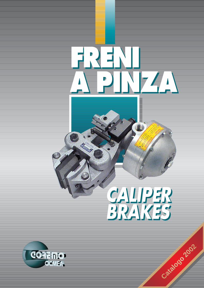
FRENI A PINZA FRENI A PINZA CALIPER BRAKES CALIPER BRAKES Catalogo 2002

Welcome message from author
This document is posted to help you gain knowledge. Please leave a comment to let me know what you think about it! Share it to your friends and learn new things together.
Transcript
FRENIA PINZAFRENIA PINZA
CALIPERBRAKESCALIPERBRAKES
Catalo
go20
02
COREMO OCMEAmanufactures mechanical, pneumatic or hydraulic brakes and clutches for the industries of wire & cable, metalforming, steel, textile, paper, converting, packaging and for all other industrial applications. COREMO OCMEA, established 1960, is based in Assago - Milan (Italy) with a 3.200 m2 plant.
COREMO OCMEAproduit des freins et des embrayages mécaniques, pneumatiques ou hydrauliques pour les tréfileries, les câbleries, le travail du métal, la sidérurgie, le textile, le papier, l'emballage, le conditionnement et toutes autres applications industrielles.COREMO OCMEA fondée en 1960 est basée à Assago - Milan (Italie) sur un site de 3200 m2.
COREMO OCMEAproduziert mechanisch, pneumatisch und hydraulisch betätigte Bremsen und Kupplungen für verschiedene Industrien wie Draht & Kabel, Blech, Stahl, Textil, Papierherstellung, Papierverarbeitung, Verpackung und andere industrielle Anwendungen. COREMO OCMEA, gegründet 1960, ist in Assago - Mailand (Italien) beheimatet und verfügt über 3.200 m2 Büro- und Produktionsfläche.
COREMO OCMEAfabrica frenos y embragues de accionamiento mecánico, neumático e hidráulico para los sectores de alambre & cable, siderurgia, acero, textil, papel, converting, envasado y para otras aplicaciones industriales. COREMO OCMEA, fundada en 1960, tiene la sede en Assago - Milan (Italy) con una planta de 3.200 m2.
COREMO OCMEAproduce freni e frizioni ad azionamento meccanico, pneumatico ed idraulico per i settori del filo & cavo, lamiera, siderurgico, tessile, carta, converting,packaging ed in generale per tutte le applicazioni industriali. COREMO OCMEA, fondata nel 1960, ha sede ad Assago (MI), in uno stabilimento di 3.200 m2.
COREMOCALIPER BRAKES
biggerstrongerfaster
COREMOCALIPER BRAKES
biggerstrongerfaster
ISO 9001Certif. n°0238
MANUALIA comando manuale
Mechanically actuated
PNEUMATICINegativi
Spring applied pneumatically released
COMBINATIPositivi e Negativi
Air Applied and Fail Safe
PNEUMATICIPositivi
Air actuated brakes
IDRAULICI Negativi
Spring applied hydraulically released
IDRAULICI Positivi
Hydraulically actuted
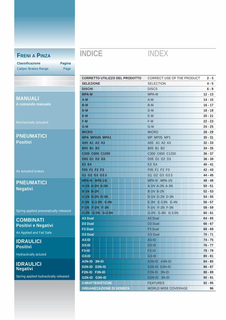
INDICE INDEX
CORRETTO UTILIZZO DEL PRODOTTO CORRECT USE OF THE PRODUCT 2 - 3
SELEZIONE SELECTION 4 - 5
DISCHI DISCS 6 - 9
MPA-M MPA-M 12 - 13
A-M A-M 14 - 15
B-M B-M 16 - 17
D-M D-M 18 - 19
E-M E-M 20 - 21
F-M F-M 22 - 23
G-M G-M 24 - 25
MICRO MICRO 28 - 29
MPA MPA05 MPA1 MP MP05 MP1 30 - 31
A05 A1 A2 A3 A05 A1 A2 A3 32 - 33
B05 B1 B2 B05 B1 B2 34 - 35
C300 C600 C1200 C300 C600 C1200 36 - 37
D05 D1 D2 D3 D05 D1 D2 D3 38 - 39
E3 E4 E3 E4 40 - 41
F05 F1 F2 F3 F05 F1 F2 F3 42 - 43
G1 G2 G3 G3.5 G1 G2 G3 G3.5 44 - 45
MPA-N MPA-1N MPA-N MPA-1N 48 - 49
A-1N A-2N A-3N A-1N A-2N A-3N 50 - 51
B-1N B-2N B-1N B-2N 52 - 53
D-1N D-2N D-3N D-1N D-2N D-3N 54 - 55
E-3N E-3.5N E-4N E-3N E-3.5N E-4N 56 - 57
F-1N F-2N F-3N F-1N F-2N F-3N 58 - 59
G-2N G-3N G-3.5N G-2N G-3N G-3.5N 60 - 61
A3 Dual A3 Dual 64 - 65
D3 Dual D3 Dual 66 - 67
F3 Dual F3 Dual 68 - 69
G3 Dual G3 Dual 70 - 71
A3-ID A3-ID 74 - 75
D3-ID D3-ID 76 - 77
F3-ID F3-ID 78 - 79
G3-ID G3-ID 80 - 81
A2N-ID 3N-ID A2N-ID A3N-ID 84 - 85
D2N-ID D3N-ID D2N-ID D3N-ID 86 - 87
F2N-ID F3N-ID F2N-ID 3N-ID 88 - 89
G2N-ID G3N-ID G2N-ID 3N-ID 90 - 91
CARATTERISTICHE FEATURES 92 - 95
ORGANIZZAZIONE DI VENDITA WORLD WIDE COVERAGE 96
FRENI A PINZA
Classificazione Pagina
Caliper Brakes Range Page
CORRETTO UTILIZZODEL PRODOTTO
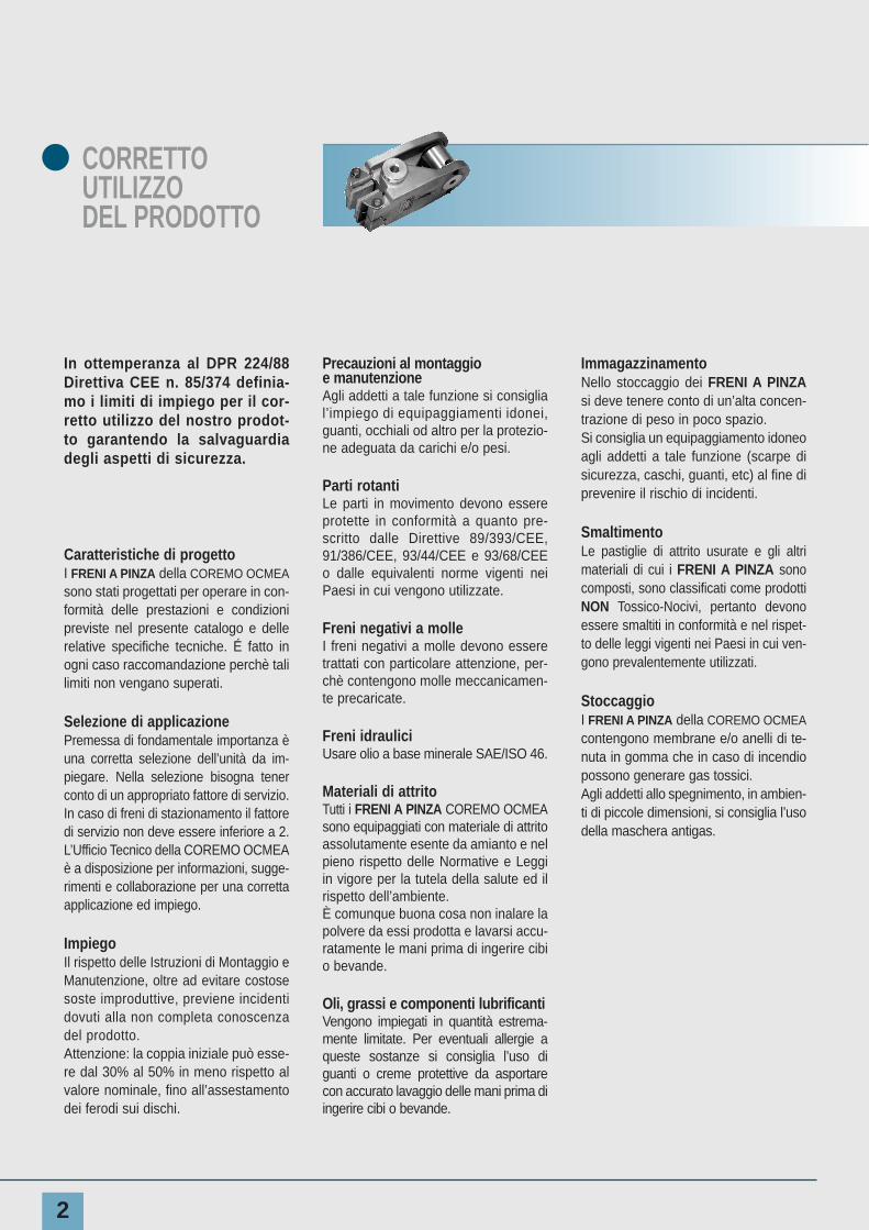
In ottemperanza al DPR 224/88Direttiva CEE n. 85/374 definia-mo i limiti di impiego per il cor-retto utilizzo del nostro prodot-to garantendo la salvaguardiadegli aspetti di sicurezza.
Caratteristiche di progettoI FRENI A PINZA della COREMO OCMEAsono stati progettati per operare in con-formità delle prestazioni e condizionipreviste nel presente catalogo e dellerelative specifiche tecniche. É fatto inogni caso raccomandazione perchè talilimiti non vengano superati.
Selezione di applicazione Premessa di fondamentale importanza èuna corretta selezione dell’unità da im-piegare. Nella selezione bisogna tenerconto di un appropriato fattore di servizio.In caso di freni di stazionamento il fattoredi servizio non deve essere inferiore a 2.L’Ufficio Tecnico della COREMO OCMEAè a disposizione per informazioni, sugge-rimenti e collaborazione per una correttaapplicazione ed impiego.
ImpiegoIl rispetto delle Istruzioni di Montaggio eManutenzione, oltre ad evitare costosesoste improduttive, previene incidentidovuti alla non completa conoscenzadel prodotto.Attenzione: la coppia iniziale può esse-re dal 30% al 50% in meno rispetto alvalore nominale, fino all’assestamentodei ferodi sui dischi.
Precauzioni al montaggio e manutenzioneAgli addetti a tale funzione si consiglial’impiego di equipaggiamenti idonei,guanti, occhiali od altro per la protezio-ne adeguata da carichi e/o pesi.
Parti rotantiLe parti in movimento devono essereprotette in conformità a quanto pre-scritto dalle Direttive 89/393/CEE,91/386/CEE, 93/44/CEE e 93/68/CEEo dalle equivalenti norme vigenti neiPaesi in cui vengono utilizzate.
Freni negativi a molleI freni negativi a molle devono esseretrattati con particolare attenzione, per-chè contengono molle meccanicamen-te precaricate.
Freni idrauliciUsare olio a base minerale SAE/ISO 46.
Materiali di attritoTutti i FRENI A PINZA COREMO OCMEAsono equipaggiati con materiale di attritoassolutamente esente da amianto e nelpieno rispetto delle Normative e Leggiin vigore per la tutela della salute ed ilrispetto dell’ambiente. È comunque buona cosa non inalare lapolvere da essi prodotta e lavarsi accu-ratamente le mani prima di ingerire cibio bevande.
Oli, grassi e componenti lubrificantiVengono impiegati in quantità estrema-mente limitate. Per eventuali allergie aqueste sostanze si consiglia l’uso diguanti o creme protettive da asportarecon accurato lavaggio delle mani prima diingerire cibi o bevande.
Immagazzinamento Nello stoccaggio dei FRENI A PINZAsi deve tenere conto di un’alta concen-trazione di peso in poco spazio. Si consiglia un equipaggiamento idoneoagli addetti a tale funzione (scarpe disicurezza, caschi, guanti, etc) al fine diprevenire il rischio di incidenti.
SmaltimentoLe pastiglie di attrito usurate e gli altrimateriali di cui i FRENI A PINZA sonocomposti, sono classificati come prodottiNON Tossico-Nocivi, pertanto devonoessere smaltiti in conformità e nel rispet-to delle leggi vigenti nei Paesi in cui ven-gono prevalentemente utilizzati.
Stoccaggio I FRENI A PINZA della COREMO OCMEAcontengono membrane e/o anelli di te-nuta in gomma che in caso di incendiopossono generare gas tossici.Agli addetti allo spegnimento, in ambien-ti di piccole dimensioni, si consiglia l’usodella maschera antigas.
2
3
CORRECTUSEOF THE PRODUCT
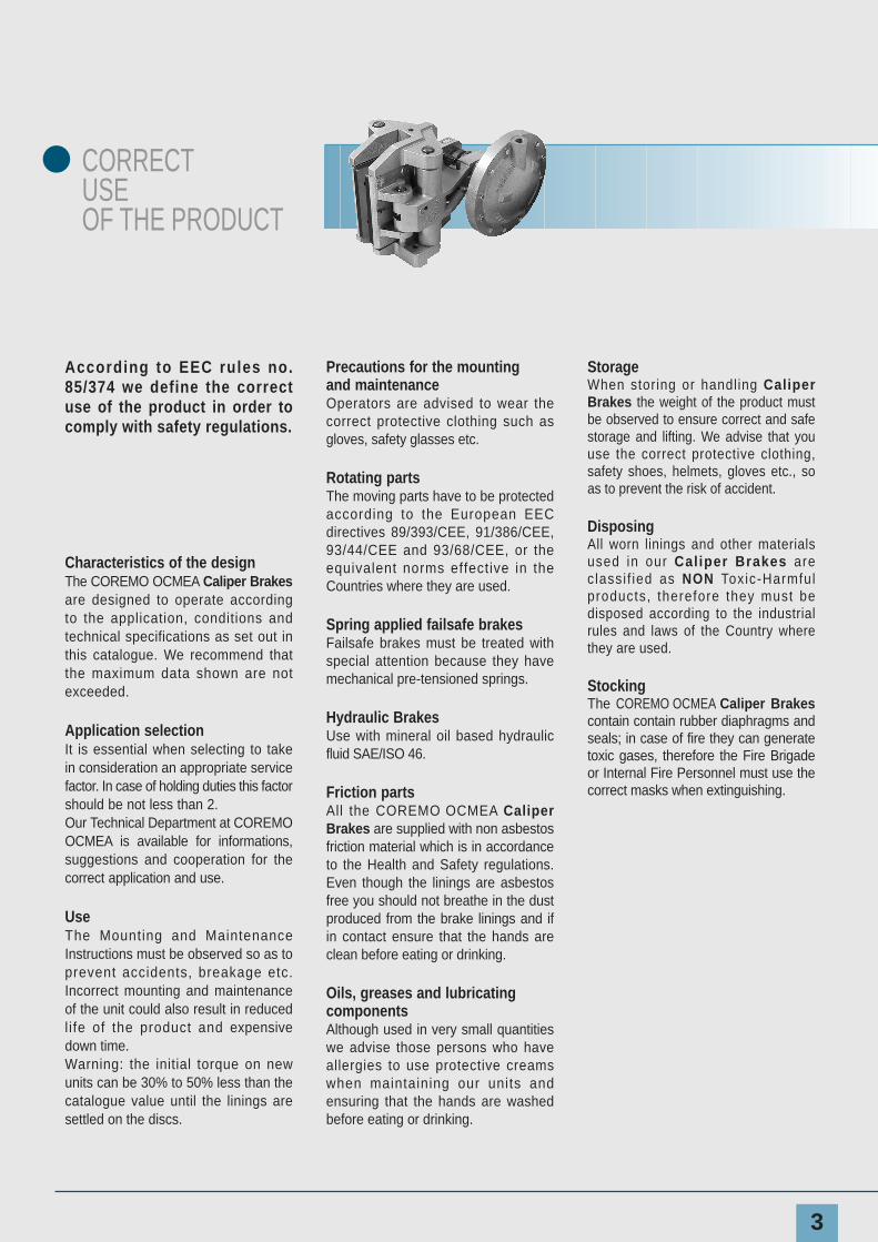
According to EEC rules no.85/374 we define the correctuse of the product in order tocomply with safety regulations.
Characteristics of the designThe COREMO OCMEA Caliper Brakesare designed to operate accordingto the application, conditions andtechnical specifications as set out inthis catalogue. We recommend thatthe maximum data shown are notexceeded.
Application selectionIt is essential when selecting to takein consideration an appropriate servicefactor. In case of holding duties this factorshould be not less than 2. Our Technical Department at COREMOOCMEA is available for informations,suggestions and cooperation for thecorrect application and use.
UseThe Mounting and MaintenanceInstructions must be observed so as toprevent accidents, breakage etc.Incorrect mounting and maintenanceof the unit could also result in reducedlife of the product and expensivedown time. Warning: the initial torque on newunits can be 30% to 50% less than thecatalogue value until the linings aresettled on the discs.
Precautions for the mounting and maintenanceOperators are advised to wear thecorrect protective clothing such asgloves, safety glasses etc.
Rotating partsThe moving parts have to be protectedaccording to the European EECdirectives 89/393/CEE, 91/386/CEE,93/44/CEE and 93/68/CEE, or theequivalent norms effective in theCountries where they are used.
Spring applied failsafe brakes Failsafe brakes must be treated withspecial attention because they havemechanical pre-tensioned springs.
Hydraulic BrakesUse with mineral oil based hydraulicfluid SAE/ISO 46.
Friction partsAll the COREMO OCMEA CaliperBrakes are supplied with non asbestosfriction material which is in accordanceto the Health and Safety regulations.Even though the linings are asbestosfree you should not breathe in the dustproduced from the brake linings and ifin contact ensure that the hands areclean before eating or drinking.
Oils, greases and lubricating componentsAlthough used in very small quantitieswe advise those persons who haveallergies to use protective creamswhen maintaining our units andensuring that the hands are washedbefore eating or drinking.
StorageWhen storing or handling CaliperBrakes the weight of the product mustbe observed to ensure correct and safestorage and lifting. We advise that youuse the correct protective clothing,safety shoes, helmets, gloves etc., soas to prevent the risk of accident.
DisposingAll worn linings and other materialsused in our Caliper Brakes areclassi f ied as NON Toxic-Harmfulproducts, therefore they must bedisposed according to the industrialrules and laws of the Country wherethey are used.
StockingThe COREMO OCMEA Caliper Brakescontain contain rubber diaphragms andseals; in case of fire they can generatetoxic gases, therefore the Fire Brigadeor Internal Fire Personnel must use thecorrect masks when extinguishing.
4
SELEZIONE SELECTION
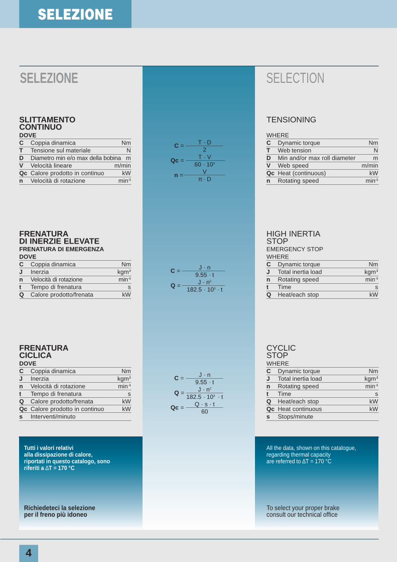
SLITTAMENTOCONTINUODOVEC Coppia dinamica NmT Tensione sul materiale ND Diametro min e/o max della bobina mV Velocità lineare m/minQc Calore prodotto in continuo kWn Velocità di rotazione min-1
TENSIONING
WHEREC Dynamic torque NmT Web tension ND Min and/or max roll diameter mV Web speed m/minQc Heat (continuous) kWn Rotating speed min-1
C = T · D2
Qc = T · V60 · 103
n = Vπ · D
FRENATURADI INERZIE ELEVATEFRENATURA DI EMERGENZADOVEC Coppia dinamica NmJ Inerzia kgm2
n Velocità di rotazione min-1
t Tempo di frenatura sQ Calore prodotto/frenata kW
HIGH INERTIASTOPEMERGENCY STOPWHEREC Dynamic torque NmJ Total inertia load kgm 2
n Rotating speed min -1
t Time sQ Heat/each stop kW
C = J · n9.55 · t
Q = J · n2
182.5 · 103 · t
FRENATURACICLICADOVEC Coppia dinamica NmJ Inerzia kgm2
n Velocità di rotazione min -1
t Tempo di frenatura sQ Calore prodotto/frenata kWQc Calore prodotto in continuo kWs Interventi/minuto
CYCLICSTOPWHEREC Dynamic torque NmJ Total inertia load kgm 2
n Rotating speed min -1
t Time sQ Heat/each stop kWQc Heat continuous kWs Stops/minute
C = J · n9.55 · t
Q = J · n2
182.5 · 103 · t
Qc = Q · s · t60
Tutti i valori relativialla dissipazione di calore,riportati in questo catalogo, sonoriferiti a ∆T = 170 °C
All the data, shown on this catalogue,regarding thermal capacityare referred to ∆T = 170 °C
Richiedeteci la selezioneper il freno più idoneo
To select your proper brakeconsult our technical office
SELEZIONE
SELECTION
5
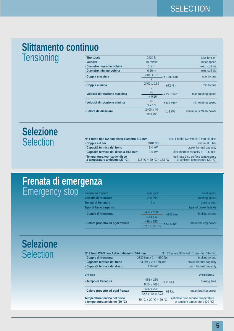
- Tiro totale 2420 N total tension- Velocità 40 m/min linear speed- Diametro massimo bobina 1.5 m max. coil dia- Diametro minimo bobina 0.56 m min. coil dia
- Coppia massima 2400 x 1.5 max torque2
= 1800 Nm
- Coppia minima 2400 x 0.56 min torque2
= 672 Nm
- Velocità di rotazione massima 40 max rotating speedπ x 0.56
= 22.7 min-1
- Velocità di rotazione minima 40 min rotating speedπ x 1.5
= 8.5 min-1
- Calore da dissipare 2400 x 40 continuous mean power60 x 103
= 1.6 kW
N° 1 freno tipo D2 con disco diametro 610 mm No. 1 brake D2 with 610 mm dia disc- Coppia a 6 bar 2040 Nm torque at 6 bar- Capacità termica del freno 3.4 kW brake thermal capacity- Capacità termica del disco a 10.6 min-1 2.4 kW disc thermal capacity at 10.6 min-1
- Temperatura teorica del disco estimate disc surface temperaturea temperatura ambiente (20° C) 113 °C + 20 °C = 133 °C at ambient temperature (20° C)
Slittamento continuoTensioning
Inerzia da frenare 486 kgm2 total inertia
Velocità di rotazione 250 min-1 rotating speed
Tempo di frenatura 3 s braking time
Tipo di freno:negativo type of brake: failsafe
- Coppia di frenatura 486 x 250 braking torque9.55 x 3
= 4241 Nm
- Calore prodotto ad ogni frenata 486 x 2502
mean braking power182.5 x 103 x 3
= 55.5 kW
N° 2 freni D3-N con 1 disco diametro 514 mm No. 2 brakes D3-N with 1 disc dia. 514 mm- Coppia di frenatura 2330 Nm x 2 = 4660 Nm braking torque- Capacità termica del freno 84 kW x 2 = 168 kW brake thermal capacity- Capacità termica del disco 176 kW disc thermal capacity
VERIFICA VERIFICATION
- Tempo di frenatura 486 x 250 braking time9,55 x 4660
= 2,73 s
- Calore prodotto ad ogni frenata 486 x 2502
mean braking power182,5 x 103 x 2,73
= 61 kW
Temperatura teorica del disco 59 °C + 20 °C = 79 °C estimate disc surface temperaturea temperatura ambiente (20 °C) at ambient temperature (20 °C)
SelezioneSelection
Frenata di emergenzaEmergency stop
SelezioneSelection
6
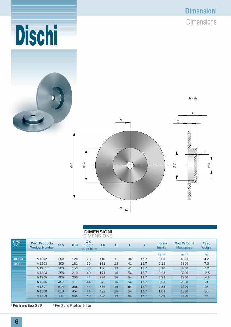
DIMENSIONIDIMENSIONS
TIPO Cod. Prodotto Ø A Ø BØ C
Ø D E F G Inerzia Max Velocità PesoSIZE
Product Numbergrezzo
Inertia Max speed Weightrough bore
kgm2 min-1 kgDISCO A 1302 250 128 20 116 6 36 12.7 0.08 4500 4.2
DISC A 1303 300 181 30 161 13 41 12.7 0.12 3800 7.3A 1311 * 300 150 30 130 13 41 12.7 0.10 3800 7.2A 1304 356 210 40 171 16 54 12.7 0.23 3200 12.5A 1305 406 260 44 234 16 54 12.7 0.33 2800 14.5A 1306 457 311 44 273 16 54 12.7 0.53 2500 21A 1307 514 368 44 336 16 54 12.7 0.83 2200 25A 1308 610 464 44 422 16 54 12.7 1.63 1850 36A 1309 711 565 80 528 19 54 12.7 3.36 1400 55
Piatti per freni a pinza
* Per freno tipo D e F * For D and F caliper brake
Ø A
Ø B
Ø D
F
GA
A
A - A
E
ØC
DischiDimensioniDimensions
7
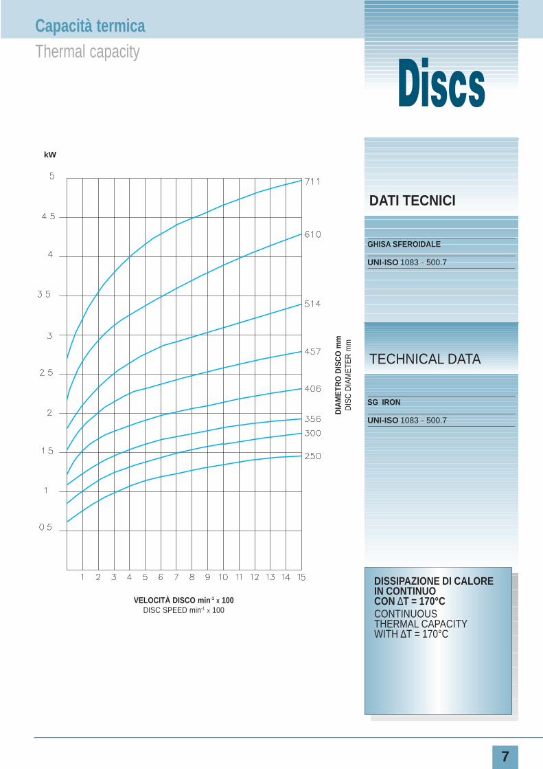
DATI TECNICI
GHISA SFEROIDALE
UNI-ISO 1083 - 500.7
SG IRON
UNI-ISO 1083 - 500.7
TECHNICAL DATA
Plates for caliper brakes
DISSIPAZIONE DI CALOREIN CONTINUOCON ∆T = 170°CCONTINUOUSTHERMAL CAPACITYWITH ∆T = 170°C
VELOCITÀ DISCO min-1 X 100DISC SPEED min-1 X 100
DIA
MET
RO
DIS
CO
mm
DIS
C D
IAM
ETE
R m
m
kW
DiscsCapacità termicaThermal capacity
DISCHI
8
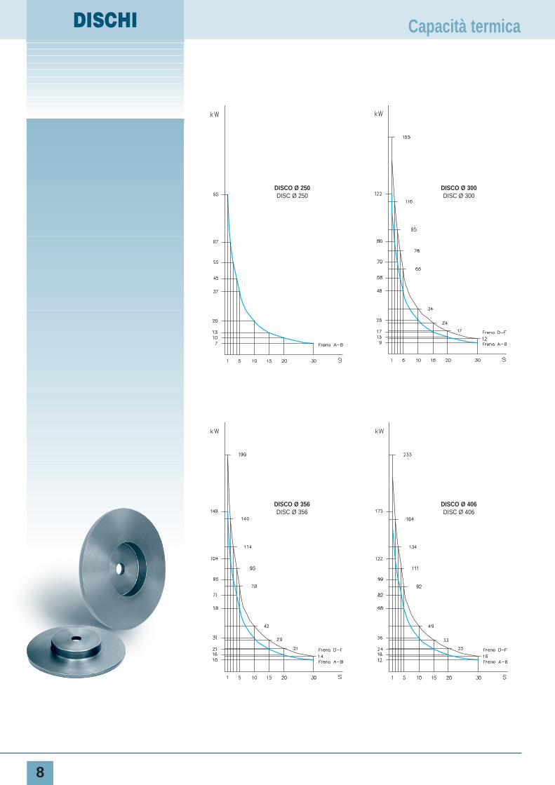
Capacità termica
DISCO Ø 250DISC Ø 250
DISCO Ø 300DISC Ø 300
DISCO Ø 406DISC Ø 406
DISCO Ø 356DISC Ø 356
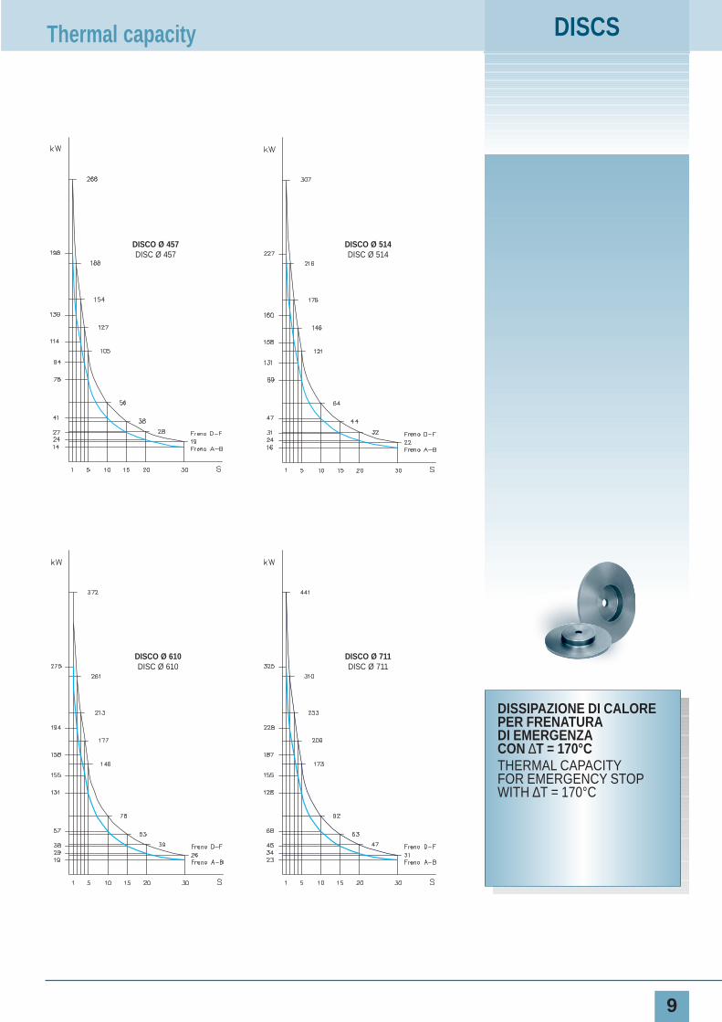
DISCS
9
DISSIPAZIONE DI CALOREPER FRENATURADI EMERGENZACON ∆T = 170°CTHERMAL CAPACITYFOR EMERGENCY STOPWITH ∆T = 170°C
Thermal capacity
DISCO Ø 610DISC Ø 610
DISCO Ø 711DISC Ø 711
DISCO Ø 514DISC Ø 514
DISCO Ø 457DISC Ø 457

10
I freni idraulici hanno la ca-ratteristica di avere il pregiodi fare una specifica cosache li contraddistingue da al-tri tipi di prodotti di altra fat-tura e/o della concorrenza. Inparticolare i freni positivinon sono negativi e vicever-sa.Questi freni si adattano a quasitutto ed è per questa cosa chevengono chiamati anche freni“fatti a posta”.Queste notizie rappresentanoun
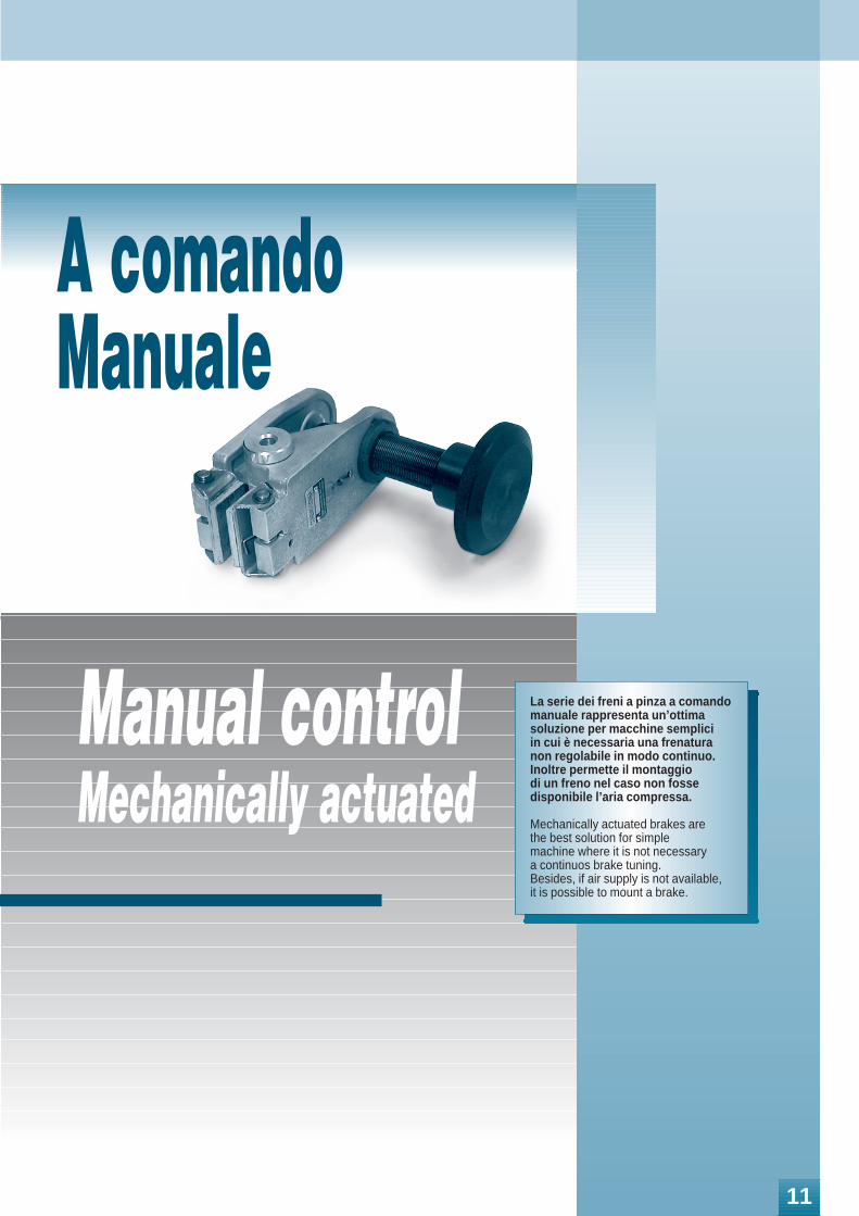
Manual control Mechanically actuated
La serie dei freni a pinza a comandomanuale rappresenta un’ottima soluzione per macchine semplici in cui è necessaria una frenaturanon regolabile in modo continuo.Inoltre permette il montaggio di un freno nel caso non fosse disponibile l’aria compressa.
Mechanically actuated brakes are the best solution for simple machine where it is not necessary a continuos brake tuning.Besides, if air supply is not available, it is possible to mount a brake.
A comandoManuale
11
MANUALE
MPA-M
12
DIMENSIONIDIMENSIONS
TIPO Cod. Prodotto A B ØC D E FPeso
SIZEProduct Number
Weightkg
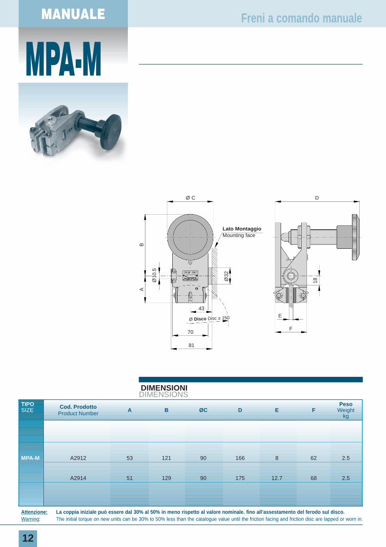
MPA-M A2912 53 121 90 166 8 62 2.5
A2914 51 129 90 175 12.7 68 2.5
Freni a comando manuale
Attenzione: La coppia iniziale può essere dal 30% al 50% in meno rispetto al valore nominale. fino all’assestamento del ferodo sul disco.Warning: The initial torque on new units can be 30% to 50% less than the catalogue value until the friction facing and friction disc are lapped or worn in.
Ø C
Lato MontaggioMounting face
D
43E
F70
81
Ø Disco Disc ≥ 150
A
Ø10
.5
Ø32
18
B
13
DATI TECNICI
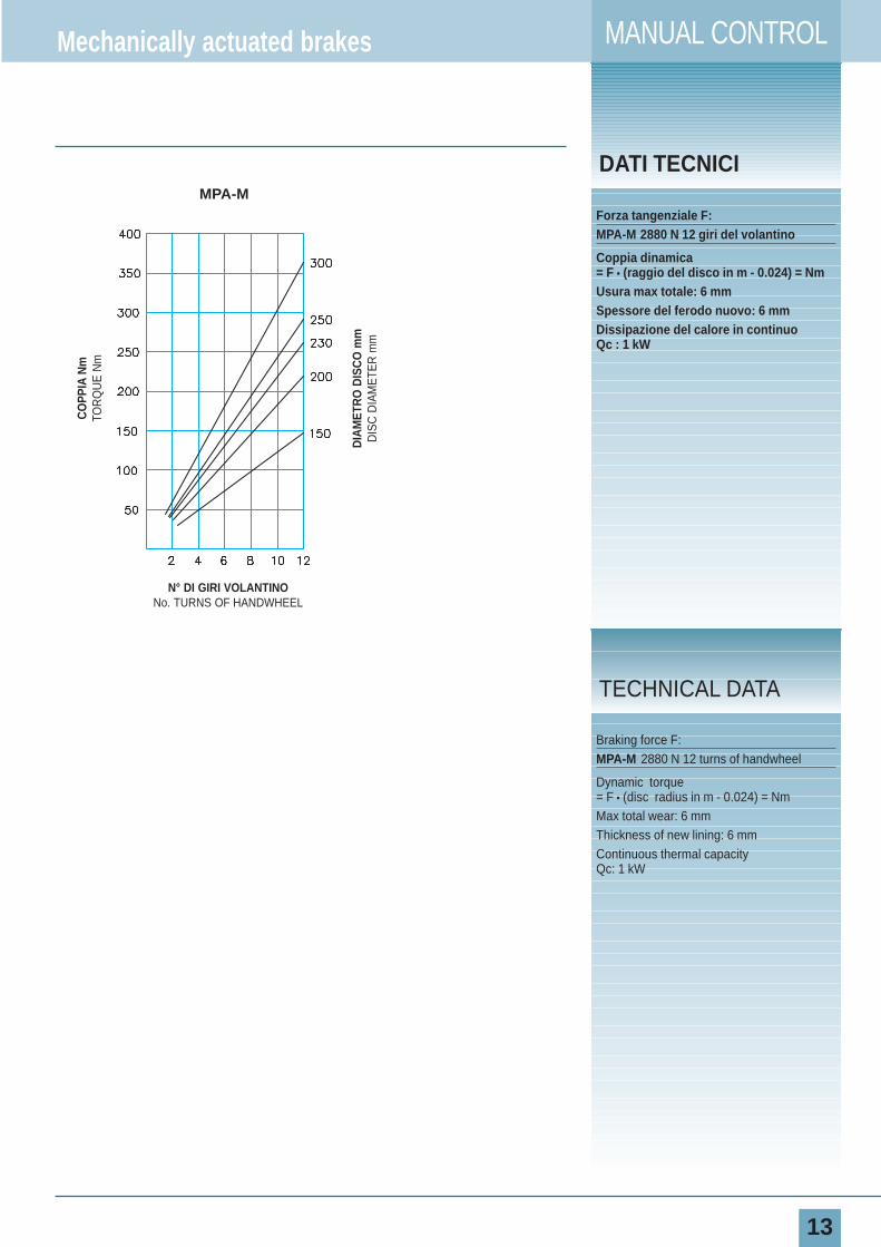
Forza tangenziale F:MPA-M 2880 N 12 giri del volantino
Coppia dinamica= F • (raggio del disco in m - 0.024) = NmUsura max totale: 6 mmSpessore del ferodo nuovo: 6 mmDissipazione del calore in continuoQc : 1 kW
Braking force F: MPA-M 2880 N 12 turns of handwheel
Dynamic torque= F • (disc radius in m - 0.024) = NmMax total wear: 6 mmThickness of new lining: 6 mmContinuous thermal capacity Qc: 1 kW
TECHNICAL DATA
Mechanically actuated brakes MANUAL CONTROL
N° DI GIRI VOLANTINONo. TURNS OF HANDWHEEL
DIA
MET
RO
DIS
CO
mm
DIS
C D
IAM
ETE
R m
m
CO
PPIA
Nm
TOR
QU
E N
m
MPA-M
MANUALE
A-M
14
DIMENSIONIDIMENSIONS
TIPO Cod. Prodotto A B ØC DPeso
SIZE Product Number Weightkg
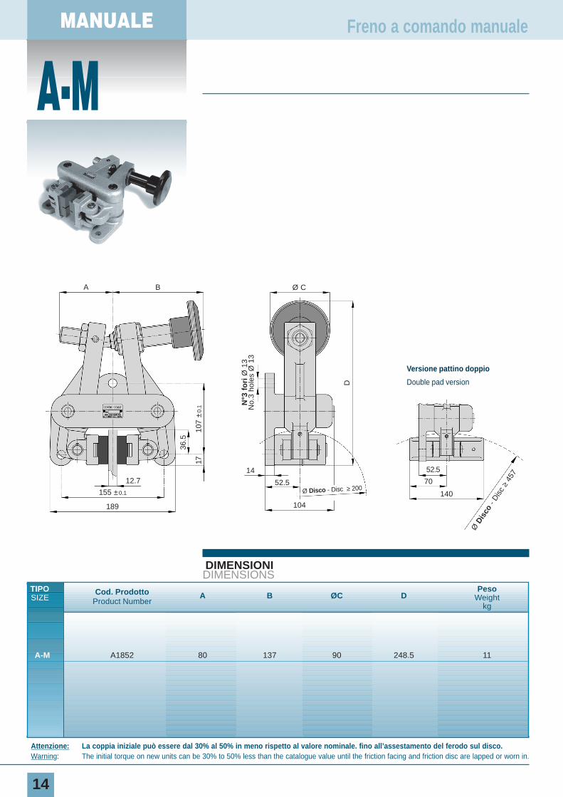
A-M A1852 80 137 90 248.5 11
Freno a comando manuale
Attenzione: La coppia iniziale può essere dal 30% al 50% in meno rispetto al valore nominale. fino all’assestamento del ferodo sul disco.Warning: The initial torque on new units can be 30% to 50% less than the catalogue value until the friction facing and friction disc are lapped or worn in.
Ø C
14
N°3
fo
riØ
13
No.
3 ho
les
Ø 1
3
D
52.5
104
Ø Disco - Disc ≥ 20012.7
A B
36.5
107
±0.
117
155 ±0.1
189
Ø D
isco
- D
isc
≥45
752.5
70
140
Versione pattino doppio
Double pad version

MANUAL
15
DATI TECNICI
Forza tangenziale F:A-M 2880 N 12 giri del volantino
Coppia dinamica= F • (raggio del disco in m - 0.03) = NmUsura max totale: 12 mmSpessore del ferodo nuovo: 16 mmDissipazione del calore in continuoQc: 1.7 kW
Dissipazione di calore in continuocon pattino doppioQc: 2.7 kW
Mechanically actuated brake
Braking force F:A-M 2880 N 12 turns of handwheel
Dynamic torque= F • (disc radius in m - 0.03) = NmMax total wear: 12 mmThickness of new lining: 16 mmContinuous thermal capacityQc: 1.7 kW
Continuous thermal capacity of double pad versionQc: 2.7 kW
TECHNICAL DATAN° DI GIRI VOLANTINO
No. TURNS OF HANDWHEEL
DIA
MET
RO
DIS
CO
mm
DIS
C D
IAM
ETE
R m
m
CO
PPIA
Nm
TOR
QU
E N
m
A-M
MANUALE
B-M
16
DIMENSIONIDIMENSIONS
TIPO Cod. Prodotto ØA B C DPeso
SIZE Product NumberWeight
kg
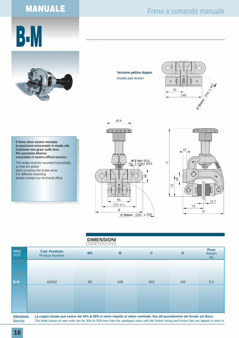
B-M A2012 90 169 242 145 5.5
Freno a comando manuale
Il freno deve essere montatoin posizione orizzontale in modo cheil pistone non gravi sulle leve.Per posizioni diverseconsultare il nostro ufficio tecnico.
The brake must be mounted horizontallyso that the pistondoes not press the brake arms.For different mountingplease contact our technical office.
Attenzione: La coppia iniziale può essere dal 30% al 50% in meno rispetto al valore nominale, fino all’assestamento del ferodo sul disco.Warning: The initial torque on new units can be 30% to 50% less than the catalogue value until the friction facing and friction disc are lapped or worn in.
Ø A
48
C
73
20
13
12.7
73
D
81
B
Ø Disco - Disc ≥ 200
121 ±0.1
N°2 fori Ø15No. 2 holes Ø15
Ø D
isco
- D
isc
≥45
7
70
140
Versione pattino doppio
Double pad version
MANUAL
17
DATI TECNICI
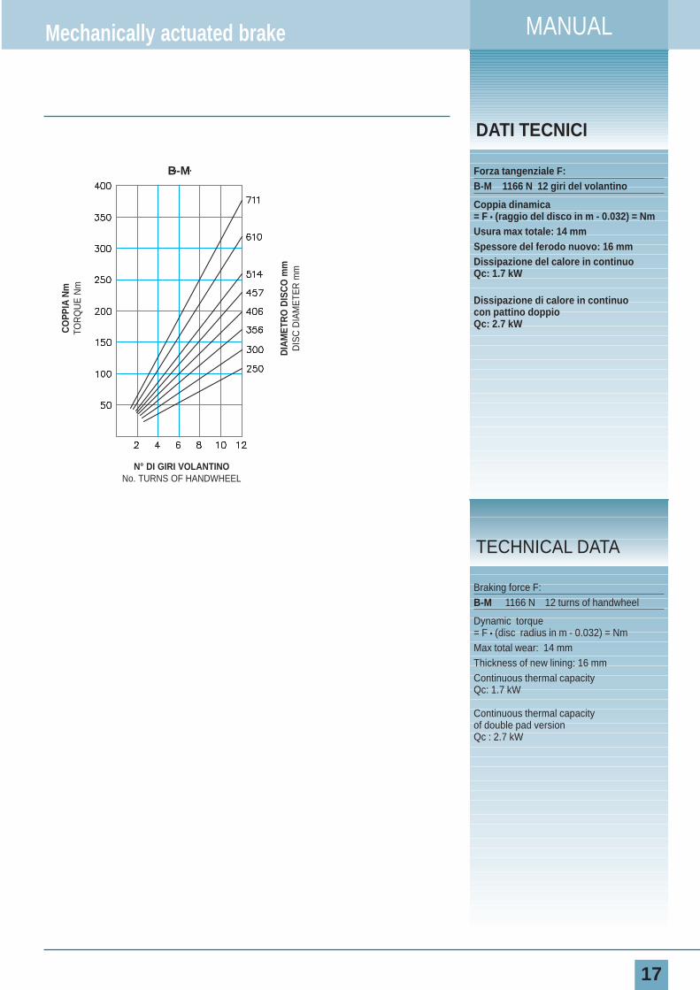
Forza tangenziale F:B-M 1166 N 12 giri del volantino
Coppia dinamica= F • (raggio del disco in m - 0.032) = NmUsura max totale: 14 mmSpessore del ferodo nuovo: 16 mmDissipazione del calore in continuoQc: 1.7 kW
Dissipazione di calore in continuocon pattino doppioQc: 2.7 kW
Mechanically actuated brake
Braking force F:B-M 1166 N 12 turns of handwheel
Dynamic torque= F • (disc radius in m - 0.032) = NmMax total wear: 14 mmThickness of new lining: 16 mmContinuous thermal capacityQc: 1.7 kW
Continuous thermal capacity of double pad versionQc : 2.7 kW
TECHNICAL DATA
N° DI GIRI VOLANTINONo. TURNS OF HANDWHEEL
DIA
MET
RO
DIS
CO
mm
DIS
C D
IAM
ETE
R m
m
CO
PPIA
Nm
TOR
QU
E N
m
B-M
DIMENSIONIDIMENSIONS
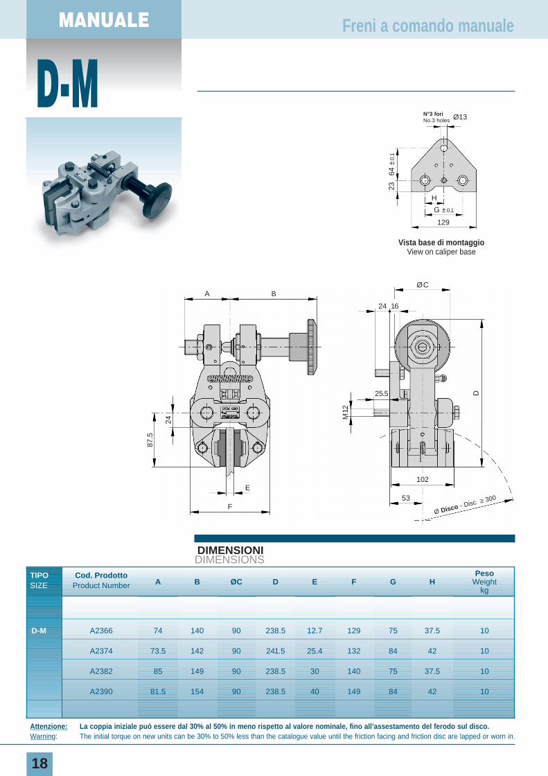
Attenzione: La coppia iniziale può essere dal 30% al 50% in meno rispetto al valore nominale, fino all’assestamento del ferodo sul disco.Warning: The initial torque on new units can be 30% to 50% less than the catalogue value until the friction facing and friction disc are lapped or worn in.
MANUALE
D-M
18
Freni a comando manuale
ØC
24 16
25.5 D
53
102
Ø Disco - Disc ≥ 300
E
A B
87.5
24
M12
F
TIPO Cod. ProdottoA B ØC D E F G H
Peso
SIZE Product Number Weightkg
D-M A2366 74 140 90 238.5 12.7 129 75 37.5 10
A2374 73.5 142 90 241.5 25.4 132 84 42 10
A2382 85 149 90 238.5 30 140 75 37.5 10
A2390 81.5 154 90 238.5 40 149 84 42 10
Vista base di montaggioView on caliper base
129
N°3 fori No.3 holes Ø13
H
64 ±
0.1
23
G ±0.1
MANUAL
19
DATI TECNICI
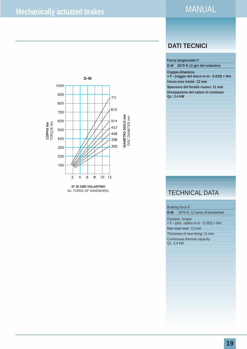
Forza tangenziale F:D-M 2670 N 12 giri del volantino
Coppia dinamica= F • (raggio del disco in m - 0.033) = NmUsura max totale: 12 mmSpessore del ferodo nuovo: 11 mmDissipazione del calore in continuoQc: 3.4 kW
Mechanically actuated brakes
Braking force F:D-M 2670 N 12 turns of handwheel
Dynamic torque= F • (disc radius in m - 0.033) = NmMax total wear: 12 mmThickness of new lining: 11 mmContinuous thermal capacityQc: 3.4 kW
TECHNICAL DATAN° DI GIRI VOLANTINO
No. TURNS OF HANDWHEEL
DIA
MET
RO
DIS
CO
mm
DIS
C D
IAM
ETE
R m
m
CO
PPIA
Nm
TOR
QU
E N
m
D-M
MANUALE
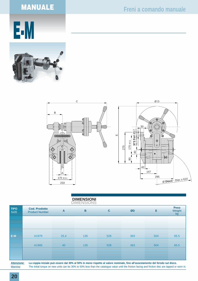
E-M
20
DIMENSIONIDIMENSIONS
TIPO Cod. ProdottoA B C ØD E
Peso
SIZE Product Number Weightkg
E-M A1979 25.4 135 528 363 504 65.5
A1985 40 135 528 363 504 65.5
Freni a comando manuale
Attenzione: La coppia iniziale può essere dal 30% al 50% in meno rispetto al valore nominale, fino all’assestamento del ferodo sul disco.Warning: The initial torque on new units can be 30% to 50% less than the catalogue value until the friction facing and friction disc are lapped or worn in.
C Ø D
3017
0 ±
0.1
40
80
42
147
295
Ø Disco - Disc ≥ 610
275
E
N°3
Fo
riØ
17N
o.3
hole
sØ
17
B
A
233
170 ±0.1
MANUAL
21
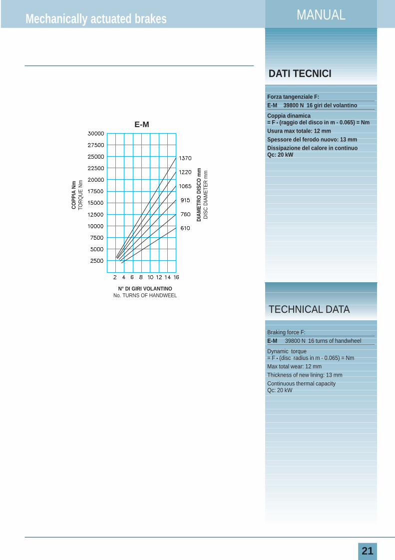
DATI TECNICI
Forza tangenziale F:E-M 39800 N 16 giri del volantino
Coppia dinamica= F • (raggio del disco in m - 0.065) = NmUsura max totale: 12 mmSpessore del ferodo nuovo: 13 mmDissipazione del calore in continuoQc: 20 kW
Mechanically actuated brakes
Braking force F:E-M 39800 N 16 turns of handwheel
Dynamic torque= F • (disc radius in m - 0.065) = NmMax total wear: 12 mmThickness of new lining: 13 mmContinuous thermal capacity Qc: 20 kW
TECHNICAL DATA
CO
PPIA
Nm
TOR
QU
E N
m
DIA
MET
RO
DIS
CO
mm
DIS
C D
IAM
ETE
R m
m
N° DI GIRI VOLANTINONo. TURNS OF HANDWEEL
E-M
MANUALE
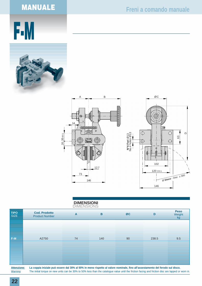
F-M
22
Freni a comando manuale
Attenzione: La coppia iniziale può essere dal 30% al 50% in meno rispetto al valore nominale, fino all’assestamento del ferodo sul disco.Warning: The initial torque on new units can be 30% to 50% less than the catalogue value until the friction facing and friction disc are lapped or worn in.
DIMENSIONIDIMENSIONS
TIPO Cod. Prodotto A B ØC DPeso
SIZE Product NumberWeight
kg
F-M A2750 74 140 90 238.5 9.5
ØC
D
120 ±0.1
146
102
Ø Disco - Disc ≥ 300
12.7
73
A B
20
14
63
146
N°4
Fo
riØ
13N
o.4
hole
sØ
13
35±
0.1

MANUAL
23
DATI TECNICI
Forza tangenziale F:F-M 2670 N 12 giri del volantino
Coppia dinamica= F • (raggio del disco in m - 0.033) = NmUsura max totale: 12 mmSpessore del ferodo nuovo: 11 mmDissipazione del calore in continuoQc: 3.4 kW
Mechanically actuated brakes
Braking force F:F-M 2670 N 12 turns of handwheel
Dynamic torque= F • (disc radius in m - 0.033) = NmMax total wear: 12 mmThickness of new lining: 11 mmContinuous thermal capacityQc: 3.4 kW
TECHNICAL DATA
CO
PPIA
Nm
TOR
QU
E N
m
DIA
MET
RO
DIS
CO
mm
DIS
C D
IAM
ETE
R m
m
N° DI GIRI VOLANTINONo. TURNS OF HANDWEEL
F-M
MANUALE
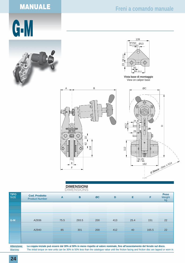
G-M
24
Freni a comando manuale
Attenzione: La coppia iniziale può essere dal 30% al 50% in meno rispetto al valore nominale, fino all’assestamento del ferodo sul disco.Warning: The initial torque on new units can be 30% to 50% less than the catalogue value until the friction facing and friction disc are lapped or worn in.
DIMENSIONIDIMENSIONS
TIPO Cod. Prodotto A B ØC D E FPeso
SIZEProduct Number
Weightkg
G-M A2936 75.5 293.5 200 413 25.4 151 22
A2940 85 301 200 412 40 165.5 22
Vista base di montaggioView on caliper base
139
A B ØC22
62
118
M12 D
112
E
F
182
52.25
24
26
16
N°3 fori No.3 holes
Ø13
42
64 ±
0.1
23
84 ±0.1
Ø Disco - Disc ≥ 514
MANUAL
25
DATI TECNICI
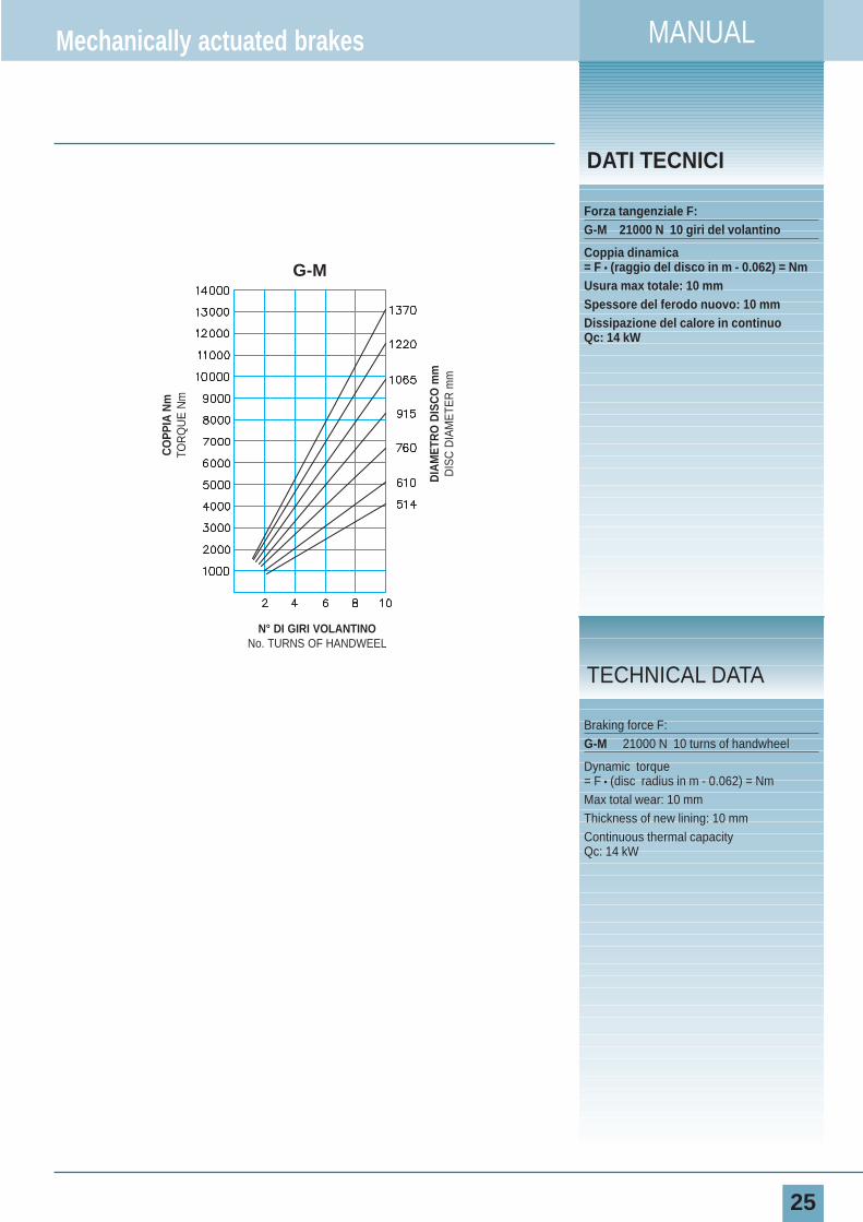
Forza tangenziale F:G-M 21000 N 10 giri del volantino
Coppia dinamica= F • (raggio del disco in m - 0.062) = NmUsura max totale: 10 mmSpessore del ferodo nuovo: 10 mmDissipazione del calore in continuoQc: 14 kW
Mechanically actuated brakes
Braking force F:G-M 21000 N 10 turns of handwheel
Dynamic torque= F • (disc radius in m - 0.062) = NmMax total wear: 10 mmThickness of new lining: 10 mmContinuous thermal capacity Qc: 14 kW
TECHNICAL DATA
CO
PPIA
Nm
TOR
QU
E N
m
DIA
MET
RO
DIS
CO
mm
DIS
C D
IAM
ETE
R m
m
N° DI GIRI VOLANTINONo. TURNS OF HANDWEEL
G-M

26
I freni idraulici hanno la ca-ratteristica di avere il pregiodi fare una specifica cosache li contraddistingue da al-tri tipi di prodotti di altra fat-tura e/o della concorrenza. Inparticolare i freni positivinon sono negativi e vicever-sa.Questi freni si adattano a quasitutto ed è per questa cosa chevengono chiamati anche freni“fatti a posta”.Queste notizie rappresentanoun
PNEUMATICAir Applied
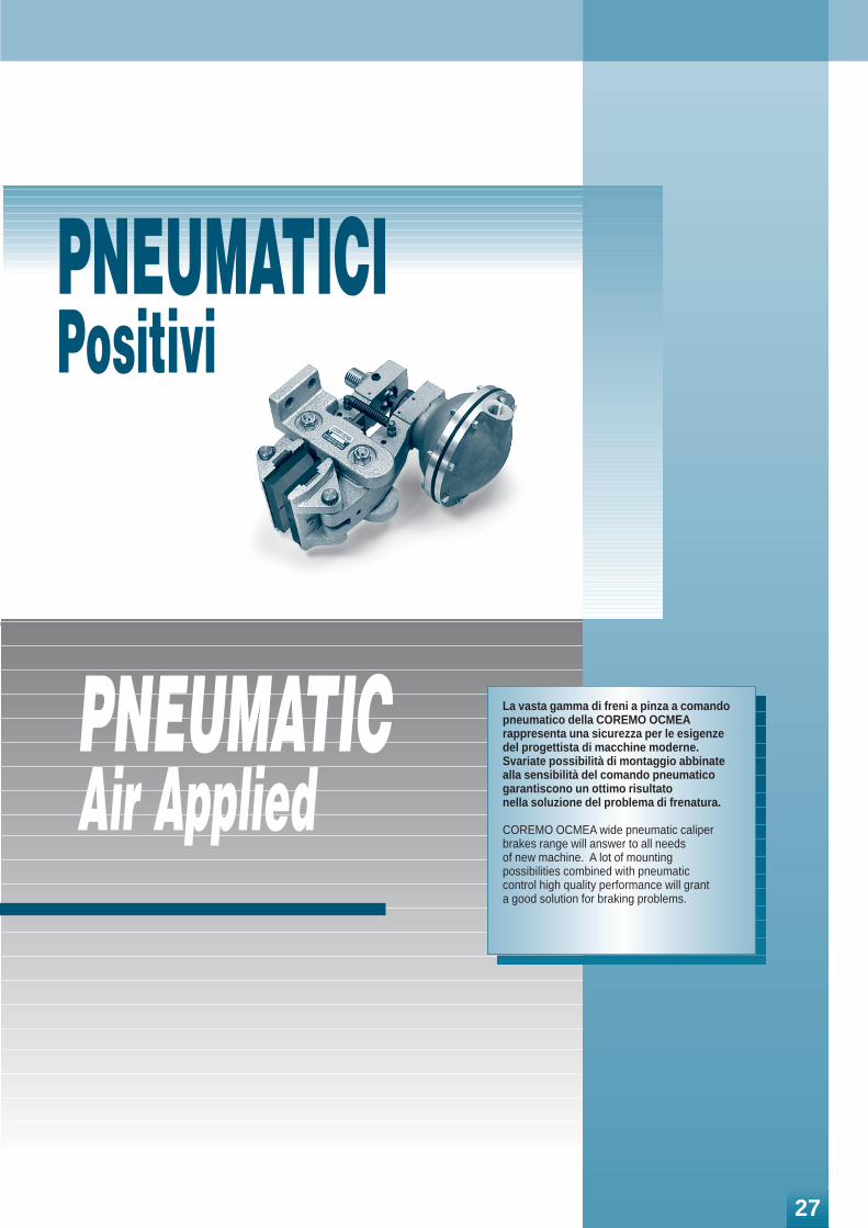
La vasta gamma di freni a pinza a comandopneumatico della COREMO OCMEArappresenta una sicurezza per le esigenzedel progettista di macchine moderne. Svariate possibilità di montaggio abbinate alla sensibilità del comando pneumatico garantiscono un ottimo risultato nella soluzione del problema di frenatura.
COREMO OCMEA wide pneumatic caliperbrakes range will answer to all needs of new machine. A lot of mounting possibilities combined with pneumatic control high quality performance will grant a good solution for braking problems.
PNEUMATICIPositivi
27
PNEUMATICO
MICRO
28
DIMENSIONIDIMENSIONS
TIPO Cod. Prodotto A B C ØD EVolume aria Peso
SIZE Product Number Air Volume Weightmin ÷ max dm3 kg
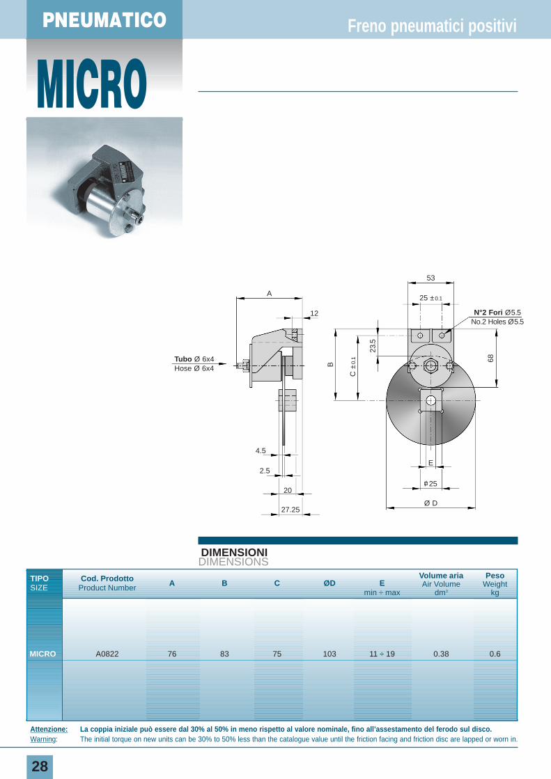
MICRO A0822 76 83 75 103 11 ÷ 19 0.38 0.6
Freno pneumatici positivi
Attenzione: La coppia iniziale può essere dal 30% al 50% in meno rispetto al valore nominale, fino all’assestamento del ferodo sul disco.Warning: The initial torque on new units can be 30% to 50% less than the catalogue value until the friction facing and friction disc are lapped or worn in.
A
12
53
25 ±0.1
N°2 Fori Ø5.5No.2 Holes Ø5.5
Tubo Ø 6x4Hose Ø 6x4
4.5
2.5
20
E
Ø D
/ 25
27.25
B
C ±
0.1
23.5
68
PNEUMATIC
29
DIAGRAMMACHART
DATI TECNICI
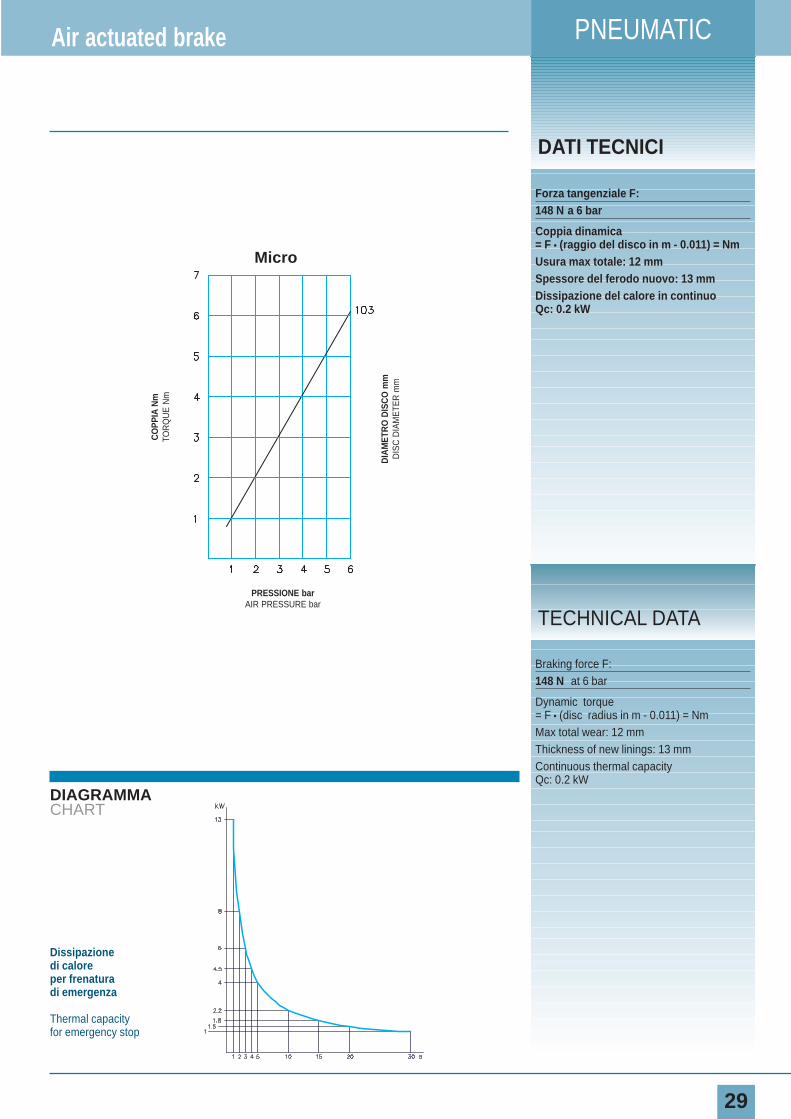
Forza tangenziale F:148 N a 6 bar
Coppia dinamica= F • (raggio del disco in m - 0.011) = NmUsura max totale: 12 mmSpessore del ferodo nuovo: 13 mmDissipazione del calore in continuoQc: 0.2 kW
Air actuated brake
Braking force F:148 N at 6 bar
Dynamic torque= F • (disc radius in m - 0.011) = NmMax total wear: 12 mmThickness of new linings: 13 mmContinuous thermal capacity Qc: 0.2 kW
TECHNICAL DATA
Dissipazione di caloreper frenatura di emergenza
Thermal capacityfor emergency stop
PRESSIONE barAIR PRESSURE bar
DIA
MET
RO
DIS
CO
mm
DIS
C D
IAM
ETE
R m
m
CO
PPIA
Nm
TOR
QU
E N
m
Micro
PNEUMATICO
MPA
30
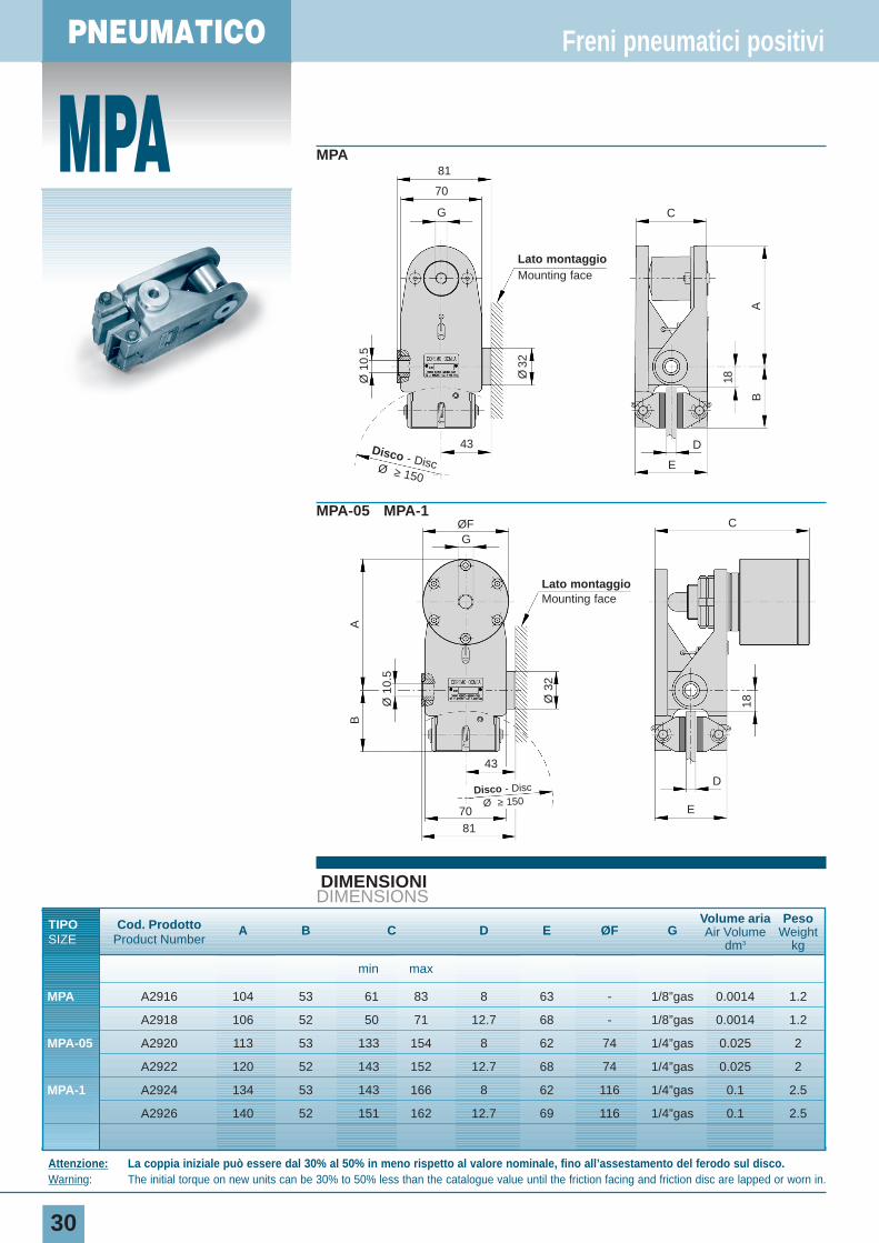
MPA
MPA-05 MPA-1
DIMENSIONIDIMENSIONS
TIPO Cod. Prodotto A B C D E ØF GVolume aria Peso
SIZE Product NumberAir Volume Weight
dm3 kg
min max
MPA A2916 104 53 61 83 8 63 - 1/8”gas 0.0014 1.2
A2918 106 52 50 71 12.7 68 - 1/8”gas 0.0014 1.2
MPA-05 A2920 113 53 133 154 8 62 74 1/4”gas 0.025 2
A2922 120 52 143 152 12.7 68 74 1/4”gas 0.025 2
MPA-1 A2924 134 53 143 166 8 62 116 1/4”gas 0.1 2.5
A2926 140 52 151 162 12.7 69 116 1/4”gas 0.1 2.5
Freni pneumatici positivi
Attenzione: La coppia iniziale può essere dal 30% al 50% in meno rispetto al valore nominale, fino all’assestamento del ferodo sul disco.Warning: The initial torque on new units can be 30% to 50% less than the catalogue value until the friction facing and friction disc are lapped or worn in.
C
D
18
BA
ØF
43
G
Ø 1
0.5
Ø 3
2
81
70
G C
Disco - DiscØ ≥ 150
Disco - Disc
Ø ≥ 150
43
E
D
18
BA
Ø32
Ø 1
0.5
E
Lato montaggioMounting face
Lato montaggioMounting face
7081
PNEUMATIC
31
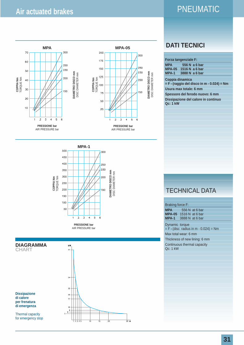
DIAGRAMMACHART
DATI TECNICI
Forza tangenziale F:MPA 556 N a 6 barMPA-05 1516 N a 6 barMPA-1 3888 N a 6 bar
Coppia dinamica= F • (raggio del disco in m - 0.024) = NmUsura max totale: 6 mmSpessore del ferodo nuovo: 6 mmDissipazione del calore in continuoQc: 1 kW
Air actuated brakes
Braking force F:MPA 556 N at 6 barMPA-05 1516 N at 6 barMPA-1 3888 N at 6 bar
Dynamic torque= F • (disc radius in m - 0.024) = NmMax total wear: 6 mmThickness of new lining: 6 mmContinuous thermal capacity Qc: 1 kW
TECHNICAL DATA
Dissipazione di caloreper frenatura di emergenza
Thermal capacityfor emergency stop
MPA MPA-05
MPA-1
CO
PPIA
Nm
TOR
QU
E N
m
DIA
MET
RO
DIS
CO
mm
DIS
C D
IAM
ETE
R m
m
PRESSIONE barAIR PRESSURE bar
CO
PPIA
Nm
TOR
QU
E N
m
DIA
MET
RO
DIS
CO
mm
DIS
C D
IAM
ETE
R m
m
PRESSIONE barAIR PRESSURE bar
CO
PPIA
Nm
TOR
QU
E N
m
DIA
MET
RO
DIS
CO
mm
DIS
C D
IAM
ETE
R m
m
PRESSIONE barAIR PRESSURE bar
PNEUMATICO
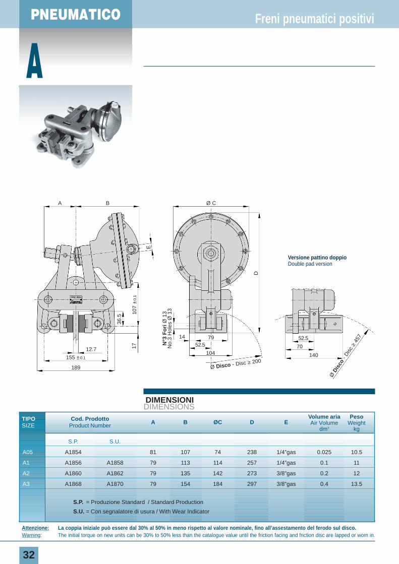
A
32
DIMENSIONIDIMENSIONS
TIPO Cod. Prodotto A B ØC D EVolume aria Peso
SIZE Product Number Air Volume Weightdm3 kg
S.P. S.U.
A05 A1854 81 107 74 238 1/4”gas 0.025 10.5
A1 A1856 A1858 79 113 114 257 1/4”gas 0.1 11
A2 A1860 A1862 79 135 142 273 3/8”gas 0.2 12
A3 A1868 A1870 79 154 184 297 3/8”gas 0.4 13.5
S.P. = Produzione Standard / Standard Production
S.U. = Con segnalatore di usura / With Wear Indicator
Freni pneumatici positivi
Attenzione: La coppia iniziale può essere dal 30% al 50% in meno rispetto al valore nominale, fino all’assestamento del ferodo sul disco.Warning: The initial torque on new units can be 30% to 50% less than the catalogue value until the friction facing and friction disc are lapped or worn in.
A B Ø C
D
Ø Disco - Disc ≥ 200
Ø D
isco
- D
isc
≥45
714
12.7
155 ±0.1
189
107
±0.
1
E
36.5
17 52.5 79 52.5
70
140104
N°3
Fo
riØ
13
No.
3 H
oles
Ø 1
3
Versione pattino doppioDouble pad version
PNEUMATIC
33
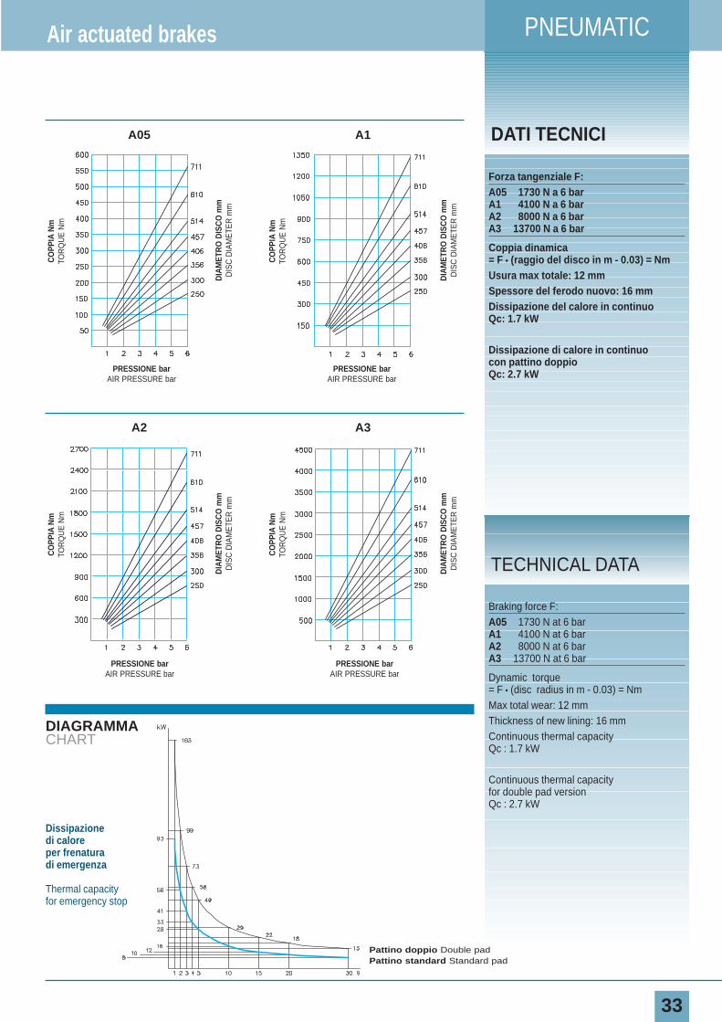
DIAGRAMMACHART
DATI TECNICIA05 A1
Forza tangenziale F:A05 1730 N a 6 barA1 4100 N a 6 barA2 8000 N a 6 barA3 13700 N a 6 bar
Coppia dinamica= F • (raggio del disco in m - 0.03) = NmUsura max totale: 12 mmSpessore del ferodo nuovo: 16 mmDissipazione del calore in continuoQc: 1.7 kW
Dissipazione di calore in continuocon pattino doppioQc: 2.7 kW
Air actuated brakes
Braking force F:A05 1730 N at 6 barA1 4100 N at 6 barA2 8000 N at 6 barA3 13700 N at 6 bar
Dynamic torque= F • (disc radius in m - 0.03) = NmMax total wear: 12 mmThickness of new lining: 16 mmContinuous thermal capacity Qc : 1.7 kW
Continuous thermal capacity for double pad versionQc : 2.7 kW
TECHNICAL DATA
Dissipazione di caloreper frenatura di emergenza
Thermal capacityfor emergency stop
A3A2
CO
PPIA
Nm
TOR
QU
E N
m
DIA
MET
RO
DIS
CO
mm
DIS
C D
IAM
ETE
R m
m
PRESSIONE barAIR PRESSURE bar
CO
PPIA
Nm
TOR
QU
E N
m
DIA
MET
RO
DIS
CO
mm
DIS
C D
IAM
ETE
R m
m
PRESSIONE barAIR PRESSURE bar
CO
PPIA
Nm
TOR
QU
E N
m
DIA
MET
RO
DIS
CO
mm
DIS
C D
IAM
ETE
R m
m
PRESSIONE barAIR PRESSURE bar
CO
PPIA
Nm
TOR
QU
E N
m
DIA
MET
RO
DIS
CO
mm
DIS
C D
IAM
ETE
R m
m
PRESSIONE barAIR PRESSURE bar
Pattino doppio Double padPattino standard Standard pad
PNEUMATICO
34
DIMENSIONIDIMENSIONS
TIPO Cod. ProdottoØA B C
Volume aria Peso
SIZE Product NumberAir Volume Weight
dm3 kg
Std Std S.U. H6 H6 S.U. H12 H12 S.U.
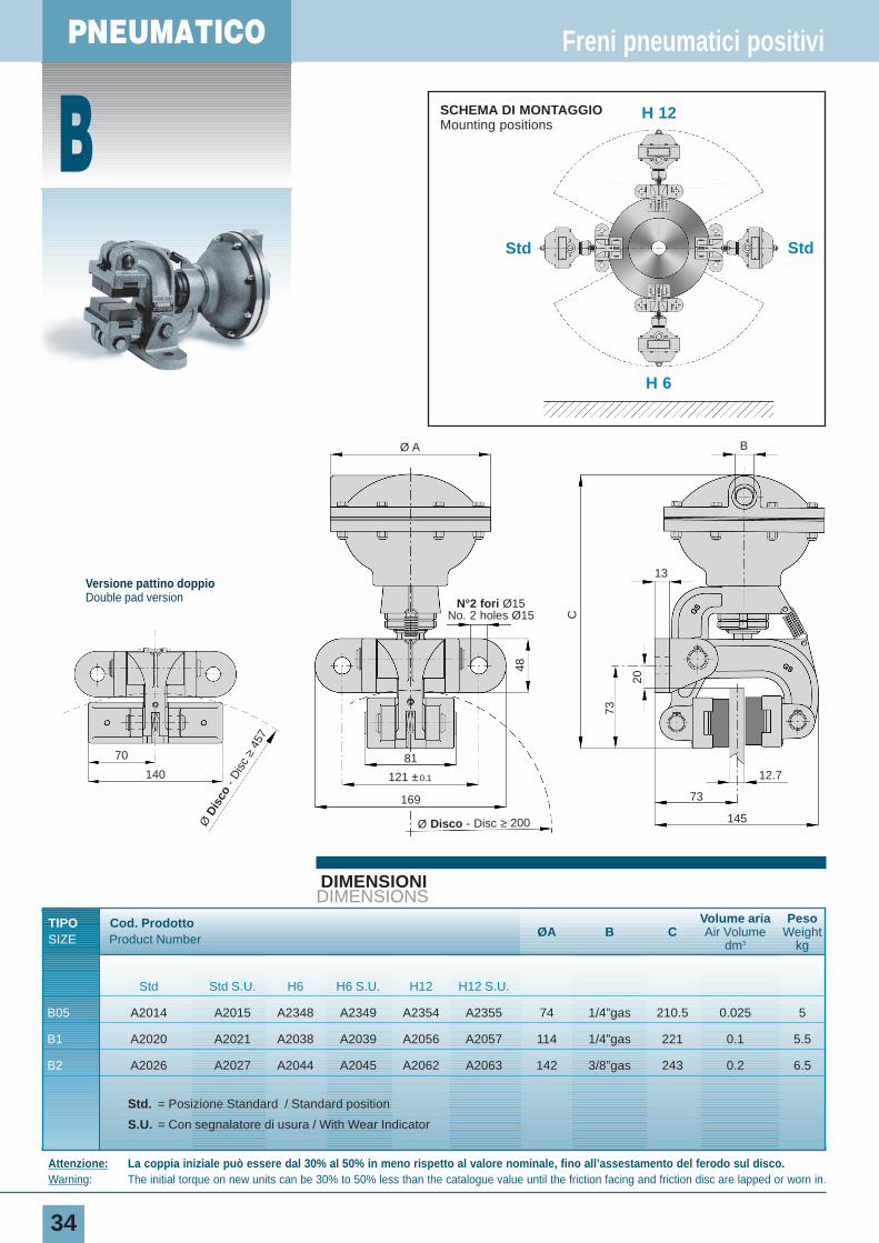
B05 A2014 A2015 A2348 A2349 A2354 A2355 74 1/4”gas 210.5 0.025 5
B1 A2020 A2021 A2038 A2039 A2056 A2057 114 1/4”gas 221 0.1 5.5
B2 A2026 A2027 A2044 A2045 A2062 A2063 142 3/8”gas 243 0.2 6.5
Std. = Posizione Standard / Standard position
S.U. = Con segnalatore di usura / With Wear Indicator
Freni pneumatici positivi
Attenzione: La coppia iniziale può essere dal 30% al 50% in meno rispetto al valore nominale, fino all’assestamento del ferodo sul disco.Warning: The initial torque on new units can be 30% to 50% less than the catalogue value until the friction facing and friction disc are lapped or worn in.
Ø Disco - Disc ≥ 200
169
121 ±0.1
81
Ø A B
13
12.7
73
145
N°2 fori Ø15No. 2 holes Ø15
48
73
20
C
BStd Std
H 6
H 12SCHEMA DI MONTAGGIOMounting positions
Versione pattino doppioDouble pad version
Ø D
isco
- D
isc
≥45
7
70
140
PNEUMATIC
35
DIAGRAMMACHART
DATI TECNICI
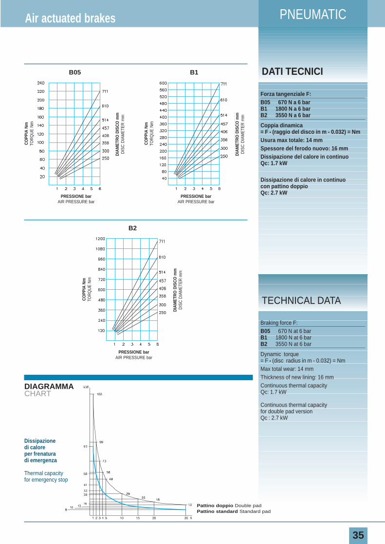
Forza tangenziale F:B05 670 N a 6 barB1 1800 N a 6 barB2 3550 N a 6 bar
Coppia dinamica= F • (raggio del disco in m - 0.032) = NmUsura max totale: 14 mmSpessore del ferodo nuovo: 16 mmDissipazione del calore in continuoQc: 1.7 kW
Dissipazione di calore in continuocon pattino doppioQc: 2.7 kW
Air actuated brakes
Braking force F:B05 670 N at 6 barB1 1800 N at 6 barB2 3550 N at 6 bar
Dynamic torque= F • (disc radius in m - 0.032) = NmMax total wear: 14 mm Thickness of new lining: 16 mmContinuous thermal capacity Qc: 1.7 kW
Continuous thermal capacity for double pad versionQc : 2.7 kW
TECHNICAL DATA
CO
PPIA
Nm
TOR
QU
E N
m
DIA
MET
RO
DIS
CO
mm
DIS
C D
IAM
ETE
R m
m
PRESSIONE barAIR PRESSURE bar
CO
PPIA
Nm
TOR
QU
E N
m
DIA
MET
RO
DIS
CO
mm
DIS
C D
IAM
ETE
R m
m
PRESSIONE barAIR PRESSURE bar
CO
PPIA
Nm
TOR
QU
E N
m
DIA
MET
RO
DIS
CO
mm
DIS
C D
IAM
ETE
R m
m
PRESSIONE barAIR PRESSURE bar
B05 B1
B2
Dissipazione di caloreper frenatura di emergenza
Thermal capacityfor emergency stop
Pattino doppio Double padPattino standard Standard pad
PNEUMATICO
C
36
DIMENSIONIDIMENSIONS
TIPO Cod. Prodotto A B ØC DVolume aria Peso
SIZE Product Number Air Volume Weightdm3 kg
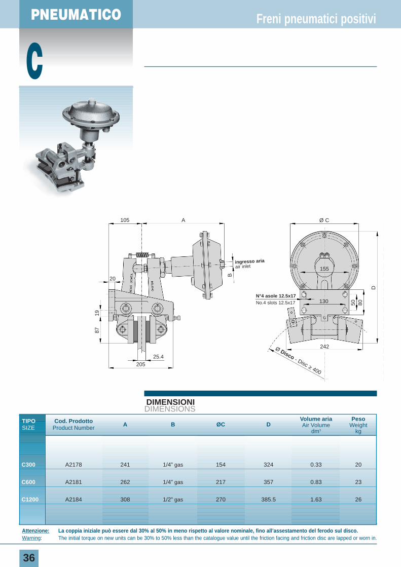
C300 A2178 241 1/4” gas 154 324 0.33 20
C600 A2181 262 1/4” gas 217 357 0.83 23
C1200 A2184 308 1/2” gas 270 385.5 1.63 26
Freni pneumatici positivi
Attenzione: La coppia iniziale può essere dal 30% al 50% in meno rispetto al valore nominale, fino all’assestamento del ferodo sul disco.Warning: The initial torque on new units can be 30% to 50% less than the catalogue value until the friction facing and friction disc are lapped or worn in.
105
20
25.4
242
N°4 asole 12.5x17No.4 slots 12.5x17
205
A Ø C
130
155
B
50 80
D
1987
Ø Disco - Disc ≥ 400
ingresso ariaair inlet
PNEUMATIC
37
DIAGRAMMACHART
DATI TECNICI
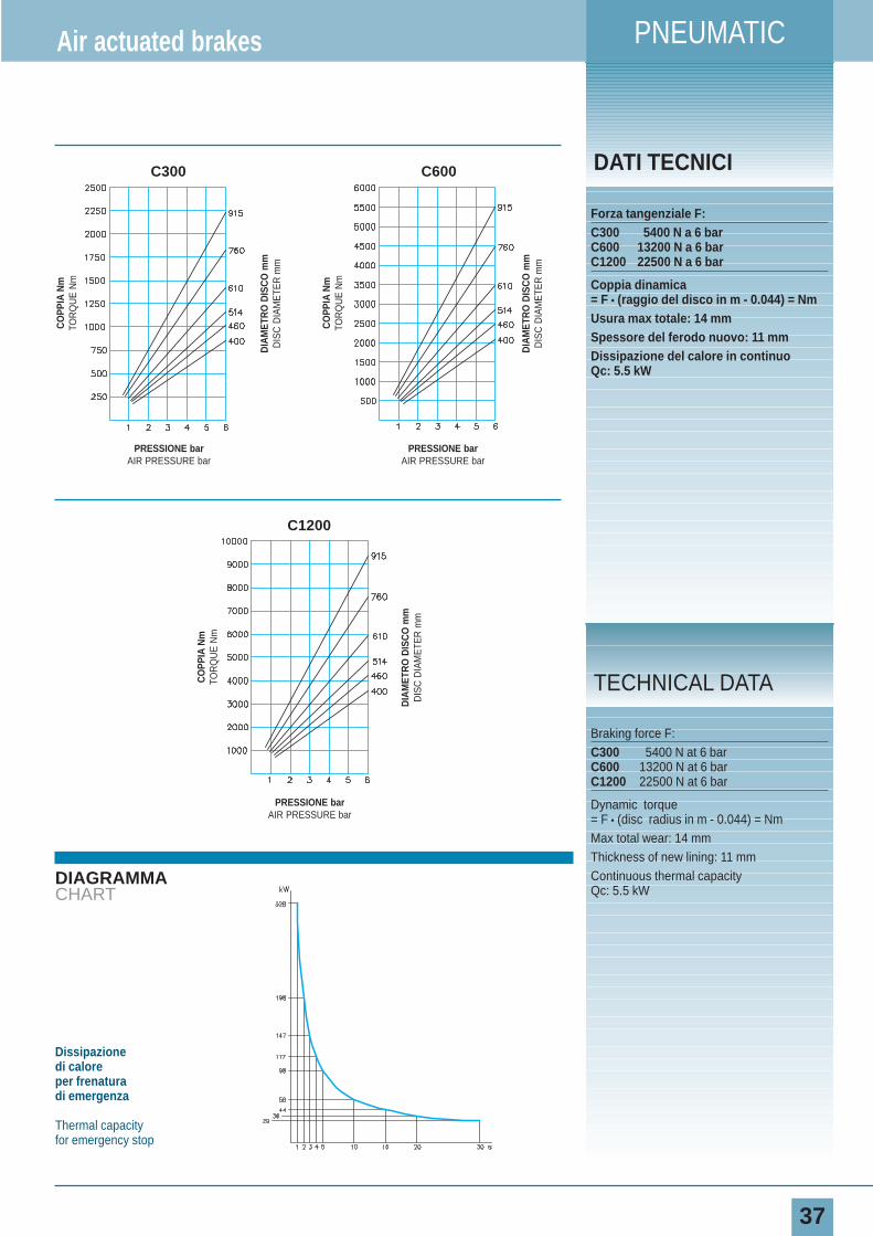
Forza tangenziale F:C300 5400 N a 6 barC600 13200 N a 6 barC1200 22500 N a 6 bar
Coppia dinamica= F • (raggio del disco in m - 0.044) = NmUsura max totale: 14 mmSpessore del ferodo nuovo: 11 mmDissipazione del calore in continuoQc: 5.5 kW
Air actuated brakes
Braking force F:C300 5400 N at 6 barC600 13200 N at 6 barC1200 22500 N at 6 bar
Dynamic torque= F • (disc radius in m - 0.044) = NmMax total wear: 14 mmThickness of new lining: 11 mmContinuous thermal capacity Qc: 5.5 kW
TECHNICAL DATA
Dissipazione di caloreper frenatura di emergenza
Thermal capacityfor emergency stop
CO
PPIA
Nm
TOR
QU
E N
m
DIA
MET
RO
DIS
CO
mm
DIS
C D
IAM
ETE
R m
m
PRESSIONE barAIR PRESSURE bar
CO
PPIA
Nm
TOR
QU
E N
m
DIA
MET
RO
DIS
CO
mm
DIS
C D
IAM
ETE
R m
m
PRESSIONE barAIR PRESSURE bar
CO
PPIA
Nm
TOR
QU
E N
m
DIA
MET
RO
DIS
CO
mm
DIS
C D
IAM
ETE
R m
m
PRESSIONE barAIR PRESSURE bar
C300 C600
C1200
PNEUMATICO
D
38
DIMENSIONIDIMENSIONS
TIPO Cod. Prodotto A B ØC D E F G H IVolume aria Peso
SIZE Product NumberAir Volume Weight
dm3 kg
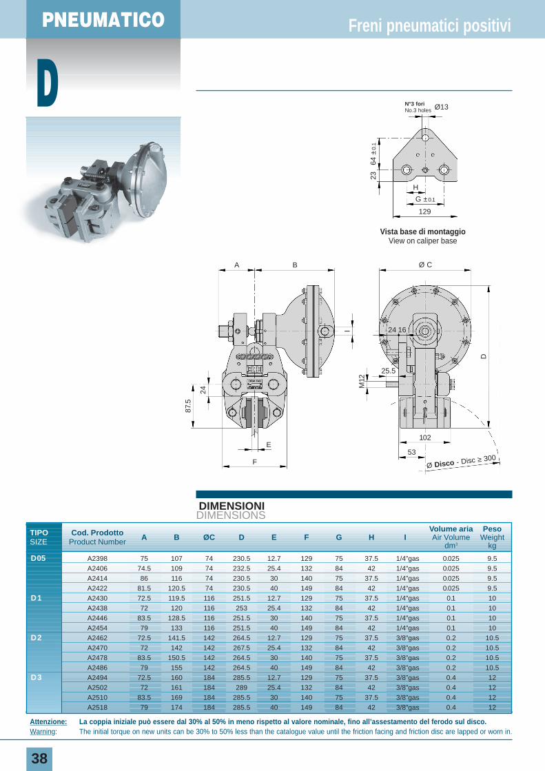
D05 A2398 75 107 74 230.5 12.7 129 75 37.5 1/4”gas 0.025 9.5A2406 74.5 109 74 232.5 25.4 132 84 42 1/4”gas 0.025 9.5A2414 86 116 74 230.5 30 140 75 37.5 1/4”gas 0.025 9.5A2422 81.5 120.5 74 230.5 40 149 84 42 1/4”gas 0.025 9.5
D1 A2430 72.5 119.5 116 251.5 12.7 129 75 37.5 1/4”gas 0.1 10A2438 72 120 116 253 25.4 132 84 42 1/4”gas 0.1 10A2446 83.5 128.5 116 251.5 30 140 75 37.5 1/4”gas 0.1 10A2454 79 133 116 251.5 40 149 84 42 1/4”gas 0.1 10
D2 A2462 72.5 141.5 142 264.5 12.7 129 75 37.5 3/8”gas 0.2 10.5A2470 72 142 142 267.5 25.4 132 84 42 3/8”gas 0.2 10.5A2478 83.5 150.5 142 264.5 30 140 75 37.5 3/8”gas 0.2 10.5A2486 79 155 142 264.5 40 149 84 42 3/8”gas 0.2 10.5
D3 A2494 72.5 160 184 285.5 12.7 129 75 37.5 3/8”gas 0.4 12A2502 72 161 184 289 25.4 132 84 42 3/8”gas 0.4 12A2510 83.5 169 184 285.5 30 140 75 37.5 3/8”gas 0.4 12A2518 79 174 184 285.5 40 149 84 42 3/8”gas 0.4 12
Freni pneumatici positivi
Attenzione: La coppia iniziale può essere dal 30% al 50% in meno rispetto al valore nominale, fino all’assestamento del ferodo sul disco.Warning: The initial torque on new units can be 30% to 50% less than the catalogue value until the friction facing and friction disc are lapped or worn in.
A B Ø C
1624
25.5
102
53
M12
D
24
87.5
E
F
I
Ø Disco - Disc ≥ 300
Vista base di montaggioView on caliper base
129
N°3 fori No.3 holes Ø13
H
64 ±
0.1
23
G ±0.1
PNEUMATIC
39
DIAGRAMMACHART
DATI TECNICI
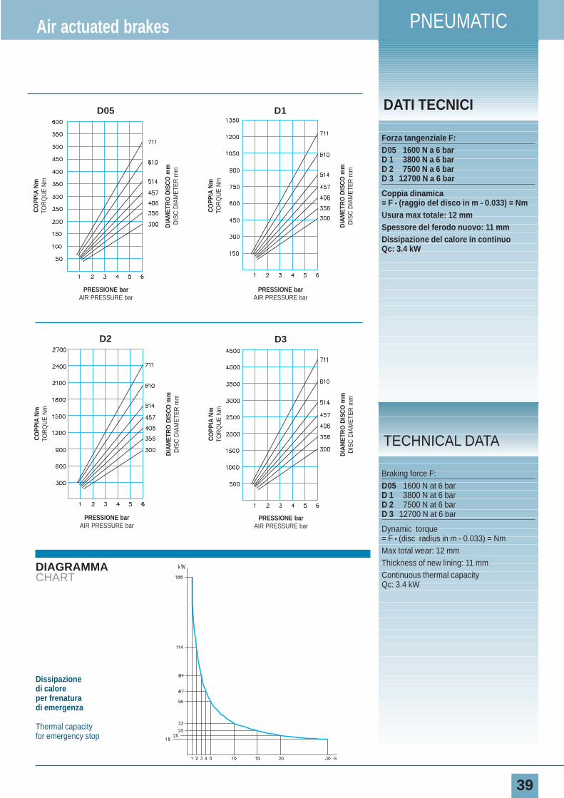
Forza tangenziale F:D05 1600 N a 6 barD 1 3800 N a 6 barD 2 7500 N a 6 barD 3 12700 N a 6 bar
Coppia dinamica= F • (raggio del disco in m - 0.033) = NmUsura max totale: 12 mmSpessore del ferodo nuovo: 11 mmDissipazione del calore in continuoQc: 3.4 kW
Air actuated brakes
Braking force F:D05 1600 N at 6 barD 1 3800 N at 6 barD 2 7500 N at 6 barD 3 12700 N at 6 bar
Dynamic torque= F • (disc radius in m - 0.033) = NmMax total wear: 12 mmThickness of new lining: 11 mmContinuous thermal capacity Qc: 3.4 kW
TECHNICAL DATA
Dissipazione di caloreper frenatura di emergenza
Thermal capacityfor emergency stop
CO
PPIA
Nm
TOR
QU
E N
m
DIA
MET
RO
DIS
CO
mm
DIS
C D
IAM
ETE
R m
m
PRESSIONE barAIR PRESSURE bar
CO
PPIA
Nm
TOR
QU
E N
m
DIA
MET
RO
DIS
CO
mm
DIS
C D
IAM
ETE
R m
m
PRESSIONE barAIR PRESSURE bar
CO
PPIA
Nm
TOR
QU
E N
m
DIA
MET
RO
DIS
CO
mm
DIS
C D
IAM
ETE
R m
m
PRESSIONE barAIR PRESSURE bar
D1
CO
PPIA
Nm
TOR
QU
E N
m
DIA
MET
RO
DIS
CO
mm
DIS
C D
IAM
ETE
R m
m
PRESSIONE barAIR PRESSURE bar
D05
D2 D3
PNEUMATICO
E
40
DIMENSIONIDIMENSIONS
TIPO Cod. ProdottoA B C ØD E F
Volume aria Peso
SIZE Product NumberAir Volume Weight
dm3 kg
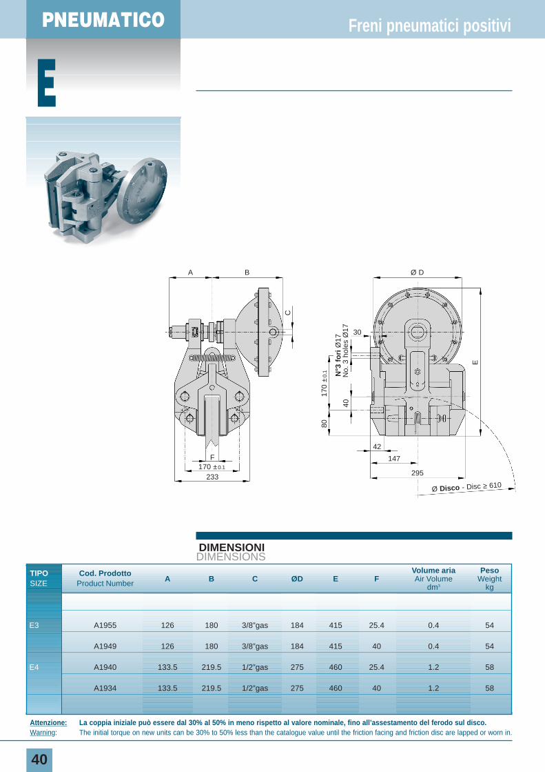
E3 A1955 126 180 3/8”gas 184 415 25.4 0.4 54
A1949 126 180 3/8”gas 184 415 40 0.4 54
E4 A1940 133.5 219.5 1/2”gas 275 460 25.4 1.2 58
A1934 133.5 219.5 1/2”gas 275 460 40 1.2 58
Freni pneumatici positivi
Attenzione: La coppia iniziale può essere dal 30% al 50% in meno rispetto al valore nominale, fino all’assestamento del ferodo sul disco.Warning: The initial torque on new units can be 30% to 50% less than the catalogue value until the friction facing and friction disc are lapped or worn in.
Ø Disco - Disc ≥ 610
Ø DA B
30
42
147
295
170
±0.
1
170 ±0.1
233
F
80
E
40
C
N°3
fo
riØ
17N
o. 3
hol
es Ø
17
PNEUMATIC
41
DIAGRAMMACHART
DATI TECNICI
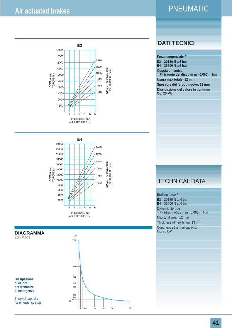
Forza tangenziale F:E3 20180 N a 6 barE4 36600 N a 6 barCoppia dinamica= F • (raggio del disco in m - 0.065) = NmUsura max totale: 12 mmSpessore del ferodo nuovo: 13 mmDissipazione del calore in continuoQc: 20 kW
Air actuated brakes
Braking force F:E3 20180 N at 6 barE4 36600 N at 6 barDynamic torque= F • (disc radius in m - 0.065) = NmMax total wear: 12 mmThickness of new lining: 13 mmContinuous thermal capacity Qc: 20 kW
TECHNICAL DATA
Dissipazione di caloreper frenatura di emergenza
Thermal capacityfor emergency stop
CO
PPIA
Nm
TOR
QU
E N
m
DIA
MET
RO
DIS
CO
mm
DIS
C D
IAM
ETE
R m
m
PRESSIONE barAIR PRESSURE bar
CO
PPIA
Nm
TOR
QU
E N
m
DIA
MET
RO
DIS
CO
mm
DIS
C D
IAM
ETE
R m
m
PRESSIONE barAIR PRESSURE bar
E3
E4
PNEUMATICO
F
42
DIMENSIONIDIMENSIONS
TIPO Cod. Prodotto A B C ØD EVolume aria Peso
SIZE Product Number Air Volume Weightdm3 kg
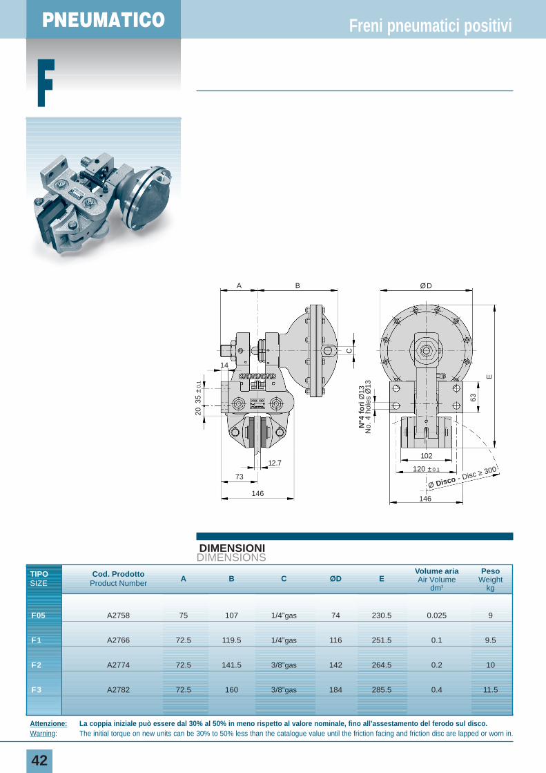
F05 A2758 75 107 1/4”gas 74 230.5 0.025 9
F1 A2766 72.5 119.5 1/4”gas 116 251.5 0.1 9.5
F2 A2774 72.5 141.5 3/8”gas 142 264.5 0.2 10
F3 A2782 72.5 160 3/8”gas 184 285.5 0.4 11.5
Freni pneumatici positivi
Attenzione: La coppia iniziale può essere dal 30% al 50% in meno rispetto al valore nominale, fino all’assestamento del ferodo sul disco.Warning: The initial torque on new units can be 30% to 50% less than the catalogue value until the friction facing and friction disc are lapped or worn in.
Ø Disco - Disc ≥ 300
ØDA B
73
12.7
14
146
102
C
63
E
N°4
fo
riØ
13N
o. 4
hol
es Ø
13
120 ±0.1
146
35 ±
0.1
20
PNEUMATIC
43
DIAGRAMMACHART
DATI TECNICI
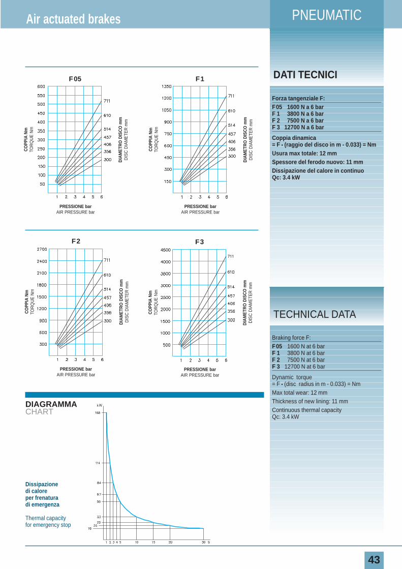
Forza tangenziale F:F05 1600 N a 6 barF 1 3800 N a 6 barF 2 7500 N a 6 barF 3 12700 N a 6 bar
Coppia dinamica= F • (raggio del disco in m - 0.033) = NmUsura max totale: 12 mmSpessore del ferodo nuovo: 11 mmDissipazione del calore in continuoQc: 3.4 kW
Air actuated brakes
Braking force F:F05 1600 N at 6 barF 1 3800 N at 6 barF 2 7500 N at 6 barF 3 12700 N at 6 bar
Dynamic torque= F • (disc radius in m - 0.033) = NmMax total wear: 12 mmThickness of new lining: 11 mmContinuous thermal capacity Qc: 3.4 kW
TECHNICAL DATA
Dissipazione di caloreper frenatura di emergenza
Thermal capacityfor emergency stop
CO
PPIA
Nm
TOR
QU
E N
m
DIA
MET
RO
DIS
CO
mm
DIS
C D
IAM
ETE
R m
m
PRESSIONE barAIR PRESSURE bar
CO
PPIA
Nm
TOR
QU
E N
m
DIA
MET
RO
DIS
CO
mm
DIS
C D
IAM
ETE
R m
m
PRESSIONE barAIR PRESSURE bar
F1
CO
PPIA
Nm
TOR
QU
E N
m
DIA
MET
RO
DIS
CO
mm
DIS
C D
IAM
ETE
R m
m
PRESSIONE barAIR PRESSURE bar
F05
F3
CO
PPIA
Nm
TOR
QU
E N
m
DIA
MET
RO
DIS
CO
mm
DIS
C D
IAM
ETE
R m
m
PRESSIONE barAIR PRESSURE bar
F2
PNEUMATICI
G
44
DIMENSIONIDIMENSIONS
TIPO Cod. ProdottoA B ØC D E F G
Volume aria Peso
SIZE Product Number Air Volume Weightdm3 kg
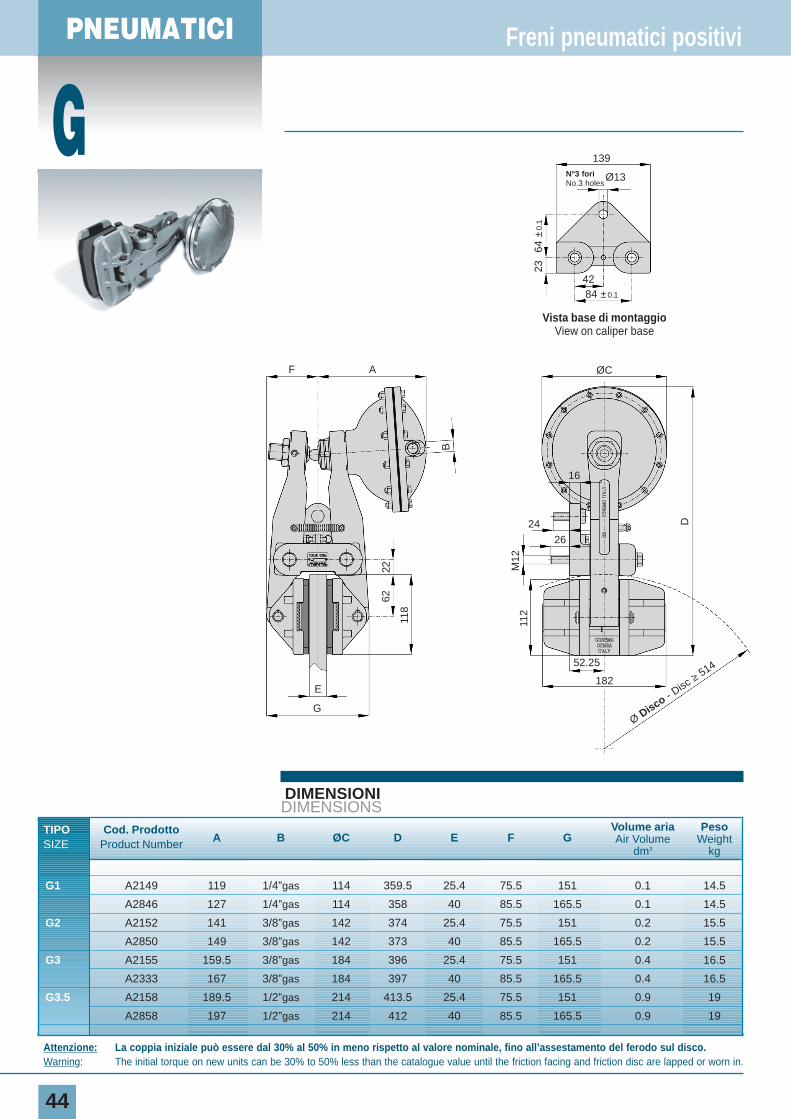
G1 A2149 119 1/4”gas 114 359.5 25.4 75.5 151 0.1 14.5
A2846 127 1/4”gas 114 358 40 85.5 165.5 0.1 14.5
G2 A2152 141 3/8”gas 142 374 25.4 75.5 151 0.2 15.5
A2850 149 3/8”gas 142 373 40 85.5 165.5 0.2 15.5
G3 A2155 159.5 3/8”gas 184 396 25.4 75.5 151 0.4 16.5
A2333 167 3/8”gas 184 397 40 85.5 165.5 0.4 16.5
G3.5 A2158 189.5 1/2”gas 214 413.5 25.4 75.5 151 0.9 19
A2858 197 1/2”gas 214 412 40 85.5 165.5 0.9 19
Freni pneumatici positivi
Attenzione: La coppia iniziale può essere dal 30% al 50% in meno rispetto al valore nominale, fino all’assestamento del ferodo sul disco.Warning: The initial torque on new units can be 30% to 50% less than the catalogue value until the friction facing and friction disc are lapped or worn in.
Vista base di montaggioView on caliper base
139
F A ØC22
62
118
M12
D
112
E
G
182
52.25
24
26
16
B
N°3 fori No.3 holes
Ø13
42
64 ±
0.1
23
84 ±0.1
Ø Disco - Disc
≥514
PNEUMATIC
45
DIAGRAMMACHART
DATI TECNICI
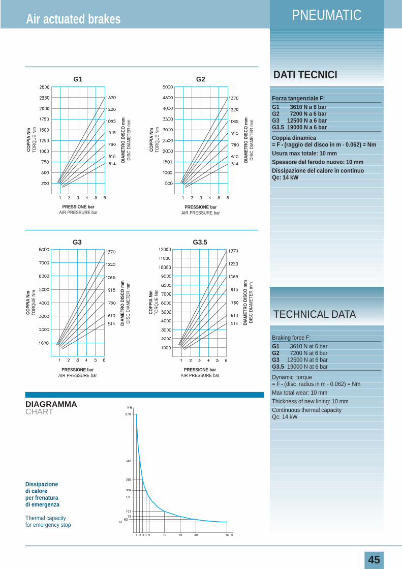
Forza tangenziale F:G1 3610 N a 6 barG2 7200 N a 6 barG3 12500 N a 6 barG3.5 19000 N a 6 bar
Coppia dinamica= F • (raggio del disco in m - 0.062) = NmUsura max totale: 10 mmSpessore del ferodo nuovo: 10 mmDissipazione del calore in continuoQc: 14 kW
Air actuated brakes
Braking force F:G1 3610 N at 6 barG2 7200 N at 6 barG3 12500 N at 6 barG3.5 19000 N at 6 bar
Dynamic torque= F • (disc radius in m - 0.062) = NmMax total wear: 10 mmThickness of new lining: 10 mmContinuous thermal capacity Qc: 14 kW
TECHNICAL DATA
Dissipazione di caloreper frenatura di emergenza
Thermal capacityfor emergency stop
CO
PPIA
Nm
TOR
QU
E N
m
DIA
MET
RO
DIS
CO
mm
DIS
C D
IAM
ETE
R m
m
PRESSIONE barAIR PRESSURE bar
CO
PPIA
Nm
TOR
QU
E N
m
DIA
MET
RO
DIS
CO
mm
DIS
C D
IAM
ETE
R m
m
PRESSIONE barAIR PRESSURE bar
G1
G3 G3.5
CO
PPIA
Nm
TOR
QU
E N
m
DIA
MET
RO
DIS
CO
mm
DIS
C D
IAM
ETE
R m
m
PRESSIONE barAIR PRESSURE bar
CO
PPIA
Nm
TOR
QU
E N
m
DIA
MET
RO
DIS
CO
mm
DIS
C D
IAM
ETE
R m
m
PRESSIONE barAIR PRESSURE bar
G2
46
I freni idraulici hanno la ca-ratteristica di avere il pregiodi fare una specifica cosache li contraddistingue da al-tri tipi di prodotti di altra fat-tura e/o della concorrenza. Inparticolare i freni positivinon sono negativi e vicever-sa.Questi freni si adattano a quasitutto ed è per questa cosa chevengono chiamati anche freni“fatti a posta”.Queste notizie rappresentanoun
PNEUMATICFailsafe brakes
SPRING APPLIED PNEUMATICALLY RELEASED
Freni di sicurezza
Failsafes brakes
Spring applied pneumatically release
PNEUMATICINegativi
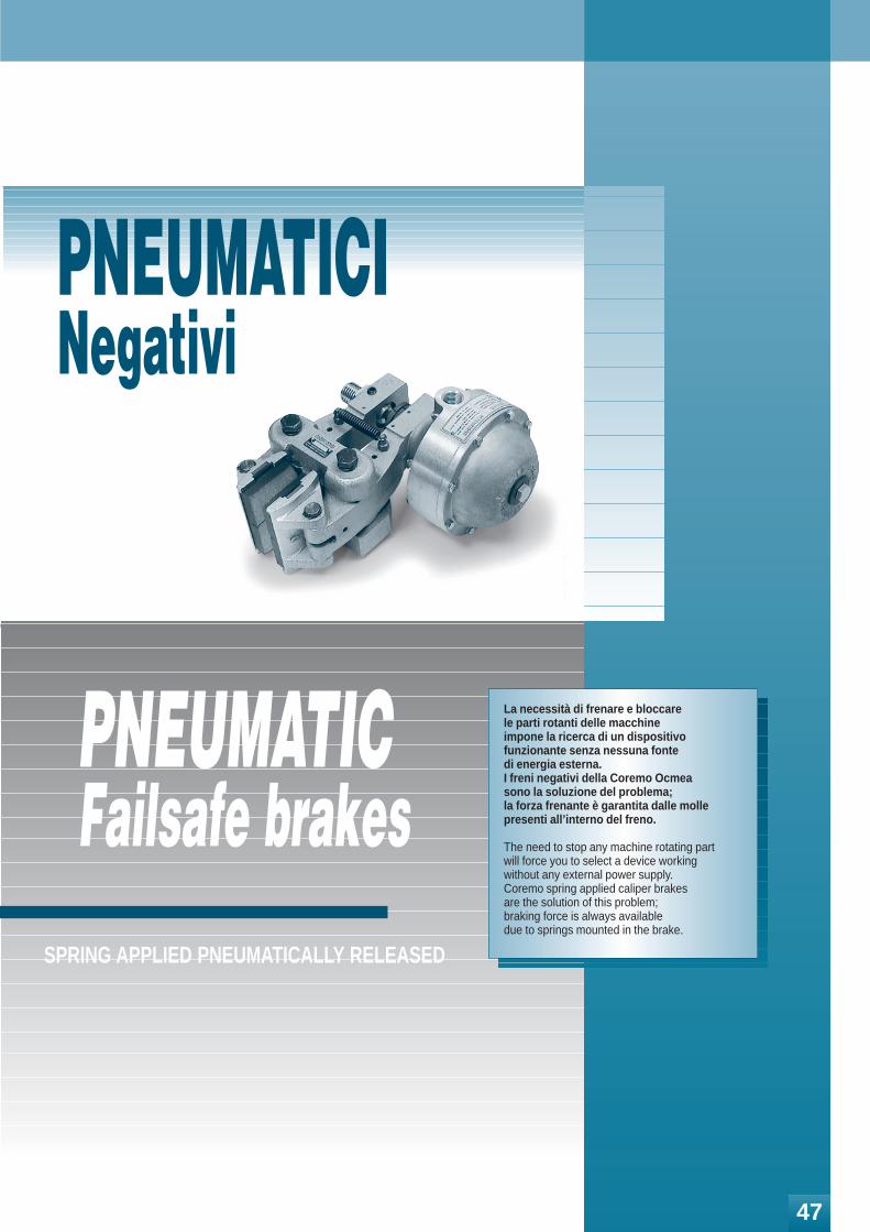
La necessità di frenare e bloccare le parti rotanti delle macchine impone la ricerca di un dispositivo funzionante senza nessuna fonte di energia esterna. I freni negativi della Coremo Ocmea sono la soluzione del problema; la forza frenante è garantita dalle molle presenti all’interno del freno.
The need to stop any machine rotating part will force you to select a device working without any external power supply. Coremo spring applied caliper brakes are the solution of this problem; braking force is always available due to springs mounted in the brake.
47
PNEUMATICI
MPA-N
48
DIMENSIONIDIMENSIONS
Freni di sicurezza
Attenzione: La coppia iniziale può essere dal 30% al 50% in meno rispetto al valore nominale, fino all’assestamento del ferodo sul disco.Warning: The initial torque on new units can be 30% to 50% less than the catalogue value until the friction facing and friction disc are lapped or worn in.
ØF
C
81
70
43
BA
Ø10
.5
Ø32
18
G
D
E
Ø Disco - Disc ≥ 150
Lato montaggio
Mounting face
TIPO Cod. Prodotto A B C D E ØF GVolume aria Peso
SIZE Product NumberAir Volume Weight
dm3 kg
min max
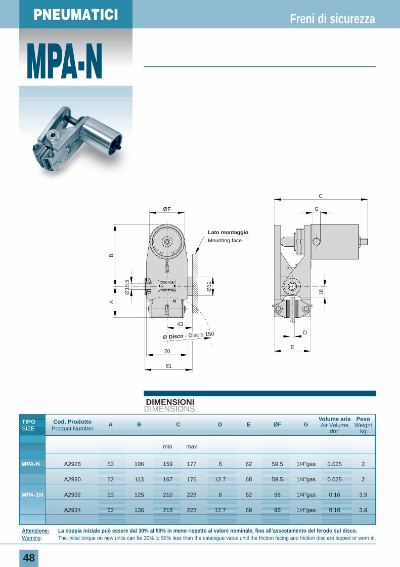
MPA-N A2928 53 106 159 177 8 62 59.5 1/4”gas 0.025 2
A2930 52 113 167 176 12.7 68 59.5 1/4”gas 0.025 2
MPA-1N A2932 53 125 210 228 8 62 98 1/4”gas 0.16 3.9
A2934 52 136 218 228 12.7 69 98 1/4”gas 0.16 3.9
PNEUMATIC
49
DIAGRAMMACHART
DATI TECNICI
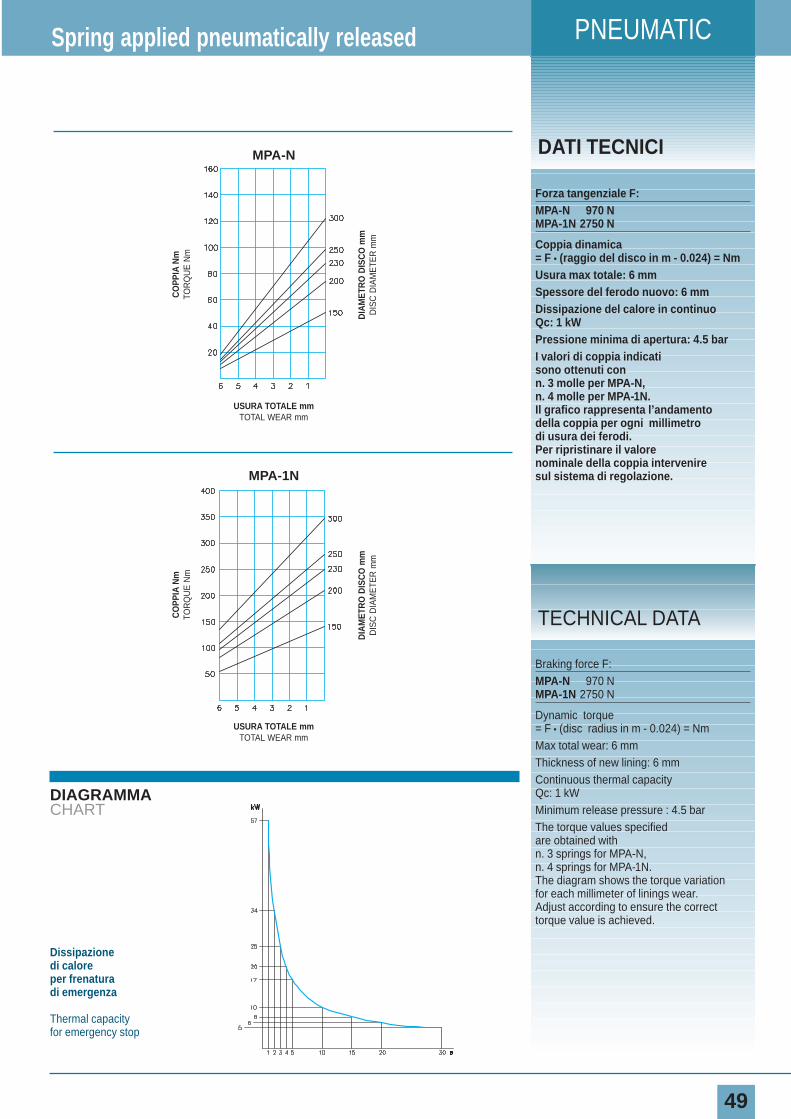
Forza tangenziale F:MPA-N 970 NMPA-1N 2750 N
Coppia dinamica= F • (raggio del disco in m - 0.024) = NmUsura max totale: 6 mmSpessore del ferodo nuovo: 6 mmDissipazione del calore in continuoQc: 1 kWPressione minima di apertura: 4.5 barI valori di coppia indicatisono ottenuti con n. 3 molle per MPA-N,n. 4 molle per MPA-1N.Il grafico rappresenta l’andamentodella coppia per ogni millimetrodi usura dei ferodi.Per ripristinare il valorenominale della coppia interveniresul sistema di regolazione.
Spring applied pneumatically released
Braking force F:MPA-N 970 NMPA-1N 2750 N
Dynamic torque= F • (disc radius in m - 0.024) = NmMax total wear: 6 mmThickness of new lining: 6 mmContinuous thermal capacity Qc: 1 kWMinimum release pressure : 4.5 barThe torque values specifiedare obtained with n. 3 springs for MPA-N,n. 4 springs for MPA-1N.The diagram shows the torque variationfor each millimeter of linings wear.Adjust according to ensure the correcttorque value is achieved.
TECHNICAL DATA
Dissipazione di caloreper frenatura di emergenza
Thermal capacityfor emergency stop
CO
PPIA
Nm
TOR
QU
E N
m
DIA
MET
RO
DIS
CO
mm
DIS
C D
IAM
ETE
R m
m
USURA TOTALE mmTOTAL WEAR mm
CO
PPIA
Nm
TOR
QU
E N
m
DIA
MET
RO
DIS
CO
mm
DIS
C D
IAM
ETE
R m
m
USURA TOTALE mmTOTAL WEAR mm
MPA-N
MPA-1N
PNEUMATICO
A-N
50
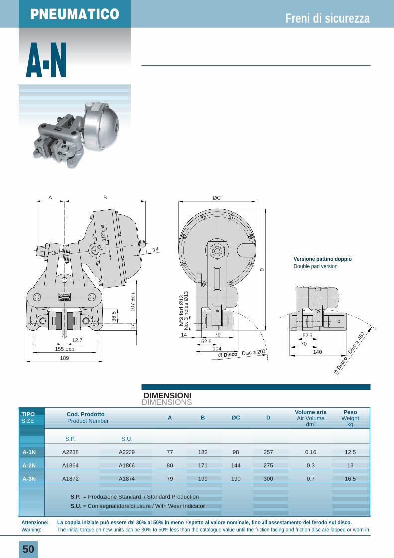
DIMENSIONIDIMENSIONS
TIPO Cod. Prodotto A B ØC DVolume aria Peso
SIZE Product Number Air Volume Weightdm3 kg
S.P. S.U.
A-1N A2238 A2239 77 182 98 257 0.16 12.5
A-2N A1864 A1866 80 171 144 275 0.3 13
A-3N A1872 A1874 79 199 190 300 0.7 16.5
S.P. = Produzione Standard / Standard Production
S.U. = Con segnalatore di usura / With Wear Indicator
Freni di sicurezza
Attenzione: La coppia iniziale può essere dal 30% al 50% in meno rispetto al valore nominale, fino all’assestamento del ferodo sul disco.Warning: The initial torque on new units can be 30% to 50% less than the catalogue value until the friction facing and friction disc are lapped or worn in.
N°3
fo
riØ
13N
o. 3
hol
es Ø
13
A
14
12.77914
52.5104155 ±0.1
189
B ØC
36.5
107
±0.
1
1/2”
gas
17
D
Ø Disco - Disc ≥ 200
Ø D
isco
- D
isc
≥45
752.5
70
140
Versione pattino doppioDouble pad version
PNEUMATIC
51
DIAGRAMMACHART
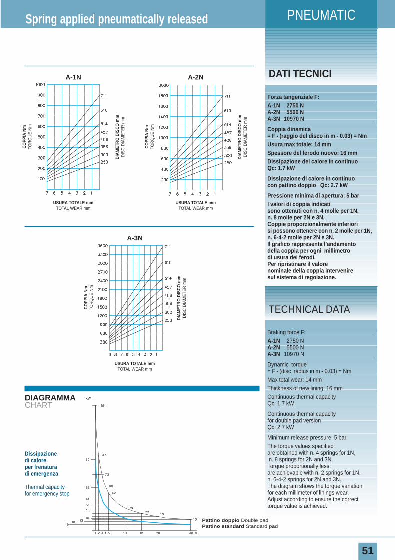
DATI TECNICI
Forza tangenziale F:A-1N 2750 NA-2N 5500 NA-3N 10970 N
Coppia dinamica= F • (raggio del disco in m - 0.03) = NmUsura max totale: 14 mmSpessore del ferodo nuovo: 16 mmDissipazione del calore in continuoQc: 1.7 kW
Dissipazione di calore in continuocon pattino doppio Qc: 2.7 kW
Pressione minima di apertura: 5 barI valori di coppia indicatisono ottenuti con n. 4 molle per 1N,n. 8 molle per 2N e 3N.Coppie proporzionalmente inferiorisi possono ottenere con n. 2 molle per 1N, n. 6-4-2 molle per 2N e 3N.Il grafico rappresenta l’andamentodella coppia per ogni millimetrodi usura dei ferodi.Per ripristinare il valorenominale della coppia interveniresul sistema di regolazione.
Spring applied pneumatically released
Braking force F:A-1N 2750 NA-2N 5500 NA-3N 10970 N
Dynamic torque= F • (disc radius in m - 0.03) = NmMax total wear: 14 mmThickness of new lining: 16 mmContinuous thermal capacity Qc: 1.7 kW
Continuous thermal capacity for double pad versionQc: 2.7 kW
Minimum release pressure: 5 barThe torque values specifiedare obtained with n. 4 springs for 1N,n. 8 springs for 2N and 3N.Torque proportionally lessare achievable with n. 2 springs for 1N,n. 6-4-2 springs for 2N and 3N. The diagram shows the torque variationfor each millimeter of linings wear.Adjust according to ensure the correcttorque value is achieved.
TECHNICAL DATA
CO
PPIA
Nm
TOR
QU
E N
m
DIA
MET
RO
DIS
CO
mm
DIS
C D
IAM
ETE
R m
m
USURA TOTALE mmTOTAL WEAR mm
CO
PPIA
Nm
TOR
QU
E N
m
DIA
MET
RO
DIS
CO
mm
DIS
C D
IAM
ETE
R m
m
USURA TOTALE mmTOTAL WEAR mm
A-2N
CO
PPIA
Nm
TOR
QU
E N
m
DIA
MET
RO
DIS
CO
mm
DIS
C D
IAM
ETE
R m
m
USURA TOTALE mmTOTAL WEAR mm
A-1N
A-3N
Dissipazione di caloreper frenatura di emergenza
Thermal capacityfor emergency stop
Pattino doppio Double padPattino standard Standard pad
PNEUMATICO
B-N
52
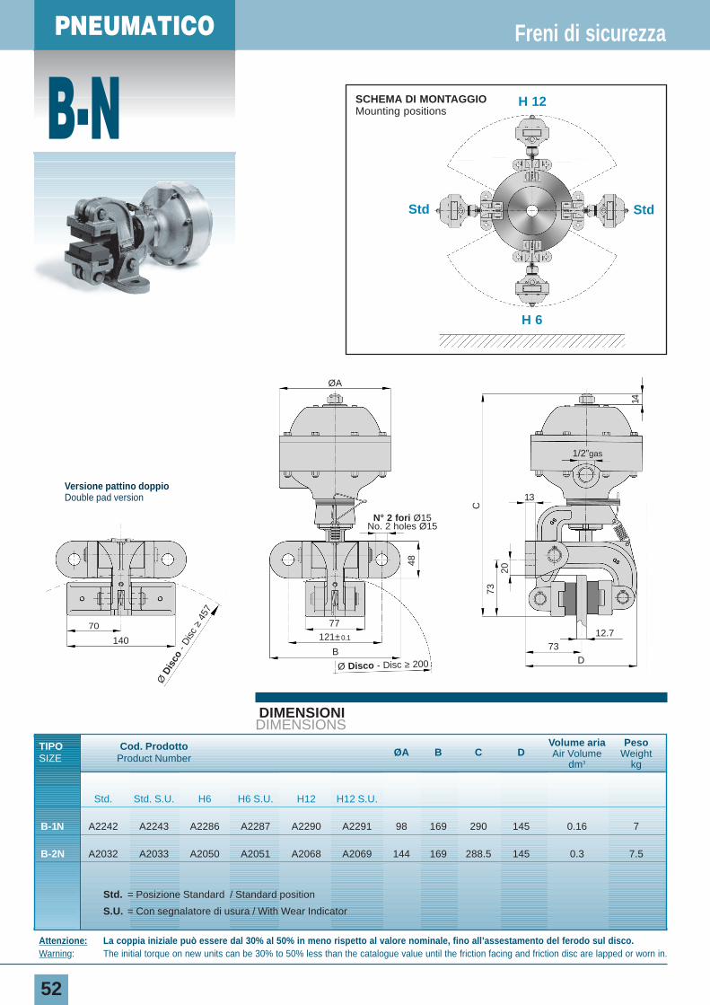
DIMENSIONIDIMENSIONS
TIPO Cod. Prodotto ØA B C DVolume aria Peso
SIZE Product Number Air Volume Weightdm3 kg
Std. Std. S.U. H6 H6 S.U. H12 H12 S.U.
B-1N A2242 A2243 A2286 A2287 A2290 A2291 98 169 290 145 0.16 7
B-2N A2032 A2033 A2050 A2051 A2068 A2069 144 169 288.5 145 0.3 7.5
Std. = Posizione Standard / Standard position
S.U. = Con segnalatore di usura / With Wear Indicator
Freni di sicurezza
Attenzione: La coppia iniziale può essere dal 30% al 50% in meno rispetto al valore nominale, fino all’assestamento del ferodo sul disco.Warning: The initial torque on new units can be 30% to 50% less than the catalogue value until the friction facing and friction disc are lapped or worn in.
48
73
C
20
7312.7
13
1/2”gas
D
14
ØA
77121±0.1
B
Ø Disco - Disc ≥ 200
N° 2 fori Ø15No. 2 holes Ø15
Std Std
H 6
H 12SCHEMA DI MONTAGGIOMounting positions
Versione pattino doppioDouble pad version
Ø D
isco
- D
isc
≥45
7
70
140
PNEUMATIC
53
DIAGRAMMACHART
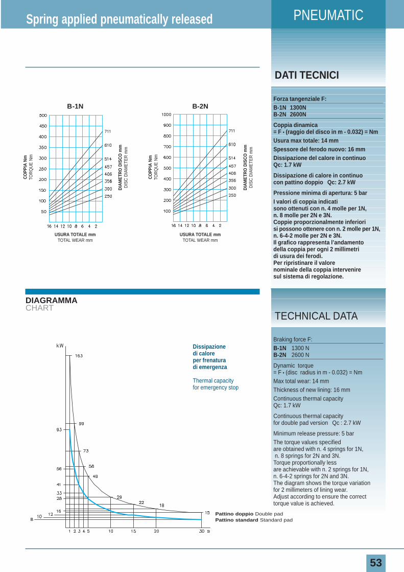
DATI TECNICI
Forza tangenziale F:B-1N 1300NB-2N 2600N
Coppia dinamica= F • (raggio del disco in m - 0.032) = NmUsura max totale: 14 mmSpessore del ferodo nuovo: 16 mmDissipazione del calore in continuoQc: 1.7 kW
Dissipazione di calore in continuocon pattino doppio Qc: 2.7 kW
Pressione minima di apertura: 5 barI valori di coppia indicatisono ottenuti con n. 4 molle per 1N,n. 8 molle per 2N e 3N.Coppie proporzionalmente inferiorisi possono ottenere con n. 2 molle per 1N, n. 6-4-2 molle per 2N e 3N.Il grafico rappresenta l’andamentodella coppia per ogni 2 millimetridi usura dei ferodi.Per ripristinare il valorenominale della coppia interveniresul sistema di regolazione.
Spring applied pneumatically released
Braking force F:B-1N 1300 NB-2N 2600 N
Dynamic torque= F • (disc radius in m - 0.032) = NmMax total wear: 14 mmThickness of new lining: 16 mmContinuous thermal capacity Qc: 1.7 kW
Continuous thermal capacity for double pad version Qc : 2.7 kW
Minimum release pressure: 5 barThe torque values specifiedare obtained with n. 4 springs for 1N,n. 8 springs for 2N and 3N.Torque proportionally lessare achievable with n. 2 springs for 1N,n. 6-4-2 springs for 2N and 3N. The diagram shows the torque variationfor 2 millimeters of lining wear.Adjust according to ensure the correcttorque value is achieved.
TECHNICAL DATA
Dissipazione di caloreper frenatura di emergenza
Thermal capacityfor emergency stop
Pattino doppio Double padPattino standard Standard pad
CO
PPIA
Nm
TOR
QU
E N
m
DIA
MET
RO
DIS
CO
mm
DIS
C D
IAM
ETE
R m
m
USURA TOTALE mmTOTAL WEAR mm
B-2N
CO
PPIA
Nm
TOR
QU
E N
m
DIA
MET
RO
DIS
CO
mm
DIS
C D
IAM
ETE
R m
m
USURA TOTALE mmTOTAL WEAR mm
B-1N
PNEUMATICO
D-N
54
DIMENSIONIDIMENSIONS
TIPO Cod. Prodotto A B ØC D E F G H IVolume aria Peso
SIZE Product NumberAir Volume Weight
dm3 kg
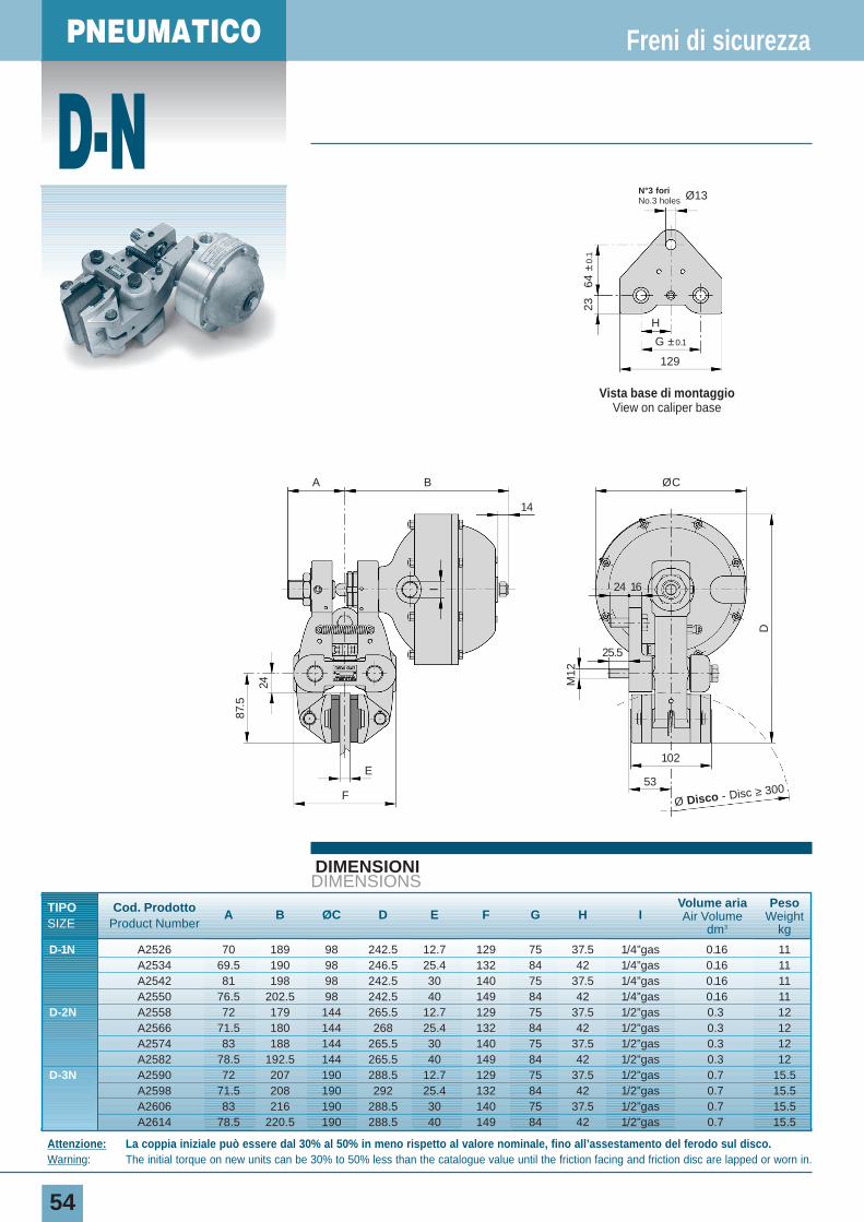
D-1N A2526 70 189 98 242.5 12.7 129 75 37.5 1/4”gas 0.16 11A2534 69.5 190 98 246.5 25.4 132 84 42 1/4”gas 0.16 11A2542 81 198 98 242.5 30 140 75 37.5 1/4”gas 0.16 11A2550 76.5 202.5 98 242.5 40 149 84 42 1/4”gas 0.16 11
D-2N A2558 72 179 144 265.5 12.7 129 75 37.5 1/2”gas 0.3 12A2566 71.5 180 144 268 25.4 132 84 42 1/2”gas 0.3 12A2574 83 188 144 265.5 30 140 75 37.5 1/2”gas 0.3 12A2582 78.5 192.5 144 265.5 40 149 84 42 1/2”gas 0.3 12
D-3N A2590 72 207 190 288.5 12.7 129 75 37.5 1/2”gas 0.7 15.5A2598 71.5 208 190 292 25.4 132 84 42 1/2”gas 0.7 15.5A2606 83 216 190 288.5 30 140 75 37.5 1/2”gas 0.7 15.5A2614 78.5 220.5 190 288.5 40 149 84 42 1/2”gas 0.7 15.5
Freni di sicurezza
Attenzione: La coppia iniziale può essere dal 30% al 50% in meno rispetto al valore nominale, fino all’assestamento del ferodo sul disco.Warning: The initial torque on new units can be 30% to 50% less than the catalogue value until the friction facing and friction disc are lapped or worn in.
24
87.5
M12
I
DE
F53
14
24
25.5
16
102
A B ØC
Ø Disco - Disc ≥ 300
Vista base di montaggioView on caliper base
129
N°3 fori No.3 holes Ø13
H
64 ±
0.1
23
G ±0.1
PNEUMATIC
55
DIAGRAMMACHART
DATI TECNICI
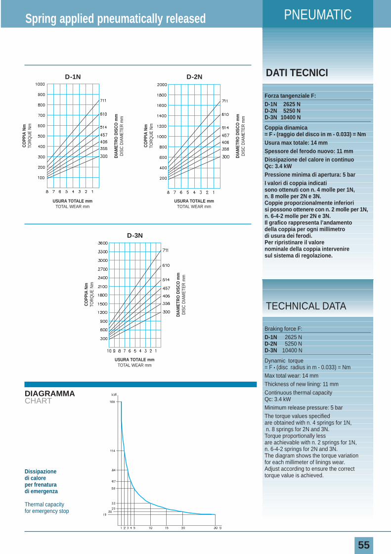
Forza tangenziale F:D-1N 2625 ND-2N 5250 ND-3N 10400 N
Coppia dinamica= F • (raggio del disco in m - 0.033) = NmUsura max totale: 14 mmSpessore del ferodo nuovo: 11 mmDissipazione del calore in continuoQc: 3.4 kWPressione minima di apertura: 5 barI valori di coppia indicatisono ottenuti con n. 4 molle per 1N,n. 8 molle per 2N e 3N.Coppie proporzionalmente inferiorisi possono ottenere con n. 2 molle per 1N, n. 6-4-2 molle per 2N e 3N.Il grafico rappresenta l’andamentodella coppia per ogni millimetrodi usura dei ferodi.Per ripristinare il valorenominale della coppia interveniresul sistema di regolazione.
Spring applied pneumatically released
Braking force F:D-1N 2625 ND-2N 5250 ND-3N 10400 N
Dynamic torque= F • (disc radius in m - 0.033) = NmMax total wear: 14 mmThickness of new lining: 11 mmContinuous thermal capacity Qc: 3.4 kWMinimum release pressure: 5 barThe torque values specifiedare obtained with n. 4 springs for 1N,n. 8 springs for 2N and 3N.Torque proportionally lessare achievable with n. 2 springs for 1N,n. 6-4-2 springs for 2N and 3N. The diagram shows the torque variationfor each millimeter of linings wear.Adjust according to ensure the correcttorque value is achieved.
TECHNICAL DATA
Dissipazione di caloreper frenatura di emergenza
Thermal capacityfor emergency stop
CO
PPIA
Nm
TOR
QU
E N
m
DIA
MET
RO
DIS
CO
mm
DIS
C D
IAM
ETE
R m
m
USURA TOTALE mmTOTAL WEAR mm
CO
PPIA
Nm
TOR
QU
E N
m
DIA
MET
RO
DIS
CO
mm
DIS
C D
IAM
ETE
R m
m
USURA TOTALE mmTOTAL WEAR mm
D-2N
CO
PPIA
Nm
TOR
QU
E N
m
DIA
MET
RO
DIS
CO
mm
DIS
C D
IAM
ETE
R m
m
USURA TOTALE mmTOTAL WEAR mm
D-1N
D-3N
PNEUMATICI
E-N
56
DIMENSIONIDIMENSIONS
TIPO Cod. Prodotto A B ØC D E F GVolume aria Peso
SIZE Product Number Air Volume Weightdm3 kg
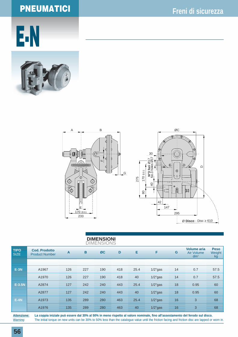
E-3N A1967 126 227 190 418 25.4 1/2”gas 14 0.7 57.5
A1970 126 227 190 418 40 1/2”gas 14 0.7 57.5
E-3.5N A2874 127 242 240 443 25.4 1/2”gas 18 0.95 60
A2877 127 242 240 443 40 1/2”gas 18 0.95 60
E-4N A1973 135 289 280 463 25.4 1/2”gas 16 3 68
A1976 135 289 280 463 40 1/2”gas 16 3 68
Freni di sicurezza
Attenzione: La coppia iniziale può essere dal 30% al 50% in meno rispetto al valore nominale, fino all’assestamento del ferodo sul disco.Warning: The initial torque on new units can be 30% to 50% less than the catalogue value until the friction facing and friction disc are lapped or worn in.
275
F
170
±0.
180
40
D
ØCBA
E
G
42
147
295170 ±0.1
233
30
Ø Disco - Disc ≥ 610
N°3
fo
riØ
17N
o.3
hole
s Ø
17

PNEUMATIC
57
DIAGRAMMACHART
DATI TECNICI
Forza tangenziale F:E-3N 14150 NE-3.5N 26600 NE-4N 32800 NCoppia dinamica= F • (raggio del disco in m - 0.065) = NmUsura max totale: 12 mmSpessore del ferodo nuovo: 13 mmDissipazione del calore in continuoQc: 20 kWPressione minima di apertura: 5 barI valori di coppia indicati sono ottenuti con: n. 8 molle per 3N, n. 12 molle per 3.5N e 4N.Coppie proporzionalmente inferiorisi possono ottenere con:n. 6-4-2 molle per 3N, n. 10-8-6 molle per 3.5N e 4N.Il grafico rappresenta l’andamentodella coppia per ogni millimetrodi usura dei ferodi.Per ripristinare il valorenominale della coppia interveniresul sistema di regolazione.
Spring applied pneumatically released
Braking force F:E-3N 14150 NE-3.5N 26600 NE-4N 32800 NDynamic torque= F • (disc radius in m - 0.065) = NmMax total wear: 12 mmThickness of new lining: 13 mmContinuous thermal capacity Qc: 20 kWMinimum release pressure: 5 barThe torque values specifiedare obtained with No. 8 springs for 3N, No. 12 springs for 3.5N and 4N.Torque proportionally lessare achievable with No. 6-4-2 springs for 3N, No. 10-8-6 springs for 3.5N and 4N.The diagram shows the torque variationfor each millimeter of linings wear.Adjust according to ensure the correcttorque value is achieved.
TECHNICAL DATA
Dissipazione di caloreper frenatura di emergenza
Thermal capacityfor emergency stop
CO
PPIA
Nm
TOR
QU
E N
m
DIA
MET
RO
DIS
CO
mm
DIS
C D
IAM
ETE
R m
m
USURA TOTALE mmTOTAL WEAR mm
CO
PPIA
Nm
TOR
QU
E N
m
DIA
MET
RO
DIS
CO
mm
DIS
C D
IAM
ETE
R m
m
USURA TOTALE mmTOTAL WEAR mm
E-3.5N
CO
PPIA
Nm
TOR
QU
E N
m
DIA
MET
RO
DIS
CO
mm
DIS
C D
IAM
ETE
R m
m
USURA TOTALE mmTOTAL WEAR mm
E-3N
E-4N
PNEUMATICI
F-N
58
DIMENSIONIDIMENSIONS
TIPO Cod. Prodotto A B C ØD EVolume aria Peso
SIZE Product Number Air Volume Weightdm3 kg
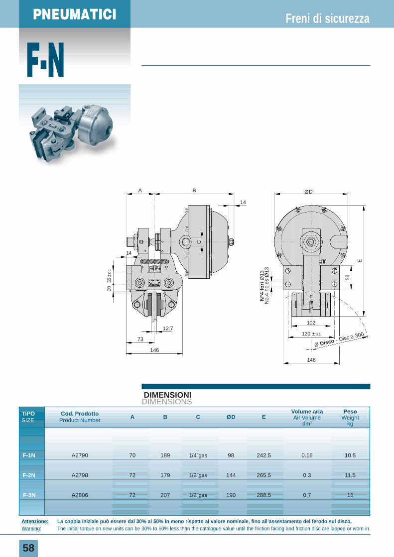
F-1N A2790 70 189 1/4”gas 98 242.5 0.16 10.5
F-2N A2798 72 179 1/2”gas 144 265.5 0.3 11.5
F-3N A2806 72 207 1/2”gas 190 288.5 0.7 15
Freni di sicurezza
Attenzione: La coppia iniziale può essere dal 30% al 50% in meno rispetto al valore nominale, fino all’assestamento del ferodo sul disco.Warning: The initial torque on new units can be 30% to 50% less than the catalogue value until the friction facing and friction disc are lapped or worn in.
C
35±
0.1
20
63
E
ØDBA
14
12.7
14
73
146
146
120 ±0.1
102
Ø Disco - Disc ≥ 300
N°4
fo
riØ
13N
o.4
hole
s Ø
13
PNEUMATIC
59
DIAGRAMMACHART
DATI TECNICI
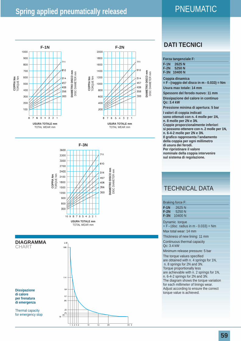
Forza tangenziale F:F-1N 2625 NF-2N 5250 NF-3N 10400 N
Coppia dinamica= F • (raggio del disco in m - 0.033) = NmUsura max totale: 14 mmSpessore del ferodo nuovo: 11 mmDissipazione del calore in continuoQc: 3.4 kWPressione minima di apertura: 5 barI valori di coppia indicatisono ottenuti con n. 4 molle per 1N,n. 8 molle per 2N e 3N.Coppie proporzionalmente inferiorisi possono ottenere con n. 2 molle per 1N, n. 6-4-2 molle per 2N e 3N.Il grafico rappresenta l’andamentodella coppia per ogni millimetrodi usura dei ferodi.Per ripristinare il valorenominale della coppia interveniresul sistema di regolazione.
Spring applied pneumatically released
Braking force F:F-1N 2625 NF-2N 5250 NF-3N 10400 N
Dynamic torque= F • (disc radius in m - 0.033) = NmMax total wear: 14 mmThickness of new lining: 11 mmContinuous thermal capacity Qc: 3.4 kWMinimum release pressure: 5 barThe torque values specifiedare obtained with n. 4 springs for 1N,n. 8 springs for 2N and 3N.Torque proportionally lessare achievable with n. 2 springs for 1N,n. 6-4-2 springs for 2N and 3N. The diagram shows the torque variationfor each millimeter of linings wear.Adjust according to ensure the correcttorque value is achieved.
TECHNICAL DATA
Dissipazione di caloreper frenatura di emergenza
Thermal capacityfor emergency stop
CO
PPIA
Nm
TOR
QU
E N
m
DIA
MET
RO
DIS
CO
mm
DIS
C D
IAM
ETE
R m
m
USURA TOTALE mmTOTAL WEAR mm
CO
PPIA
Nm
TOR
QU
E N
m
DIA
MET
RO
DIS
CO
mm
DIS
C D
IAM
ETE
R m
m
USURA TOTALE mmTOTAL WEAR mm
F-2N
CO
PPIA
Nm
TOR
QU
E N
m
DIA
MET
RO
DIS
CO
mm
DIS
C D
IAM
ETE
R m
m
USURA TOTALE mmTOTAL WEAR mm
F-1N
F-3N
PNEUMATICI
G-N
60
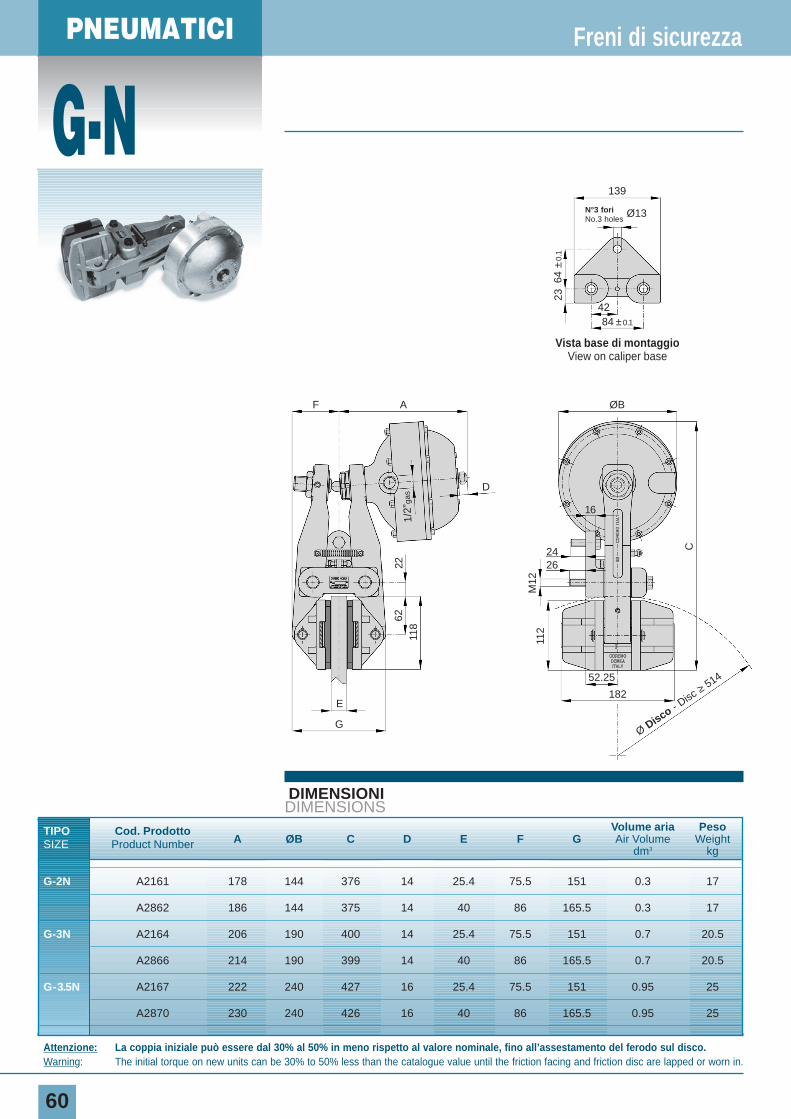
DIMENSIONIDIMENSIONS
TIPO Cod. ProdottoA ØB C D E F G
Volume aria Peso
SIZE Product Number Air Volume Weightdm3 kg
G-2N A2161 178 144 376 14 25.4 75.5 151 0.3 17
A2862 186 144 375 14 40 86 165.5 0.3 17
G-3N A2164 206 190 400 14 25.4 75.5 151 0.7 20.5
A2866 214 190 399 14 40 86 165.5 0.7 20.5
G-3.5N A2167 222 240 427 16 25.4 75.5 151 0.95 25
A2870 230 240 426 16 40 86 165.5 0.95 25
Freni di sicurezza
Attenzione: La coppia iniziale può essere dal 30% al 50% in meno rispetto al valore nominale, fino all’assestamento del ferodo sul disco.Warning: The initial torque on new units can be 30% to 50% less than the catalogue value until the friction facing and friction disc are lapped or worn in.
Vista base di montaggioView on caliper base
139
N°3 fori No.3 holes
Ø13
42
64 ±
0.1
23
C
221/
2”ga
s62
118
M12
112
84 ±0.1
ØB
24
16
E
G
26
AF
D
52.25
182
Ø Disco - Disc
≥514
PNEUMATIC
61
DIAGRAMMACHART
DATI TECNICI
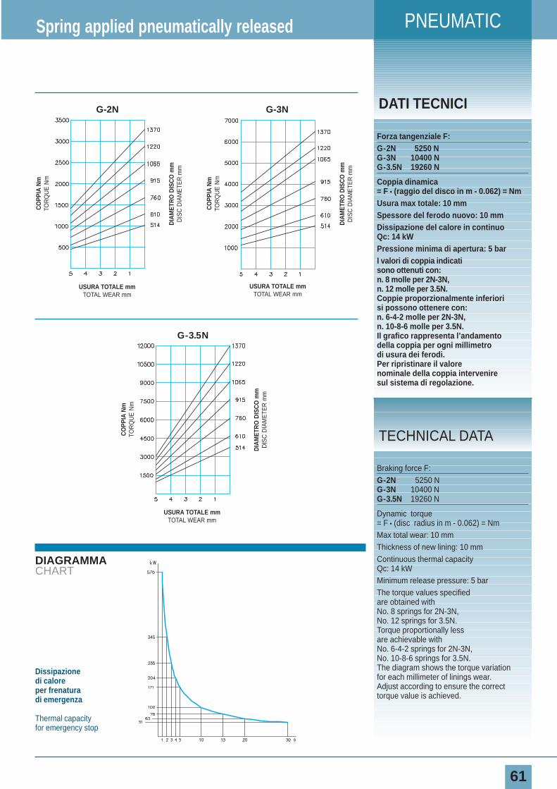
Forza tangenziale F:G-2N 5250 NG-3N 10400 NG-3.5N 19260 N
Coppia dinamica= F • (raggio del disco in m - 0.062) = NmUsura max totale: 10 mmSpessore del ferodo nuovo: 10 mmDissipazione del calore in continuoQc: 14 kWPressione minima di apertura: 5 barI valori di coppia indicati sono ottenuti con: n. 8 molle per 2N-3N, n. 12 molle per 3.5N.Coppie proporzionalmente inferiorisi possono ottenere con:n. 6-4-2 molle per 2N-3N, n. 10-8-6 molle per 3.5N.Il grafico rappresenta l’andamentodella coppia per ogni millimetrodi usura dei ferodi.Per ripristinare il valorenominale della coppia interveniresul sistema di regolazione.
Spring applied pneumatically released
Braking force F:G-2N 5250 NG-3N 10400 NG-3.5N 19260 N
Dynamic torque= F • (disc radius in m - 0.062) = NmMax total wear: 10 mmThickness of new lining: 10 mmContinuous thermal capacity Qc: 14 kWMinimum release pressure: 5 barThe torque values specifiedare obtained with No. 8 springs for 2N-3N, No. 12 springs for 3.5N.Torque proportionally lessare achievable with No. 6-4-2 springs for 2N-3N, No. 10-8-6 springs for 3.5N.The diagram shows the torque variationfor each millimeter of linings wear.Adjust according to ensure the correcttorque value is achieved.
TECHNICAL DATA
Dissipazione di caloreper frenatura di emergenza
Thermal capacityfor emergency stop
CO
PPIA
Nm
TOR
QU
E N
m
DIA
MET
RO
DIS
CO
mm
DIS
C D
IAM
ETE
R m
m
USURA TOTALE mmTOTAL WEAR mm
CO
PPIA
Nm
TOR
QU
E N
m
DIA
MET
RO
DIS
CO
mm
DIS
C D
IAM
ETE
R m
m
USURA TOTALE mmTOTAL WEAR mm
CO
PPIA
Nm
TOR
QU
E N
m
DIA
MET
RO
DIS
CO
mm
DIS
C D
IAM
ETE
R m
m
USURA TOTALE mmTOTAL WEAR mm
G-2N G-3N
G-3.5N
62
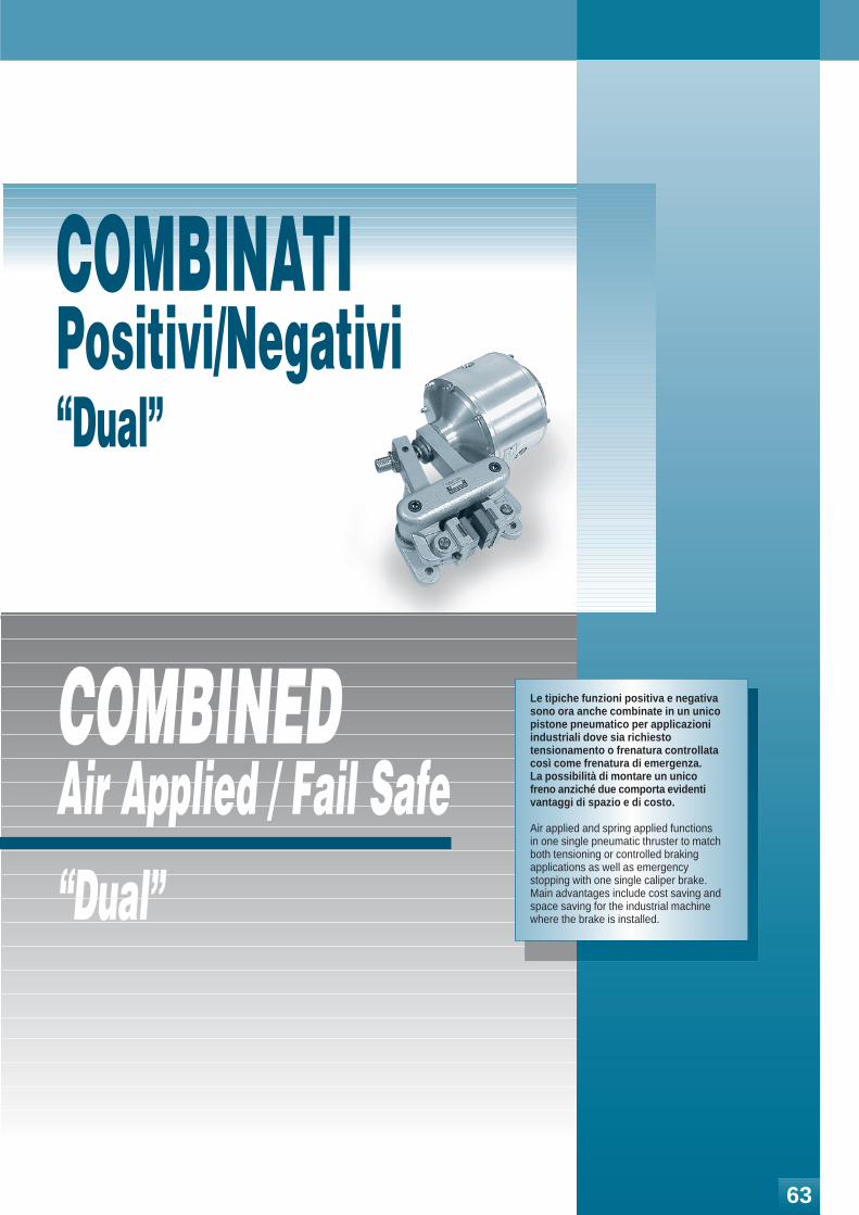
COMBINEDAir Applied / Fail Safe“Dual”
COMBINATIPositivi/Negativi“Dual”
Le tipiche funzioni positiva e negativa sono ora anche combinate in un unico pistone pneumatico per applicazioni industriali dove sia richiesto tensionamento o frenatura controllata così come frenatura di emergenza. La possibilità di montare un unico freno anziché due comporta evidenti vantaggi di spazio e di costo.
Air applied and spring applied functions in one single pneumatic thruster to match both tensioning or controlled braking applications as well as emergency stopping with one single caliper brake.Main advantages include cost saving and space saving for the industrial machine where the brake is installed.
63
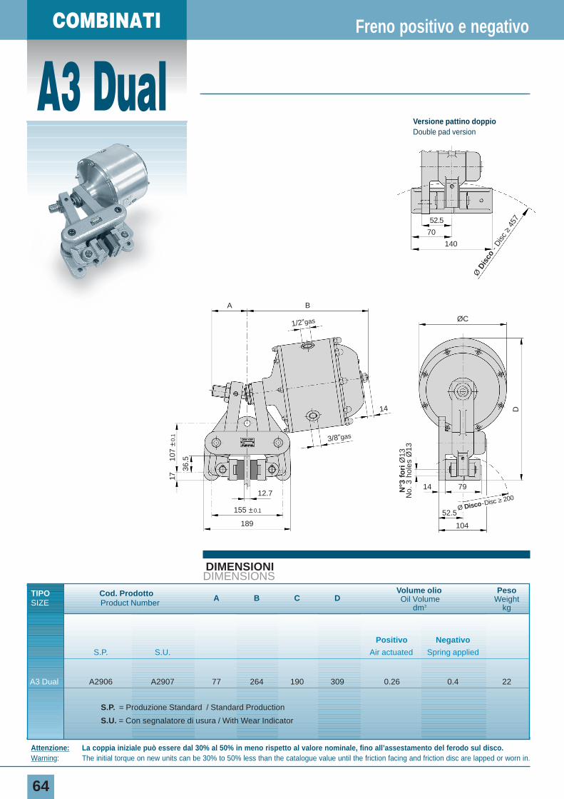
A3 Dual
64
DIMENSIONIDIMENSIONS
Freno positivo e negativo
Attenzione: La coppia iniziale può essere dal 30% al 50% in meno rispetto al valore nominale, fino all’assestamento del ferodo sul disco.Warning: The initial torque on new units can be 30% to 50% less than the catalogue value until the friction facing and friction disc are lapped or worn in.
COMBINATI
N°3
fo
riØ
13N
o. 3
hol
es Ø
13
A
14
12.77914
52.5
104
155 ±0.1
189
B
ØC
36.510
7 ±
0.1
1/2”gas
3/8”gas
17
DØ Disco-Disc ≥ 200
Ø D
isco
- D
isc
≥45
752.5
70
140
Versione pattino doppioDouble pad version
TIPO Cod. Prodotto A B C DVolume olio Peso
SIZE Product Number Oil Volume Weightdm3 kg
Positivo Negativo
S.P. S.U. Air actuated Spring applied
A3 Dual A2906 A2907 77 264 190 309 0.26 0.4 22
S.P. = Produzione Standard / Standard Production
S.U. = Con segnalatore di usura / With Wear Indicator
COMBINED
65
DIAGRAMMACHART
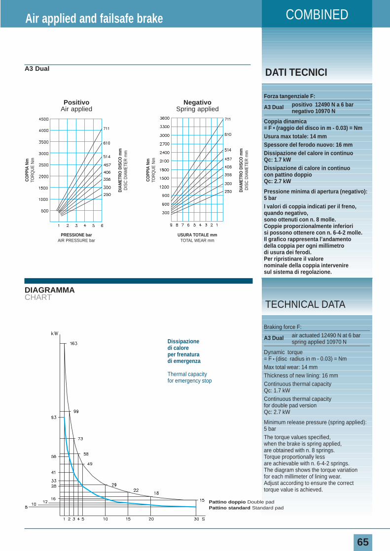
DATI TECNICIA3 Dual
Forza tangenziale F:
A3 Dual positivo 12490 N a 6 barnegativo 10970 N
Coppia dinamica= F • (raggio del disco in m - 0.03) = NmUsura max totale: 14 mmSpessore del ferodo nuovo: 16 mmDissipazione del calore in continuoQc: 1.7 kWDissipazione di calore in continuocon pattino doppioQc: 2.7 kW
Pressione minima di apertura (negativo):5 barI valori di coppia indicati per il freno,quando negativo,sono ottenuti con n. 8 molle.Coppie proporzionalmente inferiorisi possono ottenere con n. 6-4-2 molle.Il grafico rappresenta l’andamentodella coppia per ogni millimetrodi usura dei ferodi.Per ripristinare il valorenominale della coppia interveniresul sistema di regolazione.
Air applied and failsafe brake
Braking force F:
A3 Dual air actuated 12490 N at 6 barspring applied 10970 N
Dynamic torque= F • (disc radius in m - 0.03) = NmMax total wear: 14 mmThickness of new lining: 16 mmContinuous thermal capacityQc: 1.7 kWContinuous thermal capacity for double pad versionQc: 2.7 kW
Minimum release pressure (spring applied):5 barThe torque values specified,when the brake is spring applied,are obtained with n. 8 springs.Torque proportionally lessare achievable with n. 6-4-2 springs.The diagram shows the torque variationfor each millimeter of lining wear.Adjust according to ensure the correcttorque value is achieved.
TECHNICAL DATA
Dissipazione di caloreper frenatura di emergenza
Thermal capacityfor emergency stop
CO
PPIA
Nm
TOR
QU
E N
m
DIA
MET
RO
DIS
CO
mm
DIS
C D
IAM
ETE
R m
m
USURA TOTALE mmTOTAL WEAR mm
NegativoSpring applied
CO
PPIA
Nm
TOR
QU
E N
m
DIA
MET
RO
DIS
CO
mm
DIS
C D
IAM
ETE
R m
m
PRESSIONE barAIR PRESSURE bar
PositivoAir applied
Pattino doppio Double padPattino standard Standard pad
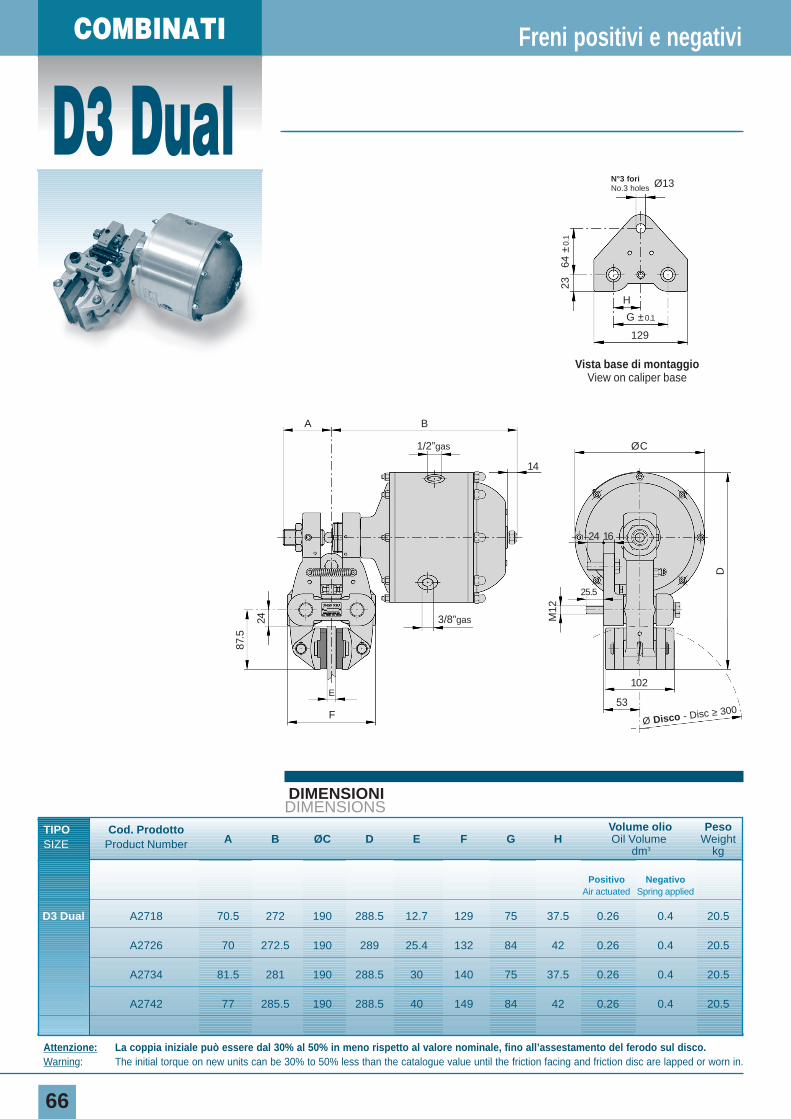
D3 Dual
66
DIMENSIONIDIMENSIONS
Freni positivi e negativi
Attenzione: La coppia iniziale può essere dal 30% al 50% in meno rispetto al valore nominale, fino all’assestamento del ferodo sul disco.Warning: The initial torque on new units can be 30% to 50% less than the catalogue value until the friction facing and friction disc are lapped or worn in.
COMBINATI
24
87.5
M12
D
E
F53
14
24
25.5
16
102
A B
ØC
Ø Disco - Disc ≥ 300
Vista base di montaggioView on caliper base
129
N°3 fori No.3 holes Ø13
H
64 ±
0.1
23
G ±0.1
1/2”gas
3/8”gas
TIPO Cod. ProdottoA B ØC D E F G H
Volume olio Peso
SIZE Product Number Oil Volume Weightdm3 kg
Positivo NegativoAir actuated Spring applied
D3 Dual A2718 70.5 272 190 288.5 12.7 129 75 37.5 0.26 0.4 20.5
A2726 70 272.5 190 289 25.4 132 84 42 0.26 0.4 20.5
A2734 81.5 281 190 288.5 30 140 75 37.5 0.26 0.4 20.5
A2742 77 285.5 190 288.5 40 149 84 42 0.26 0.4 20.5
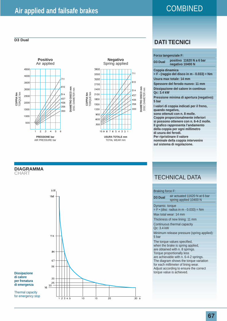
COMBINED
67
DIAGRAMMACHART
DATI TECNICID3 Dual
Forza tangenziale F:
D3 Dual positivo 11620 N a 6 barnegativo 10400 N
Coppia dinamica= F • (raggio del disco in m - 0.033) = NmUsura max totale: 14 mmSpessore del ferodo nuovo: 11 mmDissipazione del calore in continuoQc: 3.4 kWPressione minima di apertura (negativo):5 barI valori di coppia indicati per il freno,quando negativo, sono ottenuti con n. 8 molle.Coppie proporzionalmente inferiorisi possono ottenere con n. 6-4-2 molle.Il grafico rappresenta l’andamentodella coppia per ogni millimetrodi usura dei ferodi.Per ripristinare il valorenominale della coppia interveniresul sistema di regolazione.
Air applied and failsafe brakes
Braking force F:
D3 Dual air actuated 11620 N at 6 barspring applied 10400 N
Dynamic torque= F • (disc radius in m - 0.033) = NmMax total wear: 14 mmThickness of new lining: 11 mmContinuous thermal capacityQc: 3.4 kWMinimum release pressure (spring applied):5 barThe torque values specified,when the brake is spring applied,are obtained with n. 8 springs.Torque proportionally lessare achievable with n. 6-4-2 springs.The diagram shows the torque variationfor each millimeter of lining wear.Adjust according to ensure the correcttorque value is achieved.
TECHNICAL DATA
Dissipazione di caloreper frenatura di emergenza
Thermal capacityfor emergency stop
CO
PPIA
Nm
TOR
QU
E N
m
DIA
MET
RO
DIS
CO
mm
DIS
C D
IAM
ETE
R m
m
USURA TOTALE mmTOTAL WEAR mm
NegativoSpring applied
CO
PPIA
Nm
TOR
QU
E N
m
DIA
MET
RO
DIS
CO
mm
DIS
C D
IAM
ETE
R m
m
PRESSIONE barAIR PRESSURE bar
PositivoAir applied
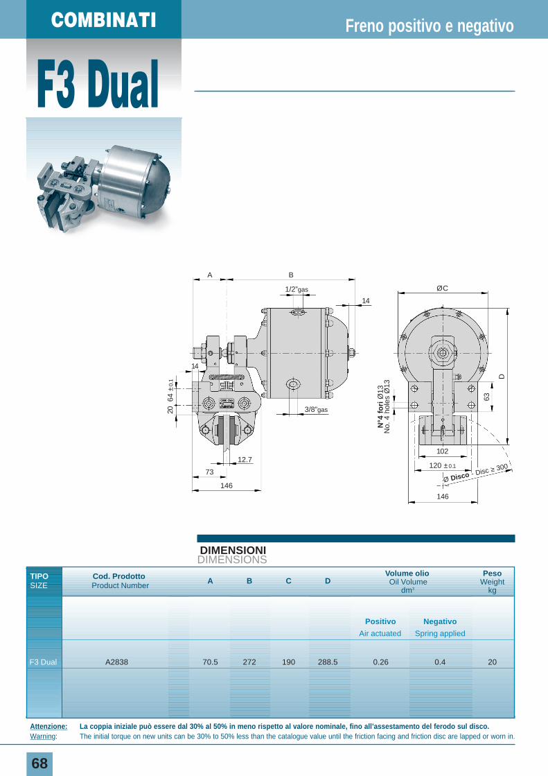
F3 Dual
68
DIMENSIONIDIMENSIONS
Freno positivo e negativo
Attenzione: La coppia iniziale può essere dal 30% al 50% in meno rispetto al valore nominale, fino all’assestamento del ferodo sul disco.Warning: The initial torque on new units can be 30% to 50% less than the catalogue value until the friction facing and friction disc are lapped or worn in.
COMBINATI
2064
±0.
1
63
D
12.7
14
73
146
146
14
102
120 ±0.1
A B
ØC
Ø Disco - Disc ≥ 300
1/2”gas
3/8”gas
N°4
fo
riØ
13N
o. 4
hol
es Ø
13
TIPO Cod. Prodotto A B C DVolume olio Peso
SIZE Product Number Oil Volume Weightdm3 kg
Positivo Negativo
Air actuated Spring applied
F3 Dual A2838 70.5 272 190 288.5 0.26 0.4 20
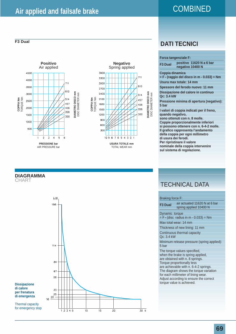
COMBINED
69
DIAGRAMMACHART
DATI TECNICIF3 Dual
Forza tangenziale F:
F3 Dual positivo 11620 N a 6 barnegativo 10400 N
Coppia dinamica= F • (raggio del disco in m - 0.033) = NmUsura max totale: 14 mmSpessore del ferodo nuovo: 11 mmDissipazione del calore in continuoQc: 3.4 kWPressione minima di apertura (negativo):5 barI valori di coppia indicati per il freno,quando negativo,sono ottenuti con n. 8 molle.Coppie proporzionalmente inferiorisi possono ottenere con n. 6-4-2 molle.Il grafico rappresenta l’andamentodella coppia per ogni millimetrodi usura dei ferodi.Per ripristinare il valorenominale della coppia interveniresul sistema di regolazione.
Air applied and failsafe brake
Braking force F:
F3 Dual air actuated 11620 N at 6 barspring applied 10400 N
Dynamic torque= F • (disc radius in m - 0.033) = NmMax total wear: 14 mmThickness of new lining: 11 mmContinuous thermal capacityQc: 3.4 kWMinimum release pressure (spring applied):5 barThe torque values specified,when the brake is spring applied,are obtained with n. 8 springs.Torque proportionally lessare achievable with n. 6-4-2 springs.The diagram shows the torque variationfor each millimeter of lining wear.Adjust according to ensure the correcttorque value is achieved.
TECHNICAL DATA
Dissipazione di caloreper frenatura di emergenza
Thermal capacityfor emergency stop
CO
PPIA
Nm
TOR
QU
E N
m
DIA
MET
RO
DIS
CO
mm
DIS
C D
IAM
ETE
R m
m
USURA TOTALE mmTOTAL WEAR mm
NegativoSpring applied
CO
PPIA
Nm
TOR
QU
E N
m
DIA
MET
RO
DIS
CO
mm
DIS
C D
IAM
ETE
R m
m
PRESSIONE barAIR PRESSURE bar
PositivoAir applied
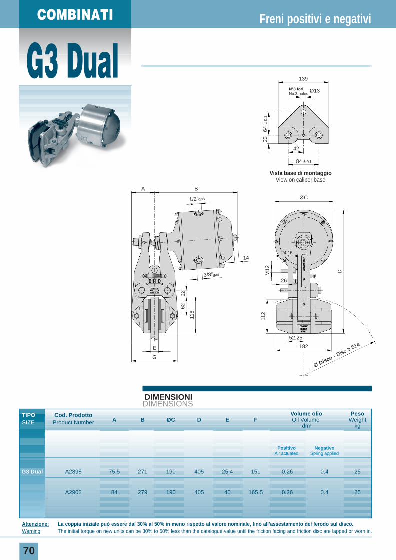
G3 Dual
70
DIMENSIONIDIMENSIONS
Freni positivi e negativi
Attenzione: La coppia iniziale può essere dal 30% al 50% in meno rispetto al valore nominale, fino all’assestamento del ferodo sul disco.Warning: The initial torque on new units can be 30% to 50% less than the catalogue value until the friction facing and friction disc are lapped or worn in.
COMBINATI
D
22
1/2”gas
3/8”gas
62
118
M12
112
Vista base di montaggioView on caliper base
139
N°3 fori No.3 holes
Ø13
42
64 ±
0.1
23
84 ±0.1
ØC
24 16
E
G
26
BA
14
52.25
182
Ø Disco - Disc ≥ 514
TIPO Cod. ProdottoA B ØC D E F
Volume olio Peso
SIZE Product Number Oil Volume Weightdm3 kg
Positivo NegativoAir actuated Spring applied
G3 Dual A2898 75.5 271 190 405 25.4 151 0.26 0.4 25
A2902 84 279 190 405 40 165.5 0.26 0.4 25
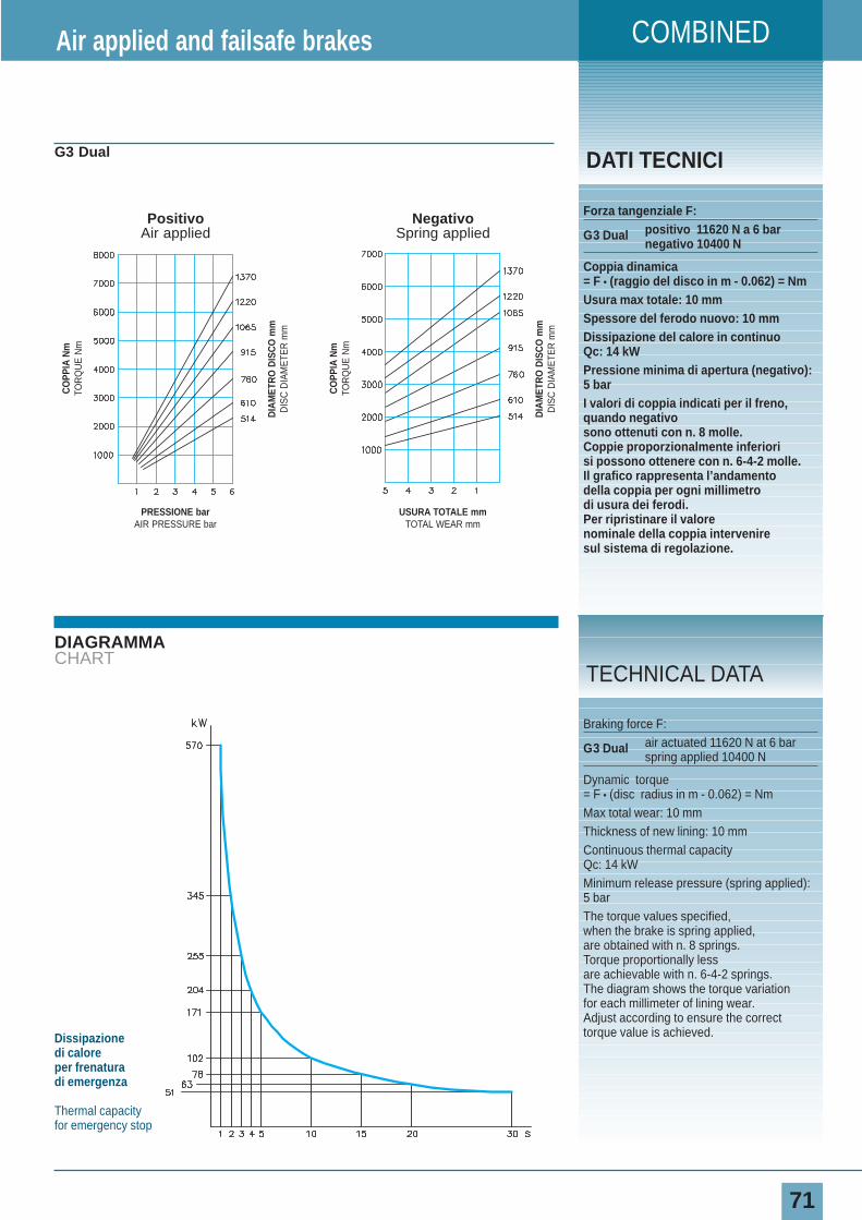
COMBINED
71
DIAGRAMMACHART
DATI TECNICIG3 Dual
Forza tangenziale F:
G3 Dual positivo 11620 N a 6 barnegativo 10400 N
Coppia dinamica= F • (raggio del disco in m - 0.062) = NmUsura max totale: 10 mmSpessore del ferodo nuovo: 10 mmDissipazione del calore in continuoQc: 14 kWPressione minima di apertura (negativo):5 barI valori di coppia indicati per il freno,quando negativosono ottenuti con n. 8 molle.Coppie proporzionalmente inferiorisi possono ottenere con n. 6-4-2 molle.Il grafico rappresenta l’andamentodella coppia per ogni millimetrodi usura dei ferodi.Per ripristinare il valorenominale della coppia interveniresul sistema di regolazione.
Air applied and failsafe brakes
Braking force F:
G3 Dual air actuated 11620 N at 6 barspring applied 10400 N
Dynamic torque= F • (disc radius in m - 0.062) = NmMax total wear: 10 mmThickness of new lining: 10 mmContinuous thermal capacityQc: 14 kWMinimum release pressure (spring applied):5 barThe torque values specified,when the brake is spring applied,are obtained with n. 8 springs.Torque proportionally lessare achievable with n. 6-4-2 springs.The diagram shows the torque variationfor each millimeter of lining wear.Adjust according to ensure the correcttorque value is achieved.
TECHNICAL DATA
Dissipazione di caloreper frenatura di emergenza
Thermal capacityfor emergency stop
CO
PPIA
Nm
TOR
QU
E N
m
DIA
MET
RO
DIS
CO
mm
DIS
C D
IAM
ETE
R m
m
USURA TOTALE mmTOTAL WEAR mm
NegativoSpring applied
CO
PPIA
Nm
TOR
QU
E N
m
DIA
MET
RO
DIS
CO
mm
DIS
C D
IAM
ETE
R m
m
PRESSIONE barAIR PRESSURE bar
PositivoAir applied
72
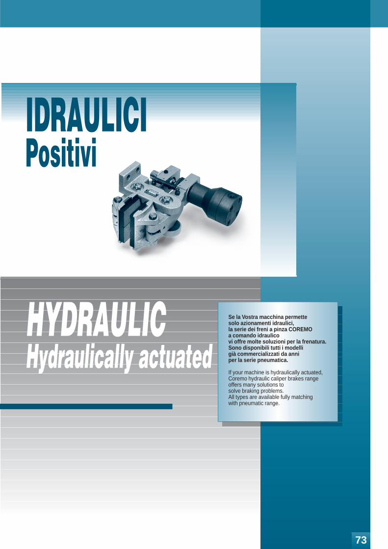
I freni idraulici hanno la ca-ratteristica di avere il pregiodi fare una specifica cosache li contraddistingue da al-tri tipi di prodotti di altra fat-tura e/o della concorrenza. Inparticolare i freni positivinon sono negativi e vicever-sa.Questi freni si adattano a quasitutto ed è per questa cosa chevengono chiamati anche freni“fatti a posta”.Queste notizie rappresentanoun
HYDRAULICHydraulically actuated
Se la Vostra macchina permette solo azionamenti idraulici, la serie dei freni a pinza COREMO a comando idraulico vi offre molte soluzioni per la frenatura.Sono disponibili tutti i modelli già commercializzati da anni per la serie pneumatica.
If your machine is hydraulically actuated, Coremo hydraulic caliper brakes range offers many solutions to solve braking problems.All types are available fully matching with pneumatic range.
IDRAULICIPositivi
73
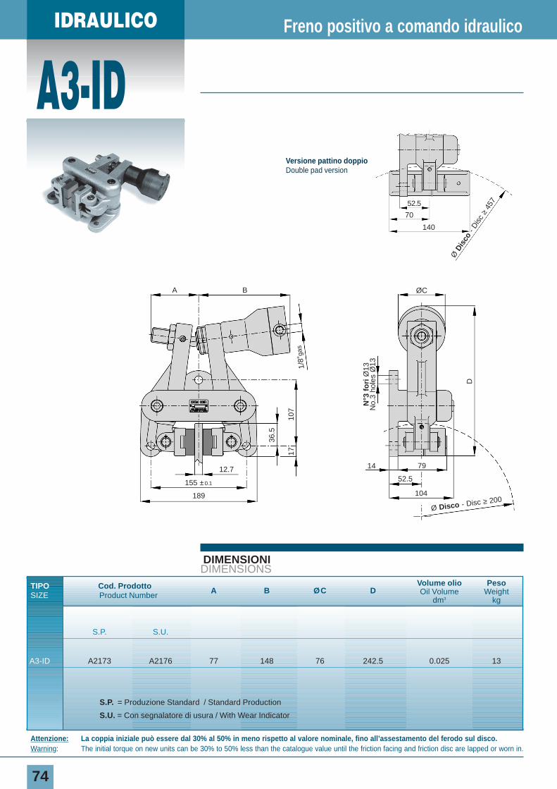
IDRAULICO
A3-ID
74
DIMENSIONIDIMENSIONS
TIPO Cod. Prodotto A B ØC DVolume olio Peso
SIZE Product Number Oil Volume Weightdm3 kg
S.P. S.U.
A3-ID A2173 A2176 77 148 76 242.5 0.025 13
S.P. = Produzione Standard / Standard Production
S.U. = Con segnalatore di usura / With Wear Indicator
Freno positivo a comando idraulico
Attenzione: La coppia iniziale può essere dal 30% al 50% in meno rispetto al valore nominale, fino all’assestamento del ferodo sul disco.Warning: The initial torque on new units can be 30% to 50% less than the catalogue value until the friction facing and friction disc are lapped or worn in.
107
1/8”
gas
17
36.5
155 ±0.1
189
14 79
52.5
104
12.7
A B
D
ØC
Ø Disco - Disc ≥ 200
N°3
fo
riØ
13N
o.3
hole
s Ø
13
Ø D
isco
- D
isc
≥45
752.5
70
140
Versione pattino doppioDouble pad version
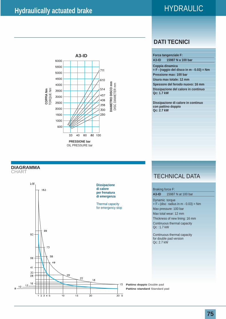
HYDRAULIC
75
DIAGRAMMACHART
DATI TECNICI
Forza tangenziale F:A3-ID 15987 N a 100 bar
Coppia dinamica= F • (raggio del disco in m - 0.03) = NmPressione max: 100 barUsura max totale: 12 mmSpessore del ferodo nuovo: 16 mmDissipazione del calore in continuoQc: 1.7 kW
Dissipazione di calore in continuocon pattino doppioQc: 2.7 kW
Hydraulically actuated brake
Braking force F:A3-ID 15987 N at 100 bar
Dynamic torque= F • (disc radius in m - 0.03) = NmMax pressure: 100 barMax total wear: 12 mmThickness of new lining: 16 mmContinuous thermal capacity Qc : 1.7 kW
Continuous thermal capacity for double pad versionQc: 2.7 kW
TECHNICAL DATA
CO
PPIA
Nm
TOR
QU
E N
m
DIA
MET
RO
DIS
CO
mm
DIS
C D
IAM
ETE
R m
m
PRESSIONE barOIL PRESSURE bar
A3-ID
Dissipazione di caloreper frenatura di emergenza
Thermal capacityfor emergency stop
Pattino doppio Double pad
Pattino standard Standard pad
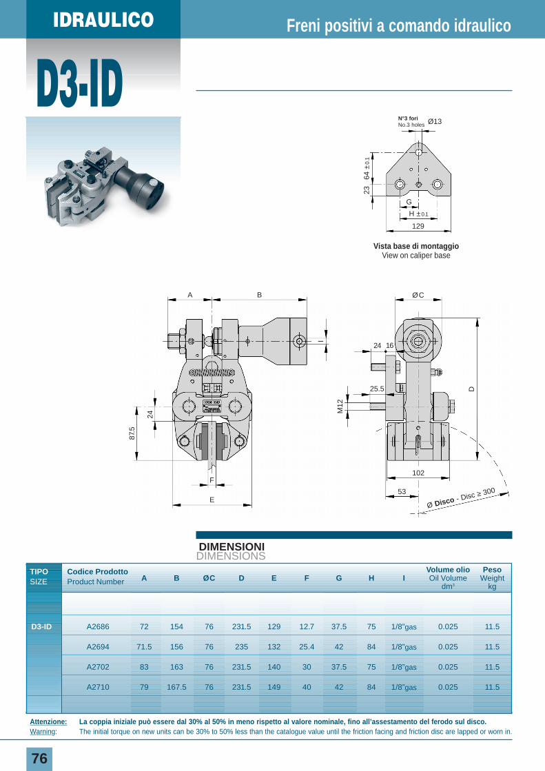
IDRAULICO
D3-ID
76
DIMENSIONIDIMENSIONS
TIPO Codice ProdottoA B ØC D E F G H I
Volume olio Peso
SIZE Product Number Oil Volume Weightdm3 kg
D3-ID A2686 72 154 76 231.5 129 12.7 37.5 75 1/8”gas 0.025 11.5
A2694 71.5 156 76 235 132 25.4 42 84 1/8”gas 0.025 11.5
A2702 83 163 76 231.5 140 30 37.5 75 1/8”gas 0.025 11.5
A2710 79 167.5 76 231.5 149 40 42 84 1/8”gas 0.025 11.5
Freni positivi a comando idraulico
Attenzione: La coppia iniziale può essere dal 30% al 50% in meno rispetto al valore nominale, fino all’assestamento del ferodo sul disco.Warning: The initial torque on new units can be 30% to 50% less than the catalogue value until the friction facing and friction disc are lapped or worn in.
I
E
F
24
87.5
D
ØCBA
102
53
M12
1624
25.5
Ø Disco - Disc ≥ 300
Vista base di montaggioView on caliper base
129
N°3 fori No.3 holes Ø13
G
64 ±
0.1
23
H ±0.1
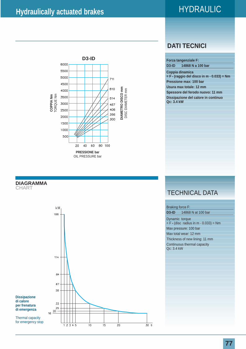
HYDRAULIC
77
DIAGRAMMACHART
DATI TECNICI
Forza tangenziale F:D3-ID 14868 N a 100 bar
Coppia dinamica= F • (raggio del disco in m - 0.033) = NmPressione max: 100 barUsura max totale: 12 mmSpessore del ferodo nuovo: 11 mmDissipazione del calore in continuoQc: 3.4 kW
Hydraulically actuated brakes
Braking force F:D3-ID 14868 N at 100 bar
Dynamic torque= F • (disc radius in m - 0.033) = NmMax pressure: 100 barMax total wear: 12 mmThickness of new lining: 11 mmContinuous thermal capacity Qc: 3.4 kW
TECHNICAL DATA
Dissipazione di caloreper frenatura di emergenza
Thermal capacityfor emergency stop
CO
PPIA
Nm
TOR
QU
E N
m
DIA
MET
RO
DIS
CO
mm
DIS
C D
IAM
ETE
R m
m
PRESSIONE barOIL PRESSURE bar
D3-ID
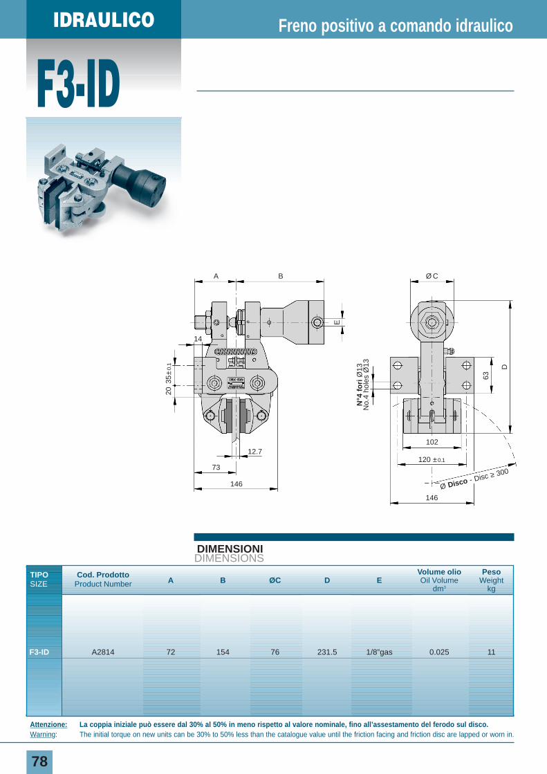
IDRAULICO
F3-ID
78
DIMENSIONIDIMENSIONS
TIPO Cod. ProdottoA B ØC D E
Volume olio Peso
SIZE Product Number Oil Volume Weightdm3 kg
F3-ID A2814 72 154 76 231.5 1/8”gas 0.025 11
Freno positivo a comando idraulico
Attenzione: La coppia iniziale può essere dal 30% al 50% in meno rispetto al valore nominale, fino all’assestamento del ferodo sul disco.Warning: The initial torque on new units can be 30% to 50% less than the catalogue value until the friction facing and friction disc are lapped or worn in.
E
35±
0.1
20
Ø CBA
14
12.7102
120 ±0.1
146
73
14663
D
Ø Disco - Disc ≥ 300
N°4
fo
riØ
13N
o.4
hole
s Ø
13
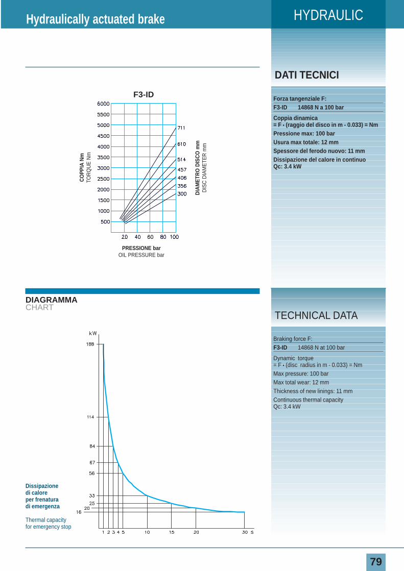
HYDRAULIC
79
DIAGRAMMACHART
DATI TECNICI
Forza tangenziale F:F3-ID 14868 N a 100 bar
Coppia dinamica= F • (raggio del disco in m - 0.033) = NmPressione max: 100 barUsura max totale: 12 mmSpessore del ferodo nuovo: 11 mmDissipazione del calore in continuoQc: 3.4 kW
Hydraulically actuated brake
Braking force F:F3-ID 14868 N at 100 bar
Dynamic torque= F • (disc radius in m - 0.033) = NmMax pressure: 100 barMax total wear: 12 mmThickness of new linings: 11 mmContinuous thermal capacity Qc: 3.4 kW
TECHNICAL DATA
Dissipazione di caloreper frenatura di emergenza
Thermal capacityfor emergency stop
CO
PPIA
Nm
TOR
QU
E N
m
DIA
MET
RO
DIS
CO
mm
DIS
C D
IAM
ETE
R m
m
PRESSIONE barOIL PRESSURE bar
F3-ID
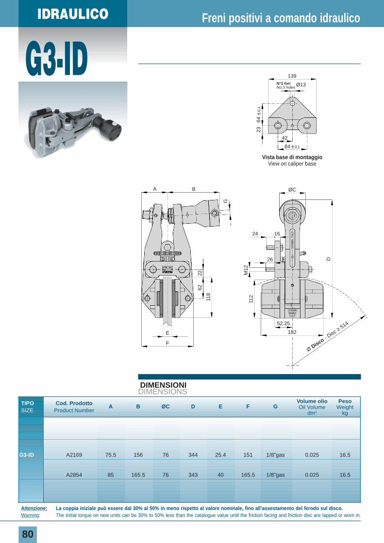
IDRAULICO
G3-ID
80
DIMENSIONIDIMENSIONS
TIPO Cod. Prodotto A B ØC D E F GVolume olio Peso
SIZE Product NumberOil Volume Weight
dm3 kg
G3-ID A2169 75.5 156 76 344 25.4 151 1/8”gas 0.025 16.5
A2854 85 165.5 76 343 40 165.5 1/8”gas 0.025 16.5
Freni positivi a comando idraulico
Attenzione: La coppia iniziale può essere dal 30% al 50% in meno rispetto al valore nominale, fino all’assestamento del ferodo sul disco.Warning: The initial torque on new units can be 30% to 50% less than the catalogue value until the friction facing and friction disc are lapped or worn in.
Vista base di montaggioView on caliper base
139N°3 fori No.3 holes
Ø13
42
64 ±
0.1
23
84 ±0.1
G
M12
112
118
6222
ØCBA
E
F
52.25
182
26
24 16
D
Ø Disco - Disc
≥514
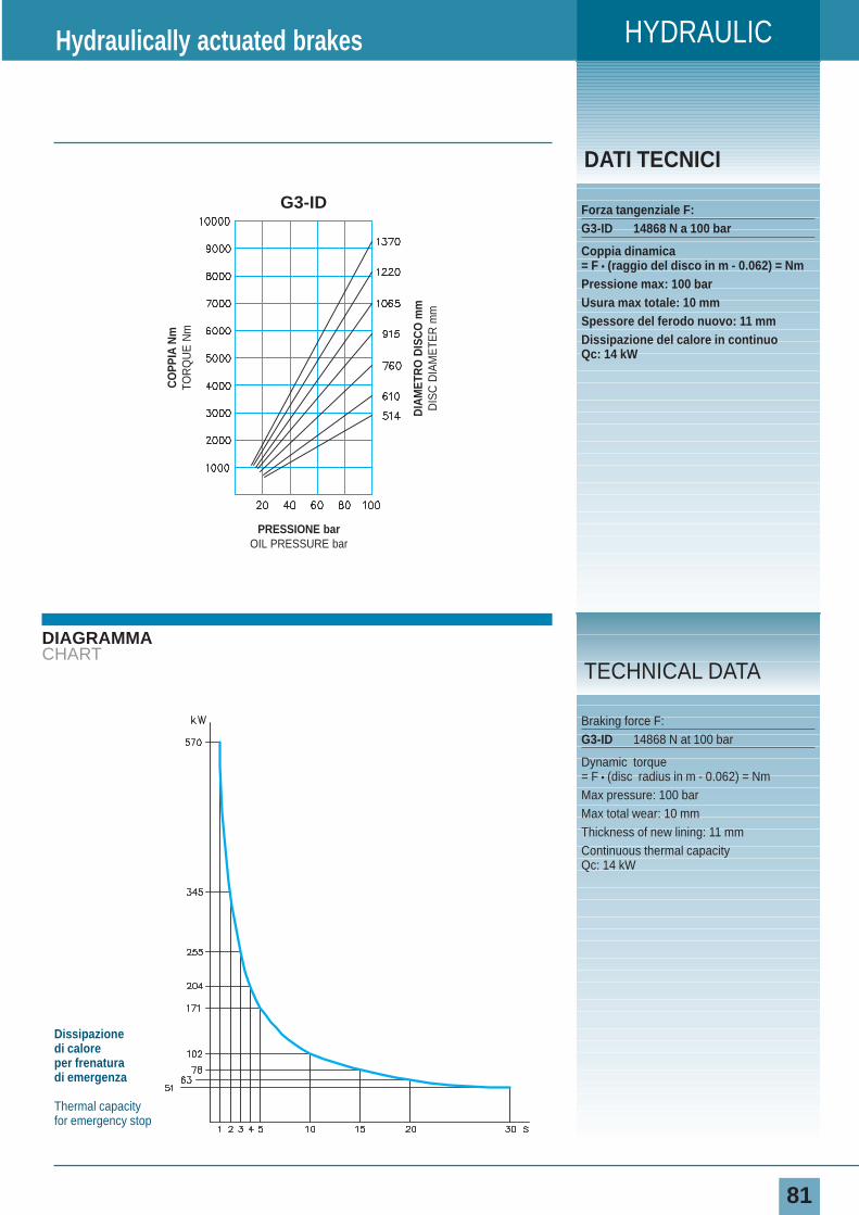
HYDRAULIC
81
DIAGRAMMACHART
DATI TECNICI
Forza tangenziale F:G3-ID 14868 N a 100 bar
Coppia dinamica= F • (raggio del disco in m - 0.062) = NmPressione max: 100 barUsura max totale: 10 mmSpessore del ferodo nuovo: 11 mmDissipazione del calore in continuoQc: 14 kW
Hydraulically actuated brakes
Braking force F:G3-ID 14868 N at 100 bar
Dynamic torque= F • (disc radius in m - 0.062) = NmMax pressure: 100 barMax total wear: 10 mmThickness of new lining: 11 mmContinuous thermal capacity Qc: 14 kW
TECHNICAL DATA
Dissipazione di caloreper frenatura di emergenza
Thermal capacityfor emergency stop
CO
PPIA
Nm
TOR
QU
E N
m
DIA
MET
RO
DIS
CO
mm
DIS
C D
IAM
ETE
R m
m
PRESSIONE barOIL PRESSURE bar
G3-ID
82
HYDRAULICFailsafe brakes
Spring applied hydraulically released
IDRAULICINegativi
Per poter rispondere in modo efficace alle normative di sicurezza, abbiamo previsto una gamma di freni a molle a comando idraulico.
To reply properly to safety laws, our spring applied - hydraulically released caliper brakes range is available.
83
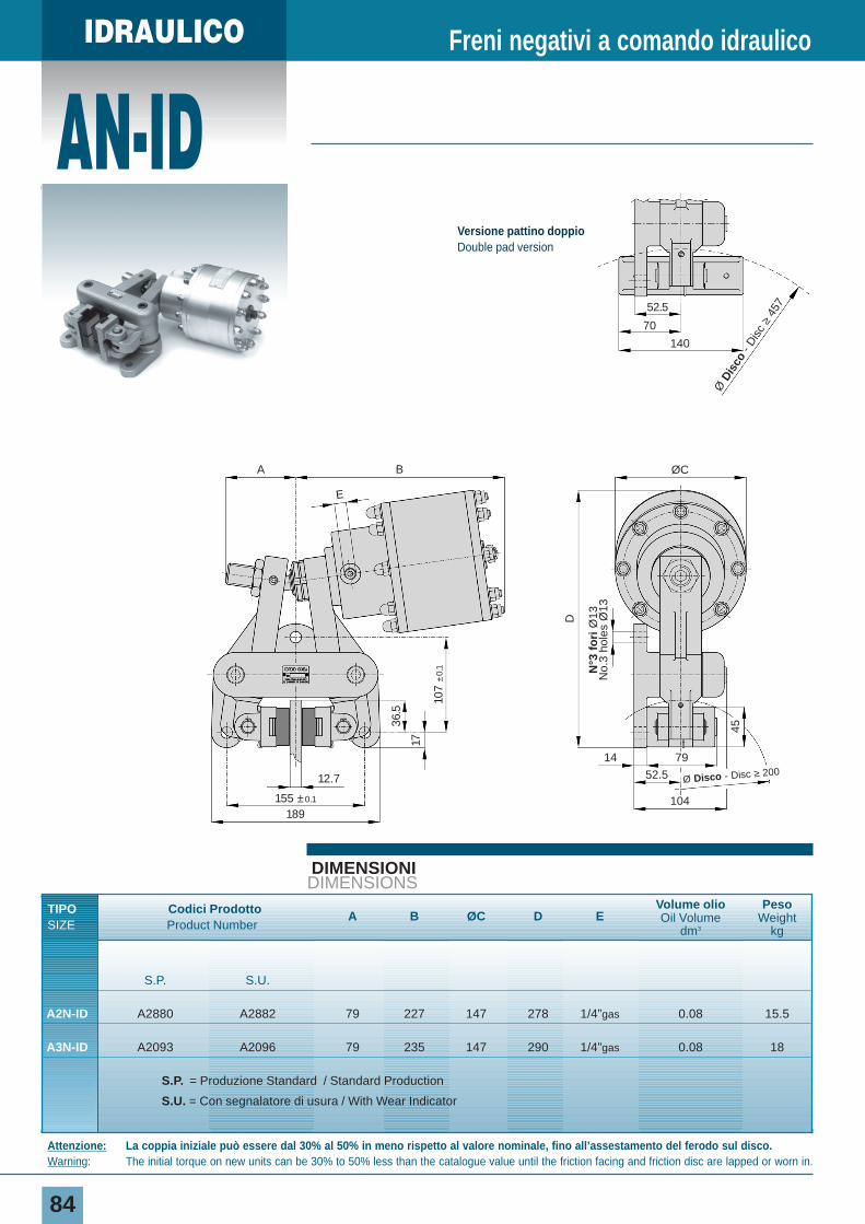
IDRAULICO
84
DIMENSIONIDIMENSIONS
TIPO Codici Prodotto A B ØC D EVolume olio Peso
SIZE Product NumberOil Volume Weight
dm3 kg
S.P. S.U.
A2N-ID A2880 A2882 79 227 147 278 1/4”gas 0.08 15.5
A3N-ID A2093 A2096 79 235 147 290 1/4”gas 0.08 18
S.P. = Produzione Standard / Standard Production
S.U. = Con segnalatore di usura / With Wear Indicator
Freni negativi a comando idraulico
AN-ID
Attenzione: La coppia iniziale può essere dal 30% al 50% in meno rispetto al valore nominale, fino all’assestamento del ferodo sul disco.Warning: The initial torque on new units can be 30% to 50% less than the catalogue value until the friction facing and friction disc are lapped or worn in.
155 ±0.1
12.7
36.5
17
107
±0.
1
45
14 79
52.5
104
D
189
ØCBA
E
Ø Disco - Disc ≥ 200
N°3
fo
riØ
13N
o.3
hole
s Ø
13
Ø D
isco
- D
isc
≥45
752.5
70
140
Versione pattino doppioDouble pad version
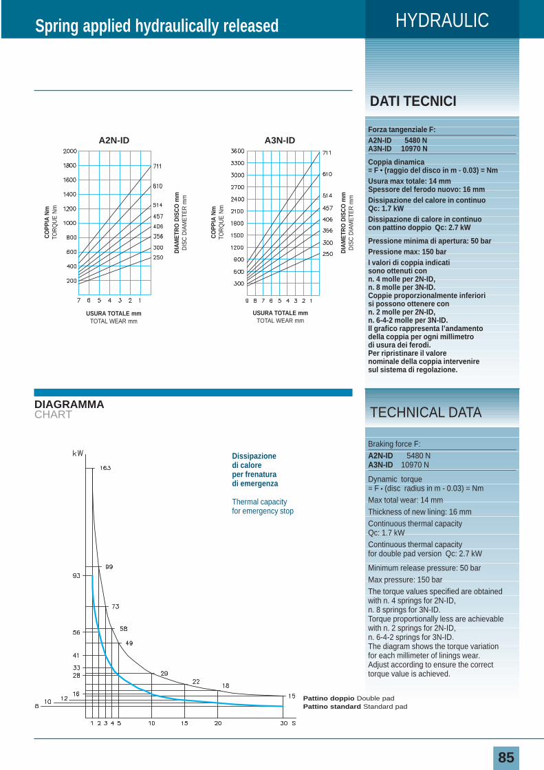
85
DIAGRAMMACHART
DATI TECNICI
Forza tangenziale F:A2N-ID 5480 NA3N-ID 10970 N
Coppia dinamica= F • (raggio del disco in m - 0.03) = NmUsura max totale: 14 mm Spessore del ferodo nuovo: 16 mmDissipazione del calore in continuoQc: 1.7 kWDissipazione di calore in continuocon pattino doppio Qc: 2.7 kW
Pressione minima di apertura: 50 barPressione max: 150 barI valori di coppia indicatisono ottenuti con n. 4 molle per 2N-ID,n. 8 molle per 3N-ID.Coppie proporzionalmente inferiorisi possono ottenere con n. 2 molle per 2N-ID,n. 6-4-2 molle per 3N-ID.Il grafico rappresenta l’andamentodella coppia per ogni millimetrodi usura dei ferodi.Per ripristinare il valorenominale della coppia interveniresul sistema di regolazione.
Spring applied hydraulically released
Braking force F:A2N-ID 5480 NA3N-ID 10970 N
Dynamic torque= F • (disc radius in m - 0.03) = NmMax total wear: 14 mmThickness of new lining: 16 mmContinuous thermal capacityQc: 1.7 kWContinuous thermal capacity for double pad version Qc: 2.7 kW
Minimum release pressure: 50 barMax pressure: 150 barThe torque values specified are obtainedwith n. 4 springs for 2N-ID, n. 8 springs for 3N-ID.Torque proportionally less are achievablewith n. 2 springs for 2N-ID,n. 6-4-2 springs for 3N-ID.The diagram shows the torque variationfor each millimeter of linings wear.Adjust according to ensure the correcttorque value is achieved.
TECHNICAL DATA
HYDRAULIC
Dissipazione di caloreper frenatura di emergenza
Thermal capacityfor emergency stop
Pattino doppio Double padPattino standard Standard pad
CO
PPIA
Nm
TOR
QU
E N
m
DIA
MET
RO
DIS
CO
mm
DIS
C D
IAM
ETE
R m
m
USURA TOTALE mmTOTAL WEAR mm
CO
PPIA
Nm
TOR
QU
E N
m
DIA
MET
RO
DIS
CO
mm
DIS
C D
IAM
ETE
R m
m
USURA TOTALE mmTOTAL WEAR mm
A2N-ID A3N-ID
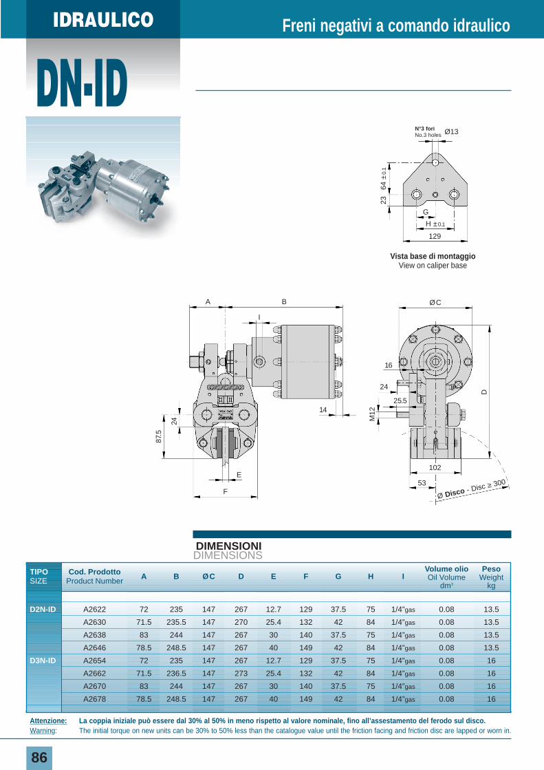
IDRAULICO
DN-ID
86
DIMENSIONIDIMENSIONS
TIPO Cod. Prodotto A B ØC D E F G H IVolume olio Peso
SIZE Product Number Oil Volume Weightdm3 kg
D2N-ID A2622 72 235 147 267 12.7 129 37.5 75 1/4”gas 0.08 13.5
A2630 71.5 235.5 147 270 25.4 132 42 84 1/4”gas 0.08 13.5
A2638 83 244 147 267 30 140 37.5 75 1/4”gas 0.08 13.5
A2646 78.5 248.5 147 267 40 149 42 84 1/4”gas 0.08 13.5
D3N-ID A2654 72 235 147 267 12.7 129 37.5 75 1/4”gas 0.08 16
A2662 71.5 236.5 147 273 25.4 132 42 84 1/4”gas 0.08 16
A2670 83 244 147 267 30 140 37.5 75 1/4”gas 0.08 16
A2678 78.5 248.5 147 267 40 149 42 84 1/4”gas 0.08 16
Freni negativi a comando idraulico
Attenzione: La coppia iniziale può essere dal 30% al 50% in meno rispetto al valore nominale, fino all’assestamento del ferodo sul disco.Warning: The initial torque on new units can be 30% to 50% less than the catalogue value until the friction facing and friction disc are lapped or worn in.
M12
D
102
53
ØCBA
I
24
14
16
E
24
87.5
F
25.5
Ø Disco - Disc ≥ 300
Vista base di montaggioView on caliper base
129
N°3 fori No.3 holes Ø13
G
64 ±
0.1
23
H ±0.1
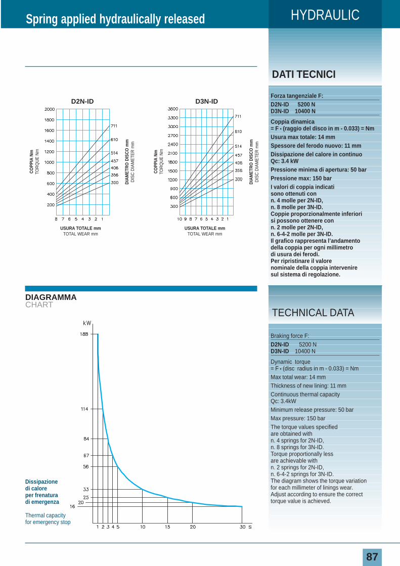
HYDRAULIC
87
DIAGRAMMACHART
DATI TECNICI
Forza tangenziale F:D2N-ID 5200 ND3N-ID 10400 N
Coppia dinamica= F • (raggio del disco in m - 0.033) = NmUsura max totale: 14 mmSpessore del ferodo nuovo: 11 mmDissipazione del calore in continuoQc: 3.4 kWPressione minima di apertura: 50 barPressione max: 150 barI valori di coppia indicatisono ottenuti con n. 4 molle per 2N-ID,n. 8 molle per 3N-ID.Coppie proporzionalmente inferiorisi possono ottenere con n. 2 molle per 2N-ID,n. 6-4-2 molle per 3N-ID.Il grafico rappresenta l’andamentodella coppia per ogni millimetrodi usura dei ferodi.Per ripristinare il valorenominale della coppia interveniresul sistema di regolazione.
Spring applied hydraulically released
Braking force F:D2N-ID 5200 ND3N-ID 10400 N
Dynamic torque= F • (disc radius in m - 0.033) = NmMax total wear: 14 mmThickness of new lining: 11 mmContinuous thermal capacity Qc: 3.4kWMinimum release pressure: 50 barMax pressure: 150 barThe torque values specifiedare obtained with n. 4 springs for 2N-ID,n. 8 springs for 3N-ID.Torque proportionally lessare achievable with n. 2 springs for 2N-ID,n. 6-4-2 springs for 3N-ID.The diagram shows the torque variationfor each millimeter of linings wear.Adjust according to ensure the correcttorque value is achieved.
TECHNICAL DATA
Dissipazione di caloreper frenatura di emergenza
Thermal capacityfor emergency stop
CO
PPIA
Nm
TOR
QU
E N
m
DIA
MET
RO
DIS
CO
mm
DIS
C D
IAM
ETE
R m
m
USURA TOTALE mmTOTAL WEAR mm
D3N-ID
CO
PPIA
Nm
TOR
QU
E N
m
DIA
MET
RO
DIS
CO
mm
DIS
C D
IAM
ETE
R m
m
USURA TOTALE mmTOTAL WEAR mm
D2N-ID
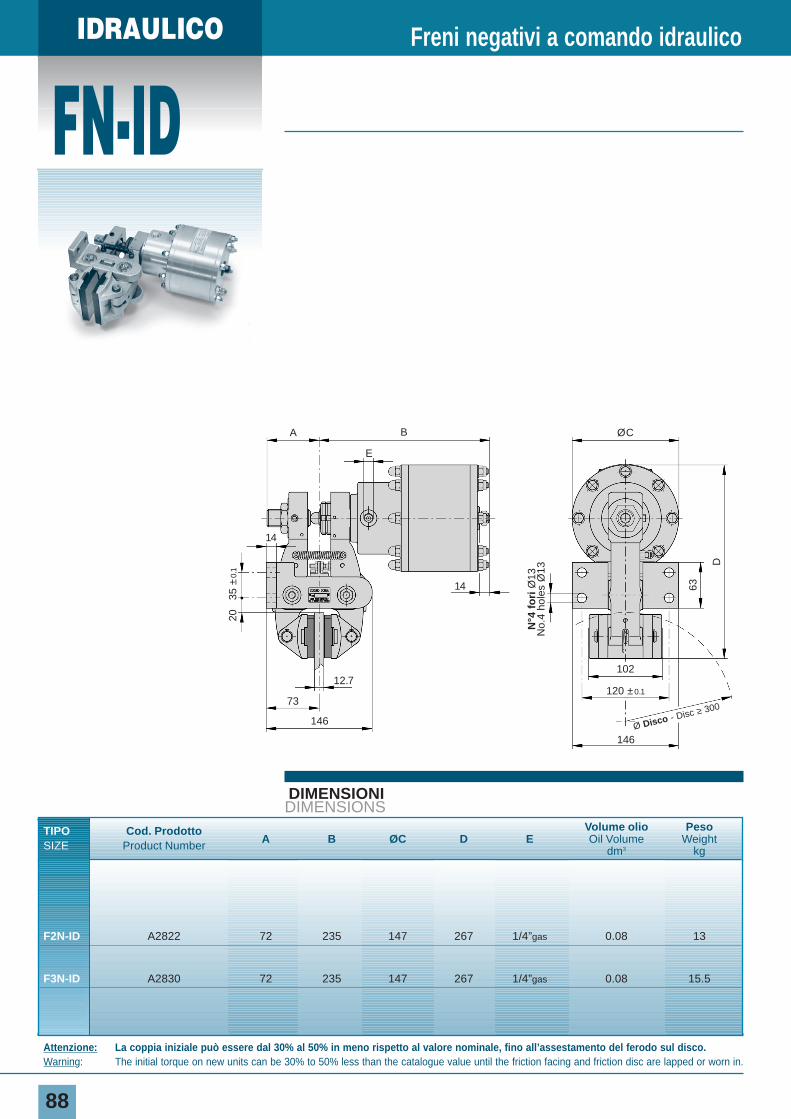
IDRAULICO
FN-ID
88
DIMENSIONIDIMENSIONS
TIPO Cod. ProdottoA B ØC D E
Volume olio Peso
SIZE Product NumberOil Volume Weight
dm3 kg
F2N-ID A2822 72 235 147 267 1/4”gas 0.08 13
F3N-ID A2830 72 235 147 267 1/4”gas 0.08 15.5
Freni negativi a comando idraulico
Attenzione: La coppia iniziale può essere dal 30% al 50% in meno rispetto al valore nominale, fino all’assestamento del ferodo sul disco.Warning: The initial torque on new units can be 30% to 50% less than the catalogue value until the friction facing and friction disc are lapped or worn in.
D
63
102
73
14
A B
2035
±0.
1
12.7
14
146
120 ±0.1
146
ØC
E
Ø Disco - Disc ≥ 300
N°4
fo
riØ
13N
o.4
hole
s Ø
13
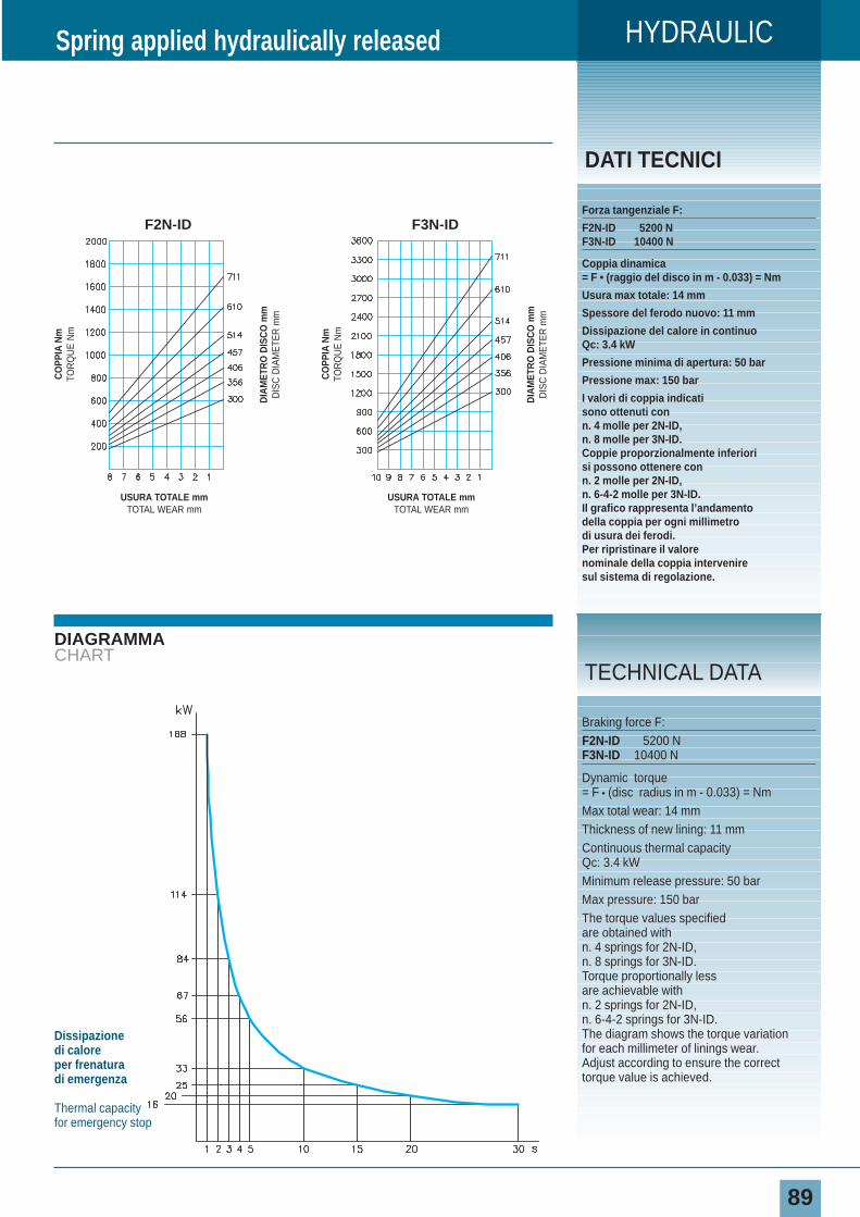
HYDRAULIC
89
DIAGRAMMACHART
DATI TECNICI
Forza tangenziale F:
F2N-ID 5200 NF3N-ID 10400 N
Coppia dinamica= F • (raggio del disco in m - 0.033) = Nm
Usura max totale: 14 mm
Spessore del ferodo nuovo: 11 mm
Dissipazione del calore in continuoQc: 3.4 kW
Pressione minima di apertura: 50 bar
Pressione max: 150 bar
I valori di coppia indicatisono ottenuti con n. 4 molle per 2N-ID,n. 8 molle per 3N-ID.Coppie proporzionalmente inferiorisi possono ottenere con n. 2 molle per 2N-ID,n. 6-4-2 molle per 3N-ID.Il grafico rappresenta l’andamentodella coppia per ogni millimetrodi usura dei ferodi.Per ripristinare il valorenominale della coppia interveniresul sistema di regolazione.
Spring applied hydraulically released
Braking force F:F2N-ID 5200 NF3N-ID 10400 N
Dynamic torque= F • (disc radius in m - 0.033) = NmMax total wear: 14 mmThickness of new lining: 11 mmContinuous thermal capacityQc: 3.4 kWMinimum release pressure: 50 barMax pressure: 150 barThe torque values specifiedare obtained with n. 4 springs for 2N-ID,n. 8 springs for 3N-ID.Torque proportionally lessare achievable with n. 2 springs for 2N-ID,n. 6-4-2 springs for 3N-ID.The diagram shows the torque variationfor each millimeter of linings wear.Adjust according to ensure the correcttorque value is achieved.
TECHNICAL DATA
Dissipazione di caloreper frenatura di emergenza
Thermal capacityfor emergency stop
CO
PPIA
Nm
TOR
QU
E N
m
DIA
MET
RO
DIS
CO
mm
DIS
C D
IAM
ETE
R m
m
USURA TOTALE mmTOTAL WEAR mm
F3N-ID
CO
PPIA
Nm
TOR
QU
E N
m
DIA
MET
RO
DIS
CO
mm
DIS
C D
IAM
ETE
R m
m
USURA TOTALE mmTOTAL WEAR mm
F2N-ID
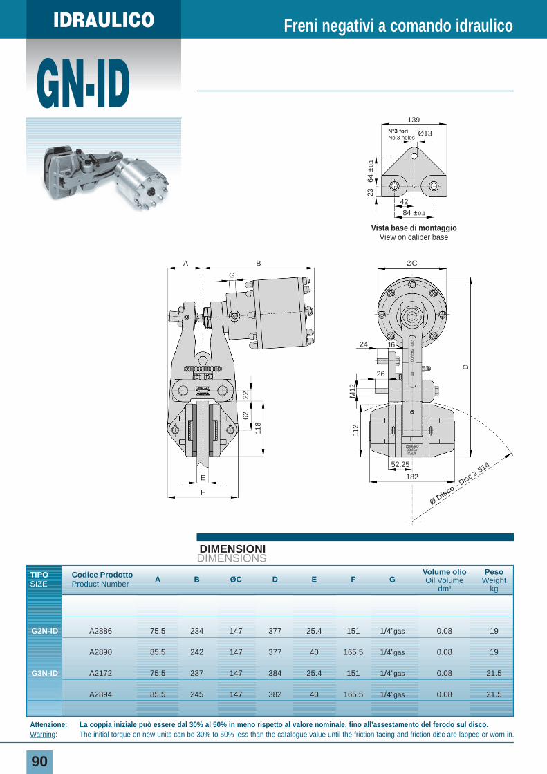
IDRAULICO
GN-ID
90
DIMENSIONIDIMENSIONS
TIPO Codice Prodotto A B ØC D E F GVolume olio Peso
SIZE Product Number Oil Volume Weightdm3 kg
G2N-ID A2886 75.5 234 147 377 25.4 151 1/4”gas 0.08 19
A2890 85.5 242 147 377 40 165.5 1/4”gas 0.08 19
G3N-ID A2172 75.5 237 147 384 25.4 151 1/4”gas 0.08 21.5
A2894 85.5 245 147 382 40 165.5 1/4”gas 0.08 21.5
Freni negativi a comando idraulico
Attenzione: La coppia iniziale può essere dal 30% al 50% in meno rispetto al valore nominale, fino all’assestamento del ferodo sul disco.Warning: The initial torque on new units can be 30% to 50% less than the catalogue value until the friction facing and friction disc are lapped or worn in.
Vista base di montaggioView on caliper base
139
N°3 fori No.3 holes
Ø13
42
64 ±
0.1
23
84 ±0.1
112
M12
D
6222
G
118
26
52.25
182
F
E
ØCBA
Ø Disco - Disc
≥ 514
24 16
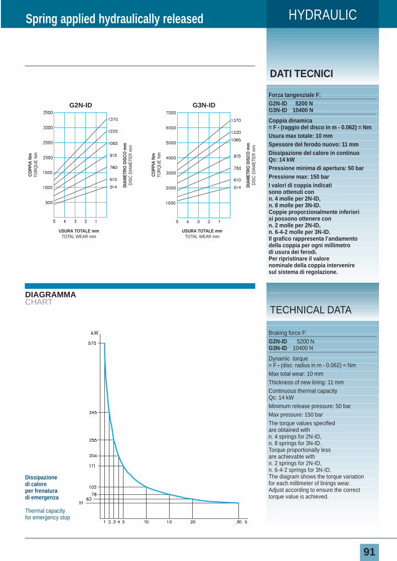
HYDRAULIC
91
DIAGRAMMACHART
DATI TECNICI
Forza tangenziale F:G2N-ID 5200 NG3N-ID 10400 N
Coppia dinamica= F • (raggio del disco in m - 0.062) = NmUsura max totale: 10 mmSpessore del ferodo nuovo: 11 mmDissipazione del calore in continuoQc: 14 kWPressione minima di apertura: 50 barPressione max: 150 barI valori di coppia indicatisono ottenuti con n. 4 molle per 2N-ID,n. 8 molle per 3N-ID.Coppie proporzionalmente inferiorisi possono ottenere con n. 2 molle per 2N-ID,n. 6-4-2 molle per 3N-ID.Il grafico rappresenta l’andamentodella coppia per ogni millimetrodi usura dei ferodi.Per ripristinare il valorenominale della coppia interveniresul sistema di regolazione.
Spring applied hydraulically released
Braking force F:G2N-ID 5200 NG3N-ID 10400 N
Dynamic torque= F • (disc radius in m - 0.062) = NmMax total wear: 10 mmThickness of new lining: 11 mmContinuous thermal capacity Qc: 14 kWMinimum release pressure: 50 barMax pressure: 150 barThe torque values specifiedare obtained with n. 4 springs for 2N-ID,n. 8 springs for 3N-ID.Torque proportionally lessare achievable with n. 2 springs for 2N-ID,n. 6-4-2 springs for 3N-ID.The diagram shows the torque variationfor each millimeter of linings wear.Adjust according to ensure the correcttorque value is achieved.
TECHNICAL DATA
Dissipazione di caloreper frenatura di emergenza
Thermal capacityfor emergency stop
CO
PPIA
Nm
TOR
QU
E N
m
DIA
MET
RO
DIS
CO
mm
DIS
C D
IAM
ETE
R m
m
USURA TOTALE mmTOTAL WEAR mm
G3N-ID
CO
PPIA
Nm
TOR
QU
E N
m
DIA
MET
RO
DIS
CO
mm
DIS
C D
IAM
ETE
R m
m
USURA TOTALE mmTOTAL WEAR mm
G2N-ID
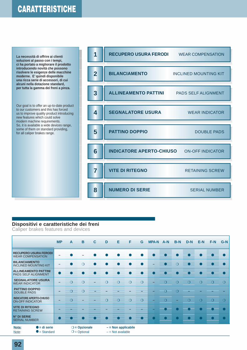
5
4
3
2
CARATTERISTICHE
92
Dispositivi e caratteristiche dei freniCaliper brakes features and devices
MP A B C D E F G MPA-N A-N B-N D-N E-N F-N G-N
RECUPERO USURA FERODIWEAR COMPENSATION – ● – ● ● ● ● ● ● ● ● ● ● ● ●
BILANCIAMENTOINCLINED MOUNTING KIT – ● ❍ ● ● ● ● ● – ● ❍ ● ● ● ●
ALLINEAMENTO PATTINI PADS SELF ALIGNMENT ● ● ● ● ● ● ● ● ● ● ● ● ● ● ●
SEGNALATORE USURAWEAR INDICATOR – ❍ ❍ – ❍ ❍ ❍ ❍ – ❍ ❍ ❍ ❍ ❍ ❍
PATTINO DOPPIODOUBLE PADS – ❍ ❍ – – – – – – ❍ ❍ – – – –
INDICATORE APERTO-CHIUSOON-OFF INDICATOR – ❍ – – ❍ ❍ ❍ ❍ – ❍ – ❍ ❍ ❍ ❍
VITE DI RITEGNORETAINING SCREW – – – – – – – – – ● ● ● ● ● ●
N° DI SERIESERIAL NUMBER ● ● ● ● ● ● ● ● ● ● ● ● ● ● ●
Nota: ● = di serie ❍ = Opzionale – = Non applicabileNote: ● = Standard ❍ = Optional – = Not available
BILANCIAMENTO INCLINED MOUNTING KIT
1 RECUPERO USURA FERODI WEAR COMPENSATION
ALLINEAMENTO PATTINI PADS SELF ALIGNMENT
SEGNALATORE USURA WEAR INDICATOR
PATTINO DOPPIO DOUBLE PADS
INDICATORE APERTO-CHIUSO ON-OFF INDICATOR6
7
8
VITE DI RITEGNO RETAINING SCREW
NUMERO DI SERIE SERIAL NUMBER
La necessità di offrire ai clienti soluzioni al passo con i tempi, ci ha portato a migliorare il prodotto introducendo novità che possono risolvere le esigenze delle macchinemoderne. E’ quindi disponibile una ricca serie di accessori, di cui alcuni nella dotazione standard, per tutta la gamma dei freni a pinza.
Our goal is to offer an up-to-date productto our customers and this has forced us to improve quality product introducingnew features which could solve modern machine requirements. So, it is available a wide devices range,some of them on standard providing, for all caliper brakes range.
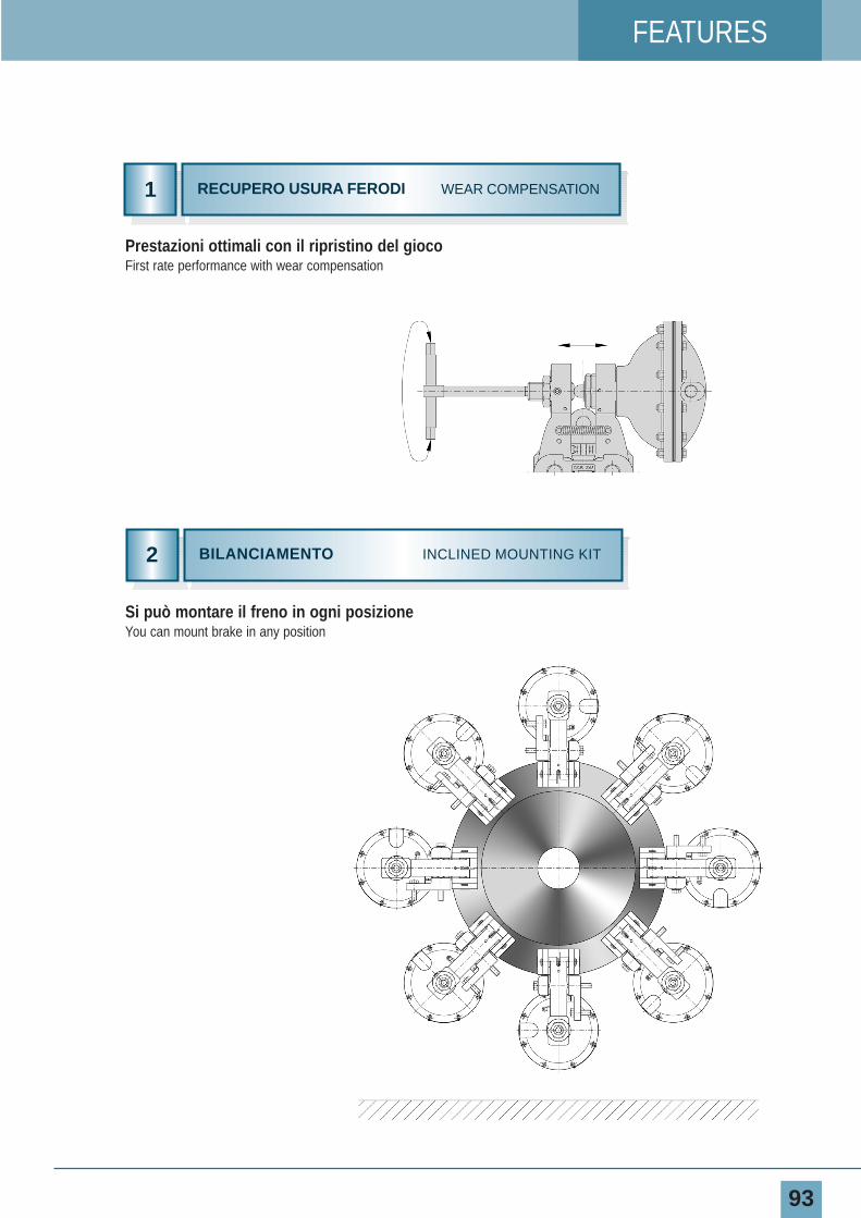
93
FEATURES
Si può montare il freno in ogni posizioneYou can mount brake in any position
Prestazioni ottimali con il ripristino del giocoFirst rate performance with wear compensation
2 BILANCIAMENTO INCLINED MOUNTING KIT
1 RECUPERO USURA FERODI WEAR COMPENSATION
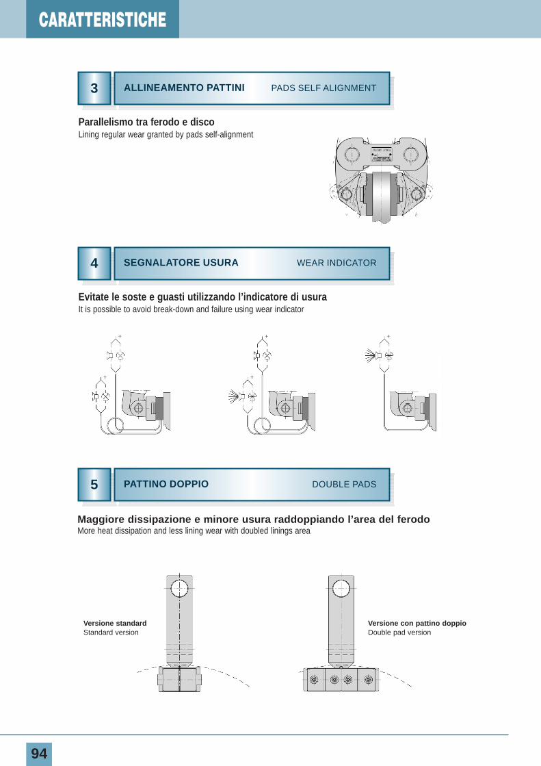
CARATTERISTICHE
94
5
4
3 ALLINEAMENTO PATTINI PADS SELF ALIGNMENT
SEGNALATORE USURA WEAR INDICATOR
PATTINO DOPPIO DOUBLE PADS
Maggiore dissipazione e minore usura raddoppiando l’area del ferodoMore heat dissipation and less lining wear with doubled linings area
Parallelismo tra ferodo e discoLining regular wear granted by pads self-alignment
Evitate le soste e guasti utilizzando l’indicatore di usuraIt is possible to avoid break-down and failure using wear indicator
Versione standardStandard version
Versione con pattino doppioDouble pad version
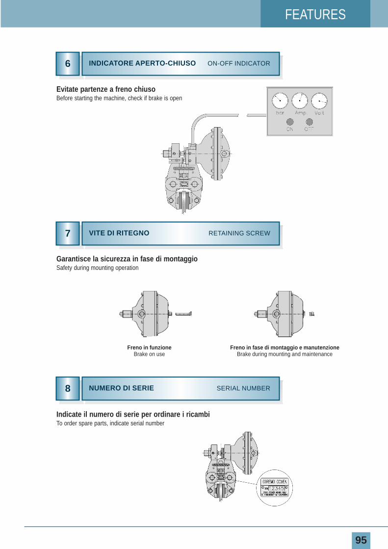
FEATURES
95
Evitate partenze a freno chiusoBefore starting the machine, check if brake is open
Garantisce la sicurezza in fase di montaggioSafety during mounting operation
Indicate il numero di serie per ordinare i ricambiTo order spare parts, indicate serial number
INDICATORE APERTO-CHIUSO ON-OFF INDICATOR6
7
8
VITE DI RITEGNO RETAINING SCREW
NUMERO DI SERIE SERIAL NUMBER
Freno in funzioneBrake on use
Freno in fase di montaggio e manutenzioneBrake during mounting and maintenance
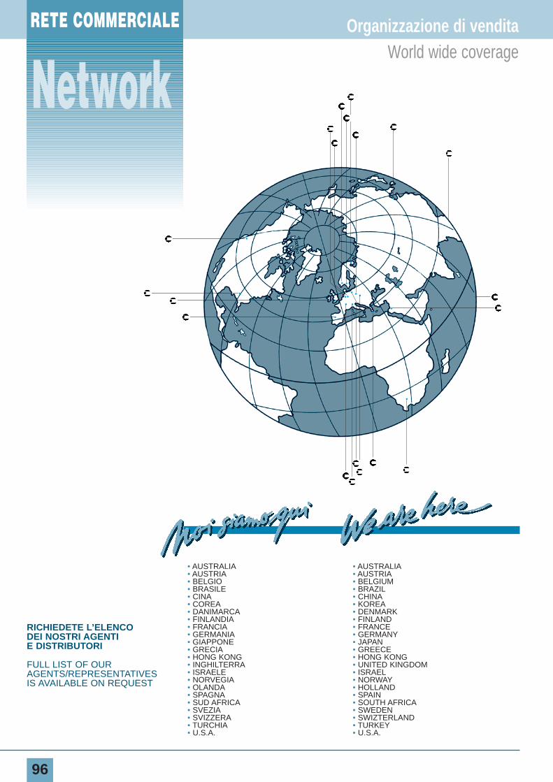
RETE COMMERCIALE
96
Organizzazione di venditaWorld wide coverage
• AUSTRALIA • AUSTRALIA• AUSTRIA • AUSTRIA• BELGIO • BELGIUM• BRASILE • BRAZIL• CINA • CHINA• COREA • KOREA• DANIMARCA • DENMARK• FINLANDIA • FINLAND• FRANCIA • FRANCE• GERMANIA • GERMANY• GIAPPONE • JAPAN• GRECIA • GREECE• HONG KONG • HONG KONG• INGHILTERRA • UNITED KINGDOM• ISRAELE • ISRAEL• NORVEGIA • NORWAY• OLANDA • HOLLAND• SPAGNA • SPAIN• SUD AFRICA • SOUTH AFRICA• SVEZIA • SWEDEN• SVIZZERA • SWIZTERLAND• TURCHIA • TURKEY• U.S.A. • U.S.A.
•
•
•
•
• •
•
• • •
•
• •••
••
•
RICHIEDETE L’ELENCODEI NOSTRI AGENTIE DISTRIBUTORI
FULL LIST OF OURAGENTS/REPRESENTATIVESIS AVAILABLE ON REQUEST
Network
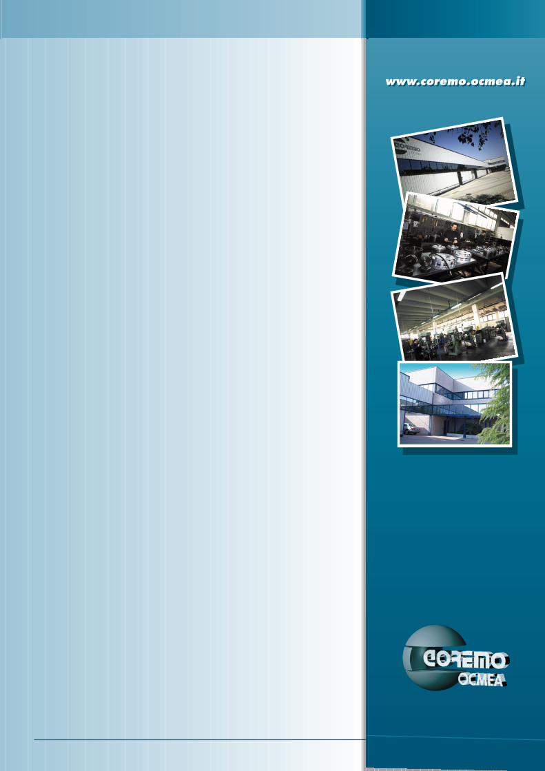
www.coremo.ocmea.itwww.coremo.ocmea.it
DISTRIBUITO DADISTRIBUTED BY
I.T. 020304
FRENIFRIZIONI PNEUMATICHEGIUNTICONTROLLI INDUSTRIALI
BRAKESPNEUMATIC CLUTCHESCOUPLINGSINDUSTRIAL CONTROLS
SEDE CENTRALE E STABILIMENTO
HEAD OFFICE AND WORKS
COREMO OCMEA s.r.l.20090 ASSAGO (MI) ITALYVIA GALILEI 12P.O. BOX 8 ASSAGOTEL. +39/02.4880697 (5 Linee r.a.)FAX +39/02.4881940INTERNET: www.coremo.ocmea.itE•MAIL: [email protected]
Related Documents


![Presentazione04 Freni print.ppt [modalità compatibilità]campus.unibo.it/154030/1/Presentazione04_Freni.pdf · Freni Bibliografia • E. Funaioli, A. Maggiore, U. Meneghetti, Lezioni](https://static.cupdf.com/doc/110x72/5c6a920f09d3f27a7e8ce47d/presentazione04-freni-printppt-modalita-compatibilita-freni-bibliografia.jpg)