Document n° 1350-2 ~ 15/01/2009 Fujitsu General (Euro) GmbH Werftstrasse 20 40549 Düsseldorf - Germany Subject to modifications without notice. Non contractual document. Heat pump air/water split single service Installation and operating manual intended for professionals To be saved for future consultation FR EN NL IT DE

Welcome message from author
This document is posted to help you gain knowledge. Please leave a comment to let me know what you think about it! Share it to your friends and learn new things together.
Transcript

Document n° 1350-2 ~ 15/01/2009
Fujitsu General (Euro) GmbH
Werftstrasse 20
40549 Düsseldorf - Germany
Subject to modifications without notice.
Non contractual document.
Heat pump air/watersplit single service
Installation and
operating manual
intended for professionals
To be saved
for future consultation
FR EN NL ITDE

2 Installation and operating manual “1350-EN”
Heat pump, Split, single service
Packing list
Heat pump Outside unit Hydraulic module
Designation Code Model Code Model Code
AOYA18LALL WSYA 050 DA 023600
AOYA18LALL WSYA 065 DA 023601
AOYA24LALL WSYA 080 DA 023602
AOYA30LBTL WSYA 095 DA 023603
AOYA45LATLAOYA45LBTL
WSYA 128 DA 023604
AOY54LJBYL WSYA 155 DA 023605
Optional equipment
• 2nd circuit kit (UTW-KZSXA)- for connecting 2 heating circuits
• DHW kit (UTW-KDWXA)- for connecting a DHW tank (with built-in electricalbackups)
• Boiler connection kit (UTW-KBSXA)- for connecting a boiler to the heat pump
• Room thermostat (UTW-C55XA)- For correcting the ambient temperature
• Remote control (UTW-C75XA)- For correcting the ambient temperature andprogramming the heat pump.
• Cooling kit (UTW-KCLXA)
• Swimming pool kit (UTW-KSPXA)
• High flow rate circulating pump kit (UTW-PHFXA)For the installation of 1 circuit floor heating withmodel 128 and 155
• Cooling kit (UTW-KCHXA) compatible with high flowrate circulating pump (128 and 155)
Scope of application
This heat pump provides:
- Heating in winter,
- Control of two heating circuits*,
- Production of domestic hot water* (provided thatcombined with a DHW tank).
- Cooling in summer*.
- Ins ta l la t ion wi th bo i le r connect ion as asupplementary heating for the coldest days*.
* : These options require the use of additional kits(see § “Optional equipment”).

Installation and operating manual “1350-EN” 3
Heat pump, Split, single service
Contents
Description of the unit . . . . . . . . . . . . . . . . . . . . . . . . . . . . . . . . . . . . P. 4
Package . . . . . . . . . . . . . . . . . . P. 4
Definitions . . . . . . . . . . . . . . . . . P. 4
Specifications . . . . . . . . . . . . . . . P. 5
Heating power curve . . . . . . . . . . . P. 6
Description. . . . . . . . . . . . . . . . P. 11
Operating principle . . . . . . . . . . . P. 12
Installation . . . . . . . . . . . . . . . . . . . . . . . . . . . . . . . . . . . . . . . . . . P. 14
Regulation installation and maintenance
conditions . . . . . . . . . . . . . . . . P. 14
Unpacking and reservations . . . . . . P. 14
Receipt . . . . . . . . . . . . . . . . . . . . P. 14
Handling . . . . . . . . . . . . . . . . . . . P. 14
Accessories provided. . . . . . . . . . . . . P. 14
Installation position . . . . . . . . . . . P. 14
Installation of the outside unit . . . . . P. 14
Installation precautions . . . . . . . . . . . P. 14
Outside unit positioning . . . . . . . . . . . P. 16
Condensate drain hose. . . . . . . . . . . . P. 16
Installing the hydraulic module . . . . . P. 17
Installation precautions . . . . . . . . . . . P. 17
Positioning the hydraulic module. . . . . . . P. 17
Refrigeration connections. . . . . . . . P. 18
Rules and precautions . . . . . . . . . . . . P. 18
Refrigeration connections . . . . . . . . . . P. 18
Creating the flarings . . . . . . . . . . . . . P. 18
Shaping the refrigeration pipes . . . . . . . P. 19
Connecting the flared connections . . . . . P. 19
Filling the installation with gas . . . . . P. 21
Creating a vacuum and filling the refrigeration
connections with gas . . . . . . . . . . . . . P. 21
Sealing test . . . . . . . . . . . . . . . . . . P. 21
Additional charge . . . . . . . . . . . . . . . P. 22
Connecting
the heating circuit hydraulically . . . . P. 23
General . . . . . . . . . . . . . . . . . . . . P. 23
Rinsing out the installation . . . . . . . . . . P. 23
Filling and purging the installation . . . . . . P. 23
Electrical connections . . . . . . . . . P. 24
Characteristic of the electrical supply . . . . P. 24
General remarks on electrical connections . P. 24
Overview of all the electrical connections . . P. 25
Cable section and protection rating . . . . . P. 25
Electrical connections on outside unit side . P. 26
Electrical connections on the hydraulic module
side . . . . . . . . . . . . . . . . . . . . . . P. 27
Outdoor sensor . . . . . . . . . . . . . P. 29
Room thermostat and/or remote control P. 29
Start-up . . . . . . . . . . . . . . . . . P. 30
Configuring the room thermostat . . . . P. 30
Configuring remote control . . . . . . . P. 30
Regulation system . . . . . . . . . . . . . . . . . . . . . . . . . . . . . . . . . . . . . P. 31
User interface and remote control
(Option) . . . . . . . . . . . . . . . . . P. 31
Room thermostat (Option) . . . . . . . P. 32
Temperature control. . . . . . . . . . . P. 32
Manual adjustment . . . . . . . . . . . P. 32
Self-adaptation . . . . . . . . . . . . . P. 32
Parametering the setting . . . . . . . . P. 34
General . . . . . . . . . . . . . . . . . . . . P. 34
Setting parameters . . . . . . . . . . . . . . P. 34
List of function lines
(settings, diagnosis, status) . . . . . . . . . P. 34

4 Installation and operating manual “1350-EN”
Heat pump, Split, single service
Configuring the installation . . . . . . . . . . . . . . . . . . . . . . . . . . . . . . . . P. 46
Configuration 1, 2, 3 or 4:
heat pumps with electric back-ups . . P. 47
Hydraulic connections . . . . . . . . . . . P. 47
Electrical connections . . . . . . . . . . P. 47
Parametering the setting . . . . . . . . . P. 47
Special cases . . . . . . . . . . . . . . . P. 47
Electrical wiring diagrams . . . . . . . . . . . . . . . . . . . . . . . . . . . . . . . . . P. 52
Troubleshooting . . . . . . . . . . . . . . . . . . . . . . . . . . . . . . . . . . . . . . P. 57
Faults displayed on hydraulic module . P. 57
Faults displayed on the outside unit . . P. 58
Information display . . . . . . . . . . . P. 59
Instructions for the user . . . . . . . . . . . . . . . . . . . . . . . . . . . . . . . . . . P. 60
1 Description of the unit
1.1 Package
• 1 package: Outside unit
• 1 package: hydraulic module and outdoor sensor
1.2 Definitions
Split: The heat pump consists of two elements (anoutside unit for outside and a hydraulic module forinside the dwelling).
Air/water: The surrounding air is the energy source.This energy is transmitted to the water in the heatingcircuit by the heat pump.
Inverter: the fan and compressor speeds aremodulated according to the heating requirements.
This technology enables you to save on energy andoperate on a single-phase power supply, whateverthe heat pump’s output, by avoiding heavy intensitieson start-up.
COP (coefficient of performance): this is therelationship between the energy transmitted to theheating circuit and electrical energy consumed.

1.3 Specifications
Designation, Model . . . . . . . . . . . . . . . . . . . . . . . . 050 . . . . 065 . . . . 080 . . . . 095 . . . . 128 . . . . 155
Nominal heating performances (outside temperature/ initial temperature)
Heat output
+7 °C / +35 °C - Floor heating system . . . . kW . . . . . . 5 . . . . . 6,5 . . . . . 8 . . . . . 10,3 . . . . 12,8 . . . . 15,5
-7 °C / +35 °C - Floor heating system . . . . kW. . . . . . 4,8 . . . . . 5,6 . . . . . 7 . . . . . 8,1 . . . . . 11. . . . . 13,8
+7 °C / +45 °C - Low temperature radiator . kW . . . . . 4,15 . . . . 5,4 . . . . . 6,2 . . . . . 8,3 . . . . . 9,7 . . . . 13,3
-7 °C / +45 °C - Low temperature radiator . . kW . . . . . 4,05 . . . . 5,1 . . . . . 5,9 . . . . . 7,3 . . . . . 8,3 . . . . . 11
Power absorbed
+7 °C / +35 °C - Floor heating system . . . . kW . . . . . 1,16 . . . . 1,63 . . . . 1,88 . . . . 2,57 . . . . 3,12 . . . . 3,88
-7 °C / +35 °C - Floor heating system . . . . kW . . . . . 1,75 . . . . 2,24 . . . . 2,54 . . . . 3,52 . . . . 3,79 . . . . 5,3
+7 °C / +45 °C - Low temperature radiator . . kW . . . . . 1,15 . . . . 1,61 . . . . 1,88 . . . . 2,51 . . . . 3,13 . . . . 4,09
-7 °C / +45 °C - Low temperature radiator . . kW . . . . . 1,72 . . . . 2,32 . . . . 2,62 . . . . 3,48 . . . . 4,61 . . . . 5,37
Nominal coefficient of performance (COP)
(+7 °C / + 35 °C) . . . . . . . . . . . . . . . . . . - . . . . . . 4,3 . . . . . 4 . . . . . 4,25 . . . . . 4 . . . . . 4,1 . . . . . 4
Electrical characteristics
Supply voltage (50 HZ) . . . . . . . . . . . . . . . V . . . . . 230 . . . . 230 . . . . 230 . . . . 230 . . . . 230 . . . . 230
Maximum start-up current of the appliance . . . . A . . . . . 10,5 . . . . 10,5 . . . . 12,9 . . . . 15,3 . . . . 22,6 . . . . 25,9
Nominal intensity . . . . . . . . . . . . . . . . . . A . . . . . . 8,3 . . . . . 8,3 . . . . 10,6 . . . . 11,7 . . . . 16,7 . . . . 20,6
Maximum current of the electrical back-ups . . . . A . . . . . . 13 . . . . . 13 . . . . . 13. . . . . 26,1 . . . . 26,1 . . . . 26,1
Power of the electrical back-ups . . . . . . . . . kW . . . . . . 3 . . . . . . 3 . . . . . . 3 . . . . . . 6 . . . . . . 6 . . . . . . 6
Real power absorbed
- By the fan . . . . . . . . . . . . . . . . . . . W . . . . . . 54 . . . . . 54 . . . . . 65 . . . . . 103 . . . . 2x10³ . . . 2x10³
- By the circulation pump . . . . . . . . . . . . W . . . . . 113 . . . . 113 . . . . 113 . . . . 113 . . . . 151 . . . . 151
Maximum power absorption
- By the outside unit . . . . . . . . . . . . . . . W . . . . . 2600 . . . . 2600 . . . . 2930 . . . . 3500 . . . . 5150 . . . . 5900
Hydraulic circuit
Maximum operating pressure . . . . . . . . . . . bar . . . . . . 3 . . . . . . 3 . . . . . . 3 . . . . . . 3 . . . . . . 3 . . . . . . 3
Hydraulic system flow rate
4°C<�t<8°C (nominal conditions)
- minimum . . . . . . . . . . . . . . . . . . . . . l/h . . . . . 540 . . . . 600 . . . . 860 . . . . 1000 . . . . 1380 . . . . 1670
- maximum . . . . . . . . . . . . . . . . . . . . . l/h . . . . . 1100 . . . . 1400 . . . . 1700 . . . . 2100 . . . . 2700 . . . . 3300
Various
Weight of outside unit . . . . . . . . . . . . . . . kg . . . . . . 40 . . . . . 40 . . . . . 44 . . . . . 64 . . . . . 98 . . . . . 105
Noise level at 5 meters (outside unit) . . . . . . . dB . . . . . . 39 . . . . . 39 . . . . . 40 . . . . . 41 . . . . . 40 . . . . . 40
Weight of hydraulic module (empty/full of water) . kg. . . . 52,5 / 77,5. 52,5 / 77,5. 52,5 / 77,5. 52,5 / 77,5. 52,5 / 77,5. 52,5 / 77,5
Water capacity of the hydraulic module . . . . . . . l . . . . . . 25 . . . . . 25 . . . . . 25 . . . . . 25 . . . . . 25 . . . . . 25
Heating system operating limits
Exterior temp mini/maxi . . . . . . . . . . . . . . °C . . . . -15/+24 . . -15/+24 . . -15/+24 . . -15/+24 . . -15/+24 . . -15/+24
Initial max. heating water temperature
- Floor heating system . . . . . . . . . . . . . . °C . . . . . . 45 . . . . . 45 . . . . . 45 . . . . . 45 . . . . . 45 . . . . . 45
- Low temperature radiator . . . . . . . . . . . °C . . . . . . 52 . . . . . 52 . . . . . 52 . . . . . 52 . . . . . 52 . . . . . 52
Initial min. heating water temperature. . . . . . . °C . . . . . . 8 . . . . . . 8 . . . . . . 8 . . . . . . 8 . . . . . . 8 . . . . . . 8
Refrigeration circuit
Diameter of gas pipes . . . . . . . . . . . . . inches. . . . . . 1/2 . . . . . 1/2 . . . . . 5/8 . . . . . 5/8 . . . . . 5/8 . . . . . 5/8
Diameter of fluid pipes . . . . . . . . . . . . . inches . . . . . . ¼ . . . . . ¼ . . . . . ¼ . . . . . 3/8 . . . . . 3/8 . . . . . 3/8
Factory charge of refrigerant R410A . . . . . . . . g . . . . . 1250 . . . . 1250 . . . . 1700 . . . . 2100 . . . . 3350 . . . . 3400
Maximum operating pressure . . . . . . . . . . . bar . . . . . . 45 . . . . . 45 . . . . . 45 . . . . . 45 . . . . . 45 . . . . . 45
Minimum length of pipes . . . . . . . . . . . . . . m . . . . . . 0 . . . . . . 0 . . . . . . 5 . . . . . . 5 . . . . . . 5 . . . . . . 5
Maximum length of pipes* . . . . . . . . . . . . . m . . . . . . 10 . . . . . 10 . . . . . 15 . . . . . 20 . . . . . 20 . . . . . 20
Maximum length of pipes** . . . . . . . . . . . . . m . . . . . . 20 . . . . . 20 . . . . . 30 . . . . . 40 . . . . . 40 . . . . . 40
Maximum level difference**. . . . . . . . . . . . . m . . . . . . 15 . . . . . 15 . . . . . 20 . . . . . 30 . . . . . 30 . . . . . 30
* Factory charge of refrigerant R410A
** Taking into account the possible additional load ofrefrigeration fluid R410A (see p. 22)
Installation and operating manual “1350-EN” 5
Heat pump, Split, single service

6 Installation and operating manual “1350-EN”
Heat pump, Split, single service
5
1,00
2,00
3,00
4,00
5,00
6,00
7,00
8,00
-20 -15 -10 -5 0 5 10 15 20
Outside temperature (°C)
Po
wer
(kW
)
Floor heating system
Very low temperature radiator
Heat output
Power absorbed
6
1,00
2,00
3,00
4,00
5,00
6,00
7,00
8,00
9,00
10,00
-20 -15 -10 -5 0 5 10 15 20
Outside temperature (°C)
Po
wer
(kW
)
Heat output
Power absorbed
Floor heating system
Very low temperature radiator
8
1,00
2,00
3,00
4,00
5,00
6,00
7,00
8,00
9,00
10,00
11,00
-20 -15 -10 -5 0 5 10 15 20
Outside temperature (°C)
Po
wer
(kW
)
Heat output
Power absorbed
Floor heating system
Very low temperature radiator
1.4 Heating power curve Values according to standard EN 14511, for which it is necessary
to add the power absorbed by the heating circulation pump
080
065
050

Installation and operating manual “1350-EN” 7
Heat pump, Split, single service
10
1,00
3,00
5,00
7,00
9,00
11,00
13,00
-20 -15 -10 -5 0 5 10 15 20
Outside temperature (°C)
Po
wer
(kW
)Heat output
Power absorbed
Floor heating system
Very low temperature radiator
13
1,00
3,00
5,00
7,00
9,00
11,00
13,00
15,00
17,00
19,00
-20 -15 -10 -5 0 5 10 15 20
Outside temperature (°C)
Po
wer
(kW
)
Heat output
Power absorbed
Floor heating system
Very low temperature radiator
16
1,00
3,00
5,00
7,00
9,00
11,00
13,00
15,00
17,00
19,00
21,00
-20 -15 -10 -5 0 5 10 15 20
Outside temperature (°C)
Po
wer
(kW
)
Heat output
Power absorbed
Floor heating system
Very low temperature radiator
155
128
095

8 Installation and operating manual “1350-EN”
Heat pump, Split, single service
Figure 1 - Dimensions in mm
540
66790
10
347
300
189
177
578
320
121184
A
B
A
B
S8S5S6
1/4” 1/4”
1/2” 5/8”
Top view
Front view
Sight of lower part
Overflow hole (Ø 20)4 Holes Ø 10)
AIR
Side view
AIR
050
065080
� Outside unit,Model 050, 065, 080
77900
830
21
9
400
33031 12
196
147
170
99
3/8”
5/8”
370
650
AIR
Front view
Side view
Top view
AIR
Overflow hole (Ø 20) 4 Ø 10)Holes
Sight of lower part
� Outside unit,Model 095

Installation and operating manual “1350-EN” 9
Heat pump, Split, single service
Figure 2 - Dimensions in mm
31 77900330 12
9
400
650
21
1290
147
170
196
370
99
3/8”
5/8”
Air
Overflow hole (Ø 20) 4 Ø 10)Holes
Top view
Front view
Sight of lower part
Side view
Air
Air
� Outside unit,Model 128, 155
480
88235
450
1034
1000
Front view Side view
Heating flowØ M 26x34
Heating returnØ M 26x34
Figure 3 - Dimensions in mm
� Hydraulic module

10 Installation and operating manual “1350-EN”
Heat pump, Split, single service
Fig. 4 - Hydraulic pressures and flow rates available
Fig. 5 - Ohmic values of the sensors
(Hydraulic module)
0,8 1 1,2 1,4 1,6
0
100
200
300
400
500
600
mbar 1 mbar = 10 mmCE = 100 Pa
1,8
m /h3
0,60,4
1
2
3
0
2500
5000
7500
10000
12500
15000
17500
20000
22500
25000
27500
30000
32500
0 10 20 30 40 50 60 70 80 90 100
°C
Ω
10 k 25°CΩ,
-50
1000
10000
43907
2490
338
-25 0 25 50 75 ° C
Ω
1 k 25°CΩ,
Outdoor sensor QAC34
Condensation sensorHeat pump return sensorHeat pump flow sensor
10000
1000
100
10
1
-20 -10 0 10 20 30 40 50 60 70 80 90 100 110 120 130
ΩO
hm
icva
lue
(k)
- Evaporator outlet- Evaporator centre- Compressor casing
- Outside
- Compressor- Discharge
Temperature °C
Fig.6 - Ohmic values of the sensors (outside unit)

1.5 Description
Installation and operating manual “1350-EN” 11
Heat pump, Split, single service
Figure 7 - Outside unit components
� Model 050, 065, 080 � Model 128, 155
13
1 2
12 1110
9
8
7
6
543
13 1 2
12 1110
9
8
7
6
53
� Model 095
13
1 2
12 1110
9
8
7
6
543 Legend
1 - Low-noise, high-output coil
2 - Electric variable speed "inverter" motor
3 - "Inverter" control module
4 - Vacuum start (pump down) and control light
5 - Connection terminal blocks (power andinterconnection)
6 - Refrigerant accumulator bottle
7 - Cycle reversing valve
8 - Anti-corrosion treated bodywork
9 - Electronic expansion valve
10 - Noise and temperature insulated "inverter"compressor
11 - Refrigeration connection valves (flaredconnectors) with protective caps
12 - Holding tank with condensate drain hole
13 - High-performance exchange surfaceevaporator; anti-corrosion treated hydrophilicaluminium fins and grooved copper tubes.

12 Installation and operating manual “1350-EN”
Heat pump, Split, single service
1
2
3
4
5
6 7 8
9
10
11
12
13 14
1516
Front view Side view
Identification plate
Figure 8 - Hydraulic module components
Legend
1 - Electric box
2 - Regulator / User interface
3 - Start/stop switch
4 - Heating circulation pump
5 - Initial heating
6 - Gas refrigeration connection
7 - Fluid refrigeration connection
8 - Heating return
9 - Drain valve
10 - Safety valve
11 - Safety thermostat ()
12 - Manometer
13 - Manual drainer
14 - Expansion vessel
15 - Condenser
16 - Electric back-ups
1.6 Operating principle
The heat pump transmits the energy contained in thesurrounding air into the dwelling to be heated.
The heat pump consists of four main elements, inwhich a refrigerant fluid (R410A) circulates.
- In the evaporator (rep. 13, fig 7, page 11): Theenergy is taken from the surrounding air and istransmitted to the refrigerant.
- Because it has a low boiling point, it changes fromthe liquid state to the vapour state, even in coldweather (down to -15 °C outside temperature).
- In the compressor (rep. 10, fig 7, page 11): Thevaporised refrigerant brought to high pressure andtakes on more calories.
- In the condenser (rep. 15, fig 8, page 12): Theenergy in the refrigerant is transmitted to theheating circuit. The refrigerant returns to liquidstate.
- In the expansion valve (rep. 9, fig 7, page 11): Theliquefied refrigerant is brought back to low pressureand returns to its initial temperature and pressure.
The heat pump is equipped with a controller, whichcontrols the internal temperature based on theoutside temperature measurement and governed bythe temperature control.
The room thermostat (optional) provides a correctiveaction for the temperature control
The hydraulic module is equipped with an electricback-ups system, which is triggered to provideadditional heat during the coldest periods.
Regulation functions
- The heating circuit’s initial temperature is controlledby the temperature control.
- The power of the outside unit is modulatedaccording to initial heating temperature via the“inverter” compressor.
- Control of the electric back-up heating.
- The daily timer program enables you to define theperiods for comfortable or reduced ambienttemperature.
- Summer/winter mode switchover is automatic.
- Control of the supplementary boiler* (the electricback-ups are deactivated).
- The room thermostat* (optional) provides acorrective action for the temperature control
- Control of a second heating circuit*.
- Domestic hot water: Heating time programme,control of the operation of the DHW circulationpump.
- Control of swimming pool heating*.
Protection functions
- Anti-legionella cycle for domestic hot water.
* If the heat pump is equipped with optionalequipment and the associated kits.

Domestic hot water (DHW) operating principle
Two domestic hot water (DHW) temperatures can beparametered: comfort temperature (line 1610 to 60°C) and reduced temperature (line 1612 to 40 °C).
Setting for reduced temperature can be useful toprevent the DHW from switching on too often and fortoo long during the day.
The production of domestic hot water (DHW) istriggered when the temperature in the tank falls 7°C(setting from line 5024) below the set temperature.
The heat pump produces the domestic hot water,which is then supplemented, if required, by electricalbackup heating from the tank.
Depending on how the parameter (1620) is set,comfort temperature can be reached 24h/day or onlyat night or depending on the heat pump programme.
If the contract concluded with the energy providerincludes a subscription to day/night tariff, theelectrical backup is subordinate to the supplier’spower tariff and the comfort temperature may only bereached at night.
If no particular contract is concluded, the comforttemperature can be reached at any time, includingduring the day
The production of DHW takes priority over heating;nevertheless the production of DHW is controlled bycycles that control the times assigned to the heatingand the product ion of DHW in the event ofsimultaneous demand.
A DHW “ boost” function is available on the front ofthe user interface (see ref. 1, fig. 39, p 31).
This DHW boost enables the DHW to be heated tothe comfort temperature at any time during the day.The boost function is cancelled automatically whenthe demand for hot water has been met.
If the heating installation is equipped with a DHWcirculation pump, the pump’s operation during DHWcycles can be parametered.
Anti-legionella cycles can be programmed.
Installation and operating manual “1350-EN” 13
Heat pump, Split, single service
Ev
Dt
Cn
Cp
PAC
1 kW
COP 4
4 kW
20 °C
Electricalenergyconsumed
Energy from the air
Heat producedHeat produced
Figure 9 - Heat pump operating principle
PAC - Heat pump
Ev - Evaporator
Cp - Compressor
Cn - Condenser
Dt - Expansion valve

2 Installation
2.1 Regulation installation andmaintenance conditions
The appliance must be installed and the maintainedby an approved professional in accordance with theprevailing regulations and code of practice, inparticular:The legislation on the handling of refrigerants.
2.2 Unpacking and reservations
2.2.1 Receipt
Carefully check, in the carrier ’s presence, thegeneral appearance of the appliances and checkthat the outside unit is not laid on its side or back.
In the case of any dispute, state any appropriatereservations to the carrier in writing within 48 hoursand send a copy of this letter to the After-Salesservice.
2.2.2 Handling
The outside unit should not be laid on its side or backduring transport.
Laying the unit down during transport is likely todamage the internal tubes and the compressorsuspensions.
Any damage caused by transportation of the unitlying down is not covered by the warranty.
If necessary the outside unit may be tilted only duringmanual handling (to go through a door or use astaircase).
This operation must be conducted very carefully andthe appliance must be immediately restored toupright position.
2.2.3 Accessories provided
Accessor ies provided wi th the outs ide uni t(figure 10).
Accessories provided with the hydraulic module(figure 11)
2.3 Installation position
The choice of the position for installation isparticularly important insofar as any later movementis a delicate operation requiring the intervention of aqualified person.
Choose the site of the outside unit and the hydraulicmodule after discussion with the customer.
Observe the maximum and minimum distancesbetween the hydraulic module and the outside unit(Figure 13); the guarantee of the performances andthe system’s service life depend on this.
2.4 Installation of the outside unit
2.4.1 Installation precautions
� The outside unit must only be installedoutside (outdoors). If a shelter is required, itmust have broad openings on the 4 walls andobserve the installation clearances (fig. 12).
• Choose a site that is preferably sunny and shelteredfrom strong cold predominant winds (mistral,tramontana, etc…).
• The unit must be easily accessible for futureinstallation and maintenance work (fig. 12).
• Ensure that it is possible to make the connections tothe hydraulic module easily.
14 Installation and operating manual “1350-EN”
Heat pump, Split, single service
1 32 4
Figure 10 - Accessories provided
with the outside unit
8
5 6 7
Figure 11 - Accessories provided
with the hydraulic module
1 Elbow For draining away thecondensates
2Plug (x 2)(Depend ingon the model)
3Flexiblei n s u l a t i o nplate
For filling the emptyspace at the input to theinterconnection cable
4Hex / Al lenkey
To open the valves
5 BracketTo secure thehydraulic model
6 Outdoor sensorTo moni to r theoutside temp
71/2" - 5/8" and/or1/4" - 3/8" adapter
To connect theflared connectionand the hydraulicmodel8
Nut (1/2" and/or)1/4"

Installation and operating manual “1350-EN” 15
Heat pump, Split, single service
AIR
100 mm 100 mm
600 mm
100 à 300 mm
300 mm
300 mm
250 mmFor access
250 mmFor access
250 mmFor access
AIR
AIR
AIR
minimum600 mm
AIR
Figure 12 - Minimum installation clearances around outside unit
(All models)
• The outside unit is able to withstand bad weatherbut avoid installing in a position where it is likely tobe exposed to significant dirt or flowing water (undera defective gutter for example).
• Water may drain away from the outside unit when itis operating. You can let this defrosted water run offover a gravel or sand bed or a concrete slab with adiamond point and a sinkhole in the ground. If theinstallation is in an area where the temperature canbe lower than 0°C for a long period, check that thepresence of ice does not present any danger. Adrainage pipe can also be connected to outside unit(see § 2.4.3, page 16).
• Nothing should obstruct the air circulation throughthe evaporator and from the fan (fig. 12).
• Keep the outside unit away from heat sources andinflammable products.
• Make sure the appliance not disturb the surroundingarea or users (noise level, draught generated, lowtemperature of the air being blown out, with the riskof freezing plants in its path).
The surface receiving the outside unit must be ablegenerally to support its weight; provide a solid fixingand do not transmit any vibration to the dwelling.

Anti-vibratory blocks are available, please consultyour retailer (Atlantic).
2.4.2 Outside unit positioning
The outside unit must be raised at least 50mm abovethe ground. In snowy areas, this height must beincreased (figure 14)
Fasten the outside unit by means of screws andrubber tightening or toothed lock washers to avoidtheir coming loose.
2.4.3 Condensate drain hose
(see figure 14).
If the use of a discharge pipe is imperative:
Use the e lbow prov ided (C ) to connec t a16mm-diameter hose for draining away thecondensate.
Use the stopper or stoppers provided (B) to block theopening of the condensate tank.
Allow for the condensate to flow away under theforce of gravity (waste water, rain water, gravel bed).
� If the installation is made in an area where thetemperature can be lower than 0°C for a longperiod, provide the drain pipe with a traceresistance to avoid it icing up. The traceresistance must heat not only the pipe buta lso the bottom of the appl iance’scondensate collection tank.
16 Installation and operating manual “1350-EN”
Heat pump, Split, single service
PAC
Unité extérieure
PAC
Modulehydraulique
DLmini5 m
Figure 13 - Pipe diameters (in inches) and permissible lengths (in metres)
Heat pump Gas and fluid conduits
model Gas FluidM i n i m u mlength (L)
*M a x i m u mlength (L)
**Maxi leve ldifference (D)
050
0651/2" ¼" 0 10 15
080 5/8" ¼" 5 15 20
095
128
155
5/8" 3/8" 5 20 30
* : Without additional charge of R410A
** : Taking into account the possible additional load of refrigeration fluid R410A (see
§ 2.7.3, page 22).
S
B
C
BH > 50 mm*
(Ø 12 mm)
(Ø 10 mm)
Depending on the model
Depending on the model
* In regions subject to frequent snow,(H) must be greater than the average snow layer.
4 holes
4 holes
Figure 14 - Positioning of the outside unit, draining
away the condensate

2.5 Installing the hydraulic module
2.5.1 Installation precautions
• The room in which the appliance operates mustcomply with the prevailing regulations.
• To facilitate maintenance and to allow access to thevarious components, we recommend that youprovide sufficient space all around the hydraulicmodule (figure 15).
• Be careful not to bring inflammable gas near to theheat pump during its installation, in particular whenit requires brazing
The appliances are not fireproof and should nottherefore be installed in a potentially explosiveatmosphere.
2.5.2 Positioning the hydraulic module
- 1, 2, 3 : Remove the front panel (2 screws A, figure 16)
- 4, 5 : Remove the sides (4 screws B, figure 17).
- Fix the support solidly (3 screws and plugs) to a flat,hard-wearing wall (not a light partition) ensuringthat it is correctly levelled.
- Hook the appliance onto its support.
- Refit the sides.
- Refit the front facing.
Installation and operating manual “1350-EN” 17
Heat pump, Split, single service
200 mm
1000 mm
150 mm
150 mm
Figure 15 - Minimum installation clearances
around the hydraulic module and distances to the
combustible partitions
1
3
2 A
Figure 16 - Removing the front facing
90 mm
(S)
505 mm
240 mm
150 mm
200 mm
305 mm
Figure 17 - Removing the sides and fixing the support (S)
B
B
(S)
5
5
4

2.6 Refrigeration connections
� This appliance uses refrigerant R410A.
Comply with the legislation for handling refrigerationfluids.
2.6.1 Rules and precautions
• After every intervention on the refrigeration circuitand before final connection, take care to replace theplugs in order to avoid any pollution from therefrigeration circuit.
• Tools
Set of manometers with hoses exclusively reservedfor HFCs (Hydrofluorocarbons).
Vacuum pump specially for HFCs.
Provision on using tools that have been in contactwith HCFCs (R22 for example) or CFCs.
Use of a traditional vacuum pump is authorized if,and only if, it is fitted with a non-return valve on thesuction side.
The manufacturer declines any liability with regard tothe guarantee if the above instructions are notobserved.
• Flared connections
� Lubrication with mineral oil (for R12, R22) isforbidden.
- Only lubricate with polyolester refrigeration oil(POE). I f POE is not avai lable, f i t wi thoutlubrication.
• Braz ing on the refr igerat ion circui t ( i fnecessary)
- Silver brazing (40% minimum recommended).
- Brazing only under dry nitrogen internal flux.
• To eliminate any filings in the pipes, use dry nitrogento avoid introducing any humidity that mayadversely affect the appliances operation. Ingeneral, take every precaution to avoid humiditypenetrating into the appliance.
Proceed to insulate the gas and liquid pipes to avoidany condensation.
Use insulating sleeves resistant to temperaturesover 120°C. In addition if the humidity level in theareas where the refrigeration pipes pass risksexceeding 70%, protect the pipes with insulatingsleeves. Use a sleeve thicker than 15mm if thehumidity reaches 80%, and a sleeve thicker than20mm if the humid i ty exceeds 80%. I f therecommended thicknesses are not observed underthe conditions described above, condensation willform on the surface of the insulation material. Lastly,take care to use insulating sleeves whose thermalconductivity is 0.045 W/mK or less when thetemperature is 20°C. The insulation must beimpermeable to resist the passage of steam duringthe defrosting cycles (fibreglass wool is prohibited).
2.6.2 Refrigeration connections
The outside unit must be connected to the hydraulicmodule wi th copper pipes and connect ions(refrigeration quality), insulated separately.
Comply with the pipe diameters and the permittedpipe lengths (figure 13).
The minimum length of the refr igerat ionconnections is 5m for correct operation.
The appliance will be excluded from guarantee if it isused with refrigeration connections less than 5mlong.
Manipulate the pipes and take them through wallswith protective plugs in place.
If the distance between the outside unit and thehydraul ic module exceeds the length of themaximum conduits indicated in the table, anadditional charge of R410A must be loaded.
The quantity of R410A added must be adapted to thelength of the refrigeration circuit in order to the heatpump’s per formance wi thout damaging thecompressor (figure 23).
2.6.3 Creating the flarings
- Cut the pipe to an appropriate length with apipe-cutter without deforming it.
- Carefully deburr it, holding the pipe towards thebottom to avoid introducing filings into the pipe.
- Remove the flared connection nut situated on thevalve to be connected and slip the pipe into the nut.
- Proceed to flare, letting the pipe overflow the flaringtool.
- After flaring, check the condition of the workingradius (L). This must not show any scratch or traceof any fracturing. Also check the dimension (B).
18 Installation and operating manual “1350-EN”
Heat pump, Split, single service
B
L
C
L B 0- 0,4 C
6,35 (1/4”)
15,88 (5/8”)
1,8 2→
2,9 3,1→
9,1
19,7
17
29
9,52 (3/8”) 2,5 2,7→ 13,2 22
12,7 (1/2”) 2,6 2,9→ 16,6 26
Ø HoseDimensions in mm
Flaring tool
Hose
Flarenut
Figure 18 - Flaring for flare connections

2.6.4 Shaping the refrigeration pipes
The refrigeration pipes must be shaped only on abending machine or with a bending spring in order toavoid any risk of crushing or breaking them.
� Warning
• Remove the insulation material locally to bend thepipes.
• Do not bend the copper to any angle over 90°.
• Never bend pipes more than 3 times in the sameposition otherwise traces of fracturing may appear(from strain-hardening the metal).
2.6.5 Connecting the flared connections
� The small pipe must always be connectedbefore the large one.
� Take particular care positioning the tubeopposite its connector so as not to riskdamaging the threads. A carefully alignedconnector can be fitted easily by handwithout much force being required.
� The refrigeration circuit is very sensitive todust and humidity: check that the areaaround the connection is clean and drybefore removing the plugs protecting therefrigeration connectors.
Installation and operating manual “1350-EN” 19
Heat pump, Split, single service
Liquid valve
Flare nut
Liquid refrigeration connexionDiameter D2
“Gas” refrigeration connexionD1 Diameter
Gas valve
Flare nut
Flare nut
Flare nut
Adapter R2,dependingon the model
Adapter R1,dependingon the model
Outsideunit
Hydraulicmodule
Figure 19 - Connecting the flared connections
Outsideunit connections
Diameterof refr igerat ionconnections
Male-femaleadapter(reduction)
Hydraulic moduleconnections
Model 050
Model 065
Gas 1/2" (D1) 1/2" (R1) 1/2"-5/8" 5/8"
Fluid ¼" (D2) ¼" (R2) ¼"-3/8" 3/8"
Model 080Gas 5/8" (D1) 5/8" None 5/8"
Fluid ¼" (D2) ¼" (R2) ¼"-3/8" 3/8"
Model 095
Model 128
Model 155
Gas 5/8" (D1) 5/8" None 5/8"
Fluid 3/8" (D2) 3/8" None 3/8"

- Depending on the case, connect an adapter(reducer) ¼’’- 3/8’’ or 1/2’’- 5/8’’. (see figure 19).
- Remove the plugs from the pipes and therefrigeration connections.
- Present the pipe to the flared connector and screwthe nut by hand while holding the connector with awrench until contact.
- Comply with the recommended tightening torques.
(see figure 21).
20 Installation and operating manual “1350-EN”
Heat pump, Split, single service
Coat the flared surfacewith POE refrigeration oil
Do not use mineral oil.
Figure 20 - Prevention of gas leaks
Holding wrench
Torque wrench
Designation
Flare nut 6,35 mm (1/4”)
Flare nut 9,52 mm (3/8”)
Flare nut 12,7 mm (1/2”)
Flare nut 15,88 mm (5/8”)
Plug (A) 3/8”, 1/4”
Plug (A) 1/2”
Plug (B) 3/8”, 5/8”
Tightening torque
14 to 18 Nm
33 to 42 Nm
50 to 62 Nm
63 to 77 Nm
20 to 25 Nm
25 to 30 Nm
10 to 12 Nm
Plug (A) 5/8” 30 to 35 Nm
Plug (B) 1/2”, 1/4” 12,5 to 16 Nm
Figure 21 - Tightening torque

2.7 Filling the installation with gas
� This operation is reserved for installersfamiliar with the legislation for handlingrefrigeration fluids.
� Creating a vacuum with a vacuum pump isessential.
� Never use equipment used beforehand withany refrigerant other than a HFC.
2.7.1 Creating a vacuum and filling the
refrigeration connections with gas
(see figure 22).
- Remove the protective plugs (B) from the charginghole (Schrader) in the gas valve (large diameter).
- Connect the blue hose (on the side with a valvepusher in good condi t ion) f rom the set ofmanometers (manifold).
- Connect the yellow hose to a vacuum pump andopen the blue valve on the set of manometers.
- Create a vacuum until the residual pressure in thecircuit falls below 0.01 bar.
- Let the pump continue to operate for another 15minutes after reaching the vacuum.
- Close the blue valve on the set of manometers andthen s top the vacuum pump w ithoutdisconnecting any of the hoses in place.
- Wait 10 minutes. If the pressure rises during this10-minute period, there is a leak in the circuit. Traceit and repair it: then start again.
When the pressure has remained stable for 10
minutes after the vacuum pump stops, the circuit is
considered to be gas-tight.
- Remove the access plugs (A) from the valvecontrols.
� If an additional charge is requires, add theadditional charge before filling the hydraulicmodule with gas. Please refer to the section(“Additional charge”, page 22).
- First of all fully open the small valve and then thelarge one using a hex key (counterclockwisedirection) without forcing excessively against thestop.
- Remove the blue hose rapidly.
- Ref i t the 2 plugs and t ighten them to therecommended tightening torque (see figure 21).
The outside unit does not contain any additionalrefrigerant, enabling the installation to be purged.
Flushing is strictly forbidden.
2.7.2 Sealing test
Once the refrigeration circuit has been gassed asdescribed above, check that all the refrigerationconnectors are gas-tight:
6 connectors for models 050 and 065, 5 connectorsfor model 080 and 4 connectors for models 095, 128and 155.
The sealing test must be performed with anapproved gas detector.
If the flarings have been made correctly, there shouldbe no leaks.
If there is a leak, make the connection again.
Installation and operating manual “1350-EN” 21
Heat pump, Split, single service
Figure 22 - Extraction under vacuum and gassing
Lo Hi
Manometer kit(manifold)
Vacuum pump
Service hose
Lowpressure
Highpressure
Gas valveLarge diameter
Vacuum meter
Refrigeration connexion
Plug (A)
Hex / Allen key of 4 mm
3-way valve
Load orifice
Plug (B)Service hose (blue)fitted with valve push-button

2.7.3 Additional charge
The charge in the outside units corresponds to themaximum distances between the outside unit andthe hydraulic module defined in Figure 13.
If the distances are greater, an additional charge ofR410A is required.
The additional charge depends on the distancebetween the outside unit and the hydraulic modulefor each type of appliance (Fig. 23)
The additional charge of R410A must necessarily bemade by an approved refrigeration engineer.
• Example for a heat pump model 155
An outside unit 32m away from the hydraulic modulewill require an additional charge of:
Additional charge = (32 - 20) x 40 = 480 g
The charge must be introduced after creating thevacuum and before the hydraulic module is filled withgas, as follows:
- Disconnect the vacuum pump (yellow hose) andconnect a bottle of R410A instead in the fluidextraction position.
- Open the bottle’s valve.
- Bleed the yellow hose by loosening it slightly on themanifold side.
- Place the bottle on scales with a minimum accuracyof 10g. Note the weight.
- Carefully open the blue valve slightly and check thevalue shown on the scales.
- As soon as the value displayed has dropped by thevalue for the calculated additional charge, close thebottle and disconnect it.
- Then rapidly disconnect the hose connected to theappliance.
- Proceed to fill the hydraulic module with gas.
� Warning
• Only use R410A!
• Only use too ls su i tab le for R410A (set ofmanometers).
• Always charge in the fluid phase.
• Never exceed the length or the maximum differencein level.
22 Installation and operating manual “1350-EN”
Heat pump, Split, single service
Model 050 - Model 065 20 g of R410A per additional meter
Length of the connections 10 m 15 m 20 m
Additional charge none 100 g 200 g
Model 080 20 g of R410A per additional meter
Length of the connections 15 m 20 m 25 m 30 m
Additional charge none 100 g 200 g 300 g
Model 095 40 g of R410A per additional meter
Length of the connections 15 m 20 m 30 m 40 m
Additional charge none 200 g 600 g 1000 g
Model 128 50 g of R410A per additional meter
Length of the connections 20 m 30 m 40 m
Additional charge none 500 g 1000 g
Model 155 40 g of R410A per additional meter
Length of the connections 20 m 30 m 40 m
Additional charge none 400 g 800 g
Figure 23 - Additional charge
R410A
Gas
Fluid
Figure 24 - Gas bottle R410A

2.8 Connectingthe heating circuit hydraulically
2.8.1 General
The connection must comply with good tradepractice according to local building regulations.
The heating circulating pump is built into thehydraulic module.
Connect the central heating pipes to the hydraulicmodule, complying with the direction of circulation.
The diameter of the pipes between the hydraulicmodule and the heating collector must be at least 1inch (24x36mm).
Calculate the diameter of the pipes according to theflow rates and the lengths of the hydraulic systems.
Use union connectors to facilitate removing thehydraulic module.
Preferentially use connection hoses to avoidtransmitting noise and vibrations to the building.
Connect the drains from the drain valve and thesafety valve to the main sewer system.
Reminder : Sea l every th ing when f i t t ing inaccordance with prevailing trade practice forplumbing work:
- Use suitable seals (fibre seals, o-rings).
- Use Teflon tape or hemp.
- Use sealing paste (synthetic depending on thecase).
The use of glycol is not necessary.
If you are using a glycol/water mix, provide for anannual check on the quantity of glycol.
In certain installations, the presence of differentmetals can cause corrosion problems; the formationof metal particles and sludge in the hydraulic circuitis then seen.
In this case, it is advisable to use a corrosion inhibitorin the proportions indicated by its manufacturer.
It is also necessary to ensure that the treated waterdoes not become aggressive.
2.8.2 Rinsing out the installation
Before connecting the hydraulic module to theinstallation, rinse out the heating system correctly toel iminate any part ic les that may affect theappliance’s correct operation.
Do not use solvents or aromatic hydrocarbons(petrol, paraffin, etc.).
In the case of an old installation, provide a sufficientlylarge decanting pot with a drain on the return fromthe boiler and at the lowest point in the system inorder to collect and remove the impurities.
Add an alkaline product to the water and adispersant.
Rinse the installation several times before filling itdefinitively.
2.8.3 Filling and purging the installation
Check the pipe fixings, the tightness of theconnectors and the stability of the hydraulic module.
Check the direction in which the water is circulatingand that all the valves open.
Proceed to fill the installation.
Do not operate the circulating pump while filling.Open all the drain valves in the installation and thebleed valve for the hydraulic module to remove theair contained in the conduits.
Close the drain and bleed valves and add water untilthe pressure in the hydraulic circuit reaches 1.5 bar.
If the pressure is lower than 0,5 bar, the Heat Pumpstops and posts error 369.
Check that the hydraulic circuit has been purgedcorrectly.
Check that there are no leaks and that the circulatingpumps are not seized (if need be, release them).
After the “Start-up” stage (see p. 30), once themachine has started, purge the hydraulic moduleagain (2 litres of water).
Installation and operating manual “1350-EN” 23
Heat pump, Split, single service
Figure 25 - Release of the
circulation pump
IIS 5S 6S 8S 10
IIIS 13S 16
Figure 26 - Recommended
circulation speed (for radiator)
(P)
Figure 27 - (P) Hydraulic
module bleeder valve
II
050
065
080
095
III
128
155

2.9 Electrical connections
Ensure that the general electrical power supply hasbeen cut off before starting any repair work.
2.9.1 Characteristic of the electrical supply
The electrical installation must be conducted inaccordance with the prevailing regulations.
The electrical connections must only be made whenall the other fitting operations have been completed(fixing, assembly, etc.).
� Warning
The contract concluded with the energy providermust be sufficient not only to cover the heat pump’spower but also the combined sum of all theappliances likely to be operating at the same time.
When the voltage is too low, check with your energyprovider the value subscribed to in your contract.
Never use a socket for the power supply.
The heat pump must be supplied with power byspecial protected leads from the electric panel via2-pole circuit breakers specially dedicated to theheat pump:
Curve D for the outside unit, curve C for the electricheating and domestic water back-ups (see tables onpage 25).
The electrical installation must necessarily beequipped with a 30mA differential protection.
Use a flexible cable of H07 RN-F type.
This appliance is intended to operate under anominal voltage of 230V +/- 10%, 50 Hz.
2.9.2 General remarks on electrical
connections
Tighten the screws on the terminal blocks perfectly.Unsufficient tightening can cause overheating,leading to breakdown or even a fire.
Use cable clamps to prevent the conductors frombeing disconnected accidentally.
Connection to Earth and Earth bonding continuityare essential.
• Connecting to screw terminals
Rigid wires (A, fig. 28).
Rigid wires are always preferable for f ixedinstallations, particularly in a building.
- Always select a wire that complies with theprevailing standards.
- Strip away around 25 mm from the end of the wire.
- With round end pliers, form a loop with a diametercorresponding to the tightening screws on theterminal.
- Tighten the terminal screw firmly onto the loopcreated.
Flexible wires (B, fig. 28)
H07RNF type flexible wire can be used with certainprecautions:
- Strip away around 10mm from the end of the wire.
- With tightening pliers, fit a round tag with a diametercorresponding to the terminal screw’s diameter onthe end of the wire.
- Tighten the tag firmly onto the terminal with ascrewdriver.
- We strongly advise against using flexible wireswithout round tags.
- Always protect the cables when passing themthrough cable clamps with PVC protective conduit0.5 to 1mm thick.
• Connecting to regulation cards
- Remove the corresponding connector and makethe connection.
• Connecting to spring terminals (fig. 30)
Rigid wires
- Strip away around 10mm from the end of the wire.
- Slide the wire into the opening provided for thispurpose.
- Push the spring with a screwdriver so that the wireenters the cage.
- Remove the screwdriver and then check that thewire is jammed in the cage by pulling on it.
Flexible wires
- Use the ends and proceed as before.
24 Installation and operating manual “1350-EN”
Heat pump, Split, single service
25 mm10 mm
A : Rigid wires B : Flexible wires
LoopRound terminal tightened
Special screw andwasher
Terminalblock
Figure 28 - Outside unit terminal block
Figure 29 - Regulation connector
Figure 30 - Hydraulic module terminal block

Installation and operating manual “1350-EN” 25
Heat pump, Split, single service
Interconnection between the external unitand the hydraulic modulePhase, Neutral, Earth, Communication busCable 4 x 1.5 mm²
General electrical supplyPhase, Neutral, EarthCable 3 x 1.5 to 4 mm² (depending on heat pump power)
Power supply to the electrical back-upsPhase, Neutral, EarthCable 3 x 2.5 to 6 mm²(depending on heat pump power)
Room thermostat(option)cable 2 x 0.5 mm²
Outdoor sensorCable 2 x 0.75 mm²
Electric panel
Remote control (option) :cable 3 x 0.5 mm²
Figure 31 - Overall layout of the electrical connections for a simple installation (1 heating circuit)
2.9.3 Overview of all the electrical connections
The wiring diagram for the hydraulic module is shown in detail on page 56.
2.9.4 Cable section and protection rating
The cable sections are given for information purposes only and do not exempt the installer from checking thatthese sections correspond to the requirements and comply with the prevailing standards.
• Power supply to outside unit
Heat pump Electricity supply 230 V - 50 Hz
Model Power absorbed Cable connection(Phase, Neutral, Earth)
Curve D circuit breakersize (A)
050, 065 1860 W 3 x 1,5 mm² 16
080 2210 W 3 x 2,5 mm² 16
095 2680 W 3 x 2,5 mm² 20
128 3770 W 3 x 4 mm² 25
155 4700 W 3 x 4 mm² 32
Interconnection between the outside unit and the hydraulic module. The hydraulic module is powered bythe outside unit by means of a 4 x 1.5 mm² cable (Phase, Neutral, Earth, Communication bus).
• Power supply to the electrical back-ups
The hydraulic module contains two stages of electrical back-ups installed in a heat exchange cylinder.
Heat pump Electric back-ups Power supply to the electrical back-ups
Model Power Nominal intensityCable connection
(Phase, Neutral, Earth)
Curve C circuit breakersize (A)
050, 065, 080 2 x 1,5 kW 13 A 3 x 2,5 mm² 16
095, 128, 155 2 x 3 kW 26,1 A3 x 4 mm²
3 x 6 mm²32
Outdoor sensor, ambient air sensor, remote control
For the room thermostat, use a 2 x 0.5 mm² telephone type cable.
For the remote control, use a 3 x 0.5 mm² telephone type cable.
For the outdoor sensor, use a 2 x 0.75 mm² cable.

2.9.5 Electrical connections on outside unit
side
Access to the connection terminals
• Model 050, 065, 080
- Remove the cap (figure 32).
• Model 095, 128, 155
- Remove the front panel
- Remove the cap (figure 34).
Make the connections in accordance with thediagram(s) Fig. 33.
Use cable clamps to prevent the conductors frombeing disconnected accidentally.
Fill in the space where the cables enter the outsideunit with the insulating plate (fig. 35).
26 Installation and operating manual “1350-EN”
Heat pump, Split, single service
Remove the cap(1 screw)
Figure 32 - Access to outside unit’s terminal block
(model 050, 065, 080)
General electricalsupply
Terminalblock
Interconnectionbetween the external unitand the hydraulic module
Figure 33 - Connections to outside unit’s terminal
block
Remove the front panel(2 screws)
Remove the front panel(2 screws)
Removethe cap (1 screw)
Figure 34 - Access to outside unit’s terminal block
(model 095, 128, 155)

2.9.6 Electrical connections on the hydraulic
module side
Access to the connection terminals
- Remove the front panel (2 screws) (fig. 16, p. 17)
- Remove the cover of the electric box.
- Make the connections in accordance with thediagram(s) Fig. 37.
Do not place the sensor lines and the sector supplylines in parallel in order to avoid causing inadvertentinterference due to voltage points in the sectorsupply.
Ensure that all the electrical cables are housed in thespaces provided for this purpose inside the liftinghandles.
Installation and operating manual “1350-EN” 27
Heat pump, Split, single service
Release
Cable clamp
Cable clamp
Flexibleinsulation plate
Cables(supply andinterconnection)
Cables
Gas valve
Figure 35 - Finalisation of connection
to outside unit
Transformer
Power card
Interface card
Heat pump regulator
Terminal blocks
Power relay
Cable grommet (Power)
Cable grommet (low voltage)
Safety thermostat
Figure 36 - Access to hydraulic model electric box and description

• Interconnection between the outside unit andthe hydraulic module
Comply with the correspondence between themarkings on the hydraulic module’s terminals andthose on the outside unit when connecting theinterconnection cables.
A connection error could cause the destruction ofone or other of the units.
• Electric back-ups
If the heat pump is not installed with a boilerconnection:
Connect the electrical supply for the back-ups(terminals 9, 10 and 11) to the electrical panel.
• Boiler connection
- Please refer to the instructions supplied with theboiler connection kit.
- Please refer to the instructions supplied with theboiler.
• Domectic hot water tank
If the installation is fitted with a DHW tank withelectrical back-up heating:
Please refer to the instructions supplied with theDWH kit.
Please refer to the instructions supplied with theDWH tank.
Second heating circuit
Please refer to the instructions supplied with thesecond circuit kit.
• Contract with the power provider
The heat pump’s operation can be controlled to suitspecial contracts (e.g. off-peak, day/night).
In particular, domestic hot water (DHW) at Comforttemperature will be produced during the off-peakhours when electricity is cheaper.
- Connect the “Power Provider” contact to input EX5or EX4.
- Set the parameter (1620) to “Off-peak hours”.
• 230V on input EX5 = “Peak hours” informationactivated.
• Power limitation or EJP (peak day removal)
Power limitation is intended to reduce electricalconsumption when this is too high compared to thecontract with the power provider.
- Connect the power limiting device to input EX4(E6), the back-ups for the heat pump and the DHWstop in the event of over-consumption by thedwelling.
230 V on input EX4 (E6) = power limitation inprogress. (Operating line 2920)
28 Installation and operating manual “1350-EN”
Heat pump, Split, single service
Rp ECS
1 2 3 4 5 6 7 8 9 10 11 12131415161718
Rp 1 Rp 2
L N
19
L NL N L N
NL
Interconnection between the outside unitand the hydraulic module
Electricity supply230 V
Outside unit Hydraulic module
DHW
Resistance of the back-up unit 1
Resistanceof the back-up unit 2
Boile
rro
om
therm
osta
tte
rmin
als
3w
ay
dis
trib
ution
valv
e(d
evia
tion
boile
r)O
peni
ngsi
gnal
(230
V)
Pow
er
supply
toth
eele
ctr
icalback-u
ps
Pow
er
supply
toth
eele
ctr
icalback-u
ps
Connexio
nto
the
DH
Wta
nk
resis
tance
HP andelectric back-ups
HP andboiler connection
Figure 37 - Connection to terminal block and power relays

• External faults the heat pump
Any component of carryforward of information(thermostat, pressure switch, etc.) may signal anexternal problem and stop the heat pump.
E.g.: A thermostat on the heating floor will stop theheat pump if the temperature in the floor is too high
- Connect the safety component to input EX6.
• 230 V on input EX6 = stoppage of heat pump (thesystem displays Error 369).
2.10 Outdoor sensor
The outdoor sensor is required for the heat pump tooperate correctly.
Consult the fitting instructions on the sensor’spackaging.
Place the sensor on the coldest part, generally thenorthern or north-eastern side.
In any case, it must not be exposed to the morningsun.
It must be installed so as to be easily accessible butat least 2.5m from the floor.
It is essential that it avoid any sources of heat suchas flues, the upper parts of doors and windows,proximity to extraction vents, the underneath ofbalconies and under-eave areas which would isolatethe sensor from variations in the outside airtemperature.
- Connect the outdoor sensor to the M and B9terminals on the heat pump control board (fig. 38,p. 29).
2.11 Room thermostat and/or remotecontrol
The room thermostat (remote control) is optional.
Consult the fitting instructions on the sensor’spackaging.
The sensor must be installed in the living room areaon a very uncluttered wall, 1.5m above the floor.
Avoid direct sources of heat (chimney/f lue,te lev is ion , cook ing hobs) , d raughty areas(ventilation, door, etc.).
Air leaks in the seals in the constructions are oftentranslated into cold air blowing through the electricalconduits. Lag the electrical conduits if there is a colddraught on the back of the IR sensor.
Installation and operating manual “1350-EN” 29
Heat pump, Split, single service
2
1
MB9
CL-
CL+
3
2
CL-
CL+
EX6
EX5
EX4
5 6
2
1
1
CL-
CL+
G+
Outdoor sensor
Room thermostatcircuit 1
or
External fault
Tariffs, day / night,
Power sheddingor EJP (peak day removal)
peak times/off-peak times
External component contact*(faults, load shedder, power meter)
* If the control component does not provide a spare potential contact, the contact must be relayed to create equivalent wiring.In all cases, please refer to the instruction manuals for the external components (load limiting device, power meters) to create the wiring.
Remote control
Room thermostatcircuit 2
Figure 38 - Connections to the heat pump regulator (accessories and options)

• Installation equipped with two room thermostats
- Connect each of the sensors to one of the CL+ orCL- terminals on the heat pump control board(fig. 38, p. 29) using the connector supplied.
• Installation equipped with a room thermostat and aremote control
- Connect the sensor to one of the CL+ or CL-terminals on the heat pump control board (fig. 38,p. 29).
- Connect the remote control to the other CL+, CL-terminals and to G+.
2.12 Start-up
- Close the installation’s main circuit breaker.
On first commissioning (or in winter), in order to allowthe compressor to pre-heat, engage the installation’smain circuit breaker (power supply to the outsideunit) some hours before starting up the tests.
- Engage the heat pump’s ON/OFF button.
When the power is switched on and every time thatthe ON/OFF button is switched off and then switchedon again, the outside unit will take approximately 4minutes to start up, even if the setting is requestingheating.
- Make all the specific adjustments to the setting(configuring the installation).
- Press the key
- Hold down the key for 3s and select the level of
access used with the aid of the knob .
- Confirm with the key
- Parameter the heat pump’s setting
- Consult the settings’ list (page 34).
On commissioning (or the case of error 10), theelectrical backup heaters are liable to start up even ifthe outside temperature at the time is above theheaters’ trigger temperature.
The regulating system uses an average initialoutside temperature of 0°C and requires some timeto update this temperature.
To mitigate this situation, the sensor must beconnected correctly. Re-initialise parameter 8703(implementation level, consumer diagnostic menu).
2.13 Configuring the room thermostat
Room thermostat
To configure the room thermostat and connect it tothe appropriate heating zone:
- Hold down the presence key for more than 3seconds. The room thermostat displays RU and anumber flashes.
- Turn the wheel to choose the zone (1, 2).
� If the installation is fitted with 2 roomthermostats,- First connect one room thermostat andconfigure it in zone 2- Then connect the other room thermostatand configure it as default in zone 1.
- Hold down the presence key; the room thermostatdisplays P1 and a flashing number.1: Automatic recording: a correction of the settingwith the button is adopted without any particularconfirmation (timeout) or by pressing the regimekey.2: Recording with confirmation: a correction of thesetting with the button is not adopted until theregime key is pressed.
- Press the presence key again; the room thermostatdisplays P2 and a flashing number.0: OFF: all the operating elements are engaged.1: ON; the following operating elements are locked:
Switching over the heating circuit’s operating mode
Adjusting the comfort setting
Changing the operating level
The room thermostat displays OFF for 3 secondswhen a locked button is pressed.
2.14 Configuring remote control
Remote control
During commissioning, after an initialisation periodof approx. 3 minutes, the user’s language must beset:
Press the key “OK”
Choose menu “Bedieneinheit”
Choose language (Sprache)
Select the language (english, français, nederlands,español, etc)
30 Installation and operating manual “1350-EN”
Heat pump, Split, single service
OK
OK

Installation and operating manual “1350-EN” 31
Heat pump, Split, single service
Ref. Function - Definitions
1 Selection of the DHW operating regime(Domestic hot water)
- If the installation is fitted with a DHW tank.
- ON: Production of DHW according to the time program.
- Off: Preparing the domestic hot water for stopping with theanti-frost function active.
- Boost: Hold down the DHW key for 3 seconds. Immediate DHWoperation after use of the electrical back-ups until the DHWcomfort setting has been reached
2 Digital display - Operating control. Readout of the current temperature, of the
heating regime and of any faults .
- View the settings
3 Exit "ESC" - Quit the menu.
4 Navigation and setting - Selecting the menu.
- Setting parameters.
- Adjusting the ambient temperature setpoint.
5 Selecting the heating regime - Heating operating according to the heating programme(Summer/winter mode switchover is automatic).
- Constant comfort temperature.
- Constant reduced temperature.
- Stand-by regime with anti-frost protection (Provided thatthe heat pump's electrical power supply is not interrupted).
6 Information display - Various data (please see page 59).
- Reading error codes (please see page 57).
- Information concerning maintenance, special regime.
7 Confirm "OK" - Input into the selected menu.
- Confirmation of the parameter settings.
- Confirmation of the adjustment to the comfort temp. setting.
8 Selecting cooling mode - If the installation is fitted with the cooling kit:
- Cooling operating according to the heating programme(Summer/winter mode switchover is automatic).
9 RESET button(Hold down the "RESET" key for 3 seconds).
- Reinitialising the parameters and cancelling error messages.Do not use during normal operation.
3 Regulation system
3.1 User interface and remote control(Option)
Figure 39
1
2
3
4
5
6
7
8
9
1
2
3
4
5
6
7
8
13
ON
Off

3.2 Room thermostat (Option)
3.3 Temperature control
The heat pump’s operation is subject to thetemperature control.
The set temperature for the water in the heatingcircui t is adjusted according to the outsidetemperature
The tempera ture cont ro l may be chosenautomatically by the machine (self-adaptation) or setmanually by the installer (Parameters 720, 721 and726).
If there are thermostatic valves on the installation,these must be fully open or adjusted for higher thanthe normal set temperature.
3.4 Manual adjustment
During installation, the temperature control must beparametered according to the heat emitters and thedwelling’s insulation.
The temperature control’ curves (Fig. 41) refer to anambient setting of 20°C.
The slope of the temperature control (parameter720) determines the impact of the variations in theouts ide tempera ture on the in i t ia l heat ingtemperature variations.
The higher the slope, the more a slight reduction inthe outside temperature causes a significantincrease in the initial water temperature in theheating circuit.
The off-set in the temperature control (parameter721) alters the initial temperature of all the curves,without altering the slope (Fig. 42).
The cor rec t ive ac t ions in the case of anyinconvenience are detailed in the table (Figure 43).
3.5 Self-adaptation
When this function is active (parameter 726), thetemperature control are automatically adjusted; it istherefore futile to alter the slope or the off-set in thetemperature control (parameters 720 and 721).
When this function is first activated, the end usermay experience some inconvenience for a few days.
This period of no more than a week is required by theregulator to determine the slope and off-set in thetemperature control.
We advise against changing the temperaturesettings during this period.
The following instructions must be observed for theself-adaptation system to operate correctly:
- A room thermostat must be connected.
- The inf luence of the ambient temperature"(parameter 750) must be set between 1 and 100%.
- Depending on the installation, the room thermostatmay have a greater or lesser influence on thetemperature control.
- The room in which the room thermostat is installedmust not contain any thermostatic valves. If this isthe case, the valves must be open fully.
32 Installation and operating manual “1350-EN”
Heat pump, Split, single service
°C
10
12
13
11
Figure 40 - Room thermostat (option)
Ref. Function - Definitions
10 Selecting the heating regime - Heating operating according to the heating programme(Summer/winter mode switchover is automatic).
- Constant comfort temperature.
- Constant reduced temperature.
- Stand-by regime with anti-frost protection (Provided thatthe heat pump's electrical power supply is not interrupted).
11 Digital display - Operating control. Readout of the current temperature, of the
heating regime and of any faults .
12 Control knob - Adjusting the ambient temperature setpoint
13 Presence key - Comfort / Reduced switchover

Installation and operating manual “1350-EN” 33
Heat pump, Split, single service
30
40
50
60
70
-20-15-10-505101520
20
0,25
0,5
0,75
1
1,25
External temperature (°C)
He
atin
gflo
wte
mp
era
ture
(°C
) Heating curve slope
Lowtemperatureradiator
Floorheatingsystem
Boiler connexion application
Heat pump application only
Figure 41 - Heating curve slope (line 720)
40
50
60
70
-20-15-10-5510
-4,5
+4,520
0,5
0
10
30
0
30
External temperature (°C)
Heating
flow
tem
pera
ture
(°C
)
Heatingcurve slope
Curve off-set
Figure 42 - Off-set of the heating curve (line 721)
Sensations... Corrective actions on the temperature control:
...in mild weather ...in cold weatherCurve slope
(line )720Curve off-set
(line )721
and
and
and
and
and
and
and
and
and
No correction No correction
No correction
No correction
No correction
No correction
OK
Cold
Cold
Cold
OK
OK
Hot
Hot
Hot
OK
Hot
OK
Cold
Hot
Cold
Hot
OK
Cold
Figure 43 - Corrective actions in the case of discomfort

34 Installation and operating manual “1350-EN”
Heat pump, Split, single service
Line Function Setting rangeor display
Settingincrement
Basicsetting
Date and time
1 U Hours / minutes 00:00… 23:59 1
2 U Day / Month 01.01… 31.12 1
3 U Year 1900… 2099 1
5 S Start of Summer time (Day / Month) 01.01...31.12 1 25.03
6 S End of Winter time (Day / Month) 01.01...31.12 1 25.10
The change of hour will appear at 3:00 first Sunday after the regulated date
User interface
20 U Language English, ...
22 I Info Temporary | Permanent Temporary
26 S Operation locking On | Off Off
27 S Programming locking On | Off Off
28 S Direct setting Saving... ...automatic | ...withconfirmation
...withconfirmation
Hours / minutesDay / MonthYear
Hours 1...24 hMinutes 0...60 min
End user
123
Time and date
User interface
CC1 time programme
...
Press
for 3 seconds
OEMSpecialistStart-upEnd user
Hours / minutesDay / MonthYear
Start of Summer time
End of Winter time
01.01...31.12
123
4
5
Date and time
User interface
CC1 time programme
...
Brief
press
Basic
display
3.6 Parametering the setting
3.6.1 General
Only the parameters accessible to levels:
U End user
I Start-up
S SpecialistAre described in this document.
The access levels are specified in the secondcolumn of the table by means of the letters U, I and S.
The OEM parameters are not described and requirea manufacturer’s access code.
3.6.2 Setting parameters
- Choose the desired level.
- Scroll the menu list.
- Choose the desired menu.
- Scroll the function lines.
- Choose the desired line.
- Adjust the parameter
- Check the setting by pressing OK
- To return the menu, press ESC
If no setting is made for 8 minutes, the screen returnsautomatically to the basic display.
3.6.3 List of function lines
(settings, diagnosis, status)

Installation and operating manual “1350-EN” 35
Heat pump, Split, single service
44 I Operation HC2 Jointly with HC1 |Independent
Jointly withHC1
This function enables you to choose whether you wish the room thermostat (as an option) to act on both zones or
just a single zone.
46 I Operation HCP Jointly with HC1 |Independent
Jointly withHC1
70 S Software version
Heating time programme, circuit 1
500 U Pre-selection (day / week)Mon-Sun Mon-Fri Sat-Sun Monday Tuesday…
Mon-Sun
501 U 1st phase On (start) 00 : 00… - -:- - 10 min 6 : 00
502 U 1st phase Off (end) 00 : 00… - -:- - 10 min 22 : 00
503 U 2nd phase On (start) 00 : 00… - -:- - 10 min - -:- -
504 U 2nd phase Off (end) 00 : 00… - -:- - 10 min - -:- -
505 U 3rd phase On (start) 00 : 00… - -:- - 10 min - -:- -
506 U 3rd phase Off (end) 00 : 00… - -:- - 10 min - -:- -
516 U Standard values, Circuit 1 no, yes no
Yes + OK: The standard values memorised in the regulator replace and cancel the customised heating
programmes. Your customised settings are therefore lost.
Heating time programme, circuit 2
Only with the 2nd circuit kit option
520 U Pre-selection (day / week)Mon-Sun Mon-Fri Sat-Sun Monday Tuesday…
Mon-Sun
521 U 1st phase On (start) 00 : 00… - -:- - 10 min 6 : 00
522 U 1st phase Off (end) 00 : 00… - -:- - 10 min 22 : 00
523 U 2nd phase On (start) 00 : 00… - -:- - 10 min - -:- -
524 U 2nd phase Off (end) 00 : 00… - -:- - 10 min - -:- -
525 U 3rd phase On (start) 00 : 00… - -:- - 10 min - -:- -
526 U 3rd phase Off (end) 00 : 00… - -:- - 10 mn - -:- -
536 U Standard values, Circuit 2 no, yes no
Yes + OK: The standard values memorised in the regulator replace and cancel the customised heating
programmes. Your customised settings are therefore lost.
Time programme 4 / DHW
If the installation is fitted with a DHW tank. (Only with the DWH kit option)
560 U Pre-selection (day / week)Mon-Sun Mon-Fri Sat-Sun Monday Tuesday…
Mon-Sun
561 U 1st phase On (start) 00 : 00… - -:- - 10 min 00 : 00
562 U 1st phase Off (end) 00 : 00… - -:- - 10 min 05: 00
563 U 2nd phase On (start) 00 : 00… - -:- - 10 min - -:- -
564 U 2nd phase Off (end) 00 : 00… - -:- - 10 min - -:- -
565 U 3rd phase On (start) 00 : 00… - -:- - 10 min - -:- -
566 U 3rd phase Off (end) 00 : 00… - -:- - 10 min - -:- -
Line Function Setting rangeor display
Settingincrement
Basicsetting

36 Installation and operating manual “1350-EN”
Heat pump, Split, single service
576 U Standard values no, yes no
Time programme 5 / Cooling
If the installation is fitted with the cooling kit (Only with the cooling kit option)
600 U Pre-selection (day / week)Mon-Sun Mon-Fri Sat-Sun Monday Tuesday…
Mon-Sun
601 U 1st phase On (start) 00 : 00… - -:- - 10 min 6 : 00
602 U 1st phase Off (end) 00 : 00… - -:- - 10 min 22 : 00
603 U 2nd phase On (start) 00 : 00… - -:- - 10 min - -:- -
604 U 2nd phase Off (end) 00 : 00… - -:- - 10 min - -:- -
605 U 3rd phase On (start) 00 : 00… - -:- - 10 min - -:- -
606 U 3rd phase Off (end) 00 : 00… - -:- - 10 min - -:- -
616 U Standard values no, yes no
Yes + OK: The standard values memorised in the regulator replace and cancel the customised heating
programmes. Your customised settings are therefore lost.
Holidays, heating circuit 1
641 U Preselection Period 1 to 8 Period 1
642 U Date holidays start (Day / Month) 01.01… 31.12 1
643 U Date holidays end (Day / Month) 01.01… 31.12 1
648 U Heating schedule during the holidays Frost protection,Reduced
Frostprotection
Holidays, heating circuit 2
If the installation consists of 2 heating circuits (Only with the 2nd circuit kit option)
651 U Preselection Period 1 to 8 Period 1
652 U Date holidays start (Day / Month) 01.01… 31.12 1
653 U Date holidays end (Day / Month) 01.01… 31.12 1
658 U Heating schedule during the holidays Frost protection,Reduced
Frostprotection
Heating adjustment, circuit 1
710 U Comfort ambient temperature setpoint From reduced temperatureto 35°C
0,5 °C 20 °C
712 U Reduced ambient temperature setpoint from frost-free temp… tocomfort temperature
0,5 °C 18 °C
714 U Frost-free ambient temperature setpoint from 4°C…to reduced temperature
0,5 °C 8 °C
716 S Maximum comfort setpoint 20 °C… 35 °C 1 °C 28 °C
720 I Heating curve slope (See Figure 41) 0.1... 4 0,02 0.5
721 I Off-set of the heating curve (See Figure 42) -4.50 °C… 4.5 °C 0,5 °C 0 °C
726 S Auto-adaptation of the heating curve (see § 3.3.2) off, on on
730 I Summer/Winter heating limits 8 °C … 30 °C 0,5 °C 18 °C
When the average of the outside temperatures over the past 24 hours reaches 18°C, the regulator switches off the
heating (as an economy measure).
During summer mode, the display shows "Eco". This function is only active in automatic mode.
Line Function Setting rangeor display
Settingincrement
Basicsetting

Installation and operating manual “1350-EN” 37
Heat pump, Split, single service
732 S Limit of daily heating -10 °C … 10 °C 1 °C -3 °C
This function enables you partially to offset the automatic summer/winter switchover during the intermediate seasons.
Increasing the value delays the switchover to summer regime.
Decreasing the value advances the switchover to summer regime.
This function is only active in automatic mode.
750 I Influence of the ambient temperature 1%... 100% 1% 20%
If the installation is fitted with a room thermostat:
This function enables you to choose the ambient temperature's influence on the setting.
If no value is entered, the setting is made based on the temperature control.
If the parameter is set at 100%, the setting is only based on the ambient temperature.
790 S Maximum optimisation on switch-on 0 … 360 min 10 min 120 min
791 Maximum optimisation on switch-off 0 … 360 min 10 120 min
800 S Start of increase in reduced functioning mode - 30 … 10 °C 1 °C ---
801 S End of increase in reduced functioning mode - 30 … 10 °C 1 °C -5 °C
830 S Mixer valve boost 0...50 °C 1 °C 0
832 S Type of servomotor 2-pos, 3-pos 2-pos
833 S Switching differential 2-pos 0 … 20 °C 0,5 °C 2 °C
834 S Servomotor travel time 30 … 873 s 1 s 240 s
850 I Floor controlled drying (fig. 44) off
– off: Early interruption of the current programme, programme inactive– Operational heating– Heating ready for occupation– Operational heating + ready heating– Ready heating + operational heating– Manual
Manual mode enables you to programme your own concrete slab drying time.The function ends automatically after
25 days.
851 I Manual floor drying setpoint(if line 850 = manual)
0 °C… 95°C 1 °C 25 °C
This function enables you to set the custom concrete slab drying temperature. This temperature remains fixed. The
concrete slab-drying programme stops automatically after running for 25 days.
856 I Current drying day 0 ... 32
857 I Terminated drying days 0 ... 32
50
45
40
35
30
2050
25
55
1 15 7
X
10 18
25
15
1
Day
Operationalheating
Heating
flow
tem
pera
ture
°C
Heating ready for occupation
Operational heating + Heating ready for occupation
Figure 44 - Diagram of the concrete slab drying programmes
� Please comply with thestandards and instructionsof the manufacturer of thebui ld ing! A goodperformance of th isfunction is only possiblewi th an insta l la t ioncorrect ly implemented(hydraulic, electricity andadjustments)! This functioncan be stopped byanticipation when settingthe adjustment on “Stop”.
Line Function Setting rangeor display
Settingincrement
Basicsetting

38 Installation and operating manual “1350-EN”
Heat pump, Split, single service
900 S Change of regime None, Protection mode,Reduced, Comfort,Automatic
1 Protectionmode
Operating mode at end of concrete slab drying period
Cooling circuit 1
901 U Regime off, Automatic off
902 U Comfort ambient temperature setpoint 17...40 °C 0,5 °C 24 °C
907 U Release 24h/day, Time programmeHC, Time programme 5 /Refresh
24h/day
908 I Flow temp setp at OT 25°C 6...35 °C 0,5 °C 20 °C
909 I Flow temp setp at OT 35°C 6...35 °C 0,5 °C 16 °C
912 I Cooling limit at OT - - -, 8...35 °C 0,5 °C 24 °C
913 S Lock time at end of heating - - -, 8...100 1 h 24
918 S Summer comp start at OT 20...50 °C 1 °C 26 °C
919 S Summer comp end at OT 20...50 °C 1 °C 40 °C
920 S Summer comp setp increase - - -, 1...10 °C 1 °C 4 °C
923 S Flow temp setp min OT 25°C 6...35 °C 0,5 °C 18 °C
924 S Flow temp setp min OT 35°C 6...35 °C 0,5 °C 18 °C
928 I Influence of the ambient temperature - - -, 1...100 % 1 % 80 %
If the installation is fitted with an room sensor:
This function enables you to choose the ambient temperature's influence on the setting.
If no value is entered, the setting is made based on the temperature control.
If the parameter is set at 100%, the setting is only based on the ambient temperature.
932 S Room temp limitation - - -, 0,5...4 0,5 °C 0,5 °C
938 S Mixing valve decrease 0...20 °C 1 °C 0 °C
939 S Type of servomotor 2-pos, 3-pos 3-pos
940 S Switching differential 2-pos 0...20 °C 0,5 °C 2,5 °C
941 S Servomotor travel time 30...873 s 1 s 240 s
945 S Mixing valve in heating mode Control, Open Control
946 S Lock time dewpoint limiter - - -, 10...600 min 10 min 60 min
947 S Flow temp setp incr hygro - - -, 1...20 °C 1 °C 10 °C
948 S Flow setp incr start at r.h. 0...100 % 1 % 60 %
950 S Flow temp diff dewpoint ---, 0...5 °C 1 °C 2 °C
963 S With prim contr/system pump No, Yes No*
*Basic setting : 1 circuit = No ; 2 circuits = Yes
969 S Change of regime None, off, Automatic off
Heating adjustment, Circuit 2
If the installation consists of 2 heating circuits (Only with the 2nd circuit kit option)
1010 U Comfort ambient temperature setpoint From reduced temperatureto 35°C
0,5 °C 20 °C
1012 U Reduced ambient temperature setpoint from frost-free temp… tocomfort temperature
0,5 °C 18 °C
Line Function Setting rangeor display
Settingincrement
Basicsetting

Installation and operating manual “1350-EN” 39
Heat pump, Split, single service
1014 U Frost-free ambient temperature setpoint from 4°C… to reducedtemperature
0,5 °C 8 °C
1016 S Maximum comfort setpoint 20…35 °C 1 °C 28 °C
1020 I Heating curve slope 0.1... 4 0,02 0.5
1021 I Off-set of the heating curve -4.50 °C… 4.5 °C 0,5 °C 0 °C
1026 S Adaptation of the heating curve (see § 3.3.2) off, ON off
1030 I Summer/Winter heating limits 8 °C … 30 °C 0,5 °C 18 °C
When the average of the outside temperatures over the past 24 hours reaches 18°C, the regulator switches off the
heating (as an economy measure).
During summer mode, the display shows "Eco".
This function is only active in automatic mode.
1032 S Limit of daily heating -10 °C … 10 °C 1 °C -3 °C
This function enables you partially to offset the automatic summer/winter switchover during the intermediate seasons.
Increasing the value delays the switchover to summer regime.
Decreasing the value advances the switchover to summer regime.
This function is only active in automatic mode.
1050 I Influence of the ambient temperature 1%... 100% 1% 20%
If the installation is fitted with a room thermostat:
This function enables you to choose the ambient temperature's influence on the setting.
If no value is entered, the setting is made based on the temperature control.
If the parameter is set at 100%, the setting is only based on the ambient temperature.
1090 S Maximum optimisation on switch-on 0 … 360 min 10 min 120 min
1091 S Maximum optimisation on switch-off 0 … 360 min 10 min 120 min
1100 S Start of increase in reduced functioning mode - 30 … 10 °C, --- °C 1 °C ---
1101 S End of increase in reduced functioning mode - 30 … 10 °C, --- °C 1 °C - 5 °C
1130 S Mixer valve increase 0 … 50 °C 1 °C 0 °C
1132 S Type of servomotor 2-pos, 3-pos 3-pos
1133 S Switching differential 2-pos 0 … 20 °C 0,5 °C 2 °C
1134 S Servomotor travel time 30 … 873 s 1 s 240 s
1150 I Floor controlled drying (fig. 44) off
– off: Early interruption of the current programme, programme inactive– Operational heating– Heating ready for occupation– Operational heating + ready heating– Ready heating + operational heating– Manual
Manual mode enables you to programme your own concrete slab drying time.The function ends automatically after
25 days.
1151 I Manual floor drying setpoint(if line 850 = manual)
0 °C… 95°C 1 °C 25 °C
This function enables you to set the custom concrete slab drying temperature. This temperature remains fixed. The
concrete slab-drying programme stops automatically after running for 25 days.
1156 I Current drying day 0 ... 32
1157 I Terminated drying days 0 ... 32
1161 S Excess heat evacuation off, Heating regime,Permanent
Permanent
Line Function Setting rangeor display
Settingincrement
Basicsetting

40 Installation and operating manual “1350-EN”
Heat pump, Split, single service
1200 S Change of regime None, Protection mode,Reduced, Comfort,Automatic
1 Protectionmode
Operating mode at end of concrete slab drying period
DHW setting (domestic hot water) (Only with the DWH kit option)
1610 U Comfort setting Reduced setting (line 1612)… to65 °C
1 60 °C
The backup electrical system is required to reach this level.
1612 U Reduced setting 8 °C,,,toComfort setting (line 1610)
1 40 °C
1620 I Release of DHW load 24h/dayHeating circuit timeprogrammeProgramme 4/DHWOff-peak tariff (Off-peak)Programme 4/DHW andOff-peak
Programme4/DHW
24h/day: The temperature of the DHW is constantly maintained at the DHW comfort setting.
Heating circuit time programme: The DHW is produced according to the programming for the ambient
temperature (with 1 hour in advance when switched on).
Programme 4/DHW: The DHW programme is separate form the heating circuit programme.
Off-peak tariff*: The electrical backup heating is only authorised to operate during the off-peak period.
Programme 4/DHW and Off-peak*:
The electrical backup heating is authorised to operate during the comfort period or off peak.
* - Connect the "Power Provider" contact to input EX5 or EX4.. (See Figure 38, page 29). In the case of a day /night
contract, the electric back-ups for the DHW tank are subject to the power supplier's tariffs. Switching on the electric
back-up for the DHW tank is only authorised during off-peak hours.
1640 I Anti-legionella function off,Periodic (depending on theline setting 1641)Set day of the week(depending on the linesetting 1642)
off
1641 I Intervals for the anti-legionella cycles 1 to 7 1 day 7
1642 I Weekday anti-legionella cycle run Monday, Tuesday,... Saturday
1644 I Hour of anti-legionella cycle run --:--, 00 :00… 23 :50 --:--
If no value is entered, no anti-legionella cycle has been run.
1645 I Anti-legionella setting 55 °C… 95 °C 65 °C
1646 I Duration of anti-legionella cycle --:--, 10 min… 360 min 30
1647 I Circulating pump anti-legionella cycle ON, off ON
1660 I Release of circulating pump Programme 3/HCP,Release of DHW,Programme 4/DHW
Release ofDHW
Swimming pool (Only with swimming pool kit option)
2056 U Generator heating setting 8...35 22
Heat pump
2884 I Release el flow below OTElectrical release - start-up with outside temperature
-30...30 °C 2 °C
Line Function Setting rangeor display
Settingincrement
Basicsetting

Installation and operating manual “1350-EN” 41
Heat pump, Split, single service
2920 S With electrical utility lock (EX4) Locked, Released Released
Released : HP = ON _ Back-up DHW = off _ 1st back-up HP = off _ 2nd back-up HP = off _ Boiler = ON
Locked : HP = off _ Back-up DHW = off _ 1st back-up HP = off _ 2nd back-up HP = off _ Boiler = ON
Additional generator (Boiler connection)
3700 S Release under outside temperature --- , -50 … 50 °C 0,5 °C 2 °C
3705 I Time delay on stopping 0 … 120 min 1 min 20
Domestic hot water (DHW) (Only with the DWH kit option)
5020 S Overheight initial setting 0 … 30°C 1 °C 5 °C
5024 S Differential 0 … 20°C 1 °C 7 °C
5030 S Limitation on load duration 10 … 600 min 10 min 90 min
5060 S Electrical resistance regime Replacement, Summer,Always, Cooling regime
Replacement
5061 S Release of electrical resistance 24h/day, Release of DHW,Programme 4/DHW
Release ofDHW
Installation configuration
5700 I Pre-setting 1,2,3...12 1 1
This control enables you to choose one of the 8 pre-selected installation configurations. The hydraulic layouts for
the various configurations are detailed in the section: "Installation Configurations".
– Pre-setting 1 : 1 heating circuit– Pre-setting 2 : 1 heating circuit and DHW tank.– Pre-setting 3 : 2 heating circuits.– Pre-setting 4 : 2 heating circuits and DHW tank.– Pre-setting 5 : Boiler connection and 1 heating circuit.– Pre-setting 6 : Boiler connection and 2 heating circuits– Pre-setting 7 : Boiler connection, 1 heating circuit and DHW tank.– Pre-setting 8 : Boiler connection, 2 heating circuits and DHW tank.– Pre-setting 9 to 12 : Do not use for heat pump model "S". Reserved only for heat pump model "Duo"
5711 S Cooling circuit 1 Off, System with 4 tubes,System with 2 tubes
Off
5870 S Combined DHW tank no, yes No
6046 I Function input H21 - Operating mode change HCs + DHW2 - Operating mode change HCs3 - Operating mode change HC14 - Operating mode change HC26 - Error/alarm message9 - Dew point monitoring16 - Swimming pool release
1 … 16 1 9
6047 I Contact type H2NC - Normally-closed, NO - Normally-opened
NC, NO NO
6100 S Outside temperature sensor correction -3 … 3 °C 0,1 °C 0 °C
6120 S Installation frost-free mode ON, Off ON
6205 S Re-initialise parameters No, yes No
6220 S oftware version (RVS) 0...99 0
Error
6711 U Heat pump Reset No, yes No
6740 S Temperature alarm initiation CC1 ---, 10… 240 min 10 min ---
Line Function Setting rangeor display
Settingincrement
Basicsetting

42 Installation and operating manual “1350-EN”
Heat pump, Split, single service
6741 S Temperature alarm initiation CC2 ---, 10… 240 min 10 min ---
6745 S DHW load alarm ---, 1… 48 h 1 h ---
6746 S Temperature alarm initiation Cold 1 ---, 10… 240 min 10 min ---
6800 S History 1 Time, Date, Error code
6802 S History 2 Time, Date, Error code
6804 S History 3 Time, Date, Error code
6806 S History 4 Time, Date, Error code
6808 S History 5 Time, Date, Error code
6810 S History 6 Time, Date, Error code
6812 S History 7 Time, Date, Error code
6814 S History 8 Time, Date, Error code
6816 S History 9 Time, Date, Error code
6818 S History 10 Time, Date, Error code
Maintenance / special regime
7070 I Interval time for maintenance HP --- , 1… 240 1 Month ---
7071 I Operating time HP since last maintenance.Reset ? (no, yes)
0… 240 1 Month 0
7072 I Maximum number of starting of the compressor 1,authorized per hour of operation.
--- , 0,1 … 12 0,1 ---
7073 I Average number of starts of the compressor per hour ofoperation, since the 6 last weeks.Reset ? (no, yes)
0 … 12 0
7076 I Maximum discrepancy condens / week --- , 1… 250 1 ---
7077 I Current maximum discrepancy condens / weekReset ? (no, yes)
0… 250
7078 I Minimum discrepancy condens / week --- , 1… 250 1 ---
7079 I Current minimum discrepancy condens / weekReset ? (no, yes)
0… 250 0
7090 I DHW tank period --- , 1… 240 1 Month ---
7091 I DHW tank since maintenanceReset ? (no, yes)
0… 240 0
7092 I Heat pump DHW min load temperature 5… 80 °C 1 5 °C
7141 U Emergency regime Off, ON Off
Off: The heat pump does not use the backup electrical heating system or the boiler connection when a fault occurs (error
370)
ON: The heat pump uses the backup electrical system or the boiler connection when a fault occurs (error 370).
In the "ON" position, the energy costs can be onerous if the error is not eliminated.
7142 S Emergency service operating type Manual, Automatic Manual
Manual: Emergency mode is not active when a fault occurs. (Emergency mode = OFF)
Automatic: Emergency mode is active when a fault occurs. (Emergency mode = ON)
In automatic position, the energy cost can be onerous if the error is not detected and eliminated.
7150 I Outside temperature simulation --- , -50 … 50 °C 0,5 ---
7181 I Contact's telephone 1 0 … 255
7183 I Contact's telephone 2 0 … 255
Line Function Setting rangeor display
Settingincrement
Basicsetting

Installation and operating manual “1350-EN” 43
Heat pump, Split, single service
Inputs / outputs test
7700 I Relay test No test
This consists of instructing the regulator's relays one by one and checking their outputs. This enables you to check
that the relays are working and that the cabling is correct. Check that each appliance in the installation is operating
correctly.
– No test _ Everything is on STOP _ Relay output QX23, QX22, QX21 module 1 _ Relay output QX1 toQX6 _ Relay output QX23, QX21, QX22 module 2 _ Relay output QX7
The display shows the “Key” symbol. Pressing the Info button displays “Error 368”
Warning: The component being tested is receiving electrical power throughout the test.
7710 I Output (Ux) test --- , 0 … 100 % 1 ---
7711 I Voltage (Ux) value 0 … 10 Volt 0
7720 I Digital outputs test 0 = No test1 = Everything is on STOP2 = Digital output DO13 = Digital output DO
No test
7721 I Digital output DO1 Cooling regime,Heating regime
Heatingregime
7722 I Digital output DO2 Off, ON ON
7730 I Outside temperature (B9) -50 … 50 °C 0
7820 I Sensor temperature BX1 -28 … 350 °C 0
7823 I Sensor temperature BX4 -28 … 350 °C 0
7824 I Sensor temperature BX5 -28 … 350 °C 0
7830 I Sensor temperature BX21 module 1 -28 … 350 °C 0
7831 I Sensor temperature BX22 module 1 -28 … 350 °C 0
7832 I Sensor temperature BX21 module 2 -28 … 350 °C 0
7833 I Sensor temperature BX22 module 2 -28 … 350 °C 0
7841 I Contact status H1 Open, Closed Open
7846 I Contact status H2 Open, Closed Open
7855 I Contact status H3 Open, Closed Open
7914 I Input EX4 0, 230 V 0
7915 I Input EX5 0, 230 V 0
7916 I Input EX6 0, 230 V 0
Etat
8000 I State heating circuit 1 0
8001 I State heating circuit 2 0
8003 I State DHW 0
8004 I State cooling circuit 1 0
8006 I State heat pump 0
8011 I State swimming pool 0
8022 I State supplementary source 0
8050 I History 1 Time, Date, State code
8052 I History 2 Time, Date, State code
8054 I History 3 Time, Date, State code
8056 I History 4 Time, Date, State code
Line Function Setting rangeor display
Settingincrement
Basicsetting

44 Installation and operating manual “1350-EN”
Heat pump, Split, single service
8058 I History 5 Time, Date, State code
8060 I History 6 Time, Date, State code
8062 I History 7 Time, Date, State code
8064 I History 8 Time, Date, State code
8066 I History 9 Time, Date, State code
8068 I History 10 Time, Date, State code
Generator diagnosis
8402 I Electrical resistance flow 1 Off, ON Off
8403 I Electrical resistance flow 2 Off, ON Off
8406 I Condenser pump Off, ON Off
8410 U Heat pump return temperature 0 … 140 °C
Setpoint (flow) HP 0 … 140 °C
8412 U Heat pump flow temperature 0 … 140 °C
Setpoint (flow) HP 0 … 140 °C
8413 U Compressor modulation 0 … 100%
8425 I Condenser temperature difference -50 … 140 °C
8440 I Min forced stop, compressor 1 0 … 255 min
8454 S Locking time Heat PumpReset ? (no, yes)
0 … 2730 h
8455 S Heat pump stops counterReset ? (no, yes)
0 … 65535
8456 S Hours run electrical flowReset ? (no, yes)
0 … 2730 h
8457 S Start counter electrical flowReset ? (no, yes)
0 … 65535
Diagnostics consumers
8700 U Outside temperature -50 .. 50 °C
8701 U Minimum outside temperatureReset ? (no, yes)
-50 .. 50 °C
8702 U Maximum outside temperatureReset ? (no, yes)
-50 .. 50 °C
8703 I Attenuated outside temperatureReset ? (no, yes)
-50 .. 50 °C
This is the average of the outside temperature over a 24-hour period. This value is used for automatic Summer /
Winter switchover (line 730)
8704 I Mixed outside temperature -50 .. 50 °C
The mixed outside temperature is a combination of the current outside temperature and the average outside
temperature calculated by the regulator. This value is used for calculating the initial temperature.
8720 I Ambient relative humidity 0 … 100 %
8721 U Room temperature 0 .. 50 °C
8722 I Dew point 1 0 … 50 °C
8730 I Circulation pump, circuit 1 Off, ON Off
8731 I Mixer valve HC1 open Off, ON Off
8732 I Mixer valve HC1 closed Off, ON Off
Line Function Setting rangeor display
Settingincrement
Basicsetting

Installation and operating manual “1350-EN” 45
Heat pump, Split, single service
8740 U Room temperature 1 0 … 50 °C 20 °C
Ambient temperature setting 1 4 … 35 °C 20
8743 U Flow temperature 1 0 … 140 °C 50
Flow temperature setpoint 1 0 … 140 °C 50
8756 U Cooling flow temperature 1 0 … 140 °C 0
Cooling flow temperature setpoint 1 0 … 140 °C 0
8760 I Circulation pump, circuit 2 Off, ON Off
8761 I Mixer valve HC2 open Off, ON Off
8762 I Mixer valve HC2 closed Off, ON Off
8770 U Room temperature 2 0 … 50 °C 20
Ambient temperature setpoint 2 4 … 35 °C 20
8773 U Flow temperature 2 0 … 140 °C 50
Flow temperature setpoint 2 0 … 140 °C 50
8820 I DHW pump Off, ON Off
8821 I DHW electrical resistance Off, ON Off
8830 U DHW (domestic hot water) temperature 0 … 140 °C
DHW temperature setpoint 5 … 80 °C 50
8840 S DHW pump operating timesReset ? (no, yes)
0 … 2730 h
8841 S DHW pump start-ups counter 0 … 2730 h
8842 S DHW electric operating times 0 … 2730 h
8843 DHW electric start-ups counter 0 … 65535
8900 U Swimming pool temperature 0 … 140 °C
Swimming pool temperature setpoint 0 … 80 °C 24
8950 I Common flow temperature 0 … 140 °C
I Common flow temperature setpoint 0 … 140 °C 0
8957 I Common flow setpoint, refrigeration 0 … 140 °C
9031 I Relay output QX1 Off, ON Off
9032 I Relay output QX2 Off, ON Off
9033 I Relay output QX3 Off, ON Off
9034 I Relay output QX4 Off, ON Off
9035 I Relay output QX5 Off, ON Off
9036 I Relay output QX6 Off, ON Off
9037 I Relay output QX7 Off, ON Off
9050 I Relay output QX21 module 1 Off, ON Off
9051 I Relay output QX22 module 1 Off, ON Off
9052 I Relay output QX23 module 1 Off, ON Off
9053 S Relay output QX21 module 2 Off, ON Off
9054 I Relay output QX22 module 2 Off, ON Off
9055 I Relay output QX23 module 2 Off, ON Off
Line Function Setting rangeor display
Settingincrement
Basicsetting
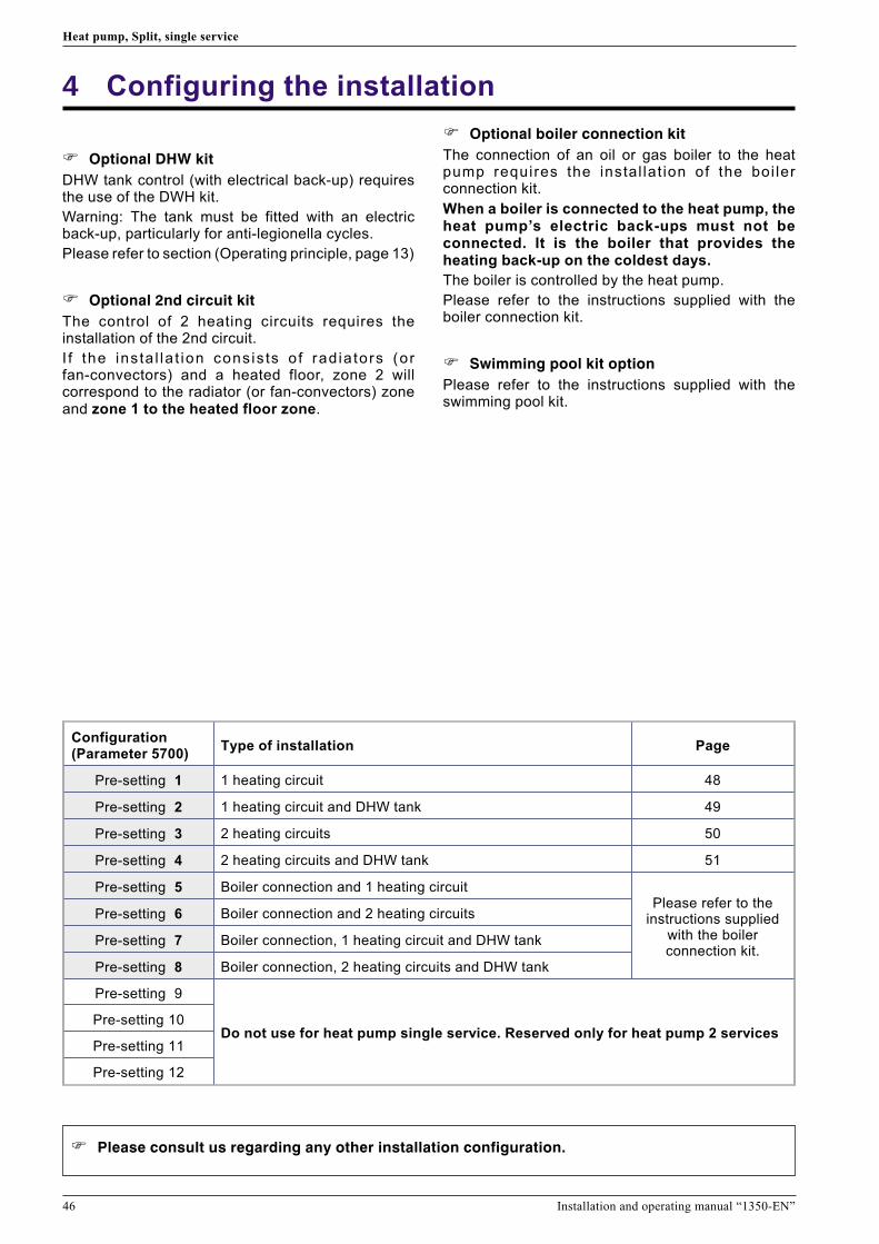
46 Installation and operating manual “1350-EN”
Heat pump, Split, single service
4 Configuring the installation
� Optional DHW kit
DHW tank control (with electrical back-up) requiresthe use of the DWH kit.
Warning: The tank must be fitted with an electricback-up, particularly for anti-legionella cycles.
Please refer to section (Operating principle, page 13)
� Optional 2nd circuit kit
The control of 2 heating circuits requires theinstallation of the 2nd circuit.
I f the ins ta l la t ion cons is ts of rad ia tors (orfan-convectors) and a heated floor, zone 2 willcorrespond to the radiator (or fan-convectors) zoneand zone 1 to the heated floor zone.
� Optional boiler connection kit
The connection of an oil or gas boiler to the heatpump requires the instal lat ion of the boi lerconnection kit.
When a boiler is connected to the heat pump, theheat pump’s electric back-ups must not beconnected. It is the boiler that provides theheating back-up on the coldest days.
The boiler is controlled by the heat pump.
Please refer to the instructions supplied with theboiler connection kit.
� Swimming pool kit option
Please refer to the instructions supplied with theswimming pool kit.
Configuration(Parameter 5700)
Type of installation Page
Pre-setting 1 1 heating circuit 48
Pre-setting 2 1 heating circuit and DHW tank 49
Pre-setting 3 2 heating circuits 50
Pre-setting 4 2 heating circuits and DHW tank 51
Pre-setting 5 Boiler connection and 1 heating circuitPlease refer to the
instructions suppliedwith the boilerconnection kit.
Pre-setting 6 Boiler connection and 2 heating circuits
Pre-setting 7 Boiler connection, 1 heating circuit and DHW tank
Pre-setting 8 Boiler connection, 2 heating circuits and DHW tank
Pre-setting 9
Do not use for heat pump single service. Reserved only for heat pump 2 servicesPre-setting 10
Pre-setting 11
Pre-setting 12
� Please consult us regarding any other installation configuration.

Installation and operating manual “1350-EN” 47
Heat pump, Split, single service
4.1 Configuration 1, 2, 3 or 4:heat pumps with electric back-ups
DHW tank control (with electrical back-up) requiresthe use of the DWH kit.
The control of 2 heating circuits requires theinstallation of the 2nd circuit.
4.1.1 Hydraulic connections
� In the case of a mixed DHW tank
Install the directional valve on the heating circuit (oncircuit 2 if it exists).
� In the case of 2 heating circuits
With the 2nd circuit kit, the hydraulic module’scirculation pump (CC1) must be moved and installedin a box of the 2nd circuit kit (CC1).
4.1.2 Electrical connections
• 1 - Power supply to outside unitPlease refer to section (Electrical connections onthe outside unit side page 26).
• 2 - Interconnection between the outside unit and thehydraulic module (See fig. 37, p. 28).
• 3 - Power supply to the electrical back-ups:
- Connect the electrical supply for the back-ups(terminals 9, 10 and 11) to the electrical panel. (seefig. 37, p. 28).
• 4 - Outdoor sensor (see fig. 37, p. 28).
• 5 - Air thermostat and/or remote control (Option,See fig. 38, p. 29).
• 6 - Contract with the power provider:
- Connect the “Power Provider” contact to input EX5or EX4. (see fig. 38, p. 29)
� In the case of a mixed DHW tank
Please refer to the instructions supplied with theDWH kit.
• 7 - Connect the directional valve to connector QX4,(See fig. 38, p. 29).
• 8 - Connect the domestic water sensor to terminalBX1 on the heat pump’s control panel (see fig. 38,p. 29).
• 9 - Connect the back-up resistance to terminal 19(Earth) and relay RP DHW to terminals 2 (L) and 4(N). (see fig. 37, p. 28)
• 10 - Connect the electrical power supply for thedomestic water back-up (terminals 17, 18 and 19) tothe electric panel. (see fig. 37, p. 28)
� In the case of 2 heating circuits
Please refer to the instructions supplied with thesecond circuit kit.
11 - Circulation pump
12 - Circulation pump
13 - Mixer valve
14 - Initial sensor
() - Interconnection between RVS and AVS
� In the case of a heated floor
Heated floor thermal safety fuse
• 20 - Thermal safety will stop the heat pump if thetemperature in the floor is too high.
4.1.3 Parametering the setting
• Adjust the configuration: 1, 2, 3 or 4, Line 5700.
• Adjust the DHW programme (Line 1610 to 1661)
• 1 heating circuitAdjust the heating curve slope.Line 720
• 2 heating circuitsAdjust the heating curve slope.Line 720 (Circuit 1)Line 1020 (Circuit 2)
4.1.4 Special cases
Please consult us regarding any other installationconfiguration
� Parameter 5700
Configuration 1 : 1 heating circuit (See Figure page 48)
Configuration 2 : 1 heating circuit and DHW tank. (See Figure page 49)
Configuration 3 : 2 heating circuits (See Figure page 50)
Configuration 4 : 2 heating circuits and DHW tank. (See Figure page 51)

48 Installation and operating manual “1350-EN”
Heat pump, Split, single service
CC
SA
SE
R
SP
CC
SA
SE
R
SP
1
2
3
6 5
4
20
Legend
CC - Heating circulation pump
R - Radiators (or fan convectors)
SA - Room thermostat (option)
SE - Outdoor sensor
SP - Heated floor thermal safety fuse
Configuration 1 :1 heating circuit.
� See detailed instructionson Page 47
Overview of all the electrical connections
Overall hydraulic layout

Installation and operating manual “1350-EN” 49
Heat pump, Split, single service
M
CC
VD
SA
KS SSaSE
AE
RR
SP
CAR
M
CC
VD
SA
KS SSaSE
AE
RR
SP
1
2
3
4
5
7
8
9
10
6
20
Legend
CAR - Non-return valve
AE - Electric back-up
CC - Heating circulation pump
KS - DHW kit
R - Radiators (or fan convectors)
SA - Room thermostat (option)
SE - Outdoor sensor
SP - Heated floor thermal safety
fuse
SSa - DWH sensor
VD - Distribution valve
Configuration 2 :1 heating circuit and DHW tank.
Overview of all the electrical connections
Overall hydraulic layout
� See detailed instructionson Page 47

50 Installation and operating manual “1350-EN”
Heat pump, Split, single service
Configuration 3 :2 heating circuits
Circuit 2
Circuit 1
CC2
M
VM1
CC1
SA2
SA1
K2c
SDp1
SE
R
SPCAR
CAR
Circuit 2
Circuit 1
CC2
M
VM1
CC1
SA2
SA1
K2c
SDp1
SE
R
SP
1
2
3
4
5
11
1213
14
56
AVS 20
Legend
CAR - Non-return valve
CC1 - Heating circulation pump, Circuit 1 (Remote heat
pump circulation pump)
CC2 - Heating circulation pump, Circuit 2
K2c - 2nd circuit kit
R - Radiators (or fan convectors)
SA1 - Room thermostat, Circuit 1 (option)
SA2 - Room thermostat, Circuit 2 (option)
SE - Outdoor sensor
SDp1 - Flow sensor, Circuit 1
SP - Heated floor thermal safety fuse
VM1 - Mixer valve, Circuit 1
Overview of all the electrical connections
Overall hydraulic layout
� See detailed instructionson Page 47

Installation and operating manual “1350-EN” 51
Heat pump, Split, single service
Circuit 2
Circuit 1
M
CC2
VD
M
VM1
CC1
SA2
SA1
K2c
SDp1
KS
SSaSE
AE
R
SP
R
CAR
CAR
Circuit 2
Circuit 1
M
CC2
VD
M
VM1
CC1
SA2
SA1
K2c
SDp1
KS
SSaSE
AE
R
SP
R
1
2
3
4
5
7
8
9
10
6
11
1213
14
5
AVS 20
Legend
AE - Electric back-up
CAR - Non-return valve
CC1 - Heating circulation pump,
Circuit 1 (Remote heat pump
circulation pump)
CC2 - Heating circulation pump,
Circuit 2
KS - DHW kit
K2c - 2nd circuit kit
R - Radiators (or fan convectors)
SA1 - Room thermostat, Circuit 1
(option)
SA2 - Room thermostat, Circuit 2
(option)
SE - Outdoor sensor
SDp1 - Flow sensor, Circuit 1
SSa - DWH sensor
SP - Heated floor thermal safety
fuse
VD - Distribution valve
VM1 - Mixer valve, Circuit
Configuration 42 heating circuits and DHW tank.
Overview of all the electrical connections
Overall hydraulic layout
� See detailed instructionson Page 47

52 Installation and operating manual “1350-EN”
Heat pump, Split, single service
5 Electrical wiring diagrams
Gre
en
123456
123456
123456
123456
123
123
123
123
12
12
12
12
1234
1234
1212
123
123
CN71
CN73
CN72
CN70
W4
W2
W1
W3
W11
W10
CN40
CN801
W7W8W9
CN30 4WV
PMV
F M
S (S)
C (T)
R (R)
C M
2( N )
1 3 L N
15A 250V
3.15A250V
Black
Red
White
Yellow
Blue
Red
White
Black
Red
Brown
Blue
Orange
Yellow
White
Black
Black
Black
Black
Black
Black
Black
White
White
Red
Brown
Brown
Brown
Brown
Black
Black
White
Red
Yello
w
Yello
w
Bla
ck
Bla
ck
Bla
ck
Red
White
Black
4-way valve
Ventilator
Electronic
expansion
valve
Compressor
Reactance
Evaporator
outlet
Discharge
Compressor
Outside
Fuse
250V 5A
Terminal
block
Interconnection
between the outside unit
and the hydraulic module
Electricity supply
Fuse 250V 20A
Regulation board
Fuse
Fuse
Tem
pera
ture
sensors
Evaporator
centre
Figure 45 - Electrical wiring of outside unit Model 050, 065, 080

Installation and operating manual “1350-EN” 53
Heat pump, Split, single service
1098765432110987654321
21
1098765432110987654321
654321
654321
43214321
43214321
321
321
21
2121
76543
21
21
21
654321
7654321
654321
321
321
21
21
21
21
21
21
21
21
21
21
CN700
CN801
CN500
CN110CN1
CN400CN200
CN11
CN60
CN61
CN62
CN64
CN90
CN40CN42
CN303 CN301W306
W307
W302
W301
W17
W16
TM102TM101
W303W
W304V W305
U
W8
W7
W13
W12
L2 L1+
P
N1
N2
L0
TM600TM601
W4
RC
S
CN100
1 2
W29W28W25W26
W21 W20W9 W17
W3
W18W2W1
W19
1 2 3 L N
F M
PMV
4WV
C M
Klemmenstrook
ACTPM
I P M PCB
RedRed
BrownBrown
BlueBlue
BlackBlack
BrownBrown
Black
Black
WhiteYellowOrangeBlueBrownRed
Red
Red
Black
GreenBlackWhiteWhite
Black
Purple
White
Yellow Yellow
Blue Blue
Black
Red
Brown
Orange
Black Black
White White
Red Red
Orange
Orange
Bla
ck
Whi
te
Bro
wn
Red
Bro
wn
Red
Ora
nge
Yel
low
Gre
enB
lue
Pur
ple
Gre
yB
lack
Whi
te
Bro
wn
Red
Ora
nge
Yel
low
Bla
ck
Bla
ck
Whi
te
Gre
y
Whi
teW
hiteWhi
te
Whi
te
Terminal block
Fuse 250V 25A
HP pressure switch
Coil
Posistor
Compressor
Terminal block
Capacitor PCB
Power card
Regulation board
Evaporator centre
Discharge
Compressor
Outside
Tem
pera
ture
sensors
4-way valve
Electronic
expansion valve
Electricity supply
Interconnection
between the outside unit
and the hydraulic module
BrownYellowWhiteBlack Ventilator
Figure 46 - Electrical wiring of outside unit Model 095

54 Installation and operating manual “1350-EN”
Heat pump, Split, single service
R(R)
S(S)
C(T)
Temperature sensors
Discharge Compressor
Outside
Compressor
Terminal block
Coil
Red
White
Black
White
Red
Black
Module
filtre
actif
BrownRed
Orange
Yellow
Yellow
Blue
Posistor
Orange
Orange
Red
Black
White
Black
White
Brown
Bla
ck
Fu
se
25
A
Wh
ite
Bla
ck
Gre
en
Terminal block
Re
d
Wh
ite
Electrical cabling
Bla
ck
Re
d
Wh
ite
Bla
ck
Bro
wn
HP pressure switch
4-way valve
Electronic
expansion
valve
Fuse
Fuse
Ventilator 1
Ventilator 2
Red
Red
Black
Black
Red
WhiteYellow
Brown
Red
Brown
BlueOrange
YellowWhite
Black
Red
WhiteYellow
Brown
Black
Black
Black Black
Brown Brown
Blue
Filter
Evaporator outlet
Evaporator centre Compressor casing
Interconnection
between the outside unit
and the hydraulic module
Regulation board
Fu
se
10
A
Figure 47 - Electrical wiring of outside unit Model 128

Installation and operating manual “1350-EN” 55
Heat pump, Split, single service
Temperature sensors
Dis
charg
e
Evapora
tor
Com
pre
ssor
Outs
ide
Compressor
Regulation board
Terminal block
Coil
Posistor
Terminal block
Electricity
supply
HP pressure switch
4-way valve
Electronic
expansion
valve
Fuse
Ventilator 1
Ventilator 2
Bla
ck
Bro
wn
Bro
wn
Blu
e
Bla
ck
Active
filter
unit
White
Brown
Filter EMI
Filter EMIConnector
Yellow
Blue
OrangeRed
Red
Brown
Yellow
Diode bridgeRelay
Red
White
Red
White
Bla
ck
Gre
y
Gre
y
Bla
ck
Red
Filter EMI FilterFilter EMI
Red
Red
Black
Yellow
Brown
White
Orange
Blue
Black
Red
Black
Yellow
Brown
White
Black
Yellow
Brown
White
Red
White
Black
White
Bla
ck
White
Bla
ck
Gre
en
White
Bla
ck
Bla
ck
Red
Bro
wn
Com
pre
ssor
casin
g
Interconnection
between the outside unit
and the hydraulic module
Filter EMI
White
Violet
Terminal block
BlackBlack
Ora
nge
Ora
nge
Filter EMI
Fuse
10
A
Red
Figure 48 - Electrical wiring of outside unit Model 155

56 Installation and operating manual “1350-EN”
Heat pump, Split, single service
CN9
CN1
CN2
CN4
CN5
CN14
CN15
CN7
CN8
CN103
CN106
CN114
CN105
CN113CN116
CN104
MBX5MBX4MDO2MDO1
QX7QX6QX5
QX3
N
N
L
UrefUX
H3MH1
A1 A2
B1 B2
A1 A2
B1 B2
2a 2b
1a 1b
1 2 3 4 5 6 7 8 9 10 11 121314151617 1819
RpECS Rp1 Rp2
X50ouX30
Condensationsensor
Return sensor
Flow sensor
Heating circulation pump
Resistance 2of the back-up unit
Resistance 1of the back-up unit
Safety thermostat
Start/stopswitch
Timed fuse3,15 A - 250V
Figure 49 - Electrical wiring, Hydraulic module (Except installer's connections)
Connection to terminal block andpower relays (see figure 37, page 28)
Connections to the heat pumpregula tor (accessor ies andoptions) (see figure 38, page 29)
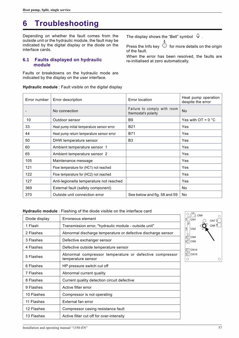
6 Troubleshooting
Depending on whether the fault comes from theoutside unit or the hydraulic module, the fault may beindicated by the digital display or the diode on theinterface cards.
6.1 Faults displayed on hydraulicmodule
Faults or breakdowns on the hydraulic mode areindicated by the display on the user interface.
The display shows the “Bell” symbol .
Press the Info key for more details on the originof the fault.
When the error has been resolved, the faults arere-initialised at zero automatically.
Installation and operating manual “1350-EN” 57
Heat pump, Split, single service
Hydraulic module : Fault visible on the digital display
Error number Error description Error locationHeat pump operationdespite the error
- No connectionFai lure to comply wi th roomthermostat's polarity
No
10 Outdoor sensor B9 Yes with OT = 0 °C
33 Heat pump initial temperature sensor error B21 Yes
44 Heat pump return temperature sensor error B71 Yes
50 DHW temperature sensor B3 Yes
60 Ambient temperature sensor 1 Yes
65 Ambient temperature sensor 2 Yes
105 Maintenance message Yes
121 Flow temperature for (HC1) not reached Yes
122 Flow temperature for (HC2) not reached Yes
127 Anti-legionella temperature not reached Yes
369 External fault (safety component) No
370 Outside unit connection error See below and fig. 58 and 59 No
Hydraulic module : Flashing of the diode visible on the interface card
Diode display Erroneous element
1 Flash Transmission error, "hydraulic module - outside unit"
2 Flashes Abnormal discharge temperature or defective discharge sensor
3 Flashes Defective exchanger sensor
4 Flashes Defective outside temperature sensor
5 FlashesAbnormal compressor temperature or defective compressortemperature sensor
6 Flashes HP pressure switch cut off
7 Flashes Abnormal current quality
8 Flashes Current quality detection circuit defective
9 Flashes Active filter error
10 Flashes Compressor is not operating
11 Flashes External fan error
12 Flashes Compressor casing resistance fault
13 Flashes Active filter cut off for over-intensity
CN9
CN1
CN2
CN4
CN5
CN14
CN15
CN7
CN8

58 Installation and operating manual “1350-EN”
Heat pump, Split, single service
Outside unit, Reference AOYA18LALL (Model 050 and 065) and Reference AOYA24LALL (Model 080)
Diode display Erroneous element
0,1 seconds lit and 0,1 seconds unlit Defective temperature sensor (see hydraulic module)
0,5 seconds lit and 0,5 seconds unlit Abnormal intensity detector error
2 seconds lit and 2 seconds unlit Electric current circuit breaker error
5 seconds lit and 5 seconds unlit Defective fan motor
0,1 seconds lit and 2 seconds unlit Position of the compressor’s rotor not detected
5 seconds lit and 0,1 seconds unlit Abnormal PAM circuit voltage
1 seconds lit and 0,1 seconds unlit Timer cut off
2 seconds lit and 5 seconds unlit Abnormal compressor temperature
5 seconds lit and 2 seconds unlit Active filter error
Permanently lit Abnormal discharge temperature
Outside unit, Reference AOYA30LBTL (Model 095)
Diode display Erroneous element
0,1 seconds lit and 0,1 seconds unlit Defective temperature sensor (see hydraulic module)
0,5 seconds lit and 0,5 seconds unlit Defective IPM card
2 seconds lit and 2 seconds unlit Communication serial bus error (terminals 3 outside unit & hydraulic module)
5 seconds lit and 5 seconds unlit Defective fan motor
0,1 seconds lit and 2 seconds unlit Position of the compressor’s rotor not detected
5 seconds lit and 0,1 seconds unlit Defective ACTPM card
Permanently lit Abnormal discharge temperature
6.2 Faults displayed on the outside unit
To access the electronic board, you must remove the front (right-hand) facing from the outside unit.
Faults are coded by diode flashes.

6.3 Information display
Various data can be displayed by pressing the infobutton.
Depending on the type of unit, configuration andoperating state, some of the info lines listed belowmay not appear.
- Possible error messages from the error code list(See table, page 57).
- Possible service messages from the maintenancecode list.
- Possible special mode messages.
- Various data (See below).
Designation Line
Floor drying current setpoint -
Current drying day -
Terminated drying days -
Room temperature 8721
State heat pump 8006
State supplementary source 8022
State DHW 8003
State swimming pool 8011
State heating circuit 1 8000
State cooling circuit 1 8001
State heating circuit 2 8004
Outside temperature 8700
Room setpoint 1 8740
Flow temperature 18743
Flow temperature setpoint1
Room setpoint 2 8771
Flow temperature 28773
Flow temperature setpoint 2
DHW (domestic hot water) temperature 8830
Heat pump return temperature8410
Setpoint (flow) HP
Heat pump flow temperature8412
Setpoint (flow) HP
Swimming pool temperature8900
Swimming pool temperature setpoint
Installation and operating manual “1350-EN” 59
Heat pump, Split, single service
Outside unit,Reference AOYA45LATL, AOYA45LBTL (Model 128) and Reference AOY54LJBYL (Model 155)
Diode display Erroneous element
1 Flash Transmission error, "hydraulic module - outside unit"
2 Flashes Defective “discharge” temperature sensor
3 Flashes Defective “evaporator” temperature sensor
4 Flashes Defective “outside” temperature sensor
5 Flashes (Model 128) Defective “evaporator centre” temperature sensor
6 Flashes (Model 128) Abnormal discharge temperature
7 Flashes Defective compressor temperature sensor
8 Flashes Defective “compressor casing” temperature sensor
9 Flashes Defective HP pressure switch
10 Flashes (Model 128) Abnormal compressor temperature
12 Flashes Defective IPM card
13 Flashes Position of the compressor’s rotor not detected
14 Flashes Compressor is not operating
15 Flashes Defective upper fan motor
16 Flashes Defective lower fan motor
5 seconds lit and 1 seconds unlit Switched to safety mode
1 seconds lit and 1 seconds unlit (Model 128) Switched to vacuum
Permanently lit No error

7 Instructions for the user
Explain to the user how his installation operates, inparticular the functions of the room thermostat andthe programmes accessible to him from the userinterface.
Emphasise that a heated floor has significant inertiaand that therefore any adjustments must be madeprogressively
Also explain to the user how to check the filling of theheating circuit
60 Installation and operating manual “1350-EN”
Heat pump, Split, single service
Complies with :
- Low tension Directive 73/23/CEE, under standard NF-EN60335-1.
- Electromagnetic compatibility Diretive 89/336/CEE
- Directive 98/37/EC,
- Directive for pressurised equipment 97/23/EC,
- Directive for labelling energy consumption 2002/31/EC
This appliance also conforms to:- Decree No. 92-1271 (and its modifications) relating to certain refrigeration fluids used in refrigerating andair conditioning equipment.
- The standards relating to the product and the testing methods used:
Air-conditioners, refrigeration units and heat pumps with compressor driven by electric motor for heating and
refrigeration EN 14511-1, 14511-2, 14511-3, and 14511-4
- To standard XP ENV 12102: Air-conditioners, heat pumps and dehumidifiers with compressor driven by electric
motor. Measurement of airborne noise. Determination of acoustic power level.
Related Documents