Formation of sub-nanosecond UWB impulse using sharp edge generator and planar antenna M. Greitans, E. Hermanis, G.Supols Institute of Electronics and Computer Science, Dzerbenes 14, Riga, LV1006, Latvia, e-mail: [email protected] Electronics 2010, May 18-20, KTU, VGTU Lithuania

Welcome message from author
This document is posted to help you gain knowledge. Please leave a comment to let me know what you think about it! Share it to your friends and learn new things together.
Transcript

Formation of sub-nanosecond UWB impulse using sharp edge generator and planar antenna
M. Greitans, E. Hermanis, G.SupolsInstitute of Electronics and Computer Science,
Dzerbenes 14, Riga, LV1006, Latvia,e-mail: [email protected]
Electronics 2010, May 18-20, KTU, VGTU Lithuania

2
Outline• Introduction• Motivation and goals• UWB pulse generation• UWB antennas• Experimental setup and results• Conclusions

3
What is UWB?
Fractional bandwidth (measured at the -10dB (fh -fl )/fc , > 20% or total BW > 500 MHz.
FCC/ITU-R Definition UWB

4
UWB types:• Direct sequence (DS) UWB:
using the whole available spectrum▫ transmitting very short
pulses (impulse radio)• Multiband: dividing the
available spectrum into several bands, each having a minimum of 500 MHz of bandwidth.
5
Pulse based UWB. Why?• Advantages
▫ Mixed localisaton and data transfer possibility▫ Simple transmitter side design▫ Noise-like spectrum
• Applications▫ Wireless comunication systems▫ Road information systems (Car <-> Road signs)▫ Non-contact medical examination▫ Localisation, positioning

6
Motivation and goals• To gain experience/knowledge in design of
wideband/microwave systems• UWB impulse generation, antenna,
localization and data transfer experiments• Practical goals:
Universal UWB antenna test systemGround penetrating radar (GPR)Through wall imaging device (TWI)

7
Different aproaches
A)
B)

8
Different aproaches
A)
B)

9
UWB pulse generation
Antenna is a part of UWB pulse generator!
Principle Test system
UWB impulse is formed as an antenna step response
ObjectImpact Response

10
A fast rise time differential pulse generator in combination with a Bow-Tie type antenna on a lossy dielectric
UWB pulse generation
A Step Recovery Diode (SRD) is used as a differential pulse sharpener

11
Typically used antennas

12
UWB antenna requirements• Small size (for embeded
devices)• Effective energy transfer• Linear phase delay• Wide frequency range
impedance matching• Short step response (radar
applications)• Non-resonant (multi resonant)• 0 < Q factor < 1
13
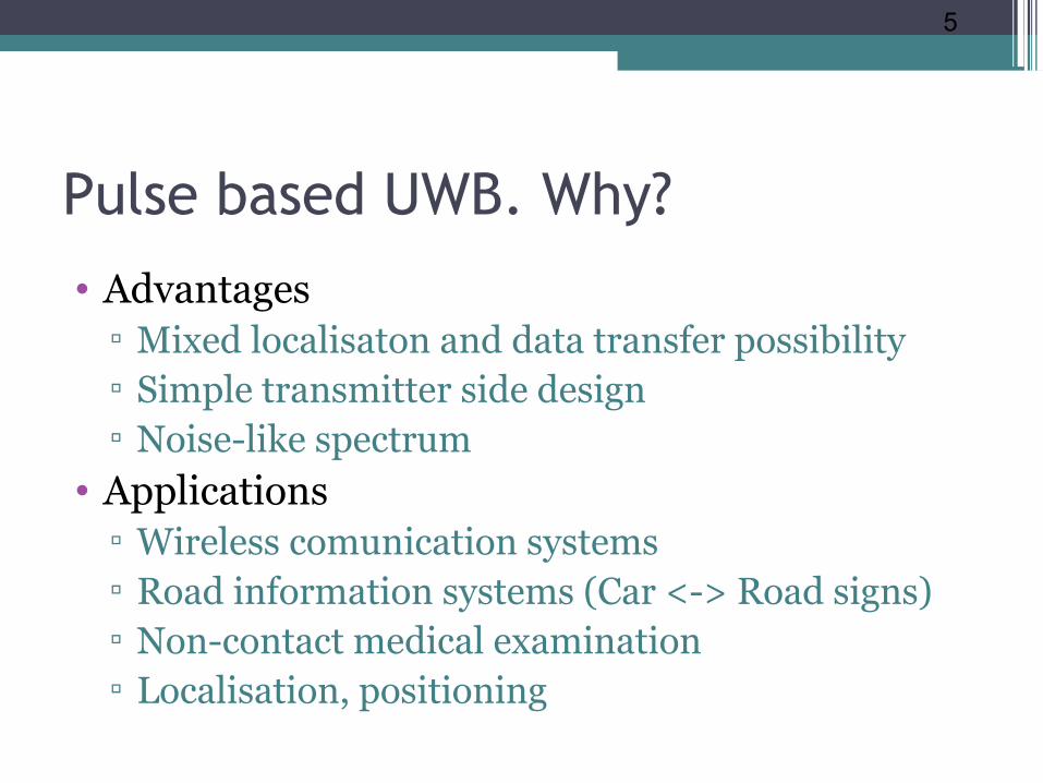
Antenna couple used for experiments
• A Bow-Tie type antena is used
• Antenna is made on a lossy dielectric material

14
Experimental setup

15
Real-world look

16
Receivers side
Stroboscopic converter

17
Transmitters side
Differential microstrip line with SRD at the end
18
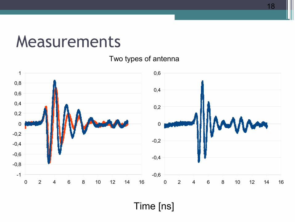
Measurements
0 2 4 6 8 10 12 14 16-1
-0,8
-0,6
-0,4
-0,2
0
0,2
0,4
0,6
0,8
1
Time [ns]
0 2 4 6 8 10 12 14 16-0,6
-0,4
-0,2
0
0,2
0,4
0,6
Two types of antenna

19
Pulse spectrum
0 5 0 0 1 0 0 0 1 5 0 0 2 0 0 0 2 5 0 0 3 0 0 0 3 5 0 0 4 0 0 0 4 5 0 01 0 - 2
1 0 - 1
1 0 0
frequency (MHZ)
rela
tive
ampl
itude
Impulse spectrum

20
Conclusions• Experimental setup is developed for further
research• Obtained first results confirms the correctness of
the approach• Some experience in high frequency design is
gained
21
Questions?
Research is supported by ESF grant:
2009/0219/1DP/1.1.1.2.0/APIA/VIAA/020R&D Center for Smart Sensors and Networked Embedded Systems
Related Documents