FOR FHVVA ENGINEERS I US Department of Transportation Federal Highway Administration Publication No. FHWA-PD-96-037 Office of Engineering Pavement Division October 1996

Welcome message from author
This document is posted to help you gain knowledge. Please leave a comment to let me know what you think about it! Share it to your friends and learn new things together.
Transcript
FOR FHVVA ENGINEERS
I US Department of Transportation
Federal Highway Administration
Publication No. FHWA-PD-96-037
Office of Engineering Pavement Division
October 1996

Pavement Notebook for FHWA Engineers
Chief, Pavement Division HNG-40
Regional Administrators Federal Lands Highway Program Administrator Division Administrators
Attached are copies of, the 2nd revision to the Pavement Notebook for FHWA Engineers. This notebook serves as a compilation of FHWA policy and guidance on pavement issues. Formal updates and revisions are coordinated through the Pavement Division. The notebook provides space in Chapter 11 for pavement related comments.
Request for additional copies should be addressed to:
Federal Highway Administration Pavement Division - Attn: Mr. Peter J. Serrano, P.E. Pavement Design and Rehabilitation Branch (HNG-42) 400 Seventh Street, S.W. Washington, D.C. 20590
Attachments

INSTRUCTIONS FOR REVISION NO. 2
Table of Contents
1. Remove old introductory information and replace with new introductory information (3 pages).
2. Remove old Table of Contents and replace with new Table of Contents.
Chapter 1 Pavement Policy
1. Remove old Chapter 1 title page and replace with new Chapter 1 title page*
2. Remove Section 1.1 (Pavement Policy - Mr. R.D. Morgan, January 13, 1989) and replace with new Section 1.1 (Pavement Design and Management Requirements, Pavement Management System, 23 CFR 500, Subpart B, April 22,1994; Non-Regulatory Supplement, General Pavement Design Considerations, October 5, 1995).
3. Remove Section 1.2 (FEPM 6-2-4-1, Pavement Management and Design Policy, March 6,1989) and replace with new Section 1.2 (ISTEA Pavement Management Systems.
4. Add new Section 1.3 (Cost Comparison of Asphalt vs. Concrete Pavement, OIG Final Report, July 26,1994).
5. Add new Section 1.4 (Proposed Final Interstate Maintance Fund Transfer Policy, September 21, 1994). l Transfer of Interstate Maintance Program Funds, Proposed Final
Policy Statement, Federal Register, September 02, 1994). l Transfer of Interstate Maintance Program Funds, Interim Policy
Statement, Federal Register, March 03,1993).
Chapter 2 Pavement Issues
1. Remove old Chapter 2 title page and replace with new Chapter 2 title page.
INSTRUCTIONS FOR REVISION NO. 2
Chapter 2 Pavement Issues
2. Remove Section 2.10 (Life Cycle Cost, M new Section 2.10 (Life Cycle Cost Analysi Interim Policy Statement, July 11, 1994).
3. Add to Section 2.13 (Preventive Maintena Information on Interstate Maintenance P
4. Add new Section 2.14 (Computer Softwar July 1995).
Chapter 3 Rigid Pavement
1. Remove old Chapter 3 title page and repl; Pals*
2. Add to Section 3.5 (Dowel Bar Inserters,
3. Add new Section 3.10 (TA 5080.17, Port Design and Field Control, July 14, 1994).
Chapter 4 Flexible Pavement
1. Remove old Chapter 4 title page and replace page-
2. Add new Section 4.8, Aggregate Gradatic Particle Size Distribution Curve, 1962. 0 Aggregate Gradation: Simplification,
Uniform Appllication l A New Graphical Chart for Evaluating
Chapter 5 Pavement Drainage
1. Remove old Chapter 5 title page and repl page-

INSTRUCTIONS FOR REVISION NO. 2
Chapter 5 Pavement Drainage
2. Add new Section 5.6 (Western States Pavement Subdrainage Conference, August 10, 1994).
3. Add new Section 5.7 (Drainable Pavement Systems, Demonstration Project 87, April 06, 1992).
4. Add new Section 5.8 (Effectiveness of Highway Edgedrains, Concrete Pavement Drainage Rehabilitation, State of Practice Report, Experimental Project No. 12, April 14, 1993).
5. Add new Section 5.9 (Maintenance of Pavement Edgedrain Systems, March 21, 1995).
6. Add new Section 5.10 (Pavement Subsurface Drainage Activities, December 16,1994).
Chapter 7 Pavement Rehabilitation
1. Remove old Chapter 7 title page and replace with new Chapter 7 title page*
2. Add new Section 7.9 (Overview of Surface Rehabilitation Techniques, Report Number FHWA-PD-92-008, April 6,1992).
3. Add new Section 7.10 (State of the Practice Design, Construction, and Performance of Micro-Surfacing, Report Number FHWA-SA-94-051, July 12, 1994).
4. Add new Section 7.11 (Retrofit Load Transfer, Special Project 204, February 10,1994).
5. Add new Section 7.13 (Thin Bonded Overlay and Surface Lamination Pavements and Bridges, ISTEA 6005, July 1, 1994).
HMSTRUCTIQNS FOR VISION NO. 2
Chapter 8 Surface and Other Considerations
1. Remove old Chapter 8 title page and replace with new Chapter 8 title page*
2. Add new Section 8.7 (Measurements, Specifications, and Achievement of Smoothness for Pavement Construction, NCHRP No. 167, 1990).
3. Add new Section 8.8 (A Half Century with the California Profilograph, Report Number FHWA-AZ-SP9102, February 1992).
Chapter 9 Pavement Management
1. Remove old Chapter 9 title page and replace with new Chapter 9 title page-
2. Remove Section 9.1 (Pavement Management System, A National Perspective) and replace with new Section 9.1 (A National Perspective on Pavement Management, July 1994).
3. Add new Section 9.5 (Pavement Management System - Federal Register, December 1,1993).
Chapter 10 Strategic Highway Research Program Product
1. Add new Chapter 10 title page.
2. Add new Section 10.1 (Strategic Highway Research Program Product Implementation Status Report, De cember 1995 (Published Quarterly)
3. Add new Section 10.2 (Strategic Highway Research Program (SHRP), Information Clearinghouse, July 22, 1994).

INTRODUCTION
This notebook is intended to be a working tool that provides a readily available compilation of current FHWA policy and guidance on pavements. Users are encouraged to add material as they see fit.
The notebook is composed of:
(1) Reference to appropriate Federal-aid Highway Program Manual directives;
(2) Other issuances, such as Technical Advisories and Notices which present short-term instructions or interim policy;
(3) FHWA memorandums clarifying policy or providing technical guidance;
(4) Discussions reflecting current state-of-the-art or philosophy;
(5) Material on developmental and research areas related to pavements.
The material is arranged by subject into chapters and sections. The Table of Contents shows current date for each document.
Any comments, suggested additions, or revisions to the notebook should be directed to the Federal Highway Administration, Attn: Mr. Peter J. Serrano, Pavement Division, HNG-46, 400 Seventh St., S.W., Washington, D.C.; Telephone number 202.366.1341 or email at Peter. J. [email protected].

Enclosed is the second revision to the Pavement Notebook For f/-WA Engineers. Please make the changes contained in the attachment. Submit the attached form on the following page so that we can include your name and address on our mailing list. For further information or additional copies of the notebook contact Mr. Peter J. Serrano at 202366.1341 or Peter. J. Serrano@fh wa. dot. gov.

Chief, Pavement Division Federal Highway Administration 400 Seventh Street, SW., Room 3118 Washington, D.C. 20590-0001
Refer to: HNG-40
Attn: Mr. Peter J. Serrano, P.E.
Dear Sir:
I have received a copy of the Pavement Notebook for FHWA Engineers and would like to be on your distribution list for future updates and/or additions to the notebook.
Request for additional copies should be addressed to:
Federal Highway Administration Pavement Division - Attn: Mr. Peter J. Serrano, P.E. Pavement Design and Rehabilitation Branch (HNG-42) 400 Seventh Street, S.W. Washington, D.C 20590
Please mail or fax the form below.
----------------------- cut here ------------------------
Name:
Title:
Agency: --
Address:
Telephone Number:
Federal Highway Administration - Pavement DLvisFon Attn: Hr. Peter J. Serrano, P.E. (HNG-42); Fax number: 202.366.3713
. . . 1,*

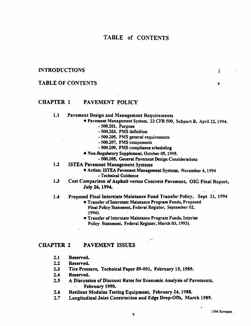
TABLE of CONTENTS
INTRODUCTIONS i
TABLE OF CONTENTS V
CHAPTER 1 PAVJZMENT POLICY
1.1
1.2
1.3
1.4
Pavement Design and Management Requirements l Pavement Management System, 23 CFR 500, Subpart B, April 22,1994.
- 500.201, Purpose - 500.203, PMS definition - 500.205, PMS general requirements - 500.207, PMS components - 500.209, PMS compliance scheduling
@ Non-Regulatory Supplement, October 051995. - 500.205, General Pavement Design Considerations
ISTEA Pavement Management Systems l Action: ISTFA Pavement Management Systems, November 4,1994
- Technical Guidance Cost Comparison of Asphalt versus Concrete Pavement, OIG Final Report,
JuIy 26,1994. - -
Proposed Final Interstate Maintance Fund Transfer Policy, Sept 21,1994 l Transfer of Interstate Maintauce Program Funds, Proposed
Final Policy Statement, Federal Register, September 02, 1994).
o Transfer of Interstate Maintance Program Funds, Interim Policy Statement, Federal Register, March 03,1993).
-.
_. CElAPTER 2 PAVEMENT ISSUES
2.1 2.2 2.3 2.4 2.5
2.6 2.7
Reserved. Reserved. Tire Pressure, Technical Paper 89-001, February 1!5,1989. Reserved. A Discussion of Discount Rates for Economic Analysis of Pavements,
. February 1990. Resilient Modulus Testing Equipment, February 24,198s. Longitudinal Joint Construction and Edge Drop-Offs, March 1989.
, 1996 Revision
V
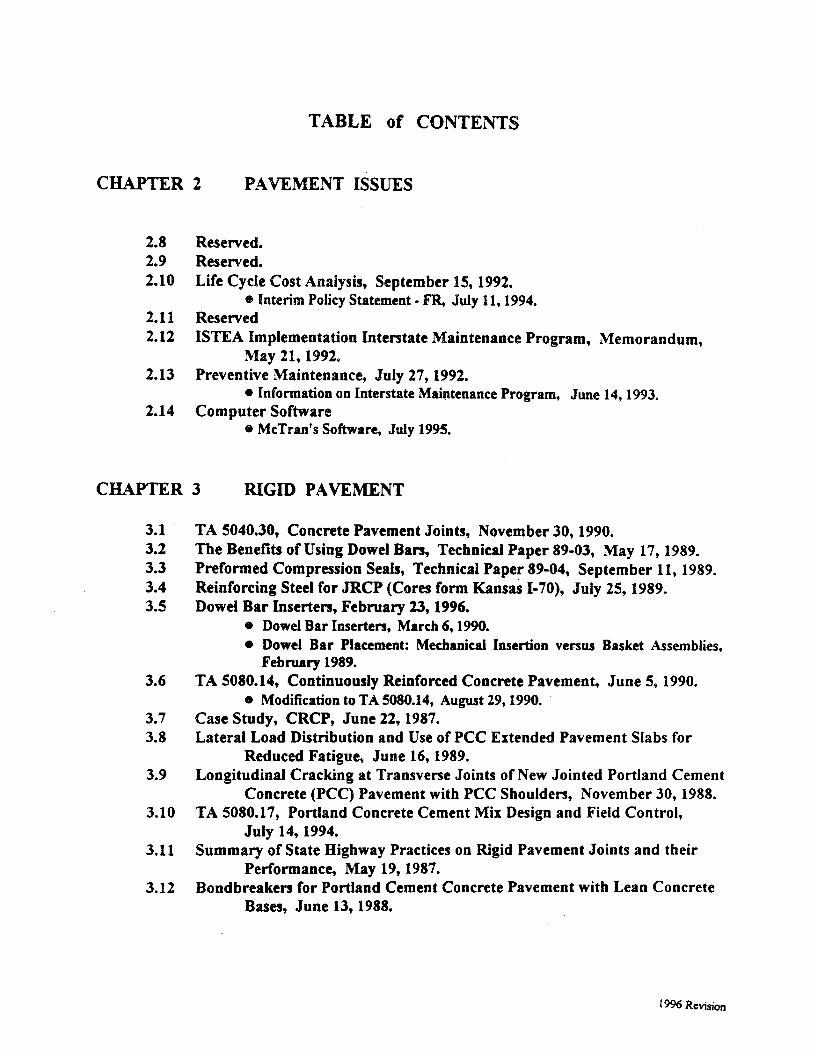
TABLE of CONTENTS
CHAPTER 2 PAVEMENT IhJES
2.8 Reserved. 2.9 Reserved. 2.10 Life Cycie Cost Andysis, September 15, 1992.
@ Interim Policy Statement - ER, July 11.1994. 2.11 Reserved 2.12 ISTEA Implementation Interstate Maintenance Program, Memorandum,
May 21,1992. 2.13 Preventive Maintenance, July 27,1992.
l Information on Interstate Maintenance Program, June 14,1993. 2.14 Computer Software
8 McTran’s Software, July 1995.
CHAPTER 3 RIGID PAVEMENT
3.1 3.2 3.3 3.4 3.5
3.6
3.7 3.8
3.9
3.10
3.11
3.12
TA 5040.30, Concrete Pavement Joints, November 30,199O. The Benefits of Using Dowel Bars, Technical Paper 89-03, May 17,1989. Preformed Compression Seals, Technical Paper 89-04, September 11, 1989. Reinforcing Steel for JRCP (Cores form Kansas I-70), July 25,1989* Dowel Bar Inserters, February 23,1996.
* Dowel Bar Inserters, March 6.1990. l Dowel Bar Placement: Mechanical Insertion versus Basket Assemblies,
February 1989. TA 5080.14, Continuously Reinforced Concrete Pavement, June 5,199O.
o Modification to TA 5080.14, August 29,199O. Case Study, CRCP, June 22,1987. Lateral Load Distribution and Use of PCC Extended Pavement Slabs for
Reduced Fatigue, June 16,1989. Longitudinal Cracking at Transverse Joints of New Jointed Portland Cement
Concrete (PCC) Pavement with PCC Shoulders, November 30,1988. TA 5080.17, Portland Concrete Cement Mix Design and Fieid Control,
July 14,1994. Summary of State Highway Practices on Rigid Pavement Joints and their
Performance, May 19,1987. Bondbreakers for Portland Cement Concrete Pavement with Lean Concrete
Bases, June 13,1988.
19% Revision
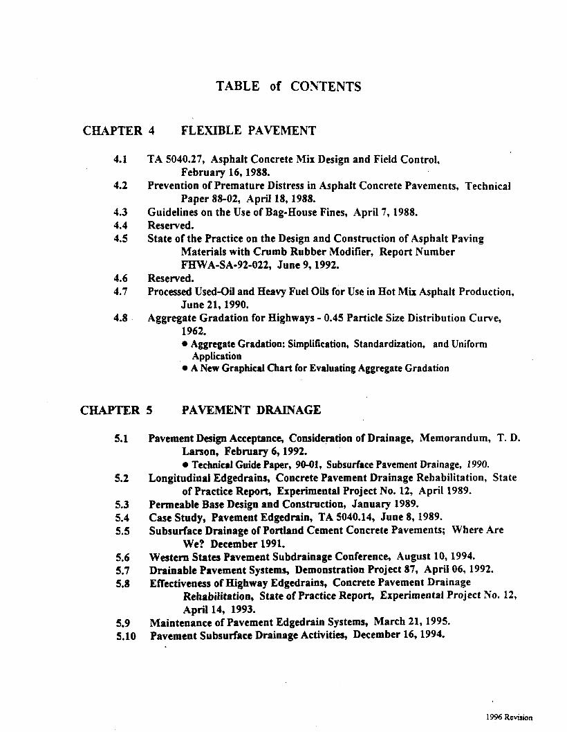
TABLE of CONTENTS
CHAPTER 4 FLEXIBLE PAVEMENT
4.1
4.2
4.3 4.4 4.5
TA 5040.27, Asphalt Concrete Mix Design and Field Control, February l&1988.
Prevention of Premature Distress in Asphalt Concrete Pavements, Technical Paper 88-02, April 18,1988.
Guidelines on the Use of Bag-House Fines, April 7, 1988. Reserved.
4.6 4.7
4.8
State of the Practice on the Design and Construction of Asphalt Paving Materials with Crumb Rubber Modifier, Report Number FHWA-SA-92-022, June 9,1992.
Reserved. Processed Used-Oil and Heavy Fuel Oils for Use in Hot Mix Asphalt Production,
June 21,199O. Aggregate Gradation for Highways - 0.45 Particle Size Distribution Curve,
1962. l Aggregate Gradation: Simplification, Standardization, and Uniform
Application ‘0 A New Graphical Chart for Evaluating Aggregate Gradation
C-R 5 PAVEMENT DRAINAGE
5.1
5.2
5.3 5.4 5.5
Pavement Design Acceptance, Consideration of Drainage, Memorandum, T. D. Larson, February 6,1992. 0 Technical Guide Paper, 90-01, Subsurface Pavement Drainage, 1990.
Longitudinal Edgedrains, Concrete Pavement Drainage Rehabilitation, State of Practice Report, Experimental Project No. 12, April 1989.
Permeable Base Design and Construction, January 1989. Case Study, Pavement Edgedrain, TA 5040.14, June 8, 1989. Subsurface Drainage of Portland Cement Concrete Pavements; Where Are
We? December 1991. 5.6 5.7 5.8
Western States Pavement Subdrainage Conference, August 10,1994. Drainable Pavement Systems, Demonstration Project 87, April 06, 1992. Effectiveness of Highway Edgedrains, Concrete Pavement Drainage
Rehabilitation, State of Practice Report, Experimental Project No. 12, April 14, 1993.
5.9 Maintenance of Pavement Edgedrain Systems, March 21,1995. 5.10 Pavement Subsurface Drainage Activities, December 16,1994.
1996 Revision
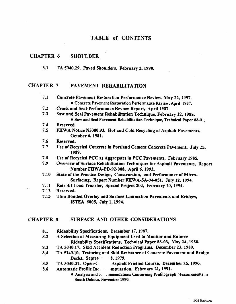
TABLE of CONTENTS
CHAPTER 6 SHOULDER
6*1 TA 5040.29, Paved Shoulders, February 2,199O.
CHAPTER 7 PAVEMENT REHABILITATION
7.1
7.2 7.3
7.4 7.5
7.6 7.7
7.8 7.9
7.10
7.11 7.12 7.13
Concrete Pavement Restoration Performance Review, May 22,1997. 0 Concrete Pavement Restoration Performaace Review, April 1987.
Crack and Seat Performance Review Report, April 1987. Saw and Seal Pavement Rehabilitation Technique, February 22,1988.
* Saw and Seal Pavement Rehabilitation Technique, Technical Paper 88-01. Reserved FHWA Notice NS080.93, Hot and Cold Recycling of Asphalt Pavements,
October 6,P9%1. Reserved. Use of Recycled Concrete in Portland Cement Concrete Pavement, July 25,
1989. Use of Recycled PCC as Aggregates in PCC Pavements, February 1985. Overview of Surface Rehabilitation Techniques for Asphalt Pavements, Report
Number FHWA-PD-92-OOS, April 6,1992. State of the Practice Design, Construction, and Performance of Micro-
Surfacing, Report Number FHWA-SA-94-051, July 12,1994. Retrofit Load Transfer, Special Project 204, February 10,1994, Reserved. Thin Bonded Overiay and Surface Lamination Pavements and Bridges,
ISTEA 6005, July 1,1994.
CHAPTER 8 SURFACE AND OTHER CONSIDERATIONS
8.1 8.2
8.3 8.4
8.5 8.6
Rideability Specifications, December 17,1987. A Selection of Measuring Equipment Used to Monitor and Enforce
RideabiIity Specifications, Technical Paper 88-03, May 24,1988. TA 5040.17, Skid Accident Reduction Programs, December 23,198O. TA 5140.10, Texturing and Skid Resistance of Concrete Pavement and Bridge
Decks, Septer-, .-I 8, 1979. TA 5040.31, Open-C; Asphalt Friction Course, December 26,199O. Automatic Profile Into . Jmputation,. February 21,199l.
@ Analysis and > dmmendations Concerning Profilograph .\leasurements in South Dakota, i\ovember 1990.
1996 Revision
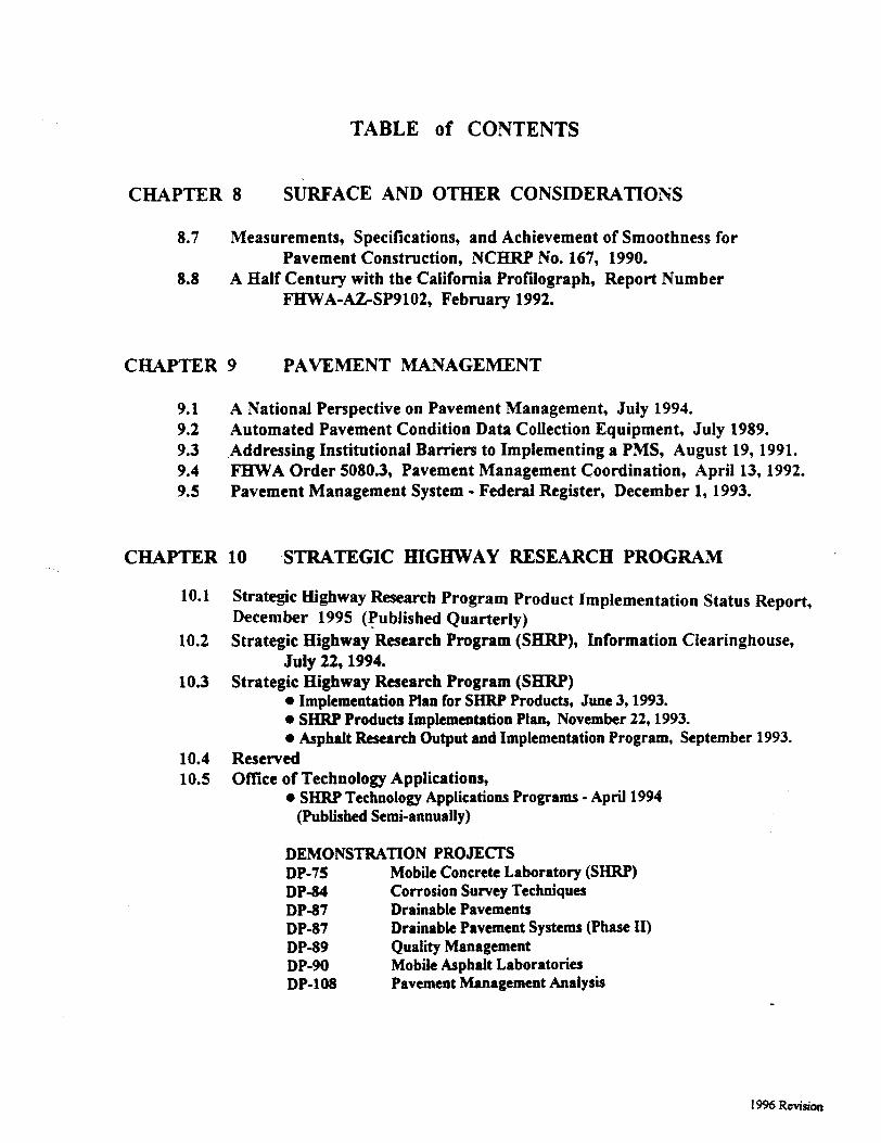
TABLE of CONTENTS
CHAPTER 8 SUItFACE AND OTHER CONSIDERATIONS
8.7
8.8
Measurements, Specifications, and Achievement of Smoothness for Pavement Construction, NCHRP No. 167, 1990.
A Half Century with the California Profilograph, Report Number FHWA-AZSP9102, February 1992.
CHAPTER 9 PAVEMENT MANAGEMENT
9.1 A National Perspective on Pavement Management, July 1994. 9.2 Automated Pavement Condition Data Collection Equipment, July 1989. 9.3 .Addressing Institutional Barriers to Implementing a PMS, August 19, 1991. 9.4 FHWA Order 5080.3, Pavement Management Coordination, April 13,1992. 9.5 Pavement Management System - Federal Register, December 1,1993.
CHAPTER 10 -STRATEGIC H-IGHSVAY RESEARCH PROGRAM
10.1 Strategic Highway Research Program Product Implementation Status Report, December 1995 (Published Quarterly)
10.2 Strategic Highway Research Program (SHRP), Information Clearinghouse, July 22,1994.
10.3 Strategic Highway Research Program (SHRP) l Implementation Plan for SHRP Products, June 3,1993. l SHRP Products Implementation Plan, November 22,1993. l Asphalt Research Output and Implementation Program, September 1993.
10.4 Reserved 10.5 Office of Technology Applications,
l SI-IRP Technology Applications Programs - April 1994 (Published Semi-annually)
DEMONSTRATION PROJECTS DP-75 Mobile Concrete Laboratory (SHRP) DP-84 Corrosion Survey Techniques DP-87 Drainable Pavements DP-87 Drainable Pavement Systems (Phase II) DP-89 Quality Management DP-90 Mobile Asphalt Laboratories DP-1OS Pavement Management Analysis
19% Revision
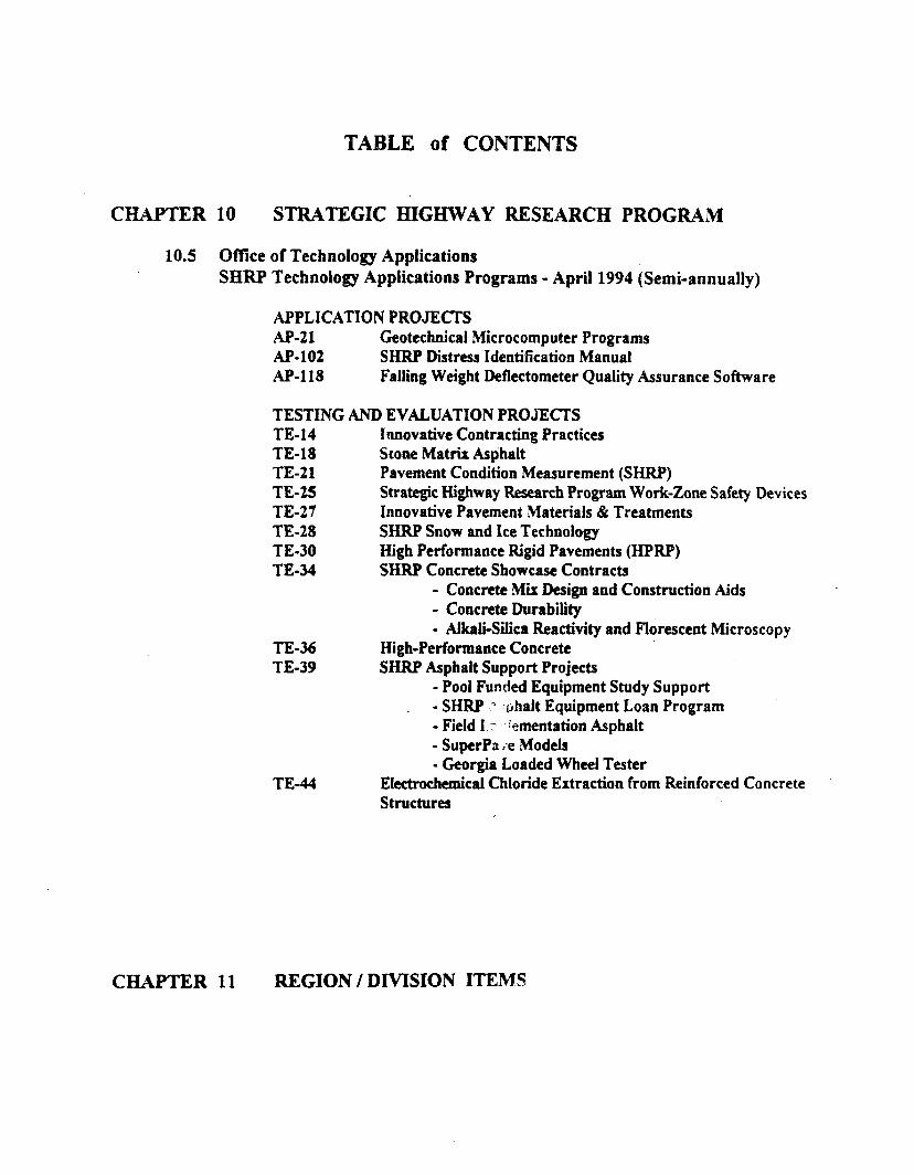
TABLE of CONTENTS
CHAPTER 10 STRATEGIC HIGHWAY RESEARCH PROGRAM
10.5 Offke of Technology Applications SHRP Technology Applications Programs - April 1994 (Semi-annually)
APPLICATION PROJECTS AP-21 Geotechnical Microcomputer Programs AP-102 SHRP Distress Identification Manual AP-118 Failing Weight Deflectometer Quality Assurance Software
TESTING AND EVALUATION PROJECTS TE-14 Innovative Contracting Practices TE-18 Stone Matria Asphalt TE-21 Pavement Condition Measurement (SHRP) TE-2S Strategic Highway Research Program Work-Zone Safety Devices TE-27 Innovative Pavement Materials & Treatments TE-28 SHRP Snow and Ice Technology TE-30 High Performance Rigid Pavements (HPRP) TE-34 SHRP Concrete Showcase Contracts
- Concrete Mix Design and Construction Aids - Concrete Durability
TE-36 TE-39
- Akaii-Silica Reactivity and Florescent Microscopy High-Performance Concrete SHRP Asphalt Support Projects
- Pool Funded Equipment Study Support - SHRP J :rjhait Equipment Loan Program - Field I. :’ .- kmentation Asphalt - SuperPa.+*e Models
TE-44 - Georgia Loaded Wheel Tester
Ektrochemical Chloride Extraction from Reinforced Concrete Structures
CHAPTER 11 REGION / DMSION ITEIW
Chapter 1
Pavement Policy

CHAPTER 1
PAVEMENT POLICY
1.1 Pavement Design and Management Requirements l Pavement Management System, 23 CFR 500, Subpart B, April 22,1994.
- 500.201, Purpose - 500.203, PMS definition - 500.205, PMS general requirements - 500.207, PMS components - 500.209, PMS compliance scheduling
l Non-Regulatory Supplement, October 05, 1995. - 500.205, General Pavement Design Considerations
1.2 ISTEA Pavement Management Systems @ Action: ISTEA Pavement Management Systems, November 4, 1994
- Technical Guidance
1.3 Cost Comparison of Asphalt versus Concrete Pavement, OIG Final Report, July 26, 1994.
1.4 Proposed Final Interstate Maintance Fund Transfer Policy, September 21, 1994). l Transfer of Interstate Maintance Program Funds, Proposed Final Policy
Statement, Federal Register, September 02, 1994). l Transfer of Interstate Maintance Program Funds, Interim Policy
Statement, Federal Register, March 03, 1993).

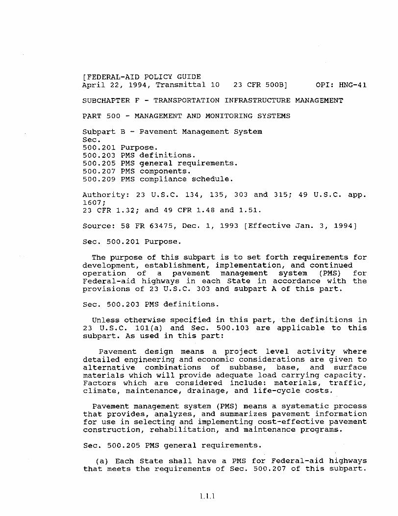
[FEDERAL-AID POLICY GUIDE April 22, 1994, Transmittal 10 23 CFR 500B] OPI: HNG-41
SUBCHAPTER F - TRANSPORTATION INFRASTRUCTURE MANAGEMENT
PART 500 - MANAGEMENT AND MONITORING SYSTEMS
Subpart B - Pavement Management System Sec. 500.201 Purpose. 500.203 PMS definitions. 500.205 PMS general requirements. 500.207 PMS components. 500.209 PMS compliance schedule.
Authority: 23 U.S.C. 134, 135, 303 and 315; 49 U.S.C. app. 1607; 23 CFR 1.32; and 49 CFR 1.48 and 1.51.
Source: 58 FR 63475, Dec. 1, 1993 [Effective Jan. 3, 19941
Sec. 500.201 Purpose.
The purpose of this subpart is to set forth requirements for development, establishment, implementation, and continued operation of a pavement management system (PMS) for Federal-aid highways in each State in accordance with the provisions of 23 U.S.C. 303 and subpart A of this part.
Sec. 500.203 PMS definitions.
Unless otherwise specified in this part, the definitions in 23 U.S.C. 101(a) and Sec. 500.103 are applicable to this subpart. As used in this part:
Pavement design means a project level activity where detailed engineering and economic considerations are given to alternative combinations of subbase, base, and surface materials which will provide adequate load carrying capacity. Factors which are considered include: materials, traffic, climate, maintenance, drainage, and life-cycle costs.
Pavement management system (PMS) means a systematic process that provides, analyzes, and summarizes pavement information for use in selecting and implementing cost-effective pavement construction, rehabilitation, and maintenance programs.
Sec. 500.205 PMS general requirements.
(a) Each State shall have a PMS for Federal-aid highways that meets the requirements of Sec. 500.207 of this subpart.
1.1.1
(b) The State is Federal-aid highways
responsible for assuring that all
federally owned, in the State, except those that are
are covered by a PMS. Coverage of federally owned public roads shall be determined cooperatively by the State, the FHWA, and the agencies that own the roads.
(c) PMSs should be based on the concepts described in the "AASHTO Guidelines for Pavement Management Systems." [AASHTO Guidelines for Pavement Management Systems, July 1990, can be purchased from the American Association of State Highway and Transportation Officials, 444 N. Capitol Street, NW* I suite 225, Washington, DC 20001. Available for inspection as prescribed in 49 CFR part 7, appendix D.]
(d) Pavements shall be designed to accommodate current and predicted traffic needs in a safe, durable, and cost-effective manner.
Sec. 500.207 PMS components.
(a) The PMS for the National Highway System (NHS) shall, as a minimum, consist of the following components:
(1) Data collection and management.
(i) An inventory of physical pavement features including the number of lanes, length, width, surface type, functional classification, and shoulder information.
(ii) A history of project dates and types of construction, reconstruction, rehabilitation, and preventive maintenance.
(iii) Condition surveys that include ride, rutting,
distress, and surface friction.
(iv) Traffic information including volumes, classification, and load data.
(v) A data base that links all data files related to the PMS. The data base shall be the source of pavement related information reported to the FHWA for the HPMS in accordance with the HPMS Field Manual. [Highway Performance Monitoring System (HPMS) Field Manual for the Continuing Analytical and Statistical Data Base, DOT/FHWA, August 30, 1993, (FHWA Order M5600.1B). Available for inspection and copying as prescribed in 49 CFR part 7, appendix D-1
1.1.2
(2) Analyses, at a frequency established by the State consistent with its PMS objectives.
(i) A pavement condition analysis that includes ride, distress, rutting, and surface friction.
(ii) A pavement performance analysis that includes an estimate of present and predicted performance of specific pavement types and an estimate of the remaining service life of all pavements on the network.
(iii) An investment analysis that includes:
(A) A network-level analysis that estimates total costs for present and projected conditions across the network.
(B) A project level analysis that determines investment strategies including a prioritized list of recommended candidate projects with recommended preservation treatments that span single-year and multi-year periods using life-cycle cost analysis.
(C) Appropriate horizons, as determined by the State, for these investment analyses.
(iv) For appropriate sections, an engineering analysis that includes evaluation of design, construction, rehabilitation, materials, mix designs, and preventive maintenance as they relate to the performance of pavements.
(3) Update. The PMS shall be evaluated annually, based on the agency's current policies, engineering criteria, practices, and experience, and updated as necessary.
(b) The PMS for Federal-aid highways that are not on the NHS shall be modeled on the components described in paragraph (a) of this section, but may be tailored to meet State and local needs. These components shall incorporate the use of the international roughness index or the pavement serviceability rating data as specified in Chapter IV of the HPMS Field Manual.
Sec. 500.209 PMS compliance schedule.
(a) By October 1, 1994, the State shall develop a work plan that identifies major activities and responsibilities and includes a schedule that demonstrates full operation and use of the PMS on the NHS by October 1, 1995, and on non-NHS Federal-aid highways by October 1, 1997.
1.1.3
(b) By October 1, 1995:
(1) The PMS for the NHS shall be fully operational and shall provide projects and programs for consideration in developing metropolitan and statewide transportation plans and improvement programs; and
(2) PMS design for non-NHS Federal-aid highways shall be completed or underway in accordance with the State's work plan.
(c) By October 1, 1997, the PMS for non-NHS Federal-aid highways shall be fully operational and shall provide projects and programs for consideration in developing metropolitan and statewide transportation plans and improvement programs.
1.1.4
P u U. S. Department of Transportation
Federal Highway Administration
Federal-Aid Policy Guide
Subject
FECERAL-AID POLICY GUIDE - CHANGE
Date Transmittal Number
7 &. 2TJRIpOSE. To transmit new and revised pages to the Federal-
Aid Poli cy Guide (FAPG) .
L. COMMENTS. The FANG is being updated to include the following items.
a. Federal-aid regulations previously published in the Federal Register.
(1) Revised sections: (a) 23 CFR Fart 630, Preconstruction Procedures, (b) 23 CFR Part 637, Construction Inspection and ApproxJal, (c) 23 CFR Part 645, Utilities, and (d) 49 CFR Part 18, Grants and Cooperative Agreements to State and Local Governments.
(2) Removed section: 23 CFR Part 1204, Uniform Guidelines for State Highway Safety Programs.
‘b . Supplemental sections NS 23 CFR 140G, NS 23 CFR Fart 500, NS 23 CFR Part 635D, NS 23 CFR Part 645A and NS 23 CFR Part 660A have been revised.
C. Revised pages to the Table of Contents are also included with this transmittal.
3. REGULATORY KATERIAL. The regulatory material contained in this directive has been published in the Federal Resister and will be codified in Title 23, Code of Federal Regulations.
4. ACTION. Each recipient office is responsible for fiiing the attached FAPG pages into the binders provided.
George S. Moore, Jr. Associate Administrator
for Administration n
1.1.5 OPI:

THIS PAGE LEFT 3IJ.XK INTENTI3NALL'f
1.1.6

FEDERAL-AID POLICY GUIDE October 5, 1995, Transmittal 14 NS 23 CFR 500
NON-REGULATORY SUPPLEMENT
OPI: HNG-42
GENERAL PAVEMENT DESIGN CONSIDERATIONS (23 CFR 500.205(d))
Title 23 CFR 500.205(d) establishes the following requirement: "Pavements shall be designed to accommodate current and predicted traffic needs in a safe, durable, and cost-effective manner." The regulations do not specify the procedures to be followed to meet this requirement. Rather each State Highway Agency (SHA) is expected to use a design procedure which is appropriate for their conditions. The SHA may use the design procedures outlined in the AASHTO Guide for Design of Pavement Structures or they may use other pavement design procedures that, based on past performance or research, are expected to produce satisfactory pavement designs.
a. FHWA Evaluation of Pavement Desisn Procedures
(1) Consistent with FHWA's Operational Philosophy on process review/product evaluation (PR/PE) attached to Executive Director Carlson's November 12, 1991 memorandum, the FHWA field offices will conduct periodic reviews of the SHA's pavement design process. As part of the review, FHWA field offices will sample a sufficient number of projects to determine that the pavement design process is being followed and the process provides reasonable engineering results. If the reviews show that the SHAs have and are following an acceptable pavement design process, routine pavement design reviews of individual projects will not be required.
(2) The FHWA encourages the development of mechanistic pavement design procedures. To promote consistency in application of mechanistic related design procedures,
1.1.7
FESERAL-AID POLICY GVIDE October 5, 1995, Transmittal 14 NS 23 CFR 500
the Pavement Division will participate with the Region and Division offices in reviewing and discussing these procedures with development.
the State during their
b. Factors to Consider in Pavement Design.
Highway agencies should pay particular attention to the following items in designing pavements.
(1) Traffic. Pavement designers should work closely with the SHA component responsible for the development of the Traffic Monitoring System for Highways (TMS/H) required under 23 CFR 500.801.
The TMS/H should reflect the accuracy of traffic volume, classification, and truck weight data required for pavement design.
(a) Accurate cumulative load (normally expressed as 18 kip equivalent single axle loads or ESALs) estimates are extremely important to structural pavement design. Load estimates should be based on representative current vehicle classification and truck weight data and anticipated growth in heavy truck volumes and weights. Representative current traffic data should be obtained using statistically valid procedures for obtaining count, classification, and weight data based on the concepts described in the FHWA "Traffic Monitoring Guide" and the "AASHTO Guidelines for Traffic Data Programs."
(b) Accurate vehicle classification data on the n.Jtnber and types of trucks is essential to estimating cumulative loads during the design period and should be given special emphasis. Weight information should be obtained using weigh-in-
1.1.8

FEDERAL-AID POLICY GUIDE October 5, 1995, Transmittal 14 NS 23 CFR 500
motion (WIM) equipment since this data is more representative than data obtained using static enforcement scales which are plagued with avoidance problems. States should continue to automate their monitoring program through installation of strategically placed automatic vehicle classification and WIM systems as soon as possible to improve the current base traffic data used to forecast future truck volumes and loads.
(cl The SHA's forecasts of future loadings should, as a minimum, be based on two truck classes: trucks up to 4-axle combination and trucks with 5-axles or more. Changes in load factors should also be monitored and forecasted. The forecasting procedures should consider past trends and future economic activity in the area. A traffic data collection and forecasting program that identifies the most important truck types and the changes in numbers and weights of these truck types during the design period should provide realistic load estimates.
(2) Roadbed Soils. Both the 1986 and 1993 versions of the "AASHTO Guide For Design of Pavement Structures" require the use of the Resilient Modulus ($1 (a measure of the elastic property of soils) in lieu of soil support value as the basic materials value to characterize roadbed soils for flexible pavements. The AASHTO Guide strongly recommends that SHAs acquire the necessary equipment to measure M,. SHAs who use M, values converted from CBR and R-value should conduct correlation studies using a range of soil types, saturation levels, and densities to determine realistic input values. For rigid pavements, the
1.1.9
FEDERAL-AID POLICY GUIDE
I October 5, 1995, Transmittal 14 NS 23 CFR 500
use of a k-value is required. NCHRP Report 372, Support Under Portland Cement Concrete Pavements, provides improved guidance on selecting appropriate values for this factor. Proper roadbed soil support is needed for longer pavement service lives and more cost-effective pavement design.
(3) Drainaqe
(a) Drainage is one of the more import ant factors in pavement design, yet inadequate subsurface drainage continues to be a significant cause of pavement distress, particularly in portland cement concrete pavements. During the last 10 years significant strides have been made in the development of positive drainage systems for new and reconstructed pavements. There have also been major developments in products and materials which can be used for retrofit longitudinal edgedrains.
(b) The developments in permeable base technology and longitudinal edgedrains make positive pavement drainage possible and affordable. Accordingly, pavement design procedures need to consider the effects of moisture on the performance of the pavement. Where the drainage analysis or past performance indicates the potential for reduced service life due to saturated structural layers or pumping, the design needs to include positive measures to minimize that potential.
(4) Shoulder Structure
(a) Recent studies demonstrate that full structural shoulders improve both mainline pavement and shoulder performance. Research results have
.
1.1.10
FEDERAL-AID POLICY GUIDE October 5, 1995, Transmittal 14 NS 23 CFR 500
shown that widening the right pavement lane and placing the edge stripe 0.5 m from the outside pavement edge significantly improves pavement performance.
(b) The SHAs are encouraged to use paved shoulders where conditions warrant. Shoulders should be structurally capable of withstanding wheel loadings from encroaching truck traffic. On urban freeways or expressways, strong consideration should be given to constructing the shoulder to the same structural, section as the mainline pavement. This will allow the shoulder to be used as a temporary detour lane during future rehabilitation or reconstruction.
(c) On new and reconstructed pavement projects, the SHAs are encouraged to investigate the advantage of specifying that the shoulder be constructed of the same materials as the mainline, particularly on high-volume roadways. Constructing shoulders of the same materials as the mainline facilitates construction, reduces maintenance costs, improves mainline pavement performance, and provides additional flexibility for future rehabilitation.
Engineering and Economic Analysis.
The design of both new and rehabilitated pavements should include an engineering and economic evaluation of alternative strategies and materials. The project specific analysis should be evaluated in light of the needs of the entire system. Appendix B of the 1993 "AASHTO Guide for Design of Pavement Structures," and the "FHWA Pavement Rehabilitation Manual," provide guidance on engineering considerations. The Engineering
1.1.11
FEDERAL-AID POLICY GUIDE
I October 5, 1995, Transmittal 14 NS 23 CFR 500
evaluation should include consideration of the use of recycled materials or pavement recycling techniques where feasible. Economic considerations include an economic analysis based on Life Cycle Costs (LCC) . The FHWA interim policy statement on LCC analysis published in the July 11, 1994 Federal Resister provides guidance on LCC Analysis.
(a) Pavements are long term public investments and all the costs (both agency and user) that occur throughout their lives should be considered. LCCA identifies the long term economic efficiency of competing pavement designs. However, the resulting numbers themselves are less important than the logical analysis framework fostered by LCCA in which the consequences of competing alternatives are evaluated. When performing LCCA for pavement design, the-variability of input parameters needs to be considered. The results of LCCA should be evaluated to determine whether differences in costs between competing alternatives are statistically significant. This evaluation is particularly important when the LCC analysis reflects relatively small economic differences between alternatives.
(b) The FHWA's policy on alternate bids, which would include bids for alternate pavement types, is addressed in 23 CFR 635.411(b). This section requires the use of alternate bid items "When . . . more than one... product... will fulfill the requirements... and these . . . products are judged... equally acceptable on the basis of engineering analysis and the
1.1.12
FEDERAL-AID POLICY GUIDE October 5, 1995, Transmittal 14 NS 23 CFR 500
anticipated prices... are estim,?ted to be approximately the same.
(1) The FHWA does not encourage the use of alternate bids to determine the mainline pavement type, primarily due to the difficulties in developing truly equivalent pavement designs.
(2) In those rare instances where the use of alternate bids is considered, the SHA's engineering and economic analysis of the pavement type selection process should clearly demonstrate that there is no clear cut choice between two or more alternatives having equivalent designs. Equivalent design implies that each alternative will be designed to perform equally over the same performance period and have similar life-cycle costs.
C. Rehabilitation Pavement Desisn. It is essential that rehabilitation projects be properly engineered to achieve the best return possible for the money expended. When an existing pavement structure is sound and the cost to restore serviceability is minor when compared to the cost of a new pavement structure or major rehabilitation, an engineering and economic analysis of alternative actions may not be necessary. In general, for all major rehabilitation projects, each of the following steps should be followed to properly analyze and design the project.
(1) Proiect Evaluation
(a) Obtain the necessary information to evaluate the performance and establish the condition of the in- place pavement with regard to traffic loading, environmental conditions, material strength, and quality. Historical pavement condition data, obtained from the Pavement Management System (PMS), can provide good initial information.
1.1.13
FEDERAL-AID POLICY G'JIDE October 5, 1995, Transmittal 14 NS 23 CFR 500
lb) Identify the types of pavement distresses and the factors causing the distresses before developing appropriate rehabilitation alternatives. The tools necessary to analyze pavement failures, such as coring, boring, trenching, and deflection measurements, are well known, and need to be employed more often.
Cc) Evaluate the array of feasible alternatives in terms of how well they address the causes of the deterioration, repair the existing distress, and prevent the premature reoccurrence of the distress.
(2)
(3) Project Design
Project Analysis
(a) Perform an engineering and economic analysis of candidate strategies. The engineering analysis should consider the traffic loads, climate, materials, construction practices, and expected performance. The economic analysis should be based on life cycle cost- and consider service life, initial cost, maintenance costs, user costs, and future rehabilitation requirements, including maintenance of traffic.
(b) Select the rehabilitation alternative which best satisfies the needs of a particular project considering economics, budget constraints, traffic service, climate, and engineering judgment.
(a) Conduct sufficient testing, both destructive and non-destructive, to verify the assumptions made during the alternative evaluation phase. The SHAs should consider a new distress survey if the original
1.1.14
FEDERAL-AID POLICY GUIDE October 5, 1995, Transmittal 14 NS 23 CFR 500
(4)
condition survey was sample based or if the survey is not current in terms of the time the project is scheduled to go to contract.
(b) Consider and address all factors causing the distress in addition to the surface indicators in the final design. Such factors as structural capacity, subgrade support, surface and subsurface drainage characteristics need to be considered and provided for in the final design.
(c) Once a rehabilitation alternative is selected, design the project using appropriate engineering techniques. A number of publications are available to guide the selection of these engineering techniques. The FHWA's "Pavement Rehabilitation Manual," and training course "Techniques for Pavement Rehabilitation" provide excellent guidelines. There are also a number of excellent guides available from the asphalt and concrete industries.
Proiect Implementation
(a) Document the intent of the design in the project plans and specifications to provide both the contractor and the construction engineering personnel a clear and concise project proposal. In addition, maintain adequate communication between the design and construction engineers. This will reinforce the intent of the design and provide feedback on project constructability and performance to aid timely evaluation of the selected rehabilitation alternative.
1.1.15
FEDERAL-AID POLICY GUIDE October 5, 1995, Transmittal 14 NS 23 CFR 500
2. SAFETY (23 CFR 500.205d)
(b) The performance information should also be included as a part of the SHA's PMS. The lack of good performance data on pavement rehabilitation techniques is one of the weaker points in the rehabilitation process. Increased emphasis should be placed on developing basic performance and maintenance cost data on rehabilitation techniques where performance data is not presently available.
a. The SHAs should provide skid resistant surfaces on all projects, regardless of funding source. New pavement surfaces constructed with Federal funds must have skid resistant properties suitable for the needs of the traffic. New pavement surfaces on projects where a skid resistant surface was previously constructed with Federal funds must have skid resistant properties suitable for the needs of the traffic even if not now financed with Federal-aid funds.
b. The SHAs should analyze pavement performance histories and existing skid data to ensure that the materials, mix designs, and construction techniques used are capable of providing a satisfactory skid resistant surface over the expected performance period of the pavement. Each SHA's skid accident reduction program should include a systematic process to identify, analyze, and correct hazardous skid locations. The SHAs should use the same construction procedures and quality standards used in constructing new pavements in pavement maintenance operations.
C. Plans and specifications for proposed pavement rehabilitation and reconstruction projects should include items to minimize disruption and ensure adequate protection of the motorists and workers within the
1.1.16
FEDERAL-AID POLICY GUIDE October 5, 1995, Transmittal 14 NS 23 CFR 500
construction work zone in accordance with the provisions of 23 CFR 630, subpart J and 23 CFR 635, subpart A.
1.1.17

NOV 04 1994
ACTION: ISTEA Pavement Management Systems
Director, Office of Engineering HNG-41
Regional Administrators
Ye are approaching the first bench mark in implementing the Pavement Management System (PMS) provisions in ISTEA. By January 1, 1995, each State is required to submit to the division office the certification statement, worb plan, and status for implementing its PMS. The division office should review the submission and forward its comments and a copy of the documents to the region. The regional office has the responsibility to review and accept the submission and notify the division office accordingly.
The purpose of this memorandum is twofold. First, we want to provide technical guidance and criteria in order to implement the PMS provisions in ISTEA in a complete and consistent manner. Secondly, we request your cooperation and assistance in providing us with PMS information, so we can continue to monitor the States' progress in developing and implementing their PMS'S.
1.
2.
During the past months, we have assisted several field offices in reviewing draft work plans and noted some deficiencies and inconsistencies that warrant attention. Presently, we need to focus on four technical items: (1) multi-year prioritization, (2) life-cycle cost analysis, (3) condition survey distresses, and (4) condition survey samples. Attached IS technical guidance on these four items for your use. We have reiterated SOM of the fundamentals of PMS for the benefit of the States and divisionsUlo are experiencing a high turnover and influx of engineers and managers who are new to PMS.
For the past 8 years the Pavement Management Branch has maintained a national database on the status of the States' PMS's that is used to assess and guide the national PMS program. With the advent of the ISTEA certification process, the information in the database will continue to play atiliIiiIiortant role in managing the national program. As you know, the information has always been collected and reported by the FHUA staff. Ue are requesting your cooperation and assistance to have the division office PMS specialists update this information when they concurrently review the States' PMS certifications and work plans. Please send the completed PMS Survey form (copy attached) to the Pavement Management Branch, HN6-41 by January 17, 1995.
1.2.1
Implementing the WS provisions in ISTEA is of vital importance to MUA. The key to success is a strong joint effort between Headquarters and the field offices. Ye will contfnue to provide technical guidance and direction as needed to help achieve a comprehensive and consistent MS program. If you have any questions, or need technical assistance, please contact Ur. frank Botelho at 202-366-1336.
William A. Weseman Willlam A. Yesaturn
1.2.2
1. Multi-Year Prioritization. Multi-year prioritization is the heart of a PMS. It provides a prioritized listing of projects for which rehabilitation/preservation actions are reconxnended for each year of the planning horizon. The multi-year prioritized list of candidate projects and treatments is a "first cut" list that is normally produced by the Pavement Management Engineer(s) and submitted to the appropriate offices in the Agency to be used as inout in developing the statewide pavement preservation program. The prioritization is based on priority factors, predicted performance, and economic analysis relative to the goals set by the State for its network. The candidate projects should have a high benefit cost ratio based on life-cycle cost analysis. The prioritization process must be objective, analytical, formalized, and automated (computerized for State and large local networks) in order to be stable and repeatable with time and changing of personnel. Its established engineering criteria and analytical methodology are the basis and means of producing and documenting an accountable and justifiable pavement preservation program.
Many States have not yet established or utilized the above criteria for multi-year prioritization. Rather, they are prioritizing projects solely on a subjective, manual, and "worst first' basis. The field offices need to promote and support major efforts by the State highway agencies (WA's) to satisfy the intent of our regulation on multi-year prioritization.
2. Life-Cvcle Cost Analysis. The need and purpose for life-cycle cost analysis is strongly emphasized in ISTEA. The FWA issued an interim policy stateuent on life-cycle cost on July 11, 1994. This policy statement.should be used by the field when evaluating the States' life-cycle cost analysis procedures. Prioritization and life-cycle cost analysis are the analytical basis for demonstrating that the expenditure of Federal-aid funds are justifiably and cost efftctivq.
A State PM must include a lift-cycle cost.analysis (that is cmnensurate with the level of investment and types of preservation kwtments) for candidate projects in order to compare alternative treatments and strategies to product a cost effective preservation program that satisfies the goals of the Agency. The life-cycle cost analysis should be based on the performance prediction and economic models used in multi-year prioritization. Life-cycle cost analysis of specific project treatments should consider future treatments rtqulred to maintaln the pavement until reconstruction. Life-cycle cost analysis of network-level strategies requires an analysis period of at least one complete cycle in the lift of the network, which should be at least 35 years.
1.2.3
3. Condition Survey Disfresse~. Pavement condition data are the foundation for measuring and monitoring: the "health' of the network; the current and predicted performance of pavements; and the remaining service life of the network. A PMS condition survey bridges the "information gap" between general planning data and detailed design data. Condition data are combined with performance data, life-cycle cost analysis, and priority factors to develop the multi-year list of prioritized projects. The type, extent, and severity of the individual distresses are also used to determine viable preservation treatments.
The types of distresses that are measured in a pavement condition survey should be chosen on the basis that they support the decisions on where, when, and how to preserve the network. A "sufficiency rating' (conmtonly used for planning purposes) or a single distress survey do not constitute a Pt4S condition survey. The premise of using either one as a 'common denominabgr" does not provide the engineering detail needed in MS's,
4. Condition Survev Samoleq. The reliability of condition data is crucial to the credibility of a PHS. The least amount of error will occur if 100 percent of the pavement is sampled. The viability of sampling 100 percent is only possible when using automated survey equipment, such as the equipment that is currently used to measure roughness, rutting, and faulting. In the absence of automated equipment, M's customarily measure distress data using an approximate 10 percent representative sample. That is, a 10 percent sample on each and every mile of the network. This may somewhat increase or decrease depending on the variability in pavement condttion.
Because of the expanded network coverage of ISTEA (i.e., a total of 936,000 centerline miles of Federal-aid highway), some WA's are exploring cost cutting measures to reduce the added burden of collecting pavement condition data. Generally, reducing the number
-of distresses or redutig the sample size does not result in real cost savings because of the increased risk of errors in P?IS. However, WA's can achieve real cost savings by reducing the freauency of the condition surveys. Condition surveys can be conducted every 2 years instead of every year. Biennial surveys should be supplemented with annual updates for newly improved sections and when unexpected changes occur caused by either the environment, loading, premature failures, or accelerated deterioration.
While these fundamental criteria apply to all Federal-aid highways, we want t prevent unnecessary data collection and analysis burde?s, so please remind PM practitioners that the level of effort needed to do items 1, 2, and 3 is far less for lower order roads than for the proposed National Highway System.
1.2.4
Date
NHS PMS SURVEY ('iuestlon I.;(A) applies.to both the NHS and Non-NHS) 1
I. ORWWATION' ,
A. State
B. FHluA Region
f Y. State Staffing Resources
. 'T-he following staff?ng,'information pertains only to the staff at the centra? 1 office. It does 'not apply to district'staff or'field data collection crews.
1. Does the SHA have a person who IS designated as th,e State's PMS..Enginee'r'? Yes NO (If no. still provide a name: .address; etc. for the point'of - contact). " . . :
, 0
~ Name =
. . Address
'. . *.
'my ST Lip&de Plusbour 0 Phone mx
7 Co.~s the PMS Engineer work full time on PMS? Yes '&at percentage js &pent.-onPMS? Part-Time Percentage
No If part-:V7e.
3. Does the PMS Engineer have the full responsibility and authority to"sad-:?e development, implementation. and operation of PM'S? Yes No;.
4. If NO, how is PMS managed?
If the PMS engineer has an ass;stant(s)..staff. or in-house support: ‘rd::ate zach position(persbn's name). .F;ercent time spent on PMS. and,,a- brief descr70.t.;n of their primary function(s). 31s pertains only to.the central offqce and excludes 'condition survey- c.rews.C.3dd addItional 'names on separate sheet..)
Name Percent TSme - Primarv Function(s.1 . a. b. C.
0
-'PMS Engjnepr is the person who IS in char,&. of leading and tiorking .on - deveJ.opiFg. aimplementirig. and operating "ths PMS.on ,a day-to-day basis. ,.
* 0 0 . . ..~ .' ._ Q es--.-.-- &vised 10/20/% a i) * ,
* 1.2.5
0. Does the-state have an active PMS committee(s) or group(s) that guide and tipdate the PMS? Yes No Provide the positions(i.e. pavement design, materials. etc.)ofPMS c%Krtee(s) members on an attached sheet.
II. PMS DATABASE
II . Federal-aid Highway Mileage (Center,litie) I I ,
State
Local
Covered Not Covered
NHS Non NHS NHS Non *NHS . ' Total
0
:
B. Inventory Cata
1. Pavement type 2. Pavement width' 3. Shoulder type 4. Shoulder width 5. Number of lanes 6. Layer thicknesses 7 ;C' ,' Joint spacing
'. 8. Load transfer, 9. Subgrade classification
10. Material properties *-11.- Resilient modulus
12. Drainage
Yes Under Development.
- .
- a
- .
7.3
Considering In Future 0
No
- -
’
-9
13. Other (specify) *,- L. Project History fSS Under No
"~1. Construction. Development ,*
2. Rehabilitation 3. Maintenance' .' : .I E 1 '
a
.
'"Maintenance" refers to preventive maintenance not corrective maintenance, Corrective maintenance .refers to.pot hole repair, etc. . a .
R&vised. 10/L
1.2.6
D Condition Survey
E
1. Fiide 3 3: Rutting
Fa-ulting 4. 3racK;ng 5. S,i;riace 'Fraction 6. P;et,florx-;evei
Deflection
: * D-i.stress Yes Under" Considering No
't-!igh. speed windshield * Development In Future
survey at.30 to 55.mph.: s Lbw speed survey'& --.
P
0 to 10 mph. Combination of high - -. and low speed. 35mm f?lm viewed at d d a workstation. . ? Video tape viewed at a workstation. .. Distress. Identification 0 Manual.with pictorial
. e
references used to' . . calibrate extent and severity.
.Fuliy ‘automated. Spec: fy eqbipment:
3
Yes Under Development
Considering No In Future
Equipment
,
-.
F. 'rj'hat is the frequency, of condit;ori data.collection on the NHS?
G. How does the State collect the:r csndition data? In House Contractor(szec;fy)
H. Traffic/Load Data
l.O Does the PMS database c~ntj'fl .Yes Under Considering NO. , 0 . Development In Future a. Annual ESAL's b. Forecast ESAL's, C. Cumulative ESAL's
2; .Does the PMS have an ESAL flow map that is route specific?
Yes Under Development Considering in Future No
I. Does the PMS provide IRI orPSR(circle one) to'FHWA HO for the.'HPMS Sample sites?
Yes - Under Development __. No -
0 Revised 10/20/94
J. Does the PMS have a relational database?
Yes - Under Development No . " ' -I -
I(.' -tow much work has been completed in developing the PMS database? ,eve,ppmept ldork would irxlude: establishing data files. collecting dSta,.loadl.ng data. tir:tlrg application programs for analysis. etc..
O-25”: - 25-50% 50-75x - 75-100x; _ -.
XI. INVESTMENT ANALYSES
A. Prioritization
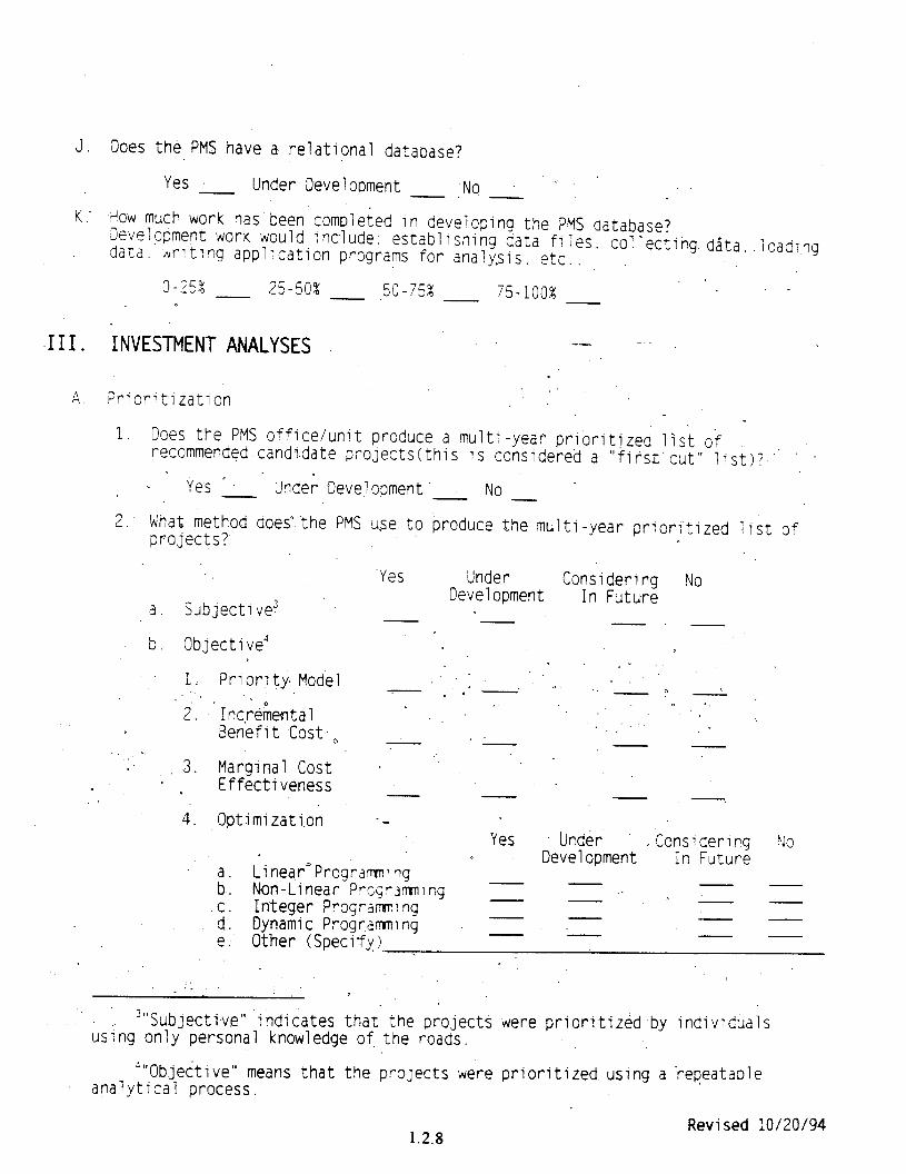
1. Does the PMS office/unit produce a multi-year prioritized list of recommended candi.date projects(this IS considered a "first'cut" list)? " '
Ye’s * Under Development'.. No
2. Khat method does".the PMS use to produce the multi-year prior?tized list of projects?
a
b
.Yes Under Considering No
Subjective3 Development In Future
-. - Objective' v
I- . 1. Priority Model . _'
7 0 a .-. 0. ,'.' , -y -
2. Inc,r&ental J
Benefit Cost., '.' *
3. Margin.al Cost . .' . Effectiveness -. 4. Optimization --
Yes Under 0
LinearnProgrdmlng Development '
Considering '40 In Future
i: Non-Linear Prc4r3mning . . C. Integer Progra&:ng d. Dynamic Programming e. Other (Specify)
: .
3"Subjective" indicates that. the projects were prioritized by individuals using only personal knowledge of. the roads.
""Objective" means that the projects were prioritized using a repeatable analytical process.
1.2.8 Revised 10/20/94
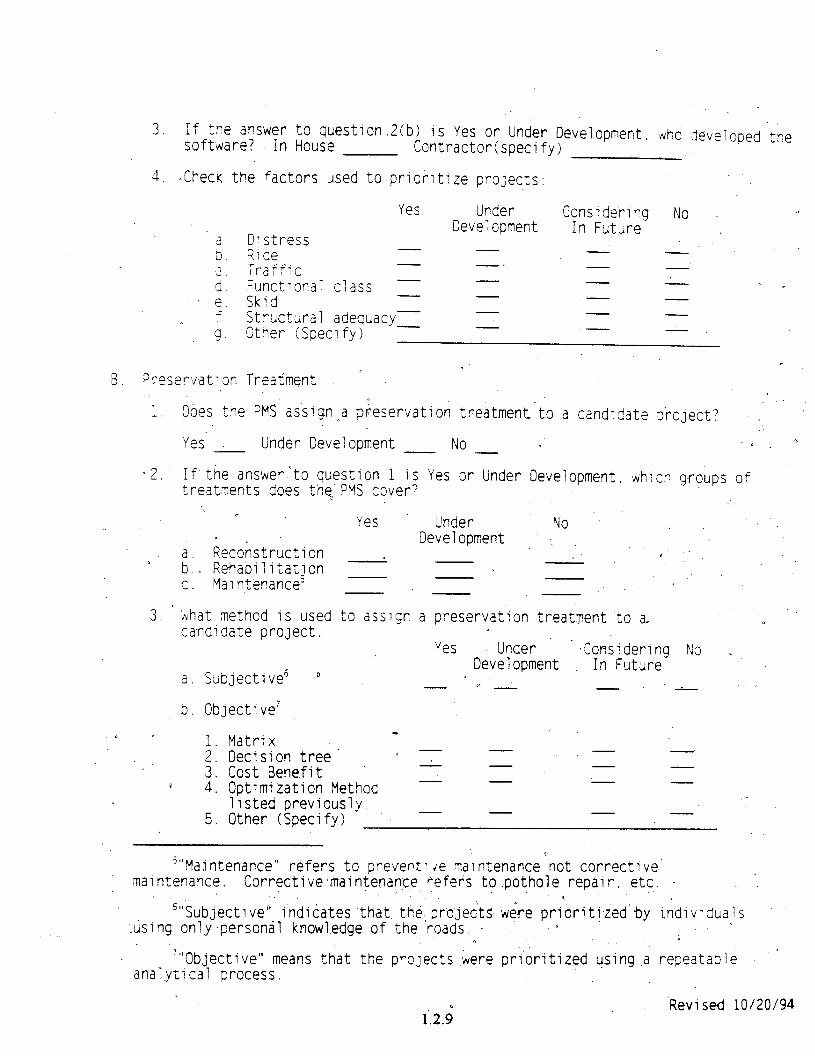
3. If the answer to question.2(b) is Yes or Under Development, whd -developed t?e software? In House Contractor(specify)
4. *Check the factors used to prioritize projects:
a 5.
;I e. f 9
6. Praeservati on Treatment "
Yes Under Considering No
Distress Development In Future
rilde Traffic -.
Functional c?ass -.- - . I Skid Structural adequacy- 7 Cther (Specify) .-- - -
1. Does the PMS assign-a pseservation . .
treatment-to a candidate project? :
Yes Under Development No D ? a
-2. If the answer'to question 1 is Yes or Under Development, which groups of treatments does the PMS cover?
Yes ’ Under No,
a. Reconstruction Development .,
e b.. Rehabilitation D -
c. Maintenance'
3. m, Nhat method is used to assign a preservation treatment to a0 0 ca-ndldate project.
Yes Under .Considering No ,
a. Subjective6 ' Development In Future
0 - '.- I
b. Objective' r
: :
* 2
5.
Matrix Decision tree' a 7 - - - Cost Benefit Optimization Methoc - - listed previously. Other (Specify) - -
'"Maintenance" refers to preven:: ie maintenance not corrective maintenance. Corrective.maintenance,eefers to.pothole repair, etc. . :
9 '"Subjective"
:tising only-personal indicates that, the.-projects were prioriti,zed'by individuals
knowledge of the roads. *
7'"Objective" means that the projects were prioritized using.a repeatable ' analytical process.
1..2.$ 'Revised 10/20/94
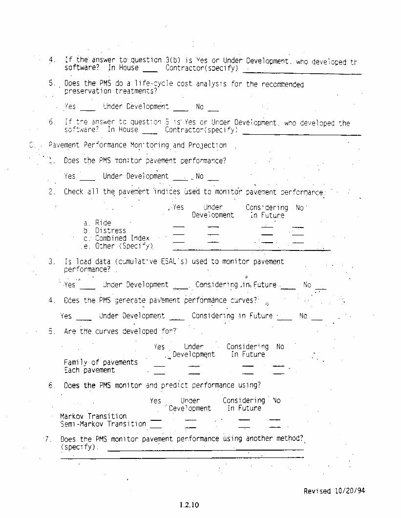
4. If ihe. answer to. question 3(b') is Yes or Under- Development. who developed tt- software? In House - Contractor(specify)
5. _ Does the PMS do a life-cycle cost analysis for the recommended preservation treatments?
Yes Under Development No
6. If the arisker to question 5'1s' Yes or Under Development. who developed the soft,dare? In House - Contractor(specify)
C.,. Pavement Performance Monitoring,and ProJection
-.I. Does the PMS monitor pavement performance?
Yes Under Development : ._ No -
2. Check all the0 pavement 'indices used to monitor paiement performance: ' .' I)
.Yes Under Considering No" Development In Future
;: C. e.
Ride Distress Combined Index Other (Specify ).
3. Is load data (cumulative [SAL's) used to monitor pavement ,. performance?
0 .' .yes" Under Development ~ Cons.idering,iR Future, No
. . 4. Does the PMS generate pavement performance curves?' ~3 .- .a;
0 Yes - Under Development Considering in Future 0 No, _'.
0 s 5. Are the curves developed for?'
Yes Under :I Development.
Considering No In Future n
Family of pavements o . 0
Each pavement - - 7
6. Ooes the PMS monitor and predict performance using?
Yes Under
Markov Transition ,'Oevelopment
Considering. No In Future
Semi -Markov Transition - = '. . 1 z
7. Does the PMS monitor pavement performance using another method?, (specify).
Revised 10/20/94
1.2.10
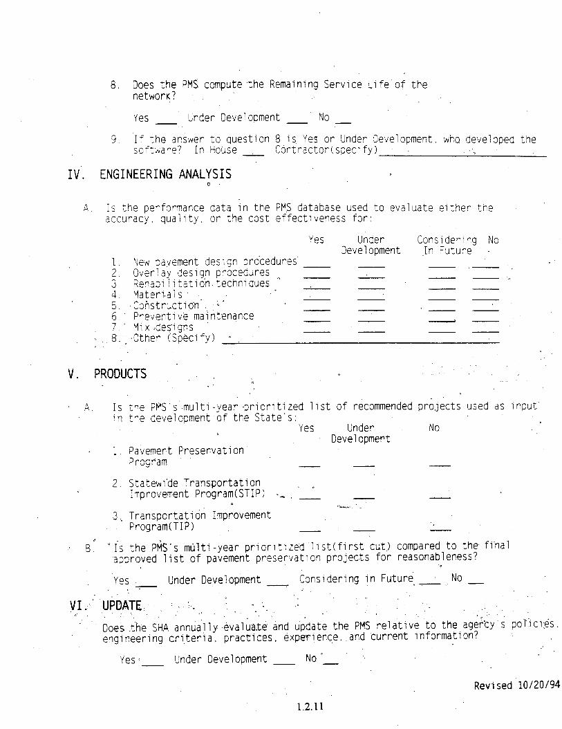
8. Does the PMS compute the Remaining Service Life of the network? :
Yes Under Development No
9 ‘If the answer to question 8 is, Yes or Under Development, who developed the <oVaare? In House .A i A Contractor(specify) '1
IV'. ENGINEERING ANALYSIS 0
A. Is the performance data in the PM8 database used to accuracy. quality, or the cost effectiveness for:
Yes Under
evaluate either the
Considerlrg No Development .in Future
1 New pavement design procedures 2: Overlay.design procedures o
- ',- ',
iI ~~~~~~,~~~a,tion-te,chnlques.- : L I
5. Construction*.. : b'
- "
6.' Preventive maintenance -- -
I- ' Mix :des'i-gns
'.. .8:.* .Other (Specify) 0 - -
V. PRODUCTS . . ; 1
IS in
1.
2.
3 '.
a Is
the FWS'~s'-multi-year -prioritized list of recommended projects used as input the development of the State's:
Yes Under No Development
Pavement Preservation' Program
Statewi'de Transportation ~ Improvement Program(STIP) -_ - -
Transportatibn Imp&vement 'h.....
Program(TIP) . . -.
the P6tS's multi-year priorlt;zed.llst(first cut) compared to the fi'nal approved list of pavement preservation projects for reasonableness? . Yes e Under Development ~ Conslderying in Future ~.* No - b7 . I. .
U&ATE:, : .~ :-e ,, ; I -*,:..,, 1, . ',..
., :: : ; . I .:.
Does .the St-IA annua.lly .&al;a.te and. &date the PMS relative to the ager;'cY's POlici:es. engineering criteria. practices, experience..and current information?
: Yes - Under Development Nom
Revised 10/20/94
1.2.11

Subject:
From:
To:
INFORMATION: OIG Final Report on the Date: July 26, 1994 Audit of Cost Comparison of Asphalt Versus Concrete Pavement-
Rodney E. Slater Administrator
Rrply to Attn. of: HMS-11
The Honorable A. Mary Schiavo Inspector General (JA-1)
We have completed our review of the final report on the Audit of Cost Comparison of Asphalt Versus Concrete Pavement in Region 4. Your transmittal memorandum requested that we reconsider our nonconcurrences with your recommendations and provide specific target dates and further clarification where we have agreed to corrective actions.
Our specific comments relative to each recommendation are contained in the attachment to this memorandum. For clarification, we have included our responses to the draft report, as well as a summary of the OIG comments on those responses in the attachment.
Our further review of the report reveals a fundamental philosophical difference in our approach to administering the Federal-aid highway program. This difference is specifically stated in the report's synopsis, alluded to in the report itself, and incorporated into many of the report's recommendations.
The philosophical difference is clearly articulated in the statement on page iv which reads as follows: *(. . .the continuincr Broblem with FHWA's traditional stratecnr of facilitatincr, rather than mandatinu Ia The report suggests that the FHWA needs to alter its ope;a;i&l relationship with State highway agencies (SHA) and adopt, as we interpret it, a strategy that is inconsistent with this Administration's approach toward customer service and minimizing mandates. We find this to be totally unacceptable and continue to nonconcur with that premise and in all recommendations in the report that would lead the FHWA in that direction.
The FHWA's basic philosophy of Uvfacilitatina, rather than mandatincP is based upon the fact that the Federal-aid highway program is a federally assisted State program. The FHWA must administer it in that light. The Federal-aid highway program is fundamentally a formula allocated program. With finite
1.3.1
2
allocations, SHAs are independently under intense fiscal pressure to assure the most efficient use of all highway dollars, whether they are Federal, State, or local dollars.
The FHWA's fostering of a cooperative partnership approach has served FHWA, the States, and the Nation well since its inception. This partnership approach was strengthened by the passage of the Intermodal Surface Transportation Efficiency Act of 1991. The FHWA continues to look toward bettering, not dismantling, this relationship in the future.
In response to the specific recommendations contained in the report, among other things, we have attached specific clarification and timetables for life-cycle cost analysis (LCCA) and pavement design activities as you requested. The FHWA believes that it is important to note that we have made significant progress over the last few years in both of these areas.
In the area of LCCA, we have reviewed the recent 1993 American Association of State Highway and Transportation Officials (AASHTO) survey of SHA applications of LCCA, conducted an FHWA/AASHTO symposium on LCCA in December 1993, and plan to publish an interim policy statement on LCCA. This policy statement will include recommendations on minimum analysis periods to be used and references Office of Management and Budget Circular A-94 for guidance on the selection of appropriate discount rates. The goal of this policy statement is to clearly define the FHWA's position on some of the more important components of LCCA, including analysis period, discount rate, and user costs. We intend to publish this policy statement in early summer,
It is important to note that we are making significant progress in this area and will be in a better position to further determine our course as current efforts evolve.
The same is true in the area of assuring high quality, cost-effective highway pavement design, construction, maintenance, and preservation. The new December 1993 Pavement Management System (PMS) regulation requires SHAs to develop comprehensive coordinated systems to effectively manage pavement to address current and evolving long-term pavement needs. It also broadens the pavement design requirements to include an analysis of the entire pavement structure (subgrade, subbase, base, and pavement). The regulation specifically requires that pavement design analysis consider life-cycle costs.
The FHWA intends to rewrite its Federal-Aid Policy Guide (FAPG) on pavement design to better track with the recently revised PMS regulation by the end of this calendar year. The revised FAPG, in conjunction with the new PMS regulation, will provide
1.3.2
significantly more definitive guidanck on pavement design. As noted in our earlier response, the FHWA agreed to direct its regional pavement engineers to participate with the divisions in pavement design and management reviews in each State during the next 2 years. Headquarters pavement engineers will participate in at least one of these reviews per region.
Further, we continue to stand by our original position, as stated in our September 2 memorandum, that the audit report does not support a finding of a material internal control weakness.
We appreciate the opportunity to comment on this draft report concerning the Audit of Cost Comparison of Asphalt Versus Concrete Pavement in Region 4.
2 Attachments
1.3.3

Subject’
From Director, Office of Engineering
To,
U.S. Department of Transportation
Federal wm A4lministmtion
INFORMATION: Proposed Final Interstate Maintenance Fund Transfer Policy
Date SEP 2 1 1994
Reoly to Attn of HN'G-42
Regional Administrators
Attached is a copy of the FHWA's proposed final policy statement on Interstate Maintenance Fund Transfers, which was published in the Federal Resister on Friday, September 2. It addresses criteria relating to the decisions on adequate maintenance of the Interstate System for purposes of the Interstate Maintenance Program Transfer provisions of Title 23, United States Code, Section 119(f)(l). It is a proposed replacement for the Interim Maintenance Fund Transfer Policy, published at 58 Federal Reqister 12229, on March 3, 1993.
The proposed final policy statement would add safety and geometric criteria not originally proposed in the interim policy, and modify the existing criteria for pavements. Modifications to the pavement criteria would change the IRI criteria from 240 cm/km (150 inches/mile) to 200 cm/km (127 inches/mile), modify the faulting criteria to reflect a faulting rate of 525 mm/km (33 inches/mile) for both plain and reinforced jointed concrete pavements, and add a surface friction related criteria.
We have reopened the docket and will be accepting written public comments until November 1, 1994. We would appreciate it if FHWA field offices would adhere to that date in submitting any comments. Please note, that until we publish a final policy statement, the interim Interstate Fund Transfer Policy, published in the Federal Reaister on March 3, 1993, is still in effect and governs Interstate Maintenance Fund Transfer requests.
The Pavement Division continues to coordinate this effort for the Office of Engineering. Please direct any questions relating to this policy and/or its implementation to Mr. John Hallin. He can be reached at (202) 366-1323.
HA4 y William A. Weseman
Attachment
NOTE : The proposed final policy statement proposes changes to agency policy and has been published to gather public comment. Until the statement becomes final the interim policy statement will prevail for transfer of interstate maintenance program funds.
1.4.1

e Ugitttr / VOL. 59. No. ‘170 / Friday, September 2. 19% ! Notices 45747
Federal HIghway AdrnMstration [FHWA Dockat No. 9%101
Transfer of tnterstata Maintenance Program Fun& AGENCY: Federal Highway Administration (FHWA). WT. ACTION: Proposed final policy statement: requests for comments.
SUMMARY: This proposed fd policy statement sets forth the FIiWA’s policy for addressing the interstate maintenance program funds transfer provisions of 23 U.S.C. 119(f)(l). The criteria for determining what constitutes adequate maintenance. which am included in this policy, are associated with only the transfer of Interstate Maintenance (IMI funds and are not related to th8 State’s responsibility to properly maintain projects co- with Federal-aid funds outlined in 23 u.s.c 116, Main timanct. DATER conunents must be received on or bet%8 November 1, f994. ADDRESSES: Subit written, signed - comments con- this policy statement to FHVVA Do&& No, 93-10, Federal Highway Administration, Room 4232, HCC-10, Office of the Chief .. Counsel, 400 Seventh Street, SW., . Washington, DC 20590. Au cxxnments received will be available for examination it the above address between 8~30 a.m and 3:3ff p.m., st. Monday through Friday, ekcept Federal holidam ., . FoR-w~TloN~~ML JohnHalli~~Chkf.P~Design. and RehabiAitehon Bnmch. (202) 366- 1323, or Ms. Vivian Philbin. Attorney- Advisor, Of&x of Chief Counsel. General Law Branch, (202) 3-780. Federal Highway Administration. 400 Seventh Street SW., Washington, DC 20590.
Onhhrdx3.1993.theFXWA publsheci an in&rim policy statement. onthetranskoi~erstate~ program funds ctt w FR 12299, and provid&a 60-&y public comment period which closed on May 3.1993, Duringthein~gperiodFHwA hasewlaetedtbecommsnarand reconsidered its initial positicra. ha. nasuitthaF’HWAiaproP&qto modifyfbepavemen trouglulessled ” faultiuguite&m sml to edd additi05& criteria that were.not proposed in &s inkim licy.
‘A tot r of 18 S&ate high-y ag& (SHAsf and the Highway User Federation for Safety and Mobility ., -
(HUFSAM). a public interest group, provided written comments to the docket estabtiished for the interim policy statement.
The SHA mmments ranged from administrative type questions. such a~ requests for clarification of measurement procedures and use of etisting pavement management system data. to fundamental positions on the individual indicators and the specific established criteria. Some SHAs endorsed various portions of the criteria established, while others took exception to part or ail of the criteria.
The HUFSAM strongly endorsed the interim policy. It stressed the need to assure that the Interstate System be maintained at a very high level and noted that, &om its studies, nationwide, the Intarstate maintenance funding levels are inadequate.
After evaluating the comments received, the FHWA continues to believe eat transfers of apportioned IM funds specificdy earmarked for Interstate maintenance to other designated programs should bo;- permitted only when the Mers@te System routes are in a physic&
_
oparationa& and sak condition&d perform at or n8ar the 18veI forwhich they were designed. and constrkted; B8caus8 pavement and bridge activitk. constitute the major cost items of IM eligible xt.ivitiez+, the interim policy focused on pavement and bridge condition indicatars asthe determining factors fbr eIigiity to transfer rrvl funds. Other essential elements, necessary to maintain the physicaLan& operational integrity of the Interstate. must also be consid& in transportation decisions Responses to the interim policy, however, indicate a concern that other essential elements need not be considered in transfer decisions. This was not the intent of the interim policy statement.
Section lOl(a) of Title 23 USC. . defines“maint8nanca” to-the presentation of the eatirs highway, including sxuk8, shoulder% me&i& smlcturer, and such traffic contif d8vicerasUe~ facitssalsnd efficient utiujE8tion, As the IM pzogram now provider the major n36om for rehabilitatim IWA&K@. cmd r8stmation (3Rl wwkon the In-: Sys+8m,8x&xIiqth88aaviolif6of8ll~ majoruniapontntsalndeahancing highway-an tha sys&m skouk# receivefirstpri&yf+h4fand~.For zph vr 25 percant of the pro@&
aplmma@y10perce0ffun& froMtheiMprajpnQrtcurrentlyb8ing expaxWontmffkandsafety improvement projects. The FHWA
1.4.3

45748 Federal Register I Vol. 59, No. 170 / Friday, September 2, 1994 1 Notices
supports a continued strong emphasis on safety.
In a sampling of SHA pavement management systems conducted during the past year, the FHWA found that the pavement condition indicators . established in the interim policy are generally collected and used by the States in evaluating the condition of the Interstate for their own management purposes. While the data collection and reporting procedures differ somewhat, the fundamental indicators are consistently used by the %-IA’s to manage their Interstate pavements.
The proposed final policy includes the original pavement and bridge condition indicators established in the interim policy and adds pavement surface friction as a fourth pavement condition indicator. However, the roughness criteria has been modified and the separate faulting criteria for jointed plain and joint reinforced concrete pavement (JPCP and JRCP) has been replaced with a single criterion of 525 mm/km (33 inches/mile) for both jointed
In ad d: avement types. ‘tion to these interim factors.
this proposed pinal policy statement . adds criteria for the additional traffic and safety related indicators of (1) safety appurtenances, (2) traffic control devices, and (3) geometric elements. These indicators are equally critical to the Interstate System which relies heavily on the availability of IM funds for continued adequacy. Maintenance of the Interstate System’s operational as well as physical characteristics in a satisfactory manner remains the’i%st priority for the use of these funds. Comments Received
This section addresses specific SHA comments organized around the criteria established for each of the individual condition indicators. Pavement Roughness
Three SHAs suggested that the International Roughrress Index (IRI), developed at the International Road Roughness wt. is not the appropriate measure of rideability. The FHWA recognizesthat-EU does have some limitations. It does, however, provide a common quantitative basis with which to reference the different measures of roughness. Purther. it is currently collected by SHAs and provided to FHWA underthe Highway Performance Monitoring System (HPMSI submission requirements. Akhough the WA is open to use of improved pavement surface rideability measures, until such time that improved measures and equipment to measure them are accepted and readily available
to SHA’s, the FHWA will continue to rely on IRI as the ride indicator.
Four SHAs commented that the specific IRI criteria of 240 cm/km (150 inches./mile) was too severe. The FHWA disagrees. The selection of the 240 cm/ km upper limit criteria on pavement roughness was directly tied to the FHWA’s desire to require Interstate pavement to be in fair or better condition. The interim policy noted that initial IRI to pavement serviceability rating 1 (PSR) conversion studies2 indicated a 240 cm/km IRI is equivalent to a PSR range of 3.0 to 3.5. Pavements within this range are classified as fair in the FHWA’s “1992 Highway Statistics”3 report. Subsequent additional analysis of the IRI/PSR correlation indicates that a 240 cm/km IRJ more accurately reflects a much lower PSR range of 2.5 to 2.8 (pavements in this range are classified as being in poor to mediocre condition4). Based on this furthei analysis, the FHWA has established an upper limit of allowable W of 200 cm/ km (127”/miIe). This converts to a PSR of between 2.8 and 3.2 which is more consistent with the FHWA’s original objective that pavements be in fair or better condition 5. Rutting
Rutting comments were limited to data collection difficulties and reflected a degree of uncertainty about what data collection equipment and procedure would be considered acceptable. No comments were received concerning the appropriateness of the rutting indicator or the established criteria. Therefore the FHWA has retained 15 mm (5/8 inch) as the upper allowable limit of rutting. Concerns related to data collection equipment and procedures are addressed under “Pavement Data Collection,” later in the preamble. Faulting
The SHA comments on the faulting criteria were split evenly: five SHAs
‘The PSR concept was developed at the 1966 American Association of State Highway Officials (MSHO) med test to relate the pavament serviwabiIity index (PSI). aunputed from objectively measured pavement distress, witb subjective serviceability ratings by panels of road USWS.
2 Bashar AI-Omari and Michaal L Darter. “Relationships between IRI and PSR: A Report of the Findings of Pavement Model E&emeamtafor the Highway Performance Monitoring System (HPMSI.” Transportation Engineering Series No. 69. University of Illinois at Urbana Champaign. Report No. UfLL!-ENG-92~2013, September 1992. Thi, document is available for inspsctioo in FHWA Docket No. 93-10.
JFHWA. “Highway Statistics 1992.” FHWA-PL- 93423. A copy of this document in available for inspection in FHWh Docket No. 93-m.
4 Ibid. 5 l-bid.
thought that the faulting criteria were too restrictive, while five SHAs . commented that the criteria were
/
acceptable. In addition, the HUFSAX. found the criteria acceptable.
One SHA recommended simplifyink the policy by replacing the separate faulting criteria for jointed plain and ’ jointed reinforced concrete pavement (JPCP and JRCP) with a single faulting criterion in mm/km (inches/mile] for both pavement types. A mm/km based criteria would eliminate the need to t&e joint frequency into account, as the average allowable faulting per joint would be directly related to the number of joints/mile. The FHWA recognizes the merit in this recommendation and has replaced the separate faulting criteria of 3 nun on JPCP and 6 mm on JRCP with an equivalent maximum faulting rate of 525 nun/km (33 inches/ mile) for both. This faulting rate is equivalent to 3 mm per joint on typical JPCP with 6 meter (20 foot) joint spacing and 6 mm per joint on jRCP with 12 meter (40 foot) joint spacing. Because joint spacing varies between States, the allowable faulting per joint wiU differ from State to State, even thou& the faulting rate per km remains cdnstant.
Administrative-Procedural Tolerw ?.imits
The most common comment, recki*. from seven SHA.9. was that the scope of the application of the criteria was too stringent. The crux of the argument wa+ that some tolerance limit should be established to allow a SHA in substantial compliance to transfer funds. A common suggestion was that the FHWA only require that 90 to 95. percent of the Interstate System meet the criteria before allowing transfer.
The FHWA recognizes that there are continually evolving pavement and bridge needs and, at any one point in time, even SHAs with exceptionally- good pavements might not meet the criteria on 100 percent of their Interstate system. The FHWA has already provided relief for this situation. The interim policy specifically allows transfer when all criteria ai% not met on the Interstate if the work necessary to . correct any deficient segments is 7 included in the approved State Transportation Improvement Program, required by 23 U.S.C. 135(f). This relief is included in the 6nal policy. The FHWA believes that allowing a 5 to u) percent exemption or tolerance would be unwise, as it would allow transk money necessary to maintain the Interstate highway system.
1.4.4
Federal Reeister 1 Vol. 59, No. 170 / Fridav, September 2. 1994 I Notices 45749
Pavement Data Collection Several SHAs posed comments and
questions on data collection and reporting procedures. The primary concern appeared to be whether FHWA . would require a specific data collection effort using some standardized equipment and procedures that would be different from what is currently used by the individual SHAs. Further, the comments included request for flexibility in summarizing the data. Several suggested that FHWA should use whatever SHA PMS data was available to determine the acceptability of a certification accompanying a transfer request.
The FHWA intends to rely primarily on current surface roughness, rutting, and faulting information contained in SHAs PMS database(s) and from information reported in HPMS in evaluating the pavement component of State certifications accompanying Interstate maintenance fund transfer requests.
The FHWA recognizes the uniqueness of each SHA’s PMS and the diversity of equipment and procedures used by the SHAs to meet their particular pavement management needs. The FHWA is not prescribing new specific uniform data collection equipment, procedures,- 1 sampling, or data reduction techniques
I’ to determine compliance with the. -: I. pavement Interstate maintenance transfer criteria. Bridges
Only two WA’s commented on the bridge section of the policy. Both endorsed the use of the current National Bridge Inventory (NBII bridge deck condition rating (Item 58) as an indicator and supported the criteria requirement that bridge decks have a condition rating of 5 or better. This is consistent with the long standing use of a deck rating of less than 5 to determine a structurally deficient bridge.
Both States also recommended that CL... FHWA include the withe superstructure and -i policy and delete the’&@ - requirement contaii&Eti tr
sting _ - e interim
policy. >“ The FHWA origkaky co&wed -- .
using superstructure and tibstructure; ratings as specific criteria when it initially developed the interim policy. Upon @rther consideration, FHWA still supports “load posting” criterion which reflects superstructure and substructlire condition ratings and is aIso a measnre of potential safkty con&m.
The need for load posting is an end result of applying superstructure and substructure conditions, Biong with
other factors. in making load carrying capacity calculations. Changes in condition ratings, and therefore, the load posting, are affected by a reduced maintenance effort which eventually leads to continual and long-term deterioration of bridge elements.
One of the SHAs further recommended that the FHWA incorporate failure susceptibility as an indicator. Failure susceptibility is not required nor normally assessed by States in the course of inspecting bridges to meet national bridge inspection standards. As a result. the FHWA believes it would be inappropriate to use failure susceptibility as a nationwide criterion in the IM fund transfer policy, and has not included it.
Finally, oneSHA recommended that bridge railing adequacy should be included in the decision factors. ‘I&e FHWA considered including bridge railing adequacy as indicated by NBI. Item 36 in the early development of policy criteria. The NBI Item 36 is a four segment item that rates bridge railings for adequate impact strength, and approach guardrail for adequate vehicle safety and protection. *
The adequacy of bridge railings and approach guardrail is a seri0n.S safety - concern and should be considered ~JX the States’ maintenance program as well as in developinghighway safety project+ ” .,I 4. . -u Bridge Data.ColIecGon - -.
The NBI.ratitigs are determined‘in .’ accordance;with, the “Recording and’: c Coding Guide for the Structure Inventory and Apptisal of the Natidn’s Bridges” (Coding Guide) U.S. DOT/ FHWA. December 1988.
Policy For de purpose of 23 U.S.C. 119(f)(I),
which provides for transfer of State apportioned IM funds that are in excess of a State’s need to the State’s NHS and STP apportionment, the FHJ’VA will accept a State’s certification if the State’s Interstate routes meet the following criteria: . . Pavement: -
(11 An IRI of 200 &n per km (127 in&J per m’ile) or less: -
(2) Rutting of 16~mm (518 inch) or lek on flexible pavements:
~31Gunulativefaultinp.of5i5 mm perian (3i &heslmile) or Less & jointed ridd . . pavements: and
(4) Surfaces have adequate surface Mction and ‘d&mute. based on the State accidents record system not identifying any locations with a high incidence of wet weather accidents.
Bridges: (I) Bridge decks in “fair condition” or
better (Coding Guide item 5.8 rated 5 or better): and
(2) No load posting required [Coding Guide item 70 rated 5).
Sqfety Appurtenances: Guardrail. bridge rails, safety barriers, and
other safety features including the upstream ends of all traffic barriers meet (a) the performance criteria of 23 CFR 625. (b) acceptable use warrants, and (cl installation requirements per State standard plans.
Traffic Control Devices:
All major guide, regulatory. and warning signs meet the minimum size, shape. color, format, and message requirements as well as the day and night legibility and visibility requirements of the MUTCD and amendments.
Geometric Elements: (I] The horizontal and vertical alignment.
and widths of median. traveled way, and shoulders meet the AASHTO Interstate Standards. as incorporated in 23CFR 625, in effect either at the time of original% construction. major reconstructiontbr . inchsiun into the Interstate system&which. ever was the latest: and . ..
(2) Hazardous feahms (fixed objects. steep. sideslopes. etc.) within the clear zone are’ either eliminated, corrected, or adequately shielded. .L
In the event that the~~&iition, as ‘” reflecred by current databs, does-not meet the required ci&ria, fdany segment of Interstafe, the State’s request for funding transfer may. not be approved unless the Statacertifies’that the deficient segments have either been subsequently upgraded to meet the required criteria or that the work necessary to correct any such deficient segments is included in the approved State Transportation Improvement Program. required by 23 U.S.C. 135(f).
Section 119(0(2) of Title 23, U.S.C., allows the States to transfer up to 20 percent of the apportioneq IM funds to the NHS and STP apportionment based solely on the request of the States.
'(23 U.S.C. 119 and &.; 49 CFR 1.48(b)) Issued on: August 29.1994.
RodneyE.Slater. . . : Fedem~ Highway Administm tar- [FRIhc.94-217S7 FiledS-1-9-k 8:45ad WuJNa cooE*Dl&z%P I” -
1.4.5

Federal &xi&r / Vol. 58, No. 40 / Wednesday, March 3, 1993 I Notices 12299
. NOTE : The proposed final policy statement proposes changes to agency policy and has been published to gather public comment. Until the statement becomes final the interim policy sratcment will prevail for transfer of interstate maintenance program funds.
Federal Hlghway Administratlon (FHWA Docket No, %+lO]
Transfer of Interstate Maintenance Program Fundo
AGENCY: Federal Highway Administration (FHEA), DOT. ACTION: Interim policy statement.
SUMUARY: This interim policy statement establishes the FHWA’s policy for addressing the interstate maintenance program funds transfer provisions of 6ection 119(f)(l) of titla 23. United States Code (U.S.C.1, which was amended by Section 1009 of the Intermodal Surface Transportation Efficiency Act (ISTEA) of 1991. By publishing this interim policy statement the FHWA seeks to advise States of the criteria the agency will use in evaluating a State’s request to transfer interstate L6ntenanca funds, while providing the
lortunity for public comment prior to ding a final policy statement.
6ATES: Comments must be received on or before May 3,1993. ADDRESSES: Submit written, signed comments concerning this policy statement to F’HWA Docket No. 93-10, Federal Highway Administration, room 4232, XC-10, Office of the Chief Counsel, 400 Seventh Street, SW., Washington, DC 20590. All comments received will be available for examination at the above address between 8:30 a.m. and 3:30 p.m. e.t., Monday through Friday, except legal Federal holidays. FOR FURTHER HFORMATlON COMTACZ kfr. Louis Papet. Chief, Pavement Divfsioa (202) 3661324, or Mrs. Vivian phiibin, Attorney Advisor, Office of Chill Counsel, General Law Branch, (2021 366-0780. Federal Highway Administration, 400 Seventh Street SW.. Washington DC 20590.
SUPPLEMENTARY WORYATIOW Background
~ecziora 1009 of the ISTEA amended 23 U.S.C 119 by replacing “Inter&&a Q&em resurfacing” with the “Interstate
ntenance pw” (II& Public Lew 102-240. section 1009.105 Stat.
itil4.1933. Section 1009 also established additional con&mints
affecting the States’ options for transferring a portion of these funds to the States’ apportionments for other Federal-aid programs.
Section 119(0{fI, as amended, allows the transfer of IM funds to other Federal-aid highway prugrams provided the State certifies to the Secretary that: (1) Any part of the 1M funds are in excess of the needs of the State for resurfacing, restoring, or rehabilitating Interstate System routes and (2) tbst it is adequately maintaining the Interstate System. and the secretary accepts such certification. Notwithstanding section 119(f)(l), section 119((f)(2), as amended, ailows the States to “unconditionally’” transfer up to 20 percent of unobligated IM apportioned funds based solely on the request of the States.
Further, section 1009(c)(2) of the ISTEA requires the Secretary to develop l
and make available to the States criteria for determining what constitutes adequate maintenance of the Lnterstate System for the purposes of section 119(f)(l) of title 23. United States Code. The criteria for determining what constitutes adequate maintenance, which are included in this policy, are associated with only the transfer of IM funds and are not related to the State’s responsibility to properly maintain projects constructed with Federal-aid funds outlined in 23 U.S.C. 116, Maintenance.
In developing the specific criteria. the FHWA believes that transfers of apportioned IM funds specifically earmarked for Interstate maintenance to other designated programs should only he allowed when the Interstate System routes are in a physical condition to perform at or near the level for which they were designed and intended.
Pavement and bridge activities constitute the majority of &I eligible activities. The FHWA has focused on pavement and bridge condition indicators aa detsnmining fadorJ for . eligibility to transfer iM funds.
The FHWA has selected Interstate pavement condition indicators (surface roughness, rutting, and faulting) and bridge condition indica!ors (bridge deck condition and the need for load posting) fix evaluating State’s requasts to transfer IM funds under the provisions of 23 U.S.C. 119(f)(l), These indicators are collected and used by the States in evaluating the condition of the Lntetiate for their own management pmposes- They are generally incorporated into state pavement and bridge management systems and the national bridge inventory and highway performance moni&orillg 6ydfm.L
1.4.7
Pavement Condition Indicators Roughness
The FHWA will use the International Roughness Index (IRI) to evaluate roadway roughness, and has set an upper IRI limit of 240 cm per km (150 inches
The &I er mile) for surface roughness.
was developed at the International Road Roughness Experiment sponsored by the World Bank and several countries, including the United States, in Brazil in 1982. It is designed to provide a common quantitative basis with which to referenca the different measures of roughness. It summarizes the longitudinal surface refile in the wheel track and simulates tE e response of on? wheel of a typical passenger car traveling 80 km per hour (50 miles per hour] to road mu
P ess.
The IRI upper lmit of 240 cm per km, selected by the FHWA. is based on consideration of research efforts that relate actual roadways with a known IRI with the public’s perception of ride
uality. A recent study 1 conducted for % e FHWA indicated that objectively developed IRI numbers could be : mathematically correlated with F subjectively developed pavement serviceability ratings2 (PSR) generated by
P anels of road users. This work
inc uded mathematical formulas that allow conversions between DRI readings and anticipated road user evaluation of pavement-prformanca (Le., PSR).
Gmvemon formulas s indicate that an Wof24OanperkmcorrelateatoaPSR range of between 3.0 and 3.5, which is slightly greater than the 2.5 to 3.0 PSR range associated with terminal serviceahilie for Interstate highway pavements.’
‘BadwrAI-andMLchaaI.~. ‘~nallipabelweenuusndPSR:AReportaf the Fiadln@ of Pavement Model Enhancamenls for the lilgbway Performallc3 Monitoring system (HpMS).” Trsasmdw Bnghrecrieg serlea No. 6% Lh~iveraity d tllinoia at U&ma Uumpaila. Rapad No. UILU-ENG-924013. September 1892. This document is available for hpecth in FIWA rhcket No. x3-10.
‘The PSR mncapt was developed at the 19S8 AIBea+om .4amch3tioIl d slate bigbwa~ OfEcielr (AASHO)madteetlordatethep4v~ aervicse~iity index Wm. ocmpukd hns objectively mealued pa*emcnt diseera with .subjective servicwbillty rathgr by pen& of maci uaera.
Jtlxludeewnvsrioahutaadeveicped ldloenbydu~edh4a&e.hIheSwth Carolina pavement management system by PMS (nc and the previously mentioned ,GChari md Darter reatwcb died In footnote No. 1.
‘The “AASKID Guide for I)eaign of Pavemsnt Sbuchlrtm”. AAm. 19aa (pega I-8) dalbea lonniMl servicmbili~ index ea the loweat 5meptabla level before nmdadng or rwxutruction
12300 Federal Register I Vol. 58, No. 40 f Wednesday, March 3, 1993 / Notices
Rutting The FHWA has established 15 mm (?‘a
inch) as the upper allowable limit of rutting.
The American Association of State Highway and Transportation Officials (AASHTO) Highway Subcommittee on Construction surveyed State highway agencies in 1988 on rutting. The surve revealed that for State maintained ma c! s. 112 inch ruttinq would initiate rehabilitation‘in about 35 percent of the States. An additional 35 percent of tie States indicated that % inch of rutting would initiate rehabilitation. The “Highway Pavement Distress Identification Manual” (HPDIM)’ classifies % to 1 inch of rutting as moderate severity.
The FHWA 15 mm (“/II inch) criterion is consistent with the performance levels expected on the Interstate System. Faulting
The FHWA has established two levels of faulting criteria that are related to pavement type. The FHWA has established an upper limit on faulting of 3 mm (% inch) on jointed plain concrete pavements (JPCP), and an upper limit on faulting of 6 mm (l/a inch) on jointed reinforced concrete pavements (JRCP).
Generally, State highway agencies consider faulting to be objectionable in the I/R to % inch range. The HPDtM classifies faulting between VIO and % inch as moderate severity. The “Pavement and Shoulder Maintenance Performance Guides,” August 1964, FHWA publication numb& TS84-208. indicates faulting should be repaired at % inch. A copy of TSM-208 is available for inspection in FHWA Docket No. 93-10.
The FHWA selected a lower level of faulting for JPCP than for JRCP because JPCP joints occur more l?equently. The levels selected am consistent with the higher expectation the traveling public associates with Interstate highways. Pavement Dota
Procedums for developing IRI are currently well defined in the guidance provided in the “Highway Performance Monitoring System (HPMS) Field Manual.” Appendix J “Roughness Equipment, Calibration and Data Collection.” This document is widelv available in planning sections of St&
a terminal serviceability index of 2.~ IO 3.0 Ir often suggested lot use lo the derign of major highways. A copy of hlhlr pubiicatroo ia available for inspection In FHWA Docket No. W-IO.
‘The “Higbwey Pavumenl Dim Identifitiw Manual”. us Ixrr/PHwA. DOT-FH-11-417Y NCZifW 1-19. Much. 1979 mxinted Pebmetv 1986. X-117 Pubiiucioo b avtilable ior inspgtion io’ FfiWA lhcket No. 93-10.
highway agencies and the FHWA division offices and a co y of this publication is available or inspection in P FHWA Docket No. 93-10. IRI data am collected annuallv and muorted to the FHWA under the’HPMS p’rogram.
The FHWA pavement policy, (23 CFR part 626) requires each State to have an operational pavement management system (PMS) for principal arterials (which includes the Interstate system) in place by January 13. 1993.
The FHWA envisions that the States will assemble necessary pavement surface rounh,?ess. ruttinE. and faulting information from data c&ntly - available in the States’ PMS database(s)
. and from information reported in HPMS.
The FHWA division offices will work with the States in identifying acceptable procedures for measuring and compiling the data available fmm the States’ PMS. Data supporting each State’s JIM transfer request will be made available for inspection by the FHWA. Bridge Condition Indicators ~
The FHWA will use the current national bridge inventory (NBI) bridge deck condition rating (item 58) and the rating indicating whether the bridge requires load posting (item 70) as indicators of Interstate bridge condition for purposes of evaluating States’ requests for Ih4 transfer. The NBI ratings are determined in accordance with the “Recording and Coding Guide for the Structure IInventory ana Appraisal of the Nation’s Bridges” (Coding Guide) US DOTIFHWA, December 1988. A copy of this publication is available for. inspection in FHWA Docket No. 93-10. Bridge Decks
The FHWA will require that bridge decks have a condition rating (item 58) of 5 or better.
Bridge decks are rated in item 58 on ascaleofOto9witharatingof9 representing a bridge deck in excellent condition. A Coding Guide deck rating of less than s indicates a poor condition with the deck showing deterioration and spalling. In relation to pavement roughness, a deck with a rating less than 5 is considered a rough deck that would not provide a reasonabiy smooth ride. A deck rating of less than s is a long standing condition rating used to determine a structurally deficient bridge. Posting
The FHWA will require that NBI item 70, for load posting, must be a rating of 5.
The National Bridge Inspection Standards (23 CFR part 650, subpart C)
require the posting of load limits only if the maximum legal load in a State produces stresses in excess of the operating stre5s levels. The operating stress level will result from the absolute maximum permissible load to which a bridge may be subjected. Coding Guide item 70 of the NBI is the item for bridge posting, and a State’s rating of 5 indicates that no posting is required at the operating level.
Load posting of a bridge reduces the level of service of the system of which the bridge is an integral part and can potentially disrupt interstate and intrastate commerce. Heavy vehicles may be required to take long detour routes thereby inciirectlv addinn to the costs the public must b& for g;ods and services. Load posting of a bridge may also be an indicator of a bridge’s superstructure or substructure capacity that may have been affected by . continual and long term deterioration of the bridge’s elements and which could have been prevented or abated by adequate preventive maintenance. Policy
For the purpose of 23 U.S.C. 119(fl(l). which pro-vides for transfer of IM funds apportioned to the States, the FHWA Wiil accept a State’s certification if the State’s Interstate mutes meet the following criteria: - Pavement L
(l)AnIRIof240cmperkm(l50 - inches per mile) or less;
(2) Rutting of 15 mm (5/8 inch) or less; and
(3) Faulting of 3 mm (l/8 inch) or less on JXP and 6 mm (114 inch) or less on flQ. Bridges
(1) Bridge decks in “fair condition” or better (Coding Guide item 58 rated 5 or better); and
(2) No load posting required (Coding Guide item 70 rated 51.
In the event that the condition, as reflected by current condition data bases, for any segment of Interstate pavement or bridge does not meet the required criteria, the State’s request for funding transfer may later be approved only if the State certifies that the deficient segments have been subsequently upgraded to meet the required criteria or that the work necessary to correct any such deficient segments is included in the approved State Transportation Improvement Program. required by 23 U.S.C. 135(f).
Section 119(f)(2) of title 23 U.S.C. allows the States to “unconditionally” transfer up to 20 percent of unobligated I?4 apportioned funds hased solely on the request of the States.
Authorlt)? 23 U.S.C 119 and 31% 49 c9R 1.48(b).
issued on: February 24,1993. E. Dspn Cu&on, Executive Director. Fedem! Hi&my Administration. IFR Dx. 93-4809 Filed 3-Z-93; 8:45 ami 1LL%4G cou! (01cGz-a
1.4.8
Chapter 2
Pavement Issues

CHAPTER 2
PAVEMENT ISSUES
2.1 Reserved.
2.2 Reserved.
2.3 Tire Pressure, Technical Paper 89-001, February 15, 1989.
2.4 Reserved.
2.5 A Discussion of Discount Rates for Economic Analysis of Pavements, February 1990.
2.6 Resilient Modulus Testing Equipment, February 24, 1988.
2.7 Longitudinal Joint Construction and Edge Drop-Offs, March 1989.
2.8 Reserved.
2.9 Reserved.
2.10 Life Cycle Cost Analysis, September 15, 1992. 0 Interim Policy Statement - FR, July 11, 1994.
2.11 Reserved
2.12 ISTEA Implementation Interstate Maintenance Program, Memorandum, May 21,1992.
2.13 Preventive Maintenance, July 27, 1992. l Information on Interstate Maintenance Program, June 14, 1993.
2.14 Computer Software o McTran’s Software, July 1995.

Suolecr ACTION: Life-Cycle Cost Analysis
From Chairman, PMCG
Cate SEP I 5 m
Aecdy 10 All- 0’ .HNG-42
To PMCG Members (See Attached List)
A Life-Cycle Costing (LCC) Task Force has been formed in response to LCC interest expressed by the FHWA Research and Development Executive Board at its 1991-92 winter meeting. The Task Force consists of representatives from the Associate Administrators for Policy (HPP-12), Research (HNR-ZO), Program Development (HNG-42), Motor Carrier (HIA-ZO), and Administration (HCP-22). The Task Force mission is to develop recommendations for the Research and Development Executive Board on appropriate ways to incorporate LCC analysis into the Federal-aid highway program, as well as the necessary LCC research, development, and training needs.
Attached for your review and comments is a draft of the Task Force's preliminary study paper, "Life-Cycle Costing and Life-Cycle Cost Analysis: Applications Within FHWA and The Federal-aid Highway Program." We are scheduling a presentation and discussion period of the Task Force's initial effort at the next PMCG meeting. We are seeking PMCG reaction, input and suggestion for improvement necessary to obtain PMCG endorsement of a course of action prior to presenting 'the task force findings to the Executive Research Review Board on October 22.
We would appreciate receiving your comments by September 28. Mr. Jim Walls has been designated to coordinate'this effort and is available to address any questions you may have or clarify any proposals contained in the preliminary study. Mr. Walls can be reached at 366-1339.
/
2.10.1
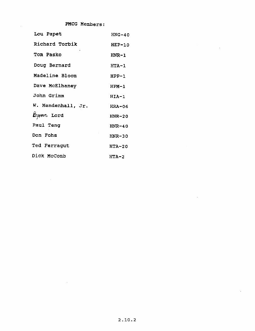
PMCG Members:
Lou Papet HNG-40
Richard Torbik HEP-lo
Tom Pasko m-1
Doug Bernard
Madeline Bloom
Dave McElhaney
John Grimm
w . Mendenhall, Jr.
d$?qm% Lord
Paul Teng
Don Fohs
Ted Ferragut
Dick McComb
HTA-1
HPP-1
HPM-1
HIA-
HRA-06
HNR-20
HNR-40
HNR-30
HTA-20
HTA-2
2.10.2
Life Cycle Casting and Life Cycle
Cost Analysis: -
Appiications W*in
FHWA and The Federal-aid
Highway Program
Preliminary Study
August 1992
Task Force Members:
Jim Walls HNG-42 (Pavements)
Byron Lord HNR-20 (Research)
Walt Manning HPP-12 (Policy)
Dennis Miller HIA- (Motor Carrier)
Frank Waltos HCP-32 (Contracts and Procurement)
2.10.3
Executive Sumnary
In response to interest expressed by the FHWA Research and Development Executive Board in Life-Cycle Costing (LCC), the Pavement Management Coordinating Group (PMCG) established an internal LCC Task Force consisting of representatives from the major affected*Associate Administrators. The Task Force was specifically charged with developing recommendations on appropriate LCC research needs.
Fundamental to accomplishing its primary tasking, the Task Force had to first identify current and potential FHWA LCC applications along-with some fundamental policy implications. The Task Force also looked at the LCC implication of the ISTEA. This paper includes the Task Force's preliminary efforts in this area.
In terms of its specific tasking on LCC research needs, this paper identifies relevant LCC issues and limitations. It lays out research approach options and a plan of action.
Based on its initial efforts, the Task Force proposes two separate but concurrent KC efforts; an internal LCC policy development effort and a two-phase LCC contract research effort. The policy development effort, although internally directed, would most likely require some outside contractor support.
Under Phase I of the contract research effort, FHWA would contract with several companies to provide inter-disciplinary teams to define and clarify LCC issues and necessary research. Phase I work would include development of detailed work plans that address the identified LCC research needs. Under Phase II, FHWA would continue 'to fund a more limited number of multi-disciplinary research teams to actually conduct the more promising research activities identified in Phase 1.
The results of this proposed multi-phase research effort and the internal policy development effort would eventually be digested into FHWA guidance on LCC. This final step would most likely be done with in-house staff using consultant support.
The Task Force stresses from the onset that the outputs of life-cycle cost analysis (LCCA) are not decisions in themselves; but rather inputs into the decision making process.
A draft copy of this paper was circulated to the PMCG and discussed at the last July 14 PMCG meeting. The draft paper has been revised to incorporate their views and comments.
The Task Force at this point has not made contact with any of FHWA's partners and/or customers. Consistent with FHWAls outreach program, the Task Force suggests that appropriate outside groups be contacted before research funding decisions are made. Groups such as the American Trucking Association and the Association of American Railroads have conducted research in this area and are likely to have a keen interest in FHWA's efforts. Industry groups such as NAPA, AI, PCA, plus ARTBA would also be interested.
2.10.4
A Life-Cycle Costing the PMCG, in respons
(LCC) Task Force was formed by Hr. Loui t Papet, Chairman of ;e to LCC interest expressed by the Research and Development-
Executive Board at i ts 1991 - 92 ,winter meeting. The Task Force is composed of representatives-from the Associate Administrators for Policy (HPP-12). Research (HNR-20), Program Development (HNG-42), Motor Carrier (HIA-20), and Administration (HCP-22). Specific Task Force members include:
Jim Walls HNG-42 (Office of Engineering, Pavements Division)
Byron Lord HNR-20 (Office of Engineering, Highway Operations Research and Development, Pavements Division)
Ualt Manning HPP-12 (Office of Policy Development, Transportation Studies Division)
Dennis Miller HIA- (Motor Carrier)
Frank Waltos HCP-32 (Office of Contracts and Procurement Research and Special Programs Division)
The Task Force mission is to develop recommendations for the FHUA Research and Development Executive Board on appropriate ways to incorporate LCC analysis into the Federal-aid highway program,. as well as the necessary LCC research, development, and training needs.
This study paper first defines LCC, LCC analysis, and cost effectiveness. It then discusses potential LCC applications with their implications. This discussion is followed by a sumnary of current policies and a look at new LCC mandates. General LCC technical and policy related issues and limitations are then discussed. In the closing sections, the paper discusses potential approaches to determining and conducting needed research and training necessary to implement LCCA, and finally, the last section presents recommendations on the preferred course of action.
Definitions
Current literature loosely defines 1 ife-cycle-costing/life-cycle cost analysis as a form of economic analysis which focuses attention on determining the longer term economic imp1 ications of alternative strategies rather than merely the initial or front end costs of the immediate decision at hand. It is a tool that can be used to assist in making economically prudent long-term expenditure decisions, i.e., . cost-effective investment decisions.
The Task Force believes the terms "life-cycle costing" and "life-cycle cost analysis" are synonymous. However, life-cycle cost analysis is more descriptive of the inherent analytical process and, as a result, the remainder of this paper uses the term life-cycle cost analysis (LCCA).
2.10.5
A related tenh, cost effectiveness, also'has bearing in tenns.of Fl#A.Policy. Cost effectiveness is an economic related measure (generally a ratio) that describes how well an alternative meets a performance type objective inielation to the cost of achieving that performance. The cost component of cost- effectiveness wasures .should generally reflect life-cycle cost. The attractiveness of using cost-effectiveness measures is based on its ability to tie cost to perfomance. 'For example, a cost-effective measure in the safety area might be cost/accident reduced. In terms of pavements, it could be cost per ESAL carried until terminal serviceability is reached.
As well as defining what LCCA and cost effectiveness are, it is equally important to define what they are not. The Task Force stresses from the onset that the outputs of life-cycle cost analysis are not decisions in themselves; but rather inputs into the decisionmaking process.
LCC Applications
The Task Force sees two distinct areas where LCCA could be applied within FHWA, . internal and external applications. .The FHWA can use internal applications ioes;pport decisionmaking at the national level. External applications are those related to the Federal-aid highway program. Within each area there are multiple application possibilities.
In terms of the Federal-aid highway program, there are several potential decision levels where highway agencies could.apply LCCA. These decision levels include but are not necessarily limited to:
State Network Analysis - To evaluate total funding needs and to determine resource allocation levels for the various systems; project
2. categories, or improvement types in relation to established system wide performance goals. The‘LCCA can also be incorporated into the various management systems required by the ISTEA.
Project Prioritization - To Compare the merits of funding one project in lieu of another.
Pavement Design - To asfist in pavement type selection and to evaluate the marginal rate of return for providing premium in lieu of standard pavements.
Haterials Specifications - To compare the use of imported premium. aggregate versus lower quality, but locally available, aggregate.
Total Qua1 ity Management - To evaluate the long-term impact of increased attention to quality control. For example, increased expenditure for research and testing equipment may quickly pay for itself.
Operational Analysis - To evaluate catch basin clean out policy,.the type and application rates of de-icing- chemicals, use of cathodic protection, etc.
2.10.6
m-t LCC ml 1 a ..; .
Internally, the FWA already incorporates cost-effective considerations'in terms of national level policy development and analysis of alternate Investment strategies. The Associate Administrator for Policy incorporates many aspects of life-cycle costing analysis during development of the biennial report to Congress, 'Status.of the Nations Highway and Bridges.: Some LCC principles have been and more will be included in cost allocation -studies and in developing and evaluating legislative proposals.
Externally, the FHWA does not specifically require State highway agencies (SHA) to conduct life-cycle costing or economic analysis in support of either program or project level decisions as a precondition for federal-aid funding. This is not true for other US DOT Modal Administrations.
The Federal Transit Administration (FTA) requires development of cost- effectiveness measures based on life-cycle cost analysis in support of grant applications for Section 3 discretionary money. This requirement, called an Alternati es nalvsis, must be conducted by applicants at the Draft EIS stage and the rlsults must be included in the Draft EIS. This Alternatives Analysik requirement has been in place for many years, and the FTA has developed and published specific procedural guidelines on how to conduct it.
In contrast, the FHWA has administered a formula based rather than a' discretionary program and has encouraged rather than mandated LCCA in the State and local decisionmaking process affecting Federal-aid highway funds. While FHUA will continue to administer a predominately formula based program; FHUA now administers some discretionary programs. The LCC would appear to have a more substantive roll in discretionary programs.
The FHUA, in its pavement policy, requires S‘HA's.to have a pavement management systems (PMS). In that policy, FHUA defines PMS as a set of tools for finding cost-effective strategies.
At its March 8-10 meeting, the Research.and Technology Coordinating Committee developed comments on the FHUA R&T program. Among other comments, the committee noted that, ". . . the lack of attention to life-cycle costs and benefits is a major impediment to the utilization of highway related technologies. Particular effort should be made in the research program to develop novel, user-friendly, and robust methods and tools for life-cycle costing"
ISTEA LCC Provisions
The Inter-modal Surface Transportation Efficiency,Act (ISTEA) of 1991. specifically addresses LCC under sections 134(f)(12) and 135(c)(20). These sections require that the metropolitan and statewide planning processes incorporate consideration of several factors including "the use of life-cycle costs in the design atid engineering of bridges, tunnels, or pavement."
Cost effectiveness is referenced in section 119, “Interstate Maintenance Program." Under subsection 4, it establishes eligibility when a "State can demonstrate . . . that such activities are 3 cost- effective means . . ."
2.10.7
.The ISTEA also addresses LCCA in FTAfs Se&ion 3(1-j progrh. -The revisions both weaken and strengthen the application of LCC In FtA's Alternitive Analysis While .the Teg~SlatiOn specifically exempts certain metropolitan. areas fro& Alternatives Analysi 5 requireJWntS, requirements in non exempted areas.
it strengthened the Alternative Analysis
One aspect of 'the-ISTEA that presents somewhat of a dilelnma for LCCA is the requirement to develop-and implement several management systems. While current experience reveals that PMS's can be used to foster systematic decisions based on life-cycle Costs, few if any, explicitly incorporate user costs or the time value of money. Most focus on maximizing perfonance -based on fixed ,budgets. Even in those highway agencies that have PMS's in which budget -level and performance impact are directly related, the systems have little to do with ultimate budget decisions.
LCC Analysis Issues
Each LCCA application will, to varying degrees, have its own specific LCC issues. However, some of the more obvious fundamental issues include determining:
(a) the appropriate life cycle and analysis periods (b) the alternatives that should be included (c) the performance histories of the alternatives (d) the cost factors to be fncluded (e) the actual costs of the various cost factors (f) the appropriate discount rate . .
Procedural issues are also a concern. It include concerns over how: __ _... .-.--, . -- :' ; (a) inflation is addressed?'. (b) sensitive the results qre to the discount rate? (c) performance history variations are addressed? (d) Agency Costs and User Costs are incorporated? (e) SHAs can capture and re-invest user cost savings?
Technical, Policy and Procedural Issues and LImItations
Leoitimate Subiective Inputs
Being a form of economic analysis, LCCA has all the strengths, weaknesses, and limitat.ions of traditional economic analysis. Foremost among the weaknesses is the fact that LCCA includes many technical assumptions and policy related positions which directly influence the outcome of such analysis. The assumptions and policy inputs necessary to conduct an analysis can be very subjective and highly susceptible to criticism from all parties impacted by the analysis.
Technical assumptions and policy inputs must be clearly identified along with supporting rational. Rational limits or acceptable ranges should be established for technical inputs and policy related assumptions. Sensitivity analys+s should be conducted within the acceptable ranges to evaluate the influence of the parameter being considered.
2.10.8
Alternative DeveloDment f
Another, important LCC‘ issue is assuring consideration of a broad.range of alternatives. The .LCCA cannot be used to evaluate the economic' wisdom of a particular alternative in and of itself. mertts between-alternatives.
It canonly evaluate the relative As such, incorporating all viable alternatives is
essential. This'- .skould include promising new approaches and technology. Unfortunately, estimating the performance Tlves of alternatives, is at best, both an art .and a science even when historical data is available. Untried but promising alternatives inherently incorporate greater risk than the tried and true. This additional risk has to be addressed. -
Private industry incorporates risk through the selection of appropriate-dfscount rates. Riskier projects (investments) require prospects of greater (generally 3-5X more) return. The SHA efforts in developing PM Systems and SHRP-LTPP research will develop a better understanding of pavement performance relationships and should help in reducing risk.
Performance Eauivalency . Implicit in economic analysis is the assumption that performance differences between alternatives can be clearly defined, captured, and reflected in the analytical results. While this is true for some aspects, it is not always the case. All alternatives which have the same "useful life," in terms of either years or loadings, do not necessari.ly provide equivalent performance over that "useful life." "
For example, two competing pavement rehabilitation alternatives with the same pavement life, may very well deteriorate differently. If this 1s the case, then they will provide different levels of service over their useful lives, even if they reach the same terminal serviceability at the'same time (see figure 1).
Alternative A
3i Alternative 6
I I
0 ! I 2 4 i
I I I I 8 10 1; . 14 16 18 20 Time/ESALS -->
Figure 1 Pavement Performance Histories
2.10.9
- table and 'Non-ouantifiable
1n any economic analysjs, there are, generally speaking, non- costable quantifiable elements that, nqn+e+ss, need to be considered in the
and non- decfsion and non- making process. The how and the degree to which the non-costable
quantifiable elements are ,addressed is a major issue. While broader scope analysis are more complete, they.are not necessarily more accurate.
The degree to which current and future costs and benefits can be accurately estimated severely limit the ability of LCCA to distinguish between of alternatives when LCCA reveals ltttle economic difference. When LCCA results are relatively close (within l&20% of one another) relative risk and other considerations take on greater significance;
User Costs
.Highway user costs, particularly travel time or delay cost, have been controversial. While they may be difficult to quantify and price, construction imposed traffic delays have become, and are likely to continue to be., an ever increasing burden imposed on the public.
Currently, highway agencies have little economic incentive to select alternatives that minimize total (agency plus user) ICC. The alternative with the lowest total life-cycle cost may well be 'the one that has the lowest user cost but, at the same time, the highest agency cost. Because there are no readily available mechanisms for highway agencies to transform reductions in user costs to additional highway investment capital, the current system encourages highway agencies to minimize agency rather than total costs. This tends to .rpsult in significant sub-optimization of totaT possible beneftts. . -1 ,r:i.; . .: ". . ._ This issue is addressed to some extent by requiring. full maintenance of traffic on heavily traveled routes. Highway agencies are already paying a premium on certain projects for limiting the contractors hours of operation and/or elaborate traffic detours. Highway agencies need to anticipate this trend and incorporate higher future rehabilitation cost in current life-cycle cost analysis.
Marqinal Costs
The LCCA is generally used as a means of determining the most economically efficient (some times the cheapest) project.from among a set of alternative that adequately meet the minimum performance requirements. This may well be short sighted. Highway agencies need to look at marginal costs, especially when relatively modest total cost increases make significant differences in performance and or service lives. Premium pavements may be economically justified in areas with no alternative routes for maintenance, rehabilitation, and/or reconstruction activities.
Discount Rate
As a minimum, model LCCA procedures should incorporate the time value of money and discount future cost and benefits to a common time. As just noted, such procedures must include internal (highway agency), as well as external (user)
2.10.10
.‘.costs associated with ?- highway facttity ovei its intended keftil’ I4fe protedures, however, would have to provide guidance on how to deal withSFzi highway agency's inability to Capture-user cost Saving for future reinvestment.
Procedures
To be practick; CCCKmust be conducted .using procedures that recognize the policy issues that influence the .analysis and explicitly document the policy positions taken in the analysis. The FHUA does not currently have LCCA procedural guidelines. If the FHWA intends to use LCCA internally, it needs to establish procedures governing such applications. If, on the other hand, FHWA expects to encourage consideration of LCCA in State and local highway agency decisions affecting Federal-aid highway funds, FHUA will need to establish LCCA procedural guidelines. From a technical aspect, model procedures should identify and evaluate all viable alternatives and relevant cost factors. They should incorporate techniques for developing accurate cost, performance, and service lives of identified alternatives.
Alternate ADDroaches
While the Task Force has been able to identify areas where LCCA research would be productive, it believes a more comprehensive look at the entire process as applies to highway investment decisionmaking is warranted. The Task Force further believes that integration ofthe many debatable positions into a cohesive position on the application of LCC and appropriate guidelines on the conduct of LCCA within the FHWA program would be much more positive contribution.
The Task Force also looked at developing an in-house working group to review the literature and identify and conduct the needed research. The Task force believes FHUA does not have sufficient manpower in the approprjate multi-disciplinary fields available to make a significant contribution'to advancing LCC within FHWA. LCC embraces many complex .issues; some are readily apparent, others are more subtle. Prior to more active FHWA involvement, endorsement, or technical support of LCC, FHWA sponsored research is necessary to:
(1) more clearly define, explore, and resolve identified LCC issues; (2) identify and explore other-important LCC issues not currently
identified; and (3) develop a comprehensive approach to incorporate the research
findings into integrated procedures for the various LCC applications.
Poljcv Reccnmnendatjons
The Task Force recommends that FHWA policy explicitly promote the long-term cost- effective use of, Federal funds, both in its internal operations and in the Federal-aid highway program.
The FHWA should continue to use LCCA and cost-effectiveness considerations in its internal operations to evaluate the condition and performance trend of the Nation's highways, and to determine whether or not we are using resources to the
2.10.11
-maximum advantage% achiering the national transportatjon goals. Other internal applications could inc!ude developdng and analyzing highway .tnvest&nt policy developing and evaluating cost allocatton studies, and evaluation of competing ~vHS technologies and other R&D .activities. :
The FHWA-should:increase its efforts to encourage,*supRort, and implement State and local.use of life--cycle cost analysis principles at all decision levels. It should develop model -LCC guidelines, building' on extensive exlstlng LCCA knowledge base including that of State and local highway agencies. The FHUA should make these LCCA guidelines available to highway agencies and require consideration of LCC in the Urban and Statewide Planning processes. The FHWA should also require the development of LCC and cost-effectiveness information as part of each ISTEA mandated management system.
In response to specific ISTEA LCC requirements, FHWA should focus on program rather than project specific requirements. The FHWA should provide guidance on conducting LCCA, require that it be conducted, and ensure that the results are explicitly considered in the decisionmaking process. It should & become involved in conducting or reviewing/approving actual LCCA's conducted by State and local highway agencies, even on Federal-aid highway program funded projects.
Research Recomnendationf :
In order to move forward with LCCA;FHWA should initiate research and training, necessary to foster improved LCC analysis at all decision levels. -'
Because of the financial/economic focus, the research should be conducted by a multi-disciplinary team that draws on the strengths of economists, financial analysts; and other appropriate disciplines, as well as the highway engineering community. '* I... .,-r;_ T *-.a-. -, -: t L _ 5, ..,. - 7. L-c. ; ;=+ ;
L . . -. ~._ - Because of the enormity and.complexity of'LCCA and the pervasiveness of potential application opportunities, it will be difficult to formulate a comprehensive research work plan with existing in-house resources.
The Task force recommends that FHWA pursue a two-phase LCCA contract research effort as follows:
Phase I - an innovative exploratory i-*search effort.
Phase II - a traditional, in depth; detailed research effort into specific LCCA issue areas identified in phase I.
Phase 1 - FxDlQratory Research
The exploratory research phase would require that selected contractor(s) develop an inter-disciplinary team acceptable to FHWA that would;
1. Explore policy issues and the implications of various FHWA courses of action.
2.10.12
2. Identify sPeclfiC.LCC research- needs l Ssc(Clated with, the courses of .actlon identtfied.
3. Develop a detolled work plan and cost proposal that addrestes the specific research needs identified.
Because- of the .complexity of LCCA, and the relatively inexpensive cost anticipated for the exploratory research, the Task Force believes it would be extremely beneficial (Le., cost effective from a LCC perspective) to fund multiple research teams for this early stage research. The Task Force envisions awarding multiple contracts under one primary exploratory research contract. The exact number of exploratory research contracts to be funded would be based on the responses received to the request for proposals (RFP).
Phase 11 - Detailed Research
The Phase II research component ,is basically designed to carry out the specific research that will be proposed in the detailed work plans developed by the inter- discipl inary teams under Phase I. Upon completion of the Phase I exploratory research, FHWA would evaluate the research team(s) findings and proposed work plans. At that point, FHWA would decide whether to fund of all or part ,of the research activities identified by one or all the exploratory research contractors. The Task Force envisions the Phase II component would be an option included in the Phase I research contract.
On completion of thls proposed two-phase research effort, FHUA will still need to consolidate the various research teams efforts, produce LCCA guidelines, and where necessary, develop LCCA policy, technical advisories, and possibly regulations. The Task Force recommends that the final component would be to establish appropriate training. program(s).
With the concurrence of the Research and Development Executive Board, the Task Force will establish a LCCA'working group to develop an RFP consistent with the preceding recomnendations. Preliminary estimates are that an RFP could be ready for early FY 93 Funding. Funding for the second phase would not be necessary until FY 94.
2.10.13

.35qo4 . . .. G&!d atqgsbr / VOL 59, No.‘-131 f Monday, j& 11.’ lBQ4 / Naticas
dtltabAi$hesLx3cAprixicipAestob. applhdbyFhlfn in~t8MApsscandinevaIuatiog
/ thewAequqnfstate * %@
wayagunq jJmadtImsuml¶dinam uctingrsquirsd Lax fk ixwastments funded through
_ *_ the Faiemhid highway program. States and AQC$ agencisc; are -ted to apply z;Png *~If~~u-%Prpgmm
P Ewe 1 mvestment decrsums
invo ving Fedemhid highwaJi funds as requimd undar applicable FHWA lsgutationh Comments am solicited on potential prt3blems in imphtmetlt.ing provisi~ons of this policy atatemant and
ztixd~&y and technicnl
DATES This interim poky statement is effective on July 11.1994. Comments on the interim policy statement must be received on or before October 11.1994. A final ICCA policy statement will be published that takes into consideration comments received on this interim statement. .-
-submitwritten.Bigned wmmenta conmming this interim policy statement to FHWADocht No. W-15, Federal Highway Administration, room 4232. HCXXO, .. o&eofibc2hfc2ounseL~sevsnth StreeL SW.. washiqmn AC zosQo. In Ulditi~tOSpdfiCmmmnnhOIlth& poucJr*-- zmqqadon~d~ udataKs~toimpAemen!LOCA. AAAuxnmentammiveJdwilAhe*vaiAahAe for examination at the above address between 8:30 a.m. and 3:30 pm. at. Monday through Friday. except legal Federal holidays FORFURlHER#FDRyI Tim cowAcrm Mr. James W. March. Chief. Systems Analysis Branch, (202) 36f+Q237. or Mr. Steven M. Rocbiis. Legislation and Regulations Division, (202) 366-1395, Federal Highway Admin.istrat.ion. 400 Seventh Street SW., Washington D-C 20590.
Federal Highway Administration
(FHWA Docket No. 9615j
Li?ecycle cost Analysb
AGENCY: Federal Highway Administration (FHWA). DOT. AC1W)N: interim policy statement; request for comments.
8UPPLEMENlARY )NF0RMNIW:
Background There is an .incmasing recognition that
total life-cycle costs of highway and transportation investment8 must be given greater consideration in ah phases of highway programs. Executive Order
12893. “Principle of Federal Infrastructure Investment,” requires that benefits and costs of Srastructure investment be measured and appropriately discounted over the full life cycle of each pro+& sections 1024 and 1025 of the Intermodal Surface Transportation Efficiency Act of lQ91 (ISTEA] (Pub. L 102-240.105 Stat 1914.1977) also reguim consideration of “the use of life-cycle coat in the
SuMY*RY: This FHWA policy statement on life-q& coat analysis fUXA1 helps fulfill Federal management responsibilities for analyzing life-cycle oost aspects of infrastructure investment decisions under Executive Order 12893. “Principles of Federal infrastructute Investment” The policy statement
2.10.15
inplXttQttS&iU0lS0ffuhus~ requimmrmts and to the development of impmvsfnant plograms. -p=+y wik%nthlmamhdgetamrtrornts,
Theweofuah4eengharingis receiving i,rmead attention u a technique for aIu+dng the fIlnctianr of aprogpam. ~jed.systsnsprodud~
LL ServinetQi r.ttify.4pportanftiesto . signi&xktly low8r cortr while &II ~achieving the es8sentia.l fuxtioxu Lifa cycle costs are often uulyzed to - that llnnv astsamuvaidedby considering futum operatkxu. maintenanca, and rscomrtnrctia requirements.
Totailife-cyclec&aofspadfk. facilities may be mrey tima &a initial CQIl§tTUCti~CQStSWhQWCQStS~
considered lt is d that a * term perspective be taken in pq$rsmming impruvemanu. -g among alternative maid- rehabilitation, and -on strmgies. aud designing pavements. structurwi, aud other highway elements. Longer design kives may have to be cmsidemd. and traditic4 stmtegies br pl%gamm@Jnuint-and mhabiUtatiau activltiea may have to be Revaluated to determine whether thy
FM m. i kl; SB. NO. 131 I Monday,. I& 11.1641 1 Notiws - 35405 .
adequately amsider futum costs, iixhding user delarr&ted costr -
b&XZZ?3 am8smakuitcri~tofuliyconsider Ukycle aads of invusrment decisions. sdetyaxLwcnsatlda~ -coastomain~. rehabilitate, or -cologarted higbwaysandbridgaamiertmfIicue vetryhighUsercostsaudd&ysaround wQ*mDesixlcmrgastudamasmaybe even higher and mpxusemt si@fhnt inefficiencius that me) adversely affect ucQmxDic prQductitity, cspehlly on the National Highway System (NHS). These delaya can arode productivity. gainamalhadbyth~growingnumbarof industries dug just-in-tinneaadothe? advanced bgistka strategiss that depend on e&e&nt and pmdictati tllmptatiQr.l.
Regardlessofwhetheruau&atsam ixxhdedtnaformsd~,mastStates ah&y finplidtly amsfdar w CQsts when they ChweJe to pay premiums to maintaintmf5c~wortwuesQr -’ _ _ __
~~withhigharipbtip)~ inordefrtoachieve~thg~ swingsinwmniltvustmQt mquimmfmtih~~fq -instanos.~rnQmprQ~wurrrpt’ tecmmmdon rathe than Emha- strategitrs. that eariy intammtia~ w&b preventive maintuyws LcQueKact.iw, orthatromewbathi&erdesQnsa AeveAs ofrarvice may be apprupriate far SQUHYflditisgTklUFHWArscognites thntlqx.~~mayrudtinprQpouab for greatur expeditures up frant At the same time vimally all tmupmation ageracieswiUamtinuetofsmbudgetary Hmitatiflns nt least orsr the dmrt tfzrm Life-cycle anu analysis will help agencies identify and explain the sxsl CostsbQlnuby traarportatim-d inadequ.nte-famdiDg. Fk&~~~.CCAunassistagcmchs
. tsi.nmakingthe bestuseofavaiiablefunds.Seua& statesahadyu3eLa3Aial~pirq astwork improvamsnt programa a pprt oftheirpavenlentandbai* _ .
6tfmgadurban~hadudiagw anrtainuxAmakespbsaimplicit comidemtions explidt. and mmy help identify other opporhmitias to lsducs 0verallagQcyandwcaar -y~-&@pfh$-g-
baidgusdtmlRe~Qdtlm4t . _ assQdatadtraf5ccontmL~. extviKmmQtBl. Qd bydradic compcments has Ied to ixresed iDten?st ill the potential foa LCXA to ~p~H!dy$~~*Qd
highway and Qtber tlaospomtial programs. The FHWA and the American A&5Qciaticm of state Highway and TmrEpmation-IAhsHID) jointly SpQnQmd a uyInpQaitun in Dfmxmba1993tolearnmomebQut LCXXprsaicesamangtheStates~dto identify rmeaxh. trai&g, tech&al essiaanoa, and policy-r&ted needs to improve uxlh applhtion hn llnpmtant input to that symposiul was anMmsurvynfstateUX=h
-%~~cuxlAissuesQd msearchnbedS\*msidentifiedrtthe TV&=&=-=-; - isQu
-the appropriate a&yxia perif& how to value and properly ccauider w a=&. and how to choose the apprupriate diswunt rata. Participnnts alsQ iderltijiedimpartantmsearchanddata n~-~,,,~~~ pmfo-
Aniqmtnntpo~cpi8nm~at the sympsium was the maqitirsi that results of LCCA may favor Aeckm of
2.10.16
3 5406 FM Register ./ Vol. 59, No., I.31 I hdonciay. July 11. -1994 1 Notices
100 or more years. The consideration of’ longer design lives will require longer analysis periods in LCCA. Analysis periods for projects involving other modes generally should be long enough to cover the full life-expectancv of the investment-the timeXnti1 facilities would have to be reconstructed if ’ _ _ initially constructed to &I optimum - design. These lives would vary according to the modal alternative being examined. Analysis periods for all project alternatives should be the same len
A? e’inclusion of user costs in LCCA is particularly controversial among some States. Part of the controversy over user costs is the fact that they often are many times higher than agency costs and can critically iniluence decisions. While all motorists do not value costs of delays as bigbly as do commercial travelers. the costs and lost productivity to businesses of delays around work zones are simply too bigb to ignore. In fact, such delays arguably have a greater, impact on business than delays associated with inadequate capacity because businesses factor normal congestion costs into their plans; but delays around work zones generally cannot be foreseen and thus are more disruptive. Technical advisories to be deveio
p” d on estimating user operating
and de ay costs will address this issue in greatei detail.
in addition to increased delav and vehicle operating costs. rehab&tatioi and maintenance activities may result in increased accident costs around work zones. Technical advisories will be developed to assist in estimating increases in accident rates associated with different types of rehabilitation and maintenance activities. The most comprehensive information on the costs of motor vehicle accidents is contained in the National Highway Traffic Safety Administration’s publication. “The Economic Cost of Motor Vehicle Crashes, 1990.” A copy of this document is available in the public docket for this,notice.
The proper use of the discount rate has been an issue for LCCA. cost-benefit analysis and other types of economic analysis as well. Among the issu& are ’ the relationship between the discount rate and inflation, factors that affect the choice of rates, and how to &stab&b rates over a long analysis period. Office of Management and Budget (OMB] Circular A-44, “Guidelines and Discount Rate for Benefit-Cost Analysis of Federal Progmms,” provides guidance on selecting appropriate discount rates for economic analyses. Since the choice of discount rate can affect relative life-cycle costs, sensitivity
analysis may be appropriate if two or more alternatives are close in cost. if stmms of costs and benefits among alternatives vary significantly over time, or if the discount rate is outside the range of discount rates recommended by OMB.
The FHWA will develop training and technical assistance materials to address issues in LCCA. These materials should suppiement guidance on economic analysis techniques contained in AASHTO’s 1977 publication, “A Manual on User Benefit Analysis of Highway and Bus-Transit Improvements. ” 1 the “Red Book.” in the forthcoming update to that publication which was developed under National Cooperative Highway Research program Project 7-12, and in other guidance onLCCA issues. While additional materials are being developed, this interim policy statement provides guidance on LCCA principles applicable to highway and structure design.
The FHWA is reviewing its policy on alternative bridge designs (53 FR 21637. June 9.1988) for consistency with&is. interim life-cycle cost analysis policy as well as with Executive Order 12893.
POliCy
The following is FHWA’s LCCA policy for e investment analyses. It represents good practice that should be followed by States and local transportation agencies in making, zzmad pr@=t investment
1. L&-cycle costs are an important consideration in ali highway investment decisions.
2. Tbe level of detail in LCCA should be commensurate with the level of investment involved and the types of alternatives being analyzmi. Investments on the NHS generally warrant more detailed analysis than investments on non-NHS routes. Similarly, evaluation of decisions whether to reconstruct or rehabilitate a facility warrants niore detailed analysis than consideration of alternative maintenance stmt ‘es.
3. Typical life-cycle cost ana ysis 7 profiles may be developed and used as the basis for evaluating alternatives for general types of improveme$s,-such as. consideration of alternative pavement designs or different types of bridges on various functional class highways. Major programs and projects. however,
1 This docummt la mitbie for inspectLou as p&bed l t 4s Cra Put 7. Appendix D. It may bepunbudfmmthAm8~Awooiatimof State Highway ad Tmnqnntaths Offichk 444 N. Capitol Street. NW.. Suite 225. Washingtoo IX 20001. A mpy aho wiU be available in the puMic docket for this notrce.
often will whim consideration of a broad.range’of alternative rehabilitation and reconstruction options and more detailed analysis of potential alternatives. The potential applicability and use of LCXX profiles will be discussed in greater detail in future technical advisories.
4. Other factors, including budgetary, environmental, and safety considerations, legitimately influence highway investment decisions and should be considered along with the results of LCCA in evaluating investment alternatives. Life-cycle cost analysis principles should be used in conjunction with other appropriate economic analysis techniques in pavement and bridge management systems. Systemwide or network objectives as well as project level concerns should be considered in decisionmaking. and both levels of analysis should consider life-cycle costs.
5. Analysis periods should be for the life of the facility or system of facilities being evaluated imd should account for costs of foreseeable future actions. Analysis periods sllould not be less than 75 years for major bridge, tunnel. or hydraulic system investments, and not less than 35 years for vement investments. Longer’ cc igIkliVCSrSaybt? appropriate for the NHS or other major routes or cotidore.
6. All appropriate agen a3
costs anticipated during tile ysisperiod should be considered in the analysis. including traffic control costs during maintenance and rehabilitation, costs of special constnlction procedures mquired to maintain traffic, and agency operating costs for such things as tunnel lighting and ventilation. In those cases when, the agency mq&ed to opemte a f&i&y is not the one making the investment decision, it is important for the funding agency to include operating costs borne by other organizatiqns responsible for operating the facilities.
‘7. User costs including increased vehicle operating costs, accident costs, and delay-related costs incurred throughout the analysis period should be considered in LCCA. Increased costs
due to deteriorated riding surfaces. circuitous routings. and accidents arid delays around and tbrougb maintenance and construction work zones am all important.
8.Futumagencyandusercosts~ should be discounted’to net present value or converted tii equivalent uniform annual costs using appropriate discount rates. Discount mtesx&cted should be consistent withguidance provided in OMB Circular A-94.
2.10.17
2.10.18
emorandum
INFORMTION: Suolect
1991 Intermodal Surface Transportatioa Efficiency Act (ISTEA) Implementation are MAY 21 t992 Interstate Maintenance Program
Reoly lo From Associate Administrator for
Program Development Atln 01 HNG- 13
lo Regional Federal Highway Administrators Federal Lands Highway Program Administrator
The purpose of this memorandum is to provide written guidance regarding the provisions in the 1991 ISTEA which created the Interstate maintenance (IN) program.
Authorizations - Section 1003
Section 1003(a)(l) establishes the first annual authorizations for the IM program for FY 1992 through FY 1997, in amounts ranging from $2.431 billion to $2.914 billion.
Acwortionments - Section 1009
Sectfon 1009 modified,Sectfon 104(b)(S)(B) of Tftle 23, whfch previously established the apportionment formula for the I-4R program. The formula remains based on the same factors, lane-mile (55 percent) and vehicular miles of travel (45 percent), for apportioning I?4 funds, but the formula now includes those Interstate routes designated under Sections 103 and 139(c) of Title 23 plus Interstate routes designated under 23 U.S.C., Section 139(a) before March 9, 1984 (except toll roads not subject to a secretarial agreement as provided in Sectfon 10s of the Federal-Aid Highway Act of 1978). Section 104(b)(S)(B) of Title 23 provides that no State shall receive less than one-half percent of the total IH funds apportloned annually.
The certificate of apportionment of FY 1992 funds was transmitted by the FHWA Notice N 4510.264 dated December 18, 1991.
Availabilitv - Section 1020
Section 1020(a) rewrites 23 U.S.C. 118 and provides that IM funds shall remain available for oblfgation In a State for a period of 3 years after the last day of the fiscal year for which they are authorized. For example, FY 1992 funds were apportioned on December 18, 1991, and will lapse on September 30, 1995, and FY 1993 funds will be apportioned on October 1, 1992, and will lapse on September 30, 1996.
2.12.1
2
Federal Share - Section 1021
Section 1021(a) provides that the Federal share on all IH projects shall be 90 percent, except as modified In States with sliding scales.
ilioibilitv - Section 1009
Section llOO9(e)(S) amends 23 U.S.C. 119(a) to permit the Secretary to approve I!! funded projects for resutfactng, restoring, and rehabilitating routes on the Interstate System designated under Sections 103 and 139(c) of Title 23, and routes designated prior to March 9, 1984, under Section 139(a) and (b) of Title 23.
Section 1009(e)(3) amends Section 119(c) of Title 23 to establish types of work eligible for II4 funding. The seetion has been interpreted to Include as eligible, those work items which provide for 3R work on existing features on the Interstate route and its interchanges and grade separations s!thin normal "touchdown limits." For example, the rehabilitation of existing roadside hardware may include II4 funding for work such as bringing old guardrail up to current standards, maintenance of impact attenuators, refurbishing existing traffic control signs, pavement markings, and other devices, etc. However, excluded from eligibility for In funding are all new work elements, such as new Interchanges, new ramps, new rest areas, new nojse walls, or other work which does not resurface, restore, or rehabilitate an existing element.
Existing bridges (including over crossing structures) ray be replaced with IM fundso provided they meet the structurally deficient criteria of the brddge program. Bridges classified as functionally obsolete may also'be replaced with In funding, except that capacity expansion elements should be subject to the limitations discussed in the following paragraphs.
Section 1009(a) prohibits IH funding for the portion of the cost of any project attributable to the expansion of the capacity of any Interstate highway or bridge, except for the addition of high-occupancy vehicle lanes or auxiliary lanes (such as truck climbing lanes).
In determining what port1.011 of a project 1s eligible for III funding and what portion is capacity expansion (and, thertfort, not tl~giblt for I?4 funds), the basic purpose of the projtct should be considered. If the project,is a combination of preservation and capacity expansion, the cost should be split with 3R items eligiblt for II4 funding and capacity txpansion items eligiblt for other funds. In determining the split, it may be helpful to visualize the project without the capacity expansion work (added lants, bridge wfdening or extension for example) and allow Ii4 funding for all necessary 3R items. ,
Section 1009(e)(4) amends 23 U.S.C. 119(e) to l llw II4 funding for preventative maintenance activities, which a State can demonstrate through its pavement management system, are a cost-effectivt acans of extending Interstate pavement life. Preventative maintenance includes activities such as sealing joints and cracks, patching concrete pavement, shouldtr repair, and.ttstoration of drainage systems which are found to be cost-tfftctive projects rtsulting in extending the servict life of pavements.
2.12.2
3
This provision has been extended administratively to allow IM funding for other preventative maintenance activities. Examples may include structure work such as crack sealing, joint repair, seismic retrofit, scour countermeasures, and painting of steel members which are cost-effective in extending the service life of the structure.
Toll Roads, Bridaes and Tunnels - Section 1012
Section 1012(d) provides that existing toll agreements entered into under Section 119(e) or 129 of Title 23 prior to and in effect on the date of enactment of the 1991 ISTEA, shall continue in effect. All new agreements must be executed in accordance with the provisions of the 1991 ISTEA. Guidance on the use of Federal-aid funds on toll roads has been provided by Mr. Kane's memorandum of March 12, 1992.
Di scretionarv Funds
There is no provision for set aside of funds from the IM program for discretionary purposes. Also there is no provision for reallocation of apportioned IM funds which lapse at the end of the availability period.
Section 1020 does provide for a continuation of the I-4R discretionary fund program that is separate and distinct from the IM program. The source of the I-4R discretionary funds is an annual set aside from National Highway System (NHS) funds. These I-4R discretionary funds may be used for M-type projects or for other improvements on the Interstate including projects to provide additional Interstate capacity. A memorandum was issued on December 20, 1991, which outlined procedures for applying for FY 1992 I-4R discretionary funds. A similar memorandum will be issued annually.
Transferability - Section 1009
Section 1009(e)(S)(D) and (E) modifies 23 U.S.C. 119(f) to allow a State to unconditionally transfer an amount not to exceed 20 percent of its IH apportionment to its apportionments under 23 U.S.C. 104(b)(l) for the NHS, or 23 U.S.C. 104(b)(3) for the Surface Transportation Program (STP).
Section 1009(b) further amends 23 U.S.C. 119(f) to allow a State to transfer an amount in excess of the 20 percent unconditional IH fund transfer, if the State certifies to the Secretary that (1) the sums to be transferred.are in excess of its needs for resurfacing, restoration or rehabilitating its Interstate System routes and (2) the State is adequately maintaining the interstate System, and if the Secretary accepts the certification.
State requests to transfer In funds should be submitted to the Division Administrator and may be approved by the Regional Federal Highway Administrator. Funds transferred into the STP will be transferred into the State Flexible Appropriation Code 330.
2.12.3
Adeauate Maintenance of the Interstate &tern
Requfrements for The State to certify that It is adequately maintaining the Interstate System and that the Secretary develop criteria for detenaining what constitutes 'adequate maintenance" were added by Section 1009(c)(2).
We anticipate that formal rulemaking may be necessary to allow input from the States in the development of definitive guidance on what constitutes adequate maintenance. Therefore, for the purpose of evaluatlng State requests to transfer IM funds, in excess of the 20 percent unconditional amount, and until such time as these criteria are established, the guldanct contained in the Federal-Aid Policy Guide, CFR 63% and its supplement (old FHPn 6-4-3-l) should be used for determining whether the State is adequately maintaining the Interstate System.
Headauarters Contacts
This guidance will be updated in the future.lf further clariftcatlono are found necessary. Questions about what constitutes adequate maintenance of the Interstate System should be dlrccted to the Construction and Maintenance Division (HNG-21). Pavement management systems are coordinated by the Pavement Dlvislon (HNG-41). Other questions about the I!! program should be dlrected to the Interstate and Program Support Branch (HNC-13).
. &e-L-- Anthony R. Kane
2.12.4
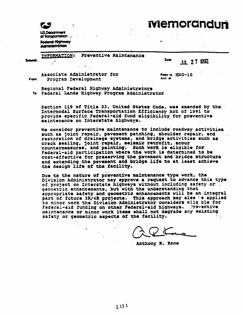
. .
--: Provmtive Haintmmnce .- . . D'r a 21 la . -
Associate Administrator for mobto HNC-10 . from: Program Devclopmmt *WI 04
Regional Federal Highway Administrators to: Federal Lands Highway Program Administrator
Section 119 of Title 23, United States Code, was amended by the.. Intermodal Surface Transportation Efficiency Act of 1991 to provide specific Federal-aid fund eligibility for proventive maintenance on Interstate highways.
We consider preventive maintenanc8 to include‘roadvay activities such as joint repair, pavmmnt patching, shoulder repair, and . restoration of drainage systems, and bridge activities such as crack sealing, joint repair, 8eissiC retrofit, scour countermeasures, and painting. Such work is eligible for Federal-aid participation where the work is detemained to be test-effective for prrserving tha pavement and bridge structure and extending the pavement and bridge life to at least achieve the design Iii8 qf t&e f8cflity.
-.. me to the nature of praventiva maintenaxk type work, the Division Ad?zinirtratox may approve a request to advance this type of project on Interstate highways without including safety or . gconctric enhancements, but with the understanding that appropriato safety and geometric enhancements will be an integral part of future 3R/4R projmes. This approach may also ?-• applied to minor work the Division Administrator considers elfg-ble ‘for Federal-aid funding on other Federal-aid highways. .?reventivm maintenance or minor work items shall not degrade any existing safety or geometric aspects of th8 facility.
-. .
Anthony R. Kane
2.13.1

2E .
--- . .-
Subtect’ INFORMATION: Interstate Maintenance Program Due June 14, 1993
Reov 10 F ram Executive Director A:r? of HNG-21
TO Regional Federal Highway Administrators Division Administrators Federal Lands Highway Program Administrator
Over the last decade, the State highway agencies have carried out necessary resurfacing, restoration, rehabilitation and reconstruction (4R) of Interstate highways in accordance.with the provisions of 23 U.S.C. 119 using funds apportioned under 23 U.S.C. 104(b)(5)(8). Since there was no differenttation in eligibility or pro rata funding for the various classes of work, there was not a need to develop strict definitions for deterraining whether the proposed work was resurfacing, restoration, rehabilitation or reconstruction. General definitions for pavement reconstruction and pavement rehabilitation (3R) are included in the "Pavement Policy' (23 CFR 626) which was established in 2988.
Currently, some questions pertaining to the deftnitions for rehabilitation and reconstruction havg been raised since Section 1009(e) of the ISTEA of 1991 generaily eliminated reconstruction on the Interstate System. from eligibility under 23 U.S.C. 119, Interstate Maintenance (II!) Program. As revised, this sectior! promotes maintenance of the Interstate System through approval of projects for resurfacing, restoration and rehabilitation, and through preventive maintenance activities.
Preventive maintenance includes restoration or rehabilitaticr of specific elements of a highway facility when it can be demonstrated tnat such activities are a cost-effective means of extending the pavement life. The list of specific work elements which are generally accepted as extending the service life of pavements and bridges is extensive. In general, any work which provides additional pavement structural capacity (general overlays or replacement of.portions of the pavement structure), or prevents the intrusion of water into the pavement or pavement base (seal. coats, joint seals, crack seals, overlays), or provides for removal of water that is in the pavement or pavement base (underdrains , restoration of drainage systems), restores pavement rideability (profiling, milling), or prevents the deterioration of. bridges (cleaning and painting, seismic retrofit, scour countermeasures, deck' rehabilitation or repair, deck drain cleaning) are considered to be work which extends the service life of the highway. 7hese typical preventive maintenance work items are not intended to be all inclusive but are rather a limited list of examples. The changes made by Section 1009(e) of the ISTEA of 1991 allow considerable flexibility in determining, based on -ood engineering analysis, the most cost-effective method of extending the serrice life of the existing Interstate pavements and bridges.
2.13.3
2 Each of the States tithtr havt or art in tbt prodtss of developing pavement, bridge and other management SyStmt in rtSpOMt tt tht ISTEA of 1991 and prtvlout FHUA pdjcits. One of the purposes of a pavtmtnt managtmtnt system is to identify cost-tffpctlvt strategies for proposed pavement work. In some cases, the most cost-effective pavement strategy may be removal and replacement of all or part of a badly deteriorated pavement structure. However, if a removal and replacement strategy is considered ineligible for 1~ funding, a less cost-effective strategy may be selected by the State based only on the class of available funding. Forcing any particular strategy based primarily on availrbiljty of funds would not provide the public with the best use of Federal-aid funds. Therefore, in order to provldt the States with necessary flexibility and still meet the intent of the rtvfstd 23 U.S.C. 119, pavement work which is identified by the State's pavement management system as being cost-effective, including removal and rtplactment strategies, where no additional capacity is provided is eligible as an I!4 Program funded project.
Reconstruction on the Interstate Systemmay still be approved; however, unless the proposed work meets the eligibillty requirtmtnts'of 23 U.S.C. 119(c);such work must use funds other than those apportjontd under 23 U.S.C. 104(b)(S)(B).
Mr. Anthony R. Kant's Way 21, 1992, memorandum on l 1991 Intermodal Surface Transportation Efficiency Act (MEA) Impltmtntation Interstate Uainttnanct Program. listed, as examples, stvtril types of improvtmtnts which were not eligible for IN funding. The .txamplt conctmlng %tu ramps' has created some confusion. As a rtsult, further clarifkation Is necessary.
After reviewing the legislation; we have dtttWntd that the addition ofinew ramps at existing ,inttrchmgts is properly 8 part of *Interchange *. . . T- reconstruction' arid dots not constitute added capacity uridtr 23 U.S.C. 119(g). Eligible new ramps may include those associated with reconstructton of existing interchanges necessitated by traffic growth or operational problems. Examples might include the addition of one or more loops to an exjsting diamond interchange, the addition of a dirtctional ramp to relieve Interstate traffic.congestion , or the addition of a ramp or ramps to provide a missing traffic movement. These examples are -also not intended to be all inclusive. In general, new ramps associated with the reconstruction of an existing interchange art tl4gible for I?4 funding and conversely, new ramps on an Interstate route where there is presently no existing interchange are not eligible for IM funding.
In addition to these comments and guidance concemingepavement and interchange eligibility; any proposals for III funded projects should include considerations for safety or geometric enhancements In accordance with Mr. Kane's July 27, 1992, memorandum on 'Preventive Maintenance.'.
E. Dean Carlson
2.13.4
HIGHWAY ENO~NEER~ND
Con8truction Management 4 Highway Design 5
Hydraulics 9 Pavements 17 Surveying 20 TRAFFIC ENOINLERIND
Capacity Analysis 22
Data Processing 26 .
General Traffic 29 Safety and Accident Records 32
Signal Timing and Warrants 33
Simulation and Analysis 4 1
Traffic Maintenance 4 2 _ TRANSIT
Operations 44
Planning 46 TRANSPORTATION PLANNING
Data Processing 47
Demand Modeling 48
Network Assignment 5 1
Project Management 53
Site Analysis 54
GENERAL INTEREST
Administration 5 6
Miscellaneous 5 7
PRoDUCT LIST 59
AL0 MCTfNIS (Center for Micro-
computers in Tronsportotion), is a software distribution and
user support center, originally
established by the Federal Highwoy Administration
(FHWA), ond now supported
by the Federal Transit Admin-
istration (FTA). The MCTra/7$
Center provides support to microcomputer users through
technical assistance of the
software it distributes.
Our goal is to serve 0s the’ nation’s primary center for
technical support and distribu-
tion of highway tronsportotian
and transit software. With a
staff of experts in o wide range of spociolties,
MCTCWW fields inquiries on
a variety of subiectt, such as:
what progroms ore avoikble
for your needs, which com-
puter should be purchased to
run your software, and help
with specific progromr.
As a support center, we learn
about what softworo others
ore using ond hoor about
progromr that you are looking
for. Feel free to call MC Tram with your quoations: 1.800- 226-l 013 (24hour message
hotline); (904) 392-0378;
Fox: (904) 392.3224; or logon to f&link, our 24-hour
electronic bulletin board,
(904) 392.3225.
McFinder, the McTrans catalog-on-disk, is updated quarterly. This cotolog is up-
dated annually, with quarterly
updates in the McTrans Newsletter. Bath can be obtained free on request.
d NEW PRODUCTS since June 94
3 UPDATES since June 94
2.14.1
HIGHWAI ENGINEERING PAVEMENT5
j Carson City PMS i The Carson City Pavement Management Sy* 1 tern was developed under an FHWA Rural / Technical Assistance Program (RTAPP) project.
Road inventory data include street name, seg- j ment limits and locatIon, subgrade strengths, 1 leng!hs. widths and surrounding land uses. : Structural information includes presence of
curb and gutter, shoulder width, surface and base type, thickness and deflection. The condi- tion survey includes information on ride qual- ity, alligator cracking, ravelling and longitudi- nal plus traverse cracking as the recorded forms of distress; and acceptable, tolerable and unac- ceptable listed as the three degrees of severity. The total quantity of each distress and severity combination is recorded for each street segment and deduct values assigned. Traffic survey in- formation includes volumes and classification. The type and extent of distress determine the re- habilitation strategy alternative. The ride qual- ity, alligator cracking and status of surface ravel- ling are checked. Then, depending on the traffic index la measure of truck volume and weights), a maintenance and rehabilitation treatment is recommended. Priorities are assigned based on a cost-benefit ratio determined as a function of cost-per-vehicle-mile. Cost estimates are then applied and listed with the expected life cycle before new treatments are required. LOS: 3 (from FHWA) Operating System: IBM PG’MS-DOS 2.1+ l3tiK and Hard Disk)
Supporting Software: dBASE III+ Productl Description CCPMS Carson City PMS, 7189 CCPMS.D Documentation
Price 550 SIO
ELSYM 5 ELSYM 5 is a computerized procedure which models a three-dimensional idealized elastic layered pavement system. It computes the varb 0”s component strasa, smins, an& diipke- merits along with principal values at locrtionr specified by the user, within the layered pavt ment. This program was developed for the Fed- eral Highway Administration. LOS: 3 (from FHWA) Operating System: IBM PC/MS-DOS 21+ Productt Description Price
ELSYM ELSYMS, 12/86 MO ELSYMD Documentation S.5
EXPEAR EXPEAR (upert system for eavemenb Evalu- ation And Rehabilitation) is a comprehensive computerized system to assist engineers in evaluating concrete highway pavements, dc- veloping feasible rehabilitation alternatives, and predicting the performance and c-t effec- tiveness of the alternatives. In its current state of development it is considered an excellent
training tooi. 5ome modifications would be required to make this program suitable for routine use. A computer program has been developed for each of the three pavement types: jointed Plain Concrete Pavement IJPCP), Jointed Rein- forced Concrete Pavements (IRCP), and Con- tinuously Reinforced Concrete Pavement ICRCP). The current version is EXPEAR 1.4 which possesses the capability to do life-cycle cost analysis and to delay rehabilitation up to five years. EXPEAR was developed by the University of Illinois at Urbana-Champaign under FHWA administrative funded or Highway Planning and Research funded contracts. Further work to enhance the capabilities of EXPEAR is pro- posed. A hard disk is recommended both for speed of execution and storage of data files. EXPEAR comes from Kathleen T. Hall of the University of Illinois. A supplemental docu- ment describing the Concrete Pavement Evalu- ation and Rehabilitation System is also avail- able. LOS: 3 Operating System: IBM PC/MS-DOS 3.0+ Product* Description Price EXPEAR EXPEAR, Ver.1.4 $45 EXPEAR.D Documentation 520 EXPEAR.DS Supplemental Document $25
HDM-III and HDM-PC HDM-III and HDM-PC (Highway Design and Maintenance Standards Model) is designed to make comparative cost estimates and economic evaluations of different construction and main- tenance options, including different time stag ing strategies, either for a given road section or an entire network. The concept can simply be outlined as: determining costs, adding the set of costs over time and comparing the total cost streama for various auintenance and construc- tion altemativa HP-PC indudes the core HDM-III modeL a fr cility to input data, a mechanism to use the out- puts with Lotus l-2-3, and a constrained version of the Expmdihue Budgeting Model (EBM). If HDM is used with the EBM, it is capable of comparing options under year-to-year budget co”erai”h. The basic data requiremeoh are the network de- scription. con.druction options, maintenance standards and unit costs, vehicle characteristics and unit costs, traffic voluma and proojectionm, exogenous benefits and costs, and analysis period and discount rata. The program is distributed ex- elusively by MC Tm under license frum the World Bank in W&ington, DC. The HDM-PC coma in two veniom 1) fully sup potted. which in&da free techniul assistance and updates and U unsupported which has no support tica. Both include the HDM-PC Us&s Manual and the EBM. The EBM may also
be purchased separately IPC only). The main- frame version is only available as fuily sup ported. The main HDM-III documentation (HDM.DVl ad .DV2 below), whtch de-be the model in detail, must be purchased separately. A French version of HDM III is available from PENDC of Pal-is or through Mcfrens Call for details. LOS: 1 (Copyright 1988. the World Bank) Operating System: IBM PC’MS-DOS 2.2~ I&MJK and Hard Disk) and .Mainframe Productl) Description Price HDM Fully supported HDM-PC. %OO
Ver.2.0 (incl. EB.M. Uset’s Manual, Volumes 1. 2 and HDM Manager)
EBM Fully supported version 560 of EBM (incl. Uset’s Manual)
HDM.LQG Upgrade to supported 9300 HDM.UN Unsupported HDM-PC Sloe
(incl. EBM and L’se<s Manual) EBM.UN Unsupported version of 530
EBM (incl. User’s .Manual) HDM.D Extra copies of HDM-PC
User/s Slanual $15
HDM.DVl HDM model documentation $20 Vol. 1: Description of HDM-III
HDM.DV2 HDM model documentation 525 Vol. 2: Use<s ,Manual for HDM-III
HDM Manager HDM Manager is a user-friendly shell environ- ment for specific customized applications of HDM-III. It stores the input data in an efficient manner, creates all the required HDM-III input files, runs the HDM-III program, collects the results and presents the results in a practical way. It provides a simple but powerful package for learning and using the maior concepts of HDM-III. HDM Manager is designed to be used with the fuII HDM-III package and documentation, which must be obtained separately. HDM Manager comes from the World Bank and is m- cludcd with the fully-supported HDM-III. LOS: 3 (Copyright 1993, The World Bank) Operating System: IBM PC/MS-DOS 3.1+ Product) Description Price HDM.MCR HDM .Manager, Ver.2.0 515
ILLI-6ACK ILLI-BACK is a closed-form backcalculation procedure for rigid pavements. It is a comput- erized adaptation of a rigorous. theoretically sound and efficient backcalculation proce- dure, applicable to two-layer, rigid pavement systems. This method simplifies considerably the effort required in interpreting nondestruc- tive testing (NDT) data. A unique feature of this appmach is that in addition to yielding the required backcahzulated parameters. it also
_^_, *.--.- FAX (904) 392-3224
2.14.2
HIGHWAY ENGINEERING PAVEMENTS
allows an evaluation of the degree to which the in situ system behaves as idealized by theory, and provides an indication of possible equipment shortcomings when these arise in the field. The ILLI-BXCK backcalculation procedure considers a two-layer system, consisting of a rigid pavement slab resting on an elastic solid tES1 or a dense liquid iDLl foundation. The backcalculation process requires four sensor deflections and utilizes the concept for deter- mining the Area of the deflecting basin.
When ILLI-BACK is executed on a personal computer, execution time per deflection basin permits the interpretation of a vast amount of NOT data in a very reasonable time. The method makes it feasible for the first time to have a practical backcalculation procedure at- tached to the testing device in the field, pro- viding instant checks on the accuracy of the deflection results generated, while there is still time and opportunity for remedial action. The program supports English and Metric units and runs interactively or in batch mode and is distributed in Copy-Protected format.
LOS: 7 (Copyright 1988, A.&l. Ioannides) Operating System: IBM PC/MS-DOS 2.1+ and math coprocessor Productl Description Price
ILBACK ILLI-BACK, Ver.2.0 S225
ILLI-PAVE Algorithms ILLI-PAVE Algorithms is a program based on a set of algorithms that were assembled from ILLI-PAVE, a very large complex finite element program. The algorithms are contained in the program called ILLIALGR in the form of a se- ries of spreadsheets selected from the menus. ILLI-P.\VE Algorithms can be used for prelimi- nary design and analysis of flexible pavements. This program was developed for the Federal Highway Administration. LOS: 3 (from FHWAI Operating System: IBM PC/MS-DOS 2.1+ Products Description Price
ILL1 ILL&PAVE, lY86 $40 1LLI.D Documentation $5
JCP-1 JCP-1 t Jointed Concrete Pavement) determines the serviceability and fatigue data for use in rigid pavement design. The design process is an iterative process in which a designer speci- fies trial structural designs, determines the re- quired inputs, executes the program, analyzes the resulting fatigue and serviceability data, modifies the design, and repeats the procedure. The program will analyze any number of slab thicknesses and provide outputs for each thick- ness, while holding a11 other inputs constant. LOS: 3 (from FHWA)
Operating System: IBM PC/MS-DOS 2.0+ Product* Description Price ICP Jointed Concrete S.&s
Pavement-l, I>86 JCP.0 Documentation $3
Long Beach PMS The Long Beach Pavement Management Sys- tem was also developed under the FHWA Rural Technical Assistance Program (RTAPI project. The system uses data files for physical informa- tion on the sections to be included in the analy- sis; pavement survey data detailing the condi- tion of the surface; and information on the scor- ing, treatment and cost estimates for each road segment. Traffic data are incorporated into the analysis in the form of a Traffic Index based on ESAL’s. A” evaluation system is utilized which rates the sections from the pavement surveys and applies a decision tree to determine initial proposed treatments and their estimated costs. LBPMS analyzes both flexible (asphalt con- crete) and rigid (Portland cement concrete) pavement types and produces several interme- diate and final reports. LOS: 3 (From FHWAI
Operating System: IBM PC/MS-DOS 2.1+ (384K and Hard Disk) Supporting Software: dBASE III+
Productl Description
LBPMS Long Beach PMS, 6189 LBPMS.0 Documentation
Price
540 $10
MAPCON MAPCON (Methods for Analyzing Pavement CONdition data) is a comprehensive, but user friendly package for pavement safety, rough- ness, structural capacity and surface condition analysis. MAPCON includes ELSYMS and the Calfomia FPMS and RPMS (which also are dis- tributed separately) and others. MAPCON pro- vides “paths” to all the individual programs, enabling the user to better analyze the pave- ment conditions, which can then be made part of a pavement management system. MAPCON was developed by Pennsylvania State University and ARE, Inc., under contract to FHWA. A hard disk is highly desirable, but not required. LOS: 3 (from FHWAI Operating System: IBM PCMS-DOS 2.0+ t512KI Productt Description Price
MAPCON MAPCON, 4l87 5100 MAPC0N.D Documentation s65
MIX MIX is a menu driven, BASIC program which calculates the specific gravities of aggregates for the design of the asphalt mix and the pm- portions of each aggregate in the mix. The pm- gram is based on the methodology described in
the MS-2 Report published by the Asphalt I stitute. No formal documentation is avaiiabl LOS: 5 (from University of Puerto Rico) Operating System: IBM PC!MS-DOS t.O+ Supporting Software: BASIC Productt Description P MIX .MIX, I!80
MODULUS and PASELS MODULUS and PASELS are two programs assess the current condition of the moduli a various structural layers of existing asphalt pavement. The moduli values are often ob- tained through nondestructive testing with use of falling weight deflectometen. The h: volume data collection capabilities of mode nondestructive testing equipment require a analysis method which is capable of rapid backcalculation of pavement layer moduli production mode of data reduction. A layer elastic method, MODULUS, was developer microcomputer use which is very fast in OF tion and provides consistently reliable rest Random errors in the measurements and ST tematic errors in the backcalculation proce may be reduced-the former by repeating tI measurements and the latter by using a mi computer expert system, PASELS, to provi consistently acceptable layer moduli value These programs were developed under a tional Cooperative Highway Research Prc gram project, the results of which are pub lished as NCHRP Report 327, “Determini Asphaltic Concrete Pavement Structural f erties by Nondestructive Testing.” This n which contains user’s manuals for both p grams, may be obtained through the Tran tation Research Board, Washington, D.C.
LOS: 3 Operating System: IBM PC/MS-DOS 2&
Product# Description
MODUL MODULUS, Ver.4.0 PASEL PASELS, Ver.l.0
NULOAD NULOAD is a computerized procedure th evaluates the effect of legal load limit cha on the (set of 12) life cycle costs of fIexiblc rigid, and/or composite pavements. Data I are interactively input through NULDIN, user-friendly processor for NULOAD. CO erable input data is required. LOS: 3 (from FHWA) Operating System: IBM PC/MS-DOS 2.01
Productd Description NULOAD NULOAD, 12’86 NUL0AD.D Documentation
;% A T A L 0 0 : ’
2.14.3
HIGH -Y EPdGZWEERING
PAVDCHEK
Pavechek is a software package for designing interlocking concrete pavements. The strut- tural design of flexible interlocking concrete pavements can be accomplished quickly on this menu-driven, PC computer based pro- gram. Pavement cross section designs can be generated for both new or overlay interlock- ing concrete pavements with unbound or bound base materials. Various levels of so- phtstication can be used in the program de- pending on the level of detail of input data available. The design rationale is based on the widely used 1986 AASHTO “Guide for the Design of Pavement Structures”. LOS: 7 Operating System: IBM PC:MS-DOS 2.1+ (Graphics) Product* Description Price PAVECHEK Pavechek, Ver.I.0 $53
Pavement Management Forecasting Model Pavement Management Forecasting &Model tP%IF) is a Lotus I-Z-3 template for use in plan- ning roadway maintenance and strategies. It runs in a Lotus, Release 2 environment and is completely menu’dnven. Data on road mainte- nance and construction unit costs, pavement deterioration rates. future funding estimates and current road conditions are required. Based upon three repair strategies, output is generated in tabular summaries and graphic plots. It allows changes at any level to iterate to desired results.
Agencies responsible for roadway maintenance related funding decisions will find it useful to compare various alternatives. The Lotus design is included in the appendix for users who might modify the algorithms to customized ap plications. PMF was donatedby Mr. William .Massicott of the Metropolitan Area Planning Council, Boston.
LOS: 3 Operating System: IBM PC/MS-DOS tO+ Supporting Software: Lotus I-2-3 Product * Description Price PMF PMF, Ver. 1.0 s40 PMF.D Documentation 515
Pavement Management System
Pavement Management System (PMS) is a dc- cision support tool used to assist management responsible for allocating pavement maintc nance resources. In a simple view, PMS is a process where information about the pave- ment system is collected, stored, analyzed and reported. This third generation, Version 3.0, combines a life cycle approach to pavement maintenance with a user-friendly, mouse or keyboard driven graphical user interface. This standard
system includes five modules for analyzing inventory, h’stnry. pavement condition, cost and budget, and a knowledge-based ranking System. It uses dl maintenance priority ranking system based upon the data collected and stored in the other four modules. In addition, the system’s modular design allows the inte- gration with other software to provide en- hanced graphical reports and system perfor- mance feedback.
LOS: 7 (Copyright 1992, Resource Intema- tional, Inc.)
Operation System:lBM PC/MS-DOS 3.0+ ProductU Description Price PMS PMS 5695 PMS.CIS PMS GIS version S2500
&J PMSPro
PMSPro is a pavement management program written in the .Microsoft Windows environ- ment using FoxPro for Windows. The program allows the user to completely customize the program by defining decision trees, rehabilita- tion strategies, deterioration cumes. deduct curves, and costs for different pavement types, functional classes, and traffic classes. PMSPro also contains other methods of calculating condition scores such as: WADOT PSC, FAA PCI, PAVER PCI.
P!USPro evaluates a street network both at the project level and the netwdrk level. At the Project Level, condition scores art used to pri- oritize streets. Decision trees evaluate the type and amount of distress to select an appropri- ate rehabilitation strategy. PMSPro can evalu- ate all street segments or only those that have changed since the last analysis. A complete cost accounting package allows costs to be adjusted according to the type and amount of distress as well as other costs such IS flagging and engineering. At the Network Level, a simplified decision proccu uses future calculated condition scores to select an appropriate rehabilitation stxattgy and cost. The analysis period can range from 5 to 80 years. Evaluate by functional class or traffic class. Carry unspent funds forward. Pri- oritize by Worst First or Last. PMSPm also can handle condition surveys or ditches, sidewalks, street signs and other street accessories. A maintenance module al- lows the tracking of past maintenance and costs. Compatible with most CIS programs. includ- ing MapInfo from Mapinfo, Inc. A GIS pro- gram can display pavement condition, recom- mended rehabilitation strategies, pavement types, sign inventory, etc. by connecting the databases to a map. LOS: 7 (Copyright 199201994. Pavement Engi- neers, Inc.)
Operating Software: IBM PCIMS-DOS 3.0+ Product # Description Price PMSPRO PMSPRO Pavement Sl.CQO
Management Program Ver. 5.2
Road Manager”
The Road ManagerrY is a modular roadway management system. Its umque features are the ability to include ALL roadway features in the evaluation of a road section, a modulu design, user defined parameters allowing extensive customization to fit local conditions and poli- cies. and a modem software design using light bar menus, a complete help system and pick lists for easy data entry. The General Roadway module serves as the “control center” for all other modules, record- ing road lengths, widths, classifications, etc., as well as overall condition indices for eight dif- ferent types of roadway features. The General Roadway module can also be used as a stand alone system, suitable for “windshield survey evaluation of a road network. l%he General Roudwny module is rpqutred foor ull other mod- ules.
The Asphalt Pavement. Roadway Drainage and Roadway Utility modules allow the detailed in- ventory and evaluation of roadway distresses, drainage needs and utility related features. These modules include a user definable deci- sion table that determines recommended re- pairs or maintenance. All calculations related to determining a condition index, recommended repaim and estimated costs can be modified by the user.
The Improvement Plan module uses informa- tion generated in the Asphalt Pavement, Road- way Drainage and Roadway Utility modules lo develop lists of recommended improvements 6s well as required budgets to attain a given network condition level. The computer-gener- ated plan for improvements can be overridden by the user. The estimated deterioration curve. used by the system in pmjecting fiahue pave ment and utility patch condition can also be modified. The Repair History module serves as an elec- tronic file cabinet, recording all work ptr- formed on a road section as it is completed. The Street Diagram module graphically displays and prints a11 Drainage and Utility features that have been inventoried through their respective modules. LOS: 7 (Copyright 1989, The Info Center, Inc.) Operating System: IBM PC/MS-DOS 3.0+ (MK and Hard Disk) PmductW Description Price RMRD General Roadway, Ver. 1.51 W95 RMAS Asphalt Pavement, 5995
Var. 1.51 RMCR Gravel Road, Vtr. 1.51 w95
FAX (904) 392.3224 C A T A L 0 G~iel-&-JJ-~~
2.14.4
Chapter 3
Rigid Pavement

CHAPTER 3
RIGID PAVEMENT
3.1 TA 5040.30, Concrete Pavement Joints, November 30,199O.
3.2 The Benefits of Using Dowel Bars, Technical Paper 89-03, May 17, 1989.
3.3 Preformed Compression Seals, Technical Paper 89-04, September 11, 1989.
3.4 Reinforcing Steel for JRCP (Cores form Kansas I-70), July 25, 1989.
3.5 Dowel Bar Inserters, February 23,1996. @ Dowel Bar Inserters, March 6,199O. o Dowel Bar Placement: Mechanical Insertion versus Basket Assemblies,
February 1989.
3.6 TA 5080.14, Continuously Reinforced Concrete Pavement, June 5, 1990. l Modification to TA 5080.14, August 29,199O.
3.7 Case Study, CRCP, June 22,1987.
3.8 Lateral Load Distribution and Use of PCC Extended Pavement Slabs for Reduced Fatigue, June 16,1989.
3.9 Longitudinal Cracking at Transverse Joints of New Jointed Portland Cement Concrete (PCC) Pavement with PCC Shoulders, November 30, 1988.
3.10 TA 5080.17, Portland Concrete Cement Mix Design and Field Control, July 14, 1994.
3.11 Summary of State Highway Practices on Rigid Pavement Joints and their Performance, May 19,1987.
3.12 Bondbreakers for Portland Cement Concrete Pavement with Lean Concrete Bases, June 13,198s.

t ‘) us oepmmlt dl- FodudtughwJy - Admlnlrtrdlon
mot dU
SJC ect Oowel Bar Inserters ;ore February 23, 1996
zczrr: Chref, Pavement Division 7eLlrv :o Ann. 31 HNG-40
r,3: Regional Administrators Federal Lands Highway Program Administrator Attention: Regional Pavement Engineers
.
By a March 6, 1990, memorandum, Mr. Louis Papet provided a copy of a Wisconsin Oepartment of Transportation report on “Dowel Bar Placement: Mechanical Insertion Versus Basket Assemblies.” Since that time, there appears to have been poor acceptance of the use of dowel bar Inserters. A recent draft NCHRP report noted that 8 States allow the use of inserters, 13 States allow it as an acceptable option, and 20 States do not allow their use
This technique has been used exclusively in some European countries for over 20 years . with satisfactory dowel placement results. We believe all States should be encouraged to make this an ailowable option in their specifications. We continue to encourage checking of dowel tolerances by probing through the fresh concrete early during the project and periodically as the work progresses. We also continue to recommend that when either baskets or inserters are used, the locatton of the dowels in the completed pavement be verified using metal detectors, pachometers, and cores.
If you have any comments or questons please contact Mr. John Hallin at (202) 366-l 323 or Mr. Roger Larson at (202) 366-l 3.25
T. Paul Teng, P.E. / ’
3.5.1(a)

t 3 c/ U.S. Department of Transportation
Federal Highway Administration
I vis Subject
PORTLAND CEMENT CONCRETE MIX DESIGN AND FIELD CONTROL
Classification Code Date
T 5080.17 July 14, 1994
Par. 1. Purpose 2. Background 3. Materials 4. Proportioning 5. Properties of Concrete 6. Mixing, Agitation, and Transportation 7. Placement and Consolidation 8. Curing and Protection 9. Concrete Distress Conditions 10. Manufactured Concrete Products 11. Quality Control and Testing
1. PURPOSE. To set forth guidance and recommendations relating to portland cement concrete materials, covering the areas of material selection, mixture design, mixing, placement, and quality control.
2. BACKGROUND
a. Each year approximately 46 million cubic meters of concrete are used in all highway construction. The vast majority of States use a prescription type specification for portland cement concrete, often specifying minimum cement content, maximum water cement ratio, slump range, air content, and many times aggregate proportions. Admixtures such as fly ash are incorporated into mixes as a part of the prescription.
b. This system has worked fairly well in the past but may change as emphasis is placed on performance based specifications. States have begun to reduce or eliminate the amount of inspection at concrete plants as automation has increased productivity.
3. MATERIALS
a. Portland Cement. The proper type of portland cement should be specified for the conditions which exist.
OPI: HNG-23
3.10.1
FHWA TECHNICAL ADVISORY T 5080.17 July 14, 1994
(1)
(2)
(3)
Types I, II, III, IP, and IS are typically used in highway construction. Type I is used when no special circumstances exist. Type II is used when sulfate exposure conditions are present. Type III is used when high early strengths are required. The use of Types IP and IS result in lower early strength gains and can be substituted for Type I cement when early strength is not a concern. In addition to the above mentioned types, Types IV and V are sometimes used in highway applications to meet special conditions. Further information about these cements can be found in the book Design and Control of Concrete Mixtures published by the Portland Cement Association (PCA).
It is recommended that the acceptance of portland cement be based on certification by the supplier. The certification should contain the lot number of the cement. The supplier's test results should accompany the certification or be available to the State. Verification samples should be taken and used as part of the acceptance system,
If alkali aggregate reactivity (AAX) is a concern, a maximum alkali content of 0.6 percent should be specified. Some State highway agencies consider this amount too high and recommend smaller amounts. If AAR is a problem in the State, a review of a States' Materials Manual is suggested. See Concrete Distress Conditions Section for other remedies.
b. Aggregates. Aggregates make up 60 to 70 percent of the volume of concrete mixes. A significant portion of poorly performing highway concrete can be traced to aggregate quality problems.
(1) The fine aggregate should meet the requirements of the American Association of State Highway and Transportation Officials (AASHTO) M 6.
3.10.2
FHWA TECHNICAL ADVISORY T 5080.17 July 14, 1994
(2)
(3)
The range for the gradation of fine aggregate is quite broad. The fineness modulus (FM), calculated using AASHTO T 27, can be used as a tool for assessing the variability of the fine aggregate gradation. The specifications should limit the range of the FM between 2.3 and 3.1 according to AASHTO M6 and the variation of the FM should not be more than 0.20 from the value of the aggregate source.
The FM is a means to control the influence that fine aggregate has on workability and the air content of the mix and is sometimes specified in the mix design. Further information regarding FM can be found in the Federal Highway Administration's manual FHWA- ED-89-006 (Portland Cement Concrete Materials Manual).
(4) It should also be noted that to provide good skid resistance, the PCA recommends that the siliceous particle content of the fine aggregate should be at least 25 percent. Consideration should be given, however, to the possibility of alkali-silica reactions when this is done.
(5) The coarse aggregate should meet the requirements stated in AASHTO M 80. For most parts of the country the severe exposure requirements should be used which means the use of class A aggregate for structural concrete and class B aggregate for pavements. The following table contains some of the more common information provided by Table 1 in AASHTO M 80.
3.10.3
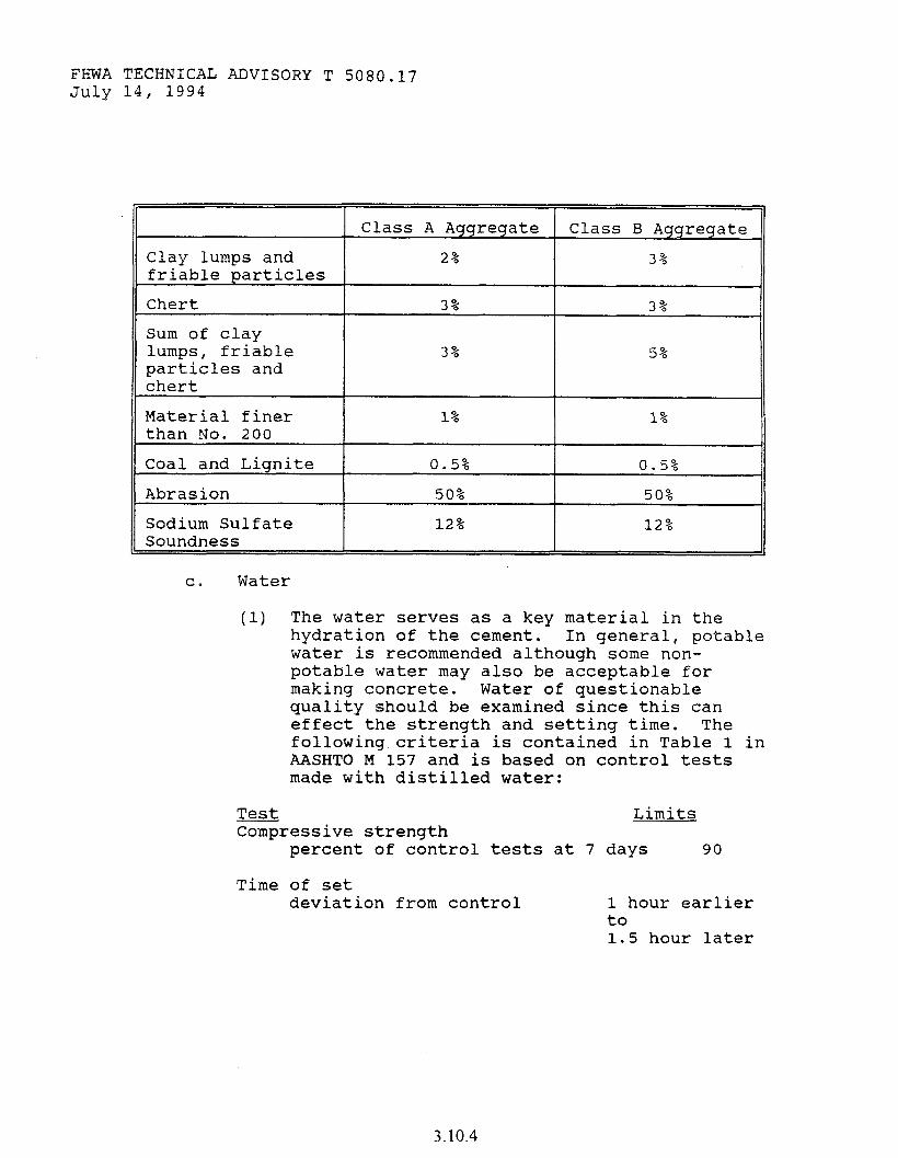
FHWA TECHNICAL ADVISORY T 5080.17 July 14, 1994
Class A Aggregate Class B Aggregate
Clay lumps and 2% 3% friable particles
Chert
Sum of clay lumps, friable particles and chert
3% 3%
3% 5%
Material finer than No. 200
1% 1%
Coal and Lignite
Abrasion
Sodium Sulfate Soundness
0.5% 0.5%
50% 50%
12% 12%
C!. Water
(1) The water serves as a key material in the hydration of the cement. In general, potable water is recommended although some non- potable water may also be acceptable for making concrete. Water of questionable quality should be examined since this can effect the strength and setting time. The following criteria is contained in Table 1 in AASHTO M 157 and is based on control tests made with distilled water:
Test Compressive strength
Limits
percent of control tests at 7 days 90
Time of set deviation from control 1 hour earlier
to 1.5 hour later
3.10.4
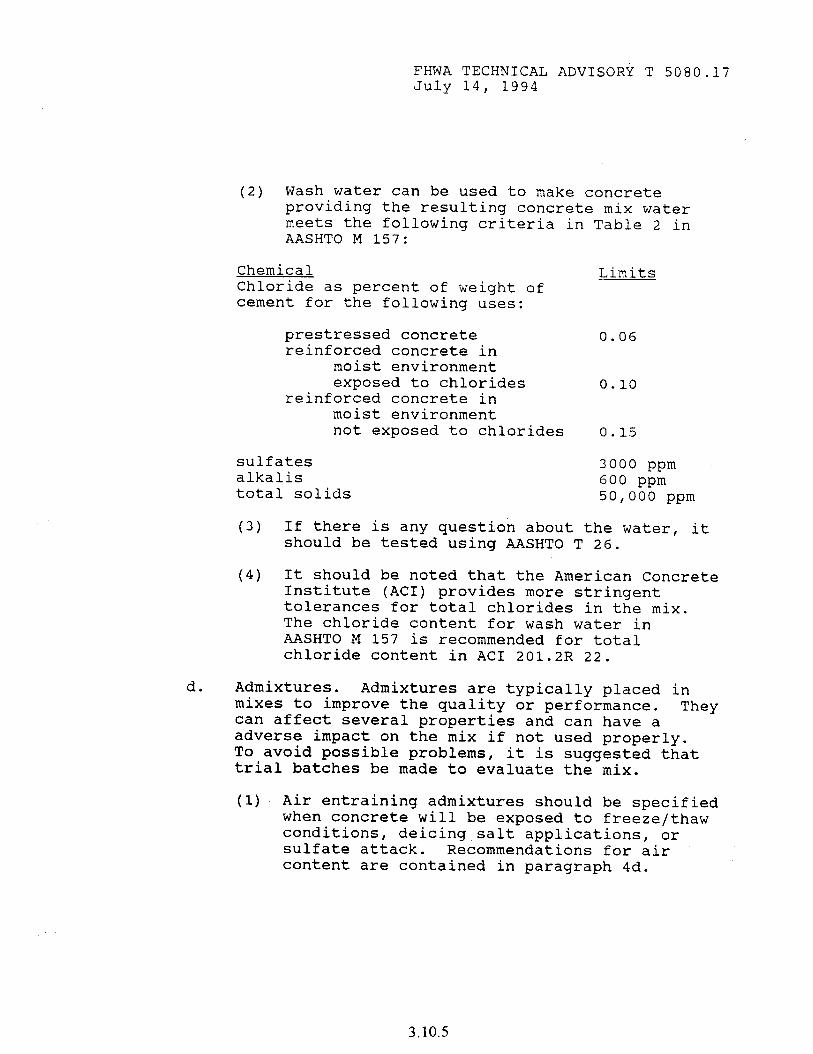
FHWA TECHNICAL ADVISORY T 5080.17 July 14, 1994
(2) Wash water can be used to make concrete providing the resulting concrete mix water meets the following criteria in Table 2 in AASHTO M 157:
Chemical Chloride as percent of weight of cement for the following uses:
Limits
prestressed concrete 0.06 reinforced concrete in
moist environment exposed to chlorides 0.10
reinforced concrete in moist environment not exposed to chlorides 0.15
sulfates alkalis
3000 ppm
total solids 600 ppm 50,000 ppm
(3) If there is any question about the water, it should be tested using AASHTO T 26.
(4) It should be noted that the American Concrete Institute (ACI) provides more stringent tolerances for total chlorides in the mix. The chloride content for wash water in AASHTO M 157 is recommended for total chloride content in AC1 201.2R 22.
d. Admixtures. Admixtures are typically placed in mixes to improve the quality or performance. can affect several properties and can have a
They
adverse impact on the mix if not used properly. To avoid possible problems, it is suggested that trial batches be made to evaluate the mix.
(1) Air entraining admixtures should be specified when concrete will be exposed to freeze/thaw conditions, deicing salt applications, or sulfate attack. Recommendations for air content are contained in paragraph 4d.
3.10.5
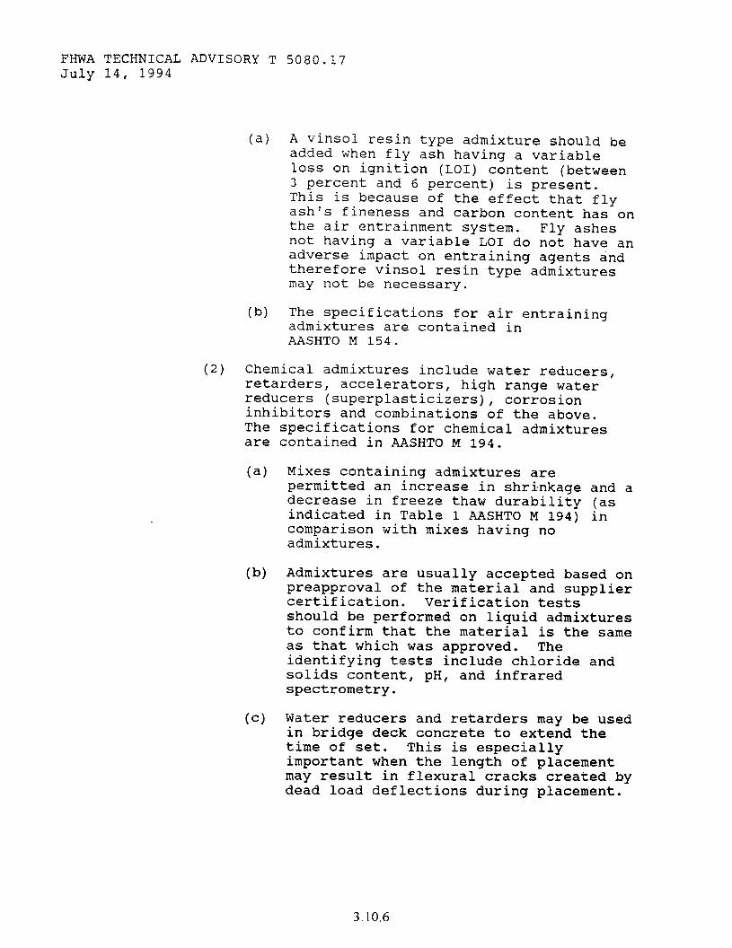
FHWA TECHNICAL ADVISORY T 5080.17 July 14, 1994
(a) A vinsol resin type admixture should be added when fly ash having a variable loss on ignition (LOI) content (between 3 percent and 6 percent) is present. This is because of the effect that fly ash's fineness and carbon content has on the air entrainment system. Fly ashes not having a variable LO1 do not have an adverse impact on entraining agents and therefore vinsol resin type admixtures may not be necessary.
(b) The specifications for air entraining admixtures are contained in AASHTO M 154.
(2) Chemical admixtures include water reducers, retarders, accelerators, high range water reducers (superplasticizers), corrosion inhibitors and combinations of the above. The specifications for chemical admixtures are contained in AASHTO M 194.
(a) Mixes containing admixtures are permitted an increase in shrinkage and a decrease in freeze thaw durability (as indicated in Table 1 AASHTO M 194) in comparison with mixes having no admixtures.
lb) Admixtures are usually accepted based on preapproval of the material and supplier certification. Verification tests should be performed on liquid admixtures to confirm that the material is the same as that which was approved. The identifying tests include chloride and solids content, pH, and infrared spectrometry.
(c) Water reducers and retarders may be used in bridge deck concrete to extend the time of set. This is especially important when the length of placement may result in flexural cracks created by dead load deflections during placement.
3.10.6
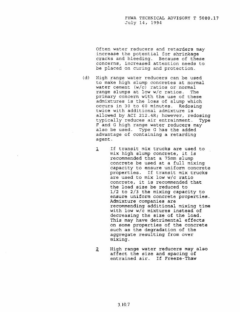
FHWA TECHNICAL ADVISORY T 5080.17 July 14, I994
(d)
Often water reducers and retarders may increase the potential for shrinkage cracks and bleeding. Because of these concerns, increased attention needs to be placed on curing and protection.
High range water reducers can be used to make high slump concretes at normal water cement (w/c) ratios or normal range slumps at low w/c ratios. The primary concern with the use of these admixtures is the loss of slump which occurs in 30 to 60 minutes. Redosing twice with additional admixture is allowed by AC1 212.4R; however, redosing typically reduces air entrainment. Tme F and G high range water reducers may also be used. Type G has the added advantage of containing a retarding agent.
If transit mix trucks are used to mix high slump concrete, it is recommended that a 75mm slump concrete be used at a full mixing capacity to ensure uniform concrete properties. If transit mix trucks are used to mix low w/c ratio concrete, it is recommended that the load size be reduced to l/2 to 2/3 the mixing capacity to ensure uniform concrete properties. Admixture companies are recommending additional mixing time with low w/c mixtures instead of decreasing the size of the load. This may have detrimental effects on some properties of the concrete such as the degradation of the aggregate resulting from over mixing.
2 High range water reducers may also affect the size and spacing of entrained air. If Freeze-Thaw
3.10.7
FHWA TECHNICAL ADVISORY T 5080.17 July 14, 1994
testinq as described bv ASTM C 666 indicates this to be a-problem, it is recommended that the air content be increased by lf percent.
(e) Calcium chloride, the most commonly used accelerator, has been associated with corrosion of reinforcing steel and should not be used where reinforcing steel is present. In addition to the corrosion problem calcium chloride also reduces sulfate resistance, increases alkali-aggregate reaction, and increases shrinkage. Calcium chloride should not be used in hot weather conditions, prestressed concrete, or steam cured concrete. In applications using calcium chloride, the dosage rate should be limited to 2 percent by weight of cement.
(f) Non-Calcium Chloride accelerators are available and can be used where reinforcing steel is present. However, care must be taken in selecting these since some may be soluble salts which can also aggravate corrosion.
(g) Calcium Nitrate, which can be used as a corrosion inhibitor, also can function as an accelerator. There are no consensus standards available for the use of this material. Manufacturer specification sheets should be consulted for proper use.
Mineral admixtures include fly ash, ground granulated blast furnace slag, natural pozzolans, lime, and microsilica (microsilica is also known as silica fume). Currently all of these materials are being used as additives or to reduce cement contents. Mineral admixtures are accepted based on approved sources with certifications and verification samples.
3.10.8
FHWA TECHNICAL ADVISORY T 5080.17 July 14, 1994
(a) According to the American Society of Testing and Materials (ASTM) C 618 and AASHTO M 295 there are two classes of fly ash, class C and class F. Since variability in fineness and carbon content can affect air content, the optional uniformity specifications in AASHTO M 295 should be specified when air entrained concrete is used. Fly ashes with LO1 values less than 3 percent will typically not affect air content. Vinsol resin air entrainment admixtures should be specified when fly ash with LO1 higher than 3 percent is used.
1 Fly ash may be used as a supplement or a replacement and is typically limited to 15 to 25 percent. If it is used as a replacement, it replaces cement on a 1.0 to 1.2:1 basis by weight.
2
2
Fly ash can be used to increase workability, reduce permeability, and mitigate alkali silica reaction (A=) ; some Class C can make it worse. Class F fly ash with a calcium oxide content less than 10 percent can be used to mitigate ASR and sulfate attack. Fly ash with a calcium oxide content greater than 10 percent should be used in concrete which will be subjected to sulfate attack only with verification testing. This percentage and fly ash classification should only be used as a guide; further qualification should be based on ASTM C 452.
The cementing action with fly ash is pozzolanic in nature. The pozzolanic reaction with fly ash stops at approximately 40 Celsius.
3.10.9
FHWA TECHNICAL ADVISORY T 5080.17 July 14, 1994
Precautions need to be taken when using fly ash in concrete at lower temperatures. It should also be noted that fly ash can reduce early strength development and, therefore, should be monitored closely.
(b) Ground granulated blast furnace slag specifications are contained in AASHTO M 302.
L Ground granulated blast furnace slag (GGBFS) is a cementitious material and can be substituted for cement on a 1:l basis by weight for up to 50 percent of the cement in the mix.
2 For fresh concrete using GGBFS, the air entrainment agent dosage may need to be increased. The workability and finishability typically are improved but in mixes having high cementitious material content, mixes can be sticky and difficult to finish. Bleeding may be reduced and setting time may be longer.
1 Ground granulated blast furnace slag can reduce sulfate attack, alkali-aggregate reactions, and permeability. The rate of strength gain is usually decreased and sensitive to low temperature.
(c) Microsilica specifications are contained in AASHTO M 307. Microsilica can be used as an admixture or as a replacement for an equivalent amount of cement to produce high strength concrete. Microsilica will reduce permeability and help reduce alkali-aggregate reactions.
3.10.10
FHWA TECHNICAL ADVISORY T 5080.17 July 14, 1994
1 Microsilica has been used as an addition to concrete up to 15 percent by weight of cement, although the normal proportion is 10 percent. With an addition of 15 percent, the potential exists for very strong, brittle concrete. It increases the water demand in a concrete mix; however, dosage rates of less than 5 percent will not typically require a water reducer. High replacement rates will require the use of a high range water reducer.
2 Microsilica greatly increases the cohesion of a mix, virtually eliminating the ‘potential for segregation. However, the cohesion may cause mixes to be sticky and difficult to finish. It may be necessary to specify a higher slump than normal to offset the increased cohesion and maintain workability. In addition, microsilica in the mix greatly reduces bleeding; therefore, mixes which contain microsilica tend to have a greater potential for plastic shrinkage cracking. It is imperative to use the proper curing methods to prevent the surface water from evaporating too quickly.
4. PROPORTIONING. Most of the concrete placed in highway facilities in the United States are under severe exposure conditions. State highway agencies specify a recipe for concrete mixes which includes minimum cement content, maximum water-cement ratio, air content range, and minimum strength. These requirements are necessary to achieve durability, as well as strength.
a. The maximum aggregate size should be as large as possible. This reduces total aggregate surface area and results in lower cement demand. The
3.10.11
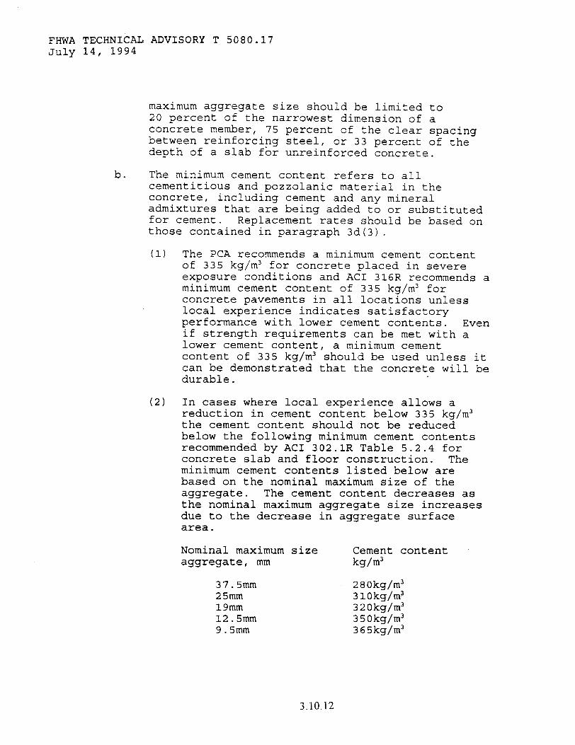
FHWA TECHNICAL ADVISORY T 5080.17 July 14, 1994
maximum aggregate size should be limited to 20 percent of the narrowest dimension of a concrete member, 75 percent of the clear spacing between reinforcing steel, or 33 percent of the depth of a slab for unreinforced concrete.
b. The minimum cement content refers to all cementitious and pozzolanic material in the concrete, including cement and any mineral admixtures that are being added to or substituted for cement. Replacement rates should be based on those contained in paragraph 3d(3).
(1) The PCA recommends a minimum cement content of 335 kg/m3 for concrete placed in severe exposure conditions and AC1 316R recommends a minimum cement content of 335 kg/m3 for concrete pavements in all locations unless local experience indicates satisfactory performance with lower cement contents. Even if strength requirements can be met with a lower cement content, a minimum cement content of 335 kg/m3 should be used unless it can be demonstrated that the concrete will be durable.
(2) In cases where local experience allows a reduction in cement content below 335 kg/m3 the cement content should not be reduced below the following minimum cement contents recommended by AC1 302.1R Table 5.2.4 for concrete slab and floor construction. The minimum cement contents listed below are based on the nominal maximum size of the aggregate. The cement content decreases as the nominal maximum aggregate size increases due to the decrease in aggregate surface area.
Nominal maximum size Cement content aggregate, mm kg/m3
37.5mm 280kg/m3 25mm 3lOkg/m? 19mm 320kg/m3 12.5mm 350kg/m3 9.5mm 365kg/m3
3.10.12
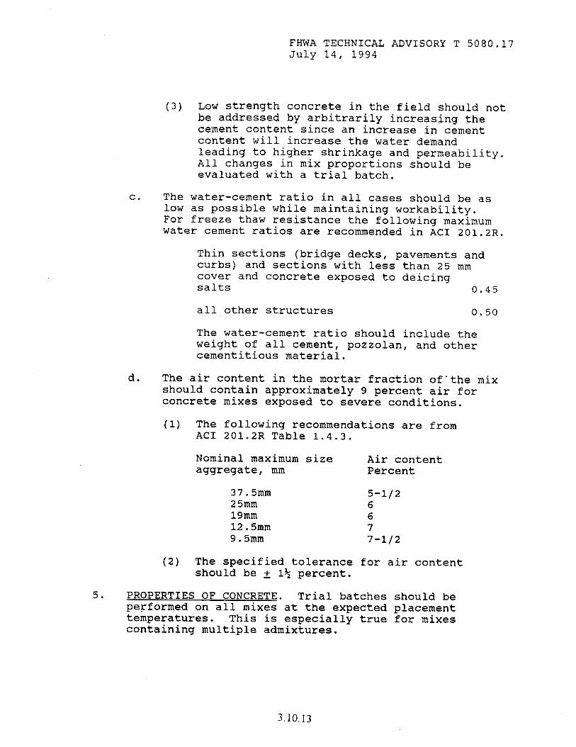
FHWA TECHNICAL ADVISORY T 5080.17 July 14, 1994
(3) Low strength concrete in the field should not be addressed by arbitrarily increasing the cement content since an increase in cement content will increase the water demand leading to higher shrinkage and permeability. All changes in mix proportions should be evaluated with a trial batch.
C. The water-cement ratio in all cases should be as low as possible while maintaining workability. For freeze thaw resistance the following maximum water cement ratios are recommended in AC1 201.2R.
Thin sections (bridge decks, pavements and curbs) and sections with less than 25 mm cover and concrete exposed to deicing salts 0.45
all other structures 0.50
The water-cement ratio should include the weight of all cement, pozzolan, and other cementitious material.
d. The air content in the mortar fraction of-the mix should contain approximately 9 percent air for concrete mixes exposed to severe conditions.
(1) The following recommendations are from AC1 201.2R Table 1.4.3.
Nominal maximum size Air content aggregate, mm Percent
37.5mm 5-l/2 25mm 6 19mm 6 12.5mm 7 9.5mm 7-l/2
(2) The specified tolerance for air content should be + 1% percent.
5. PROPERTIES OF CONCRETE. Trial batches should be performed on all mixes at the expected placement temperatures. This is especially true for mixes containing multiple admixtures.
3.10.13
FHWA TECHNICAL ADVISORY T 5080.17 July 14, 1994
a. Workability. A concrete mix must be workable to ensure proper consolidation and finishing. The workability of a mix is a function of the gradation of the aggregate, amount and type of admixtures, water content, concrete temperature, and time. Once a workable mix is established during the trial batch process, slump can be used to monitor the consistency and uniformity of the mix. Slump, by itself, is not a measure of workability.
b. Durability
(1) Freeze-thaw durability depends on durable aggregates, proper air entrainment, low permeability, and a low water-cement ratio.
(2) D-cracking is strictly a pavement durability problem and is associated with aggregates. It should be addressed with the source approval of the aggregates.
(3) Alkali aggregate reactions are mostly the result of the alkali content of the cement in the concrete. The most common alkali aggregate reaction is associated with silicious aggregates although reactions have occurred with carbonate materials. If a reactive aggregate is encountered, several options are available: not using the source of aggregate, using a low alkali cement, using fly ash, or using microsilica. If alkali reactive aggregates are used, testing should be performed with the mix prior to its use to ensure a durable concrete.
(4) Resistance to.or susceptibility to sulfate attack depends on the chemical composition of the cementitious portion of the concrete. Sulfate attack can occur from ground water, deicing salts, or sea water. Type II or Type V cement or some fly ashes, may be used to mitigate the problem.
C. Strength. The strength requirement is the compressive strength, f',, at 28 days. This must be equal to or exceed the average of any set of
3.10.14
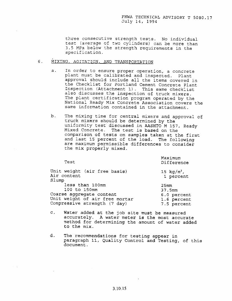
FHWA TECHNICAL ADVISORY T 5080.17 July 14, 1994
three consecutive strength tests. No individual test (average of two cylinders) can be more than 3.5 MPa below the strength requirements in the specification.
6. MIXING, AGITATION, AND TRANSPORTATION
a. In order to ensure proper operation, a concrete plant must be calibrated and inspected. Plant approval should include all the items covered in the Checklist for Portland Cement Concrete Plant Inspection (Attachment 1). This same checklist also discusses the inspection of truck mixers. The plant certificationprogram operated by the National Ready Mix Concrete Association covers the same information contained in the attachment.
b. The mixing time for central mixers and approval of truck mixers should be determined by the uniformity test discussed in AASHTO M 157, Ready Mixed Concrete. The test is based on the comparison of tests on samples taken at the first and last 15 percent of the load. The following are maximum permissible differences to consider the mix properly mixed.
Test Maximum Difference
Unit weight (air free basis) Air content Slump
less than 1OOmm 100 to 150mm
Coarse aggregate content Unit weight of air free mortar Compressive strength (7 day)
15 kg/m3, 1 percent
25mm 37.5mm 6.0 percent 1.6 percent 7.5 percent
C. Water added at the job site must be measured accurately. A water meter is the most accurate method for determining the amount of water added to the mix.
d. The recommendations for testing appear in paragraph 11, Quality Control and Testing, of this document.
3.10.15
FHWA TECHNICAL ADVISORY T 5080.17 July 14, 1994
7.
e. The haul time should be limited to 90 minutes for truck mixers that agitate the mix and 30 minutes for trucks that do not agitate the mix. The maximum number of revolutions for truck mixers should be limited to 300.
f. No admixtures or water should be permitted to be added to the mix after the mixer has started unloading.
PLACEMENT AND CONSOLIDATION
a. Prior to placement of the concrete an inspection should occur covering the items in either the checklist for the placement of structural concrete (Attachment 2) or the checklist for the placement of concrete paving (Attachment 3).
b. Acceptance testing for pumped concrete should occur at the discharge end of the pump.
C. Aluminum pipe and chutes should not be used in concrete pumping operations.
d. Concrete can be conveyed to the location of placement by several commonly used methods including pumps, belt conveyors, buckets, chutes, and dropchutes. Care should be taken to ensure that there is no debris or blockages that will hinder or influence the properties or flow of the material. Concrete should not be allowed to free fall from distances greater than 1.2 .meters to avoid segregation.
e. All concrete should be accompanied to the project with a delivery ticket. A sample delivery ticket appears as Attachment 4.
f. The proper consolidation of concrete is a significant factor in the ultimate performance of the concrete and it is achieved through vibration.
3.10.16
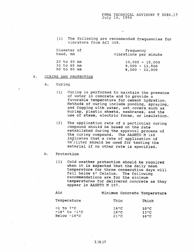
FHWA TECHNICAL ADVISORY T 5080.17 July 14, 1994
8.
(1) The following are recommended frequencies for vibrators from AC1 309.
Diameter of Frequency head, mm vibrations per minute
20 to 40 mm 10,000 - 15,000 30 to 65 mm 9,000 - 13,500 50 to 90 mm 8,000 - 12,000
CURING AND PROTECTION
a. Curing
(1) Curing is performed to maintain the presence of water in concrete and to provide a favorable temperature for cement hydration. Methods of curing include ponding, spraying, and fogging with water, wet covers such as burlap, plastic sheets, membranes, and the use of steam, electric forms, or insulation.
(2) The application rate of a particular curing compound should be based on the rate established during the approval process of the curing compound. The AASHTO M 148 in$iicates that a rate of application of 5m /liter should be used for testing the material if no other rate is specified.
b. Protection
(1) Cold weather protection should be required when it is expected that the daily mean temperature for three consecutive days will fall below 4O Celsius. The following recommendations are for the minimum temperatures for delivered concrete as they appear in AASHTO M 157.
Air Minimum Concrete Temperature
Temperature Thin Thick
-1 to 7oc -18O to -1OC Below -18OC
16°C 1ooc 18OC 13oc 21oc 16OC
3.10.17
FHWA TECHNICAL ADVISORY T 5080.17 July 14, 1994
.
Thin sections are defined as those less than 300 mm.
(2) concrete should never be placed on a frozen subgrade. Care should be taken to assure that the subgrade is free from frost.
(3) Hot weather conditions can be defined as a condition of high temperature, low humidity, and high winds. The existence of these conditions can be determined by finding the evaporation rate described in AC1 305 and included in Attachment 5. An evaporation rate exceeding 1 kg/m'/hr has the potential of causing plastic shrinkage cracks. The evaporation rate is a function of concrete temperature, ambient temperature, relative humidity, and wind velocity. This chart has been incorporated into several State specifications. It may not completely apply in all cases, especially in mixes containing admixtures which reduce the amount of bleeding.
(4) In addition to the plastic shrinkage cracking problem, ultimate strength will decrease with higher temperatures. The AC1 has not recommended a maximum concrete temperature since strength loss can be compensated for by other means.
However, significant strength loss occurs above 32OC. Due to the strength loss and increase in potential for plastic shrinkage cracking, many States have set a maximum ambient placement temperature of 32OC. In all cases, trial batches should be performed at the highest expected temperature to ensure that the concrete will have the desired properties.
9. CONCRETE DISTRESS CONDITIONS
a. Alkali aggregate reactivity can be one of two tw=s, alkali-silica and alkali-carbonate. The most prominent problem is cracking of the concrete due to the alkali-silica reaction (ASR).
3.10.18
FHWA TECHNICAL ADVISORY T 5080.17 July 14, 1994
(1) A widely used test to determine ASR is ASTM C 227. The current test criteria allow a maximum expansion of 0.05 percent at 3 months and 0.1 percent at 6 months. Research by PCA indicates that the critical criteria is 0.1 percent ultimate expansion. Since some reactions take longer than others, testing should continue as long as expansion is occurring. Some aggregates may take several years to show expansion.
(a) Recently the Strategic Highway Research Program developed a test which can be used for rapid determination of ASR. It is called the Gel Fluorescence Test and can be performed easily and inexpensively by field personnel. With this test, a 5 percent solution of uranyl acetate is applied on the concrete surface. Ultraviolet light is then used to illuminate the surface and if ASR exists, a yellow-green fluorescent glow will appear. Some safety concerns may be associated with this test so proper precautions are recommended. It should also be noted that the test is limited to preexisting concrete and not to fresh concrete.
(b) Alkali-silica reaction can be mitigated by limiting the alkali content of portland cement to 0.6 percent, by using class F fly ash or microsilica admixtures, or by reducing the water to cement ratio. The success of this approach may be limited; therefore, laboratory testing should be conducted. Protecting the final structure from moisture also reduces ASR.
(c) Although PCA recommends 25 percent of the fine aggregate be siliceous material to improve skid resistance, the use of
' some siliceous material can promote the ASR reaction and requires care to ensure this will not occur.
3.10.19
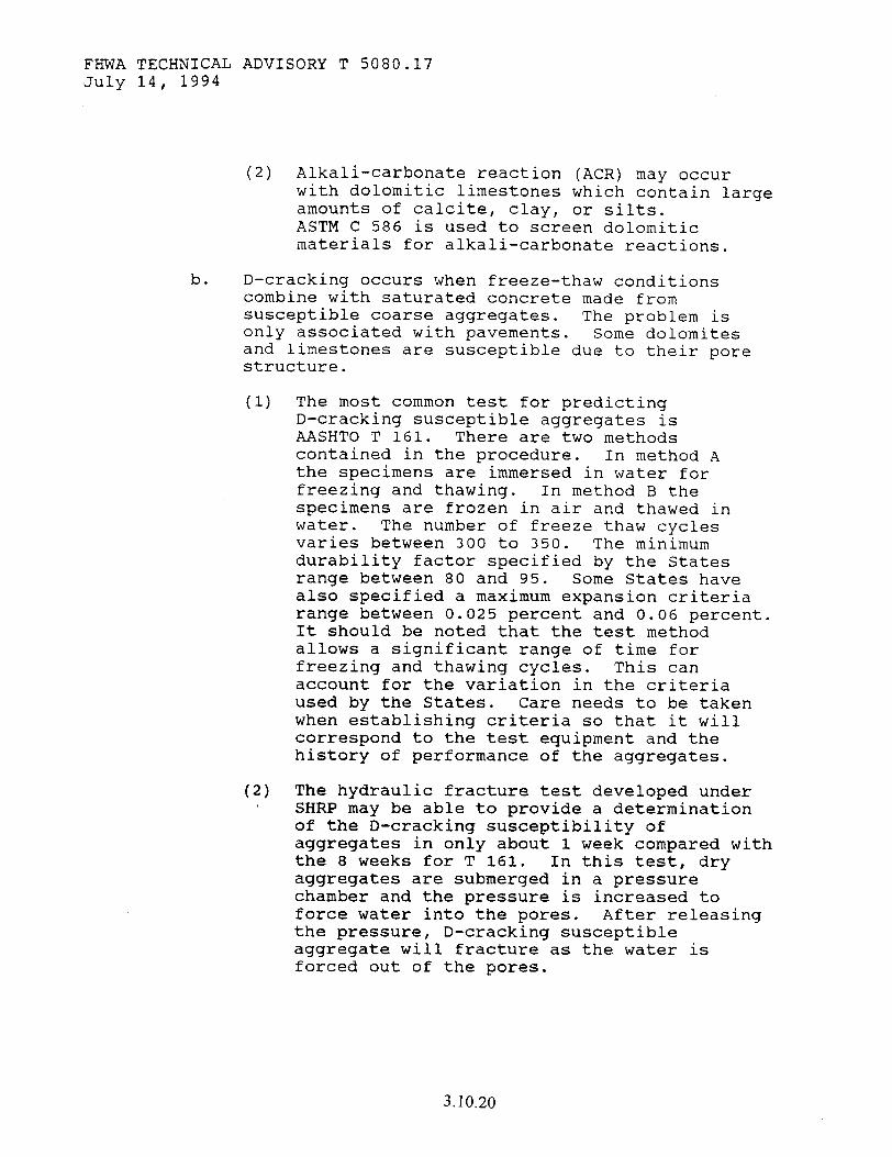
FHWA TECHNICAL ADVISORY T 5080.17 July 14, 1994
(2) Alkali-carbonate reaction (ACR) may occur with dolomitic limestones which contain large amounts of calcite, clay, or silts. ASTM C 586 is used to screen dolomitic materials for alkali-carbonate reactions.
b. D-cracking occurs when freeze-thaw conditions combine with saturated concrete made from susceptible coarse aggregates. The problem is only associated with pavements. Some dolomites and limestones are susceptible due to their pore structure.
(1) The most common test for predicting D-cracking susceptible aggregates is AASHTO T 161. There are two methods contained in the procedure. In method A the specimens are immersed in water for freezing and thawing. In method B the specimens are frozen in air and thawed in water. The number of freeze thaw cycles varies between 300 to 350. The minimum durability factor specified by the States range between 80 and 95. Some States have also specified a maximum expansion criteria range between 0.025 percent and 0.06 percent. It should be noted that the test method allows a significant range of time for freezing and thawing cycles. This can account for the variation in the criteria used by the States. Care needs to be taken when establishing criteria so that it will correspond to the test equipment and the history of performance of the aggregates.
(2) The hydraulic fracture test developed under SHRP may be able to provide a determination of the D-cracking susceptibility of aggregates in only about 1 week compared with the 8 weeks for T 161. In this test, dry aggregates are submerged in a pressure chamber and the pressure is increased to force water into the pores. After releasing the pressure, D-cracking susceptible aggregate will fracture as the water is forced out of the pores.
3.10.20
FHWA TECHNICAL ADVISORY T 5080.17 July 14, 1994
10.
11.
MANUFACTURED CONCRETE PRODUCTS Concrete products consist of structural elements constructed at a plant and trucked to the jobsite. These precast products typically consist of beams, pipes, barriers, poles and other special elements. The criteria outlined within this document apply to these products as well. Additional information about prestressed products are contained in the Checklist for Prestressed Concrete Products in Attachment 6.
QUALITY CONTROL AND TESTING
a. All testing should be performed by certified technicians. The AC1 and the National Institute for Certification in Engineering Technologies (NICET) administer a concrete technician certification program. Guidance for establishing a certification program for testing personnel appears in a FHWA paper titled "Laboratory Accreditation and Certification of Testing Personnel."
b. Process control testing should be performed on aggregate moisture content, aggregate gradation, air content, unit weight, and slump at the plant.
(1) The specifications should require that the contractor provide a process control plan. The State should also provide guidance on the minimum requirements for a process control plan. As a minimum, the process control plan should include the information contained in Attachment 7.
(2) All process control tests should be plotted on control charts. Control charts are a good visual tool for discovering trends quickly before major problems occur.
C. The acceptance procedures should include monitoring of the process control activities includ,ing aggregate gradation testing. In addition, acceptance testing at placement would include slump, strength, and air content. Close monitoring of the water-cement ratio is also required since this will ultimately affect the durability and strength of the concrete.
3.10.21
FHWA TECHNICAL ADVISORY T 5080.17 July 14, 1994
Additional information on acceptance procedures is provided in the Technical Advisory on Acceptance of Materials T 5080.11.
d. It is recommended that compressive strength be accepted using statistical criteria (based on average strength and standard deviation) to ensure that the strength, f',, at 28 days, is equal or exceeded by the average of any set of three consecutive strength tests. No individual test (average of two cylinders) can be more than 3.5 MPa below the specified strength. There are two strengths to be considered. One is the minimum specified strength (f',) which is a function of the structural requirements. The second is the average strength for mix design (f',,). The f',, must be higher than f', to ensure that the concrete will exceed the minimum specified strength. The following recommendations for f',, are from AC1 318.
(1) Unknown Standard Deviation
Specified compressive strength, MPa
Required average compressive. strength, MPa
Less than 20MPa f'c + 6.9
20MPa to 35MPa f'c + 8.3
Over 35MPa f'c + 9.6
(2) Known Standard Deviation
For greater than 30 test results (one test result is the average of two cylinder breaks) f 'cr is the greater of the two values from the following equations.
MPa
f',, = f', + 1.4s f',, = f', + 2.4s - 3.5
s = Standard deviation
3.10.22
FHWA TECHMICAL ADVISORY T 5080.17 July 14, 1994
(3) For 15 to 30 test results the standard deviation in the above formulas can be modified by the following factors.
Modification factor for No. of Tests standard deviation
Less than 15 use table for unknown s 15 1.16 20 1.08 25 1.03 30 1.00
Air content and slump should be accepted based on an attribute system, i.e., pass/fail. The following is a recommended criteria.
Acceptance criteria
Acceptable
Air content deviation, %
< 1.5
Slump deviation, mm < 25mm
Acceptable for trucks on , the road 1.5 to 2 25 to 31.5mm
Reject >2 > 31.5mm
Testing procedures for resistance to freeze-thaw damage, deicing salt attack, and abrasion resistance are long and involved and do not lend themselves to testing on a routine basis. These tests are usually conducted to determine the durability of the concrete. It should also be noted that high strength concrete does not always insure durable concrete.
Anthony R. Kane Associate Administrator
for Program Development
Attachments
3.10.23

THTS PAGE LEFT BLANK INTENTIONALLY
3.10.24
FHWA TECHNICAL ADVISORY T 5080.17 July 14, 1994 ATTACHMENT 1
CHECKLIST FOR PORTLAND CEMENT CONCRETE PLANT INSPECTION
1. Materials
A. Cements and Mineral Admixtures (cement, fly ash, etc.)
(1) Is evidence of cement or fly ash acceptability present (certification, test results)?
(2) Are bins or silos tight and provide for free ' movement to discharge opening?
(3) Are bins or silos periodically check for caking?
emptied to
(4) Plants should provide separate storage for each type of cement or mineral admixture being used. Are the materials being isolated to prevent intermingling or contamination?
B. Aggregates
(1)
(2)
(3)
(4)
(5)
Does the plant display evidence of source approval?
Are aggregates stockpiled to prevent segregation and degradation? The preferred method of stockpiling is in layers. Cone shaped stockpiles will segregate.
Are stockpiles adequately separated to prevent intermingling?
Does the plant maintain separate storage bins or compartments for each size or type of aggregate? Are the aggregates tested for gradation and moisture content?
What is the surface underneath stockpiles? Soil or paved? Are the stockpiles covered?
3.10.25
FHWA TECHNICAL ADVISORY T 5080.17 July 14, 1994 ATTACHMENT 1
C. Water
(1) Does the plant have an adequate water supply with pressure sufficient to prevent interference with accuracy of measurement?
(2) Is there any evidence or history of contaminants in supply?
D. Liquid Admixtures
(1) Is there evidence of source approval?
(2) Is the admixture and dispensing equipment protected from freezing, contamination, or dilution?
(3) How often are the admixture metering and dispensing equipment periodically cleaned?
2. Batchins Ecuioment
A. Scales
(1)
(2)
(3)
(4)
(5)
(6)
Scales should indicate weight by means of a beam with balance indicator, full range dial, or digital display.
For all types of weighing devices batchman and the stations.
batching systems the must be readable by the inspector from their normal
Scales should be certified or should be calibrated with a certified scale.
Ten 25 kilogram test weights should be available at the plant at all times.
Scale accuracy should generally be within plus or minus .4 percent of the scale capacity.
Water meters will need to be calibrated to 1 percent of total added amount.
3.10.26
FHWA TECHNICAL ADVISORY T 5080.17 July 14, 1984 ATTACHMENT 1
B. Batchers
(1)
(2)
(3)
(4)
(5)
(6)
(7)
(8)
3. Mixinq
Cementitious material should be weighed on a scale that is separate and distinct from other materials.
Bins with adequate separation should be provided for fine aggregate and each size coarse aggregate.
Weigh hoppers should not allow the accumulation of tare materials and should fully discharge into the mixer.
Batchers should be capable of completely stopping the flow of material and water hatchers should be capable of leak free cut off.
Separate dispensers will be provided for each admixture.
Each volumetric admixture dispenser should be an accurately calibrated container that is visible to the batchman from his normal position.
Aggregate should be measured to plus or minus 2 percent of the desired weight, cement to 1 percent; water to 1 percent and admixtures to 3 percent.
Semi-automatic and automatic control mechanisms should be appropriately interlocked.
A. Stationary Mixers
(1) Mixers should be equipped with a metal plate that indicates mixing speed and capacity.
(2) Mixers should be equipped with an acceptable timing device that will not permit discharge until the specified mixing time has elapsed.
3.10.27

FHWA TECHNICAL ADVISORY T 5080.17 July 14, 1994 ATTACHMENT 1
(3) Mixers are to be examined periodically to detect changes in condition due to accumulation of hardened concrete or blade wear. A copy of the manufacturer's design, showing dimensions and arrangements of blades, should be available at the plant at all times.
B. Truck Mixers
(1)
(2)
(3)
(4)
4. Weather
A.
(1)
(2)
B.
(1)
Mixers should be equipped with a metal plate that indicates mixing speed, capacity, mixing revolutions, agitating speed and agitating capacity.
Mixers should be equipped with a revolution counter.
Mixers are to be examined to determine satisfactory interior condition, that is, no appreciable accumulation of hardened concrete and no excessive blade wear. A copy of the manufacturer's design, showing dimensions and arrangements of blades,, should be available at the plant at all times.
Charging and discharge openings and chutes should be in good condition.
Hot Weather
When concreting during hot weather, is plant equipped to cool ingredients? Is equipment available to produce acceptable ice?
How are aggregates cooled? If by sprinkling, is provision made to account for excessive water?
Cold Weather
When concreting during cold weather, is plant equipped to heat ingredients to produce concrete of applicable minimum temperature.
3.10.28
FHWA TECHNICAL ADVISORY T 5080.17 July 14, 1994 ATTACHMENT 2
CHECKLIST FOR STRUCTURAL CONCRETE
1. TREATMENT OF FOUNDATION MATERIAL
Has special care been taken not to disturb the bottom of any foundation excavation?
2. CURING
Is the concrete being cured for 7 days, by one of the following methods?
(a) Waterproof paper method
(b) Polyethylene sheeting method
Cc) Wetted burlap method
(d) Membrane curing method
3. REINFORCEMENT BAR STORAGE
Are all delivered rebars being stored above the ground upon skids, platform, or other supports? A light coating of rust will not be considered objectionable.
Are epoxy coated bars being stored on padded supports and handled to prevent damage to the bar coating?
4. FORMS
Are the forms clean, braced, tight, and sufficiently rigid to prevent distortion?
When wooden forms are used, are they dressed lumber or plywood and oiled prior to rebar placement?
Are all sharp corners in forms being filleted with 20 millimeters molding, unless otherwise specified?
5. REINFORCEMENT BAR PLACEMENT
Are all reinforcement bars tied securely in place? Are epoxy coated bars being tied with plastic or epoxy coated tie wire?
3.10.29
FHWA TECHNICAL ADVISORY T 5080.17 July 14, 1994 ATTACHMENT 2
When epoxy coated bars are cut in the field, are they being sawed, sheared, or cut with a torch? with a torch is not acceptable.
Cutting If cut in the field,
the bars should be repainted at the cut ends with a similar type of epoxy paint.
Are at least 50 percent of the bar intersections being tied?
Are all rebar laps of the specified length?
Are all portions of metal bar supports in contact with any concrete surface galvanized or plastic coated? Are epoxy coated bars being supported with plastic, plastic coated, or epoxy wire chairs?
Are the reinforcement bar support in sufficient quantity and adequately spaced to rigidly support the reinforcement bars?
After epoxy coated bars are in place, are the bars inspected for damage to the coating and is the contractor repairing all scars and minor defects using the specified repair materials?
Is the finishing machine being used to detect high bars by making a "dry run" over the length of the deck prior to concrete placement? Is.the proper coverage being maintained between the bars and any form work or surface, top, side, and bottom?
6. PRE-POUR INSPECTION
Prior to the placement of the concrete have the reinforcement bars, construction joints, and forms been cleaned of mortar, dirt, and debris?
Are the strike-off screeds set to crown, and other equipment on the job-site (such as vibrators) in good working condition?
7. USE OF RETARDING ADMIXTURE (BRIDGE DECK1
If the specified temperature is reached, is a retarding admixture being used in the bridge deck concrete?
3.10.30
8.
9.
FHWA TECHNICAL ADVISORY T 5080.17 July 14, 1994 ATTACHMENT 2
TEMPERATURE CONTROL
Are proper precautions being taken for hot and cold weather concrete?
If outside temperatures warrant it, are temperature checks of the plastic concrete being taken?
TIME OF HAUL
Is all concrete that is being hauled in truck mixers being deposited within 90 minutes from the time stamped on the tickets?
If central-mixed concrete is hauled in nonagitor trucks, is the concrete being deposited within 30 minutes?
10. REVOLUTIONS
Have 70 to 100 mixing revolutions at mixing speed been put on the truck at the required speed (6-18 RPM)?
Have 30 mixing revolutions been placed on the truck at the required speed (6-18 RPM) after water has been added at the site?
Is the agitating speed between 2-6 RPM?
Are total number of revolutions being limited to 300?
11. CONCRETE DELIVERY TICKET
Are all truck tickets being properly completed, collected, and retained?
12. WATER CONTROL
Is all water that is being added to the mix accounted for and checked to ensure the w/c ratio is not exceeded?
13. AIR CONTENT DETERMINATION
Are air content tests being performed according to the required frequency?
3.10.31

FHWA TECHNICAL ADVISORY T 5080.17 July 14, 1994 ATTACHMENT 2
14. SLUMP TEST
Are slump tests bring performed according to the required frequency?
15. STRENGTH TEST
Are concrete test specimens being cast at the site of work as per the required frequency?
16. PLACING CONCRETE
Is the concrete being deposited as near its final position as possible? (Moving concrete horizontally with vibrators is not permitted.)
Is the concrete being bucketed, belt conveyed, pumped, or otherwise placed in such a manner as to avoid segregation and is not being allowed to drop more than 1.2 meters?
17.
18.
19.
20.
CONSOLIDATION
Is all the concrete being consolidated with hand operated spud vibrators while it is being placed?
FINISHING (DECKS)
Is a finishing machine (having at least one reciprocating, nonvibratory screed operating on rails or other supports) being used to strike off and screed the bridge deck?
STRAIGHTEDGE TESTING AND SURFACE CORRECTION (DECK)
Is the plastic concrete being tested for trueness with a 3 meter straightedge held in contact with the slab in successive positions parallel to the centerline?
Are all depressions being immediately filled and all high areas being cut down and refinished?
SURFACE TEXTURING
Is the deck surface being textured with either a burlap drag or an artificial turf drag followed by tining with a flexible metal comb?
3.10.32
FHWA TECHNICAL ADVISORY T 5080.17 July 14, 1994 ATTACHMENT 3
CHECKLIST FOR
PORTLAND CEMENT CONCRETE PAVING
1. SUBBASE TRIMMING
Has the subbase been trimmed prior to paving?
2. PAVING FORMS (IF USED)
Are the forms: metal, not less than 3 meters in length, equipped with both pin locks and joint locks, within 2 millimeters along the length of its upper edge, within 7.5 millimeters along the length of its front face, and in sufficient suppty.
Is the height of form face at least the edge thickness of proposed pavement, the base width equal to or greater than the height, and are three steel pins being used to secure each section?
Are the forms being set on a hard and true grade, built up in 12.5 millimeters maximum lifts of granular material in low areas (without using wooden shims) and oiled prior to the placing of concrete?
When wooden forms are allowed, are they full depth, smooth, free of warp, not less than 50 millimeters thick when used on tangent, line and grade?
and securely fastened to
Are curved form of metal or wood being used on curves of 30 meters radius or less?
3. FORM ALIGNMENT
Is the contractor checking the forms for line and grade and making necessary adjustments prior to concrete placement?
4. TEMPLATE
Is the surface of the subbase being tested for crown and elevation by means of a template?
3.10.33

FHWA TECHNICAL ADVISORY T 5080.17 July 14, 1984 DTTP~PiVFKT ?
5. SUBBASE THICKNESS TEST
After trimming, is the thickness of the subbase being checked?
6. DRAINAGE
Is the subgrade being kept drained during all operations? Are all berms of earth deposited adjacent to the grade being kept drained by cutting lateral ditches through the berms?
7. LUG SYSTEMS (CONTINUOUSLY REINFORCED)
If concrete lug end anchorages are specified, are they staked and checked for dimensions and re-bar placement as shown in the plans?
Are they constructed of Structural Concrete at least 24 hours prior to pavement construction?
8. LONGITUDINAL JOINT KEYWAY AND BARS
Are the beginning and ending stations marked where adjacent curb, median, or pavement will necessitate the placement of keyway and/or bars in the edge of the proposed pavement?
9. SUPERELEVATION STAKING
Are the plan curb data examined for all curves to determine where to stake the beginning and ending stations for all superelevation transitions?
10. TEMPERATURE LIMITATIONS
Does the outside air temperature in the shade meet State specifications?
Does the temperature of the concrete meet State specifications at the time of placement?
11. REINFORCEMENT LAPPING
Are the locations and lengths of lap for bar or fabric reinforcement in conformance with the specifications.
Are all bar and fabric laps being tied?
3.10.34
FHWA TECHNICAL ADVISORY T 5080.17 July 14, 1994 ATTACHMENT 3
12. TRUCK REOUIREMENTS
Is all concrete in a stationary mixer being deposited within 30 minutes when hauled in non-agitating trucks and within 90 minutes when hauled in agitator trucks?
Is transit mixed concrete being delivered and deposited within 90 minutes from the time stamped on the ticket?
If the contractor plans to use previously placed pavement as a haul road, are the truck weights checked to assure compliance with maximum weights permitted by State Law?
13. REINFORCEMENT PLACEMENT
Is the reinforcement being placed in accordance with one of the following methods?
Method A - After the full depth concrete is struck off the reinforcement should be placed into the concrete to the required depth by mechanical means.
Method B - The reinforcement should be supported on the prepared subbase by approved chairs having sand plates.
Method C - When the concrete is being placed in two layers the reinforcement should be laid full length on the struck-off bottom layer of concrete in its final position without further manipulation. (Cover within 30 minutes.) The depth of the first lift is 2/3 the depth of the pavement.
Method D - The reinforcement may be placed in the pavement using a method which does not require transverse steel or support chairs for support of the longitudinal steel. are still required.
Tie bars at longitudinal joints
14. SEOUENCES OF FORM TYPE PAVING
Is all of the required concrete finishing equipment on the job and in acceptable working condition? Are the following sequences for form type paving being properly followed:
3.10.35
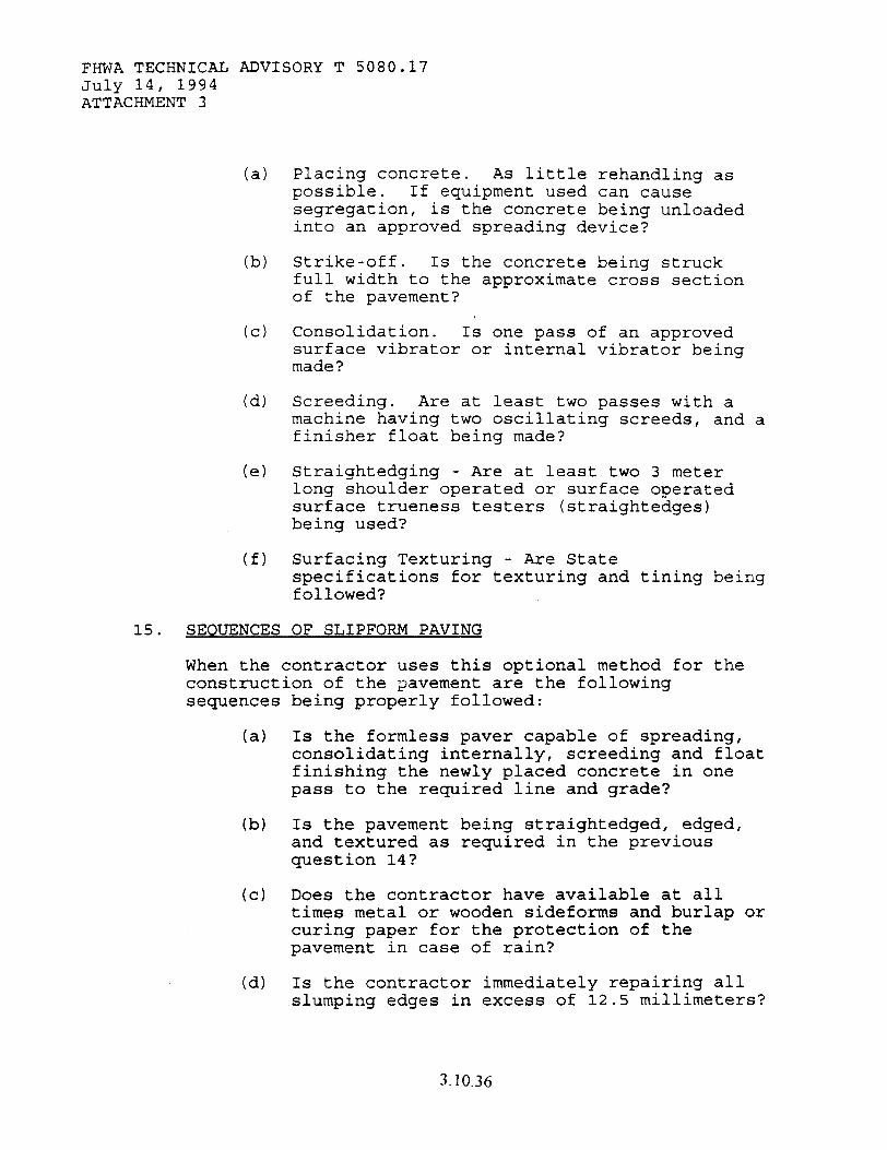
FHWA TECHNICAL ADVISORY T 5080.17 July 14, 1994 ATTACHMENT 3
(a)
(b)
(cl
(d)
(e)
(f)
Placing concrete. As little rehandling as possible. If equipment used can cause segregation, is the concrete being unloaded into an approved spreading device?
Strike-off. Is the concrete being struck full width to the approximate cross section of the pavement?
Consolidation. Is one pass of an approved surface vibrator or internal vibrator being made?
Screeding. Are at least two passes with a machine having two oscillating screeds, and a finisher float being made?
Straightedging - Are at least two 3 meter long shoulder operated or surface operated surface trueness testers (straightedges) being used?
Surfacing Texturing - Are State specifications for texturing and tining being followed?
15. SEOUENCES OF SLIPFORM PAVING
When the contractor uses this optional method for the construction of the TJavement are the followins sequences
(a)
(b)
(cl
(d)
being properly followed:
Is the formless paver capable of spreading, consolidating internally, screeding and float finishing the newly placed concrete in one pass to the required line and grade?
Is the pavement being straightedged, edged, and textured as required in the previous question 14?
Does the contractor have available at all times metal or wooden sideforms and burlap or curing paper for the protection of the pavement in case of rain?
Is the contractor immediately repairing all slumping edges in excess of 12.5 millimeters?
3.10.36
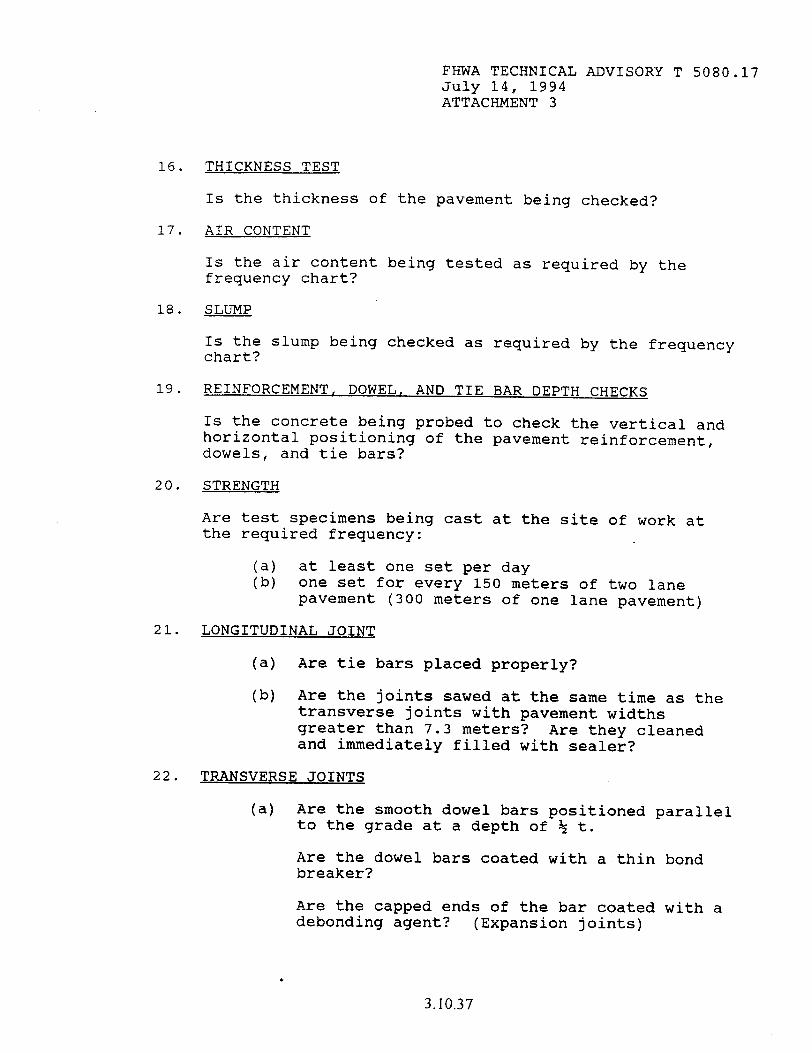
FHWA TECHNICAL ADVISORY T 5080.17 July 14, 1994 ATTACHMENT 3
16. THICKNESS TEST
IS the thickness of the pavement being checked?
17. AIR CONTENT
IS the air content being tested as required by the frequency chart?
18. SLUMP
Is the slump being checked as required by the frequency chart?
19.
20.
21.
22.
REINFORCEMENT, DOWEL, AND TIE BAR DEPTH CHECKS
Is the concrete being probed to check the vertical and horizontal positioning of the pavement reinforcement, dowels, and tie bars?
STRENGTH
Are test specimens being cast at the site of work at the required frequency:
I;; at least one set per day one set for every 150 meters of two lane pavement (300 meters of one lane pavement)
LONGITUDINAL JOINT
(a) Are tie bars placed properly?
(b) Are the joints sawed at the same time as the transverse joints with pavement widths greater than 7.3 meters? Are they cleaned and immediately filled with sealer?
TRANSVERSE JOINTS
(a) Are the smooth dowel bars positioned parallel to the grade at a depth of % t.
Are the dowel bars coated with a thin bond breaker?
Are the capped ends of the bar coated with a debondins asent? (Exnansion joints)
3.10.37
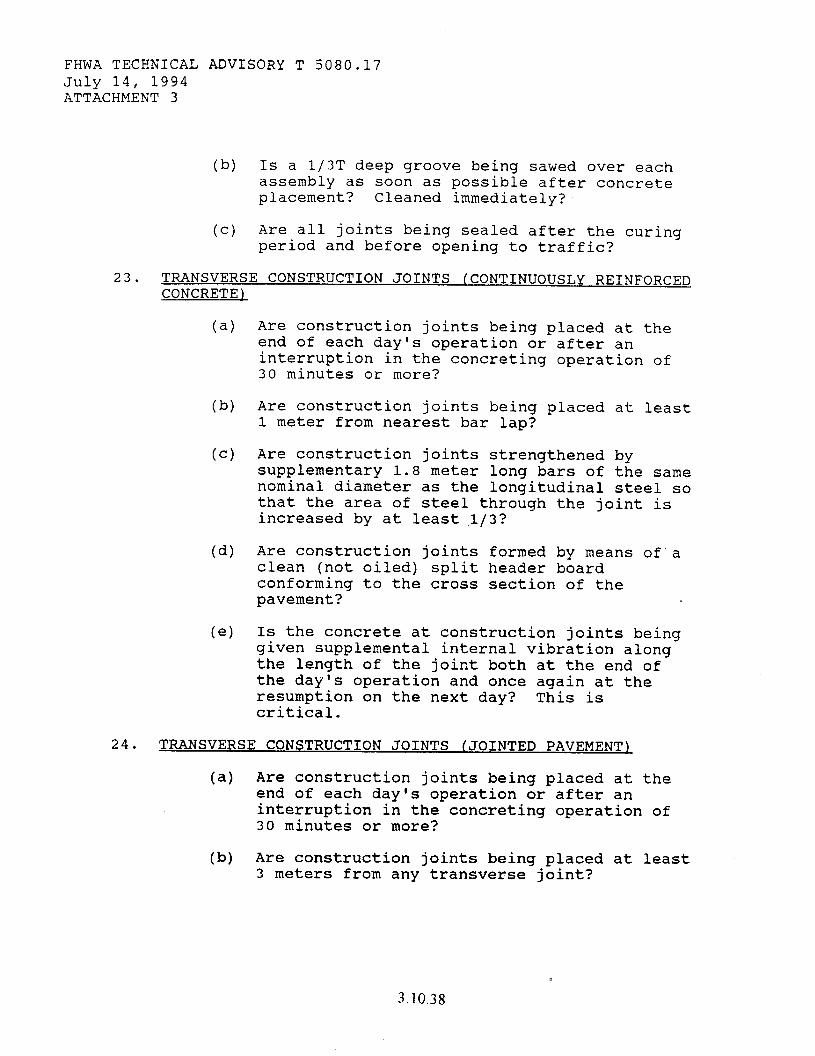
FHWA TECHNICAL ADVISORY T 5080.17 July 14, 1994 ATTACHMENT 3
(b) Is a 1/3T deep groove being sawed over each assembly as soon as possible after concrete placement? Cleaned immediately?
(c) Are all joints being sealed after the curing period and before opening to traffic?
23. TRANSVERSE CONSTRUCTION JOINTS (CONTINUOUSLY REINFORCED CONCRETE)
(4
(b)
Cc)
Cd)
(e)
Are construction joints being placed at the end of each day's operation or after an interruption in the concreting operation of 30 minutes or more?
Are construction joints being placed at least 1 meter from nearest bar lap?
Are construction joints strengthened by supplementary 1.8 meter long bars of the same nominal diameter as the longitudinal steel so that the area of steel through the joint is increased by at least,l/3?
Are construction joints formed by means 0f.a clean (not oiled) split header board conforming to the cross section of the pavement?
Is the concrete at construction joints being given supplemental internal vibration along the length of the joint both at the end of the day's operation and once again at the resumption on the next day? This is critical.
24. TRANSVERSE CONSTRUCTION JOINTS (JOINTED PAVEMENT)
(a) Are construction joints being placed at the end of each day's operation or after an interruption in the concreting operation of 30 minutes or more?
(b) Are construction joints being placed at least 3 meters from any transverse joint?
3.10.38
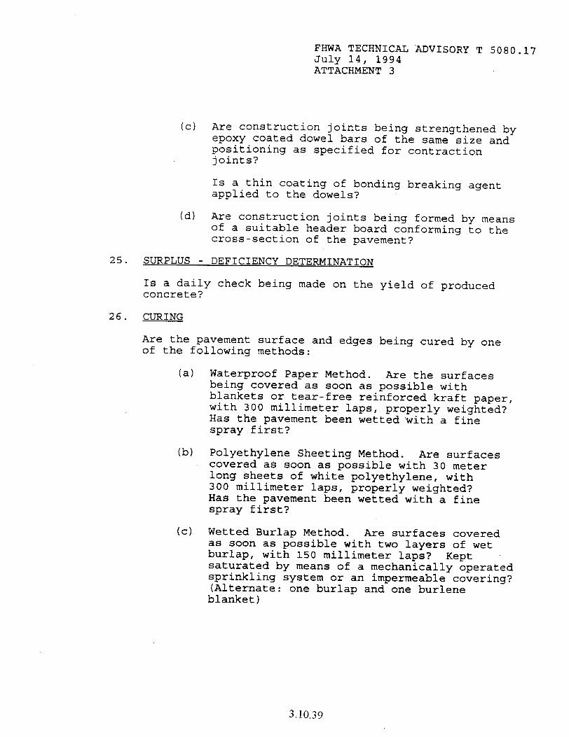
2.5.
26.
FHWA TECHNICAL ADVISORY T 5080.17 July 14, 1994 ATTACHMENT 3
(c) Are construction joints being strengthened by epoxy coated dowel bars of the same size and positioning as specified for contraction joints?
Is a thin coating of bonding breaking agent applied to the dowels?
(d) Are construction joints being formed by means of a suitable header board conforming to the cross-section of the pavement?
SURPLUS - DEFICIENCY DETERMINATION
Is a daily check concrete?
being made on the yield of produced
CURING
Are the pavement of the following
surface and edges being cured by one methods:
(a)
lb)
(cl
Waterproof Paper Method. Are the surfaces being covered as soon as possible with blankets or tear-free reinforced kraft paper, with 300 millimeter laps, properly weighted? Has the pavement been wetted with a fine spray first?
Polyethylene Sheeting Method. Are surfaces covered as soon as possible with 30 meter long sheets of white polyethylene, with 300 millimeter laps, properly weighted? Has the pavement been wetted with a fine spray first?
Wetted Burlap Method. Are surfaces covered as soon as possible with two layers of wet burlap, with 150 millimeter laps? Kept saturated by means of a mechanically operated sprinkling system or an impermeable covering? (Alternate: one burlap and one burlene blanket)
3.10.39

FHWA TECHNICAL ADVISORY T 5080.17 July 14, 1994 ATTACHMENT 3
27.
28.
29.
Cd) Membrane Curing Method. Are surfaces covered as soon as the water sheen has disappeared, with two separate applications of agitated white curing coppound being uniformly applied at a rate of 5m/l? (Note that each application should be separated by at least 1 minute).
Do the curing compounds meet specification requirements?
PROTECTION
IS the contractor providing protection of the pavement from low temperatures?
Does the contractor have adequate protection on hand in case of rain?
SURFACE VARIATIONS
At the end of curing period, is the pavement being profilographed or straightedged in each wheel lane for surface variations?
(a) Are all bumps being marked, ground down or pavement replaced?
OPENING TO TRAFFIC
IS the pavement being closed to traffic until:
(4
(b)
(cl
(d)
The curing and protection period has elapsed?
All joints have been sealed?
The required strength has been achieved by test specimen?
If the contractor wishes to open the pavement to traffic prior to the date of your first routine strength test, are additional specimens being cast and then allowed to cure out in the open the same as the pavement?
3.10.40
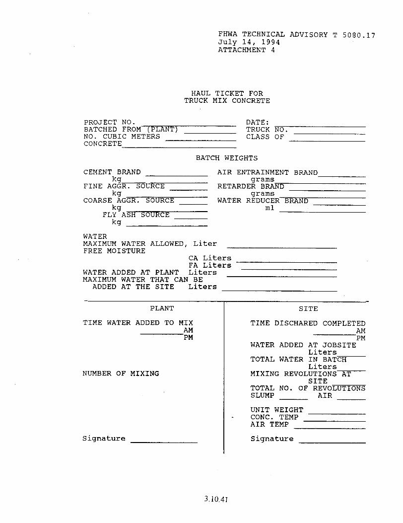
FHWA TECHNICAL ADVISORY T 5080.17 July 14, 1994 ATTACHMENT 4
HAUL TICKET FOR TRUCK MIX CONCRETE
PROJECT NO. BATCHED FROM (PLANT) NO. CUBIC METERS CONCRETE
DATE: TRUCK NO. CLASS OF
BATCH WEIGHTS
CEMENT BRAND kg
FINE AGGR. SOURCE kg
COARSE AGGR. SOURCE kg
FLY ASH SOURCE kg
AIR ENTRAINMENT BRAND grams
RETARDER BRAND grams
WATER REDUCER BRAND ml
WATER MAXIMUM WATER ALLOWED, Liter FREE MOISTURE
CA Liters FA Liters
WATER ADDED AT PLANT Liters MAXIMUM WATER THAT CAN BE
ADDED AT THE SITE Liters
PLANT SITE
TIME WATER ADDED TO MIX AM PM
NUMBER OF MIXING
Signature
TIME DISCHARED COMPLETED AM PM
WATER ADDED AT JOBSITE Liters
TOTAL WATER IN BATCH Liters
MIXING REVOLUTIONS AT SITE
TOTAL NO. OF REVOLUTIONS SLUMP AIR
UNIT WEIGHT L CONC. TEMP
AIR TEMP
Signature
3.10.41

THIS PAGE LEFT BLANK INTENTIONALLY
3.10.42
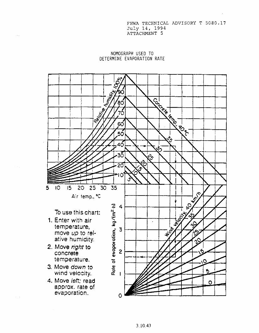
FHWA TECHNICAL ADVISORY T 5080.17 July 14, 1994 ATTACHMENT 5
NOMOGRAPH USED TO. DETERMINE EVAPORATION RATE
Air temp.,
To use this cha Enter with air temperature, move UD to ret,
Move right to 8 concrete z 2 temperature. i Move down to al wind velocity. 2 1 Move left: read approx. rate of evaporation. 0
3.10.43

THIS PAGE LEFT BLANK INTENTIONALLY
3.10.44
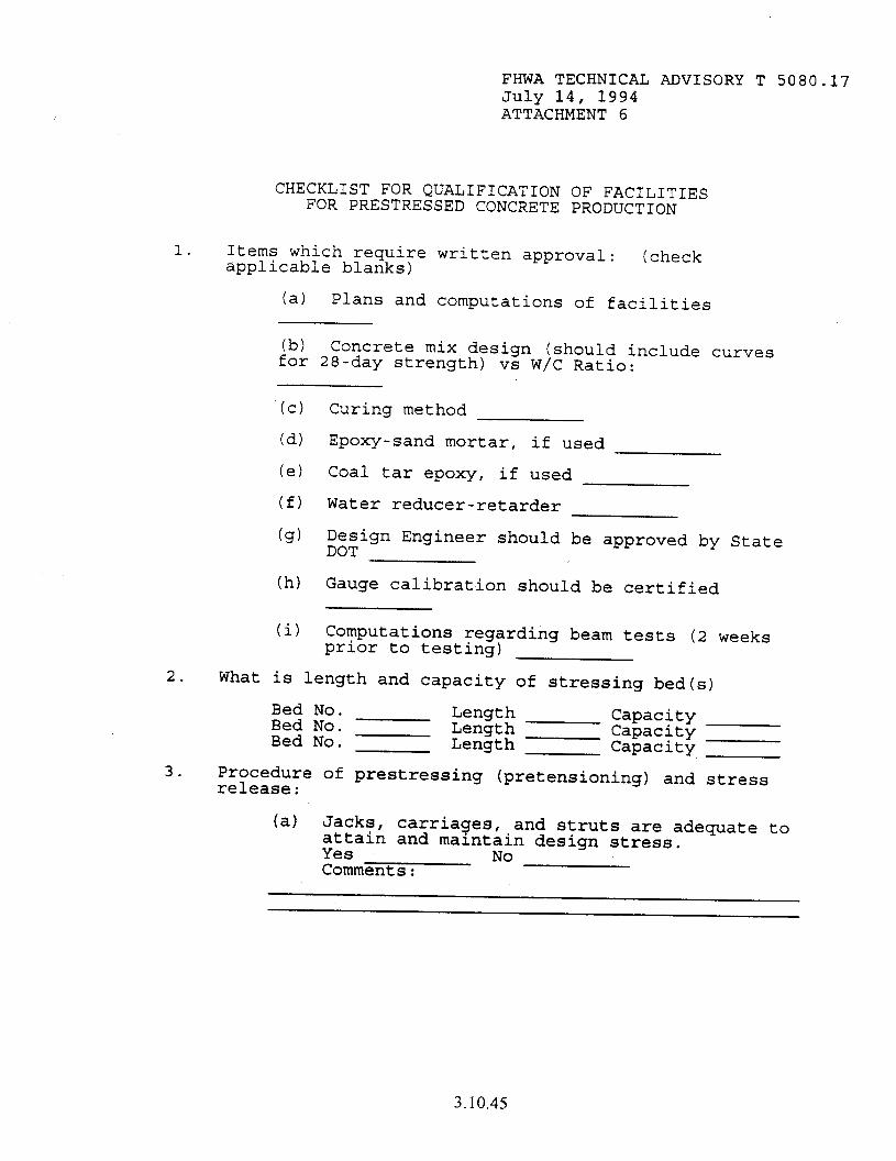
FHWA TECHNICAL ADVISORY T 5080.17 July 14, 1994 ATTACHMENT 6
CHECKLIST FOR QUALIFICATION OF FACILITIES FOR PRESTRESSED CONCRETE PRODUCTION
1. Items which require written approval: applicable blanks) (check
(a) Plans and computations of facilities
(b) Concrete mix design (should include curves for 28-day strength) vs W/C Ratio:
(cl
(d)
(e)
(f)
(9)
Curing method
Epoxy-sand mortar, if used
Coal tar epoxy, if used
Water reducer-retarder
Design Engineer should be approved by State DOT
(h) Gauge calibration should be certified
(i) Computations regarding beam tests (2 weeks prior to testing)
2. What is length and capacity of stressing bed(s)
Bed No. Bed No. Bed No.
Length Length Length
Capacity Capacity Capacity
3. Procedure of prestressing (pretensioning) and stress release:
(a) Jacks, carriages, and struts are adequate to attain and maintain design stress. Yes No Comments:
3.10.45
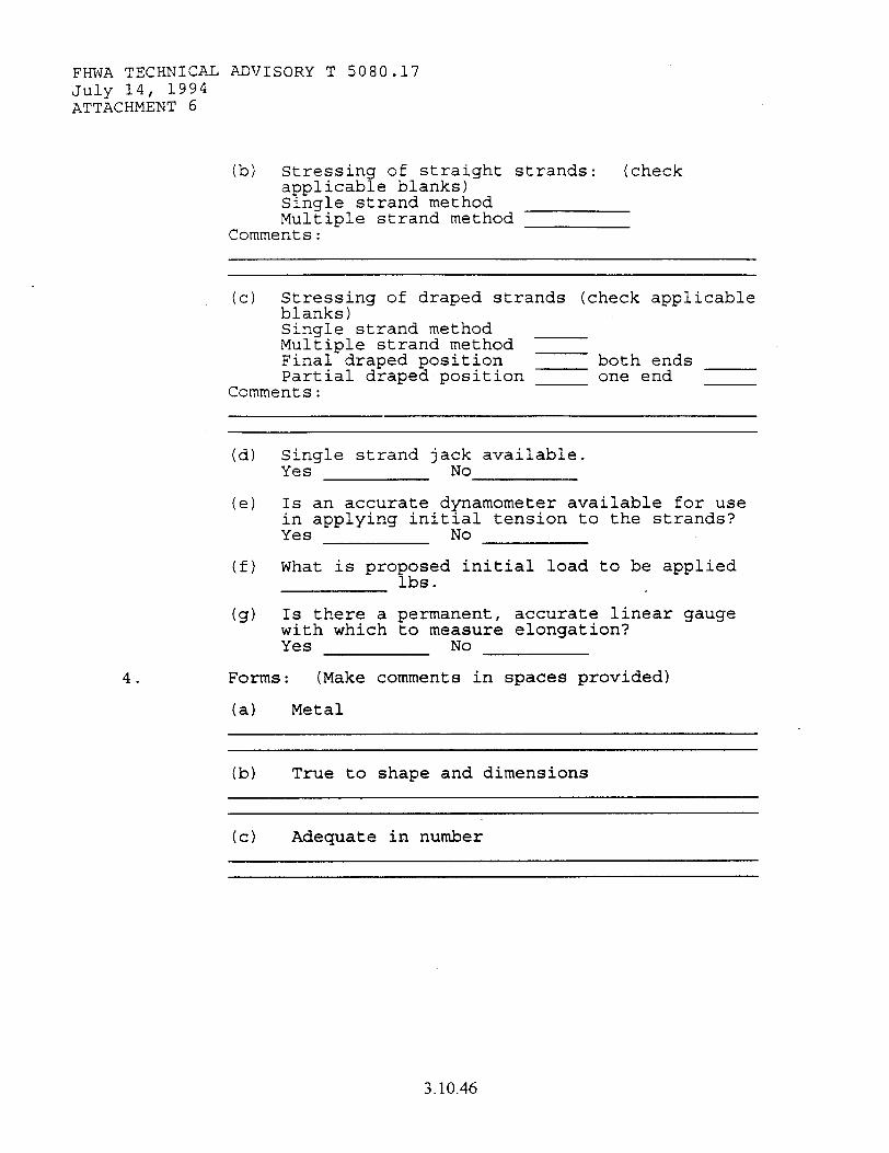
FHWA TECHNICAL ADVISORY T 5080.1-I July 14, 1994 ATTACHMENT 6
(b) Stressing applicabl Single st Multiple
Comments:
of straight strands: (check e blanks) rand method strand method
4.
(c) Stressing of draped strands (check applicable blanks) Single strand method Multiple strand method Final draped position both ends Partial draped position one end
Comments:
(d) Single strand jack available. Yes No
(e) Is an accurate dynamometer available for use in applying initial tension to the strands? Yes No
(f) What is proposed initial load to be applied lbs.
(9) Is there a permanent, accurate linear gauge with which to measure elongation? Yes No
Forms: (Make comments in spaces provided)
(a) Metal
(b) True to shape and dimensions
(c) Adequate in number
3.10.46

5.
FHWA TECHNICAL ADVISORY T 5080.17 July 14, 1994 ATTACHMENT 6
(d) Condition and composition of bulkheads
(e) Type of hold-down device to be used
(f) Is provision being made to maintain 25 millimeter concrete cover over hold-down device?
(9) Are bulkheads and hold-down devices adequate to maintain dimensions of strand centers as shown on the plans?
Are facilities adequate for proper storage and handling of bridge members? Yes No
(a) area
(b) area
Approximate available storage
Condition of storage
6. Are facilities available for properly testing a member of the design type to be fabricated? Yes No (if No explain)
7.
8.
Are adequate lighting facilities available in the event that placing of concrete at night is necessary? Yes No
Vibrating equipment:
(a) Condition
(b) Number to be used in placing
3.10.47
FHWA TECHNICAL ADVISORY T 5080.17 July 14, 1994 ATTACHMENT 6
9.
10.
11.
(c) Two spaces available
Source of Materials:
(4 Steel Wire and Strand (manufacturer)
(b) Cement (type and brand name)
(c) Coarse Aggregate (producer and location)
Cd) Sand (producer and location)
(e) Retarder (brand name)
(f) Form Oil (type and name)
(4) Reinforcing Steel (producer)
Type of concrete mixing facilities: mixed at plant Ready Mix concrete
(a) Are concrete batching facilities adequate to ensure good quality and sufficient quantity to avoid delays under all working conditions? Yes No
Testing equipment available: (check applicable blanks)
Plastic cylinder molds Available
(b) Slump Cone
Air content device volumetric \
Cd) Facilities for testing cylinders available at (proposed location)
3.10.48
12. Requirements for steam cure method:
FHWA TECHNICAL ADVISORY T 5080.17 July 14, 1994 ATTACHMENT 6
(a) Three (3) recording thermometers available
(b) Temperature record charts
(cl Adequate temperature control valves
(1) What are the increments of spacing of control valves?
13.
14.
Are facilities available for proper protection and handling of component materials in storage? ItSIt if satisfactory,
(Rate "U" if unsatisfactory, and
ltNAtt if not applicable)
(a) Wire and/or strand lb) Reinforcing steel (c) Structural steel (d) Cement [;I Coarse Aggregate
Sand
Is there a suitable shelter (at least 14 square meters floor space, desk(s),
facilities for lights, heat, etc.) available for the inspector's use?
15. Personnel present during inspection of plants:
Producers/Contractors Highway Department
3.10.49
THIS PAGE LEFT BLANK INTENTIONALLY
3.10.50
FHWA TECHNICAL ADVISORY T 5080.17 July 14, 1994 ATTACHMENT 7
GUIDE FOR QUALITY CONTROL PLAN FOR PORTLAND CEMENT CONCRETE
REQUIREMENTS
1. General Requirements:
2.
The contractor should provide and maintain a quality control system that will provide reasonable assurance that all materials and products submitted to the State for acceptance will conform to the contract requirements whether manufactured or processed by the contractor or procured from suppliers or subcontractors or vendors. The contractor should perform or have performed the inspections and tests required to substantiate product conformance to contract document requirements and should also perform or have performed all inspections and tests otherwise required by the contract. The quality control inspections and tests should be documented and should be available for review by the engineer throughout the life of the contract.
Qualitv Control Plan:
The contractor should prepare a Quality Control Plan detailing the type and frequency of inspection, sampling and testing deemed necessary to measure, and control the various properties of materials and construction governed by the Specifications. As a minimum, the sampling and testing plan should detail sampling location and techniques, and test frequency to be utilized. The Quality Control Plan should be submitted in writing to the engineer at the preconstruction conference.
The Plan should identify the personnel responsible for the contractor's quality control. This should include the company official who will act as liaison with State personnel, as well as the Certified Portland Cement Concrete Technician who will direct the inspection program.
The class or classes of concrete involved will be listed separately. If existing mix designs are to be utilized, the Mix Design Numbers should be listed.
3.10.51
FHWA TECHNICAL ADVISORY T 5080.17 July 14, 1994 ATTACHMENT 7
Quality control sampling, testing, and inspection should be an integral part of the contractor's quality control system. In addition to the above requirements, the contractor's quality control system should document the quality control requirements shown in Table 1. The quality control activities shown in Table 1 are considered to be normal activities necessary to control the production and placing of a given product or material at an acceptable quality level. To facilitate the States' activities, all completed gradation samples should be retained by the contractor until further disposition is designated by the State.
It is intended that sampling and testing be in accordance with standard methods and procedures, and that measuring and testing equipment be properly calibrated. If alternative sampling methods, procedures and inspection equipment are to be used, they should be detailed in the Quality Control Plan.
3. Documentation:
The contractor should maintain adequate records of all inspections and tests. The records should indicate the nature and number of observations made, the number and type of deficiencies found, the quantities approved and rejected, and the nature of corrective action taken as appropriate. The contractor's documentation procedures will be subject to the review and approval of the State prior to the start of the work and to compliance checks during the progress of the work.
4. Charts and Forms:
All conforming and non-conforming inspections and tests, results should be kept complete and should be available at all times to the State during the performance of the work. Batch tickets and gradation data will be submitted to the State as the work progresses. All test data will be plotted on control charts. It is normally expected that testing and charting will be completed within 48 hours after sampling.
3.10.52
5.
6.
7.
FHWA TECHNICAL ADVISORY T 5080.17 July 14, 1994 ATTACHMENT 7
All charts and records documenting the contractor's quality control inspections and tests should become property of the State upon completion of the work.
Corrective Action:
The contractor should take prompt action to correct conditions which have resulted, or could result, in the submission to the State of materials and products which do not conform to the requirements of the Contract documents.
Non-Conformins Materials:
The contractor should establish and maintain an effective and positive system for controlling non-conforming material, including procedures for its identification, isolation, and disposition. Reclaiming or reworking of non-conforming materials should be in accordance with procedures acceptable to the State.
All non-conforming materials and products should be positively identified to prevent use, shipment, and intermingling with conforming materials and products. Holding areas, mutually agreeable to the State and the contractor, should be provided by the contractor.
Acceotance:
The State will monitor the performance of the contractor's quality control plan and will perform verification testing to ensure that proper sampling and testing procedures are used by the contractor. The State may shut down the contractors operations for failing to follow the approved process control plan. All acceptance testing will be performed by State personnel.
3.10.53

FHWA TECHNICAL ADVISORY T 5080.17 July 14, 1994 ATTACHMENT 7
TABLE 1
CONTRACTOR'S OUALITY CONTROL REOUIREMENTS
Minimum Oualitv Control Requirement Frequency
A. PLANT AND TRUCKS
1.
2.
3.
4.
Mixer Blades
Scales
2 Tared Calibrate
C. Check Calibration Gauges and Meters - Plant and Truck a. Calibrate b. Check Calibration Admixture Dispenser a. Calibrate b. Check Operation and
Calibration
B. AGGREGATES
1. Fine Aggregate
:: Gradation Deleterious Substances
C. Moisture 2. Coarse Aggregates
:: Gradation Percent Passing No. 200 Sieve
C. Moisture
C. PLASTIC CONCRETE
1. Entrained Air Content
2. Consistency
3. Temperature
4. Yield
Prior to Start of Job and weekly Prior to Start of Job and weekly Daily Prior to Start of Job Weekly
Yearly ' Weekly
Prior to Start of Job Daily
21 Days Daily Daily
21 Days Daily
Daily
One Per l/2 Day Operation One Per l/2 Day of Operation One Per l/2 Day of Operation One Per l/2 Day of Operation
3.10.54
Chapter 4
Flexible Pavement

CHAPTER 4
FLEXIBLE PAVEMENT
4.1 TA 5040.27, Asphalt Concrete Mix Design and Field Control, February 16,1988.
4.2 Prevention of Premature Distress in Asphalt Concrete Pavements, Technical Paper W-02, April 181988.
4.3 Guidelines on the Use of Bag-House Fines, April 7,1988.
4.4 Reserved.
4.5 State of the Practice on the Design and Construction of Asphalt Paving Materials with Crumb Rubber Modifier, Report Number FHWA-SA-92- 022, June 9,1992.
4.6 Reserved.
4.7 Processed Used-Oil and Heavy Fuel Oils for Use in Hot Mix Asphalt Production, June 21,199O.
4.8 Aggregate Gradation for Highways - 0.45 Particle Size Distribution Curve, 1962. l Aggregate Gradation: Simplification, Standardization, and Uniform
Application l A New Graphical Chart for Evaluating Aggregate Gradation

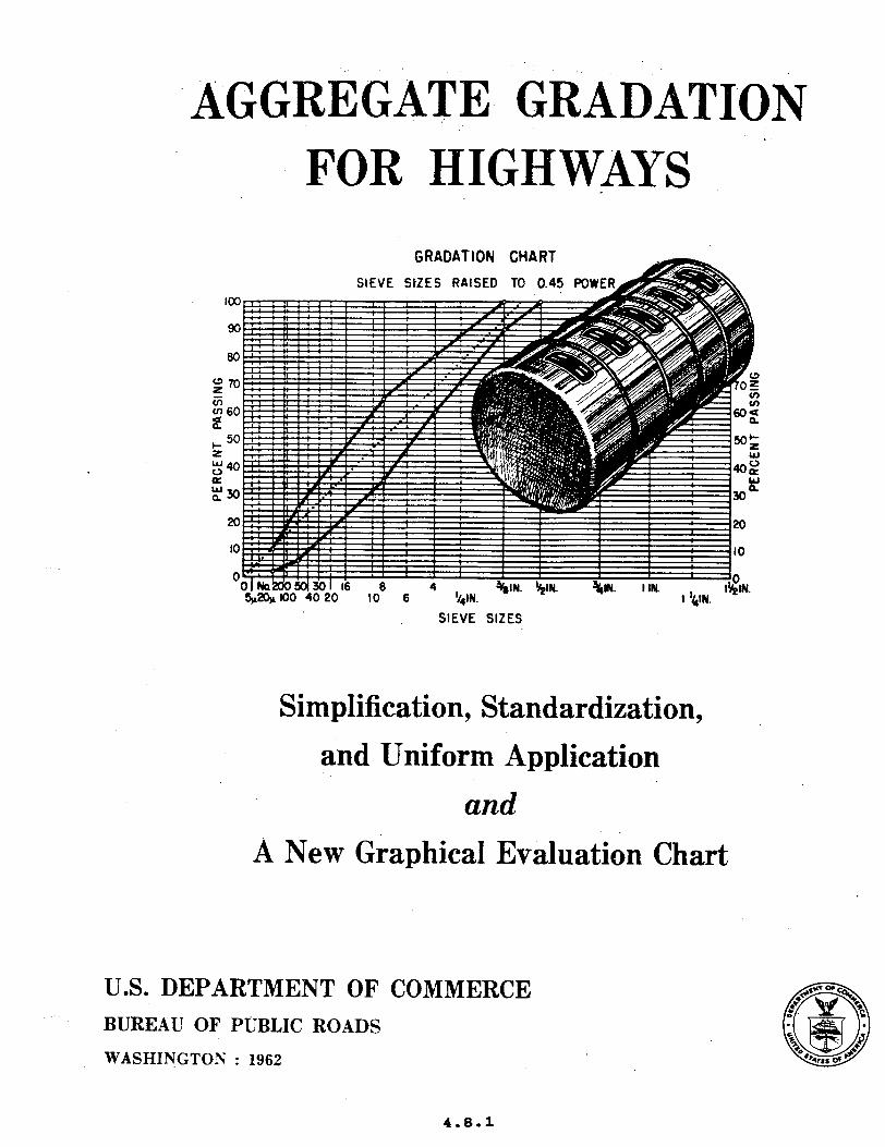
FOR HIGHV&!kYS
SIEVE SIZES
Simplification, Standardization,
and Uniform Application
and A New Graphical Evaluation Chart
U.S.DEPARTMENT OF COMMERCE BUREAU OF HJBLIC ROADS
WASHINGTON : 1962
4.8.1

THIS PAGE LEFT BLANK INTENTIONALLY
4.8.2
AGGREGATE GRADATION FOR HIGHWAYS
Aggregate Gradation: Simplification, Standardization, and ‘i’niform Application
and
A New Graphical Chart for Evaluating Aggregate Gradation
By the Bureau of Public Roads
U.S. DEPARTMENT OF COMMERCE Luther H. Hodgee. Secretatu
BUREAU OF PUBLIC ROADS Rex %f. Whitton. hfminietrator
United States Government Printing Otlke, Warbington. D.C. : May 1962
4.8.3
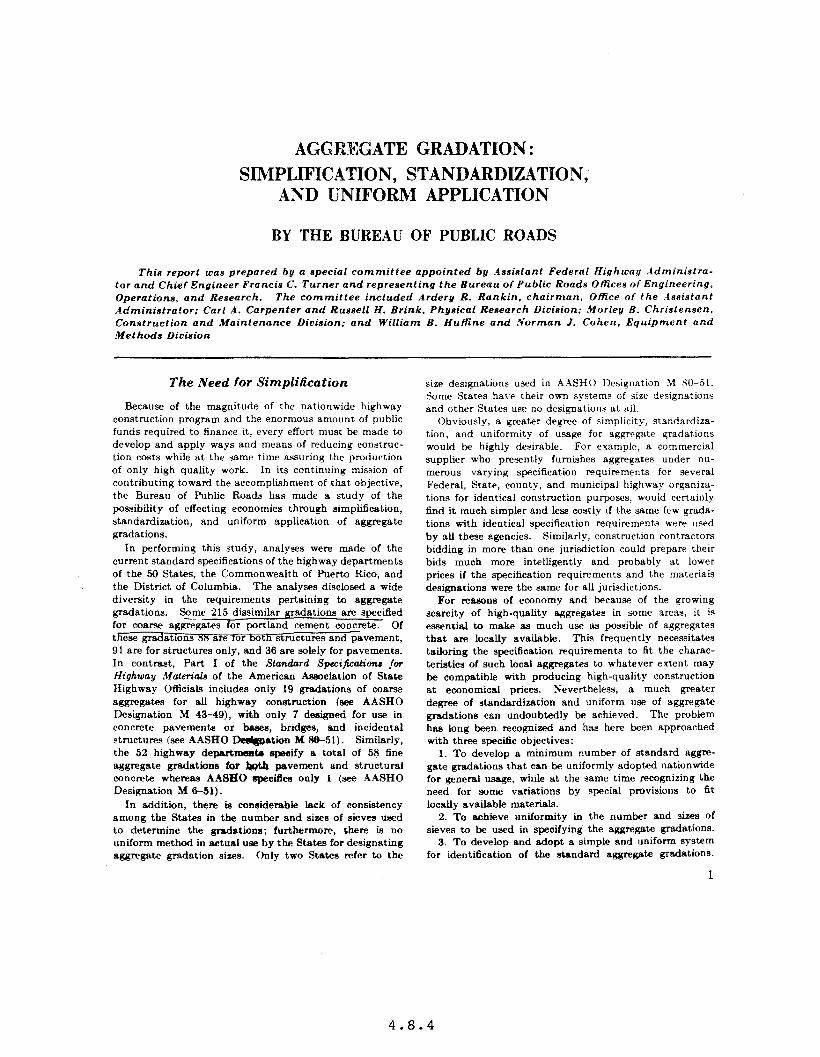
AGGREGATE GRADATION: SIMPLIFICATION, STANDARDIZATION,
AND UNIFORM APPLICATION
BY THE BUREAU OF PUBLIC ROADS
This report IOCW prepared by a special committee appointed by .4ssistant Federal Highway .4dministra- tor and Chief Engineer Francis C. Turner and representing the Bureau of Public Roads Offices of Engineering, Operations, and Research. The committee included Ardery R. Rankin, chairman, Otfice of the Assistant iadministrator; Carl A. Carpenter and Russell H. Brink, Physical Research Dioision: Morley B. Christensen, Construction and Maintenance Division: and William B. Huffine and Norman 1. Cohen, Equipment and Methods Division
The Need for Simplification
Because of the magnitude of the nationwide highway construction program and the enormous amount of public funds required to finance it, every effort must be made to develop and apply ways and means of reducing construc- tion costs while at the same time assuring the production of only high quality work. In its continuing mission of contributing toward the accomplishment of that objective, the Bureau of Public Roads has made a study of the possibility of effecting economies thmugh simplification, standardisation, and uniform application of aggregate gradations.
In performing this study, analyses were made of the current standard specifications of the highway departments of the 50 States, the Commonwealth of Puerto Rico, and the District of Columbia. The analyses disclosed a wide diversity in the requirements pertaining to aggregate gradations. So-me 215 dissimilar gradations are specified for coarse aggregates for portland cement concrete. Of these gradations ~8 are ror wtn structures and pavement, 91 are for structures only, and 36 are solely for pavements. In contrast, Part I of the Standard Speci@tions far Highway Maferials of the American hciation of State Highway Officials includes only 19 gradations of coarse aggregates for all highway construction (see AASHO Designation M 43-49), with only 7 designed for use in concrete pavements or bases, bridges, and incidental structures (see AASHO mation M M-51). Similarly, the 52 highway departmemti apseify a total of 58 fine aggregate gradations for I@4 pavement and structural concrete whereas AASHO xpecifies only 1 (see AASHO Designation M 6-51).
In addition, there is considerable lack of consistency among the States in the number and sizes of sieves used to determine the gradations; furthermore, there is no uniform method in actual use by the States for designating aggregate gradation sizes. Only two States refer to the
size designations used in AASHO Designation &I SO-51. Some States have their own systems of size designations and other States use no designations at all.
Obviously, a greater degree of simplicity, standardiza- tion, and uniformity of usage for aggregate gradations would be highly desirable. For example, a commercial supplier who presently furnishes aggregates under nu- memus varying specification requirements for several Federal, State, county, and municipal highway orqaniza- tions for identical construction purposes, would certainly find it much simpler and less costly if the same few grada- tions with identical specification requirements were used by aU these agencies. Similarly, construction contractors bidding in more than one jurisdiction could prepare their bids much more intelligently and probably at lower prices if the specification requirements and the materials designations were the same for all jurisdictions.
For reasons of economy and because of the growing scarcity of high-quality aggregates in some areas, it is essential to make as much use as possible of aggregates that am locally available. This frequently necessitates tailoring the specification requirements to fit the charac- teristics of such local aggregates to whatever extent may be compatible with producing high-quality construction at economical prices. Nevertheless. a much greater degree of standardisation and uniform use of aggregate gradations can undoubtedly be achieved. The problem has long been recognised and has here been approached with three specific objectives:
1. To develop a minimum number of standard aggre- gate gradations that can be uniformly adopted nationwide for general usage, while at the same time recognizing the need for some variations by special provisions to fit locally available materials.
2. To achieve uniformity in the number and sizes of sieves to be used in specifying the aggregate gradations.
3. To develop and adopt a simple and uniform system for identification of the standard aggregate gradations.
1
4.8.4

The Simplified Practice Recommendation .4 major step toward accomplishing these objectives
was taken on June 30, 1948, when the Department of Commerce approved and issued Simplified Practice Recommendations R 163-48 ’ for coarse aggregates, including crushed stone, gravel, and slag. A predecessor recommendation had originally been approved for pm- mulgation in June 1936 and issued as R 163-36. It was proposed by the Joint Technical Committee of the Slineral Aggregates Association, composed of representa- tives of the Xationai Sand and Gravel .4ssociation, the Sational Crushed Stone Association, and the National Slag Association. qroducers, distributors, and users of mineral aggregate all cooperated in developing the simpli- fied practice recommendation. .4n intermediate revision was approved and published in 1939 and some additional revisions subsequent to 1939 resulted in the publication of the current issue of 1948. Table I shows the SPR gradings that are currently in effect.
As will shortly be described, the SPR system has been essentially adopted by both the American .4asociation of State Highway Officials and the American Society for Testing and Materials.
Value of the SPR system
The simplified practice recommendation R 163-48 em- bodies a number of highly logical and useful features:
1. Standard sieves.-The SPR gradings employ a simple and convenient. square-opening, sieve-size series based primarily on the logarithmic principle.
The basic logarithmic sieve series employed begins with a sieve having clear openings of 3 inches and each smeller sieve has clear openings the diameter of which ia one-half that of the next larger one. Thus the basic series is 3-inch, Iftinch. x-inch, M-inch, No. 4, No. 8. No. 16, No. 30, No. 50, ?;o. 100, and No. 200. Because some consumer interests consider that the logarithmic series does not provide enough control in the larger sizes while others desire greater freedom in selecting maximum sizes, the gaps have been reduced in the SPR series by superimposing upon the logarithmic series. the arbitrary sizes -l-inch, 35;-inch, Winch, 2-inch, I-inch. and H-inch. Also. two of the logarithmic sizes were left out of the SPR series-the So. 30 because it “89 felt that it serves no useful purpose in grading control of coarse commercial aggregates, and the No. 200 because material of this size (soil fines and commercial mineral filler for bituminous paving mixtures) is not and should not be considered an ingredient of commercial coarse aggregates. Both the Xo. 30 and the No. 200 sievea are required in specifying sands and fillers, aa in the ASTM and AASHO standards, and both fit in the logarithmic series.
2. Simple system.-The SPR gradings embody a simple and readily understandable system of individual size and grading designations consisting basically of single-digit numbers.
The single-digit numbering series starts with No. 1 for the standard commercial aggregate having the largest top-size particles and progresses from NO. 1 through No. 9 aa the individual standard coane aggregates decrease in sise, as shown in table 2.
Because of consistent demands for certain longer grad- ings than the relatively short ones represented by the basic series, shown in the 6rst column of table 2, a secondary
Table l.-S1xe11 of eo8rse 8ggreg8te (a&ed 8toae. gr8rel, 8nd ely) fkoa SimpMed Pr8etSce &eommend8tion. R 163-48 I
100 m-Ial s66 o-lb IW OD-la@ -_______ m-66 IQ) Qe;g ‘o-i~- w-w
_ _ _ . _ _ . w-m
- . _ . _ _ . 1w W-100 a-111 .__ _ ___ _ _ ___-_. _ .-.___._ ._.___._ 5 Elii .____... ______._ __ -___._ 10
.-_ -____ ___.-_. _ -_---_._ w-190 ________ w-w . ..-” aa-1w ____-_._ 5675 -----.-
w-95 ___ ___._ w-50 .------
No. 4 No. 6 j No. 16 / No. WI No. 100
._.. _ ..,.__..___,__._.___1________
.- ____.,________,________I________ _ _ _ _ _ _ _ _ _ _ _ _ _ . _ _ _ _ . _ _ _ . _ _ _ . _ _ _
o-b _ _ . _ _ _ _ _ . _ _. _ . . - - . _ -.
9-b _______ _ __._____ -------- O-10 0-b __ ._._._ ..__. __.
od ____.___ ________ .--- ----
O-10 &b _ _ _ . . . - - - -
E.i o-b . _ _ _ _ _ _ _ . - - . . - - -
O-10 o-6 .___. ___ 104 O-10 o-6 ._._____
4.8.5
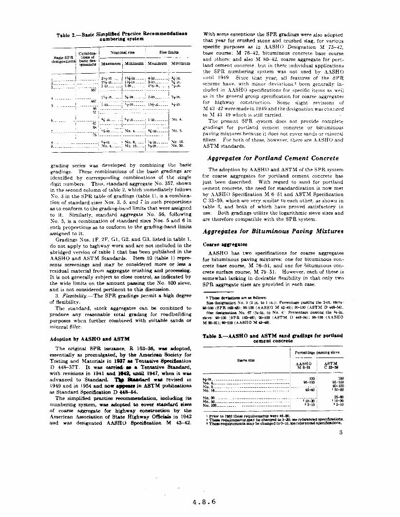
Table 2.--B&ok Simplified Fhctfee Recommendationa numbering system
With some exceptions the SPR gradings *ere alto adopted that year for crushed stone and crushed slag, for various specific purposes aa in AMHO Designation M 75-42, brtie course: 11 7&42, bituminous concrete base course and 3thers; and also M 8&42, coarse aggregate for port- land cement concrete: but in these individual applications the SPR numbering system wa.s not used by AASHO Iuntil 1949. Since that year, ail features of the SPR scheme have, alth minor deviations.2 been generally in- cluded in .4XSHO specifications for specific items as well as in the general group specification for coarse aggregates for highway construction. Some slight revisions of M K-42 were made in 1949 and the designation was changed to SI 4:jMY which is still carried.
The present SPR system does not provide complete gradings for portland cement concrete or bituminous paving mixtures because it does not cover sands or mineral tillers. For both of these, howea-er. there are AASH and ASTM standards.
grading series ~S‘BJ developed by combining the basic gradings. These combinations of the b&c gradings are identified by corresponding combinations of the single digit numbers. Thus, standard aggregate ?r’o. 357. shown in the second column of table 2. which immediately follows Yo. 3 in the SPR table of gradings (table 1). is a combina- tion of standard sizes Xos. 3, 5, and 7 in such proportions as to conform to the grading-band limits that were assigned to it. Similarly, standard aggregate No. 56, following Xo. 5, is a combination of standard sizes Nos. 5 and 6 in such proportions as to conform to the grading-band limits assigned to it.
Gradings SOS. 1F. 2F. Gl, G2. and G3, listed in table 1, do not apply to highway work and are not included in the abridged version of table 1 that has been published in the AASHO and i\STM Standards. Item 10 (table 1) repre- sents screenings and may be considered more or less a residual material from aggregate crushing and processing. It is not generally subject to cl- control, as indicated by the wide limits on the amount passing the No. 100 sieve, and is not considered pertinent to this discussion.
3. Fkzibilily.-The SPR gradings permit a high degree of flexibi1it.v.
The standard, stock aggregates can be combined to produce any reasonable total grading for roadbuilding purposes when further combined with suitable sands or mineral filler.
Adoption by AASHO and ASTM
The original SPR issuance, R 163-36, was adopted, essentially as promulgated, by the American Sooiety for Testing and Materials in 1937 Y Tentative Specifiestion D 44%37T. It was carrio& P in Tentative Ward,
with revisions in 1941 and @4%, until 1947, when it wazl advanced to Standard. q &udud WM revised in 1949 and in 1954 and now M in ASTM pubiicstiona
as Standard Specification D 448-64. The simplified practice recommendation, including its
numbering system, WBB adopted to cover standard sim of coarse aggregate for highway co~tcu~tioo by the American Association of State Highway O&i& in 1942 and was designated AASHO Specification M 43-42.
Aggregate8 for Portland Cement Concrete
The adoption by .4.4SHO and ASTM of the YPR system for coarse aggregates for portland cement concrete has just been described. With regard to sand for portland cement concrete, the need for standardization is now met by A.4SHO Specification M 651 and .4STM Specification C 33-59, which are very similar to each other, as shown in table 3, and both of which have proved satisfactory in use. Both gradings utilize the logarithmic sieve sizes and are therefore compatible with the SPR system.
Aggregatea for Bituminous Paving Mixtures
Coarse aggregatea
AASHO has two specifications for coarse aggregates for bituminous paving mixtures: one for bituminous con- crete base course, .M 7651, and one for bituminous con- crete surface course, .U 79-51. However, each of these is somewhat lacking in desirable flexibility in that only two SPR aggregate sizes are provided in each case.
Sim desigmtloo No. 3 (2 in. to 1 III.): Percentage psrainu the Z-in. slew: 961Ol (SPR 1BMB); M-la) (AASHO M 4.3-49): %3100 (ASTM D 448-54).
She de6ignatlon No. 67 (%-In. ta No. 4): Percentage passing the N-in. .9k~e: gD-im (9PR 1m.48); 6c-im (ASTM D w3-54); 96-km (.4.4SHO bf m-.51); m-lm (uaH0 M we).
Table 3.-AASHO and ASTM sand gradings for portI-d cement concrete
Sieve sire
%in. ____..____....__.._.-.--..-.-----.-.-.--. 100 i 100 No.,-........-...-.-.--.---.-------.---.---~--- 96-100 j NO.8..........-........---------------.-.... .___._.-.....- ,g::g No. 16 __..--.____.___..._.-.~~----.--.---.-...- / -1 ‘W-86
NO.30 _.____.._.__._______-...----..-.---.-.--- j.. .___....-___ -z-m NO.Jo......-..-......---~-.-...----......-...-, ‘:;I$ ! ~10-30 No. 100.. ____._____._______ _ _____________..___. / 2 a-10
4.8.6

Table .&-Grading requirements for eosrse agUelate for bituminous psting mixtures, from ASTM Designation D 6g2-6gT
ASTXl had had for some YP~TS a specification for coarse aggregates for bituminous paving mixcures, D 692, cover- ing 9 standard SPR sizes. In 1959 the then current \-eraion. I> 692-54. was amended, by adding SPR aggre- gates SOS. 5, 6. and 68. and the specification now carries the d&qnation D 69%59T. It has much greater Hexi- bility. therefore. than the current hlYH0 specifications. The current hSTS1 requirements are shown in tahie 1.
Sands
In the case of sands for bituminous paving mixtures. .\STAI has recently completed a committee study of cur-
Table S.-Grading requirements 1 for fine aggregate for bituminous pavements, from ASTM Designation D 107349T
Table C-ASTM mine4 igtr padIng, from ASTM Dealmatiu D 24%67T ’
rent practices with the p:rrtl(,lp:\tion of r(./)r(‘s(‘llt:tfi~1’~ of the ,\.4SHO 1Iscerials (‘ommittw. the Eiinhway ltl.yc.J,rC.t, Hoard. the .kphalt Ill~titrlr~~. thth N;rt~o~~al Slag .\.+soc*ia- tion. thr S:~t~onal Siand LLLI~ (;rawl .\ssoctntiol,. t ht. Sntional Ready S11wd (‘oncr~~tr .\ssociatlon, angi th,. Sational C’rlrshtvl Stonv .1ssoclation. Th<, l511rcau of Public Roads was ttctivc31y reprrrrnted 111 :\I1 of this .AST\l committee work. Follow-inn this study and with ttr,. participation of thr same repwsentatives. .ASTLl ha+ revised its prewous sprcifications for fine arZgregatt+z for sheet wphalt and bltummous concrete pavements. and now provides for three sand types under Specificaciou D 1073 -5YT. fine aggrenates for bituminous paving mis- t\lrtx as ihown in table j These yradinys also iltilize thr losar!thm:c sirvr series and are therefow compatlhl(a with the SPR system.
Mineral ffller
The current ASTM specification for mineral filler. Designation D 242-57T. w as last rrvlsrd in lY5i and is generally representative of present thinking. It fails to Iestrict the types of mineral that couid be approved for use as fillers but. in controlling the Kradinu. it utilizes the logarithmic sieve series and is therefore compatible with the SPR system. The parading requirements are show-n in table 6. Control below the So. 200 sieve is under study.
Combined Gradings
Bituminous paring mixtures
In general, current design practice for bituminous pav- ing mixtures differs from that for portland cement concrete. As step one in bituminous mix design, it is almost a universal practice to set up definite grading patterns for bituminous paving mixtures wherein the coarse aggregate, the fine aggregate or sand, and the mineral filler are com- bined to produce gradings that will fall within specified bands delineated by minimum and maximum limiti for each sieve. In some cases the gradings have been estab- lished mainly through experience, but more frequently they have been established through laboratory and field research which has shown, among other things, t-&t high density within certain limits promotes stability, and that high density w%SiZ hm~ta prsnce to weather- -- ing of the bituminous binder. While the factor of den&y
4.8.7
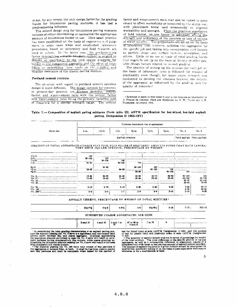
is not, by any means. the only design factor for the grading bands for bituminous paving mixtures, it has had a predominating influence.
The second design siep for brtumlnous paving mixtures consists of either determining or estimating the approprtate amount of bituminous bmder to use. Here aaatn practice haa been established on the basis of experience axd judg- ment in some cases while well established ‘aboratorv procedures. bawd on laboratory and field research. arc !lwd in others. In the latter csse,thrpr~?dominating
btndrr in the compacted xgrecate and the effect of over- fiilinq or ~indrrfillin~ these voids UII the it;rbilitv and
weather resistance of rhe plastic oavinu mixture.
Portland cement concrete
The situation aith regard to portland cement concrete design is qlnte different. The design controls for concrete in present-da,- practice are- fineness modulus. cement factor. and water-cement ratio aith the cement factor and water-cement ratio bemg the primary variables used in drsignilnz for a suecmc strength raalge. Ihe cement
factor and water-cement ratio msv also be varied to some extent to affect workability as measured by the slump test. with plasticizers being workabiiitv and strength.
used occasionally to improve From the practical stalldpoi[lt
of field control. no one factor JO ti rdverselv affe<.ts the titrength and uniformitv of the concrete BY lack ,,f i.OllfPn~ of water content. The proportions are set up on the basis of IaOOratur!: trial mixtures. utllixing the akgremt,aS for
Table 7.- Composition of asphalt paving mixtures (from table III. ASTM specification for hot-mixed. hot-laid asphalt paving, Designation D 1663493)
GRADING OF TOTAL AGGREGATE iCOARSE PLUS FISE. PLCS FILLER IF REQL-IRED). .4MOCNTS FINER THAN EACH LABOR.4 TORY SIEVE (JQI;ARE OPENISG), PERCENTAGE BY WEIGHT
Z’~in.....---.....---.......-.....--.----~ 100 I..._._._______ ~ ________._._.. I __.___________ i ____.___._.... I . . . . . . . . . . . ...’ . . . .._..__.... . . . . .._._.....
ASPHALT CEMENT. PERCENTAGE BY WEIGHT OF TOTAL MIXTURE’
SUOOESTED COARSE AOOREGATES. SPR SIZES
4.8.8
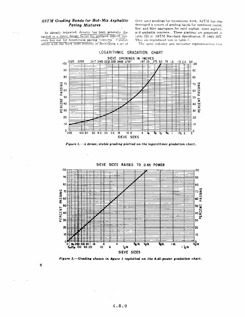
AST.M Grading Bands for Hot-Mix Asphaltic three sand gradinps for hitnmino~ls work, .+&TM has .~lso Paving Mixtures developed a system of grading bands for combined coarse,
fir!?. and filler aagregates for sand asphalt, sheet asphalt, ;\s already indicated. denr;ity has been generally dis- and asphaltic concrete. These gradings are presented ~1s
carded as a direct desyqn factor foz+nd cement con.. -- table III in ;\STSf Standard Specification D 166:$-59T. crete b,lt nor for bituminous paving mixtures ~‘OllCllr- They aw reproduced here in table 7. lrAntl?l with the work done recerTiIy in deveioplng a set of Thv same industry and consumer represerltativcs ttuc
LOGARITHMIC GRADATION CHART
80
g 70 z v, 60 2
50 s g 40 a & 30
20
IO
SIEVE OPENINGS IN INCHES .Oll7 0165 .0232.0331 ,046s .0787 ,187 .25 .375 50 .75 1.0 I.5 2.0 3.0
100
90
80
70 g
60 2 d
50 I- 2
40 “u a
30 E
20
IO
Figure I.--A dense, stable grading plotted on the logarithmic gradation chart.
SIEVE SIZES RAISED TO 0.45 POWER too
so
SIEVE SIZES
Figure t.-Grading shown in figure 1 replotted on the 0.45-power gradation chart.
4.8.9
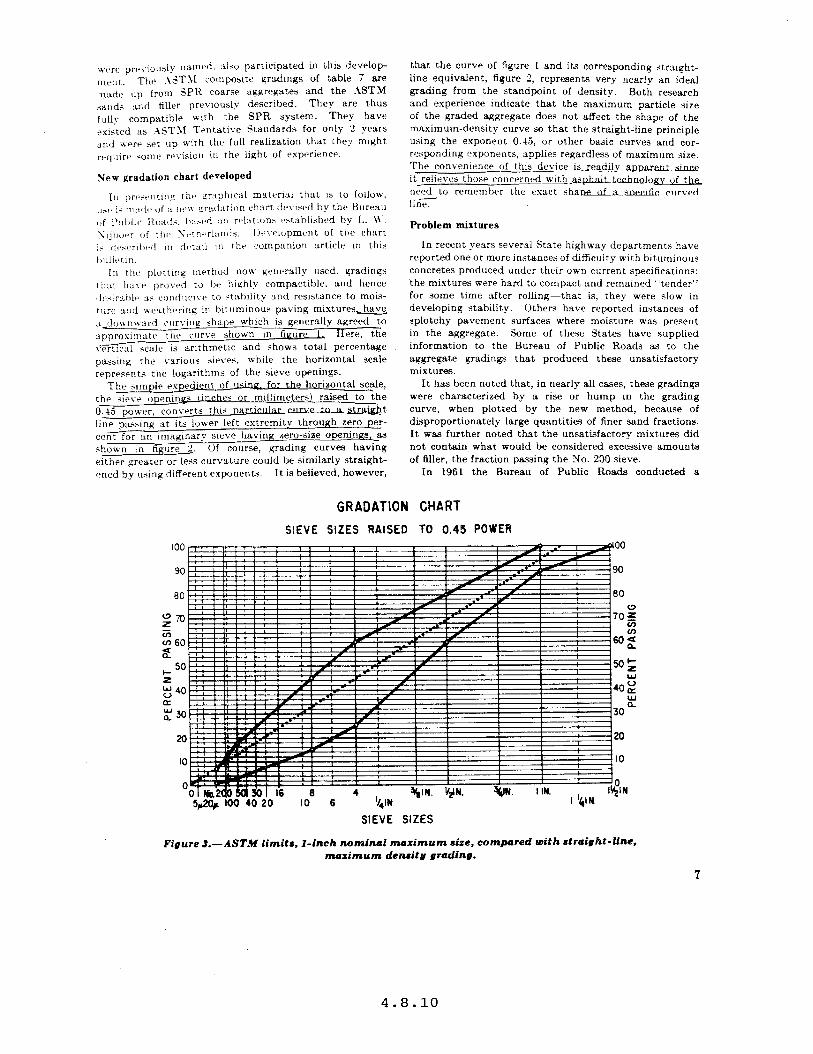
:i doa-n~vurrl crrrvirls shape which is generally agreed to spprosirrmte the carve whom-n in figure I, Here, the \‘erticnl scale is arithmetic and shows total percentage pa~ng the various sieves, while the horizontal scale represents the logarithms of the sieve openings.
The simple expedient of rrsmg&r the horizontal scale, the <ieve openinns tin,& s or millimeters) raised to the 0.45 poll-er. converts this DarticlllarellrVP to a straight line ps,sring at its lower left extremity through zero per- cent for an imaginary sieve having zero-size ape rungs, as shown in figure 2. c)f course, grading curves having either greater or less curvature could he similarly straight- ened by using different exponents. It is believed, however,
that the curve of figure 1 and its corresponding stmight- line equivalent, figure 2, represents very nearly an ideal grading from the standpoint of density. Both research and experience indicate that the maximum particle size of the graded aggregate does not affect the shape of the maximum-density curve so that the straight-line principle using the exponent 0.45, or other basic curves and cor- responding exponents, applies regardless of maximum size. The convenience of this..device is resdi!y_apparent since it relieves those concerned-C&.asphalt technology of tk need to remember the exact shane of a snecihc crrrved lini
Problem mixtures
In recent years several State highway departments have reported one or more instances of difficuity with bituminous concretes produced under their own current specifications: the mixtures were hard to compact and remained ‘%ender” for some time after rolling-that is, they were slow in developing stability. Others have reported instances of splotchy pavement surfaces where moisture was present in the aggregate. Some of these States have supplied information to the Bureau of Public Roads as to the aggregate gradings that produced these unsatisfactory mixtures.
It hau been noted that, in nearly all cases, these gradings were characterized by a rise or hump in the grading curve, when plotted by the new method, because of disproportionately large quantities of finer sand fractions. It was further noted that the unsatisfactory mixtures did not contain what would be considered excessive amounts of Idler, t.he fraction passing the No. 200 sieve.
In 1961 the Bureau of Public Roads conducted a
GRADATION CHART
SlEVE SIZES RAISED TO 0.45 POWER
SIEVE SIZES
Figure 3.-ASTM limits, l-inch nominal maximum size. compared with rtraight-line. musimum deneity grading.
7
4.8.10
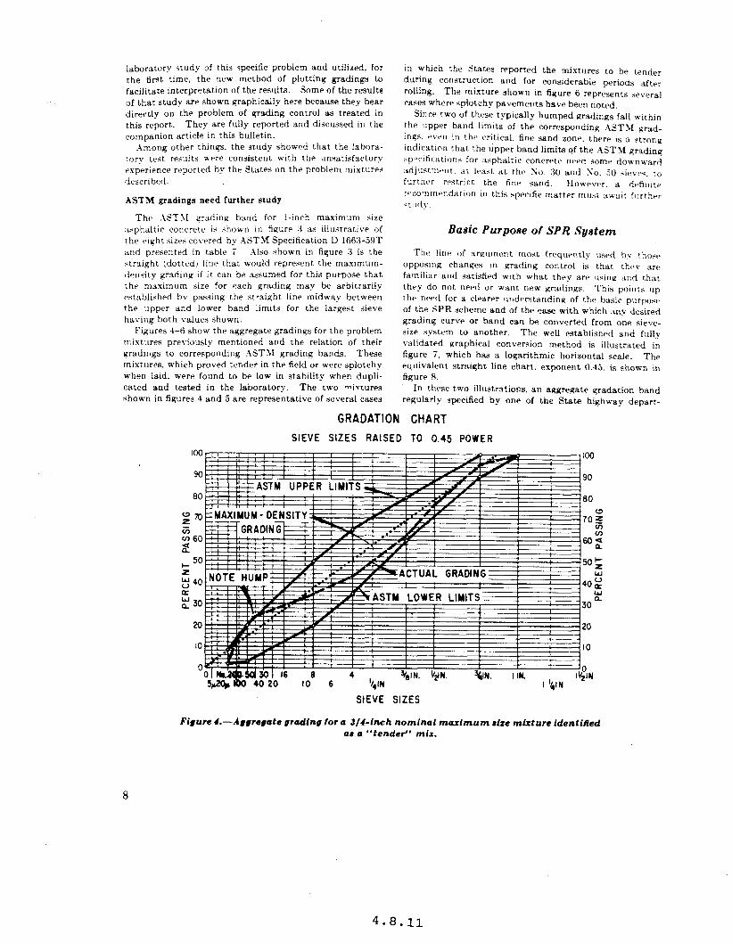
laboratory irudy of this specific problem and utilized, for the first, time, the new method of plotting gradings to facilitate interpretation of the results. Some of the results of that study are shown graphically here because they bear directly on the problem of grading control 1~ treated in this report. They are fully reported and discussed in the companion article in this bulletin.
.\mong other things, the study showed that the Isbora- tory test results wpre consistent with the unsatisfactory rspcrience reported by the States on the problem mixtur+ described.
ASTM gradings need further study
Thtb .IdT\I rradinq hand for l-inch maximum size asphaltic concrete is *hown in liqure 3 as iilustrative of the eight sizes covered bv ASTM Specification D 1663-59T xnd presented in table ?. Also shown in figure 3 is the >traight (dottcdj lincz that would represent the maximum- density grading If it can be assumed for this purpose that the maximum Gae for each grading may be arbitrarily *bstablished by passing the straight line midway between the upper and lower band limits for the largest sieve having both values shown.
Figures 1-6 show the aggregate gradings for the problem mixtures previously mentioned and the relation of their gradings to corresponding ASTSl grading bands. These mixtures. which proved tender in the field or wvpre splotchy when laid. were found to be low in statxlity when dupli- cated and tested in the laboratory. The two mivtures shown in figures 3 and 5 are representative of several cases
in which the states reported the rmxtures to be tender during construction and for considerable periods after rolling. The mixture shown in figure 6 represents several ca*es where splotchy pavements have been noted.
Since two of these typically humped gradings fall within the upper band limits of the corresponding .kT\l grad- inas. P\PII in the critical. fine sand zone. there IS a AtronK indication that the upper band limits of the ASTXf grading ~pvlticxtion~ for ssphaltic concn=t~~ IIPP~ some dou-nward :idjustmf*ilt. :it k:c>t at thv So. 30 and So. .jO +ievls<. to furthrr rrlstrict the Anta *and. However. a dl~firlitr rt~commrvldation in this .sp~~fic matter must await fllrthrr ;tildy.
Basic Purpose of SPR System
Thv line of xrqrurw,r~t most frequr-ntl?- usrcl hy I host% opposing changes 1n Erading control is that they arri familiar and satisfied with what they are IlGrlu and t,hat thrp do not nerd or want new gmdiny~. This points up the nr4 for a clrarrr understanding of the basic purpop+’ of the SPR scheme and of the ease with which any desired grading curve or band can be converted from one sieve- size system to another. The weLl established and fully validated graphical conversion method is illustrated in figure 7, which haa a logarithmic horizontal scale. The equivalent straight line chart. exponent 0.45, is shown in figure 8.
In these two illustrations, an aggregate gradation band regularly Jpecified by one of the State highw-ay depart-
GRADATION CHART
SIEVE SIZES RAISED TO 0.45 POWER
StEVE SIZES
Figure I.--dggre#ate grading for a J/I-inch nominal maximum stze mtxturc identified aa a “tender” mix.
8
4.8.11
GRADATION CHART
SIEVE SIZES RAISED TO 0.45 POWER
LO +.+q-+:f'i No 2dO 501 30 1 16
I1 t-----i +.--- + -
; 8 4 $81 N ‘I21 N VIIN I IN 5JOp 100 40 20 IO 6 ‘QN
&‘:I N I ‘/4lN
SIEVE SIZES
Figure 5.-.Jggregate grading for a 3/S-inch nominal maximum size mixture identified (IS (I “tender” mix.
GRADATION CHART
SIEVE SIZES RAISED TO 0.45 POWER
80
2 40 rc : 30
20
IO
0
&IN ” -
SIEVE SIZES
I’GIN -
Figure 6.-Typical grading for a I/Z-inch maximum size mixture where a small amount of moisture in the aggregate has resulted in a splotchy pavement surface.
4.8.12
LOGARITHMIC GRADATION CHART
SIEVE SIZES
Figure 7.-Conoersion of a current State specification to SPR sieve sires, using the logarithmic gradation chart.
GRADATION CHART
SIEVE SIZES RAISED TO 0.45 POWER
S& 100 40 20 IO- 6 Il,,w .~ . . . . .=...
SIEVE SIZES
_ igure 8 .-Conversion of a current State specification to SPR sieve sizer, using the Public Roads gradation chart.
10
4.8.13

However. this phiio3ophy Cannot kqltimately be llsed to justify the kirld of tri\-ial diffrrrncra that awolmt for a large proportion of th? hundreds of ayyrenate eradations appearina in State specifications
Recommended Course of Action
The study which is the subject of this report was under- taken for the purpose of furthering the three objectives mentionedArastic reduction of “standard” gradations, agreement on sieve sizes. and agreement on a uniform sys- tem of identification of standard gradations. Because of the inherent flexibiiity of the SPR scheme, coupled with compatible sand and filler specifications now available as A;\SHO and ASTXI standards. it is believed that a large proportion of the many special gradings now appearing in State specifications could be eiiminated, thereby achiev- ing important economies in higha-ay construction. In many cases, it would only be necessary to convert to the
SPR standard *ieve sibes, as dlustrated in tigures ; and 5, and to use SPR gradinq designations.
A desirable course of action and one that i3 strongly recommended for implementation b-v the .imerican ,4jso- ciation of State Highway Officials is essentiaiiy as follows:
1. Elimination from individual State specifications of all <ieve sizes that are at variance with those officially adopted by A.XSHO and substitution thrrrfor of conforming <ie\-r tiara. This could br donp rasily by Iltilizing the mrlthod IIIustratc>d in tipurw 7 and *. Thr now ersdirq tables w-ouid prov& thr same yrndation< as thosti prF,viouslv .ipt:cifird.
2. l~kmination from individual titatta spwificariuns of other vradation rc~quirement.~ not conforming to A.idH() or rrlatrtd ;\ST.\l standard,* to they ma.ximum practicable rxtent.
3. Retention for use, as special provisions or .ilppie- mental speciticatlon,y of such nonc~~nformirle gradation re- qulrements as may be justificad.
, Standards Now Recommended
The following .4.4SHO and .4ST>l standard% are recom- mended for general use by all highway departments:
1. hhSH0 SI X-.&9. standard sizrs of coarse aggregate for highway construction.
2. A.4SHO 11 80-51, coarse aggregate for portland cement concrete.
3. AASHO M 6-51, fine aggregate for portland cement concrete.
4. ASTM D 69%59T, coarse aggregate for bituminous paving mixtures.’
5. ASTM D IOK-59T, fine aggregate for bituminous paving mixtures.
6. ASTM D 242-5i’T, mineral filler for sheet asphalt and bituminous concrete pavements.
In addition to the above six standards. the following tentative standard is recommended for study, possible revision, and general use:
i. .4STM D 1663-59T, hot mixed, hot laid asphalt paving mixtures.
11
4.8.14
A NEW GRAPHICAL CHART FOR EVALUATING AGGREGATE GRADATION
By the Physical Research Division Bureau of Public Roads
Reported 1 by Joseph F. Goode, Highway Research Engineer and Lawrence A. Lufsep, Highway Engineering Technician
The Problem of Diverse Gradations
As forcefully brought home in the companion article in this bulletin, there is a wide diversity in the requirements pertaining to aggregate gradations in the current standard specifications of the State highway departments, and the multiplicity would be increased many foid if the speci- fications of county, city, and other government jurisdic- tions responsible for highway construction were taken into account. It is obviously questionable that so many variants are necessary. or that they all are as good as they might be.
Engineers are becoming increasingly aware of the im- portance of the proper design of bituminous paving mix- tures to provide pavements that will meet the demands of modern traffic. They generally agree that gradation of th_e aggregate is one of the factors that must be caref* considered, especially for heavy duty highways. But they disagree as to what gradations are the more satis- factory. This can be verified by examining the gradation requirements of specifications used by the various State highway departments and other agencies. They differ widely.
Some specifications are so broad that they permit the use of paving mixtures ranging from those that result in open and coarse surface textured pavements to those that are tight and fine grained. They also permit the use of paving mixtures of either low or high stability. Within these gradation limits the engineer often has considerable leeway in selecting pavement type to his liking, and whether the most satisfactory gradation is .selected will depend on hb judgment or experience.
Other specifications am nuxow enough to permit little variation in pavement type and characteristics. But these tighter specifications di@er enough among themselves to result in a wide range in types and characteristics of pavement.
h review of the many different gradation requirements will aiso show that engineers do not aarce as to method for specifying gradations. They employ at least four different methods:
1. Percentages by weight of total aggregate passing each of several specified sieves (total percent passing basis,.
2. Percentages by weight of total aggregate retained on each of several specified sieves (total percent retained basis).
3. Percentages by weight of totat aggregate between consecutive sizes of specified sieves (passing and retained. total aggregate basis).
-I. Percentages of aggregate, by weight of bituminous mixture, between consecutive sizes of specified sieves (passing and rezained, mix basis).
To complicate matters further, different combinations of sieve sises are specified to control specific grading ranges and a few agencies even specify round opening screens for coarse aggregate grading control.
Such nonuniformity in methods of expressing gradations adds to the difficulty of studying and evaluating aggregate gradations in terms of construction characteristics and pavement performance. In some instances it also tends to add unnecessarily to the construction costs. Stand- ardization of sieve sizes and aggregate gradations and the conscientious use of such standards would almost certainly result in fewer, more uniform, and probably better specifi- cations, and in more economical construction.
Development of a New Gradation Chart
The primary purpose of this article is to present and illustrate the use of a new aggregate gradation chart that will be especially valuable in developing more realistic specifications and in evaluating individual gradations.
Those accustomed to expressing gradations as percent- ages pasaing the various sieves are thoroughly familiar with the common gradation chart in which percentages passing are shown arithmetically on the vertical scale and the logarithmic scale is used for the horizontal spacing
13
4.8.15
of sieve sizes :see fig, 7 in the preceding article. p, 10). This chart. which will be referred to hereafter as the logarithmic gradation chart. has had wide use for some 30 pears and has proven valuable in illustrating individual gradations and determtning their position relative to speci- fication limits. This t>-pe of chart, however, h:is one significant disadvantage in that it Ghows a lnaximum density gradation as a deeply sagging curve. the shape of Lx-hich i; ‘n:ird t,) define.
To provide :L brttrr means of relating actual aggregate gradation to mLtyimum den+lry gradation. a IWK chart has been devwed b>- the B11reau of Public Roads. The hori- zontal +c:tle for t hr +wr:d ;IC’VP iizrs of this chart is a power function r:lrhtsr rhsn IhP logarlrhm of the 5ieve opening in microns. The vertical wale is arithmetical, the same :U for the logarithmic chsrr. .\n importanr feature of the new than is that it provides for a zero th~orrticnl *ieve size. Thus. for practical purposes. ail straight lirw plotred from the lower left corner of the chnrt. at zero pclrcrnt passing zero theoretical sievr size. upward and Toward the righL to any specific mnximum size. reprearnt martimum density gradations. Thr ex- ponent of thr poner function is 0.45, i.e., the horizontal scale represents the various sieve openings in microns raised to the 0.45 power.
Background of development
The selection of the 0.45 exponent was based on research performed by L. W. Xijboer of the Netherlands and first published in 1048.1 Sijboer used a double logarithmic gradation chart in a study of the influence of aggregate gradation on mineral voids. All gradations used in his study were represented by straight lines, with various slopes, shen plotted on his chart; the variation in slope resulting from his use of several different gradations of the same maximum (?,-inch) size. Xijboer made two series of tests on compacted bituminous mi.xtures, using rounded gravel for the coarse aggregate in one seiies of tests and an angular crushed stone in the other. Mineral voids were determined for all of the mixtures and were plotted
2 Plodtieify ad a Factor !n fhe Design of Dcnae Biluminow Road Carp&. by L. R. Nijboer. Elsevier Puhlishmg Co., 1948.
SIEVE SIZE NO. 200 NO.16 'N* 3/4iN.
LOGARITHM OF SlEVE OPENING IN YKRONS
Figure I.--Maximum den&g grudotfon plotted on a double log chart.
agamst the slopes of the strsivht line Prrsti;trwn c\lr\-ps. For both types of coarse aggregate. the minlm:lm minrrai voids, or maximum aqgragate density. occurred for a gradation having a siope of 0.45 on thr double log chart.
Figure I shows this maxmum density gtadation for a “i-inch maximum size aggregate plotted on a double log chart. The figure aljo illustrates a maximum density curve for a gradation with a maximum size de.iiq,ated as .U microns. for the following discuislon in which it is assumed that all ma\-imum drns:lty c!irvt’- haw 3 <lope of 0.45 on the double ioq chart r~~rrardlt~~:: of !xi\irn~lrn size.
In developing the equntlurl for :L m:~~m~~m dtanslty curve let:
.U = maximum iize of :iygrt~aate In micron?.
S=;ize of opening for 3 partIcIIl;Lr nit’w.
P=percrntage pas:dinc the p:wriclktr ~ww’.
log B=intercept un vertical :~SX of th<J ch:irt
The general equation of the curve is: log P= 10~ 13 A 0.45 lore ,i.. _ ( 1)
Other equations are: log 100-iog B=O.45 (log J&log II: or
Z-log B=0.45 (log .W: or
log B=“-0.45log .~~-----.....--..---~~~
Substituting equation (2) in equation (1) we ha\-e:
log P=2-0.45 log M-O.45 lop; .s; or
log P=2*0.45 (log S-log Jf); or &“ 04s
P=lOo z ( 1 --------------------------- The exponent in equation (3) 1s the one used in design-
ing the new gradation chart. By the use of logarithms, the sizes of Steve openings in microns were raised to the 0.45 power. These values were then employed with a suitable arithmetical scale for establishing the horizontal position of each sieve. The procedure is illustrated for a few of the sieve sizes on figure 2.
Figure 2 siso illustrates how maximum density grada- tion is indicated for a gradation having a maximum size of &f microns: simply by plotting a straight line from the origin, at the lower left corner of the chart, to the selected maximum size at the top of the chart. As can be seen from the information on the left side of the chart, the equation for such a line is that shown above as equation (3). Thus, any gradation that will piot as a straight line through the origin of the new chart will aiso plot as a straight line on the double log chart of Sijboer and will have a slope of 0.45.
The new gradation chart described in this article. and hereafter referred to as the Public Roads gradation chart, is not, strictly speaking, an entirely new type. The Sational Crushed Stone Association. in its Crushed Stone Journal, haa been using a square-root gradation chart for several years to illustrate gradations. The only difference between the Association’s chart and the new one presented here ia that the former is based on an exponent of 0.50 for the power function instead of 0.45. The research of Xjboer and data to be presented later in this article show that 0.45 is a more realistic value for indicating maximum density.
4.8.16
100
80
20
Y*hA”u DEN&Y YAhJM DEN&Y 0’ 0’
CURVE FOR YAX. CURVE FOR YAX. SIZE OF l Y* SIZE OF l Y*
,/ ,/ 0 0
MICRONS MICRONS
:OR MAX. DENSITY CURVE LET: :OR MAX. DENSITY CURVE LET: 0 4 : MAX. SIZE, MICRONS 4 : MAX. SIZE, MICRONS
0 .
) : PERCENT ) : PERCENT PASSING SIEVE PASSING SIEVE HAVING OPENING HAVING OPENING k’l ,
OF ‘5’ MICRONS OF ‘5’ MICRONS 0 n = SLOPE OF CURVE n = SLOPE OF CURVE 0 :OUATION OF CURVE IS Y - mX :OUATION OF CURVE IS Y - mX 0 I”, y : p, I”, y : p, x : ~0.~~ AND x : ~0.~~ AND I
, 100 0
/ #
0..5 ‘. P = 100 0 2 ,
COMPUTATIONS
u 0
SIEVE OPENING, LOG S 0.45A ANTILOG B SIZE MICRONS OR
I . . . ” , 4 S A 8 ] s
a.5 4
-I-I-I--. / I 314 IN 19100 4.261 1.926 04 4
Nsq$o 0 ’ NO. 16 NO. 16 1190 3.076 1.364 24.2 4’ SIEVE
I/ NO. 200 74 1.669 0.641 6.9
314 SIEVE IN.
I I 0 /z9 24.2 0 -1
I - 0.0 84.4
* t -. -.
IO 20 30 40 50 60 70 80 X - ARITHMETICAL SCALE FOR So..’ OR (SIEVE OPENING, MICRONS)“-”
1
Figure Z.-Illustration of computations and method of positioning sieve sires cn setting up the Public Roads gradation chart.
GRADATION CHART SIEVE SIZES RAISED TO 0.45 POWER
70
:: 60 iii In
2 ~YAXIYUY DENSITY GRADATION my_;1 ” I -
)TE: THE UPPER EXTREYITY OF THE e IGHT LINE SHOULD REPRESENT 40 2
EFFECTIVE YAXIYUY SIZE WHICH IN THIS CASE IS LESS THAN 3/4-INCH.
0” .,n 30 .J”
20 20
Ifi .- IO
0 0 IK).2oowx)!
n 503016 8 4 I IN: t&Low 20 lo 6 ‘f@ 3@N. I,lN. 3/41N.
SIEVE SIZES
Figure &-Gradations of problem mixture (project A) compared with maximum density gradation.
Using Cimrt in Study of Tender Mixes several bituminous mixtures that had been reported as having unsatisfactory compaction characteristics. During
Soon after the Public Roads gradation chart was de- the past 4 or 5 years, engineers have reported several veloped it was used to study gradations of aggregate from instances of hot asphaltic concrete mixtures that con-
15
4.8.17
formed :o rheir speclfications but couid not be compacted in the normal manner because they were siow in devel@ng S’U clent sraolhry to withstand the weight of roe.ng equipment. >uch mixtures are usually called “tender” -- _ ml
Those having experience vith such mixtures have tended to place most of the blame on the particular asphalt used. Occasionally it was recognized that such factors a~ high remperarurrs of the mixture. the air. and the underiving structure. excessively hpavy rolling equipment. or the prvencr of moisture In the mixture might con- trlhure :o the unsatisfacfory condition. The posslhility uas vcxry +ldom considered that aggregate gradation could be an rquall~ important fscror and that the grading requirements used could be contrlbutmq to this problem.
critical mi.xzure which did not compact satisfactorily at any asphalt content within the specification limits. At asphalt contents only slightly below the one that was most nearly satisfactory, the mixture was friable and developed cracks behind the finishing machine. It, only slightly higher asphalt contents the mixture was too unstable to compact.
To illustrate the type of ayyre&ate yrsdatlon that seems TO he rather consistently associated with tender mixtures. some specific examples from three different parts of the country are discussed in the paragraphs that follow.
.Uthough the engineers suspected the asphalt was at farlit they drclded to try a modified gradation. which rrssultrd in a less critical mixture with greatly improved compaction characteristics. The initial and final grada- tions and the corresponding maximum denalty gmdation are shown plotted on the Public Roads gradation chart in fiyure 3. Attention is called to the hump in the curve above the maximum density line a1 the SOS. .50, 40, and 30 sieve sizes for the initial gradation used in the un- satisfactory mixture and to the absence of a hump at theso sieve sizes for the final gradation which produced the more satisfactory mixture.
(ln a 19.5.G construction project, identified as project A, the engineem were careful to select cold feed materials and
Figure 4 shows gradations used on three other projects, each having a hump above the maximum density line at
proportions for the a-earing course mixture that would about the To. 30 sieve when plotted on the Public Roads provide it median gradation within the specification limits. chart. Two of these, for projects B and D, built in I!).% Deaplte these precautions. the resuiting mixture had the characteristics of a tender mix.
in a different State than project A, are gradations of It was described as a mixtures containing gravel and sand that were described
GRADATION CHART SIEVE SIZES RAISED TO 0.4s POWER
90 90
60 So
70 loo
:: I 60 z 90
:K) iFI
so
x 40 L
too
30 90
20 60
to TO
0 60 % 2
50 s B
IO 40.: Y
2 0 30
LO
lo IO
0 0 ~OmmomoM 30 Id 6 4 I IN.
Nodo eo IO 6 ‘/*IN. %* IN. ‘4 IN. 3tpl.
SIEVE SIZES
Figure I.-Gradations of problem mixtures (projects B, C, and D) compared with maximum denrity gradatione.
16
4.8.18
60 50
P : (;)’ WHERE!
P - PERCENT PASSING SIEVE HAVING
ii AN OPENING OF ‘S’ MICRONS.
‘i
Y = YAXIYUY SIZE IN MICRONS.
0 7
I I I I I I I I
NO. 200 NO. 100 NO. 50 NO. 30 NO. 16 NO. 0 NO. 4 SIEVE SUE
3/8#,, ,525 IN.
Figure 5.-Gradations .Vos. I-6 plotted on double log chart
GRADATION CHART SIEVE SIZES A
100 ,I
80
70
: i i i 60
IAl ISED TO 0.45 POWER
0” 30
20
IO’
0 ONO.~8030 I6 8 4
80
162 1620 I
16.1 14.7 1930 IS.0
SIEVE
I IN.
Figure b.-Gradotionil Noe. l-6 (rtraight-Iine gradationa in Ag. 5) plotted on the Public Roada gradation chart.
17
4.8.19
33 tender mixes. The third gradation, for project C, is typic31 of those used in a &ate which has had considerable difficulty with moizture problems in laying bituminous pavements containing certain coarze aggregates. A very zmall 3mount of moisture in such mixtures often results in 3 splotchy pavement surface.
Thtlre have been exceptions, but nearly all gradation curvp~ of problem mixturez studied by the research labora- rorks of the Burp311 of Public Roads have been characterized by 3 hump above the maximum density line 3t or near the SO. 30 Gvr. such mixtures have an excess of fine sand in rt>lation lo tot31 s3nd. This excess not only results in lower comp3ct,ld densities hut tends to float the larger particle3 and destroy stability that might otherwise result from course aggregate interlock. In addition, tine sand is inherentlv lezz stable than coarse sand.
T&us, imorvreaL;tte gradation is identified as a_n importnnt contributing factor to the ugai-isfactory _- -- -- behavior of some bituminous mixtures. .other factqn, zilch 3s asphslt characterlstlcs,~i~-tempera~~~~~-~s,. and moisture vapor csnnot be ruit; -bht. unzati_sfactory grading. particularly oversanding in the fine sizes, must not be overlooked 3s 3 possible source of trouble.
Laboratory Evaluation of Gradation Chart
To evaluate further the usefulness of the new Public Roads gradation chart, a laboratory study was undertaken with two main objectives: To substantiate Sijboer’s findings, and to determine morP precisely the effect of “hump” gradations on mineral voids nnd stability of compacted asphaltic concrete. The study employed the gyratory method of molding and thr Marshall stability test.
The investigation was limited to ‘24 different gradations of gravel, sand, and limestone dust 3ggreQate having 3 maximum size of 0.525 inch. These gr3dations are $hovvn in table 1 of the appendix (p. 24). together with values for effective specific gravity v3lucs which were used in computing voids.
VerMcation of 0.45 exponent
In order to verify Xijboer’z Endings. the first six grada- tions were made up zo that,Jhey would plot 3s strsight lines with varyinK slopes K on the double log chart, 3s shown in figure 5. When plotted on the New Public Roads
AIR VOIDS - 4.0%
S OF TESTS
SLOPE ‘K: SEE Fl6.5
Piguru 7.-Mineral voids and Marrhall &abilities of gradations Noa. l-6.
18
4.8.20
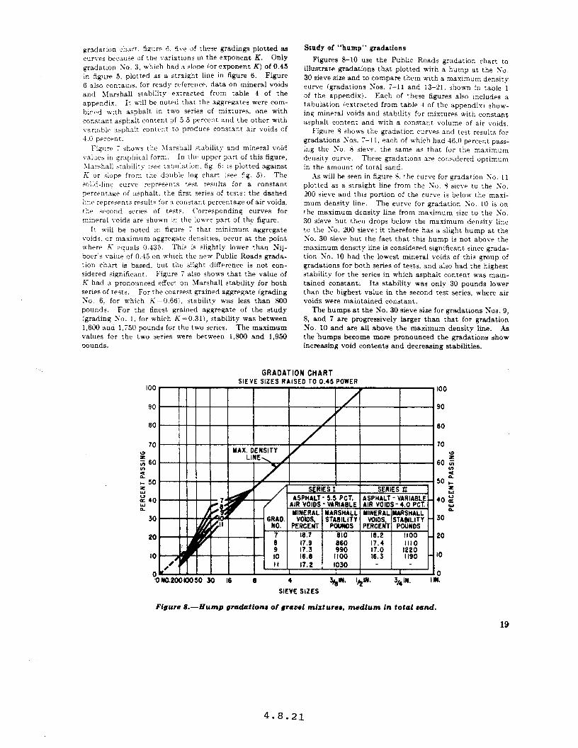
gradation chars. tlgure i, five of these gradings plotted as curves because of the variations m the exponent K. Only gradation So. 3, which had a slope (Or exponent K) of 9.45 in figure 5, plotted as a straight line in figure 6. Figure 6 also contams, for ready reference, data on mineral voids and lIarshal stability extracted from table 4 of the appendix, It will be noted that the aggregates were com- bined with asphalt in two series of mixtures, one with constant asphalt content of 5.5 percent and the other with variable asphalt content to produce constant air voids of 4.0 percent.
Figure 7 shows the SIamhall stsbility and mineral void values in srsphicnl form. In the upper part of this figure, Sl:irshnll :‘tahility ~see rshlilation. fig. 61 is plotted against K or .Tlope from the doiible 104 chart (see 64. 5). The solid-line curve represents test results for a constant prrcentaae of tisphalt. the first series of tests: the dashed line reprknts rrsu1t.c for a constant percentage of air voids, tlhe second series of tests. Corresponding curves for mmrral voids are sham-n in the low-rr part of the figure.
It will be noted in figure 7 that minimum aggregate voids. or maximum aggregate densities, occur at the point where K equals 0.435. This is slightly lower than Nij- hoer’s value of 0.45 on which the new Public Roads grada- tion chart is based, but the slight difference is not con- sidered significant. Figure 7 also shows that the value of k’ had a pronounced effect on Marshall stability for both series of tests. For the coarsest grained aggregate (grading So. 6, for which K=O.66), stability was less than 800 pounds. For the finest grained aggregate of the study (grading To. 1. for which K=0.311, stability was between 1,600 and 1,750 pounds for the two series. The maximum values for the two series were between 1,809 and 1,950 oounds.
Study of “hump” gradations
Figures 8-10 use the Public Roads gradation chart to illustrate gradations that plotted with a hump at the So. 30 sieve size and to compare them with a maximum density curve (gradations ?;os. 7-11 and 13-21, shown in table 1 of the appendix). Each of these figures also includes a tabulation (extracted from table 4 of the appendix) show- ing mineral voids and stability for mixtures with constant asphalt content and with a constant volume of air voids,
Figure S shows the gradation curves and test results for gradations 10s. 7- 11, each of which had 46.0 percent pass- ing the So. 3 sieve, the same a~ that for the maximum density curve. These gradations are considered optimum in the amount of total sand.
;\s will be seen in figure 9. the curve for gradation So. 11 plotted as a straight line from the Xo. 8 sieve to the So. 200 sieve and this portion of the curve is below the maxi- mum density line. The curve for gradation So. 19 is on the maximum density line from maximum size to the So. 30 sieve but then drops below the maxlmum density line to the 10. 290 sieve; it therefore has a slight hump at the So. 30 sieve but the fact that this hump is not above the maximum density line is considered significant since grada- tion So. 10 had the lowest mineral voids of this group of gradations for both series of tests, and also had the highest stability for the series in which asphalt content was main- tained constant. Its stability was only 30 pounds loa-er than the highest value in the second test series, where air voids were maintained constant.
The humps at the So. 30 sieve size for gradations SOS. 9, 8, and 7 are progressively larger than that for gradation No. 10 and are aII above the maximum density line. As the ‘humps become more pronounced the gradations show increasing void contents and decreasing stabilities.
GRADATION CHART SIEVE SIZES RAISED TO 0.45 POWER
pi 60
: 50
P 40
30
0 UMO.2OOowKSO 30 16 6 4 $lN. '4lu. 3,$N. lW.
SIEVE SIZES
Figure (I.--Bump gradations of #ravel mixtursq medium in total sand. Figure (I.--Bump gradations of #ravel mixtursq medium in total sand.
19
4.8.21
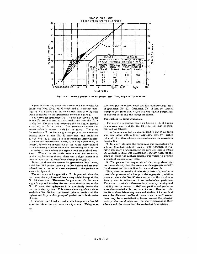
GRADATION CHART SIEVE SIZES RAISED TO 0.45 POWER
IO 16.6 660 ) I?.? 1 IO60 ]
0 0 ON0.200~050 30 16 8 4 3/6’N. I,2~N. 3,4’N. I IN.
SIEVE SIZES
Figure O.--Hump gradations of granel mixtures, high in total aond.
Figure 9 shows the gradation curves and test results for gradations Yios. 13-17. all of which had 53.3 percent pass- ing the ?jo. 8 sieve and are considered high in total sand when compared to the gradations shown in figure 8.
The curve for gradation 50. 17 does not have a hump at the So. 30 sieve size; it is a straight line from the No. 8 to the No. 200 sieve and intersects the maximum density curve at the So. 30 sieve. This gradation showed the lowest value of mineral voids for the group. The curve for gradation Xo. 16 has a slight hump above the maximum density curve at the No. 30 sieve size, and gradation curves SOS. 15, 11, and 13 have increasingly larger humps. Allowing for experimental error, it will be noted that, in general, increasing magnitude of the hump corresponded with increasing mineral voids and decreasing stability for the series of tests where the asphalt was maintained con- &ant. Where the air voids were maintained constant, in the two instances shown, there was a slight increase in mineral voids but no significant change in stability.
Figure 10 shows the curves for gradations Nos. 18-21, which had 38.9 percent passing the No. 8 sieve and are con- sidered low in total sand when compared to the gradations shown in figure 8.
The entire curve far grrdirtion No. 21 plotted below the maximum density Iin? ti hrs 8 very slight bump at the So. 30 sieve size. Tha.curve for gradation No. 20 has a slight hump and touch the maximum density line at the Xo. 30 sieve size; qt&rw%e it is completely below the maximum density line. This is considered significant since gradation No. ‘20 had the lowest mineral voids and the highest stability of this group of gradations in both series of tests.
Gradation No. 19 had a considerable hump at the No. 30 sieve size, above the maximum density curve. This grada-
20
tion had greater mineral voids and less stability than those of gradation No. 20. Gradation So. 18 had the largest hump of the group and it also had the highest percentage of mineral voids and the lowest stabilities.
Conclusions on hump gradations
The above discussions, based on figures 8-10, of humps in gradation curves at the No. 30 sieve size, may be sum- marized as follows:
1. A hump above the maximum density line in all cases was associated with a lower aggregate density (higher mineral voids) than a hump that just touches the maximum density line.
2. In nearly all cases the hump also-was associated with a lower Marshall stability value. The reduction in sta- bility was more pronounced for the series of tests in which the asphalt content was maintained constant than for the series in which the asphalt content was varied to provide a constant volume of air voids.
3. The greater the magnitude of the hump above the maximum density line, the lower was the aggregate density (in all cases) and the stability (in nearly all cases).
Thus, bssed on results of laboratory tests of gravel mix- tures, the presence of a hump in the aggregate gradation curve at about the No. 30 sieve and above the maximum density line is indicative of an undesirable gradation. The extent to which di&erences in laboratory density and stability can be related to ibid compaction and perform- ancc characteristics is not now known. However, the results of these laboratory tests and studies of known field examples discussed earlier do show that “hump” grsda- tions may be a contributing factor toward the unsatis- factory behavior of mixtures. Further verification of their effect, should be determined by controlled field studies.
4.8.22
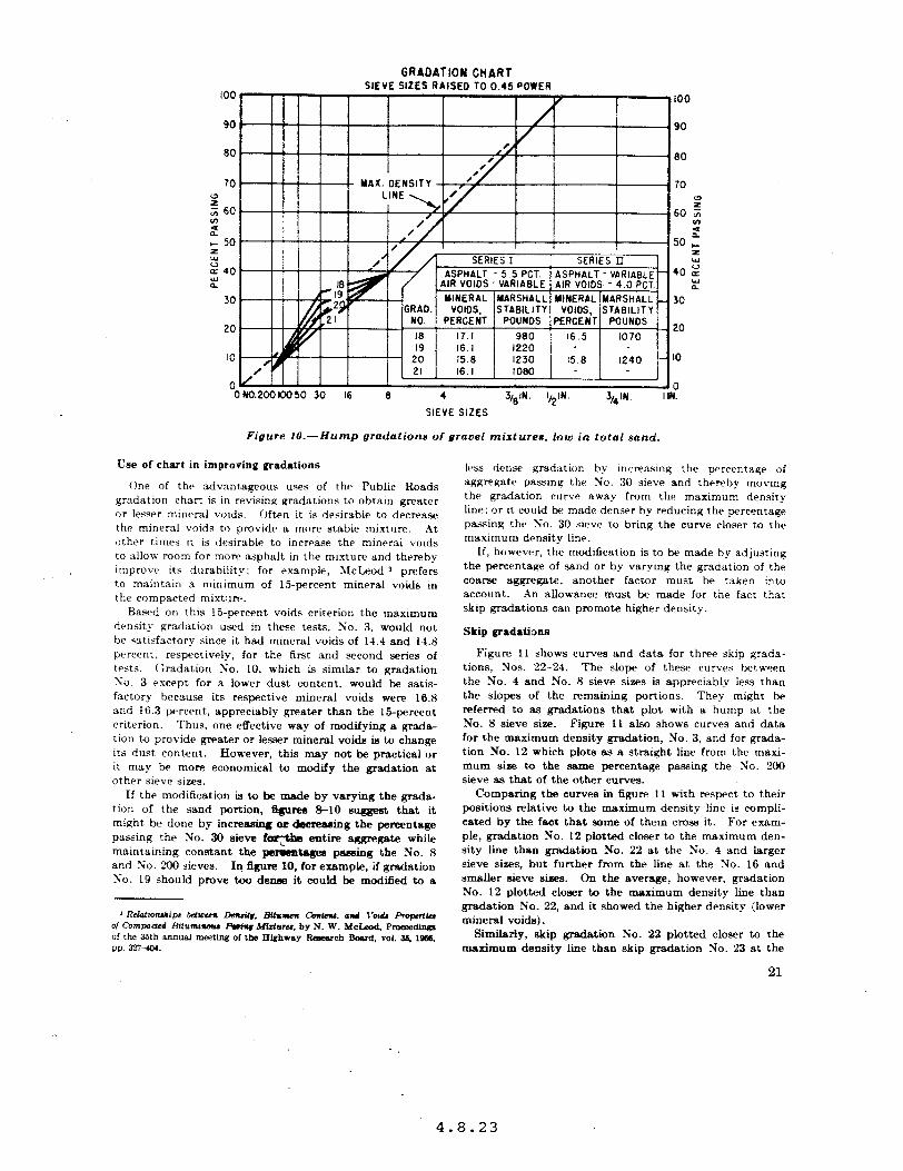
GRADATION CHART SIEVE SIZES RAISED TO 0.45 POWER
70
s ;; 60 m 2 I- 50 5 z 40 2
30
w MAX. DENSITY ! _”
D.2OOKlO50 30 16 8 4 3/,,‘N. lQ2iN. 3,41N. I IN
SIEVE SIZES
20
IO
0
Figure IO.-Hump gradntione of gravel mixtures, Low in total sand.
Use of chart in improving gradations
One of the, sdvant,ageous uses of thta Public Roads gradation chart is in revising gradations to obtain greater or lesser mineral voids. Often it is desirable to decrease the mineral voids to provide a more stabie mixture. At <Ither times it is desirable to increase the mineral voids to allow room for more asphalt in the mixture and thereby improve its durability; for example, 5icLeod J prefers to maintain a minimum of ISpercent mineral voids in the compacted mixtllre.
Basrd on this IS-percent voids criterion the maximum density gradation used in these tests, Xo. 3. would not be satisfactory since it had mineral voids of 14.1 and 14.8 percent. respectively, for the first and second series of tests. Gradation No. 10, which ia similar to gradation So. 3 except for a lower dust content, would be satis- factory because its respective mineral voids were 16.8 and 16.3 percent, appreciably greater than the 15-percent criterion. Thus, one effective way of modifying a gmcia- tion to provide greater or lesser mineral voids is to change its dust content. However, this may not be practical or it may be more economical to modify the gradation at other sieve sizes.
If the modification is to be made by varying the grada- tion of the sand portion, @urea 8-10 suggest that it might be done by increasing OE decrea&g the percentage passing the No. 30 sieve foQ& entire aggregate while maintaining constant the psrclsne passing the No. 8 and So. Xl0 sieves. Iq 5gure 10, for ersmpie, if gradation So. 19 should prove too denm it could be modified to a
1 Rclatmuhips kimem Lhai#, Bitsrun Cbmtat. omd 1’oid.a propnlia of Compacud Rifum- pciry Midwu. by N. W. McLmd, I’rom~dinca of the 35th annual me&ins ol fbe HI&way Research Baud, vol. 35.1966, PP. 327-4lM.
less dense gradation by increusmq the percentage of aggregate passing the No. 30 sieve and thereby moving the gradation curve away from the maximum density line: or it could be made denwr bp reducing the percentage passing the No. 30 sieve to bring the curve closer to the maximum density line.
If, however, the modification is to be made by adjusting the percentage of sand or by varying the gradation of the coam aggregate, another factor must be taken into account. An allowance must be made for the fact that skip gradations can promote higher density.
Skip gradations
Figure 11 shows curves and data for three skip grada- tions, Nos. 22-24. The slope of these curves between the No. 4 and No. 8 sieve sizes is appreciably less than the slopes of the remaining portions. They might be referred to as gradations that plot with a hump at the No. 8 sieve size. Figure I1 also shows curves and data for the maximum density gradation, No. 3, and for grada- tion No. 12 which plots as a straight line from the maxi- mum size to the same percentage passing the No. 200 sieve as that of the other curves.
Comparing the curves in figure 11 with respect to their positions relative to the maximum density line is compli- cated by the fact that some of them cross it. For exam- ple, gradation No. 12 plotted closer to the maximum den- sity line than gradation No. 22 at the So. 4 and larger sieve sizes, but further from the line at the No. 16 and smaller sieve s&es. On the average, however, gradation No. 12 plotted closer to the maximum density line than gradation No. 22, and it showed the higher density (lower mineral voids).
Similarly, skip gradation No. 22 plotted closer to the maximum density line than skip gradation No. 23 at the
21
4.8.23
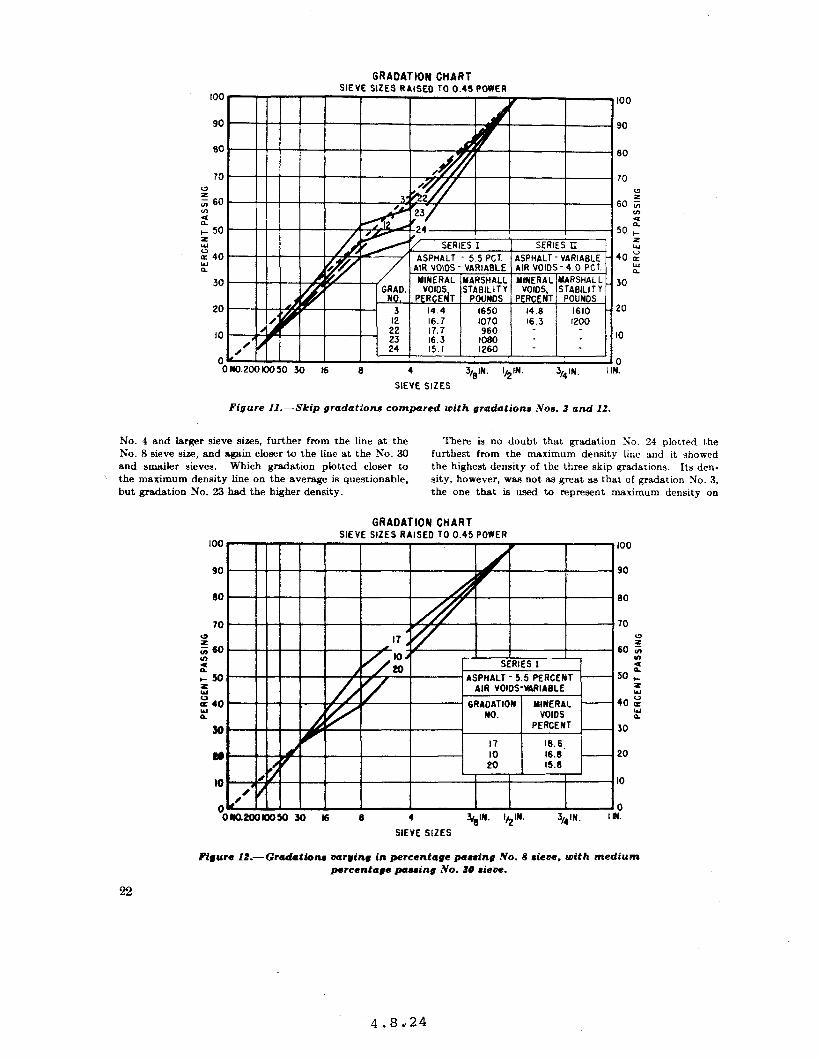
GRADATION CHART SIEVE SIZES RAISED TO 0.45 POWER
El0
70
s z 60 f-0 ;: I- 50 z LY 40 :
30
20
0 0#0.2OOKx)50 30 I6 8 4 3,lN. I,* IN. 3,41N.
I
I
I
Ild
100
90
80
70 G
60 5
: 50 I-
l5 40 2
2 30
20
0
3 I.
SIEVE SIZES
Figure Il.-Skip gradationu compared with gradations Nos. 3 and 12.
No. 4 and larger sieve sizes, further from the tine at the There is no doubt that gradation 30. 24 plotted the No. 8 sieve size, and again closer to the line at the No. 30 furthest from the maximum density line and it showed and smaller sieves. Which gradation plotted closer to the highest density of the three skip gradations. Its den-
\ the maximum density line on the average is questionable, sity, however, was not as great as that of gradation No. 3, but gradation No. 23 had the higher density. the one that is used to represent maximum density on
GRADATION CHART SIEVE SIZES RAISED TO 0.45 POWER
’ IO L I I ~. _. UB
I A/ 20 “-b60: SERIES I 2 ASPHALT - 5.5 PERCEWT 50 c -
GRAOATION MINERAL 40 z No. VOIOS E
PERCENT __ 30
t-9 a* c
0” 30.
I 3V.V. H iti 16.8 - 20
I
at
20 IS.6
IO I I
I I . IO
.I
ok 0Na200loo5030 IG 8 4 ~R’N. i/,lN. 3/*iN. I IN.
SIEVE SIZES - -
Pi#ure IL-Gradationa varying in percentage passing No. 8 aiew. with medium percentage paaaing No. 30 sieve.
22
4.8d24
the gradation chart. But thie does not pmiude the pas- sibiiity that there may be other skip gradations of the same maximum size that will exceed the density of gra-
ation No. 3. Figures 12 and 13 compare data for gradations that
vary in the percentage passing the No. 8 sieve. These were selected from previous figures used to illustrate “hump” grsdations. They provide the same indications as figure 11. For example, in figure 13, gradation ?io. ‘20 plotted further from the maximum density line than gra- dation No. 10 but had the higher density. The same rela- tionship held for gradations ?;os. 1X and R in figure 13. Incidentally. gradation No. 20 in figure 12 and gradations Nos. S and 18 in figure 13 can be classified as skip grada- tions as well as .‘hump” gradations because they plot with slopes flatter between the No. 8 and the No. 30 sieve s~r.e than elsewhere.
In reference to the higher density skip gradations in figures 11-13, it is considered important to note that in all cases the right-hand portion of the gradation curve was below the maximum density line. This fact must be taken into account when using the maximum density line as 8 reference for adjusting skip gradations to provide a lower or a higher density.
Conclusions
The laboratory study covered by this article was limited to data representing 24 different gradations of aggregate of a single maximum sise. Only one asphalt and one type of aggregate were used in the mixtures. Based on these
limited cnnditiona, the following conclusions am war- IXQkd:
1. The new Public Roads gradation chart provides a much more convenient meana of studying aggregate grada- tions than the logarithmic chart now eommoniy used. The greater convenience results from the fact that maxi- mum density gradations can be represented on the chart by a straight line from a theoretical sero percent passing zem sieve $11~ to 100 percent paasmg the effective maxi- mum sire.
2. This maximum density tine constitutes a new design tool, in that it serves as an easily remembered line in com- paring different gradations or in adjusting gradations to pmvide desired voids and stability characteristics.
3. For gradations of ph plot as smooth curves entirely above or belaw the rpaxi- mum density line, those closest to the linp. represent grtudations v&l&g the w in tJre compacted mixture.
4. For gradations of the same type of aggregate which plot as identical curves except for the portion between the No. 8 and the No. 200 sieves, those that show appreciable humps above the maximum density line at about the No. 30 sieve will have higher mineral voids and lower Marshall stabilities than those plotting with lesser humps. Analysis of several problem mixtures from field projects has clearly confirmed this finding and points up the detrimental effect of gradation humps in the finer aggregate sises.
5. For skip gradations, low mineral voids are associated with curves that stay appreciably below the maximum density line in the right-band or amme aggregate xone of the chart.
GRADATION CHART SIEVE SIZES RAISED TO 0.45 POWER
30
20 20
lo
Figure N.-Gmdetioru vmr#iry in percmt8#e pmuin# No. 8 r&w, with h&h pemntepe pcruing No. U dew.
23
4.8.25
APPENDIX: PROCEDURE AND DETAILS OF PROJECT
Processing aggregate
Table 1 shows the aggregate gradations used in the study and includes values of effective specific gravity which were used in computing voids. The effective specific gravities are rational values determined directly on several of the mi.xtures by the Rice vacuum saturation procedure.’
The aearegatc larger than the No. 4 sieve and a portion of that passing the No. 4 sieve and retained on the No. 8 sieve %-as an uncrushed river gravel. The remainder of the aggregate consisted of sand from the same source and a commercial limestone mineral filler. The amount of mineral filler used varied with the gradation. In all cases 60 percent of the total aggregate passing the NO. ‘200 sieve consisted of limestone dust.
Table 2 gives the apparent and bulk specific gravities of the three stock aggregates. Rational values of apparent and bulk specific gravity of the combined aggregate representing different gradations were not determined.
In preparing the aggregate to be combined to meet the several gradations. the gravel and the sand larger than the No. 8 sieve were accurately separated into 0.5~inch to ?/,-inch, J+nch to No. 4, and No. 4 to No. 8 sieve size fractions. Since it is very difficult to obtain clean separa- tions for fine size aggregate in large quantities, no attempt was made to separate the sand into exact sieve size frac- tions. Instead, it was separated into approximate sizes by a relatively rapid sieving process, and the gradations
of the several fractions were then accurately determinec and used in computing the correct proportions to provide the desired combined gradations.
Preparing mixtures and test specimens
An 85-100 penetration grade asphalt was used in all mixtures. Table 3 gives its test properties.
The mixtures were prepared in a laboratory mixer from aggregate heated to 325” F. and asphalt heated to 300’ F. Each batch was just sufficient for one test specimen, which, immediately after being mixed, was compacted in a gyratory mold heated to 200’ F. Figure 14 ;p. 26) shows the gyratory compactor used in molding the specimens.
The test specimens, 4 inches in diameter and 24$ inches in height, were molded by applying 30 gyrations at a l- degree angle and under a foot pressure of 100 p.s.i. Pre- vious work by McRae and McDaniel 5 indicated that this procedure produced densities corresponding to those of the 50-blow, hand-compacted Marshall specimen.
Tests performed
The specimens were tested for bulk specific gravity, Marshall stability, and Marshall flow value. Bulk specific
gravity was determined by the procedure described in Section 4(a) of AASHO Method T-165. Air and mineral voids, based on effective specific gravity of the aggregate, were computed from the bulk specific gravities.
s Roqrcu Rtprt a the Orpa of Envh.m’ Kneading Compodor for Ritu- mtnmu Miduru. by J. L. McRae and A. R. McDaniel. Pmeedin@ of the ASSOIlation of Asphalt Paving Tecbnok@ts. Vol. Zi, 1858. PP. 357-332.
Table I.-Cksdstion snd effective speddc gravity of aggregate blends
Gradation No. I 1 0.525 tn.
-
,.............................- ........ la? 2 ... .._ ....... .._._..____.______ _ _____ 3 _ ............. _. _. .... _. ....... - _. .... E 4.....-................--.------------ - 5...~..................-..-...-...-..-. D B.........-.......-...--..-------.---- - la,
,........._.....-.-.-.------.---.-.-.-. 8 .... .._....__._.._...-.....-------.- - i i g....--.--..-...-..-..----.--------.-- - ,o~....--......-.......-.----.-.-.---- - ii i 11......-...........-...-..----------- - HI0
12.......-..........----..------------ - lco
13............-..-....--.------------- - Il........-..-.........------------- - ii lJ............--.-..-.----- - - - ---- - _ _ ml 16......---..-..---.-~-------~------- - MO I,.-....--...--.-------------~------- - lol
... la...........----.------..----------- - Lg......-----.---.---.--------------- - :izl al. _.________________________ - -------- 109 21.....-----.-.--------------~---.--- .. im
m--..-.---------~--_----------------- - m........-------.--.---------------.- - i i i ~.......-...---....-------~---------- - 106
wn. ; Min.
-
.-
-
No. R No. 16
58.6 5% 0
iit: 36.2 91
43.0
iti
2:
43.1
53.3 53.3 za.3 8.3 53.3
38.9 38.9 38.9 a.9
2: 83.0
No. 50
2: 13.0 13.8 10.6 Rl
24.8 la 1
‘it2 7.: 5.2
%i la I 15.9 141
la.3 11. 4 10. 4 9. 4 &7
1x5 a4
55 ia 1 13.9
13.3 123
Y: 9.4
al.4 11.4 ia i ia4 15.9 9.5 13.0 8.5
15.6 9.3 14.2 8.1 123 8.1
No. loo No. am
-
.-
-
20.0 13.9 9. 7 8. 7 4.7 3.2
4.1 4.7
::: 4. 7
4. 7
4. 7 4. 7 4. 7 4.7 4.7
4. 7 4.7 4.7 4.7
4.7 4.7 4.7
_I-
etlect1ve PpeCl5C
gravity ’
2.651 2.050 2. 049 2. MS 2. 046 2. 043
2. e&5 2.361 2.658 2. 055 2.053
2. 351
2. ml 2. 067 2.063 2.060 2.657
2.059 2. s-56 2. a53 2. By)
%Z 2. 049
-
4.8.26
Table 3.-Ph~dul properlen of uphdt
orI@ild Mpbak: 6 FE
rdcmamt .TP,W F ’ bPobx. z0.c
.................................. ____/
%ftemtlU Wm. ....................................... ‘F
.......................................... Penerratlon. 77’ F. 100 B
a?::/ .. s see.. ........
DuctflIty.77 F....................-.-.-.-..-......-....--~-: 1 Bitumen
................................
.................................... After oven Icw test (AMHO T (71.
psrasnr ..’
Las.. ............................................... Peneustion
.prmnt .. ....................................................
Recauied wnetmtion.. .
......... .. .................. bf’ater thm-tlim own tea !.4hSKO T 179)
..pmxnt ..i
Loua .................. -......~........................permnc ..’ Wknlnu wl~t............................................~F ..’ Penetration ................................... Reuuned penetrstmn..
................. ............................. ..?eercent ..,
Ducrllity.................................................~m ..
1.014 St0 117
9a
9ci
0.04
ii : lAJH0 methe& T M aad T 35.
Two series of tests were conducted, the results of which are summarized in table 4. The first series ~8s performed on all 24 gradations shown in table 1. A11 24 mixtures contained 55 percent of asphalt by weight of the aggre- gate. A total of 72 test specimens, 3 for each of the 24 gradations, was made. The work was done in three rounds, one round of ‘24 specimens being prepared on each of three different days. The test results for each gmup of three corresponding specimens from the three rounds were averaged.
The second series of tests was performed on 14 of the 24 gradations. Asphalt contents were computed from the results of the first series of tests to produce air voids in
0. 20 132
iii Is8
pairs of compacted specimens shghtly greater and slightly less than 4 percent so that test results for this second test series could be interpolated for exactly 4-percent air voids. A total of 84 specimens, 3 pairs for each of the 14 grada-
tions, was made. The work was done III :i rounds, 1 round of 28 specimens for the 14 gradations bemg prepared on each of 3 diflerent days. The test results for each group of &responding specimens were averaged.
Table 4 .-Phrdcd propertic of gyrstm compw%ed gravel mixturee
*art HI-3 14.7
2: 1e4 17.9
la7 17.0 17.1 14.8 17.1
14.7
Ri:
$3
ii:
:t:
:t: 14.1
: 9 8
: a
I............-..-............- .. 2...........-........-......~-~. tE 3...........................- ...
:::::::::::::::::: ............................ i;
o......................-~...~ ... 1190
7.....-.......-.........--...- .. 8 ............................... i i 9- .............................. 2m IO-..................--~.-~...-. 2 311 Il... ........................... 2318
12 .............................. zps
13........-.......--....~---.-~. 14--.....---........-.~.-~---~- . i i i IS...-..-......-....-.--.------. IO..........................- ... 17........-...........--~~.-~ ...
;g
18......-.-......-.-------.--- .. lg.....................-...--- .. 2E 20 .............................. . 2344 n........... .................. ?. 344
?2 .............................. I 23 24
............................ ..I
............................. .
I
25
4.8.27

THIS PAGE LEFT BLANK INTENTIONALLY
Chapter 5
Pavement Drainage


CHAPTER 5
PAVEMENT DRAINAGE
5.1 Pavement Design Acceptance, Consideration of Drainage, Memorandum, T. D. Larson, February 6,1992. o Technical Guide Paper, 90-01, Subsurface Pavement Drainage, 1990.
5.2 Longitudinal Edgedrains, Concrete Pavement Drainage Rehabilitation, State of Practice Report, Experimental Project No. 12, April 1989.
5.3 Permeable Base Design and Construction, January 1989.
5.4 Case Study, Pavement Edgedrain, TA 5040.14, June 8,1989.
5.5 Subsurface Drainage of Portland Cement Concrete Pavements; Where Are We? December 1991.
5.6 Western States Pavement Subdrainage Conference, August 10,1994.
5.7 Drainable Pavement Systems, Demonstration Project 87, April 06, 1992.
5.8 Effectiveness of Highway Edgedrains, Concrete Pavement Drainage Rehabilitation, State of Practice Report, Experimental Project No. 12, April 14, 1993.
5.9 Maintenance of Pavement Edgedrain Systems, March 21,1995.
5.10 Pavement Subsurface Drainage Activities, December 16, 1994.

Subject
From
To
us. Department of ~ranspcfrution Federal Hghway Administration -
INFORMATION: Distribution of Proceedings Western States Drainable PCC Pavement Workshop
Date
Director, Office of Engineering For: Director, Office of Technology
Applications
Regional Administrators Federal Lands.Highway Program Administrator ATTENTION: Technology Transfer Coordinators
The Federal Highway Administration, in cooperation with the California Department of Transportation along with the Southwest Concrete Pavement Association, sponsored the subject conference in Sacramento, California, during July 21-22, 1993. This memorandum transmits copies of the proceedings (Publication No. FHWA-SA-94-045) and provides you with an update on our pavement drainage efforts.
Presentations describing the design and construction procedures used in the construction of permeable bases were made by the various western State hig ay agencies (Arizona, California, Nevada, Oregon, Washington, and Wyoming). F he proceedings were compiled by Mr. James H. Woodstrom of the Southwest Concrete Pavement Association.
Currently, we have completed presentations of Demonstration Project No. 87 W' 871, "Drainable Pavement Systems" in 42 States, Puerto Rico, and the District of Columbia. This demonstration project primarily covered drainage of Portland Cement Concrete (PCC) pavements. Unfortunately, one of the reoccurring comments during the presentation was that it did not cover'drainage of flexible pavements or retrofit longitudinal edgedrains.
On June 6-8, a Technical Working Group‘(TWG) on Flexible Pavement Drainage Design was convened to develop input for the design and construction of permeable bases for flexible pavements. Discussions and input from the TWG are being reviewed by the Pavement Division and a design consensus will be formulated. This guidance will be provided to the field.
The National Highway Institute will also incorporate this new guidance on flexible pavement drainage design in its new NH1 Course No. 13126, "Pavement Subsurface Drainage Design." This training course will be a complete drainage
5.6.01
2
package covering PCC and flexible pavements and retrofit longitudinal edgedrains. A Request for Proposal for the course has-been developed and has been forwarded to the Office of Contracts and Procurement. The development time will be approximately 2 years.
Sufficient copies of the publication have been distributed to provide one copy to each regional office, and two copies to each division office. Di'rect distribution has been made to the division offices, which are asked to forward one copy to the State. If additional copies of the proceedings are desired, or if you have any questions regarding DP 87, the western States report, or pavement drainage, please contact Project Manager Bob Baumgardner at 202-366-4612.
Attachment
5.6.02
Subject ACTION: Demonstration Project No. 87 -Date
"Drainable Pavement Systems" m 6=
From Director, Office of Engineering Reply to Attn of. . HNG-42
Director, Office of Technology Applications . .
TO Regional Federal Highway Administrators Federal Lands Highway Program Administrator ATTN: Technology Transfer Coordinators Regional Pavement Engineers
We a,re pleased to announce that the subject demonstration project is available to State highway agencies (SHA's).
The pavement structural section is the single most costly element of a highway system. Water in the pavement section has been determined to be a factor in premature pavement deterioration. Inadequate base drainage has been identified as a nationwide problem, particularly in concrete pavements. A number of SHA's have developed innovative pavement designs and construction practices that have been successful in draining the pavement section. Application of these innovative techniques can reduce premature pavement failures and extend the useful life and investment in the Nation's roadways.
To demonstrate these newer pavement drainage techniques and other concepts, the Federal Highway Administration's (FHWA) Office of Technology Applications and Office of Engineering have developed Demonstration Project No. 87, "Drainable Pavement Systems." The project centers around classroom discussions that provide current state-of-the-art guidance for designing, constructing, and maintaining permeable base drainage systems. Detailed guidance will'be provided for the design and construction of both unstabilized and stabilized permeable bases. The staff will also,demonstrate the permeability of different base course materials.
Forwarded under separate cover are additional copies of the attached project flyer. These flyers are for distribution to the State agencies in your region. Interested project through the
agencies should submit requests for the demonstration local FHWA office.
Please call Project have any questions.
.7
Manager Robert Baumgardner at (202) 366-4612, should you
Attachments
5.7.01

THIS PAGE LEFT BLANK INTENTIONALLY
5.7.02
Subject
From
To
u.mepartTnent of Transportution
Federal Highway Administtatkn
emorandum
INFORMATION: "Effectiveness of Highway Edgedrains,-" Experimental Project No. 12, Concrete Pavement Date
Drainage Rehabilitation Am f 4 1993
Chief, Pavement Division Reply to _ HNG-40 Chief, Engineering Applications Division Attn of HTA-EO
Federal Regional Highway Administrators Division Administrators Federal Lands Highway Program Administrator
Transmitted under separate cover are sufficient copies of the subject report for use by you and your States. This study measured concurrent rainfall and edgedrain discharges, piezometric water levels and soil moisture under the pavement and shoulders in 10 States (Alabama, Arkansas, California, Illinois, Minnesota, New York, North Carolina, Oregon, West Virginia, and Wyoming). This report should be of interest to State pavement design and research engineers in your region. and the participating State
We would like to take this opportunity to thank you and division staffs for making this project a
success.
We believe that a principal contribution that this report makes is that it provides an excellent guide to any State interested in developing a pavement drainage study. documented.
The pavement instrumentation necessary for drainage is well
Your attention is particularly directed to the CONCLUSION, Effectiveness of Edqedrains, section on page 78 of the subject report. We feel that the following three statements have considerable impact on the national pavement subsurface drainage effort to reduce damage to the pavement structure caused by surface infiltration through joints and cracks:
0 "Retrofitting longitudinal edgedrains to an existing highway provides a sink to collect water draining laterally off pavement surfaces, as well as water reaching the edgedrain through subgrade voi,ds and channels."
0 "Tight, low permeability subgrade material precludes ready, lateral drainage with or without edgedrains."
0 "If highway restoration, as well as construction, includes provisions for a permeable subgrade (base), as well as edgedrains, the two together should prove the most efficient in restoring the highway."
We would like to direct your attentionto Column (8) of Table 3 on page 64. The wide range of the percent of rainfall that shows up in the edgedrain discharges indicates how difficult it is to design edgedrain systems. Therefore, this study fully supports the "Time-to-Drain" concepts presented in Demonstration Project No. 87, "Drainable Pavement Systems' (Demo 87).
5.8.01
We would like to take this opportunity to update you-on our pavement drainage efforts. Currently,. we are making presentations of Demo 87. Attached is a map showing the progress of the project. It should-be noted that this project only covers drainage of new or reconstructed portland cement concrete (PCC) pavements with permeable bases, a separator layer and edgedrains. Drainage of asphalt concrete (AC) pavements or retrofit longitudinal edgedrains is not covered in the demonstration project.
The next generation of our pavement drainage activities will include the development of the National Highway Institute Course No. 13I26, "Pavement Subsurface Drainage Design." Drainage of pavement infiltration for both PCC and AC pavements, along with retrofit longitudinal edgedrains, will be covered. This project is in the conceptual stage with a National Highway Institute proposal under development.
A limited number of additional copies of the attached report are available from our Report Center, or by purchase from the Geological Survey (Report No. WRRI 92-4147, cost - $13.00, and telephone number (303) 236-7476):
U.S. Geological Survey Books and Open-File‘Reports Section Box 25286, Federal Center Denver, Colorado 80225
If you have any additional questions, please contact Mr. Robert Baumgardner (202) 366-4612 in the Pavement Division.
Attachments
5.8.02
U.S. Departn-tent of Transportation
Federal Highway Administration
Memorandum
Sub’ect ACTION: Maintenance of Pavement Edgedrain Dale- MAR 2 I 1995
Systems
From: Associate Administrator for Program Development
To. Regional Administrators Federal Lands Highway Program Administrator ATTENTION: Regional Pavement Engineers
Reply to Attn of HNG-42
The purpose of this memorandum is to strongly reiterate the need for maintenance of edgedrain systems. We have become increasingly concerned about the lack of maintenance of the edgedrain systems that we have observed around the country. Recently, one of our division offices made an extensive review of the maintenance of pavement edgedrain systems and prepared an excellent report documenting their findings. Attached is a copy of their report "Maintenance of Pavement Underdrain System." The reference to the identity of the division office and the State highway agency has been removed at their request. We recommend that the division offices in your region conduct similar field evaluations of existing edgedrain systems.
Sufficient copies of the publication are attached to provide one copy to each regional office, and two copies to each division office. We ask that this report be forwarded to the State. If additional copies of the report are needed, please contact Mr. Robert Baumgardner at (202) 366-4612.
We cannot over emphasize the importance of proper construction and maintenance of pavement edgedrain systems. If water is not rapidly removed from these systems, they will serve as reservoirs saturating pavement bases and causing rather than preventing accelerated pavement deterioration.
Currently, we are finalizing a service contract for the video inspection of highway edgedrains. This service will assist you and the State in evaluating pavement drainage systems. The video inspection will provide a qualitative picture of edgedrain conditions in the State.
m Thomas J. Ptak'
Farm DOT F 1320SA (Rev. 5183)
5.9.1
OFFICIAL FlLt Gut+

THIS PAGE LEFT BLANK INTENTIONALLY
5.9.2
U.S. Department of Transportation
Federal Hlghway Administration
s"b~ec' INFORMATION: Pavement Subsurface Draina \
Date EC 1 6 I& Activities
From Chief, Pavement Divison I
:;:y:yd: HNG-42
To. Regional Administrators Federal Lands Highway Program Administrator
The purpose of this memorandum is to update you on our pavement drainage activities and transmit a copy of the Demonstration Project No. 87, (Demo 87) 'Drainable Pavement Systems Instructor's Guide". This publication provides a capsulized picture of pavement subsurface drainage design. Demo 87 was presented in over 40 States, Puerto Rico and the District of Columbia. Attached is a map showing participation.
With the successful completion of the first phase of Demo 87, we are moving into Phase II of Demo 87, which consists of three activities:
First, a Technical Working Group (TWG) on Flexible Pavement Drainage Design consisting of particip.ants from FHWA, State highway agencies (SHA's), universities, and industries was convened in June of this year. The participants provided input as a TWG by drawing on their experience and expertise. Wide ranging discussions on the design and construction of flexible pavements revealed that there was no clear definition of the role of drainage in flexible pavements. One point of consensus was that, if a permeable base was provided in a flexible pavement, it would primarily combat pavement infiltration water; it would not solve ground water problems. A summary of the TWG workshop's notes was transmitted to each regional office by memorandum dated November 21, 1994.
_
Second, we have developed a Proposal (RFP) entitled "Video Inspection of Highway Edgedrains," which is now being considered for contract award. This will provide SHA's with a qualitative video picture of edgedrain conditions. Upon request of the SHA, the video contractor will be available to the SHA for up to a week to investigate the edgedrain in-situ conditions. Both existing edgedrains and new construction could be viewed on both AC and PCC pavements. After the inspection, the Contractor will provide the SHA with a copy of video tapes and 35 mm slides taken during the inspection. Also available will be Graphic Information System (GIS) output documenting both the vertical and horizontal alinement of the edgedrain system.
-to be available about March 1, 1995. We expect this activity
5.10.1
2
Third, we are interested in continuing to develop expertise and provide technical support in the construction of permeable base and drainage systems for both flexible and concrete pavements. We would appreciate feedback from your office to identify upcoming construction projects, so that we can assess developing construction techniques and practices and provide technical support as appropriate. We encourage studies to evaluate the effect of drainable systems on pavement performance (particularly AC pavements) which includes a non-drained control section. Please keep us informed of any studies underway or planned.
Attached is a brief one-page description of our current drainage activities that you may want to disseminate to your division offices and SHA's.
2 Attachments
5.102
SUMMARY OF FHUA'S CURRENT PAVEMENT SUBSURFACE DRAI?iAGE ACTIVITIES
December 1994
Demonstration Project No. 87, "Drainable Pavement Systems" (Demo 87) provided detailed design and construction guidance for drainage systems under Portland Cement Concrete (PCC) pavements. Established drainage design procedures were combined with the state-of-the-art in practical permeable base construction to provide a well balanced approach for the drainage of PCC pavements. Detail design and construction guidance was provided for permeable bases, separator layers and edgedrains. Demo 87 was presented in over 40 States, Puerto Rico and the District of Columbia. With the successful completion of the first phase of Demo 87, we are moving into Phase II of Demo 87 which consists of athree activities.
First, a Technical Working Group on Flexible Pavement Drainage Design (TWG) consisting of participants from FHWA, State highway agencies (SHA's), Universities, and Industry was convened in June of this year. The participants provided input as a TWG by drawing on their experience and expertise. Wide ranging discussions on the design and construction of flexible pavements revealed that there was no clear definition of the role of drainage in flexible pavements. The only point of consensus was that, if a permeable base was provided in a flexible pavement, it would primarily combat pavement infiltration water; it would not solve ground water problems. A summary of the TWG workshop is available.
Second, we are preparing to award a contract in response to a Request for . Proposal (RFP) entitled "Video Inspection of Highway Edgedrains" contract. This will provide State highway agencies (SHA's) with a qualitative video picture of edgedrain conditions. Upon request of the SHA, the Contractor will be available to the SHA's for up the a week to investigate the edgedrain in situ conditions. Both existing edgedrains and new construction for AC and PCC pavements could be viewed. The equipment cannot inspect "fin" drains or round pipe less than IO0 mm diameter. After the inspection, the Contractor will provide the SHA with a copy of video tapes and 35 mm slides taken during the inspection. Also, Graphic Information Systems (GIS) information on edgedrain vertical and horizontal alinement will be provided. We expect this activity to be available by March 1, 1995. .
Third, we are interested in continuing to develop expertise and provide technical support in the construction of permeable base and drainage systems for both flexible and concrete pavements. To accomplish this activity, field trips will be made to view construction and provide technical support for placing permeable bases in both rigid and flexible pavements. We are also interested in studies evaluating the effect of these systems on pavement performance.
5.10.3
2
entitled "Pavement Subsurface Drainage We are now finalizing a RFP Microcomputer Program.' Th procedures contained in the engineers with a useful too
is microcomputer program will replicate the design Demo 87 Participant Notebook. This will provide
1 for drainage design..
The National Highway Institute (NHI) has advertised a RFP for developing a training course entitled NH1 Course No. 13126 "Pavement Subsurface Drainage Design.' Drainage guidance for PCC and flexible pavements, along with retrofit edgedrains, will be compiled into a comprehensive pavement drainage training course. The length of the course will be about 3 days and will follow a slide-lecture format. This training course will be available to all SHA's and Industry though NHI.
5.10.4
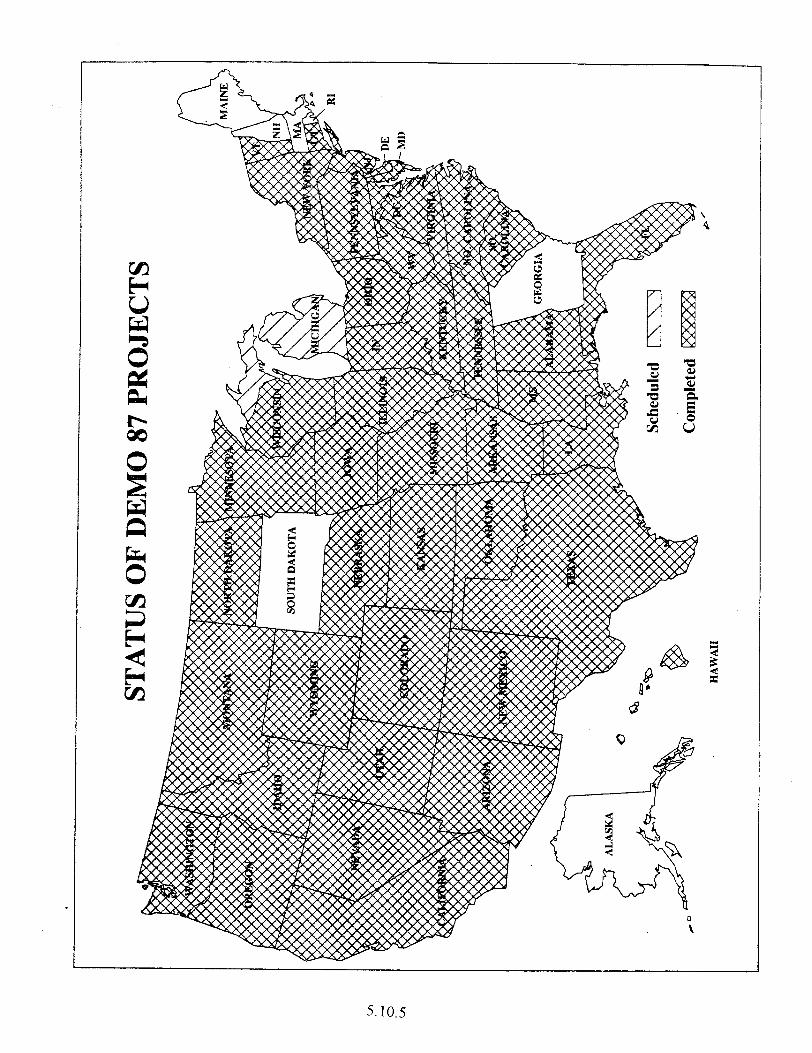
5.10.5
THIS PAGE LEFT BLANK INTENTIONALLY
5.10.6

Chapter 6
Shoulder

CHAPTER 6
SHOULDER
6.1 TA 5040.29, Paved Shoulders, February 2, 1990.

Chapter 7
Pavement Rehabilitation

CHAPTER ‘7
PAVEMENT REHABILITATION
7.1 Concrete Pavement Restoration Performance Review, May 22, 1997. l Concrete Pavement Restoration Performance Review, April 1987.
7.2 Crack and Seat Performance Review Report, April 1987.
7.3 Saw and Seal Pavement Rehabilitation Technique, February 22,1988. l Saw and Seal Pavement Rehabilitation Technique, Technical Paper 88-01.
7.4 Reserved
7.5 FHWA Notice N5080.93, Hot and Cold Recycling of Asphalt Pavements, October 6, 1981.
7.6 Reserved.
7.7 Use of Recycled Concrete in Portland Cement Concrete Pavement, July 25, 1989.
7.8 Use of Recycled PCC as Aggregates in PCC Pavements, February 1985.
7.9 Overview of Surface Rehabilitation Techniques for Asphalt Pavements, Report Number FHWA-PD-92-008, April 6,1992.
7.10 State of the Practice Design, Construction, and Performance of Micro- Surfacing, Report Number FHWA-SA-94-051, July 12,1994.
7.11 Retrofit Load Transfer, Special Project 204, February 10,1994.
7.,12 Reserved.
7.13 Thin Bonded Overlay and Surface Lamination Pavements and Bridges, ISTEA 6005, July 1,1994.

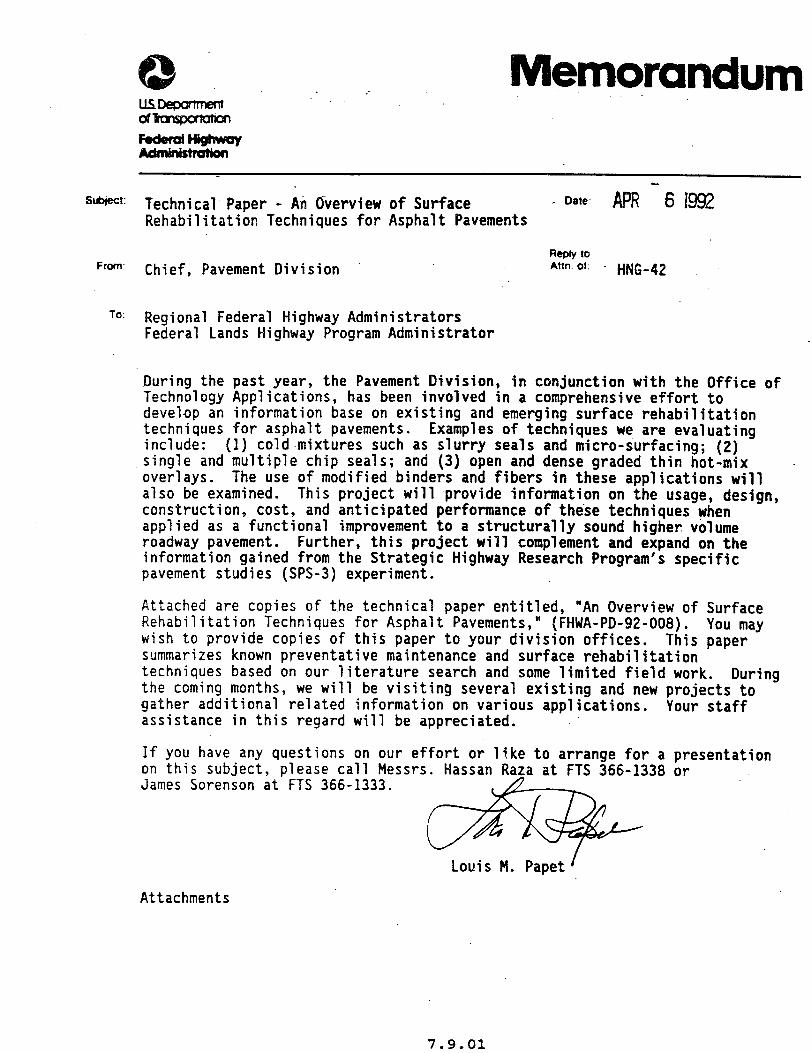
: emorandum ----
sl&ject: Technical Paper - An Overview of Surface . Date. APR-61992 Rehabilitation Techniques for Asphalt Pavements
Rcpty IO FWTl: Chief, Pavement Division Attn Of. _ HNG-42
10: Regional Federal Highway Administrators Federal Lands Highway Program Administrator
.During the past year, the Pavement Division, in conjunction with the Office of Technology Applications, has been involved in .a comprehensive effort to develop an information base on existing and emerging surface rehabilitation techniques for asphalt pavements. include: (1)
Examples of techniques we are evaluating cold.mixtures such as slurry seals and micro-surfacing; (2)
single and multiple chip seals; and (3) open and dense graded thin hot-mix overlays. The use of modified binders and fibers in these applications will also be examined. This project will provide information on the usage, design, construction, cost, and anticipated performance of these techniques when applied as a functional improvement to a structurally sound higher volume roadway pavement. Further, this project will complement and expand on the information gained from the Strategic Highway Research Program's specific pavement studies (SPS-3) experiment.
Attached are copies of the technical paper entitled, "An Overview of Surface Rehabilitation Techniques for Asphalt Pavements," (FHWA-PD-92-008). You may wish to provide copies of this paper to your division offices. This paper summarizes known preventative maintenance and surface rehabilitation techniques based on our literature search and some limited field work. During the coming months, we will be visiting several existing and new projects to gather additional related information on various applications. Your staff assistance in this regard will be appreciated.
If you have any questions on our effort or like to arrange for a presentation on this subject, please call Messrs. Hassan Raza at FTS 366-1338 or James Sorenson at FTS 366-1333.
Louis M. Papet'
Attachments
7.9.01

THIS PAGE LEFT BLANK INTENTIONALLY
7.9.02
Subfecl &CTION: Distribution of Publication Da'e July 12, 1994
From Director I Office of Engineering Director, Office of Technology
Applications
Reoly lo- Attn of HNG-42
TO Regional Administrators Federal Lands Highway Program Administrator
The attached publication, State of the Practice Desian, Construction. and Performance of Micro-surfacinq (FHWA-SA-94-051) provides a comprehensive discussion on an emerging surface rehabilitation technology. Sufficient copies of this publication are attached for your use and further distribution to the division offices and Stateswithin your region. Copies have also been distributed to each of the LTAP Technology Transfer Centers. Additional copies are available in limited supply from the Research and Technology Report Center, HRD-11, 6300 Georgetown Pike, McLean, Virginia 22101-2296 (telephone 703-285-2144).
Micro-surfaci,ng consists of polymer-modified asphalt emulsio: crushed--aggregate; mineral filler, water;- and .field-controlled additives as needed. existing surfaces,
Micro-surfacing is primarily used to seal improve surface friction, and fill wheel ruts
on both moderate and high volume roads. and constructed,
When properly designed micro-surfacing has shown promising results with
several years of service life. This surface rehabilitation technique has also been used effectively on portland cement concrete pavements to improve surface friction or address mechanical wear in the wheel paths.
. This state-of-the-practice paper is a result of a joint effort by the offices of Engineering and Technology Applications, and the industry to develop information on existing and emerging surface rehabilitation techniques for asphalt pavements. The first product of this effort, An Overview of Surface Rehabilitation Techniaues for Asphalt Pavements (FHWA-PD-92-008) was developed and distributed in April 1992. Presentation slides for both of the above papers will be available later this fall.
7.10.01
In a related effort,-an Office of Engineering memorandum dated June 24 announced the availability of warranty guide specifications for micro-surfacing projects on the National Highway System under Experimental Project 14. If vou have
in the any guestiom-or would like-to request technical suppo&
surface rehabilitation area, please call Hassan Raza ;202-366-1338. . - at
FOR:.%irector, Ozfice of Technology Applications
.
7.10.02
Subject INFORMATION: SP204 - Retrofit Load Transfer Date FEB I 0 1998
Reply lo From Chief, Pavement Division Attn of
Chief, Engineering Applications Division " HNG-42
- HTA-21
To Regional Federal Highway Administrators Division Federal Highway Administrators Federal Lands Highway Program Administrator
Attached are the following documents for your use and information:
1. Current status report - SPECIAL PROJECT 204 - Retrofit Load Transfer and December 27, 1993 report Retrofit Load Transfer in Jointed Concrete Pavements
2. TRB Preprint 940247, Linda M. Pierce, PCCP Rehabilitation in Washington State (A Case Study)
3. Inspection report by Lynn Porter and Cathy Nicolas on Washington State Load Transfer Retrofit Project
4. Report by -Roger Larson of load transfer restrofit field visits in Puerto and Indiana
Until recently, load transfer retrofit had been used only experimentally in the continental United States. In the last ten years, an estimated 300 lane Km of faulted or cracked undoweled jointed plain concrete pavement (JPCP) has been successfully rehabilitated in Puerto Rico. Based on the generally good performance of previously constructed load transfer retrofit experimental sections in the U.S. and the outstanding performance in Puerto Rico,. SP-204
the development of equipment to construct multiple increase the production rate for this technique and cost and road user delays.
was initiated to encourage slots in each wheelpath to to reduce the construction
Attachment 1 describes the Attachment 2 describes the section construction that State. Attachment 3 descr underway involving 53 km (
current status and background of this effort.. preliminary engineering and experimental test
led to the 53 km project now underway in Washington ibes the major Washington State project currently about 24 km now complete) of retrofit load transfer
on eastbound I-90. Attachment 4 describes field visits to Puerto R'ico to * observe the long term performance of retrofit load transfer projects and to Indiana to observe a demonstration of the feasibility of using carbide milling technology to construct multiple slots in jointed reinforced concrete pavement (JRCP) .
7.11.01
Based upon the recent construction of 24 lane km of retrofit dowels (JPCP) in the project currentlyunderway in Washington State and the successful demonstration of milling three slots per wheelpath in 'one pass on working cracks i.n a JRCP ramp in Indiana, equipment is now available to economically construct retrofit load transfer at joints or cracks in existing jointed concrete pavements. The bid price to construct retrofit-load transfer devices in Washington State was $34.50 per dowel installed (62,000 38 mm dowels in 64 mm wide slots). The average bid price in Puerto Rico is $20 per dowel installed (25 mm dowel in 40 mm wide slots) where this has been done routinely for ten years (slots sawed individually).
,This technique should be used with other concrete pavement restoration techniques to rehabilitate existing jointed concrete pavement before serious deterioration is present. Perhaps the most cost-effective initial application of this technique would be to restore load transfer at working cracks developing in under-reinforced JRCP in other wise good condition. If .performed early, it would also provide a cost-effective extension of the service life at the joints on undowel.ed JPCP and at transverse cracks without serious deterioration in either doweled or undoweled JPCP. If serious deterioration is present, full depth patching and/or selective slab replacements should be performed instead.
When properly applied, this technique will result in a cost-effective I extension of the service life of existing jointed concrete pavements in good
to fair condition. This technique would also be a very effective routine and preventive maintenance technique to reduce the cost and user delays during repairs of working cracks shortly after they develop and before full depth patches or slab replacements become necessary.
If you have comments or questions, please contact Mr. Roger Larson, the project manager of SP 204, at (202) 366-1326. A Technical Working Group will be formed shortly to update guidance reflecting the new equipment developments and other critical technical issues to help ensure success of this promising technique.
de Louis M. Papet
4 Attachments
7.11.02
Subject:
From:
To:
%m-v Federal Highway Administration
ACTION: ISTEA Section 6005 Thin Bonded Overlay and Surface Lamination Pavements and Bridges Reply due: October 31, 1994
Director, Office of Engineering
Date: July 1, 19%
Reoly to Attn. of:
HNG-32 HNG-42
Regional Federal Highway Administrators
We are requesting applications for additional projects for the Thin Bonded Overlay and Surface Lamination (Tf30) Program, which is part of the Applied Research and Technology (ART) Program established by Section 6005 of the Intermodal Surface Transportation Efficiency Act (ISTEA) of 1991. A summary of the TBO program and the application procedures are described in Attachment A. The application form is included as Attachment B. A summary of information on technologies is included in Attachment C. A listing of bridge deck and pavement overlay projects and TBO technologies previously approved is included in Attachment D and the evaluation plans developed for these projects are included in Attachment E.
Additional projects are being sought for available fiscal year (FY) 1994 and 1995 funding. encouraged.
Projects proposed for construction in FY 1996 and I997 are also There may be no future solicitations for ISTEA TBO projects if
enough candidate projects are available for selection from responses to this request. Please contact the States in your region for candidate projects for the TBO program. Candidate projects proposed by the State highway agencies must be submitted on the application form (Attachment B) and sent with any supporting information to the appropriate Federal Highway Administration Division Office by October 14, 1994, for forwarding to this office by October 31. The Section 6005 funding provided (100 percent for reporting and evaluation and 80 percent for construction .and an equal amount of obligation authority for projects approved as a part of this solicitation) is in addition to the individual State's regular Federal-aid. Please also note that priority for funding will be given to the technologies listed in the New Projects Sought section of Attachment A.
Your cooperation and attention are greatly appreciated. If you have any questions or comments, please contact Mr. Vasant Mistry, HNG-32, (202) 366-4599 or Mr. Roger Larson, HNG-42, (202) 366-1326. General questions' on the ART Program should be addressed to Mr. Richard A. McComb, HTA-2, (202) 366-2792.
flAA 0~ William A. Weseman
5 Attachments
7.13.01

THIS PAGE LEFT BLANK INTENTIONALLY
7.13.02
Chapter 8
Surface and Other
Considerations

CHAPTER 8
SURFACE AND OTHER CONSIDERATIONS
8.1 Rideability Specifications, December 17, 1987.
8.2 A Selection of Measuring Equipment Used to Monitor and Enforce Rideability Specifications, Technical Paper W-03, May 24, 1988.
8.3 TA 5040.17, Skid Accident Reduction Programs, December 23,198O.
8.4 TA 5140.10, Texturing and Skid Resistance of Concrete Pavement and Bridge Decks, September 18,1979.
8.5 TA 5040.31, Open-Graded Asphalt Friction Course, December 26, 1990.
8.6 Automatic Profile Index Computation, February 21,199l. l Analysis and Recommendations Concerning Profilograph Measurements in
South Dakota, November 1990.
8.7 Measurements, Specifications, and Achievement of Smoothness for Pavement Construction, NCHRP No. 167, 1990.
8.8 A Half Century with the California Profilograph, Report Number FHWA-AZSP9102, February 1992.

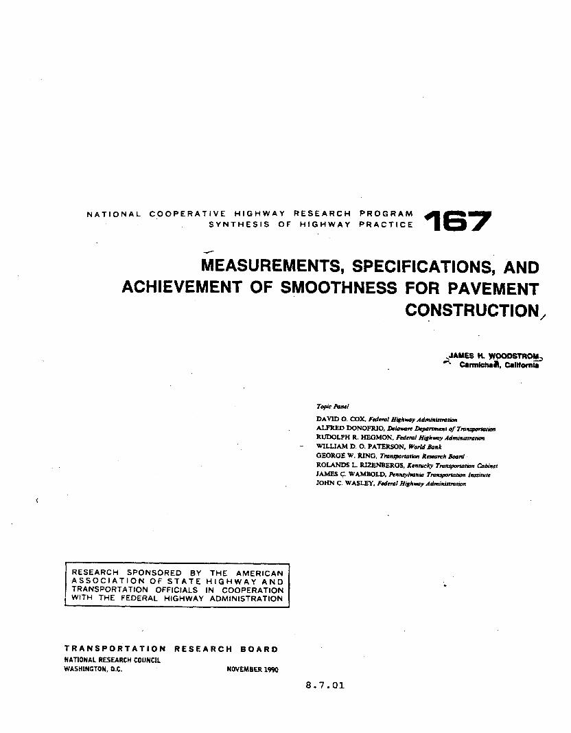
NATIONAL COOPERATIVE HIGHWAY RESEARCH PROGRAM SYNTHESIS OF HIGHWAY PRACTICE 167
MEASUREMENTS, sPEclF1cATi0~s, AND ACHIEVEMENT OF SMOOTHNESS FOR PAVEMENT
CONSTRUCTION,
DAVID 0. COX, Fedem Ht&hwy Admbtistmtian
ALFRED DONOFRIO, LWown &wtmmr of 7’mttqwtotitm RUDOLPH R. HEGMON. Fdeml H#hwy Adminumukm
- WILLIAM D. 0. PAlERSON, World Rank
GEQRGE W. RING, Tmnqwtotion Resmrrh Barrtd ROUNDS L. RIZENBERGS, Ketwauky Tmupwtin &bitter
JAMES c. WAMBOLD. Ftnnryl*onio Tmuponation Institute JOHN C. WASLEY. Fdeml Htghvoy Admbrirtmtion
RESEARCH SPONSORED BY THE AMERICAN ASSOCIATION OF STATE HIGHWAY AND TRANSPORTATION OFFICIALS IN COOPERATION WITH THE FEDERAL HIGHWAY ADMINISTRATION
TRANSPQRTATION RESEARCH BOARD
NATIONAL RESEARCH COUNCIL WASHINGTON, D.C. NOVEMBER 1990
8.7.01
THIS PAGE LEFT BLANK INTENTIONALLY
8.7.02
MEASUREME 73, SPEGIFICAPIONS, AND ACHIEVEMENT OF
SMOOTHNESS ‘FOR PAVEMENT CONSTRUCTDON
SUMMARY The concern about the smoothness Of highway Surfaces precedes the development of motorized vehicles. In the early days, the simple straightedge was used as the sole indicator of smoothness. But even before the turn of the century, efforts were directed at developing improved devices for smoothness evaluation. From 1900 to near midcen- tury, numerous devices of increasing complexity were invented. These were primarily mechanical devices with elaborate multi-wheeled support systems. Advances iu several technological fields have now been applied to smoothness-measuring equipment, re- sulting in the incorporation of electrical circuitry, electronics, ultrasonics, lasers, and computerization.
Although the early devices were primarily of co~lcern to the practicing engineer, the advent of test road construction brought the research engineer onto the scene. Many devices were developed in connection with specific research efforts. The automotive industry became interested because of the effect that certain types of pavement had on motor vehicles. In recent years highway managers have recognized that the public rates a highway primarily on its tiding characteristic. Thus it is necesslvy to program an increasing amount of highway funds to address the issue of pavement smoothness on a system-wide basis.
As a consequence, several smoothness-measuring devices have been developed and are in current use. The fundamentals of operation, cost, and appropriateness to address a specific need vary considerably. Certain devices are far better suited than others to the purpose of controlling the smoothness of newly constructed pavements. Therefore, it is important for those concerned with obtaining smoothness in construction to be aware of the quipment best suited for that purpose and the relation of that equipment to the entire spectrum of smoothness-measuring devices.
Smoothness-measuring equipment currently used in new pavement construction includes straightedges (static and rolling), profilographs, response-type road- roughness-measuring systems, and inertial profilometers. All agencies use a straight- edge-a few as the sole approach to smoothness control, but most as an adjunct to other equipment. The type of instrument receiving increased application is the profilograph, either the California or Rainhart type. These devices are similar in that they portray graphically certain characteristics of pavement smoothness, are relatively simple mechanical devices, can be used on new concrete pavement surfaces soon after construction, are low-cost/low-maintenance devices, and provide information that is readily acceptable by specifying agencies and the construction industry. Profilographs provide an analog trace to which specification tolerances are. applied. The traces can be used to locate specific pavement features in the field. The primary disadvantages with this type of instrument are the slow speed of operation (3 mph) and the time required for evaluating the profiles, although the latter item has been addressed by computerized models that are now available. Other disadvantages include the exaggera- tion and suppression of parts of the surface wavelength spectrum, the occasional
8.7.03
2 .
exclusion by the blanking baud of surface irregularities that may be of inqxjrtan% =d a mediocre corrdation to other rcfcrcrlcc roughness standards.
other devices being used in cvaluatillg smoothness of new wnstrMction, includiug response-~ road-roughness-measuring systems aind inertial profilometcrs, are used considerably less often than profilographs for a variety of reasons. They a~ not able to be-used on concrete pavrments for a considerable time after paving (i.e., until the concrete gains sufkient strength), they don’t allow ready identification or location of pavement surface aberrations, and, in some cases, they are very costly items. However, they can operate at high speeds; thus a considerable amount. of data can be obtained at a lower cost. Also, the smoothness statistic is achieved with little or no manual processing. High-speed equipment has its‘greatest application in entire highway system assessment, research applications, and for calibration purposes.
Numerous research efforts as well as symposia and workshops have been directed -toward providing information on the use of smoothness-measuring equipment. Al- though there are vast dkerences in equipment types and their ultimate application, the relationships of several smoothness indexes have been compared and are reasonably well defined.
A survey of practices in use in the United States and Canada revealed that there is a wide diversity in the use of smoothness specifications and equipment. However, emphasis on smoothness by specifying agencies, together with strong support from the construction industry, has led to the attainment of increasingly smoother pavements.
8.7.04
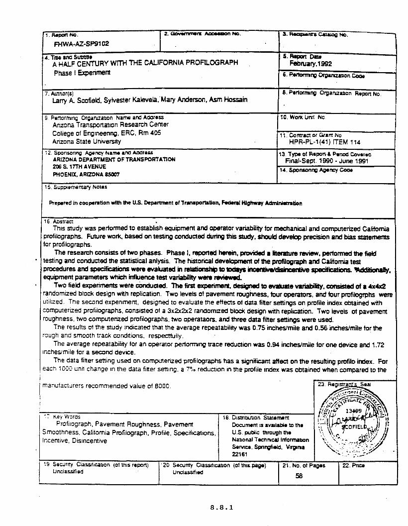
by wn’H THE CALIFORNIA PROFILOGRAPH
Phase I Experiment
15. Suppiomentary Notes
6. Aostracr . This study was performed to establish equipment and operator Variability for m8chanical and computerized California
,rofilographs. Future work. based on testing conducted during thii !Wdy, should develop precision and bias statements or profilographs.
The research consists of two phases. Phase I. reported hemin, pmvickd a Iit0rat1~n3 ruvisw, performed the Geld esting and conducted the statistical anlysis. The historical d8velopm8nt of the profilograph and California test ,rocedures and sp8okations were evakrated in -to tod8ya m specificatPns. WdcMuWy, quipment parameters which iMuenc8 test vafiabiMy w8m Mewe&
Two field experiments were knduded. The first experiment. dcfign#l to evahtate variabii, a~~&ed of a &4x2 andomized block design with replication. Two levels of pavement roughness. four opeators, and four profilogfphs were 8tiirzed. The second experiment. designed to evaluate the efiects of data fitter settings on profile index obtained with omputerized profilographs, consisted of a 3x2~2~2 randomaed block design with replication. Two levels ot pavement sughness, two computerized profilographs. two operataon. and three data fitter settings were used.
The results of the study indicated that the average repeatability was 0.75 incheJmile and 0.56 inchedmile for the wgh and smooth track condnlons, respectfully.
The average repeatability tor an operator performing trace reduction was 0.94 in&&mile for one device and 1.72 lches/mile for a second device.
The data titter setting used on computerued profilographs has a signifkant affect on the resulting profilo tiex. For ach 1000 unti change In the data fitter setting. a 79; reduction in the profile index was obtained when compared to the
ilograph. Pavement Roughness, Pavement ess, California Pmfilograph, Profile, Specikatlons,
Icentive, Disincentrve
Unclasifmd

THIS PAGE LEFT BLANK INTENTIONALLY
Chapter 9
Pavement Management

CHAPTER 9
PAVEMENT MANAGEMENT
9.1 A National Perspective on Pavement Management, July 1994.
9.2 Automated Pavement Condition Data Collection Equipment, July 1989.
9.3 Addressing Institutional Barriers to Implementing a PMS, August 19, 1991.
9.4 FHWA Order 5080.3, Pavement Management Coordination, April 13, 1992. ,
9.5 Pavement Management System - Federal Register, December 1,1993.

National Perspective on Pavement Mana ement
FRANK BOTEU-iO
he nation’s highway network represents a multtbillion dollar investment that allows for the essential movement of people
and goods. Sound decisions on preventtve mainte-
nance, rehabilitation, and reconstruction of highway pavements are crucial to pro-
. tecting that investment. For this reason, Pavement Management Systems (PMS) have become increasingly important and are now federally mandated on all Fed- eral-aid highways. PMS provide valuable assistance to decision makers in deter- mining cost-effective strategies for pro- viding and maintaining pavements in ser- viceable condition.
History of PMS
Unlike other management systems that have’begun in- recent years, PM5 were started two decades ago. Although they have made steady progress since that time, they are still new compared with other institutional functions such as plan- ning, design, construction, maintenance, and research.
By the mid-1980s PMS were proving themselves and the benefits were being. documented. By the end of the 1980s
Frank Botelho is Chief, Pavement Manage- ment Branch, Federal Highway Adminis- tration. I
more than half the states were developing or implementing PMS. In 1989 the Fed- eral Highway Administration (FHWA) issued a policy requrring all states to have a PMS that would cover principal arterials under the states’ jurisdiction. It was there- fore apparent to FHWA that a PMS was needed by all to ensure the cost-effective expenditure of Federal-aid funds.
The scope of federal and state involve- ment in PMS expa.nded when Congress passed the Intermodal Surface Trans- portation Efficiency Act of 1991 (ISTEA) and required all states to have a PMS that covers all Federal-aid highways. The most significant aspect of this law was the expanded network coverage. FHWA’s 1989 policy covered 313,700 centerline miles and ISTEA approximately tripled that coverage, increasing it to 916,200 centerline miles. This expanded coverage translates into a need for significant coor- dination among state and local govern- ments. For example, of the total of 916,200 miles covered, 365,200 are under local jurisdiction.
In December 1993, FHWA issued a reg- ulation covering all management systems. Section 500, Subpart B, of the regulation describes the ISTEA requirements for PMS. The following items are noteworthy:
. 1. The regulation is nonprescriptive; 2. Federal-aid funds are eligible for the
development, implementation, and an- nual operation of a PMS;
3. States must develop their work plan by October 1994, designed to meet the
implementation requirements; 4. Standards are included for the
National Highway System (NHS); 5. The PMS for the NHS must be fully
operational by October 1995; 6. The states have full flexibility to
develop the standards for the PMS that cover the non-NHS routes;
7. The PMS for non-NHS routes must be fully operational by October 1997; and
8. PMS information must be used as input into the development of the metro- politan and statewide transportation plans and improvement programs.
Section 500.207, PMS Components, contains the components of a PMS for highways on NHS, There are three pri- mary components: data collection, analy- ses, and update. The components under data collection include
1. Inventory: physical pavement fea- tures including the number of lanes, length, width, surface type, functional classification, and shoulder information;
2. History: project dates and types of construction, reconstruction, rehabilita- tion, and preventive maintenance;
3. Condition survey: roughness or ride, pavement distress, rutting, and surface friction;
4. Traffic: volume, vehicle type, and load data; and
5. Data base: compilation of all data files used in the PMS.
The components under analyses include
7-R News 173, July-August 1994 5
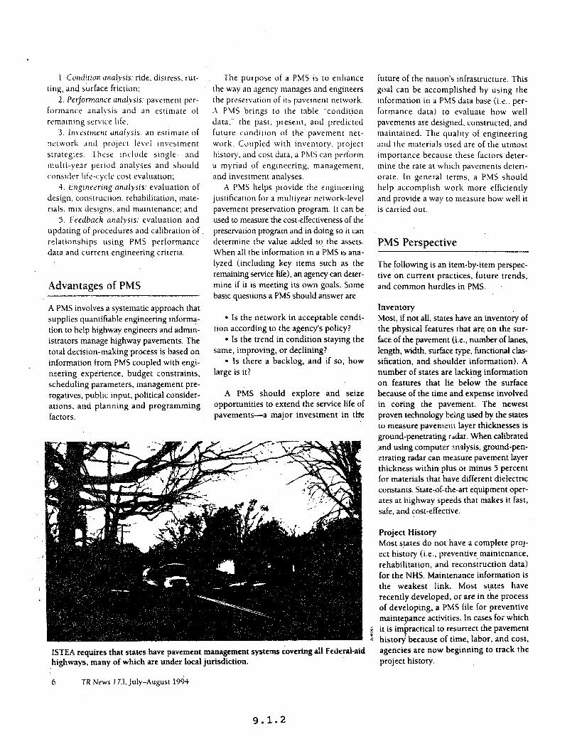
.
I. Cotdirm mul~ysis: ride, distress, rut- ting. and surface friction:
2. Performcince ancd~sis: pavement per- formance analysis and an estrmate of remaining service life,
3. Inwsltnent urlolysrs: an estimate of network and project level Investment strategres. These Include smgle- and multi-year perrod analyses and should consider Irfe-cycle cost evaluation;
4. Engincrring analysis: evaluation of design, construction, rehabilitation, mate- rra!s, mix designs, and maintenance; and
5. Feedback analysis: evaluation and updating of procedures and calibration of. relationships using PMS performance data and current engineering criterra.
Advantages of PMS
A PMS involves a systematic approach that supplies quantifiable engineering informa- tion to help highway engineers and admin- istrators manage highway pavements. The total decision-making process is based on information from PMS coupled with engi- neering experience, budget constraints, scheduling parameters, management pre- rogatives, public input, political consider- ations, and planning and programming factors.
The purpose of a PMS is to enhance the way an agency manages and engineers the presemation of Its pavement network. .A PMS brings to the table “condition data,” the past, present, and predicted future condition of the pavement net- work. Coupled with inventory. project history, and cost data, a PMS can perform a myriad of engineering, management, and investment analyses.
X PMS helps provide the engineering justification for a multiyear network-level pavement preservation program. It can be used to measure the cost-effectiveness of the preservation program and in doing so it can determine the value added to, the assets. When all the information in a PMS is ana- lyzed (including key items such as the remaining service life), an agency can deter- mine if it is meeting its own goals. Some basic questions a PMS should answer are
Q Is the network in acceptable condi- tion according to the agency’s policy?
l Is the trend in condition staying the same, improving, or declining?
* Is there a backlog, and if so, how large is it?
A PMS should explore and seize opportunities to extend the service life of pavements-a major investment in tk
future of the nation’s infrastructure. This goal can be accomplished by using the information in a PMS data base (i.e.. per- formance data) to evaluate how well pavements are designed, constructed. and maintained. The quality of engineering and the materials used are of the utmost importance because these factors deter- mine the rate at which pavements deterr- orate. ln general terms, a PMS should help accomplish work more efficrently and provide a way to measure how well it IS carried out.
PMS Perspective
The following is an item-by-item perspec- tive on current practices, future trends, and common hurdles in PMS.
linventory Most, if not all, states have an inventory of the physical features that are on the sur- face of the pavemerrt (i.e., number of lanes, length, width, surface type, functional clas- sification, and shoulder information). A number of states are lacking information on features that lie below the surface because of the time and expense involved in coring the pavement. The newest proven technology being used by the states to measure pavement layer thicknesses is ground-penetrating radar. When calibrated .and using computer analysis, ground-pen- etrating radar can measure pavement layer thickness within plus or minus 5 percent for materials that have different dielectric constants. State-of-the-art equipment oper- ates at highway speeds that makes it fast, safe, and cost-effective.
Project History Most states do not have a complete proj- ect history (i.e., preventive maintenance, rehabilitation. and reconstruction data) for the NHS. Maintenance information is the weakest link. Most states have recently developed, or are in the process of developing, a PMS file for preventive
rice activities. In cases for which r 5 ractrcal to resurrect the pavement = because of time, labor, and cost.
ISTEA requires that states have pavement management systems covering all Federal-aid agencies are now beginning to track the highways, many of which are under local jurisdiction. project history.
6 TR News 173, July-August 1994
9.1.2
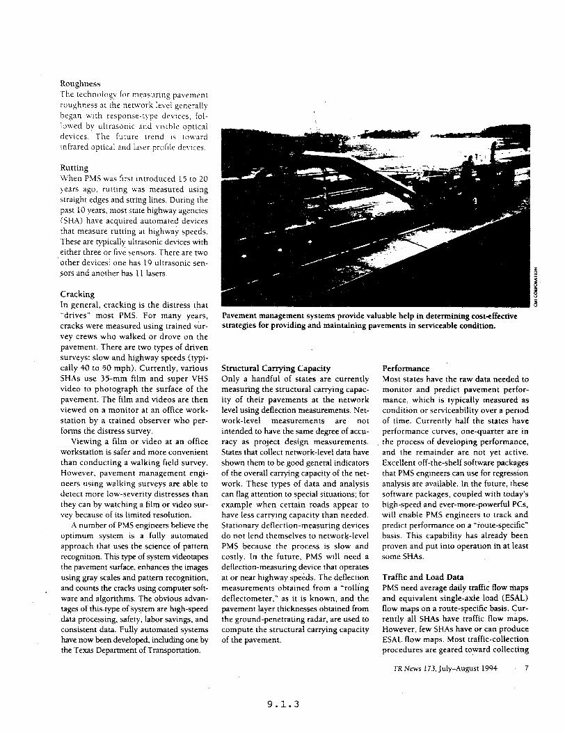
Roughness The technology lor measuring pavement roughness at the network level generally began Lvith response-type devices, fol- lowed by ultrasonic and vwble optical devices. The future trend IS toward Infrared optical and laser profile devices.
Rutting When PMS was first introduced 15 to 20 years ago, rutting was measured using straight edges and string lines. During the past 10 years, most state highway agencies (SHA) have acquired automated devices that measure rutting at highwai speeds. These are typically ultrasonic devices with either three or five sensors. There are two other devices: one has 19 ultrasonic sen- sors and another has 11 lasers.
Cracking In general, cracking is the distress that “drives” most PMS. For many years, cracks were measured using trained sur- vey crews who walked or drove on the pavement. There are two types of driven surveys: slow and highway speeds (typi- cally 40 to 50 mph). Currently, various SHAs use 3%mm film and super VHS video to photograph the surface of the pavement. The film and videos are then viewed on a monitor at an office work- station by a trained observer who per- forms the distress survey.
Viewing a film or video at an office workstation is safer and more convenient than conducting a walking field survey. However, pavement management engi- neers using walking surveys are able to detect more low-severity distresses than they can by watching a film or video sur- vey because of its limited resolution.
A number of PMS engineers believe the optimum system is a fully automated approach that uses the science of pattern recognition. This type of system videotapes the pavement surface, enhances the images using gray scales and pattern recognition, and counts the cracks using computer soft- ware and algorithms. The obvious advan- tages of thistype of system are high-speed
.data processing, safety, labor savings, and consistent data. Fully automated systems have now been developed, including one by the Texas Department of Transportation.
Pavement management systems provide valuable help in determining cost+zffective strategies for providing and maintaining pavements in serviceable condition.
Structural Carrying Capacity Only a handful of states are currently measuring the structural cat-tying capac- ity of their pavements at the network level using deflection measurements. Net- work-level measurements are not intended to have the same degree of accu- racy as project design measurements. States that collect network-level data have shown them to be good general indicators of the overall carrying capacity of the net- work. These types of data and analysis can flag attention to special situations; for example when certain roads appear to have less carrying capacity than needed. Stationary deflection-measuring devices do not lend themselves to network-level PMS because the process is slow and costly. In the future, PMS will need a deflection-measuring device that operates at or near highway speeds. The deflection measurements obtained from a “rolling deflectometer,” as it is known, and the pavement layer thicknesses obtained from the ground-penetrating radar, are used to compute the structural carrying capacity of the pavement.
Performance Most states have the raw data needed to monitor and predict pavement perfor- mance, which is typically measured as condition or serviceability over a period of time. Currently half the states have performance curves, one-quarter are in the process of developing performance, and the remainder are not yet active. Excellent off-the-shelf software packages that PMS engineers can use for regression analysis are available. In the future, these software packages, coupled with today’s high-speed and ever-more-powerful PCs, will enable PMS engineers to track and predict performance on a “route-specific” basis. This capability has already been proven and put into operation in at least some SHAs.
Traffic and Load Data PMS need average daily traffic flow maps and equivalent single-axle load (ESAL) flow maps on a route-specific basis. Cur- rently all SHAs have traffic flow maps. However, few SHAs have or can produce ESAL flow maps. Most traffic-collection procedures are geared toward collecting
TR News 173, July-August 1994 7
9.1.3

Lraffic volumes. ivhich are prtmanly used by hIghway engineers and planners for capactty analysis. Until PMS came along, there \vas no need to collect traffic data for load analysis on a (oute-specific basis. Unfortunately for PMS engineers, collect- ing load data on a route-specific basis is more expensive than the exlsung traffic- collection process and it is not known if the additional expense (which has not been calculated for each state) is justifi- able. More study is needed on this topic. Many PMS engineers and planners believe that better traffic- and load-prediction models are needed.
Ranking Projects The backbone and heart of a PMS is its ability to rank in priority order pavement preservation projects that are justifiable and cost-effective. The most impottant phrase in the new (December 1993) FHWA regulation on management sys- tems is the requirement that PMS for NHS produce “a prioritized list of tecom- mended candidate projects with recom- mended preservation treatments that span single-year and multi-year periods using life-cycle cost analysis.” Currently most state.PMS do not produce a multiyeat ranked list of projects with recommended treatments using life-cycle cost analysis, but are expected to have this capability in the future.
Remaining Service Life Determining “remaining service life” is a requirement in the new regulation for. NHS. Currently only 10 SHAs perform this analysis, but in the future it is antic- ipated that most will find this an unen- cumbered task. It is important to monitor the long-range health of a network and this analysis enables managers and pro- grammers to maintain a “steady state” in their multiyear workload and budget.
Relational Data Base A PMS cannot automatically, systemati- cally, consistently, and efficiently function without a “relational data base” because the amount and complexity of data cannot be computed manually for a typical state PMS. Currently half the SHAs have tela- tionai data bases, one-quarter are develop-
8 TR News 173, July-August 1994
trig them. and the remainder are not active at the present titne. Gilen the state-of-the- art capabilities in relational data-base management systems, it is anticipated that most SHAs uill have relational data bases in the near future.
Unifotmity ‘2’
Currently there is little-to-no uniformity among the states in the:way they mea- sure, collect, and report:PMS condition data. The reason is that all states devel- oped their PMS independently. This inde- pendence, of course, has many advan- tages for designing a PMS to meet the
.needs and obJec:ives of any agency. But states are at a disadvantage when com- municating with each other about basic condition information such as toughness, rutting, and crackmg. They will find a lack of uniformity, which means that they cannot communicate ot help each other to enhance this area of PMS. Efforts are under way and accomplishments have been made by ASTM and the Road Pto- filet Users Group (RPUG) that deserve commendation. The other management systems such as bridge and safety already have national standards for data collec- tion and reporting.
PMS will benefit if the 50 states, Puerto Rico, and the District of Columbia agree to adopt more unif*>rm methods to collect and report conditil>n data. Future efforts by ASTM; RPUG; Strategic High- way Research Program, Long-Term Pave- ment Performance; FHWA; and the American Association of State Highway and Transportation Officials’ Task Force on Pavements are aimed in that direction.
In-House and Outside Resources Pavement ,management is a procedure that includes a wide variety of technical components. Some of these requite a high degree of technical skill to develop and implement, whereas others require a high concentration of effort to establish. Each agency should carefully and objectiveiy weigh its in-house capabilities, and if it does not have the resources, it should seriously consider seeking assistance from a consultant or a university. In the long run, it will save a lot of time and money and result in a better final product..
-+
Staffing The biggest problem the states face in developing. implementing, updating, and operattng a PMS is staffing. There is a sig- nificant shortage of people who under- stand PMS. Once employees are trained and gain some experience, they are often promoted or transferred to other jobs. For the past five years, the annual turnover rate of state PMS engineers has been approximately 25 percent. The CLI:~ incentives for early retirements have fueled that rate in the past two years. Gen- erally, most SHAs have onlv one person who oversees the management and daily operation of the complete PVS program. and when that person leaves, most often the PMS shuts down. This situation occurs quite frequently and because of the current budget constraints and staffing ceilings in most highway agencies; it is not likely to improve. Unfortunately there is no quick ftx to this problem.
Future Implementation of PMS
In gauging the future success of imple- menting PMS as called for in ISTEA, organizations must first decide whether they ate serious about PMS. If so, and the commitment is made to do the work, sup: ply the resources, and use the system, then PMS use is likely to be successful.
Students in the-nation’s colleges and universities will provide the life blood fat PMS in the future. Currently 24 such institutions offer coutses on PMS. but mote are needed. FHWA and SHAs should support academia in providing more education about PMS and other management systems.
The largest institutional obstacle fac- ing PMS today is acceptance by all man- agers and engineers in all agencies (including federal. state, and local). The reasons for this are many. The future holds more hard work for those who are serious about pavement management.
9.1.4

FM Rq@8r / Vol. 58. No. 229 / Wednesday, December 1. 1993 I Rules and Requiatlons 63475
PART -NAGEMENT AND MONITORINQ SYSTEMS
suepeltA--Grrud
set XXl101 f%lpO¶8. 500.103 5efin111ona. 500.105 Development. establishment. md
~plemeatat~oa of the synema. 500.107 Camplmnce. 500.109 Smct~onr. 500.111 Funds for development.
establishment. and unpiementauon of the systsmr
500.113 Accaptmce of ex;sting mMagemmt systems.
suw-L-pmrmtyrugmnt~Y-- 500.201 PuqJall. 500.202 PMS d&nitionr. 500.205 PM geoed mquhnmu. 500.207 ms compooeau SOQtm PMS compliaaa ochedule. -- -t- sm.301 Purpoa. MO.303 EMS dotlaitioor 500.3os BMS poemI lvquinK8etla Sam07 BMS aDIIlpmonu MO.309 BMS coalpliulco ubadulr
~soo.101 furpam
The purpose of this parC is to implement the Kqulmments of 23 U.S.C. 303. Management Systems, which requires State development. establishment. and i~plemenration of systems for managing highway pavement of Federal-aid hlghways (PMS). bridgea on and off Federal-aid highways (BMS). hlghway safety (SMS]. traffic congestion (CMSL public transportation facilities and equipment (PTMS). and intermodal tansponatlon Iacilitiea and systems KMSL Sectlon 303 also cequim State development. establishment. and implementation of a t&k monitoring system for highways and public transportation facilitms and equipment. This subpart includes definitions and general requirements that are applicabb to all of these systems. Additional requilsmenta applicrblo to a specific system are included in suubpar~ B through 5-i of this P-- ~soo.193 -
Unlnr otherwiv specified in tJGa m lbe definitions in 23 U.s.c 101(a) a~ rppliabio to thir put. As used in thirput:
Gwti~ng oficial(rl means the ptitiao(r) deailputed by the Gwemor of I Statm or the Cummonweeith of Puerto Rim or the Mayor of the District of Columbia lo certify that the management system(s) iS/uv being implemented in rho StA1..
Ci9ope~on means working together tn achiew a common goal or objactive.
Faded agmqfies) means for the FMS yd BMS. the Fedal Highway himhstmtioo (FHWA): for the SMS. the FHWA and th ,N+oaal Highway Tm5c Safety A~tioa: for the CMS. VIMS. and IM!L rho FHWA and figderMmMit Mmillistmtion
. Fedmukid highwop swans Thor
bighwayr rligiblo far wistancm under till. 23. U.S.C. wp1 thaw ~~.lfid u local or mml
annanca Monitor@ S~~onsutlebS~~fl~nl syumnuudbytheFHWAtopwidr informatiaa on th extent and physial conditiM of the oAtion’s tgghwr sysm&itlJ ua. perramaDa, unl mah. The syuau includm all inventory of thm nation’8 hi%lr*rys inchding arffic volumea
9.5.1
$3478 F&al R+s&r 1 VoL SC). Na 229 I We& y. Ikcsmbet 1. 1993 1 Rules and Regulations
over the life of the pfajui 0~ investment
.Uonogemcnt sysMn memns a systematic proasS. daignned to assist decisionmakat’a in s&cting coet- effective stmt~ss/actions to improve the efficiency and safety of. and protect the mveument in. the nation’s transportation infrastnxztum. A management system indudes: Identification of performance pleas-: data collection and analysts; determination of needs; rvaluation and 4ection of appropriate rtntegies/ ections to rddresa the beak and evaluation of the effectiveness of the implemented strrtegi4ections.
bfeetvpotlitan planning anx means the Rf9OfUWhic ma in Which The kGo$olitan trenr*tion planning procese mquimd by 23 USC 134 and section 8 of the Federal Transit Ad (49 u.s.c rpp. 16071 must k amiod out,
Metmpliton p&nning ok-ganisotion OfFO) meut8 thr fonun for wopax8tiva tmnaportreiao deciaionmaking for a metmpo6itan planning ama.
National highway system NHS) means the system of highway0 desiwted and approved in ma vdip*ym~i;a5 d 23 u.s.c 103(b).
opemtional ckantZrti conditicm. oz other appropriate puammmidu~-kto evaluate th8 adaquay of wuqortation faciliciesMd-5lllad.d im rovema~ttb
8 tatemeuuanyonoofthatUty States. the District of Cbhuabir or PlJaeo RicD.
specIAod in suhputa B thmugk H of this put. DOCUXII~~~~~.~OU that denrihee eech mnegement rydem rhmll be maintained by the States for ti Feded agenciee to determine. on a periodic basis. whether the systems meet the rsqturements in this subDalt and subDarts B thmueh H
” all have orocedures.
within the tite’r organhtion, for coordination of the development. establishment, implementation and operation of the management The
systems, rocedums must include:
(1 An oversight praxsa to a- that P ad
7 u&e r~~urces are rvailable for
imp ementation and that target dates in the work plan(sJ are met;
(2)nl.uea0fdA~hnmwithtl common or coordinated r&wnox~ syyms and methods for data &wing;
(31 A media&m Po ddre6s issuee mlaed to the pwpoea of mom than one
each mansgem~nt--ltMm. ih stata ” shall coopuate with MPoa IIt metmpol6tan usa lad offbida in non-moempoKem amm dhctmi . . euwana under the it%i?‘i?tt ‘iad other m
riwer owmers and
-(dlIarcrrrdurawith~pmvWoaa of 23 u.s.c 134fiH31 and 49 u3.c l DD.
i3 U.S.C i34d 49 U&app. 1907. tnI13mOtrOPdjtMPm-tht
aseistnnca under the Fdml Transit Act. and other egendss involved in the devebpment. establishment. and implementation of each went shall b mutually determined by ihs partlea involved. A State may enter into agreements with local governments, regional agencies (such as hfP0s). recipients of funds under the Federal Tranrit AU. or other entitia to develop. establish. and implement appropriate parts of any OP all of the systems. but the State shall be responsible for overseeing and coordinating such activities.
(i) Section 204W of htle 23. USC. requires the SectWary in caopemtion with the Secretaries of the Intenor and Agricultum to develop the safety, bridge and pavement management systems for Federal lends highways, as defined in 23 U&C 101(r). TO avoid duplication of effort. the management systems mquirad under t&a part should be lased to the udent appmpriata to fulfill the requirement in 23 U.S.C ZCM(aI repding estabiiduneat and implementation of pavement. bridge. and a&y tnanagatnmt systems for Federml Lnds bighwaya Tbo Stats. thm Fodti agtmcia and th@ am that own the mad5 aha66 ampumtively dot-0 rsrp0nrriW.i~~ for -rage of Fedenl lands bighunys under tbair mmuttw iurisi~aonr~6 amtrol pad
highGays am aveil&&. es rppmpriatc for,consideration in devolopmg metxqolitan and statewide tmnsportation p!uie and improvemen( pmgmms and am ‘dmdtoth FHwAforussin r eloping F&ml
ammwt to rvdrute
ehr rffeuivmanr of implezoeIlted
9.5.2
Federal Regiotet I Vd. 58. No. 229 I Wednesday. December 1. 1993 I RuIes and Regulaticjns 63477
compliance schedule for that system as specified in subparts B through C of this part.
(b) The Governor of the State or the Commonwealth of Puerto Rico or the Mavor of the District of Columbia shall notify the FHWA Division Administrator in writing by September 30. 1994. of the title(s) of the certifying official(s) for each management system. If there is a change in designated position(s). the State shall provide documentation of the revised designation with. or prior to. the next annual certification. In those States where responsibility for ali of the management systems is within a single agency (e.g.. State DOT), designation of one certifying official for afl of the
“EYElztx~~~~~~~~Eti be submikted by the certifying oCtia1(s) to the FHWA Division Administrator by January 1 of each year. beginning January 1.2995. To the extent possible. one certification statement should cover a11 six management systems. If more than one certification statasnent will be submitted by a State, the statements should be an&ins&d at the State level and submitted simuhaneously. The first certificatioa statement s&U include a copy of the workplan( required in accordance with the compliance schedule for each management system. and a sll~~aaty of the status of impiemeotation of the men-t system(s1. Subsequent certification statement(s) shall include a summary of the status of impiemenfation d each management system and a discussion of planned corrective actions for any management systesn(s1 or subsystem(s) that are not under development or fuIIy operational in accordance with the comphance schedule aud work pian ku the management
- Id) The F-kfw~?%~n Administrator will provide copies of the certification statement(s) and any relevmt supporting docnmentation and coResQundsocl, to othu Federsi agencies i&Mfii for the sfmcifw system(s) in 5 500.103. Within 90 @ of receipt, the Federal agmciss wilt review the certiflcalia, ind the PHWA Division Adminismcrr will n&b tite State whether the certification is acceptable or if aanctfons may be imposed in accordance with the provisions of 8 500.109.
(e) A State shall be considered to be imptementing ti t&tic monitting system for highways (TWWHJ. specified in sub- H of this pati. if the system is under dewlopment or in USB in accordance with the compliance schedtda in S m.809. The Slate ShaIX submitthewc&p!anfortht’IMS/Hto
the FHWA Division Adminiatrala by january 1, 1995. (The information cutlection rtx~uinmen(s in paragraphr LC) aod w of gsoo.ro7 hawe been approved by the Office of Management and Budget under control number z~zs-~x&)
g 500.108 Sanctions. la) Beginning January 1. 1995. if a
State fails to certify annually as required by this regulation. or if the Federal agencies determine that any management system or subsystem. specified in subparts B through G of this part, is not being adequately implemented. notwithstandingthe State’s certifiiation[s). the Secretary may withhold up to 10 percent of the funds apportioned to the State under titJe 23, USC.. and to any recipient of assistance under the FederaI Transit Act for any fiscal year beginning after September 30, 1995. Sanctions may be imposed on a statewide basis. oo a subarea of a State, for specific categories of funds or types of projects. or far specific recipients or s&recipients of funds under tifle 23. U.S.C.. or under the Federal Transit Act depending on the adequacy of implementation of the
m~$KE~s2t?%im&y enter into agreements with IocaI governments or other agencies to develop, establish, and imptement al1 or parts of the management systems, in accordance with 5 500.1051s). the State &akI he responsible br ensuring that the systems are being impfemented statewide and for taking any aecef~~r~ corrective action, in&ding impiemenfing the systems at the re
7 ional and Local levels ifnecesaary. cl Prior to imposing a sanction. a
State wit! be notified in writing by tim FHWA of the sanction(s) to be imposed. the reasons for the sanctions, and the actions necessary to correct the deficiencies. After 60 days from the date of notifimion to the Slate. the Federal agencies wil! consider any cone&we actions proposed by the State and the FHWA will notify the State if such actions am accephbte or if sanctions are to be applied.
(d) in instances where a State, or responsible sub-unit of a State or recipient of funds under the FederqI Transit Act, has not fully imphzme,n@d all of the management systeers. considecatim shall be given by tbe Fedaal w to &Forts and-y or planned to make the systems My operational within a reasonable time period.
(4 To the exAe& th by hvm not laQssd,fundsrilhhddpasuwttuti subpart ahuff be made mmikble to the State or recipient under the Fedncal
Transit Act upon a determination by the Federal agencies th0t the management systems am being adequately implemented.
Q 500.111 Funds for development, establishment, and Imgkmmntation of tw systems.
(a) The following categories of funds may be used for development. establishment, and implementation of any of the management and monitoring systems: National Highway System. Surface Transportation Program. FHW’A State planning and research and metropolitan planning funds (in&ding the optional use of minimum allocation funds authorized under 23 U.S.C. 157[c] for carrying out the provisions of 23 U.S.C. 307(cJ(l) and 23 USC. 134(a)). FederaI Transit Act Section 8 (49 U.S.C. app. 1607). Federal Transit Act Section 9 (49 USC app. 1607a). Federal Transit Act Section 26(a)(2) (49 U.S.C. app. 1622(a)(2)). and Federal Transit Act Section 26(b)(l) (49 U.S.&. app. 162t4bMl)l Congestion Mitigation and Air Quality improvement wrn funds (23 USC. 1M(b#2)) may be used for those rnasagement systems that can be shown to coniribute to the attainment 01 a national ambient air quality standard. Apporticmed bridge funds (23 U.S.C. 144(e)) may be used for developmenl and establishment of the bridge management system.
(b) Fe&al funds identified in paragraph 6) d this section used for development. establishment. or implementation of the mamgernent and monitoring systems shall be administered in accordance with the procedures and requi PeRreRts oQpiicat&? to the cakgory of funds.
(a) Existing S&ate Iaws. r&s, or procedures that the FederaJ agencies determine futiLfiu the prpoaes da rnv syslem. or portion thereof. 8s specified in tbk pert may be accepted by the Feded agencies in lieu of development and implementati~ of a new system.
fb) If a State has existing ism rules. or procedures that it wanis to us8 lo - meet the requirements of this pd. it shall submit a written request to the FHWA DMsion Administmtor that the Federal ageocias aaxtpt tbe existing managsment system in lieu of development of a new syat-. l%e request shall include a discussion, end TY necesrqy arpporCing
~tbetlrhmrrsbowtbe existing spshem ma&s the mquirements ofthisQa&-rlm -:o(ian shell renectthb~OftlIoUPOs.ba~
9.5.3
Chapter 10
Strategic Highway Research
Program Product

CHAPTER 10
10.1
10.2
10.3
10.4
10.5
STRATEGIC HIGmAY RESEARCH PROGRAM
Strategic Highway Research Program Product Implementation Status Report, De!ember 1995 (Published Quarterly)
Strategic Highway Research Program (SHRP), Information Clearinghouse, July 22, 1994.
Strategic Highway Research Program (SHRP) o Implementation Plan for SHRP Products, June 3, 1993. e SHRP Products Implementation Plan, November 22, 1993. 0 Asphalt Research Output and Implementation Program, September 1993.
Reserved
Office of Technology Applications, l SHRP Technology Applications Programs - April 1994
(Published Semi-annually)
DEMONSTRATION PROJECTS DP-75 Mobile Concrete Laboratory (SHRP) DP-84 Corrosion Survey Techniques DP-87 Drainable Pavements DP-87 Drainable Pavement Systems (Phase II) DP-89 Quality Management DP-90 Mobile Asphalt Laboratories DP-108 Pavement Management Analysis
APPLICATION PROJECTS AP-21 Geotechnical Microcomputer Programs AP-102 SHRP Distress Identification Manual AP-118 Falling Weight Deflectometer Quality Assurance Software
TESTING AND EVALUATION PROJECTS TE-14 Innovative Contracting Practices TE-18 Stone Matrix Asphalt TE-21 Pavement Condition Measurement (SHRP) TE-25 Strategic Highway Research Program Work-Zone Safety Devices TE-27 Innovative Pavement Materials & Treatments TE-28 SHRP Snow and Ice Technology TE-30 High Performance Rigid Pavements (HPRP)
CHAPTER 10
STRATEGIC HIGHWAY RESEARCH PROGRAM
10.5 Office of Technology Applications,
TESTING AND EVALUATION PROJECTS TE-34 SHRP Concrete Showcase Contracts
- Concrete AMix Design and Construction Aids - Concrete Durability
TE-36 TE-39
TE-44
- Alkali-Silica Reactivity and Florescent Microscopy High-Performance Concrete SHRP Asphalt Support Projects
- Pool Funded Equipment Study Support - SHRP Asphalt Equipment Loan Program - Field Implementation Asphalt - SuperPave Models - Georgia Loaded Wheel Tester
Electrochemical Chloride Extraction from Reinforced Concrete Structures
SMTUS fW=OUT
Strategic Highway Research Program
roduct Implementation
December 1995
10.1.1

Table of Contents Foreword .................................................................................... 3
Asphalt Update.. ........................................................................ 5
Concrete and Structures Update ............................................. 9
Highway Operations Update ................................................. 12
Long-Term Pavement Performance Update.. ...................... .16
Technical Working Group Rosters
Asphalt ............................................................................... 19
Concrete and Structures ................................................. .21
Highway Operations . ......................................................... 23
Long-Term Pavement Petiormance ................................ 25
SHRP Product implementation Status Report l December 1995
10.1.3

10.1.4
3
FOREWORD The Strategic Highway Research Program (SHRP) was conceived and funded by State highway departments as a means of developing new technologies for designing and malntaining longer-lasting, safer road- ways. During the 5-year program, experts in materials, construction, maintenance, t&c operations, and other areas focused on develop- lng better ways of building and maintaining roads and bridges.
The research program ended in 1993. Since then, the Federal Hlgh- way Administration (FWA), the American Association of State High- way and Transportation Officials (AASHTO), and the Transportation Research Roard (TRB) have been working with highway agencies and industry on the implementation of SHRP products. This Status Report, which is published periodically, summarizes the activities and projects currently under way for implementing the products of the Strategic Highway Research Program.
lf you are familiar with the SHRP technologies and have followed the development of the implementation acGvlGes, the information in the Status Report gets right to the heart of the subject. However, if you are not quite so familiar with the subject, the Status Report may actu- ally generate more questions. In those cases whe= the “bridge” is not complete, we encourage you to pick up the telephone and contact the chairman or secretary of the appropriate technical working group for additional information.
The strategic plan for SHRP implementation is described in the Implementation Plun-SHRPProducts (June 1993, FHWA-SA-93-054). The plan describes the internal and external organizational structure, partners and partnerships, purposes, roles, and the implementation mechanisms and support functions that are used to accomplish the program. The plan provides the framework under which the partner- ships fQnction in developing the detailed product implementation plans.
FHWA provides several sources of information and assistance with SHRP products, including the following: l Pooled-fund purchases of new test equipment. l Tet and evaluation projects. * Training, equipment demonstrations, workshops, and exhibits. l SHRP Information Clearinghouse, a computerized, on-line source
of information on FHWA’s SHRP implementation activities. l Foci, a monthly newsletter reporting on State, Federal, and in-
dustry initiatives for implementing SHRP products.
SHRP Prcxhct implementation Status Report l December 1995
10.1.5
Assisting in the development of the overall strategy for SHRP impie- mentation is the Transportation Research Board’s SHRP Committee. The committee, composed of top-level managers from industry, State highway agencies, academia, and FHWA, provides oversight to the long- term pavement performance studies and serves as a sounding board for ideas for overcoming institutional barriers to SHRP implementa- tion.
Each State and FHWA regionaJ and division office has designated a SHRP implementation coordinator. So that these coordinators can benefit from each others’ experiences, FHWA holds a coordinators meeting each January in Washington, D.C.
The technical working groups and their subgroups, known as ex- pert task groups, are key players in shaping the scope, structure, and content of the SHRP implementation program.
The AASHTO Task Force on SHRP implementation, chaired by BobbieTempleton of theTexas Department offransportation, provides coordination and guidance to States in implementing SHRP products.
With local governments responsible for more than 70 percent of our Nations roads and streets, local highway organizations are prime candidates for impIementing SHRP products. FHWA has contracted with Hibbs Highway Engineering Set-vices to assist the LocalTechnical Assistance Program (J-TAP) centers with the delivery of SHRP products to local governments. Toward that end, Hibbs provides the IIAP cen- ters with news articles, technicaJ materials, product exhibits, loaner equipment, and training packages geared to the needs of local high- way agencies.
(24Miffued from page 3
--.- SHRP Product Implementation Status Report l Oecember 1995
10. I.6
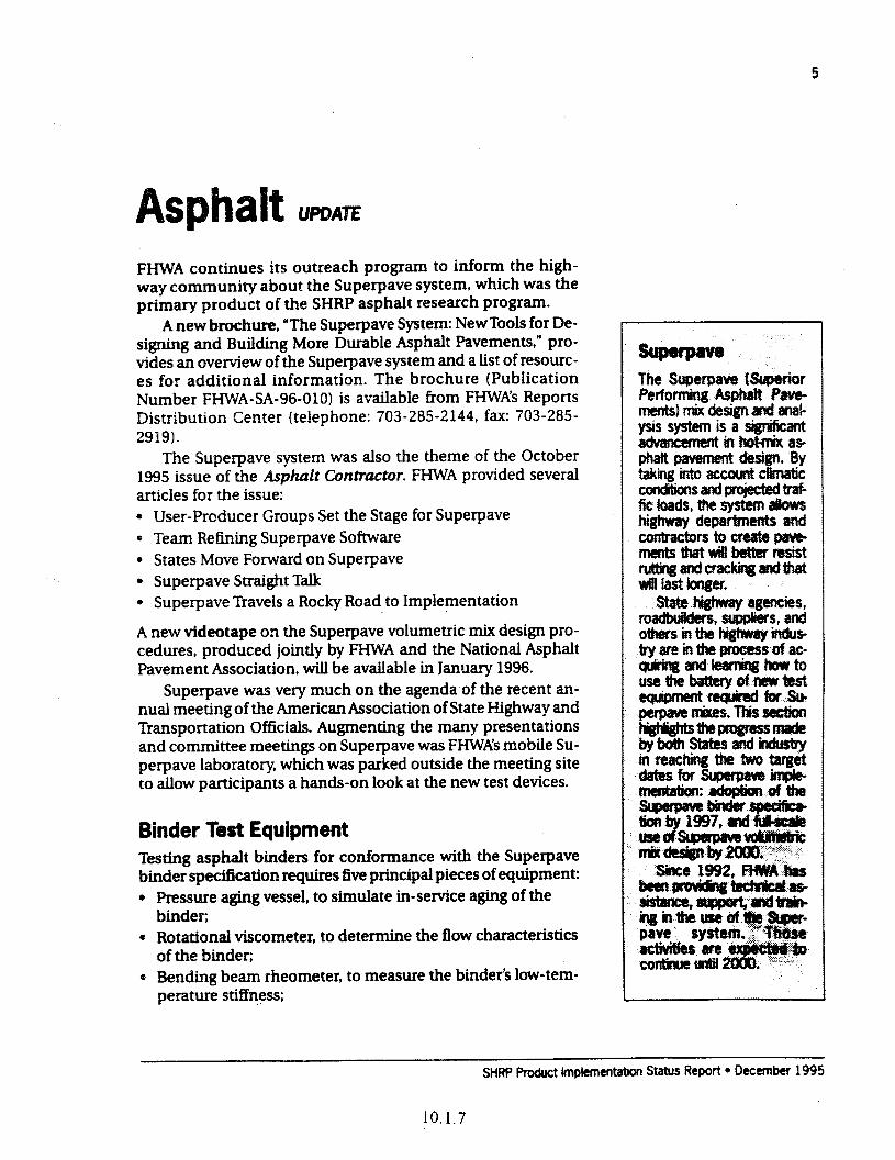
5
FHWA continues its outreach program to inform the high- way community about the Superpave system, which was the primary product of the SHRP asphalt research program.
A new brochure, “The Superpave System: NewTools for De- signing and Building More Durable Asphalt Pavements,” pro- vides an oveiview of the Superpave system and a list of resourc- es for additional information. The brochure (Pubhcation Number FHWA-SA-96-010) is available from FHWA’s Reports Distribution Center (telephone: 703-285-2144, fax: 703-285- 2919).
The Superpave system was also the theme of the October 1995 issue of the Asphalt Cbniractm. FWA provided several articles for the issue: 0 User-Producer Groups Set the Stage for Superpave 0 Team Refining Superpave Software l States Move Forward on Superpave * Superpave Straight Talk * Superpave Travels a Rocky Road to Implementation
A new videotape on the Superpave volumetric mix design pro- cedures, produced jointly by FI-IWA and the National Asphalt Pavement Association, will be available in January 1996.
Superpave was very much on the agenda of the recent an- nual meeting of the &nerican Association of State Highway and Transportation Officials. Augmenting the many presentations and committee meetings on Superpave was FHWA’s mobile Su- perpave laboratory, which was parked outside the meeting site to allow participants a hands-on look at the new test devices.
Binder Test Equipment Testing asphalt binders for conformance with the Super-pave binder specification requires five principal pieces of equipment: * Pressure aging vessel, to sitrmiate in-service aging of the
binder; 4 RotationaI viscometer, to determine the flow characteristics
of the binder; 4 Bending beam rheometer, to measure the binder’s low- tem-
perature stiffness;
SHRP Product knplementation Status Report 4 December 1995
IO. 1.7
n%wtsatFHWA Suue Raking and Field . John B&m&ii T&phone 202.3664 287 Fax: 2U2-366-7909 Wflail: jlinhdWntergate.dot.gov hiobik AspMt Lahratories~ Tom tiarman Telephone: 202~36M859 Fax: 202-366-7909 email: tfww@Mefgate.&t.gov
tztz?= RegiOf@ John&m Telephone 202-366-l 287 Fax: 202-366-7909 email: . . ~ate~dot.gov Superpaw?kdeisand
Ezavm Telephne: 202-3662084 F= 2U%366-3713 em& jmae~ate.&t.gov~
gr-- Gerry :w Tm: 202.3664853 Fax: 202-3669981 e!rnak geffdbtergatt.dot.gov
l Dynamic shear rheometer, to measure the binder’s stifhxss and phase angle at intermediate and high temperatures:
l Direct tension tester, to measure the low-temperature ten- sile and fracture properties.
AU States now have the pressure aging vessel. rotatlonal viscometer, bending beam rheometer, and dynamic shear rhe- ometer. These devices were obtained through a pooled-fund purchase coordinated by FHWA.
In addition, FHWA has loaned a W set of the binder test equipment to each of the five regional asphalt user-producer groups. This equipment will be used both for tmining engineers and technicians and for testing asphalt binder samples provid- ed by State departments of transportation and others.
The prototype for the third generation of the direct tension tester, the final piece of necessary binder equipment, is currently undergoing testing and evaluation at FHWA’s Tkner-Fairbank Highway Research Center (TFHRC). Once this evaluation is com- plete and necessary changes have been made, FHWA will pur- chase up to five additional units and loan them to the regional user-producer groups (UPGs) for ruggedness testing. The pooled-fund procurement for the States is expected to begin in late 1996.
Superpave Vdurnetric Mix Design The Superpave mix design system is based on volumetric pro- portioning of the asphalt and aggregate materials and labora- tory compactioq of trial mixes using the Superpave gyratory compactor. All 50 States, as well as Puerto Rico and the District of Columbia, have received the Superpave gyratory compactor as part of the pooled-fund purchase.
The Superpave system also includes mix analysis procedures for predicting how well a mix will petiorm in the field. These procedures are intended for mixes that will be placed in pave- ments with very high traffic volumes and loads, 73v~ new, so- phisticated pieces of laboratmy equipment-the Superpave shear tester and the indirect tensile tester-provide the data needed for the performance models.
A prototype of the Superpave shear tester is currently being evaluated at thelTHRC and by the five Superpave regional cen- ters (Alabama, Indiana, Pennsylvania, Nevada, and Texas). Be- cause of the high cost and complexity of the device, highway agencies and contractors have expressed interest in a simpli- fied version that would perform only the shear test (no ancil- lary tests) and would not require a pressure chamber. Once the evaluation of the full-scale Superpave shear tester is complete,
SHRf Product lm@ementatm Status fk.. , ] a;, 1’ i
IO. 1.8
FWM?A will look into developing a simplified, less costly version. The fist-article indirect tensile tester was delivered to the
TFHRC in July 1995. It is now undergoing testing and evalua- tion.
Since 1993, theAsphalt Institute has, under contract with FHWA, offered Superpave training courses and technical assistance to State departments of transportation, paving contractors, asphah suppliers, and others. The Institute’s National AsphaIt Training Center, located in Lexington, Kentucky, has held sixteen 1 -week courses in hinder testing, drawing 290 participants. The center has also taught fourteen l-week courses in mix design to 275 engineers and technicians.
FHWA recently awarded the Asphalt Institute a contract for the second phase of Superpave training. Over the next 3 years, the National Asphalt Training Center will provide additional lab- oratory training in the areas of mix design and pavement per- formance prediction. The center will also work with the Super- pave regional centers to provide local on-site training, technical assistance, and workshops.
Two training manuals developed for the courses, Superpave Peqormance-Graded Asphalt Binder Specification and lhting (Publication No. SP- 1) and Superpave Level 1 Mix Design Pub- lication No. SP-21, are available from the Asphah Institute.
Mobile Asphatt Laboratories FHWA now has two mobile asphalt laboratories. The laborato- ries are staffed with skilled technicians who provide assistance and training in Superpave volumetric mix design and quality control/quality assurance at construction sites across the coun- try. The mobile laboratories are each equipped with a Super- pave gyratory compactor and are used to demonstrate the prin- ciples of Superpave volumetric mix design.
This year, the labs have provided assistance at a dozen job sites, including an extended evaluation at FHW” new test track, WesTrack
Superpave Software The Superpave sofhware and performance models are currently being retied in response to evabiations by mA and its con- tractors, as well as a select group of field testers.
The first version of the software will be demonstrated at
phalt Usw- Producer Groups Notieast kpbalt Usef- Producer Group Frank Fee Telephone: 6094284808 Fax: 609%3-0111
Southeast Asphalt User- Producer Group Paul Kfugier Teiephone: 512465-7632 Fax: 512-302-2215
Noti Central AspJxtit User- Producef Group Dick Ingberg TeIeptme: 612-942-3066 Fax: 612-942-3059
Rocky Momtain User- Producer Group BobRask Tw: 3Q379M972 Fax: 303794.-5205
EC- Rick- Telephone: 7134444257 Fax: 7135444150
:
FHWA’s technology fair of SHRP products which will be held in conjunction with the Transportation Research BQ~ annual meeting in Washington, D.C., in January 1996.
FHWA has contracted with the University of Maryland to refine and manage the software, pa.rticuJarJy the performance models.
Test Tracks The Super-pave system is currently being tested and validated through a variety of eqerirnental projects. These include the new WesIkack facihty, located at the Nevada Automotive Test Center. The track features 26 hot-mix asphalt pavement test sec- tions. The performance of the various test sections will be eval- uated against the Super-pave performance prediction models.
FHWA is also colJecting performance data, using two accel- erated loading facihty machines at the TFHRC, to validate the Super-pave asphalt binder and mixture specifications.
Regional Coordination and Training The asphah user-producer groups continue to play a key role in developing and facilitating the implementation of the Super- pave system. They have outlined a sensible, well-planned strat- egy for adopting the Superpave system on a regional basis.
Super-pave centers have been established in each of the five asphalt user-producer group regions. The centers, operated jointly by universities and State departments of transportation, wiJJ conduct a thorough and coordinated shakedown of the pro- cedures used with the Super-pave shear test and indirect tensile test. They wiU aJso provide training on a regionaJ basis.
New Logo Emphasizes Pa To emphasize the partnerships involved in implementing the Superpave system, FHWA recently logo. The logo shows the principaJ partners in the Su- perpave implementation program-namely, the American Association of State Highway andTranspor- tation Officials, the highway industry, and FHWA. “Super- pave 2000” signifies the target date for nationwide implemen- tation of the Superpave mix design procedures.
SHRP Product implementation Status Report l December 1995
lO.l.10
Concrete and Structures umz Showcase workshops, conducted on a regional basis, are one of the pri.ncipaJ means of conveying information about the SHRP products for improving construction and maintenance practices for concrete pavements and structures. Each workshop features hands-on training and classroom learning on a group of related SHRP products. In some cases, technical assistance and loaner equipment are available to State highway agencies. After each workshop, participants from State highway agencies, industry, and FHWA meet to discuss how the technologies can be imple- mented on a regional basis.
Showcase workshops are available or planned in the foJlow- ing six topic areas: * Alkali-Silica Reactivity (ASR) 0 Concrete DurabiJity l Assessment of the Physical Condition of Reinforced Con-
crete Structures 0 Methodologies for Reinforced Concrete Removal, Repair,
Protection, and Rehabilitation l Electrochemical Chloride &traction l High-Performance Concrete for Bridges and Higb-Perfor-
mance R&id Pavements .
The pilot concrete durability showcase workshop was held June 27-28, 1995, in Arlington, Viiginia. Presented by Construction Technologies Laboratories ((XL), the course introduced partic- ipants to a number of devices and procedures for evaluating the durabihty of concrete. The workshop covered five main topics: l Permeability l Freeze-thaw resistance l Quality control
l Nondestructive testing l Expert systems
Techniques discussed included the impact-echo method for measuring concrete thickness and locating defects, the micro- wave oven drying method for determining water content, and the hydraulic fracture test. FHWA will begin holding concrete durability works+ps on a regional basis in April 1996.
Eight ASR showcase workshops were held in 1995. These
SHRP Product hnplemeritation Status Rem l December 19%
10.1.11
fieidandin~J&o&ory.jn- dudes hands-on training in idedyhg ASR. T-et audii ewe: rnaterlals engineers in highway departments and industry.
Next wrxkdog: Montreal, Quebec, &till6l8,1996.
Contact Roger Surdahi, 202-366-1563 (fax: 202- 366.9981; emai4: rsurdahl @intergate.dot.govI.
Concrete DumMity Covers freezethaw durab& ty@ concrete permeability, and nondes@Wive testjng of concrete. Target audience: mater& and research engi- neers and technicians.
Sched&: Works~ps wi4i commence in &i4 1996.
Contact: Gary Crawford, 202-366-I 286 (fax: 202- 3667909: emad: gcrawford @intergate.dotgovI.
Assesynent of .Jhe Physkai tkd&M?e~d
Fe-s corrosion detec%n deices, radar units, and rap- id chtoride test kits and MT+ *asizes using these devic- es to evaluate bare and covered bridges. T-et at+. dience: bridge ti con*- tion eng4neefs and tech& ChS.
sc~Thepibtshow caseistMati&yscheMed for March 1996.
(2onta&~Jackson, 202-366-6770 (fax: 20% 3667w e-maik djackm QMtefgate.dotgovl.
workshops are designed to give participants hands-on training in identifying and mitigating the effects of ASP-induced deteri- craGon in portland cement concrete. The next workshop is scheduled for ApriJ 1996 in Montreal, Quebec.
PiJot workshops for the showcases on assessing the physi- cal condition of concrete structures and repairing, protecting# and rehabilitating concrete structures will be held in spring 1996.The two showcases will run back-to-back during the same week, to make it possible for more engineers and technicians to attend.
Two ground-penetrating radar units for bridge deck evalua- tions have been ordered for use in both the workshops and field corrosion activities. The equipment is due to be delivered in the spring of 1996.
Three pilot electrochemical chloride extraction (ECE) projects have been insta.Ued: a bridge deck inArJington,Virgin- ia, and bridge columns and piers in Chariottesville,Viiginia, and Sioux City, South Dakota. ECE is a promising technique for re- moving chloride ions from reinforced concrete structures, thus slowing deterioration. The pilot projects are designed to pro- vide more information on the results of the ECE process, includ- ing how long a treatment can be expected to last and under what conditions ECE treatment is advised.
Open houses held at the pilot projects attracted a diverse group of attendees from State and Federal governments, pri- vate industry, and academia.
The pilot workshop on ECE was held in Arlington, Virginia, in July 1995. A field trip to the Arlington bridge project was in- cluded as part of the workshop.
Equipment Evaluations Field evaluations of the impact-echo device are under way. The devices have been loaned to the highway departments in WB- consin, NewYork, Iowa, Cahfomia, South Dakota, MissourLVir- ginia, Texas, Mississippi, West Viiginia, New Jersey, Nevada, North Carolina, Massachusetts, and Pennsylvania, as well as the University of Washington and the University of Texas. In addi- tion, Kansas, South Dakota, Indiana, and the University of Lou- isville have each purchased the equipment.
Initial evaluation reports of the device have been turned in by Missouri, W~consin, West Viia, and Via. Users have reported difficulties in taking measurements and interpreting data with the device and have recommended additional research and development. The biggest problem they encountered was measuring the pavement thickness within the desired accuracy of k9 mm; results to date have been in the range of il3 mm. TO
SHRP Product lmplementatfon Status Report l C&ember 1995
to. 1.12
11
address this problem, FHWA has begun testing a new produc- tion unit that shows users to measure pavement thickness more accurately (*4 mm).
Five small hydraulic fracture test chambers have been pur- chased for round-robin testing. The units have been sent to Ken- tucky, Iowa, Missouri, North Dakota, and Maryland.
Additional air permeability test devices have also been pur- chased, bringing the total avaiIable for loans to five. To date, the equipment has been loaned to Florida, New Jersey, Nevada, Ar- kansas, Missouri, the University of Nebraska, theVirginiaTra.ns- portation Research Council, and South Dakota.
High-Performance Concrete Officials from FHWA and the American Association of State Highway and Transportation Officials, together with represen- tatives from private contractors and consulting agencies, recent- ly toured the Northumberiand Strait Crossing Project in Prince Edward Island, Canada. They met with Canadian officials and had an opportunity for a first-hand Iook at the bridge that is being built with high-pexformance concrete (HPC).
The first HPC for bridges showcase workshop wiII be held March 25-27, 1996, in Houston, Texas. It wiR cover the advan- tages and disadvantages of high-performance concrete, mix proportioning, structuraI design considerations, and evahration of bridge component performance.
There are currently five HPC bridge projects being con- structed in four States:Texas (2 bridges),ViQi.nia, Nebraska, and New Hampshire. The projects are funded jointly by the Office of Technology Applications, the Office of Engineering R&D, the Office of Advanced Research, and the participating States. In ad- dition, 10 States (CaIifomia, Georgia, Iowa, Massachusetts, Min- nesota, New York, Ohio, Pennsylvania, Texas, and Washington) have pooled a portion of their research funds to help.fInance two of the projects. projects. Seven more HPC for bridges projects have been proposed by Georgia, Colorado, Ohio, Wash- ington, North Carolina, Nevada, and Indiana.
FHWA is making arrangements to host an htemational HPC conference! in 1997.
Members of the expert task group (ETG) on high-perfor- mance! rigid pavements (HPRP) held their first meeting in ApriI 1995, As a rest& of their discussions, FI-M?A, through its region- aI offices, has invited State highway agencies to submit propos- als for modifying or developing concrete paving projects to in- corporate high-performance features.
StiRP Product lmpkmentation Status Report * December 1995
12
The WFP highway opera-
Mlkwwwp contam smwimdlcecontrui tzontaa~Nassif* 202-366-1557 %aKz 20% 366-998l:emaiksnassif fimtergate.dot.gov~.
m HI Y Pavement Preventive More tkn 100 persons attended the May 1995 pilot showcase workshop on pavement preventive maintenance, held in Den- ver, Colorado. Designed for pavement, construction, and mam- tenance engineers, the workshop covered preventive treatments for both hot-mix asphalt and portland cement concrete pave- ments.
Regional workshops are tentatively scheduled to begin in early 1996. Workshop leaders will explain and demonstrate promising treatments that have been found to extend pavement service life. Test and evaluation plans for preventive mainte- nance treatments will be developed, and technical assistance will be provided to those State highway agencies participating in the evaluations.
Innovative Pavement Maintenance The pilot showcase workshop on innovative pavement effective- ness was heidin August 1995 inWashington, D.C.The workshop covered the four.maintenance areas studied under SHRP: l pothole repair in asphalt concrete pavements, . crack seaiing and filling in asphalt concrete pavements, . spa4 repair in portland cement concrete pavements, and l joint resealing in portland cement concrete pavements. The workshop was divided into six sessions. The first two ses- sions were aimed at upper management and emphasized the importance of pavement maintenance to a sound pavement management strategy. The other sessions were geared for main- tenance engineers and provided more detailed information.
Regional workshops are scheduled to begin early in 1996.
Snow and Ice Technology FHWA recently wrapped up its 2-year and-icing test and ewa.b ation project (T&E Project 28). The study, which consisted of extensive field testing of various anti-icing technologies, cu.L minated in a symposium in Estes F&k, Colorado, in October
SHRP Product lmpkmentabon Status Report * December 1995
10. I. 14
1995. The symposium drew more than 200 maintenance engi- neers and managers from State and local highway agencies, ac- ademia, consultants, suppliers, and manufactureti. The 15 State highway agencies that participated in the study reported the strategies they used and the benefits they gained. The contrac- tor for the project, the U.S. Army Corps of Engineers Cold Re- gions Research and Engineering Laboratory (CRREL) , surnma- rized the overall findings and described the methodologies used in the study.
Based on data colIected in the study, CRRBL has developed a guidance manual for anti-icing operations under a variety of storm conditions. Highway agencies will be able to use the man- ual to develop their own localized anti-icing strategies. A draft of the manual was distributed at the Colorado symposium, and a final version is expected in early 1996.
Beginning in 1996, FHWA will conduct a series of 2-day re- gional workshops to showcase the snow and ice technologies. In addition to anti-icing strategies and technologies, the work- shops will cover l methods for evaluating chemical deicers, l ice disbanding, l road weather information systems, l customized weather prediction, l snow drift control, l snowplow cutting edge, l snowplow design, and l snowplow scoop.
PHWA is currently seeking participants for five test anti ewalua- tion projects: 0 Anti-icing-to evaluate how well spreader equipment distrib-
utes a fmeiy graded salt prewetted with a liquid chemical. l Road weather information systems-to determine the inte-
gration and interoperability between systems from different vendors and to establish a standard protocol.
l Road weather information systems--to test and evaluate snow and ice control management systems that are based on road weather @formation systems.
l Cutting edge--to evaluate a plow blade coated with a high cobalt grade of tungsten carbide to resist wear from shock
l Plow design-to evaluate a plow that combines the SHRP- developed cutting edge, snowplow scoop, and moldboard design.
. .
SHRP Product lmdementation Status Report 0 December 1995
Highwzry work zones are dm gems places. The need to perform critical road repairs often conflicts with the need to maintain traffic flow, lead- ing to increased potentiai for work zone accidents. The SHRP work zone safety de- tices were designed to a& dress these opposing needs.
The SHRP wxk zone safe ty c&ices are descrii and portrayed in an FHWA bm chwe, h?rm&e Dewices for safer work zones. The bm chure cowers the flashing SWWJ.W fmjdk poftabk rur&ieMp, pwt&eall4er- rain sign and &md, direction indicator barricade, oppos- ing traffic lane diuicief, irttw sion alarm, twmt* driven WehicIe, fmab!ecrashcush ion, truck- attenua- ttol-f&f~y&s‘ and
. The brochure a&o in-
cMesalistbgoftheSHftP WTXkX#ltSifE!ty~~C~ tMS~@tiOfthl!FttWA Rgials.
To request a brochuR, contact aizg 7 Jenkins at 202-366-8025 (fax 202.36G7909: emaii: jjenkin~fgak.ti.gw).
-
Since 1992, the SHRP work zone safety devices have been dis- played at 41 major events, including such recent ones as the Texas Municipal League 1995 Convention and the I995 annual meeting of the American Association of State Highway and Transportation Officials. Each FHWA region and most Local Technical Assistance Program &TAP) centers have received a fulI set of the safety devices, allowing the devices to be shown at many regional and 1ocaI events. To make it easier for the regions and LTAP centers to demonstrate the SHRP products to local and State highway agencies, FHWA has provided utihty trailers that can easily store and transport the entire complement of work zone safety devices.
FHWA is encouraging highway agencies to try out the prod- ucts in actual field applications. Technical assistance and fund- ing support have been provided to participating States.
Availability of Devices Seven work zone safety devices are now commercialIy available.*
Five companies currently manufacture intrusion alarms. The Safety Line Infrared Alarm (ASTI Transportation Systems, Newark9 Delaware) consists of an infrared transmission unit housed in a traffic cone; the alarm unit is housed in a second cone. It provides both longitudinal and transverse detection.
The Safety Sentinel Microwave Alarm (Traffic Management Systems Corporation, St. Louis, Missouri) is a two-unit system housed in plastic drums. Solar cells are mounted on top of the drums to recharge the batteries as needed. The system uses a microwave beam to provide longitudinal detection. It also in- cludes a drone radar transmitter that sets off radar detectors in vehicles within 600 meters of the unit, helping to slow approach- ing tra.fEc.
The Model 10 two-unit intrusion alarm (Safe Lite System, Newtown, Pennsylvania) runs on rechargeable batteries and uses a radio communications linkage between the units. A pneu- matic tube laid on the pavement is used to detect intruding ve- hicles and provides transverse detection at the lane closure.
The intrusion alarm manufactured by the Columbia Safety Sign Company (Woodland, Washington~ aIsb uses a pneumatic tube to detect intruding vehicles.
TheWatchdog (Kenco International, Ligonier, Pemqlvania) consists of a series of pneumatic hoses hard-wired to the alarm unit.
The U.S. Government does not endorse products or manufacturers. lkade or manu- facturers’ names ippear herein solely because they are considered essential to the ob- ject of this report.
SliRP Product Implementation Status Reprt l Oecember 1995
Impact Recovery Systems (San Antonio, Texas), Flexstake, Inc. (Ft. Meyers, Florida), and Flasher Handhng Corporation (&pew, NewYork) currently manufacture the opposing traffic 1-e divider. All three products feature a similar two-arrow face &sign, with the main difference between the three being the support systems for returning the divider to an upright posi- tion when hit.
Three companies currently manufacture devices that meet the basic criteria for SHBP’s dhction indicator barricade. The product fi0rnWI.J Industries, Inc., (Viia Park, Illinois) has a hor- izontal arrow on a type II barricade, while Flasher Handling Corporation (Depew, NewYork) and Carsonite, Inc. (Carson City, Nevada) place the sign panels on a support with a weighted base. The device’s primary objective is to provide guidance during lane closures. Currently, the barricade is still considered experimen- tal and thus requires permission from FI-IW’A for use.
Poly Enterprise (Monrovia, California) has produced a mold- ed version of the portable rumble strip using virgin and recy- cled plastic in place of the neoprene laminated version devel- oped by SHRI? The rumble strip works best under low speed traffic conditions; under high traffic speeds or heavy truck vol- ume, the strip is subject to rotation and movement.
The original SHRP-designed flashing stop/slow paddle is currently being produced by a Canadian firm, Detronics, and distributed by Graham-M&let& Inc. (Independence, Missouri). In addition, Columbia Safety Sign Corporation (Woodland, Washington), Action West (Kelso, Washington), A/C Enterprise (Vancouver, Washington), Medifax, Inc. (La Center, Washington), and Brittney Safety Sign (Copper Country Safety Sales, Phoe- nix, Arizona) are each manufacturing a paddie that is based on the SHRP concept but that uses strobe lights or bulbs rather than high-intensity halogen bulbs.
Napoleon Fabricators, Inc. (Napoleon, Ohlo) and AdraCorp. (Huntsville, Alabama) both manufacture the portable all-ter- rain sign and stand. AdraCorp’s product is a tripod version that weighs just over 3 kilograms (7 pounds).
The queue detector, which consists of a transmitter, receiv- er, and electronics module, is available &om ASTI Transporta- tion Systems (New Castle, Delaware), The detector alerts driv- ers to stopped or siow trafiic ahead, giving them more time to react and prevent accidents.
Still Undef Dfwe~opment The portable crash cushion is currently being modified so that it uses a small trailer for more maneuverability in loading and unloading.Three trailer units are currently being manufactured for testing and evaluation by State highway agencies.
SHRP Product lmpiementti Status Report l December 1995
10.1.17
16
Designed to give States the information and products they,fwdt0bi&artdmai~ tain longer latiitig pave- -*tfezoYe~~m pavement performance pJp!y$i~~~t
ho-, alreedy t3thrini p&yg$g--
ff=fafwJ=m- tertiiwath~ti.
some of the products nowafailableredatetom -t=f%!*-P= fwnance monitorbg, and equipment standards and. cafibmth pmcedtns. Still
iiitiaz. andemofe nance strategbs, perfor- manceofvakw5retabib tion techfhques and mat- e+s,andthe~of d=&f$p&fc--
reGon&x- tial.
.
rm Pavement Perf ante UmAE
Strategic Plan Published In September 1995, the LTPP program published TheLong-Twm Pavement Perjonnance R&map A Strtategic Plan. The plan was developed with input from State and provincial highway agencies, the American Association of State Highway andTrans- portation Officials (AGHTO), the Transportation Research Board (TRB), industry, academia, and FHWA.
The Roadmap contains a data analysis plan for developing LTPP products, and it identifies critical issues facing the LPP program. The Rou&xzp also provides a brief history of the LTPP program, its partners, and their roles. It charts a course to the program’s near-term and longer term destinations.
The Roudmap is being widely distributed to help inform the highway community about the projects and products of the LTPP program. AASHTO has sent copies of the Roadmap to each State.
Just as the LTPP program is a dynamic process, so too is the Roadmap; the report will be updated periodically to reflect changing needs &rd priorities.
A new pocket-sized brochure descrlbing the LTPP program was published by FHV,?A in October 1995. The brochure, titled Improving Pavement Technology: A ZO-Year Journey, consists of a series of commonly asked questions and answers about the LTPP program.
National Conference To Be Held in March To provide an update on the LTPP program’s accomplishments and the products being developed by the program, FHWA will convene a conference in Irvine, California, in March 1996. The conference, “Improving Pavements with LTPP: Products for To- day and Tomorrow,” will be held March 26-28 at the Arnold & Mabel Beckman Center of the National Academies of Science and Engineering.
The conference will focus upon LTPP products that contr-ib- ute to increased pavement life: eariy products available from
SHRP Product lmpternentation Status Report l December 1995
10.1.18
the ETPP program, and the path to developing additional antic- ipated products.
The conference is intended primarily for State, Federal, and industry engineers and managers with responsibilities for de- livering pavement programs. The conference will also be of in- terest to engineers involved in the conduct of the LTPP studies or other pavement research programs.
The conference is cosponsored by: 0 American Association of State Highway and Transportation
Officials l American Concrete Pavement Association 0 American Trucking Associations l Canadian Strategic Highway Research Program l NationaJ Asphah Pavement Association 0 National Stone Association
z 0 Transportation Research Board
LTPP Product Preview In January 1996, FHWA will distribute a new brochure contain- ing a list of the available and planned LTPP products. The LTPP Pruducf Pmview will include a description of each product, its status, and a name of the person to contact for more informa- tion.
Products will be grouped in four categories: materials test- ing, design guidelines, pavement monitoring procedures,‘and equipment standards and calibration. The Product Preview will be used to develop implementation plans for the products. En- gineers and managers who desire to be among the earlier users of the products will also find the brochure helpful.
SPS-3/4 1995 Field Evaluations Completed Expert teams of engineers from State highway agencies, indus- try, and FHWA have completed their evaluations of the perfor- mance of various preventive maintenance treatments construct- ed in 1990 as part of SHRR Regional teams conducted on-site field evaluations of the specifk pavement studies (SPS) experi- ments (flexible pavements, SPS-3, and rigid pavements, SPS-4) during August, September, and October 1995. Each field review was 6 to 10 days in length. More than 81 experimental sites and 405 test sections were visited.
The review teams’ subjective evahrations will be used to complement the LTPP data analysis now under way on the 5 years of performance data collected at the sites. The objective of this analysis e,ffort is the formulation of sound conclusions
SHRP Product lmplementatirx Status Report * December 1995
10.1.19
18
and recommendations on the performance and use of these preventive maintenance treatments-that is, what works, and what doesn’t. A nationaJ summary report detailing the observa- tions, conclusions, and recommendations of the review teams is being developed by an FHIVA contractor, Nichols Consulting Engineers, and shouJd be avaiJabJe in early 1996. A final report on the entire SPS 3&4 project is also being prepared. Tmhnolo- gy transfer materials and ma.nuaJs of practice will be developed to assist highway agencies in implementing the study findings.
Monitored Traffic Data Now Included in National Information Management System The LTPP NationaJ Information Management System now in- cludes actual traffic data collected at monitored gene& pave- ment studies (GPS) sites. State and provinciaJ highway agencies have been collecting the data since 1990, but access to the data was delayed untiJ standardized processing procedures could be deveIoped.
The newly available trafEc data covers the 1990- 1993 period and contains information on l traffic and truck volumes, l weight distributions of axle groups by vehicle type, and l equivalent single-axle load estimates. The information is based on vehicle counts collected at more than 470 GPS sites and vehicle weights measured at nearly 400 GPS sites in 48 States and provinces.
UPP Activitks at the 1996 mB Annual Meeting The LTPP program wilJ be very visible at the 1996 Transporta- tion Research Board Armuai Meeting in Washington, D.C. The activities start on January 6 with the Data Analysis Working Group meeting. At the SHRP Coordinators meeting on January 7, highligbts of the IIPP program will be presented in the ple- nary session. An LI’PP exhibit will be set up at the technology fair that follows the coordinators meeting.
The international LI’PP coordinators will meet on January 7. Participants will share the status of their LTPP activities and explore opportunities for further cooperative efforts”
On Jarwuy 8, Session 42 will feature a series of presenta- tions on the Roudmup, related AASHTO activities, and UPP products.
SHRP Product lmplementabon Status Report 9 December 1995
IO. 1.20
19
sphalt Tt3cMcal Wofkirtg Group
Andrewski, Dave Materials Engineer Indiana DOT 100 North Senate Avenue Indianapolis IN 452042249 Phone: 3 17-232-5280 Fax: 3 17.356935 I
Collins, Ronald State Matenais & Research
Engineer Georgia DOT Off(f; of Materials &, Research
15 Kennedy Drive Forest Park GA 30050 Phone: 404-363-75 10 Fax: 404363-7684
D’Angelo, John Highway Engineer Federal Highway Administration 400 7th Street, S.W., HTA-21 Washington DC 20590 Phone: 202-36wl21 Fax: 202-3667909
Decker, Dale Director of Engineering National Asphalt Pavement
Association 5 100 Forbes Boulevard Lanham MD 207-l 3 Phone: 301-731-4748 Fax: 301-7314621
Eller, Gerald Director, Office of Engineering Federal Highway Administration 400 7th Street, S.W., HNG20 Washington DC 20590 Phone: 202.3664853 Fax: 202-366-9981
Epps, Jon A. Professor of Civil Engineering Universrty of Nevada-Reno College of Engineering Mail Stop 256 Reno NV 89557-0901 Phone: 702-784-6873 Fax: 702-7841429
Fee, Francis Manager, Technical Services Elf Asphalt, Incorporated 36th and River Road P.O. Box 638 . Pennsaukan NJ 08 110 Phone: 6094288808 Fax: 609-963-00 11
Fehsenfeld, Fred Executive Committee Chairman Asphalt Refining Company 5400 W. 86th Street Indianapolis IN 46268-0123 Phone: 3178726010 Fax: 3178798145
Fevre, M. Claude Directeur Groupement Professionnel des
Bitumes 4, avenue Hoche Paris 75008 FRANCE Phone: 33140537000 Fax: 33140537049
Finkle, Rodney Materials Engineer Washington DOT Transportation Building, KF-01 Jefferson Street at Maple Park Olympia WA 985047300 Phone: 2067537 103 Fax: 2067056808
Hallin, John P. Pavement Design and
Rehabilitation Federal Highway Administration 400 7th Street, S.W., HNG-42 Washington DC 20590 Phone: 202-366-l 323 Fax: 202-366-3713
Holt, Dave Executive Vice President Minnesota Asphalt Pavement
Association 900 Long Lake Road, Suite 202 New Brighton MN 55112 Phone: 6 12-63&%666 Fax: 6126364790
SHRP Product Implementation Status Report l December 1995
10.1.21
20
Kidner, Everett Materials Supervisor Idaho DOT 3311 West State Street P.O. 60x 7129 Boise ID 83707 Phone: 2083348439 Fax: 208334-3858
Kline, Charles Chief of Materials & Testing Pennsylvania DOT Transportation & Safety Building Commonwealth & Forster Streets Harrisburg PA 17120 Phone: 717-7874720 Fax: 7 17-787-549 1
Lord, Byron N. Chief, Engineering Applications Federal Highway Administration 400 7th Street, S.W. Washington DC 20590 Phone: 202-366-0131 Fax: 202-3667909
McCarthy, Bernard Director of Technical Services The Asphalt institute 6917 Arlington Road Bethesda MD 20814 Phone: 3016565824 Fax: 3016565825
Page, Gale Bit. Materials & Research Eng. Flonda DOT State Materials Office 605 Suwannee Street Tallahassee FL 32399-0450 Phone: 904-372-5304 Fax: 904-277-3403
Potts, Charles F. President APAC, Incorporated 900 Ashwood Parkway,
Suite 700 Atlanta GA 30338-4780 Phone: 404-392-5462 Fax: 404392-5593
Rafalowski, Mike Highway Engineer Federal Highway Administration HNG23 400 7th Street, S.W. Washington DC 20590 Phone: 202-3661571 Fax: 202-360-9981
Telford, Jack Division Engineer-Materials Oktahoma DOT 200 N.E. 21st Street Oklahoma City OK 731053204 Phone: 405521-2677 Fax: 405-521-2524
Trent, Roy Chief, Engrg. & Special Projects Office of Engineering R&D Turner-Fairbank Highway
Research Center 6300 Georgetown Pike McLean, VA 22101 Telephone: 7032852062 Fax: 7032853105
22
21
Concrete and Structures tic/mica1 wotiing tiup Brdwn, Bernard C. State Materials Engineer Iowa DOT Office of Materials 800 Lincoln Way Ames IA 50010 Phone: 5152391452 Fax: 515-239-1309
Bushman, James President Bushman Associates P.O. Box 425 Medina OH 44258 Phone: 2 167693694 Fax: 2167692197
Clemens, Gerald0 Senior Research Scientist Virginia Highway & Transportation
Research Council 530 Edgemont Road Charlottesvrlle VA 22903-2454 Phone: 804-293-l 949 Fax: 8042931990
Cole, Lawrence W. Vice President, Engineering &
Research American Concrete Pavement
Associatiofl 5420 Old Orchard Road Skokie IL 60077-l 083 Phone: 708-%6-6200 Fax: 708%6-978 1
Fiorato, Tony Vice President Portland Cement Association 5420 Old Orchard Road Skokie IL 60077-1083 Phone 708%66200 Fax: 7089889781
Gaynor, Richard D. Executtve Vice President NtiNRMCA 900 Spring Street Silver Spring MD 20910 Phone: 301-587-1400 Fax: 301~58!+I219
Gehler, James C. Chief Materials & Phy. Research Illinois DOT 2300 South Dirksen Parkway Springfield IL 62764 Phone: 2 17-782-7200. Fax: 2 17-782-6828
Girard, Robert J. Matehals Research Director Missouri Highway and
Transportation Department Highway and Transportation
Building 1 5;JclL$ouri Boulevard,
P.O. Box 270 Jefferson City MO 65102 Phone: 314-751-1040 Fax: 314-7518682
Hoblitzel~, James Structural Engineer Federal Highway Administration HNG32 400 7th Street, S.W.,
Room 3203 ‘Washington DC 20590 Phone: 202-36H598 Fax: 202-366-998 1
Holland, Terrence Director of Engineering Master Builders 23700 Chagrin Boulevard Cleveland OH 441225554 Phone: 216-831-5500 Fax: 216-831-3470
Hover, Kenneth C. Director, Department of
Structural Engineering Cornell University Hollister Hall lthaca NY 146533501 Phone: 607-2553406 Fax: 607-255-9004
Jackson, Donald Highway Engineer Federal Highway Administration 400 7th Street, S.W., HTA22 Washington DC 20570 Phone: 202-3666770 Fax: 202-366-7909
SHRP Product lmpiernentation Status Report 9 December 1995
10.1.23
22
Concrete artd Structures Techkal Working Gmup fconthedj
Larson, Roger M. Highway Research Engineer Federal Highway Administration 400 7th Street, S.W. Washington DC 20590 Phone: 202-3661326 Fax: 202-366-9981
Naret, Frank Structures Engineer New York DOT Building 5, State Cffice Campus Albany NY 12232 Phone: 5184851386 Fax: 5 15-485-402 1
Pasko, Jr., Thomas J, Office of Advanced Research Ctr. Federal Highway Administration 6300 Georgetown Pike, HAR-1 McLean VA 22101-2296 Phone: 7032852034 Fax: 7032852379
Roberts, James E. Chief, Division of Structures California DOT 1120 N Street P.O. Box 942673 Sacramento CA 94273-0001 Fhne: 9lG4453810 Fax: 9166546608
Smith, Lawrence L. State Materiais &? Research
Engineer Florida DCT Bureau of Materials & Research 605 Suwannee Street Tallahassee FL 32399-0450 Phone: 904-372-5304 Fax: 904-277-3403
Younger, Carey Research Engineer New Jersey State DOT 1035 Parkway Avenue, CN 600 Trenton NJ 08625 Phone: 60953@2001 Fax: 609530.8294
Vanikar, Suneel Highway Engineer Federal Highway Administration HTA2 1 400 7th Street, SW. Washington DC 20590 Phone: 202-3684120 Fax: 202-3667909
Virmani, Paur Highway Research Engineer Federal Highway Administration 6300 Georgetown @ike, HNR-10 McLean VA 22101 Phone: 7032852439 Fax: 7032852439
Weit, Thomas Group Product Manager W.R. Grace & Company 62 Whittmore Avenue Cambridge MA 0214CJl692 Phone: 6 17476-l 400 Fax: 6174761400
SHRP Product implementation Status Report l December 1995
23
Highway Am&r, Sr., Duane E. Civil Engineer ill New York DOT Building 5, State Dffice Campus Albany NY 12232-0001 Phone: 515457-9501 Fax: 5184574021
Burk, Mike Safety & Design Appiications
Branch Federal Highway Administration 400 7th Street, S.W., HTA-31 Washington DC 20590 Phone: 202-3668033 Fax: 202-366-85 18
Cumberledge, Gaylord Chief, Roadway Management
Systems Pennsylvania DOT Transportation & Safety Building Commonwealth & Forster Streets Harrisburg PA 17120 Phone: 717-783-6145 Fax: 717-787-7839
Dudeck, Conrad L. Professor of Civil Engineering Texas A&M Uniirsity Tll-CE Tower, Suite 310 Texas Transportation Institute College Station TX 778433135 Phone: 409&61727 Fax: 4098456254
Garrett, Robert M. Executive Director Amencan Traffic Service
Association ATSSA Building 5440 Jefferson Davis Highway Fredericksburg VA 22407 Phone: 703-898-5400 Fax: 70359855 10
Hanneman, Richard L. President Salt Institute 700 North Fairfax Street,
Suite 600 Alexandria VA 223143040 Phone: 703549-4648 Fax: 703-548-2 194
Henderson, Gary Chief, Roadway Applications
Branch Federal Highway Administration Nassif Building, HTA-21 400 7th Street, SW.,
Room 6319 Washington DC 20590 Phone: 202-366-l 283 Fax: 202-366-7909
Humphrey, Norman Maintenance Engineer South Dakota DOT Transportation Building 700 East Broadway Avenue Pierre SD 57501-2586 Phone: 6057733571 Fax: 6057733921
Joseph, Charles President Charles Joseph Traffic Services 514 S. Church Street Rockford IL 61101 Phone: 815%4-9640 Fax: 815%4-5318
Kuemmel, David A. Assistant Professor of Civil
Engineering Marquette University 15 15 West Wisconsin Avenue P.O. Box 65 Milwaukee WI 53233 Phone: 4 142883528 Fax: 4142887082
Lasek, Joseph Chief, Technical Development Federal Highway Administration HHS-11 400 7th Street, S.W. Washington DC 20590 Phone: 202-366-2174 Fax: 202-36685 18
Law, Charles District Engineer Georgia DOT 15 Kennedy Driie Cartersville GA 30120 Phone: 404-387-3602 Fax: 404-3637684
StiRP Product Implementation Status Report l December 1995
1
IO. 1.25
24
Mgbway Operatims Ted&a/ Wohing Gmp [contihuedj
Lord, Byron N. Smithson, Leland Chief, Engineering Applications Federal Highway Administration 400 7th Street, S.W. Washington DC 20590 Phone: 202-355-0131 Fax: 202-366-7909
MacMulien, John Membership Services
Representative American Public Works
Association 105 West 1 lth Street,
Suite 1600 Kansas City MO 641051805 Phone: 816-472-5100 Fax: 816-472-1510
McCarthy, Bernard Director of Technical Services The Asphalt Institute 69 17 Arlington Road Bethesda MD 20814 Phone: 3016565824 Fax: 3016565825
Pletan, Rodney A. State Maintenance Engineer Minnesota DOT Transportation Building 395 John keland Boulevard Saint Paul MN 55155 Phone: 512-297-3590 Fax: 612-297-3150
Director, Office of Maintenance Iowa DOT 800 Lincoln Way Ames IA 50010 Phone 5152391519 Fax: 515239-l 539
Stop, Jesse Chief, Program Management Federal Highway Administration C&M Division, HNG21 400 7th Street, S.W. Washington DC 20590 Phone: 202-3661552 Fax: 202-366-998 1
Swenson, Arlen T. Manager, Rental Marketing John Deere National Sales
Division 400 19th Street
e Moline IL 61265 Phone: 3097653170 Fax: 3097653 123
Tignor, Samuel Information & Behavoriai
Systems Division Federal Highway Administration TFHRC, Room T-210 400 7th Street, SW. Washington DC 20590 Phone: 7032852031 Fax: 7032852 113
Toth, Stephen A. Chief, Bureau of Equipment New Jersey State DOT 1035 Parkway Avenue, CN 600 Trenton NJ 08625 Phone: 60953G2200 Fax: 5095308294
SHRP Product implementation Status Report l December 1995
10. I.26
6 25
Long-Teim Paveme Performance Edvtical Wor&ing Group
Christory, Jean-Pierre Laboratorie reg. de IQuest
Parisien 12, rue Teissereno de Bert 78190 Trappes France Phone: 33-l-24821234 Fax: 33-l-30508369
Churilla, Charles J. Chief, Pavement Performance
Division Federal Highway Administration Turner-Fairbanks Highway
Research Center 6300 Georgetown Pike (HNR40) McLean VA 22101 Phone: 7032852355 Fax: 7032852767
Dougan, Ph.D., Charles E. Director of Research & Materials Connecticut DOT 24 Wolcott Hill Road Wethersfield CT 06109 Phone: 203-258-0372 Fax: 2035664904
Ertman Larsen, Hans Jorgen Head of Road Research Division Danish Road Institute Elisagaardsvej 5 P.O. 80x 235 Roskilde DK 4000 DENMARK Phone: 4546300100 Fax: 4546300 105
Hallin, John P. Pavement Design and
Rehabilitation Federal Highway Administration 400 7th Street, S.W., HNG-42 Washington DC 20590 Phone: 202-366-l 323 Fax: 202-3663713
Henderson, Gary Chief, Roadway Appiications
Branch Federal Highway Administration Nassif Building, HTA-21 400 7th Street, S.W.,
Room 6319 Washington DC 20590 Phone: 202-3661283 Fax: 202-366-7909
Knutson, Marlin J. President American Concrete Pavement
Association 3800 N. Wilke Road, Suite 490 Arlington Heights IL 60004 Phone: 70839455 77 Fax: 70839456 10
Lord, 6yron N. Chief, Engineering Applications Federal Highway Administration 400 7th Street, S.W. Washington DC 20590 ’ Phone: 202-366Cl3 1 Fax: 202-3667909
Mathews, Jack R. Executive Director Alabama Asphalt Pavement
Association . P.O. Box 70396 Montgomery AL 3610743% Phone: 2058355314 Fax: 205-265-4931
Staggs, William Pavement Management Engineer Arkansas State Highway &
Transportation Department P.O. 80x 2261 10324 Interstate 30 Little Rock AR 72203 Phone: 501-569-2265 Fax: 501-5692623
McWaters, Brian Pavement Engineer Iowa DOT 800 Lincoln Way Ames IA 50010 Phone: 5152391510 Fax: 5152391873
Pryor, Charles A. Vice President Engineering National Stone Association 1415 Elliot Place, N.W. Washington DC 20007-2599 Phone: 202-342-I 100 Fax: 202.3424702
SHFtP f%duct ImrAementation Status Report l December 1995
10.1.27
26
Shaffer, Douglas L, Senior Program Dfficer Transportation Research Board GR 326 2101 Constitution Avenue, N.W. Washington DC 20418 Phone 202-3341430 Fax: 202-3342003
Sullivan, Richard H. Director Minnesota DOT Transportation Building 395 John Ireland Boulevard Saint Paul MN 55155 Phone: 612.2965509 Fax: 612-297-3160
Tahir, A. Haleem SHRP Product Implementation
Coordinator American Association of State
Highway and Transportation Officials
Building 226, Room A365 Gaithersburg MD 20899 Phone: 301-97%704 Fax: 301-33@1956
Teng, Paul Chief, Pavement Division Federal Highway Administration 400 7th Street, S.W,, HNG-40 Washington DC 20590 Phone: 202-366-1324 Fax: 202-366-9981
Way, George Pavement 81 Design Section
Engineer Arizona DOT 206 S. 17th Avenue, Room 102A Phoenix AZ 85007 Phone: 602-2558085 .Fax: 6022558138
iHRP Product Implementation Status Report l December 1995
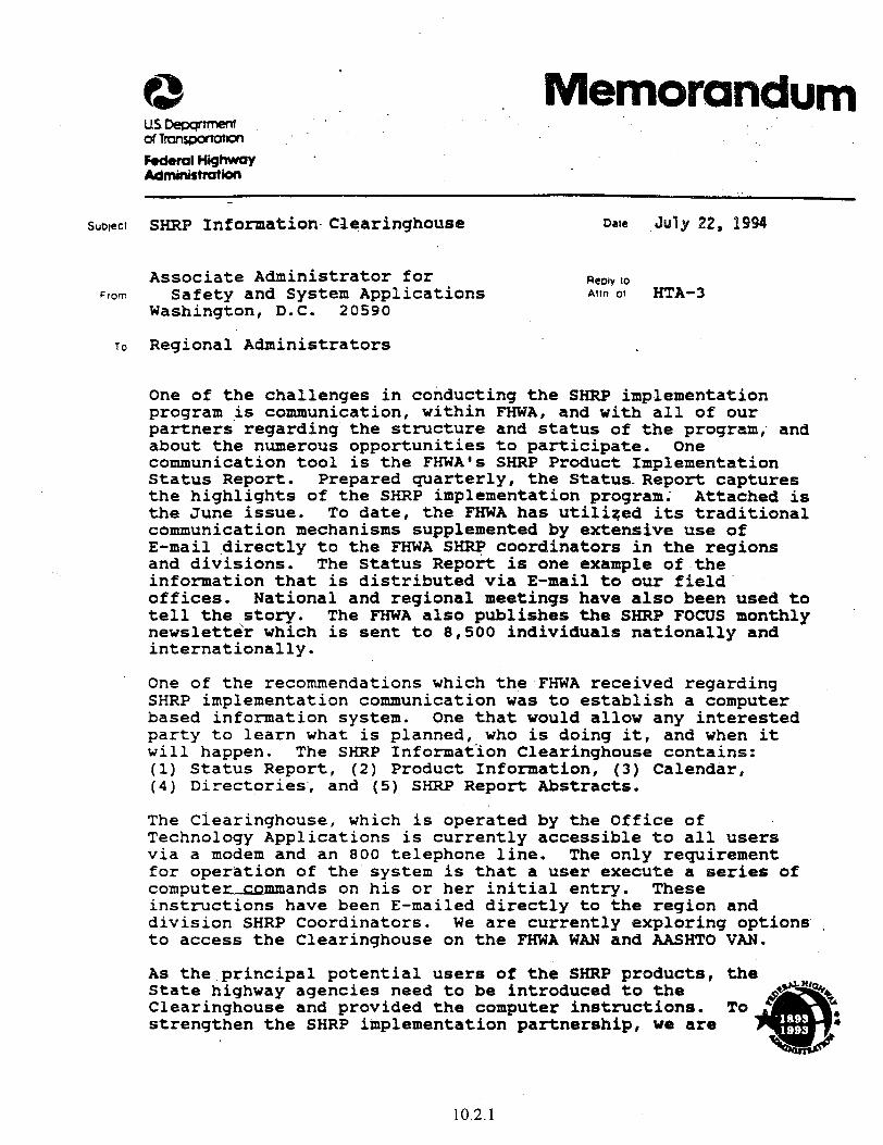
Subtecl SHRP Information- Clearinghouse Date ,&Jly 22, 1994
Associate Administrator for ReDby to from Safety and System Applications Aun of HTA-3
Washington, D.C. 20590
To Regional Administrators
One of the challenges in conducting the SHRP implementation program is communication, within FHWA, and with all of our partners regarding the structure and status of the program; and about the numerous opportunities to participate. One communication tool is the FHWA's SHRP Product Implementation Status Report. Prepared guarterly, the Status Report captures the highlights of the SHRP implementation program; Attached is the June issue. To date, the FHWA has utiliqed its traditional communication mechanisms supplemented by extensive use of E-mail directly to the FHWA SHRP coordinators in the regions and divisions. The Status Report is one example of.the information that is distributed via E-mail to our field. offices. National and regional meetings have also been used to tell the story. The FHWA also publishes the SHRP FOCUS monthly newsletter which is sent to 8,500 individuals nationally and internationally.
One of the recommendations which the FHWA received regarding SHRP implementation communication was to establish a computer based information system. One that would allow any interested party to learn what is planned, who is doing it, and when it will happen. The SHRP Information Clearinghouse contains: (1) Status Report, (2) Product Information, (3) Calendar, (4) Directories., and (5) SHRP Repoti Abstracts.
The Clearinghouse, which is'operated by the Office of Technology Applications is currently accessible to all users via a modem and an 800 telephone line. The only reguirement for operation of the'system is that a user execute a series of compute mands on his or her initial entry. These instmctions have been E-mailed directly to the region and division SHRP Coordinators. We are currently exploring options , to access the Clearinghouse on the FHWA WAN and AASHTO VAN.
As the.principal potential users of the SHRP products, the State highway agencies need to be introduced to the Clearinghouse and provided the computer instructions. To strengthen the SHRP implementation partnershipfl we are
10.2.1
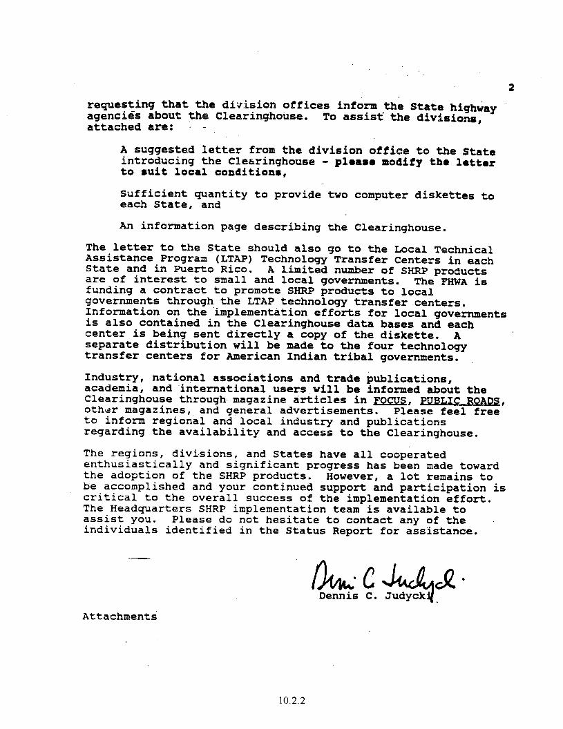
2 requesting that the div,kim offices inform the State highGay agencigs about the ClearinghoWe. attached are: - -
To assist' the divisj.ons,
A suggested letter from the division office to the State introducing the Clearinghouse - to 8uit local conditioxm,
pleame modify the letter
sufficient guantity to provide two computer diskettes to each State, and
An information page describing the Clearinghouse.
The letter to the State should also go to the Local Technical Assistance Program (LTAP) Technology Transfer Centers in each State and in Puerto Rico. A limited number of SHRP products are of interest to small and local governments. The FHWA is funding a contract to promote SHFW products to local governments through the LTAP technology transfer centers. Information on the implementation efforts for local governments is also contained in the Clearinghouse data bases and each center is being sent directly a copy of the diskette. A separate distribution will be made to the four technology transfer centers for American Indian tribal governments.
Industry, academia,
national associations and trade bublications, and international users.will be informed about the
Clearinghouse through. magazine articles in FOCUS, PUBLIC ROADS, other magazines, and general advertisements. Please feel free to inform regional and local industry and publications regarding the availability and access to the Clearinghouse.
The regions, divisions, and States have all cooperated enthusiastically and significint progress has been made toward the adoption of the SHRP products. However, a lot remains to be accomplished and your continued support and participation is critical to the overall success of the implementation effort. The Headguarters SHRP implementation team is available to assist you. Please do not hesitate to contact any of the individuals identified in the Status Report for assistance.
/L44d+CQ* Dennis C. Judyck
Attachments
10.2.2
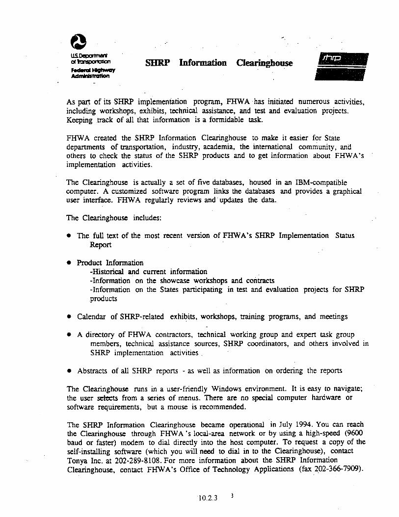
As part of its SHRP implementation program, FHWA has initiated numerous activities, including workshops, exhibits, twhnical assistance, and test and evaluation projects. Keeping track of all that information is a formidable task.
FHWA created the SIlRP Information Clearinghouse to make it easier for State departments of transportation, industry, academia, the international community, and others to check the status of the SHRP products and to get information about FHWA’s implementation activities.
The Clearinghouse is actually a set of five databases, housed in an IBM-compatible computer. A customized software program links the databases and provides a grapbicat user interface. FIXWA regularly reviews and updates the data.
The Clearinghouse includes:
o The full text of the most recent version of FHWA’s SHRP Implementation Status Rvfi
e uct Information -H’istorical and current information -Information on the showcase workshops and contracts -Information on the States participating in test and evaluation projects for SHRP ,products
0 Calendar of SW-related exhibits, workshops, training programs, and meetings
0 A directory of FHWA contractors, technical working group and expert task group members, technical assistance sources, SHRP coordinators, and others involved in SHFZP implementation activities
* Abstracts of all SHRP reports - as well as information on ordering the reports
The Clearinghouse runs in a user-friendly Windows environment. It is easy to navigate; the user s&cts from a series of menus. There are no special computer hardware or software requirements, but a mouse is recommended.
The SHRP Information Clearinghouse became operational in July 1994. You can reach the Clearinghouse through FHWA ‘s local-area network or by using a high-speed (9600 baud or faster) modem to dial directly into the host computer. To request a copy of the self-installing software (which you will need to dial in to the Clearinghouse), contact Tonya Inc. at 202-2$9-8108. For more information about the SHRP Information Clearinghouse, contact FHWA’s Office of Technology Applications (fax 202-866-7909).
10.2.3 j
THI§ PAGE LEFT BLANK INTENTI0WiLLY
10.2.4
.
Subject Implementation Plan *for the Strategic Dale June 3, 1993 Highway Research Program (SHRP) Products ,..
From Executive. Director
To Associate Administrators 4 Regional Administrators Federal Lands Highway Program Administrator
The Federal H.ighway Administration (FHWA) continues to put a priority on the implementation program for the SHRP products. Most recently, the attached plan on SHRP products implementation was developed under the direction of the FHWA SHRP Implementation Coordination Group (SICG). The.plan describes the overall approach, the partnerships,that are considered essential to the successful implementation of.the SHRP products and the roles of the involved organizations, including our field offices. Also, attached is a companion document that lists the organizational memberships of the various committees arid task forces associated with this program.
The plan was developed with the understanding that it is a living document that would grow'and change in response to the needs of the users of the SHRP products. It provides the framework by which the specific individual product(s) implementation plans, both national, regional and State, will be developed. To be successful, the specific product implementation plans must be tailored to meet regional and State conditions. It is strongly recommended that the regions and divisions be active participants with the States and industry in the development of these implementation plans.
During the coming months, FHWA will continue to put in place the SHW products implementation mechanisms and activities such as the four technical working groups, the development of specific national plans and the showcase contracts referred to in the plan. However, within the framework described in the plan you are encomged to begin planning the development of regional strategies and possible organizational structures that include our partners. I strongly encourage you to become actively involved in this process and in the subseguent implementation activities. -
10.3.1
The office ~f~T@ctumlo~ A~~l~~ati~~~ (OTA) is available t6 ~t2.onaLl infomatick re
plan and 3x3 as 'st your staff in r&ng ae sm implementation
ring this summer e development of regioial and
mmtings d fall visits by OTA staff to
your staff. wiJ.1 be held to discuss the program with
E. D&n Carlson
,..‘,. Tedera Highway Admbi.stration ~TA-3:~~~*~i~~~~~j~:366O66~6~5/~6/~3 =C: HOA-
HOA- HOA- HOAES HST-I. 340% HTA-1 HTA-3 official File
10.3.2
smpc7 SKRP Prodacts Xmplementation
From Executive Director
Associate Administrators To Regional Administrators
Federal Lands Highway Program Administrator
The Federal Highway Administration (FHWA) has made significant progress in the SHRR implementation activities at the national level. The four Technical Working Groups (TWGs) have been formed and are addressing the development of product-=specific implementation plans# contracts for various SHRP implementation support functions are in place; and the first of the showcase contracts has been awarded. Attached for your information is the SI-RP Implementation Status Report.that describes the FHWA activities. This report is routinely distributed on E-mail to the region and division office SHRP coordinatorse
Gne of the SHRP support activities im a Speakers Bureau that provides FHWA a mechanism to respond to the many requests for presentations on .SHRP product8. When FHWA staff i8 unable to respond to a request for a SRRP presentation, the Speakers Bureau can provide a knowledgeable individual from the private sector. The FHWA also has other means available when we wish to utilize an individual from a State highway agency as a SHRP products speaker. Please contact Charlie Churilla (202-366-6626) in the Office of Technology Applications if w8 can help in this regard.
One of the field office SHIW implementation activities that is extremely important is working with the State highway agencies to' establish or foster the operation of SHRP implementation activities. A number of States have established SHRP implementation committees as a means to coordinate the evaluation and adoption of SHRP products. In those States that have such a committee, the region and division offices can play valuable roles as an information source on the products and a champion for the xnany implementation activities being offered by FHWA. I am requesting that you encourage the Division Administrators to discuss SHRP implementation with their State counterparts. In those instances where an implementation process does not exist, the importance of taking action now should be stressed.
10.3.3
sportation Research is being continued
ecus on the n~~Aua~ion of the Long Term
Pavement s meeting has been d with repres om 70+ percent of
presentative, and n from OAe of your ivisicm offices, is
~ashi~g~o~ Office Direczted Travel has been approved Ct3ordinator5~ m@e~iAg~
ts have visited information on
iscuss the region and OAF of the items "
hese meetings was the &ties at the regional
em plans are opportunity to
evaluatims~ r administrative Office of Technolo office in th the funding entation activities. Detailed information regarding the funding of the regional plams will be forthcominge
ntatim to b anticipation b
iz=es the e national levelf nificant steps
ely reach the goal, the States in cxmperation with the FHW4 field offices and local indusEry ust act. I# again, want to strong1 encourage you and your staff to continue to be active p implementatiex3 E-OCtZSS - --
nts in the
2 Attac .ents
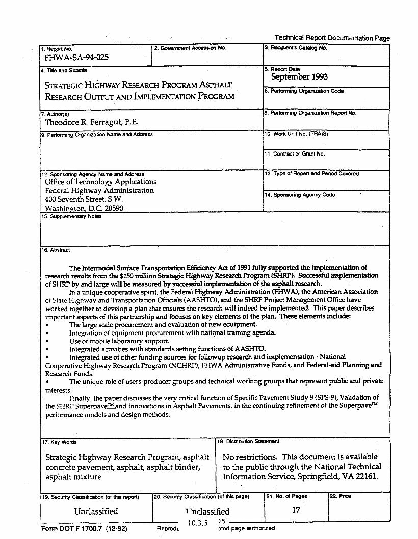
?echnica~ Paw
STRATEGIC HI&-WAY RESEARF ~OGRAM ASPHALT
RESEARCH 0uTruT m I&IJ LEMENTATION -mCXXAM
ll.ContractorGrantNo.
5. Supplementary Notes
6. Abstract
The Intemxxbl Surface Transportation Efficiency Act of 1991 fblly supported the implementation of research results from the $150 million Strategic Highway Research Propm 6HRR. Su~ful implenxmtation of SHRP by and large will be mea&xi by successful implenwzntation of the asphalt research.
In a unique cooperative spirit, the Federal Highway Administration (FHWA), the American Association of State Highway and Transportation Officials fAASHl0, and the SHRl’ Project Management Office have worked together to develop a plan that ensures the research will indeed be implemented. This paper describes important awts of this partnership and tbxses on key elements of the plan. These elements include: . The large scale procurement and evaluation of new equipment. . Integration of equipment procurement with national training agenda. . Use of mobile labora tory support. . Integrated activities with standards setting functions of AASHTO. . Integrated use of other funding sources for followup research and implementation - National Cooperative Highway Research Program 0KHRPL FHWA Administrative Funds, and Federal-aid Planning and Research Funds. . The unique role of users-prcducer groups and technical working groups that represent public and private interests.
Finally, the paper discusses the very critical function of Specific Pavement Study 9 WS-91, Validation of the SHRP Superpavmnd Innovations in Asphalt Pavements, in the continuing refinement of the Superpave~ performanoz models and design methods.
?. Key Words
Strategic Highway Research Program, asphalt ccmcrete pavement, asphalt, asphalt binder, asphalt mixture
9. Seouriv Classifcabon (of this report) 20. SeciJrlly classifi~tlo
I& Distributica Statement
No restrictions. This document is available to the public through the National Technical Information !3ervice, Springfield, VA 22161.
Unclassified 1 Tnclassified 103s )Ea
Form DOT F 1?00.7 (12-92) - -.- .-
Reprod mad page authorized
e
Sutaec: INFOFLMATION: Distribution of Publication
~~~, Associate Administrator for Safety , and System Applications
Regional Administrators -e - Federal Lands Highway Program Administrator
Distributed with this memorandum is Federal Hiuhway Administration Technolocv Applications Prouram, April 1994, Publication No. FHWA-SA-94-028, an update of the July 1993 publication (FHWA-SA-93-075). This provides a current listing of all technology transfer projects and an up-to-date status on the activities within the project. The,Office of Technology Applications (OTA) will continu@ to update and distribute this publication periodically in order to keep the field offices, States, and Technology Transfer Centers up to date on the *~~*~+~zz~*W-- technology transfer activities underway.
Sufficient copies of this publication are being distributed to provide 6 copies to each regional office and 10 to each division office. Direct distribution is being made to the division offices; copies for State highway agencies are included with the copies for the division offices. Two copies are also being sent to each Local Technical Assistance Program Technology Transfer Center.
A limited number of additional copies are available from the FHWA Research and Technology Report Center, HRD-11, Room A-200, 6300 Georgetown Pike, McLean, Virginia 22101-2296.
Dennis C. Judycki
Attachment
10.5.1

THXS Pi632 LiFT BLiNK x XONALLY
DP-75 Mobile Concrete Laboratory (SHRP)
DESCRIPTION : The project’s goals include demonstration of state-of-the-art concrete technology in materials selection, mix designs, Iaboratory testing, an? Jd testing, Project activities include guidance for updating specifications and use of computer technology for ..zsign, testing, and data storage. A partnership with manufacturers, contractors, industiy associations, and academia is maintained in all of the project’s activities.
This project demonstrates the use of innovative laboratory and in situ testing equipment, and promotes high- performance concrete and the use of chemical admixtures. This project also supports the activities of SP-20 1, “Accelerated Rigid Paving Techniques.”
BACKGROUND : With today’s construction heavily involved in rehabilitation and reconstruction, highway engineers place ever greater demands on Portland cement concrete. These demands include lower permeabihQ, higher and earlier strength, and improved workability. Many concrete admixtures are available today that specificall>, address these demands. However, to understand and effectively use these admixtures, innovative mix designs, testing equipment, and techniques are a prerequisite.
With the use of a mobile concrete laboratory, 26 field demonstrations have been performed in the last 5 years. Two-day workshops on state-of-the-art concrete technology have been conducted in 44 States. Twenty l-day seminars on “Concrete Admixtures” have been conducted. Many presentations, including the mobile concrete laboratoy, have been given at national, regionaI, and local FHWA and industry meetings. More than 2500 State DOT and FI-IWA engineers have attended workshops, seminars, and tield demonstrations. Under the equipment loan program, in situ testing equipment has been loaned to 20 States.
PROJECT LmNAGERS : Suneel Vanikar, HTA-21, (202) 366-0120 and Gary Crawford, HTA-2 1, (202) 366-1286
STATUS : In 1995, mobile laboratory field demonstrations were conducted in Texas, Ohio, and Virginia. One-day nondestnictive testing (NDT) workshops were held in Missouri and Iowa. This NDT workshop will be presented in several States over the next few years. This workshop includes some SHRP-developed products. A Concrete admixtures seminar was presented in Hawaii.
The remaining States will be visited over the next several years, with many States asking for repeat visits as the SHRPdeveloped products are inc!uded in the laboratoiy. The 1 -day admixture seminars will continue for a few more years. Additionally, this mobile laboratory will support efforts related to implementing SHRP-developed concrete technology. The major emphasis for the next several years will be on tield demonstrations of the SHRP- developed products and implementation of Performance Related Specification for Concrete Pavements.
TECHNOLOGYTkANSFER AIDS : Mobile laboratory, telephone and on-site assistance, speakers, specialized workshops and seminars, and nondestructive equipment loan program. A new mobiIe concrete laboratory was acquired in 1995.
PUBLICATIONS : FHWA reports on several field studies available through the Offke of Technology Applications.
10.5.3

10.5.4

Corrosion Survey Techniques
DESCRIPTION : The objective of this project is to demonstrate and document the latest concepts and test procedures for corrosion sweys on reinforced concrete structures. A secondary objective is to work in conjunction with States to collect data on structures that already have protective systems and to determine their effectiveness. The project is divided into three distinct modules:
Executive Presentation Slide presentation and some equipment demonstration.
Equipment Demonstration Slide presentation on bridge evaluation techniques and I- to 2-day equipment demonstrations.
Hands-on Training and Testing. Three to four days of hands-on experience with equipment.
A loan program for States that are interested in a particular piece of equipment.
Several products developed under the Strategic Highway Research Program (SHRP) are being demonstrated as part of this project.
BACKGROUND : Deterioration of reinforced concrete by corrosion of the reinforcing steel is the most tiequent cause for needing maintenance, rehabilitation or replacement of concrete structural elements. The ability to identity an active corrosion process in the early stages is the most important factor in minimizing the cost of corrosion-related repairs. .
Today’s equipment is lighter, stronger, more durable, and is capable of interfacing with microcomputers through CADD-like software. Additionally, with the growing attention paid to concrete substructure corrosion, this equipment solves some of the difIicuIties of surveying vertical surfaces over rivers, coastal waters, and freeways. Some tests that will be performed are half-cell potential survey, delamination mapping, rapid field measuring, chloride content, concrete cover survey, rebar corrosion rates, and crack measurement.
PROJECT MANAGER : Donald Jackson, HTA-22 (202) 366-6770
STATUS : This project was announced late in 1991. DP-84 has been presented 36 times since then. Interested States may request demonstrations from the project manager.
10.5.5

YHZS PAGE LEF? 3-U.VK I?JTEYTI3!4ALi*i
10.5.6

DP-87 Drainable Pavements
DESCRIPTION : This project was developed to help State highway agencies and industry partners become more familiar with new techniques in permeable base and edgedrain system design and construction. This project concentrates on the use of permeable bases with concrete pavements and consists of a workshop that features a slide presentation design manual, and field construction technical assistance. It also incorporates a hydraulic demonstration model that presents the drainage rate of various aggregate materials used in road building, including permeable bases.
BACKGROUND : Water in the pavement section is recognized as a major factor in pavement deterioration and early loss of pavement service life. In recent years, highway engineers have recognized the cost benefits of providing permeable bases to drain the pavement section. New aggregate gradations and stabilizing materials for base courses have been used to provide a balance between drainability and stability. Construction engineers also have developed new techniques for placing and compacting permeable base material.
PROJECT MANAGER : Robert Baumgardner, HNG-42, (202) 366-46 12
STATUS : More than 40 workshops have been completed to date. Scheduled presentations concluded in !vlarch 1994, The scope of the workshop portion of this project will be expanded in a future NH1 course to include retrofit edgedrains and drainage of flexible pavement. (See DP-87 Phase II, page under Asphalt Pavement Design and Construction.)
TECHNOLOGY TRAN§FER AIDS i Workshop available.on request (subject to long-range planning), specifications from Wisconsin technical assistance, construction evaluation monies (limited), computer software available from PCTrans, University of Kansas, and McTrans, University of Florida.
10.5.7

DP-87 Drainable Pavement Systems (Phase II)
DESCRIPTION : This project was developed to help State highway agencies and industry partners become more familiar with new techniques in permeable base and edgedrain system design and construction for concrete pavements. This phase of the project will concentrate on the use of permeable bases with asphalt pavements and, as with concrete pavements under Phase I, consists of a workshop that features a slide presentation, design manuals and field construction technical assistance.
BACKGROUND : Water in the pavement section is recognized as a major factor in pavement deterioration and early loss of pavement service life. in recent years, highway engineers have recognized the cost benefits of providing permeable bases to drain the pavement section. New aggregate gradations and stabilizing materials for base courses have been used to provide a balance between drainability and stability. Construction engineers also have developed new techniques for placing and compacting permeable base material.
PROJECT MANAGER : Robert Baumgardner, HNG-42, (202) 36646 i2
STATUS : This project is being expanded in an NH1 course to include retrolit edgedrains and drainage of flexible pavement. In addition, a contract has been awarded to Applied Research Associates to develop a microcomputer program to calculate pavement subsurface drainage.
TECFINOLOGY TRANSFElR AIDS : Workshop available on request (subject to long-range planning), equipment demonstration.
10.5.9

10.5.10
DP-89 Quality Management
DESCRIPTION : The goal of this project is to build top-level support and awareness of quality management and to provide training to State highway agencies in statistical quality control techniques. It is part of the National Quality Initiative. This project involves four quality management activities.
Participate on a joint FI-IWA/AASHTO/industry steeiing committee to guide and help focus efforts on the quality of construction, performance, and quality management with emphasis on a partnership effort.
Develop (jointly) and issue broadly based national policy/goals.
Hold high level seminars for upper management of Federal, State, industry, and others to educate and gain support,
Provide technical training, guidance, and tools to others responsible for implementation.
BACKGROUNJI : There has been a conscious effort within the United States during the past decade to promote a correlation between .4merican products and quality. In general, this effort has been focused in the manufacturing industry The United States has begun to promote the concept of American quality because quality is an important factor in maintaining global competitiveness.
With the emphasis on quality again moving toward national significance, this project will provide direction and address a broader role of quality in the highway environment.
PROJECT MANAGER: Don Tuggle, I-ING-21, (202)‘366-1553
PROJEt COORDINATOR : Gary Henderson, HTA-22, (202) 366-1283
STATUS : In an effort to widely disseminate the principles and ideals begun at the National Quality initiative Seminar in Dallas/‘Ft. Worth, Texas on November 10, 1992, four AASHTO Regional NQI Seminars involving well over 10,000 people nationwide have been conducted. Additional support of state-level NQI activities has been provided.
An *‘NQI National Conference” will be held in Alexandria, VA on November 14 and 1.5, 1995. The first-ever NQI Achievement Award will be presented for the best highway project at this conference.
A May training ccxuse (Materials Control andAcceptance: Quality Assurance) and a 2-day workshop (Qu&ty hlanagementforkhnagers) is being co-sponsored with the National I-hghway Institute. Appro,ximateIy 38 of the 50 available five-day courses and 4 1 of the 56 available two-day workshops have been presented. Several statistical quality assurance computer programs have been developed by the New Jersey DOT. A technical review of the user manual has been completed, and distribution of the manuals and programs is espected by the end of 1995. In addition a number of workshops and seminars have been supported such as a technician training and certitication workshop in Platteville, Wisconsin and a quality assurance specifications development workshop in Little Rock, Arkansas.
TECHNOLOGY TRANSFER AIDS : One-week course, two-day workshops, technical assistance, speakers, and computer programs.
10.5.11
10.5.12
DP-90 Mobile Asphalt Laboratories
DESCRIPTION : This project is a major Office of Technology Applications initiative to promote Strategic Highway Research Program (SHRP) fmdings in the asphalt area. This project uses two mobile laborator& to provide State highway agencies with a hands-on demonstration of the SHRP SUPERPAVE design system and field management techniques.
The major objective of the project is to promote the Super Pave Mix design system and mix verijication / volumetric quality control in thejield
The typical project centers on transplanting a mobile lab to an active paving project at the invitation of the State. Once it is on site, State, contractor, and Federal engineers can witness, compare, and critique the test procedures and sequences.
PROJECT MANAGERS : Thomas Harman, HTA-21, (202) 346-0859; John D’Angelo, HTA-21, (202) 366-0121; and John Bukowski, HTA-21, (202) 366-1287.
STATUS : The use of mobile laboratories for asphalt mix is ongoing. The concepts of Mix Verification and Voids Acceptance have been demonstrated and field simulated in more than 38 States in the last 8 years. As an additional service, more than 50 Federal and State contractors, engineers, and technicians have spent 2 to 5 days in a mobile laboratory learning and strengthening their skills in the asphalt mix area. In 199 1, a formal 2-day workshop was added to the demonstration. In 1993, key elements of the SHRP SUPERPAVE mix design system were also added to the workshop. During 1994 and 1995 the laboratory provided field control on several projects using SUPERPAVE designed mixes.
A report detailing the results of the field simulation was voted the “Best Paper of the Year 199 1” by the Association of Asphalt Paving Technologists. This report, Summay of Simulation Studies, is available from the project managers.
The remaining States will be visited over the next several years. With the addition of the SUPERPAVE system, many States are expected to request repeat visits as they explore the adoption of the new techniques. The mobile laboratory has supported other OTA activities, such as stone matrix asphalt (SMA), and is expected to perform this support activity more frequently in the next few years.
TECHNOLOGY TRANSFER AIDS : Mobile laboratory (subject to scheduling), telephone and on-site assistance, speakers, and specialized workshops and seminars.
PUBLICATIOm Summary of Simulation Studies, by J. D’Angelo and T. Ferragut, 199 1.
10.5.13

10.5.14

DP-108 Pavement Management Analysis
PURPOSE : To demonstrate how various PMS prioritization methods are used to identify justifiable and cost- effective pavement preservation strategies for various funding levels and develop multi-year prioritized list of pavement preservation projects.
To demonstrate how PMS pavement performance data is used to perform engineering analyses that could evaluate pavement design, construction, materials and maintenance procedures as they relate to performance of pavements.
BACKGROUND : The ISTEA Interim Final Rule for management systems requires each State Highway Agency to develop a PMS for the National Highway System capable of performing various pavement analyses.
These analyses included pavement performance analysis to analyze the current and predicted performance of specific pavement types, investment analyses to estimate total cost for present and projected conditions across the network, and investment strategies to prioritized pavement preservation projects with recommended preservation treatments that span single and multi-year periods using life-cycle cost analysis.
The regulation also requires the PMS to be capable of performing engineering analyses for appropriate network sections that could evaluate pavement design construction, rehabilitation, materials, mix designs, and preventive maintenance as they relate to performance of pavements.
State examples of pavement performance, multi-year prioritization methods, cost analyses and engineering analyses will be used to develop two to three-day demonstration sessions. The project consists. of two demonstration activities.
The first activity consists of a series of PMS outreach sessions to provide one-on-one discussions and technical assistance to States that are developing the analyses required to perform multi-year prioritization of pavement preservation projects.
The second project consists a demonstration of the use of PMS performance data in engineering applications.
The main topics to be demonstrated in the multi-year prioritization demonstration activity are:
Pavement Performance Analysis
Selection of Pavement Preservation Strategies and Treatments
Cost Analyses
Effects of Budget Constraints
Project Selection Process
The main topics to be demonstrated in the use of PMS performance data in engineering applications demonstration activity are:
Historical Performance Data
10.5.15
Evaluation of Pavement Design Procedure
Evaluation of Pavement Construction Practices
Materials Performance Analysis
Pavement Preservation Analysis
PROJECT MANAGER : Luis Rodriguez, HNG-4 1, (202) 366- 1335
STATUS : A contract has been awarded for the multi-year prioritization demonstrations. Demonstration sessions are expected to begin in the first quarter of 1996.
Bids are currently being evaluated for a contract to perform PMS engineering analysis demonstrations, The contract should be awarded by the end of 1995 and sessions are expected to begin in early 1997.
Bridge Design and Construction
Bridge design as many other segments of civil engineering, has evolved from early art forms to a sophisticated science. A hundred years of experience have been assimilated into the engineering practice, and modem research and development fmdings have been re-examined, tested, proven in service, and coditied into bridge specifications and practice. The traditional design philosophies and methods, such as Working Stress Design (WSD) and Ultimate Strength Design (USD), are still used in bridge design. However, recent developments in bridge design specifications have departed from the traditional approaches to incorporate more rational methods.
Load Factor Design (LFD) was a fast step toward implementing a bridge design code based on statistical factors accounting for variability of loads, lack of accuracy in the analysis, and the probability of simultaneous occurrence of different loads. Load and Resistance Factor Design (LRFD) extended the philosophy to include resistance factors that account for the variability of material properties, structural dimensions and workmanship, and the uncertainty in the prediction of resistance. The LRFD code, properly applied, is expected to lead to more rational bridge designs that will produce more economical and durable highway bridges. A concerted effort to train bridge designers in the concept of load and resistance factors, as well as the application to bridge design, is crucial to the successful implementation of the new codes.
The LRFD specifications are ideal for assimilating new developments in bridge materials and construction methods, such as electroslag welding and high performance concretes, since resistance factors can be moditied as necessary to represent uncertainties in material properties. Part of this project will involve promoting new bridge materials and construction methods and also implementing the LRFD code in bridge design software.
Recent innovative developments in bridge design codes, bridge materials, and construction methods have led to the establishment of IO milestones.
I. Develop and initiate formal training sessions for the design of bridge superstructures and bridge foundations using the LRFD code.
2. Develop and initiate formal training sessions for the use of nondestructive load testing to determine load ratings of bridges.
3. Develop and initiate a demonstration project on electroslag welding for steel bridges.
10.5.16
4
5.
6.
7.
8.
9.
IO.
Approve the LWD specifications as the sole AASHTO code for design of highway bridges.
Upgrade major bridge design analysis, and rating software with LRFD code: BRASS, AASHTO BDS.
Use High-Performance Concrete in a prestressed concrete bridge in Virginia.
Prepare Technology Transfer material and conduct a regional seminar on the use of High-Performance Concrete in a prestressed concrete bridge in Texas.
Use High-Performance Concrete in parallel structures conventional concrete in one- HPC in the other.
Establish an equipment loan program for SHRPdeveloped High-Performance Concrete test equipment.
Establish design and construction guidelines for High-Performance Concrete.
10.5.17

10.5.18
AP-2 1 Geotechnical Microcomputer Programs
DESCRIPTION : This project has involved the development of several geotechnical programs under contract with geotechnical microcomputer programming firms. These programs have been made available to the States by the OTA.
BACKGROUND : The microcomputer industry has undergone rapid changes in recent years. New developments in hardware and software make the use of the microcomputer in civil engineering applications more feasible, practical, and almost indispensable.
The microcomputer can be used to solve many geotechnical problems that need repetitive and yet complicated calculations, such as analyzing embankment and foundation deformations, estimating pile behavior under static and dynamic forces, and calculating foundation settlements. Five of the microcomputer programs developed or under development are:
COM624P: Analyzes the behavior of piles or drilled shafts, subjected to lateral loads using the p-y method.
EMBANK: Determines one-dimensional compression settlement because of embankment loads.
SPILE: Calculates the ultimate static pile capacity in cohesive and cohesionless soils.
Ftss: Analyzes stability of slopes that contain soil reinforcement. The analysis is performed using a two-dimensional limiting equilibrium method.
MSEW: Designs and/or analyzes required reinforcement for mechanically stabilized retaining walls, which does not consider specific facing configurations.
DRIVEN: This program is the updated version of the SPILE Program.
PILE FOUNDATION : This program will be developed based on the UniversiQ of Florida program -
LPGSTAN which is capable of analyzing bridge foundations subject to extreme events (hurricanes, ship and ice imports). The program will extend its capabilities to include the analysis and design of sound walls, retaining walls, signs and high mast lighting structures.
PROJECT MANAGER : Chien-Tan Chang, HTA-22, (202) 366-6749
STATUS : The SPILE Program has been upgraded, the new program is called Driven. This program is estimated to be completed by the end of 1995. RSS Program has been completed. It will be tested for about 2 months and will be distributed early December 1995. Contracts are being negotiated to develop a new version of MSEW program and a multiple faceted program called Pile Foundations.
10.5.19

10.5.20
AP-IO2 SHRP Distress Identification Manual
DESCRIPTION : The Distress IdenhJkation ManuaI is a pictorial rating manual for distress identification on highway pavements. The manual’s photographs, descriptions, and illustrations provide a reference for the consistent identification and quantification of the severity and extent of pavement distress. It also provides a common language for describing cracks, potholes, rutting, spaIhng, and other pavement distresses. As a “distress dictionary,” the manual has the potential to improve inter- and intra-agency communication while leading to more uniform evaluations of pavement performance.
The manual is divided into three sections that focus on particular types of pavement: (1) asphalt concrete surfad (2) jointed Portland cement concrete, and (3) continuously reinforced Portland cement concrete. Each distress is clearly labeled, described, and illustrated.
BACKGROUND : In 1987, the Strategic Highway Research Program (SHRP) began its largest and most comprehensive pavement performance the Long-Term Pavement Performance (LTPP) program. The Distress Identijkation Manual was developed as a tool for the LTPP program. It allows States and others to provide accurate, uniform, and comparable information on the condition of LTPP test sections. Moreover, it enables individuals and agencies to interpret LTPP data or to correlate LTPP fmdings with their own research efforts.
PROJECT MANAGER : James Walls, HNG42, (202) 366- 1339
STATUS : The SHRP distributed multiple copies of the latest color version of be Distress Identijcation A4anual in July 1993. NH1 will offer several training courses on the Manual to State and local highway agencies starting in the Fall of 1995.
Copies of the training materials will be made available to academia and the Technology Transfer Centers.
TECHNOLOGY TRANSFER AIDS : The project manager will continue to provide technical advice and participate in conferences, seminars, workshops, and user training sessions. Test and evaluation by a limited number of States is also anticipated.
PUBLICATIONS : i%e Distress Identijkation h4anual for the Long-Term Pavement Performance Project can be purchased from the Transportation Research Board. Telephone: (202) 334-32 14; Fax: (202) 334-25 19. cost: $20.
10.5.21

10.5.22
AP-I 18 Falling Weight Deflectometer Quality Assurance Software (SHRP)
DESCRIPTION : This project develops, markets, and distributes generic versions of the Strategic Highway Research Program’s (SJ5RP’s) Failing Weight Deflectometer (FWD) Quality Assurance software for use by State highway agencies. The generic versions accommodate various FWDs, sensor numbers, sensor spacings, .and test protocols.
BACKGROVND : The SHRP FWD Quality Assurance Software is a spinoff product of SHRP’s Long-Term Pavement Performance (LTPP) studies. It is one of four spinoff products SHRP recommended for FHWA implementation activities in 1992.
Falling Weight Deflectometers are used widely by highway agencies to collect pavement response data used m pavement rehabilitation, design pavement management systems, and forensic examinations of failed pavements. The overall goal of the SHRP FWD Quality Assurance Software is to ensure the consistent collection of high- quality pavement deflection data.
To provide quality assurance for FWD data collection, SHRP developed four software programs and established reference calibration centers at several State highway agencies to provide for quality measurement and data collection.
Since many of the State highway agencies either own or contract for deflection testing services by an FWD, the use of this quality assurance software should provide improved testing data. Unfortunately, all of this software was written specifically for SHRP and its methods. As an example, the programs are written to read data files from Dynatest FWD with seven sensors at the prescribed SHRP sensor spacing.
PROJECT MANAGER : Max Gregg, (5 18)43 l-4224.
STATUS : A Technical Working Group was established in 1993. During 1994 the LTPP Division continued to revise these software packages based upon their need, experience, and input from the Technical Working Group. These modifications should be completed by October 1995. In 1996 a consultant contract will be executed to perform the software modification. Additional funding will provide for training on the software and the calibration centers. Limited field testing by the SHAs will be conducted, and modified generic software will be marketed.
10.5.23

10.5.24
TE-14 Innovative Contracting Practices
DESCRIPTION : The objective of this project is to identify innovative contracting practices for evaluation and documentation that have the potential to reduce life-cycle costs to State highway agencies, while maintaining product quality and an acceptable level of contractor profitability. Practices tested under this contract include design/build, warranties, guarantees, lane rental, cost plus time bidding, and incentives/disincentives.
BACKGROUND : This project resulted horn the work of a 1988 Transportation Research Board (TRB) task force that spent 3 years exploring innovative practices in the US. and abroad. Its findings were released as Transportation Research Circular Number 386, titled %novative Contracting Practices” (199 1).
Another initiative relative to,innovative contracting practices resulted from an asphalt pavement study group’s 1990 European tour. The group was impressed with what it saw and recommended three innovative practices that could be pursued through a test and evaluation effort:
Functional contracts (design/build),
Warranties of riding surfaces, and
Lane rental.
In addition a fourth practice, cost-plus-time bidding, has gained widespread acceptance from State highway agencies.
PROJECT MANAGER : Wady Williams, I-ING-22, (202) 366-0606
STATUS : This project has been operational for over 5 years and approximately 65 percent of the SHA’s have participated at least once.
By far, the most popular technique used has been cost-plus-time bidding. Twenty-six States and the District of Columbia have used this method thus far. Six %-IA’s have either completed design/build contracts or have initiated such contracts. Contacts have been completed in Arizona and Colorado with favorable results. Total project time was substantially less than would have been expected for conventional design-bid-build projects, there was no significant change in design costs, and claims were essentially eliminated. Six SHA’s have undertaken projects using the lane rental concept to reduce road-user impacts and, eight SHA’s have chosen to use and evaluate warranty provisions.
In 1995 FHWA published Rebuilding America: Partnership For Investment, FHWA publication No. FHWA- PD-95-028, which contains descriptions of innovative practices and a list of projects using these practices.
TECHNOLOGY TRANSFER AlDS : Lane rental specifications, background information on warranties and guarantees (from the Transportation Research Board), and telephone and speaker assistance.
10.5.25

10.5.26
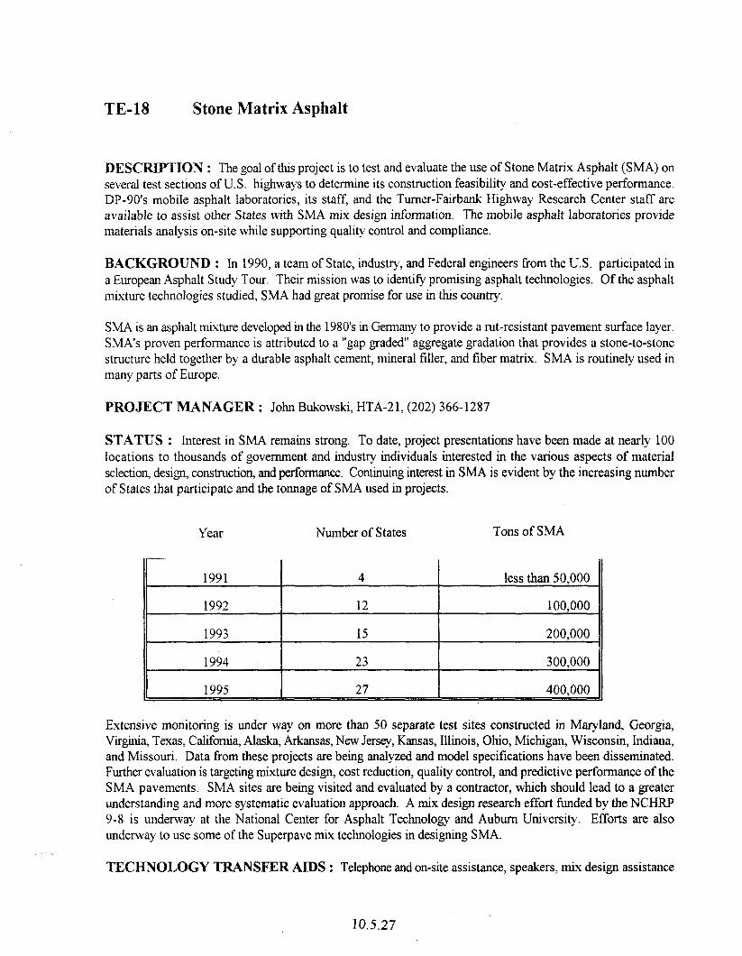
TE-18 §tone Matrix Asphalt
DESCRIPTION : The goal of this project is to test and evaluate the use of Stone Matrix Asphalt (SMA) on several test sections of U.S. highways to determine its construction feasibility and cost-effective performance, DP-90’s mobile asphalt laboratories, its staff, and the Turner-Fairbank Highway Research Center staff are available to assist other States with SMA mix design information. The mobile asphalt Iaboratories provide materials analysis on-site while supporting quality control and compliance.
BACKGROUND : In 1990, a team of State, industry, and Federal engineers from the U.S. participated in a European Asphalt Study Tour. Their mission was to identify promising asphalt technologies. Of the asphalt mixture technologies studied, SMA had great promise for use in this country.
SMA is an asphalt mixture developed in the 1980’s in Germany to provide a rut-resistant pavement surface layer, SMA’s proven performance is attributed to a “gap graded” aggregate gradation that provides a stone-to-stone structure held together by a durable asphalt cement, mineral filler, and liber matrix. SMA is routinely used in many parts of Europe.
PROJECT MANAGER : John Bukowski, HTA-21, (202) 366-1287
STATUS : Interest in SMA remains strong. To date, project presentations have been made at nearly 100 locations to thousands of government and industry individuals interested in the various aspects of material selection design, construction, and performance. Continuing interest in SMA is evident by the increasing number of States that participate and the tonnage of SMA used in projects.
Year Number of States Tons of SMA
1991
1992
1993
1994
1995
4
12
15
23
27
less than 50,000
100,000
200,000
300,000
400,000
Extensive monitoring is under way on more than 50 separate test sites constructed in Maryland, Georgia, Virginia, Texas, California, Alaska, Arkansas, New Jersey, Kansas, Illinois, Ohio, Michigan, Wisconsin, Indiana, and Missouri. Data from these projects are being analyzed and model specifications have been disseminated. Further evaluation is targeting mixture design, cost reduction, quality control, and predictive performance of the SMA pavements. SMA sites are being visited and evaluated by a contractor, which should lead to a greater understanding and more systematic evaluation approach. A mix design research effort funded by the NCHRP 9-S is underway at the National Center for Asphalt Technology and Auburn University. Efforts are also underway to use some of the Superpave mix technologies in designing SMA.
TECHNOLOGY TRANSFER AIDS : Telephone and on-site assistance, speakers, mix design assistance
10.5.27

(based on laboratory availability), and mobile laboratory (subject to long-range planning).
HJBLICATIQNS : SMA Model Materials Selection and Construction Guidelines are available through the Office of Technology Applications and are also being distributed by the industv. Copies of material on European SMA Synthesis also are available upon request.
10.5.28
TE-21 Pavement Condition Measurement (SHRP)
DESCRIPTION : This project evaluates and promotes state-of-the-art pavement condition evaluation equipment and consolidates previous ongoing activities with SHRP implementation efforts related to pavement condition measurement. The project will be expanded to include new technology as it becomes available.
Three kinds of equipment have been evaluated through field test and evaluation:
SHRP Ground Penetrating Radar
SHRP Seismic Pavement Analyzer
Fully Automated Pavement Distress Measuring Equipment
PROJECT MANAGERS : Luis Rodriquez, HNG-4 1, (202) 366-1335 and George Jones, HNG-4 1, (202) 364-1338.
STATUS : The fmal report on the fUy automated pavement distress measuring equipment has been completed and distributed to all State highway agencies. Reports on additional equipment analysis will be issued upon completion of field test and evaluation. A follow-up test was conducted in North Carolina during December 1994. North Carolina DOT is currently completing the data analysis from that test.
The Technical Working Group met and decided not to tid any additional testing of either the ground penetrating radar or the seismic pavement analyzer. The developers of both pieces of equipment are continuing with the equipments’ development. Commercial development through the private sector is encouraged.
TECHNOLOGY TRANSFER AIDS : Test and evaluation in selected States through work orders and equipment loan. A follow-up program of workshops, seminars, and literature is envisioned.
10.529

10.5.30
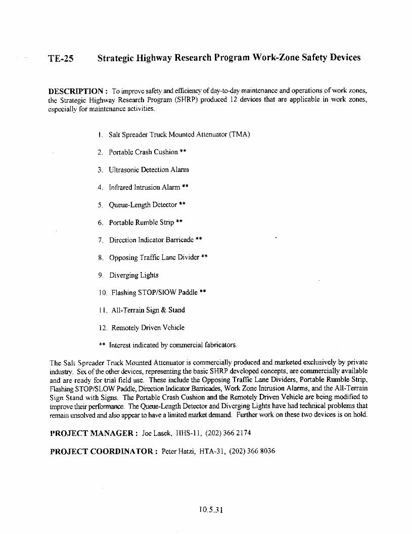
TE-25 Strategic Highway Research Program Work-Zone Safety Devices
~ESCFUPTION : To improve safety and efficiency of day-to-day maintenance and operations of work zones, the Strategic Highway Research Program (SHRP) produced 12 devices that are applicable in work zones, especially for maintenance activities.
1. Salt Spreader Truck Mounted Attenuator (TMA)
2. Portable Crash Cushion **
3. Ultrasonic Detection Alarm
4. Infrared Intrusion Alarm **
5. Queue-Length Detector **
6. Portable Rumble Strip **
7. Direction Indicator Barricade **
8. Opposing Traffic Lane Divider **
9. Diverging Lights
IO. Flashing STOP/Slow Paddle **
11. All-Terrain Sign & Stand
12. Remotely Driven Vehicle
** Interest indicated by commercial fabricators.
The Salt Spreader Truck Mounted Attenuator is commercially produced and marketed exclusively by private industry. Six of the other devices, representing the basic SHRP developed concepts, are commercially available and are ready for trial field use. These include the Opposing Trafftc Lane Dividers, Portable Rumble Strip, Flashing STOP/SLOW Paddle, Direction Indicator Barricades, Work Zone Intrusion Alarms, and the All-Terrain Sign Stand with Signs. The Portable Crash Cushion and the Remotely Driven Vehicle are being modified to improve their pet%ormance. The Queue-Length Detector and Diverging Lights have had technical problems that remain unsolved and also appear to have a limited market demand. Further work on these two devices is on hold.
PROJECT MANAGER : Joe Lasek, HHS- 1 I, (202) 366 2 174
PROJECT COORDLNATOR : Peter Hatzi, HTA-3 1, (202) 366 8036
10.5.3 1
§TATUS : Most of the devices have been exhibited by the FHWA and SHRP staff at many national and regional conferences and technical shows. The purpose of showcasing the devices during tiscal years 1992 through 1994 is to acquaint potential users with these new devices and to develop interest in their use.
FHWA supports activities to provide the various devices to State highway agencies for trial use and evaluation. A solicitation of interest was made to the State DOTS through FHWA division offices. Based upon responses> funds were provided to the States to acquire limited numbers of the devices for trial use under actual work conditions. In return information on the overall performance of the devices will be provided to FHWA.
Some additional funding will be made available in FY 1994 for acquiring Intrusion Alarms and other devices that may become available for trial use and evaluation. The fording will be provided under normal Federal aid procedures. Through this evaluation method, FHWA will accumulate an information base on the in-service performance of the various devices, while allowing the States to gain experience with them.
10.532
Innovative Pavement Materiak 6% Treatments
DESCRIPTION : This project provides States an opportunity to evaluate SHRP pavement maintenance products and techniques by introducing preventive maintenance technology and principles. Technical assistance will be provided on surface treatments and guidance will be available in the use of innovative materials. SHRP technology in two areas is included:
Effectiveness of pavement preventive maintenance: management concepts, optimum timing of various surface treatment applications, guide specifications for preventive maintenance, and a I -day workshop.
Innovative materials: pothole patching, crack sealing, joint sealing, spa11 repair and other materials and surface repair guidelines, introduction of objective data collection techniques for joint seal effectiveness, and a I -day workshop.
PROJECT MANAGER : Patrick Bauer, HNG-21, (202) 346-1554 and Michael Smith, HNG-42, (202) 366-4057.
PROJECT COORDINATORS : Jim Sorenson HNG-42, (202) 366-1333 and Gary Henderson, HTA-2 1, (202) 366-1283.
STATUS : Showcase contracts have been awarded for Preventive Maintenance and Innovative Materials, and pilot workshops have been conducted. Test and Evaluation programs are under development. The first pilot workshop was held in May, 1995, in Colorado. The second pilot is being held in September, 1995, in Arizona. It is anticipated that workshops for both technologies will be available in the late Fall of 1995.
TECHNOLOGY TRANSFER AIDS : Seminars, technical assistance, and field test and evaluation work orders.
10.5.33

THIS PAGE LEF? SLAm I?iTESTI3NALLY
10.5.34
TE-28 SHRP Snow and Ice Technology
DESCRIPTION : This project tests and evaluates SHRP snow and ice technology products in five major areas: snowplow cutting edges, snow fences, roadway weather information systems, anti-icing technologies, and de-icing chemicals. The project will provide an opportunity for States to test and evaluate better designed snowplows and snow fences, improved storm forecasting and communication methods, and more efficient and effective snow removal and ice control methods.
The primary products emerging from this SHRP technology area are design guides, manual of practice for anti- icing operations, research reports, handbooks, evaluation methodologies, and improved snow removal equipment, Guidelines have been developed for evaluating equipment, materials, and methods for utilizing anti-icing technology. FHWA’s implementation effort of the SHRP technology has three parts:
Anti-icing TechnoloB through a technical services support agreement with U.S. Army Corp of Engineers (Cold Regions Research and Engineering Laboratory CRREL).
Showcasing contract incorporating workshops, field test and evaluation, and equipment loans,
Field Test and Evaluations through work orders with State highway agencies.
PROJECT MANAGERS : SalimNassif, HNG-21, (202) 366-1557;Chung Eng, HNG-21, (202) 366-1555.
PROJECT COORDINATOR : Gary Henderson, HTA-2 1, (202) 366- 1283
STATUS : Product/technologies currently being evaluated include weather information systems for highway operations, anti-icing operations, innovative snow fence design and construction, and snow scoops. Additional products/technologies and participants will be added through the showcasing contract. Work orders were established with 15 State highway agencies to evaluate the effectiveness of SHRP anti-icing techniques over the 1993/94 and 1994/95 winter period. Work orders were also established with an additional seven State highway agencies; four to evaluate the Wels portable interactive weather prediction system, and several other weather services in terms of usefulness and accuracy for highway operations; two to evaluate snow fences designed in accordance with SHRP guidelines; and one to evaluate the effectiveness of the snow scoop retrofitted to their existing plows.
A showcase contract has been executed to package the various technologies and develop a series of workshops and seminars focusing on snow and ice technologies. Additional lield trials will be initiated with selected States to further evaluate various products by winter 1995/96. Workshops will begin during the first quarter of 1996.
TECHNOLOGY TRANSFER AIDS : Workshops on snow and ice technology will be available in the near future. Following standard work order procedures, States may participate in field tests and evaluations of selected products. Technical assistance will be available to guide participants on proper application and evaluation of products/technology. Limited funding is available.
Pavement Management Technology : This technolom group focuses on those technologies related to identification, evaluation, and testing for pavement distress and collection of pavement performance data. It includes a Distress Identification Manual and several pieces of equipment developed under the Strategic Highway Research Program’s Long Term Pavement Performance (LTPP) program. Programs under this group will establish a continuing effort to test and evaluate emerging equipment and technolom and will provide
10.5.35

comprehensive reports of testing results to the industry. This effort will result eventually in more accurate and consistent distress identification and perforinance data.
10.5.36
TE-3Q High Performance Rigid Pavements (HPRP)
DESCRIPTION : The immediate goal of the HPRP Program is to construct some selected highway projects to explore the applicability of other innovative concrete pavement design and construction concepts in the United States. The long range goal is further improvement of cement concrete pavement design, materials, and construction technology and equipment through innovation, research, training, and following pavement technology developments in other nations.
BACKGROUND : In 1992 a team of State, industry, and Federal engineers participated in the U.S. Tour of European Concrete Highways. Their mission was to review European concrete pavement experiences and obtain information relating to finance, research, design, construction, maintenance, and performance to assist with development of appropriate actions for enhancing the U.S. highway system. The follow-up visits to Germany and Austria obtained sufficient information to construct experimental sections using German design and Austrian exposed aggregate surface treatment technique to reduce tire/pavement noise..
PROJECT MANAGER : John M. Becker, HNG-40, (202) 366-1340
PROJECT COORDINATOR : Suneel Vanikar, HTA-2 1, (202) 366-O 120
STATUS : In 1993 a l-mile test section was constructed on I-75 (Chrysler Freeway) in downtown Detroit, Michigan. The design and construction procedures, of the experimental pavement section were similar to those used in Germany and Austria. The project will be monitored for 3 years and evaluation reports have and will be prepared. An open house was organized during construction to demonstrate the European design and construction technology. FHWA plans to participate in additional projects incorporating some of the European and other innovative design features.
State Highway Agencies have been asked to submit proposals for HPRP projects by October 10, 1995. Expert Working Groups will be formed to select projects for FY 1996 funding, to evaluate HPRP performance and to oversee open house activities and to develop T2 workshops.
TFCHNOLOGY TR4NSFER Am!3 : Telephone and on-site assistance, speakers, and mobile laboratory.
PUBLICATIONS : Report on the 1992 U.S. Tour of European Concrete Highways, 1992, and Summary Report of Follow-up Tour of Germany and Austria, 1993. Both reports are available through the Office of Technology Applications. A video-tape on the Michigan project is available from the Office of Technology Applications.
10.5.37

10.5.38
TE-34 SHRP Concrete Showcase Contracts
CONCRETE MIX DESIGN AND CONSTRUCTION AIDS (SHRP)
DESCRIPTION : This project provides State DOTS and industry with SHRP-developed information on concrete mix design and curing tables along with providing technical assistance for implementation. Curing tables will aid resident engineers and contractors in their decision process.
BACKGROUND : Packing diagrams have been developed by SHRP to get dense concrete. The diagrams are used as mix design techniques. Properly used, the mix design may improve tensile strength and durability. Curing tables have been developed and include temperature, cement content, and critical dimensions to aid proper curing. The goal of these efforts is to obtain dense, impermeable, and durable concrete with minimum cracks.
PROJECT MANAGER : Suneel Vanikar, HTA-21, (202) 3660120
STATUS : A Work Order was provided to the Indiana DOT in 1992 to perform tield verification of packing diagrams, and tield testing and evaluation are complete. A work order was provided to the University of Louisville for additional testing and evaluation in 1994 and is underway, Minnesota DOT conducted their own packing handbook evaluation in 1994. In 1994, the Missouri HTD examined the packing handbook for possible use in mix design.
In 1994, these products were promoted through presentations, and they will be incorporated into other SHRE’- related impiementation efforts for concrete durability and high performance concrete.
In 1995, the draft Packing Handbook evaluation report and the Curing Tables evaluation report were sent to AASHTO and distributed to members of the Technical Working Group.
TECHNOLOGY TRANSFER AIDS : Presentations are available upon request from the Office of Technology Applications.
CONCRETE DURABILITY (SHRP)
DESCRIPTION : This project will showcase SHRPdeveloped products and provide education and technical assistance to State DOTS and the industry by developing and presenting workshops and providing testing equipment to State DOTS through an equipment loan program.
This implementation effort includes new test procedures for D-Cracking potential of aggregates, a revised test procedure for lbeeze-thaw durability, and specifications for aggregates. It will also include an expert system for rehabihtation strategy. The durability of concrete structures and pavements is a key issue in rebuilding infrastructure.
PROJECT MANAGER : Gary Crawford, HTA-2 I, (202) 366- 1286
10.5.39
PROJECT COORDINATOR : Suneel Vanikar, HTA-2 I, (202) 366-0120
§TATUS : Five impact echo devices, five in situ surface air flow permeameters and five hydraulic fracture devices have been purchased and are available through an equipment loan program. The impact-echo device has been loaned to ten agencies, the surface air flow permeameter has been loaned to eight agencies, and the hydraulic i?acture device has been loaned to five interested highway agencies. The products are being promoted through a manual? workshops, equipment loans, and technical assistance. Consultant services were obtained in 1994 to develop and present workshops, showcase products, manage the equipment loan program, and provide technical assistance. A pilot workshop was held in Virginia in June 1995. Regional workshops will start in late 1995 and continue through 1996~ Some products will also be demonstrated in the FHWA mobile concrete laboratoy.
TECHNOLOGY TRANSFER AIDS : Workshops, equipment loans, and technical assistance through consultant services. A manual will be developed for the workshops.
ALKALI-SILICA REACTIVITY (ASR) AND FLORESCENT MICROSCOPY (SHRP)
DESCRIPTION : This project will provide e&cation and technical assistance to State DOTS and the indust? while showcasing SHRP-developed products relating to alkali-silica reactivity (ASR) and florescent microscopy.
ASR is a problem for many States, particularly those with concrete pavements. This implementation effort includes identification of ASR, field and laboratory tests, mitigation of ASR in existing structures, and mix design procedures to reduce potential for ASR.
The project will develop and present workshops, provide testing equipment to State DOTS through an equipment loan program, and provide technical assistance.
PROJECT MANAGE : Roger Surdahl, HNG-23, (202) 346-1563
PROJECT COORDINATOR : Suneel Vanikar, HTA-2 1, (202) 366-O I20
STATUS : Six ASR field detection test kits have been purchased. The consultant contract to develop a 3-day workshop and other showcase activities was awarded in 1993. A pilot workshop was held in Pennsylvania in late 1994. Workshop presentations started in 1995, and workshops were presented in Nebraska, New Jersey, North Carolina, Wyoming, Nevada, Oregon, Minnesota, and New Mexico. An equipment loan program has been established, and technical assistance is provided under the contract. Equipment loan and technical assistance were provided to Pennsylvania, Nevada, Idaho, Delaware, Oregon, and Indiana DOT’s Field testing of lithium compounds to minimize ASR is underway in New Mexico, Nevada, New Hampshire, and Pennsylvania.
In 1996, the products will be promoted through a manual, additional workshops, product showcasing, and technical assistance Some products will continue to be demonstrated in the FHWA mobile concrete laboratory.
TECHNOLOGY TRANSFER AIDS : Workshops, equipment loans, and technical assistance through consultant services.
10.5.40
Concrete Pavement Design and ConsWhon
The concrete pavement design and construction technology group focuses on innovative designs and construction techniques that provide immediate solutions to specific Portland cement concrete pavement problems. The range of technologies addresses water in pavements, faulting joints and cracks, paving under limited time restrictions, pavement durability and economy, and methods of achieving improved overall performance through performance-related specifications.
Several projects incorporating emerging technologies for design and construction are in development stages. These include high-performance rigid pavement design and construction methods, various concrete pavement texturing techniques to,minimize noise and enhance safety, and evaluation and implementation of performance-related specifications for concrete pavements.
10.5.41

10.5.42
High-Performance Concrete
DESCRIPTION : This national effort will include seminars, workshops, equipment loan programs, demonstration bridges, and technical assistance to evaluate, showcase, and promote high performance concrete and SHRP research products in high performance concrete. The initial goals are to obtain a11 equipment, specifications, test procedures, and reference documents related to the subject; organize the materials; develop seminar and workshop technology transfa materials; and plan an equipment loan program. The secondav goals are to present seminars and workshops, implement the equipment loan program, provide technical assistance, and construct Demonstration Bridges.
BACKGROUND : The Strategic Highway Research Program (SHRP) supported considerable research into high performance concrete. As a result of this research, new testing methods have been developed and some existing testing methods have been modified to 1) determine the validity of existing test methods; 2) give greater uniformity to test results; and 3) give engineers greater confidence in the material properties of high performance concrete.
A major goal of SHRP was to develop improved criteria and testing methods for the mechanical properties and behavior of high-performance concrete. The training and dissemination of information to personnel (governmental and industry) required to perform tests and mixture design is an essential step for the effective use of new field identification procedures, test procedures, and mixture design methods.
PROJECT MANAGER : Teny D. HalLyard, HTA-22, (202) 366-6765
PROJECT COORDINATOR : John M. Hooks, HTA-22, (202) 366-6643
STATUS : A national multi-year effort is planned that would target a maximum number of interested govemment and private industry engineers and technicians. This effort will promote the use of high performance concrete and the thorough evaluation of SHRP-developed products to transfer technology to a wide audience throughout the United States. High performance concrete is being used in bridges under construction in Nebraska, Texas and Virginia, and plans are being made for its use in bridges in New Hampshire, Ohio, Colorado, Georgia and Washington. A workshop on the use of high performance concrete in the Texas bridge is plamed for early 1996.
TECHNOLOGY TRANSFER AIDS : Workshops on High Performance Concrete, technical assistance, speakers, and presentation materials.
Bridge Inspection and Bridge Management
More than 40 percent of the Nation’s 575,000 highway bridges are functionally obsolete or structurally deficient. These deficient structures represent significant impediments to the safe, economical use of the highway system and result in safety hazards, high user costs, and huge outlays for preservation and replacement. Balanced against this backlog of bridge needs is a generally inadequate level of fading by public agencies for infrastructure needs.
The collapse of the Silver Bridge in 1967 was the immediate catalyst for what became a comprehensive bridge safety inspection program mandated by the National Bridge Inspection Standards (IBIS). Every bridge on a public road must be inspected at least every 2 years and highway agencies across the Nation have inspection
10.5.43
staffs and programs that collect and update critical bridge inventory and inspection data. After almost 20 years, there is still a manifest need to more effectively analyze this data, to better define bridge needs, and to find effective solutions.
The complexities and costs associated with preserving the Nation’s bridge infrastructure demand innovative approaches to collection and analysis of data and prediction of current and future bridge preservation actions, These needs, coupled with the availability of modem analytical methods and high-speed computers, are leading to the development of comprehensive bridge management systems. Prior to the late 1980s there were no existing management systems adaptable to the management of bridge programs nor was there any clear definition of key bridge management principles or objectives. Therefore, in cooperation with AASHTO, California DOT, and a specially formulated technical working group (TWG) representing several State DOT’s, OTA was able to establish the following primary requirements of a comprehensive Bridge Management System (BMS):
General Procedures
I. Identify and estabtish responsibility for data collection and management and for bridge decision making based on a comprehensive BMS.
2. Coordinate program and project-level decisions and coordinate bridge maintenance and improvement actions and a process of priority programming.
3. Ensure a clear method of communicating needs and programs.to outside audiences,
Functional Needs
1. Automated database of bridge inventory, condition data, and a historical data file.
2. Deterioration models for projecting future condition of bridge elements with or without intervening actions.
3. Identify costs related to feasible actions, user costs associated with a deficient bridge condition, and budget and other key constraints.
4. Develop multi-period procedures and reporting capabilities.
Efforts to define modem bridge management led to a cooperative effort with California DOT and the TWG to be develop the PONTIS BMS. With Pontis under development, and with the added incentive of the Intermodal Surface Transportation Efficiency Act (ISTEA) of 199 1, six milestones were established:
1. Pubhsh Version 2.0 of PONTIS, the BMS jointly developed by FHWA, California DOT and the TWG (complete); accomplish transfer of PONTIS support to the AASHTOWare software system (complete).
2. Develop and begin formal BMS training sessions for bridge inspectors and bridge managers (sessions to be underway beginning in October 1995).
3. Establish an FHWA network of BMS specialists and regional TWGs to provide BMS training and support to SHA and local agency bridge managers (underway).
4. Implement a &nmonly &xognized (CoRe) Element system to define standard bridge elements
10.5.44
(complete); establish uniform method of converting core element condition data to NBI format (ready for adoption).
5. Each State implement a comprehensive BMS (underway).
6. Organize a new demonstration project to promote innovative computer hardware and software to improve effkiency and quality of bridge data collection and management (scheduled to begin in FY 1997).
10.5.45

10.5.46
TE-39 SHRP Asphalt Support Projects
This project supports a multitude of activities to promote the SHRP asphalt program,
PROJECT MANAGERS : The managers for all TE-39 projects are: John D’Angelo, HTA-2 1, (202) 366- 0121; Thomas Harman, HTA-21, (202) 366-0859; and John Bukowski, HTA21, (202) 366-1287.
POOLED FUND EOUIPMENT STUDY SUPPORT (SHRP)
DESCRIPTION : FHWA, in cooperation with AASHTO and SHRP, initiated a pooled fund study that gives the participating States the opportunity to acquire SUPERPAVE asphalt binder and mix test equipment. Since the pooled fund announcement on January IO, 1992, States have committed at least a portion of the estimated $335,000 to purchase the equipment, The pooled fund study allows each State to use its Federal SP&R monies without matching fmds.
STATUS : Procurement of the equipment is scheduled for a 4-year period. All participating States have received the SUPERPAVE binder equipment. The mix design equipment must go through further development with a series of first article testing. This process should allow for a more rigid analysis of the equipment prior to the purchase. The States have received the gyratory compaction equipment to begin work on the SUPERPAVE mix design system.
Procurement of the mixture analysis equipment and the SUPERPAVE Shear Tester and Indirect Tensile Tester will initially be limited to six units. These will be evaluated at SUPERPAVE Centers established in PA, AL, TX, NV, and IN as well as at the FHWA TFHRC. Equipment procurement for all State DOTS of these devices is scheduled for 1996.
TECHNOLOGY TRANSFER AIDS : Equipment on loan (subject to availability), State reports available through the Office of Technology Applications (subject to availability), and telephone assistance.
SHRP ASPHALT EOUIPMENT LOAN PROGRAM
DESCRIPTION : This project evaluates asphalt binder equipment developed to support the binder specification under the Strategic Highway Research Program (SHRP). The Office of Technology Applications (OTA) has five sets of asphalt cement testing equipment, plus one set for OTA and one set for FHWA’s Research and Development. This equipment includes:
Bending beam rheometer with computer
Dynamic shear rheometer with computer
Pressure aging vessel
Direct tension tester with computer
Brookfield viscometer
m5.47
Ruggedness and precision/bias data are being collected for the final specitications (a secondary but very important purpose of this project). OTA is working closely with the AASHTO Subcommittee on Materials to accomplish this expeditiously.
STATUS : All equipment has been delivered and will continue to be loaned to States within each user-producer group. Funding also involves workshops (that include the user-producer group concept) and evaluation monies, as required.
TECHNQLOGY TRANSFER AIDS : Equipment specifications, vendor list, and provisional test procedures. Binder technicians are available for on-site training, three-day workshops, and telephone assistance.
SHRP FIELD IMPLEMENTATION ASPHALT
DESCRIPTION : This project will provide technical assistance to the States in the local use of Superpave equipment provided under the pooled fund buy. A competitive contract was awarded to the Asphalt Institute for field engineers and technicians to assist the States. Assistance will include equipment setup, testing, test interpretation, local workshops, training in the design and construction of mixes, and guidance for the construction of Special Pavement Section (SPS) 9 design and construction. This project will be closely integrated with LTPP.
STATUS : The contract was be let in FY 1995 and will last for 3 to 5 years.
TECHNOLOGY TRANSFER AIDS : On site training, field and telephone technical assistance
SHRP SUPERPAVE MODELS
DESCRIPTION : This project will assist in completing the SHRP work on the model - that underpin SUPERPAVE. The effort will be completed through a competitive bid contract. The work will include software support, model documentation, and further retinement and documentation. The contract for technical assistance win be let in 1993 and operate for 3 to 4 years.
STATUS : Procurement is on hold until the SHRP reports on the models are made available to include in procurement documents.
DESCRIPTION : This project supports SHRP asphalt implementation efforts by evaluating innovative asphalt testing equipment. Products under consideration include the nuclear asphalt content gauge, indirect tensile test, moisture sensitivity tests, and most significantly, the Georgia Loaded Wheel Tester (LWT). While not directly associated with SHRP, this project will tinance additional evaluations of SHRP-developed products not specifically identified in the pooled fund buy.
BACKGROUND : The Georgia LWT was developed by Dr. Jim Lai at Georgia Tech, in cooperation with
10.5.48
the Georgia DOT. It is a quick, efficient, and inexpensive method for determining rut susceptibility of surface mixes. Georgia DOT has developed a specification that is used on all high-traffic roadway projects and other projects where rutting susceptibility is a concern.
FHWA sponsored a round-robin test program with six State DOTS to evaluate the Georgia device, which was found to be repeatable and reproducible. A Work Order with Georgia DOT was issued by FHWA to modi@ the device to make it semiautomatic and controlled electronically. The modified device is capable of testing multiple samples at one time and handling 75 by 125 by 375 mm samples. The temperature and the hose pressure also are adjustable.
A second round-robin test program is planned to evaluate the modified device.
STATUS : Five States have evaluated the Georgia LWT and will report their findings during the next several years. Georgia Tech has upgraded several features of the LWT to make it semiautomatic and electronically controlled. This modified device is being tested currently. An Expert Task Group was assembled in late 1993 as States completed their evaluations. Funding for this project considers additional State evaluations of this and as yet undefined equipment and techniques that show promise.
TECHNOLOGY TRANSFER AIDS : Equipment loans, field and telephone technical assistance.
Asphalt Pavement Design and Construction
The asphalt pavement design and construction technology group focuses on innovative techniques for design and construction of high performance asphalt pavements used in new construction, reconstruction, rehabilitation restoration, or resurfacing.
Since 1987, the Federal Highway Administration (FHWA) has supported the “Development of Performance- Related Specifications for Highway Consnuction” as one of its high priority research areas. Performance-related specifications (PRS) require materials and construction tests, the results of which correlate to a known degree with the performance of the completed product. A series of FHWA, National Cooperative Highway Research Program (NCHRP), and State Planning and Research (SP&R) studies have produced the initial framework and at least a partial system of PRS for hot mix asphalt pavement construction.
The fwus in the PRS is on qualiq control of construction selecting the best available materials and establishing the mix and pavement designs. PRS addresses three questions:
e What quality control tests need to be run during construction to minimize premature fatigue cracking or rutting?
What is the impact on the subsequent performance of deviations from the target values of properties such as density or asphalt content, or both?
What payment adjustments are appropriate when such deviations are encountered?
The focus of other projects under this technology group is to evaluate these specific technologies to determine the optimum procedure to achieve quality construction and high performance asphalt pavements.
~ OS.49

hblication No. FHWA-PD-96-037 HNG-40/8-96(25O)QE
TE-44 Electrochemical Chloride Extraction from Reinforced Concrete Structures
DESCRIPTION : The objective of this project is to demonstrate and document the results established under the SHRP Study. A secondary objective is to work in conjunction with States, private sector, and academia to collect data on new structures protected using the chloride extraction method. Pilot projects will include installations on both the decks and substructures.
BACKGROUND : Corrosion of reinforcing steel is recognized as one of the major contributors to the deterioration of retiorced concrete structures, and the chloride ions that penetrate to the level of the reinforcing bars are a critical element in the corrosion process. One technique for dealing with this problem is chloride extraction. The electrochemical extraction of chloride from concrete structures is accomplished by applying an anode and an electrolyte to the concrete surface and passing direct current (DC) between the anode and the reinforcing steel, which acts as a cathode. Since anions (negatively charged ions) migrate toward the anode, it is possible to cause the negatively charged chloride ions to migrate toward the anode and away from the steel. Chloride extraction is similar in principle to cathodic protection (CP). The major difference is in the magnitude of the current, which is about 100 to 500 times that used for cathodic protection. The total amount of charge (current time) applied for chloride extraction is about the same as a CP system would deliver over a period of about 10 years. The other important difference is that chloride extraction is a short-term treatment, whereas cathodic protection is normally intended to remain in operation for the life of the structure.
PROJECT MANAGER : Donald R. Jackson, HTA-22, (202) 366-6770
STATUS : A work order with Virginia and South Dakota Departments of Transportation to install and evaluate the electrochemical chloride extraction procedure was approved for a bridge carrying 34th Street over I-395 into Arlington, Virginia, and a bridge in Sioux City, South Dakota. The procedure was installed on three sections of the Virginia deck and three piers of the South Dakota bridge in the early spring of 1995. The procedure was also installed on three substructure piers on a structure in Charlottesville, Virginia, in the Spring of 1995.
Open houses were held for the Virginia and South Dakota installations in August 1995. The Open Houses were well attended. Ten States were represented at the Virginia Open House, and five at the South Dakota Open House. The South Dakota Open House took place on August 9, 1995 in Sioux City. Fifty guests, representing Federal, State, academic and private sector organizations, attended each Open House.
10.5.51

10.5.52
Chapter 11
Regional / Divisional Items


CHAPTER 11 REGION / DIVISION ITEMS


hblication No. FHWA-PD-96-037 HNG-40/8-96(25O)QE
Related Documents


