Brigham Young University Brigham Young University BYU ScholarsArchive BYU ScholarsArchive Theses and Dissertations 2011-03-30 FM Demodulators in Software-Defined Radio Using FPGAs with FM Demodulators in Software-Defined Radio Using FPGAs with Rapid Prototyping Rapid Prototyping Marc Anthony Padilla Brigham Young University - Provo Follow this and additional works at: https://scholarsarchive.byu.edu/etd Part of the Electrical and Computer Engineering Commons BYU ScholarsArchive Citation BYU ScholarsArchive Citation Padilla, Marc Anthony, "FM Demodulators in Software-Defined Radio Using FPGAs with Rapid Prototyping" (2011). Theses and Dissertations. 2718. https://scholarsarchive.byu.edu/etd/2718 This Thesis is brought to you for free and open access by BYU ScholarsArchive. It has been accepted for inclusion in Theses and Dissertations by an authorized administrator of BYU ScholarsArchive. For more information, please contact [email protected], [email protected].

Welcome message from author
This document is posted to help you gain knowledge. Please leave a comment to let me know what you think about it! Share it to your friends and learn new things together.
Transcript
Brigham Young University Brigham Young University
BYU ScholarsArchive BYU ScholarsArchive
Theses and Dissertations
2011-03-30
FM Demodulators in Software-Defined Radio Using FPGAs with FM Demodulators in Software-Defined Radio Using FPGAs with
Rapid Prototyping Rapid Prototyping
Marc Anthony Padilla Brigham Young University - Provo
Follow this and additional works at: https://scholarsarchive.byu.edu/etd
Part of the Electrical and Computer Engineering Commons
BYU ScholarsArchive Citation BYU ScholarsArchive Citation Padilla, Marc Anthony, "FM Demodulators in Software-Defined Radio Using FPGAs with Rapid Prototyping" (2011). Theses and Dissertations. 2718. https://scholarsarchive.byu.edu/etd/2718
This Thesis is brought to you for free and open access by BYU ScholarsArchive. It has been accepted for inclusion in Theses and Dissertations by an authorized administrator of BYU ScholarsArchive. For more information, please contact [email protected], [email protected].

FM Demodulators in Software-Defined Radio
Using FPGAs with Rapid Prototyping
Marc A. Padilla
A thesis submitted to the faculty ofBrigham Young University
in partial fulfillment of the requirements for the degree of
Master of Science
Brent E. Nelson, ChairMichael D. Rice
Brad L. Hutchings
Department of Electrical and Computer Engineering
Brigham Young University
April 2011
Copyright c© 2011 Marc A. Padilla
All Rights Reserved


ABSTRACT
FM Demodulators in Software-Defined Radio
Using FPGAs with Rapid Prototyping
Marc A. Padilla
Department of Electrical and Computer Engineering
Master of Science
With the advent of software-defined radio, many radio applications have and arecurrently being designed for FPGAs, due to their high performance and reconfigurability.Invariably, “legacy” waveforms, such as FM, will need to be supported in such systems. Achallenge that comes with programming FPGAs is the increased design and implementa-tion time over conventional software programming. In this thesis, three FM demodulatortechniques are implemented and compared in an FPGA. Two techniques are found to havesimilar SNR performance while having very different FPGA implementation characteristics.Library based design is explored for demodulators to increase FPGA design productivity. Ablock library is created and verified by use in tested demodulator designs. Two design toolsthat aim to increase design productivity in FPGAs, Ogre and HMFlow, are also examinedand used to implement FM demodulators in a PCM/FM receiver design. Ogre leveragesthe demodulator block library, along with accompanying metadata, to decrease design timesignificantly. Design performance is not sacrificed when using Ogre. HMFlow, which relieson finer-grained blocks, reuses block implementation data to speed up implementation of thefull design. The implementation of the HMFlow demodulator design is sped up by ≈ 3× but,when compared with the standard flow, produces an implementation with a reduced maxi-mum clock rate (≈ 1/2) and with slightly more resources (≈ 6%). When comparing Ogrewith HMFlow, the coarser-grained blocks of Ogre provide a more efficient design experiencethan that of HMFlow.
Keywords: FPGA, software-defined radio, frequency modulation, design productivity

ACKNOWLEDGMENTS
I would like to thank my advisor, Dr. Nelson, and my committee members, Dr. Rice
and Dr. Hutchings. Without their support, this work would not have been possible. I would
also like to thank my fellow students in the Configurable Computing Lab, many of whom
have directly contributed to this work. Finally, thanks to my wonderful wife, Eliza, for her
patience, love, and support.
This work was supported by the I/UCRC Program of the National Science Foundation
under Grant No. 0801876.

Table of Contents
List of Tables ix
List of Figures xii
1 Introduction 1
2 FM Demodulators in SDRs Using FPGAs 5
2.1 Introduction . . . . . . . . . . . . . . . . . . . . . . . . . . . . . . . . . . . . 5
2.2 Discrete-Time FM . . . . . . . . . . . . . . . . . . . . . . . . . . . . . . . . 6
2.2.1 Feed-Forward FM Demodulator . . . . . . . . . . . . . . . . . . . . . 8
2.2.2 Feedback FM Demodulator: the Discrete-Time PLL . . . . . . . . . . 10
2.3 Performance . . . . . . . . . . . . . . . . . . . . . . . . . . . . . . . . . . . . 11
2.3.1 Arctangent-Differentiate System . . . . . . . . . . . . . . . . . . . . . 12
2.3.2 Differentiate-Divide System 1 . . . . . . . . . . . . . . . . . . . . . . 12
2.3.3 Differentiate-Divide System 2 . . . . . . . . . . . . . . . . . . . . . . 13
2.3.4 Feedback (PLL) System . . . . . . . . . . . . . . . . . . . . . . . . . 13
2.3.5 Comparison . . . . . . . . . . . . . . . . . . . . . . . . . . . . . . . . 13
2.3.6 Signal Processing Considerations . . . . . . . . . . . . . . . . . . . . 15
2.4 Conclusions . . . . . . . . . . . . . . . . . . . . . . . . . . . . . . . . . . . . 22
3 Library Based Design 23
3.1 Introduction . . . . . . . . . . . . . . . . . . . . . . . . . . . . . . . . . . . . 23
vii

3.2 Considerations . . . . . . . . . . . . . . . . . . . . . . . . . . . . . . . . . . 23
3.2.1 Granularity . . . . . . . . . . . . . . . . . . . . . . . . . . . . . . . . 23
3.2.2 Interfacing . . . . . . . . . . . . . . . . . . . . . . . . . . . . . . . . . 25
3.3 Base Radios . . . . . . . . . . . . . . . . . . . . . . . . . . . . . . . . . . . . 26
3.3.1 QPSK . . . . . . . . . . . . . . . . . . . . . . . . . . . . . . . . . . . 26
3.3.2 PCM/FM . . . . . . . . . . . . . . . . . . . . . . . . . . . . . . . . . 27
3.4 Creating a Building Block Library . . . . . . . . . . . . . . . . . . . . . . . . 28
3.5 Radio Construction Using the Block Library . . . . . . . . . . . . . . . . . . 29
3.5.1 QPSK . . . . . . . . . . . . . . . . . . . . . . . . . . . . . . . . . . . 29
3.5.2 Other Radio Personalities and FPGA Targets . . . . . . . . . . . . . 32
4 Rapid Prototyping of PCM/FM Demodulators in FPGAs 35
4.1 Introduction . . . . . . . . . . . . . . . . . . . . . . . . . . . . . . . . . . . . 35
4.2 Basic PCM/FM Design . . . . . . . . . . . . . . . . . . . . . . . . . . . . . . 36
4.3 Designing with the Ogre Tool . . . . . . . . . . . . . . . . . . . . . . . . . . 38
4.4 Laboratory Test Results . . . . . . . . . . . . . . . . . . . . . . . . . . . . . 41
4.5 Designing with HMFlow . . . . . . . . . . . . . . . . . . . . . . . . . . . . . 43
4.6 Ogre and HMFlow . . . . . . . . . . . . . . . . . . . . . . . . . . . . . . . . 47
4.7 Conclusion . . . . . . . . . . . . . . . . . . . . . . . . . . . . . . . . . . . . . 49
5 Conclusion 51
Bibliography 53
viii
List of Tables
2.1 FM Demodulator Design Implementation Comparison . . . . . . . . . . . . . 18
3.1 Sample Blocks from Block Set . . . . . . . . . . . . . . . . . . . . . . . . . . 29
3.2 Clock Rates and Resource Usage . . . . . . . . . . . . . . . . . . . . . . . . 31
3.3 Radio Demodulators Created with Block Set and Ogre . . . . . . . . . . . . 32
3.4 Library Block Variations . . . . . . . . . . . . . . . . . . . . . . . . . . . . . 34
4.1 Standard Flow vs. HMFlow . . . . . . . . . . . . . . . . . . . . . . . . . . . 46
ix

x

List of Figures
2.1 Block diagram of a typical software-defined radio. . . . . . . . . . . . . . . . 5
2.2 Two feed-forward FM demodulator structures . . . . . . . . . . . . . . . . . 10
2.3 The discrete-time PLL used as an FM demodulator. . . . . . . . . . . . . . . 11
2.4 Resource comparison for the four FM demodulators. . . . . . . . . . . . . . . 14
2.5 FM signal and channelizing filter for fmT = 0.01 and fdT = 0.115 . . . . . . 16
2.6 Examples of distortion due to noise in FM demodulators . . . . . . . . . . . 17
2.7 FM signal and channelizing filter for fmT = 0.0025 and fdT = 0.03125 . . . . 19
2.8 Simulation block diagram . . . . . . . . . . . . . . . . . . . . . . . . . . . . 19
2.9 SNR performance of the FM demodulators for fmT = 0.01 . . . . . . . . . . 20
2.10 SNR performance of the FM demodulators for fmT = 0.0025 . . . . . . . . . 21
3.1 The QPSK demodulator . . . . . . . . . . . . . . . . . . . . . . . . . . . . . 26
3.2 The PCM/FM demodulator . . . . . . . . . . . . . . . . . . . . . . . . . . . 27
3.3 FPGA-based demodulator test setup . . . . . . . . . . . . . . . . . . . . . . 30
3.4 QPSK bit-error rates . . . . . . . . . . . . . . . . . . . . . . . . . . . . . . . 31
4.1 PCM/FM demodulator block diagram . . . . . . . . . . . . . . . . . . . . . 37
4.2 Photograph of the Xilinx/Nallatech XtremeDSP board . . . . . . . . . . . . 37
4.3 The options for the FM demodulator. . . . . . . . . . . . . . . . . . . . . . . 39
4.4 Detailed block diagram of the bit timing synchronization PLL. . . . . . . . . 40
4.5 The FM demodulator built using the Ogre tool . . . . . . . . . . . . . . . . 42
xi
4.6 Parameter window for Loop Filter (loop filter v2 0) library block. . . . . . . 42
4.7 Ogre tool VHDL generation. . . . . . . . . . . . . . . . . . . . . . . . . . . . 44
4.8 Laboratory test configuration. . . . . . . . . . . . . . . . . . . . . . . . . . . 45
4.9 A photograph of the laboratory test configuration . . . . . . . . . . . . . . . 45
4.10 Laboratory test results for the PCM/FM demodulator . . . . . . . . . . . . 46
4.11 PCM/FM demodulator design used in testing HMFlow . . . . . . . . . . . . 48
xii

Chapter 1
Introduction
Software defined radios (SDR) are becoming a desirable alternative to traditional
radio systems due, in large part, to their flexibility. SDRs have the ability to be repro-
grammed, which means that they are upgradeable to a certain extent. Future-proof may be
too strong a promise but the point is an appropriately made SDR can support a very large
set of waveforms and coding schemes. This is a very attractive option because as technologies
advance and waveforms change, traditional systems require costly replacement while SDRs
may require simple upgrades. SDRs can also, in some cases, replace a set of many traditional
radios [1]. This can reduce operating costs as well as space requirements while maintaining
or improving functionality of the original system.
It is important that a SDR be able to process many different waveforms for it to
be viable. This includes legacy “analog” waveforms such as frequency modulation (FM).
This work compares three discrete-time FM demodulation schemes in SDR when the tar-
get platform is a field-programmable gate array (FPGA). FPGAs are often included as an
integral part of SDRs because they handle digital signal processing (DSP) algorithms very
well. FPGAs are also reconfigurable. The comparison study includes FPGA area cost and
performance analysis, as well as signal-to-noise ratio (SNR) performance. These FM de-
modulation schemes are tested in a PCM/FM receiver system built on an FPGA using the
standard vendor tool flow. Bit-error rate (BER) curves are given for comparison of the three
demodulation types.
Previous work by others in the area of digital FM has focused on three areas: novel
algorithms, implementations, and comparison studies. The novel algorithms tend to search
for leaner implementations, requiring less power and/or complexity, while providing similar
or improved performance. For instance, Kwon and Lee [2] introduced a novel digital FM
1

receiver which had a significantly lower complexity than conventional receivers and offered
better bit-error rate (BER) performance for wideband FM and comparable BER performance
for narrowband FM. In [3], Abeysekera applied the sigma-delta (Σ-∆) modulator architecture
to FM demodulation and showed that less complex receivers which avoid using multipliers can
be built and offer adequate performance in signal recovery. In [4], Wu et al. presented a novel
algorithm for multi-symbol detection in PCM/FM which improved on the current Multi-
Symbol Detection (MSD) algorithm by reducing computational complexity while maintaining
BER performance. In both [3] and [4], the presented algorithms were intended for an FPGA
but were not actually implemented.
There are many works that focus on actual implementations of digital FM systems,
especially in FPGAs. Uusikartano et al. [5] implemented a digital FM modulator on a
Xilinx XC4000E FPGA. In [6], Zhang et al. implemented a fully digital FM radio receiver
which used a Xilinx Virtex-II Pro FPGA to handle filtering, mixing, and demodulation.
They concluded that using an FPGA for the majority of the work allows the use of a more
general-purpose radio frequency (RF) front end, which in turn enables the system to operate
with a wider variety of waveforms, a property that is essential in SDRs. In [1], harris et al.
replaced a room full of analog FM modulators with a single Xilinx Virtex-4 FPGA. Besides
the advantage of smaller space requirements, it is noted that the FPGA system allows easy
incorporation of updates in the near future.
Of the many works that present digital FM implementations, few provide valuable
comparison studies of different implementations. One study that does compare digital FM
demodulation implementations is found in [7]. There, Schnyder and Haller implement a pair
of FM demodulator algorithms on a digital signal processor (DSP). For the given specifi-
cations, they concluded that the mixed demodulator (see [7]) was a better choice than the
phase-locked loop (PLL) algorithm, based on signal quality and computing time. This work
has much value for future systems using DSPs for FM demodulation. However, FPGA archi-
tecture is very different from that of the DSP and these same conclusions do not necessarily
hold for FPGA implementations. In [8], Hatai and Chakrabarti implemented a PLL-based
FM demodulator in a Virtex-II Pro FPGA. This implementation was compared to a few
other FM demodulator implementations by others. Although valuable, the comparison was
2

somewhat less effective due to the range of devices used for implementation and the variety
of different measurements used (Virtex-II Pro LUTs, Spartan3 LUTs, gates, etc.). It is hard
to see with the numbers alone which implementations are better and in what way; there are
many other variables that should be considered but which are difficult to quantify.
This work differs from previous works in that the focus is not an analytical study but
an actual implementation comparison study of FM demodulation techniques in a modern
FPGA. The focus is to implement a variety of FM demodulators in an FPGA, compare the
implementations, and analyze the results. The results will provide insight into which FM
demodulation is best in an SDR with an FPGA as the target platform.
Though there are significant flexibility and/or performance advantages in using FP-
GAs over other alternatives for DSP, designing for FPGAs is much more difficult and time-
consuming. Motivated by this challenge, this work additionally explores ways to rapidly
prototype demodulators in FPGAs. Library based design is examined and a building block
library is created for specific use in designing demodulators in FPGAs. This library is used
in conjunction with Ogre, a tool which aims to increase FPGA design productivity, and ap-
plied to the design of a FM demodulator. The demodulator as well as two others built using
the block library are tested in a larger PCM/FM system. Bit error rate curves are given and
compared with currently available receivers. Another design productivity tool, HMFlow, is
also applied to the design of a FM demodulator. The goal of HMFlow is to decrease design
implementation time by leveraging previously implemented cores, called hard macros. The
results of the implementation are compared with that of the conventional flow. Suggested
uses of Ogre and HMFlow are proposed.
In summary, the contributions of this work are:
1. A comparison study for FM demodulators in FPGAs.
2. A building block library specifically created for demodulator design in FPGAs.
3. Experimental results on two emerging design tools for rapid prototyping in FPGAs:
Ogre and HMFlow.
3

4
Chapter 2
FM Demodulators in SDRs Using FPGAs
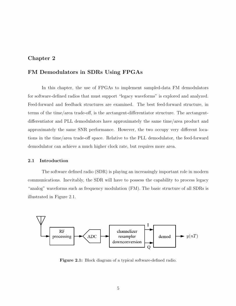
In this chapter, the use of FPGAs to implement sampled-data FM demodulators
for software-defined radios that must support “legacy waveforms” is explored and analyzed.
Feed-forward and feedback structures are examined. The best feed-forward structure, in
terms of the time/area trade-off, is the arctangent-differentiator structure. The arctangent-
differentiator and PLL demodulators have approximately the same time/area product and
approximately the same SNR performance. However, the two occupy very different loca-
tions in the time/area trade-off space. Relative to the PLL demodulator, the feed-forward
demodulator can achieve a much higher clock rate, but requires more area.
2.1 Introduction
The software defined radio (SDR) is playing an increasingly important role in modern
communications. Inevitably, the SDR will have to possess the capability to process legacy
“analog” waveforms such as frequency modulation (FM). The basic structure of all SDRs is
illustrated in Figure 2.1.
Figure 2.1: Block diagram of a typical software-defined radio.
5

The RF signals picked up by the antenna are conditioned prior to sampling. Ideally,
this conditioning is little more than amplification by a low-noise amplifier (LNA). Given
the current state of technology, the conditioning usually consists of additional tasks such
as filtering and frequency translation to an intermediate frequency (IF). After conversion to
the discrete-time domain, the desired frequency band is isolated using a channelizer. The
desired frequency band is translated to complex (or I/Q) baseband and resampled to a
lower, more manageable sample rate. The most efficient SDR designs do not perform the
functions of channelization, downconversion, and resampling separately, but rather perform
these functions jointly by exploiting the properties of multirate processing of bandpass signals
[9].
When the desired signal is a frequency modulated carrier, the complex baseband
signal output by the channelizer/downconversion/resampler process must be demodulated
using a discrete-time FM demodulator. At this point, the system designer is faced with an
interesting design challenge: Is it best to mimic the continuous-time FM demodulator or to
do something else? As Prof. fred harris pointed out, a DSP-based radio is not a digitized
analog radio [10]. With this in mind, this chapter explores the options available to a system
designer when the target platform is a field programmable gate array (FPGA).
The performance of three options for demodulating a frequency modulated signal in
discrete-time processing is explored. For convenience, a sinusoidal modulating signal is used
as the input to the FM modulator. The performance of these modulators is quantified both
as a signal processing system and as a digital system. As a signal processor, the performance
is measured using the output signal-to-noise ratio (SNR) as a function of the input carrier-
to-noise ratio (CNR). As a digital system, the performance is measured using FPGA area
and maximum achievable clock speed. It is shown that efficient feed-forward and feedback
discrete-time algorithms exist and can be implemented on an FPGA.
2.2 Discrete-Time FM
In general, the complex-baseband representation for a frequency modulated carrier is
s(t) = ejφ(t) (2.1)
6
where φ(t) is the instantaneous excess phase that is usually expressed as
φ(t) = 2πfd
∫ t
0
m(x)dx (2.2)
where fd is the frequency deviation with units cycles/s per unit amplitude and m(t) is the
modulating signal. For sinusoidally modulated FM
m(t) = Am cos(2πfmt) (2.3)
so that the instantaneous excess phase is
φ(t) = β sin(2πfmt) (2.4)
where β = Amfd/fm is the modulation index. The 90% (onesided) bandwidth is given by
the well-known Carsons rule [11]
B90 = (β + 1)fm. (2.5)
There are two approaches usually taken to demodulate FM: the limiter-discriminator
and the phase lock loop (PLL) [11]. The limiter-discriminator is based on a derivative
operation followed by an envelope detector. These operations are preceded by a band-
pass limiter to remove amplitude fluctuations. The PLL uses an FM modulator (voltage
controlled oscillator) in a feedback arrangement. Both methods exhibit a threshold effect:1
in general, the PLL demodulator has a lower threshold, indicating better performance, than
the limiter-discriminator.
A discrete-time version of s(t) is formed by sampling Equation 2.1 at T-spaced inter-
vals. (The sample rate is 1/T .) The n-th sample is
s(nT ) = ejφ(nT ) (2.6)
1The FM threshold is the input carrier-to-noise ratio below which the output signal-to-noise ratio is muchworse. This effect can be observed in the SNR performance of the discrete-time PLL in Figure 2.9.
7

where
φ(nT ) = 2πfd
∫ nT
0
m(x)dx
≈ 2πfdTn−1∑k=0
m(kT ). (2.7)
Note that the product fdT plays the role of the discrete-time frequency deviation with units
cycles/sample per unit amplitude. Using m(kT ) = Am cos(2πfmTk) produces
φ(nT ) ≈ 2πfdTn−1∑k=0
Am cos(2πfmTk) (2.8)
≈ 2πfdTAm2πfmT
sin(2πfmTn) (2.9)
where the second approximation is valid for 2πfmT � 1 rads/sample. Retaining the defini-
tion for the modulation index β, the discrete-time version of complex-baseband FM signal
is
s(nT ) = ejβ sin(2πfmTn). (2.10)
Carsons rule for the 90% bandwidth still applies:
B90T = (β + 1)fmT cycles/sample. (2.11)
Discrete-time demodulators can be based on feed-forward processing or on feedback
processing as described below.
2.2.1 Feed-Forward FM Demodulator
The feed-forward demodulator, or limiter-discriminator demodulator, is based on the
definitions for FM signals. Let the demodulator input be
r(nT ) = ejφ(nT ) + w(n) = I(nT ) + jQ(nT ) (2.12)
8
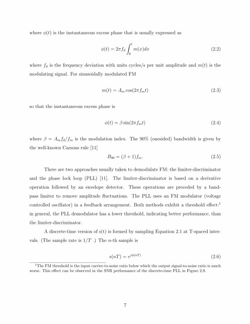
where w(n) is a discrete-time additive noise sequence. If the variance of the additive noise is
small relative to the power of the FM signal, then a good approximation of the instantaneous
excess phase is
φ(nT ) = tan−1 Q(nT )
I(nT ). (2.13)
The desired signal is the time-derivative of the instantaneous excess phase
y(nT ) =d
dttan−1 Q(nT )
I(nT )(2.14)
=I(nT )Q(nT )− I(nT )Q(nT )
I2(nT ) +Q2(nT )(2.15)
where I(nT ) means dI(t)/dt evaluated at t = nT . The same interpretation applies to Q(nT ).
Equations 2.14 and 2.15 suggest the two demodulator structures illustrated in Fig-
ure 2.2. The system illustrated in Figure 2.2 (a) is based on a four-quadrant arctangent
operation. In discrete-time processing, the arctangent is computed using the CoRDiC oper-
ation [12], [13], [14]. As a practical matter, the four quadrant arctangent operation must be
followed by a phase “unwrap” operation (not shown) to remove phase discontinuities. The
phase unwrap function, g(·) may be expressed as
g(x) = [x+ πsign(x)] mod (2π)− πsign(x) (2.16)
when [x + πsign(x)] mod (2π) 6= 0. Note that g(0) = 0 and g(x) = π when [x + πsign(x)]
mod (2π) = 0. The derivative may be computed using an FIR filter as described in Chapter
3 of [15]. The system illustrated in Figure 2.2 (b) is based on the derivative and divide
operations. Again, the derivative operations may be computed using a pair of identical
FIR filters. The divide operation can be implemented with a dedicated hardware divider or
using CoRDiC. The relative performance merits of these two approaches is summarized in
Section 2.3.
9

Figure 2.2: Two feed-forward FM demodulator structures: (a) the arctangent/derivativeprocess suggested by Equation 2.14; (b) the derivative/divide suggested by Equation 2.15.
2.2.2 Feedback FM Demodulator: the Discrete-Time PLL
A discrete-time PLL, suitable for use as an FM demodulator with a complex-baseband
input is illustrated in Figure 2.3. The system described in the next section uses a “propor-
tional-plus-integrator” loop filter whose transfer function is
F (z) = K1 +K2
1− z−1. (2.17)
10
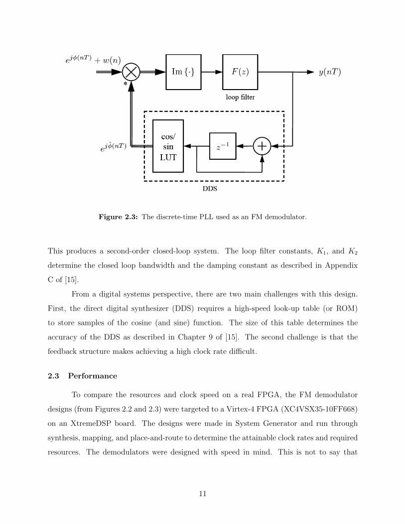
Figure 2.3: The discrete-time PLL used as an FM demodulator.
This produces a second-order closed-loop system. The loop filter constants, K1, and K2
determine the closed loop bandwidth and the damping constant as described in Appendix
C of [15].
From a digital systems perspective, there are two main challenges with this design.
First, the direct digital synthesizer (DDS) requires a high-speed look-up table (or ROM)
to store samples of the cosine (and sine) function. The size of this table determines the
accuracy of the DDS as described in Chapter 9 of [15]. The second challenge is that the
feedback structure makes achieving a high clock rate difficult.
2.3 Performance
To compare the resources and clock speed on a real FPGA, the FM demodulator
designs (from Figures 2.2 and 2.3) were targeted to a Virtex-4 FPGA (XC4VSX35-10FF668)
on an XtremeDSP board. The designs were made in System Generator and run through
synthesis, mapping, and place-and-route to determine the attainable clock rates and required
resources. The demodulators were designed with speed in mind. This is not to say that
11
these designs were pipelined to the maximum level (if there is one) but speed was given
some preference over area.
2.3.1 Arctangent-Differentiate System
The feed-forward demodulator of Figure 2.2 (a), here called the arctangent-differen-
tiate system, was based on an “unwrapped” four-quadrant arctangent and a length-31 FIR
derivative filter. The arctangent operation was realized by the Xilinx CoRDiC Atan block,
which was implemented using building blocks from the Xilinx blockset. An 18-stage CoRDiC
computation was “unrolled” to create a pipelined feed-forward processing unit. The filter
realization was based on the Xilinx LogiCORE FIR Compiler V4.0. The coefficients of
the length-31 derivative filter were computed using the Blackman window following the
technique described in Chapter 3 of [15]. The phase unwrap function was implemented
using basic logic blocks. In this design, the inputs were represented by 16-bit signed fixed
point signals, with 14 bits to the right of the radix point. As the signals propagated through
the design, the expected bit growth was observed, however signals were truncated/rounded
at strategic locations in the design. The dedicated multipliers (DSP48s) were pipelined
to achieve maximum speed. The required resources and clock rate performance have been
summarized in the second row of Table 2.1.
2.3.2 Differentiate-Divide System 1
The feed-forward demodulator of Figure 2.2 (b), here called the differentiate-divide
system 1, was based on the same derivative filters described in Section 2.3.1 and a divide op-
eration based on CoRDiC. The CoRDiC divider was implemented using the Xilinx CoRDiC
block which was based on building blocks from the Xilinx blockset. A 40-stage CoRDiC
computation was “unrolled” to create a pipelined feed-forward processing unit. The input
words were 16-bit fixed point values with 14 bits to the right of the radix point. As before,
the dedicated multipliers were pipelined to achieve maximum speed. The required resources
and clock rate performance have been summarized in the third row of Table 2.1.
12

2.3.3 Differentiate-Divide System 2
The differentiate-divide system 2 was an alternate implementation of the feed-forward
demodulator of Figure 2.2 (b) where the divide operation was based on the Divider Generator
2.0 block. The divide operation was implemented through the Xilinx LogiCORE Divider
v2.0. The derivative filters were identical to those described in Section 2.3.2. The same
finite precision arithmetic was also used. The required resources and clock rate performance
have been summarized in the fourth row of Table 2.1.
2.3.4 Feedback (PLL) System
The feedback demodulator based on the PLL of Figure 2.3 was implemented by a
straight-forward use of addition and multiplication blocks. The DDS was based on two
lookup tables (one each for the cosine and sine) made up of 4096 12-bit words implemented
in the on-chip block RAMs. The System Generator DDS block was not used so that loop
delay could be carefully controlled. The DDS implementation was straightforward with none
of the precision-enhancing tricks such as those found in Chapter 9 of [15]). Consequently,
the SNR performance (described below) suffered somewhat. The input words were 16-bit
fixed point words with 14 bits to the right of the radix point. The loop filter coefficients
and registers were 44-bit fixed point values with 40 bits to the right of the radix point. The
required resources and clock rate performance have been summarized in the fifth row of
Table 2.1.
2.3.5 Comparison
The data presented in Table 2.1 demonstrate that the four designs considered present
a variety of time/area trade-offs. The place each design occupies in this trade-off space is
illustrated in Figure 2.4. Area is quantified using slices and time is quantified using the
period of the equivalent sample period. Sample period was used to remove any ambiguity
regarding the relationship between clock rate and sample rate when pipelining is used. Also
indicated are the time-area products with units slices-ns normalized to the lowest value (that
of the PLL).
13
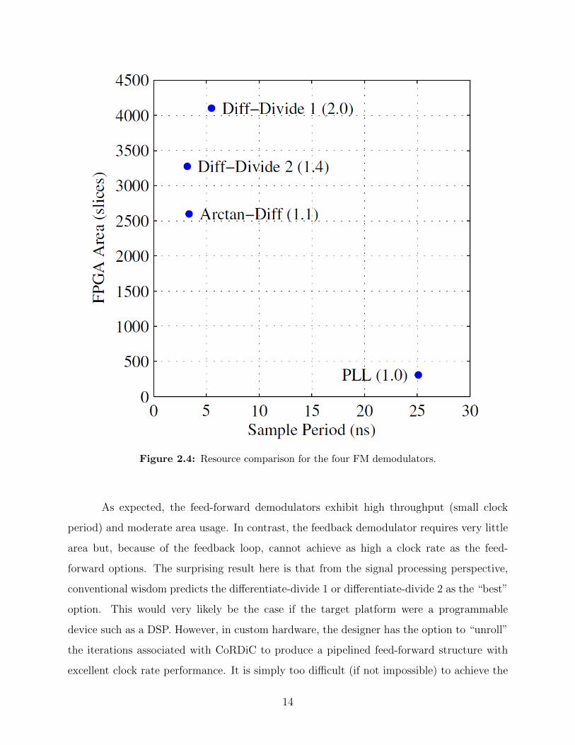
Figure 2.4: Resource comparison for the four FM demodulators.
As expected, the feed-forward demodulators exhibit high throughput (small clock
period) and moderate area usage. In contrast, the feedback demodulator requires very little
area but, because of the feedback loop, cannot achieve as high a clock rate as the feed-
forward options. The surprising result here is that from the signal processing perspective,
conventional wisdom predicts the differentiate-divide 1 or differentiate-divide 2 as the “best”
option. This would very likely be the case if the target platform were a programmable
device such as a DSP. However, in custom hardware, the designer has the option to “unroll”
the iterations associated with CoRDiC to produce a pipelined feed-forward structure with
excellent clock rate performance. It is simply too difficult (if not impossible) to achieve the
14

same pipelining advantage in programmable processors. In the end, the area of the CoRDiC
arctangent is on the order of the area of a single multiplier.
In all cases, the area resources are quite small. This is a result of including only the
basic demodulator functions in the comparison. In a real system, support for channeliza-
tion and input/output must also be considered. In most SDR applications, the FM radio
personality will be one of many radio instantiations on an FPGA of any practically usable
size.
2.3.6 Signal Processing Considerations
The last dimension in the performance space is the signal-to-noise ratio performance
of the demodulators. A test signal was used to perform the SNR tests. The test signal was
m(nT ) = cos(2πfmTn). (2.18)
The modulation index was set to β = 11.5 by using fd = βfm = 11.5fm. The motivation
for using a large modulation index is to explore the performance of wideband FM, which is
more challenging than narrowband FM. The performance relative to sample rate was also
explored. This experiment showed that PLL performance improves as sample rate increases,
whereas the performance of the feed-forward FM demodulators is less dependent on sample
rate, as long as the derivative filters are properly designed.
First, the case fmT = 0.01 cycles/sample was considered. In this case fdT = 0.115
cycles/sample. The discrete-time Fourier transform (DTFT) of the resulting FM signal is
shown in Figure 2.5. Note the presence of the spectral lines whose heights are proportional
to Bessel functions Jk(β) [11]. The bandwidth given by Carsons Rule is
B90T = (β + 1)fmT = 0.125 cycles/sample (2.19)
which corresponds to the frequency at which the spectral lines are about 35 dB below the
unmodulated signal. Also shown in Figure 2.5 is the DTFT of the filter applied at the
modulator input. A length-51 FIR filter was used to represent the performance of polyphase
15

Figure 2.5: The spectral representation of the discrete-time FM modulated signal (solid line)and the channelizing filter (dashed line) for fmT = 0.01 and fdT = 0.115.
channelizer that precedes the demodulator in most SDR applications – see Figure 2.1 and
references [15, Chap. 9], [9], [16].
An example of the output of the arctangent-differentiate demodulator is illustrated
in Figure 2.6 (a) for an input carrier-to-noise ratio (measured before the IF filter) of 10 dB.
Observe the presence of large “spikes” caused by abrupt phase changes in the noisy signal.
These spikes are the primary cause of signal-to-noise ratio (SNR) performance degradation
in feed-forward FM demodulators. Motivated by this phenomenon, the outputs of the arith-
metic processors in the FPGA were designed to saturate at a level approximately 1.5 times
the amplitude of the noise-free output. An example of the output of the PLL demodulator
is illustrated in Figure 2.6 (b). The dominant cause of SNR performance degradation in
16

Figure 2.6: Examples of distortion due to noise in the two types of demodulators: (a) “FMclick” or “spike” distortions in the feed-forward FM demodulator; (b) “Cycle slips” in the PLLdemodulator.
17

PLL-based demodulators is the phenomenon of “cycle slips”. In Figure 2.6 (b), the largest
“cycle slips” can be seen from sample indices 0 to 250 and from 600 to 900. In these ranges,
the noise causes the PLL to lose sync with the original sinusoid, which shows up as erroneous
oscillations in the output.
Table 2.1: A summary of the required resources and clock rate performance of four FMdemodulator designs. For each design, the sample rate is equal to the clock rate. Totals
and percentages are based on available resources in a Virtex-4 SX35 FPGA.
Design Max. Clock Slices/Total Flip-Flops/Total BRAMs/Total DSP48s/TotalArctan-Diff 297.8 MHz 2,598/15K (16%) 3,492/31K (11%) 0/192 (0%) 29/192 (15%)Diff-Divide 1 182.1 MHz 4,103/15K (26%) 6,291/31K (11%) 0/192 (0%) 37/192 (19%)Diff-Divide 2 314.0 MHz 3.275/15K (21%) 4,402/31K (14%) 0/192 (0%) 34/192 (17%)PLL 39.8 MHz 307/15K (1%) 117/31K (1%) 6/192 (3%) 2/192 (1%)
To explore the influence of sample rate on performance, the sample rate was increased
by 4 while keeping the modulation index β fixed at 11.5. This was accomplished using
fmT = 0.0025 cycles/sample and fdT = 0.02875 cycles/sample. The 90% bandwidth using
Carsons rule is
B90T = (β + 1)fmT = 0.03125 cycles/sample. (2.20)
An illustration of the resulting FM modulated signal and the length-101 channelizing filter
are illustrated in Figure 2.7.
SNR experiments were conducted using a combination of Matlab/Simulink and Sys-
tem Generator as illustrated in Figure 2.8. In Matlab/Simulink, the following steps were
performed:
1. The test signal was generated and frequency modulated.
2. Noise samples were added to the FM signal. The noise was a sequence of uncorrelated
zero-mean Gaussian random variables.
3. The noisy FM signal was filtered by the IF filter.
In System Generator, the noisy, filtered, FM signal was demodulated using the four de-
modulator designs described previously. The resulting demodulator output was transferred
18

Figure 2.7: The spectral representation of the discrete-time FM modulated signal (solid line)and the channelizing filter (dashed line) for fmT = 0.0025 and fdT = 0.03125.
Figure 2.8: A block diagram illustrating the simulations used to generate the performanceresults.
19

back to Matlab/Simulink for calculation of the output signal-to-noise ratio. Note that the
performance of the FM demodulators was simulated in System Generator to capture all the
effects of finite precision and signal routing associated with the FPGA implementation.
Figure 2.9: The SNR performance of the four FM demodulators described in Section 2.2 forfmT = 0.01 : the differential/divide feed-forward demodulator of Figure 2.2 (b), the arctan-gent/differential (or CoRDiC/differential) feed-forward demodulator of Figure 2.2 (a), and thePLL-based feedback demodulator of Figure 2.3.
The SNR performance of the four FM demodulators for fmT = 0.01 and fmT = 0.0025
are plotted in Figures 2.9 and 2.10, respectively. The three feed-forward demodulators used a
length-31 derivative filter (although this was overkill for the fmT = 0.0025 case). The arctan-
gent operation was implemented using an 18-stage CoRDiC algorithm. The CoRDiC-based
20

Figure 2.10: The SNR performance of the four FM demodulators described in Section 2.2for fmT = 0.0025: the differential/divide feed-forward demodulator of Figure 2.2 (b), thearctangent/differential (or CoRDiC/differential) feed-forward demodulator of Figure 2.2 (a),and the PLL-based feedback demodulator of Figure 2.3.
divide operation used a 40-stage algorithm. For fmT = 0.01, the PLL-based demodula-
tor had a closed-loop bandwidth of 0.25 cycles/sample and a damping constant of 1. For
fmT = 0.0025, the PLL-based demodulator had a closed-loop bandwidth of 0.2 cycles/sample
and a damping constant of 1.
Some general observations are in order. First, the SNR performance of the three
feed-forward options is essentially the same. This implies that the improvements in FPGA
time/area (see Figure 2.4) are not achieved at the expense of SNR performance. Second, the
SNR performance of the PLL FM demodulator is about 2 to 3 dB inferior to that of the feed-
forward demodulators for fmT = 0.01. The performance gap closes to approximately 1 dB
21
for fmT = 0.0025. This behavior confirms the notion that the SNR performance of the PLL
demodulator improves as the oversample factor increases. (The differences between the SNR
performance of the feed-forward demodulators in Figures 2.9 and 2.10 are due to the different
IF filters used.) The SNR performance of the PLL demodulator “flattens” at high input
CNR. This is due to quantization effects resulting from how the DDS look-up tables were
implemented. At high CNR, the quantization effects dominate the SNR performance. Hence
improving the input CNR does improve output SNR. The point at which this phenomenon
occurs improves with the use of more sophisticated DDS architectures.
2.4 Conclusions
This chapter has explored the use of FPGAs to implement sampled-data FM de-
modulators for software-defined radios that must support “legacy waveforms.” Feed-forward
and feedback structures were examined. The performance of these structures, both as a
digital system and as a signal processor were quantified. The best feed-forward structure,
in terms of the time/area trade-off was, surprisingly, the arctangent-differentiator structure.
Simulation results showed that the hardware advantages, relative to the other feed-forward
demodulators, were not achieved at the expense of SNR performance. The arctangent-
differentiator and PLL demodulators have approximately the same time/area product and
approximately the same SNR performance. However, the two occupy very different locations
in the time/area trade-off space. In applications that need to maximize clock rate (minimize
sample period), the arctangent-differentiator is the best choice. In applications that need to
minimize area, the PLL demodulator is the best choice.
22

Chapter 3
Library Based Design
3.1 Introduction
This chapter investigates library based design for demodulators in FPGAs. Key
considerations for building an initial block set will be explored. A pair of demodulators are
built to explore the types of blocks needed in the design space. The block library creation
is then discussed, based on insights gained from the two demodulator designs. Finally, the
library is tested and verified in actual demodulator designs.
3.2 Considerations
Before constructing a block set, a few key factors should be considered. These include
choosing a granularity level and deciding how the blocks will interface with each other. The
decisions made in these two categories will affect the types of blocks that will be created for
the library.
3.2.1 Granularity
In designing a library of cores, it is important to establish a granularity level. There is
a choice to be made between a fine-grained block set vs. a more coarse-grained block set. For
instance, a very fine-grained library might contain low-level gates, such as 2-input AND gates,
XOR gates, etc. At the other end of the spectrum, a very coarse-grained approach (in the
context of radio receivers) could be a library that was made up of full-blown demodulators,
one for PCM/FM, one for QPSK, etc. Ideally, a library targeting the design of demodulators
would contain blocks at a level of granularity somewhere between these two extremes. This
raises the question: what level of granularity is most appropriate for a library of blocks
targeting demodulator design?
23

There are distinct advantages and disadvantages for both fine- and coarse-grained
blocks. In the case of a fine-grained block library, one advantage is that the resulting design
space is nearly limitless, that is, by using very low-level blocks almost any design may be
realized. The larger the design space for a particular block library, the better, because this
means that the library will be highly reusable. Another advantage of fine-grained libraries is
that by using relatively simple blocks, block usage becomes very straightforward with little
to no documentation required to explain block behavior. This also increases reusability: the
easier it is to use a block, the more likely a designer will actually understand how to use
it, and reuse it, in their designs. The main disadvantage to fine-grained libraries is that it
takes many blocks to create an entire design. This causes design time to be lengthy, with
the possibility of many design pieces being unnecessarily built repeatedly.
By using coarse-grained block libraries the designer can avoid the high design times
required when using fine-grained blocks. This is because designs can be created with rel-
atively few blocks. This is one of the most attractive features of coarse-grained libraries.
Another advantage is that by providing a library of these optimized blocks that have been
tested and verified by use in many other designs, the designer can worry less about the
low-level details of each block. Any bugs in the blocks will have been found and flushed
out, allowing the designer to focus less on debugging, which can often be a lengthy and te-
dious task. Although the block itself may not be defective, problems arise in coarse-grained
libraries when parameter values are incorrectly set or assumed. Parameters in this context
refer to properties within a block which can be set and which can change the behavior of
the block. When dealing with coarse-grained libraries, parameterization is often essential to
enable reuse. For instance, an 18×18-bit multiplier block is an excellent choice for multi-
plying two 18-bit numbers, but what if an algorithm calls for the multiplication of two 9-bit
numbers? Or two 32-bit numbers? It may be possible for the 18×18-bit multiplier block to
be used in these cases, but it would probably not provide a very efficient implementation. A
more reusable block might be a parameterizable multiplier, where the bit widths could be
set manually, and the implementation tailored to the input widths. While parameters allow
coarse-grained blocks to be more reusable, blocks with many parameters can be confusing
for a designer and without proper documentation, the potential reusability of the block is
24

lost. Put simply, if designers cannot understand how to use a block, they will not use it.
Instead they will make their own version of the block that they can understand. For this
reason, it is essential for coarse-grained block libraries to include documentation for the block
set to be viably reusable. Even with highly-parameterized and well-documented blocks, li-
braries that are too coarse-grained suffer from the disadvantage that the design space is
restricted. Coarse-grained blocks are only reusable in a certain set of designs, and the more
coarse-grained the blocks are, the more restricted that set becomes.
3.2.2 Interfacing
Another question that arises in the use of a block library is “how will the blocks
interface with one another?” Generally, there are two options: either the blocks are created
in such a way as to fit together seamlessly, or such is not the case and some interfacing logic
is required. Both approaches are valid and both have pros and cons. These two approaches
can be compared and contrasted in the context of HMFlow and Ogre, two design flow tools
that are currently being researched at the Configurable Computing Lab at BYU.
HMFlow (based on work in [17] and [18]) takes the first approach, drawing its block
library from the Xilinx System Generator blockset where the blocks are designed to hook
together without any additional logic. This is a good feature, but the blocks themselves are
at a low enough granularity level to make large demodulator designs unruly to manage and
lengthy to design. System Generator provides subsystems to help consolidate these lower
level blocks into coarser-grained virtual blocks, but unfortunately this feature of is not yet
supported by HMFlow. Another way that System Generator attempts to allow coarser-
grained blocks is through the importing of external cores, through the Black Box block.
While this can be done successfully, it is somewhat difficult to properly incorporate foreign
cores into complex System Generator designs. An extra configuration file, which usually
requires user editing, must accompany each Black Box and extra System Generator blocks
may be required to interface the external core to the rest of the design appropriately.
Ogre ([19],[20]), on the other hand, relies on automated interface synthesis techniques
to provide valid connections between any two cores, given the source and meta-data descrip-
tion files for each block. Automating the creation of interfacing logic allows the use of blocks
25

that are more coarse-grained, which in turn, requires fewer blocks per design and speeds
up the design time. The drawback to this approach is that for this interface synthesis to
work, an XML description file is required for every block in the library. At this point, much
of the information needed in this file can be inferred from the core’s source, however some
information may be required by the block creator to fully describe the core’s behavior.
3.3 Base Radios
To better understand what types of blocks are used in radio systems and how best
to parameterize a building block library, a few radio demodulators were first built manually
using Xilinx System Generator. This experience was also to help better understand the most
appropriate level of granularity for a library of demodulator building blocks.
3.3.1 QPSK
interpolator
TED
decision
PED
matched filter
TED
loop filter
NCO
PED
loop strobe
NCOloop filter
DDS
Figure 3.1: The QPSK demodulator. Single lines represent real-valued signals; double linesrepresent complex-valued signals.
26
The QPSK demodulator, with a pll-type demodulation, is representative of a whole
class of radios. It was the first radio built and is shown in Figure 3.1.
The demodulator loop was designed to run at two samples/symbol. Most of the radio
consists of multipliers and adders but there are a few blocks which required more complex
functionality including the front end downsampling filters and the Direct Digital Synthesizer
(DDS). The Xilinx CoreGen Finite Impulse Response (FIR) filter generator was used to
create the front-end filters. The DDS required the hand implementation of two 4096x12-bit
look-up tables for generation of sine and cosine values.
3.3.2 PCM/FM
derivative
filter
derivative
filter
delay
divide
+
−
delay
resampling
filterinterpolator
TED
loop
filterNCO
decision
Bit Sync
Limiter/Discriminator
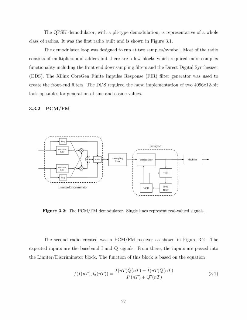
Figure 3.2: The PCM/FM demodulator. Single lines represent real-valued signals.
The second radio created was a PCM/FM receiver as shown in Figure 3.2. The
expected inputs are the baseband I and Q signals. From there, the inputs are passed into
the Limiter/Discriminator block. The function of this block is based on the equation
f(I(nT ), Q(nT )) =I(nT )Q(nT )− I(nT )Q(nT )
I2(nT ) +Q2(nT )(3.1)
27

where I(nT ) and Q(nT ) are the time derivatives of I and Q, respectively. In our system, this
block was created using two 31-length FIR filters from CoreGen for the derivative filters and
a CoreGen Divide Generator v2.0 for the division. The output of the Limiter/Discriminator
block is fed into a resampling filter, a low pass filter which also downsamples the signal.
This block was generated using a CoreGen FIR Filter as well. The next block, the area
labeled “Bit Sync” in Figure 3.2, consists of blocks that are very similar to those in the
QPSK receiver (see Figure 3.1). Due to the similarities, most of the components in the Bit
Sync were able to be reused from the QPSK design.
3.4 Creating a Building Block Library
Based on the experience gained in the construction of the two previously described
radios, a building block set was next designed to target the construction of many radio re-
ceivers. These radio receiver personalities include QPSK, Offset QPSK, PCM/FM, 16QAM,
8PSK, and 16APSK, although other desired constellations may also be possible with slight
adjustments. The creation of the block set took advantage of the fact that there are many
recurring blocks in these different radio types. These recurring blocks include interpola-
tors, timing error detectors (TEDs), phase error detectors (PEDs), loop filters, direct digital
synthesis (DDS) blocks, and numerically controlled oscillators (NCOs). Each block was pa-
rameterized to make it reusable in a variety of radio personalities. A list of the created
blocks in the block set and their parameters is given in Table 3.1.
In addition to the parameterization reflected in Table 3.1, multiple versions of each
block were also designed which differ in the level of pipelining they contain. Thus, for
each block there are mostly combinational versions as well as heavily pipelined versions
to facilitate different radio requirements. A list of the different block versions and their
timing/area characteristics can be found in Table 3.4. All blocks in the library exist as
VHDL designs.
28

Table 3.1: Sample Blocks from Block Set
Block Variations Parameters
Timing Error Detector (TED) early-late numInputszero-crossing samplesPerSymbolgardner
Interpolator farrowcubic
Loop Filter first order accumulationWidthsecond order loopBandwidth
dampingFactorphaseDetectorGainddsGainsamplesPerSymbollatencykPrecision
Numerically Controlled Oscillator (NCO) samplesPerSymbolCalculate Mu samplesPerSymbolDirect Digital Synthesizer (DDS) phaseOffset
gainromAddressWidth
Complex RotatePhase Error Detector(PED)
3.5 Radio Construction Using the Block Library
3.5.1 QPSK
For initial testing and verification of the block set, two QPSK radios were manually
constructed using the block set previously described. Both radios targeted a 5M bit data
rate (2.5M symbols/sec). The first was designed to use the lowest possible clock rate and
therefore used only combinational versions of the library blocks. The second used the highly
pipelined versions of the library blocks and thus ran at a much higher clock rate. These thus
represented the two extremes in terms of clock rate possible for this QPSK demodulator.
Figure 3.1 shows the blocks that were used and how they were connected for both designs.
The combinational version ran at 5MHz (2.5M symbols/sec × 2 samples/symbol is
5M samples/sec to be processed). Connecting the blocks for the combinational QPSK was
29
very straightforward. The pipelined QPSK ran at 75MHz (15 cycles/sample) and represented
the other extreme in terms of clocking.
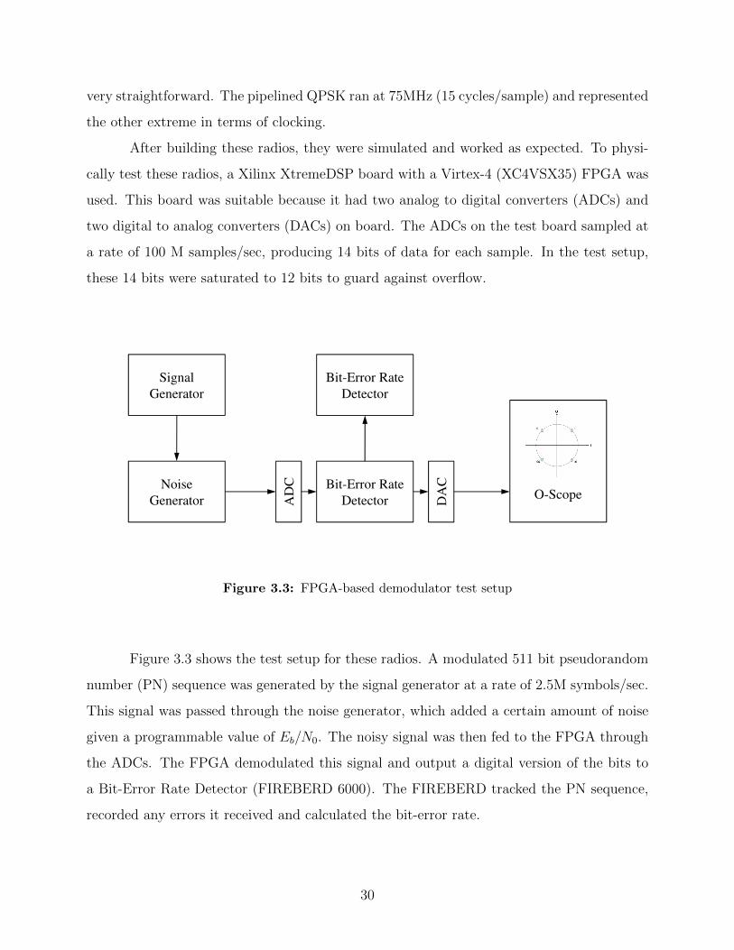
After building these radios, they were simulated and worked as expected. To physi-
cally test these radios, a Xilinx XtremeDSP board with a Virtex-4 (XC4VSX35) FPGA was
used. This board was suitable because it had two analog to digital converters (ADCs) and
two digital to analog converters (DACs) on board. The ADCs on the test board sampled at
a rate of 100 M samples/sec, producing 14 bits of data for each sample. In the test setup,
these 14 bits were saturated to 12 bits to guard against overflow.
Signal
Generator
Bit-Error Rate
Detector
Noise
Generator
Bit-Error Rate
DetectorAD
C
DA
C
O-Scope
Figure 3.3: FPGA-based demodulator test setup
Figure 3.3 shows the test setup for these radios. A modulated 511 bit pseudorandom
number (PN) sequence was generated by the signal generator at a rate of 2.5M symbols/sec.
This signal was passed through the noise generator, which added a certain amount of noise
given a programmable value of Eb/N0. The noisy signal was then fed to the FPGA through
the ADCs. The FPGA demodulated this signal and output a digital version of the bits to
a Bit-Error Rate Detector (FIREBERD 6000). The FIREBERD tracked the PN sequence,
recorded any errors it received and calculated the bit-error rate.
30

0 2 4 6 8 10 12 1410
−8
10−6
10−4
10−2
100
Eb/N
0 (dB)
P b
TheoreticalQPSK (Combinational)QPSK (Pipelined)
Figure 3.4: QPSK bit-error rates
The combinational QPSK was tested first and its bit-error rate curve was generated.
After successfully testing the combinational version, the pipelined QPSK was inserted in the
same wrapper and also tested. It worked properly without any problems. Figure 3.4 shows
the bit-error rates for these radios vs. the theoretical bit-error rate for QPSK. Note that the
bit-error rates are not the same for both versions. The reason is that slightly different word
bit-widths were used in the two implementations.
Table 3.2: Clock Rates and Resource Usage
Combination QPSK Pipelined QPSK
Clock Rate 5 MHz 75 MHz
Cycles/sample 1 15
Slices 1,951 (13%) 1,974 (13%)
DSP48s 67 (35%) 66 (34%)
31

3.5.2 Other Radio Personalities and FPGA Targets
With the block set created, the process of creating other QAM systems was trivial
(PSK is considered here as a special case of QAM). The block library was used, in conjunction
with the Ogre tool, to produce several more radios, as shown in Table 3.3. Seven different
QPSK demodulators were implemented using different block variations. The timing charac-
teristics of these seven designs varied between 1 clock cycle/sample up to 18 cycles/sample.
A BPSK design, an 8PSK design, and a 16QAM design were also created from the block set
to show that the design space was not limited to only QPSK. The designs were very similar
to the QPSK designs described above, with only a few changes in parameters, specific to
each constellation and system.
Table 3.3: Radio Demodulators Created with Block Set and Ogre. See Table 3.4 for list ofblock versions used.
Radio Type Cycles/Sample Design Details
Many different block variations
QPSK(×7) 1 to 18 used in different combinations
to create 7 different designs
BPSK 1 Combinational blocks used
8PSK 17 Pipelined (multi-cycle) blocks used
16QAM 1 Combinational blocks used
In addition to the QAM demodulators built, a PCM/FM demodulator was also con-
structed. This radio used Xilinx Core Generator blocks in addition to the blocks from the
block set described above. This radio will be discussed in more detail in Chapter 4 and
represents a non-QAM demodulator which can be built from the block set with only minor
additions.
During testing a Virtex-4 FPGA was used, although other FPGAs are easily tar-
getable with the block set. Some of the library blocks (especially the pipelined ones) used
32

Xilinx DSP blocks and/or Xilinx Core Generator blocks. Because of this, some designs cre-
ated using the library blocks may be Xilinx-specific, but others will be easily ported to other
vendors’ FPGA platforms.
33
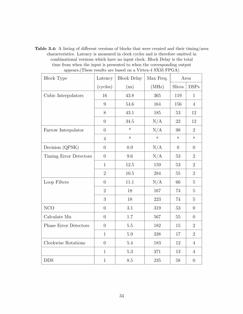
Table 3.4: A listing of different versions of blocks that were created and their timing/areacharacteristics. Latency is measured in clock cycles and is therefore omitted in
combinational versions which have no input clock. Block Delay is the totaltime from when the input is presented to when the corresponding output
appears.(These results are based on a Virtex-4 SX35 FPGA)
Block Type Latency Block Delay Max Freq. Area
(cycles) (ns) (MHz) Slices DSPs
Cubic Interpolators 16 43.8 365 119 1
9 54.6 164 156 4
8 43.1 185 53 12
0 34.5 N/A 22 12
Farrow Interpolator 0 * N/A 98 2
4 * * * *
Decision (QPSK) 0 0.9 N/A 0 0
Timing Error Detectors 0 9.6 N/A 53 2
1 12.5 159 53 2
2 10.5 284 55 2
Loop Filters 0 11.1 N/A 66 5
2 18 167 74 5
3 18 223 74 5
NCO 0 3.1 319 53 0
Calculate Mu 0 1.7 567 55 0
Phase Error Detectors 0 5.5 182 15 2
1 5.9 338 17 2
Clockwise Rotations 0 5.4 183 12 4
1 5.3 371 13 4
DDS 1 8.5 235 58 0
34
Chapter 4
Rapid Prototyping of PCM/FM Demodulators in FPGAs
This chapter describes the use of two efficient FPGA design flows developed at BYU
to design and implement PCM/FM demodulators. The first, called Ogre, exploits the notion
of reuse by taking advantage of a library of specially designed cores parameterized by XML
metadata. A judicious choice of library cores, targeted to signal processing functions common
to sampled data modulators and demodulators, reduces the design and test cycle time. This
is demonstrated by using the tool to construct rapid prototypes of one of three different
versions of an FM demodulator and show that the bit error rate performance is comparable
to demodulators on the market today. Another tool, HMFlow, is also presented which
reuses hard macros (previously implemented cores) to decrease the implementation time of
an entire design. The flow is applied to a FM demodulator design and is shown to speed up
implementation while sacrificing some performance when compared with the standard flow.
4.1 Introduction
As discussed in Chapter 1, there are challenges in developing communication systems
with FPGAs. Design and test processes can be lengthy and tedious, but design productivity
can be increased through reuse [19]. One way to apply reuse (or using again) is to leverage
previous FPGA designs in much the same way a computer programmer leverages subroutines
available in a code library. The key to reuse in this case is a library of cores that offer
sufficient flexibility to be useful and are not too small or too large, like the blocks presented
in Chapter 3. Another way to apply reuse is to a single design which may go through
many iterations. In this case, implementation information (previous placement and routing
decisions) can be saved in initial runs and reused in later runs to avoid unnecessary work,
decreasing implementation time.
35

To address the FPGA development challenges, the Configurable Computing Labora-
tory at Brigham Young University has developed two tools that enable rapid prototyping of
radios. The first tool, called Ogre ([19],[20]), is a design flow for FPGAs that exploits the
library of parameterizable cores presented in Chapter 3. Each core is also accompanied by
XML metadata providing a description of the core. The Ogre tool flow leverages this meta-
data to intelligently interface cores which have been connected in a design. The second tool
is called HMFlow ([17],[18]) and is a design flow that is able to preserve FPGA placement
and routing data, through hard macros, and use this data to speed up subsequent design
implementations. The block set for HMFlow is drawn from Xilinx System Generator, upon
which the system is currently based.
This chapter reports on the application of the Ogre and HMFlow tools to design
PCM/FM demodulators. The design flows and testing are described in the following sections.
Laboratory experiments show that the Ogre design flow is able to produce good PCM/FM
demodulators in a matter of hours without sacrificing performance. Experimental results
with HMFlow show that implementation time can be sped up significantly with some loss of
design performance.
4.2 Basic PCM/FM Design
The basic outline of the PCM/FM demodulator is illustrated in Figure 4.1. The
1 Mbit/s PCM/FM signal at an IF of 70 MHz is presented to an ADC sampling at 100
Msamples/s. The sampled signal is translated to I/Q baseband using a discrete-time quadra-
ture mixer. The I/Q baseband samples are downsampled to 20 Msamples/s and presented
to the FM demodulator. The FM demodulator output is downsampled to 4 Msamples/s to
produce a PCM pulse train at 4 samples/bit. Timing synchronization is performed by a tim-
ing synchronization PLL. The target platform for this design is the Nallatech XTremeDSP
board illustrated in Figure 4.2.
Three options for the FM demodulator were explored. These three demodulation
techniques were the same ones presented in Chapter 2. The block diagrams are repeated
here in Figure 4.3 for convenience. The main purpose of examining these three demodulation
techniques in Chapter 2 was that of comparing SNR performance and FPGA implementation
36

Figure 4.1: PCM/FM demodulator block diagram, divided into sections based on clockdomains.
Figure 4.2: The target platform for the PCM/FM demodulator: the Xilinx/NallatechXtremeDSP board.
37
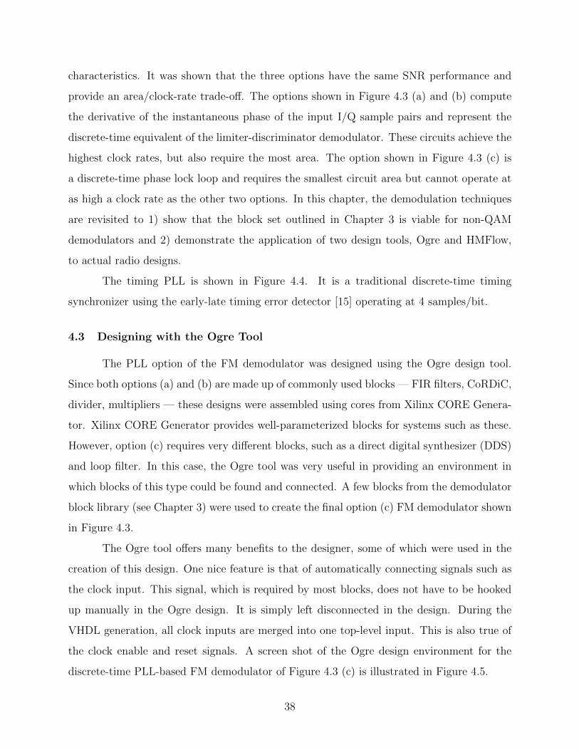
characteristics. It was shown that the three options have the same SNR performance and
provide an area/clock-rate trade-off. The options shown in Figure 4.3 (a) and (b) compute
the derivative of the instantaneous phase of the input I/Q sample pairs and represent the
discrete-time equivalent of the limiter-discriminator demodulator. These circuits achieve the
highest clock rates, but also require the most area. The option shown in Figure 4.3 (c) is
a discrete-time phase lock loop and requires the smallest circuit area but cannot operate at
as high a clock rate as the other two options. In this chapter, the demodulation techniques
are revisited to 1) show that the block set outlined in Chapter 3 is viable for non-QAM
demodulators and 2) demonstrate the application of two design tools, Ogre and HMFlow,
to actual radio designs.
The timing PLL is shown in Figure 4.4. It is a traditional discrete-time timing
synchronizer using the early-late timing error detector [15] operating at 4 samples/bit.
4.3 Designing with the Ogre Tool
The PLL option of the FM demodulator was designed using the Ogre design tool.
Since both options (a) and (b) are made up of commonly used blocks — FIR filters, CoRDiC,
divider, multipliers — these designs were assembled using cores from Xilinx CORE Genera-
tor. Xilinx CORE Generator provides well-parameterized blocks for systems such as these.
However, option (c) requires very different blocks, such as a direct digital synthesizer (DDS)
and loop filter. In this case, the Ogre tool was very useful in providing an environment in
which blocks of this type could be found and connected. A few blocks from the demodulator
block library (see Chapter 3) were used to create the final option (c) FM demodulator shown
in Figure 4.3.
The Ogre tool offers many benefits to the designer, some of which were used in the
creation of this design. One nice feature is that of automatically connecting signals such as
the clock input. This signal, which is required by most blocks, does not have to be hooked
up manually in the Ogre design. It is simply left disconnected in the design. During the
VHDL generation, all clock inputs are merged into one top-level input. This is also true of
the clock enable and reset signals. A screen shot of the Ogre design environment for the
discrete-time PLL-based FM demodulator of Figure 4.3 (c) is illustrated in Figure 4.5.
38

Figure 4.3: The options for the FM demodulator.
39

Figure 4.4: Detailed block diagram of the bit timing synchronization PLL.
Along with merging common inputs, such as the clock, the Ogre tool generates a
state machine to enable every block at the correct time. It does this by creating a schedule,
based on information from the XML metadata, of when every block requires its inputs and
when each blocks outputs are ready. Once this schedule is created, VHDL is generated to
enable the validIn port for each block at the appropriate time. This feature is and has been
especially useful for pipelining designs which need to run at higher clock rates. The designer
may simply add registers anywhere in the design for timing closure to be met. These registers
are taken into account by the Ogre tool when the schedule is created so that the data in
the design still flows appropriately. In this way, the functionality of the original design is
maintained while allowing the design to be clocked at much higher rates. In the PLL option
design, this feature was not necessary due to the simplicity of the schedule. The Ogre tool
was able to figure this out and a state machine was generated which enabled every block on
every cycle.
The parameters on each block in the Ogre tool are easily updated. Figure 4.6 shows
an example of how parameters are set for a certain block, in this case the loop filter block.
40

Once a block in the design is clicked, the current parameters for the block are shown and
can be changed by the user.
The information regarding what parameters exist and what values are valid for each
parameter is found in the XML metadata accompanying each block. Parameters range from
low-level things such as bit widths, to higher-level properties such as loop bandwidth. With
these highly parameterized blocks and the ease of changing parameters, blocks become very
reusable to designers.
Overall, the design process for the PLL option was very much simplified by the use
of Ogre. With the ability to reuse blocks and with Ogre doing much of the work itself, the
design was completed in less than an hour. Of course, this did not represent the complete
design. The generated VHDL had to be integrated with the rest of the system for the FPGA
to be correctly configured. However, the overall design time was reduced due to the use of
Ogre on this section of the design.
When the designer is finished connecting the blocks in their design, the BYU Interface
Synthesis block (which is present in every Ogre design) is clicked to reveal the Ogre VHDL
generation interface. An example is shown in Figure 4.7. Once the output directory is
specified, the designer clicks the Generate button to start the process. It is at this point
that the design is reviewed, the schedule is created, and the top-level VHDL is output along
with VHDL for the state machine. The VHDL for all of the library cores used in the design
is also output to provide the designer with everything necessary to use the new design.
4.4 Laboratory Test Results
Each receiver design was tested in hardware using the setup shown in Figure 4.8.
A tri-mode telemetry transmitter from Quasonix was used as the PCM/FM source. The
data source was set to the internally generated length-(215− 1) PN sequence and the carrier
frequency was set to 2255 MHz. The resulting signal was mixed to 70 MHz using an LO and
mixer as shown. A calibrated noise source was used to set the desired Eb/N0. A modest LNA
was used to set the signal level as required by the ADC. The ADC and FPGA were housed
on the Nallatech/Xilinx XtremeDSP board. The ADC operated at 100 Msamples/s and the
FPGA was a Virtex-4 (XC4VSX35-10FF668). Data and clock were output from the FPGA
41

Figure 4.5: The discrete-time PLL-based FM demodulator of Figure 4.3 (c) using the Ogretool. The VHDL code generated from this model was used in the final design.
Figure 4.6: Parameter window for Loop Filter (loop filter v2 0) library block.
42

board and used by the bit error rate test set to measure the bit error rate performance. A
photograph of the experiment is shown in Figure 4.9.
All three designs used a pair of identical low-pass FIR filters as shown in Figure 4.1.
This filter plays the role of the IF filter in more traditional analog designs and controls
the trade-off between intersymbol interference and noise power [21]. The low-pass filter
was a length-469 FIR filter with an equivalent 3-dB bandwidth of 200 kHz and a transition
bandwidth of 678 kHz. The PLL-based demodulator was a second order loop with a damping
constant of 1 and closed loop bandwidth of 200 kHz.
The test results are summarized by the plots in Figure 4.10. For the three approaches,
the front end and timing synchronization parts of the design (see Figure 4.1) were kept the
same, with only the FM demodulator changing. The tests results show that the discrete-
time versions of the limiter-discriminator shown in Figure 4.3 (a) and (b) produce essentially
the same bit error rate performance. The PLL-based demodulator has a slightly higher bit
error rate: about 0.6 dB inferior to the limiter-discriminator approaches. A reference curve
is also included in Figure 4.10. The reference curve is derived from Figure 2-10 of the 199-06
Telemetry Applications Handbook [21]. The relationship between the BER performance of
the rapid-prototype demodulator and the reference curves shows that the BER performance
of the rapid-prototype is comparable to the commercially available demodulator used to
generate the data in the Telemetry Applications Handbook.
4.5 Designing with HMFlow
Along with being designed with the library blocks, the arctangent demodulator option
(see Figure 4.3 (a)) was designed and implemented using HMFlow. In HMFlow, all of the
designing currently happens in the System Generator environment. At this point, not all
of the System Generator blocks are supported, but a large subset (>75%) are supported.
This was a large enough subset to allow the creation of the arctangent design without any
issues; all blocks that were needed were supported. The one main difference in designing
for HMFlow vs. standard System Generator is that HMFlow does not currently support
the use of subsystems in a design. Normally, subsystems allow System Generator designers
to hierarchically group blocks and even other subsystems to allow better organization and
43

Figure 4.7: Ogre tool VHDL generation.
management of the design. By not supporting this feature, HMFlow designs can quickly
become large and hard to manage. This was the case with the arctangent design.
Despite the design organization shortcomings, HMFlow did deliver on its promise
to decrease implementation time significantly. The results of the comparison between the
standard System Generator flow and HMFlow are shown in Table 4.1. The first noticeable
difference is between the implementation time for the design. HMFlow is about 3× faster
44

Figure 4.8: Laboratory test configuration.
Figure 4.9: A photograph of the laboratory test configuration for the PCM/FM demodulators.
45

Figure 4.10: Laboratory test results for the PCM/FM demodulator using the three FMdemodulators outlined in Figure 4.3. The reference curve is from Figure 2-10 of [21].
Table 4.1: Standard Flow vs. HMFlow
Standard Flow HMFlow
Implementation Time 226 sec 65 sec
Slices 5,799 (37%) 6,136 (40%)
BRAMs 21 (10%) 21 (10%)
DSP48s 2 (4%) 2 (4%)
Max Clock Rate 140 MHz 67 MHz
46
than the standard flow. This gain, however, is achieved at the expense of additional FPGA
resources and a slower maximum clock rate, as the other comparison figures show in Table 4.1.
While the amount of BRAMs and DSP48s remained constant between designs, the number
of slices required increased slightly and the maximum clock rate took a significant hit. The
slight increase in slice use is most likely due to the nature of the hard macro building blocks,
which are fixed in their placement and routing. The standard flow, on the other hand, is
able to combine partially used slices together, even if those slices bridge two or more blocks.
The decrease in clock rate is really where the price is paid for fast implementation. This
design suffered ≈ 2× decrease in maximum clock rate, which is significant. However, while
this lower clock rate may not be sufficient for the final design, the implemented design that
was output by HMFlow was able to be put on an FPGA board and run successfully. This
indicates that this design flow can be very useful for debugging and simulation purposes,
in the case where simulation run times are too long to feasibly run on a desktop computer.
Such a case that applies to demodulators would be determining bit error rate curves, where
many data samples are needed to obtain each point on the curve.
4.6 Ogre and HMFlow
It would be impossible to try to compare and contrast Ogre and HMFlow. While
both aim to increase design productivity, the specific goals and means used to achieve those
goals are very different. This section, then, is not meant to be a comparison between the two
flows, where a definitive “winner” is chosen. Rather, this section summarizes the relative
advantages and disadvantages of these two very distinct flows when compared with the
standard design flow. The intention is to provide insights into these flows from a designer’s
point of view.
To summarize Sections 4.3 and 4.5, the pros and cons of designing with Ogre and
HMFlow are shown below.
• Ogre Advantages
– Graphical interface allows ease of design
– Automatic interface synthesis takes care of low-level control signals
47

Figure 4.11: PCM/FM arctangent-based demodulator design (shown in System Generator)used in testing HMFlow. Part of the design is shown in detail as an example of block granularity.
• Ogre Disadvantages
– XML description necessary for each core in library
• HMFlow Advantages
– Graphical design and simulation through use of System Generator
– Fast implementation using hard macros (≈ 3.5× faster than standard flow)
• HMFlow Disadvantages
– Lower design performance (maximum clock frequency reduce by 1/2)
– Large designs are difficult to manage due to fine-grained blocks
While both flows have weaknesses, both also have strengths that will help a designer
decide in what scenarios it would make sense to use a certain flow. For instance, one of
Ogre’s biggest strength is the abstraction it provides from the low-level details of the blocks
and overall design. A scenario where it would make sense to use Ogre is when the designer
48

is not specifically an FPGA designer, but perhaps has expertise in another field, and wishes
to create a design with blocks familiar to them. A major strength of HMFlow is the very
low design-to-FPGA implementation time. Since a designer can go very quickly from the
design to running it on an FPGA, HMFlow lends itself to debug cycles. During debug cycles,
many small changes are being made and often hardware testing is necessary for complete
verification. When compared with the standard flow, HMFlow excels in this domain.
While Ogre and HMFlow cannot be compared directly, there is one noticeable dif-
ference between the two design experiences: block granularity. The Ogre PLL design was
shown in Figure 4.5, which corresponded to the block diagram in Figure 4.3 (c). The blocks
in the actual Ogre design mapped almost exactly to the block diagram provided. This was in
stark contrast with the HMFlow design, shown in Figure 4.11, which was based on the block
diagram in Figure 4.3 (a)1. While the block diagram was made up of two blocks, the actual
HMFlow design required over 400 System Generator blocks to be completed. The blocks
used in HMFlow are much finer-grained than those available in Ogre and caused an increase
in the number of blocks required and in initial design time. Also, the HMFlow design was so
large as to become very unmanageable for the designer, whereas the Ogre design was much
more easily managed with its coarser-grained blocks and block parameters.
The bottom line is that Ogre and HMFlow are two very different approaches to reuse
and both make valuable contributions to the field of FPGA design productivity. However,
Ogre and HMFlow take very different stances on block granularity and, at least for demod-
ulator design, Ogre’s coarser-grained blocks provide a much better design experience than
the too-fine-grained blocks of HMFlow.
4.7 Conclusion
In this chapter two rapid prototyping environments for FPGAs specifically targeting
demodulators were described. The first tool, called Ogre, reduced the design and test cycle
times by exploiting reuse based on a carefully chosen library of cores. The design environment
was applied to design one of three different versions of a PCM/FM demodulator in less than
1The HMFlow design (Figure 4.11) had additional FIR filters preceding both inputs to the CoRDiCarctangent block (one filter for each input) which are not shown in the block diagram in Figure 4.3 (a).
49
an hour. The other two versions were designed using the same block library with a few
additions. Laboratory tests showed that the bit error rate of the PCM/FM demodulators
was comparable to those available on the market today. Thus, the rapid prototyping of
Ogre did not sacrifice performance. The second tool, HMFlow, approached reuse in a much
different manner, reusing previous implementation work to speed up design implementation.
While performance was sacrificed in the case of FPGA clock rate, preliminary use showed
that HMFlow was successfully used to implement demodulator designs quickly for use on
an actual FPGA. This can be a great benefit for debug cycles and simulation runs where
running on hardware is necessary. One main difference between designing with Ogre and
designing with HMFlow was that Ogre’s blocks were much coarser-grained, which provided
a better design experience than the fine-grained blocks of HMFlow.
50

Chapter 5
Conclusion
This work compared FM demodulator implementations in FPGAs. Library based
design in the context of demodulator design was also discussed and demonstrated. Two
design tools which aim to increase design productivity for FPGAs were examined and applied
to a few FM demodulator designs.
Chapter 2 characterized three distinct FM demodulation techniques for use in soft-
ware-defined radios, specifically for FPGAs. Signal performance was examined and FPGA
implementation was considered for each demodulator. The arctangent-differentiator and PLL
demodulators were found to have similar signal performance characteristics while differing
widely in FPGA resources and clock rate. The arctangent-differentiator technique was found
to be best for applications where higher clock rate is necessary, while the PLL was the best
choice when area minimization is the ultimate goal. These conclusions parallel those found
in [7] where it was shown that for implementation on DSPs, a PLL demodulator takes nearly
twice as much computing time as a mixed feed-forward demodulator.
In Chapter 3 library based design issues, including block granularity, interfacing, and
parameterization, were discussed. Two initial demodulators were created to explore the
design space that the library would target. A set of blocks was created in VHDL with
a granularity level appropriate for demodulator design. Blocks such as interpolators, loop
filters, timing error detectors (TEDs), etc. were found to be recurring cores which were
necessary in several demodulator types and corresponding parameterized blocks were built
and added to the block library. Several QAM demodulators, including QPSK, 8PSK, and
16QAM, as well as a parts of a non-QAM demodulator (PCM/FM) were built using the
block library. Bit error rate curves were presented for two QPSK demodulators built with
51
the library to show functionality. The other systems were also implemented and the output
constellations verified.
Two rapid prototyping environments for FPGAs, Ogre and HMFlow, were presented
in Chapter 4. Ogre was shown to reduce design time by enabling reuse of coarser-grained
blocks, those presented in Chapter 3. These blocks were able to be used due to the automated
interface synthesis provided by Ogre to connect the blocks together. An FM PLL-based de-
modulator was built using Ogre and the two other feed-forward FM demodulators were built
with the block set. These demodulators were used in a larger PCM/FM design which was
tested on an FPGA board to obtain bit error rate curves. The results showed that the
performance of the demodulators was on par with that of currently available PCM/FM de-
modulators. Performance was not decreased significantly when using Ogre and the block
library. HMFlow was also applied to an FM demodulator, the arctangent-differentiator
option. The experimental results showed that HMFlow decreased implementation time sig-
nificantly (≈ 3×), but that this came with some performance and area penalties. In the
demodulator design, the maximum clock rate was reduced by a factor of 2 while the area
increased only slightly (≈ 6%). These results showed that HMFlow may not be entirely ap-
propriate for producing fully-optimized implementations, but that it can serve to save time
in debug cycles and long simulation runs.
52
Bibliography
[1] f. harris, D. Vuletic, and W. Lowdermilk, “How to pack a room of analog FM modulatorsinto a Xilinx FPGA,” Xilinx DSP Magazine, April 2007. 1, 2
[2] H. Kwon and K. Lee, “A novel digital FM receiver for mobile and personal communi-cations,” IEEE Transactions on Communications, vol. 44, no. 11, pp. 1466–1476, Nov.1996. 1
[3] S. Abeysekera, “Bandpass sigma-delta (Σ-∆) architecture based efficient FM demodu-lator for software radio,” in Circuits and Systems, 2004. ISCAS ’04. Proceedings of the2004 International Symposium on, vol. 4, May 2004, pp. IV – 381–4 Vol.4. 2
[4] Z. Wu, N. Zhao, S. Li, and G. Ren, “A novel PCM/FM multi-symbol detection algorithmfor FPGA implementation,” Information Technology Journal, vol. 8, no. 4, pp. 583–588,2009. 2
[5] R. Uusikartano, J. Nittylahti, and M. Renfors, “Area-optimized FPGA implementationof a digital FM modulator,” in Circuits and Systems, 1999. ISCAS ’99. Proceedings ofthe 1999 IEEE International Symposium on, vol. 4, July 1999, pp. 360–362 vol.4. 2
[6] C. Zhang, C. Anderson, and P. Athanas, “All digital FPGA based FM radio receiver,”SDR Forum Technical Conference, 2007. 2
[7] F. Schnyder and C. Haller, “Implementation of FM demodulator algorithms on a highperformance digital signal processor,” Master’s thesis, Nanyang Technological Univer-sity and Hochschule For Technik Rapperswil, 2002. 2, 51
[8] I. Hatai and I. Chakrabarti, “FPGA implementation of a digital FM modem for SDRarchitecture,” in Computers and Devices for Communication, 2009. CODEC 2009. 4thInternational Conference on, Dec. 2009, pp. 1–4. 2
[9] f. harris, Multirate Signal Processing for Communication Systems. Prentice-Hall, 2004.6, 16
[10] ——, “A trap to avoid: A DSP based radio is NOT a digitized analog radio,” inProceedings of the International Symposium on Advanced Radio Technologies. Boulder,CO: Institute for Telecommunications Sciences, 1998. 6
[11] R. Ziemer and W. Tranter, Principles of Communications. Hoboken, NJ: John Wiley& Sons, 2009. 7, 15
[12] J. Volder, “The CORDIC trigonometric computing technique,” IRE Transactions onElectronic Computers, vol. 8, no. 3, pp. 330–334, Sept. 1959. 9
53
[13] J. Walther, “A unified algorithm for elementary functions,” in Proceedings of the AFISSpring Joint Computer Conference, vol. 38. American Federation of Information Pro-cessing Societies, Inc., 1971, pp. 279–385. 9
[14] R. Andraka, “A survey of CORDIC algorithms for FPGA based computers,” in Pro-ceedings of the 1998 ACM/SIGDA sixth international symposium on Field programmablegate arrays, ser. FPGA ’98. New York, NY, USA: ACM, 1998, pp. 191–200. 9
[15] M. Rice, Digital Communications: A Discrete-Time Approach. Upper Saddle River,NJ: Pearson Prentice-Hall, 2009. 9, 11, 12, 13, 16, 38
[16] f. harris, C. Dick, and M. Rice, “Digital receivers and transmitters using polyphasefilter banks for wireless communications,” IEEE Transactions on Microwave Theoryand Techniques, vol. 51, no. 4, pp. 1395 – 1412, Apr. 2003. 16
[17] C. Lavin, M. Padilla, S. Ghosh, B. Nelson, B. Hutchings, and M. Wirthlin, “Usinghard macros to reduce FPGA compilation time,” in Proc. of Intl. Conference on Field-Programmable Logic and Applications (FPL), Milano, Italy, Aug. 31 - Sep. 2 2010. 25,36
[18] C. Lavin, M. Padilla, J. Lamprecht, P. Lundrigan, B. Nelson, and B. Hutchings, “Rapidprototyping tools for FPGA designs: RapidSmith,” in Proc. of International Conferenceon Field-Programmable Technology (FPT), Beijing, China, Dec. 8-10 2010. 25, 36
[19] A. Arnesen, K. Ellsworth, D. Gibelyou, T. Haroldsen, J. Havican, M. Padilla, B. Nelson,M. Rice, and M. Wirthlin, “Increasing design productivity through core reuse, meta-data encapsulation, and synthesis,” in Proc. of Intl. Conference on Field-ProgrammableLogic and Applications (FPL), Milano, Italy, Aug. 31 - Sep. 2 2010. 25, 35, 36
[20] A. Arnesen, “Increasing design productivity for FPGAs through IP-reuse and meta-dataencapsulation,” Master’s thesis, Brigham Young University, 2011. 25, 36
[21] Document 119-06 Telemetry Applications Handbook, Range Commanders CouncilTelemetry Group, 2006. 43, 46
54
Related Documents