Energy Research and Development Division FINAL PROJECT REPORT Flywheel Systems for Utility Scale Energy Storage A Transformative Flywheel Project for Commercial Readiness California Energy Commission Gavin Newsom, Governor January 2019 | CEC-500-2019-012

Welcome message from author
This document is posted to help you gain knowledge. Please leave a comment to let me know what you think about it! Share it to your friends and learn new things together.
Transcript
Energy Research and Development Division
FINAL PROJECT REPORT
Flywheel Systems for
Utility Scale Energy Storage A Transformative Flywheel Project for Commercial Readiness
California Energy Commission
Gavin Newsom, Governor
California Energy Commission
Edmund G. Brown Jr., Governor
January 2019 | CEC-500-2019-012
Month Year | CEC-XXX-XXXX-XXX
PREPARED BY:
Primary Author(s):
Will Sutherland
Matthew Senesky, Ph.D.
Wei-Tai Kwok
Mark Stout
Seth Sanders, PhD.
Ed Chiao
Ramnath Bhat
Amber Kinetics, Inc.
32920 Alvarado-Niles Road, Suite 250
Union City, CA 94587
Phone: 510-474-1000 | Fax:
http://www.amberkinetics.com
Contract Number: EPC-15-016
PREPARED FOR:
California Energy Commission
Ostap Loredo-Contreras
Project Manager
Fernando Piña
Office Manager
ENERGY SYSTEMS RESEARCH OFFICE
Laurie ten Hope
Deputy Director
ENERGY RESEARCH AND DEVELOPMENT DIVISION
Drew Bohan
Executive Director
DISCLAIMER
This report was prepared as the result of work sponsored by the California Energy Commission. It does not
necessarily represent the views of the Energy Commission, its employees or the State of California. The
Energy Commission, the State of California, its employees, contractors and subcontractors make no
warranty, express or implied, and assume no legal liability for the information in this report; nor does any
party represent that the uses of this information will not infringe upon privately owned rights. This report has
not been approved or disapproved by the California Energy Commission nor has the California Energy
Commission passed upon the accuracy or adequacy of the information in this report.

i
PREFACE
The California Energy Commission’s Energy Research and Development Division supports
energy research and development programs to spur innovation in energy efficiency, renewable
energy and advanced clean generation, energy-related environmental protection, energy
transmission and distribution and transportation.
In 2012, the Electric Program Investment Charge (EPIC) was established by the California Public
Utilities Commission to fund public investments in research to create and advance new energy
solutions, foster regional innovation and bring ideas from the lab to the marketplace. The
California Energy Commission and the state’s three largest investor-owned utilities – Pacific Gas
and Electric Company, San Diego Gas and Electric Company and Southern California Edison
Company – were selected to administer the EPIC funds and advance novel technologies, tools
and strategies that provide benefits to their electric ratepayers.
The Energy Commission is committed to ensuring public participation in its research and
development programs which promote greater reliability, lower costs and increase safety for
the California electric ratepayer and include:
• Providing societal benefits.
• Reducing greenhouse gas emission in the electricity sector at the lowest possible cost.
• Supporting California’s loading order to meet energy needs first with energy efficiency
and demand response, next with renewable energy (distributed generation and utility
scale), and finally with clean conventional electricity supply.
• Supporting low-emission vehicles and transportation.
• Providing economic development.
• Using ratepayer funds efficiently.
Flywheel Systems for Utility Scale Energy Storage is the final report for the Flywheel Energy
Storage System project (contract number EPC-15-016) conducted by Amber Kinetics, Inc. The
information from this project contributes to Energy Research and Development Division’s EPIC
Program.
For more information about the Energy Research and Development Division, please visit the
Energy Commission’s website at www.energy.ca.gov/research/ or contact the Energy
Commission at 916-327-1551.
ii
ABSTRACT
The rapid growth of renewable energy sources like photovoltaic solar and wind generation is
driving the need for cost-effective energy storage to capture energy during peak generation
periods so it can be used during peak demand periods. The available solutions today have many
drawbacks including environmental impacts, safety hazards, declining capacity, high
maintenance requirements, limited operating conditions, and grid management constraints. The
kinetic energy storage system based on advanced flywheel technology from Amber Kinetics
maintains full storage capacity throughout the product lifecycle, has no emissions, operates in
a wide range of environmental conditions, and is fully recyclable at the end of life.
This project has advanced the commercial readiness of flywheel technology by enhancing the
product design, confirming performance and reliability, advancing manufacturing processes,
validating the safety criteria, and demonstrating the management of a multi-unit array. More
than 15 flywheel units have been tested with the fleet accumulating more than 38,000 hours of
operating history. Numerous design and manufacturing enhancements emerged from this
process. Multiple failure modes were intentionally induced to experimentally confirm the safety
of the system design. And operations of paralleled flywheel arrays capable of achieving utility-
scale deployment have been demonstrated.
Keywords: Flywheel, Reliable, Safety, Energy Storage, Multi-unit array,
Please use the following citation for this report:
Sutherland, Will, Matthew Senesky, Ph.D, Wei-Tai Kwok, Mark Stout, Seth Sanders, PhD., Ed
Chiao and Ramnath Bhat. 2019. Flywheel Systems for Utility Scale Energy Storage.
California Energy Commission. Publication Number: CEC-500-2019-012.

iii
TABLE OF CONTENTS
Page
PREFACE ..................................................................................................................................................... i
ABSTRACT ............................................................................................................................................... ii
TABLE OF CONTENTS ......................................................................................................................... iii
LIST OF FIGURES .................................................................................................................................. iv
LIST OF TABLES ...................................................................................................................................... v
EXECUTIVE SUMMARY ........................................................................................................................ 1
Introduction ................................................................................................................................................ 1
Project Purpose .......................................................................................................................................... 2
Project Process ........................................................................................................................................... 3
Project Results ........................................................................................................................................... 3
Outreach ...................................................................................................................................................... 4
Benefits to California ................................................................................................................................ 5
CHAPTER 1: The Need for Flywheel Energy Storage ....................................................................... 7
California’s Ambitious Energy Storage Goals ......................................................................................... 7
Flywheels Add Value .................................................................................................................................... 8
Flywheel Energy Storage Can Provide Versatility ............................................................................... 8
Flywheel Energy Storage Delivers Greater Value ................................................................................ 9
Flywheel Energy Storage Unlocks Operation Flexibility ................................................................. 10
CHAPTER 2: Commercial Readiness .................................................................................................. 12
The Starting Point ...................................................................................................................................... 12
Method .......................................................................................................................................................... 12
Results .......................................................................................................................................................... 13
Fleet Operating Data .............................................................................................................................. 13
Energy Storage Capacity ....................................................................................................................... 15
Design Stability and Manufacturability ............................................................................................. 15
Design Validation ................................................................................................................................... 17
Third Party Validation ............................................................................................................................... 20
San Diego Gas and Electric ................................................................................................................... 20
Emerging Power Inc., Subic Bay, Philippines .................................................................................... 22
Hawaiian Electric Company (HECO), Campbell Industrial Park, Hawaii ..................................... 22
Summary .................................................................................................................................................. 23
CHAPTER 3: Safety Validation ............................................................................................................ 25
Test Plan ....................................................................................................................................................... 26
Test Results ................................................................................................................................................. 26
Overspeed Test ....................................................................................................................................... 26
iv
Loss of Vacuum ...................................................................................................................................... 26
Lower Bearing Failure ............................................................................................................................ 27
Upper Bearing Failure ............................................................................................................................ 27
Stub Shaft Failure ................................................................................................................................... 28
Catastrophic Rotor Failure ................................................................................................................... 28
Seismic Event Tolerance ....................................................................................................................... 30
Summary ...................................................................................................................................................... 30
CHAPTER 4: Multi-Unit Arrays ........................................................................................................... 31
System Development ................................................................................................................................. 31
Multi-Flywheel Array Controls ............................................................................................................. 31
Hardware Development ........................................................................................................................ 31
Software Development .......................................................................................................................... 32
Multi-Unit Array Testing ........................................................................................................................... 32
State of Charge Balance ........................................................................................................................ 33
Recovery from Divergence ................................................................................................................... 35
Summary ...................................................................................................................................................... 36
CHAPTER 5: Results of Project ............................................................................................................ 37
Project Goals and Objectives ................................................................................................................... 37
Progress Assessment ................................................................................................................................. 37
Commercial Readiness .......................................................................................................................... 37
Safety Validation .................................................................................................................................... 38
Multi-Unit Array ...................................................................................................................................... 39
Benefits to California Ratepayers ........................................................................................................... 39
Reduce Transmission Congestion and Losses ................................................................................. 39
Transmission and Distribution Upgrade Deferral .......................................................................... 40
Peak Shaving and Energy Arbitrage .................................................................................................... 40
Production Readiness Plan ....................................................................................................................... 40
Technology and Knowledge Transfer .................................................................................................... 41
GLOSSARY .............................................................................................................................................. 42
REFERENCES .......................................................................................................................................... 43
LIST OF FIGURES
Page
Figure ES-1: Amber Kinetics M32 Flywheel .................................................................................. 2
Figure 1: Solar Curtailment Opportunity With Storage ............................................................ 7
Figure 2: Energy Storage Total Cost of Ownership Comparison ........................................ 10
Figure 3: California ISO Revenue Potential ................................................................................ 11
v
Figure 4: Fleet Operating Hours ..................................................................................................... 13
Figure 5: Full Charge/Discharge Cycles ...................................................................................... 14
Figure 6: Operating Hours by Unit Number ............................................................................... 15
Figure 7: M25 Unit Installed in Original Containment Design ............................................ 16
Figure 8: M32 Unit Installed in New Containment Design .................................................... 17
Figure 9: Example of M32 Power and Energy Validation ...................................................... 18
Figure 10: Advanced CNC Machining of High Precision Parts ............................................ 19
Figure 11: Environmental Test Chamber to Validate Temperature Requirements ..... 20
Figure 12: Demo Installation at Subic Bay, Philippines ......................................................... 22
Figure 13: Demo for HECO at Campbell Industrial Park, Hawaii ....................................... 23
Figure 14: Amber Kinetics Central California Test Site ......................................................... 25
Figure 15: Rotor Burst Forensics .................................................................................................... 29
Figure 16: Vault Liner after Burst Test ........................................................................................ 29
Figure 17: Multi-Unit Array System Architecture .................................................................... 32
Figure 18: Enel Multi-Unit Test Array ........................................................................................... 33
Figure 19: Four Unit Array SOC Results ...................................................................................... 34
Figure 20: Four Unit Array Power Tracking .............................................................................. 34
Figure 21: SOC Balance Test (Power) ............................................................................................ 35
Figure 22: SOC Balance Test (State of Charge) .......................................................................... 36
LIST OF TABLES
Page
Table 1: Amber Flywheel Capabilities ................................................................................................. 8
Table 2: Financial Payback Analysis ................................................................................................... 21
1
EXECUTIVE SUMMARY
Introduction
Utility-scale power generation has moved beyond conventional coal-fired, natural gas, nuclear,
and hydroelectric sources. Increasingly, significant amounts of electric power are generated by
renewable sources such as wind, solar, and geothermal. California is at the forefront of this
push to adopt renewable energy resources. On September 10, 2018, California passed Senate
Bill 100, (De León, Chapter 312. 2018), requiring a mix of renewable portfolio standard-eligible
and zero-carbon resources by December 31, 2045, for a total of 100 percent clean energy.
However, generation from these renewable sources does not always align with the demand of
power users. For example, the sun shines brightest in the middle of the day, and the wind blows
when atmospheric conditions align, but not necessarily when there is peak energy demand.
Therefore, energy storage is critical to help align the supply of renewable energy with demand
by storing the energy when it’s cheaper and abundant and using it when it’s in high demand.
California recognizes this need and is driving the investor-owned utilities (IOUs) to invest in
energy storage. Assembly Bill 2514 (Skinner, Chapter 469, 2010) has mandated procuring 1.325
gigawatts (GW) of energy storage by IOUs and publicly-owned utilities by 2020. However, there
is a notable lack of commercially viable energy storage solutions to fulfill the emerging market
for utility scale use. The traditional solution of pumped hydro faces growth challenges from
limited geographic options, environmental impacts, and local resistance. Lithium ion batteries
are an early winner to address growing demand, but this technology faces environmental,
safety, capacity degradation, and operational restrictions that limit its viability as a solution.
Additionally, as electric vehicle use increases, there will be greater competition for Lithium ion
manufacturing capacity. There are other chemical-based solutions under development that
have potential yet are far from perfect. A diversity of technology solutions is necessary to
create a competitive marketplace and address all demands for the utility-scale energy storage
challenge, including the flywheel.
A flywheel is a “mechanical battery” that stores kinetic or moving energy. The basic concept of
a spinning mass is well-established and is found in many mechanical systems such as
automotive engines. High-performance flywheels have been used for uninterruptible power
supply and frequency-regulation applications, which require high power for a short duration.
The flywheel offers long operating life with no capacity degradation. Additionally, flywheels are
capable of many charge/discharge cycles per day (compared to many other energy storage
technologies) without any degradation of performance over time, and they can provide ancillary
services like frequency regulation, offering grid operators more value from an energy storage
device. The technology can be used in a wide range of environmental conditions without using
cooling loads, and there is no risk of fire or chemical discharge from this all-steel, recyclable
product. A long duration flywheel is worthy of consideration for many emerging utility
applications.
End users, such as utilities tend to be conservative with new technologies and require proof of
operation and competitive costs. To make flywheels an option in the market, operational run
time and lower costs are required. Bringing a commercially viable flywheel technology to
market will provide IOUs with an additional energy storage option to choose from; furthermore,
the technology will help to drive down pricing for IOU electricity ratepayers due to its
advantages in optimizing grid management.
2
Project Purpose
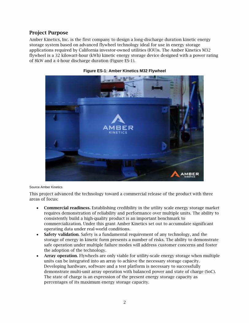
Amber Kinetics, Inc. is the first company to design a long-discharge duration kinetic energy
storage system based on advanced flywheel technology ideal for use in energy storage
applications required by California investor-owned utilities (IOU)s. The Amber Kinetics M32
flywheel is a 32 kilowatt-hour (kWh) kinetic energy storage device designed with a power rating
of 8kW and a 4-hour discharge duration (Figure ES-1).
Figure ES-1: Amber Kinetics M32 Flywheel
Source Amber Kinetics
This project advanced the technology toward a commercial release of the product with three
areas of focus:
• Commercial readiness. Establishing credibility in the utility scale energy storage market
requires demonstration of reliability and performance over multiple units. The ability to
consistently build a high-quality product is an important benchmark to
commercialization. Under this grant Amber Kinetics set out to accumulate significant
operating data under real-world conditions.
• Safety validation. Safety is a fundamental requirement of any technology, and the
storage of energy in kinetic form presents a number of risks. The ability to demonstrate
safe operation under multiple failure modes will address customer concerns and foster
the adoption of the technology.
• Array operation. Flywheels are only viable for utility-scale energy storage when multiple
units can be integrated into an array to achieve the necessary storage capacity.
Developing hardware, software and a test platform is necessary to successfully
demonstrate multi-unit array operation with balanced power and state of charge (SoC).
The state of charge is an expression of the present energy storage capacity as
percentages of its maximum energy storage capacity.
3
Successfully completing these efforts moved the Amber Kinetics flywheels toward commercial
viability.
Project Process
The project activities were structured into three different groups: commercial readiness, safety
validation, and multi-unit array operation. The three activities were independent but equally
important in demonstrating a commercially viable technology for utility-scale energy storage.
Commercial Readiness
This effort demonstrated that Amber Kinetics flywheel units are capable of repeatedly and
reliably delivering energy storage services. This was accomplished by building, instrumenting
and operating multiple flywheel units. Accumulating operating hours was a key metric for the
project as was the number of discharge cycles at full power. The performance of individual
units was evaluated over time compared to design specifications and fleet averages.
Operating experience led to design and manufacturing changes on the rotor geometry to
improve robustness and reliability on a continuous basis; units were often upgraded and
compared to earlier versions of the product. Continually improving the units resulted in a more
robust and higher performing energy storage system. The cycle time for building, installing,
and commissioning new units improved throughout the project. Also, unit-to-unit consistency
has improved.
Safety Validation
Any energy storage system has the potential to release its energy in an unplanned manner –
flywheels are no exception. Amber Kinetics has taken this concern very seriously in the design
and manufacturing of its products, using the resources provided by this grant to
experimentally validate design assumptions and manufacturing quality and to characterize the
system response to rare, unplanned events. The Amber Kinetics team identified a number of
failure modes and structured a series of experiments to obtain feedback for the final product
design.
Safety validation testing was performed at a remote site to allow flywheels to be stressed to
failure in a safe manner. The failure modes tested included: loss of vacuum, overspeed, top and
bottom bearing failure, and rotor burst. Temperatures, accelerations, electrical parameters,
video footage and photographs were collected as appropriate.
Multi-Unit Array Operation
Sizing flywheel energy storage capacity to meet a utility scale requires integrating many units
into an array. Before this project, Amber Kinetics only operated flywheels in an individual,
stand-alone configuration. A hybrid approach using hardware and software was developed to
simultaneously control multiple flywheel units in parallel, while maintaining balance of power
and state of charge throughout the array.
Project Results
Design and manufacturing changes were made to improve the performance, lifetime, reliability,
safety, and cost effectiveness of flywheel systems. Thousands of operating hours on more than
a dozen units enhanced the credibility of flywheels as a viable solution for the IOUs. Extreme
testing conditions were used to validate the design criteria and safety assumptions.
4
Additionally, operating multi-unit arrays connected to the grid has advanced the flywheel
scalability for utility-sized energy storage.
Commercial Readiness
More than 38,000 operating hours have been accumulated on more than dozen flywheel units,
completing more than 880 full charge/discharge cycles with zero degradation of capacity.
Marathon runs of more than 1,000 continuous hours were completed on multiple occasions,
with the lead flywheel unit accumulating more than 6,500 operating hours.
The design and manufacturing process for Amber Kinetics flywheels has stabilized during this
project. The knowledge gained from the accumulated operating experience has led to design
changes improving the reliability, performance, and unit-to-unit consistency while enhancing
the credibility of these flywheels. One noteworthy advancement was uprating the product
energy storage capacity from the model M25 (25kWh) to the model M32 (32kWh), improving
performance while reducing cost.
Amber Kinetics installed a M32 flywheel demonstration unit at Hawaiian Electric Company in
January 2018, and has contracted with West Boylston Municipal Lighting Plant in Massachusetts
for 16 M32 units to be installed in fall 2018.
Safety Validation
The safety design criteria have been validated through a series of induced failures and
overstress events. Flywheels are a heavy rotating mass contained in a vacuum environment to
minimize air friction. They are supported by an upper and lower bearing to axially constrain the
rotation. Amber Kinetics has determined through multiple safety validation tests that
flywheels can tolerate the loss of vacuum without damage. During the safety validation, no
unusual behavior was noted in over speed tests, indicating a good performance margin. The
units responded to bearing failures in a benign and safe manner. A catastrophic rotor burst is a
very unlikely but potentially hazardous event; the installation concept endorsed by Amber
Kinetics showed no release of fragments above-grade.
Multi-Unit Array
The capability to manage units has grown from single unit operation to arrays of up to four
units. Features have been created to share power and maintain the charge balance among the
units within the array. Bench testing simulations validated the processing and communications
capability to handle 32 units, which is an important step toward utility scale use. The
demonstration of multiple operating scenarios including frequency regulation, multi-cycle -per-
day operation, and spinning reserves may improve grid management strategies for IOU’s.
Outreach
Amber Kinetics engaged in different technology transfer activities by commercializing its
flywheel technology in the U.S. and abroad. For example, Amber kinetics presented its
technology pilot project in a press conference and ribbon cutting with Hawaiian Electric at the
Campbell Industrial Park Generating Facility on Oahu to demonstrate the flywheel’s real-world
capabilities on the distribution system. The Amber Kinetics team also participated as
presenters in different conferences such as the Maui Energy Conference and the Hawaiian
Electric Flywheel Pilot Project. They also presented at the Energy Storage Association’s Annual
Conference and at the Roosevelt Strategic Council Microgrid & DERS Summit in Alexandria, VA.
5
Moreover, the Amber kinetics team is contributing to shaping the UL 9540 standard for "Energy
Storage Systems and Equipment" to apply updated and improved public safety standards
regarding flywheels.
Benefits to California
This project contributes multiple benefits to California’s electricity ratepayers. Any form of
energy storage allows the IOU’s to add additional solar and wind capacity without risking the
need for curtailment. The strategic locating of storage capacity and multi-cycle capability of
flywheels can save millions of dollars in transmission congestion costs. There are even larger
savings to ratepayers due to the deferral of transmission and distribution system upgrades.
Industrial customers can effectively reduce the demand charge element of their electrical bills
through a peak shaving strategy. Storing energy to use during peak demand periods reduces
the need to add new generating capacity.
The Amber Kinetics flywheels offer many added benefits. The fast system response can provide
many benefits to IOU’s by stabilizing the local grid and offering ancillary services like frequency
regulation. The flywheels are a long-duration, high use, cost-effective solution that does not
degrade over time and can operate in a wide range of environmental conditions without heating
or cooling which reduces system operating losses and improves reliability. Service reliability to
electrical ratepayers can be improved through strategic location of storage facilities. Flywheels
have no emissions, consume no water, emit no noise, and have no risk of fire or hazardous
material spills making them a good neighbor solution to California’s energy challenge.

6

7
CHAPTER 1:
The Need for Flywheel Energy Storage
California’s Ambitious Energy Storage Goals Utility-scale power generation has moved beyond the tried and true coal-fired, oil-burning,
natural gas, nuclear, and hydroelectric stages. Increasingly, significant amounts of electric
power are generated using generally smaller, “alternative” sources such as wind, solar, tidal,
and geothermal. On September 10, 2018, California passed Senate Bill 100, (De León, Chapter
312. 2018) this bill requires that it is the policy of the state that eligible renewable energy
resources and zero-carbon resources supply 100% of retail sales of electricity to California end-
use customers and 100% of electricity procured to serve all state agencies by December 31,
2045. Renewables, however, are not always reliable, which makes it challenging for utilities.
Energy storage is a critical element of any plan to increase reliance on small generation sources;
the only alternative is curtailment where generators are required to reduce output from what
could otherwise be produced. Storage is able to absorb excess PV solar generation during the
day to be used later in the day when the demand for electricity increases (Figure 1).
Figure 1: Solar Curtailment Opportunity With Storage
Energy + Environmental Economics, The Role of Energy Storage as a Renewable Integration Solution under a 50% RPS,
Joint California Energy Commission and California Public Utilities Commission Long-Term Procurement Plan Workshop
on Bulk Energy Storage, Nov 2015
Source Amber Kinetics
8
California recognizes this and is driving the investor-owned utilities (IOU) to invest in energy
storage. Assembly Bill 2514 (Skinner, Chapter 469, 2010), approved in 2010, mandated the
procurement of 1.325 gigawatts (GW) of energy storage by IOUs and publicly-owned utilities
(POUs) by 2020. Assembly Bill 2868 (Gatto, Chapter 681, 2016), approved in 2016, mandated
procuring an additional 500 megawatts (MW) of distribution-interconnected energy storage,
evenly distributed between the three major electric IOUs. However, there are not a lot of
commercially viable energy storage solutions to fulfill the merging market for utility scale
deployment. The traditional solution of pumped hydro faces growth challenges from limited
geographic options, environmental impacts, and local resistance. Lithium ion batteries are an
early winner to address growing demand, but this technology faces environmental, safety,
capacity degradation, and operational restrictions that limit its viability as a solution. There are
other chemical-based solutions being developed with potential but are far from perfect. More
solutions are necessary to create a competitive marketplace and address all the utility scale
energy storage challenges.
Flywheels Add Value Flywheels are a well understood, mechanical battery that stores energy as kinetic or moving
energy and releases it back to the grid when there is demand. The origins of flywheels go back
hundreds of years to the potter’s wheel. Many mechanical systems, like automotive engines,
incorporate flywheel concepts into their design, but most flywheel systems today target
applications that demand short burst of high power. In the power industry, flywheels can be
found commonly in uninterrupted power supply (UPS) and frequency regulation applications.
This project is to demonstrate that this technology can address the requirements of energy
storage at a utility-scale. Long duration discharge, low cost, high reliability, high efficiency, and
long life are some of the requirements for utility scale storage that demand new innovations in
flywheel design.
Flywheel Energy Storage Can Provide Versatility
Unlike previous flywheels designs, Amber Kinetics flywheel energy storage system, (FESS) can
potentially deliver the full range of energy capacity, ancillary services products relevant to
utilities, Independent Power Producers (IPPs), and commercial & industrial (C&I) customers. The
system’s all-steel design provides superior operating performance and capabilities relative to
batteries without the risks of complicated, volatile or toxic chemistries. Applying widely-
available, low-carbon steel to proven flywheel technology results in a product with the
structural integrity to outperform and outlast battery alternatives, making it highly desirable to
customers who demand reliability and durability. Some of the potential capabilities of Amber
Kinetic’s flywheel are listed in (Table 1).
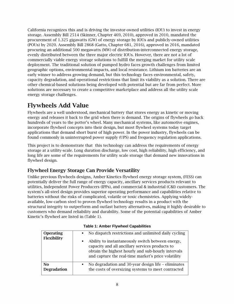
Table 1: Amber Flywheel Capabilities
Operating
Flexibility
▪ No dispatch restrictions and unlimited daily cycling
▪ Ability to instantaneously switch between energy,
capacity and all ancillary services products to
obtain the highest hourly and sub-hourly intervals
and capture the real-time market's price volatility
No
Degradation
▪ No degradation and 30-year design life – eliminates
the costs of oversizing systems to meet contracted
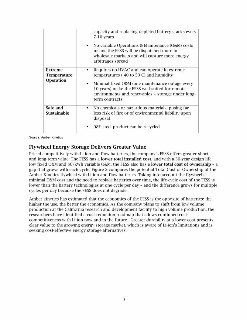
9
capacity and replacing depleted battery stacks every
7-10 years
▪ No variable Operations & Maintenance (O&M) costs
means the FESS will be dispatched more in
wholesale markets and will capture more energy
arbitrages spread
Extreme
Temperature
Operation
▪ Requires no HVAC and can operate in extreme
temperatures (-40 to 50 C) and humidity
▪ Minimal fixed O&M (one maintenance outage every
10 years) make the FESS well-suited for remote
environments and renewables + storage under long-
term contracts
Safe and
Sustainable
▪ No chemicals or hazardous materials, posing far
less risk of fire or of environmental liability upon
disposal
▪ 98% steel product can be recycled
Source: Amber Kinetics
Flywheel Energy Storage Delivers Greater Value
Priced competitively with Li-ion and flow batteries, the company’s FESS offers greater short-
and long-term value. The FESS has a lower total installed cost, and with a 30-year design life,
low fixed O&M and $0/kWh variable O&M, the FESS also has a lower total cost of ownership – a
gap that grows with each cycle. Figure 2 compares the potential Total Cost of Ownership of the
Amber Kinetics flywheel with Li-ion and flow batteries. Taking into account the flywheel’s
minimal O&M cost and the need to replace batteries over time, the life-cycle cost of the FESS is
lower than the battery technologies at one cycle per day – and the difference grows for multiple
cycles per day because the FESS does not degrade.
Amber kinetics has estimated that the economics of the FESS is the opposite of batteries: the
higher the use, the better the economics. As the company plans to shift from low volume
production at the California research and development facility to high volume production, the
researchers have identified a cost reduction roadmap that allows continued cost-
competitiveness with Li-ion now and in the future. Greater durability at a lower cost presents
clear value to the growing energy storage market, which is aware of Li-ion’s limitations and is
seeking cost-effective energy storage alternatives.

10
Figure 2: Energy Storage Total Cost of Ownership Comparison
Source: Amber Kinetics
Flywheel Energy Storage Unlocks Operation Flexibility
Unlike Li-ion and flow batteries, the company’s FESS has no dispatch restrictions and can
operate multiple cycles, 24 hours per day to provide capacity, energy, and ancillary services.
The system can switch between services almost instantaneously to capture the highest price at
hourly and sub-hourly intervals and can generate longer than four hours for utilities and
industrials with broad peaks. This optionality can add 15-30% more in revenue than one cycle
per day of Li-ion batteries, as renewables increase peak/off-peak spreads and volatility.
• Multiple Cycles Per Day: Amber Kinetics marginal cost of a cycle (defined as 0% to 100%
state of charge (SOC) and back) is $0. The FESS can operate multiple cycles per day at no
additional cost. Revenues are projected to increase as energy price spreads widen due to
increased renewables penetration.
▪ 24 Hour/Day Operation: The FESS $0 marginal operating cost means that the system
can be dispatched 24/7, earning revenue 24 hours per day, switching between energy
and ancillary services to maximize revenue.
▪ Capturing Intra-Day Price Volatility: The FESS can cycle between 0% to 100% output
multiple times per hour to take advantage of the real-time market’s price volatility.
Figure 3 shows a simulation comparing a 1 MW/4MWh storage system’s performance
operating in the day-ahead and real-time California ISO markets in 2015. While
capturing the full revenue potential represented in Table 2 would require perfect
knowledge, there is clearly potential to earn more than being limited to operating in the
day-ahead market.

11
Figure 3: California ISO Revenue Potential
Source: Helman Analytics and Amber Kinetics, Feb 2017

12
CHAPTER 2:
Commercial Readiness
Assessing the commercial readiness of any product is subjective especially with the stringent,
expectations of the utility industry. Utility assets commonly operate for decades in harsh
environments with high availability and reliability. Typically, investor-owned utilities are
reluctant to use new products and technologies without an extensive operation track record.
Operating data are important for supporting the commercial use of a product, particularly a
utility-scale energy storage product.
This project was to advance Amber Kinetics’ flywheel as a viable energy storage technology for
California’s investor owned utilities. Several different criteria were addressed including design
stability to manufacturing capability to system performance to reliability of operation. The
team’s approach was to build and operate multiple units since the operating experience
provides real world feedback to support design enhancements and the cumulative history
builds a foundation of credibility to support market adoption.
The Starting Point Amber Kinetics had built a small number of engineering prototype flywheels which had been
operated for short durations totaling about a 100 operating hours. FW4 had been built and
tested prior to the project and demonstrated good energy storage capabilities and roundtrip
efficiencies, however there were limitations that had to be addressed before it could be
considered a commercially viable product. The unit was a proof-of-concept system lacking
manufacturability, serviceability, and reliability.
Based on the experience gained from FW4, the company designed the M25 model flywheel for
this project. Three units of this new improved design were being manufactured when the
project was awarded in February 2016. Shortly after the project award the first unit for the
project, FW5, was installed at company’s Alameda Test Site (ATS).
The team spent time debugging the M25 during initial use and limited the operating hours
during the first few weeks. The units were returned to the factory for analysis, rework, and
adjustments. The units started accumulating meaningful numbers of hours beginning in April
when FW5 operated continuously for three weeks and completed the first full power cycle.
Method This effort was to accumulate operating hours and full power cycles on multiple flywheel units;
however, the benefits and measures of success were to go well beyond the accumulation of
metrics. Amber Kinetics wanted to study flywheel behavior to characterize performance over a
wide range of operating scenarios.
System faults, component issues, performance anomalies, and other observations were not
considered as failures but opportunities to enhance and improve the design. A closed loop
feedback loop was used throughout the project to the identify issues to drive corrective actions.
The specific issues encountered, and solutions adopted were beyond the scope of this report;
however, the process used and progress towards commercial readiness resulting from this
project will be discussed.
13
Results
Fleet Operating Data
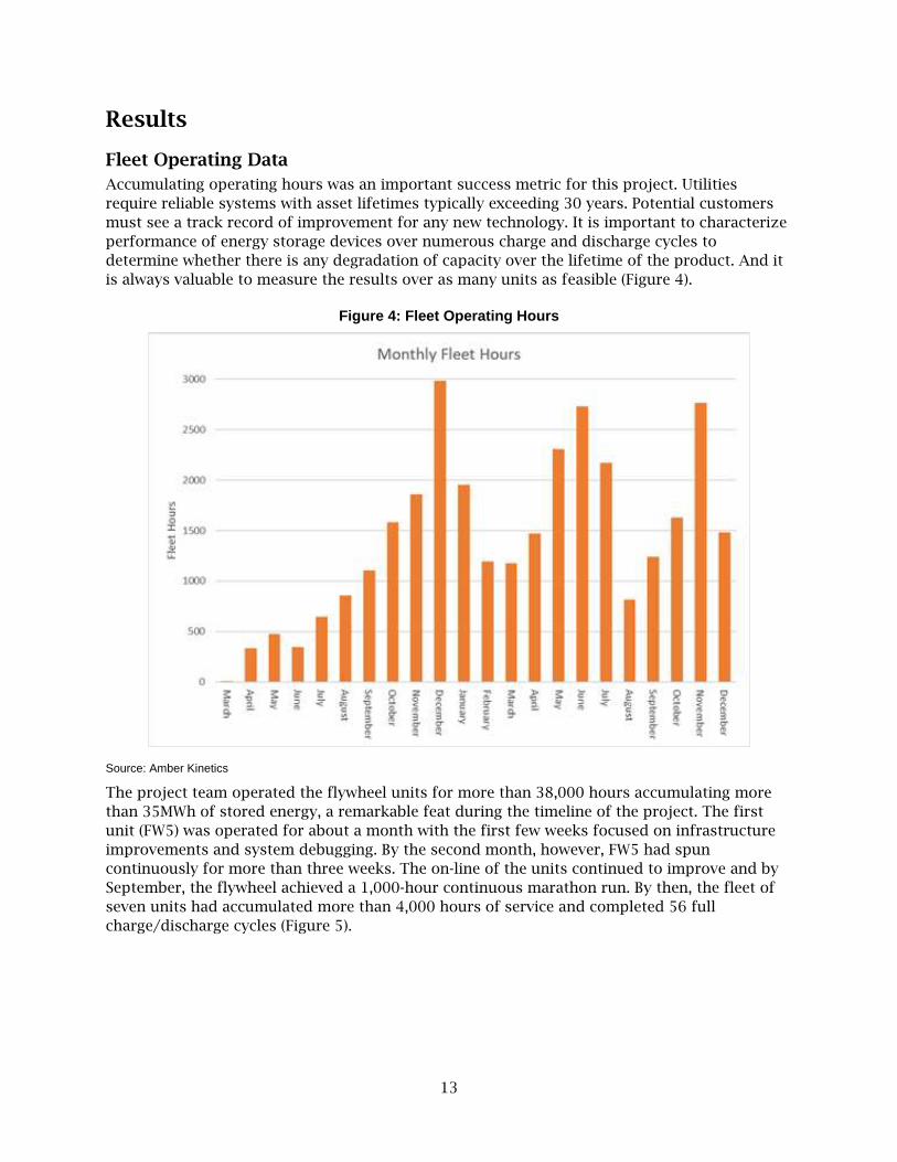
Accumulating operating hours was an important success metric for this project. Utilities
require reliable systems with asset lifetimes typically exceeding 30 years. Potential customers
must see a track record of improvement for any new technology. It is important to characterize
performance of energy storage devices over numerous charge and discharge cycles to
determine whether there is any degradation of capacity over the lifetime of the product. And it
is always valuable to measure the results over as many units as feasible (Figure 4).
Figure 4: Fleet Operating Hours
Source: Amber Kinetics
The project team operated the flywheel units for more than 38,000 hours accumulating more
than 35MWh of stored energy, a remarkable feat during the timeline of the project. The first
unit (FW5) was operated for about a month with the first few weeks focused on infrastructure
improvements and system debugging. By the second month, however, FW5 had spun
continuously for more than three weeks. The on-line of the units continued to improve and by
September, the flywheel achieved a 1,000-hour continuous marathon run. By then, the fleet of
seven units had accumulated more than 4,000 hours of service and completed 56 full
charge/discharge cycles (Figure 5).
14
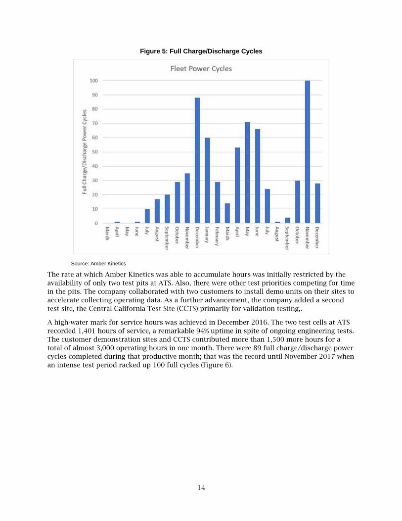
Figure 5: Full Charge/Discharge Cycles
Source: Amber Kinetics
The rate at which Amber Kinetics was able to accumulate hours was initially restricted by the
availability of only two test pits at ATS. Also, there were other test priorities competing for time
in the pits. The company collaborated with two customers to install demo units on their sites to
accelerate collecting operating data. As a further advancement, the company added a second
test site, the Central California Test Site (CCTS) primarily for validation testing,.
A high-water mark for service hours was achieved in December 2016. The two test cells at ATS
recorded 1,401 hours of service, a remarkable 94% uptime in spite of ongoing engineering tests.
The customer demonstration sites and CCTS contributed more than 1,500 more hours for a
total of almost 3,000 operating hours in one month. There were 89 full charge/discharge power
cycles completed during that productive month; that was the record until November 2017 when
an intense test period racked up 100 full cycles (Figure 6).

15
Figure 6: Operating Hours by Unit Number
Source: Amber Kinetics
The focus on operating hours by the project team transitioned to other project and company
priorities, but operating hours have continued to accumulate over the duration of the project.
The most recent data shows that 38,649 hours of operation and 35.6 megawatt-hours (MWh) of
cumulative energy storage on the fleet since the start of the project. During that time, more
than a dozen units within the fleet have completed more than 880 full charge/discharge power
cycles. This data is a solid foundation for establishing the reliability of flywheels to meet the
demands of utility scale energy storage.
Energy Storage Capacity
The rated energy storage capacity for the M25 at the beginning of the project was 25 kilowatt
hours (kWh) with a 4-hour discharge duration (6.2kW power rating). The safety validation
overspeed testing was an important input to uprating of the M25 unit to 32kWh of energy
storage capacity (8kw power rating). Other performance parameters like roundtrip efficiency
and accumulating operating hours were also key.
Design Stability and Manufacturability
There are a numerous encouraging signs towards the commercial readiness of the M32 flywheel
during the design validation testing. The M25 design has eliminated the weaknesses identified
in the first units and the manufacturing processes have been standardized and quality control
points more clearly defined resulting in more consistency unit-to-unit. The time required to
build and test a flywheel unit has significantly decreased as the work cells have become
16
formalized, parts stocked, designs and processed documented, and performance expectations
more predictable.
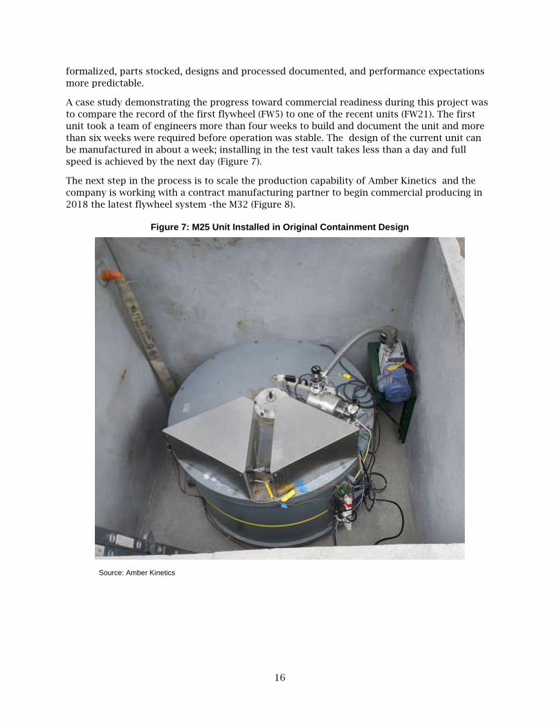
A case study demonstrating the progress toward commercial readiness during this project was
to compare the record of the first flywheel (FW5) to one of the recent units (FW21). The first
unit took a team of engineers more than four weeks to build and document the unit and more
than six weeks were required before operation was stable. The design of the current unit can
be manufactured in about a week; installing in the test vault takes less than a day and full
speed is achieved by the next day (Figure 7).
The next step in the process is to scale the production capability of Amber Kinetics and the
company is working with a contract manufacturing partner to begin commercial producing in
2018 the latest flywheel system -the M32 (Figure 8).
Figure 7: M25 Unit Installed in Original Containment Design
Source: Amber Kinetics

17
Figure 8: M32 Unit Installed in New Containment Design
Source: Amber Kinetics
Design Validation
Any new product goes through a period of debugging, refinement, and optimization before it is
ready for release. A system failure during this early stage is not a setback as much as an
opportunity for improvement, a chance to make a more reliable product. The circular
engineering process of design, build, test, evaluate, and repeat was used throughout the
project; continuous improvement is only possible when care is taken to identify and eliminate
the root cause of problems.
Testing must be conducted on multiple units to flush out whether the observed results are
random behavior of a single unit or systematic to the design. This project advanced the
commercial readiness of the Amber Kinetics’ flywheels by supporting the time consuming,
deliberate, and necessary process of preparing the product for release. There is no single test
that certifies the product is ready; it is the cumulative results and the effectiveness of
corrective actions that builds confidence in the product.
18
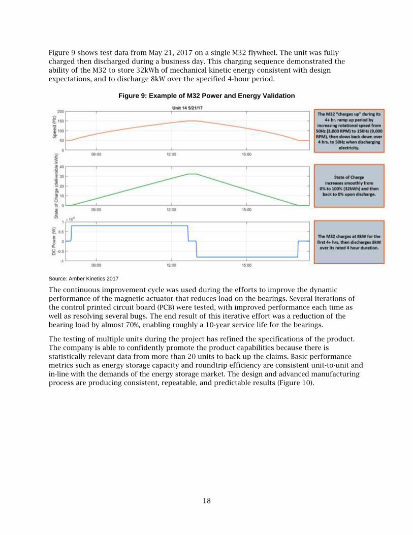
Figure 9 shows test data from May 21, 2017 on a single M32 flywheel. The unit was fully
charged then discharged during a business day. This charging sequence demonstrated the
ability of the M32 to store 32kWh of mechanical kinetic energy consistent with design
expectations, and to discharge 8kW over the specified 4-hour period.
Figure 9: Example of M32 Power and Energy Validation
Source: Amber Kinetics 2017
The continuous improvement cycle was used during the efforts to improve the dynamic
performance of the magnetic actuator that reduces load on the bearings. Several iterations of
the control printed circuit board (PCB) were tested, with improved performance each time as
well as resolving several bugs. The end result of this iterative effort was a reduction of the
bearing load by almost 70%, enabling roughly a 10-year service life for the bearings.
The testing of multiple units during the project has refined the specifications of the product.
The company is able to confidently promote the product capabilities because there is
statistically relevant data from more than 20 units to back up the claims. Basic performance
metrics such as energy storage capacity and roundtrip efficiency are consistent unit-to-unit and
in-line with the demands of the energy storage market. The design and advanced manufacturing
process are producing consistent, repeatable, and predictable results (Figure 10).

19
Figure 10: Advanced CNC Machining of High Precision Parts
Source Amber Kinetics
Amber Kinetics has pushed beyond the original plans of the project to validate the readiness of
the M32 flywheel design for utility scale energy storage. One of the advantages of flywheel
technology is the environmental tolerance; chemical batteries perform poorly outside of a
limited temperature range which often necessitates axillary heating and cooling systems that
reduce system power conversion efficiency.
Demonstrating environmental compatibility of complete flywheel systems over a wide range of
conditions from-20-40o Centigrade (Co) has been challenging, however notable progress has
been made in the field and the lab. Components have been subjected to repeated cycles of hot
and cold in an environmental chamber. Entire flywheels were placed in a chiller where operating
conditions were simulated (Figure 11). And two units were used as customer demonstrations in
a hot, humid climate. The results to date support the expectation that flywheels can operate
reliably in a wide range of environments without the need for ancillary heating or cooling.

20
Figure 11: Environmental Test Chamber to Validate Temperature Requirements
Source Amber Kinetics
Third Party Validation Internal testing of products is central to validating commercial readiness, but direct feedback
and operational experience from customers is equally important. During the project, Amber
Kinetics collaborated with multiple customers on demonstration projects and while these
efforts were not part of this project, the experiences add to the narrative.
San Diego Gas and Electric
In October 2016, ASWB Engineering, an engineering, training, and energy management
consulting firm, was directed by San Diego Gas & Electric (SDG&E) Emerging Technologies
Program to conduct a measurement and verification analysis of the Amber Kinetics FESS. The
analysis determined the applicability of this emerging technology to various sectors of the
energy distribution grid. The testing for the SDG&E analysis was performed at ATS where two
identical flywheels were located in separate underground concrete bunkers, with an on-site
monitoring and control room inside of a separate structure.
This study :
▪ Used Amber Kinetics data monitoring systems, monitor various system metrics
throughout the testing procedures, including rotational speed and energy usage.
▪ Confirmed maximum energy capacity.
▪ Confirmed maximum charge/discharge rates.
▪ Confirmed manufacturer efficiency claims.
21
▪ Calculated cost savings associated with load shifting based on SDG&E's AL-TOU
Secondary rate.
▪ Determined flywheel ancillary services potential.
▪ Conduced a life cycle cost analysis.
To monetize the load shift associated with the FESS, a Time of Use (TOU) utility rate is
necessary. At the request of the SDG&E project manager, this report used the AL-TOU-
Secondary rate from SDG&E.
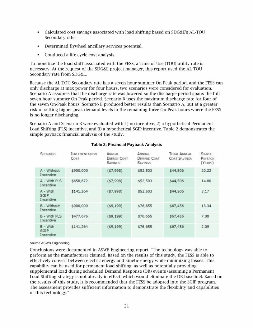
Because the AL-TOU-Secondary rate has a seven-hour summer On-Peak period, and the FESS can
only discharge at max power for four hours, two scenarios were considered for evaluation.
Scenario A assumes that the discharge rate was lowered so the discharge period spans the full
seven-hour summer On-Peak period. Scenario B uses the maximum discharge rate for four of
the seven On-Peak hours. Scenario B produced better results than Scenario A, but at a greater
risk of setting higher peak demand levels in the remaining three On-Peak hours where the FESS
is no longer discharging.
Scenario A and Scenario B were evaluated with 1) no incentive, 2) a hypothetical Permanent
Load Shifting (PLS) incentive, and 3) a hypothetical SGIP incentive. Table 2 demonstrates the
simple payback financial analysis of the study.
Table 2: Financial Payback Analysis
Source ASWB Engineering
Conclusions were documented in ASWB Engineering report, “The technology was able to
perform as the manufacturer claimed. Based on the results of this study, the FESS is able to
effectively convert between electric energy and kinetic energy while minimizing losses. This
capability can be used for permanent load shifting, as well as potentially providing
supplemental load during scheduled Demand Response (DR) events (assuming a Permanent
Load Shifting strategy is not already in effect, which would eliminate the DR baseline). Based on
the results of this study, it is recommended that the FESS be adopted into the SGIP program.
The assessment provides sufficient information to demonstrate the flexibility and capabilities
of this technology.”

22
This third party independent analysis of Amber Kinetics’ FESS is publicly available and
downloadable on the internet.1
Emerging Power Inc., Subic Bay, Philippines
An early unit from the project, an M25 with a power capacity of 6.25kW and 25kWh energy
storage capacity flywheel, was temporarily sent to a site in Subic Bay Philippines by Emerging
Power, Inc. to demonstrate integrating energy storage into their 150MW solar-wind facility
(Figure 12). Additionally, there was an opportunity to test the M25 early design flywheel
capabilities in real world operational scenarios by providing load shifting and fast ramping
response services. This demonstration spanned more than 1.5 years with valuable information
gained including project siting, remote deployment challenges, infrastructure requirement, and
general system operation. The lessons learned included flywheel reliability improvements, civil
design considerations, user interface feedback, and operation challenges in harsh environments
which will facilitate improved future uses, however, at this time, the specific test results are
confidential to Emerging Power.
Figure 12: Demo Installation at Subic Bay, Philippines
Source Amber Kinetics
Hawaiian Electric Company (HECO), Campbell Industrial Park, Hawaii
On March 12, 2018, Hawaiian Electric, in partnership with Amber Kinetics and Elemental
Excelerator launched operations of a four-hour kinetic energy storage system (KESS) powered
1 Flywheel Energy Storage Study, Prepared for Emerging Technologies Program, San Diego Gas & Electric by John Baffa,
PE, and Mark Hinrichs of ASWB Engineering, March 22, 2017. Https://www.etcc-ca.com/reports/flywheel-energy-storage-study
23
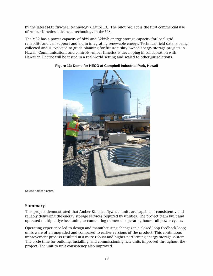
by the latest M32 flywheel technology (Figure 13). The pilot project is the first commercial use
of Amber Kinetics’ advanced technology in the U.S.
The M32 has a power capacity of 8kW and 32kWh energy storage capacity for local grid
reliability and can support and aid in integrating renewable energy. Technical field data is being
collected and is expected to guide planning for future utility-owned energy storage projects in
Hawaii. Communications and controls Amber Kinetics is developing in collaboration with
Hawaiian Electric will be tested in a real-world setting and scaled to other jurisdictions.
Figure 13: Demo for HECO at Campbell Industrial Park, Hawaii
Source Amber Kinetics
Summary
This project demonstrated that Amber Kinetics flywheel units are capable of consistently and
reliably delivering the energy storage services required by utilities. The project team built and
operated multiple flywheel units, accumulating numerous operating hours full power cycles.
Operating experience led to design and manufacturing changes in a closed loop feedback loop;
units were often upgraded and compared to earlier versions of the product. This continuous
improvement process resulted in a more robust and higher performing energy storage system.
The cycle time for building, installing, and commissioning new units improved throughout the
project. The unit-to-unit consistency also improved.

24
There are other metrics of commercial readiness that go beyond the scope of the effort for this
project. A commercially viable product must be cost effective and the supply chain should be
stable to support the business plan. There must be manufacturing capacity in place to produce
the required numbers of units. The project helped to significantly advance these efforts, but
considerable work remains on these fronts.

25
CHAPTER 3:
Safety Validation
All products have risks, however the chances of an event occurring and the impact if that event
occurs are important considerations when evaluating if a product or technology is to be
commercialized..
Stored energy in any form can be unintentionally released which inherently creates risk. All
energy storage technologies must assess their inherent risks and design appropriately. Lithium
ion batteries, for example, are at risk of fire if exposed to air; an uncontrolled chemical reaction
can aggressively spread. Flywheels, on the other hand, store energy kinetically; the spontaneous
release of that energy could be dramatic.
Amber Kinetics used two strategies to mitigate the inherent safety risks of kinetic energy
storage. The first was designing the flywheel unit to minimize the chances of an uncontrolled
release. The second recommended an installation design to customers that offer the best
chance to contain the energy release in the unlikely event that it does occur. Validations of the
safety design criteria for the flywheel and containment design are critical to demonstrating the
viability of flywheels for utility scale energy storage.
A test site in Central California (CCTS) was prepared to conduct a series of experiments.
Multiple different failure modes were simulated, and the results analyzed to better understand
flywheel performance (Figure 14).
Figure 14: Amber Kinetics Central California Test Site
Source: Amber Kinetics (2018)

26
Test Plan The test site was chosen to minimize any potential risk to the Amber Kinetics team and
neighbors to the test site. Units were to be subjected to extreme operating conditions, and the
potential results were uncertain. Safety was a primary consideration.
Units that had completed service in the reliability test program were designated to the safety
validation tests. One of these five M32 test units was installed in a vault at the CCTS. Five
different failure modes were considered for this safety validation testing.
• Overspeed
• Loss of vacuum
• Lower bearing failure
• Upper bearing failure
• Stub shaft failure
• Catastrophic rotor failure
Test Results
Overspeed Test
Amber Kinetics has done extensive modeling of the stresses in a rotor under operating
conditions, so it was important to validate the assumptions of basic rotor strength in field use.
The flywheel was brought to full speed (9,000 rotations per minute [rpm]) which is equivalent
to the maximum energy storage capacity of 32kWh for the M32 flywheel. Using custom controls
software, the speed was increased to 9,653 rpm which is a 15% overstress condition to the
flywheel rotor. This overstress condition is consistent with industry norms for stress testing.
Two M25 units were tested using this procedure. The speed, acceleration, and internal pressure
were monitored throughout the test. No unusual behavior was noted on either unit during the
test program. There was no damage or degradation to either unit. At the conclusion of the tests,
the units were functioning normally and were advanced to the next round of testing.
A third unit was tested in a more extreme overspeed condition during another phase of the
safety validation testing. For this unit, a series of tests were conducted where the unit speed
was progressively increased. The rotor achieved a top speed of 11,800 rpm, a 95% overstress
condition, before the unit suffered a failure unrelated to rotor stress. The team concluded the
M25 design has a large rotor stress safety margin .
The results of the overspeed testing were the final confirmation of the safety margin of the
rotor design and the company to increase the rated energy storage capacity for the FESS from
25MWh to 32MWh. The project played a role in boosting the energy storage capacity by more
than 28%, a dramatic impact on the cost effectiveness of the technology.
Loss of Vacuum
Amber Kinetics flywheels operate in a vacuum to minimize the friction loss from air. Rapidly
introducing atmospheric pressure into the rotor chamber could have unforeseen impacts to the
operating the flywheel. At a minimum, the air will act to slow the flywheel and for composite
rotors, the sudden air friction can cause a destructive failure to occur.
The test unit was brought to full speed. After operating normally for a period of at least 2
hours, a solenoid valve released the vacuum almost instantaneously. The speed, accelerations,

27
internal pressure, and shell temperature were logged. The rotor spun down within 10 minutes.
Accelerations were modest during the event and the unit remained fully intact. The shell
temperature rose 110oC from the friction of the air.
The test unit was allowed to cool down. All systems were inspected and found to be in working
order. The team concluded that this failure mode is very benign and the unit was restarted.
The original test for the project planned on this test for one flywheel. Amber Kinetics has
repeated the loss of vacuum test while doing other development activities. The subsequent
tests have confirmed the initial findings.
Lower Bearing Failure
The design of the M32 flywheel includes an electromagnet to lift the load of the rotor from the
bearings. This reduces friction losses and extends the life of the bearings. There is a reasonable
concern about what might happen if the magnet fails and the full load of the rotor were placed
on the lower bearing. It is expected the bearing to eventually fail because it is stressed beyond
the design limits in this test however, it is not clear what happens next.
The test unit was brought to full speed. The speed, acceleration, and internal pressure were
monitored throughout the test. After operating normally for a period of at least 2 hours the
electromagnet was deactivated, and the full weight of the rotor fell on the lower bearing. The
system was driven in charge mode to maintain the rotor at full speed until the failure. The
bearing survived almost 30 minutes before failure. During this time, the flywheel behaved
normally, and accelerations were low. The unit began to shake when the bearing was failing,
lasting just seconds.
The flywheel remained fixed to the mounts in the vault. The rotor remained inside of the shell.
There were no overt signs from the outside that the unit had failed. The unit was removed from
the vault and directed to failure analysis. When opened, it was obvious the unit was destroyed.
The rotor had made contact with the motor generator assembly. Salvage operations were
limited to recycling. But the failure mode was very benign from a safety perspective.
Upper Bearing Failure
This test is similar to the lower bearing failure test. It is possible that the upper bearing could
fail prematurely through normal wear and tear or from a control system failure that overloads
the upper bearing. Regardless of the cause, it is valuable to characterize how the flywheel will
respond to this potential failure mode.
The test unit was brought to full speed. The speed, acceleration, and internal pressure were
monitored throughout the test. In this case, the electromagnet was driven to high power to
overload the upper bearing. The system was driven in charge mode to maintain the rotor at full
speed until the failure. This bearing also survived about 30 minutes before failure. During this
30 minutes, the flywheel behaved normally, and accelerations were low. The unit began to
shake when the bearing was failing; lasting a few seconds.
The flywheel remained fixed to the mounts in the vault. The rotor remained inside of the shell.
There were no overt signs from the outside that the unit had failed. The unit was removed from
the vault and directed to failure analysis. When opened, it was obvious the unit was destroyed.
The rotor had made contact with electromagnet before dropping onto the motor generator
assembly. Salvage operations were limited to recycling. The failure mode was benign from a
safety perspective.
28
Stub Shaft Failure
The M32 flywheel design has a stub shaft mounted to the rotor with the bearings attached to
the stub shafts. There is a good safety margin in the stub shaft mounts which makes such an
event unlikely. The project plan did not even intend to test this failure mode, however
circumstances in other tests lead to a unit failing in a manner consistent with a stub shaft
failure.
One of the units used in the safety validation testing is believed to have experienced a stub
shaft failure. During the failure analysis it was observed that the stub shaft had become
disengaged from the rotor. In spite of this extreme overstress condition, the flywheel behaved
normally for several hours until almost the instant of failure; at that moment, the unit began to
shake. The event lasted seconds before the unit came to rest.
The flywheel remained fixed to the mounts in the vault. The rotor remained inside of the shell.
There were no overt signs from the outside that the unit had failed. The unit was removed from
the vault and opened; it was obvious the unit was destroyed. The rotor had made contact with
electromagnet before dropping onto the motor generator assembly. Salvage operations were
limited to recycling however, the failure mode was benign from a safety perspective.
Catastrophic Rotor Failure
The worst possible failure of a flywheel system is a catastrophic rotor failure. This failure mode
is similar to a jet engine suffering a rotor failure. Great efforts have been taken to minimize the
chance of such an event occurring with the M32 flywheel, however the company recommends
installing the flywheels in some type of containment vessel should this failure happen.
The first challenge of this test turned out to be finding an effective method to induce a failure.
It took multiple attempts to get a rotor to fail. Initial engineering analysis suggested that a
series of grooves or notches on the surface of the rotor would be adequate to induce a crack
and lead to failure. After a period of normal operation, the unit was brought to a 15% overstress
condition at 9,563rpm. The unit did not fail. The rotor was removed, the notches enlarged and
the test repeated; the results were the same. The unit was cycled repeatedly in an unsuccessful
attempt to grow the cracks to failure. The stress level (speed) was increased incrementally until
the unit finally reached 11,800 rpm which is an overstress level of 71%. At that point another
failure mode destroyed the unit in a benign manner.
The next attempt deployed 10 inch slots cut into the rotor. There were some difficulties
achieving balance of the rotor with the notches and high accelerations caused failures to other
systems on two attempts. Finally, the team was successful in inducing a failure on the third try
with the slot design. The same approach was tried on a second system using 4 inch slots
instead to increase the energy level of the burst event. The fragments of both rotors were
logged for size and location (Figure 15). This data was analyzed to support modeling of
different flywheel models, operating scenarios, containment designs, and spacing requirements.

29
Figure 15: Rotor Burst Forensics
Source: Amber Kinetics (2017)
The most significant finding from this test was that all fragments were released in a radial
direction. All fragments were contained in the soil or rocks surrounding the containment
vessel. There was virtually no axial element to the trajectories. Items sitting above the flywheel
such as the electronics and vacuum pump were barely impacted during the event. The shell and
vault liner were destroyed (Figure 16).
The results of this testing suggest that a below grade installation with soil or rocks between
units is an effective design to contain a catastrophic rotor failure. The vault liner should be
designed adequately to hold back the soil, but no attempt should be made to have the vault
liner contain the rotor fragments. A reinforced concrete vault should be avoided as it may cause
fragments to ricochet uncontrollably.
Figure 16: Vault Liner after Burst Test
Source: Amber Kinetics
30
Seismic Event Tolerance
Testing the FESS tolerance to seismic event was not planned as a part of the project, however, a
preliminary relevant data point was obtained during the project. A magnitude 4.4 earthquake
occurred at 2:39 am on January 4, 2018 in Berkeley, California. The epicenter was 8.2 km from
the Alameda Test Site.
The operating data from a flywheel discharging at the time showed higher than normal
accelerations in the accelerometer data, and the electromagnet feedback loop detected higher
than normal forces. This triggered a force fault of the unit which resulted in the flywheel being
automatically placed in a coasting mode. Less than one second later the electromagnet force
stabilized. The unit suffered no damage and was returned to active operation by an operator
several hours later.
Summary A wide range of safety validation tests were conducted on the Amber Kinetics M32 flywheel.
The results of the testing exceeded expectations. The system is tolerant of several potential
failure modes. The system behavior was more benign in several harsh failure modes than was
predicted in advance. The difficulty bursting a rotor which led to unit operation in high
overstress conditions demonstrates that the product design has more than an adequate safety
margin. This project has advanced the safety validation of flywheels for utility scale energy
storage.

31
CHAPTER 4:
Multi-Unit Arrays
Before this project, Amber Kinetics flywheels had only been operated in standalone, single-unit
installations. While useful from a product development point of view, single-unit operation
represents a subset of the technology required for multiple-unit arrays storing energy on a
utility scale. The project’s third goal was to advance the hardware and software required to
operate multi-unit arrays. A multiple-unit array offers additional degrees of operational
freedom, but requires careful attention to communications, system dynamics, and unit-to-unit
power and state-of-charge balance.
During this project, a flywheel management system (FMS) was developed using utility-grade
hardware. Communication protocols and control algorithms for coordinating multiple flywheels
were developed. A multiple-unit test site was constructed, and operation of multiple flywheels
on a common direct current (DC) bus was demonstrated. The project was successful in
demonstrating multiple operating scenarios for charging and discharging multiple flywheels.
Also, the performance of arrays as compared to single flywheels was evaluated.
System Development
Multi-Flywheel Array Controls
There are two objectives in implementing multi-unit array controls: maintaining a stable
balance of power among units so that maximum site power can be achieved without violating
individual flywheel power limits and maintaining balanced state-of-charge across the array so
that maximum site power is always available over the full SOC range. The following
implementation strategy was chosen:
• Multiple flywheels share a common DC bus with a grid inverter.
• High-bandwidth power balancing is implemented locally on each flywheel with a droop
control scheme.
• Low-bandwidth state-of-charge balancing is implemented in the central FMS using an
adaptive droop parameter update.
Hardware Development
A multi-unit flywheel array operates as a single, integrated system. The chosen architecture for
this project was to connect all flywheels to a common DC bus feeding a grid inverter using the
30B3-4xF inverter from Ideal Power.. A central FMS was designed around an industrial computer
from Advantech. Communications between the FMS and flywheels use transmission control
protocol/ internet protocol (TCP/IP); the FMS accepts commands and returns data to a
connected supervisory control and data acquisition (SCADA)system via distributed network
protocol(DNP3) (Figure 17).

32
Figure 17: Multi-Unit Array System Architecture
Source: Amber Kinetics
Software Development
Several major software blocks were developed for array operation:
• A distributed balancing control algorithm for the individual flywheel microcontrollers.
• A state-of-charge balancing algorithm for the FMS.
• Algorithms for aggregate power dispatch.
• A user interface for array control.
Multi-Unit Array Testing The multi-unit control system has been used at ATS and CCTS. Up to four units were
simultaneously operated at CCTS while ATS was limited to the two vaults available there.
Recent data shows more than 900 hours of operation and 1.9 MWh of cumulative energy
storage at CCTS and an additional 400 hours of operation and 1.8MWh of cumulative energy
storage at ATS. Additional benchtop testing has validated communications for up to 32 units
simultaneously.
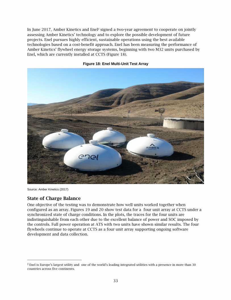
33
In June 2017, Amber Kinetics and Enel2 signed a two-year agreement to cooperate on jointly
assessing Amber Kinetics’ technology and to explore the possible development of future
projects. Enel pursues highly efficient, sustainable operations using the best available
technologies based on a cost-benefit approach. Enel has been measuring the performance of
Amber Kinetics’ flywheel energy storage systems, beginning with two M32 units purchased by
Enel, which are currently installed at CCTS (Figure 18).
Figure 18: Enel Multi-Unit Test Array
Source: Amber Kinetics (2017)
State of Charge Balance
One objective of the testing was to demonstrate how well units worked together when
configured as an array. Figures 19 and 20 show test data for a four unit array at CCTS under a
synchronized state of charge conditions. In the plots, the traces for the four units are
indistinguishable from each other due to the excellent balance of power and SOC imposed by
the controls. Full power operation at ATS with two units have shown similar results. The four
flywheels continue to operate at CCTS as a four unit array supporting ongoing software
development and data collection.
2 Enel is Europe’s largest utility and one of the world’s leading integrated utilities with a presence in more than 30
countries across five continents.
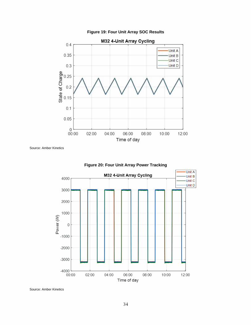
34
Figure 19: Four Unit Array SOC Results
Source: Amber Kinetics
Figure 20: Four Unit Array Power Tracking
Source: Amber Kinetics
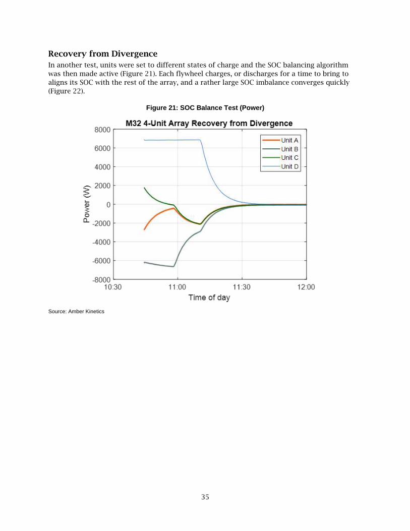
35
Recovery from Divergence
In another test, units were set to different states of charge and the SOC balancing algorithm
was then made active (Figure 21). Each flywheel charges, or discharges for a time to bring to
aligns its SOC with the rest of the array, and a rather large SOC imbalance converges quickly
(Figure 22).
Figure 21: SOC Balance Test (Power)
Source: Amber Kinetics

36
Figure 22: SOC Balance Test (State of Charge)
Source: Amber Kinetics
Summary Amber Kinetics was successful in developing hardware and software to support the operation
of M32 flywheel arrays. The resulting system expands Amber Kinetics’ capability from single-
unit deployments to multiple-unit deployments. The system has been used to operate two and
four unit flywheel arrays in the field. The available power and efficiency of the flywheel array
showed no degradation compared to the aggregated single flywheel performance. The
proprietary balancing algorithms successfully balanced power and SOC among the units.

37
CHAPTER 5:
Results of Project
Project Goals and Objectives This project explored flywheel energy storage R&D to reach commercial viability for utility scale
energy storage. This required advancing the design, manufacturing capability, system cost,
storage capacity, efficiency, reliability, safety, and system level operation of flywheel energy
storage technology. The team tested three specific areas to support this goal: commercial
readiness, safety validation, and multi-unit array operation.
To test the commercial readiness of the flywheel the team built and operated multiple, discrete
flywheel units. The flywheel units accumulated as many service hours as possible and were
stressed in multiple ways to identify opportunities to improve the reliability and repeatability
of the product design. Building multiple units presented the opportunity to define, document,
and optimize the manufacturing process and quality controls necessary to consistently produce
flywheel units.
Safety validation subjected the flywheels to predictable failure modes and assessed the system
response. The team evaluated vacuum system failure, overspeed operation, bearing overload,
and a rotor burst. Repeat tests were conducted whenever possible to increase confidence in the
results.
The path to utility scale use of FESS was through multi-unit arrays; a single 1MW, 4-hour
discharge duration flywheel was not feasible with current technology and utility scale requiring
significantly more storage capacity. Amber Kinetics developed the system level hardware and
software required to manage and control multi-unit arrays. Testing the capabilities and limits of
array operation is an important validation step. Simulating various operating scenarios would
help to define the advantages of kinetic energy storage to the IOUs.
Progress Assessment As a result of this project in October 2018, Amber Kinetics had achieved the commercial release
of the M32 flywheel product with the company first shipping production units from their first
manufacturing facility.. This will give California IOU’s new choices when addressing their
energy storage needs. A robust and healthy marketplace for energy storage solutions is vital to
supporting California’s clean energy goals.
Commercial Readiness
This project team was successful in establishing a baseline record for the reliability of the FESS
for utility scale energy storage. Although the duration of the project was limited, the company
was able to accumulate more than 38,000 operating hours on a fleet of more than 15 flywheel
units. The flywheels completed more than 880 full charge/discharge cycles with zero
degradation of capacity. Marathon runs of more than 1,000 continuous hours were completed
on multiple occasions. The fleet leader has accumulated more than 6,500 total operating hours.
Although small to the lifetime expectations for utility storage, they are a foundation that
demonstrates the viability of the Amber Kinetics FESS.

38
Several major utilities contracted Amber Kinetics to conduct technology trials of the FESS. For
example, Emerging Power Inc of the Philippines (EPI) embedded a unit in its planned 150MW
wind and solar farm in Subic Bay. “Amber Kinetics’ technology will be very useful in
smoothing out the energy generation of our solar and wind farm by taking out the variability. We
are very excited to work with Amber and hopeful that this milestone deal will be replicated in
future renewable energy projects in the country,” said Alberto Guanzon, EPI Head of Marketing.
Europe’s largest utility, Enel, acquired two M32 units in late 2017. Enel’s Head of Global Thermal Generation, Enrico Viale, explained publicly at the time that “due to the growing energy demand on grids, it is increasingly important to find grid balancing solutions to peaks in demand. Amber Kinetics’ flywheel addresses this issue with an interesting alternative to traditional batteries, providing Enel with a flexible solution to energy demand peaks that can be applied across the company’s diverse generation mix.” Hawaiian Electric is currently testing a unit in Oahu, Hawaii, and according to Colton Ching, Hawaiian Electric senior vice president for planning and technology, “Hawaiian Electric is eager to test the grid stabilizing and renewable energy storing of the flywheel. Our evaluation of this very promising energy storage system will help us determine how we can use flywheels to help integrate renewables at a lower cost while improving reliability and resiliency of the grid.” The project was designed to do more than just accumulate operating hours. New products must
to be validated, refined, and optimized. The product design and manufacturing process for the
Amber Kinetics FESS have stabilized during the course of this project. Unit-to-unit performance
variability is small, manufacturing cycle times have been dramatically reduced, and quality has
improved. Operating units in a wide variety of environmental conditions demonstrates a robust
product design. The progress made as a result of this project helped advance the commercial
release of the Amber Kinetics FESS to the energy storage market. Plans to scale production in a
new factory are becoming a reality, clearly achieved its goals.
Safety Validation
The project team conducted a comprehensive series of tests to characterize the safety of the
Amber Kinetics FESS. Consideration was given to safety in the design of the product, however it
is imperative to conduct field tests in predictable fault scenarios to observe the system
response. The safety design criteria were validated though a series of induced failures and
overstress events.
The flywheels were completely tolerant of a number of fault scenarios such as a loss of
vacuum, loss of power, and overspeed; they survived these types of events without damage and
were easily put back into service. The overspeed tests also validated that the rotor has a large
safety margin above the design stress levels; furthermore, the lack of any unusual behavior by
the units during the testing supports the case for product robustness. Other potential faults
like bearing failures were induced and resulted in benign and safe outcomes for the unit.
A catastrophic rotor burst is a very unlikely but a potentially hazardous event; the testing
conducted as a part of this project demonstrated that the energy released during such an event
is entirely in the radial direction. The subterranean installation concept endorsed by Amber
Kinetics was demonstrated to successfully contain this event. Any company adopting kinetic
energy storage would benefit from considering this approach.
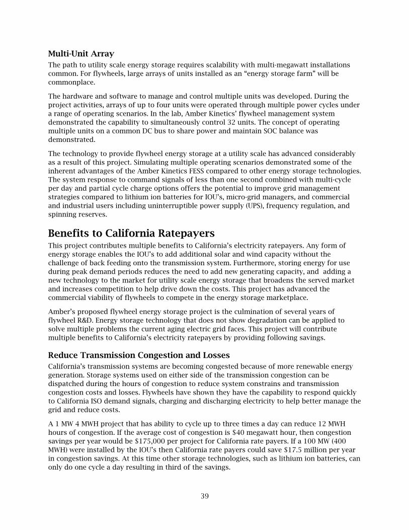
39
Multi-Unit Array
The path to utility scale energy storage requires scalability with multi-megawatt installations
common. For flywheels, large arrays of units installed as an “energy storage farm” will be
commonplace.
The hardware and software to manage and control multiple units was developed. During the
project activities, arrays of up to four units were operated through multiple power cycles under
a range of operating scenarios. In the lab, Amber Kinetics’ flywheel management system
demonstrated the capability to simultaneously control 32 units. The concept of operating
multiple units on a common DC bus to share power and maintain SOC balance was
demonstrated.
The technology to provide flywheel energy storage at a utility scale has advanced considerably
as a result of this project. Simulating multiple operating scenarios demonstrated some of the
inherent advantages of the Amber Kinetics FESS compared to other energy storage technologies.
The system response to command signals of less than one second combined with multi-cycle
per day and partial cycle charge options offers the potential to improve grid management
strategies compared to lithium ion batteries for IOU’s, micro-grid managers, and commercial
and industrial users including uninterruptible power supply (UPS), frequency regulation, and
spinning reserves.
Benefits to California Ratepayers This project contributes multiple benefits to California’s electricity ratepayers. Any form of
energy storage enables the IOU’s to add additional solar and wind capacity without the
challenge of back feeding onto the transmission system. Furthermore, storing energy for use
during peak demand periods reduces the need to add new generating capacity, and adding a
new technology to the market for utility scale energy storage that broadens the served market
and increases competition to help drive down the costs. This project has advanced the
commercial viability of flywheels to compete in the energy storage marketplace.
Amber’s proposed flywheel energy storage project is the culmination of several years of
flywheel R&D. Energy storage technology that does not show degradation can be applied to
solve multiple problems the current aging electric grid faces. This project will contribute
multiple benefits to California’s electricity ratepayers by providing following savings.
Reduce Transmission Congestion and Losses
California’s transmission systems are becoming congested because of more renewable energy
generation. Storage systems used on either side of the transmission congestion can be
dispatched during the hours of congestion to reduce system constrains and transmission
congestion costs and losses. Flywheels have shown they have the capability to respond quickly
to California ISO demand signals, charging and discharging electricity to help better manage the
grid and reduce costs.
A 1 MW 4 MWH project that has ability to cycle up to three times a day can reduce 12 MWH
hours of congestion. If the average cost of congestion is $40 megawatt hour, then congestion
savings per year would be $175,000 per project for California rate payers. If a 100 MW (400
MWH) were installed by the IOU’s then California rate payers could save $17.5 million per year
in congestion savings. At this time other storage technologies, such as lithium ion batteries, can
only do one cycle a day resulting in third of the savings.

40
Transmission and Distribution Upgrade Deferral
The FESS can significantly avoid transmission and distribution upgrades for the utility by
reducing the peak load and avoid having to replace overloaded circuits. Upgrading transmission
and distribution systems cause the most increases for ratepayers. .
A 100 MW (400 MWH) installation would avoid distribution upgrades of 100 MW which can save
close to $600 million over life time of the system.
Peak Shaving and Energy Arbitrage
Amber flywheel can be installed in customer specific locations significantly reducing demand
charges and large portion of their electricity bills. Installing 100 MW’s worth of flywheels used
for distribution can reduce demand charges by $36 million and provide $8 million of energy
savings a year since the FESS can eliminate mid-day peak and evening peaks of electricity use.
Lithium battery technology can only do one peak reduction a day.
The Amber flywheel provides flexibility and unique operational characteristics and can be used
to tackle multiple use cases for utility and behind the meter applications. The company is
developing a product road map to provide all the use cases that can help California rate payers
significantly reduce their costs while enhancing grid reliability. Installing 100 MW worth of
flywheels can reduce $37 million per year for utility deployments and $42 million per year for
customer sited deployment.
Production Readiness Plan This project has significantly advanced the design stability and manufacturing processes for
flywheels, helping Amber Kinetics move toward the mass production of the kinetic energy
storage system. Fundamental product needs have been addressed including refinement of
design documentation, definition of manufacturing procedures, establishment of test
procedures and quality standards, and qualification of the supply chain. These results have
allowed the company to start down the road to building the infrastructure to mass produce the
flywheels.
The size and weight of flywheels present a unique challenge to the manufacturing strategy
because logistics can add considerably to the product cost. Mitigating this challenge requires
that system integration be located close to the fabrication centers for rotors and housings so
that the system ships as a complete unit to project sites, or that facility should be located close
to the project site to minimize post assembly transport costs. A large, central factory does not
make much sense for this business case.
Amber Kinetics has built a pilot production facility at the Union City, California headquarters;
all units used in this project were made in this facility. Production units are currently being
shipped to customers from this factory. In addition to meeting customer demand, this facility is
developing, documenting, and refining the manufacturing process and create a template for
growth on a global scale. Amber Kinetics will use critical learnings from its California
production facilities to prepare to expand production throughout markets in North America
and worldwide.
The first units have been built, and the production capacity is being scaled to planned capacity
of 1,000 flywheels per year to address customer demand. Additional factories in the United
States and around the world are in the planning stage.

41
Customer demand for Amber Kinetics FESS is emerging on a global scale. Orders for production
units have been received from four continents plus the island nation of the Philippines. West
Boylston Municipal Lighting Plant in Massachusetts recently ordered 16 units scheduled for
delivery fall 2018.
Technology and Knowledge Transfer Amber Kinetics engaged in different technology transfer activities through commercialization
of its flywheel technology in the U.S. and abroad. For example, Amber kinetics presented its
technology pilot project in a press conference and ribbon cutting with Hawaiian Electric at the
Campbell Industrial Park Generating Facility on Oahu to demonstrate the flywheel’s real-world
capabilities on the distribution system. The Amber Kinetics team also participated as
presenters in different conferences such as the Maui Energy Conference and the Hawaiian
Electric Flywheel Pilot Project. They also presented at the Energy Storage Association’s Annual
Conference and at the Roosevelt Strategic Council Microgrid & DERS Summit in Alexandria,
Virginia.
Moreover, the Amber kinetics team is contributing to shaping the UL 9540 standard for "Energy
Storage Systems and Equipment" to apply updated and improved public safety standards
regarding flywheels. Amber kinetics firmly believes that supporting and adopting standards will
help eliminate existing shortcomings on how flywheel safety is defined, leading to more
transparency and ultimately safer outcomes.

42
GLOSSARY
Term Definition
EPIC Electric Program Investment Charge
Smart Grid Smart Grid is the thoughtful integration of intelligent technologies and
innovative services that produce a more efficient, sustainable, economic, and
secure electrical supply for California communities.
CCTS Central California test site
ATS Alameda test site
SOC State of charge
kW Kilowatt
kWh Kilowatt-hour
MW Megawatt
MWh Megawatt-hour
FESS Flywheel Energy Storage System
IOU investor owned utilities
FMS Flywheel Management System
C&I commercial and industrial
IPP Independent Power Producers
UPS Uninterruptible power supply
A/S ancillary services
California ISO California Independent System Operator
CPUC California Public Utilities Commission
CEQA California Environmental Quality Act
DOE U.S. Department of Energy
O&M operations and maintenances
QA/QC quality assurance/quality control
SDG&E San Diego Gas and Electric
UI user interface
M25 Flywheel rated for 25kWh energy storage
M32 Flywheel rated for 32kWh energy storage
Rpm Rotations per minute
43
REFERENCES
Energy + Environmental Economics, The Role of Energy Storage as a Renewable Integration
Solution under a 50% RPS, Joint California Energy Commission and California Public
Utilities Commission Long-Term Procurement Plan Workshop on Bulk Energy Storage,
Nov 2015.
Flywheel Energy Storage Study, Prepared for Emerging Technologies Program, San Diego Gas &
Electric by John Baffa, PE, and Mark Hinrichs of ASWB Engineering, March 22, 2017.
Download at https://www.etcc-ca.com/reports/flywheel-energy-storage-study.
Related Documents