Power Xpert Solar 1500/1670 kW Inverter Utility-Scale Photovoltaic Inverter Installation and Operation User Manual Effective October 2014 New Information

Welcome message from author
This document is posted to help you gain knowledge. Please leave a comment to let me know what you think about it! Share it to your friends and learn new things together.
Transcript
Power Xpert Solar 1500/1670 kW Inverter
Utility-Scale Photovoltaic Inverter
Installation and Operation
User ManualEffective October 2014
New Information

Power Xpert Solar 1500/1670 kW Inverter
Power Xpert Solar 1500/1670 kW Inverter MN141001EN—October 2014 www.eaton.com i
Disclaimer of Warranties and Limitation of Liability
The information, recommendations, descriptions and safety notations in this document are based on Eaton Corporation’s (“Eaton’s”) experience and judgment and may not cover all contingencies. If further information is required, an Eaton sales office should be consulted. Sale of the product shown in this literature is subject to the terms and conditions outlined in appropriate Eaton selling policies or other contractual agreement between Eaton and the purchaser.
THERE ARE NO UNDERSTANDINGS, AGREEMENTS, WARRANTIES, EXPRESSED OR IMPLIED, INCLUDING WARRANTIES OF FITNESS FOR A PARTICULAR PURPOSE OR MERCHANTABILITY, OTHER THAN THOSE SPECIFICALLY SET OUT IN ANY EXISTING CONTRACT BETWEEN THE PARTIES. ANY SUCH CONTRACT STATES THE ENTIRE OBLIGATION OF EATON. THE CONTENTS OF THIS DOCUMENT SHALL NOT BECOME PART OF OR MODIFY ANY CONTRACT BETWEEN THE PARTIES.
In no event will Eaton be responsible to the purchaser or user in contract, in tort (including negligence), strict liability or otherwise for any special, indirect, incidental or consequential damage or loss whatsoever, including but not limited to damage or loss of use of equipment, plant or power system, cost of capital, loss of power, additional expenses in the use of existing power facilities, or claims against the purchaser or user by its customers resulting from the use of the information, recommendations and descriptions contained herein. The information contained in this manual is subject to change without notice.
Cover Photo: Power Xpert® Solar 1500/1670 kW Inverter
Power Xpert Solar 1500/1670 kW Inverter
ii Power Xpert Solar 1500/1670 kW Inverter MN141001EN—October 2014 www.eaton.com
Scope of the Manual
Target AudienceThis manual describes the installation, operation, and maintenance of the Eaton Power Xpert Solar 1500/1670 kW Inverters. This manual is intended for professionals working in the photovoltaic industry. The information provided will enable Architects, Consultants, Contractors, Engineers, Solar Integrators, and Utilities to successfully specify, order, design-in, install, commission, operate, and maintain the inverter.
This equipment, its installation, operation, and maintenance is intended for qualified personnel who are licensed and trained for electrical-power systems ranging to 35 kV volts AC, and 1000 volts DC. This manual addresses the inverter specific input DC and output AC voltages.
Product UsageEaton Power Xpert Solar 1500/1670 kW Inverter is intended for conversion of photovoltaic-module energy into alternating-current for grid-tie applications. Usage other than as intended is prohibited, voiding the warranty and certification.
Power Xpert Solar 1500/1670 kW Inverter
Power Xpert Solar 1500/1670 kW Inverter MN141001EN—October 2014 www.eaton.com iii
Support Services
The goal of Eaton is to ensure your greatest possible satisfaction with the operation of our products. We are dedicated to providing fast, friendly, and accurate assistance. That is why we offer you so many ways to get the support you need. Whether it’s by phone, fax, or email, you can access Eaton’s support information 24 hours a day, seven days a week. Our wide range of services is listed below.
Please contact your local distributor or sales representative for product specification, availability pricing, and ordering. Product-application assistance is available through these channels.
Website
Use the Eaton website to find product information, directly. You can also find information on local distributors or Eaton’s sales offices.
Product Website
www.eaton.com/powerxpertsolar ● Photovoltaic Inverters
www.eaton.com/solar● Photovoltaic Balance of System Products
EatonCare Customer Support Center
Call the EatonCare Support Center if you need assistance with placing an order, stock availability or proof of shipment, expediting an existing order, emergency shipments, product price information, returns other than warranty returns, and information on local distributors or sales offices.
Voice: 855-ETN-SOLR (386-7657)(8:00 a.m.–6:00 p.m. EST)FAX: 800-752-8602
After-Hours Emergency: 800-543-7038 (6:00 p.m.–8:00 a.m. EST)
Technical Resource Center
Voice: 877-ETN-CARE (386-2273)(8:00 a.m.–5:00 p.m. EST)FAX: 828-651-0549
email: [email protected]
Photovoltaic-Inverter Specific Contact Information
Eaton901 S 12th StreetWatertown, WI 53094United States
Power Xpert Solar 1500/1670 kW Inverter
iv Power Xpert Solar 1500/1670 kW Inverter MN141001EN—October 2014 www.eaton.com
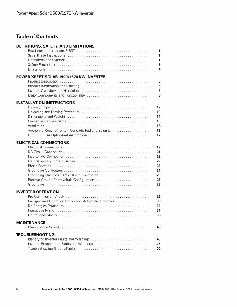
Table of Contents
DEFINITIONS, SAFETY, AND LIMITATIONSRead these Instructions FIRST . . . . . . . . . . . . . . . . . . . . . . . . . . . . . . . . . . . . . 1
Save These Instructions . . . . . . . . . . . . . . . . . . . . . . . . . . . . . . . . . . . . . . . . . . 1
Definitions and Symbols . . . . . . . . . . . . . . . . . . . . . . . . . . . . . . . . . . . . . . . . . . 1
Safety Procedures . . . . . . . . . . . . . . . . . . . . . . . . . . . . . . . . . . . . . . . . . . . . . . . 2
Limitations . . . . . . . . . . . . . . . . . . . . . . . . . . . . . . . . . . . . . . . . . . . . . . . . . . . . . 4
POWER XPERT SOLAR 1500/1670 KW INVERTERProduct Description . . . . . . . . . . . . . . . . . . . . . . . . . . . . . . . . . . . . . . . . . . . . . . 5
Product Information and Labeling . . . . . . . . . . . . . . . . . . . . . . . . . . . . . . . . . . . 5
Inverter Overview and Highlights . . . . . . . . . . . . . . . . . . . . . . . . . . . . . . . . . . . 6
Major Components and Functionality . . . . . . . . . . . . . . . . . . . . . . . . . . . . . . . . 8
INSTALLATION INSTRUCTIONSDelivery Inspection . . . . . . . . . . . . . . . . . . . . . . . . . . . . . . . . . . . . . . . . . . . . . . 13
Unloading and Moving Procedure . . . . . . . . . . . . . . . . . . . . . . . . . . . . . . . . . . . 13
Dimensions and Weight . . . . . . . . . . . . . . . . . . . . . . . . . . . . . . . . . . . . . . . . . . 14
Clearance Requirements . . . . . . . . . . . . . . . . . . . . . . . . . . . . . . . . . . . . . . . . . . 15
Ventilation . . . . . . . . . . . . . . . . . . . . . . . . . . . . . . . . . . . . . . . . . . . . . . . . . . . . . 16
Anchoring Requirements—Concrete Pad and Seismic . . . . . . . . . . . . . . . . . . . 16
DC Input Fuse Options—Re-Combiner . . . . . . . . . . . . . . . . . . . . . . . . . . . . . . . 17
ELECTRICAL CONNECTIONSElectrical Connections . . . . . . . . . . . . . . . . . . . . . . . . . . . . . . . . . . . . . . . . . . . . 19
DC Circuit Connection . . . . . . . . . . . . . . . . . . . . . . . . . . . . . . . . . . . . . . . . . . . . 21
Inverter AC Connection . . . . . . . . . . . . . . . . . . . . . . . . . . . . . . . . . . . . . . . . . . . 22
Neutral and Equipment Ground . . . . . . . . . . . . . . . . . . . . . . . . . . . . . . . . . . . . . 23
Phase Rotation . . . . . . . . . . . . . . . . . . . . . . . . . . . . . . . . . . . . . . . . . . . . . . . . . 23
Grounding Conductors . . . . . . . . . . . . . . . . . . . . . . . . . . . . . . . . . . . . . . . . . . . . 24
Grounding Electrode Terminal and Conductor . . . . . . . . . . . . . . . . . . . . . . . . . . 25
Positive-Ground Photovoltaic Configuration . . . . . . . . . . . . . . . . . . . . . . . . . . . 26
Grounding . . . . . . . . . . . . . . . . . . . . . . . . . . . . . . . . . . . . . . . . . . . . . . . . . . . . . 26
INVERTER OPERATIONPre-Commission Check . . . . . . . . . . . . . . . . . . . . . . . . . . . . . . . . . . . . . . . . . . . 29
Energize and Operation Procedure: Automatic Operation . . . . . . . . . . . . . . . . . 30
De-Energize Procedure . . . . . . . . . . . . . . . . . . . . . . . . . . . . . . . . . . . . . . . . . . . 33
Interactive Menu . . . . . . . . . . . . . . . . . . . . . . . . . . . . . . . . . . . . . . . . . . . . . . . . 34
Operational States . . . . . . . . . . . . . . . . . . . . . . . . . . . . . . . . . . . . . . . . . . . . . . . 36
MAINTENANCEMaintenance Schedule . . . . . . . . . . . . . . . . . . . . . . . . . . . . . . . . . . . . . . . . . . . 40
TROUBLESHOOTINGIdentifying Inverter Faults and Warnings . . . . . . . . . . . . . . . . . . . . . . . . . . . . . . 43
Inverter Response to Faults and Warnings . . . . . . . . . . . . . . . . . . . . . . . . . . . . 43
Troubleshooting Ground-Faults . . . . . . . . . . . . . . . . . . . . . . . . . . . . . . . . . . . . . 56
Power Xpert Solar 1500/1670 kW Inverter
Power Xpert Solar 1500/1670 kW Inverter MN141001EN—October 2014 www.eaton.com v
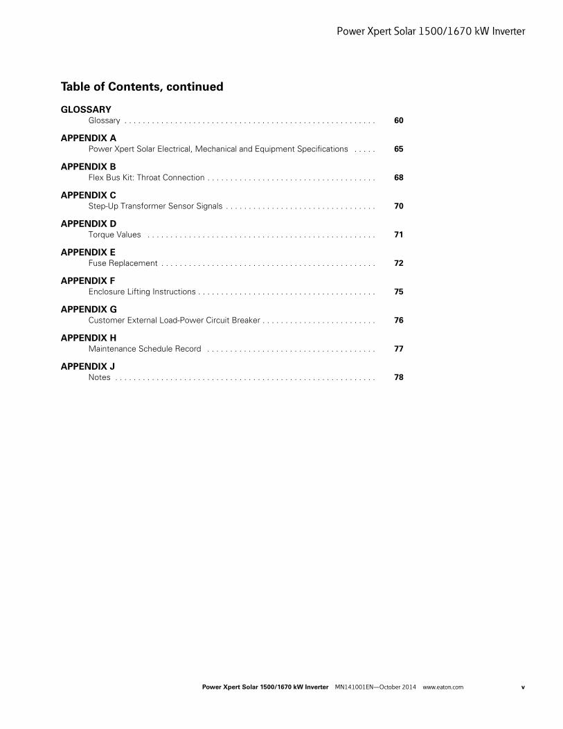
Table of Contents, continued
GLOSSARYGlossary . . . . . . . . . . . . . . . . . . . . . . . . . . . . . . . . . . . . . . . . . . . . . . . . . . . . . . . 60
APPENDIX APower Xpert Solar Electrical, Mechanical and Equipment Specifications . . . . . 65
APPENDIX BFlex Bus Kit: Throat Connection . . . . . . . . . . . . . . . . . . . . . . . . . . . . . . . . . . . . . 68
APPENDIX CStep-Up Transformer Sensor Signals . . . . . . . . . . . . . . . . . . . . . . . . . . . . . . . . . 70
APPENDIX DTorque Values . . . . . . . . . . . . . . . . . . . . . . . . . . . . . . . . . . . . . . . . . . . . . . . . . . 71
APPENDIX EFuse Replacement . . . . . . . . . . . . . . . . . . . . . . . . . . . . . . . . . . . . . . . . . . . . . . . 72
APPENDIX FEnclosure Lifting Instructions . . . . . . . . . . . . . . . . . . . . . . . . . . . . . . . . . . . . . . . 75
APPENDIX GCustomer External Load-Power Circuit Breaker . . . . . . . . . . . . . . . . . . . . . . . . . 76
APPENDIX HMaintenance Schedule Record . . . . . . . . . . . . . . . . . . . . . . . . . . . . . . . . . . . . . 77
APPENDIX JNotes . . . . . . . . . . . . . . . . . . . . . . . . . . . . . . . . . . . . . . . . . . . . . . . . . . . . . . . . . 78
Power Xpert Solar 1500/1670 kW Inverter
vi Power Xpert Solar 1500/1670 kW Inverter MN141001EN—October 2014 www.eaton.com
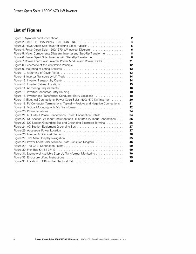
List of Figures
Figure 1. Symbols and Descriptions . . . . . . . . . . . . . . . . . . . . . . . . . . . . . . . . . . . . . . . . 2
Figure 2. DANGER—WARNING—CAUTION—NOTICE . . . . . . . . . . . . . . . . . . . . . . . . . 4
Figure 3. Power Xpert Solar Inverter Rating Label (Typical) . . . . . . . . . . . . . . . . . . . . . . 5
Figure 4. Power Xpert Solar 1500/1670 kW Inverter Diagram . . . . . . . . . . . . . . . . . . . . 6
Figure 5. Major Components Diagram: Inverter and Step-Up Transformer . . . . . . . . . . 8
Figure 6. Power Xpert Solar Inverter with Step-Up Transformer . . . . . . . . . . . . . . . . . . 8
Figure 7. Power Xpert Solar: Inverter Power Module and Power Stacks . . . . . . . . . . . . 11
Figure 8. Schematic of the Ventilation-Principle . . . . . . . . . . . . . . . . . . . . . . . . . . . . . . . 12
Figure 9. Mounting of Lifting Brackets . . . . . . . . . . . . . . . . . . . . . . . . . . . . . . . . . . . . . . 13
Figure 10. Mounting of Cover Plates . . . . . . . . . . . . . . . . . . . . . . . . . . . . . . . . . . . . . . . 13
Figure 11. Inverter Transport by Lift Truck . . . . . . . . . . . . . . . . . . . . . . . . . . . . . . . . . . . . 14
Figure 12. Inverter Transport by Crane . . . . . . . . . . . . . . . . . . . . . . . . . . . . . . . . . . . . . . 14
Figure 13. Inverter Cabinet Locations . . . . . . . . . . . . . . . . . . . . . . . . . . . . . . . . . . . . . . 15
Figure 14. Anchoring Requirements . . . . . . . . . . . . . . . . . . . . . . . . . . . . . . . . . . . . . . . 16
Figure 15. Inverter Conductor Entry-Routing . . . . . . . . . . . . . . . . . . . . . . . . . . . . . . . . . 18
Figure 16. Inverter and Transformer Conductor Entry Locations . . . . . . . . . . . . . . . . . . 18
Figure 17. Electrical Connections, Power Xpert Solar 1500/1670 kW Inverter . . . . . . . . 20
Figure 18. PV Conductor Terminations (Typical)—Positive and Negative Connections . 21
Figure 19. Typical Mounting with MV Transformer . . . . . . . . . . . . . . . . . . . . . . . . . . . . 22
Figure 20. Phase Locations . . . . . . . . . . . . . . . . . . . . . . . . . . . . . . . . . . . . . . . . . . . . . . 24
Figure 21. AC Output Phase Connections: Throat Connection Details . . . . . . . . . . . . . 24
Figure 22. DC Section: 24 Input-Circuit options, Illustrated PV Input Connections . . . . 26
Figure 23. DC Section Grounding Bus and Grounding Electrode Terminal . . . . . . . . . . 26
Figure 24. AC Section Equipment Grounding Bus . . . . . . . . . . . . . . . . . . . . . . . . . . . . . 27
Figure 25. Accessory Power Location . . . . . . . . . . . . . . . . . . . . . . . . . . . . . . . . . . . . . . 27
Figure 26. Inverter AC Cabinet Section . . . . . . . . . . . . . . . . . . . . . . . . . . . . . . . . . . . . . 28
Figure 27. HMI Menu Display Navigation . . . . . . . . . . . . . . . . . . . . . . . . . . . . . . . . . . . . 35
Figure 28. Power Xpert Solar Machine-State Transition Diagram . . . . . . . . . . . . . . . . . 46
Figure 29. The GFDI Connection Points . . . . . . . . . . . . . . . . . . . . . . . . . . . . . . . . . . . . . 59
Figure 30. Flex Bus Kit: 84-37413-1 . . . . . . . . . . . . . . . . . . . . . . . . . . . . . . . . . . . . . . . . 69
Figure 31. Example of Available Step-Up Transformer Monitoring . . . . . . . . . . . . . . . . . 70
Figure 32. Enclosure Lifting Instructions . . . . . . . . . . . . . . . . . . . . . . . . . . . . . . . . . . . . 75
Figure 33. Location of CB4 in the Electrical Path . . . . . . . . . . . . . . . . . . . . . . . . . . . . . . 76
Power Xpert Solar 1500/1670 kW Inverter
Power Xpert Solar 1500/1670 kW Inverter MN141001EN—October 2014 www.eaton.com vii
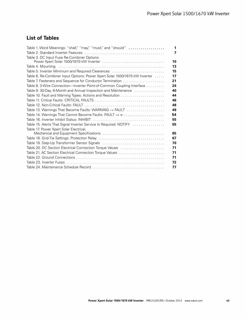
List of Tables
Table 1. Word Meanings: “shall,” “may,” “must,” and “should” . . . . . . . . . . . . . . . . . . 1
Table 2. Standard Inverter Features . . . . . . . . . . . . . . . . . . . . . . . . . . . . . . . . . . . . . . . . 7
Table 3. DC Input Fuse Re-Combiner Options: Power Xpert Solar 1500/1670 kW Inverter . . . . . . . . . . . . . . . . . . . . . . . . . . . . . . . 10
Table 4. Mounting . . . . . . . . . . . . . . . . . . . . . . . . . . . . . . . . . . . . . . . . . . . . . . . . . . . . . 13
Table 5. Inverter Minimum and Required Clearances . . . . . . . . . . . . . . . . . . . . . . . . . . 15
Table 6. Re-Combiner Input Options: Power Xpert Solar 1500/1670 kW Inverter . . . . . 17
Table 7. Fasteners and Sequence for Conductor Termination . . . . . . . . . . . . . . . . . . . . . 21
Table 8. 3-Wire Connection—Inverter Point-of-Common Coupling Interface . . . . . . . . . 24
Table 9. 30-Day, 6-Month and Annual Inspection and Maintenance . . . . . . . . . . . . . . . 40
Table 10. Fault and Warning Types: Actions and Resolution . . . . . . . . . . . . . . . . . . . . . . 44
Table 11. Critical Faults: CRITICAL FAULTS . . . . . . . . . . . . . . . . . . . . . . . . . . . . . . . . . . . 46
Table 12. Non-Critical Faults: FAULT . . . . . . . . . . . . . . . . . . . . . . . . . . . . . . . . . . . . . . . . 48
Table 13. Warnings That Become Faults: WARNING R FAULT . . . . . . . . . . . . . . . . . . . 49
Table 14. Warnings That Cannot Become Faults: FAULT R . . . . . . . . . . . . . . . . . . . . . 54
Table 16. Inverter Inhibit Status: INHIBIT . . . . . . . . . . . . . . . . . . . . . . . . . . . . . . . . . . . . 55
Table 15. Alerts That Signal Inverter Service Is Required: NOTIFY . . . . . . . . . . . . . . . . 55
Table 17. Power Xpert Solar Electrical, Mechanical and Equipment Specifications . . . . . . . . . . . . . . . . . . . . . . . . . . . . . . . 65
Table 18. Grid-Tie Settings: Protection Relay . . . . . . . . . . . . . . . . . . . . . . . . . . . . . . . . . 67
Table 19. Step-Up Transformer Sensor Signals . . . . . . . . . . . . . . . . . . . . . . . . . . . . . . . 70
Table 20. DC Section Electrical Connection Torque Values . . . . . . . . . . . . . . . . . . . . . . 71
Table 21. AC Section Electrical Connection Torque Values . . . . . . . . . . . . . . . . . . . . . . . 71
Table 22. Ground Connections . . . . . . . . . . . . . . . . . . . . . . . . . . . . . . . . . . . . . . . . . . . . 71
Table 23. Inverter Fuses . . . . . . . . . . . . . . . . . . . . . . . . . . . . . . . . . . . . . . . . . . . . . . . . . 72
Table 24. Maintenance Schedule Record . . . . . . . . . . . . . . . . . . . . . . . . . . . . . . . . . . . . 77
Power Xpert Solar 1500/1670 kW Inverter
viii Power Xpert Solar 1500/1670 kW Inverter MN141001EN—October 2014 www.eaton.com
Definitions, Safety, and Limitations
Power Xpert Solar 1500/1670 kW Inverter MN141001EN—October 2014 www.eaton.com 1
Definitions, Safety, and Limitations
Read these Instructions FIRSTRead this manual thoroughly and make sure the procedures are understood before attempting to receive, install, commission, operate, or maintain the inverter.
Do not attempt to receive, install, operate, or maintain this equipment without proper training, tools, and safety equipment.
Save These Instructions
SAVE THESE INSTRUCTIONS—This manual contains important instructions for the Power Xpert Solar 1500/1670 kW Inverters that shall be followed during all aspects of planning, designing-in, ordering, receiving, installing, operating, and maintaining the inverter.
Definitions and Symbols
Nomenclature and Glossary
In this document, the Power Xpert Solar 1500/1670 kW Inverter is referred to as Power Xpert Solar or the Inverter.
A glossary covering many of the terms applicable to the understanding and operation of these grid-tie photovoltaic (PV) inverters is included. The glossary defines terms used within this document and applicable to photovoltaic-inverter applications and photovoltaic systems.
DANGER, WARNING, CAUTION, and NOTICE
Through this document and the inverter itself, the wording and use of the symbols; Danger, Danger of Electric Shock Hazard; Warning!; Caution!; and Notices! have specific meanings and precede task-descriptions in compliance with the NEC®, OSHA, NFPA-70E®, and industry practice. While repetitive in nature, they alert of the potential personal and physical dangers associated with equipment. The specific text accompanies each of the specific symbols.
DANGER is used when an accident will happen and the result will be death or serious injury.
WARNING is used when an accident could happen and the probability of death or serious injury.
CAUTION is used when an accident could happen and the result will be moderate or minor injury.
NOTICE is used when an accident could result in property or equipment damage.
DANGER of Electric Shock Hazard
DANGER of Electric Shock Hazard indicates a hazardous situation that, if not avoided, will result in death or serious injury.
When this symbol appears in this document or is posted on/in the inverter equipment, read and follow the instructions carefully.
WARNING!
WARNING indicates a hazardous situation that, if not avoided, could result in death or serious injury.
When this symbol appears in this document or is posted in/on the inverter equipment, read and follow the instructions carefully.
CAUTION!
CAUTION indicates a hazardous situation that, if not avoided, could result in moderate or minor injury.
When this symbol appears in this document or is posted in/on the inverter equipment, read and follow the instructions carefully.
NOTICE!
NOTICE indicates a situation that, if not avoided, can result in property or equipment damage.
When this symbol appears in this document or is posted in/on the inverter equipment, read and follow the instructions carefully.
shall—may—must—should
These words derive from various sources including the Code of Federal Regulations (USA), Title 29, Part 1910, NFPA Standard 70E-2009/11 Edition and Eaton policy documents. When used in this document their meanings are as follows:
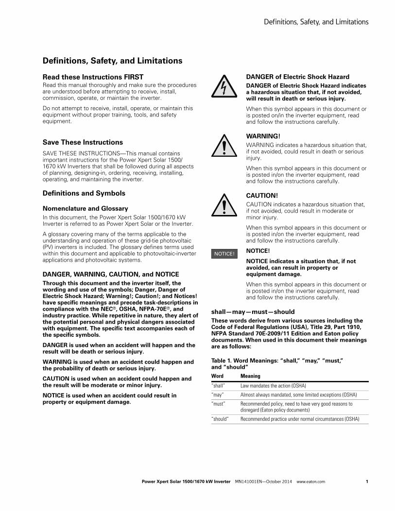
Table 1. Word Meanings: “shall,” “may,” “must,” and “should”
Word Meaning
“shall” Law mandates the action (OSHA)
“may” Almost always mandated, some limited exceptions (OSHA)
“must” Recommended policy, need to have very good reasons to disregard (Eaton policy documents)
“should” Recommended practice under normal circumstances (OSHA)
Definitions, Safety, and Limitations
2 Power Xpert Solar 1500/1670 kW Inverter MN141001EN—October 2014 www.eaton.com
Symbols
Definition of the symbols used within this document and inverter.
Figure 1. Symbols and Descriptions
Safety Procedures
Personal Safety
When installing or maintaining the Power Xpert Solar inverter, there are exposed components with housings or protrusions at or above utility and photovoltaic voltage potentials. Extreme care shall be taken to protect against electric shock and arc-flash hazards by de-energizing and isolating all sources of connected and stored energy BEFORE attempting to install or perform work on/inside the Power Xpert Solar.
Verify all equipment and tools are properly grounded. Stand on an insulating pad and make it a habit to use only the right hand when checking components. Always work with another person in case an emergency occurs.
Wear appropriate electrical personal protective equipment (PPE), including safety glasses and hearing protection whenever working on this equipment and while operating rotating or moving machinery during installation or performing maintenance or service.
Disconnect all sources of power prior to accessing any portion of the inverter following OSHA and NFPA-70E electric-shock and arc-flash safety procedures.
All Danger, Danger of Electric Shock Hazard; Warning!; Caution!; and Notices! alerts must be followed for the proper and warranted use of the inverter.
Equipment Safety
The inverter shall be installed in accordance with all applicable codes and regulations. Consult the latest edition of NFPA 70: National Electrical Code®. The installer and operator shall comply with Code, building, fire marshal, and seismic standards and with NFPA 70E. Utility interconnect approval is required before installation and operation of this medium voltage grid-tie photovoltaic inverter.
Canadian installations shall follow the NEC 690 and applicable Canadian Standards Association (CSA), Canadian Electrical Code (CE Code), and the National Building Code of Canada (NBC). Consult all local and utility regulations for solar photovoltaic.
Non-Code compliant installations will adversely affect the safe usage and serviceability of the inverter, including applicable balance-of-system products, including the photovoltaic modules. Use only modules specific for grounded PV systems.
The inverter is designed and certified to meet the NEC, OSHA, and NFPA-70E standards and installation methods. These shall take precedence over non-USA centric regulations.
Lock Out Tag Out (LOTO)
When installing or maintaining the inverter, Lock Out and Tag Out (LOTO) all Photovoltaic and Grid (utility) disconnects before working on the equipment.
A LOTO policy must be in place when working on the inverter and solar site.
- or “-”
-- or “+”
Symbol DescriptionDirect current
Alternating current- sinusoidal waveform - Phase symbol for AC electricity
Used to identify field-wiring Equipment Grounding Conductor (EGC)
Used for identifying points within equipment that are intended to be bounded to earth ground (e.g., GET). ON
OFF
Negative PV
Positive PV
Ø
Definitions, Safety, and Limitations
Power Xpert Solar 1500/1670 kW Inverter MN141001EN—October 2014 www.eaton.com 3
De-Energizing the Inverter
The Power Xpert Solar 1500/1670 kW Inverter is designed to be connected to photovoltaic DC energy and export AC energy. It stores a significant amount of capacitance electrical energy.
The Inverter Must Be Considered Energized Whenever:
● The medium voltage transformer is energized from the utility.
● The inverter’s main output circuit breaker CB1 is closed.
● The inverter’s control-power circuit breaker CB2 is closed.
● Any of the PV System’s external (to the inverter) disconnects are closed.
Closed (ON) means the switching-device contact(s)’ are engaged and able to transfer energy: Voltage or Current.
AC and DC Disconnecting Means:
● The inverter does not provide a means to isolate utility voltage on the transformer-side of circuit breaker CB1, CB2 or CB4, which are located inside the inverter AC cabinet (section) outer door panel.
● The AC bus will be energized whenever the MV transformer is energized.
● The inverter does not provide a means to isolate input-circuits from the PV system’s side of disconnects DS1, DS2, and DS3, nor the inverter’s pre-charge fuses located inside the doors of the inverter DC cabinet (section).
● The DC Cabinet Section will be energized whenever external PV-disconnects are closed (electrically connected to the inverter)
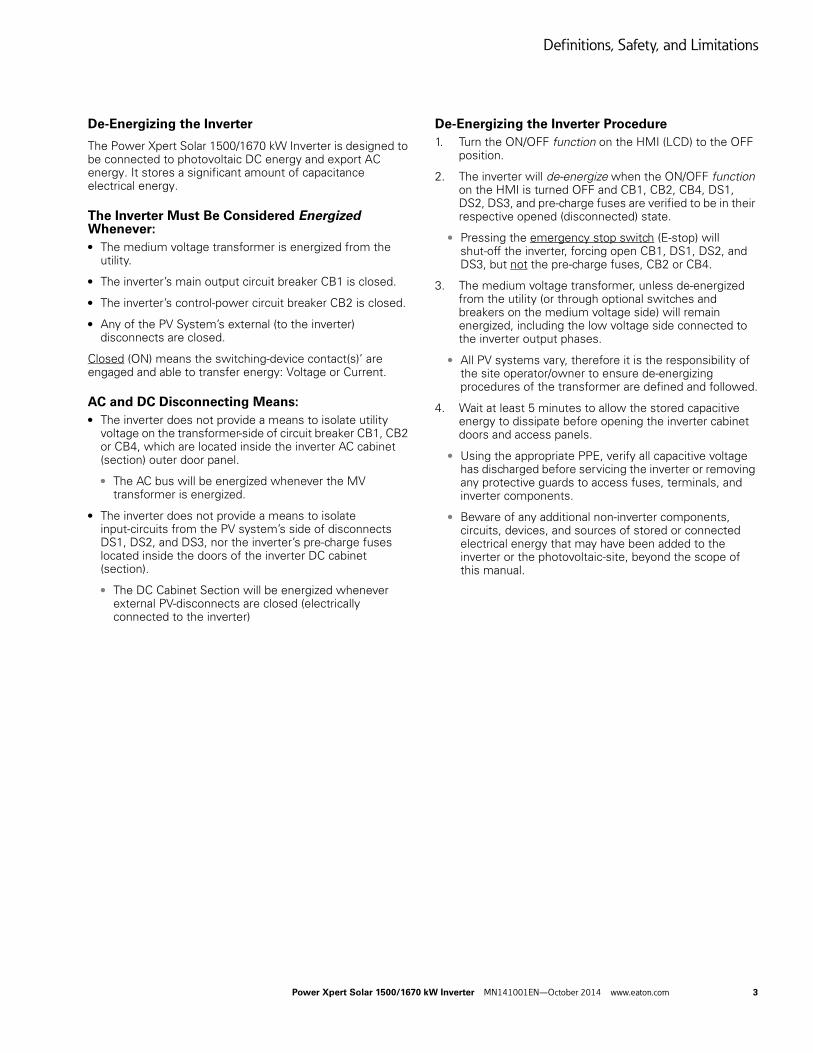
De-Energizing the Inverter Procedure
1. Turn the ON/OFF function on the HMI (LCD) to the OFF position.
2. The inverter will de-energize when the ON/OFF function on the HMI is turned OFF and CB1, CB2, CB4, DS1, DS2, DS3, and pre-charge fuses are verified to be in their respective opened (disconnected) state.
● Pressing the emergency stop switch (E-stop) will shut-off the inverter, forcing open CB1, DS1, DS2, and DS3, but not the pre-charge fuses, CB2 or CB4.
3. The medium voltage transformer, unless de-energized from the utility (or through optional switches and breakers on the medium voltage side) will remain energized, including the low voltage side connected to the inverter output phases.
● All PV systems vary, therefore it is the responsibility of the site operator/owner to ensure de-energizing procedures of the transformer are defined and followed.
4. Wait at least 5 minutes to allow the stored capacitive energy to dissipate before opening the inverter cabinet doors and access panels.
● Using the appropriate PPE, verify all capacitive voltage has discharged before servicing the inverter or removing any protective guards to access fuses, terminals, and inverter components.
● Beware of any additional non-inverter components, circuits, devices, and sources of stored or connected electrical energy that may have been added to the inverter or the photovoltaic-site, beyond the scope of this manual.
Definitions, Safety, and Limitations
4 Power Xpert Solar 1500/1670 kW Inverter MN141001EN—October 2014 www.eaton.com
Photovoltaic Ground-Fault
The inverter is designed for grounded PV systems only. It is furnished with photovoltaic Ground-Fault Detection and Interruption (GFDI). If the inverter detects a PV Ground Fault, it will interrupt the fault-current within the inverter, set a ground-fault alarm error message visual on the HMI (LCD) and Modbus, stop exporting power (turn-off) and open CB1, DS1, DS2, and DS3. Additional corrective and protective actions will be required when this alarm is active. Refer to “Troubleshooting Ground Faults” on Page 43 for a detailed description of the ground fault detection and interruption circuit: operation and servicing requirements.
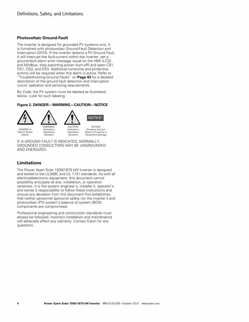
By Code, the PV system must be labeled as illustrated, below. Look for such labeling.
Figure 2. DANGER—WARNING—CAUTION—NOTICE
IF A GROUND FAULT IS INDICATED, NORMALLY GROUNDED CONDUCTORS MAY BE UNGROUNDED AND ENERGIZED.
Limitations
The Power Xpert Solar 1500/1670 kW Inverter is designed and tested to the UL508C and UL 1741 standards. As with all electrical/electronic equipment, this document cannot possibility anticipate all site, installation, or operation variances. It is the system engineer’s, installer’s, operator’s and owner’s responsibility to follow these instructions and ensure any deviation from this document first establishes that neither personnel (persons) safety nor the inverter’s and photovoltaic (PV) system’s balance of system (BOS) components are compromised.
Professional engineering and construction standards must always be followed. Incorrect installation and maintenance will adversely affect any warranty. Contact Eaton for any questions.
DANGER of
Electric Shock
Hazard
WARNING!
Indicates a
Hazardous
Situation
CAUTION!
Indicates a
Hazardous
Situation
NOTICE!
Situation that can
Result in Property or
Equipment Damage
Power Xpert Solar 1500/1670 kW Inverter
Power Xpert Solar 1500/1670 kW Inverter MN141001EN—October 2014 www.eaton.com 5
Power Xpert Solar 1500/1670 kW Inverter
Product Description
The Power Xpert Solar 1500/1670 kW Inverter is designed for commercial and utility-scale photovoltaic systems. Engineered for ease-of-installation, operation and maintenance, the inverter contains the intelligence to facilitate the commissioning, operation and shut-down procedures. The inverter is based upon proprietary Eaton technology, algorithms, and software.
The Power Xpert Solar 1500/1670 kW Inverter is designed specifically for North American, 60-Hertz, 3-phase grid tie applications and 1000 Vdc (array Voc) photovoltaic modules and systems. The medium voltage level must be defined when ordering.
Product Information and Labeling
Complete inverter specifications are listed in Appendix A.
The most up-to-date inverter information and documentation is available on the internet.
Navigate to: www.eaton.com/PowerXpertSolar
On the front of the inverter, near the Rating Label is the unit general order number (GO#) and the serial number. Please use this identification when contacting Eaton regarding your inverter.
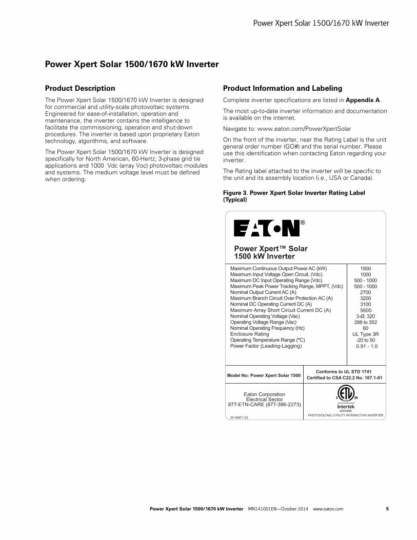
The Rating label attached to the inverter will be specific to the unit and its assembly location (i.e., USA or Canada).
Figure 3. Power Xpert Solar Inverter Rating Label (Typical)
30-46871-02
Model No: Power Xpert Solar 1500
4003986
PHOTOVOLTAIC UTIILITY INTERACTIVE INVERTER
®
Maximum Continuous Output Power AC (kW)Maximum Input Voltage Open Circuit, (Vdc)Maximum DC Input Operating Range (Vdc)Maximum Peak Power Tracking Range, MPPT, (Vdc)Nominal Output Current AC (A)Maximum Branch Circuit Over Protection AC (A) Nominal DC Operating Current DC (A)
Maximum Array Short Circuit Current DC (A)Nominal Operating Voltage (Vac)Operating Voltage Range (Vac)Nominal Operating Frequency (Hz)Enclosure RatingOperating
Temperature Range (°C)Power Factor (Leading-Lagging)
15001000
500 - 1000500 - 1000
270032003100
56003-Ø, 320
288 to 35260
UL
Type 3R-20 to 50
0.91 - 1.0
Power Xpert™ Solar1500 kW Inverter
Eaton CorporationElectrical Sector
877-ETN-CARE (877-386-2273)
Conforms to UL STD 1741
Certified to CSA C22.2 No. 107.1-01
Power Xpert Solar 1500/1670 kW Inverter
6 Power Xpert Solar 1500/1670 kW Inverter MN141001EN—October 2014 www.eaton.com
Inverter Overview and Highlights
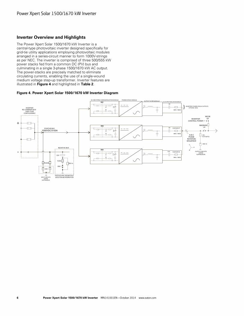
The Power Xpert Solar 1500/1670 kW Inverter is a central-type photovoltaic inverter designed specifically for grid-tie utility applications employing photovoltaic modules arranged in a series-circuit manner to form 1000V-strings as per NEC. The inverter is comprised of three 500/555 kW power stacks fed from a common DC (PV) bus and culminating in a single 3-phase 1500/1670 kW AC output. The power-stacks are precisely matched to eliminate circulating currents, enabling the use of a single-wound medium voltage step-up transformer. Inverter features are illustrated in Figure 4 and highlighted in Table 2.
Figure 4. Power Xpert Solar 1500/1670 kW Inverter Diagram
+
DS1
K1
K2
K11
DC-INPUT/PRE-CHARGE/ISOLATION MODULE POWER-STACK MODULEOUTPUT FILTER MODULE
AC-OUTPUT/ISOLATION MODULE
3
K8
690V, 1800A
DS3
K1
K2
K13
3
K10 F28/F29/F30
690V, 1800A
DS2
K3
K4
K12
3
K9 F25/F26/F27
690V, 1800A
} INVERTER POWER-STACK OUTPUTS
3-PHASE- 60Hz
CB2INVERTER
CONTROL POWER
CB1
30A
F31/F32/F33
A-B-C
PHASE
ROTATION
SEQUENCE
3
SS2 /4
OUTPUT-CIRCUITS
SURGE
SUPPRESSOR
A
B
C
-
INVERTER
RE-COMBINER BOX
1000V FUSE
CONFIGURABLE
POSITIVE BUS
1000VDC/3100A
NEGATIVE BUS
F2/20A
SS1
CS1
F3/5A
CB3
RG1-4
INPUT-CIRCUITS
SURGE
SUPPRESSOR
PHOTOVOLATAIC GROUND FAULT
DETECTION AND INTERRUPTION
MCCB
MAGNUM
Power Xpert Solar 1500/1670 kW Inverter
Power Xpert Solar 1500/1670 kW Inverter MN141001EN—October 2014 www.eaton.com 7
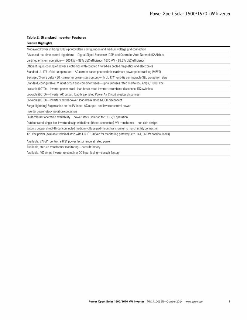
Table 2. Standard Inverter Features
Feature Highlights
Megawatt Power utilizing 1000V-photovoltaic configuration and medium voltage grid connection
Advanced real-time control algorithms—Digital Signal Processor (DSP) and Controller Area Network (CAN) bus
Certified efficient operation—1500 kW = 98% CEC efficiency; 1670 kW = 98.5% CEC efficiency
Efficient liquid-cooling of power electronics with coupled filtered-air cooled magnetics and electronics
Standard UL 1741 Grid-tie operation—AC current-based photovoltaic maximum power point tracking (MPPT)
3-phase / 3-wire delta / 60 Hz inverter power-stack output with UL 1741 grid-tie configurable SEL protection relay
Standard, configurable PV input circuit sub-combiner fuses—up to 24 fuses rated 160 to 355 Amps / 1000 Vdc
Lockable (LOTO)—Inverter power-stack, load-break rated inverter-recombiner disconnect DC switches
Lockable (LOTO)—Inverter AC output, load-break rated Power Air Circuit Breaker disconnect
Lockable (LOTO)—Inverter control-power, load-break rated MCCB disconnect
Surge (lightning) Suppression on the PV input, AC output, and Inverter control power
Inverter power-stack isolation contactors
Fault-tolerant operation availability—power-stack isolation for 1/3, 2/3 operation
Outdoor rated single-box inverter design with direct (throat-connected) MV transformer—non-skid design
Eaton’s Cooper direct-throat connected medium voltage pad-mount transformer to match utility connection
120 Vac power (available terminal strip with L-N-G 120 Vac for monitoring gateway, etc.; 3 A, 360 W nominal loads)
Available, VAR/PF control; ± 0.91 power factor range at rated power
Available, step-up transformer monitoring—consult factory
Available, 400 Amps inverter re-combiner DC input fusing—consult factory
Power Xpert Solar 1500/1670 kW Inverter
8 Power Xpert Solar 1500/1670 kW Inverter MN141001EN—October 2014 www.eaton.com
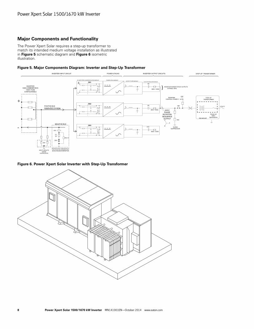
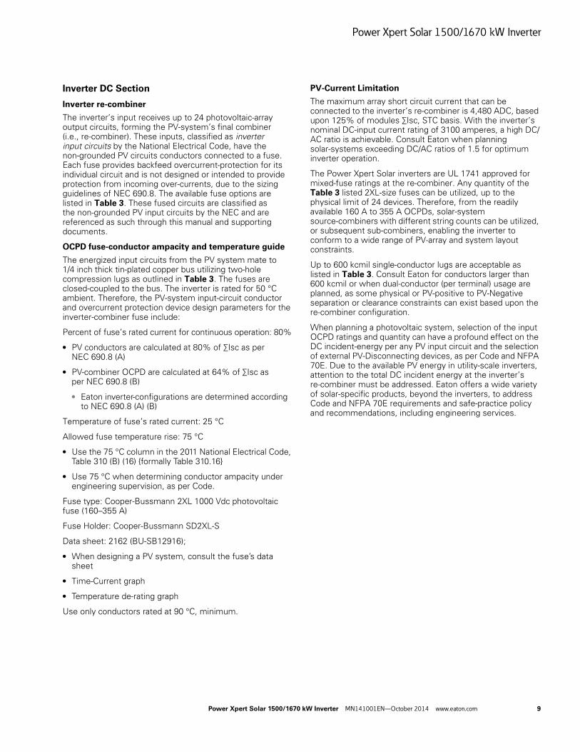
Major Components and Functionality
The Power Xpert Solar requires a step-up transformer to match its intended medium voltage installation as illustrated in Figure 5 schematic diagram and Figure 6 isometric illustration.
Figure 5. Major Components Diagram: Inverter and Step-Up Transformer
Figure 6. Power Xpert Solar Inverter with Step-Up Transformer
+
-
+
-}
Power Xpert Solar 1500/1670 kW Inverter
Power Xpert Solar 1500/1670 kW Inverter MN141001EN—October 2014 www.eaton.com 9
Inverter DC Section
Inverter re-combiner
The inverter’s input receives up to 24 photovoltaic-array output circuits, forming the PV-system’s final combiner (i.e., re-combiner). These inputs, classified as inverter input circuits by the National Electrical Code, have the non-grounded PV circuits conductors connected to a fuse. Each fuse provides backfeed overcurrent-protection for its individual circuit and is not designed or intended to provide protection from incoming over-currents, due to the sizing guidelines of NEC 690.8. The available fuse options are listed in Table 3. These fused circuits are classified as the non-grounded PV input circuits by the NEC and are referenced as such through this manual and supporting documents.
OCPD fuse-conductor ampacity and temperature guide
The energized input circuits from the PV system mate to 1/4 inch thick tin-plated copper bus utilizing two-hole compression lugs as outlined in Table 3. The fuses are closed-coupled to the bus. The inverter is rated for 50 °C ambient. Therefore, the PV-system input-circuit conductor and overcurrent protection device design parameters for the inverter-combiner fuse include:
Percent of fuse’s rated current for continuous operation: 80%
● PV conductors are calculated at 80% of ∑Isc as per NEC 690.8 (A)
● PV-combiner OCPD are calculated at 64% of ∑Isc as per NEC 690.8 (B)
● Eaton inverter-configurations are determined according to NEC 690.8 (A) (B)
Temperature of fuse’s rated current: 25 °C
Allowed fuse temperature rise: 75 °C
● Use the 75 °C column in the 2011 National Electrical Code, Table 310 (B) (16) {formally Table 310.16}
● Use 75 °C when determining conductor ampacity under engineering supervision, as per Code.
Fuse type: Cooper-Bussmann 2XL 1000 Vdc photovoltaic fuse (160–355 A)
Fuse Holder: Cooper-Bussmann SD2XL-S
Data sheet: 2162 (BU-SB12916);
● When designing a PV system, consult the fuse’s data sheet
● Time-Current graph
● Temperature de-rating graph
Use only conductors rated at 90 °C, minimum.
PV-Current Limitation
The maximum array short circuit current that can be connected to the inverter’s re-combiner is 4,480 ADC, based upon 125% of modules ∑Isc, STC basis. With the inverter’s nominal DC-input current rating of 3100 amperes, a high DC/AC ratio is achievable. Consult Eaton when planning solar-systems exceeding DC/AC ratios of 1.5 for optimum inverter operation.
The Power Xpert Solar inverters are UL 1741 approved for mixed-fuse ratings at the re-combiner. Any quantity of the Table 3 listed 2XL-size fuses can be utilized, up to the physical limit of 24 devices. Therefore, from the readily available 160 A to 355 A OCPDs, solar-system source-combiners with different string counts can be utilized, or subsequent sub-combiners, enabling the inverter to conform to a wide range of PV-array and system layout constraints.
Up to 600 kcmil single-conductor lugs are acceptable as listed in Table 3. Consult Eaton for conductors larger than 600 kcmil or when dual-conductor (per terminal) usage are planned, as some physical or PV-positive to PV-Negative separation or clearance constraints can exist based upon the re-combiner configuration.
When planning a photovoltaic system, selection of the input OCPD ratings and quantity can have a profound effect on the DC incident-energy per any PV input circuit and the selection of external PV-Disconnecting devices, as per Code and NFPA 70E. Due to the available PV energy in utility-scale inverters, attention to the total DC incident energy at the inverter’s re-combiner must be addressed. Eaton offers a wide variety of solar-specific products, beyond the inverters, to address Code and NFPA 70E requirements and safe-practice policy and recommendations, including engineering services.
Power Xpert Solar 1500/1670 kW Inverter
10 Power Xpert Solar 1500/1670 kW Inverter MN141001EN—October 2014 www.eaton.com
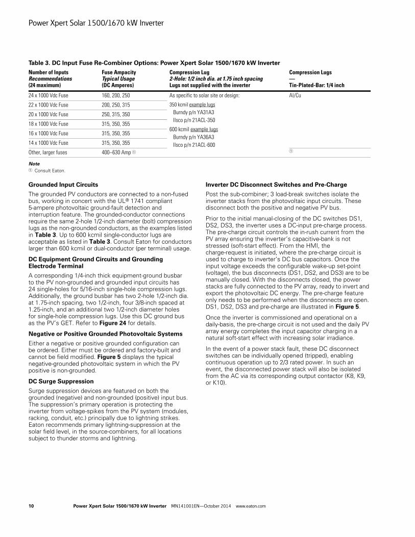
Table 3. DC Input Fuse Re-Combiner Options: Power Xpert Solar 1500/1670 kW Inverter
Note1 Consult Eaton.
Grounded Input Circuits
The grounded PV conductors are connected to a non-fused bus, working in concert with the UL® 1741 compliant 5-ampere photovoltaic ground-fault detection and interruption feature. The grounded-conductor connections require the same 2-hole 1/2-inch diameter (bolt) compression lugs as the non-grounded conductors, as the examples listed in Table 3. Up to 600 kcmil single-conductor lugs are acceptable as listed in Table 3. Consult Eaton for conductors larger than 600 kcmil or dual-conductor (per terminal) usage.
DC Equipment Ground Circuits and Grounding Electrode Terminal
A corresponding 1/4-inch thick equipment-ground busbar to the PV non-grounded and grounded input circuits has 24 single-holes for 5/16-inch single-hole compression lugs. Additionally, the ground busbar has two 2-hole 1/2-inch dia. at 1.75-inch spacing, two 1/2-inch, four 3/8-inch spaced at 1.25-inch, and an additional two 1/2-inch diameter holes for single-hole compression lugs. Use this DC ground bus as the PV’s GET. Refer to Figure 24 for details.
Negative or Positive Grounded Photovoltaic Systems
Either a negative or positive grounded configuration can be ordered. Either must be ordered and factory-built and cannot be field modified. Figure 5 displays the typical negative-grounded photovoltaic system in which the PV positive is non-grounded.
DC Surge Suppression
Surge suppression devices are featured on both the grounded (negative) and non-grounded (positive) input bus. The suppression’s primary operation is protecting the inverter from voltage-spikes from the PV system (modules, racking, conduit, etc.) principally due to lightning strikes. Eaton recommends primary lightning-suppression at the solar field level, in the source-combiners, for all locations subject to thunder storms and lightning.
Inverter DC Disconnect Switches and Pre-Charge
Post the sub-combiner; 3 load-break switches isolate the inverter stacks from the photovoltaic input circuits. These disconnect both the positive and negative PV bus.
Prior to the initial manual-closing of the DC switches DS1, DS2, DS3, the inverter uses a DC-input pre-charge process. The pre-charge circuit controls the in-rush current from the PV array ensuring the inverter’s capacitive-bank is not stressed (soft-start effect). From the HMI, the charge-request is initiated, where the pre-charge circuit is used to charge to inverter’s DC bus capacitors. Once the input voltage exceeds the configurable wake-up set-point (voltage), the bus disconnects (DS1, DS2, and DS3) are to be manually closed. With the disconnects closed, the power stacks are fully connected to the PV array, ready to invert and export the photovoltaic DC energy. The pre-charge feature only needs to be performed when the disconnects are open. DS1, DS2, DS3 and pre-charge are illustrated in Figure 5.
Once the inverter is commissioned and operational on a daily-basis, the pre-charge circuit is not used and the daily PV array energy completes the input capacitor charging in a natural soft-start effect with increasing solar irradiance.
In the event of a power stack fault, these DC disconnect switches can be individually opened (tripped), enabling continuous operation up to 2/3 rated power. In such an event, the disconnected power stack will also be isolated from the AC via its corresponding output contactor (K8, K9, or K10).
Number of InputsRecommendations(24 maximum)
Fuse AmpacityTypical Usage(DC Amperes)
Compression Lug2-Hole: 1/2 inch dia. at 1.75 inch spacingLugs not supplied with the inverter
Compression Lugs—Tin-Plated-Bar: 1/4 inch
24 x 1000 Vdc Fuse 160, 200, 250 As specific to solar site or design:
350 kcmil example lugs Burndy p/n YA31A3 Ilsco p/n 21ACL-350
600 kcmil example lugs Burndy p/n YA36A3 Ilsco p/n 21ACL-600
Al/Cu
22 x 1000 Vdc Fuse 200, 250, 315
20 x 1000 Vdc Fuse 250, 315, 350
18 x 1000 Vdc Fuse 315, 350, 355
16 x 1000 Vdc Fuse 315, 350, 355
14 x 1000 Vdc Fuse 315, 350, 355
Other, larger fuses 400–630 Amp 1 1
Power Xpert Solar 1500/1670 kW Inverter
Power Xpert Solar 1500/1670 kW Inverter MN141001EN—October 2014 www.eaton.com 11
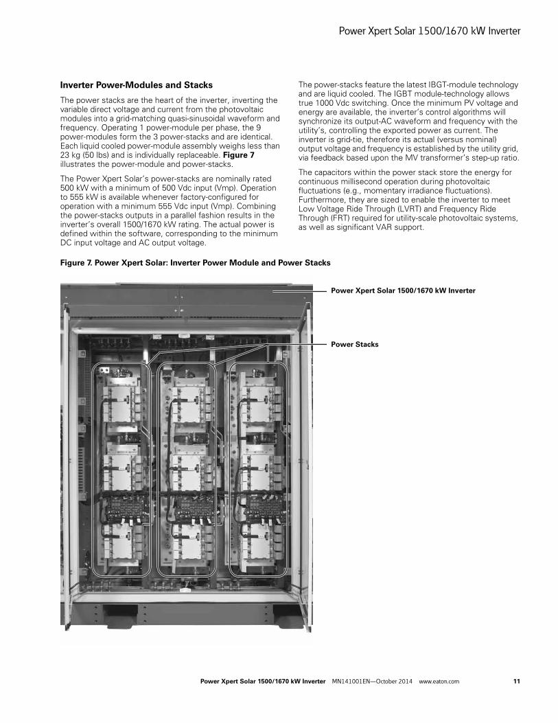
Inverter Power-Modules and Stacks
The power stacks are the heart of the inverter, inverting the variable direct voltage and current from the photovoltaic modules into a grid-matching quasi-sinusoidal waveform and frequency. Operating 1 power-module per phase, the 9 power-modules form the 3 power-stacks and are identical. Each liquid cooled power-module assembly weighs less than 23 kg (50 lbs) and is individually replaceable. Figure 7 illustrates the power-module and power-stacks.
The Power Xpert Solar’s power-stacks are nominally rated 500 kW with a minimum of 500 Vdc input (Vmp). Operation to 555 kW is available whenever factory-configured for operation with a minimum 555 Vdc input (Vmp). Combining the power-stacks outputs in a parallel fashion results in the inverter’s overall 1500/1670 kW rating. The actual power is defined within the software, corresponding to the minimum DC input voltage and AC output voltage.
The power-stacks feature the latest IBGT-module technology and are liquid cooled. The IGBT module-technology allows true 1000 Vdc switching. Once the minimum PV voltage and energy are available, the inverter’s control algorithms will synchronize its output-AC waveform and frequency with the utility’s, controlling the exported power as current. The inverter is grid-tie, therefore its actual (versus nominal) output voltage and frequency is established by the utility grid, via feedback based upon the MV transformer’s step-up ratio.
The capacitors within the power stack store the energy for continuous millisecond operation during photovoltaic fluctuations (e.g., momentary irradiance fluctuations). Furthermore, they are sized to enable the inverter to meet Low Voltage Ride Through (LVRT) and Frequency Ride Through (FRT) required for utility-scale photovoltaic systems, as well as significant VAR support.
Figure 7. Power Xpert Solar: Inverter Power Module and Power Stacks
Power Stacks
Power Xpert Solar 1500/1670 kW Inverter
Power Xpert Solar 1500/1670 kW Inverter
12 Power Xpert Solar 1500/1670 kW Inverter MN141001EN—October 2014 www.eaton.com
Inverter Output Circuit
Inductors and capacitors, working as LC filters on the output stage of the power-stacks, removes (filters) the carrier frequency and smooth’s the voltage waveform, resulting in a nominal 320 AC (357 for the 1670 kW inverter) sinusoidal AC waveform, ready to be transmitted to the step-up medium voltage transformer.
The final components of the individual power-stacks and LC-filter are the isolation contactors, K8, K9, and K10, illustrated in Figure 4. Each isolates the power-stack and LC-filter from the utility-AC before the power-stack outputs are combined in a parallel-output manner prior to the main circuit breaker CB1. Located on the inverter side of CB1, these contactors are opened to isolate the inverter stacks and LC-filters during sleep-mode, faults, and when turned off.
A 3-phase AC surge suppressor (transient voltage suppression) protects the inverter from voltage spikes stemming from the utility-side connection. In areas prone to lightning, utility-side medium voltage suppression is recommended, as is the typical practice for utility-scale projects.
The main AC disconnect is an Eaton Magnum® circuit breaker, noted as CB1 in Figure 4. The circuit breaker CB2, connected on the utility side of CB1, supplies the inverter’s control power. It must be closed prior to inverter operation. When CB2 is off (open/tripped), the inverter will not operate, regardless of whether utility voltage is connected to the medium voltage transformer.
Cooling-System
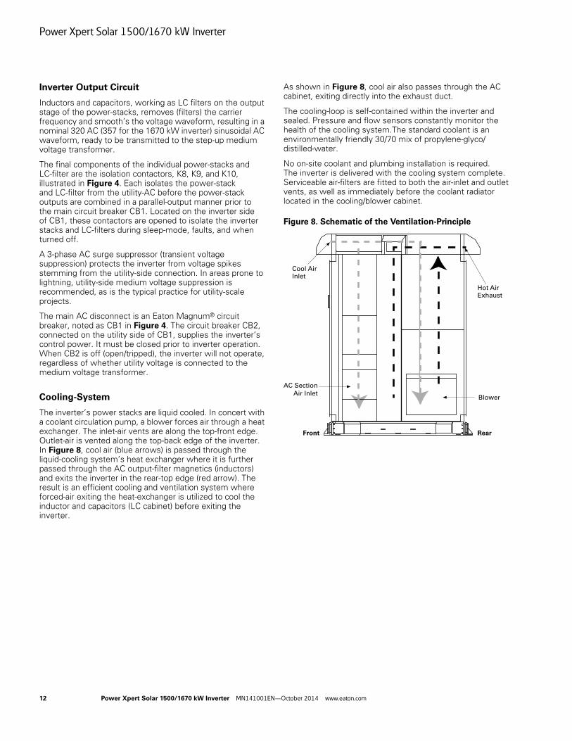
The inverter’s power stacks are liquid cooled. In concert with a coolant circulation pump, a blower forces air through a heat exchanger. The inlet-air vents are along the top-front edge. Outlet-air is vented along the top-back edge of the inverter. In Figure 8, cool air (blue arrows) is passed through the liquid-cooling system’s heat exchanger where it is further passed through the AC output-filter magnetics (inductors) and exits the inverter in the rear-top edge (red arrow). The result is an efficient cooling and ventilation system where forced-air exiting the heat-exchanger is utilized to cool the inductor and capacitors (LC cabinet) before exiting the inverter.
As shown in Figure 8, cool air also passes through the AC cabinet, exiting directly into the exhaust duct.
The cooling-loop is self-contained within the inverter and sealed. Pressure and flow sensors constantly monitor the health of the cooling system.The standard coolant is an environmentally friendly 30/70 mix of propylene-glyco/distilled-water.
No on-site coolant and plumbing installation is required. The inverter is delivered with the cooling system complete. Serviceable air-filters are fitted to both the air-inlet and outlet vents, as well as immediately before the coolant radiator located in the cooling/blower cabinet.
Figure 8. Schematic of the Ventilation-Principle
Cool AirInlet
AC Section
Air Inlet
Hot AirExhaust
Blower
Front Rear
Installation Instructions
Power Xpert Solar 1500/1670 kW Inverter MN141001EN—October 2014 www.eaton.com 13
Installation Instructions
Connect the Power Xpert Solar 1500/1670 kW Inverter to the photovoltaic array and utility per the NEC, ANSI/NFPA70 requirements. Additional utility and local codes may also apply. Following the inverter-specific instructions will ensure optimum performance, longevity, and warranty retention. Contact Eaton if there are any questions.
DANGER of Electric Shock Hazard
WARNING!
NOTICE!
Delivery Inspection
The Power Xpert Solar 1500/1670 kW Inverter undergoes scrupulous tests and quality checks at the factory before delivery. There remains however the possibility of damage during shipment. Upon receiving and unpacking the inverter, verify no damage is found on or inside the product and that the delivery is complete. If the inverter has been damaged during shipping, please contact the carrier and cargo insurance company. If the delivery does not correspond to your order, contact the supply-chain seller immediately.
Note: Shipping damage typically must be declared at the time of delivery.Verify the shipping carrier’s terms before the scheduled delivery.
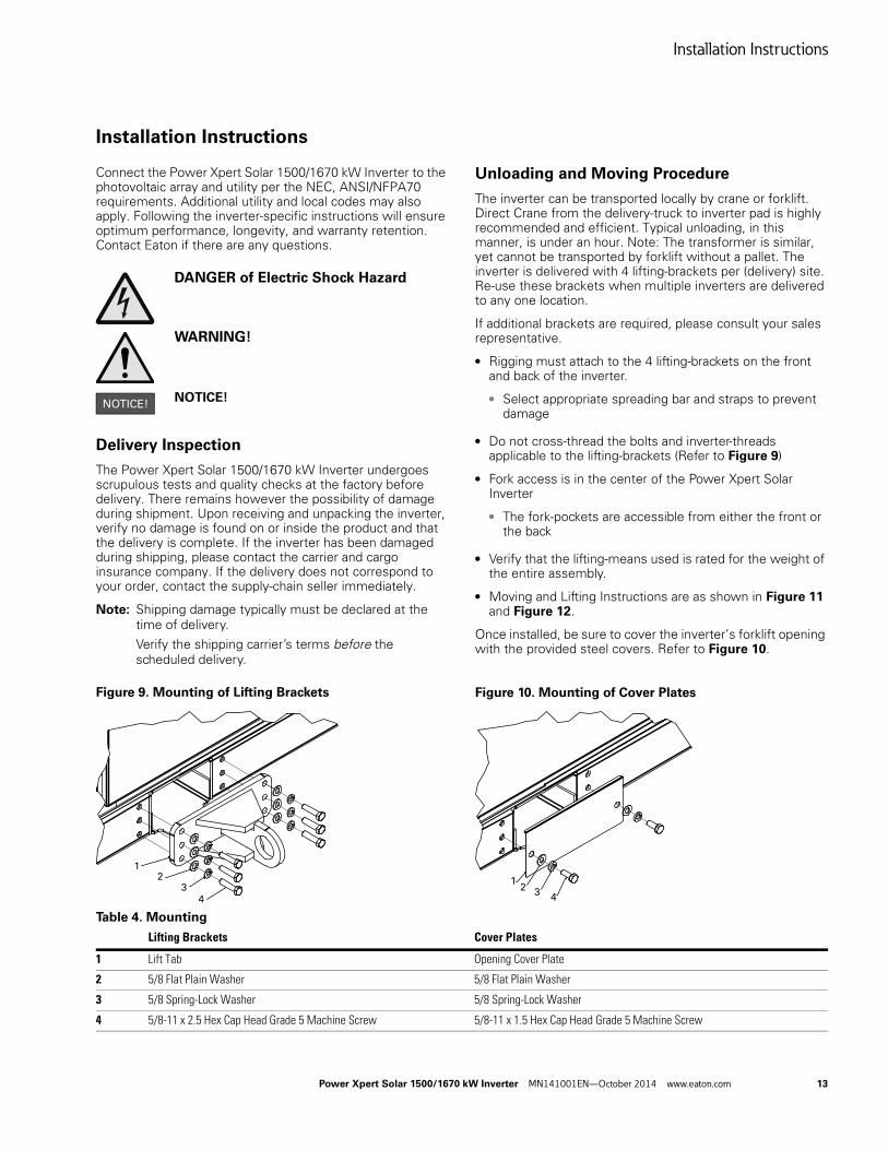
Figure 9. Mounting of Lifting Brackets
Unloading and Moving Procedure
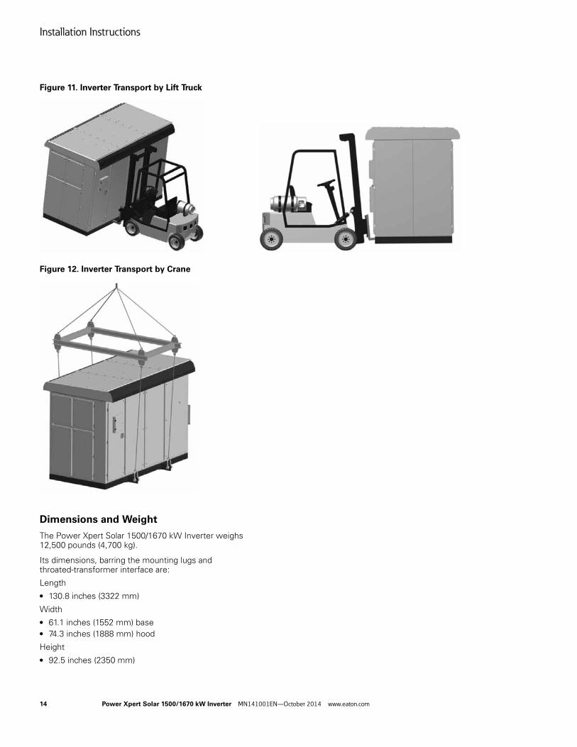
The inverter can be transported locally by crane or forklift. Direct Crane from the delivery-truck to inverter pad is highly recommended and efficient. Typical unloading, in this manner, is under an hour. Note: The transformer is similar, yet cannot be transported by forklift without a pallet. The inverter is delivered with 4 lifting-brackets per (delivery) site. Re-use these brackets when multiple inverters are delivered to any one location.
If additional brackets are required, please consult your sales representative.
● Rigging must attach to the 4 lifting-brackets on the front and back of the inverter.
● Select appropriate spreading bar and straps to prevent damage
● Do not cross-thread the bolts and inverter-threads applicable to the lifting-brackets (Refer to Figure 9)
● Fork access is in the center of the Power Xpert Solar Inverter
● The fork-pockets are accessible from either the front or the back
● Verify that the lifting-means used is rated for the weight of the entire assembly.
● Moving and Lifting Instructions are as shown in Figure 11 and Figure 12.
Once installed, be sure to cover the inverter’s forklift opening with the provided steel covers. Refer to Figure 10.
Figure 10. Mounting of Cover Plates
Table 4. Mounting
12
3
4
12
34
Lifting Brackets Cover Plates
1 Lift Tab Opening Cover Plate
2 5/8 Flat Plain Washer 5/8 Flat Plain Washer
3 5/8 Spring-Lock Washer 5/8 Spring-Lock Washer
4 5/8-11 x 2.5 Hex Cap Head Grade 5 Machine Screw 5/8-11 x 1.5 Hex Cap Head Grade 5 Machine Screw
Installation Instructions
14 Power Xpert Solar 1500/1670 kW Inverter MN141001EN—October 2014 www.eaton.com
Figure 11. Inverter Transport by Lift Truck
Figure 12. Inverter Transport by Crane
Dimensions and Weight
The Power Xpert Solar 1500/1670 kW Inverter weighs 12,500 pounds (4,700 kg).
Its dimensions, barring the mounting lugs and throated-transformer interface are:
Length● 130.8 inches (3322 mm)
Width● 61.1 inches (1552 mm) base● 74.3 inches (1888 mm) hood
Height● 92.5 inches (2350 mm)
Installation Instructions
Power Xpert Solar 1500/1670 kW Inverter MN141001EN—October 2014 www.eaton.com 15
Mechanical engineering drawings, in 2D DWG format, are available for use in designing and planning a photovoltaic system using the Power Xpert Solar 1500/1670 kW inverters. Consult Eaton for access to these drawings.
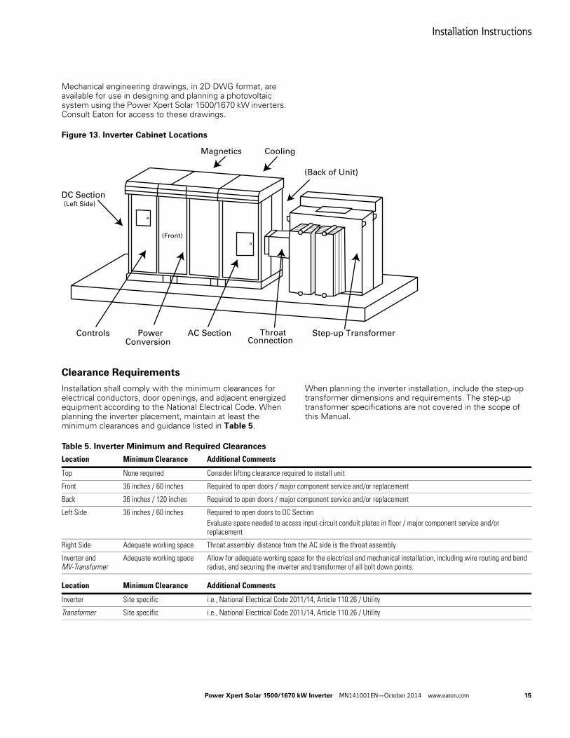
Figure 13. Inverter Cabinet Locations
Clearance Requirements
Installation shall comply with the minimum clearances for electrical conductors, door openings, and adjacent energized equipment according to the National Electrical Code. When planning the inverter placement, maintain at least the minimum clearances and guidance listed in Table 5.
When planning the inverter installation, include the step-up transformer dimensions and requirements. The step-up transformer specifications are not covered in the scope of this Manual.
Table 5. Inverter Minimum and Required Clearances
DC Section
Step-up Transformer
Magnetics Cooling
Controls PowerConversion
AC Section ThroatConnection
(Left Side)
(Back of Unit)
(Front)
Location Minimum Clearance Additional Comments
Top None required Consider lifting clearance required to install unit
Front 36 inches / 60 inches Required to open doors / major component service and/or replacement
Back 36 inches / 120 inches Required to open doors / major component service and/or replacement
Left Side 36 inches / 60 inches Required to open doors to DC SectionEvaluate space needed to access input-circuit conduit plates in floor / major component service and/or replacement
Right Side Adequate working space Throat assembly: distance from the AC side is the throat assembly
Inverter and MV-Transformer
Adequate working space Allow for adequate working space for the electrical and mechanical installation, including wire routing and bend radius, and securing the inverter and transformer of all bolt down points.
Location Minimum Clearance Additional Comments
Inverter Site specific i.e., National Electrical Code 2011/14, Article 110.26 / Utility
Transformer Site specific i.e., National Electrical Code 2011/14, Article 110.26 / Utility
Installation Instructions
16 Power Xpert Solar 1500/1670 kW Inverter MN141001EN—October 2014 www.eaton.com
Ventilation
Outdoor
The inverter is designed for outdoor installation. Following the working clearances specified in Table 5, no additional space is required for the inverter to achieve proper air-flow ventilation.
Indoor
When installing indoors (e-house), plan for the inverter’s heat-rejection during daily operation:
● Intake/exhaust air volume is 4500 cfm
● Recommended room-air exchange rate
● Rejected heat is up to 35 kW at full export power under optimum operation and cooling.
● 1 kW = 3412 Btu/hr
● 1 Btu = 1,055.0559 Joules
Site Recommendations
Eaton recommends that for optimum performance, the front of the inverter should be facing the South-East direction.
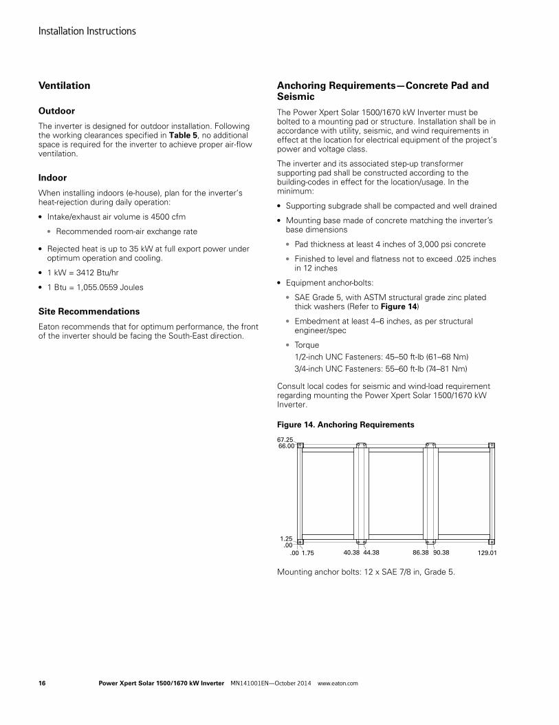
Anchoring Requirements—Concrete Pad and Seismic
The Power Xpert Solar 1500/1670 kW Inverter must be bolted to a mounting pad or structure. Installation shall be in accordance with utility, seismic, and wind requirements in effect at the location for electrical equipment of the project’s power and voltage class.
The inverter and its associated step-up transformer supporting pad shall be constructed according to the building-codes in effect for the location/usage. In the minimum:
● Supporting subgrade shall be compacted and well drained
● Mounting base made of concrete matching the inverter’s base dimensions
● Pad thickness at least 4 inches of 3,000 psi concrete
● Finished to level and flatness not to exceed .025 inches in 12 inches
● Equipment anchor-bolts:
● SAE Grade 5, with ASTM structural grade zinc plated thick washers (Refer to Figure 14)
● Embedment at least 4–6 inches, as per structural engineer/spec
● Torque 1/2-inch UNC Fasteners: 45–50 ft-lb (61–68 Nm)3/4-inch UNC Fasteners: 55–60 ft-lb (74–81 Nm)
Consult local codes for seismic and wind-load requirement regarding mounting the Power Xpert Solar 1500/1670 kW Inverter.
Figure 14. Anchoring Requirements
Mounting anchor bolts: 12 x SAE 7/8 in, Grade 5.
.001.25
66.0067.25
.00 1.75 40.38 44.38 86.38 90.38 129.01
Installation Instructions
Power Xpert Solar 1500/1670 kW Inverter MN141001EN—October 2014 www.eaton.com 17
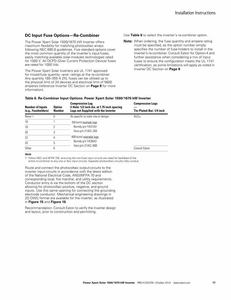
DC Input Fuse Options—Re-Combiner
The Power Xpert Solar 1500/1670 kW Inverter offers maximum flexibility for matching photovoltaic arrays following NEC 690.8 guidelines. Five standard options cover the most common quantity of the inverter’s input-fuses, easily matching available solar-modules technologies rated for 1000 V. All OCPD (Over Current Protection Device) fuses are rated for 1000 Vdc.
The Power Xpert Solar inverters are UL 1741 approved for mixed-fuse quantity –and– ratings at the re-combiner. Any quantity 160–355 A 2XL fuses can be utilized up to the physical limit of 24 devices and electrical limit of 5600 amperes (reference Inverter DC Section on Page 9 for more information).
Use Table 6 to select the inverter’s re-combiner option.
Note: When ordering, the fuse quantity and ampere rating must be specified, as the option number simply specifies the number of fuse-holders to install in the inverter’s re-combiner. Consult Eaton for Option-4 and further assistance when considering a mix of input fuses to ensure the configuration meets the UL 1741 certification, as some limitations will apply as noted in Inverter DC Section on Page 9.
Table 6. Re-Combiner Input Options: Power Xpert Solar 1500/1670 kW Inverter
Note1 Follow NEC and NFPA 70E, ensuring the non-fuse input circuits are rated for backfeed of the
entire re-combiner to any one or few input circuits. Separate photovoltaic circuits in/by conduit.
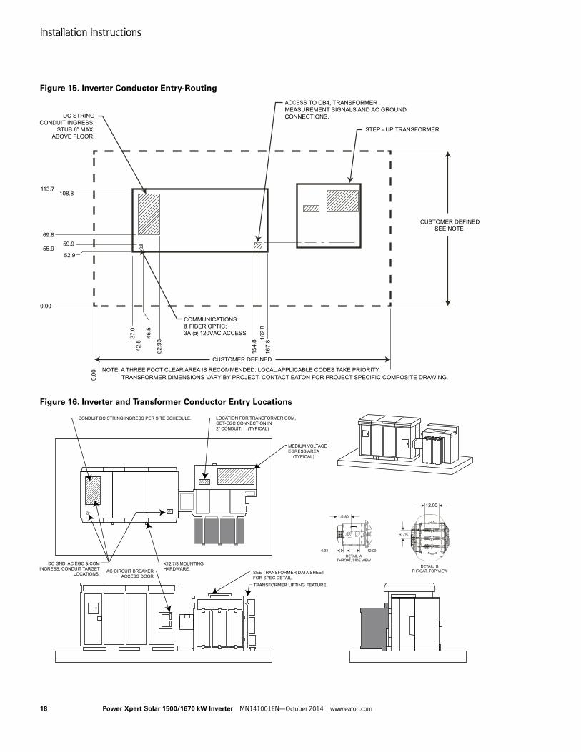
Route and connect the photovoltaic output-circuits to the inverter input-circuits in accordance with the latest edition of the National Electrical Code, ANSI/NFPA 70 and corresponding local, fire marshal, and utility requirements. Conductor entry is via the bottom of the DC section allowing for photovoltaic positive, negative, and ground inputs. Use this same opening for connecting the grounding electrode conductor. Mechanical engineering drawings in 2D DWG format are available for the inverter, as illustrated in Figure 15 and Figure 16.
Recommendation: Consult Eaton to verify the inverter design and layout, prior to construction and permitting.
Number of Inputs (e.g., Fuseholders)
Option Number
Compression Lug2-Hole: 1/2 inch dia. at 1.75 inch spacingLugs not Supplied with the Inverter
Compression Lugs—Tin-Plated-Bar: 1/4 inch
None 1 0 As specific to solar site or design:
350 kcmil example lugs Burndy p/n YA31A3 Ilsco p/n 21ACL-350
600 kcmil example lugs Burndy p/n YA36A3 Ilsco p/n 21ACL-600
Al/Cu
16 1
18 2
20 3
22 4
24 5
Other 6 Consult Eaton
Installation Instructions
18 Power Xpert Solar 1500/1670 kW Inverter MN141001EN—October 2014 www.eaton.com
Figure 15. Inverter Conductor Entry-Routing
Figure 16. Inverter and Transformer Conductor Entry Locations
Electrical Connections
Power Xpert Solar 1500/1670 kW Inverter MN141001EN—October 2014 www.eaton.com 19
Electrical Connections
Utilize wiring methods when installing the Power Xpert Solar 1500/1670 kW Inverter in accordance with the ANSI/NFPA 70: National Electrical Code. In addition, determine and follow applicable local, state, and utility regulations. Use only high-quality aluminum (Al) or copper (Cu) conductors with an insulation rating of 90 °C (minimum). Select the DC, AC and Ground circuit conductor’s wire-type and voltage-ratings as appropriate per Code, and directed by the inverter’s UL 1741 certification and power rating.
DANGER of Electric Shock Hazard
DISCONNECT AT POWER SOURCE—UTILITY GRID
DISCONNECT AT POWER SOURCE—PHOTOVOLTAIC SOURCE
LOTO THE AC DISCONNECT AND PHOTOVOLTAIC DISCONNECTS EXTERNAL TO THE INVERTER WHEN INSTALLING OR SERVICING THE INVERTER.
Electrical Connections
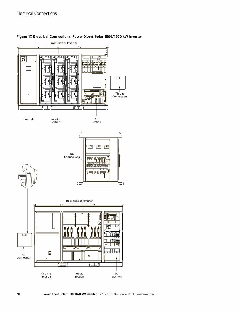
All the inverter’s photovoltaic input and AC output connection points are tin-plated copper busbars. Use only high quality compression lugs for the PV conductor terminations. The throat-coupled AC connection to the transformer is provided as a kit, including specific instructions. The basic electrical connections locations are illustrated in Figure 17. The PV-conductor securing methods are illustrated in Figure 18 and Table 7.
Electrical Connections
20 Power Xpert Solar 1500/1670 kW Inverter MN141001EN—October 2014 www.eaton.com
Figure 17. Electrical Connections, Power Xpert Solar 1500/1670 kW Inverter
Back-Side of Inverter
Controls
ACConnection
CoolingSection
InductorSection
DCSection
DCConnections
Front-Side of Inverter
ThroatConnection
ACSection
InverterSection
Electrical Connections
Power Xpert Solar 1500/1670 kW Inverter MN141001EN—October 2014 www.eaton.com 21
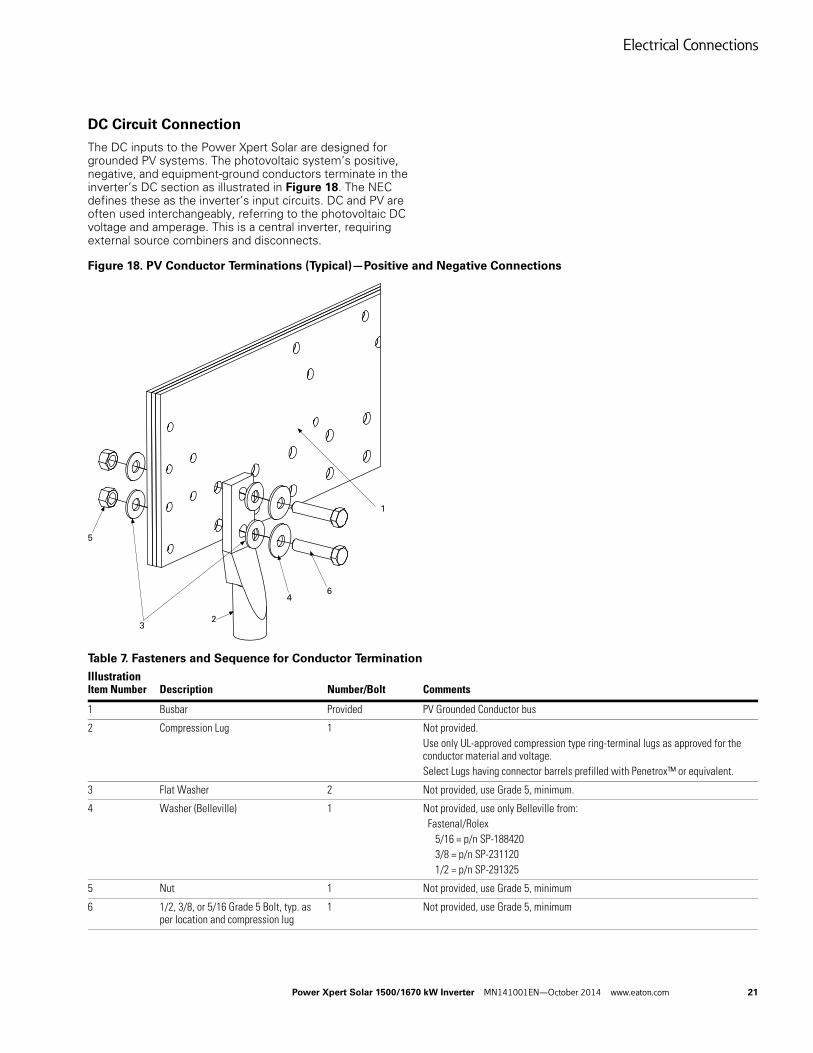
DC Circuit Connection
The DC inputs to the Power Xpert Solar are designed for grounded PV systems. The photovoltaic system’s positive, negative, and equipment-ground conductors terminate in the inverter’s DC section as illustrated in Figure 18. The NEC defines these as the inverter’s input circuits. DC and PV are often used interchangeably, referring to the photovoltaic DC voltage and amperage. This is a central inverter, requiring external source combiners and disconnects.
Figure 18. PV Conductor Terminations (Typical)—Positive and Negative Connections
Table 7. Fasteners and Sequence for Conductor Termination
IllustrationItem Number Description Number/Bolt Comments
1 Busbar Provided PV Grounded Conductor bus
2 Compression Lug 1 Not provided.Use only UL-approved compression type ring-terminal lugs as approved for the conductor material and voltage.Select Lugs having connector barrels prefilled with Penetrox™ or equivalent.
3 Flat Washer 2 Not provided, use Grade 5, minimum.
4 Washer (Belleville) 1 Not provided, use only Belleville from:Fastenal/Rolex 5/16 = p/n SP-188420 3/8 = p/n SP-231120 1/2 = p/n SP-291325
5 Nut 1 Not provided, use Grade 5, minimum
6 1/2, 3/8, or 5/16 Grade 5 Bolt, typ. as per location and compression lug
1 Not provided, use Grade 5, minimum
1
46
32
5
Electrical Connections
22 Power Xpert Solar 1500/1670 kW Inverter MN141001EN—October 2014 www.eaton.com
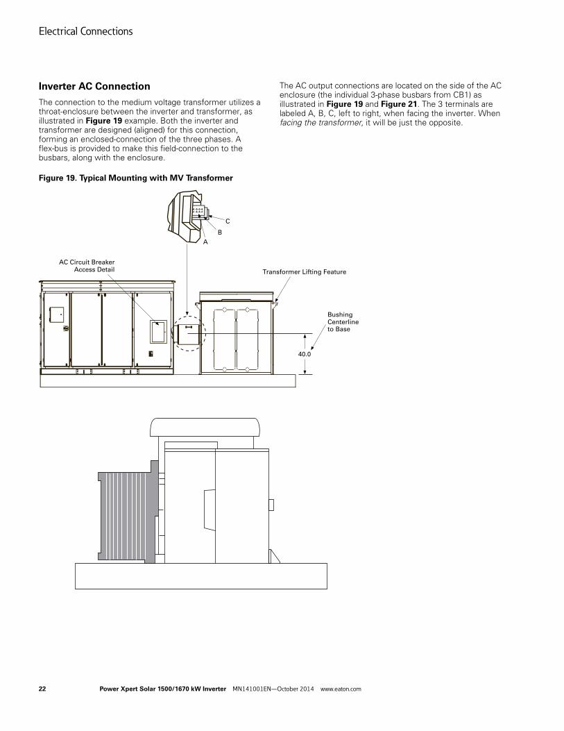
Inverter AC Connection
The connection to the medium voltage transformer utilizes a throat-enclosure between the inverter and transformer, as illustrated in Figure 19 example. Both the inverter and transformer are designed (aligned) for this connection, forming an enclosed-connection of the three phases. A flex-bus is provided to make this field-connection to the busbars, along with the enclosure.
The AC output connections are located on the side of the AC enclosure (the individual 3-phase busbars from CB1) as illustrated in Figure 19 and Figure 21. The 3 terminals are labeled A, B, C, left to right, when facing the inverter. When facing the transformer, it will be just the opposite.
Figure 19. Typical Mounting with MV Transformer
AC Circuit BreakerAccess Detail Transformer Lifting Feature
BushingCenterlineto Base
40.0
A
B
C
Electrical Connections
Power Xpert Solar 1500/1670 kW Inverter MN141001EN—October 2014 www.eaton.com 23
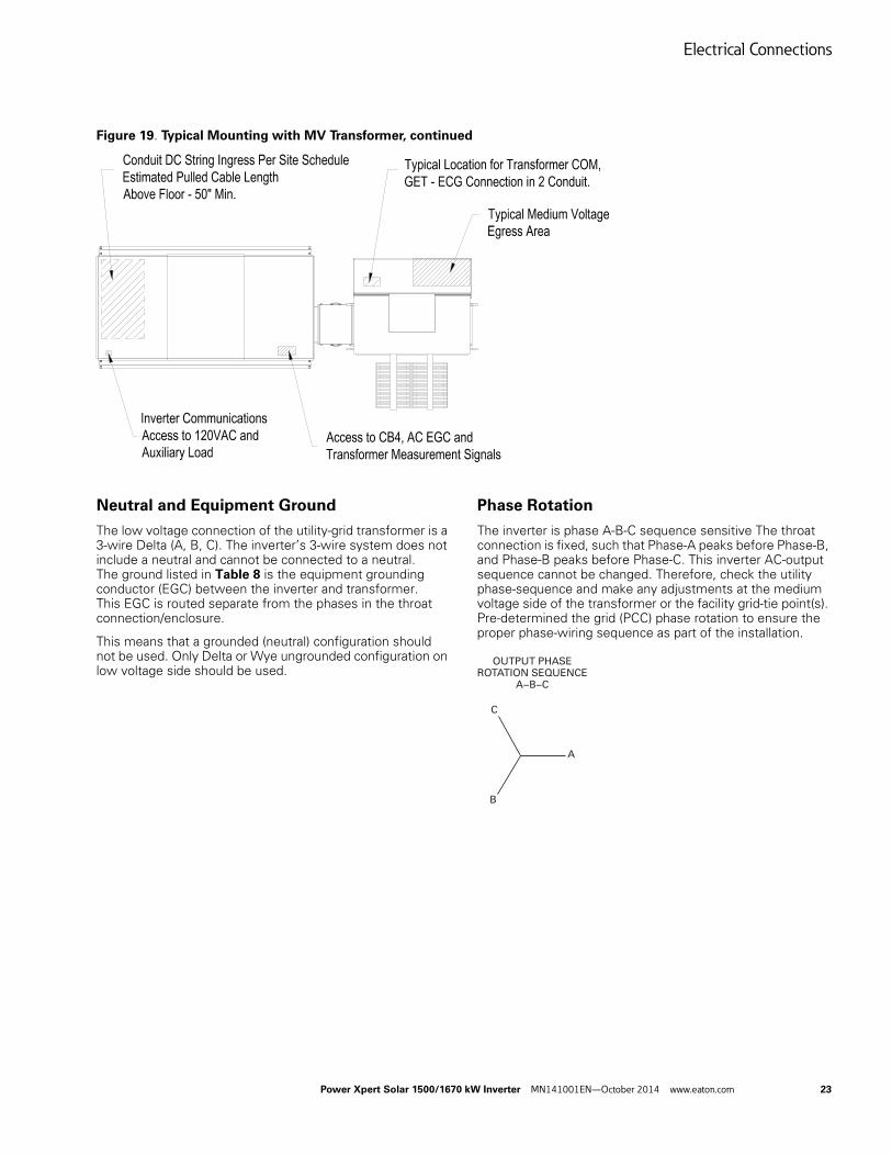
Figure 19. Typical Mounting with MV Transformer, continued
Neutral and Equipment Ground
The low voltage connection of the utility-grid transformer is a 3-wire Delta (A, B, C). The inverter’s 3-wire system does not include a neutral and cannot be connected to a neutral. The ground listed in Table 8 is the equipment grounding conductor (EGC) between the inverter and transformer. This EGC is routed separate from the phases in the throat connection/enclosure.
This means that a grounded (neutral) configuration should not be used. Only Delta or Wye ungrounded configuration on low voltage side should be used.
Phase Rotation
The inverter is phase A-B-C sequence sensitive The throat connection is fixed, such that Phase-A peaks before Phase-B, and Phase-B peaks before Phase-C. This inverter AC-output sequence cannot be changed. Therefore, check the utility phase-sequence and make any adjustments at the medium voltage side of the transformer or the facility grid-tie point(s). Pre-determined the grid (PCC) phase rotation to ensure the proper phase-wiring sequence as part of the installation.
C
B
A
OUTPUT PHASEROTATION SEQUENCE
A−B−C
Electrical Connections
24 Power Xpert Solar 1500/1670 kW Inverter MN141001EN—October 2014 www.eaton.com
Table 8. 3-Wire Connection—Inverter Point-of-Common Coupling Interface
Appendix B references the contents of the flex-bus kit and the instructions which accompany the inverter. No provisions for a cabled connection is provided, or allowed.
As illustrated in Figure 21:
● Prepare each mating bus face with Penetrox “E” or suitable equivalent for copper connections
● DO NOT use Penetrox “A” or similar compounds made for Al to Al or Al to Cu connections
● Apply a tamper-proof torque-marking paint, once the hardware is properly torqued
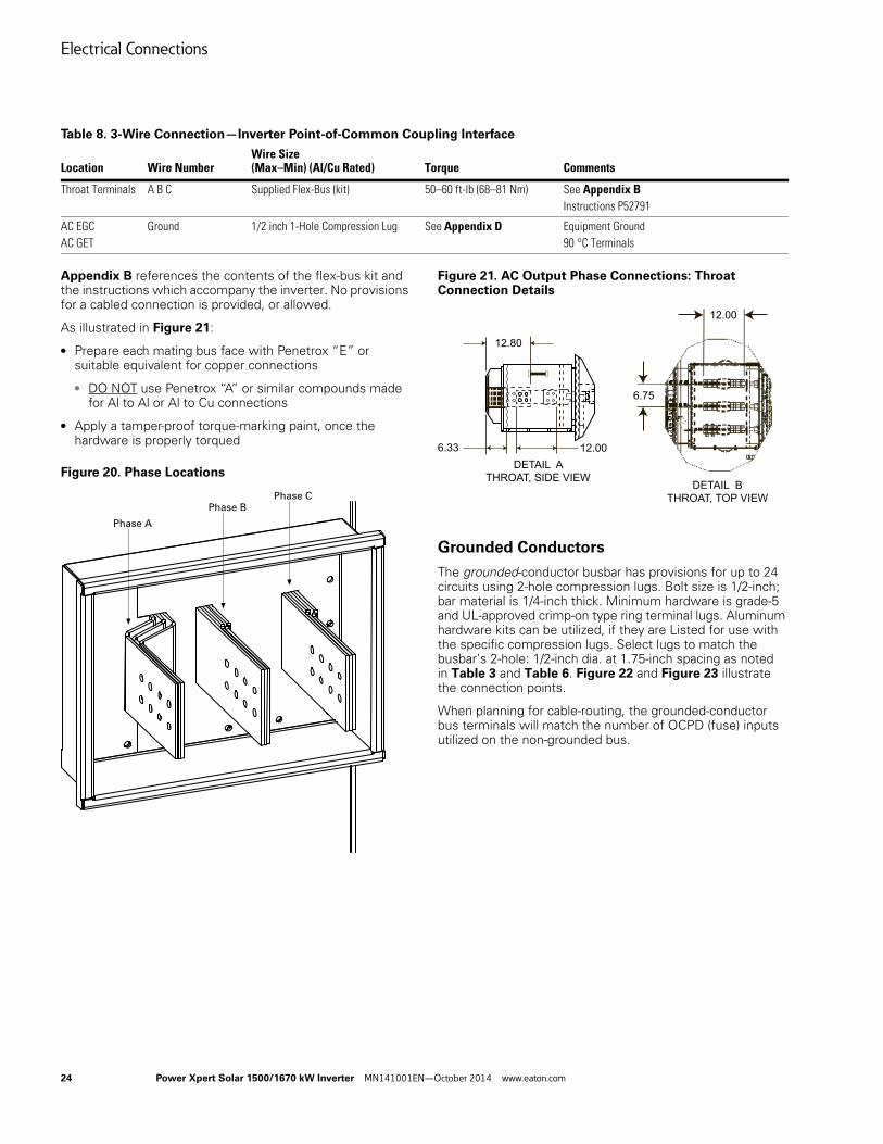
Figure 20. Phase Locations
Figure 21. AC Output Phase Connections: Throat Connection Details
Grounded Conductors
The grounded-conductor busbar has provisions for up to 24 circuits using 2-hole compression lugs. Bolt size is 1/2-inch; bar material is 1/4-inch thick. Minimum hardware is grade-5 and UL-approved crimp-on type ring terminal lugs. Aluminum hardware kits can be utilized, if they are Listed for use with the specific compression lugs. Select lugs to match the busbar’s 2-hole: 1/2-inch dia. at 1.75-inch spacing as noted in Table 3 and Table 6. Figure 22 and Figure 23 illustrate the connection points.
When planning for cable-routing, the grounded-conductor bus terminals will match the number of OCPD (fuse) inputs utilized on the non-grounded bus.
Location Wire NumberWire Size (Max–Min) (Al/Cu Rated) Torque Comments
Throat Terminals A B C Supplied Flex-Bus (kit) 50–60 ft-lb (68–81 Nm) See Appendix BInstructions P52791
AC EGCAC GET
Ground 1/2 inch 1-Hole Compression Lug See Appendix D Equipment Ground 90 °C Terminals
Phase A
Phase BPhase C
12.80
12.006.33
DETAIL A
THROAT, SIDE VIEW
12.00
6.75
DETAIL B
THROAT, TOP VIEW
Electrical Connections
Power Xpert Solar 1500/1670 kW Inverter MN141001EN—October 2014 www.eaton.com 25
Non-Grounded Conductors
The non-grounded PV array conductors1 terminate to individual flat-busbars associated with the input fuse (OCPD). Based upon the fuse rating and PV system design, up to 24 circuits using 2-hole compression lugs are possible. Bolt size is 1/2-inch; bar material is 1/4-inch thick. Minimum hardware is grade-5 and UL-approved crimp-on type ring terminal lugs. Aluminum hardware kits can be utilized, if they are Listed for use with the specific compression lugs. Select lugs to match the busbar’s 2-Hole: 1/2-inch dia. at 1.75-inch spacing as noted in Table 3 and Table 6. Figure 22 illustrates the fused input-circuit connection points.
When planning for cable-routing, the non-grounded OCPD conductor bus terminals will match the number of grounded conductors inputs utilized.
The OCPD offerings are listed in Table 6. The fuse options must be ordered and factory installed. Fuses of a different quantity (up to 24) and amperage-ratings (mixing of fuses) are allowed. Eaton encourages coordination with our solar-engineering team’s application engineer to select the optimum photovoltaic system layout configuration and OCPD selection.
1 PV panels are available in grounded negative or grounded positive configurations, depending upon the manufacturer and technology. The Power Xpert Solar Inverter can accommodate either. However, the configuration must be ordered and factory tested. Changing the inverter polarity once the inverter has left the factory requires additional expense and removal of the UL 1741 certification. Therefore, verify the photovoltaic modules that will be used to ensure the proper inverter, before ordering. Consult Eaton for application assistance.
Negative Grounded PV: The PV-negative are the grounded conductors.
See cabinet label: NEGATIVE GROUND SYSTEM
Positive Grounded PV: The PV-positive are the grounded conductors.
See cabinet label: POSITIVE GROUND SYSTEM
Equipment Grounding Conductors
The PV system’s equipment-grounding conductors (EGC) from the array’s modules, racking, source-combiners, conduit, and external PV-disconnecting means terminate to a ground-bus common (bonded) to the inverter cabinet and AC ground bus. Up to 24 circuits using 1-hole compression lugs are possible. Bolt size is 5/16-inch on a 1/4-inch thick tin-plated bar. Minimum hardware is grade-5 and UL-approved crimp-on type ring terminal lugs. Figure 23 illustrates the ground-busbar for 24 input-circuit option.
When planning for cable-routing, the EGCs conductors will match the quantity of the grounded and non-grounded PV circuits at the inverter’s re-combiner, coming from each source-combiner, array sub-combiners, or external PV-disconnects.
Grounding Electrode Terminal and Conductor
The DC ground bus further forms the Grounding Electrode Terminal (GET) connection for establishing photovoltaic grounding-electrode system. Follow 2011 NEC 690.47 (C) (1), (2), or (3) practice as appropriate for the installation (project) to establish the PV earth-ground.
● The minimum size of the equipment-grounding or bonding conductors, as per UL 1741, Table 18.1 for the inverter’s 2707 A AC output:
● 3000 A => 400 kcmil (203 mm2) Cu
● 3000 A => 600 kcmil (304 mm2) Al
● The minimum size of the PV grounding electrode conductor, as per UL 1741 Table 18.1
● 800–6000 A => 3/0 (85.0 mm2) Cu
● 800–6000 A => 250 (127 mm2) Al
[e.g., establishing the PV grounding electrode system … and tying it to the facility’s AC grounding electrode system, as per NEC 690.47 (C) (1), (2), or (3)]
● Inverter’s DC input Current: 3100 amperes (nominal rating)
● Inverter’s AC output Current: 2700–2707 amperes (nominal rating)
● Inverter’s AC branch circuit over-current: 3200 amperes (maximum rating)
Additionally, the ground-busbar has two 2-Hole 1/2-inch dia. at 1.75-inch spacing, four 3/8-inch spaced at 1.25-inch, and an additional two 1/2-inch diameter holes for single-hole compression lugs. Use this DC Ground bus as the PV’s GET.
Bond the GEC to the GET bus by use of irreversible bonding connectors, such as an irreversible busbar connector (e.g., Hubbell p/n HYG14BTC28) or approved compression lug secured to the GET with an appropriate (star) lock washer with bolted hardware.
Do not exothermally-weld the GEC inside the inverter (i.e., to an exposed ground-rod or the GET bus).
Electrical Connections
26 Power Xpert Solar 1500/1670 kW Inverter MN141001EN—October 2014 www.eaton.com
Conductor Size and Type
The holed-busbar offerings for terminating the photovoltaic circuits, coupled to a large conduit stub-up opening (39 x 21 inches) at the base of the inverter’s DC section allow for maximum flexibility in designing a PV system. The conduit stub-up shall not extend more than 5 inches above the base (floor) of the inverter. Generous room allows for large-diameter conductors bending radius, with the ability to segment or group input conductors to align or match a PV system layout. The busbars are tin-coated copper for long-life. Select compression lugs appropriate to the conductor material (Aluminum or Copper) and securing hardware for tin-coated copper bus.
Care should be taken to verify that the polarity is maintained when wiring the positive and negative conductors from the Array to the DC section. This is to prevent wiring the non-grounded (positive) and grounded (negative) PV-circuits to the wrong terminals. The wire should be rated for use in 1000 Vdc circuit, with the wire size depending on the number of circuits being supplied from source-(string)-combiner or array-(sub)-combiners according to NEC 690. Use and install external PV-circuit disconnects within sight of the inverter as per Code. Be aware of the high arc-flash risk-category from PV, as per NFPA70E. Plan accordingly.
Negative-Ground Photovoltaic Configuration
The PV-positive (non-grounded) conductors are to be connected to the OCPD fuses.
The PV-negative (grounded) conductors are to be connected the negative (no fuse) bus.
The PV-Equipment ground conductors are to be connected to the ground or GET bus.
Positive-Ground Photovoltaic Configuration
The PV-negative (non-grounded) conductors are to be connected to the OCPD fuses.
The PV-positive (grounded) conductors are to be connected to the negative (no fuse) bus.
The PV-Equipment ground conductors are to be connected to the ground or GET bus.
For all DC wire terminal connections:
● Apply an antioxidant, such as Penetrox as appropriate to the connection base-metals
● Penetrox “E” or suitable equivalent for all-copper connections.
● Penetrox “A” or similar compounds made for Al to Al or Al to Cu connections.
● Apply a tamper-proof torque-marking paint, once the fasteners are properly torqued.
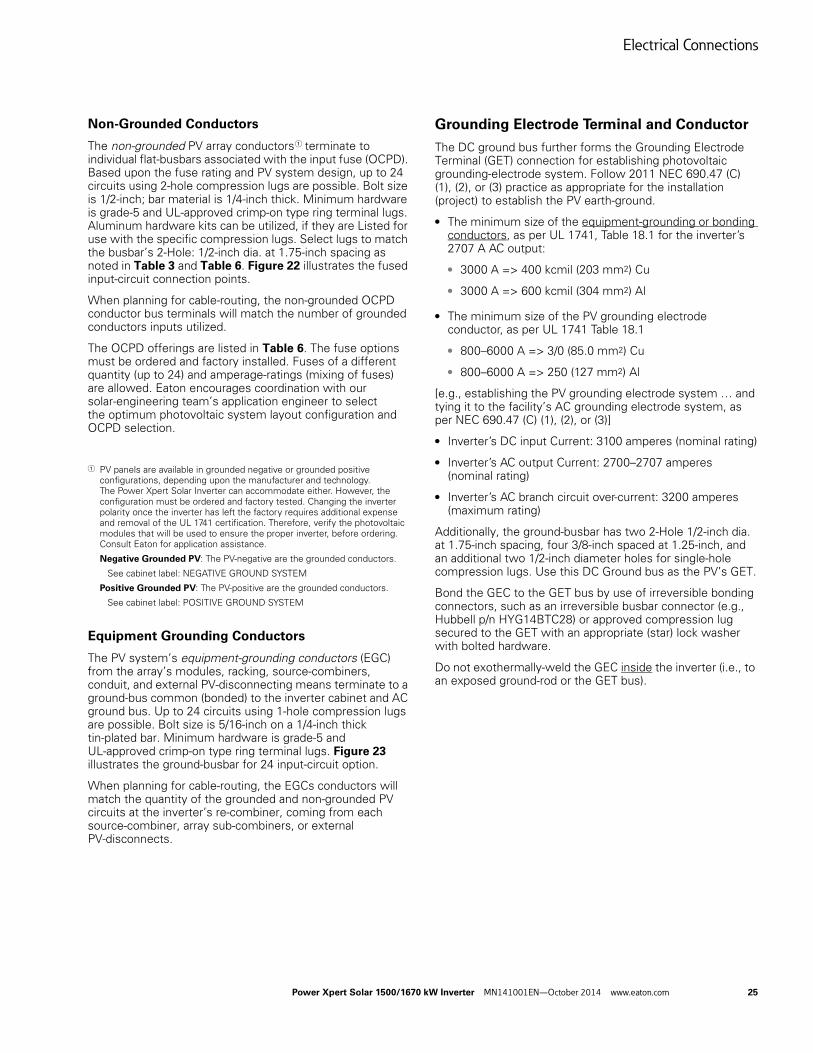
DC Section Layout and Connection Points
Figure 22. DC Section: 24 Input-Circuit options, Illustrated PV Input Connections
Figure 23. DC Section Grounding Bus and Grounding Electrode Terminal
Grounding
The inverter must be earth grounded. Based upon the installation construction and site, common practices are by ground-rings at the installation pad, ground rods, Ufer grounds and similar means to establish earth ground. Verify and document the proper grounding means during the design-approval process with the permitting authority, electrical inspector and the utility.
The inverter’s DC ground bus and AC ground bus are internally bonded, forming a continuous ground plane within the inverter. The installer shall ensure these are bonded to earth (ground).
Neutral
The inverter is configured as a 3-wire only. No neutral wire for a 4-wire grid connection configuration is allowed.
DC Switches
DC Positive(fused) Input
DC NegativeInput
DC GroundBus Bar
24x PV ECG connection points
Electrical Connections
Power Xpert Solar 1500/1670 kW Inverter MN141001EN—October 2014 www.eaton.com 27
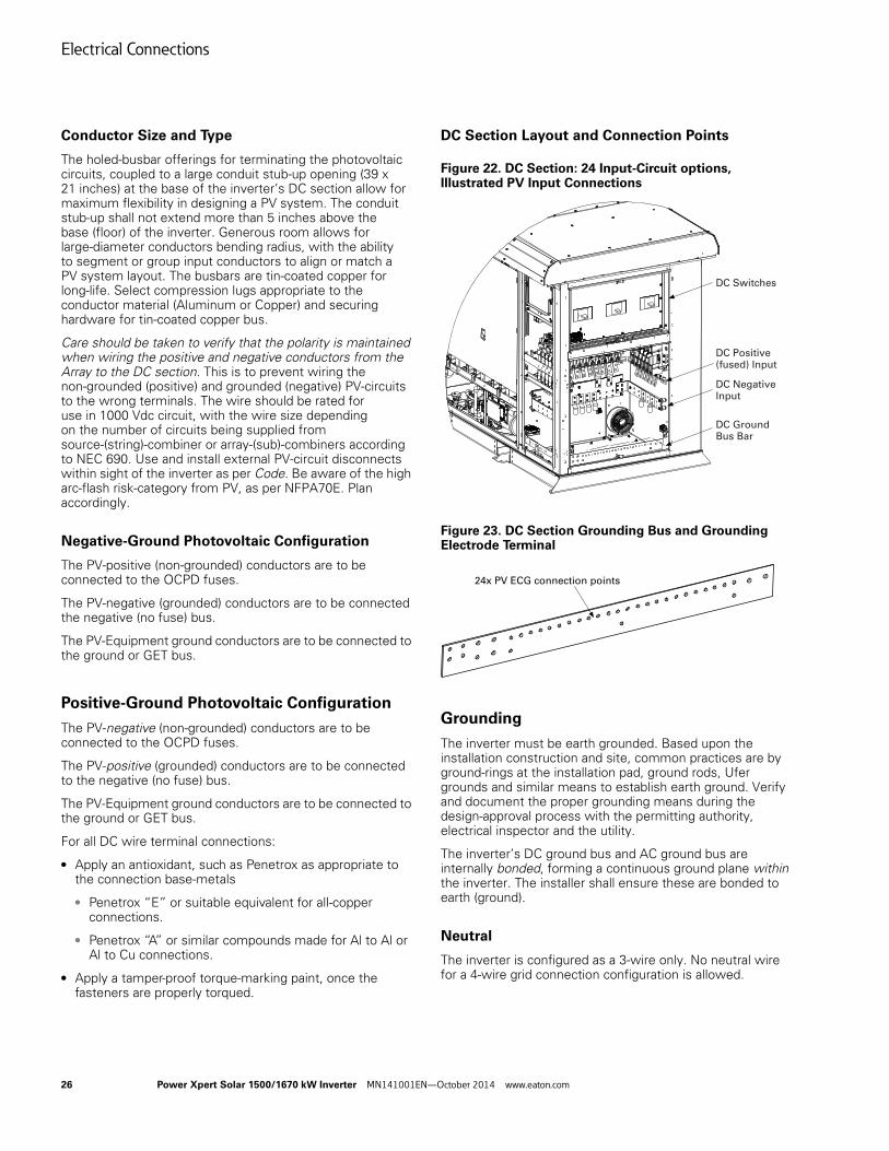
AC EGC Connection
The EGC is the Equipment Ground Conductor (Grounding Conductor, Equipment in the NEC). The AC equipment ground conductor from the step-up transformer shall be bonded to the AC ground bus that is located in the AC section of the unit. This bus is for connecting the step-up transformer enclosure-ground to the inverter, ensuring both are referenced to the same earth-ground (utility reference). See Figure 24.
Figure 24. AC Section Equipment Grounding Bus
GEC Connection
The GEC is the Grounding Electrode Conductor. The Grounding Electrode Conductor shall be attached to the ground terminal labeled Grounding Electrode Terminal (GET) that is located in the DC section of the unit. The minimum wire size is 3/0 for copper (Cu) and 250 kcmil for aluminum (Al) conductor material. This is based upon inverter’s input DC amperage. Connecting the inverter Install as per 2011 NEC 690 and the permitting authority and utility.
Step-Up Transformer Sensor Signals
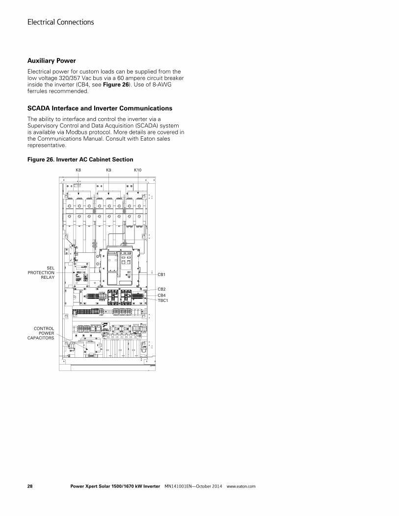
Connection of the step-up transformer sensor signals is via terminal block TBC1 located in the AC Cabinet. These signals are made available on the inverter’s Modbus® network, ready for remote monitoring. The usage is based upon the transformer (options). Reference Figure 26 for the location of TBC1 and Appendix C for example signals. The actual sensors and connections are subject to change due to the step-up transformer selected, as appropriate for the project requirements. Consult with Eaton for both the inverter and step-up transformer configurations and options prior to order.
Accessory Power
Within the Control Cabinet, available 120 Vac power is provided via terminal strip TBC3. Use 90 °C rated copper 14-AWG for the L-N-G 120 Vac connections, as labeled. Rated 360 W (3 A at 120 Vac), TBC3 is useful for powering third-party monitoring gateway, etc. See Figure 25. Use of 14-AWG ferrules recommended.
Figure 25. Accessory Power Location
ACGROUNDBUS
AC GROUND
& COMM(S)
CONDUITFLOOR-PLATEOPENING: 6” x 8”
Electrical Connections
28 Power Xpert Solar 1500/1670 kW Inverter MN141001EN—October 2014 www.eaton.com
Auxiliary Power
Electrical power for custom loads can be supplied from the low voltage 320/357 Vac bus via a 60 ampere circuit breaker inside the inverter (CB4, see Figure 26). Use of 8-AWG ferrules recommended.
SCADA Interface and Inverter Communications
The ability to interface and control the inverter via a Supervisory Control and Data Acquisition (SCADA) system is available via Modbus protocol. More details are covered in the Communications Manual. Consult with Eaton sales representative.
Figure 26. Inverter AC Cabinet Section
CB1
CB2
CB4
TBC1
SELPROTECTION
RELAY
CONTROLPOWER
CAPACITORS
K8 K9 K10
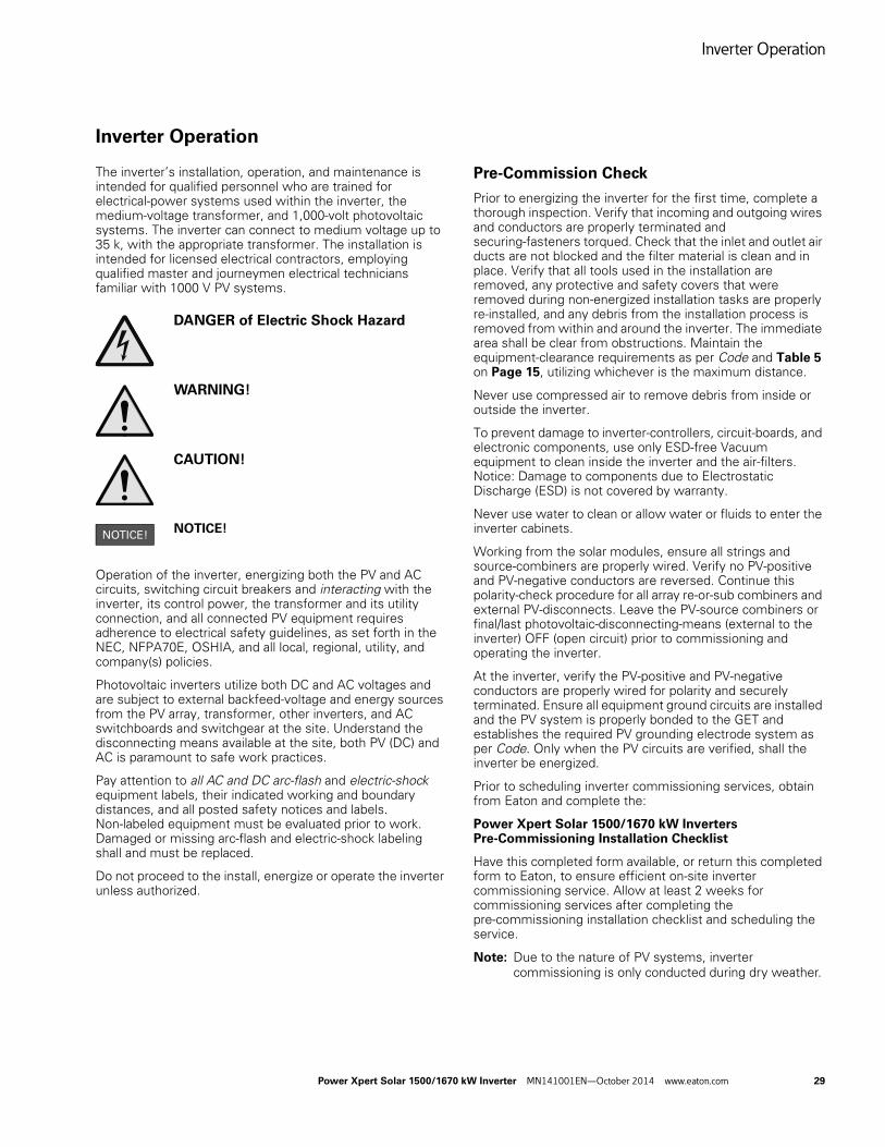
Inverter Operation
Power Xpert Solar 1500/1670 kW Inverter MN141001EN—October 2014 www.eaton.com 29
Inverter Operation
The inverter’s installation, operation, and maintenance is intended for qualified personnel who are trained for electrical-power systems used within the inverter, the medium-voltage transformer, and 1,000-volt photovoltaic systems. The inverter can connect to medium voltage up to 35 k, with the appropriate transformer. The installation is intended for licensed electrical contractors, employing qualified master and journeymen electrical technicians familiar with 1000 V PV systems.
DANGER of Electric Shock Hazard
WARNING!
CAUTION!
NOTICE!
Operation of the inverter, energizing both the PV and AC circuits, switching circuit breakers and interacting with the inverter, its control power, the transformer and its utility connection, and all connected PV equipment requires adherence to electrical safety guidelines, as set forth in the NEC, NFPA70E, OSHIA, and all local, regional, utility, and company(s) policies.
Photovoltaic inverters utilize both DC and AC voltages and are subject to external backfeed-voltage and energy sources from the PV array, transformer, other inverters, and AC switchboards and switchgear at the site. Understand the disconnecting means available at the site, both PV (DC) and AC is paramount to safe work practices.
Pay attention to all AC and DC arc-flash and electric-shock equipment labels, their indicated working and boundary distances, and all posted safety notices and labels. Non-labeled equipment must be evaluated prior to work. Damaged or missing arc-flash and electric-shock labeling shall and must be replaced.
Do not proceed to the install, energize or operate the inverter unless authorized.
Pre-Commission Check
Prior to energizing the inverter for the first time, complete a thorough inspection. Verify that incoming and outgoing wires and conductors are properly terminated and securing-fasteners torqued. Check that the inlet and outlet air ducts are not blocked and the filter material is clean and in place. Verify that all tools used in the installation are removed, any protective and safety covers that were removed during non-energized installation tasks are properly re-installed, and any debris from the installation process is removed from within and around the inverter. The immediate area shall be clear from obstructions. Maintain the equipment-clearance requirements as per Code and Table 5 on Page 15, utilizing whichever is the maximum distance.
Never use compressed air to remove debris from inside or outside the inverter.
To prevent damage to inverter-controllers, circuit-boards, and electronic components, use only ESD-free Vacuum equipment to clean inside the inverter and the air-filters. Notice: Damage to components due to Electrostatic Discharge (ESD) is not covered by warranty.
Never use water to clean or allow water or fluids to enter the inverter cabinets.
Working from the solar modules, ensure all strings and source-combiners are properly wired. Verify no PV-positive and PV-negative conductors are reversed. Continue this polarity-check procedure for all array re-or-sub combiners and external PV-disconnects. Leave the PV-source combiners or final/last photovoltaic-disconnecting-means (external to the inverter) OFF (open circuit) prior to commissioning and operating the inverter.
At the inverter, verify the PV-positive and PV-negative conductors are properly wired for polarity and securely terminated. Ensure all equipment ground circuits are installed and the PV system is properly bonded to the GET and establishes the required PV grounding electrode system as per Code. Only when the PV circuits are verified, shall the inverter be energized.
Prior to scheduling inverter commissioning services, obtain from Eaton and complete the:
Power Xpert Solar 1500/1670 kW Inverters Pre-Commissioning Installation Checklist
Have this completed form available, or return this completed form to Eaton, to ensure efficient on-site inverter commissioning service. Allow at least 2 weeks for commissioning services after completing the pre-commissioning installation checklist and scheduling the service.
Note: Due to the nature of PV systems, inverter commissioning is only conducted during dry weather.
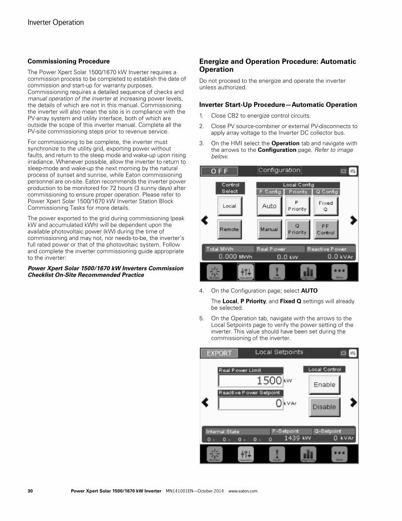
Inverter Operation
30 Power Xpert Solar 1500/1670 kW Inverter MN141001EN—October 2014 www.eaton.com
Commissioning Procedure
The Power Xpert Solar 1500/1670 kW Inverter requires a commission process to be completed to establish the date of commission and start-up for warranty purposes. Commissioning requires a detailed sequence of checks and manual operation of the inverter at increasing power levels, the details of which are not in this manual. Commissioning the inverter will also mean the site is in compliance with the PV-array system and utility interface, both of which are outside the scope of this inverter manual. Complete all the PV-site commissioning steps prior to revenue service.
For commissioning to be complete, the inverter must synchronize to the utility grid, exporting power without faults, and return to the sleep mode and wake-up upon rising irradiance. Whenever possible, allow the inverter to return to sleep-mode and wake-up the next morning by the natural process of sunset and sunrise, while Eaton commissioning personnel are on-site. Eaton recommends the inverter power production to be monitored for 72 hours (3 sunny days) after commissioning to ensure proper operation. Please refer to Power Xpert Solar 1500/1670 kW Inverter Station Block Commissioning Tasks for more details.
The power exported to the grid during commissioning (peak kW and accumulated kWh) will be dependent upon the available photovoltaic power (kW) during the time of commissioning and may not, nor needs-to-be, the inverter’s full rated power or that of the photovoltaic system. Follow and complete the inverter commissioning guide appropriate to the inverter:
Power Xpert Solar 1500/1670 kW Inverters Commission Checklist On-Site Recommended Practice
Energize and Operation Procedure: Automatic Operation
Do not proceed to the energize and operate the inverter unless authorized.
Inverter Start-Up Procedure—Automatic Operation
1. Close CB2 to energize control circuits.
2. Close PV source-combiner or external PV-disconnects to apply array voltage to the Inverter DC collector bus.
3. On the HMI select the Operation tab and navigate with the arrows to the Configuration page. Refer to image below.
4. On the Configuration page; select AUTO
The Local, P Priority, and Fixed Q settings will already be selected.
5. On the Operation tab, navigate with the arrows to the Local Setpoints page to verify the power setting of the inverter. This value should have been set during the commissioning of the inverter.
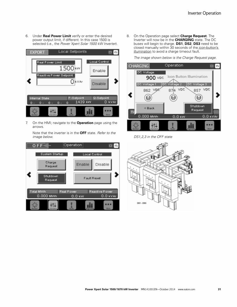
Inverter Operation
Power Xpert Solar 1500/1670 kW Inverter MN141001EN—October 2014 www.eaton.com 31
6. Under Real Power Limit verify or enter the desired power output limit, if different. In this case 1500 is selected (i.e., the Power Xpert Solar 1500 kW Inverter).
7. On the HMI; navigate to the Operation page using the arrows.
Note that the inverter is in the OFF state. Refer to the image below.
8. On the Operation page select Charge Request. The Inverter will now be in the CHARGING state. The DC buses will begin to charge. DS1, DS2, DS3 need to be closed manually within 30 seconds of the icon-button’s illumination to avoid a charge timeout fault.
The image shown below is the Charge Request page.
DS1,2,3 in the OFF state
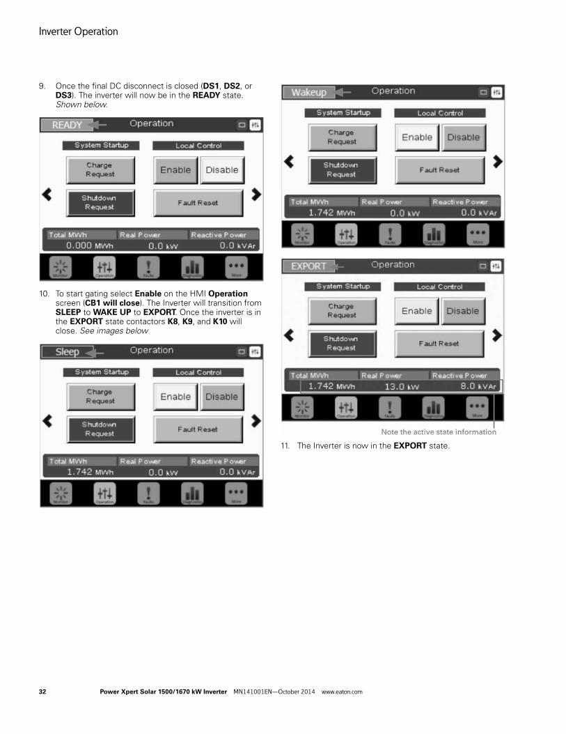
Inverter Operation
32 Power Xpert Solar 1500/1670 kW Inverter MN141001EN—October 2014 www.eaton.com
9. Once the final DC disconnect is closed (DS1, DS2, or DS3). The inverter will now be in the READY state. Shown below.
10. To start gating select Enable on the HMI Operation screen (CB1 will close). The Inverter will transition from SLEEP to WAKE UP to EXPORT. Once the inverter is in the EXPORT state contactors K8, K9, and K10 will close. See images below
11. The Inverter is now in the EXPORT state.
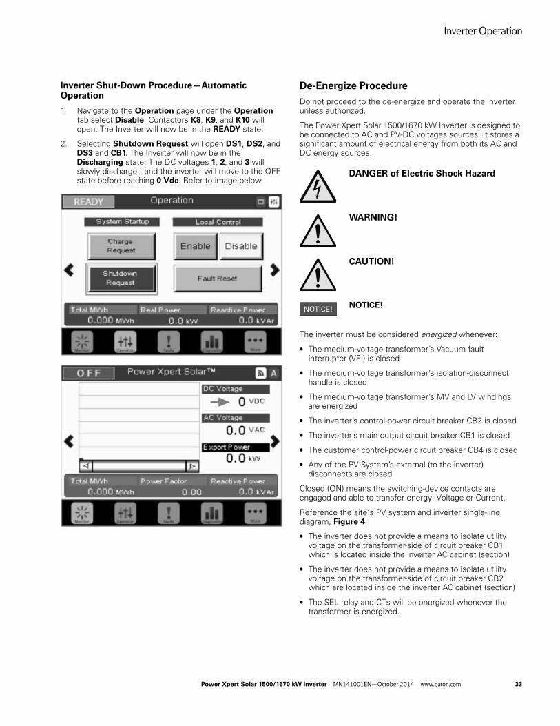
Inverter Operation
Power Xpert Solar 1500/1670 kW Inverter MN141001EN—October 2014 www.eaton.com 33
Inverter Shut-Down Procedure—Automatic Operation
1. Navigate to the Operation page under the Operation tab select Disable. Contactors K8, K9, and K10 will open. The Inverter will now be in the READY state.
2. Selecting Shutdown Request will open DS1, DS2, and DS3 and CB1. The Inverter will now be in the Discharging state. The DC voltages 1, 2, and 3 will slowly discharge t and the inverter will move to the OFF state before reaching 0 Vdc. Refer to image below
De-Energize Procedure
Do not proceed to the de-energize and operate the inverter unless authorized.
The Power Xpert Solar 1500/1670 kW Inverter is designed to be connected to AC and PV-DC voltages sources. It stores a significant amount of electrical energy from both its AC and DC energy sources.
DANGER of Electric Shock Hazard
WARNING!
CAUTION!
NOTICE!
The inverter must be considered energized whenever:
● The medium-voltage transformer’s Vacuum fault interrupter (VFI) is closed
● The medium-voltage transformer’s isolation-disconnect handle is closed
● The medium-voltage transformer’s MV and LV windings are energized
● The inverter’s control-power circuit breaker CB2 is closed
● The inverter’s main output circuit breaker CB1 is closed
● The customer control-power circuit breaker CB4 is closed
● Any of the PV System’s external (to the inverter) disconnects are closed
Closed (ON) means the switching-device contacts are engaged and able to transfer energy: Voltage or Current.
Reference the site’s PV system and inverter single-line diagram, Figure 4.
● The inverter does not provide a means to isolate utility voltage on the transformer-side of circuit breaker CB1 which is located inside the inverter AC cabinet (section)
● The inverter does not provide a means to isolate utility voltage on the transformer-side of circuit breaker CB2 which are located inside the inverter AC cabinet (section)
● The SEL relay and CTs will be energized whenever the transformer is energized.
Inverter Operation
34 Power Xpert Solar 1500/1670 kW Inverter MN141001EN—October 2014 www.eaton.com
● The inverter does not provide a means to isolate utility voltage on the transformer-side of circuit breaker CB4 or any additional control-power disconnect(s) which are located inside the inverter AC cabinet (section)
● The inverter does not provide a means to isolate input circuits from the PV-array (system) side of disconnects DS1, DS2, and DS3, which are located inside the inverter DC cabinet (section). Unless the PV-array is fully disconnected externally from the inverter, the inverter re-combiner will be energized
De-Energized Inverter
1. Verify the inverter is in the OFF state
2. The inverter will de-energize stored capacitive-energy when in the OFF state.
a. and CB1, CB2, CB4, DS1, DS2, and DS3 and are verified opened.
b.Notice: the inverter will remain energized unless the transformer is also disconnected or isolated form the utility grid and completely de-energized. The inverter’s throat-connection is a direct feed from the transformer.
c. Notice: the inverter will remain energized unless the external PV-disconnects are fully open. Disconnects DS1 DS2 and DS2 do not isolate the inverter re-combiner from the PV array system.
● Pressing the emergency stop switch will also shut-off the inverter, forcing open CB1, DS1, DS2, and DS3, but not CB2 or CB4.
a. Notice: the inverter control power and transformer will remain live.
b.Notice: the inverter re-combiner will remain energized from the PV.
● Wait at least 5 minutes to allow the stored capacitive energy to dissipate before opening the cabinet doors and access panels.
● Always VERIFY no-voltage is present using calibrated instruments appropriate to the voltage.
● Always follow applicable safety requirements and equipment labeling when verifying voltage
● Follow defined LOTO procedures prior to servicing the inverter
● PV Systems: Understand and verify all sources of external power connected to the inverter, including backfeed from the photovoltaic system, other inverters, loop-feed transformers and their common points of utility connection.
Interactive Menu
The HMI’s LCD touch-screen provides information pertaining to the inverter’s present and historical operating status and provides access to user adjustable parameters. Navigation through the menus is achieved through a combination of menu screens icons, each with subsequent touch screen sub-menus. After the duration of 15 minutes the display will always return to the default screen of the current menu.
Five main menus are available for operating the inverter, obtaining information from the inverter, and troubling-shooting. Figure 27 illustrates the menu structure and available screens
Screen Notes:
● Menus ICONS are located along the bottom of the screen
● The icons are similar to a Footer on a printed page
● Operational status is located in the top-left corner, for example;
● OFF
● Sleep
● Wake-up
● Export
● Fault
● Based upon the menu, selective information is displayed through the screen between the top and bottom sections
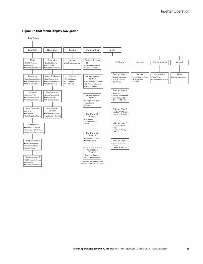
Inverter Operation
Power Xpert Solar 1500/1670 kW Inverter MN141001EN—October 2014 www.eaton.com 35
Figure 27. HMI Menu Display Navigation
Any Screen
Monitor Operation Faults Diagnostics More
Main
• DC/AC Voltages
• Total MWh
• Real/Reactive Power
Monitors
• Real/Reactive Power
• DC Voltage/Current
• Status Indicators
Voltages
• Vab, Vbc, Vcb
• Output Frequency
• Real/Reactive Power
Line Currents
• Ia, Ib, Ic
• DC Power
• Real/Reactive Power
DC Monitors
• Primary DC Voltage
• Secondary DC Voltages
• Secondary DC Currents
Temperatures 1
• Inlet/Outlet Temp
• Inlet/Outlet Pressure
• Return Flow
Temperatures 2
• IGBT Module Temps
• Total MWh
• Real/Reactive Power
Operation
• Enable/Disable
• Fault Reset
• Charge/Shutdown
Local Set Points
• Real Power Limit
• Reactive Power/PF
• Enable/Disable
Configuration
• Local/Remote Sel
• Auto/Maunal
• PF Control Enable
Application
Custom
• Customer Specific
• Application Specific
Active
List of Active Alarms
History
• Alarm History
• 0 = Logged
• X = Cleared
System Comms
• HMI
• SCADA Connection
• Internal Comms
Hardware Alarm
Inputs 1
• Grid Voltages/Currents
• DC Voltages/Currents
• External Faults
Hardware Alarm
Inputs 2
• E-Stop/Door Open
• Fuse Faults
• Blower
Hardware I/O
Status 1
• DC Inputs/
• Commands per
• Stack
Hardware I/O
Status 2
• Breaker/Contactors
• Pump/Blower
Application
Custom
• Customer Specific
• Application Specific
Standard version displays
general purpose MF I/O status
Settings Page 1
• Wake-Up Voltage
• SCADA Timeout
• Date/Time
Service
• Pump/Blower Force
• Bypasss Door
• Interlock
About
Firmware Versions
Commision
• Date/Time
• Commission Status
Settings Service Commission About
Settings Page 2
• Ramp Up
• System Power Limit
• Auto Retry/Grid
• Reconnect Timers
Settings Page 3
• Modbus/TCP Enable
• Inverter IP Address
Settings Page 4
• Inverter Subnet
• Mask
• Inverter Gateway
• Address
Settings Page 5
• Optional I/O PLC
• Enable
• I/O PLC IP Address
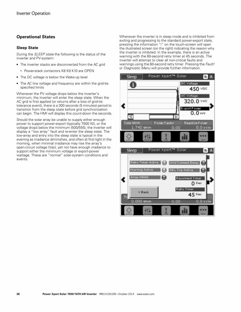
Inverter Operation
36 Power Xpert Solar 1500/1670 kW Inverter MN141001EN—October 2014 www.eaton.com
Operational States
Sleep State
During the SLEEP state the following is the status of the inverter and PV-system:
● The inverter stacks are disconnected from the AC grid
● Power-stack contactors K8 K9 K10 are OPEN
● The DC voltage is below the Wake-up level
● The AC line voltage and frequency are within the grid-tie specified limits
Whenever the PV voltage drops below the inverter’s minimum, the inverter will enter the sleep state. When the AC grid is first applied (or returns after a loss of grid-tie tolerance event), there is a 300 seconds (5 minutes) period to transition from the sleep state before grid synchronization can begin. The HMI will display this count-down the seconds.
Should the solar array be unable to supply either enough power to support power-export (typically 7500 W), or the voltage drops below the minimum (500/555), the inverter will display a “low array” fault and re-enter the sleep state. The low-array and entry into the sleep state is typical in the evening as irradiance diminishes, and often at first light in the morning, when minimal irradiance may rise the array’s open-circuit voltage (Vac), yet not have enough irradiance to support either the minimum voltage or export-power wattage. These are “normal” solar-system conditions and events.
Whenever the inverter is in sleep mode and is inhibited from exiting and progressing to the standard power-export state, pressing the information “i” on the touch-screen will open the illustrated screen (on the right) indicating the reason why the inverter is inhibited. In the example, there is an active warning with the 60-second retry timer at 45 seconds. The inverter will attempt to clear all non-critical faults and warnings using the 60-second retry timer. Pressing the Fault! or Diagnostic Menu will provide further information.
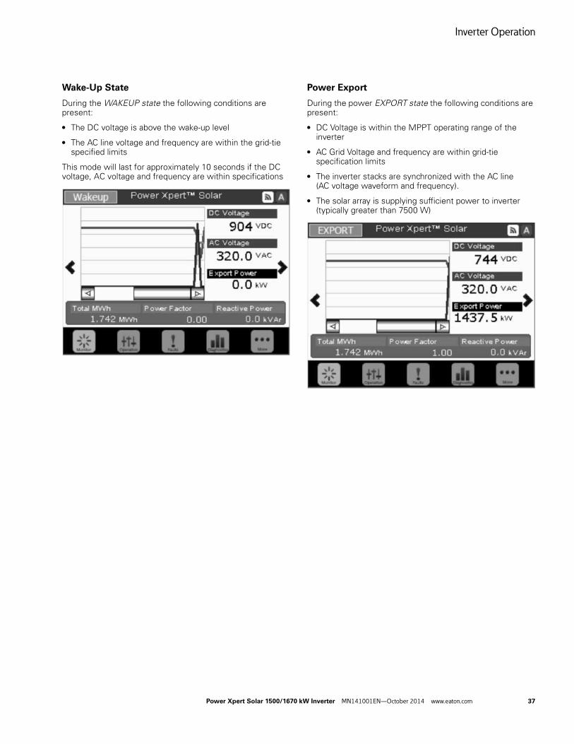
Inverter Operation
Power Xpert Solar 1500/1670 kW Inverter MN141001EN—October 2014 www.eaton.com 37
Wake-Up State
During the WAKEUP state the following conditions are present:
● The DC voltage is above the wake-up level
● The AC line voltage and frequency are within the grid-tie specified limits
This mode will last for approximately 10 seconds if the DC voltage, AC voltage and frequency are within specifications
Power Export
During the power EXPORT state the following conditions are present:
● DC Voltage is within the MPPT operating range of the inverter
● AC Grid Voltage and frequency are within grid-tie specification limits
● The inverter stacks are synchronized with the AC line (AC voltage waveform and frequency).
● The solar array is supplying sufficient power to inverter (typically greater than 7500 W)
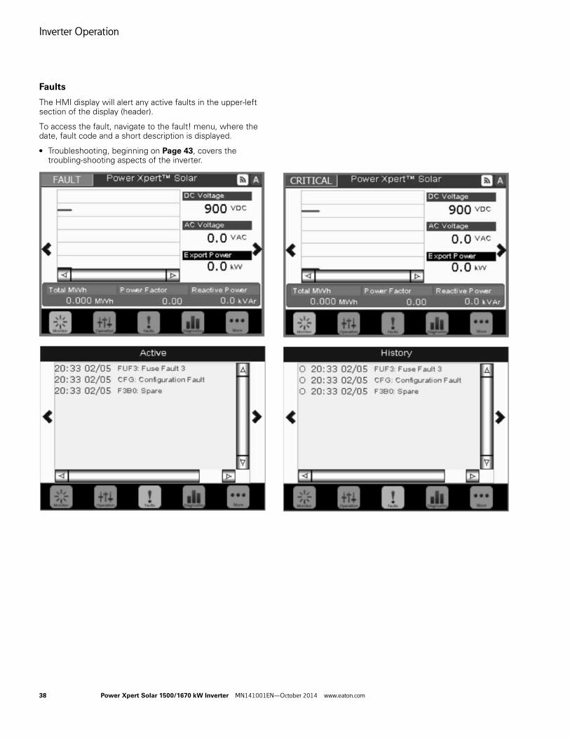
Inverter Operation
38 Power Xpert Solar 1500/1670 kW Inverter MN141001EN—October 2014 www.eaton.com
Faults
The HMI display will alert any active faults in the upper-left section of the display (header).
To access the fault, navigate to the fault! menu, where the date, fault code and a short description is displayed.
● Troubleshooting, beginning on Page 43, covers the troubling-shooting aspects of the inverter.
Maintenance
Power Xpert Solar 1500/1670 kW Inverter MN141001EN—October 2014 www.eaton.com 39
Maintenance
The Power Xpert Solar 1500/1670 kW Inverter is easy to maintain. No periodic adjustments are required. Only basic field-wiring, systems checks and inspections are required. The monitoring system is designed to alert to operator of a case requiring non-periodic maintenance. Only qualified personnel shall maintain the inverter. Please consult your local sales person for support.
CAUTION!
NOTICE!
Turn OFF and de-energize the Inverter before performing any inspections or maintenance. Disconnect (open) and LOTO all remote DC and AC power sources, following established Lock-Out / Tag-Out procedures. Wait at least 5 minutes before opening the enclosure doors to allow capacitive energy to dissipate.
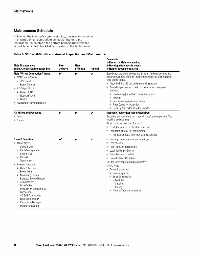
Maintenance
40 Power Xpert Solar 1500/1670 kW Inverter MN141001EN—October 2014 www.eaton.com
Maintenance Schedule
Following the inverter’s commissioning, the inverter must be maintained on an appropriate schedule, fitting to the installation. To establish the correct periodic maintenance schedule, an initial check-list is provided in the table below.
Table 9. 30-Day, 6-Month and Annual Inspection and Maintenance
Field MaintenanceTasks/Checks/Maintenance Log
First 30 Days
First 6 Months Annual
Comments1) Record in Maintenance Log2) Develop site-specific needs3) Helpful recommendations
Field-Wiring Connection Torque■ PV DC Input Circuits
❑ ±PV Circuit❑ Equip. Grounds
■ AC Output Circuits❑ Phases A/B/C❑ Neutral (4-wire)❑ Ground
■ Inverter bolt-down fasteners
✔ ✔ ✔ Based upon the initial 30-day and 6-month findings, develop and schedule recurring (periodic) maintenance tasks to ensure proper field-wiring torque.■ After the initial 30-day and 6-month inspection:■ Annual Inspection and checks of the inverter is required,
minimum.❑ Field wiring (PV and AC connection points)❑ Inverter ❑ internal wiring and components❑ Filter-Capacitor inspection❑ Solar System external to the inverter
Air Filters and Passages■ Inlets■ Outlets
✔ ✔ ✔ Inspect: Clean or Replace as Required Excessive environmental dust that will require more periodic filter checking and cleaning.What is the cause of the filter dirt?■ Local (temporary) construction or activity■ Long-term (chronic) air contaminates
❑ Increase periodic filter maintenance/change
Overall Condition■ Water Ingress
❑ Conduit Seals❑ Cable/Wire glands❑ Control HMI❑ Cabinet❑ Transformer
■ Inverter Operation❑ Data Collection❑ Power Meter❑ Monitoring System❑ Expected Energy Harvest❑ Temperatures❑ Lose Cables❑ Evidence of “hot spots” at
Connections❑ AC Grid Connections❑ Labels (sun faded?)❑ Vandalism /Damage❑ Other as Specified
✔ ✔ ✔ Is there any undue water or moisture ingress?■ Loss of seals■ High (condensing) Humidity■ Local flooding or Splash■ Overall exterior condition■ Overall Interior ConditionHas the Inverter performed as Expected?If Not, Why?■ Determine cause(s)
❑ Inverter specific❑ Solar Site specific
– Modules– Shading– Soiling
❑ Note for future maintenance
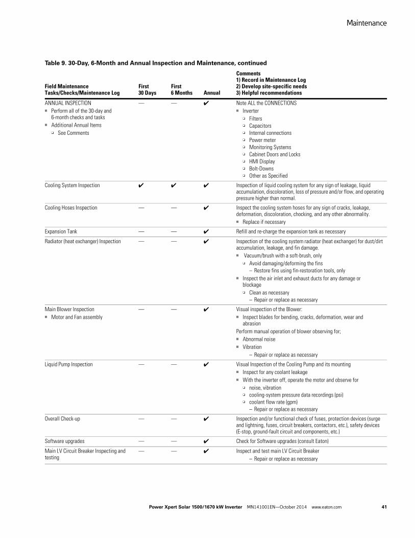
Maintenance
Power Xpert Solar 1500/1670 kW Inverter MN141001EN—October 2014 www.eaton.com 41
ANNUAL INSPECTION■ Perform all of the 30-day and
6-month checks and tasks■ Additional Annual Items
❑ See Comments
— — ✔ Note ALL the CONNECTIONS■ Inverter
❑ Filters❑ Capacitors❑ Internal connections❑ Power meter❑ Monitoring Systems❑ Cabinet Doors and Locks❑ HMI Display❑ Bolt-Downs❑ Other as Specified
Cooling System Inspection ✔ ✔ ✔ Inspection of liquid cooling system for any sign of leakage, liquid accumulation, discoloration, loss of pressure and/or flow, and operating pressure higher than normal.
Cooling Hoses Inspection — — ✔ Inspect the cooling system hoses for any sign of cracks, leakage, deformation, discoloration, chocking, and any other abnormality.■ Replace if necessary
Expansion Tank — — ✔ Refill and re-charge the expansion tank as necessary
Radiator (heat exchanger) Inspection — — ✔ Inspection of the cooling system radiator (heat exchanger) for dust/dirt accumulation, leakage, and fin damage. ■ Vacuum/brush with a soft-brush, only
❑ Avoid damaging/deforming the fins– Restore fins using fin-restoration tools, only
■ Inspect the air inlet and exhaust ducts for any damage or blockage❑ Clean as necessary
– Repair or replace as necessary
Main Blower Inspection■ Motor and Fan assembly
— — ✔ Visual inspection of the Blower:■ Inspect blades for bending, cracks, deformation, wear and
abrasionPerform manual operation of blower observing for;■ Abnormal noise■ Vibration
– Repair or replace as necessary
Liquid Pump Inspection — — ✔ Visual Inspection of the Cooling Pump and its mounting■ Inspect for any coolant leakage■ With the inverter off, operate the motor and observe for
❑ noise, vibration❑ cooling-system pressure data recordings (psi)❑ coolant flow rate (gpm)
– Repair or replace as necessary
Overall Check-up — — ✔ Inspection and/or functional check of fuses, protection devices (surge and lightning, fuses, circuit breakers, contactors, etc.), safety devices (E-stop, ground-fault circuit and components, etc.)
Software upgrades — — ✔ Check for Software upgrades (consult Eaton)
Main LV Circuit Breaker Inspecting and testing
— — ✔ Inspect and test main LV Circuit Breaker– Repair or replace as necessary
Table 9. 30-Day, 6-Month and Annual Inspection and Maintenance, continued
Field MaintenanceTasks/Checks/Maintenance Log
First 30 Days
First 6 Months Annual
Comments1) Record in Maintenance Log2) Develop site-specific needs3) Helpful recommendations
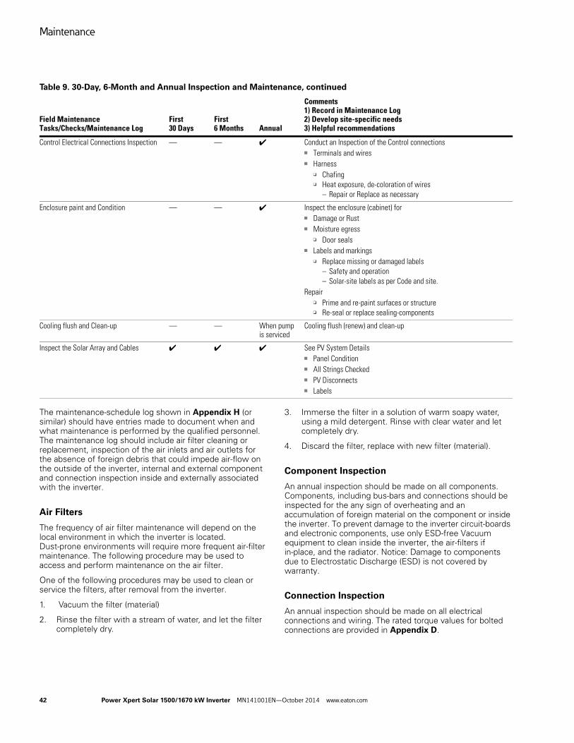
Maintenance
42 Power Xpert Solar 1500/1670 kW Inverter MN141001EN—October 2014 www.eaton.com
The maintenance-schedule log shown in Appendix H (or similar) should have entries made to document when and what maintenance is performed by the qualified personnel. The maintenance log should include air filter cleaning or replacement, inspection of the air inlets and air outlets for the absence of foreign debris that could impede air-flow on the outside of the inverter, internal and external component and connection inspection inside and externally associated with the inverter.
Air Filters
The frequency of air filter maintenance will depend on the local environment in which the inverter is located. Dust-prone environments will require more frequent air-filter maintenance. The following procedure may be used to access and perform maintenance on the air filter.
One of the following procedures may be used to clean or service the filters, after removal from the inverter.
1. Vacuum the filter (material)
2. Rinse the filter with a stream of water, and let the filter completely dry.
3. Immerse the filter in a solution of warm soapy water, using a mild detergent. Rinse with clear water and let completely dry.
4. Discard the filter, replace with new filter (material).
Component Inspection
An annual inspection should be made on all components. Components, including bus-bars and connections should be inspected for the any sign of overheating and an accumulation of foreign material on the component or inside the inverter. To prevent damage to the inverter circuit-boards and electronic components, use only ESD-free Vacuum equipment to clean inside the inverter, the air-filters if in-place, and the radiator. Notice: Damage to components due to Electrostatic Discharge (ESD) is not covered by warranty.
Connection Inspection
An annual inspection should be made on all electrical connections and wiring. The rated torque values for bolted connections are provided in Appendix D.
Control Electrical Connections Inspection — — ✔ Conduct an Inspection of the Control connections■ Terminals and wires■ Harness
❑ Chafing❑ Heat exposure, de-coloration of wires
– Repair or Replace as necessary
Enclosure paint and Condition — — ✔ Inspect the enclosure (cabinet) for■ Damage or Rust■ Moisture egress
❑ Door seals■ Labels and markings
❑ Replace missing or damaged labels– Safety and operation– Solar-site labels as per Code and site.
Repair❑ Prime and re-paint surfaces or structure❑ Re-seal or replace sealing-components
Cooling flush and Clean-up — — When pump is serviced
Cooling flush (renew) and clean-up
Inspect the Solar Array and Cables ✔ ✔ ✔ See PV System Details■ Panel Condition■ All Strings Checked■ PV Disconnects■ Labels
Table 9. 30-Day, 6-Month and Annual Inspection and Maintenance, continued
Field MaintenanceTasks/Checks/Maintenance Log
First 30 Days
First 6 Months Annual
Comments1) Record in Maintenance Log2) Develop site-specific needs3) Helpful recommendations
Troubleshooting
Power Xpert Solar 1500/1670 kW Inverter MN141001EN—October 2014 www.eaton.com 43
Troubleshooting
Reasons for troubleshooting the inverter include annunciated faults, reduced-exported power, and physical damage to the inverter from external events. Understanding the basis of any troubles characterized as either array-based, inverter-based or grid-based forms the analysis process of troubleshooting the inverter.
Array-Input
The inverter’s input-power window is the specified minimum and maximum DC voltage while supplying enough current to overcome approximately 0.5% of the inverter’s AC power rating. The minimum DC voltage is defined as the lower MPPT voltage. The inverter will not synchronize to the utility and export power when the PV array is below its minimum voltage. The maximum DC voltage is defined as 1000 V, typically corresponding to the photovoltaic array’s Vac during non-operation. The PV array (input power) must always remain slightly greater than the export power (barring momentary LVRT events if the inverter is so equipped or operated). While detected and annunciated as a FAULT or WARNING, loss of the appropriate photovoltaic input-power may not be considered an inverter-centric troubleshooting event. For example, when operating near the inverter’s lower voltage window, large arrays can lose enough power due to sudden shading that the inverter will shut-off as its natural power processing will collapse the array’s voltage. While such events are outside the scope of this manual and normal inverter operation, understanding the available faults and warnings will give rise to determining if an external event adversely affected the inverter’s INPUT.
AC-Output
The inverter’s sinusoidal output waveform must match the utility’s across the step-up transformer’s 3-phases, accounting for voltage magnitude, frequency, phase-angle, and power-factor. The UL1741 grid-tie IEEE 1547 settings are the default-basis for the grid specification and continued inverter operation. While detected and annunciated as a FAULT or WARNING, loss of the appropriate grid may not be considered an inverter-centric troubleshooting event. While such events are outside the scope of this manual and normal inverter operation, understanding the available faults and warnings will give rise to determining if an external event adversely affected the AC-OUTPUT.
Inverter
Multiple fault-tolerant control algorithms will always try to reset the inverter whenever the PV-array or AC-Grid fall outside of the operating specifications, automatically resuming operation once both the input (array) and output (grid) are within specification. While complex engineering-level diagnostic steps are outside the scope of this manual, understanding the available faults and warnings will give rise to determining if an internal event adversely affected the INVERTER.
Identifying Inverter Faults and Warnings
Detected events or situations that prevent power export are annunciated via the HMI and Modbus as either faults or warnings. In addition, a history log is stored on-board the inverter.
● The inverter will indicate specific faults and warnings via the HMI display.
● Active and historical data is stored under the fault! menu and can be accessed via the HMI display.
Inverter Response to Faults and Warnings
FAULT and WARNING are divided in 4 categories which provide the basis of the inverter’s behavior whenever these are detected or present. The FAULT category takes precedence over the WARNING category. Detection takes place in any state, however;
● For instance … if already in the fault state and a critical fault occurs, the inverter transitions appropriately.
● When in the critical fault state, the inverter will still detect most warnings and faults, yet they will not be acted upon.
Fault location:
● Power-Stack 1 indicates the fault occurred in the 1st inverter (left-side stack).
● Power-Stack 2 indicates the fault occurred in the 2nd inverter (middle stack).
● Power-Stack 3 indicates the fault occurred in the 3rd inverter (right-side stack).
Inverter system (Inv sys):
● Indicates the fault occurred outside of the inverter, and within the separate diagnostic circuits from the modules or stacks.
Fault text on HMI:
● Displays the fault code followed by the fault text
DESCRIPTION is a basic statement about the fault
RESOLUTION is the basic recommendation for gathering information, addressing the issue and resuming inverter operation.
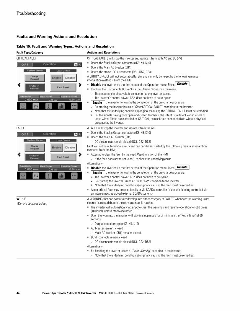
Troubleshooting
44 Power Xpert Solar 1500/1670 kW Inverter MN141001EN—October 2014 www.eaton.com
Faults and Warning Actions and Resolution
Table 10. Fault and Warning Types: Actions and Resolution
Fault Type/Category Actions and Resolutions
CRITICAL FAULT CRITICAL FAULTS will stop the inverter and isolate it from both AC and DC (PV).■ Opens the Stack’s Output contactors (K8, K9, K10)■ Opens the Main AC breaker (CB1)■ Opens the stacks’ DC disconnects (DS1, DS2, DS3).A CRITICAL FAULT will not automatically retry and can only be re-set by the following manual intervention methods. From the HMI;■ Disable the inverter via the first screen of the Operation menu: Press .■ Re-close the Disconnects DS1-2-3 via the Charge Request on the menu.
❑ This restores the photovoltaic connection to the inverter stacks.❑ The inverter’s control power, CB2, does not have to be re-cycled
■ the inverter following the completion of the pre-charge procedure.❑ Re-starting the inverter issues a “Clear CRITICAL FAULT” condition to the inverter.❑ Note that the underlying condition(s) originally causing the CRITICAL FAULT must be remedied.❑ For the signals having both open and closed feedback, the intent is to detect wiring errors or
loose wires. These are classified as CRITICAL, as a solution cannot be fixed without physical presence at the inverter.
FAULT A FAULT will stop the inverter and isolate it from the AC.■ Opens the Stack’s Output contactors (K8, K9, K10)■ Opens the Main AC breaker (CB1)
❑ DC disconnects remain closed (DS1, DS2, DS3)Fault will not be automatically retry and can only be re-started by the following manual intervention methods. From the HMI;■ Attempt to clear the fault by the Fault Reset function of the HMI
❑ If the fault does not re-set (clear), re-check the underlying causeAlternatively;■ Disable the inverter via the first screen of the Operation menu: Press .■ the inverter following the completion of the pre-charge procedure.
❑ The inverter’s control power, CB2, does not have to be cycled❑ Re-Starting the inverter issues a “Clear Fault” condition to the inverter. ❑ Note that the underlying condition(s) originally causing the fault must be remedied.
■ A non-critical fault may be reset locally or via SCADA controller (if the unit is being controlled via an interconnect-approved external SCADA system.)
W R FWarning becomes a Fault
A WARNING that can potentially develop into either category of FAULTS whenever the warning is not cleared (corrected) before the retry attempts is reached.■ The inverter will automatically attempt to clear the warnings and resume operation for 600 times
(10 hours), unless otherwise noted.■ Upon the warning, the inverter will stay in sleep mode for at minimum the “Retry Time” of 60
seconds.❑ Output contactors open (K8, K9, K10)
■ AC breaker remains closed❑ Main AC breaker (CB1) remains closed
■ DC disconnects remain closed❑ DC disconnects remain closed (DS1, DS2, DS3)
Alternatively;■ Re-Enabling the inverter issues a “Clear Warning” condition to the inverter.
❑ Note that the underlying condition(s) originally causing the fault must be remedied.
Disable
Enable
Disable
Enable
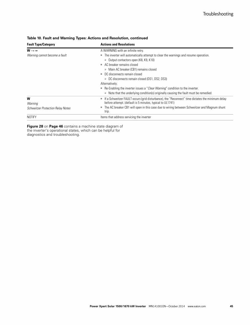
Troubleshooting
Power Xpert Solar 1500/1670 kW Inverter MN141001EN—October 2014 www.eaton.com 45
Figure 28 on Page 46 contains a machine state diagram of the inverter’s operational states, which can be helpful for diagnostics and troubleshooting.
W R ∞Warning cannot become a fault
A WARNING with an infinite retry.■ The inverter will automatically attempt to clear the warnings and resume operation.
❑ Output contactors open (K8, K9, K10)■ AC breaker remains closed
❑ Main AC breaker (CB1) remains closed■ DC disconnects remain closed
❑ DC disconnects remain closed (DS1, DS2, DS3)Alternatively;■ Re-Enabling the inverter issues a “Clear Warning” condition to the inverter.
❑ Note that the underlying condition(s) originally causing the fault must be remedied.
WWarningSchweitzer Protection Relay Notes
■ If a Schweitzer FAULT occurs (grid disturbance), the “Reconnect” time dictates the minimum delay before attempt. (default is 5 minutes, typical to UL1741)
■ The AC breaker CB1 will open in this case due to wiring between Schweitzer and Magnum shunt trip.
NOTIFY Items that address servicing the inverter
Table 10. Fault and Warning Types: Actions and Resolution, continued
Fault Type/Category Actions and Resolutions
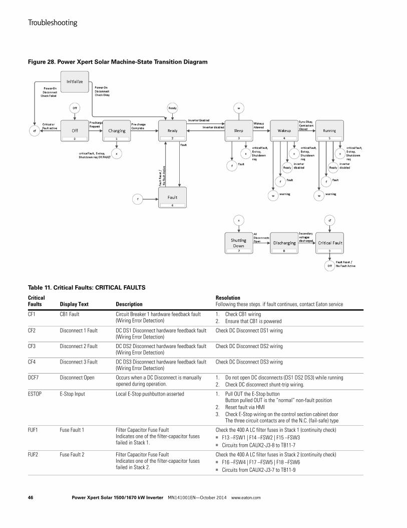
Troubleshooting
46 Power Xpert Solar 1500/1670 kW Inverter MN141001EN—October 2014 www.eaton.com
Figure 28. Power Xpert Solar Machine-State Transition Diagram
Table 11. Critical Faults: CRITICAL FAULTS
Critical Faults Display Text Description
ResolutionFollowing these steps. if fault continues, contact Eaton service
CF1 CB1 Fault Circuit Breaker 1 hardware feedback fault(Wiring Error Detection)
1. Check CB1 wiring2. Ensure that CB1 is powered
CF2 Disconnect 1 Fault DC DS1 Disconnect hardware feedback fault(Wiring Error Detection)
Check DC Disconnect DS1 wiring
CF3 Disconnect 2 Fault DC DS2 Disconnect hardware feedback fault(Wiring Error Detection)
Check DC Disconnect DS2 wiring
CF4 Disconnect 3 Fault DC DS3 Disconnect hardware feedback fault(Wiring Error Detection)
Check DC Disconnect DS3 wiring
DCF7 Disconnect Open Occurs when a DC Disconnect is manually opened during operation.
1. Do not open DC disconnects (DS1 DS2 DS3) while running2. Check DC disconnect shunt-trip wiring.
ESTOP E-Stop Input Local E-Stop pushbutton asserted 1. Pull OUT the E-Stop buttonButton pulled OUT is the “normal” non-fault position
2. Reset fault via HMI3. Check E-Stop wiring on the control section cabinet door
The three circuit contacts are of the N.C. (fail-safe) type
FUF1 Fuse Fault 1 Filter Capacitor Fuse FaultIndicates one of the filter-capacitor fuses failed in Stack 1.
Check the 400 A LC filter fuses in Stack 1 (continuity check)■ F13 –FSW1 | F14 –FSW2 | F15 –FSW3■ Circuits from CAUX2-J3-8 to TB11-7
FUF2 Fuse Fault 2 Filter Capacitor Fuse FaultIndicates one of the filter-capacitor fuses failed in Stack 2.
Check the 400 A LC filter fuses in Stack 2 (continuity check)■ F16 –FSW4 | F17 –FSW5 | F18 –FSW6■ Circuits from CAUX2-J3-7 to TB11-9
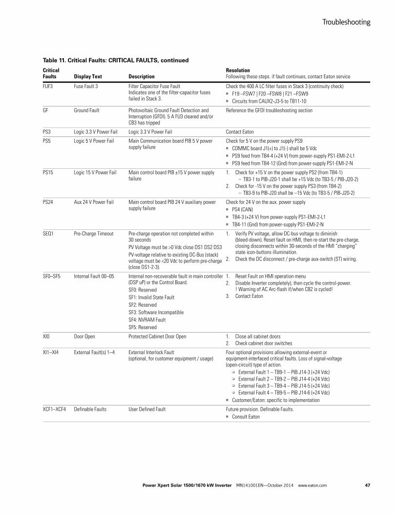
Troubleshooting
Power Xpert Solar 1500/1670 kW Inverter MN141001EN—October 2014 www.eaton.com 47
FUF3 Fuse Fault 3 Filter Capacitor Fuse FaultIndicates one of the filter-capacitor fuses failed in Stack 3.
Check the 400 A LC filter fuses in Stack 3 (continuity check)■ F19 –FSW7 | F20 –FSW8 | F21 –FSW9■ Circuits from CAUX2-J3-5 to TB11-10
GF Ground Fault Photovoltaic Ground Fault Detection and Interruption (GFDI). 5 A FU3 cleared and/or CB3 has tripped
Reference the GFDI troubleshooting section
PS3 Logic 3.3 V Power Fail Logic 3.3 V Power Fail Contact Eaton
PS5 Logic 5 V Power Fail Main Communication board PIB 5 V power supply failure
Check for 5 V on the power supply PS9■ COMMC board J1(+) to J1(-) shall be 5 Vdc■ PS9 feed from TB4-4 (+24 V) from power-supply PS1-EMI-2-L1■ PS9 feed from TB4-12 (Gnd) from power-supply PS1-EMI-2-N
PS15 Logic 15 V Power Fail Main control board PIB ±15 V power supply failure
1. Check for +15 V on the power supply PS2 (from TB4-1)– TB3-1 to PIB-J20-1 shall be +15 Vdc (to TB3-5 / PIB-J20-2)
2. Check for -15 V on the power supply PS3 (from TB4-2)– TB3-9 to PIB-J20 shall be –15 Vdc (to TB3-5 / PIB-J20-2)
PS24 Aux 24 V Power Fail Main control board PIB 24 V auxiliary power supply failure
Check for 24 V on the aux. power supply■ PS4 (CAN)■ TB4-3 (+24 V) from power-supply PS1-EMI-2-L1■ TB4-11 (Gnd) from power-supply PS1-EMI-2-N
SEQ1 Pre-Charge Timeout Pre-charge operation not completed within 30 secondsPV Voltage must be >0 Vdc close DS1 DS2 DS3PV-voltage relative to existing DC-Bus (stack) voltage must be <20 Vdc to perform pre-charge (close DS1-2-3).
1. Verify PV voltage, allow DC-bus voltage to diminish (bleed-down). Reset fault on HMI, then re-start the pre-charge, closing disconnects within 30-seconds of the HMI “charging” state icon-buttons illumination.
2. Check the DC disconnect / pre-charge aux-switch (ST) wiring.
SF0–SF5 Internal Fault 00–05 Internal non-recoverable fault in main controller (DSP uP) or the Control Board.SF0: ReservedSF1: Invalid State FaultSF2: ReservedSF3: Software IncompatibleSF4: NVRAM FaultSF5: Reserved
1. Reset Fault on HMI operation menu2. Disable Inverter completely), then cycle the control-power.
! Warning of AC Arc-flash if/when CB2 is cycled!3. Contact Eaton
XI0 Door Open Protected Cabinet Door Open 1. Close all cabinet doors2. Check cabinet door switches
XI1–XI4 External Fault(s) 1–4 External Interlock Fault(optional, for customer equipment / usage)
Four optional provisions allowing external-event or equipment-interfaced critical faults. Loss of signal-voltage (open-circuit) type of action.
❑ External Fault 1 – TB9-1 – PIB J14-3 (+24 Vdc)❑ External Fault 2 – TB9-2 – PIB J14-4 (+24 Vdc)❑ External Fault 3 – TB9-4 – PIB J14-5 (+24 Vdc)❑ External Fault 4 – TB9-5 – PIB J14-6 (+24 Vdc)
■ Customer/Eaton: specific to implementation
XCF1–XCF4 Definable Faults User Defined Fault Future provision. Definable Faults.■ Consult Eaton
Table 11. Critical Faults: CRITICAL FAULTS, continued
Critical Faults Display Text Description
ResolutionFollowing these steps. if fault continues, contact Eaton service
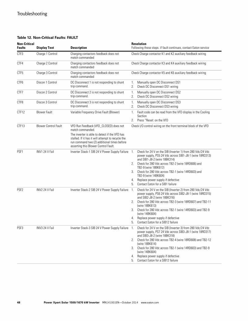
Troubleshooting
48 Power Xpert Solar 1500/1670 kW Inverter MN141001EN—October 2014 www.eaton.com
Table 12. Non-Critical Faults: FAULT
Non-Critical Faults Display Text Description
ResolutionFollowing these steps. if fault continues, contact Eaton service
CTF3 Charge 1 Control Charging contactors feedback does not match commanded
Check Charge contactor K1 and K2 auxiliary feedback wiring
CTF4 Charge 2 Control Charging contactors feedback does not match commanded
Check Charge contactor K3 and K4 auxiliary feedback wiring
CTF5 Charge 3 Control Charging contactors feedback does not match commanded
Check Charge contactor K5 and K6 auxiliary feedback wiring
CTF6 Discon 1 Control DC Disconnect 1 is not responding to shunt trip command.
1. Manually open DC Disconnect DS12. Check DC Disconnect DS1 wiring
CTF7 Discon 2 Control DC Disconnect 2 is not responding to shunt trip command.
1. Manually open DC Disconnect DS22. Check DC Disconnect DS2 wiring
CTF8 Discon 3 Control DC Disconnect 3 is not responding to shunt trip command.
1. Manually open DC Disconnect DS32. Check DC Disconnect DS3 wiring
CTF12 Blower Fault Variable Frequency Drive Fault (Blower) 1. Fault code can be read from the VFD display in the Cooling Section
2. Press “Reset: on the VFD
CTF13 Blower Control Fault VFD Run Feedback (VFD_CLOSED) does not match commanded.The inverter is able to detect if the VFD has stalled. If it has it will attempt to recycle the run command two (2) additional times before asserting this Blower Control Fault.
Check I/O control wiring on the front terminal block of the VFD
PSF1 INV1 24 V Fail Inverter Stack-1 SIB 24 V Power Supply Failure 1. Check for 24 V on the SIB (Inverter 1) from 280 Vdc/24 Vdc power supply, PS5 24 Vdc across SIB1-J8-1 (wire 18RD313) and SIB1-J8-2 (wire 18BK314)
2. Check for 280 Vdc across TB2-2 (wire 18RD606) and TB2-9 (wire 18BK612)
3. Check for 280 Vdc across TB2-1 (wire 14RD603) and TB2-9 (wire 14BK604)
4. Replace power supply if defective5. Contact Eaton for a SIB1 failure
PSF2 INV2 24 V Fail Inverter Stack-2 SIB 24 V Power Supply Failure 1. Check for 24 V on the SIB (Inverter 2) from 280 Vdc/24 Vdc power supply, PS6 24 Vdc across SIB2-J8-1 (wire 18RD315) and SIB2-J8-2 (wire 18BK316)
2. Check for 280 Vdc across TB2-3 (wire 18RD607) and TB2-11 (wire 18BK613)
3. Check for 280 Vdc across TB2-1 (wire 14RD603) and TB2-9 (wire 14BK604)
4. Replace power supply if defective5. Contact Eaton for a SIB12 failure
PSF3 INV3 24 V Fail Inverter Stack-3 SIB 24 V Power Supply Failure 1. Check for 24 V on the SIB (Inverter 3) from 280 Vdc/24 Vdc power supply, PS7 24 Vdc across SIB3-J8-1 (wire 18RD317) and SIB3-J8-2 (wire 18BK318)
2. Check for 280 Vdc across TB2-4 (wire 18RD608) and TB2-12 (wire 18BK614)
3. Check for 280 Vdc across TB2-1 (wire 14RD603) and TB2-9 (wire 14BK604)
4. Replace power supply if defective5. Contact Eaton for a SIB12 failure
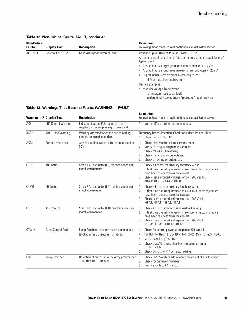
Troubleshooting
Power Xpert Solar 1500/1670 kW Inverter MN141001EN—October 2014 www.eaton.com 49
XF1–XF20 External Fault 1–20 General Purpose External Fault Optional: up to 20 I/O at terminal Block TBC1–20 As implemented per customer/site: definition/de-bounce/set level(s)/type-of-fault■ Analog Input voltages (from an external source): 0–24 Vdc■ Analog Input current (from an external current-loop): 4–20 mA■ Digital Inputs (from external switch-to-ground):
❑ +5 V pull-up circuit at inverterUsages examples:■ Medium Voltage Transformer
❑ temperature transducer fault❑ coolant level / temperature / pressure / rapid-rise / etc.
Table 13. Warnings That Become Faults: WARNING R FAULT
Warning R F Display Text DescriptionResolutionFollowing these steps. if fault continues, contact Eaton service
ACF1 CB1 Control Warning Indicates that the PCC (point of common coupling) is not responding to command.
1. Verify CB1 control-wiring connections
ACF2 Anti-Island Warning Warning asserted when the anti-islanding detects an island condition.
Frequency-based detection: Check for sudden loss of utility1. Clear faults on the HMI
ACF3 Current Imbalance Any line-to-line current differential exceeding 50%.
1. Check HMI Monitors, Line currents menu2. Verify reading in Magnum AC breaker3. Check mains AC line wiring4. Check ribbon cable connections. 5. Check CT wiring on output bus.
CTF9 K8 Control Stack 1 AC contactor (K8) feedback does not match commanded
1. Check K8 contactor auxiliary feedback wiring2. If first time operating inverter, make sure all factory jumpers
have been removed from the contact.3. Check (series-routed) voltages on coil: 208 Vac L-L
K8-A1: TB1-15 - K8-A2: TB1-8
CTF10 K9 Control Stack 2 AC contactor (K9) feedback does not match commanded
1. Check K9 contactor auxiliary feedback wiring2. If first time operating inverter, make sure all factory jumpers
have been removed from the contact.3. Check (series-routed) voltages on coil: 208 Vac L-L
K9-A1: K8-A1 - K9-A2: K8-A2
CTF11 K10 Control Stack 3 AC contactor (K10) feedback does not match commanded
1. Check K10 contactor auxiliary feedback wiring2. If first time operating inverter, make sure all factory jumpers
have been removed from the contact.3. Check (series-routed) voltages on coil: 208 Vac L-L
K10-A1: K8-A1 - K10-A2: K8-A2
CTW14 Pump Control Fault Pump Feedback does not match commanded(evoked after 5 unsuccessful retries)
1. Check for control power at the pump: 208 Vac L-L ■ F49- TB1-4–TR2-X1 | F50- TB1-11–TR2-X2 | F51- TB1-22–TR2-X3■ 6.25 A Fuses F49 | F50 | F512. Check that AUTO reset has been selected on pump
contactor K143. Check pump and K14 contactor wiring
DCF1 Array Backfeed Detection of current into the array greater than –25 Amps for 10 seconds.
1. Check HMI Monitors, Main menu; polarity of “Export Power'”2. Check for damaged modules3. Verify GFDI fuse F3 is intact
Table 12. Non-Critical Faults: FAULT, continued
Non-Critical Faults Display Text Description
ResolutionFollowing these steps. if fault continues, contact Eaton service
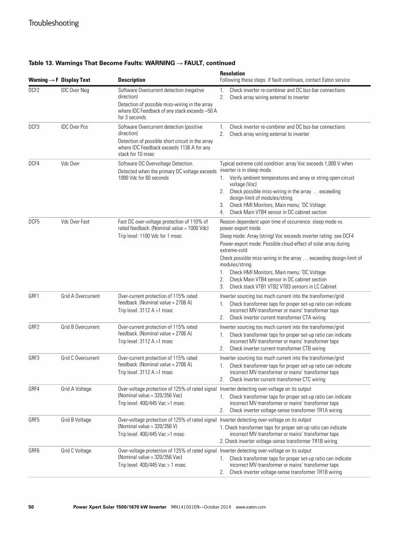
Troubleshooting
50 Power Xpert Solar 1500/1670 kW Inverter MN141001EN—October 2014 www.eaton.com
DCF2 IDC Over Neg Software Overcurrent detection (negative direction)Detection of possible miss-wiring in the array where IDC Feedback of any stack exceeds –50 A for 3 seconds.
1. Check inverter re-combiner and DC bus-bar connections2. Check array wiring external to inverter
DCF3 IDC Over Pos Software Overcurrent detection (positive direction)Detection of possible short circuit in the array where IDC Feedback exceeds 1136 A for any stack for 10 msec
1. Check inverter re-combiner and DC bus-bar connections2. Check array wiring external to inverter
DCF4 Vdc Over Software DC Overvoltage Detection.Detected when the primary DC voltage exceeds 1080 Vdc for 60 seconds
Typical extreme cold condition: array Voc exceeds 1,000 V when inverter is in sleep mode.1. Verify ambient temperatures and array or string open-circuit
voltage (Voc)2. Check possible miss-wiring in the array … exceeding
design-limit of modules/string3. Check HMI Monitors, Main menu; 'DC Voltage4. Check Main VTB4 sensor in DC cabinet section
DCF5 Vdc Over Fast Fast DC over-voltage protection of 110% of rated feedback. (Nominal value = 1000 Vdc)Trip level: 1100 Vdc for 1 msec
Reason dependent upon time of occurrence: sleep mode vs. power-export modeSleep mode: Array (string) Voc exceeds inverter rating: see DCF4Power-export mode: Possible cloud-effect of solar array during extreme-coldCheck possible miss-wiring in the array … exceeding design-limit of modules/string1. Check HMI Monitors, Main menu; 'DC Voltage2. Check Main VTB4 sensor in DC cabinet section3. Check stack VTB1 VTB2 VTB3 sensors in LC Cabinet
GRF1 Grid A Overcurrent Over-current protection of 115% rated feedback. (Nominal value = 2706 A)Trip level: 3112 A >1 msec
Inverter sourcing too much current into the transformer/grid1. Check transformer taps for proper set-up ratio can indicate
incorrect MV-transformer or mains’ transformer taps2. Check inverter current-transformer CTA wiring
GRF2 Grid B Overcurrent Over-current protection of 115% rated feedback. (Nominal value = 2706 A)Trip level: 3112 A >1 msec
Inverter sourcing too much current into the transformer/grid1. Check transformer taps for proper set-up ratio can indicate
incorrect MV-transformer or mains’ transformer taps2. Check inverter current-transformer CTB wiring
GRF3 Grid C Overcurrent Over-current protection of 115% rated feedback. (Nominal value = 2706 A)Trip level: 3112 A >1 msec
Inverter sourcing too much current into the transformer/grid1. Check transformer taps for proper set-up ratio can indicate
incorrect MV-transformer or mains’ transformer taps2. Check inverter current-transformer CTC wiring
GRF4 Grid A Voltage Over-voltage protection of 125% of rated signal (Nominal value = 320/356 Vac)Trip level: 400/445 Vac >1 msec
Inverter detecting over-voltage on its output1. Check transformer taps for proper set-up ratio can indicate
incorrect MV-transformer or mains’ transformer taps2. Check inverter voltage-sense transformer TR1A wiring
GRF5 Grid B Voltage Over-voltage protection of 125% of rated signal (Nominal value = 320/356 V)Trip level: 400/445 Vac >1 msec
Inverter detecting over-voltage on its output1. Check transformer taps for proper set-up ratio can indicate
incorrect MV-transformer or mains’ transformer taps2. Check inverter voltage-sense transformer TR1B wiring
GRF6 Grid C Voltage Over-voltage protection of 125% of rated signal (Nominal value = 320/356 Vac)Trip level: 400/445 Vac > 1 msec
Inverter detecting over-voltage on its output1. Check transformer taps for proper set-up ratio can indicate
incorrect MV-transformer or mains’ transformer taps2. Check inverter voltage-sense transformer TR1B wiring
Table 13. Warnings That Become Faults: WARNING R FAULT, continued
Warning R F Display Text DescriptionResolutionFollowing these steps. if fault continues, contact Eaton service
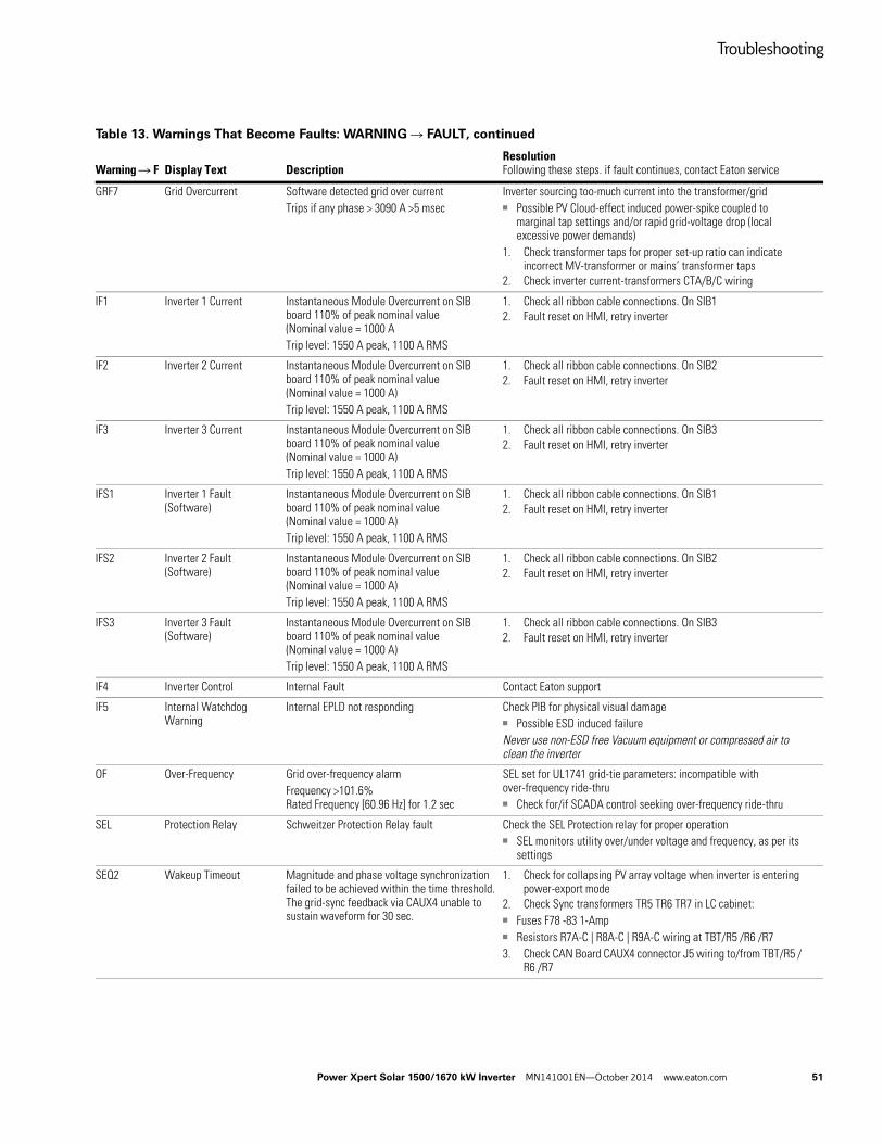
Troubleshooting
Power Xpert Solar 1500/1670 kW Inverter MN141001EN—October 2014 www.eaton.com 51
GRF7 Grid Overcurrent Software detected grid over currentTrips if any phase > 3090 A >5 msec
Inverter sourcing too-much current into the transformer/grid■ Possible PV Cloud-effect induced power-spike coupled to
marginal tap settings and/or rapid grid-voltage drop (local excessive power demands)
1. Check transformer taps for proper set-up ratio can indicate incorrect MV-transformer or mains’ transformer taps
2. Check inverter current-transformers CTA/B/C wiring
IF1 Inverter 1 Current Instantaneous Module Overcurrent on SIB board 110% of peak nominal value (Nominal value = 1000 ATrip level: 1550 A peak, 1100 A RMS
1. Check all ribbon cable connections. On SIB12. Fault reset on HMI, retry inverter
IF2 Inverter 2 Current Instantaneous Module Overcurrent on SIB board 110% of peak nominal value (Nominal value = 1000 A)Trip level: 1550 A peak, 1100 A RMS
1. Check all ribbon cable connections. On SIB22. Fault reset on HMI, retry inverter
IF3 Inverter 3 Current Instantaneous Module Overcurrent on SIB board 110% of peak nominal value (Nominal value = 1000 A)Trip level: 1550 A peak, 1100 A RMS
1. Check all ribbon cable connections. On SIB32. Fault reset on HMI, retry inverter
IFS1 Inverter 1 Fault (Software)
Instantaneous Module Overcurrent on SIB board 110% of peak nominal value (Nominal value = 1000 A)Trip level: 1550 A peak, 1100 A RMS
1. Check all ribbon cable connections. On SIB12. Fault reset on HMI, retry inverter
IFS2 Inverter 2 Fault (Software)
Instantaneous Module Overcurrent on SIB board 110% of peak nominal value (Nominal value = 1000 A)Trip level: 1550 A peak, 1100 A RMS
1. Check all ribbon cable connections. On SIB22. Fault reset on HMI, retry inverter
IFS3 Inverter 3 Fault (Software)
Instantaneous Module Overcurrent on SIB board 110% of peak nominal value (Nominal value = 1000 A)Trip level: 1550 A peak, 1100 A RMS
1. Check all ribbon cable connections. On SIB32. Fault reset on HMI, retry inverter
IF4 Inverter Control Internal Fault Contact Eaton support
IF5 Internal Watchdog Warning
Internal EPLD not responding Check PIB for physical visual damage■ Possible ESD induced failureNever use non-ESD free Vacuum equipment or compressed air to clean the inverter
OF Over-Frequency Grid over-frequency alarmFrequency >101.6% Rated Frequency [60.96 Hz] for 1.2 sec
SEL set for UL1741 grid-tie parameters: incompatible with over-frequency ride-thru■ Check for/if SCADA control seeking over-frequency ride-thru
SEL Protection Relay Schweitzer Protection Relay fault Check the SEL Protection relay for proper operation■ SEL monitors utility over/under voltage and frequency, as per its
settings
SEQ2 Wakeup Timeout Magnitude and phase voltage synchronization failed to be achieved within the time threshold. The grid-sync feedback via CAUX4 unable to sustain waveform for 30 sec.
1. Check for collapsing PV array voltage when inverter is entering power-export mode
2. Check Sync transformers TR5 TR6 TR7 in LC cabinet:■ Fuses F78 -83 1-Amp■ Resistors R7A-C | R8A-C | R9A-C wiring at TBT/R5 /R6 /R73. Check CAN Board CAUX4 connector J5 wiring to/from TBT/R5 /
R6 /R7
Table 13. Warnings That Become Faults: WARNING R FAULT, continued
Warning R F Display Text DescriptionResolutionFollowing these steps. if fault continues, contact Eaton service
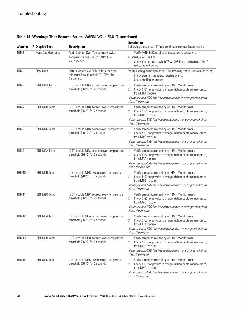
Troubleshooting
52 Power Xpert Solar 1500/1670 kW Inverter MN141001EN—October 2014 www.eaton.com
THM1 Main Cab Overtemp Main Cabinet Over Temperature switch.Temperature over 60 °C (140 °F) for >60 seconds
1. Verify FAN4 in Control cabinet section is operational■ Verify 2 A Fuse F772. Check temperature switch TSW-CAB in control cabinet: 60 °C
set-point and wiring
THM5 Flow Fault Return water flow GPM is less than the minimum flow threshold (27 GPM) for 5 seconds.
Verify cooling pump operation: This Warning set to 5-retires (not 600)1. Check possible pump overload relay trip.2. Check cooling pressures
THM6 IGBT M1A Temp IGBT module M1A exceeds over-temperature threshold (96 °C) for 2 seconds
1. Verify temperature reading on HMI: Monitor-menu2. Check SIB1 for physical damage, ribbon-cable connectors to/
from M1A moduleNever use non-ESD free Vacuum equipment or compressed air to clean the inverter
THM7 IGBT M1B Temp IGBT module M1B exceeds over-temperature threshold (96 °C) for 2 seconds
1. Verify temperature reading on HMI: Monitor-menu2. Check SIB1 for physical damage, ribbon-cable connectors to/
from M1B moduleNever use non-ESD free Vacuum equipment or compressed air to clean the inverter
THM8 IGBT M1C Temp IGBT module M1C exceeds over-temperature threshold (96 °C) for 2 seconds
1. Verify temperature reading on HMI: Monitor-menu2. Check SIB1 for physical damage, ribbon-cable connectors to/
from M1C moduleNever use non-ESD free Vacuum equipment or compressed air to clean the inverter
THM9 IGBT M2A Temp IGBT module M2A exceeds over-temperature threshold (96 °C) for 2 seconds
1. Verify temperature reading on HMI: Monitor-menu2. Check SIB2 for physical damage, ribbon-cable connectors to/
from M2A moduleNever use non-ESD free Vacuum equipment or compressed air to clean the inverter
THM10 IGBT M2B Temp IGBT module M2B exceeds over-temperature threshold (96 °C) for 2 seconds
1. Verify temperature reading on HMI: Monitor-menu2. Check SIB2 for physical damage, ribbon-cable connectors to/
from M2B moduleNever use non-ESD free Vacuum equipment or compressed air to clean the inverter
THM11 IGBT M2C Temp IGBT module M2C exceeds over-temperature threshold (96 °C) for 2 seconds
1. Verify temperature reading on HMI: Monitor-menu2. Check SIB2 for physical damage, ribbon-cable connectors to/
from M2C moduleNever use non-ESD free Vacuum equipment or compressed air to clean the inverter
THM12 IGBT M3A Temp IGBT module M3A exceeds over-temperature threshold (96 °C) for 2 seconds
1. Verify temperature reading on HMI: Monitor-menu2. Check SIB3 for physical damage, ribbon-cable connectors to/
from M3A moduleNever use non-ESD free Vacuum equipment or compressed air to clean the inverter
THM13 IGBT M3B Temp IGBT module M3B exceeds over-temperature threshold (96 °C) for 2 seconds
1. Verify temperature reading on HMI: Monitor-menu2. Check SIB3 for physical damage, ribbon-cable connectors to/
from M3B moduleNever use non-ESD free Vacuum equipment or compressed air to clean the inverter
THM14 IGBT M3C Temp IGBT module M3C exceeds over-temperature threshold (96 °C) for 2 seconds
1. Verify temperature reading on HMI: Monitor-menu2. Check SIB3 for physical damage, ribbon-cable connectors to/
from M3C moduleNever use non-ESD free Vacuum equipment or compressed air to clean the inverter
Table 13. Warnings That Become Faults: WARNING R FAULT, continued
Warning R F Display Text DescriptionResolutionFollowing these steps. if fault continues, contact Eaton service
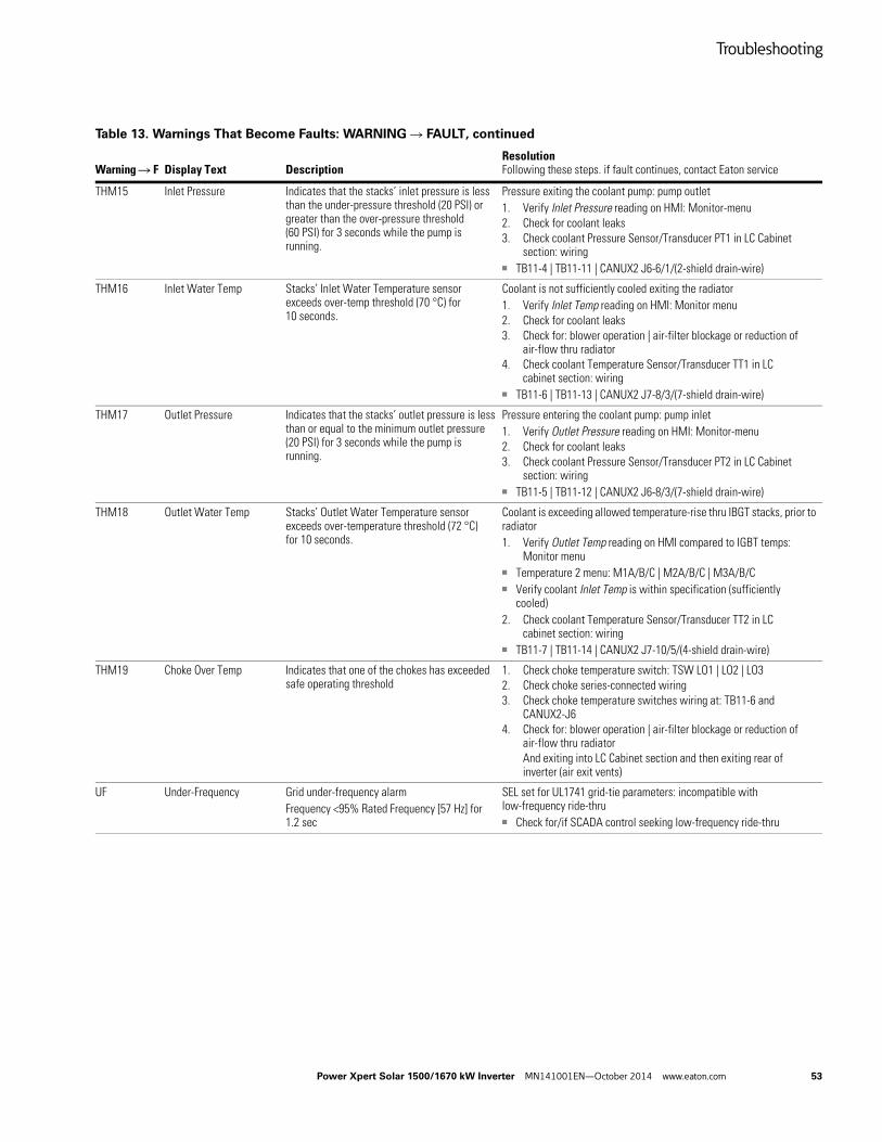
Troubleshooting
Power Xpert Solar 1500/1670 kW Inverter MN141001EN—October 2014 www.eaton.com 53
THM15 Inlet Pressure Indicates that the stacks’ inlet pressure is less than the under-pressure threshold (20 PSI) or greater than the over-pressure threshold (60 PSI) for 3 seconds while the pump is running.
Pressure exiting the coolant pump: pump outlet1. Verify Inlet Pressure reading on HMI: Monitor-menu2. Check for coolant leaks3. Check coolant Pressure Sensor/Transducer PT1 in LC Cabinet
section: wiring■ TB11-4 | TB11-11 | CANUX2 J6-6/1/(2-shield drain-wire)
THM16 Inlet Water Temp Stacks’ Inlet Water Temperature sensor exceeds over-temp threshold (70 °C) for 10 seconds.
Coolant is not sufficiently cooled exiting the radiator1. Verify Inlet Temp reading on HMI: Monitor menu2. Check for coolant leaks3. Check for: blower operation | air-filter blockage or reduction of
air-flow thru radiator4. Check coolant Temperature Sensor/Transducer TT1 in LC
cabinet section: wiring■ TB11-6 | TB11-13 | CANUX2 J7-8/3/(7-shield drain-wire)
THM17 Outlet Pressure Indicates that the stacks’ outlet pressure is less than or equal to the minimum outlet pressure (20 PSI) for 3 seconds while the pump is running.
Pressure entering the coolant pump: pump inlet1. Verify Outlet Pressure reading on HMI: Monitor-menu2. Check for coolant leaks3. Check coolant Pressure Sensor/Transducer PT2 in LC Cabinet
section: wiring■ TB11-5 | TB11-12 | CANUX2 J6-8/3/(7-shield drain-wire)
THM18 Outlet Water Temp Stacks’ Outlet Water Temperature sensor exceeds over-temperature threshold (72 °C) for 10 seconds.
Coolant is exceeding allowed temperature-rise thru IBGT stacks, prior to radiator1. Verify Outlet Temp reading on HMI compared to IGBT temps:
Monitor menu■ Temperature 2 menu: M1A/B/C | M2A/B/C | M3A/B/C■ Verify coolant Inlet Temp is within specification (sufficiently
cooled)2. Check coolant Temperature Sensor/Transducer TT2 in LC
cabinet section: wiring■ TB11-7 | TB11-14 | CANUX2 J7-10/5/(4-shield drain-wire)
THM19 Choke Over Temp Indicates that one of the chokes has exceeded safe operating threshold
1. Check choke temperature switch: TSW LO1 | LO2 | LO32. Check choke series-connected wiring3. Check choke temperature switches wiring at: TB11-6 and
CANUX2-J64. Check for: blower operation | air-filter blockage or reduction of
air-flow thru radiatorAnd exiting into LC Cabinet section and then exiting rear of inverter (air exit vents)
UF Under-Frequency Grid under-frequency alarmFrequency <95% Rated Frequency [57 Hz] for 1.2 sec
SEL set for UL1741 grid-tie parameters: incompatible with low-frequency ride-thru■ Check for/if SCADA control seeking low-frequency ride-thru
Table 13. Warnings That Become Faults: WARNING R FAULT, continued
Warning R F Display Text DescriptionResolutionFollowing these steps. if fault continues, contact Eaton service
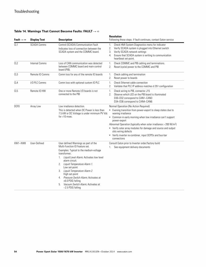
Troubleshooting
54 Power Xpert Solar 1500/1670 kW Inverter MN141001EN—October 2014 www.eaton.com
Table 14. Warnings That Cannot Become Faults: FAULT R
Fault R ∞ Display Text DescriptionResolutionFollowing these steps. if fault continues, contact Eaton service
CL1 SCADA Comms Control (SCADA) Communication Fault Indicates loss of connection between the SCADA system and the COMMC board.
1. Check HMI System Diagnostics menu for indicator2. Verify SCADA system is plugged into Ethernet switch3. Verify SCADA network settings4. Ensure that SCADA system is writing to communication
heartbeat set-point.
CL2 Internal Comms Loss of CAN communication was detected between COMMC board and main control board (PIB).
1. Check COMMC and PIB cabling and terminations.2. Reset (cycle) power to the COMMC and PIB
CL3 Remote IO Comms Comm loss for any of the remote IO boards 1. Check cabling and termination2. Reset power to boards
CL4 I/O PLC Comms Comm loss with optional custom IO PLC 1. Check Ethernet cable connection2. Validate that PLC IP address matches d.351 configuration
CL5 Remote IO HW One or more Remote I/O boards is not connected to the PIB
1. Check wiring to PIB, connector J152. Observe which LED on the PIB board is illuminated
D30~D32 correspond to CAN1~CAN3D34~D36 correspond to CAN4~CAN6
DCF0 Array Low Low irradiance detection.This is detected when DC Power is less than 7.5 kW or DC Voltage is under minimum PV Vdc for >10 msec.
Normal Operation (No Action Required)■ Evening transition from power-export to sleep states due to
waning irradiance■ Common in early morning when low irradiance can’t support
power-exportAbnormal Operation (typically when solar irradiance > 200 W/m2)■ Verify solar array modules for damage and source and output
ckts wiring defects■ Verify inverter re-combiner, input OCPDs and bus-bar
connections
XW1–XW8 User-Defined User defined Warnings as part of the Multi-Function IO Feature set.Examples: Typical to the medium-voltage transformer;1. Liquid Level Alarm; Activates low level
alarm circuit.2. Liquid Temperature Alarm 1.
Low set-point3. Liquid Temperature Alarm 2.
High set-point4. Pressure Switch Alarm; Activates at
+6.0 PSIG falling5. Vacuum Switch Alarm; Activates at
–2.5 PSIG falling
Consult Eaton prior to Inverter order/factory build1. See equipment delivery documents
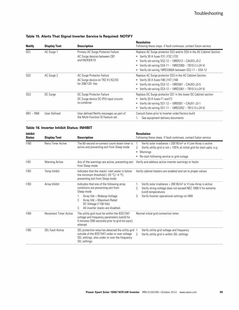
Troubleshooting
Power Xpert Solar 1500/1670 kW Inverter MN141001EN—October 2014 www.eaton.com 55
Table 15. Alerts That Signal Inverter Service Is Required: NOTIFY
Notify Display Text DescriptionResolutionFollowing these steps. if fault continues, contact Eaton service
SG1 AC Surge 1 Primary AC Surge Protector Failure AC Surge devices between CB1 and K8/K9/K10
Replace AC Surge protector SS2 and/or SS4 in the AC Cabinet Section■ Verify 30 A fuses F31 | F32 | F33■ Verify ckt-wiring SS2-12 – 18RD513 – CAUX3-J3-2■ Verify ckt-wiring SS4-11 – 18RD3360 – TB10-2 (+24 V)■ Verify ckt-wiring 18RD3360A between SS2-11 – SS4-12
SG2 AC Surge 2 AC Surge Protector FailureAC Surge device on TR2 X1/X2/X3 for 208/120- Vac
Replace AC Surge protector SS3 in the AC Cabinet Section■ Verify 30 A fuses F46 | F47 | F48■ Verify ckt-wiring SS3-12 – 18RD581 – CAUX3-J3-5■ Verify ckt-wiring SS3-12 – 18RD3361 – TB10-3 (+24 V)
SG3 DC Surge DC Surge Protector FailureDC Surge device DC (PV) input circuits re-combiner
Replace DC Surge protector SS1 in the lower DC Cabinet section■ Verify 20 A fuses F1 and F2■ Verify ckt-wiring SS1-12 – 18RD501 – CAUX1-J3-1■ Verify ckt-wiring SS1-11 – 18RD3352 – TB12-5 (+24 V)
XN1 – XN8 User-Defined User defined Notify messages as part of the Multi-Function IO Feature set.
Consult Eaton prior to Inverter order/factory build1. See equipment delivery documents
Table 16. Inverter Inhibit Status: INHIBIT
Inhibit Status Display Text Description
ResolutionFollowing these steps. if fault continues, contact Eaton service
I1B0 Retry Timer Active The 60-second re-connect count-down timer is active and preventing exit from Sleep mode
1. Verify solar irradiance > 200 W/m2 or if Low-Array is active2. Verify utility-grid is not > 105% at initial grid-tie start-up(s), e.g.;■ Mornings■ Re-start following service or grid-outage
I1B1 Warning Active Any of the warnings are active, preventing exit from Sleep mode
Verify and address active inverter warnings or faults
I1B2 Temp Inhibit Indicates that the stacks’ inlet water is below the minimum threshold (–20 °C/–4 °F), preventing exit from Sleep mode
Verify cabinet heaters are enabled and set to proper values
I1B3 Array Inhibit Indicates that one of the following array conditions are preventing exit from Sleep mode1. Array Vdc < Wakeup Voltage2. Array Vdc > Maximum Rated
DC Voltage (1100 Vdc)3. All inverter stacks are disabled.
1. Verify solar irradiance > 200 W/m2 or if Low-Array is active2. Verify string-voltage does not exceed NEC 1000 V for extreme
(cold) temperatures.3. Verify Inverter operational settings on HMI
I1B4 Reconnect Timer Active The utility-grid must be within the IEEE1547 voltage and frequency parameters (valid) for 5 minutes (300 seconds) prior to grid-tie (sync) attempt.
Normal initial grid-connection timer.
I1B5 SEL Fault Active SEL protection relay has detected the utility-grid outside of the IEEE1547 under or over voltage SEL settings, else under or over the frequency SEL settings.
1. Verify utility-grid voltage and frequency2. Verify utility-grid is within SEL settings
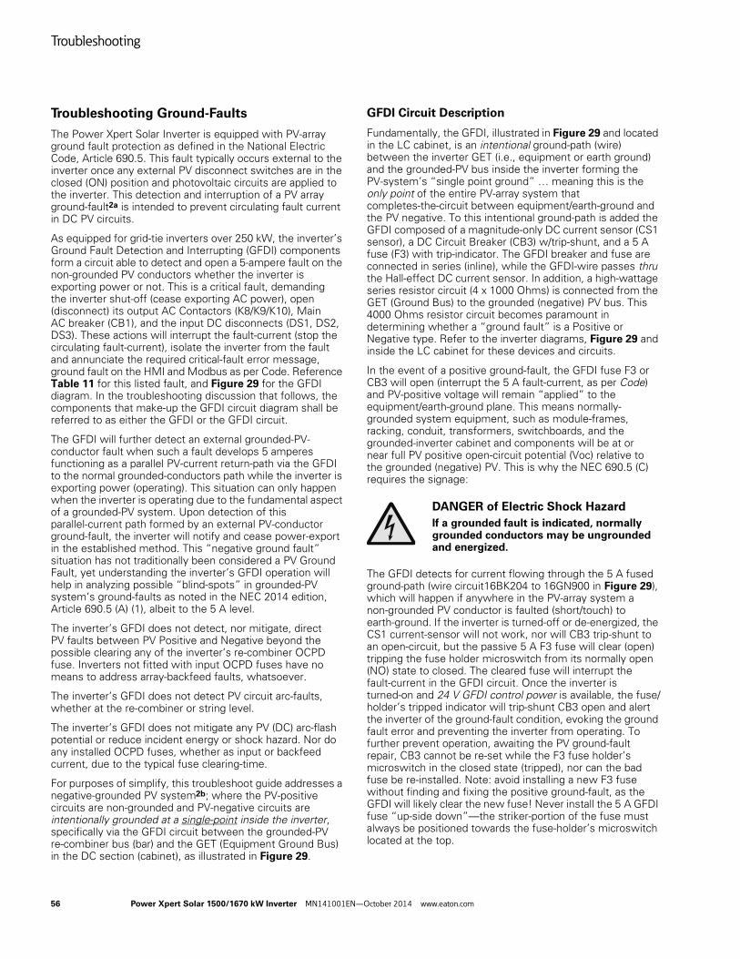
Troubleshooting
56 Power Xpert Solar 1500/1670 kW Inverter MN141001EN—October 2014 www.eaton.com
Troubleshooting Ground-Faults
The Power Xpert Solar Inverter is equipped with PV-array ground fault protection as defined in the National Electric Code, Article 690.5. This fault typically occurs external to the inverter once any external PV disconnect switches are in the closed (ON) position and photovoltaic circuits are applied to the inverter. This detection and interruption of a PV array ground-fault2a is intended to prevent circulating fault current in DC PV circuits.
As equipped for grid-tie inverters over 250 kW, the inverter’s Ground Fault Detection and Interrupting (GFDI) components form a circuit able to detect and open a 5-ampere fault on the non-grounded PV conductors whether the inverter is exporting power or not. This is a critical fault, demanding the inverter shut-off (cease exporting AC power), open (disconnect) its output AC Contactors (K8/K9/K10), Main AC breaker (CB1), and the input DC disconnects (DS1, DS2, DS3). These actions will interrupt the fault-current (stop the circulating fault-current), isolate the inverter from the fault and annunciate the required critical-fault error message, ground fault on the HMI and Modbus as per Code. Reference Table 11 for this listed fault, and Figure 29 for the GFDI diagram. In the troubleshooting discussion that follows, the components that make-up the GFDI circuit diagram shall be referred to as either the GFDI or the GFDI circuit.
The GFDI will further detect an external grounded-PV- conductor fault when such a fault develops 5 amperes functioning as a parallel PV-current return-path via the GFDI to the normal grounded-conductors path while the inverter is exporting power (operating). This situation can only happen when the inverter is operating due to the fundamental aspect of a grounded-PV system. Upon detection of this parallel-current path formed by an external PV-conductor ground-fault, the inverter will notify and cease power-export in the established method. This “negative ground fault” situation has not traditionally been considered a PV Ground Fault, yet understanding the inverter’s GFDI operation will help in analyzing possible “blind-spots” in grounded-PV system’s ground-faults as noted in the NEC 2014 edition, Article 690.5 (A) (1), albeit to the 5 A level.
The inverter’s GFDI does not detect, nor mitigate, direct PV faults between PV Positive and Negative beyond the possible clearing any of the inverter’s re-combiner OCPD fuse. Inverters not fitted with input OCPD fuses have no means to address array-backfeed faults, whatsoever.
The inverter’s GFDI does not detect PV circuit arc-faults, whether at the re-combiner or string level.
The inverter’s GFDI does not mitigate any PV (DC) arc-flash potential or reduce incident energy or shock hazard. Nor do any installed OCPD fuses, whether as input or backfeed current, due to the typical fuse clearing-time.
For purposes of simplify, this troubleshoot guide addresses a negative-grounded PV system2b; where the PV-positive circuits are non-grounded and PV-negative circuits are intentionally grounded at a single-point inside the inverter, specifically via the GFDI circuit between the grounded-PV re-combiner bus (bar) and the GET (Equipment Ground Bus) in the DC section (cabinet), as illustrated in Figure 29.
GFDI Circuit Description
Fundamentally, the GFDI, illustrated in Figure 29 and located in the LC cabinet, is an intentional ground-path (wire) between the inverter GET (i.e., equipment or earth ground) and the grounded-PV bus inside the inverter forming the PV-system’s “single point ground” … meaning this is the only point of the entire PV-array system that completes-the-circuit between equipment/earth-ground and the PV negative. To this intentional ground-path is added the GFDI composed of a magnitude-only DC current sensor (CS1 sensor), a DC Circuit Breaker (CB3) w/trip-shunt, and a 5 A fuse (F3) with trip-indicator. The GFDI breaker and fuse are connected in series (inline), while the GFDI-wire passes thru the Hall-effect DC current sensor. In addition, a high-wattage series resistor circuit (4 x 1000 Ohms) is connected from the GET (Ground Bus) to the grounded (negative) PV bus. This 4000 Ohms resistor circuit becomes paramount in determining whether a “ground fault” is a Positive or Negative type. Refer to the inverter diagrams, Figure 29 and inside the LC cabinet for these devices and circuits.
In the event of a positive ground-fault, the GFDI fuse F3 or CB3 will open (interrupt the 5 A fault-current, as per Code) and PV-positive voltage will remain “applied” to the equipment/earth-ground plane. This means normally- grounded system equipment, such as module-frames, racking, conduit, transformers, switchboards, and the grounded-inverter cabinet and components will be at or near full PV positive open-circuit potential (Voc) relative to the grounded (negative) PV. This is why the NEC 690.5 (C) requires the signage:
DANGER of Electric Shock Hazard
If a grounded fault is indicated, normally grounded conductors may be ungrounded and energized.
The GFDI detects for current flowing through the 5 A fused ground-path (wire circuit16BK204 to 16GN900 in Figure 29), which will happen if anywhere in the PV-array system a non-grounded PV conductor is faulted (short/touch) to earth-ground. If the inverter is turned-off or de-energized, the CS1 current-sensor will not work, nor will CB3 trip-shunt to an open-circuit, but the passive 5 A F3 fuse will clear (open) tripping the fuse holder microswitch from its normally open (NO) state to closed. The cleared fuse will interrupt the fault-current in the GFDI circuit. Once the inverter is turned-on and 24 V GFDI control power is available, the fuse/holder’s tripped indicator will trip-shunt CB3 open and alert the inverter of the ground-fault condition, evoking the ground fault error and preventing the inverter from operating. To further prevent operation, awaiting the PV ground-fault repair, CB3 cannot be re-set while the F3 fuse holder’s microswitch in the closed state (tripped), nor can the bad fuse be re-installed. Note: avoid installing a new F3 fuse without finding and fixing the positive ground-fault, as the GFDI will likely clear the new fuse! Never install the 5 A GFDI fuse “up-side down”—the striker-portion of the fuse must always be positioned towards the fuse-holder’s microswitch located at the top.
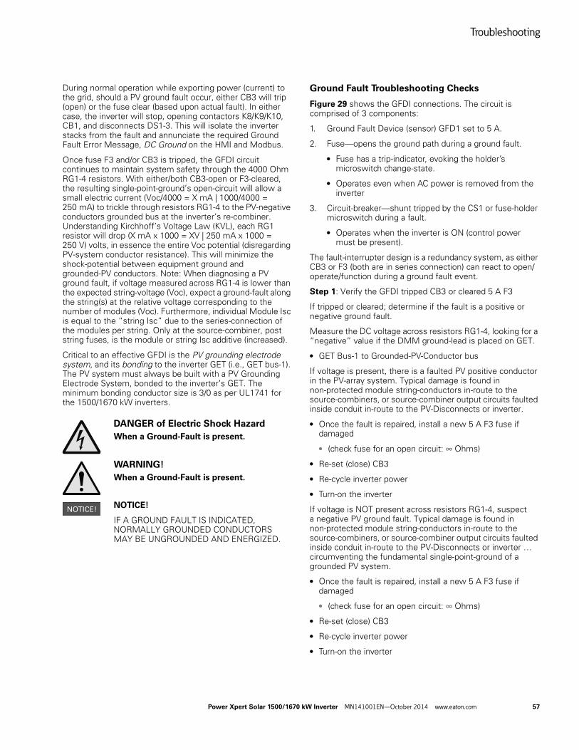
Troubleshooting
Power Xpert Solar 1500/1670 kW Inverter MN141001EN—October 2014 www.eaton.com 57
During normal operation while exporting power (current) to the grid, should a PV ground fault occur, either CB3 will trip (open) or the fuse clear (based upon actual fault). In either case, the inverter will stop, opening contactors K8/K9/K10, CB1, and disconnects DS1-3. This will isolate the inverter stacks from the fault and annunciate the required Ground Fault Error Message, DC Ground on the HMI and Modbus.
Once fuse F3 and/or CB3 is tripped, the GFDI circuit continues to maintain system safety through the 4000 Ohm RG1-4 resistors. With either/both CB3-open or F3-cleared, the resulting single-point-ground’s open-circuit will allow a small electric current (Voc/4000 = X mA | 1000/4000 = 250 mA) to trickle through resistors RG1-4 to the PV-negative conductors grounded bus at the inverter’s re-combiner. Understanding Kirchhoff’s Voltage Law (KVL), each RG1 resistor will drop (X mA x 1000 = XV | 250 mA x 1000 = 250 V) volts, in essence the entire Voc potential (disregarding PV-system conductor resistance). This will minimize the shock-potential between equipment ground and grounded-PV conductors. Note: When diagnosing a PV ground fault, if voltage measured across RG1-4 is lower than the expected string-voltage (Voc), expect a ground-fault along the string(s) at the relative voltage corresponding to the number of modules (Voc). Furthermore, individual Module Isc is equal to the “string Isc” due to the series-connection of the modules per string. Only at the source-combiner, post string fuses, is the module or string Isc additive (increased).
Critical to an effective GFDI is the PV grounding electrode system, and its bonding to the inverter GET (i.e., GET bus-1). The PV system must always be built with a PV Grounding Electrode System, bonded to the inverter’s GET. The minimum bonding conductor size is 3/0 as per UL1741 for the 1500/1670 kW inverters.
DANGER of Electric Shock Hazard
When a Ground-Fault is present.
WARNING!
When a Ground-Fault is present.
NOTICE!
IF A GROUND FAULT IS INDICATED, NORMALLY GROUNDED CONDUCTORS MAY BE UNGROUNDED AND ENERGIZED.
Ground Fault Troubleshooting Checks
Figure 29 shows the GFDI connections. The circuit is comprised of 3 components:
1. Ground Fault Device (sensor) GFD1 set to 5 A.
2. Fuse—opens the ground path during a ground fault.
● Fuse has a trip-indicator, evoking the holder’s microswitch change-state.
● Operates even when AC power is removed from the inverter
3. Circuit-breaker—shunt tripped by the CS1 or fuse-holder microswitch during a fault.
● Operates when the inverter is ON (control power must be present).
The fault-interrupter design is a redundancy system, as either CB3 or F3 (both are in series connection) can react to open/operate/function during a ground fault event.
Step 1: Verify the GFDI tripped CB3 or cleared 5 A F3
If tripped or cleared; determine if the fault is a positive or negative ground fault.
Measure the DC voltage across resistors RG1-4, looking for a “negative” value if the DMM ground-lead is placed on GET.
● GET Bus-1 to Grounded-PV-Conductor bus
If voltage is present, there is a faulted PV positive conductor in the PV-array system. Typical damage is found in non-protected module string-conductors in-route to the source-combiners, or source-combiner output circuits faulted inside conduit in-route to the PV-Disconnects or inverter.
● Once the fault is repaired, install a new 5 A F3 fuse if damaged
● (check fuse for an open circuit: ∞ Ohms)
● Re-set (close) CB3
● Re-cycle inverter power
● Turn-on the inverter
If voltage is NOT present across resistors RG1-4, suspect a negative PV ground fault. Typical damage is found in non-protected module string-conductors in-route to the source-combiners, or source-combiner output circuits faulted inside conduit in-route to the PV-Disconnects or inverter … circumventing the fundamental single-point-ground of a grounded PV system.
● Once the fault is repaired, install a new 5 A F3 fuse if damaged
● (check fuse for an open circuit: ∞ Ohms)
● Re-set (close) CB3
● Re-cycle inverter power
● Turn-on the inverter
Troubleshooting
58 Power Xpert Solar 1500/1670 kW Inverter MN141001EN—October 2014 www.eaton.com
Alternatively to measuring the voltage across resistors RG1-4, checking for milliampere-current thru this resistor circuit will determine if PV-positive is faulted to equipment/earth ground. Due to the low amperage, an inline ammeter can be used, by carefully lifting the circuit-wire off GET (wire 16GN902), and placing the ammeter between the wire 16GN902 and effective GET Bus.
The presence of current indicate a Positive ground-fault.
Step-2: Is the Inverter damaged?
Should PV positive been applied directly to the PV-negative, if the inverter’s PV-disconnecting means (DS1, DS2, DS3) were closed, excessive fault-current can flow through the inverter and damage the inverter stack by flowing current through the IGBT bypass diodes. The DC bus capacitors will have been reversed biased, in addition.
Before proceeding, ensure the PV-array and AC-grid are fully disconnected (isolated) from the inverter, and the inverter’s DC bus capacitance is fully discharged.
Conduct an inverter (Stack) diode and capacitor check.
Consult Eaton if damage is found. The inverter stacks will have to be replaced.
If a Ground-fault problem persists contact Eaton.
Notes:
2a A PV Array Ground Fault is defined as a short-circuit (i.e., an electrical contact) between the grounding electrode (and equipment) of the PV system and the normally non-grounded PV array conductors. Such a fault condition, if unchecked, allows non-intended current to flow in the normal grounding conductors and equipment back to the PV energy source (i.e., solar cells). This type of Ground Fault is not to be confused with a “direct short” (i.e., electrical contact) between the non-grounded PV conductors or circuits (e.g., PV positive) and the grounded PV conductors or circuits (e.g., PV negative). Such a PV direct short is protected (limited) by the combiner-box fuses of the PV system source-combiners and the inverter re-combiner.
2b A positive-grounded PV systems will look physically the same, yet be electrically opposite in polarity by grounding the PV positive to earth (i.e., voltage-meter will read opposite polarity). SunPower Corporation supplied positive-ground solar modules in the past, now moot with modules that can be negative grounded. As noted earlier in this manual, inverter’s employing positive-grounded modules must be factory built and UL1741 End-of-Line tested as a positive-ground inverters. They cannot be field-changed and retain the factory UL1741 certification.
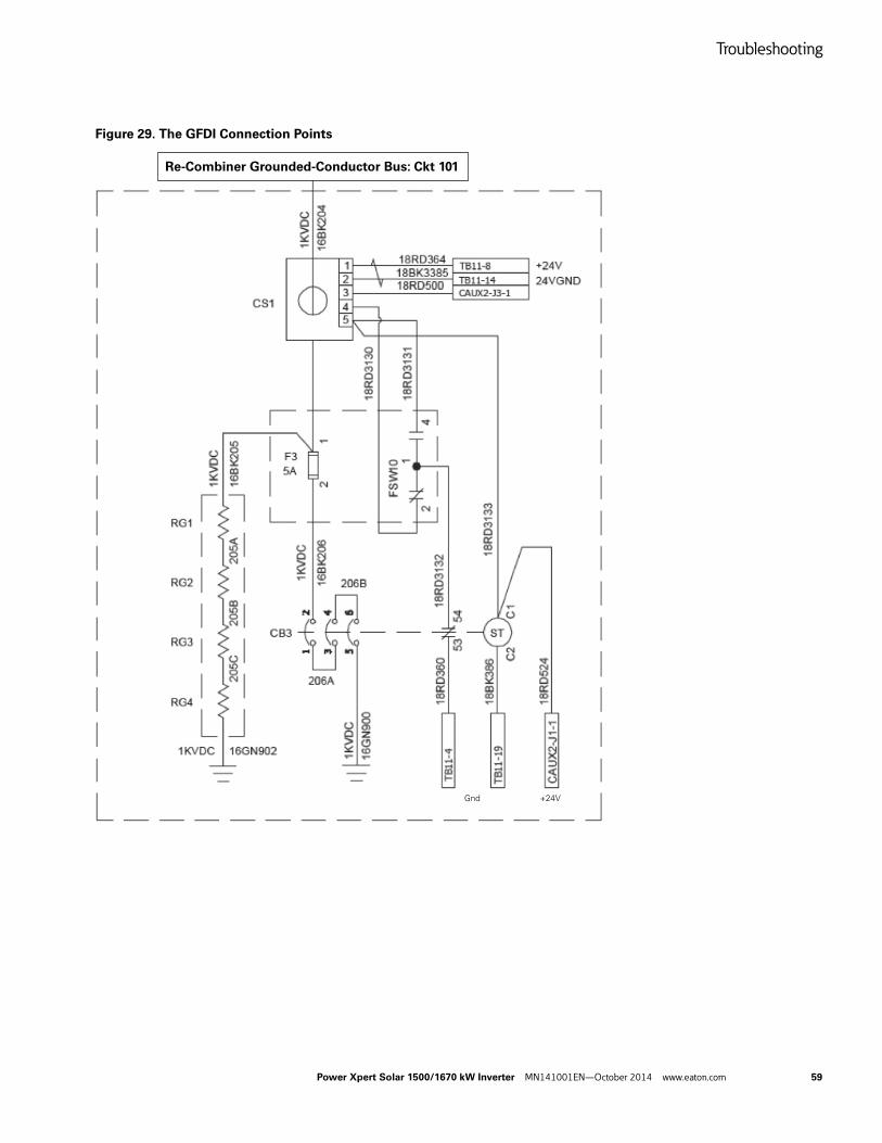
Troubleshooting
Power Xpert Solar 1500/1670 kW Inverter MN141001EN—October 2014 www.eaton.com 59
Figure 29. The GFDI Connection Points
Re-Combiner Grounded-Conductor Bus: Ckt 101
+24VGnd
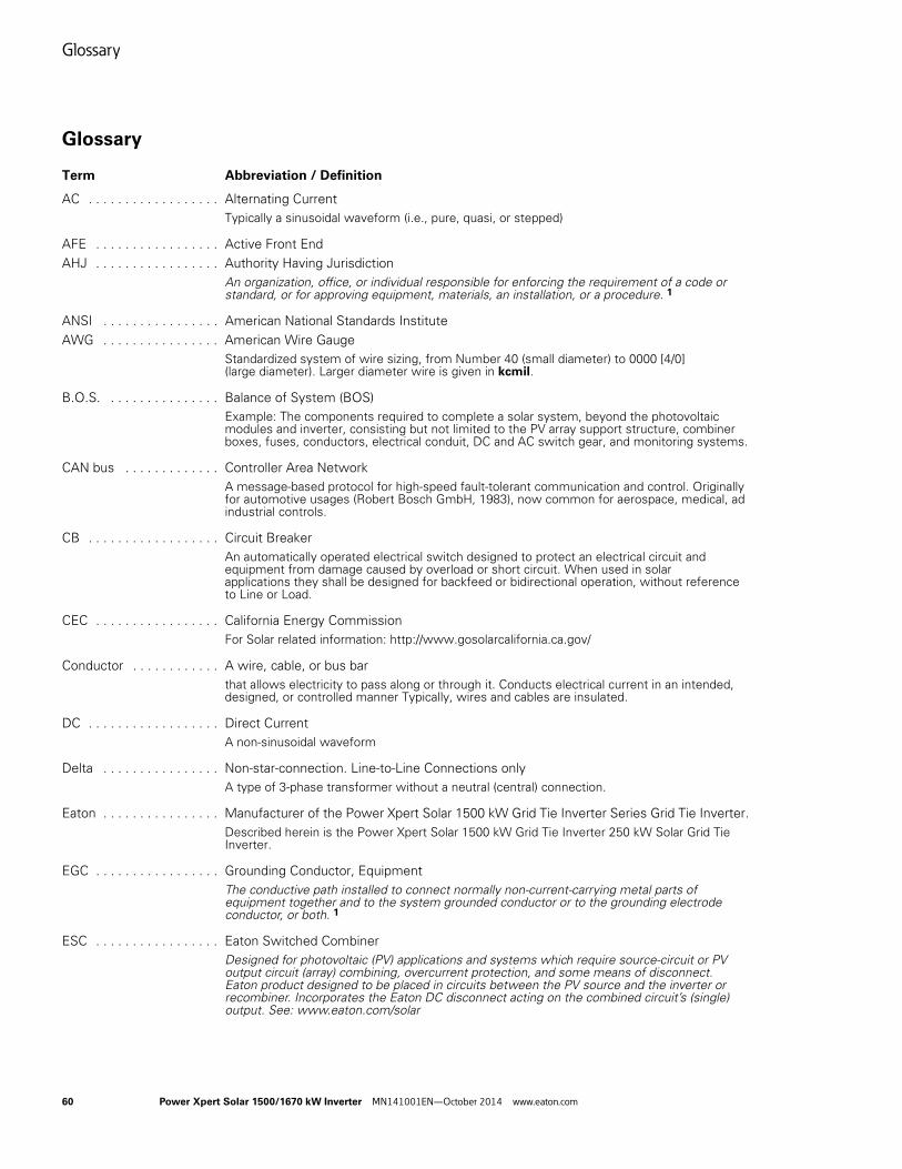
Glossary
60 Power Xpert Solar 1500/1670 kW Inverter MN141001EN—October 2014 www.eaton.com
Glossary
Term Abbreviation / Definition
AC . . . . . . . . . . . . . . . . . . Alternating CurrentTypically a sinusoidal waveform (i.e., pure, quasi, or stepped)
AFE . . . . . . . . . . . . . . . . . Active Front EndAHJ . . . . . . . . . . . . . . . . . Authority Having Jurisdiction
An organization, office, or individual responsible for enforcing the requirement of a code or standard, or for approving equipment, materials, an installation, or a procedure. 1
ANSI . . . . . . . . . . . . . . . . American National Standards InstituteAWG . . . . . . . . . . . . . . . . American Wire Gauge
Standardized system of wire sizing, from Number 40 (small diameter) to 0000 [4/0] (large diameter). Larger diameter wire is given in kcmil.
B.O.S. . . . . . . . . . . . . . . . Balance of System (BOS)Example: The components required to complete a solar system, beyond the photovoltaic modules and inverter, consisting but not limited to the PV array support structure, combiner boxes, fuses, conductors, electrical conduit, DC and AC switch gear, and monitoring systems.
CAN bus . . . . . . . . . . . . . Controller Area NetworkA message-based protocol for high-speed fault-tolerant communication and control. Originally for automotive usages (Robert Bosch GmbH, 1983), now common for aerospace, medical, ad industrial controls.
CB . . . . . . . . . . . . . . . . . . Circuit BreakerAn automatically operated electrical switch designed to protect an electrical circuit and equipment from damage caused by overload or short circuit. When used in solar applications they shall be designed for backfeed or bidirectional operation, without reference to Line or Load.
CEC . . . . . . . . . . . . . . . . . California Energy CommissionFor Solar related information: http://www.gosolarcalifornia.ca.gov/
Conductor . . . . . . . . . . . . A wire, cable, or bus barthat allows electricity to pass along or through it. Conducts electrical current in an intended, designed, or controlled manner Typically, wires and cables are insulated.
DC . . . . . . . . . . . . . . . . . . Direct CurrentA non-sinusoidal waveform
Delta . . . . . . . . . . . . . . . . Non-star-connection. Line-to-Line Connections onlyA type of 3-phase transformer without a neutral (central) connection.
Eaton . . . . . . . . . . . . . . . . Manufacturer of the Power Xpert Solar 1500 kW Grid Tie Inverter Series Grid Tie Inverter. Described herein is the Power Xpert Solar 1500 kW Grid Tie Inverter 250 kW Solar Grid Tie Inverter.
EGC . . . . . . . . . . . . . . . . . Grounding Conductor, EquipmentThe conductive path installed to connect normally non-current-carrying metal parts of equipment together and to the system grounded conductor or to the grounding electrode conductor, or both. 1
ESC . . . . . . . . . . . . . . . . . Eaton Switched CombinerDesigned for photovoltaic (PV) applications and systems which require source-circuit or PV output circuit (array) combining, overcurrent protection, and some means of disconnect. Eaton product designed to be placed in circuits between the PV source and the inverter or recombiner. Incorporates the Eaton DC disconnect acting on the combined circuit’s (single) output. See: www.eaton.com/solar
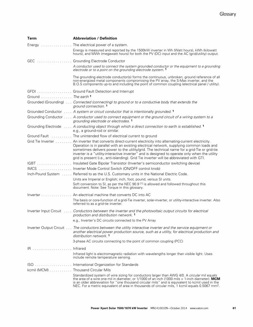
Glossary
Power Xpert Solar 1500/1670 kW Inverter MN141001EN—October 2014 www.eaton.com 61
Term Abbreviation / Definition
Energy . . . . . . . . . . . . . . . The electrical power of a system.Energy is measured and reported by the 1500kW inverter in Wh (Watt hours), kWh (kilowatt hours), and MWh (megawatt hours) for both the PV (DC) input and the AC (grid/utility) output.
GEC . . . . . . . . . . . . . . . . . Grounding Electrode ConductorA conductor used to connect the system grounded conductor or the equipment to a grounding electrode or to a point on the grounding electrode system. 1
The grounding electrode conductor(s) forms the continuous, unbroken, ground reference of all non-energized metal components compromising the PV array, the S-Max inverter, and the B.O.S components up-to and including the point of common coupling (electrical panel / utility).
GFDI . . . . . . . . . . . . . . . . . Ground Fault Detection and InterruptGround . . . . . . . . . . . . . . . The earth 1
Grounded (Grounding) . . . Connected (connecting) to ground or to a conductive body that extends the ground connection. 1
Grounded Conductor . . . . A system or circuit conductor that is intentionally grounded. 1
Grounding Conductor . . . . A conductor used to connect equipment or the ground circuit of a wiring system to a grounding electrode or electrodes. 1
Grounding Electrode . . . . A conducting object through which a direct connection to earth is established. 1 e.g., a ground-rod or similar.
Ground Fault . . . . . . . . . . The unintended flow of electrical current to groundGrid Tie Inverter . . . . . . . . An inverter that converts direct-current electricity into alternating-current electricity.
Operation is in parallel with an existing electrical network, supplying common loads and sometimes delivers power to the utility/grid. The technical name for a grid-Tie or grid-tie inverter is a “utility-interactive inverter” and is designed to operate only when the utility grid is present (i.e., anti-islanding). Grid Tie inverter will be abbreviated with GTI.
IGBT . . . . . . . . . . . . . . . . . Insulated Gate Bipolar Transistor (Inverter’s semiconductor switching device)IMCS . . . . . . . . . . . . . . . . Inverter Mode Control Switch (ON/OFF control knob)Inch-Pound System . . . . . Referred to as the U.S. Customary units in the National Electric Code.
Units are Imperial or English; inch, foot, pound, versus SI units.Soft conversion to SI, as per the NEC 90.9 [1] is allowed and followed throughout this document. Note: See Torque in this glossary.
Inverter . . . . . . . . . . . . . . . An electrical machine that converts DC into ACThe basis or core-function of a grid-Tie inverter, solar-inverter, or utility-interactive inverter. Also referred to as a grid-tie inverter.
Inverter Input Circuit . . . . Conductors between the inverter and the photovoltaic output circuits for electrical production and distribution network. 1 e.g., Inverter’s DC circuits connected to the PV Array
Inverter Output Circuit . . . The conductors between the utility interactive inverter and the service equipment or another electrical power production source, such as a utility, for electrical production and distribution network. 1
3-phase AC circuits connecting to the point of common coupling (PCC)
IR . . . . . . . . . . . . . . . . . . . Infrared Infrared light is electromagnetic radiation with wavelengths longer than visible light. Uses include remote temperature sensing.
ISO . . . . . . . . . . . . . . . . . . International Organization for Standardskcmil (MCM) . . . . . . . . . . . Thousand Circular Mils
Standardized system of wire sizing for conductors larger than AWG 4/0. A circular mil equals the area of a wire one mil in diameter, or 1/1000 of an inch (1000 mils = 1-inch diameter). MCM is an older abbreviation for “one thousand circular mils” and is equivalent to kcmil used in the NEC. For a metric equivalent of area in thousands of circular mils, 1 kcmil equals 0.5067 mm2.
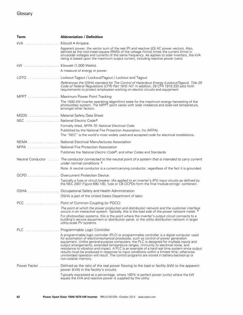
Glossary
62 Power Xpert Solar 1500/1670 kW Inverter MN141001EN—October 2014 www.eaton.com
Term Abbreviation / Definition
kVA . . . . . . . . . . . . . . . . . Kilovolt • Ampere. Apparent power, the vector sum of the real (P) and reactive (jQ) AC power vectors. Also, defined as the root-mean-square (RMS) of the voltage (Vrms) times the current (Irms) in sinusoidal voltages and currents of the same frequency. As applies to solar inverters, the kVA rating is based upon the maximum output current, including reactive power (vars).
kW . . . . . . . . . . . . . . . . . . Kilowatt (1,000 Watts). A measure of energy or power.
LOTO . . . . . . . . . . . . . . . . Lockout-Tagout / Lockout/Tagout / Lockout and TagoutReferences the OSHA standard for The Control of Hazardous Energy (Lockout/Tagout), Title 29 Code of Federal Regulations (CFR) Part 1910.147. In addition, 29 CFR 1910.333 sets forth requirements to protect employees working on electric circuits and equipment.
MPPT . . . . . . . . . . . . . . . . Maximum Power Point TrackingThe 1500 kW inverter operating (algorithm) state for the maximum energy harvesting of the photovoltaic system. The MPPT point varies with solar irradiance and solar-cell temperature, amongst other factors.
MSDS . . . . . . . . . . . . . . . Material Safety Data SheetNEC . . . . . . . . . . . . . . . . . National Electric Code®
Formally titled, NFPA 70: National Electrical Code. Published by the National Fire Protection Association, Inc (NFPA).The “NEC” is the world's most widely used and accepted code for electrical installations.
NEMA . . . . . . . . . . . . . . . National Electrical Manufactures AssociationNFPA . . . . . . . . . . . . . . . . National Fire Protection Association
Publishes the National Electric Code®, and other Codes and Standards
Neutral Conductor . . . . . . The conductor connected to the neutral point of a system that is intended to carry current under normal conditions. 1 Note: A neutral conductor is a current-carrying conductor, regardless of the fact it is grounded.
OCPD . . . . . . . . . . . . . . . . Overcurrent Protection Device. Typically a fuse or circuit breaker. (As applied to an inverter’s (PV) input circuits as defined by the NEC 2001 Figure 690.1(B), fuse or CB OCPDs form the final module-strings’ combiner).
OSHA . . . . . . . . . . . . . . . . Occupational Safety and Health AdministrationOSHA is part of the United States Department of labor.
PCC . . . . . . . . . . . . . . . . . Point of Common Coupling (or POCC)The point at which the power production and distribution network and the customer interface occurs in an interactive system. Typically, this is the load side of the power network meter. 1
For photovoltaic systems, this is the point where the inverter’s output circuit connects to a building’s service equipment or distribution panel, or the utility distribution network in larger utility-scale PV systems.
PLC . . . . . . . . . . . . . . . . . Programmable Logic ControllerA programmable logic controller (PLC) or programmable controller is a digital computer used for automation of electromechanical processes, such as control of power generation equipment. Unlike general-purpose computers, the PLC is designed for multiple inputs and output arrangements, extended temperature ranges, immunity to electrical noise, and resistance to vibration and impact. A PLC is an example of a hard real time system since output results must be produced in response to input conditions within a limited time, otherwise unintended operation will result. The control programs are stored in battery-backed-up or non-volatile memory.
Power Factor . . . . . . . . . . Defined as the ratio of the real power flowing to the load or facility (kW) to the apparent power (kVA) in the facility’s circuits. Typically expressed as a percentage, where 100% is perfect power (unity) where the kW equals the kVA and reactive power is supplied by the utility.
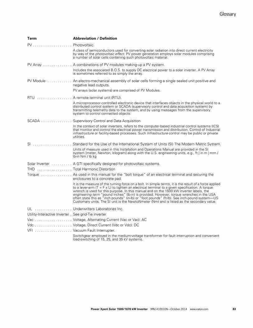
Glossary
Power Xpert Solar 1500/1670 kW Inverter MN141001EN—October 2014 www.eaton.com 63
Term Abbreviation / Definition
PV . . . . . . . . . . . . . . . . . . . PhotovoltaicA class of semiconductors used for converting solar radiation into direct current electricity by way of the photovoltaic effect. PV power generation employs solar modules comprising a number of solar cells containing such photovoltaic material.
PV Array . . . . . . . . . . . . . . A combinations of PV modules making-up a PV system. Includes the associated B.O.S. to supply DC electrical power to a solar inverter. A PV Array is sometimes referred to as simply the array.
PV Module . . . . . . . . . . . . An electro-mechanical assembly of solar cells forming a single sealed unit positive and negative lead outputs.PV arrays (solar systems) are comprised of PV Modules.
RTU . . . . . . . . . . . . . . . . . A remote terminal unit (RTU). A microprocessor-controlled electronic device that interfaces objects in the physical world to a distributed control system or SCADA (supervisory control and data acquisition system) by transmitting telemetry data to the system, and by using messages from the supervisory system to control connected objects.
SCADA . . . . . . . . . . . . . . . Supervisory Control and Data AcquisitionIn the context of solar inverters, refers to the computer-based industrial control systems (ICS) that monitor and control the electrical power transmission and distribution. Control of Industrial infrastructure or facility-based processes. Such Infrastructure control may be public or private utilities.
SI . . . . . . . . . . . . . . . . . . . Standard for the Use of the International System of Units (SI) The Modern Metric System.Units of measure used in this Installation and Operations Manual are provided in the SI system [meter, Newton, kilogram] along with the U.S. engineering units, e.g., ft | in m | mm / lb-in Nm / lb kg
Solar Inverter . . . . . . . . . . A GTI specifically designed for photovoltaic systems.THD . . . . . . . . . . . . . . . . . Total Harmonic DistortionTorque . . . . . . . . . . . . . . . As used in this manual for the “bolt torque” of an electrical terminal and securing the
enclosures to a concrete pad.It is the measure of the turning force on a bolt. In simple terms, it is the result of a force applied to a lever-arm (T = F x L) to tighten an electrical terminal to a given specification. A torque wrench is used for this purpose. In this manual and on the 1500 kW inverter labels, the engineering term “pound inches” (lb-in) is provided. However, torque wrenches in the USA often state this as “inch pounds” (in-lb) or “foot pounds” (ft-lb). See inch-pound system—US Customary units. The SI unit is the NewtoNmeter (Nm) and is listed as the secondary value.
UL . . . . . . . . . . . . . . . . . . Underwriters Laboratories Inc.Utility-Interactive Inverter . See grid-Tie inverterVac . . . . . . . . . . . . . . . . . . Voltage, Alternating Current (Vac or Vac): ACVdc . . . . . . . . . . . . . . . . . . Voltage, Direct Current (Vdc or Vdc): DCVFI . . . . . . . . . . . . . . . . . . Vacuum Fault Interrupter.
Switchgear employed in the medium-voltage transformer for fault interruption and convenient load-switching of 15, 25, and 35 kV systems.
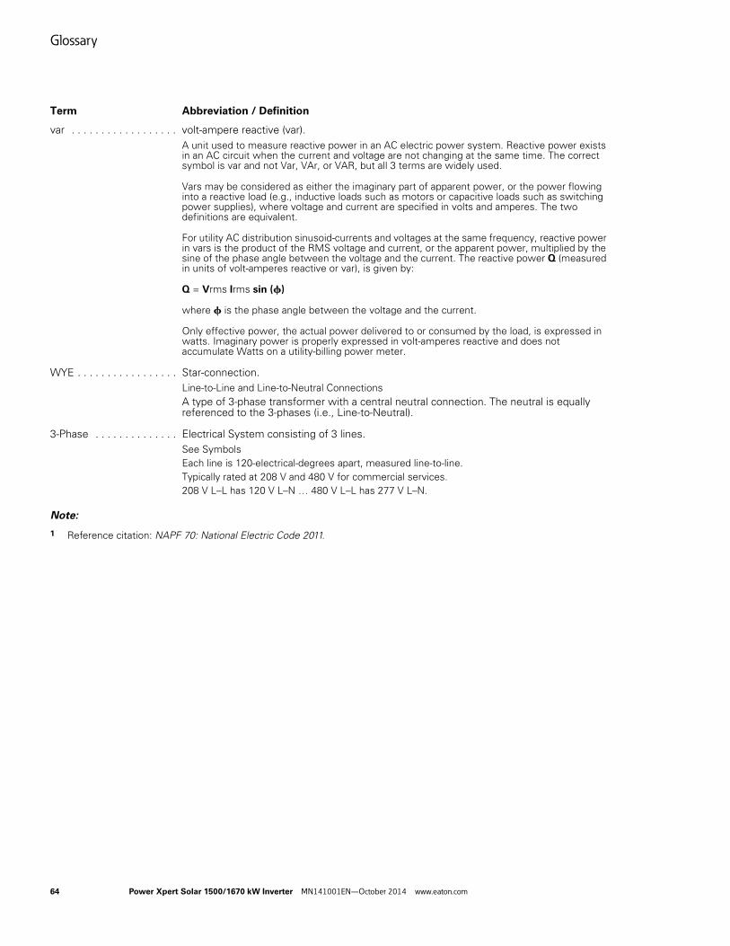
Glossary
64 Power Xpert Solar 1500/1670 kW Inverter MN141001EN—October 2014 www.eaton.com
Term Abbreviation / Definition
var . . . . . . . . . . . . . . . . . . volt-ampere reactive (var). A unit used to measure reactive power in an AC electric power system. Reactive power exists in an AC circuit when the current and voltage are not changing at the same time. The correct symbol is var and not Var, VAr, or VAR, but all 3 terms are widely used.
Vars may be considered as either the imaginary part of apparent power, or the power flowing into a reactive load (e.g., inductive loads such as motors or capacitive loads such as switching power supplies), where voltage and current are specified in volts and amperes. The two definitions are equivalent.
For utility AC distribution sinusoid-currents and voltages at the same frequency, reactive power in vars is the product of the RMS voltage and current, or the apparent power, multiplied by the sine of the phase angle between the voltage and the current. The reactive power Q (measured in units of volt-amperes reactive or var), is given by:
Q = Vrms Irms sin (f)
where f is the phase angle between the voltage and the current.
Only effective power, the actual power delivered to or consumed by the load, is expressed in watts. Imaginary power is properly expressed in volt-amperes reactive and does not accumulate Watts on a utility-billing power meter.
WYE . . . . . . . . . . . . . . . . . Star-connection. Line-to-Line and Line-to-Neutral ConnectionsA type of 3-phase transformer with a central neutral connection. The neutral is equally referenced to the 3-phases (i.e., Line-to-Neutral).
3-Phase . . . . . . . . . . . . . . Electrical System consisting of 3 lines. See SymbolsEach line is 120-electrical-degrees apart, measured line-to-line.Typically rated at 208 V and 480 V for commercial services.208 V L–L has 120 V L–N … 480 V L–L has 277 V L–N.
Note:
1 Reference citation: NAPF 70: National Electric Code 2011.
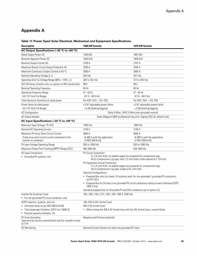
Appendix A
Power Xpert Solar 1500/1670 kW Inverter MN141001EN—October 2014 www.eaton.com 65
Appendix A
Table 17. Power Xpert Solar Electrical, Mechanical and Equipment Specifications
Description 1500 kW Inverter 1670 kW Inverter
AC Output Specifications (–20 °C to +50 °C)
Rated Output Power AC 1500 kW 1667 kW
Nominal Apparent Power AC 1650 kVA 1850 kVA
Nominal Output Current AC 2700 A 2707 A
Maximum Branch Circuit Output Protection AC 3200 A 3200 A
Maximum Continuous Output Current at 50 °C 3000 A 3000 A
Nominal Operating Voltage (L-L) 320 Vac 357 Vac
Operating Grid-Tie Voltage Range (88%–110% L-L) 282 to 352 Vac 313 to 392 Vac
CEC Efficiency (inverter only, no options or MV transformer) 98.0 98.5
Nominal Operating Frequency 60 Hz 60 Hz
Operating Frequency Range(UL1741 Grid-Tie Range)
57– 63 Hz(57.0 – 60.5 Hz)
57– 63 Hz(57.0 – 60.5 Hz)
Total Harmonic Distortion at rated power Per IEEE 1547, < 5% TDD Per IEEE 1547, < 5% TDD
Power factor at rated power(UL1741 Grid-Tie Range)
± 0.91 adjustable power factor± 0.99 (leading/lagging)
± 0.91 adjustable power factor± 0.99 (leading/lagging)
AC Configuration Delta 3-Wire / WYE 3-Wire (non-grounded neutral)
AC Output breaker Eaton Magnum MDS (w/Optional trip units: Digitrip 520 LSI, default unit)
DC Input Specifications (–20 °C to +50 °C)
Maximum Input Voltage, PV VOC 1000 Vdc 1000 Vdc
Nominal DC Operating Current 3100 A 3100 A
Maximum PV-Array Short-Circuit Current(Total array short-circuit current connected to the inverter re-combiner)
5600 A[4,480 A with the application of NEC 690.8 (A)]
5600 A[4,480 A with the application of NEC 690.8 (A)]
PV Input Voltage Operating Range 500 to 1000 Vdc 550 to 1000 Vdc
Maximum Power Point Tracking (MPPT) Range (CEC) 500–800 Vdc 550–800 Vdc
DC Input Connections■ Grounded PV systems, only
PV-Circuit Conductors: To 1/4-inch thick, tin-plated copper bus prepared for compression lugsAl/Cu Compression Lug type: dual 1/2-inch holes: holes spaced at 1-3/4 inch
PV Equipment Ground Conductors: To 1/4-inch thick, tin-plated copper bus prepared for compression lugsAl/Cu Compression Lug type: single 5/16 -inch hole
Optional Configurations:■ Prepared Bus only (no fuses): 24 locations each for non-grounded / grounded PV conductors,
and PV EGCs■ Prepared Bus for 24 (max.) non-grounded PV circuit conductors mating to each individual OCPD
1000 V fuseStandard prepared bus for Grounded-PV and EGC conductors {as in option (1)}
Inverter Re-Combiner Fuses■ For non-grounded PV circuit conductor, only
160 / 200 / 250 / 315 / 350 / 355 / 400 A 1000 Vdc
OCPD selection, quantity, and mix■ Individual fuses as per NEC 690.8 (A) (B)■ Total amperage limitation: [∑(PV-Isc) ≤5600 A]■ Physical quantity limitation: 24
160–355 A (2XL-format fuse): 400 A (3L format fuse):■ When mixing the 400 A 3L-format fuse with the 2XL format fuses: consult Eaton
PV Array GroundingType must be factory-ordered (built-and-EoL tested) to retail UL1741
Negative and Positive (optional)
DC Monitoring Optional Current Sensors on each non-grounded DC Input
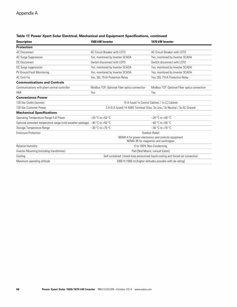
Appendix A
66 Power Xpert Solar 1500/1670 kW Inverter MN141001EN—October 2014 www.eaton.com
Protection
AC Disconnect AC Circuit Breaker with LOTO AC Circuit Breaker with LOTO
AC Surge Suppression Yes, monitored by Inverter SCADA Yes, monitored by Inverter SCADA
DC Disconnect Switch disconnect with LOTO Switch disconnect with LOTO
DC Surge suppression Yes, monitored by Inverter SCADA Yes, monitored by Inverter SCADA
PV Ground Fault Monitoring Yes, monitored by Inverter SCADA Yes, monitored by Inverter SCADA
AC Grid-Tie Yes, SEL 751A Protection Relay Yes, SEL 751A Protection Relay
Communications and Controls
Communications with plant central controller Modbus TCP; Optional Fiber optics connection Modbus TCP; Optional Fiber optics connection
HMI Yes Yes
Convenience Power
120 Vac Outlet (service) 15 A-fused 1x Control Cabinet / 1x LC Cabinet
120 Vac Customer Power 3 A (5 A fused) 14-AWG Terminal Silos: 3x Line / 3x Neutral / 3x AC-Ground
Mechanical Specifications
Operating Temperature Range Full Power –20 °C to +50 °C –20 °C to +50 °C
Optional extended temperature range (cold weather package) –40 °C to +50 °C –40 °C to +50 °C
Storage Temperature Range –30 °C to +70 °C –30 °C to +70 °C
Enclosure Protection Outdoor RatedNEMA 4 for power electronics and controls equipment
NEMA 3R for magnetics and switchgear
Relative Humidity 0 to 100% Non-Condensing
Inverter Mounting (including transformer) Pad [Skid Mount, consult Eaton]
Cooling Self-contained: closed-loop pressurized liquid cooling and forced-air convection
Maximum operating altitude 3300 ft (1000 m) [higher altitudes possible with de-rating]
Table 17. Power Xpert Solar Electrical, Mechanical and Equipment Specifications, continued
Description 1500 kW Inverter 1670 kW Inverter
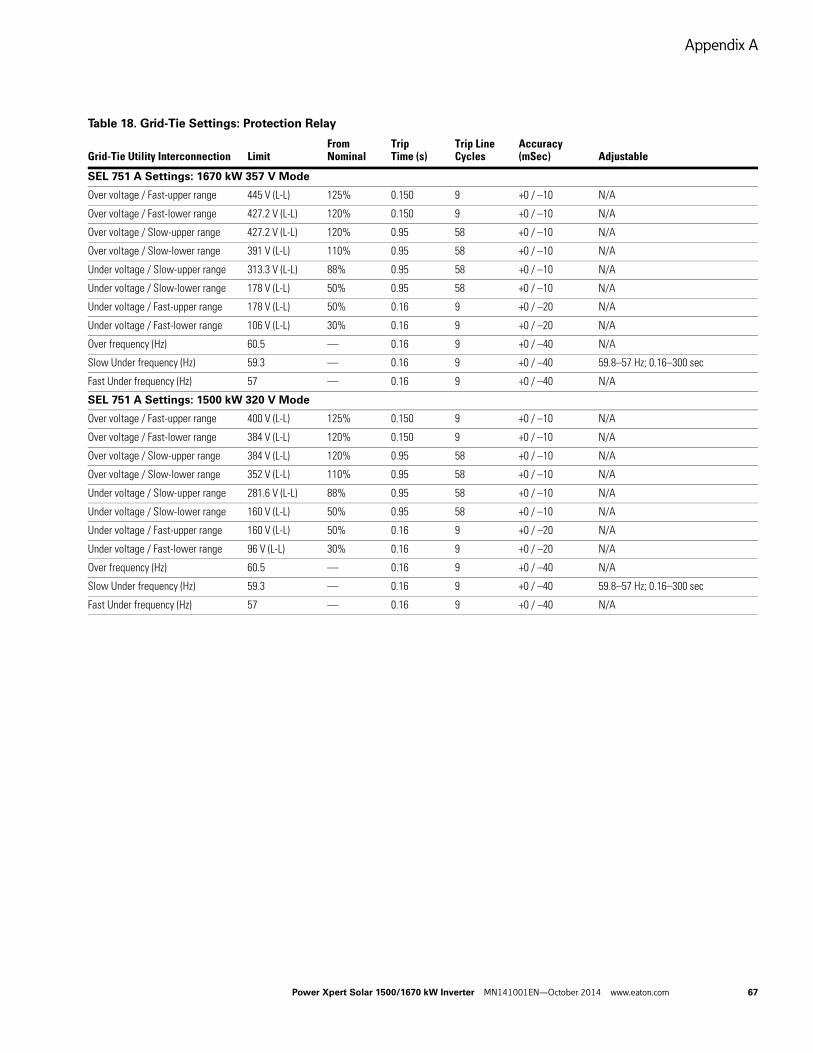
Appendix A
Power Xpert Solar 1500/1670 kW Inverter MN141001EN—October 2014 www.eaton.com 67
Table 18. Grid-Tie Settings: Protection Relay
Grid-Tie Utility Interconnection LimitFrom Nominal
Trip Time (s)
Trip Line Cycles
Accuracy (mSec) Adjustable
SEL 751 A Settings: 1670 kW 357 V Mode
Over voltage / Fast-upper range 445 V (L-L) 125% 0.150 9 +0 / –10 N/A
Over voltage / Fast-lower range 427.2 V (L-L) 120% 0.150 9 +0 / –10 N/A
Over voltage / Slow-upper range 427.2 V (L-L) 120% 0.95 58 +0 / –10 N/A
Over voltage / Slow-lower range 391 V (L-L) 110% 0.95 58 +0 / –10 N/A
Under voltage / Slow-upper range 313.3 V (L-L) 88% 0.95 58 +0 / –10 N/A
Under voltage / Slow-lower range 178 V (L-L) 50% 0.95 58 +0 / –10 N/A
Under voltage / Fast-upper range 178 V (L-L) 50% 0.16 9 +0 / –20 N/A
Under voltage / Fast-lower range 106 V (L-L) 30% 0.16 9 +0 / –20 N/A
Over frequency (Hz) 60.5 — 0.16 9 +0 / –40 N/A
Slow Under frequency (Hz) 59.3 — 0.16 9 +0 / –40 59.8–57 Hz; 0.16–300 sec
Fast Under frequency (Hz) 57 — 0.16 9 +0 / –40 N/A
SEL 751 A Settings: 1500 kW 320 V Mode
Over voltage / Fast-upper range 400 V (L-L) 125% 0.150 9 +0 / –10 N/A
Over voltage / Fast-lower range 384 V (L-L) 120% 0.150 9 +0 / –10 N/A
Over voltage / Slow-upper range 384 V (L-L) 120% 0.95 58 +0 / –10 N/A
Over voltage / Slow-lower range 352 V (L-L) 110% 0.95 58 +0 / –10 N/A
Under voltage / Slow-upper range 281.6 V (L-L) 88% 0.95 58 +0 / –10 N/A
Under voltage / Slow-lower range 160 V (L-L) 50% 0.95 58 +0 / –10 N/A
Under voltage / Fast-upper range 160 V (L-L) 50% 0.16 9 +0 / –20 N/A
Under voltage / Fast-lower range 96 V (L-L) 30% 0.16 9 +0 / –20 N/A
Over frequency (Hz) 60.5 — 0.16 9 +0 / –40 N/A
Slow Under frequency (Hz) 59.3 — 0.16 9 +0 / –40 59.8–57 Hz; 0.16–300 sec
Fast Under frequency (Hz) 57 — 0.16 9 +0 / –40 N/A
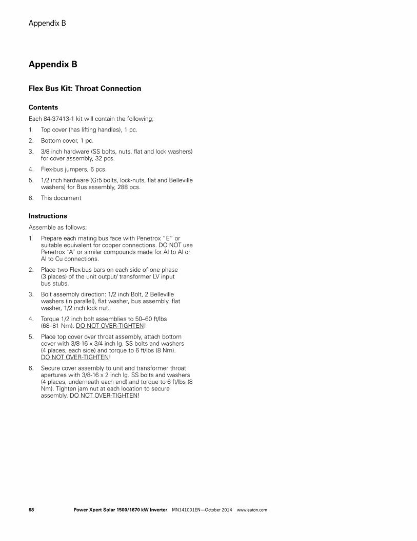
Appendix B
68 Power Xpert Solar 1500/1670 kW Inverter MN141001EN—October 2014 www.eaton.com
Appendix B
Flex Bus Kit: Throat Connection
Contents
Each 84-37413-1 kit will contain the following;
1. Top cover (has lifting handles), 1 pc.
2. Bottom cover, 1 pc.
3. 3/8 inch hardware (SS bolts, nuts, flat and lock washers) for cover assembly, 32 pcs.
4. Flex-bus jumpers, 6 pcs.
5. 1/2 inch hardware (Gr5 bolts, lock-nuts, flat and Belleville washers) for Bus assembly, 288 pcs.
6. This document
Instructions
Assemble as follows;
1. Prepare each mating bus face with Penetrox “E” or suitable equivalent for copper connections. DO NOT use Penetrox “A” or similar compounds made for Al to Al or Al to Cu connections.
2. Place two Flex-bus bars on each side of one phase (3 places) of the unit output/ transformer LV input bus stubs.
3. Bolt assembly direction: 1/2 inch Bolt, 2 Belleville washers (in parallel), flat washer, bus assembly, flat washer, 1/2 inch lock nut.
4. Torque 1/2 inch bolt assemblies to 50–60 ft/lbs (68–81 Nm). DO NOT OVER-TIGHTEN!
5. Place top cover over throat assembly, attach bottom cover with 3/8-16 x 3/4 inch lg. SS bolts and washers (4 places, each side) and torque to 6 ft/lbs (8 Nm). DO NOT OVER-TIGHTEN!
6. Secure cover assembly to unit and transformer throat apertures with 3/8-16 x 2 inch lg. SS bolts and washers (4 places, underneath each end) and torque to 6 ft/lbs (8 Nm). Tighten jam nut at each location to secure assembly. DO NOT OVER-TIGHTEN!
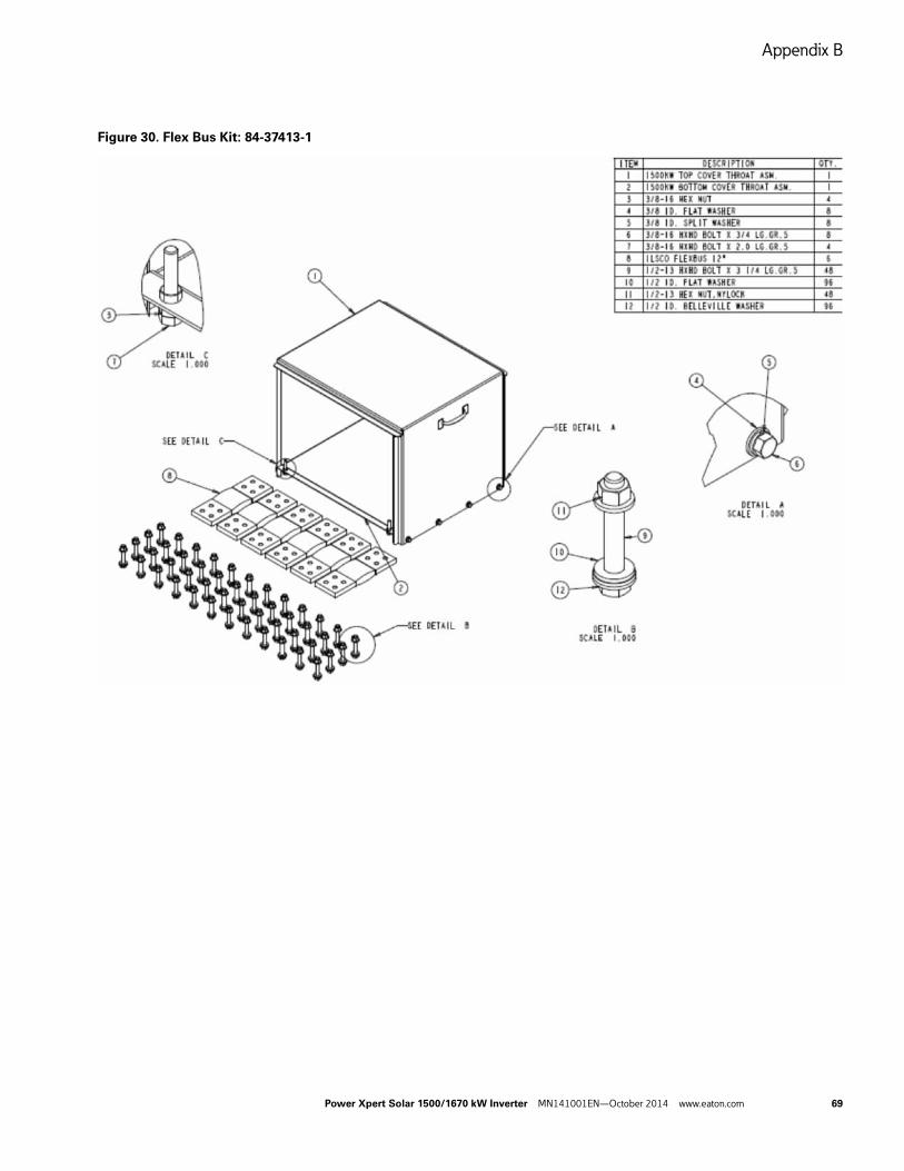
Appendix B
Power Xpert Solar 1500/1670 kW Inverter MN141001EN—October 2014 www.eaton.com 69
Figure 30. Flex Bus Kit: 84-37413-1
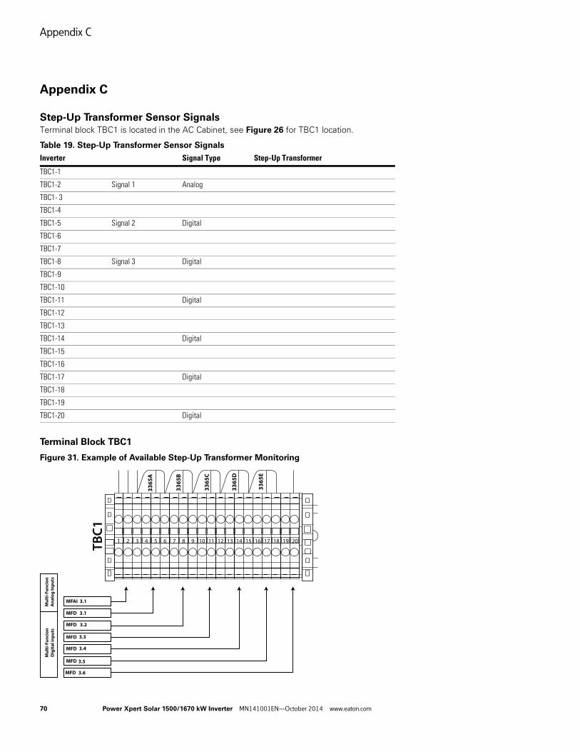
Appendix C
70 Power Xpert Solar 1500/1670 kW Inverter MN141001EN—October 2014 www.eaton.com
Appendix C
Step-Up Transformer Sensor Signals
Terminal block TBC1 is located in the AC Cabinet, see Figure 26 for TBC1 location.
Table 19. Step-Up Transformer Sensor Signals
Terminal Block TBC1
Figure 31. Example of Available Step-Up Transformer Monitoring
Inverter Signal Type Step-Up Transformer
TBC1-1
TBC1-2 Signal 1 Analog
TBC1- 3
TBC1-4
TBC1-5 Signal 2 Digital
TBC1-6
TBC1-7
TBC1-8 Signal 3 Digital
TBC1-9
TBC1-10
TBC1-11 Digital
TBC1-12
TBC1-13
TBC1-14 Digital
TBC1-15
TBC1-16
TBC1-17 Digital
TBC1-18
TBC1-19
TBC1-20 Digital
TBC1
Mul
ti-F
unci
onD
igit
al in
puts
Mul
ti-F
unci
onA
nalo
g In
puts
3365
A
3365
B
3365
C
3365
D
3365
E
MFAI 3.1
1 2 3 4 5 6 7 8 9 10 11 12 13 14 15 16 17 18 19 20
3.1
3.2
3.3
3.4
3.5
3.6
MFD
MFD
MFD
MFD
MFD
MFD
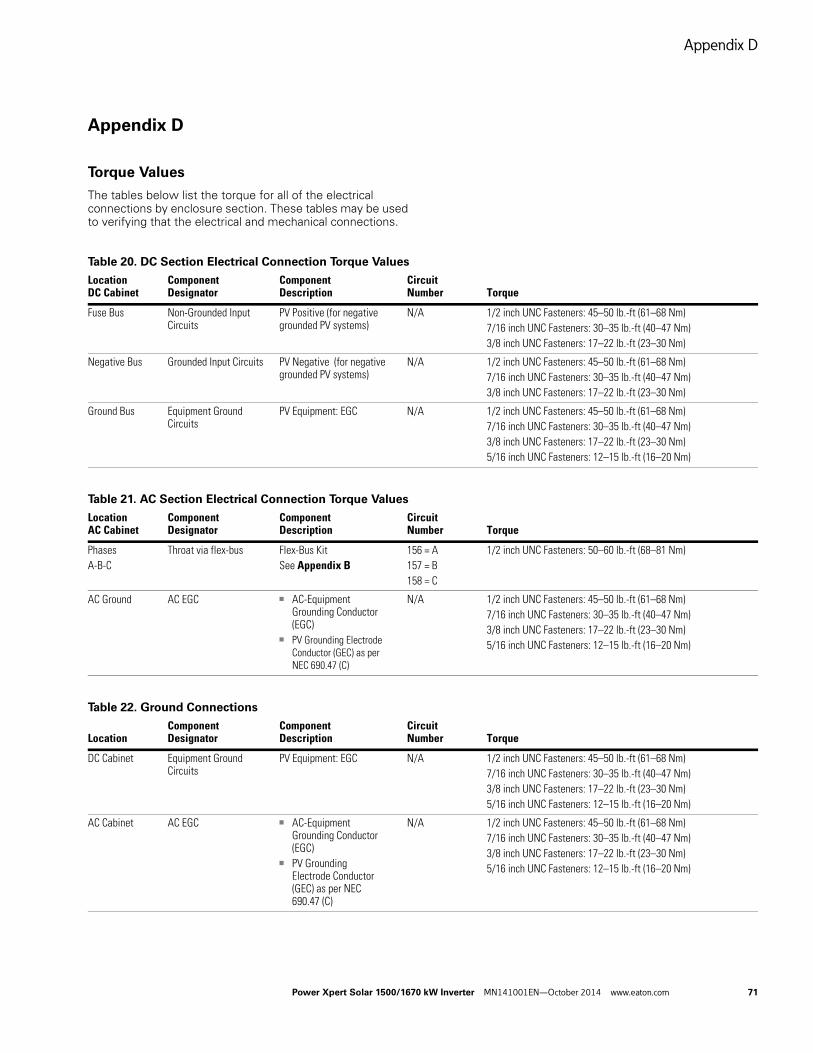
Appendix D
Power Xpert Solar 1500/1670 kW Inverter MN141001EN—October 2014 www.eaton.com 71
Appendix D
Torque Values
The tables below list the torque for all of the electrical connections by enclosure section. These tables may be used to verifying that the electrical and mechanical connections.
Table 20. DC Section Electrical Connection Torque Values
Table 21. AC Section Electrical Connection Torque Values
Table 22. Ground Connections
Location DC Cabinet
Component Designator
Component Description
Circuit Number Torque
Fuse Bus Non-Grounded Input Circuits
PV Positive (for negative grounded PV systems)
N/A 1/2 inch UNC Fasteners: 45–50 lb.-ft (61–68 Nm)7/16 inch UNC Fasteners: 30–35 lb.-ft (40–47 Nm)3/8 inch UNC Fasteners: 17–22 lb.-ft (23–30 Nm)
Negative Bus Grounded Input Circuits PV Negative (for negative grounded PV systems)
N/A 1/2 inch UNC Fasteners: 45–50 lb.-ft (61–68 Nm)7/16 inch UNC Fasteners: 30–35 lb.-ft (40–47 Nm)3/8 inch UNC Fasteners: 17–22 lb.-ft (23–30 Nm)
Ground Bus Equipment Ground Circuits
PV Equipment: EGC N/A 1/2 inch UNC Fasteners: 45–50 lb.-ft (61–68 Nm)7/16 inch UNC Fasteners: 30–35 lb.-ft (40–47 Nm)3/8 inch UNC Fasteners: 17–22 lb.-ft (23–30 Nm)5/16 inch UNC Fasteners: 12–15 lb.-ft (16–20 Nm)
Location AC Cabinet
Component Designator
Component Description
Circuit Number Torque
Phases A-B-C
Throat via flex-bus Flex-Bus KitSee Appendix B
156 = A157 = B158 = C
1/2 inch UNC Fasteners: 50–60 lb.-ft (68–81 Nm)
AC Ground AC EGC ■ AC-Equipment Grounding Conductor (EGC)
■ PV Grounding Electrode Conductor (GEC) as per NEC 690.47 (C)
N/A 1/2 inch UNC Fasteners: 45–50 lb.-ft (61–68 Nm)7/16 inch UNC Fasteners: 30–35 lb.-ft (40–47 Nm)3/8 inch UNC Fasteners: 17–22 lb.-ft (23–30 Nm)5/16 inch UNC Fasteners: 12–15 lb.-ft (16–20 Nm)
LocationComponent Designator
Component Description
Circuit Number Torque
DC Cabinet Equipment Ground Circuits
PV Equipment: EGC N/A 1/2 inch UNC Fasteners: 45–50 lb.-ft (61–68 Nm)7/16 inch UNC Fasteners: 30–35 lb.-ft (40–47 Nm)3/8 inch UNC Fasteners: 17–22 lb.-ft (23–30 Nm)5/16 inch UNC Fasteners: 12–15 lb.-ft (16–20 Nm)
AC Cabinet AC EGC ■ AC-Equipment Grounding Conductor (EGC)
■ PV Grounding Electrode Conductor (GEC) as per NEC 690.47 (C)
N/A 1/2 inch UNC Fasteners: 45–50 lb.-ft (61–68 Nm)7/16 inch UNC Fasteners: 30–35 lb.-ft (40–47 Nm)3/8 inch UNC Fasteners: 17–22 lb.-ft (23–30 Nm)5/16 inch UNC Fasteners: 12–15 lb.-ft (16–20 Nm)
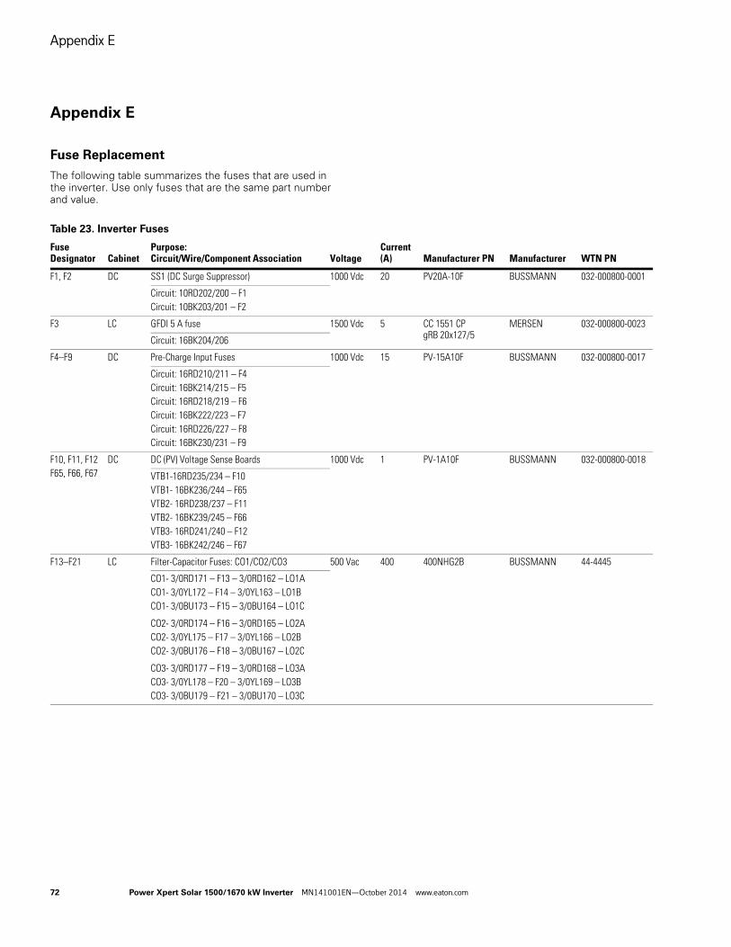
Appendix E
72 Power Xpert Solar 1500/1670 kW Inverter MN141001EN—October 2014 www.eaton.com
Appendix E
Fuse Replacement
The following table summarizes the fuses that are used in the inverter. Use only fuses that are the same part number and value.
Table 23. Inverter Fuses
Fuse Designator Cabinet
Purpose:Circuit/Wire/Component Association Voltage
Current (A) Manufacturer PN Manufacturer WTN PN
F1, F2 DC SS1 (DC Surge Suppressor) 1000 Vdc 20 PV20A-10F BUSSMANN 032-000800-0001
Circuit: 10RD202/200 – F1 Circuit: 10BK203/201 – F2
F3 LC GFDI 5 A fuse 1500 Vdc 5 CC 1551 CP gRB 20x127/5
MERSEN 032-000800-0023
Circuit: 16BK204/206
F4–F9 DC Pre-Charge Input Fuses 1000 Vdc 15 PV-15A10F BUSSMANN 032-000800-0017
Circuit: 16RD210/211 – F4Circuit: 16BK214/215 – F5Circuit: 16RD218/219 – F6Circuit: 16BK222/223 – F7Circuit: 16RD226/227 – F8Circuit: 16BK230/231 – F9
F10, F11, F12F65, F66, F67
DC DC (PV) Voltage Sense Boards 1000 Vdc 1 PV-1A10F BUSSMANN 032-000800-0018
VTB1-16RD235/234 – F10VTB1- 16BK236/244 – F65VTB2- 16RD238/237 – F11VTB2- 16BK239/245 – F66VTB3- 16RD241/240 – F12VTB3- 16BK242/246 – F67
F13–F21 LC Filter-Capacitor Fuses: CO1/CO2/CO3 500 Vac 400 400NHG2B BUSSMANN 44-4445
CO1- 3/0RD171 – F13 – 3/0RD162 – LO1ACO1- 3/0YL172 – F14 – 3/0YL163 – LO1BCO1- 3/0BU173 – F15 – 3/0BU164 – LO1C
CO2- 3/0RD174 – F16 – 3/0RD165 – LO2ACO2- 3/0YL175 – F17 – 3/0YL166 – LO2BCO2- 3/0BU176 – F18 – 3/0BU167 – LO2C
CO3- 3/0RD177 – F19 – 3/0RD168 – LO3ACO3- 3/0YL178 – F20 – 3/0YL169 – LO3BCO3- 3/0BU179 – F21 – 3/0BU170 – LO3C
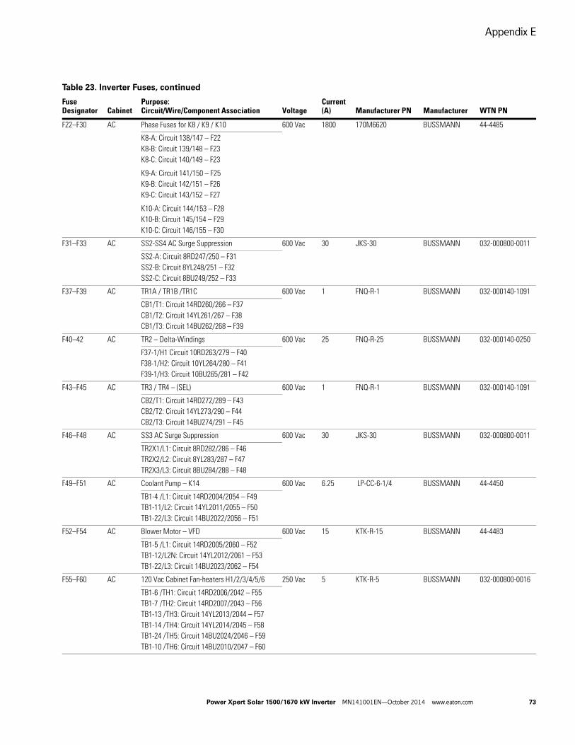
Appendix E
Power Xpert Solar 1500/1670 kW Inverter MN141001EN—October 2014 www.eaton.com 73
F22–F30 AC Phase Fuses for K8 / K9 / K10 600 Vac 1800 170M6620 BUSSMANN 44-4485
K8-A: Circuit 138/147 – F22K8-B: Circuit 139/148 – F23K8-C: Circuit 140/149 – F23
K9-A: Circuit 141/150 – F25K9-B: Circuit 142/151 – F26K9-C: Circuit 143/152 – F27
K10-A: Circuit 144/153 – F28K10-B: Circuit 145/154 – F29K10-C: Circuit 146/155 – F30
F31–F33 AC SS2-SS4 AC Surge Suppression 600 Vac 30 JKS-30 BUSSMANN 032-000800-0011
SS2-A: Circuit 8RD247/250 – F31SS2-B: Circuit 8YL248/251 – F32SS2-C: Circuit 8BU249/252 – F33
F37–F39 AC TR1A / TR1B /TR1C 600 Vac 1 FNQ-R-1 BUSSMANN 032-000140-1091
CB1/T1: Circuit 14RD260/266 – F37CB1/T2: Circuit 14YL261/267 – F38CB1/T3: Circuit 14BU262/268 – F39
F40–42 AC TR2 – Delta-Windings 600 Vac 25 FNQ-R-25 BUSSMANN 032-000140-0250
F37-1/H1 Circuit 10RD263/279 – F40F38-1/H2: Circuit 10YL264/280 – F41F39-1/H3: Circuit 10BU265/281 – F42
F43–F45 AC TR3 / TR4 – (SEL) 600 Vac 1 FNQ-R-1 BUSSMANN 032-000140-1091
CB2/T1: Circuit 14RD272/289 – F43CB2/T2: Circuit 14YL273/290 – F44CB2/T3: Circuit 14BU274/291 – F45
F46–F48 AC SS3 AC Surge Suppression 600 Vac 30 JKS-30 BUSSMANN 032-000800-0011
TR2X1/L1: Circuit 8RD282/286 – F46TR2X2/L2: Circuit 8YL283/287 – F47TR2X3/L3: Circuit 8BU284/288 – F48
F49–F51 AC Coolant Pump – K14 600 Vac 6.25 LP-CC-6-1/4 BUSSMANN 44-4450
TB1-4 /L1: Circuit 14RD2004/2054 – F49TB1-11/L2: Circuit 14YL2011/2055 – F50TB1-22/L3: Circuit 14BU2022/2056 – F51
F52–F54 AC Blower Motor – VFD 600 Vac 15 KTK-R-15 BUSSMANN 44-4483
TB1-5 /L1: Circuit 14RD2005/2060 – F52TB1-12/L2N: Circuit 14YL2012/2061 – F53TB1-22/L3: Circuit 14BU2023/2062 – F54
F55–F60 AC 120 Vac Cabinet Fan-heaters H1/2/3/4/5/6 250 Vac 5 KTK-R-5 BUSSMANN 032-000800-0016
TB1-6 /TH1: Circuit 14RD2006/2042 – F55TB1-7 /TH2: Circuit 14RD2007/2043 – F56TB1-13 /TH3: Circuit 14YL2013/2044 – F57TB1-14 /TH4: Circuit 14YL2014/2045 – F58TB1-24 /TH5: Circuit 14BU2024/2046 – F59TB1-10 /TH6: Circuit 14BU2010/2047 – F60
Table 23. Inverter Fuses, continued
Fuse Designator Cabinet
Purpose:Circuit/Wire/Component Association Voltage
Current (A) Manufacturer PN Manufacturer WTN PN
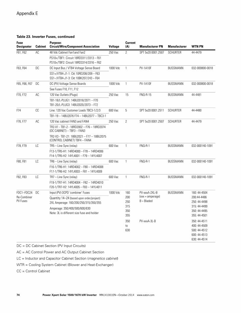
Appendix E
74 Power Xpert Solar 1500/1670 kW Inverter MN141001EN—October 2014 www.eaton.com
DC = DC Cabinet Section (PV Input Circuits)
AC = AC Control Power and AC Output Cabinet Section
LC = Inductor and Capacitor Cabinet Section (magnetics cabinet)
WTR = Cooling System Cabinet (Blower and Heat-Exchanger)
CC = Control Cabinet
F61, F62 AC 48 Vdc Cabinet Fan1and Fan2 250 Vac 2 SPT 5x20 0001.2507 SCHURTER 44-4479
PS10+/TBF1: Circuit 18RD3311/3313 – F61PS10+/TBF2: Circuit 18RD3314/3316 – F62
F63, F64 DC DC Input Bus / VTB4 Voltage Sense Board 1000 Vdc 1 PV-1A10F BUSSMANN 032-000800-0018
SS1+/VTB4-J1-1: Ckt 10RD208/209 – F63SS1−/VTB4-J1-3: Ckt 10BK207/243 – F64
F65, F66, F67 DC DC (PV) Voltage Sense Boards 1000 Vdc 1 PV-1A10F BUSSMANN 032-000800-0018
See Fuses F10, F11, F12
F70, F72 AC 120 Vac Outlets (Plugs) 250 Vac 15 FNQ-R-15 BUSSMANN 44-4481
TB1-18/L-PLUG1: 14BU2018/2071 – F70TB1-20/L-PLUG3: 14BU2020/2073 – F72
F74 CC Line: 120 Vac Customer Loads TBC3-1/2/3 600 Vac 5 SPT 5x20 0001.2511 SCHURTER 44-4480
TB1-19 – 14BU2076 F74 – 14BU2077 – TBC3-1
F76, F77 AC 120 Vac cabinet FAN3 and FAN4 250 Vac 2 SPT 5x20 0001.2507 SCHURTER 44-4479
TR2-X1 - TB1-2 - 18RD2002 – F76 – 18RD2074 (DC CABINET) – TBF3 – FAN3
TR2-X3 - TB1-21: 18BU2021 – F77 – 18BU2075 (CONTROL CABINET) TBF4 – FAN4
F78, F79 LC TR5 – Line Sync (relay) 600 Vac 1 FNQ-R-1 BUSSMANN 032-000140-1091
F13-1/TR5-H1: 14RD4000 – F78 – 14RD4006F14-1/TR5-H2: 14YL4001 – F79 – 14YL4007
F80, F81 LC TR6 – Line Sync (relay) 600 Vac 1 FNQ-R-1 BUSSMANN 032-000140-1091
F16-1/TR6-H1: 14RD4002 – F80 – 14RD4008F17-1/TR6-H2: 14YL4003 – F81 – 14YL4009
F82, F83 LC TR7 – Line Sync (relay) 600 Vac 1 FNQ-R-1 BUSSMANN 032-000140-1091
F19-1/TR7-H1: 14RD4004 – F82 – 14RD4010F20-1/TR7-H2: 14YL4005 – F83 – 14YL4011
FDC1–FDC24Re-Combiner PV Fuses
DC Input (PV) OCPD ‘combiner’ Fuses 1000 Vdc 160200250315350355
350to630
PV-xxxA-2XL-B(xxx = amperage) B = Bladed
PV-xxxA-3L-B
BUSSMANN 160: 44-4504200:44-4486250: 44-4498315: 44-4499350: 44-4495355: 44-4501
350: 44-4511400: 44-4509500: 44-4512600: 44-4513630: 44-4514
Quantity 14–24 (based upon order/project)2XL Amperage: 160/200/250/315/350/355
Amperage: 350/400/500/600/630Note: 3L is different size fuse and holder
Table 23. Inverter Fuses, continued
Fuse Designator Cabinet
Purpose:Circuit/Wire/Component Association Voltage
Current (A) Manufacturer PN Manufacturer WTN PN
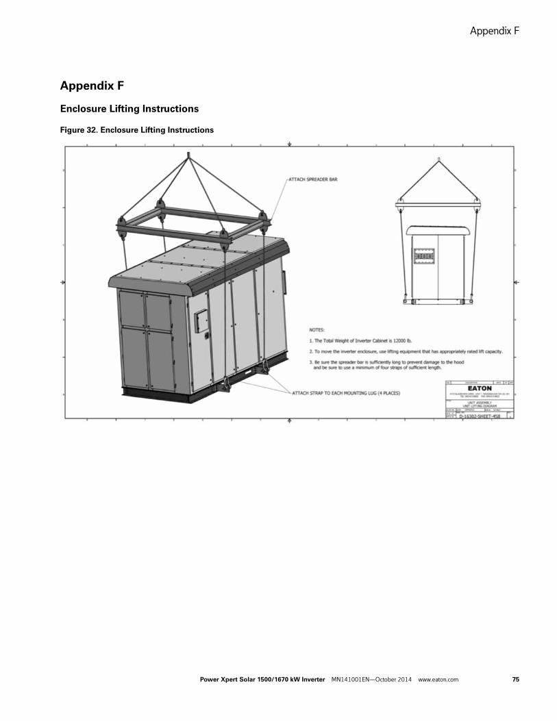
Appendix F
Power Xpert Solar 1500/1670 kW Inverter MN141001EN—October 2014 www.eaton.com 75
Appendix F
Enclosure Lifting Instructions
Figure 32. Enclosure Lifting Instructions
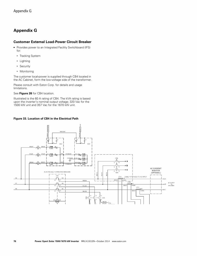
Appendix G
76 Power Xpert Solar 1500/1670 kW Inverter MN141001EN—October 2014 www.eaton.com
Appendix G
Customer External Load-Power Circuit Breaker
● Provides power to an Integrated Facility Switchboard (IFS) for:
● Tracking System
● Lighting
● Security
● Monitoring
The customer local-power is supplied through CB4 located in the AC Cabinet, form the low-voltage side of the transformer.
Please consult with Eaton Corp. for details and usage limitations.
See Figure 26 for CB4 location.
Illustrated is the 60 A rating of CB4. The kVA rating is based upon the inverter’s nominal output voltage; 320 Vac for the 1500 kW unit and 357 Vac for the 1670 kW unit.
Figure 33. Location of CB4 in the Electrical Path
Appendix H
Power Xpert Solar 1500/1670 kW Inverter MN141001EN—October 2014 www.eaton.com 77
Appendix H
Maintenance Schedule Record
The following maintenance log should have entries made to document when maintenance is performed. The log should also describe what maintenance was performed. Please submit the log to your Eaton representative.
Table 24. Maintenance Schedule Record
Date: DD/MM/YY Items Identified Items Corrected Person Performing Maintenance
Appendix J
78 Power Xpert Solar 1500/1670 kW Inverter MN141001EN—October 2014 www.eaton.com
Appendix J
Notes
Date Notes Other


Eaton is a registered trademark.
All other trademarks are property of their respective owners.
Eaton is dedicated to ensuring that reliable, efficient and safe power is available when it’s needed most. With unparalleled knowledge of electrical power management across industries, experts at Eaton deliver customized, integrated solutions to solve our customers’ most critical challenges.
Our focus is on delivering the right solution for the application. But, decision makers demand more than just innovative products. They turn to Eaton for an unwavering commitment to personal support that makes customer success a top priority. For more information, visit www.eaton.com/electrical.
Eaton
1000 Eaton BoulevardCleveland, OH 44122 United StatesEaton.com
© 2014 EatonAll Rights ReservedPrinted in USAPublication No. MN141001EN / Z15242October 2014
Related Documents


