www.advelectronicmat.de 2000623 (1 of 30) © 2020 The Authors. Advanced Electronic Materials published by Wiley-VCH GmbH REVIEW Fluidic and Mechanical Thermal Control Devices Katja Klinar, Timm Swoboda, Miguel Muñoz Rojo, and Andrej Kitanovski* DOI: 10.1002/aelm.202000623 With regard to thermal management, conventional heat sinks combined with fans and extended surfaces, heat pipes, or water cooling will be insufficient to control thermal transients or to dissipate large amounts of heat to the ambient on a small scale. Potential solutions include implementing thermal control circuits consisting of thermal control devices (TCDs) that enable better control of the heat flux. [4,5] In analogy to electronics, these devices include thermal diodes (thermal rectifiers), thermal switches, thermal regulators, and thermal transis- tors that can rectify, switch on/off, and change the heat flux propagation between two surfaces/bodies with different tem- peratures, respectively. Each TCD has its own operation principle that defines its thermal resistance and thereby affects the heat flux through it (Figure 1). The change in thermal resistance in thermal diodes and thermal regulators is controlled by bias directionality and/ or temperature, resulting in autonomous, passive operation. By contrast, thermal switches and thermal transistors require external energy (i.e., a stimulus) to change their thermal resist- ance. [4] Thermal resistance R is defined as the ratio of the tem- perature difference ΔT between the hot and the cold terminals (heat source and heat sink, respectively) to the net heat flux Q between both terminals: R T Q =Δ / (1) Typically, the performance of TCDs is compared by using the switching ratio SR for thermal switches and thermal regulators and the rectification ratio RR for thermal diodes. The switching ratio is defined as the ratio between the heat flux on Q during the on state and off Q during the off state. In the specific case of a constant temperature difference, it simplifies to the ratio between the thermal resistances during the off (R off ) and on (R on ) states. Q Q R R T = → = Δ = SR / SR / const. on off off on (2) The rectification ratio is most commonly defined in two different ways: I: RR / fwd rev rev Q Q Q ( ) = - (3) II :RR / fwd rev Q Q = (4) In recent years, intensive studies on thermal control devices have been conducted for the thermal management of electronics and computers as well as for applications in energy conversion, chemistry, sensors, buildings, and outer space. Conventional cooling or heating techniques realized using tradi- tional thermal resistors and capacitors cannot meet the thermal requirements of advanced systems. Therefore, new thermal control devices are being inves- tigated to satisfy these requirements. These devices include thermal diodes, thermal switches, thermal regulators, and thermal transistors, all of which manage heat in a manner analogous to how electronic devices and circuits control electricity. To design or apply these novel devices as well as thermal control principles, this paper presents a systematic and comprehensive review of the state-of-the-art of fluidic and mechanical thermal control devices that have already been implemented in various applications for different size scales and temperature ranges. Operation principles, working parameters, and limitations are discussed and the most important features for a particular device are identified. K. Klinar, Prof. A. Kitanovski Faculty of Mechanical Engineering University of Ljubljana Askerceva 6, Ljubljana 1000, Slovenia E-mail: [email protected] T. Swoboda, Dr. M. Muñoz Rojo Department of Thermal and Fluid Engineering University of Twente Enschede 7500 AE, the Netherlands The ORCID identification number(s) for the author(s) of this article can be found under https://doi.org/10.1002/aelm.202000623. 1. Introduction As a device becomes more compact and efficient, its output power increases, performance improves, and specific costs decrease. This trend is evident in the field of electronics. Moore’s law from 1965 [1] states that computing power doubles roughly every two years and costs simultaneously decrease. His predic- tion remained valid for more than 50 years; however, advances in this field have recently begun to plateau owing to two main problems: thermal management and physical limits in devices with sizes of the order of only a few nanometers. [1,2] Researchers are expected to solve these problems by applying “beyond- Moore” or “more-than-Moore” technologies and principles. [3] © 2020 The Authors. Advanced Electronic Materials published by Wiley-VCH GmbH. This is an open access article under the terms of the Creative Commons Attribution License, which permits use, distribution and reproduction in any medium, provided the original work is properly cited. Adv. Electron. Mater. 2020, 2000623

Welcome message from author
This document is posted to help you gain knowledge. Please leave a comment to let me know what you think about it! Share it to your friends and learn new things together.
Transcript
www.advelectronicmat.de
2000623 (1 of 30) © 2020 The Authors. Advanced Electronic Materials published by Wiley-VCH GmbH
Review
Fluidic and Mechanical Thermal Control Devices
Katja Klinar, Timm Swoboda, Miguel Muñoz Rojo, and Andrej Kitanovski*
DOI: 10.1002/aelm.202000623
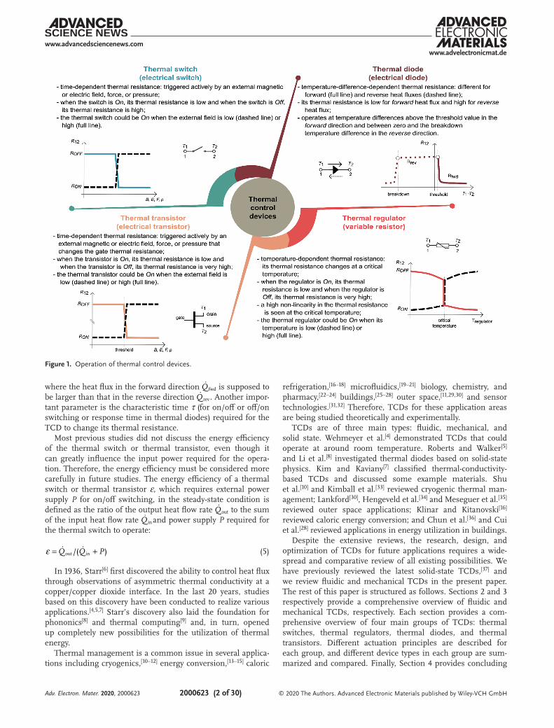
With regard to thermal management, conventional heat sinks combined with fans and extended surfaces, heat pipes, or water cooling will be insufficient to control thermal transients or to dissipate large amounts of heat to the ambient on a small scale. Potential solutions include implementing thermal control circuits consisting of thermal control devices (TCDs) that enable better control of the heat flux.[4,5] In analogy to electronics, these devices include thermal diodes (thermal rectifiers), thermal switches, thermal regulators, and thermal transis-tors that can rectify, switch on/off, and change the heat flux propagation between two surfaces/bodies with different tem-peratures, respectively. Each TCD has its own operation principle that defines its thermal resistance and thereby affects the heat flux through it (Figure 1). The change in thermal resistance in thermal diodes
and thermal regulators is controlled by bias directionality and/or temperature, resulting in autonomous, passive operation. By contrast, thermal switches and thermal transistors require external energy (i.e., a stimulus) to change their thermal resist-ance.[4] Thermal resistance R is defined as the ratio of the tem-perature difference ΔT between the hot and the cold terminals (heat source and heat sink, respectively) to the net heat flux Q� between both terminals:
R T Q�= ∆ / (1)
Typically, the performance of TCDs is compared by using the switching ratio SR for thermal switches and thermal regulators and the rectification ratio RR for thermal diodes. The switching ratio is defined as the ratio between the heat flux onQ� during the on state and offQ� during the off state. In the specific case of a constant temperature difference, it simplifies to the ratio between the thermal resistances during the off (Roff) and on (Ron) states.
Q Q R RT� �=→
=∆ =SR / SR /const.on off off on (2)
The rectification ratio is most commonly defined in two different ways:
I : RR /fwd rev revQ Q Q� � �( )= − (3)
II : RR /fwd revQ Q� �= (4)
In recent years, intensive studies on thermal control devices have been conducted for the thermal management of electronics and computers as well as for applications in energy conversion, chemistry, sensors, buildings, and outer space. Conventional cooling or heating techniques realized using tradi-tional thermal resistors and capacitors cannot meet the thermal requirements of advanced systems. Therefore, new thermal control devices are being inves-tigated to satisfy these requirements. These devices include thermal diodes, thermal switches, thermal regulators, and thermal transistors, all of which manage heat in a manner analogous to how electronic devices and circuits control electricity. To design or apply these novel devices as well as thermal control principles, this paper presents a systematic and comprehensive review of the state-of-the-art of fluidic and mechanical thermal control devices that have already been implemented in various applications for different size scales and temperature ranges. Operation principles, working parameters, and limitations are discussed and the most important features for a particular device are identified.
K. Klinar, Prof. A. KitanovskiFaculty of Mechanical EngineeringUniversity of LjubljanaAskerceva 6, Ljubljana 1000, SloveniaE-mail: [email protected]. Swoboda, Dr. M. Muñoz RojoDepartment of Thermal and Fluid EngineeringUniversity of TwenteEnschede 7500 AE, the Netherlands
The ORCID identification number(s) for the author(s) of this article can be found under https://doi.org/10.1002/aelm.202000623.
1. Introduction
As a device becomes more compact and efficient, its output power increases, performance improves, and specific costs decrease. This trend is evident in the field of electronics. Moore’s law from 1965[1] states that computing power doubles roughly every two years and costs simultaneously decrease. His predic-tion remained valid for more than 50 years; however, advances in this field have recently begun to plateau owing to two main problems: thermal management and physical limits in devices with sizes of the order of only a few nanometers.[1,2] Researchers are expected to solve these problems by applying “beyond-Moore” or “more-than-Moore” technologies and principles.[3]
© 2020 The Authors. Advanced Electronic Materials published by Wiley-VCH GmbH. This is an open access article under the terms of the Creative Commons Attribution License, which permits use, distribution and reproduction in any medium, provided the original work is properly cited.
Adv. Electron. Mater. 2020, 2000623
www.advancedsciencenews.comwww.advelectronicmat.de
2000623 (2 of 30) © 2020 The Authors. Advanced Electronic Materials published by Wiley-VCH GmbH
where the heat flux in the forward direction fwdQ� is supposed to be larger than that in the reverse direction revQ� . Another impor-tant parameter is the characteristic time τ (for on/off or off/on switching or response time in thermal diodes) required for the TCD to change its thermal resistance.
Most previous studies did not discuss the energy efficiency of the thermal switch or thermal transistor, even though it can greatly influence the input power required for the opera-tion. Therefore, the energy efficiency must be considered more carefully in future studies. The energy efficiency of a thermal switch or thermal transistor ε, which requires external power supply P for on/off switching, in the steady-state condition is defined as the ratio of the output heat flow rate outQ� to the sum of the input heat flow rate inQ� and power supply P required for the thermal switch to operate:
/( )out inQ Q P� �ε = + (5)
In 1936, Starr[6] first discovered the ability to control heat flux through observations of asymmetric thermal conductivity at a copper/copper dioxide interface. In the last 20 years, studies based on this discovery have been conducted to realize various applications.[4,5,7] Starr’s discovery also laid the foundation for phononics[8] and thermal computing[9] and, in turn, opened up completely new possibilities for the utilization of thermal energy.
Thermal management is a common issue in several applica-tions including cryogenics,[10–12] energy conversion,[13–15] caloric
refrigeration,[16–18] microfluidics,[19–21] biology, chemistry, and pharmacy,[22–24] buildings,[25–28] outer space,[11,29,30] and sensor technologies.[31,32] Therefore, TCDs for these application areas are being studied theoretically and experimentally.
TCDs are of three main types: fluidic, mechanical, and solid state. Wehmeyer et al.[4] demonstrated TCDs that could operate at around room temperature. Roberts and Walker[5] and Li et al.[8] investigated thermal diodes based on solid-state physics. Kim and Kaviany[7] classified thermal-conductivity-based TCDs and discussed some example materials. Shu et al.[10] and Kimball et al.[33] reviewed cryogenic thermal man-agement; Lankford[30], Hengeveld et al.[34] and Meseguer et al.[35] reviewed outer space applications; Klinar and Kitanovski[16] reviewed caloric energy conversion; and Chun et al.[36] and Cui et al.[28] reviewed applications in energy utilization in buildings.
Despite the extensive reviews, the research, design, and optimization of TCDs for future applications requires a wide-spread and comparative review of all existing possibilities. We have previously reviewed the latest solid-state TCDs,[37] and we review fluidic and mechanical TCDs in the present paper. The rest of this paper is structured as follows. Sections 2 and 3 respectively provide a comprehensive overview of fluidic and mechanical TCDs, respectively. Each section provides a com-prehensive overview of four main groups of TCDs: thermal switches, thermal regulators, thermal diodes, and thermal transistors. Different actuation principles are described for each group, and different device types in each group are sum-marized and compared. Finally, Section 4 provides concluding
Figure 1. Operation of thermal control devices.
Adv. Electron. Mater. 2020, 2000623
www.advancedsciencenews.comwww.advelectronicmat.de
2000623 (3 of 30) © 2020 The Authors. Advanced Electronic Materials published by Wiley-VCH GmbH
remarks and some ideas for future work on different fluidic and mechanical TCDs. Further, the Supporting Information contains tables that summarize the characteristics of and com-pare different types of TCDs.
2. Fluidic Thermal Control Devices
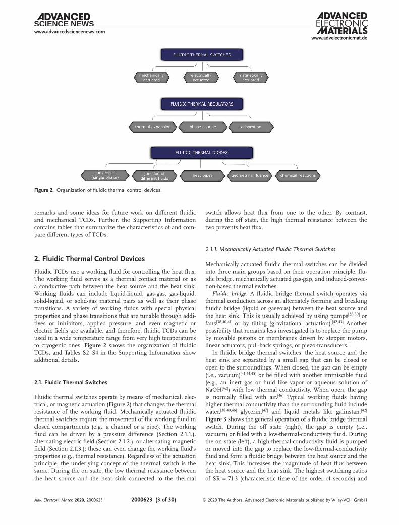
Fluidic TCDs use a working fluid for controlling the heat flux. The working fluid serves as a thermal contact material or as a conductive path between the heat source and the heat sink. Working fluids can include liquid-liquid, gas-gas, gas-liquid, solid-liquid, or solid-gas material pairs as well as their phase transitions. A variety of working fluids with special physical properties and phase transitions that are tunable through addi-tives or inhibitors, applied pressure, and even magnetic or electric fields are available, and therefore, fluidic TCDs can be used in a wide temperature range from very high temperatures to cryogenic ones. Figure 2 shows the organization of fluidic TCDs, and Tables S2–S4 in the Supporting Information show additional details.
2.1. Fluidic Thermal Switches
Fluidic thermal switches operate by means of mechanical, elec-trical, or magnetic actuation (Figure 2) that changes the thermal resistance of the working fluid. Mechanically actuated fluidic thermal switches require the movement of the working fluid in closed compartments (e.g., a channel or a pipe). The working fluid can be driven by a pressure difference (Section 2.1.1.), alternating electric field (Section 2.1.2.), or alternating magnetic field (Section 2.1.3.); these can even change the working fluid’s properties (e.g., thermal resistance). Regardless of the actuation principle, the underlying concept of the thermal switch is the same. During the on state, the low thermal resistance between the heat source and the heat sink connected to the thermal
switch allows heat flux from one to the other. By contrast, during the off state, the high thermal resistance between the two prevents heat flux.
2.1.1. Mechanically Actuated Fluidic Thermal Switches
Mechanically actuated fluidic thermal switches can be divided into three main groups based on their operation principle: flu-idic bridge, mechanically actuated gas-gap, and induced-convec-tion-based thermal switches.
Fluidic bridge: A fluidic bridge thermal switch operates via thermal conduction across an alternately forming and breaking fluidic bridge (liquid or gaseous) between the heat source and the heat sink. This is usually achieved by using pumps[38,39] or fans[38,40,41] or by tilting (gravitational actuation).[42,43] Another possibility that remains less investigated is to replace the pump by movable pistons or membranes driven by stepper motors, linear actuators, pull-back springs, or piezo-transducers.
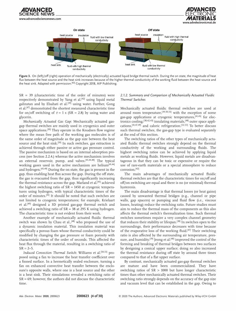
In fluidic bridge thermal switches, the heat source and the heat sink are separated by a small gap that can be closed or open to the surroundings. When closed, the gap can be empty (i.e., vacuum)[41,44,45] or be filled with another immiscible fluid (e.g., an inert gas or fluid like vapor or aqueous solution of NaOH[42]) with low thermal conductivity. When open, the gap is normally filled with air.[46] Typical working fluids having higher thermal conductivity than the surrounding fluid include water,[38,40,46] glycerin,[47] and liquid metals like galinstan.[42] Figure 3 shows the general operation of a fluidic bridge thermal switch. During the off state (right), the gap is empty (i.e., vacuum) or filled with a low-thermal-conductivity fluid. During the on state (left), a high-thermal-conductivity fluid is pumped or moved into the gap to replace the low-thermal-conductivity fluid and form a fluidic bridge between the heat source and the heat sink. This increases the magnitude of heat flux between the heat source and the heat sink. The highest switching ratios of SR = 71.3 (characteristic time of the order of seconds) and
Figure 2. Organization of fluidic thermal control devices.
Adv. Electron. Mater. 2020, 2000623
www.advancedsciencenews.comwww.advelectronicmat.de
2000623 (4 of 30) © 2020 The Authors. Advanced Electronic Materials published by Wiley-VCH GmbH
SR = 39 (characteristic time of the order of minutes) were respectively demonstrated by Yang et al.[42] using liquid metal galinstan and by Elsahati et al.[39] using water. Further, Gong et al.[47] demonstrated the shortest measured characteristic time for on/off switching of τ = 1 s (SR = 2.8) by using water and glycerin.
Mechanically Actuated Gas Gap: Mechanically actuated gas-gap thermal switches are mainly used in cryogenics and outer space applications.[10] They operate in the Knudsen flow regime where the mean free path of the working gas molecules is of the same order of magnitude as the gap size between the heat source and the heat sink.[10] In such switches, gas extraction is achieved through either passive or active gas pressure control. The passive mechanism is based on an internal adsorption pro-cess (see Section 2.2.4.) whereas the active mechanism involves an external reservoir, pump, and valves.[41,44,48] The typical working gases used in the active mechanism are helium[41,44] and hydrogen.[45,49] During the on state, the gas is present in the gap, thus enabling heat flux across the gap. During the off state, the gas is evacuated from the gap, thus significantly increasing the thermal resistance across the gap. Marland et al.[45] achieved the highest switching ratio of SR = 1450 at cryogenic tempera-tures using hydrogen, with typical characteristic times of the order of minutes.[41] It should be noted that such switches are not limited to cryogenic temperatures; for example, Krielaart et al.[49] designed a 3D printed gas-gap thermal switch and achieved a switching ratio of SR = 38 at 295 K using hydrogen. The characteristic time is not evident from their work.
Another example of mechanically actuated fluidic thermal switch was shown by Chau et al.,[48] who proposed the use of a dynamic insulation material. This insulation material was specifically a porous foam whose thermal conductivity could be modified by changing the gas pressure or foam porosity with characteristic times of the order of seconds. This affected the heat flux through the material, resulting in a switching ratio of SR = 2–5.
Induced Convection Thermal Switch: Williams et al.[50,51] pro-posed using a fan to increase the heat transfer coefficient over a finned surface. In a hermetically sealed enclosure, turning a fan on enhanced convective heat transfer between the enclo-sure’s opposite walls, where one is a heat source and the other is a heat sink. Their simulations revealed a switching ratio of SR = 69; however, the authors did not discuss the characteristic time.
2.1.2. Summary and Comparison of Mechanically Actuated Fluidic Thermal Switches
Mechanically actuated fluidic thermal switches are used at around room temperature,[39,50,51] with the exception of some gas-gap applications at cryogenic temperatures,[41,45] for elec-tronics cooling,[38,42,43] insulating materials,[48] outer space appli-cations,[41,47,49] and caloric refrigeration.[52,53] To better discuss such thermal switches, the gas-gap type is evaluated separately at the end of this section.
The switching ratios of the other types of mechanically actu-ated fluidic thermal switches strongly depend on the thermal conductivity of the working and surrounding fluids. The highest switching ratios can be achieved by applying liquid metals as working fluids. However, liquid metals are disadvan-tageous in that they can be toxic or expensive or require the use of rare-earth materials or a special atmosphere to reduce corrosion.[42]
The main advantages of mechanically actuated fluidic thermal switches are that the characteristic times for on/off and off/on switching are equal and there is no (or minimal) thermal hysteresis.
The main disadvantage is that thermal losses (or heat gains) caused by unwanted thermal bridges (e.g., channel or pipe walls, gap spacers) or pumping and fluid flow (i.e., viscous losses, heating) reduce the switching ratio. Future studies must aim to reduce the thermal mass of the components as this also affects the thermal switch’s thermalization time. Such thermal switches sometimes require a very complex channel geometry that reduces their stability or lifespan.[38] In switches open to the surroundings, their performance decreases with time because of the evaporative loss of the working fluid.[47] Their switching ratio is also affected by the surrounding air temperature, pres-sure, and humidity.[39] Jeong et al.[40] improved the control of the forming and breaking of thermal bridges between two surfaces by designing a conical upper surface; doing so also increased the thermal resistance during off state by around three times compared to that of a flat upper surface.
By contrast, mechanically actuated gas-gap thermal switches are mature and have been commercialized. They have switching ratios of SR > 1000 but have longer characteristic times than other mechanically actuated thermal switches. Their switching ratio strongly depends on the accuracy of the gap size and vacuum level that can be established in the gap. Owing to
Figure 3. On (left)/off (right) operation of mechanically (electrically) actuated liquid bridge thermal switch. During the on state, the magnitude of heat flux between the heat source and the heat sink increases because of the higher thermal conductivity of the working fluid between the heat source and the heat sink. Adapted with permission.[42] Copyright 2018, AIP Publishing.
Adv. Electron. Mater. 2020, 2000623
www.advancedsciencenews.comwww.advelectronicmat.de
2000623 (5 of 30) © 2020 The Authors. Advanced Electronic Materials published by Wiley-VCH GmbH
the effect of thermal expansion of thermal switch parts, gas-gap thermal switches are designed for precise operating param-eters. The performance of these thermal switches deteriorates over time owing to gas leakage. Further, such thermal switches normally consist of metal parts that are soldered or welded together; however, the porosity of welded joints increases over time, resulting in reduced tightness. Krielaart et al.[49] designed 3D printed gas-gap thermal switch that is considered more reliable because it has no welded joints, but it could suffer gas leakage owing to the porosity of the 3D printed material. Generally, the lower the operating temperature of the gas-gap thermal switch, the more complex are its design and operation.
Existing studies have not discussed the energy efficiency (Equation (5)) of mechanical actuation. This must be addressed in future studies.Figure 4 summarizes the key points of mechanically actu-
ated fluidic thermal switches, and Table S2 in the Supporting Information presents additional details.
2.1.3. Electrically Actuated Fluidic Thermal Switches
Fluidic thermal switches can be electrically actuated by various physical principles that cause fluid movement or a change in the fluid’s thermal properties. With regard to fluid movement, electrically induced flows can be produced at the microscale through continuous microfluidics (e.g., electrokinetics and electrohydrodynamics (EHD)) or digital microfluidics (e.g.,
electrowetting).[54] Electrokinetics involves charged particles or fluids (electrolytes), whereas EHD involves poorly conducting dielectric fluids and solids that are polarized under an electric field.[54] Studies have also investigated the influence of electric fields on heat transfer in fluids. This principle has been known since 1936, when Senftleben and Braun first conducted experi-ments with gases.[55] Subsequent studies[56–58] have analyzed different fluids, gases, oils, and refrigerants for convective heat transfer, condensation, boiling, and refrigeration applica-tions. The heat transfer coefficient has been enhanced by up to 900%;[58] however, only a few principles have been applied to thermal switches (see Table S3 in Supporting Information).Electrothermoconvection: Electroconvection (EC) is a subdo-main of EHD in which electrical forces are used to influence fluid movement by overcoming the gravitational and buoyancy forces acting in the fluid.[59] If the fluid also contains a thermal gradient, the resulting effect is called electrothermoconvection (ETC). During the on state of such thermal switch, the voltage applied to the electrodes surrounding the fluid triggers convec-tion in the fluid and enhances heat transfer. By contrast, during the off state, no voltage is applied and heat is transferred only via conduction. Hehlen et al.[60] reported a switching ratio of SR = 4.7 for a hydrofluoroether layer with a thickness of d = 500 µm under a bias voltage of U = 390 V with characteristic time of τ = 0.1 s.
Electrically Induced Anisotropy in Thermal Conductivity: A wide range of responses have already been reported for stim-uli-responsive liquid-crystalline polymer networks.[61] Nematic
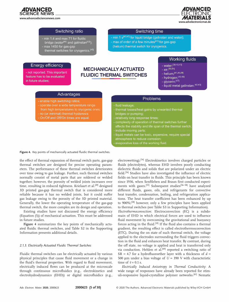
Figure 4. Key points of mechanically actuated fluidic thermal switches.
Adv. Electron. Mater. 2020, 2000623
www.advancedsciencenews.comwww.advelectronicmat.de
2000623 (6 of 30) © 2020 The Authors. Advanced Electronic Materials published by Wiley-VCH GmbH
liquid crystals exhibit spatial anisotropy of the effective thermal conductivity.[62] Theoretically, the thermal conductivity changes by up to three times between the parallel and the perpendicular orientations of the molecules.[62] This effect can be produced by applying an electric field across the liquid crystal sample.[63–65] For applying this principle to a thermal switch, the liquid crystal in a closed compartment between the heat source and the heat sink must be surrounded with two pairs of oppositely placed electrodes. During the off state, the voltage is applied to one pair of opposite electrodes, and the resulting electric field aligns the molecules in a direction that results in low thermal conductivity. During the on state, the voltage is applied to the other pair of opposite electrodes, thereby changing the direc-tion of the electric field and reorienting the molecules parallel to the heat flux, resulting in high thermal conductivity.
Sahraoui et al.[64] experimentally achieved a switching ratio of SR = 1.75 in polymer-dispersed liquid crystals with an elec-tric field of up to E = 0.5 V µm−1. The characteristic time of these switches would be of the order of milliseconds. Fumeron et al.[65] numerically evaluated heat spreader and heat concen-trator elements made of nematic liquid crystals; these showed a promising switching ratio of SR = 200. They performed numerical calculations by using the analogy of topological defects in nematic liquid crystals to gravitational line sources in cosmology.
Applying an electric field to electrorheological fluids aligns the particles into chains, thereby increasing their thermal con-ductivity and enhancing heat transfer compared to the case in which they are discretely suspended in the fluid. Dhar et al.[66] reported that the use of Al2O3-based colloids increased the thermal conductivity by up to 80% compared to that in the zero-field case. A similar effect is discussed in Section 2.1.5. with magnetorheological fluids.
Electrophoresis: Electrophoresis refers to the movement of dispersed particles relative to the surrounding base fluid under an externally applied electric field. It improves a nanofluid’s thermal conductivity by providing an additional heat transfer mechanism alongside Brownian motion. When electropho-resis is applied in a thermal switch, the applied electric field during the on state increases the magnitude of heat flux com-pared to the case where the electric field is not applied during the off state. Dhar et al.[67] applied an electric field of up to E = 60 V cm−1 to nanofluids (Al2O3, CuO, or TiO2 particles in deionized water) and achieved a 13%–30% lower temperature
gradient between the heat source and the heat sink compared to the case in which no electric field was applied. Authors did not discuss the switching ratio and characteristic time.
Ionic Wind: Ionic wind, a type of forced convection, can be generated by a corona discharge device with low input power, high voltage, and no moving parts.[68] Ionic wind is produced by driving air ions by an electric field. Because these ions are drawn to the surface, the thermal and velocity boundary layers are rather small; this additionally influences heat transfer.[68] In a thermal switch, such a convective flow can increase the con-vective heat transfer coefficient during the on state. Go et al.[69] and Yoshida[70] respectively achieved switching ratios of SR < 3 and SR < 5 via convection with ionic wind in air with input volt-ages of U = 4.39–6.15 kV; however, the authors did not discuss the characteristic times.
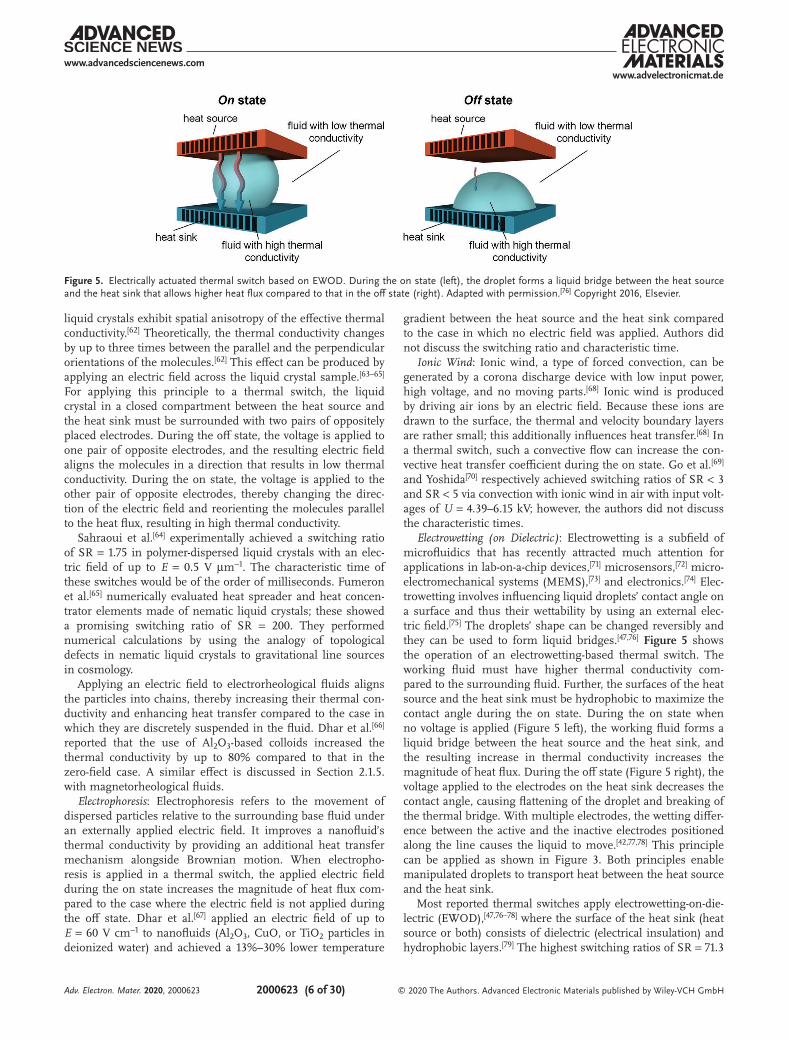
Electrowetting (on Dielectric): Electrowetting is a subfield of microfluidics that has recently attracted much attention for applications in lab-on-a-chip devices,[71] microsensors,[72] micro-electromechanical systems (MEMS),[73] and electronics.[74] Elec-trowetting involves influencing liquid droplets’ contact angle on a surface and thus their wettability by using an external elec-tric field.[75] The droplets’ shape can be changed reversibly and they can be used to form liquid bridges.[47,76] Figure 5 shows the operation of an electrowetting-based thermal switch. The working fluid must have higher thermal conductivity com-pared to the surrounding fluid. Further, the surfaces of the heat source and the heat sink must be hydrophobic to maximize the contact angle during the on state. During the on state when no voltage is applied (Figure 5 left), the working fluid forms a liquid bridge between the heat source and the heat sink, and the resulting increase in thermal conductivity increases the magnitude of heat flux. During the off state (Figure 5 right), the voltage applied to the electrodes on the heat sink decreases the contact angle, causing flattening of the droplet and breaking of the thermal bridge. With multiple electrodes, the wetting differ-ence between the active and the inactive electrodes positioned along the line causes the liquid to move.[42,77,78] This principle can be applied as shown in Figure 3. Both principles enable manipulated droplets to transport heat between the heat source and the heat sink.
Most reported thermal switches apply electrowetting-on-die-lectric (EWOD),[47,76–78] where the surface of the heat sink (heat source or both) consists of dielectric (electrical insulation) and hydrophobic layers.[79] The highest switching ratios of SR = 71.3
Figure 5. Electrically actuated thermal switch based on EWOD. During the on state (left), the droplet forms a liquid bridge between the heat source and the heat sink that allows higher heat flux compared to that in the off state (right). Adapted with permission.[76] Copyright 2016, Elsevier.
Adv. Electron. Mater. 2020, 2000623
www.advancedsciencenews.comwww.advelectronicmat.de
2000623 (7 of 30) © 2020 The Authors. Advanced Electronic Materials published by Wiley-VCH GmbH
(τ ≈ 5 s) and SR = 14 (τ = 2–40 s) were demonstrated by Yang et al.[42] using liquid metal galinstan and McLanahan et al.[77] using glycerol and water. Yang et al.[42] reported on 46% energy efficiency. The characteristic times strongly depend on the size of the droplets and fluids, and they range from the order of milliseconds[78] to a few seconds.[42]
Electrowetting can also influence boiling nucleation. For example, Cho et al.[80] demonstrated the periodic control of water bubble growth on a surface with a switching ratio of SR = 10 under a bias voltage of U = 2 V with characteristic time of τ < 1 s.
Jumping Droplets: Section 2.3.3 describes the principle of heat transfer by jumping droplets for thermal diodes in detail. This self-propelled heat transfer can be improved by applying an electric field.[81,82] An external electric field pro-vides necessary energy to droplets that otherwise do not have sufficient inertia from the jump and therefore fall down. Oh et al.[81] demonstrated hot spot cooling in electronic devices. Under the same configuration and operating conditions with jumping droplets, a thermal diode with an electric field rejected 1.3-times more heat to the surroundings than one without an electric field.
2.1.4. Summary and Comparison of Electrically Actuated Fluidic Thermal Switches
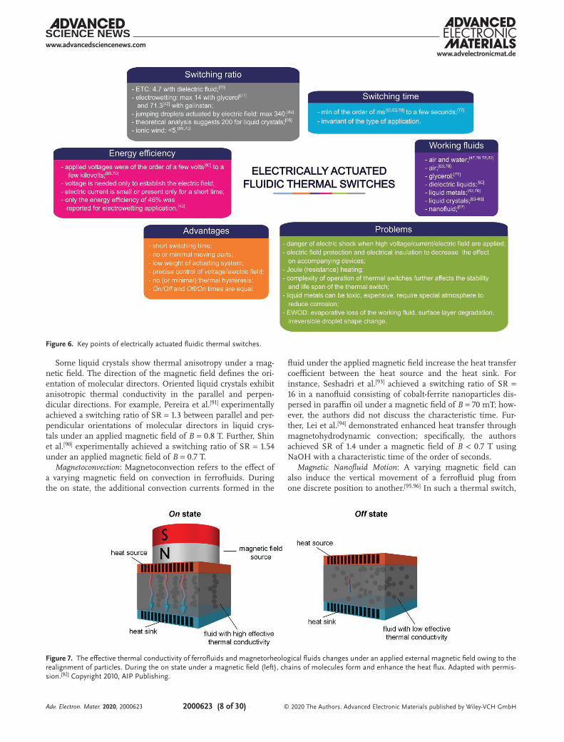
Electrically actuated fluidic thermal switches are used at around room temperature. They find applications in electronics cooling,[42,67,76,81] caloric refrigeration,[60,63] outer space,[47,82] boiling,[80] and MEMS.[77,78] Based on their operating mecha-nism, electrically actuated fluidic thermal switches can be divided into two groups. The first group includes thermal switches in which an electric field forms a fluidic bridge where two different fluids form a conductive path between the heat source and the heat sink (e.g., electrowetting[42,47,76,77] and jumping droplets[81,82]). The second group includes switches in which only one fluid forms a conductive path between the heat sink and the heat source at all times (e.g., ETC,[60] electropho-resis,[67] ionic wind,[69,70] liquid crystals[63–65]); the electric field only changes the fluid properties or forms additional internal convection currents. The first group generally has a higher switching ratio and a longer characteristic time compared to the second group.
The main advantage of electrically actuated fluidic thermal switches compared to mechanically actuated ones is the absence of moving parts (except for the fluid). This results in less noise, vibration, and friction between the parts during operation; the absence of large actuation mechanisms also reduces the overall mass and size. Further, they contain few electrodes and wires, thus enabling very compact designs. Finally, the applied electric field or voltage enables very pre-cise control of the operation.
However, one disadvantage is that the applied currents, elec-tric field strengths, or voltages must sometimes be very high (e.g., U = 390 V[60] or even U = 7 kV[69]). Therefore, appropriate precautions must be taken to prevent electric shocks and to shield the electric fields in accompanying devices. Further, the switch’s overall thermal performance can be reduced by heat gains (losses) due to Joule (resistance) heating. Finally,
the thermal performance of droplet thermal switches can be affected by droplet evaporation,[76] surface layer degradation,[83] and irreversible droplet shape change.[47]
Unfortunately, existing studies have not discussed the sta-bility, reliability, and performance of such devices during long-term operation and on the energy efficiency (Equation 5). These issues must be addressed in future studies.Figure 6 summarizes the key points of electrically actuated
fluidic thermal switches, and Table S3 in the Supporting Infor-mation presents additional details.
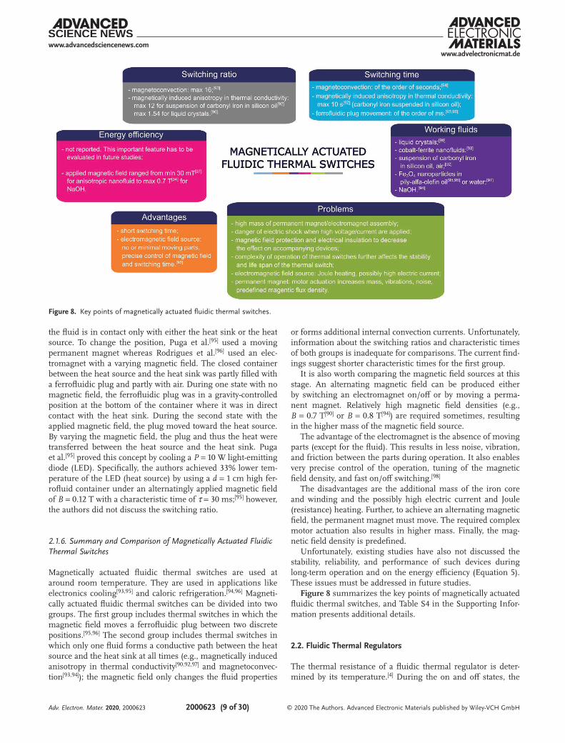
2.1.5. Magnetically Actuated Fluidic Thermal Switches
A magnetic field influences the magnetic moments in elec-trically conductive or magnetic fluids, thereby changing the thermal, rheological, magnetic, and electric properties of these fluids. Nguyen[84] noted that the main research directions in micro-magnetofluidics include magnetohydrodynamics, dig-ital magnetofluidics, ferrohydrodynamics, magnetorheology, and magnetophoresis. Magnetohydrodynamics involves fluid motion induced by magnetic fields in electrically conductive fluids;[85] digital magnetofluidics, magnetowetting; and fer-rohydrodynamics, the motion of a ferrofluid (nanofluid with suspended magnetic particles) induced by a changing magnetic field.[85] Magnetorheological fluids (MRFs) are particle suspen-sions containing particles with sizes of the order of microm-eters. Magnetophoresis involves the electric-current-induced motion of magnetic fluids with particles larger than 1 µm in size.[85]
Although numerous investigations have been conducted in this area, to the best of our knowledge, only a few magnetically actuated fluidic thermal switches have been experimentally tested to date (see Table S4 in Supporting Information).Magnetically Induced Anisotropy in Thermal Conductivity: An applied magnetic field realigns the particles in ferrofluids,[86–88] magnetorheological suspensions,[89] or liquid crystals[90,91] and thus influences their thermal conductivity.
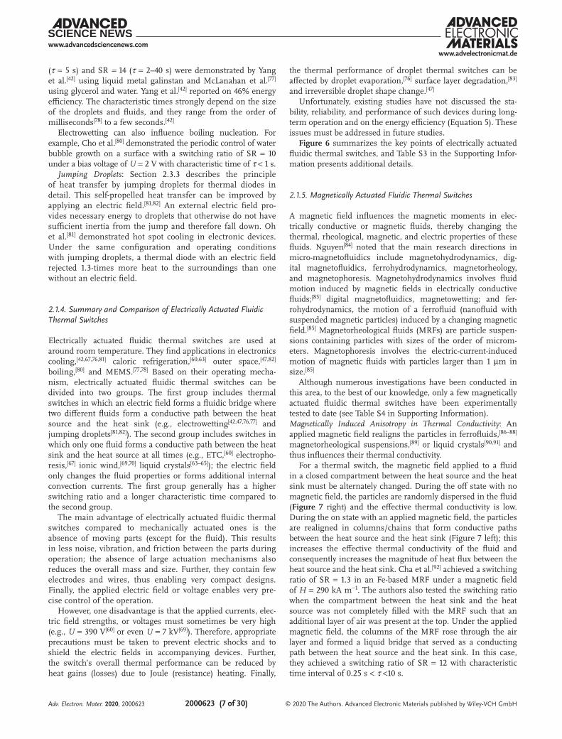
For a thermal switch, the magnetic field applied to a fluid in a closed compartment between the heat source and the heat sink must be alternately changed. During the off state with no magnetic field, the particles are randomly dispersed in the fluid (Figure 7 right) and the effective thermal conductivity is low. During the on state with an applied magnetic field, the particles are realigned in columns/chains that form conductive paths between the heat source and the heat sink (Figure 7 left); this increases the effective thermal conductivity of the fluid and consequently increases the magnitude of heat flux between the heat source and the heat sink. Cha et al.[92] achieved a switching ratio of SR = 1.3 in an Fe-based MRF under a magnetic field of H = 290 kA m−1. The authors also tested the switching ratio when the compartment between the heat sink and the heat source was not completely filled with the MRF such that an additional layer of air was present at the top. Under the applied magnetic field, the columns of the MRF rose through the air layer and formed a liquid bridge that served as a conducting path between the heat source and the heat sink. In this case, they achieved a switching ratio of SR = 12 with characteristic time interval of 0.25 s < τ <10 s.
Adv. Electron. Mater. 2020, 2000623
www.advancedsciencenews.comwww.advelectronicmat.de
2000623 (8 of 30) © 2020 The Authors. Advanced Electronic Materials published by Wiley-VCH GmbH
Some liquid crystals show thermal anisotropy under a mag-netic field. The direction of the magnetic field defines the ori-entation of molecular directors. Oriented liquid crystals exhibit anisotropic thermal conductivity in the parallel and perpen-dicular directions. For example, Pereira et al.[91] experimentally achieved a switching ratio of SR = 1.3 between parallel and per-pendicular orientations of molecular directors in liquid crys-tals under an applied magnetic field of B = 0.8 T. Further, Shin et al.[90] experimentally achieved a switching ratio of SR = 1.54 under an applied magnetic field of B = 0.7 T.
Magnetoconvection: Magnetoconvection refers to the effect of a varying magnetic field on convection in ferrofluids. During the on state, the additional convection currents formed in the
fluid under the applied magnetic field increase the heat transfer coefficient between the heat source and the heat sink. For instance, Seshadri et al.[93] achieved a switching ratio of SR = 16 in a nanofluid consisting of cobalt-ferrite nanoparticles dis-persed in paraffin oil under a magnetic field of B = 70 mT; how-ever, the authors did not discuss the characteristic time. Fur-ther, Lei et al.[94] demonstrated enhanced heat transfer through magnetohydrodynamic convection; specifically, the authors achieved SR of 1.4 under a magnetic field of B < 0.7 T using NaOH with a characteristic time of the order of seconds.
Magnetic Nanofluid Motion: A varying magnetic field can also induce the vertical movement of a ferrofluid plug from one discrete position to another.[95,96] In such a thermal switch,
Figure 7. The effective thermal conductivity of ferrofluids and magnetorheological fluids changes under an applied external magnetic field owing to the realignment of particles. During the on state under a magnetic field (left), chains of molecules form and enhance the heat flux. Adapted with permis-sion.[92] Copyright 2010, AIP Publishing.
Figure 6. Key points of electrically actuated fluidic thermal switches.
Adv. Electron. Mater. 2020, 2000623
www.advancedsciencenews.comwww.advelectronicmat.de
2000623 (9 of 30) © 2020 The Authors. Advanced Electronic Materials published by Wiley-VCH GmbH
the fluid is in contact only with either the heat sink or the heat source. To change the position, Puga et al.[95] used a moving permanent magnet whereas Rodrigues et al.[96] used an elec-tromagnet with a varying magnetic field. The closed container between the heat source and the heat sink was partly filled with a ferrofluidic plug and partly with air. During one state with no magnetic field, the ferrofluidic plug was in a gravity-controlled position at the bottom of the container where it was in direct contact with the heat sink. During the second state with the applied magnetic field, the plug moved toward the heat source. By varying the magnetic field, the plug and thus the heat were transferred between the heat source and the heat sink. Puga et al.[95] proved this concept by cooling a P = 10 W light-emitting diode (LED). Specifically, the authors achieved 33% lower tem-perature of the LED (heat source) by using a d = 1 cm high fer-rofluid container under an alternatingly applied magnetic field of B = 0.12 T with a characteristic time of τ = 30 ms;[95] however, the authors did not discuss the switching ratio.
2.1.6. Summary and Comparison of Magnetically Actuated Fluidic Thermal Switches
Magnetically actuated fluidic thermal switches are used at around room temperature. They are used in applications like electronics cooling[93,95] and caloric refrigeration.[94,96] Magneti-cally actuated fluidic thermal switches can be divided into two groups. The first group includes thermal switches in which the magnetic field moves a ferrofluidic plug between two discrete positions.[95,96] The second group includes thermal switches in which only one fluid forms a conductive path between the heat source and the heat sink at all times (e.g., magnetically induced anisotropy in thermal conductivity[90,92,97] and magnetoconvec-tion[93,94]); the magnetic field only changes the fluid properties
or forms additional internal convection currents. Unfortunately, information about the switching ratios and characteristic times of both groups is inadequate for comparisons. The current find-ings suggest shorter characteristic times for the first group.
It is also worth comparing the magnetic field sources at this stage. An alternating magnetic field can be produced either by switching an electromagnet on/off or by moving a perma-nent magnet. Relatively high magnetic field densities (e.g., B = 0.7 T[90] or B = 0.8 T[94]) are required sometimes, resulting in the higher mass of the magnetic field source.
The advantage of the electromagnet is the absence of moving parts (except for the fluid). This results in less noise, vibration, and friction between the parts during operation. It also enables very precise control of the operation, tuning of the magnetic field density, and fast on/off switching.[98]
The disadvantages are the additional mass of the iron core and winding and the possibly high electric current and Joule (resistance) heating. Further, to achieve an alternating magnetic field, the permanent magnet must move. The required complex motor actuation also results in higher mass. Finally, the mag-netic field density is predefined.
Unfortunately, existing studies have also not discussed the stability, reliability, and performance of such devices during long-term operation and on the energy efficiency (Equation 5). These issues must be addressed in future studies.Figure 8 summarizes the key points of magnetically actuated
fluidic thermal switches, and Table S4 in the Supporting Infor-mation presents additional details.
2.2. Fluidic Thermal Regulators
The thermal resistance of a fluidic thermal regulator is deter-mined by its temperature.[4] During the on and off states, the
Figure 8. Key points of magnetically actuated fluidic thermal switches.
Adv. Electron. Mater. 2020, 2000623
www.advancedsciencenews.comwww.advelectronicmat.de
2000623 (10 of 30) © 2020 The Authors. Advanced Electronic Materials published by Wiley-VCH GmbH
low and high thermal resistance of the thermal regulator allow large and small heat flux, respectively, between the heat source and the heat sink. Thermal regulators can be divided into three groups, as shown in Figure 2. The first group includes thermal-expansion-based thermal regulators (without accompa-nying phase change) (Section 2.2.1). The second group includes phase-change-based thermal regulators, including variable-con-ductance heat pipes (VCHPs) (Section 2.2.2). The third group includes adsorption-based thermal regulators (Section 2.2.3).
The thermal resistance of thermal regulators changes at a critical temperature via reaching the required length/size (for thermal-expansion-based thermal regulators and VCHPs), the occurrence of a phase transition (for phase-change-based thermal regulators), or reaching the required gas adsorp-tion level (for adsorption-based thermal regulators). It is very important to carefully consider the switching hysteresis in thermal regulators: the characteristic time for on/off switching is normally longer than that for off/on switching. Addition-ally, the critical temperature (or temperature interval) for on/off switching could be shifted compared to that for off/on switching.
It is sometimes difficult to determine whether a given device is a thermal regulator or a thermal diode because both have similar actuation principles. Wehmeyer et al.[4] stated that all thermal diodes are also thermal regulators. The main differ-ence between the two devices is the temperature dependence of the thermal resistance, which is shown for both cases in Figure 1. Because information on the temperature depend-ence of thermal resistance was incomplete in some studies, we included all phase-change-based fluidic TCDs (except for heat pipes) under thermal regulators.
2.2.1. Thermal-Expansion-Based Fluidic Thermal Regulators (Without Phase Change)
Some fluids that expand or contract during heating or cooling have been implemented as thermal regulators in certain appli-cations. When the fluid changes shape or size owing to tem-perature change, it forms (on state) or breaks (off state) a thermal contact between the heat source and the heat sink, thereby increasing or decreasing the heat flux, respectively. For instance, Gaddam et al.[99] built a mercury-based thermal regulator for outer space applications. The authors filled a compartment between the heat source and the heat sink partly with air and partly with mercury. When the temperature of the mercury rose to 323 K, it expanded to such an extent that it formed a conductive bridge between the heat source and the heat sink and increased the heat flux; this is the on state. When the temperature of the mercury decreased, it contracted and broke the conductive bridge between the heat source and the heat sink and decreased the heat flux; this is the off state. For an average temperature change of 50 K, mercury expanded/contracted by 0.3%. For 20 mm of mercury, the height of the air gap was ≈60 µm. The authors achieved a rectification ratio RR = 1.5; however, they did not discuss the characteristic time and thermal hysteresis.
Morey and Gorman[100] also developed a thermal-expan-sion-based thermal regulator for outer space applications.
The authors connected a bellows filled with Freon gas, which expanded and contracted depending on the temperature, to an actuator rod and spring. During the on state, the bellows expanded and formed a thermal bridge between the heat source and the heat sink, thereby increasing the heat flux. During the off state, the bellows contracted and the spring returned the rod to the initial position to break the thermal bridge between the heat source and the heat sink, thereby decreasing the heat flux. With regard to switching thermal hysteresis, the temperature intervals for on/off and off/on switching were 276–283 K and 280–272 K, respectively. The authors achieved a high switching ratio of SR = 50 because the bellows were surrounded by a vacuum, resulting in very small heat flux during the off state. Further, they reported that this thermal regulator showed good cyclic stability during long-term operation.
Fluidic and solid thermal regulators based on thermal expan-sion have many common features. They have long character-istic times and show thermal hysteresis, as indicated by the change of the critical temperature between the expansion/contraction processes and the different expansion/contraction times. Experiments[100] clearly indicate that the expansion/con-traction in the first few operation cycles is larger than that in the following cycles; therefore, it is important to perform evalu-ations during stable operation.
Fluidic thermal regulators show greater application potential because the thermal expansion coefficient of fluids is generally larger than that of metals. Further, the thermal conductivity of fluids is lower than that of metals (although liquid metals have moderate thermal conductivity). Finally, the liquid–solid inter-face has lower thermal contact resistance than the solid–solid interface.
However, the main disadvantage of thermal-expansion-based fluidic thermal regulators is their gravity-dependent operation. In particular, the gravity-dependent direction of liquid flow could affect the uniformity of the cross-sectional shape and size of the liquid column.
The switching ratio of thermal-expansion-based fluidic thermal regulators can be increased by optimizing their geom-etry (e.g., by reducing thermal losses through the container walls in the parallel and perpendicular directions and reducing the dead volume of both fluids) and by optimizing working and surrounding low-conductivity fluid (the ideal combination is a liquid metal as a working fluid surrounded by vacuum).
Table S5 in the Supporting Information presents additional details.
2.2.2. Phase-Change-Based Fluidic Thermal Regulators
The phase change between solid, liquid, or gaseous phases occurs around the critical temperature of a certain phase of a material used in the thermal regulator (solid-solid phase change based TCDs in Swoboda et al.[37]). Phase-change-based fluidic thermal regulators are divided into three groups. The first group includes regulators in which one or more materials undergo solid-liquid phase change. The second group includes regulators in which one or more fluids undergo liquid-gas phase change. In some cases, fluid expansion associated with a phase change is also used to create a conduction path between
Adv. Electron. Mater. 2020, 2000623
www.advancedsciencenews.comwww.advelectronicmat.de
2000623 (11 of 30) © 2020 The Authors. Advanced Electronic Materials published by Wiley-VCH GmbH
the heat source and the heat sink. The third group includes VCHPs.
The three phases usually have different thermal and physical properties. The regulator is turned on and off when the mate-rial has high and low thermal conductivity, respectively. Phase-change-based fluidic thermal regulators contain phase change fluids such as alcohols, glycols, wax, hydrates, or different gases.[101,102] In particular, thermal regulators containing wax are called wax motors or wax actuators.[103]
Solid–Liquid Phase Change Fluidic Thermal Regulators: A solid-liquid phase change fluidic thermal regulator contains a compartment between the heat source and the heat sink that is partly filled with a phase change material (PCM) and partly with air or other gases. This type of thermal regulator exploits the change in thermal conductivity in different phases as well as the accompanying volume/shape change of the fluid. During the off state, the solid PCM has low temperature and does not connect the heat source and the heat sink, thereby limiting the heat flux. During the on state, the PCM’s temperature rises, causing it to expand and liquefy and connect the heat source and the heat sink, thereby increasing the heat flux. The on and off states are reversed in a PCM with a negative thermal expan-sion coefficient.[104]
Geng et al.[31] used low-melting-point alloys (different com-positions of Bi, In, Pb, Sn, Ga, and Ag) as a thermal-expansion-based thermal regulator in MEMS. This regulator contained a closed compartment with the heat source at the bottom and the heat sink at the top separated by a thin air gap. Separated alloy droplets were positioned on the heat source surface. The gap height between the heat source and the heat sink was deter-mined through temperature-displacement measurements; the highest displacement of 70 µm was measured at the melting point temperature of 320.5 K. Because of the displacement hys-teresis between temperature increase (melting) and decrease (solidification), the highest switching ratio of SR = 26 was measured at an air gap of 60 µm. The characteristic times for off/on and on/off switching were τ = 10 s and τ = 30 s, respectively. Device tests confirmed repeatable and reversible switching between both phases.
Wax thermal regulators were mainly developed for thermal management in outer space applications.[105–107] Wax thermal regulators had switching ratios ranging from SR = 30 (τ = 3 min)[105] to SR = 130.[106] The thermal resistance of wax can change by an order of magnitude between two different phases. For example, Shinozaki et al.[106] reported that the thermal resistance during off and on states was R = 143 K W−1 and R = 1.16 K W−1, respectively. However, thermal hyster-esis is present as melting and solidification do not occur at the same temperature. Pauken et al.[29] reported that melting started above 293 K whereas solidification started below 291 K. Thermal hysteresis is also seen in the characteristic times, with on/off switching usually taking longer than off/on switching. Further, the characteristic time was usually of the order of min-utes. Thorough tests of wax thermal regulators for outer space applications over 20000 cycles showed no wear and degradation of thermal performance.[107]
Most existing thermal regulators are difficult to implement in biomedical applications owing to the poor biocompatibility of their constituent materials and their complicated structures.
However, hydrogel-based materials like poly(N-isopropylacryla-mide) (PNIPAm) show great potential in this regard.[108,109] The polymer network in PNIPAm hydrogel stretches below and shrinks above the critical temperature. When the polymer network stretches, the hydrogel becomes hydrophilic and its internal space accommodates more water. By contrast, when the polymer network shrinks, the hydrogel becomes hydro-phobic and a large amount of water is expelled from its internal space. Feng et al.[108] found that the water extraction process was rather long but intensive: in the first 5 min, the sample expelled 64% of its water mass. The higher the water content, the higher is the thermal conductivity of the PNIPAm hydrogel. For example, the thermal conductivity of the PNIPAm hydrogel decreased sharply from k = 0.51 to k = 0.35 W m−1 K−1 as the tem-perature increased from 306 and 308 K.[108] This would result in a switching ratio of SR = 1.45; however, the careful imple-mentation of the thermal regulator resulted in a switching ratio of SR = 3.6 (τ ≈ 1 h). Li et al.[109] achieved a switching ratio of SR = 1.15 with a characteristic time of the order of milliseconds.
Some researchers tried to enhance the thermal performance of thermal regulators by using multilayered PCM composites arranged in series. The two or more phase change fluids used in combination must have similar phase transition tempera-tures. Among room-temperature applications, Cottrill et al.[110] combined polystyrene foam impregnated with octadecane and PNIPAm solution, Chen et al.[111] combined eicosane C20H42 and polyethylene glycol PEG4000, Pallecchi et al.[112] combined PNIPAm and polydimethylsiloxane (PDMS) polymers, and Meng et al.[113] combined CaCl2∙6H2O and wax. Solid-liquid phase change thermal regulators may have unstable thermal performance.[113] Pallecchi et al.[112] demonstrated the highest switching ratio of SR = 4.
By using a combination of fluids with different thermal con-ductivity versus temperature trends, this principle could also be used to realize a thermal diode (see Section 2.3.1.).
Liquid-Gas Phase Change Fluidic Thermal Regulators: Liquid-gas phase change fluidic thermal regulators can be divided in two groups: those with accompanying thermal expansion and those without. Van Velson et al.[114] reported a typical example of the first group; they developed a thermal regulator containing a metallic bellows encapsulated in a vacuum seal. The bellows was attached to the heat source positioned at the top; the heat sink was positioned at the bottom of the compartment and was separated by a gap. The bellows was filled with water. During the off state, the size of the bellows was so small that it was not in contact with the heat sink at the bottom; therefore, the heat flux between the heat source and the heat sink was very small. However, during the on state, when the water in the bel-lows heated up and started evaporating, the bellows expanded toward the heat sink and the thermal bridge was connected, resulting in increased heat flux between the heat source and the heat sink. the authors achieved a switching ratio of SR = 20. However, they did not discuss the extension of the bellows and the stability, reliability, and performance during long-term operation.
Thermal regulators without accompanying thermal expan-sion rely on the change in thermal conductivity between dif-ferent phases. For example, Ng et al.[115] designed a vapor-layer thermal regulator for thermal management of an electronic
Adv. Electron. Mater. 2020, 2000623
www.advancedsciencenews.comwww.advelectronicmat.de
2000623 (12 of 30) © 2020 The Authors. Advanced Electronic Materials published by Wiley-VCH GmbH
device/element mounted on a heat sink. The authors used a closed compartment containing deionized water with dis-solved sodium chloride, where the bottom and top surfaces were respectively the heat sink and the heat source. During the on state, heat was transferred from top to bottom by conduc-tion and convection, thereby heating up the electronic device/element. During the off state, as the temperature increased to the limiting temperature and water finally began to boil, a few-millimeter-thick steam layer was formed below the upper hot surface; it insulated the heat source and prevented heat transfer to the electronic device/element. The authors achieved a switching ratio of SR = 2.4. However, they did not discuss the long-term operation of this regulator.
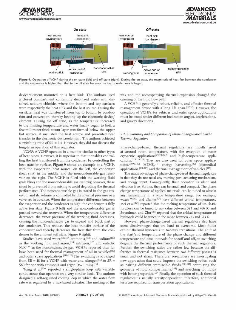
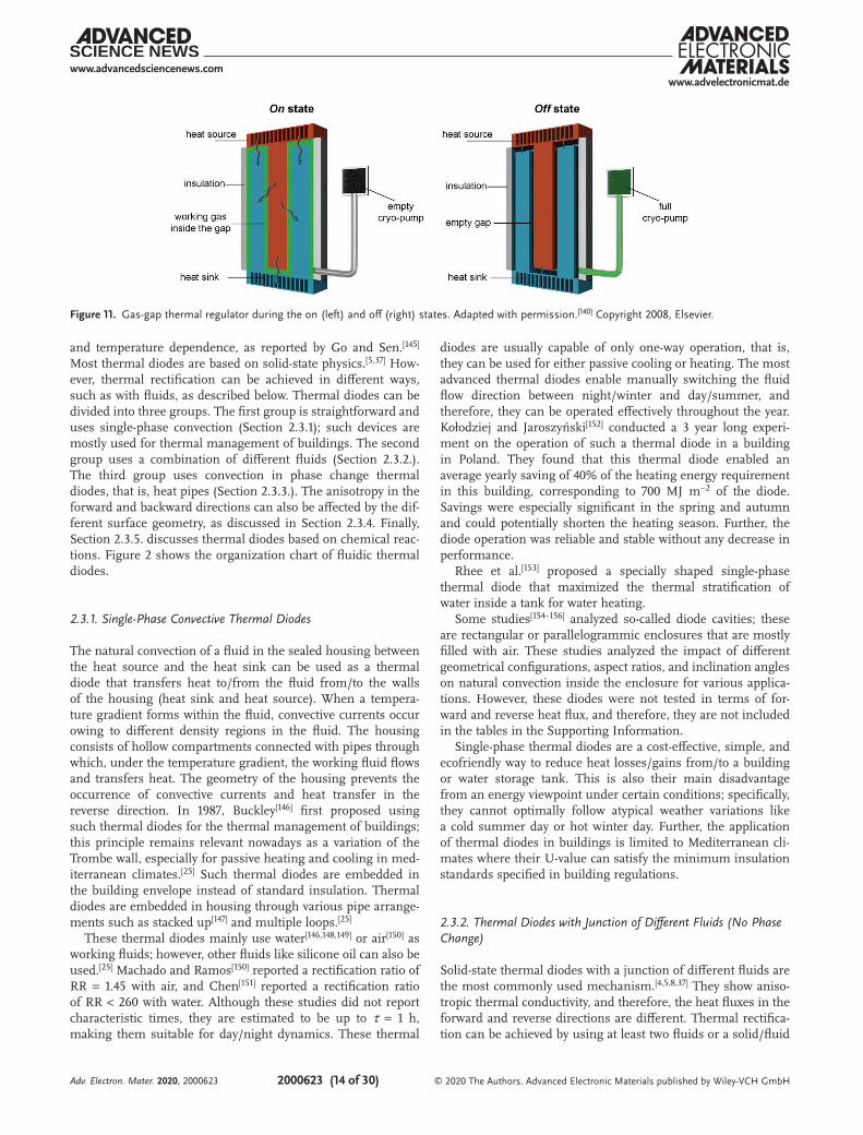
VCHP: A VCHP operates in a manner similar to other types of heat pipes. However, it is superior in that it enables control-ling the heat transferred from the condenser by controlling the heat transfer surface. Figure 9 shows an example of a VCHP, with the evaporator (heat source) on the left, the condenser (heat sink) in the middle, and the noncondensable gas reser-voir on the right. The VCHP is filled with the working fluid (pale blue) and the noncondensable gas (yellow); however, these must be prevented from mixing to avoid degrading the thermal performance. The noncondensable gas is stored in the gas res-ervoir, and its volume is controlled by the internal pressure or a valve set in advance. When the temperature difference between the evaporator and the condenser is high, the condenser is fully active (on state, Figure 9 left) and the noncondensable gas is pushed toward the reservoir. When the temperature difference decreases, the vapor pressure of the working fluid decreases, causing the noncondensable gas to expand and block part of the condenser. This reduces the heat transfer surface of the condenser and thereby decreases the heat flux from the con-denser to the ambient (off state, Figure 9 right).
Studies have used water,[116,117] ammonia,[118] and sodium[119] as the working fluid and argon,[118] nitrogen,[117] and eutectic NaK[119] as the noncondensable gas. VCHPs reported thus far have been used for thermal management of oil in vehicles[117] and outer space applications.[118–120] The switching ratio ranged from SR = 18 for a VCHP with water and nitrogen[117] to SR = 580 for one with ammonia and argon (τ = 1 min).[118]
Wang et al.[120] reported a single-phase loop with variable conductance that operates on a very similar basis. The authors designed a self-regulated cooling loop in which the water flow rate was regulated by a wax-based actuator. The melting of the
wax and the accompanying thermal expansion changed the opening of the fluid flow path.
A VCHP is generally a robust, reliable, and effective thermal management device with a long life span.[117,121] However, the operation of VCHPs for vehicles and outer space applications must be tested under different inclination angles, accelerations, and gravity directions.
2.2.3. Summary and Comparison of Phase-Change-Based Fluidic Thermal Regulators
Phase-change-based thermal regulators are mostly used at around room temperature, with the exception of some cryogenic applications[29,118,122] and high-temperature appli-cations.[115,119,120] They are also used for outer space applica-tions,[29,99,100] MEMS,[31] energy harvesting,[32] biomedical applications,[108,109] and thermal management of vehicles.[117]
The main advantage of phase-change-based thermal regulators is that they do not need any moving part, actuating mechanism, and energy input. Consequently, their operation is silent and vibration free. Further, they can be small and compact. The phase change temperature of applied materials can be tuned to almost any temperature in a wide temperature range. For example, waxes[101,102] and alkanes[124] have different critical temperatures. Mei et al.[125] reported that the melting temperature of Sn-Pb-Bi-In alloys can be tuned to any value between 323 and 456 K, and Strandman and Zhu[126] reported that the critical temperature of hydrogels could be tuned in the range between 273 and 373 K.
However, phase-change-based thermal regulators also have some disadvantages that are hard to overcome. Most fluids exhibit thermal hysteresis in two-way transitions. The shift of the start/end temperature of the phase change and different temperature and time intervals for on/off and off/on switching degrade the thermal performance of such thermal regulators. Further, the switching ratios are rather low because the dif-ference in thermal resistance between two different phases is small and not sharp. Therefore, researchers are investigating new approaches that could improve the switching ratios, such as pairing different immiscible fluids,[110–113] optimizing the geometry of fluid compartments,[108] and searching for fluids with better properties.[127] Finally, the operation of such thermal regulators is usually gravity-dependent; therefore, additional tests are required for transportation applications.
Figure 9. Operation of VCHP during the on state (left) and off state (right). During the on state, the magnitude of heat flux between the condenser and the evaporator is higher than that in the off state because the heat transfer area is larger.
Adv. Electron. Mater. 2020, 2000623
www.advancedsciencenews.comwww.advelectronicmat.de
2000623 (13 of 30) © 2020 The Authors. Advanced Electronic Materials published by Wiley-VCH GmbH
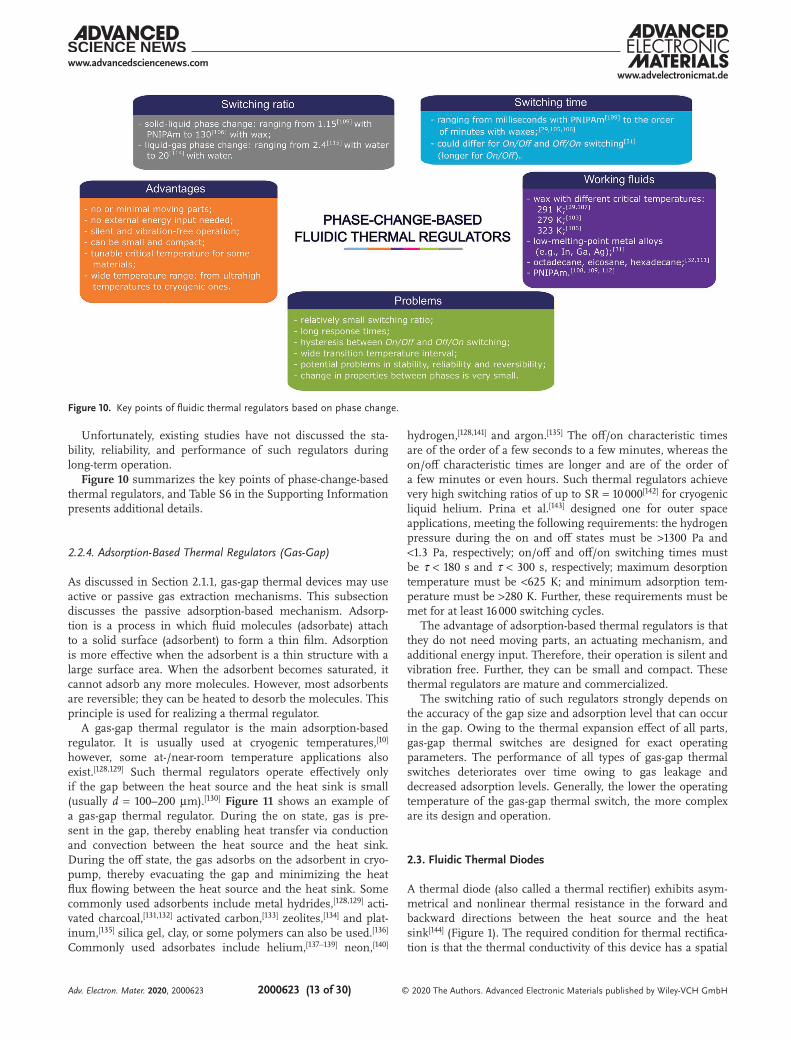
Unfortunately, existing studies have not discussed the sta-bility, reliability, and performance of such regulators during long-term operation.Figure 10 summarizes the key points of phase-change-based
thermal regulators, and Table S6 in the Supporting Information presents additional details.
2.2.4. Adsorption-Based Thermal Regulators (Gas-Gap)
As discussed in Section 2.1.1, gas-gap thermal devices may use active or passive gas extraction mechanisms. This subsection discusses the passive adsorption-based mechanism. Adsorp-tion is a process in which fluid molecules (adsorbate) attach to a solid surface (adsorbent) to form a thin film. Adsorption is more effective when the adsorbent is a thin structure with a large surface area. When the adsorbent becomes saturated, it cannot adsorb any more molecules. However, most adsorbents are reversible; they can be heated to desorb the molecules. This principle is used for realizing a thermal regulator.
A gas-gap thermal regulator is the main adsorption-based regulator. It is usually used at cryogenic temperatures,[10] however, some at-/near-room temperature applications also exist.[128,129] Such thermal regulators operate effectively only if the gap between the heat source and the heat sink is small (usually d = 100–200 µm).[130] Figure 11 shows an example of a gas-gap thermal regulator. During the on state, gas is pre-sent in the gap, thereby enabling heat transfer via conduction and convection between the heat source and the heat sink. During the off state, the gas adsorbs on the adsorbent in cryo-pump, thereby evacuating the gap and minimizing the heat flux flowing between the heat source and the heat sink. Some commonly used adsorbents include metal hydrides,[128,129] acti-vated charcoal,[131,132] activated carbon,[133] zeolites,[134] and plat-inum,[135] silica gel, clay, or some polymers can also be used.[136] Commonly used adsorbates include helium,[137–139] neon,[140]
hydrogen,[128,141] and argon.[135] The off/on characteristic times are of the order of a few seconds to a few minutes, whereas the on/off characteristic times are longer and are of the order of a few minutes or even hours. Such thermal regulators achieve very high switching ratios of up to SR = 10 000[142] for cryogenic liquid helium. Prina et al.[143] designed one for outer space applications, meeting the following requirements: the hydrogen pressure during the on and off states must be >1300 Pa and <1.3 Pa, respectively; on/off and off/on switching times must be τ < 180 s and τ < 300 s, respectively; maximum desorption temperature must be <625 K; and minimum adsorption tem-perature must be >280 K. Further, these requirements must be met for at least 16 000 switching cycles.
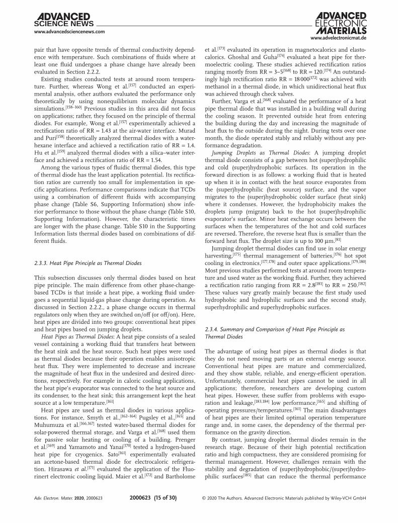
The advantage of adsorption-based thermal regulators is that they do not need moving parts, an actuating mechanism, and additional energy input. Therefore, their operation is silent and vibration free. Further, they can be small and compact. These thermal regulators are mature and commercialized.
The switching ratio of such regulators strongly depends on the accuracy of the gap size and adsorption level that can occur in the gap. Owing to the thermal expansion effect of all parts, gas-gap thermal switches are designed for exact operating parameters. The performance of all types of gas-gap thermal switches deteriorates over time owing to gas leakage and decreased adsorption levels. Generally, the lower the operating temperature of the gas-gap thermal switch, the more complex are its design and operation.
2.3. Fluidic Thermal Diodes
A thermal diode (also called a thermal rectifier) exhibits asym-metrical and nonlinear thermal resistance in the forward and backward directions between the heat source and the heat sink[144] (Figure 1). The required condition for thermal rectifica-tion is that the thermal conductivity of this device has a spatial
Figure 10. Key points of fluidic thermal regulators based on phase change.
Adv. Electron. Mater. 2020, 2000623
www.advancedsciencenews.comwww.advelectronicmat.de
2000623 (14 of 30) © 2020 The Authors. Advanced Electronic Materials published by Wiley-VCH GmbH
and temperature dependence, as reported by Go and Sen.[145] Most thermal diodes are based on solid-state physics.[5,37] How-ever, thermal rectification can be achieved in different ways, such as with fluids, as described below. Thermal diodes can be divided into three groups. The first group is straightforward and uses single-phase convection (Section 2.3.1); such devices are mostly used for thermal management of buildings. The second group uses a combination of different fluids (Section 2.3.2.). The third group uses convection in phase change thermal diodes, that is, heat pipes (Section 2.3.3.). The anisotropy in the forward and backward directions can also be affected by the dif-ferent surface geometry, as discussed in Section 2.3.4. Finally, Section 2.3.5. discusses thermal diodes based on chemical reac-tions. Figure 2 shows the organization chart of fluidic thermal diodes.
2.3.1. Single-Phase Convective Thermal Diodes
The natural convection of a fluid in the sealed housing between the heat source and the heat sink can be used as a thermal diode that transfers heat to/from the fluid from/to the walls of the housing (heat sink and heat source). When a tempera-ture gradient forms within the fluid, convective currents occur owing to different density regions in the fluid. The housing consists of hollow compartments connected with pipes through which, under the temperature gradient, the working fluid flows and transfers heat. The geometry of the housing prevents the occurrence of convective currents and heat transfer in the reverse direction. In 1987, Buckley[146] first proposed using such thermal diodes for the thermal management of buildings; this principle remains relevant nowadays as a variation of the Trombe wall, especially for passive heating and cooling in med-iterranean climates.[25] Such thermal diodes are embedded in the building envelope instead of standard insulation. Thermal diodes are embedded in housing through various pipe arrange-ments such as stacked up[147] and multiple loops.[25]
These thermal diodes mainly use water[146,148,149] or air[150] as working fluids; however, other fluids like silicone oil can also be used.[25] Machado and Ramos[150] reported a rectification ratio of RR = 1.45 with air, and Chen[151] reported a rectification ratio of RR < 260 with water. Although these studies did not report characteristic times, they are estimated to be up to τ = 1 h, making them suitable for day/night dynamics. These thermal
diodes are usually capable of only one-way operation, that is, they can be used for either passive cooling or heating. The most advanced thermal diodes enable manually switching the fluid flow direction between night/winter and day/summer, and therefore, they can be operated effectively throughout the year. Kołodziej and Jaroszyński[152] conducted a 3 year long experi-ment on the operation of such a thermal diode in a building in Poland. They found that this thermal diode enabled an average yearly saving of 40% of the heating energy requirement in this building, corresponding to 700 MJ m−2 of the diode. Savings were especially significant in the spring and autumn and could potentially shorten the heating season. Further, the diode operation was reliable and stable without any decrease in performance.
Rhee et al.[153] proposed a specially shaped single-phase thermal diode that maximized the thermal stratification of water inside a tank for water heating.
Some studies[154–156] analyzed so-called diode cavities; these are rectangular or parallelogrammic enclosures that are mostly filled with air. These studies analyzed the impact of different geometrical configurations, aspect ratios, and inclination angles on natural convection inside the enclosure for various applica-tions. However, these diodes were not tested in terms of for-ward and reverse heat flux, and therefore, they are not included in the tables in the Supporting Information.
Single-phase thermal diodes are a cost-effective, simple, and ecofriendly way to reduce heat losses/gains from/to a building or water storage tank. This is also their main disadvantage from an energy viewpoint under certain conditions; specifically, they cannot optimally follow atypical weather variations like a cold summer day or hot winter day. Further, the application of thermal diodes in buildings is limited to Mediterranean cli-mates where their U-value can satisfy the minimum insulation standards specified in building regulations.
2.3.2. Thermal Diodes with Junction of Different Fluids (No Phase Change)
Solid-state thermal diodes with a junction of different fluids are the most commonly used mechanism.[4,5,8,37] They show aniso-tropic thermal conductivity, and therefore, the heat fluxes in the forward and reverse directions are different. Thermal rectifica-tion can be achieved by using at least two fluids or a solid/fluid
Figure 11. Gas-gap thermal regulator during the on (left) and off (right) states. Adapted with permission.[140] Copyright 2008, Elsevier.
Adv. Electron. Mater. 2020, 2000623
www.advancedsciencenews.comwww.advelectronicmat.de
2000623 (15 of 30) © 2020 The Authors. Advanced Electronic Materials published by Wiley-VCH GmbH
pair that have opposite trends of thermal conductivity depend-ence with temperature. Such combinations of fluids where at least one fluid undergoes a phase change have already been evaluated in Section 2.2.2.
Existing studies conducted tests at around room tempera-ture. Further, whereas Wong et al.[157] conducted an experi-mental analysis, other authors evaluated the performance only theoretically by using nonequilibrium molecular dynamics simulations.[158–160] Previous studies in this area did not focus on applications; rather, they focused on the principle of thermal diodes. For example, Wong et al.[157] experimentally achieved a rectification ratio of RR = 1.43 at the air-water interface. Murad and Puri[158] theoretically analyzed thermal diodes with a water-hexane interface and achieved a rectification ratio of RR = 1.4. Hu et al.[159] analyzed thermal diodes with a silica–water inter-face and achieved a rectification ratio of RR = 1.54.
Among the various types of fluidic thermal diodes, this type of thermal diode has the least application potential. Its rectifica-tion ratios are currently too small for implementation in spe-cific applications. Performance comparisons indicate that TCDs using a combination of different fluids with accompanying phase change (Table S6, Supporting Information) show infe-rior performance to those without the phase change (Table S10, Supporting Information). However, the characteristic times are longer with the phase change. Table S10 in the Supporting Information lists thermal diodes based on combinations of dif-ferent fluids.
2.3.3. Heat Pipe Principle as Thermal Diodes
This subsection discusses only thermal diodes based on heat pipe principle. The main difference from other phase-change-based TCDs is that inside a heat pipe, a working fluid under-goes a sequential liquid-gas phase change during operation. As discussed in Section 2.2.2., a phase change occurs in thermal regulators only when they are switched on/off (or off/on). Here, heat pipes are divided into two groups: conventional heat pipes and heat pipes based on jumping droplets.
Heat Pipes as Thermal Diodes: A heat pipe consists of a sealed vessel containing a working fluid that transfers heat between the heat sink and the heat source. Such heat pipes were used as thermal diodes because their operation enables anisotropic heat flux. They were implemented to decrease and increase the magnitude of heat flux in the undesired and desired direc-tions, respectively. For example in caloric cooling applications, the heat pipe’s evaporator was connected to the heat source and its condenser, to the heat sink; this arrangement kept the heat source at a low temperature.[161]
Heat pipes are used as thermal diodes in various applica-tions. For instance, Smyth et al.,[162–164] Pugsley et al.,[165] and Muhumuza et al.[166,167] tested water-based thermal diodes for solar-powered thermal storage, and Varga et al.[168] used them for passive solar heating or cooling of a building. Prenger et al.[169] and Yamamoto and Yanai[170] tested a hydrogen-based heat pipe for cryogenics. Sato[161] experimentally evaluated an acetone-based thermal diode for electrocaloric refrigera-tion. Hirasawa et al.[171] evaluated the application of the Fluo-rinert electronic cooling liquid. Maier et al.[172] and Bartholome
et al.[173] evaluated its operation in magnetocalorics and elasto-calorics. Ghoshal and Guha[174] evaluated a heat pipe for ther-moelectric cooling. These studies achieved rectification ratios ranging mostly from RR = 3–5[168] to RR = 120.[174] An outstand-ingly high rectification ratio RR = 18 000[172] was achieved with methanol in a thermal diode, in which unidirectional heat flux was achieved through check valves.
Further, Varga et al.[168] evaluated the performance of a heat pipe thermal diode that was installed in a building wall during the cooling season. It prevented outside heat from entering the building during the day and increasing the magnitude of heat flux to the outside during the night. During tests over one month, the diode operated stably and reliably without any per-formance degradation.
Jumping Droplets as Thermal Diodes: A jumping droplet thermal diode consists of a gap between hot (super)hydrophilic and cold (super)hydrophobic surfaces. Its operation in the forward direction is as follows: a working fluid that is heated up when it is in contact with the heat source evaporates from the (super)hydrophilic (heat source) surface, and the vapor migrates to the (super)hydrophobic colder surface (heat sink) where it condenses. However, the hydrophobicity makes the droplets jump (migrate) back to the hot (super)hydrophilic evaporator’s surface. Minor heat exchange occurs between the surfaces when the temperatures of the hot and cold surfaces are reversed. Therefore, the reverse heat flux is smaller than the forward heat flux. The droplet size is up to 100 µm.[81]
Jumping droplet thermal diodes can find use in solar energy harvesting,[175] thermal management of batteries,[176] hot spot cooling in electronics,[177,178] and outer space applications.[179,180] Most previous studies performed tests at around room tempera-ture and used water as the working fluid. Further, they achieved a rectification ratio ranging from RR = 2.8[181] to RR = 250.[182] These values vary greatly mainly because the first study used hydrophobic and hydrophilic surfaces and the second study, superhydrophilic and superhydrophobic surfaces.
2.3.4. Summary and Comparison of Heat Pipe Principle as Thermal Diodes
The advantage of using heat pipes as thermal diodes is that they do not need moving parts or an external energy source. Conventional heat pipes are mature and commercialized, and they show stable, reliable, and energy-efficient operation. Unfortunately, commercial heat pipes cannot be used in all applications; therefore, researchers are developing custom heat pipes. However, these suffer from problems with evapo-ration and leakage,[183,184] low performance,[165] and shifting of operating pressures/temperatures.[161] The main disadvantages of heat pipes are their limited optimal operation temperature range and, in some cases, the dependency of the thermal per-formance on the gravity direction.
By contrast, jumping droplet thermal diodes remain in the research stage. Because of their high potential rectification ratio and high compactness, they are considered promising for thermal management. However, challenges remain with the stability and degradation of (super)hydrophobic/(super)hydro-philic surfaces[185] that can reduce the thermal performance
Adv. Electron. Mater. 2020, 2000623
www.advancedsciencenews.comwww.advelectronicmat.de
2000623 (16 of 30) © 2020 The Authors. Advanced Electronic Materials published by Wiley-VCH GmbH
during long-term operation. Another challenge is droplet evap-oration to the surroundings. This can be solved by using her-metically sealed compartments[181] or filling the compartment with a noncondensable gas.[176] Gravitational independence could be established by additionally applying an electric field.[81]
Figure 12 summarizes the key points of phase-change thermal diodes, and Table S12 in the Supporting Information presents additional details.
2.3.5. Shape-Induced Fluidic Thermal Diodes
Thermal rectification can be induced by modifying the geom-etry of the thermal diode. This mechanism has been success-fully realized at the nanoscale with solid-state thermal diodes (see Swoboda et al.[37]), however, it has also been theoretically evaluated to some extent with fluids.
Solórzano et al.[186] simulated the flow of a 2D gas of Len-nard-Jones particles through a sawtooth channel. The channel shape affected the heat flux in the forward and reverse direc-tions, resulting in small thermal rectification. This effect was more intense with a low-density gas, where particle–wall colli-sions outperformed particle–particle collisions.
The thermal properties of fluids were also affected by the geometry of liquid crystals. Liquid crystals show anisotropy in thermal conductivity. In the nematic state, the molecules have an orientational order but not a positional one. When they are confined by a flat or curved surface, different topological defects form. Escaped radial disclination,[187] one such defect, was tested for use in thermal rectification. Melo et al.[188] pro-posed a thermal diode based on nematic liquid crystals con-fined in a capillary tube. The authors numerically simulated thermal rectification in a liquid crystal that formed an escaped radial disclination defect along the tube. The simulations were performed by varying different parameters including the
molecular arrangement, temperature difference between both sides, heat flux, and thermal conductivities. They achieved a maximum rectification ratio of RR = 1.035. Further, Silva et al.[189] conducted numerical simulations of thermal rectifica-tion by using a thermotropic nematic liquid crystal confined in a conical capillary tube. They achieved a rectification ratio of RR = 12.66 owing to the axially anisotropic escaped radial disclination defect.
2.3.6. Epicatalytic Thermal Diode
Sheehan and Welsh[190,191] theoretically investigated an epicata-lytic thermal diode that is based on chemical reactions of an epicatalytically active gas with a surface (i.e., gas-surface catal-ysis). They found that this principle could be used as a heat pump. When two different surfaces were positioned against each other, the gas concentrations desorbing from epicatalytic surfaces differed, resulting in steady temperature differences between the two surfaces. However, further investigations are needed to thoroughly evaluate this phenomenon.
2.4. Fluidic Thermal Transistors
A fluidic thermal transistor is a three-terminal thermal device whose thermal conductivity can be controlled in real time by using an external stimulus such as an electric or magnetic field, stress, pressure, or chemical reaction. The heat flux between the heat source and the heat sink is controlled by the thermal properties of the third terminal. This enables switching the device between on (conducting) and off (insulating) states. To the best of our knowledge, no fluidic thermal transistor has been designed and experimentally tested thus far, although two theoretical studies have been conducted.
Figure 12. Key points of thermal diodes based on phase change.
Adv. Electron. Mater. 2020, 2000623
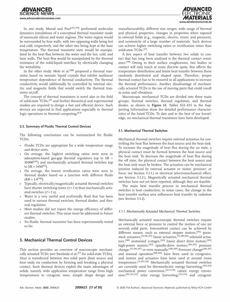
www.advancedsciencenews.comwww.advelectronicmat.de
2000623 (17 of 30) © 2020 The Authors. Advanced Electronic Materials published by Wiley-VCH GmbH
In one study, Murad and Puri[192,193] performed molecular dynamics simulations of a conceptual thermal transistor made of nanoscale silicon and water regions. The water region would be surrounded by four walls, with two opposing walls being hot and cold, respectively, and the other two being kept at the base temperature. The thermal transistor state would be manipu-lated by the heat flux between the water and the hot, cold, and base walls. The heat flux would be manipulated by the thermal resistance of the solid-liquid interface by electrically changing the wettability.
In the other study, Melo et al.[188] proposed a thermal tran-sistor based on nematic liquid crystals that exhibit nonlinear temperature dependence of thermal conductivity. The thermal conductivity would additionally be controlled by external elec-tric and magnetic fields that would switch the thermal tran-sistor on/off.
The concept of thermal transistors is novel also in the field of solid-state TCDs,[37] and further theoretical and experimental studies are required to design a fast and efficient device. Such devices are expected to find applications especially in thermal logic operations in thermal computing.[8,9]
2.5. Summary of Fluidic Thermal Control Devices
The following conclusions can be summarized for fluidic TCDs:
• Fluidic TCDs are appropriate for a wide temperature range and device sizes.
• On average, the highest switching ratios were seen in adsorption-based gas-gap thermal regulators (up to SR = 10 000[142]) and mechanically actuated thermal switches (up to SR = 1450[45]).
• On average, the lowest rectification ratios were seen in thermal diodes based on a junction with different fluids (RR = 1.4[158]).
• Typically, electrically/magnetically actuated thermal switches have shorter switching times (τ < 1 s) than mechanically actu-ated switches (τ > 1 s).
• Water is a very useful and ecofriendly fluid that has been used in various thermal switches, thermal diodes, and ther-mal regulators.
• Most studies did not report the energy efficiency of differ-ent thermal switches. This issue must be addressed in future studies.
• No fluidic thermal transistor has been experimentally tested so far.
3. Mechanical Thermal Control Devices
This section provides an overview of macroscopic mechani-cally actuated TCDs (see Swoboda et al.[37] for solid-state TCDs). Heat is transferred between two solid parts (heat source and heat sink) via conduction by forming and breaking a physical contact. Such thermal devices exploit the main advantages of solids, namely, wide application temperature range from high temperatures to cryogenic ones, simple shape design and
manufacturability, different size ranges, wide range of thermal and physical properties, changes in properties when exposed to external fields (e.g., magnetic, electric, stress, and pressure), and nontoxicity of a large number of materials. Such devices can achieve higher switching ratios or rectification ratios than solid-state TCDs.[37]
A key aspect of heat transfer between two solids in con-tact that has long been analyzed is the thermal contact resist-ance.[194] Owing to their surface roughnesses, two bodies in contact will only touch at some discrete spots; this affects the temperature distribution and limits heat transfer between these randomly distributed and shaped spots. Therefore, proper thermal contact has to be ensured in all applications to increase the thermal performance. Another disadvantage of mechani-cally actuated TCDs is the use of moving parts that could result in noise and vibrations.
Macroscopic mechanical TCDs are divided into three main groups: thermal switches, thermal regulators, and thermal diodes, as shown in Figure 13. Tables S12–S15 in the Sup-porting Information show the detailed performance character-istics of the listed TCDs. To date and to the best of our knowl-edge, no mechanical thermal transistors have been developed.
3.1. Mechanical Thermal Switches
Mechanical thermal switches require external actuation for con-trolling the heat flux between the heat source and the heat sink. To increase the magnitude of heat flux during the on state, a physical contact must be formed between the heat source and the heat sink. To decrease the magnitude of heat flux during the off state, the physical contact between the heat source and the heat sink must be broken. The actuation can be mechanical (motion induced by external actuator or motor, pressure, or force; see Section 3.1.1.) or electrical (electromechanical effect, see Section 3.1.2.). Magnetically actuated mechanical thermal switches have not yet been reported, although they are feasible.
The main heat transfer process in mechanical thermal switches is heat conduction; in some cases, the change in the heat transfer surface area influences heat transfer by radiation (see Section 3.1.2).
3.1.1. Mechanically Actuated Mechanical Thermal Switches
Mechanically actuated macroscopic thermal switches require an external force or pressure to control the motion of one (or several) solid parts. Intermittent contact can be achieved by different means, such as external stepper motors,[195] piezo-stack actuators,[14,196,197] linear actuators,[15,198,199] solenoid actua-tors,[200] motorized z-stages,[201] linear direct drive motors,[202] high-power motors,[203] spindle-drive motors,[204,205] pressure change,[52,206,207] or even manually.[208,209] Pressure change[206,207] and manual operation[208,209] have been used in cryogenics, and motors and actuators have been used at around room temperature.[15,201,210] Mechanically actuated thermal switches are currently used for thermoelectric energy harvesting,[195,203] mechanical power conversion,[14,15,210] caloric energy conver-sion,[201,211,212] solar energy harvesting,[213,214] and cryogenic
Adv. Electron. Mater. 2020, 2000623
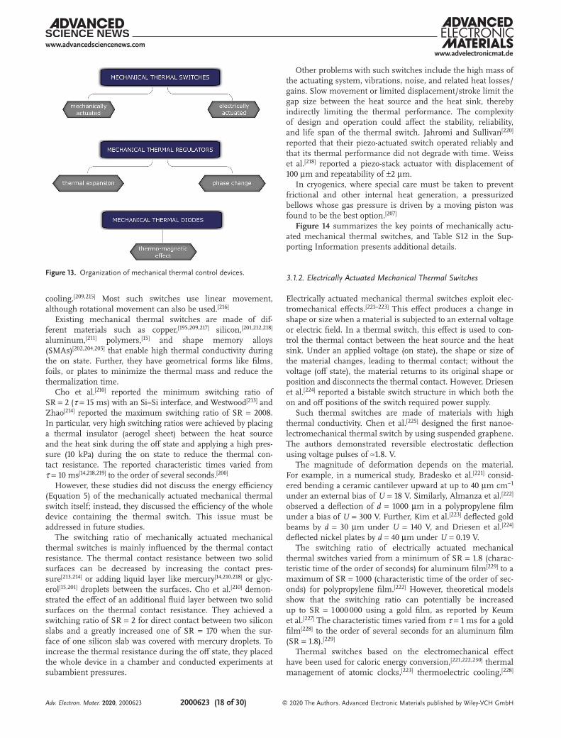
www.advancedsciencenews.comwww.advelectronicmat.de
2000623 (18 of 30) © 2020 The Authors. Advanced Electronic Materials published by Wiley-VCH GmbH
cooling.[209,215] Most such switches use linear movement, although rotational movement can also be used.[216]
Existing mechanical thermal switches are made of dif-ferent materials such as copper,[195,209,217] silicon,[201,212,218] aluminum,[211] polymers,[15] and shape memory alloys (SMAs)[202,204,205] that enable high thermal conductivity during the on state. Further, they have geometrical forms like films, foils, or plates to minimize the thermal mass and reduce the thermalization time.
Cho et al.[210] reported the minimum switching ratio of SR = 2 (τ = 15 ms) with an Si–Si interface, and Westwood[213] and Zhao[214] reported the maximum switching ratio of SR = 2008. In particular, very high switching ratios were achieved by placing a thermal insulator (aerogel sheet) between the heat source and the heat sink during the off state and applying a high pres-sure (10 kPa) during the on state to reduce the thermal con-tact resistance. The reported characteristic times varied from τ = 10 ms[14,218,219] to the order of several seconds.[200]
However, these studies did not discuss the energy efficiency (Equation 5) of the mechanically actuated mechanical thermal switch itself; instead, they discussed the efficiency of the whole device containing the thermal switch. This issue must be addressed in future studies.
The switching ratio of mechanically actuated mechanical thermal switches is mainly influenced by the thermal contact resistance. The thermal contact resistance between two solid surfaces can be decreased by increasing the contact pres-sure[213,214] or adding liquid layer like mercury[14,210,218] or glyc-erol[15,201] droplets between the surfaces. Cho et al.[210] demon-strated the effect of an additional fluid layer between two solid surfaces on the thermal contact resistance. They achieved a switching ratio of SR = 2 for direct contact between two silicon slabs and a greatly increased one of SR = 170 when the sur-face of one silicon slab was covered with mercury droplets. To increase the thermal resistance during the off state, they placed the whole device in a chamber and conducted experiments at subambient pressures.
Other problems with such switches include the high mass of the actuating system, vibrations, noise, and related heat losses/gains. Slow movement or limited displacement/stroke limit the gap size between the heat source and the heat sink, thereby indirectly limiting the thermal performance. The complexity of design and operation could affect the stability, reliability, and life span of the thermal switch. Jahromi and Sullivan[220] reported that their piezo-actuated switch operated reliably and that its thermal performance did not degrade with time. Weiss et al.[218] reported a piezo-stack actuator with displacement of 100 µm and repeatability of ±2 µm.
In cryogenics, where special care must be taken to prevent frictional and other internal heat generation, a pressurized bellows whose gas pressure is driven by a moving piston was found to be the best option.[207]
Figure 14 summarizes the key points of mechanically actu-ated mechanical thermal switches, and Table S12 in the Sup-porting Information presents additional details.
3.1.2. Electrically Actuated Mechanical Thermal Switches
Electrically actuated mechanical thermal switches exploit elec-tromechanical effects.[221–223] This effect produces a change in shape or size when a material is subjected to an external voltage or electric field. In a thermal switch, this effect is used to con-trol the thermal contact between the heat source and the heat sink. Under an applied voltage (on state), the shape or size of the material changes, leading to thermal contact; without the voltage (off state), the material returns to its original shape or position and disconnects the thermal contact. However, Driesen et al.[224] reported a bistable switch structure in which both the on and off positions of the switch required power supply.
Such thermal switches are made of materials with high thermal conductivity. Chen et al.[225] designed the first nanoe-lectromechanical thermal switch by using suspended graphene. The authors demonstrated reversible electrostatic deflection using voltage pulses of ≈1.8. V.
The magnitude of deformation depends on the material. For example, in a numerical study, Bradesko et al.[221] consid-ered bending a ceramic cantilever upward at up to 40 µm cm−1 under an external bias of U = 18 V. Similarly, Almanza et al.[222] observed a deflection of d = 1000 µm in a polypropylene film under a bias of U = 300 V. Further, Kim et al.[223] deflected gold beams by d = 30 µm under U = 140 V, and Driesen et al.[224] deflected nickel plates by d = 40 µm under U = 0.19 V.
The switching ratio of electrically actuated mechanical thermal switches varied from a minimum of SR = 1.8 (charac-teristic time of the order of seconds) for aluminum film[229] to a maximum of SR = 1000 (characteristic time of the order of sec-onds) for polypropylene film.[222] However, theoretical models show that the switching ratio can potentially be increased up to SR = 1 000 000 using a gold film, as reported by Keum et al.[227] The characteristic times varied from τ = 1 ms for a gold film[228] to the order of several seconds for an aluminum film (SR = 1.8).[229]
Thermal switches based on the electromechanical effect have been used for caloric energy conversion,[221,222,230] thermal management of atomic clocks,[223] thermoelectric cooling,[228]
Figure 13. Organization of mechanical thermal control devices.
Adv. Electron. Mater. 2020, 2000623
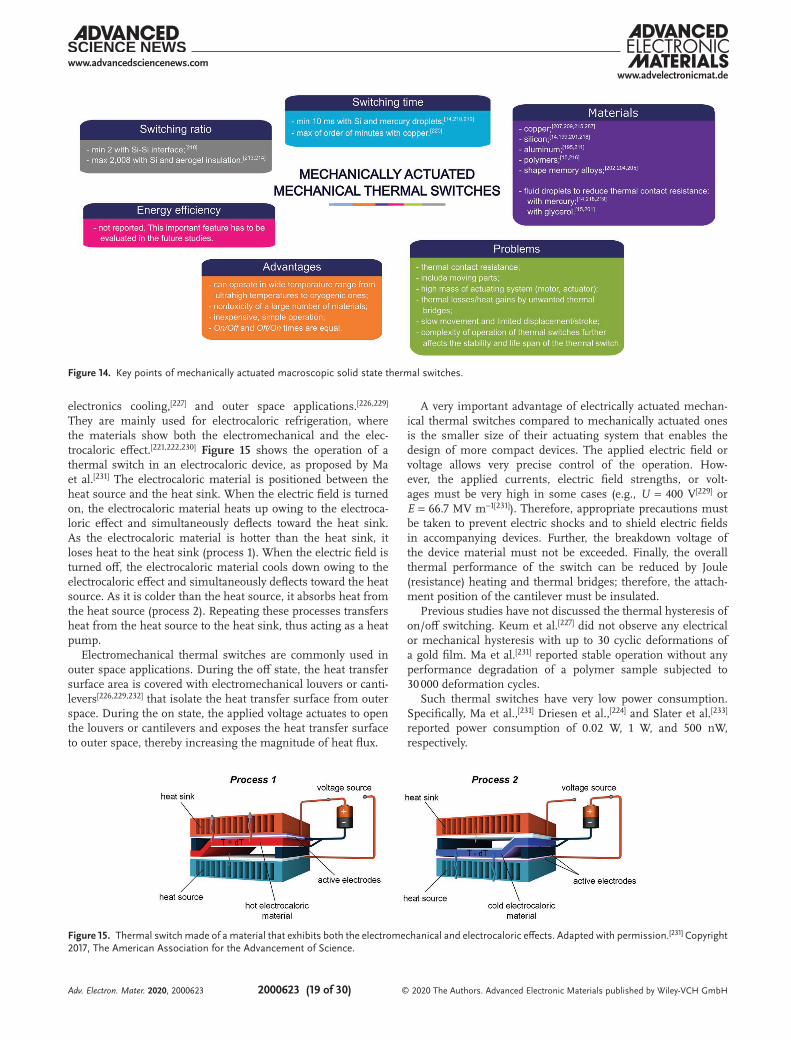
www.advancedsciencenews.comwww.advelectronicmat.de
2000623 (19 of 30) © 2020 The Authors. Advanced Electronic Materials published by Wiley-VCH GmbH
electronics cooling,[227] and outer space applications.[226,229] They are mainly used for electrocaloric refrigeration, where the materials show both the electromechanical and the elec-trocaloric effect.[221,222,230] Figure 15 shows the operation of a thermal switch in an electrocaloric device, as proposed by Ma et al.[231] The electrocaloric material is positioned between the heat source and the heat sink. When the electric field is turned on, the electrocaloric material heats up owing to the electroca-loric effect and simultaneously deflects toward the heat sink. As the electrocaloric material is hotter than the heat sink, it loses heat to the heat sink (process 1). When the electric field is turned off, the electrocaloric material cools down owing to the electrocaloric effect and simultaneously deflects toward the heat source. As it is colder than the heat source, it absorbs heat from the heat source (process 2). Repeating these processes transfers heat from the heat source to the heat sink, thus acting as a heat pump.
Electromechanical thermal switches are commonly used in outer space applications. During the off state, the heat transfer surface area is covered with electromechanical louvers or canti-levers[226,229,232] that isolate the heat transfer surface from outer space. During the on state, the applied voltage actuates to open the louvers or cantilevers and exposes the heat transfer surface to outer space, thereby increasing the magnitude of heat flux.
A very important advantage of electrically actuated mechan-ical thermal switches compared to mechanically actuated ones is the smaller size of their actuating system that enables the design of more compact devices. The applied electric field or voltage allows very precise control of the operation. How-ever, the applied currents, electric field strengths, or volt-ages must be very high in some cases (e.g., U = 400 V[229] or E = 66.7 MV m−1[231]). Therefore, appropriate precautions must be taken to prevent electric shocks and to shield electric fields in accompanying devices. Further, the breakdown voltage of the device material must not be exceeded. Finally, the overall thermal performance of the switch can be reduced by Joule (resistance) heating and thermal bridges; therefore, the attach-ment position of the cantilever must be insulated.
Previous studies have not discussed the thermal hysteresis of on/off switching. Keum et al.[227] did not observe any electrical or mechanical hysteresis with up to 30 cyclic deformations of a gold film. Ma et al.[231] reported stable operation without any performance degradation of a polymer sample subjected to 30 000 deformation cycles.
Such thermal switches have very low power consumption. Specifically, Ma et al.,[231] Driesen et al.,[224] and Slater et al.[233] reported power consumption of 0.02 W, 1 W, and 500 nW, respectively.
Figure 14. Key points of mechanically actuated macroscopic solid state thermal switches.
Figure 15. Thermal switch made of a material that exhibits both the electromechanical and electrocaloric effects. Adapted with permission.[231] Copyright 2017, The American Association for the Advancement of Science.
Adv. Electron. Mater. 2020, 2000623
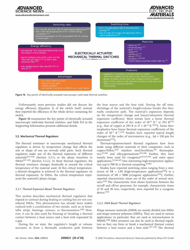
www.advancedsciencenews.comwww.advelectronicmat.de
2000623 (20 of 30) © 2020 The Authors. Advanced Electronic Materials published by Wiley-VCH GmbH
Unfortunately, most previous studies did not discuss the energy efficiency (Equation 5) of the switch itself; instead, they reported the efficiency of the whole device containing the switch.Figure 16 summarizes the key points of electrically actuated
macroscopic solid-state thermal switches, and Table S13 in the Supporting Information presents additional details.
3.2. Mechanical Thermal Regulators
The thermal resistance in macroscopic mechanical thermal regulators is driven by temperature change that affects the size or shape of one (or several) solid parts. Such thermal regulators make use of the thermal expansion of different materials[234–236] (Section 3.2.1.) or the phase transition in SMAs[237–239] (Section 3.2.2.). In these thermal regulators, the thermal resistance changes drastically at around the critical temperature of the material used. At this critical temperature, a desired elongation is achieved in the thermal regulators via thermal expansion. In SMAs, the critical temperature repre-sents the material’s phase change.
3.2.1. Thermal-Expansion-Based Thermal Regulators
This section describes mechanical thermal regulators that expand or contract during heating or cooling but are not con-sidered SMAs. This phenomenon has already been widely realized with a combination of two metals, such as in bime-tallic strips, bearings, sensors, or thermometers.[240] How-ever, it can be also used for forming or breaking a thermal contact between a heat source and a heat sink separated by a gap.
During the on state, the regulator’s length or volume increases to form a thermally conductive path between
the heat source and the heat sink. During the off state, shrinkage of the material’s length/volume breaks this ther-mally conductive path. The material’s expansion depends on the temperature change and linear/volumetric thermal expansion coefficient. Most metals have a linear thermal expansion coefficient of the order of 10−6 K−1 at 293 K[241] (e.g., that of copper at 293 K is 17 × 10−6 K−1[241]). Some ther-moplastics have linear thermal expansion coefficients of the order of 10−4 K−1.[242] Studies have reported typical length changes of the order of micrometers (e.g., Δd = 130 µm for aluminum[235]).
Thermal-expansion-based thermal regulators have been made using different materials or their composites, such as copper/Teflon,[243] stainless steel/beryllium,[45] thermoplas-tics,[11,244] and silica/germanium.[245,246] Further, they have mainly been used for cryogenics[234,235,243] and outer space applications.[11,244,247] One interesting high-temperature applica-tion (up to 700 K) is thermal computing.[9,246]
Studies have reported switching ratios ranging from a min-imum of SR = 1.09 (high-temperature applications[246]) to a maximum of SR = 5000 (cryogenic applications[235]). Further, reported characteristic times are of the order of several min-utes.[239] The characteristic time shows hysteresis between the on/off and off/on processes; for example, characteristic times of 45 and 18 min, respectively, were reported for a cryogenic device.[234]
3.2.2. SMA-Based Thermal Regulators
Shape memory materials (SMM) are mainly divided into SMAs and shape memory polymers (SMPs). They are used in various applications; in particular, they are used as microactuators in MEMS.[248] SMA actuators can also be used as thermal regula-tors as they can form or break a mechanical thermal contact between a heat source and a heat sink.[237–239] The thermal
Figure 16. Key points of electrically actuated macroscopic solid state thermal switches.
Adv. Electron. Mater. 2020, 2000623
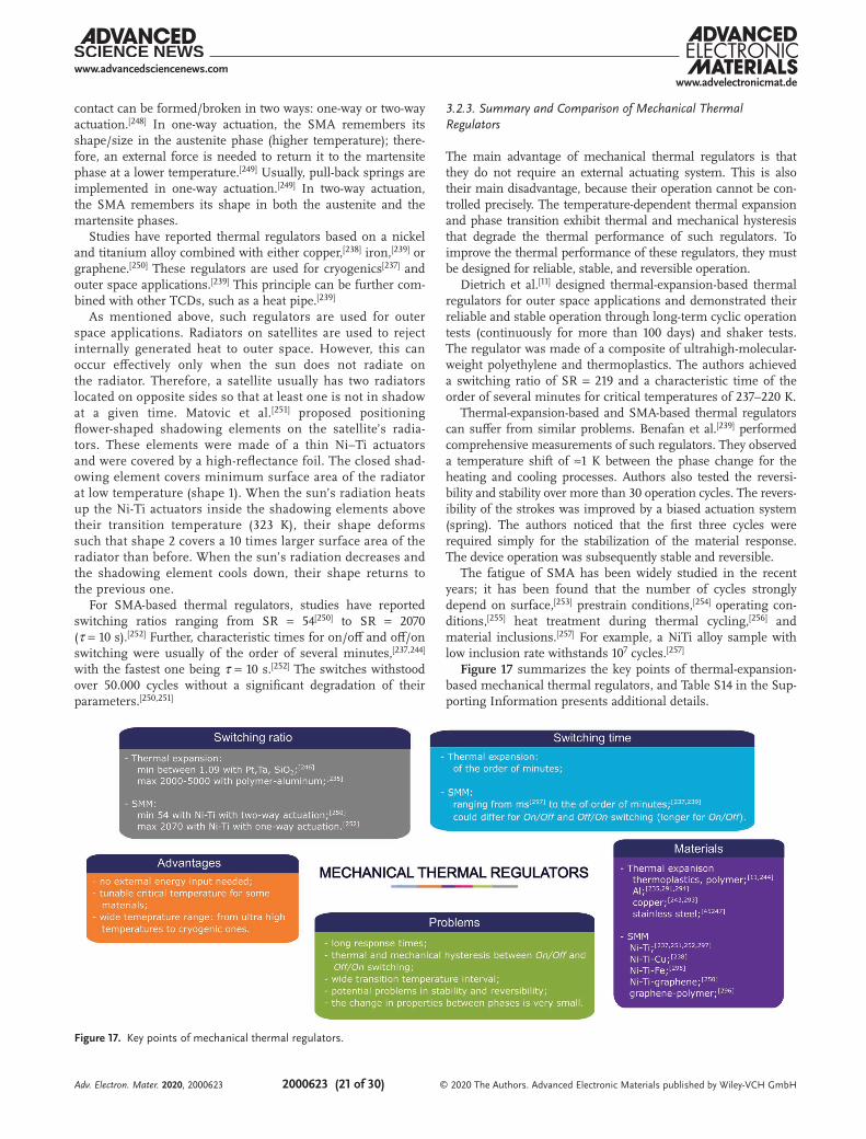
www.advancedsciencenews.comwww.advelectronicmat.de
2000623 (21 of 30) © 2020 The Authors. Advanced Electronic Materials published by Wiley-VCH GmbH
contact can be formed/broken in two ways: one-way or two-way actuation.[248] In one-way actuation, the SMA remembers its shape/size in the austenite phase (higher temperature); there-fore, an external force is needed to return it to the martensite phase at a lower temperature.[249] Usually, pull-back springs are implemented in one-way actuation.[249] In two-way actuation, the SMA remembers its shape in both the austenite and the martensite phases.
Studies have reported thermal regulators based on a nickel and titanium alloy combined with either copper,[238] iron,[239] or graphene.[250] These regulators are used for cryogenics[237] and outer space applications.[239] This principle can be further com-bined with other TCDs, such as a heat pipe.[239]
As mentioned above, such regulators are used for outer space applications. Radiators on satellites are used to reject internally generated heat to outer space. However, this can occur effectively only when the sun does not radiate on the radiator. Therefore, a satellite usually has two radiators located on opposite sides so that at least one is not in shadow at a given time. Matovic et al.[251] proposed positioning flower-shaped shadowing elements on the satellite’s radia-tors. These elements were made of a thin Ni–Ti actuators and were covered by a high-reflectance foil. The closed shad-owing element covers minimum surface area of the radiator at low temperature (shape 1). When the sun’s radiation heats up the Ni-Ti actuators inside the shadowing elements above their transition temperature (323 K), their shape deforms such that shape 2 covers a 10 times larger surface area of the radiator than before. When the sun’s radiation decreases and the shadowing element cools down, their shape returns to the previous one.
For SMA-based thermal regulators, studies have reported switching ratios ranging from SR = 54[250] to SR = 2070 (τ = 10 s).[252] Further, characteristic times for on/off and off/on switching were usually of the order of several minutes,[237,244] with the fastest one being τ = 10 s.[252] The switches withstood over 50.000 cycles without a significant degradation of their parameters.[250,251]
3.2.3. Summary and Comparison of Mechanical Thermal Regulators
The main advantage of mechanical thermal regulators is that they do not require an external actuating system. This is also their main disadvantage, because their operation cannot be con-trolled precisely. The temperature-dependent thermal expansion and phase transition exhibit thermal and mechanical hysteresis that degrade the thermal performance of such regulators. To improve the thermal performance of these regulators, they must be designed for reliable, stable, and reversible operation.
Dietrich et al.[11] designed thermal-expansion-based thermal regulators for outer space applications and demonstrated their reliable and stable operation through long-term cyclic operation tests (continuously for more than 100 days) and shaker tests. The regulator was made of a composite of ultrahigh-molecular-weight polyethylene and thermoplastics. The authors achieved a switching ratio of SR = 219 and a characteristic time of the order of several minutes for critical temperatures of 237–220 K.
Thermal-expansion-based and SMA-based thermal regulators can suffer from similar problems. Benafan et al.[239] performed comprehensive measurements of such regulators. They observed a temperature shift of ≈1 K between the phase change for the heating and cooling processes. Authors also tested the reversi-bility and stability over more than 30 operation cycles. The revers-ibility of the strokes was improved by a biased actuation system (spring). The authors noticed that the first three cycles were required simply for the stabilization of the material response. The device operation was subsequently stable and reversible.
The fatigue of SMA has been widely studied in the recent years; it has been found that the number of cycles strongly depend on surface,[253] prestrain conditions,[254] operating con-ditions,[255] heat treatment during thermal cycling,[256] and material inclusions.[257] For example, a NiTi alloy sample with low inclusion rate withstands 107 cycles.[257]
Figure 17 summarizes the key points of thermal-expansion-based mechanical thermal regulators, and Table S14 in the Sup-porting Information presents additional details.
Figure 17. Key points of mechanical thermal regulators.
Adv. Electron. Mater. 2020, 2000623
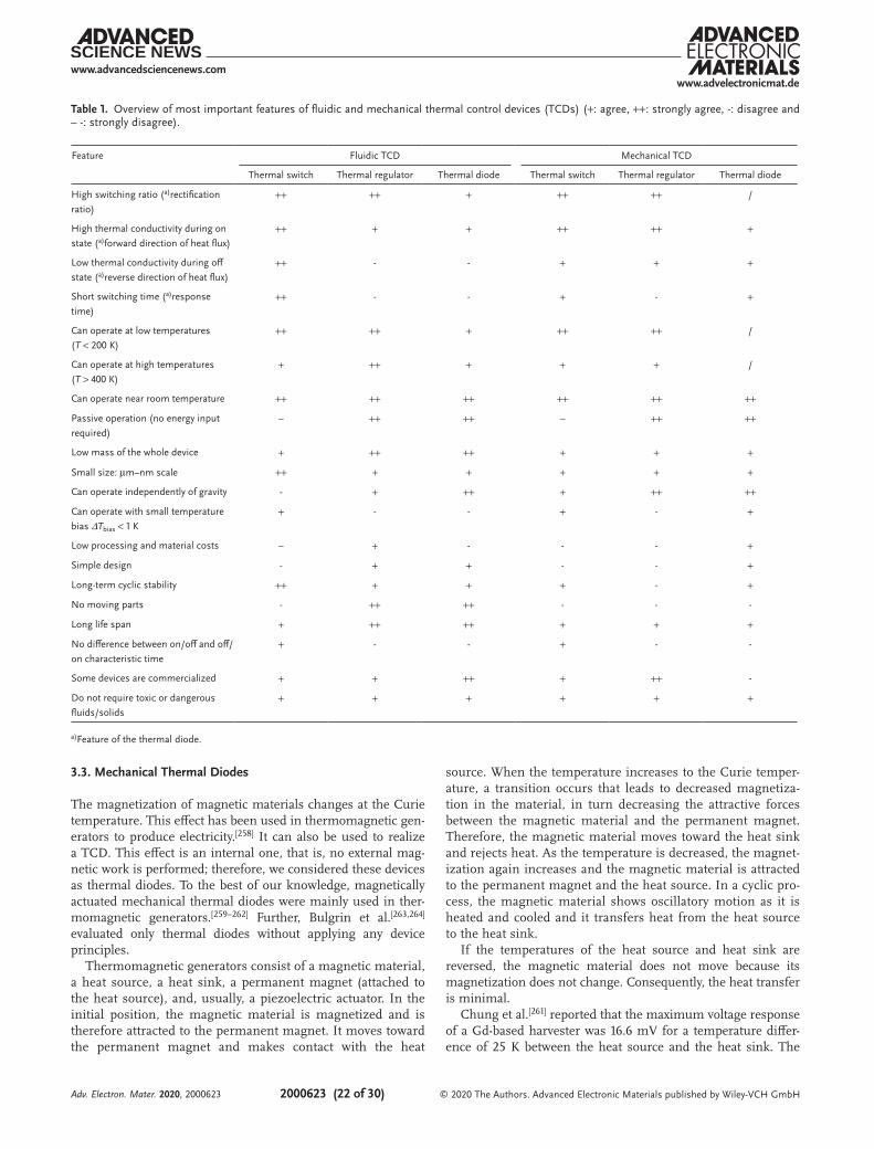
www.advancedsciencenews.comwww.advelectronicmat.de
2000623 (22 of 30) © 2020 The Authors. Advanced Electronic Materials published by Wiley-VCH GmbH
3.3. Mechanical Thermal Diodes
The magnetization of magnetic materials changes at the Curie temperature. This effect has been used in thermomagnetic gen-erators to produce electricity.[258] It can also be used to realize a TCD. This effect is an internal one, that is, no external mag-netic work is performed; therefore, we considered these devices as thermal diodes. To the best of our knowledge, magnetically actuated mechanical thermal diodes were mainly used in ther-momagnetic generators.[259–262] Further, Bulgrin et al.[263,264] evaluated only thermal diodes without applying any device principles.
Thermomagnetic generators consist of a magnetic material, a heat source, a heat sink, a permanent magnet (attached to the heat source), and, usually, a piezoelectric actuator. In the initial position, the magnetic material is magnetized and is therefore attracted to the permanent magnet. It moves toward the permanent magnet and makes contact with the heat
source. When the temperature increases to the Curie temper-ature, a transition occurs that leads to decreased magnetiza-tion in the material, in turn decreasing the attractive forces between the magnetic material and the permanent magnet. Therefore, the magnetic material moves toward the heat sink and rejects heat. As the temperature is decreased, the magnet-ization again increases and the magnetic material is attracted to the permanent magnet and the heat source. In a cyclic pro-cess, the magnetic material shows oscillatory motion as it is heated and cooled and it transfers heat from the heat source to the heat sink.
If the temperatures of the heat source and heat sink are reversed, the magnetic material does not move because its magnetization does not change. Consequently, the heat transfer is minimal.
Chung et al.[261] reported that the maximum voltage response of a Gd-based harvester was 16.6 mV for a temperature differ-ence of 25 K between the heat source and the heat sink. The
Table 1. Overview of most important features of fluidic and mechanical thermal control devices (TCDs) (+: agree, ++: strongly agree, -: disagree and – -: strongly disagree).
Feature Fluidic TCD Mechanical TCD
Thermal switch Thermal regulator Thermal diode Thermal switch Thermal regulator Thermal diode
High switching ratio (a)rectification ratio)
++ ++ + ++ ++ /
High thermal conductivity during on state (a)forward direction of heat flux)
++ + + ++ ++ +
Low thermal conductivity during off state (a)reverse direction of heat flux)
++ - - + + +
Short switching time (a)response time)
++ - - + - +
Can operate at low temperatures (T < 200 K)
++ ++ + ++ ++ /
Can operate at high temperatures (T > 400 K)
+ ++ + + + /
Can operate near room temperature ++ ++ ++ ++ ++ ++
Passive operation (no energy input required)
– ++ ++ – ++ ++
Low mass of the whole device + ++ ++ + + +
Small size: µm–nm scale ++ + + + + +
Can operate independently of gravity - + ++ + ++ ++
Can operate with small temperature bias ΔTbias < 1 K
+ - - + - +
Low processing and material costs – + - - - +
Simple design - + + - - +
Long-term cyclic stability ++ + + + - +
No moving parts - ++ ++ - - -
Long life span + ++ ++ + + +
No difference between on/off and off/on characteristic time
+ - - + - -
Some devices are commercialized + + ++ + ++ -
Do not require toxic or dangerous fluids/solids
+ + + + + +
a)Feature of the thermal diode.
Adv. Electron. Mater. 2020, 2000623
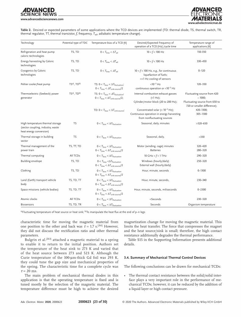
www.advancedsciencenews.comwww.advelectronicmat.de
2000623 (23 of 30) © 2020 The Authors. Advanced Electronic Materials published by Wiley-VCH GmbH
characteristic time for moving the magnetic material from one position to the other and back was τ = 1.7 s.[261] However, they did not discuss the rectification ratio and other thermal parameters.
Bulgrin et al.[263] attached a magnetic material to a spring to enable it to return to the initial position. Authors set the temperature of the heat sink to 273 K and varied that of the heat source between 273 and 523 K. Although the Curie temperature of the 100-µm-thick Gd foil was 293 K, they could tune the gap size and mechanical properties of the spring. The characteristic time for a complete cycle was τ = 20 ms.
The main problem of mechanical thermal diodes in this application is that the operating temperature is fixed and is tuned mostly by the selection of the magnetic material. The temperature difference must be high to achieve the desired
magnetization change for moving the magnetic material. This limits the heat transfer. The force that compresses the magnet and the heat source/sink is small; therefore, the high contact resistance additionally degrades the thermal performance.
Table S15 in the Supporting Information presents additional details.
3.4. Summary of Mechanical Thermal Control Devices
The following conclusions can be drawn for mechanical TCDs:
• The thermal contact resistance between the solid/solid inter-face plays a very important role in the performance of me-chanical TCDs; however, it can be reduced by the addition of a liquid layer or high contact pressure.
Table 2. Desired or expected parameters of some applications where the TCD devices are implemented (TD: thermal diode, TS, thermal switch, TR, thermal regulator, TT, thermal transistor, f, frequency, Tad, adiabatic temperature change).
Technology Potential type of TDC Temperature bias of a TCD [K] Desired/Expected Frequency of operation of a TCD [Hz] /cycle time
Temperature range of applications [K]
Refrigeration and heat pump caloric technologies
TS, TD 0 < Tbias < ΔTad 10 < f < 100 Hz 150-350
Energy harvesting by Caloric technologies
TS, TD 0 < Tbias < ΔTad 10 < f < 100 Hz 330–450
Cryogenics by Caloric technologies
TS, TD 0 < Tbias < ΔTad 10 < f < 100 Hz, e.g., for continuous liquefaction of fuels;
<<1 Hz cooling of sensors
0–120
Peltier cooler/heat pump TSa), TDb) TS: 0 < Tbias < ΔTfluctuation;0 < Tbias < ΔTsink-source/2
<10−3 Hzcontinuous operation or <10−3 Hz
120–350
Thermoelectric (Seebeck) power generator
TSa), TDb) TS: 0 < Tbias < ΔTfluctuation;0 < Tbias < ΔTsink-source/2;
TD: 0 < Tbias < ΔTsink-source;
Internal combustion exhaust gasses(<1 Hz);
Cylinder/motor block (20 to 200 Hz);
Concentrated solar (< 10−3 Hz);Continuous operation in energy harvesting
from nonfluctuating sources
Fluctuating source from 420 – 1000;
Fluctuating source from 650 to 720 or smaller difference);
420–1300;305–1300
High temperature thermal storage (sector coupling, industry, waste heat energy conversion)
TS 0 < Tbias < ΔTfluctuation Seasonal, daily, minutes >320–650
Thermal storage in building sector
TS 0 < Tbias < ΔTfluctuation Seasonal, daily, <330
Thermal management of the power train
TS, TT, TD 0 < Tbias < ΔTfluctuation
0 < Tbias < ΔTsink-source/2Motor (winding, cage) minutes
Batteries320–420280–320
Thermal computing All TCDs 0 < Tbias < ΔTfluctuation 10 GHz < f < 1 THz 290–320
Building envelope TS, TD 0 < Tbias <ΔTfluctuation
0 < Tbias < ΔTsink-source/2Windows (hourly/daily)
External wall (hourly/daily)250–320
Clothing TS, TD 0 < Tbias < ΔTfluctuation
0 < Tbias < ΔTsink-source/2Hour, minute, seconds 0–1300
Land (Earth) transport vehicle body
TS, TD, TT 0 < Tbias < ΔTfluctuation
0 < Tbias < ΔTsink-source/2Hour, minute, seconds, 230–340
Space missions (vehicle bodies) TS, TD, TT 0 < Tbias < ΔTfluctuation
0 < Tbias < ΔTsink-source/2Hour, minute, seconds, miliseconds 0–2300
Atomic clocks All TCDs 0 < Tbias < ΔTfluctuation <Seconds 230–320
Biosensors TS, TD, TR 0 < Tbias < ΔTfluctuation Seconds Organism temperature
a)Fluctuating temperature of heat source or heat sink; b)To manipulate the heat flux at the end of p–n legs
Adv. Electron. Mater. 2020, 2000623
www.advancedsciencenews.comwww.advelectronicmat.de
2000623 (24 of 30) © 2020 The Authors. Advanced Electronic Materials published by Wiley-VCH GmbH
• On average, the highest switching ratios were experimentally achieved for thermal-expansion-based thermal regulators (up to SR = 5000[235]).
• The lowest switching ratios were experimentally achieved with electrically actuated thermal switches (down to SR = 1.8[229]).
• Typically, mechanically and electrically actuated thermal switches enable very short switching times of the order of milliseconds.
• Most studies did not report the energy efficiency of the differ-ent types of thermal switches. This issue should be addressed in future studies.
• Mechanical TCDs are appropriate for a wide temperature range and device sizes.
4. Conclusion
This paper reviews the state-of-the art of fluidic and mechanical TCDs that are expected to be used in future thermal manage-ment applications. It aims to provide key information about the physical background, applied materials, operation princi-ples, and thermal characteristics required to design a TCD for a specific application. This area has seen intensive studies; non-etheless, novel approaches could possibly realize unique TCDs with outstanding performance in the future.Table 1 provides a comparative overview of the characteristics
of different fluidic and mechanical TCDs. This comparison is generalized because the operating mechanisms can differ greatly even within the same group of thermal switches, thermal regula-tors, or thermal diodes. A particular advantage or disadvantage is noted based on the reported experimental results for TCDs.
Fluidic and mechanical TCD are already established devices, while solid-state TCD have lately received increased attention due to the recent advances in the field.[37] Solid-state phe-nomena exhibit high potential for thermal control, especially at the nanoscale. The performance of solid-state TCD is typically lower than in fluidic and mechanical devices. However, they present unique advantages like no need of moving parts, reli-able operation, and scalability. This field could bring exciting opportunities in the area of thermal computing[8,9,265–267] and energy management, conversion and storage.[268,269] A gen-eral comparison of fluidic and mechanical TCD with solid-state devices is shown in Table S1 in Supporting Informa-tion. Future studies of fluidic and mechanical TCDs should verify promising numerical results through experiments, pro-duce devices with different dimensions and different geom-etries, and discover new operation principles and materials for increasing the switching (rectification) ratio and decreasing the switching (response) time. Further, because most TCDs are used in thermal management applications, their energy effi-ciency (Equation 5) should be determined. Other important parameters that can be considered include the life span, cyclic stability, environmental impact, and, in the case of further com-mercialization, the technology readiness level, production costs, and manufacturing complexity. Recent developments in rapid prototyping for electronics, MEMS, and microfluidics[270,271] have provided various new possibilities for manufacturing TCDs relatively inexpensively.
On the one hand, most of the applications require of TCD with the highest possible switching or rectification ratios for improved system performance. On the other hand, the desired operating frequencies (response times) of TCD must be also known to determine the area of applicability. In Table 2 we have listed the desired or expected requirements of some technolo-gies that could benefit greatly from TCD.
Overall, previous studies in this field have made numerous breakthroughs and developed and tested promising principles for benefiting thermal management applications of the future. The information reviewed and summarized in the present paper should motivate and inspire researchers to make further advances and innovations in the field of TCDs. These can cer-tainly be achieved through complementary-interdisciplinary research collaboration between different research domains and different research groups.
Supporting InformationSupporting Information is available from the Wiley Online Library or from the author.
AcknowledgementsThe authors acknowledge the financial support of the Slovenian Research Agency for the projects Electrocaloric devices for active cooling of electronic circuits J2-1738 and Multicaloric Cooling J2-9253 and the research core funding No. P2-0223.
The authors acknowledge the financial support of the Rectorates University of Twente (UT) & University of Münster (WWU) for the Decision Strategic Collaboration Grants – University of Twente and University of Münster 2019–2020, (reference number: CvB UIT-4395).
Conflict of InterestThe authors declare no conflict of interest.
Keywordsheat transfer, thermal diodes, thermal management, thermal regulators, thermal switches
Received: June 16, 2020Revised: November 12, 2020
Published online:
[1] G. E. Moore, Electronics 1965, 38, 8.[2] H. Zhang, F. Che, T. Lin, W. Zhao, H. Zhang, F. Che, T. Lin,
W. Zhao, Modeling, Analysis, Design, and Tests for Electronics Packaging beyond Moore, Elsevier Inc., Duxford, UK 2019.
[3] J. Kaur, Int. J. Comput. Sci. Mobile Comput. 2016, 56, 233.[4] G. Wehmeyer, T. Yabuki, C. Monachon, J. Wu, C. Dames, Appl.
Phys. Rev. 2017, 4, 041304.[5] N. A. Roberts, D. G. Walker, Int. J. Therm. Sci. 2011, 50, 648.[6] C. Starr, J. Appl. Phys. 1936, 7, 15.[7] K. Kim, M. Kaviany, Phys. Rev. B 2016, 94, 155203.
Adv. Electron. Mater. 2020, 2000623
www.advancedsciencenews.comwww.advelectronicmat.de
2000623 (25 of 30) © 2020 The Authors. Advanced Electronic Materials published by Wiley-VCH GmbH
[8] N. Li, J. Ren, L. Wang, G. Zhang, P. Hänggi, B. Li, Rev. Mod. Phys. 2012, 84, 1045.
[9] A. Hamed, M. Elzouka, S. Ndao, Int. J. Heat Mass Transfer 2019, 134, 359.
[10] Q. S. Shu, J. A. Demko, J. E. Fesmire, IOP Conf. Ser.: Mater. Sci. Eng. 2017, 278, 012133.
[11] M. Dietrich, A. Euler, G. Thummes, Cryogenics 2017, 83, 31.[12] M. Li, L. Li, D. Xu, J. Phys. Conf. Ser. 2017, 897, 012016.[13] J. H. Cho, L. W. Weiss, C. D. Richards, D. F. Bahr, R. F. Richards,
J. Micromech. Microeng. 2007, 17, S217.[14] H. K. Bardaweel, M. J. Anderson, R. F. Richards, C. D. Richards,
J. Micromech. Microeng. 2008, 18, 104014.[15] G. Cha, Y. S. Ju, Sens. Actuators, A 2013, 189, 100.[16] K. Klinar, A. Kitanovski, Renewable Sustainable Energy Rev. 2020,
118, 109571.[17] A. Kitanovski, J. Tušek, U. Tomc, U. Plaznik, M. Ožbolt,
A. Poredoš, Magnetocaloric Energy Conversion, Springer International Publishing, Switzerland, 2015.
[18] M. Almanza, L. Depreux, F. Parrain, M. Lobue, M. Almanza, L. Depreux, F. Parrain, M. Lobue, M. Almanza, L. Depreux, F. Parrain, M. Lobue, Appl. Phys. Lett. 2018, 112, 083901.
[19] Y. Zhang, N. T. Nguyen, Lab Chip 2017, 17, 994.[20] Z. Yan, M. Jin, Z. Li, G. Zhou, L. Shui, Micromachines 2019, 10, 1.[21] J. Jeon, J. B. Lee, S. K. Chung, D. Kim, Lab Chip 2017, 17, 128.[22] G. A. Miño-Galaz, J. Phys. Chem. B 2015, 119, 6179.[23] G. T. Craven, D. He, A. Nitzan, Phys. Rev. Lett. 2018, 121, 247704.[24] L. Medrano Sandonas, R. Gutierrez, A. Dianat, G. Cuniberti, RSC
Adv. 2015, 5, 54345.[25] W. Chun, Y. J. Ko, H. J. Lee, H. Han, J. T. Kim, K. Chen, Sol. Energy
2009, 83, 409.[26] A. Hemaida, A. Ghosh, S. Sundaram, T. K. Mallick, Sol. Energy
2020, 195, 185.[27] C. Marco, in Proc. of the Second Int. Conf. on Advances in Civil,
Structural, and Environmental Engineering (Ed: R. Kumar), Institute of Research Engineers and Doctors, New York, USA 2014.
[28] H. Cui, M. Overend, Energy Build. 2019, 199, 427.[29] M. Pauken, E. Sunada, K. Novak, C. Phillips, G. Birur, K. Lankford,
in Proc. of 32nd International Conference on Environmental Systems, SAE International, San Antonio, Texas, Warrendale, PA 2002.
[30] K. Lankford, in Spacecraft thermal control handbook, Vol. 1 (Ed: D. G. Gilmore), Knovel, Norwich, NY, US 2007, Ch. 10, pp 353–371.
[31] X. Geng, P. Patel, A. Narain, D. D. Meng, J. Micromech. Microeng. 2011, 21, 085018.
[32] S. Wang, A. L. Cottrill, Y. Kunai, A. R. Toland, P. Liu, W. J. Wang, M. S. Strano, Phys. Chem. Chem. Phys. 2017, 19, 13172.
[33] M. O. Kimball, P. J. Shirron, E. R. Canavan, J. G. Tuttle, A. E. Jahromi, M. J. Dipirro, B. L. James, M. A. Sampson, R. V. Letmate, IOP Conf. Ser.: Mater. Sci. Eng. 2017, 278, 012010.
[34] D. W. Hengeveld, J. E. Braun, M. M. Mathison, E. A. Groll, A. D. Williams, HVAC&R Res 2010, 16, 189.
[35] J. Meseguer, I. Pérez-Grande, A. Sanz-Andrés, Spacecraft Thermal Control, Woodhead Publishing Limited, Cambridge, UK 2012.
[36] W. Chun, S. J. Oh, H. Han, J. T. Kim, Int. J. Low- Carbon Technol. 2008, 2, 83.
[37] T. Swoboda, K. Klinar, A. S. Yalamarthy, A. Kitanovski, M. M. Rojo, Adv. Electron. Mater., https://doi.org/10.1002/aelm.202000625.
[38] S. H. Jeong, W. Nakayama, J. Y. Joo, S. K. Lee, IEEE Trans. Compon. Packag. Technol. 2009, 32, 100.
[39] M. Elsahati, H. Liu, R. F. Richards, Appl. Phys. Lett. 2019, 114.[40] S. H. Jeong, S. K. Nam, W. Nakayama, S. K. Lee, Appl. Therm. Eng.
2013, 59, 283.[41] S. Dermenakis, Master Thesis, Delft University of Technology, 2016.[42] T. Yang, B. Kwon, P. B. Weisensee, J. G. Kang, X. Li, P. Braun,
N. Miljkovic, W. P. King, Appl. Phys. Lett. 2018, 112, 063505.
[43] T. Yang, T. Foulkes, B. Kwon, J. G. Kang, P. V. Braun, W. P. King, N. Miljkovic, IEEE Trans. Compon. Packag. Manuf. Technol. 2019, 9, 2341.
[44] R. P. Bywaters, R. A. Griffin, Cryogenics 1973, 13, 6.[45] B. Marland, D. Bugby, C. Stouffer, AIP Conf. Proc. 2000, 504, 837.[46] S. H. Jeong, W. Nakayama, S. K. Lee, Appl. Therm. Eng. 2012, 39,
151.[47] J. Gong, G. Cha, Y. S. Ju, C. J. Kim, in Proc. IEEE Int. Conf. on
Micro Electro Mechanical Systems, MEMS (Eds: O. Brand, Y. Zohar), IEEE, Piscataway, NJ 2008, pp. 848–851.
[48] M. Chau, B. A. F. Kopera, V. R. Machado, S. M. Tehrani, M. A. Winnik, E. Kumacheva, M. Retsch, Mater. Horiz. 2017, 4, 236.
[49] M. A. R. Krielaart, C. H. Vermeer, S. Vanapalli, Rev. Sci. Instrum. 2015, 86, 115116.
[50] A. D. Williams, S. E. Palo, Proc. SPIE 2006, 6221, 622108.[51] A. D. Williams, A. Ave, K. Afb, S. E. Palo, in Proc. 20th Annual
AIAA/USU Conf. on Small Satellites (Eds: P. L. Patterson, R. H. Meurer), AIAA, Logan, UT 2006, pp. 1–11.
[52] S. Hirasawa, T. Kawanami, K. Shirai, Am. J. Phys. Appl. 2016, 4, 134.[53] S. Hirasawa, T. Kawanami, K. Shirai, J. Electron. Cool. Therm. Con-
trol 2016, 06, 78.[54] M. Z. Bazant, J. Fluid Mech. 2015, 782, 1.[55] H. Senftleben, W. Braun, Z. Phys. 1936, 102, 480.[56] P. H. G. Allen, T. G. Karayiannis, Heat Recovery Syst. CHP 1995, 15,
389.[57] I. W. Eames, H. M. Sabir, Appl. Therm. Eng. 1997, 17, 79.[58] E. D. Fylladitakis, M. P. Theodoridis, A. X. Moronis, IEEE Trans.
Plasma Sci. 2014, 42, 358.[59] A. Castellanos, Electrohydrodynamics, Springer Verlag GMBH, Wien
1998.[60] M. P. Hehlen, A. H. Mueller, N. R. Weisse-Bernstein, R. I. Epstein,
Proc. SPIE 2013, 86380D-1.[61] W. J. Tomothy, B. J. Dirk, Nat. Mater. 2015, 14, 1087.[62] F. Rondelez, W. Urbach, H. Hervet, Am. Phys. Soc. 1978, 41, 1058.[63] R. I. Epstein, K. J. Malloy, J. Appl. Phys. 2009, 106, 064509.[64] A. H. Sahraoui, S. Delenclos, S. Longuemart, D. Dadarlat, J. Appl.
Phys. 2011, 110, 083117.[65] S. Fumeron, E. Pereira, F. Moraes, Phys. Rev. E: Stat., Nonlinear,
Soft Matter Phys. 2014, 89, 020501.[66] P. Dhar, L. S. Maganti, A. R. Harikrishnan, Soft Matter 2018, 14,
4278.[67] P. Dhar, L. Lakshmi Sirisha, A. R. Harikrishnan, R. Chandan, Exp.
Therm. Fluid Sci. 2019, 106, 138.[68] J. Wang, T. Zhu, Y. Xi Cai, J. Fei Zhang, J. Bo Wang, Int. J. Heat
Mass Transf. 2020, 152, 119545.[69] D. B. Go, R. A. Maturana, T. S. Fisher, S. V. Garimella, Int. J. Heat
Mass Transf. 2008, 51, 6047.[70] K. Yoshida, Energies 2019, 12, 2963.[71] E. Samiei, M. Tabrizian, M. Hoorfar, Lab Chip 2016, 16, 2376.[72] A. Tröls, S. Clara, B. Jakoby, Sens. Actuators, A 2016, 244, 261.[73] D. W.-Y. Chung, Y.-S. Tsai, S.-G. Miaou, W. H. Chang, Y.-J. Chang,
S.-C. Chen, Y. Y. Hong, C. S. Chyang, Q.-S. Chang, H.-Y. Hsu, J. Hsu, W.-C. Yao, M.-S. Hsu, M.-C. Chen, S.-C. Lee, C. Hsu, L. Miao, K. Byrd, M. F. Chouikha, X.-B. Gu, P. C. Wang, H. Szu, Proc. SPIE 2007, 6576, 65760R.
[74] N. T. Nguyen, M. Hejazian, C. H. Ooi, N. Kashaninejad, Microma-chines 2017, 8, 186.
[75] N. T. Nguyen, S. T. Wereley, Fundamentals and Applications of Microfluidcs, Artech House Inc., Norwood, MA 2006.
[76] G. Cha, C. J. Kim, Y. S. Ju, Appl. Therm. Eng. 2016, 98, 189.[77] A. R. McLanahan, C. D. Richards, R. F. Richards, J. Micromech.
Microeng. 2011, 21, 104009.[78] A. R. McLanahan, A. Hamdan, C. Richards, R. Richards,
M. Science, in Proc. PowerMEMS 2009 (Ed: R. Ghodssi), Transducer Research Foundation, San Diego 2009, pp. 534–537.
Adv. Electron. Mater. 2020, 2000623
www.advancedsciencenews.comwww.advelectronicmat.de
2000623 (26 of 30) © 2020 The Authors. Advanced Electronic Materials published by Wiley-VCH GmbH
[79] W. C. Nelson, C. C. J. Kim, J. Adhes. Sci. Technol. 2012, 26, 1747.[80] H. J. Cho, J. P. Mizerak, E. N. Wang, Nat. Commun. 2015, 6, 1.[81] J. Oh, P. Birbarah, T. Foulkes, S. L. Yin, M. Rentauskas, J. Neely,
R. C. N. Pilawa-Podgurski, N. Miljkovic, Appl. Phys. Lett. 2017, 110, 123107.
[82] B. Traipattanakul, C. Y. Tso, C. Y. H. Chao, Int. J. Heat Mass Transf. 2019, 135, 294.
[83] D. Li, Encyclopedia of Microfluidics and Nanofluidics, Springer, NY 2008.
[84] N. T. Nguyen, Microfluid. Nanofluid. 2012, 12, 1.[85] R. E. Rosensweig, Ferrohydrodynamics, Cambridge University
Press, Cambridge 1985.[86] R. Azizian, E. Doroodchi, T. McKrell, J. Buongiorno, L. W. Hu,
B. Moghtaderi, Int. J. Heat Mass Transf. 2014, 68, 94.[87] J. Philip, P. D. Shima, B. Raj, Appl. Phys. Lett. 2008, 92, 043108.[88] M. Sheikholeslami, H. B. Rokni, Int. J. Heat Mass Transf. 2017, 115,
1203.[89] B. N. Reinecke, J. W. Shan, K. K. Suabedissen, A. Cherkasova,
J. Appl. Phys. 2008, 104, 023507.[90] J. Shin, M. Kang, T. Tsai, C. Leal, P. V. Braun, D. G. Cahill, ACS
Macro Lett. 2016, 5, 955.[91] J. R. D. Pereira, A. J. Palangana, A. C. Bento, M. L. Baesso,
A. M. Mansanares, E. C. da Silva, Rev. Sci. Instrum. 2003, 74, 822.[92] G. Cha, Y. S. Ju, L. A. Ahuŕ, N. M. Wereley, J. Appl. Phys. 2010, 107,
09B505.[93] I. Seshadri, A. Gardner, R. J. Mehta, R. Swartwout, P. Keblinski,
T. Borca-Tasciuc, G. Ramanath, Appl. Phys. Lett. 2013, 102.[94] Z. Lei, C. Haberstroh, S. Odenbach, K. Eckert, Int. J. Refrig. 2015,
62, 166.[95] J. B. Puga, B. D. Bordalo, D. J. Silva, M. M. Dias, J. H. Belo,
J. P. Araújo, J. C. R. E. Oliveira, A. M. Pereira, J. Ventura, Nano Energy 2017, 31, 278.
[96] C. Rodrigues, M. M. Dias, L. Martins, D. J. Silva, J. P. Araújo, J. C. R. E. Oliveira, A. M. Pereira, J. Ventura, Energy Convers. Manage. 2019, 197, 111881.
[97] L. Shi, Y. Hu, Y. He, Nano Energy 2020, 71, 104582.[98] K. Klinar, U. Tomc, B. Jelenc, S. Nosan, A. Kitanovski, Appl. Energy
2019, 236, 1062.[99] P. R. Gaddam, S. T. Huxtable, W. A. Ducker, Int. J. Heat Mass
Transf. 2017, 106, 741.[100] T. F. Morey, D. N. Gorman, J. Spacecr. Rockets 1976, 13, 229.[101] W. Su, J. Darkwa, G. Kokogiannakis, Renewable Sustainable Energy
Rev. 2015, 48, 373.[102] Y. Cui, J. Xie, J. Liu, J. Wang, S. Chen, Adv. Mech. Eng. 2017, 9,
https://doi.org/10.1177/1687814017700828.[103] L. Klintberg, M. Karlsson, L. Stenmark, J. Schweitz, G. Thornell,
Sens. Actuators, A 2002, 96, 189.[104] W. Miller, C. W. Smith, D. S. MacKenzie, K. E. Evans, J. Mater. Sci.
2009, 44, 5441.[105] X. Wang, C. Y. Tso, B. Traipattanakul, C. Y. H. Chao, HKIE Trans.
2017, 24, 107.[106] K. Shinozaki, T. Nohara, M. Ando, A. Okamoto, M. Maeda,
H. Sugita, S. Takada, Trans. Jpn. Soc. Aeronaut. Space Sci. Aerospace Technol. Jpn 2014, 12, Po_4_7.
[107] E. Sunada, K. Lankford, M. Pauken, K. S. Novak, G. Birur, AIP Conf. Proc. 2002, 608, 211.
[108] H. Feng, N. Tang, M. An, R. Guo, D. Ma, X. Yu, J. Zang, N. Yang, J. Phys. Chem. C 2019, 123, 31003.
[109] C. Li, Y. Ma, Z. Tian, ACS Macro Lett. 2018, 7, 53.[110] A. L. Cottrill, S. Wang, A. T. Liu, W. J. Wang, M. S. Strano, Adv.
Energy Mater. 2018, 8, 1702692.[111] R. Chen, Y. Cui, H. Tian, R. Yao, Z. Liu, Y. Shu, C. Li, Y. Yang,
T. Ren, G. Zhang, R. Zou, Sci. Rep. 2015, 5, 8884.[112] E. Pallecchi, Z. Chen, G. E. Fernandes, Y. Wan, J. H. Kim, J. Xu,
Mater. Horiz. 2015, 2, 125.
[113] Z. Meng, R. Gulfam, P. Zhang, F. Ma, Int. J. Heat Mass Transf. 2020, 147, 118915.
[114] N. Van Velson, C. Tarau, W. G. Anderson, A. C. Technologies, in Proc. 45th Int. Conf. on Environmental Systems (Eds: T. Swarmer, D. L. Akin, K. P. Davis), Texas Tech University, Texas, USA 2015.
[115] B. T. Ng, Z. Y. Lim, Y. M. Hung, M. K. Tan, RSC Adv. 2016, 6, 87159.[116] T. Liu, J. W. Palko, J. S. Katz, E. M. Dede, F. Zhou, M. Asheghi,
K. E. Goodson, Appl. Phys. Lett. 2019, 115, 254102.[117] M. Leriche, S. Harmand, M. Lippert, B. Desmet, Appl. Therm. Eng.
2012, 38, 48.[118] D. Mishkinis, J. Corrochano, in Proc. 2nd Int. Conf. on Heat Pipes
Space Application (Eds: A. Leontyev, K. Goncharov), Russian Federal Space Agency, Moscow, Russia 2014.
[119] W. G. Anderson, C. Tarau, AIP Conf. Proc. 2008, 969, 679.[120] J. X. Wang, H. S. Zhang, Y. Z. Li, S. N. Wang, Y. N. Zhang,
M. L. Zhong, in Proc. IEEE/ASME Int. Conf. on Advanced Intelli-gent Mechatronics, AIM, IEEE, Piscataway, NJ 2016, pp. 1503–1508.
[121] D. Mishkinis, J. Corrochano, in Proc. 2nd Int. Conf. on Heat Pipes Space Applications (Eds: A. Leontyev, K. Goncharov), Russian Federal Space Agency, Moscow, Russia 2014.
[122] H. M. Chang, H. J. Kim, Cryogenics 2000, 40, 769.[123] K. S. Novak, C. J. Phillips, E. T. Sunada, G. M. Kinsella, SAE Tech.
Pap. 2005, 114, 118.[124] C. Vélez, M. Khayet, J. M. Ortiz De Zárate, Appl. Energy 2015, 143,
383.[125] Z. Mei, F. Hua, J. Glazer, C. C. Key, Proc. - IEEE/CPMT Int. Electron.
Manuf. Technol. Symp. 1997, 10, 463.[126] S. Strandman, X. X. Zhu, Prog. Polym. Sci. 2015, 42, 154.[127] T. Rehman, H. M. Ali, M. M. Janjua, U. Sajjad, W. M. Yan, Int. J.
Heat Mass Transf. 2019, 135, 649.[128] S. Vanapalli, B. Colijn, C. Vermeer, H. Holland, T. Tirolien,
H. J. M. Ter Brake, Phys. Procedia 2015, 67, 1206.[129] J. F. Burger, H. J. Holland, H. van Egmond, M. Elwenspoek,
H. J. M. ter Brake, H. Rogalla, in Cryocoolers 10 (Ed: R. G. Ross), Kluwer Academic/Plenum Publishers, New York 1999, p. 565.
[130] J. Franco, B. Galinhas, P. B. De Sousa, D. Martins, I. Catarino, G. Bonfait, Phys. Procedia 2015, 67, 1117.
[131] J. A. Barreto Almeida, Gas Gap Heat Switch for CryoFree Project, Universidade Nova de Lisboa, Lisboa 2014.
[132] M. J. Dipirro, P. J. Shirron, Cryogenics 2014, 62, 172.[133] A. Kashani, B. P. M. Helvensteijn, F. J. McCormack, A. L. Spivak,
Adv. Cryog. Eng. 1994, 39, 1657.[134] S. Breon, P. Shirron, R. Boyle, E. Canavan, M. Dipirro, J. Tuttle,
P. Whitehouse, Cryogenics 1999, 39, 677.[135] T. Avanessian, G. Hwang, J. Appl. Phys. 2016, 120.[136] Adsorbents, http://www.separationprocesses.com/Adsorption/
AD_Chp01a.htm (accessed: March 2019).[137] E. N. Smith, J. M. Parpia, J. R. Beamish, J. Low Temp. Phys. 2000,
119, 507.[138] L. Duband, in Cryocoolers 8 (Ed: R. G. Ross Jr.), Springer, New York
1995, p. 731.[139] I. Park, D. Yoo, J. Park, S. Jeong, in Int. Cryocooler Conf. Inc.
(Eds: S. D. Miller, R. G. Ross Jr.), International Cryocooler Confer-ence, Inc., Boulder, CO 2014, pp. 577–585.
[140] I. Catarino, G. Bonfait, L. Duband, Cryogenics 2008, 48, 17.[141] I. Catarino, L. Duband, G. Bonfait, in Cryocoolers 15, Int. Cryo-
cooler Conf. Inc. (Eds: S. D. Miller, R. G. Ross Jr.), International Cryocooler Conference, Inc., Boulder, CO, 2009, pp. 553–559.
[142] J. P. Torre, G. Chanin, Rev. Sci. Instrum. 1984, 55, 213.[143] M. Prina, J. G. Kulleck, R. C. Bowman, J. Alloys Compd. 2002,
330–332, 886.[144] M. Terraneo, M. Peyrard, G. Casati, Phys. Rev. Lett. 2002, 88, 2.[145] D. B. Go, M. Sen, J. Heat Transfer 2010, 132, 124502.[146] S. Buckley, Sol. Energy 1978, 20, 495.[147] G. F. Jones, J. Sol. Energy Eng. 1986, 108, 163.
Adv. Electron. Mater. 2020, 2000623
www.advancedsciencenews.comwww.advelectronicmat.de
2000623 (27 of 30) © 2020 The Authors. Advanced Electronic Materials published by Wiley-VCH GmbH
[148] K. Chen, P. Chailapo, W. Chun, S. Kim, K. J. Lee, Sol. Energy 1998, 64, 257.
[149] X. Fang, L. Xia, Renewable Energy 2010, 35, 679.[150] H. A. Machado, A. G. Ramos, Rev. Eng. Térmica 2006, 5, 66.[151] K. Chen, J. Sol. Energy Eng. 1988, 110, 299.[152] A. S. Kołodziej, M. Jaroszyński, Sol. Energy 1997, 61, 321.[153] J. Rhee, A. Campbell, A. Mariadass, B. Morhous, Sol. Energy 2010,
84, 507.[154] A. Baïri, E. Zarco-Pernia, J. M. García De María, Appl. Therm. Eng.
2014, 63, 304.[155] A. Baïri, J. M. García De María, I. Baïri, N. Laraqi, E. Zarco-Pernia,
N. Alilat, Int. J. Heat Mass Transf. 2012, 55, 4970.[156] T. Villeneuve, M. Boudreau, G. Dumas, Int. J. Heat Mass Transf.
2017, 108, 2060.[157] M. Y. Wong, B. Traipattanakul, C. Y. Tso, C. Y. H. Chao, H. Qiu, Int.
J. Heat Mass Transf. 2019, 138, 173.[158] S. Murad, I. K. Puri, Appl. Phys. Lett. 2016, 108.[159] M. Hu, J. V. Goicochea, B. Michel, D. Poulikakos, Appl. Phys. Lett.
2009, 95, 15.[160] T. S. Komatsu, N. Ito, Phys. Rev. E: Stat., Nonlinear, Soft Matter
Phys. 2010, 81, 010103.[161] W. Sato, in Proc. ASME 2013 Int. Mechanical Engineering Con-
gress and Exposition, IMECE2013, ASME, New York 2013, IMECE2013-62258, V08BT09A002.
[162] M. Smyth, P. Quinlan, J. D. Mondol, A. Zacharopoulos, D. McLarnon, A. Pugsley, Renewable Energy 2017, 113, 1160.
[163] M. Smyth, P. Quinlan, J. D. Mondol, A. Zacharopoulos, D. McLarnon, A. Pugsley, Renewable Energy 2018, 121, 116.
[164] M. Smyth, A. Pugsley, G. Hanna, A. Zacharopoulos, J. Mondol, A. Besheer, A. Savvides, Renewable Energy 2019, 137, 137.
[165] A. Pugsley, A. Zacharopoulos, J. D. Mondol, M. Smyth, Int. J. Heat Mass Transf. 2019, 144, 118660.
[166] R. Muhumuza, A. Zacharopoulos, J. D. Mondol, M. Smyth, A. Pugsley, G. F. Giuzio, D. Kurmis, Renewable Energy 2019, 138, 1051.
[167] R. Muhumuza, A. Zacharopoulos, J. D. Mondol, M. Smyth, A. Pugsley, Sustain. Energy Technol. Assess. 2019, 34, 214.
[168] S. Varga, A. C. Oliveira, C. F. Afonso, Energy Build. 2002, 34, 227.[169] F. C. Prenger, W. F. Stewart, J. E. Runyan, in Advances in Cryogenic
Engineering (Eds: P. Kittel, V. Mathot), Springer, New York 1994, p. 1707.
[170] J. Yamamoto, M. Yanai, Rev. Sci. Instrum. 1979, 50, 1382.[171] S. Hirasawa, T. Nakamu, T. Kawanami, K. Shirai, in Proc. ASME
2015 Int. Mechanical Engineering Congress and Exposition IMECE2015, ASME, New York 2015, pp. 1–6.
[172] L. M. Maier, T. Hess, A. Kaube, P. Corhan, A. Fitger, N. Bachmann, O. Schäfer-Welsen, J. Wöllenstein, K. Bartholomé, Rev. Sci. Instrum. 2020, 91, 065104.
[173] K. Bartholome, A. Fitger, M. Winkler, O. Schaefer-Welsen, in Thermag VIII – Int. Conf. Caloric Cooling Abstract B., IIR (Eds: O. Gutfleisch, A. Barcza), IIR, Paris, France 2018, p. 111.
[174] U. Ghoshal, A. Guha, J. Electron. Mater. 2009, 38, 1148.[175] J. B. Boreyko, Y. Zhao, C. H. Chen, Appl. Phys. Lett. 2011, 99,
234105.[176] F. Zhou, Y. Liu, S. N. Joshi, E. M. Dede, X. Chen, A. Justin, in Proc.
16th Intersociety Conf. on Thermal and Thermomechanical Phe-nomena in Electronic Systems (ITherm 2017) IEEE, Piscataway, NJ 2017, p. 521.
[177] T. Foulkes, J. Oh, P. Birbarah, J. Neely, N. Miljkovic, R. C. N. Pilawa-Podgurski, in Conf. Proc. – IEEE Applied Power Electronics Conf. Exposition – APEC, IEEE, Piscataway, NJ 2017, p. 912.
[178] T. Foulkes, J. Oh, R. Pilawa-Podgurski, N. Miljkovic, Int. J. Heat Mass Transf. 2019, 133, 1154.
[179] C. H. Chen, Fundamental Studies of Jumping-Drop Thermal Diodes, Air Force Research Laboratory, Aberdeen, Ave SE 2016.
[180] J. A. Supowit, C. H. Baker, B. Zhao, J. McHale, R. Miller, P. Pichardo, C. A. Zuhlke, N. Roth, A. Tsubaki, M. Mohammadi Ghaleni, S. Nejati, D. R. Alexander, in Joint Thermophysics and Heat Transfer Conf., AIAA, Reston, VA 2018, pp. 1–10.
[181] T. Tsukamoto, T. Hirayanagi, S. Tanaka, J. Micromech. Microeng. 2017, 27, 045001.
[182] J. B. Boreyko, C. H. Chen, Int. J. Heat Mass Transf. 2013, 61, 409.[183] L. M. Maier, T. Hess, O. Schaefer-Wiesen, J. Woellenstein,
K. Bartholomé, in Thermag VIII – Int. Conf. Caloric Cooling Abstract B., IIR (Eds: O. Gutfleisch, A. Barcza), IIR, Paris, France, 2018, p. 107.
[184] K. Bartholomé, A. Fitger, M. Winkler, O. Schaefer-Wiesen, in Thermag VIII – Int. Conf. Caloric Cooling Abstract B., IIR (Eds: O. Gutfleisch, A. Barcza), IIR, Paris, France, 2018, p. 110.
[185] H. J. Cho, D. J. Preston, Y. Zhu, E. N. Wang, Nat. Rev. Mater. 2016, 2, 16092.
[186] S. Solórzano, N. A. M. Araújo, H. J. Herrmann, Phys. Rev. E 2017, 96, 032901.
[187] P. Oswald, P. Pieranski, Nematic and Cholesteric Liquid Crystals Concepts and Physical Properties Illustrated by Experiments, CRS Press, Boca Raton, FL 2005.
[188] D. Melo, I. Fernandes, F. Moraes, S. Fumeron, E. Pereira, Phys. Lett. Sect. A: Gen. At. Solid State Phys. 2016, 380, 3121.
[189] J. G. Silva, S. Fumeron, F. Moraes, E. Pereira, Braz. J. Phys. 2018, 48, 315.
[190] D. P. Sheehan, WO2014194138 2014,.[191] D. P. Sheehan, T. M. Welsh, Sustainable Energy Technol. Assess.
2019, 31, 355.[192] S. Murad, I. K. Puri, J. Chem. Phys. 2013, 139, 151102.[193] S. Murad, I. K. Puri, Appl. Phys. Lett. 2013, 102.[194] M. G. Copper, B. B. Mikic, M. M. Yovanovich, Int. J. Heat Mass
Transf. 1969, 12, 279.[195] R. McCarty, D. Monaghan, K. Hallinan, B. Sanders, J. Thermophys.
Heat Transf. 2007, 21, 505.[196] K. R. Crain, Electronic Dissertations and Theses - Mechanical and
Materials Engineering - Electronic Theses, Washington State Univer-sity, 2005.
[197] T. Tsukamoto, M. Esashi, S. Tanaka, J. Micromech. Microeng. 2012, 22, 094008.
[198] Y. D. Wang, S. J. Smullin, M. J. Sheridan, Q. Wang, C. Eldershaw, D. E. Schwartz, Appl. Phys. Lett. 2015, 107, 134103.
[199] Y. Wang, D. E. Schwartz, S. J. Smullin, Q. Wang, M. J. Sheridan, J. Microelectromech. Syst. 2017, 26, 580.
[200] T. Tsukamoto, M. Esashi, S. Tanaka, J. Micromechan. Microeng. 2012, 22, 094008.
[201] Y. Jia, Y. S. Ju, Appl. Phys. Lett. 2012, 100, 242901.[202] M. Schmidt, J. Ullrich, A. Wieczorek, J. Frenzel, A. Schütze,
G. Eggeler, S. Seelecke, S. Mem, Shape Memory Superelasticity 2015, 1, 132.
[203] X. Gou, H. Ping, Q. Ou, H. Xiao, S. Qing, Appl. Energy 2015, 160, 843.
[204] H. Ossmer, F. Wendler, M. Gueltig, F. Lambrecht, S. Miyazaki, M. Kohl, Smart Mater. Struct. 2016, 25, 085037.
[205] H. Ossmer, S. Miyazaki, M. Kohl, 2015 Transducers – 2015 18th Int. Conf. on Solid-State Sensors, Actuators Microsystems, Trans-ducers 2015, IEEE, Piscataway, NJ 2015, p. 726.
[206] J. H. Colwell, Rev. Sci. Instrum. 1969, 40, 1182.[207] P. R. Roach, J. B. Ketterson, B. M. Abraham, P. D. Roach,
J. Monson, Rev. Sci. Instrum. 1975, 46, 207.[208] R. L. Dolecek, J. J. Madden, Rev. Sci. Instrum. 1953, 24, 1063.[209] M. Li, L. Li, D. Xu, J. Phys. Conf. Ser. 2017, 897, 012016.[210] J. H. Cho, C. D. Richards, R. F. Richards, Rev. Sci. Instrum. 2008,
79, 034901[211] S. Hirasawa, T. Kawanami, K. Shirai, Am. J. Phys. Appl. 2016, 4,
134.
Adv. Electron. Mater. 2020, 2000623
www.advancedsciencenews.comwww.advelectronicmat.de
2000623 (28 of 30) © 2020 The Authors. Advanced Electronic Materials published by Wiley-VCH GmbH
[212] S. J. Smullin, Y. Wang, D. E. Schwartz, Appl. Phys. Lett. 2015, 107, 093903.
[213] M. Westwood, Thermal Rectification to Increase Power and Efficiency of Solar-Thermal Electricity Generation, University of California, Berkeley 2015.
[214] X. Zhao, Thermal Diode Bridge Applied to Solar Energy Harvesting, University of California, Berkeley 2015.
[215] J. Ancsin, J. L. G. Lamarche, Rev. Sci. Instrum. 1967, 38, 368.[216] Y. Utaka, K. Hu, Z. Chen, Y. Zhao, Appl. Therm. Eng. 2019, 196.[217] N. Bluzer, S. K. Bahl, Rev. Sci. Instrum. 1972, 43, 1841.[218] L. W. Weiss, J. H. Cho, K. E. McNeil, C. D. Richards, D. F. Bahr,
R. F. Richards, J. Micromech. Microeng. 2006, 16, S262.[219] J. Cho, T. Wiser, C. Richards, D. Bahr, R. Richards, Sens. Actuators,
A 2007, 133, 55.[220] A. E. Jahromi, D. F. Sullivan, Rev. Sci. Instrum. 2014, 85, 065118.[221] A. Bradeško, D. Juričić, M. S. Zarnik, B. Malič, Z. Kutnjak, T. Rojac,
Appl. Phys. Lett. 2016, 109, 143508.[222] M. Almanza, L. Depreux, F. Parrain, M. Lobue, Appl. Phys. Lett.
2018, 112, 083901.[223] H. S. Kim, H. H. Liao, O. S. Hyun, T. W. Kenny, in Proc. IEEE Int.
Conf. Micro Electro Mechanical Systems, IEEE, Piscataway, NJ 2008, p. 852.
[224] M. Driesen, F. Ceyssens, J. Decoster, R. Puers, Sens. Actuators, A 2010, 164, 148.
[225] M. Chen, F. Lian, M. Muñoz Rojo, A. Sood, K. Goodson, E. Pop, Presented at 2018 MRS Spring Meeting, Phoenix, Arizona, USA April 2018.
[226] W. Biter, S. Hess, S. Oh, AIP Conf. Proc. 2005, 746, 99.[227] H. Keum, M. Seong, S. Sinha, S. Kim, Appl. Phys. Lett. 2012, 100,
211904.[228] C. Hilbert, R. Nelson, J. Reed, B. Lunceford, A. Somadder, K. Hu,
U. Ghoshal, in 18th Int. Conf. on Thermoelectric, Piscataway, New Jersey 1999, pp. 117–122.
[229] W. Biter, S. Oh, S. Hess, AIP Conf. Proc. 2002, 608, 73.[230] Y. S. Ju, J. Electron. Packag. 2010, 132, 041004.[231] R. Ma, Z. Zhang, K. Tong, D. Huber, R. Kornbluh, Y. S. Ju, Q. Pei,
Science 2017, 357, 1130.[232] J. Currano, S. Moghaddam, J. Lawler, J. Kim, J. Thermophys. Heat
Transf. 2008, 22, 360.[233] T. Slater, P. Van Gerwen, E. Masure, F. Preud’homme, K. Baert,
Sens. Actuators, A 1996, 53, 423.[234] M. Wang, L. Yang, T. Yan, J. Cai, J. Liang, in Int. Cryocoolers Conf.
(Eds: S. D. Miller, R. G. Ross Jr.), Vol. 14, International Cryocooler Conference, Inc., Boulder, CO, 2007, pp. 589–594.
[235] B. Marland, D. Bugby, C. Stouffer, Cryogenics 2004, 44, 413.[236] M. A. Dos Santos Bernardes, Int. J. Heat Mass Transf. 2014, 73, 354.[237] V. B. Krishnan, J. D. Singh, T. R. Woodruff, W. U. Notardonato,
R. Vaidyanathan, AIP Conf. Proc. 2004, 711, 26.[238] C. Y. Tso, C. Y. H. Chao, Int. J. Heat Mass Transf. 2016, 93, 605.[239] O. Benafan, W. U. Notardonato, B. J. Meneghelli, R. Vaidyanathan,
Smart Mater. Struct. 2013, 22, 105017.[240] Y. S. Touloukian, R. K. Kirby, R. E. Taylor, P. D. Desai, Thermal
Expansion Metallic Elements and Alloys, Springer Science + Busi-ness Medial, LLC, New York 1975.
[241] Y. S. Touloukian, R. K. Kirby, R. E. Taylor, P. D. Desai, Thermal Expansion Metallic Elements and Alloys, Springer Science+ Business Medial, LLC, New York 1975.
[242] Goodfellow, “UHMW-poymer properties,” http://www.goodfellow.com/E/Polyethylene-UHMW-Polymer.html, n.d. (accessed: September 2019).
[243] K. Chunhui, C. Liubiao, L. Sixue, Z. Yuan, W. Junjie, IOP Conf. Ser.: Mater. Sci. Eng. 2017, 171, 012040.
[244] M. Dietrich, A. Euler, G. Thummes, Cryogenics 2014, 59, 70.[245] M. Criado-Sancho, D. Jou, J. Appl. Phys. 2017, 121, 024503.[246] M. Elzouka, S. Ndao, Sci. Rep. 2017, 7, 44901.
[247] F. H. Milanez, M. B. H. Mantelli, Int. J. Heat Mass Transf. 2003, 46, 4573.
[248] P. S. Lobo, J. Almeida, L. Guerreiro, Procedia Eng. 2015, 114, 776.[249] A. AbuZaiter, M. Nafea, A. A. Mohd Faudzi, S. Kazi,
M. S. Mohamed Ali, Microsyst. Technol. 2016, 22, 2125.[250] J. Ma, R. Zhu, D. Lu, T. Yin, M. Zhong, Y. Min, S. Lu, Energy
Sources, Part A 2019, 42, 898.[251] J. Matovic, A. Vujanic, C. Kment, K. Reichenberger, Inst. Phys. Conf.
Ser. 2003, 180, 613.[252] M. Hao, J. Li, S. Park, S. Moura, C. Dames, Nat. Energy 2018, 3,
899.[253] M. Patel, R. F. Gordon, in Proc. Int. Conf. on Shape Memory and
Superelastic Technologies (Eds: B. Berg, M. R. Mitchell, J. Proft), ASM International, Materials Park, OH 2006.
[254] D. Tolomeo, S. Davidson, M. Santinoranont, in Proc. Int. Conf. on Shape Memory and Superelastic Technologies (Eds: A. R. Pelton, S. M. Russell), SMST, the International Organization on Shape Memory and Superelastic Technology, Fremont, CA 2000.
[255] S. Miyazaki, K. Mizukoshi, T. Ueki, T. Sakuma, Y. Liu, Mater. Sci. Eng. A 1999, 273-275, 658.
[256] M. F.-X. Wagner, N. Nayan, U. Ramamurty, J. Phys. D: Appl. Phys. 2008, 41, 185408.
[257] M. Launey, S. W. Robertson, L. Vien, K. Senthilnathan, P. Chintapalli, A. R. Pelton, J. Mech. Behav. Biomed. Mater. 2014, 34, 181.
[258] R. A. Kishore, S. Priya, Renewable Sustainable Energy Rev. 2018, 81, 33.[259] R. Radebaugh, W. N. Lawless, J. D. Siegwarth, A. J. Morrow,
Cryogenics 1979, 19, 187.[260] S. Ahmim, M. Almanza, A. Pasko, F. Mazaleyrat, M. Loube,
in Thermag VIII – Int. Conf. Caloric Cooling. Abstract B. (Eds: O. Gutfleisch, A. Barcza), IIR, Paris, France 2018, pp. 16–20.
[261] T. K. Chung, U. Shukla, C. Y. Tseng, C. C. Chen, C. M. Wang, Proc. SPIE 2013, 8688, 86880M.
[262] L. Carlioz, J. Delamare, S. Basrour, in Transducers 2009 – 15th Int. Conf. Solid-State Sensors, Actuators Microsystems, IEEE, Piscat-away, NJ 2009, pp. 1385–1388.
[263] K. Bulgrin, A. Lavine, Y. Ju, in PowerMEMS (Ed: R. Ghodssi), Transducer Research Foundation, San Diego 2009, pp. 153–156.
[264] K. E. Bulgrin, Y. S. Ju, G. P. Carman, A. S. Lavine, J. Heat Transfer 2011, 133, 101401.
[265] L. Wang, B. Li, Phys. Rev. Lett. 2008, 101, 1.[266] S. R. Sklan, AIP Adv. 2015, 5, 053302.[267] L. Wang, B. Li, Phys. World 2008, 21, 27.[268] C. Acar, I. Dincer, Energy Storage 2019, 1, e47.[269] C. Alaoui, IEEE Trans. Veh. Technol. 2013, 62, 98.[270] J. Paredes, K. D. Fink, R. Novak, D. Liepmann, Sens. Actuators, B
2015, 216, 263.[271] G. G. Morbioli, N. C. Speller, M. E. Cato, T. P. Cantrell,
A. M. Stockton, Sens. Actuators, B 2019, 284, 650.[272] S. Murad, I. K. Puri, Appl. Phys. Lett. 2014, 104, 211601.[273] D. Copic, J. A. Hart, ACS Appl. Mater. Interfaces 2015, 7, 8218.[274] Y. Wu, X. Yan, P. Meng, P. Sun, G. Cheng, R. Zheng, Carbon 2015,
94, 417.[275] K. S. Novak, C. J. Phillips, G. C. Birur, E. T. Sunada, M. T. Pauken,
AIP Conf. Proc. 2003, 654, 194.[276] I. Catarino, C. Paine, Cryogenics 2011, 51, 45.[277] T. Avanessian, G. Hwang, Int. J. Heat Mass Transf. 2018, 124, 201.[278] D. J. Frank, T. C. Nast, Adv. Cryog. Eng. 1986, 933.[279] E. N. Smith, J. M. Parpia, J. R. Beamish, Phys. B Condens. Matter
2000, 284–288, 2026.[280] P. Shirron, Cryogenics 2014, 62, 140.[281] M. O. Kimball, P. J. Shirron, AIP Conf. Proc., 2012, 1434, 853.[282] M. O. Kimball, P. J. Shirron, B. L. James, T. T. Muench,
M. A. Sampson, R. V. Letmate, IOP Conf. Ser. Mater. Sci. Eng. 2015, 101, 012157.
Adv. Electron. Mater. 2020, 2000623
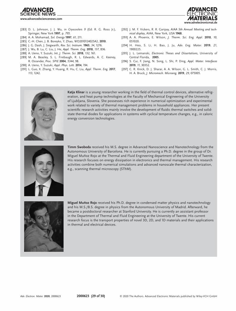
www.advancedsciencenews.comwww.advelectronicmat.de
2000623 (29 of 30) © 2020 The Authors. Advanced Electronic Materials published by Wiley-VCH GmbH
[283] D. L. Johnson, J. J. Wu, in Cryocoolers 9 (Ed: R. G. Ross Jr.), Springer, New York 1997, p. 795.
[284] A. A. Mohamad, Sol. Energy 1997, 61, 211.[285] C.-H. Chen, J. B. Boreyko, Y. Zhao, WO2010124025A2, 2010.[286] J. G. Dash, J. Siegwarth, Rev. Sci. Instrum. 1963, 34, 1276.[287] J. Wu, B. Lu, C. Liu, J. He, Appl. Therm. Eng. 2018, 137, 836.[288] A. Ueno, Y. Suzuki, Int. J. Therm. Sci. 2018, 132, 161.[289] M. A. Beasley, S. L. Firebaugh, R. L. Edwards, A. C. Keeney,
R. Osiander, Proc. SPIE 2004, 5344, 98.[290] A. Ueno, Y. Suzuki, Appl. Phys. Lett. 2014, 194.[291] L. Guo, X. Zhang, Y. Huang, R. Hu, C. Liu, Appl. Therm. Eng. 2017,
113, 1242.
[292] J. M. F. Vickers, R. R. Garipay, AIAA 5th Annual Meeting and tech-nical display, AIAA, New York, USA 1968.
[293] A. A. Phoenix, E. Wilson, J. Therm. Sci. Eng. Appl. 2018, 10, 051020.
[294] H. Heo, S. Li, H. Bao, J. Ju, Adv. Eng. Mater. 2019, 21, 1900225.
[295] J. L. Lemanski, Electronic Theses and Dissertations, University of Central Florida, 2005.
[296] S. Cui, F. Jiang, N. Song, L. Shi, P. Ding, Appl. Mater. Interfaces 2019, 11, 30352.
[297] C. R. Knick, D. J. Sharar, A. A. Wilson, G. L. Smith, C. J. Morris, H. A. Bruck, J. Micromech. Microeng. 2019, 29, 075005.
Katja Klinar is a young researcher working in the field of thermal control devices, alternative refrig-eration, and heat pump technologies at the Faculty of Mechanical Engineering of the University of Ljubljana, Slovenia. She possesses rich experience in numerical optimization and experimental work related to variety of thermal management problems in household appliances. Her present scientific research activities mainly involve the development of fluidic thermal switches and solid-state thermal diodes for applications in systems with cyclical temperature changes, e.g., in caloric energy conversion technologies.
Timm Swoboda received his M.S. degree in Advanced Nanoscience and Nanotechnology from the Autonomous University of Barcelona. He is currently pursuing a Ph.D. degree in the group of Dr. Miguel Muñoz Rojo at the Thermal and Fluid Engineering department of the University of Twente. His research focuses on energy dissipation in electronics and thermal management. His research activities combine both numerical simulations and advanced nanoscale thermal characterization, e.g., scanning thermal microscopy (SThM).
Miguel Muñoz Rojo received his Ph.D. degree in condensed matter physics and nanotechnology and his M.S./B.S. degree in physics from the Autonomous University of Madrid. Afterward, he became a postdoctoral researcher at Stanford University. He is currently an assistant professor in the Department of Thermal and Fluid Engineering at the University of Twente. His current research focus is the transport properties of novel 3D, 2D, and 1D materials and their applications in thermal and electrical devices.
Adv. Electron. Mater. 2020, 2000623
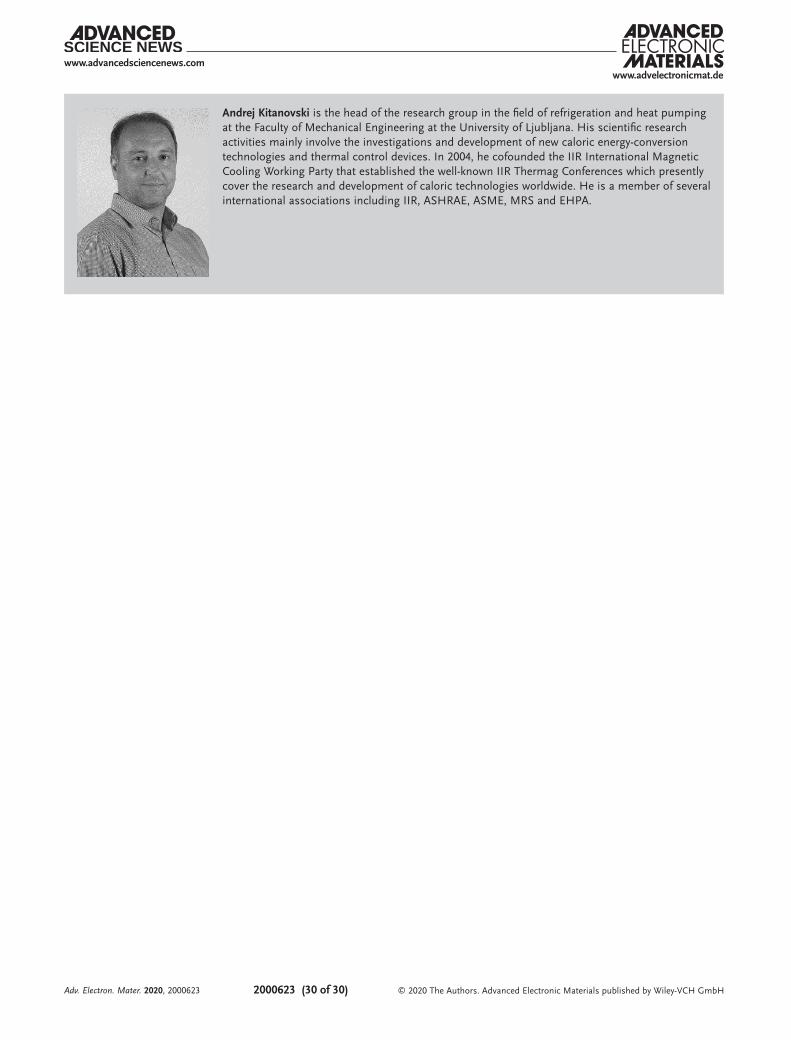
www.advancedsciencenews.comwww.advelectronicmat.de
2000623 (30 of 30) © 2020 The Authors. Advanced Electronic Materials published by Wiley-VCH GmbH
Andrej Kitanovski is the head of the research group in the field of refrigeration and heat pumping at the Faculty of Mechanical Engineering at the University of Ljubljana. His scientific research activities mainly involve the investigations and development of new caloric energy-conversion technologies and thermal control devices. In 2004, he cofounded the IIR International Magnetic Cooling Working Party that established the well-known IIR Thermag Conferences which presently cover the research and development of caloric technologies worldwide. He is a member of several international associations including IIR, ASHRAE, ASME, MRS and EHPA.
Adv. Electron. Mater. 2020, 2000623
Related Documents