A Swagelok ® Pre-Engineered Subsystem • Pre-engineered subsystems available in weeks, not months. • Field-tested design ensures optimum system performance. • Versatile manifold for gas and liquid applications • Swagelok components for reliability • Fluid distribution headers can be connected inline to create longer lengths Fluid Distribution Header Application Guide

Welcome message from author
This document is posted to help you gain knowledge. Please leave a comment to let me know what you think about it! Share it to your friends and learn new things together.
Transcript

A Swagelok® Pre-Engineered
Subsystem
• Pre-engineered subsystems
available in weeks, not months.
• Field-tested design ensures
optimum system performance.
• Versatile manifold for gas and liquid applications
• Swagelok components for reliability
• Fluid distribution headers can be connected inline to create longer lengths
Fluid Distribution
HeaderApplication Guide
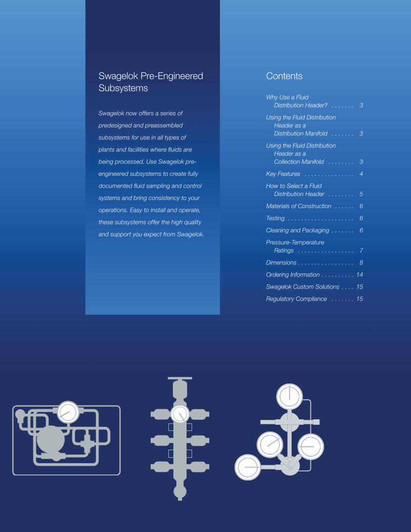
Swagelok Pre-Engineered Subsystems
Swagelok now offers a series of
predesigned and preassembled
subsystems for use in all types of
plants and facilities where fluids are
being processed. Use Swagelok pre-
engineered subsystems to create fully
documented fluid sampling and control
systems and bring consistency to your
operations. Easy to install and operate,
these subsystems offer the high quality
and support you expect from Swagelok.
Contents
Why Use a Fluid Distribution Header? . . . . . . . 3
Using the Fluid Distribution Header as a Distribution Manifold . . . . . . . 3
Using the Fluid Distribution Header as a Collection Manifold . . . . . . . . 3
Key Features . . . . . . . . . . . . . . . 4
How to Select a Fluid Distribution Header . . . . . . . . 5
Materials of Construction . . . . . . 6
Testing . . . . . . . . . . . . . . . . . . . . 6
Cleaning and Packaging . . . . . . . 6
Pressure-Temperature Ratings . . . . . . . . . . . . . . . . . 7
Dimensions . . . . . . . . . . . . . . . . . 8
Ordering Information . . . . . . . . . . 14
Swagelok Custom Solutions . . . . 15
Regulatory Compliance . . . . . . . 15

A Swagelok Pre-Engineered Subsystem Fluid Distribution Header
3
The Swagelok Fluid Distribution Header (FDH)Why Use a Fluid Distribution Header?Fluid distribution headers are common components used in a variety of gas and liquid
applications. An FDH provides a flow path while allowing multiple outlets, acting much like a
large branch fitting.
A fluid distribution header is characterized by an inlet on one end, a drain on the other end, with
multiple outlets on the sides. Typical fluid distribution headers are manufactured from a piece of
pipe or bar and feature welded or threaded end connections.
Using the Fluid Distribution Header as a Distribution ManifoldAs a distribution manifold or header, an FDH
connects several users to the source of a
utility fluid. Typical applications include:
• Cooling water
• Steam
• Compressed air
• Plant nitrogen
In a typical analyzer house, for instance, one
FDH is an instrument air header, another
FDH is the plant nitrogen header, and yet
another FDH is the LP steam header. If
needed, multiple FDH subsystems can be
screwed together end-to-end to make longer
header runs.
Typically, an FDH has a main isolation valve and several outlets, each with its own isolation valve.
For potentially wet gases, such as compressed air or steam, it is best to install the FDH vertically
with a drain valve at the bottom.
For liquid service, it is best to install the FDH vertically, with the supply entering at the bottom
and the top valve acting as a vent for removing trapped air or allowing air in for draining the FDH
during maintenance.
Typical Swagelok Fluid Distribution Header (FDH)

A Swagelok Pre-Engineered Subsystem Fluid Distribution Header
4
Using the Fluid Distribution Header as a Collection ManifoldAs a collection manifold or header, an FDH collects several fluid streams and provides a single
connection for disposal. Typical disposal points include:
• Low-pressure return to process
• Flare header
• Atmospheric vent
• Drain or sewer
Key FeaturesThe Swagelok FDH is a pre-engineered and fully documented piping assembly that can act as a
distribution manifold or collection manifold in gas or liquid applications.
The Swagelok FDH offers several distinctive features:
• Available in 1 and 2 in. sizes, an extruded manifold body design features squared sides that
mount solidly and prevent twisting.
• Standard branch locations offer flexibility; additional outlets can be added to the header
without welding.
• The FDH can be ordered with 2 to 16 branch outlets, with or without valves, so users can
add ports as needed.
• A choice of high-quality valves and end connections, all manufactured by Swagelok.
• Working pressures up to 3000 psig (206 bar).
• Mounting brackets can be positioned by the installer.
A Swagelok Pre-Engineered Subsystem Fluid Distribution Header
5
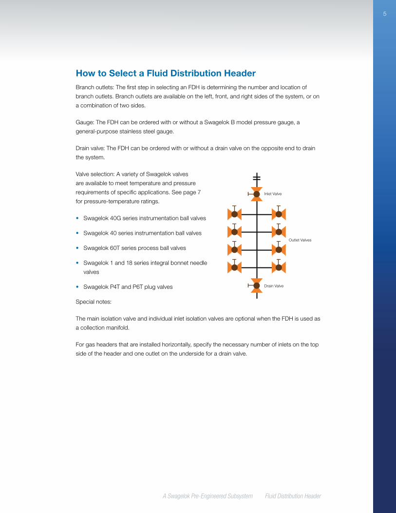
How to Select a Fluid Distribution HeaderBranch outlets: The first step in selecting an FDH is determining the number and location of
branch outlets. Branch outlets are available on the left, front, and right sides of the system, or on
a combination of two sides.
Gauge: The FDH can be ordered with or without a Swagelok B model pressure gauge, a
general-purpose stainless steel gauge.
Drain valve: The FDH can be ordered with or without a drain valve on the opposite end to drain
the system.
Valve selection: A variety of Swagelok valves
are available to meet temperature and pressure
requirements of specific applications. See page 7
for pressure-temperature ratings.
• Swagelok 40G series instrumentation ball valves
• Swagelok 40 series instrumentation ball valves
• Swagelok 60T series process ball valves
• Swagelok 1 and 18 series integral bonnet needle
valves
• Swagelok P4T and P6T plug valves
Special notes:
The main isolation valve and individual inlet isolation valves are optional when the FDH is used as
a collection manifold.
For gas headers that are installed horizontally, specify the necessary number of inlets on the top
side of the header and one outlet on the underside for a drain valve.
Inlet Valve
Outlet Valves
Drain Valve

A Swagelok Pre-Engineered Subsystem Fluid Distribution Header
6
Materials of ConstructionFor detailed product data, including additional
seat materials and nonwetted materials of
construction, see individual product catalogs.
ComponentManufacturer,
Model Material
1 Extrusion Swagelok316 stainless steel
2 End caps Swagelok
3 O-rings Various Fluorocarbon FKM
4 Mounting brackets
Swagelok 316 stainless steel
5 End connections
Swagelok 316 stainless steel
6 Adapter fittings
Swagelok 316 stainless steel
7 Valves
Swagelok 60 series
See Swagelok Ball Valves, General Purpose and Special Application—
60 Series catalog, MS-01-146
Swagelok 40G and 40 series
ball valves
See Swagelok One-Piece Instrumentation Ball Valves—40G
Series and 40 Series catalog, MS-02-331
Swagelok 1 and 18 series needle valves
See Swagelok Integral-Bonnet Needle Valves—O, 1, 18, 20, and
26 Series catalog, MS-01-164
Swagelok P4T and P6T series
plug valves
See Swagelok Plug Valves—P4T and P6T Series catalog, MS-01-59
8 GaugeSwagelok B
model
See Swagelok Pressure Gauges, Industrial and Process—PGI Series
catalog, MS-02-170
Wetted components listed in italics.
TestingEvery FDH subsystem is shell tested
with nitrogen at 250 psig (17.2 bar) to a
requirement of no detectable leakage with a
liquid leak detector.
See individual valve product catalogs for
shutoff testing information.
Cleaning and PackagingAll FDH subsystems are cleaned in
accordance with Swagelok Standard
Cleaning and Packaging (SC-10), MS-06-62.
5
7
7
8
7
2
3
2
1
4
6
3
A Swagelok Pre-Engineered Subsystem Fluid Distribution Header
7
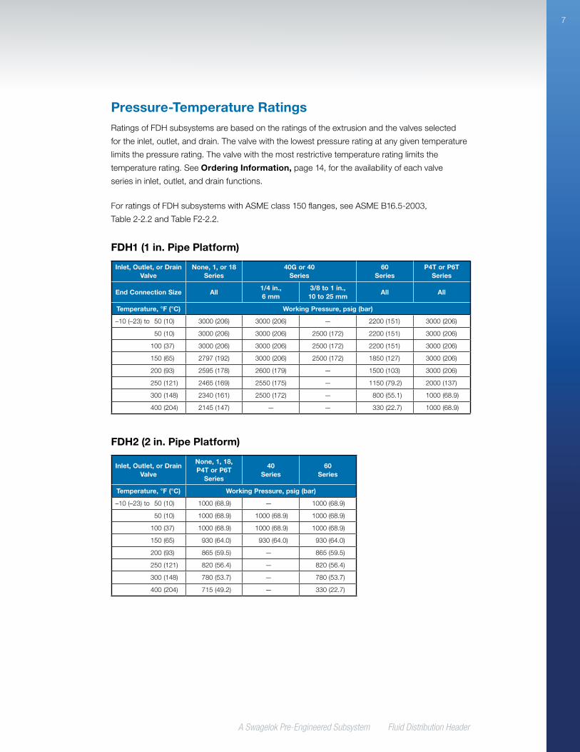
Pressure-Temperature RatingsRatings of FDH subsystems are based on the ratings of the extrusion and the valves selected
for the inlet, outlet, and drain. The valve with the lowest pressure rating at any given temperature
limits the pressure rating. The valve with the most restrictive temperature rating limits the
temperature rating. See Ordering Information, page 14, for the availability of each valve
series in inlet, outlet, and drain functions.
For ratings of FDH subsystems with ASME class 150 flanges, see ASME B16.5-2003,
Table 2-2.2 and Table F2-2.2.
FDH2 (2 in. Pipe Platform)
Inlet, Outlet, or Drain Valve
None, 1, 18, P4T or P6T
Series
40 Series
60 Series
Temperature, °F (°C) Working Pressure, psig (bar)
–10 (–23) to 50 (10) 1000 (68.9) — 1000 (68.9)
50 (10) 1000 (68.9) 1000 (68.9) 1000 (68.9)
100 (37) 1000 (68.9) 1000 (68.9) 1000 (68.9)
150 (65) 930 (64.0) 930 (64.0) 930 (64.0)
200 (93) 865 (59.5) — 865 (59.5)
250 (121) 820 (56.4) — 820 (56.4)
300 (148) 780 (53.7) — 780 (53.7)
400 (204) 715 (49.2) — 330 (22.7)
FDH1 (1 in. Pipe Platform)
Inlet, Outlet, or Drain Valve
None, 1, or 18 Series
40G or 40 Series
60 Series
P4T or P6T Series
End Connection Size All1/4 in., 6 mm
3/8 to 1 in., 10 to 25 mm
All All
Temperature, °F (°C) Working Pressure, psig (bar)
–10 (–23) to 50 (10) 3000 (206) 3000 (206) — 2200 (151) 3000 (206)
50 (10) 3000 (206) 3000 (206) 2500 (172) 2200 (151) 3000 (206)
100 (37) 3000 (206) 3000 (206) 2500 (172) 2200 (151) 3000 (206)
150 (65) 2797 (192) 3000 (206) 2500 (172) 1850 (127) 3000 (206)
200 (93) 2595 (178) 2600 (179) — 1500 (103) 3000 (206)
250 (121) 2465 (169) 2550 (175) — 1150 (79.2) 2000 (137)
300 (148) 2340 (161) 2500 (172) — 800 (55.1) 1000 (68.9)
400 (204) 2145 (147) — — 330 (22.7) 1000 (68.9)
A Swagelok Pre-Engineered Subsystem Fluid Distribution Header
8
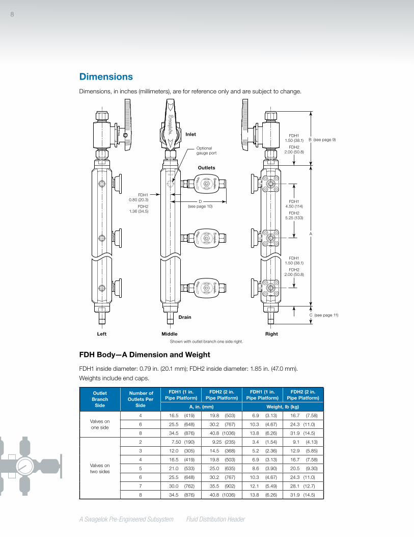
DimensionsDimensions, in inches (millimeters), are for reference only and are subject to change.
FDH Body—A Dimension and Weight
FDH1 inside diameter: 0.79 in. (20.1 mm); FDH2 inside diameter: 1.85 in. (47.0 mm).
Weights include end caps.
Outlet Branch
Side
Number of Outlets Per
Side
FDH1 (1 in. Pipe Platform)
FDH2 (2 in. Pipe Platform)
FDH1 (1 in. Pipe Platform)
FDH2 (2 in. Pipe Platform)
A, in. (mm) Weight, lb (kg)
Valves on one side
4 16.5 (419) 19.8 (503) 6.9 (3.13) 16.7 (7.58)
6 25.5 (648) 30.2 (767) 10.3 (4.67) 24.3 (11.0)
8 34.5 (876) 40.8 (1036) 13.8 (6.26) 31.9 (14.5)
Valves on two sides
2 7.50 (190) 9.25 (235) 3.4 (1.54) 9.1 (4.13)
3 12.0 (305) 14.5 (368) 5.2 (2.36) 12.9 (5.85)
4 16.5 (419) 19.8 (503) 6.9 (3.13) 16.7 (7.58)
5 21.0 (533) 25.0 (635) 8.6 (3.90) 20.5 (9.30)
6 25.5 (648) 30.2 (767) 10.3 (4.67) 24.3 (11.0)
7 30.0 (762) 35.5 (902) 12.1 (5.49) 28.1 (12.7)
8 34.5 (876) 40.8 (1036) 13.8 (6.26) 31.9 (14.5)
R
RR
R
B
D
A
C
FDH1 1.50 (38.1)
FDH2 2.00 (50.8)
FDH1 0.80 (20.3)
FDH2 1.36 (34.5)
FDH1 1.50 (38.1)
FDH2 2.00 (50.8)
FDH1 4.50 (114)
FDH2 5.25 (133)
Inlet
Drain
Left Middle Right
Outlets
(see page 10)
(see page 9)
(see page 11)
Optional gauge port
Shown with outlet branch one side right.

A Swagelok Pre-Engineered Subsystem Fluid Distribution Header
9
DimensionsDimensions are for reference only and are subject to change.
FDH1 (1 in. Pipe Platform) Inlet—B Dimension
End Connections
Inlet Valve
No Valve40G or 40
Series60 Series
Type Size B, in. (mm)
Female NPT
3/8 in. 0.50 (12.7) 3.87 (98.3) 4.07 (103)
1/2 in. 0.86 (21.8) 5.07 (129) 4.65 (118)
3/4 in. 1.21 (30.7) — 5.85 (149)
Fractional Swagelok tube fitting
1/2 in. 1.37 (34.8) 4.88 (124) 5.00 (127)
3/4 in. 1.40 (35.6) 4.95 (126) 5.07 (129)
1 in. 1.67 (42.4) — 6.54 (166)
Metric Swagelok tube fitting
12 mm 1.40 (35.6) 5.96 (151) 6.08 (154)
25 mm 1.69 (42.9) — 7.71 (196)
Swagelok tube adapter
3/8 in. 1.20 (30.5) — —
1/2 in. 1.46 (37.1) — —
3/4 in. 1.59 (40.4) — —
1 in. 1.93 (49.0) — —
ASME class 150 flange
1/2 in. 2.74 (69.6) — 6.36 (162)
1 in. 3.56 (90.4) — 8.14 (207)
FDH2 (2 in. Pipe Platform) Inlet—B Dimension
End ConnectionsInlet Valve
No Valve 40 Series 60 Series
Type Size B, in. (mm)
Female NPT
1/2 in. 0.88 (22.4) 5.09 (129) 4.67 (119)
3/4 in. 0.88 (22.4) — 5.52 (140)
1 in. 0.88 (22.4) — 5.86 (149)
Fractional Swagelok tube fitting
1/2 in. 1.62 (41.1) 5.13 (130) 5.25 (133)
3/4 in. 1.62 (41.1) 5.13 (130) 5.25 (133)
1 in. 1.79 (45.5) — 6.66 (169)
2 in. 3.19 (81.0) — 12.3 (312)
Metric Swagelok tube fitting
25 mm 1.80 (45.7) — 7.71 (196)
50 mm 3.19 (81.0) — —
Swagelok tube adapter
3/4 in. 1.77 (45.0) — —
1 in. 2.05 (52.1) — —
2 in. 3.51 (89.2) — —
ASME class 150 flange
1/2 in. 2.99 (75.9) — 6.61 (168)
1 in. 3.68 (93.5) — 8.23 (209)
2 in. 6.43 (163) — 15.2 (386)
B
40 Series Inlet Valve with Swagelok
Tube Fitting End Connections Shown

A Swagelok Pre-Engineered Subsystem Fluid Distribution Header
10
DimensionsDimensions are for reference only and are subject to change.
FDH1 (1 in. Pipe Platform) Outlet—D Dimension
End Connections
Outlet Valve
No Valve40G or 40
Series60 Series
1 or 18 Series
P4T or P6T Series
Type Size D, in. (mm)
Female NPT
1/4 in. 0.80 (20.3) 3.72 (94.5) 3.82 (97.0) 3.78 (96.0) 4.04 (103)
3/8 in. 2.03 (51.6) 4.18 (106) 4.38 (111) 4.68 (119) —
1/2 in. 2.29 (58.2) 4.92 (125) 4.50 (114) 4.80 (122) 4.68 (119)
Fractional Swagelok tube fitting
1/4 in. 2.02 (51.3) 3.89 (98.8) 4.85 (123) 3.95 (100) 3.85 (97.8)
3/8 in. 2.10 (53.3) 4.73 (120) 4.85 (123) 4.26 (108) 4.34 (110)
1/2 in. 2.24 (56.9) 5.70 (145) 5.82 (148) 4.58 (116) 4.66 (118)
Metric Swagelok tube fitting
6 mm 2.02 (51.3) 4.11 (104) 4.89 (124) 3.99 (101) 3.89 (98.8)
10 mm 2.14 (54.4) 4.79 (122) 4.92 (125) 4.32 (110) 4.40 (112)
12 mm 2.24 (56.9) 5.78 (147) 5.90 (150) 4.66 (118) 4.82 (122)
Swagelok tube
adapter
1/4 in. 1.99 (50.5) — — — —
3/8 in. 2.06 (52.3) — — — —
1/2 in. 2.28 (57.9) — — — —
FDH2 (2 in. Pipe Platform) Outlet—D Dimension
End Connections
Outlet Valve
No Valve 40 Series 60 Series1 or 18 Series
P4T or P6T Series
Type Size D, in. (mm)
Female NPT
3/8 in. 2.39 (60.7) 4.85 (123) 5.05 (128) 5.35 (136) —
1/2 in. 1.36 (34.5) 5.57 (141) 5.15 (131) 5.45 (138) 5.33 (135)
3/4 in. 3.00 (76.2) — 6.02 (153) — —
1 in. 3.14 (79.8) — 5.24 (133) — —
Fractional Swagelok tube fitting
3/8 in. 2.80 (71.1) 5.44 (138) 5.56 (141) 4.97 (126) 5.05 (128)
1/2 in. 2.91 (73.9) 6.40 (163) 6.52 (166) 5.28 (134) 5.36 (136)
3/4 in. 2.97 (75.4) 6.40 (163) 6.52 (166) 6.28 (160) —
1 in. 3.24 (82.3) — 7.90 (201) — —
Metric Swagelok tube fitting
10 mm 2.81 (71.4) 5.50 (140) 5.63 (143) 5.03 (128) 5.11 (130)
12 mm 2.91 (73.9) 6.45 (164) 6.57 (167) 5.33 (135) 5.49 (139)
25 mm 3.24 (82.3) — 7.96 (202) — —
Swagelok tube
adapter
3/8 in. 2.76 (70.1) — — — —
1/2 in. 2.98 (75.7) — — — —
3/4 in. 3.04 (77.2) — — — —
R
D
60 Series Outlet Valve with Swagelok Tube
Fitting End Connections Shown
A Swagelok Pre-Engineered Subsystem Fluid Distribution Header
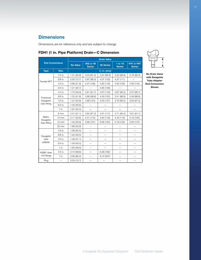
11
FDH1 (1 in. Pipe Platform) Drain—C Dimension
End Connections
Drain Valve
No Valve40G or 40
Series60 Series
1 or 18 Series
P4T or P6T Series
Type Size C, in. (mm)
Female NPT
1/4 in. 1.41 (35.8) 3.44 (87.4) 3.54 (89.9) 3.50 (88.9) 3.76 (95.5)
3/8 in. 0.50 (12.7) 3.87 (98.3) 4.07 (103) 4.37 (111) —
1/2 in. 0.86 (21.8) 5.07 (129) 4.65 (118) 4.95 (126) 4.83 (123)
3/4 in. 1.21 (30.7) — 5.85 (149) — —
Fractional Swagelok tube fitting
1/4 in. 1.73 (43.9) 3.61 (91.7) 4.57 (116) 3.67 (93.2) 3.57 (90.7)
3/8 in. 1.25 (31.8) 3.88 (98.6) 4.00 (102) 3.41 (86.6) 3.49 (88.6)
1/2 in. 1.37 (34.8) 4.88 (124) 5.00 (127) 3.76 (95.5) 3.84 (97.5)
3/4 in. 1.40 (35.6) — — — —
1 in. 1.67 (42.4) — — — —
Metric Swagelok tube fitting
6 mm 2.01 (51.1) 3.83 (97.3) 4.61 (117) 3.71 (94.2) 3.61 (91.7)
10 mm 2.11 (53.6) 4.51 (115) 4.64 (118) 4.40 (112) 4.12 (105)
12 mm 1.40 (35.6) 5.96 (151) 6.08 (154) 5.19 (132) 5.00 (127)
25 mm 1.69 (42.9) — — — —
Swagelok tube
adapter
1/4 in. 1.99 (50.5) — — — —
3/8 in. 1.20 (30.5) — — — —
1/2 in. 1.46 (37.1) — — — —
3/4 in. 1.59 (40.4) — — — —
1 in. 1.93 (49.0) — — — —
ASME class 150 flange
1/2 in. 2.74 (69.6) — 6.36 (162) — —
1 in. 3.56 (90.4) — 8.14 (207) — —
Plug — 0.50 (12.7) — — — —
DimensionsDimensions are for reference only and are subject to change.
C
No Drain Valve with Swagelok Tube Adapter
End Connection Shown
A Swagelok Pre-Engineered Subsystem Fluid Distribution Header
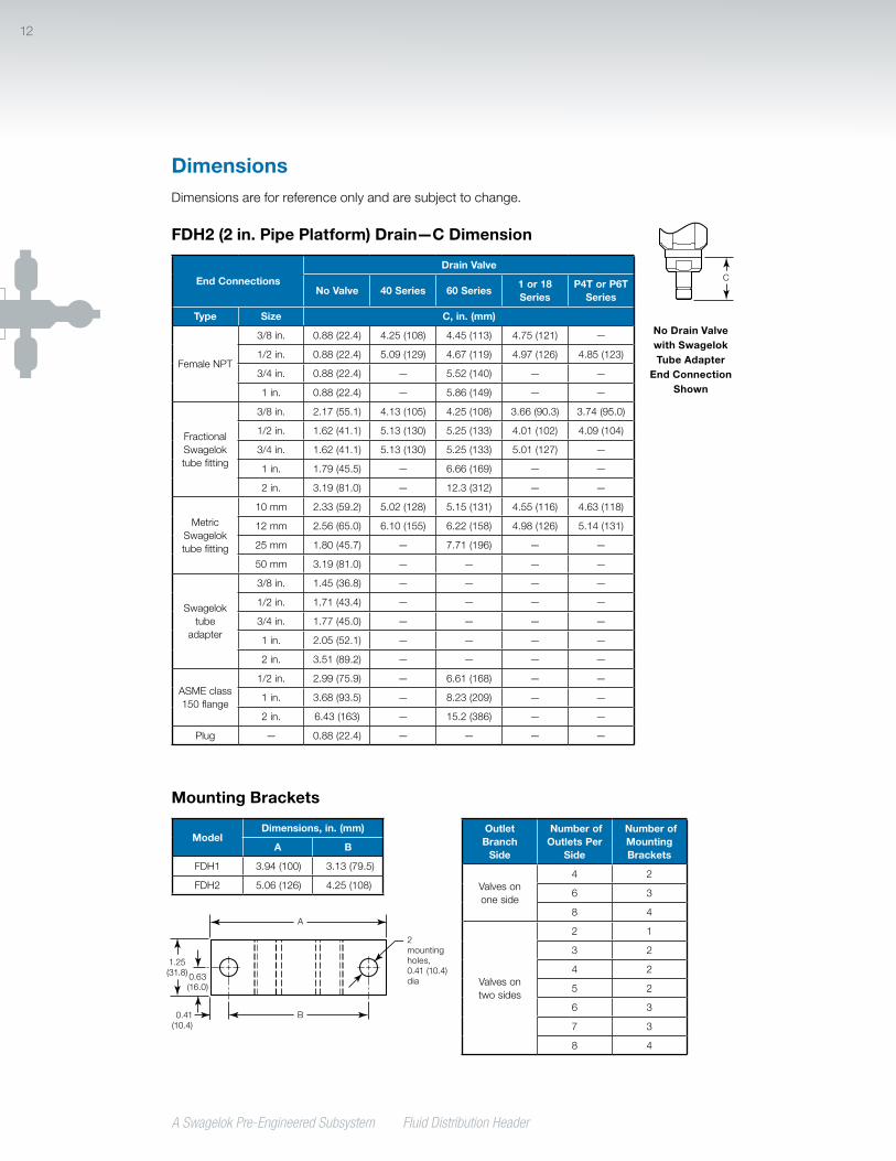
12
1.25 (31.8) 0.63
(16.0)
0.41 (10.4)
2 mounting holes, 0.41 (10.4) dia
A
B
Mounting Brackets
ModelDimensions, in. (mm)
A B
FDH1 3.94 (100) 3.13 (79.5)
FDH2 5.06 (126) 4.25 (108)
Outlet Branch
Side
Number of Outlets Per
Side
Number of Mounting Brackets
Valves on one side
4 2
6 3
8 4
Valves on two sides
2 1
3 2
4 2
5 2
6 3
7 3
8 4
FDH2 (2 in. Pipe Platform) Drain—C Dimension
End Connections
Drain Valve
No Valve 40 Series 60 Series1 or 18 Series
P4T or P6T Series
Type Size C, in. (mm)
Female NPT
3/8 in. 0.88 (22.4) 4.25 (108) 4.45 (113) 4.75 (121) —
1/2 in. 0.88 (22.4) 5.09 (129) 4.67 (119) 4.97 (126) 4.85 (123)
3/4 in. 0.88 (22.4) — 5.52 (140) — —
1 in. 0.88 (22.4) — 5.86 (149) — —
Fractional Swagelok tube fitting
3/8 in. 2.17 (55.1) 4.13 (105) 4.25 (108) 3.66 (90.3) 3.74 (95.0)
1/2 in. 1.62 (41.1) 5.13 (130) 5.25 (133) 4.01 (102) 4.09 (104)
3/4 in. 1.62 (41.1) 5.13 (130) 5.25 (133) 5.01 (127) —
1 in. 1.79 (45.5) — 6.66 (169) — —
2 in. 3.19 (81.0) — 12.3 (312) — —
Metric Swagelok tube fitting
10 mm 2.33 (59.2) 5.02 (128) 5.15 (131) 4.55 (116) 4.63 (118)
12 mm 2.56 (65.0) 6.10 (155) 6.22 (158) 4.98 (126) 5.14 (131)
25 mm 1.80 (45.7) — 7.71 (196) — —
50 mm 3.19 (81.0) — — — —
Swagelok tube
adapter
3/8 in. 1.45 (36.8) — — — —
1/2 in. 1.71 (43.4) — — — —
3/4 in. 1.77 (45.0) — — — —
1 in. 2.05 (52.1) — — — —
2 in. 3.51 (89.2) — — — —
ASME class 150 flange
1/2 in. 2.99 (75.9) — 6.61 (168) — —
1 in. 3.68 (93.5) — 8.23 (209) — —
2 in. 6.43 (163) — 15.2 (386) — —
Plug — 0.88 (22.4) — — — —
DimensionsDimensions are for reference only and are subject to change.
C
No Drain Valve with Swagelok Tube Adapter
End Connection Shown

A Swagelok Pre-Engineered Subsystem Fluid Distribution Header
13
Ordering InformationBuild an FDH subsystem ordering number by combining the designators in the sequence shown below.
FDH1 (1 in. Pipe Platform)
FDH1 - A C - C 1 - C 1 - C 3 - 02 41 3 5 6 7 8 9
1 Outlet Branch Sides A = 1 side right B = 1 side left C = 2 sides 180° apart D = 2 sides right/middle 90° apart E = 2 sides left/middle 90° apart
2 Number of Outlets A = 4 B = 6 C = 8 D = 10 (2-side configurations only) E = 12 (2-side configurations only) F = 14 (2-side configurations only) G = 16 (2-side configurations only)
3 Inlet Connections B = 3/8 in. female NPT C = 1/2 in. female NPT D = 3/4 in. female NPT➀ H = 1/2 in. Swagelok tube fitting J = 3/4 in. Swagelok tube fitting K = 1 in. Swagelok tube fitting➀ P = 12 mm Swagelok tube fitting Q = 25 mm Swagelok tube fitting➀ S = 1/2 in. NPS ASME class 150
flange➀ T = 1 in. NPS ASME class 150
flange➀ W = 3/8 in. Swagelok tube adapter➁ X = 1/2 in. Swagelok tube adapter➁ Y = 3/4 in. Swagelok tube adapter➁ Z = 1 in. Swagelok tube adapter➁
➀ Available with no inlet valve and 60 series valve only.➁ Available with no inlet valve only.
8 Drain Valve 0 = None 1 = 40G (1/4 in. and 6 mm drain
connections) or 40 series (all other drain connection sizes) ball valve
2 = 60 series ball valve 3 = 1 or 18 series needle valve 4 = P4T or P6T series plug valve
9 Pressure GaugeGauges are dual scale with bar primary and psig secondary scales. 0 = None 1 = 0 to 10 bar (0 to 145 psig) 2 = 0 to 40 bar (0 to 580 psig) 3 = 0 to 100 bar (0 to 1450 psig) 4 = 0 to 160 bar (0 to 2320 psig) 5 = 0 to 250 bar (0 to 3625 psig)
5 Outlet Connections A = 1/4 in. female NPT B = 3/8 in. female NPT➀ C = 1/2 in. female NPT F = 1/4 in. Swagelok tube fitting G = 3/8 in. Swagelok tube fitting H = 1/2 in. Swagelok tube fitting M = 6 mm Swagelok tube fitting N = 10 mm Swagelok tube fitting P = 12 mm Swagelok tube fitting V = 1/4 in. Swagelok tube adapter➁ W = 3/8 in. Swagelok tube adapter➁ X = 1/2 in. Swagelok tube adapter➁
➀ Available with no outlet valve, 40G or 40 series valve, 1 or 18 series valve, and 60 series valve only.
➁ Available with no outlet valve only.
4 Inlet Valve 0 = None 1 = 40G (1/4 in. and 6 mm inlet
connections) or 40 series (all other inlet connection sizes) ball valve
2 = 60 series ball valve
6 Outlet Valve 0 = None 1 = 40G (1/4 in. and 6 mm outlet
connections) or 40 series (all other outlet connection sizes) ball valve
2 = 60 series ball valve 3 = 1 or 18 series needle valve 4 = P4T or P6T series plug valve
7 Drain Connection A = 1/4 in. female NPT B = 3/8 in. female NPT➀ C = 1/2 in. female NPT D = 3/4 in. female NPT➁ F = 1/4 in. Swagelok tube fitting G = 3/8 in. Swagelok tube fitting H = 1/2 in. Swagelok tube fitting J = 3/4 in. Swagelok tube fitting➂ K = 1 in. Swagelok tube fitting➂ M = 6 mm Swagelok tube fitting N = 10 mm Swagelok tube fitting P = 12 mm Swagelok tube fitting Q = 25 mm Swagelok tube fitting➂ S = 1/2 in. NPS ASME class 150
flange➁ T = 1 in. NPS ASME class 150
flange➁ V = 1/4 in. Swagelok tube adapter➂ W = 3/8 in. Swagelok tube adapter➂ X = 1/2 in. Swagelok tube adapter➂ Y = 3/4 in. Swagelok tube adapter➂ Z = 1 in. Swagelok tube adapter➂ ZZ = Plug
➀ Available with no drain valve, 40G or 40 series valve, 1 or 18 series valve, and 60 series valve only.
➁ Available with no drain valve and 60 series valve only.
➂ Available with no drain valve only.

A Swagelok Pre-Engineered Subsystem Fluid Distribution Header
14
1 Outlet Branch Sides A = 1 side right B = 1 side left C = 2 sides 180° apart D = 2 sides right/middle 90° apart E = 2 sides left/middle 90° apart
2 Number of Outlets A = 4 B = 6 C = 8 D = 10 (2-side configurations only) E = 12 (2-side configurations only) F = 14 (2-side configurations only) G = 16 (2-side configurations only)
8 Drain Valve 0 = None 1 = 40 series ball valve 2 = 60 series ball valve 3 = 1 or 18 series needle valve 4 = P4T or P6T series plug valve
9 Pressure Gauge
Gauges are dual scale with bar primary and psig secondary scales.
0 = None 1 = 0 to 10 bar (0 to 145 psig) 2 = 0 to 40 bar (0 to 580 psig) 3 = 0 to 100 bar (0 to 1450 psig)
4 Inlet Valve 0 = None 1 = 40 series ball valve 2 = 60 series ball valve
6 Outlet Valve 0 = None 1 = 40 series ball valve 2 = 60 series ball valve 3 = 1 or 18 series needle valve 4 = P4T or P6T series plug valve
Ordering InformationBuild an FDH subsystem ordering number by combining the designators in the sequence shown below.
FDH2 (2 in. Pipe Platform)
FDH2 - C G - T 0 - H 2 - H 3 - 02 41 3 5 6 7 8 9
3 Inlet Connections C = 1/2 in. female NPT D = 3/4 in. female NPT➀ E = 1 in. female NPT➀ H = 1/2 in. Swagelok tube fitting J = 3/4 in. Swagelok tube fitting K = 1 in. Swagelok tube fitting➀ L = 2 in. Swagelok tube fitting➀ Q = 25 mm Swagelok tube fitting➀ R = 50 mm Swagelok tube fitting➁ S = 1/2 in. NPS ASME class 150
flange➀ T = 1 in. NPS ASME class 150
flange➀ U = 2 in. NPS ASME class 150
flange➀ Y = 3/4 in. Swagelok tube adapter➁ Z = 1 in. Swagelok tube adapter➁ AA = 2 in. Swagelok tube adapter➁
➀ Available with no inlet valve and 60 series valve only.➁ Available with no inlet valve only.
5 Outlet Connections B = 3/8 in. female NPT➀ C = 1/2 in. female NPT D = 3/4 in. female NPT➁ E = 1 in. female NPT➁ G = 3/8 in. Swagelok tube fitting H = 1/2 in. Swagelok tube fitting J = 3/4 in. Swagelok tube fitting➀ K = 1 in. Swagelok tube fitting➁ N = 10 mm Swagelok tube fitting P = 12 mm Swagelok tube fitting Q = 25 mm Swagelok tube fitting➁ W = 3/8 in. Swagelok tube adapter➂ X = 1/2 in. Swagelok tube adapter➂ Y = 3/4 in. Swagelok tube adapter➂
➀ Available with no outlet valve, 40G or 40 series valve, 1 or 18 series valve, and 60 series valve only.
➁ Available with no outlet valve and 60 series valve only.
➂ Available with no outlet valve only.
7 Drain Connection B = 3/8 in. female NPT➀ C = 1/2 in. female NPT D = 3/4 in. female NPT➁ E = 1 in. female NPT➁ F = 1/4 in. Swagelok tube fitting G = 3/8 in. Swagelok tube fitting H = 1/2 in. Swagelok tube fitting J = 3/4 in. Swagelok tube fitting➀ K = 1 in. Swagelok tube fitting➁ L = 2 in. Swagelok tube fitting➁ N = 10 mm Swagelok tube fitting P = 12 mm Swagelok tube fitting Q = 25 mm Swagelok tube fitting➁ R = 50 mm Swagelok tube fitting➂ S = 1/2 in. NPS ASME class 150
flange➁ T = 1 in. NPS ASME class 150
flange➁ U = 2 in. NPS ASME class 150
flange➁ W = 3/8 in. Swagelok tube adapter➂ X = 1/2 in. Swagelok tube adapter➂ Y = 3/4 in. Swagelok tube adapter➂ Z = 1 in. Swagelok tube adapter➂ AA = 2 in. Swagelok tube adapter➂ ZZ = Plug
➀ Available with no drain valve, 40G or 40 series valve, 1 or 18 series valve, and 60 series valve only.
➁ Available with no drain valve and 60 series valve only.
➂ Available with no drain valve only.

A Swagelok Pre-Engineered Subsystem Fluid Distribution Header
15
Swagelok Custom SolutionsAlthough a wide variety of valves and fittings are available as standard,
there may be those applications which require different components
or configurations.
If a custom solution is required, Swagelok welcomes
these requests.
Nonstandard assemblies may include:
• Customized port spacing
• Other Swagelok products
• Different manifold lengths.
Regulatory Compliance
Europe
• Pressure Equipment Directive (PED) 2014/68/EU
• Atmospheres Explosive Directive (ATEX) 2014/34/EU
• Restriction of Hazardous Substances Directive (RoHS) 2011/65/EU
Americas
• Hazardous location electrical approval (CSA/UL)
• CRN registered in Canada (individual components of assembly)
Contact your authorized Swagelok representative for specific assembly compliance approvals
and certifications available from the manufacturer.

Swagelok—TM Swagelok Company © 2011-2018 Swagelok Company, October 2018, RevD, MS-02-358
Safe Product SelectionWhen selecting a product, the total system design must be considered to ensure safe, trouble-free performance. Function, material compatibility, adequate ratings, proper installation, operation, and maintenance are the responsibilities of the system designer and user.
Caution: Do not mix or interchange Swagelok product components with those of other manufacturers.
Warranty InformationSwagelok products are backed by The Swagelok Limited
Lifetime Warranty. For a copy, visit swagelok.com or contact
your authorized Swagelok representative.
Related Documents