International Environmental Modelling and Software Society (iEMSs) 2010 International Congress on Environmental Modelling and Software Modelling for Environment’s Sake, Fifth Biennial Meeting, Ottawa, Canada David A. Swayne, Wanhong Yang, A. A. Voinov, A. Rizzoli, T. Filatova (Eds.) http://www.iemss.org/iemss2010/index.php?n=Main.Proceedings Abstract: The mathematical description of the evolution of the scour hole generated around a hydraulic structure requires a detailed analysis of the kinematic characteristics of flow and of turbulent structures. The scouring phenomenon is complex and experimental works show that the characteristics of such turbulent structures depend on the water jet condition and on the geometry of the structure itself. The aim of the present work is to get a better understanding on scour evolution and flow field downstream of a rigid basement of a control structure. The analysis is conducted by using experimental data collected in a straight laboratory flume realized at the laboratory of the “Dipartimento di Ingegneria Idraulica ed Applicazioni Ambientali” - University of Palermo (Italy). Keywords: Open channel flow; local scour; grade control structure; flow turbulence structure. 1. INTRODUCTION The estimation of geometric characteristics of scour hole occurring downstream of hydraulic structures (piers, abutments, bed sills, etc...) is a topic of strong importance in river engineering. Many theoretical and experimental studies have been carried out to evaluate the maximum scour depth around of bridge piers (Oliveto & Hager, 2002, Coleman et al., 2003) or of bulkheads (Hassan & Narayanan, 1985, Chatterjee et al. 1994; Kurniawan et al., 2001) or downstream of bed sills and of control structures (Mossa, 1998; Gaudio & Marion, 2003, Lenzi et al. 2003), for different conditions of the water jet (Rajaratnam & Berry, 1977; Rajaratnam, 1981; Mazurek & Rajaratnam, 2003). The understanding of the phenomenon is complex because of the three-dimensionality of flow in the scour hole with the formation of turbulent structures whose characteristics depend on the water jet condition and on the geometry of the considered hydraulic structure (Kwan & Melville 1994, Melville, 1995; Dey et al. 1995; Rajkumar & Dey, 2009). The aim of the present work is to get a better understanding on the time evolution of the scour hole and to provide a further contribution on the analysis of flow field in the scour downstream of the rigid bed of a control structure. For this aim experimental work has been performed in a straight laboratory flume realized at the laboratory of the “Dipartimento di Ingegneria Idraulica ed Applicazioni Ambientali” - University of Palermo (Italy). 2 EXPERIMENTAL SET UP The experiments have been carried out in a rectangular flume 11.2 m long and 0.4 m wide. In the first reach of the channel (2.65 m in length) the bed is rigid; this rigid-bed channel reach is followed by a mobile-bed reach 8.55 m long. The bed is of quartz sand (D 84 = 1.1 mm, D 50 = 0.86 mm and D 16 = 0.68 mm), with longitudinal slope equal to 0.4%. In Figure 1 the photo of the channel and a scheme of the scour hole are reported. Flow kinematic characteristics in the scour hole downstream of a grade-control structure Donatella Termini 1 , Vincenzo Sammartano 2 Dipartimento di Idraulica ed Applicazioni Ambientali, Facoltà di Ingegneria, Università di Palermo, Italy, phone: +39 0916557722; fax: ++39 0916557749; e-mail: 1 [email protected] ; 2 [email protected]

Welcome message from author
This document is posted to help you gain knowledge. Please leave a comment to let me know what you think about it! Share it to your friends and learn new things together.
Transcript
International Environmental Modelling and Software Society (iEMSs) 2010 International Congress on Environmental Modelling and Software
Modelling for Environment’s Sake, Fifth Biennial Meeting, Ottawa, Canada David A. Swayne, Wanhong Yang, A. A. Voinov, A. Rizzoli, T. Filatova (Eds.)
http://www.iemss.org/iemss2010/index.php?n=Main.Proceedings
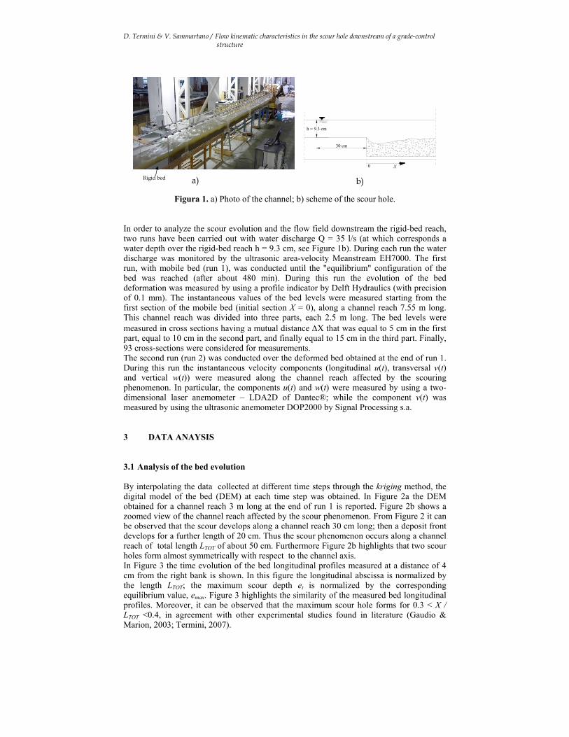
Abstract: The mathematical description of the evolution of the scour hole generated around a hydraulic structure requires a detailed analysis of the kinematic characteristics of flow and of turbulent structures. The scouring phenomenon is complex and experimental works show that the characteristics of such turbulent structures depend on the water jet condition and on the geometry of the structure itself. The aim of the present work is to get a better understanding on scour evolution and flow field downstream of a rigid basement of a control structure. The analysis is conducted by using experimental data collected in a straight laboratory flume realized at the laboratory of the “Dipartimento di Ingegneria Idraulica ed Applicazioni Ambientali” - University of Palermo (Italy). Keywords: Open channel flow; local scour; grade control structure; flow turbulence structure. 1. INTRODUCTION The estimation of geometric characteristics of scour hole occurring downstream of hydraulic structures (piers, abutments, bed sills, etc...) is a topic of strong importance in river engineering. Many theoretical and experimental studies have been carried out to evaluate the maximum scour depth around of bridge piers (Oliveto & Hager, 2002, Coleman et al., 2003) or of bulkheads (Hassan & Narayanan, 1985, Chatterjee et al. 1994; Kurniawan et al., 2001) or downstream of bed sills and of control structures (Mossa, 1998; Gaudio & Marion, 2003, Lenzi et al. 2003), for different conditions of the water jet (Rajaratnam & Berry, 1977; Rajaratnam, 1981; Mazurek & Rajaratnam, 2003). The understanding of the phenomenon is complex because of the three-dimensionality of flow in the scour hole with the formation of turbulent structures whose characteristics depend on the water jet condition and on the geometry of the considered hydraulic structure (Kwan & Melville 1994, Melville, 1995; Dey et al. 1995; Rajkumar & Dey, 2009). The aim of the present work is to get a better understanding on the time evolution of the scour hole and to provide a further contribution on the analysis of flow field in the scour downstream of the rigid bed of a control structure. For this aim experimental work has been performed in a straight laboratory flume realized at the laboratory of the “Dipartimento di Ingegneria Idraulica ed Applicazioni Ambientali” - University of Palermo (Italy). 2 EXPERIMENTAL SET UP The experiments have been carried out in a rectangular flume 11.2 m long and 0.4 m wide. In the first reach of the channel (2.65 m in length) the bed is rigid; this rigid-bed channel reach is followed by a mobile-bed reach 8.55 m long. The bed is of quartz sand (D84 = 1.1 mm, D50 = 0.86 mm and D16 = 0.68 mm), with longitudinal slope equal to 0.4%. In Figure 1 the photo of the channel and a scheme of the scour hole are reported.
Flow kinematic characteristics in the scour hole downstream of a grade-control structure
Donatella Termini1, Vincenzo Sammartano2
Dipartimento di Idraulica ed Applicazioni Ambientali, Facoltà di Ingegneria, Università di Palermo, Italy, phone: +39 0916557722; fax: ++39 0916557749;
e-mail: [email protected] ; [email protected]
D. Termini & V. Sammartano / Flow kinematic characteristics in the scour hole downstream of a grade-control structure
h = 9.3 cm
30 cm
0 X
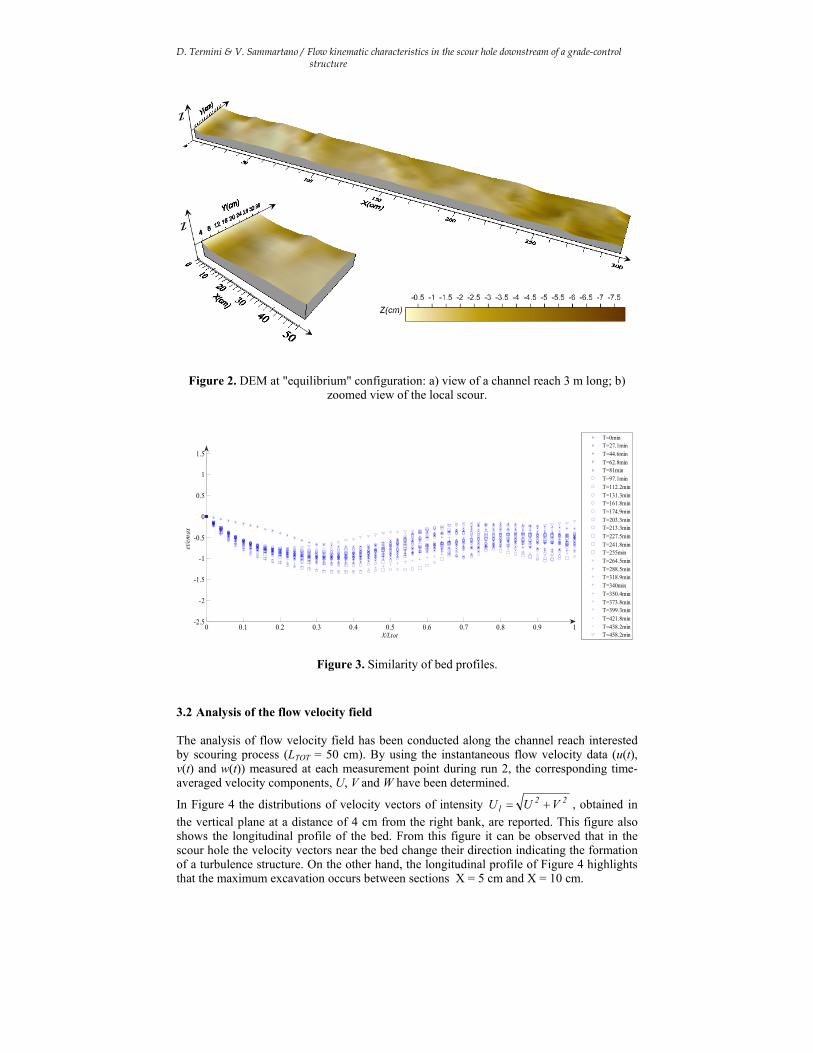
Figura 1. a) Photo of the channel; b) scheme of the scour hole. In order to analyze the scour evolution and the flow field downstream the rigid-bed reach, two runs have been carried out with water discharge Q = 35 l/s (at which corresponds a water depth over the rigid-bed reach h = 9.3 cm, see Figure 1b). During each run the water discharge was monitored by the ultrasonic area-velocity Meanstream EH7000. The first run, with mobile bed (run 1), was conducted until the "equilibrium" configuration of the bed was reached (after about 480 min). During this run the evolution of the bed deformation was measured by using a profile indicator by Delft Hydraulics (with precision of 0.1 mm). The instantaneous values of the bed levels were measured starting from the first section of the mobile bed (initial section X = 0), along a channel reach 7.55 m long. This channel reach was divided into three parts, each 2.5 m long. The bed levels were measured in cross sections having a mutual distance X that was equal to 5 cm in the first part, equal to 10 cm in the second part, and finally equal to 15 cm in the third part. Finally, 93 cross-sections were considered for measurements. The second run (run 2) was conducted over the deformed bed obtained at the end of run 1. During this run the instantaneous velocity components (longitudinal u(t), transversal v(t) and vertical w(t)) were measured along the channel reach affected by the scouring phenomenon. In particular, the components u(t) and w(t) were measured by using a two-dimensional laser anemometer – LDA2D of Dantec®; while the component v(t) was measured by using the ultrasonic anemometer DOP2000 by Signal Processing s.a. 3 DATA ANAYSIS 3.1 Analysis of the bed evolution By interpolating the data collected at different time steps through the kriging method, the digital model of the bed (DEM) at each time step was obtained. In Figure 2a the DEM obtained for a channel reach 3 m long at the end of run 1 is reported. Figure 2b shows a zoomed view of the channel reach affected by the scour phenomenon. From Figure 2 it can be observed that the scour develops along a channel reach 30 cm long; then a deposit front develops for a further length of 20 cm. Thus the scour phenomenon occurs along a channel reach of total length LTOT of about 50 cm. Furthermore Figure 2b highlights that two scour holes form almost symmetrically with respect to the channel axis. In Figure 3 the time evolution of the bed longitudinal profiles measured at a distance of 4 cm from the right bank is shown. In this figure the longitudinal abscissa is normalized by the length LTOT; the maximum scour depth et is normalized by the corresponding equilibrium value, emax. Figure 3 highlights the similarity of the measured bed longitudinal profiles. Moreover, it can be observed that the maximum scour hole forms for 0.3 < X / LTOT <0.4, in agreement with other experimental studies found in literature (Gaudio & Marion, 2003; Termini, 2007).
a) b) Rigid bed
D. Termini & V. Sammartano / Flow kinematic characteristics in the scour hole downstream of a grade-control structure
Figure 2. DEM at "equilibrium" configuration: a) view of a channel reach 3 m long; b) zoomed view of the local scour.
0 0.1 0.2 0.3 0.4 0.5 0.6 0.7 0.8 0.9 1-2.5
-2
-1.5
-1
-0.5
0
0.5
1
1.5
X/Ltot
et/e
max
T=0minT=27.1minT=44.6minT=62.8minT=81minT=97.1minT=112.2minT=131.3minT=161.8minT=174.9minT=203.3minT=213.3minT=227.5minT=241.8minT=255minT=264.5minT=288.5minT=318.9minT=340minT=350.4minT=373.8minT=399.3minT=421.8minT=438.2minT=458.2min
Figure 3. Similarity of bed profiles.
3.2 Analysis of the flow velocity field The analysis of flow velocity field has been conducted along the channel reach interested by scouring process (LTOT = 50 cm). By using the instantaneous flow velocity data (u(t), v(t) and w(t)) measured at each measurement point during run 2, the corresponding time-averaged velocity components, U, V and W have been determined.
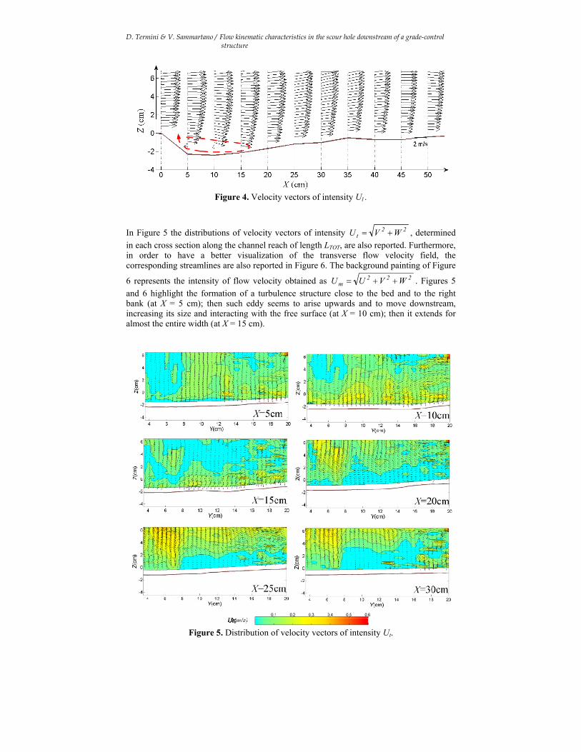
In Figure 4 the distributions of velocity vectors of intensity 22l VU U , obtained in
the vertical plane at a distance of 4 cm from the right bank, are reported. This figure also shows the longitudinal profile of the bed. From this figure it can be observed that in the scour hole the velocity vectors near the bed change their direction indicating the formation of a turbulence structure. On the other hand, the longitudinal profile of Figure 4 highlights that the maximum excavation occurs between sections X = 5 cm and X = 10 cm.
D. Termini & V. Sammartano / Flow kinematic characteristics in the scour hole downstream of a grade-control structure
Figure 4. Velocity vectors of intensity Ul .
In Figure 5 the distributions of velocity vectors of intensity 22t WV U , determined
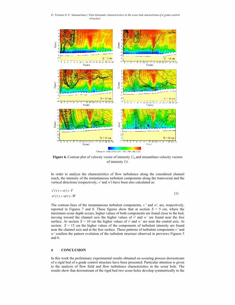
in each cross section along the channel reach of length LTOT, are also reported. Furthermore, in order to have a better visualization of the transverse flow velocity field, the corresponding streamlines are also reported in Figure 6. The background painting of Figure
6 represents the intensity of flow velocity obtained as 222m WVU U . Figures 5
and 6 highlight the formation of a turbulence structure close to the bed and to the right bank (at X = 5 cm); then such eddy seems to arise upwards and to move downstream, increasing its size and interacting with the free surface (at X = 10 cm); then it extends for almost the entire width (at X = 15 cm).
Figure 5. Distribution of velocity vectors of intensity Ut.
D. Termini & V. Sammartano / Flow kinematic characteristics in the scour hole downstream of a grade-control structure
Figure 6. Contour plot of velocity vector of intensity Um and streamlines velocity vectors
of intensity Ut. In order to analyze the characteristics of flow turbulence along the considered channel reach, the intensity of the instantaneous turbulent components along the transversal and the vertical directions (respectively, v' and w') have been also calculated as:
W-)t(w )t('w
V-)t(v )t('v
(1)
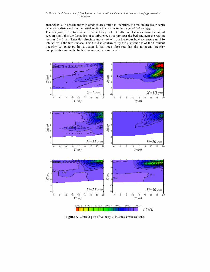
The contour-lines of the instantaneous turbulent components, v ' and w', are, respectively, reported in Figures 7 and 8. These figures show that at section X = 5 cm, where the maximum scour depth occurs, higher values of both components are found close to the bed; moving toward the channel axis the higher values of v' and w’ are found near the free surface. At section X = 10 cm the higher values of v' and w’ are near the central axis. At section X = 15 cm the higher values of the components of turbulent intensity are found near the channel axis and at the free surface. These patterns of turbulent components v’ and w’ confirm the pattern evolution of the turbulent structure observed in previews Figures 5 and 6. 4 CONCLUSION In this work the preliminary experimental results obtained on scouring process downstream of a rigid bed of a grade control structure have been presented. Particular attention is given to the analysis of flow field and flow turbulence characteristics in the scour hole. The results show that downstream of the rigid bed two scour holes develop symmetrically to the
D. Termini & V. Sammartano / Flow kinematic characteristics in the scour hole downstream of a grade-control structure
channel axis. In agreement with other studies found in literature, the maximum scour depth occurs at a distance from the initial section that varies in the range (0.3-0.4) LTOT. The analysis of the transversal flow velocity field at different distances from the initial section highlights the formation of a turbulence structure near the bed and near the wall at section X = 5 cm. Then this structure moves away from the scour hole increasing until to interact with the free surface. This trend is confirmed by the distributions of the turbulent intensity components. In particular it has been observed that the turbulent intensity components assume the highest values in the scour hole.
Figure 7. Contour plot of velocity v’ in some cross sections.
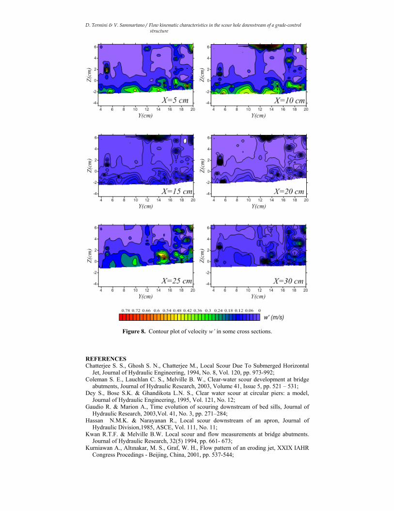
D. Termini & V. Sammartano / Flow kinematic characteristics in the scour hole downstream of a grade-control structure
Figure 8. Contour plot of velocity w’ in some cross sections. REFERENCES Chatterjee S. S., Ghosh S. N., Chatterjee M., Local Scour Due To Submerged Horizontal
Jet, Journal of Hydraulic Engineering, 1994, No. 8, Vol. 120, pp. 973-992; Coleman S. E., Lauchlan C. S., Melville B. W., Clear-water scour development at bridge
abutments, Journal of Hydraulic Research, 2003, Volume 41, Issue 5, pp. 521 – 531; Dey S., Bose S.K. & Ghandikota L.N. S., Clear water scour at circular piers: a model,
Journal of Hydraulic Engineering, 1995, Vol. 121, No. 12; Gaudio R. & Marion A., Time evolution of scouring downstream of bed sills, Journal of
Hydraulic Research, 2003,Vol. 41, No. 3, pp. 271–284; Hassan N.M.K. & Narayanan R., Local scour downstream of an apron, Journal of
Hydraulic Division,1985, ASCE, Vol. 111, No. 11; Kwan R.T.F. & Melville B.W. Local scour and flow measurements at bridge abutments.
Journal of Hydraulic Research, 32(5) 1994, pp. 661- 673; Kurniawan A., Altınakar, M. S., Graf, W. H., Flow pattern of an eroding jet, XXIX IAHR
Congress Procedings - Beijing, China, 2001, pp. 537-544;
D. Termini & V. Sammartano / Flow kinematic characteristics in the scour hole downstream of a grade-control structure
Lenzi M. A., Marion A., Comiti F., Interference processes on scouring at bed sills, Earth Surf. Processes Landforms, 2003, 28(1), pp. 99 –110;
Mazurek K. A., Rajaratnam N., Sego D. C., Scour of a cohesive soil by submerged plane turbulent wall jets, Journal of Hydraulic Research, 2003,Volume 41, pp. 195 – 206;
Melville B.W., Bridge Abutment scour in Compound Channels. , Journal Hydraulic Engineering, 1995, 118(4), pp. 863- 868;
Mossa M., Experimental study downstream of grade - control structures, XXVI Convegno di Idraulica e Costruzioni Idrauliche, 9-12 Settembre 1998, Catania;
Oliveto G. & W. H. Hager, Temporal Evolution of Clear-Water Pier and Abutment Scour, Journal of Hydraulic Engineering, 2002,Vol. 128, No. 9;
Rajaratnam N. & Berry B., Erosion by circular turbulent wall jets, Journal Hydraulic Research,1977, 15(3), pp. 277–289;
Rajaratnam N. , Erosion by PlaneTurbulent Jets, Journal Hydraulic Research IAHR,1981, 19(4), pp. 339–358;
Rajkumar V. R. & Dey S., Maximum scour depth at piers in armor-beds, KSCE Journal of Civil Engineering, 2009, 13(2), pp. 137-142;
Termini D., Temporal evolution of scour downstream bed sills, Proceedings of the 10th International Symposium on river Sedimentation, August 1-4, 2007, Moscow, vol. II.
Related Documents