CFD-BASED METHODS FOR NUMERICAL MODELLING OF SCOUR Greg Melling 1 , Justin Dix 1 , Stephen Turnock 2 , University of Southampton - [email protected] Richard Whitehouse, HR Wallingford 1. Introduction Marine local scour is understood as the removal of sediment from around the base of an object on the seabed caused by waves and currents. The introduction of a flow obstruction to the seafloor will have a significant impact on the local hydrodynamics, causing acceleration, pressure gradients, boundary-layer separation and increased turbulence at the seabed and in the wake of the object. Where the seabed cannot resist the increased magnitude of impinging shear forces, e.g. in non-cohesive mobile sediment such as sands, sediment will be eroded to form a characteristic scour hole. Scour, left unchecked can cause structural damage and major economic losses. The ability to predict scour, both vertical and lateral, is thus a prerequisite for the optimised design of a structure and provision of scour protection. At present, empirical equations are used for simple two- dimensional objects such as vertical and horizontal cylindrical type in the forecast of maximum scour depths. Fewer relations are available for the quantification lateral scour extent and evolution of the scour pit with time. For a more comprehensive scour prediction or assessment of more complex structures, expensive and time- consuming physical model experiments are required. The aim of this PhD project is to develop a numeric method for scour modelling in openFOAM CFD which will be capable of predicting scour around complex three-dimensional seabed structures. In this study, we will focus on the discussion of the available approaches for scour modelling using CFD methods. 2. CFD-based scour modelling The first CFD-based methods were tentatively used for scour modelling in the 1990s. Two general approaches have crystallised that can be distinguished as fundamentally

Welcome message from author
This document is posted to help you gain knowledge. Please leave a comment to let me know what you think about it! Share it to your friends and learn new things together.
Transcript

CFD-BASED METHODS FOR NUMERICAL MODELLING OF SCOURGreg Melling1, Justin Dix1, Stephen Turnock2, University of Southampton - [email protected]
Richard Whitehouse, HR Wallingford
1. Introduction
Marine local scour is understood as the removal of sediment from around the base of an object on the seabed caused by waves and currents. The introduction of a flow obstruction to the seafloor will have a significant impact on the local hydrodynamics, causing acceleration, pressure gradients, boundary-layer separation and increased turbulence at the seabed and in the wake of the object. Where the seabed cannot resist the increased magnitude of impinging shear forces, e.g. in non-cohesive mobile sediment such as sands, sediment will be eroded to form a characteristic scour hole. Scour, left unchecked can cause structural damage and major economic losses. The ability to predict scour, both vertical and lateral, is thus a prerequisite for the optimised design of a structure and provision of scour protection.At present, empirical equations are used for simple two-dimensional objects such as vertical and horizontal cylindrical type in the forecast of maximum scour depths. Fewer relations are available for the quantification lateral scour extent and evolution of the scour pit with time. For a more comprehensive scour prediction or assessment of more complex structures, expensive and time-consuming physical model experiments are required.
The aim of this PhD project is to develop a numeric method for scour modelling in openFOAM CFD which will be capable of predicting scour around complex three-dimensional seabed structures. In this study, we will focus on the discussion of the available approaches for scour modelling using CFD methods.
2. CFD-based scour modelling
The first CFD-based methods were tentatively used for scour modelling in the 1990s. Two general approaches have crystallised that can be distinguished as fundamentally different (Fig. 1). Earlier methods were concerned with flow simulations coupled with a morphological description that drives the deformation of the bottom computational mesh to produce a scour hole. Successive refinement in the following years saw routines of varying complexity being employed for the calculation of the mesh deformation tensor. A boundary adjustment technique (e.g. Li and Cheng, 1999; Lu et al., 2005) has been employed which relates the magnitude of deformation to the equilibrium of the bottom shear stress τ and critical threshold for incipient sediment motion τc, i.e. the mesh vertices are adjusted in vertical direction in response to the impinging flow until the condition τ = τc is reached. More common has been method based on sediment transport theory in which the morphological model consists of bedload and/or suspended sediment equations and the bed evolution is determined by solving the mass balance of sediment equation (e.g. Olsen and Melaaen, 1993; Brørs, 1999; Liang and Cheng, 2005; Liu and Garcia, 2008).More recently, scour predictions based on two-phase flow considerations have been presented (Zhao and Fernando, 2007; Amoudry et al., 2008; Yeganeh-Bakhtiary et al., 2011). Euler-Euler models treat the fluid and solids as phases as interpenetrating continua capable of exchanging properties like mass and momentum. The advantage of two-phase models is that fluid-solid and solid-solid interactions are considered and no empirical relations are required.
1 Geology/Geophysics Research Group, School of Ocean and Earth Sciences, University of Southampton2 Fluid Structure Interaction Research Group, Faculty of Engineering and Environment, University of Southampton

Fig. 1 CFD-based scour modelling methods
3. Numerical Investigations3.1. Mesh deformation techniques – capturing the basicsa. Resolving the flow
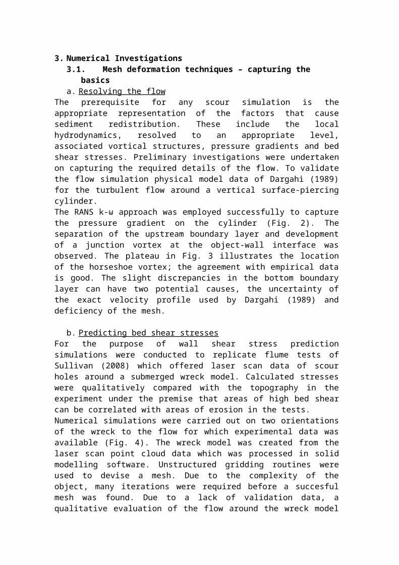
The prerequisite for any scour simulation is the appropriate representation of the factors that cause sediment redistribution. These include the local hydrodynamics, resolved to an appropriate level, associated vortical structures, pressure gradients and bed shear stresses. Preliminary investigations were undertaken on capturing the required details of the flow. To validate the flow simulation physical model data of Dargahi (1989) for the turbulent flow around a vertical surface-piercing cylinder. The RANS k-ω approach was employed successfully to capture the pressure gradient on the cylinder (Fig. 2). The separation of the upstream boundary layer and development of a junction vortex at the object-wall interface was observed. The plateau in Fig. 3 illustrates the location of the horseshoe vortex; the agreement with empirical data is good. The slight discrepancies in the bottom boundary layer can have two potential causes, the uncertainty of the exact velocity profile used by Dargahi (1989) and deficiency of the mesh.
b. Predicting bed shear stresses For the purpose of wall shear stress prediction simulations were conducted to replicate flume tests of Sullivan (2008) which offered laser scan data of scour holes around a submerged wreck model. Calculated stresses were qualitatively compared with the topography in the experiment under the premise that areas of high bed shear can be correlated with areas of erosion in the tests.Numerical simulations were carried out on two orientations of the wreck to the flow for which experimental data was available (Fig. 4). The wreck model was created from the laser scan point cloud data which was processed in solid modelling software. Unstructured gridding routines were used to devise a mesh. Due to the complexity of the object, many iterations were required before a succesful mesh was found. Due to a lack of validation data, a qualitative evaluation of the flow around the wreck model was undertaken with respect to the boundary layer separation and expected gross flow features. Further, the adequacy of the hydrodynamics were “validated” indirectly in light of the resulting pattern of bed shear stresses, as these are the results of some discernible flow feature such as enhanced levels of flow or vorticity. The visualisations
in Figs. 5 and 6 show the major flow features and the presence of flow separation in both simulations. A counter-rotating vortex is resolved at the wall-object interface for both cases. The upright wreck results in a recirculation zone in the lee of the object.
Fig. 2 Validation of pressure gradients on stagnation line
Fig. 3 Validation of pressure gradient at the base of the cylinder in x-direction
Fig. 4 Wreck model meshes: upright, 90° to flow (left) and on port side, 45° to flow
Interesting turbulent wake patterns are visualised by the streamtubes. On the upright wreck eddies originate from flow spinning off the lateral ends of the object. Where the flow passes over the object similar eddies are observed in the vertical plane. For the wreck oblique to the incoming flow, it was observed that a large part of the flow passes directly over the object, with a smaller proportion passing around the sides. A vortex is shown corkscrewing off the wreck as a result of the interaction between the downward flow in the lee of the wreck and accelerated flows around the ends. As will be shown in the visualisation of wall shear forces, it is the presence of these areas of increased turbulent energy that are responsible for driving the scour process.
Fig. 5 Slice and stream tubes of U(x) Fig. 6 Isosurface of Q coloured in U and streamlines
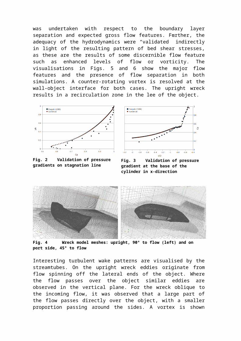
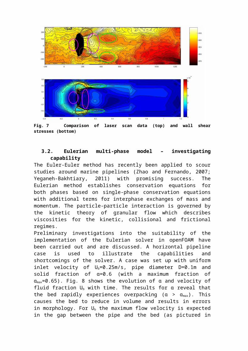
Fig. 7 offers a comparison of the laser scan data with calculated wall shear stresses. There is general agreement between areas of high shear and zones of erosion (brown and green circles). Similarly, quiescent accumulation zones show low shear stresses (pink circles). It is however evident that the turbulent energy of the wake is not fully captured (green circles). This could be improved by increasing the mesh resolution and a vortex-following mesh-adaptive algorithm.In summary, the building blocks for the implementation of a moving mesh technique have been investigated. As illustrated above, once the model and mesh requirements for resolution of flow and bed shear stresses have been established, a routine for mesh movement can be developed.
Fig. 7 Comparison of laser scan data (top) and wall shear stresses (bottom)
3.2. Eulerian multi-phase model – investigating capabilityThe Euler-Euler method has recently been applied to scour studies around marine pipelines (Zhao and Fernando, 2007; Yeganeh-Bakhtiary, 2011) with promising success. The Eulerian method establishes conservation equations for both phases based on single-phase conservation equations with additional terms for interphase exchanges of mass and momentum. The particle-particle interaction is governed by the kinetic theory of granular flow which describes viscosities for the kinetic, collisional and frictional regimes.Preliminary investigations into the suitability of the implementation of the Eulerian solver in openFOAM have been carried out and are discussed. A horizontal pipeline case is used to illustrate the capabilities and shortcomings of the solver. A case was set up with uniform inlet velocity of Ub=0.25m/s, pipe diameter D=0.1m and solid fraction of α=0.6 (with a maximum fraction of αmax=0.65). Fig. 8 shows the evolution of α and velocity of fluid fraction Ub with time. The results for α reveal that the bed rapidly experiences overpacking (α > αmax). This causes the bed to reduce in volume and results in errors in morphology. For Ub the maximum flow velocity is expected in the gap between the pipe and the bed (as pictured in the initial condition t=0). However, the flow is reduced significantly with time which causes the bedforms to smooth out.
t=0.0
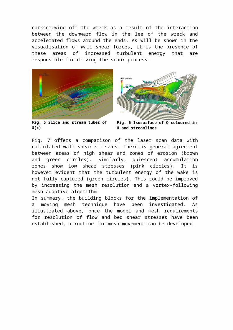
Fig. 8 Evolution of phase fraction α and velocity of fluid fraction Ub
Several issues have been identified with the standard solver. Using kinetic theory alone to control the maximum solid fraction, the bed is subject to strong overpacking. The attenuation of flow in the near-bed area is caused by an inadequate representation of the particle-turbulence interaction which causes a strong reduction in flow velocity leading to rapid settling out of particles near the pipe. Another issue is a discrepancy in timescales. The characteristic timescale of particle-turbulence interaction is shorter than the time required for the flow to adjust to the bed morphology change, causing errors in the scour calculation. This has also been reported by Zhao and Fernando (2007). A number of modifications are required. To alleviate overpacking, a particle normal force model is used that introduces a solids pressure term in the conservation equation. Initial inclusion has shown to improve the control of the maximum solid fraction. For issues with particle-turbulence interaction a number of potential remedies have been identified. Elghobashi and Abou-Arab (1983) have developed a two-phase turbulence model which includes terms for the effect of particles on turbulence. This could be implemented. Another option could be a “frozen bed switch” which entails not solving for the solid phase while the hydrodynamics are calculated; once the flow is fully developed, both phases are solved to allow for bed adjustment before returning to the previous step (Fig. 9). Similarly, iterative mapping between a transient single-phase and the Euler-Euler solver could be used to provide accurate hydrodynamics while respecting the disparity between the characteristic timescales (Fig. 10).
Fig. 9 “Frozen bed switch” Fig. 10 Iterative mapping between solvers
4. ConclusionsTwo possible approaches to scour modelling using CFD methods have been outlined: mesh deformation techniques and multi-phase models. For the prior, the basic components – accurate prediction of hydrodynamics and bed shear stresses – of such an approach have been investigated in openFOAM CFD and discussed in light of physical model data. Based on the presented numerical experiments, a moving mesh approach can be developed and implemented. Multi-phase approaches have only recently been used in scour prediction; previous studies have shown the Euler-Euler method to be suitable. The capabilities of the openFOAM implementation of the Eulerian solver are explored using a two-dimensional pipeline case. Several shortcomings have been illustrated and modifications have been suggested to develop the solver for the purposes of scour modelling.
ReferencesAmoudry, L. O., Hsu, T.-J., & Liu, P. L.-F. (2008). Two-phase model for sand transport in sheet flow regime. Journal of Geophysical Research, 113(C3), 1-15. doi:10.1029/2007JC004179
Brørs, B. (1999). Numerical modelling of flow and scour at pipelines. Journal of Hydraulic Engineering, 125(5), 511-523.
Dargahi, B. (1989). The turbulent flow field around a circular cylinder. Experiments in Fluids, 8(1), 1–12.
Elghobashi, S., & Abou-Arab, T. (1983). A two-equation turbulence model for two-phase flows. Physics of Fluids, 26(4), 931-938.
Li, F., & Cheng, L. (1999). Numerical model for local scour under offshore pipelines. Journal of Hydraulic Engineering, 125(4), 400-406.
Liang, D., Cheng, L., & Li, F. (2005). Numerical modeling of flow and scour below a pipeline in currents Part II. Scour simulation. Coastal Engineering, 52(1), 43-62.
Liu, X., & Garcia, M. H. (2008). Three-Dimensional Numerical Model with Free Water Surface and Mesh Deformation for Local Sediment Scour. Journal of Waterway, Port, Coastal, and Ocean Engineering, 134(4), 203-217.
Lu, L., Li, Y., & Qin, J. (2005). Numerical simulation of the equilibrium profile of local scour around submarine pipelines based on renormalized group turbulence model. Ocean Engineering, 32(17-18), 2007-2019.
Olsen, N., & Melaaen, M. C. (1993). Three-Dimensional Calculation of Scour Around Cylinders. Journal of Hydraulic Engineering, 119(9), 1048-1054.
Sullivan, R., (2008). Physical Modelling of Scour Under Bidirectional Flow Conditions Around Submerged Three Dimensional Objects. MSc Thesis, School of Ocean and Earth Sciences, University of Southampton.
Yeganeh-Bakhtiary, A., Kazeminezhad, M. H., Etemad-Shahidi, A., Baas, J. H., & Cheng, L. (2011). Euler–Euler two-phase flow simulation of tunnel erosion beneath marine pipelines. Applied Ocean Research, 33(2), 137-146.
Zhao, Z., & Fernando, H. J. S. (2007). Numerical simulation of scour around pipelines using an Euler–Euler coupled two-phase model. Environmental Fluid Mechanics, 7(2), 121-142.
Related Documents