The solution to accommodate building drift, the DSSCB, is used to support cold-formed steel bypass framing to the edge of a floor slab. The DSSCB also simplifies installation by allowing installers for panelized construction to install finished panels while working off the top of the slab without the need to predrill or preinstall anchors for each clip. It also eliminates the coordination difficulties associated with pre-anchorage of standard bypass clips. With prepunched slots and round holes, the DSSCB is a dual-function connector that can be used for slide-clip and fixed-clip applications. Features • The clips come in lengths of 3 ", 6" and 8". • Prepunched slots provide a full 1" of both upward and downward deflection. • Precision-manufactured shouldered screws, provided with DSSCB connectors, are designed to prevent overdriving and to ensure the clip functions properly. • Works with 13/16" and 1 " strut channels as given in the accompanying figures. Common manufactured brands are Unistrut ® , PHD and B-Line. Struts are not supplied by Simpson Strong-Tie. • The maximum slide-clip standoff distance is 3 1/16" for 13/16" struts, 3 " for 1 " struts and 2 " for concrete inserts. • Depending on the application and the Designer’s specifications, struts can be either mechanically anchored, welded or cast in place. • Pre-engineered design solutions are provided for channel strut anchorage. • Tabulated design values are based on assembly testing to mitigate risk for designers, engineers and architects. • Optional pre-cast concrete inserts for flush mounting. • Optional drift stopper, DSHS, for clip alignment flexibility (where drift not required). Material: DSSCB – 97 mil (12 ga.), 50 ksi; DSHS – 97 mil (12 ga.), 33 ksi Finish: Galvanized (G90) Codes: Testing performed in accordance with ICC-ES AC 261. Visit strongtie.com for the latest load values and testing information. Ordering Information: The DSSCB43.5-KT25, DSSCB46-KT25 and DSSCB48-KT25 contain 25 connectors and enough shouldered screws for installation. The DSHS-R100 contains 100 connectors. Note: Replacement #14 shouldered screws for DSSCB connectors are the XLSH78B1414-RP83. XLSH78B1414 #14 Shouldered Screw for Attachment to Stud Framing (included) 0.24" " DSSCB48 DSSCB43.5 DSSCB46 SIMPSON Strong-tie ® Use & Warnings: strongtie.com/info DSSCB43.5 SIMPSON Strong-tie ® Use & Warnings: strongtie.com/info DSSCB48 SIMPSON Strong-tie ® Use & Warnings: strongtie.com/info DSSCB46 Patent Pending Patent Pending Patent Pending © 2017 Simpson Strong-Tie Company Inc. F-CF-DSSCB17 DSSCB — Bypass Framing Drift Strut Connector

Welcome message from author
This document is posted to help you gain knowledge. Please leave a comment to let me know what you think about it! Share it to your friends and learn new things together.
Transcript

The solution to accommodate building drift, the DSSCB, is used to support cold-formed steel bypass framing to the edge of a floor slab. The DSSCB also simplifies installation by allowing installers for panelized construction to install finished panels while working off the top of the slab without the need to predrill or preinstall anchors for each clip. It also eliminates the coordination difficulties associated with pre-anchorage of standard bypass clips. With prepunched slots and round holes, the DSSCB is a dual-function connector that can be used for slide-clip and fixed-clip applications.
Features
• The clips come in lengths of 3 1/2", 6" and 8".
• Prepunched slots provide a full 1" of both upward and downward deflection.
• Precision-manufactured shouldered screws, provided with DSSCB connectors, are designed to prevent overdriving and to ensure the clip functions properly.
• Works with 13/16" and 1 5/8" strut channels as given in the accompanying figures. Common manufactured brands are Unistrut®, PHD and B-Line. Struts are not supplied by Simpson Strong-Tie.
• The maximum slide-clip standoff distance is 3 1/16" for 13/16" struts, 3 7/8" for 1 5/8" struts and 2 1/4" for concrete inserts.
• Depending on the application and the Designer’s specifications, struts can be either mechanically anchored, welded or cast in place.
• Pre-engineered design solutions are provided for channel strut anchorage.
• Tabulated design values are based on assembly testing to mitigate risk for designers, engineers and architects.
• Optional pre-cast concrete inserts for flush mounting.
• Optional drift stopper, DSHS, for clip alignment flexibility (where drift not required).
Material: DSSCB – 97 mil (12 ga.), 50 ksi; DSHS – 97 mil (12 ga.), 33 ksi
Finish: Galvanized (G90)
Codes: Testing performed in accordance with ICC-ES AC 261. Visit strongtie.com for the latest load values and testing information.
Ordering Information: The DSSCB43.5-KT25, DSSCB46-KT25 and DSSCB48-KT25 contain 25 connectors and enough shouldered screws for installation. The DSHS-R100 contains 100 connectors.
Note: Replacement #14 shouldered screws for DSSCB connectors are the XLSH78B1414-RP83.
XLSH78B1414 #14 Shouldered Screw for Attachment to Stud
Framing (included)0.24"
7/8"
DSSCB48
DSSCB43.5DSSCB46
SIMPSON
Strong-tie®
Use & Warnings:strongtie.com/info
DSSCB43.5
SIMPSON
Strong-tie®
Use & Warnings:strongtie.com/info
DSSCB48
SIMPSON
Strong-tie®
Use & Warnings:strongtie.com/info
DSSCB46
Patent Pending
Patent Pending
Patent Pending
© 2017 Simpson Strong-Tie Company Inc. F-CF-DSSCB17
DSSCB — Bypass Framing Drift Strut Connector

No-Equal stamp marks the center of the slots to help ensure correct shouldered-screw placement
Dual-function clips can be used for either deflection or fixed conditions
Stiffened edges and heavy 12-gauge construction provide jobsite durability and superior tabulated loads
Squaring flange helps the clip stay
square with the strut
Unique formed insert works with standard 13/16"
and 15/8"-deep, 12-gauge strut, minimizes friction, and allows
an easy twist-in installation
DSSCB Dimensions
SIMPSON
Strong-tie®
Use & Warnings:strongtie.com/info
DSSCB
½"
4"
1⅝"
1¼"
2¼"
1¾" 6"(DSSCB46)
3½"(DSSCB43.5)
8"(DSSCB48)
⅞"The Simpson Strong-Tie DSSCB works with 12-gauge standard strut channels (not sold by Simpson Strong-Tie). See p. 10 for strut requirements and p. 11 for concrete insert requirements. See pp. 7–8 for model numbers and capacities.
10' and 20' standard lengths
13⁄16"
1⅝"
10' and 20' standard lengths
1⅝"
1⅝"
DSHS used to prevent horizontal sliding when needed (sold separately)
DSHS strongtie.com/info
®
19⁄16"
11⁄16"
1½"
⅝"
¼"
Patent Pending
Patent Pending
Patent Pending
2
© 2
017
Sim
pson
Str
ong-
Tie
Com
pany
Inc.
F-C
F-D
SS
CB
17
Product Information
Bypass Framing Drift Strut Connector

SIMPSON
Strong-tie®
Use & Warnings:strongtie.com/info
DSSCB46
F1
F2
F3
DSSCB Screw Patterns (Slide-Clip Applications)
Model Pattern A
DSSCB43.5
SIMPSON
Strong-tie®
Use & Warnings:strongtie.com/info
DSSCB43.5
Model Pattern B Pattern C Pattern D
DSSCB46
SIMPSON
Strong-tie®
Use & Warnings:strongtie.com/info
DSSCB46
SIMPSON
Strong-tie®
Use & Warnings:strongtie.com/info
DSSCB46
SIMPSON
Strong-tie®
Use & Warnings:strongtie.com/info
DSSCB46
Model Pattern E Pattern F Pattern G
DSSCB48
SIMPSON
Strong-tie®
Use & Warnings:strongtie.com/info
DSSCB48
SIMPSON
Strong-tie®
Use & Warnings:strongtie.com/info
DSSCB48
SIMPSON
Strong-tie®
Use & Warnings:strongtie.com/info
DSSCB48
Typical DSSCB Installation — Slide-Clip Application
DSHS
stro
ngtie
.com
/info®
1½"
SIMPSON
Strong-tie®
Use & Warnings:
strongtie.com/info
DSSCB46
DSHS
stro
ngtie
.com
/info®
DSHS Connector (sold separately and optional if required by designer). Use to prevent
horizontal movement when needed. Fasten to top of strut channel
with (1) #10-16.
3
© 2
017
Sim
pson
Str
ong-
Tie
Com
pany
Inc.
F-C
F-D
SS
CB
17
Product Information
Bypass Framing Drift Strut Connector
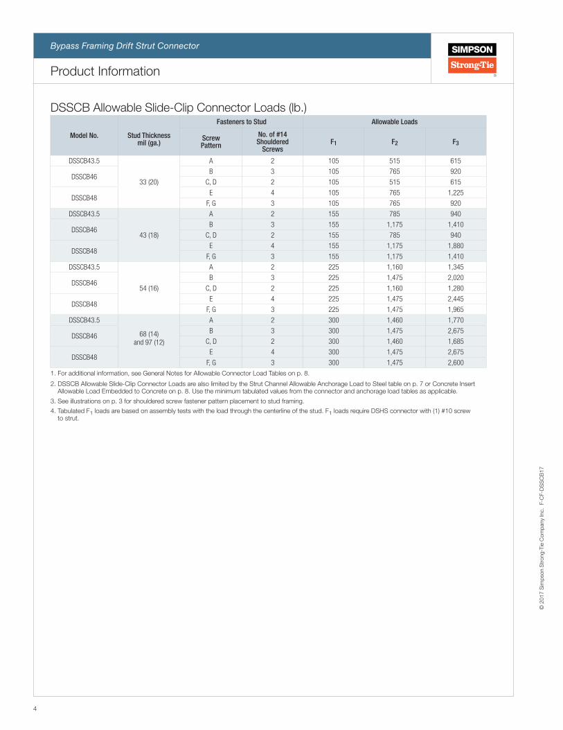
DSSCB Allowable Slide-Clip Connector Loads (lb.)
Model No. Stud Thickness mil (ga.)
Fasteners to Stud Allowable Loads
Screw Pattern
No. of #14 Shouldered
Screws F1 F2 F3
DSSCB43.5
33 (20)
A 2 105 515 615
DSSCB46B 3 105 765 920
C, D 2 105 515 615
DSSCB48E 4 105 765 1,225
F, G 3 105 765 920
DSSCB43.5
43 (18)
A 2 155 785 940
DSSCB46B 3 155 1,175 1,410
C, D 2 155 785 940
DSSCB48E 4 155 1,175 1,880
F, G 3 155 1,175 1,410
DSSCB43.5
54 (16)
A 2 225 1,160 1,345
DSSCB46B 3 225 1,475 2,020
C, D 2 225 1,160 1,280
DSSCB48E 4 225 1,475 2,445
F, G 3 225 1,475 1,965
DSSCB43.5
68 (14)and 97 (12)
A 2 300 1,460 1,770
DSSCB46B 3 300 1,475 2,675
C, D 2 300 1,460 1,685
DSSCB48E 4 300 1,475 2,675
F, G 3 300 1,475 2,6001. For additional information, see General Notes for Allowable Connector Load Tables on p. 8.
2. DSSCB Allowable Slide-Clip Connector Loads are also limited by the Strut Channel Allowable Anchorage Load to Steel table on p. 7 or Concrete Insert Allowable Load Embedded to Concrete on p. 8. Use the minimum tabulated values from the connector and anchorage load tables as applicable.
3. See illustrations on p. 3 for shouldered screw fastener pattern placement to stud framing.
4. Tabulated F1 loads are based on assembly tests with the load through the centerline of the stud. F1 loads require DSHS connector with (1) #10 screw to strut.
4
© 2
017
Sim
pson
Str
ong-
Tie
Com
pany
Inc.
F-C
F-D
SS
CB
17
Product Information
Bypass Framing Drift Strut Connector

SIMPSON
Strong-tie®
Use & Warnings:strongtie.com/info
DSSCB46
F1
F2
F3
F4
Typical DSSCB Installation — Fixed-Clip Application
DSSCB Screw Patterns (Fixed-Clip Applications)Model Pattern H Pattern I Pattern J
DSSCB43.5
SIMPSON
Strong-tie®
Use & Warnings:strongtie.com/info
DSSCB43.5
SIMPSON
Strong-tie®
Use & Warnings:strongtie.com/info
DSSCB43.5
SIMPSON
Strong-tie®
Use & Warnings:strongtie.com/info
DSSCB43.5
Model Pattern K Pattern L Pattern M
DSSCB46
SIMPSON
Strong-tie®
Use & Warnings:strongtie.com/info
DSSCB46
SIMPSON
Strong-tie®
Use & Warnings:strongtie.com/info
DSSCB46
SIMPSON
Strong-tie®
Use & Warnings:strongtie.com/info
DSSCB46
Model Pattern N Pattern O Pattern P
DSSCB48
SIMPSON
Strong-tie®
Use & Warnings:strongtie.com/info
DSSCB48
SIMPSON
Strong-tie®
Use & Warnings:strongtie.com/info
DSSCB48
SIMPSON
Strong-tie®
Use & Warnings:strongtie.com/info
DSSCB48
DSHS
stro
ngtie
.com
/info®
1½"
SIMPSON
Strong-tie®
Use & Warnings:
strongtie.com/info
DSSCB46
DSHS
stro
ngtie
.com
/info®
DSHS Connector (sold separately and optional if required by designer). Use to prevent
horizontal movement when needed. Fasten to top of strut channel
with (1) #10-16.
5
© 2
017
Sim
pson
Str
ong-
Tie
Com
pany
Inc.
F-C
F-D
SS
CB
17
Product Information
Bypass Framing Drift Strut Connector

DSSCB Allowable Fixed-Clip Connector Loads (lb.)
Model No. Stud Thickness mil (ga.)
Screw Pattern
No. of #10 Screws
Allowable Loads (lb.)
F1 F2 F3 F4
DSSCB43.5
33 (20)
H 4 220 705 705 345
I, J 2 185 355 355 175
DSSCB46K 6 220 1,060 1,060 355
L, M 4 185 705 705 350
DSSCB48N 8 220 1,060 1,060 545
O, P 4 185 705 705 505
DSSCB43.5
43 (18)
H 4 285 1,050 1,050 450
I, J 2 240 525 525 230
DSSCB46K 6 285 1,125 1,580 460
L, M 4 240 1,050 1,050 455
DSSCB48N 8 285 1,145 1,580 710
O, P 4 240 1,050 1,050 660
DSSCB43.5
54 (16)
H 4 330 1,410 2,085 1,025
I, J 2 300 1,070 1,045 515
DSSCB46K 6 360 1,410 3,130 1,050
L, M 4 300 1,410 2,135 1,040
DSSCB48N 8 360 1,440 3,130 1,145
O, P 4 300 1,420 2,135 1,070
DSSCB43.5
68 (14)and 97 (12)
H 4 395 1,410 2,160 1,025
I, J 2 300 1,080 1,080 515
DSSCB46K 6 395 1,410 3,130 1,050
L, M 4 300 1,410 2,160 1,040
DSSCB48N 8 395 1,440 3,240 1,145
O, P 4 300 1,420 2,160 1,0701. For additional information, see General Notes for Allowable Connector Load Tables on p. 8.
2. DSSCB Allowable Fixed-Clip Connector Loads are also limited by the Strut Channel Allowable Anchorage Load table on p. 7. Use the minimum tabulated values from the connector and anchorage load tables as applicable.
3. See illustrations on p. 5 for screw fastener pattern placement to stud framing.
4. Tabulated F1 loads are based on assembly tests with the load through the centerline of the stud. F1 loads require DSHS connector with (1) #10 screw to strut.
6
© 2
017
Sim
pson
Str
ong-
Tie
Com
pany
Inc.
F-C
F-D
SS
CB
17
Product Information
Bypass Framing Drift Strut Connector

Strut Channel Allowable Anchorage Loads to Steel (lb.)
Strut Size (in.)
Models
Welded Anchorage ea. Flange #12–24 Screw Anchorage
Weld Spacing
(in.)
Required Weld
Length (in.)
F1 (lb.)
F2 (lb.)
F3 (lb.)
F4 (lb.)
Screw Spacing
(in.)
F1 (lb.)
F2 (lb.)
F3 (lb.)
F4 (lb.)
13/16
Unistrut®
P4520; P4520HS; P4520T; P4520KO
4 1 1/2 775 1,430 2,540 870 4 755 1,235 2,540 870
6 1 1/2 775 955 2,540 870 6 755 845 2,540 840
PHD1201; 1202; 1211; 1212; 1221; 1222; 1241; 1242
8 1 775 715 2,540 740 8 755 715 2,540 —
10 1 775 570 2,540 — — — — — —
B-LineB52;
B52H1 7/8; B52SH; B52KO6
12 1 775 475 2,540 — — — — — —
16 1 775 360 2,540 — — — — — —
1 5/8
UnistrutP1000;
P1000HS; P1000T; P1000KO
4 1 1/2 775 1,870 3,630 — 4 755 1,270 3,630 —
6 1 1/2 775 1,870 3,630 — 6 755 845 3,630 —
PHD1001; 1002; 1011; 1012; 1021; 1022; 1041; 1042
8 1 775 1,775 3,630 — 8 755 845 3,630 —
10 1 775 1,420 3,630 — — — — — —
B-LineB22;
B22H1 7/8; B22SH; B22KO6
12 1 775 1,185 3,630 — — — — — —
16 1 775 885 3,630 — — — — — —
1. For additional information, see General Information on p. 8.
2. Allowable anchorage loads are also limited by the DSSCB Connector Load tables on pp. 4 and 6. Use the minimum tabulated values from the connector and anchorage load tables as applicable.
3. Allowable loads are based on 97 mil (12 ga.) thickness strut channel members with a minimum yield strength, Fy, of 33 ksi, tensile strength, Fu, of 45 ksi.
4. Allowable loads for self-drilling screws are based on installation in minimum 3/16"-thick structural steel with Fy = 36 ksi. Values listed above may be used where other thicknesses of steel are encountered provided that the fastener has equal or better tested values into thicker steel. It is the responsibility of the Designer to select the proper length fasteners based on the steel thickness installation.
5. For screw fastener installation into steel backed by concrete, predrilling of both the steel and the concrete is suggested. For predrilling, use a maximum 3/16"- diameter drill bit. Screw to be installed through steel portion of channel strut (1.5 x screw diameter from punch-out) and centered vertically in web.
6. For any connector occuring within 2" of channel strut splice, load not to exceed — F2 = 865 lb. and F4 = 785 lb.
7. Maximum allowable load of strut channel can be increased at high concentrated loads by welding each flange 1 1/2" from the strut channel to support directly at clip location: For 13/16" strut size — F1 = 775 lb., F2 = 1,430 lb., F3 = 2,540 lb. and F4 = 1,050 lb. For 1 5/8" strut size — F1 = 775 lb., F2 = 1,870 lb. and F3 = 3,630 lb.
8. Required weld length is on each flange at spacing indicated.
9. Anchorage spacing cannot be greater than framing spacing.
10. Connector load to be located a minimum of 2" from end of strut channel.
7
© 2
017
Sim
pson
Str
ong-
Tie
Com
pany
Inc.
F-C
F-D
SS
CB
17
Product Information
Bypass Framing Drift Strut Connector

Typical DSSCB Installation — Concrete Insert ApplicationSIM
PSONStrong-tie
®
DSSCB46
Use & Warnings:strongtie.com/info
F2
F3
Concrete Insert Allowable Load Embedded to Concrete (lb.)Strut Size
(in.)Concrete Insert Models for
the DSSCB
Embed Spacing
(in.)
F2
(lb.)
F3
(lb.)
13/16 or 7/8Unistrut® 3300 Series
B-Line B52IPHD 4101, 4102
4 1,500 2,540
1 PHD 4201, 4202 4 2,000 2,540
1 3/8Unistrut 3200 Series
B-Line B32IPHD 4001, 4002
4 2,000 2,540
1 5/8B-Line B22I
PHD 4301, 43024 2,000 2,540
1. Minimum concrete compressive strength, f'c = 3,000 psi.
2. Multiply tabulated values by a factor of 0.50 when clip is installed within 2" of the end of strut channel.
3. Minimum connector load spacing is 12" o.c.4. Tabulated values are for concrete inserts with a 12"
minimum length.5. Allowable anchorage loads are also limited by
connector load table on p. 4. Use the minimum tabulated value for the connector and the anchorage load tables as applicable.
General Notes for Allowable Connector Load Tables1. Allowable loads are for use when utilizing the traditional Allowable Stress Design methodology. Contact Simpson Strong-Tie for LRFD
loads unless otherwise noted.
2. Allowable loads are based on cold-formed steel members with a minimum yield strength, Fy, of 33 ksi and tensile strength, Fu, of 45 ksi for 43 mil (18 ga.) and thinner, and a minimum yield strength of 50 ksi and tensile strength of 65 ksi for 54 mil (16 ga.) and thicker.
3. Allowable loads may not be increased for wind or seismic load.
4. Allowable loads for #12 self-drilling screws are based on a minimum nominal shear strength, Pss, of 2,520 lb. and nominal tension strength, Pts, of 2,535 lb. and the allowable loads for #10 self-drilling screws are based on a minimum nominal shear strength, Pss, of 1,620 lb. and nominal tension strength, Pts, of 2,460 lb.
5. It is the responsible of the Designer to select the proper length fasteners based on installation need. Screw length must ensure fastener extends through the connection a minimum of three exposed threads unless noted otherwise.
6. Allowable loads for welded connections require E70XX electrodes with a minimum throat size equal to the clip thickness. Welding shall be in compliance with AWS D1.3. Welding galvanized steel may produce harm fumes; follow proper welding procedures and precautions.
7. Clips do not replace lateral or stability bracing. Design of bracing is the responsibility of the Designer.
8. It is the responsibility of the Designer to verify the adequacy of the stud. Allowable loads are based on clips installed an adequate distance away from penetrations, notches, ends of studs and other conditions that may affect the clip performance.
9. It is the responsibility of the Designer to check the adequacy of the supporting structure for loads imposed by connectors.
10. Industry studies show that hardened fasteners can experience performance problems in wet or corrosive environments. Accordingly, use these products in dry and non-corrosive environments only.
11. For load combinations that include F1 and/or F2 and/or F3 and/or F4, use an appropriate interaction equation.
8
© 2
017
Sim
pson
Str
ong-
Tie
Com
pany
Inc.
F-C
F-D
SS
CB
17
Product Information
Bypass Framing Drift Strut Connector

DSSCB Standoff Distance with 13/16" Strut and Minimum Fastener Edge Distance for
Fixed-Clip Application
SIMPSON
Strong-tie®
Use & Warnings:strongtie.com/infoDSSCB46
Standoff distance
⅜" min.
DSSCB Standoff Distance with 15/8" Strut (13/16" Strut Similar) and Minimum Fastener Edge
Distance for Slide-Clip Application
SIMPSON
Strong-tie®
Use & Warnings:strongtie.com/info
DSSCB46
Standoff distance
⅜" min.
DSSCB Standoff Distances (in.)
Model No. Application Screw Pattern
No. of Screws
13/16" Struts 15/8" Struts Concrete Inserts
Min. Standoff (in.)
Max. Standoff (in.)
Min. Standoff (in.)
Max. Standoff (in.)
Min. Standoff (in.)
Max. Standoff (in.)
DSSCB43.5
Slide Clip
A 2
1
2 5/16
1 13/16
3 1/8
3/16
1 1/2
DSSCB46
B 3 2 5/16 3 1/8 1 1/2
C 2 2 5/16 3 1/8 1 1/2
D 2 3 1/16 3 7/8 2 1/4
DSSCB48
E 4 2 5/16 3 1/8 1 1/2
F 3 2 5/16 3 1/8 1 1/2
G 3 3 1/16 3 7/8 2 1/4
DSSCB43.5
Fixed Clip
H 4
1
2 11/16
—
—
—
—
I 2 2 11/16 — —
J 2 3 7/16 — —
DSSCB46
K 6 2 11/16 — —
L 4 2 11/16 — —
M 4 3 7/16 — —
DSSCB48
N 8 2 11/16 — —
O 4 2 11/16 — —
P 4 3 7/16 — —
9
© 2
017
Sim
pson
Str
ong-
Tie
Com
pany
Inc.
F-C
F-D
SS
CB
17
Product Information
Bypass Framing Drift Strut Connector

1⅝"
13⁄16"
⅜"
9⁄32"
13/16" 12 ga. 33 ksi Strut Channel (by others)
1⅝"
⅜"
9⁄32"
1⅝"
1 5/8" 12 ga. 33 ksi Strut Channel (by others)
1⅝"
1⅛" 2"
9⁄16"
7⁄16" min.
1 1/8" x 9/16" @ 2" o.c. Punchout Pattern
1⅝"
3" 6"
⅞" dia. holes
7/8" @ 6" o.c. Punchout Pattern
1⅝"
Unpunched Condition
1⅝"
1⅞"
9⁄16" dia. holes
15⁄16"
9/16" @ 2" o.c. Punchout Pattern
Splice location: Deburr the ends (if burrs are present from a saw cut) and align strut channels so the DSSCB can slide across splice.
Weld size and spacing per table or per Designer.
Locate welds no more than1" away from a splice or
the end of a strut channel.
Typical Strut Channel Anchorage with Welds
Splice location: Deburr the ends (if burrs are present from a saw cut) and align strut channels so the DSSCB can slide across splice.
#12–24 screws centered vertically and horizontally between punchouts. Screw spacing per table or per Designer. Note: When using 13⁄16" strut channel, coordinate screw locations so that they don’t interfere with DSSCB clips(drift allowance will be from screw head to edge of clip).
Locate screws no more than 21/8"away from a splice or
the end of a strut channel.
Typical Strut Channel Anchorage with Screws
Weld size and spacing per table p. 7 or per Designer.
#12-24 screws centered vertically and horizontally between punchouts. Screw spacing per table p. 7 or per Designer.Note: When using 13/16" strut channel, coordinate screw locations so that they don't interfere with DSSCB clips (drift allowance will be from screw head to edge of clip.
10
© 2
017
Sim
pson
Str
ong-
Tie
Com
pany
Inc.
F-C
F-D
SS
CB
17
Bypass Framing Drift Strut Connector
Strut Requirements

13⁄16"
⅞"
1⅝"
B
A
12 ga. 33 ksi Concrete Insert (by others)
Typical Unistrut Concrete Insert Typical B-Line and PHD Concrete Insert
Min. Concrete Edge and End Distance
12 ga. 33 ksi Concrete Insert (by others)Manufacturer Model A B
Unistrut®3200 1 3/8" 1 1/2"
3300 7/8" 1 1/2"
B-Line
B22I 1 5/8" 1 1/2"
B32I 1 3/8" 1 1/2"
B52I 13/16" 1 1/2"
PHD
4001, 4002 1 3/8" 1 3/16"
4101, 4102 13/16" 1 1/2"
4201, 4202 1" 1 1/4"
4301, 4302 1 5/8" 1 1/2"
3"
3"
3"
11
© 2
017
Sim
pson
Str
ong-
Tie
Com
pany
Inc.
F-C
F-D
SS
CB
17
Bypass Framing Drift Strut Connector
Concrete Insert Requirements

This flier is effective until December 31, 2019, and reflects information available as of September 1, 2017. This information is updated periodically and should not be relied upon after December 31, 2019. Contact Simpson Strong‑Tie for current information and limited warranty or see strongtie.com.
© 2017 Simpson Strong‑Tie Company Inc. • P.O. Box 10789, Pleasanton, CA 94588 F-CF-DSSCB17 9/17 exp. 12/19
(800) 999-5099strongtie.com
With Simpson Strong-Tie® CFS Designer™ Software
New for 2017 — CFS Designer Version V2.0!CFS Designer V2.0 now includes a module that empowers users to design multi-story load-bearing wall systems. With this new time-saving feature engineers can design up to eight stories of wall framing in a matter of minutes. The design tool automates the bookkeeping for transferring loads from one level to another, and it also checks up to ten different load combinations for each stud.
Additional Key Features: • Enables input of a complicated array of axial loads, distributed loads, sloped loads and point loads.
• Supports 2012, 2010, 2007 and 2004 AISI Specifications.
• Member design includes single stud and track sections, z-sections, box-sections, I-Sections, built-up stud and track sections and HSS sections per AISC 13th Edition.
• Automates the selection of Simpson Strong-Tie SUBH bridging connectors, and SCB, SCW, SSB and FCB curtain-wall connectors.
GET THERE QUICKER!
System Requirements1. Microsoft Windows® 2003 or newer2. Microsoft .NET Framework 4.0 Client Profile3. Adobe Reader 9.04. Display Resolution 1280 x 768
Efficient, accurate, AISI-compliant design of cold-formed steel (CFS) structures is made possible by Simpson Strong-Tie CFS Designer software. Powerful design tools automate common CFS systems, complicated AISI design provisions, complex loading scenarios and more. A modern development platform and intuitive user interface enable fast input and simplify file management, as multiple systems can be saved within a single job file. Output is generated in PDF files that can be saved separately, if needed.
Beam-column design tool models up to 3-span beams with overhangs at each end
Design automation tools for framed wall openings, x-braced and sheathed shearwalls, floor joists, rafters and stacked walls
Please visit strongtie.com/cfsdesigner to: • View complete system features
• Compare to LGBEAMER™ software
• Test drive the demo version
• View release notes
• Purchase and download CFS Designer software
Related Documents