Polymers 2021, 13, 3604. https://doi.org/10.3390/polym13203604 www.mdpi.com/journal/polymers Article Flexural Behavior of Natural Hybrid FRP‐Strengthened RC Beams and Strain Measurements Using BOTDA Krisada Chaiyasarn 1 , Nazam Ali 2 , Phatthanayu Phuphasuwan 1 , Nakhorn Poovarodom 1 , Panuwat Joyklad 3, *, Hisham Mohamad 4 , Mingliang Zhou 5 and Qudeer Hussain 6, * 1 Thammasat Research Unit in Infrastructure Inspection and Monitoring, Repair and Strengthening (IIMRS), Thammasat School of Engineering, Thammasat University, Rangsit, Klong Luang Pathumthani 12121, Thailand; [email protected] (K.C.); [email protected] (P.P.); [email protected] (N.P.) 2 Department of Civil Engineering, School of Engineering, University of Management and Technology, Lahore 54770, Pakistan; [email protected] 3 Department of Civil and Environmental Engineering, Srinakharinwirot University, Nakhonnayok 26120, Thailand 4 Civil and Environmental Engineering Department, Universiti Teknologi PETRONAS, Seri Iskandar 32610, Perak, Malaysia; [email protected] 5 Key Laboratory of Geotechnical and Underground Engineering of Ministry of Education, Department of Geotechnical Engineering, Tongji University, Siping Road 1239, Shanghai 12476, China; [email protected] 6 Center of Excellence in Earthquake Engineering and Vibration, Department of Civil Engineering, Chulalongkorn University, Bangkok 10330, Thailand * Correspondence: [email protected] (P.J.); [email protected] (Q.H.) Abstract: Experimental and finite element analysis results of reinforced concrete beams under mon‐ otonic loading were presented in this study. In the experimental program, one beam was tested in an as‐built condition. The other two beams were strengthened using natural hybrid FRP layers in different configurations. The natural hybrid FRP composite was developed by using natural jute FRP and basalt FRP. One of the most appealing advantages of natural fiber is its beneficial impact on the environment, which is necessary for the sustainability recognition as an alternative to syn‐ thetic FRP. The hybrid FRP was applied to the bottom concrete surface in one beam, while a U‐ shaped strengthening pattern was adopted for the other beam. The flexural behavior of each beam was assessed through strain measurements. Each beam was incorporated with conventional strain gages, as well as the Brillouin Optical Time Domain Analysis (BOTDA) technique. BOTDA has its exclusive advantages due to its simple system architecture, easy implementation, measurement speed, and cross‐sensitivity. The experimental results revealed that the beam strengthened with the U‐shaped hybrid FRP composite pattern had a better flexural response than the other counterpart beams did both in terms of peak loads and maximum bottom longitudinal steel bar strains. Beams B‐01 and B‐02 exhibited 20.5% and 28.4% higher energy dissipation capacities than the control beam did, respectively. The ultimate failure of the control beam was mainly due to the flexural cracks at very low loads, whereas the ultimate failure mode of FRP composite‐strengthened beams was due to the rupture of the hybrid FRP composite. Further, strain measurements using BOTDA exhibited similar patterns as conventional strain gage measurements did. However, it was concluded that BOTDA measurements were substantially influenced by the bottom flexural cracks, ultimately re‐ sulting in shorter strain records than those of conventional strain gages. Nonlinear structural anal‐ ysis of the beams was performed using the computer program ATENA. The analytical results for the control beam specimen showed a close match with the corresponding experimental results mainly in terms of maximum deflection. However, the analytical peak load was slightly higher than the corresponding experimental value. Keywords: natural hybrid FRP; BOTDA; optical fibers; natural jute FRP; basalt FRP; ATENA Citation: Chaiyasarn, K.; Ali, N.; Phuphasuwan, P.; Poovarodom, N.; Joyklad, P.; Mohamad, H.; Zhou, M.; Hussain, Q. Flexural Behavior of Natural Hybrid FRP‐Strengthened RC Beams and Strain Measurements Using BOTDA. Polymers 2021, 13, 3604. https://doi.org/10.3390/ polym13203604 Academic Editor: Luciano Feo Received: 15 September 2021 Accepted: 14 October 2021 Published: 19 October 2021 Publisher’s Note: MDPI stays neu‐ tral with regard to jurisdictional claims in published maps and institu‐ tional affiliations. Copyright: © 2021 by the authors. Li‐ censee MDPI, Basel, Switzerland. This article is an open access article distributed under the terms and con‐ ditions of the Creative Commons At‐ tribution (CC BY) license (http://crea‐ tivecommons.org/licenses/by/4.0/).

Welcome message from author
This document is posted to help you gain knowledge. Please leave a comment to let me know what you think about it! Share it to your friends and learn new things together.
Transcript
Polymers 2021, 13, 3604. https://doi.org/10.3390/polym13203604 www.mdpi.com/journal/polymers
Article
Flexural Behavior of Natural Hybrid FRP‐Strengthened RC
Beams and Strain Measurements Using BOTDA
Krisada Chaiyasarn 1, Nazam Ali 2, Phatthanayu Phuphasuwan 1, Nakhorn Poovarodom 1, Panuwat Joyklad 3,*,
Hisham Mohamad 4, Mingliang Zhou 5 and Qudeer Hussain 6,*
1 Thammasat Research Unit in Infrastructure Inspection and Monitoring, Repair and Strengthening (IIMRS),
Thammasat School of Engineering, Thammasat University, Rangsit, Klong Luang Pathumthani 12121,
Thailand; [email protected] (K.C.); [email protected] (P.P.); [email protected] (N.P.) 2 Department of Civil Engineering, School of Engineering, University of Management and Technology,
Lahore 54770, Pakistan; [email protected] 3 Department of Civil and Environmental Engineering, Srinakharinwirot University, Nakhonnayok 26120,
Thailand 4 Civil and Environmental Engineering Department, Universiti Teknologi PETRONAS, Seri Iskandar 32610,
Perak, Malaysia; [email protected] 5 Key Laboratory of Geotechnical and Underground Engineering of Ministry of Education, Department of
Geotechnical Engineering, Tongji University, Siping Road 1239, Shanghai 12476, China;
[email protected] 6 Center of Excellence in Earthquake Engineering and Vibration, Department of Civil Engineering,
Chulalongkorn University, Bangkok 10330, Thailand
* Correspondence: [email protected] (P.J.); [email protected] (Q.H.)
Abstract: Experimental and finite element analysis results of reinforced concrete beams under mon‐
otonic loading were presented in this study. In the experimental program, one beam was tested in
an as‐built condition. The other two beams were strengthened using natural hybrid FRP layers in
different configurations. The natural hybrid FRP composite was developed by using natural jute
FRP and basalt FRP. One of the most appealing advantages of natural fiber is its beneficial impact
on the environment, which is necessary for the sustainability recognition as an alternative to syn‐
thetic FRP. The hybrid FRP was applied to the bottom concrete surface in one beam, while a U‐
shaped strengthening pattern was adopted for the other beam. The flexural behavior of each beam
was assessed through strain measurements. Each beam was incorporated with conventional strain
gages, as well as the Brillouin Optical Time Domain Analysis (BOTDA) technique. BOTDA has its
exclusive advantages due to its simple system architecture, easy implementation, measurement
speed, and cross‐sensitivity. The experimental results revealed that the beam strengthened with the
U‐shaped hybrid FRP composite pattern had a better flexural response than the other counterpart
beams did both in terms of peak loads and maximum bottom longitudinal steel bar strains. Beams
B‐01 and B‐02 exhibited 20.5% and 28.4% higher energy dissipation capacities than the control beam
did, respectively. The ultimate failure of the control beam was mainly due to the flexural cracks at
very low loads, whereas the ultimate failure mode of FRP composite‐strengthened beams was due
to the rupture of the hybrid FRP composite. Further, strain measurements using BOTDA exhibited
similar patterns as conventional strain gage measurements did. However, it was concluded that
BOTDA measurements were substantially influenced by the bottom flexural cracks, ultimately re‐
sulting in shorter strain records than those of conventional strain gages. Nonlinear structural anal‐
ysis of the beams was performed using the computer program ATENA. The analytical results for
the control beam specimen showed a close match with the corresponding experimental results
mainly in terms of maximum deflection. However, the analytical peak load was slightly higher than
the corresponding experimental value.
Keywords: natural hybrid FRP; BOTDA; optical fibers; natural jute FRP; basalt FRP; ATENA
Citation: Chaiyasarn, K.; Ali, N.;
Phuphasuwan, P.; Poovarodom, N.;
Joyklad, P.; Mohamad, H.; Zhou, M.;
Hussain, Q. Flexural Behavior of
Natural Hybrid FRP‐Strengthened
RC Beams and Strain Measurements
Using BOTDA. Polymers 2021, 13,
3604. https://doi.org/10.3390/
polym13203604
Academic Editor: Luciano Feo
Received: 15 September 2021
Accepted: 14 October 2021
Published: 19 October 2021
Publisher’s Note: MDPI stays neu‐
tral with regard to jurisdictional
claims in published maps and institu‐
tional affiliations.
Copyright: © 2021 by the authors. Li‐
censee MDPI, Basel, Switzerland.
This article is an open access article
distributed under the terms and con‐
ditions of the Creative Commons At‐
tribution (CC BY) license (http://crea‐
tivecommons.org/licenses/by/4.0/).

Polymers 2021, 13, 3604 2 of 22
1. Introduction
Since the start of human‐made constructions, earthquakes have been causing de‐
struction and leaving their mark. To avoid these losses, many researchers around the
globe have been proposing different techniques to strengthen the resistance of constructed
structures against earthquakes. There are many reasons why it is important to assess and
study the performance of structures against earthquakes, as earthquakes are one of the
reasons that change the social, political, and cultural fabric of society along with causing
massive structural, economic, and human losses. Therefore, with the advent of different
structural materials, researchers have been studying the performance of difference mate‐
rials to determine their endurance against seismic catastrophes by improving the mechan‐
ical properties of structures with different strengthening techniques. Around the globe,
special attention has been given to improve the performance of structures against earth‐
quakes. Over the previous decades, many research studies have reported a significant
number of modifications to the building standards to reduce the associated seismic risks.
These efforts to reduce the seismic losses have become more prominent in recent years,
which reflect the growing public desire to preserve the built environment against these
catastrophes by using different strengthening techniques. In addition to earthquakes,
there are also some other factors that lead to the degradation of concrete structures such
as temperature and humidity, freeze–thaw cycle, UV irradiation, static/dynamic loading,
and other coupling environments [1,2]. Therefore, it is imperative to investigate the per‐
formance of reinforced concrete beams under different configurations and using sustain‐
able FRP composites to determine how to improve the performance of the concrete struc‐
tures.
Structural strengthening and the upgradation or repairing of reinforced structures
(RC) with different materials have evolved over the years and have become a complex
science. This science of strengthening involves the use of different conventional cement‐
based materials, concrete jacketing [3–5], steel jacketing [6–9], as well as the use of new
composite materials [10–14]. Regardless of the experience and experiments, the
knowledge gained over the years dictates that concrete deteriorates due to natural causes
and different manmade errors. However, the conventional RC and steel jacketing tech‐
niques are the cause of the significant increase in the weight of the structures and do not
allow its use during strengthening, consequently causing an extra burden of increased
costs and arrangements on the foundation of the structures. Further, both the steel and
concrete jacketing alter the stiffness of the member with steel jackets being further prone
to corrosion [15,16]. Therefore, in recent years, the use of Fiber‐Reinforced Polymer (FRP)
composites has gained much popularity because they do not significantly increase the
weight of the structures and are easy to apply, which greatly improve the bearing capac‐
ities of the component members and enable the use of structures during strengthening
[17–20].
Due to the convenience of application and short time required for the application of
FRP composites, they are becoming an effective strengthening substitute. The reinforce‐
ment of structural members with the help of different FRP composites using different con‐
figurations and types has been studied by many researchers. The use of glass and basalt
fiber for the strengthening of concrete structures at different temperatures was investi‐
gated, and it was found that basalt fiber performed better than glass fiber. Basalt fiber out‐
performed in flexural strength testing; both the yielding and ultimate strength of the spec‐
imen improved up to 27% depending upon the application of the number of layers [21].
The performance of natural hemp fiber was tested to determine the flexural capacity of
the unreinforced masonry walls, and it was inferred from a sensitivity analysis that the
flexural capacity and ductility of the masonry structures increased with the reinforced
ratio [22]. Sisal fibers were used for the reinforced cementitious strengthening of masonry
structures, and it was reported that with the application of loading, the stiffness effect of
mortar between cracks progressively reduced compared with reference masonry struc‐
tures [23–25]. Based on the performance and properties of these different types of fibers,
Polymers 2021, 13, 3604 3 of 22
different researchers have studied their impacts and reported their findings. For example,
it has been reported that the basalt fibers have better tensile strength as compared with
the glass fibers, greater failure strain than the carbon fibers, and good resistance to chem‐
ical attack [26]. Due to these advantages, the use of basalt fibers for the applicability of
structural strengthening is more and highly expected. The behavior of hemp and jute fiber
is more brittle as compared with basalt fiber, while the basalt fiber has a higher strain
failure than jute fiber [14].
It has been observed that synthetic FRP composites have high strength and low
weight and are widely used in building construction. Some of the synthetic FRP compo‐
sites include carbon, glass, aramid, or basalt fibers, which are externally bonded to in‐
crease the stiffness, load carrying, and resistance to environmental corrosion. However,
the manufacturing process of these synthetic FRP composites consumes a lot of energy,
which poses environmental threats to the eco‐system after they are wasted. Therefore, due
to the increased recognition of climate change, natural fibers have become an alternative
and attractive element of strengthening as compared with the synthetic FRP composite.
One of the most compelling benefits of using natural fibers is their sustainability to the
environment. Another benefit of the natural fibers is the low cost incurred for their man‐
ufacturing process [27,28]. The cost‐efficiency of the natural fibers has been extensively
studied by many researchers. For example, it was stated that the cost efficiency of jute
fiber is 20–50% as compared to the glass fiber, which is capable of resisting the tensile load
of 100 kN [29]. Though synthetic FRP composites have the advantage of high tensile
strength, they are not environmentally sustainable, which makes them less acceptable as
a strengthening element in building construction. On the contrary, the disadvantages of
natural fibers include the lower tensile strength, poor durability once exposed to moisture,
and large scatter in the material properties. Additionally, there is some uncertainty in the
literature regarding the cost‐efficiency of the natural fibers, which mostly comprise the
cost of the raw material and does not include the manufacturing cost. Additionally, the
size effect is neglected because when natural fibers are used in larger quantities for flex‐
ural strengthening, they underperform as compared with the synthetic FRP composite.
Therefore, it is necessary and imperative to investigate and evaluate the combined perfor‐
mance of synthetic and natural fibers to comprehend their performance in building con‐
struction. Different researchers have used different combinations of the hybrid FRP com‐
posite such as palm/kenaf, basalt/biocarbon, banana/glass, and wood/glass [14,17]. These
different combinations help in changing the properties of different composite applications
[30]. Some of the common benefits of using these hybrid FRP composites can be attributed
to their reduced costs in production, better chemical resistance, improved mechanical
properties, and high thermal stability. However, it is very important to find a balance in
the properties of the composite materials in order to attain the required properties of the
materials.
In this research study, combined/hybrid FRP composites were used to investigate the
performance of beams, as it is evident from the literature that natural fibers are more sus‐
tainable but exhibit lower performance in flexural strengthening as compared with syn‐
thetic fibers, which are strong in flexural behavior but exhibit brittle failure. Therefore, in
this study, the combined behavior of natural fiber (jute) and synthetic fiber (basalt) was
studied on beams. Additionally, the performance of the failure behavior of these beams
was monitored using two techniques, including conventional strain gauges and Brillouin
Optical Time Domain Analysis (BOTDA). Different research studies have revealed that
the sensitivity of strain gauges is higher as compared with BODTA, but they are costly
and difficult to monitor because of the complexity of data logging. In addition, strain
gauges monitor the local failure behavior, while BODTA is used for monitoring global
failure behavior. The costs incurred in the BODTA technique are lower than those of the
strain gauges.
This study investigated the effectiveness of composite natural jute and basalt fibers
in the flexural strengthening of RC beams. This hybrid composite scheme employed the
Polymers 2021, 13, 3604 4 of 22
strengths of each fiber to overcome the weaknesses of the other fiber. To the authors’
knowledge, this hybrid scheme has not been employed in the past. Further, the efficiency
of optical fiber strain sensing (BOTDA) was assessed with conventional strain gage read‐
ings. This paper is organized as follows: Section 2 describes the experimental program,
materials, and methods used in this study. Section 3 discusses the results and main find‐
ings of this research study. Detailed discussion on the results and some of the findings are
described in Section 4. Finally, Section 4 summarizes the conclusions, and future research
directions are also proposed.
2. Materials and Methods
A total of 3 beams were tested in this study. One beam was tested without strength‐
ening and was referred to as the control beam. The other 2 beams were strengthened using
hybrid natural jute and basalt FRPs. Two layers each of natural jute and basalt fiber were
applied to each of the strengthened beams. The natural jute FRP has a lower fracture strain
as compared to the basalt FRP composite. Therefore, the first two layers of the basalt FRP
for strengthening was chosen. Natural jute was applied as the second two layers. The
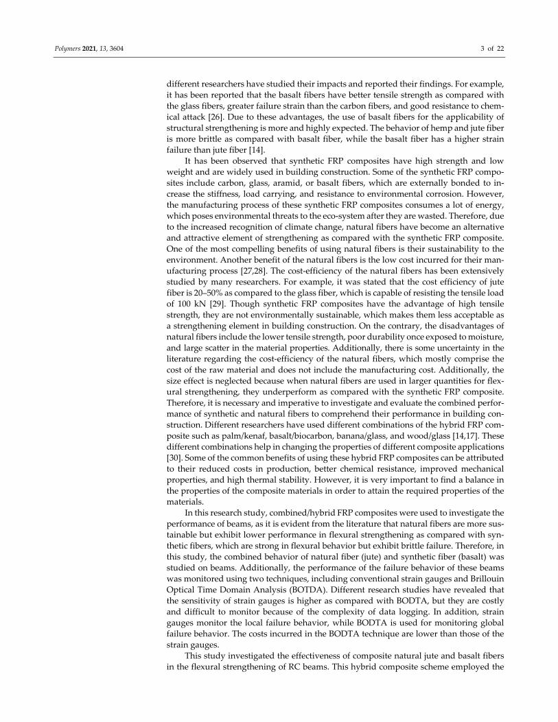
strengthening pattern of the two beams was different. On one beam, FRP layers were ap‐
plied to the bottom side only, as shown in Figure 1. In previous studies, it was found that
the use of FRP in the form of a u‐shape i.e., at the bottom and sides (below the neutral
axis), is very effective to further enhance the load carrying capacity of the RC beams as
compared to the bottom side only. She et al. reported that the use of a U‐shaped FRP is
also very helpful to avoid the de‐bonding of the FRP from the tensions side of RC beams.
Therefore, in this study, the RC beam (B‐02) was strengthened with a u‐shaped pattern on
the surface below its neutral axis, as shown in Figure 2. In the u‐shaped pattern, the hybrid
FRP composite was applied at the sides and bottom. Table 1 summarizes the strengthen‐
ing scheme adopted in this study.
Figure 1. Strengthening detail of beam B‐01 (units: mm).
Figure 2. Strengthening detail of beam B‐02 (units: mm).
Polymers 2021, 13, 3604 5 of 22
Table 1. Test matrix and strengthening scheme.
Beam ID Hybrid FRP Layers Strengthening Pattern
B‐CON N/A N/A
B‐01 4 Bottom face only
B‐02 4 U‐shaped pattern
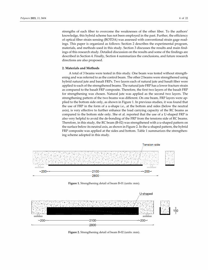
2.1. Specimen Details
RC beams had a cross‐section of 150 mm × 300 mm with a support‐to‐support length
of 2500 mm. The total length of each beam was 2800 mm. The top and bottom longitudi‐nal bars consisted of two 12 mm‐diameter deformed bars. Shear reinforcement consisted
of 6 mm diameter round bars. Within the shear span, the spacing of stirrups was 100 mm,
which was doubled just outside the shear spans. A concrete cover of 20 mm was provided
on all sides. Details of the RC beams are shown in Figure 3.
Figure 3. Specimen details (units: mm).
2.2. Material Properties
Deformed and plain steel bars were used for longitudinal and transverse reinforce‐
ment, respectively. Their mechanical properties were found following the protocols of
ASTM A615/A615M ‐ 20 [31]. A total number of five steel bars were tested for each type
of steel bar. Table 2 presents the “average mechanical properties of steel bars” in terms of
diameter, elastic modulus, yield stress, yield strain, fracture stress, and strain. All beams
were constructed using a single batch of concrete. Standard cylinders were cast as per the
recommendations of ASTM C39/C39M ‐ 21 [32]. For this purpose, three cylinders of stand‐
ard size, i.e., 150 mm × 300 mm (diameter × height), were cast and tested under axial com‐
pression. Table 3 shows the “average concrete characteristics.” In this study, woven basalt
fabric was provided by Kamenny Vek, Russia, and locally available woven jute fabric was
used. The epoxy resin was obtained from Smart and Bright Co., Ltd., Thailand. The epoxy
resin was made of two parts, i.e., resin and hardener. The mixing ratio of resin was con‐
sidered as 1:2 (hardener:resin). Further, the properties of FRP composites were deter‐
mined following the procedures of ASTM D7565/D7565M ‐ 10(2017) [33]. A total number
Polymers 2021, 13, 3604 6 of 22
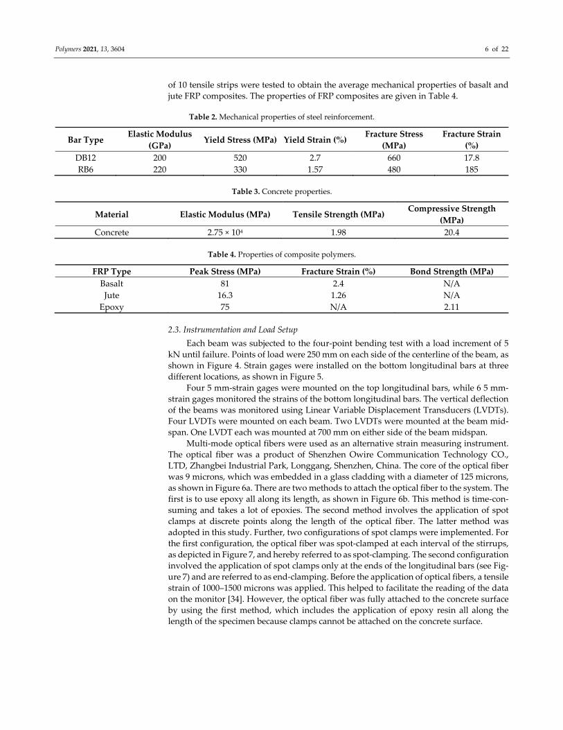
of 10 tensile strips were tested to obtain the average mechanical properties of basalt and
jute FRP composites. The properties of FRP composites are given in Table 4.
Table 2. Mechanical properties of steel reinforcement.
Bar Type Elastic Modulus
(GPa) Yield Stress (MPa) Yield Strain (%)
Fracture Stress
(MPa)
Fracture Strain
(%)
DB12 200 520 2.7 660 17.8
RB6 220 330 1.57 480 185
Table 3. Concrete properties.
Material Elastic Modulus (MPa) Tensile Strength (MPa) Compressive Strength
(MPa)
Concrete 2.75 × 10⁴ 1.98 20.4
Table 4. Properties of composite polymers.
FRP Type Peak Stress (MPa) Fracture Strain (%) Bond Strength (MPa)
Basalt 81 2.4 N/A
Jute 16.3 1.26 N/A
Epoxy 75 N/A 2.11
2.3. Instrumentation and Load Setup
Each beam was subjected to the four‐point bending test with a load increment of 5
kN until failure. Points of load were 250 mm on each side of the centerline of the beam, as
shown in Figure 4. Strain gages were installed on the bottom longitudinal bars at three
different locations, as shown in Figure 5.
Four 5 mm‐strain gages were mounted on the top longitudinal bars, while 6 5 mm‐
strain gages monitored the strains of the bottom longitudinal bars. The vertical deflection
of the beams was monitored using Linear Variable Displacement Transducers (LVDTs).
Four LVDTs were mounted on each beam. Two LVDTs were mounted at the beam mid‐
span. One LVDT each was mounted at 700 mm on either side of the beam midspan.
Multi‐mode optical fibers were used as an alternative strain measuring instrument.
The optical fiber was a product of Shenzhen Owire Communication Technology CO.,
LTD, Zhangbei Industrial Park, Longgang, Shenzhen, China. The core of the optical fiber
was 9 microns, which was embedded in a glass cladding with a diameter of 125 microns,
as shown in Figure 6a. There are two methods to attach the optical fiber to the system. The
first is to use epoxy all along its length, as shown in Figure 6b. This method is time‐con‐
suming and takes a lot of epoxies. The second method involves the application of spot
clamps at discrete points along the length of the optical fiber. The latter method was
adopted in this study. Further, two configurations of spot clamps were implemented. For
the first configuration, the optical fiber was spot‐clamped at each interval of the stirrups,
as depicted in Figure 7, and hereby referred to as spot‐clamping. The second configuration
involved the application of spot clamps only at the ends of the longitudinal bars (see Fig‐
ure 7) and are referred to as end‐clamping. Before the application of optical fibers, a tensile
strain of 1000–1500 microns was applied. This helped to facilitate the reading of the data
on the monitor [34]. However, the optical fiber was fully attached to the concrete surface
by using the first method, which includes the application of epoxy resin all along the
length of the specimen because clamps cannot be attached on the concrete surface.

Polymers 2021, 13, 3604 7 of 22
Figure 4. Test setup and LVDT placement (units: mm).
Figure 5. Position of strain gages on longitudinal reinforcement (units: mm).
(a) (b)
Figure 6. (a) Optical fiber used; (b) bonding methods.

Polymers 2021, 13, 3604 8 of 22
Figure 7. Application of spot glue for optical fiber bonding.
It should be mentioned that a single continuous optical fiber was used for the top and
bottom reinforcement and beam bottom surface in continuation (see Figure 8). Optical
fiber was mounted to the concrete surface in the case of the control beam, while it moni‐
tored strains of the FRPs in the case of strengthened specimens. The mounting sequence
of optical fibers was as follows: starting from the BOTDA logger to the bottom left steel bar
(L‐01) to the top left steel bar (L‐02) to the bottom right steel bar (L‐03) to the top right steel
bar (L‐04) to the bottom concrete surface (L‐05) before finally reaching the BOTDA logger.
This sequence of optical fiber instrumentation was chosen to facilitate the application of
both clamping configurations in each beam. For instance, the left bottom and top longitu‐
dinal bars were instrumented with optical fibers using the 1st configuration, while the 2nd
configuration was adopted for the right bottom and top longitudinal bars. It is worth men‐
tioning that the strain data obtained from the optical fibers were in spatial coordinates of
the optical fiber. Therefore, the records of each bar were differentiated from the other two
consecutive (previous and next) bars by providing a spare length of optical fiber for ap‐
proximately 3 m before attaching to the next steel bar, as shown in Figure 9.
Figure 8. Schematic of optical fiber mounting.

Polymers 2021, 13, 3604 9 of 22
Figure 9. Spare length provided in optical fiber after each attachment to steel bar.
3. Results and Discussions
3.1. Failure Modes
3.1.1. Beam B‐Con
Due to sufficient shear spans, the behavior of the control beam was controlled by
flexure. Flexural cracks were observed at very low loads, as shown in Figure 10. However,
this was merely a transition from the uncracked to cracked concrete stage with no drop in
strength. A further increase in load accompanied the spread and generation of new flex‐
ural cracks. Failure of the control beam was observed at a 53 kN load, exhibiting large
flexural cracks (see Figure 11), as well as yielding of the bottom longitudinal steel bars
and crushing of the concrete at extreme compression (see Figure 12). Overall, the failure
mode of beam B‐Con was controlled by the tensile behavior of the longitudinal reinforce‐
ment at the tension face after the appearance of the first crack. Similar failure modes have
been reported in previous studies [35,36].
Figure 10. Onset of flexure cracks at early load stage.
Spare length of
optical fiber

Polymers 2021, 13, 3604 10 of 22
Figure 11. Final failure of control beam.
Figure 12. Typical crushing of concrete in all specimens.
3.1.2. Beam B‐01
Beam B‐01 also exhibited hairline flexural cracks at the early load stage. This beam
failed at a 66 kN load, exhibiting large flexural cracks and yielding of longitudinal rein‐
forcement. Unlike the control specimen, B‐01 exhibited concrete compression. At failure
load, rupture of the FRP was observed, reflecting that the capacity of the FRP composite
was exhausted. Flexural cracks formed a wedge‐shaped pattern within the vicinity of the
FRP rupture, as shown in Figure 13. The formation of a wedge‐shaped pattern was mainly
due to the presence of the FRP composite as the tension side. Due to the FRP composite,
the crack width of the flexural cracks was small and there were few cracks with a large
crack width at the location of the FRP rupture. Further, FRP de‐bonding was observed
slightly prior to its rupture.

Polymers 2021, 13, 3604 11 of 22
Figure 13. FRP rupture and wedge formation at final failure of beam B‐01.
3.1.3. Beam B‐02
The formation of flexural cracks at the early load stage could not be observed, due to
the application of the U‐shaped FRP composite layers. However, flexural cracks pene‐
trated through the top edges of the U‐shaped FRP at a failure load of 74 kN, as shown in
Figure 14. No debonding of FRP was observed in contrast to the specimen B‐01. However,
final failure was still accompanied by FRP rupture, as shown in Figure 15.
Figure 14. Final failure of specimen B‐02.
Figure 15. FRP rupture at failure of beam B‐02.

Polymers 2021, 13, 3604 12 of 22
Strain measurements revealed that strains of the bottom longitudinal bars were suf‐
ficiently exceeded beyond their yield limits. Similar to other specimens, concrete crushing
was also observed at the top surface.
3.2. Load–Deflection Curves
A comparison of the load–deflection curve was necessary to reveal the beneficial im‐
pact of the strengthening schemes. LVDTs were mounted at the midspan for this purpose.
Figure 16 shows the measured load–deflection response of all beams. The load versus de‐
flection response of the control beams was observed to be tri‐linear. The first part repre‐
sented a linear increase in the load until the first tension crack. The second part was also
linear until the yielding of the steel bars. However, the stiffness of the second part was
lower than that of the first part. In the third part, the load versus deflection curve was
almost a straight line with a small increase in the load. In the FRP‐strengthened beams,
the first and second parts of the load versus deflection curves were similar to the control
beam; however, in the third part, the increase in load was high as compared to the control
beam due to the presence of the FRP composite at the tension side. Once the beams B‐01
and B‐02 reached their ultimate load, FRP rupture occurred and a sudden drop in the load
versus deflection curves was observed. The sudden drop was further stabilized due to the
presence of the steel bars in the tension zone of beams B‐01 and B‐02. It is evident that the
control specimen made the lowest bound in terms of flexural strength followed by beams
B‐01 and B‐02. Beyond the yielding point, B‐Con exhibited negligible stiffness. With the
concrete below the neutral axis cracked, all of the load was carried by the bottom longitu‐
dinal bars. On the contrary, both the strengthened specimens exhibited a higher post‐yield
stiffness than did the control specimen attributed to the support imparted by FRP layers.
It can be observed that the U‐shaped pattern performed better both in terms of post‐yield
stiffness and peak load than B‐01 did. The maximum load sustained by the control speci‐
men was 53 kN, which increased to 24.5 and 39.6% for beams B‐01 and B‐02, respectively.
Figure 16. Experimental load–deflection response.
3.3. Energy Dissipation Capacities (EDC)
High‐energy dissipation is an indicator of the ductile mode of failure. EDC was cal‐
culated for each beam by the summation of areas under their respective load–deflection
curves up to the softening point. Corresponding EDC values are tabulated in Table 5. The
lowest bound of EDC was created by the control beam. On the contrary, beams B‐01 and
0
10
20
30
40
50
60
70
80
0 10 20 30 40 50
Loa
d (
kN
)
Deflection (mm)
CON
B-01
B-02
Polymers 2021, 13, 3604 13 of 22
B‐02 exhibited 20.5% and 28.4% higher energy dissipation capacities than the control beam
did, respectively.
Table 5. Energy dissipation capacity.
Specimen ID Energy Dissipation Capacity (kN‐mm) Change from B‐CON (%)
B‐CON 1097 0
B‐01 1323 +20.5
B‐02 1409 +28.4
3.4. Strain Measurements of Steel Bars
3.4.1. Strain Gauge Data
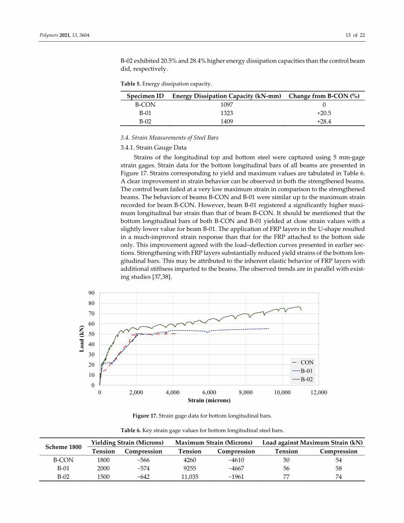
Strains of the longitudinal top and bottom steel were captured using 5 mm‐gage
strain gages. Strain data for the bottom longitudinal bars of all beams are presented in
Figure 17. Strains corresponding to yield and maximum values are tabulated in Table 6.
A clear improvement in strain behavior can be observed in both the strengthened beams.
The control beam failed at a very low maximum strain in comparison to the strengthened
beams. The behaviors of beams B‐CON and B‐01 were similar up to the maximum strain
recorded for beam B‐CON. However, beam B‐01 registered a significantly higher maxi‐
mum longitudinal bar strain than that of beam B‐CON. It should be mentioned that the
bottom longitudinal bars of both B‐CON and B‐01 yielded at close strain values with a
slightly lower value for beam B‐01. The application of FRP layers in the U‐shape resulted
in a much‐improved strain response than that for the FRP attached to the bottom side
only. This improvement agreed with the load–deflection curves presented in earlier sec‐
tions. Strengthening with FRP layers substantially reduced yield strains of the bottom lon‐
gitudinal bars. This may be attributed to the inherent elastic behavior of FRP layers with
additional stiffness imparted to the beams. The observed trends are in parallel with exist‐
ing studies [37,38].
Figure 17. Strain gage data for bottom longitudinal bars.
Table 6. Key strain gage values for bottom longitudinal steel bars.
Scheme 1800 Yielding Strain (Microns) Maximum Strain (Microns) Load against Maximum Strain (kN)
Tension Compression Tension Compression Tension Compression
B‐CON 1800 −566 4260 −4610 50 54
B‐01 2000 −574 9255 −4667 56 58
B‐02 1500 −642 11,035 −1961 77 74
0
10
20
30
40
50
60
70
80
90
0 2,000 4,000 6,000 8,000 10,000 12,000
Loa
d (
kN
)
Strain (microns)
CON
B-01
B-02

Polymers 2021, 13, 3604 14 of 22
Strain gage compression steel recordings are presented in Figure 18. A reverse trend
was observed from tensile steel strain recordings. Both B‐CON and B‐01 recorded very
high compression strain values. However, beam B‐01 compression strains were limited in
contrast to its tensile longitudinal strains. This is an indication of a much‐improved tensile
steel performance in specimen B‐02. The application of U‐shaped FRP layers significantly
reduced the strain demand on compression steel. Further, the maximum strain obtained
in beam B‐02 occurred at a much higher load than that of beams B‐C0N and B‐01 did (see
Table 6).
Figure 18. Strain gage data for top longitudinal bars.
3.4.2. BOTDA Data
A single optical fiber was run along the top and bottom steel bars, as well as the
concrete bottom surface. Therefore, the strain data obtained were in spatial coordinates of
the optical fiber. Figures 19 and 20 show strain records obtained for beams B‐CON and B‐
02. As described in earlier sections, optical fibers were mounted to steel bars using spot
and end clamping. However, the end clamping failed earlier in all three specimens, re‐
sulting in no record. Therefore, the data presented hereby only describe spot clamping
records. Further, strain data could not be recorded for beam B‐01, due to the malfunction
of the optical fiber. Table 7 specifies maximum BOTDA strains for B‐CON and B‐02. Sim‐
ilar to strain gage recordings, the maximum strain of the control beam occurred at a lower
peak load than that of beam B‐02. The maximum strain of the bottom longitudinal bar was
also higher in beam B‐02 than B‐CON. This agrees well with strain gage records of the
respective beams.
0
10
20
30
40
50
60
70
80
90
-5000 -4000 -3000 -2000 -1000 0
Loa
d (
kN
)
Strain (microns)
CON
B-01
B-02

Polymers 2021, 13, 3604 15 of 22
Figure 19. BOTDA records for beam B‐CON.
Figure 20. BOTDA records for beam B‐02.
Table 7. Maximum strain from BOTDA.
Specimen ID Maximum Strain (Microns)
Peak Load (kN) Bottom Steel Top Steel Bottom Concrete
B‐CON 1128 133 1414 40
B‐02 2087 165 2900 56
3.4.3. Comparison of Strain Records
A comparison of strains obtained from strain gages and BOTDA is presented in this
section. Figure 21 presents this comparison for the control beam. Up to the cracking load,
both curves exhibited similar patterns. Beyond the cracking load, BOTDA records devi‐
ated from strain gage records. A further increase in load resulted in the propagation of
bottom flexural cracks toward the top. The BOTDA records obtained were much shorter
than the strain gage records, as optical fibers failed before the yielding of steel bars. The
strain gauges usually comprised small gauge lengths, and strain measurements were local
-200
0
200
400
600
800
1000
1200
1400
1600
8 10 12 14 16 18 20 22 24 26
Str
ain
(mic
rons
)
Distance (m)
40 kN
35 kN
30 kN
25 kN
20 kN
Bottom steel
Top steel
Bottom concrete
-500
0
500
1,000
1,500
2,000
2,500
3,000
3,500
8 10 12 14 16 18 20 22 24 26
Stra
in (
mic
ron
s)
Distance (m)
56 kN51 kN46 kN36 kN30 kN16 kN
Bottom steel
Top steel
Bottom side

Polymers 2021, 13, 3604 16 of 22
for a small part of the steel bar and/or concrete surface, whereas the BOTDA wire was
continuous and installed along the full length of the steel bars. As a result, the strain mon‐
itoring through strain gauges was usually higher than that of the BOTDA. It is also be‐
lieved that the upward propagation of cracks beyond the position of optical fibers might
have broken them.
Figure 21. Comparison of strain records from strain gages and BOTDA for beam B‐CON.
This comparison for beam B‐02 is presented in Figure 22. Interestingly, both curves
exhibited a similar response up to the failure of optical fibers. This may be attributed to
the delayed propagation and lower number of flexural cracks in beam B‐02 due to the U‐
shaped FRP layers. This agrees with the failure mode of beam B‐02 presented earlier. This
delayed propagation allowed the steel bars to yield before significant cracks damaged op‐
tical fibers. Similar findings have also been found in previous studies [39–41].
Figure 22. Comparison of strain records from strain gages and BOTDA for beam B‐02.
0
10
20
30
40
50
60
0 500 1000 1500 2000 2500 3000 3500 4000 4500
Loa
d (
kN
)
Strain (microns)
Strain gauge
BOTDA
0
10
20
30
40
50
60
70
80
90
0 2,000 4,000 6,000 8,000 10,000 12,000
Loa
d (
kN
)
Strain (microns)
Strain gauge
BOTDA

Polymers 2021, 13, 3604 17 of 22
3.5. Finite Element Model
Further investigations into the structural behavior were carried out using nonlinear
finite element analysis using computer program ATENA. ATENA is a tool for nonlinear
structural analysis [42–44]. Some researchers have also used the techniques of Steel‐Rein‐
forced Grout (SRG) for the experimental investigation and modeling of reinforced con‐
cretes using different continuous and discontinuous U‐shaped SRG strips. Their analytical
FEM modeling predictions of the shear capacity of SRG beams are in agreement with the
experimental results with an accurate average value of 0.98 of predicted/experimental ra‐
tio [45,46]. On the similar patterns, in this research study, a nonlinear FEM model was
created for all three beams using the built‐in material models of ATENA. Concrete was
modeled using the fracture‐plastic constitutive material model that is available in
ATENA’s library as CC3DNonLinCementitiois2. This model accounts for the nonlinearity
in both tension and compression as per the recommendations of MC10. CEB‐FIP Model
Code 2010 [47]. Post‐cracking tensile behavior was simulated using a fictitious crack
model based upon crack‐opening law and fracture energy. The function of crack opening
based on the exponential function experimentally derived by Hordijk 1991 [48] was uti‐
lized. Steel reinforcement was simulated using 1D truss element CC Reinforcement, which
is also available in ATENA’s built‐in library. As the reinforcing bars were continuous with
sufficient anchorage capacities, no slip between reinforcing bars and concrete was ex‐
pected. Therefore, a perfect bond between steel bars and surrounding concrete was
adopted in this study. Further, the buckling of steel bars was also not considered and the
same material model was used for tension and compression steel. The effect of external
FRP composite sheets was considered by an elastic steel plate attached to the beam at the
position of the FRP composite sheets. Figure 23 is a typical model of beams in this study,
while Figure 24 shows the application of the prescribed displacement control loading.
Figure 23. RC beam model in ATENA.
Figure 24. Point of application of prescribed displacement‐controlled loading.
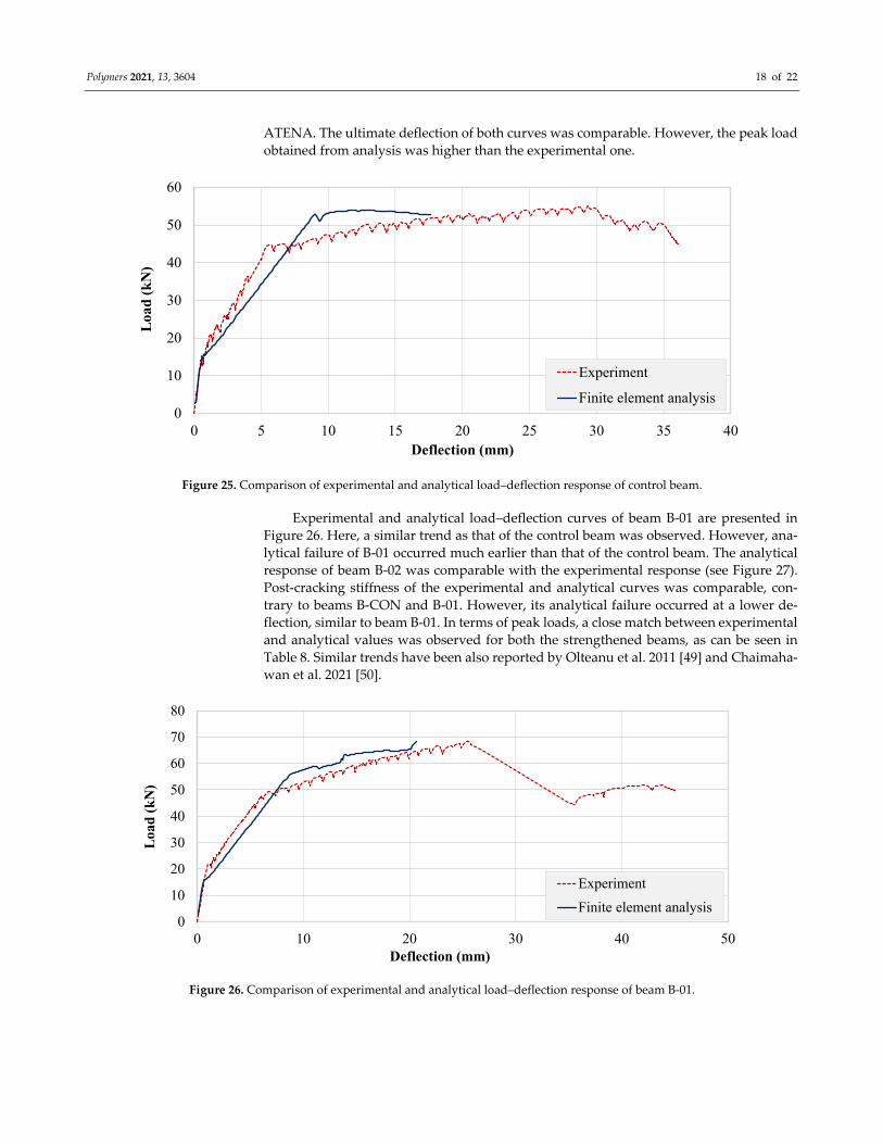
Figure 25 compares the experimental and analytical load–deflection curves of the
control beam. Both curves showed similar pre‐cracking stiffness and cracking loads. The
experimental post‐cracking stiffness was found to be higher than that obtained from
Polymers 2021, 13, 3604 18 of 22
ATENA. The ultimate deflection of both curves was comparable. However, the peak load
obtained from analysis was higher than the experimental one.
Figure 25. Comparison of experimental and analytical load–deflection response of control beam.
Experimental and analytical load–deflection curves of beam B‐01 are presented in
Figure 26. Here, a similar trend as that of the control beam was observed. However, ana‐
lytical failure of B‐01 occurred much earlier than that of the control beam. The analytical
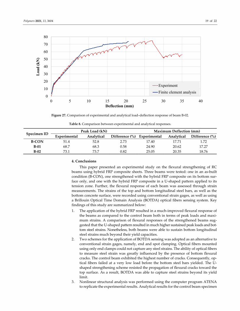
response of beam B‐02 was comparable with the experimental response (see Figure 27).
Post‐cracking stiffness of the experimental and analytical curves was comparable, con‐
trary to beams B‐CON and B‐01. However, its analytical failure occurred at a lower de‐
flection, similar to beam B‐01. In terms of peak loads, a close match between experimental
and analytical values was observed for both the strengthened beams, as can be seen in
Table 8. Similar trends have been also reported by Olteanu et al. 2011 [49] and Chaimaha‐
wan et al. 2021 [50].
Figure 26. Comparison of experimental and analytical load–deflection response of beam B‐01.
0
10
20
30
40
50
60
0 5 10 15 20 25 30 35 40
Loa
d (
kN
)
Deflection (mm)
Experiment
Finite element analysis
0
10
20
30
40
50
60
70
80
0 10 20 30 40 50
Loa
d (
kN
)
Deflection (mm)
Experiment
Finite element analysis
Polymers 2021, 13, 3604 19 of 22
Figure 27. Comparison of experimental and analytical load–deflection response of beam B‐02.
Table 8. Comparison between experimental and analytical responses.
Specimen ID Peak Load (kN) Maximum Deflection (mm)
Experimental Analytical Difference (%) Experimental Analytical Difference (%)
B‐CON 51.4 52.8 2.73 17.40 17.71 1.72
B‐01 68.7 68.3 0.58 24.90 20.62 17.27
B‐02 73.1 73.7 0.82 25.05 20.35 18.76
4. Conclusions
This paper presented an experimental study on the flexural strengthening of RC
beams using hybrid FRP composite sheets. Three beams were tested: one in an as‐built
condition (B‐CON), one strengthened with the hybrid FRP composite on its bottom sur‐
face only, and one with the hybrid FRP composite in a U‐shaped pattern applied to its
tension zone. Further, the flexural response of each beam was assessed through strain
measurements. The strains of the top and bottom longitudinal steel bars, as well as the
bottom concrete surface, were recorded using conventional strain gages, as well as using
a Brillouin Optical Time Domain Analysis (BOTDA) optical fibers sensing system. Key
findings of this study are summarized below:
1. The application of the hybrid FRP resulted in a much‐improved flexural response of
the beams as compared to the control beam both in terms of peak loads and maxi‐
mum strains. A comparison of flexural responses of the strengthened beams sug‐
gested that the U‐shaped pattern resulted in much higher sustained peak loads and bot‐
tom steel strains. Nonetheless, both beams were able to sustain bottom longitudinal
steel strains much beyond their yield capacities.
2. Two schemes for the application of BOTDA sensing was adopted as an alternative to
conventional strain gages, namely, end and spot clamping. Optical fibers mounted
using only end clamps could not capture any steel strains. The ability of optical fibers
to measure steel strain was greatly influenced by the presence of bottom flexural
cracks. The control beam exhibited the highest number of cracks. Consequently, op‐
tical fibers failed at a very low load before the bottom steel bars yielded. The U‐
shaped strengthening scheme resisted the propagation of flexural cracks toward the
top surface. As a result, BOTDA was able to capture steel strains beyond its yield
limit.
3. Nonlinear structural analysis was performed using the computer program ATENA
to replicate the experimental results. Analytical results for the control beam specimen
0
10
20
30
40
50
60
70
80
0 5 10 15 20 25 30 35 40
Loa
d (k
N)
Deflection (mm)
Experiment
Finite element analysis

Polymers 2021, 13, 3604 20 of 22
showed a close match with corresponding experimental results mainly in terms of
maximum deflection. However, the analytical peak load was slightly higher than the
corresponding experimental value. Analytical responses of the strengthened beams
also exhibited slightly higher peak loads than their corresponding experimental val‐
ues. Unlike the control specimen, the maximum recorded deflection was much lower
than their corresponding experimental values.
Author Contributions: Conceptualization, K.C., P.P., N.P. and P.J.; data curation, K.C., N.A., P.P.,
N.P., P.J., M.Z. and Q.H.; methodology, K.C., N.A., P.P., N.P., P.J., H.M., M.Z. and Q.H.; validation,
Q.H.; writing—original draft preparation, K.C., N.A., P.P., N.P., P.J., H.M., M.Z. and Q.H.; writing—
review and editing, K.C., N.A., P.P., N.P., P.J., H.M., M.Z. and Q.H. All authors have read and
agreed to the published version of the manuscript.”
Funding: This research was funded by Thammasat University Rangsit, Klong Luang Pathumthani,
Thailand.
Institutional Review Board Statement: Not applicable.
Informed Consent Statement: Not applicable.
Data Availability Statement: The data presented in this study are available on request from the
corresponding author.
Acknowledgments: This work was supported by the Thammasat Research Unit in Infrastructure
Inspection and Monitoring, Repair and Strengthening (IIMRS), Thammasat School of Engineering,
Thammasat University Rangsit, Klong Luang Pathumthani, Thailand. The authors are very much
thankful to the Asian Institute of Technology (AIT), Thailand for providing the testing facilities to
carry out this research study.
Conflicts of Interest: The authors declare no conflict of interest
References
1. Saba, M.; Quinones‐Bolanos, E.E.; Batista, H.F.M. Impact of environmental factors on the deterioration of the Wall of Cartagena
de Indias. J. Cult. Herit. 2019, 39, 305–313.
2. Fernandez, F., Germinario, S., Basile, R., Montagno, R., Kapetanaki, K., Gobakis, K., & Maravelaki, P. N. (2020). Development
of Eco‐Friendly and Self‐Cleaning Lime‐Pozzolan Plasters for Bio‐Construction and Cultural Heritage. Buildings, 10(10), 172.
3. Júlio, E.S.; Branco, F.; Silva, V.D. Structural rehabilitation of columns with reinforced concrete jacketing. Prog. Struct. Eng. Mater.
2003, 5, 29–37.
4. Li, X.; Wang, J.; Bao, Y.; Chen, G. Cyclic behavior of damaged reinforced concrete columns repaired with high‐performance
fiber‐reinforced cementitious composite. Eng. Struct. 2017, 136, 26–35.
5. Joyklad, P.; Hussain, Q. Axial compressive response of grouted cement–clay interlocking hollow brick walls. Asian J. Civ. Eng.
2019, 20, 733–744.
6. Nagaprasad, P.; Sahoo, D.R.; Rai, D.C. Seismic strengthening of RC columns using external steel cage. Earthq. Eng. Struct. Dyn.
2009, 38, 1563–1586.
7. Daudey, X.; Filliatrault, A. Seismic evaluation and retrofit with steel jackets of reinforced concrete bridge piers detailed with
lap‐splices. Can. J. Civ. Eng. 2000, 27, 1–16.
8. Theint, P.S.; Ruangrassamee, A.; Hussain, Q. Strengthening of shear‐critical RC columns by high‐strength steel‐rod collars. Eng.
J. 2020, 24, 107–128.
9. Santarsiero, G.; Masi, A. Seismic Upgrading of RC Wide Beam–Column Joints Using Steel Jackets. Buildings 2020, 10, 203.
10. Hussain, Q.; Ruangrassamee, A.; Tangtermsirikul, S.; Joyklad, P.; Wijeyewickrema, A.C. Low‐Cost Fiber Rope Reinforced Pol‐
ymer (FRRP) Confinement of Square Columns with Different Corner Radii. Buildings 2021, 11, 355.
11. Hussain, Q.; Ruangrassamee, A.; Tangtermsirikul, S.; Joyklad, P. Behavior of concrete confined with epoxy bonded fiber ropes
under axial load. Constr. Build. Mater. 2020, 263, 120093.
12. Rodsin, K.; Hussain, Q.; Suparp, S.; Nawaz, A. Compressive behavior of extremely low strength concrete confined with low‐
cost glass FRP composites. Case Stud. Constr. Mater. 2020, 13, e00452.
13. Rodsin, K.; Hussain, Q.; Joyklad, P.; Nawaz, A.; Fazliani, H. Seismic strengthening of nonductile bridge piers using low‐cost
glass fiber polymers. Bulletin of the Polish Academy of Sciences. Tech. Sci. 2020, 68.
14. Wahab, N.; Srinophakun, P.; Hussain, Q.; Chaimahawan, P. Performance of concrete confined with a jute–polyester hybrid
Fiber reinforced polymer composite: A novel strengthening technique. Fibers 2019, 7, 72.
15. Raza, S.; Khan, M.K.; Menegon, S.J.; Tsang, H.H.; Wilson, J.L. Strengthening and repair of reinforced concrete columns by jack‐
eting: State‐of‐the‐art review. Sustainability 2019, 11, 3208.

Polymers 2021, 13, 3604 21 of 22
16. Yoddumrong, P.; Rodsin, K.; Katawaethwarag, S. Seismic strengthening of low‐strength RC concrete columns using low‐cost
glass fiber reinforced polymers (GFRPs). Case Stud. Constr. Mater. 2020, 13, e00383, ISSN 2214‐5095.
17. Chaiyasarn, K.; Hussain, Q.; Joyklad, P.; Rodsin, K. New hybrid basalt/E‐glass FRP jacketing for enhanced confinement of re‐
cycled aggregate concrete with clay brick aggregate. Case Stud. Constr. Mater. 2021, 14, e00507.
18. Hu, W.; Li, Y.; Yuan, H. Review of Experimental Studies on Application of FRP for Strengthening of Bridge Structures. Adv.
Mater. Sci. Eng. 2020, 2020, 21, https://doi.org/10.1155/2020/8682163.
19. Hussain, Q.; Pimanmas, A. Shear strengthening of RC deep beams with sprayed fiber‐reinforced polymer composites (SFRP):
Part 2 Finite element analysis. Lat. Am. J. Solids Struct. 2015, 12, 1266–1295.
20. Hussain, Q., Rattanapitikon, W., & Pimanmas, A. (2016). Axial load behavior of circular and square concrete columns confined
with sprayed fiber‐reinforced polymer composites. Polymer Composites, 37(8), 2557‐2567.
21. Sim, J.; Park, C. Characteristics of Basalt Fiber as a Strengthening Material for Concrete Structures. Compos. Part B Eng. 2005, 36,
504–512. https://doi.org/10.1016/j.compositesb.2005.02.002.
22. Bitar, R.; Saad, G.; Awwad, E.; El Khatib, H.; Mabsout, M. Strengthening unreinforced masonry walls using natural hemp fibers.
J. Build. Eng. 2020, 30, 101253, ISSN 2352‐7102. https://doi.org/10.1016/j.jobe.2020.101253.
23. Sen, T.; Reddy, H.J. Flexural strengthening of RC beams using natural sisal and artificial carbon and glass fabric reinforced
composite system. Sustain. Cities Soc. 2014, 10, 195–206, ISSN 2210‐6707. https://doi.org/10.1016/j.scs.2013.09.003.
24. Pimanmas, A.; Hussain, Q.; Panyasirikhunawut, A.; Rattanapitikon, W. Axial strength and deformability of concrete confined
with natural fibre‐reinforced polymers. Mag. Concr. Res. 2019, 71, 55–70.
25. Yinh, S.; Hussain, Q.; Joyklad, P.; Chaimahawan, P.; Rattanapitikon, W.; Limkatanyu, S.; Pimanmas, A. Strengthening effect of
natural fiber reinforced polymer composites (NFRP) on concrete. Case Stud. Constr. Mater. 2021, 15, e00653.
26. Berozashvili, M. Continuous reinforcing fibers are being offered for construction, civil engineering and other composites appli‐
cations. Adv. Mater. Com. News Compos. Worldw. 2001, 21, 5–6.
27. Xian, G.; Guo, R.; Li, C.; Hong, B. Effects of rod size and fiber hybrid mode on the interface shear strength of carbon/glass fiber
composite rods exposed to freezing‐thawing and outdoor environments. J. Mater. Res. Technol. 2021, 14, 2812–2831.
28. Yang, Y.; Wang, X.; Wu, Z. Long‐span cable‐stayed bridge with hybrid arrangement of FRP cables. Composite Structures 2020,
237, 111966.
29. Sen, T.; Reddy, H.J. Strengthening of RC beams in flexure using natural jute fibre textile reinforced compo‐site system and its
comparative study with CFRP and GFRP strengthening systems. Int. J. Sustain. Built Environ. 2013, 2, 41–55, ISSN 2212‐6090.
https://doi.org/10.1016/j.ijsbe.2013.11.001.
30. Alecci, V.; De Stefano, M.; Focacci, F.; Luciano, R.; Rovero, L.; Stipo, G. Strengthening masonry arches with lime‐based mortar
composite. Buildings 2017, 7, 49.
31. ASTM A615/A615M‐20. Standard Specification for Deformed and Plain Carbon‐Steel Bars for Concrete Reinforcement; ASTM Interna‐
tional: West Conshohocken, PA, USA, 2020.
32. ASTM C39/C39M‐21. Standard Test Method for Compressive Strength of Cylindrical Concrete Specimens; ASTM International: West
Conshohocken, PA, USA, 2021.
33. ASTM D7565/D7565M‐10(2017). Standard Test Method for Determining Tensile Properties of Fiber Reinforced Polymer Matrix Compo‐
sites Used for Strengthening of Civil Structures; ASTM International: West Conshohocken, PA, USA, 2017.
34. Gao, J.; Shi, B.; Zhang, W.; Zhu, H. Monitoring the stress of the post‐tensioning cable using fiber optic distributed strain sensor.
Measurement 2006, 39, 420–428.
35. Sirisonthi, A.; Suparp, S.; Joyklad, P.; Hussain, Q.; Julphunthong, P. Experimental study of the load‐deformation behaviour of
the precast post‐tensioned continuous girder for straddle monorail: Full‐scale load test under service and ultimate loading
conditions. Case Stud. Constr. Mater. 2021,15, e00666.
36. Joyklad, P.; Suparp, S.; Hussain, Q. Flexural response of JFRP and BFRP strengthened RC beams. Int. J. Eng. Technol. 2019, 11,
203‐207.
37. Smith, S.T.; Teng, J.G. FRP‐strengthened RC beams. I: Review of debonding strength models. Eng. Struct. 2002, 24, 385–395.
38. Ceroni, F. Experimental performances of RC beams strengthened with FRP materials. Constr. Build. Mater. 2010, 24, 1547–1559.
39. Altun, F. An experimental study of the jacketed reinforced‐concrete beams under bending. Constr. Build. Mater. 2004, 18, 611–
618.
40. Berrocal, C.G.; Fernandez, I.; Rempling, R. Crack monitoring in reinforced concrete beams by distributed optical fiber sensors.
Struct. Infrastruct. Eng. 2021, 17, 124–139.
41. Berrocal, C.G.; Fernandez, I.; Bado, M.F.; Casas, J.R.; Rempling, R. Assessment and visualization of performance indicators of
reinforced concrete beams by distributed optical fibre sensing. Struct. Health Monit. 2021, 1475921720984431.
42. Cervenka, V.; Cervenka, J.; Pukl, R. ATENA—A tool for engineering analysis of fracture in concrete. Sadhana 2002, 27, 485–492.
43. Červenka, V.; Jendele, L.; Červenka, J. ATENA Program Documentation Part. Cervenka Consult. Sro 2000.
44. Mello, A.F.A.D.; Souza, R.A.D. Analysis and design of reinforced concrete deep beams by a manual approach of stringer‐panel
method. Lat. Am. J. Solids Struct. 2016, 13, 1126–1151.
45. Ombres, L.; Verre, S. Shear strengthening of reinforced concrete beams with SRG (Steel Reinforced Grout) composites: Experi‐
mental investigation and modelling. J. Build. Eng. 2021, 42, 103047.
46. Ombres, L.; Verre, S. Experimental and numerical investigation on the steel reinforced grout (SRG) composite‐to‐concrete bond.
J. Compos. Sci. 2020, 4, 182.

Polymers 2021, 13, 3604 22 of 22
47. MC10. CEB‐FIP Model Code Bulletin d’Information No. 65/66; Comité Euro‐International Du Béton, Heron Quay, London: 2010.
48. Hordijk, D.A. Local Approach to Fatigue of Concrete. PhD Thesis, Technische Universiteit Delft, Netherlands. W.D. Meinema
b.v. Delft. Oud‐Beijerland, The Netherlands. 1991.
49. Olteanu, I.; Alistar, A.; Budescu, M. Non‐linear Analysis of Reinforced Concrete Frames with ATENA 3‐D Program. Buletinul
Institutului Politehnic din lasi. Sect. Constr. Arhit. 2011, 57, 93.
50. Chaimahawan, P.; Suparp, S.; Joyklad, P.; Hussain, Q. Finite Element Analysis of Reinforced Concrete Pile Cap using ATENA.
Lat. Am. J. Solids Struct. 2021, 18.
Related Documents


