1681 SP-230—95 Modelling of Reinforced Concrete Flexural Members Strengthened with Near-Surface Mounted FRP Reinforcement by R. El-Hacha, S.H. Rizkalla, and R. Kotynia Synopsis: Synopsis: Synopsis: Synopsis: Synopsis: This paper presents an analytical investigation conducted to study the flexural behavior of reinforced concrete beams strengthened with various Near-Surface Mounted (NSM) Fiber-Reinforced Polymers (FRP) reinforcements. The materials used in this investigation included carbon-fiber-reinforced-polymer (CFRP) rebars and strips, and glass fiber-reinforced-polymer (GFRP) rebars and strips. The analysis included the effects of strengthening on the serviceability and ultimate limit states as well the effect of tension stiffening. The effectiveness of NSM FRP rebars and strips was examined and compared to externally bonded (EB) FRP strips and sheets using the same material type and axial stiffness. Results from the analytical models were compared with those obtained from experimental studies. The analytical results agree very well with those obtained from the experimental results. It was found that the analytical model could effectively simulate the behaviour of the reinforced concrete beams strengthened with various NSM FRP and EB FRP reinforcements. Using the same axial stiffness of FRP to strengthen reinforced concrete beams, the beams strengthened with NSM FRP reinforcement achieved higher ultimate load than beams strengthened with EB FRP reinforcement. This result is due to the high utilization of the tensile strength of the FRP reinforcement. Keywords: carbon; externally bonded; fiber-reinforced polymers; glass; near-surface mounted; rebars; reinforced concrete beam; strengthening; strips

Welcome message from author
This document is posted to help you gain knowledge. Please leave a comment to let me know what you think about it! Share it to your friends and learn new things together.
Transcript
1681
SP-230—95
Modelling of ReinforcedConcrete Flexural Members
Strengthened with Near-SurfaceMounted FRP Reinforcement
by R. El-Hacha, S.H. Rizkalla, and R. Kotynia
Synopsis:Synopsis:Synopsis:Synopsis:Synopsis: This paper presents an analytical investigation conducted to study theflexural behavior of reinforced concrete beams strengthened with various Near-SurfaceMounted (NSM) Fiber-Reinforced Polymers (FRP) reinforcements. The materials used inthis investigation included carbon-fiber-reinforced-polymer (CFRP) rebars and strips,and glass fiber-reinforced-polymer (GFRP) rebars and strips. The analysis included theeffects of strengthening on the serviceability and ultimate limit states as well the effectof tension stiffening. The effectiveness of NSM FRP rebars and strips was examined andcompared to externally bonded (EB) FRP strips and sheets using the same material typeand axial stiffness. Results from the analytical models were compared with thoseobtained from experimental studies. The analytical results agree very well with thoseobtained from the experimental results. It was found that the analytical model couldeffectively simulate the behaviour of the reinforced concrete beams strengthened withvarious NSM FRP and EB FRP reinforcements. Using the same axial stiffness of FRP tostrengthen reinforced concrete beams, the beams strengthened with NSM FRPreinforcement achieved higher ultimate load than beams strengthened with EB FRPreinforcement. This result is due to the high utilization of the tensile strength of the FRPreinforcement.
Keywords: carbon; externally bonded; fiber-reinforced polymers;glass; near-surface mounted; rebars; reinforced concrete beam;strengthening; strips
1682 El-Hacha et al.ACI Member Raafat El-Hacha is an Assistant Professor in the Department of Civil
Engineering at the University of Calgary, Canada. He is a member of the ACI Committee
440, Fiber Reinforced Polymer (FRP) Reinforcement and co-chair of Sub-Committee
440-I, FRP Prestressed Concrete. His research interests include strengthening, reinforcing
and prestressing concrete structures with FRP composites.
FACI Member Sami H. Rizkalla is a Distinguished Professor, Director of the
Constructed Facilities Laboratory (CFL), and Director of the NSF Industry/University
Cooperative Research Center at North Carolina State University, USA. He is the
immediate Past President and the Founder of the ISIS Canada, and Past Chairman of ACI
Committee 440, Fiber Reinforced Polymer (FRP) Reinforcement.
ACI Member Renata Kotynia is an Assistant Professor in the Department of Concrete
Structures at the Technical University of Lodz, Poland. She is a member of the
International Association for Bridge and Structural Engineering (IABSE), International
Institute for FRP in Construction (IIFC) and the Polish Association for Engineers and
Technicians of Civil Engineers. Her research interests include the strengthening concrete
structures with externally bonded and NSM FRP composites.
INTRODUCTION
Fiber-Reinforced Polymers (FRP) materials have been used extensively, in
different configurations and techniques, in the last decade for strengthening bridges and
buildings. Externally bonded (EB) FRP sheets and strips are currently the most
commonly used technique for flexural and shear strengthening of concrete beams and
slabs. This method of strengthening has been the subject of extensive experimental
investigations, and codes and design guidelines/manuals have been published that address
many aspects of this technology. Several researchers reported that the failure of concrete
members strengthened with EB FRP sheets or strips could be brittle due to debonding
and/or peeling of the FRP reinforcements especially in the zones of high flexural and
shear stresses [1]
. An innovative area of this work that is emerging is the use of
prestressed FRP sheets for strengthening structures. By applying a prestress to the FRP
sheets or strips, the material may be used more efficiently since a greater portion of its
tensile capacity is engaged. Several systems have been developed to induce a prestress in
the FRP sheets or strips for flexural strengthening [1]
. However, EB FRP sheets and strips
could be highly susceptible to damage from collision, fire, temperature, ultraviolet rays,
and moisture absorption [2]
. In some cases, insufficient protection may reduce the service
life of the structure. To minimize these problems, to improve utilization of the FRP
materials, and to ensure long service life for the selected system, near-surface mounted
(NSM) reinforcement was recently introduced as a promising strengthening technique
and a valid alternative to the EB FRP technique for increasing flexural strength of
reinforced concrete members [3,4,5,6,7]
. The NSM technique consists of placing the FRP
reinforcing rebars or strips into grooves precut into the concrete cover in the tension side
of the strengthened concrete member filled with high-strength epoxy adhesive. This
method is relatively simple and considerably enhances the bond of the FRP
reinforcements, thereby using the material more effectively. Configuration of the FRP

FRPRCS-7 1683reinforcements used for the NSM technique is controlled by the depth of the concrete
cover.
Over the past few years, a number of researchers have studied the behavior and
modeling of reinforced concrete members strengthened with EB FRPs. Published
literature on the use of NSM FRP rebars and strips for structural strengthening is very
limited when compared with that of EB FRP sheets and strips. Design guidelines for the
NSM FRP strengthening technique are currently under consideration by ACI Committee
440 for the coming version of the “Guide for the Design and Construction of Externally
Bonded FRP Systems for Strengthening Concrete Structures (ACI 440.2R-02).”
RESEARCH SIGNIFICANCE
This paper presents an analytical investigation conducted to study the structural
performance of reinforced concrete beams strengthened in flexure with various Near-
Surface Mounted (NSM) Fiber-Reinforced Polymers (FRP) reinforcements. The
effectiveness of NSM FRP rebars and strips was examined and compared to externally
bonded (EB) FRP strips and sheets using the same material type and axial stiffness. The
variables investigated were the type of fibers including carbon-fiber-reinforced-polymer
(CFRP) and glass fiber-reinforced-polymer (GFRP), and the configuration of the FRP
reinforcement including rebars, strips and sheets. The analysis included the effects of
strengthening on the serviceability and ultimate limit states as well the effect of tension
stiffening. Results from the analytical models were compared with those obtained from
experimental studies [5,6]
.
EXPERIMENTAL INVESTIGATION
Test Specimens and Set-up
A total of ten, simply supported, concrete T-beams were constructed and tested
under a monotonic concentrated load applied at midspan of the beam using displacement-
control mode at a loading rate of 1.07 mm/min. The test set-up of a T-beam specimen is
shown in Figure 1. Details of the test specimens can be found in El-Hacha and Rizkalla
(2004).
Test Matrix and FRP Strengthening Systems
One beam was tested without strengthening (B0) and served as a control
specimen for comparison purposes to evaluate the improvement in flexural strength
provided by the various NSM and externally bonded FRP reinforcements. Five beams
(B1, B2, B3, B4, and B5) were strengthened with different NSM FRP systems using
Carbon Fiber-Reinforced Polymer (CFRP) rebars [7]
, Glass Fiber-Reinforced Polymer
(GFRP) rebars[7]
, two different types of unidirectional pultruded CFRP strips [8,9]
, and
unidirectional pultruded thermoplastic GFRP strips [9]
. Four beams (B2a, B3a, B4a, and
B5a) were strengthened with externally bonded CFRP strips [8,9]
, GFRP strips [10]
, and
CFRP sheets [11]
. A summary of these beams is given in Table 1. The various FRP
strengthening systems are shown in Figure 2. The material properties of the different FRP
reinforcements are given in Table 2 as reported by the manufacturers with linear stress-
1684 El-Hacha et al.strain behavior up to failure. The embedment lengths of all NSM FRP rebars and strips
and the length of the externally bonded FRP strips were kept constant in all beams as
2400 mm. The same axial stiffness, (EA)FRP
, for all FRP reinforcements was kept
constant, hence according to the classical beam theory the load-deflection behavior of all
strengthened beams is anticipated to be identical, where E and A are the modulus of
elasticity and the area of the FRP reinforcement, respectively.[5,6]
Installation of the NSM and EB FRP Reinforcements
Installation procedure of the various NSM FRP rebars and strips and the EB FRP
strips and sheets can be found in El-Hacha and Rizkalla (2004).
Test Results
A comprehensive discussion on the effectiveness of NSM CFRP rebar versus NSM
CFRP strips, the effectiveness of NSM strips versus EB CFRP strips, and the effect of
material type of fiber (CFRP strips versus GFRP strips) has been reported in details by
El-Hacha and Rizkalla (2004) and El-Hacha et al. (2004). However, the experimental
results of the beam strengthened with NSM GFRP rebars and the beam strengthened with
EB CFRP sheets have not been reported elsewhere. Therefore, a brief summary of the
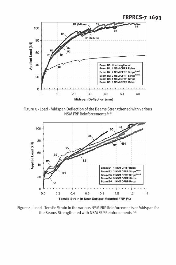
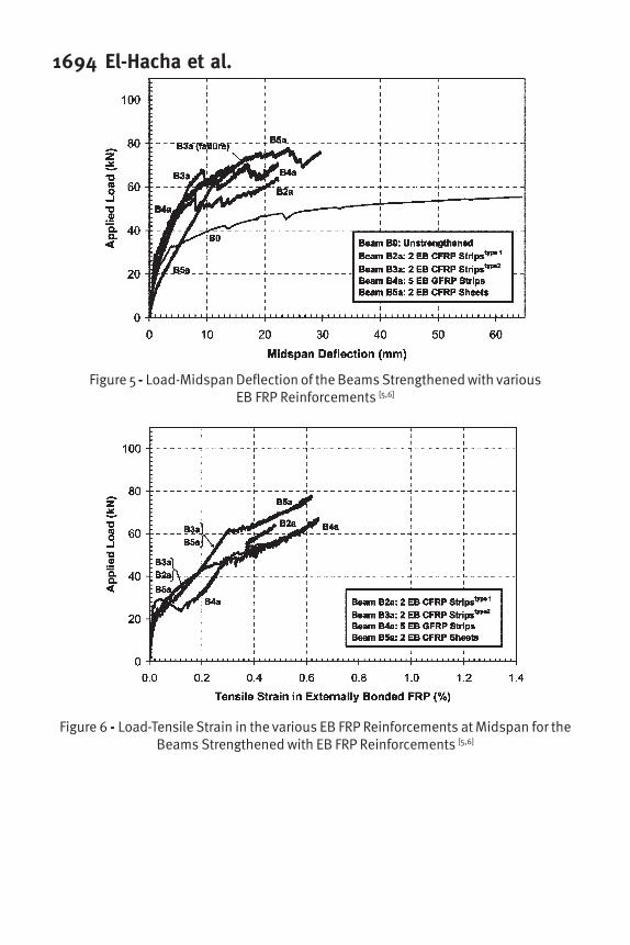
experimental test results is reported in this paper. The comparison is presented by the
experimental load-midspan deflection curves shown in Figures 3 and 5 for the beams
strengthened with various NSM FRP reinforcements and the beams strengthened with
various EB FRP reinforcements, respectively. Figures 4 and 6 show the experimental
load versus tensile strain at midspan in the NSM FRP reinforcements and the EB FRP
reinforcements, respectively. A Summary of significant test results and the failure mode
of all tested beams are given in Table 3, and is presented briefly hereafter:
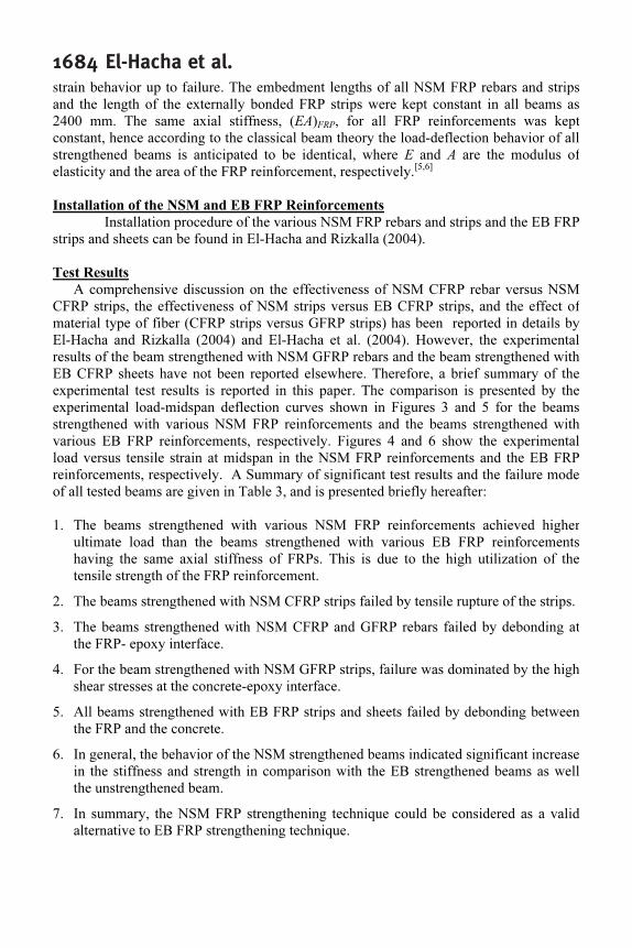
1. The beams strengthened with various NSM FRP reinforcements achieved higher
ultimate load than the beams strengthened with various EB FRP reinforcements
having the same axial stiffness of FRPs. This is due to the high utilization of the
tensile strength of the FRP reinforcement.
2. The beams strengthened with NSM CFRP strips failed by tensile rupture of the strips.
3. The beams strengthened with NSM CFRP and GFRP rebars failed by debonding at
the FRP- epoxy interface.
4. For the beam strengthened with NSM GFRP strips, failure was dominated by the high
shear stresses at the concrete-epoxy interface.
5. All beams strengthened with EB FRP strips and sheets failed by debonding between
the FRP and the concrete.
6. In general, the behavior of the NSM strengthened beams indicated significant increase
in the stiffness and strength in comparison with the EB strengthened beams as well
the unstrengthened beam.
7. In summary, the NSM FRP strengthening technique could be considered as a valid
alternative to EB FRP strengthening technique.
FRPRCS-7 1685ANALYTICAL MODELLING
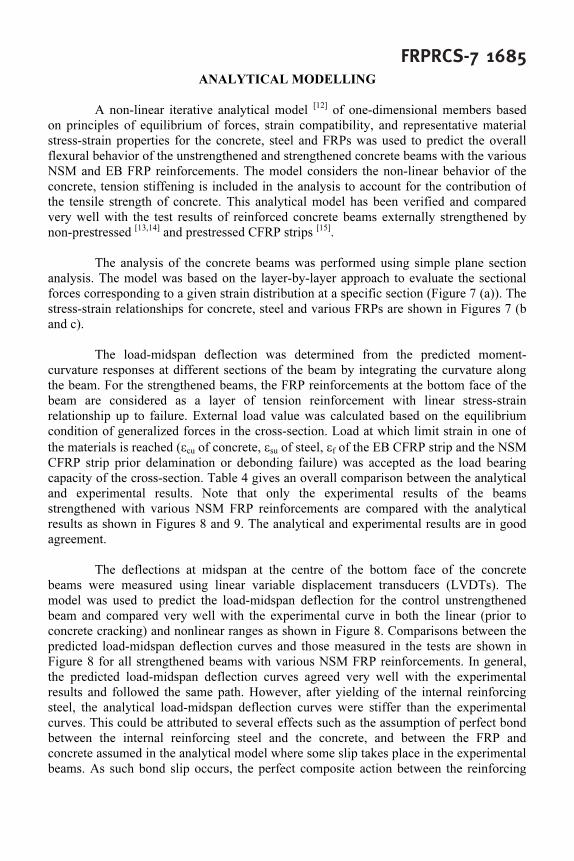
A non-linear iterative analytical model [12]
of one-dimensional members based
on principles of equilibrium of forces, strain compatibility, and representative material
stress-strain properties for the concrete, steel and FRPs was used to predict the overall
flexural behavior of the unstrengthened and strengthened concrete beams with the various
NSM and EB FRP reinforcements. The model considers the non-linear behavior of the
concrete, tension stiffening is included in the analysis to account for the contribution of
the tensile strength of concrete. This analytical model has been verified and compared
very well with the test results of reinforced concrete beams externally strengthened by
non-prestressed [13,14]
and prestressed CFRP strips [15]
.
The analysis of the concrete beams was performed using simple plane section
analysis. The model was based on the layer-by-layer approach to evaluate the sectional
forces corresponding to a given strain distribution at a specific section (Figure 7 (a)). The
stress-strain relationships for concrete, steel and various FRPs are shown in Figures 7 (b
and c).
The load-midspan deflection was determined from the predicted moment-
curvature responses at different sections of the beam by integrating the curvature along
the beam. For the strengthened beams, the FRP reinforcements at the bottom face of the
beam are considered as a layer of tension reinforcement with linear stress-strain
relationship up to failure. External load value was calculated based on the equilibrium
condition of generalized forces in the cross-section. Load at which limit strain in one of
the materials is reached (εcu
of concrete, εsu
of steel, εf of the EB CFRP strip and the NSM
CFRP strip prior delamination or debonding failure) was accepted as the load bearing
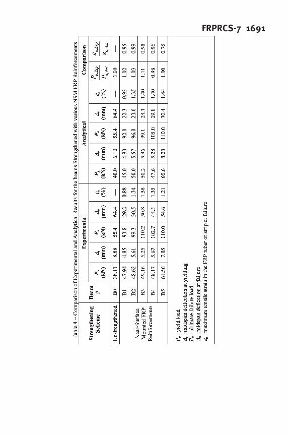
capacity of the cross-section. Table 4 gives an overall comparison between the analytical
and experimental results. Note that only the experimental results of the beams
strengthened with various NSM FRP reinforcements are compared with the analytical
results as shown in Figures 8 and 9. The analytical and experimental results are in good
agreement.
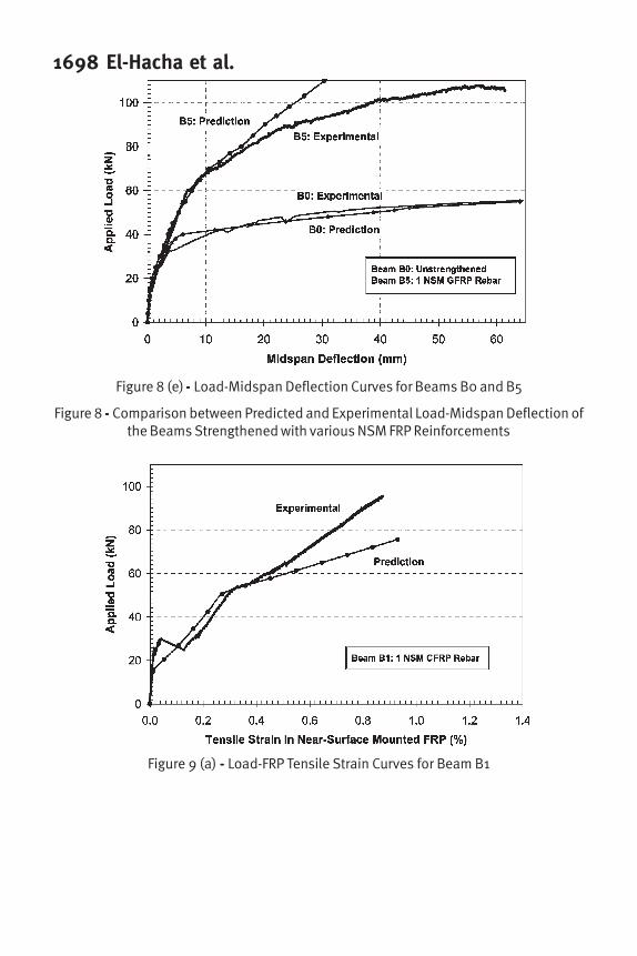
The deflections at midspan at the centre of the bottom face of the concrete
beams were measured using linear variable displacement transducers (LVDTs). The
model was used to predict the load-midspan deflection for the control unstrengthened
beam and compared very well with the experimental curve in both the linear (prior to
concrete cracking) and nonlinear ranges as shown in Figure 8. Comparisons between the
predicted load-midspan deflection curves and those measured in the tests are shown in
Figure 8 for all strengthened beams with various NSM FRP reinforcements. In general,
the predicted load-midspan deflection curves agreed very well with the experimental
results and followed the same path. However, after yielding of the internal reinforcing
steel, the analytical load-midspan deflection curves were stiffer than the experimental
curves. This could be attributed to several effects such as the assumption of perfect bond
between the internal reinforcing steel and the concrete, and between the FRP and
concrete assumed in the analytical model where some slip takes place in the experimental
beams. As such bond slip occurs, the perfect composite action between the reinforcing

1686 El-Hacha et al.steel and concrete is reduced and the overall stiffness of the experimental load-midspan
deflection of the beams is expected to be lower than for the analytical model.
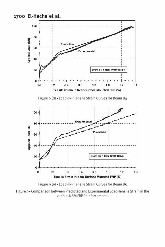
The tensile measured strains in the NSM FRP reinforcements at midspan were
monitored during testing using electrical resistance 120 ohms strain gauges. Comparison
between the predicted load-tensile strain in the various FRP reinforcements at midspan
and those measured in the tests are shown in Figure 9 for all strengthened beams. The
comparison between the predicted and experimental curves shows good agreement in
both the linear (prior to concrete cracking) and nonlinear ranges.
As shown in Figures 4 and 6, during testing just prior to failure, some beams
showed reversal strain in the FRP reinforcement that could be attributed most likely to a
local effect caused by the major cracks close to midspan. The strain reversal could also be
due to some sudden local delamination or debonding that preceded the failure as can be
observed in the sudden drops of the applied load as shown in the experimental load-
midspan deflection curves of the various strengthened beams with NSM FRP
reinforcement (Figures 3 and 5). This behavior does not occur in the analytical model
prediction as the effect of debonding or delamination was not taken into account. The
maximum predicted NSM FRP tensile strains at failure in all strengthened beams were
very close to the values obtained from the experimental results and confirmed the
dominate failure modes observed in each of the strengthened beams during the test as
shown in Table 3.
As can be seen that the experimental load-deflection and load-strain curves of all
tested beams confirmed compatibility of the analytical model over the entire range of
loads. Therefore, this model can be used for designing reinforced concrete members
strengthened in flexure with NSM FRP reinforcements. The model may be applied in two
different ways; the first method is based on the actual strength material characteristic of
the concrete, steel and FRP reinforcement to determine the nominal moment capacity.
The nominal moment is multiplied by a performance factor to give the design (ultimate)
value. In the second method, the factored resistance moment (design load bearing
capacity) is determined based on the design strength properties of all materials assessed
using appropriate material resistance factors (partial safety factors) for concrete, steel and
FRP reinforcement.
In general, the predicted load-midspan deflection and load-FRP tensile strain
curves for the strengthened beams determined from the analytical model were in good
agreement with the experimental results. In terms of the ultimate load and strain in the
FRP at failure, the analytical results differ by less than 1% from the experimental results.
The difference between the experimental and analytical curves is insignificant and could
be considered within the range of experimental errors associated with physical constants
(such as material properties such as, concrete was assumed homogeneous), physical
variables (such as supports conditions, loading position, tolerance during fabrication and
testing, depth of the internal steel and concrete cover), and errors in electronic measuring
devices. The difference between the experimental and analytical curves could also be due

FRPRCS-7 1687to the assumption considered in the analytical model that perfect bond between the epoxy
and the FRP reinforcement exists until failure.
CONCLUSIONS
The following conclusions can be drawn from this investigation:
• Strengthening concrete beams with NSM FRP reinforcements increased the
flexural stiffness and the ultimate load carrying capacity of the strengthened
beams compared to the unstrengthened beam and to the strengthened beams with
externally bonded FRP reinforcement.
• For the beams strengthened with various NSM FRP reinforcements, the
predicted load-midspan deflection curves agreed very well with the experimental
results in both the linear (prior to concrete cracking) and non-linear ranges.
• The load-tensile strain curves for the various NSM FRP reinforcements showed
good agreement between the experimental results and the prediction from the
non-linear analytical model.
• Both the predicted load-midspan deflection and load-tensile strain in the various
FRP reinforcements have similar trends with those obtained from the
experimental results.
• The iterative non-linear analytical model used in this study demonstrated very
well the behavior of the concrete beams and provided better understanding of
the NSM FRP strengthened concrete beams.
• The analytical model can be used to conservatively estimate the load-carrying
capacity of concrete beams strengthened with NSM FRP reinforcements. The
model can be used to develop design guidelines for strengthening reinforced
concrete beams with NSM and EB FRP reinforcements.
ACKNOWLEDGMENTS
The authors would like to thank the technical staff at the Constructed Facilities
Laboratory at North Carolina State University and J. N. da Silva Filho for their help withthe laboratory work. The authors are grateful to the support provided by Hughes Brothers
and Dow Chemical Co. for donating the FRP materials. The authors would like to thankT. Hassan for designing and constructing the beams during his PhD studies at theUniversity of Manitoba. The authors wish to acknowledge the support of the Natural
Sciences and Engineering Research Council of Canada (NSERC).
REFERENCES
[1] El-Hacha, R., Wight, R.G., and Green, M.F., 2001, “Prestressed Fibre-Reinforced
Polymer Laminates for Strengthening Structures.” Progress in Structural
Engineering and Materials, 2001:3, pp. 111-121.
[2] ACI Committee 440, 1996, “State-of-the-Art Report on Fiber Reinforced Plastic
Reinforcement for Concrete Structures (440R-96) (Reapproved 2002),” American
Concrete Institute, Farmington Hills, Mich., 68 p.
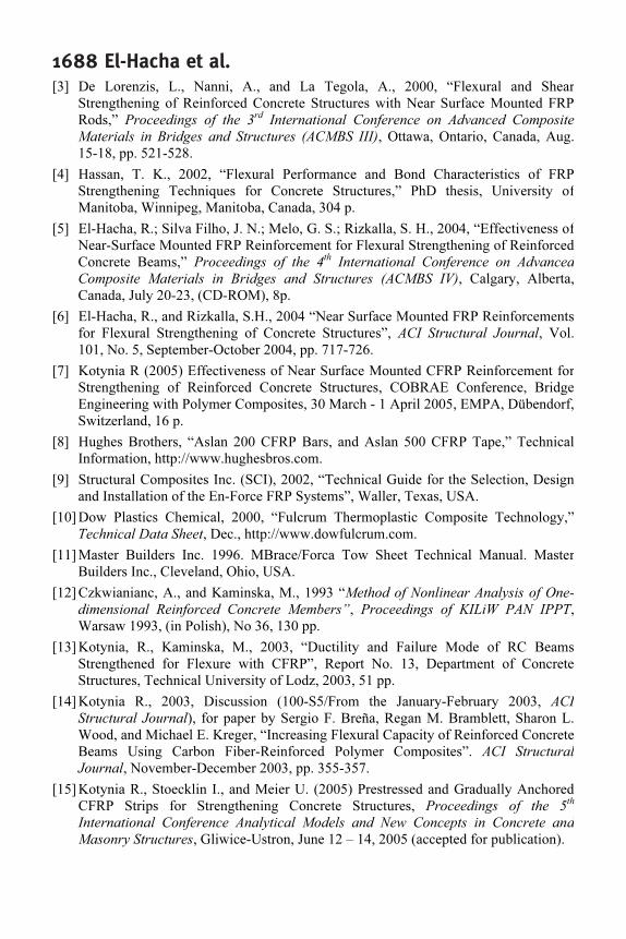
1688 El-Hacha et al.[3] De Lorenzis, L., Nanni, A., and La Tegola, A., 2000, “Flexural and Shear
Strengthening of Reinforced Concrete Structures with Near Surface Mounted FRP
Rods,” Proceedings of the 3rd
International Conference on Advanced Composite
Materials in Bridges and Structures (ACMBS III), Ottawa, Ontario, Canada, Aug.
15-18, pp. 521-528.
[4] Hassan, T. K., 2002, “Flexural Performance and Bond Characteristics of FRP
Strengthening Techniques for Concrete Structures,” PhD thesis, University of
Manitoba, Winnipeg, Manitoba, Canada, 304 p.
[5] El-Hacha, R.; Silva Filho, J. N.; Melo, G. S.; Rizkalla, S. H., 2004, “Effectiveness of
Near-Surface Mounted FRP Reinforcement for Flexural Strengthening of Reinforced
Concrete Beams,” Proceedings of the 4th
International Conference on Advanced
Composite Materials in Bridges and Structures (ACMBS IV), Calgary, Alberta,
Canada, July 20-23, (CD-ROM), 8p.
[6] El-Hacha, R., and Rizkalla, S.H., 2004 “Near Surface Mounted FRP Reinforcements
for Flexural Strengthening of Concrete Structures”, ACI Structural Journal, Vol.
101, No. 5, September-October 2004, pp. 717-726.
[7] Kotynia R (2005) Effectiveness of Near Surface Mounted CFRP Reinforcement for
Strengthening of Reinforced Concrete Structures, COBRAE Conference, Bridge
Engineering with Polymer Composites, 30 March - 1 April 2005, EMPA, Dübendorf,
Switzerland, 16 p.
[8] Hughes Brothers, “Aslan 200 CFRP Bars, and Aslan 500 CFRP Tape,” Technical
Information, http://www.hughesbros.com.
[9] Structural Composites Inc. (SCI), 2002, “Technical Guide for the Selection, Design
and Installation of the En-Force FRP Systems”, Waller, Texas, USA.
[10] Dow Plastics Chemical, 2000, “Fulcrum Thermoplastic Composite Technology,”
Technical Data Sheet, Dec., http://www.dowfulcrum.com.
[11] Master Builders Inc. 1996. MBrace/Forca Tow Sheet Technical Manual. Master
Builders Inc., Cleveland, Ohio, USA.
[12] Czkwianianc, A., and Kaminska, M., 1993 “Method of Nonlinear Analysis of One-
dimensional Reinforced Concrete Members”, Proceedings of KILiW PAN IPPT,
Warsaw 1993, (in Polish), No 36, 130 pp.
[13] Kotynia, R., Kaminska, M., 2003, “Ductility and Failure Mode of RC Beams
Strengthened for Flexure with CFRP”, Report No. 13, Department of Concrete
Structures, Technical University of Lodz, 2003, 51 pp.
[14] Kotynia R., 2003, Discussion (100-S5/From the January-February 2003, ACI
Structural Journal), for paper by Sergio F. Breña, Regan M. Bramblett, Sharon L.
Wood, and Michael E. Kreger, “Increasing Flexural Capacity of Reinforced Concrete
Beams Using Carbon Fiber-Reinforced Polymer Composites”. ACI Structural
Journal, November-December 2003, pp. 355-357.
[15] Kotynia R., Stoecklin I., and Meier U. (2005) Prestressed and Gradually Anchored
CFRP Strips for Strengthening Concrete Structures, Proceedings of the 5th
International Conference Analytical Models and New Concepts in Concrete and
Masonry Structures, Gliwice-Ustron, June 12 – 14, 2005 (accepted for publication).

FRPRCS-7 1689

1690 El-Hacha et al.
FRPRCS-7 1691

1692 El-Hacha et al.
Figure 1 - Beam Details and Test Set-Up [6]
Figure 2 ----- Various FRP Strengthening Schemes
FRPRCS-7 1693
Figure 3 ----- Load - Midspan Deflection of the Beams Strengthened with variousNSM FRP Reinforcements [5,6]
Figure 4 ----- Load - Tensile Strain in the various NSM FRP Reinforcements at Midspan forthe Beams Strengthened with NSM FRP Reinforcements [5,6]
1694 El-Hacha et al.
Figure 5 ----- Load-Midspan Deflection of the Beams Strengthened with variousEB FRP Reinforcements [5,6]
Figure 6 ----- Load-Tensile Strain in the various EB FRP Reinforcements at Midspan for theBeams Strengthened with EB FRP Reinforcements [5,6]

FRPRCS-7 1695
Figure 7 (a) ----- Calculation Model for a Specimen Strengthened with NSM FRP
Figure 7 (b) - - - - - Stress-Strain Relationship for Concrete
Figure 7 (c) - - - - - Stress-Strain Relationships for various FRP reinforcements andReinforcing Steel

1696 El-Hacha et al.
Figure 8 (a) - - - - - Load-Midspan Deflection Curves for Beams B0 and B1
Figure 8 (b) - - - - - Load-Midspan Deflection Curves for Beams B0 and B2

FRPRCS-7 1697
Figure 8 (c) - - - - - Load-Midspan Deflection Curves for Beams B0 and B3
Figure 8 (d) - - - - - Load-Midspan Deflection Curves for Beams B0 and B4
1698 El-Hacha et al.
Figure 8 (e) - - - - - Load-Midspan Deflection Curves for Beams B0 and B5
Figure 8 - - - - - Comparison between Predicted and Experimental Load-Midspan Deflection ofthe Beams Strengthened with various NSM FRP Reinforcements
Figure 9 (a) - - - - - Load-FRP Tensile Strain Curves for Beam B1

FRPRCS-7 1699
Figure 9 (b) - - - - - Load-FRP Tensile Strain Curves for Beam B2
Figure 9 (c) - - - - - Load-FRP Tensile Strain Curves for Beam B3
1700 El-Hacha et al.
Figure 9 (d) - - - - - Load-FRP Tensile Strain Curves for Beam B4
Figure 9 (e) - - - - - Load-FRP Tensile Strain Curves for Beam B5
Figure 9 - - - - - Comparison between Predicted and Experimental Load-Tensile Strain in thevarious NSM FRP Reinforcements
Related Documents