Flexural Analysis and Design of Beams Chapter 3

Welcome message from author
This document is posted to help you gain knowledge. Please leave a comment to let me know what you think about it! Share it to your friends and learn new things together.
Transcript
Flexural Analysis and Design of Beams
Chapter 3
Introduction
• Fundamental Assumptions
• Simple case of axial loading
• Same assumptions and ideal concept apply
• This chapter includes analysis and design for flexure, dimensioning cross section and reinforcement
• Shear design, bond anchorage, serviceability in chapters 4, 5, 6.
Bending of Homogeneous beam
• Steel, timber
• Internal forces-normal and tangential
• Normal-bending/flexural stress-bending moment
• Tangential-shear stress-shear force
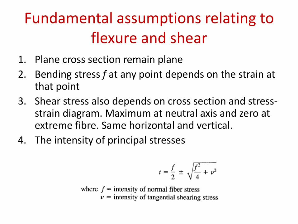
Fundamental assumptions relating to flexure and shear
1. Plane cross section remain plane
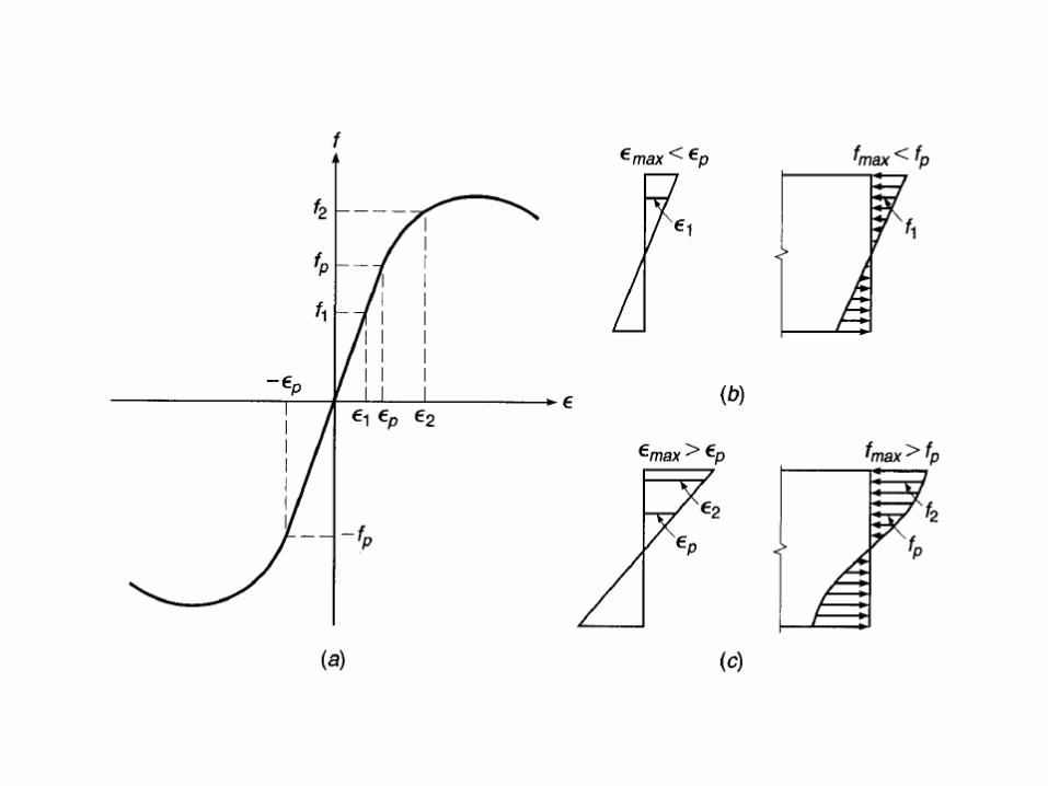
2. Bending stress f at any point depends on the strain at that point
3. Shear stress also depends on cross section and stress-strain diagram. Maximum at neutral axis and zero at extreme fibre. Same horizontal and vertical.
4. The intensity of principal stresses
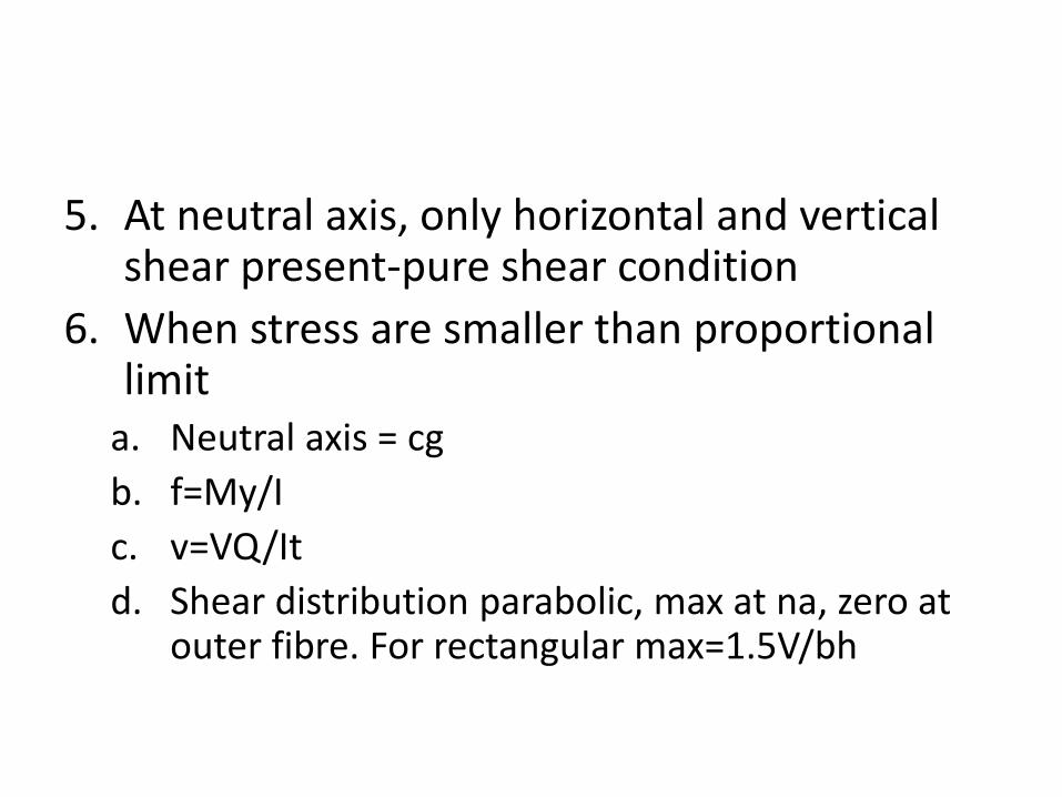
5. At neutral axis, only horizontal and vertical shear present-pure shear condition
6. When stress are smaller than proportional limit
a. Neutral axis = cg
b. f=My/I
c. v=VQ/It
d. Shear distribution parabolic, max at na, zero at outer fibre. For rectangular max=1.5V/bh
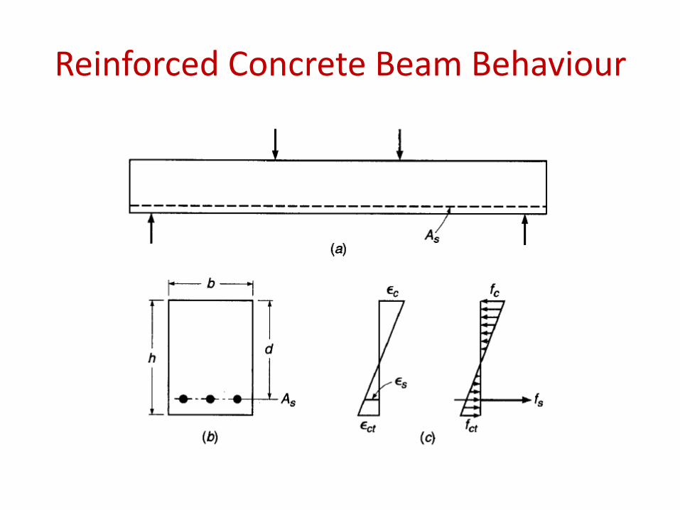
Reinforced Concrete Beam Behaviour

Video
• See video clips
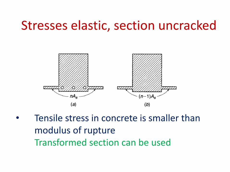
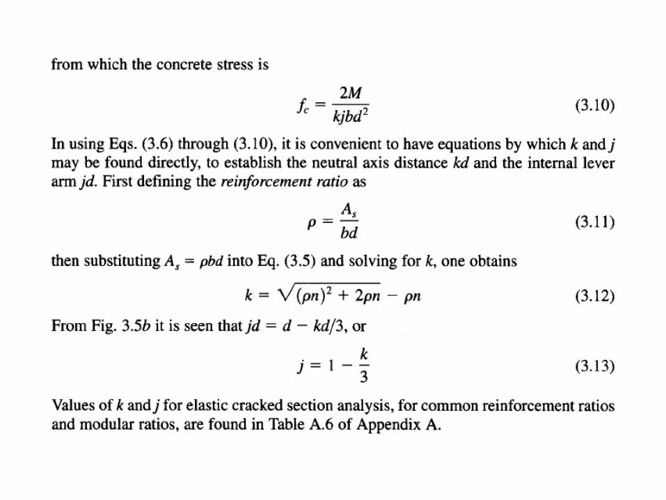
• Tensile stress in concrete is smaller than modulus of rupture Transformed section can be used
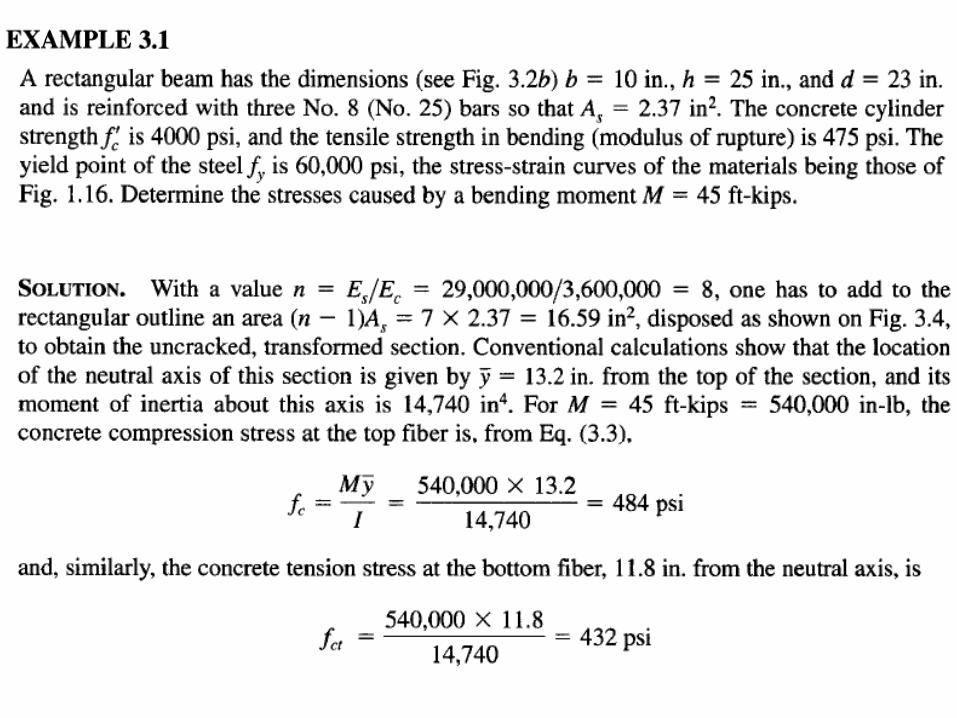
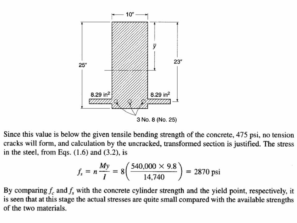
Stresses elastic, section uncracked
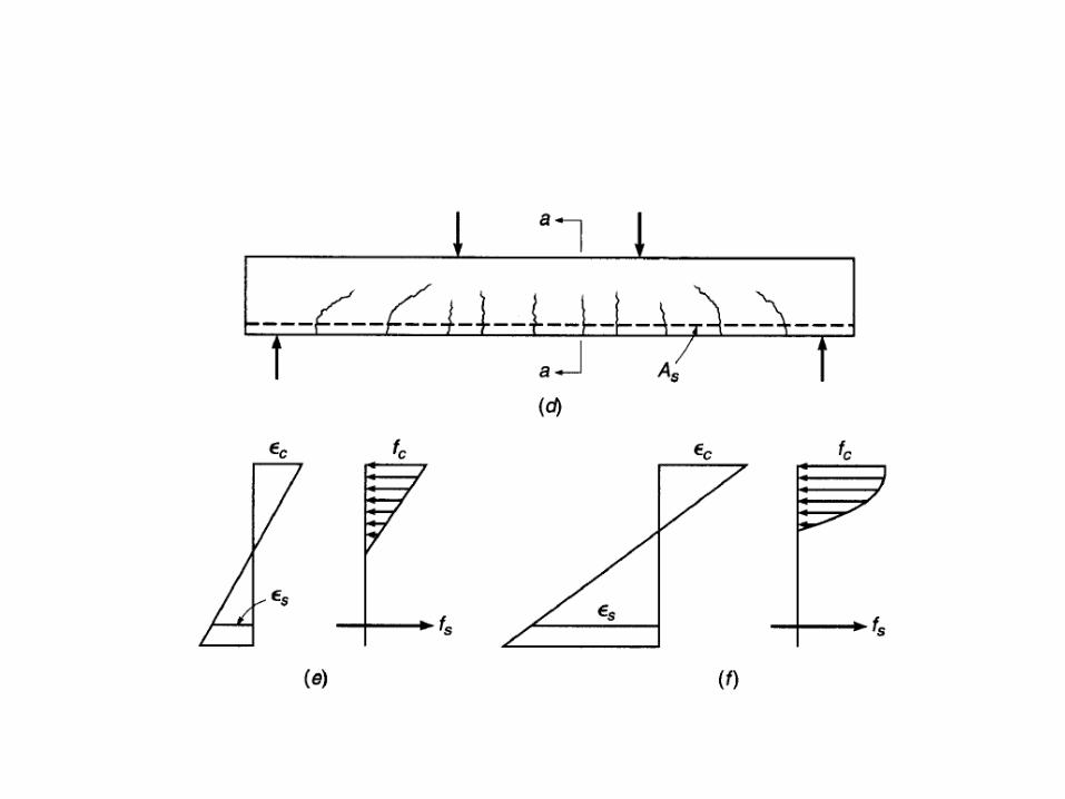
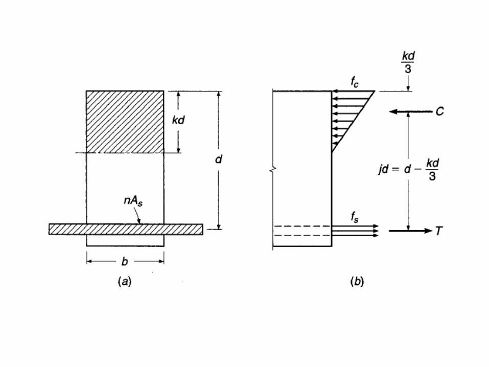
Stresses Elastic, Section cracked
• Concrete tensile stress exceeds mod of rupture
• Concrete compressive stress is less than fc’ /2
• Steel stress less than yield
• Assume tension crack up to neutral axis
• Transformed section can still be used
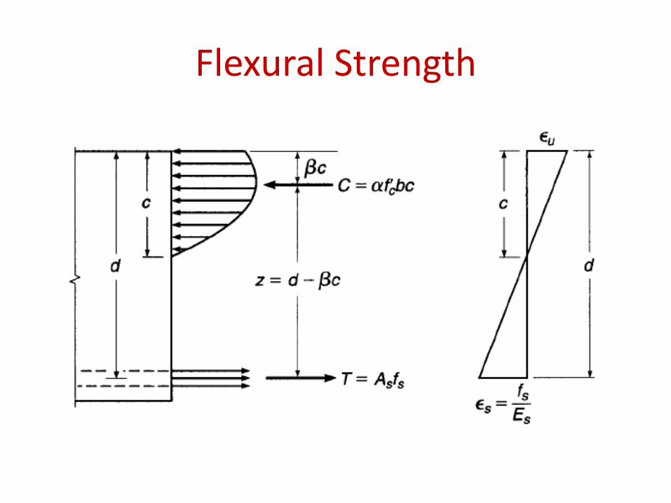
Flexural Strength
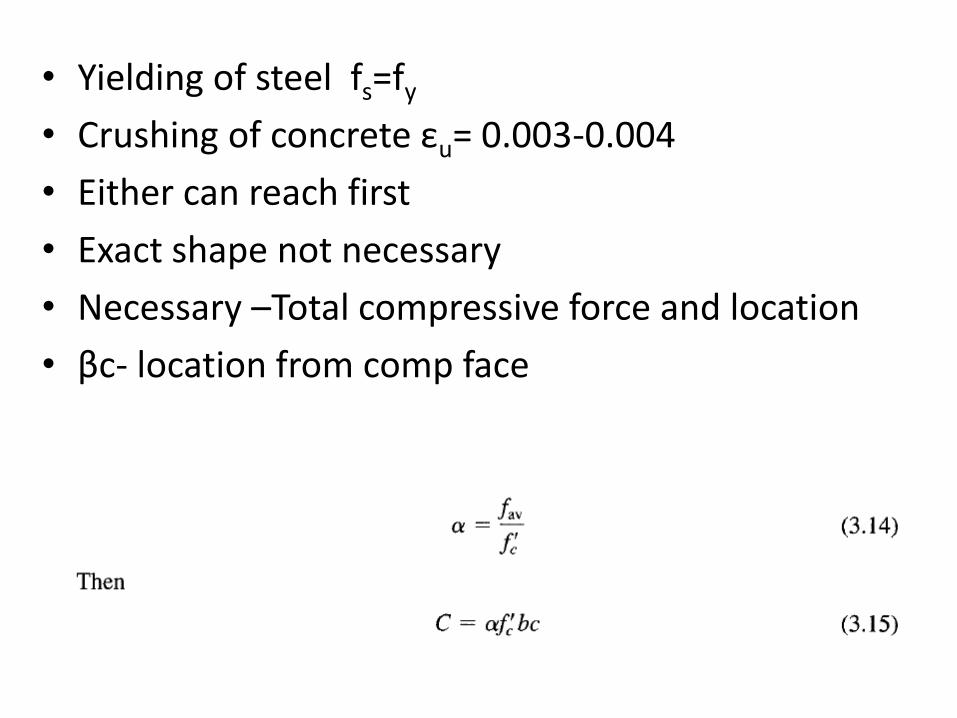
• Yielding of steel fs=fy
• Crushing of concrete εu= 0.003-0.004
• Either can reach first
• Exact shape not necessary
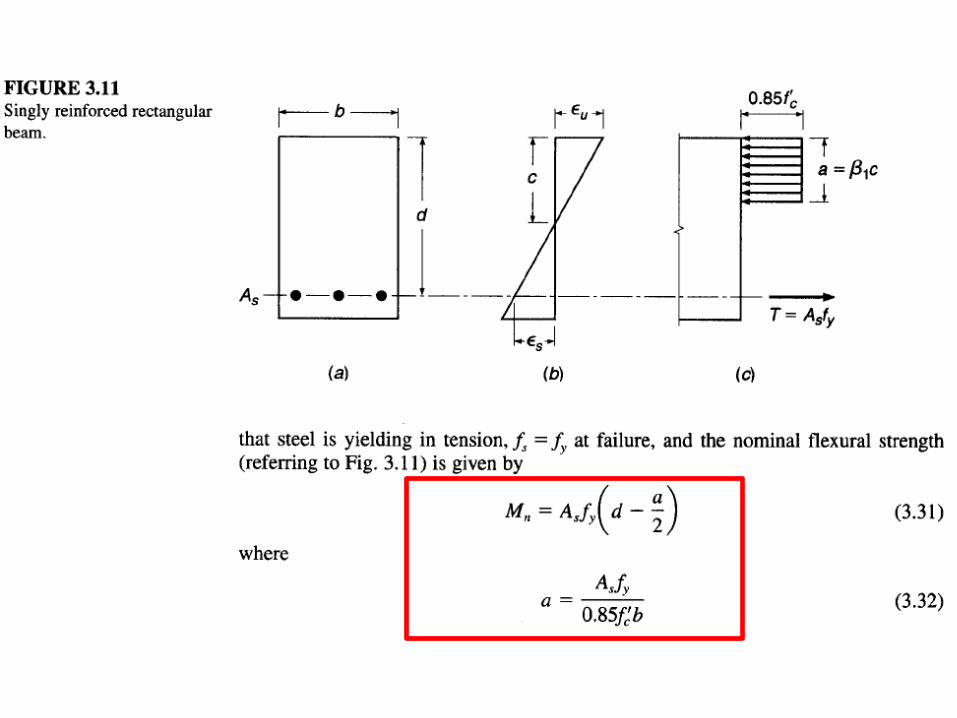
• Necessary –Total compressive force and location
• βc- location from comp face
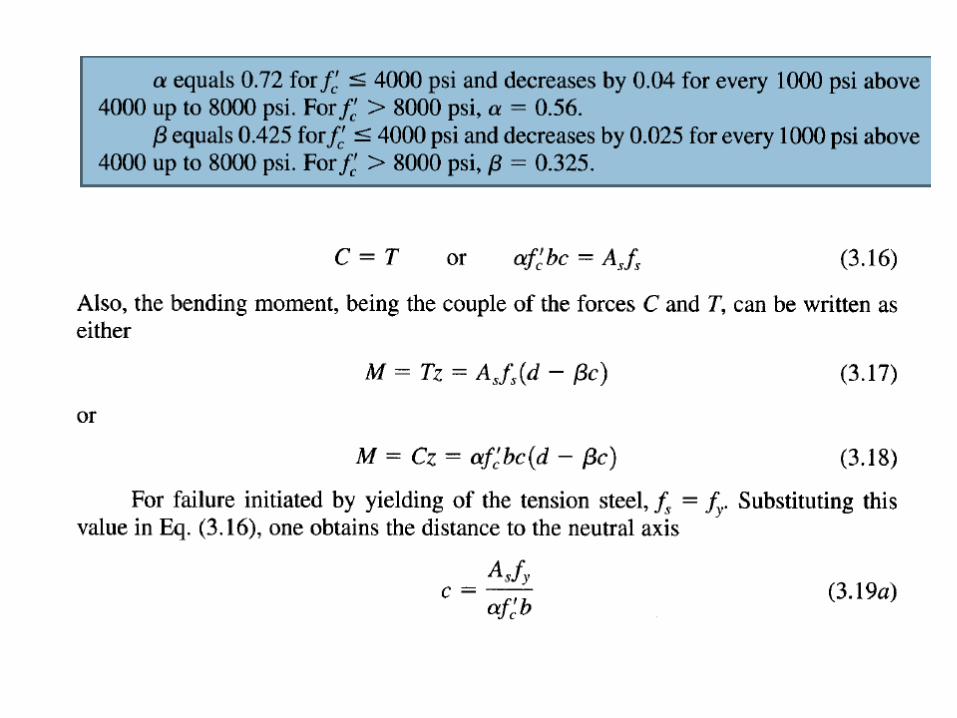

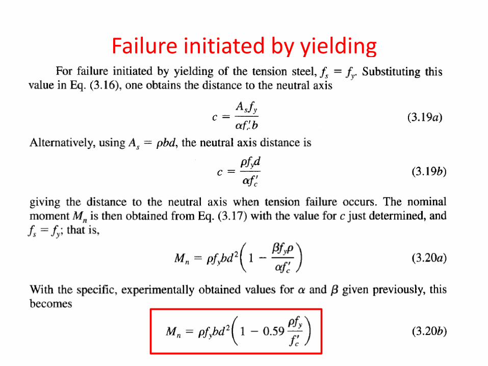
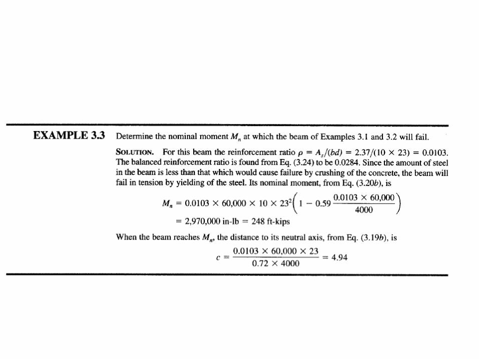
Failure initiated by yielding
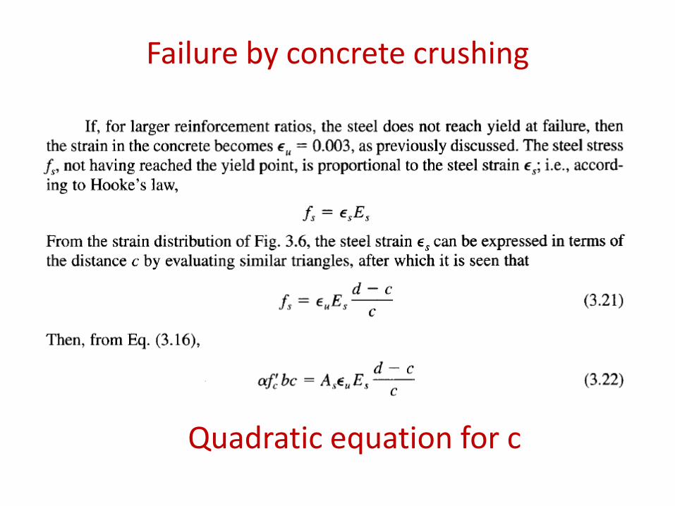
Failure by concrete crushing
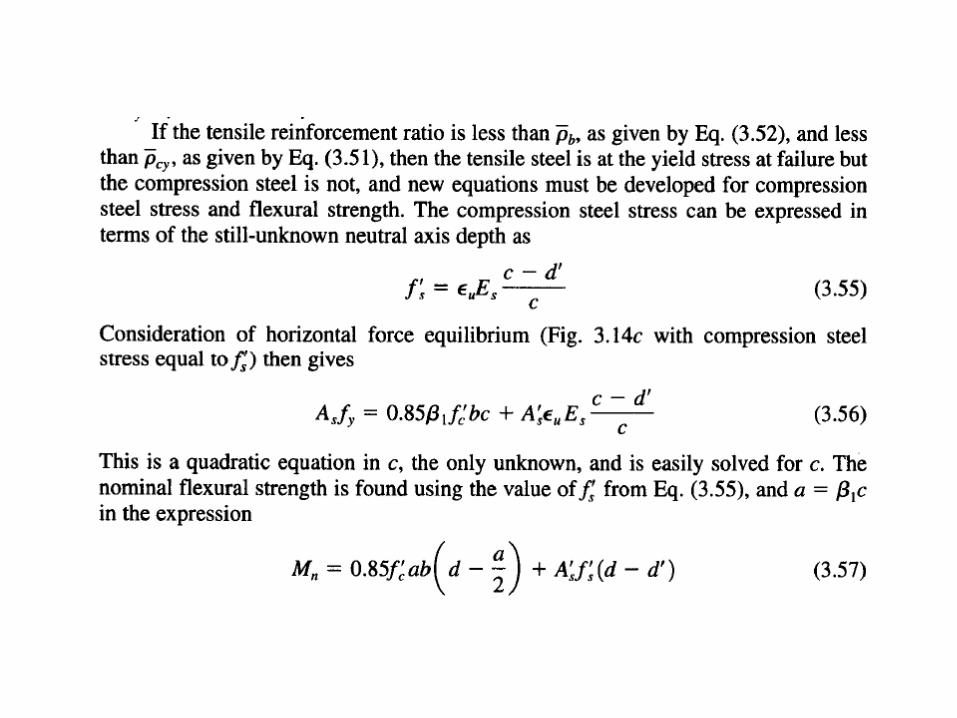
Quadratic equation for c
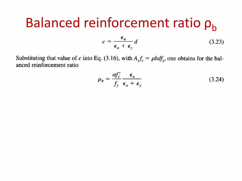
Balanced reinforcement ratio ρb
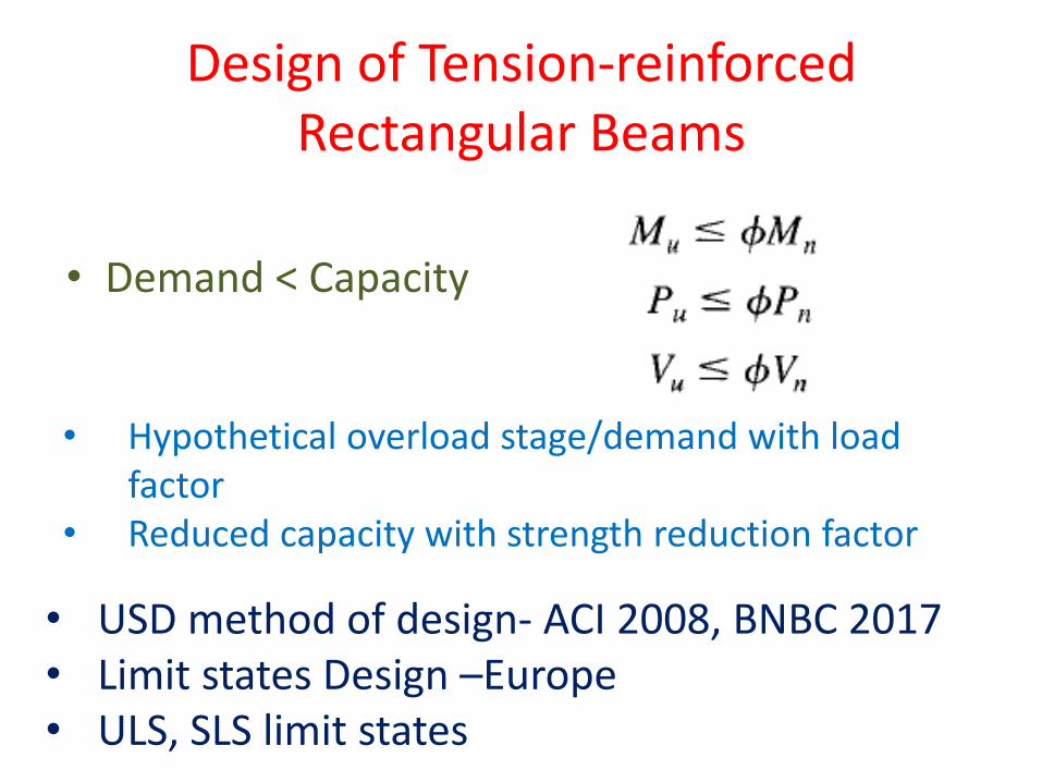
Design of Tension-reinforced Rectangular Beams
• Demand < Capacity
• USD method of design- ACI 2008, BNBC 2017 • Limit states Design –Europe • ULS, SLS limit states
• Hypothetical overload stage/demand with load factor
• Reduced capacity with strength reduction factor
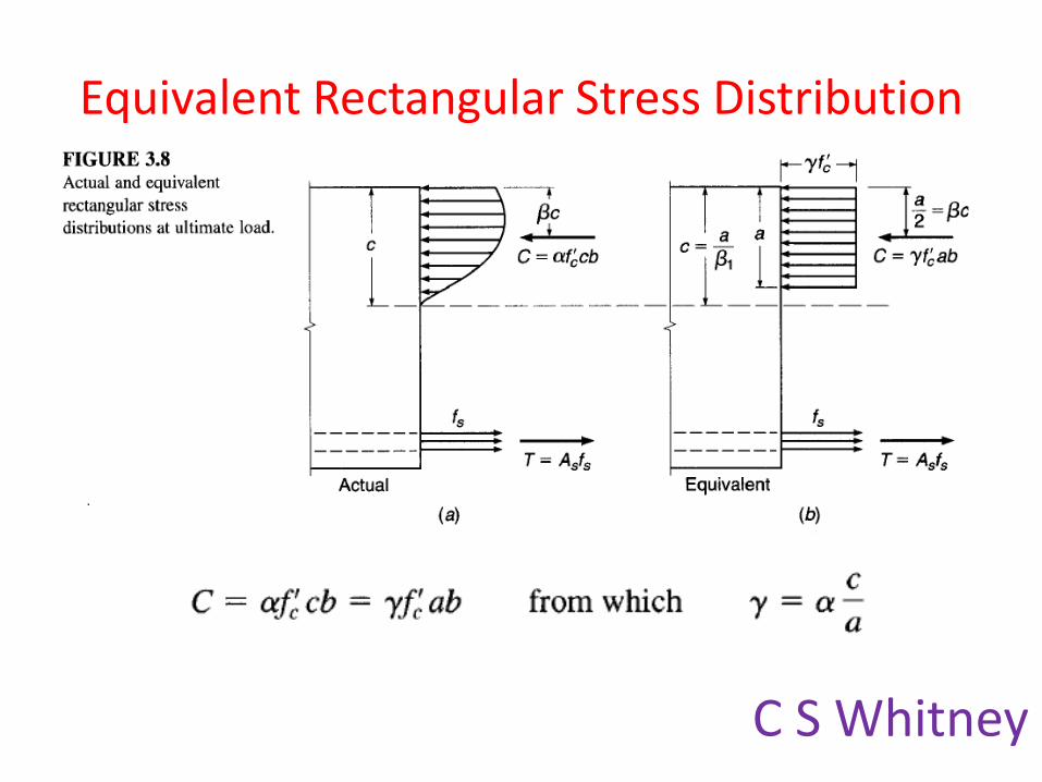
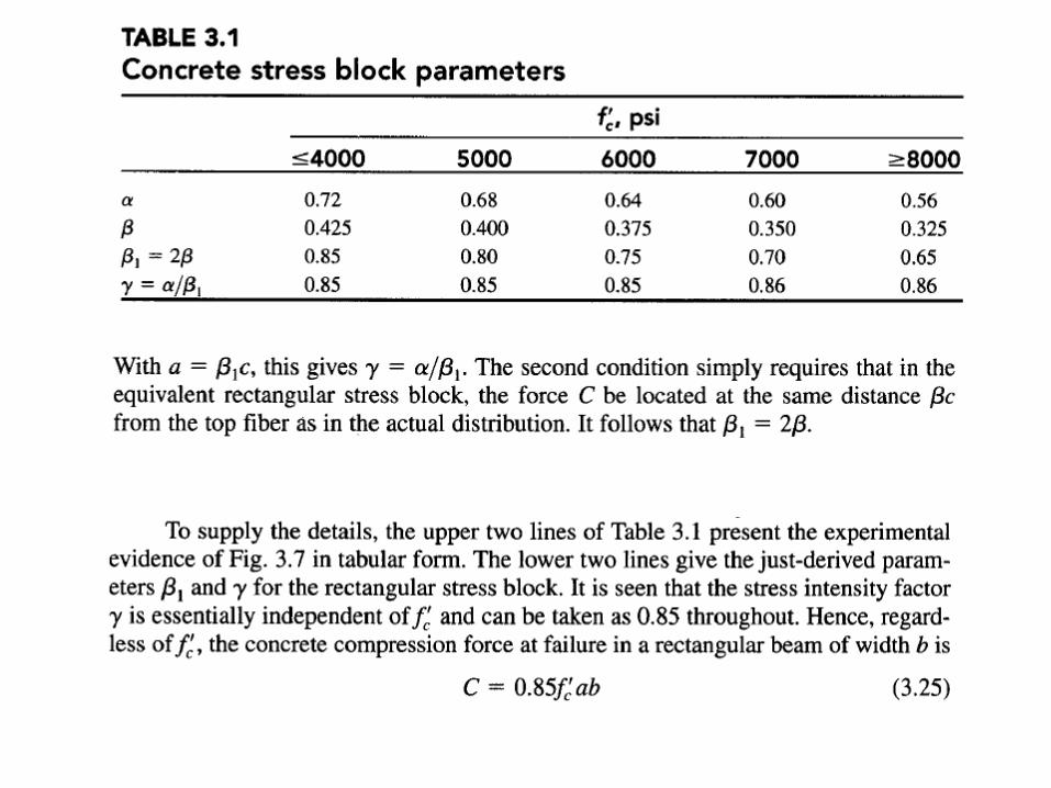
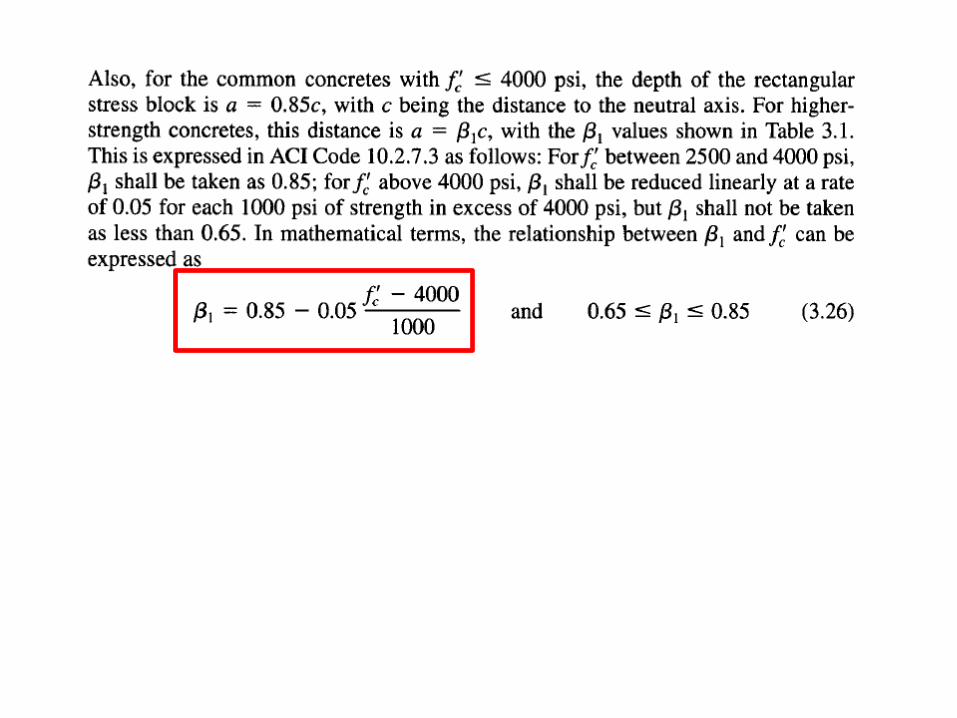
Equivalent Rectangular Stress Distribution
C S Whitney
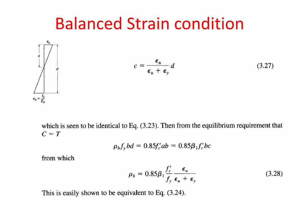
Balanced Strain condition
Underreinforced beam
• Compression failure is abrupt
• Tensile failure gradual
• ρ should be less than ρb
Read points why?
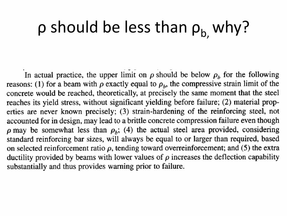
ρ should be less than ρb, why?
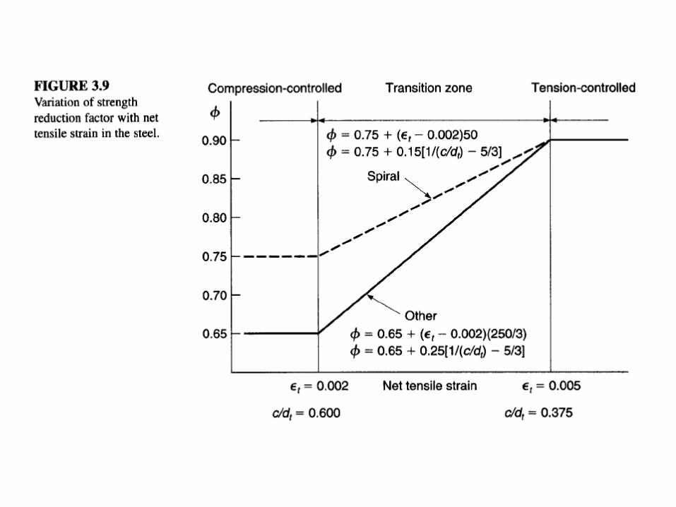
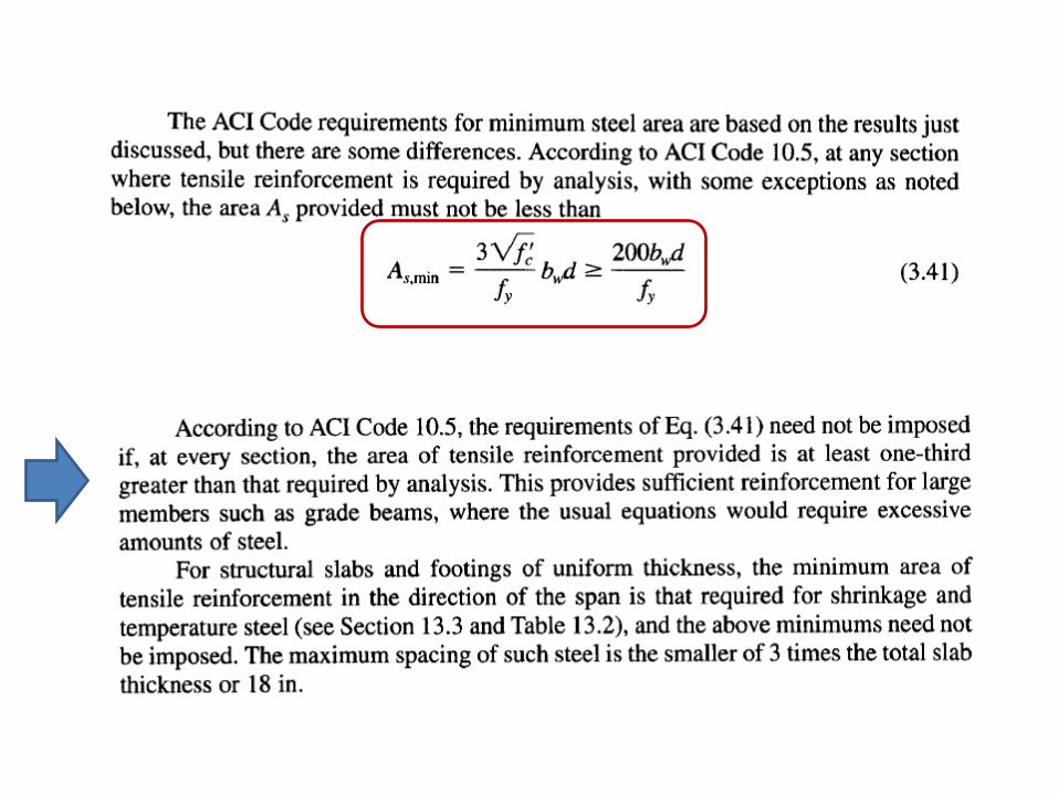
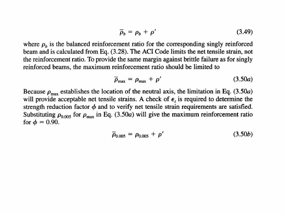
ACI provisions for underreinforced beam
• ACI establishes some safe limits
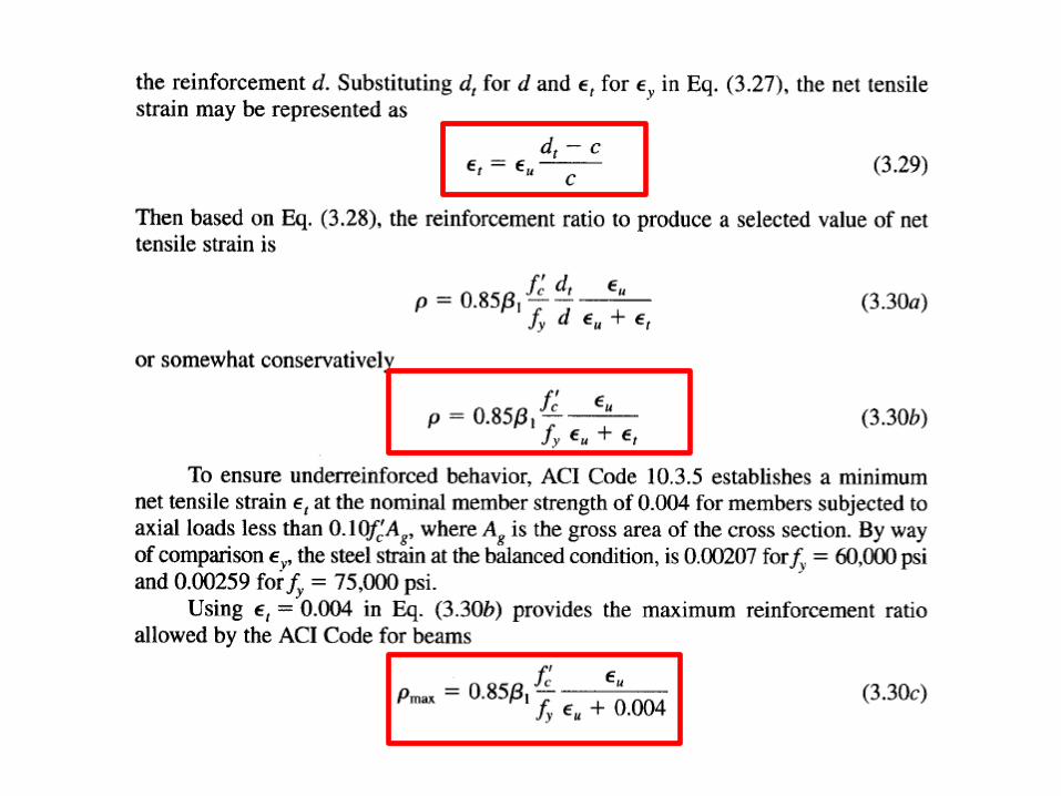
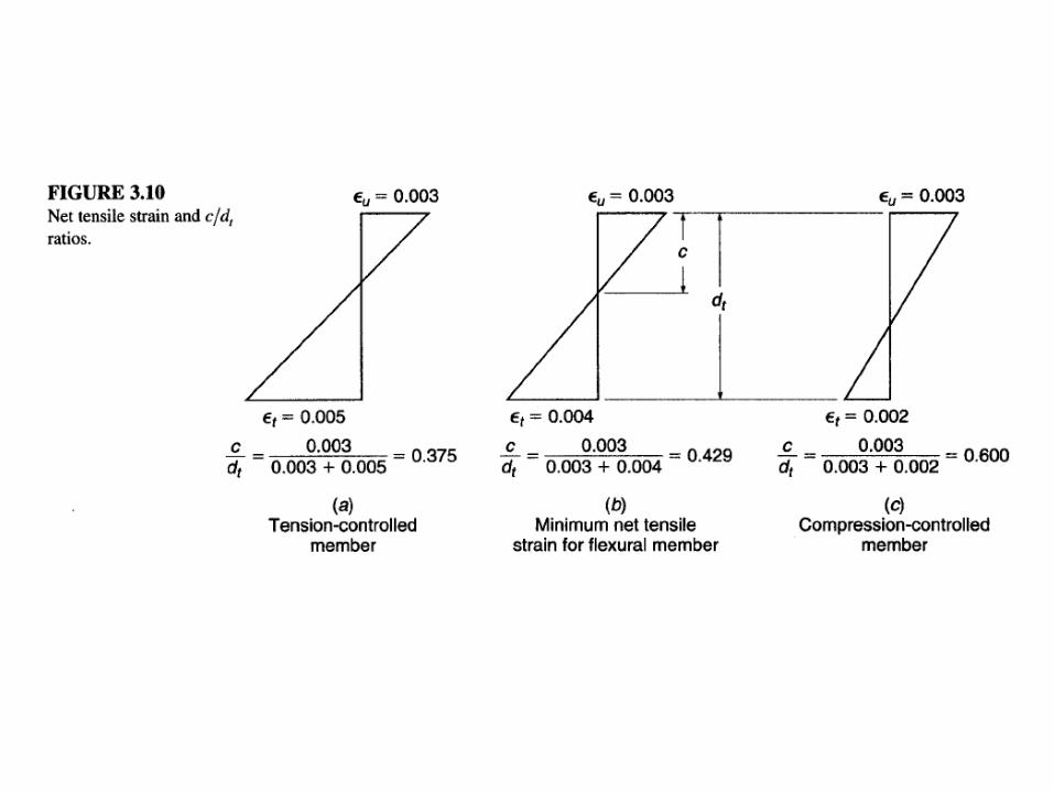
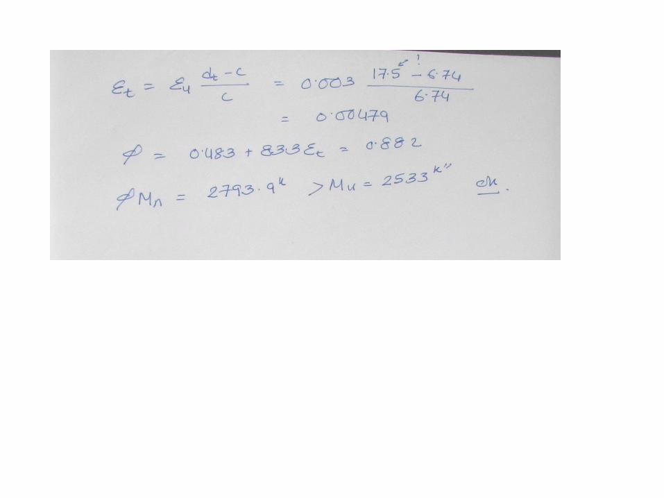
• Net tensile strain Єt at farthest from comp face
• Strength reduction factor φ
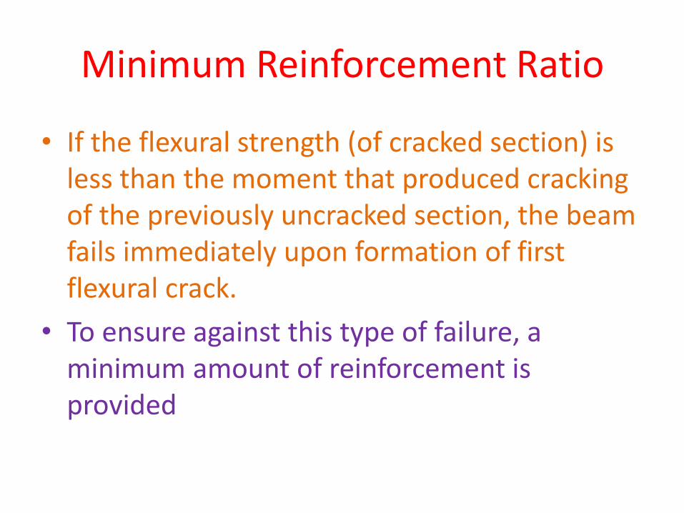
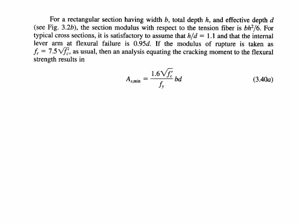
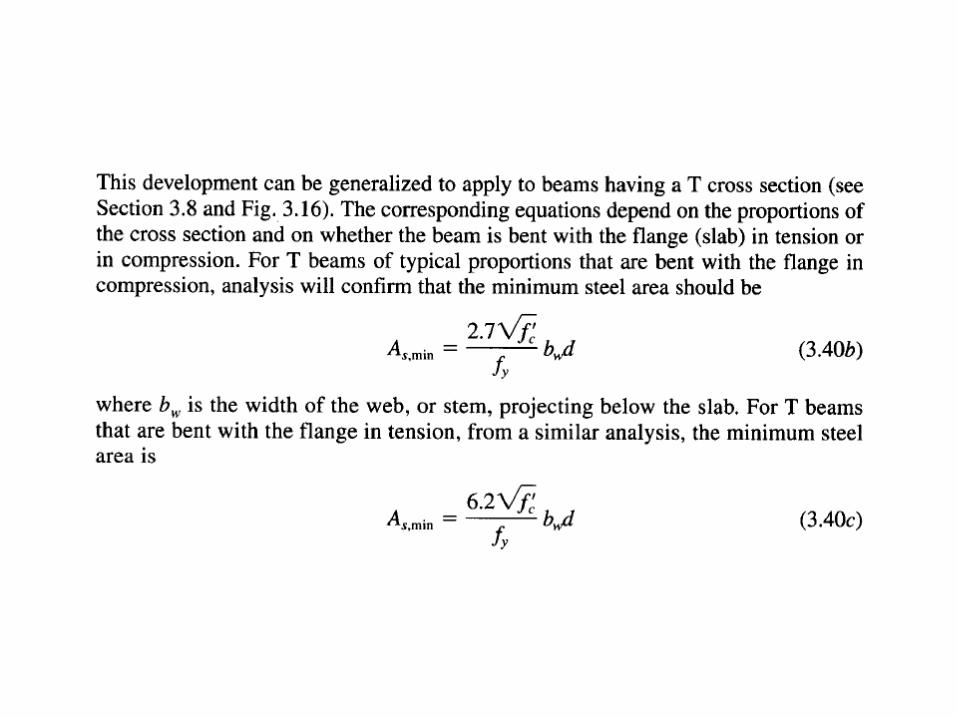
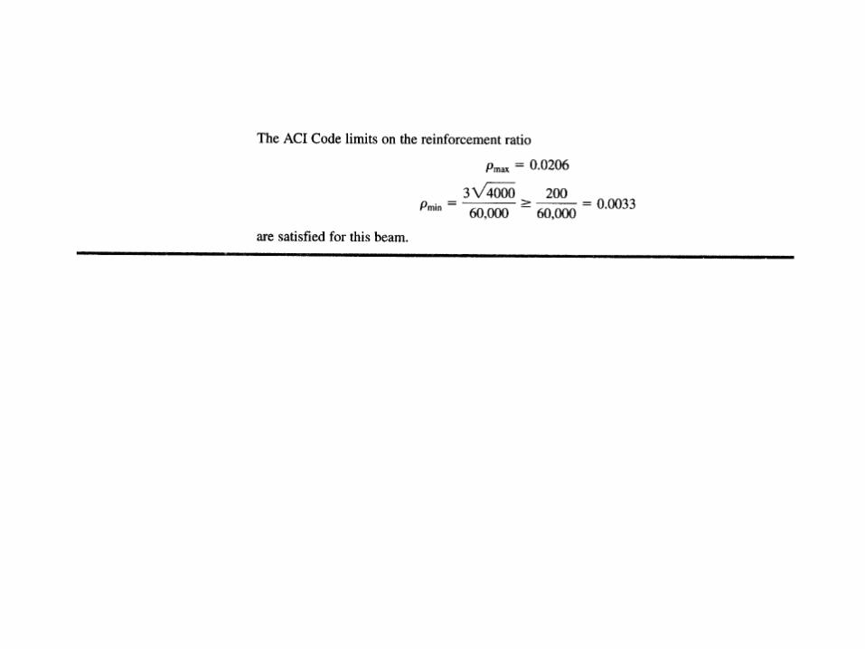
Minimum Reinforcement Ratio
• If the flexural strength (of cracked section) is less than the moment that produced cracking of the previously uncracked section, the beam fails immediately upon formation of first flexural crack.
• To ensure against this type of failure, a minimum amount of reinforcement is provided
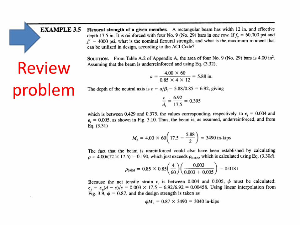
Review problem
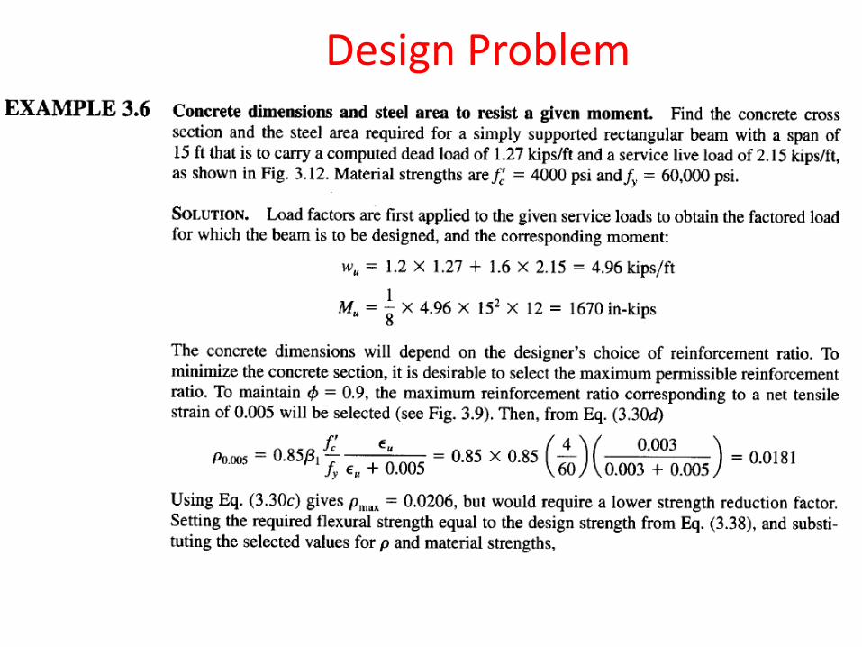
Design Problem
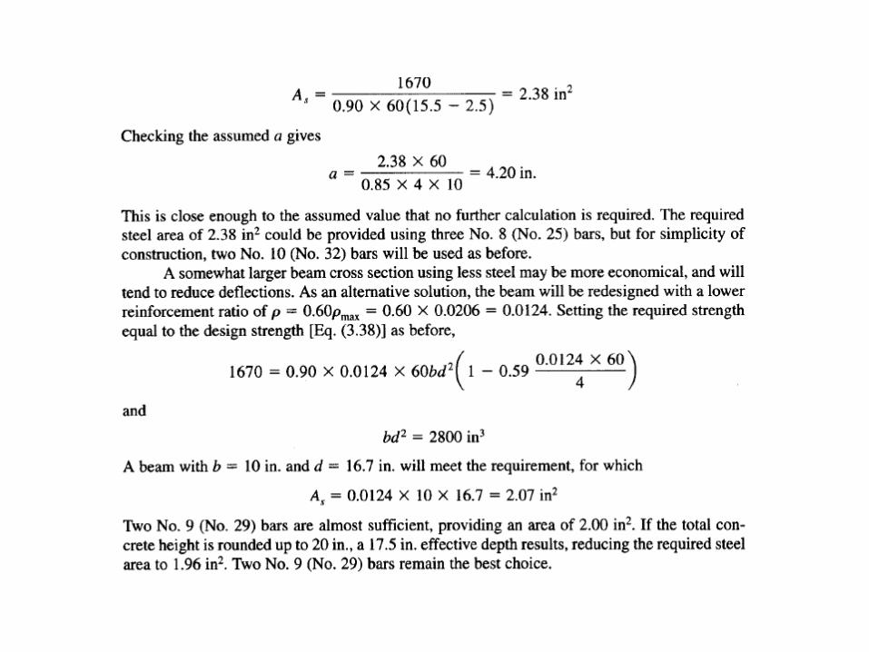
• Infinite number of solution is possible
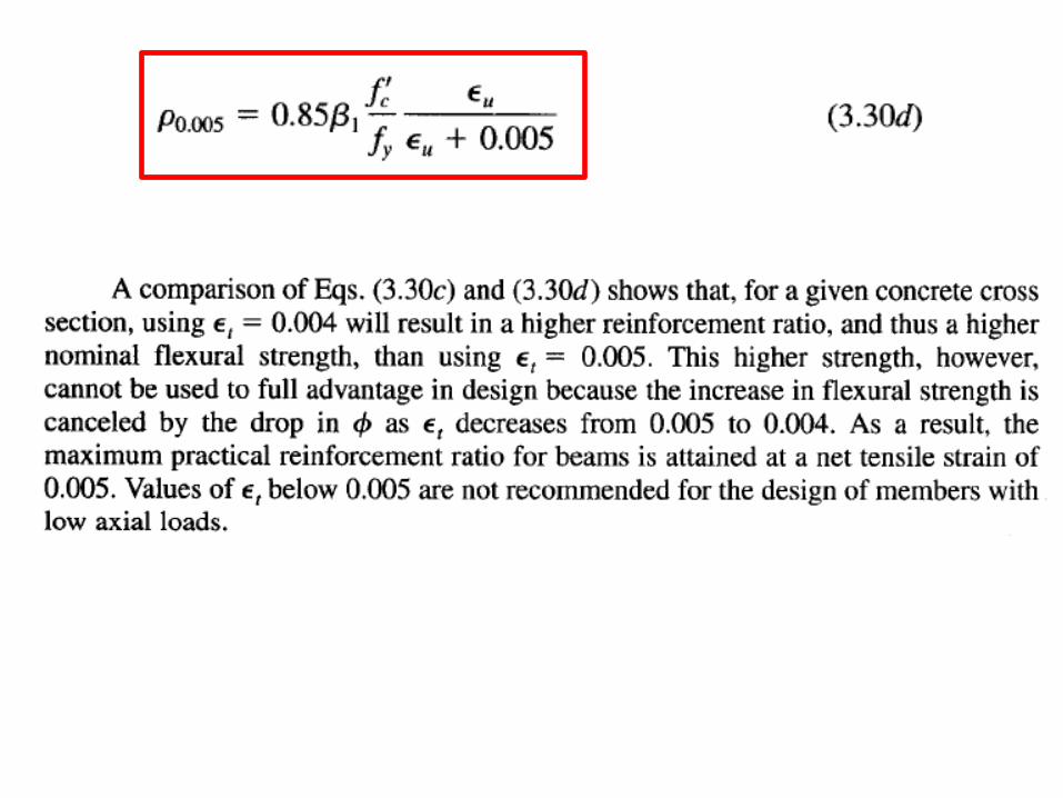
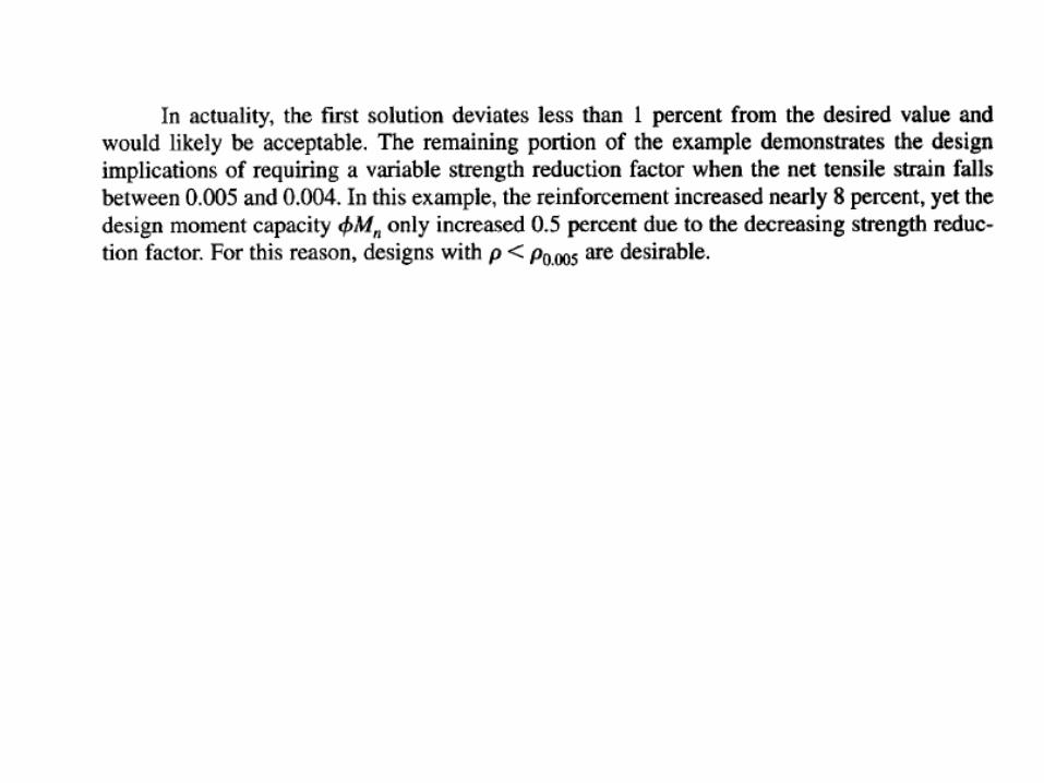
• Economic 0.5ρ0.005 to 0.75ρ0.005
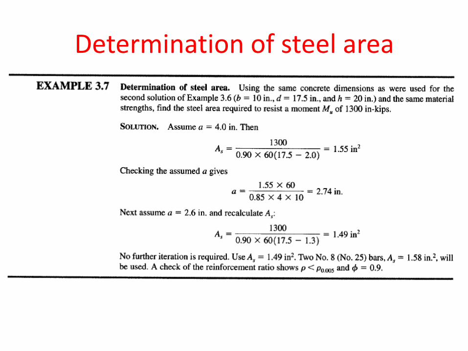
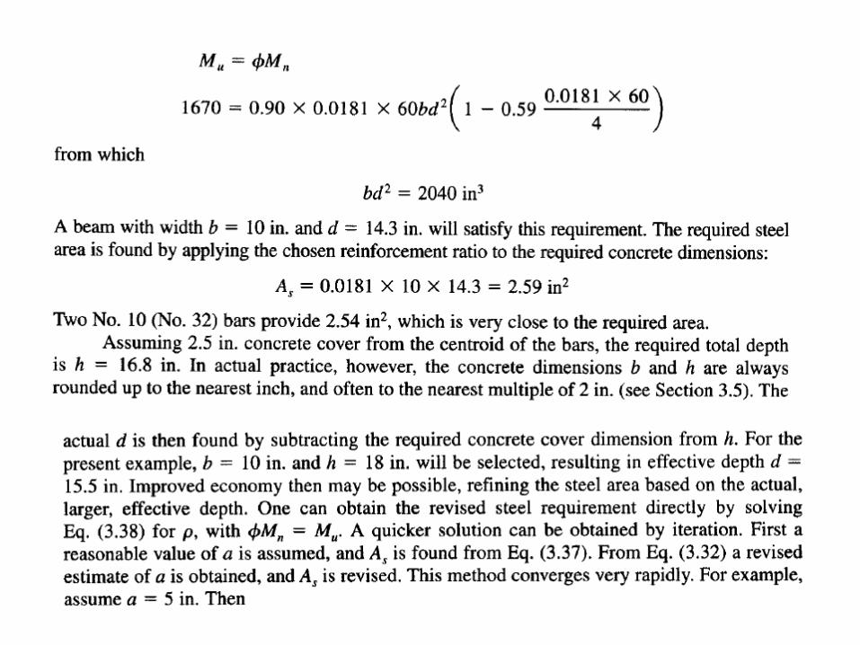
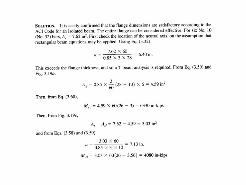
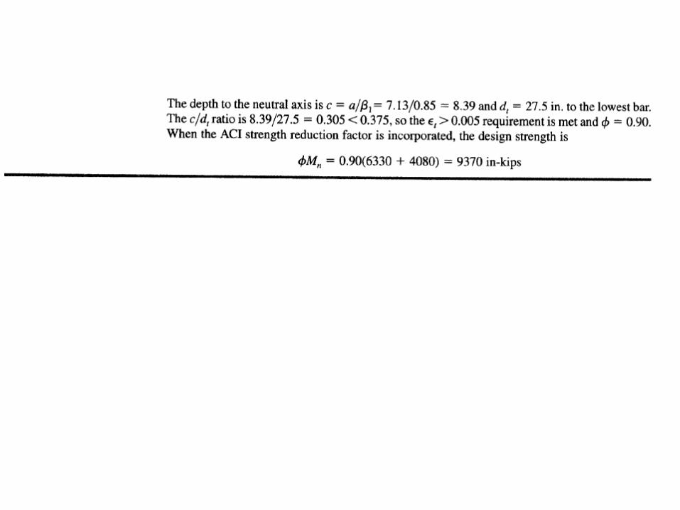
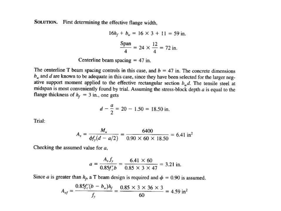
Determination of steel area
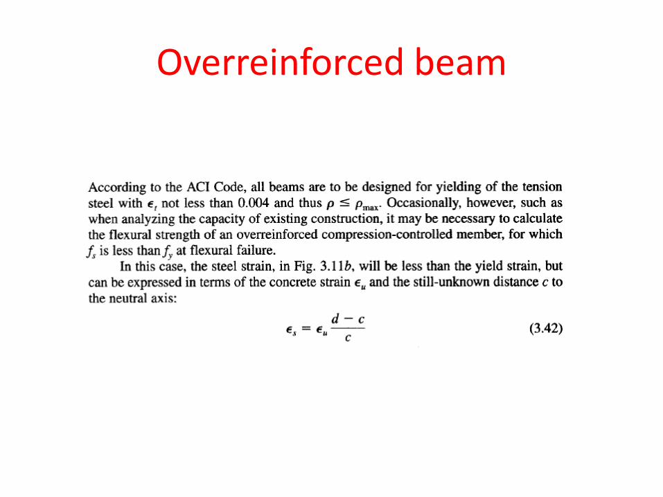
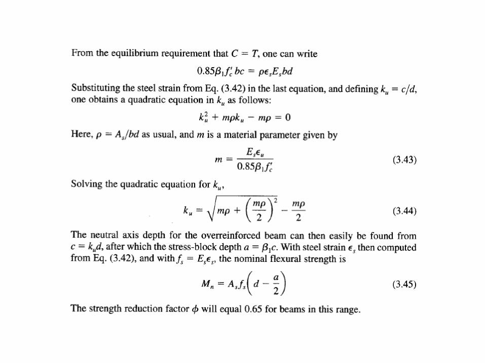
Overreinforced beam
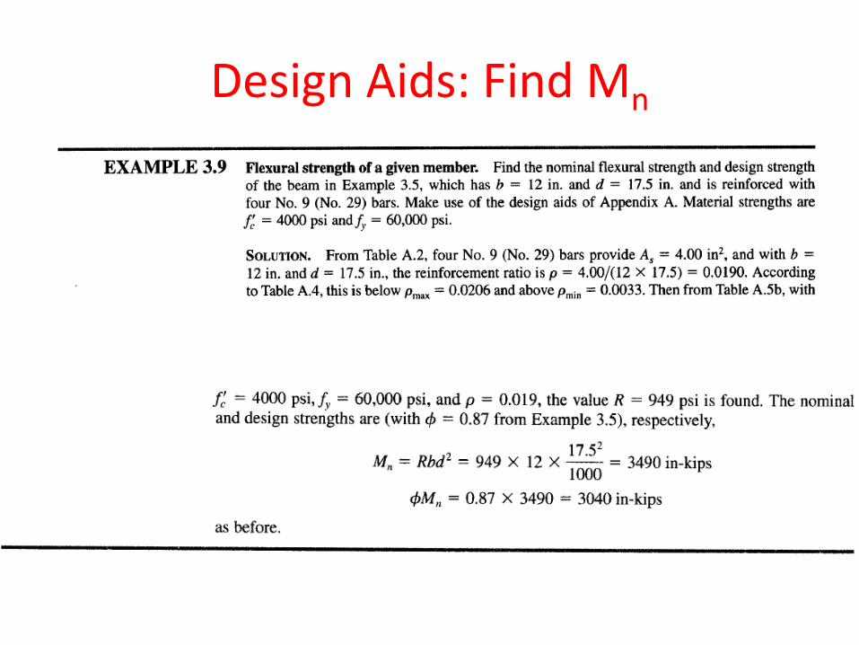
Design Aids: Find Mn
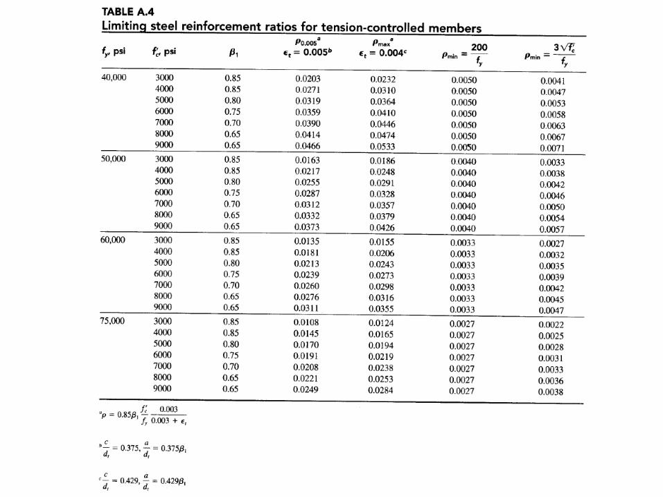
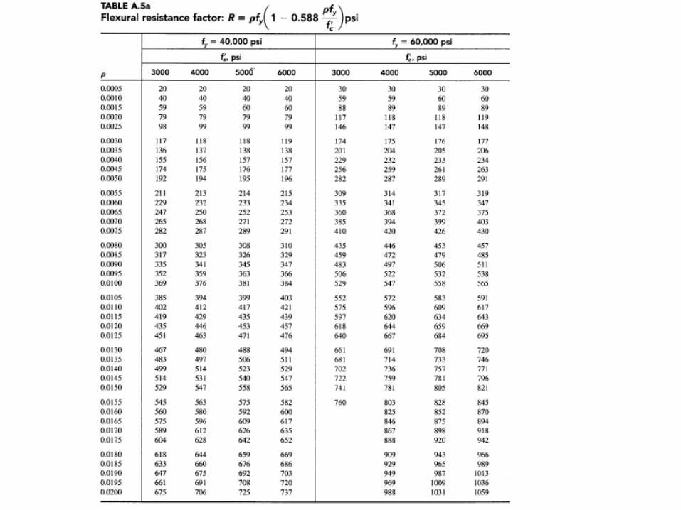
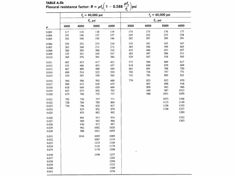
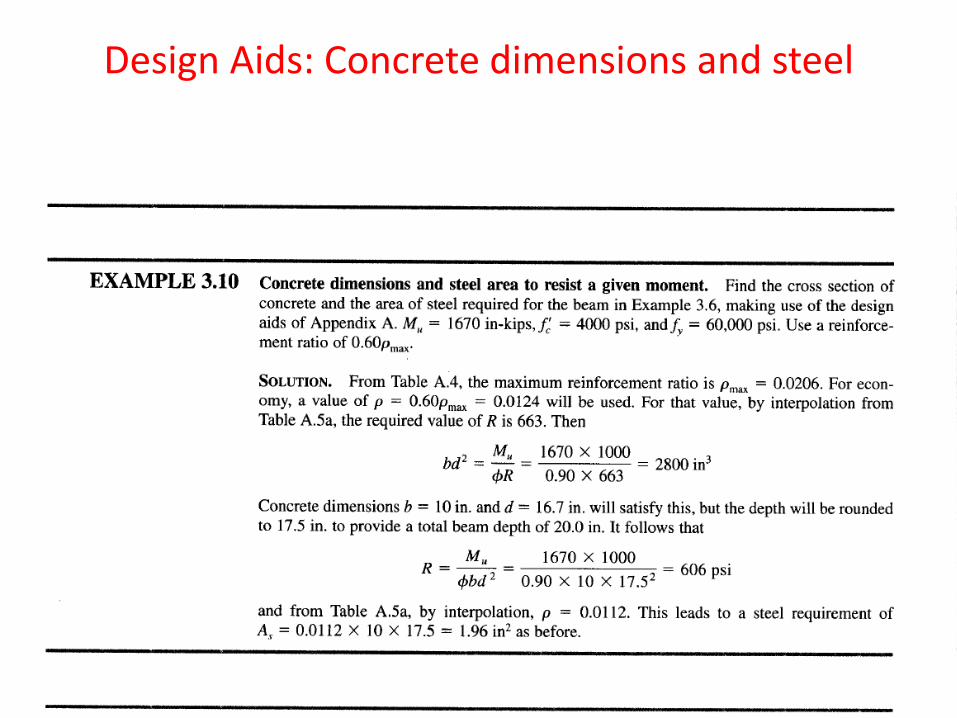
Design Aids: Concrete dimensions and steel
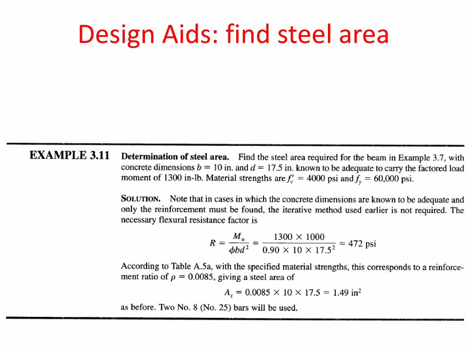
Design Aids: find steel area
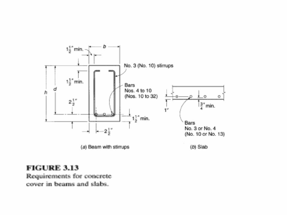
Practical considerations in the design of Beams: Concrete Protection for reinforcement
• Protection for steel against fire and corrosion
• Concrete cover depends on member and exposure
• Surfaces not exposed to ground or weather – Not less than ¾ in for slab
– Not less than 1.5 in for beams and columns
• Surfaces exposed to weather or in contact with ground – At least 2in
• Cast against ground with no form work – Min 3 in cover
• b and h are rounded to 1 or 2 inch
• Slab rounded to ¼ or ½ inch (greater than 6 inch)
• Proportions- d 2-3 times of b
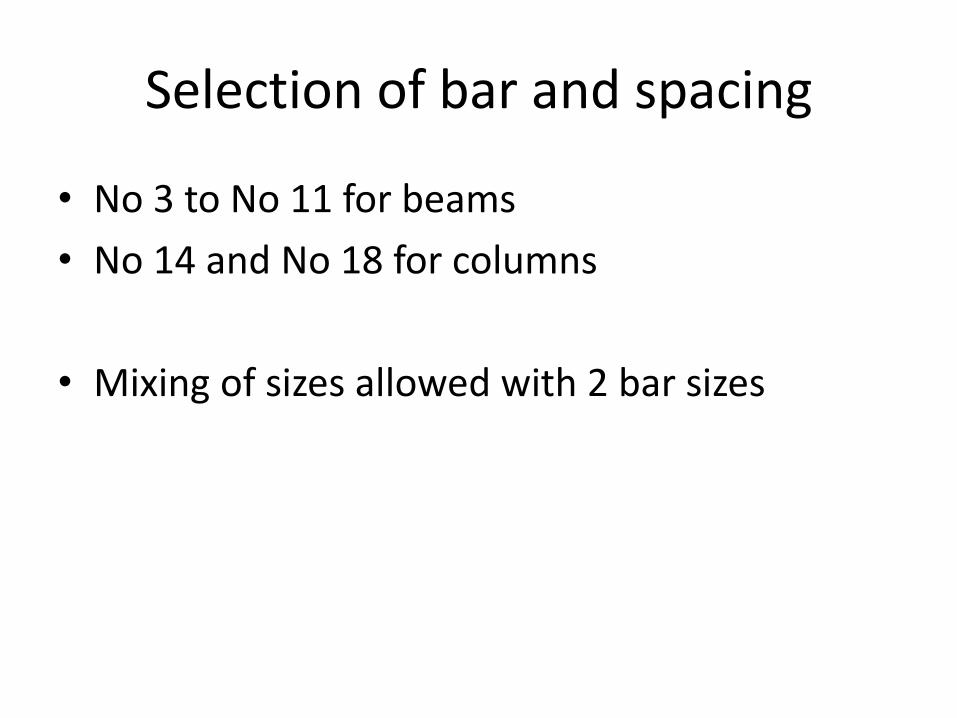
Selection of bar and spacing
• No 3 to No 11 for beams
• No 14 and No 18 for columns
• Mixing of sizes allowed with 2 bar sizes
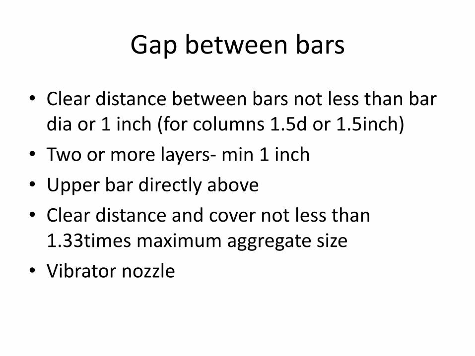
Gap between bars
• Clear distance between bars not less than bar dia or 1 inch (for columns 1.5d or 1.5inch)
• Two or more layers- min 1 inch
• Upper bar directly above
• Clear distance and cover not less than 1.33times maximum aggregate size
• Vibrator nozzle
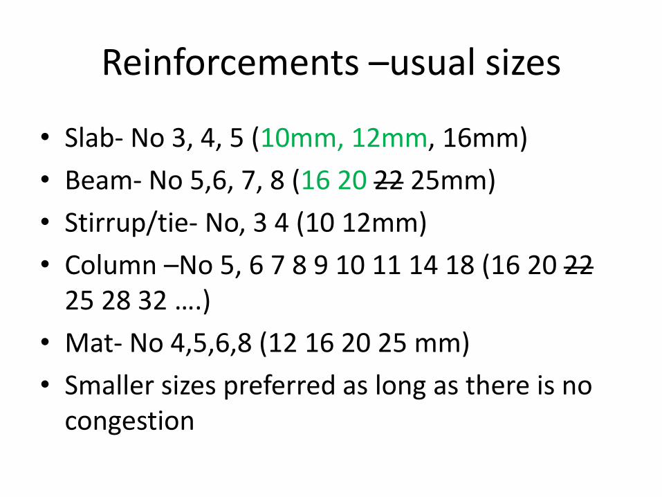
Reinforcements –usual sizes
• Slab- No 3, 4, 5 (10mm, 12mm, 16mm)
• Beam- No 5,6, 7, 8 (16 20 22 25mm)
• Stirrup/tie- No, 3 4 (10 12mm)
• Column –No 5, 6 7 8 9 10 11 14 18 (16 20 22 25 28 32 ….)
• Mat- No 4,5,6,8 (12 16 20 25 mm)
• Smaller sizes preferred as long as there is no congestion
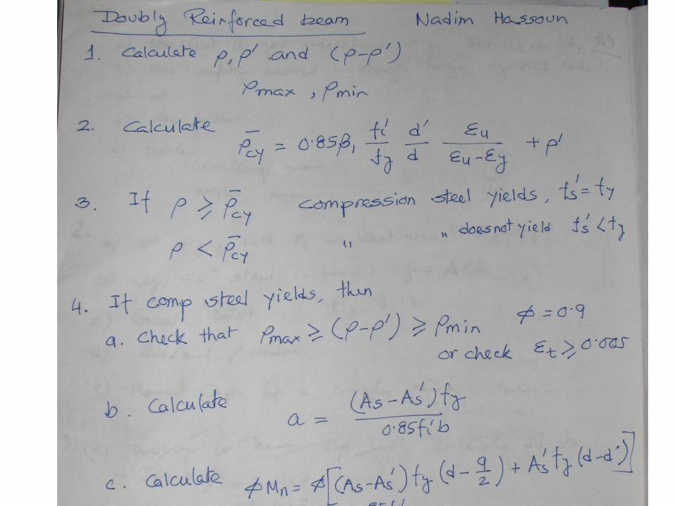
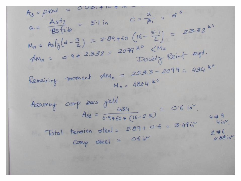
DOUBLY REINFORCED BEAM
• Beams with tension and compression reinforcement
• Cross section is limited
• Compression steel is used for other reasons-long term deflection, reversal of moment, hanger bar for stirrup
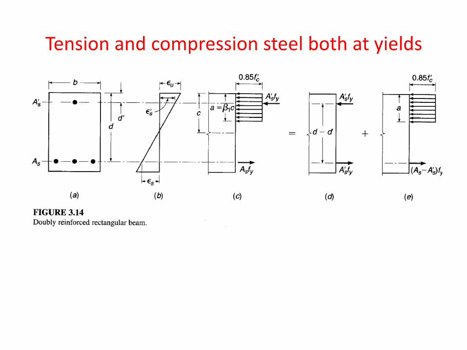
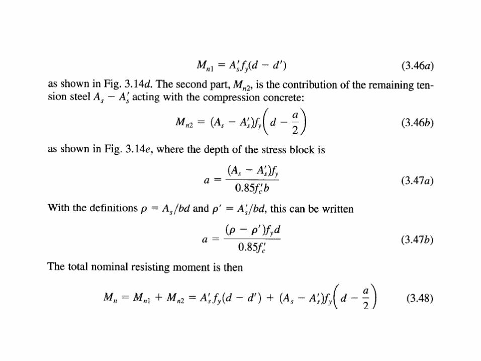
Tension and compression steel both at yields
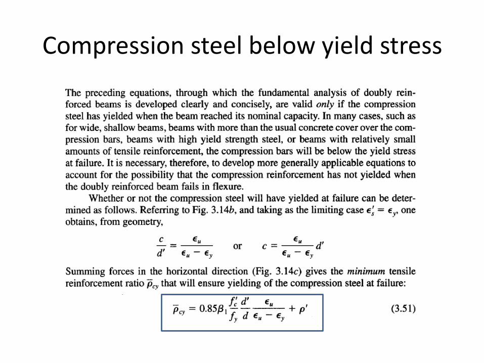
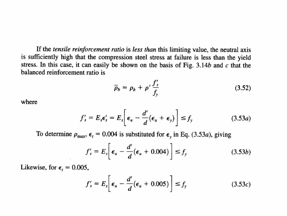
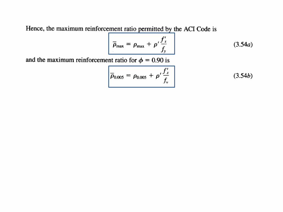
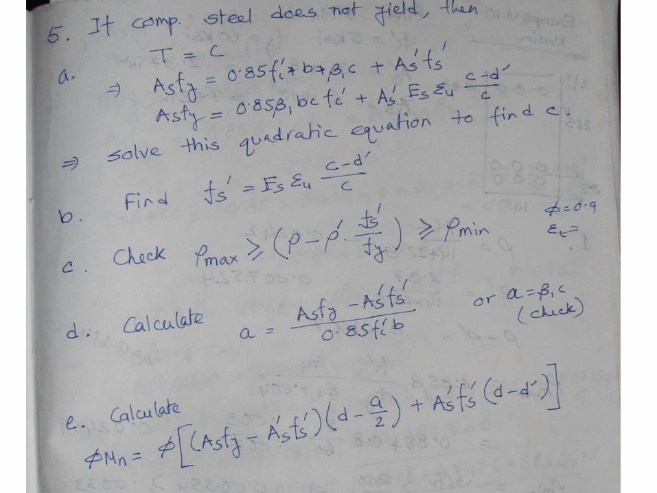
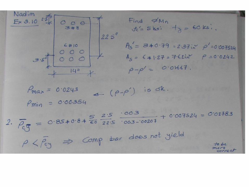
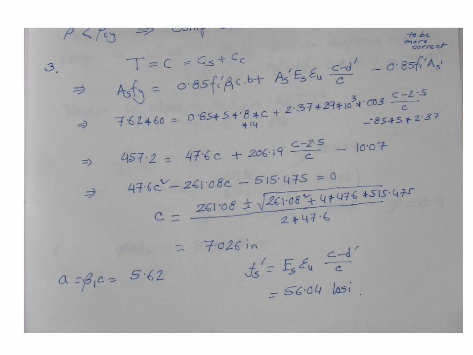
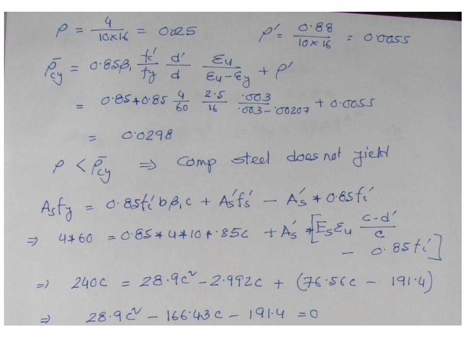
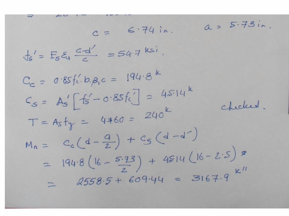
Compression steel below yield stress
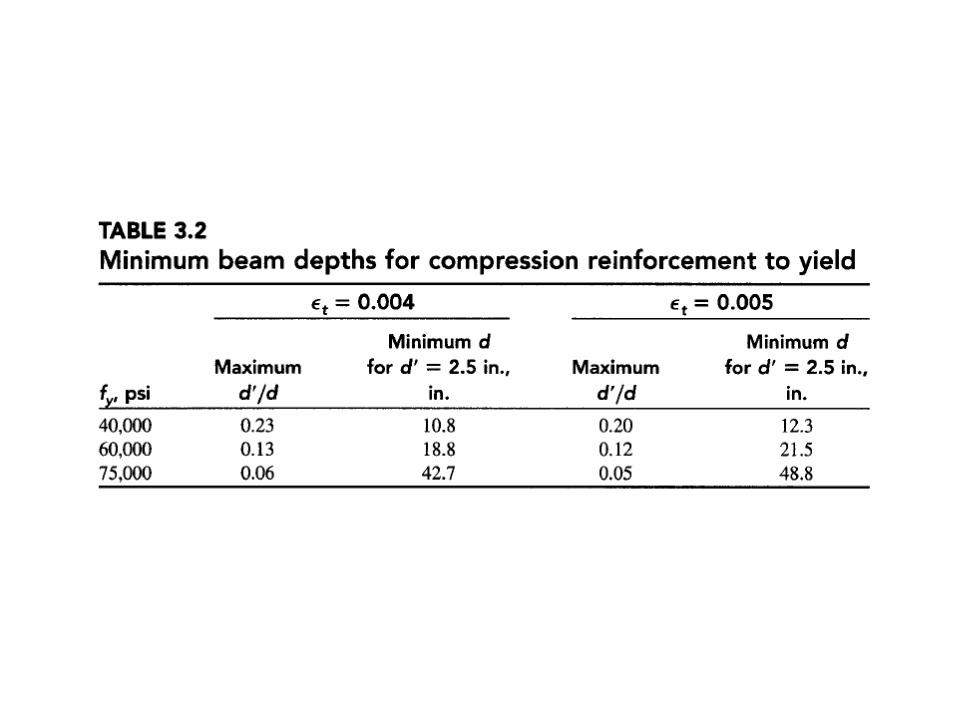
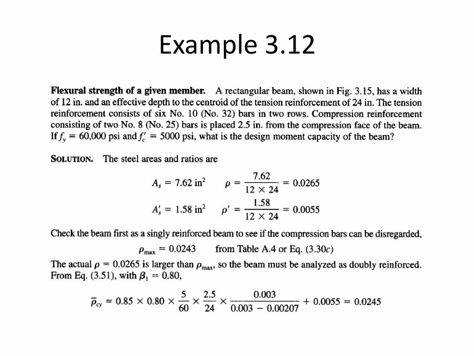
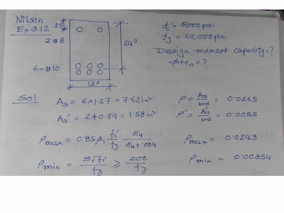
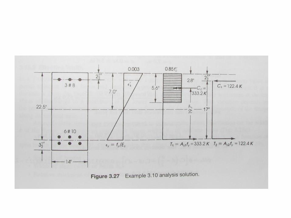
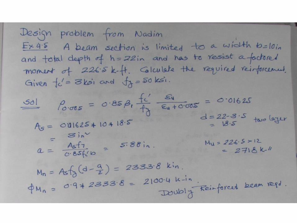
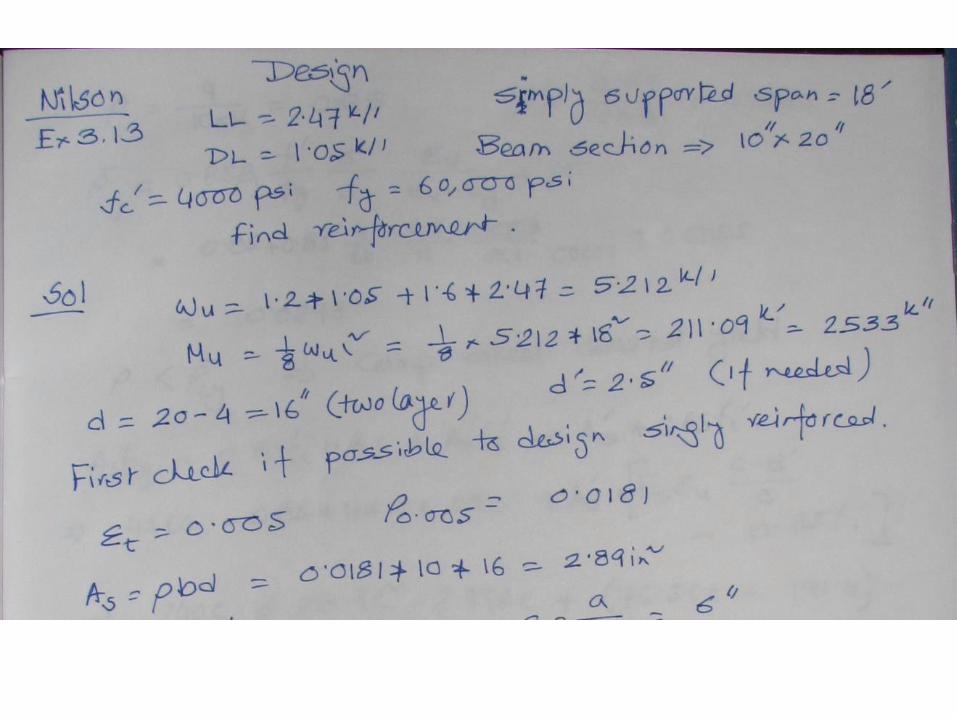
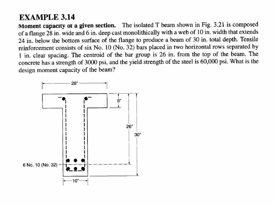
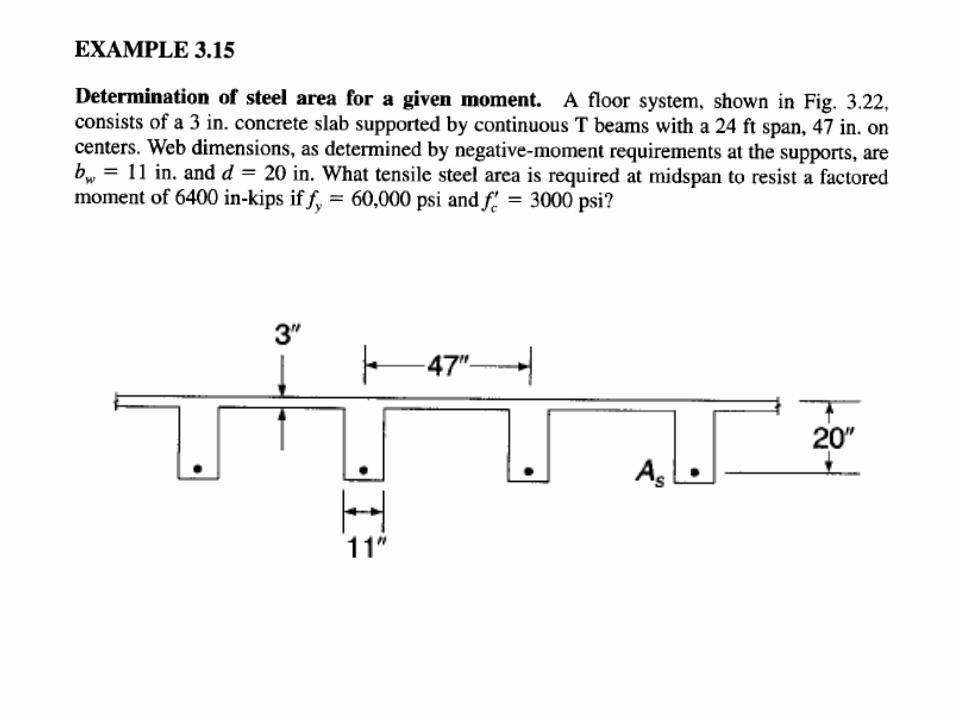
Example 3.12
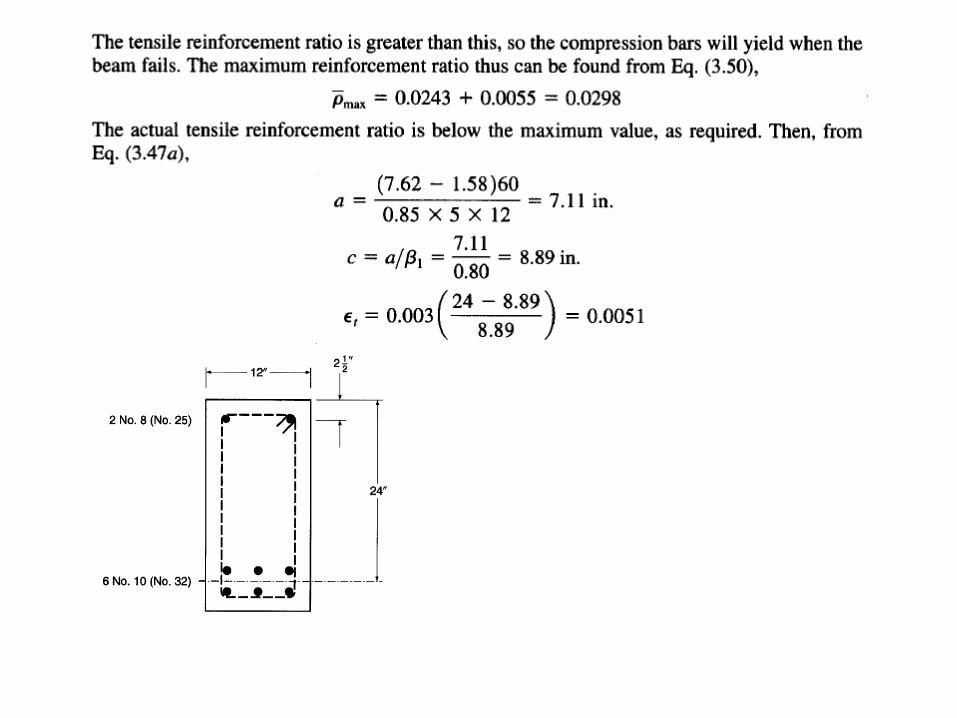
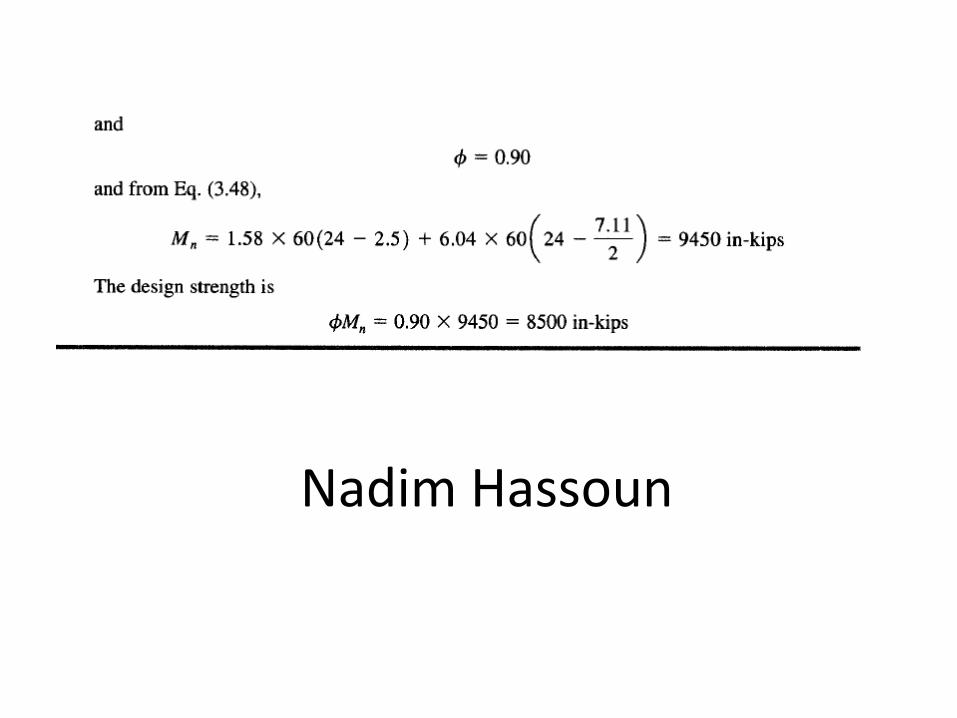
Nadim Hassoun

Find ϕMn

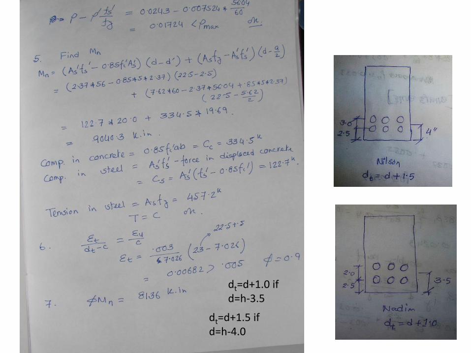
dt=d+1.0 if d=h-3.5
dt=d+1.5 if d=h-4.0
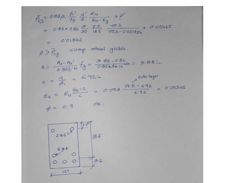
Design of Doubly Reinforced Beam
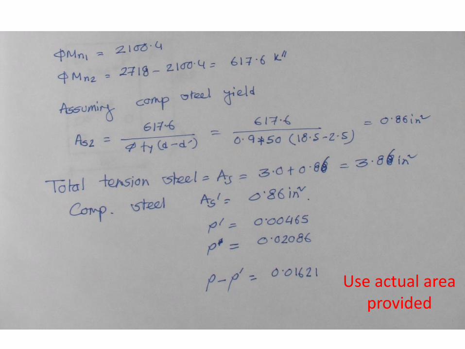
Use actual area provided
T-beam
• RC beam and slab are monolithically cast
• Beam stirrups and bent bars extend into the slab
• A part of slab act along with beam top to take longitudinal compression
• Slab forms the beam flange
• Part of beam below slab is called web/stem
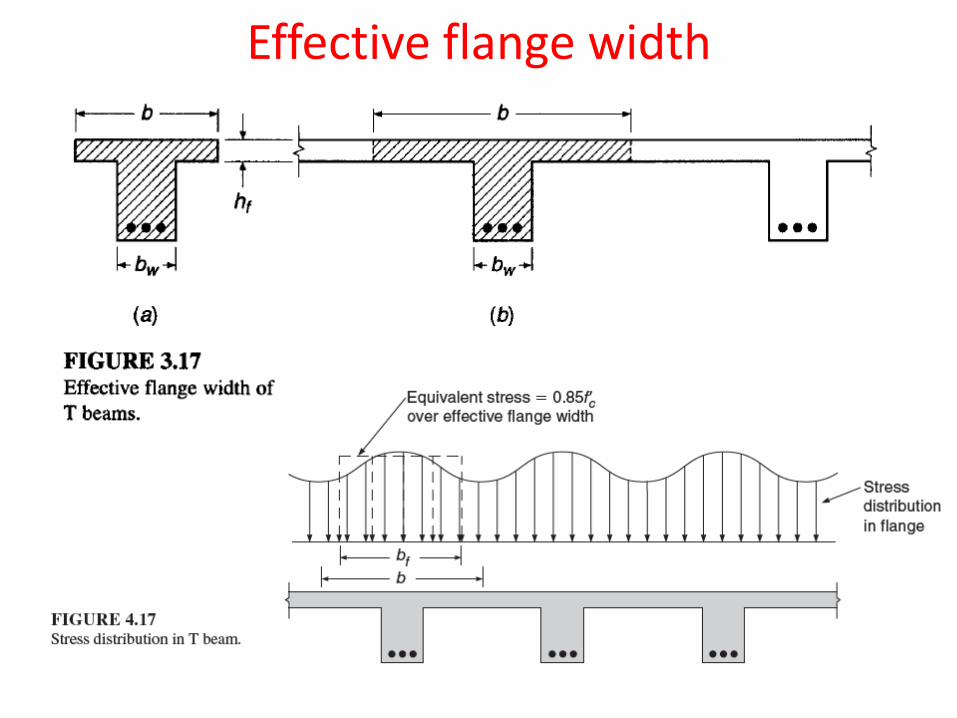
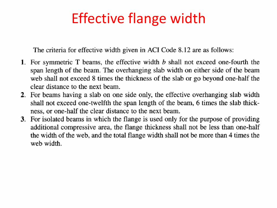
Effective flange width
Effective flange width
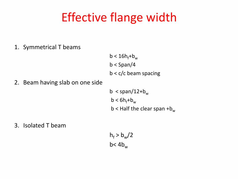
1. Symmetrical T beams
b < 16hf+bw
b < Span/4
b < c/c beam spacing
2. Beam having slab on one side
b < span/12+bw
b < 6hf+bw
b < Half the clear span +bw
3. Isolated T beam
hf > bw/2
b< 4bw
Effective flange width
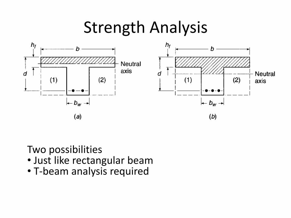
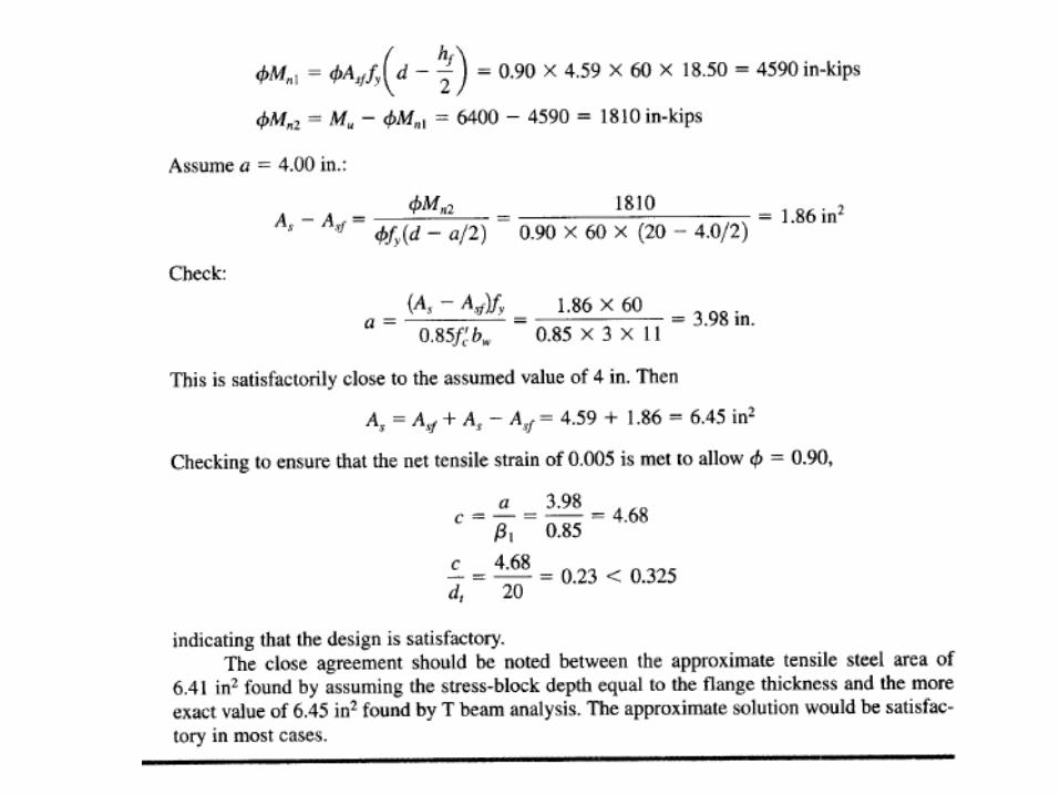
Strength Analysis
Two possibilities • Just like rectangular beam • T-beam analysis required
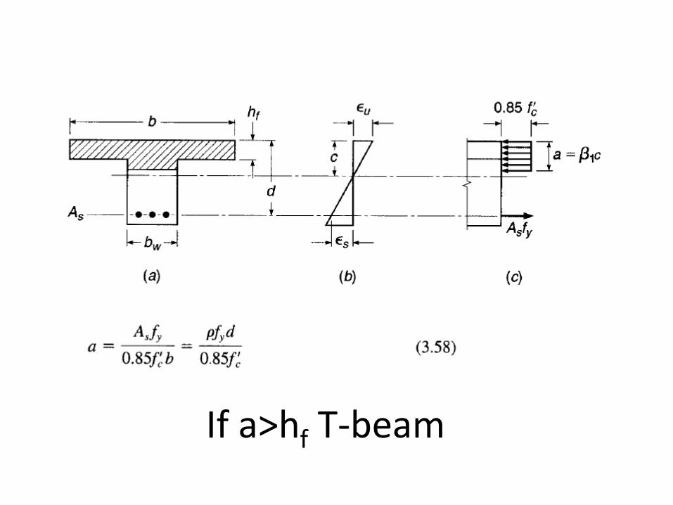
If a>hf T-beam
bw
Related Documents