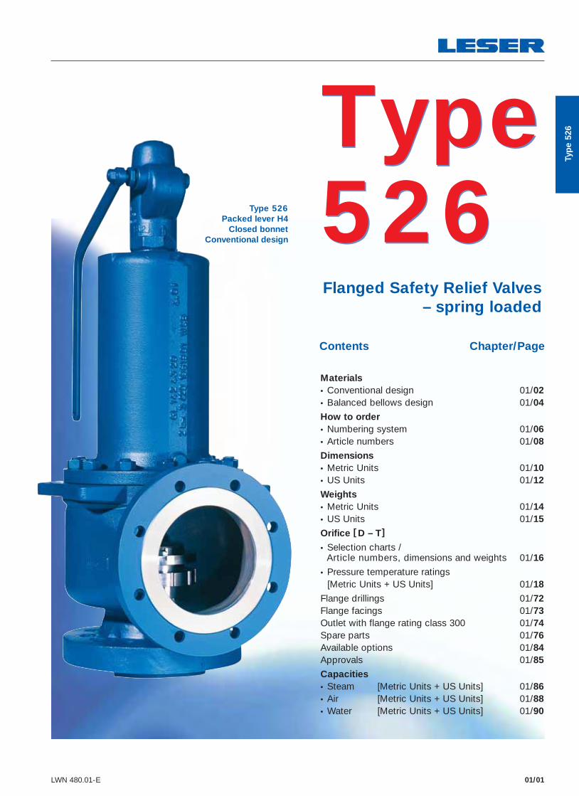
01/01 LWN 480.01-E Type 526 Flanged Safety Relief Valves – spring loaded Contents Chapter/Page Materials • Conventional design 01/02 • Balanced bellows design 01/04 How to order • Numbering system 01/06 • Article numbers 01/08 Dimensions • Metric Units 01/10 • US Units 01/12 Weights • Metric Units 01/14 • US Units 01/15 Orifice [ D – T ] • Selection charts / Article numbers, dimensions and weights 01/16 • Pressure temperature ratings [Metric Units + US Units] 01/18 Flange drillings 01/72 Flange facings 01/73 Outlet with flange rating class 300 01/74 Spare parts 01/76 Available options 01/84 Approvals 01/85 Capacities • Steam [Metric Units + US Units] 01/86 • Air [Metric Units + US Units] 01/88 • Water [Metric Units + US Units] 01/90 Type 526 Type 526 Packed lever H4 Closed bonnet Conventional design Type 526

Welcome message from author
This document is posted to help you gain knowledge. Please leave a comment to let me know what you think about it! Share it to your friends and learn new things together.
Transcript
01/01LWN 480.01-E
Type 526
Flanged Safety Relief Valves – spring loaded
Contents Chapter/Page
Materials • Conventional design 01/02 • Balanced bellows design 01/04
How to order
• Numbering system 01/06 • Article numbers 01/08
Dimensions • Metric Units 01/10 • US Units 01/12
Weights • Metric Units 01/14 • US Units 01/15
Orifice [ D – T]
• Selection charts / Article numbers, dimensions and weights 01/16
• Pressure temperature ratings [Metric Units + US Units] 01/18
Flange drillings 01/72 Flange facings 01/73 Outlet with flange rating class 300 01/74 Spare parts 01/76 Available options 01/84 Approvals 01/85
Capacities • Steam [Metric Units + US Units] 01/86 • Air [Metric Units + US Units] 01/88 • Water [Metric Units + US Units] 01/90
Type 526Type 526
Packed lever H4Closed bonnet
Conventional design
Typ
e 52
6
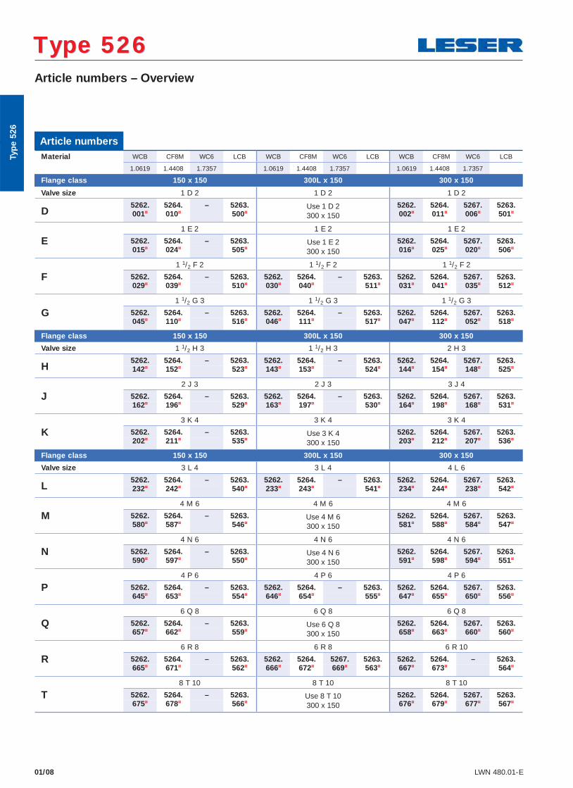
01/08 LWN 480.01-E
Article numbers – Overview
Type 526 Type 526
Article numbersMaterial WCB CF8M WC6 LCB WCB CF8M WC6 LCB WCB CF8M WC6 LCB
1.0619 1.4408 1.7357 1.0619 1.4408 1.7357 1.0619 1.4408 1.7357
Flange class 150 x 150 300L x 150 300 x 150
Valve size 1 D 2 1 D 2 1 D 2
D5262. 5264. – 5263. Use 1 D 2
300 x 1505262. 5264. 5267. 5263.
001¤ 010¤ 500¤ 002¤ 011¤ 006¤ 501¤
E1 E 2 1 E 2 1 E 2
5262. 5264. – 5263. Use 1 E 2300 x 150
5262. 5264. 5267. 5263.015¤ 024¤ 505¤ 016¤ 025¤ 020¤ 506¤
F1 1/2 F 2 1 1/2 F 2 1 1/2 F 2
5262. 5264. – 5263. 5262. 5264. – 5263. 5262. 5264. 5267. 5263.029¤ 039¤ 510¤ 030¤ 040¤ 511¤ 031¤ 041¤ 035¤ 512¤
G1 1/2 G 3 1 1/2 G 3 1 1/2 G 3
5262. 5264. – 5263. 5262. 5264. – 5263. 5262. 5264. 5267. 5263.045¤ 110¤ 516¤ 046¤ 111¤ 517¤ 047¤ 112¤ 052¤ 518¤
Flange class 150 x 150 300L x 150 300 x 150
Valve size 1 1/2 H 3 1 1/2 H 3 2 H 3
H5262. 5264. – 5263. 5262. 5264. – 5263. 5262. 5264. 5267. 5263.142¤ 152¤ 523¤ 143¤ 153¤ 524¤ 144¤ 154¤ 148¤ 525¤
J2 J 3 2 J 3 3 J 4
5262. 5264. – 5263. 5262. 5264. – 5263. 5262. 5264. 5267. 5263.162¤ 196¤ 529¤ 163¤ 197¤ 530¤ 164¤ 198¤ 168¤ 531¤
K3 K 4 3 K 4 3 K 4
5262. 5264. – 5263. Use 3 K 4300 x 150
5262. 5264. 5267. 5263.202¤ 211¤ 535¤ 203¤ 212¤ 207¤ 536¤
Flange class 150 x 150 300L x 150 300 x 150
Valve size 3 L 4 3 L 4 4 L 6
L5262. 5264. – 5263. 5262. 5264. – 5263. 5262. 5264. 5267. 5263.232¤ 242¤ 540¤ 233¤ 243¤ 541¤ 234¤ 244¤ 238¤ 542¤
M4 M 6 4 M 6 4 M 6
5262. 5264. – 5263. Use 4 M 6300 x 150
5262. 5264. 5267. 5263.580¤ 587¤ 546¤ 581¤ 588¤ 584¤ 547¤
N4 N 6 4 N 6 4 N 6
5262. 5264. – 5263. Use 4 N 6300 x 150
5262. 5264. 5267. 5263.590¤ 597¤ 550¤ 591¤ 598¤ 594¤ 551¤
P4 P 6 4 P 6 4 P 6
5262. 5264. – 5263. 5262. 5264. – 5263. 5262. 5264. 5267. 5263.645¤ 653¤ 554¤ 646¤ 654¤ 555¤ 647¤ 655¤ 650¤ 556¤
Q6 Q 8 6 Q 8 6 Q 8
5262. 5264. – 5263. Use 6 Q 8300 x 150
5262. 5264. 5267. 5263.657¤ 662¤ 559¤ 658¤ 663¤ 660¤ 560¤
R6 R 8 6 R 8 6 R 10
5262. 5264. – 5263. 5262. 5264. 5267. 5263. 5262. 5264. – 5263.665¤ 671¤ 562¤ 666¤ 672¤ 669¤ 563¤ 667¤ 673¤ 564¤
T8 T 10 8 T 10 8 T 10
5262. 5264. – 5263. Use 8 T 10300 x 150
5262. 5264. 5267. 5263.675¤ 678¤ 566¤ 676¤ 679¤ 677¤ 567¤
Typ
e 52
6
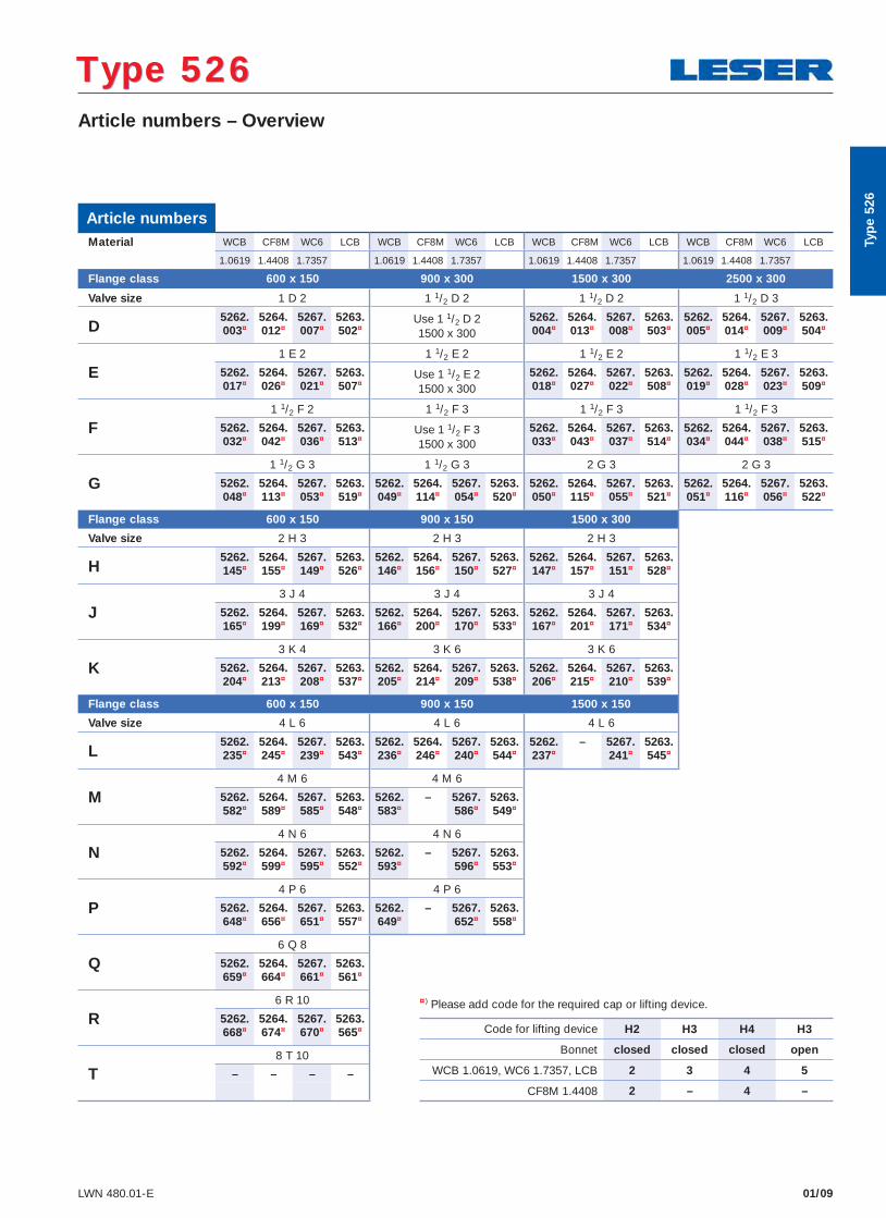
01/09LWN 480.01-E
Article numbers – Overview
Type 526 Type 526
Article numbersMaterial WCB CF8M WC6 LCB WCB CF8M WC6 LCB WCB CF8M WC6 LCB WCB CF8M WC6 LCB
1.0619 1.4408 1.7357 1.0619 1.4408 1.7357 1.0619 1.4408 1.7357 1.0619 1.4408 1.7357
Flange class 600 x 150 900 x 300 1500 x 300 2500 x 300
Valve size 1 D 2 1 1/2 D 2 1 1/2 D 2 1 1/2 D 3
D5262. 5264. 5267. 5263. Use 1 1/2 D 2
1500 x 3005262. 5264. 5267. 5263. 5262. 5264. 5267. 5263.
003¤ 012¤ 007¤ 502¤ 004¤ 013¤ 008¤ 503¤ 005¤ 014¤ 009¤ 504¤
E1 E 2 1 1/2 E 2 1 1/2 E 2 1 1/2 E 3
5262. 5264. 5267. 5263. Use 1 1/2 E 21500 x 300
5262. 5264. 5267. 5263. 5262. 5264. 5267. 5263.017¤ 026¤ 021¤ 507¤ 018¤ 027¤ 022¤ 508¤ 019¤ 028¤ 023¤ 509¤
F1 1/2 F 2 1 1/2 F 3 1 1/2 F 3 1 1/2 F 3
5262. 5264. 5267. 5263. Use 1 1/2 F 31500 x 300
5262. 5264. 5267. 5263. 5262. 5264. 5267. 5263.032¤ 042¤ 036¤ 513¤ 033¤ 043¤ 037¤ 514¤ 034¤ 044¤ 038¤ 515¤
G1 1/2 G 3 1 1/2 G 3 2 G 3 2 G 3
5262. 5264. 5267. 5263. 5262. 5264. 5267. 5263. 5262. 5264. 5267. 5263. 5262. 5264. 5267. 5263.048¤ 113¤ 053¤ 519¤ 049¤ 114¤ 054¤ 520¤ 050¤ 115¤ 055¤ 521¤ 051¤ 116¤ 056¤ 522¤
Flange class 600 x 150 900 x 150 1500 x 300
Valve size 2 H 3 2 H 3 2 H 3
H5262. 5264. 5267. 5263. 5262. 5264. 5267. 5263. 5262. 5264. 5267. 5263.145¤ 155¤ 149¤ 526¤ 146¤ 156¤ 150¤ 527¤ 147¤ 157¤ 151¤ 528¤
J3 J 4 3 J 4 3 J 4
5262. 5264. 5267. 5263. 5262. 5264. 5267. 5263. 5262. 5264. 5267. 5263.165¤ 199¤ 169¤ 532¤ 166¤ 200¤ 170¤ 533¤ 167¤ 201¤ 171¤ 534¤
K3 K 4 3 K 6 3 K 6
5262. 5264. 5267. 5263. 5262. 5264. 5267. 5263. 5262. 5264. 5267. 5263.204¤ 213¤ 208¤ 537¤ 205¤ 214¤ 209¤ 538¤ 206¤ 215¤ 210¤ 539¤
Flange class 600 x 150 900 x 150 1500 x 150
Valve size 4 L 6 4 L 6 4 L 6
L5262. 5264. 5267. 5263. 5262. 5264. 5267. 5263. 5262. – 5267. 5263.235¤ 245¤ 239¤ 543¤ 236¤ 246¤ 240¤ 544¤ 237¤ 241¤ 545¤
M4 M 6 4 M 6
5262. 5264. 5267. 5263. 5262. – 5267. 5263.582¤ 589¤ 585¤ 548¤ 583¤ 586¤ 549¤
N4 N 6 4 N 6
5262. 5264. 5267. 5263. 5262. – 5267. 5263.592¤ 599¤ 595¤ 552¤ 593¤ 596¤ 553¤
P4 P 6 4 P 6
5262. 5264. 5267. 5263. 5262. – 5267. 5263.648¤ 656¤ 651¤ 557¤ 649¤ 652¤ 558¤
Q6 Q 8
5262. 5264. 5267. 5263.659¤ 664¤ 661¤ 561¤
R6 R 10
5262. 5264. 5267. 5263.668¤ 674¤ 670¤ 565¤
T8 T 10
– – – –
¤ ) Please add code for the required cap or lifting device.
Code for lifting device H2 H3 H4 H3
Bonnet closed closed closed open
WCB 1.0619, WC6 1.7357, LCB 2 3 4 5
CF8M 1.4408 2 – 4 –
Typ
e 52
6
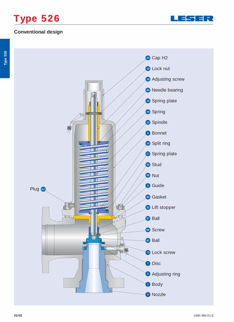
01/02 LWN 480.01-E
Conventional design
Type 526 Type 526
40 Cap H2
69 Needle bearing
16 Spring plate
54 Spring
12 Spindle
9 Bonnet
17 Spring plate
55 Stud
56 Nut
22 Lift stopper
57 Ball
66 Screw
61 Ball
73 Lock screw
7 Disc
6 Adjusting ring
1 Body
5 Nozzle
8 Guide
60 Gasket
14 Split ring
19 Lock nut
18 Adjusting screw
Plug 64
Typ
e 52
6
01/03LWN 480.01-E
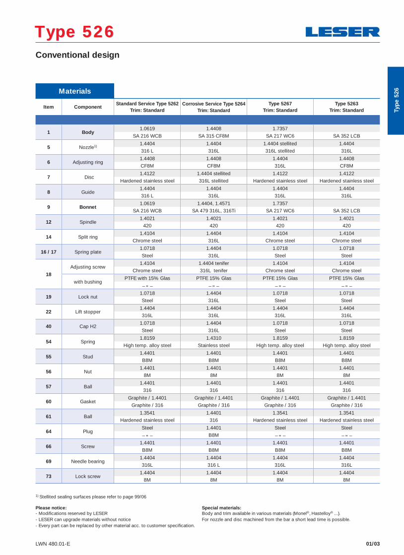
Materials
Item ComponentStandard Service Type 5262
Trim: StandardCorrosive Service Type 5264
Trim: StandardType 5267
Trim: StandardType 5263
Trim: Standard
1 Body1.0619 1.4408 1.7357
SA 216 WCB SA 315 CF8M SA 217 WC6 SA 352 LCB
5 Nozzle1)1.4404 1.4404 1.4404 stellited 1.4404
316 L 316L 316L stellited 316L
6 Adjusting ring1.4408 1.4408 1.4404 1.4408
CF8M CF8M 316L CF8M
7 Disc 1.4122 1.4404 stellited 1.4122 1.4122
Hardened stainless steel 316L stellited Hardened stainless steel Hardened stainless steel
8 Guide1.4404 1.4404 1.4404 1.4404
316 L 316L 316L 316L
9 Bonnet1.0619 1.4404, 1.4571 1.7357
SA 216 WCB SA 479 316L, 316Ti SA 217 WC6 SA 352 LCB
12 Spindle1.4021 1.4021 1.4021 1.4021
420 420 420 420
14 Split ring1.4104 1.4404 1.4104 1.4104
Chrome steel 316L Chrome steel Chrome steel
16 / 17 Spring plate1.0718 1.4404 1.0718 1.0718
Steel 316L Steel Steel
18
Adjusting screw1.4104 1.4404 tenifer 1.4104 1.4104
Chrome steel 316L tenifer Chrome steel Chrome steel
with bushingPTFE with 15% Glas PTFE 15% Glas PTFE 15% Glas PTFE 15% Glas
– " – – " – – " – – " –
19 Lock nut1.0718 1.4404 1.0718 1.0718
Steel 316L Steel Steel
22 Lift stopper1.4404 1.4404 1.4404 1.4404
316L 316L 316L 316L
40 Cap H21.0718 1.4404 1.0718 1.0718
Steel 316L Steel Steel
54 Spring1.8159 1.4310 1.8159 1.8159
High temp. alloy steel Stainless steel High temp. alloy steel High temp. alloy steel
55 Stud1.4401 1.4401 1.4401 1.4401
B8M B8M B8M B8M
56 Nut1.4401 1.4401 1.4401 1.4401
8M 8M 8M 8M
57 Ball1.4401 1.4401 1.4401 1.4401
316 316 316 316
60 GasketGraphite / 1.4401 Graphite / 1.4401 Graphite / 1.4401 Graphite / 1.4401
Graphite / 316 Graphite / 316 Graphite / 316 Graphite / 316
61 Ball1.3541 1.4401 1.3541 1.3541
Hardened stainless steel 316 Hardened stainless steel Hardened stainless steel
64 PlugSteel 1.4401 Steel Steel
– " – B8M – " – – " –
66 Screw1.4401 1.4401 1.4401 1.4401
B8M B8M B8M B8M
69 Needle bearing1.4404 1.4404 1.4404 1.4404
316L 316 L 316L 316L
73 Lock screw1.4404 1.4404 1.4404 1.4404
8M 8M 8M 8M
Conventional design
Type 526 Type 526
1) Stellited sealing surfaces please refer to page 99/06
Please notice: Special materials:- Modifi cations reserved by LESER Body and trim available in various materials (Monel®, Hastelloy® ...).- LESER can upgrade materials without notice For nozzle and disc machined from the bar a short lead time is possible. - Every part can be replaced by other material acc. to customer specification.
Typ
e 52
6
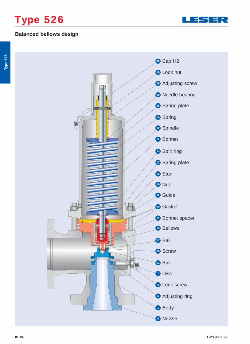
01/04 LWN 480.01-E
Balanced bellows design
Type 526 Type 526
40 Cap H2
69 Needle bearing
16 Spring plate
54 Spring
12 Spindle
9 Bonnet
17 Spring plate
55 Stud
56 Nut
15 Bellows
57 Ball
66 Screw
61 Ball
73 Lock screw
7 Disc
6 Adjusting ring
1 Body
5 Nozzle
8 Guide
60 Gasket
14 Split ring
19 Lock nut
18 Adjusting screw
11 Bonnet spacer
Typ
e 52
6
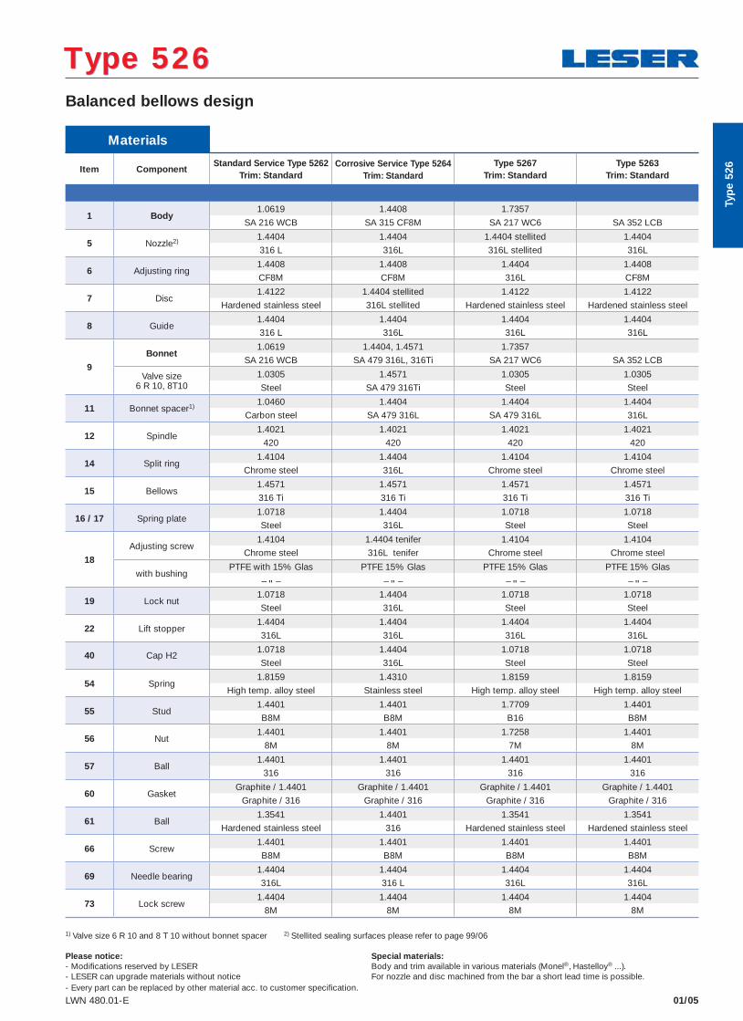
Materials
Item ComponentStandard Service Type 5262
Trim: StandardCorrosive Service Type 5264
Trim: StandardType 5267
Trim: StandardType 5263
Trim: Standard
1 Body1.0619 1.4408 1.7357
SA 216 WCB SA 315 CF8M SA 217 WC6 SA 352 LCB
5 Nozzle2)1.4404 1.4404 1.4404 stellited 1.4404
316 L 316L 316L stellited 316L
6 Adjusting ring1.4408 1.4408 1.4404 1.4408
CF8M CF8M 316L CF8M
7 Disc 1.4122 1.4404 stellited 1.4122 1.4122
Hardened stainless steel 316L stellited Hardened stainless steel Hardened stainless steel
8 Guide1.4404 1.4404 1.4404 1.4404
316 L 316L 316L 316L
9
Bonnet1.0619 1.4404, 1.4571 1.7357
SA 216 WCB SA 479 316L, 316Ti SA 217 WC6 SA 352 LCB
Valve size6 R 10, 8T10
1.0305 1.4571 1.0305 1.0305
Steel SA 479 316Ti Steel Steel
11 Bonnet spacer1)1.0460 1.4404 1.4404 1.4404
Carbon steel SA 479 316L SA 479 316L 316L
12 Spindle1.4021 1.4021 1.4021 1.4021
420 420 420 420
14 Split ring1.4104 1.4404 1.4104 1.4104
Chrome steel 316L Chrome steel Chrome steel
15 Bellows1.4571 1.4571 1.4571 1.4571
316 Ti 316 Ti 316 Ti 316 Ti
16 / 17 Spring plate1.0718 1.4404 1.0718 1.0718
Steel 316L Steel Steel
18
Adjusting screw1.4104 1.4404 tenifer 1.4104 1.4104
Chrome steel 316L tenifer Chrome steel Chrome steel
with bushingPTFE with 15% Glas PTFE 15% Glas PTFE 15% Glas PTFE 15% Glas
– " – – " – – " – – " –
19 Lock nut1.0718 1.4404 1.0718 1.0718
Steel 316L Steel Steel
22 Lift stopper1.4404 1.4404 1.4404 1.4404
316L 316L 316L 316L
40 Cap H21.0718 1.4404 1.0718 1.0718
Steel 316L Steel Steel
54 Spring1.8159 1.4310 1.8159 1.8159
High temp. alloy steel Stainless steel High temp. alloy steel High temp. alloy steel
55 Stud1.4401 1.4401 1.7709 1.4401
B8M B8M B16 B8M
56 Nut1.4401 1.4401 1.7258 1.4401
8M 8M 7M 8M
57 Ball1.4401 1.4401 1.4401 1.4401
316 316 316 316
60 GasketGraphite / 1.4401 Graphite / 1.4401 Graphite / 1.4401 Graphite / 1.4401
Graphite / 316 Graphite / 316 Graphite / 316 Graphite / 316
61 Ball1.3541 1.4401 1.3541 1.3541
Hardened stainless steel 316 Hardened stainless steel Hardened stainless steel
66 Screw1.4401 1.4401 1.4401 1.4401
B8M B8M B8M B8M
69 Needle bearing1.4404 1.4404 1.4404 1.4404
316L 316 L 316L 316L
73 Lock screw1.4404 1.4404 1.4404 1.4404
8M 8M 8M 8M
01/05LWN 480.01-E
Balanced bellows design
Type 526 Type 526
1) Valve size 6 R 10 and 8 T 10 without bonnet spacer 2) Stellited sealing surfaces please refer to page 99/06
Please notice: Special materials:- Modifi cations reserved by LESER Body and trim available in various materials (Monel®, Hastelloy® ...).- LESER can upgrade materials without notice For nozzle and disc machined from the bar a short lead time is possible. - Every part can be replaced by other material acc. to customer specification.
Typ
e 52
6
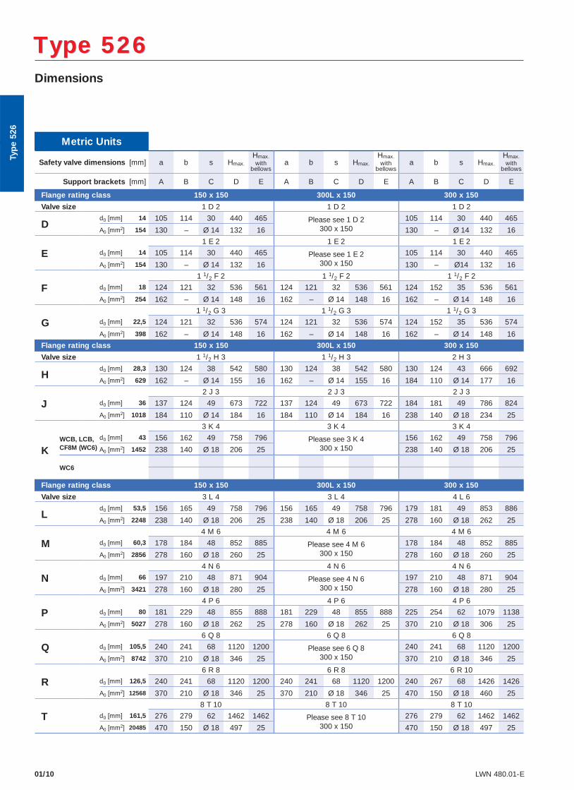
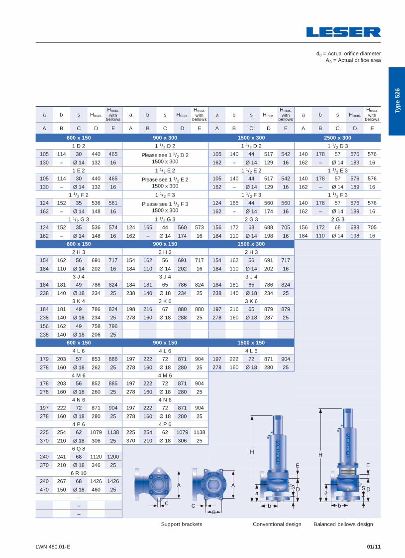
01/10 LWN 480.01-E
Dimensions
Type 526 Type 526
Metric Units
Safety valve dimensions [mm] a b s Hmax.
Hmax. with
bellowsa b s Hmax.
Hmax. with
bellowsa b s Hmax.
Hmax. with
bellows
Support brackets [mm] A B C D E A B C D E A B C D E
Flange rating class 150 x 150 300L x 150 300 x 150
Valve size 1 D 2 1 D 2 1 D 2
Dd0 [mm] 14 105 114 30 440 465 Please see 1 D 2
300 x 150105 114 30 440 465
A0 [mm2] 154 130 – Ø 14 132 16 130 – Ø 14 132 16
E1 E 2 1 E 2 1 E 2
d0 [mm] 14 105 114 30 440 465 Please see 1 E 2 300 x 150
105 114 30 440 465
A0 [mm2] 154 130 – Ø 14 132 16 130 – Ø14 132 16
F1 1/2 F 2 1 1/2 F 2 1 1/2 F 2
d0 [mm] 18 124 121 32 536 561 124 121 32 536 561 124 152 35 536 561
A0 [mm2] 254 162 – Ø 14 148 16 162 – Ø 14 148 16 162 – Ø 14 148 16
G1 1/2 G 3 1 1/2 G 3 1 1/2 G 3
d0 [mm] 22,5 124 121 32 536 574 124 121 32 536 574 124 152 35 536 574
A0 [mm2] 398 162 – Ø 14 148 16 162 – Ø 14 148 16 162 – Ø 14 148 16
Flange rating class 150 x 150 300L x 150 300 x 150
Valve size 1 1/2 H 3 1 1/2 H 3 2 H 3
Hd0 [mm] 28,3 130 124 38 542 580 130 124 38 542 580 130 124 43 666 692
A0 [mm2] 629 162 – Ø 14 155 16 162 – Ø 14 155 16 184 110 Ø 14 177 16
J2 J 3 2 J 3 2 J 3
d0 [mm] 36 137 124 49 673 722 137 124 49 673 722 184 181 49 786 824
A0 [mm2] 1018 184 110 Ø 14 184 16 184 110 Ø 14 184 16 238 140 Ø 18 234 25
K
3 K 4 3 K 4 3 K 4
WCB, LCB, CF8M (WC6)
d0 [mm] 43 156 162 49 758 796 Please see 3 K 4300 x 150
156 162 49 758 796
A0 [mm2] 1452 238 140 Ø 18 206 25 238 140 Ø 18 206 25
WC6
Flange rating class 150 x 150 300L x 150 300 x 150
Valve size 3 L 4 3 L 4 4 L 6
Ld0 [mm] 53,5 156 165 49 758 796 156 165 49 758 796 179 181 49 853 886
A0 [mm2] 2248 238 140 Ø 18 206 25 238 140 Ø 18 206 25 278 160 Ø 18 262 25
M4 M 6 4 M 6 4 M 6
d0 [mm] 60,3 178 184 48 852 885 Please see 4 M 6300 x 150
178 184 48 852 885
A0 [mm2] 2856 278 160 Ø 18 260 25 278 160 Ø 18 260 25
N4 N 6 4 N 6 4 N 6
d0 [mm] 66 197 210 48 871 904 Please see 4 N 6300 x 150
197 210 48 871 904
A0 [mm2] 3421 278 160 Ø 18 280 25 278 160 Ø 18 280 25
P4 P 6 4 P 6 4 P 6
d0 [mm] 80 181 229 48 855 888 181 229 48 855 888 225 254 62 1079 1138
A0 [mm2] 5027 278 160 Ø 18 262 25 278 160 Ø 18 262 25 370 210 Ø 18 306 25
Q6 Q 8 6 Q 8 6 Q 8
d0 [mm] 105,5 240 241 68 1120 1200 Please see 6 Q 8300 x 150
240 241 68 1120 1200
A0 [mm2] 8742 370 210 Ø 18 346 25 370 210 Ø 18 346 25
R6 R 8 6 R 8 6 R 10
d0 [mm] 126,5 240 241 68 1120 1200 240 241 68 1120 1200 240 267 68 1426 1426
A0 [mm2] 12568 370 210 Ø 18 346 25 370 210 Ø 18 346 25 470 150 Ø 18 460 25
T8 T 10 8 T 10 8 T 10
d0 [mm] 161,5 276 279 62 1462 1462 Please see 8 T 10300 x 150
276 279 62 1462 1462
A0 [mm2] 20485 470 150 Ø 18 497 25 470 150 Ø 18 497 25
Typ
e 52
6
01/11LWN 480.01-E
a b s Hmax.
Hmax. with
bellowsa b s Hmax.
Hmax. with
bellowsa b s Hmax.
Hmax. with
bellowsa b s Hmax.
Hmax. with
bellows
A B C D E A B C D E A B C D E A B C D E
600 x 150 900 x 300 1500 x 300 2500 x 300
1 D 2 1 1/2 D 2 1 1/2 D 2 1 1/2 D 3
105 114 30 440 465 Please see 1 1/2 D 2 1500 x 300
105 140 44 517 542 140 178 57 576 576
130 – Ø 14 132 16 162 – Ø 14 129 16 162 – Ø 14 189 16
1 E 2 1 1/2 E 2 1 1/2 E 2 1 1/2 E 3
105 114 30 440 465 Please see 1 1/2 E 2 1500 x 300
105 140 44 517 542 140 178 57 576 576
130 – Ø 14 132 16 162 – Ø 14 129 16 162 – Ø 14 189 16
1 1/2 F 2 1 1/2 F 3 1 1/2 F 3 1 1/2 F 3
124 152 35 536 561 Please see 1 1/2 F 3 1500 x 300
124 165 44 560 560 140 178 57 576 576
162 – Ø 14 148 16 162 – Ø 14 174 16 162 – Ø 14 189 16
1 1/2 G 3 1 1/2 G 3 2 G 3 2 G 3
124 152 35 536 574 124 165 44 560 573 156 172 68 688 705 156 172 68 688 705
162 – Ø 14 148 16 162 – Ø 14 174 16 184 110 Ø 14 198 16 184 110 Ø 14 198 16
600 x 150 900 x 150 1500 x 300
2 H 3 2 H 3 2 H 3
154 162 56 691 717 154 162 56 691 717 154 162 56 691 717
184 110 Ø 14 202 16 184 110 Ø 14 202 16 184 110 Ø 14 202 16
3 J 4 3 J 4 3 J 4
184 181 49 786 824 184 181 65 786 824 184 181 65 786 824
238 140 Ø 18 234 25 238 140 Ø 18 234 25 238 140 Ø 18 234 25
3 K 4 3 K 6 3 K 6
184 181 49 786 824 198 216 67 880 880 197 216 65 879 879
238 140 Ø 18 234 25 278 160 Ø 18 288 25 278 160 Ø 18 287 25
156 162 49 758 796
238 140 Ø 18 206 25
600 x 150 900 x 150 1500 x 150
4 L 6 4 L 6 4 L 6
179 203 57 853 886 197 222 72 871 904 197 222 72 871 904
278 160 Ø 18 262 25 278 160 Ø 18 280 25 278 160 Ø 18 280 25
4 M 6 4 M 6
178 203 56 852 885 197 222 72 871 904
278 160 Ø 18 260 25 278 160 Ø 18 280 25
4 N 6 4 N 6
197 222 72 871 904 197 222 72 871 904
278 160 Ø 18 280 25 278 160 Ø 18 280 25
4 P 6 4 P 6
225 254 62 1079 1138 225 254 62 1079 1138
370 210 Ø 18 306 25 370 210 Ø 18 306 25
6 Q 8
240 241 68 1120 1200
370 210 Ø 18 346 25
6 R 10
240 267 68 1426 1426
470 150 Ø 18 460 25
–
–
–
d0 = Actual orifi ce diameterA0 = Actual orifi ce area
Conventional design Balanced bellows designSupport brackets
Typ
e 52
6
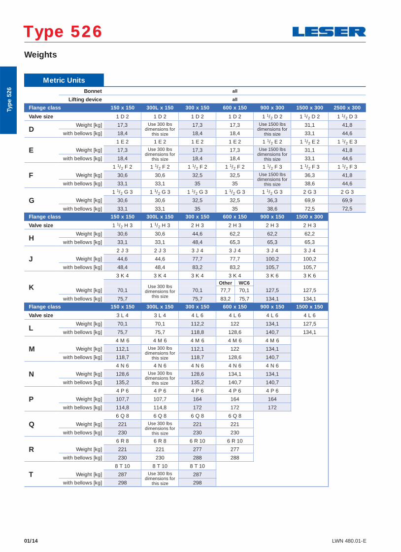
01/14 LWN 480.01-E
Weights
Type 526 Type 526
Metric UnitsBonnet all
Lifting device all
Flange class 150 x 150 300L x 150 300 x 150 600 x 150 900 x 300 1500 x 300 2500 x 300
Valve size 1 D 2 1 D 2 1 D 2 1 D 2 1 1/2 D 2 1 1/2 D 2 1 1/2 D 3
DWeight [kg] 17,3 Use 300 lbs
dimensions for this size
17,3 17,3 Use 1500 lbs dimensions for
this size
31,1 41,8
with bellows [kg] 18,4 18,4 18,4 33,1 44,6
E1 E 2 1 E 2 1 E 2 1 E 2 1 1/2 E 2 1 1/2 E 2 1 1/2 E 3
Weight [kg] 17,3 Use 300 lbs dimensions for
this size
17,3 17,3 Use 1500 lbs dimensions for
this size
31,1 41,8
with bellows [kg] 18,4 18,4 18,4 33,1 44,6
F1 1/2 F 2 1 1/2 F 2 1 1/2 F 2 1 1/2 F 2 1 1/2 F 3 1 1/2 F 3 1 1/2 F 3
Weight [kg] 30,6 30,6 32,5 32,5 Use 1500 lbs dimensions for
this size
36,3 41,8
with bellows [kg] 33,1 33,1 35 35 38,6 44,6
G1 1/2 G 3 1 1/2 G 3 1 1/2 G 3 1 1/2 G 3 1 1/2 G 3 2 G 3 2 G 3
Weight [kg] 30,6 30,6 32,5 32,5 36,3 69,9 69,9
with bellows [kg] 33,1 33,1 35 35 38,6 72,5 72,5
Flange class 150 x 150 300L x 150 300 x 150 600 x 150 900 x 150 1500 x 300
Valve size 1 1/2 H 3 1 1/2 H 3 2 H 3 2 H 3 2 H 3 2 H 3
HWeight [kg] 30,6 30,6 44,6 62,2 62,2 62,2
with bellows [kg] 33,1 33,1 48,4 65,3 65,3 65,3
J2 J 3 2 J 3 3 J 4 3 J 4 3 J 4 3 J 4
Weight [kg] 44,6 44,6 77,7 77,7 100,2 100,2
with bellows [kg] 48,4 48,4 83,2 83,2 105,7 105,7
K
3 K 4 3 K 4 3 K 4 3 K 4 3 K 6 3 K 6
Use 300 lbs dimensions for
this size
Other WC6
Weight [kg] 70,1 70,1 77,7 70,1 127,5 127,5
with bellows [kg] 75,7 75,7 83,2 75,7 134,1 134,1
Flange class 150 x 150 300L x 150 300 x 150 600 x 150 900 x 150 1500 x 150
Valve size 3 L 4 3 L 4 4 L 6 4 L 6 4 L 6 4 L 6
LWeight [kg] 70,1 70,1 112,2 122 134,1 127,5
with bellows [kg] 75,7 75,7 118,8 128,6 140,7 134,1
M4 M 6 4 M 6 4 M 6 4 M 6 4 M 6
Weight [kg] 112,1 Use 300 lbs dimensions for
this size
112,1 122 134,1
with bellows [kg] 118,7 118,7 128,6 140,7
N4 N 6 4 N 6 4 N 6 4 N 6 4 N 6
Weight [kg] 128,6 Use 300 lbs dimensions for
this size
128,6 134,1 134,1
with bellows [kg] 135,2 135,2 140,7 140,7
P4 P 6 4 P 6 4 P 6 4 P 6 4 P 6
Weight [kg] 107,7 107,7 164 164 164
with bellows [kg] 114,8 114,8 172 172 172
Q6 Q 8 6 Q 8 6 Q 8 6 Q 8
Weight [kg] 221 Use 300 lbs dimensions for
this size
221 221
with bellows [kg] 230 230 230
R6 R 8 6 R 8 6 R 10 6 R 10
Weight [kg] 221 221 277 277
with bellows [kg] 230 230 288 288
T8 T 10 8 T 10 8 T 10
Weight [kg] 287 Use 300 lbs dimensions for
this size
287
with bellows [kg] 298 298
Typ
e 52
6
01/16 LWN 480.01-E
Selection chart
WC
B
WC
6 C
F8M
150 x 150
5262.001X
300L x 150 300 x 150
5262.002X
600 x 150
5262.003X
900 x 300
–
1500 x 300
5262.004X
2500 x 300
5262.005X
5264.010X – 5264.011X 5264.012X – 5264.013X 5264.014X
–
5267.006X 5267.007X 5267.008X 5267.009X
WCB
WC6
CF8M
– – –
150 x 150 300L x 150 300 x 150 600 x 150 900 x 300 1500 x 300 2500 x 300
-400
-300
-200
-100
0
100
200
300
400
500
600
700
800
900
1000
500
0
100
200
300
400
500
600
700
900
800
1000
p [psig]
p [bar]
p [bar]
0
100
200
300
400
400
300
200
100
0
-100
-200
0 1000 1500 2000 3000 4000 5000 6000
25 0 50 75 100 150 200 250 300 350 400
6000 5000 4000 3000 2000 1500 1000 0 500
400 350 300 250 200 150 100 75 50 0 25
p [psig]
T [°
F]
T [°
C]
T [°
F]
T [°
C]
Type 526 Orifice DType 526 Orifice D
D
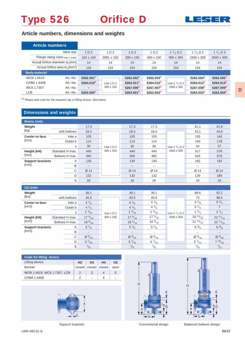
01/17LWN 480.01-E
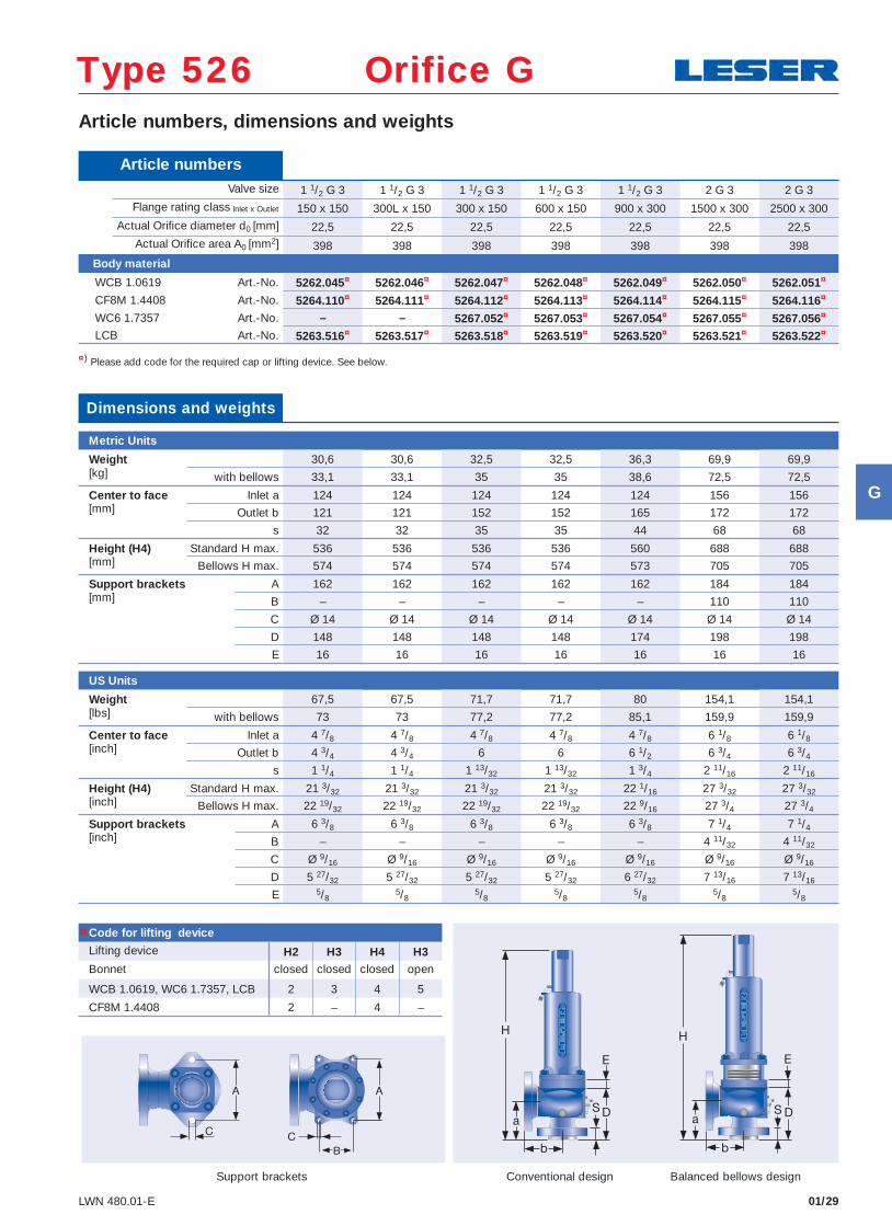
Article numbers, dimensions and weights
Conventional design Balanced bellows designSupport brackets
¤) Please add code for the required cap or lifting device. See below.
Type 526 Orifice DType 526 Orifice D
Article numbers Valve size 1 D 2 1 D 2 1 D 2 1 D 2 1 1/2 D 2 1 1/2 D 2 1 1/2 D 3
Flange rating class Inlet x Outlet 150 x 150 300L x 150 300 x 150 600 x 150 900 x 300 1500 x 300 2500 x 300 Actual Orifi ce diameter d0 [mm] 14 14 14 14 14 14 14 Actual Orifi ce area A0 [mm2] 154 154 154 154 154 154 154
Body material
WCB 1.0619 Art.-No. 5262.001¤ 5262.002¤ 5262.003¤ 5262.004¤ 5262.005¤
CF8M 1.4408 Art.-No. 5264.010¤ 5264.011¤ 5264.012¤ 5264.013¤ 5264.014¤
WC6 1.7357 Art.-No. – 5267.006¤ 5267.007¤ 5267.008¤ 5267.009¤
LCB Art.-No. 5263.500¤ 5263.501¤ 5263.502¤ 5263.503¤ 5263.504¤
Use 1 D 2300 x 150
Use 1 1/2 D 21500 x 300
Code for lifting device
Lifting device H2 H3 H4 H3Bonnet closed closed closed open
WCB 1.0619, WC6 1.7357, LCB 2 3 4 5
CF8M 1.4408 2 – 4 –
Dimensions and weights
Metric Units
Weight 17,3 17,3 17,3 31,1 41,8[kg] with bellows 18,4 18,4 18,4 33,1 44,6
Center to face Inlet a 105 105 105 105 140[mm] Outlet b 114 114 114 140 178
s 30 30 30 44 57
Height (H4) Standard H max. 440 440 440 517 576[mm] Bellows H max. 465 465 465 542 576
Support brackets A 130 130 130 162 162[mm] B – – – – –
C Ø 14 Ø 14 Ø 14 Ø 14 Ø 14
D 132 132 132 129 189
E 16 16 16 16 16
US Units
Weight 38,1 38,1 38,1 68,6 92,2[lbs] with bellows 40,5 40,5 40,5 73 98,4
Center to face Inlet a 4 1/8 4 1/8 4 1/8 4 1/8 5 1/2
[inch] Outlet b 4 1/2 4 1/2 4 1/2 5 1/2 7
s 1 3/16 1 3/16 1 3/16 1 3/4 2 1/4
Height (H4) Standard H max. 17 5/16 17 5/16 17 5/16 20 11/32 22 11/16[inch] Bellows H max. 18 5/16 18 5/16 18 5/16 21 11/32 22 11/16
Support brackets A 5 1/8 5 1/8 5 1/8 6 3/8 6 3/8[inch] B – – – – –
C Ø 9/16 Ø 9/16 Ø 9/16 Ø 9/16 Ø 9/16
D 5 7/32 5 7/32 5 7/32 5 7/32 7 15/32
E 5/85/8
5/85/8
5/8
Use 1 D 2300 x 150
Use 1 1/2 D 21500 x 300
Use 1 D 2300 x 150
Use 1 1/2 D 21500 x 300
¤
D
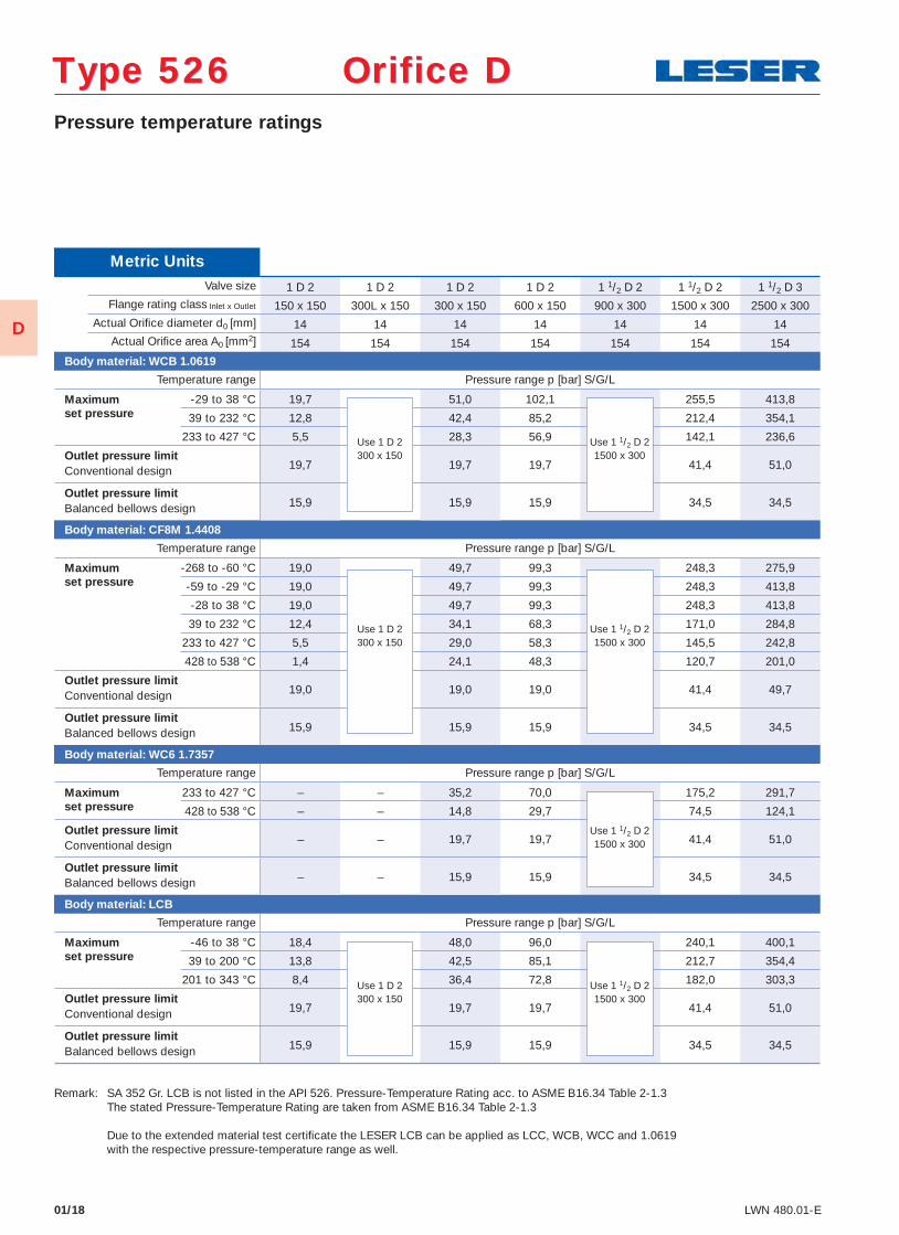
01/18 LWN 480.01-E
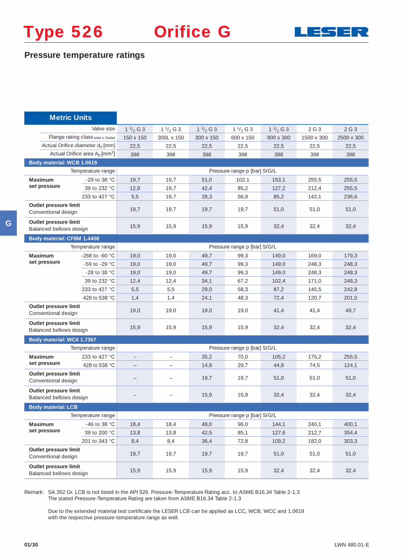
Pressure temperature ratings
Type 526 Orifice DType 526 Orifice D
Metric Units Valve size 1 D 2 1 D 2 1 D 2 1 D 2 1 1/2 D 2 1 1/2 D 2 1 1/2 D 3
Flange rating class Inlet x Outlet 150 x 150 300L x 150 300 x 150 600 x 150 900 x 300 1500 x 300 2500 x 300 Actual Orifi ce diameter d0 [mm] 14 14 14 14 14 14 14 Actual Orifi ce area A0 [mm2] 154 154 154 154 154 154 154
Body material: WCB 1.0619
Temperature range Pressure range p [bar] S/G/L
Maximum -29 to 38 °C 19,7 51,0 102,1 255,5 413,8 set pressure 39 to 232 °C 12,8 42,4 85,2 212,4 354,1 233 to 427 °C 5,5 28,3 56,9 142,1 236,6
Outlet pressure limit19,7 19,7 19,7 41,4 51,0 Conventional design
Outlet pressure limit15,9 15,9 15,9 34,5 34,5 Balanced bellows design
Body material: CF8M 1.4408
Temperature range Pressure range p [bar] S/G/L
Maximum -268 to -60 °C 19,0 49,7 99,3 248,3 275,9 set pressure -59 to -29 °C 19,0 49,7 99,3 248,3 413,8 -28 to 38 °C 19,0 49,7 99,3 248,3 413,8
39 to 232 °C 12,4 34,1 68,3 171,0 284,8
233 to 427 °C 5,5 29,0 58,3 145,5 242,8
428 to 538 °C 1,4 24,1 48,3 120,7 201,0
Outlet pressure limit19,0 19,0 19,0 41,4 49,7 Conventional design
Outlet pressure limit15,9 15,9 15,9 34,5 34,5 Balanced bellows design
Body material: WC6 1.7357
Temperature range Pressure range p [bar] S/G/L
Maximum 233 to 427 °C – – 35,2 70,0 175,2 291,7 set pressure 428 to 538 °C – – 14,8 29,7 74,5 124,1
Outlet pressure limit– – 19,7 19,7 41,4 51,0 Conventional design
Outlet pressure limit– – 15,9 15,9 34,5 34,5 Balanced bellows design
Body material: LCB
Temperature range Pressure range p [bar] S/G/L
Maximum -46 to 38 °C 18,4 48,0 96,0 240,1 400,1 set pressure 39 to 200 °C 13,8 42,5 85,1 212,7 354,4 201 to 343 °C 8,4 36,4 72,8 182,0 303,3
Outlet pressure limit19,7 19,7 19,7 41,4 51,0 Conventional design
Outlet pressure limit15,9 15,9 15,9 34,5 34,5 Balanced bellows design
Use 1 D 2300 x 150
Use 1 1/2 D 21500 x 300
Use 1 D 2300 x 150
Use 1 1/2 D 21500 x 300
Use 1 1/2 D 21500 x 300
Remark: SA 352 Gr. LCB is not listed in the API 526. Pressure-Temperature Rating acc. to ASME B16.34 Table 2-1.3 The stated Pressure-Temperature Rating are taken from ASME B16.34 Table 2-1.3 Due to the extended material test certifi cate the LESER LCB can be applied as LCC, WCB, WCC and 1.0619 with the respective pressure-temperature range as well.
Use 1 D 2300 x 150
Use 1 1/2 D 21500 x 300
D
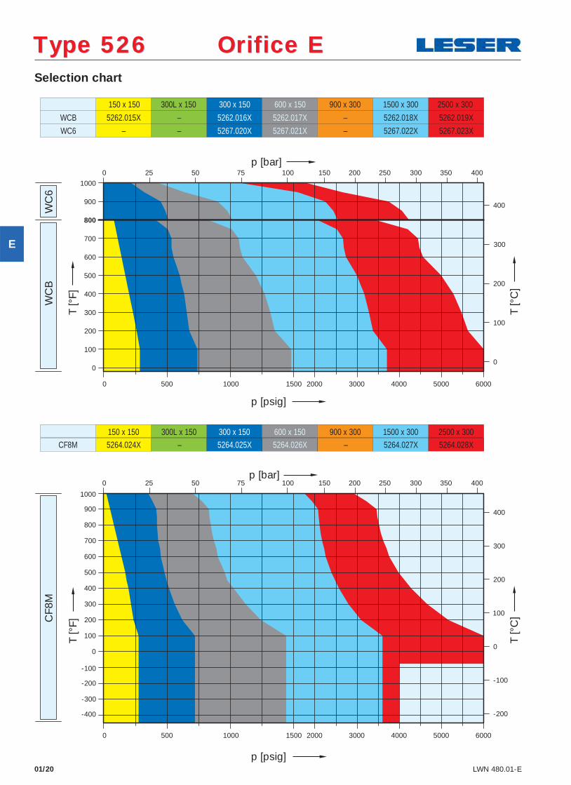
Selection chart
01/20 LWN 480.01-E
Type 526 Orifice EType 526 Orifice E W
CB
WC
6C
F8M
150 x 150
5262.015X
300L x 150 300 x 150
5262.016X
600 x 150
5262.017X
900 x 300
–
1500 x 300
5262.018X
2500 x 300
5262.019X–
5267.020X 5267.021X 5267.022X 5267.023X
WCB
WC6 – – –
150 x 150 300L x 150 300 x 150 600 x 150 900 x 300 1500 x 300 2500 x 3005264.024X – 5264.025X 5264.026X – 5264.027X 5264.028XCF8M
T [°
C]
T [°
F]
p [psig]
-400
-300
-200
-100
0
100
200
300
400
500
600
700
800
900
1000
500
0
100
200
300
400
500
600
700
900
800
1000
0
100
200
300
400
400
300
200
100
0
-100
-200
0 1000 1500 2000 3000 4000 5000 6000
250 50 75 100 150 200 250 300 350 400
60005000400030002000150010000 500
40035030025020015010075500 25
T [°
F]
p [psig]
p [bar]
T [°
C]
p [bar]
E
01/21LWN 480.01-E
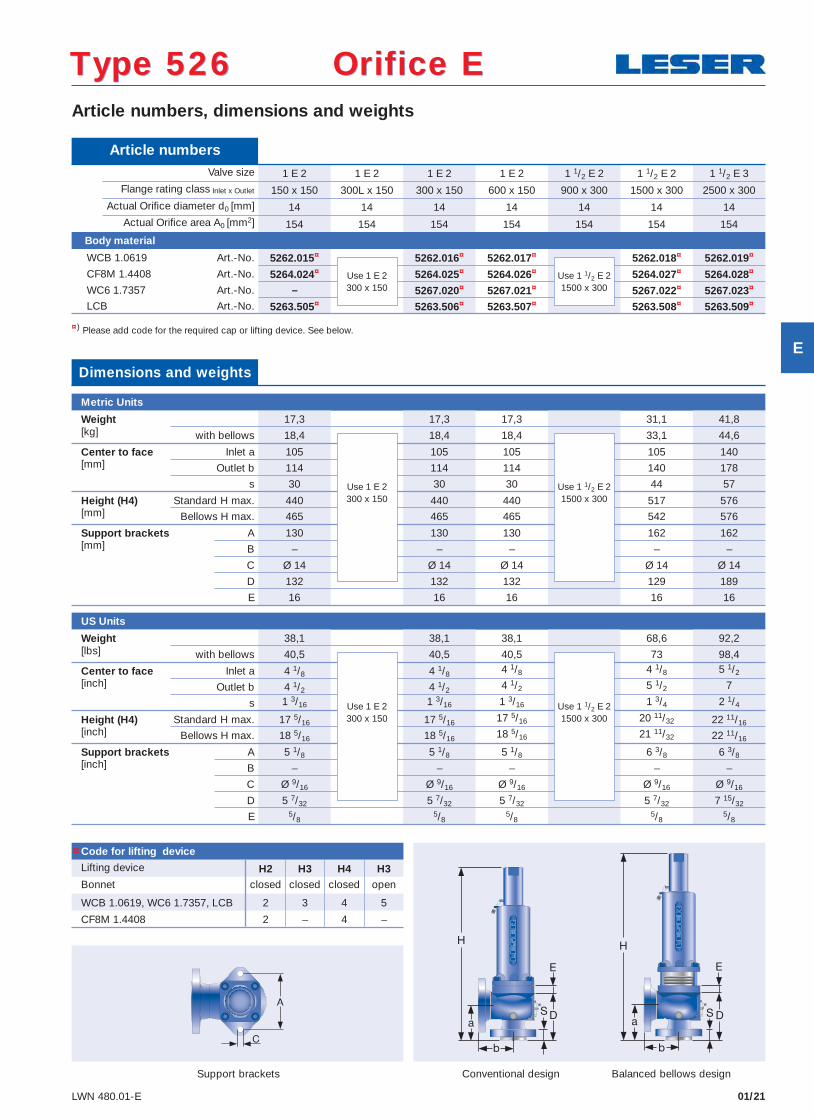
Article numbers, dimensions and weights
Conventional design Balanced bellows designSupport brackets
¤) Please add code for the required cap or lifting device. See below.
Article numbers Valve size 1 E 2 1 E 2 1 E 2 1 E 2 1 1/2 E 2 1 1/2 E 2 1 1/2 E 3
Flange rating class Inlet x Outlet 150 x 150 300L x 150 300 x 150 600 x 150 900 x 300 1500 x 300 2500 x 300 Actual Orifi ce diameter d0 [mm] 14 14 14 14 14 14 14 Actual Orifi ce area A0 [mm2] 154 154 154 154 154 154 154
Body material
WCB 1.0619 Art.-No. 5262.015¤ 5262.016¤ 5262.017¤ 5262.018¤ 5262.019¤
CF8M 1.4408 Art.-No. 5264.024¤ 5264.025¤ 5264.026¤ 5264.027¤ 5264.028¤
WC6 1.7357 Art.-No. – 5267.020¤ 5267.021¤ 5267.022¤ 5267.023¤
LCB Art.-No. 5263.505¤ 5263.506¤ 5263.507¤ 5263.508¤ 5263.509¤
Use 1 E 2300 x 150
Use 1 1/2 E 21500 x 300
Code for lifting device
Lifting device H2 H3 H4 H3Bonnet closed closed closed open
WCB 1.0619, WC6 1.7357, LCB 2 3 4 5
CF8M 1.4408 2 – 4 –
Dimensions and weights
Metric Units
Weight 17,3 17,3 17,3 31,1 41,8[kg] with bellows 18,4 18,4 18,4 33,1 44,6
Center to face Inlet a 105 105 105 105 140[mm] Outlet b 114 114 114 140 178
s 30 30 30 44 57
Height (H4) Standard H max. 440 440 440 517 576[mm] Bellows H max. 465 465 465 542 576
Support brackets A 130 130 130 162 162[mm] B – – – – –
C Ø 14 Ø 14 Ø 14 Ø 14 Ø 14
D 132 132 132 129 189
E 16 16 16 16 16
US Units
Weight 38,1 38,1 38,1 68,6 92,2[lbs] with bellows 40,5 40,5 40,5 73 98,4
Center to face Inlet a 4 1/8 4 1/8 4 1/8 4 1/8 5 1/2
[inch] Outlet b 4 1/2 4 1/2 4 1/2 5 1/2 7
s 1 3/16 1 3/16 1 3/16 1 3/4 2 1/4
Height (H4) Standard H max. 17 5/16 17 5/16 17 5/16 20 11/32 22 11/16[inch] Bellows H max. 18 5/16 18 5/16 18 5/16 21 11/32 22 11/16
Support brackets A 5 1/8 5 1/8 5 1/8 6 3/8 6 3/8[inch] B – – – – –
C Ø 9/16 Ø 9/16 Ø 9/16 Ø 9/16 Ø 9/16
D 5 7/32 5 7/32 5 7/32 5 7/32 7 15/32
E 5/85/8
5/85/8
5/8
Use 1 E 2300 x 150
Use 1 1/2 E 21500 x 300
Use 1 E 2300 x 150
Use 1 1/2 E 21500 x 300
Type 526 Orifice EType 526 Orifice E
¤
E
01/22 LWN 480.01-E
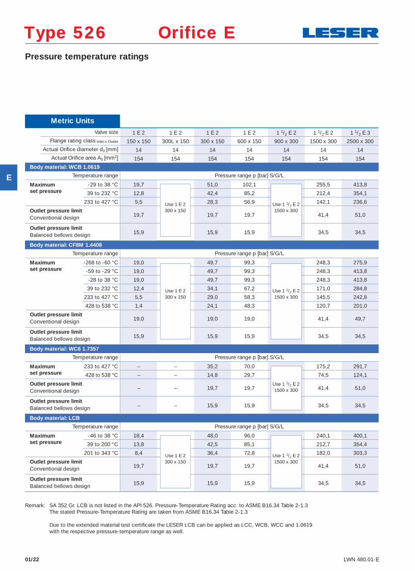
Pressure temperature ratings
Type 526 Orifice EType 526 Orifice E
Metric Units Valve size 1 E 2 1 E 2 1 E 2 1 E 2 1 1/2 E 2 1 1/2 E 2 1 1/2 E 3
Flange rating class Inlet x Outlet 150 x 150 300L x 150 300 x 150 600 x 150 900 x 300 1500 x 300 2500 x 300 Actual Orifi ce diameter d0 [mm] 14 14 14 14 14 14 14 Actual Orifi ce area A0 [mm2] 154 154 154 154 154 154 154
Body material: WCB 1.0619
Temperature range Pressure range p [bar] S/G/L
Maximum -29 to 38 °C 19,7 51,0 102,1 255,5 413,8 set pressure 39 to 232 °C 12,8 42,4 85,2 212,4 354,1 233 to 427 °C 5,5 28,3 56,9 142,1 236,6
Outlet pressure limit19,7 19,7 19,7 41,4 51,0 Conventional design
Outlet pressure limit15,9 15,9 15,9 34,5 34,5 Balanced bellows design
Body material: CF8M 1.4408
Temperature range Pressure range p [bar] S/G/L
Maximum -268 to -60 °C 19,0 49,7 99,3 248,3 275,9 set pressure -59 to -29 °C 19,0 49,7 99,3 248,3 413,8 -28 to 38 °C 19,0 49,7 99,3 248,3 413,8
39 to 232 °C 12,4 34,1 67,2 171,0 284,8
233 to 427 °C 5,5 29,0 58,3 145,5 242,8
428 to 538 °C 1,4 24,1 48,3 120,7 201,0
Outlet pressure limit19,0 19,0 19,0 41,4 49,7 Conventional design
Outlet pressure limit15,9 15,9 15,9 34,5 34,5 Balanced bellows design
Body material: WC6 1.7357
Temperature range Pressure range p [bar] S/G/L
Maximum 233 to 427 °C – – 35,2 70,0 175,2 291,7 set pressure 428 to 538 °C – – 14,8 29,7 74,5 124,1
Outlet pressure limit– – 19,7 19,7 41,4 51,0 Conventional design
Outlet pressure limit– – 15,9 15,9 34,5 34,5 Balanced bellows design
Body material: LCB
Temperature range Pressure range p [bar] S/G/L
Maximum -46 to 38 °C 18,4 48,0 96,0 240,1 400,1 set pressure 39 to 200 °C 13,8 42,5 85,1 212,7 354,4 201 to 343 °C 8,4 36,4 72,8 182,0 303,3
Outlet pressure limit19,7 19,7 19,7 41,4 51,0 Conventional design
Outlet pressure limit15,9 15,9 15,9 34,5 34,5 Balanced bellows design
Use 1 E 2300 x 150
Use 1 1/2 E 21500 x 300
Use 1 E 2300 x 150
Use 1 1/2 E 21500 x 300
Use 1 1/2 E 21500 x 300
Use 1 E 2300 x 150
Use 1 1/2 E 21500 x 300
Remark: SA 352 Gr. LCB is not listed in the API 526. Pressure-Temperature Rating acc. to ASME B16.34 Table 2-1.3 The stated Pressure-Temperature Rating are taken from ASME B16.34 Table 2-1.3 Due to the extended material test certifi cate the LESER LCB can be applied as LCC, WCB, WCC and 1.0619 with the respective pressure-temperature range as well.
E
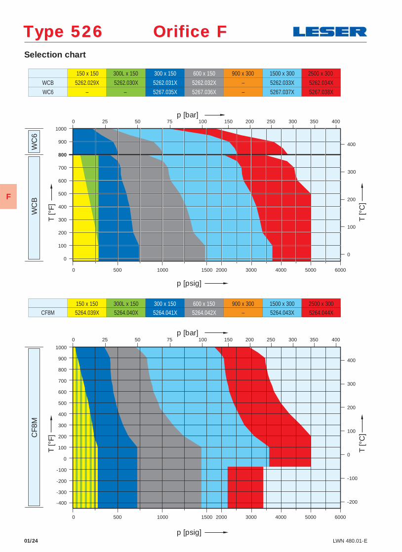
Type 526 Orifice FType 526 Orifice F Selection chart
01/24 LWN 480.01-E
WC
B
WC
6 C
F8M
150 x 150
5262.029X
300L x 150 300 x 150
5262.031X
600 x 150
5262.032X
900 x 300
–
1500 x 300
5262.033X
2500 x 300
5262.034X 5262.030X
5267.035X 5267.036X 5267.037X 5267.038X
WCB
WC6 – – –
150 x 150 300L x 150 300 x 150 600 x 150 900 x 300 1500 x 300 2500 x 300 5264.039X 5264.040X 5264.041X 5264.042X – 5264.043X 5264.044X CF8M
-400
-300
-200
-100
0
100
200
300
400
500
600
700
800
900
1000
500
0
100
200
300
400
500
600
700
900
800
1000
0
100
200
300
400
400
300
200
100
0
-100
-200
0 1000 1500 2000 3000 4000 5000 6000
25 0 50 75 100 150 200 250 300 350 400
6000 5000 4000 3000 2000 1500 1000 0 500
400 350 300 250 200 150 100 75 50 0 25
p [bar]
T [°
F]
T [°
C]
p [psig]
p [bar]
T [°
F]
p [psig]
T [°
C]
F
01/25LWN 480.01-E
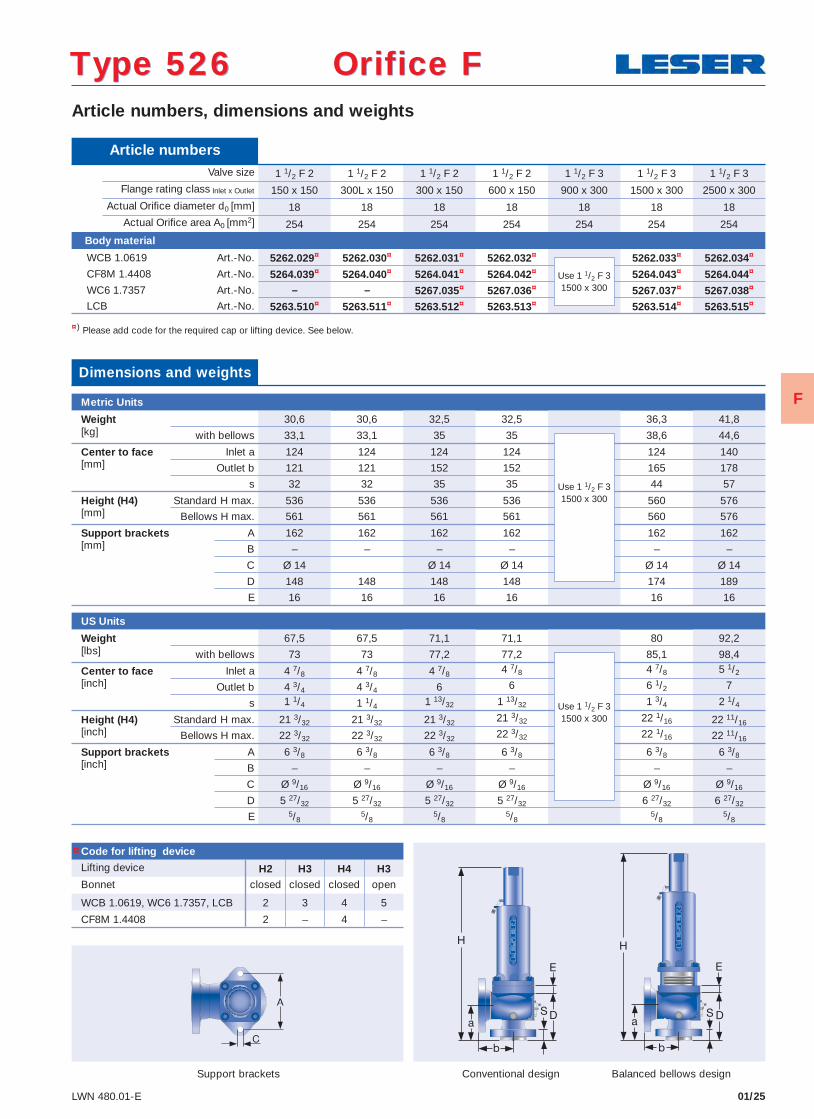
Article numbers, dimensions and weights
Conventional design Balanced bellows designSupport brackets
¤) Please add code for the required cap or lifting device. See below.
Article numbers Valve size 1 1/2 F 2 1 1/2 F 2 1 1/2 F 2 1 1/2 F 2 1 1/2 F 3 1 1/2 F 3 1 1/2 F 3
Flange rating class Inlet x Outlet 150 x 150 300L x 150 300 x 150 600 x 150 900 x 300 1500 x 300 2500 x 300 Actual Orifi ce diameter d0 [mm] 18 18 18 18 18 18 18 Actual Orifi ce area A0 [mm2] 254 254 254 254 254 254 254
Body material
WCB 1.0619 Art.-No. 5262.029¤ 5262.030¤ 5262.031¤ 5262.032¤ 5262.033¤ 5262.034¤
CF8M 1.4408 Art.-No. 5264.039¤ 5264.040¤ 5264.041¤ 5264.042¤ 5264.043¤ 5264.044¤
WC6 1.7357 Art.-No. – – 5267.035¤ 5267.036¤ 5267.037¤ 5267.038¤
LCB Art.-No. 5263.510¤ 5263.511¤ 5263.512¤ 5263.513¤ 5263.514¤ 5263.515¤
Use 1 1/2 F 31500 x 300
Code for lifting device
Lifting device H2 H3 H4 H3Bonnet closed closed closed open
WCB 1.0619, WC6 1.7357, LCB 2 3 4 5
CF8M 1.4408 2 – 4 –
Dimensions and weights
Metric Units
Weight 30,6 30,6 32,5 32,5 36,3 41,8[kg] with bellows 33,1 33,1 35 35 38,6 44,6
Center to face Inlet a 124 124 124 124 124 140[mm] Outlet b 121 121 152 152 165 178
s 32 32 35 35 44 57
Height (H4) Standard H max. 536 536 536 536 560 576[mm] Bellows H max. 561 561 561 561 560 576
Support brackets A 162 162 162 162 162 162[mm] B – – – – – –
C Ø 14 Ø 14 Ø 14 Ø 14 Ø 14
D 148 148 148 148 174 189
E 16 16 16 16 16 16
US Units
Weight 67,5 67,5 71,1 71,1 80 92,2[lbs] with bellows 73 73 77,2 77,2 85,1 98,4
Center to face Inlet a 4 7/8 4 7/8 4 7/8 4 7/8 4 7/8 5 1/2
[inch] Outlet b 4 3/4 4 3/4 6 6 6 1/2 7
s 1 1/4 1 1/4 1 13/32 1 13/32 1 3/4 2 1/4
Height (H4) Standard H max. 21 3/32 21 3/32 21 3/32 21 3/32 22 1/16 22 11/16[inch] Bellows H max. 22 3/32 22 3/32 22 3/32 22 3/32 22 1/16 22 11/16
Support brackets A 6 3/8 6 3/8 6 3/8 6 3/8 6 3/8 6 3/8[inch] B – – – – – –
C Ø 9/16 Ø 9/16 Ø 9/16 Ø 9/16 Ø 9/16 Ø 9/16
D 5 27/32 5 27/32 5 27/32 5 27/32 6 27/32 6 27/32
E 5/85/8
5/85/8
5/85/8
Use 1 1/2 F 31500 x 300
Use 1 1/2 F 31500 x 300
Type 526 Orifice FType 526 Orifice F
¤
F
Type 526 Orifice FType 526 Orifice F
01/26 LWN 480.01-E
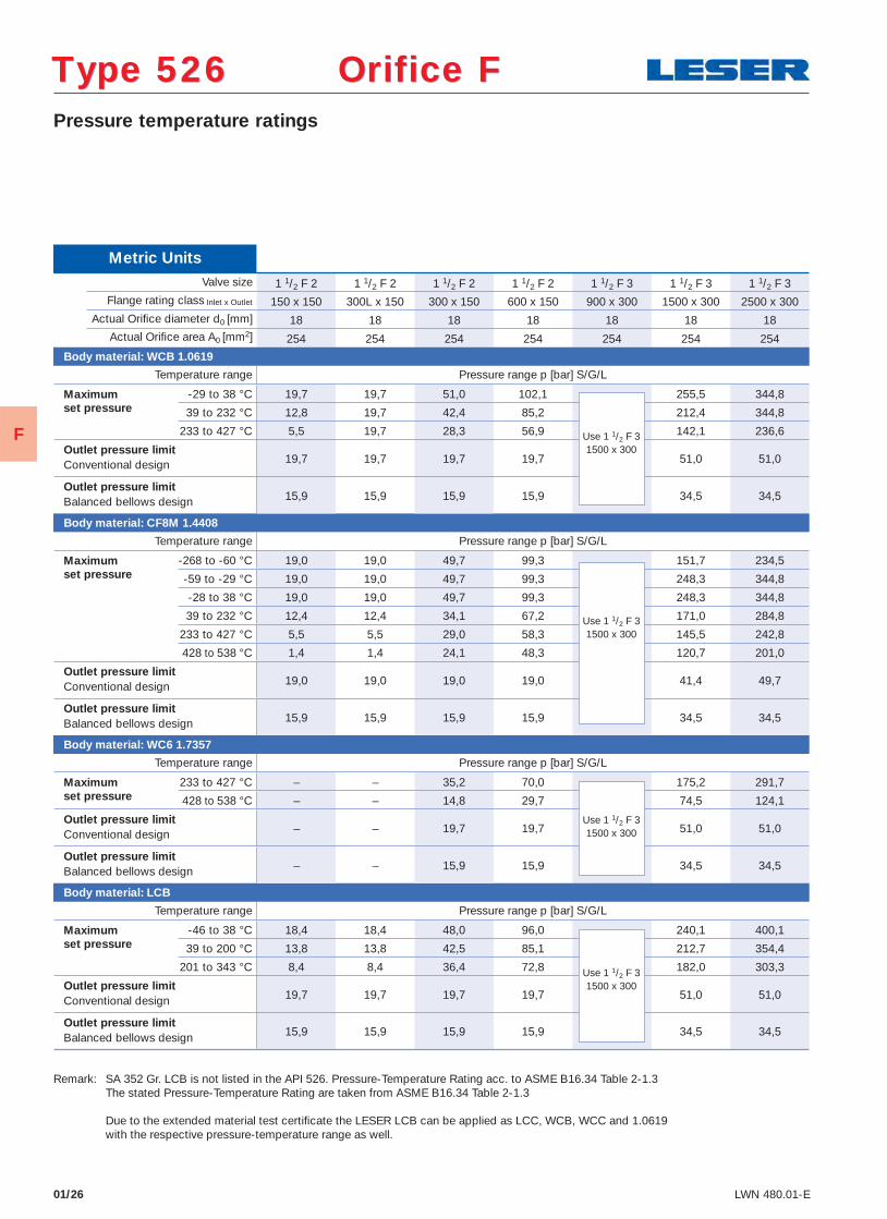
Pressure temperature ratings
Metric Units Valve size 1 1/2 F 2 1 1/2 F 2 1 1/2 F 2 1 1/2 F 2 1 1/2 F 3 1 1/2 F 3 1 1/2 F 3
Flange rating class Inlet x Outlet 150 x 150 300L x 150 300 x 150 600 x 150 900 x 300 1500 x 300 2500 x 300 Actual Orifi ce diameter d0 [mm] 18 18 18 18 18 18 18 Actual Orifi ce area A0 [mm2] 254 254 254 254 254 254 254
Body material: WCB 1.0619
Temperature range Pressure range p [bar] S/G/L
Maximum -29 to 38 °C 19,7 19,7 51,0 102,1 255,5 344,8 set pressure 39 to 232 °C 12,8 19,7 42,4 85,2 212,4 344,8 233 to 427 °C 5,5 19,7 28,3 56,9 142,1 236,6
Outlet pressure limit19,7 19,7 19,7 19,7 51,0 51,0 Conventional design
Outlet pressure limit15,9 15,9 15,9 15,9 34,5 34,5 Balanced bellows design
Body material: CF8M 1.4408
Temperature range Pressure range p [bar] S/G/L
Maximum -268 to -60 °C 19,0 19,0 49,7 99,3 151,7 234,5 set pressure -59 to -29 °C 19,0 19,0 49,7 99,3 248,3 344,8 -28 to 38 °C 19,0 19,0 49,7 99,3 248,3 344,8
39 to 232 °C 12,4 12,4 34,1 67,2 171,0 284,8
233 to 427 °C 5,5 5,5 29,0 58,3 145,5 242,8
428 to 538 °C 1,4 1,4 24,1 48,3 120,7 201,0
Outlet pressure limit19,0 19,0 19,0 19,0 41,4 49,7 Conventional design
Outlet pressure limit15,9 15,9 15,9 15,9 34,5 34,5 Balanced bellows design
Body material: WC6 1.7357
Temperature range Pressure range p [bar] S/G/L
Maximum 233 to 427 °C – – 35,2 70,0 175,2 291,7 set pressure 428 to 538 °C – – 14,8 29,7 74,5 124,1
Outlet pressure limit– – 19,7 19,7 51,0 51,0 Conventional design
Outlet pressure limit– – 15,9 15,9 34,5 34,5 Balanced bellows design
Body material: LCB
Temperature range Pressure range p [bar] S/G/L
Maximum -46 to 38 °C 18,4 18,4 48,0 96,0 240,1 400,1 set pressure 39 to 200 °C 13,8 13,8 42,5 85,1 212,7 354,4 201 to 343 °C 8,4 8,4 36,4 72,8 182,0 303,3
Outlet pressure limit19,7 19,7 19,7 19,7 51,0 51,0 Conventional design
Outlet pressure limit15,9 15,9 15,9 15,9 34,5 34,5 Balanced bellows design
Use 1 1/2 F 31500 x 300
Use 1 1/2 F 31500 x 300
Use 1 1/2 F 31500 x 300
Use 1 1/2 F 31500 x 300
Remark: SA 352 Gr. LCB is not listed in the API 526. Pressure-Temperature Rating acc. to ASME B16.34 Table 2-1.3 The stated Pressure-Temperature Rating are taken from ASME B16.34 Table 2-1.3 Due to the extended material test certifi cate the LESER LCB can be applied as LCC, WCB, WCC and 1.0619 with the respective pressure-temperature range as well.
F
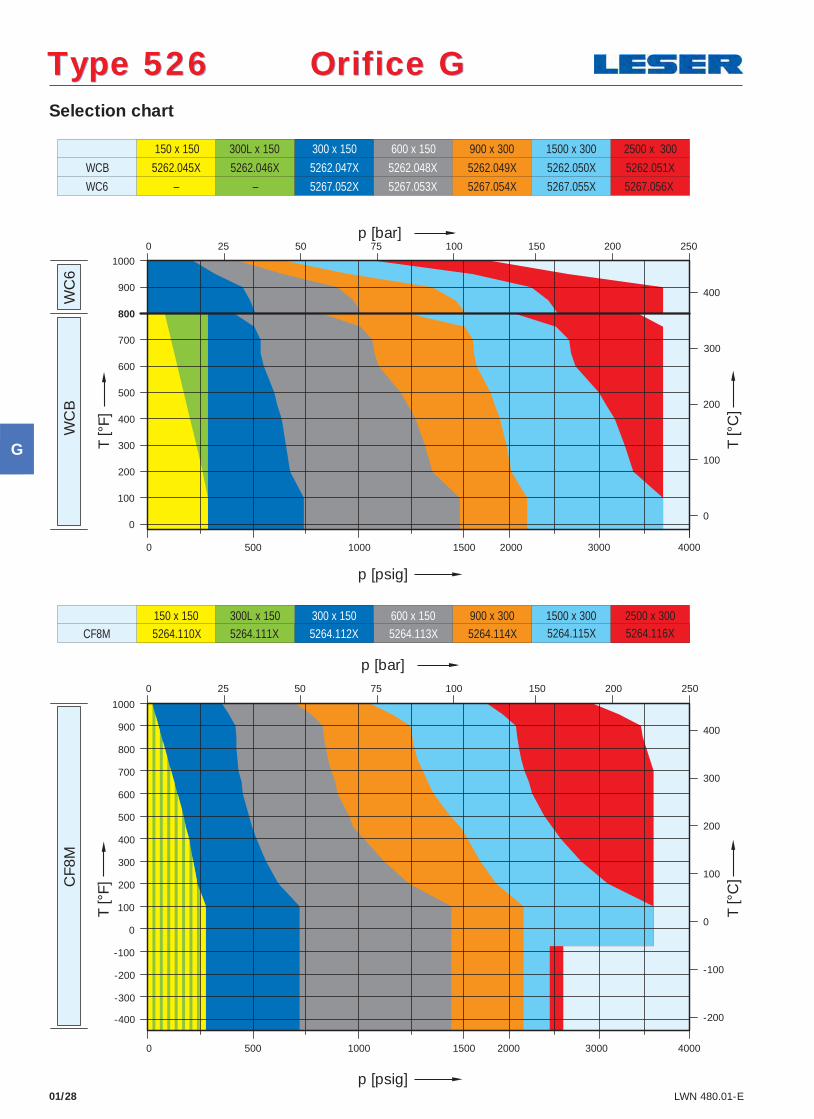
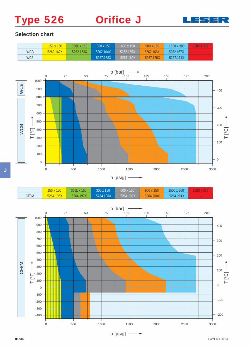
Type 526 Orifice GType 526 Orifice G Selection chart
01/28 LWN 480.01-E
WC
B
WC
6 C
F8M
150 x 150
5262.045X
300L x 150 300 x 150 600 x 150
5262.048X
900 x 300
5262.049X
1500 x 300
5262.050X
2500 x 300
5262.051X 5262.046X 5262.047X
5267.052X 5267.053X 5267.055X 5267.056X
WCB
WC6 – – 5267.054X
150 x 150 300L x 150 300 x 150 600 x 150 900 x 300 1500 x 300 2500 x 300 5264.110X 5264.111X 5264.112X 5264.113X 5264.114X 5264.115X 5264.116X CF8M
p [psig]
p [bar]
T [°
F]
T [°
C]
p [psig]
T [°
F]
T [°
C]
p [bar]
-400
-300
-200
-100
0
100
200
300
400
500
600
700
800
900
1000
0
100
200
300
400
500
600
700
900
800
1000
0
100
200
300
400
400
300
200
100
0
-100
-200
0 4000
0
4000 2000 0
0
500 1000 1500 2000 3000
500 1000 1500 3000
25 75 50 100 150 200 250
25 50 75 100 150 200 250
G
01/29LWN 480.01-E
Article numbers, dimensions and weights
Conventional design Balanced bellows design
¤) Please add code for the required cap or lifting device. See below.
Article numbers Valve size 1 1/2 G 3 1 1/2 G 3 1 1/2 G 3 1 1/2 G 3 1 1/2 G 3 2 G 3 2 G 3
Flange rating class Inlet x Outlet 150 x 150 300L x 150 300 x 150 600 x 150 900 x 300 1500 x 300 2500 x 300 Actual Orifi ce diameter d0 [mm] 22,5 22,5 22,5 22,5 22,5 22,5 22,5 Actual Orifi ce area A0 [mm2] 398 398 398 398 398 398 398
Body material
WCB 1.0619 Art.-No. 5262.045¤ 5262.046¤ 5262.047¤ 5262.048¤ 5262.049¤ 5262.050¤ 5262.051¤
CF8M 1.4408 Art.-No. 5264.110¤ 5264.111¤ 5264.112¤ 5264.113¤ 5264.114¤ 5264.115¤ 5264.116¤
WC6 1.7357 Art.-No. – – 5267.052¤ 5267.053¤ 5267.054¤ 5267.055¤ 5267.056¤
LCB Art.-No. 5263.516¤ 5263.517¤ 5263.518¤ 5263.519¤ 5263.520¤ 5263.521¤ 5263.522¤
Code for lifting device
Lifting device H2 H3 H4 H3Bonnet closed closed closed open
WCB 1.0619, WC6 1.7357, LCB 2 3 4 5
CF8M 1.4408 2 – 4 –
Dimensions and weights
Metric Units
Weight 30,6 30,6 32,5 32,5 36,3 69,9 69,9[kg] with bellows 33,1 33,1 35 35 38,6 72,5 72,5
Center to face Inlet a 124 124 124 124 124 156 156[mm] Outlet b 121 121 152 152 165 172 172
s 32 32 35 35 44 68 68
Height (H4) Standard H max. 536 536 536 536 560 688 688[mm] Bellows H max. 574 574 574 574 573 705 705
Support brackets A 162 162 162 162 162 184 184[mm] B – – – – – 110 110
C Ø 14 Ø 14 Ø 14 Ø 14 Ø 14 Ø 14 Ø 14
D 148 148 148 148 174 198 198
E 16 16 16 16 16 16 16
US Units
Weight 67,5 67,5 71,7 71,7 80 154,1 154,1[lbs] with bellows 73 73 77,2 77,2 85,1 159,9 159,9
Center to face Inlet a 4 7/8 4 7/8 4 7/8 4 7/8 4 7/8 6 1/8 6 1/8[inch] Outlet b 4 3/4 4 3/4 6 6 6 1/2 6 3/4 6 3/4
s 1 1/4 1 1/4 1 13/32 1 13/32 1 3/4 2 11/16 2 11/16
Height (H4) Standard H max. 21 3/32 21 3/32 21 3/32 21 3/32 22 1/16 27 3/32 27 3/32[inch] Bellows H max. 22 19/32 22 19/32 22 19/32 22 19/32 22 9/16 27 3/4 27 3/4
Support brackets A 6 3/8 6 3/8 6 3/8 6 3/8 6 3/8 7 1/4 7 1/4[inch] B – – – – – 4 11/32 4 11/32
C Ø 9/16 Ø 9/16 Ø 9/16 Ø 9/16 Ø 9/16 Ø 9/16 Ø 9/16
D 5 27/32 5 27/32 5 27/32 5 27/32 6 27/32 7 13/16 7 13/16
E 5/85/8
5/85/8
5/85/8
5/8
Type 526 Orifice GType 526 Orifice G
Support brackets
¤
G
Type 526 Orifice GType 526 Orifice G
01/30 LWN 480.01-E
Pressure temperature ratings
Metric Units Valve size 1 1/2 G 3 1 1/2 G 3 1 1/2 G 3 1 1/2 G 3 1 1/2 G 3 2 G 3 2 G 3
Flange rating class Inlet x Outlet 150 x 150 300L x 150 300 x 150 600 x 150 900 x 300 1500 x 300 2500 x 300 Actual Orifi ce diameter d0 [mm] 22,5 22,5 22,5 22,5 22,5 22,5 22,5 Actual Orifi ce area A0 [mm2] 398 398 398 398 398 398 398
Body material: WCB 1.0619
Temperature range Pressure range p [bar] S/G/L
Maximum -29 to 38 °C 19,7 19,7 51,0 102,1 153,1 255,5 255,5 set pressure 39 to 232 °C 12,8 19,7 42,4 85,2 127,2 212,4 255,5 233 to 427 °C 5,5 19,7 28,3 56,9 85,2 142,1 236,6
Outlet pressure limit19,7 19,7 19,7 19,7 51,0 51,0 51,0 Conventional design
Outlet pressure limit15,9 15,9 15,9 15,9 32,4 32,4 32,4 Balanced bellows design
Body material: CF8M 1.4408
Temperature range Pressure range p [bar] S/G/L
Maximum -268 to -60 °C 19,0 19,0 49,7 99,3 149,0 169,0 179,3 set pressure -59 to -29 °C 19,0 19,0 49,7 99,3 149,0 248,3 248,3 -28 to 38 °C 19,0 19,0 49,7 99,3 149,0 248,3 248,3
39 to 232 °C 12,4 12,4 34,1 67,2 102,4 171,0 248,3
233 to 427 °C 5,5 5,5 29,0 58,3 87,2 145,5 242,8
428 to 538 °C 1,4 1,4 24,1 48,3 72,4 120,7 201,0
Outlet pressure limit19,0 19,0 19,0 19,0 41,4 41,4 49,7 Conventional design
Outlet pressure limit15,9 15,9 15,9 15,9 32,4 32,4 32,4 Balanced bellows design
Body material: WC6 1.7357
Temperature range Pressure range p [bar] S/G/L
Maximum 233 to 427 °C – – 35,2 70,0 105,2 175,2 255,5 set pressure 428 to 538 °C – – 14,8 29,7 44,8 74,5 124,1
Outlet pressure limit– – 19,7 19,7 51,0 51,0 51,0 Conventional design
Outlet pressure limit– – 15,9 15,9 32,4 32,4 32,4 Balanced bellows design
Body material: LCB
Temperature range Pressure range p [bar] S/G/L
Maximum -46 to 38 °C 18,4 18,4 48,0 96,0 144,1 240,1 400,1 set pressure 39 to 200 °C 13,8 13,8 42,5 85,1 127,6 212,7 354,4 201 to 343 °C 8,4 8,4 36,4 72,8 109,2 182,0 303,3
Outlet pressure limit19,7 19,7 19,7 19,7 51,0 51,0 51,0 Conventional design
Outlet pressure limit15,9 15,9 15,9 15,9 32,4 32,4 32,4 Balanced bellows design
Remark: SA 352 Gr. LCB is not listed in the API 526. Pressure-Temperature Rating acc. to ASME B16.34 Table 2-1.3 The stated Pressure-Temperature Rating are taken from ASME B16.34 Table 2-1.3 Due to the extended material test certifi cate the LESER LCB can be applied as LCC, WCB, WCC and 1.0619 with the respective pressure-temperature range as well.
G
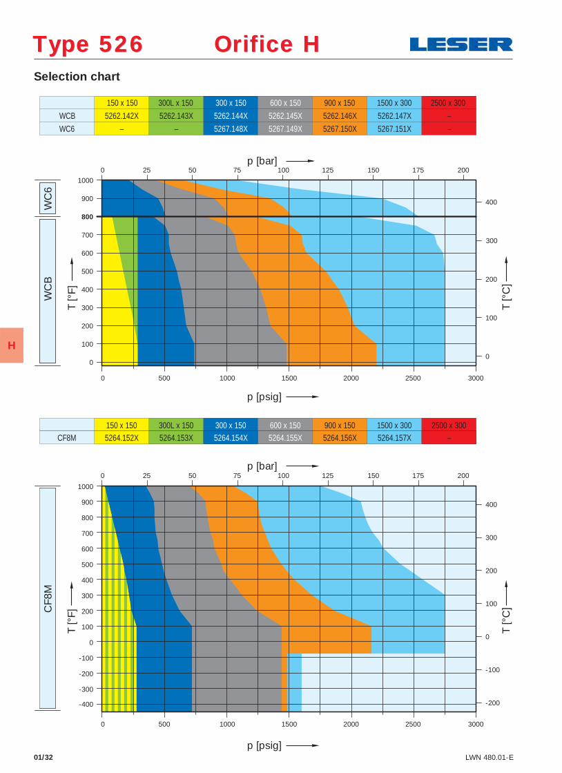
Selection chart
01/32 LWN 480.01-E
CF8
M
150 x 150 300L x 150 300 x 150 600 x 150 900 x 150 1500 x 300 2500 x 300
WC
B
WC
6
150 x 150 5262.142X
300L x 150 300 x 150
5262.144X
600 x 150
5262.145X
900 x 150
5262.146X
1500 x 300
5262.147X
2500 x 300
–
5264.152X 5264.153X 5264.154X 5264.155X 5264.156X 5264.157X –
5262.143X
5267.148X 5267.149X 5267.151X –
WCB
WC6
CF8M
– – 5267.150X
-400
-300
-200
-100
0
100
200
300
400
500
600
700
800
900
1000
0
100
200
300
400
500
600
700
900
800
1000
0
100
200
300
400
400
300
200
100
0
-100
-200
0 3000
25 0 50 75 100
2500 2000 1500 1000 500
125 150 175 200
500 1000 1500 2000 2500 3000 0
200 175 150 125 100 75 50 0 25
p [psig]
p [bar]
T [°
F]
T [°
C]
p [bar]
p [psig]
T [°
F]
T [°
C]
Type 526 Orifice HType 526 Orifice H
H
01/33LWN 480.01-E
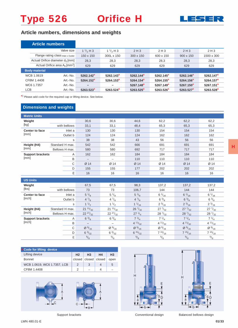
Article numbers, dimensions and weights
Conventional design Balanced bellows design
¤) Please add code for the required cap or lifting device. See below.
Article numbers Valve size 1 1/2 H 3 1 1/2 H 3 2 H 3 2 H 3 2 H 3 2 H 3
Flange rating class Inlet x Outlet 150 x 150 300L x 150 300 x 150 600 x 150 900 x 150 1500 x 300 Actual Orifi ce diameter d0 [mm] 28,3 28,3 28,3 28,3 28,3 28,3 Actual Orifi ce area A0 [mm2] 629 629 629 629 629 629
Body material
WCB 1.0619 Art.-No. 5262.142¤ 5262.143¤ 5262.144¤ 5262.145¤ 5262.146¤ 5262.147¤
CF8M 1.4408 Art.-No. 5264.152¤ 5264.153¤ 5264.154¤ 5264.155¤ 5264.156¤ 5264.157¤
WC6 1.7357 Art.-No. – – 5267.148¤ 5267.149¤ 5267.150¤ 5267.151¤
LCB Art.-No. 5263.523¤ 5263.524¤ 5263.525¤ 5263.526¤ 5263.527¤ 5263.528¤
Code for lifting device
Lifting device H2 H3 H4 H3Bonnet closed closed closed open
WCB 1.0619, WC6 1.7357, LCB 2 3 4 5
CF8M 1.4408 2 – 4 –
Dimensions and weights
Metric Units
Weight 30,6 30,6 44,6 62,2 62,2 62,2[kg] with bellows 33,1 33,1 48,4 65,3 65,3 65,3
Center to face Inlet a 130 130 130 154 154 154[mm] Outlet b 124 124 124 162 162 162
s 38 38 43 56 56 56
Height (H4) Standard H max. 542 542 666 691 691 691[mm] Bellows H max. 580 580 692 717 717 717
Support brackets A 162 162 184 184 184 184[mm] B – – 110 110 110 110
C Ø 14 Ø 14 Ø 14 Ø 14 Ø 14 Ø 14
D 155 155 177 202 202 202
E 16 16 16 16 16 16
US Units
Weight 67,5 67,5 98,3 137,2 137,2 137,2[lbs] with bellows 73 73 106,7 144 144 144
Center to face Inlet a 5 1/8 5 1/8 5 1/8 6 1/16 6 1/16 6 1/16[inch] Outlet b 4 7/8 4 7/8 4 7/8 6 3/8 6 3/8 6 3/8
s 1 1/2 1 1/2 1 1/16 2 3/16 2 3/16 2 3/16
Height (H4) Standard H max. 21 11/32 21 11/32 26 7/32 27 7/32 27 7/32 27 7/32[inch] Bellows H max. 22 27/32 22 27/32 27 1/4 28 7/32 28 7/32 28 7/32
Support brackets A 6 3/8 6 3/8 7 1/4 7 1/4 7 1/4 7 1/4[inch] B – – 4 11/32 4 11/32 4 11/32 4 11/32
C Ø 9/16 Ø 9/16 Ø 9/16 Ø 9/16 Ø 9/16 Ø 9/16
D 6 3/32 6 3/32 6 31/32 7 15/16 7 15/16 7 15/16
E 5/85/8
5/85/8
5/85/8
Type 526 Orifice HType 526 Orifice H
Support brackets
¤
H
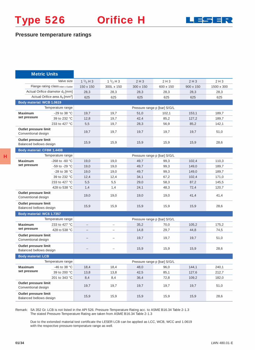
01/34 LWN 480.01-E
Pressure temperature ratings
Type 526 Orifice HType 526 Orifice H
Metric Units Valve size 1 1/2 H 3 1 1/2 H 3 2 H 3 2 H 3 2 H 3 2 H 3
Flange rating class Inlet x Outlet 150 x 150 300L x 150 300 x 150 600 x 150 900 x 150 1500 x 300 Actual Orifi ce diameter d0 [mm] 28,3 28,3 28,3 28,3 28,3 28,3 Actual Orifi ce area A0 [mm2] 625 625 625 625 625 625
Body material: WCB 1.0619
Temperature range Pressure range p [bar] S/G/L
Maximum -29 to 38 °C 19,7 19,7 51,0 102,1 153,1 189,7 set pressure 39 to 232 °C 12,8 19,7 42,4 85,2 127,2 189,7 233 to 427 °C 5,5 19,7 28,3 56,9 85,2 142,1
Outlet pressure limit19,7 19,7 19,7 19,7 19,7 51,0 Conventional design
Outlet pressure limit15,9 15,9 15,9 15,9 15,9 28,6 Balanced bellows design
Body material: CF8M 1.4408
Temperature range Pressure range p [bar] S/G/L
Maximum -268 to -60 °C 19,0 19,0 49,7 99,3 102,4 110,3 set pressure -59 to -29 °C 19,0 19,0 49,7 99,3 149,0 189,7 -28 to 38 °C 19,0 19,0 49,7 99,3 149,0 189,7
39 to 232 °C 12,4 12,4 34,1 67,2 102,4 171,0
233 to 427 °C 5,5 5,5 29,0 58,3 87,2 145,5
428 to 538 °C 1,4 1,4 24,1 48,3 72,4 120,7
Outlet pressure limit19,0 19,0 19,0 19,0 41,4 41,4 Conventional design
Outlet pressure limit15,9 15,9 15,9 15,9 15,9 28,6 Balanced bellows design
Body material: WC6 1.7357
Temperature range Pressure range p [bar] S/G/L
Maximum 233 to 427 °C – – 35,2 70,0 105,2 175,2 set pressure 428 to 538 °C – – 14,8 29,7 44,8 74,5
Outlet pressure limit– – 19,7 19,7 19,7 51,0 Conventional design
Outlet pressure limit– – 15,9 15,9 15,9 28,6 Balanced bellows design
Body material: LCB
Temperature range Pressure range p [bar] S/G/L
Maximum -46 to 38 °C 18,4 18,4 48,0 96,0 144,1 240,1 set pressure 39 to 200 °C 13,8 13,8 42,5 85,1 127,6 212,7 201 to 343 °C 8,4 8,4 36,4 72,8 109,2 182,0
Outlet pressure limit19,7 19,7 19,7 19,7 19,7 51,0 Conventional design
Outlet pressure limit15,9 15,9 15,9 15,9 15,9 28,6 Balanced bellows design
Remark: SA 352 Gr. LCB is not listed in the API 526. Pressure-Temperature Rating acc. to ASME B16.34 Table 2-1.3 The stated Pressure-Temperature Rating are taken from ASME B16.34 Table 2-1.3 Due to the extended material test certifi cate the LESER LCB can be applied as LCC, WCB, WCC and 1.0619 with the respective pressure-temperature range as well.
H
Selection chart
01/36 LWN 480.01-E
WC
B
WC
6 C
F8M
150 x 150
5262.162X
300L x 150 300 x 150
5262.164X
600 x 150
5262.165X
900 x 150
5262.166X
1500 x 300
5262.167X
2500 x 300
– 5262.163X
5267.168X 5267.169X 5267.171X –
WCB
WC6 – – 5267.170X
150 x 150 300L x 150 300 x 150 600 x 150 900 x 150 1500 x 300 2500 x 300 5264.196X 5264.197X 5264.198X 5264.199X 5264.200X 5264.201X – CF8M
-400
-300
-200
-100
0
100
200
300
400
500
600
700
800
900
1000
500
0
100
200
300
400
500
600
700
900
800
1000
0
100
200
300
400
400
300
200
100
0
-100
-200
0 1000 1500 2000 3000
25 0 50 75 100
3000 2000 1500 1000 0 500
100 75 50 0 25
2500
2500
125 150 175 200
125 150 175 200
p [psig]
p [bar]
T [°
F]
T [°
C]
p [bar]
p [psig]
T [°
F]
T [°
C]
Type 526 Orifice JType 526 Orifice J
J
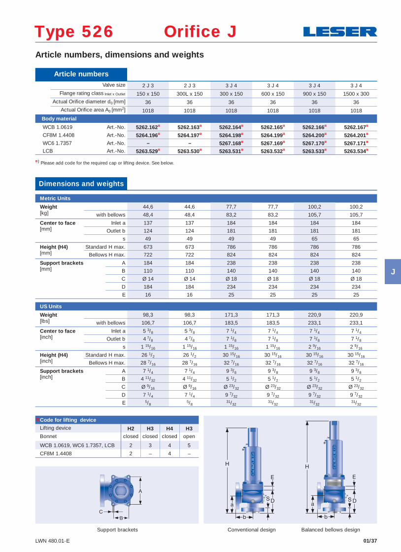
01/37LWN 480.01-E
Article numbers, dimensions and weights
Conventional design Balanced bellows design
¤) Please add code for the required cap or lifting device. See below.
Article numbers Valve size 2 J 3 2 J 3 3 J 4 3 J 4 3 J 4 3 J 4
Flange rating class Inlet x Outlet 150 x 150 300L x 150 300 x 150 600 x 150 900 x 150 1500 x 300 Actual Orifi ce diameter d0 [mm] 36 36 36 36 36 36 Actual Orifi ce area A0 [mm2] 1018 1018 1018 1018 1018 1018
Body material
WCB 1.0619 Art.-No. 5262.162¤ 5262.163¤ 5262.164¤ 5262.165¤ 5262.166¤ 5262.167¤
CF8M 1.4408 Art.-No. 5264.196¤ 5264.197¤ 5264.198¤ 5264.199¤ 5264.200¤ 5264.201¤
WC6 1.7357 Art.-No. – – 5267.168¤ 5267.169¤ 5267.170¤ 5267.171¤
LCB Art.-No. 5263.529¤ 5263.530¤ 5263.531¤ 5263.532¤ 5263.533¤ 5263.534¤
Code for lifting device
Lifting device H2 H3 H4 H3Bonnet closed closed closed open
WCB 1.0619, WC6 1.7357, LCB 2 3 4 5
CF8M 1.4408 2 – 4 –
Dimensions and weights
Metric Units
Weight 44,6 44,6 77,7 77,7 100,2 100,2[kg] with bellows 48,4 48,4 83,2 83,2 105,7 105,7
Center to face Inlet a 137 137 184 184 184 184[mm] Outlet b 124 124 181 181 181 181
s 49 49 49 49 65 65
Height (H4) Standard H max. 673 673 786 786 786 786[mm] Bellows H max. 722 722 824 824 824 824
Support brackets A 184 184 238 238 238 238[mm] B 110 110 140 140 140 140
C Ø 14 Ø 14 Ø 18 Ø 18 Ø 18 Ø 18
D 184 184 234 234 234 234
E 16 16 25 25 25 25
US Units
Weight 98,3 98,3 171,3 171,3 220,9 220,9[lbs] with bellows 106,7 106,7 183,5 183,5 233,1 233,1
Center to face Inlet a 5 3/8 5 3/8 7 1/4 7 1/4 7 1/4 7 1/4[inch] Outlet b 4 7/8 4 7/8 7 1/8 7 1/8 7 1/8 7 1/8
s 1 15/16 1 15/16 1 15/16 1 15/16 2 9/16 2 9/16
Height (H4) Standard H max. 26 1/2 26 1/2 30 15/16 30 15/16 30 15/16 30 15/16[inch] Bellows H max. 28 7/16 28 7/16 32 7/16 32 7/16 32 7/16 32 7/16
Support brackets A 7 1/4 7 1/4 9 3/8 9 3/8 9 3/8 9 3/8[inch] B 4 11/32 4 11/32 5 1/2 5 1/2 5 1/2 5 1/2
C Ø 9/16 Ø 9/16 Ø 23/32 Ø 23/32 Ø 23/32 Ø 23/32
D 7 1/4 7 1/4 9 7/32 9 7/32 9 7/32 9 7/32
E 5/85/8
31/3231/32
31/3231/32
Type 526 Orifice JType 526 Orifice J
Support brackets
¤
J
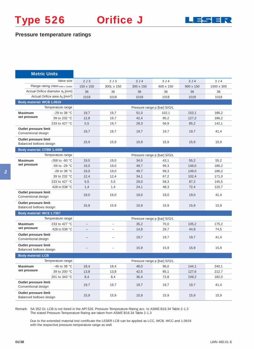
01/38 LWN 480.01-E
Pressure temperature ratings
Type 526 Orifice JType 526 Orifice J
Metric Units Valve size 2 J 3 2 J 3 3 J 4 3 J 4 3 J 4 3 J 4
Flange rating class Inlet x Outlet 150 x 150 300L x 150 300 x 150 600 x 150 900 x 150 1500 x 300 Actual Orifi ce diameter d0 [mm] 36 36 36 36 36 36 Actual Orifi ce area A0 [mm2] 1018 1018 1018 1018 1018 1018
Body material: WCB 1.0619
Temperature range Pressure range p [bar] S/G/L
Maximum -29 to 38 °C 19,7 19,7 51,0 102,1 153,1 186,2 set pressure 39 to 232 °C 12,8 19,7 42,4 85,2 127,2 186,2 233 to 427 °C 5,5 19,7 28,3 56,9 85,2 142,1
Outlet pressure limit19,7 19,7 19,7 19,7 19,7 41,4 Conventional design
Outlet pressure limit15,9 15,9 15,9 15,9 15,9 15,9 Balanced bellows design
Body material: CF8M 1.4408
Temperature range Pressure range p [bar] S/G/L
Maximum -268 to -60 °C 19,0 19,0 34,5 43,1 55,2 55,2 set pressure -59 to -29 °C 19,0 19,0 49,7 99,3 149,0 186,2 -28 to 38 °C 19,0 19,0 49,7 99,3 149,0 186,2
39 to 232 °C 12,4 12,4 34,1 67,2 102,4 171,0
233 to 427 °C 5,5 5,5 29,0 58,3 87,2 145,5
428 to 538 °C 1,4 1,4 24,1 48,3 72,4 120,7
Outlet pressure limit19,0 19,0 19,0 19,0 19,0 41,4 Conventional design
Outlet pressure limit15,9 15,9 15,9 15,9 15,9 15,9 Balanced bellows design
Body material: WC6 1.7357
Temperature range Pressure range p [bar] S/G/L
Maximum 233 to 427 °C – – 35,2 70,0 105,2 175,2 set pressure 428 to 538 °C – – 14,8 29,7 44,8 74,5
Outlet pressure limit– – 19,7 19,7 19,7 41,4 Conventional design
Outlet pressure limit– – 15,9 15,9 15,9 15,9 Balanced bellows design
Body material: LCB
Temperature range Pressure range p [bar] S/G/L
Maximum -46 to 38 °C 18,4 18,4 48,0 96,0 144,1 240,1 set pressure 39 to 200 °C 13,8 13,8 42,5 85,1 127,6 212,7 201 to 343 °C 8,4 8,4 36,4 72,8 109,2 182,0
Outlet pressure limit19,7 19,7 19,7 19,7 19,7 41,4 Conventional design
Outlet pressure limit15,9 15,9 15,9 15,9 15,9 15,9 Balanced bellows design
Remark: SA 352 Gr. LCB is not listed in the API 526. Pressure-Temperature Rating acc. to ASME B16.34 Table 2-1.3 The stated Pressure-Temperature Rating are taken from ASME B16.34 Table 2-1.3 Due to the extended material test certifi cate the LESER LCB can be applied as LCC, WCB, WCC and 1.0619 with the respective pressure-temperature range as well.
J
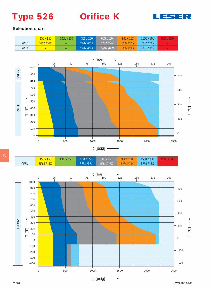
Selection chart
01/40 LWN 480.01-E
WC
B
WC
6 C
F8M
150 x 150
5262.202X
300L x 150 300 x 150
5262.203X
600 x 150
5262.204X
900 x 150
5262.205X
1500 x 300
5262.206X – –
5267.207X 5267.208X 5267.210X –
WCB
WC6 – – 5267.209X
150 x 150 300L x 150 300 x 150 600 x 150 900 x 150 1500 x 300 2500 x 300 5264.211X – 5264.212X 5264.213X 5264.214X 5264.215X – CF8M
2500 x 300
-400
-300
-200
-100
0
100
200
300
400
500
600
700
800
900
1000
0
100
200
300
400
500
600
700
900
800
1000
0
100
200
300
400
400
300
200
100
0
-100
-200
0
0
0
0
2500 500 1000 1500 2000
25 50 75 100 125 150 175 200
1500 1000 500 2000 2500
200 175 150 125 100 75 50 25
p [psig]
p [bar]
T [°
F]
T [°
C]
p [bar]
p [psig]
T [°
F]
T [°
C]
Type 526 Orifice KType 526 Orifice K
K
01/41LWN 480.01-E
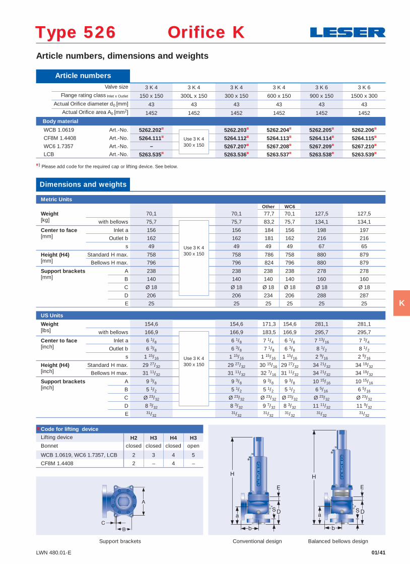
Article numbers, dimensions and weights
Conventional design Balanced bellows design
¤) Please add code for the required cap or lifting device. See below.
Type 526 Orifice KType 526 Orifice K
Article numbers Valve size 3 K 4 3 K 4 3 K 4 3 K 4 3 K 6 3 K 6
Flange rating class Inlet x Outlet 150 x 150 300L x 150 300 x 150 600 x 150 900 x 150 1500 x 300 Actual Orifi ce diameter d0 [mm] 43 43 43 43 43 43 Actual Orifi ce area A0 [mm2] 1452 1452 1452 1452 1452 1452
Body material
WCB 1.0619 Art.-No. 5262.202¤ 5262.203¤ 5262.204¤ 5262.205¤ 5262.206¤
CF8M 1.4408 Art.-No. 5264.111¤ 5264.112¤ 5264.113¤ 5264.114¤ 5264.115¤
WC6 1.7357 Art.-No. – 5267.207¤ 5267.208¤ 5267.209¤ 5267.210¤
LCB Art.-No. 5263.535¤ 5263.536¤ 5263.537¤ 5263.538¤ 5263.539¤
Use 3 K 4300 x 150
Code for lifting device
Lifting device H2 H3 H4 H3Bonnet closed closed closed open
WCB 1.0619, WC6 1.7357, LCB 2 3 4 5
CF8M 1.4408 2 – 4 –
Dimensions and weights
Metric UnitsOther WC6
Weight 70,1 70,1 77,7 70,1 127,5 127,5[kg] with bellows 75,7 75,7 83,2 75,7 134,1 134,1
Center to face Inlet a 156 156 184 156 198 197[mm] Outlet b 162 162 181 162 216 216
s 49 49 49 49 67 65
Height (H4) Standard H max. 758 758 786 758 880 879[mm] Bellows H max. 796 796 824 796 880 879
Support brackets A 238 238 238 238 278 278[mm] B 140 140 140 140 160 160
C Ø 18 Ø 18 Ø 18 Ø 18 Ø 18 Ø 18
D 206 206 234 206 288 287
E 25 25 25 25 25 25
US Units
Weight 154,6 154,6 171,3 154,6 281,1 281,1[lbs] with bellows 166,9 166,9 183,5 166,9 295,7 295,7
Center to face Inlet a 6 1/8 6 1/8 7 1/4 6 1/8 7 13/16 7 3/4[inch] Outlet b 6 3/8 6 3/8 7 1/8 6 3/8 8 1/2 8 1/2
s 1 15/16 1 15/16 1 15/16 1 15/16 2 9/16 2 9/16
Height (H4) Standard H max. 29 27/32 29 27/32 30 15/16 29 27/32 34 21/32 34 19/32[inch] Bellows H max. 31 11/32 31 11/32 32 7/16 31 11/32 34 21/32 34 19/32
Support brackets A 9 3/8 9 3/8 9 3/8 9 3/8 10 15/16 10 15/16[inch] B 5 1/2 5 1/2 5 1/2 5 1/2 6 5/16 6 5/16
C Ø 23/32 Ø 23/32 Ø 23/32 Ø 23/32 Ø 23/32 Ø 23/32
D 8 3/32 8 3/32 9 7/32 8 3/32 11 11/32 11 9/32
E 31/3231/32
31/3231/32
31/3231/32
Use 3 K 4300 x 150
Use 3 K 4300 x 150
Support brackets
¤
K
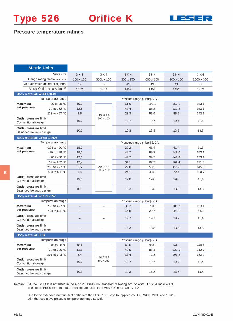
01/42 LWN 480.01-E
Pressure temperature ratings
Type 526 Orifice KType 526 Orifice K
Metric Units Valve size 3 K 4 3 K 4 3 K 4 3 K 4 3 K 6 3 K 6
Flange rating class Inlet x Outlet 150 x 150 300L x 150 300 x 150 600 x 150 900 x 150 1500 x 300 Actual Orifi ce diameter d0 [mm] 43 43 43 43 43 43 Actual Orifi ce area A0 [mm2] 1452 1452 1452 1452 1452 1452
Body material: WCB 1.0619
Temperature range Pressure range p [bar] S/G/L
Maximum -29 to 38 °C 19,7 51,0 102,1 153,1 153,1 set pressure 39 to 232 °C 12,8 42,4 85,2 127,2 153,1 233 to 427 °C 5,5 28,3 56,9 85,2 142,1
Outlet pressure limit19,7 19,7 19,7 19,7 41,4 Conventional design
Outlet pressure limit10,3 10,3 13,8 13,8 13,8 Balanced bellows design
Body material: CF8M 1.4408
Temperature range Pressure range p [bar] S/G/L
Maximum -268 to -60 °C 19,0 36,2 41,4 41,4 51,7 set pressure -59 to -29 °C 19,0 49,7 99,3 149,0 153,1 -28 to 38 °C 19,0 49,7 99,3 149,0 153,1
39 to 232 °C 12,4 34,1 67,2 102,4 171,0
233 to 427 °C 5,5 29,0 58,3 87,2 145,5
428 to 538 °C 1,4 24,1 48,3 72,4 120,7
Outlet pressure limit19,0 19,0 19,0 19,0 41,4 Conventional design
Outlet pressure limit10,3 10,3 13,8 13,8 13,8 Balanced bellows design
Body material: WC6 1.7357
Temperature range Pressure range p [bar] S/G/L
Maximum 233 to 427 °C – – 35,2 70,0 105,2 153,1 set pressure 428 to 538 °C – – 14,8 29,7 44,8 74,5
Outlet pressure limit– – 19,7 19,7 19,7 41,4 Conventional design
Outlet pressure limit– – 10,3 13,8 13,8 13,8 Balanced bellows design
Body material: LCB
Temperature range Pressure range p [bar] S/G/L
Maximum -46 to 38 °C 18,4 48,0 96,0 144,1 240,1 set pressure 39 to 200 °C 13,8 42,5 85,1 127,6 212,7 201 to 343 °C 8,4 36,4 72,8 109,2 182,0
Outlet pressure limit19,7 19,7 19,7 19,7 41,4 Conventional design
Outlet pressure limit10,3 10,3 13,8 13,8 13,8 Balanced bellows design
Remark: SA 352 Gr. LCB is not listed in the API 526. Pressure-Temperature Rating acc. to ASME B16.34 Table 2-1.3 The stated Pressure-Temperature Rating are taken from ASME B16.34 Table 2-1.3 Due to the extended material test certifi cate the LESER LCB can be applied as LCC, WCB, WCC and 1.0619 with the respective pressure-temperature range as well.
Use 3 K 4300 x 150
Use 3 K 4300 x 150
Use 3 K 4300 x 150
K
Selection chart
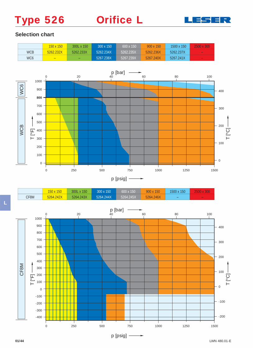
01/44 LWN 480.01-E
150 x 150 300L x 150 300 x 150 600 x 150 900 x 150 1500 x 150 2500 x 300
WC
B
WC
6 C
F8M
150 x 150
5262.232X
300L x 150 300 x 150
5262.234X
600 x 150
5262.235X
900 x 150
5262.236X
1500 x 150
5262.237X – 5262.233X
5267.238X 5267.239X 5267.241X –
WCB
WC6 – – 5267.240X
5264.242X 5264.243X 5264.244X 5264.246X – – CF8M 5264.245X
p [psig]
p [bar]
T [°
F]
T [°
C]
p [psig]
T [°
F]
T [°
C]
-400
-300
-200
-100
0
100
200
300
400
500
600
700
800
900
1000
250
0
100
200
300
400
500
600
700
900
800
1000
0
100
200
300
400
0 500 750 1000 1250 1500
0 20 40 60 80 100
p [bar]
400
300
200
100
0
-100
-200
1500125010007505000 250
0 4020 60 80 100
2500 x 300
Type 526 Orifice LType 526 Orifice L
L
01/45LWN 480.01-E
Article numbers, dimensions and weights
Conventional design Balanced bellows design
¤) Please add code for the required cap or lifting device. See below.
Type 526 Orifice LType 526 Orifice L
Article numbers Valve size 3 L 4 3 L 4 4 L 6 4 L 6 4 L 6 4 L 6
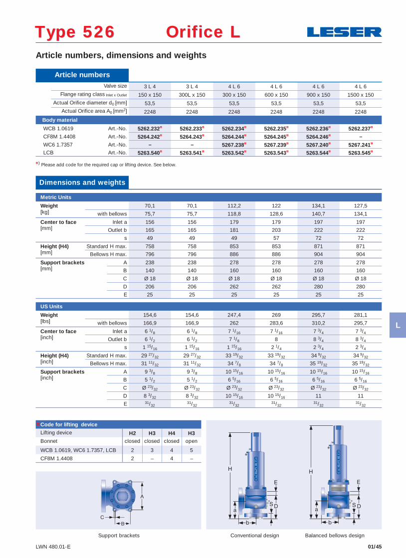
Flange rating class Inlet x Outlet 150 x 150 300L x 150 300 x 150 600 x 150 900 x 150 1500 x 150 Actual Orifi ce diameter d0 [mm] 53,5 53,5 53,5 53,5 53,5 53,5 Actual Orifi ce area A0 [mm2] 2248 2248 2248 2248 2248 2248
Body material
WCB 1.0619 Art.-No. 5262.232¤ 5262.233¤ 5262.234¤ 5262.235¤ 5262.236¤ 5262.237¤
CF8M 1.4408 Art.-No. 5264.242¤ 5264.243¤ 5264.244¤ 5264.245¤ 5264.246¤ –
WC6 1.7357 Art.-No. – – 5267.238¤ 5267.239¤ 5267.240¤ 5267.241¤
LCB Art.-No. 5263.540¤ 5263.541¤ 5263.542¤ 5263.543¤ 5263.544¤ 5263.545¤
Code for lifting device
Lifting device H2 H3 H4 H3Bonnet closed closed closed open
WCB 1.0619, WC6 1.7357, LCB 2 3 4 5
CF8M 1.4408 2 – 4 –
Dimensions and weights
Metric Units
Weight 70,1 70,1 112,2 122 134,1 127,5[kg] with bellows 75,7 75,7 118,8 128,6 140,7 134,1
Center to face Inlet a 156 156 179 179 197 197[mm] Outlet b 165 165 181 203 222 222
s 49 49 49 57 72 72
Height (H4) Standard H max. 758 758 853 853 871 871[mm] Bellows H max. 796 796 886 886 904 904
Support brackets A 238 238 278 278 278 278[mm] B 140 140 160 160 160 160
C Ø 18 Ø 18 Ø 18 Ø 18 Ø 18 Ø 18
D 206 206 262 262 280 280
E 25 25 25 25 25 25
US Units
Weight 154,6 154,6 247,4 269 295,7 281,1[lbs] with bellows 166,9 166,9 262 283,6 310,2 295,7
Center to face Inlet a 6 1/8 6 1/8 7 1/16 7 1/16 7 3/4 7 3/4[inch] Outlet b 6 1/2 6 1/2 7 1/8 8 8 3/4 8 3/4
s 1 15/16 1 15/16 1 15/16 2 1/4 2 3/4 2 3/4
Height (H4) Standard H max. 29 27/32 29 27/32 33 19/32 33 19/32 34 9/32 34 9/32[inch] Bellows H max. 31 11/32 31 11/32 34 7/8 34 7/8 35 19/32 35 19/32
Support brackets A 9 3/8 9 3/8 10 15/16 10 15/16 10 15/16 10 15/16[inch] B 5 1/2 5 1/2 6 5/16 6 5/16 6 5/16 6 5/16
C Ø 23/32 Ø 23/32 Ø 23/32 Ø 23/32 Ø 23/32 Ø 23/32
D 8 3/32 8 3/32 10 15/16 10 15/16 11 11
E 31/3231/32
31/3231/32
31/3231/32
Support brackets
¤
L
01/46 LWN 480.01-E
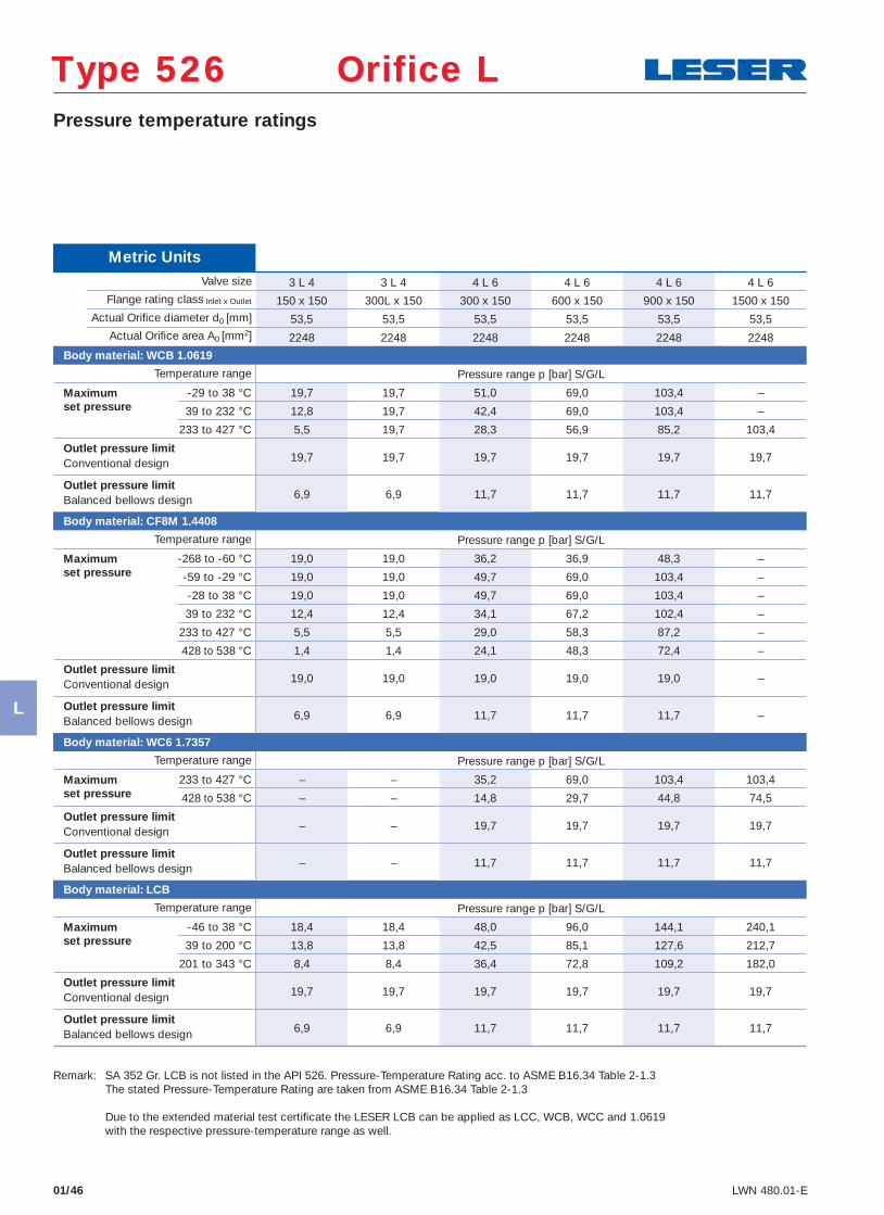
Pressure temperature ratings
Type 526 Orifice LType 526 Orifice L
Metric Units Valve size 3 L 4 3 L 4 4 L 6 4 L 6 4 L 6 4 L 6
Flange rating class Inlet x Outlet 150 x 150 300L x 150 300 x 150 600 x 150 900 x 150 1500 x 150 Actual Orifi ce diameter d0 [mm] 53,5 53,5 53,5 53,5 53,5 53,5 Actual Orifi ce area A0 [mm2] 2248 2248 2248 2248 2248 2248
Body material: WCB 1.0619
Temperature range Pressure range p [bar] S/G/L
Maximum -29 to 38 °C 19,7 19,7 51,0 69,0 103,4 – set pressure 39 to 232 °C 12,8 19,7 42,4 69,0 103,4 – 233 to 427 °C 5,5 19,7 28,3 56,9 85,2 103,4
Outlet pressure limit19,7 19,7 19,7 19,7 19,7 19,7 Conventional design
Outlet pressure limit6,9 6,9 11,7 11,7 11,7 11,7 Balanced bellows design
Body material: CF8M 1.4408
Temperature range Pressure range p [bar] S/G/L
Maximum -268 to -60 °C 19,0 19,0 36,2 36,9 48,3 – set pressure -59 to -29 °C 19,0 19,0 49,7 69,0 103,4 – -28 to 38 °C 19,0 19,0 49,7 69,0 103,4 –
39 to 232 °C 12,4 12,4 34,1 67,2 102,4 –
233 to 427 °C 5,5 5,5 29,0 58,3 87,2 –
428 to 538 °C 1,4 1,4 24,1 48,3 72,4 –
Outlet pressure limit19,0 19,0 19,0 19,0 19,0 – Conventional design
Outlet pressure limit6,9 6,9 11,7 11,7 11,7 – Balanced bellows design
Body material: WC6 1.7357
Temperature range Pressure range p [bar] S/G/L
Maximum 233 to 427 °C – – 35,2 69,0 103,4 103,4 set pressure 428 to 538 °C – – 14,8 29,7 44,8 74,5
Outlet pressure limit– – 19,7 19,7 19,7 19,7 Conventional design
Outlet pressure limit– – 11,7 11,7 11,7 11,7 Balanced bellows design
Body material: LCB
Temperature range Pressure range p [bar] S/G/L
Maximum -46 to 38 °C 18,4 18,4 48,0 96,0 144,1 240,1 set pressure 39 to 200 °C 13,8 13,8 42,5 85,1 127,6 212,7 201 to 343 °C 8,4 8,4 36,4 72,8 109,2 182,0
Outlet pressure limit19,7 19,7 19,7 19,7 19,7 19,7 Conventional design
Outlet pressure limit6,9 6,9 11,7 11,7 11,7 11,7 Balanced bellows design
Remark: SA 352 Gr. LCB is not listed in the API 526. Pressure-Temperature Rating acc. to ASME B16.34 Table 2-1.3 The stated Pressure-Temperature Rating are taken from ASME B16.34 Table 2-1.3 Due to the extended material test certifi cate the LESER LCB can be applied as LCC, WCB, WCC and 1.0619 with the respective pressure-temperature range as well.
L
Selection chart
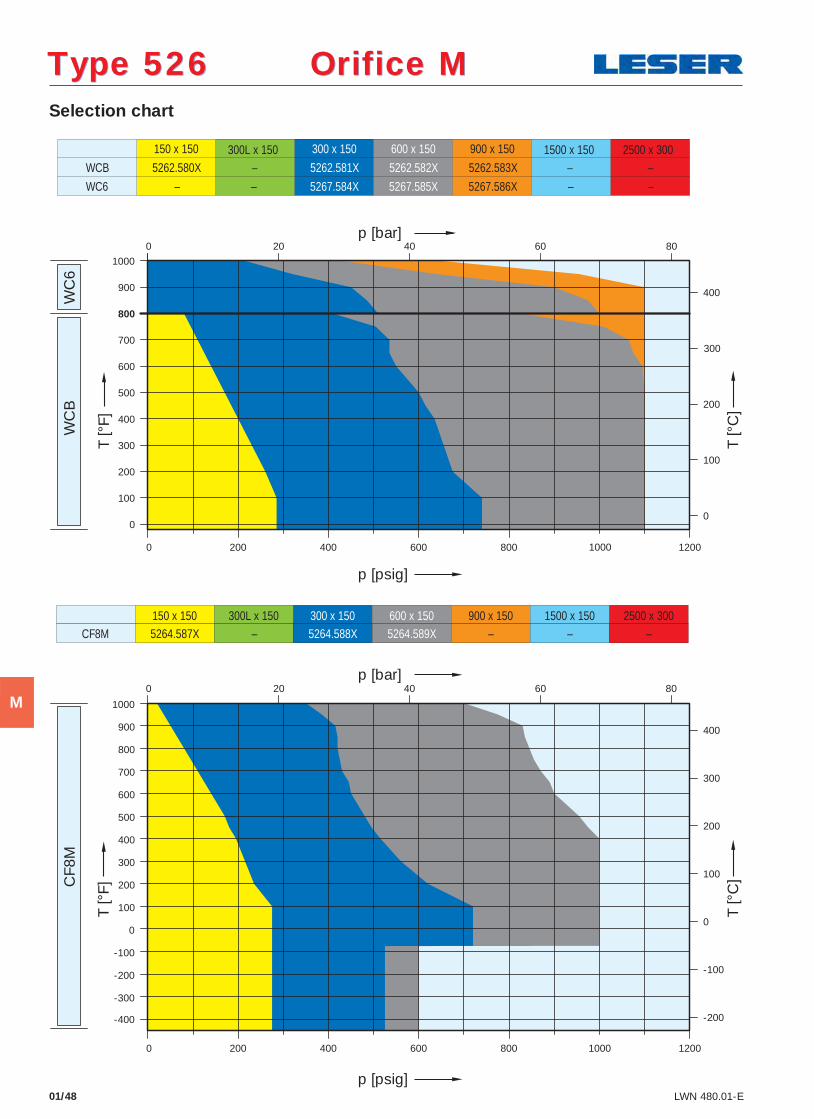
01/48 LWN 480.01-E
WC
B
WC
6 C
F8M
150 x 150
5262.580X
300 x 150
5262.581X
600 x 150
5262.582X
900 x 150
5262.583X – – –
5267.584X 5267.585X – –
WCB
WC6 – – 5267.586X
150 x 150 300L x 150 300 x 150 600 x 150 900 x 150 1500 x 150 2500 x 300 5264.587X – 5264.588X 5264.589X – – – CF8M
300L x 150 1500 x 150 2500 x 300
-400
-300
-200
-100
0
100
200
300
400
500
600
700
800
900
1000
200
0
100
200
300
400
500
600
700
900
800
1000
0
100
200
300
400
400
300
200
100
0
-100
-200
0 400 600 800 1000 1200
0
1200 1000 800 600 400 0 200
0
20 40 60 80
20 40 60 80
p [psig]
p [bar]
T [°
F]
T [°
C]
p [bar]
p [psig]
T [°
F]
T [°
C]
Type 526 Orifice MType 526 Orifice M
M
01/49LWN 480.01-E
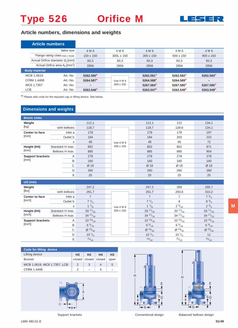
Article numbers, dimensions and weights
Conventional design Balanced bellows design
¤) Please add code for the required cap or lifting device. See below.
Type 526 Orifice MType 526 Orifice M
Article numbers Valve size 4 M 6 4 M 6 4 M 6 4 M 6 4 M 6
Flange rating class Inlet x Outlet 150 x 150 300L x 150 300 x 150 600 x 150 900 x 150 Actual Orifi ce diameter d0 [mm] 60,3 60,3 60,3 60,3 60,3 Actual Orifi ce area A0 [mm2] 2856 2856 2856 2856 2856
Body material
WCB 1.0619 Art.-No. 5262.580¤ 5262.581¤ 5262.582¤ 5262.583¤
CF8M 1.4408 Art.-No. 5264.587¤ 5264.588¤ 5264.589¤ –
WC6 1.7357 Art.-No. – 5267.584¤ 5267.585¤ 5267.586¤
LCB Art.-No. 5263.546¤ 5263.547¤ 5263.548¤ 5263.549¤
Code for lifting device
Lifting device H2 H3 H4 H3Bonnet closed closed closed open
WCB 1.0619, WC6 1.7357, LCB 2 3 4 5
CF8M 1.4408 2 – 4 –
Dimensions and weights
Metric Units
Weight 112,1 112,1 122 134,1[kg] with bellows 118,7 118,7 128,6 134,1
Center to face Inlet a 178 178 178 197[mm] Outlet b 184 184 203 222
s 48 48 56 72
Height (H4) Standard H max. 852 852 852 871[mm] Bellows H max. 885 885 885 904
Support brackets A 278 278 278 278[mm] B 160 160 160 160
C Ø 18 Ø 18 Ø 18 Ø 18
D 260 260 260 280
E 25 25 25 25
US Units
Weight 247,2 247,2 269 295,7[lbs] with bellows 261,7 261,7 283,6 310,2
Center to face Inlet a 7 7 7 7 3/4[inch] Outlet b 7 1/4 7 1/4 8 8 3/4
s 1 7/8 1 7/8 2 3/16 2 3/4
Height (H4) Standard H max. 33 17/32 33 17/32 33 17/32 33 17/32[inch] Bellows H max. 34 27/32 34 27/32 34 27/32 34 27/32
Support brackets A 10 15/16 10 15/16 10 15/16 10 15/16[inch] B 6 5/16 6 5/16 6 5/16 6 5/16
C Ø 23/32 Ø 23/32 Ø 23/32 Ø 23/32
D 10 1/4 10 1/4 10 1/4 11
E 31/3231/32
31/3231/32
Support brackets
Use 4 M 6300 x 150
Use 4 M 6300 x 150
Use 4 M 6300 x 150
¤
M
Metric Units Valve size 4 M 6 4 M 6 4 M 6 4 M 6 4 M 6
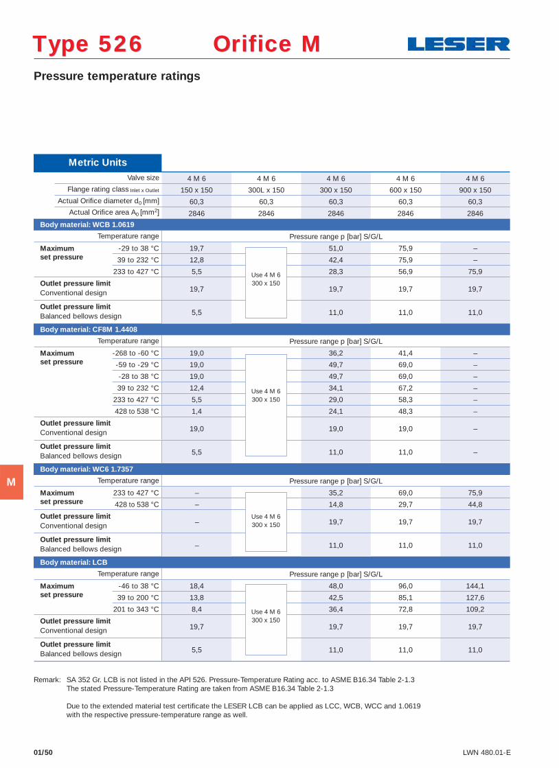
Flange rating class Inlet x Outlet 150 x 150 300L x 150 300 x 150 600 x 150 900 x 150 Actual Orifi ce diameter d0 [mm] 60,3 60,3 60,3 60,3 60,3 Actual Orifi ce area A0 [mm2] 2846 2846 2846 2846 2846
Body material: WCB 1.0619
Temperature range Pressure range p [bar] S/G/L
Maximum -29 to 38 °C 19,7 51,0 75,9 – set pressure 39 to 232 °C 12,8 42,4 75,9 – 233 to 427 °C 5,5 28,3 56,9 75,9
Outlet pressure limit19,7 19,7 19,7 19,7 Conventional design
Outlet pressure limit5,5 11,0 11,0 11,0 Balanced bellows design
Body material: CF8M 1.4408
Temperature range Pressure range p [bar] S/G/L
Maximum -268 to -60 °C 19,0 36,2 41,4 – set pressure -59 to -29 °C 19,0 49,7 69,0 – -28 to 38 °C 19,0 49,7 69,0 –
39 to 232 °C 12,4 34,1 67,2 –
233 to 427 °C 5,5 29,0 58,3 –
428 to 538 °C 1,4 24,1 48,3 –
Outlet pressure limit19,0 19,0 19,0 – Conventional design
Outlet pressure limit5,5 11,0 11,0 – Balanced bellows design
Body material: WC6 1.7357
Temperature range Pressure range p [bar] S/G/L
Maximum 233 to 427 °C – 35,2 69,0 75,9 set pressure 428 to 538 °C – 14,8 29,7 44,8
Outlet pressure limit– 19,7 19,7 19,7 Conventional design
Outlet pressure limit– 11,0 11,0 11,0 Balanced bellows design
Body material: LCB
Temperature range Pressure range p [bar] S/G/L
Maximum -46 to 38 °C 18,4 48,0 96,0 144,1 set pressure 39 to 200 °C 13,8 42,5 85,1 127,6 201 to 343 °C 8,4 36,4 72,8 109,2
Outlet pressure limit19,7 19,7 19,7 19,7 Conventional design
Outlet pressure limit5,5 11,0 11,0 11,0 Balanced bellows design
01/50 LWN 480.01-E
Pressure temperature ratings
Use 4 M 6300 x 150
Use 4 M 6300 x 150
Use 4 M 6300 x 150
Use 4 M 6300 x 150
Type 526 Orifice MType 526 Orifice M
Remark: SA 352 Gr. LCB is not listed in the API 526. Pressure-Temperature Rating acc. to ASME B16.34 Table 2-1.3 The stated Pressure-Temperature Rating are taken from ASME B16.34 Table 2-1.3 Due to the extended material test certifi cate the LESER LCB can be applied as LCC, WCB, WCC and 1.0619 with the respective pressure-temperature range as well.
M
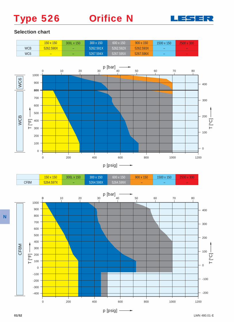
Selection chart
01/52 LWN 480.01-E
WC
B
WC
6 C
F8M
150 x 150
5262.590X
300 x 150
5262.591X
600 x 150
5262.592X
900 x 150
5262.593X – – –
5267.594X 5267.595X – –
WCB
WC6 – – 5267.596X
150 x 150 300L x 150 300 x 150 600 x 150 900 x 150 1500 x 150 2500 x 300 5264.597X – 5264.598X 5264.599X – – – CF8M
300L x 150 1500 x 150 2500 x 300
-400
-300
-200
-100
0
100
200
300
400
500
600
700
800
900
1000
200
0
100
200
300
400
500
600
700
900
800
1000
0
100
200
300
400
400
300
200
100
0
-100
-200
0 400 600 800 1000 1200
0
1200 1000 800 600 400 0 200
0
10 20 30 40 50 60 70 80
0 10 20 30 40 50 60 70 80
p [psig]
p [bar]
T [°
F]
T [°
C]
p [bar]
p [psig]
T [°
F]
T [°
C]
Type 526 Orifice NType 526 Orifice N
N
01/53LWN 480.01-E
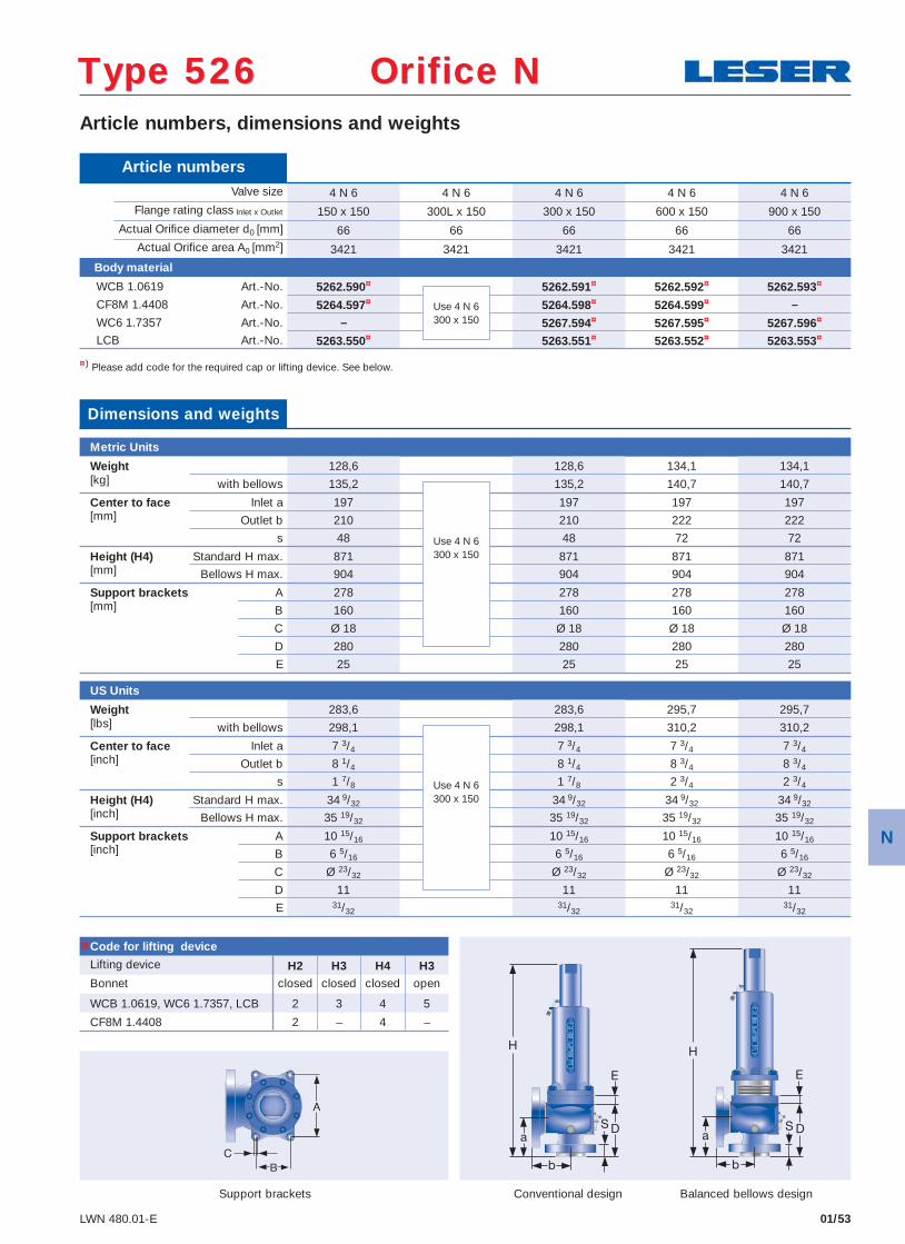
Article numbers, dimensions and weights
Conventional design Balanced bellows design
¤) Please add code for the required cap or lifting device. See below.
Type 526 Orifice NType 526 Orifice N
Article numbers Valve size 4 N 6 4 N 6 4 N 6 4 N 6 4 N 6
Flange rating class Inlet x Outlet 150 x 150 300L x 150 300 x 150 600 x 150 900 x 150 Actual Orifi ce diameter d0 [mm] 66 66 66 66 66 Actual Orifi ce area A0 [mm2] 3421 3421 3421 3421 3421
Body material
WCB 1.0619 Art.-No. 5262.590¤ 5262.591¤ 5262.592¤ 5262.593¤
CF8M 1.4408 Art.-No. 5264.597¤ 5264.598¤ 5264.599¤ –
WC6 1.7357 Art.-No. – 5267.594¤ 5267.595¤ 5267.596¤
LCB Art.-No. 5263.550¤ 5263.551¤ 5263.552¤ 5263.553¤
Code for lifting device
Lifting device H2 H3 H4 H3Bonnet closed closed closed open
WCB 1.0619, WC6 1.7357, LCB 2 3 4 5
CF8M 1.4408 2 – 4 –
Dimensions and weights
Metric Units
Weight 128,6 128,6 134,1 134,1[kg] with bellows 135,2 135,2 140,7 140,7
Center to face Inlet a 197 197 197 197[mm] Outlet b 210 210 222 222
s 48 48 72 72
Height (H4) Standard H max. 871 871 871 871[mm] Bellows H max. 904 904 904 904
Support brackets A 278 278 278 278[mm] B 160 160 160 160
C Ø 18 Ø 18 Ø 18 Ø 18
D 280 280 280 280
E 25 25 25 25
US Units
Weight 283,6 283,6 295,7 295,7[lbs] with bellows 298,1 298,1 310,2 310,2
Center to face Inlet a 7 3/4 7 3/4 7 3/4 7 3/4[inch] Outlet b 8 1/4 8 1/4 8 3/4 8 3/4
s 1 7/8 1 7/8 2 3/4 2 3/4
Height (H4) Standard H max. 34 9/32 34 9/32 34 9/32 34 9/32[inch] Bellows H max. 35 19/32 35 19/32 35 19/32 35 19/32
Support brackets A 10 15/16 10 15/16 10 15/16 10 15/16[inch] B 6 5/16 6 5/16 6 5/16 6 5/16
C Ø 23/32 Ø 23/32 Ø 23/32 Ø 23/32
D 11 11 11 11
E 31/3231/32
31/3231/32
Support brackets
Use 4 N 6300 x 150
Use 4 N 6300 x 150
Use 4 N 6300 x 150
¤
N
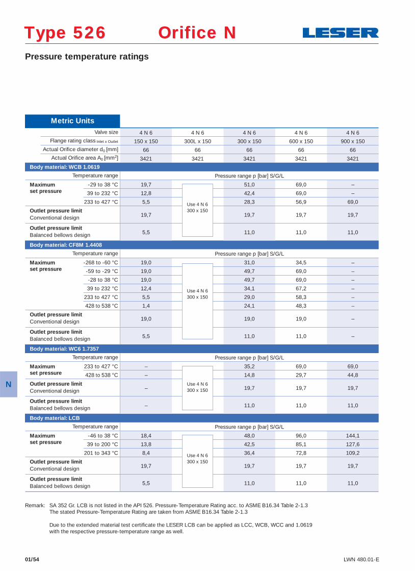
01/54 LWN 480.01-E
Pressure temperature ratings
Type 526 Orifice NType 526 Orifice N
Metric Units Valve size 4 N 6 4 N 6 4 N 6 4 N 6 4 N 6
Flange rating class Inlet x Outlet 150 x 150 300L x 150 300 x 150 600 x 150 900 x 150 Actual Orifi ce diameter d0 [mm] 66 66 66 66 66 Actual Orifi ce area A0 [mm2] 3421 3421 3421 3421 3421
Body material: WCB 1.0619
Temperature range Pressure range p [bar] S/G/L
Maximum -29 to 38 °C 19,7 51,0 69,0 – set pressure 39 to 232 °C 12,8 42,4 69,0 – 233 to 427 °C 5,5 28,3 56,9 69,0
Outlet pressure limit19,7 19,7 19,7 19,7 Conventional design
Outlet pressure limit5,5 11,0 11,0 11,0 Balanced bellows design
Body material: CF8M 1.4408
Temperature range Pressure range p [bar] S/G/L
Maximum -268 to -60 °C 19,0 31,0 34,5 – set pressure -59 to -29 °C 19,0 49,7 69,0 – -28 to 38 °C 19,0 49,7 69,0 –
39 to 232 °C 12,4 34,1 67,2 –
233 to 427 °C 5,5 29,0 58,3 –
428 to 538 °C 1,4 24,1 48,3 –
Outlet pressure limit19,0 19,0 19,0 – Conventional design
Outlet pressure limit5,5 11,0 11,0 – Balanced bellows design
Body material: WC6 1.7357
Temperature range Pressure range p [bar] S/G/L
Maximum 233 to 427 °C – 35,2 69,0 69,0 set pressure 428 to 538 °C – 14,8 29,7 44,8
Outlet pressure limit– 19,7 19,7 19,7 Conventional design
Outlet pressure limit– 11,0 11,0 11,0 Balanced bellows design
Body material: LCB
Temperature range Pressure range p [bar] S/G/L
Maximum -46 to 38 °C 18,4 48,0 96,0 144,1 set pressure 39 to 200 °C 13,8 42,5 85,1 127,6 201 to 343 °C 8,4 36,4 72,8 109,2
Outlet pressure limit19,7 19,7 19,7 19,7 Conventional design
Outlet pressure limit5,5 11,0 11,0 11,0 Balanced bellows design
Use 4 N 6300 x 150
Use 4 N 6300 x 150
Use 4 N 6300 x 150
Use 4 N 6300 x 150
Remark: SA 352 Gr. LCB is not listed in the API 526. Pressure-Temperature Rating acc. to ASME B16.34 Table 2-1.3 The stated Pressure-Temperature Rating are taken from ASME B16.34 Table 2-1.3 Due to the extended material test certifi cate the LESER LCB can be applied as LCC, WCB, WCC and 1.0619 with the respective pressure-temperature range as well.
N
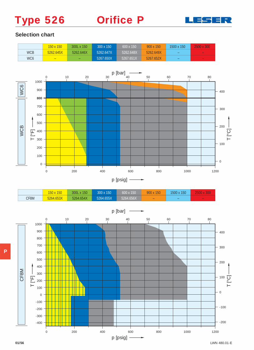
Type 526 Orifice PType 526 Orifice P Selection chart
01/56 LWN 480.01-E
WC
B
WC
6 C
F8M
150 x 150
5262.645X
300L x 150 300 x 150
5262.647X
600 x 150
5262.648X
900 x 150
5262.649X – – 5262.646X
5267.650X 5267.651X – –
WCB
WC6 – – 5267.652X
150 x 150 300L x 150 300 x 150 600 x 150 900 x 150 1500 x 150 2500 x 300 5264.653X 5264.654X 5264.655X 5264.656X – – – CF8M
1500 x 150 2500 x 300
-400
-300
-200
-100
0
100
200
300
400
500
600
700
800
900
1000
200
0
100
200
300
400
500
600
700
900
800
1000
0
100
200
300
400
400
300
200
100
0
-100
-200
0 400 600 800 1000 1200
0
1200 1000 800 600 400 0 200
0
10 20 30 40 50 60 70 80
10 20 30 40 50 60 70 80
p [psig]
p [bar]
T [°
F]
T [°
C]
p [bar]
p [psig]
T [°
F]
T [°
C]
P
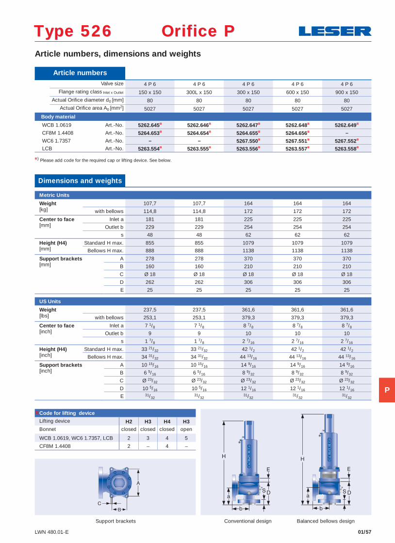
01/57LWN 480.01-E
Article numbers, dimensions and weights
Conventional design Balanced bellows design
¤) Please add code for the required cap or lifting device. See below.
Type 526 Orifice PType 526 Orifice P
Article numbers Valve size 4 P 6 4 P 6 4 P 6 4 P 6 4 P 6
Flange rating class Inlet x Outlet 150 x 150 300L x 150 300 x 150 600 x 150 900 x 150 Actual Orifi ce diameter d0 [mm] 80 80 80 80 80 Actual Orifi ce area A0 [mm2] 5027 5027 5027 5027 5027
Body material
WCB 1.0619 Art.-No. 5262.645¤ 5262.646¤ 5262.647¤ 5262.648¤ 5262.649¤
CF8M 1.4408 Art.-No. 5264.653¤ 5264.654¤ 5264.655¤ 5264.656¤ –
WC6 1.7357 Art.-No. – – 5267.550¤ 5267.551¤ 5267.552¤
LCB Art.-No. 5263.554¤ 5263.555¤ 5263.556¤ 5263.557¤ 5263.558¤
Code for lifting device
Lifting device H2 H3 H4 H3Bonnet closed closed closed open
WCB 1.0619, WC6 1.7357, LCB 2 3 4 5
CF8M 1.4408 2 – 4 –
Dimensions and weights
Metric Units
Weight 107,7 107,7 164 164 164[kg] with bellows 114,8 114,8 172 172 172
Center to face Inlet a 181 181 225 225 225[mm] Outlet b 229 229 254 254 254
s 48 48 62 62 62
Height (H4) Standard H max. 855 855 1079 1079 1079[mm] Bellows H max. 888 888 1138 1138 1138
Support brackets A 278 278 370 370 370[mm] B 160 160 210 210 210
C Ø 18 Ø 18 Ø 18 Ø 18 Ø 18
D 262 262 306 306 306
E 25 25 25 25 25
US Units
Weight 237,5 237,5 361,6 361,6 361,6[lbs] with bellows 253,1 253,1 379,3 379,3 379,3
Center to face Inlet a 7 1/8 7 1/8 8 7/8 8 7/8 8 7/8[inch] Outlet b 9 9 10 10 10
s 1 7/8 1 7/8 2 7/16 2 7/16 2 7/16
Height (H4) Standard H max. 33 21/32 33 21/32 42 1/2 42 1/2 42 1/2[inch] Bellows H max. 34 31/32 34 31/32 44 13/16 44 13/16 44 13/16
Support brackets A 10 15/16 10 15/16 14 9/16 14 9/16 14 9/16[inch] B 6 5/16 6 5/16 8 9/32 8 9/32 8 9/32
C Ø 23/32 Ø 23/32 Ø 23/32 Ø 23/32 Ø 23/32
D 10 5/16 10 5/16 12 1/16 12 1/16 12 1/16
E 31/3231/32
31/3231/32
31/32
Support brackets
¤
P
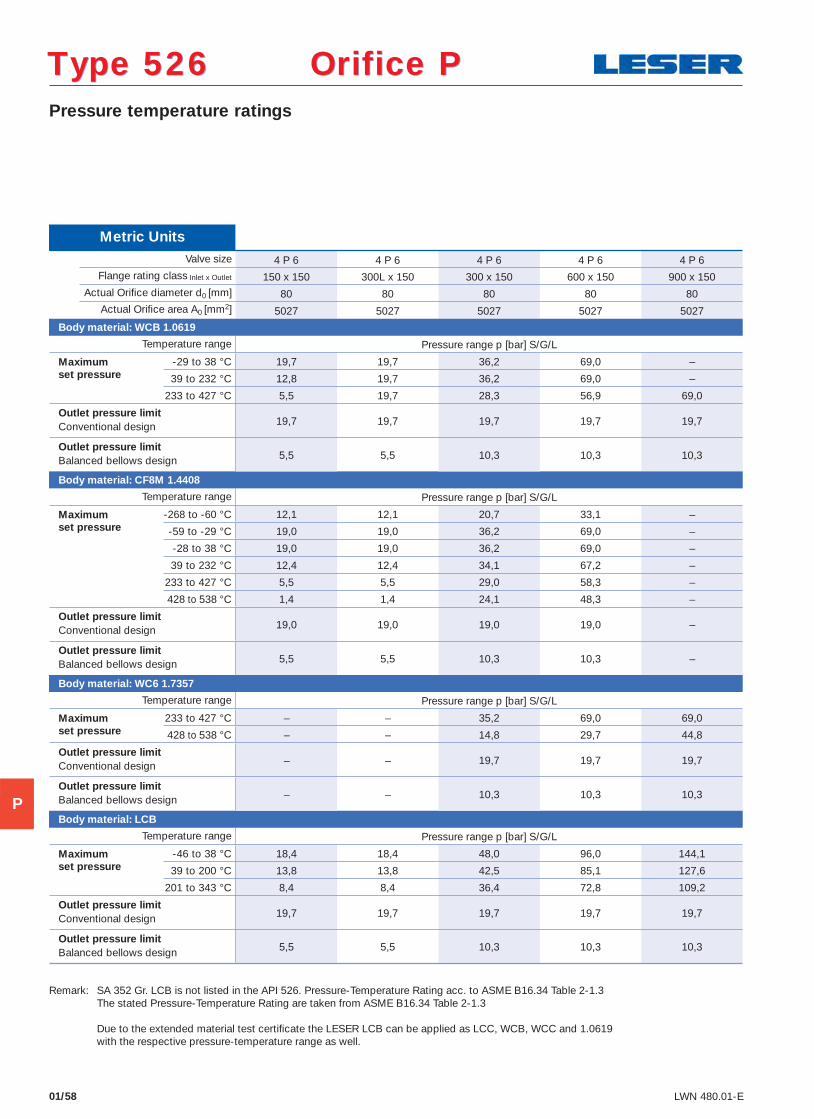
Type 526 Orifice PType 526 Orifice P
01/58 LWN 480.01-E
Pressure temperature ratings
Metric Units Valve size 4 P 6 4 P 6 4 P 6 4 P 6 4 P 6
Flange rating class Inlet x Outlet 150 x 150 300L x 150 300 x 150 600 x 150 900 x 150 Actual Orifi ce diameter d0 [mm] 80 80 80 80 80 Actual Orifi ce area A0 [mm2] 5027 5027 5027 5027 5027
Body material: WCB 1.0619
Temperature range Pressure range p [bar] S/G/L
Maximum -29 to 38 °C 19,7 19,7 36,2 69,0 – set pressure 39 to 232 °C 12,8 19,7 36,2 69,0 – 233 to 427 °C 5,5 19,7 28,3 56,9 69,0
Outlet pressure limit19,7 19,7 19,7 19,7 19,7 Conventional design
Outlet pressure limit5,5 5,5 10,3 10,3 10,3 Balanced bellows design
Body material: CF8M 1.4408
Temperature range Pressure range p [bar] S/G/L
Maximum -268 to -60 °C 12,1 12,1 20,7 33,1 – set pressure -59 to -29 °C 19,0 19,0 36,2 69,0 – -28 to 38 °C 19,0 19,0 36,2 69,0 –
39 to 232 °C 12,4 12,4 34,1 67,2 –
233 to 427 °C 5,5 5,5 29,0 58,3 –
428 to 538 °C 1,4 1,4 24,1 48,3 –
Outlet pressure limit19,0 19,0 19,0 19,0 – Conventional design
Outlet pressure limit5,5 5,5 10,3 10,3 – Balanced bellows design
Body material: WC6 1.7357
Temperature range Pressure range p [bar] S/G/L
Maximum 233 to 427 °C – – 35,2 69,0 69,0 set pressure 428 to 538 °C – – 14,8 29,7 44,8
Outlet pressure limit– – 19,7 19,7 19,7 Conventional design
Outlet pressure limit– – 10,3 10,3 10,3 Balanced bellows design
Body material: LCB
Temperature range Pressure range p [bar] S/G/L
Maximum -46 to 38 °C 18,4 18,4 48,0 96,0 144,1 set pressure 39 to 200 °C 13,8 13,8 42,5 85,1 127,6 201 to 343 °C 8,4 8,4 36,4 72,8 109,2
Outlet pressure limit19,7 19,7 19,7 19,7 19,7 Conventional design
Outlet pressure limit5,5 5,5 10,3 10,3 10,3 Balanced bellows design
Remark: SA 352 Gr. LCB is not listed in the API 526. Pressure-Temperature Rating acc. to ASME B16.34 Table 2-1.3 The stated Pressure-Temperature Rating are taken from ASME B16.34 Table 2-1.3 Due to the extended material test certifi cate the LESER LCB can be applied as LCC, WCB, WCC and 1.0619 with the respective pressure-temperature range as well.
P
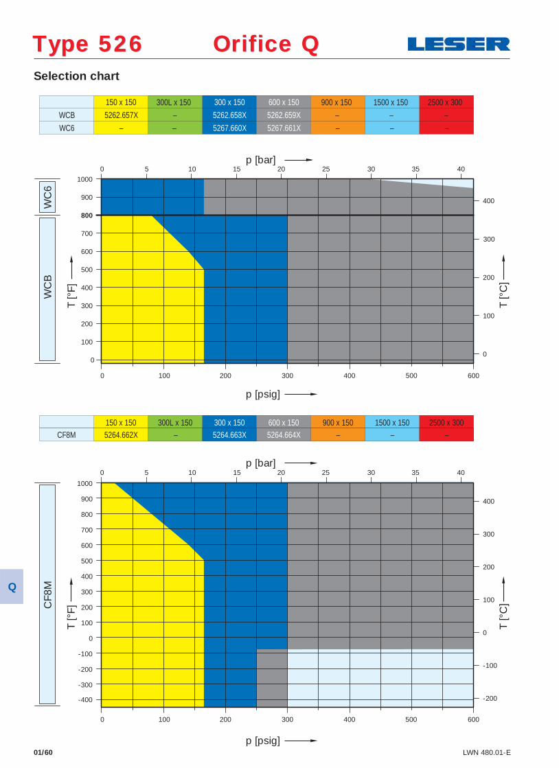
Selection chart
01/60 LWN 480.01-E
WC
B
WC
6 C
F8M
150 x 150
5262.657X
300 x 150
5262.658X
600 x 150
5262.659X – – – –
5267.660X 5267.661X – –
WCB
WC6 – – –
150 x 150 300L x 150 300 x 150 600 x 150 900 x 150 1500 x 150 2500 x 300 5264.662X – 5264.663X 5264.664X – – – CF8M
300L x 150 900 x 150 1500 x 150 2500 x 300
-400
-300
-200
-100
0
100
200
300
400
500
600
700
800
900
1000
100
0
100
200
300
400
500
600
700
900
800
1000
0
100
200
300
400
400
300
200
100
0
-100
-200
0 200 300 400 500 600
0
600 500 400 300 200 0 100
0
5 10 15 20 25 30 35 40
5 10 15 20 25 30 35 40
p [psig]
p [bar]
T [°
F]
T [°
C]
p [bar]
p [psig]
T [°
F]
T [°
C]
Type 526 Orifice QType 526 Orifice Q
Q
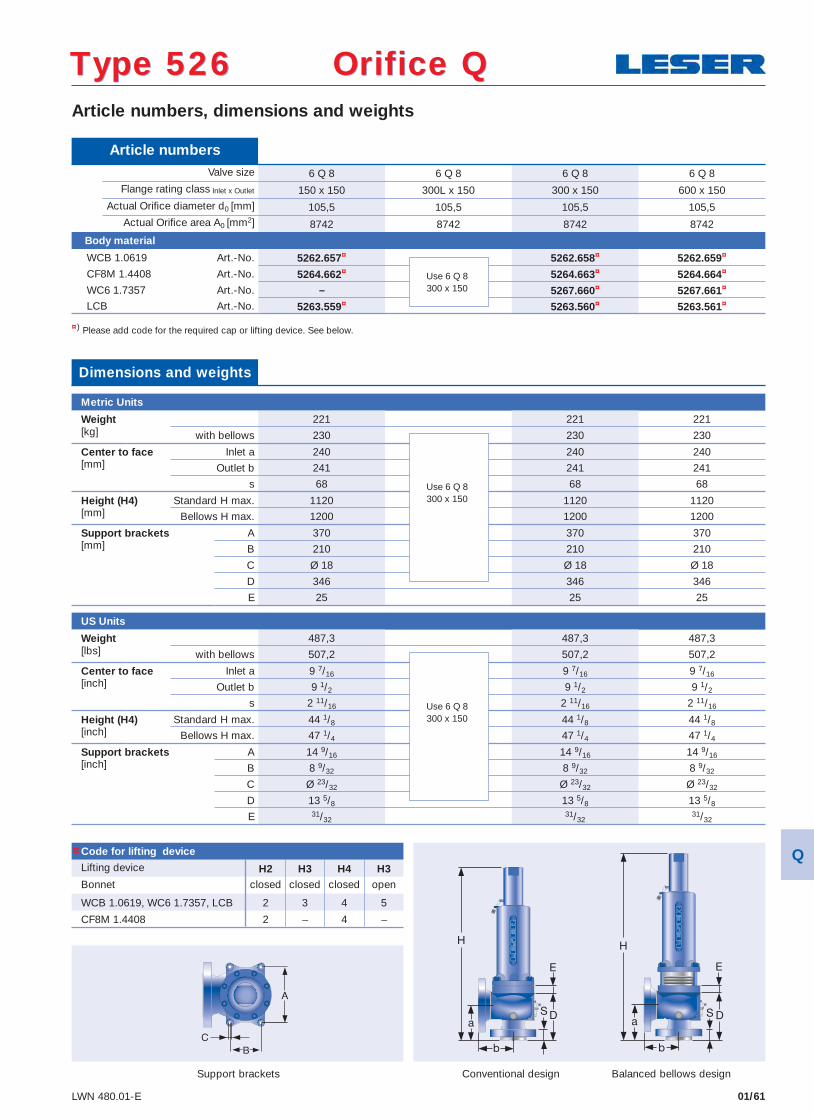
01/61LWN 480.01-E
Article numbers, dimensions and weights
Conventional design Balanced bellows design
¤) Please add code for the required cap or lifting device. See below.
Type 526 Orifice QType 526 Orifice Q
Article numbers Valve size 6 Q 8 6 Q 8 6 Q 8 6 Q 8
Flange rating class Inlet x Outlet 150 x 150 300L x 150 300 x 150 600 x 150 Actual Orifi ce diameter d0 [mm] 105,5 105,5 105,5 105,5 Actual Orifi ce area A0 [mm2] 8742 8742 8742 8742
Body material
WCB 1.0619 Art.-No. 5262.657¤ 5262.658¤ 5262.659¤
CF8M 1.4408 Art.-No. 5264.662¤ 5264.663¤ 5264.664¤
WC6 1.7357 Art.-No. – 5267.660¤ 5267.661¤
LCB Art.-No. 5263.559¤ 5263.560¤ 5263.561¤
Code for lifting device
Lifting device H2 H3 H4 H3Bonnet closed closed closed open
WCB 1.0619, WC6 1.7357, LCB 2 3 4 5
CF8M 1.4408 2 – 4 –
Dimensions and weights
Metric Units
Weight 221 221 221[kg] with bellows 230 230 230
Center to face Inlet a 240 240 240[mm] Outlet b 241 241 241
s 68 68 68
Height (H4) Standard H max. 1120 1120 1120[mm] Bellows H max. 1200 1200 1200
Support brackets A 370 370 370[mm] B 210 210 210
C Ø 18 Ø 18 Ø 18
D 346 346 346
E 25 25 25
US Units
Weight 487,3 487,3 487,3[lbs] with bellows 507,2 507,2 507,2
Center to face Inlet a 9 7/16 9 7/16 9 7/16[inch] Outlet b 9 1/2 9 1/2 9 1/2
s 2 11/16 2 11/16 2 11/16
Height (H4) Standard H max. 44 1/8 44 1/8 44 1/8[inch] Bellows H max. 47 1/4 47 1/4 47 1/4
Support brackets A 14 9/16 14 9/16 14 9/16[inch] B 8 9/32 8 9/32 8 9/32
C Ø 23/32 Ø 23/32 Ø 23/32
D 13 5/8 13 5/8 13 5/8
E 31/3231/32
31/32
Support brackets
Use 6 Q 8300 x 150
Use 6 Q 8300 x 150
Use 6 Q 8300 x 150
¤ Q
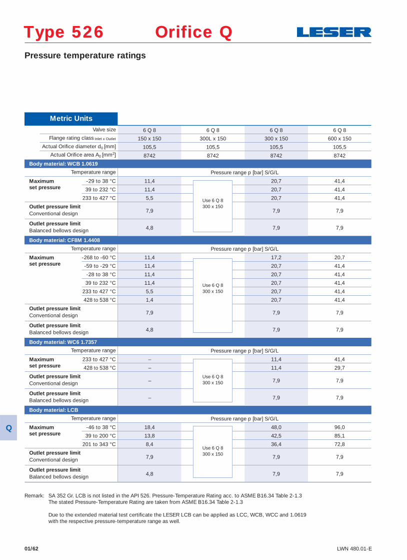
Metric Units Valve size 6 Q 8 6 Q 8 6 Q 8 6 Q 8
Flange rating class Inlet x Outlet 150 x 150 300L x 150 300 x 150 600 x 150 Actual Orifi ce diameter d0 [mm] 105,5 105,5 105,5 105,5 Actual Orifi ce area A0 [mm2] 8742 8742 8742 8742
Body material: WCB 1.0619
Temperature range Pressure range p [bar] S/G/L
Maximum -29 to 38 °C 11,4 20,7 41,4 set pressure 39 to 232 °C 11,4 20,7 41,4 233 to 427 °C 5,5 20,7 41,4
Outlet pressure limit7,9 7,9 7,9 Conventional design
Outlet pressure limit4,8 7,9 7,9 Balanced bellows design
Body material: CF8M 1.4408
Temperature range Pressure range p [bar] S/G/L
Maximum -268 to -60 °C 11,4 17,2 20,7 set pressure -59 to -29 °C 11,4 20,7 41,4 -28 to 38 °C 11,4 20,7 41,4
39 to 232 °C 11,4 20,7 41,4
233 to 427 °C 5,5 20,7 41,4
428 to 538 °C 1,4 20,7 41,4
Outlet pressure limit7,9 7,9 7,9 Conventional design
Outlet pressure limit4,8 7,9 7,9 Balanced bellows design
Body material: WC6 1.7357
Temperature range Pressure range p [bar] S/G/L
Maximum 233 to 427 °C – 11,4 41,4 set pressure 428 to 538 °C – 11,4 29,7
Outlet pressure limit– 7,9 7,9 Conventional design
Outlet pressure limit– 7,9 7,9 Balanced bellows design
Body material: LCB
Temperature range Pressure range p [bar] S/G/L
Maximum -46 to 38 °C 18,4 48,0 96,0 set pressure 39 to 200 °C 13,8 42,5 85,1 201 to 343 °C 8,4 36,4 72,8
Outlet pressure limit7,9 7,9 7,9 Conventional design
Outlet pressure limit4,8 7,9 7,9 Balanced bellows design
01/62 LWN 480.01-E
Pressure temperature ratings
Use 6 Q 8300 x 150
Use 6 Q 8300 x 150
Use 6 Q 8300 x 150
Use 6 Q 8300 x 150
Type 526 Orifice QType 526 Orifice Q
Remark: SA 352 Gr. LCB is not listed in the API 526. Pressure-Temperature Rating acc. to ASME B16.34 Table 2-1.3 The stated Pressure-Temperature Rating are taken from ASME B16.34 Table 2-1.3 Due to the extended material test certifi cate the LESER LCB can be applied as LCC, WCB, WCC and 1.0619 with the respective pressure-temperature range as well.
Q
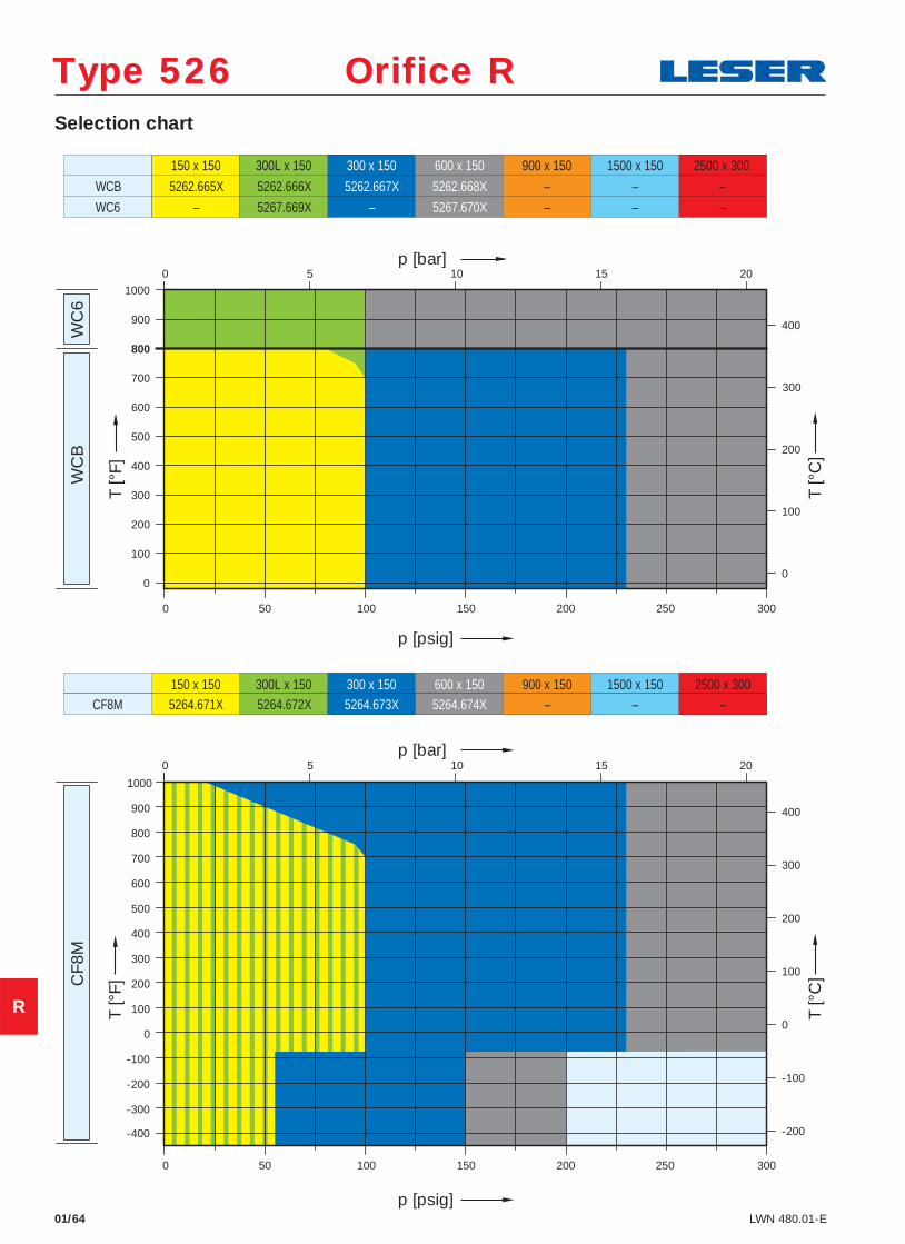
Selection chart
01/64 LWN 480.01-E
WC
B
WC
6 C
F8M
150 x 150
5262.665X
300L x 150 300 x 150
5262.667X
600 x 150
5262.668X
900 x 150
–
1500 x 150
–
2500 x 300
– 5262.666X
– 5267.670X – –
WCB
WC6 – 5267.669X –
150 x 150 300L x 150 300 x 150 600 x 150 900 x 150 1500 x 150 2500 x 300 5264.671X 5264.672X 5264.673X 5264.674X – – – CF8M
-400
-300
-200
-100
0
100
200
300
400
500
600
700
800
900
1000
50
0
100
200
300
400
500
600
700
900
800
1000
0
100
200
300
400
400
300
200
100
0
-100
-200
0 100 150 200 250 300
0
300 250 200 150 100 0 50
0
5 10 15 20
5 10 15 20
p [psig]
p [bar]
T [°
F]
T [°
C]
p [bar]
p [psig]
T [°
F]
T [°
C]
Type 526 Orifice RType 526 Orifice R
R
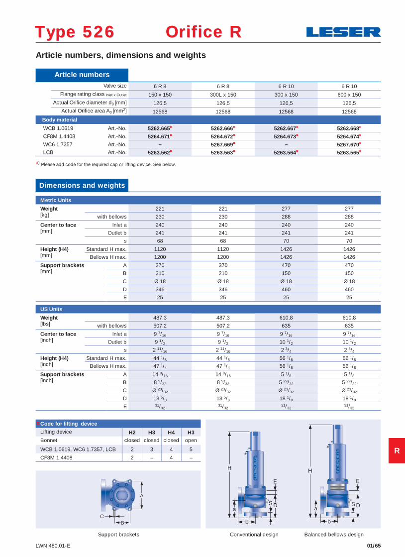
01/65LWN 480.01-E
Article numbers, dimensions and weights
Conventional design Balanced bellows design
¤) Please add code for the required cap or lifting device. See below.
Type 526 Orifice RType 526 Orifice R
Article numbers Valve size 6 R 8 6 R 8 6 R 10 6 R 10
Flange rating class Inlet x Outlet 150 x 150 300L x 150 300 x 150 600 x 150 Actual Orifi ce diameter d0 [mm] 126,5 126,5 126,5 126,5 Actual Orifi ce area A0 [mm2] 12568 12568 12568 12568
Body material
WCB 1.0619 Art.-No. 5262.665¤ 5262.666¤ 5262.667¤ 5262.668¤
CF8M 1.4408 Art.-No. 5264.671¤ 5264.672¤ 5264.673¤ 5264.674¤
WC6 1.7357 Art.-No. – 5267.669¤ – 5267.670¤
LCB Art.-No. 5263.562¤ 5263.563¤ 5263.564¤ 5263.565¤
Code for lifting device
Lifting device H2 H3 H4 H3Bonnet closed closed closed open
WCB 1.0619, WC6 1.7357, LCB 2 3 4 5
CF8M 1.4408 2 – 4 –
Dimensions and weights
Metric Units
Weight 221 221 277 277[kg] with bellows 230 230 288 288
Center to face Inlet a 240 240 240 240[mm] Outlet b 241 241 241 241
s 68 68 70 70
Height (H4) Standard H max. 1120 1120 1426 1426[mm] Bellows H max. 1200 1200 1426 1426
Support brackets A 370 370 470 470[mm] B 210 210 150 150
C Ø 18 Ø 18 Ø 18 Ø 18
D 346 346 460 460
E 25 25 25 25
US Units
Weight 487,3 487,3 610,8 610,8[lbs] with bellows 507,2 507,2 635 635
Center to face Inlet a 9 7/16 9 7/16 9 7/16 9 7/16[inch] Outlet b 9 1/2 9 1/2 10 1/2 10 1/2
s 2 11/16 2 11/16 2 3/4 2 3/4
Height (H4) Standard H max. 44 1/8 44 1/8 56 1/8 56 1/8[inch] Bellows H max. 47 1/4 47 1/4 56 1/8 56 1/8
Support brackets A 14 9/16 14 9/16 5 1/8 5 1/8[inch] B 8 9/32 8 9/32 5 29/32 5 29/32
C Ø 23/32 Ø 23/32 Ø 23/32 Ø 23/32
D 13 5/8 13 5/8 18 1/8 18 1/8
E 31/3231/32
31/3231/32
Support brackets
¤
R
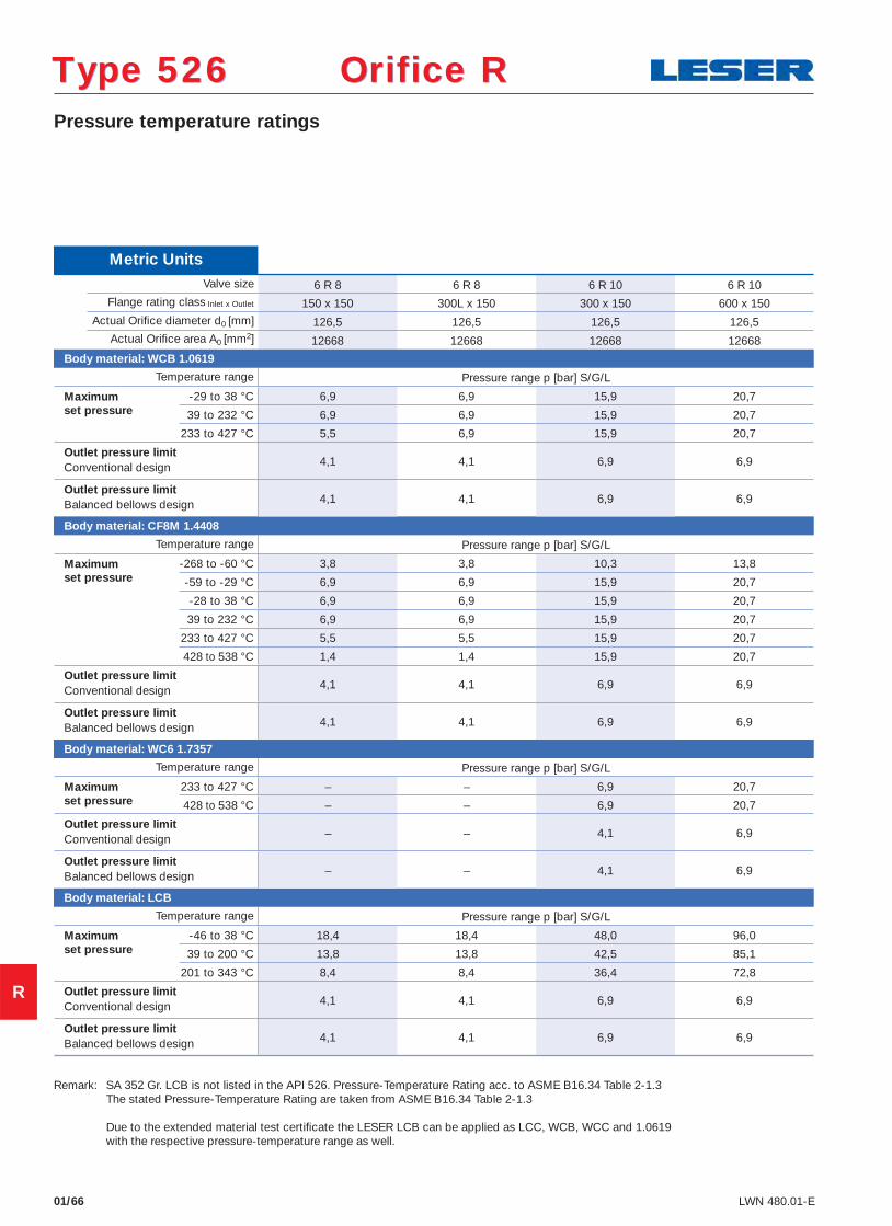
01/66 LWN 480.01-E
Pressure temperature ratings
Type 526 Orifice RType 526 Orifice R
Metric Units Valve size 6 R 8 6 R 8 6 R 10 6 R 10
Flange rating class Inlet x Outlet 150 x 150 300L x 150 300 x 150 600 x 150 Actual Orifi ce diameter d0 [mm] 126,5 126,5 126,5 126,5 Actual Orifi ce area A0 [mm2] 12668 12668 12668 12668
Body material: WCB 1.0619
Temperature range Pressure range p [bar] S/G/L
Maximum -29 to 38 °C 6,9 6,9 15,9 20,7 set pressure 39 to 232 °C 6,9 6,9 15,9 20,7 233 to 427 °C 5,5 6,9 15,9 20,7
Outlet pressure limit4,1 4,1 6,9 6,9 Conventional design
Outlet pressure limit4,1 4,1 6,9 6,9 Balanced bellows design
Body material: CF8M 1.4408
Temperature range Pressure range p [bar] S/G/L
Maximum -268 to -60 °C 3,8 3,8 10,3 13,8 set pressure -59 to -29 °C 6,9 6,9 15,9 20,7 -28 to 38 °C 6,9 6,9 15,9 20,7
39 to 232 °C 6,9 6,9 15,9 20,7
233 to 427 °C 5,5 5,5 15,9 20,7
428 to 538 °C 1,4 1,4 15,9 20,7
Outlet pressure limit4,1 4,1 6,9 6,9 Conventional design
Outlet pressure limit4,1 4,1 6,9 6,9 Balanced bellows design
Body material: WC6 1.7357
Temperature range Pressure range p [bar] S/G/L
Maximum 233 to 427 °C – – 6,9 20,7 set pressure 428 to 538 °C – – 6,9 20,7
Outlet pressure limit– – 4,1 6,9 Conventional design
Outlet pressure limit– – 4,1 6,9 Balanced bellows design
Body material: LCB
Temperature range Pressure range p [bar] S/G/L
Maximum -46 to 38 °C 18,4 18,4 48,0 96,0 set pressure 39 to 200 °C 13,8 13,8 42,5 85,1 201 to 343 °C 8,4 8,4 36,4 72,8
Outlet pressure limit4,1 4,1 6,9 6,9 Conventional design
Outlet pressure limit4,1 4,1 6,9 6,9 Balanced bellows design
Remark: SA 352 Gr. LCB is not listed in the API 526. Pressure-Temperature Rating acc. to ASME B16.34 Table 2-1.3 The stated Pressure-Temperature Rating are taken from ASME B16.34 Table 2-1.3 Due to the extended material test certifi cate the LESER LCB can be applied as LCC, WCB, WCC and 1.0619 with the respective pressure-temperature range as well.
R
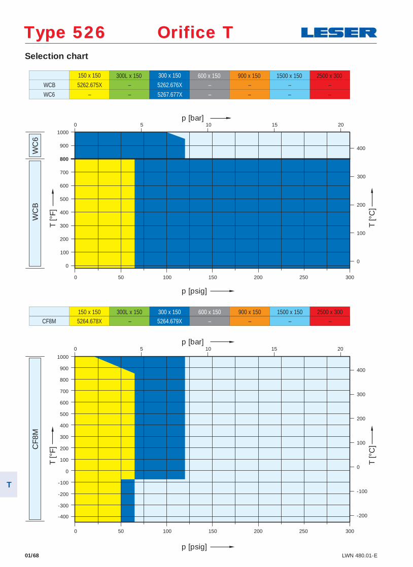
Selection chart
01/68 LWN 480.01-E
WC
B
WC
6 C
F8M
150 x 150
5262.675X
300 x 150
5262.676X – – – – –
5267.677X – – –
WCB
WC6 – – –
150 x 150 300L x 150 300 x 150 600 x 150 900 x 150 1500 x 150 2500 x 300 5264.678X – 5264.679X – – – – CF8M
300L x 150 600 x 150 900 x 150 1500 x 150 2500 x 300
-400
-300
-200
-100
0
100
200
300
400
500
600
700
800
900
1000
50
0
100
200
300
400
500
600
700
900
800
1000
0
100
200
300
400
400
300
200
100
0
-100
-200
0 100 150 200 250 300
0
300 250 200 150 100 0 50
0
5 10 15 20
5 10 15 20
p [psig]
p [bar]
T [°
F]
T [°
C]
p [bar]
p [psig]
T [°
F]
T [°
C]
Type 526 Orifice TType 526 Orifice T
T
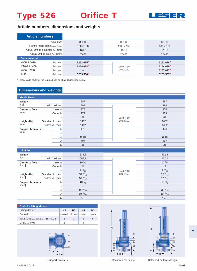
01/69LWN 480.01-E
Article numbers, dimensions and weights
Conventional design Balanced bellows design
¤) Please add code for the required cap or lifting device. See below.
Type 526 Orifice TType 526 Orifice T
Article numbers Valve size 8 T 10 8 T 10 8 T 10
Flange rating class Inlet x Outlet 150 x 150 300L x 150 300 x 150 Actual Orifi ce diameter d0 [mm] 161,5 161,5 161,5 Actual Orifi ce area A0 [mm2] 20485 20485 20485
Body material
WCB 1.0619 Art.-No. 5262.675¤ 5262.676¤
CF8M 1.4408 Art.-No. 5264.678¤ 5264.679¤
WC6 1.7357 Art.-No. – 5267.677¤
LCB Art.-No. 5263.566¤ 5263.567¤
Code for lifting device
Lifting device H2 H3 H4 H3Bonnet closed closed closed open
WCB 1.0619, WC6 1.7357, LCB 2 3 4 5
CF8M 1.4408 2 – 4 –
Dimensions and weights
Metric Units
Weight 287 287[kg] with bellows 298 298
Center to face Inlet a 276 276[mm] Outlet b 279 279
s 62 62
Height (H4) Standard H max. 1462 1462[mm] Bellows H max. 1462 1462
Support brackets A 470 470[mm] B – –
C Ø 18 Ø 18
D 497 497
E 25 25
US Units
Weight 632,8 632,8[lbs] with bellows 657,1 657,1
Center to face Inlet a 10 7/8 10 7/8[inch] Outlet b 11 11
s 2 7/16 2 7/16
Height (H4) Standard H max. 57 9/16 57 9/16[inch] Bellows H max. 57 9/16 57 9/16
Support brackets A 18 1/2 18 1/2[inch] B – –
C Ø 23/32 Ø 23/32
D 19 9/16 19 9/16
E 31/3231/32
Support brackets
Use 8 T 10300 x 150
Use 8 T 10300 x 150
Use 8 T 10300 x 150
¤
T
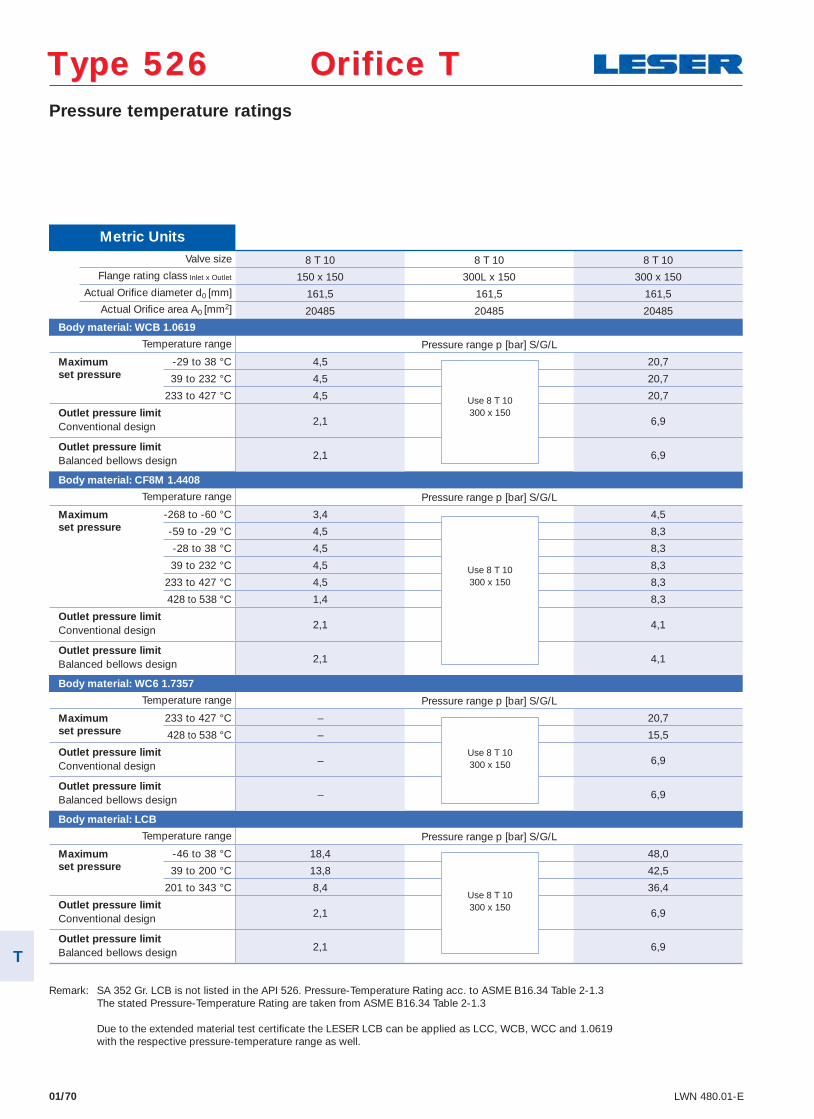
01/70 LWN 480.01-E
Pressure temperature ratings
Type 526 Orifice TType 526 Orifice T
Metric Units Valve size 8 T 10 8 T 10 8 T 10
Flange rating class Inlet x Outlet 150 x 150 300L x 150 300 x 150 Actual Orifi ce diameter d0 [mm] 161,5 161,5 161,5 Actual Orifi ce area A0 [mm2] 20485 20485 20485
Body material: WCB 1.0619
Temperature range Pressure range p [bar] S/G/L
Maximum -29 to 38 °C 4,5 20,7 set pressure 39 to 232 °C 4,5 20,7 233 to 427 °C 4,5 20,7
Outlet pressure limit2,1 6,9 Conventional design
Outlet pressure limit2,1 6,9 Balanced bellows design
Body material: CF8M 1.4408
Temperature range Pressure range p [bar] S/G/L
Maximum -268 to -60 °C 3,4 4,5 set pressure -59 to -29 °C 4,5 8,3 -28 to 38 °C 4,5 8,3
39 to 232 °C 4,5 8,3
233 to 427 °C 4,5 8,3
428 to 538 °C 1,4 8,3
Outlet pressure limit2,1 4,1 Conventional design
Outlet pressure limit2,1 4,1 Balanced bellows design
Body material: WC6 1.7357
Temperature range Pressure range p [bar] S/G/L
Maximum 233 to 427 °C – 20,7 set pressure 428 to 538 °C – 15,5
Outlet pressure limit– 6,9 Conventional design
Outlet pressure limit– 6,9 Balanced bellows design
Body material: LCB
Temperature range Pressure range p [bar] S/G/L
Maximum -46 to 38 °C 18,4 48,0 set pressure 39 to 200 °C 13,8 42,5 201 to 343 °C 8,4 36,4
Outlet pressure limit2,1 6,9 Conventional design
Outlet pressure limit2,1 6,9 Balanced bellows design
Use 8 T 10300 x 150
Use 8 T 10300 x 150
Use 8 T 10300 x 150
Use 8 T 10300 x 150
Remark: SA 352 Gr. LCB is not listed in the API 526. Pressure-Temperature Rating acc. to ASME B16.34 Table 2-1.3 The stated Pressure-Temperature Rating are taken from ASME B16.34 Table 2-1.3 Due to the extended material test certifi cate the LESER LCB can be applied as LCC, WCB, WCC and 1.0619 with the respective pressure-temperature range as well.
T
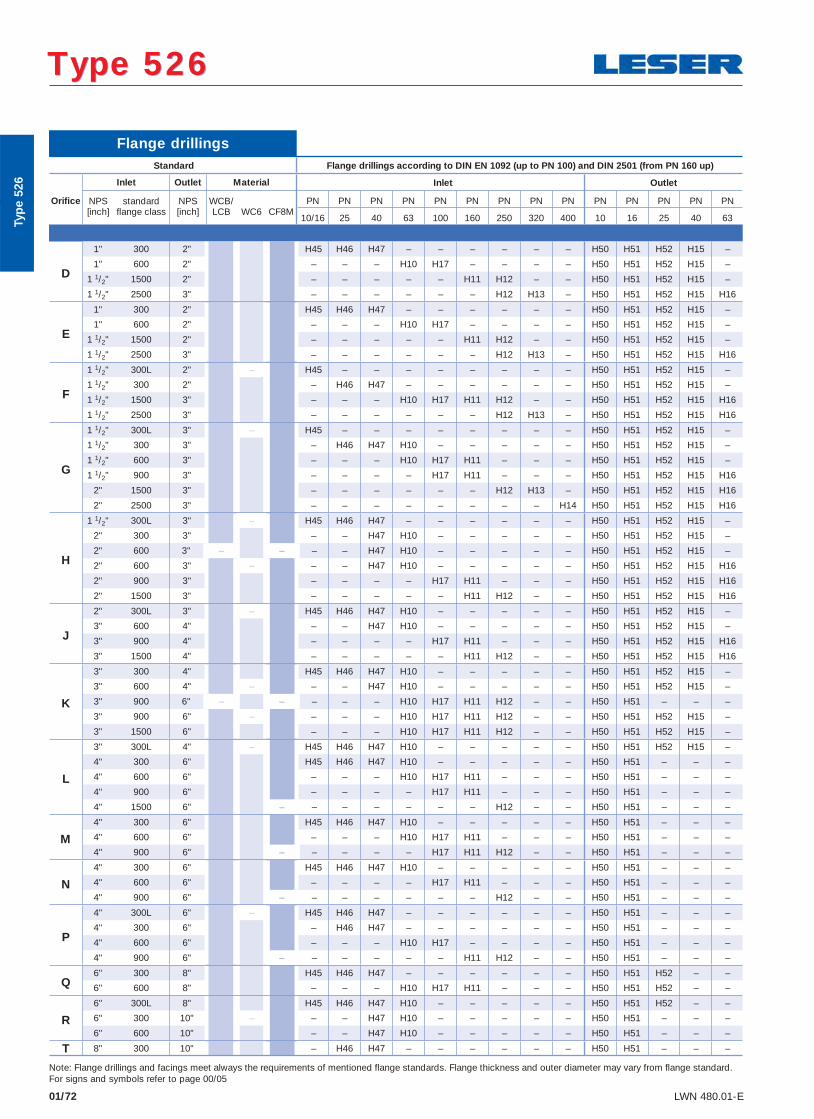
01/72 LWN 480.01-E
Type 526 Type 526
Flange drillings
Standard Flange drillings according to DIN EN 1092 (up to PN 100) and DIN 2501 (from PN 160 up)
Inlet Outlet Material Inlet Outlet
Orifi ce NPS standard NPS WCB/ PN PN PN PN PN PN PN PN PN PN PN PN PN PN[inch] fl ange class [inch] LCB WC6 CF8M
10/16 25 40 63 100 160 250 320 400 10 16 25 40 63
D
1" 300 2" H45 H46 H47 – – – – – – H50 H51 H52 H15 –
1" 600 2" – – – H10 H17 – – – – H50 H51 H52 H15 –
1 1/2" 1500 2" – – – – – H11 H12 – – H50 H51 H52 H15 –
1 1/2" 2500 3" – – – – – – H12 H13 – H50 H51 H52 H15 H16
E
1" 300 2" H45 H46 H47 – – – – – – H50 H51 H52 H15 –
1" 600 2" – – – H10 H17 – – – – H50 H51 H52 H15 –
1 1/2" 1500 2" – – – – – H11 H12 – – H50 H51 H52 H15 –
1 1/2" 2500 3" – – – – – – H12 H13 – H50 H51 H52 H15 H16
F
1 1/2" 300L 2" – H45 – – – – – – – – H50 H51 H52 H15 –
1 1/2" 300 2" – H46 H47 – – – – – – H50 H51 H52 H15 –
1 1/2" 1500 3" – – – H10 H17 H11 H12 – – H50 H51 H52 H15 H16
1 1/2" 2500 3" – – – – – – H12 H13 – H50 H51 H52 H15 H16
G
1 1/2" 300L 3" – H45 – – – – – – – – H50 H51 H52 H15 –
1 1/2" 300 3" – H46 H47 H10 – – – – – H50 H51 H52 H15 –
1 1/2" 600 3" – – – H10 H17 H11 – – – H50 H51 H52 H15 –
1 1/2" 900 3" – – – – H17 H11 – – – H50 H51 H52 H15 H16
2" 1500 3" – – – – – – H12 H13 – H50 H51 H52 H15 H16
2" 2500 3" – – – – – – – – H14 H50 H51 H52 H15 H16
H
1 1/2" 300L 3" – H45 H46 H47 – – – – – – H50 H51 H52 H15 –
2" 300 3" – – H47 H10 – – – – – H50 H51 H52 H15 –
2" 600 3" – – – – H47 H10 – – – – – H50 H51 H52 H15 –
2" 600 3" – – – H47 H10 – – – – – H50 H51 H52 H15 H16
2" 900 3" – – – – H17 H11 – – – H50 H51 H52 H15 H16
2" 1500 3" – – – – – H11 H12 – – H50 H51 H52 H15 H16
J
2" 300L 3" – H45 H46 H47 H10 – – – – – H50 H51 H52 H15 –
3" 600 4" – – H47 H10 – – – – – H50 H51 H52 H15 –
3" 900 4" – – – – H17 H11 – – – H50 H51 H52 H15 H16
3" 1500 4" – – – – – H11 H12 – – H50 H51 H52 H15 H16
K
3" 300 4" H45 H46 H47 H10 – – – – – H50 H51 H52 H15 –
3" 600 4" – – – H47 H10 – – – – – H50 H51 H52 H15 –
3" 900 6" – – – – – H10 H17 H11 H12 – – H50 H51 – – –
3" 900 6" – – – – H10 H17 H11 H12 – – H50 H51 H52 H15 –
3" 1500 6" – – – H10 H17 H11 H12 – – H50 H51 H52 H15 –
L
3" 300L 4" – H45 H46 H47 H10 – – – – – H50 H51 H52 H15 –
4" 300 6" H45 H46 H47 H10 – – – – – H50 H51 – – –
4" 600 6" – – – H10 H17 H11 – – – H50 H51 – – –
4" 900 6" – – – – H17 H11 – – – H50 H51 – – –
4" 1500 6" – – – – – – – H12 – – H50 H51 – – –
M4" 300 6" H45 H46 H47 H10 – – – – – H50 H51 – – –
4" 600 6" – – – H10 H17 H11 – – – H50 H51 – – –
4" 900 6" – – – – – H17 H11 H12 – – H50 H51 – – –
N4" 300 6" H45 H46 H47 H10 – – – – – H50 H51 – – –
4" 600 6" – – – – H17 H11 – – – H50 H51 – – –
4" 900 6" – – – – – – – H12 – – H50 H51 – – –
P
4" 300L 6" – H45 H46 H47 – – – – – – H50 H51 – – –
4" 300 6" – H46 H47 – – – – – – H50 H51 – – –
4" 600 6" – – – H10 H17 – – – – H50 H51 – – –
4" 900 6" – – – – – – H11 H12 – – H50 H51 – – –
Q6" 300 8" H45 H46 H47 – – – – – – H50 H51 H52 – –
6" 600 8" – – – H10 H17 H11 – – – H50 H51 H52 – –
R6" 300L 8" H45 H46 H47 H10 – – – – – H50 H51 H52 – –
6" 300 10" – – – H47 H10 – – – – – H50 H51 – – –
6" 600 10" – – H47 H10 – – – – – H50 H51 – – –
T 8" 300 10" – H46 H47 – – – – – – H50 H51 – – –
Note: Flange drillings and facings meet always the requirements of mentioned fl ange standards. Flange thickness and outer diameter may vary from fl ange standard.For signs and symbols refer to page 00/05
Typ
e 52
6Ty
pe
526
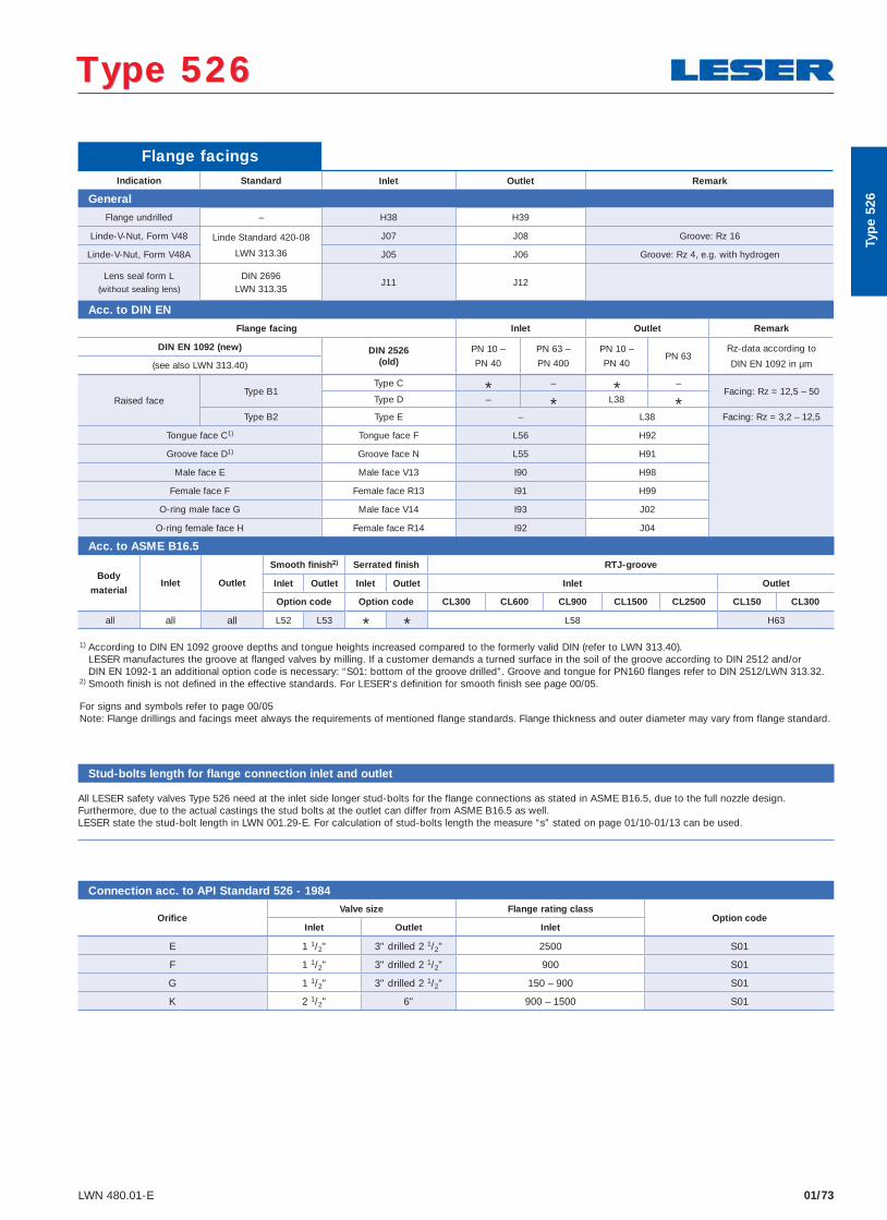
01/73LWN 480.01-E
Type 526 Type 526
1) According to DIN EN 1092 groove depths and tongue heights increased compared to the formerly valid DIN (refer to LWN 313.40). LESER manufactures the groove at flanged valves by milling. If a customer demands a turned surface in the soil of the groove according to DIN 2512 and/or DIN EN 1092-1 an additional option code is necessary: “S01: bottom of the groove drilled”. Groove and tongue for PN160 flanges refer to DIN 2512/LWN 313.32.
2) Smooth finish is not defined in the effective standards. For LESER‘s definition for smooth finish see page 00/05.
For signs and symbols refer to page 00/05Note: Flange drillings and facings meet always the requirements of mentioned flange standards. Flange thickness and outer diameter may vary from flange standard.
Flange facingsIndication Standard Inlet Outlet Remark
General
Flange undrilled – H38 H39
Linde-V-Nut, Form V48 Linde Standard 420-08
LWN 313.36
J07 J08 Groove: Rz 16
Linde-V-Nut, Form V48A J05 J06 Groove: Rz 4, e.g. with hydrogen
Lens seal form L(without sealing lens)
DIN 2696LWN 313.35
J11 J12
Acc. to DIN EN
Flange facing Inlet Outlet Remark
DIN EN 1092 (new) DIN 2526(old)
PN 10 –
PN 40
PN 63 –
PN 400
PN 10 –
PN 40PN 63
Rz-data according to
DIN EN 1092 in µm(see also LWN 313.40)
Raised faceType B1
Type C * – * –Facing: Rz = 12,5 – 50
Type D – * L38 *Type B2 Type E – L38 Facing: Rz = 3,2 – 12,5
Tongue face C1) Tongue face F L56 H92
Groove face D1) Groove face N L55 H91
Male face E Male face V13 I90 H98
Female face F Female face R13 I91 H99
O-ring male face G Male face V14 I93 J02
O-ring female face H Female face R14 I92 J04
Acc. to ASME B16.5
Body
materialInlet Outlet
Smooth finish2) Serrated finish RTJ-groove
Inlet Outlet Inlet Outlet Inlet Outlet
Option code Option code CL300 CL600 CL900 CL1500 CL2500 CL150 CL300
all all all L52 L53 * * L58 H63
Typ
e 52
6
Connection acc. to API Standard 526 - 1984
Orifi ceValve size Flange rating class
Option codeInlet Outlet Inlet
E 1 1/2" 3" drilled 2 1/2" 2500 S01
F 1 1/2" 3" drilled 2 1/2" 900 S01
G 1 1/2" 3" drilled 2 1/2" 150 – 900 S01
K 2 1/2" 6" 900 – 1500 S01
Stud-bolts length for flange connection inlet and outlet
All LESER safety valves Type 526 need at the inlet side longer stud-bolts for the flange connections as stated in ASME B16.5, due to the full nozzle design.Furthermore, due to the actual castings the stud bolts at the outlet can differ from ASME B16.5 as well.LESER state the stud-bolt length in LWN 001.29-E. For calculation of stud-bolts length the measure “s” stated on page 01/10-01/13 can be used.
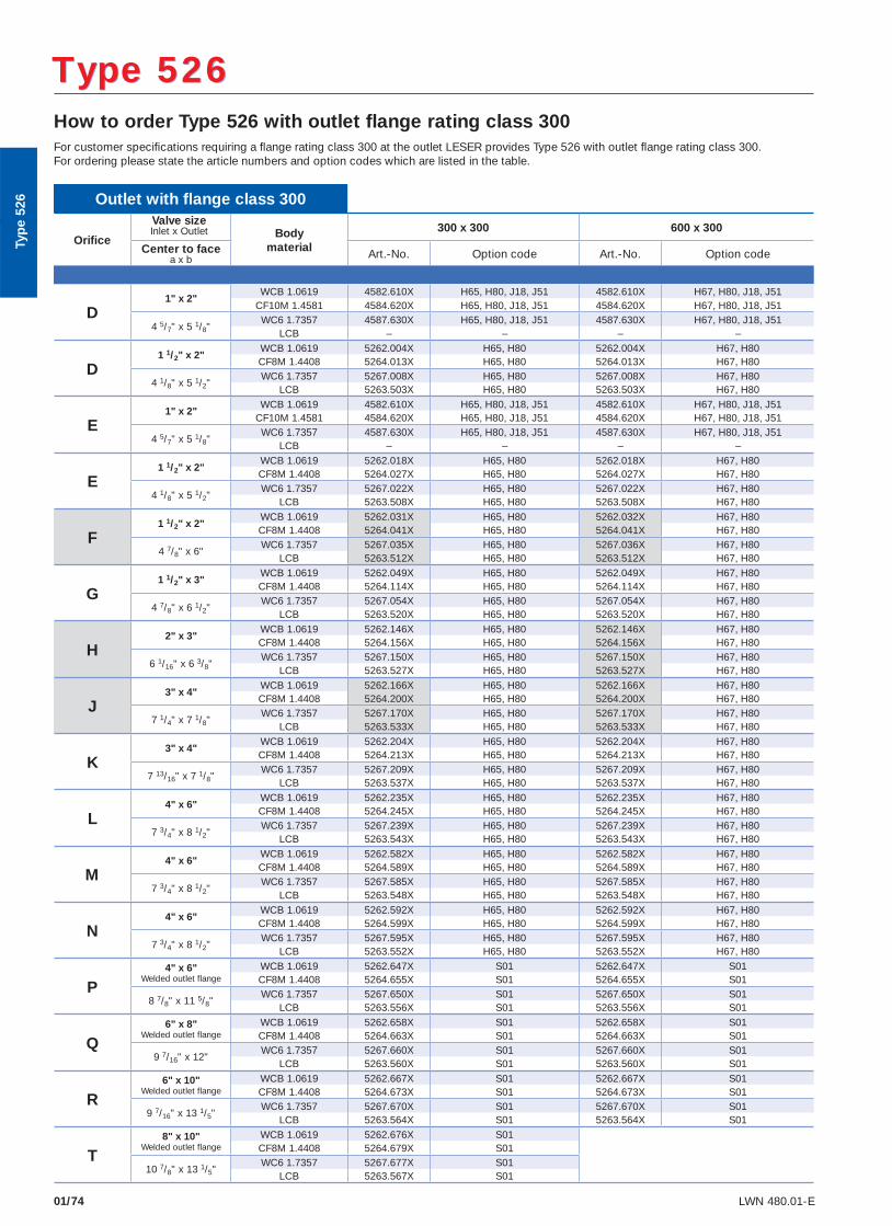
01/74 LWN 480.01-E
How to order Type 526 with outlet flange rating class 300For customer specifi cations requiring a fl ange rating class 300 at the outlet LESER provides Type 526 with outlet fl ange rating class 300.For ordering please state the article numbers and option codes which are listed in the table.
Type 526 Type 526
Outlet with fl ange class 300
Orifi ce
Valve sizeInlet x Outlet Body
material
300 x 300 600 x 300
Center to facea x b Art.-No. Option code Art.-No. Option code
D1" x 2"
WCB 1.0619 4582.610X H65, H80, J18, J51 4582.610X H67, H80, J18, J51CF10M 1.4581 4584.620X H65, H80, J18, J51 4584.620X H67, H80, J18, J51
4 5/7" x 5 1/8"WC6 1.7357 4587.630X H65, H80, J18, J51 4587.630X H67, H80, J18, J51
LCB – – – –
D1 1/2" x 2"
WCB 1.0619 5262.004X H65, H80 5262.004X H67, H80CF8M 1.4408 5264.013X H65, H80 5264.013X H67, H80
4 1/8" x 5 1/2"WC6 1.7357 5267.008X H65, H80 5267.008X H67, H80
LCB 5263.503X H65, H80 5263.503X H67, H80
E1" x 2"
WCB 1.0619 4582.610X H65, H80, J18, J51 4582.610X H67, H80, J18, J51CF10M 1.4581 4584.620X H65, H80, J18, J51 4584.620X H67, H80, J18, J51
4 5/7" x 5 1/8"WC6 1.7357 4587.630X H65, H80, J18, J51 4587.630X H67, H80, J18, J51
LCB – – – –
E1 1/2" x 2"
WCB 1.0619 5262.018X H65, H80 5262.018X H67, H80CF8M 1.4408 5264.027X H65, H80 5264.027X H67, H80
4 1/8" x 5 1/2"WC6 1.7357 5267.022X H65, H80 5267.022X H67, H80
LCB 5263.508X H65, H80 5263.508X H67, H80
F1 1/2" x 2"
WCB 1.0619 5262.031X H65, H80 5262.032X H67, H80CF8M 1.4408 5264.041X H65, H80 5264.041X H67, H80
4 7/8" x 6"WC6 1.7357 5267.035X H65, H80 5267.036X H67, H80
LCB 5263.512X H65, H80 5263.512X H67, H80
G1 1/2" x 3"
WCB 1.0619 5262.049X H65, H80 5262.049X H67, H80CF8M 1.4408 5264.114X H65, H80 5264.114X H67, H80
4 7/8" x 6 1/2"WC6 1.7357 5267.054X H65, H80 5267.054X H67, H80
LCB 5263.520X H65, H80 5263.520X H67, H80
H2" x 3"
WCB 1.0619 5262.146X H65, H80 5262.146X H67, H80CF8M 1.4408 5264.156X H65, H80 5264.156X H67, H80
6 1/16" x 6 3/8"WC6 1.7357 5267.150X H65, H80 5267.150X H67, H80
LCB 5263.527X H65, H80 5263.527X H67, H80
J3" x 4"
WCB 1.0619 5262.166X H65, H80 5262.166X H67, H80CF8M 1.4408 5264.200X H65, H80 5264.200X H67, H80
7 1/4" x 7 1/8"WC6 1.7357 5267.170X H65, H80 5267.170X H67, H80
LCB 5263.533X H65, H80 5263.533X H67, H80
K3" x 4"
WCB 1.0619 5262.204X H65, H80 5262.204X H67, H80CF8M 1.4408 5264.213X H65, H80 5264.213X H67, H80
7 13/16" x 7 1/8"WC6 1.7357 5267.209X H65, H80 5267.209X H67, H80
LCB 5263.537X H65, H80 5263.537X H67, H80
L4" x 6"
WCB 1.0619 5262.235X H65, H80 5262.235X H67, H80CF8M 1.4408 5264.245X H65, H80 5264.245X H67, H80
7 3/4" x 8 1/2"WC6 1.7357 5267.239X H65, H80 5267.239X H67, H80
LCB 5263.543X H65, H80 5263.543X H67, H80
M4" x 6"
WCB 1.0619 5262.582X H65, H80 5262.582X H67, H80CF8M 1.4408 5264.589X H65, H80 5264.589X H67, H80
7 3/4" x 8 1/2"WC6 1.7357 5267.585X H65, H80 5267.585X H67, H80
LCB 5263.548X H65, H80 5263.548X H67, H80
N4" x 6"
WCB 1.0619 5262.592X H65, H80 5262.592X H67, H80CF8M 1.4408 5264.599X H65, H80 5264.599X H67, H80
7 3/4" x 8 1/2"WC6 1.7357 5267.595X H65, H80 5267.595X H67, H80
LCB 5263.552X H65, H80 5263.552X H67, H80
P4" x 6"
Welded outlet flangeWCB 1.0619 5262.647X S01 5262.647X S01CF8M 1.4408 5264.655X S01 5264.655X S01
8 7/8" x 11 5/8"WC6 1.7357 5267.650X S01 5267.650X S01
LCB 5263.556X S01 5263.556X S01
Q6" x 8"
Welded outlet flangeWCB 1.0619 5262.658X S01 5262.658X S01CF8M 1.4408 5264.663X S01 5264.663X S01
9 7/16" x 12"WC6 1.7357 5267.660X S01 5267.660X S01
LCB 5263.560X S01 5263.560X S01
R6" x 10"
Welded outlet flangeWCB 1.0619 5262.667X S01 5262.667X S01CF8M 1.4408 5264.673X S01 5264.673X S01
9 7/16" x 13 1/5"WC6 1.7357 5267.670X S01 5267.670X S01
LCB 5263.564X S01 5263.564X S01
T8" x 10"
Welded outlet flangeWCB 1.0619 5262.676X S01CF8M 1.4408 5264.679X S01
10 7/8" x 13 1/5"WC6 1.7357 5267.677X S01
LCB 5263.567X S01
Typ
e 52
6
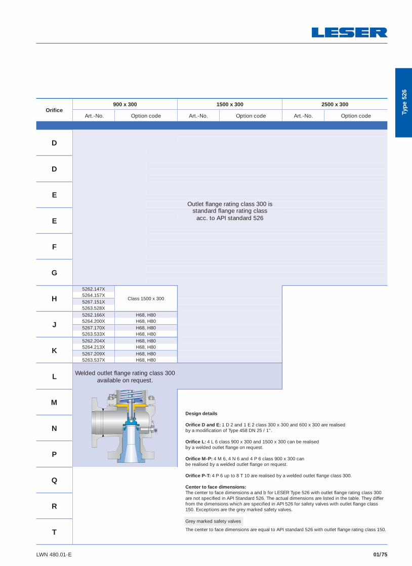
01/75LWN 480.01-E
Orifi ce900 x 300 1500 x 300 2500 x 300
Art.-No. Option code Art.-No. Option code Art.-No. Option code
D
D
EOutlet fl ange rating class 300 is
Estandard fl ange rating class
acc. to API standard 526
F
G
H5262.147X
Class 1500 x 3005264.157X5267.151X5263.528X
J5262.166X H68, H805264.200X H68, H805267.170X H68, H805263.533X H68, H80
K5262.204X H68, H805264.213X H68, H805267.209X H68, H805263.537X H68, H80
L Welded outlet fl ange rating class 300 available on request.
MDesign details
Orifi ce D and E: 1 D 2 and 1 E 2 class 300 x 300 and 600 x 300 are realised by a modifi cation of Type 458 DN 25 / 1".
Orifi ce L: 4 L 6 class 900 x 300 and 1500 x 300 can be realised by a welded outlet fl ange on request.
Orifi ce M-P: 4 M 6, 4 N 6 and 4 P 6 class 900 x 300 can be realised by a welded outlet fl ange on request.
Orifi ce P-T: 4 P 6 up to 8 T 10 are realised by a welded outlet fl ange class 300.
Center to face dimensions:The center to face dimensions a and b for LESER Type 526 with outlet fl ange rating class 300 are not specifi ed in API Standard 526. The actual dimensions are listed in the table. They differ from the dimensions which are specifi ed in API 526 for safety valves with outlet fl ange class 150. Exceptions are the grey marked safety valves.
N
P
Q
R
T
Typ
e 52
6
Grey marked safety valves
The center to face dimensions are equal to API standard 526 with outlet fl ange rating class 150.
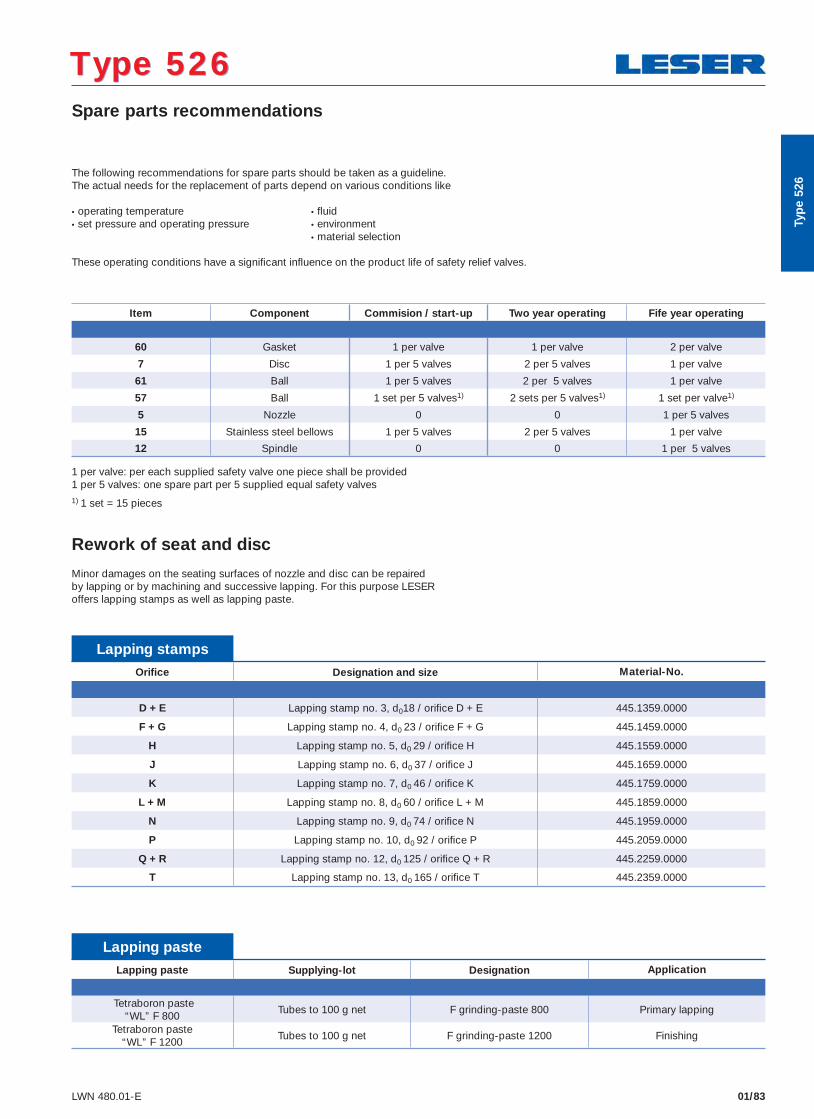
01/83LWN 480.01-E
Type 526 Type 526 Spare parts recommendations
The following recommendations for spare parts should be taken as a guideline. The actual needs for the replacement of parts depend on various conditions like
• operating temperature • fl uid • set pressure and operating pressure • environment • material selection
These operating conditions have a signifi cant infl uence on the product life of safety relief valves.
Item Component Commision / start-up Two year operating Fife year operating
60 Gasket 1 per valve 1 per valve 2 per valve
7 Disc 1 per 5 valves 2 per 5 valves 1 per valve
61 Ball 1 per 5 valves 2 per 5 valves 1 per valve
57 Ball 1 set per 5 valves1) 2 sets per 5 valves1) 1 set per valve1)
5 Nozzle 0 0 1 per 5 valves
15 Stainless steel bellows 1 per 5 valves 2 per 5 valves 1 per valve
12 Spindle 0 0 1 per 5 valves
1 per valve: per each supplied safety valve one piece shall be provided 1 per 5 valves: one spare part per 5 supplied equal safety valves 1) 1 set = 15 pieces
Rework of seat and disc
Minor damages on the seating surfaces of nozzle and disc can be repaired by lapping or by machining and successive lapping. For this purpose LESER offers lapping stamps as well as lapping paste.
Lapping stamps Orifi ce Designation and size Material-No.
D + E Lapping stamp no. 3, d018 / orifi ce D + E 445.1359.0000
F + G Lapping stamp no. 4, d0 23 / orifi ce F + G 445.1459.0000
H Lapping stamp no. 5, d0 29 / orifi ce H 445.1559.0000
J Lapping stamp no. 6, d0 37 / orifi ce J 445.1659.0000
K Lapping stamp no. 7, d0 46 / orifi ce K 445.1759.0000
L + M Lapping stamp no. 8, d0 60 / orifi ce L + M 445.1859.0000
N Lapping stamp no. 9, d0 74 / orifi ce N 445.1959.0000
P Lapping stamp no. 10, d0 92 / orifi ce P 445.2059.0000
Q + R Lapping stamp no. 12, d0 125 / orifi ce Q + R 445.2259.0000
T Lapping stamp no. 13, d0 165 / orifi ce T 445.2359.0000
Lapping paste Lapping paste Supplying-lot Designation Application
Tetraboron paste“WL” F 800
Tubes to 100 g net F grinding-paste 800 Primary lapping
Tetraboron paste“WL” F 1200
Tubes to 100 g net F grinding-paste 1200 Finishing
Typ
e 52
6
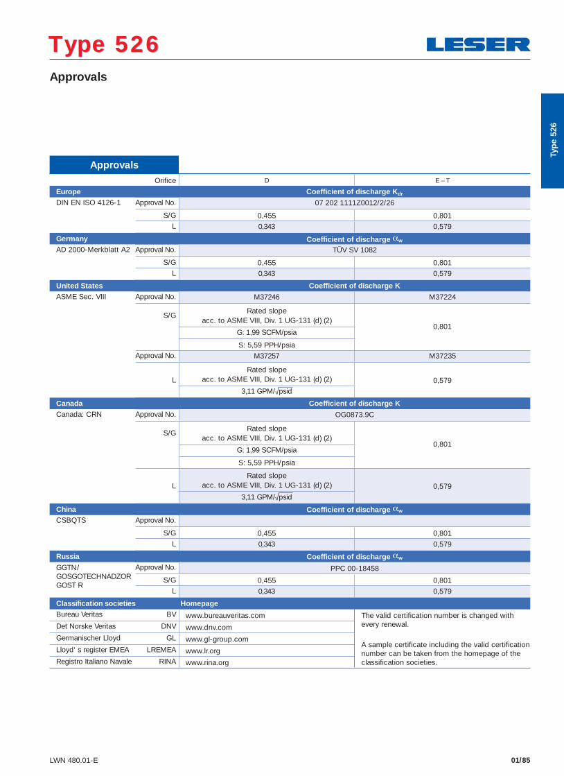
01/85LWN 480.01-E
Approvals
Type 526 Type 526
Typ
e 52
6
Approvals Orifi ce D E – T
Europe Coefficient of discharge Kdr DIN EN ISO 4126-1 Approval No. 07 202 1111Z0012/2/26
S/G 0,455 0,801L 0,343 0,579
Germany Coefficient of discharge αw
AD 2000-Merkblatt A2 Approval No. TÜV SV 1082
S/G 0,455 0,801L 0,343 0,579
United States Coefficient of discharge KASME Sec. VIII Approval No. M37246 M37224
S/GRated slope
acc. to ASME VIII, Div. 1 UG-131 (d) (2)0,801
G: 1,99 SCFM/psia
S: 5,59 PPH/psiaApproval No. M37257 M37235
LRated slope
acc. to ASME VIII, Div. 1 UG-131 (d) (2) 0,579
3,11 GPM/√psid
Canada Coefficient of discharge K
Canada: CRN Approval No. OG0873.9C
S/GRated slope
acc. to ASME VIII, Div. 1 UG-131 (d) (2)0,801
G: 1,99 SCFM/psia
S: 5,59 PPH/psia
LRated slope
acc. to ASME VIII, Div. 1 UG-131 (d) (2) 0,579
3,11 GPM/√psid
China Coefficient of discharge αw
CSBQTS Approval No.
S/G 0,455 0,801L 0,343 0,579
Russia Coefficient of discharge αw
GGTN/GOSGOTECHNADZORGOST R
Approval No. PPC 00-18458
S/G 0,455 0,801L 0,343 0,579
Classification societies Homepage Bureau Veritas BV www.bureauveritas.com The valid certification number is changed with
every renewal.
A sample certificate including the valid certification number can be taken from the homepage of the classification societies.
Det Norske Veritas DNV www.dnv.com Germanischer Lloyd GL www.gl-group.com Lloyd‘ s register EMEA LREMEA www.lr.org Registro Italiano Navale RINA www.rina.org
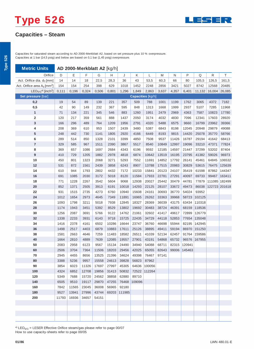
01/86 LWN 480.01-E
Capacities – Steam
Type 526 Type 526
Metric Units AD 2000-Merkblatt A2 [kg/h]Orifi ce D E F G H J K L M N P Q R T
Act. Orifice dia. d0 [mm] 14 14 18 22,5 28,3 36 43 53,5 60,3 66 80 105,5 126,5 161,5
Act. Orifice area A0 [mm2] 154 154 254 398 629 1018 1452 2248 2856 3421 5027 8742 12568 20485
LEOS/G*) [inch2] 0,111 0,196 0,324 0,506 0,801 1,296 1,849 2,863 3,637 4,357 6,401 11,132 16,004 26,085
Set pressure [bar] Capacities [kg/h]
0,2 19 54 89 139 221 357 509 788 1001 1199 1762 3065 4372 7182
0,5 42 90 149 232 367 595 848 1313 1668 1999 2937 5107 7285 11968
1 71 134 221 345 546 883 1260 1951 2479 2969 4363 7587 10823 17780
2 120 217 359 561 888 1437 2050 3174 4032 4830 7096 12341 17603 28920
3 166 296 489 764 1209 1956 2791 4320 5488 6575 9660 16799 23962 39366
4 208 369 610 953 1507 2439 3480 5387 6843 8198 12045 20948 29879 49088
5 248 442 730 1141 1805 2920 4166 6449 8193 9815 14420 25078 35770 58766
6 289 514 850 1328 2101 3399 4850 7508 9537 11426 16787 29194 41642 68413
7 329 585 967 1511 2390 3867 5517 8540 10849 12997 19096 33210 47371 77824
8 369 657 1086 1697 2684 4343 6196 9592 12185 14597 21447 37299 53202 87404
9 410 729 1205 1882 2978 4818 6874 10642 13519 16195 23795 41382 59026 96973
10 450 801 1323 2068 3271 5293 7552 11691 14852 17792 26141 45461 64845 106532
12 531 872 1561 2439 3858 6243 8907 13788 17515 20983 30829 53615 76475 125639
14 610 944 1793 2802 4432 7172 10233 15841 20123 24107 35419 61598 87862 144347
16 691 1085 2030 3172 5018 8120 11584 17933 22781 27291 40097 69733 99467 163411
18 771 1228 2267 3542 5604 9068 12938 20027 25442 30479 44781 77879 111085 182499
20 852 1371 2505 3913 6191 10018 14293 22125 28107 33672 49473 86038 122723 201618
22 931 1515 2735 4273 6760 10940 15608 24161 30693 36770 54024 93952
24 1012 1654 2973 4645 7349 11891 16965 26262 33363 39968 58723 102125
26 1093 1798 3211 5018 7938 12845 18327 28369 36039 43175 63434 110318
28 1174 1943 3451 5392 8529 13802 19692 30483 38724 46391 68159 118536
30 1256 2087 3691 5766 9122 14762 21061 32602 41417 49617 72899 126779
32 1338 2233 3931 6143 9718 15725 22435 34729 44118 52853 77654 135048
34 1416 2378 4161 6502 10286 16644 23747 36760 46698 55944 82195 142945
36 1498 2517 4403 6879 10883 17611 25126 38895 49411 59194 86970 151250
38 1581 2663 4646 7259 11483 18582 26511 41039 52134 62457 91764 159586
40 1664 2810 4889 7639 12085 19557 27901 43191 54868 65732 96576 167955
50 2083 2958 6123 9567 15134 24490 34940 54088 68711 82315 120941
60 2506 3704 7364 11506 18203 29456 42025 65055 82643 99006 145463
70 2945 4455 8656 13525 21396 34624 49398 76467 97141
80 3388 5236 9957 15558 24613 39828 56823 87962
90 3854 6023 11326 17697 27997 45305 64636 100056
100 4324 6852 12708 19856 31413 50832 72522 112264
120 5349 7688 15720 24562 38858 62880 89710
140 6505 9510 19117 29870 47255 76468 109096
160 7842 11565 23045 36008 56965 92180
180 9527 13941 27996 43744 69203 111985
200 11793 16936 34657 54151
*) LEOS/G = LESER Effective Orifice steam/gas please refer to page 00/07How to use capacity-sheets refer to page 00/05
Capacities for saturated steam according to AD 2000-Merkblatt A2, based on set pressure plus 10 % overpressure.Capacities at 1 bar (14,5 psig) and below are based on 0,1 bar (1,45 psig) overpressure.
Typ
e 52
6
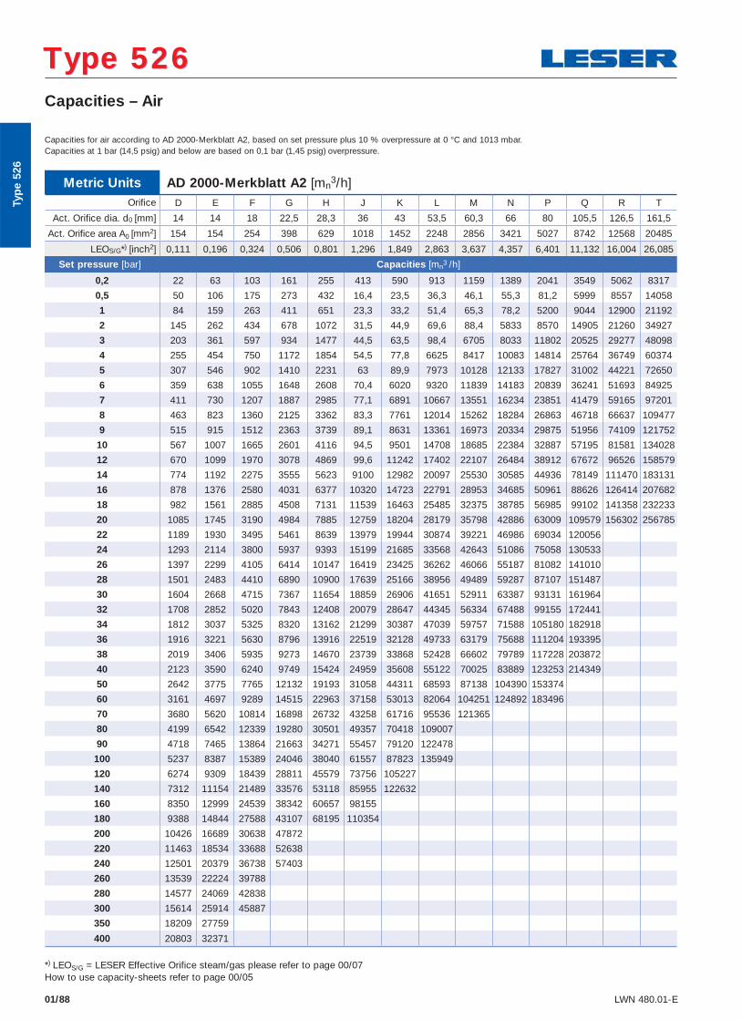
01/88 LWN 480.01-E
Capacities – Air
Type 526 Type 526
Metric Units AD 2000-Merkblatt A2 [mn3/h]
Orifi ce D E F G H J K L M N P Q R T
Act. Orifice dia. d0 [mm] 14 14 18 22,5 28,3 36 43 53,5 60,3 66 80 105,5 126,5 161,5
Act. Orifice area A0 [mm2] 154 154 254 398 629 1018 1452 2248 2856 3421 5027 8742 12568 20485
LEOS/G*) [inch2] 0,111 0,196 0,324 0,506 0,801 1,296 1,849 2,863 3,637 4,357 6,401 11,132 16,004 26,085
Set pressure [bar] Capacities [mn3 /h]
0,2 22 63 103 161 255 413 590 913 1159 1389 2041 3549 5062 8317
0,5 50 106 175 273 432 16,4 23,5 36,3 46,1 55,3 81,2 5999 8557 14058
1 84 159 263 411 651 23,3 33,2 51,4 65,3 78,2 5200 9044 12900 21192
2 145 262 434 678 1072 31,5 44,9 69,6 88,4 5833 8570 14905 21260 34927
3 203 361 597 934 1477 44,5 63,5 98,4 6705 8033 11802 20525 29277 48098
4 255 454 750 1172 1854 54,5 77,8 6625 8417 10083 14814 25764 36749 60374
5 307 546 902 1410 2231 63 89,9 7973 10128 12133 17827 31002 44221 72650
6 359 638 1055 1648 2608 70,4 6020 9320 11839 14183 20839 36241 51693 84925
7 411 730 1207 1887 2985 77,1 6891 10667 13551 16234 23851 41479 59165 97201
8 463 823 1360 2125 3362 83,3 7761 12014 15262 18284 26863 46718 66637 109477
9 515 915 1512 2363 3739 89,1 8631 13361 16973 20334 29875 51956 74109 121752
10 567 1007 1665 2601 4116 94,5 9501 14708 18685 22384 32887 57195 81581 134028
12 670 1099 1970 3078 4869 99,6 11242 17402 22107 26484 38912 67672 96526 158579
14 774 1192 2275 3555 5623 9100 12982 20097 25530 30585 44936 78149 111470 183131
16 878 1376 2580 4031 6377 10320 14723 22791 28953 34685 50961 88626 126414 207682
18 982 1561 2885 4508 7131 11539 16463 25485 32375 38785 56985 99102 141358 232233
20 1085 1745 3190 4984 7885 12759 18204 28179 35798 42886 63009 109579 156302 256785
22 1189 1930 3495 5461 8639 13979 19944 30874 39221 46986 69034 120056
24 1293 2114 3800 5937 9393 15199 21685 33568 42643 51086 75058 130533
26 1397 2299 4105 6414 10147 16419 23425 36262 46066 55187 81082 141010
28 1501 2483 4410 6890 10900 17639 25166 38956 49489 59287 87107 151487
30 1604 2668 4715 7367 11654 18859 26906 41651 52911 63387 93131 161964
32 1708 2852 5020 7843 12408 20079 28647 44345 56334 67488 99155 172441
34 1812 3037 5325 8320 13162 21299 30387 47039 59757 71588 105180 182918
36 1916 3221 5630 8796 13916 22519 32128 49733 63179 75688 111204 193395
38 2019 3406 5935 9273 14670 23739 33868 52428 66602 79789 117228 203872
40 2123 3590 6240 9749 15424 24959 35608 55122 70025 83889 123253 214349
50 2642 3775 7765 12132 19193 31058 44311 68593 87138 104390 153374
60 3161 4697 9289 14515 22963 37158 53013 82064 104251 124892 183496
70 3680 5620 10814 16898 26732 43258 61716 95536 121365
80 4199 6542 12339 19280 30501 49357 70418 109007
90 4718 7465 13864 21663 34271 55457 79120 122478
100 5237 8387 15389 24046 38040 61557 87823 135949
120 6274 9309 18439 28811 45579 73756 105227
140 7312 11154 21489 33576 53118 85955 122632
160 8350 12999 24539 38342 60657 98155
180 9388 14844 27588 43107 68195 110354
200 10426 16689 30638 47872
220 11463 18534 33688 52638
240 12501 20379 36738 57403
260 13539 22224 39788
280 14577 24069 42838
300 15614 25914 45887
350 18209 27759
400 20803 32371
*) LEOS/G = LESER Effective Orifice steam/gas please refer to page 00/07How to use capacity-sheets refer to page 00/05
Capacities for air according to AD 2000-Merkblatt A2, based on set pressure plus 10 % overpressure at 0 °C and 1013 mbar.Capacities at 1 bar (14,5 psig) and below are based on 0,1 bar (1,45 psig) overpressure.
Typ
e 52
6
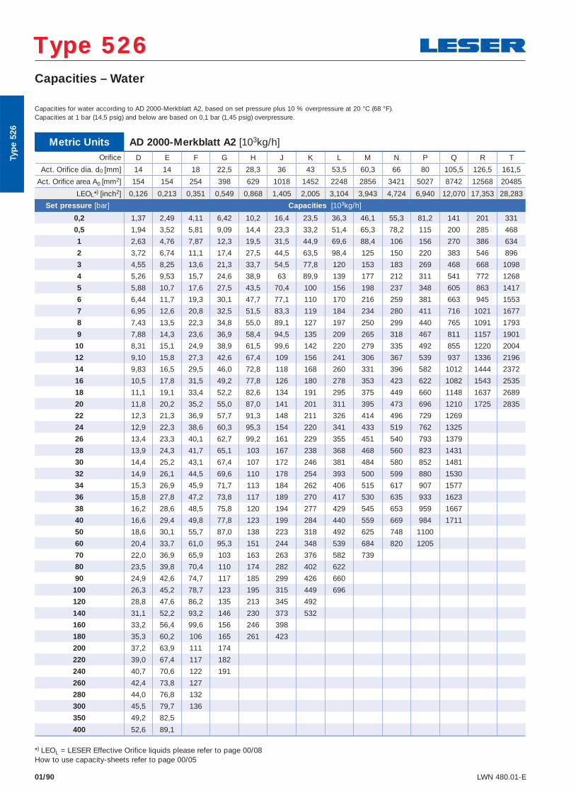
01/90 LWN 480.01-E
Capacities – Water
Type 526 Type 526
Metric Units AD 2000-Merkblatt A2 [103kg/h]Orifi ce D E F G H J K L M N P Q R T
Act. Orifice dia. d0 [mm] 14 14 18 22,5 28,3 36 43 53,5 60,3 66 80 105,5 126,5 161,5
Act. Orifice area A0 [mm2] 154 154 254 398 629 1018 1452 2248 2856 3421 5027 8742 12568 20485
LEOL*) [inch2] 0,126 0,213 0,351 0,549 0,868 1,405 2,005 3,104 3,943 4,724 6,940 12,070 17,353 28,283
Set pressure [bar] Capacities [103kg/h]
0,2 1,37 2,49 4,11 6,42 10,2 16,4 23,5 36,3 46,1 55,3 81,2 141 201 331
0,5 1,94 3,52 5,81 9,09 14,4 23,3 33,2 51,4 65,3 78,2 115 200 285 468
1 2,63 4,76 7,87 12,3 19,5 31,5 44,9 69,6 88,4 106 156 270 386 634
2 3,72 6,74 11,1 17,4 27,5 44,5 63,5 98,4 125 150 220 383 546 896
3 4,55 8,25 13,6 21,3 33,7 54,5 77,8 120 153 183 269 468 668 1098
4 5,26 9,53 15,7 24,6 38,9 63 89,9 139 177 212 311 541 772 1268
5 5,88 10,7 17,6 27,5 43,5 70,4 100 156 198 237 348 605 863 1417
6 6,44 11,7 19,3 30,1 47,7 77,1 110 170 216 259 381 663 945 1553
7 6,95 12,6 20,8 32,5 51,5 83,3 119 184 234 280 411 716 1021 1677
8 7,43 13,5 22,3 34,8 55,0 89,1 127 197 250 299 440 765 1091 1793
9 7,88 14,3 23,6 36,9 58,4 94,5 135 209 265 318 467 811 1157 1901
10 8,31 15,1 24,9 38,9 61,5 99,6 142 220 279 335 492 855 1220 2004
12 9,10 15,8 27,3 42,6 67,4 109 156 241 306 367 539 937 1336 2196
14 9,83 16,5 29,5 46,0 72,8 118 168 260 331 396 582 1012 1444 2372
16 10,5 17,8 31,5 49,2 77,8 126 180 278 353 423 622 1082 1543 2535
18 11,1 19,1 33,4 52,2 82,6 134 191 295 375 449 660 1148 1637 2689
20 11,8 20,2 35,2 55,0 87,0 141 201 311 395 473 696 1210 1725 2835
22 12,3 21,3 36,9 57,7 91,3 148 211 326 414 496 729 1269
24 12,9 22,3 38,6 60,3 95,3 154 220 341 433 519 762 1325
26 13,4 23,3 40,1 62,7 99,2 161 229 355 451 540 793 1379
28 13,9 24,3 41,7 65,1 103 167 238 368 468 560 823 1431
30 14,4 25,2 43,1 67,4 107 172 246 381 484 580 852 1481
32 14,9 26,1 44,5 69,6 110 178 254 393 500 599 880 1530
34 15,3 26,9 45,9 71,7 113 184 262 406 515 617 907 1577
36 15,8 27,8 47,2 73,8 117 189 270 417 530 635 933 1623
38 16,2 28,6 48,5 75,8 120 194 277 429 545 653 959 1667
40 16,6 29,4 49,8 77,8 123 199 284 440 559 669 984 1711
50 18,6 30,1 55,7 87,0 138 223 318 492 625 748 1100
60 20,4 33,7 61,0 95,3 151 244 348 539 684 820 1205
70 22,0 36,9 65,9 103 163 263 376 582 739
80 23,5 39,8 70,4 110 174 282 402 622
90 24,9 42,6 74,7 117 185 299 426 660
100 26,3 45,2 78,7 123 195 315 449 696
120 28,8 47,6 86,2 135 213 345 492
140 31,1 52,2 93,2 146 230 373 532
160 33,2 56,4 99,6 156 246 398
180 35,3 60,2 106 165 261 423
200 37,2 63,9 111 174
220 39,0 67,4 117 182
240 40,7 70,6 122 191
260 42,4 73,8 127
280 44,0 76,8 132
300 45,5 79,7 136
350 49,2 82,5
400 52,6 89,1
*) LEOL = LESER Effective Orifice liquids please refer to page 00/08How to use capacity-sheets refer to page 00/05
Capacities for water according to AD 2000-Merkblatt A2, based on set pressure plus 10 % overpressure at 20 °C (68 °F).Capacities at 1 bar (14,5 psig) and below are based on 0,1 bar (1,45 psig) overpressure.
Typ
e 52
6
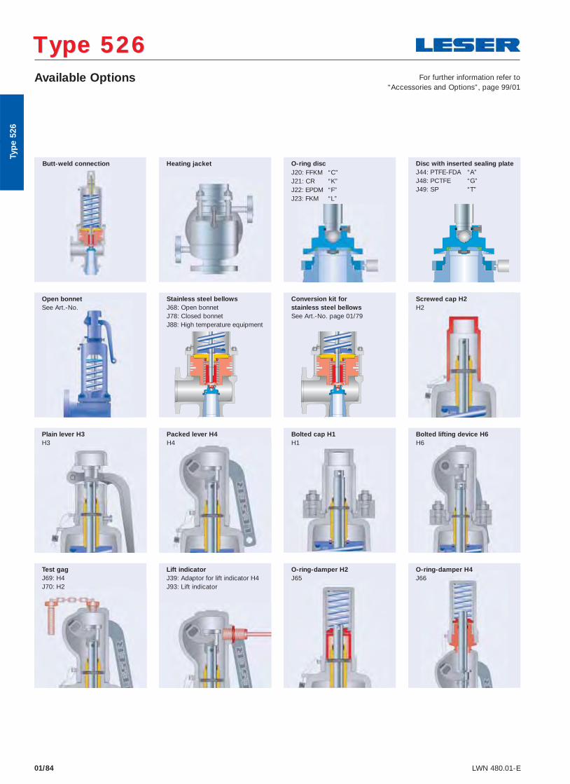
01/84 LWN 480.01-E
Available Options
Type 526 Type 526 For further information refer to
“Accessories and Options”, page 99/01
Heating jacket
Packed lever H4 H4
Plain lever H3 H3
O-ring-damper H2 J65
Lift indicator J39: Adaptor for lift indicator H4 J93: Lift indicator
Test gag J69: H4 J70: H2
O-ring-damper H4 J66
Conversion kit for stainless steel bellows See Art.-No. page 01/79
Stainless steel bellows J68: Open bonnet J78: Closed bonnet J88: High temperature equipment
Open bonnet See Art.-No.
Screwed cap H2 H2
Butt-weld connection
Disc with inserted sealing plate J44: PTFE-FDA “A” J48: PCTFE “G” J49: SP “T”
O-ring disc J20: FFKM “C”J21: CR “K”J22: EPDM “F”J23: FKM “L”
Bolted lifting device H6 H6
Typ
e 52
6
Bolted cap H1 H1
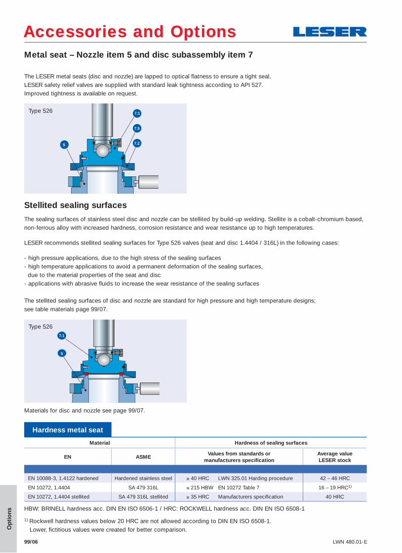
Metal seat – Nozzle item 5 and disc subassembly item 7
Accessories and OptionsAccessories and Options
99/06 LWN 480.01-E
Type 526
7.5
7.2
7.1
5
Op
tio
ns
The LESER metal seats (disc and nozzle) are lapped to optical flatness to ensure a tight seal.LESER safety relief valves are supplied with standard leak tightness according to API 527. Improved tightness is available on request.
Stellited sealing surfaces
The sealing surfaces of stainless steel disc and nozzle can be stellited by build-up welding. Stellite is a cobalt-chromium based, non-ferrous alloy with increased hardness, corrosion resistance and wear resistance up to high temperatures.
LESER recommends stellited sealing surfaces for Type 526 valves (seat and disc 1.4404 / 316L) in the following cases:
- high pressure applications, due to the high stress of the sealing surfaces- high temperature applications to avoid a permanent deformation of the sealing surfaces, due to the material properties of the seat and disc- applications with abrasive fluids to increase the wear resistance of the sealing surfaces
The stellited sealing surfaces of disc and nozzle are standard for high pressure and high temperature designs; see table materials page 99/07.
Hardness metal seat
Material Hardness of sealing surfaces
EN ASMEValues from standards or
manufacturers specifi cationAverage value LESER stock
EN 10088-3, 1.4122 hardened Hardened stainless steel ≥ 40 HRC LWN 325.01 Harding procedure 42 – 46 HRC
EN 10272, 1.4404 SA 479 316L ≤ 215 HBW EN 10272 Table 7 16 – 19 HRC1)
EN 10272, 1.4404 stellited SA 479 316L stellited ≥ 35 HRC Manufacturers specifi cation 40 HRC
HBW: BRINELL hardness acc. DIN EN ISO 6506-1 / HRC: ROCKWELL hardness acc. DIN EN ISO 6508-1
1) Rockwell hardness values below 20 HRC are not allowed according to DIN EN ISO 6508-1. Lower, fictitious values were created for better comparison.
5
7.1
Type 526
Materials for disc and nozzle see page 99/07.
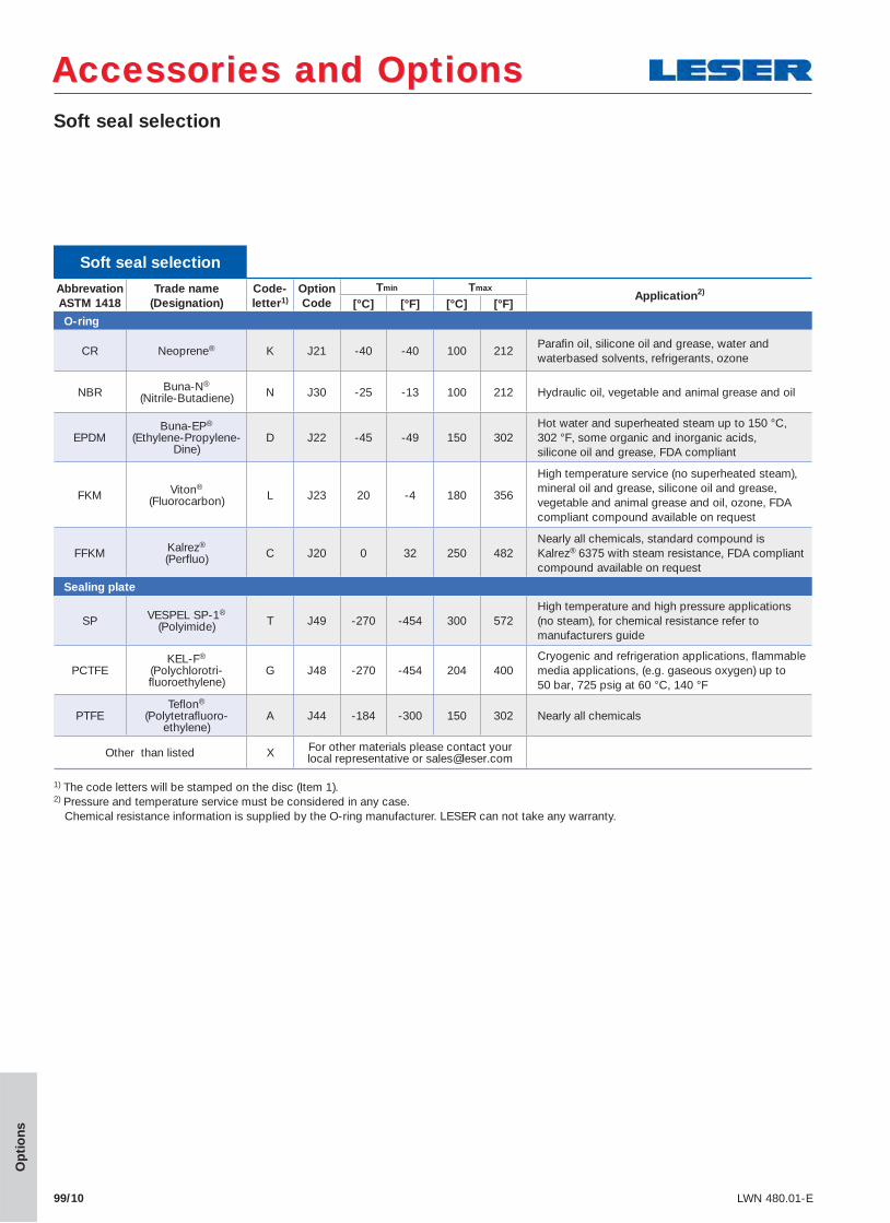
Soft seal selection
Accessories and OptionsAccessories and Options
99/10 LWN 480.01-E
Op
tio
ns
Soft seal selection
Abbrevation ASTM 1418
Trade name(Designation)
Code-letter1)
Option Code
Tmin TmaxApplication2)
[°C] [°F] [°C] [°F]O-ring
CR Neoprene® K J21 -40 -40 100 212Parafi n oil, silicone oil and grease, water and waterbased solvents, refrigerants, ozone
NBR Buna-N®
(Nitrile-Butadiene) N J30 -25 -13 100 212 Hydraulic oil, vegetable and animal grease and oil
EPDMBuna-EP®
(Ethylene-Propylene-Dine)
D J22 -45 -49 150 302Hot water and superheated steam up to 150 °C, 302 °F, some organic and inorganic acids, silicone oil and grease, FDA compliant
FKM Viton®
(Fluorocarbon) L J23 20 -4 180 356
High temperature service (no superheated steam), mineral oil and grease, silicone oil and grease, vegetable and animal grease and oil, ozone, FDA compliant compound available on request
FFKM Kalrez®
(Perfluo) C J20 0 32 250 482Nearly all chemicals, standard compound is Kalrez® 6375 with steam resistance, FDA compliant compound available on request
Sealing plate
SP VESPEL SP-1®
(Polyimide) T J49 -270 -454 300 572High temperature and high pressure applications (no steam), for chemical resistance refer to manufacturers guide
PCTFEKEL-F®
(Polychlorotri-fl uoroethylene)
G J48 -270 -454 204 400Cryogenic and refrigeration applications, fl ammable media applications, (e.g. gaseous oxygen) up to 50 bar, 725 psig at 60 °C, 140 °F
PTFETefl on®
(Polytetrafl uoro-ethylene)
A J44 -184 -300 150 302 Nearly all chemicals
Other than listed X For other materials please contact your local representative or [email protected]
1) The code letters will be stamped on the disc (Item 1). 2) Pressure and temperature service must be considered in any case. Chemical resistance information is supplied by the O-ring manufacturer. LESER can not take any warranty.
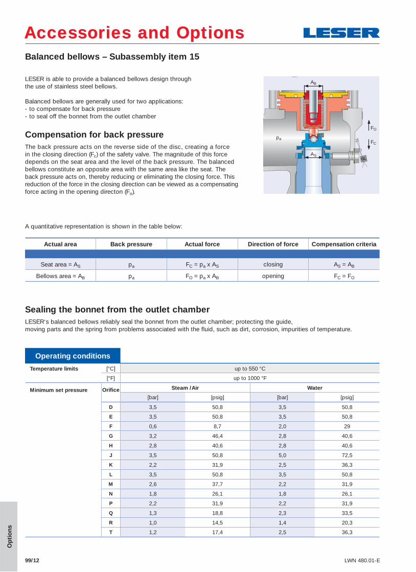
99/12 LWN 480.01-E
Balanced bellows – Subassembly item 15
Accessories and OptionsAccessories and Options
Operating conditions
Temperature limits [°C] up to 550 °C
[°F] up to 1000 °F
Minimum set pressure
Orifi ce Steam /Air Water
[bar] [psig] [bar] [psig]
D 3,5 50,8 3,5 50,8
E 3,5 50,8 3,5 50,8
F 0,6 8,7 2,0 29
G 3,2 46,4 2,8 40,6
H 2,8 40,6 2,8 40,6
J 3,5 50,8 5,0 72,5
K 2,2 31,9 2,5 36,3
L 3,5 50,8 3,5 50,8
M 2,6 37,7 2,2 31,9
N 1,8 26,1 1,8 26,1
P 2,2 31,9 2,2 31,9
Q 1,3 18,8 2,3 33,5
R 1,0 14,5 1,4 20,3
T 1,2 17,4 2,5 36,3
Op
tio
ns
Actual area Back pressure Actual force Direction of force Compensation criteria
Seat area = AS pa FC = pa x AS closing AS = AB
Bellows area = AB pa FO = pa x AB opening FC = FO
LESER is able to provide a balanced bellows design through the use of stainless steel bellows. Balanced bellows are generally used for two applications: - to compensate for back pressure - to seal off the bonnet from the outlet chamber
Compensation for back pressureThe back pressure acts on the reverse side of the disc, creating a force in the closing direction (Fc) of the safety valve. The magnitude of this force depends on the seat area and the level of the back pressure. The balanced bellows constitute an opposite area with the same area like the seat. The back pressure acts on, thereby reducing or eliminating the closing force. This reduction of the force in the closing direction can be viewed as a compensating force acting in the opening directon (Fo).
A quantitative representation is shown in the table below:
AS
pa
FO
FC
AB
Sealing the bonnet from the outlet chamberLESER‘s balanced bellows reliably seal the bonnet from the outlet chamber; protecting the guide, moving parts and the spring from problems associated with the fluid, such as dirt, corrosion, impurities of temperature.
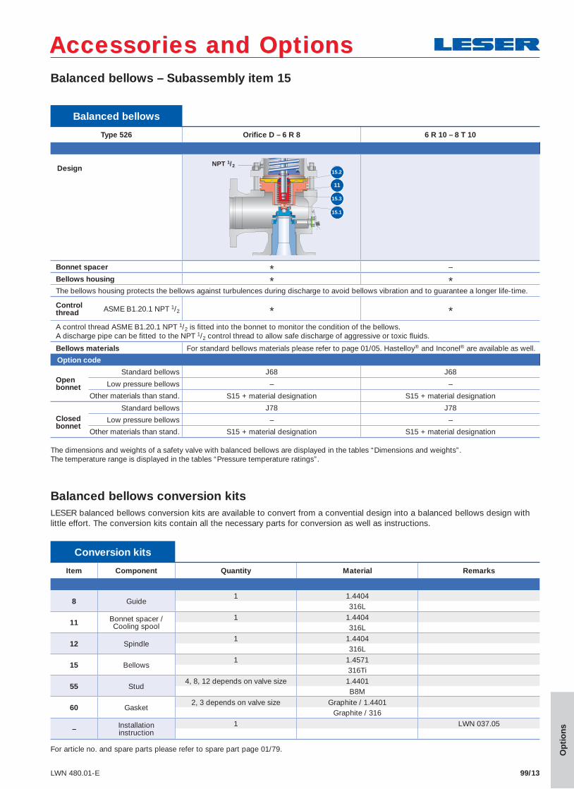
99/13LWN 480.01-E
Balanced bellows – Subassembly item 15
Accessories and OptionsAccessories and Options
Op
tio
ns
Balanced bellows
Type 526 Orifi ce D – 6 R 8 6 R 10 – 8 T 10
Design
Bonnet spacer * –
Bellows housing * *The bellows housing protects the bellows against turbulences during discharge to avoid bellows vibration and to guarantee a longer life-time.
Controlthread ASME B1.20.1 NPT 1/2 * *A control thread ASME B1.20.1 NPT 1/2 is fi tted into the bonnet to monitor the condition of the bellows. A discharge pipe can be fi tted to the NPT 1/2 control thread to allow safe discharge of aggressive or toxic fl uids.
Bellows materials For standard bellows materials please refer to page 01/05. Hastelloy® and Inconel® are available as well.
Option code
Openbonnet
Standard bellows J68 J68
Low pressure bellows – –
Other materials than stand. S15 + material designation S15 + material designation
Closedbonnet
Standard bellows J78 J78
Low pressure bellows – –
Other materials than stand. S15 + material designation S15 + material designation
15.2
15.3
15.1
11
NPT 1/2
The dimensions and weights of a safety valve with balanced bellows are displayed in the tables “Dimensions and weights”. The temperature range is displayed in the tables “Pressure temperature ratings”.
Conversion kits
Item Component Quantity Material Remarks
8 Guide1 1.4404
316L
11 Bonnet spacer / Cooling spool
1 1.4404316L
12 Spindle1 1.4404
316L
15 Bellows1 1.4571
316Ti
55 Stud4, 8, 12 depends on valve size 1.4401
B8M
60 Gasket2, 3 depends on valve size Graphite / 1.4401
Graphite / 316
– Installation instruction
1 LWN 037.05
For article no. and spare parts please refer to spare part page 01/79.
Balanced bellows conversion kitsLESER balanced bellows conversion kits are available to convert from a convential design into a balanced bellows design with little effort. The conversion kits contain all the necessary parts for conversion as well as instructions.
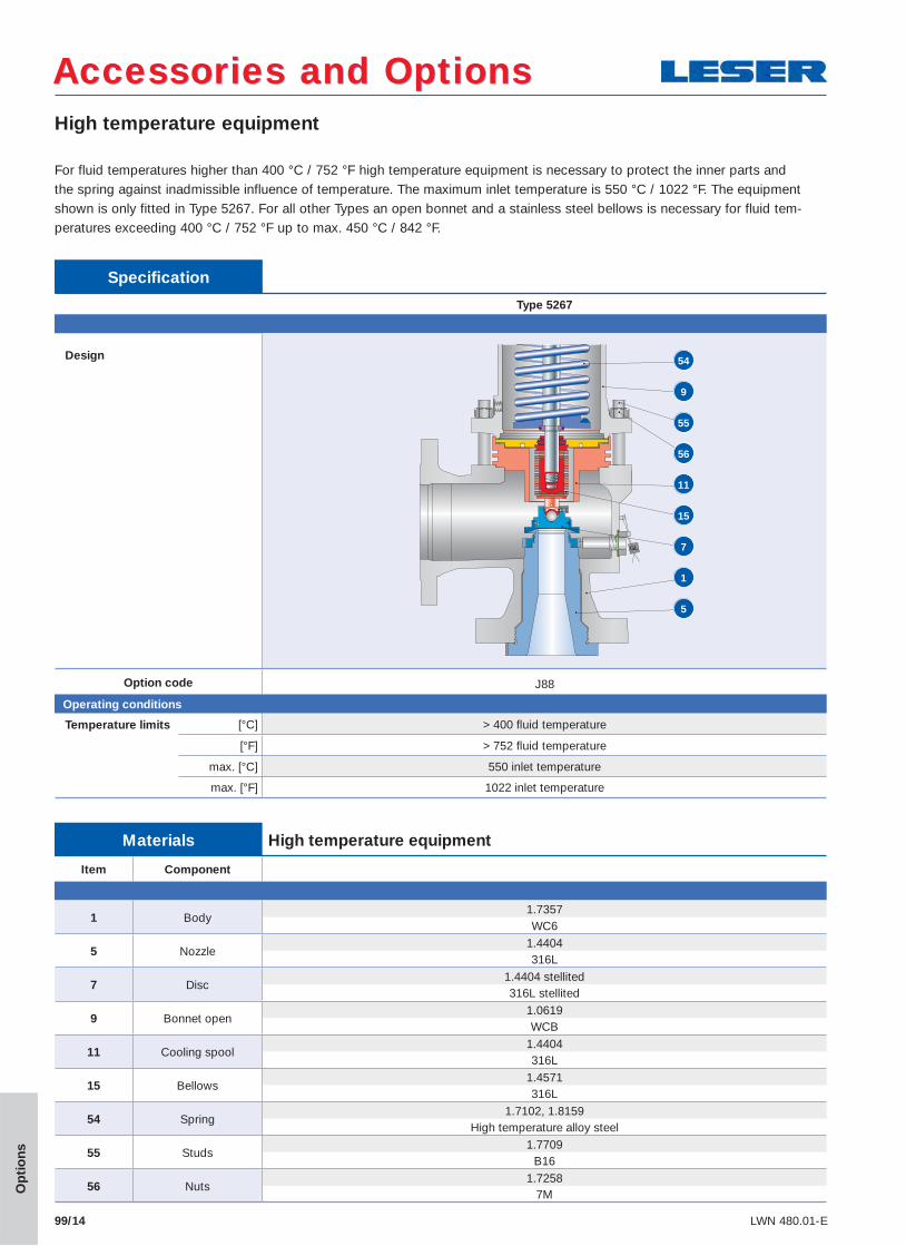
99/14 LWN 480.01-E
High temperature equipment
Accessories and OptionsAccessories and Options
Op
tio
ns
For fluid temperatures higher than 400 °C / 752 °F high temperature equipment is necessary to protect the inner parts and the spring against inadmissible influence of temperature. The maximum inlet temperature is 550 °C / 1022 °F. The equipment shown is only fitted in Type 5267. For all other Types an open bonnet and a stainless steel bellows is necessary for fluid tem-peratures exceeding 400 °C / 752 °F up to max. 450 °C / 842 °F.
Temperature limits [°C] > 400 fl uid temperature
[°F] > 752 fl uid temperature
max. [°C] 550 inlet temperature
max. [°F] 1022 inlet temperature
Materials High temperature equipment
Item Component
1 Body1.7357WC6
5 Nozzle1.4404316L
7 Disc1.4404 stellited316L stellited
9 Bonnet open1.0619WCB
11 Cooling spool1.4404316L
15 Bellows1.4571316L
54 Spring1.7102, 1.8159
High temperature alloy steel
55 Studs1.7709
B16
56 Nuts1.7258
7M
Specifi cation
Type 5267
Design
Option code J88
Operating conditions
54
55
56
9
11
5
1
7
15
Related Documents