School of Mechanical and Industrial Engineering Mechanical Engineering Department Machine design project II Project on Flange Coupling Design By:- ROMEO/WONDIE-CHANIE ID No 0502760 SUBMITTED TO:- Page 1 BAHIR DAR UNIVERSITY

Welcome message from author
This document is posted to help you gain knowledge. Please leave a comment to let me know what you think about it! Share it to your friends and learn new things together.
Transcript
School of Mechanical and Industrial EngineeringMechanical Engineering Department
Machine design project IIProject on Flange Coupling Design
By:- ROMEO/WONDIE-CHANIE
ID No 0502760
SUBMITTED TO:-
Page 1
BAHIR DAR UNIVERSITY

ADDISU NEGASH
(Mr.)
SUBMITION DATE:- 20/08/2007 E.C
Acknowledgement
This project would have been part of our day to
day activity, if not for the help and
encouragement from our lecture, ADDISU N. (Mr).
I am so grateful for he has allowed me to
carry out the project in the sense it will
impart me future life.
Page 2

I would also like to mention my friends for
the encouragement and corporation they have had
with me.
Finally, yet importantly, I express my
heartfelt thanks my parents.
Table of Contents
Acknowledgement..............................2
Page 3
1. Introduction.............................4
2. Literature survey........................5
1.2.1. Rigid coupling:.....................5
3. Problem statement........................8
4. Objectives...............................8
5. Geometric analysis and proportions.......9
6. Material Selection......................13
7. Methodology.............................14
8. Design of flange coupling...............15
9. Manufacturing Processes.................17
10. Cost analysis..........................19
11. Conclusion.............................21
Page 4
12. Recommendation.........................22
13. Reference..............................23
1. IntroductionDesigning a machine component is not a simple task. It needs tooptimize and consider all design parameters. Moreover, the economic, aesthetic values and environmental effects of the design need to be considered. We have organized our knowledge of flange coupling design; concept design in the literature review, embodiment design as the geometric and procedure analysis.A shaft is a rotating machine element which is usedto transmit power from one place to another. The power isdelivered to the shaft by some tangential force and theresultant torque (or twisting moment) set up within the shaftpermits the power to betransferred to various machineslinked up to the shaft. In orderto transfer the power fromone shaft to another, the various members such as pulleys,gears etc., are mounted on it. These members along withthe forces exerted upon them causes the shaftto bending.In other words, we may say that a shaft is used for thetransmission of torque and bending moment. The variousmembers are mounted on the shaft by means of keys orsplines.A key is a piece of mild steel inserted between the shaftandhuborbossofthepulleytoconnectthesetogether in order to prevent relative motion between them. It is always inserted
Page 5
parallelto the axis of the shaft. Keys are usedastemporaryfasteningsandaresubjectedtoconsider- able crushing and shearing stresses. A keyway is a slot or recess ina shaft and hub of the pulley to accommodatea key.A coupling is a device used to connect two shafts together at their ends for the purpose of transmitting power. Couplings do not normally allow disconnection of shafts during operation, however there are torque limiting couplings which can slip or disconnect when some torque limit is exceeded.The primary purpose of couplings is to join two pieces of rotating equipment while permitting some degree of misalignmentor end movement or both. By careful selection, installation andmaintenance of couplings, substantial savings can be made in reduced maintenance costs and downtime.Shaft couplings are used in machinery to provide connection of shafts of units which are manufactured separately such as a motor and generator, to provide for disconnection for repairs or alternations, to provide for misalignment of the shafts or to introduce mechanical flexibility, to reduce the transmissionof shock loads from one shaft to another, to introduce protection against overloads.A good shaft coupling should have the following requirements:
It should be easy to connect or disconnect the coupling.It does allow some misalignment between the two adjacentshaft rotation axes.Its goal should be to minimize the remaining misalignment inrunning operation so as to maximize power transmission and to maximize machine runtime (coupling, bearing and sealing'slifetime).
2. Literature survey
Page 6
Types of shafts couplings
Rigid coupling:A rigid coupling is a unit of hardware used to join two shafts within a motor or mechanical system. It may be used to connect two separate systems, such as a motor and a generator, or to repair a connection within a single system. A rigid coupling may also be added between shafts to reduce shock and wear at the point where the shafts meet.When joining shafts within a machine, mechanics can choose between flexible and rigid couplings. While flexible units offer some movement and give between the shafts, rigid couplings are the most effective choice for precise alignment and secure hold. By precisely aligning the two shafts and holding them firmly in place, rigid couplings help to maximize performance and increase the expected life of the machine. These rigid couplings are available in two basic designs to fitthe needs of different applications. Sleeve-style couplings arethe most affordable and easiest to use. They consist of a single tube of material with an inner diameter that's equal in size to the shafts. The sleeve slips over the shafts so they meet in the middle of the coupling. A series of set screws can be tightened so they touch the top of each shaft and hold them in place without passing all the way through the coupling.Clamped or compression rigid couplings come in two parts and fit together around the shafts to form a sleeve. They offer more flexibility than sleeved models, and can be used on shaftsthat are fixed in place. They generally are large enough so that screws can pass all the way through the coupling and into the second half to ensure a secure hold. Flanged rigid couplings are designed for heavy loads or industrial equipment.
Page 7
They consist of short sleeves surrounded by a perpendicular flange. One coupling is placed on each shaft so the two flangesline up face to face. A series of screws or bolts can then be installed in the flanges to hold them together. Because of their size and durability, flanged units can be used to bring shafts into alignment before they are joined together. Rigid couplings are used when precise shaft alignment is required; shaft misalignment will affect the coupling's performance as well as its life. ExamplesTypes of rigid coupling Sleeve or Muff CouplingThis is a simple coupling which is used to connect two shafts rigidly. Muff coupling has a hollow cylinder whose inner diameter is the same as that of the shaft. It is fitted over the ends of the two shafts by means of either key, taper pins or set screws as shown in fig. 1. The torque is transmitted from one shaft to the other shaft by means of a key and a sleeve. Design of sleeve or muff coupling procedure:Clamp or Compression Coupling This type of coupling is the modification of the sleeve coupling. It is also known as split muff coupling. This coupling is made in two parts which are machined to fit the shaft. The two halves of the coupling are clamped rigidly against the surface of the shaft ends by through studs or bolts. The number of bolts may be two, four or six. This coupling may be used for heavy duty and moderate speeds. In theclamp or compression coupling, the power is transmitted from one shaft to the other by means of key and the friction betweenthe muff and shaft. Flange Coupling A flange coupling usually applies to a coupling having two separate cast iron flanges. Each flange is mounted on the shaft
Page 8
end and keyed to it. The faces are turned up at right angle to the axis of the shaft. One of the flanges has a projected portion and the other flange has a corresponding recess. This helps to bring the shafts into line and to maintain alignment. The two flanges are coupled together by means of bolts and nuts. The flange couplings are of the following three types:a.Unprotected type flange coupling.
In an unprotected type flange coupling, as shown in Fig. 3, each shaft is keyed to the boss of a flange with a counter sunkkey and the flanges are coupled together by means of bolts. Generally, three, four or six bolts are used. The keys are staggered at right angle along the circumference of the shafts in order to divide the weakening effect caused by keyways.b.Protected type flange coupling
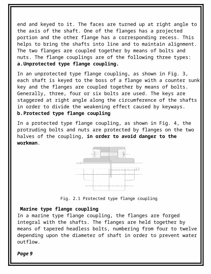
In a protected type flange coupling, as shown in Fig. 4, the protruding bolts and nuts are protected by flanges on the two halves of the coupling, in order to avoid danger to the workman.
Fig. 2.1 Protected type flange coupling
Marine type flange couplingIn a marine type flange coupling, the flanges are forged integral with the shafts. The flanges are held together by means of tapered headless bolts, numbering from four to twelve depending upon the diameter of shaft in order to prevent water outflow.
Page 9
Flexible couplingsFlexible couplings are used to transmit torque from one shaft to another when the two shafts are slightly misaligned. Flexible couplings can accommodate varying degrees of misalignment up to 3° and some parallel misalignment. In addition, they can also be used for vibration damping or noise reduction.Flexible coupling: used to connect two shafts having both
lateral and angular misalignment.a.Bushed pin type coupling
b.Universal coupling
c.Oldham coupling
Bushed–pin Flexible CouplingA bushed-pin flexible coupling, as shown in Fig. 6, is a modification of the rigid type of flange coupling. The couplingbolts are known as pins. The rubber or leather bushes are used over the pins. The two halves of the coupling are dissimilar inconstruction. A clearance of 5 mm is left between the face of the two halves of the coupling. There is no rigid connection between them and the drive takes place through the medium of the compressible rubber or leather bushes.In designing the bushed-pin flexible coupling, the proportions of the rigid type flange coupling are modified. The main modification is to reduce the bearing pressure on the rubber orleather bushes and it should not exceed 0.5 N/mm2. In order to keep the low bearing pressure, the pitch circle diameter and the pin size is increased.Oldham CouplingIt is used to join two shafts which have lateral misalignment. It consists of two flanges A and B with slots and a central floating part E with two tongues T1 and T2 at right angles as shown inFig. 7. The central floating part is held by means of a
Page 10
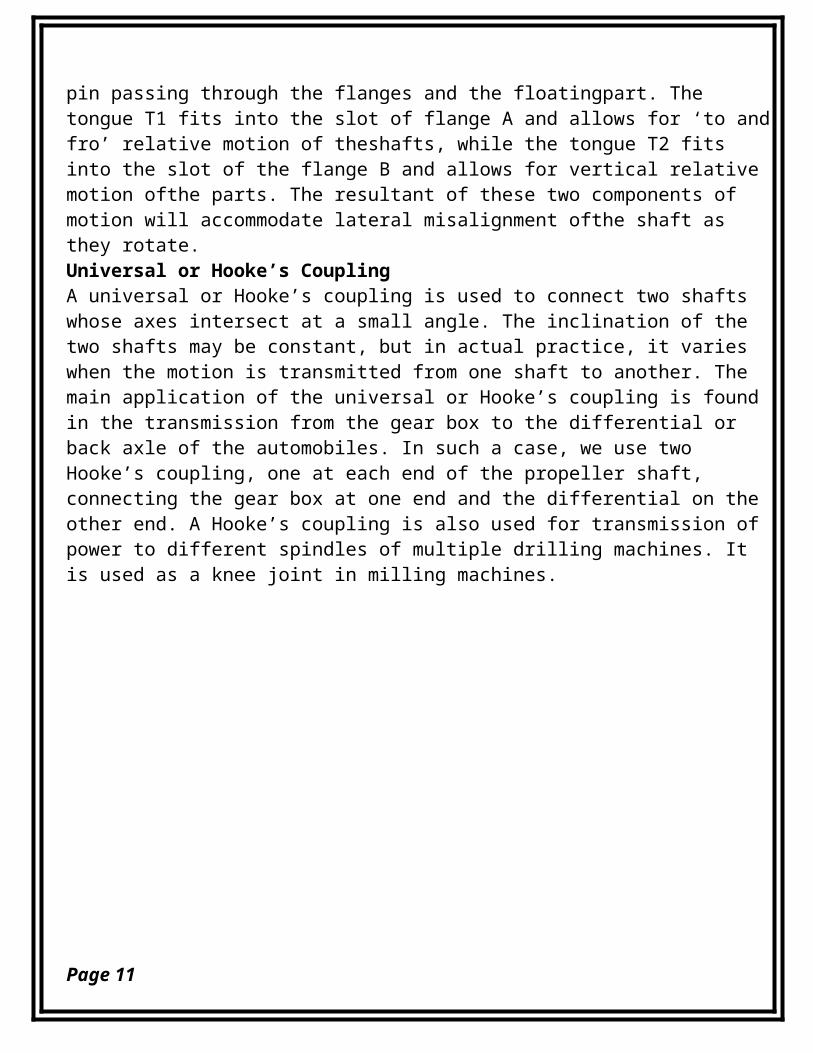
pin passing through the flanges and the floatingpart. The tongue T1 fits into the slot of flange A and allows for ‘to andfro’ relative motion of theshafts, while the tongue T2 fits into the slot of the flange B and allows for vertical relative motion ofthe parts. The resultant of these two components of motion will accommodate lateral misalignment ofthe shaft as they rotate.Universal or Hooke’s CouplingA universal or Hooke’s coupling is used to connect two shafts whose axes intersect at a small angle. The inclination of the two shafts may be constant, but in actual practice, it varies when the motion is transmitted from one shaft to another. The main application of the universal or Hooke’s coupling is found in the transmission from the gear box to the differential or back axle of the automobiles. In such a case, we use two Hooke’s coupling, one at each end of the propeller shaft, connecting the gear box at one end and the differential on the other end. A Hooke’s coupling is also used for transmission of power to different spindles of multiple drilling machines. It is used as a knee joint in milling machines.
Page 11
3. Problem statement
Design of flange shaft coupling of light operating
condition, power to be transmitted 45kw at angular
speed of 140rpm and economic via light weight materials
is our design project in two weeks work time. Cross
check the design parameters and interpolate the design
variables considering the component service life, safe
environmental, operating and maintenance conditions.
4. Objectives
The main objective is design of flange coupling taking
into account the design constraints such as material
availability, machinability and cost of manufacturing.
Specific objectives
To acquaint ourselves to the design constraints
To identify the design parameters
Page 12
To optimize the design variables to safe mode of
operating conditions
To survey the manufacturing sites and equipment to
be used
To acquire functional and non functional skills for
the design of complex and intricate components of a
machine
5. Geometric analysis and proportions
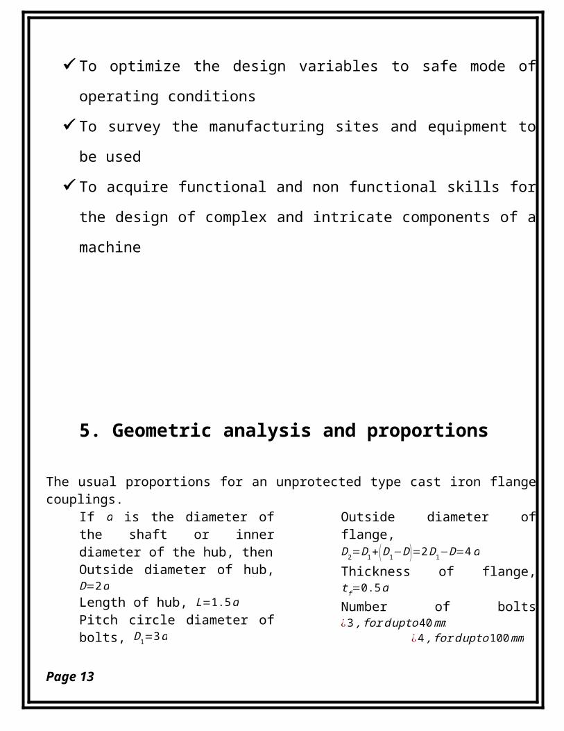
The usual proportions for an unprotected type cast iron flangecouplings.
If d is the diameter ofthe shaft or innerdiameter of the hub, thenOutside diameter of hub,D=2dLength of hub, L=1.5dPitch circle diameter ofbolts, D1=3d
Outside diameter offlange,D2=D1+(D1−D)=2D1−D=4dThickness of flange,tf=0.5dNumber of bolts¿3,fordupto40mm
¿4,fordupto100mm
Page 13
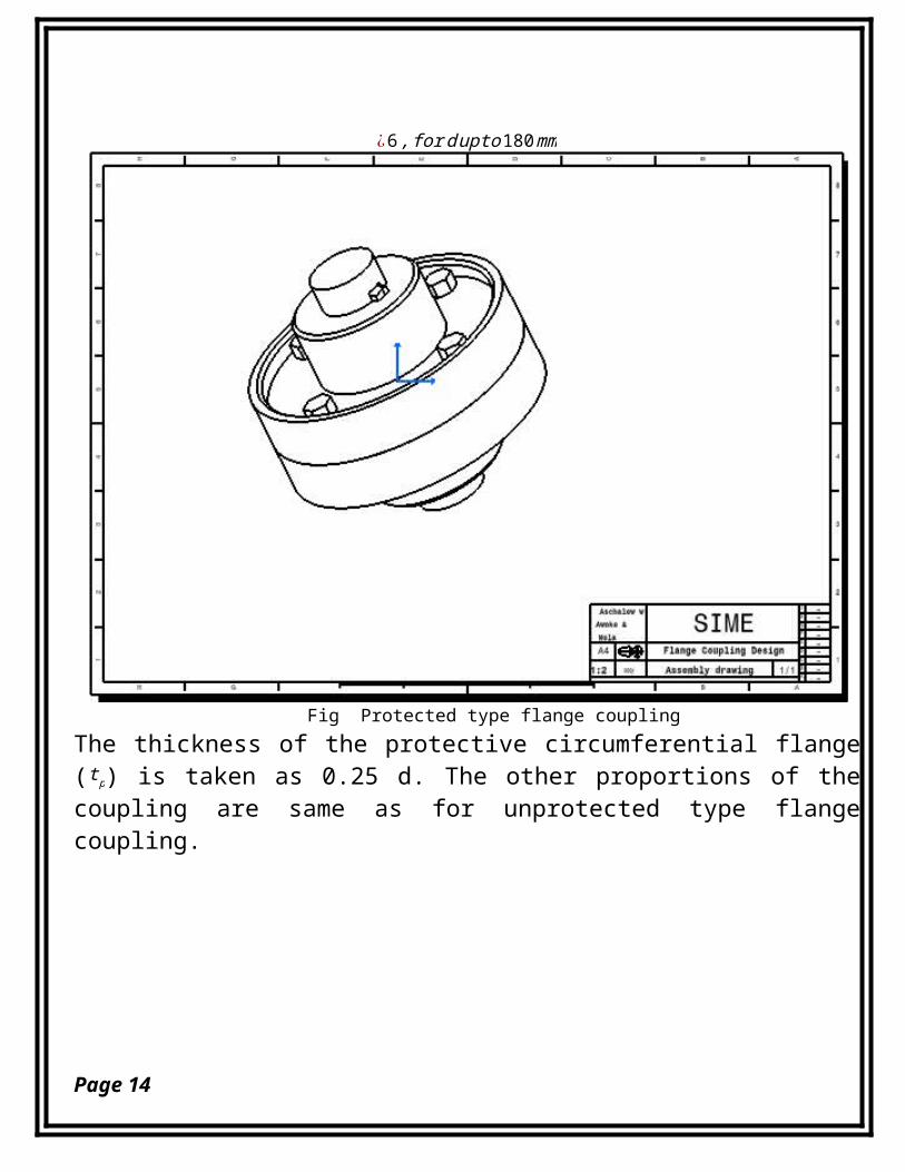
¿6,fordupto180mm
Fig Protected type flange couplingThe thickness of the protective circumferential flange(tp) is taken as 0.25 d. The other proportions of thecoupling are same as for unprotected type flangecoupling.
Page 14
Page 15
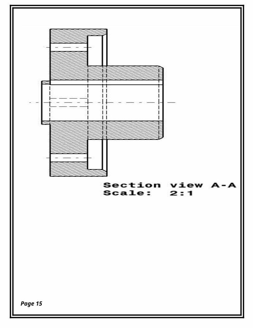
Fig. Protected type flange coupling
6. Material SelectionThe selectionof a proper material,for engineeringpurposes, isone of the most difficult problemsforthedesigner.The basic question is how do we go about selecting a material for a givenpart? This may seem like a very complicated process until we realize than we are often restrained by choices we have alreadymade. For example, if different parts have to interact then material choice becomes limited. When we talk about choosing materials for a component, we take into account many different factors. These factors can be broken down into the following areas. Material Properties The expected level of performance from the material Material Cost and Availability Material must be priced appropriately (not cheap but right) Material must be available (better to have multiple sources) Processing Must consider how to make the part, for example:
Casting
Machining
Welding
Environment
The effect that the
service environment has
on the part
The effect the part has
on the environment
Page 16
The effect that
processing has on the
environment
Now clearly these issues are inter-linked in some fashion. For example, cost is a direct result of how difficult a material is to obtain and to machine. And the effect of the environment on the material is clearly related to the material properties. So if we really want to use a novel or unusual material, the choice must be made early in the design process. Then we can do the detailed design work using the correct material properties. Consider the example of wooden airplanes and metal-framed airplanes. If we were to design an airplane ofeither material we will have to make the choice early. The enddesigns are quite different. So, the material choice can radically alter the final design. But the possibility also exists that it may not. After all what are the real differencebetween a 1045 and 1035 carbon steel? Fabrication Properties
Ease of machining
Ease of welding, casting,
etc
Availability
Joining
techniques
We have selected steel of 40 C8 for the shaft, key and bolt,and cast iron of 48Mpa.Thefollowingfactorsare metwhileselectingthesematerials:
1. Availability2. Suitabilityfortheworkingconditionsinservice,and3. Thecost.
Page 17
7. MethodologyParameters Analysis for Material Selection
In order to manipulate the material selection with respect to
the design parameters we have used the following method of
analysis.
Function: what does the component do?
A shaft subjected to torsion
Objective: what essential conditions must be met?
Minimize weight and light operating condition
Constraints: what is to be maximized or minimized?
Shaft diameter and flange length or thickness
Free Variable: identify which variables are free?
Cross-sectional area and Material, therefore minimize
weight by maximizing Yield Stress / Densitym >= (F) (L)
(Density/Yield Stress)
Eliminate free variable:
m = A*L*Density
F/A < Yield Stress
Design of flange coupling procedure:
Step 1: Design of shaft
Step 2: Design for hub
Step 3: Design for key Step 4: Design for flange
Page 18
Step 5:Design for bolts
We have also used Mechanical modeling software (Catia v5)for the drawing in order to apply the skills we acquirefor other practical works.
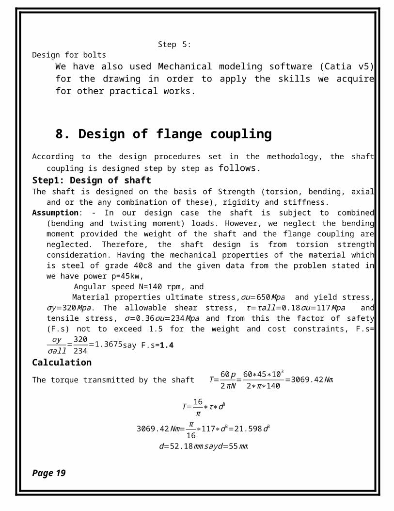
8. Design of flange couplingAccording to the design procedures set in the methodology, the shaft
coupling is designed step by step as follows.Step1: Design of shaftThe shaft is designed on the basis of Strength (torsion, bending, axial
and or the any combination of these), rigidity and stiffness. Assumption: - In our design case the shaft is subject to combined
(bending and twisting moment) loads. However, we neglect the bendingmoment provided the weight of the shaft and the flange coupling areneglected. Therefore, the shaft design is from torsion strengthconsideration. Having the mechanical properties of the material whichis steel of grade 40c8 and the given data from the problem stated inwe have power p=45kw,
Angular speed N=140 rpm, and Material properties ultimate stress,σu=650Mpa and yield stress,
σy=320Mpa. The allowable shear stress, τ=τall=0.18σu=117Mpa andtensile stress, σ=0.36σu=234Mpa and from this the factor of safety(F.s) not to exceed 1.5 for the weight and cost constraints, F.s=σyσall
=320234
=1.3675say F.s=1.4
CalculationThe torque transmitted by the shaft T=
60p2πN=
60∗45∗1032∗π∗140
=3069.42Nm
T=16π
∗τ∗d3
3069.42Nm= π16
∗117∗d3=21.598d3
d=52.18mmsayd=55mm
Page 19
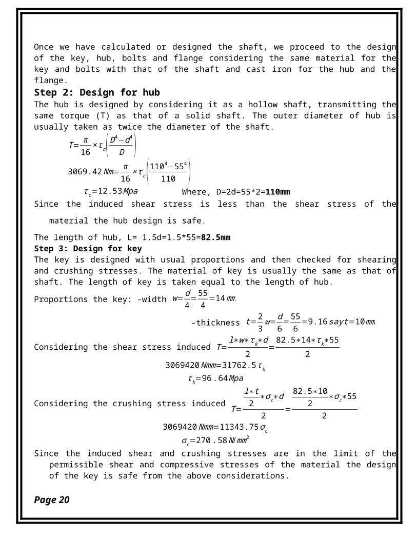
Once we have calculated or designed the shaft, we proceed to the designof the key, hub, bolts and flange considering the same material for thekey and bolts with that of the shaft and cast iron for the hub and theflange.Step 2: Design for hubThe hub is designed by considering it as a hollow shaft, transmitting thesame torque (T) as that of a solid shaft. The outer diameter of hub isusually taken as twice the diameter of the shaft.
T= π16
×τc(D4−d4
D )3069.42Nm= π
16×τc(1104−554
110 )τc=12.53Mpa Where, D=2d=55*2=110mm
Since the induced shear stress is less than the shear stress of the
material the hub design is safe.
The length of hub, L= 1.5d=1.5*55=82.5mmStep 3: Design for keyThe key is designed with usual proportions and then checked for shearingand crushing stresses. The material of key is usually the same as that ofshaft. The length of key is taken equal to the length of hub.
Proportions the key: -width w=d4=55
4=14mm
-thickness t=23w=
d6=556
=9.16sayt=10mm
Considering the shear stress induced T=l∗w∗τk∗d
2=82.5∗14∗τk∗55
23069420Nmm=31762.5τk
τk=96.64Mpa
Considering the crushing stress induced T=
l∗t2
∗σc∗d
2=
82.5∗102
∗σc∗55
23069420Nmm=11343.75σc
σc=270.58N/mm2
Since the induced shear and crushing stresses are in the limit of thepermissible shear and compressive stresses of the material the designof the key is safe from the above considerations.
Page 20
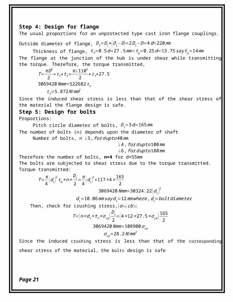
Step 4: Design for flangeThe usual proportions for an unprotected type cast iron flange couplings.
Outside diameter of flange, D2=D1+(D1−D)=2D1−D=4d=220mmThickness of flange, tf=0.5d=27.5mm∧tp=0.25d=13.75saytp=14mm
The flange at the junction of the hub is under shear while transmittingthe torque. Therefore, the torque transmitted,
T=πD2
2 ∗τf∗tf=π ¿1102
2 ∗τf∗27.5
3069420Nmm=522682τfτf=5.872N /mm2
Since the induced shear stress is less than that of the shear stress ofthe material the flange design is safe. Step 5: Design for boltsProportions:
Pitch circle diameter of bolts, D1=3d=165mmThe number of bolts (n) depends upon the diameter of shaft
Number of bolts, n ¿3,fordupto40mm¿4,fordupto100mm¿6,fordupto180mm
Therefore the number of bolts, n=4 for d=55mmThe bolts are subjected to shear stress due to the torque transmitted. Torque transmitted:
T=π4 (d1 )2τb×n×
D12
=π4 (d1 )2∗117×4× 1652
3069420Nmm=30324.22 (d1 )2
d1=10.06mmsayd1=12mmwhere,d1=boltdiameter Then, check for crushing stress,(σ¿¿cb)¿
T=(n×d1×tf×σcb)D1
2=(4×12×27.5×σcb ) 1652
3069420Nmm=108900σcb
σcb=28.2N /mm2
Since the induced crushing stress is less than that of the corresponding
shear stress of the material, the bolts design is safe
Page 21
9. Manufacturing ProcessesThe knowledge of manufacturing processes is of great for a
design engineer. The following are the various manufacturing
processes used in the manufacturing of flange coupling with the
design specifications. We have listed systematically the
operation that we do in one way another as follows.
Primary shaping processes.
Casting Forging, Extruding Rolling
Drawing Bending Shearing Spinning
Powder MetalForming
Squeezing,Etc.
Machining Processes.
Turning Planning Shaping Drilling
BoringReaming Sawing Broaching
MillingGrinding etc.
Surface finishing processes.
PolishingBuffing Honing LappingAbrasive BeltGrinding
Barrel TumblingSuper finishingetc.
Page 22
Processes effecting change in properties.
Heat treatment:-
Hot-Working
Cold-Working
Page 23
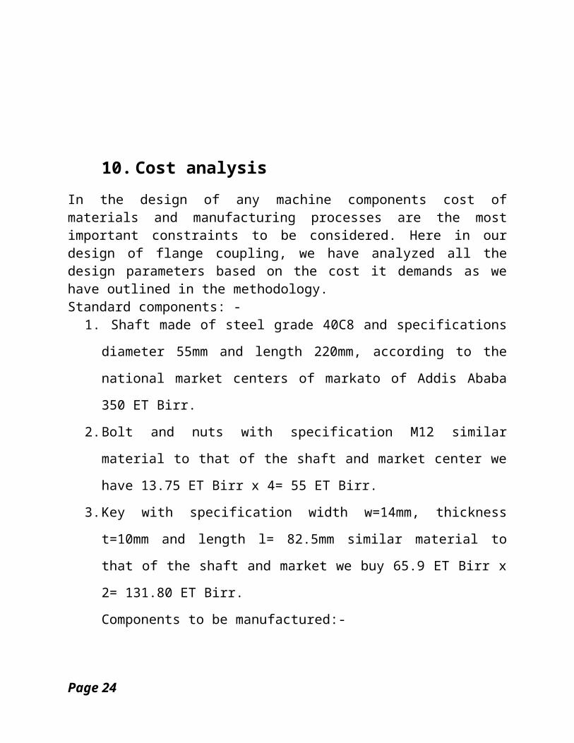
10. Cost analysisIn the design of any machine components cost ofmaterials and manufacturing processes are the mostimportant constraints to be considered. Here in ourdesign of flange coupling, we have analyzed all thedesign parameters based on the cost it demands as wehave outlined in the methodology.Standard components: -
1. Shaft made of steel grade 40C8 and specifications
diameter 55mm and length 220mm, according to the
national market centers of markato of Addis Ababa
350 ET Birr.
2.Bolt and nuts with specification M12 similar
material to that of the shaft and market center we
have 13.75 ET Birr x 4= 55 ET Birr.
3.Key with specification width w=14mm, thickness
t=10mm and length l= 82.5mm similar material to
that of the shaft and market we buy 65.9 ET Birr x
2= 131.80 ET Birr.
Components to be manufactured:-
Page 24
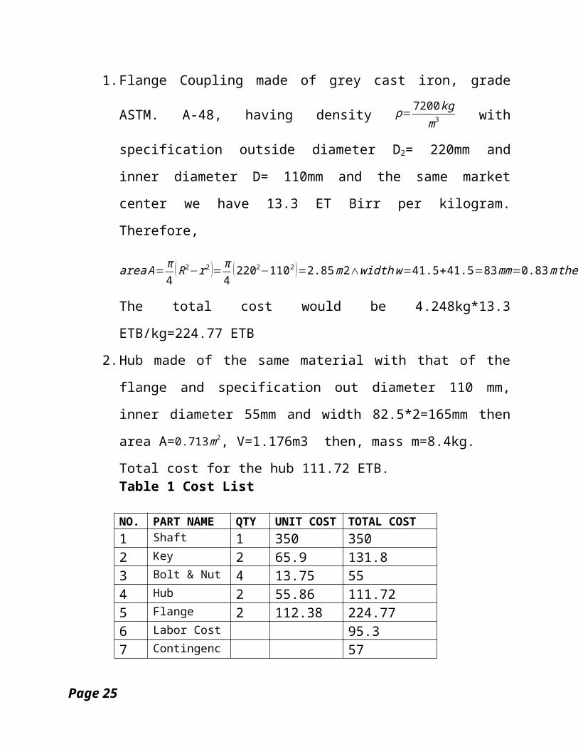
1.Flange Coupling made of grey cast iron, grade
ASTM. A-48, having density ρ=7200kg
m3 with
specification outside diameter D2= 220mm and
inner diameter D= 110mm and the same market
center we have 13.3 ET Birr per kilogram.
Therefore,
areaA=π4
(R2−r2 )=π4
(2202−1102 )=2.85m2∧widthw=41.5+41.5=83mm=0.83mthen,thevolumeV=A∗W=2.36m3,finallymassm=V∗ρ=0.59∗7200=16.9kg.
The total cost would be 4.248kg*13.3
ETB/kg=224.77 ETB
2.Hub made of the same material with that of the
flange and specification out diameter 110 mm,
inner diameter 55mm and width 82.5*2=165mm then
area A=0.713m2, V=1.176m3 then, mass m=8.4kg.
Total cost for the hub 111.72 ETB. Table 1 Cost List
NO. PART NAME QTY UNIT COST TOTAL COST1 Shaft 1 350 3502 Key 2 65.9 131.83 Bolt & Nut 4 13.75 554 Hub 2 55.86 111.725 Flange 2 112.38 224.776 Labor Cost 95.37 Contingenc 57
Page 25
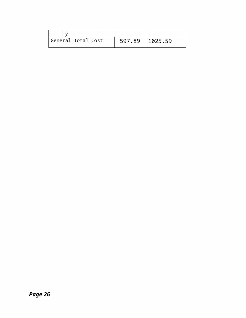
y General Total Cost 597.89 1025.59
Page 26
11. Conclusion
I conclude my design project having
designed flange coupling taking into
account all the design parameters.
Page 27
12. RecommendationIn order to coup up with the advancement of
technology and complicated designs, we have
used mechanical software like Catia for the
geometric and assembly drawings. Therefore,
strongly recommend design engineers to
develop and adapt mechanical softwares for
accuracy and further application of
creative designs. For the printing and
Page 28

copying cost constraints, we slightly
impart the recommended documentation
format.
Page 29
13. Reference
1. http://ethiovisit.com/
attractions/attractions.html on
28/07/2006
2. Wikipedia on 28/07/06
3. Charles R.Mischke, Joseph
E.Shigly, Mechanical engineering
design, 2001, 6th Ed.
4. Frank W. Wilson, Manufacturing
and planning and Estimating
Handbook, 1964.
Page 30
5. Dr.D.S Kumar, Elements of
mechanical engineering, 2006, 2nd
Ed.
6. BDU IOT Lecture Notes
Page 31

Related Documents