ECE/OPTI533 Digital Image Processing class notes 220 Dr. Robert A. Schowengerdt 2003 2-D FILTER DESIGN TYPES • Finite Impulse Response (FIR) described here • Infinite Impulse Response (IIR) not discussed

Welcome message from author
This document is posted to help you gain knowledge. Please leave a comment to let me know what you think about it! Share it to your friends and learn new things together.
Transcript

ECE/OPTI533 Digital Image Processing class notes 220 Dr. Robert A. Schowengerdt 2003
2-D FILTER DESIGNTYPES
• Finite Impulse Response (FIR) Ñ described here
• Infinite Impulse Response (IIR) Ñ not discussed

ECE/OPTI533 Digital Image Processing class notes 221 Dr. Robert A. Schowengerdt 2003
2-D FILTER DESIGNZERO-PHASE FILTERS
• h(m,n) is zero-phase if , i.e. H is real
• Zero-phase desired in digital filters to avoid signal distortion
Zero-phase not guaranteed in physical filters, e.g. optical defocus and square scan spots (see Notes4 and 5)
• H real implies
Prove the above equation
H k l,( ) H* k l,( )=
h m n,( ) h* m– n–,( )=

ECE/OPTI533 Digital Image Processing class notes 222 Dr. Robert A. Schowengerdt 2003
2-D FILTER DESIGN• Furthermore, since h is assumed real in our case,
, i.e. h is two-fold symmetric
• Greater symmetry reduces number of independent points (Degrees of Freedom (DOF)) required in filter design
h m n,( ) h m– n–,( )=
n
m
6
3
3
22

ECE/OPTI533 Digital Image Processing class notes 223 Dr. Robert A. Schowengerdt 2003
2-D FILTER DESIGN• Additional symmetries
four-fold (includes two-fold):
eight-fold (includes four-fold):
h m n,( ) h m– n,( ) h m n–,( )= =
n
m
6
3
3
22
h m n,( ) h m– n,( ) h m n–,( ) h n m,( )= = =
n
m
6
3
3
33

ECE/OPTI533 Digital Image Processing class notes 224 Dr. Robert A. Schowengerdt 2003
2-D FILTER DESIGNFILTER SPECIFICATION
• Frequency domain
• Ideal, continuous, radial filters (note, none are FIR)
type F(ρ) f(r)
Low-Pass FIlter (LPF)
High-Pass Filter (HPF)
Band-Pass Filter (BPF)
Band-Stop Filter (BSF)
cyl ρ2ρc--------
π4---somb 2ρcr( )
1 cyl ρ2ρc--------
– δ r( )πr
---------- π4---somb 2ρcr( )–
cyl ρ2ρ2---------
cyl ρ2ρ1---------
, ρ2 ρ1>– π4--- somb 2ρ2r
2( ) somb 2ρ1r
1( )–[ ]
1 cyl ρ2ρ2---------
cyl ρ2ρ1---------
, ρ2 ρ1>+– δ r( )πr
---------- π4--- somb 2ρ2r2( ) somb 2ρ2r2( )–[ ]–

ECE/OPTI533 Digital Image Processing class notes 225 Dr. Robert A. Schowengerdt 2003
2-D FILTER DESIGN• Amplitude transition cannot be
sharp with real filters
• Therefore, specify transition region and tolerances in designed filters
in passband region:
in stopband region:
which measure quality of filter relative to ideal case
1 εp– H u v,( ) 1 εp+< <
H u v,( ) εs<
passband
transitionband
stopband
u
v

ECE/OPTI533 Digital Image Processing class notes 226 Dr. Robert A. Schowengerdt 2003
2-D FILTER DESIGNFILTER DESIGN
• Assume a continuous, periodic frequency domain filter and a discrete spatial domain filter, with the Discrete-Space Fourier Transform relation,
Rewrite in terms of angular frequencies ω1=2πu, ω2=2πv
Examples
• Specify H and calculate h
H u v,( ) h m n,( )e j2πum– e j2πvn–
n ∞–=
∞
∑m ∞–=
∞
∑=
h m n,( ) H u v,( )ej2πumej2πvn ud vdv 1 2⁄–=
1 2⁄∫u 1 2⁄–=
1 2⁄∫=
H u v,( ) rect ua--- v
b---,
, u 1 2⁄≤ v 1 2⁄<,=
h m n,( ) a b sinc am bn,( )=

ECE/OPTI533 Digital Image Processing class notes 227 Dr. Robert A. Schowengerdt 2003
2-D FILTER DESIGN• Specify h and calculate H
n
m
1/3
1/6
1/6
1/61/6
H u v,( ) h m n,( )e j2πum– e j2πvn–
n ∞–=
∞
∑m ∞–=
∞
∑=
13--- 1
6--- e ju– eju e jv– ejv+ + +( )+=
13--- 1
6--- 2 u 2 vcos+cos( )+=
13--- 1 ucos vcos+ +( )=
ECE/OPTI533 Digital Image Processing class notes 228 Dr. Robert A. Schowengerdt 2003
2-D FILTER DESIGNMethods for Filter Design
• window (1-D extension)
• frequency sampling (1-D extension)
• transformation (unique to 2-D)

ECE/OPTI533 Digital Image Processing class notes 229 Dr. Robert A. Schowengerdt 2003
2-D FILTER DESIGNWindow Method
• Assume a desired frequency response
• Ideal frequency domain filters result in Infinite Impulse Responses (IIR)
• Limit the extent of the spatial response with a window function w
• Corresponds to a convolution in frequency domain
• Desirable properties of W(u,v):
• narrow main-lobe
• low side-lobes
• finite extent in spatial domain
Hd u v,( )
h m n,( ) hd m n,( )w m n,( )=
H u v,( ) Hd u v,( ) ❉ ❉ W u v,( )=
ECE/OPTI533 Digital Image Processing class notes 230 Dr. Robert A. Schowengerdt 2003
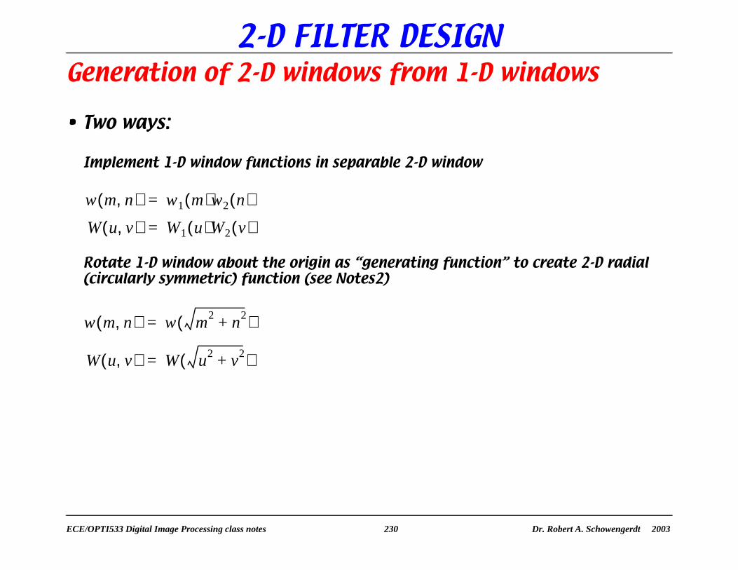
2-D FILTER DESIGNGeneration of 2-D windows from 1-D windows
• Two ways:
Implement 1-D window functions in separable 2-D window
Rotate 1-D window about the origin as “generating function” to create 2-D radial (circularly symmetric) function (see Notes2)
w m n,( ) w1 m( )w2 n( )=
W u v,( ) W1 u( )W2 v( )=
w m n,( ) w m2 n2+( )=
W u v,( ) W u2 v2+( )=

ECE/OPTI533 Digital Image Processing class notes 231 Dr. Robert A. Schowengerdt 2003
2-D FILTER DESIGN• Examples
• All defined with:
width b=8
plot array M=N=32
spatial region of support = 8 x 8 (separable) or radius = 4 (radial)
plot layout:
w(x,y)
|W(u,v)|
w(r)
|W(ρ)|
separable version
radial version

ECE/OPTI533 Digital Image Processing class notes 232 Dr. Robert A. Schowengerdt 2003
2-D FILTER DESIGN
rectangle window - separable version radial version
510
1520
2530
510
1520
2530
5
10
15
20
510
1520
2530
510
1520
2530
2
4
6
8
10
12
510
1520
2530
510
1520
2530
0
50
100
150
200
250
510
1520
2530
510
1520
2530
0
50
100
150
200
250
• rectangle (see Notes1)
• cylinder
w x( ) 1=
w r( ) cyl rb---
=

ECE/OPTI533 Digital Image Processing class notes 233 Dr. Robert A. Schowengerdt 2003
2-D FILTER DESIGN
• Hanning (raised cosine) w r( ) 0.5 0.5 2π rb---
cos+=
510
1520
2530
510
1520
2530
0.5
1
1.5
2
2.5
3
3.5
510
1520
2530
510
1520
2530
0
50
100
150
200
250

ECE/OPTI533 Digital Image Processing class notes 234 Dr. Robert A. Schowengerdt 2003
2-D FILTER DESIGN
• Hamming w r( ) 0.54 0.46 2π rb---
cos+=
510
1520
2530
510
1520
2530
0.5
1
1.5
2
2.5
3
3.5
4
510
1520
2530
510
1520
2530
0
50
100
150
200
250

ECE/OPTI533 Digital Image Processing class notes 235 Dr. Robert A. Schowengerdt 2003
2-D FILTER DESIGN• Kaiser
where I0 is a modified Bessel function of the first kind, order zero, and α controls the window shape:
α smaller Ñ> mainlobe narrower, α larger Ñ> sidelobes lower
w r( ) 1I0 α( )-------------I0 α 1 2r b⁄( )2–( )=
α = 1 radial version α = 3
510
1520
2530
510
1520
2530
0
50
100
150
200
250
510
1520
2530
510
1520
2530
0
50
100
150
200
250
510
1520
2530
510
1520
2530
2
4
6
8
10
510
1520
2530
510
1520
2530
1
2
3
4
5
6

ECE/OPTI533 Digital Image Processing class notes 236 Dr. Robert A. Schowengerdt 2003
2-D FILTER DESIGNFrequency Sampling Method
• Sample 2-D continuous frequency domain filter H(u,v) to obtain H(k,l) (origin-centered)
• Calculate inverse DFT to obtain h(m,n) (origin-centered)
Frequency Sampling Method
• add linear phase (M and N odd)
• sample
• inverse DFT
• shift
Hl u v,( ) Hz u v,( )ej2πu M 1–( ) 2⁄( )–
ej2πv N 1–( ) 2⁄( )–
=
Hl k l,( ) Hl k M⁄ l N⁄,( )=
k 0 1 …M 1–, ,=
l 0 1 …N 1–, ,=
hl m n,( )
hz m n,( ) hl m M 1–( ) 2⁄+ n N 1–( ) 2⁄+,( )=

ECE/OPTI533 Digital Image Processing class notes 237 Dr. Robert A. Schowengerdt 2003
2-D FILTER DESIGN• Sampling of ideal frequency
domain filters results in discontinuities at cut-off and cut-on frequencies
• Apply “smoothing” in transition region
Simple linear transition works fine
• Origin-centering important to maintain zero phase
Related Documents