University of Kentucky University of Kentucky UKnowledge UKnowledge Theses and Dissertations--Mechanical Engineering Mechanical Engineering 2014 FINITE ELEMENT MODELING AND FABRICATION OF AN SMA- FINITE ELEMENT MODELING AND FABRICATION OF AN SMA- SMP SHAPE MEMORY COMPOSITE ACTUATOR SMP SHAPE MEMORY COMPOSITE ACTUATOR Mohammad Souri University of Kentucky, [email protected] Right click to open a feedback form in a new tab to let us know how this document benefits you. Right click to open a feedback form in a new tab to let us know how this document benefits you. Recommended Citation Recommended Citation Souri, Mohammad, "FINITE ELEMENT MODELING AND FABRICATION OF AN SMA-SMP SHAPE MEMORY COMPOSITE ACTUATOR" (2014). Theses and Dissertations--Mechanical Engineering. 38. https://uknowledge.uky.edu/me_etds/38 This Doctoral Dissertation is brought to you for free and open access by the Mechanical Engineering at UKnowledge. It has been accepted for inclusion in Theses and Dissertations--Mechanical Engineering by an authorized administrator of UKnowledge. For more information, please contact [email protected].

Welcome message from author
This document is posted to help you gain knowledge. Please leave a comment to let me know what you think about it! Share it to your friends and learn new things together.
Transcript

University of Kentucky University of Kentucky
UKnowledge UKnowledge
Theses and Dissertations--Mechanical Engineering Mechanical Engineering
2014
FINITE ELEMENT MODELING AND FABRICATION OF AN SMA-FINITE ELEMENT MODELING AND FABRICATION OF AN SMA-
SMP SHAPE MEMORY COMPOSITE ACTUATOR SMP SHAPE MEMORY COMPOSITE ACTUATOR
Mohammad Souri University of Kentucky, [email protected]
Right click to open a feedback form in a new tab to let us know how this document benefits you. Right click to open a feedback form in a new tab to let us know how this document benefits you.
Recommended Citation Recommended Citation Souri, Mohammad, "FINITE ELEMENT MODELING AND FABRICATION OF AN SMA-SMP SHAPE MEMORY COMPOSITE ACTUATOR" (2014). Theses and Dissertations--Mechanical Engineering. 38. https://uknowledge.uky.edu/me_etds/38
This Doctoral Dissertation is brought to you for free and open access by the Mechanical Engineering at UKnowledge. It has been accepted for inclusion in Theses and Dissertations--Mechanical Engineering by an authorized administrator of UKnowledge. For more information, please contact [email protected].

STUDENT AGREEMENT: STUDENT AGREEMENT:
I represent that my thesis or dissertation and abstract are my original work. Proper attribution
has been given to all outside sources. I understand that I am solely responsible for obtaining
any needed copyright permissions. I have obtained needed written permission statement(s)
from the owner(s) of each third-party copyrighted matter to be included in my work, allowing
electronic distribution (if such use is not permitted by the fair use doctrine) which will be
submitted to UKnowledge as Additional File.
I hereby grant to The University of Kentucky and its agents the irrevocable, non-exclusive, and
royalty-free license to archive and make accessible my work in whole or in part in all forms of
media, now or hereafter known. I agree that the document mentioned above may be made
available immediately for worldwide access unless an embargo applies.
I retain all other ownership rights to the copyright of my work. I also retain the right to use in
future works (such as articles or books) all or part of my work. I understand that I am free to
register the copyright to my work.
REVIEW, APPROVAL AND ACCEPTANCE REVIEW, APPROVAL AND ACCEPTANCE
The document mentioned above has been reviewed and accepted by the student’s advisor, on
behalf of the advisory committee, and by the Director of Graduate Studies (DGS), on behalf of
the program; we verify that this is the final, approved version of the student’s thesis including all
changes required by the advisory committee. The undersigned agree to abide by the statements
above.
Mohammad Souri, Student
Dr. Haluk Karaca, Major Professor
Dr. James McDonough, Director of Graduate Studies

FINITE ELEMENT MODELING AND FABRICATION
OF AN SMA-SMP SHAPE MEMORY COMPOSITE
ACTUATOR
_______________________________________________
DISSERTATION ________________________________________
A dissertation submitted in partial fulfillment of the
requirements for the degree of Doctor of Philosophy in the
College of Engineering
at the University of Kentucky
By
MOHAMMAD SOURI
Lexington, Kentucky
Director: Dr. Haluk E. Karaca, Professor of Mechanical Engineering
Lexington, Kentucky
2014
Copyright © Mohammad Souri 2014

ABSTRACT OF DISSERTATION
Finite Element Modeling and Fabrication of an SMA-SMP Shape Memory
Composite Actuator
Shape memory alloys and polymers have been extensively researched
recently because of their unique ability to recover large deformations. Shape
memory polymers (SMPs) are able to recover large deformations compared to
shape memory alloys (SMAs), although SMAs have higher strength and are able
to generate more stress during recovery.
This project focuses on procedure for fabrication and Finite Element
Modeling (FEM) of a shape memory composite actuator. First, SMP was
characterized to reveal its mechanical properties. Specifically, glass transition
temperature, the effects of temperature and strain rate on compressive response
and recovery properties of shape memory polymer were studied. Then, shape
memory properties of a NiTi wire, including transformation temperatures and stress
generation, were investigated. SMC actuator was fabricated by using epoxy based
SMP and NiTi SMA wire. Experimental tests confirmed the reversible behavior of
fabricated shape memory composites.
The Finite Element Method was used to model the shape memory
composite by using a pre-written subroutine for SMA and defining the linear elastic
and plastic properties of SMP. ABQUS software was used to simulate shape

memory behavior. Beside the animated model in ABAQUS, constitutive models for
SMA and SMP were also developed in MATLAB® by using the material properties
obtained from experiments. The results of FEM simulation of SMC were found to
be in good agreement with experimental results.
KEYWORDS: Shape Memory Polymer, Shape Memory Alloy,
Shape Memory Composite, Finite Element
Modeling, Actuators
Mohammad Souri _________________________________ Student’s Signature
_________________________________ Date

Finite Element Modeling and Fabrication of an SMA-SMP Shape Memory
Composite Actuator
By
Mohammad Souri
Dr. Haluk Karaca ______________________________
Director of Dissertation
Dr. James McDonough ______________________________
Director of Graduate Studies
______________________________

Finite Element Modeling and Fabrication of an SMA-SMP Shape Memory
Composite Actuator
By
Mohammad Souri
Dr. Haluk Karaca ______________________________
Director of Dissertation
Dr. Charles Lu ______________________________
Co-Director of Dissertation
Dr. James McDonough ______________________________
Director of Graduate Studies
______________________________

To Marjan - my wife, my love, and my best friend, who has supported me
unconditionally

iii
ACKNOWLEDGEMENTS
I would like to thank my advisor, Dr. Haluk E. Karaca, who helped me to
develop the basic principles of this study. This work could not be accomplished
without his persistent guidance and motivation. I greatly appreciate his
unconditional and continuous support.
I am really grateful for having Dr. Y. Charles Lu as my co-advisor who
helped me a lot during the project. I would like to thank Dr. Rouch, Dr. Cheng, and
Dr. Bazrgari for serving as committee members and for their time.
I would also like to thank my parents to whom I am indebted for their
unconditional support despite being far away from me.
I am very lucky to have developed such great friendships during the course
of my studies. I would like to express my deepest gratuities to Gurdish Singh Ded,
Sayed Mohammad Saghaian, Dr. Burak Basaran, Dr. Hirobumi Tobe, Ali Sadi
Turabi, Irfan Kaya, Peizhen Li, Dr. Adnan Kaya, Emre Acar, Anil Erol, Rayan
Schulte, Kevin Wieman, Spandana Pulla, Vitali, Masoud Jabbari, and Amirhossein
Ghasemi.
And lastly, without help of my dear friends, Sonia Erfani, and Katherine
George, my work would not expressed as good.

iv
TABLE OF CONTENTS
TABLE OF CONTENTS .......................................................................................iv
LIST OF TABLES .................................................................................................vi
LIST OF FIGURES .............................................................................................. vii
1 INTRODUCTION ........................................................................................... 1
1.1 PRELIMINARY INTRODUCTION ............................................................ 1
1.2 MOTIVATION .............................................................................................. 2
1.3 LITERATURE REVIEW ............................................................................... 3
1.4 RESEARCH OBJECTIVES ......................................................................... 6
2 SHAPE MEMORY POLYMER, CHARACTERIZATION AND MODELING .... 8
2.1 INTRODUCTION ..................................................................................... 8
2.2 HISTORY OF SMP CHARACTERIZATION ............................................ 8
2.3 SAMPLE PREPARATION ..................................................................... 10
2.3.1 EXPERIMENTAL SETUP ............................................................... 11
2.4 EXPERIMENTAL RESULTS ................................................................. 15
2.4.1 GLASS TRANSITION TEMPERATURE ......................................... 15
2.4.2 SHAPE MEMORY EFFECT ............................................................ 17
2.4.3 DEFORMATION LIMIT ON NGDE3 SMP ....................................... 19
2.4.4 COMPRESSION RESPONSES AND RECOVERY ........................ 20
2.4.5 EFFECTS OF TEMPERATURE ON DEFORMATION BEHAVIOR 22
2.4.6 CONSTRAINT SHAPE RECOVERIES ........................................... 24
2.4.7 EFFECTS OF THERMO-MECHANICAL HISTORY ........................ 27
2.5 SMP MODELLING................................................................................. 30
2.5.1 LITERATURE REVIEW .................................................................. 30
2.5.2 SMP CONSTITUTIVE MODEL FOR SMALL DEFORMATIONS .... 31
2.5.3 FINITE ELEMENT MODELLING OF SMP IN ABAQUS® ................ 35
3 NiTi WIRE CHARACTERIZATION AND MODELLING ................................ 40
3.1 EXPERIMENTAL CHARACTERIZATION OF NiTi WIRE ...................... 40
3.1.1 DSC RESULTS ON NiTi WIRE ....................................................... 40

v
3.1.2 STRESS INCREASE OF CONSTRAINED NiTi WIRES WITH
TEMPERATURE SCAN .............................................................................. 41
3.2 SMA MODELLING................................................................................. 42
3.2.1 LITERATURE REVIEW .................................................................. 43
3.2.2 LAGOUDAS APPROACH FOR SMA CONSTITUTIVE MODEL ..... 45
3.2.3 ANSYS MODEL OF A DOG-BONE TENSILE SMA SAMPLE ........ 49
3.2.4 SMA MODEL IN ABAQUS .............................................................. 54
4 SHAPE MEMORY COMPOSITE ACTUATOR: FABRICATION AND FINITE
ELEMENT MODELING ...................................................................................... 59
4.1 BACKGROUND ..................................................................................... 59
4.2 SMA-SMP COMPOSITES ..................................................................... 61
4.2.1 RULE OF MIXTURE ....................................................................... 66
4.2.2 EXPERIMENTAL RESULTS AND DISCUSSION ........................... 68
4.3 SMC MODEL IN ABAQUS .................................................................... 71
4.3.1 Wire SMC FEM ............................................................................... 71
4.3.2 Spring-SMC FEM ............................................................................ 75
4.3.3 SMC with SMA-SMP bending plates ............................................... 77
5. CONCLUSIONS .......................................................................................... 79
REFERENCES ................................................................................................... 80
VITA ................................................................................................................... 84

vi
LIST OF TABLES
Table 2-1: Chemical formulations of the NGDE3 SMP ....................................... 10
Table 2-2: Calibrated functions for strain calculation .......................................... 33
Table 2-3: Material specification of SMP in different temperatures ..................... 36
Table 2-4: Plastic definition for SMP at room temperature for 50% compression
according to ABAQUS requirements ........................................................... 36
Table 3-1: ANSYS SMA material constant definitions ........................................ 50
Table 3-2: Comparison of the results for the maximum von-misses stress in
different temperatures ................................................................................. 53
Table 3-3: SMA material parameter's values ...................................................... 56
Table 4-1: Main material properties of NiTi SMAs and SMPs [17] ...................... 62
Table 4-2: Calculated the number of needed wires for SMC according to rule of
mixture......................................................................................................... 67

vii
LIST OF FIGURES
Figure 2-1: Lindberg/BlueM box furnace (BF514841) ..................................................... 11
Figure 2-2: Illustration of MTS and its components ......................................................... 12
Figure 2-3: Servo-Hydraulic Mechanical Tester (MTS) setup schematic ........................ 12
Figure 2-4: Perkin Elmer Pyris DMA 7E .......................................................................... 13
Figure 2-5: Pyris1 DSC used for finding the glass transition temperature of SMP and
transition temperature of SMA wire ......................................................................... 15
Figure 2-6: Results of DSC for NGDE3 SMP .................................................................. 16
Figure 2-7: Schematic of the three-point bending test [41] ............................................. 16
Figure 2-8: Results of the three-point bending test for the NGDE3 epoxy-based SMP .. 17
Figure 2-9: Shape memory effect of SMP with illustrated schematics ............................ 19
Figure 2-10: Failure test result of NGDE3 SMP .............................................................. 20
Figure 2-11: Compression test results for SMP at room temperature ............................. 21
Figure 2-12: Recovery of compressed SMP samples by increasing the temperature .... 22
Figure 2-13: SMP compression test in different temperatures ........................................ 23
Figure 2-14: Recovery tests on compressed specimens at different temperature .......... 23
Figure 2-15: Strain-temperature profiles of constraint shape recoveries of the SMP ...... 24
Figure 2-16: Stress-temperature profiles of constraint shape recoveries of the SMP ..... 26
Figure 2-17: The maximum stress generated during constraint shape recovery as a
function of fixing strain ............................................................................................. 27
Figure 2-18: (a) Schematic of the mechanical behavior of the SMP at T<Tg, (b)
Schematic of the mechanical behavior of the SMP at T>Tg, and (c) Combined view
of (a) and (b) ............................................................................................................ 28
Figure 2-19: 3D stress-strain-temperature profile showing the shape recoveries of the
SMP under complex thermo-mechanical cycles ..................................................... 29
Figure 2-20: SMP composed of active and frozen phases in the model proposed by
Lagoudas et al. [53] ................................................................................................. 31
Figure 2-21: a) Strain-temperature and b) Calibrated frozen volume fraction-temperature
graphs of SMP ......................................................................................................... 34
Figure 2-22: Comparison between the experimental shape memory effect (colored) and
the theoretical results (black) .................................................................................. 35
Figure 2-23: (a) Applying constraint on the bottom end of the SMP, (b) Applying load on
the top end of SMP .................................................................................................. 37

viii
Figure 2-24: Illustration of shape memory effect on SMP FE model. a) Loading, b)
Cooling, c) Unloading, d) Heating ........................................................................... 38
Figure 2-25: Comparison between experimental SME and ABAQUS results ................. 39
Figure 3-1: DSC result of NiTi wire ................................................................................ 41
Figure 3-2: Stress generation test for a SMA wire .......................................................... 42
Figure 3-3: Super-elastic behavior of SMA with definitions of the important variables
(from ANSYS online help and [1]) ........................................................................... 50
Figure 3-4: Transformation stress versus temperature curves for SMA material ............ 51
Figure 3-5: Superelastic responses at selected temperatures ........................................ 51
Figure 3-6: Dog-bone tensile specimen dimensions ....................................................... 52
Figure 3-7: Load and boundary condition that applied to the dog-bone tensile specimen
................................................................................................................................ 53
Figure 3-8: The contour plot of generated stress at 70 °c ............................................... 54
Figure 3-9: Pseudo-elastic behavior of SMA with definition of SMA parameters [30] ..... 55
Figure 3-10: Contour plot of SMA bar under load ........................................................... 57
Figure 3-11: Superelasticity results of a SMA that was defined in ABAQUS at selected
temperatures ........................................................................................................... 57
Figure 3-12: ABAQUS results: shape memory effect of a SMA wire a) in 2D and b) in3D
................................................................................................................................ 58
Figure 4-1: Change of a) elastic modulus and b) yield stress with temperature of SMA,
SMP and steel [104] ................................................................................................ 63
Figure 4-2: SMC actuation illustration ............................................................................. 64
Figure 4-3: Stress-strain graph for NiTi wire ................................................................... 67
Figure 4-4: SMC sample made with NGDE3 SMP matrix and Flexinol NiTi wires .......... 68
Figure 4-5: SMC actuation results with 1 °C/min ............................................................ 69
Figure 4-6: Alternative SMC cycle done by adjusting the thermal cycling range with a
rate of 5 °c/min ........................................................................................................ 70
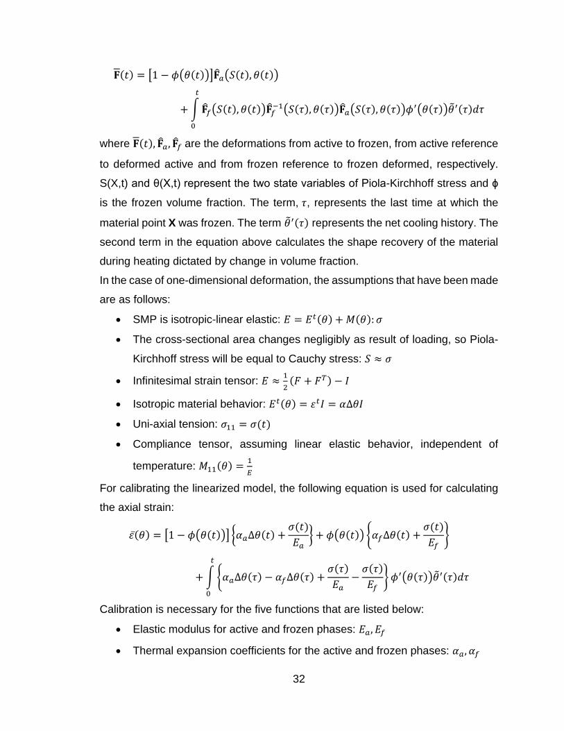
Figure 4-7: SMC model in ABAQUS ............................................................................... 72
Figure 4-8: SMC FEM in action, a) cooled down b) heated up ....................................... 73
Figure 4-9: Comparison between finite element model results and experimental results
of SMC .................................................................................................................... 74
Figure 4-10: SMC results with SMP plastic behavior ...................................................... 75
Figure 4-11: Contour plots of spring SMC ....................................................................... 76
Figure 4-12: Displacement versus temperature graph for spring-SMC actuation ........... 76

ix
Figure 4-13: Contour plots of SMC bending plates ......................................................... 77
Figure 4-14: Angle versus temperature graph for bending plates SMC .......................... 78

1
1 CHAPTER I: INTRODUCTION
1.1 PRELIMINARY INTRODUCTION
As a new "smart" material, shape memory polymers (SMPs) are one of the most
interesting subjects research groups have studied in recent years. Many
applications are being explored because of their rare benefits, such as large
recoverable deformation, easier pretreatment procedure, low fabrication cost and
adjustable recovery temperatures. As soon as the shape-memory effects in shape
memory polymers were found out, a lot of applications have been introduced. Heat
shrinkable tapes and tubes made with radiation-cross-linked polyethylene,
information storage that can allow thermally reversible recording [1-3], temperature
sensors and actuators are some of the examples of their applications [1]. However,
novel applications are mostly focused on medical devices, such as biodegradable
sutures [4, 5], actuators [6], catheters, and stents [1, 7].
The other novel shape memory materials are shape memory alloys (SMAs). SMAs
can produce very high recoverable shape changes (~4‐8%) as a result of
reversible martensitic phase transformations that can be triggered by changes in
temperature, stress state or magnetic field. Their remarkable mechanical property
features, such as high recovery force to weight ratio and large recoverable
deformation have enabled them to be utilized for actuators and sensors in a
diversity of fields. SMAs have higher energy density than pneumatic actuators, D.C
motors or other active materials and are equivalent in performance to hydraulic
actuators while being compact, robust, lightweight, frictionless, quiet, easier and
less costly to be inspected and maintained [8]. Due to these unique properties,
industries such as aerospace, automotive, oil and gas and many others have
become increasingly interested in SMAs [8-10].
A composite is a hybrid of two or more constituent materials with significantly
different physical or chemical properties that remain discrete on a macroscopic
level within the finished structure. A composite is designed to display a

2
combination of the best characteristics of each of the constituent materials.
Consequently, a composite’s performance is superior to those of its constituents
acting independently [11]. SMAs have high strength, good thermal conductivity,
and ability to generate high forces, but are more expensive, denser and show lower
recovery strain in comparison to SMPs [12]. On the other hand, SMPs are
lightweight, inexpensive, have good formability and provide high recovery strain;
however, they lack strength, have low modulus at high temperatures and do not
have the ability to perform reversible actuation [11, 12]. A SMC can be created by
embedding SMA components (e.g. in wire or powder forms) in a SMP polymer
matrix resulting in a low density composite with increased strength and modulus.
Also, the addition of SMA wires, through electrical resistance, can supply heat
energy to the overall polymer matrix to trigger the actuation motion. The size,
distribution, and volume fraction of wires can be adjusted to control the SMC
properties in accordance with the application requirements. The temperature
range at which the SMC will function is one of the design variables that should be
engineered and designed according to SMA and SMP transition temperatures.
This project focuses on a novel shape memory composite actuator that is designed
with a shape memory polymer cylinder specimen and a NiTi shape memory alloy
wire. The actuator is triggered by temperature and combines the shape memory
effect of both SMP and SMA. The actuator shows reversible shape change with
temperature.
1.2 MOTIVATION
Smart materials are engineering materials that have inherent sensing, actuating,
and controlling or information processing capabilities in their microstructures. They
have the ability to respond to changes in temperature, electric field, or magnetic
field owing to their intrinsic intelligence. Shape memory materials, piezoelectric
materials, fiberoptics, magneto‐(electro‐)strictive materials, magneto‐(electro‐
)rheological fluids and some functional polymers are some examples of smart
materials [13, 14]. They all have great potential in a variety of applications;
however, shape memory materials (SMAs and SMPs) are the major elements of

3
smart composites because of their unusual properties of shape memory effect,
pseudoelasticity, damping capacity, and adaptive properties.
In SMPs, the modulus changes significantly at the glass transition temperature
(Tg), decreasing as the polymer is heated above the transition temperature [15,
16]. As a result, strain can be introduced into the polymer with relative ease at
temperatures above the transition temperature. If the strain is maintained and the
temperature of the material is decreased below the transition temperature, the
strain is ʹfrozen inʹ.
This strain is recovered when the polymer is heated above the transition
temperature again [17, 18]. SMPs have found use in structural applications in
which epoxy‐based materials are often used owing to their intrinsically high
mechanical properties, chemical resistance, thermal stability, and tunable
transition temperatures. SMPs can be employed in open cellular (foam) form as
low mass, low volume, and low-cost self-deployable structures for space and
commercial applications [19]. Their advantages include low mass, low storage
volume, high reliability (no deployment mechanisms are required), high dynamic
damping, ease of fabrication, impact and radiation resistance, and thermal and
electrical insulation and low cost [20]. Because SMPs exhibit physical properties
similar to those of human tissues, they are thought of as ideal candidates for many
medical applications.
1.3 LITERATURE REVIEW
Shape memory composite, as described above, is a state-of-the-art actuator for
which few groups have studied.
Tobushi et al. made a bending actuator using SMA and SMP properties in 2009.
By putting a super-elastic kind SMA tape and a shape memory effect type SMA
tape inside of a SMP tape. The two different kinds of SMAs have memory by heat-
treatment in different directions. When SMC heated the recovery force increases
and the SMC changes the shape and when cooled the recovery force is decreases
and it will get back to the original shape [21].

4
Tobushi et al. fabricated the SMC belt, composed of SMA tapes and a SMP in
which they showed that a small rotary actuator can be developed using the torsion
properties of SMA-tape. They have fabricated the SMC belt with the SMA tapes
covered by SMP tape. By using the characterizations of SMA and SMP, a three-
way bending movement of the SMC belt during heating and cooling was observed
[22].
In another effort, Tobushi et al. made a composite belt with a SMA wire and SMP
sheet and the thermomechanical properties of the SMC matrix has been
investigated [23].
Dapino and Noeth have tried to fabricate a shape memory composite by inserting
pre-deformed shape memory alloy texture in shape memory polymer plate to
achieve a fully reversible actuator. They have explained the techniques that they
have used to embed the wire into the polymer by creating surface modifications
using shape memory wires and modifying polymer using vacuum actuation [24].
Bollas et al. have investigated the stress generated in a shape memory wire
embedded in fibrous polymer. The stress fields measured have confirmed that
SMA wires can serve as effective stress-actuators. The wire composition and level
of pre-strain turned out to be very important factors on efficiency of stress
generation. The maximum value of stress recorded in the fibers at a distance of
almost one wire radius was 227 MPa [25].
Turner has showed the results from experimental validation of a recently
developed model for predicting the thermo-mechanical behavior of shape memory
alloy hybrid composite (SMAHC) structures, composite structures with an
embedded SMA constituent. The model captures the material nonlinearity of the
material system with temperature and is capable of modeling constrained,
restrained, or free recovery behavior from experimental measurements of
fundamental engineering properties. A brief description of the model and analysis
procedures is given, followed by an overview of a parallel effort to fabricate and
characterize the material system of SMAHC specimens. Static and dynamic
experimental configurations for the SMAHC specimens are described and
experimental results for thermal post-buckling and random response are

5
presented. Excellent agreement is achieved between the measured and predicted
results, fully validating the theoretical model for constrained recovery behavior of
SMAHC structures [14].
Initial experimental efforts by Tobushi et al. provided data from small deformation
experiments with applied extensions of 2%, 4%, and 10% [21]. The tests
investigated the stress-strain relationship of thin polyurethane SMPs. The results
obtained during this experimental investigation represent one of the first attempts
to capture the entire shape memory effect of SMPs. In particular, the stress due to
constrained cooling and the shape recovery upon subsequent heating was noted.
Additional efforts by Tobushi et al. involved deforming the thin films to extensions
of 20% and 100% [26]. The thermo-mechanical response of specimens loaded at
different temperatures were captured. In addition, the stress-strain relationship
upon loading was observed to be nonlinear for extensions greater than
approximately 20%.
The preliminary cyclic effects on the shape recovery were investigated, and a shift
in the stress-strain-temperature results was noted for subsequent thermo-
mechanical cycles [26]. In particular, the accumulated amount of irrecoverable
deformation continued to increase for each of the ten thermo-mechanical cycles,
and Tobushi noted that the SMPs recovered approximately 98% of the applied
deformation during each thermo- mechanical cycle.
Extensive efforts on the thermo-mechanical behavior of SMPs for small
deformations were also conducted by Liu et al. [27]. These experiments
characterized dog-bone shaped specimens, and the data was subsequently used
to calibrate and validate the proposed constitutive model. The experiments
performed by Liu not only aimed to obtain the material properties above and below
the glass transition temperature, but also characterize the thermo-mechanical
response when deformed to a range of values, up to 9% in magnitude, of applied
tensile and compressive strains. In these experiments, both the stress increase
due to constrained cooling and the nonlinear strain-temperature relationship during
zero load recovery were captured and observed to occur in a smooth, nonlinear
manner.

6
Recent experimental efforts have shifted from the characterization of the response
due to small deformations to the large deformation response of SMPs processed
in a dog-bone shape. For instance, Baer et al. [28] tested polyurethane SMP
specimens to tensile extensions of 20% and 100% for use in medical applications.
In these experiments, the SMP recovered approximately 90% of the applied
deformation, and the effects of cyclic deformation at a range of temperatures were
investigated. The results from the cyclic deformation study indicated the greatest
shift in material response from the first cycle to the second cycle with an apparent
training, or stabilization in material response, occurred from the second to fifth
cycles.
Additionally, Atli et al. thermo-mechanically characterized SMPs for applied tensile
strains up to 75% for dog-bone specimens [29]. The experiments performed by Atli
are similar in principle to those presented in this work such that the same
VeriflexTM shape memory polymer is used and subjected to a similar thermo-
mechanical load path. Due to experimental apparatus limitations, however, the
complete shape recovery profile during heating was not captured by Atli.
1.4 RESEARCH OBJECTIVES
Review of available literature on SMCs reveals that only limited work has been
done on them. In order to be able to fabricate SMCs, there are critical steps to
undertake. First, properties of SMPs must be characterized thoroughly to
determine their glass transition temperature, fracture stress level, effects of
temperature, and the amount of stress that can be generated.
The SMC was made with epoxy-based SMP cylinder and NiTi SMA wire. Thus,
shape memory properties of NiTi wire should be characterized as well. For SMA
wire, the transition temperature and the amount of stress that the SMA wire can
generate were characterized.
For modeling, both SMA and SMP models were used. For SMA model, a
subroutine that has developed by Lagoudas et al. (based on Tanaka, Boyd and
Lagoudas, and Liand and Rogers constitutive models) was used [30]. This
subroutine implements the SMA behavior in ABAQUS. In this study, this subroutine

7
was used for finite element modeling of the SMC. The required geometry was
created and meshed with appropriate hexagonal elements and the material
properties were assigned by the subroutine. For SMP, it is important to know its
shape memory behavior and material properties very well. For SMC, SMP can be
modeled as a linear-elastic material with plastic definition. SMP behavior is highly
temperature dependent and it has to be considered in the material definition. A
constitutive model for SMP that has proposed by Volk and Lagoudas [31] also was
coded in MATLAB®.
In conclusion, the objectives of this study are:
- Thermo-mechanical characterization of the SMP that includes:
o Fabrication of epoxy-based SMPs
o Determining the glass transition temperature
o Determining the critical stress for failure
o Revealing shape memory effect
o Investigating stress-strain tests as a function of temperature
o Revealing stress generation as a function of strain
o Studying the effects of loading history on SMP behavior
o Modelling the SMP behavior
- Thermo-mechanical characterization of SMA wire that includes:
o Determining the transition temperature
o Revealing the critical stress for failure
o Determining the elastic modulus
- Fabricating the SMC
- Determining the thermo-mechanical behavior of SMC
- Modelling of the SMC by using a commercial FEM software

8
2 CHAPTER II: SHAPE MEMORY POLYMER, CHARACTERIZATION AND MODELING
2.1 INTRODUCTION
The main focus of this chapter is the characterization of shape memory polymers
and modeling its behavior by using a constitutive model from Volk and Lagoudas
and a hyper-elastic model in ABAQUS. SMP characterization including the
fabrication process to tailor the glass transition temperature, introduction of the
experimental setup to perform the needed experiments, and detailed discussion of
the characterization processes including the glass transition temperature, failure
test, and shape memory effect, effects of temperature, recovery tests, stress
generation tests, and effects of loading history, were investigated.
2.2 HISTORY OF SMP CHARACTERIZATION
The origin of SMPs can be traced back to the French company CdF-Chimie in
1984, and in less than a year, SMPs gained attention by Nippon Zeon Company
in Japan because of their processability. Over the two decades, there have been
great improvements to the understanding and applications of SMPs, but recently
it gained greater interest [32].
SMPs function in two phases, separated by its glass transition temperature (Tg).
The first state, below Tg, is a solid, fixed state, often times referred to as the glass
state. When the SMP’s temperature is increased above its Tg, the material
transitions into a softer, rubber-like phase. During this state, the material is
thermally reversible; the SMP will recover most, if not all, of its initial shape. It
should be noted that the Tg can be adjusted by the composition of SMP and can
be increased to 100 °C or more.
The mechanical properties of shape memory polymers were first characterized in
1992 by Tobushi et al. [33]. This first study tested the resistance to deformation of
polyurethane above Tg by running tensile cycles with a strain level of 50%. The
results showed that resistance to deformation increased with the number of cycles
[33]. In four years, the research group of Tobushi published another paper that
reported several results from different experiments on polyurethane, including

9
isothermal stress-strain responses in tension at constant strain rate, creep tests,
and relaxation tests at different temperatures [34].
The shape fixity and recovery were examined in tension for polyurethane thin films
at different temperatures by Tobushi et al. [35]. In 2003, Abrahamson et al.
conducted isothermal tensile tests with constant strain rate experimentally [36]. In
2004, Liu and Gall et al. have done uniaxial compression and tension on shape
memory polymer [37]. In 2009, Atli et al. characterized SMPs in a dog-bone shape
for values of extensions up to 75% [29]. In 2011, Lagoudas et al. also have done
a complete thermo-mechanical characterization of SMP in tension [31]. A few
researchers have studied the effect of polymer structure on recovery properties at
moderate strains. Baer et al. examined the thermo-mechanics and shape-memory
behavior for thermoset polyurethanes intended for medical applications as a
function of curing temperature, Tr, and deformation strain [28, 38].
Although, a great increase in the understanding of the constitutive response of
SMPs was evident, there has been little effort to connect the effects of SMP
structure, temperature, and strain limits to one another. Due to this deficiency of
knowledge, it is difficult to optimize the strain recovery of an SMP by altering its
structure and/or deformation temperature.
Currently, research is being focused on the characterization of thermo-mechanical
properties of epoxy-based SMPs. Several approaches are being investigated to
help our understanding of these properties, such as compression and recovery
tests, failure tests, effect of temperature, etc. The epoxy-based SMPs were
fabricated based on an approach introduced in the study by Xie et al. [39]. A series
of epoxy-based SMPs was introduced in the aforementioned work with various
glass transition temperatures. They have named NGDE1 to NGDE4 based on their
glass transition temperature. In this project, one epoxy-based shape memory
polymer that will be specifically focused on is the NGDE3 (part of the NGDE
series). NGDE3 has been selected because of the appropriate range of glass
transition that it has and needed to fabricate SMC.

10
2.3 SAMPLE PREPARATION
The SMP used for our experiments is epoxy-based and composed of an epoxy
monomer (EPON 826), Jaffamine D230 (curing agent) and NGDE (neopentyl
glycol diglycidyl ether). The detailed formulations of the epoxy SMP are
summarized in Table 2-1. EPON 826 was weighed in a glass bottle and melted at
70 °C. After melting EPON 826, weighed Jeffamine D230, and NGDE (or
decylamine) were introduced into the bottle, which was then shaken vigorously by
hand for about 10 seconds to mix the components. Next, the mixture was poured
into a Teflon container to get a cylindrical shape for compression tests. The epoxy
samples were thermally cured at 100 °C for 1.5 hours and post-cured at 130 °C for
1 hour.
Upon the completion of the cure, the epoxy cylindrical samples could be cut into
appropriate lengths for compression and recovery tests and the thin plates into
rectangular shapes with needed dimensions for DMA three-point bending tests
[39].
Table 2-1: Chemical formulations of the NGDE3 SMP
A Lindberg/BlueM BF514841 Box furnace (Figure 2-1) was used for curing the
polymer. Equipped with a UT150 controller, the furnace could be programmed to
a single set-point while using a desired ramp rate. The furnace was set to the
desired temperature and allowed to reach the set temperature before the sample
was place in the furnace. After putting the liquid polymer or a sample in the furnace,
the time was noted once the temperature reached the set temperature again [40].

11
Figure 2-1: Lindberg/BlueM box furnace (BF514841)
2.3.1 EXPERIMENTAL SETUP
All experiments for this project were performed at the Smart Material’s Laboratory
at the Mechanical Engineering Department of University of Kentucky. The
compression tests are performed by a Landmark 370.10 MTS (Servo-hydraulic
Mechanical Tester) with 100kN capacity. As shown in Figure 2-2, MTS has a
temperature controller. The specimen was heated in a furnace and cooled via
convection using liquid nitrogen introduced near the bottom of the furnace at a rate
of 10 °C/min. An Omega CN8200 series temperature controller ensured stable
heating-cooling rates with K-type thermocouples attached to both the specimen
and grips. A cryogenic grade, on/off solenoid valve commanded by the
temperature controller was used to control the flow of liquid nitrogen [40].

12
Figure 2-2: Illustration of MTS and its components
Figure 2-3 shows a schematic of MTS and its main parts.
Figure 2-3: Servo-Hydraulic Mechanical Tester (MTS) setup schematic
The compression sample was polished mechanically with 600-grit paper to remove
any residue after being removed of its Teflon container Teflon container. Once the
sample was ready, a K-type thermocouple was attached to the sample by fastening
it with fine gauge copper wire, followed by placing the sample between the test
setup in proper position. Typical strain rate used for isothermal cycling was (2*10-
4) mm/sec for loading. The sample was unloaded with 100 N/sec.
For recovery tests, a DMA (Dynamic Mechanical Analyzer) was used (Figure 2-4).
The Perkin Elmer DMA 7e provides the performance and flexibility necessary for

13
the characterization of a broad range of materials from soft samples, such as
elastomers, thin films and single filament fibers, to hard samples, like composites,
ceramics and metals. The DMA 7e’s multiple measuring systems accommodate
most sample types, and its multiple operating modes, including temperature, time,
frequency scan, stress scan, creep-recovery, and constant force (TMA), further
enhance flexibility and accurate material characterization. The temperature range
for Perkin Elmer Pyris DMA 7e is from -170 C to 500 C [40].
For the SMP recovery test, the sample was placed inside the chamber of DMA
underneath of the probe after which the temperature was increased from 20 °C to
80 °C. By recording the change in the length of the sample, strain could be
calculated.
The three-point bending test is another important test that can be performed on a
SMP thin plate by the DMA. This test has mainly performed to confirm the glass
transition temperature of SMP.
Figure 2-4: Perkin Elmer Pyris DMA 7E
The Perking Elmer Differential Scanning Calorimeter (Pyris 1) has been used to
determine the glass transition temperature of SMP and also the transition
temperature of SMA wire (Figure 2-5). Differential scanning calorimetry (DSC) is a
thermo-analytical technique in which the difference in the amount of heat required

14
to increase the temperature of a sample and reference are measured as a function
of temperature. Both the sample and reference are maintained at nearly the same
temperature throughout the experiment. The heating and cooling rate used to run
the experiments was fixed at 5°C/minute. The temperature scale was calibrated
using the furnace calibration feature in Pyris software. The minimum and maximum
set-point is entered in the sub menu for furnace calibration and the software
calculates seven other points between the desired ranges, as specified by the
user. The thermocouple temperature is matched to the programmed furnace
temperature when this calibration is complete. The enthalpy scale was calibrated
using the observed delta-H from an accurately known amount of indium.
Samples were encapsulated in disposable aluminum pans, typically using 20 to 40
milligrams of sample. There are two styles of pans available, one used for solids,
and a hermetically sealed version for liquids. Aluminum pans (Perkin Elmer part
number 0219-0041) with a temperature range of -170°C to 600°C and volume
capacity of 40 μL were used. The sample pans ensured safety against material
that can leak out into the DSC can contaminate and cause permanent damage to
the DSC’s furnace, particularly if there are metals present in the sample that could
make an alloy with the platinum furnace holders.
There is a sample side and a reference side in the furnace. A blank pan was
inserted into the reference side. For all samples, it was noted that the sample
maintained good contact with the bottom of the pan, thus ensuring good contact
with the sensor, especially when using large samples since the thermal gradient
effects can increase. Large samples produce larger transition, hence are preferred
for study even the small changes, but thermal gradient should be taken into
account while using them [40].

15
Figure 2-5: Pyris1 DSC used for finding the glass transition temperature of SMP and transition temperature of SMA wire
2.4 EXPERIMENTAL RESULTS
In this section, all experiments necessary for characterizing SMP behavior will be
discussed. The detailed information about the devices and performing the
experiments are presented and the results were inputted for subsequent modeling.
2.4.1 GLASS TRANSITION TEMPERATURE
Glass transition temperature (Tg) of an SMP is the temperature at which a
substance transitions from a fixed phase to a rubber phase. The Tg can vary
among the different types of SMPs and can be manipulated by altering the
chemical composition of the SMP. Determining this glass transition temperature
is a crucial step prior to the thermo-mechanical testing of an SMP.
In order to find the Tg of an SMP, a technique called Differential Scanning
Calirometry (DSC), as described in the previous part, is used. For SMPs, as
temperature increases, the internal energy steadily changes, and the Tg is marked
by a fluctuation of the internal energy. As illustrated in the graph of Figure 2-6, the
glass transition temperature of NGDE3 SMP is around 43 °C.
Reference
Pan
Sample
Pan

16
Figure 2-6: Results of DSC for NGDE3 SMP
Another common test that is performed on materials to characterize the transition
temperature is three-point-bending test. This test was performed by DMA device.
Figure 2-7 shows a schematic of the three-point-bending test clamp.
Figure 2-7: Schematic of the three-point bending test [41]
A rectangular 1 mm thick (t) SMP specimen was cut to 5 mm in width and 15 mm
in length and put in the furnace of DMA while clamped on a special grip. The

17
distance between the 2 sides of the grip is 12 mm (L). Once the probe touches the
middle of the sample and with amplitude of 20 mN for dynamic force and static
force of 100 mN, the test begins. The temperature range is from 15 °C to 75 °C.
The peak for heat flow will show the transition temperature. Figure 2-8 shows the
results for the NGDE3 specimen. The glass transition temperature obtained from
this test is consistent with the results from DSC (~43 °C).
Figure 2-8: Results of the three-point bending test for the NGDE3 epoxy-based SMP
2.4.2 SHAPE MEMORY EFFECT
The driving force for shape recovery in a polymer is the elastic strain generated
during the deformation. Deformation at high temperature is much easier due to the
lower rubbery modulus of the polymer that makes the orientation of polymer more
feasible. However, the orientation will be partly relaxed before the structure is
frozen in during the subsequent cooling cycle. On the other hand, deformation at
low temperature is more difficult due to the higher glassy state modulus of the
polymer but chain orientation will remain at a higher degree as the relaxation

18
process is slowed down. A high glassy state modulus (Eg) will provide the material
with high shape fixity during simultaneous cooling and unloading, whereas a high
rubbery modulus (Er) will provide high elastic recovery at high temperature [13].
Shape recovery is important to SMPs because it is the material's ability to
completely return to its original shape after stretching. Shape recovery is most
often studied by loading and unloading an SMP at various temperatures, then
heating it up to above the glass transition temperature.
Figure 2-9 shows the complete cycle of the shape memory effect of an SMP.
The thermo-mechanical cycle in which SMP is recovered can be summarized as
follows:
1. While kept at a zero stress, heat the material above its glass transition
temperature (Point 1).
2. At high temperature, compress the SMP to the desired strain level (Point 2).
3. Cool the material down to a temperature below its glass transition temperature
while keeping the strain constant (Point 3).
4. Unload the stress from the specimen (Point 4).
5. To recover the original shape, heat the material above its Tg (Point 1).
The SMP's recovery characteristics are best illustrated by producing a shape-
memory plot of strain vs. temperature. This plot also shows the material's shape
fixity or its ability to hold a shape after it has been deformed. Figure 2-9 gives a
breakdown of the shape-memory plot and what each section represents. The
material is first loaded to 2.75 MPa at a constant temperature above Tg which is
60 °C (process 1: Heating). The loading is then held constant for one minute to
determine if there is any creep present (process 2: Loading). Then, the material is
cooled down to 12 °C (below Tg) under the constant stress of 2.75 MPa (process
3: Cooling). After cooling, the load is released (process 4: Unloading). Finally, the
material is reheated to the original temperature above Tg (which was 60 °C) and
recovery profile is seen in the final section of the graph (process 5: Heating)
During the shape memory effect, 19% strain was recovered, and recovery process
shows a glass transition temperature of 43 °C which is consistent with DSC results
described in the previous section.

19
Figure 2-9: Shape memory effect of SMP with illustrated schematics
2.4.3 DEFORMATION LIMIT ON NGDE3 SMP
Figure 2-10 shows the stress versus strain graph for an NGDE3 SMP sample in
compression at room temperature. It indicates that 65% strain compression is
needed for an SMP sample to fail which is relatively high for rubbery materials.
The graph shows that the stress level does not exceed 30 MPa until the material
is roughly compressed to about 55%. Even though the area of the sample is
increased, after this point the stress level is increasing at a much higher rate

20
suggesting that the material is going to fail. At a strain of 65%, the SMP fails at a
compressive stress of 75 MPa. It has been reported that some SMPs could be
stretched up to 800% in tension [1], but tensile test study was not performed in the
current project. The modulus of elasticity calculated from the compressive stress-
strain curve and is found to be 1.3 GPa and the yield strength (the maximum stress
in stress-strain curve) is determined to be 22 MPa. Strain rate is very important in
determining these factors.
Figure 2-10: Failure test result of NGDE3 SMP
2.4.4 COMPRESSION RESPONSES AND RECOVERY
Epoxy-based SMP has a unique behavior on compression. It behaves like an
elastic material up to some extent of deformation after which the stress level
decreases and plastic deformation occurs. A compression test for NGDE3 SMP
sample was performed with MTS at room temperature. It is important to note that
the strain rate significantly affects the stress level that is obtained in this test.
Compression tests have been done up to 40% of the original length at room
temperature. After loading to the pre-determined strain levels of 10%, 20%, 30%,
and 40% in compression (Figure 2-11), the sample was unloaded. Upon unloading
the material has unrecovered strain at room temperature,

21
After loading and unloading at room temperature, the sample was heated in DMA,
where the probe was touching the sample in stress control. By tracking the position
of the probe, recovery graphs can be created. Figure 2-12 shows recovery tests
that were done with DMA from room temperature to 80 ⁰C with a heating rate of 5
⁰C/min. The other important information from the recovery tests is the observing
glass temperature for NGDE3 as 43 ⁰C which is in good agreement with DSC
results. The recovery of the SMP is 100% after the temperature is reached above
its glass transition temperature.
Figure 2-11: Compression test results for SMP at room temperature
The recovery characteristics of the SMP can be illustrated by producing a shape-
memory plot of strain vs. temperature. From this plot, the linear shape recovery
ratio, R, can be estimated
100)h
h1(R
i
f
Where hi and hf are the initial and final heights of the cylindrical specimens. After
the final step, the SMP has returned completely to its original position. The linear

22
shape recovery ratio was calculated as ~100%, indicating that the SMP exhibits
perfect shape recovery.
Figure 2-12: Recovery of compressed SMP samples by increasing the temperature
2.4.5 EFFECTS OF TEMPERATURE ON DEFORMATION BEHAVIOR
In this section the effects of temperature on SMP recovery and produced stress
are discussed. As temperature increases, the material softens and requires less
stress for the same amount of deformation inflicted. Basically, the SMP behaves
like rubbery material at temperatures higher than the glass transition temperature
and no plastic deformation is observed.
The compression/recovery tests are done at five selected temperatures from 15°C
to 55 °C (Figure 2-13). The amount of compressive strain was fixed to 10%. It is
clear that as the temperature increases, the mechanical behavior of SMP more
closely resembles pure elastic material. Its behavior is completely linear at 55°C,
above the glass transition temperature. The required applied stress for 10%
deformation was decreased considerably as SMP softened.

23
Figure 2-13: SMP compression test in different temperatures
Figure 2-14 shows the recovery tests of the same sample that is compressed at
selected temperatures (see figure 2-13). Upon heating, complete recovery was
observed for the deformed specimens. SMPs compressed above the transition
temperature exhibited elastic behavior
Figure 2-14: Recovery tests on compressed specimens at different temperature

24
2.4.6 CONSTRAINT SHAPE RECOVERIES
From the practical application point of view, the ability for a programmed SMP to
recover its original shape under loads is critical. The process of heating a deformed
SMP under constant stress is called the constraint shape recovery. In this study,
the constraint shape recovery tests began by deforming the cylindrical SMP
specimens in the glassy phase to a compressive strain of 10%. Then, the samples
are unloaded to the loads of 2 MPa and 3 MPa and the loads are kept constant.
The specimens were heated to 70°C at a rate of 5°C/min. The stress was held
constant to allow the shape change. Finally, the materials were cooled down to the
glassy phase under the same constant loads. Figure 2-14 shows the thermal
cycling under constant stress results. Upon heating after deformation the material
is trying to recover (in tensile direction) the pre-deformation amount of 10%.
However, since load is applied and the elastic modulus of SMP decreases
dramatically above Tg, The recovery stops and the sample is deformed in
compression. Thus, during heating the pre-deformed sample initially elongated but
then shortens under constant stress. It should be noted that there is an optimum
stress level for fully reversible behavior. In this study it is founf to be 2 MPa. If lower
stress of 1 MPa is applied, the recovery is more pronounced than the compression
due to modulus change and vice versa if 3 MPa is applied.
Figure 2-15: Strain-temperature profiles of constraint shape recoveries of the SMP

25
Figure 2-15 is indicating an important achievement in SMPs since normally, they
do not show reversible shape memory behavior during thermal cycling. By applying
the optimized stress two-way-shape-memory-effect (TWSME) can be observed in
SMPs. In other words, SMPs could be used as an temperature activated actuator
that is acting reversibly by temperature cycling.
Another version of the constraint shape recovery test is to hold the SMP at a
constant strain during the heating which would allow measuring the stress
generation of SMPs. The amount of stress generated during the recovery process
is a very useful actuator property of the SMPfor designs. In this test, cylindrical
SMP specimens were deformed to selected compressive strains ranging from 10%
to ~50%. Then the samples were unloaded to 0.5 MPa and the ends of the SMP
are fixed by displacement control. Specimens were then heated to elevated
temperatures while maintaining the strain constant. As the temperature increased,
the material tried to recover to initial length by expansion, however since the ends
of the SMP are fixed, it exerted reaction loads. As expected, such loads reached
to the maximum level around the glass transition temperature and then decreased
as temperatures continued to increase (Fig. 2-16). The load decreased after the
glass transition temperature due to low elastic modulus and elastic behavior of the
SMP at higher temperatures.

26
Figure 2-16: Stress-temperature profiles of constraint shape recoveries of the SMP
The amount of stress generated is almost linearly dependent upon the amount of
compressive strain applied to the SMP prior to the test (Fig. 2-17). It is seen that
the present SMPs can generate a maximum stress of 24 MPa after pre-strain of
50%. Such high magnitude of stress generation from an SMP is promising and
even comparable to that generated from shape memory alloys [16, 25].

27
Figure 2-17: The maximum stress generated during constraint shape recovery as a function of fixing strain
2.4.7 EFFECTS OF THERMO-MECHANICAL HISTORY
Earlier mechanical tests have shown that the present SMP has very distinct
behaviors at glassy and rubbery states. These temperature-dependent mechanical
behaviors can be sketched as shown in Fig.15. In the glassy state (T<Tg), the
material exhibits elastic and perfect plastic deformation (Fig. 2-18 (a)). While in the
rubbery state (T>Tg) the material exhibits revisable hyper-elastic deformation (Fig.
2-18 (b)). So, for any applied stress at low temperature there exist two different
strains (points 1 and 3 in Fig. 2-18 (c)). For any applied stress at elevated
temperatures, there exists only one strain (point 2 in Fig. 2-18 (c)).
0
5
10
15
20
25
30
0 10 20 30 40 50 60
Max
miu
m S
tre
ss G
en
era
ted
(M
Pa)
Compressive Strain (%)

28
Figure 2-18: (a) Schematic of the mechanical behavior of the SMP at T<Tg, (b) Schematic of the mechanical behavior of the SMP at T>Tg, and (c) Combined
view of (a) and (b)
According to this unique material behavior, different loading histories might be
used to reach the same stress-strain condition for the same material. Fig. 2-19
depicts a three-dimensional stress-strain-temperature plot showing the shape
recoveries of the present SMP under two selected thermo-mechanical cycles. The
first cycle started from point 0, in which the SMP was at room temperature under
zero load/displacement. The specimen was then loaded to 5 MPa at the same
temperature (point 1). The material was heated to an elevated temperature (60°C)
under the applied load, which resulted in a large strain (point 2). The constraint
material was subsequently cooled down to room temperature (point 3). The second

29
cycle started from point 3, where the SMP was at room temperature under
constrained load. To begin the cycle, the material was unloaded at low temperature
and the strain was stored (point 4). Next, the material was heated to a rubbery
state (60°C), after which the material recovered to its original shape (point 5). The
material was loaded again to reach point 2 and cooled down again to reach point
3. The entire thermo-mechanical process involved two distinct cycles: 0123 – the
constraint recovery and 34523 – the free recovery. The SMP is seen to have fully
recovered its shape (from point 1 to point 5) in this very complex thermo-
mechanical cycle.
Figure 2-19: 3D stress-strain-temperature profile showing the shape recoveries of the SMP under complex thermo-mechanical cycles

30
2.5 SMP MODELLING
2.5.1 LITERATURE REVIEW
There have been various efforts to develop constitutive modeling for SMPs, but
most efforts concentrate on small deformations, namely 10% nominal strain for
compression or tension.
Tobushi had developed a spring-dashpot system to model the behavior of SMP for
small deformations [42, 43]. In 2000, Tobushi and Bhattacharyya developed the
model further [44] and in 2001, Tobushi et al. added more details on constitutive
modeling. They incorporated nonlinear elastic terms, thermal expansion and
viscosity in the model after which the viscoelasticity of SMP for small deformations
was studied [45]. In 2007, Hong encountered the relaxation modulus in different
temperatures for model input [46]. Srinivasa and Gosh developed a rheological
model and used a spring-dashpot system and based on Gibbs potential approach,
solved the state of the material with the result of differential equations [47]. The
shape memory behavior and the process that SMP encountering during the shape
memory effect, including the formation of different phases has been developed by
Rao [48]. The model by Rao stated that the crystalline phase stores the
deformation and the melting of the crystalline returns the material to its original
shape. Liu et al. also proposed a model that predicted the small deformation [27,
49]. Liu’s model proposed the frozen volume fraction and stored strain as two state
variables and defines the strain as fractions of elastic, thermal and stored
components. Then, the model describes the deformation in the frozen phase
contributes to the stored strain. By heating up the stored deformation returns to its
permanent shape. In 2008, Chen and Lagoudas proposed a model that can
support three-dimensional SMP constitutive model for large deformations [50, 51].
This model continues the framework of Liu et al. [49] and uses the same concepts
such as the stored strain and frozen volume fraction.

31
2.5.2 SMP CONSTITUTIVE MODEL FOR SMALL DEFORMATIONS
Lagoudas’ model is on the basis of nonlinear thermo-elasticity and formulated
according to Gibbs free energy [31, 52-54]. It is assumed that individual material
particles transform from the frozen (glass) phase to the active (rubber) phase, and
vice versa, until the entire material has transformed into a single phase. Based on
this theory, SMP is assumed to be a mixture of these particles. Initially, the
equations for a single phase are proposed. The model is formulated in terms of a
general deformation gradient. SMP is composed of individual particles, as can be
seen in Figure 2-20, that may be transformed to another phase at different
temperatures. Deformation is continuous during the transformations and an
integral technique is used over the entire volume to determine the average
deformation gradient.
Figure 2-20: SMP composed of active and frozen phases in the model proposed by Lagoudas et al. [53]
The average deformation gradient for the entire SMP undergoing homogenous
deformation was calculated via the volume integral of individual material particles
in each phase (introducing frozen volume fraction and net cooling history). In
general, the deformation gradient is defined by the following equation:
32
𝐅(𝑡) = [1 − 𝜙(𝜃(𝑡))]��𝑎(𝑆(𝑡), 𝜃(𝑡))
+ ∫ ��𝑓(𝑆(𝑡), 𝜃(𝑡))��𝑓−1(𝑆(𝜏), 𝜃(𝜏))��𝑎(𝑆(𝜏), 𝜃(𝜏))𝜙′(𝜃(𝜏))��′(𝜏)𝑑𝜏
𝑡
0
where 𝐅(𝑡), ��𝑎, ��𝑓 are the deformations from active to frozen, from active reference
to deformed active and from frozen reference to frozen deformed, respectively.
S(X,t) and θ(X,t) represent the two state variables of Piola-Kirchhoff stress and ϕ
is the frozen volume fraction. The term, 𝜏, represents the last time at which the
material point X was frozen. The term ��′(𝜏) represents the net cooling history. The
second term in the equation above calculates the shape recovery of the material
during heating dictated by change in volume fraction.
In the case of one-dimensional deformation, the assumptions that have been made
are as follows:
SMP is isotropic-linear elastic: 𝐸 = 𝐸𝑡(𝜃) + 𝑀(𝜃): 𝜎
The cross-sectional area changes negligibly as result of loading, so Piola-
Kirchhoff stress will be equal to Cauchy stress: 𝑆 ≈ 𝜎
Infinitesimal strain tensor: 𝐸 ≈1
2(𝐹 + 𝐹𝑇) − 𝐼
Isotropic material behavior: 𝐸𝑡(𝜃) = 𝜀𝑡𝐼 = 𝛼∆𝜃𝐼
Uni-axial tension: 𝜎11 = 𝜎(𝑡)
Compliance tensor, assuming linear elastic behavior, independent of
temperature: 𝑀11(𝜃) =1
𝐸
For calibrating the linearized model, the following equation is used for calculating
the axial strain:
𝜀(𝜃) = [1 − 𝜙(𝜃(𝑡))] {𝛼𝑎∆𝜃(𝑡) +𝜎(𝑡)
𝐸𝑎} + 𝜙(𝜃(𝑡)) {𝛼𝑓∆𝜃(𝑡) +
𝜎(𝑡)
𝐸𝑓}
+ ∫ {𝛼𝑎∆𝜃(𝜏) − 𝛼𝑓∆𝜃(𝜏) +𝜎(𝜏)
𝐸𝑎−
𝜎(𝜏)
𝐸𝑓} 𝜙′(𝜃(𝜏))��′(𝜏)𝑑𝜏
𝑡
0
Calibration is necessary for the five functions that are listed below:
Elastic modulus for active and frozen phases: 𝐸𝑎, 𝐸𝑓
Thermal expansion coefficients for the active and frozen phases: 𝛼𝑎, 𝛼𝑓

33
Frozen volume fraction: 𝜙(𝑡)
The above functions will be calibrated by using the experimental data. The elastic
modulus for the current epoxy-based SMP used for characterizing the active and
frozen phases and also the thermal expansion coefficient are listed in Table 2-2.
Table 2-2: Calibrated functions for strain calculation
Active Phase Frozen Phase
Elastic Moduli 1.3 GPa 0.2 GPa
Thermal
Expansion
Coefficient
1.17e-5 K-1 2.3e-6 K-1
Frozen Volume
Fraction 𝜙(𝜃(𝑡)) 𝜙(𝜃(𝑡))
The frozen volume fraction should be normalized according to the strain-
temperature graph of the SMP. Figure 2-21a shows the strain-temperature
behavior of the SMP. By normalizing the graph to the range of 0 to 1, the frozen
volume fraction function will be generated as shown in Figure 2-21b. At
temperatures below the glass transition temperature, the function has the value of
1 for frozen volume fraction, indicating that the material is fully in the frozen phase.
By increasing the temperature to above the glass transition temperature, the frozen
volume fraction has the value of almost zero, consistent with the material being in
the active phase. During the transition, the function returns a value between 0 and
1 depending on the temperature.

34
Figure 2-21: a) Strain-temperature and b) Calibrated frozen volume fraction-temperature graphs of SMP
After determining the calibrated volume fraction function, the shape memory effect
modeling requires four steps, as described in the experimental results section.
Each step has to be identified correctly and then implemented in MATLAB®
program with ode45 function. The governing equation for each step is as follows:
At a temperature greater than glass transition temperature, the sample will
be loaded:
𝜀(𝑡) = [1 − 𝜙(𝜃(𝑡))]𝜎(𝑡)
𝐸𝑎+ 𝜙(𝜃(𝑡))
𝜎(𝑡)
𝐸𝑓
While the load is held constant, the temperature decreases to below the
glass transition temperature:
𝑑𝜎′(𝜃)
𝑑𝜃= −
[1 − 𝜙(𝜃)]𝛼𝑎 + 𝜙(𝜃)𝛼𝑓
[1 − 𝜙(𝜃)
𝐸𝑎+
𝜙(𝜃)𝐸𝑓
]
In the third step, the material will be unloaded at the temperature below the
glass transition temperature:
𝜀(𝑡) = 𝜀𝑝𝑟𝑒 + [1 − 𝜙(𝜃2)
𝐸𝑎+
𝜙(𝜃2)
𝐸𝑓] [𝜎(𝑡) − 𝜎(𝜃2)]

35
In the last step, recovery occurs while the temperature increases to above
the transition temperature and load remains zero:
𝑑𝜀′(𝜃)
𝑑𝜃= [1 − 𝜙(𝜃)]𝛼𝑎 + 𝜙(𝜃)𝛼𝑓 + [
1
𝐸𝑎−
1
𝐸𝑓]𝜙′(𝜃)𝜎′(𝜃)
The above equations were implemented in MATLAB® with appropriate material
specifications determined from the experimental characterization results shown
before (see Table 2-2). The predicted results are matching very well with
experimental results as shown in Figure 2-22. It should be noted that In this graph,
the cooling was done on strain control, while stress control was used by Volk et al.
[53].
Figure 2-22: Comparison between the experimental shape memory effect (colored) and the theoretical results (black)
2.5.3 FINITE ELEMENT MODELLING OF SMP IN ABAQUS®
There have been several studies of finite element modeling of SMP in which
commercial software was used. For example, Khanokar et al.[55] reported a
subroutine for glassy shape memory polymers based on the constitutive model
developed by Rao et al. [48]. However, a simpler model is used in this study since
SMP is deformed only in compression and temperature-dependent elastic

36
modulus and the plastic behavior is known. Thus, it could be modeled in ABAQUS
as an elastic material with plastic definitions. The material specifications at different
temperatures, according to experimental results, are indicated in Table 2-3.
Table 2-3: Material specification of SMP in different temperatures
TEMPERATURE
(K)
ELASTIC
MODULI (GPA)
POISON’S
RATIO
THERMAL
EXPANSION COEF.
288 1.3 0.3 2.3e-6
298 0.9 0.3 2.3e-6
308 0.4 0.4 2.3e-6
318 0.3 0.4 1.17e-5
328 0.2 0.45 1.17e-5
373 0.1 0.45 1.17e-5
The plastic behavior of the material was defined according to the experimental
results for 50% compression at room temperature with regards to ABAQUS
requirements as shown in Table 2-4.
Table 2-4: Plastic definition for SMP at room temperature for 50% compression according to ABAQUS requirements
STRESS
(MPA)
STRAIN
(%)
70 0
45 5
50 18
70 50
The model that was created in ABAQUS is a cylindrical specimen with the diameter
of ¼” and length of 3”. The geometry created in ABAQUS matches with the sample
dimensions and was meshed with average size hexagonal elements. In order to
prevent the rigid body motion in FEM simulation, the bottom end of the cylindrical

37
sample has to be constrained for all degrees of freedom. In order to do so, a
reference point was defined and the kinematic motion of the reference point was
coupled with the bottom surface. With applying constraint on the reference point,
the whole surface will be constrained as shown in Figure 2-23a. On the top end,
another reference point was defined that was coupled for kinematic motions with
the top surface. The load was applied to the top reference point as pictured in the
Figure2-23b.
Figure 2-23: (a) Applying constraint on the bottom end of the SMP, (b) Applying load on the top end of SMP
For shape memory effect modeling in ABAQUS, material properties given in
Tables 3 and 4 were used, along with the following steps:
Initial step: In this step, all the initial conditions were set. The temperature was set
to 363 K, which is above the glass transition temperature, and load at zero. The
boundary conditions were defined in this step.
Step 1: In this step, the temperature was kept at 363 K and a compressive load of
1500 N (approximately 75 MPa) was applied to the top surface. The applied load
resulted in the deformation amount of around 20% (Figure 2-24a).
Step 2: While the load was kept constant, the temperature decreased with a
constant rate to 263 °K, which is lower than the glass transition temperature.
(Figure 2-24b).

38
Step 3: The load was removed and the temperature was kept constant. Thus, the
elastic deformation was released and the sample remained deformed (Figure 2-
24c).
Step 4: The temperature was increased with a constant rate up to 363 K, which is
above the glass transition temperature at which the sample will recover back to its
original shape (Figure 2-24d).
A summary of the shape memory effect that was done in ABAQUS on the created
SMP sample is illustrated in Figure 2-24.
Figure 2-24: Illustration of shape memory effect on SMP FE model. a) Loading, b) Cooling, c) Unloading, d) Heating
The graph on Figure 2-25 shows the shape memory effect in a 3D plot for
temperature-strain-stress variations that compares the FEM results with

39
experimental results. The SME graph from ABAQUS shows a difference in
experimental SME. Although both cooled by the same method, ABAQUS shows a
strain release. The reason is because a constant force was applied to the SMP
for loading that was maintained during cooling as well. The elastic modulus is
increasing in different temperatures and the reaction force from SMP is also
increasing because of that. The increased reaction force causes the strain release.
In the current model there is no control over this behavior.
Figure 2-25: Comparison between experimental SME and ABAQUS results

40
CHAPTER III: NiTi WIRE CHARACTERIZATION AND MODELLING
3.1 EXPERIMENTAL CHARACTERIZATION OF NiTi WIRE
For the SMC fabrication, the shape memory properties of NiTi should be
characterized. Flexinol NiTi wires were ordered from DYNALLOY© and used in as-
received form. Flexinol wires were heat treated by the factory to show shape
memory behavior. To determine the transition temperature, DSC testing was
performed on the NiTi wires. Also, stress-strain and recovery tests were conducted
on the wires to determine the elastic modulus and plastic strain. Moreover, the
fracture stress of the wire was also determined. The stress generation tests were
conducted by loading the wire at room temperature and heating it up above the
transition temperature while keeping the strain constant.
3.1.1 DSC RESULTS ON NiTi WIRE
Figure 3-1 shows the results of DSC response of the NiTi wire that was used to
fabricate the SMC actuator. The results show the martensite to austenite
transformation of the wire. The peak observed at DSC during heating corresponds
to martensite to austenite transformation. This transition does not happen
suddenly. Martensite to austenite transformation starts at 68 °C and finishes at 78
°C. Thus, austenite start temperature is 68 °C and austenite finish temperature is
78 °C. For the cooling part, the peak shows austenite to martensite transformation.
Martensite start temperature is 50 °C and martensite finish temperature is 40 °C.

41
Figure 3-1: DSC result of NiTi wire
3.1.2 STRESS INCREASE OF CONSTRAINED NiTi WIRES WITH TEMPERATURE SCAN
To determine the stress generation of NiTi wires, MTS Landmark test setup with
custom heating system was used. The wire was clamped to both grips and then
loaded to tensile stress of 10 MPa at room temperature when it is martensite. Then,
the wire was heated up to 200°C in displacement control mode which means that
the distance between the end points of the wire kept were kept constant during the
temperature scan. As the temperature increases, the NiTi wire has a tendency to
transform to austenite. Since NiTi wire wants to contract as it transforms to
austenite, additional stress was applied to keep the length of the wire constant. At
the end, the wire generated a stress level up to 800 MPa, as shown in Figure 3-2.
The graph is not smooth since the servo-hydraulic MTS controller has to constantly
adjust the applied force to a thin wire to keep the length of the wire constant as
temperature increases. The initial increase of the force up to 120 °C is related to
the change of the elastic modulus and strength of martensite. At temperatures

42
above 120 °C, the force is applied to prevent the martensite to austenite
transformation, resulting in a steeper slope. At temperatures above 180 °C, the
stress generation becomes saturated due to plastic deformation or completion of
martensite to austenite transformation.
Figure 3-2: Stress generation test for a SMA wire
3.2 SMA MODELLING
In this part, the constitutive SMA model, developed by Lagoudas et al., [50, 51] will
be reviewed. The subroutine is based on this constitutive model. In another effort,
a dog-bone shape tensile sample was created in ANSYS with the built-in SMA
predefined material in its library. The built-in SMA material in ANSYS was
developed according to constitutive model that has provided by Auricchio et al.
[56], for isothermal analysis Finally, the modeling of the SMA wire by ABAQUS will
be described. Shape memory effect has been demonstrated by implementing a
subroutine USERMAT that was developed by Lagoudas et al. [30]. The modeled
NiTi wire was later used to simulate the behavior of shape memory composite in
ABAQUS.

43
3.2.1 LITERATURE REVIEW
One-dimensional SMA modeling was first reported in 1986 [57]. Tanaka proposed
to use an exponential hardening function for the phase transformation. However,
the model was very simple in which the material properties remained constant
during the transformation [57]. Achenbach proposed a model with two different
phases including austenite, martensite in tension and compression by utilizing
potential energy wells [58]. Later, Seelecke and Muller expanded the work by
Achenbach [59]. Helmholtz free energy has been used in Liang and Rogers model
[60] in which, similar to Tanaka’s model, the material properties were kept
constant, but cosine hardening function was used instead of exponential hardening
function [60]. Brinson and Abeyaratne used Helmholtz free energy in their works
as well. Brinson uses a cosine hardening function and the model allows twinned
martensite [61]. Abeyaratne did not use martensitic volume fraction, instead strain
was presented in each phase [62]. Govindjee and Kasper used a phase diagram
based model in which not only martensitic phase in compression and tension were
considered, but the coefficient of thermal expansion and the plasticity as well [63].
Auricchio and Sacco also developed a phase diagram based model for isothermal
super-elasticity. A linear hardening function with critical temperatures input has
been used for model development [64]. Bekker and Brinson also used a phase
diagram based model with cosine hardening function [65]. Ivshin and Pence have
used hyperbolic function to model the transformation hysteresis. The model
considered both hysteretic and non-hysteretic conditions [66]. Rajagopal and
Srinivasa, as well as Savi and Paiva, have used Helmholtz free energy to construct
models as reported in two different works. In Savi and Paiva’s work, two-way
shape memory effects and internal sub-loops in tension and compression were
also considered [67, 68].
Three-dimensional SMA models have been developed by several groups. In 1987,
Patoor et al. used Gibbs free energy formulation to simulate transformation of a
single crystalline SMA. The model was then extended to predict the polycrystalline
behavior as well [69]. Liang and Rogers developed their one-dimensional model
based on transformation surfaces and Helmholtz free energy [70]. Sun and Hwang

44
used Gibbs free energy to formulate a model in macro-scale by using the
microstructure variables martensitic volume fraction and re-oriented martensitic
volume fraction [71]. Boyd and Lagoudas used Gibbs free energy and a polynomial
hardening function to model the phase transformation. Martensitic volume fraction
was used as an internal variable [72]. Auricchio et al. extended the work previously
done by Auricchio and Sacco [64] for a three-dimensional case. An exponential
hardening function was used and FEM implementation of the model has been
described [73]. Lagoudas et al. generated a unified framework from the works of
Tanaka [74], Liang [70] and Boyd [72] by Gibbs free energy formulation [75].
Leclercq and Lexcellent also used Helmholtz free energy and exponential
hardening function in their model. Two internal variables were used to allow both
twinned and detwinned martensitic transformation [76]. Raniecki and Lexcellent
have used Gibbs free energy and exponential hardening function to model tension
and compression asymmetry [77]. Bo and Lagoudas have extend their work to
include transformation induced plasticity as well [78]. Qidwai and Lagoudas have
also used Gibbs free energy to extend the work of Boyd and Lagoudas [72] by
adding several different transformation surfaces [79]. Govindjee et al. extended
their phenomenological model by allowing arbitrary numbers of martensitic
variants. They have also focused on the numerical implementation of their model
[80]. Brocca, Brinson and Bazant have developed a microplane-based model that
allows for nonproportional loading paths [81]. Juhasz et al. considered the effects
of reorientation by taking the whole transformation strain as an internal variable
instead of just the detwined martensite volume fraction [82]. Lagoudas and
Entchev have extended upon the work of Bo and Lagoudas that was reported in
2003 [30]. Helm and Haupt used Helmholtz free energy and considered both
temperature and stress induced cases. They used kinematic hardening for both
the forward and reverse cases [83]. Anand and Gurtin have also developed a
model based on Helmhotz free energy and derived a finite deformation framework.
Tension and compression in single crystal has been considered [84]. Popov and
Lagoudas considered three different phases of twinned and detwinned martensite
and austenite and developed a three-dimensional implementation based on Gibbs

45
free energy [85]. Reese and Christ [86] used Helmholtz free energy to focus on
large deformation of SMAs. Only isothermal pseudo-elasticity has been
considered. They used kinematic hardening function based on Helm and Haupt
model [83].
3.2.2 LAGOUDAS APPROACH FOR SMA CONSTITUTIVE MODEL
Qidwai and Lagoudas have developed constitutive models for shape memory and
super-elastic materials based on the first principles of thermodynamics [79]. In their
approach, the second law of thermodynamics is written in terms of the Gibbs free
energy. Strain, temperature and martensitic volume fraction were state variables
that must satisfy the second law of thermodynamics. An evolution equation for the
martensitic volume fraction is derived from a dissipation potential and the effective
transformation surfaces are evaluated as functions of the state variables. This
approach also allows for temperature dependent elastic properties for austenite
and martensite and accommodates both mechanical and thermal loading.
Modeling of the shape memory alloys using thermodynamic equations is important
since this model can be used to predict the behavior of complex SMA parts in
selected thermomechanical loading conditions.
The current work is based on Lagoudas’ constitutive model since they have
implemented their model in ABAQUS. The important equations of their constitutive
model are discussed below.
The explicit form of the Gibbs free energy is given by [87]:
𝐺(𝜎, 𝑇, 𝜉, 𝜀𝑡) = −1
2𝜌𝜎: 𝑆: 𝜎 −
1
𝜌𝜎: [𝛼(𝑇 − 𝑇0) + 𝜀𝑡] + 𝑐 [(𝑇 − 𝑇0) − 𝑇𝑙𝑛 (
𝑇
𝑇0)] − 𝑠0𝑇
+ 𝑢0 +1
𝜌𝑓(𝜉)
where G is the specific Gibbs free energy, σ represents Cauchy stress tensor, T is
temperature tensor, ξ is martensitic volume fraction, 𝜀𝑡 is uniaxial transformation

46
strain, ρ represents mass density, α is thermal expansion coefficient, T0 is
reference temperature, c is specific heat capacity, s0 and u0 represent specific
entropy and specific internal energy at reference point, respectively, and f is the
hardening function.
After algebraic calculations and adding the explicit equations for stress and
compliances, the following equation for thermodynamic force conjugated to ξ
can be extracted:
𝜋(𝜎, 𝑇, 𝜉) = 𝜎: 𝛬 +1
2𝜎: 𝛥𝑆: 𝜎 + 𝜎: 𝛥𝛼(𝑇 − 𝑇0) − 𝜌𝛥𝑐 [(𝑇 − 𝑇0) − 𝑇𝑙𝑛 (
𝑇
𝑇0)] + 𝜌𝛥𝑠0𝑇
− 𝜌𝛥𝑢0 −𝜕𝑓
𝜕𝜉
where π is thermodynamic force conjugated to ξ, Λ is transformation tensor, and
S represents the compliance tensor.
By having the Clausius-Plank inequality as below:
(𝜎: 𝛬 − 𝜌𝜕𝐺
𝜕𝜉) �� = 𝜋�� ≥ 0
The conditions in which the forward and reverse martensitic phase
transformations could happen can be defined.
• In forward martensitic transformation, �� is positive because austenite is
transforming to martensite. Now the Clausius-Planck inequality can only be
satisfied if π is a positive value. For the forward martensitic transformation, �� > 0,
the function π will take the condition of π = Y.
• In the reverse martensitic transformation, �� will be negative because martensite
is transforming back into austenite. Now the Clausius-Planck inequality can only
be satisfied if π is a negative value. For the forward martensitic transformation, ��
< 0, the function π will take the condition of π = -Y.
• While stress and temperature of the SMA is in the situation that there is no
phase transformation occurring, the value of ξ remains constant and �� = 0.

47
Therefore, the Clausius-Planck inequality is always satisfied, regardless of the
value of π, because π�� = 0.
The above constraints, called Kuhn-Tucker conditions, are presented below for
both the forward and reverse phase transformations:
�� ≥ 0; Ф (𝜎, 𝑇, 𝜉) = 𝜋 − 𝑌 ≤ 0; Ф𝜉 = 0;
�� ≤ 0; Ф (𝜎, 𝑇, 𝜉) = −𝜋 − 𝑌 ≤ 0; Ф𝜉 = 0;
where Ф represents the transformation function and Y is the critical value for
thermodynamic force to cause transformation.
The final step in the constitutive formulation is to define an appropriate hardening
function, f (ξ). The hardening function defines the interactions between the
austenitic and martensitic phases, and also among the martensitic variants
themselves. Here, the hardening function that Lagoudas proposed is as follows:
𝑓(𝜉) = {
1
2𝜌𝑏𝑀𝜉2 + (𝜇1 + 𝜇2)𝜉; �� > 0
1
2𝜌𝑏𝐴𝜉2 + (𝜇1 − 𝜇2)𝜉; �� < 0
where ρbM, ρbA, μ1, and μ2 are model parameters that could be determined from
thermo-mechanical experiments and M and A represent the martensite phase and
austenite phase, respectively.
Overall, after submitting the required criteria for the forward and reverse stages,
five separate equations have to be considered as follows:
1. Beginning of forward phase transformation at zero stress:
𝜋(𝜎, 𝑇, 𝜉) = 𝑌 𝑎𝑡 𝜎 = 0, 𝑇 = 𝑀𝑠, 𝜉 = 0
2. Ending of forward phase transformation at zero stress:

48
𝜋(𝜎, 𝑇, 𝜉) = 𝑌 𝑎𝑡 𝜎 = 0, 𝑇 = 𝑀𝑓 , 𝜉 = 1
3. Beginning of reverse phase transformation at zero stress:
𝜋(𝜎, 𝑇, 𝜉) = −𝑌 𝑎𝑡 𝜎 = 0, 𝑇 = 𝐴𝑠, 𝜉 = 1
4. Ending of reverse phase transformation at zero stress:
𝜋(𝜎, 𝑇, 𝜉) = −𝑌 𝑎𝑡 𝜎 = 0, 𝑇 = 𝐴𝑓, 𝜉 = 0
5. Continuity of Gibbs free energy:
𝑓(𝜉 = 1)|��>0 = 𝑓(𝜉 = 1)|��<0
Model parameters for the quadratic polynomial hardening function model are
defined as below:
𝑌 =1
4𝜌∆𝑠0(𝑀𝑠 + 𝑀𝑓 − 𝐴𝑓 − 𝐴𝑠)
𝑏𝐴 = −∆𝑠0(𝐴𝑓 − 𝐴𝑠)
𝑏𝑀 = −∆𝑠0(𝑀𝑠 − 𝑀𝑓)
𝜇1 =1
2𝜌∆𝑠0(𝑀𝑠 + 𝐴𝑓) − 𝜌∆𝑢0)
𝜇2 =1
4𝜌∆𝑠0(𝐴𝑠−𝐴𝑓 − 𝑀𝑓 + 𝑀𝑠)

49
3.2.3 ANSYS MODEL OF A DOG-BONE TENSILE SMA SAMPLE
These are strong thermo-mechanically coupled problems due to the latent heat
that is released and absorbed during austenite-martensite phase transformations.
To facilitate the development of these new devices and obtain a better
understanding of their working mechanism, an efficient computational tool such as
finite element method (FEM) has to be used.
This work was performed to show the capabilities of the built-in SMA material in
ANSYS. It is relatively easy to model the SMA behavior by ANSYS; however, the
drawback of this software would be its limitation to isothermal condition. A dog-
bone tensile sample was created to show the capability of the SMA material in
ANSYS.
ANSYS is a general purpose finite element modeling package for numerically
solving of a wide variety of mechanical problems and is used widely in industry
to simulate the response of a physical system to structural loading, and thermal
and CFD effects. ANSYS uses the finite-element method to solve the underlying
governing equations and the associated problem-specific boundary conditions. In
this report, ANSYS was used to analyze the nonlinear behavior of framed
structures.
ANSYS 12.0 and later versions have SMA material in their built-in material library.
This SMA material was developed by utilizing Auricchio’s constitutive model [64]
which is limited to isothermal loading. Thus, the tensile specimen was loaded at
selected constant temperatures and the results were compared to each other.
The shape memory alloy material model implemented (accessed with TB, SMA
which is the command for SMA material definition in ANSYS) is intended to model
the super-elastic behavior of NiTi alloys in which the material undergoes large
deformations without showing permanent deformation under isothermal
conditions. Figure 3-3 shows the super-elastic behavior of SMA. The indicated
points show the critical stress values for the start and finish of austenite to
martensite and martensite to austenite transformation. The maximum residual
strain is also indicated as 𝜀�� in figure 3-3.

50
Figure 3-3: Super-elastic behavior of SMA with definitions of the important variables (from ANSYS online help and [1])
Table 3-1 shows the constants that have to be defined for SMA material in ANSYS.
Table 0-1: ANSYS SMA material constant definitions

51
For the specimen, the material model was extracted from the following curves at
selected temperatures as shown in Figure 3-4. Then, the specifications were
defined in ANSYS according to the needed constants and are shown in Table 3-1.
Figure 3-4: Transformation stress versus temperature curves for SMA material
The values for start and finish stresses for forward and backward transformations
as a function of temperature can also be defined according to the results shown in
Figure 3-5.
Figure 3-5: Superelastic responses at selected temperatures

52
The SMA specimen geometry was created in ANSYS with the following
dimensions as showed in Figure 3-6. It was then meshed with a size of 4 in smart
mesh.
Figure 3-6: Dog-bone tensile specimen dimensions
Load and boundary conditions were applied to the specimen after being meshed.
The load was applied on the top curve of the upper hole and the constraint was
applied to the lower curve of the bottom hole. Figure 3-7 shows the pressure load
on the upper curve of the upper hole and the constraint for all degrees of freedom
was applied to the lower curve of the bottom hole.

53
Figure 3-7: Load and boundary condition that applied to the dog-bone tensile specimen
Table 3-2 provides the maximum von-misses stresses that were generated
because of the applied pressure at selected temperatures. It is clear that as
temperature increases, the maximum stress increases.
Table 0-2: Comparison of the results for the maximum von-misses stress in different temperatures

54
Also, Figure 3-8 shows a contour plot of the SMA sample that was deformed at 70
°C. As expected, the maximum stress was generated by the holes where the load
and constraint were applied.
Figure 3-8: The contour plot of generated stress at 70 °c
3.2.4 SMA MODEL IN ABAQUS
As described in previous sections, the subroutine developed by Lagoudas’ group
for SMA modeling in ABAQUS was used [30]. The subroutine is a FORTRAN
coded numerical implementation for SMA that is called SMA_UM (Shape Memory
Alloy-Unified Model). The material has to be defined in a certain way and the
required parameters have to be provided by the user.
The required material specifications are: the Young’s modulus of both austenite
and martensite phases (EA and EM), thermal expansion coefficients for both
phases (αA and αM), martensite start and finish and austenite start and finish
temperatures at zero stress (M0s, M0f, A0s and A0f), maximum transformation strain

55
(H), and austenite and martensite stress influence coefficients (ρΔsA and ρΔsM). In
addition, the subroutine is capable of using different hardening functions in which
according to the selection, the hardening constants must also be defined [30].
Figure 3-9 shows the pseudoelasticity of SMA and the parameters that can be
obtained.
Figure 3-9: Pseudo-elastic behavior of SMA with definition of SMA parameters [30]
The stress influence coefficients for both phases could then be defined as:
𝜌∆𝑠𝐴 = −𝜎𝐴
𝑇𝑇𝑒𝑠𝑡 − 𝐴0𝑠𝐻
𝜌∆𝑠𝑀 = −𝜎𝑀
𝑇𝑇𝑒𝑠𝑡 − 𝑀0𝑠𝐻
The material parameters values that were used for the SMA wire are listed in Table
3-3:

56
Table 0-3: SMA material parameter's values
Material Parameter Value
Austenite elastic modulus EA 70 GPa
Martensite elastic modulus EM 30 GPa
Poisson’s ratio ν 0.33
Austenite coefficient of thermal expansion
αA
22.0 x 10-
6/K
Martensite coefficient of thermal expansion
αM
22.0 x 10-
6/K
Martensite start temperature M0s 291 K
Martensite finish temperature M0f 271 K
Austenite start temperature A0s 345 K
Austenite finish temperature A0f 365 K
Maximum transformation strain H 0.08
Austenite stress influence coefficient ρΔsA -0.35
MPa/K
Martensite stress influence coefficient
ρΔsM
-0.35
MPa/K
For material verification, a simple model of a SMA bar was created in ABAQUS
and loaded up to 5000 N (Approximately 1000 MPa) at selected temperatures. The
bar was created with 2 cubic elements and the load was applied to the top surface.
The bottom surface was constrained for all degrees of freedom. A contour graph
of the model is shown in Figure 3-10.

57
Figure 3-10: Contour plot of SMA bar under load
The simulated superelasticity results for SMA at selected temperatures are
shown in Figure 3-11.
Figure 3-11: Superelasticity results of a SMA that was defined in ABAQUS at selected temperatures

58
In another effort, shape memory effect was examined on a SMA wire model. This
model consisted of two beam elements. The bottom node was constrained for all
degrees of freedom and the top node was loaded in tension while the temperature
was kept above the austenite finish temperature right at 100 °C. Then, while the
load was kept constant, temperature was lowered to below martensite finish
temperature. The load was then removed and temperature was increased to 100
°C for recovery.
Figure 3-12a shows the simulated 2D results for strain versus temperature and
Figure 3-12b shows the 3D results of the shape memory effect.
Figure 3-12: ABAQUS results: shape memory effect of a SMA wire a) in 2D and b) in3D

59
4 CHAPTER IV: SHAPE MEMORY COMPOSITE ACTUATOR: FABRICATION AND FINITE ELEMENT MODELING
4.1 BACKGROUND
Conventional SMAs are a unique class of shape memory materials with the ability
to recover their shapes when temperature is increased. In addition, under specific
conditions, SMAs can absorb and dissipate mechanical energy by undergoing a
reversible hysteretic shape change when subjected to the applied mechanical
cyclic loading. These unique characteristics of SMAs have made them popular for
sensing and actuation, impact absorption, and vibration damping applications [88].
SMAs have two phases: a high temperature phase or austenite, and a low
temperature phase or martensite. Martensite has a different crystal structure and
therefore different properties than austenite. The transformation from one structure
to the other does not occur by diffusion of atoms, but rather by shear lattice
distortion which is known as martensitic transformation. Although the shape
memory phenomenon has been observed in a variety of alloys, near equiatomic
NiTi (49‐51 at% Ni) has been the workhorse of research and applications due its
excellent ductility and shape memory properties. In this proposal, unless it is stated
otherwise, SMAs will refer to NiTi alloys.
SMAs have been utilized as smart composites in which SMA fibers (powders,
wires) are used as reinforcements in the matrix. One example is to make
composites by mixing NiTi SMA fibers or particles with other materials, such as
metal powders and polymers, so that SMA fibers or particles are embedded in the
matrix. In general, there are two main techniques by which to utilize SMAs
embedded composite structures: active property tuning and active strain energy
tuning [60]. Active property tuning refers to the increase of the Young’s modulus,
yield strength, and other properties of the SMA during the transformation of
martensite phase to austenite phase. These changes in material properties,
especially the Young’s modulus, were used to modify the dynamic characteristics
of the composite plate in which the SMA wires had been embedded. On the other
hand, active strain energy tuning involves the embedment of the pre‐strained SMA

60
wires in martensitic phase into a composite material. Upon the application of heat,
the SMA wires are constrained from returning to their memorized length, thus
creating the recovery force. This recovery force is used to increase the strain
energy and the stiffness of the structure and thus improves structural problems
(e.g., shifting natural frequency), suppresses vibration, increases critical and
thermal buckling loads, controls post‐buckling and thermal post‐buckling
deflections and prevents cracks and fatigues. When the composite is used in an
application, the pre‐existing internal compressive stress will compensate the
tensile stress applied from the external load, thus improving the tensile and fatigue
resistance of the composite [89]. Increase in tensile strength and decrease in crack
propagation rate with temperature is observed in those composites indicating the
strengthening mechanisms by SMAs [90]. It has also been observed that size and
aspect ratio of fibers, pre-strain and thermo-mechanical history of SMAs, and the
interface between the fibers and matrix affect the strength of composites [89, 91,
92].
In addition to strengthening, remarkable properties of SMAs have been utilized as
a composite constitute to produce intelligent materials with improved and tunable
stiffness, fracture toughness, damping properties. The resulting SMA‐based
composites exhibit unique properties or functions such as self‐strengthening,
active modal modification, high damping, damage resistance, and shape control
that make them useful in many engineering applications [93].
SMAs are mostly added to polymer matrices, although they have also been used
with metal matrices [89, 92]. It has been reported that SMA wire‐reinforcement
increases ductility and strength in fiberglass composites [94] and shifts the natural
frequency of a structure away from its exciting frequency and as such controls the
amplitude of the structure’s motion during vibration [95] and alters the stiffness
properties when the SMAs are activated. The hybridized composites can also be
utilized for shape control, as well as for various vibration controls, due to the
excellent damping properties of the SMAs [96-98].
Due to their low thermal conductivity, lower mechanical properties, and reduction
in shape memory performance over the first several thermo-mechanical cycles and

61
high‐thermal‐expansion coefficients, SMP composites are produced by adding
inorganic particles or fibers (thermal conductivity) to improve their properties [16,
98]. The addition of inorganic particles increases thermal conductivity, but
decreases shape recovery. Carbon nanotubes improve thermal conductivity
slightly, but enhance the mechanical properties considerably. The addition of multi-
walled carbon nanotubes increases shape recovery and recovery stresses, but
decreases shape fixity [99]; while organically and carbon nano-fibers are found to
be efficient in decreasing the coefficient of linear thermal expansion [100].
Electro‐active shape‐memory composites were synthesized using conducting
polyurethane (PU) composites and multi‐walled carbon nanotubes (MWNTs).
Electro‐active shape recovery was observed in the experiments for the surface‐
modified MWNT composites with an energy conversion efficiency of up to 10.4%,
making these composites promising candidates for use as smart actuators [101].
In another study, a deployable shape memory polymer composite (SMPC)
reinforced by carbon fiber fabrics was fabricated, followed by experiments to
demonstrate the feasibility of using an SMPC hinge as a deployable structure with
an aim of overcoming the relatively low modulus and low strength by fiber
reinforced SMPC and utilizing the extremely high recovery strain, low density and
low cost [102]. A shape recovery ratio of the SMPC upon bending above 90% was
observed in the experiments conducted.
Additionally, fiber micro-buckling was found to be the primary mechanism for
obtaining a large strain in the bending of the SMPC. As a result, an SMPC hinge
was fabricated, and a prototype of a solar array actuated by the SMPC hinge was
successfully deployed.
4.2 SMA-SMP COMPOSITES
The main properties of SMAs and SMPs are given in Table 4-1 [17]. It is clear that
SMAs have one order of magnitude higher recovery stress, but also one magnitude
of order lower recovery strain than SMPs. SMPs are softer at high temperature
and have a lower density, easier formability and lower heat conductivity than
SMAs. Moreover, the modulus decreases as the polymer is heated through the

62
glass transition temperature (Tg) or the crystalline melting temperature (Tm). The
elastic modulus is normally observed to increase with heating for SMAs.
SMPs are lightweight and inexpensive and have good formability and provide high
recovery strain. The main drawbacks of SMPs are their lack of strength, low
modulus at high temperatures and an inability for reversible actuation [17, 103].
On the other hand, SMAs have high strength, good conductivity, and the ability to
generate high forces, but are more expensive, dense and show lower recovery
strain than SMPs [17]. A shape memory composite (SMC) can be created by
embedding SMA components (e.g. wires) in SMP polymers that will result in low
density composites with increased strength and modulus. Also, the addition of
SMA wires can supply electrical resistive heat to the overall polymer matrix to
trigger the actuation. The size, distribution, and volume fraction of wires can be
adjusted to control the SMC properties.
Table 4-1: Main material properties of NiTi SMAs and SMPs [17]
There have been only a few studies on SMA+SMP composites [21, 103, 104].
Tobushi and his team investigated two-way bending deformation and recovery
force of shape memory composites [21]. Two kinds of SMA tapes showing SME

63
and the SE were heat-treated to memorize a round shape. Shape-memorized
round tapes were arranged facing in opposite directions and were sandwiched by
one SMP sheet in the middle part and by two SMP sheets from upper and lower
sides. The fabricated SMC belt bends in the direction of the shape-memorized
round shape of the SME-SMA tape during heating and bends in the direction of
the shape-memorized round shape of the SE-SMA tape during cooling. The two-
way bending deformation with an angle of 56 degrees was observed.
Figures 4-1a and 4-1b compare the elastic modulus and yield stress variations in
different temperatures for SMA, SMP, and steel. This graph supports another
reason for the use of SMA-SMP composites. By increasing the temperature,
SMA’s elastic modulus is increasing, while the elastic modulus of the SMP is
decreasing and vice-versa. An SMA-SMP composite could have appropriate
mechanical strength in all temperatures.
Figure 4-1: Change of a) elastic modulus and b) yield stress with temperature of SMA, SMP and steel [104]
In this project, shape memory composites will be studied in two novel research
areas:
1) Novel functional composites: The material properties of both SMAs and
SMPs are temperature dependent. SMA+SMP composites can be classified as a
novel SMC with multifunctional material properties of which could be governed by
temperature. Furthermore, the properties of SMA+SMP composites could be
optimized for a specific application (by changing the chemical compositions of

64
SMP and SMA, applying heat treatments on SMA and altering the volume fraction
of either constituent).
2) Reversible Actuation with SMA+SMP composites: There is a possibility of
inducing reversible actuation in SMCs through a careful adjustment of the
transformation temperatures of SMA and Tg of SMP. The proposed mechanism for
a reversible SMC actuator and how to build this composite is explained as follows:
In SMAs, the start and finish temperatures of the martensite to austenite
transformation are given as As and Af while start and finish temperatures of the
austenite to martensite transformation are depicted as Ms and Mf, respectively.
These temperatures are referred to as transformation temperatures (TTs) and are
strongly composition and thermo-mechanical treatment dependent and can be
adjusted. In order to achieve reversible actuation, we will use a SMP that has a Tg
higher than Ms and lower than As. The original length of the SMA wires with self-
accommodated (twinned) martensite structure is designated as “S” in Figure 4-2.
Figure 4-2: SMC actuation illustration

65
When stress is applied to the SMA wires in martensite phase, their length will
increase from “S” to “L” due to detwinning of martensite and upon unloading it will
not change but remain as “L”. The SMP cylinder, described previously, will be used
as the matrix. After drilling a thorough hole at the center of SMP cylinder, the wire
will go through that and from the sides. Both ends of the SMC will be rigid to ensure
the compatibility and the transformation of the induced stress from one component
to the other. Next, these steps should be realized in the given sequence for the
SMC to successfully perform reversible actuation:
i) Heat the composite to T1>Af>Tg. Above Tg ,the SMP is soft and can be easily
deformed, while the SMA will transform from detwinned martensite to austenite
where the length of the SMA will shorten from initial length “L” to compressed
length “S”. Since the ends of composite are rigid, SMA wires will apply force to the
soft SMP, resulting in a decrease in the overall length of the composite as shown
in Figure 4-2b.
ii) In the second step, the temperature will decrease down to T2 (Ms <T2< Tg).
The SMP will harden in the compressed length “S”. Upon further cooling to T3<Mf,
austenite will transform to twinned martensite and the length of the composite “S”
will remain the same (Figure 4-2c).
iii) In the third step, the temperature will be increased to T4 (Tg <T4<As). In this
case, the polymer will create a recovery force to change the length from its
compressed length of “S” to initial length of “L”. Since the force required to
transform twinned martensite to detwinned martensite is low in the SMA wire, the
length of the composite will increase from “S” to “L” (Figure 4-2d).
iv) When the composite is cooled down to RT it will retain its length “L” and steps
1 to 3 can be repeated for reversible actuation (Figures 4-2c and 4-2d).
v) There is an alternative way to achieve reversible actuation: After step 2, the
temperature can be increased to T4 first and then to T1 (T4< Af <T1) where the
length of the composite will increase from “S” to “L” first and then decrease from
“L” to “S”. Therefore, reversible actuation during heating can be observed.

66
Following the same cooling process as described in step 2, the shape of the SMC
can be reset and the heating process can be repeated.
4.2.1 RULE OF MIXTURE
To be able to determine how many wires are needed for SMC that can show
reversible actuation, the rule of mixture with exact dimensions and elastic modulus
for both SMP and SMA wire is used. Importantly, the elastic modulus of SMP
changes drastically with temperature, making the design a bit challenging. Rule of
mixture has shown in the following equation [105]
0 = 𝑓𝛺��𝛺(𝜀𝑃𝛺 − 𝛾𝛺) + 𝑓𝑀��𝑀(𝜀𝑃
𝑀 − 𝛾𝑡𝑀)
where f, E, ε, and γ represent the volume fraction, elastic modulus, plastic strain
and elastic strain, respectively, Ω and M represent SMA wire and SMP matrix,
respectively. The first term is the total force that is generated by SMA wire and the
second term is the total force that has been generated by SMP. The SMP cylinder
“S” has the diameter of 0.25” and the wire has the diameter of 0.008”. The elastic
moduli of the SMP at selected temperatures are given in Figure 8. The elastic
modulus of the wire was determined from the experiments to be around 30 GPa
as shown in Figure 4-3.

67
Figure 4-3: Stress-strain graph for NiTi wire
Table 4-2 shows the number of wires needed for equilibrium condition at selected
temperatures.
Table 4-2: Calculated the number of needed wires for SMC according to rule of mixture
Temperature 15°C 25°C 35°C 45°C 55°C
SMP Matrix
Elastic
Modulus
(GPa)
1.3 0.9 0.4 0.3 0.2
SMA Wire
Elastic
Modulus
(GPa)
30 30 30 30 30
Wires
Needed 43 29 13 9 6

68
As the temperature increases, the volume fraction of SMA should decrease to
reach equilibrium. At low temperatures, there is no need for large number of wires
since SMA will not contract. At higher temperatures, a few wires can do their job
of deforming the SMP; however the force that SMA is producing should overcome
the matrix’s force. The most important stage is the time that SMP wants to recover.
The SMP should be able to overcome the force that is created by wires. As
indicated in Table 4-2, nine wires are needed for equilibrium at the glass transition
temperature of SMP (43°C). If any fewer wires are installed, the SMP will be able
to recover. Thus, eight wires were installed in SMC, with four at the center hole
and four at the sides.
4.2.2 EXPERIMENTAL RESULTS AND DISCUSSION
The SMC was fabricated by using epoxy-based NGDE3 SMP and Flexinol NiTi
wires from DYNALLOY©. The clamps were machined from stainless steel. Figure
4-4 shows the fabricated SMC used in experiments.
The SMC sample was tested in DMA. After placing the sample inside the chamber,
the probe needs to touch the clamp. Thermal cycling was done between room
temperature and 130 °C (above Af) for complete recovery and maximum action.
The temperature rate of 1 °C/min was used. The strain was calculated from the
Figure 4-4: SMC sample made with NGDE3 SMP matrix and Flexinol NiTi wires

69
displacement of probe. Strain versus temperature response of the SMC is shown
in Figure 4-5.
Figure 4-5: SMC actuation results with 1 °C/min
The SMC sample was been placed in DMA, reflected by point 1 on the graph. Point
2 shows the austenite start temperature where the wire is contracting and will
deform the SMP matrix as well. At higher temperatures, the SMP has lower elastic
modulus and is very elastic. NiTi wire can easily deform the SMP. At point 3, the
wire contracts and transforms to austenite. When the sample is cooled down, the
modulus of SMP increases, thus, SMP exerts additional force to NiTi wire which
transforms to martensite, resulting in increased length of the composite. In order
to understand why compressive strain increases when the sample is cooled further
to point 5, figure 2-11 is needed to be reviewed. As the temperature is reduced,
the elastic modulus of SMP was increased and SMP went from pure elastic
behavior to elastoplastic type behavior. As the stress applied to SMP was
increased, SMP was deformed plastically as shown in Figure 2-11. Therefore, the
compressive strain of SMC was increased. At point 5, the sample is at its lowest

70
temperature in the cycle and as expected, the SMP matrix is in deformed condition.
Upon heating, the SMC expands to recover and softens with temperature. Thus
the wires are expanded due to variant reorientation. As temperature exceeds As,
the wire transforms to austenite and contracts the SMC. The SMC was thermally
cycled two more times to observe the reversible actuation behavior. It is clear that
the response is fully reversible after the initial heating.
Figure 4-6: Alternative SMC cycle done by adjusting the thermal cycling range with a rate of 5 °c/min
The plastic behavior of SMP at temperatures below point 4, provides an alternative
method to create reversible behavior. Instead of cooling the sample further from 4
to 5 shown in Figure 4-5, the temperature of the sample can be cycled between 3
and 4 shown in Figure 4-5. Figure 4-6 shows the alternative cycle that was done
at the rate of 5°C/min. In this test, the sample was placed inside the furnace at
point 1. After heating the sample up, the wires started to contract at point 2. At 110
°C, contraction was complete and the sample as it was transformed to austenite.
Upon cooling, the SMA transforms to martensite where its modulus decreases

71
while SMP becomes harder with increased modulus, resulting in increased length
of the SMC. Upon heating, martensite to austenite transformation results in
contraction of the SMC. The alternative experiment was done for two additional
cycles to check the repeatability.
4.3 SMC MODEL IN ABAQUS
Modeling of the behavior of SMC in ABAQUS will now be described. As described
in the previous sections, SMP and SMAs models are individually created. For SMC
modeling, not only are two types of materials needed, but the interactions between
these materials play a very important role. In order to to model the SMC, either
SMA has to be in tension before contraction or SMP needs to be in compression
before they can be tied together.
4.3.1 Wire SMC FEM
ABAQUS has the capability to define a contraction between two separate parts.
Also, it is possible to have a “model change” during the steps. This way contraction
will not work for the steps that there is no need for that. This capability was used
for the model. The only difference between the SMA model that was used for SMC
and the one that was introduced in the previous section is that hexagonal elements
were used as the element type instead of beams. The total area of the wires used
in the experiments were superimposed and one bar with an area equal to the total
area of the wires was created. The length of the SMA bar is considered a little
shorter so it matches the length of SMP when in compression. Figure 4-7 shows
the geometry of the SMC created in ABAQUS.
72
Figure 4-7: SMC model in ABAQUS
In this model, there are two reference points defined at the top and bottom of SMP.
They are coupled with top and bottom surfaces of SMP cylinder, respectively. The
bottom point was constrained for all degrees of freedom. SMC behavior was tested
in ABAQUS through the following steps:
Step 1: SMP was compressed for 10% of its original length at 110 °C which is
above its glass transition temperature.
Step 2: The temperature decreased to 20 °C which is below the glass transition
temperature of SMP. The interaction between the two parts was also activated.
The load was removed after cooling down from SMP in this step.
Step 3: The temperature was increased to 110 °C which is higher than the glass
transition temperature of SMP.
Step 4: The deformed SMP tried to recover but it was tied to the SMA part. As a
result, the SMA rod will be deformed in this step.

73
Step 5: The temperature increased to 110 °C which is more than the austenite
finish temperature of SMA and activated the SMA to recover to its original shape.
However, since SMA was tied to SMP, it also deformed the SMP.
The heating and cooling steps were added for two more cycles to ensure that the
SMC actuator is moving back and forth only with altering the temperature.
Figure 4-8 shows the two slides of the SMC was after being cooled down and then
heated up. The pictures show the same position for both SMA and SMP and also
confirm that the movement is due only to changes in temperature, a main goal of
this study.
Figure 4-8: SMC FEM in action, a) cooled down b) heated up
Figure 4-9 shows both experimental and simulation results of SMC behavior with
temperature.

74
Figure 4-9: Comparison between finite element model results and experimental results of SMC
The FEM results match quite well with the experimental results with the exception
that full recovery was achieved at each step and resulted in less hysteresis
compared to the experimental results. This discrepancy is a result of how the SMP
was defined in this project in experiments, the SMP properties change instantly
with alterations in temperature, while in FEM, a gradual change in properties is
noted with temperature, thus resulting in less hysteresis. The simulation results
capture the general behavior of SMC actuation. However, because of the
limitations of a simple SMP model, the simulation results do not exactly match with
experimental results.
In order to confirm that the contraction with further cooling from point 4 to 5 in
Figure 4-5 is due to plastic deformation of SMP, the temperature range was
changed in ABAQUS model. Figure 4-10 shows the FEM results includes the
plastic behavior of SMP. It shows the behavior that we observed in experiments.

75
However the hysteresis is lower in this case because after the heating the gained
displacement is lower.
Figure 4-10: SMC results with SMP plastic behavior
4.3.2 Spring-SMC FEM
In another effort, a NiTi coil spring was used instead of NiTi wire to create a SMC
by attaching it to a SMP cylinder. The concept is exactly the same beside the fact
that we have to encounter the spring force according to Hooke’s law in rule of
mixture equation. As such, the equation becomes:
0 = 𝑓𝛺��𝛺(𝜀𝑃𝛺 − 𝛾𝛺) + 𝑓𝑀��𝑀(𝜀𝑃
𝑀 − 𝛾𝑡𝑀) + 𝐾∆𝐿
where K represents the spring stiffness and ΔL represents the SMC actuator
stroke. Figure 4-11 shows contour plots of the SMC in two cases while it is in its
upper and lower level of its stroke.

76
Figure 4-11: Contour plots of spring SMC
Figure 4-12 shows the spring SMC actuator behavior. It clearly shows a reversible
motion with temperature cycling.
Figure 4-12: Displacement versus temperature graph for spring-SMC actuation

77
4.3.3 SMC with SMA-SMP bending plates
In order to be able to show that SMC simulations would work for different actuator
designs, SMC was created by using the plates of SMP and SMA to work in
bending. The NiTi plate has an original curved shape and SMP plate has an original
straight shape. The SMP plate was then bended and attached to the SMA plate at
a higher temperature than its glass transition temperature. While the load is still
applied to the SMP, the temperature decreased. The load was then removed and
SMP attached to the SMA plate. By heating them up, the SMP plate generates
stress because it wants to bend to its original straight shape and it contracts the
SMA plate as well. Figure 4-13 shows the contour plots of bending plates in two
positions.
Figure 4-13: Contour plots of SMC bending plates
Figure 4-14 shows the reversible behavior by temperature track but on the rotation
angle of the bended plates.

78
Figure 4-14: Angle versus temperature graph for bending plates SMC

79
5. CONCLUSIONS
In this work, the thermomechanical properties of epoxy-based SMP were
investigated. The glass transition temperature was determined from DSC results
and was confirmed by three-point-bending testing at DMA. Failure and
compression tests, along with recovery, of the SMP were shown. Two cases for
constrained loading of SMP were reviewed. In the constrained load test, two-way
shape memory effect under stress was revealed. In the constrained displacement
test, 24 MPa stress was generated at glass transition temperature. A simple
elastic-plastic model was generated in ABAQUS for SMP that shows shape
memory effect; however findings for the cooling section were not consistent with
experimental results. Importantly, this simple model of SMP is sufficient for
evaluating the kinematic behavior of SMA-SMP shape memory composite.
In Chapter 3, properties of the NiTi wire were discussed. Transformation
temperatures were determined by DSC tests. Stress generation and stress-strain
tests at room temperature were performed. For modeling of NiTi wire in ABAQUS,
a developed subroutine from Lagoudas et al. [30] was used. The net cross-
sectional area of the total wires in experiments was considered equal to the rod
cross sectional area used in the model. The pseudoelasticity graphs in different
temperatures were shown for a simple element.
In the last chapter, the SMA-SMP shape memory composite was fabricated and its
response with temperature change was revealed. In the experiments, it was
confirmed that SMC shows a reversible behavior with temperature cycling. By
adjusting the temperature range, the cycle could be more efficient if the plastic
deformation of the SMP was not allowed. The model of the SMC in ABAQUS
yielded comparable results to those of experiments. Moreover, a spring coil was
used instead of wires in the ABAQUS model and another reversible behavior with
higher stroke was shown. Since the ABAQUS model indicates a very good
estimation of kinematic behavior of the SMA-SMP composite actuator, there is
opportunity to simulate the behavior of different SMC designs. Simulation of the
actuation behavior of a SMC consists of two bending plates was done in ABAQUS
and the results showed a reversible behavior in bending as well

80
REFERENCES
[1] Liu C, Qin H, Mather P. Journal of Materials Chemistry 2007;17:1543. [2] Ebine T, Harada H. Jpn. Pat 2002;2002006280. [3] Terai T. Jpn. Pat 2002;2002086914. [4] Grablowitz H, Langer RS, Lendlein A, Schmidt A. Biodegradable shape memory polymers. Google Patents, 2000. [5] Lendlein A, Langer RS. Biodegradable Shape Memory Polymeric Sutures. Google Patents, 2012. [6] Small W, Metzger MF, Wilson TS, Maitland DJ. Selected Topics in Quantum Electronics, IEEE Journal of 2005;11:892. [7] Gall K, Yakacki CM, Liu Y, Shandas R, Willett N, Anseth KS. Journal of Biomedical Materials Research Part A 2005;73:339. [8] Noebe R BT, Padula SA NiTi-Based High-Temperature Shape-Memory Alloys: Properties, Prospects, and Potential Applications. In: Soboyejo WO ST, editor. Advanced Structural Materials: Properties, Design Optimization, and Applications. NW: Taylor & Francis Group, 2007. [9] LeBlanc L. Part I - 'Smart metals' providing actuation, sealing, and completion functions downhole. Offshore, vol. 61, 2001. [10] LeBlanc L. Part II - 'Smart metals' providing actuation, sealing, and completion functions downhole. Offshore, vol. 62, 2002. [11] Murray SJ, Marioni M, Allen SM, O'Handley RC, Lograsso TA. Applied Physics Letters 2000;77:886. [12] Albertini F, Canepa F, Cirafici S, Franceschi EA, Napoletano M, Paoluzi A, Pareti L, Solzi M. Composition dependence of magnetic and magnetothermal properties of Ni-Mn-Ga shape memory alloys. Elsevier Science Bv, 2004. p.2111. [13] Mohr R, Kratz K, Weigel T, Lucka-Gabor M, Moneke M, Lendlein A. Proceedings of the National Academy of Sciences of the United States of America 2006;103:3540. [14] Turner TL. Thermomechanical Response of Shape Memory Alloy Hybrid Composites. Hampton: Langley Research Center, 2001. p.239. [15] Gall K, Mikulas M, Munshi NA, Beavers F, Tupper M. Journal of Intelligent Material Systems and Structures 2000;11:877. [16] Ratna D, Karger-Kocsis J. J Mater Sci 2008;43:254. [17] Hiltz J. Defence RD Canada 2002. [18] Gall K, Kreiner P, Turner D, Hulse M. Journal of Microelectromechanical Systems 2004;13:472. [19] Sokolowski WM, Chmielewski AB, Hayashi S, Yamada T. SPIE 1999;3669:179. [20] Dietsch B, Tong T. Journal of Advanced Materials 2007;39:3. [21] Tobushi H, Hayashi S, Sugimoto Y, Date K. Materials 2009;2:1180. [22] Tobushi H, Hayashi S, Pieczyska E, Date K, Nishimura Y. Archives of Mechanics 2011;63:443. [23] Tobushi H, Pieczyska E, Ejiri Y, Sakuragi T. Mechanics of Advanced Materials and Structures 2009;16:236. [24] Noeth Z. 2008. [25] Bollas D, PappaS P, Parthenios J, Gallotis C. Acta Materialia 2007;55:5489. [26] Pieczyska EA, Nowacki WK, Tobushi H, Hayashi S. Qirt Journal 2009;6:189. [27] Liu YP, Gall K, Dunn ML, Greenberg AR, Diani J. International Journal of Plasticity 2006;22:279.

81
[28] Baer GM, Wilson TS, Small W, Hartman J, Benett WJ, Matthews DL, Maitland DJ. Journal of Biomedical Materials Research Part B: Applied Biomaterials 2009;90:421. [29] Atli B, Gandhi F, Karst G. Journal of Intelligent Material Systems and Structures 2009;20:87. [30] Lagoudas D, Bo Z, Qidwai M, Entchev P. Texas A&M University, College Station, TX 2003. [31] Volk BL, Lagoudas DC, Maitland DJ. Smart Materials and Structures 2011;20:094004. [32] Huang WM, Yang B, Fu YQ. Polyurethane shape memory polymers: CRC Press, 2011. [33] Tobushi H, Hayashi S, Kojima S. JSME international journal. Ser. 1, Solid mechanics, strength of materials 1992;35:296. [34] Tobushi H, Hara H, Yamada E, Hayashi S. Smart Materials and Structures 1996;5:483. [35] Tobushi H, Hashimoto T, Ito N, Hayashi S, Yamada E. Journal of Intelligent Material Systems and Structures 1998;9:127. [36] Abrahamson ER, Lake MS, Munshi NA, Gall K. Journal of intelligent material systems and structures 2003;14:623. [37] Liu Y, Gall K, Dunn ML, McCluskey P. Mechanics of Materials 2004;36:929. [38] Baer G, Wilson T, Matthews D, Maitland D. Journal of applied polymer science 2007;103:3882. [39] Xie T, Rousseau IA. Polymer 2009;50:1852. [40] Ded GS. 2010. [41] Tobushi H, Hara H, Yamada E, Hayashi S. Smart Materials & Structures 1996;5:483. [42] Tobushi H, Hashimoto T, Hayashi S, Yamada E. Journal of Intelligent Material Systems and Structures 1997;8:711. [43] Tobushi H, Ito N, Takata K, Hayashi S. Thermomechanical constitutive modeling of polyurethane-series shape memory polymer. In: Saburi T, editor. Shape Memory Materials, vol. 327-3. 2000. p.343. [44] Bhattacharyya A, Tobushi H. Polymer Engineering and Science 2000;40:2498. [45] Tobushi H, Okumura K, Hayashi S, Ito N. Mechanics of materials 2001;33:545. [46] Hong SJ, Yu WR, Youk JH. Thermomechanical deformation analysis of shape memory polymers using viscoelasticity. AIP Conference Proceedings, vol. 907, 2007. p.853. [47] Srinivasa AR, Gosh P. A simple, Gibbs potential based multinetwork model for shape memory polymers. AIP conference proceedings, vol. 1029, 2008. p.58. [48] Barot G, Rao I. Zeitschrift für angewandte Mathematik und Physik ZAMP 2006;57:652. [49] Diani J, Liu YP, Gall K. Polymer Engineering and Science 2006;46:486. [50] Chen YC, Lagoudas DC. Journal of the Mechanics and Physics of Solids 2008;56:1752. [51] Chen Y-C, Lagoudas DC. Journal of the Mechanics and Physics of Solids 2008;56:1766. [52] VOLK BL. Thermomechanical characterization and modeling of shape memory polymers. Texas A&M University, 2009. [53] Volk BL, Lagoudas DC, Chen Y-C. Smart Materials and Structures 2010;19:075006. [54] Volk B. Three-Dimensional Modeling of Shape Memory Polymers Considering Finite Deformations and Heat Transfer. 2013. [55] Khanolkar M, Sodhi J, Rao IJ. Modeling the Behavior of Crystallizable Shape Memory Polymers Subject to Inhomogeneous Deformations. ASME 2010 Conference on Smart Materials, Adaptive Structures and Intelligent Systems: American Society of Mechanical Engineers, 2010. p.105. [56] Auricchio F, Taylor R. Shape memory alloy superelastic behavior: 3D finite-element simulations. 3rd International Conference on Intelligent Materials: International Society for Optics and Photonics, 1996. p.487. [57] Tanaka K, Kobayashi S, Sato Y. International Journal of Plasticity 1986;2:59.

82
[58] Achenbach M. International Journal of Plasticity 1989;5:371. [59] Seelecke S, Muller I. Applied Mechanics Reviews 2004;57:23. [60] Liang CR, C.A. Am. Inst. Aeronaut, Astronaut 1989;89-:2011. [61] Brinson LC. Journal of Intelligent Material Systems and Structures 1993;4:229. [62] Abeyaratne R, Knowles JK. Journal of the Mechanics and Physics of Solids 1993;41:541. [63] Govindjee S, Kasper EP. Computer Methods in Applied Mechanics and Engineering 1999;171:309. [64] Auricchio F, Sacco E. International Journal of Non-Linear Mechanics 1997;32:1101. [65] Bekker A, Brinson L. Journal of the Mechanics and Physics of Solids 1997;45:949. [66] Ivshin Y, Pence TJ. Journal of intelligent material systems and structures 1994;5:455. [67] Paiva A, Savi MA, Braga AMB, Pacheco PMCL. International Journal of Solids and Structures 2005;42:3439. [68] Rajagopal K, Srinivasa A. Zeitschrift für angewandte Mathematik und Physik ZAMP 1999;50:459. [69] Patoor E, Eberhardt A, Berveiller M. Acta Metallurgica 1987;35:2779. [70] Liang C, Rogers C. Journal of Engineering Mathematics 1992;26:429. [71] Sun QP, Hwang KC. Journal of the Mechanics and Physics of Solids 1993;41:19. [72] Boyd JG, Lagoudas DC. Journal of Intelligent Material Systems and Structures 1994;5:333. [73] Auricchio F, Taylor RL, Lubliner J. Computer Methods in Applied Mechanics and Engineering 1997;146:281. [74] Tobushi H, Yamada S, Hachisuka T, Ikai A, Tanaka K. Smart Materials & Structures 1996;5:788. [75] Lagoudas DC, Bo Z, Qidwai MA. MECHANICS OF COMPOSITE MATERIALS AND STRUCTURES An INTERNATIONAL JOURNAL 1996;3:153. [76] Leclercq S, Lexcellent C. Journal of the Mechanics and Physics of Solids 1996;44:953. [77] Raniecki B, Lexcellent C. European Journal of Mechanics-A/Solids 1998;17:185. [78] Lagoudas DC, Bo ZH. International Journal of Engineering Science 1999;37:1141. [79] Qidwai M, Lagoudas D. International Journal for Numerical Methods in Engineering 2000;47:1123. [80] Govindjee S, Miehe C. Computer Methods in Applied Mechanics and Engineering 2001;191:215. [81] Brocca M, Brinson L, Bažant Z. Journal of the Mechanics and Physics of Solids 2002;50:1051. [82] Juhasz L, Schnack E, Hesebeck O, Andrä H. Journal of intelligent material systems and structures 2002;13:825. [83] Helm D, Haupt P. International Journal of Solids and Structures 2003;40:827. [84] Anand L, Gurtin ME. Journal of the Mechanics and Physics of Solids 2003;51:1015. [85] Popov P, Lagoudas DC. International Journal of Plasticity 2007;23:1679. [86] Reese S, Christ D. International Journal of Plasticity 2008;24:455. [87] Machado LG, Lagoudas DC. Thermomechanical Constitutive Modeling of SMAs. Shape Memory Alloys, vol. 1. Springer US, 2008. p.121. [88] Lagoudas DC. Shape Memory Alloys: Modeling and Engineering Applications. New York: Springer, 2008. [89] Liu Y, Al-Matar B, Newaz G. Metallurgical and Materials Transactions a-Physical Metallurgy and Materials Science 2008;39A:2749. [90] Furuya Y. Design and material evaluation of shape memory composites. Technomic Publ Co Inc, 1996. p.321.

83
[91] Hamada K, Lee JH, Mizuuchi K, Taya M, Inoue K. Metallurgical and Materials Transactions a-Physical Metallurgy and Materials Science 1998;29:1127. [92] Xie CL, Hailat M, Wu X, Newaz G, Taya M, Raju B. Journal of Engineering Materials and Technology-Transactions of the Asme 2007;129:69. [93] Zhang RX, Ni QQ, Natsuki T, Iwamoto M. Composite Structures 2007;79:90. [94] Moore CL, Bruck HA. Smart Materials & Structures 2002;11:130. [95] Davoodi H, Noori, M.N., Hou Z. & Marioni, A. Application of shape memory alloys in vibration control. Proc. 16th Can. Congr. Applied Mechanics, CANCAM. Quebec, 1997. [96] Zhang RX, Ni QQ, Masuda A, Yamamura T, Iwamoto M. Composite Structures 2006;74:389. [97] Park JS, Kim JH, Moon SH. Composite Structures 2004;63:179. [98] Razzaq MY, Frormann L. Polymer Composites 2007;28:287. [99] Meng QH, Hu JL. Composites Part a-Applied Science and Manufacturing 2008;39:314. [100] Gunes IS, Cao F, Jana SC. Journal of Polymer Science Part B-Polymer Physics 2008;46:1437. [101] Cho JW, Kim JW, Jung YC, Goo NS. Macromolecular Rapid Communications 2005;26:412. [102] Lan X, Liu YJ, Lv HB, Wang XH, Leng JS, Du SY. Smart Materials & Structures 2009;18. [103] Tobushi H, Hayashi S, Hoshio K, Makino Y, Miwa N. Bending actuation characteristics of shape memory composite with SMA and SMP. Sage Publications Ltd, 2006. p.1075. [104] Tobushi H, Hoshio K, Hayashi S, Miwa N. Key Engineering Materials 2007;340-341 II:1187. [105] Jarali CS, Raja S, Upadhya A. Smart Materials and Structures 2010;19:105029.

84
VITA
Mohammad Souri
http://www.linkedin.com/in/msouri
_______________________________________________________ Education:
Doctorate of Philosophy in Mechanical Engineering, University of Kentucky, Lexington, Kentucky; Anticipated May 2014 GPA: 3.81/4.0 Scope of Dissertation: Design, fabrication, and modeling of shape memory alloy (SMA) – shape memory polymer (SMP) composites. Honors: Full scholarship from the Materials Center at the University of Kentucky, Fall 2011.
Bachelor of Science in Mechanical Engineering, Sharif University of Technology, Tehran, Iran; August 2007
Publications and Presentations:
I. Kaya, M. Souri, H. E. Karaca, Y.I. Chumlyakov, "Orientation effects on the shape memory behavior in single crystal Ni51Ti49," submission to Acta Materialia is in process (April 2014).
S. M. Saghaian, H. E. Karaca, M. Souri, H. Tobe, B. Basaran, R. Noebe, Y. I.
Chumlyakov, "Orientation Dependence of Solutionized and Aged Ni-rich NiTiHf Shape Memory Single Crystal," submission to Acta Materialia is in process (April 2014).
H.E. Karaca, Y. Chumlyakov, A. Turabi, H. Tobe, M. Souri, Kireeva, B. Basaran, "A Novel Ferrous Shape Memory Alloy with Ultra Large Transformation Strain," submission to Acta Materialia is in process (April 2014).
M. Souri, Y. C. Lu, A. Erol, S. S. Pulla, H. E. Karaca, "Unconstrained and Constrained Shape Recoveries of an Epoxy-Based Shape Memory Polymer," submitted to the Polymer Testing journal for publication in September of 2013.
S. S. Pulla, M. Souri, H. E. Karaca, Y. C. Lu, "Characterization of Electrically Conductive Shape Memory Polymer Composites," Proceedings of the American Society of Mechanical Engineers (ASME) ’13 Conference, Salt Lake City, UT, 2013.
M. Souri, S. S. Pulla, A. Erol, H. E. Karaca, Y. C. Lu, "Thermo-Mechanical Behavior and Constitutive Modeling of Epoxy-Based SMPs and their Hybrid Composites," presented at the Society of Photo-optical Instrumentation Engineers (SPIE) ’13 Conference, San Diego, CA, 2013.
M. Souri, A. Erol, B. Basaran, H. E. Karaca, "Shape Memory Polymers and Composites and their Properties," presented at the Materials Science & Technology (Ms&T) ’11 Conference, Columbus, OH, 2011.
M. Souri, A. Erol, B. Basaran, H. E. Karaca, "Thermo-Mechanical Properties of Shape Memory Polymers,” presented at the SPIE ’11 Conference, San Diego, CA, 2011.

85
M. Souri, K. Wieman, B. Basaran, H. E. Karaca, "Thermo-Mechanical Properties of Epoxy-Based Shape Memory Polymers and Composites," Proceedings of the Ms&T ’10 Conference, Houston, TX, 2010.
G. Ded, H. E. Karaca, M. Souri, S. Saghaian, R. Noebe, A. Garg, Y. I. Chumlyakov, "Development of NiTi(Cu,Pd)Hf High Temperature Shape Memory Alloys (HTSMAs) for Aerospace Applications," Proceedings of the Ms&T ’09 Conference, Pittsburg, PA, 2009.
H. E. Karaca, G. Ded, R. Noebe, A. Hatemi, M. Souri, Y. I. Chumlyakov, "Shape Memory Behaviour of Ni-rich NiTi(Cu,Pd)Hf High Temperature Shape Memory Alloys (HTSMAs)," Proceedings of the European Symposium on Martensitic Transformation (ESOMAT) Conference ’09, Prague, Czech Republic, 2009.
Related Documents