Finite element analysis of lining of tunnel Gourab Mandal & A. K. Singh National Institute of Technology, Jamshedpur, Jharkhand, India ABSTRACT Tunnel play a vital role in our way of life as it eases the method of the transportation. Lining is the necessary permanent ground support system to the periphery of a tunnel or shaft excavation, and/or the material installed in the position with an inner surface suitable for the specific end use of the underground excavation. Lining of tunnel is technically an important component and generally constitutes 30 % to 40 % of the total cost of the tunnel. Therefore, lining operation requires considerable study and careful planning. Due to complexity of various problems in engineering field, Finite Element Analysis [FEA] is widely used. It divides the domain of the problem into several sub-domains thus it is easier to solve the complex problem. In this paper, cut and cover canal tunnel lining subjected to gravity load, horizontal and overburden pressure using FEA based software “GTS-NX” and the thickness of the tunnel has been designed and the result is compared with USBR method. Thickness of tunnel lining for lower overburden loading over crest in both the analysis is same but for higher overburden loading (8 m and 11 m), thickness is slightly less in GTS-NX than USBR monogram method. 1 INTRODUCTION Tunnel play a vital role in our day to day life as it made easy the transportation. In developing country like India, due to rapid urbanization, development, industrialization & civilization, there is scarcity of land, and hence tunnel is important. In case of metro tunnel, it can be constructed underground. Further, for civic needs in developing country, tunnel can be used for shelters, recreations, defence, water conductor system, commercial activities, etc. The first tunnel was constructed by Sir Marc Isambard Brunel and his son Isambard Kingdom Brunel under the Thames River (London) between 1825 and 1843.Bull (1944) divided the tunnel ring into 16 equal divisions with external loads combined to give 16-point loads, one acting upon each division. Terzaghi (1948) formulated the first rational method of evaluating rock loads appropriate to design of steel arches. Philips and Allen (1968) analysed different shapes of tunnel for three values of crown thickness, t, expressed in terms of the internal crown radius. A conduit of unit length was considered in the analysis. Bending moment, thrust and shear coefficient were determined at various locations, and are expressed in terms of unit intensity of loading and unit internal crown radius. IS: 4880-Part IV (1971) has set of basic equations for calculating radial stress, tensile stress in concrete lining and surrounding rock mass for the design of tunnel lining for internal water pressure and bending moment, normal trust, radial trust, radial shear, horizontal shear and vertical deflection in the concrete lining and surrounding rock mass for the design of tunnel lining for external load. Kumar & Singh (1990) described that the concrete lining of pressure tunnels needs to be reinforced on several situations. The amount of reinforcement in the lining and its spacing must be selected to ensure a reasonable crack width and distribution of crack. Toma (2011) provided programming to choose suitable tunnel lining methods from different lining methods available such as precast concrete segments, cast steel segments, cast in place concrete, pipe jacking and shotcrete lining. Zakir et al. (2015) made an analysis on modelling of TBM segmental lining at accidental cases. An appropriate model for simulating segmental lining components was made using Midas GTS-NX. 1.1 Lining of Tunnel Lining is the permanent support system to the periphery of the tunnel, play the main role to protect tunnel from collapse and provide safety. It usually consists of precast concrete segments which form rings. Cast iron linings were traditionally used in tunnels, while steel liners were sometimes used elsewhere. Lining may be of timber, steel, masonry, precast and cast in-situ concrete, fibre-reinforced concrete. 1.2 Methods of Tunnel Lining There are various methods of construction of tunnel are:

Welcome message from author
This document is posted to help you gain knowledge. Please leave a comment to let me know what you think about it! Share it to your friends and learn new things together.
Transcript

Finite element analysis of lining of tunnel Gourab Mandal & A. K. Singh National Institute of Technology, Jamshedpur, Jharkhand, India ABSTRACT Tunnel play a vital role in our way of life as it eases the method of the transportation. Lining is the necessary
permanent ground support system to the periphery of a tunnel or shaft excavation, and/or the material installed in
the position with an inner surface suitable for the specific end use of the underground excavation. Lining of tunnel
is technically an important component and generally constitutes 30 % to 40 % of the total cost of the tunnel.
Therefore, lining operation requires considerable study and careful planning. Due to complexity of various
problems in engineering field, Finite Element Analysis [FEA] is widely used. It divides the domain of the problem
into several sub-domains thus it is easier to solve the complex problem. In this paper, cut and cover canal tunnel
lining subjected to gravity load, horizontal and overburden pressure using FEA based software “GTS-NX” and the
thickness of the tunnel has been designed and the result is compared with USBR method. Thickness of tunnel
lining for lower overburden loading over crest in both the analysis is same but for higher overburden loading (8 m
and 11 m), thickness is slightly less in GTS-NX than USBR monogram method.
1 INTRODUCTION
Tunnel play a vital role in our day to day life as it
made easy the transportation. In developing country
like India, due to rapid urbanization, development,
industrialization & civilization, there is scarcity of land,
and hence tunnel is important. In case of metro
tunnel, it can be constructed underground. Further, for
civic needs in developing country, tunnel can be used
for shelters, recreations, defence, water conductor
system, commercial activities, etc. The first tunnel
was constructed by Sir Marc Isambard Brunel and his
son Isambard Kingdom Brunel under the Thames
River (London) between 1825 and 1843.Bull (1944)
divided the tunnel ring into 16 equal divisions with
external loads combined to give 16-point loads, one
acting upon each division. Terzaghi (1948) formulated
the first rational method of evaluating rock loads
appropriate to design of steel arches. Philips and
Allen (1968) analysed different shapes of tunnel for
three values of crown thickness, t, expressed in terms
of the internal crown radius. A conduit of unit length
was considered in the analysis. Bending moment,
thrust and shear coefficient were determined at
various locations, and are expressed in terms of unit
intensity of loading and unit internal crown radius. IS:
4880-Part IV (1971) has set of basic equations for
calculating radial stress, tensile stress in concrete
lining and surrounding rock mass for the design of
tunnel lining for internal water pressure and bending
moment, normal trust, radial trust, radial shear,
horizontal shear and vertical deflection in the concrete
lining and surrounding rock mass for the design of
tunnel lining for external load. Kumar & Singh (1990)
described that the concrete lining of pressure tunnels
needs to be reinforced on several situations. The
amount of reinforcement in the lining and its spacing
must be selected to ensure a reasonable crack width
and distribution of crack. Toma (2011) provided
programming to choose suitable tunnel lining methods
from different lining methods available such as
precast concrete segments, cast steel segments, cast
in place concrete, pipe jacking and shotcrete lining.
Zakir et al. (2015) made an analysis on modelling of
TBM segmental lining at accidental cases. An
appropriate model for simulating segmental lining
components was made using Midas GTS-NX.
1.1 Lining of Tunnel
Lining is the permanent support system to the
periphery of the tunnel, play the main role to protect
tunnel from collapse and provide safety. It usually
consists of precast concrete segments which form
rings. Cast iron linings were traditionally used in
tunnels, while steel liners were sometimes used
elsewhere. Lining may be of timber, steel, masonry,
precast and cast in-situ concrete, fibre-reinforced
concrete.
1.2 Methods of Tunnel Lining
There are various methods of construction of tunnel
are:

(i) Cut and Cover Method of Tunnel Construction
(ii) Tunnel Boring Machine (TBM) Method
(iii) Shaft Tunnelling Method
(iv) Drilling and Blasting Method
(v) Underwater Tunnelling Method
1.3 Factors Affecting Lining
There are various factors on which tunnel lining
depends:
(i) Tunnel function
(ii)Tunnel cross sectional profile
(iii) Groundwater conditions
(iv) Ground condition
1.4 Importance of Finite Element Method
Finite element analysis (FEA) has developed
simultaneously with the increasing use of high speed
computers and with growing emphasis on numerical
methods for engineering analysis. Although, the
method was developed originally for structure
analysis, the general nature of the theory on which it
was based has also made possible its successful
application for solutions of problems in other fields of
engineering. The general principle is “going from part
to whole” as it breaks up the continuum into discrete
number of smaller elements. Finite element can be
applied in two ways i.e. first is analytical solution and
second using software. Due to innovation and
development of different kind of software, it is easier
to apply finite element method in the field of
engineering application. Nevertheless, the method
can also be applied to non-linear elastic problems.
1.5 Importance of the Study
In the hilly region like Jharkhand, surface level is
undulated, and it is very difficult to construct canal
without elevated section or underground section.
Level should be maintained in canal to flow water and
if elevated ground surfaces or hill is encountered in
the way of canal, then it is highly essential to
construct underground tunnel. There is scarcity of
water in Jharkhand and hence dam and canal are the
only solution to supply water. The primary objective of
the study is to analyse the forces and reactions acting
on the tunnel lining, study the effect of arching of soil
on the tunnel lining. The design of the tunnel lining
section is the other objective of this study. In this work
“GTS-NX” software has been used for analysis of
tunnel lining.
2 THEORETICAL ANALYSIS
2.1 Arching of Soil
Arching effect is one of the most universal
phenomena encountered in soils both in the field and
in the laboratory. Arching can be best described as a
transfer of forces between a yielding mass of geo-
material and adjoining stationary members. A
redistribution of stresses in the soil body takes place.
The shearing resistance tends to keep the yielding
mass in its original position resulting in a change of
the pressure on both of the yielding part's support and
the adjoining part of soil. If the yielding part moves
downward, the shear resistance will act upward and
reduce the stress at the base of the yielding mass. On
the contrary, if the yielding part moves upward, the
shear resistance will act downward to impede its
movement and cause increase of stress at the
support of the yielding part. Depending upon relative
stiffnesses in the ground mass, arching can either be
active or passive. Active arching occurs when the
structure is more compressible than the surrounding
soil. In passive arching, the soil is more compressible
than the structure.
2.2 Theory of Arching in Soil
The stress condition within the backfill show that the
arching is generally governed by the void, trenches,
filling areas, wall roughness i.e. interface friction
angle(δ), friction angle of the backfill material (ϕ), unit
weight of backfill (γ). Two essential prerequisite for
arching phenomenon to be developed in soil are
(i) Inducement of relative movement within the soil
mass
(ii) Availability of shear strength
2.2.1 Terzaghi’s Theory of Arching
The theory is based on the assumption:
(i) Arching is fully developed.
(ii) Surface of sliding are vertical and shear strength is
fully mobilized on these surfaces.
The real surfaces of sliding, as observed by Terzaghi
in 1936, are curved and at the soil surface their
spacing is greater than the width of the yielding strip.
The yielding strip ‘ab’ at the solid base is presented in
Fig. 1, and the real sliding surfaces are curve ac and
curve ‘db’ in the same figure. The sliding surfaces are
assumed to be vertical. The vertical sections ‘ae’ and
‘bf’ through the outer edges of the yielding strip in Fig.
1 represent surfaces of sliding. The pressure on the
yielding strip is thus equal to the difference between
the weight of the sand located above the strip ‘ab’ and
the shear resistance along the vertical sections. The
free body diagram for a slice of soil in the yielding

zone above strip ‘ab’ is presented in Fig. 2. In addition
to the vertical sliding surface assumption, Terzaghi
also assumed that the normal stress is uniform across
horizontal sections and the coefficient of lateral stress
(K) is a constant. Cohesion (c) was assumed to exist
along the sliding surfaces.
Figure 1. Yielding in soil caused by downward
movement of a long narrow section (ab) at the base;
curve ‘ac’ & ‘bd’: actual sliding surfaces, line ‘ae’ &
‘bf’: assumed sliding surfaces
Figure 2. Free body diagram for a slice of soil in the
yielding zone
The vertical equilibrium for the free body in Fig. 2 is:
2Bγdz = 2B (σv+ dσv) - 2Bσv+ 2cdz + 2σhdztanϕ [1]
where,
2B = width of the yielding strip (ab), z = depth, γ = unit
weight of soil, σv = vertical stress, σh = horizontal
stress = Kσv, K= the coefficient of lateral stress, c =
cohesion, ϕ= friction angle.
The boundary conditions are σv= q (surcharge) at z
=0. Solving Equation [1], leads to
σv = B (γ−
c
B)
K.tanϕ(1 − exp(− K (
z
B) tanϕ) + q
exp(− K (z
B) tanϕ) [2]
where, q = surcharge at the soil surface.
Terzaghi applied the aforementioned theory to tunnel
design (Terzaghi, 1943). The state of stresses in the
soil above the top of a tunnel is similar to the state of
stress in the soil above a yielding strip. Terzaghi
assumed the soil adjacent to the tunnel yields laterally
toward the tunnel during construction. This creates an
active earth pressure condition with the boundaries of
the yielding zone inclined at about (45°+ϕ/2).
At the level of the tunnel roof, the width of the yielding
strip (2B1) for a rectangular tunnel is
2B1= 2[Bo+ H tan (45 -ϕ
2)] [3]
If the tunnel roof is located at a depth Din the ground,
the vertical stress on the roof is
σv=B1 (γ−
c
B)
K.tanϕ(1 − exp(− K (
D
B1) tanϕ)) [4]
If a tunnel is located at a great depth below the
surface, the arching effect cannot extend beyond a
certain elevation D1above the tunnel roof (like z2in the
last section, Figure 1). Also, the soil located above
this elevation has a depth D2(z1 in Fig. 1). The vertical
stress on the roof is then expressed as:
σv = B1 (γ−
c
B)
K.tanϕ(1 − exp(− K (
D1
B1) tanϕ)) +
𝛾D2 exp(− K (D1
B1) tanϕ) [5]
When D, is very large, the vertical stress σv will reach
a limit value
σv = B1 (γ−
c
B)
K.tanϕ [6]
If the tunnel is constructed in sand, then cohesion (c)
is equal to 0. However, for safety reasons, c = 0 is
assumed and equation [6] can be simplified to:
σv = B1γ
K.tanϕ [7]
2.2.2 USBR Monogram Method
This monograph presents the result of stress analysis
by means of Beggs Deformer Apparatus, of nine
shaped single barrel conduits. A partial analytical
check was made using the least work method
redundant reaction for all shapes for a uniform vertical
load and a uniform horizontal load. Reaction
coefficient for bending moment, shear and thrust at
selected location due to centroidal axis of conduits
have been determined for 15 different loading
conditions. Bending moment, thrust, shear
coefficients were determined at various location are
shown are expressed in terms of unit intensity of
loading and unit internal crest radius. Multiplying the
reaction coefficient by proper load factor gives the
actual values of bending moment, thrust and shear at
the centroid of the section under consideration. As the
foundation modulus increases, the foundation load
approaches a concentration at the outside corner of
the conduit and as it decreases the load approaches
uniform distribution. So, in case of rock foundation
triangular foundation reaction occurs and in case of
pure soil uniform foundation reaction occurs.
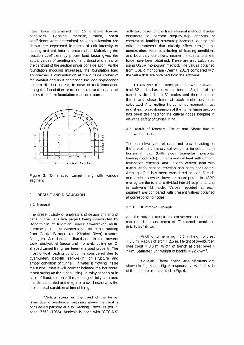
Figure 3. ‘D’ shaped tunnel lining with various
segment
3 RESULT AND DISCUSSION
3.1 General
The present study of analysis and design of lining of
canal tunnel is a live project being constructed by
Department of Irrigation, under Swarnrekha multi-
purpose project at Sundernagar for canal starting
from Ganjia Barrage (on Kharkai River) towards
Jadugora, Jamshedpur, Jharkhand. In the present
work, analysis of forces and moments acting on ‘D’
shaped tunnel lining has been analysed properly. The
most critical loading condition is considered due to
overburden, backfill, self-weight of structure and
empty condition of tunnel. If water is flowing inside
the tunnel, then it will counter balance the horizontal
thrust acting on the tunnel lining. In rainy season or in
case of flood, the backfill material gets fully saturated
and this saturated unit weight of backfill material is the
most critical condition of tunnel lining.
Vertical stress on the crest of the tunnel
lining due to overburden pressure above the crest is
considered partially due to “Arching Effect” as per IS
code: 7563 (1986). Analysis is done with “GTS-NX”
software, based on the finite element method. It helps
engineers to perform step-by-step analysis of
excavation, banking, structure placement, loading and
other parameters that directly affect design and
construction. After substituting all loading conditions
and boundary conditions moment, thrust and shear
force have been obtained. These are also calculated
using USBR monogram method. The values obtained
from USBR monogram (Verma, 2017) compared with
the value that are obtained from the software.
To analyse the tunnel problem with software,
total 62 nodes has been considered. So, half of the
tunnel is divided into 32 nodes and then moment,
thrust and shear force at each node has been
calculated. After getting the combined moment, thrust
and shear force, dimension of the tunnel lining section
has been designed for the critical nodes keeping in
view the safety of tunnel lining.
3.2 Result of Moment, Thrust and Shear due to
various loads
There are five types of loads and reaction acting on
the tunnel lining namely self-weight of tunnel, uniform
horizontal load (both side), triangular horizontal
loading (both side), uniform vertical load with uniform
foundation reaction; and uniform vertical load with
triangular foundation reaction has been considered.
Arching effect has been considered as per IS code
and vertical stresses have been computed. In USBR
monogram the tunnel is divided into 14 segments and
in software 32 node. Values reported at each
segment are compared with present values obtained
at corresponding nodes.
3.2.1 Illustrative Example
An illustrative example is considered to compute
moment, thrust and shear of ‘D’ shaped tunnel and
details as follows:
Width of tunnel lining = 5.0 m, Height of crest
= 5.0 m, Radius of arch = 2.5 m, Height of overburden
over crest = 8.0 m, Width of trench at crest level =
7.0m, Saturated unit weight of backfill = 22 kN/m3.
Solution: These nodes and elements are
shown in Fig. 4 and Fig. 5 respectively. Half left side
of the tunnel is represented in Fig. 6.

Figure 4. Nodes of the tunnel
Figure 5. Elements of the tunnel
Figure 6. Half left side nodes of the tunnel
The tunnel is analysed for different loading and the
variation of moment, thrust and shear are calculated.
The distribution of moment thrust and shear force due
to triangular horizontal loading have been represented
in Fig. 7 to Fig. 9. The values are tabulated in Table 1.
Figure 7. Moment distribution due to triangular
horizontal load of tunnel
Figure 8. Axial thrust distribution due to triangular
horizontal load of tunnel
Figure 9. Shear force distribution due to triangular
horizontal load of tunnel
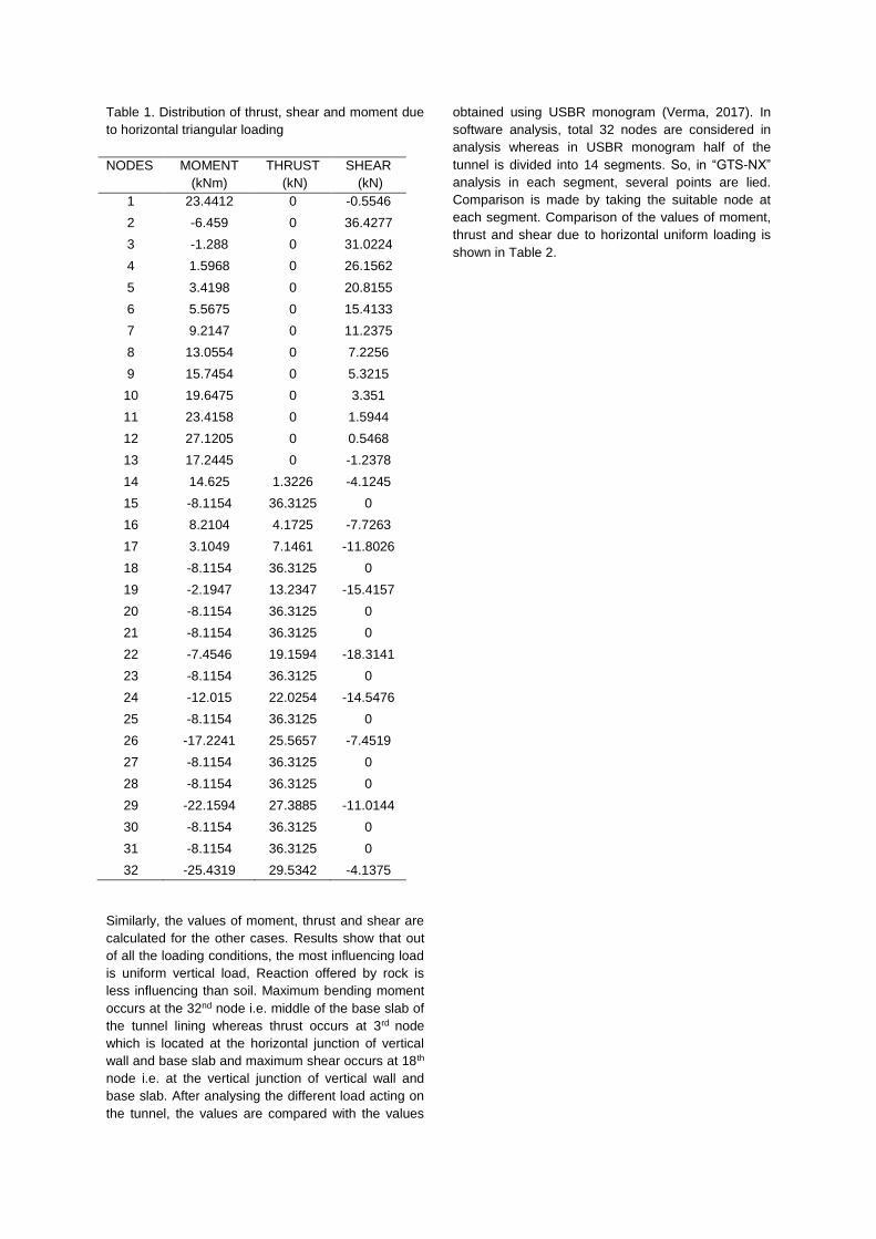
Table 1. Distribution of thrust, shear and moment due
to horizontal triangular loading
NODES MOMENT
(kNm)
THRUST
(kN)
SHEAR
(kN)
1 23.4412 0 -0.5546
2 -6.459 0 36.4277
3 -1.288 0 31.0224
4 1.5968 0 26.1562
5 3.4198 0 20.8155
6 5.5675 0 15.4133
7 9.2147 0 11.2375
8 13.0554 0 7.2256
9 15.7454 0 5.3215
10 19.6475 0 3.351
11 23.4158 0 1.5944
12 27.1205 0 0.5468
13 17.2445 0 -1.2378
14 14.625 1.3226 -4.1245
15 -8.1154 36.3125 0
16 8.2104 4.1725 -7.7263
17 3.1049 7.1461 -11.8026
18 -8.1154 36.3125 0
19 -2.1947 13.2347 -15.4157
20 -8.1154 36.3125 0
21 -8.1154 36.3125 0
22 -7.4546 19.1594 -18.3141
23 -8.1154 36.3125 0
24 -12.015 22.0254 -14.5476
25 -8.1154 36.3125 0
26 -17.2241 25.5657 -7.4519
27 -8.1154 36.3125 0
28 -8.1154 36.3125 0
29 -22.1594 27.3885 -11.0144
30 -8.1154 36.3125 0
31 -8.1154 36.3125 0
32 -25.4319 29.5342 -4.1375
Similarly, the values of moment, thrust and shear are
calculated for the other cases. Results show that out
of all the loading conditions, the most influencing load
is uniform vertical load, Reaction offered by rock is
less influencing than soil. Maximum bending moment
occurs at the 32nd node i.e. middle of the base slab of
the tunnel lining whereas thrust occurs at 3rd node
which is located at the horizontal junction of vertical
wall and base slab and maximum shear occurs at 18th
node i.e. at the vertical junction of vertical wall and
base slab. After analysing the different load acting on
the tunnel, the values are compared with the values
obtained using USBR monogram (Verma, 2017). In
software analysis, total 32 nodes are considered in
analysis whereas in USBR monogram half of the
tunnel is divided into 14 segments. So, in “GTS-NX”
analysis in each segment, several points are lied.
Comparison is made by taking the suitable node at
each segment. Comparison of the values of moment,
thrust and shear due to horizontal uniform loading is
shown in Table 2.
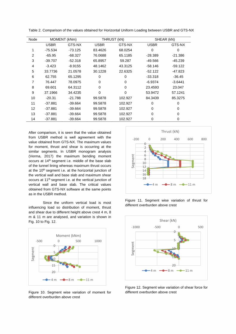
Table 2. Comparison of the values obtained for Horizontal Uniform Loading between USBR and GTS-NX
Node MOMENT (kNm) THRUST (kN) SHEAR (kN)
USBR GTS-NX USBR GTS-NX USBR GTS-NX
1 -75.534 -73.125 83.4626 68.0254 0 0
2 -65.95 -68.327 76.0688 65.1185 -28.389 -21.386
3 -39.707 -52.318 65.8957 59.287 -49.566 -45.239
4 -3.423 -8.9155 48.1462 43.3125 -58.146 -59.122
5 33.7736 21.0578 30.1228 22.6325 -52.122 -47.823
6 62.755 65.1295 0 0 -33.318 -36.45
7 76.447 78.0975 0 0 -6.9374 -3.6441
8 69.601 64.3112 0 0 23.4593 23.047
9 37.1966 34.4235 0 0 53.9472 57.1241
10 -20.31 -21.788 99.5878 102.927 84.3439 85.3275
11 -37.881 -39.664 99.5878 102.927 0 0
12 -37.881 -39.664 99.5878 102.927 0 0
13 -37.881 -39.664 99.5878 102.927 0 0
14 -37.881 -39.664 99.5878 102.927 0 0
After comparison, it is seen that the value obtained
from USBR method is well agreement with the
value obtained from GTS-NX. The maximum values
for moment, thrust and shear is occurring at the
similar segments. In USBR monogram analysis
(Verma, 2017) the maximum bending moment
occurs at 14th segment i.e. middle of the base slab
of the tunnel lining whereas maximum thrust occurs
at the 10th segment i.e. at the horizontal junction of
the vertical wall and base slab and maximum shear
occurs at 11th segment i.e. at the vertical junction of
vertical wall and base slab. The critical values
obtained from GTS-NX software at the same points
as in the USBR method.
Since the uniform vertical load is most
influencing load so distribution of moment, thrust
and shear due to different height above crest 4 m, 8
m & 11 m are analysed, and variation is shown in
Fig. 10 to Fig. 12.
Figure 10. Segment wise variation of moment for
different overburden above crest
Figure 11. Segment wise variation of thrust for
different overburden above crest
Figure 12. Segment wise variation of shear force for
different overburden above crest
0
5
10
15
20
-500 0 500 1000
Segm
ent
Moment (kNm)
4 m 8 m 11 m
02468
1012141618
-200 0 200 400 600 800
Segm
ent
Thrust (kN)
4 m 8 m 11 m
0
5
10
15
20
-1000 -500 0 500
Segm
ent
Shear (kN)
4 m 8 m 11 m

3.3 Combined Moment, Thrust and Shear force
For all four loading condition and two foundation
reactions (uniform in case of soil and triangular
foundation reaction in case of rock), combined
bending moment, thrust and shear have been
analysed. The loading diagram and their variation in
moment, thrust and shear is shown in Fig. 13 to Fig.
16.
Figure 13. Combined load acting on tunnel
Figure 14. Moment distribution due to combined
Loading on tunnel
Figure 15. Thrust distribution due to combined
Loading on tunnel
Figure 16. Shear force distribution due to combined
loading on tunnel
The foundation of tunnel at Sundarnagar site,
proportion of soil and rock is 40% and 60%
respectively. So, for design purpose, 40%
weightage has been given to soil and 60%
weightage has been given to rock and combined
weightage has been presented in Table 3. It is
totally engineering judgement of
researcher/designer.
Table 3. Distribution of combined moment, thrust
and shear due to various loads and combined
foundation reaction
NODES MOMENT (kNm)
THRUST (kN)
SHEAR (kN)
1 -62.2231 606.07384 -81.03886 2 7.3901 606.07384 112.25914 3 -4.52006 606.07384 88.2673 4 2.9757 606.07384 69.4138
5 28.79004 606.07384 30.81086 6 54.12722 606.07384 14.0247 7 60.2257 606.07384 3.089 8 70.85174 606.07384 -5.73498 9 45.9371 606.07384 -16.47206 10 24.10746 606.07384 -23.81198 11 5.3096 606.07384 -28.45608 12 -33.71078 606.07384 -56.2154 13 -181.4483 536.70874 -57.85242 14 -203.2203 504.44444 -19.6749 15 114.68 144.67152 -495.2559 16 -167.86514 457.7847 51.9565
17 -108.5459 427.50584 74.34016 18 46.00606 130.9452 -62.44494 19 -54.20686 389.91316 134.53966 20 101.82582 130.9452 -24.62998 21 118.55048 130.9452 -9.8395 22 2.8752 352.7627 106.1835 23 151.73252 130.9452 -5.63516 24 71.33366 292.5383 81.17452 25 182.2574 130.9452 -2.0156 26 171.5351 256.1523 53.69872 27 223.75252 130.9452 0 28 278.38822 130.9452 0

29 211.08818 227.27622 27.9884 30 310.0687 130.9452 0 31 351.46484 130.9452 0 32 238.74042 201.35128 -7.9847
The value of moment, thrust and shear obtained for
the case of combined all four loading by considering
proportion of soil and rock is 40% and 60%
respectively from “GTS-NX” software is compared
with values obtained from “USBR” monogram
method. The value at important segment is
compared in Table 4.
Table 4. Comparison of moment, thrust and shear between USBR and GTS-NX software
Segment
Moment (kNm) Thrust (kN) Shear (kN)
USBR GTS-NX USBR GTS-NX USBR GTS-NX
1 214.5431 238.7404 170.3616 201.3512 -6.1589 -7.9487
4 -101.2425 -108.545 366.4601 389.3731 143.8951 134.5396
7 -69.1793 -62.2231 574.665 606.0738 -35.0147 -56.2154
11 136.8798 114.68 600.3691 606.0738 -466.9874 -495.2559
14 328.1205 351.4648 112.4109 130.9452 0 0
4 CONCLUSIONS
On the basis of the results and religious discussion
made, important conclusions are drawn as follows:
Thickness of tunnel lining for lower
overburden loading over crest in both the analysis is
same but for higher overburden loading (8 m and 11
m) thickness is 450 mm and 550 mm in GTS-NX
whereas 500 mm and 600 mm in USBR monogram
method. Thickness of tunnel lining for different
parameters of soil obtained in GTS-NX is less than
USBR monogram method.
It is obvious that with increase of radius of
tunnel the thickness of lining increases, but the
thickness of tunnel for different radius obtained in
GTS-NX is less in comparison to USBR.
The lining of tunnel has been analysed in
USBR monogram method, values obtained for
bending moment, thrust and shear using obtained
from “GTS-NX” is compared for all the cases. It has
been seen that the values obtained in both cases
are nearby equal. Hence, it can be concluded that
the analysis using “GTS-NX” software results in
more economical. So, one can prefer to analyse
and design the tunnel using “GTS-NX” software.
Arching of soil plays very important role in
computing the loads and reactions acting on the
tunnel lining. Arching of soil reduces the vertical and
horizontal pressure due to overburden above the
crest.
The most critical loading condition is due
to overburden, backfill, self-weight of structure and
empty condition of tunnel. Buoyant force, uplift
pressure and seepage force do not play vital role in
most critical loading condition.
5 REFERENCES
IS: 4880(PART IV)-1971, Structural design of
concrete lining in rock, BIS New Delhi.
Jaafar, Md. 2017. Numerical modelling for circular
tunnel under static and dynamic Load, VSB-
Technical University of Ostrava.
Mouratidis, A. 2008 The ‘Cut and Cover’ and ‘Cover
and Cut’ technique in highway engineering,
Electronic Journal Geotechnical Engineering, Vol.
13.
Palassi, M. and Mohebbi, M. 2015. Design of lining
of tunnels excavated in soft soil and rock, University
of Tehran, Iran.
Philips, H. B. and Allen, I. E. 1968. Beggs
deformeter stress analysis of single barrel conduits,
United States Bureau of Reclamation, United
States.

Singh, B. and Kumar, P. 1990, Design of reinforced
concrete lining in pressure tunnel, Tunnelling and
Space Technology, 5: 591-601.
Terzaghi, K. 1943. Theoretical soil mechanics, John
Wiley and Sons, New York. Verma, P.
2017.Analysis and design of lining of canal tunnel,
M. Tech. Dissertation submitted in Deptt. Of Civil
Engg., N.I.T. Jamshedpur
Related Documents