1 FINAL TECHNICAL REPORT CONTRACT No.: ENK6-CT-2000-00346 PROJECT No.: NNE5-2000-00511 ACRONYM: EVAPCOOL TITLE: Passive Downdraught Cooling Systems Using Porous Ceramic Evaporators. PROJECT CO-ORDINATOR: WSP ENVIRONMENTAL LTD PARTNERS: UNIVERSITY OF NOTTINGHAM, UK AXIMA LAB., SWITZERLAND REPORTING PERIOD: FROM 1 March 2001 TO 30 August 2003 PROJECT START DATE: 1 March 2001 DURATION: 30 months Date of Issue of this report: 30/10/2003 Project funded by the European Community under the Fifth Framework Programme (1998- 2002)

Welcome message from author
This document is posted to help you gain knowledge. Please leave a comment to let me know what you think about it! Share it to your friends and learn new things together.
Transcript

1
FINAL TECHNICAL REPORT
CONTRACT No.:
ENK6-CT-2000-00346
PROJECT No.:
NNE5-2000-00511
ACRONYM:
EVAPCOOL
TITLE: Passive Downdraught Cooling Systems Using Porous Ceramic Evaporators.
PROJECT CO-ORDINATOR:
WSP ENVIRONMENTAL LTD
PARTNERS:
UNIVERSITY OF NOTTINGHAM, UK
AXIMA LAB., SWITZERLAND
REPORTING PERIOD: FROM 1 March 2001 TO 30 August 2003 PROJECT START DATE: 1 March 2001
DURATION: 30 months
Date of Issue of this report:
30/10/2003
Project funded by the European Community
under the Fifth Framework Programme (1998-
2002)

2
CONTENTS
Part 1: Publishable Final Report
1.1 Executive Publishable Summary
1.2 Publishable Synthesis Report
Part 2: Detailed Final Report
2.1 Objectives and strategic aspects
2.2 Scientific and technical description of the results
2.3 Assessment of Results and Conclusions
2.4 Acknowledgements
2.5 References
Part 3: Management Final Report
3.1 List of Deliverables
3.2 Comparison of initially planned activities and work actually
accomplished
3.3 Management and Co-ordination aspects

PART 1 - PUBLISHABLE REPORT
1.1 Executive Publishable Summary
The Evapcool project was initiated to design, develop and test new
porous ceramic products for improved evaporator performance as
part of an innovative cooling system and for integration within
buildings. The main parameters affecting the rate of evaporation
are ambient conditions (dry - wet bulb air temperature) and the rate
of air movement over the evaporating surface, as well as water
pressure and porosity of the evaporator. Theoretical models of both
the direct and indirect evaporative cooling systems were found to
have reasonable agreement with the climate chamber at
Nottingham University. The casting technique was used in this
project for the manufacture of the prototype evaporators, which
were designed to be stacked, hung or cantilevered, according to
the different options for building integration. The components
developed in the project are the subject of a patent application, and
commercial partners are being sought to make these components
available in the market.
A design proposal for the integration of theses components within
an office building in Teheran, Iran, was tested using dynamic
thermal analysis (Trnsys) and CFD. Results indicated that for this
location, the Evapcool system will meet 85% of the cooling load of
the offices. Predicted annual energy savings for cooling were 32-
42kWh/m2. The analysis for this project also revealed the
degradation in performance with height of the array. From this data
a simplified design tool has been developed to enable designers to
size the system. A series of seminars and workshops devoted to
downdraught cooling are planned to disseminate this research
project.
1. Physical Model of Office Integration
2. Stacked Evaporator Prototype
3. Hung Prototype

4
1.2 Publishable Synthesis Report
The Evapcool research project is concerned with the application of
direct and indirect evaporative cooling in non domestic buildings.
Evapcool was preceded by the Joule research project into Passive
Downdraught Evaporative Cooling (PDEC - Contract No. JOR3-
CT95-0078, 1996-1999). PDEC has been found to be technically
and economically viable for non-domestic buildings. A number of
buildings (including the recent Malta Stock Exchange [1]) have
successfully applied the system. However, most PDEC applications
use misting nozzles under high pressure to generate a high rate of
evaporation and this has a number of disadvantages which tend to
preclude its use for small non-domestic projects or residential
buildings.
In reviewing traditional evaporative cooling techniques using
porous ceramics, opportunities for improving the performance of
this very simple technique became apparent and formed the basis
of a patent application related to both direct and indirect
evaporative cooling systems (UK Patent Application No.
0325891.0). It also became apparent that little analysis had been
undertaken of the process of evaporative cooling through porous
ceramic. The Evapcool Project was thus initiated in order to
develop theoretical models of this process and to design, develop
and test new products for improved evaporator performance and for
their integration within buildings.
Theoretical Models – The rate of evaporation (and thus cooling) of
a porous ceramic evaporator (PCE) depends on the ambient
conditions (dry and wet bulb air temperature) and the rate of air
movement over the surface, as well as the water pressure and the
porosity of the PCE. The use of both CFD and dynamic thermal
modelling contributed to the theoretical analysis and the creation of
a simplified steady state calculation tool to enable designers to
calculate the performance of different direct system configurations.
A model was also developed of the indirect system but cooling
performance for the indirect system was found to be 0.2-0.5 of the
performance of the direct system and therefore the indirect system
was not developed beyond the laboratory scale prototype.
5. Assumptions of Theoretical Models
4. Principle of operation of the direct system

5
Prototype Design and Testing – Most ceramic building products
(e.g. cladding panels) are produced by extrusion. By contrast,
many domestic ceramic products (e.g. pots, jars, etc.) are produced
by casting. The casting technique allows the creation of a container
for water, but there are limitations imposed by this production
technique on the size and shape of the container. Both the
opportunities and limitations of the casting technique were explored
in the process of designing a number of different ceramic
components for the new direct and indirect evaporative cooling
systems. Laboratory testing revealed that better performance would
generally be achieved by the direct system, and so full scale
prototype assemblies of two of the different components designs
were tested in a climate chamber at University of Nottingham. Both
systems showed similar values of specific cooling when compared
at similar air volume flow rates. The experimental work allowed the
performance to be characterised in terms of cooling as a function of
the difference between saturated vapour pressure (es) and vapour
pressure of the supply air (e).
Specific Cooling Power per Meter Width and per Meter Hight in Function of the Temperature Difference
0
10
20
30
40
50
60
70
80
0 1 2 3 4 5 6 7 8 9 10 11 12 13 14 1temperature difference (Tdb - Twb) [K]
spec
. coo
ling
pow
er p
er m
eter
wid
th
and
per m
eter
hig
ht [W
/Km
2]
h = 1.0 mh = 0.6 mh = 0.4 m
h = 0.2 m
6. Specific cooling power per meter width, per meter height and per temperature difference.
System Design and Performance Analysis – Generic design
solutions for the integration of the direct systems into wall and roof
assemblies were developed to explore and illustrate the practical
implications of application. These were illustrated through a series
of generic drawings and model studies. The integration of these
prototype systems into a small office building project in Teheran,
Iran has also been proposed, and the overall system (i.e. building)
performance has been assessed. Results from the analysis
revealed that, for this case study in this location, the Evapcool
7. Integration Options
width
d
0.4 m
Hei
ght h
width
d
0.4 m
Hei
ght h
8. Direct System
Specific cooling power per meter width, per meter heightand per temperature difference

6
system will meet 85% of the cooling load of the office (i.e. a
threshold temperature of 26degC will only be exceeded for 15% of
the time). The predicted annual energy savings for cooling is 32-42
kWh/m2 (electricity based on a set point of 26degC), where the
annual water consumption of the system was estimated at
approximately 5liters per person per day.
The analysis also revealed the degradation in performance with
height of the array. Greatest efficiency can be achieved if the
height of the array can be limited to 0.2m. However, in practice, a
greater height may be required in order to meet the cooling need.
This data has been used in the definition of a performance
nomogram to give designers the information required for
preliminary sizing of a system.
12. Proposed integration at the Green Office Building in Teheran
Further developments and plans for exploitations - The project has
developed a number of components which are ‘close to market’.
These components are the subject of a further patent application
(UK Patent Application No. 0325891.0) and commercial partners
are being sought in various parts of Europe and in Iran. The
development by UK ceramic manufacturers of new material for use
in the moulds required for casting, may lead to substantial
reductions in production costs. Evapcool system costs will have to
be lower than the costs of ‘comfort cooling’ in Europe (desert
coolers in Iran) if it is to be taken up very widely. This is possible,
but will require wider knowledge of the opportunities and benefits of
the system to encourage take up and application on a wider scale.
10. Green Office, Teheran, Ground Floor Plan
11 Green Office, Teheran, Cross Section
9. ‘Hanging’ Prototype installed in Nottingham

7
A working demonstration project is vital. The project in Teheran is
due for completion in 2004 and further support for this project will
be sought from the EC under the COOPENER programme. The
University of Nottingham and WSP Environmental are also actively
seeking the opportunity to demonstrate Evapcool in South of Spain
and Greece.
A short publication summarising the experience, opportunities and
implications of Evapcool, PDEC and Hybrid Downdraught Cooling
would act as an important catalyst to promote further uptake. The
interest in Iran shown for the project is also indicative of
opportunities in other developing countries with similar climate
regions. The Evapcool Partners would like to hear from companies,
institutions and individuals interested in the further development of
these low energy cooling techniques. A series of seminars and
workshops entirely devoted to Downdraught Cooling is planned.
8
PART 2 - DETAIL FINAL REPORT 2.1 Objectives and strategic aspects
The environmental risks associated with climate change and the
devastating effect of pollutant emissions in the atmosphere are the
principal reasons behind the European Union’s commitment to
reducing the greenhouse gases to 8% of the 1990 levels (Kyoto
Agreement) by 2012. Energy consumption by buildings, particularly
in the non-domestic sector, represents 41% of the total energy
consumption in Europe [2] and therefore greenhouse gases
reduction in this sector by a replicable technology would have
significant impact.
In recent years the European Commission has issued legislation
which promotes the use of renewable energy together with a more
efficient use of energy in buildings. The directive 2002/91/EC,
published at the beginning of this year, sets out guidelines for
regulation of energy performance in buildings across the member
states and highlights the importance of thermal performance and
energy efficiency in the building sector.
Across the European countries a large proportion of energy is
consumed for cooling. The air-conditioning market is rapidly
increasing in Europe and in 1997 it constituted 6% of the world’s
air-conditioning market. In the tertiary sector approximately 27% of
buildings have air-conditioning and this number is constantly
increasing [3].
The proposed Passive Evaporative Cooling (Evapcool) systems can
potentially contribute to energy savings since their application
relies on natural cooling processes based on water evaporation
and solar power. The results of the project provide an
understanding of the performance potential and the implications of
building integration. This technique could make a significant
contribution to reducing energy consumption in new and existing
buildings in many European countries and throughout the hot dry
regions of the world.

9
2.2 Scientific and technical description of the results
2.1.1 Background This project was preceded by the JOULE Research Project into
Passive Downdraught Evaporative Cooling (PDEC 1996-1999
Contract No. JOR3-CT95-0078) which concluded that in
architectural and engineering terms a mixed mode approach (PDEC
+ back-up mechanical system) is technically and economically
viable, and is competitive against conventional air-conditioning for
office buildings in southern Europe [4].
The PDEC research was based on a specification using misting
nozzles under high pressures (20-50bar) to generate a high rate of
evaporation and to minimise moisture carry-over. This system
provides improved performance and other advantages over directly
wetted cellulose pads, but it still has a number of disadvantages:
high quality water required, risk of nozzles blocking up, risk of
dripping (carry-over), risk of microbiological contamination
(Legionella), and other maintenance issues. A recent market
assessment [5] has compared the cost of PDEC with comfort
cooling (approximately 150-200 €/m2).
While PDEC is viable (and has been applied in a number of
projects including the Malta Stock Exchange [1]), it is clearly
desirable to develop a cooling system which avoids these
problems. Alternative systems using porous media can overcome
many of these disadvantages and would also extend the
geographical and climatic range of applications. In order to promote
wider confidence in this approach to cooling in Europe, further work
is required to develop and improve products and systems
specifically designed for this market, and this was the subject of
this research.
1. Diagram showing Structure of Work
THEORY LAB TESTS
DESIGN MODELLING
MANUFACTURE MONITORING
CO
-OR
DIN
ATI
ON
10
The project was divided into 6 work packages (WP1-6). Each work
package had a Partner leader who was responsible for managing
the tasks and delivering the results. The Partner leaders per each
work package are listed below.
WP1 – Theoretical Models – Axima Lab., CH
Review of the theoretical basis for evaporative cooling through
porous ceramic materials and the development of dynamic
modelling tools to enable performance assessment of the technique
applied to non-domestic buildings in both Northern and Southern
Europe.
WP2 – Laboratory Scale Measurements – Nottingham University, UK
Design and construction of a laboratory scale prototype for two
porous ceramic components/systems including quantitative
performance testing for each system under controlled conditions of
temperature, relative humidity and buoyancy air flow.
WP3 – Integrated System Design - WSP Environmental Ltd., UK
Investigate the architectural and engineering design implications in
terms of detailed design, performance and cost, of the proposed
passive downdraught cooling systems and their integration into the
context of a ‘real’ building. Investigate the manufacturing options
and limitations on the design of the prototype.
WP4 – System Performance Analysis – Axima Lab., CH
Evaluate the performance of a case study office building with a
passive downdraught cooling system incorporating either direct or
indirect ceramic evaporators and compare performance and cost
with that of the same building with chilled water cooling coils.
WP5 – Prototype Design & Manufacture – WSP Environmental Ltd., UK
Design and manufacture a full scale prototype of the proposed
passive downdraught cooling systems.
WP6 – Prototype Installation & Testing – Nottingham University, UK
Install and test the full scale prototype systems in an existing
climate chamber in Nottingham.
WP7 – Co-ordination – WSP Environmental Ltd., UK
Coordination, reporting and dissemination of findings.

11
2.1.2 Direct Evaporative Cooling The passive direct evaporative cooling system is based on the use
of porous ceramic water containers located within a duct or
intermediate space between inside and outside of the building.
These unglazed ceramic evaporators intercept the hot and dry air
stream from the outside and deliver cooled and humidified air into
the interior space (Fig. 2). The rate of evaporation depends on
ambient conditions - dry and wet bulb air temperature, air flow rate
and also, significantly, the water pressure and porosity of the
ceramic evaporator. This implies that that the potential for
evaporative cooling in a particular location can be derived from
analysis of the local weather data.
2.1.3 Indirect Evaporative Cooling The indirect cooling system (Fig. 3) transfers the ‘coolth’ provided
by the ceramic evaporator to an adjacent but separate zone. This is
accomplished by heat pipes with cooling fins which transfer heat
from the area needing to be cooled to the ceramic evaporator side.
2.1.4 Development of Theoretical Models The review of the thermodynamic principles regulating the process
of evaporative cooling and the development of the theoretical
model (heat and mass transfer) constituted the first task of the
research. The main assumptions (fig. 4) for the model were:
Adiabatic process of evaporation along a uniformly wetted surface
(no moving water film); undisturbed air flow outside the boundary
layer with constant temperature and humidity along the height of
the plate. Thus the surface temperature is equal to the wet bulb
temperature and the total heat flux “ Q�” can be calculated
according to the formula below (1).
(1) A)TwbTdb(hQ ����� [W]
Where:
h = specific heat transfer coefficient [W/m2K],
Tdb = Dry bulb temperature [K],
Twb = Wet bulb temperature [K],
A = Surface area [m2].
Different models were explored in order to calculate the heat
transfer coefficient under downdraught conditions, resulting from
2. Principle of operation of the direct system
3. Principle of operation of the indirect system
4. Main Assumptions

12
the negative buoyancy from phase change (evaporation). It was
found that the calculation for a channel flow regime is the most
representative of the laboratory scale monitoring results. A
FORTRAN program and an Excel spreadsheet were developed to
calculate the system’s specific heat flux.
Based on the calculation model a methodology for the
dimensioning of the direct evaporative cooling system was
established. The methodology can be applied for a system similar
to figure 5, where the height of the elements is variable but the
other dimensions are fixed to 400 mm and 35 mm. The system
parameters are the height of the system, the space “d” between the
elements and the width of the system.
The specific cooling capacity decreases with increasing height (fig
6). For a target cooling capacity and a possible width, the height of
the system should therefore be chosen to be as small as possible,
consisting with meeting the cooling load. Furthermore, for each
height there is an optimal space dimension which is only slightly
depending on the temperature difference. The optimal space “d”
can be determined by equation (3).
(3) 625.15h375.9d ���
Where h = height of the system [m]; d = space between the
elements [mm]
Specific Cooling Power per Meter Width and per Meter Hight in Function of the Temperature Difference
0
10
20
30
40
50
60
70
80
0 1 2 3 4 5 6 7 8 9 10 11 12 13 14 1temperature difference (Tdb - Twb) [K]
spec
. coo
ling
pow
er p
er m
eter
wid
th
and
per m
eter
hig
ht [W
/Km
2]
h = 1.0 mh = 0.6 mh = 0.4 m
h = 0.2 m
6. Specific cooling power per meter width, per meter height and per temperature difference.
The diagram can be used to calculate the cooling power.
width
d
0.4 m
Hei
ght h
width
d
0.4 m
Hei
ght h
5. Direct System
7. 3D CFD simulation of experimental duct
Specific cooling power per meter width, per meter heightand per temperature difference

13
Additional CFD analysis was undertaken in order to simulate the
direct system test duct (Fig. 7). The results from the simulation and
the laboratory experiment conducted at Nottingham University can
be compared on the basis of the specific heat flux q [W/m2]: qcfd =
80 W/m2 and qexp = 138 W/m2. Uneven distribution of air
temperatures in the laboratory measurements and neglecting the
effect of thermal radiation (20W/m2) in the calculation may explain
the discrepancy of the results.
The indirect system was modelled for the ceramic and heat pipe
parts respectively. It was concluded that a relatively larger surface
of evaporators compared to the surface of heat-pipe is required.
The relationship between cooling action “Q” (W) and dry/wet bulb
temperature depression is linear and the system performance is
mainly dependent on the evaporative end. The theoretical cooling
potential of the indirect system was found to be between 5-50W/m²
of evaporator, for buoyancy driven airflow. Fan driven air flow over
the heat pipe fins can significantly improve performance.
2.1.5 Prototype Design and Manufacture Different types of component have been developed, targeting
different types of office building integration. Their shape and
assembly technique are related to the opportunity for integration
within building elements. Their geometry is mainly influenced by
maximisation of the evaporative surface versus volume of water,
and limitations of the manufacturing process. Other components of
the Evapcool system include the water supply and distribution
systems the supporting structure, vents and access panels.
Three prototype options correspond to three different structural and
assembling principles and are proposed for different types of
building integration. The design of the ‘stacked’ evaporators (figs.
8-11) made full use of the potential of cast porous ceramic as their
shape would be very difficult to realise with another industrial
manufacturing technique. The evaporators were designed to create
a self-supporting system where no other components were required
other than a drip tray for collection of possible seepage and the
water supply pipes.
The ‘hung’ option (figs. 12-15) was developed to fit with the typical
dimensions for reinforced concrete columns within an office
building. One undeveloped idea was to combine the structural
8. 3D of Stacked Evaporator
9. Stacked Evaporator Prototype
10. 3D of Stacked prototype assembly
11. Staked Prototypes

14
support with the water distribution function provided by GRP tubes.
A simpler option was given by placing the evaporators on either
stainless steel rods or aluminium sections integrated into the wall
duct.
The ‘cantilevered’ option (figs. 16) envisaged cladding type
applications. The design of the prototypes was limited by the
mechanical properties of the ceramic and the manufacturing
process of casting. It is clearly desirable to minimise the costs
associated with the supporting and water distribution components.
The limiting factors of the design and manufacturing of the
prototypes were a) mechanical properties of the ceramic; b)
manufacturing process; and c) cost. The ceramic casting technique
was regarded as the most suitable for the manufacture of the
porous ceramic reservoir because it enable the manufacture of
highly porous ceramic and of relatively complex closed shapes,
which other ceramic manufacturing techniques such as drawing or
pressing could not achieve. However, the casting technique does
not allow the manufacture of very large items.
The cost of the ceramic evaporators increases with the complexity
of its geometry. This is due to a more complex and expensive
mould and also a longer production cycle. However, recent
research undertaken in the ceramic manufacturing industry has
resulted in a chemical alternative to the use of chalk moulds. This
could potentially lower the cost of expensive chalk moulds as well
as reduce the production time. The target cost of the Evapcool
System has been estimated as 150-200 €/m2, which corresponds
to the cost of comfort cooling in Europe (year 2002).
12. 3D Hung Evaporator
13. Hung Prototype
14. Hung prototype assembly option 1
15. Prototypes supported on rods 16. Cladding System

15
2.1.6 Laboratory Scale Measurements Ceramic evaporators were tested in both direct and indirect cooling
configurations (fig. 17). A chilled water cooling coil was also tested
for comparative purposes. The performance of direct cooling
ceramic evaporator prototypes was characterised in terms of a
parameter that expresses the force driving the evaporation of water
from a wetted surface (saturated-ambient vapour pressure
difference [es-e]).
18. Measured Cooling for Direct System
Significant cooling was measured for the direct cooling ceramic
evaporator systems tested in single and twin row configuration, as
well as low and high supply water pressure. For medium and high
porosity evaporators, cooling achieved varied from a minimum of
55 W/m2 to a max of 224 W/m2 for each respectively (fig. 18). The
indirect system performance ranged from minimum cooling of 9.6
W/m2 to maximum 48.9 W/m2. The chart below compares the
theoretical models with the lab scale results (fig. 19).
Comparison between calculation and laboratory test
0
20
40
60
80
100
120
140
0 2 4 6 8 10 12 14 16 18 20temperature difference (Tdb-Twb) [K]
spec
ific
heat
tran
sfer
[W/m
2]
Calculations
Measurements
19. Heat transfer per surface area in function of the temperature difference for
measurements of the laboratory test and calculations.
17. Ceramic Evaporator with Heat Pipe

16
2.1.7 Integrated System Design The integration of direct system prototypes into the building fabric
was investigated in relation to a generic office building and to a
specific case study project. The study showed that these
components can be integrated within walls or roofs in a variety of
ways to deliver cooling to perimeter areas of both existing and new
buildings (fig. 20).
A range of different generic system/component types were
developed, for integration within wall and roof assemblies. These
proposals were produced to explore the implications of the
integration of these new components within what may be
considered to be a typical concrete frame commercial building (fig.
21). They could potentially form the basis of a cost analysis, and
also help to highlight related issues of control and maintenance.
The generic types developed included: Perimeter Column,
Perimeter Wall, Wind-catcher, Light-vent Pipe, Double façade, Roof
tiles.
The Integration of EVAPCOOL panels as a Perimeter Column
(Figs. 22, 23) incorporates an external supply air grille at high level
and internal grille at low level, with 35mm ceramic panels hung in
rows adjacent to a structural concrete column (typically 450 –
500mm). This arrangement has the advantage of achieving a large
surface area relative to the area of external wall required. The
model illustrates that such an arrangement could be achieved
either side of a column, and still allow a considerable area of
glazing. Removable panels on the interior allow access for
maintenance.
An arrangement in which interlocking panels are simply stacked to
form a perforated Wall below the cill of the window was also
developed. (Figs. 24, 25). The external supply grille is below the
cill, and the internal grille is at floor level. This arrangement could
be used for the full height of the room where there is no window. It
is simple to construct, but has the disadvantage of a small surface
area of panels relative to the external wall area required.
A ‘Wind catcher’ type of roof mounted ventilator can be fitted with
stacking or plain panels to provide a source of evaporative cooling
for top floor rooms (Fig. 26). In order to provide the large area of
evaporator required, a continuous ‘ridge’ type ventilator would
20. Physical Model of Office Integration
21. Integration Options

17
deliver more cooling. In the configuration shown, interlocking
panels provide a large surface area relative to the volume
enclosed, and importantly do not reduce the floor area of the floor
served. This type of component also has the advantage of
potentially serving areas, which are remote from the perimeter (i.e.
deeper plan spaces). Motorised dampers provide control at ceiling
level. Maintenance can be provided from the roof, so does not
cause disruption to the occupied floor.
The incorporation of EVAPCOOL ceramic panels within the
ventilated cavity which can be created outside a Light-pipe
enables the system to bypass the top floor and deliver cooling to
lower floors (Fig. 27). Such a component could usefully be located
6 – 10 meters from the perimeter, to deliver both light and cooled
air to the deeper part of the plan. This system is also probably most
suited to refurbishment projects rather than new build. The
cylindrical duct surround minimises both the physical and visual
intrusion on the top floor. The duct cover would include removable
access panels for maintenance, and motorised dampers would
provide control at ceiling level of the floor served.
Double façade construction can have definite acoustic and thermal
benefits, but can also give rise to increased overheating risk, and
consequent cooling load. Recent buildings have resolved the
overheating risk by making the whole façade openable using
automated glazed louvers. This solution is extremely expensive,
and also reduces the acoustic effectiveness of the ‘buffer zone’.
EVAPCOOL panels incorporated as cladding within the cavity of
the double façade (Figs. 28-29) would induce direct evaporative
cooling of the air within the cavity, preventing overheating. This
innovation would enable the external façade to be sealed, reducing
the cost (associated with opening facades), improving noise
reduction, and reducing the cooling load in adjacent offices.
The integration of EVAPCOOL panels in Roof (Fig. 30)
construction could provide significant indirect cooling to spaces
below. This could be applied in developing countries like India,
where ‘high performance’ insulated roofs are rare and top floors
frequently overheat. Mallick [5] has described the use of ceramic
pots within built up roofs in Bangladesh to reduce solar heat gain.
The integration of EVAPCOOL panels would not just reduce solar
22. Perimeter Column and Windcatcher
23. Physical model showing integration
24. Window cill and Light-vent-pipe
25. Physical model showing integration

18
heat gain through the roof, but through evaporative cooling, also
further reduce the surface temperature of the ceiling.
30. Roof Application of the Evapcool system
Evapcool Systems have been included in the design for a small
office building in Teheran, Iran (Fig. 30). With very hot and dry
summers Teheran has the ideal climate for the application of
evaporative cooling and mechanically driven desert coolers are
widely used.
31. Proposed integration at the Green Office Building in Teheran
EVAPCOOL ceramic panels will be integrated within the perimeter
wall of the offices located on the ground and top floors (fig. 32-33).
A ‘windcatcher’ type of installation was also proposed on the South
side of the building as part of an environmental design strategy for
the North and South offices. This project is planned for construction
in 2004. It has been estimated that the EVAPCOOL system will
meet 85% of the cooling load of the offices.
26. Windcather
27. Light-vent Pipe
29. Lyon Convention Centre by R. Piano
28. Double facade

19
2.1.8 System Performance Analysis The results of the dynamic simulation (fig. 34) for the Teheran
Office buildingshowed that for 85% of the time indoor temperature
is below 26degC. Increasing the height of the elements from 0.8 m
to 1.2 m did not reduce the number of hours above 26degC
significantly. It was found that by reducing the temperatures, the
humidity is also increased. The predicted annual energy saving for
cooling was 32 - 42 kWh/m2 (electricity based on T set point of
26degC) where the annual water consumption of the system was
estimated as 12.3m3/annum (approximately 5 litres per
person/day).
Variation of Temperatures, Air Change RateWhole Year
-10
0
10
20
30
40
50
0 1000 2000 3000 4000 5000 6000 7000 8000
Time
Ambient Ambient wet bulbRoom airSupplyAir change rate
34. Results of Dynamic thermal Model
By comparing the modelling results with the results from the full
scale measurements it was found that the model predicted a
smaller cooling power than the test results (Fig. 35). On average
the difference was of about 16%. Considering the difficulty of
measuring the outlet temperature in the full-scale test overall there
was good agreement between the two sets of results.
Comparison between calculation and fullscale prototype
0
5
10
15
20
25
30
35
40
45
50
8 9 9 10 10 11 11 12 12
temperature difference (Tdb-Twb) [K]
spec
. coo
ling
pow
er [W
/m2] measurements
calculation
35. Comparison between calculations and full-scale testing
32. Ground Floor Plan
33. Cross Section

20
2.1.9 Full Scale Prototype Monitoring The full-scale direct prototype systems were installed and
performance tested in the climate chamber of University of
Nottingham. The tested systems were: the Perimeter Column (fig.
36) (hanging/suspended column) and the Perimeter Wall (fig. 37).
The stacking option was assembled from two types of evaporator.
Coned holes and extensions on the top and bottom respectively,
allow them to locate, while also channelling the water. These were
stacked to form a wall. The second system, designated was
assembled using 400mm×200mm×35mm ceramic units which were
placed on a frame 70mm apart.
During the experimental work the two systems were tested at two
different air volume flows and a variety of DB Temperatures and
RH combinations. Tabular and graphical presentation of the results
(Fig. 38) show the cooling performance of the suspended row
system reaching a mean maximum cooling of 45.7W/m2 at
44.3degC and 45.5%, and air volume flow rate of 145m3/hr. The
stacked wall system recorded mean maximum cooling of 61.2W/m2
at 43.5 oC and 35.8%, inlet conditions, and air volume flow rate of
140m3/h. At an airflow rate of 65m3/h, mean maximum cooling is
43.0W/m2 at 44.1 oC and 32.6 %, inlet conditions.
Both systems show similar values of specific cooling, when
compared at similar air volume flow rate. This indicates a
potentially similar performance at other operating conditions.
y = -0.0073x2 + 1.3859xR2 = 0.6489
y = 0.7161xR2 = 0.8995
0
20
40
60
80
0.0 10.0 20.0 30.0 40.0 50.0 60.0 70.0
[es-e] mB
Coo
ling
(W/m
2 )
stacked- Q=140m3/h stacked- Q=65m3/h suspended- Q=145m3/h
38. Specific cooling power of monitored prototype systems
37. ‘Stacking’ Prototype installed in Nottingham
36. ‘Hanging’ Prototype installed in Nottingham

21
2.1.10 Simplified Design Tool A simplified design tool was developed for estimating performance
and for the preliminary sizing of systems. This methodology is
outlined below (Table 1). The method is subdivided in different
steps, from preliminary analysis to commissioning and refers to
case study project in Teheran.
Following the Theoretical and Performance Analysis a Performance
Chart (fig. 39) was created for the dimensioning of the Evapcool
system. These notes explain how to use the chart and calculate the
total cooling output of the system.
In the Evapcool system (fig. 40) the system parameters are the
height of the array, the space “d” between the elements and the
width of the system. The height is variable and a multiple of 0.2 m
where the other evaporators’ dimensions are fixed to 400 mm and
35 mm. The optimum spacing between the columns of evaporators
is given by the formula below (6).
(6) d = 9.375*h + 15.625;
Where d is the spacing between the evaporators and h is the height
of the system. The width is also variable and depends on the
availability of space and the type of integration.
The chart below shows the specific cooling power of the Evapcool
system per meter width and meter height as a function of the dry
and wet bulb temperature difference. It is shown that the specific
cooling capacity decreases with increasing height. Therefore for a
target cooling capacity and a given width, the height of the system
should be chosen to be as small as possible.
In using the chart the steps are the following:
1. Climate Analysis A climate analysis will assess the suitability of the local climate for
the application of passive evaporative cooling. The criterion is WBT
below 24degC for 100hrs in summer and a high wet – dry bulb air
temperature difference.
2. Design Strategy Develop a design strategy for the integration of the Evapcool
system at building level.
width
d
0.4 m
Hei
ght h
width
d
0.4 m
Hei
ght h
40. Direct System

22
TABLE 1 - EVAPCOOL SIMPLIFIED DESIGN TOOL
6. Calculate the building’s cooling demand and compare it to the cooling output of the Evapcool system chosen.
YES
8. Commissioning
3. Identify Weather Conditions
4. Choose System Height
5. Quantify Cooling Output
NO
Increase System Size
6. Cooling Output Vs Demand
7. Specification
2. Develop Design Strategy
1. Climate Analysis D r y & W e t B u lb T e m p e r a t u r e a n d P D EC p o t e n t ia l
0
5
10
15
2 0
2 5
3 0
3 5
4 0
4 5
5 6 7 8 9
Tem
pera
ture
(C)
D B T W B T PDEC
1.
Specific Cooling Power per Meter Width and per Meter Hight in Function of the Temperature Difference
0
10
20
30
40
50
60
70
80
0 1 2 3 4 5 6 7 8 9 10 11 12 13 14 1temperature difference (Tdb - Twb) [K]
spec
. coo
ling
pow
er p
er m
eter
wid
th
and
per m
eter
hig
ht [W
/Km
2]
h = 1.0 mh = 0.6 mh = 0.4 m
h = 0.2 m
3.
4.
5.
Cooling Demand in Function of Temperature Difference
0.0
50.0
100.0
150.0
200.0
250.0
300.0
0.0 2.0 4.0 6.0 8.0 10.0 12.0 14.0 16.0 18.0 20.0temperature difference (Tdb - Tsurf) [K]
cool
ing
dem
and
/ tem
p. d
iffer
ence
[W/K
]
6. 8.
2.
H=0.2m H=0.6m H=1m
1. A climate analysis will assess the suitability of the local climate for the application of passive evaporative cooling. The criterion is WBT below 24degC for 100hrs in summer and high ∆wb/dbT.
2. Develop a design strategy for the
integration of the Evapcool system at
building level.
3. Identify the design weather conditions, i.e. the typical wb/db depression for your location in summer and enter this value on the x axis of the Evapcool design chart.
4. Choose the system type you wish to integrate in your building. The systems differ by height (0.2 to 1.2m). Each system is represented by a curve on the Evapcool chart.
5. On the Evapcool chart you can identify the cooling output that each 1m wide system can produce underthe prescribed weather conditions.
* If the cooling output meets the requirements go to stage 7. If it doesn’t you can either choose a different system height or increase the width of the current system.
7. Specify the system components using specification tables, detail drawings and system schematics for the distribution of water.
8. At commissioning stage installation and maintenance manuals will be prepared for the client. 7.

23
3. Identify Weather Conditions In order to derive the specific cooling power the first step is to enter
the wet – dry bulb temperature difference we are designing for.
39. Performance Chart for calculation of the system total cooling power
4. Choose System Height For the given temperature difference it is possible to choose a
different system height.
5. Quantify Specific Cooling Power The total cooling output Qt [W] is calculated as follows:
(7) Qt = Qs x ∆T x h;
Where Qs is the specific cooling power [W/m2.K] (derived from the
chart); ∆T is the dry-wet bulb temperature difference and h is the
system height.
With a temperature difference of 12 K, a system of 1 m width and
0.2 m height has a total cooling power of 70x12x0.2=168W. A
Specific Cooling Power per Meter Width and per Meter Hight in Function of the Temperature Difference
0
10
20
30
40
50
60
70
80
0 1 2 3 4 5 6 7 8 9 10 11 12 13 14 1temperature difference (Tdb - Twb) [K]
spec
. coo
ling
pow
er p
er m
eter
wid
th
and
per m
eter
hig
ht [W
/Km
2]
h = 1.0 mh = 0.6 mh = 0.4 m
h = 0.2 m
Specific cooling power per meter width, per meter height as a function of temperature difference
Specific Cooling Power per Meter Width and per Meter Hight in Function of the Temperature Difference
0
10
20
30
40
50
60
70
80
0 1 2 3 4 5 6 7 8 9 10 11 12 13 14 1temperature difference (Tdb - Twb) [K]
spec
. coo
ling
pow
er p
er m
eter
wid
th
and
per m
eter
hig
ht [W
/Km
2]
h = 1.0 mh = 0.6 mh = 0.4 m
h = 0.2 m

24
system of 0.6 m height at the same conditions would have a total
cooling power of 49x12x0.6=353W. This shows that by doubling the
width of the system with 0.2 m height we achieve almost the same
cooling capacity as a 1 meter wide system with 0.6 m height.
6. Cooling Output Vs Cooling Demand The basic requirement for the application of the dimensioning
method illustrated above is the knowledge of the cooling demand
and the related temperature difference for a certain case. In the
Teheran project the Evapcool wall system was 6.5m wide. With a
temperature difference of 12K and a height of 0.8 this gives a
cooling power per Kelvin of 45x6.5x0.8=234W/K. This can be
compared to the hourly cooling demand of the office expressed as
cooling demand over temperature difference [W/K] as shown in the
graph below (fig. 41). In the Teheran project this allowed the
dimensioning of the system prior to the full dynamic thermal
simulation performed using Transys modelling software.
Cooling Demand in Function of Temperature Difference
0.0
50.0
100.0
150.0
200.0
250.0
300.0
0.0 2.0 4.0 6.0 8.0 10.0 12.0 14.0 16.0 18.0 20.0temperature difference (Tdb - Tsurf) [K]
cool
ing
dem
and
/ tem
p. d
iffer
ence
[W/K
]
Specific Cooling Power per Meter Width and per Meter Hight in Function of the Temperature Difference
0
10
20
30
40
50
60
70
80
0 1 2 3 4 5 6 7 8 9 10 11 12 13 14 1temperature difference (Tdb - Twb) [K]
spec
. coo
ling
pow
er p
er m
eter
wid
th
and
per m
eter
hig
ht [W
/Km
2]
h = 1.0 mh = 0.6 mh = 0.4 m
h = 0.2 m

25
41. Cooling Demand as a function of wet/dry bulb temperature difference
7. Specification Specify the system components using specification tables, detail
drawings and system schematics for the distribution of water.
8. Commissioning At commissioning stage installation and maintenance manuals will
be prepared for the client.
2.1.11 Conclusions
During the 30 months research project on ‘Passive Downdraught
Evaporative Cooling Using Porous Ceramic in non-domestic
Buildings’ the following objectives were achieved:
Theoretical models of downdraught cooling resulting from
evaporation through porous ceramic panels in both direct and
indirect systems were developed. The design and development of
new products for improved performance of passive downdraught
cooling systems were undertaken. Specifically, two innovative
direct evaporative systems incorporating porous ceramic
evaporators were designed, manufactured and tested.
A comparison between the performance of the direct and indirect
evaporative cooling systems with conventional chilled water cooling
coils under buoyancy driven airflow was made. The architectural
and engineering implications of integrating these new passive
downdraught cooling systems and components in a case study
building were investigated.
A brief summary of results for each work package is enclosed.
WP1 – Theoretical Models – Axima Lab., CH
The theory of evaporative cooling through porous ceramic materials
and its adaptation onto dynamic modelling tools was investigated.
A methodology for the preliminary assessment of the system
performance and a steady stated simulation tool were developed.
The analysis established, in accordance with the experimental
results, that in buoyancy driven conditions and for highly porous
ceramic the direct system can achieve a specific cooling power of
100W/m2 of ceramic surface area.

26
WP2 – Laboratory Scale Measurements – Nottingham University, UK
Laboratory scale evaporators were designed and manufactured for
the direct and indirect systems. These were tested in controlled
conditions within the climate chamber at Nottingham University.
The measurements showed a specific cooling power of 100-
200W/m2 of ceramic surface area of the direct system but very low
air velocities. This compared with measured cooling results of the
indirect system of 10-50W/m2. Air velocities were too low to
measure implying that buoyancy forces alone are not sufficient to
drive a significant air flow in the configuration tested.
WP3 – Integrated System Design - WSP Environmental Ltd., UK
Generic types of building integration were developed to investigate
the architectural and engineering design implications in terms of
detailed design and performance of the proposed passive direct
systems. Different types of wall and roof integrated systems were
developed and described in detailed drawings (scale 1:10) and a
physical model of an office room. Their integration and
performance in the context of an office building project in Teheran
was also investigated. A cooling strategy and an outline
specification of the proposed system were developed.
WP4 – System Performance Analysis – Axima Lab., CH
The performance of the case study office building in Teheran was
evaluated and compared with that of the same building with
conventional air-conditioning. Dynamic thermal simulation
assessed the annual performance of one representative office and
CFD analysis investigated the system’s performance under forced
ventilation in peak conditions. Results showed that comfort can be
achieved for 85% of the occupied time and that the specific cooling
achieved with an airflow of 145m3/h is approximately 32W/m2.K.
This is in partial agreement with the full-scale prototype
measurements which report a specific cooling power 16% higher
under the same conditions.
WP5 – Prototype Design & Manufacture – WSP Environmental Ltd., UK
Two full-scale ceramic prototypes of the direct system were
designed and manufactured. Pre-production detailed drawings
(scaled 1:10, 1:1) were prepared to enable the manufacture of the
ceramic prototypes. These were delivered to the test facilities of
Nottingham University for the full-scale monitoring. The

27
manufacturing options and their limitations on the design of the
ceramic prototypes were thoroughly investigated. The design
highlighted issues of cost and geometrical limitations of the
manufacturing process, assembly of the prototypes components
and their maintenance. This experience suggests that alternative
methods of manufacture and assembly should be investigated.
WP6 – Prototype Installation & Testing – Nottingham University, UK
The two full-scale prototype systems were installed and tested in
an existing climate chamber at Nottingham University. The test rig
was designed (architectural drawings scale 1:20) and the chamber
was modified to simulate a full-scale room and two full-scale
perimeter wall and perimeter column systems. The test was
performed under controlled conditions and forced ventilation. The
results showed that for the high porosity ceramic prototypes a
specific cooling power of approximately 40-45W/m2.K is achieved.
WP7 – Co-ordination – WSP Environmental Ltd., UK
The Co-ordination of the tasks and management of the Consortium
was carried out throughout the duration of the project. This was
done by assuring a constant dialogue and communication with and
amongst the partners. Problems of delayed delivery of the full-scale
ceramic prototypes and the eviction of one of the partners seriously
undermined the timing of the project. However, the Consortium
overcame these problems completing the tasks in the given
timescale. The technical and financial reporting to the Commission
was also carried out. The achieved results have been disseminated
in conference papers and posters and articles to journals and
magazines. Further dissemination and promotion is planned.
The research concluded that for the direct evaporative system a
large area of porous ceramic panels is required to achieve
significant cooling under buoyancy driven air flow. Buoyancy driven
air velocities for the porous ceramic panels were negligible
compared to tests for chilled water cooling coils. The direct
evaporative system can provide a specific cooling rate of 40-
45W/m2.degC (ceramic surface area per degC of wet/dry bulb
differential) at an air flow rate of 145m3/h.
Performance can be improved by the introduction of a low wattage
fan. Significant energy savings (30-40kWh/m2 per annum) still can
be achieved compared to the use of conventional air-conditioning
Cooling Rate
Energy Savings

28
but this makes the system very similar to a conventional desert
cooler (the advantage being that it is building integrated).
A cost appraisal of the system and its components has not been
undertaken as yet. However, an outline specification of the system
was undertaken for the case study building and this could
constitute the basis of a cost analysis. It is envisaged that until
economies of scale are achieved, the cost of the ceramic prototype
will be potentially higher than the other system’s components. A
preliminary cost estimate from an Italian ceramic manufacturer
suggested that for 1,000 evaporators the cost would approximate to
6,000 Euro (30 €/m2). The cost of comfort cooling in Europe is 150-
200 €/m2 (year 2002).
Salt deposition on and into the ceramic evaporators can lead to
risks of blockage of the water connections between the
evaporators. Possible solutions include periodic washing with
descaling solutions or the use of an ionised system. It is envisaged
that for good practice such a maintenance regime should be
applied every year.
In the case study building the annual water consumption for the
was estimated to be 12.5m3, which equates to 5.7l/person per day
and represents only 11% of the daily office water consumption per
person (50l). Also, comparing the system water consumption of
165mm/m2 to the annual precipitation of Teheran (270mm/m2), rain
water could be a viable option for the system’s water supply.
Further investigations are required on alternative and effective
ways of integrating the direct evaporative system making full use of
the building geometry and natural buoyancy driven air flow.
Alternative types of integration such as wind towers and double
facades should be explored in order to achieve a totally passive
solution which will bring additional energy and cost savings.
It is proposed:
��To develop proposals for the integration of porous ceramic
cooling within Double Facades to be subject of a further R&D
research project.
��A detailed cost appraisal of the developed systems and their
components as part of a Market Assessment on the applicability
Capital Costs
Maintenance
Water Consumption
Further Work

29
of the proposed direct evaporative system to residential
buildings in South of Spain.
��The integration of the theoretical models within other current
practice simulation tools and the development of nomograms
for the preliminary sizing of the developed system by architects
and designers.
��The dissemination of the developed techniques and related
systems to a wider audience of designers, architects and
professionals in the construction industry, through workshops,
seminars and other events.
��The exploitation of the developed and patented ideas as
described in the Technological Implementation Plan. This will
include a search for potential investors/manufacturer to whom
licence the commercialisation of the cooling systems and
components.
2.3 Acknowledgements The partners acknowledge the contribution of George
Papagiannopulos, Mario Cucinella Architects, Elsa Ceramiche
s.a.s. and Atelier One structural engineers and WSP Civils for their
kind assistance during the project.
2.4 References [1] Ford, B., Diaz, C. “Passive Downdraught Cooling: hybrid cooling
in the Malta Stock Exchange”. Plea Conference, Chile, November
2003.
[2] Eicker, U. Solar technologies for buildings. Wiley Books,
Chichester, UK, 2003
[3] Adnot, J. "Energy Efficiency of Room Air-Conditioners", EERAC,
study for the Directorate General for Energy (DGXVII) of the
Commission of the European Communities, May 1999
[4] The European Commission, ‘Passive Downdraught Evaporative
Cooling in Non-Domestic Buildings’ (1996-‘99), general information
can be found on the EC website: http://www.dbs.cordis.lu/cordis-
cgi/
[5] Ford B., at al. “Market Assessment of opportunities for passive
downdraught cooling in Southern Europe”. Plea Conference, Chile,
November 2003.
[6] Mallick, F. H. Unpublished doctoral thesis, Architectural
Association, London, 1994.
30
Additional publications and dissemination activities by the partners: E Ibrahim, L Shao, S B Riffat, “Performance of porous ceramic for
building cooling application", Energy & Buildings, 2003; Vol. 35
Issue 9: pp941-949.
E Ibrahim, L Shao, S B Riffat, “Experimental investigation of porous
ceramic evaporators for building cooling application",
CIBSE/ASHRAE International Conference – Building Sustainability
Value and Profit, Edinburgh, Scotland, September 2003.
E Ibrahim, L Shao, S B Riffat, “Porous ceramic for building
evaporative cooling", International Conference on Sustainable
Development in Building & Environment, Chongqing, China,
October 2003.
B. Ford, R. Schiano-Phan, “Evaporative Cooling Using Porous
Ceramic Evaporators – Product Development and Generic Building
Integration”, ‘The Plan – Architecture and Technologies in detail’,
Centauro srl. Bologna, Italy, October 2003.
B. Ford, R. Schiano-Phan, “Evaporative Cooling Using Porous
Ceramic Evaporators – Product Development and Generic Building
Integration”, Plea Conference, Chile, November 2003.

31
PART 3 - MANAGEMENT REPORT
3.1 List of Deliverables
A list of Deliverables with related planned and actual completion
dates is included below.
D1- Report on the theoretical basis for evaporative cooling through
porous ceramic evaporators – Planned month 6; Completed month
6.
D2 – Report on theoretical basis for dynamic models which predicts
performance of porous ceramic evaporators within: a) a
downdraught tower and b) a whole building – Planned month 12;
Completed month 16.
D3 – Report on proposed modelling methods to predict
performance of Chilled water cooling coils under negative
buoyancy driven air flow. – Planned month 12; completed month
17.
D4 - Report on the design and manufacture of two laboratory-scale
components/systems, including design drawings (scale 1:10) –
Planned month 10; completed month 6.
D5 - Prototype laboratory scale units of the proposed systems
delivered to the test laboratory – Planned month 10; completed
month 7.
D6 – Report on the performance characteristics of the two systems,
with comparative data on conventional a/c. – Planned month 12;
completed month 15.
D7 - Report on the architectural and engineering design
implications of the proposed systems integrated within case study
buildings – Planned month 16; completed month 27.
D8 - Technical report incorporating architectural and engineering
detailed drawings for the two porous ceramic systems including a
review of pertinent legislation covering design and specification –
Planned month 18; completed month 27.
D9 - Report on the manufacturing options and limitations of the
design of the prototype – Planned month 18; completed month 27.
D10 - Report describing the comparative analysis of the proposed
passive downdraught cooling systems in the context of the case
study building. – Planned month 18; completed month 30.
D11 – Technical report including design and working drawings
(scale 1:50 / 1:10) describes the manufacturing solutions for the full
scale prototype. – Planned month 18; completed month 27.

32
D12 – Two full scale porous ceramic prototype systems for direct
and indirect evaporative cooling delivered to the test site. –
Planned month 18; completed month 28.
D13 – Field data which can be used to calibrate the computer
models. – Planned month26; completed month 30.
D14 – A report with comparative analysis of the performance of the
full scale prototype systems. – Planned month 26; completed
month 30.

33
3.2 Comparison of initially planned activities and work actually accomplished
A critical overview of the technical state of the research by work packages follows.
Work Package 1 – Development of Theoretical Models
Stated Objectives Work Planned Work Performed Achieved Objectives
Reference / Deliverables
1.1 To review the theory behind the evaporative cooling process through porous ceramic materials and to develop the theoretical basis for two specific system ideas based on direct and indirect evaporative cooling
Review of previous work on evaporative cooling through porous ceramic.
�
�
D1
1.2 To develop a dynamic modelling methodology to predict temperature, relative humidity, air velocity and cooling capacity achieved through porous ceramic evaporators within a) a downdraught tower b) a building, arising from direct and indirect evaporative cooling.
Development of theoretical model describing the evaporative process in the direct and indirect system.
�
Detail modelling of direct evaporative cooling system using Computational Fluid Dynamics; steady state computer script able to predict the cooling performance of the direct system for given environmental conditions. The results of the script correlates well with lab scale measurements.
D1 D3
Minutes of Partners
Meeting 02/10/02
Development of dynamic modelling methods to predict performance of proposed evaporative systems within a tower and a building.
The analysis focused on the prediction of performance of the direct system components in a shaft and in an office using CFD. A simplified computer script has been developed to predict the cooling capacity (W/m2 surface area) of the direct system.
The comparison was made between indirect system and chilled beams (D3).
D2 D3
Minutes of Partners
Meeting 02/10/02

34
Work Package 2 – Laboratory Scale Measurements
Stated Objectives Work Planned Work Performed Achieved Objectives
Reference / Deliverables
Design and manufacture of laboratory scale prototypes for the direct and indirect systems
A lab scale ceramic prototype was developed to be used both for the direct and indirect systems. The prototype was supplied in the preferred shape and size but in different porosity in order to assess influence on performance.
�
D4 D5
Laboratory test of both direct and indirect system in vertical duct inside test cell to assess the cooling capacity as function of the environmental conditions and porosity.
As planned
The test on the direct system shows a cooling capacity of up to 200W/m2 for high porosity panels in a single row stack. Poor performance (15-50W/m2) has been recorded for the indirect system.
D6
Comparative test with refrigerant based chilled water cooling coil.
As planned
�
Addendum 1 to D6
To design and build a laboratory scale prototype of two component/system ideas and to test each system under controlled conditions with measurements of temperatures, relative humidity and air velocities, and to compare these results with the performance of a conventional chilled water cooling coil under the same test conditions.
Not originally planned.
Further investigations were required on: 1) Performance of
evaporators in single row stack.
2) Effect of water pressure.
3) Assessment of Passive Down-draught.
4) Accelerated Salt deposition.
�
Addendum 2 to D6
35
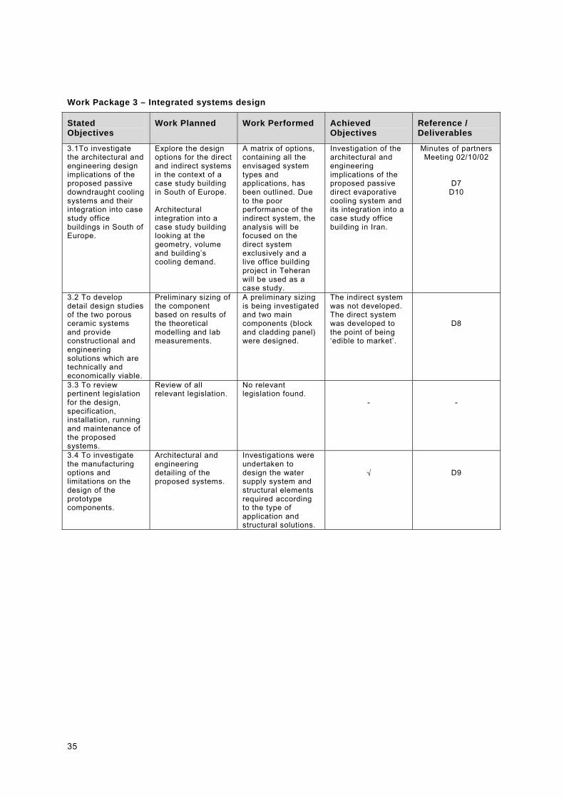
Work Package 3 – Integrated systems design
Stated Objectives
Work Planned Work Performed Achieved Objectives
Reference / Deliverables
3.1To investigate the architectural and engineering design implications of the proposed passive downdraught cooling systems and their integration into case study office buildings in South of Europe.
Explore the design options for the direct and indirect systems in the context of a case study building in South of Europe. Architectural integration into a case study building looking at the geometry, volume and building’s cooling demand.
A matrix of options, containing all the envisaged system types and applications, has been outlined. Due to the poor performance of the indirect system, the analysis will be focused on the direct system exclusively and a live office building project in Teheran will be used as a case study.
Investigation of the architectural and engineering implications of the proposed passive direct evaporative cooling system and its integration into a case study office building in Iran.
Minutes of partners Meeting 02/10/02
D7 D10
3.2 To develop detail design studies of the two porous ceramic systems and provide constructional and engineering solutions which are technically and economically viable.
Preliminary sizing of the component based on results of the theoretical modelling and lab measurements.
A preliminary sizing is being investigated and two main components (block and cladding panel) were designed.
The indirect system was not developed. The direct system was developed to the point of being ‘edible to market’.
D8
3.3 To review pertinent legislation for the design, specification, installation, running and maintenance of the proposed systems.
Review of all relevant legislation.
No relevant legislation found.
-
-
3.4 To investigate the manufacturing options and limitations on the design of the prototype components.
Architectural and engineering detailing of the proposed systems.
Investigations were undertaken to design the water supply system and structural elements required according to the type of application and structural solutions.
�
D9
36
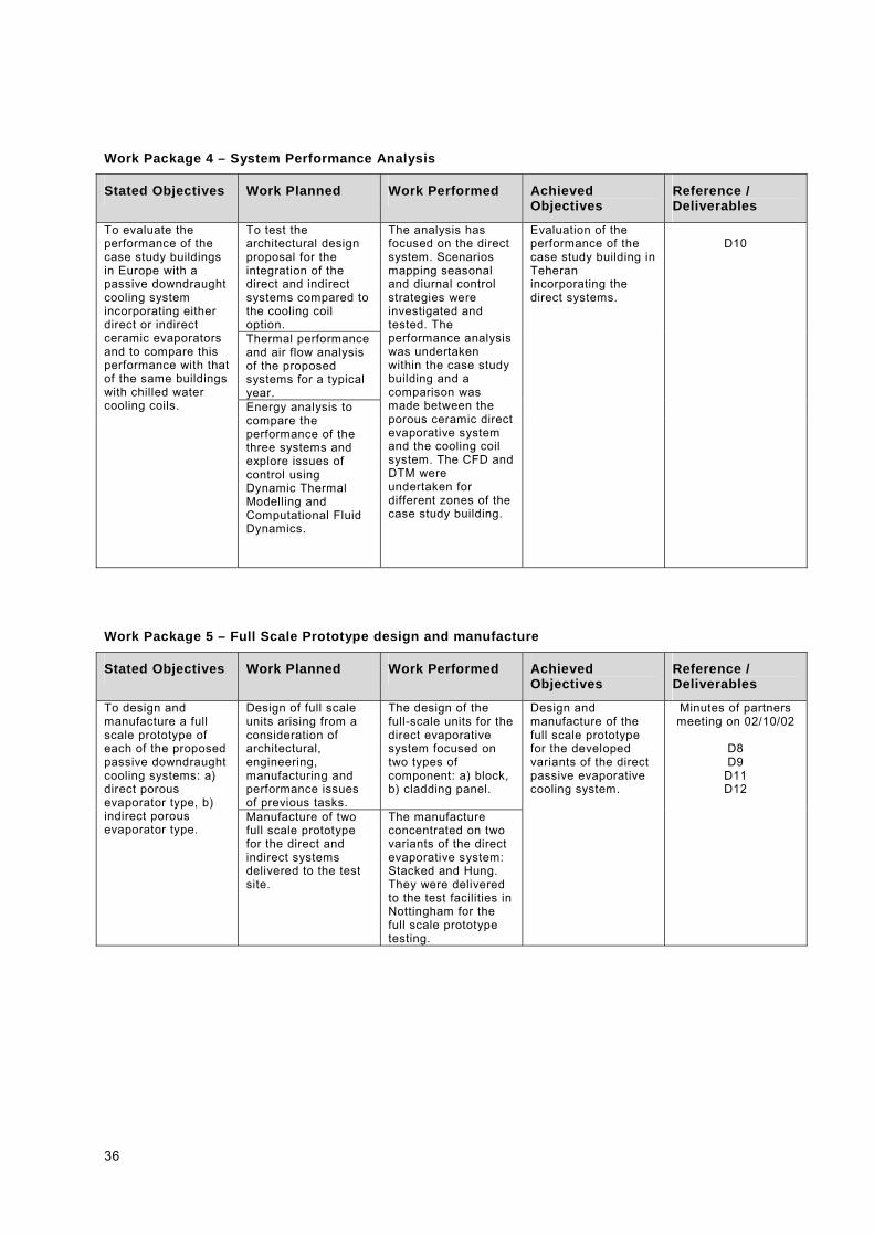
Work Package 4 – System Performance Analysis
Stated Objectives Work Planned Work Performed Achieved Objectives
Reference / Deliverables
To test the architectural design proposal for the integration of the direct and indirect systems compared to the cooling coil option. Thermal performance and air flow analysis of the proposed systems for a typical year.
To evaluate the performance of the case study buildings in Europe with a passive downdraught cooling system incorporating either direct or indirect ceramic evaporators and to compare this performance with that of the same buildings with chilled water cooling coils. Energy analysis to
compare the performance of the three systems and explore issues of control using Dynamic Thermal Modelling and Computational Fluid Dynamics.
The analysis has focused on the direct system. Scenarios mapping seasonal and diurnal control strategies were investigated and tested. The performance analysis was undertaken within the case study building and a comparison was made between the porous ceramic direct evaporative system and the cooling coil system. The CFD and DTM were undertaken for different zones of the case study building.
Evaluation of the performance of the case study building in Teheran incorporating the direct systems.
D10
Work Package 5 – Full Scale Prototype design and manufacture
Stated Objectives Work Planned Work Performed Achieved Objectives
Reference / Deliverables
Design of full scale units arising from a consideration of architectural, engineering, manufacturing and performance issues of previous tasks.
The design of the full-scale units for the direct evaporative system focused on two types of component: a) block, b) cladding panel.
To design and manufacture a full scale prototype of each of the proposed passive downdraught cooling systems: a) direct porous evaporator type, b) indirect porous evaporator type.
Manufacture of two full scale prototype for the direct and indirect systems delivered to the test site.
The manufacture concentrated on two variants of the direct evaporative system: Stacked and Hung. They were delivered to the test facilities in Nottingham for the full scale prototype testing.
Design and manufacture of the full scale prototype for the developed variants of the direct passive evaporative cooling system.
Minutes of partners meeting on 02/10/02
D8 D9
D11 D12

37
Work Package 6 – Testing and Installation
Stated Objectives Work Planned Work Performed Achieved Objectives
Reference / Deliverables
To install and test the full scale prototypes of the proposed porous ceramic downdraught cooling system design and manufactured in WP5. The purpose is to investigate actual performance under buoyancy driven airflow and real weather conditions.
Five month monitoring campaign in test facilities in Nottingham. The test was performed as a combination of long-term and short-term experiments. Data on DBT, RH and air velocity were recorded and analysed to calibrate models.
The installation and testing was performed on two variants of the direct evaporative system as specified in WP5. The full-scale prototype testing of the two variants was performed under controlled conditions in the test facilities in Nottingham. UNOTT was involved in the set up of the installation and the monitoring in the climate chamber.
Installation and testing of two types of the direct evaporative cooling system in controlled conditions. The tests were performed in the climate chamber of the University of Nottingham.
Minutes of partners meeting on 02/10/02
D13 D14
Work Package 7 – Co-ordination
Stated Objectives Work Planned Work Performed Achieved Objectives
Reference / Deliverables
7.1 To carry out the co-ordination and management of the research activity.
Assure a good level of communication between the partners. Arrange regular meetings. Be responsible for liasing with the Commission.
�
7.2 To carry out the reporting activity and the dissemination of the results of the research.
Report to the Commission on the developments of the research and the results of the completed work packages. Periodic issue of 6 and 12 months progress reports, Mid Term Assessment, Final Report and Technical Implementation Plan.
�
The dissemination work so far included the preparation of the PLEA conference paper to be presented in Chile in Nov 2003 and the publication of an article in the architectural magazine The Plan.
7.3 To develop exploitation plans and registration of patents.
A technical Implementation plan will be developed.
The tasks were carried out as planned. Delay was experienced in the delivery of the MTR (due in June 02). This was due to a series of resourcing problems during the summer. Also problems of communication with the ceramic manufacturer absorbed most of the co-ordination time, aggravated by their limited knowledge of the English language. The resourcing problem of P1 has been successfully overcome with the allocation of a full time person engaged exclusively on the research project for the last 12 months of the project.
�
Progress Report Mid Term Report Final Report Technical Implementation Plan

38
3.3 Management and Co-ordination aspects The co-ordination of a research project and the management of an
international consortium is a particularly onerous task especially for
first time co-ordinators. During this 30 months project there were
several aspects of co-ordination that required good communication
skills and familiarity with the contractual rules of the European
Commission’s Framework. At times, many issues related to the
organisation of work and communication with the Commission
constituted obstacles to the even progress of the research. This
chapter reports on the main aspects of co-ordination throughout the
project, highlighting the problems encountered and, where
appropriate, making some suggestions for future reference.
Since the beginning of the project the co-ordinator (WSPE) put in
place a structure for managing the project and co-ordinating the
work of the partners. Since the kick-off meeting the co-ordinator
tried to clarify for the partners the rules and structure of the project.
This was done in the form of a brief presentation on the Goals,
Resources and Process of development of the Research Project
(Fig. 42, 43). Important aspects such as Contractual rules, Process
of payment, Confidentiality, Intellectual Property, Internal
Communication, Delivery of results and Reporting were discussed
and an agreement on all those issues was sought from the start.
However these aspects were dealt on an ‘ad hoc’ basis. Previous
experience on the PDEC project had suggested the extreme
difficulty of obtaining a Consortium Agreement.
The partners were invited since the beginning to read the Annex II
of the Contract containing the contractual terms and conditions
between the Consortium and the Commission. It must be said that
for organisations which are for the first time in partnership with the
Commission and are not familiar with the way it operates, the
language and presentation of these rules (with their legal
terminology) is not very reader friendly and at times lacks
transparency.
It was agreed that Intellectual Property arising from the research
project is shared jointly by the partners. When the initial research
proposal was made in 1999 a confidentiality agreement on the
outcome of the research was signed by the partners. After the
failure of the first application Brian Ford and Prof. Saffa Riffat
Management of co-ordination task
Contractual Rules
Intellectual property
42. Diagrams of communication strategy
43. Diagrams of Work Packages structure

39
applied for a joint patent on the ideas of direct and indirect
evaporative cooling systems using porous ceramic evaporators.
This constitute a so called background patent to any future patent
on direct systems arising from the project. After numerous
discussions and the eviction of Il Coccio Umidificatori from the
Consortium, a patent application on the two direct evaporative
systems developed was put forward by University of Nottingham
and WSP Environmental. Axima was not interested in patenting the
idea and therefore did not subscribed to the application. By
patenting the developed products UNOTT and WSPE are hoping to
be able to either licence (or sell) the rights of manufacture to a
ceramic manufacturer for the commercialisation of this product as
part of a novel passive cooling system. The application was made
at the end of the project but it is still unknown if it will be successful
or not. More details on the commercial exploitation of results are
included in the Technical Implementation Plan.
Confidentiality and the commercial nature of the project implied
that any paper or publishable material had to be circulated in
advance between the partners and the information released in them
to be subject to the partners’ approval. According to the EC
guidelines on IPR the general rule was to disseminate the whats
and whys of the research but not the know-how. Several papers
have been published since the beginning of the research and all
contributed to the dissemination of the results. A list of titles is
included in the references of Part I.
Assuring an effective and constant communication amongst the
Partners and between the Consortium and the Commission is one
of the most difficult and time consuming tasks for the co-ordinator.
Regardless how good a structure is put in place for an efficient
management of this task, there are barriers that are often
underestimated. ‘Language’ barriers, both from the linguistic and
professional point of view are very difficult to overcome and are the
principal cause of faults in a project. Even where ‘English’ is the
common language in our project, ‘communication’ problems were
experienced, amongst the others, with Il Coccio Umidificatori. Il
Coccio was the Italian partner carrying out one of the crucial tasks
of the project: manufacture of laboratory and full-scale prototypes.
Although members of the co-ordination team were Italian mother
tongue, deeper misunderstandings occurred throughout the project.
These were mainly related to the fact that Il Coccio was a very
Confidentiality and Dissemination
Internal Communication

40
small organisation and their business language was not up to
scratch with the international community. Communicating with them
was a particularly time consuming task as all the correspondence
had to be translated and they did not seem to make an effort to
actively overcome this problem. Also, as unfortunately it is custom
in many Italian businesses, they were quite flexible on deadlines
and delivery dates which was very disruptive and completely
unacceptable in an international context. This also demonstrated
how unfamiliar they were with the problems of the construction
industry where the commitment to quality and timing are essential.
Although, on a technical level it cannot be denied that the
contribution of Il Coccio was very valuable, overall the partnership
with them was a clear burden for the Consortium and very hard
work for the co-ordination. The co-ordinator takes a big risk in
taking on partners with which they are not familiar. This risk should
be recognised in the reconnection of the coordinating partner.
Throughout the duration of the project the obvious patterns of
communication were assured by recurrent partners meetings and
task specific meetings. Exchange of emails and constant
correspondence was promoted, not only between partners and co-
ordinators but also amongst the partners, for the accomplishment
of the administrative and technical tasks. Partners meetings took
place in Nottingham (UNOTT), Winterthur (AXIMA lab), Florence
and London (WSPE) acting as a forum for communication and
decision making at different stages of the project.
A timetable for the 30 months duration of the project was prepared
and discussed with the partners at the beginning of the project. It
was emphasised the importance of looking well in advance to
deliverables dates and meeting dates, planning the successful
routes to an on time delivery. Indicative deadlines and optimum
periods for drafting and commenting on deliverables were
suggested. Inevitably the rate of success of this forecast was very
small as the actual delivery dates largely overrun the predicted
deadlines. Nevertheless it was very important to have a timescale
which gave the partners guidelines on the duration of the tasks and
completion dates. The prepared timetable was continuously
discussed and adjusted according to the work in progress in order
to project as a realistic forecast as possible. Severe delays on
completion of tasks and issue of deliverables were experienced
Timescale and Delivery

41
occasionally and this was especially the case for the delivery of the
full-scale prototypes.
The development of the theoretical models took longer than
anticipated. Minor delays also occurred in the production of the
laboratory prototypes due to unforeseen production difficulties at
the manufacturing plant in Florence, Italy, and consequent slight
delay in the experimental programme at UNOTT. During the second year problems with one of the partners were
experienced and this once again disrupted the continuation of the
other tasks. Partner No. 4, Il Coccio Umidificatori srl. underwent a
period of financial difficulties and was taken over by a company
called Industrie Ceramiche Toscane spa. After numerous attempts
to prompt ICT to fulfil their tasks and contractual obligation with the
Commission, they communicated to us that they were not willing to
be involved in the Evapcool Project. This inevitably led to the
eviction of P4 from the Consortium.
Regrettably problems with the supply of the ceramic prototypes
lead to continuous and severe delays in their delivery to Unott’s
test facilities. The prototypes were not shipped to University of
Nottingham until the 21st of June 2003. Obviously this considerably
delayed the other tasks, having a negative impact on the
development of the research. Much effort was placed by UNOTT,
who overcame this delay and managed to complete the required
task by the end of the project. However if the tests had been done
as planned more time would probably be allocated to the
investigation of other aspects arising from the first set of
measurements. Also, delays were experienced in the delivery of
the work performed by Axima on the Performance Analysis of the
case study.
Reporting to the Commission is another crucial task of the co-
ordinator. The level of information that the Commission requires is
often very detailed and often no flexibility is given in the reporting
format. Procedural changes can make the reporting task the co-
ordinator a very time consuming affair, particularly when reports
are sent back to the co-ordinator for minor amendments. Similarly,
the amount of administrative forms to fill in before and during the
project is sometimes excessive.
Reporting

42
Retrospectively it is now quite clear that some of the major
obstacles to the efficient development of the project were poor
understanding of the rules, difficult communication with some of the
Partners and at times excessive bureaucracy (especially at the
contract preparation stage), and lack of flexibility from the
Commission. Possible ways of overcoming these problems should
be sought by the Commission with the help of project co-ordinators.
From this Consortium experience it is proposed that the following
measures are taken into consideration by the Commission:
�� Training for first time co-ordinators
�� Introductory seminars for first time partners
�� More resources allocated for Co-ordination
�� More transparency in the bureaucratic procedures
�� Clearer and simpler rules accessible by anyone
�� More and closer assistance from the Commission
�� Partners Satisfaction Survey and Feedback questionnaire at
the end of the project
Overall the project was a very interesting and challenging
experience for the Consortium. From the technical point of view the
partners feel to have accomplished the goals set at the beginning
of the project and are reasonably pleased with the outcome of the
research. The hypotheses outlined in the research proposal have
all been verified and more knowledge has been acquired on
passive direct evaporative cooling systems using porous ceramic
as a mean to provide cooling in non domestic buildings. However,
further investigation is required to assess if this is a commercially
viable technique. From the management point of view the co-
ordination team and the Consortium have overcome quite
reasonably the obstacles presented along the project and made
possible the successful completion of the research in the given
timescale.
The contact person for the future follow-up of the project is:
Rosa Schiano-Phan
WSP Environmental Ltd.
Buchanan House
24-30 Holborn
London EC1N 2HS
Lessons and suggestions
Related Documents