1 Chapter 1 INTRODUCTION 1.1 OVERVIEW An electric light is a converter which produces light energy when electric current passes through it. The main purpose of road lighting is to make people, vehicles and objects on the road visible. In engineering field green issue has been raised where many researchers and engineers are involving themselves to find the techniques to reduce energy consumption, environment friendly equipment and to increase product efficiency. The best method is the smart system when it is applied in industrial, residential and commercial areas etc. Smart system is an autonomous operation which detects the change in environment with the help of sensors and act to correct the offset cause of the environment. The systems perform continually to reach the optimal solution. The main advantage of the street light is the extension of human life quality for the dark period of the day. Life quality comprises the crime prevention, traffic safety on road, aesthetic impact, behavior of human and many more. Street lighting consumes two percent of global energy and also responsible for the annual exhaust of millions of Co2. Many researches and techniques are made by engineering students, faculty of universities, colleges and research organizations to make the outdoor lighting system less power consuming. The latest technology, which is used globally in these days is light emitting diode based system, it is treated as energy efficient and reliable lighting technology, which reduced the public lighting cost as well as energy consumption up to 80% and also responsible for the reduction of carbon dioxide emissions. LED lamps last about 50 times longer than other Conventional light bulbs. A Constant lighting is the best solution in busy areas; however, it is definitely not in rural residential areas. In former cases, many people are walking around midnight when they come from, their shops, cinemas, restaurants etc. but in the latter case, only a few numbers of people using the streets during night. So, there is a temporary need for lighting streets or road, in relation to a continuous illumination of streets or road in urban areas. For energy saving on street lights we can install an automatic system which can turn on or off lighting system or the brightness of lamps increase or decrease according to detection of traffic on the road. Today world is facing energy shortages due to the increase of the

Welcome message from author
This document is posted to help you gain knowledge. Please leave a comment to let me know what you think about it! Share it to your friends and learn new things together.
Transcript

1
Chapter 1
INTRODUCTION
1.1 OVERVIEW
An electric light is a converter which produces light energy when electric current passes
through it. The main purpose of road lighting is to make people, vehicles and objects
on the road visible. In engineering field green issue has been raised where many
researchers and engineers are involving themselves to find the techniques to reduce
energy consumption, environment friendly equipment and to increase product
efficiency. The best method is the smart system when it is applied in industrial,
residential and commercial areas etc. Smart system is an autonomous operation which
detects the change in environment with the help of sensors and act to correct the offset
cause of the environment. The systems perform continually to reach the optimal
solution. The main advantage of the street light is the extension of human life quality
for the dark period of the day. Life quality comprises the crime prevention, traffic safety
on road, aesthetic impact, behavior of human and many more. Street lighting consumes
two percent of global energy and also responsible for the annual exhaust of millions of
Co2.
Many researches and techniques are made by engineering students, faculty of
universities, colleges and research organizations to make the outdoor lighting system
less power consuming. The latest technology, which is used globally in these days is
light emitting diode based system, it is treated as energy efficient and reliable lighting
technology, which reduced the public lighting cost as well as energy consumption up
to 80% and also responsible for the reduction of carbon dioxide emissions. LED lamps
last about 50 times longer than other Conventional light bulbs. A Constant lighting is
the best solution in busy areas; however, it is definitely not in rural residential areas. In
former cases, many people are walking around midnight when they come from, their
shops, cinemas, restaurants etc. but in the latter case, only a few numbers of people
using the streets during night. So, there is a temporary need for lighting streets or road,
in relation to a continuous illumination of streets or road in urban areas. For energy
saving on street lights we can install an automatic system which can turn on or off
lighting system or the brightness of lamps increase or decrease according to detection
of traffic on the road. Today world is facing energy shortages due to the increase of the
2
average consumption of energy per capita and this has led to continuous decrease of the
world reserves of natural gas and oil. Non-Conventional energy technologies have
drawn tremendous interest worldwide to find solutions for energy crisis. Recently,
photovoltaic systems have found fairly wide applications. One of the PV applications
is the Standalone Street lighting system which is using most efficient and the cost
effective LED lamps. This system doesn't require any power source plus it is free of
pollution. It can install anywhere, where grid availability is not possible, i.e. in hilly
areas, etc. Sun is used as a power source which is recognized as being an
environmentally clean source from energy production point of view. We can also add
sun tracker system in standalone system to attain maximum energy from sun for
charging of battery. This system will automatically ON-OFF through electronic
circuitry which save energy and make our lighting system more reliable and modern.
In India, in these days high intensity discharge lamps are used for street lighting.
Recently, new street light modules have gained a lot of attention to reduce the amount
of energy consumed by this type of lamp and also reduce the amount of Co2 emissions.
Latest technology light emitting diode lamp with their current performances has proved
themselves to be the most suitable solution for street lighting. It offers many advantages
such as: long life, less power consumption, no effect on the environment due to absence
of lead, no external reflector and they have high efficiency. LEDs are good light source
and their efficiency is 160 lm/W.
By using this type of high efficiency lamps, we can reduce 50% of the energy used by
HID lamps. By applying the proposed system, streets can be illuminated with lower
power consumption lamps, low operating cost, low Co2 emissions and environmentally
friendly.
1.2 OBJECTIVE OF THE WORK
The objective of the dissertation is to develop a Smart Street Lighting System that is
powered by two sources, battery and solar system and is operated at the required
intensity such that they are economically viable for the energy sector. The aim of this
dissertation is to limit the energy wastage and also reduce carbon dioxide emissions.
1.3 METHODOLOGY USED
Hardware implementation of Auto light intensity and Auto switching system control
for Smart Street lighting system is proposed. Also, sun seeker tracker can be used to
make efficient use of solar energy.
3
Chapter 2
SMART STREET LIGHTS
2.1 LIGHT
Light is in the form of radiation, which is visible to the human eye and is responsible
for the sense of light. It is also called as electromagnetic radiation (EMR) which is
having a wavelength in the range of 400 nm to 700 nm- between the infrared, with
longer wavelengths and the ultraviolet, with shorter wavelengths. The ranges
mentioned above do not represent the absolute limits of human vision, but it gives the
approximate range in which people can see well. Visible light as narrowly as 420nm to
680 nm to as broadly as 380nm to 800nm be defined by various sources. People can see
infrared up to 1050nm and in case of ultraviolet, children and young people can see
down to about 310 to 313nm. Intensity, propagation direction, frequency, wavelength
spectrum and polarization are the primary properties of visible light and the speed of
light is 3×10⁸ m/s. The visible light with these all types of EMR move at this velocity
in a vacuum. In all types of EMR, visible light is emitted and absorbed in tiny particles
called photons and exhibit properties of wave and particles. Street light is placed on the
road to make visible everything on the road at night to prevent accidents and to increase
safety of people.
2.2 CONVENTIONAL LIGHTING SYSTEM
An electric light is a device that produces light when electricity passes through it. Our
forefathers used kerosene oil lamp and candles for lighting system at night.
Incandescent lamps were made in the early and middle 19th century but had less use
now days.
Types:
There are several kinds of light bulbs.
• Incandescent - the most common light bulb in the house until about 2003.
• Gas discharge lamp - a type of light bulb that includes the fluorescent light.
Compact fluorescent lights (CFLs) have now replaced incandescent light bulbs in the
house.
• Low Pressure Sodium – It is the most efficient light source which is used in street
lighting. LPS lamp is producing a monochromatic orange-yellow light and is also a
good way to reduce sky glow. The drawback of this lamp is only CRI. Everything

4
around it looks yellow-orange when the lamp is in ON position and its uses more
wattage as the age of lamp increases.
• High Intensity Discharge – It requires an external ballast to operate. It takes 3 to 5
minutes to reach its full intensity. The lamp will be shut off if there is a dip in
electricity.
HPS must cool sufficiently to restrict, which usually takes about 1 minute to 10
minutes.
HPS lamps are of following types:
1.Mercury vapor: It is a high intensity discharge lamp. It uses an arc through vaporized
mercury in a high pressure lamp to create a weaker light that mainly creates UV light
to excite the phosphors. Lamps have a good efficiency and Color rendering is better
than that of high pressure sodium street lights.
2.Metal halide: It consists of an arc tube with an outer bulb. It may be made of either
quartz or ceramic and contains an argon gas, mercury and metal halide salts.
Traditional quartz MH arc tubes are similar in shape to mercury vapor arc tubes, but
they operate at high temperatures and pressures. They are more energy efficient than
mercury vapor and greater lumen output.
3. High pressure sodium: It is the most common lamp for street lighting and this is an
improvement over the LPS lamp i.e. it has a more CRI with greater efficiency of a
sodium lamp.
2.3 MODERN LIGHTING: LIGHT EMITTING DIODE
Solid states LEDs have been popular as indicator lights since the 1970s. In recent years,
efficacy and output have risen to the point where LEDs are now being used in niche
lighting applications. Indicator LEDs are known for their extremely longer life, up to
100,000 hours, but lighting LEDs are operated much less conservatively (due to high
LED cost per watt), and consequently have much shorter lives than indicator LEDs.
Due to the relatively high cost per watt, LED lighting is most useful at very low powers;
typically for lamp assemblies of fewer than 10 W. LEDs are currently most useful and
cost-effective in low power applications, such as night lights and flashlights. Colored
LEDs can also be used for accent lighting, such as for glass objects. They are also being
increasingly used as holiday lighting. LED efficiencies vary over a very wide range.
Some have lower efficiency than filament lamps, and some significantly higher. LED
performance in this respect is prone to being misinterpreted, as the inherent

5
directionality of LEDs gives them a much higher light intensity in one direction per
given total light output. LED technology is useful for lighting designers because of its
low power consumption, low heat generation and instantaneous on/off control. For
general domestic lighting, total cost of ownership of LED lighting is still much higher
than for other well established lighting types.
Leading the Revolution - LEDs has become the driving force in the evolution of street
lighting. The combination of improved night time visibility and safety, reduced
maintenance/operational costs, no toxic chemicals and a decrease in carbon emissions
have made LED lighting systems, a top consideration for municipalities and utility
companies everywhere.
Smart Operational Control – Roadway lighting covers a broad range of locations,
from low-traffic residential neighborhoods and rural roads. All have their own
requirements for acceptable light levels and distribution patterns and this is where LED
street light systems with “smart control” can be the most effective. The light can be
easily controlled with intelligent systems. The light can be turned on and off instantly
and can be dimmed for added energy savings at dawn, dusk, and also during hours of
low traffic. Switching on-off and dimming does not affect the lifetime of the lamp.
Quality of Life – Because of its capability for dynamic control, LED street lighting can
address issues of dark sky and light pollution in residential areas during the late night
hours.
Alternately, where and when needed, LED’s nearly white light makes it feel like
day time, which can significantly help in reducing criminal activity. The improved
illumination can also improve safety for drivers, cyclists and pedestrians.
Carbon Footprints – LED lights contain no toxic materials and are 100% recyclable.
Because of their long life, they can significantly reduce landfills and bulb disposal costs
compared to conventional street lights.
2.4 DIFFERENCE BETWEEN CONVENTIONAL AND SMART STREET
LIGHT
A Street light is a raised source of light on the edge of a road or walkway, which is
turned ON at a certain time every night. In conventional street lights, the bulbs which
are used, they consume more power and at that time there is no controlling technique
available. So, energy wastage was more. The street lights remain switched ON even
when there is no traffic. In smart street light technologies such as LED, emit a white

6
light that provides a high level of scotopic Lumens allowing Street Lights with lower
wattages and lower photonic Lumens to replace existing street lights. In these days,
smart street lights are controlled by various techniques such as wireless sensor network,
ZigBee based street light control system, and microcontroller based control scheme and
much more. For instance, in the ZigBee control system, street light control is composed
of three parts, centralized control center, remote concentrator and street light control
terminals. Centralized control center resides in a local government office usually. At
the centralized control center, operators monitor and control street lights by using the
operator’s terminal. Centralized control center computers communicate with remote
concentrator which control lights installed alongside every road.
Figure 2.1: Representation of intelligent Street light functions
Remote concentrators control lights and gather status information. Third, components
of a street light control system is street light control terminals. To control each light
individually, this street light control terminal is needed. It is installed to every street
light pole to detect status of light and to control lighting. It communicates with remote
concentrator to give and receive commands and status information for the control
center. ZigBee is rising communication protocol, which is used for data transfer within
centralized control center, remote concentrator and street light control terminals. With
the help of these above mention control techniques, the energy consumption of street
lighting can be reduced by the following methods.
• By switching the street lights in an organized manner.
• By controlling the light intensity of lamps from 0 to 100 percent.
• Switching off the lights at selected locations where there is no traffic after midnight.
7
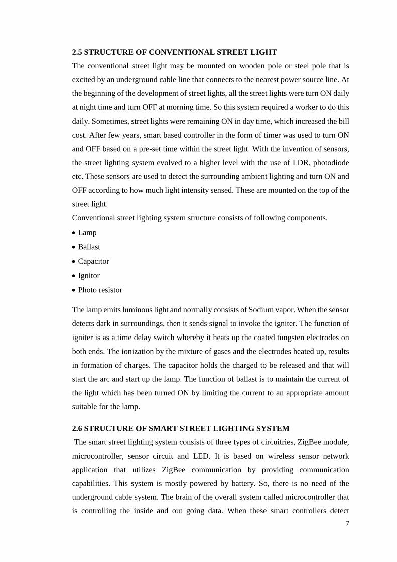
2.5 STRUCTURE OF CONVENTIONAL STREET LIGHT
The conventional street light may be mounted on wooden pole or steel pole that is
excited by an underground cable line that connects to the nearest power source line. At
the beginning of the development of street lights, all the street lights were turn ON daily
at night time and turn OFF at morning time. So this system required a worker to do this
daily. Sometimes, street lights were remaining ON in day time, which increased the bill
cost. After few years, smart based controller in the form of timer was used to turn ON
and OFF based on a pre-set time within the street light. With the invention of sensors,
the street lighting system evolved to a higher level with the use of LDR, photodiode
etc. These sensors are used to detect the surrounding ambient lighting and turn ON and
OFF according to how much light intensity sensed. These are mounted on the top of the
street light.
Conventional street lighting system structure consists of following components.
Lamp
Ballast
Capacitor
Ignitor
Photo resistor
The lamp emits luminous light and normally consists of Sodium vapor. When the sensor
detects dark in surroundings, then it sends signal to invoke the igniter. The function of
igniter is as a time delay switch whereby it heats up the coated tungsten electrodes on
both ends. The ionization by the mixture of gases and the electrodes heated up, results
in formation of charges. The capacitor holds the charged to be released and that will
start the arc and start up the lamp. The function of ballast is to maintain the current of
the light which has been turned ON by limiting the current to an appropriate amount
suitable for the lamp.
2.6 STRUCTURE OF SMART STREET LIGHTING SYSTEM
The smart street lighting system consists of three types of circuitries, ZigBee module,
microcontroller, sensor circuit and LED. It is based on wireless sensor network
application that utilizes ZigBee communication by providing communication
capabilities. This system is mostly powered by battery. So, there is no need of the
underground cable system. The brain of the overall system called microcontroller that
is controlling the inside and out going data. When these smart controllers detect

8
surrounding as dark or bright then it immediately send a HIGH or LOW signal to turn
ON and OFF the street light. With the help of ZigBee transceiver, the microcontroller
reports every activity and status of the street light to the control station wirelessly. The
host of the control station is able to monitor and control the street light 24 hrs.
In smart street lighting system, we can also check the status of the lamp like healthy,
unhealthy and faulty. In healthy condition street light operates in a normal working
condition by turning ON and OFF automatically for night and day light, but in
unhealthy condition the street light does not turn ON or OFF and it sends a feedback
message to control room to notify the host. The host is able to turn ON or OFF the street
light manually and wirelessly with the help of graphical user interface. In a fault
condition, the street light sends an error message to the control room to alert the host or
operator regarding the fault. The operator is notified and takes further action to carry
out repair works. As compared to the conventional street lighting system, the smart
street system offers high reliability, low maintenance with the deployment of feedback
system. The feedback system allows the street light to respond with the control room
reporting its daily status and condition. Instead of the above scheme, many other
controlling techniques that are used for smart street lighting system are follows:-
1. Street Light Control System Design by using ZigBee Communication Protocol.
2. GSM Based Autonomous Street Illumination System for Efficient Power
Management.
3. PLC based Smart Street Lighting Control using LDR.
4. Remote-Control System of High Efficiency and Intelligent Street Lighting using a
ZigBee Network of Devices and Sensors.
5. Wireless Dimming System for LED Street Lamp Based on ZigBee and GPRS.
2.7 BENEFITS OF STREET LIGHTING:
Modern well designed installed and maintained street lighting provides many benefits.
1. Helpful in reducing the fear of street crime to some extent.
2. Preventing night time personal injury accidents.
3. It allows the effective use of CCTV systems in cities at night.
4. Assisting the emergency services to identify locations and carry out their duties.
9
5. Promoting sustainable transport, public transport, cycling and walking.
6. Promoting economic development by support at 24 hours leisure economy.
7. Facilitating social inclusion by providing the freedom to use our street after dark.
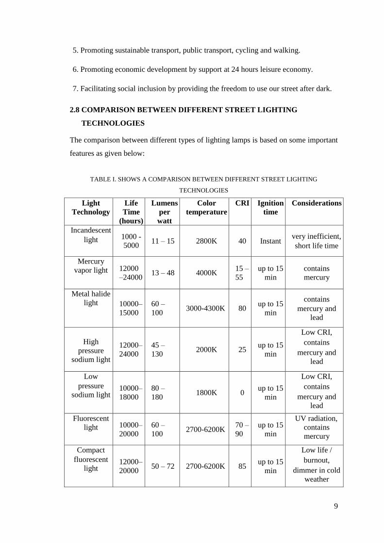
2.8 COMPARISON BETWEEN DIFFERENT STREET LIGHTING
TECHNOLOGIES
The comparison between different types of lighting lamps is based on some important
features as given below:
TABLE I. SHOWS A COMPARISON BETWEEN DIFFERENT STREET LIGHTING
TECHNOLOGIES
Light
Technology
Life
Time
(hours)
Lumens
per
watt
Color
temperature
CRI Ignition
time
Considerations
Incandescent
light 1000 -
5000 11 – 15 2800K 40 Instant
very inefficient,
short life time
Mercury
vapor light 12000
–24000 13 – 48 4000K
15 –
55
up to 15
min
contains
mercury
Metal halide
light 10000–
15000
60 –
100 3000-4300K 80
up to 15
min
contains
mercury and
lead
High
pressure
sodium light
12000–
24000
45 –
130 2000K 25
up to 15
min
Low CRI,
contains
mercury and
lead
Low
pressure
sodium light 10000–
18000
80 –
180 1800K 0
up to 15
min
Low CRI,
contains
mercury and
lead
Fluorescent
light 10000–
20000
60 –
100 2700-6200K
70 –
90
up to 15
min
UV radiation,
contains
mercury
Compact
fluorescent
light 12000–
20000 50 – 72 2700-6200K 85
up to 15
min
Low life /
burnout,
dimmer in cold
weather

10
Induction
light 60000-
100000 70 – 90 2700-6500K 80 Instant
Higher initial
cost, negatively
affected by heat
Light
emitting
diode
50000–
100000
70 –
150 3200-6400K
85 –
90 Instant
Relatively
higher initial
cost
2.9 DESIGN OF STREET LIGHTING
Street light must be designed in such a way that it must be energy efficient, reliable
and safe, technically advance, cost effective, convenient for maintenance etc.
2.10 LIST AND DESCRIPTION OF COMPONENT USED:
1. Input AC Supply: The 220V, 50 Hz AC supply fed as the primary winding of the
step down transformer.
2. Step-down transformer: It is a Static device which transfers electrical energy from
one circuit to another without changing any frequency. Step down transformer is
used for Stepping down the 220V to 12V supply.
3. 7805 Voltage Regulator IC:
Figure 2.2: Pin configuration of IC 7805
TABLE II. PIN DESCRIPTION
Pin No. Function Name
1 Input voltage (5V-18V) Input
2 Ground (0V) Ground
3 Regulated output: 5V (4.8V-5.2V) Output
11
Features:
• Output Current up to 1A
• Output Voltages of 5, 6, 8, 9, 10, 12, 15, 18
• Thermal Overload Protection
• Short Circuit Protection
Description: The 78xx is a family of self-contained fixed linear voltage regulator
integrated circuits which is commonly used in electronic circuits requiring a
regulated power supply due to their ease-of-use and low cost. The 78xx lines are
positive voltage regulators: they produce a voltage that is positive relative to a
common ground.78xx series ICs have built-in protection against a circuit drawing
too much power. They have protection against overheating and short-circuits,
making them quite robust in most applications. In some cases, the current-limiting
features of the 78xx devices can provide protection not only for the 78xx itself, but
also for other parts of the circuit. This IC is designed as fixed voltage regulator and
with adequate heat sinking can deliver output current in excess of 1A.
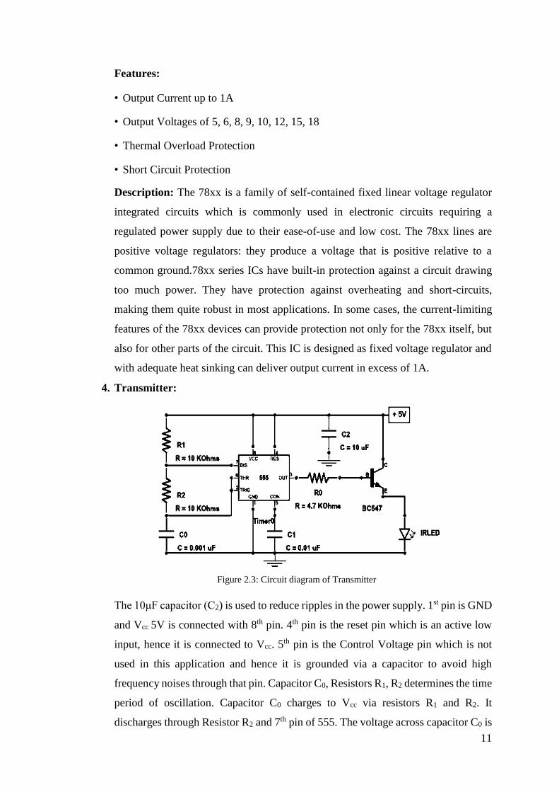
4. Transmitter:
Figure 2.3: Circuit diagram of Transmitter
The 10μF capacitor (C2) is used to reduce ripples in the power supply. 1st pin is GND
and Vcc 5V is connected with 8th pin. 4th pin is the reset pin which is an active low
input, hence it is connected to Vcc. 5th pin is the Control Voltage pin which is not
used in this application and hence it is grounded via a capacitor to avoid high
frequency noises through that pin. Capacitor C0, Resistors R1, R2 determines the time
period of oscillation. Capacitor C0 charges to Vcc via resistors R1 and R2. It
discharges through Resistor R2 and 7th pin of 555. The voltage across capacitor C0 is

12
connected to the internal comparators via 2nd and 6th pins of 555. The output is taken
from the 3rd pin of the IC. Charging time constant of the capacitor (output HIGH
period) is determined by the expression 0.693 (R1+R2) C0 and discharging time
constant (output LOW period) is determined by 0.693R2C0, they are approximately
equal.
5. IR Receiver: For receiving signals send by the transmitter we need only TSOP382.
Vs is Connect to 5V and Ground to GND pin of TSOP382.Output of TSOP382 will
be LOW when no signals fall on it and the output will be HIGH when 38 KHz
infrared rays fall on it.
6. Transistor BC547: BC547 is a NPN bi-polar junction transistor. A transistor, stands
for transfer of resistances, is commonly used to amplify current. A small current at
its base controls a larger current at collector & emitter terminals. It is mainly used
for amplification and switching purposes. It has a maximum current gain of 800. Its
equivalent transistors are BC548 and BC549.
Figure 2.4: Pin configuration of NPN Transistor
The transistor terminals require a fixed DC voltage to operate in the desired region
of its characteristic curves. This is known as the biasing. For amplification
applications, the transistor is biased such that it is partly on for all input conditions.
The input signal at the base is amplified and taken at the emitter. BC547 is used in a
common emitter configuration for amplifiers. The voltage divider is the commonly
used biasing mode. For switching applications, the transistor is biased so that it
remains fully on if there is a signal at its base. In the absence of base signal, it gets
completely off.

13
7. IR LED:
Figure 2.5: Infrared LED
An IR LED, also known as IR transmitter, is a special purpose LED that transmits
infrared rays in the range of 760 nm wavelength. Such LEDs are usually made of
Gallium Arsenide or Aluminum Gallium Arsenide. They, along with IR receivers,
are commonly used as sensors. The appearance is same as a common LED. Since
the human eye cannot see the infrared radiations, it is not possible for a person to
identify whether the IR LED is working or not, unlike a common LED. To overcome
this problem, the camera on a cell phone can be used. The camera can show us the
IR rays being emanated from the IR LED in a circuit.
8. Preset:
Figure 2.6: Preset used for variable resistance
Preset is a three legged electronic component which can be made to offer varying
resistance in a circuit. The resistance is varied by adjusting the rotary control over it.
The adjustment can be done by using a small screwdriver or a similar tool.
9. Capacitor:
Figure 2.7: Electrolyte Capacitor

14
A capacitor is a passive component used to store charge. Capacitors offer infinite
reactance to zero frequency so they are used for blocking DC components or by
passing the AC signals. The capacitor undergoes through a recursive cycle of
charging and discharging in AC circuits where the voltage and current across it
depends on the RC time constant. For this reason, capacitors are used for smoothing
Power supply variations. Since the capacitors store charge, they must be carefully
discharged before troubleshooting the circuits. The maximum voltage rating of the
capacitors used must always be greater than the supply voltage.
10. Resistor: A resistor is a two-terminal commonly used electronic component
designed to oppose an electric current by producing a voltage drop between its
terminals in proportion to the current, that is, in accordance with Ohm's law:
V = IR
11. LED: LEDs are semiconductor devices. Like transistors, and other diodes, LEDs are
made of silicon. What makes an LED give off light are the small amounts of
chemical impurities that are added to the silicon, such as Gallium, Arsenide, Indium
and Nitride. When current passes through the LED, it emits photons as a byproduct.
Normal light bulbs produce light by heating a metal filament until it is white hot.
LEDs produce photons directly and not via heat, they are far more efficient than
incandescent bulbs.
Typical LED circuit symbol
(a) (b)
Figure 2.8 (a) Typical LED (b) Circuit symbol of LED
12. NE 555N Timer IC: The NE 555 timer IC is an integrated circuit (chip) used in a
variety of timer, pulse generation, and oscillator applications. It can be used to
provide time delays, as an oscillator, and as a flip-flop element.

15
Figure 2.9: NE555 Timer IC
Pin diagram:
Fig. 2.10: Pin Diagram of NE 555 Timer IC
TABLE III. CONNECTION OF THE PINS FOR A DIP PACKAGE
PIN NAME PURPOSE
1 GND Ground reference voltage, low level (0 V)
2 TRIG The OUT pin goes high and a timing interval starts when this input
falls below 1/2 of CTRL voltage (which is typically 1/3 of VCC,
when CTRL is open)
3 OUT This output is driven to approx. 1.7 V below +VCC or GND.
4 RESET A time interval may be reset by driving this input to GND, but the
timing does not begin again until RESET rises above approximately
0.7 volts.
5 CTRL Provides "control" access to the internal voltage divider (by default,
2/3 VCC).
6 THR The timing (OUT high) interval ends when the voltage at THR is
greater than that at CTRL (2/3 VCC if CTRL is open).
7 DIS Open collector output which may discharge a capacitor between
intervals.
8 Vcc Positive supply voltage, which is usually between 3 and 15 V
depending on the variation.

16
Modes:
The 555 has following operating modes:
Monostable mode: In this mode, the 555 functions as a "one-shot" pulse generator.
Applications include timers, missing pulse detection, bounce free switches, touch
switches, frequency divider, capacitance measurement, pulse-width modulation
(PWM) and so on. Referring to figure the external capacitor is initially held
discharged by a transistor inside the timer. Upon applications of a negative trigger
pulse to pin 2, the flip-flop is set, which releases the short circuit across the external
capacitor and drives the output high. The voltage across the capacitor increases
exponentially with the time constant.
t = Ra C
When the voltage across the capacitor equals 2/3 Vcc. The comparator resets
the flip-flop, which, in turn, discharges the capacitor rapidly and drives the output to
its low state. Figure shows the actual waveforms generated in this mode of operation.
The circuit triggers on a negative going input signal when the level reaches 1/3
Vcc. Once triggered, the circuit will remain in this state until the set time is elapsed,
even if it is triggered again during this interval. The time that the output is in the high
state is given by: t= 1.1 Ra C
Applying a negative pulse to the reset terminal (pin 4) during the timing cycle
discharges the external capacitor and causes the cycle to start over again. The timing
cycle will now commence on the positive edge of the reset pulse. During the time
the reset pulse is applied, the output is driven to its low state.

17
Fig. 2.11: Circuit Diagram of NE 555 Timer IC in Monostable mode
Astable (free-running) mode: The 555 can operate as an oscillator. Uses include
LED and lamp flashers, pulse generation, logic clocks, tone generation, security
alarms, pulse position modulation. If the circuit is connected as shown in figure (pins
2 and 6 connected). It will trigger itself and free run as a multivibrator. The external
capacitor charges through Ra and Rb and discharges through Rb only. Thus, the duty
cycle may be precisely set by the ratio of these two resistors. In this mode of
operation the capacitor charges and discharges between 1/3 Vcc and 2/3 Vcc. As in
the triggered mode, the charge and discharges times, and therefore, the frequency
are independent of the supply voltage. Figure shows the actual waveforms generated
in this mode of operation.
The charge time (output high) is given by:
t1 = 0.685 (Ra + Rb) C
And the discharge time (output low) by:
t2 = 0.685 (Rb) C
Thus, the total period is given by:
T = t1 + t2 = 0.685 (Ra + 2Rb) C
The frequency of oscillation is then:
f = 1.46
(Ra + 2Rb) C

18
Fig. 2.12: Circuit Diagram of NE 555 Timer IC Astable mode
TABLE IV. SPECIFICATIONS
Supply voltage (Vcc) 4.5 to 15 V 4.5 to 15 V
Supply current (Vcc) = +5 V) 3 to 6 mA
Supply current (Vcc) = +15 V) 10 to 15 mA
Output current (maximum) 200 mA
Maximum Power dissipation 600 mW
Power consumption (minimum operating) 30 mW@5V, 225 mW@15V
Operating temperature 0 to 70o C
13. Diodes
A Diode is the simplest two-terminal unilateral semiconductor device. It allows current
to flow only in one direction and blocks the current that flows in the opposite direction.
The two terminals of the diode are called as anode and cathode. The symbol of diode is
as shown in the figure below.

19
Fig 2.13: Diodes polarity
The diode operates when a voltage signal is applied across its terminals. The application
of a DC voltage to make the diode operate in a circuit is called as ‘Biasing’. As already
mentioned above the diode resembles to that of a one way switch so it can either be in
a state of conduction or in a state of non-conduction. The ‘ON’ state of a diode is
achieved by ‘Forward biasing’ which means that positive or higher potential is applied
to the anode and negative or lower potential is applied at the cathode of the diode. In
other words, the ‘ON’ state of diode has the applied current in the same direction of the
arrow head. The ‘OFF’ state of a diode is achieved by ‘Reverse biasing’ which means
that positive or higher potential is applied to the cathode and negative or lower potential
is applied at the anode of the diode. In other words, the ‘OFF’ state of diode has the
applied current in the opposite direction of the arrow head.
During ‘ON’ state, the practical diode offers a resistance called as the ‘Forward
resistance’. The diode requires a forward bias voltage to switch to the ‘ON’ condition
which is called Cut-in-voltage. The diode starts conducting in reverse biased mode
when the reverse bias voltage exceeds its limit which is called as the Breakdown
voltage. The diode remains in ‘OFF’ state when no voltage is applied across it.
A simple p-n junction diode is fabricated by doping p and n type layers on a silicon or
germanium wafer. The germanium and silicon materials are preferred for diode
fabrication because:
They are available in high purity. Slight doping like one atom per ten million atoms of
a desired impurity can change the conductivity to a considerable level. The properties
of these materials change on applying heat and light and hence it is important in the
development of heat and light sensitive devices.
20
Chapter 3
HARDWARE IMPLEMENTATION
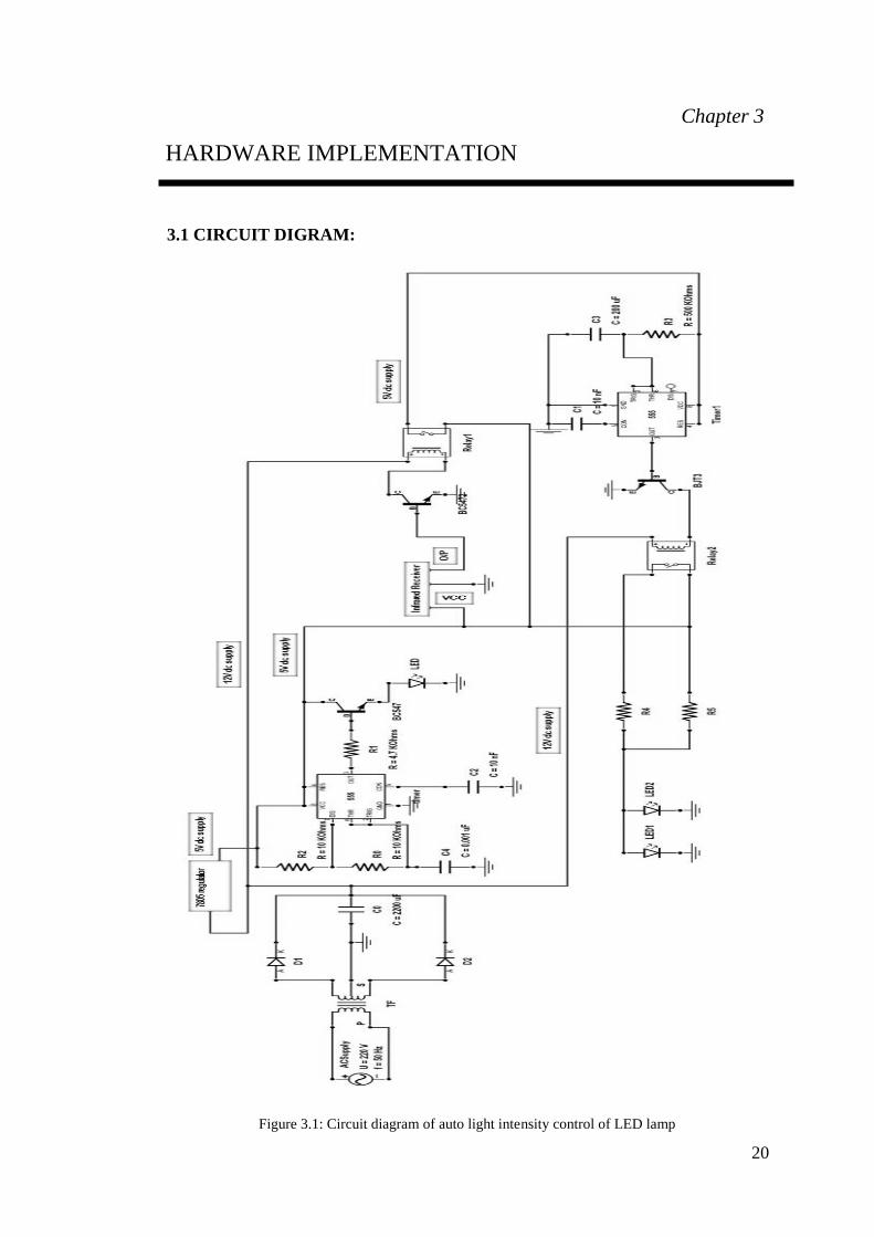
3.1 CIRCUIT DIGRAM:
Figure 3.1: Circuit diagram of auto light intensity control of LED lamp

21
Figure 3.2: Simplified Circuit diagram of Smart Street Lighting system
3.2 POWER SUPPLY
Figure 3.3: Power Supply circuit diagram of Smart Street Lighting system
3.3 WORKING
Input supply is 220 V AC, which is from the switch board. It is fed to a center tapped
transformer (750mA). A transformer is an electrical device that transfers energy
between two or more circuits through electromagnetic induction. Commonly,
transformers are used to increase or decrease the voltages of alternating current in
electric power applications. Here it is transferring energy from the power source to the
circuit used in the project. The reason for using the center tap is to create a bi-polar
power supply (a three-wire power supply with common, plus, and minus voltages).
Say, for example, you have a 30VDC full-wave rectifier circuit (with 30VDC measured
22
across the two lines). If you measure from the positive line to the center tap, the voltage
will be +15VDC. If you measure from the negative line to the center tap, the voltage
will be -15VDC.
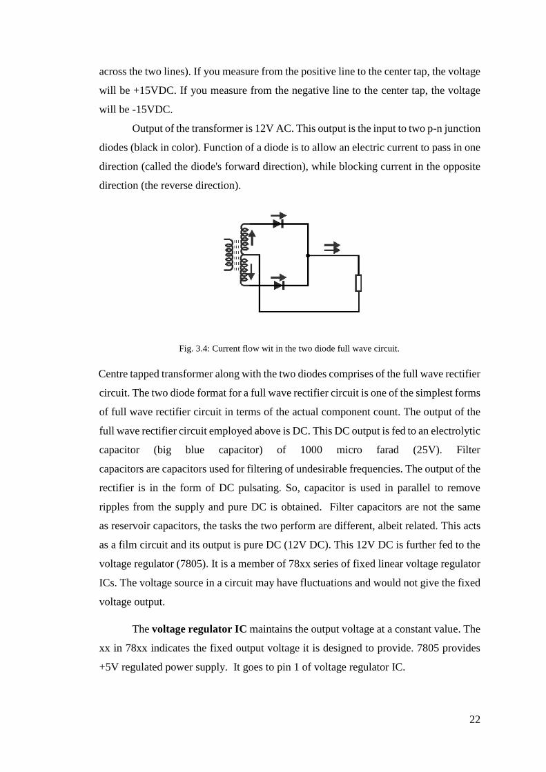
Output of the transformer is 12V AC. This output is the input to two p-n junction
diodes (black in color). Function of a diode is to allow an electric current to pass in one
direction (called the diode's forward direction), while blocking current in the opposite
direction (the reverse direction).
Fig. 3.4: Current flow wit in the two diode full wave circuit.
Centre tapped transformer along with the two diodes comprises of the full wave rectifier
circuit. The two diode format for a full wave rectifier circuit is one of the simplest forms
of full wave rectifier circuit in terms of the actual component count. The output of the
full wave rectifier circuit employed above is DC. This DC output is fed to an electrolytic
capacitor (big blue capacitor) of 1000 micro farad (25V). Filter
capacitors are capacitors used for filtering of undesirable frequencies. The output of the
rectifier is in the form of DC pulsating. So, capacitor is used in parallel to remove
ripples from the supply and pure DC is obtained. Filter capacitors are not the same
as reservoir capacitors, the tasks the two perform are different, albeit related. This acts
as a film circuit and its output is pure DC (12V DC). This 12V DC is further fed to the
voltage regulator (7805). It is a member of 78xx series of fixed linear voltage regulator
ICs. The voltage source in a circuit may have fluctuations and would not give the fixed
voltage output.
The voltage regulator IC maintains the output voltage at a constant value. The
xx in 78xx indicates the fixed output voltage it is designed to provide. 7805 provides
+5V regulated power supply. It goes to pin 1 of voltage regulator IC.

23
It which steps down 12 V DC to 5 V DC. Pin 3 of voltage regulator7805 IC is
connected to another capacitor (black capacitor) of 1000 microfarad (10v). It also acts
as a filter capacitor to get pure 5V DC voltage. The output of the filter capacitor is fed
to the 555 timer at input pins 4 and 8. The 555 timer is used in Monostable state. In
Monostable mode the 555 timer outputs a high pulse, which begins when the trigger
pin is set low. The duration of this pulse is dependent on the values of the resistor R
and capacitor C. When the trigger pin is high, it causes the discharge pin (pin 7) to drain
all charge off the capacitor. This makes the voltage across the capacitor (and the voltage
of pin 6) = 0.
When the trigger pin gets flipped low, the discharge pin is no longer able to
drain current; this causes charge to build up on the capacitor according to the equation
below. Once the voltage across the capacitor (the voltage of pin 6) equals 2/3 of the
supply voltage the output of the 555 is driven back low. The output remains low until
the trigger pin is pulsed low again, restarting the process.
Further we have employed a variable resistor (preset) of 500 kilo ohm. A preset
is a three legged electronic component which can be made to offer varying resistance
in a circuit. The resistance is varied by adjusting the rotary control over it. The
adjustment can be done by using a small screw driver or a similar tool. The resistance
does not vary linearly but rather varies in exponential or logarithmic manner. The
variable resistance is obtained across the single terminal at front and one of the two
other terminals. The two legs at back offer fixed resistance which is divided by the front
leg. So whenever only the back terminals are used, a preset acts as a fixed resistor.
Presets are specified by their fixed value resistance.
Pin 3 of the 555 timer is connected to a resistor of 1iloom which is further
connected to the transistor. The base of the transistor is a very low resistance from base
to emitter. Hence we placed a resistor in to limit the current into the base. If the resistor
is too big, your load won't turn on; if it’s too small the transistor dies. So, 1 kilo ohm
worked perfect for us. The transistors are connected for street light LEDs working.
A transmitter which is placed on one side of the road and IR Receiver placed
opposite to transmitter near street light towers. The transmitter sends signal all time i.e.
both are communicating with each other when no vehicle passes on the road and IR
receiver output will be LOW when no signal falls on it and the output will be HIGH
24
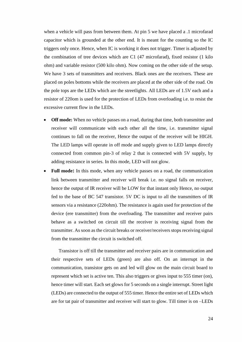
when a vehicle will pass from between them. At pin 5 we have placed a .1 microfarad
capacitor which is grounded at the other end. It is meant for the counting so the IC
triggers only once. Hence, when IC is working it does not trigger. Timer is adjusted by
the combination of tree devices which are C1 (47 microfarad), fixed resistor (1 kilo
ohm) and variable resistor (500 kilo ohm). Now coming on the other side of the setup.
We have 3 sets of transmitters and receivers. Black ones are the receivers. These are
placed on poles bottoms while the receivers are placed at the other side of the road. On
the pole tops are the LEDs which are the streetlights. All LEDs are of 1.5V each and a
resistor of 220om is used for the protection of LEDs from overloading i.e. to resist the
excessive current flow in the LEDs.
Off mode: When no vehicle passes on a road, during that time, both transmitter and
receiver will communicate with each other all the time, i.e. transmitter signal
continues to fall on the receiver, Hence the output of the receiver will be HIGH.
The LED lamps will operate in off mode and supply given to LED lamps directly
connected from common pin-3 of relay 2 that is connected with 5V supply, by
adding resistance in series. In this mode, LED will not glow.
Full mode: In this mode, when any vehicle passes on a road, the communication
link between transmitter and receiver will break i.e. no signal falls on receiver,
hence the output of IR receiver will be LOW for that instant only Hence, no output
fed to the base of BC 547 transistor. 5V DC is input to all the transmitters of IR
sensors via a resistance (220ohm). The resistance is again used for protection of the
device (ere transmitter) from the overloading. The transmitter and receiver pairs
behave as a switched on circuit till the receiver is receiving signal from the
transmitter. As soon as the circuit breaks or receiver/receivers stops receiving signal
from the transmitter the circuit is switched off.
Transistor is off till the transmitter and receiver pairs are in communication and
their respective sets of LEDs (green) are also off. On an interrupt in the
communication, transistor gets on and led will glow on the main circuit board to
represent which set is active ten. This also triggers or gives input to 555 timer (on),
hence timer will start. Each set glows for 5 seconds on a single interrupt. Street light
(LEDs) are connected to the output of 555 timer. Hence the entire set of LEDs which
are for tat pair of transmitter and receiver will start to glow. Till timer is on –LEDs

25
will glow. Timer off- LEDs off. After a few seconds (5 seconds) the circuit will
reset at its previous position, i.e. into off mode.
The advantages by using these two modes is
1.Saving of energy
2. Reduced light pollution
3.4 FLOW CHART
The following flow chart explains the operation of auto street light intensity control of
the LED lamp.
Flow chart no. 3.1: Auto light intensity control of LED lamp

26
3.4 APPLICATIONS:
1. Street lights
2. Parking lights
3. Garden lights
3.5 BENEFITS
The green way to lowering energy costs
Low power consumption
Long lumen constancy
Long and predictable lifetime
Light emission can be easily redirected
Reliability (robust against shock and vibration)
Environment friendly (CO2 saving and mercury free)
Quick turn on/off and dimming
Reduced maintenance costs
Reduced energy consumption
Performance and energy-consumption data at your fingertips
Reduced greenhouse gas emissions
Greater citizen satisfaction
From incandescent lamps to HID, LED
Inefficient light sources such as incandescent lamps will be phased out
LED technology will push the lighting market
HID and HB LED offer outstanding luminous efficiency
3.5 CONCLUSION
This technique is a cost effective, eco-friendly and easiest way of saving energy.
27
Chapter 4
PRACTICAL APPLICATIONS OF SMART STREET
LIGHTING SYSTEM
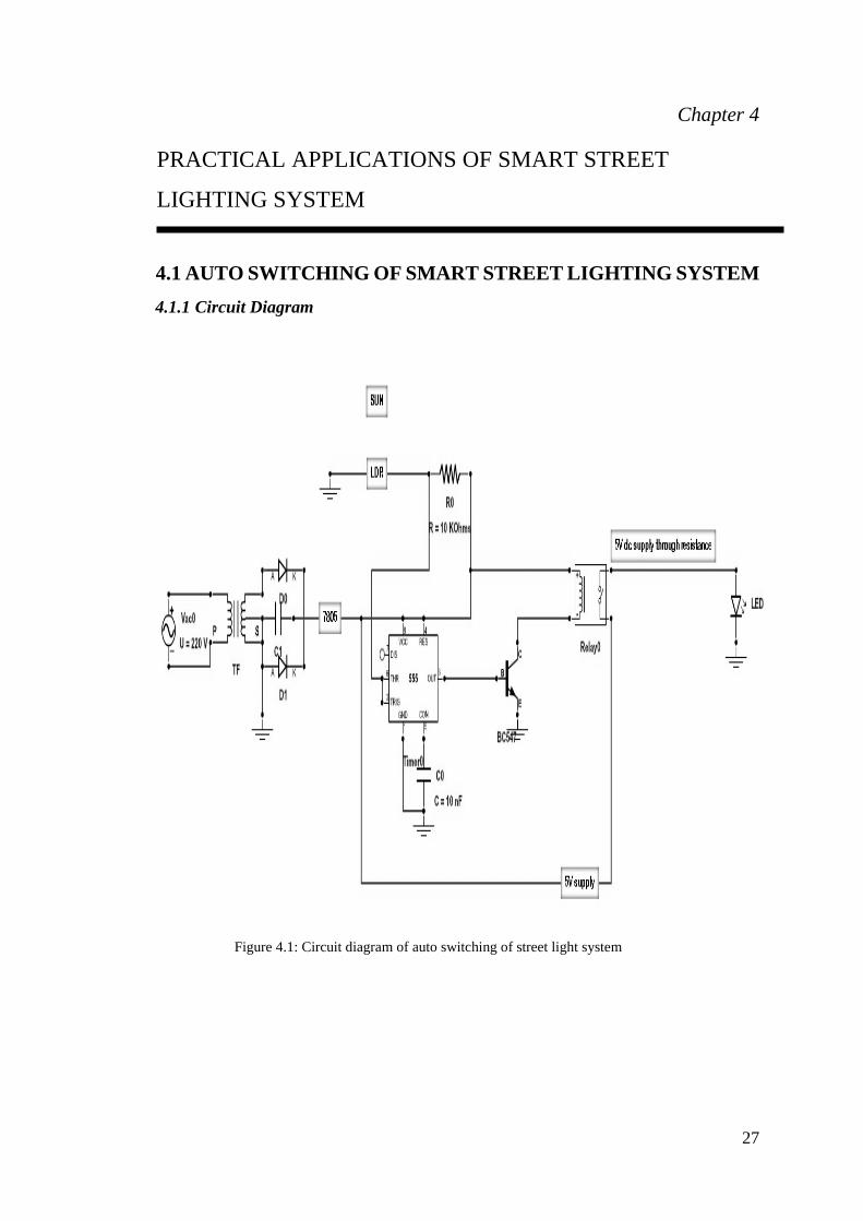
4.1 AUTO SWITCHING OF SMART STREET LIGHTING SYSTEM
4.1.1 Circuit Diagram
Figure 4.1: Circuit diagram of auto switching of street light system

28
4.1.2 Flow Chart
The following flow chart explains the operation of the auto switching system
of Smart Street light.
Flow chart no. 4.1: Auto Switching of Street Light System

29
4.1.3 Working
The above circuit is made to design the auto switching system of Smart Street
Light. The working of the circuit depends upon the conditions of day and night.
During the day: The sun rays are continue falling on LDR and its resistance
decreases, which results in an increase of the voltage at pin 2 of the IC 555. IC 555
has got comparator inbuilt, which compares between the input voltage from pin2
and 1/3rd of the power supply voltage. The input rises above 1/3rd, output is set
LOW and the relay gets de-energized. During the de - energized mode, the relay
will operate in NO mode; hence there is no supply in NC mode. So, the street light
will not turn ON at day time.
During the night: At night time, when there is no light fall on LDR i.e. its
resistance increases, which results in a decrease of the voltage at pin 2 of the IC
555. The timing IC output goes HIGH and the relay gets energized and starts
operating in NC mode. Hence, the power supply from the COM point of relay gets
connected with street lights and it will switch ON during the night. In next day
when the sun rises, then light will turn OFF automatically.
4.1.4 Benefits
1. By using the auto switching system of Smart Street light we can also reduce
energy consumption because manually operating lighting system are not
switched ON earlier before sunset and also not switched OFF properly after the
sun rise.
2. Complete elimination of man power.
3. Reduction in carbon dioxide emissions.
4. Reduction in cost.
5. Higher community satisfaction.
6. Reduce energy costs

30
4.2 SUN SEEKER
4.2.1 Circuit Diagram
Figure 4.2: Circuit diagram of Sun Seeker

31
4.2.2 Flow Chart
The following flow chart explains the operation of sun seeker system.
Flow chart no. 4.2: Sun Seeker

32
4.2.3 Working
The above circuit is made for sun seeker tracker system which attains maximum energy
from the sun at day time and solar energy is used for charging the battery, which is used
for lighting at night time.
At Day Time When Sun Rises: When light falls on LDR, its resistance decreases
hence the voltage at pin no. 2 of NE 555 timing IC-1 is above than 1/3 level of the
supply voltage. So, the output of the IC goes LOW (0) and hence relay 1 is stable in
DE energized mode. During de-energized mode, there is no supply in NC mode. So,
motor will stop rotating in that direction from where, it detects sun light.
At Night Time When Sun Is About To Set: At night time, when the sun sets, it mean
no light falls on LDR and its resistance increases, then the voltage at pin no. 2 of NE
555 timing IC-1 is lower than 1/3 level of the supply voltage. So, the output of the IC
goes HIGH (1) and relay 1 gets energized. Hence, there is 5V supply in NC mode.
When the relay starts operate in NC mode, then NE 555 timing IC-2 also triggers and
starts operation in Monostable mode. During this period, relay 2 is also energized and
starts operation in NC mode. From NC mode of relay, 12V supply goes to DC motor
and it starts rotating to detect the sun with the help of LDR. Motor rotates continue
depending upon the timing period, which further depends on the resistance and
capacitor used for Monostable mode. During the night, it stops rotating and in the
morning, again starts working and detects the sun to attain maximum sun's energy.
Power Fed From Battery To Led Lamps: The energy produced by PV module saved
in battery during day time and supplies to LED lamps during the night. SPDT Relay is
used to interface the battery power and power from a grid source with LED street
lighting. When grid is used as a source, then the relay is energized and the powers from
the battery side automatically cuts off when power from the grid source gets switched
off, then relay de-energized and connects power from battery to LED street lights. The
advantages of tracking system are continually orient PV panels towards the sun and
attain maximum energy; they are beneficial as the sun position in the sky will change
gradually over the length of a day and over the seasons throughout the year.

33
Chapter 5
ANALYSIS BETWEEN HPS AND LED AND DESIGN OF
PV OFF-GRID SYSTEM
5.1 COMPARISON
Figure 5.1: Night time lighting view of the HPS and LED lamp of different rating
The above picture shows the difference between High Pressure Sodium Lamp (250W)
and Light Emitting Diode (120W). The white LED street light seems brighter due to its
higher CRI>80 (color rendering index) and objects illuminated could be identified
clearly. Objects are hard to be identified in case of HPS because of low CRI-40, though
HPS produces much more lumens. Therefore, no need for LED lights to reach same
Lux levels as HPS to achieve the equivalent luminous effect.
The specifications of HPS and LED lamps are following here.
LED Lamp, 120W specification:
• Power = 120W
• Input voltage = AC 85-265V
• Working frequency = 50-60 Hz
• Working temperature = -45o to 50oC
• Lamp efficiency: >95%
• Harmonic Distortion: <10%
• Power factor: >0.95
• LED luminous efficiency: 90-100 lm/W
• Luminous flux: >10200 lm
• Color (CRI): cool white / white: Ra>80, warm white: Ra>70

34
• Color temperature: 6000-7000K, warm white:3000-4000K
• Beam angle: 1200, 900
HPSV LAMP, 250W SPECIFICATIONS:
• Power = 250W
• Color temperature = 1900/2000K
• High CRI = 40
• Lamp voltage = 127/253V
• Luminous flux = 2800lm/3200lm
• Color of light – Pink orange
5.2 TOTAL INITIAL COST OF LED LAMP
At Mody University, approximately 200 Street Light, lamps are used which consists
of 95% Sodium vapor lamp (250W) and 5% Metal halide lamps. If we replace these
lamps with LED lamps then we can save large amount of energy, electricity bills and
also reduce Co2 emissions per year.
The cost of one 120W LED lamp = Rs. 12000
Cost of 200 pieces of 120W LED lamp = Rs. 12000×200 = Rs. 24, 00,000
5.3 ENERGY SAVING PER YEAR IF HPS LAMP REPLACE WITH LED
HIGH PRESSURE SODIUM LAMP:
1. Lamp: High Pressure Sodium Lamp (250W)
2. Working life: 24000 hours
3. Startup speed: quite low(over 10 min)
4. Environmental pollution: contains a lead element
5. Maintenance: frequent maintenance required
Calculation:
1. The Power consumed by 250W per day with 1 fixture for 10 hours burning =
(250/1000) ×10 hours = 2.5 kWh = 2.5 units
2. The Power consumed by 250W per day for 200 fixtures for 10 hours burning =
(250/1000) ×10 hours ×200 = 500 kWh = 500 units
3. Total Co2 emissions per year = 182 tones
LIGHT EMITTING DIODE
1. Lamp: Light Emitting Diode (120W)

35
2. Working life: Long > 50000hrs
3. Start speed: Rapid (2s)
4. Heating: Cold light
5. Environmental pollution: less as compared to HPS
6. Maintenance: Almost NIL
Calculation:
1. The Power consumed by 120W per day with 1 fixture for 10 hours burning =
(120/1000) ×10 hours = 1.2 kWh = 1.2 units
2. The Power consumed by 120W per day for 200 fixtures for 10 hours burning =
(120/1000) ×10 hours ×200 = 240 kWh = 240 units
3. Total Co2 emissions per year = 87.36 tones
POWER SAVING
1. Per day Power saving with 200 LED fixtures = 500-240 = 260kWh = 260 units
2. Per month Power saving with 200 LED fixtures = 260×30 = 7800 units
3. Per year, Power saving = 7800×12 = 93600 units
MONEY SAVING
1. Total money saving per year = Total no. of units × unit cost per kWh
2. Unit cost per kWh of public lighting = Rs 6.10 (according to Rajasthan Power
Regulatory Commission report, 2014 )
3. Total Saving = Rs 6.10×93,600 = Rs 570960
Co2 REDUCTION
Co2 emissions reduction per year = 182- 87.6 tons = 94.64 tons per year
PAY BACK PERIOD:
Annually maintenance cost of LED = Nil
Formula used = (Initial cost) / (annually saving) – Maintenance cost
= 2400000/570960 = 4.2 years

36
5.4 DESIGN OF PV OFF-GRID SYSTEMS FOR STREET LIGHTS AT
MODY UNIVERSITY
Figure 5.2: Stand-alone PV system with battery storage
At Mody University near 200 street lights are used for lighting during night and each
LED Lamp will be of 120W rating. The system components used are following.
Solar panels: A number of photovoltaic modules are connected in parallel or series,
which gives a DC output of the incident irradiance. The important design
parameters of PV modules are orientation and tilt as well as shading from
surroundings obstructions. Different types of solar cells are there. e.g.
Monocrystalline Cells: These are made using cells cut from a single cylindrical
crystal of silicon. It offers the highest efficiency (18%) and their complex
manufacturing process makes them slightly more expensive.
Polycrystalline Cells: These are made by cutting micro-fine wafers from ingots of
molten and crystallized silicon. These are cheaper to produce, but there is a slight
compromise on efficiency (14%).
Solar charger controller: It is the main component of PV off-grid system, also
called brain of the system. It is responsible for performance, durability and
functions. It is also known as solar regulator. It controls the flow of current to and
from batteries to protect it from overcharging, after reaching the required voltage
within the battery. It also protects again overcharging when the load causes
critical/min voltage within the battery.

37
Batteries: The battery bank used number of deep cycle batteries connected in series
or parallel depending upon the requirement of voltage and current. The power
produced by PV modules is saved in batteries and discharge it when we need it.
The electrical power stored in batteries used for lighting during night.
Pure sine wave inverter: A power converter that converts the DC power produced
by solar modules into AC power. The characteristics of output signal should match
the voltage, frequency and power quality limits in the network. The rating of the
inverter is in watt or kilowatt.
Load: It is the component responsible to absorb this energy and transform it into
work
DESIGN OF PV OFF-GRID SYSTEM
A. Determine power consumption demands: The first step in designing a solar PV
system is to find out the total power and energy consumption of all loads that need to
be supplied by the solar PV system as follows:
Total lighting load = 120W×200 = 24000W
The lamps used 10 hours per day = 24000×10hrs = 240000 Wh/day
The total PV panels, energy needed = 240000×1.25 = 300000 Wh/day (+25% reserves
energy and losses)
Sizing the PV generator: Total Wp of PV panel capacity needed = 300000/7 = 42857
Wp Factor 7 = Avg. Daily solar exposure in hours in Patiala during summer but in
winter it may be 4-5 hrs.
No. of PV panels needed = 42857/180Wp = 238 module of 180Wp
This system should be powered by at least 238 modules of 180Wp which will be
connected in series-parallel connection.
B. Sizing the inverter:
Total wattage of Lighting load = 24000W
For safety, the inverter should be considered 25-30% bigger size.
The inverter size should be about 24000×1.3 = 31200W = 32000W or greater.
38
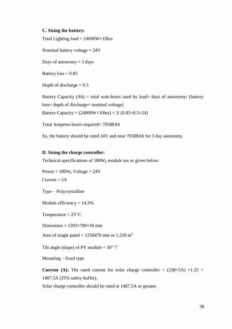
C. Sizing the battery:
Total Lighting load = 24000W×10hrs
Nominal battery voltage = 24V
Days of autonomy = 3 days
Battery loss = 0.85
Depth of discharge = 0.5
Battery Capacity (Ah) = total watt-hours used by load× days of autonomy/ (battery
loss× depth of discharge× nominal voltage)
Battery Capacity = (24000W×10hrs) × 3/ (0.85×0.5×24)
Total Amperes-hours required= 70588Ah
So, the battery should be rated 24V and near 70588Ah for 3 day autonomy.
D. Sizing the charge controller:
Technical specifications of 180Wp module are as given below:
Power = 180Wp Voltage = 24V
Current = 5A
Type – Polycrystalline
Module efficiency = 14.3%
Temperature = 25o C
Dimension = 1593×790×50 mm
Area of single panel = 1258470 mm or 1.259 m2
Tilt angle (slope) of PV module = 30o 7’
Mounting – fixed type
Current (A): The rated current for solar charge controller = (238×5A) ×1.25 =
1487.5A (25% safety buffer).
Solar charge controller should be rated at 1487.5A or greater.

39
Voltage (V): The PV voltage (Voc) of 238×180Wp panels, connected parallel will be
24×1.2 = 28.8V (20% safety buffer).
The maximum allowed voltage within a 24V PWM controller is 52V and it should not
exceeded 28.8V.
According to the above calculation (238×180Wp) 1487.5A PWM charger controller for
24V system should be chosen.
5.5 GRAPHICAL REPRESENTATION OF CALCULATIONS:
1. The graph 5.1 represents the power consumed by 200 fixtures per day by
High Sodium Vapor Lamp and LED Lamp.
Graph 5.1: Power consumed by HPS Lamp and LED Lamp
2. The graph 5.2 represents the life time hours of HPS and LED Lamp
Graph 5.2: Life time hours of HPS and LED Lamp
0
50
100
150
200
250
300
350
400
450
500
1 2 3 4 5
Power consumed by 200
fixtures of HPS lamp (kwh)
Power consumed by 200
fixtures of LED lamp (kwh)
0
500
1000
1500
2000
2500
3000
3500
4000
4500
5000
1 2 3
Life time of HPS Lamp
Life time of LED Lamp
(hours)

40
3. The graph 5.3 represents the power saving per month and year by 200
fixtures if we replace HPS Lamp with LED
Graph 5.3: Annually Power saving
0
10000
20000
30000
40000
50000
60000
70000
80000
90000
100000
Power saving
per
month(Kwh)
Power saving
per year (Kwh)

41
Chapter 6
RESULTS
6.1 EXPERIMENTAL SETUP:
• Normal View:
Figure 6.1: Hardware view of auto light intensity control of LED lamp
• In Off Mode: When there is no traffic on the road, the LED lamps work in
OFF mode, which save energy when there is no use.
Figure 6.2: Hardware View in Dim mode
• In Full Mode: When any vehicle passes on the road, then the IR sensor placed
opposite to transmitter detects it and increases LED lamp intensity for the few
seconds that is depended upon timer IC output interval time.
Figure 6.3: Hardware View in full intensity mode

42
6.2 EXPERIMENTAL RESULT
6.2.1 Transmitter Output:
Figure 6.4: NE 555 Timer IC output waveform of transmitter circuit
Figure 6.5: Infrared white LED during dim mode waveform of transmitter circuit
Figure 6.6: Infrared white LED during full mode waveform of transmitter circuit

43
6.2.2 Transformer Output:
Figure 6.7: Transformer output waveform
6.2.3 Full Wave Rectifier Output:
Figure 6.8: Full wave rectifier output waveform
6.2.4 IC 7805 Output:
Figure 6.9: output waveform of IC 7805

44
Chapter 7
CONCLUSION
In conventional system high intensity discharge lamps are used for street lighting
system based on the principle of gas discharge. The system efficiency is very less. There
are techniques present which control the light intensity of these Lamps so that energy
wastage can be minimized during night when there is no traffic on road. But the
proposed system has many advantages over the conventional one. It reduces the energy
wastage so the efficiency of the system increases. The proposed system has less number
of components. So, the system is less complex and more economical. The proposed
system is modeled and a hardware prototype is developed in the lab. Sun tracking
system is used to extract maximum solar energy .The solar energy is converted to DC
power stored in a 12 volt, 2.5Ah battery with the help of solar panel. DC power serves
as the standby supply in case of load shedding. The charging and discharging time and
the voltage developed across the battery because of the solar panel connected at the
source end are recorded at an interval of four and fifteen minutes respectively. The
recorded data’s are presented in tabular form as well as graph. The main supply is
rectified and fed to the lighting loads. In case of obstacles near the lights the LED will
glow with full intensity otherwise dim lighting will be there reducing the wastage of
extra energy. The proposed system calculation shows 50% of energy saving compared
to conventional system.
7.1 FUTURE SCOPE
In the future, Mathematical and Simulink model of the proposed system can be
developed.
Related Documents