Final Project Report MAE 4344 Interdisciplinary Design Projects Team Name: Go Baby Go, OK Outriders Project Champions: OK ABLE Tech, Dr. Jerome Hausselle Team Members: Ben Davis, Colton Mullin, Colton Tubbs, Christopher Young, Hannah Cox 3 May 2019

Welcome message from author
This document is posted to help you gain knowledge. Please leave a comment to let me know what you think about it! Share it to your friends and learn new things together.
Transcript
Final Project Report
MAE 4344 Interdisciplinary Design Projects
Team Name: Go Baby Go, OK Outriders
Project Champions: OK ABLE Tech, Dr. Jerome Hausselle
Team Members: Ben Davis, Colton Mullin, Colton Tubbs, Christopher
Young, Hannah Cox
3 May 2019
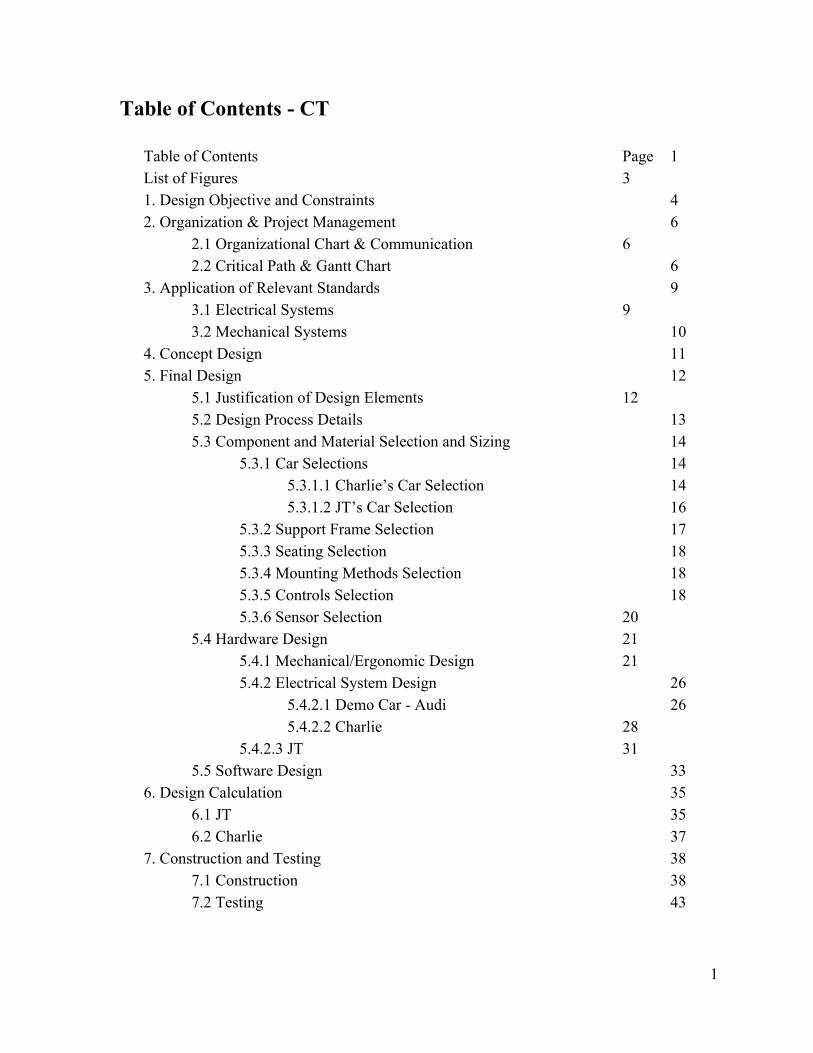
Table of Contents - CT
Table of Contents Page 1 List of Figures 3 1. Design Objective and Constraints 4 2. Organization & Project Management 6
2.1 Organizational Chart & Communication 6 2.2 Critical Path & Gantt Chart 6
3. Application of Relevant Standards 9 3.1 Electrical Systems 9 3.2 Mechanical Systems 10
4. Concept Design 11 5. Final Design 12
5.1 Justification of Design Elements 12 5.2 Design Process Details 13
5.3 Component and Material Selection and Sizing 14 5.3.1 Car Selections 14
5.3.1.1 Charlie’s Car Selection 14 5.3.1.2 JT’s Car Selection 16
5.3.2 Support Frame Selection 17 5.3.3 Seating Selection 18 5.3.4 Mounting Methods Selection 18 5.3.5 Controls Selection 18
5.3.6 Sensor Selection 20 5.4 Hardware Design 21
5.4.1 Mechanical/Ergonomic Design 21 5.4.2 Electrical System Design 26
5.4.2.1 Demo Car - Audi 265.4.2.2 Charlie 28
5.4.2.3 JT 31 5.5 Software Design 33
6. Design Calculation 35 6.1 JT 35 6.2 Charlie 37
7. Construction and Testing 38 7.1 Construction 38 7.2 Testing 43
1
8. Budget 46 9. Project Review, Future Work, and Closing Remarks 48 References 49
Literature Review Standards and Codes
Appendix 50
Appendix A Problem Assignment Appendix B Standard Operating Procedure Appendix C Go Baby Go Inspection Checklist
2

List of Figures
Figure 1.1: Childrens’ Challenges for Adaptive Design Figure 2.1: Organizational Chart Figure 2.2: Critical Path Summary Figure 2.3: Gantt Chart and Critical Path Figure 4.1:Inspiration Design Figure 5.1: Charlie’s Challenges for Adaptive Design Figure 5.2: JT’s Challenges for Adaptive Design Figure 5.3: Decision Matrix for Charlie’s Car Selection Figure 5.4: Selected Car Model for Charlie Figure 5.5: Decision Matrix for JT’s Car Selection Figure 5.6: Selected Car Model for JT Figure 5.7: Padded Seat and Harness for JT Figure 5.6: Dual Potentiometer Analog Joystick Figure 5.7: Koosh Pushbutton Sensory Feedback Switch Figure 5.8: PVC Support Structure Figure 5.9: PVC Mounting Bracket Figure 5.10: 3D Printed Bracket Figure 5.11: Plywood Base for Seat Figure 5.12: Plywood Seat and Bracket Assembly Figure 5.13: Sensory Feedback Toys for JT Figure 5.14: Modular Hose Coil and Mounting Pad Figure 5.15: Modular Hose Locline Base Dimensions Figure 5.16: Manufacturer Design for Demo Car Electrical System Figure 5.17: Final Design for Modified Demo Car Electrical System Figure 5.18: Manufacturer Design for Jeep Electrical System Figure 5.19: Final Design for Modified Jeep Electrical System Figure 5.20: Baseball Thrower To Modify Figure 5.21: Manufacturer Design for Mercedes Electrical System Figure 5.22: Final Design for Mercedes Electrical System Figure 6.1: Von Mises Stress Calculation for Seat Assembly Figure 6.2: Strain of Seat Assembly Figure 6.3: Displacement of Seat Assembly Figure 7.1: Seat Model Figure 7.2: Seat Frame and Base Figure 7.3: Modular Hose Figure 7.4: Ball Thrower Figure 7.5: Joystick Mounting Figure 7.6: Sensors Mounted Figure 7.7: Normal Use Testing Procedure Figure 8.1: Detailed Bill of Materials Figure 8.2: Project Cost Totals
3
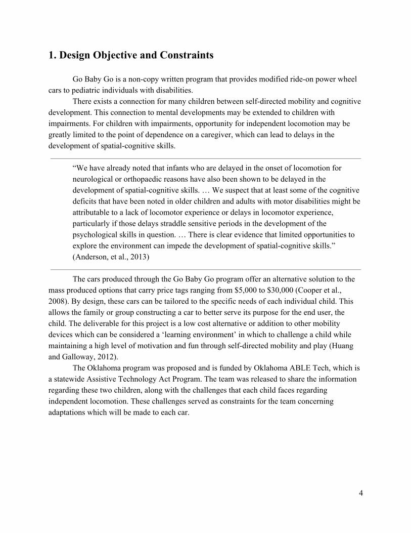
1. Design Objective and Constraints
Go Baby Go is a non-copy written program that provides modified ride-on power wheel cars to pediatric individuals with disabilities.
There exists a connection for many children between self-directed mobility and cognitive development. This connection to mental developments may be extended to children with impairments. For children with impairments, opportunity for independent locomotion may be greatly limited to the point of dependence on a caregiver, which can lead to delays in the development of spatial-cognitive skills.
“We have already noted that infants who are delayed in the onset of locomotion for neurological or orthopaedic reasons have also been shown to be delayed in the development of spatial-cognitive skills. … We suspect that at least some of the cognitive deficits that have been noted in older children and adults with motor disabilities might be attributable to a lack of locomotor experience or delays in locomotor experience, particularly if those delays straddle sensitive periods in the development of the psychological skills in question. … There is clear evidence that limited opportunities to explore the environment can impede the development of spatial-cognitive skills.” (Anderson, et al., 2013)
The cars produced through the Go Baby Go program offer an alternative solution to the
mass produced options that carry price tags ranging from $5,000 to $30,000 (Cooper et al., 2008). By design, these cars can be tailored to the specific needs of each individual child. This allows the family or group constructing a car to better serve its purpose for the end user, the child. The deliverable for this project is a low cost alternative or addition to other mobility devices which can be considered a ‘learning environment’ in which to challenge a child while maintaining a high level of motivation and fun through self-directed mobility and play (Huang and Galloway, 2012).
The Oklahoma program was proposed and is funded by Oklahoma ABLE Tech, which is a statewide Assistive Technology Act Program. The team was released to share the information regarding these two children, along with the challenges that each child faces regarding independent locomotion. These challenges served as constraints for the team concerning adaptations which will be made to each car.
4
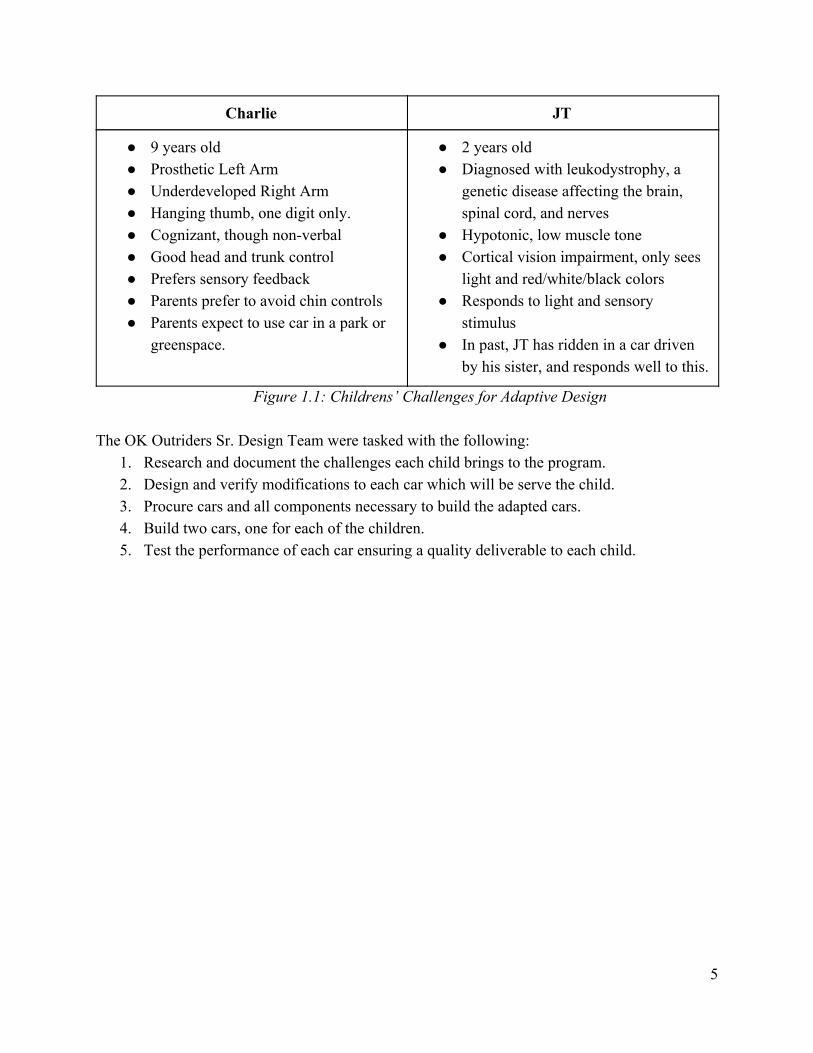
Charlie JT
● 9 years old ● Prosthetic Left Arm ● Underdeveloped Right Arm ● Hanging thumb, one digit only. ● Cognizant, though non-verbal ● Good head and trunk control ● Prefers sensory feedback ● Parents prefer to avoid chin controls ● Parents expect to use car in a park or
greenspace.
● 2 years old ● Diagnosed with leukodystrophy, a
genetic disease affecting the brain, spinal cord, and nerves
● Hypotonic, low muscle tone ● Cortical vision impairment, only sees
light and red/white/black colors ● Responds to light and sensory
stimulus ● In past, JT has ridden in a car driven
by his sister, and responds well to this.
Figure 1.1: Childrens’ Challenges for Adaptive Design The OK Outriders Sr. Design Team were tasked with the following:
1. Research and document the challenges each child brings to the program. 2. Design and verify modifications to each car which will be serve the child. 3. Procure cars and all components necessary to build the adapted cars. 4. Build two cars, one for each of the children. 5. Test the performance of each car ensuring a quality deliverable to each child.
5
2. Organization & Project Management
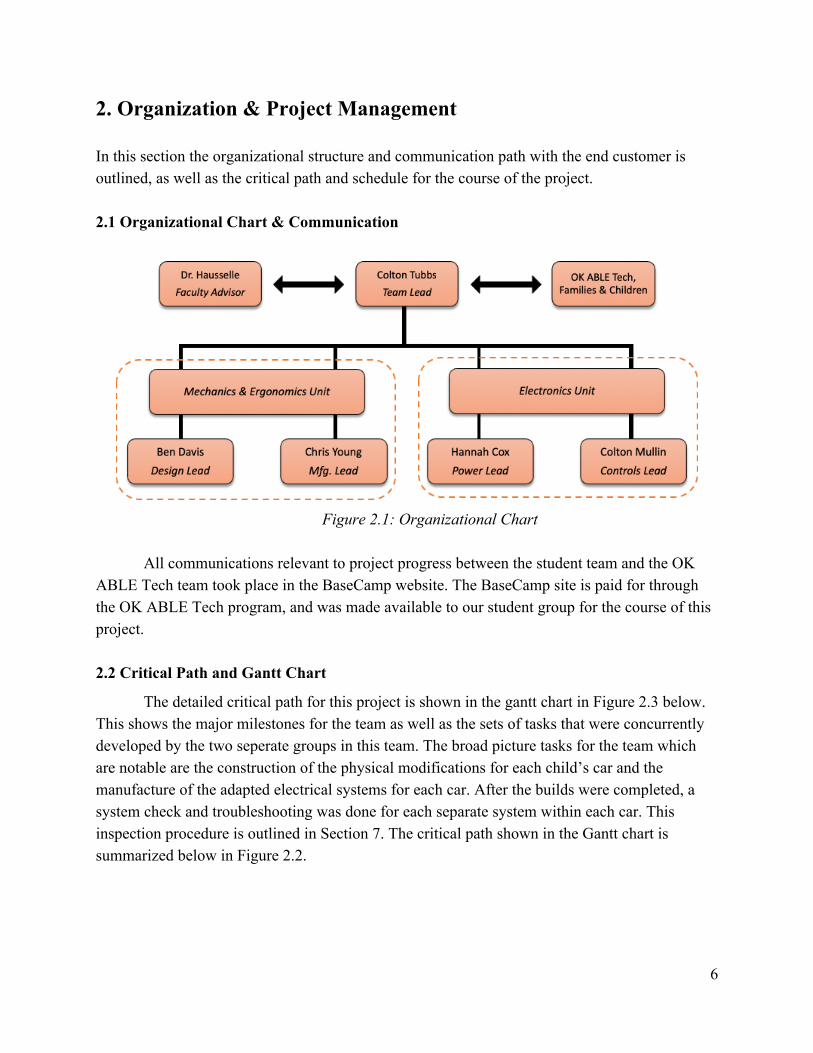
In this section the organizational structure and communication path with the end customer is outlined, as well as the critical path and schedule for the course of the project. 2.1 Organizational Chart & Communication
Figure 2.1: Organizational Chart
All communications relevant to project progress between the student team and the OK
ABLE Tech team took place in the BaseCamp website. The BaseCamp site is paid for through the OK ABLE Tech program, and was made available to our student group for the course of this project. 2.2 Critical Path and Gantt Chart
The detailed critical path for this project is shown in the gantt chart in Figure 2.3 below. This shows the major milestones for the team as well as the sets of tasks that were concurrently developed by the two seperate groups in this team. The broad picture tasks for the team which are notable are the construction of the physical modifications for each child’s car and the manufacture of the adapted electrical systems for each car. After the builds were completed, a system check and troubleshooting was done for each separate system within each car. This inspection procedure is outlined in Section 7. The critical path shown in the Gantt chart is summarized below in Figure 2.2.
6
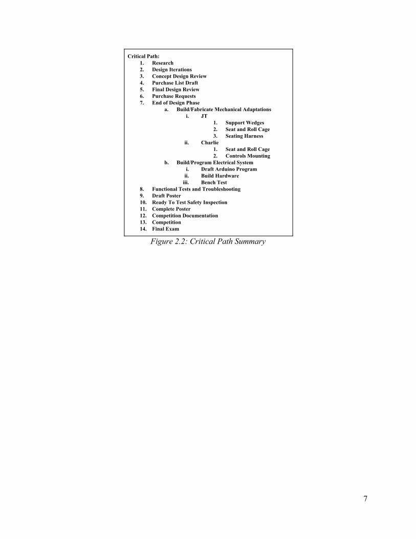
Critical Path: 1. Research 2. Design Iterations 3. Concept Design Review 4. Purchase List Draft 5. Final Design Review 6. Purchase Requests 7. End of Design Phase
a. Build/Fabricate Mechanical Adaptations i. JT
1. Support Wedges 2. Seat and Roll Cage 3. Seating Harness
ii. Charlie 1. Seat and Roll Cage 2. Controls Mounting
b. Build/Program Electrical System i. Draft Arduino Program
ii. Build Hardware iii. Bench Test
8. Functional Tests and Troubleshooting 9. Draft Poster 10. Ready To Test Safety Inspection 11. Complete Poster 12. Competition Documentation 13. Competition 14. Final Exam
Figure 2.2: Critical Path Summary
7
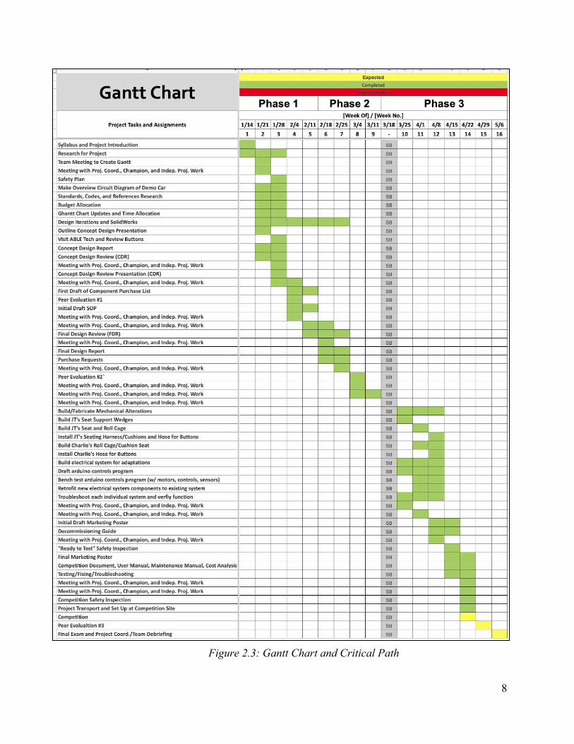
Figure 2.3: Gantt Chart and Critical Path
8
3. Application of Relevant Standards
The cars selected, as with all toys designed for use by small children, are manufactured in accordance to ASTM F963-17. This standard relates to the safety and design of children’s toys.
3.1 Electrical Systems
All modifications done to the electrical systems outline in Section 4.3.2 were done in according to the same standard, ensuring the safety of the finished product when put into use by each of the children. The subcategories outlined in the list below provide a guideline for the steps considered for electrical modifications for each car.
● 4.25.1 ○ “Toys shall be marked permanently on the battery compartment or on the area
immediately adjacent to the battery compartment to show the correct battery polarity using the polarity symbols “+” and “-”. Additional marking located on the toy or in the instruction shall indicate the correct battery size and voltage.”
● 4.25.2 ○ “The maximum allowable direct current potential between any two accessible
electrical points is 24V nominal.” ● 4.25.6
○ “Batteries of different types or capacities shall not be mixed within any single electrical circuit. In applications requiring more than one type or capacity of battery to provide different functions or in applications requiring the combination of alternating current and non-rechargeable batteries, each circuit shall be isolated electrically to prevent current from flowing between the individual circuits.”
● 4.25.7 ○ The surfaces of the batteries shall not achieve temperatures exceeding 71°C.
● 5.15.1.1 (b) & Note 18 ○ b) RISK OF FIRE. Do not bypass. Replace only with ____. ○ NOTE 18: This warning shall be placed at the location of any user replaceable
fuse or circuit protection device. Manufacturer should state the part number or equivalent.
● 4.25.10.4.(3) ○ Switches - “The switch shall not fail in a mode that could cause the vehicle to run
continuously (switch stuck in the "on" position) when subjected to the endurance test and the overload test in 8.18.6.”
9
3.2 Mechanical Systems
● 8.5 ○ “ Normal Use Testing—These tests are intended to simulate normal use
conditions so as to ensure that hazards are not generated through normal wear and deterioration. The object of these tests shall be to simulate the normal play mode of the toy, and the tests are therefore unrelated to the reasonably foreseeable abuse tests of 8.6 — 8.13. The tests are intended to uncover hazards rather than to demonstrate the reliability of the toy. The fact that a mechanism or material of a toy fails during testing is relevant only if the failure creates a potential hazard. Toys shall be subject to appropriate tests to simulate the expected mode of use of the particular toy. For example, levers, wheels, catches, triggers, strings, wires, chains, and so on, that are intended to be actuated by a child shall be operated repeatedly. Spring or power-operated devices shall be tested similarly. The tests shall be conducted in an expected use environment. The toy shall be inspected after such tests, and hazards such as points, sharp edges, and release of small parts shall be evaluated in accordance with the relevant requirements listed in Section 4.”
10
4. Concept Design
The two children we were assigned had very different sets of needs as discussed above. While the specifics of both cars were tailored to the individual child, the cars have the same basic functions. Both vehicles are able to go left, right, forward, backward, and have some additional fun aspect. We planned to include sensors on the front and back of the cars to prevent the child from running into any obstacles. All added components and controls were incorporated through an added Arduino Uno microcontroller.
Since JT has much lower gross motor function, we left the steering intact so that his older sister is able to drive the vehicle. A large sensory feedback button was added, which will allow JT to better engage with the accelerator button and allow him to feel the sensory feedback of movement. Mechanically, we added a five-point harness for JT to hold him in place. In place of a separate five point harness, a seat padding and harness unit was used to accomplish a secure and comfortable seating position. Additional padding was added around the seat to ensure safety and comfort. We added additional support around the vehicle using PVC pipe and pool noodles.
Charlie has much better control of his torso and is able to sit up without assistance so a simple seat belt was used instead of a harness. Some form of control system comprised of either directional buttons or a joystick control was proposed for his right arm. Initially we planned for exclusive chin control but adjusted when informed that the family would prefer use of his arm. The extra feature for Charlie’s car is a ball thrower. A large button will be added on the left side to activate the ball thrower. His family goes to the baseball field often and this will allow him to interact more with his peers and family.
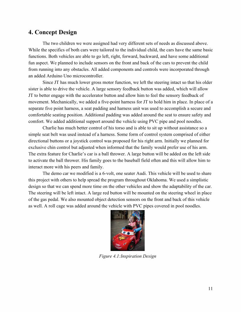
The demo car we modified is a 6-volt, one seater Audi. This vehicle will be used to share this project with others to help spread the program throughout Oklahoma. We used a simplistic design so that we can spend more time on the other vehicles and show the adaptability of the car. The steering will be left intact. A large red button will be mounted on the steering wheel in place of the gas pedal. We also mounted object detection sensors on the front and back of this vehicle as well. A roll cage was added around the vehicle with PVC pipes covered in pool noodles.
Figure 4.1:Inspiration Design
11
5. Final Design
The Final Design proposed here was developed through the steps outlined below in Section 5.2. Each of the design components listed in this section were chosen to address the key considerations identified by our team through the initial phases of this program. 5.1 Justification of Design Elements
Each of the two children we worked with in this project brought distinct challenges to the table, our designs varied between the two. For each child a solution was determined that would best fit their specific needs while fitting within the overall design constraints for the Go Baby Go program.
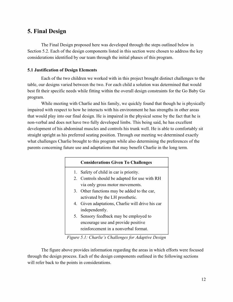
While meeting with Charlie and his family, we quickly found that though he is physically impaired with respect to how he interacts with his environment he has strengths in other areas that would play into our final design. He is impaired in the physical sense by the fact that he is non-verbal and does not have two fully developed limbs. This being said, he has excellent development of his abdominal muscles and controls his trunk well. He is able to comfortably sit straight upright as his preferred seating position. Through our meeting we determined exactly what challenges Charlie brought to this program while also determining the preferences of the parents concerning future use and adaptations that may benefit Charlie in the long term.
Considerations Given To Challenges
1. Safety of child in car is priority. 2. Controls should be adapted for use with RH
via only gross motor movements. 3. Other functions may be added to the car,
activated by the LH prosthetic. 4. Given adaptations, Charlie will drive his car
independently. 5. Sensory feedback may be employed to
encourage use and provide positive reinforcement in a nonverbal format.
Figure 5.1: Charlie’s Challenges for Adaptive Design
The figure above provides information regarding the areas in which efforts were focused through the design process. Each of the design components outlined in the following sections will refer back to the points in considerations.
12
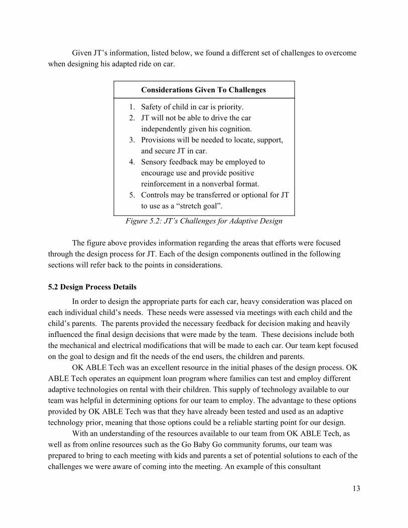
Given JT’s information, listed below, we found a different set of challenges to overcome when designing his adapted ride on car.
Considerations Given To Challenges
1. Safety of child in car is priority. 2. JT will not be able to drive the car
independently given his cognition. 3. Provisions will be needed to locate, support,
and secure JT in car. 4. Sensory feedback may be employed to
encourage use and provide positive reinforcement in a nonverbal format.
5. Controls may be transferred or optional for JT to use as a “stretch goal”.
Figure 5.2: JT’s Challenges for Adaptive Design
The figure above provides information regarding the areas that efforts were focused through the design process for JT. Each of the design components outlined in the following sections will refer back to the points in considerations.
5.2 Design Process Details
In order to design the appropriate parts for each car, heavy consideration was placed on each individual child’s needs. These needs were assessed via meetings with each child and the child’s parents. The parents provided the necessary feedback for decision making and heavily influenced the final design decisions that were made by the team. These decisions include both the mechanical and electrical modifications that will be made to each car. Our team kept focused on the goal to design and fit the needs of the end users, the children and parents.
OK ABLE Tech was an excellent resource in the initial phases of the design process. OK ABLE Tech operates an equipment loan program where families can test and employ different adaptive technologies on rental with their children. This supply of technology available to our team was helpful in determining options for our team to employ. The advantage to these options provided by OK ABLE Tech was that they have already been tested and used as an adaptive technology prior, meaning that those options could be a reliable starting point for our design.
With an understanding of the resources available to our team from OK ABLE Tech, as well as from online resources such as the Go Baby Go community forums, our team was prepared to bring to each meeting with kids and parents a set of potential solutions to each of the challenges we were aware of coming into the meeting. An example of this consultant
13
relationship with the parents was clear in the initial design phases for JT’s car. From the information we had been provided, we knew that certain elements such as a five point harness would be necessary, but we were also unsure if JT would be able to independently control the car given his low level of cognition and reactions to stimuli. His low muscle tone would also present a major challenge, particularly if he were physically unable to manipulate switches by overcoming the minute spring forces built into them. This was a concern for our team, and we setup a meeting as soon as possible in hopes of resolving these questions. After meeting with JT’s parents in this meeting, we determined as a group that he would not be able to independently operate the ride on car, but hope was not lost. In the past, his family had roughly adapted a ride on car with blankets to allow JT to ride along in a car that was controlled by his sister. Both the parents as well as our team saw value in pursuing a design that would allow JT to ride along in the car controlled by his sister, while making this design safer and more secure than simply bundling him in blankets to avoid any sharp edges or the chance of falling out of the car. Through this meeting we also determined that though JT’s level of vision is unclear to his parents, he does react well to lights and red colors. If JT can react to a stimulus and connect that stimulus to a command for the car, or even simply to a positive feedback in the form of vibration or acceleration, then he may be able to control the car in some minute way even though he could not directly control all of it. Through breakthroughs such as this, we could determine directions for our design to go based on a more grounded understanding of the children we are working with as well as constructive input from the parents of each child.
5.3 Component and Material Selection and Sizing
Justifications for each of the major components used in each system are provided below. These are broken up into subcategories where differences vary widely between each child.
5.3.1 Car Selections
Given the challenges brought by each child, the team decided to purchase separate car models in order to fit the needs of each child individually. The decision matrices for each car purchase for each child are shown below.
5.3.1.1 Charlie’s Car Selection
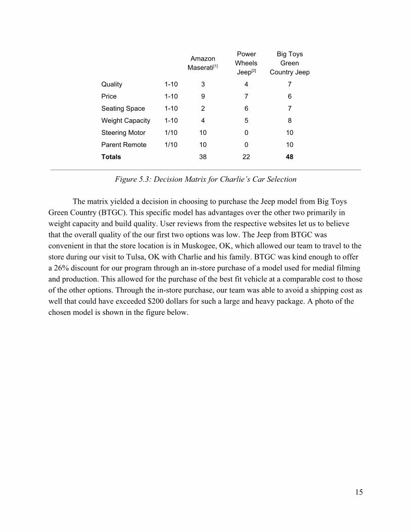
Three options were reviewed for purchase for Charlie. Certain criteria for selection were regarded as non-negotiable, such as the requirement to have a remote allowing for parental control of the car. These criteria are scored with either a 1 or a 10. Other criteria were scored in a range 1-10, with the most points (10) equating to the best fit for each criteria.
14
Amazon Maserati[1]
Power Wheels Jeep[2]
Big Toys Green
Country Jeep
Quality 1-10 3 4 7
Price 1-10 9 7 6
Seating Space 1-10 2 6 7
Weight Capacity 1-10 4 5 8
Steering Motor 1/10 10 0 10
Parent Remote 1/10 10 0 10
Totals 38 22 48
Figure 5.3: Decision Matrix for Charlie’s Car Selection
The matrix yielded a decision in choosing to purchase the Jeep model from Big Toys
Green Country (BTGC). This specific model has advantages over the other two primarily in weight capacity and build quality. User reviews from the respective websites let us to believe that the overall quality of the our first two options was low. The Jeep from BTGC was convenient in that the store location is in Muskogee, OK, which allowed our team to travel to the store during our visit to Tulsa, OK with Charlie and his family. BTGC was kind enough to offer a 26% discount for our program through an in-store purchase of a model used for medial filming and production. This allowed for the purchase of the best fit vehicle at a comparable cost to those of the other options. Through the in-store purchase, our team was able to avoid a shipping cost as well that could have exceeded $200 dollars for such a large and heavy package. A photo of the chosen model is shown in the figure below.
15
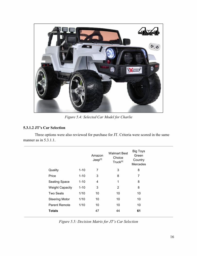
Figure 5.4: Selected Car Model for Charlie
5.3.1.2 JT’s Car Selection
Three options were also reviewed for purchase for JT. Criteria were scored in the same manner as in 5.3.1.1.
Amazon Jeep[3]
Walmart Best Choice Truck[4]
Big Toys Green
Country Mercedes
Quality 1-10 7 3 8
Price 1-10 3 8 7
Seating Space 1-10 4 1 8
Weight Capacity 1-10 3 2 8
Two Seats 1/10 10 10 10
Steering Motor 1/10 10 10 10
Parent Remote 1/10 10 10 10
Totals 47 44 61
Figure 5.5: Decision Matrix for JT’s Car Selection
16
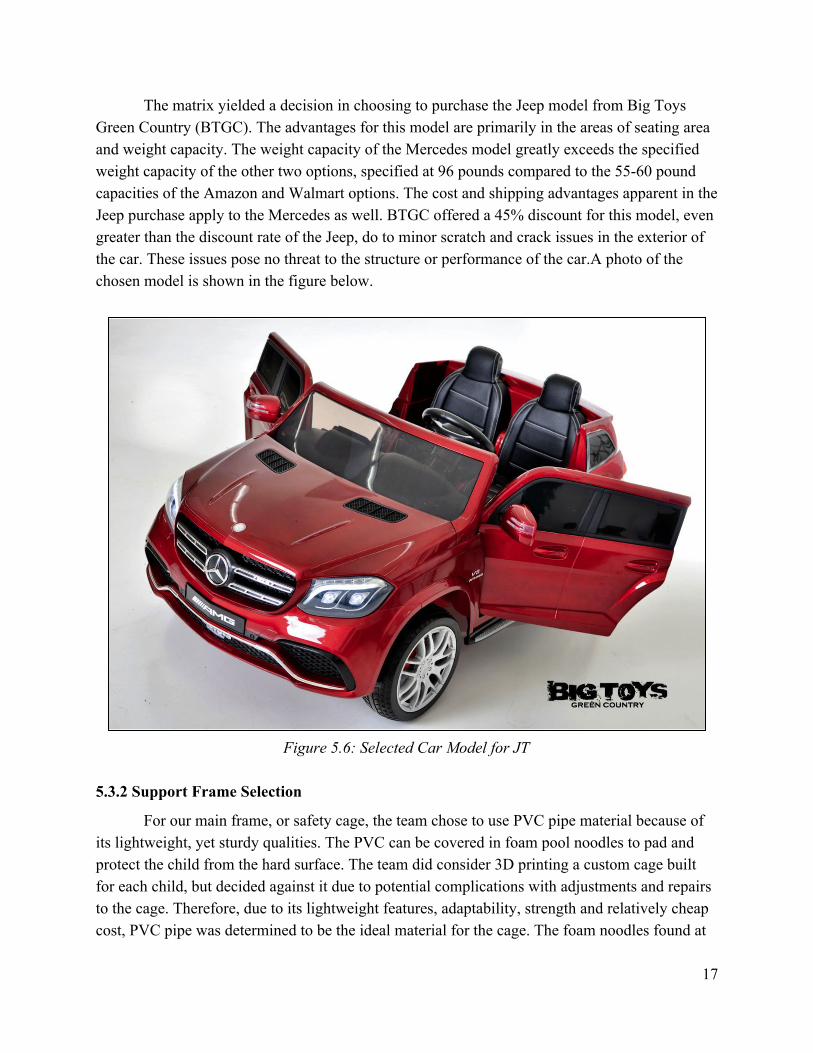
The matrix yielded a decision in choosing to purchase the Jeep model from Big Toys Green Country (BTGC). The advantages for this model are primarily in the areas of seating area and weight capacity. The weight capacity of the Mercedes model greatly exceeds the specified weight capacity of the other two options, specified at 96 pounds compared to the 55-60 pound capacities of the Amazon and Walmart options. The cost and shipping advantages apparent in the Jeep purchase apply to the Mercedes as well. BTGC offered a 45% discount for this model, even greater than the discount rate of the Jeep, do to minor scratch and crack issues in the exterior of the car. These issues pose no threat to the structure or performance of the car.A photo of the chosen model is shown in the figure below.
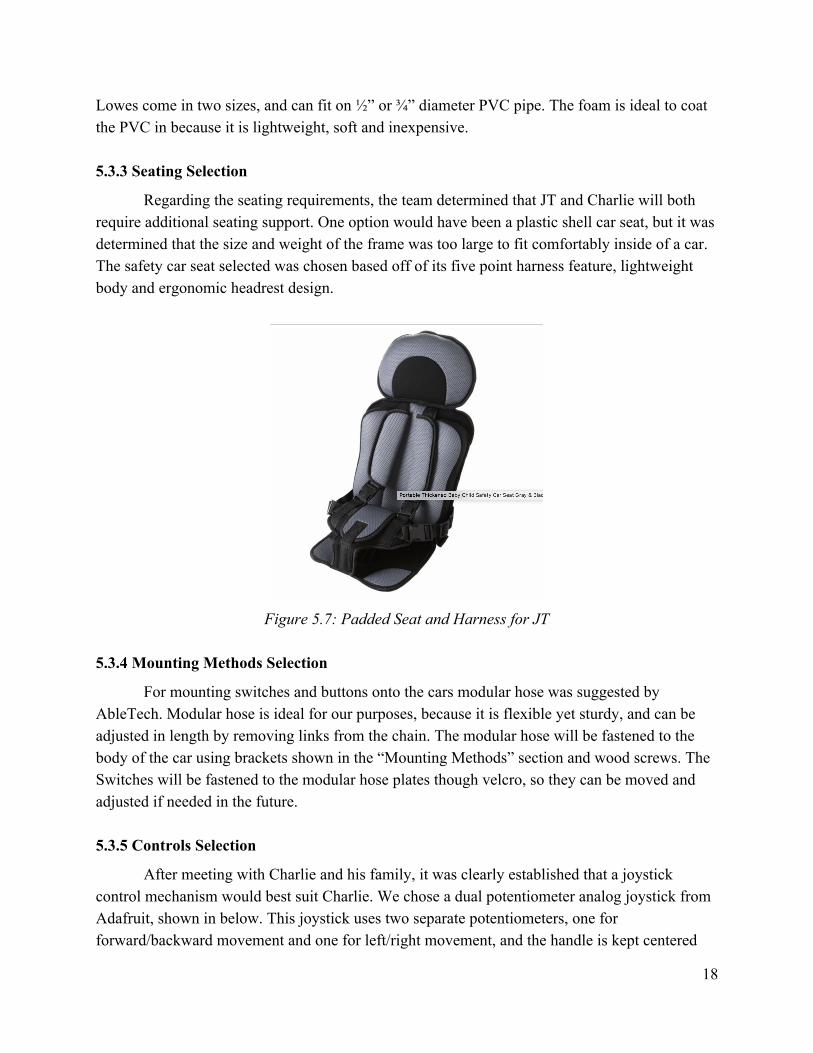
Figure 5.6: Selected Car Model for JT
5.3.2 Support Frame Selection
For our main frame, or safety cage, the team chose to use PVC pipe material because of its lightweight, yet sturdy qualities. The PVC can be covered in foam pool noodles to pad and protect the child from the hard surface. The team did consider 3D printing a custom cage built for each child, but decided against it due to potential complications with adjustments and repairs to the cage. Therefore, due to its lightweight features, adaptability, strength and relatively cheap cost, PVC pipe was determined to be the ideal material for the cage. The foam noodles found at
17
Lowes come in two sizes, and can fit on ½” or ¾” diameter PVC pipe. The foam is ideal to coat the PVC in because it is lightweight, soft and inexpensive.
5.3.3 Seating Selection
Regarding the seating requirements, the team determined that JT and Charlie will both require additional seating support. One option would have been a plastic shell car seat, but it was determined that the size and weight of the frame was too large to fit comfortably inside of a car. The safety car seat selected was chosen based off of its five point harness feature, lightweight body and ergonomic headrest design.
Figure 5.7: Padded Seat and Harness for JT
5.3.4 Mounting Methods Selection
For mounting switches and buttons onto the cars modular hose was suggested by AbleTech. Modular hose is ideal for our purposes, because it is flexible yet sturdy, and can be adjusted in length by removing links from the chain. The modular hose will be fastened to the body of the car using brackets shown in the “Mounting Methods” section and wood screws. The Switches will be fastened to the modular hose plates though velcro, so they can be moved and adjusted if needed in the future.
5.3.5 Controls Selection
After meeting with Charlie and his family, it was clearly established that a joystick control mechanism would best suit Charlie. We chose a dual potentiometer analog joystick from Adafruit, shown in below. This joystick uses two separate potentiometers, one for forward/backward movement and one for left/right movement, and the handle is kept centered
18
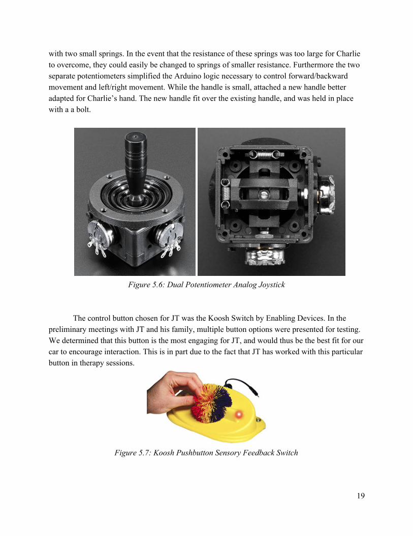
with two small springs. In the event that the resistance of these springs was too large for Charlie to overcome, they could easily be changed to springs of smaller resistance. Furthermore the two separate potentiometers simplified the Arduino logic necessary to control forward/backward movement and left/right movement. While the handle is small, attached a new handle better adapted for Charlie’s hand. The new handle fit over the existing handle, and was held in place with a a bolt.
Figure 5.6: Dual Potentiometer Analog Joystick
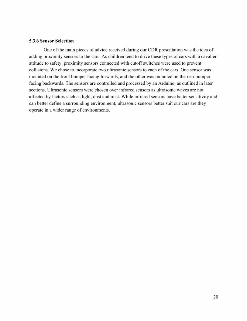
The control button chosen for JT was the Koosh Switch by Enabling Devices. In the
preliminary meetings with JT and his family, multiple button options were presented for testing. We determined that this button is the most engaging for JT, and would thus be the best fit for our car to encourage interaction. This is in part due to the fact that JT has worked with this particular button in therapy sessions.
Figure 5.7: Koosh Pushbutton Sensory Feedback Switch
19
5.3.6 Sensor Selection
One of the main pieces of advice received during our CDR presentation was the idea of adding proximity sensors to the cars. As children tend to drive these types of cars with a cavalier attitude to safety, proximity sensors connected with cutoff switches were used to prevent collisions. We chose to incorporate two ultrasonic sensors to each of the cars. One sensor was mounted on the front bumper facing forwards, and the other was mounted on the rear bumper facing backwards. The sensors are controlled and processed by an Arduino, as outlined in later sections. Ultrasonic sensors were chosen over infrared sensors as ultrasonic waves are not affected by factors such as light, dust and mist. While infrared sensors have better sensitivity and can better define a surrounding environment, ultrasonic sensors better suit our cars are they operate in a wider range of environments.
20
5.4 Hardware Design
In the same manner that our organizational structure is separated into two distinct areas of focus, our hardware design was separated into distinct areas. The design components for both Charlie and JT are explained in the following sections, and will refer to Section 4.1 in order to connect component design back to the considerations given for each child’s challenges.
5.4.1 Mechanical and Ergonomics Design
For mechanical and ergonomics design, the team used SolidWorks to produce the basic designs for each component. In total, a combination of PVC pipe, 3D printed parts, common wood screws and bolts, and wood will be used for the assembly of each individual component. The decisions to choose PVC pipe for this frame is provided in Section 8.1. As each child has unique challenges, the design for each individual component may need to undergo slight modifications in overall dimensions to fit the different cars for the different children. A general part or assembly may be used to convey the modified version that will be implemented on one individual child’s car.
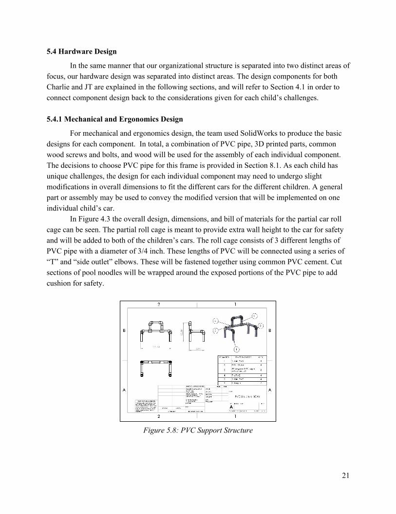
In Figure 4.3 the overall design, dimensions, and bill of materials for the partial car roll cage can be seen. The partial roll cage is meant to provide extra wall height to the car for safety and will be added to both of the children’s cars. The roll cage consists of 3 different lengths of PVC pipe with a diameter of 3/4 inch. These lengths of PVC will be connected using a series of “T” and “side outlet” elbows. These will be fastened together using common PVC cement. Cut sections of pool noodles will be wrapped around the exposed portions of the PVC pipe to add cushion for safety.
Figure 5.8: PVC Support Structure
21
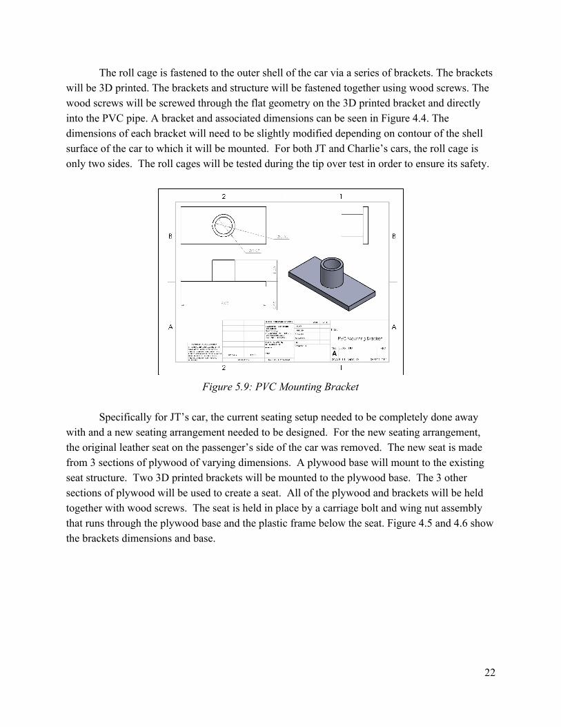
The roll cage is fastened to the outer shell of the car via a series of brackets. The brackets will be 3D printed. The brackets and structure will be fastened together using wood screws. The wood screws will be screwed through the flat geometry on the 3D printed bracket and directly into the PVC pipe. A bracket and associated dimensions can be seen in Figure 4.4. The dimensions of each bracket will need to be slightly modified depending on contour of the shell surface of the car to which it will be mounted. For both JT and Charlie’s cars, the roll cage is only two sides. The roll cages will be tested during the tip over test in order to ensure its safety.
Figure 5.9: PVC Mounting Bracket
Specifically for JT’s car, the current seating setup needed to be completely done away
with and a new seating arrangement needed to be designed. For the new seating arrangement, the original leather seat on the passenger’s side of the car was removed. The new seat is made from 3 sections of plywood of varying dimensions. A plywood base will mount to the existing seat structure. Two 3D printed brackets will be mounted to the plywood base. The 3 other sections of plywood will be used to create a seat. All of the plywood and brackets will be held together with wood screws. The seat is held in place by a carriage bolt and wing nut assembly that runs through the plywood base and the plastic frame below the seat. Figure 4.5 and 4.6 show the brackets dimensions and base.
22
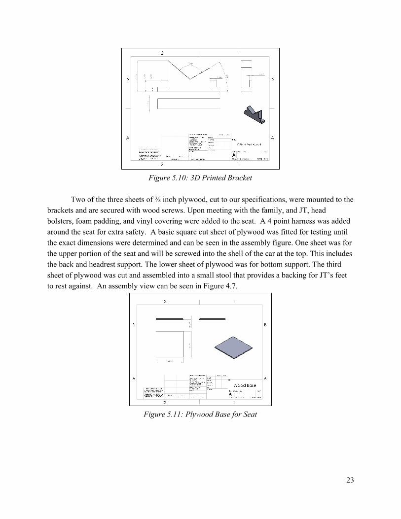
Figure 5.10: 3D Printed Bracket
Two of the three sheets of ⅜ inch plywood, cut to our specifications, were mounted to the
brackets and are secured with wood screws. Upon meeting with the family, and JT, head bolsters, foam padding, and vinyl covering were added to the seat. A 4 point harness was added around the seat for extra safety. A basic square cut sheet of plywood was fitted for testing until the exact dimensions were determined and can be seen in the assembly figure. One sheet was for the upper portion of the seat and will be screwed into the shell of the car at the top. This includes the back and headrest support. The lower sheet of plywood was for bottom support. The third sheet of plywood was cut and assembled into a small stool that provides a backing for JT’s feet to rest against. An assembly view can be seen in Figure 4.7.
Figure 5.11: Plywood Base for Seat
23
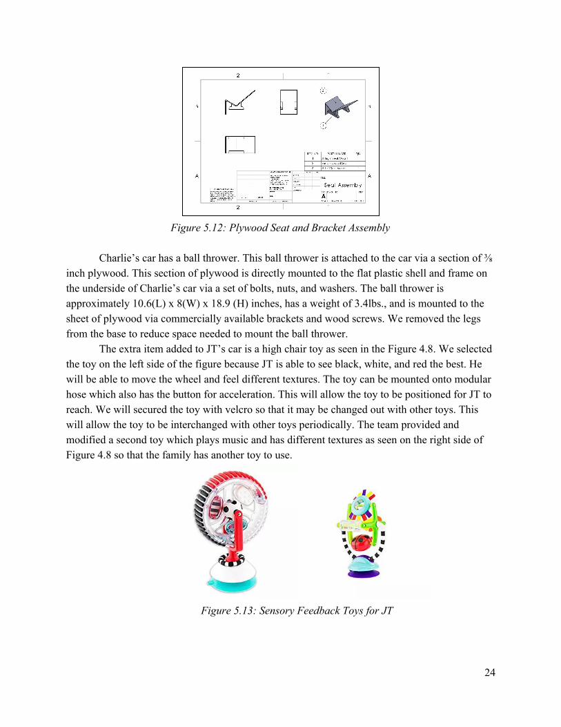
Figure 5.12: Plywood Seat and Bracket Assembly
Charlie’s car has a ball thrower. This ball thrower is attached to the car via a section of ⅜
inch plywood. This section of plywood is directly mounted to the flat plastic shell and frame on the underside of Charlie’s car via a set of bolts, nuts, and washers. The ball thrower is approximately 10.6(L) x 8(W) x 18.9 (H) inches, has a weight of 3.4lbs., and is mounted to the sheet of plywood via commercially available brackets and wood screws. We removed the legs from the base to reduce space needed to mount the ball thrower.
The extra item added to JT’s car is a high chair toy as seen in the Figure 4.8. We selected the toy on the left side of the figure because JT is able to see black, white, and red the best. He will be able to move the wheel and feel different textures. The toy can be mounted onto modular hose which also has the button for acceleration. This will allow the toy to be positioned for JT to reach. We will secured the toy with velcro so that it may be changed out with other toys. This will allow the toy to be interchanged with other toys periodically. The team provided and modified a second toy which plays music and has different textures as seen on the right side of Figure 4.8 so that the family has another toy to use.
Figure 5.13: Sensory Feedback Toys for JT
24
Upon completing the installation of all of the partial roll cage assemblies and JT’s seating assembly, the team mounted all additional padding. The padding is comprised of pool noodles and foam covered in vinyl. JT’s purchased seating harness is attached to the plywood backing.
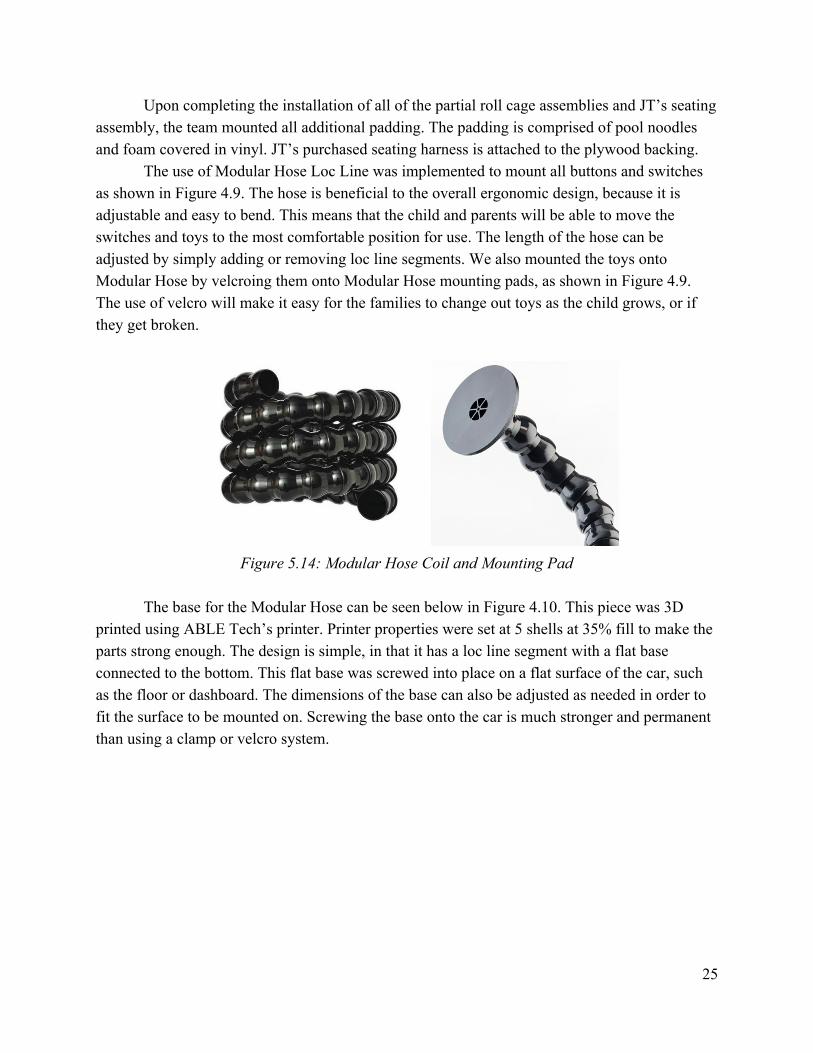
The use of Modular Hose Loc Line was implemented to mount all buttons and switches as shown in Figure 4.9. The hose is beneficial to the overall ergonomic design, because it is adjustable and easy to bend. This means that the child and parents will be able to move the switches and toys to the most comfortable position for use. The length of the hose can be adjusted by simply adding or removing loc line segments. We also mounted the toys onto Modular Hose by velcroing them onto Modular Hose mounting pads, as shown in Figure 4.9. The use of velcro will make it easy for the families to change out toys as the child grows, or if they get broken.
Figure 5.14: Modular Hose Coil and Mounting Pad
The base for the Modular Hose can be seen below in Figure 4.10. This piece was 3D
printed using ABLE Tech’s printer. Printer properties were set at 5 shells at 35% fill to make the parts strong enough. The design is simple, in that it has a loc line segment with a flat base connected to the bottom. This flat base was screwed into place on a flat surface of the car, such as the floor or dashboard. The dimensions of the base can also be adjusted as needed in order to fit the surface to be mounted on. Screwing the base onto the car is much stronger and permanent than using a clamp or velcro system.
25
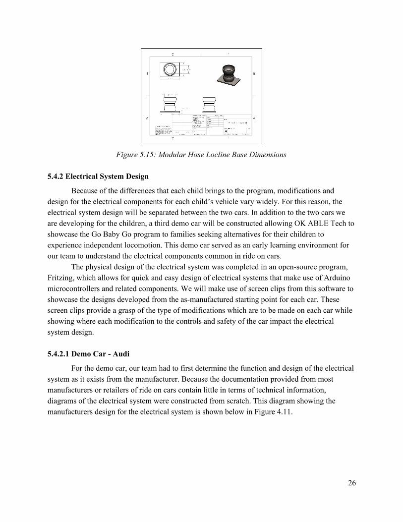
Figure 5.15: Modular Hose Locline Base Dimensions
5.4.2 Electrical System Design
Because of the differences that each child brings to the program, modifications and design for the electrical components for each child’s vehicle vary widely. For this reason, the electrical system design will be separated between the two cars. In addition to the two cars we are developing for the children, a third demo car will be constructed allowing OK ABLE Tech to showcase the Go Baby Go program to families seeking alternatives for their children to experience independent locomotion. This demo car served as an early learning environment for our team to understand the electrical components common in ride on cars.
The physical design of the electrical system was completed in an open-source program, Fritzing, which allows for quick and easy design of electrical systems that make use of Arduino microcontrollers and related components. We will make use of screen clips from this software to showcase the designs developed from the as-manufactured starting point for each car. These screen clips provide a grasp of the type of modifications which are to be made on each car while showing where each modification to the controls and safety of the car impact the electrical system design. 5.4.2.1 Demo Car - Audi
For the demo car, our team had to first determine the function and design of the electrical system as it exists from the manufacturer. Because the documentation provided from most manufacturers or retailers of ride on cars contain little in terms of technical information, diagrams of the electrical system were constructed from scratch. This diagram showing the manufacturers design for the electrical system is shown below in Figure 4.11.
26
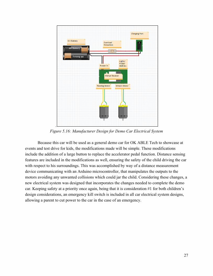
. Figure 5.16: Manufacturer Design for Demo Car Electrical System
Because this car will be used as a general demo car for OK ABLE Tech to showcase at
events and test drive for kids, the modifications made will be simple. These modifications include the addition of a large button to replace the accelerator pedal function. Distance sensing features are included in the modifications as well, ensuring the safety of the child driving the car with respect to his surroundings. This was accomplished by way of a distance measurement device communicating with an Arduino microcontroller, that manipulates the outputs to the motors avoiding any unwanted collisions which could jar the child. Considering these changes, a new electrical system was designed that incorporates the changes needed to complete the demo car. Keeping safety at a priority once again, being that it is consideration #1 for both children’s design considerations, an emergency kill switch is included in all car electrical system designs, allowing a parent to cut power to the car in the case of an emergency.
27
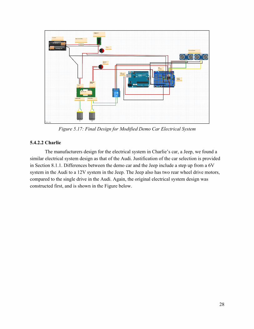
Figure 5.17: Final Design for Modified Demo Car Electrical System
5.4.2.2 Charlie
The manufacturers design for the electrical system in Charlie’s car, a Jeep, we found a similar electrical system design as that of the Audi. Justification of the car selection is provided in Section 8.1.1. Differences between the demo car and the Jeep include a step up from a 6V system in the Audi to a 12V system in the Jeep. The Jeep also has two rear wheel drive motors, compared to the single drive in the Audi. Again, the original electrical system design was constructed first, and is shown in the Figure below.
28
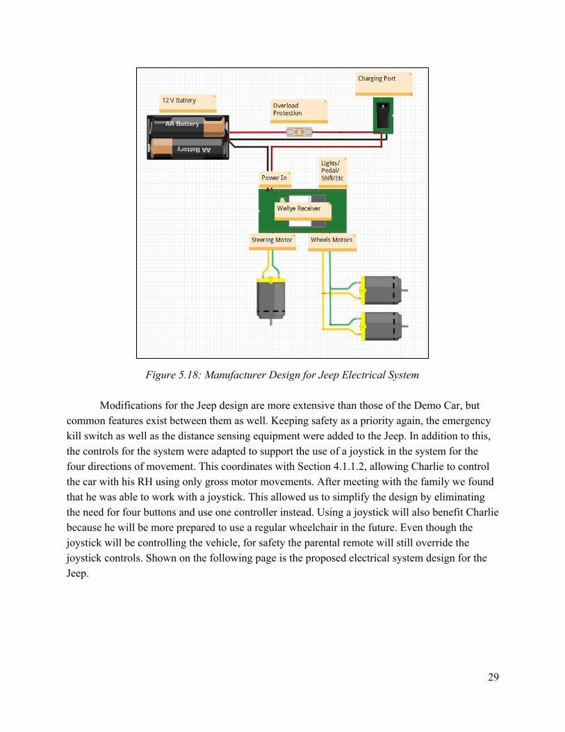
Figure 5.18: Manufacturer Design for Jeep Electrical System
Modifications for the Jeep design are more extensive than those of the Demo Car, but common features exist between them as well. Keeping safety as a priority again, the emergency kill switch as well as the distance sensing equipment were added to the Jeep. In addition to this, the controls for the system were adapted to support the use of a joystick in the system for the four directions of movement. This coordinates with Section 4.1.1.2, allowing Charlie to control the car with his RH using only gross motor movements. After meeting with the family we found that he was able to work with a joystick. This allowed us to simplify the design by eliminating the need for four buttons and use one controller instead. Using a joystick will also benefit Charlie because he will be more prepared to use a regular wheelchair in the future. Even though the joystick will be controlling the vehicle, for safety the parental remote will still override the joystick controls. Shown on the following page is the proposed electrical system design for the Jeep.
29
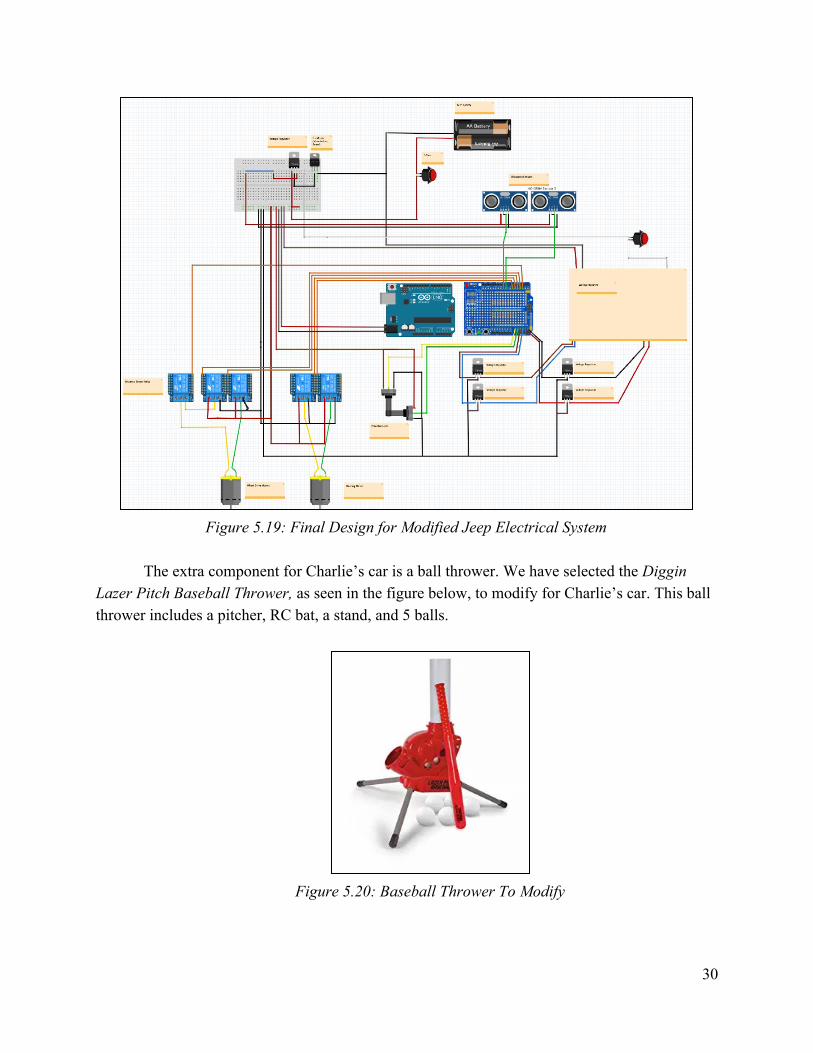
Figure 5.19: Final Design for Modified Jeep Electrical System
The extra component for Charlie’s car is a ball thrower. We have selected the Diggin
Lazer Pitch Baseball Thrower, as seen in the figure below, to modify for Charlie’s car. This ball thrower includes a pitcher, RC bat, a stand, and 5 balls.
Figure 5.20: Baseball Thrower To Modify
30
We selected this ball thrower because it has two settings for control. The first is automatic and the second is bat activated pitch. If placed on automatic the ball thrower will pitch balls every eight seconds. For bat activated pitch, the kit has an RC bat with a button the child can press to cause the machine to release a ball. To modify the ball thrower we removed the controls currently in the bat and wired them to a large button for Charlie to press. When his parents would like to have the ball thrower activated, they simply need to switch the machine from off to bat controlled. The ball thrower uses 4 D batteries which serve as the power source for the machine. This will prevent the need to add another battery or overdraw of the current car battery.
5.4.2.3 JT
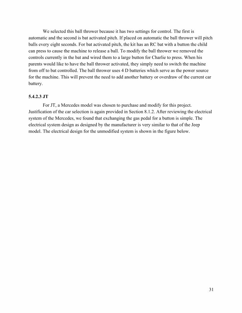
For JT, a Mercedes model was chosen to purchase and modify for this project. Justification of the car selection is again provided in Section 8.1.2. After reviewing the electrical system of the Mercedes, we found that exchanging the gas pedal for a button is simple. The electrical system design as designed by the manufacturer is very similar to that of the Jeep model. The electrical design for the unmodified system is shown in the figure below.
31
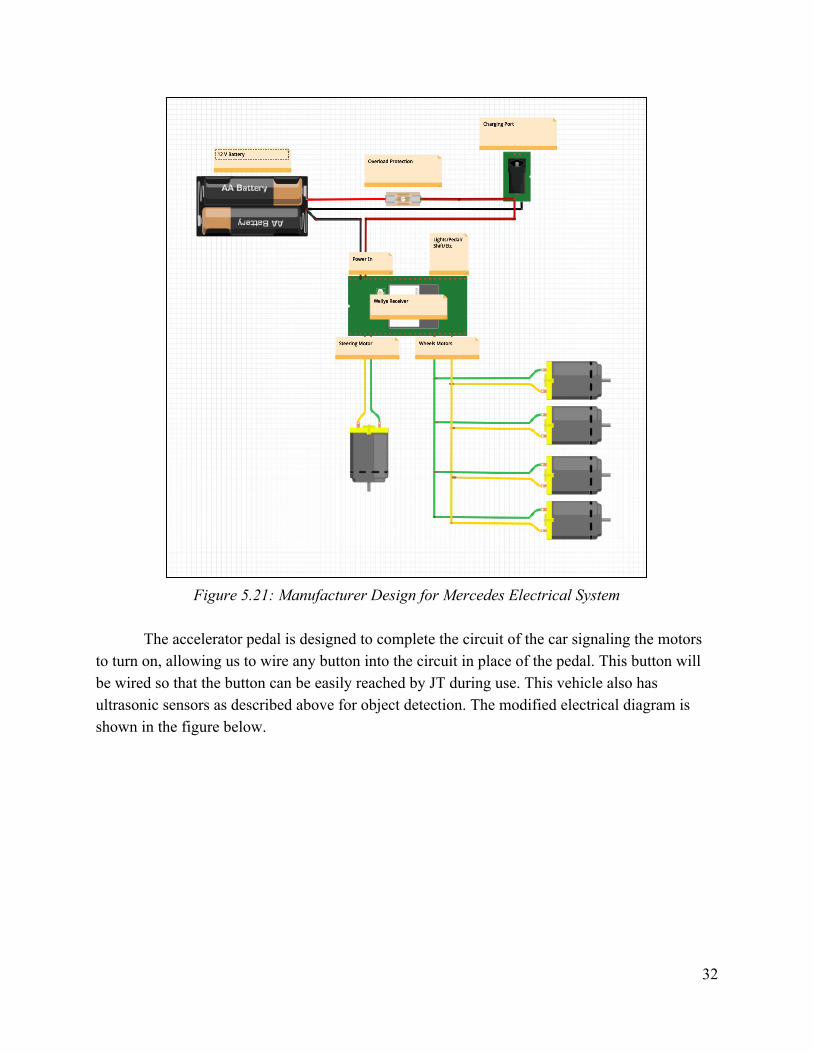
Figure 5.21: Manufacturer Design for Mercedes Electrical System
The accelerator pedal is designed to complete the circuit of the car signaling the motors
to turn on, allowing us to wire any button into the circuit in place of the pedal. This button will be wired so that the button can be easily reached by JT during use. This vehicle also has ultrasonic sensors as described above for object detection. The modified electrical diagram is shown in the figure below.
32
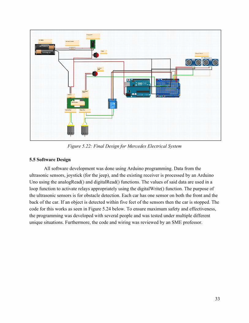
Figure 5.22: Final Design for Mercedes Electrical System
5.5 Software Design
All software development was done using Arduino programming. Data from the ultrasonic sensors, joystick (for the jeep), and the existing receiver is processed by an Arduino Uno using the analogRead() and digitalRead() functions. The values of said data are used in a loop function to activate relays appropriately using the digitalWrite() function. The purpose of the ultrasonic sensors is for obstacle detection. Each car has one sensor on both the front and the back of the car. If an object is detected within five feet of the sensors then the car is stopped. The code for this works as seen in Figure 5.24 below. To ensure maximum safety and effectiveness, the programming was developed with several people and was tested under multiple different unique situations. Furthermore, the code and wiring was reviewed by an SME professor.
33
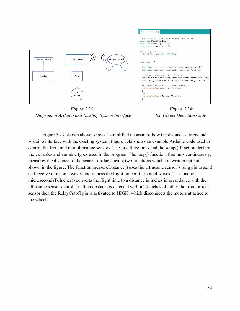
Figure 5.23: Figure 5.24:
Diagram of Arduino and Existing System Interface Ex. Object Detection Code
Figure 5.23, shown above, shows a simplified diagram of how the distance sensors and
Arduino interface with the existing system. Figure 5.42 shows an example Arduino code used to control the front and rear ultrasonic sensors. The first three lines and the setup() function declare the variables and variable types used in the program. The loop() function, that runs continuously, measures the distance of the nearest obstacle using two functions which are written but not shown in the figure. The function measureDistance() uses the ultrasonic sensor’s ping pin to send and receive ultrasonic waves and returns the flight time of the sound waves. The function microsecondsToInches() converts the flight time to a distance in inches in accordance with the ultrasonic sensor data sheet. If an obstacle is detected within 24 inches of either the front or rear sensor then the RelayCutoff pin is activated to HIGH, which disconnects the motors attached to the wheels.
34
6. Design Calculations
Calculations for design of the mechanical systems for each car was separated between the children’s considerations, which varied differently and impacted the calculations in different ways. 6.1 JT
The weight capacity of the JT’s Mercedes car is specified to be 98 lbs. We were cautious and limited the material we added to the car in order to be under the weight limit. We also took into consideration the fact that this car will be carrying two children. This will decrease the weight of material that we can add to the car. The total downward applied force is calculated below.
However, the force applied to the seat will only be the weight of one child. For this calculation, we will use the average weight of a 5 year old male, 40 lbs.[1] JT weighs 26 pounds, so this is a conservative assumption. The resultant force on the seat can be calculated as:
Table 7.1 - JT’s Weight Consideration
● F = m * a ● F = 40 lbs * 0.453592 kg/lb * 9.81 m/s^2 ● F = 178 N
Therefore, the seat frame and wedge must be able to support more than 178 N. Finite
Element Analysis for the designed seat components are shown in Figures 7.1, 7.2, and 7.3. For the FEA analysis, SolidWorks Simulation solver was used to calculate the von Mises
stress, displacement, and strain. The entire assembly was modeled as the ABS plastic material provided in SolidWorks. The upper and lower surfaces of the plywood seat were fixed. Similarly, the bottom of each mounting bracket was fixed. The 178N load was applied to both of the seat sections and can be seen in the following figures.
Table 7.1 shows some of the mechanical properties of the model and the mechanical properties of the actual parts. Due to the modeled loading conditions and material analyzed, the results are highly conservative estimates. ABS plastic has lower tensile yield strength and lower tensile modulus when compared to PLA plastic and plywood. The plastic mounting brackets will be modeled out of PLA, therefore, the PLA brackets will be sufficient. Plywood does not have definitive material properties, but it will be far stronger than the ABS plastic.
35
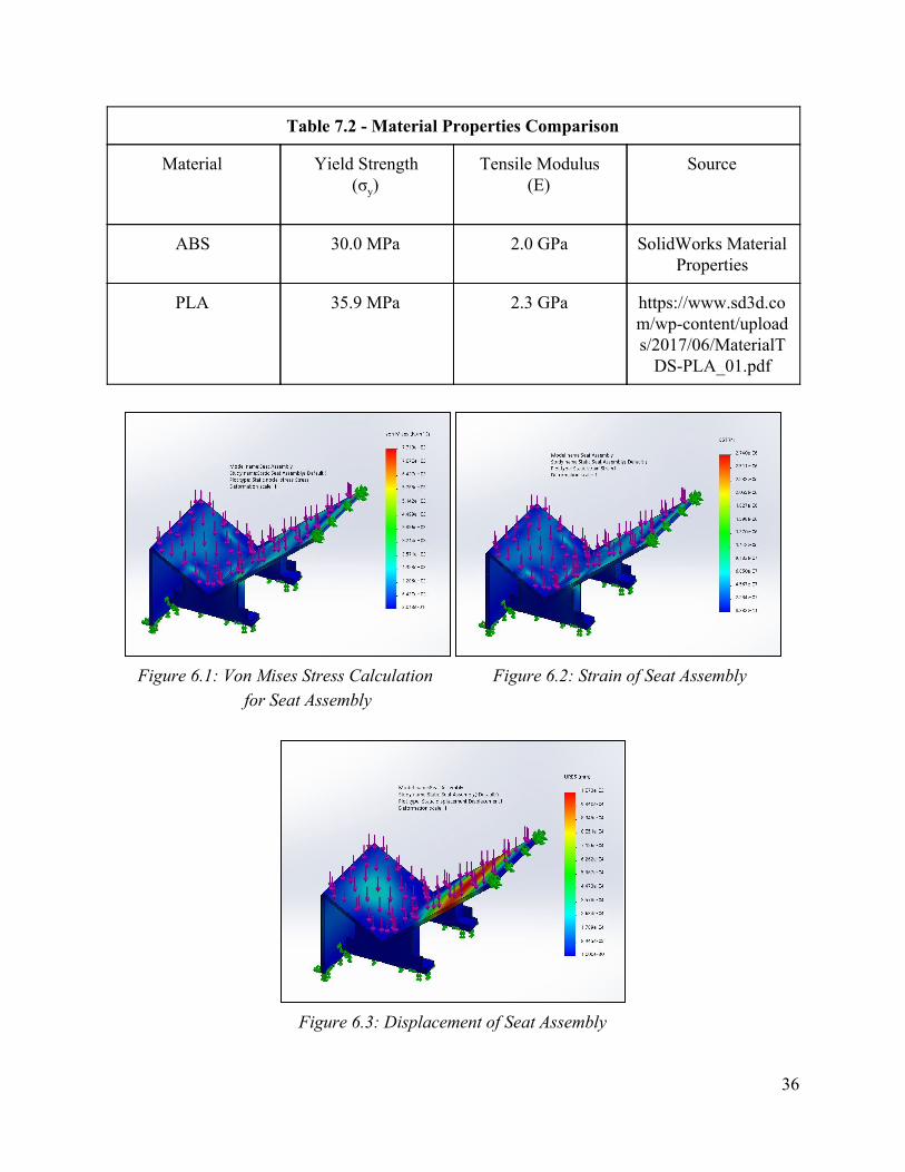
Table 7.2 - Material Properties Comparison
Material Yield Strength (σy)
Tensile Modulus (E)
Source
ABS 30.0 MPa 2.0 GPa SolidWorks Material Properties
PLA 35.9 MPa 2.3 GPa https://www.sd3d.com/wp-content/uploads/2017/06/MaterialT
DS-PLA_01.pdf
Figure 6.1: Von Mises Stress Calculation Figure 6.2: Strain of Seat Assembly
for Seat Assembly
Figure 6.3: Displacement of Seat Assembly
36
From the FEA analysis, the working stress developed in the ABS plastic system is 7,713 Pa which is far below the yield stress of 30.0 MPa. To compute the factor of safety, we divide the yield stress by the maximum working stress developed in the assembly. The factor of safety is well over 3500, meaning the parts will not fail. This factor of safety will increase when it is mounted using plywood and PLA printed brackets.
Another element to consider is dynamic motion. The mechanical structure must be able to support the movements of a child, such as getting in and out of the car or rocking back and forth. For this calculation, we multiplied the average weight of a 5 year old male at 40 lbs[1] and the acceleration of a child rocking back and forth. We assumed that the magnitude of acceleration would be close to 1 m/s^2 based off of the acceleration of an adult walking. This assumption was given to us by Dr. Hausselle. The resultant force from this motion can be calculated, and is shown below in Table 7.3. This means that the brackets and PVC cage will need to be able to withstand more than 18.2 N.
Table 7.3 - JT’s Motion Consideration
● F = m * a ● F = 40 lbs * 0.453592 kg/lb * 1 m/s^2 ● F = 18.2 N
6.2 Charlie
Charlie’s car presents significantly less design calculation work, since we will not be modifying his seat or support system. All calculations related to child rocking forces will be the same as JT, since both children weigh close to 26 lbs. This means that the cage for Charlie’s car will need to fit the same constraints as JT’s. Charlie’s car has a weight capacity of 66 lbs, meaning we will only be able to add about 40 lbs of excess material. The team will ade sure to follow this when constructing the mechanical design.
37
7. Construction & Testing
The primary challenges that our team faced began with our customers. Each of the children brought a list of things that our adaptations needed to overcome. The only way that we could begin to identify and overcome these challenges was through face-to-face meetings on multiple occasions. This was accomplished by family visits to our lab, as well as visits to Tulsa, OK on one occasion concerning Charlie. To best grasp the resources available to us in the field of adaptive technology, OK ABLE Tech was a huge resource. They currently house a surplus of adaptive technology that is available through their program to families in need on a rental basis. Our team could simply check out the equipment we needed each visit to test with our children. 7.1 Construction
Our team followed our designed Gantt chart as we began the construction process. Both the Mechanical and Electrical sub-units worked in parallel with one another. To streamline this, the Mechanical unit began working immediately on JT’s seating adaptations, as those were without a doubt the most significant modifications to be done on either car. The Electrical unit focused primarily on the implementation of the aforementioned design on the Jeep. This parallel work allowed for rapid progress to be made in the early stages of our designated construction period.
In the initial phases of construction, weekly and even bi-weekly meetings were held with ABLE Tech to provide updates on the progress and direction of the construction and adaptations that were being made. That allowed for a close relationship to be built between the student group and the customers, and ensured that each step in the process was understood and supported by ABLE Tech. Again, the expertise in the field of adaptive technology and previous work with young children proved to be a huge resource in terms of issues that were caught along the way. For example, JT’s seat was initially designed so that his feet may dangle from edge. Our team’s initial thought was that this would allow for a degree of comfortable freedom for JT, while simplifying our overall design. In the end, however, it was advised to design a simple foot board on which JT’s feed could rest. The purpose in doing so was to relieve any stress concentrations that the weight of JT’s body could induce on the edge of the seat and above all on his legs.
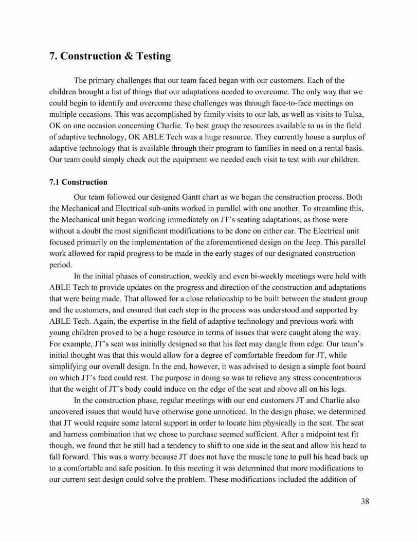
In the construction phase, regular meetings with our end customers JT and Charlie also uncovered issues that would have otherwise gone unnoticed. In the design phase, we determined that JT would require some lateral support in order to locate him physically in the seat. The seat and harness combination that we chose to purchase seemed sufficient. After a midpoint test fit though, we found that he still had a tendency to shift to one side in the seat and allow his head to fall forward. This was a worry because JT does not have the muscle tone to pull his head back up to a comfortable and safe position. In this meeting it was determined that more modifications to our current seat design could solve the problem. These modifications included the addition of
38
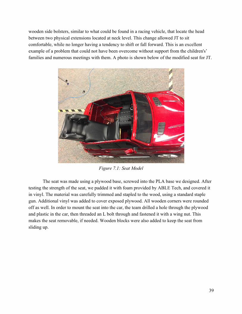
wooden side bolsters, similar to what could be found in a racing vehicle, that locate the head between two physical extensions located at neck level. This change allowed JT to sit comfortable, while no longer having a tendency to shift or fall forward. This is an excellent example of a problem that could not have been overcome without support from the children's’ families and numerous meetings with them. A photo is shown below of the modified seat for JT.
Figure 7.1: Seat Model
The seat was made using a plywood base, screwed into the PLA base we designed. After
testing the strength of the seat, we padded it with foam provided by ABLE Tech, and covered it in vinyl. The material was carefully trimmed and stapled to the wood, using a standard staple gun. Additional vinyl was added to cover exposed plywood. All wooden corners were rounded off as well. In order to mount the seat into the car, the team drilled a hole through the plywood and plastic in the car, then threaded an L bolt through and fastened it with a wing nut. This makes the seat removable, if needed. Wooden blocks were also added to keep the seat from sliding up.
39
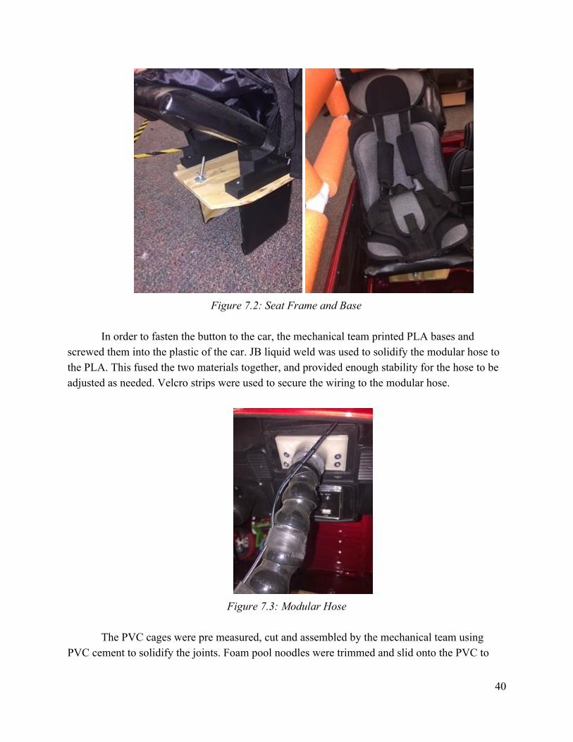
Figure 7.2: Seat Frame and Base
In order to fasten the button to the car, the mechanical team printed PLA bases and
screwed them into the plastic of the car. JB liquid weld was used to solidify the modular hose to the PLA. This fused the two materials together, and provided enough stability for the hose to be adjusted as needed. Velcro strips were used to secure the wiring to the modular hose.
Figure 7.3: Modular Hose
The PVC cages were pre measured, cut and assembled by the mechanical team using
PVC cement to solidify the joints. Foam pool noodles were trimmed and slid onto the PVC to
40
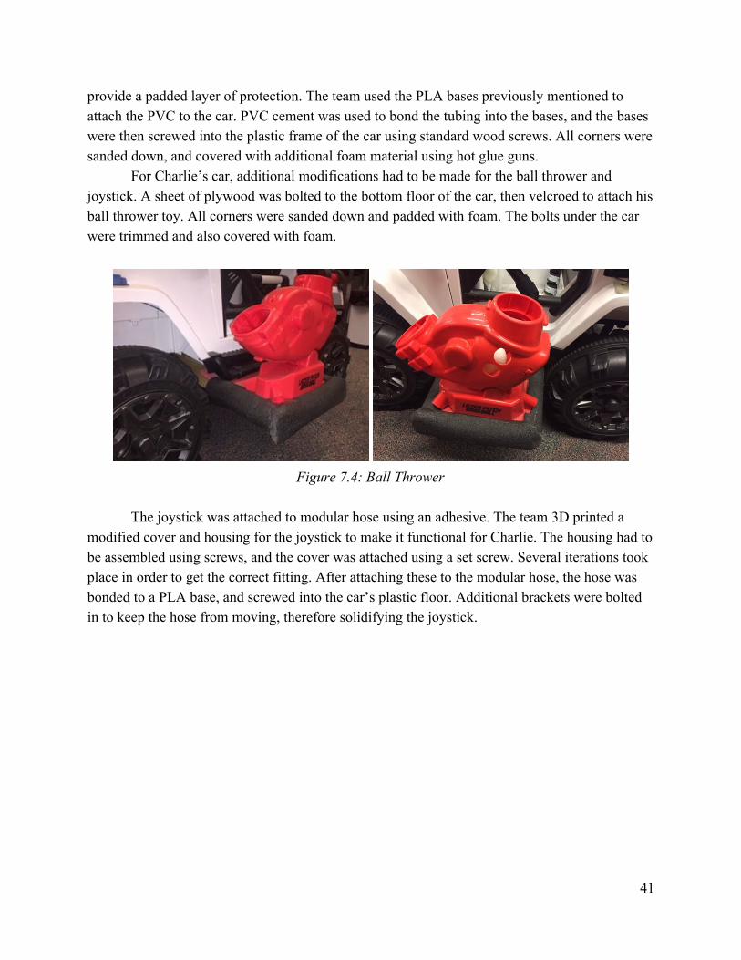
provide a padded layer of protection. The team used the PLA bases previously mentioned to attach the PVC to the car. PVC cement was used to bond the tubing into the bases, and the bases were then screwed into the plastic frame of the car using standard wood screws. All corners were sanded down, and covered with additional foam material using hot glue guns.
For Charlie’s car, additional modifications had to be made for the ball thrower and joystick. A sheet of plywood was bolted to the bottom floor of the car, then velcroed to attach his ball thrower toy. All corners were sanded down and padded with foam. The bolts under the car were trimmed and also covered with foam.
Figure 7.4: Ball Thrower
The joystick was attached to modular hose using an adhesive. The team 3D printed a
modified cover and housing for the joystick to make it functional for Charlie. The housing had to be assembled using screws, and the cover was attached using a set screw. Several iterations took place in order to get the correct fitting. After attaching these to the modular hose, the hose was bonded to a PLA base, and screwed into the car’s plastic floor. Additional brackets were bolted in to keep the hose from moving, therefore solidifying the joystick.
41
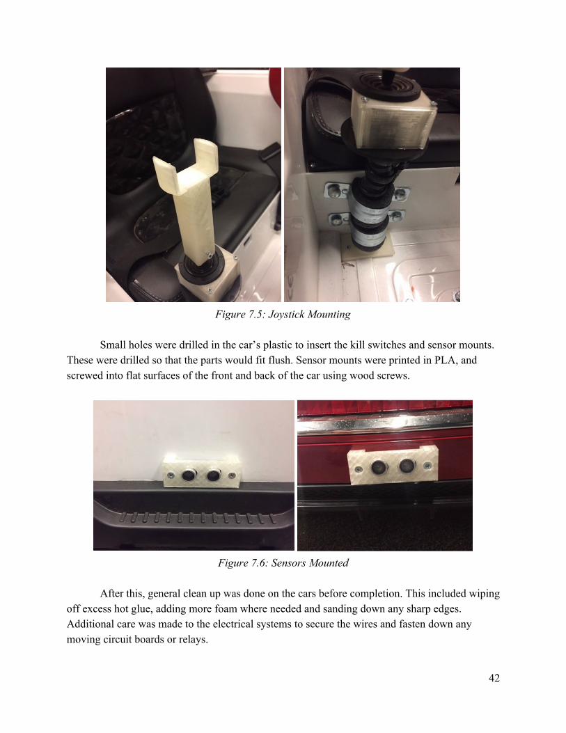
Figure 7.5: Joystick Mounting
Small holes were drilled in the car’s plastic to insert the kill switches and sensor mounts.
These were drilled so that the parts would fit flush. Sensor mounts were printed in PLA, and screwed into flat surfaces of the front and back of the car using wood screws.
Figure 7.6: Sensors Mounted
After this, general clean up was done on the cars before completion. This included wiping
off excess hot glue, adding more foam where needed and sanding down any sharp edges. Additional care was made to the electrical systems to secure the wires and fasten down any moving circuit boards or relays.
42
7.2 Testing
The final deliverables for this project are essentially tools that a family will use with guidance to encourage self-directed mobility and engagement with each children’s environment. For the deliverables to be considered successful in their designed purpose, they should provide a means to overcome each of the adaptational challenges that each child brings. In addition to this general outcome, the end deliverables much fit within and be tested against the standards mentioned above in Section 4.
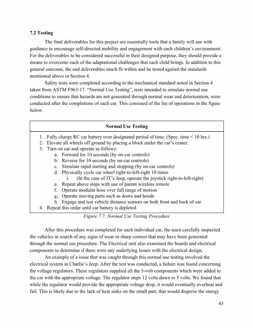
Safety tests were completed according to the mechanical standard noted in Section 4 taken from ASTM F963-17. “Normal Use Testing”, tests intended to simulate normal use conditions to ensure that hazards are not generated through normal wear and deterioration, were conducted after the completions of each car. This consisted of the list of operations in the figure below.
Normal Use Testing
1. Fully charge RC car battery over designated period of time. (Spec. time < 10 hrs.) 2. Elevate all wheels off ground by placing a block under the car’s center. 3. Turn on car and operate as follows:
a. Forward for 10 seconds (by on-car controls) b. Reverse for 10 seconds (by on-car controls) c. Simulate rapid starting and stopping (by on-car controls) d. Physically cycle car wheel right-to-left-right 10 times
i. (In the case of JT’s Jeep, operate the joystick right-to-left-right) e. Repeat above steps with use of parent wireless remote f. Operate modular hose over full range of motion g. Operate moving parts such as doors and hoods h. Engage and test vehicle distance sensors on both front and back of car
4. Repeat this order until car battery is depleted.
Figure 7.7: Normal Use Testing Procedure
After this procedure was completed for each individual car, the team carefully inspected the vehicles in search of any signs of wear or sharp corners that may have been generated through the normal use procedure. The Electrical unit also examined the boards and electrical components to determine if there were any underlying issues with the electrical design.
An example of a issue that was caught through this normal use testing involved the electrical system in Charlie’s Jeep. After the test was conducted, a failure was found concerning the voltage regulators. These regulators supplied all the 5-volt components which were added to the car with the appropriate voltage. The regulator steps 12 volts down to 5 volts. We found that while the regulator would provide the appropriate voltage drop, it would eventually overheat and fail. This is likely due to the lack of heat sinks on the small part, that would disperse the energy
43
from that voltage change to the outside environment as heat. This would not suffice for our final deliverable, as it posed both safety and endurance issues with our design. The solution was to route all 5-volt components added through the 5 volts powered by the Arduino Uno. An analysis was done over the total current required by all added components, that showed the Arduino Uno would suffice in current supply while providing the required 5 volts output. This also simplified the overall electrical system, that will add to the overall design longevity.
Along with normal use testing, functional tests were completed with each of the families and children. A meeting time was determined where each family could bring their child prior to the week of April 22. In each of these tests, the children were placed in the car and examined for fit within the vehicle. Feedback from ABLE Tech and each of the family members was helpful in determining where adjustments needed to be made, as well as where things were working well. Along with seating, the controls placement was examined to ensure that each of the children were able to easily reach the controls. Adjustments in height, locations, and number of Modular Hose sections were made during the meeting to ensure that no other revisions would be necessary. These items were the primary focus of the Mechanical unit team members.
Once the physical design was sufficient, the Electrical unit stepped in and began training the family and child on the function of each of the controls added to each car. Once the child was familiar with his surroundings, he was encouraged to operate the vehicle as designed. Each child was encouraged to drive the car in all directions for an extended period. Charlie was encouraged to make use of the ball thrower that was added for environmental engagement. JT was encouraged to make use of the Koosh Switch to activate the car. JT’s sister was encouraged to steer the car while JT made use of the switch, and was also asked to drive the car in a normal manner entirely on her own. Both families were taught on how to operate the wireless parental remote control, and were encouraged to make use of this for a brief time to ensure that the remote control would interact with the onboard car controls in the expected and appropriate manner. Each of these meetings ran upwards of a few hours. This was natural given the amount of functional checks to be made, along with the time required to instruct both the families and child on how to operate the vehicles. The User Manual will be produced to document each of the points covered in these meetings, and will serve as a educational document as to the safe operation of each of the RC cars.
In these functional meetings, the cars were tested by the students, families, children, and ABLE Tech. If items were noticed that require attention, our team would make note of the changes to be made or make adjustments at that time where possible. When all parties were content with the fit and function of each car, the meetings were adjourned and information was shared as to the timeline for the remainder of this project. This particularly concerned setting a meeting time where the cars would be turned over to each family and the final user and maintenance manuals could be reviewed in detail as a group.
44

45
8. Budget
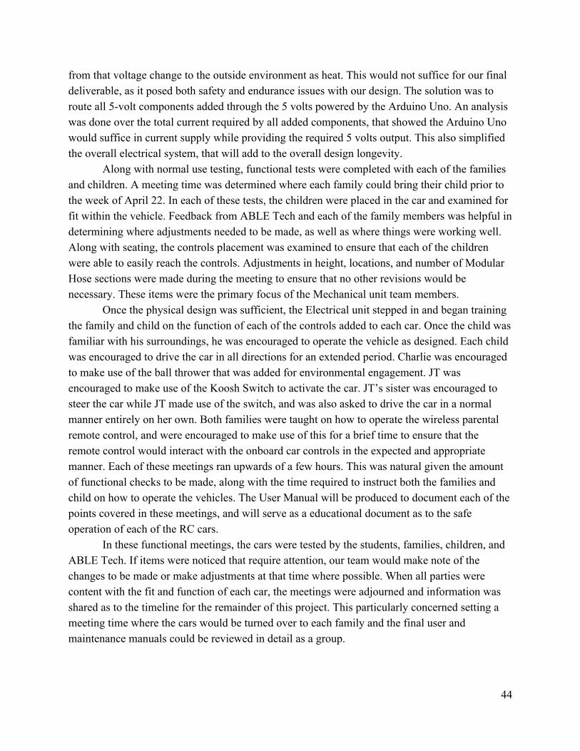
The total budget of this project is $2,000 (roughly $1,000 per car). A detailed bill of materials for this project is listed in the table below. Over the period of performance, three cars were built and will be delivered to their respective owners. The student team kept cost well under budget. Detailed information regarding personnel/labor costs are shown in the Cost Analysis deliverable submitted in the week of 4/22.
Part Website Price Qty. Total
ELECTRICAL SYSTEMS Arduino Uno Rev3 1 $22.00 3 $66.00 Misc Wires/Resistor Kit 2 $17.99 1 $17.99 Emergency Kill Switch 3 $7.36 3 $22.08 Ultrasonic Sensor Set (6 pcs.) 4 $10.99 1 $10.99 5 V 2-Channel Relay 5 $5.99 2 $11.98 5 V 1-Channel Relay Set 6 $8.99 3 $26.97 Rocker Switch 7 $0.50 6 $3.00 Voltage Regulator Set (10 pcs.) 8 $7.99 1 $7.99 Analog Joystick 9 $19.95 1 $19.95 Wire Kit (18 ga) 10 $21.90 1 $21.90 Heat Shrink Tubing Kit 11 $6.98 1 $6.98 Arduino Power Input Jack (6 pcs.) 12 $5.99 1 $5.99 Arduino Prototype Shields 13 $9.95 3 $29.85 3.5mm Female Panel Mount Jack 14 $1.15 5 $5.75 MOSFET Transistor 15 $0.95 5 $4.75 PCB (5 pcs.) 16 $5.99 1 $5.99 Koosh Switch 17 $98.95 1 $98.95 Big Button Switches 18 $65.00 2 $130.00 Misc connectors/heat shrink/other 19 $50.00 1 $50.00
MECHANICAL SYSTEMS Ball thrower 20 $30.00 1 $30.00 Modular Hose 21 $39.11 1 $39.11 Modular Hose Mounting Disk 22 $6.70 4 $26.80 Seat Harness (small) 23 $23.99 1 $23.99
46
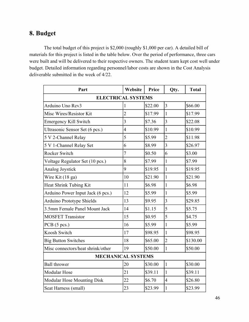
Sensory Feedback Toy 24 $16.99 1 $16.99 Sensory Feedback Toy 25 $7.99 1 $7.99 Harness Shoulder Padding 26 $6.99 1 $6.99 LOWES $258.67 1 $258.67 - PVC, plywood, pvc fittings, pvc cement - foam pad, foam noodles, screws, bolts, - nuts, tape, glue, etc.
RC CARS Audi Demo Car [Purchased by ABLE Tech] $0.00 1 $0.00 Mercedes (JT) $274.85 1 $274.85 Jeep (Charlie) $238.21 1 $238.21
Figure 8.1: Detailed Bill of Materials
TOTALS ELECTRICAL SYSTEMS $547.11 MECHANICAL SYSTEMS $410.54 RC CARS $513.06 SHIPPING FOR ALL ORDERS $203.98 PROJECT TOTAL $1,674.69
Figure 8.2: Project Cost Totals
47
9. Project Review, Future Work, and Closing Remarks
Now that the has concluded, the completed vehicles will be turned over to their respective customers. The Mercedes will go to JT’s family, the jeep to Charlie’s family, and the Audi to the Oklahoma Able Tech staff. Both children will be able to enjoy their vehicles and increased independent mobility. Able Tech will use their vehicle as a marketing tool to be able to increase visibility and promote the program. The Audi car has already been used by Able Tech at expos this semester. Oklahoma Able Tech plans to continue the work of Go Baby Go, Ok Outriders by adapting additional cars in the future to increase the mobility of disabled children. The three vehicles we adapted required a wide array of skills and each car provided its own challenges. The demonstration car gave us a starting point in the project. We were able to make more general modifications before working on the vehicles requiring specialization for each child. The changes to the Mercedes were heavily mechanical whereas the changes to the Jeep were more electrical. In addition to our work in the lab, we met with each family about three times for an initial consultation and test fittings. This allowed us to work on our soft skills in addition to our engineering design skills. The team recommends that Go Baby Go, Ok Outriders be considered for an interdisciplinary senior design project again in the future. Modifying two to three vehicles provided enough work for a team of four to five students. The varying disabilities of both children allowed students from multiple disciplines to bring their experience and expertise to the project. A budget of $2000 and initial donation of the Audi car was sufficient to modify all three vehicles. Overall, the team learned a lot throughout this project. Integrating the new electrical design with the current system of the jeep proved to be one of the most challenging portions of the project. The team also had a learning curve when it came to working with disabled children and adaptive technology. We also had to work to balance the requests of our sponsor, the clients, and the engineering department. When given conflicting feedback the team worked through the options presented to determine which would lead to the best outcome. In the end with the help of our faculty mentor and partnership with Oklahoma Able Tech the team successfully completed the project and delivered modified ride on toy vehicles to increase the independent mobility of our clients.
48
References
Literature Review
1. Anderson, D. I., Campos, J. J., Witherington, D. C., Dahl, A., Rivera, M., He, M., et al. (2013). The role of locomotion in psychological development. Front. Psychol. 4:440. doi: 10.3389/fpsyg.2013.00440
2. Cooper, R. A., Tolerico, M., Kaminski, B. A., Spaeth, D., Ding, D., and Cooper, R. (2008). Quantifying wheelchair activity of children: a pilot study. Am. J. Phys. Med. Rehabil. 87, 977–983. doi:10.1097/PHM.0b013e31818dfe74
3. Huang, H., and Galloway, J. C. (2012). Modified ride-on toy cars for early power mobility: a technical report. Pediatr. Phys. Ther. 24, 149–154. doi:10.1097/PEP.0b013e31824d73f9
Standards and Codes
1. ASTM F963-17 Standard Consumer Safety Specification for Toy Safety, ASTM International, West Conshohocken, PA, 2017, https://doi.org/10.1520/F0963-17
a. Consumer safety specification designed to establish nationally recognized safety requirements for toys.
49
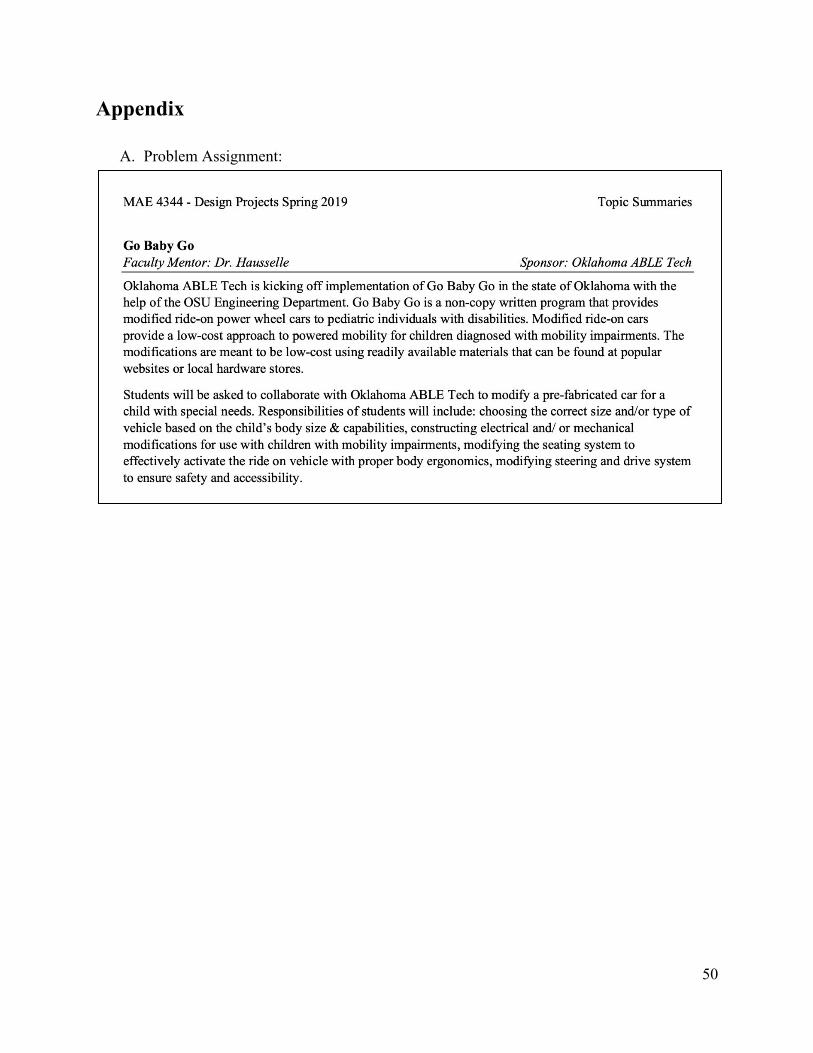
Appendix
A. Problem Assignment:
50
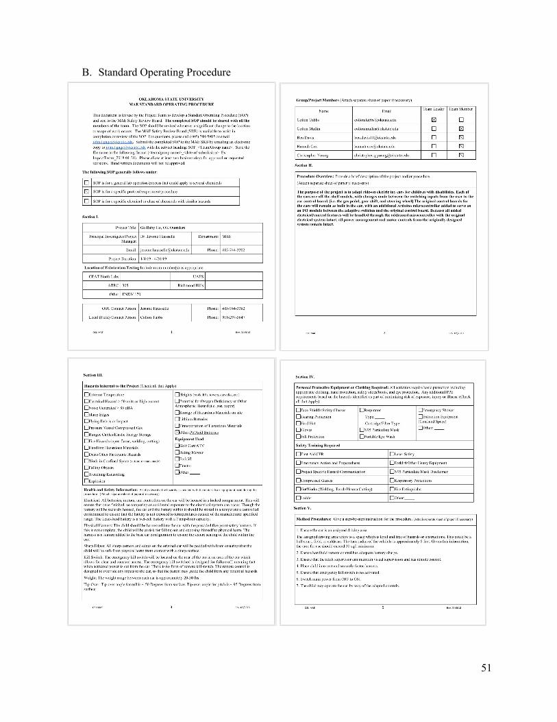
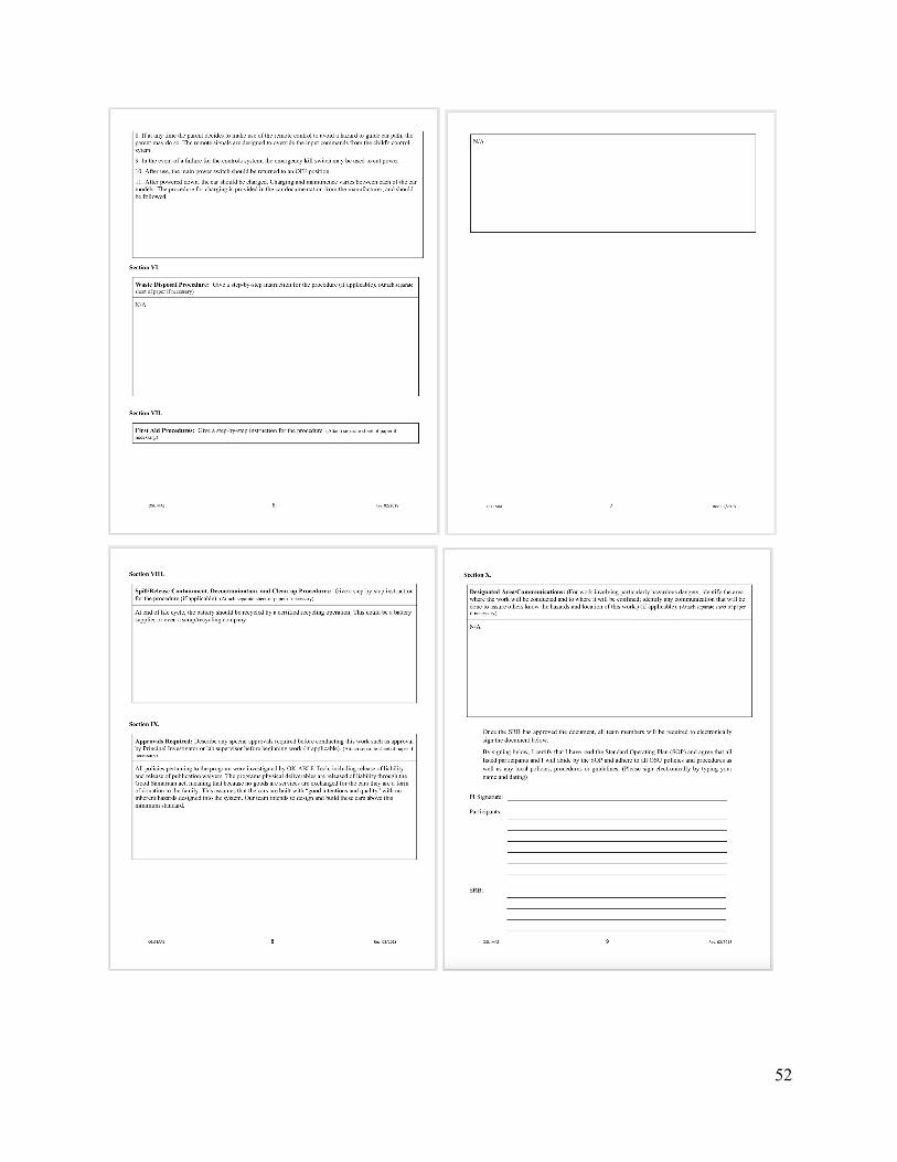
B. Standard Operating Procedure
51
52
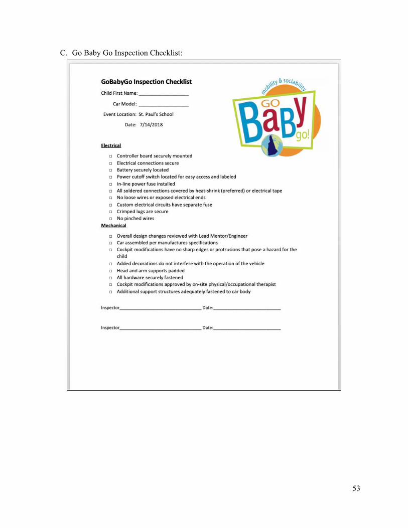
C. Go Baby Go Inspection Checklist:
53
Related Documents