Field Oriented Control of Permanent Magnet Synchronous Motors User’s Guide

Welcome message from author
This document is posted to help you gain knowledge. Please leave a comment to let me know what you think about it! Share it to your friends and learn new things together.
Transcript

Field Oriented Control of PermanentMagnet Synchronous Motors
User’s Guide
Field Oriented Control of Permanent Magnet Synchronous Motors User’s Guide
Table of Contents
Introduction . . . . . . . . . . . . . . . . . . . . . . . . . . . . . . . . . . . . . . . . . . . . . . . . . . . . . . . . . . . . . . . . . . . . . . 5
1 Permanent Magnet Synchronous Motor. . . . . . . . . . . . . . . . . . . . . . . . . . . . . . . . . . . . . . . . . . . . . . . . . 7Field Oriented Control Theory. . . . . . . . . . . . . . . . . . . . . . . . . . . . . . . . . . . . . . . . . . . . . . . . . . . . . . . . . . . . . . . . . . 8
Transformations . . . . . . . . . . . . . . . . . . . . . . . . . . . . . . . . . . . . . . . . . . . . . . . . . . . . . . . . . . . . . . . . . . . . . . . . . . . 10
Clarke Transformation . . . . . . . . . . . . . . . . . . . . . . . . . . . . . . . . . . . . . . . . . . . . . . . . . . . . . . . . . . . . . . . . . . . . . . 10
Park Transformation . . . . . . . . . . . . . . . . . . . . . . . . . . . . . . . . . . . . . . . . . . . . . . . . . . . . . . . . . . . . . . . . . . . . . . . . 10
Inverse Park Transformation. . . . . . . . . . . . . . . . . . . . . . . . . . . . . . . . . . . . . . . . . . . . . . . . . . . . . . . . . . . . . . . . . . 10
Inverse Clarke transformation. . . . . . . . . . . . . . . . . . . . . . . . . . . . . . . . . . . . . . . . . . . . . . . . . . . . . . . . . . . . . . . . . 11
Sinusoidal Voltage and SVPWM Generation . . . . . . . . . . . . . . . . . . . . . . . . . . . . . . . . . . . . . . . . . . . . . . . . . . . . . 11
PWM Generation . . . . . . . . . . . . . . . . . . . . . . . . . . . . . . . . . . . . . . . . . . . . . . . . . . . . . . . . . . . . . . . . . . . . . . . . . . 12
Phase Current Measurement Using ADC . . . . . . . . . . . . . . . . . . . . . . . . . . . . . . . . . . . . . . . . . . . . . . . . . . . . . . . 13
ADC Current Sampling Window . . . . . . . . . . . . . . . . . . . . . . . . . . . . . . . . . . . . . . . . . . . . . . . . . . . . . . . . . . . . . . . 15
Angle Estimation Using Hall Sensor State . . . . . . . . . . . . . . . . . . . . . . . . . . . . . . . . . . . . . . . . . . . . . . . . . . . . . . . 16
Speed Calculation using Hall State. . . . . . . . . . . . . . . . . . . . . . . . . . . . . . . . . . . . . . . . . . . . . . . . . . . . . . . . . . . . . 17
2 Design and Implementation . . . . . . . . . . . . . . . . . . . . . . . . . . . . . . . . . . . . . . . . . . . . . . . . . . . . . . . . . 19Design Description . . . . . . . . . . . . . . . . . . . . . . . . . . . . . . . . . . . . . . . . . . . . . . . . . . . . . . . . . . . . . . . . . . . . . . . . . 19
Software Implementation . . . . . . . . . . . . . . . . . . . . . . . . . . . . . . . . . . . . . . . . . . . . . . . . . . . . . . . . . . . . . . . . . . . . 22
Hardware Implementation . . . . . . . . . . . . . . . . . . . . . . . . . . . . . . . . . . . . . . . . . . . . . . . . . . . . . . . . . . . . . . . . . . . 25
SVPWM Generation . . . . . . . . . . . . . . . . . . . . . . . . . . . . . . . . . . . . . . . . . . . . . . . . . . . . . . . . . . . . . . . . . . . . . . . . 26
Design Customizations . . . . . . . . . . . . . . . . . . . . . . . . . . . . . . . . . . . . . . . . . . . . . . . . . . . . . . . . . . . . . . . . . . . . . 27
Performance Details . . . . . . . . . . . . . . . . . . . . . . . . . . . . . . . . . . . . . . . . . . . . . . . . . . . . . . . . . . . . . . . . . . . . . . . 29
3 Hardware Configuration and Setup Details . . . . . . . . . . . . . . . . . . . . . . . . . . . . . . . . . . . . . . . . . . . . . 31Programming the Kit . . . . . . . . . . . . . . . . . . . . . . . . . . . . . . . . . . . . . . . . . . . . . . . . . . . . . . . . . . . . . . . . . . . . . . . 31
Connecting the SmartFusion Evaluation/Development Kit with the Trinamic Kit . . . . . . . . . . . . . . . . . . . . . . . . . . 33
Connections for Programming the Kit . . . . . . . . . . . . . . . . . . . . . . . . . . . . . . . . . . . . . . . . . . . . . . . . . . . . . . . . . . 33
Programming with the SmartFusion Development Kit . . . . . . . . . . . . . . . . . . . . . . . . . . . . . . . . . . . . . . . . . . . . . . 33
Programming with the SmartFusion Evaluation Kit. . . . . . . . . . . . . . . . . . . . . . . . . . . . . . . . . . . . . . . . . . . . . . . . . 33
Connecting the BLDC Motor with the Trinamic Kit . . . . . . . . . . . . . . . . . . . . . . . . . . . . . . . . . . . . . . . . . . . . . . . . . 34
Motor Wiring Details . . . . . . . . . . . . . . . . . . . . . . . . . . . . . . . . . . . . . . . . . . . . . . . . . . . . . . . . . . . . . . . . . . . . . . . . 34
Power Supply Connection . . . . . . . . . . . . . . . . . . . . . . . . . . . . . . . . . . . . . . . . . . . . . . . . . . . . . . . . . . . . . . . . . . . 36
Dehner Elektronik SYS 1357-2424 Supply, 24 V/DC/1000 mA . . . . . . . . . . . . . . . . . . . . . . . . . . . . . . . . . . . . . . . 36
A User Interface. . . . . . . . . . . . . . . . . . . . . . . . . . . . . . . . . . . . . . . . . . . . . . . . . . . . . . . . . . . . . . . . . . . . 37Description of Options. . . . . . . . . . . . . . . . . . . . . . . . . . . . . . . . . . . . . . . . . . . . . . . . . . . . . . . . . . . . . . . . . . . . . . . 38
Conclusion . . . . . . . . . . . . . . . . . . . . . . . . . . . . . . . . . . . . . . . . . . . . . . . . . . . . . . . . . . . . . . . . . . . . . . . . . . . . . . . 39
B Product Support . . . . . . . . . . . . . . . . . . . . . . . . . . . . . . . . . . . . . . . . . . . . . . . . . . . . . . . . . . . . . . . . . . 41Customer Service . . . . . . . . . . . . . . . . . . . . . . . . . . . . . . . . . . . . . . . . . . . . . . . . . . . . . . . . . . . . . . . . . . . . . . . . . 41
Customer Technical Support Center . . . . . . . . . . . . . . . . . . . . . . . . . . . . . . . . . . . . . . . . . . . . . . . . . . . . . . . . . . . 41
Technical Support . . . . . . . . . . . . . . . . . . . . . . . . . . . . . . . . . . . . . . . . . . . . . . . . . . . . . . . . . . . . . . . . . . . . . . . . . 41
Website . . . . . . . . . . . . . . . . . . . . . . . . . . . . . . . . . . . . . . . . . . . . . . . . . . . . . . . . . . . . . . . . . . . . . . . . . . . . . . . . . 41
Contacting the Customer Technical Support Center . . . . . . . . . . . . . . . . . . . . . . . . . . . . . . . . . . . . . . . . . . . . . . . 41
Revision 0 3

Table of Contents
Email . . . . . . . . . . . . . . . . . . . . . . . . . . . . . . . . . . . . . . . . . . . . . . . . . . . . . . . . . . . . . . . . . . . . . . . . . . . . . . . . . . . . 41
My Cases . . . . . . . . . . . . . . . . . . . . . . . . . . . . . . . . . . . . . . . . . . . . . . . . . . . . . . . . . . . . . . . . . . . . . . . . . . . . . . . . 42
Outside the U.S. . . . . . . . . . . . . . . . . . . . . . . . . . . . . . . . . . . . . . . . . . . . . . . . . . . . . . . . . . . . . . . . . . . . . . . . . . . . 42
ITAR Technical Support . . . . . . . . . . . . . . . . . . . . . . . . . . . . . . . . . . . . . . . . . . . . . . . . . . . . . . . . . . . . . . . . . . . . . 42
Index . . . . . . . . . . . . . . . . . . . . . . . . . . . . . . . . . . . . . . . . . . . . . . . . . . . . . . . . . . . . . . . . . . . . . . . . . . 43
4 Revision 0
Introduction
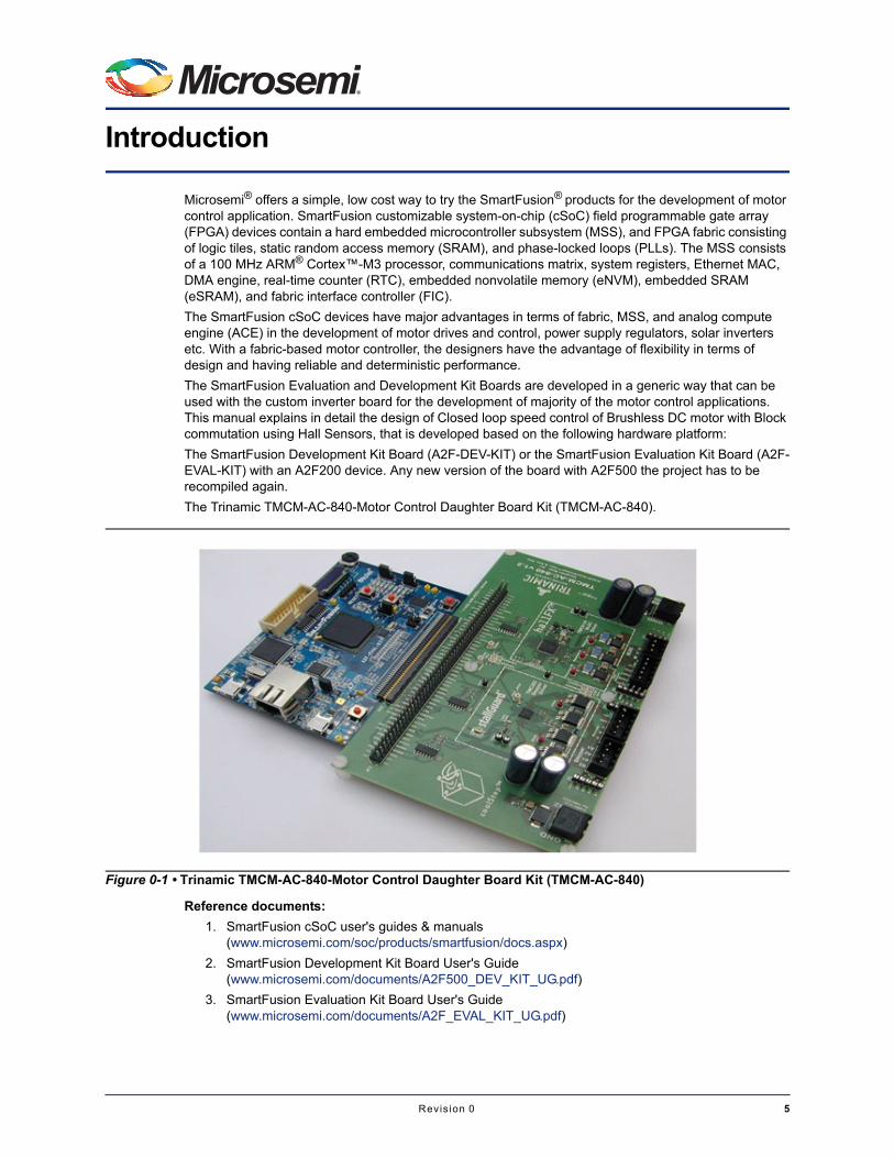
Microsemi® offers a simple, low cost way to try the SmartFusion® products for the development of motor control application. SmartFusion customizable system-on-chip (cSoC) field programmable gate array (FPGA) devices contain a hard embedded microcontroller subsystem (MSS), and FPGA fabric consisting of logic tiles, static random access memory (SRAM), and phase-locked loops (PLLs). The MSS consists of a 100 MHz ARM® Cortex™-M3 processor, communications matrix, system registers, Ethernet MAC, DMA engine, real-time counter (RTC), embedded nonvolatile memory (eNVM), embedded SRAM (eSRAM), and fabric interface controller (FIC).
The SmartFusion cSoC devices have major advantages in terms of fabric, MSS, and analog compute engine (ACE) in the development of motor drives and control, power supply regulators, solar inverters etc. With a fabric-based motor controller, the designers have the advantage of flexibility in terms of design and having reliable and deterministic performance.
The SmartFusion Evaluation and Development Kit Boards are developed in a generic way that can be used with the custom inverter board for the development of majority of the motor control applications. This manual explains in detail the design of Closed loop speed control of Brushless DC motor with Block commutation using Hall Sensors, that is developed based on the following hardware platform:
The SmartFusion Development Kit Board (A2F-DEV-KIT) or the SmartFusion Evaluation Kit Board (A2F-EVAL-KIT) with an A2F200 device. Any new version of the board with A2F500 the project has to be recompiled again.
The Trinamic TMCM-AC-840-Motor Control Daughter Board Kit (TMCM-AC-840).
Reference documents:
1. SmartFusion cSoC user's guides & manuals (www.microsemi.com/soc/products/smartfusion/docs.aspx)
2. SmartFusion Development Kit Board User's Guide (www.microsemi.com/documents/A2F500_DEV_KIT_UG.pdf)
3. SmartFusion Evaluation Kit Board User's Guide (www.microsemi.com/documents/A2F_EVAL_KIT_UG.pdf)
Figure 0-1 • Trinamic TMCM-AC-840-Motor Control Daughter Board Kit (TMCM-AC-840)
Revis ion 0 5

Introduction
4. Trinamic Kit User Manual (www.trinamic.com/tmctechlibcd/integrated_circuits/TMCM-AC-840/TMCM-AC-840_manual.pdf)
5. Trinamic 603A chip User Manual (www.trinamic.com/tmctechlibcd/integrated_circuits/TMC603/tmc603_datasheet.pdf)
6. BLDC motor datasheet (www.trinamic.com/tmc/media/Downloads/QMot_motors/QBL4208/QBL4208_manual.pdf)
6 Revis ion 0

1 – Permanent Magnet Synchronous Motor
Permanent Magnet Synchronous Motor (PMSM) is a rotating electrical machine that has the stator phase windings and rotor permanent magnets. The air gap magnetic field is provided by these permanent magnets and hence it remains constant. The conventional DC motor commutates itself with the use of a mechanical commutator whereas PMSM needs electronic commutation for the direction control of current through the windings. As the PMSM motors have the armature coils at the stator, they need to be commutated externally with the help of an external switching circuit and a three phase inverter topology is used for this purpose.
The PMSM and the driving inverter bridge topology are shown in Figure 1-1.
The torque is produced because the interaction of the two magnetic fields causes the motors to rotate. In permanent magnet motors, one of the magnetic fields is created by permanent magnets and the other is created by the stator coils. The maximum torque is produced when the magnetic vector of the rotor is at 90 degrees to the magnetic vector of the stator.
In the Block Commutation technique, there are only two coils conducting at any given point of time and the third coil remains unexcited. This causes a misalignment between the stator and rotor magnetic fields and hence the ripples are introduced to the torque. The torque ripples produce more noise, vibration and wear to the system.
Figure 1-1 • PMSM Motor and Driving Inverter Topology
Phase C
Phase A
Phase B
Vdc
PWM A High
PWM A Low PWM B Low
PWM B High PWM C High
PWM C Low
To Phase A
+
_
To Phase B To Phase CN S
010
110
100
001
101
011
Phase C
Phase B
Rotor
Phase A
Stator
Revis ion 0 7
Permanent Magnet Synchronous Motor
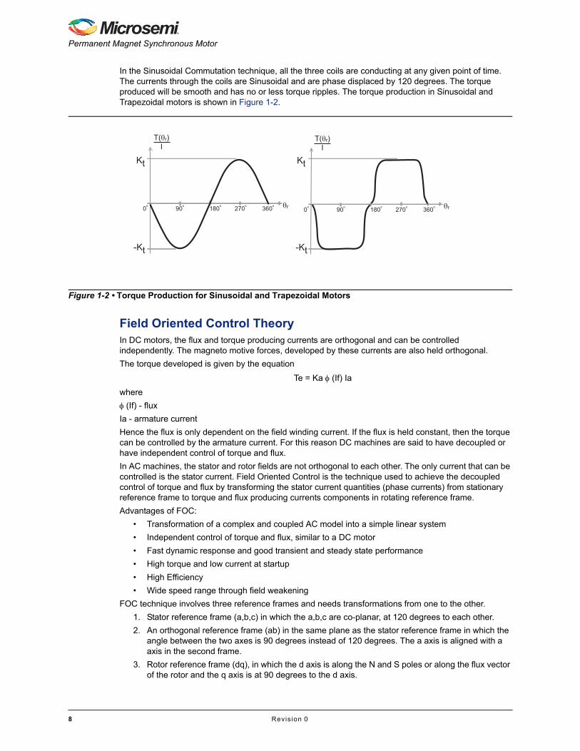
In the Sinusoidal Commutation technique, all the three coils are conducting at any given point of time. The currents through the coils are Sinusoidal and are phase displaced by 120 degrees. The torque produced will be smooth and has no or less torque ripples. The torque production in Sinusoidal and Trapezoidal motors is shown in Figure 1-2.
Field Oriented Control TheoryIn DC motors, the flux and torque producing currents are orthogonal and can be controlled independently. The magneto motive forces, developed by these currents are also held orthogonal.
The torque developed is given by the equation
Te = Ka (If) Ia
where
(If) - flux
Ia - armature current
Hence the flux is only dependent on the field winding current. If the flux is held constant, then the torque can be controlled by the armature current. For this reason DC machines are said to have decoupled or have independent control of torque and flux.
In AC machines, the stator and rotor fields are not orthogonal to each other. The only current that can be controlled is the stator current. Field Oriented Control is the technique used to achieve the decoupled control of torque and flux by transforming the stator current quantities (phase currents) from stationary reference frame to torque and flux producing currents components in rotating reference frame.
Advantages of FOC:
• Transformation of a complex and coupled AC model into a simple linear system
• Independent control of torque and flux, similar to a DC motor
• Fast dynamic response and good transient and steady state performance
• High torque and low current at startup
• High Efficiency
• Wide speed range through field weakening
FOC technique involves three reference frames and needs transformations from one to the other.
1. Stator reference frame (a,b,c) in which the a,b,c are co-planar, at 120 degrees to each other.
2. An orthogonal reference frame (ab) in the same plane as the stator reference frame in which the angle between the two axes is 90 degrees instead of 120 degrees. The a axis is aligned with a axis in the second frame.
3. Rotor reference frame (dq), in which the d axis is along the N and S poles or along the flux vector of the rotor and the q axis is at 90 degrees to the d axis.
Figure 1-2 • Torque Production for Sinusoidal and Trapezoidal Motors
Kt
-Kt
Kt
-Kt
90o0o 270o180o 360o
T( r)I
r
T( r)I
90o0o 270o180o 360o r
8 Revis ion 0

Field Oriented Control of Permanent Magnet Synchronous Motors User’s Guide
Figure 1-3 shows the transformations done for decoupling the stator currents into the torque producing (Iq) and flux producing (Id) components.
The combined representation of the quantities in the entire reference frames is shown in Figure 1-4.
Once the torque and flux producing components are controlled with the PI controller, the controlled outputs which are the voltages, are then transformed back (inverse transformation) to the stator reference frame.
Figure 1-3 • Transformations and Reference Frames
Three phase 120o reference frame Two phase reference frame Rotating reference frame
Iq
Iq
Id
Id
I
I
I IIa
Ia
Ib
Ib
Ic
Ic
Figure 1-4 • Combined Vector Representation of All Transformed Quantities
Ia
Ib
Ic
I
I
Iq
Id
Revis ion 0 9
Permanent Magnet Synchronous Motor
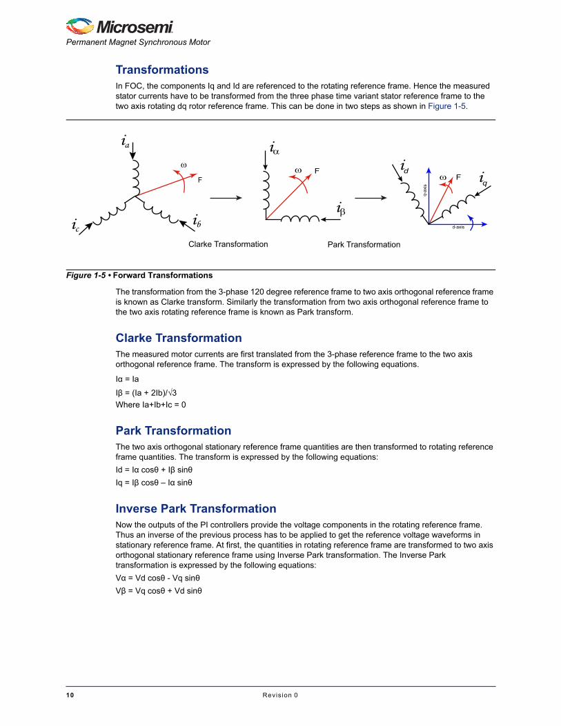
TransformationsIn FOC, the components Iq and Id are referenced to the rotating reference frame. Hence the measured stator currents have to be transformed from the three phase time variant stator reference frame to the two axis rotating dq rotor reference frame. This can be done in two steps as shown in Figure 1-5.
The transformation from the 3-phase 120 degree reference frame to two axis orthogonal reference frame is known as Clarke transform. Similarly the transformation from two axis orthogonal reference frame to the two axis rotating reference frame is known as Park transform.
Clarke TransformationThe measured motor currents are first translated from the 3-phase reference frame to the two axis orthogonal reference frame. The transform is expressed by the following equations.
Iα = Ia
Iβ = (Ia + 2Ib)/√3
Where Ia+Ib+Ic = 0
Park TransformationThe two axis orthogonal stationary reference frame quantities are then transformed to rotating reference frame quantities. The transform is expressed by the following equations:
Id = Iα cosθ + Iβ sinθ
Iq = Iβ cosθ – Iα sinθ
Inverse Park TransformationNow the outputs of the PI controllers provide the voltage components in the rotating reference frame. Thus an inverse of the previous process has to be applied to get the reference voltage waveforms in stationary reference frame. At first, the quantities in rotating reference frame are transformed to two axis orthogonal stationary reference frame using Inverse Park transformation. The Inverse Park transformation is expressed by the following equations:
Vα = Vd cosθ - Vq sinθ
Vβ = Vq cosθ + Vd sinθ
Figure 1-5 • Forward Transformations
ia
ibic
F
Clarke Transformation Park Transformation
i
i
F id iq
q-a
xis
d-axis
F
10 Revis ion 0

Field Oriented Control of Permanent Magnet Synchronous Motors User’s Guide
Inverse Clarke transformationThe transformation from two axis orthogonal stationary reference frame to the three phase stator stationary reference frame, is accomplished using the inverse Clarke transformation. The inverse Clarke transformation is expressed by the following equations
Va = Vα
Vb = [-Vα + √3.Vβ]/2
Vc = [-Vα - √3.Vβ]/2
Sinusoidal Voltage and SVPWM GenerationThe output of the inverse Clarke transformation provides the duty cycles of the Pulse-width modulation (PWM) channels that corresponds to the three Phase voltages. For sinusoidal excitation of the phase voltages, these duty cycle values are used directly. There are many conventional ways of implementing the SVPWM algorithm available. A simplified approach which is equivalent to the conventional modulation strategy is used in this current implementation.
In this approach the instantaneous average of the minimum and maximum of all the three phase voltages is calculated as the Voltage offset. Then this instantaneous Voltage offset is subtracted from the instantaneous three phase voltages.
For the SVPWM (Sine with 3rd harmonics injection) the following procedure is used:
Voff= [min(Va, Vb, Vc)+max(Va, Vb, Vc)]/2
Vanew = Va – Voff
Vbnew = Vb – Voff
Vcnew = Vc – Voff
Figure 1-6 • Sine PWM
VcVa Vb
Revis ion 0 11
Permanent Magnet Synchronous Motor
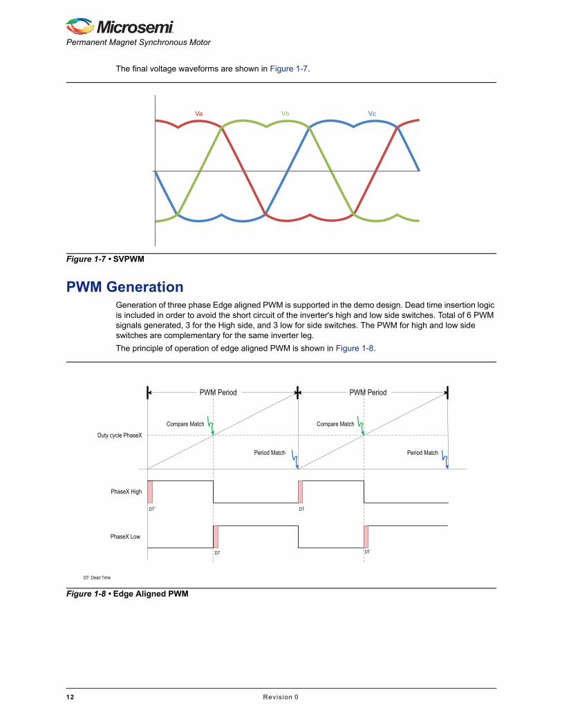
The final voltage waveforms are shown in Figure 1-7.
PWM GenerationGeneration of three phase Edge aligned PWM is supported in the demo design. Dead time insertion logic is included in order to avoid the short circuit of the inverter's high and low side switches. Total of 6 PWM signals generated, 3 for the High side, and 3 low for side switches. The PWM for high and low side switches are complementary for the same inverter leg.
The principle of operation of edge aligned PWM is shown in Figure 1-8.
Figure 1-7 • SVPWM
VcVa Vb
Figure 1-8 • Edge Aligned PWM
PWM Period PWM Period
PhaseX High
PhaseX Low
Duty cycle PhaseX
DTDT*
DT DT
DT: Dead Time
Compare Match Compare Match
Period Match Period Match
12 Revis ion 0

Field Oriented Control of Permanent Magnet Synchronous Motors User’s Guide
Phase Current Measurement Using ADCThe three phase currents can be measured using external current shunt resistors available at the lower side of the metal-oxide-semiconductor field-effect transistor (MOSFET) switches of the inverter.Three 10 m shunt resistors are used for the measurement of the phase currents. One end of the shunt resistor is connected to the low-side MOSFET and the other end is connected to the GND of DC Bus Voltage. The voltages across the shunt resistors are seen at the connections Rsense1, Rsense2, and Rsense3.
Figure 1-9 • Three Phase Current Measurement with Shunt Resistors
Revis ion 0 13
Permanent Magnet Synchronous Motor
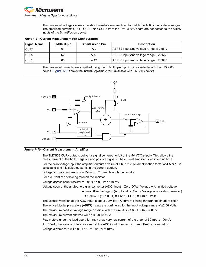
The measured voltages across the shunt resistors are amplified to match the ADC input voltage ranges. The amplified currents CUR1, CUR2, and CUR3 from the TMCM 840 board are connected to the ABPS inputs of the SmartFusion device.
The measured currents are amplified using the in built op-amp circuitry available with the TMC603 device. Figure 1-10 shows the internal op-amp circuit available with TMC603 device.
The TMC603 CURx outputs deliver a signal centered to 1/3 of the 5V VCC supply. This allows the measurement of the both, negative and positive signals. The current amplifier is an inverting type.
For the zero voltage input the amplifier outputs a value of 1.667 mV. An amplification factor of 4.5 or 18 is selectable and it is selected as 18 in the current design.
Voltage across shunt resistor = Rshunt x Current through the resistor
For a current of 1A flowing through the resistor,
Voltage across shunt resistor = 0.01 x 1= 0.01V or 10 mV.
Voltage seen at the analog-to-digital converter (ADC) input = Zero Offset Voltage + Amplified voltage
= Zero Offset Voltage + (Amplification Gain x Voltage across shunt resistor)
= 1.6667 + (18 * 0.01) = 1.6667 + 0.18 = 1.8467 Volts
The voltage variation at the ADC input is about 0.2V per 1A current flowing through the shunt resistor.
The active bipolar prescalers (ABPS) inputs are configured for the input voltage range of ±2.56 Volts.
The maximum positive voltage range possible with the circuit is 2.56 - 1.6667V = 0.9V
The maximum current allowed will be 0.9/0.18 = 5A
Few motors under no-load operation may draw very low current of the order of 50 mA to 100mA.
At 100mA, the voltage difference seen at the ADC input from zero current offset is given below,
Voltage difference = 0.1 * 0.01 * 18 = 0.018 V = 18mV.
Table 1-1 • Current Measurement Pin Configuration
Signal Name TMC603 pin SmartFusion Pin Description
CUR1 61 W9 ABPS2 input and voltage range [± 2.56]V
CUR2 62 AB7 ABPS3 input and voltage range [±2.56]V
CUR3 65 W12 ABPS6 input and voltage range [±2.56]V
Figure 1-10 • Current Measurement Amplifier
SENSE_HI
BMx
BLx
SAMPLEx
+automatic
sample point delay
autozero
Add 1 /3 VCC offset
SWC
amplify 4.5x or 18x
+VCC
1/3 VCC
^
^
track & hold stage
R
R
R
CURx
+
_
+
_
14 Revis ion 0

Field Oriented Control of Permanent Magnet Synchronous Motors User’s Guide
No-load motor operation will be a problem not only at high speed operations but will be even challenging at very low speed operations. The motor QBL4208-41-04-006 draws very low current and hence it is recommended to run the demo with a small amount of load at the motor shaft.
The CUR1,CUR2, and CUR3 are connected to the active bipolar prescalers (ABPS) channels of the SmartFusion by default. In case of ABPS the 12 bits are used to represent - 2.56 V to 2.56 V. Each bit represents 0.3125 mV, where as in case of ADC direct channels, 12 bits are used to represent 0 to 2.56V. Each bit represents 0.625 mV.
By connecting the CUR1, CUR2 of Motor to the ADC direct channels, the resolution of the measured currents can be improved by double and thus improving the motor performance. This can be done with small wiring on the board as follows:
• Connect CUR1 Pin of the TMC daughter card Header K1 to the Pin ADC7 on the same header.
• Connect CUR2 Pin of the TMC daughter card Header K1 to the Pin AC1 on the same header.
ADC Current Sampling WindowThe low-side current measurements are done when the low side switches are ON. There are practical limitations in terms of current measurement. If the ON time duty cycle of any of the phases is high, then the ON time of the corresponding low-side switch will be low and current measurements are not possible.
The sample window available mainly depends on ADC sampling time, the ON time of low-side switches, dead time, and switching transient time. This will limit the high speed operations of the motor.
The current design supports two direct ADC phase current measurements of Current A and Current B.
The current sampling is triggered with the delay of about 6 unit separator (us) after all low-side switches are ON. The 6us delay will provide the time for dead time logic and current to reach for stable value due to switching transient.
Table 1-2 • Current Measurement Pin Configuration
Signal Name
TMC603 pinSmartFusion
PinSignal Name
TMC603 pinSmartFusion
PinDescription
CUR1 61 W9 ADC7 91 T12 ADC Direct input and voltage range [0 to 2.56]V
CUR2 62 AB7 AC1 82 U9 ADC Direct input and voltage range [0 to 2.56]V
Revis ion 0 15

Permanent Magnet Synchronous Motor
The current trigger timing in Edge aligned PWM is shown in Figure 1-11.
Angle Estimation Using Hall Sensor StateFor proper Sinusoidal commutation, the absolute rotor position information is very crucial in order to produce the synchronized voltage waveforms to the motor. To get fine position information, the motors will be equipped with Encoders or Resolvers, but these sensors add cost to the system. For low cost simple solution the motors which have Hall sensors can be used.
The demo design uses the motor, which has four pole pairs. We know that for every electrical cycle there are six Hall state changes and thus provides 60 degrees of precision. Each state corresponds to an electrical angle and we have six angle steps. Figure 1-12 shows the Hall event changes and the corresponding angle information of the motor used in the demo design.
Figure 1-11 • ADC Sampling Timing with Edge Aligned PWM
Highest PWM ON TimeDuty cycle PhaseA
Duty cycle PhaseB
Duty cycle PhaseC
PWM A High
PWM A Low
DT
ADC SamplingWindow
Switchingtransient
DT*
DT*: Dead Time
DTDT
ADC Sample trigger
PWM Period PWM Period
Figure 1-12 • Hall State Change Vs Corresponding Angle for CCW Direction
270
90
150
010
011
100
101
100
WC
C
110
210 330
30
16 Revis ion 0

Field Oriented Control of Permanent Magnet Synchronous Motors User’s Guide
The Hall state change provides the information of the new electrical angle. In order to estimate the angle within the Hall state changes as the motor rotates, we can use the information available through these Hall state changes. that is, the time taken between Hall state changes or the number of PWM cycle events happened between Hall event changes. With the number of PWM cycle events happened between Hall event changes previously, the new angle can be estimated between Hall Events on every PWM cycle as shown in Figure 1-13. Also the estimated angle can be corrected when the next Hall event occurs. This method of angle estimation is not accurate and may not be well suitable for applications where load changes occur more frequently.
The angle increment count corresponds to 360 degree of electrical revolution is calculated using the following formula
Angle Increment per Electrical Rrevolution= (Number of PWM Counts between Hall Change)/(Fabric Frequency in MHz*PWM Frequency in s)
EQ 1-1
The angle increment between Hall states or within 60 electrical degrees is calculated using the following formula
Angle Increment within 60 degrees= (Angle Increment per Electrical Revolution)/(60)
EQ 1-2
Speed Calculation using Hall State
The Hall state changes provide the information on the position of the motor. For every electrical cycle there are six Hall state changes. If the time, taken between the Hall state changes, is available then the speed can be computed. A moving average technique is used to calculate the speed and this technique average the six of the previously calculated speed values.
ActualSpeed(n)= (Speed(n)+Speed(n-1)+...+Speed(n-5))/6
EQ 1-3
Figure 1-13 • PWM Cycle Counts Between Two Hall Event Change
Hall Event (n-1) Hall Event (n)
PWM cycle counts
Revis ion 0 17

2 – Design and Implementation
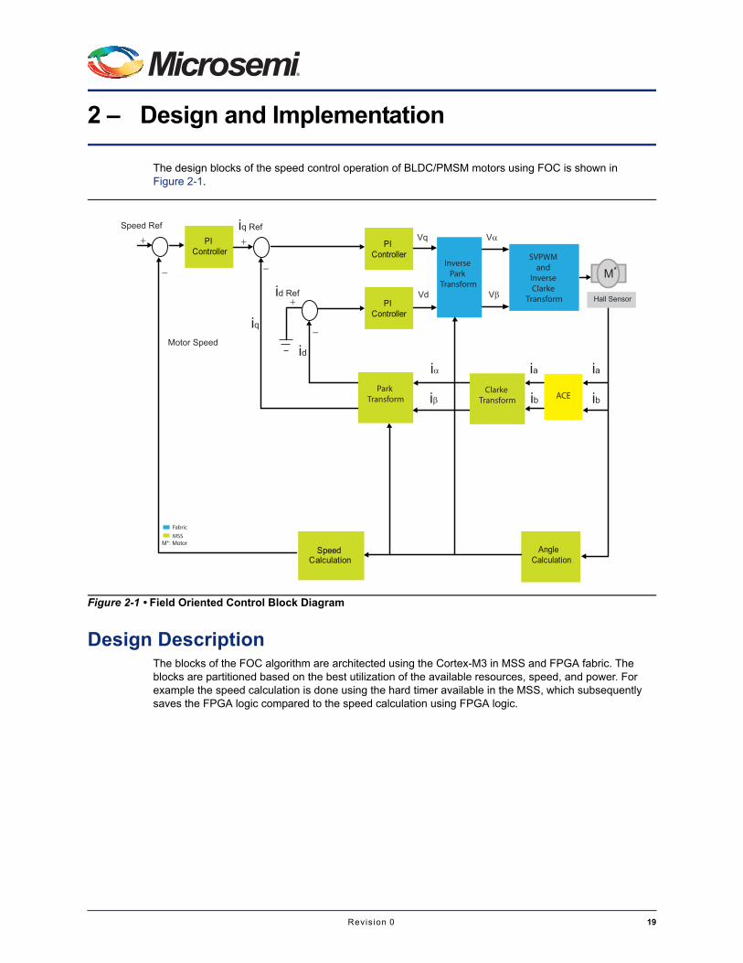
The design blocks of the speed control operation of BLDC/PMSM motors using FOC is shown in Figure 2-1.
Design DescriptionThe blocks of the FOC algorithm are architected using the Cortex-M3 in MSS and FPGA fabric. The blocks are partitioned based on the best utilization of the available resources, speed, and power. For example the speed calculation is done using the hard timer available in the MSS, which subsequently saves the FPGA logic compared to the speed calculation using FPGA logic.
Figure 2-1 • Field Oriented Control Block Diagram
PI Controller
PI Controller
PI Controller
Speed Calculation
Angle Calculation
Inverse Park
Transform
Park Transform
Clarke Transform ACE
ACE
SVPWM and
Inverse Clarke
Transform Hall Sensor
Speed Ref iq Ref
iq
id Ref
idMotor Speed
Vq
ia ia
ib ib
Vd
V
i
V
i
M*
M*: MotorMSSFabric
Revis ion 0 19

Design and Implementation
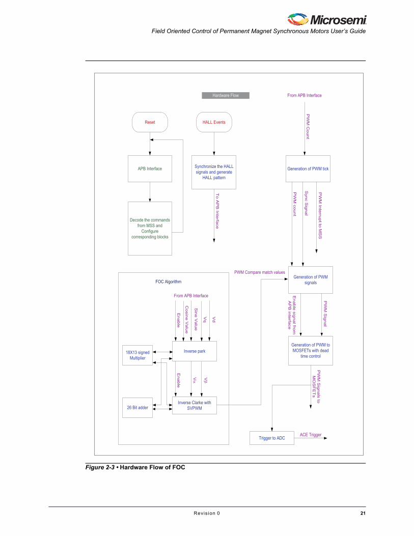
The flowchart of the complete FOC algorithm is shown in Figure 2-2 and Figure 2-3.
Figure 2-2 • Software Flow of FOC
Reset
Initialize the application
MAIN LOOP
UART Rx Interrupt
Receive UART messages
Decode
Configure the application
ADC Interrupt
Read the ADC results
Find phase currents
FOC Calculation
HALL Interrupt(GPIO)
Read the timer value
Find Actual Motor Speed in RPM
Reconfigure the timer
PWM Tick interrupt
Send the Data to GUI (Speed)
Timer 1 Interrupt Clarke and Park transformations
Speed PI controller
Torque PI controller
Program FPGA for Inverse Park and Inverse
Clarke
FOC Calculations
Software Flow
Restart the ADC for new measurements Make the Actual speed
as Zero (No HALL Event in specified time)
20 Revis ion 0
Field Oriented Control of Permanent Magnet Synchronous Motors User’s Guide
Figure 2-3 • Hardware Flow of FOC
Reset
APB Interface
Decode the commands from MSS and
Configure corresponding blocks
HALL Events
Synchronize the HALL signals and generate
HALL pattern
Generation of PWM tick
Hardware Flow
To A
PB
Inte
rface
From APB Interface
PW
M co
unt
Syn
c Sig
nal
PW
M In
terru
pt to
MS
S
Generation of PWM signals
PW
M C
ount
PWM Compare match values
Generation of PWM to MOSFETs with dead
time control
PW
M S
ignal
PW
M S
ignals to
M
OS
FE
Ts
Inverse park
From APB Interface
Sin
e V
alu
e
Cosin
e V
alu
e
Vq
Vd
Enable
Inverse Clarke with SVPWM
18X13 signed Multiplier
26 Bit adder
Enable
V V
FOC Algorithm
Enable
signal fro
m
AP
B in
terfa
ce
Trigger to ADCACE Trigger
Revis ion 0 21

Design and Implementation
Soon after the reset, the Cortex-M3 starts executing the FOC functions. During start up, it does all the initialization of all peripherals and FPGA fabric. Then it starts communicating with graphical user interface (GUI) running on host PC. It decodes all the configuration and parameters, then programs respective blocks. The analog compute engine (ACE) trigger logic in FPGA fabric generates trigger signal to ACE and in turn ACE generates interrupt to the Cortex-M3 when ADC results are available. Once the ADC results are available Cortex-M3 reads the ADC results and starts the FOC calculations like Angle calculations, Clarke, Park, PI controllers in MSS and Inverse park, Inverse Clarke, and PWM generations in FPGA fabric.
Software ImplementationThe MSS operates at 75 MHz frequency and performs the following functions of the FOC:
• Interface with GUI
• ADC results reading and converting to actual currents
• ACE reconfigurations
• Speed calculation using Hard Timer
• Speed ramp functionality
• Angle calculation
• Speed PI controller
• Torque PI Controllers
• Clarke and Park transformations
The SW blocks in the Figure 2-2 on page 20 shows the program flow sequence of the control and monitoring algorithm implemented in software. After the reset, the initialization of the MSS peripherals and parameters are done. After the initialization a while loop runs indefinitely. Cortex-M3 processor receives the following interrupts from various sources and each interrupt is processed with corresponding functionality.
• Interrupt from the universal asynchronous receiver/transmitter (UART): UART data from the GUI is processed. The GUI communicates with MSS through UART to program the configuration and control parameters of motor. Once the configuration and control parameters are programmed, then it enables the PWM generation in fabric. The fabric generates an interrupt to the ACE to sample the current values; after the sampling is done the ACE generates an interrupt to the MSS.
• Interrupt from general purpose input/output (GPIO) 1: This indicates HALL signal changes, which come from the FPGA fabric. Current count of the configured timer is read and speed calculation is done in this interrupt. The timer is reconfigured for the next speed calculation. This speed is the actual speed of the motor and it is passed to the Speed PI controller as one of the inputs to calculate the speed error from the reference speed
• Interrupt from the ACE: This indicates the availability of ADC sampling results for motor phase currents. The FPGA fabric triggers the ACE for sampling of motor phase currents, when all the bottom switches of the inverter bridge are ON. This is the starting point for the FOC calculations. Once the sampling of the motor phase currents are done, the ACE issues an interrupt to the Cortex-M3 processor. The Cortex-M3 reads the results and converts the ADC results into the actual currents. Then the FOC calculations are done in this Interrupt. Below are the functions executed in the interrupt handler.
– Speed PI Controller
– Clarke Transformation
– Park Transformation
– Torque PI Controllers
• Interrupt from FPGA fabric: This indicates the PWM tick, which is at 10 kHz rate. In this interrupt handler the ACE sequences are reconfigured for the motor phase currents during the current PWM period when all the low-side switches are ON.
22 Revis ion 0

Field Oriented Control of Permanent Magnet Synchronous Motors User’s Guide
Table 2-1 shows the details of the functions implemented in MSS:
Table 2-1 • The functions Implemented in MSS
Sr. No. Function Description
1 init_system() This function initializes the different peripherals of MSS.
2 uart0_rx_handler() This is the interrupt handler and it collects 3-Bytes from the GUI running on host PC. The first byte is ID and the subsequent two bytes are data.
3 UartMsgHandler() This function decodes all the parameters and configures the different sections of the algorithm, which are programmed from the GUI running on host PC.
4 SendStreamDATA() This function sends the speed and configuration data requested by the GUI running on the host PC. It always sends 3-Bytes of data. The first byte is ID and the subsequent two bytes are data.
5 timer1_config() The Hard Timer 1 in MSS is configured to calculate the number of clock cycles between the one of the HALL signal events, this count is used for the motor actual speed calculation in RPM.
Timer 1 is configured for one-shot mode that will only generate an interrupt once when its down-counter reaches 0. It is explicitly reloaded to start decrementing again, whenever there is an interrupt from the HALL signal.
The timer values are derived based on the minimum RPM specified by the user or the lower RPM is taken as 1. This specifies that if there is timer interrupt then it indicates that the motor is running below the minimum RPM specified by the user or motor is stopped.
6 Timer1_IRQHandler() This interrupt service routine (ISR) is mapped to the timer expiry, which indicates that the motor is running below the min speed of the motor specified by the user or that the Motor is stopped.
7 GPIO1_IRQHandler() This ISR is mapped to the one of the HALL signals, In this function the current value of the time is read and the value is converted into the actual motor speed in RPM. The timer is reconfigured for the next Hall event to calculate the Motor speed in RPM at that time.
8 angle_estimation() This implements the angle estimation logic using HALL and Interpolation technique. The angle is interpolated dynamically based on the number of PWM counts between HALL event changes.
9 ACE_PC0_Flag0_IRQHandle()
ISR is mapped to the ACE GP0 interrupt, which indicates completion of the current sampling. In this function the Motor currents are read from the ACE and translated to the original values. This interrupt occurs at PWM frequency, because the ACE is triggered from FPGA fabric for every PWM cycle to enable the ACE to sample the Motor phase currents. This also calls the FOC_Calculation() function.
Revis ion 0 23

Design and Implementation
Table 2-2 shows the macros defined in "bldc_sc.h" file used to configure the different parameters of the parameters of FOC algorithm.
10 FOC_Calculation() This function also integrates the ramp up, ramp down profile for motor start, stop, and direction change based on the ramp profile enable selection. In some of the applications, a soft start/stop or acceleration of the motor is required. The reference speed is incremented or decremented until the required speed reference is reached at the rate of the ramp up speed specified or configured. However, the functionality can be disabled if required.
The speed end reference is incremented or decremented based on the ramp rate you specify until the set reference speed is reached and the flag increment_speed is cleared with the value 0. As this function is called at every PWM period, the variable g_ramp_counter is incremented by 1 and compared with the g_ramp_count. Whenever the g-ramp-counter value exceeds the g_ramp_count, the flag increment_speed is set to 1.
Then it calls the below functions:
• angle_correction_with_enc() for angle estimation
• Clarke and Park for to calculate Iq and Id
• Speed PI controller
• Torque PI controllers
• Inverse Park and Inverse Clarke Transformations in fabric
The Angle is calculated using the function angle_correction_with_enc().
The same angle along with Phase currents is used in the Clarke and Park transformations to calculate Iq and Id.
11 PIController() This is the speed PI controller, it calculates the speed error (Desired speed - Actual speed) and it outputs the actual value to the Inner PI controller, which generates Vq for Inverse Park transformation.
12 clarke_park() This function implements the Clark and Park transformations to generate the Iq and Id.
13 PIController_0 This is the inner PI controller. The reference Id, which is Zero, and the calculated Id from the Clarke and Park transformations are fed to the inner PI controller to calculate the Vd input to the inverse park, which is implemented in the FPGA fabric.
14 PIController_1 This is the inner PI controller, the calculated Iq from the Clarke and Park transformations and the Speed PI controller output are fed to the inner PI controller to calculate the Vq input to the inverse park, which is implemented in FPGA fabric.
15 Fabric_IRQHandler () This is the ISR, mapped to the GPIO 7, which indicates the start of the current sampling. This occurs once in every PWM cycle. In this function, the ACE is restarted for current sampling.
Table 2-1 • The functions Implemented in MSS (continued)
Sr. No. Function Description
Table 2-2 • The Macros defined in "bldc_sc.h" File
Sr. No. Function Description
1 PWM_PERIOD_VAL This value defines the PWM period. To set PWM frequency as
10 KHz (100 µs), the value should be 7500 (100 * 10-6 * FPGA Frequency).
2 PWM_DEAD_TIME_VAL This value defines the dead time for inverter bridge, the value is ~ 1 µs.
3 FAB_FEQ This defines the frequency at which the FPGA logic is running.
24 Revis ion 0
Field Oriented Control of Permanent Magnet Synchronous Motors User’s Guide
Table 2-3 shows the address mapping for different parameters in FPGA fabric.
Hardware ImplementationThe logic implemented in the FPGA fabric, runs on 75 MHz clock from the clock conditioning circuit (CCC) and does the functions of the FOC as mentioned below:
• PWM generation with dead time
• Inverse Park
• Inverse Clarke with SVPWM
• APB interface
• HALL synchronization and pattern detection
The HW blocks in the Figure 2-3 on page 21 shows the program flow sequence of the blocks implemented in the FPGA fabric. After the reset from the MSS the Advanced Peripheral Bus (APB) slave
4 PWM_FREQ_IN_US This defines the PWM period in micro seconds.
5 Hall_array These values define the electrical angles corresponding to the HALL events. These values need to be identified and set appropriate values for different motors.
Table 2-2 • The Macros defined in "bldc_sc.h" File (continued)
Sr. No. Function Description
Table 2-3 • Different Parameters in FPGA Fabric
Sr. No. Register Name Register Address Description
1 PWM_PERIOD_REG_ADDR 0x40050A00UL This defines the address of the PWM period register.
2 PWM_DEAD_TIME_REG_ADDR 0x40050A10UL This defines the address of the Dead time register.
3 PWM_EN_REG_ADDR 0x40050A14UL This defines the address of the PWM enable/disable register.
4 HALL_REG_ADDR 0x40050A18UL This defines the address of the HALL pattern register.
5 SINE_VAL_INV_PARK_REG_ADDR 0x40050A34UL This defines the address of Sine values for the angle calculated in angle estimation function (to the Inverse Park transformation in the fabric).
6 COS_VAL_INV_PARK_REG_ADDR 0x40050A38UL This defines the address of Cosine values for the angle calculated in angle estimation function (to the Inverse Park transformation in the fabric).
7 VQpi_REG_ADDR 0x40050A3CUL This defines the address of Vq calculated using the Torque PI Controller.
8 VDpi_REG_ADDR 0x40050A40UL This defines the address of Vd calculated using the Torque PI Controller.
9 Valpha_REG_ADDR 0x40050A44UL This defines the address of V calculated using Inverse Park transformation fabric. This can be used for debugging purpose.
10 Vbeta_REG_ADDR 0x40050A48UL This defines the address of V calculated using Inverse Park transformation fabric. This can be used for debugging purpose.
Revis ion 0 25

Design and Implementation
implemented in FPGA fabric starts communicating with the MSS through the fabric interface controller (FIC). The APB slave decodes all the configuration data from the Cortex-M3 processor and assigns the configuration data like Vd and Vq, Sine, Cosine, PWM period, and dead time values to different modules. Once the PWM period and dead time are configured and PWM generation is enabled from Cortex-M3 processor, then the PWM count starts ticking and the count is passed to PWM compare match unit for every clock. The Cortex-M3 processor programs the Vd and Vq to Inverse Park transformation. The Inverse Park transformation calculates the Vd and Vq and passes to the Inverse Clarke transformation. In Inverse Clarke transformation calculates the PWM ON period with 3rd Harmonic injection by calculating minimum and maximum of the three phases. And then PWM ON values are passed to the PWM Compare match unit. The Compare match unit generates 3 PWM signals. These three PWM signals are fed to the dead time controller. It generates 3 PWM signals to the high side of Inverter Bridge and 3 PWM signals to the low side of Inverter Bridge.
The HALL synchronization logic synchronizes the HALL signals and decodes the pattern, which can be consumed by Cortex-M3 processor to calculate the angle. Table 2-4 shows the details of the modules implemented in FPGA fabric.
SVPWM GenerationThe Inverse Clarke implements the SVPWM logic as mentioned in "Sinusoidal Voltage and SVPWM Generation" on page 11.
The Va, Vb, and Vc from the inverse Clarke are modified using the below equation
Phase A PWM On time period = Va - (Max(Va,Vb,Vc) + Min(Va,Vb,Vc))/2
Phase B PWM On time period = Vb - (Max(Va,Vb,Vc) + Min(Va,Vb,Vc))/2
Phase C PWM On time period = Vc - (Max(Va,Vb,Vc) + Min(Va,Vb,Vc))/2
Table 2-4 • The Details of the Modules Implemented in FPGA Fabric
Sr. No. Module Name Description
1 foc_top This module is top-level module, which integrates all the sub modules.
2 apb_if.vhd This module implements the APB interface to communicate MSS with Fabric. It decodes all the commands from the MSS and programs the corresponding block.
3 Foc_algo.vhd This block has two major sub blocks called Inv_clarke (Inverse Clarke) and Inv_park (Inverse Park).
4 inv_park.vhd In this block the Inverse Park transformations are implemented using state machine, Mircosemi's standard macros 26-Bit adder, and 18x13 signed multipliers.
5 inv_clarke.vhd In this block the inverse Clarke transformations are implemented using state machine, Mircosemi's standard macros 26-Bit adder, and 18x13 signed multipliers.
The resource sharing technique is used to share Mircosemi's standard macros 26-Bit adder, and 18x13 igned multipliers between the Inverse park and Inverse Clarke transformations.
This finally generates the PWM ON Time values for all three phases with SVPWM technique Please see the SVPWM techniques used in this solution
6 pwm_gen.vhd This module takes the PWM ON time values from the sine commutation logic, compares against the PWM count, and generates the PWM signals.
7 pwm_count.vhd This module generates sync pulse for every PWM period and PWM current count to generate the PWM signals. The width of the PWM counter is 14 bit and it is an edge aligned.
8 pwm_comp.vhd This module generates the complementary signals for low-side switches.
9 hall_sync.vhd The HALL synchronization logic synchronizes the HALL signals and decodes the pattern.
26 Revis ion 0

Field Oriented Control of Permanent Magnet Synchronous Motors User’s Guide
Figure 2-4 shows the SVPWM of Phase A.
Design CustomizationsYou can customize this solution to adapt to your motors. All the Motor parameters, PI controller parameters and current offsets are programmable through the provided GUI. Figure 2-5 shows the parameters that can be configured through GUI.
Figure 2-4 • The SVPWM of Phase A
OffSet
Sine PWM
SVPWM
Figure 2-5 • The GUI for FOC
Revis ion 0 27

Design and Implementation
All the configurable parameters are set using the Set button and each one’s authenticity of configuration can be confirmed by clicking the Get button.
All the configurable parameters are set using Set button and each one can be confirmed the authenticity of configuration by clicking the Get button.
1. Pole Pair: Defines the number of poles of the Motor Speed loop configurations:
• Kp: This is the speed multiplication factor and this value is directly used in the speed PI controller without any scaling.
• Ki: This is the speed error Integration factor and this values is directly used in the speed PI controller without any scaling
2. Torque loop configurations:
• Kp: Torque multiplication factor and this value is directly used in the speed PI controller without any scaling.
• Ki: This is the torque error Integration factor and this value is directly used in the speed PI controller without any scaling.
3. Speed configuration: This specifies the desired speed of the motor.
4. Phase Current offset configurations: The phase currents from the Motor pass through the different stages and are translated to the positive level. The Zero current is mapped to the 1.667 V that is mapped to the ADC direct input and the offset is used to determine the Zero current of the Motor. These parameters are provided to you as you can change these values if you are using your own board.
• Phase A Current offset: defines the Zero current of the Phase A
• Phase B Current offset: defines the Zero current of the Phase B
• Phase B Current offset: defines the Zero current of the Phase C
5. Speed Ramp Configuration: You can specify the ramp value to ramp up or Ramp down the speed. Some of the applications need ramp profile to avoid sudden changes in the current.
6. Direction Control: This specifies the direction as Clock Wise (CW) and Counter Clock Wise(CCW).
Besides these configurations, if you want to customize the design further, you should change the code. Below are some of the possible customizations:
1. Changing PWM frequency: This may be required in different aspects like reducing the motor noise and better control. The PWM generation is implanted in the FPGA fabric, but the PWM period is programmable through software by changing PWM_PERIOD_VAL macro. The maximum width of the PWM is 13 bit, and it is unsigned. To set the PWM frequency as 20 KHz (50 µs) the value of the PWM_PERIOD_VAL macro should be 3750 (50 * 10(- 6) * FPGA frequency).
2. Changing the Dead time: The Dead time control is implanted in the FPGA fabric, but the Dead time is programmable through software by changing PWM_DEAD_TIME_VAL macro. The maximum width is 13 bit, and it is unsigned. To set the Dead time as 1 µs, the value of the PWM_DEAD_TIME_VAL macro should be 75 (1 * 10(- 6) * FPGA frequency).
3. HALL pattern change for angle: The HALL pattern is different for different motors and the angle corresponding to each motor is also different for different motors. To change the HALL pattern edit the Hall_angle array.
4. PI Controller scaling changes: The PI controller is tuned to the supplied motor. The speed PI controller output is scaled to 2 bit, Torque PI controllers output is scaled to 16 Bit. This scaling is done based on the ADC currents and their scaling values in subsequent Clarke and Park transformations, keeping in mind that the values should be normalized to unity in Inverse Clarke transformation before deriving the ON time periods.
5. Configuration changes: All the possible configuration changes can be done using the macros defined in the bldc_foc.h.
28 Revis ion 0
Field Oriented Control of Permanent Magnet Synchronous Motors User’s Guide
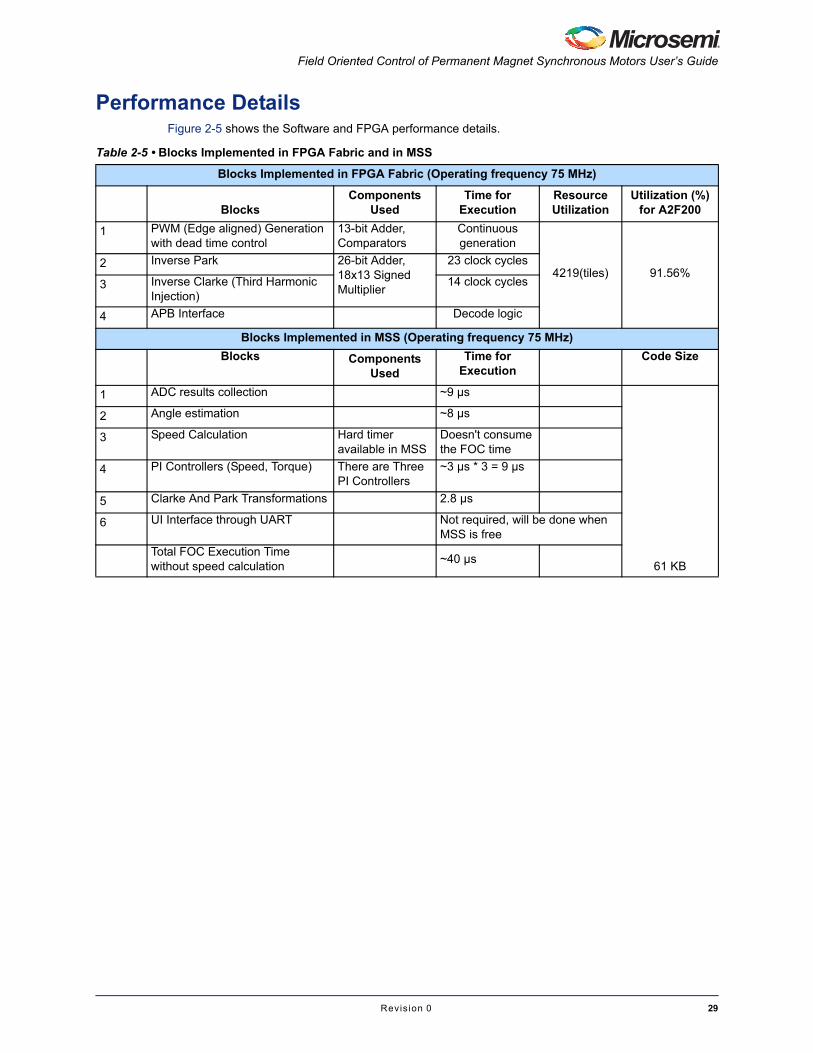
Performance DetailsFigure 2-5 shows the Software and FPGA performance details.
Table 2-5 • Blocks Implemented in FPGA Fabric and in MSS
Blocks Implemented in FPGA Fabric (Operating frequency 75 MHz)
BlocksComponents
UsedTime for
ExecutionResource Utilization
Utilization (%) for A2F200
1 PWM (Edge aligned) Generation with dead time control
13-bit Adder, Comparators
Continuous generation
4219(tiles) 91.56%2 Inverse Park 26-bit Adder,
18x13 Signed Multiplier
23 clock cycles
3 Inverse Clarke (Third Harmonic Injection)
14 clock cycles
4 APB Interface Decode logic
Blocks Implemented in MSS (Operating frequency 75 MHz)
Blocks Components Used
Time for Execution
Code Size
1 ADC results collection ~9 µs
61 KB
2 Angle estimation ~8 µs
3 Speed Calculation Hard timer available in MSS
Doesn't consume the FOC time
4 PI Controllers (Speed, Torque) There are Three PI Controllers
~3 µs * 3 = 9 µs
5 Clarke And Park Transformations 2.8 µs
6 UI Interface through UART Not required, will be done when MSS is free
Total FOC Execution Time without speed calculation
~40 µs
Revis ion 0 29


3 – Hardware Configuration and Setup Details
This demonstration design is developed for using the SmartFusion Evaluation Kit Board with an A2F200 SmartFusion cSoC device. The project needs to be recompiled for any new version of the kit with A2F500 device accordingly.
Programming the Kit1. Connect both USB cables to the evaluation board and verify that LEDs D11, D15, and LED1 turn
on.
2. Launch FlashPro v10.0 (or later) Figure 3-1.l
3. Click the New Project or click File > New Project.
4. In the New Project dialog box, type SF_DMC_FOC in the Project Name field. Make the Project Location be C:\Microsemi\SF_DMC_FOC.
Figure 3-1 • Launch FlashPro
Revis ion 0 31
Hardware Configuration and Setup Details
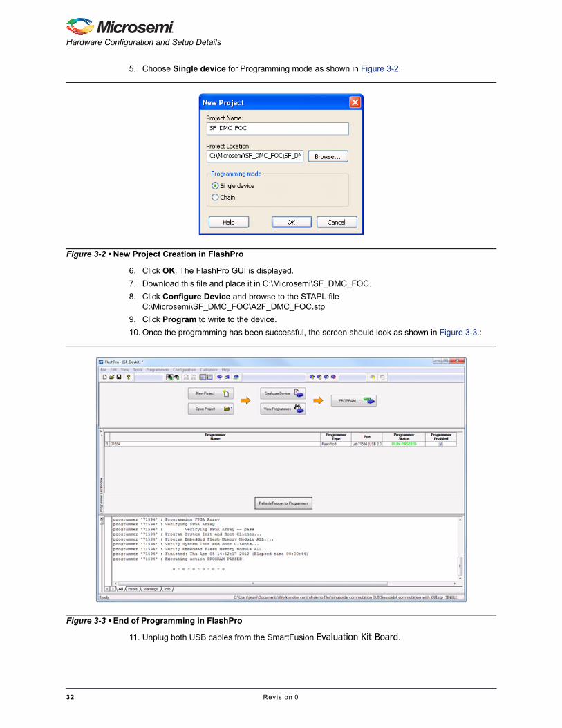
5. Choose Single device for Programming mode as shown in Figure 3-2.
6. Click OK. The FlashPro GUI is displayed.
7. Download this file and place it in C:\Microsemi\SF_DMC_FOC.
8. Click Configure Device and browse to the STAPL file C:\Microsemi\SF_DMC_FOC\A2F_DMC_FOC.stp
9. Click Program to write to the device.
10. Once the programming has been successful, the screen should look as shown in Figure 3-3.:
11. Unplug both USB cables from the SmartFusion Evaluation Kit Board.
Figure 3-2 • New Project Creation in FlashPro
Figure 3-3 • End of Programming in FlashPro
32 Revis ion 0

Field Oriented Control of Permanent Magnet Synchronous Motors User’s Guide
Connecting the SmartFusion Evaluation/Development Kit with the Trinamic Kit
When you are using the SmartFusion Development Kit Board, connect the TMCM-AC-840 Daughter Board to J21(Mixed Signal Header) via the H3 board-to-board connector.
Note: Switch off all power supplies while connecting/disconnecting the SmartFusion Development/Evaluation Kit Board from the TMCM-AC-840 Daughter Board. There is a small air gap remaining between the SmartFusion board and Trinamic's daughter board as shown in Figure 3-4.
Connections for Programming the Kit
Programming with the SmartFusion Development Kit1. Connect both USB cables supplied with the kit to J9 and J15 LCPS interface via the LC
programmer board.
2. Connect 5V power supply to J1.
Programming with the SmartFusion Evaluation KitConnect both USB cables supplied with the kit to the USB/UART interface and the USB program and debug interface.
Figure 3-4 • H3 Board Connector Interface to the SmartFusion Kit
Revis ion 0 33
Hardware Configuration and Setup Details
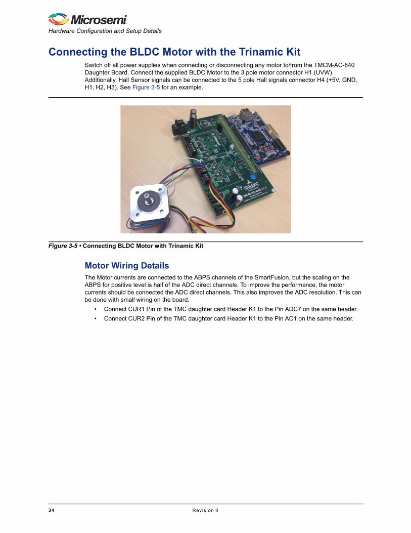
Connecting the BLDC Motor with the Trinamic KitSwitch off all power supplies when connecting or disconnecting any motor to/from the TMCM-AC-840 Daughter Board. Connect the supplied BLDC Motor to the 3 pole motor connector H1 (UVW). Additionally, Hall Sensor signals can be connected to the 5 pole Hall signals connector H4 (+5V, GND, H1, H2, H3). See Figure 3-5 for an example.
Motor Wiring DetailsThe Motor currents are connected to the ABPS channels of the SmartFusion, but the scaling on the ABPS for positive level is half of the ADC direct channels. To improve the performance, the motor currents should be connected the ADC direct channels. This also improves the ADC resolution. This can be done with small wiring on the board.
• Connect CUR1 Pin of the TMC daughter card Header K1 to the Pin ADC7 on the same header.
• Connect CUR2 Pin of the TMC daughter card Header K1 to the Pin AC1 on the same header.
Figure 3-5 • Connecting BLDC Motor with Trinamic Kit
34 Revis ion 0
Field Oriented Control of Permanent Magnet Synchronous Motors User’s Guide
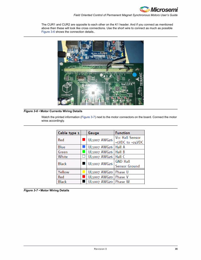
The CUR1 and CUR2 are opposite to each other on the K1 header. And if you connect as mentioned above then these will look like cross connections. Use the short wire to connect as much as possible Figure 3-6 shows the connection details..
Watch the printed information (Figure 3-7) next to the motor connectors on the board. Connect the motor wires accordingly.
Figure 3-6 • Motor Currents Wiring Details
Figure 3-7 • Motor Wiring Details
Revis ion 0 35
Hardware Configuration and Setup Details
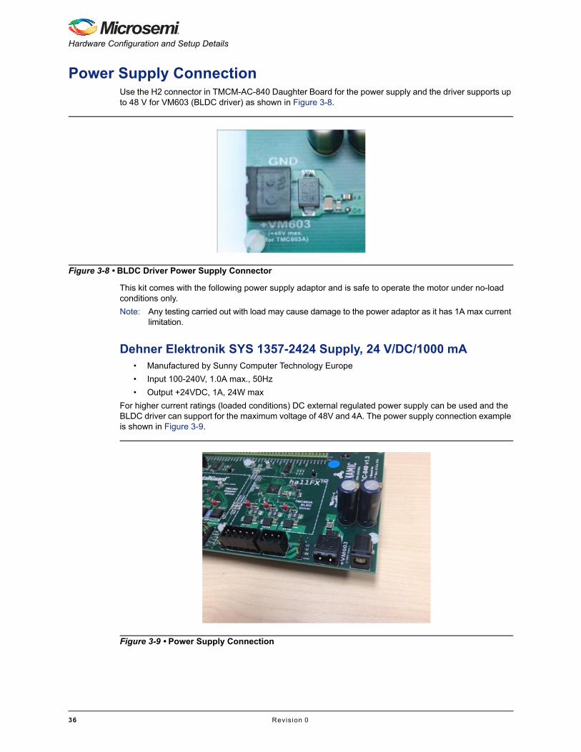
Power Supply ConnectionUse the H2 connector in TMCM-AC-840 Daughter Board for the power supply and the driver supports up to 48 V for VM603 (BLDC driver) as shown in Figure 3-8.
This kit comes with the following power supply adaptor and is safe to operate the motor under no-load conditions only.
Note: Any testing carried out with load may cause damage to the power adaptor as it has 1A max current limitation.
Dehner Elektronik SYS 1357-2424 Supply, 24 V/DC/1000 mA• Manufactured by Sunny Computer Technology Europe
• Input 100-240V, 1.0A max., 50Hz
• Output +24VDC, 1A, 24W max
For higher current ratings (loaded conditions) DC external regulated power supply can be used and the BLDC driver can support for the maximum voltage of 48V and 4A. The power supply connection example is shown in Figure 3-9.
Figure 3-8 • BLDC Driver Power Supply Connector
Figure 3-9 • Power Supply Connection
36 Revis ion 0
A – User Interface
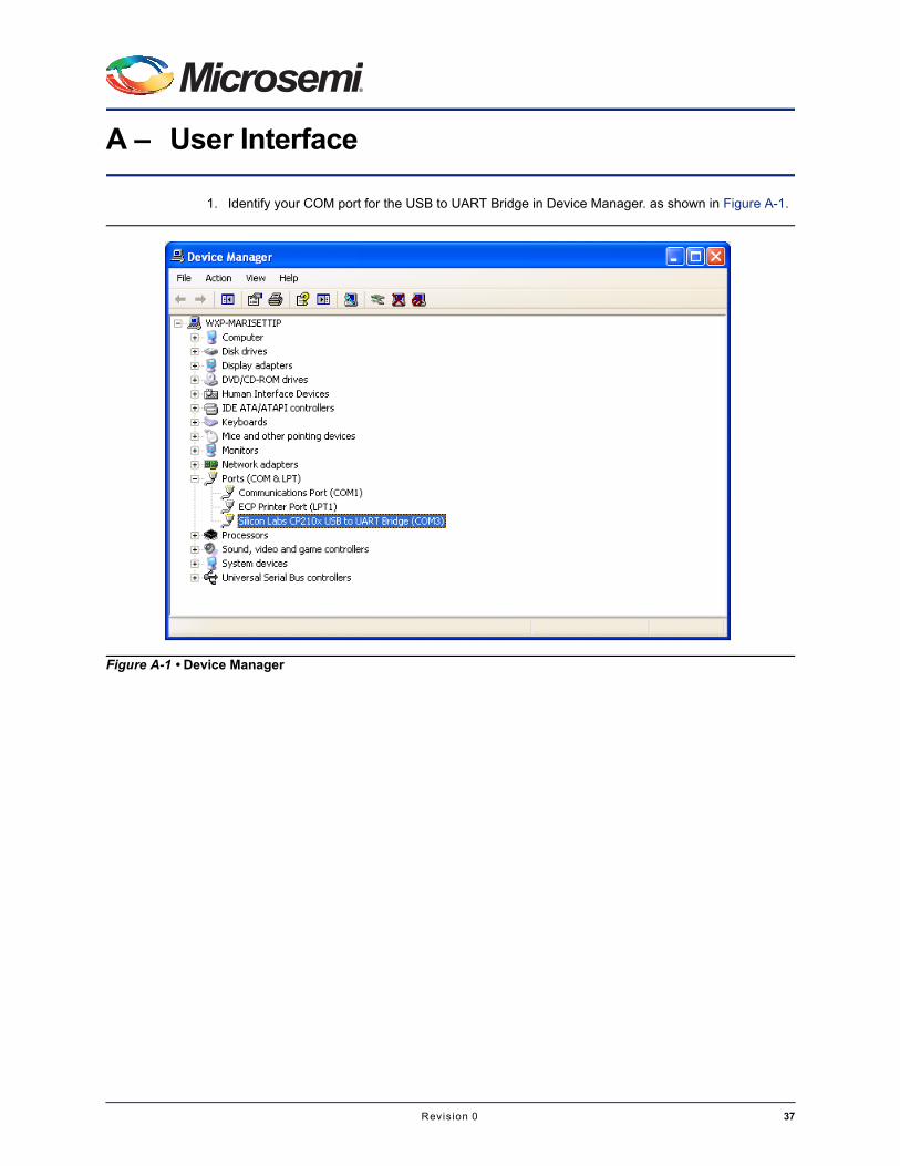
1. Identify your COM port for the USB to UART Bridge in Device Manager. as shown in Figure A-1.
Figure A-1 • Device Manager
Revis ion 0 37
User Interface
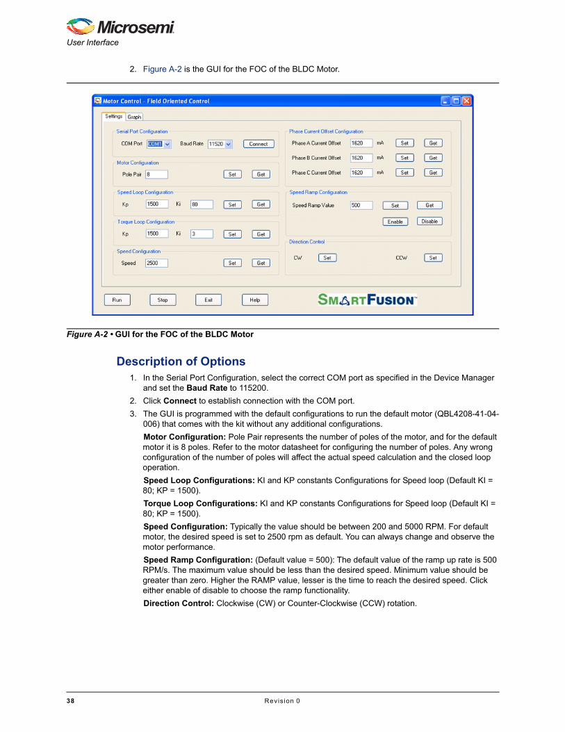
2. Figure A-2 is the GUI for the FOC of the BLDC Motor.
Description of Options1. In the Serial Port Configuration, select the correct COM port as specified in the Device Manager
and set the Baud Rate to 115200.
2. Click Connect to establish connection with the COM port.
3. The GUI is programmed with the default configurations to run the default motor (QBL4208-41-04-006) that comes with the kit without any additional configurations.
Motor Configuration: Pole Pair represents the number of poles of the motor, and for the default motor it is 8 poles. Refer to the motor datasheet for configuring the number of poles. Any wrong configuration of the number of poles will affect the actual speed calculation and the closed loop operation.
Speed Loop Configurations: KI and KP constants Configurations for Speed loop (Default KI = 80; KP = 1500).
Torque Loop Configurations: KI and KP constants Configurations for Speed loop (Default KI = 80; KP = 1500).
Speed Configuration: Typically the value should be between 200 and 5000 RPM. For default motor, the desired speed is set to 2500 rpm as default. You can always change and observe the motor performance.
Speed Ramp Configuration: (Default value = 500): The default value of the ramp up rate is 500 RPM/s. The maximum value should be less than the desired speed. Minimum value should be greater than zero. Higher the RAMP value, lesser is the time to reach the desired speed. Click either enable of disable to choose the ramp functionality.
Direction Control: Clockwise (CW) or Counter-Clockwise (CCW) rotation.
Figure A-2 • GUI for the FOC of the BLDC Motor
38 Revis ion 0

Field Oriented Control of Permanent Magnet Synchronous Motors User’s Guide
ConclusionThis User's Guide describes the features of the SmartFusion cSoC FPGAs to develop an effective FOC motor control demo by partitioning the algorithms and implementing it in MSS and Fabric effectively. Having the functional blocks in Fabric, the CPU is offloaded and the MSS can perform any other system level operations. This FOC design uses the in built fabric, ACE, and MSS along with other peripherals. These features enable the solution for better integrity, low power, more reliability and security.
Revis ion 0 39


B – Product Support
Microsemi SoC Products Group backs its products with various support services, including CustomerService, Customer Technical Support Center, a website, electronic mail, and worldwide sales offices.This appendix contains information about contacting Microsemi SoC Products Group and using thesesupport services.
Customer ServiceContact Customer Service for non-technical product support, such as product pricing, product upgrades,update information, order status, and authorization.
From North America, call 800.262.1060From the rest of the world, call 650.318.4460Fax, from anywhere in the world, 408.643.6913
Customer Technical Support CenterMicrosemi SoC Products Group staffs its Customer Technical Support Center with highly skilledengineers who can help answer your hardware, software, and design questions about Microsemi SoCProducts. The Customer Technical Support Center spends a great deal of time creating applicationnotes, answers to common design cycle questions, documentation of known issues, and various FAQs.So, before you contact us, please visit our online resources. It is very likely we have already answeredyour questions.
Technical SupportVisit the Customer Support website (www.microsemi.com/soc/support/search/default.aspx) for more information and support. Many answers available on the searchable web resource include diagrams, illustrations, and links to other resources on the website.
WebsiteYou can browse a variety of technical and non-technical information on the SoC home page, at www.microsemi.com/soc.
Contacting the Customer Technical Support CenterHighly skilled engineers staff the Technical Support Center. The Technical Support Center can becontacted by email or through the Microsemi SoC Products Group website.
EmailYou can communicate your technical questions to our email address and receive answers back by email,fax, or phone. Also, if you have design problems, you can email your design files to receive assistance.We constantly monitor the email account throughout the day. When sending your request to us, pleasebe sure to include your full name, company name, and your contact information for efficient processing ofyour request.
The technical support email address is [email protected].
Revis ion 0 41

Product Support
My CasesMicrosemi SoC Products Group customers may submit and track technical cases online by going to My Cases.
Outside the U.S.Customers needing assistance outside the US time zones can either contact technical support via email([email protected]) or contact a local sales office. Sales office listings can be found atwww.microsemi.com/soc/company/contact/default.aspx.
ITAR Technical SupportFor technical support on RH and RT FPGAs that are regulated by International Traffic in Arms Regulations (ITAR), contact us via [email protected]. Alternatively, within My Cases, select Yes in the ITAR drop-down list. For a complete list of ITAR-regulated Microsemi FPGAs, visit the ITAR web page.
42 Revis ion 0

Index
Ccontacting Microsemi SoC Products Group
customer service 17email 17web-based technical support 17
customer service 17
MMicrosemi SoC Products Group
email 17web-based technical support 17website 17
Pproduct support
customer service 17email 17My Cases 18outside the U.S. 18technical support 17website 17
Ttech support
ITAR 18My Cases 18outside the U.S. 18
technical support 17
Wweb-based technical support 17
Revis ion 0 43

s of
tortriallognd
at
MicroseOne EnWithin tSales: +Fax: +1
© 2012 Microsemi Corporation. All rights reserved. Microsemi and the Microsemi logo are trademark
Microsemi Corporation (NASDAQ: MSCC) offers a comprehensive portfolio of semiconducsolutions for: aerospace, defense and security; enterprise and communications; and indusand alternative energy markets. Products include high-performance, high-reliability anaand RF devices, mixed signal and RF integrated circuits, customizable SoCs, FPGAs, acomplete subsystems. Microsemi is headquartered in Aliso Viejo, Calif. Learn morewww.microsemi.com.
mi Corporate Headquartersterprise, Aliso Viejo CA 92656 USA
50200324.0/6.12
Microsemi Corporation. All other trademarks and service marks are the property of their respective owners.he USA: +1 (949) 380-61001 (949) 380-6136 (949) 215-4996
Related Documents