Bush Fire and Environmental Protection Branch Firebreak Location, Construction and Maintenance Guidelines

Welcome message from author
This document is posted to help you gain knowledge. Please leave a comment to let me know what you think about it! Share it to your friends and learn new things together.
Transcript
Bush Fire and Environmental Protection Branch
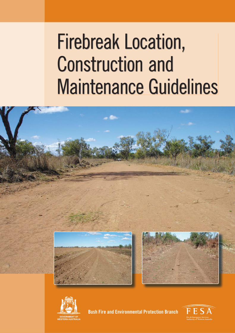
Firebreak Location, Construction and Maintenance Guidelines

Bush Fire and Environmental Protection Branch
© Fire and Emergency Services Authority of Western Australia
480 Hay Street, Perth, Western Australia, 6000
Author: Ralph Smith
ISBN: 978-0-9806116-6-3
Disclaimer
The information contained in this publication is provided by the Fire and Emergency Services Authority (FESA)
voluntarily as a public service. This document has been prepared in good faith and is derived from sources
believed to be reliable and accurate at the time of publication. Nevertheless, the reliability and accuracy of the
information cannot be guaranteed and FESA expressly disclaims liability for any act or omission done or not
done in reliance on the information and for any consequences, whether direct or indirect, arising from such act
or omission.
This publication is intended to be a guide only and readers should obtain their own independent advice and
make their own necessary inquiries.

FIREBREAK LOCATION, CONSTRUCTION AND MAINTENANCE GUIDELINES 1
Firebreak Location, Construction
and Maintenance Guidelines
Purpose ....................................................................................................................... 2
Introduction ...................................................................................................................... 2
Urban/rural interface
(includes towns, settlements and remote indigenous communities) ................................... 3
Forest fi rebreaks ............................................................................................................... 4
Pasture and non-forest lands fi rebreaks ........................................................................... 5
Placement of fi rebreaks .................................................................................................... 6
Slope ............................................................................................................... 6
Location ........................................................................................................... 6
1. Strategic external threat protection break .................................................... 6
2. Strategic internal threat protection .............................................................. 7
3. Strategic burn boundary ............................................................................... 7
4. Predetermined back-burning boundary ......................................................... 7
Mineral earth fi rebreak construction ................................................................................. 8
Soil structure ................................................................................................... 8
Soil types ......................................................................................................... 9
Causes of soil erosion ...................................................................................... 10
Preventing water erosion .................................................................................. 10
Method of creating mineral earth fi rebreaks ..................................................... 11
Water turn-outs ............................................................................................... 12
Water divergent banks on fi rebreaks ................................................................ 12
Road cross fall or camber ................................................................................ 14
Other forms of fi rebreaks .................................................................................................. 16
Rainfall ....................................................................................................................... 17
Peak discharge (maximum rate of run-off) ....................................................... 18
Environmental considerations ........................................................................................... 20
Phytophthora dieback ...................................................................................... 20
Granite outcrops .............................................................................................. 20
Declared rare fl ora and priority fl ora ................................................................. 21
Wetlands .......................................................................................................... 22
Environmentally sensitive communities ............................................................ 22
Weeds .............................................................................................................. 23
References ............................................................................................................. 25

FIREBREAK LOCATION, CONSTRUCTION AND MAINTENANCE GUIDELINES2
PurposeThe purpose of the Firebreak Location, Construction
and Maintenance Guidelines is to provide fi re and land
management practitioners with a tool to assist with the
location, construction and maintenance of fi rebreaks
on any natural environment (e.g. pastoral station, farm
or reserve). The Guidelines are designed to provide an
estimation of the situation with guidance to the soil types,
slope, estimations of water concentrations and volumes,
and the impact of these factors on soil erosion associated
with fi rebreak location, construction and maintenance.
Prior to undertaking any fi rebreak construction or
maintenance work it is essential that the potential social,
fi nancial and, very importantly, the environmental costs
and impacts are identifi ed and considered against the
potential fi re management benefi ts gained by clearing
vegetation from the land.
The Guidelines have been developed by working with
very experienced land and fi re managers within the
pastoral industry, local government and within the Fire
and Emergency Services Authority (FESA) and reference
publications on fi rebreaks, soil management and erosion.
FESA has designed these Guidelines as a reference
tool to assist pastoralists, land and fi re managers in
determining solutions for fi rebreak location, construction
and maintenance when a management issue, such as
erosion, is likely to eventuate. FESA is aware that many
pastoralists, farmers and land managers have very
extensive networks of fi rebreaks on land that suffer
no erosion and therefore do not require any additional
erosion mitigation works.
These Guidelines will assist in meeting the fi rebreak
requirements as prescribed in the Bush Fires Act 1954
and the local laws developed by local governments whilst
limiting the potential for environmental harm.
IntroductionFirebreaks used in the natural environment are developed for a range of purposes. Each purpose will
be determined by the bush fi re protection needs of the individual pastoralist owner/manager, farmer
or land manager. The bush fi re protection needs will be determined by the combination of the soil
type, slope, vegetation type and density, the risk of ignition, the fi re suppression response capability
and options, and the values such as infrastructure at risk.
Unless the land is actively eroding, run-off from undisturbed grazing or bush land is relatively free of
suspended solids. There are several management methods available to assist in reducing sediment
movement. The fi rst is to keep the area of land that is disturbed for fi rebreaks, tracks and roads to a
minimum and the second is to limit the amount of clean water run-off passing through disturbed areas.
Where erosion is not an issue, the practical application is achieving the desired result and additional
erosion control measures are not warranted.
Firebreaks serve a number of functions. Generally they are considered to be relatively narrow
man-made barriers of bare ground intended to stop bush fi res 1. Under high fuel load conditions
man-made mineral earth fi rebreaks can only be of assistance in slowing down a bush fi re rather
than stopping it, because spotting will occur and no direct fi re suppression attack is possible. Some
fi rebreaks are designed to prevent the fi re escaping, and others are designed to restrict entry of a fi re
from outside the property or area. In northern Western Australia and other locations there are very
large areas protected by strategically placed aerial burnt fi rebreaks of between 300 and 1000 metres.
1 Luke & McArthur, 1986, Bushfi re in Australia, Australian Government Publisher, Canberra.

FIREBREAK LOCATION, CONSTRUCTION AND MAINTENANCE GUIDELINES 3
Firebreaks can also provide a prepared, ready to operate back-burning boundary so that valuable
time is not lost establishing the boundary during fi re suppression activities.
Where mineral earth fi rebreaks are not required as a prevention tool, they can fi ll a very important
fi re suppression role by providing access routes for fi re vehicles and water supplies.
The vegetation type, density and period since last burnt are important determinants of the required
fi rebreak width. The soil type, slope and rainfall concentrations, peak volume and long duration
periods are also signifi cant determinants in determining the soils propensity to erode.
Firebreaks associated with grassland areas with an average 4–5 t/ha 2 are effective when they are
wider than where radiation and/or fl ame contact is expected to be less than four times the fl ame
length in the horizontal plane.
When the Fire Danger Index (FDI) on the Grassland Fire Danger Meter is less than 2.5 3, it is
recognised that the Fire Danger Rating (FDR) is low and the head fi re is expected to be stopped
by roads and tracks. An FDI of 7.5 recognises that the FDR is moderate and the head fi re is easily
attacked by water. When the FDI rises to 32, the FRD is high and the head fi re attack is generally
successful with water. When the FDI exceeds 32, the ability to successfully directly attack the head
of the bush fi re diminishes to a point to where, if the bush fi re is to be attacked, it should only occur
under favourable conditions. This is based on the assumption that the fuels are continuous and
reasonably consistent.
The impact of burning embers on bush fi re management and fi rebreak effectiveness must also be
considered when analysing whether fi rebreaks will be successful in stopping the fi re, providing
fi refi ghter access, or forming a secure boundary from which to undertake back-burning operations.
Low intensity fi res will generally have shorter spotting distances compared to very intense fi res.
Grasslands will generally have a shorter spotting distance than forest fuels.
In many areas, there are natural fi rebreaks of bare ground or areas that have been developed for
other purposes (e.g. roads, transmission line clearings or land under fallow) that provide the same
function. They create a discontinuous fuel area that will under many circumstances stop the bush
fi re or provide an area to undertake back-burning operations.
Urban/rural interface (includes towns, settlements
and remote indigenous communities)The urban/rural interface is one of the potentially most diffi cult areas to undertake bush fi re
suppression activities. The area is generally built up with homes within the vegetation. Another
factor is that many of these homes have been built to the low bush fi re threat as prescribed in
‘Australian Standard 3959—Construction of buildings in bushfi re-prone area’ when the construction
should have been for medium or high threat. Effectively, these homes will not have been built to the
suitable standard and, consequently, fi rebreaks, building protection zones, and hazard separation
zones are needed to ensure increased protection.
Firebreaks will be critical in ensuring that these homes are protected from fi res. Firebreaks also
assist in preventing bush fi res entering or leaving the property and this bush fi re movement through
the property may also pose a threat to the neighbouring property.
2 Luke & McArthur, 1986, Bushfi re in Australia, Australian Government Publisher, Canberra.3 CSIRO Forestry and Forest Products Bushfi re Behaviour and Management, 1997, ‘CSIRO Grassland Fire Danger Meter’.
FIREBREAK LOCATION, CONSTRUCTION AND MAINTENANCE GUIDELINES4
Forest fi rebreaksLike grassland area fi rebreaks the purpose of a forest fi rebreak is three-fold 4. These are to provide
protection to valuable forest assets either by preventing fi res entering, or to provide protection to
neighbours by preventing fi res from leaving the forest estate. Firebreaks also provide access into
the forest and water resources. Access into the forest can be very diffi cult and this diffi culty in
travelling can add valuable time between detection and suppression actions being commenced. This
increased time allows the fi re to develop more fully and become more diffi cult to suppress.
There appears to be a need for two different types of forest fi rebreaks. Plantations (pine and
bluegum) 5 are high value timber crops that can be adversely affected by bush fi re. It is therefore
considered important that boundary fi rebreaks be constructed quite wide (around 15 metres), and
the breaks have a minimum traffi cable width of 5 metres and also a vertical clearance of 5 metres
between the trees. The compartment breaks need to be based on the size of the compartment:
compartments up to 30 ha have a recommended width of fi rebreak of 6 metres; and for those of over
30 ha, a minimum width of 10 metres applies. The 5 metre traffi cable surface should be retained for
all fi rebreaks—these minor breaks require a minimum height clearance of four metres to facilitate
unrestricted access and maintain an effective width of fi rebreak.
There are also other plantations that are of high value either as a commercial crop or for environmental
health—these include mallet (tool handles), sandalwood, oil mallees and Casuarina spp (saline soil)
plantations. Each plantation has its own soil and rainfall requirements. The rainfall belts are:
• low rainfall zone which has less than 400 mm;
• mid-rainfall zone which has between 400–600 mm; and
• high rainfall zone which has greater than 600 mm.
These high value crops require some protection from a fi re entering into the area.
Forest fi res that have not developed may be readily suppressed on a low forest fi re danger index
(FFDI) by simply running into the fi rebreak. Even in a more intense forest fi re, the backing fi re and
tail end of the fl ank fi res may be suppressed with no additional suppression effort when they run
into a fi rebreak, particularly on a falling bush fi re hazard.
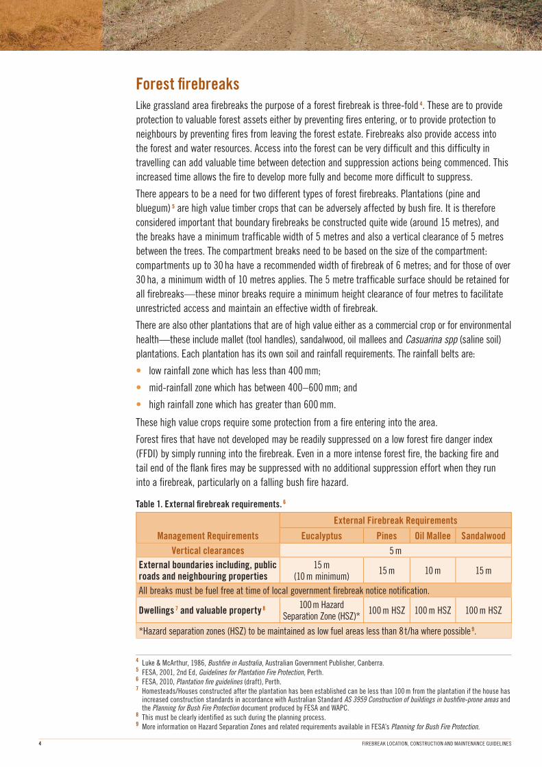
Table 1. External fi rebreak requirements. 6
Management Requirements
External Firebreak Requirements
Eucalyptus Pines Oil Mallee Sandalwood
Vertical clearances 5 m
External boundaries including, public roads and neighbouring properties
15 m (10 m minimum)
15 m 10 m 15 m
All breaks must be fuel free at time of local government fi rebreak notice notifi cation.
Dwellings 7 and valuable property 8100 m Hazard
Separation Zone (HSZ)* 100 m HSZ 100 m HSZ 100 m HSZ
*Hazard separation zones (HSZ) to be maintained as low fuel areas less than 8 t/ha where possible 9.
4 Luke & McArthur, 1986, Bushfi re in Australia, Australian Government Publisher, Canberra.5 FESA, 2001, 2nd Ed, Guidelines for Plantation Fire Protection, Perth.6 FESA, 2010, Plantation fi re guidelines (draft), Perth.7 Homesteads/Houses constructed after the plantation has been established can be less than 100 m from the plantation if the house has
increased construction standards in accordance with Australian Standard AS 3959 Construction of buildings in bushfi re-prone areas and the Planning for Bush Fire Protection document produced by FESA and WAPC.
8 This must be clearly identifi ed as such during the planning process.9 More information on Hazard Separation Zones and related requirements available in FESA’s Planning for Bush Fire Protection.
FIREBREAK LOCATION, CONSTRUCTION AND MAINTENANCE GUIDELINES 5
Pasture and non-forest lands fi rebreaksFirebreaks in grassland, pasture and non-forest land have a dual purpose. 10
1. To provide protection to valuable pasture assets either by preventing fi res entering or to provide
protection to neighbours by preventing fi res from leaving the individual pastoral station, farming
estate or other lands.
2. Firebreaks also provide access into the station, farm and other lands and also to water
resources. Access into the land can be very diffi cult and this diffi culty in travelling can add
valuable time between detection and suppression actions being commenced. This increased time
allows the fi re to develop more fully and become more diffi cult to suppress.
There appears to be a need for two different types of fi rebreaks for the vegetation types of pasture
and non-forest. Land managers can have high value pasture crops and other vegetation that can be
adversely affected by bush fi re, both for the current season and the next. It is therefore considered
important that boundary fi rebreaks be constructed quite wide—possibly 10 metres for pastoral
stations. The internal pastoral station paddock breaks need to recognise the importance of the
area being protected, and it is recommended a narrower width of break of 6 to 10 metres is used
(although this may be reduced to 3 metres where appropriate).
Firebreaks associated with grassland areas with an average 4–5 t/ha 11 are effective when they are
wider than where radiation and/or fl ame contact can be expected to be less than four times the
fl ame length in the horizontal plane. For example, if the fl ame length is expected to be one metre
then the fi rebreak needs to be four metres wide.
When the FDI on the Grassland Fire Danger Meter is less than 2.5, it is recognised that the FDR is
low and the head fi re is expected to be stopped by roads and tracks of around three metres in width.
As the FDI increases, the functionality of the minimum width fi rebreak starts to diminish because of
the increased fl ame length and the embers created, which are carried forward ahead of the fi re. In
these instances, the fi rebreak assumes two roles: fi rstly, as a fi re suppression tool primarily for the
fl ank and tail fi re; and secondly, as an access track. If the fi rebreak is used as an access track it
provides increased ease of access to water and other areas of value. It also provides an opportunity for
the fi re manager to conduct back-burning operations to contain the fi re during suppression operations.
The impact of burning embers on bush fi re management and the effectiveness of fi rebreaks must
also be considered when analysing whether fi rebreaks will be successful in stopping the fi re,
providing fi refi ghter access, or forming a secure boundary from which to undertake back-burning
operations. Low intensity fi res will generally have shorter spotting distances than very intense fi res.
Grasslands will generally have a shorter spotting distance than forest fuels.
In many areas, there are natural fi rebreaks of bare ground or areas that have been developed for
other purposes (e.g. roads, transmission line clearings or land under fallow) that provide the same
function. They create a discontinuous fuel area that will, under many circumstances, stop the bush
fi re or provide an area to undertake back-burning operations.
Bush fi res that have not developed a signifi cant head fi re may be readily suppressed on a low
grassland FDI by it simply running into the fi rebreak. Even in a more intense bush fi re, the backing
fi re and tail end of the fl ank fi res may be suppressed with little or no additional suppression effort
when they run into a suitable width fi rebreak.
10, 11 Luke & McArthur, 1986, Bushfi re in Australia, Australian Government Publisher, Canberra.
FIREBREAK LOCATION, CONSTRUCTION AND MAINTENANCE GUIDELINES6
Placement of fi rebreaks
Slope
Firebreaks need to be placed so that they fi ll all or most of the desired outcomes. As in all situations,
there will be some compromise between an ideal fi rebreak location, soil conservation, fencing
requirements, practicability and cost. The fi rebreak should therefore be located so that it will either
stop the low intensity fi re, provide a back-burning buffer from which to undertake the burning, or
provide access to key infrastructure or other areas of value.
Bush fi res travel faster upslope than downslope. It is therefore more desirable to place the fi rebreaks
lower in the profi le and, where possible, to place the fi rebreak so that it runs parallel to the contour.
Where the fi rebreak cuts across the contour, the chance of erosion is increased and measures must
be undertaken to mitigate the erosion risk.
Location
Firebreaks should be located to achieve four objectives:
1. Provide a mineral earth break or reduced fuel zone so that unplanned fi res do not enter
the property—i.e. a strategic external threat protection break.
2. Provide a mineral earth fi rebreak or reduced fuel zone so that unplanned fi res do not
leave the land holding—i.e. a strategic internal threat protection.
3. So that prescribed burns do not escape the prescribed burn area—i.e. a strategic burn
boundary.
4. Provide access to the critical areas of the land so that fi re suppression activities can be
undertaken—i.e. a predetermined back-burning boundary.
Each type of fi rebreak has important components that must be met.
1. Provide a mineral earth break so that unplanned fi res do not enter the property
(i.e. a strategic external threat protection break)
These fi rebreaks must be located close to the boundary of the property and of suffi cient width to
minimise radiant heat or the chance of direct fl ame contact with vegetation causing the fi re to
‘hop over’ the break.
In the pastoral region, particularly in the Kimberley, it is estimated that these fi rebreaks need
to be a minimum of 12 metres wide (three grader blade width breaks), but will frequently be 16
metres wide (four grader blade width breaks). It may also be appropriate to have both sides of
the boundary fence graded depending on the ownership or management of the neighbouring land.
In the pastoral regions, these breaks may be enhanced by conducting burning operations
immediately adjacent to the graded break so that embers from the fi re do not ‘hop over’ the
break. An alternative system may be to have a series of graded fi rebreaks 300 metres apart
and to burn out one parallel area each subsequent year. A fi re would therefore run into a graded
fi rebreak and a burnt buffer within 300 metres of the boundary.
On farms and other land not in the pastoral region, it may be possible to have effective fi re
management strategies that only require a fi rebreak width to be three metres.

FIREBREAK LOCATION, CONSTRUCTION AND MAINTENANCE GUIDELINES 7
2. Provide a mineral earth fi rebreak so that unplanned fi res do not leave the property
(i.e. a strategic internal threat protection)
As described in the previous section, fi rebreaks used for this purpose must be located close to
the property boundary, be of appropriate width to minimise radiant heat and the chance of direct
fl ame contact with vegetation causing the fi re to ‘hop over’ the break.
Refer to the Objective No. 1 for specifi c requirements.
3. So that prescribed burns do not escape the prescribed burn area
(i.e. a strategic burn boundary)
To ensure fi res do not escape a prescribed burn area, fi rebreaks must be located close to the
boundary of the burn and of suffi cient width to minimise radiant heat or the possibility of direct
fl ame contact with vegetation on the area not planned to be burned.
These breaks need to be a minimum of one metre wide—however, for burn security it is
recommended that the breaks be three metres wide, particularly when the grasses are greater
than 60–80 per cent cured.
Firebreaks can be very effective in bush and grassy fuels but their effectiveness diminishes
when the fi re is spotting.
4. Provide access to the critical areas of the land so that fi re suppression
activities can be undertaken (i.e. a predetermined back-burning boundary)
The provision of access is critical both for effective land management and bush fi re
management. If fi rebreaks are to be used primarily as an access track, they need to be formed
and maintained so that a constant vehicle speed can be maintained and they do not become
water-holding gullies for erosion to occur.
For these factors to be met, the fi rebreak needs to have erosion control measures implemented
and maintained. One method of achieving this is to fl at grade the fi rebreaks with windrows on
the edge of the fi rebreak in the beginning of the summer or the dry season, and then return
immediately before the onset of rain and return the windrow back across the fi rebreak. 12
This method may save some initial time and money but the risk of erosion from unseasonal or
early heavy rainfall is very high.
Whilst this soil return process is an option, the preferred option is the establishment and
maintenance of appropriate water turn-outs and fi rebreak banks that are created and maintained
during the initial fi rebreak maintenance work. The establishment and maintenance of appropriate
water turn-outs and fi rebreak banks is recommended because, with these in place, unseasonal
rainfall in the midst of the dry season will not cause the fi rebreak to erode or degrade. The
erosion control measures are built into the fi rebreak and will work regardless of the ability of the
land manager to implement additional erosion control measures that depend on time and access.
12 McGuffog, undated, The ‘how-to’ of fi rebreaks and aerial burns, Bushfi re Council NT

FIREBREAK LOCATION, CONSTRUCTION AND MAINTENANCE GUIDELINES8
Mineral earth fi rebreak constructionMineral earth fi rebreaks need to be constructed and maintained so that they will assist in stopping a
bush fi re, either directly during the low FDI or as a tool used for fi re management (e.g. as an access
track or back-burning boundary), and they should not erode. In a range of slopes and soil types
erosion may not be an issue and no additional erosion prevention works need to be undertaken. In
other locations, however, minimal soil disturbance may cause signifi cant erosion.
In some areas, such as the Pilbara, the soil may be held together with quick growing plants that
thrive after disturbance—such as buffel grass. If this is the case, then there may not be any need
for additional soil and water erosion control. If the introduction of the plants (whether by natural
means or by the land manager) does not hold the soil together, then it is proposed that the following
be considered and applied where appropriate.
Soil structure
The soil’s structure is very important in determining the type and location of the fi rebreak. 13
An inappropriate fi rebreak can result in increased water erosion and wind erosion and the loss of
the productive topsoil, termed the ‘A horizon’ (which is the top 10 to 15 cm of soil). The physical,
chemical and biological changes in the soil resulting from changes in agricultural practices also
alter the soil as a habitat for micro-organisms.
The size and stability of the soil structure directly affects the susceptibility of soils to erosion. The
determining components are the texture, structure, stability, organic matter content, soil micro-
organisms, salts and colloids. For most soils, their susceptibility to wind erosion is increased by the
reduction of soil clod or aggregate size, organic matter content and water content (e.g. affected
by ploughing, cultivating and grazing). The texture of the soil is the major factor in susceptibility
to wind erosion. This also affects the soil’s ability to hold moisture. More coarse textured soils are
generally more susceptible to erosion than fi ne textured soils. Coarse soils also hold less water and
drain more rapidly than fi ner soils, which make them more susceptible to wind erosion.
Only root material will hold soil, and this root growth and development only occurs where soils can
sustain growth. Non-wetting soils are usually coarser and the grains of sand appear to form a skin
that sheds water. These areas are generally leached of nutrients and consequently grow few plants.
A deteriorating soil structure will result in an increase in the potential for soil erosion. Many soils in
the world are renewed naturally. The Western Australian soils have probably formed more than 50
million years ago, and little deposition now occurs. 14
Wind erosion occurs when vegetation ground cover is insuffi cient to protect the soils and it is
exposed to wind. Soil particles start moving when wind speeds exceed 8 km/hr and it is the very
important fi ne particles that become airborne.
Water erosion occurs when the soil is unable to cope with rainfall that falls faster than the ground
can soak up the water. This inability to cope may occur because the soil is at storage capacity,
surface infi ltration is impeded or the hard setting nature of duplex soils restrict infi ltration. All of
these result in increased overland fl ow. The various types of water erosion all manifest themselves
by transferring soil from one location and depositing it elsewhere. The site that suffers the soil loss
may expose the less durable soils to further erosion problems.
13, 14 G A Robertson, 1987, Soil Management for Sustainable Agriculture, Resource Management Technical Report No. 95, WA Department of Agriculture.
FIREBREAK LOCATION, CONSTRUCTION AND MAINTENANCE GUIDELINES 9
15 Source: http://www.dpi.vic.gov.au/dpi.16 Anderson, Beiswenger, Purdom, 1987, Environmental Science, third edition, Merrill Publishing Company, Columbus, Ohio.
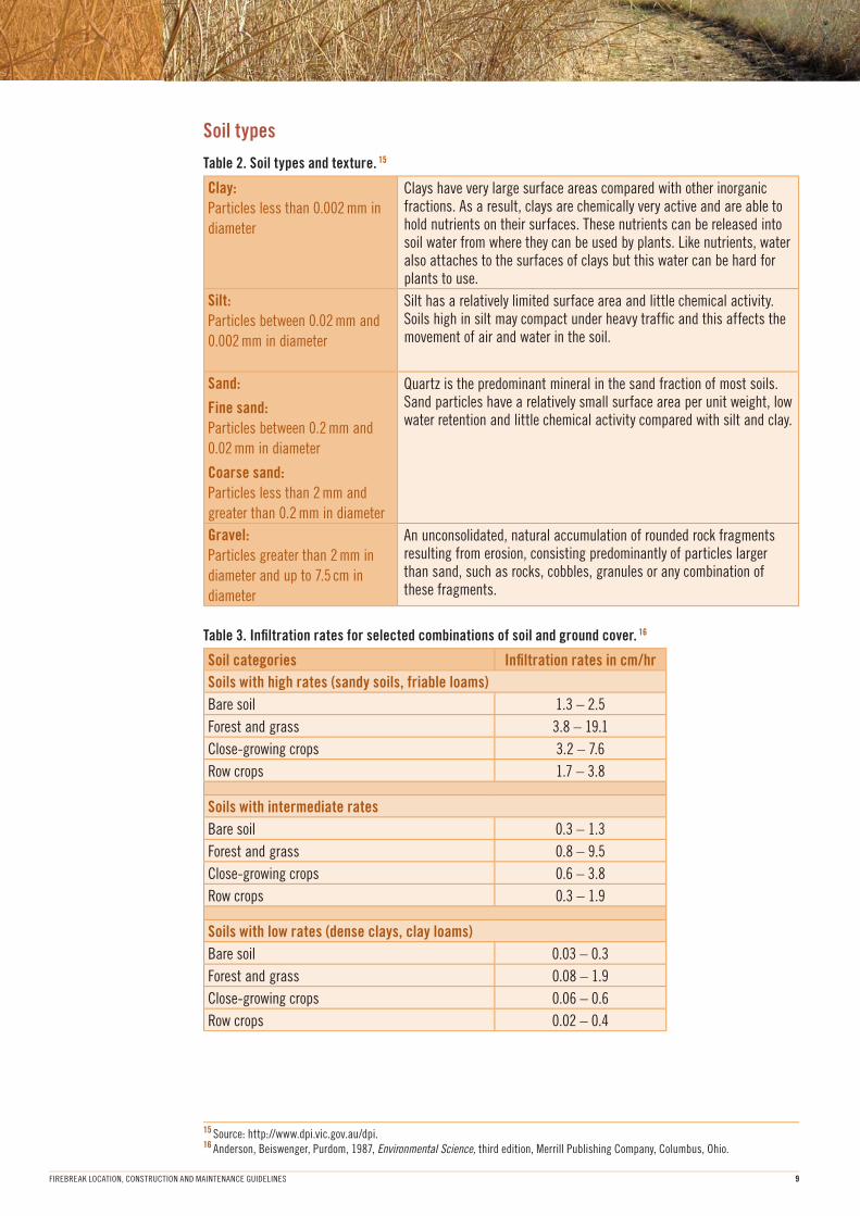
Soil types
Table 2. Soil types and texture. 15
Clay:
Particles less than 0.002 mm in
diameter
Clays have very large surface areas compared with other inorganic fractions. As a result, clays are chemically very active and are able to hold nutrients on their surfaces. These nutrients can be released into soil water from where they can be used by plants. Like nutrients, water also attaches to the surfaces of clays but this water can be hard for plants to use.
Silt:
Particles between 0.02 mm and
0.002 mm in diameter
Silt has a relatively limited surface area and little chemical activity. Soils high in silt may compact under heavy traffi c and this affects the movement of air and water in the soil.
Sand:
Fine sand:
Particles between 0.2 mm and
0.02 mm in diameter
Coarse sand:
Particles less than 2 mm and
greater than 0.2 mm in diameter
Quartz is the predominant mineral in the sand fraction of most soils. Sand particles have a relatively small surface area per unit weight, low water retention and little chemical activity compared with silt and clay.
Gravel:
Particles greater than 2 mm in
diameter and up to 7.5 cm in
diameter
An unconsolidated, natural accumulation of rounded rock fragments resulting from erosion, consisting predominantly of particles larger than sand, such as rocks, cobbles, granules or any combination of these fragments.
Table 3. Infi ltration rates for selected combinations of soil and ground cover. 16
Soil categories Infi ltration rates in cm/hr
Soils with high rates (sandy soils, friable loams)
Bare soil 1.3 – 2.5
Forest and grass 3.8 – 19.1
Close-growing crops 3.2 – 7.6
Row crops 1.7 – 3.8
Soils with intermediate rates
Bare soil 0.3 – 1.3
Forest and grass 0.8 – 9.5
Close-growing crops 0.6 – 3.8
Row crops 0.3 – 1.9
Soils with low rates (dense clays, clay loams)
Bare soil 0.03 – 0.3
Forest and grass 0.08 – 1.9
Close-growing crops 0.06 – 0.6
Row crops 0.02 – 0.4

FIREBREAK LOCATION, CONSTRUCTION AND MAINTENANCE GUIDELINES10
Causes of soil erosion
Soil erosion—happens when the energy of moving water or air is enough to overcome the cohesive
forces that bind soil particles together. Particles detach from the surface and are carried in the
moving fl uid (i.e. particles are suspended in the moving fl uid).
Sedimentation—results when fl uid fl ow decreases to the point where its kinetic energy is no longer
suffi cient to maintain the particles in suspension (i.e. where the movement of the fl uid stops enough
to keep the particles suspended).
Wind erosion—is mostly initiated by coarser particles moving in saltation (bouncing) across the
surface as carried by wind. With each bounce, fi ner material comes off the surface and is carried
along in the air.
Water erosion—can happen in two ways. These are:
• Rain drop splash. A raindrop striking an unprotected soil surface will form a small crater with
particles thrown in a roughly circular pattern around the hole. A vertically falling raindrop hitting
a sloping surface will throw more material to the downhill side—thereby a large amount of
surface soil may move down a slope during rainfall. The energy from the raindrop impact also
pulverises and compacts the soil which causes the surface to seal and reduces infi ltration.
Consequently this will increase the amount of rainfall that fl ows over the surface, contributing to
a second form of erosion.
• Gully and sheet erosion are functions of the velocity of surface water fl ow and the cohesiveness
or detachability of the soil particles.
– Flow velocity is determined by the depth of fl ow, the angle and length of the slope and the
retardance or surface roughness of the soil.
– The cohesiveness of soil particles is affected by soil type (grain size and degree of aggregation)
and by the binding effect which organic matter and plant roots have upon the soil).
Preventing water erosion
Methods of preventing water erosion include:
• Control over velocity and depth of fl ow can be exerted by constructing contour furrows or
contour banks at intervals down the slope:
– Catchment area commencing at each bank or furrow.
– This stops the run-off from reaching a depth of fl ow or velocity that would cause erosion.
– As the slope angle increases, the furrows must be spaced closer together until a point is
reached where they’re not longer effective.
• Contour cultivation is only useful to slopes below about fi ve degrees (5°). On steeper slopes, the
water-holding capacity of the individual plough furrows becomes limited.
• For slopes up to 10 degrees (10°) contour, deep-ripping or contour furrowing in conjunction with
contour cultivation can provide a reasonable degree of erosion protection for a limited time.
– Contour ripping: Ripping to a depth of 60–90 cm with conventional single or multi-type
ripper (by bulldozer). For best results use two tynes spaced one metre apart with individual
rip lines spaced two to six metres apart, depending on the slope angle.
– Contour furrowing: Single tyne fi tted with a ‘mould board’ attachment that lifts the soil from
the furrow and forms a small bank on the downhill side which increases water-holding capacity.
– Both rips and furrows should be constructed precisely on the contour.
FIREBREAK LOCATION, CONSTRUCTION AND MAINTENANCE GUIDELINES 11
– Contour banks: These are bigger versions of contour furrows with a proportionately greater
capacity to store runoff and/or drain it to some chosen discharge point. There are three types
of banks, although two or more can be used in one continuous line.
■ True contour or level banks—these are constructed exactly on the contour and can be
discharged at either or both ends.
■ Absorption banks—constructed along the contour but have both ends turned uphill to a
predetermined height so they pond a desired depth of water along their length.
■ Graded banks—constructed away from the true contour at a designed gradient so that
they drain water from one part of a slope to another (e.g. to a watercourse or dam).
As slope angle increases, the erosion control of these larger banks is reduced until—at about
12–14 degrees of slope—the need to be so close together may limit any benefi t. On a steep
slope, there is also a risk of gully erosion. 17
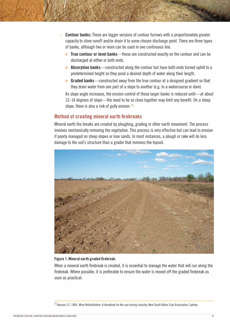
Method of creating mineral earth fi rebreaks
Mineral earth fi re breaks are created by ploughing, grading or other earth movement. The process
involves mechanically removing the vegetation. This process is very effective but can lead to erosion
if poorly managed on steep slopes or lose sands. In most instances, a plough or rake will do less
damage to the soil’s structure than a grader that removes the topsoil.
Figure 1. Mineral earth graded fi rebreak.
When a mineral earth fi rebreak is created, it is essential to manage the water that will run along the
fi rebreak. Where possible, it is preferable to ensure the water is moved off the graded fi rebreak as
soon as practical.
17 Hannan J C, 1984, Mine Rehabilitation A Handbook for the coal mining industry, New South Wales Coal Association, Sydney.
FIREBREAK LOCATION, CONSTRUCTION AND MAINTENANCE GUIDELINES12
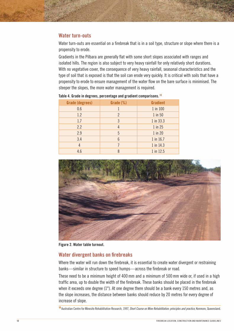
Water turn-outs
Water turn-outs are essential on a fi rebreak that is in a soil type, structure or slope where there is a
propensity to erode.
Gradients in the Pilbara are generally fl at with some short slopes associated with ranges and
isolated hills. The region is also subject to very heavy rainfall for only relatively short durations.
With no vegetative cover, the consequence of very heavy rainfall, seasonal characteristics and the
type of soil that is exposed is that the soil can erode very quickly. It is critical with soils that have a
propensity to erode to ensure management of the water fl ow on the bare surface is minimised. The
steeper the slopes, the more water management is required.
Table 4. Grade in degrees, percentage and gradient comparisons. 18
Grade (degrees) Grade (%) Gradient
0.6 1 1 in 100
1.2 2 1 in 50
1.7 3 1 in 33.3
2.2 4 1 in 25
2.9 5 1 in 20
3.4 6 1 in 16.7
4 7 1 in 14.3
4.6 8 1 in 12.5
Figure 2. Water table turnout.
Water divergent banks on fi rebreaks
Where the water will run down the fi rebreak, it is essential to create water divergent or restraining
banks—similar in structure to speed humps—across the fi rebreak or road.
These need to be a minimum height of 400 mm and a minimum of 500 mm wide or, if used in a high
traffi c area, up to double the width of the fi rebreak. These banks should be placed in the fi rebreak
when it exceeds one degree (1°). At one degree there should be a bank every 150 metres and, as
the slope increases, the distance between banks should reduce by 20 metres for every degree of
increase of slope.
18 Australian Centre for Minesite Rehabilitation Research, 1997, Short Course on Mine Rehabilitation: principles and practice, Kenmore, Queensland.
FIREBREAK LOCATION, CONSTRUCTION AND MAINTENANCE GUIDELINES 13
19 McGuffog, undated, The ‘how-to’ of fi rebreaks and aerial burns, Bushfi res Council, Northern Territory.20 PNG, 1995, Papua New Guinea Logging Code of Practice, Department of Environment and Conservation, Boroko, Papua New Guinea.21 Australian Centre for Minesite Rehabilitation Research, 1997, Short Course on Mine Rehabilitation: principles and practice, Kenmore, Queensland.
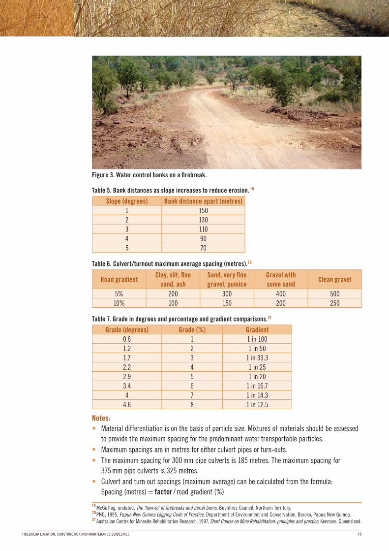
Figure 3. Water control banks on a fi rebreak.
Table 5. Bank distances as slope increases to reduce erosion. 19
Slope (degrees) Bank distance apart (metres)
1 150
2 130
3 110
4 90
5 70
Table 6. Culvert/turnout maximum average spacing (metres).20
Road gradientClay, silt, fi ne
sand, ash
Sand, very fi ne
gravel, pumice
Gravel with
some sandClean gravel
5% 200 300 400 500
10% 100 150 200 250
Table 7. Grade in degrees and percentage and gradient comparisons.21
Grade (degrees) Grade (%) Gradient
0.6 1 1 in 100
1.2 2 1 in 50
1.7 3 1 in 33.3
2.2 4 1 in 25
2.9 5 1 in 20
3.4 6 1 in 16.7
4 7 1 in 14.3
4.6 8 1 in 12.5
Notes:
• Material differentiation is on the basis of particle size. Mixtures of materials should be assessed
to provide the maximum spacing for the predominant water transportable particles.
• Maximum spacings are in metres for either culvert pipes or turn-outs.
• The maximum spacing for 300 mm pipe culverts is 185 metres. The maximum spacing for
375 mm pipe culverts is 325 metres.
• Culvert and turn out spacings (maximum average) can be calculated from the formula:
Spacing (metres) = factor / road gradient (%)
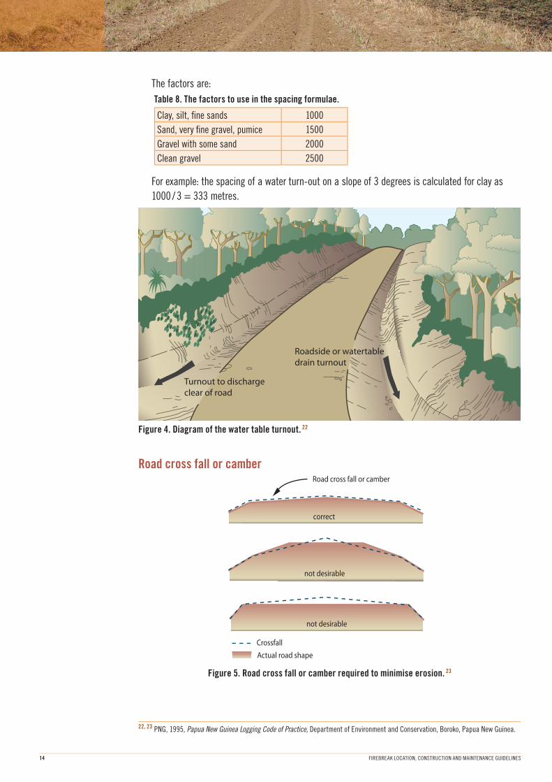
Turnout to discharge
clear of road
Roadside or watertable
drain turnout
Road cross fall or camber
correct
not desirable
not desirable
Crossfall
Actual road shape
FIREBREAK LOCATION, CONSTRUCTION AND MAINTENANCE GUIDELINES14
22, 23 PNG, 1995, Papua New Guinea Logging Code of Practice, Department of Environment and Conservation, Boroko, Papua New Guinea.
The factors are:
Table 8. The factors to use in the spacing formulae.
Clay, silt, fi ne sands 1000
Sand, very fi ne gravel, pumice 1500
Gravel with some sand 2000
Clean gravel 2500
For example: the spacing of a water turn-out on a slope of 3 degrees is calculated for clay as
1000 / 3 = 333 metres.
Figure 4. Diagram of the water table turnout. 22
Road cross fall or camber
Figure 5. Road cross fall or camber required to minimise erosion. 23
FIREBREAK LOCATION, CONSTRUCTION AND MAINTENANCE GUIDELINES 15
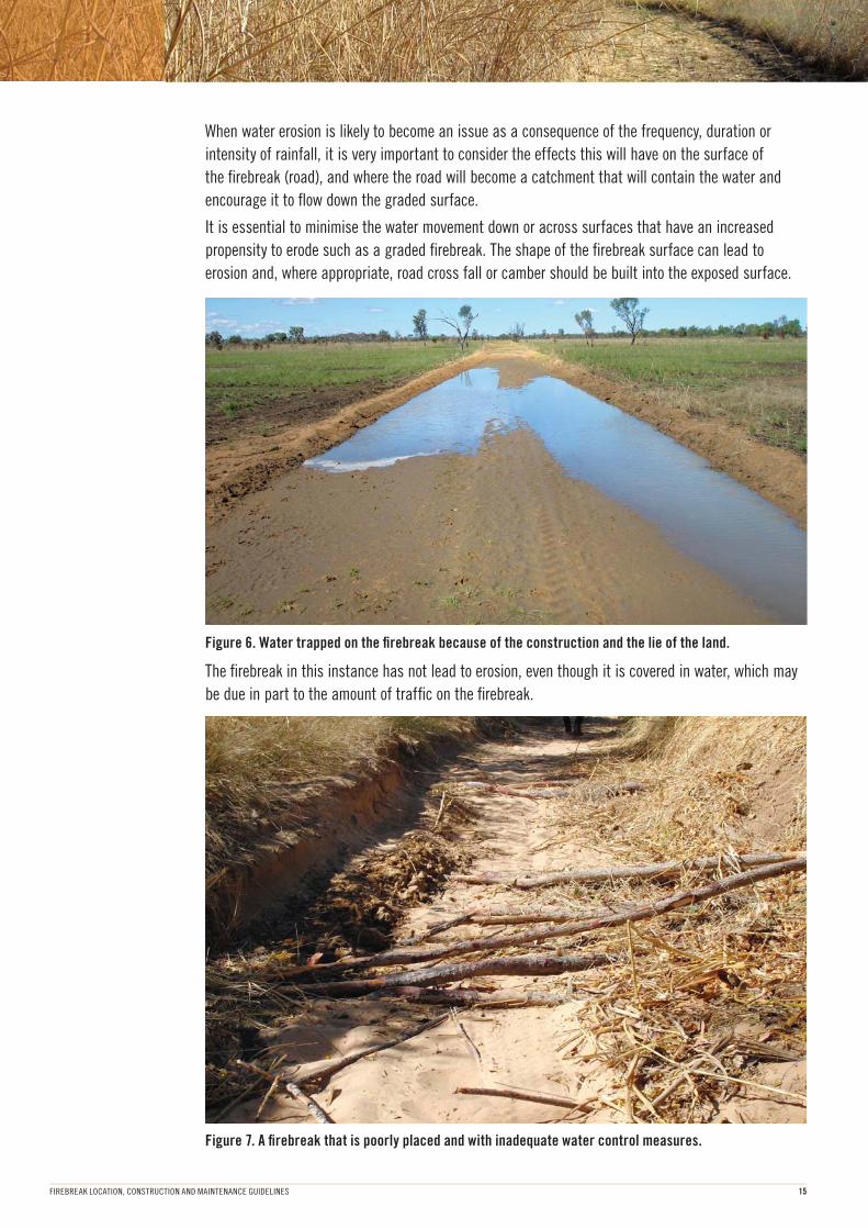
When water erosion is likely to become an issue as a consequence of the frequency, duration or
intensity of rainfall, it is very important to consider the effects this will have on the surface of
the fi rebreak (road), and where the road will become a catchment that will contain the water and
encourage it to fl ow down the graded surface.
It is essential to minimise the water movement down or across surfaces that have an increased
propensity to erode such as a graded fi rebreak. The shape of the fi rebreak surface can lead to
erosion and, where appropriate, road cross fall or camber should be built into the exposed surface.
Figure 6. Water trapped on the fi rebreak because of the construction and the lie of the land.
The fi rebreak in this instance has not lead to erosion, even though it is covered in water, which may
be due in part to the amount of traffi c on the fi rebreak.
Figure 7. A fi rebreak that is poorly placed and with inadequate water control measures.
FIREBREAK LOCATION, CONSTRUCTION AND MAINTENANCE GUIDELINES16
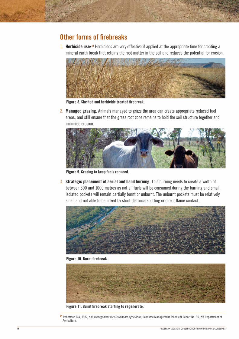
Other forms of fi rebreaks1. Herbicide use: 24 Herbicides are very effective if applied at the appropriate time for creating a
mineral earth break that retains the root matter in the soil and reduces the potential for erosion.
Figure 8. Slashed and herbicide treated fi rebreak.
24 Robertson G A, 1987, Soil Management for Sustainable Agriculture, Resource Management Technical Report No. 95, WA Department of Agriculture.
2. Managed grazing. Animals managed to graze the area can create appropriate reduced fuel
areas, and still ensure that the grass root zone remains to hold the soil structure together and
minimise erosion.
Figure 9. Grazing to keep fuels reduced.
3. Strategic placement of aerial and hand burning. This burning needs to create a width of
between 300 and 1000 metres as not all fuels will be consumed during the burning and small,
isolated pockets will remain partially burnt or unburnt. The unburnt pockets must be relatively
small and not able to be linked by short distance spotting or direct fl ame contact.
Figure 10. Burnt fi rebreak.
Figure 11. Burnt fi rebreak starting to regenerate.
primaryfirebreak main pasture area
300m burnt buffer
graded firebreaks
300m burnt buffer
FIREBREAK LOCATION, CONSTRUCTION AND MAINTENANCE GUIDELINES 17
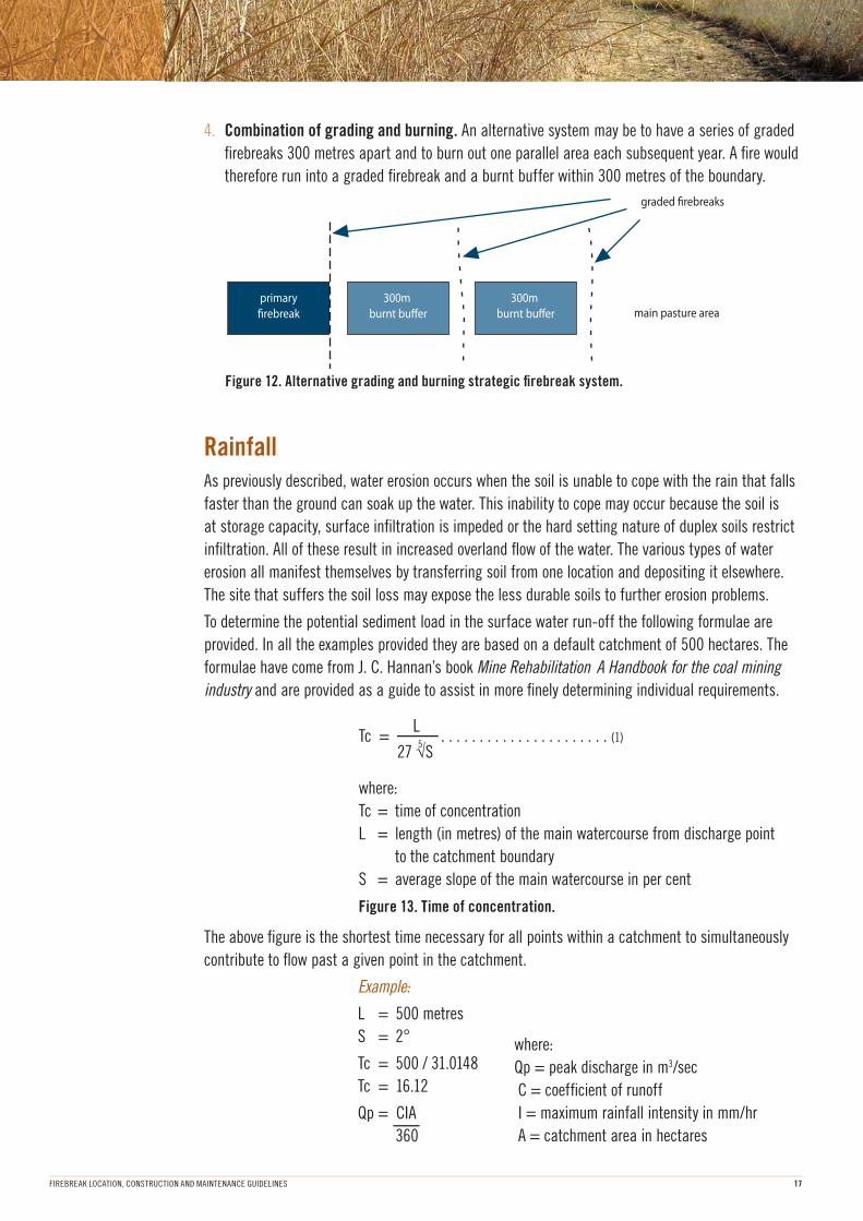
4. Combination of grading and burning. An alternative system may be to have a series of graded
fi rebreaks 300 metres apart and to burn out one parallel area each subsequent year. A fi re would
therefore run into a graded fi rebreak and a burnt buffer within 300 metres of the boundary.
Figure 12. Alternative grading and burning strategic fi rebreak system.
RainfallAs previously described, water erosion occurs when the soil is unable to cope with the rain that falls
faster than the ground can soak up the water. This inability to cope may occur because the soil is
at storage capacity, surface infi ltration is impeded or the hard setting nature of duplex soils restrict
infi ltration. All of these result in increased overland fl ow of the water. The various types of water
erosion all manifest themselves by transferring soil from one location and depositing it elsewhere.
The site that suffers the soil loss may expose the less durable soils to further erosion problems.
To determine the potential sediment load in the surface water run-off the following formulae are
provided. In all the examples provided they are based on a default catchment of 500 hectares. The
formulae have come from J. C. Hannan’s book Mine Rehabilitation A Handbook for the coal mining
industry and are provided as a guide to assist in more fi nely determining individual requirements.
L5
Tc = 27 √S
. . . . . . . . . . . . . . . . . . . . . . (1)
where:
Tc = time of concentration
L = length (in metres) of the main watercourse from discharge point
to the catchment boundary
S = average slope of the main watercourse in per cent
Figure 13. Time of concentration.
The above fi gure is the shortest time necessary for all points within a catchment to simultaneously
contribute to fl ow past a given point in the catchment.
Example:
L = 500 metres
S = 2°
Tc = 500 / 31.0148
Tc = 16.12
Qp = CIA
360
where:
Qp = peak discharge in m3/sec
C = coeffi cient of runoff
I = maximum rainfall intensity in mm/hr
A = catchment area in hectares
FIREBREAK LOCATION, CONSTRUCTION AND MAINTENANCE GUIDELINES18
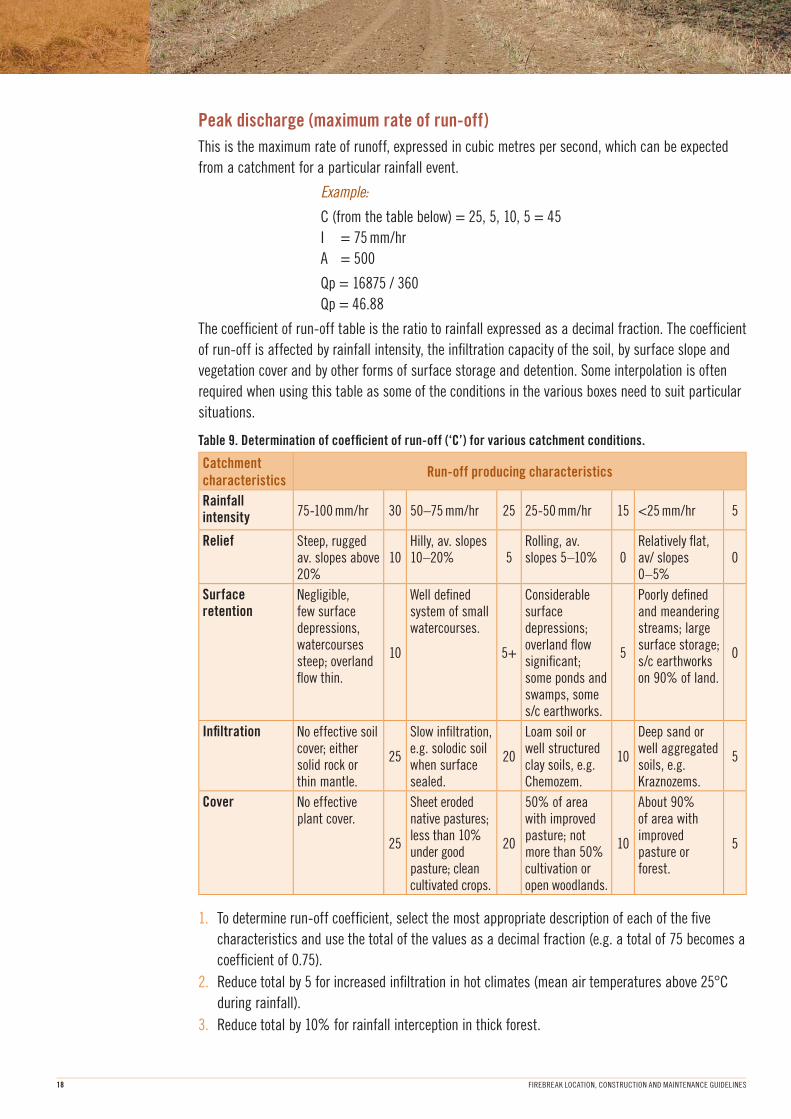
Peak discharge (maximum rate of run-off)
This is the maximum rate of runoff, expressed in cubic metres per second, which can be expected
from a catchment for a particular rainfall event.
Example:
C (from the table below) = 25, 5, 10, 5 = 45
I = 75 mm/hr
A = 500
Qp = 16875 / 360
Qp = 46.88
The coeffi cient of run-off table is the ratio to rainfall expressed as a decimal fraction. The coeffi cient
of run-off is affected by rainfall intensity, the infi ltration capacity of the soil, by surface slope and
vegetation cover and by other forms of surface storage and detention. Some interpolation is often
required when using this table as some of the conditions in the various boxes need to suit particular
situations.
Table 9. Determination of coeffi cient of run-off (‘C’) for various catchment conditions.
Catchment characteristics
Run-off producing characteristics
Rainfall intensity 75-100 mm/hr 30 50–75 mm/hr 25 25-50 mm/hr 15 <25 mm/hr 5
Relief Steep, rugged av. slopes above 20%
10Hilly, av. slopes 10–20% 5
Rolling, av. slopes 5–10% 0
Relatively fl at, av/ slopes 0–5%
0
Surface retention
Negligible, few surface depressions, watercourses steep; overland fl ow thin.
10
Well defi ned system of small watercourses.
5+
Considerable surface depressions; overland fl ow signifi cant; some ponds and swamps, some s/c earthworks.
5
Poorly defi ned and meandering streams; large surface storage; s/c earthworks on 90% of land.
0
Infi ltration No effective soil cover; either solid rock or thin mantle.
25
Slow infi ltration, e.g. solodic soil when surface sealed.
20
Loam soil or well structured clay soils, e.g. Chemozem.
10
Deep sand or well aggregated soils, e.g. Kraznozems.
5
Cover No effective plant cover.
25
Sheet eroded native pastures; less than 10% under good pasture; clean cultivated crops.
20
50% of area with improved pasture; not more than 50% cultivation or open woodlands.
10
About 90% of area with improved pasture or forest.
5
1. To determine run-off coeffi cient, select the most appropriate description of each of the fi ve
characteristics and use the total of the values as a decimal fraction (e.g. a total of 75 becomes a
coeffi cient of 0.75).
2. Reduce total by 5 for increased infi ltration in hot climates (mean air temperatures above 25°C
during rainfall).
3. Reduce total by 10% for rainfall interception in thick forest.

FIREBREAK LOCATION, CONSTRUCTION AND MAINTENANCE GUIDELINES 19
Qt = 0.2222 Tc (CIA). . . . . . . . . . . . . . . . . . . . . . (3)
where:
Qt = total run-off volume in cubic metres
C = coeffi cient of run-off
I = peak rainfall in mm/hr
A = catchment area in hectares
Figure 14. Total discharge.
This fi gure is the total discharge from storms of up to two hours duration.
Example:
C = 0.45 (as previously determined)
I = 75 mm/hr
A = 500
Tc = 16.12
Qt = 0.222.(16.12)(0.45.75.500)
Qt = 3.58 (16875)
Qt = 60,412 25
Therefore the water management associated with fi rebreaks must ensure that they can handle large
volumes of water over short durations.
25 Hannan J C, 1984, Mine Rehabilitation A Handbook for the coal mining industry, New South Wales Coal Association, Sydney.

FIREBREAK LOCATION, CONSTRUCTION AND MAINTENANCE GUIDELINES20
Environmental considerationsThe movement of soil and water can cause signifi cant environmental impact, particularly in areas
that have a propensity to erode, areas that contain diseases such as Phytophthora dieback, high
impact areas such as granite outcrops and areas that are protected by statutes such as declared
rare fl ora, priority fl ora and rare fauna, wetlands and environmentally sensitive communities.
Phytophthora dieback
‘ Phytophthora dieback is an introduced plant disease caused by Phytophthora cinnamomi.
Originally P. cinnamomi was classifi ed as a fungus, now it is classifi ed as an Oomycete or
water mould.
P. cinnamomi spends its entire life in the soil and plant tissue. It attacks the roots of plants
and causes them to rot. This kills the plant by limiting or stopping the uptake of water and
nutrients.
In sloping areas Phytophthora dieback spreads quickly when the microscopic spores move
downwards in surface and sub-surface water fl ows. The disease can also spread uphill
autonomously through root to root contact at approximately one metre per year.
However, it is human activity that causes the most signifi cant, rapid and widespread
distribution of this pathogen. Road construction, earth moving, driving vehicles on bush
roads and stock movement can all contribute signifi cantly to the spread of Phytophthora
dieback. Bush restoration projects may also inadvertently spread the pathogen.
It is important to ensure that water does not pond or accumulate in the upslope areas as
an introduction of the Phytophthora dieback into this environment will intensify the potential
spread and downslope impact.
Soil that is warm and moist provides the best conditions for Phytophthora dieback. These
conditions allow the pathogen to produce millions of spores. These spores are attracted to
the plant roots and actively swim through the soil water.’ 26
Granite outcrops
Granite outcrops form a complex part of the WA ecosystem, and therefore require protection from
unnecessary disturbance.
‘ Most granite outcrops require management if their local biota is to survive. Physical
degradation by rock removal, clearing, invasion by disease, weeds and feral animals,
excessive grazing pressure, altered fi re regime, and progressive salinisation are but some of
the ongoing processes that are likely to affect the long-term survival of granite outcrops and
their biota.’ 27
As a consequence of the very important ecological and social values associated with granite
outcrops fi re managers must wherever possible limit potential adverse fi re activities (e.g.
constructing fi rebreaks near to granite outcrops, prescribed burning at an inappropriate time or
frequency or the construction of machine fi relines in the vicinity of granite outcrops).
26 Kilgour S, 2009, Managing Phytophthora Dieback in Bushland A Guide for Landholders and Community Conservation Groups, Dieback Working Group
27 Withers P C, Overview of granite outcrops in Western Australia, Journal of the Royal Society of Western Australia, Volume 83, Part 3, September 2000.

FIREBREAK LOCATION, CONSTRUCTION AND MAINTENANCE GUIDELINES 21
Declared rare fl ora and priority fl ora
Declared rare fl ora (DRF) is protected under the Wildlife Conservation Act and must not be taken
without the approval of the Minister for the Environment. These species are extremely rare and
require protection.
Prior to constructing fi rebreaks or machine fi relines the person undertaking the work must consider
the location of the DRF and not disturb the fl ora. Ideally, locate a different fi rebreak route or, if that
is not practical or possible, then it is a legal requirement to obtain the necessary approval ‘to take’
the DRF. It must not be assumed that approval ‘to take’ will be given automatically. There will be a
requirement to justify the placement of the fi rebreak on that location.
Priority fl ora does not have the same level of legislative protection as DRF but they are still extremely
vulnerable and require protection. The approval ‘to take’ is through the administration by the
Department of Environment and Conservation. Again, it must not be assumed that approval ‘to take’
will be given automatically. There will be a requirement to justify the placement of the fi rebreak on
that location.
The following list describes the declared rare and priority fl ora:
• Declared Rare Flora—Extant Taxa
Taxa which have been adequately searched for and are deemed to be in the wild either rare, in
danger of extinction, or otherwise in need of special protection, and have been gazetted as such.
• Declared Rare Flora—Presumed Extinct Taxa
Taxa which have not been collected, or otherwise verifi ed, over the past 50 years despite
thorough searching, or of which all known wild populations have been destroyed more recently,
and have been gazetted as such.
• Priority One—Poorly known Taxa
Taxa which are known from one or a few (generally <5) populations which are under threat,
either due to small population size, or being on lands under immediate threat (e.g. road
verges, urban areas, farmland, active mineral leases, etc) or the plants are under threat (e.g.
from disease, grazing by feral animals, etc). May include taxa with threatened populations on
protected lands. Such taxa are under consideration for declaration as ‘rare fl ora’, but are in
urgent need of further survey.
• Priority Two—Poorly Known Taxa
Taxa which are known from one or a few (generally <5) populations, at least some of which are
not believed to be under immediate threat (i.e. not currently endangered). Such taxa are under
consideration for declaration as ‘rare fl ora’, but are in urgent need of further survey.
• Priority Three—Poorly Known Taxa
Taxa which are known from several populations, and the taxa are not believed to be under
immediate threat (i.e. not currently endangered), either due to the number of known populations
(generally >5), or known populations being large, and either widespread or protected. Such taxa
are under consideration for declaration as ‘rare fl ora’ but are in need of further survey.
• Priority Four—Rare Taxa
Taxa which are considered to have been adequately surveyed and which, whilst being rare (in
Australia), are not currently threatened by any identifi able factors. These taxa require monitoring
every 5–10 years.

FIREBREAK LOCATION, CONSTRUCTION AND MAINTENANCE GUIDELINES22
Wetlands
In the Environmental Protection Act a wetland is defi ned as:
(a) a wetland included in the List of Wetlands of International Importance kept under the Ramsar
Convention;
(b) a nationally important wetland as defi ned in ‘A Directory of Important Wetlands in Australia’
(2001), 3rd edition, published by the Commonwealth Department of the Environment and
Heritage, Canberra;
(c) a wetland designated as a conservation category wetland in the geomorphic wetland maps held
by, and available from, the Water and Rivers Commission;
(d) a wetland mapped in Pen, L. ‘A Systematic Overview of Environmental Values of the Wetlands,
Rivers and Estuaries of the Busselton–Walpole Region’ (1997), published by the Water and
Rivers Commission, Perth; or
(e) a wetland mapped in V & C Semeniuk Research Group ‘Mapping and Classifi cation of Wetlands
from Augusta to Walpole in the South West of Western Australia’ (1997), published by the Water
and Rivers Commission, Perth. 28
These areas require protection and must not be disturbed during the creation or maintenance of a
fi rebreak. In many instances not only will the fi rebreak be a disturbance to the wetland but it will not
effectively serve its purpose as the organic material likely to be found in the area will burn under
summer soil drought conditions.
Environmentally sensitive communities
The Environmental Protection Act Environmental Protection (Clearing of Native Vegetation) Regulations
2004 reg (6) also defi nes environmentally sensitive communities as:
(1) (a) a declared World Heritage property as defi ned in section 13 of the Environment Protection
and Biodiversity Conservation Act 1999 of the Commonwealth;
(b) an area that is registered on the Register of the National Estate, because of its natural
values, under the Australian Heritage Commission Act 1975 of the Commonwealth;
(c) a defi ned wetland and the area within 50 metres of the wetland;
(d) the area covered by vegetation within 50 metres of rare fl ora, to the extent to which the
vegetation is continuous with the vegetation in which the rare fl ora is located;
(e) the area covered by a threatened ecological community;
(f) a Bush Forever site listed in ‘Bush Forever’ Volumes 1 and 2 (2000), published by the
Western Australia Planning Commission, except to the extent to which the site may be
cleared under a decision of the Western Australia Planning Commission;
(g) the areas covered by the following policies —
(i) the Environmental Protection (Gnangara Mound Crown Land) Policy 1992;
(ii) the Environmental Protection (Western Swamp Tortoise Habitat) Policy 2002;
(h) the areas covered by the lakes to which the Environmental Protection (Swan Coastal Plain
Lakes) Policy 1992 applies;
(i) protected wetlands as defi ned in the Environmental Protection (South West Agricultural Zone
Wetlands) Policy 1998;
28 Environmental Protection Act, 1986, Environmental Protection (Clearing of Native Vegetation) Regulations 2004 (WA)

FIREBREAK LOCATION, CONSTRUCTION AND MAINTENANCE GUIDELINES 23
29 Environmental Protection Act, 1986, Environmental Protection (Clearing of Native Vegetation) Regulations 2004 (WA)
(j) areas of fringing native vegetation in the policy area as defi ned in the Environmental
Protection (Swan and Canning Rivers) Policy 1997.
(2) An area that would otherwise be an environmentally sensitive area because of subregulation (1)
is not an environmentally sensitive area unless —
(a) the declaration, registration, listing, mapping or defi nition of the area, site or fl ora has been
made public; or
(b) the owner, occupier or person responsible for the care and maintenance of the land has been
informed of the declaration, registration, listing, mapping or defi nition of the area, site or fl ora.
(3) An area that would otherwise be an environmentally sensitive area because of this regulation is
not an environmentally sensitive area to the extent to which the area is within the maintenance
area of a stretch of road or railway.
(4) For the purposes of subregulation (1)(d), an area of vegetation is continuous with another area
of vegetation if any separation between the areas is less than 5 m at one or more points.
(5) For the purposes of subregulation (1)(f), an area of a Bush Forever site may be cleared under a
decision of the Western Australia Planning Commission if —
(a) the Commission has made a decision with respect to the site that, if implemented, would
have the effect that the area may be cleared;
(b) that decision is not under assessment under Part IV of the Environmental Protection Act
1986; and
(c) where an assessment under Part IV of the Environmental Protection Act 1986 has been
made—the decision may be implemented.
(6) In determining the extent of an environmentally sensitive area in relation to the maintenance
area of a stretch of road or railway, the following apply—
(a) for an area that is an environmentally sensitive area on the day on which this regulation
comes into operation, the maintenance area of the stretch of road or railway is the
maintenance area of the stretch of road or railway on that day;
(b) for an area that becomes an environmentally sensitive area after the day on which this
regulation comes into operation, the maintenance area of the stretch of road or railway is
the maintenance area of the stretch of road or railway on the day before the day on which
the area becomes an environmentally sensitive area. 29
These areas require protection and must not be disturbed during the creation or maintenance of a
fi rebreak unless authorised by an exemption.
Weeds
What is considered a weed depends on perceptions and the context in which the term is used. In
general weeds may be regarded as such when they:
1. Are an economic threat.
2. A threat to an indigenous species.
3. When they disrupt the ecosystem process.
4. Inhibit corrective land management strategies.
FIREBREAK LOCATION, CONSTRUCTION AND MAINTENANCE GUIDELINES24
For the most part it is exotic plant species that are considered weeds or undesirable species.
Australian native plants when grown outside of their normal range can also become weeds.
The following summarises the effect of the declaration categories for plants under the Agriculture
and Related Resources Protection Act 1976:
• P1—Introduction of the plant into, or movement of the plant within, an area is prohibited.
• P2—Plant to be eradicated in the area.
• P3—Plant to be controlled by reduction in number or distribution of the plant or both.
• P4—Spread of plant beyond where it currently occurs to be prevented.
• P5—Particular action to be taken on public land or land under the control of a local government. 30
Information about requirements relating to the introduction, movement, eradication and control of
declared plants is available from the Department of Agriculture and Food.
Bushland or environmental weeds may be defi ned as ‘an unwanted plant or species growing in
bushland’. Bushland weeds may be categorised according to their degree of invasiveness—that is, as:
1. Established.
2. Adventives.
3. Casual. 31
There are several types of environmental weeds. These are:
1. Species introduced from overseas.
2. Australian species from outside Western Australia.
3. West Australian species outside their pre-European distribution. 32
Weeds are potentially a major threat to Australia’s natural environment. Soil disturbance, such as
fi rebreak construction or maintenance, can favour weeds over local indigenous species. This provides
opportunities for weeds to colonise new areas, and reduces the ability of native vegetation to compete
with and suppress invading weed plant species. Weed species frequently have a regeneration
advantage over local indigenous species because of the weed life cycle and seed production potential.
Firebreak construction and maintenance disturbances can facilitate weed establishment because all
competition for light, nutrients, moisture and space have been removed. Machinery used during the
fi rebreak work must be free of weed seeds prior to entry into a location.
The potential for environmental degradation as a consequence of fi rebreak location, construction
and maintenance must be considered during the planning and implementation phases.
30 Agriculture and Related Resources Protection Act, 1976 (WA)31 CALM, 1983, Weed management, unpublished.32 Carr, Yugovic et al, 1992, Environmental weed invasions in Victoria, E. Melbourne, Dept of Conservation & Environment & Ecological
Horticulture Pty Ltd.

FIREBREAK LOCATION, CONSTRUCTION AND MAINTENANCE GUIDELINES 25
ReferencesAgriculture and Related Resources Protection Act, 1976 (WA)
Australian Centre for Minesite Rehabilitation Research, 1997, Short Course on Mine Rehabilitation: principles and
practice, Kenmore, Queensland.
Standards Australia 1999, AS 3959 Construction of buildings in bushfi re-prone areas, Sydney, Australia.
Anderson, Beiswenger, Purdom, 1987, Environmental Science third edition, Merrill Publishing Company, Columbus, Ohio.
CALM, 1983, Weed management, unpublished.
Carr, Yugovic et al, 1992, Environmental weed invasions in Victoria, E. Melbourne, Dept of Conservation & Environment
& Ecological Horticulture Pty Ltd.
Cheney & Sullivan, 1997, Grassfi res fuel, weather and fi re behaviour, CSIRO Publishing, Canberra.
CSIRO Forestry and Forest Products Bushfi re Behaviour and Management, 1997, CSIRO Grassland Fire Danger Meter,
CSIRO Publishing, Canberra.
Environmental Protection Act 1986 Environmental Protection (Clearing of Native Vegetation) Regulations 2004 (WA)
FESA, 2001, 2nd Ed, Guidelines for Plantation Fire Protection, Perth.
FESA, 2010, Plantation fi re guidelines (draft), Perth.
Robertson G A, 1987, Soil Management for Sustainable Agriculture, Resource Management Technical Report No. 95,
WA Department of Agriculture.
Hannan J C, 1984, Mine Rehabilitation A Handbook for the coal mining industry, New South Wales Coal Association,
Sydney.
Kilgour S, 2009, Managing Phytophthora Dieback in Bushland A Guide for Landholders and Community Conservation
Groups, Dieback Working Group
Luke & McArthur, 1986, Bushfi re in Australia, Commonwealth of Australia, Canberra.
McGuffog, undated, The ‘how-to’ of fi rebreaks and aerial burns, Bushfi res Council, Northern Territory.
PNG, 1995, Papua New Guinea Logging Code of Practice, Department of Environment and Conservation, Boroko, Papua
New Guinea.
WAPC, 2001, Planning for Bush Fire Protection, Perth WA.
Withers P C, Overview of granite outcrops in Western Australia, Journal of the Royal Society of Western Australia, Volume
83, Part 3, September 2000.
Related Documents